KR20210070065A - Heatpump system for vehicle - Google Patents
Heatpump system for vehicleDownload PDFInfo
- Publication number
- KR20210070065A KR20210070065AKR1020190160086AKR20190160086AKR20210070065AKR 20210070065 AKR20210070065 AKR 20210070065AKR 1020190160086 AKR1020190160086 AKR 1020190160086AKR 20190160086 AKR20190160086 AKR 20190160086AKR 20210070065 AKR20210070065 AKR 20210070065A
- Authority
- KR
- South Korea
- Prior art keywords
- refrigerant
- line
- cooling
- coolant
- cooling water
- Prior art date
- Legal status (The legal status is an assumption and is not a legal conclusion. Google has not performed a legal analysis and makes no representation as to the accuracy of the status listed.)
- Granted
Links
Images


Classifications
- B—PERFORMING OPERATIONS; TRANSPORTING
- B60—VEHICLES IN GENERAL
- B60H—ARRANGEMENTS OF HEATING, COOLING, VENTILATING OR OTHER AIR-TREATING DEVICES SPECIALLY ADAPTED FOR PASSENGER OR GOODS SPACES OF VEHICLES
- B60H1/00—Heating, cooling or ventilating [HVAC] devices
- B60H1/00642—Control systems or circuits; Control members or indication devices for heating, cooling or ventilating devices
- B60H1/00814—Control systems or circuits characterised by their output, for controlling particular components of the heating, cooling or ventilating installation
- B60H1/00878—Control systems or circuits characterised by their output, for controlling particular components of the heating, cooling or ventilating installation the components being temperature regulating devices
- B60H1/00899—Controlling the flow of liquid in a heat pump system
- B—PERFORMING OPERATIONS; TRANSPORTING
- B60—VEHICLES IN GENERAL
- B60H—ARRANGEMENTS OF HEATING, COOLING, VENTILATING OR OTHER AIR-TREATING DEVICES SPECIALLY ADAPTED FOR PASSENGER OR GOODS SPACES OF VEHICLES
- B60H1/00—Heating, cooling or ventilating [HVAC] devices
- B60H1/00642—Control systems or circuits; Control members or indication devices for heating, cooling or ventilating devices
- B60H1/00814—Control systems or circuits characterised by their output, for controlling particular components of the heating, cooling or ventilating installation
- B60H1/00878—Control systems or circuits characterised by their output, for controlling particular components of the heating, cooling or ventilating installation the components being temperature regulating devices
- B60H1/00885—Controlling the flow of heating or cooling liquid, e.g. valves or pumps
- B—PERFORMING OPERATIONS; TRANSPORTING
- B60—VEHICLES IN GENERAL
- B60H—ARRANGEMENTS OF HEATING, COOLING, VENTILATING OR OTHER AIR-TREATING DEVICES SPECIALLY ADAPTED FOR PASSENGER OR GOODS SPACES OF VEHICLES
- B60H1/00—Heating, cooling or ventilating [HVAC] devices
- B60H1/02—Heating, cooling or ventilating [HVAC] devices the heat being derived from the propulsion plant
- B60H1/14—Heating, cooling or ventilating [HVAC] devices the heat being derived from the propulsion plant otherwise than from cooling liquid of the plant, e.g. heat from the grease oil, the brakes, the transmission unit
- B60H1/143—Heating, cooling or ventilating [HVAC] devices the heat being derived from the propulsion plant otherwise than from cooling liquid of the plant, e.g. heat from the grease oil, the brakes, the transmission unit the heat being derived from cooling an electric component, e.g. electric motors, electric circuits, fuel cells or batteries
- B—PERFORMING OPERATIONS; TRANSPORTING
- B60—VEHICLES IN GENERAL
- B60H—ARRANGEMENTS OF HEATING, COOLING, VENTILATING OR OTHER AIR-TREATING DEVICES SPECIALLY ADAPTED FOR PASSENGER OR GOODS SPACES OF VEHICLES
- B60H1/00—Heating, cooling or ventilating [HVAC] devices
- B60H1/32—Cooling devices
- B60H1/3204—Cooling devices using compression
- B60H1/3228—Cooling devices using compression characterised by refrigerant circuit configurations
Landscapes
- Engineering & Computer Science (AREA)
- Physics & Mathematics (AREA)
- Thermal Sciences (AREA)
- Mechanical Engineering (AREA)
- Chemical & Material Sciences (AREA)
- Combustion & Propulsion (AREA)
- Air-Conditioning For Vehicles (AREA)
Abstract
Description
Translated fromKorean실시예는 차량용 히트펌프 시스템에 관한 것이다. 더욱 상세하게는 증발기에서 라디에이터로 외기를 흡열하여 난방성능을 향상시키는 냉각수 유로를 구비하는 차량용 히트펌프 시스템에 관한 것이다.The embodiment relates to a heat pump system for a vehicle. More particularly, it relates to a vehicle heat pump system having a coolant flow path for improving heating performance by absorbing external heat from an evaporator to a radiator.
환경 친화적인 산업 발전 및 화석원료를 대체하는 에너지원의 개발 기조아래, 근래 자동차 산업에서 가장 주목받는 분야는 전기자동차와 하이브리드 자동차가 있다. 이들 전기자동차와 하이브리드 자동차에는 배터리가 장착되어 구동력을 제공하는데, 주행 운전뿐만 아니라 냉난방 시에도 배터리를 이용한다.Under the trend of environment-friendly industrial development and the development of energy sources that replace fossil raw materials, electric vehicles and hybrid vehicles have recently received the most attention in the automobile industry. These electric and hybrid vehicles are equipped with batteries to provide driving power, and the batteries are used not only for driving, but also for heating and cooling.
배터리를 이용하여 구동력을 제공하는 차량에서, 냉난방 시 배터리가 열원으로 사용된다는 것은 그만큼 주행거리가 감소된다는 것을 의미하는데, 위 문제를 극복하기 위하여 종래부터 가정용 냉난방장치로 널리 활용된 히트펌프 시스템을 자동차에 적용하는 방법이 제안되었다.In a vehicle that provides driving power using a battery, the fact that the battery is used as a heat source during heating and cooling means that the mileage is reduced as much as that. A method for applying it has been proposed.
참고로 히트펌프란 저온의 열을 흡수하여 흡수된 열을 고온으로 이동시키는 것을 말한다. 일 예로서의 히트펌프는 액체 냉매가 증발기 내에서 증발하고 주위에서 열을 빼앗아 기체가 되며, 다시 응축기에 의해 주위에 열을 방출하면서 액화되는 사이클을 가진다. 이를 전기자동차 또는 하이브리드 자동차에 적용하면, 종래 일반적인 공조케이스에 부족한 열원을 확보할 수 있는 장점이 있다.For reference, a heat pump absorbs low-temperature heat and moves the absorbed heat to high-temperature. As an example, a heat pump has a cycle in which a liquid refrigerant evaporates in an evaporator, takes heat from the surroundings, becomes gas, and then liquefies while releasing heat to the surroundings by a condenser. When this is applied to an electric vehicle or a hybrid vehicle, there is an advantage in that it is possible to secure a heat source insufficient in a conventional air conditioning case.
도 1은 종래의 차량용 히트펌프 시스템에서 secondary loop 냉방시스템의 구조를 나타내는 도면이다.1 is a view showing the structure of a secondary loop cooling system in a conventional vehicle heat pump system.
도 1을 참조하면, 종래의 차량용 히트펌프 시스템은 압축기(10), 응축기(20), 팽창밸브(30) 및 칠러(40)를 순환하는 냉매 순환라인과 칠러(40)를 통과하는 냉매와 열교환하는 냉각수 순환라인을 이용하여 냉난방을 수행하고 있다.Referring to FIG. 1 , in a conventional vehicle heat pump system, a refrigerant circulation line circulating a
그러나, secondary loop 냉방시스템 적용시 direct 냉방 시스템 대비 냉방 성능이 약한 문제가 있다. secondary loop 냉방 시스템은 공기를 직접 냉각시키는 것이 아닌, 냉각수를 1차로 냉각시키고, 그 냉각수로 공기를 냉각하여 냉방을 하는 시스템인바, 효율 측면에서 불리한 면이 존재한다.However, when the secondary loop cooling system is applied, there is a problem that the cooling performance is weak compared to the direct cooling system. The secondary loop cooling system does not directly cool the air, but primarily cools the cooling water and cools the air with the cooling water for cooling, which is disadvantageous in terms of efficiency.
실시예는 증발기에서 라디에이터로 외기를 흡열하여 난방 성능을 증대하는 것을 목적으로 한다.The embodiment aims to increase heating performance by absorbing external heat from the evaporator to the radiator.
또한, 흡열원으로 외기, 전장부품의 폐열 및 배터리 폐열을 선택적으로 사용하여 난방성능을 증대하는 것을 목적으로 한다.In addition, an object of the present invention is to increase heating performance by selectively using external air, waste heat of electrical components, and waste heat of a battery as a heat sink.
본 발명이 해결하고자 하는 과제는 이상에서 언급된 과제에 국한되지 않으며 여기서 언급되지 않은 또 다른 과제들은 아래의 기재로부터 당업자에게 명확하게 이해될 수 있을 것이다.The problem to be solved by the present invention is not limited to the problems mentioned above, and other problems not mentioned here will be clearly understood by those skilled in the art from the following description.
본 발명의 실시예는, 냉매를 압축하여 순환시키는 압축기; 압축된 상기 냉매를 응축시키는 응축기; 응축된 상기 냉매를 팽창시키는 제1 팽창밸브; 상기 제1 팽창밸브에서 팽창된 상기 냉매를 냉각수와 열교환시켜 기화시키는 증발기; 상기 증발기를 통과한 냉각수를 공기와 열교환시켜 실내를 냉방하는 캐빈 쿨러; 및 전장부품을 냉각하기 위한 냉각수를 외기와 열교환시키는 라디에이터;를 포함하되, 난방 모드 시, 상기 라디에이터를 통과한 냉각수가 상기 증발기에 유입되는 것을 특징으로 할 수 있다.An embodiment of the present invention, a compressor for circulating by compressing the refrigerant; a condenser condensing the compressed refrigerant; a first expansion valve for expanding the condensed refrigerant; an evaporator for vaporizing the refrigerant expanded in the first expansion valve by heat-exchanging it with cooling water; a cabin cooler that heats the cooling water that has passed through the evaporator with air to cool the room; and a radiator for exchanging cooling water for cooling electrical components with external air; but, in a heating mode, cooling water passing through the radiator is introduced into the evaporator.
바람직하게는, 상기 응축기를 통해 상기 냉매와 열교환되는 냉각수를 순환시켜 실내를 난방하는 난방라인; 및 공기 또는 상기 냉매와 열교환되는 냉각수를 순환시켜 배터리 및 전장부품을 냉각시키는 냉각라인;을 더 포함할 수 있다.Preferably, a heating line for heating the room by circulating the cooling water heat-exchanged with the refrigerant through the condenser; and a cooling line for cooling the battery and electronic components by circulating air or cooling water that exchanges heat with the refrigerant.
바람직하게는, 상기 냉각라인은 제3 냉각수 조인트 및 제5 냉각수 조인트가 배치되어 상기 라디에이터에서 상기 증발기를 순환하는 제5 냉각라인이 형성되는 것을 특징으로 할 수 있다.Preferably, the cooling line may be characterized in that a third cooling water joint and a fifth cooling water joint are disposed to form a fifth cooling line that circulates the evaporator in the radiator.
바람직하게는, 상기 제5 냉각라인에는 상기 증발기를 통해 냉매와 열교환되는 냉각수를 순환하여 실내를 냉방하는 제2 냉방라인이 연결되며, 상기 제2 냉방라인에는 상기 캐빈 쿨러가 배치되는 것을 특징으로 할 수 있다.Preferably, a second cooling line is connected to the fifth cooling line to cool the room by circulating cooling water that exchanges heat with the refrigerant through the evaporator, and the cabin cooler is disposed in the second cooling line. can
바람직하게는, 상기 제5 냉각라인에는 제2 냉방라인을 연결하는 제4 냉각수 조인트와 상기 제2 냉방라인으로 순환여부를 결정하는 제5 방향전환밸브가 배치되는 것을 특징으로 할 수 있다.Preferably, the fifth cooling line may include a fourth cooling water joint connecting the second cooling line and a fifth directional switching valve for determining whether to circulate to the second cooling line.
바람직하게는, 상기 제2 냉방라인은, 상기 상기 증발기와 캐빈 쿨러의 사이에 연결된 제4 펌프를 포함하며, 상기 제4 펌프는 상기 제4 냉각수 조인트와 상기 증발기 사이에 배치되는 것을 특징으로 할 수 있다.Preferably, the second cooling line may include a fourth pump connected between the evaporator and the cabin cooler, wherein the fourth pump is disposed between the fourth coolant joint and the evaporator. have.
바람직하게는, 상기 냉각라인의 일측에서 분기되어 상기 난방라인과 연결되는 제1 연결라인; 및 상기 냉각라인의 타측에서 분기되어 상기 난방라인과 연결되는 제2 연결라인;을 포함할 수 있다.Preferably, a first connection line branched from one side of the cooling line and connected to the heating line; and a second connection line branched from the other side of the cooling line and connected to the heating line.
바람직하게는, 상기 제1 연결라인, 제2 연결라인 및 난방라인은 제1 방향전환밸브에 연결되며, 상기 제1 방향전환밸브에 의해 냉각라인과 난방라인이 서로 연결되거나 연결이 차단되는 것을 특징으로 할 수 있다.Preferably, the first connection line, the second connection line and the heating line are connected to a first directional selector valve, and the cooling line and the heating line are connected to each other or the connection is blocked by the first directional selector valve. can be done with
바람직하게는, 상기 전장부품은 상기 제2 연결라인 상에 배치되고, 상기 냉각라인 상에 배치되는 제1 냉각수 조인트에서 분기되는 제3 연결라인은 칠러를 통과하도록 배치되는 것을 특징으로 할 수 있다.Preferably, the electrical component may be disposed on the second connection line, and a third connection line branched from the first coolant joint disposed on the cooling line may be disposed to pass through the chiller.
바람직하게는, 상기 제2 연결라인에는 상기 전장부품을 통과한 냉각수의 이동방향을 제어하는 제4 방향전환밸브가 구비되며, 상기 제4 방향전환밸브는 제4 연결라인을 통해 상기 제3 연결라인의 제3 냉각수 조인트와 연결되며, 상기 제3 냉각수 조인트는 상기 칠러의 입구측에 배치되는 것을 특징으로 할 수 있다.Preferably, the second connection line is provided with a fourth directional selector valve for controlling a movement direction of the coolant that has passed through the electrical components, and the fourth directional selector valve is connected to the third connecting line through a fourth connecting line. is connected to a third cooling water joint of the , and the third cooling water joint may be disposed on an inlet side of the chiller.
바람직하게는, 상기 응축기를 통과하는 냉매는 냉매분기부에서 일측으로 분기되어 제1 팽창밸브 및 증발기를 통과하는 제1 냉매라인과 상기 냉매분기부에서 타측으로 분기되어 제2 팽창밸브 및 칠러를 통과하는 제2 냉매라인을 포함할 수 있다.Preferably, the refrigerant passing through the condenser is branched from the refrigerant branch to one side and branched from the refrigerant branch to the first refrigerant line passing through the first expansion valve and the evaporator to the other side and passed through the second expansion valve and the chiller. It may include a second refrigerant line.
바람직하게는, 상기 제1 냉매라인에는 냉매열교환기가 배치되며, 상기 냉매열교환기는 상기 냉매분기부와 상기 제1 팽창밸브 사이에 배치되되, 상기 제1 팽창밸브로 유입되는 냉매와 상기 증발기를 통과한 냉매가 열교환되는 것을 특징으로 할 수 있다.Preferably, a refrigerant heat exchanger is disposed in the first refrigerant line, and the refrigerant heat exchanger is disposed between the refrigerant branch unit and the first expansion valve, the refrigerant flowing into the first expansion valve and the evaporator It may be characterized in that the refrigerant is heat-exchanged.
바람직하게는, 상기 난방라인은, 상기 응축기를 통해 냉매와 열교환되는 냉각수와 실내로 유입되는 공기를 열교환하여 가열된 공기를 이용해 실내를 난방하는 히터코어, 및 냉각수의 유동 방향으로 상기 히터코어의 전방에 배치되어 냉각수를 가열하는 냉각수 히터를 포함할 수 있다.Preferably, the heating line includes a heater core that heats the room using the heated air by heat-exchanging cooling water that exchanges heat with the refrigerant through the condenser and air flowing into the room, and a front of the heater core in the flow direction of the coolant. It may include a coolant heater disposed in the coolant to heat the coolant.
바람직하게는, 난방 모드시, 상기 제5 방향전환밸브는 상기 제2 냉방라인의 유로를 차단하는 것을 특징으로 할 수 있다.Preferably, in the heating mode, the fifth direction switching valve may block the flow path of the second cooling line.
바람직하게는, 상기 제4 방향전환밸브는 상기 라디에이터와 상기 전장부품에서 흡열한 냉각수가 칠러를 통과하도록 냉각수의 방향을 제어하는 것을 특징으로 할 수 있다.Preferably, the fourth direction switching valve may control the direction of the cooling water so that the cooling water absorbed by the radiator and the electric component passes through the chiller.
바람직하게는, 냉방 모드시, 상기 제5 방향전환밸브는 상기 제2 냉방라인을 폐루프로 순환시키는 것을 특징으로 하는 차량용 히트펌프 시스템.Preferably, in the cooling mode, the fifth directional selector valve circulates the second cooling line in a closed loop.
실시예에 따르면, 증발기에서 라디에이터로 외기를 흡열하여 난방성능을 향상시키는 효과가 있다.According to the embodiment, there is an effect of improving the heating performance by absorbing external heat from the evaporator to the radiator.
또한, 냉방을 위한 펌프의 위치를 변경하여 흡열 냉각유로의 유량을 증대를 통해 난방성능을 향상시킬 수 있다.In addition, by changing the position of the pump for cooling, the heating performance can be improved by increasing the flow rate of the endothermic cooling passage.
또한, 흡열원으로 외기, 전장부품의 폐열 및 배터리 폐열을 선택적으로 활용하여 난방상황에 맞춰 난방성능을 향상시킬 수 있다.In addition, it is possible to improve heating performance according to the heating situation by selectively utilizing external air, waste heat of electronic components, and battery waste heat as a heat sink.
본 발명의 다양하면서도 유익한 장점과 효과는 상술한 내용에 한정되지 않으며, 본 발명의 구체적인 실시형태를 설명하는 과정에서 보다 쉽게 이해될 수 있을 것이다.Various and advantageous advantages and effects of the present invention are not limited to the above, and will be more easily understood in the course of describing specific embodiments of the present invention.
도 1은 종래의 차량용 히트펌프 시스템에서 secondary loop 냉방시스템의 구조를 나타내는 도면이고,
도 2는 본 발명의 실시예에 따른 차량용 히트펌프 시스템의 구조도이고,
도 3은 도 2의 제1 실시예이고,
도 4는 도 2에서 난방 모드시 시스템의 동작상태를 나타내는 도면이고,
도 5는 도 3에서 난방 모드시 시스템의 동작상태를 나타내는 도면이고,
도 6는 도 3에서 냉방 모드시 시스템의 동작상태를 나타내는 도면이다.1 is a view showing the structure of a secondary loop cooling system in a conventional vehicle heat pump system,
2 is a structural diagram of a vehicle heat pump system according to an embodiment of the present invention;
Figure 3 is a first embodiment of Figure 2,
Figure 4 is a view showing the operating state of the system in the heating mode in Figure 2,
5 is a view showing the operating state of the system in the heating mode in FIG. 3,
FIG. 6 is a view showing an operating state of the system in a cooling mode in FIG. 3 .
이하, 첨부된 도면을 참조하여 본 발명의 바람직한 실시예를 상세히 설명한다.Hereinafter, preferred embodiments of the present invention will be described in detail with reference to the accompanying drawings.
다만, 본 발명의 기술 사상은 설명되는 일부 실시 예에 한정되는 것이 아니라 서로 다른 다양한 형태로 구현될 수 있고, 본 발명의 기술 사상 범위 내에서라면, 실시 예들간 그 구성 요소들 중 하나 이상을 선택적으로 결합, 치환하여 사용할 수 있다.However, the technical spirit of the present invention is not limited to some embodiments described, but may be implemented in various different forms, and within the scope of the technical spirit of the present invention, one or more of the components may be selected among the embodiments. It can be combined and substituted for use.
또한, 본 발명의 실시예에서 사용되는 용어(기술 및 과학적 용어를 포함)는, 명백하게 특별히 정의되어 기술되지 않는 한, 본 발명이 속하는 기술분야에서 통상의 지식을 가진 자에게 일반적으로 이해될 수 있는 의미로 해석될 수 있으며, 사전에 정의된 용어와 같이 일반적으로 사용되는 용어들은 관련 기술의 문맥상의 의미를 고려하여 그 의미를 해석할 수 있을 것이다.In addition, terms (including technical and scientific terms) used in the embodiments of the present invention may be generally understood by those of ordinary skill in the art to which the present invention pertains, unless specifically defined and described explicitly. It may be interpreted as a meaning, and generally used terms such as terms defined in advance may be interpreted in consideration of the contextual meaning of the related art.
또한, 본 발명의 실시예에서 사용된 용어는 실시예들을 설명하기 위한 것이며 본 발명을 제한하고자 하는 것은 아니다.In addition, the terms used in the embodiments of the present invention are for describing the embodiments and are not intended to limit the present invention.
본 명세서에서, 단수형은 문구에서 특별히 언급하지 않는 한 복수형도 포함할 수 있고, “A 및(와) B, C 중 적어도 하나(또는 한 개 이상)”로 기재되는 경우 A, B, C로 조합할 수 있는 모든 조합 중 하나 이상을 포함할 수 있다.In this specification, the singular form may also include the plural form unless otherwise specified in the phrase, and when it is described as “at least one (or more than one) of A and (and) B, C”, it is combined with A, B, and C It may include one or more of all possible combinations.
또한, 본 발명의 실시 예의 구성 요소를 설명하는 데 있어서, 제1, 제2, A, B, (a), (b) 등의 용어를 사용할 수 있다.In addition, in describing the components of the embodiment of the present invention, terms such as first, second, A, B, (a), (b), etc. may be used.
이러한 용어는 그 구성 요소를 다른 구성 요소와 구별하기 위한 것일 뿐, 그 용어에 의해 해당 구성 요소의 본질이나 차례 또는 순서 등으로 한정되지 않는다.These terms are only used to distinguish the component from other components, and are not limited to the essence, order, or order of the component by the term.
그리고, 어떤 구성 요소가 다른 구성요소에 ‘연결’, ‘결합’ 또는 ‘접속’된다고 기재된 경우, 그 구성 요소는 그 다른 구성 요소에 직접적으로 연결, 결합 또는 접속되는 경우뿐만 아니라, 그 구성 요소와 그 다른 구성 요소 사이에 있는 또 다른 구성 요소로 인해 ‘연결’, ‘결합’ 또는 ‘접속’ 되는 경우도 포함할 수 있다.And, when it is described that a component is 'connected', 'coupled' or 'connected' to another component, the component is not only directly connected, coupled or connected to the other component, but also with the component It may also include a case of 'connected', 'coupled' or 'connected' due to another element between the other elements.
또한, 각 구성 요소의 “상(위) 또는 하(아래)”에 형성 또는 배치되는 것으로 기재되는 경우, 상(위) 또는 하(아래)는 두 개의 구성 요소들이 서로 직접 접촉되는 경우뿐만 아니라 하나 이상의 또 다른 구성 요소가 두 개의 구성 요소들 사이에 형성 또는 배치되는 경우도 포함한다. 또한, “상(위) 또는 하(아래)”으로 표현되는 경우 하나의 구성 요소를 기준으로 위쪽 방향뿐만 아니라 아래쪽 방향의 의미도 포함할 수 있다.In addition, when it is described as being formed or disposed on “above (above) or under (below)” of each component, the top (above) or bottom (below) is one as well as when two components are in direct contact with each other. Also includes a case in which another component as described above is formed or disposed between two components. In addition, when expressed as “upper (upper) or lower (lower)”, the meaning of not only an upward direction but also a downward direction based on one component may be included.
이하, 첨부된 도면을 참조하여 실시 예를 상세히 설명하되, 도면 부호에 관계없이 동일하거나 대응하는 구성 요소는 동일한 참조 번호를 부여하고 이에 대한 중복되는 설명은 생략하기로 한다.Hereinafter, the embodiment will be described in detail with reference to the accompanying drawings, but the same or corresponding components are assigned the same reference numerals regardless of reference numerals, and overlapping descriptions thereof will be omitted.
도 2 내지 도 6은, 본 발명을 개념적으로 명확히 이해하기 위하여, 주요 특징 부분만을 명확히 도시한 것이며, 그 결과 도해의 다양한 변형이 예상되며, 도면에 도시된 특정 형상에 의해 본 발명의 범위가 제한될 필요는 없다.2 to 6, in order to clearly understand the present invention conceptually, only the main characteristic parts are clearly shown, and as a result, various modifications of the illustration are expected, and the scope of the present invention is limited by the specific shape shown in the drawings it doesn't have to be
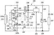
도 2는 본 발명의 실시예에 따른 차량용 히트펌프 시스템의 구조도이다.2 is a structural diagram of a vehicle heat pump system according to an embodiment of the present invention.
도 2를 참조하면, 본 발명의 실시예에 따른 차량용 히트펌프 시스템은 냉매가 순환되어 실내를 냉방하는 냉매 순환라인(100) 및 냉각수가 순환되어 실내를 난방하고 부품들을 냉각하는 냉각수 순환라인(200)으로 구성될 수 있다. 그리고 냉각수 순환라인(200)은 실내 난방을 위한 난방라인(210) 및 전장부품(231)과 배터리(237)의 냉각을 위한 냉각라인(230)을 포함할 수 있다.Referring to FIG. 2 , in a vehicle heat pump system according to an embodiment of the present invention, a
냉매 순환라인(100)은 압축기(110), 응축기(120), 냉매분기부(101), 냉매분기부(101)에서 일측으로 분기되어 제1 챙창밸브 및 증발기(151)를 통과하는 제1 냉매라인(100a)과 냉매분기부(101)에서 타측으로 분기되어 제2 팽창밸브 및 칠러(161)를 통과하는 제2 냉매라인(100b), 제1 냉매라인(100a)과 제2 냉매라인(100b)을 통과한 냉매가 통과하는 어큐뮬레이터(170)를 포함할 수 있다. 어큐뮬레이터(170)를 통과한 냉매는 압축기(110)로 재유입되어 냉매 순환이 일어나게 된다.The
이때, 제1 냉매라인(100a)에는 냉매열교환기(152)가 배치되며, 냉매열교환기(152)는 냉매분기부(101)와 제1 팽창밸브(150)사시에 배치되되, 제1 팽창밸브(150)로 유입되는 냉매와 증발기(151)를 통과한 냉매가 열교환될 수 있다.At this time, a
압축기(110)는 엔진(내연기관) 또는 모터 등으로부터 동력을 전달받아 구동하면서 냉매를 흡입하여 압축한 후 고온 고압의 기체 상태로 응축기(120) 측에 배출하게 된다.The compressor 110 receives power from an engine (internal combustion engine) or a motor, and while driving, sucks a refrigerant, compresses it, and then discharges it to the
응축기(120)는 냉방모드 및 난방모드 시 모두 응축기(120) 역할을 하게된다. 응축기(120)에 흐르는 냉매는 후술할 냉각수 순환라인(200) 상의 냉각수와 서로 열교환된 후 제1 팽창밸브(150)로 이동하게 된다. 이와 같이 응축기(120)의 냉매에 의해 가열된 냉각수는 냉각수 순환라인(200)을 통해 실내열교환기로 공급될 수 있다. 일실시예로, 응축기(120)는 수냉식 응축기(120)가 사용될 수 있다.The
냉매분기부(101)는 냉매가 제1 냉매라인(100a) 및 제2 냉매라인(100b)으로 분기되도록 한다.The
제1 냉매라인(100a)은 제1 팽창밸브(150)와 증발기(151)가 배치될 수 있다.A
제1 팽창밸브(150)는 제1 냉매라인(100a)에서 유입되는 냉매를 교축하거나 바이패스 시키거나 냉매의 흐름을 차단하는 역할을 할 수 있으며, 냉매의 유동 방향으로 증발기(151)의 입구측에 배치될 수 있다.The
증발기(151)는 공조케이스의 내부에 설치되고, 제1 냉매라인(100a)에 배치되어 제1 팽창밸브(150)에서 배출된 냉매가 공급되고, 블로어를 통해 공조케이스의 내부를 유동하는 공기가 증발기(151)를 통과하는 과정에서 증발기(151) 내부의 저온 저압의 냉매와 열교환하여 냉풍으로 바뀐 뒤, 차량 실내로 토출되어 차실내를 냉방하게 된다.The
제2 냉매라인(100b)은 제2 팽창밸브와 칠러(161)가 배치될 수 있다.A second expansion valve and a
제2 팽창밸브는 제2 냉매라인(100b)에서 유입되는 냉매를 교축하거나 바이패스 시키거나 냉매의 흐름을 차단하는 역할을 할 수 있으며, 냉매의 유동 방향으로 칠러(161)의 입구측에 배치될 수 있다.The second expansion valve may serve to throttle or bypass the refrigerant flowing in from the second
칠러(161)는 제2 팽창밸브에서 배출된 저온 저압의 냉매가 공급되어 냉각수 순환라인(200)에서 이동하는 냉각수와 열교환된다. 칠러(161)에서 열교환된 차가운 냉각수는 냉각수 순환라인(200)을 순환하여 고온의 배터리(237)와 열교환될 수 있다. 즉 배터리(237)는 냉매와 열교환되는 것이 아니라 냉각수와 열교환된다.The
어큐뮬레이터(170)는 압축기(110)의 입구 측에 설치되어 증발기(151) 및/또는 칠러(161)를 경유한 냉매가 합류되며, 냉매 중 액상 냉매와 기상 냉매를 분리하여 기상 냉매만 압축기(110)로 공급될 수 있도록 한다.The
냉매열교환기(152)는 제1 팽창밸브(150)로 유입되는 냉매와 증발기(151)에서 배출되는 냉매를 상호 열교환시켜 냉방 성능을 향상시키는 역할을 한다. 여기에서 냉매열교환기(152)는 냉매분기부(101)와 제1 팽창밸브(150)를 연결하는 증발기(151)로 냉매가 유입되는 유입측 냉매라인이 통과하고, 증발기(151)와 어큐뮬레이터(170)를 연결하는 증발기(151)에서 냉매가 배출되는 배출측 냉매라인이 통과하며, 유입측 냉매라인과 배출측 냉매라인을 통과하는 냉매들 간 열교환이 일어날 수 있다.The
그리하여 냉매열교환기(152)에 의해 제1 팽창밸브(150)로 유입되기 전에 냉매는 더욱 냉각될 수 있으며, 증발기(151)를 통한 냉방 성능이 향상됨과 동시에 냉방 시스템의 효율이 향상될 수 있다. 특히, 냉매열교환기(152)는 칠러(161)와 병렬로 연결된다.Thus, the refrigerant may be further cooled before being introduced into the
즉, 냉매열교환기(152)는 응축기(120)와 칠러(161) 사이 냉매 라인에 직렬 배치되는 것이 아닌, 증발기(151)와 인접하게 배치되어 냉매열교환기(152) 및 증발기(151)는 직렬로 배치되어 연결될 수 있다. 만약, 냉매 열교환기가 수랭식 응축기(120)와 칠러(161) 사이에 직렬로 배치될 경우, 난방 모드 시 저압측 압력 강하로 작용하여 난방 성능이 감소될 수 있다. 반대로, 냉매 열교환기가 병렬로 연결될 경우 냉방 성능은 물론 난방 성능도 증가되는데, 이는 난방 모드의 냉매 흐름 상 응축기(120)와 칠러(161) 사이에 냉매 열교환기가 없기 때문이다.That is, the
냉각수 순환라인(200)은 실내 난방을 위한 난방라인(210), 전장부품(231) 및 배터리(237)의 냉각을 위한 냉각라인(230)과 제2 냉방라인(250)을 포함할 수 있다.The cooling water circulation line 200 may include a
난방라인(210)은 응축기(120), 제1 펌프(211), 냉각수히터(212), 히터코어(213) 및 제1 방향전환밸브(214)를 포함할 수 있다.The
응축기(120)는 상기한 바와 같이 냉매 및 냉각수가 통과하면서 서로 열교환될 수 있다.As described above, the
제1 펌프(211)는 난방라인(210)을 따라 냉각수가 순환되도록 냉각수를 압송하는 수단이며, 제1 펌프(211)는 냉각수의 유동 방향으로 응축기(120)의 후방에 배치되어 냉각수라인 상에 설치될 수 있다.The
냉각수히터(212)는 냉각수를 가열하는 장치이며, 냉각수의 유동 방향으로 제1 펌프(211)의 후방 및 히터코어(213)의 전방에 배치되어 연결될 수 있다. 그리고 냉각수히터(212)는 냉각수의 온도가 특정한 온도 이하일 경우 가동될 수 있으며, 전력을 이용해 발열할 수 있는 인덕션 히터, 씨즈 히터, 피티씨 히터, 필름 히터 등 다양한 구성들이 사용될 수 있다.The
히터코어(213)는 차량의 공조장치(180) 내에 배치될 수 있으며, 송풍기에 의해 유동되는 공기가 히터코어(213)를 거치며 승온되어 차량의 실내로 공급되어 차량의 실내 난방에 이용될 수 있다. 그리고 히터코어(213)는 냉각수의 유동 방향으로 냉각수히터(212)의 후방에 배치되어 연결될 수 있다.The
제1 방향전환밸브(214)는 히터코어(213)와 응축기(120)의 사이에 설치될 수 있으며, 난방라인(210)과 이후에 설명할 냉각라인(230)을 선택적으로 연결하거나 연결을 차단하도록 구성될 수 있다.The first
보다 상세하게 제1 방향전환밸브(214)는 난방라인(210) 상에 설치되어 2개의 냉각수라인 배관이 제1 방향전환밸브(214)에 연결되고, 냉각라인(230)의 일측에서 분기된 1개의 제1 연결라인(221)이 제1 방향전환밸브(214)에 연결되며, 냉각라인(230)의 타측에서 분기된 1개의 제2연결라인이 제1 방향전환밸브(214)에 연결될 수 있다. 즉, 제1 방향전환밸브(214)에서는 4개의 냉각수 라인이 만나도록 연결되며, 제1 방향전환밸브(214)는 4개의 냉각수 라인들이 서로 연결되거나 차단된 상태를 조절할 수 있는 4방향의 방향전환밸브가 될 수 있다.In more detail, the first
냉각라인(230)은 라디에이터(233), 제2 방향전환밸브(238), 제2 펌프(239), 제1 방향전환밸브(214), 전장부품(231), 제1 냉각수 조인트(235), 제2 냉각수 조인트(232), 제3 펌프(236), 배터리(237), 칠러(161) 및 제3 방향전환밸브(234)를 포함할 수 있다.The
라디에이터(233)는 전장부품(231) 또는 배터리(237)와 열교환된 냉각수를 냉각시키며, 라디에이터(233)는 냉각팬(233a)에 의해 공랭식으로 냉각될 수 있다.The
제2 방향전환밸브(238)는 냉각라인(230) 상에 설치되어 2개의 냉각수 배관이 제2 방향전환밸브(238)에 연결되고, 난방라인(210)과 냉각라인(230)이 연결되도록 제1 방향전환밸브(214)와 제2 방향전환밸브(238)가 제1 연결라인(221)으로 연결될 수 있다.The second directional switching
즉, 제2 방향전환밸브(238)는 3개의 냉각수라인이 만나도록 연결되며, 제2 방향전환밸브(238)는 3개의 냉각수라인들이 서로 연결되거나 차단된 상태를 조절할 수 있는 3방향의 방향전환밸브가 될 수 있다.That is, the second directional switching
제2 펌프(239)는 냉각라인(230)을 따라 냉각수가 순환되도록 냉각수를 압송하는 수단이다. 그리고 제2 펌프(239)는 제1 방향전환밸브(214)와 제2 방향전환밸브(238) 사이의 제1 연결라인(221) 상에 설치되어, 제2 펌프(239)의 작동에 의해 제2 방향전환밸브(238)에서 제1 방향전환밸브(214)쪽으로 냉각수가 흐를 수 있다.The
제1 방향전환밸브(214)는 상기한 난방라인(210)에서 설명한 바와 같다.The first
전장부품(231)은 제1 방향전환밸브(214)와 제2 냉각수 조인트(232)를 연결하는 제2 연결라인(222) 상에 배치되어, 냉각수에 의해 전장부품(231)이 냉각될 수 있다. 그리고 전장부품(231)은 구동 모터, 인버터, 충전기(OBC; On Board Charger) 등이 될 수 있다.The
제3 펌프(236)는 냉각라인(230)을 따라 냉각수가 순환되도록 냉각수를 압송하는 수단이다. 그리고 제3 펌프(236)는 제1 냉각수 조인트(235)와 배터리(237) 사이의 냉각수라인에 설치되어, 제3 펌프(236)에서 배터리(237)쪽으로 냉각수가 흐를 수 있다.The
배터리(237)는 차량의 동력원이며, 차량 내 각종 전장부품(231)의 구동원이 될 수 있다. 또한 배터리(237)는 연료전지와 연결되어 전기를 저장하는 역할을 하거나, 외부에서 공급되는 전기를 저장하는 역할을 할 수 있다. 그리고 배터리(237)는 제3 펌프(236)와 제3 방향전환밸브(234) 사이의 냉각수라인 상에 배치될 수 있다. 그리하여 유동되는 냉각수와 열교환되어 배터리(237)가 냉각되거나 가열될 수 있다.The
제1 냉각수 조인트(235)는 냉각수의 유동방향으로 제2 방향전환밸브(238)의 후방의 냉각수라인에 설치되며, 제1 냉각수 조인트(235)는 3개의 냉각수라인이 만나도록 연결된다. 즉, 제1 냉각수 조인트(235)는 냉각라인(230) 상에 양측이 연결되도록 설치되며, 하측에는 제3 연결라인(223)이 연결될 수 있다. 여기에서 제3 연결라인(223)은 칠러(161)를 통과하도록 연결될 수 있다.The
제2 냉각수 조인트(232)는 제2 연결라인(222)의 후단이 냉각라인(230)과 만나는 지점에 설치될 수 있으며, 제2 냉각수 조인트(232)에서 3개의 냉각수라인이 만나도록 연결된다. 즉, 제2 냉각수 조인트(232)는 냉각라인(230) 상에 양측이 연결되도록 설치되며, 상측에는 제2 연결라인(222)이 연결될 수 있다.The
칠러(161)는 상기한 난방라인(210)에서 설명한 바와 같다.The
제3 방향전환밸브(234)는 배터리(237)와 제2 냉각수 조인트(232) 사이의 냉각수라인 상에 설치되며, 2개의 냉각수 배관이 제3 방향전환밸브(234)에 연결되고, 제3 방향전환밸브(234)의 상측에 제3 연결라인(223)이 연결되어 배터리(237)와 제3 연결라인(223)이 병렬로 연결되도록 구성될 수 있다. 이때, 제2 방향전환밸브(238)는 3개의 냉각수라인들이 서로 연결되거나 차단된 상태를 조절할 수 있는 3방향의 방향전환밸브가 될 수 있다.The third
그리고 공조장치(180)는 공기를 송풍시킬 수 있도록 일측에 송풍기가 설치되어 있으며, 공조장치(180)의 내부에는 온도조절도어가 설치될 수 있다. 또한, 공조장치(180) 내에 배치된 증발기(151) 및 히터코어(213)는 온도조절도어의 작동에 따라 송풍기에서 토출된 공기가 증발기(151)만을 거친 후 실내로 유입되도록 하거나, 증발기(151)를 거친 후 히터코어(213)를 통과하여 실내로 유입될 수 있도록 배치 및 구성될 수 있다.In addition, a blower is installed on one side of the
냉각라인(230)에는 제5 연결라인(225)이 배치될 수 있다. 제5 연결라인(225)은 라디에이터(233)와 제2 방향전환밸브(238) 사이에 배치되는 제3 냉각수조인트(253)와 라디에이터(233)와 제2 냉각수 조인트(232) 사이에 배치되는 제5 냉각수 조인트(225b)를 연결할 수 있다.A
제5 연결라인(225)은 증발기(151)를 통과하도록 배치될 수 있으며, 공조모드에 따라 라디에이터(233)를 통과한 냉각수가 증발기(151)를 거쳐 순환되도록 할 수 있다.The
제5 연결라인(225)에는 증발기(151)의 입구측에 제4 냉각수 조인트(225a)가 배치될 수 있으며, 증발기(151)의 출구측에는 제5 방향전환밸브(254)가 배치될 수 있다.A fourth cooling water joint 225a may be disposed on the inlet side of the
제4 냉각수 조인트(225a)와 제5 방향전환밸브(254)에는 제2 냉방라인(250)이 연결될 수 있다.The
제2 냉방라인(250)은 증발기(151), 캐빈 쿨러(252) 및 제4 펌프(251)를 포함할 수 있다. 여기에서 증발기(151), 캐빈 쿨러(252) 및 제4 펌프(251)가 연결된 냉각수 라인은 제5 방향전환밸브(254)의 동작에 따라 폐루프를 형성할 수 있다.The
증발기(151)는 상기한 바와 같이 냉매 및 냉각수가 통과하면서 서로 열교환될 수 있다.As described above, the
캐빈 쿨러(252)는 공랭식 증발기(151)의 역할을 하며, 증발기(151)를 통과하는 냉매와 열교환되어 냉각된 냉각수가 통과한다. 그리고 캐빈 쿨러(252)는 공조장치(180)의 내부에 배치되어, 공조장치(180)의 송풍기에 의해 유동되는 공기가 캐빈 쿨러(252)를 거치며 냉각되어 차량의 실내로 공급됨으로써 차량의 실내 냉방에 이용될 수 있다.The
제4 펌프(251)는 제2 냉방라인(250)을 따라 냉각수가 순환되도록 냉각수를 압송하는 역할을 한다. 그리고 제4 펌프(251)는 증발기(151)와 제4 냉각수 조인트(225a) 사이의 제5 연결라인(225) 상에 설치되며, 제4 펌프(251)의 작동에 의해 냉각수를 순환시킬 수 있다.The
그리하여 본 발명의 차량용 히트펌프 시스템은 차량 실내의 냉방을 위해 냉각수를 이용한 제2 냉방라인(250)을 적용함에 따라 냉매가 순환되는 냉매 순환라인(100)이 차량의 실내에 배치되지 않고 실외에 배치될 수 있어, 냉매 배관의 길이가 축소되어 냉매의 충진량을 줄일 수 있으며 냉매 순환라인(100)의 구성요소들을 모듈화 할 수 있는 장점이 있다. 또한, 냉매 순환라인(100)에 사용되는 냉매를 고효율의 자연 냉매를 사용할 수 있어 열관리 시스템의 효율이 향상되는 장점이 있다.Thus, in the vehicle heat pump system of the present invention, as the
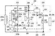
도 3은 도 2의 제1 실시예이다. 도 3은 도 2에서 제4 연결라인이 배치되는 구조를 나타내고 있다.FIG. 3 is a first embodiment of FIG. 2 . FIG. 3 shows a structure in which a fourth connection line is disposed in FIG. 2 .
도 3을 참조하면, 제2 연결라인(222)에는 전장부품(231)을 통과한 냉각수의 이동방향을 제어하는 제4 방향전환밸브(222a)가 배치될 수 있다. 제4 방향전환밸브(222a)는 제2 연결라인(222)에서 분기되는 제4 연결라인(224)이 배치되며, 제4 연결라인(224)은 제3 연결라인(223)상에 배치되는 제3 냉각수 조인트(223a)에 연결될 수 있다.Referring to FIG. 3 , a fourth
제3 냉각수 조인트(223a)는 칠러(161)로 유입되는 냉각수의 입구측에 배치되어 제4 방향전환밸브(222a)의 동작에 따라 전장부품(231)을 통과한 냉각수가 칠러(161)측으로 유입될 수 있다.The third coolant joint 223a is disposed on the inlet side of the coolant flowing into the
일실시예로, 제4 방향전환밸브(222a)의 상측과 우측이 연결되는 경우, 전장부품(231)과 칠러(161)는 직렬로 연결될 수 있다.In one embodiment, when the upper side and the right side of the fourth
도 4는 도 2에서 난방 모드시 시스템의 동작상태를 나타내는 도면이다.FIG. 4 is a view showing an operating state of the system in a heating mode in FIG. 2 .
도 4를 참조하면, 냉매 순환라인(100)에서는 압축기(110)가 작동하여 압축기(110)에서 고온고압의 냉매가 토출된다. 그리고 압축기(110)에서 토출된 냉매는 응축기(120)에서 냉각수와 열교환되어 냉각된다. 이어서 응축기(120)에서 냉각되어 응축된 냉매는 이후 냉매분기부(101)에서 분기되어 냉매의 일부는 냉매열교환기(152)를 통과한 후 제1 팽창밸브(150)를 통과하면서 교축되어 냉매가 팽창되며, 이후 팽창된 냉매는 증발기(151)를 거치면서 2차 냉방라인(250)의 냉각수와 열교환되어, 냉매에 의해 2차 냉방라인(250)의 냉각수가 냉각된다.Referring to FIG. 4 , the compressor 110 operates in the
그리고 증발기(151)에서 증발된 냉매는 냉매열교환기(152)를 거치며 제1 팽창밸브(150)로 유입되기 전의 냉매와 열교환된 후 어큐뮬레이터(170)를 거쳐 다시 압축기(110)로 유입된다.The refrigerant evaporated in the evaporator 151 passes through the
또한, 냉매분기부(101)에서 분기된 냉매의 나머지는 제2 팽창밸브(160)를 통과하면서 교축되어 냉매가 팽창되며, 이후 팽창된 냉매는 칠러(161)를 거치면서 냉각수와 열교환되어 냉매가 증발되면서 냉각수가 냉각될 수 있다. 그리고 칠러(161)에서 증발된 냉매는 어큐뮬레이터(170)를 거쳐 다시 압축기(110)로 유입된다.In addition, the remainder of the refrigerant branched from the
이와 같이 증발기(151)를 통과한 냉매와 칠러(161)를 통과한 냉매가 어큐뮬레이터(170)에서 합류되어 압축기(110)로 유입된 후, 상기한 바와 같은 과정을 반복하면서 냉매가 순환된다.As such, the refrigerant passing through the
한편, 냉각수 순환라인(200)의 냉각수는 제1 펌프(211), 제2 펌프(239), 제3 펌프(236) 및 제4 펌프(251)의 작동에 의해 순환된다. 그리고 냉각수는 응축기(120)를 통과하면서 가열되고, 냉각수 히터(212)에 의해 가열되며, 전장부품(231)의 폐열로 가열될 수 있으며, 칠러(161)를 통과하면서 냉각될 수 있다. 이때, 제1 방향전환밸브(214) 및 제2 방향전환밸브(238)는 난방라인(210)과 냉각라인(230)을 분리하는 방향으로 조절될 수 있다.Meanwhile, the cooling water of the cooling water circulation line 200 is circulated by the operation of the
보다 상세하게는 제1 방향전환밸브(214)는 상측과 우측이 서로 연결되어 냉각수가 유통되고 하측과 좌측이 서로 연결되어 냉각수가 유통될 수 있다. 그리고 제2 방향전환밸브(238)는 우측과 하측이 서로 연결되어 냉각수가 유통되고 좌측은 연결이 차단될 수 있다.In more detail, the upper and right sides of the first
또한, 제3 방향전환밸브(234)는 상측, 좌측 및 우측이 모두 개방될 수 있다.In addition, the third
그리하여 난방라인(210)의 냉각수는 제1 펌프(211), 냉각수 히터(212), 히터코어(213), 제1 방향전환밸브(214) 및 응축기(120)를 차례대로 거쳐 다시 제1 펌프(211)로 유입되어 순환되는 사이클이 반복된다.Thus, the cooling water of the
이때, 냉각수는 히터코어(213)를 거치면서 공조장치(180)의 송풍기에 의해 송풍되는 공기와 열교환되어 공기가 가열되며, 가열된 공기를 차량의 실내로 공급하여 실내 난방이 이루어진다.At this time, the cooling water is heat-exchanged with the air blown by the blower of the
그리고 난방라인(210)과 분리된 냉각라인(230)의 냉각수는 제2 펌프(239)에서부터 제1 방향전환밸브(214), 전장부품(231), 제2 냉각수 조인트(232), 제3 방향전환밸브(234), 칠러(161), 제1 냉각수 조인트(235), 제2 방향전환밸브(238)를 차례대로 거쳐 다시 제2 펌프(239)로 유입되어 순환되는 사이클이 반복된다.And the cooling water of the
또한, 배터리(237)를 통과하는 냉각수는 제3 펌프(236)를 통해 순환하게 되며, 제3 방향전환밸브(234)에서 합류되어 상측으로 유동된 후 제1 냉각수 조인트(235)에서 양쪽으로 분기될 수 있다.In addition, the coolant passing through the
이때, 제2 방향전환밸브(238)의 좌측은 차단되나, 제4 펌프(251)에 의해 별도의 냉각수 순환라인이 형성될 수 있다.At this time, the left side of the second
라디에이터(233)를 거친 냉각수는 제4 펌프(251)에 의해 제3 냉각수 조인트(253)에서 하부로 순환될 수 있으며, 증발기(151)와 제5 냉각수 조인트(225b)를 거쳐 라디에이터(233)로 재유입되는 순환라인이 형성될 수 있다. 이를 통해 냉각수는 증발기(151)에서 라디에이터(233)로 외기를 흡열할 수 있다. 또한, 제4 펌프(251)를 제5 연결라인(225)상에 배치하여 흡열 냉각수로에 유량을 증대하여 난방성능을 증대할 수 있다.The coolant that has passed through the
이 경우, 제5 연결라인(225)과 연결되는 제5 방향전환밸브(254)는 상측과 하측이 연결되고 우측을 차단하여 제2 냉방라인(250)으로 냉각수가 순환되는 것을 차단할 수 있다.In this case, the fifth
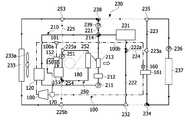
도 5는 도 3에서 난방 모드시 시스템의 동작상태를 나타내는 도면이다.FIG. 5 is a view showing an operating state of the system in a heating mode in FIG. 3 .
도 5를 참조하면, 냉매 순환라인(100)에서는 압축기(110)가 작동하여 압축기(110)에서 고온고압의 냉매가 토출된다. 그리고 압축기(110)에서 토출된 냉매는 응축기(120)에서 냉각수와 열교환되어 냉각된다. 이어서 응축기(120)에서 냉각되어 응축된 냉매는 이후 냉매분기부(101)에서 분기되어 냉매의 일부는 냉매열교환기(152)를 통과한 후 제1 팽창밸브(150)를 통과하면서 교축되어 냉매가 팽창되며, 이후 팽창된 냉매는 증발기(151)를 거치면서 2차 냉방라인(250)의 냉각수와 열교환되어, 냉매에 의해 2차 냉방라인(250)의 냉각수가 냉각된다.Referring to FIG. 5 , the compressor 110 operates in the
그리고 증발기(151)에서 증발된 냉매는 냉매열교환기(152)를 거치며 제1 팽창밸브(150)로 유입되기 전의 냉매와 열교환된 후 어큐뮬레이터(170)를 거쳐 다시 압축기(110)로 유입된다.The refrigerant evaporated in the evaporator 151 passes through the
또한, 냉매분기부(101)에서 분기된 냉매의 나머지는 제2 팽창밸브(160)를 통과하면서 교축되어 냉매가 팽창되며, 이후 팽창된 냉매는 칠러(161)를 거치면서 냉각수와 열교환되어 냉매가 증발되면서 냉각수가 냉각될 수 있다. 그리고 칠러(161)에서 증발된 냉매는 어큐뮬레이터(170)를 거쳐 다시 압축기(110)로 유입된다.In addition, the remainder of the refrigerant branched from the
이와 같이 증발기(151)를 통과한 냉매와 칠러(161)를 통과한 냉매가 어큐뮬레이터(170)에서 합류되어 압축기(110)로 유입된 후, 상기한 바와 같은 과정을 반복하면서 냉매가 순환된다.As such, the refrigerant passing through the
냉각수 순환라인(200)의 냉각수는 제1 펌프(211), 제2 펌프(239) 및 제4 펌프(251)의 작동에 의해 순환된다. 그리고 냉각수는 응축기(120)를 통과하면서 가열되고, 냉각수히터(212)에 의해 가열되며, 전장부품(231)의 폐열로 가열될 수 있으며, 칠러(161)를 통과하면서 냉각될 수 있다.The cooling water of the cooling water circulation line 200 is circulated by the operation of the
이때, 제1 방향전환밸브(214) 및 제2 방향전환밸브(238)는 난방라인(210)과 냉각라인(230)을 분리하는 방향으로 조절될 수 있다. 보다 상세하게는 제1 방향전환밸브(214)는 상측과 우측이 서로 연결되어 냉각수가 유통되고 하측과 좌측이 서로 연결되어 냉각수가 유통될 수 있다. 그리고 제2 방향전환밸브(238)는 좌측과 하측이 서로 연결되어 냉각수가 유통되고 우측은 연결이 차단될 수 있다. 또한, 제3 방향전환밸브(234)는 상측과 좌측이 서로 연결되고 우측은 차단될 수 있다.At this time, the first
그리하여 난방라인(210)의 냉각수는 제1 펌프(211), 냉각수히터(212), 히터코어(213), 제1 방향전환밸브(214) 및 응축기(120)를 차례대로 거쳐 다시 제1 펌프(211)로 유입되어 순환되는 사이클이 반복된다. 이때, 냉각수는 히터코어(213)를 거치면서 공조장치(180)의 송풍기에 의해 송풍되는 공기와 열교환되어 공기가 가열되며, 가열된 공기를 차량의 실내로 공급하여 실내 난방이 이루어진다.Thus, the cooling water of the
그리고 난방라인(210)과 분리된 냉각라인(230)의 냉각수는 제2 펌프(239)에서부터 제1 방향전환밸브(214), 전장부품(231), 제4 방향전환밸브(222a), 제3 냉각수 조인트(223a), 칠러(161), 제3 방향전환밸브(234), 라디에이터(233)를 거치며, 라디에이터를 거친 냉각수는 제3 냉각수 조인트(233a)에서 분기되어 일부는 제2 방향전환밸브(238)를 거쳐 제2 펌프(239)로 유입되고, 나머지 일부는 제5 연결라인(225)을 따라 증발기(151)에서 열교환 후, 다시 제5 냉각수 조인트(254)로 이동하여 제3 방향전환밸브(234)를 통과하는 냉각수와 합류하여 라디에이터(233)로 이동하게 된다.And the cooling water of the
여기서 제4 방향전환밸브(222a)는 칠러(161)측으로 냉각수가 이동하도록 상측과 우측이 서로 연결될 수 있으며, 냉각수는 제3 냉각수 조인트(223a)를 거쳐 칠러(161)로 이동하게 된다.Here, the upper side and the right side of the fourth
이를 통해 전장부품(231)과 칠러(161)가 직렬로 연결될 수 있으며, 외기와 폐열을 모두 흡수할 수 있는 냉각수 유로가 형성될 수 있다. 이러한 구조에서는 라디에이터(233)와 전장부품(231) 및 칠러(161)를 순환하는 냉각라인(230) 상에 분기되는 부분이 없어 거의 동일한 유량이 흘러 난방성능을 향상시킬 수 있다.Through this, the
이때, 제2 방향전환밸브(238) 및 제3 방향전환밸브(234)를 통해 배터리(237)측으로 냉각수가 흐르지 않을 수 있다.At this time, the cooling water may not flow toward the
도 6는 도 3에서 냉방 모드시 시스템의 동작상태를 나타내는 도면이다.FIG. 6 is a view showing an operating state of the system in a cooling mode in FIG. 3 .
도 6을 참조하면, 냉매 순환라인(100)에서는 압축기(110)가 작동하여 압축기(110)에서 고온고압의 냉매가 토출된다. 그리고 압축기(110)에서 토출된 냉매는 응축기(120)에서 냉각수와 열교환되어 냉각된다. 이어서 수랭식 응축기(120)에서 냉각되어 응축된 냉매는 이후 냉매분기부(101)에서 분기되어 냉매의 일부는 냉매열교환기(152)를 통과한 후 제1 팽창밸브(150)를 통과하면서 교축되어 냉매가 팽창되며, 이후 팽창된 냉매는 증발기(151)를 거치면서 2차 냉방라인(250)의 냉각수와 열교환되어, 냉매에 의해 2차 냉방라인(250)의 냉각수가 냉각된다.Referring to FIG. 6 , the compressor 110 operates in the
그리고 증발기(151)에서 증발된 냉매는 냉매열교환기(152)를 거치며 제1 팽창밸브(150)로 유입되기 전의 냉매와 열교환된 후 어큐뮬레이터(170)를 거쳐 다시 압축기(110)로 유입된다.The refrigerant evaporated in the evaporator 151 passes through the
또한, 냉매분기부(101)에서 분기된 냉매의 나머지는 제2 팽창밸브를 통과하면서 교축되어 냉매가 팽창되며, 이후 팽창된 냉매는 칠러(161)를 거치면서 냉각수와 열교환되어 냉매가 증발되면서 냉각수가 냉각될 수 있다. 그리고 칠러(161)에서 증발된 냉매는 어큐뮬레이터(170)를 거쳐 다시 압축기(110)로 유입된다.In addition, the remainder of the refrigerant branched from the
이와 같이 증발기(151)를 통과한 냉매와 칠러(161)를 통과한 냉매가 어큐뮬레이터(170)에서 합류되어 압축기(110)로 유입된 후, 상기한 바와 같은 과정을 반복하면서 냉매가 순환된다.As such, the refrigerant passing through the
또한, 제2 냉방라인(250)에서는 제4 펌프(251)의 작동에 의해 냉각수가 순환된다. 그리고 냉각수가 캐빈 쿨러(252)를 통과하면서 공조장치(180)의 송풍기에 의해 송풍되는 공기와 열교환되면서 공기가 냉각되어, 냉각된 공기를 차량의 실내로 공급하여 실내 냉방이 이루어진다. 이때, 제5 연결라인(225)에 배치되는 제5 방향전환밸브(254)는 상측와 우측이 연결되며, 하측이 폐쇄되어 제2 냉방라인(250)이 폐루프 구조로 순환하도록 한다.Also, in the
한편, 냉각수 순환라인(200)의 냉각수는 제1 펌프(211), 제2 펌프(239) 및 제3 펌프(236)의 작동에 의해 순환된다. 그리고 냉각수에 의해 응축기(120)를 통과하는 냉매, 전장부품(231) 및 배터리(237)가 냉각될 수 있으며, 가열된 냉각수는 전장용 라디에이터(233)에서 냉각팬(233a)의 작동에 의해 외부 공기와 열교환되어 냉각될 수 있다.Meanwhile, the coolant in the coolant circulation line 200 is circulated by the operation of the
이때, 제1 방향전환밸브(214) 및 제2 방향전환밸브(238)는 난방라인(210)과 냉각라인(230)을 연결하는 방향으로 조절될 수 있다. 보다 상세하게는 제1 방향전환밸브(214)는 상측과 좌측이 서로 연결되어 냉각수가 유통되고 하측과 우측이 서로 연결되어 냉각수가 유통될 수 있다. 그리고 제2 방향전환밸브(238)는 좌측과 하측이 서로 연결되어 냉각수가 유통되고 우측은 연결이 차단될 수 있다. 또한, 제3 방향전환밸브(234)는 상측과 우측이 서로 연결되어 있고 좌측은 차단되어 있을 수 있다.In this case, the first
그리하여 냉각수는 라디에이터(233)에서부터 제2 방향전환밸브(238), 제2 펌프(239), 제1 방향전환밸브(214), 응축기(120), 제1 펌프(211), 냉각수히터(212), 히터코어(213), 제1 방향전환밸브(214), 전장부품(231), 제2 냉각수 조인트(232)를 차례대로 거쳐 다시 라디에이터(233)로 유입되어 순환되는 사이클이 반복된다.Thus, the coolant is transferred from the
이때, 제4 방향전환밸브(222a)의 우측라인이 페쇄되어 제4 연결라인(224)으로 냉각수가 이동하는 것은 차단될 수 있다.At this time, the right line of the fourth
제2 방향전환밸브(238)에 의해 제2 방향전환밸브(238)에서부터 제1 냉각수 조인트(235)까지에는 냉각수가 흐르지 않으며, 제3 방향전환밸브(234)에 의해 제3 방향전환밸브(234)에서부터 제2 냉각수 조인트(232)까지는 냉각수가 흐르지 않을 수 있다.Cooling water does not flow from the second
또한, 냉각수는 칠러(161)에서부터 제1 냉각수 조인트(235), 제3 펌프(236), 배터리(237), 제3 방향전환밸브(234)를 차례대로 거쳐 다시 칠러(161)로 유입되어 순환되는 사이클이 반복된다. 즉, 제2 방향전환밸브(238) 및 제3 방향전환밸브(234)에 의해 배터리(237)와 칠러(161)는 냉각수가 순환되는 별개의 폐루프로 냉각라인(230)이 형성되어 배터리(237)가 별도로 냉각될 수 있다.In addition, the coolant flows from the
이상으로 본 발명의 실시 예에 관하여 첨부된 도면을 참조하여 구체적으로 살펴보았다.As described above, with reference to the accompanying drawings with respect to the embodiment of the present invention has been described in detail.
이상의 설명은 본 발명의 기술 사상을 예시적으로 설명한 것에 불과한 것으로서, 본 발명이 속하는 기술 분야에서 통상의 지식을 가진 자라면 본 발명의 본질적인 특성에서 벗어나지 않는 범위 내에서 다양한 수정, 변경 및 치환이 가능할 것이다. 따라서, 본 발명에 개시된 실시예 및 첨부된 도면들은 본 발명의 기술 사상을 한정하기 위한 것이 아니라 설명하기 위한 것이고, 이러한 실시예 및 첨부된 도면에 의하여 본 발명의 기술 사상의 범위가 한정되는 것은 아니다. 본 발명의 보호 범위는 아래의 청구범위에 의하여 해석되어야 하며, 그와 동등한 범위 내에 있는 모든 기술 사상은 본 발명의 권리범위에 포함되는 것으로 해석되어야 할 것이다.The above description is merely illustrative of the technical idea of the present invention, and various modifications, changes, and substitutions are possible within the range that does not depart from the essential characteristics of the present invention by those of ordinary skill in the art to which the present invention pertains. will be. Accordingly, the embodiments disclosed in the present invention and the accompanying drawings are for explaining, not limiting, the technical spirit of the present invention, and the scope of the technical spirit of the present invention is not limited by these embodiments and the accompanying drawings. . The protection scope of the present invention should be construed by the following claims, and all technical ideas within the scope equivalent thereto should be construed as being included in the scope of the present invention.
100 : 냉매 순환라인100a : 제1 냉매라인
100b : 제2 냉매라인101 : 냉매분기부
110 : 압축기120 : 응축기
150 : 제1 팽창밸브
151 : 증발기152 : 냉매열교환기
160 : 제2 팽창밸브161 : 칠러
170 : 어큐뮬레이터180 : 공조장치
200 : 냉각수 순환라인210 : 난방라인
211 : 제1 펌프212 : 냉각수히터
213 : 히터코어214 : 제1 방향전환밸브
221 : 제1 연결라인222 : 제2 연결라인
222a : 제4 방향전환밸브223 : 제3 연결라인
223a : 제3 냉각수 조인트224 : 제4 연결라인
225 : 제5 연결라인225a : 제4 냉각수 조인트
225b : 제5 냉각수 조인트230 : 냉각라인
231 : 전장부품232 ; 제2 냉각수조인트
233 : 라디에이터233a : 냉각팬
234 : 제3 방향전환밸브235 : 제1 냉각수조인트
236 : 제3 펌프237 : 배터리
238 : 제2 방향전환밸브239 : 제2 펌프
250 : 제2 냉방라인251 : 제4 펌프
252 : 캐빈 쿨러253 : 제3 냉각수조인트
254 : 제5 방향전환밸브100:
100b: second refrigerant line 101: refrigerant branch
110: compressor 120: condenser
150: first expansion valve
151: evaporator 152: refrigerant heat exchanger
160: second expansion valve 161: chiller
170: accumulator 180: air conditioner
200: cooling water circulation line 210: heating line
211: first pump 212: coolant heater
213: heater core 214: first directional switching valve
221: first connection line 222: second connection line
222a: fourth direction switching valve 223: third connection line
223a: third coolant joint 224: fourth connection line
225:
225b: fifth coolant joint 230: cooling line
231:
233:
234: third direction switching valve 235: first cooling water joint
236: third pump 237: battery
238: second directional valve 239: second pump
250: second cooling line 251: fourth pump
252: cabin cooler 253: third coolant joint
254: fifth direction switching valve
Claims (16)
Translated fromKorean압축된 상기 냉매를 응축시키는 응축기;
응축된 상기 냉매를 팽창시키는 제1 팽창밸브;
상기 제1 팽창밸브에서 팽창된 상기 냉매를 냉각수와 열교환시켜 기화시키는 증발기;
상기 증발기를 통과한 냉각수를 공기와 열교환시켜 실내를 냉방하는 캐빈 쿨러; 및
전장부품을 냉각하기 위한 냉각수를 외기와 열교환시키는 라디에이터;를 포함하되,
난방 모드 시, 상기 라디에이터를 통과한 냉각수가 상기 증발기에 유입되는 것을 특징으로 하는 차량용 히트펌프 시스템.a compressor that compresses and circulates the refrigerant;
a condenser condensing the compressed refrigerant;
a first expansion valve for expanding the condensed refrigerant;
an evaporator for vaporizing the refrigerant expanded in the first expansion valve by heat-exchanging it with cooling water;
a cabin cooler that heats the cooling water that has passed through the evaporator with air to cool the room; and
A radiator for exchanging the cooling water for cooling the electrical components with the outside air; including,
In the heating mode, the vehicle heat pump system, characterized in that the coolant that has passed through the radiator flows into the evaporator.
상기 응축기를 통해 상기 냉매와 열교환되는 냉각수를 순환시켜 실내를 난방하는 난방라인; 및
공기 또는 상기 냉매와 열교환되는 냉각수를 순환시켜 배터리 및 전장부품을 냉각시키는 냉각라인;을 더 포함하는 차량용 히트펌프 시스템.According to claim 1,
a heating line for heating the room by circulating cooling water that exchanges heat with the refrigerant through the condenser; and
The vehicle heat pump system further comprising a; cooling line for cooling the battery and electronic components by circulating air or cooling water that exchanges heat with the refrigerant.
상기 냉각라인은 제3 냉각수 조인트 및 제5 냉각수 조인트가 배치되어 상기 라디에이터에서 상기 증발기를 순환하는 제5 냉각라인이 형성되는 것을 특징으로 하는 차량용 히트펌프 시스템.3. The method of claim 2,
In the cooling line, a third coolant joint and a fifth coolant joint are disposed to form a fifth cooling line that circulates the evaporator in the radiator.
상기 제5 냉각라인에는 상기 증발기를 통해 냉매와 열교환되는 냉각수를 순환하여 실내를 냉방하는 제2 냉방라인이 연결되며,
상기 제2 냉방라인에는 상기 캐빈 쿨러가 배치되는 것을 특징으로 하는 차량용 히트펌프 시스템.4. The method of claim 3,
A second cooling line is connected to the fifth cooling line to cool the room by circulating cooling water that exchanges heat with the refrigerant through the evaporator,
The heat pump system for a vehicle, characterized in that the cabin cooler is disposed in the second cooling line.
상기 제5 냉각라인에는 제2 냉방라인을 연결하는 제4 냉각수 조인트와 상기 제2 냉방라인으로 순환여부를 결정하는 제5 방향전환밸브가 배치되는 것을 특징으로 하는 차량용 히트펌프 시스템.5. The method of claim 4,
A fourth cooling water joint connecting the second cooling line and a fifth directional switching valve for determining whether to circulate to the second cooling line are disposed in the fifth cooling line.
상기 제2 냉방라인은,
상기 상기 증발기와 캐빈 쿨러의 사이에 연결된 제4 펌프를 포함하며,
상기 제4 펌프는 상기 제4 냉각수 조인트와 상기 증발기 사이에 배치되는 것을 특징으로 하는 차량용 히트펌프 시스템.6. The method of claim 5,
The second cooling line,
a fourth pump connected between the evaporator and the cabin cooler,
and the fourth pump is disposed between the fourth coolant joint and the evaporator.
상기 냉각라인의 일측에서 분기되어 상기 난방라인과 연결되는 제1 연결라인; 및 상기 냉각라인의 타측에서 분기되어 상기 난방라인과 연결되는 제2 연결라인;을 포함하는 차량용 히트펌프 시스템.3. The method of claim 2,
a first connection line branched from one side of the cooling line and connected to the heating line; and a second connection line branched from the other side of the cooling line and connected to the heating line.
상기 제1 연결라인, 제2 연결라인 및 난방라인은 제1 방향전환밸브에 연결되며, 상기 제1 방향전환밸브에 의해 냉각라인과 난방라인이 서로 연결되거나 연결이 차단되는 것을 특징으로 하는 차량용 히트펌프 시스템.8. The method of claim 7
The first connecting line, the second connecting line and the heating line are connected to a first directional selector valve, and the cooling line and the heating line are connected to each other or the connection is blocked by the first directional selector valve. pump system.
상기 전장부품은 상기 제2 연결라인 상에 배치되고, 상기 냉각라인 상에 배치되는 제1 냉각수 조인트에서 분기되는 제3 연결라인은 칠러를 통과하도록 배치되는 것을 특징으로 하는 차량용 히트펌프 시스템.9. The method of claim 8,
The electric component is disposed on the second connection line, and the third connection line branched from the first coolant joint disposed on the cooling line is disposed to pass through the chiller.
상기 제2 연결라인에는 상기 전장부품을 통과한 냉각수의 이동방향을 제어하는 제4 방향전환밸브가 구비되며,
상기 제4 방향전환밸브는 제4 연결라인을 통해 상기 제3 연결라인의 제3 냉각수 조인트와 연결되며, 상기 제3 냉각수 조인트는 상기 칠러의 입구측에 배치되는 것을 특징으로 하는 차량용 히트펌프 시스템.10. The method of claim 9,
The second connection line is provided with a fourth direction switching valve for controlling the movement direction of the coolant that has passed through the electrical components,
The fourth direction switching valve is connected to a third coolant joint of the third connection line through a fourth connection line, and the third coolant joint is disposed on an inlet side of the chiller.
상기 응축기를 통과하는 냉매는 냉매분기부에서 일측으로 분기되어 제1 팽창밸브 및 증발기를 통과하는 제1 냉매라인과 상기 냉매분기부에서 타측으로 분기되어 제2 팽창밸브 및 칠러를 통과하는 제2 냉매라인을 포함하는 차량용 히트펌프 시스템.According to claim 1,
The refrigerant passing through the condenser is branched from the refrigerant branch to one side, and the first refrigerant line passes through the first expansion valve and the evaporator, and the second refrigerant is branched from the refrigerant branch to the other side and passes through the second expansion valve and chiller Vehicle heat pump system with line.
상기 제1 냉매라인에는 냉매열교환기가 배치되며,
상기 냉매열교환기는 상기 냉매분기부와 상기 제1 팽창밸브 사이에 배치되되, 상기 제1 팽창밸브로 유입되는 냉매와 상기 증발기를 통과한 냉매가 열교환되는 것을 특징으로 하는 차량용 히트펌프 시스템.12. The method of claim 11,
A refrigerant heat exchanger is disposed in the first refrigerant line,
The refrigerant heat exchanger is disposed between the refrigerant branch unit and the first expansion valve, and the refrigerant flowing into the first expansion valve and the refrigerant passing through the evaporator exchange heat.
상기 난방라인은,
상기 응축기를 통해 냉매와 열교환되는 냉각수와 실내로 유입되는 공기를 열교환하여 가열된 공기를 이용해 실내를 난방하는 히터코어, 및 냉각수의 유동 방향으로 상기 히터코어의 전방에 배치되어 냉각수를 가열하는 냉각수 히터를 포함하는 차량용 히트펌프 시스템.3. The method of claim 2,
The heating line is
A heater core that heats a room using air heated by exchanging the cooling water exchanged with the refrigerant through the condenser and air flowing into the room, and a coolant heater disposed in front of the heater core in the flow direction of the coolant to heat the coolant A vehicle heat pump system comprising a.
난방 모드시, 상기 제5 방향전환밸브는 상기 제2 냉방라인의 유로를 차단하는 것을 특징으로 하는 차량용 히트펌프 시스템.6. The method of claim 5,
In the heating mode, the fifth direction switching valve is a vehicle heat pump system, characterized in that blocking the flow path of the second cooling line.
상기 제4 방향전환밸브는 상기 라디에이터와 상기 전장부품에서 흡열한 냉각수가 칠러를 통과하도록 냉각수의 방향을 제어하는 것을 특징으로 하는 차량용 히트펌프 시스템.11. The method of claim 10,
and the fourth directional selector valve controls the direction of the coolant so that the coolant absorbed heat from the radiator and the electric component passes through the chiller.
냉방 모드시, 상기 제5 방향전환밸브는 상기 제2 냉방라인을 폐루프로 순환시키는 것을 특징으로 하는 차량용 히트펌프 시스템.6. The method of claim 5,
In the cooling mode, the fifth directional selector valve circulates the second cooling line in a closed loop.
Priority Applications (6)
| Application Number | Priority Date | Filing Date | Title |
|---|---|---|---|
| KR1020190160086AKR102721708B1 (en) | 2019-12-04 | 2019-12-04 | Heatpump system for vehicle |
| PCT/KR2020/017353WO2021112522A1 (en) | 2019-12-04 | 2020-12-01 | Vehicle heat pump system |
| DE112020005910.3TDE112020005910T5 (en) | 2019-12-04 | 2020-12-01 | VEHICLE HEAT PUMP SYSTEM |
| CN202080083776.8ACN114761261A (en) | 2019-12-04 | 2020-12-01 | Vehicle heat pump system |
| US17/780,246US12397610B2 (en) | 2019-12-04 | 2020-12-01 | Vehicle heat pump system |
| US18/749,718US20240351394A1 (en) | 2019-12-04 | 2024-06-21 | Vehicle heat pump system |
Applications Claiming Priority (1)
| Application Number | Priority Date | Filing Date | Title |
|---|---|---|---|
| KR1020190160086AKR102721708B1 (en) | 2019-12-04 | 2019-12-04 | Heatpump system for vehicle |
Publications (2)
| Publication Number | Publication Date |
|---|---|
| KR20210070065Atrue KR20210070065A (en) | 2021-06-14 |
| KR102721708B1 KR102721708B1 (en) | 2024-10-25 |
Family
ID=76417579
Family Applications (1)
| Application Number | Title | Priority Date | Filing Date |
|---|---|---|---|
| KR1020190160086AActiveKR102721708B1 (en) | 2019-12-04 | 2019-12-04 | Heatpump system for vehicle |
Country Status (1)
| Country | Link |
|---|---|
| KR (1) | KR102721708B1 (en) |
Cited By (2)
| Publication number | Priority date | Publication date | Assignee | Title |
|---|---|---|---|---|
| US20230173872A1 (en)* | 2021-12-06 | 2023-06-08 | Hyundai Motor Company | Heat pump system for vehicle |
| US20230173881A1 (en)* | 2021-12-08 | 2023-06-08 | Hyundai Motor Company | Heat pump system for vehicle |
Citations (3)
| Publication number | Priority date | Publication date | Assignee | Title |
|---|---|---|---|---|
| DE102012108043A1 (en)* | 2012-08-30 | 2014-05-15 | Dr. Ing. H.C. F. Porsche Aktiengesellschaft | Temperature control device for controlling temperature of components and passenger compartment of motor vehicle, has a refrigerant circuit which is thermally coupled to first and/or second coolant circuit through a heat exchanger |
| KR20190081317A (en)* | 2017-12-29 | 2019-07-09 | 한온시스템 주식회사 | thermal management system |
| KR20190124931A (en)* | 2018-04-27 | 2019-11-06 | 한온시스템 주식회사 | Heat exchange system for vehicle |
- 2019
- 2019-12-04KRKR1020190160086Apatent/KR102721708B1/enactiveActive
Patent Citations (3)
| Publication number | Priority date | Publication date | Assignee | Title |
|---|---|---|---|---|
| DE102012108043A1 (en)* | 2012-08-30 | 2014-05-15 | Dr. Ing. H.C. F. Porsche Aktiengesellschaft | Temperature control device for controlling temperature of components and passenger compartment of motor vehicle, has a refrigerant circuit which is thermally coupled to first and/or second coolant circuit through a heat exchanger |
| KR20190081317A (en)* | 2017-12-29 | 2019-07-09 | 한온시스템 주식회사 | thermal management system |
| KR20190124931A (en)* | 2018-04-27 | 2019-11-06 | 한온시스템 주식회사 | Heat exchange system for vehicle |
Cited By (4)
| Publication number | Priority date | Publication date | Assignee | Title |
|---|---|---|---|---|
| US20230173872A1 (en)* | 2021-12-06 | 2023-06-08 | Hyundai Motor Company | Heat pump system for vehicle |
| US12227055B2 (en)* | 2021-12-06 | 2025-02-18 | Hyundai Motor Company | Heat pump system for vehicle |
| US20230173881A1 (en)* | 2021-12-08 | 2023-06-08 | Hyundai Motor Company | Heat pump system for vehicle |
| US12059943B2 (en)* | 2021-12-08 | 2024-08-13 | Hyundai Motor Company | Heat pump system for vehicle |
Also Published As
| Publication number | Publication date |
|---|---|
| KR102721708B1 (en) | 2024-10-25 |
Similar Documents
| Publication | Publication Date | Title |
|---|---|---|
| US11186137B2 (en) | Heat pump system for vehicle | |
| CN112074425B (en) | Thermal management system for vehicle | |
| US11949078B2 (en) | Heat management system | |
| KR20210026705A (en) | Heat pump system for vehicle | |
| KR101313593B1 (en) | Heat pump system for vehicle | |
| KR102665060B1 (en) | Refrigerant System Module of Automotive Heat Pump | |
| US20200276879A1 (en) | Integrated heat management system for vehicle | |
| KR20200086494A (en) | Thermal management system | |
| KR20210021728A (en) | Heat pump system for vehicle | |
| US20210237537A1 (en) | Heat exchange system for vehicle | |
| KR102280621B1 (en) | Thermal management system of battery for vehicle | |
| KR20210003002A (en) | Heat pump system for vehicle | |
| US12397610B2 (en) | Vehicle heat pump system | |
| KR20220021201A (en) | Thermal management system for vehicle | |
| CN113173050B (en) | Thermal management system | |
| KR102599849B1 (en) | Air conditioning system | |
| KR20210126361A (en) | Vapor injection heat pump system | |
| CN113173049A (en) | Thermal management system | |
| KR102721708B1 (en) | Heatpump system for vehicle | |
| KR20210002848A (en) | Air conditioning system | |
| KR20210136642A (en) | Heat exchanger and heat pump system using the same | |
| KR102759936B1 (en) | Heatpump system for vehicle | |
| KR102777210B1 (en) | Heatpump system for vehicle | |
| KR102758466B1 (en) | Heatpump system for vehicle | |
| KR20210061187A (en) | Heatpump system for vehicle |
Legal Events
| Date | Code | Title | Description |
|---|---|---|---|
| PA0109 | Patent application | Patent event code:PA01091R01D Comment text:Patent Application Patent event date:20191204 | |
| PG1501 | Laying open of application | ||
| PA0201 | Request for examination | Patent event code:PA02012R01D Patent event date:20220513 Comment text:Request for Examination of Application Patent event code:PA02011R01I Patent event date:20191204 Comment text:Patent Application | |
| E902 | Notification of reason for refusal | ||
| PE0902 | Notice of grounds for rejection | Comment text:Notification of reason for refusal Patent event date:20240215 Patent event code:PE09021S01D | |
| E701 | Decision to grant or registration of patent right | ||
| PE0701 | Decision of registration | Patent event code:PE07011S01D Comment text:Decision to Grant Registration Patent event date:20241018 | |
| GRNT | Written decision to grant | ||
| PR0701 | Registration of establishment | Comment text:Registration of Establishment Patent event date:20241021 Patent event code:PR07011E01D | |
| PR1002 | Payment of registration fee | Payment date:20241022 End annual number:3 Start annual number:1 | |
| PG1601 | Publication of registration |