KR20210069701A - smart charging cable - Google Patents
smart charging cableDownload PDFInfo
- Publication number
- KR20210069701A KR20210069701AKR1020217013386AKR20217013386AKR20210069701AKR 20210069701 AKR20210069701 AKR 20210069701AKR 1020217013386 AKR1020217013386 AKR 1020217013386AKR 20217013386 AKR20217013386 AKR 20217013386AKR 20210069701 AKR20210069701 AKR 20210069701A
- Authority
- KR
- South Korea
- Prior art keywords
- current
- electric vehicle
- cable
- type
- charging
- Prior art date
- Legal status (The legal status is an assumption and is not a legal conclusion. Google has not performed a legal analysis and makes no representation as to the accuracy of the status listed.)
- Abandoned
Links
Images


Classifications
- B—PERFORMING OPERATIONS; TRANSPORTING
- B60—VEHICLES IN GENERAL
- B60L—PROPULSION OF ELECTRICALLY-PROPELLED VEHICLES; SUPPLYING ELECTRIC POWER FOR AUXILIARY EQUIPMENT OF ELECTRICALLY-PROPELLED VEHICLES; ELECTRODYNAMIC BRAKE SYSTEMS FOR VEHICLES IN GENERAL; MAGNETIC SUSPENSION OR LEVITATION FOR VEHICLES; MONITORING OPERATING VARIABLES OF ELECTRICALLY-PROPELLED VEHICLES; ELECTRIC SAFETY DEVICES FOR ELECTRICALLY-PROPELLED VEHICLES
- B60L53/00—Methods of charging batteries, specially adapted for electric vehicles; Charging stations or on-board charging equipment therefor; Exchange of energy storage elements in electric vehicles
- B60L53/10—Methods of charging batteries, specially adapted for electric vehicles; Charging stations or on-board charging equipment therefor; Exchange of energy storage elements in electric vehicles characterised by the energy transfer between the charging station and the vehicle
- B60L53/11—DC charging controlled by the charging station, e.g. mode 4
- B—PERFORMING OPERATIONS; TRANSPORTING
- B60—VEHICLES IN GENERAL
- B60L—PROPULSION OF ELECTRICALLY-PROPELLED VEHICLES; SUPPLYING ELECTRIC POWER FOR AUXILIARY EQUIPMENT OF ELECTRICALLY-PROPELLED VEHICLES; ELECTRODYNAMIC BRAKE SYSTEMS FOR VEHICLES IN GENERAL; MAGNETIC SUSPENSION OR LEVITATION FOR VEHICLES; MONITORING OPERATING VARIABLES OF ELECTRICALLY-PROPELLED VEHICLES; ELECTRIC SAFETY DEVICES FOR ELECTRICALLY-PROPELLED VEHICLES
- B60L53/00—Methods of charging batteries, specially adapted for electric vehicles; Charging stations or on-board charging equipment therefor; Exchange of energy storage elements in electric vehicles
- B60L53/60—Monitoring or controlling charging stations
- B60L53/62—Monitoring or controlling charging stations in response to charging parameters, e.g. current, voltage or electrical charge
- B—PERFORMING OPERATIONS; TRANSPORTING
- B60—VEHICLES IN GENERAL
- B60L—PROPULSION OF ELECTRICALLY-PROPELLED VEHICLES; SUPPLYING ELECTRIC POWER FOR AUXILIARY EQUIPMENT OF ELECTRICALLY-PROPELLED VEHICLES; ELECTRODYNAMIC BRAKE SYSTEMS FOR VEHICLES IN GENERAL; MAGNETIC SUSPENSION OR LEVITATION FOR VEHICLES; MONITORING OPERATING VARIABLES OF ELECTRICALLY-PROPELLED VEHICLES; ELECTRIC SAFETY DEVICES FOR ELECTRICALLY-PROPELLED VEHICLES
- B60L53/00—Methods of charging batteries, specially adapted for electric vehicles; Charging stations or on-board charging equipment therefor; Exchange of energy storage elements in electric vehicles
- B60L53/10—Methods of charging batteries, specially adapted for electric vehicles; Charging stations or on-board charging equipment therefor; Exchange of energy storage elements in electric vehicles characterised by the energy transfer between the charging station and the vehicle
- B60L53/14—Conductive energy transfer
- B60L53/16—Connectors, e.g. plugs or sockets, specially adapted for charging electric vehicles
- B—PERFORMING OPERATIONS; TRANSPORTING
- B60—VEHICLES IN GENERAL
- B60L—PROPULSION OF ELECTRICALLY-PROPELLED VEHICLES; SUPPLYING ELECTRIC POWER FOR AUXILIARY EQUIPMENT OF ELECTRICALLY-PROPELLED VEHICLES; ELECTRODYNAMIC BRAKE SYSTEMS FOR VEHICLES IN GENERAL; MAGNETIC SUSPENSION OR LEVITATION FOR VEHICLES; MONITORING OPERATING VARIABLES OF ELECTRICALLY-PROPELLED VEHICLES; ELECTRIC SAFETY DEVICES FOR ELECTRICALLY-PROPELLED VEHICLES
- B60L53/00—Methods of charging batteries, specially adapted for electric vehicles; Charging stations or on-board charging equipment therefor; Exchange of energy storage elements in electric vehicles
- B60L53/10—Methods of charging batteries, specially adapted for electric vehicles; Charging stations or on-board charging equipment therefor; Exchange of energy storage elements in electric vehicles characterised by the energy transfer between the charging station and the vehicle
- B60L53/14—Conductive energy transfer
- B60L53/18—Cables specially adapted for charging electric vehicles
- B—PERFORMING OPERATIONS; TRANSPORTING
- B60—VEHICLES IN GENERAL
- B60L—PROPULSION OF ELECTRICALLY-PROPELLED VEHICLES; SUPPLYING ELECTRIC POWER FOR AUXILIARY EQUIPMENT OF ELECTRICALLY-PROPELLED VEHICLES; ELECTRODYNAMIC BRAKE SYSTEMS FOR VEHICLES IN GENERAL; MAGNETIC SUSPENSION OR LEVITATION FOR VEHICLES; MONITORING OPERATING VARIABLES OF ELECTRICALLY-PROPELLED VEHICLES; ELECTRIC SAFETY DEVICES FOR ELECTRICALLY-PROPELLED VEHICLES
- B60L53/00—Methods of charging batteries, specially adapted for electric vehicles; Charging stations or on-board charging equipment therefor; Exchange of energy storage elements in electric vehicles
- B60L53/30—Constructional details of charging stations
- B60L53/305—Communication interfaces
- B—PERFORMING OPERATIONS; TRANSPORTING
- B60—VEHICLES IN GENERAL
- B60L—PROPULSION OF ELECTRICALLY-PROPELLED VEHICLES; SUPPLYING ELECTRIC POWER FOR AUXILIARY EQUIPMENT OF ELECTRICALLY-PROPELLED VEHICLES; ELECTRODYNAMIC BRAKE SYSTEMS FOR VEHICLES IN GENERAL; MAGNETIC SUSPENSION OR LEVITATION FOR VEHICLES; MONITORING OPERATING VARIABLES OF ELECTRICALLY-PROPELLED VEHICLES; ELECTRIC SAFETY DEVICES FOR ELECTRICALLY-PROPELLED VEHICLES
- B60L53/00—Methods of charging batteries, specially adapted for electric vehicles; Charging stations or on-board charging equipment therefor; Exchange of energy storage elements in electric vehicles
- B60L53/60—Monitoring or controlling charging stations
- B60L53/65—Monitoring or controlling charging stations involving identification of vehicles or their battery types
- B—PERFORMING OPERATIONS; TRANSPORTING
- B60—VEHICLES IN GENERAL
- B60L—PROPULSION OF ELECTRICALLY-PROPELLED VEHICLES; SUPPLYING ELECTRIC POWER FOR AUXILIARY EQUIPMENT OF ELECTRICALLY-PROPELLED VEHICLES; ELECTRODYNAMIC BRAKE SYSTEMS FOR VEHICLES IN GENERAL; MAGNETIC SUSPENSION OR LEVITATION FOR VEHICLES; MONITORING OPERATING VARIABLES OF ELECTRICALLY-PROPELLED VEHICLES; ELECTRIC SAFETY DEVICES FOR ELECTRICALLY-PROPELLED VEHICLES
- B60L53/00—Methods of charging batteries, specially adapted for electric vehicles; Charging stations or on-board charging equipment therefor; Exchange of energy storage elements in electric vehicles
- B60L53/60—Monitoring or controlling charging stations
- B60L53/68—Off-site monitoring or control, e.g. remote control
- G06K9/00087—
- G—PHYSICS
- G06—COMPUTING OR CALCULATING; COUNTING
- G06V—IMAGE OR VIDEO RECOGNITION OR UNDERSTANDING
- G06V40/00—Recognition of biometric, human-related or animal-related patterns in image or video data
- G06V40/10—Human or animal bodies, e.g. vehicle occupants or pedestrians; Body parts, e.g. hands
- G06V40/12—Fingerprints or palmprints
- G06V40/1365—Matching; Classification
- H—ELECTRICITY
- H01—ELECTRIC ELEMENTS
- H01B—CABLES; CONDUCTORS; INSULATORS; SELECTION OF MATERIALS FOR THEIR CONDUCTIVE, INSULATING OR DIELECTRIC PROPERTIES
- H01B9/00—Power cables
- H01B9/003—Power cables including electrical control or communication wires
- H—ELECTRICITY
- H02—GENERATION; CONVERSION OR DISTRIBUTION OF ELECTRIC POWER
- H02J—CIRCUIT ARRANGEMENTS OR SYSTEMS FOR SUPPLYING OR DISTRIBUTING ELECTRIC POWER; SYSTEMS FOR STORING ELECTRIC ENERGY
- H02J7/00—Circuit arrangements for charging or depolarising batteries or for supplying loads from batteries
- H02J7/00032—Circuit arrangements for charging or depolarising batteries or for supplying loads from batteries characterised by data exchange
- H02J7/00034—Charger exchanging data with an electronic device, i.e. telephone, whose internal battery is under charge
- H—ELECTRICITY
- H02—GENERATION; CONVERSION OR DISTRIBUTION OF ELECTRIC POWER
- H02J—CIRCUIT ARRANGEMENTS OR SYSTEMS FOR SUPPLYING OR DISTRIBUTING ELECTRIC POWER; SYSTEMS FOR STORING ELECTRIC ENERGY
- H02J7/00—Circuit arrangements for charging or depolarising batteries or for supplying loads from batteries
- H02J7/0029—Circuit arrangements for charging or depolarising batteries or for supplying loads from batteries with safety or protection devices or circuits
- H02J7/0031—Circuit arrangements for charging or depolarising batteries or for supplying loads from batteries with safety or protection devices or circuits using battery or load disconnect circuits
- H02J7/0032—Circuit arrangements for charging or depolarising batteries or for supplying loads from batteries with safety or protection devices or circuits using battery or load disconnect circuits disconnection of loads if battery is not under charge, e.g. in vehicle if engine is not running
- H—ELECTRICITY
- H02—GENERATION; CONVERSION OR DISTRIBUTION OF ELECTRIC POWER
- H02J—CIRCUIT ARRANGEMENTS OR SYSTEMS FOR SUPPLYING OR DISTRIBUTING ELECTRIC POWER; SYSTEMS FOR STORING ELECTRIC ENERGY
- H02J7/00—Circuit arrangements for charging or depolarising batteries or for supplying loads from batteries
- H02J7/0042—Circuit arrangements for charging or depolarising batteries or for supplying loads from batteries characterised by the mechanical construction
- H—ELECTRICITY
- H04—ELECTRIC COMMUNICATION TECHNIQUE
- H04W—WIRELESS COMMUNICATION NETWORKS
- H04W4/00—Services specially adapted for wireless communication networks; Facilities therefor
- H04W4/30—Services specially adapted for particular environments, situations or purposes
- H04W4/40—Services specially adapted for particular environments, situations or purposes for vehicles, e.g. vehicle-to-pedestrians [V2P]
- B—PERFORMING OPERATIONS; TRANSPORTING
- B60—VEHICLES IN GENERAL
- B60L—PROPULSION OF ELECTRICALLY-PROPELLED VEHICLES; SUPPLYING ELECTRIC POWER FOR AUXILIARY EQUIPMENT OF ELECTRICALLY-PROPELLED VEHICLES; ELECTRODYNAMIC BRAKE SYSTEMS FOR VEHICLES IN GENERAL; MAGNETIC SUSPENSION OR LEVITATION FOR VEHICLES; MONITORING OPERATING VARIABLES OF ELECTRICALLY-PROPELLED VEHICLES; ELECTRIC SAFETY DEVICES FOR ELECTRICALLY-PROPELLED VEHICLES
- B60L2270/00—Problem solutions or means not otherwise provided for
- B60L2270/30—Preventing theft during charging
- B60L2270/34—Preventing theft during charging of parts
- B—PERFORMING OPERATIONS; TRANSPORTING
- B60—VEHICLES IN GENERAL
- B60Y—INDEXING SCHEME RELATING TO ASPECTS CROSS-CUTTING VEHICLE TECHNOLOGY
- B60Y2200/00—Type of vehicle
- B60Y2200/90—Vehicles comprising electric prime movers
- B60Y2200/91—Electric vehicles
- B—PERFORMING OPERATIONS; TRANSPORTING
- B60—VEHICLES IN GENERAL
- B60Y—INDEXING SCHEME RELATING TO ASPECTS CROSS-CUTTING VEHICLE TECHNOLOGY
- B60Y2400/00—Special features of vehicle units
- B60Y2400/30—Sensors
- B60Y2400/308—Electric sensors
- B60Y2400/3084—Electric currents sensors
- H—ELECTRICITY
- H02—GENERATION; CONVERSION OR DISTRIBUTION OF ELECTRIC POWER
- H02J—CIRCUIT ARRANGEMENTS OR SYSTEMS FOR SUPPLYING OR DISTRIBUTING ELECTRIC POWER; SYSTEMS FOR STORING ELECTRIC ENERGY
- H02J2207/00—Indexing scheme relating to details of circuit arrangements for charging or depolarising batteries or for supplying loads from batteries
- H02J2207/40—Indexing scheme relating to details of circuit arrangements for charging or depolarising batteries or for supplying loads from batteries adapted for charging from various sources, e.g. AC, DC or multivoltage
- Y—GENERAL TAGGING OF NEW TECHNOLOGICAL DEVELOPMENTS; GENERAL TAGGING OF CROSS-SECTIONAL TECHNOLOGIES SPANNING OVER SEVERAL SECTIONS OF THE IPC; TECHNICAL SUBJECTS COVERED BY FORMER USPC CROSS-REFERENCE ART COLLECTIONS [XRACs] AND DIGESTS
- Y02—TECHNOLOGIES OR APPLICATIONS FOR MITIGATION OR ADAPTATION AGAINST CLIMATE CHANGE
- Y02T—CLIMATE CHANGE MITIGATION TECHNOLOGIES RELATED TO TRANSPORTATION
- Y02T10/00—Road transport of goods or passengers
- Y02T10/60—Other road transportation technologies with climate change mitigation effect
- Y02T10/70—Energy storage systems for electromobility, e.g. batteries
- Y—GENERAL TAGGING OF NEW TECHNOLOGICAL DEVELOPMENTS; GENERAL TAGGING OF CROSS-SECTIONAL TECHNOLOGIES SPANNING OVER SEVERAL SECTIONS OF THE IPC; TECHNICAL SUBJECTS COVERED BY FORMER USPC CROSS-REFERENCE ART COLLECTIONS [XRACs] AND DIGESTS
- Y02—TECHNOLOGIES OR APPLICATIONS FOR MITIGATION OR ADAPTATION AGAINST CLIMATE CHANGE
- Y02T—CLIMATE CHANGE MITIGATION TECHNOLOGIES RELATED TO TRANSPORTATION
- Y02T10/00—Road transport of goods or passengers
- Y02T10/60—Other road transportation technologies with climate change mitigation effect
- Y02T10/7072—Electromobility specific charging systems or methods for batteries, ultracapacitors, supercapacitors or double-layer capacitors
- Y—GENERAL TAGGING OF NEW TECHNOLOGICAL DEVELOPMENTS; GENERAL TAGGING OF CROSS-SECTIONAL TECHNOLOGIES SPANNING OVER SEVERAL SECTIONS OF THE IPC; TECHNICAL SUBJECTS COVERED BY FORMER USPC CROSS-REFERENCE ART COLLECTIONS [XRACs] AND DIGESTS
- Y02—TECHNOLOGIES OR APPLICATIONS FOR MITIGATION OR ADAPTATION AGAINST CLIMATE CHANGE
- Y02T—CLIMATE CHANGE MITIGATION TECHNOLOGIES RELATED TO TRANSPORTATION
- Y02T90/00—Enabling technologies or technologies with a potential or indirect contribution to GHG emissions mitigation
- Y02T90/10—Technologies relating to charging of electric vehicles
- Y02T90/12—Electric charging stations
- Y—GENERAL TAGGING OF NEW TECHNOLOGICAL DEVELOPMENTS; GENERAL TAGGING OF CROSS-SECTIONAL TECHNOLOGIES SPANNING OVER SEVERAL SECTIONS OF THE IPC; TECHNICAL SUBJECTS COVERED BY FORMER USPC CROSS-REFERENCE ART COLLECTIONS [XRACs] AND DIGESTS
- Y02—TECHNOLOGIES OR APPLICATIONS FOR MITIGATION OR ADAPTATION AGAINST CLIMATE CHANGE
- Y02T—CLIMATE CHANGE MITIGATION TECHNOLOGIES RELATED TO TRANSPORTATION
- Y02T90/00—Enabling technologies or technologies with a potential or indirect contribution to GHG emissions mitigation
- Y02T90/10—Technologies relating to charging of electric vehicles
- Y02T90/14—Plug-in electric vehicles
- Y—GENERAL TAGGING OF NEW TECHNOLOGICAL DEVELOPMENTS; GENERAL TAGGING OF CROSS-SECTIONAL TECHNOLOGIES SPANNING OVER SEVERAL SECTIONS OF THE IPC; TECHNICAL SUBJECTS COVERED BY FORMER USPC CROSS-REFERENCE ART COLLECTIONS [XRACs] AND DIGESTS
- Y02—TECHNOLOGIES OR APPLICATIONS FOR MITIGATION OR ADAPTATION AGAINST CLIMATE CHANGE
- Y02T—CLIMATE CHANGE MITIGATION TECHNOLOGIES RELATED TO TRANSPORTATION
- Y02T90/00—Enabling technologies or technologies with a potential or indirect contribution to GHG emissions mitigation
- Y02T90/10—Technologies relating to charging of electric vehicles
- Y02T90/16—Information or communication technologies improving the operation of electric vehicles
- Y02T90/167—Systems integrating technologies related to power network operation and communication or information technologies for supporting the interoperability of electric or hybrid vehicles, i.e. smartgrids as interface for battery charging of electric vehicles [EV] or hybrid vehicles [HEV]
- Y—GENERAL TAGGING OF NEW TECHNOLOGICAL DEVELOPMENTS; GENERAL TAGGING OF CROSS-SECTIONAL TECHNOLOGIES SPANNING OVER SEVERAL SECTIONS OF THE IPC; TECHNICAL SUBJECTS COVERED BY FORMER USPC CROSS-REFERENCE ART COLLECTIONS [XRACs] AND DIGESTS
- Y04—INFORMATION OR COMMUNICATION TECHNOLOGIES HAVING AN IMPACT ON OTHER TECHNOLOGY AREAS
- Y04S—SYSTEMS INTEGRATING TECHNOLOGIES RELATED TO POWER NETWORK OPERATION, COMMUNICATION OR INFORMATION TECHNOLOGIES FOR IMPROVING THE ELECTRICAL POWER GENERATION, TRANSMISSION, DISTRIBUTION, MANAGEMENT OR USAGE, i.e. SMART GRIDS
- Y04S30/00—Systems supporting specific end-user applications in the sector of transportation
- Y04S30/10—Systems supporting the interoperability of electric or hybrid vehicles
- Y04S30/14—Details associated with the interoperability, e.g. vehicle recognition, authentication, identification or billing
Landscapes
- Engineering & Computer Science (AREA)
- Power Engineering (AREA)
- Transportation (AREA)
- Mechanical Engineering (AREA)
- Human Computer Interaction (AREA)
- Physics & Mathematics (AREA)
- General Physics & Mathematics (AREA)
- Multimedia (AREA)
- Theoretical Computer Science (AREA)
- Computer Networks & Wireless Communication (AREA)
- Signal Processing (AREA)
- Electric Propulsion And Braking For Vehicles (AREA)
- Charge And Discharge Circuits For Batteries Or The Like (AREA)
- Electric Cable Arrangement Between Relatively Moving Parts (AREA)
Abstract
Translated fromKoreanDescription
Translated fromKorean관련 출원에 대한 상호 참조CROSS-REFERENCE TO RELATED APPLICATIONS
본 출원은 2018년 10월 11일자로 출원된 미국 가특허 출원 제62/744,322호의 우선권을 주장하며, 이 문헌의 명세서는 본원에 참조로 포함된다.This application claims priority to U.S. Provisional Patent Application No. 62/744,322, filed on October 11, 2018, the specification of which is incorporated herein by reference.
발명의 분야field of invention
본 출원의 주제는 일반적으로 예를 들어 전기 차량에 사용되는 것과 같은 배터리 충전 시스템의 분야에 관한 것이고, 보다 구체적으로는 전기 충전 케이블의 분야에 관한 것이다.The subject matter of the present application relates generally to the field of battery charging systems, such as those used for example in electric vehicles, and more particularly to the field of electric charging cables.
최근 몇 년 동안, 전세계에서 운행되는 차량의 수가 급증했다. 전기 차량(EV)은 탄소 배출 및 대기 오염을 감소시키는 효과적인 방법 중 하나로서 점점 더 고려되고 있다. 이에 의해, 많은 관할 지역에서 차량으로 인한 대기 오염을 통제하는 법이 통과되었다. 그러한 규제는 매년 끊임없이 엄격해지고 있다.In recent years, the number of vehicles operating around the world has surged. Electric vehicles (EVs) are increasingly being considered as one of the effective ways to reduce carbon emissions and air pollution. Thereby, laws have been passed in many jurisdictions to control air pollution from vehicles. Such regulations are constantly getting stricter every year.
현재, 전형적인 전기 차량(EV)은 배터리 뱅크(battery bank) 및 배터리 충전 시스템을 포함한다. 배터리 뱅크는 전형적으로 배터리를 충전하기 위해 직류(DC) 입력을 필요로 한다. 그러한 목적을 위해, 전형적으로 가정에 있는 AC 전력을 배터리 뱅크를 위한 DC 입력으로 변환하는 내장 충전 회로가 제공된다. 대부분의 EV 모델은 또한 내장 AC-DC 컨버터를 우회하는 DC 충전을 제공한다.Currently, a typical electric vehicle (EV) includes a battery bank and a battery charging system. Battery banks typically require a direct current (DC) input to charge the battery. For that purpose, a built-in charging circuit is provided that converts the AC power typically found in the home into a DC input for the battery bank. Most EV models also offer DC charging that bypasses the built-in AC-DC converter.
충전 모드는 EV와 충전 스테이션 사이의 안전 통신 프로토콜을 규정한다. 이러한 표준은 일반적으로 전세계적으로 유사하다. 모드 1 케이블은, EV 연결과 관련된 어떠한 안전 조치도 없이, 간단한 연장 코드를 사용하여 표준 AC 전력 콘센트로부터 가정에서 충전하는 데 통상적으로 사용된다. 모드 1 커넥터는 IEC 61851-1의 어떠한 제어 핀(control pin)도 필요로 하지 않으며, 미국과 같은 일부 국가에서는 모드 1 충전이 국가 규격에 의해 금지된다. 주요 이유는 필요한 접지가 모든 국내 설비에 존재하는 것은 아니기 때문이며, 그에 따라 모드 2가 임시 해결책으로서 규정되었다.The charging mode defines a safe communication protocol between the EV and the charging station. These standards are generally similar worldwide. Mode 1 cables are commonly used for home charging from standard AC power outlets using a simple extension cord, without any safety measures associated with EV connections. The mode 1 connector does not require any control pins of IEC 61851-1, and in some countries, such as the United States, mode 1 charging is prohibited by national standards. The main reason is that the necessary grounding is not present in all domestic installations, so mode 2 has been defined as a temporary solution.
통상적으로 표준 AC 전력 콘센트로부터의 가정용 충전에 사용되지만 "임시 사용 케이블(occasional use cable)"로도 알려진 특수 케이블 일체형 EV 전원공급 장비(EV Supply Equipment; EVSE)를 갖는 모드 2 케이블은 통상적으로 제조업체로부터 EV와 함께 제공된다. 이러한 케이블은 케이블 일체형 잔류-전류 장치(residual-current device; RCD), 과전류 보호, 과열 보호, 벽면 소켓으로부터의 보호 접지 검출을 제공한다. 그러나, 대부분의 차량 OEM(Original Equipment Manufacturer)은 지속적인 사용을 위해 EV 소유자의 차고에 적절한 모드-3 가정용 충전 스테이션("월-박스(wall-box)")을 설치할 것을 주장한다. 모드 3은 공공 장소 또는 가정에서의 유선 AC 충전 스테이션을 제공하여, 모드 2보다 높은 전력 레벨을 허용한다. 안전 프로토콜은 통상적으로 모드 2와 유사하다. IEC 61851-1에 따르면, 모드 3 커넥터는 케이블 양측에 다양한 제어 및 신호 핀을 필요로 한다. 모드 4는 공공 장소 또는 가정에서의 유선 DC 충전 스테이션을 제공한다. DC 충전 스테이션에서, 충전기는 자동차의 일부가 아니라 충전 스테이션의 일부이다.Mode 2 cables, typically used for home charging from standard AC power outlets, but with special cable-integrated EV Supply Equipment (EVSE), also known as “occasional use cables,” are typically supplied with EVs from the manufacturer. is provided with These cables provide a cable-integrated residual-current device (RCD), overcurrent protection, overtemperature protection, and protective earth detection from wall sockets. However, most vehicle original equipment manufacturers (OEMs) insist on installing a suitable Mode-3 home charging station ("wall-box") in the EV owner's garage for continued use. Mode 3 provides a wired AC charging station in public places or at home, allowing higher power levels than Mode 2. The safety protocol is usually similar to mode 2. According to IEC 61851-1, mode 3 connectors require various control and signal pins on both sides of the cable. Mode 4 provides a wired DC charging station in public places or at home. In a DC charging station, the charger is not part of the car, but part of the charging station.
설명된 바와 같이, 여러 상이한 세계 표준이 존재하며; 동일한 케이블을 사용하여 AC 모드 또는 DC 모드 모두에서 차량을 충전하는 유연성을 제공할 수 있는 새로운 콤보 플러그(combo plug)를 채용하는 쪽으로의 많은 노력이 있어 왔다. 현재, DC, AC, 접지 및 제어를 전송하기 위한 다수의 와이어를 갖기 때문에 전형적으로 무겁고 작동하기 어려운 상이한 버전의 콤보 플러그 및 케이블이 존재한다.As explained, there are several different world standards; There has been a lot of effort towards employing new combo plugs that can provide the flexibility to charge the vehicle in either AC mode or DC mode using the same cable. Currently, there are different versions of combo plugs and cables that are typically heavy and difficult to operate because they have multiple wires to transmit DC, AC, ground and control.
또한, 서로 호환되지 않는 상이한 버전의 콤보 플러그 및 와이어가 여전히 존재한다. 더욱이, 이러한 유형의 플러그 및 케이블은 충전 동안에 충전 케이블을 도난 당할 위험성을 감소시킬 수 있는 어떠한 결합 구조체도 갖고 있지 않다.Also, there are still different versions of combo plugs and wires that are not compatible with each other. Moreover, this type of plug and cable does not have any coupling structure which may reduce the risk of the charging cable being stolen during charging.
상기의 관점에서, 종래 기술의 상기 문제점을 극복하고, 작동하기 편리할 뿐만 아니라, 직류 전류 및 교류 전류 모두를 선택적으로 수신할 수 있는, 전기 충전 스테이션으로부터 전기 차량으로 에너지를 전달하기 위한 케이블 조립체에 대한 필요성이 존재한다는 것이 명백하다. 본 발명은 본 개시가 주어지면 당업자에게 명백해지는 다른 요구와 함께 당업계의 이러한 요구를 해결하는 것이다.In view of the above, there is a cable assembly for transferring energy from an electric charging station to an electric vehicle, which overcomes the above problems of the prior art, is not only convenient to operate, but can selectively receive both direct and alternating current. It is clear that there is a need for The present invention addresses these needs in the art, along with other needs that will become apparent to those skilled in the art given this disclosure.
본 개시는, 그 중에서도, 본 개시가 주어지면 당업자에게 명백해지는 당업계의 전술한 요구를 위한 신규하고 혁신적인 해결책을 제공한다.The present disclosure provides, inter alia, novel and innovative solutions for the aforementioned needs in the art that will become apparent to those skilled in the art given the present disclosure.
하나의 넓은 양태에서, 본 개시는 전기 차량을 충전하기 위한 시스템을 제공하며, 이 시스템은 제1 단부 및 제2 단부를 갖는 케이블을 포함한다. 케이블은 요청에 따라 AC 전류 및 DC 전류 모두를 전도할 수 있고 상기 제1 단부로부터 상기 제2 단부까지 각각 연장되는 제1 및 제2 전도체를 포함한다. 플러그는 케이블의 제1 단부를 전원 공급장치에 연결하고, 커넥터는 제2 단부를 전기 차량에 연결한다. 일부 실시예에서, 그러한 연결은 커넥터 어댑터 또는 플러그 어댑터와 같은 어댑터를 필요로 할 수 있다.In one broad aspect, the present disclosure provides a system for charging an electric vehicle, the system comprising a cable having a first end and a second end. The cable is capable of conducting both AC and DC currents upon request and includes first and second conductors respectively extending from the first end to the second end. The plug connects the first end of the cable to the power supply and the connector connects the second end to the electric vehicle. In some embodiments, such a connection may require an adapter, such as a connector adapter or a plug adapter.
일부 실시예에서, 시스템은 전류의 유형을 검출하기 위한 감지 시스템, 및 상기 전류의 유형에 따라 AC 또는 DC 어댑터가 커넥터에 연결될 수 있게 하는 메커니즘을 더 포함한다.In some embodiments, the system further comprises a sensing system for detecting a type of current, and a mechanism allowing an AC or DC adapter to be coupled to the connector depending on the type of current.
일부 대안적인 실시예에서, 시스템은 전류의 유형을 검출하기 위한 감지 시스템, 상기 전원 공급장치의 AC 또는 DC 입력부로부터 전류를 수신하기 위한 플러그의 제1 스위치, 전류를 AC 및 DC 포트로 지향시키기 위한 커넥터의 제2 스위치, 및 전류의 유형에 따라 제1 및 제2 스위치를 제어하기 위한 제어 유닛을 더 포함한다. 제어 유닛은 상기 전류의 유형이 상기 전기 차량에 의해 허용되지 않을 때 전류를 차단하도록 구성된다.In some alternative embodiments, the system comprises a sensing system for detecting the type of current, a first switch of the plug for receiving current from the AC or DC input of the power supply, and a sensing system for directing the current to the AC and DC ports. It further includes a second switch of the connector, and a control unit for controlling the first and second switches according to the type of current. The control unit is configured to cut off the current when the type of current is not permitted by the electric vehicle.
일부 실시예에서, 시스템은 전류의 유형을 검출하는 감지 시스템, 및 전류의 유형이 전기 차량에 의해 허용되지 않을 때 전류를 차단하도록 스위치를 제어하도록 구성된 제어 유닛을 포함한다.In some embodiments, the system includes a sensing system that detects a type of current, and a control unit configured to control the switch to cut off the current when the type of current is not allowed by the electric vehicle.
일 실시예에서, 감지 시스템은 전기 차량의 충전 포트의 ID를 판독하고 그에 따라 상기 전류를 전달하도록 차량의 전류 정보를 스위치 및 전원 공급장치와 통신하기 위한 ID 판독기일 수 있다.In one embodiment, the sensing system may be an ID reader for communicating the vehicle's current information with the switch and power supply to read the ID of the charging port of the electric vehicle and deliver the current accordingly.
하나의 대안적인 실시예에서, 감지 시스템은 상기 케이블에 부착되고, 전류의 유형을 제어 유닛에 통신하는 전류 센서일 수 있으며, 제어 유닛은 그에 따라 전류를 지향시켜서 전류를 전달하도록 상기 스위치를 제어한다.In one alternative embodiment, the sensing system may be a current sensor attached to the cable and communicating a type of current to a control unit, which directs the current accordingly and controls the switch to deliver the current. .
하나의 대안적인 실시예에서, 제어 유닛은 전기 차량에 대한 전류 유형 및 전류를 선택하도록 최종 장치와 통신할 수 있다.In one alternative embodiment, the control unit may communicate with the end device to select the current type and current for the electric vehicle.
하나의 대안적인 실시예에서, 케이블은 제1 단부로부터 제2 단부까지 연장되는 보호 접지 전도체를 더 포함할 수 있다. 케이블은 또한 제1 단부로부터 제2 단부까지 연장되어 전원 공급장치와 전기 차량 사이에서 데이터를 전달하는 하나 이상의 신호 케이블을 가질 수 있다.In one alternative embodiment, the cable may further include a protective grounding conductor extending from the first end to the second end. The cables may also have one or more signal cables extending from the first end to the second end to transfer data between the power supply and the electric vehicle.
일 양태에서, 시스템은 전기 차량의 신호 케이블 및 보호 접지 전도체에 연결되도록 구성된 제1 위상 고정 루프, 및 전원 공급장치의 신호 케이블 및 보호 접지 전도체에 연결되도록 구성된 제2 위상 고정 루프를 더 포함할 수 있는 케이블을 갖는다. 제1 위상 고정 루프 및 제2 위상 고정 루프는 상기 보호 접지 전도체를 통해 전원 공급장치와 전기 차량 사이에서 신호를 전송한다.In an aspect, the system may further comprise a first phase locked loop configured to be coupled to the signal cable and the protective ground conductor of the electric vehicle, and a second phase locked loop configured to be coupled to the signal cable and the protective ground conductor of the power supply. have a cable The first phase locked loop and the second phase locked loop transmit a signal between the power supply and the electric vehicle via the protective ground conductor.
일부 실시예에서, 시스템은 커넥터 어댑터를 포함할 수 있으며, 커넥터는 커넥터 어댑터를 사용하여 전기 차량의 충전 포트에 연결된다.In some embodiments, the system may include a connector adapter, wherein the connector is connected to a charging port of the electric vehicle using the connector adapter.
일 실시예에서, 시스템은 전원 공급장치로부터 전기 차량으로의 전류를 허용하기 전에 사용자의 신원을 확인하는 데 사용되는 생체 인식 시스템을 더 포함한다.In one embodiment, the system further comprises a biometric system used to verify the identity of the user prior to allowing current from the power supply to the electric vehicle.
다른 넓은 양태에서, 본 개시는 2 개의 충전 전도체만으로 AC 및 DC 충전하기 위한 충전 케이블을 제공한다. 케이블은 요청에 따라 AC 및 DC 모두를 전도할 수 있고 상기 제1 단부로부터 상기 제2 단부까지 각각 연장되는 제1 및 제2 전도체, 및 제2 단부에 부착되고 AC 포트 및 DC 포트를 갖는 커넥터를 포함한다.In another broad aspect, the present disclosure provides a charging cable for AC and DC charging with only two charging conductors. The cable is capable of conducting both AC and DC upon request and includes first and second conductors respectively extending from the first end to the second end, and a connector attached to the second end and having an AC port and a DC port. include
일부 실시예에서, 케이블은 상기 전류의 유형을 검출하기 위한 감지 시스템, 및 상기 전류의 유형에 따라 AC 또는 DC 어댑터가 커넥터에 연결될 수 있게 하는 메커니즘을 더 포함한다.In some embodiments, the cable further comprises a sensing system for detecting the type of current, and a mechanism allowing an AC or DC adapter to be connected to the connector depending on the type of current.
일부 대안적인 실시예에서, 케이블은 상기 전류의 유형을 검출하기 위한 감지 시스템, 상기 전원 공급장치의 AC 또는 DC 입력부로부터 상기 전류를 수신하기 위한 상기 플러그의 제1 스위치, 전류를 AC 및 DC 포트로 지향시키기 위한 상기 커넥터의 제2 스위치, 및 상기 전류의 유형에 따라 상기 제1 및 제2 스위치를 제어하고 상기 전류의 유형이 상기 전기 차량에 의해 허용되지 않을 때 전류를 차단하도록 구성된 제어 유닛을 포함한다.In some alternative embodiments, the cable includes a sensing system for detecting the type of current, a first switch of the plug for receiving the current from an AC or DC input of the power supply, and a current to the AC and DC ports. a second switch of the connector for directing, and a control unit configured to control the first and second switches according to a type of the current and cut off the current when the type of the current is not allowed by the electric vehicle; do.
하나의 다른 실시예에서, 케이블은 상기 전류의 유형을 검출하는 감지 시스템, 및 전류의 유형이 상기 전기 차량에 의해 허용되지 않을 때 전류를 차단하도록 스위치를 제어하도록 구성된 제어 유닛을 갖는다.In one other embodiment, the cable has a sensing system for detecting the type of current, and a control unit configured to control a switch to cut off the current when the type of current is not allowed by the electric vehicle.
일 실시예에서, 케이블은 전기 차량의 충전 포트의 ID를 판독하고 그에 따라 상기 전류를 전달하도록 차량의 전류 정보를 상기 스위치 및 전원 공급장치와 통신하기 위한 ID 판독기를 가질 수 있다.In one embodiment, the cable may have an ID reader for communicating the vehicle's current information with the switch and power supply to read the ID of the electric vehicle's charging port and deliver the current accordingly.
일부 실시예에서, 케이블은 상기 제1 단부로부터 상기 제2 단부까지 연장되어 전원 공급장치와 전기 차량 사이에서 데이터를 전달하는 하나 이상의 신호 케이블 및/또는 보호 접지 전도체를 포함할 수 있다.In some embodiments, a cable may include one or more signal cables and/or protective ground conductors extending from the first end to the second end to transfer data between the power supply and the electric vehicle.
일 예에서, 케이블은 전기 차량의 신호 케이블 및 보호 접지 전도체에 연결되도록 구성된 제1 위상 고정 루프, 및 전원 공급장치의 신호 케이블 및 보호 접지 전도체에 연결되도록 구성된 제2 위상 고정 루프를 더 포함할 수 있다. 제1 위상 고정 루프 및 제2 위상 고정 루프는 상기 보호 접지 전도체를 통해 전원 공급장치와 전기 차량 사이에서 신호를 전송한다.In one example, the cable may further include a first phase locked loop configured to be coupled to the signal cable and the protective ground conductor of the electric vehicle, and a second phase locked loop configured to be coupled to the signal cable and the protective ground conductor of the power supply. have. The first phase locked loop and the second phase locked loop transmit a signal between the power supply and the electric vehicle via the protective ground conductor.
일 실시예에서, 케이블은 전원 공급장치로부터 전기 차량으로의 전류를 허용하기 전에 사용자의 신원을 확인하는 데 사용되는 생체 인식 시스템을 더 포함한다.In one embodiment, the cable further comprises a biometric system used to verify the identity of the user prior to allowing current from the power supply to the electric vehicle.
본 예는 하기와 같은 첨부된 도시를 참조하여 보다 잘 이해될 것이다:
도 1은 본 발명의 실시예에 따른, 2 개의 전도체만을 사용하여 AC 및 DC 충전 모두를 제공할 수 있는 전기 차량 충전 시스템의 개략도를 도시한다.
도 2a는 외부 재킷 및 2 개의 전도체를 갖고 AC 및 DC 전류 모두를 전기 차량에 제공할 수 있는 케이블의 단면도를 도시한다.
도 2b는 외부 재킷, 2 개의 전도체 및 접지 전도체를 갖고 AC 및 DC 전류 모두를 전기 차량에 제공할 수 있는, 본 발명의 일 실시예에 따라 개시된 케이블의 단면도를 도시한다.
도 2c는 외부 재킷, 2 개의 전도체, 접지 전도체 및 2 개의 통신 전도체를 갖고 전기 차량에 AC 또는 DC 전류를 제공할 수 있는, 본 발명의 일 실시예에 따라 개시된 케이블의 단면도를 도시한다.
도 3은 본 발명의 실시예에 따른, AC 및 DC 충전 모두를 제공할 수 있는 전기 차량 충전 시스템의 개략도를 도시하며, 여기서 원격 장치가 시스템을 제어하는 데 사용된다.
도 4a는 ID 판독기/제어기가 전원 공급장치 및 자동차와 통신하고 그에 따라 자동차에 전류를 전달하도록 2 개의 스위치를 제어하는, 본 개시의 일 실시예에 따른 시스템의 블록도를 도시한다.
도 4b는 도 4a에 도시된 시스템이 전류를 전달하기 위해 취하는 단계의 흐름도이다.
도 4c는 플러그 어댑터 및 커넥터 어댑터만이 케이블로 하여금 특정 유형의 전류를 수신하고 그에 따라 그 전류를 차량에 전달할 수 있게 하는, 본 개시의 일 실시예에 따른 시스템의 블록도를 도시한다.
도 5a는 제어 유닛이 전기 차량 및 전원 공급장치와 통신하고 그에 따라 스위치를 제어하는, 본 개시의 일 실시예에 따른 시스템의 블록도를 도시한다.
도 5b는 도 5a에 도시된 시스템이 전류를 전달하기 위해 취하는 단계의 흐름도이다.
도 6a는 제어 유닛이 전류 센서와 통신하여 2 개의 스위치를 제어하고 전원 공급장치로부터 수신한 전류를 전기 차량으로 전달하는, 본 개시의 일 실시예에 따른 시스템의 블록도를 도시한다.
도 6b는 도 6a에 도시된 시스템이 전류를 전달하기 위해 취하는 단계의 흐름도이다.
도 7은 제어 유닛이 전류 센서 및 사용자 인터페이스와 통신하여 그에 따라 2 개의 스위치를 제어하는, 본 개시의 일 실시예에 따른 시스템의 블록도를 도시한다.
도 8은 본 개시의 일 실시예에 따른 시스템의 블록도를 도시하며, 여기서 시스템은 차량을 충전하는 데 필요한 사용자의 정보를 유지하기 위한 메모리를 갖는다.
도 9는 케이블을 고정하기 위한 잠금 메커니즘을 갖는 전기 차량 충전 시스템의 개략도를 도시한다.This example will be better understood with reference to the accompanying drawings as follows:
1 shows a schematic diagram of an electric vehicle charging system capable of providing both AC and DC charging using only two conductors, in accordance with an embodiment of the present invention.
2A shows a cross-sectional view of a cable having an outer jacket and two conductors and capable of providing both AC and DC current to an electric vehicle.
2B shows a cross-sectional view of a cable disclosed in accordance with one embodiment of the present invention, having an outer jacket, two conductors and a grounding conductor and capable of providing both AC and DC current to an electric vehicle.
2C shows a cross-sectional view of a cable disclosed in accordance with one embodiment of the present invention, having an outer jacket, two conductors, a grounding conductor and two communication conductors and capable of providing AC or DC current to an electric vehicle.
3 shows a schematic diagram of an electric vehicle charging system capable of providing both AC and DC charging, in accordance with an embodiment of the present invention, wherein a remote device is used to control the system.
4A shows a block diagram of a system according to one embodiment of the present disclosure, wherein the ID reader/controller communicates with the power supply and the vehicle and thus controls two switches to deliver current to the vehicle.
FIG. 4B is a flow diagram of the steps the system shown in FIG. 4A takes to deliver current.
4C shows a block diagram of a system according to an embodiment of the present disclosure, wherein only the plug adapter and connector adapter allow the cable to receive a particular type of current and thus pass that current to the vehicle.
5A shows a block diagram of a system according to an embodiment of the present disclosure, wherein the control unit communicates with the electric vehicle and the power supply and controls the switch accordingly.
FIG. 5B is a flow diagram of the steps the system shown in FIG. 5A takes to deliver current.
6A shows a block diagram of a system according to an embodiment of the present disclosure, wherein the control unit communicates with the current sensor to control the two switches and transfer the current received from the power supply to the electric vehicle.
6B is a flow diagram of the steps the system shown in FIG. 6A takes to deliver current.
7 shows a block diagram of a system according to an embodiment of the present disclosure, wherein the control unit communicates with the current sensor and the user interface to control the two switches accordingly.
8 shows a block diagram of a system according to an embodiment of the present disclosure, wherein the system has a memory for maintaining information of a user necessary to charge a vehicle.
9 shows a schematic diagram of an electric vehicle charging system with a locking mechanism for securing a cable;
본 명세서 전체에 걸쳐 "일 실시예", "실시예" 또는 유사한 언어에 대한 언급은 실시예와 관련하여 설명된 특정의 특징, 구조 또는 특성이 본 발명의 적어도 하나의 실시예에 포함된다는 것을 의미한다. 따라서, 본 명세서 전체에 걸쳐 문구 "일 실시예에서", "실시예에서" 및 유사한 언어의 출현은 모두 동일한 실시예를 지칭할 수 있지만, 반드시 그런 것은 아니다.Reference throughout this specification to “one embodiment,” “an embodiment,” or similar language means that a particular feature, structure, or characteristic described in connection with the embodiment is included in at least one embodiment of the invention. do. Thus, appearances of the phrases “in one embodiment,” “in an embodiment,” and similar language throughout this specification may, but need not, all refer to the same embodiment.
또한, 본 발명의 설명된 특징, 구조 또는 특성은 하나 이상의 실시예에서 임의의 적합한 방식으로 조합될 수 있다. 본 발명의 범위로부터 벗어남이 없이 본 발명에 대한 다양한 변형 및 변경이 이루어질 수 있다는 것이 당업자에게 명백할 것이다. 따라서, 본 발명은 첨부된 청구범위 및 그 등가물의 범위 내에 있다면 본 발명의 변형 및 변경을 커버하는 것으로 의도된다. 이제, 본 발명의 바람직한 실시예가 상세하게 참조될 것이다.Moreover, the described features, structures, or characteristics of the invention may be combined in any suitable manner in one or more embodiments. It will be apparent to those skilled in the art that various modifications and variations can be made to the present invention without departing from the scope thereof. Accordingly, it is intended that the present invention cover modifications and variations of this invention provided they come within the scope of the appended claims and their equivalents. Reference will now be made in detail to a preferred embodiment of the present invention.
하나의 넓은 양태에서, 본 개시는 전기 차량을 충전하기 위한 시스템(100)을 제공한다. 시스템(100)은 제1 단부 및 제2 단부를 갖는 케이블(102)을 포함한다. 케이블은 요청에 따라 AC 전류 및 DC 전류 모두를 전도할 수 있고 상기 제1 단부로부터 상기 제2 단부까지 각각 연장되는 제1 전도체(204a) 및 제2 전도체(204b)를 포함한다. 플러그(108)는 제1 단부를 전원 공급장치(404)에 연결하고, 커넥터(104)는 상기 제2 단부를 전기 차량에 연결한다. 일부 실시예에서, 그러한 연결은 커넥터 어댑터(430) 또는 플러그 어댑터(432)와 같은 어댑터를 필요로 할 수 있다.In one broad aspect, the present disclosure provides a
시스템(100)은, A) 전류의 유형을 검출하기 위한 감지 시스템, 및 상기 전류의 유형에 따라 AC 또는 DC 어댑터가 상기 커넥터에 연결될 수 있게 하는 메커니즘; B) 상기 전류의 유형을 검출하는 감지 시스템; 상기 전원 공급장치의 AC 또는 DC 입력부로부터 상기 전류를 수신하기 위한 플러그의 제1 스위치; 전류를 AC 및 DC 포트로 지향시키기 위한 커넥터의 제2 스위치; 및 상기 전류의 유형에 따라 상기 제1 및 제2 스위치를 제어하고 상기 전류의 유형이 상기 전기 차량에 의해 허용되지 않을 때 전류를 차단하도록 구성된 제어 유닛; 또는 C) 상기 전류의 유형을 검출하는 감지 시스템; 및 상기 전류의 유형이 상기 전기 차량에 의해 허용되지 않을 때 전류를 차단하도록 스위치를 제어하도록 구성된 제어 유닛 중 하나에 의해 추가로 특징지어진다.
일 실시예에서, 감지 시스템은 전기 차량의 충전 포트의 ID를 판독하고 그에 따라 상기 전류를 전달하도록 차량의 전류 정보를 스위치 및 전원 공급장치와 통신하기 위한 ID 판독기일 수 있다.In one embodiment, the sensing system may be an ID reader for communicating the vehicle's current information with the switch and power supply to read the ID of the charging port of the electric vehicle and deliver the current accordingly.
하나의 대안적인 실시예에서, 감지 시스템은 상기 케이블에 부착되고, 전류의 유형을 제어 유닛에 통신하는 전류 센서일 수 있으며, 제어 유닛은 그에 따라 전류를 지향시켜서 전류를 전달하도록 상기 스위치를 제어한다.In one alternative embodiment, the sensing system may be a current sensor attached to the cable and communicating a type of current to a control unit, which directs the current accordingly and controls the switch to deliver the current. .
하나의 대안적인 실시예에서, 제어 유닛은 전기 차량에 대한 전류 유형 및 전류를 선택하도록 최종 장치와 통신할 수 있다.In one alternative embodiment, the control unit may communicate with the end device to select the current type and current for the electric vehicle.
하나의 대안적인 실시예에서, 케이블은 제1 단부로부터 제2 단부까지 연장되는 보호 접지 전도체를 더 포함할 수 있다. 케이블은 또한 제1 단부로부터 제2 단부까지 연장되어 전원 공급장치와 전기 차량 사이에서 데이터를 전달하는 하나 이상의 신호 케이블을 가질 수 있다.In one alternative embodiment, the cable may further include a protective grounding conductor extending from the first end to the second end. The cables may also have one or more signal cables extending from the first end to the second end to transfer data between the power supply and the electric vehicle.
일 양태에서, 시스템은 전기 차량의 신호 케이블 및 보호 접지 전도체에 연결되도록 구성된 제1 위상 고정 루프(phase-locked loop), 및 전원 공급장치의 신호 케이블 및 상기 보호 접지 전도체에 연결되도록 구성된 제2 위상 고정 루프를 더 포함할 수 있는 케이블을 갖는다. 제1 위상 고정 루프 및 제2 위상 고정 루프는 상기 보호 접지 전도체를 통해 전원 공급장치와 전기 차량 사이에서 신호를 전송한다.In one aspect, the system comprises a first phase-locked loop configured to be coupled to a signal cable and a protective ground conductor of an electric vehicle, and a second phase-locked loop configured to be coupled to a signal cable of a power supply and said protective ground conductor It has a cable that may further include a fixed loop. The first phase locked loop and the second phase locked loop transmit a signal between the power supply and the electric vehicle via the protective ground conductor.
일부 실시예에서, 시스템은 커넥터 어댑터를 포함할 수 있으며, 커넥터는 커넥터 어댑터를 사용하여 전기 차량의 충전 포트에 연결된다.In some embodiments, the system may include a connector adapter, wherein the connector is connected to a charging port of the electric vehicle using the connector adapter.
일 실시예에서, 시스템은 전원 공급장치로부터 전기 차량으로의 전류를 허용하기 전에 사용자의 신원을 확인하는 데 사용되는 생체 인식 시스템(biometric recognition system)을 더 포함한다.In one embodiment, the system further comprises a biometric recognition system used to verify the identity of the user prior to allowing current from the power supply to the electric vehicle.
다른 넓은 양태에서, 본 개시는 2 개의 충전 전도체만으로 AC 및 DC 충전하기 위한 충전 케이블을 제공한다. 케이블은 요청에 따라 AC 및 DC 모두를 전도할 수 있고 상기 제1 단부로부터 상기 제2 단부까지 각각 연장되는 제1 및 제2 전도체, 및 상기 제2 단부에 부착되고 AC 포트 및 DC 포트를 갖는 커넥터를 포함한다.In another broad aspect, the present disclosure provides a charging cable for AC and DC charging with only two charging conductors. The cable is capable of conducting both AC and DC upon request and has first and second conductors respectively extending from the first end to the second end, and a connector attached to the second end and having an AC port and a DC port. includes
일부 실시예에서, 케이블은 상기 전류의 유형을 검출하기 위한 감지 시스템, 및 상기 전류의 유형에 따라 AC 또는 DC 어댑터가 커넥터에 연결될 수 있게 하는 메커니즘을 더 포함한다.In some embodiments, the cable further comprises a sensing system for detecting the type of current, and a mechanism allowing an AC or DC adapter to be connected to the connector depending on the type of current.
일부 대안적인 실시예에서, 케이블은 상기 전류의 유형을 검출하기 위한 감지 시스템, 상기 전원 공급장치의 AC 또는 DC 입력부로부터 상기 전류를 수신하기 위한 상기 플러그의 제1 스위치, 전류를 AC 및 DC 포트로 지향시키기 위한 상기 커넥터의 제2 스위치, 및 상기 전류의 유형에 따라 상기 제1 및 제2 스위치를 제어하고 상기 전류의 유형이 상기 전기 차량에 의해 허용되지 않을 때 전류를 차단하도록 구성된 제어 유닛을 포함한다.In some alternative embodiments, the cable includes a sensing system for detecting the type of current, a first switch of the plug for receiving the current from an AC or DC input of the power supply, and a current to the AC and DC ports. a second switch of the connector for directing, and a control unit configured to control the first and second switches according to a type of the current and cut off the current when the type of the current is not allowed by the electric vehicle; do.
하나의 다른 실시예에서, 케이블은 상기 전류의 유형을 검출하는 감지 시스템, 및 전류의 유형이 상기 전기 차량에 의해 허용되지 않을 때 전류를 차단하도록 스위치를 제어하도록 구성된 제어 유닛을 갖는다.In one other embodiment, the cable has a sensing system for detecting the type of current, and a control unit configured to control a switch to cut off the current when the type of current is not allowed by the electric vehicle.
일 실시예에서, 케이블은 전기 차량의 충전 포트의 ID를 판독하고 그에 따라 상기 전류를 전달하도록 차량의 전류 정보를 상기 스위치 및 전원 공급장치와 통신하기 위한 ID 판독기를 가질 수 있다.In one embodiment, the cable may have an ID reader for communicating the vehicle's current information with the switch and power supply to read the ID of the electric vehicle's charging port and deliver the current accordingly.
일부 실시예에서, 케이블은 제1 단부로부터 제2 단부까지 연장되어 전원 공급장치와 전기 차량 사이에서 데이터를 전달하는 적어도 하나의 신호 케이블 및/또는 보호 접지 전도체를 포함할 수 있다.In some embodiments, the cable may include at least one signal cable and/or protective ground conductor extending from the first end to the second end to transfer data between the power supply and the electric vehicle.
일 예에서, 케이블은 전기 차량의 신호 케이블 및 보호 접지 전도체에 연결되도록 구성된 제1 위상 고정 루프, 및 전원 공급장치의 신호 케이블 및 상기 보호 접지 전도체에 연결되도록 구성된 제2 위상 고정 루프를 더 포함할 수 있다. 제1 위상 고정 루프 및 제2 위상 고정 루프는 상기 보호 접지 전도체를 통해 전원 공급장치와 전기 차량 사이에서 신호를 전송한다.In one example, the cable further comprises a first phase locked loop configured to be coupled to the signal cable and the protective ground conductor of the electric vehicle, and a second phase locked loop configured to be coupled to the signal cable and the protective ground conductor of the power supply. can The first phase locked loop and the second phase locked loop transmit a signal between the power supply and the electric vehicle via the protective ground conductor.
일 실시예에서, 케이블은 전원 공급장치로부터 전기 차량으로의 전류를 허용하기 전에 사용자의 신원을 확인하는 데 사용되는 생체 인식 시스템을 더 포함한다.In one embodiment, the cable further comprises a biometric system used to verify the identity of the user prior to allowing current from the power supply to the electric vehicle.
일 실시예에서, ID 판독기/제어기는 감지 시스템 및 제어 유닛으로서 작동할 수 있다. ID 판독기/제어기는 전원 공급장치와 통신하고, 전원 공급장치가 전기 차량의 충전 포트의 ID에 따라 대응하는 유형의 전류를 전달하도록 2 개의 스위치를 제어한다.In one embodiment, the ID reader/controller may act as a sensing system and a control unit. The ID reader/controller communicates with the power supply and controls the two switches so that the power supply delivers a corresponding type of current according to the ID of the charging port of the electric vehicle.
다른 양태에서, 제어 유닛은 전류 센서를 사용하거나 전원 공급장치와 통신함으로써 전류의 유형을 결정하고 전류를 AC 포트 또는 DC 포트로 지향시키도록 하나 이상의 스위치를 제어한다.In another aspect, the control unit controls one or more switches to determine the type of current and direct the current to an AC port or a DC port by using a current sensor or communicating with a power supply.
대안적인 실시예에서, 제어 유닛은 앱(app)을 통해 모바일 장치와 같은 최종 장치와 통신하여 전류 유형을 선택하고, 전류를 케이블의 AC 또는 DC 출력부로 지향시키도록 하나 이상의 스위치를 제어한다.In an alternative embodiment, the control unit communicates with an end device, such as a mobile device, via an app to select the current type and control one or more switches to direct the current to the AC or DC output of the cable.
다른 양태에서, 본 개시는 케이블의 일 단부로부터 타 단부까지 각각 연장되는 2 개의 충전 전도체만을 사용하여 AC 및 DC 모두를 충전할 수 있는 충전 케이블을 제공한다. 케이블은 또한 케이블의 일 단부에 부착된 AC 포트 및 DC 포트를 갖는 커넥터, 및 상기 전류 유형에 대응하는 AC 및 DC 출력 포트 중 하나로 전류를 지향시키기 위한 하나 이상의 스위치를 갖는다. 제어 유닛은 스위치를 제어하고, 전류의 유형이 전기 차량에 의해 허용되지 않을 때 전류를 차단할 수 있다.In another aspect, the present disclosure provides a charging cable capable of charging both AC and DC using only two charging conductors each extending from one end of the cable to the other. The cable also has a connector having an AC port and a DC port attached to one end of the cable, and one or more switches for directing current to one of the AC and DC output ports corresponding to the current type. The control unit controls the switch and may cut off the current when the type of current is not allowed by the electric vehicle.
다른 실시예에서, 제어 유닛은 전원 공급장치 및/또는 전기 차량과 직접 통신함으로써 전류의 유형을 결정하고, 그에 따라 전류를 차량으로 전달하도록 스위치를 제어한다.In another embodiment, the control unit determines the type of current by communicating directly with the power supply and/or the electric vehicle and controls the switch to deliver the current to the vehicle accordingly.
일부 실시예에서, 전류 센서(602)는 시스템(100)에 부착되고 전류 정보를 제어 유닛에 통신할 수 있으며, 제어 유닛은 그에 따라 전류를 지향시켜서 전달하도록 스위치를 제어한다.In some embodiments,
일부 실시예에서, 제어 유닛은 모바일 장치(302) 또는 임의의 다른 무선 가능 장치와 통신하여 전류 유형을 선택하고, 전류를 상기 AC 포트 또는 DC 포트로 지향시키도록 하나 이상의 스위치를 제어할 수 있다. 이것은 모바일 장치의 앱 또는 브라우저를 통해 용이하게 구현될 수 있다.In some embodiments, the control unit may communicate with the
다른 양태에서, 본 개시는 일 단부에 있는 커넥터 및 타 단부에 있는 플러그와, 제어기와, 하나 이상의 스위치를 갖는 케이블을 제공하며, 스위치는 전원 공급장치로부터 공급되는 전류를 인식하여 케이블의 적절한 AC 또는 DC 출력 포트로 지향시키는 능력을 케이블에 제공한다.In another aspect, the present disclosure provides a cable having a connector at one end and a plug at the other end, a controller, and one or more switches, wherein the switch recognizes the current supplied from the power supply to determine the appropriate AC or Provides the cable with the ability to direct to the DC output port.
또한, 본 개시는 전기 차량으로의 전류 전달 측면에서 실수가 있을 경우 전류를 차단하는 능력을 갖는 케이블을 제공한다. 예를 들어, AC 충전 능력만을 갖는 차량이 DC 전원 공급장치에 연결되는 경우, 케이블은 전류가 흐르지 않게 할 것이다. 이러한 안전 특징부는 EV 및/또는 전원 공급장치에 의해 제공되는 임의의 안전 메커니즘과 독립적으로 또는 공동으로 작동할 수 있다.In addition, the present disclosure provides a cable having the ability to cut off the current in case of a mistake in terms of passing the current to the electric vehicle. For example, if a vehicle with only AC charging capability is connected to a DC power supply, the cable will not conduct current. These safety features may operate independently or in conjunction with any safety mechanism provided by the EV and/or power supply.
시스템은 전원 공급장치로부터 전류를 수신하여 2 개의 전도체를 통해 커넥터로 지향시킨다. 전류의 유형을 인식하고 전기 차량에 의해 허용되는 전류와 호환되는 것을 보장한 후에, 시스템은 전기 차량의 대응하는 포트에 또한 직접 연결되거나 전기 차량의 대응하는 포트로 이어지는 어댑터에 또한 연결된 커넥터의 대응하는 AC 또는 DC 포트를 향해 전류를 재지향시킨다.The system receives current from the power supply and directs it through the two conductors to the connector. After recognizing the type of current and ensuring that it is compatible with the current accepted by the electric vehicle, the system can be connected directly to the corresponding port of the electric vehicle or to the corresponding Redirects current towards the AC or DC port.
당업자라면, 당업계에 알려진 임의의 유형의 전도체가 상이한 실시예에서 사용될 수 있다는 것이 이해될 것이다. 전도체 유형의 전형적인 일부 예는 구리(Cu) 및 알루미늄(Al)이다. 구리는 알루미늄보다 밀도가 높고 비중이 크지만, 알루미늄보다 전도성이 높으며, 따라서 알루미늄 전도체는 전기적으로 동등한 구리 전도체보다 약 1.6배 큰 단면적을 가지며, 그럼에도 불구하고, 구리 전도체의 중량의 절반이다. 사용되는 전도체 유형의 선택은 케이블(102)의 중량에 영향을 미칠 수 있지만, 본 시스템이 기능하는 방식에는 영향을 미치지 않을 것이다.It will be appreciated by those skilled in the art that any type of conductor known in the art may be used in different embodiments. Some typical examples of conductor types are copper (Cu) and aluminum (Al). Copper is denser and has a higher specific gravity than aluminum, but is more conductive than aluminum, so an aluminum conductor has a cross-sectional area about 1.6 times greater than an electrically equivalent copper conductor, nevertheless half the weight of a copper conductor. The choice of the type of conductor used may affect the weight of the
또한, 당업자라면, 케이블(102)은, 예상치 못한 수요 및 가능한 과부하 조건을 견딜 수 있는 시스템에서, 연속적인 무고장 작동으로 적절한 전력을 안전하게 제공하는 기본적인 목적을 갖는 당업계에 알려진 상이한 유형의 절연재(insulation), 베딩(bedding), 필러(filler), 피복재(armour) 및 시스(sheath)로부터 이익을 얻을 수 있다는 것이 이해될 것이다.It will also be appreciated by those skilled in the art that the
이제 도 1이 참조되며, 도 1은 일 단부에 있는 커넥터(104) 및 타 단부에 있는 플러그(108)를 갖는 케이블(102)을 포함하는 예시적인 차량 충전 시스템(100)을 도시한다.Reference is now made to FIG. 1 , which illustrates an exemplary
도 1에 도시된 바와 같이, 일부 실시예에서, 커넥터(104)는 전기 차량(120)의 대응하는 포트(122)에 연결하기 위한 커넥터 어댑터(106)에 연결되고, 플러그(108)는 또한 전원 공급장치에 연결하기 위한 플러그 어댑터(여기서는 도시되지 않음)에 연결될 수 있다.1 , in some embodiments, the
대안적인 실시예에서, 커넥터(104) 및 플러그(108)는 전기 차량(120) 또는 전원 공급장치(404)의 대응하는 포트(122)에 직접 연결될 수 있다.In alternative embodiments,
당업자라면, 케이블(102)이 AC 및 DC 전류 모두를 제공할 수 있는 전원 공급장치에 직접 연결될 수 있고, 일부 실시예에서는 플러그(108)가 필요하지 않을 것이라는 것이 이해될 것이다. 플러그(108)는 케이블(102)을 전원 공급장치에 대해 연결 및 분리하는 능력을 사용자에게 제공하여, 따라서 케이블(102)을 보다 휴대 가능하게 하고 차량(120) 내에 보관하기 보다 용이하게 한다.It will be appreciated by those skilled in the art that the
도 3을 참조하면, 일부 실시예에서, 시스템(100)은, 사용자에게 배터리가 충전되었음을 알리고, 결제를 위한 금융 정보, 차량이 허용하는 전류, 요구 전압, 충전에 필요한 시간 및 다른 지시와 같은 다른 정보를 통신하기 위해, 모바일 애플리케이션을 사용하여 최종 장치 또는 모바일 장치(302)와 통신할 수 있다.Referring to FIG. 3 , in some embodiments, the
일 실시예에서, 시스템은 모바일 장치(302)와 통신할 수 있는 무선 통신 모듈을 갖는다. 대안적으로, 일부 실시예에서, 시스템은 전기 차량(120) 또는 전원 공급장치의 무선 네트워크와의 연결을 통해 모바일 장치(302)와 상호 작용할 수 있다.In one embodiment, the system has a wireless communication module capable of communicating with a
더욱이, 일 실시예에서, 모바일 장치(302)는 트랜잭션(transaction)을 승인하고, 케이블을 인증하고, 사용자의 금융 정보를 전달하고, 전류의 유형을 선택하고, 충전 상태, 결재할 금액 또는 다른 정보와 같은 임의의 정보를 수신하기 위해 시스템(100)을 통해 전원 공급장치와 통신할 수 있다. 이것은 통신 전도체(208a 및 208b)를 사용하여 달성될 수 있다.Moreover, in one embodiment, the
도 2a는 외부 재킷(202)과, 전기 차량(120)에 AC 또는 DC를 제공할 수 있는 전도체(204a 및 204b)를 갖는 케이블(102)의 단면도를 도시한다.2A shows a cross-sectional view of a
도 2b는, 2 개의 전도체(204 및 204b)에 부가하여, 케이블(102)이 접지 전도체(206)를 갖는 본 개시의 실시예를 도시한다. 전기 장비의 노출된 전도성 부분의 접지 연결은 전기 절연 고장이 발생하는 경우 연결된 장치의 노출된 전도성 표면을 접지 전위에 근접하게 유지함으로써 감전으로부터 보호하는 것을 돕는다. 결함이 발생하는 경우, 전류는 전력 시스템으로부터 접지로 흐른다. 전류는 과전류 보호 퓨즈 또는 회로 차단기를 작동할 정도로 충분히 높을 수 있으며, 이로 인해 회로가 차단될 것이다. 노출된 표면 상의 전압이 너무 높지 않는 것을 보장하기 위해, 접지 연결의 임피던스(저항)는 정상 회로 임피던스에 비해 낮게 유지되어야 한다.2B shows an embodiment of the present disclosure in which the
도 2c는, 2 개의 전도체(204a 및 204b) 및 접지 전도체(206)에 부가하여, 케이블(102)이 시스템(100)과 차량(120) 및 전원 공급장치(404) 사이에서 정보를 전달하는 데 사용될 수 있는 2 개의 통신 전도체(208a 및 208b)를 갖는 본 개시의 실시예를 도시한다.FIG. 2C shows, in addition to two
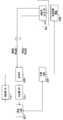
이제 도 4a를 참조하면, 일부 실시예에서, 플러그(108)는 AC 입력부(411) 및 DC 입력부(410)와, 이들을 전도체(204a 및 204b)에 연결하는 스위치 A(409)를 포함한다. 타 단부에서, 커넥터(104)는 차량이 요구하거나 수신할 수 있는 전류의 유형을 인식하기 위해 전기 차량(120)의 충전 포트(여기서는 도시되지 않음)의 ID를 판독하는 감지 시스템으로서 ID 판독기/제어기(402)를 갖는다. ID 판독기/제어기(402)는 RFID 판독기 및 광학 ID 판독기와 같은 당업계에 알려진 임의의 유형의 ID 판독기일 수 있다. 이어서, 시스템(100)은, ID 판독기를 통해 수신한 정보를 사용하여, 전기 차량(120)이 AC/DC 입력부(410)를 통해 올바른 유형의 전류를 수신하는 것을 보장한다. 이것은 ID 판독기/제어기(402), 전원 공급장치(404) 및 스위치(408 및 409) 사이의 통신을 통해 달성될 수 있다.Referring now to FIG. 4A , in some embodiments, the
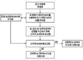
도 4b는 도 4a에 도시된 시스템(100)이 전류를 재지향시키기 위해 취하는 단계의 흐름도를 도시한다. 시스템(100)이 전기 차량(120)에 연결된 후에, ID 판독기/제어기(402)는 차량의 ID 정보를 판독하고, 이 ID 정보를 전원 공급장치(404)뿐만 아니라 스위치(408 및 409)에 보고한다. 다음에, 전원 공급장치(404)는 요청된 유형의 전류를 제공하고, 스위치(408 및 409)는 차량의 ID 정보에 의해 제공된 정보에 따라 전류를 적절한 출력부로 재지향시킨다.FIG. 4B shows a flow diagram of the steps taken by the
당업자라면, ID 정보는 차량 소유자의 금융 정보와 같은 다른 정보를 포함하여 사용자가 그러한 정보를 입력할 필요 없이 차량의 충전을 용이하게 할 수 있다는 것이 이해될 것이다. 일부 실시예에서, ID 정보는, 트랜잭션을 확인하기 위해 모바일 앱(앱 상의 생체 수단, 핀 코드 등)을 사용하는 것, 또는 케이블, 차량 또는 전원 공급장치 상에 직접 설치된 핀 보호 또는 생체 보안 수단을 갖는 것과 같은 다른 인증 방법과 조합하여 사용될 수 있다.It will be appreciated by those skilled in the art that the ID information may include other information such as the vehicle owner's financial information to facilitate charging of the vehicle without the need for the user to enter such information. In some embodiments, the ID information includes using a mobile app (biometrics on app, pin code, etc.) to confirm the transaction, or pin protection or biosecurity measures installed directly on the cable, vehicle or power supply. It can be used in combination with other authentication methods such as having
도 4c에 도시된 바와 같이, 대안적인 실시예에서, 시스템(100)은 특정 유형의 전류가 전도체(204a 및 204b)를 통과할 수 있게 하기 위한 감지 시스템으로서 작동하는 커넥터 어댑터(430) 및 플러그 어댑터(432)를 가질 수 있다. 이러한 실시예에서, AC 또는 DC 어댑터가 케이블의 일 단부에 연결될 때, 기계적 또는 전기적 연결 메커니즘은 상이한 유형의 어댑터가 타 단부에 연결될 수 없게 할 것이다. 예를 들어, 사용자가 AC 플러그 어댑터를 케이블에 연결하면, 타 단부에서 연결 핀을 이동시키는 솔레노이드가 활성화되고, AC 커넥터 어댑터만이 케이블에 연결될 수 있게 될 것이다.4C , in an alternative embodiment,
당업자라면, 상이한 실시예에서, 2 개의 어댑터의 연결 메커니즘은 케이블과 같은 기계적 메커니즘을 사용하여 기계적으로, 또는 접지 전도체(206), 데이터 케이블(208a 및 208b), 추가 케이블을 사용하거나 무선으로 신호를 전달하여 전기적으로, 서로 연결하고 작동할 수 있다는 것이 이해될 것이다.Those skilled in the art will appreciate that, in different embodiments, the connection mechanism of the two adapters may be mechanically configured using a mechanical mechanism, such as a cable, or signal using a
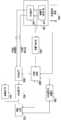
다른 실시예에서, 도 5a에 도시된 바와 같이, 차량 충전 시스템(100)은 스위치(502)를 제어할 수 있는 제어 유닛(502)을 갖는다. 제어기(502)는 전원 공급장치와 통신하여, 전도체(204a 및 204b)를 통과하는 전류의 유형을 인식하기 위한 감지 시스템으로서 작동하고, 다음에 전류를 커넥터(104)의 대응하는 AC 출력부(412) 또는 DC 출력부(414)로 지향시키고 거기로부터 전기 차량(122)으로 지향시키도록 스위치(504)를 제어한다. 전기 차량이 전원 공급장치(404)로부터 전송된 전류의 유형을 수신할 수 없는 경우, 제어기(502)는 그것을 인식하고, 전류를 차단하고 잘못된 유형의 전류를 차량으로 보내는 것을 회피하도록 스위치(504)를 제어한다. 이러한 능력은 전기 차량(120) 및 그 충전 시스템에 대한 가능한 손상을 방지하기 위한 추가 보안 계층을 시스템(100)에 제공한다.In another embodiment, as shown in FIG. 5A , the
도 5b는 도 5a에 도시된 시스템(100)이 전류를 재지향시키기 위해 취하는 단계의 흐름도를 도시한다. 시스템(100)이 전기 차량(120)에 연결된 후에, 제어 유닛(502)은 차량(120)과 통신하여, 허용하는 전류의 유형에 관한 요구 정보를 획득한다. 제어 유닛(502)은 제어 유닛(502)과 통신함으로써 전원 공급장치(404)에 의해 제공되는 전류의 유형에 관한 정보를 수신한다. 전류가 전기 차량(120)에 의해 허용되면, 제어 유닛(502)은 그에 따라 전류를 적절한 출력부로 재지향시키도록 스위치(408)에 명령한다. 허용되지 않으면, 제어 유닛(502)은 임의의 원하지 않는 사고를 회피하기 위해 전기 차량(120)에 대한 전류를 차단한다. 일 실시예에서, 제어 유닛(502)은 적절한 유형의 전류를 전원 공급장치(404)로부터 요청할 수 있다.FIG. 5B shows a flow diagram of the steps taken by the
다른 실시예에서, 도 6a에 도시된 바와 같이, 시스템(100) 자체가 감지 시스템으로서 AC/DC 센서(602)를 가지며, AC/DC 센서(602)는 케이블이 수신하는 전류의 유형을 인식하고 전류의 유형을 제어 유닛(502)에 통신하여, 그에 따라 전류를 대응하는 출력부(412 또는 414)로 지향시키도록 스위치(408 및 409)를 제어하게 한다.In another embodiment, as shown in FIG. 6A , the
당업자라면, 센서(602)는 당업계에 알려진 임의의 종류의 전류 센서일 수 있고, 시스템(100)의 어느 곳에도 배치될 수 있다는 것이 이해될 것이다.Those skilled in the art will appreciate that the
도 6b는 도 6a에 도시된 시스템(100)이 전류를 재지향시키기 위해 취하는 단계의 흐름도를 도시한다. 시스템(100)이 전기 차량(120)에 연결된 후에, 제어 유닛(502)은 차량(120)과 통신하여 허용하는 전류의 유형에 관한 요구 정보를 획득한다. 제어 유닛(502)은 전류 센서(602)를 사용하여 제공되는 전류의 유형을 검출한다. 전류가 전기 차량(120)에 의해 허용되면, 제어 유닛(502)은 그에 따라 전류를 적절한 출력부로 재지향시키도록 스위치(408 및 409)에 명령한다. 허용되지 않으면, 제어 유닛(502)은 임의의 원하지 않는 사고를 회피하기 위해 전기 차량(120)에 대해 전류를 차단한다.FIG. 6B shows a flow diagram of the steps taken by the
또한, 당업자라면, 스위치(504)는 그에 내장된 전류 센서(602) 및 제어 유닛(402)을 가질 수 있다는 것이 이해될 것이다.It will also be appreciated by those skilled in the art that the
도 7에 도시된 바와 같이, 일부 실시예에서, 사용자 인터페이스(702)가 시스템(100), 전원 공급장치(404) 및 전기 차량(120)의 상이한 요소들과 통신하고 이들을 제어하는 데 사용될 수 있다. 사용자 인터페이스는 시스템(100)에 명령을 제공하도록 제어 유닛(502)과 통신할 수 있다. 하나의 대안적인 실시예에서, 제어 유닛(502)은 충전 프로세스를 제어하도록 사용자 인터페이스(702)에 내장될 수 있다.7 , in some embodiments,
상이한 실시예에서, 사용자 인터페이스(702)는 시스템과 무선으로 통신하거나, 유선 연결을 사용하여 시스템에 연결되거나, 시스템의 일부에 내장될 수 있다.In different embodiments, the
도 8에 도시된 바와 같이, 일부 실시예에서, 시스템(100)은 사용자의 신용 카드 또는 소유자의 다른 금융 정보와 같은 정보를 저장하기 위한 메모리(802)를 갖는다. 제어기(502)는 시스템의 메모리(702)로부터 금융 정보 또는 임의의 다른 정보를 검색하고, 필요에 따라 이러한 정보를 전원 공급장치(404), 전기 차량(120) 또는 사용자 인터페이스(702)와 통신할 수 있다. 이러한 특징은 금융 정보를 입력할 필요 없이 케이블(102)을 연결하여 전기 차량(120)의 충전을 시작하는 능력을 사용자에게 제공한다. 상이한 실시예에서, 금융 정보의 인증은 전원 공급장치(404)에 의해 직접 실행되거나, 사용자 인터페이스(702) 또는 전기 차량(120)을 통해 실행될 수 있다.As shown in FIG. 8 , in some embodiments,
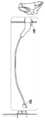
도 9를 참조하면, 일부 예에서, 시스템(100)은 케이블(102)을 전원 공급장치 스테이션에 잠그기 위한 공급장치 잠금 시스템(902) 및/또는 케이블(102)을 차량(120)에 잠그기 위한 자동차 잠금 메커니즘(904), 또는 둘 모두를 더 포함할 수 있다. 잠금 시스템은 비승인 사용자가 케이블(102)을 분리할 수 없게 하거나, 대안적으로 케이블의 임의의 비승인 분리 시에 경보를 시작하는 보다 진보된 전자 잠금 시스템에 자물쇠(padlock)를 추가하기에 간단한 장소만큼 간단한 물리적 잠금장치일 수 있다. 더욱이, 잠금 시스템은 또한 제어 시스템(502)을 통해 모바일 장치(140)에 연결될 수 있고, 케이블(102)을 분리하려는 임의의 비승인 시도에 대해 소유자에게 경보할 수 있다.Referring to FIG. 9 , in some examples,
일부 실시예에서, 본 개시는 커넥터(104) 상의 생체 식별자 잠금 시스템을 사용하여 승인된 사용자만이 차량 또는 충전 스테이션의 전원 공급장치로부터 케이블을 연결하거나, 분리하거나, 충전하게 할 수 있다. 승인된 사용자의 생체 정보는 메모리(602)에 저장될 것이다. 시스템을 사용하고자 하는 사람의 지문을 판독하고 이 지문을 제어기(402)와 통신하기 위해 지문 판독기와 같은 생체 식별 판독기가 커넥터(104) 상에 사용될 수 있다. 제어기(402)는 이러한 정보가 메모리(602)에 저장되어 있는 승인된 사람 중 하나에 속하는지 여부를 확인하고, 전류를 허용하도록 스위치(404)를 제어하고, 그리고/또는 케이블이 분리될 수 있게 하도록 잠금 시스템을 제어한다. 이것은 케이블(102)을 도난 당하지 않거나 상이한 전기 차량을 충전하는 데 사용되지 않고, 공공 장소에서 충전하는 동안 차량을 방치하여 둘 수 있는 능력을 사용자에게 제공할 것이다.In some embodiments, the present disclosure uses a biometric identifier locking system on
상기 설명은 특정 예를 참조하여 제공되었지만, 이것은 본 발명을 제한하는 것이 아니라 예시하기 위한 것이다.Although the above description has been provided with reference to specific examples, this is intended to illustrate rather than limit the invention.
Claims (17)
Translated fromKorean제1 단부 및 제2 단부를 갖는 케이블 - 상기 케이블은 요청 시 AC 전류와 DC 전류 둘 다를 전도할 수 있는 제1 전도체와 제2 전도체를 포함하며, 상기 제1 전도체와 상기 제2 전도체는 각각 상기 제1 단부로부터 상기 제2 단부까지 연장됨 -;
상기 제1 단부를 전원 공급장치에 연결하기 위한 플러그;
상기 제2 단부를 상기 전기 차량에 연결하기 위한 커넥터
를 포함하며;
상기 시스템은 또한,
상기 전류의 유형을 검출하기 위한 감지 시스템과, 상기 전류의 유형에 따라 AC 또는 DC 어댑터가 상기 커넥터에 연결될 수 있게 하는 메커니즘;
상기 전류의 유형을 검출하는 감지 시스템과; 상기 전원 공급장치의 AC 또는 DC 입력부로부터 상기 전류를 수신하기 위한 상기 플러그 내의 제1 스위치와; 상기 전류를 AC 및 DC 포트로 지향시키기 위한 상기 커넥터 내의 제2 스위치와; 상기 전류의 유형에 따라 상기 제1 및 제2 스위치를 제어하고 상기 전류의 유형이 상기 전기 차량에 의해 허용되지 않을 때 상기 전류를 차단하도록 구성된 제어 유닛;
상기 전류의 유형을 검출하는 감지 시스템과; 상기 전류의 유형이 상기 전기 차량에 의해 허용되지 않을 때 상기 전류를 차단하도록 스위치를 제어하도록 구성된 제어 유닛
중 하나에 의해 특징지어지는 것인 전기 차량을 충전하기 위한 시스템.A system for charging an electric vehicle, comprising:
A cable having a first end and a second end, the cable comprising a first conductor and a second conductor capable of conducting both an AC current and a DC current upon request, wherein the first conductor and the second conductor are each extending from the first end to the second end;
a plug for connecting the first end to a power supply;
a connector for connecting the second end to the electric vehicle
includes;
The system is also
a sensing system for detecting the type of current and a mechanism allowing an AC or DC adapter to be connected to the connector depending on the type of current;
a sensing system for detecting the type of current; a first switch in said plug for receiving said current from an AC or DC input of said power supply; a second switch in said connector for directing said current to AC and DC ports; a control unit configured to control the first and second switches according to the type of the current and cut off the current when the type of the current is not allowed by the electric vehicle;
a sensing system for detecting the type of current; a control unit configured to control a switch to cut off the current when the type of current is not permitted by the electric vehicle
A system for charging an electric vehicle, characterized by one of the
상기 감지 시스템은 상기 전기 차량의 충전 포트의 ID를 판독하고 그에 따라 상기 전류를 전달하도록 차량 전류 정보를 상기 스위치 및 전원 공급장치와 통신하기 위한 ID 판독기인 것인 전기 차량을 충전하기 위한 시스템.According to claim 1,
wherein the sensing system is an ID reader for communicating vehicle current information with the switch and power supply to read the ID of a charging port of the electric vehicle and deliver the current accordingly.
상기 감지 시스템은 상기 전류의 유형을 상기 제어 유닛에 전달하도록 상기 케이블에 부착되는 전류 센서이며, 상기 제어 유닛은 그에 따라 상기 전류를 지향시켜서 상기 전류를 전달하도록 상기 스위치를 제어하는 것인 전기 차량을 충전하기 위한 시스템.According to claim 1,
wherein the sensing system is a current sensor attached to the cable to deliver the type of current to the control unit, the control unit controlling the switch to direct the current accordingly and deliver the current. system for charging.
B 및 C의 상기 제어 유닛은 상기 전기 차량에 대한 전류 유형 및 전류를 선택하도록 최종 장치와 통신하는 것인 전기 차량을 충전하기 위한 시스템.According to claim 1,
wherein the control unit of B and C communicates with an end device to select a current type and current for the electric vehicle.
상기 케이블은 상기 제1 단부로부터 상기 제2 단부까지 연장되는 보호 접지 전도체를 더 포함하는 것인 전기 차량을 충전하기 위한 시스템.5. The method according to any one of claims 1 to 4,
wherein the cable further comprises a protective grounding conductor extending from the first end to the second end.
상기 케이블은 상기 제1 단부로부터 상기 제2 단부까지 연장되어 상기 전원 공급장치와 상기 전기 차량 간에 데이터를 전송하는 적어도 하나의 신호 케이블을 더 포함하는 것인 전기 차량을 충전하기 위한 시스템.6. The method according to any one of claims 1 to 5,
wherein the cable further comprises at least one signal cable extending from the first end to the second end to transmit data between the power supply and the electric vehicle.
상기 케이블은,
상기 전기 차량의 신호 케이블에 그리고 상기 보호 접지 전도체에 연결되도록 구성된 제1 위상 고정 루프;
상기 전원 공급장치의 신호 케이블에 그리고 상기 보호 접지 전도체에 연결되도록 구성된 제2 위상 고정 루프
를 더 포함하며,
상기 제1 위상 고정 루프와 상기 제2 위상 고정 루프는 상기 보호 접지 전도체를 통해 상기 전원 공급장치와 상기 전기 차량 간에 신호를 전송하는 것인 전기 차량을 충전하기 위한 시스템.6. The method of claim 5,
The cable is
a first phase locked loop configured to be coupled to the signal cable of the electric vehicle and to the protective ground conductor;
a second phase locked loop configured to be coupled to the signal cable of the power supply and to the protective ground conductor
further comprising,
and the first phase locked loop and the second phase locked loop transmit a signal between the power supply and the electric vehicle via the protective ground conductor.
커넥터 어댑터를 더 포함하며, 상기 커넥터는 커넥터 어댑터를 사용하여 상기 전기 차량의 충전 포트에 연결되는 것인 전기 차량을 충전하기 위한 시스템.8. The method according to any one of claims 1 to 7,
A system for charging an electric vehicle, further comprising a connector adapter, wherein the connector is connected to a charging port of the electric vehicle using a connector adapter.
생체 인식 시스템을 더 포함하며, 상기 커넥터는 상기 생체 인식 시스템을 사용하여 상기 전원 공급장치로부터 상기 전기 차량으로의 전류를 허용하기 전에 사용자의 신원을 확인하는 것인 전기 차량을 충전하기 위한 시스템.9. The method according to any one of claims 1 to 8,
A system for charging an electric vehicle, further comprising: a biometric system, wherein the connector verifies the identity of a user prior to allowing current from the power supply to the electric vehicle using the biometric system.
요청 시 AC 전류와 DC 전류 둘 다를 전도할 수 있는 제1 충전 전도체와 제2 충전 전도체 - 상기 제1 충전 전도체와 상기 제2 충전 전도체는 각각 상기 충전 케이블의 제1 단부로부터 상기 충전 케이블의 제2 단부까지 연장됨 -;
상기 제2 단부에 부착되고 AC 포트 및 DC 포트를 갖는 커넥터
를 포함하며;
상기 케이블은 또한,
상기 전류의 유형을 검출하기 위한 감지 시스템과, 상기 전류의 유형에 따라 AC 또는 DC 어댑터가 상기 커넥터에 연결될 수 있게 하는 메커니즘;
상기 전류의 유형을 검출하는 감지 시스템과; 상기 전원 공급장치의 AC 또는 DC 입력부로부터 상기 전류를 수신하기 위한 상기 플러그 내의 제1 스위치와; 상기 전류를 AC 및 DC 포트로 지향시키기 위한 상기 커넥터 내의 제2 스위치와; 상기 전류의 유형에 따라 상기 제1 및 제2 스위치를 제어하고 상기 전류의 유형이 상기 전기 차량에 의해 허용되지 않을 때 상기 전류를 차단하도록 구성된 제어 유닛;
상기 전류의 유형을 검출하는 감지 시스템과; 상기 전류의 유형이 상기 전기 차량에 의해 허용되지 않을 때 상기 전류를 차단하도록 스위치를 제어하도록 구성된 제어 유닛
중 하나에 의해 특징지어지는 것인 충전 케이블.A charging cable for AC and DC charging, comprising:
a first charging conductor and a second charging conductor capable of conducting both AC and DC current upon request, the first charging conductor and the second charging conductor being each from a first end of the charging cable to a second charging cable of the charging cable extended to the end -;
a connector attached to the second end and having an AC port and a DC port
includes;
The cable is also
a sensing system for detecting the type of current and a mechanism allowing an AC or DC adapter to be connected to the connector depending on the type of current;
a sensing system for detecting the type of current; a first switch in said plug for receiving said current from an AC or DC input of said power supply; a second switch in said connector for directing said current to AC and DC ports; a control unit configured to control the first and second switches according to the type of the current and cut off the current when the type of the current is not allowed by the electric vehicle;
a sensing system for detecting the type of current; a control unit configured to control a switch to cut off the current when the type of current is not permitted by the electric vehicle
A charging cable characterized by one of the
상기 전기 차량의 충전 포트의 ID를 판독하고 그에 따라 상기 전류를 전달하도록 차량 전류 정보를 상기 스위치 및 전원 공급장치와 통신하기 위한 ID 판독기를 더 포함하는 충전 케이블.11. The method of claim 10,
and an ID reader for communicating vehicle current information with the switch and power supply to read the ID of a charging port of the electric vehicle and deliver the current accordingly.
상기 제1 단부로부터 상기 제2 단부까지 연장되어 상기 전원 공급장치와 상기 전기 차량 사이에서 데이터를 전송하는 보호 접지 전도체를 더 포함하는 충전 케이블.12. The method of claim 10 or 11,
and a protective ground conductor extending from the first end to the second end to transmit data between the power supply and the electric vehicle.
상기 제1 단부로부터 상기 제2 단부까지 연장되어 상기 전원 공급장치와 상기 전기 차량 간에 데이터를 전송하는 적어도 하나의 신호 케이블을 더 포함하는 충전 케이블.13. The method according to any one of claims 10 to 12,
and at least one signal cable extending from the first end to the second end to transmit data between the power supply and the electric vehicle.
상기 전기 차량의 신호 케이블에 그리고 상기 보호 접지 전도체에 연결되도록 구성된 제1 위상 고정 루프;
상기 전원 공급장치의 신호 케이블에 그리고 상기 보호 접지 전도체에 연결되도록 구성된 제2 위상 고정 루프
를 더 포함하며;
상기 제1 위상 고정 루프와 상기 제2 위상 고정 루프는 상기 보호 접지 전도체를 통해 상기 전원 공급장치와 상기 전기 차량 간에 신호를 전송하는 것인 충전 케이블.14. The method according to any one of claims 11 to 13,
a first phase locked loop configured to be coupled to the signal cable of the electric vehicle and to the protective ground conductor;
a second phase locked loop configured to be coupled to the signal cable of the power supply and to the protective ground conductor
further comprising;
and the first phase locked loop and the second phase locked loop transmit a signal between the power supply and the electric vehicle via the protective ground conductor.
생체 인식 시스템을 더 포함하며, 상기 커넥터는 상기 생체 인식 시스템을 사용하여 상기 전원 공급장치로부터 상기 전기 차량으로의 전류를 허용하기 전에 사용자의 신원을 확인하는 것인 충전 케이블.15. The method according to any one of claims 10 to 14,
and a biometric system, wherein the connector uses the biometric system to verify the identity of a user prior to allowing current from the power supply to the electric vehicle.
상기 적어도 하나의 신호 케이블의 수는 상기 전기 차량과 상기 전원 공급장치 간에 사용되는 임의의 유형의 통신 프로토콜에 기초하여 결정되는 것인 전기 차량 충전 시스템.7. The method of claim 6,
and the number of the at least one signal cable is determined based on any type of communication protocol used between the electric vehicle and the power supply.
상기 적어도 하나의 신호 케이블의 수는 상기 전기 차량과 상기 전원 공급장치 간에 사용되는 임의의 유형의 통신 프로토콜에 기초하여 결정되는 것인 충전 케이블.14. The method of claim 13,
and the number of the at least one signal cable is determined based on any type of communication protocol used between the electric vehicle and the power supply.
Applications Claiming Priority (3)
| Application Number | Priority Date | Filing Date | Title |
|---|---|---|---|
| US201862744322P | 2018-10-11 | 2018-10-11 | |
| US62/744,322 | 2018-10-11 | ||
| PCT/CA2019/051456WO2020073138A1 (en) | 2018-10-11 | 2019-10-11 | Smart charging cable |
Publications (1)
| Publication Number | Publication Date |
|---|---|
| KR20210069701Atrue KR20210069701A (en) | 2021-06-11 |
Family
ID=70164167
Family Applications (1)
| Application Number | Title | Priority Date | Filing Date |
|---|---|---|---|
| KR1020217013386AAbandonedKR20210069701A (en) | 2018-10-11 | 2019-10-11 | smart charging cable |
Country Status (6)
| Country | Link |
|---|---|
| US (1) | US20210354575A1 (en) |
| EP (1) | EP3864732A4 (en) |
| JP (1) | JP2022512682A (en) |
| KR (1) | KR20210069701A (en) |
| CN (1) | CN112889195A (en) |
| WO (1) | WO2020073138A1 (en) |
Families Citing this family (16)
| Publication number | Priority date | Publication date | Assignee | Title |
|---|---|---|---|---|
| NO20190023A1 (en)* | 2019-01-07 | 2020-07-08 | Easee As | Electrical assembly for a charging station |
| KR102492458B1 (en)* | 2020-04-29 | 2023-01-30 | 주식회사 남전사 | Electric vehicle charger cable capable of AC / DC metering |
| US11745613B2 (en)* | 2020-08-26 | 2023-09-05 | Cisco Technology, Inc. | System and method for electric vehicle charging and security |
| JP7491781B2 (en)* | 2020-09-02 | 2024-05-28 | トヨタ自動車九州株式会社 | Charging connection cable and DC power supply method |
| DE102020128736A1 (en)* | 2020-11-02 | 2022-05-05 | Bury Sp. Z. O. O. | Charging device for charging the drive battery of an electric vehicle and method for recording energy consumption data when charging electric vehicles |
| DE102020129248A1 (en) | 2020-11-06 | 2022-05-12 | Dr. Ing. H.C. F. Porsche Aktiengesellschaft | charging cable |
| AU2022239007A1 (en)* | 2021-03-19 | 2023-11-02 | Hikotron Limited | Electric vehicle charging systems, methods and devices |
| DE102021108004B4 (en) | 2021-03-30 | 2023-12-14 | Ford Global Technologies Llc | Charging device for an electric vehicle |
| DE102021109796A1 (en)* | 2021-04-19 | 2022-10-20 | Bayerische Motoren Werke Aktiengesellschaft | Power supply system for a vehicle |
| US12095305B2 (en)* | 2021-12-29 | 2024-09-17 | Rivian Ip Holdings, Llc | AC and DC charging via a single coupler |
| DE102022202231B4 (en) | 2022-03-04 | 2025-06-12 | Robert Bosch Gesellschaft mit beschränkter Haftung | Connector for a supply cable and supply cable for a vehicle |
| US20230322103A1 (en)* | 2022-04-06 | 2023-10-12 | GM Global Technology Operations LLC | Cable assembly for electric vehicle to electric vehicle charging |
| SE545502C2 (en)* | 2022-06-14 | 2023-10-03 | Soler Ola | Vehicle power adaptor |
| DE202022103343U1 (en) | 2022-06-14 | 2023-09-22 | Weidmüller Interface GmbH & Co. KG | Charging plug for an electric vehicle |
| CN117104038B (en)* | 2023-10-25 | 2024-02-20 | 深圳市瑞凯诺科技有限公司 | Plug-and-play intelligent charging socket and charging control method thereof |
| FR3155769A1 (en)* | 2023-11-28 | 2025-05-30 | Stellantis Auto Sas | SMART VEHICLE IMMOBILIZER DEVICE |
Family Cites Families (9)
| Publication number | Priority date | Publication date | Assignee | Title |
|---|---|---|---|---|
| NL2004350C2 (en)* | 2010-03-05 | 2011-09-06 | Epyon B V | System, devices and method for charging a battery of an electric vehicle. |
| JP2011259658A (en)* | 2010-06-11 | 2011-12-22 | Toyota Motor Corp | Vehicular charging system and motor-driven vehicle |
| JP2013123120A (en)* | 2011-12-09 | 2013-06-20 | Chugoku Electric Power Co Inc:The | Charge plug and charge system |
| KR101466432B1 (en)* | 2012-04-24 | 2014-11-28 | 엘에스산전 주식회사 | Charging cable |
| US8967466B2 (en)* | 2013-01-09 | 2015-03-03 | Powertree Services, Inc. | Automatic authentication for service access for fueling of vehicles |
| DE102013110548B4 (en)* | 2013-09-24 | 2025-02-06 | Phoenix Contact E-Mobility Gmbh | connector part with a resistance coding |
| DE102016211335B4 (en)* | 2016-06-24 | 2025-01-02 | Volkswagen Aktiengesellschaft | Method, adapter, additional control unit and charging system for the electrical charging of electric vehicles |
| US10183583B2 (en)* | 2016-08-03 | 2019-01-22 | Solarcity Corporation | Energy generation and storage system with electric vehicle charging capability |
| US10453282B2 (en)* | 2017-08-22 | 2019-10-22 | Ford Global Technologies, Llc | EV charging connector unlock via biometric input |
- 2019
- 2019-10-11KRKR1020217013386Apatent/KR20210069701A/ennot_activeAbandoned
- 2019-10-11WOPCT/CA2019/051456patent/WO2020073138A1/ennot_activeCeased
- 2019-10-11CNCN201980066545.3Apatent/CN112889195A/enactivePending
- 2019-10-11EPEP19870120.3Apatent/EP3864732A4/enactivePending
- 2019-10-11USUS17/284,006patent/US20210354575A1/ennot_activeAbandoned
- 2019-10-11JPJP2021520191Apatent/JP2022512682A/enactivePending
Also Published As
| Publication number | Publication date |
|---|---|
| EP3864732A1 (en) | 2021-08-18 |
| EP3864732A4 (en) | 2022-09-28 |
| WO2020073138A1 (en) | 2020-04-16 |
| JP2022512682A (en) | 2022-02-07 |
| US20210354575A1 (en) | 2021-11-18 |
| CN112889195A (en) | 2021-06-01 |
Similar Documents
| Publication | Publication Date | Title |
|---|---|---|
| KR20210069701A (en) | smart charging cable | |
| KR101877602B1 (en) | Security method and apparatus for electric vehicle power transfer system | |
| TWI712726B (en) | Parking lock type smart charging pile and using method thereof | |
| US8460028B2 (en) | Self powered electric vehicle charging connector locking system | |
| EP3255739B1 (en) | User authenticating electrical outlet or connector, power mediating module, and power consuming device | |
| JP2023535609A (en) | charging cable | |
| CN207117230U (en) | Integrated vehicle charge and discharge device, charging adapter and charge power supply line | |
| CN104228601B (en) | Method and system for communicating between an electric vehicle and a charging station and charging station | |
| US20180126861A1 (en) | Modular vehicle system with an increased level of operational reliability | |
| CN109562700B (en) | Arrangement comprising a motor vehicle and a connecting device, motor vehicle and connecting device | |
| CN111231699B (en) | Car is device and vehicle of filling each other | |
| US20120092141A1 (en) | Power supply device | |
| US20120217928A1 (en) | Electric vehicle charging interface | |
| TWI583584B (en) | Locking device,fixing device and locking system for locking vehicle and method for locking vehicle | |
| KR102042543B1 (en) | Power supply device | |
| US20220118877A1 (en) | System for recharging with energy electrical apparatuses, in particular front-wheel drive electric vehicles, and connecting cable usable in such a system | |
| CN114450198A (en) | Method and device for externally powering an unlocking-related device of a vehicle | |
| CN117897299A (en) | Supply cable | |
| KR20100059641A (en) | Electricity vending machine for electric car charging using a wired or wireless electrical payment system | |
| WO2022023563A1 (en) | Electric vehicle charging system | |
| KR102330842B1 (en) | Mobile Charging System that Mixes AC Single and Three Phasese based on on Micro-Current to Satisfy both Fast Charging Speed and Charging Accessilbility | |
| JP2013188020A (en) | Power supply system with power theft prevention function | |
| KR102401989B1 (en) | A mobile charging system that combines alternating current single-phase and three-phase based on internal batteries to satisfy both fast charging speed and charging accessibility | |
| KR102401992B1 (en) | High-Speed Charging System with Equal Type Connection by Server Monitoring and Control | |
| KR102656474B1 (en) | User Authenticating mobile charging apparatus with fast and slow charging integral |
Legal Events
| Date | Code | Title | Description |
|---|---|---|---|
| PA0105 | International application | Patent event date:20210503 Patent event code:PA01051R01D Comment text:International Patent Application | |
| PG1501 | Laying open of application | ||
| PA0201 | Request for examination | Patent event code:PA02012R01D Patent event date:20221007 Comment text:Request for Examination of Application | |
| PC1902 | Submission of document of abandonment before decision of registration |