KR20210059698A - Method of manufacturing a block forged valve body with a fully encapsulated seat ring - Google Patents
Method of manufacturing a block forged valve body with a fully encapsulated seat ringDownload PDFInfo
- Publication number
- KR20210059698A KR20210059698AKR1020217003685AKR20217003685AKR20210059698AKR 20210059698 AKR20210059698 AKR 20210059698AKR 1020217003685 AKR1020217003685 AKR 1020217003685AKR 20217003685 AKR20217003685 AKR 20217003685AKR 20210059698 AKR20210059698 AKR 20210059698A
- Authority
- KR
- South Korea
- Prior art keywords
- valve
- chamber
- axis
- valve body
- hole
- Prior art date
- Legal status (The legal status is an assumption and is not a legal conclusion. Google has not performed a legal analysis and makes no representation as to the accuracy of the status listed.)
- Granted
Links
- 238000004519manufacturing processMethods0.000titleclaimsdescription17
- 238000000034methodMethods0.000claimsabstractdescription38
- 238000003754machiningMethods0.000claimsdescription14
- 238000005242forgingMethods0.000claimsdescription9
- 238000007789sealingMethods0.000claimsdescription5
- 238000003466weldingMethods0.000claimsdescription5
- 230000008901benefitEffects0.000description3
- 238000005266castingMethods0.000description3
- 238000003801millingMethods0.000description3
- 238000011144upstream manufacturingMethods0.000description3
- 238000005553drillingMethods0.000description2
- 238000005552hardfacingMethods0.000description2
- 238000007514turningMethods0.000description2
- 229910000851Alloy steelInorganic materials0.000description1
- 229910001347StelliteInorganic materials0.000description1
- 230000015572biosynthetic processEffects0.000description1
- AHICWQREWHDHHF-UHFFFAOYSA-Nchromium;cobalt;iron;manganese;methane;molybdenum;nickel;silicon;tungstenChemical compoundC.[Si].[Cr].[Mn].[Fe].[Co].[Ni].[Mo].[W]AHICWQREWHDHHF-UHFFFAOYSA-N0.000description1
- 230000006835compressionEffects0.000description1
- 238000007906compressionMethods0.000description1
- 230000032798delaminationEffects0.000description1
- 238000010586diagramMethods0.000description1
- 238000005538encapsulationMethods0.000description1
- 230000007246mechanismEffects0.000description1
- 239000002994raw materialSubstances0.000description1
- 230000000630rising effectEffects0.000description1
- 238000007493shaping processMethods0.000description1
Images


Classifications
- B—PERFORMING OPERATIONS; TRANSPORTING
- B23—MACHINE TOOLS; METAL-WORKING NOT OTHERWISE PROVIDED FOR
- B23P—METAL-WORKING NOT OTHERWISE PROVIDED FOR; COMBINED OPERATIONS; UNIVERSAL MACHINE TOOLS
- B23P15/00—Making specific metal objects by operations not covered by a single other subclass or a group in this subclass
- B23P15/001—Making specific metal objects by operations not covered by a single other subclass or a group in this subclass valves or valve housings
- B—PERFORMING OPERATIONS; TRANSPORTING
- B21—MECHANICAL METAL-WORKING WITHOUT ESSENTIALLY REMOVING MATERIAL; PUNCHING METAL
- B21K—MAKING FORGED OR PRESSED METAL PRODUCTS, e.g. HORSE-SHOES, RIVETS, BOLTS OR WHEELS
- B21K1/00—Making machine elements
- B21K1/20—Making machine elements valve parts
- B21K1/24—Making machine elements valve parts valve bodies; valve seats
- F—MECHANICAL ENGINEERING; LIGHTING; HEATING; WEAPONS; BLASTING
- F16—ENGINEERING ELEMENTS AND UNITS; GENERAL MEASURES FOR PRODUCING AND MAINTAINING EFFECTIVE FUNCTIONING OF MACHINES OR INSTALLATIONS; THERMAL INSULATION IN GENERAL
- F16K—VALVES; TAPS; COCKS; ACTUATING-FLOATS; DEVICES FOR VENTING OR AERATING
- F16K25/00—Details relating to contact between valve members and seats
- F16K25/005—Particular materials for seats or closure elements
- F—MECHANICAL ENGINEERING; LIGHTING; HEATING; WEAPONS; BLASTING
- F16—ENGINEERING ELEMENTS AND UNITS; GENERAL MEASURES FOR PRODUCING AND MAINTAINING EFFECTIVE FUNCTIONING OF MACHINES OR INSTALLATIONS; THERMAL INSULATION IN GENERAL
- F16K—VALVES; TAPS; COCKS; ACTUATING-FLOATS; DEVICES FOR VENTING OR AERATING
- F16K27/00—Construction of housing; Use of materials therefor
- F16K27/04—Construction of housing; Use of materials therefor of sliding valves
- F16K27/044—Construction of housing; Use of materials therefor of sliding valves slide valves with flat obturating members
- F—MECHANICAL ENGINEERING; LIGHTING; HEATING; WEAPONS; BLASTING
- F16—ENGINEERING ELEMENTS AND UNITS; GENERAL MEASURES FOR PRODUCING AND MAINTAINING EFFECTIVE FUNCTIONING OF MACHINES OR INSTALLATIONS; THERMAL INSULATION IN GENERAL
- F16K—VALVES; TAPS; COCKS; ACTUATING-FLOATS; DEVICES FOR VENTING OR AERATING
- F16K3/00—Gate valves or sliding valves, i.e. cut-off apparatus with closing members having a sliding movement along the seat for opening and closing
- F16K3/02—Gate valves or sliding valves, i.e. cut-off apparatus with closing members having a sliding movement along the seat for opening and closing with flat sealing faces; Packings therefor
- F16K3/04—Gate valves or sliding valves, i.e. cut-off apparatus with closing members having a sliding movement along the seat for opening and closing with flat sealing faces; Packings therefor with pivoted closure members
- F16K3/10—Gate valves or sliding valves, i.e. cut-off apparatus with closing members having a sliding movement along the seat for opening and closing with flat sealing faces; Packings therefor with pivoted closure members with special arrangements for separating the sealing faces or for pressing them together
- F—MECHANICAL ENGINEERING; LIGHTING; HEATING; WEAPONS; BLASTING
- F16—ENGINEERING ELEMENTS AND UNITS; GENERAL MEASURES FOR PRODUCING AND MAINTAINING EFFECTIVE FUNCTIONING OF MACHINES OR INSTALLATIONS; THERMAL INSULATION IN GENERAL
- F16K—VALVES; TAPS; COCKS; ACTUATING-FLOATS; DEVICES FOR VENTING OR AERATING
- F16K3/00—Gate valves or sliding valves, i.e. cut-off apparatus with closing members having a sliding movement along the seat for opening and closing
- F16K3/02—Gate valves or sliding valves, i.e. cut-off apparatus with closing members having a sliding movement along the seat for opening and closing with flat sealing faces; Packings therefor
- F16K3/16—Gate valves or sliding valves, i.e. cut-off apparatus with closing members having a sliding movement along the seat for opening and closing with flat sealing faces; Packings therefor with special arrangements for separating the sealing faces or for pressing them together
- F16K3/18—Gate valves or sliding valves, i.e. cut-off apparatus with closing members having a sliding movement along the seat for opening and closing with flat sealing faces; Packings therefor with special arrangements for separating the sealing faces or for pressing them together by movement of the closure members
- F—MECHANICAL ENGINEERING; LIGHTING; HEATING; WEAPONS; BLASTING
- F16—ENGINEERING ELEMENTS AND UNITS; GENERAL MEASURES FOR PRODUCING AND MAINTAINING EFFECTIVE FUNCTIONING OF MACHINES OR INSTALLATIONS; THERMAL INSULATION IN GENERAL
- F16K—VALVES; TAPS; COCKS; ACTUATING-FLOATS; DEVICES FOR VENTING OR AERATING
- F16K3/00—Gate valves or sliding valves, i.e. cut-off apparatus with closing members having a sliding movement along the seat for opening and closing
- F16K3/30—Details
- F16K3/314—Forms or constructions of slides; Attachment of the slide to the spindle
Landscapes
- Engineering & Computer Science (AREA)
- General Engineering & Computer Science (AREA)
- Mechanical Engineering (AREA)
- Lift Valve (AREA)
- Valve Housings (AREA)
Abstract
Translated fromKoreanDescription
Translated fromKorean본 출원은, 2018년 7월 5일에 출원된 미국 가출원 번호 제62/694,247호에 기초한 우선권의 이익을 주장하며, 그 전체 개시 내용은 본 개시에서 참조로써 포함된다.This application claims the benefit of priority based on U.S. Provisional Application No. 62/694,247 filed July 5, 2018, the entire disclosure of which is incorporated by reference in this disclosure.
본 개시는, 전반적으로 밸브 바디에 관한 것이고, 보다 구체적으로는 완전히 인캡슐레이팅된 시트 링을 갖는 블록 단조형 밸브 바디(block forged valve body)의 제조 방법과, 완전히 인캡슐레이팅된 시트 링을 갖춘 블록 단조 밸브 바디 및 그 이용 방법에 관한 것이다.The present disclosure relates generally to a valve body, and more specifically, a method of manufacturing a block forged valve body having a fully encapsulated seat ring, and a fully encapsulated seat ring. It relates to a block forged valve body and a method of using the same.
게이트 밸브는 통상적으로 유동 통로(flow passageway)를 갖는 밸브 바디와 그 유동 통로를 개방 또는 폐쇄하도록 횡 방향으로 슬라이딩하는 게이트들을 포함한다. 통상적으로, 게이트들이 개방 및 폐쇄 위치 사이에서 이동 시 게이트들과 인터페이싱하도록, 한 쌍의 밸브 시트가 유동 통로에 배치된다. 일부 실시예들에서는, 밸브 시트들이, 그 원주 둘레 주위로 완전히 인캡슐레이팅되지 않는데, 이로 인해 밸브 시트가 꺽이거나(deflection) 또는 변형(deformation)되기 쉽다. 밸브 시트의 변형은, 시트 링(예컨대 그에 적용된 하드씰 표면(hard seal surface))의 박리(delamination)를 야기할 수 있고, 이는 밸브 및 밸브 다운스트림에 위치한 장비를 통과하는 매체를 오염 및/또는 손상시키거나, 밸브가 최적의 밀봉에 미치지 못하게 할 수 있다.The gate valve typically includes a valve body having a flow passageway and gates that slide in the transverse direction to open or close the flow passage. Typically, a pair of valve seats are disposed in the flow passage so that the gates interface with the gates as they move between the open and closed positions. In some embodiments, the valve seats are not completely encapsulated around their circumference, which is liable to deflection or deformation. Deformation of the valve seat can cause delamination of the seat ring (e.g., the hard seal surface applied thereto), which contaminates and/or contaminates the medium passing through the valve and equipment located downstream of the valve. It may damage or prevent the valve from reaching its optimum seal.
일부 응용들에서, 밸브 바디가, 다양한 피쳐들(features)의 형성 및 정의를 가능하게 하는 주조(casting) 또는 다이 단조(die forging)로 만들어질 수 있다. 주조 및 다이 단조는, 쉽게 재구성할 수 없는, 비싸고 유니크한 금형들(molds) 및 다이들(dies)을 필요로 한다. 따라서, 주조 및 다이 단조 공정들은, 예컨대 더 큰 게이트 및/또는 관통 개구(through opening)가 필요한 경우에, 밸브 바디의 모양과 기능을 쉽게 재구성하는데에 적합하지 않다.In some applications, the valve body can be made by casting or die forging, which allows the formation and definition of various features. Casting and die forging requires expensive and unique molds and dies that cannot be easily reconfigured. Thus, casting and die forging processes are not suitable for easily reconfiguring the shape and function of the valve body, for example where larger gates and/or through openings are required.
또 다른 응용들에서, 밸브 바디는, 복수의 개별 부품들을 연결, 예를 들어 탑부(top), 중간부(middle) 및 바닥부(bottom), 또는 측면부(side)들을, 기계식 패스너들을 이용해서 연결함으로써, 구성될 수 있다. 그러나 이러한 유형의 밸브 바디들은, 일체형 밸브 바디(one-piece valve body)에 비해, 추가적인 패스너들과 밀봉 인터페이스들을 필요로 하고, 시간이 지남에 따라 누출에 더 취약하다.In still other applications, the valve body connects a plurality of individual parts, e.g. the top, middle and bottom, or sides, using mechanical fasteners. By doing so, it can be configured. However, valve bodies of this type, compared to a one-piece valve body, require additional fasteners and sealing interfaces, and are more susceptible to leakage over time.
이러한 이유들로 인하여, 밸브 시트들의 완전한 인캡슐레이팅을 제공하는 동시에, 다양한 밸브 메커니즘들을 수용하도록 다양한 통로들과 개구들의 용이한 재구성을 허용하는 일체형 밸브 바디에 대한 필요성이 있다.For these reasons, there is a need for an integral valve body that provides complete encapsulation of the valve seats while allowing easy reconfiguration of the various passages and openings to accommodate various valve mechanisms.
본 발명은, 다음의 청구항들에 의해 정의되며, 본 섹션의 어떤 것도 청구항들에 대한 제한으로 간주되어서는 안된다.The invention is defined by the following claims, and nothing in this section should be considered a limitation on the claims.
일 양태에서, 밸브 바디를 제조하는 방법의 일 실시예는, 대향 단부들(opposite ends), 대향 측부들(opposite sides), 탑부(top) 및 바닥부(bottom)를 갖는 일체형 바디(one-piece body)를 블록 단조(block forging)하는 단계를 포함한다. 본 방법은, 제1 최소 직경을 갖고 대향 단부들 사이에서 제1 축을 따라 연장되는 관통 홀을 가공(machining)하는 단계를 더 포함한다. 관통 홀은 유동 통로(flow passageway)를 정의한다. 본 방법은 또한 제2 최소 직경을 갖고 제1 축에 직교하는 제2 축을 따라 탑부로부터 연장되는 챔버를 가공하는 단계를 포함한다. 챔버는, 챔버를 관통 홀로부터 분리하는 플로어(floor)에 의해 정의된 바닥부를 포함한다. 본 방법은 또한 챔버와 관통 홀 사이의 플로어를 통과하는 통로를 가공하여 관통 홀을 덮는 한 쌍의 세미-원형 쉘프(shelf) 부분들을 정의하는 단계와, 그 쉘프 부분들 각각의 아래에, 제3 직경을 갖고 제1 축을 따라 연장되는 환형 숄더를 가공하는 단계를 더 포함한다. 환형 숄더들 각각은 제1 축을 따라 쉘프 부분 아래에 정의된 제1 깊이를 가지며, 관통 개구와 동축이다. 본 방법은, 각 환형 숄더에 밸브 시트를 삽입하는 단계를 더 포함하며, 여기서 각각의 밸브 시트는 제2 깊이를 갖는 원주 표면(circumferential surface)을 갖는다. 제2 깊이는 제1 깊이의 125 내지 135% 사이이다. 제1 깊이 전체가 대응 밸브 시트의 원주 표면과 접촉한다. 밸브 시트들은 각각 서로 마주보는 전방 측(front side)과, 서로로부터 반대쪽의 후방 측(backside)를 갖는다.In one aspect, one embodiment of a method of manufacturing a valve body includes a one-piece body having opposite ends, opposite sides, a top and a bottom. and block forging the body. The method further includes machining a through hole having a first minimum diameter and extending along the first axis between opposite ends. The through hole defines a flow passageway. The method also includes machining a chamber that has a second minimum diameter and extends from the tower along a second axis orthogonal to the first axis. The chamber includes a bottom portion defined by a floor separating the chamber from the through hole. The method also includes processing a passage through the floor between the chamber and the through hole to define a pair of semi-circular shelf portions covering the through hole, and under each of the shelf portions, a third And machining an annular shoulder having a diameter and extending along the first axis. Each of the annular shoulders has a first depth defined below the shelf portion along the first axis and is coaxial with the through opening. The method further includes inserting a valve seat into each annular shoulder, wherein each valve seat has a circumferential surface having a second depth. The second depth is between 125 and 135% of the first depth. The entire first depth is in contact with the circumferential surface of the corresponding valve seat. The valve seats each have a front side facing each other and a backside opposite from each other.
또 다른 양태에서, 밸브를 제조하는 방법은, 제2 축을 따라 챔버 내에 밸브 스템을 삽입하는 단계를 더 포함하며, 여기서 한 쌍의 스프링 장착 디스크(spring loaded discs)가 그 밸브 스템의 단부에 결합된다. 디스크들은, 디스크들이 밸브 시트들과 맞물려 관통 홀 내에 배치되는 폐쇄 위치로부터, 관통 채널이 디스크들에 의해 차단되지 않도록 그 디스크들이 적어도 부분적으로 챔버 내에 배치되는 개방 위치로, 제2 축을 따라 이동 가능하다.In yet another aspect, the method of manufacturing the valve further comprises inserting the valve stem into the chamber along a second axis, wherein a pair of spring loaded discs are coupled to the ends of the valve stem. . The disks are movable along a second axis from a closed position in which the disks engage the valve seats and are arranged in the through hole, to an open position in which the disks are at least partially arranged in the chamber such that the through channel is not blocked by the disks .
또 다른 양태에서, 밸브 바디의 일 실시예는, 대향 단부들, 대향 측부들, 탑부 및 바닥부를 갖는 일체형 블록 단조형 바디를 포함한다. 블록 단조형 바디는, 제1 최소 직경을 갖고 대향 단부들 사이의 제1 축을 따라 연장하는 관통 홀을 더 포함한다. 관통 홀은 유동 통로를 정의한다. 챔버는 제2 최소 직경을 가지며 제1 축에 직교하는 제2 축을 따라 탑부로부터 연장된다. 챔버는 관통 홀로부터 챔버를 분리하는 플로어에 의해 정의된 바닥부를 포함한다. 통로는 챔버와 관통 홀 사이의 플로어를 통해 연장된다. 플로어는 관통 홀 위에 놓인 한 쌍의 세미-원형 쉘프 부분들을 포함한다. 환형 숄더는 제3 직경을 가지며 각 쉘프 부분 아래에서 제1 축을 따라 연장된다. 환형 숄더는 제1 축을 따라 쉘프 부분 아래에 정의된 제1 깊이를 갖는다. 환형 숄더들은 관통 개구과 동축이다. 각 환형 숄더에는 밸브 시트가 배치된다. 각각의 밸브 시트는 제2 깊이를 가지는데, 여기서 제2 깊이는 제1 깊이의 적어도 100% 이상, 바람직하게는 125 내지 135%이다. 밸브 시트들은 각각 서로 마주보는 전방 측과 서로로부터 반대쪽의 후방 측을 갖는다.In yet another aspect, one embodiment of the valve body comprises an integral block forged body having opposite ends, opposite sides, a top and a bottom. The block forged body further includes a through hole having a first minimum diameter and extending along a first axis between opposite ends. The through hole defines the flow path. The chamber has a second minimum diameter and extends from the tower along a second axis orthogonal to the first axis. The chamber includes a bottom portion defined by a floor separating the chamber from the through hole. The passage extends through the floor between the chamber and the through hole. The floor includes a pair of semi-circular shelf parts overlying the through hole. The annular shoulder has a third diameter and extends along the first axis under each shelf portion. The annular shoulder has a first depth defined below the shelf portion along a first axis. The annular shoulders are coaxial with the through opening. A valve seat is arranged on each annular shoulder. Each valve seat has a second depth, wherein the second depth is at least 100% or more, preferably 125 to 135% of the first depth. The valve seats each have a front side facing each other and a rear side opposite from each other.
또 다른 양태에서, 밸브의 일 실시예는 챔버 내에 배치되고 제2 축을 따라 연장되는 밸브 스템을 포함한다. 한 쌍의 스프링 장착 디스크가 밸브 스템의 단부에 결합된다. 디스크들은, 디스크들이 밸브 시트들과 맞물려 관통 홀 내에 배치되는 폐쇄 위치로부터, 관통 채널이 디스크들에 의해 차단되지 않도록 그 디스크들이 적어도 부분적으로 챔버 내에 배치되는 개방 위치로, 제2 축을 따라 이동 가능하다.In yet another aspect, one embodiment of the valve includes a valve stem disposed within the chamber and extending along a second axis. A pair of spring loaded discs are coupled to the ends of the valve stem. The disks are movable along a second axis from a closed position in which the disks engage the valve seats and are arranged in the through hole, to an open position in which the disks are at least partially arranged in the chamber such that the through channel is not blocked by the disks .
밸브 바디 및 밸브, 밸브 바디 및 밸브의 제조 방법들, 및 그 이용 방법들의 다양한 실시예들이, 기타 다른 밸브 바디들, 밸브들 및 제조와 사용 방법들에 비해 큰 이점을 제공한다. 제한이 아니라 예로서, 본 문서에 개시된 밸브 바디 및 제조 방법은 일체형 밸브 바디의 사용을 허용하는데, 이는 패스너들과 씰링 인터페이스들이 필요하지 않게 하고, 이로써 밸브 바디의 무결성을 보장한다. 동시에, 블록 단조형 바디를 사용함으로써, 밸브 게이트들 및 스템들과 같은 다양한 크기의 내부 밸브 부품들을 수용하도록, 다양한 후속 가공 작업들이 쉽게 변경되거나 수정될 수 있다. 또한 단조 및 가공 작업들이 한 쌍의 쉘프를 제공하며, 이는 밸브 시트들이 전체 둘레 주위로 완전히 인캡슐레이팅되는 것을 보장하며, 그에 따라 밸브 시트들의 변형 및/또는 박리를 방지함으로써 밸브의 수명을 연장한다.Various embodiments of the valve body and valve, methods of manufacturing the valve body and valve, and methods of using the same provide great advantages over other valve bodies, valves, and methods of manufacturing and use. By way of example and not limitation, the valve body and manufacturing method disclosed in this document allows the use of an integral valve body, which eliminates the need for fasteners and sealing interfaces, thereby ensuring the integrity of the valve body. At the same time, by using a block forged body, various subsequent machining operations can be easily changed or modified to accommodate internal valve parts of various sizes such as valve gates and stems. In addition, forging and machining operations provide a pair of shelves, which ensure that the valve seats are completely encapsulated around the entire perimeter, thereby prolonging the life of the valve by preventing deformation and/or peeling of the valve seats. .
전술한 단락들은 전반적 개요로써 제공되었으며, 이후의 청구항의 범위를 제한하고자 의도된 것은 아니다. 추가적 이점과 함께 다양한 바람직한 실시예들이 첨부 도면들과 함께 다음의 상세한 설명을 참조함으로써 가장 잘 이해될 것이다.The foregoing paragraphs are provided as a general overview and are not intended to limit the scope of the claims that follow. Various preferred embodiments, along with additional advantages, will be best understood by reference to the following detailed description in conjunction with the accompanying drawings.
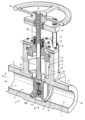
도 1은 평행 디스크 게이트 밸브의 사시 단면도이다.
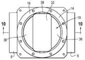
도 2는, 도 1에 도시된 디스크 게이트 밸브의 일 실시예의 상부 사시도이다.
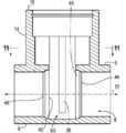
도 3은 밸브 조립체의 하부 부분의 단면도이다.
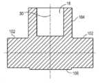
도 4는, 도 3에 도시된 밸브 시트 및 게이트들의 확대 수직 단면도이다.
도 5는 밸브 시트 및 게이트들의 확대 수평 단면도이다.
도 6은 밸브 시트들이 설치되지 않은 밸브 바디의 수직 단면도이다.
도 7a는 블록 단조형 바디(block forged body)의 사시도이다.
도 7b는, 밸브 바디의 내부 및 외부 부분을 가공한 후의 그 밸브 바디의 사시도이다.
도 8은, 도 7b에 도시된 밸브 바디의 수직 단면도이다.
도 9는, 도 8에 도시된 밸브 바디의, 추가 가공 후의 평면도이다.
도 10은, 도 9의 라인 10-10을 따라 획득된 밸브 바디의 수직 단면도이다.
도 11은, 도 10의 라인 11-11을 따라 획득된 밸브 바디의 수평 단면도이다.
도 12a-k는 블록 단조형 밸브 바디에 대한 공정 흐름을 보여주는 도면들이다.1 is a perspective cross-sectional view of a parallel disk gate valve.
2 is a top perspective view of an embodiment of the disk gate valve shown in FIG. 1.
3 is a cross-sectional view of a lower portion of the valve assembly.
4 is an enlarged vertical cross-sectional view of the valve seat and gates shown in FIG. 3.
5 is an enlarged horizontal cross-sectional view of the valve seat and gates.
6 is a vertical cross-sectional view of a valve body in which valve seats are not installed.
7A is a perspective view of a block forged body.
7B is a perspective view of the valve body after processing the inner and outer portions of the valve body.
8 is a vertical cross-sectional view of the valve body shown in FIG. 7B.
9 is a plan view of the valve body shown in FIG. 8 after further processing.
10 is a vertical cross-sectional view of the valve body taken along line 10-10 of FIG. 9.
11 is a horizontal cross-sectional view of the valve body taken along the line 11-11 of FIG. 10.
12A-K are diagrams showing a process flow for a block forged valve body.
본원에서 사용된 용어 "복수"는 둘 이상을 의미하는 것으로 이해되어야 한다. "외측" 및 "내측"라는 용어는 공통의 축 또는 평면을 기준으로 서로 다른 피처들의 상대적 위치를 나타낸다. 용어 "결합된"은 직접 또는 간접적으로, 예를 들어 개재 부재(intervening member)와 연결되거나 맞물리는 것을 의미하며, 그 맞물림이 (고정적이거나 영구적(또는 일체형)일 수도 있지만) 반드시 고정적이거나 영구적일 필요는 없다. 본 명세서에서 사용되는 용어 "제1", "제2" 등은 그렇게 지정된 특정 부품에 할당된 것을 의미하는 것이 아니라, 그보다는 단순히 언급된 번호 순서에 따라, 그러한 부품들을 지칭하는 것이며, "제1"이라고 지정된 부품는, 이후에 참조되는 순서에 따라, "제2"의 해당 구성요소가 될 수도 있다. 예를 들어, "제1" 직경은, 참조되는 순서에 따라 나중에 "제2" 직경으로 지칭될 수도 있다. 또한, "제1" 및 "제2"의 지정은 그와 같이 지정된 2개의 부품 또는 값들이 반드시 다르다는 것을 의미하는 것은 아니며, 예를 들어 제1 직경은 제2 직경과 동일 할 수 있고, 각각은 단순히 별도의 구성요소에 적용 가능함을 의미한다. 용어 "수직"및 "수평"은 도면에 도시된 다양한 부품들의 배향을 지칭하지만, 이러한 부품들은 회전되어 다른 배향으로 사용될 수도 있음을 이해해야 한다.The term “plurality” as used herein is to be understood to mean more than one. The terms "outer" and "inner" refer to the relative position of different features with respect to a common axis or plane. The term "coupled" means directly or indirectly, for example connected or engaged with an intervening member, and the engagement (although it may be fixed or permanent (or integral)) must be fixed or permanent. There is no. The terms "first", "second", etc., as used herein, do not mean that they are assigned to a specific part so designated, but rather simply refer to such parts in the order of the numbers mentioned, and "first" The part designated as "may be a corresponding component of "second" according to an order referred to later. For example, the “first” diameter may be referred to later as the “second” diameter in the order referenced. Further, the designation of “first” and “second” does not mean that the two parts or values so designated are necessarily different, for example the first diameter may be the same as the second diameter, each It simply means that it can be applied to separate components. Although the terms “vertical” and “horizontal” refer to the orientation of the various parts shown in the figures, it should be understood that these parts may be rotated and used in other orientations.
밸브 바디:Valve body:
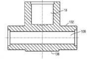
도 1 및 도 6을 참조하면, 게이트 밸브(2)는, 반전된 T- 형상을 갖는 일체형 밸브 바디로서, 그 바디의 대향 단부들 사이에서 종축(10)을 따라 연장되는 내부의 유동 통로(8)를 정의하는 한 쌍의 원통형 단부 부분들(6)를 가지는 밸브 바디를 포함하는 것으로 도시되어 있다. 단부 부분들 각각은, 내부의 통로(12)를 가지며, 통로(12)는 유동 통로(8)의 최소 직경(d1)(제한이 아니라 예로써 7.76인치 내지 24.63인치)에 의해 정의된, 가변 직경을 갖는 테이퍼진 형태이거나 원통형일 수 있다.1 and 6, the gate valve 2 is an integral valve body having an inverted T-shape, and an
원통형 목 부분(neck portion)(14)은 단부 부분들로부터 위쪽으로 연장된다. 목 부분은 바디의 탑부를 정의하는 환형 플랜지 또는 탑 표면(16)을 포함한다. 목 부분은 주변을 둘러싸는 측벽(20), 플로어(22)에 의해 정의된 바닥부 및 개방 탑부를 갖는 내부 챔버(18)를 정의한다. 측벽은 각각 직경 d2(예를 들어, 13.3인치 내지 32.5인치), d3(예를 들어, 12.62인치 내지 30.25인치)를 갖는 챔버의 상부 및 하부(26, 28)를 정의하는 스텝(24)을 포함한다. 챔버는 종축(30)을 따라, 그 종축을 가로질러 연장되는 탑부로부터 목 부분으로 아래쪽으로 연장된다. 일 실시예에서, 축(10, 30)은 직교 또는 수직이다. 챔버는, 제한이 아니라 예로서, 다양한 다각형 형상 또는 기타 다른 타원형 형상을 포함하여, 원 이외의 단면 형상을 가질 수 있음을 알아야 한다.A
통로(32)는 챔버(28)와 유동 통로(8) 사이의 플로어를 통과하여 연장된다. 일 실시예에서, 그 통로는, 도 2, 5, 6 및 11에 도시된 바와 같이 둥근 모서리들(34)을 갖는 직사각형 형상을 가지며, 도 6에 도시된 바와 같이 유동 통로(8)를 통해 아래로 연장되어 부분적으로 그 유동 통로를 정의하는 하부 챔버를 형성한다. 직사각형 형상은, 본 명세서에 더 개시되는 바와 같이 그 통로를 통한 밸브의 캐리지 및 디스크 부품들의 이동을 수용하고 치수 정해진다. 일 실시예에서, 그 통로의 폭은, 채널들이 벽의 대향 측면에 형성되도록 챔버의 직경보다 약간 더 크다. 그와 달리, 코너들(34)이, 챔버의 표면과 접하거나 그 표면으로부터 반경 방향 내측으로 위치될 수 있다. 한 쌍의 세로 홈들(38)이 도 6에 도시된 바와 같이 챔버(18)의 대향 측부들, 통로(32) 및 하부 챔버를 따라 종축(30) 방향으로 연장된다. 통로(32)와 챔버의 형상의 차이로 인해, 플로어의 일부는 한 쌍의 이격된 쉘프 부분들(36)을 포함하며, 이들 각각은, 챔버를 위한 원형 단면과 통로를 위한 직사각형 단면을 갖도록 구성된 실시예에서, 세미-원형 형상을 갖는다. 다른 실시예들에서, 쉘프들은, 챔버와 통로의 상호 형상들 및 교차부에 따라 다른 형상들을 가질 수 있다.The
환형 숄더(40)는 각각의 쉘프 부분들(36) 아래의 유동 통로(8) 주위로 원주 방향으로 종축을 따라 연장된다. 환형 숄더는 모서리를 형성하는 후방 표면(44)과 원주 표면(42)을 갖는다. 환형 숄더의 원주 표면 부분은 유동 통로의 최소 직경보다 큰 최소 직경(d4)과, 폭이라고도 지칭되는 깊이(D1)(예를 들어, 1.2인치 내지 8.37인치)를 갖는다. 환형 숄더는 축(10)을 따라 유동 통로(8)와 동축이다.The
한 쌍의 환형 밸브 시트들(50)이 환형 숄더들(40)에 배치된다. 일 실시예에서, 밸브 시트들은 SA 182 F91/SA 335 P91로 제조된다. 밸브 시트들 각각은 서로 마주보는 전방 측(52)과 서로 반대쪽을 향하는 후방 측(54)을 갖는다. 후방 측(54)은 대응 환형 숄더(40)의 후방 벽과 맞물린다. 밸브 시트들 각각은, 폭이라고도 지칭되는, 제2 깊이(D2)를 갖는 원주 표면(56)을 갖는다. 깊이(D2)는 깊이(D1)보다 크거나 깊이(D1)의 100%를 초과하여, 각 밸브 시트(40)의 대응하는 밸브 디스크(82)에 의한 맞물림이 아래에서 더 설명되는 바와 같이 보장되고, 바람직하게는 깊이(D2)가, 예를 들어 그 범위에 걸쳐 0.4인치 오버행을 포함하여 깊이(D1)의 125%와 135% 사이이다. 깊이(D1)을 갖는 원주 표면(42)의 전체가 대응하는 밸브 시트의 원주 표면(56)과 접촉하고 있는 반면, 다른 실시예에서는 원주 표면의 적어도 75%가 접촉한다. 밸브 시트는 환형 숄더에 대해 축 방향으로 고정된다는 것을 이해해야 한다.A pair of
홈(groove)으로서 형성될 수 있는 제2 환형 숄더(46)는, 종축(30)에 대해 제1 환형 숄더의 외측 단부 부분들 각각에 형성된다. 제2 환형 숄더(46)는 최소 직경(예를 들어, 8.41 내지 24.88인치)을 가지며, 종축(10)을 따라 연장되고 제1 환형 숄더(40) 및 유동 통로(8)와 동축이다. 제2 환형 숄더의 직경은 제1 환형 숄더의 직경보다 작고 유동 채널의 최소 직경보다 크다.A second
캐비티(60)는 종축(30)을 따라 위에 놓인 챔버와 수평 정렬되어 유동 통로(8) 아래의 통로(32)의 바닥부에 형성된다.The
밸브 시트(50)는, 밸브 시트들의 후방 측에 접하는, 제2 환형 숄더 또는 홈(46)에서 바디의 단부 부분들에 용접된다. 도 1 및 도 3 내지 5에 도시된 바와 같이, 밸브 시트(50)는, 밸브 바디, 특히 환형 숄더(40)에 의해 인캡슐레이팅되며, 이는 밸브 시트의 깊이(D2)의 적어도 75%가, 그 밸브 시트의 전체 원주 주위로 밸브 바디에 의해 둘러싸여 있음을 의미한다. 언급된 바와 같이, 밸브 시트는 SA 182 F91/SA 335 P91로 만들어질 수 있으며, 제한이 아니라 예로써 Stellite®hardfacing을 포함하여, 그 전방 측에, 하드 씰링 표면 또는 하드페이싱을 포함할 수 있다.The
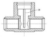
밸브 부품들Valve parts
도 1 내지 도 5을 참조하면, 보닛(70)이 챔버(18)의 개방된 탑부를 폐쇄하도록 복수의 패스너들(72)로 밸브 바디의 탑부에 고정된다. 압력 씰(pressure seal)(74)은 보닛 아래의 챔버에 배치되고 그에 결합되며, 요크(76)는 보닛의 탑부에 결합되고 그로부터 위쪽으로 연장되어 밸브 스템(80)을 지지한다. 일 실시예에서, 밸브 스템(80)은, 휠로 도시된 액추에이터(78)에 의해 나사식(threadably)으로 결합되는 상승 스템(rising stem)이다.1 to 5, the
한 쌍의 디스크(82)가, 챔버 내의 홈들을 따라 슬라이딩하는 가이드들(88)을 포함하는 캐리지(84)를 이용하여 스템의 원위 단부에 결합된다. 복수의 (2개로 도시된) 압축 스프링들(86)이 디스크들 사이에 배치되고, 디스크들을 서로로부터 바깥쪽으로 바이어스(bias)한다. 디스크들(86)은, 밸브가 폐쇄 위치에 있을 때 밸브 시트들(50)과 맞물리거나, 또는 유동 통로를 통한 유동이 중단되도록 그 유동 통로에 배치된 디스크들과 맞물리도록 바이어스된다. 캐리지(84)의 일부는 밸브가 폐쇄 위치에 있을 때 캐비티(60) 내에 배치되거나 수용될 수 있다.A pair of
동작 시, 스템(80)은 액추에이터(78)에 의해 회전될 수 있고, 이는 스템(80), 디스크들(82) 및 캐리지(84)가 유동 통로(8)로부터 위쪽으로 플로어의 통로(32)를 통해 챔버(18)를 향해 이동하도록 하며, 그런 다음 디스크들은, 유동 통로(8)가 그 디스크들에 의해 차단되지 않도록 개방 위치에 있다. 디스크들(82)은 평행하거나 쐐기 구성(wedge configuration)으로서 서로에 대해 소정 각도로 배열될 수 있다. 유동 통로(8)를 폐쇄하기 위해, 액추에이터(78)는 반대 방향으로 회전되고, 이는 디스크들이 유동 통로(8) 내로 아래쪽으로 이동하고 밸브 시트들(50)과 맞물리게 한다.In operation, the
밸브 바디의 제조Manufacture of valve body
도 7a 내지 도 12k를 참조하면, 일체형 바디는, 대향 단부들(92), 대향 측부들(94), 탑부(96) 및 바닥부(98)를 갖는, ASTM A182 Grade F91 합금강의 블록(90)을 블록 (열간) 단조하여 형성된다(도 7a 및 12a 참조). 제한이 아니라 예로서, 길이는 33인치 내지 56인치, 폭은 20인치 내지 40인치, 높이는 30인치 내지 64인치 일 수 있다. 일 실시예에서는 입방체(cube)일 수 있는, 직사각형 프리즘(100) 형상을 갖sm는 중앙 블록과, 프리즘의 대향 단부들로부터 연장되는 원통형 단부 부분들(102)과, 프리즘의 탑부로부터 위쪽으로 연장되는 원통형 목 부분(104)을 갖는, 전반적으로 반전된 T자 모양을 정의하는, 헤드 부분과 단부 부분들의 외부 표면을 형성하기 위해 황삭 가공(rough machning)이 수행될 수 있다. 프리즘은, 증가된 강도 및 두께를 제공하는 동시에, 밸브 바디의 용이한 장착 및 배치를 위한 평평한 바닥부 표면(106)을 제공한다(도 12b 참조). 용어 "가공(machining)"은, 예를 들어 공작 기계들(machine tools)을 사용해서, 제어된 재료-제거 공정에 의해 원재료 일부를 원하는 최종 형상 및 크기로 재구성하는 다양한 공정들 중 임의의 것을 의미한다. 세 가지 주요 가공 공정들은 선삭(turning), 드릴링(drilling) 및 밀링(milling)이다. 기타 다른 작업들로는 성형(shaping), 기획(planing), 보링(boring), 브로칭(broaching) 및 소잉(sawing)이 포함된다. 컴퓨터 수치 제어(CNC) 기계들이 사용될 수 있는데, 예컨대 도 12b 및 c에 도시된 바와 같이 목(neck)과 유동 보어/통로를 사전 가공(pre-machine)하는데 수직 선삭 래치(vertical turning latch; VTL)가 이용될 수 있다.Referring to Figures 7A-12K, the integral body is a
도 7b, 도 8, 도 12b 및 도 12c에 도시된 바와 같이, 관통 홀 또는 유동 보어(108)가 대향 단부들 사이에서 제1 종축(10)을 따라 (예를 들어, VTL을 사용하여) 가공되어 유동 통로를 정의한다. 관통 홀은 원통형일 수도 있고, 본원에 개시된 바와 같이 최소 직경을 갖는 테이퍼진, 절두 원추형(frusto-conical) 형상을 가질 수 있다. 서로 다른 상부와 하부를 갖는 챔버(18)를 구성하기 위해 다수의 가공 작업들이 수행될 수 있다. 관통 홀을 가공하기 전 또는 가공 후 공정으로는 종축(30)을 따라 바디의 탑부(96)로부터 챔버(18)를 가공(예를 들어, VTL)하는 것을 포함한다. 도 12d 내지 도 12h에 도시된 바와 같이, 본 명세서에 개시된 각기 다른 상부 및 하부를 갖는 챔버를 구성하기 위해 다수의 가공 작업들이 수행될 수 있다. 예를 들어, 유동 보어(108) 및 챔버(18)가, 예컨대 수평 머시닝 센터(HMC)를 사용하는 추가적인 가공을 위한 기준으로서 사용된다. 탑부 측 상의 챔버(18)의 구성은, 도 12e에 도시된 바와 같이 CNC 선반(lathe)을 사용하여 더욱 개선된다. CNC 선반은 또한 도 12f 및 도 12g에 도시된 바와 같이, 상류와 하류의 단부들을 마무리하여, 관통 홀(108)의 최종 구성을 가공하는데 사용된다.7B, 8, 12B and 12C, a through hole or flow bore 108 is machined (e.g., using VTL) along the first
도 12h를 참조하면, 공정은, 예를 들어 챔버와 관통 홀(108) 사이의 플로어를 통과하는 직사각형 포켓 밀링을 사용하여, 통로(32)를 가공하고, 관통 홀을 통해 더 아래로 가공하는 단계를 더 포함하며, 이는 관통 홀과 챔버의 가공 중 하나 또는 양자의 전이나 후에 발생할 수 있다. 가공은, 통로(32)가 가공될 때 유동 통로 아래의 바디의 바닥부에 캐비티(60)를 가공하는 단계를 더 포함할 수 있다. 통로(32) 또는 챔버의 가공은, 쉘프 부분들(36)을 형성한다. 채널들과 홈들(38)은 또한 도 12j에 도시된 바와 같이, 예를 들어 밀링 공정을 사용하여, 챔버, 통로(32), 및 하부 챔버 및 유동 통로로 가공된다.12H, the process includes machining the
공정은, 어느 순서로든, 이격된 쉘프 부분들(36) 아래에서 제1 환형 숄더들(40)을 가공(도 12g 및 h 참조)하고, 제1 환형 숄더들의 외측에 제2 환형 숄더들 또는 홈들(46)을 다시 가공하는 단계를 더 포함한다. 제1 숄더들은 그 상류 및 하류(111, 113) 부분들을 정의하는 상류 및 하류 작업들에 의해 형성된 중앙 원통형 캐비티(115)로의 통로(32)의 가공에 의해 형성될 수 있다. 도 12i에 도시된 바와 같이, 드릴링에 의해 탑부면 홀들(top face holes)이 형성될 수 있다. 프리즘 블록(100)의 바깥 모서리들이, 도 12k에 도시된 바와 같이, (예컨대 HMC를 사용하여) 모따기(chamfered)될 수 있다. 예를 들어, 그라인더를 사용하여, 전체 외부 표면이 디버링(deburring)될 수 있다.The process, in any order, processes the first
공정은, 밸브 시트들을 완전히 인캡슐레이팅하는 환형 숄더들 각각으로, 밸브 시트(40)를, 각 대응 밸브 시트와 접촉하는 원주 표면(42)의 전체 깊이(D1)로, 삽입하는 단계를 포함한다. 그런 다음 밸브 시트들은 그 밸브 시트의 후방 측을 바디에 용접하고, 특히 밸브 시트를 제2 환형 숄더를 따라 바디에 용접함으로써, 바디에 연결된다.The process includes inserting, with each of the annular shoulders completely encapsulating the valve seats, the
본 발명이 바람직한 실시예들을 참조하여 설명되었지만, 당업자는 본 발명의 사상 및 범위를 벗어나지 않고서 형태 및 세부 사항이 변경될 수 있음을 알 것이다. 따라서, 전술한 상세한 설명은 제한적이기보다는 예시적인 것으로 간주되고 본 발명의 범위를 정의하고자 의도된 것은, 모든 등가물을 포함하는 첨부의 청구 범위이다.While the present invention has been described with reference to preferred embodiments, those skilled in the art will recognize that changes in form and detail may be made without departing from the spirit and scope of the present invention. Accordingly, the foregoing detailed description is to be regarded as illustrative rather than restrictive and intended to define the scope of the present invention is the appended claims, including all equivalents.
Claims (23)
Translated fromKorean대향 단부들(opposite ends), 대향 측부들(opposite sides), 탑부(top) 및 바닥부(bottom)를 갖는 일체형 바디를 블록 단조(block forging)하는 단계;
제1 최소 직경을 갖고 상기 대향 단부들 사이에서 제1 축을 따라 연장하는 관통 홀(through hole)을 가공(machining)하는 단계- 상기 관통 홀은 유동 통로(flow passageway)를 정의함 -;
제2 최소 직경을 갖고 제2 축을 따라 상기 탑부로부터 아래쪽으로 연장되는 챔버를 가공하는 단계- 상기 제1 및 제2 축은 직교하고, 상기 챔버는 상기 관통 홀로부터 상기 챔버를 분리하는 플로어에 의해 정의된 바닥부를 포함함 -;
상기 챔버와 상기 관통 홀 사이의 상기 플로어를 통과하는 통로(passageway)를 가공하여 상기 관통 홀 위에 놓인 한 쌍의 쉘프 부분들(shelf portions)을 정의하는 단계;
상기 제1 최소 직경보다 큰 제3 최소 직경을 갖고 상기 쉘프 부분들 각각의 아래에서 상기 제1 축을 따라 연장되는 환형 숄더(annular shoulder)를 가공하는 단계- 상기 환형 숄더 각각은 상기 제1 축을 따라 상기 쉘프 부분 아래에 정의된 제1 깊이를 가지며, 상기 환형 숄더는 관통 개구와 동축임 -;
상기 환형 숄더 각각에 밸브 시트를 삽입하는 단계- 상기 밸브 시트 각각은 제2 깊이를 갖는 원주 표면(corcumferential surface)을 가지며, 상기 제2 깊이는 상기 제1 깊이의 100 내지 135%이고, 상기 밸브 시트 각각은 서로 마주보는 전방 측(front side)과, 서로로부터 반대쪽인 후방 측(backside)을 가짐 -; 및
상기 밸브 시트를 상기 환형 숄더에 고정하여 상기 밸브 시트가 상기 제1 축을 따라 움직일 수 없도록 하는 단계를 포함하는, 밸브 바디 제조 방법.As a method of manufacturing a valve body,
Block forging an integral body having opposite ends, opposite sides, a top and a bottom;
Machining a through hole having a first minimum diameter and extending along a first axis between the opposite ends, the through hole defining a flow passageway;
Machining a chamber having a second minimum diameter and extending downwardly from the tower along a second axis-the first and second axes are orthogonal and the chamber is defined by a floor separating the chamber from the through hole. Including the bottom -;
Processing a passageway through the floor between the chamber and the through hole to define a pair of shelf portions overlying the through hole;
Machining an annular shoulder extending along the first axis under each of the shelf portions and having a third minimum diameter greater than the first minimum diameter; Having a first depth defined below the shelf portion, the annular shoulder being coaxial with the through opening;
Inserting a valve seat into each of the annular shoulders-Each of the valve seats has a corcumferential surface having a second depth, the second depth is 100 to 135% of the first depth, and the valve seat Each has a front side facing each other and a backside opposite from each other -; And
And fixing the valve seat to the annular shoulder so that the valve seat cannot move along the first axis.
상기 일체형 바디를 블록 단조하는 단계는, 직사각형 프리즘을 블록 단조하는 단계를 포함하는, 밸브 바디 제조 방법.The method of claim 1,
Block forging of the integral body comprises the step of block forging a rectangular prism, valve body manufacturing method.
상기 밸브 시트를 상기 환형 숄더에 고정하는 단계는, 각각의 밸브 시트의 상기 후방 측을 상기 바디에 용접하는 단계를 더 포함하는, 밸브 바디 제조 방법.The method of claim 1,
The step of fixing the valve seat to the annular shoulder further comprises welding the rear side of each valve seat to the body.
상기 환형 숄더는 제1 환형 숄더이고,
상기 방법은,
상기 제1 환형 숄더 각각의 외측에 있는 제2 환형 숄더를 가공하는 단계를 더 포함- 상기 제2 환형 숄더 각각은 제4 최소 직경을 갖고 상기 제1 축을 따라 연장되며, 상기 제1 및 제2 숄더는 동축이고, 상기 제4 직경은 상기 제3 직경보다 작음 -하고,
상기 용접하는 단계는, 상기 밸브 시트를 상기 제2 환형 숄더를 따라 상기 바디에 용접하는 단계를 포함하는, 밸브 바디 제조 방법.The method of claim 3,
The annular shoulder is a first annular shoulder,
The above method,
Further comprising processing a second annular shoulder outside each of the first annular shoulders-each of the second annular shoulders has a fourth minimum diameter and extends along the first axis, the first and second shoulders Is coaxial, the fourth diameter is less than the third diameter-and,
The welding step includes welding the valve seat to the body along the second annular shoulder.
상기 쉘프 부분들은, 세미-원형 형상(a semi-circular shape)을 갖는, 밸브 바디 제조 방법.The method of claim 1,
The shelf parts have a semi-circular shape.
상기 통로는 직사각형 형상을 갖는, 밸브 바디 제조 방법.The method of claim 5,
The passage has a rectangular shape, the valve body manufacturing method.
상기 직사각형 형상은 둥근 모서리를 갖는, 밸브 바디 제조 방법.The method of claim 6,
The rectangular shape has a rounded corner, valve body manufacturing method.
각각의 상기 밸브 시트의 상기 전방 측이 하드 씰링(hard sealing) 표면을 포함하는, 밸브 바디 제조 방법.The method of claim 1,
The method of manufacturing a valve body, wherein the front side of each of the valve seats comprises a hard sealing surface.
상기 관통 홀의 반대 측 상에, 상기 제2 축을 따라, 상기 통로 및 챔버와 정렬된 캐비티를 가공하는 단계를 더 포함하는, 밸브 바디 제조 방법.The method of claim 1,
The method of manufacturing a valve body, further comprising processing a cavity aligned with the passage and the chamber along the second axis, on the opposite side of the through hole.
상기 제1, 상기 제2 및/또는 상기 제3 최소 직경, 및/또는 상기 통로 중 하나 이상의 치수를 변경하는 단계를 더 포함하는, 밸브 바디 제조 방법.The method of claim 1,
Changing the dimension of at least one of the first, the second and/or the third minimum diameter, and/or the passage.
제1항의 단계들을 포함하고,
상기 제2 축을 따라 상기 챔버에 밸브 스템을 삽입하는 단계를 더 포함하며,
한 쌍의 스프링 장착 디스크들(a pair of spring loaded discs)이 상기 밸브 스템의 단부에 결합되고,
상기 디스크들은, 상기 디스크들이 상기 밸브 시트들과 맞물려 상기 관통 홀 내에 배치되는 폐쇄 위치(closed position)로부터, 관통 채널이 상기 디스크들에 의해 차단되지 않도록 상기 디스크들이 상기 챔버 내에 적어도 부분적으로 배치되는 개방 위치(open opsition)로, 상기 제2 축을 따라 이동 가능한, 밸브 제조 방법.As a valve manufacturing method,
Including the steps of claim 1,
Inserting a valve stem into the chamber along the second axis,
A pair of spring loaded discs is coupled to the end of the valve stem,
The disks are opened from a closed position in which the disks engage with the valve seats and are arranged in the through hole, wherein the disks are at least partially arranged in the chamber so that the through channel is not blocked by the disks. A method of manufacturing a valve, movable along the second axis in an open opsition.
보닛(bonet)을 상기 밸브 바디의 상기 탑부에 고정하고 상기 보닛에 결합된 요크를 고정하는 단계를 더 포함- 상기 밸브 스템은 상기 요크와 나사식(threadably)으로 맞물리고(engaged), 상기 밸브 스템의 회전에 응답하여 상기 제2 축을 따라 이동할 수 있음 -하는, 밸브 제조 방법.The method of claim 11,
Further comprising fixing a bonnet to the top of the valve body and fixing a yoke coupled to the bonnet-the valve stem is threadably engaged with the yoke, and the valve stem -Which can move along the second axis in response to the rotation of the valve.
상기 보닛 아래의 상기 챔버에 배치된 압력 씰(pressure seal)을 더 포함하고, 상기 압력 씰은 상기 밸브 스템과 맞물리는, 밸브 바디 제조 방법.The method of claim 12,
A method of manufacturing a valve body, further comprising a pressure seal disposed in the chamber under the bonnet, wherein the pressure seal engages the valve stem.
대향 단부들, 대향 측부들, 탑부 및 바닥부를 포함하는 일체형 블록 단조형 바디를 포함하고,
상기 블록 단조형 바디는
제1 최소 직경을 갖고 상기 대향 단부들 사이에서 제1 축을 따라 연장하는 관통 홀- 상기 관통 홀은 유동 통로를 정의함 -;
제2 최소 직경을 갖고 상기 탑부로부터 제2 축을 따라 연장하는 챔버- 상기 제1 및 제2 축은 직교하고, 상기 챔버는 상기 관통 홀로부터 상기 챔버를 분리하는 플로어에 의해 정의된 바닥부를 포함함 -;
상기 챔버와 상기 관통 홀 사이의 상기 플로어를 통하여 연장되는 통로- 상기 플로어는 상기 관통 홀 위에 놓인 한 쌍의 세미-원형 쉘프 부분들을 포함함 -; 및
제3 최소 직경을 갖고 상기 쉘프 부분들 각각 아래에서 상기 제1 축을 따라 연장하는 환형 숄더- 상기 환형 숄더 각각은 상기 제1 축을 따라 상기 쉘프 부분 아래에 정의된 제1 깊이를 갖고, 상기 환형 숄더들은 관통 개구와 동축임 -를 포함하며,
상기 밸브 바디는 또한
상기 환형 숄더 각각에 배치된 밸브 시트- 상기 밸브 시트 각각은 제2 깊이를 가지며, 상기 제2 깊이는 상기 제1 깊이의 100 내지 135%이고, 상기 밸브 시트 각각은 서로 마주 보는 전방 측과 서로로부터 반대쪽의 후방 측을 가짐 -를 포함하는, 밸브 바디.As a valve body,
It includes an integral block forged body including opposite ends, opposite sides, a top portion and a bottom portion,
The block forged body
A through hole having a first minimum diameter and extending along a first axis between the opposite ends, the through hole defining a flow passage;
A chamber having a second minimum diameter and extending along a second axis from the top portion, the first and second axes being orthogonal, the chamber comprising a bottom portion defined by a floor separating the chamber from the through hole;
A passage extending through the floor between the chamber and the through hole, the floor comprising a pair of semi-circular shelf portions overlying the through hole; And
An annular shoulder having a third minimum diameter and extending along the first axis below each of the shelf portions-each of the annular shoulders has a first depth defined below the shelf portion along the first axis, the annular shoulders Including-is coaxial with the through opening,
The valve body is also
Valve seats disposed on each of the annular shoulders-Each of the valve seats has a second depth, the second depth is 100 to 135% of the first depth, and each of the valve seats is from a front side facing each other and from each other. Valve body, including-having an opposite rear side.
상기 밸브 시트 각각의 상기 후방 측은 상기 바디에 용접된, 밸브 바디.The method of claim 14,
The rear side of each of the valve seats is welded to the body.
상기 환형 숄더는 제1 환형 숄더이고,
상기 밸브 바디는, 상기 제1 환형 숄더 각각의 외측에 배치된 제2 환형 숄더를 더 포함하고,
상기 제2 환형 숄더 각각은 제4 최소 직경을 갖고 상기 제1 축을 따라 연장되며, 상기 제1 및 제2 숄더는 동축이고, 상기 제4 최소 직경은 상기 제3 최소 직경보다 작으며, 상기 밸브 시트 각각의 상기 후방 측은 상기 제2 환형 숄더 중 하나를 따라 상기 바디에 용접되는, 밸브 바디.The method of claim 15,
The annular shoulder is a first annular shoulder,
The valve body further includes a second annular shoulder disposed outside each of the first annular shoulders,
Each of the second annular shoulders has a fourth minimum diameter and extends along the first axis, the first and second shoulders are coaxial, the fourth minimum diameter is less than the third minimum diameter, and the valve seat Each of the rear sides is welded to the body along one of the second annular shoulders.
상기 통로는 직사각형 형상을 갖는, 밸브 바디.The method of claim 14,
The valve body, wherein the passage has a rectangular shape.
상기 직사각형 형상은 둥근 모서리를 갖는, 밸브 바디.The method of claim 17,
The rectangular shape has a rounded corner, the valve body.
상기 밸브 시트 각각의 상기 전방 측은 하드 씰링 표면을 포함하는, 밸브 바디.The method of claim 14,
The valve body, wherein the front side of each of the valve seats comprises a hard sealing surface.
상기 관통 홀의 반대 측 상에, 상기 제2 축을 따라, 상기 통로 및 챔버와 정렬되는 캐비티를 더 포함하는, 밸브 바디.The method of claim 14,
On the opposite side of the through hole, along the second axis, the valve body further comprising a cavity aligned with the passage and the chamber.
제14항의 밸브 바디를 포함하고,
상기 챔버 내에 배치되고 상기 제2 축을 따라 연장되는 밸브 스템을 더 포함하며,
한 쌍의 스프링 장착 디스크가 상기 밸브 스템의 상기 단부에 결합되고,
상기 디스크들은, 상기 디스크들이 상기 밸브 시트들과 맞물려 상기 관통 홀 내에 배치되는 폐쇄 위치(closed position)로부터, 관통 채널이 상기 디스크들에 의해 차단되지 않도록 상기 디스크들이 상기 챔버 내에 적어도 부분적으로 배치되는 개방 위치(open opsition)로, 상기 제2 축을 따라 이동 가능한, 밸브.As a valve,
Including the valve body of claim 14,
Further comprising a valve stem disposed in the chamber and extending along the second axis,
A pair of spring-loaded discs are coupled to the end of the valve stem,
The disks are opened from a closed position in which the disks engage with the valve seats and are arranged in the through hole, wherein the disks are at least partially arranged in the chamber so that the through channel is not blocked by the disks. A valve, movable along the second axis, in an open opsition.
상기 밸브 바디의 상기 탑부에 결합된 보닛 및 상기 보닛에 결합된 요크를 더 포함하고,
상기 밸브 스템은 상기 요크와 나사식으로 맞물리고,
상기 밸브 스템 및 상기 디스크들은 상기 밸브 스템의 회전에 응답하여 상기 제2 축를 따라 이동 가능한, 밸브.The method of claim 21,
Further comprising a bonnet coupled to the top portion of the valve body and a yoke coupled to the bonnet,
The valve stem is threadedly engaged with the yoke,
The valve stem and the disks are movable along the second axis in response to rotation of the valve stem.
상기 보닛 아래의 상기 챔버 내에 배치 된 압력 씰을 더 포함하고, 상기 압력 씰은 상기 밸브 스템과 맞물리는, 밸브.The method of claim 22,
A pressure seal disposed within the chamber under the bonnet, the pressure seal engaging the valve stem.
Applications Claiming Priority (3)
| Application Number | Priority Date | Filing Date | Title |
|---|---|---|---|
| US201862694247P | 2018-07-05 | 2018-07-05 | |
| US62/694,247 | 2018-07-05 | ||
| PCT/US2019/040109WO2020009984A1 (en) | 2018-07-05 | 2019-07-01 | Method for manufacturing a block forged valve body with a fully encapsulated seat ring |
Publications (2)
| Publication Number | Publication Date |
|---|---|
| KR20210059698Atrue KR20210059698A (en) | 2021-05-25 |
| KR102751639B1 KR102751639B1 (en) | 2025-01-10 |
Family
ID=69059764
Family Applications (1)
| Application Number | Title | Priority Date | Filing Date |
|---|---|---|---|
| KR1020217003685AActiveKR102751639B1 (en) | 2018-07-05 | 2019-07-01 | Method for manufacturing a block forged valve body having a fully encapsulated seat ring |
Country Status (6)
| Country | Link |
|---|---|
| US (1) | US11047487B2 (en) |
| EP (1) | EP3817873A4 (en) |
| KR (1) | KR102751639B1 (en) |
| CN (1) | CN113165051B (en) |
| CA (1) | CA3111375A1 (en) |
| WO (1) | WO2020009984A1 (en) |
Families Citing this family (7)
| Publication number | Priority date | Publication date | Assignee | Title |
|---|---|---|---|---|
| US10113661B2 (en)* | 2016-08-30 | 2018-10-30 | Griswold Controls, Llc | Flow control valve |
| CN113000775B (en)* | 2021-03-15 | 2023-05-02 | 大庆市顺康石油科技开发有限公司 | Forging method for multi-way valve at wellhead of oil production well |
| CN115126918B (en)* | 2021-03-24 | 2025-08-12 | 中核苏阀科技实业股份有限公司 | High-temperature high-pressure forged steel high-performance gate valve body with guide ribs and manufacturing method |
| CN115126919B (en)* | 2021-03-24 | 2025-08-12 | 中核苏阀科技实业股份有限公司 | High-temperature high-pressure forged steel high-performance gate valve body with guide groove and manufacturing method |
| CN114110193B (en)* | 2021-11-30 | 2024-11-08 | 常进芬 | A corrosion-resistant and pressure-resistant valve joint and its manufacturing process |
| CN114523269B (en)* | 2022-03-04 | 2023-07-14 | 安徽新欧力电器有限公司 | Refrigerator part processing system and method |
| CN115194411B (en)* | 2022-07-21 | 2024-06-14 | 玉环云泰铜业有限公司 | Tap seat processing technology |
Citations (4)
| Publication number | Priority date | Publication date | Assignee | Title |
|---|---|---|---|---|
| US1858927A (en)* | 1930-01-04 | 1932-05-17 | Victory Valves Ltd | Method of making valves |
| US3463446A (en)* | 1967-03-13 | 1969-08-26 | Acf Ind Inc | Low stress stem connection |
| US6401747B1 (en)* | 2000-07-13 | 2002-06-11 | Fmc Corporation | Gate valve |
| CN203627856U (en)* | 2013-12-27 | 2014-06-04 | 浙江科正阀门有限公司 | Forged steel gate valve |
Family Cites Families (26)
| Publication number | Priority date | Publication date | Assignee | Title |
|---|---|---|---|---|
| US1828478A (en)* | 1925-05-19 | 1931-10-20 | Columbus Machine Company | Gate valve and method of making same |
| US1803889A (en)* | 1927-03-14 | 1931-05-05 | Charles F H Bohnhardt | Noncorroding valve |
| US2065035A (en) | 1935-04-22 | 1936-12-22 | Taylor James Hall | Valve housing and method of making same |
| US2869819A (en)* | 1954-06-25 | 1959-01-20 | Acf Ind Inc | Gate valve |
| US3434692A (en)* | 1967-02-23 | 1969-03-25 | Cassius L Tillman | Bifaced wedged gate valve |
| US3486733A (en) | 1967-09-01 | 1969-12-30 | Jamesbury Corp | Seat ring for ball valves |
| US4208035A (en)* | 1978-02-13 | 1980-06-17 | Acf Industries, Incorporated | Metal gate valve seat having a flexible front lip face seal |
| US4443920A (en)* | 1981-09-08 | 1984-04-24 | Oliver John P | Method of manufacturing a gate valve body |
| US4515347A (en)* | 1982-12-27 | 1985-05-07 | Joy Manufacturing Company | Valve seat structure |
| US4566671A (en) | 1983-11-14 | 1986-01-28 | John Beson | Gate valve having a secondary seal |
| US4911407A (en) | 1989-03-17 | 1990-03-27 | Paul Jr Herman L | Valve seat structure and assembly |
| DE3942313A1 (en)* | 1989-12-21 | 1991-06-27 | Bosch Gmbh Robert | Double seat control valve - is for pneumatic vehicle braking system and has connection between pressure chamber and annular chamber |
| US6695285B1 (en) | 1999-11-23 | 2004-02-24 | Swagelok Company | Ball valve seat seal |
| CN102084163B (en) | 2006-08-14 | 2014-03-12 | 宋永生 | Valves that reduce damage during relative sliding operation between the closing member and the valve seat |
| CN201306481Y (en) | 2008-11-03 | 2009-09-09 | 大连大高阀门有限公司 | Nuclear grade one large-caliber forged steel full-flow swing type check valve |
| BRPI1008833A2 (en)* | 2009-02-04 | 2016-03-15 | Cameron Int Corp | drive sleeve and sealing mechanism for non-rising stem gate valve |
| US8403296B2 (en) | 2010-11-29 | 2013-03-26 | Vetco Gray Inc. | Metal seat seal with flexible sealing edge |
| US20120319025A1 (en)* | 2011-06-20 | 2012-12-20 | Jianchao Shu | Trunnion Control Gate Valve For Sever Service |
| CN202400417U (en) | 2011-09-29 | 2012-08-29 | 通用电气公司 | System for locking container component |
| US9759334B2 (en) | 2012-12-31 | 2017-09-12 | Vetco Gray Inc. | Gate valve arrangement including multi-valve stem and seat assemblies |
| CN205298736U (en)* | 2015-12-29 | 2016-06-08 | 上海瑞托阀门科技有限公司 | Whole die forging ultra -low temperature upper assembling type connecting rod ball ball valve |
| JP6640637B2 (en)* | 2016-03-30 | 2020-02-05 | ヴィオニア日信ブレーキシステムジャパン株式会社 | Solenoid valve, vehicle brake fluid pressure control device, and method of manufacturing electromagnetic valve |
| CN206159560U (en) | 2016-11-09 | 2017-05-10 | 尚绪河 | Qi shihuan that revolves that structure is succinct closes silence check valve |
| CN206290734U (en)* | 2016-12-20 | 2017-06-30 | 温州电泰阀门有限公司 | A kind of boxing formula solid forging gate valve |
| CN207715831U (en) | 2017-10-20 | 2018-08-10 | 中核苏阀科技实业股份有限公司 | A pin shaft built-in swing check valve |
| CN107671221A (en) | 2017-11-27 | 2018-02-09 | 二十二冶集团精密锻造有限公司 | The not shaping dies and manufacturing process of equal tee valve body |
- 2019
- 2019-07-01KRKR1020217003685Apatent/KR102751639B1/enactiveActive
- 2019-07-01USUS16/458,704patent/US11047487B2/enactiveActive
- 2019-07-01CNCN201980058413.6Apatent/CN113165051B/enactiveActive
- 2019-07-01EPEP19830826.4Apatent/EP3817873A4/enactivePending
- 2019-07-01CACA3111375Apatent/CA3111375A1/enactivePending
- 2019-07-01WOPCT/US2019/040109patent/WO2020009984A1/ennot_activeCeased
Patent Citations (4)
| Publication number | Priority date | Publication date | Assignee | Title |
|---|---|---|---|---|
| US1858927A (en)* | 1930-01-04 | 1932-05-17 | Victory Valves Ltd | Method of making valves |
| US3463446A (en)* | 1967-03-13 | 1969-08-26 | Acf Ind Inc | Low stress stem connection |
| US6401747B1 (en)* | 2000-07-13 | 2002-06-11 | Fmc Corporation | Gate valve |
| CN203627856U (en)* | 2013-12-27 | 2014-06-04 | 浙江科正阀门有限公司 | Forged steel gate valve |
Also Published As
| Publication number | Publication date |
|---|---|
| US11047487B2 (en) | 2021-06-29 |
| WO2020009984A1 (en) | 2020-01-09 |
| US20200011432A1 (en) | 2020-01-09 |
| CN113165051B (en) | 2023-10-27 |
| EP3817873A1 (en) | 2021-05-12 |
| KR102751639B1 (en) | 2025-01-10 |
| CA3111375A1 (en) | 2020-01-09 |
| CN113165051A (en) | 2021-07-23 |
| EP3817873A4 (en) | 2022-03-16 |
Similar Documents
| Publication | Publication Date | Title |
|---|---|---|
| KR102751639B1 (en) | Method for manufacturing a block forged valve body having a fully encapsulated seat ring | |
| US8136247B2 (en) | Method of forming a blowout preventer body | |
| US11209101B2 (en) | Lattice control cage for a regulator | |
| US20160238002A1 (en) | Plunger lift assembly | |
| US8490652B2 (en) | Cage valve with flow trim for reduced fracturing | |
| AU2002340466B2 (en) | Replaceable valve seat | |
| CA2945118A1 (en) | Cage valve with flow trim for reduced port erosion | |
| MX2010007648A (en) | Direct metal laser sintered flow control element. | |
| US20180216738A1 (en) | Control valves having integral trim | |
| CN105308372A (en) | Construction of a metallically sealing angle seat geometry by means of laser melting | |
| US11598449B2 (en) | Compact multi-stage control valve trim | |
| US20140109970A1 (en) | Metal cone plug valve | |
| US8210500B2 (en) | Seat ring | |
| EP1180627B1 (en) | High differential pressure regulating valve | |
| KR102826065B1 (en) | Method for manufacturing a block forged swing check valve body with a fully encapsulated seat ring | |
| US4443920A (en) | Method of manufacturing a gate valve body | |
| US3473785A (en) | Valve body for globe valves or the like | |
| US20210071779A1 (en) | Tapered Anti-Cavitation Cage | |
| CN103851219A (en) | Adjusting valve used for adjusting hydraulic volume flow rate | |
| US516658A (en) | Process of seating valve-bodies | |
| JPS62177373A (en) | Manufacture of ball valve |
Legal Events
| Date | Code | Title | Description |
|---|---|---|---|
| PA0105 | International application | Patent event date:20210205 Patent event code:PA01051R01D Comment text:International Patent Application | |
| PG1501 | Laying open of application | ||
| PN2301 | Change of applicant | Patent event date:20220420 Comment text:Notification of Change of Applicant Patent event code:PN23011R01D | |
| A201 | Request for examination | ||
| PA0201 | Request for examination | Patent event code:PA02012R01D Patent event date:20220510 Comment text:Request for Examination of Application | |
| E902 | Notification of reason for refusal | ||
| PE0902 | Notice of grounds for rejection | Comment text:Notification of reason for refusal Patent event date:20240411 Patent event code:PE09021S01D | |
| E701 | Decision to grant or registration of patent right | ||
| PE0701 | Decision of registration | Patent event code:PE07011S01D Comment text:Decision to Grant Registration Patent event date:20241028 | |
| PG1601 | Publication of registration |