KR20210053944A - Omnidirectional power generation device - Google Patents
Omnidirectional power generation deviceDownload PDFInfo
- Publication number
- KR20210053944A KR20210053944AKR1020217009572AKR20217009572AKR20210053944AKR 20210053944 AKR20210053944 AKR 20210053944AKR 1020217009572 AKR1020217009572 AKR 1020217009572AKR 20217009572 AKR20217009572 AKR 20217009572AKR 20210053944 AKR20210053944 AKR 20210053944A
- Authority
- KR
- South Korea
- Prior art keywords
- channels
- power generation
- axis
- outlet
- rotation
- Prior art date
- Legal status (The legal status is an assumption and is not a legal conclusion. Google has not performed a legal analysis and makes no representation as to the accuracy of the status listed.)
- Granted
Links
Images


Classifications
- F—MECHANICAL ENGINEERING; LIGHTING; HEATING; WEAPONS; BLASTING
- F03—MACHINES OR ENGINES FOR LIQUIDS; WIND, SPRING, OR WEIGHT MOTORS; PRODUCING MECHANICAL POWER OR A REACTIVE PROPULSIVE THRUST, NOT OTHERWISE PROVIDED FOR
- F03D—WIND MOTORS
- F03D1/00—Wind motors with rotation axis substantially parallel to the air flow entering the rotor
- F03D1/06—Rotors
- F03D1/0608—Rotors characterised by their aerodynamic shape
- F03D1/0625—Rotors characterised by their aerodynamic shape of the whole rotor, i.e. form features of the rotor unit
- F—MECHANICAL ENGINEERING; LIGHTING; HEATING; WEAPONS; BLASTING
- F03—MACHINES OR ENGINES FOR LIQUIDS; WIND, SPRING, OR WEIGHT MOTORS; PRODUCING MECHANICAL POWER OR A REACTIVE PROPULSIVE THRUST, NOT OTHERWISE PROVIDED FOR
- F03D—WIND MOTORS
- F03D1/00—Wind motors with rotation axis substantially parallel to the air flow entering the rotor
- F03D1/02—Wind motors with rotation axis substantially parallel to the air flow entering the rotor having a plurality of rotors
- F—MECHANICAL ENGINEERING; LIGHTING; HEATING; WEAPONS; BLASTING
- F03—MACHINES OR ENGINES FOR LIQUIDS; WIND, SPRING, OR WEIGHT MOTORS; PRODUCING MECHANICAL POWER OR A REACTIVE PROPULSIVE THRUST, NOT OTHERWISE PROVIDED FOR
- F03D—WIND MOTORS
- F03D5/00—Other wind motors
- F—MECHANICAL ENGINEERING; LIGHTING; HEATING; WEAPONS; BLASTING
- F03—MACHINES OR ENGINES FOR LIQUIDS; WIND, SPRING, OR WEIGHT MOTORS; PRODUCING MECHANICAL POWER OR A REACTIVE PROPULSIVE THRUST, NOT OTHERWISE PROVIDED FOR
- F03D—WIND MOTORS
- F03D1/00—Wind motors with rotation axis substantially parallel to the air flow entering the rotor
- F03D1/04—Wind motors with rotation axis substantially parallel to the air flow entering the rotor having stationary wind-guiding means, e.g. with shrouds or channels
- F—MECHANICAL ENGINEERING; LIGHTING; HEATING; WEAPONS; BLASTING
- F03—MACHINES OR ENGINES FOR LIQUIDS; WIND, SPRING, OR WEIGHT MOTORS; PRODUCING MECHANICAL POWER OR A REACTIVE PROPULSIVE THRUST, NOT OTHERWISE PROVIDED FOR
- F03D—WIND MOTORS
- F03D1/00—Wind motors with rotation axis substantially parallel to the air flow entering the rotor
- F03D1/06—Rotors
- F03D1/0608—Rotors characterised by their aerodynamic shape
- F—MECHANICAL ENGINEERING; LIGHTING; HEATING; WEAPONS; BLASTING
- F03—MACHINES OR ENGINES FOR LIQUIDS; WIND, SPRING, OR WEIGHT MOTORS; PRODUCING MECHANICAL POWER OR A REACTIVE PROPULSIVE THRUST, NOT OTHERWISE PROVIDED FOR
- F03D—WIND MOTORS
- F03D3/00—Wind motors with rotation axis substantially perpendicular to the air flow entering the rotor
- F03D3/02—Wind motors with rotation axis substantially perpendicular to the air flow entering the rotor having a plurality of rotors
- F—MECHANICAL ENGINEERING; LIGHTING; HEATING; WEAPONS; BLASTING
- F03—MACHINES OR ENGINES FOR LIQUIDS; WIND, SPRING, OR WEIGHT MOTORS; PRODUCING MECHANICAL POWER OR A REACTIVE PROPULSIVE THRUST, NOT OTHERWISE PROVIDED FOR
- F03D—WIND MOTORS
- F03D3/00—Wind motors with rotation axis substantially perpendicular to the air flow entering the rotor
- F03D3/04—Wind motors with rotation axis substantially perpendicular to the air flow entering the rotor having stationary wind-guiding means, e.g. with shrouds or channels
- F—MECHANICAL ENGINEERING; LIGHTING; HEATING; WEAPONS; BLASTING
- F03—MACHINES OR ENGINES FOR LIQUIDS; WIND, SPRING, OR WEIGHT MOTORS; PRODUCING MECHANICAL POWER OR A REACTIVE PROPULSIVE THRUST, NOT OTHERWISE PROVIDED FOR
- F03D—WIND MOTORS
- F03D3/00—Wind motors with rotation axis substantially perpendicular to the air flow entering the rotor
- F03D3/06—Rotors
- F03D3/061—Rotors characterised by their aerodynamic shape, e.g. aerofoil profiles
- F—MECHANICAL ENGINEERING; LIGHTING; HEATING; WEAPONS; BLASTING
- F03—MACHINES OR ENGINES FOR LIQUIDS; WIND, SPRING, OR WEIGHT MOTORS; PRODUCING MECHANICAL POWER OR A REACTIVE PROPULSIVE THRUST, NOT OTHERWISE PROVIDED FOR
- F03D—WIND MOTORS
- F03D3/00—Wind motors with rotation axis substantially perpendicular to the air flow entering the rotor
- F03D3/06—Rotors
- F03D3/062—Rotors characterised by their construction elements
- F—MECHANICAL ENGINEERING; LIGHTING; HEATING; WEAPONS; BLASTING
- F03—MACHINES OR ENGINES FOR LIQUIDS; WIND, SPRING, OR WEIGHT MOTORS; PRODUCING MECHANICAL POWER OR A REACTIVE PROPULSIVE THRUST, NOT OTHERWISE PROVIDED FOR
- F03D—WIND MOTORS
- F03D9/00—Adaptations of wind motors for special use; Combinations of wind motors with apparatus driven thereby; Wind motors specially adapted for installation in particular locations
- F03D9/20—Wind motors characterised by the driven apparatus
- F03D9/25—Wind motors characterised by the driven apparatus the apparatus being an electrical generator
- F—MECHANICAL ENGINEERING; LIGHTING; HEATING; WEAPONS; BLASTING
- F05—INDEXING SCHEMES RELATING TO ENGINES OR PUMPS IN VARIOUS SUBCLASSES OF CLASSES F01-F04
- F05B—INDEXING SCHEME RELATING TO WIND, SPRING, WEIGHT, INERTIA OR LIKE MOTORS, TO MACHINES OR ENGINES FOR LIQUIDS COVERED BY SUBCLASSES F03B, F03D AND F03G
- F05B2220/00—Application
- F05B2220/70—Application in combination with
- F05B2220/706—Application in combination with an electrical generator
- F—MECHANICAL ENGINEERING; LIGHTING; HEATING; WEAPONS; BLASTING
- F05—INDEXING SCHEMES RELATING TO ENGINES OR PUMPS IN VARIOUS SUBCLASSES OF CLASSES F01-F04
- F05B—INDEXING SCHEME RELATING TO WIND, SPRING, WEIGHT, INERTIA OR LIKE MOTORS, TO MACHINES OR ENGINES FOR LIQUIDS COVERED BY SUBCLASSES F03B, F03D AND F03G
- F05B2240/00—Components
- F05B2240/20—Rotors
- F05B2240/21—Rotors for wind turbines
- F05B2240/211—Rotors for wind turbines with vertical axis
- F—MECHANICAL ENGINEERING; LIGHTING; HEATING; WEAPONS; BLASTING
- F05—INDEXING SCHEMES RELATING TO ENGINES OR PUMPS IN VARIOUS SUBCLASSES OF CLASSES F01-F04
- F05B—INDEXING SCHEME RELATING TO WIND, SPRING, WEIGHT, INERTIA OR LIKE MOTORS, TO MACHINES OR ENGINES FOR LIQUIDS COVERED BY SUBCLASSES F03B, F03D AND F03G
- F05B2240/00—Components
- F05B2240/20—Rotors
- F05B2240/21—Rotors for wind turbines
- F05B2240/221—Rotors for wind turbines with horizontal axis
- F—MECHANICAL ENGINEERING; LIGHTING; HEATING; WEAPONS; BLASTING
- F05—INDEXING SCHEMES RELATING TO ENGINES OR PUMPS IN VARIOUS SUBCLASSES OF CLASSES F01-F04
- F05B—INDEXING SCHEME RELATING TO WIND, SPRING, WEIGHT, INERTIA OR LIKE MOTORS, TO MACHINES OR ENGINES FOR LIQUIDS COVERED BY SUBCLASSES F03B, F03D AND F03G
- F05B2250/00—Geometry
- F05B2250/10—Geometry two-dimensional
- F05B2250/11—Geometry two-dimensional triangular
- F—MECHANICAL ENGINEERING; LIGHTING; HEATING; WEAPONS; BLASTING
- F05—INDEXING SCHEMES RELATING TO ENGINES OR PUMPS IN VARIOUS SUBCLASSES OF CLASSES F01-F04
- F05B—INDEXING SCHEME RELATING TO WIND, SPRING, WEIGHT, INERTIA OR LIKE MOTORS, TO MACHINES OR ENGINES FOR LIQUIDS COVERED BY SUBCLASSES F03B, F03D AND F03G
- F05B2250/00—Geometry
- F05B2250/70—Shape
- Y—GENERAL TAGGING OF NEW TECHNOLOGICAL DEVELOPMENTS; GENERAL TAGGING OF CROSS-SECTIONAL TECHNOLOGIES SPANNING OVER SEVERAL SECTIONS OF THE IPC; TECHNICAL SUBJECTS COVERED BY FORMER USPC CROSS-REFERENCE ART COLLECTIONS [XRACs] AND DIGESTS
- Y02—TECHNOLOGIES OR APPLICATIONS FOR MITIGATION OR ADAPTATION AGAINST CLIMATE CHANGE
- Y02E—REDUCTION OF GREENHOUSE GAS [GHG] EMISSIONS, RELATED TO ENERGY GENERATION, TRANSMISSION OR DISTRIBUTION
- Y02E10/00—Energy generation through renewable energy sources
- Y02E10/70—Wind energy
- Y02E10/72—Wind turbines with rotation axis in wind direction
Landscapes
- Engineering & Computer Science (AREA)
- Life Sciences & Earth Sciences (AREA)
- Sustainable Development (AREA)
- Sustainable Energy (AREA)
- Mechanical Engineering (AREA)
- Combustion & Propulsion (AREA)
- Chemical & Material Sciences (AREA)
- General Engineering & Computer Science (AREA)
- Physics & Mathematics (AREA)
- Fluid Mechanics (AREA)
- Power Engineering (AREA)
- Aviation & Aerospace Engineering (AREA)
- Wind Motors (AREA)
- Other Liquid Machine Or Engine Such As Wave Power Use (AREA)
Abstract
Translated fromKoreanDescription
Translated fromKorean본 발명은, 전방향 유동들을 사용하여 에너지를 생성하는 장치이다.The present invention is an apparatus for generating energy using omnidirectional flows.
바람을 기반으로 한 에너지 생성 장치는 수직 (VAWTs) 또는 수평 (HAWTs)이 될 수 있는 그 축의 지향에 따라서 일반적으로 분류된다.Wind-based energy generating devices are generally classified according to the orientation of their axes, which can be vertical (VAWTs) or horizontal (HAWTs).
수평 축을 가진 것은 고속의 안정된 바람들에 직면했을 때 그들의 효율성을 고려해 볼 때 에너지의 많은 양들의 생산의 시장에서 가장 많이 존재하는 것이다. 그들의 주요한 한계는 그들이 바람이 방향 및 강도에 있어서 안정된 구역들에 위치되어야 할 필요가 있다는 것이고, 그들이 낮은 속도들로 작동할 수 없고 높은 속도들을 위해서는 제동 시스템들이 필요하다는 것을 고려할 때, 바람을 그것의 블레이드들에 수직으로 직면하는 방향 시스템들을 제외하고, 그것은 그것을 도시들과 같이 바람들이 변하는 구역들에 적용가능하지 않게 만든다. 보통 등록되는 다른 불편들은 고장의 상대적으로 높은 가능성이고, 그들이 진압되는 진동, 그들이 발생시키는 소음 및 시각적 측면들 및 조류군에 대한 환경적 영향 때문이다. 수직 축을 가진 것은 어느 방향으로부터 바람들을 그들의 축들에 수직으로 직면하는 능력을 갖고, 따라서 그들은 흔히 “전방향”으로 기재된다. 이 기재는 잘못되었고, 그 이유는 터빈들이 그것의 축에 직각인 바람들, 즉, 수평 바람들에서만 기능할 수 있지만, 수직 또는 대각선 바람들에는 작용하지 않기 때문이고, 따라서 바람이 수직, 수평 또는 대각선 지향에 영향을 미칠 수 있는 상황들에는 적합하지 않고, 도시의 빌딩들의 정면들과 같다. 제안된 장치는 어느 방향, 수평 뿐만 아니라 대각선 및 수직 방향의 바람들을 직면할 수 있는 능력을 갖고, 그것은 진정한 전방향으로 기재되는 것을 허락할 수 있다.Having a horizontal axis is the one that exists most in the market of producing large amounts of energy, considering their efficiency when faced with high speed and stable winds. Their main limitation is that they need to be located in areas where the wind is stable in direction and strength, and considering that they cannot operate at low speeds and braking systems are needed for high speeds, Except for the directional systems facing perpendicular to the blades, it makes it not applicable to regions where winds change, such as cities. Other inconveniences that are usually registered are the relatively high likelihood of failure, due to the vibrations they are suppressing, the noise and visual aspects they generate, and the environmental impact on the bird population. Having a vertical axis has the ability to face winds from any direction perpendicular to their axes, so they are often described as "omnidirectional". This description is wrong, because the turbines can only function in winds perpendicular to its axis, i.e. horizontal winds, but not vertical or diagonal winds, so the wind can be either vertical, horizontal or It is not suitable for situations that can affect the diagonal orientation, and is like the facades of urban buildings. The proposed device has the ability to face winds in either direction, horizontal as well as diagonal and vertical directions, which can allow it to be described in true omnidirectional directions.
"전방향"으로서 게재된 일부 에어로제너 레이터들(aerogenerators)은 ES 1,072,304, ES 2,620,927, ES 2 477 115 및 ES 2,418,680 출원에 제시된다.Some aerogenerators published as "omnidirectional" are presented in the ES 1,072,304, ES 2,620,927, ES 2 477 115 and ES 2,418,680 applications.
바람에 기반한 발전 장치는 또한 서포트(support) 또는 드래그(drag)에 의한 것이 가능한 그것의 기능 원리에 따라서, 분류될 수 있다. 수평 축 장치의 더 좋은 부분 및 다리에우스(Darrieus)와 같은, 수직 축의 일부는 서포트를 기반으로 기능한다. 예를 들어, 사보니우스(Savonius)와 같은 다른 것들은 드래그로 기능한다.Wind-based power generation devices can also be classified according to their functional principle, which is possible by means of support or drag. Better parts of the horizontal axis device and parts of the vertical axis, such as Darrieus, function based on supports. Others, for example Savonius, function as drags.
제안된 장치는 드래그 또는 서포트를 기반으로 작용하지 않고, 그것의 기능은 가변 단면으로 도관을 통과하는 유체의 압력 차이를 설명하는 벤투리 효과(Venturi effect)에 기반한다. 따라서, 각각의 채널의 입구 지점이 출구 지점보다 크면, 통과하는 공기가 나가는 그것의 압력을 감소시키면서 속도를 높이고, 입구로부터 출구까지 추진을 발생시킨다.The proposed device does not act on the basis of drag or support, its function is based on the Venturi effect, which accounts for the pressure difference of the fluid passing through the conduit with a variable cross section. Thus, if the inlet point of each channel is greater than the outlet point, the air passing through it increases its velocity while reducing its pressure as it exits, generating propulsion from the inlet to the outlet.
벤투리 효과를 기반으로 하는 다른 발전기들은 주로 프로펠러를 직면하는 공기를 가속하는 데 사용하지만 추진을 생산하지 않는다. 일부 예들은 게재물들 US 2012/0175882, US 4,508,973, EP 2264309A2 및 US 2012/0098262 A1에 있다. 따라서, 어느 방향으로부터의 유동에 기초한 에너지 발전기를 갖는 것에 대해 다루지 않은 요구가 있다.Other generators based on the Venturi effect are mainly used to accelerate the air facing the propeller, but do not produce propulsion. Some examples are in publications US 2012/0175882, US 4,508,973, EP 2264309A2 and US 2012/0098262 A1. Thus, there is an undisclosed need for having an energy generator based on flow from either direction.
이것은 수직, 수평 또는 대각선 평면들 내의 어느 방향으로부터 유체의 추진을 특정한 축 상의 회전 운동으로 변환할 수 있는 전방향 발전 장치에 관한 것이다. 이 회전 운동은 알려진 수단들을 통해 전기 에너지로 변환될 수 있다.It relates to an omnidirectional power generation device capable of converting the propulsion of a fluid from any direction in vertical, horizontal or diagonal planes into a rotational motion on a specific axis. This rotational motion can be converted into electrical energy through known means.
이 장치는 유체들의 지향과 방향이 변하는 장소들에서 특히 유용하며, 수평, 수직 및/또는 대각선 지향의 유체들로 전기를 생성할 수 있다.This device is particularly useful in places where the orientation and direction of the fluids change, and can generate electricity with fluids of horizontal, vertical and/or diagonal orientation.
이 장치는 그것의 기하학적이 그것의 어느 면들로부터 유동들을 받는 기능을 허락하는 것을 고려할 때 다른 방향들에서 유체를 향하도록 방향을 바꿀 필요가 없다.This device does not need to be redirected to direct the fluid in different directions, considering its geometry allows the ability to receive flows from either side of it.
이 장치는 다양한 비율들로 출구들보다 큰 입구들을 가진 채널들을 기반으로 한다. 유체에 의하여 이동되면, 입구 및 출구 사이의 크기 차이로 인해 입구로부터 출구까지 추진을 발생시키는 압력 차이를 야기한다.The device is based on channels with inlets that are larger than outlets in various ratios. When moved by the fluid, the difference in size between the inlet and the outlet causes a pressure difference that creates a thrust from the inlet to the outlet.
채널들은 직선 또는 곡선일 수 있고, 길이가 다양할 수 있다. 입구들은 장치의 면들의 하나에 노출될 수 있고, 출구들은 그것의 내부 및/또는 외부로 이어질 수 있다.The channels can be straight or curved and can vary in length. The inlets can be exposed on one of the faces of the device, and the outlets can lead to the inside and/or outside of it.
채널들은 기하학적 본체의 면들을 형성하도록 그룹화될 수 있고, 이러한 면들은 직선 또는 곡선일 수 있으며 다양한 다각형 형태일 수 있다. 각각의 면은 내부 및/또는 외부 유출과 함께 채널들의 하나 이상의 층들을 형성하는 하나 이상의 채널들을 포함할 수 있다.The channels can be grouped to form the facets of the geometric body, these facets can be straight or curved and can be of various polygonal shapes. Each side may comprise one or more channels forming one or more layers of channels with an inner and/or outer outlet.
채널들에 의해 같아지게 되는(conformed) 모든 면들은 특정한 축에서 회전하는 기하학적 본체와 함께 같아지게 된다. 이를 달성하기 위해, 각각의 면은 그것의 채널들이 결정된 회전 방향으로 장치를 추진하도록 지향된다.All faces that are conformed by the channels become the same with the geometric body rotating on a specific axis. To achieve this, each face is oriented such that its channels propel the device in the determined direction of rotation.
장치는 본체의 회전을 발전기로 전달하는 고정된 축에 의하여 전기 생성 시스템에 연결된다.The device is connected to the electricity generation system by a fixed shaft that transmits the rotation of the body to the generator.
장치는 예를 들어 바다의 파도들 아래 물의 유동들로부터 도시의 구역들의 바람으로부터 에너지를 생성하는 것과 같은 여러 상황들에서 유용할 수 있다.The device may be useful in many situations, such as generating energy from the winds of urban areas, for example from water flows under ocean waves.
본 발명은 첨부된 도면들을 참조하여 가장 잘 이해될 것이다.
도 1은 문자들 A, B, C 및 D로 식별되는 면들을 갖는 정사면체를 보여주는 개략도이다. 이 도면은 예시에 개시된 대로 풍력 터빈을 위한 기본 기하학적 구조를 구성할 수 있다. 도면에서 특정한 회전 축은 또한 식별되고 (k) 그것과 교차하는 정점들 (f) 및 (g).
도 2는 예에서 개시된 전방향 터빈을 보여주는 개략도이다. 삼각형 면들은 도 1에서 식별된 것과 대응한다. 이 터빈의 기본 기하학적 구조는 정사면체이다. 회전의 특정한 축 (k)은 또한 표시된다.
도 3은 회전 축의 축 방향 뷰로부터 예에 개시된 터빈을 보여주는 개략도이다. 4 개의 면들; A, B, C 및 D이 식별된다.
도 4는 회전 축의 수직 뷰로부터 예에 개시된 터빈을 보여주는 개략도이다. 4 개의 면들; A, B, C 및 D가 식별된다.
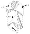
도 5는 부등각투영(axonometric) 뷰로부터 예에 개시된 터빈을 보여주는 개략도이다. 4 개의 면들은 이해를 돕기 위해 멀리 떨어져 나타나 있다. 면들A및 B는 동일하고 직면된다. 같은 방식으로 면들 C및 D는 동일하고 직면된다. A-B면들 및 C-D면들의 차이는 후자의 도면에서 설명되는 것처럼 내부 채널들의 지향이다.
도 6은 부등각투영 뷰로부터 면들A-B 및 C-D의 분해를 보여주는 개략도이다. 각각의 면은 3 개의 층들 (a), (c) 및 (e) 및 2 세트들의 구분 기호들 (b) 및 (d)로 구성된다. 분리 기호들의 지향 차이를 구별될 수 있고, 이는 예에 개시된 터빈에서 공기의 유동의 지향을 결정하는 것이다. 이 차이는 그것자체가 터빈의 대향하는 위치들에 위치할 수 있게 허락하고, 각각의 면은 바람의 추진을 항상 같은 방향으로 회전 운동으로 변환한다.
도 7은 바람이 어떻게 분산되고 각각의 면에 영향을 미치는지 시각화하는 것을 허락하는 방식으로 그룹화된 도 6에서 식별된 구성 요소들을 보여주는 개략도이다.
조합 (a + b)은 특정한 회전 축 (f) 및 (g)를 교차하는 정점들에서 발견되는 입구들이 있는 채널들의 분포를 묘사하고, 따라서 회전 축 (k)에 축 바람들을 받는 것이 된다. 이 예에서 이러한 채널들 (b)은 수직 (i) 및 대각선 (j) 바람들을 수신하고, 내부 면 (a)의 절단을 통해 내부 출구들로 유출하면서 내부 대각선으로 그들을 안내할 수 있다.
조합 (c + d)은 회전 축 (k)와 교차하지 않는 정점들에 위치한 입구들이 있는 채널들의 분포를 묘사한다. 이 예에서 이러한 채널들 (d)은 수평 (h) 및 대각선 (j) 바람들을 수신하고, 외부 출구들로 유출하면서, 내부 수평하게 그들을 안내할 수 있다.
요소 (e)는 모든 채널들 (d)을 닫는 외부 층을 묘사한다. 그 모양은 채널들에 의해 주어지고 구의 세그먼트와 정확히 대응하지 않는다.
이 예에서, 모든 채널 세트들 (b) 및 (d)의 입구들은 동일한 크기의 원형 세그먼트로 주어진다. 따라서, 모든 채널들 (b) 및 (d)의 공기 출구들은 입구들의 절반에 대응하는 영역을 갖는다.The invention will be best understood with reference to the accompanying drawings.
1 is a schematic diagram showing a tetrahedron with faces identified by letters A, B, C and D. This figure can constitute a basic geometry for a wind turbine as disclosed in the example. In the figure a particular axis of rotation is also identified (k) and the vertices (f) and (g) intersecting it.
2 is a schematic diagram showing the omnidirectional turbine disclosed in the example. The triangular faces correspond to those identified in FIG. 1. The basic geometry of this turbine is a tetrahedron. The specific axis of rotation (k) is also indicated.
3 is a schematic diagram showing the turbine disclosed in the example from an axial view of the axis of rotation. 4 sides; A, B, C and D are identified.
4 is a schematic diagram showing the turbine disclosed in the example from a vertical view of the axis of rotation. 4 sides; A, B, C and D are identified.
5 is a schematic diagram showing the turbine disclosed in the example from an axonometric view. The four sides are shown far apart to aid understanding. Faces A and B are identical and faced. In the same way faces C and D are identical and faced. The difference between the AB planes and the CD planes is the orientation of the inner channels as explained in the latter figure.
6 is a schematic diagram showing an exploded view of planes AB and CD from an isometric view. Each side consists of three layers (a), (c) and (e) and two sets of delimiters (b) and (d). The difference in the direction of the separators can be distinguished, which determines the direction of the flow of air in the turbine disclosed in the example. This difference allows it itself to be located in opposite positions of the turbine, and each side converts the propulsion of the wind into rotational motion in the same direction all the time.
7 is a schematic diagram showing the components identified in FIG. 6 grouped in a manner that allows visualizing how the wind is distributed and affecting each side.
The combination (a + b) describes the distribution of channels with inlets found at vertices crossing a particular axis of rotation (f) and (g), thus receiving axial winds on the axis of rotation (k). In this example these channels (b) can receive vertical (i) and diagonal (j) winds and guide them in the inner diagonal as they flow out to the inner outlets through a cut in the inner face (a).
The combination (c + d) describes the distribution of channels with inlets located at vertices that do not intersect the axis of rotation (k). In this example these channels (d) can receive horizontal (h) and diagonal (j) winds and guide them inside horizontally, flowing out to the outside outlets.
Element (e) depicts the outer layer closing all channels (d). Its shape is given by the channels and does not exactly correspond to the segment of the sphere.
In this example, the inlets of all channel sets (b) and (d) are given as circular segments of the same size. Thus, the air outlets of all channels (b) and (d) have an area corresponding to half of the inlets.
이 기술의 응용은 바람을 기반으로 한 에너지 발전 장치가 될 수 있다.The application of this technology could be a wind-based energy generation device.
이 장치는 정사면체를 형성하는 4 개의 삼각형 면들 (A, B, C 및 D)와 같아지게 될 수 있다(conformed). 각각의 면은 내부 유출이 있는 6 개 채널들 (b)과 외부 유출이 있는 6 개 채널들 (d)로, 2 개의 채널들의 조합들 (a + b) 및 (c + d)에 의해 같아질 수 있다. 내부 유출이 있는 채널 (b)은 외부로 유출되는 채널 (d)과 다른 방향으로 지향될 수 있다.The device can be conformed to the four triangular faces (A, B, C and D) forming a tetrahedron. Each side is 6 channels (b) with internal outflow and 6 channels (d) with external outflow, which will be equalized by combinations of the two channels (a + b) and (c + d). I can. The channel (b) with internal outflow can be oriented in a different direction than the channel (d) outflowing to the outside.
장치 (k)의 특정한 회전 축은 정사면체 (f) 및 (g)의 대향 정점들의 중앙에 위치할 수 있다. 회전 축 (b)에서 교차하는 정점들에 위치한 입구들이 있는 채널들은 축 방향 (i) 또는 대각선의 측 (j)에 대해 장치에 영향을 미치는 바람들을 기반으로 회전 운동을 생성하도록 대각선 방향으로 지향될 수 있다. 축 (d)과 교차하지 않는 정점들에 위치한 입구들이 있는 채널들은 축에 수직으로 지향될 수 있고, 장치에 수직으로(h) 또는 축에 대각선으로 (j) 영향을 주는 바람들을 기반으로 한 회전 운동을 생성할 수 있다.A particular axis of rotation of the device k can be located in the center of the opposite vertices of the tetrahedrons f and g. Channels with inlets located at the vertices intersecting at the axis of rotation (b) will be directed diagonally to create a rotational motion based on the winds affecting the device about the axial direction (i) or the diagonal side (j). I can. Channels with inlets located at vertices that do not intersect the axis (d) can be oriented perpendicular to the axis and rotate based on winds affecting the device vertically (h) or diagonally to the axis (j). You can create an exercise.
채널 (b) 및 (d)는 직선 또는 곡선 벽들로 분리될 수 있고, 상단 및 하단 면들 (a), (c) 및 (e)는 직선 또는 곡선 일 수 있다. 채널들의 길이는 다양할 수 있다. 각각의 면의 공기의 입구들과 출구들은 원형 세그먼트와 같아지게 될 수 있다. 입구와 출구의 관계는 2:1 비율로 주어질 수 있다.The channels (b) and (d) can be separated by straight or curved walls, and the top and bottom faces (a), (c) and (e) can be straight or curved. The length of the channels can vary. The air inlets and outlets on each side can be made like a circular segment. The relationship between inlet and outlet can be given in a 2:1 ratio.
장치는 축이 수직, 수평 또는 대각선 위치에 있는 빌딩의 정면에 설치될 수 있고, 이러한 위치들 중 어느 위치들에서 이 유형의 위치들에 존재하는 수직, 수평 및 대각선 바람들에 기초하여 에너지를 생성할 수 있다.The device can be installed in the front of a building whose axis is in a vertical, horizontal or diagonal position and generates energy based on vertical, horizontal and diagonal winds present in this type of position at any of these positions. can do.
Claims (1)
Translated fromKorean특정한 축 상의 회전 운동으로 유체의 추진(push)을
변환할 수 있는 전방향 발전 장치에 있어서,
복수 개의 채널들;
각각의 채널의 입구는 각각의 채널의 출구보다 크고, 일단 유체에 의해 이동되면, 상기 입구 및 상기 출구 사이의 크기 차이는
상기 입구로부터 상기 출구로의 추진을 생성하는 압력 차이를 야기함,
기하학적 본체를 형성하는 복수 개의 면들;
각각의 면은 상기 복수 개의 채널들의 하위 그룹을 그룹화하고, 각각의 면은 그것의 채널들이 결정된 회전 방향으로 상기 장치를 추진시키도록 배향됨,
전기 발전 시스템; 및
고정된 축;을 포함하고,
상기 장치는 상기 본체의 회전을 발전기로 전송하는 상기 고정된 축에 의하여 상기 전기 발전 시스템에 연결되는 전방향 발전 장치.From any direction in vertical, horizontal or diagonal planes
The fluid's push is controlled by rotational motion on a specific axis.
In the convertible omnidirectional power generation device,
A plurality of channels;
The inlet of each channel is greater than the outlet of each channel, and once moved by the fluid, the size difference between the inlet and the outlet is
Causing a pressure difference that creates propulsion from the inlet to the outlet,
A plurality of faces forming a geometric body;
Each side groups a subgroup of the plurality of channels, each side oriented so that its channels propel the device in a determined direction of rotation,
Electric power generation system; And
Including a fixed shaft;
The device is an omnidirectional power generation device connected to the electric power generation system by the fixed shaft that transmits the rotation of the body to the generator.
Applications Claiming Priority (3)
| Application Number | Priority Date | Filing Date | Title |
|---|---|---|---|
| CL2529-2018 | 2018-09-04 | ||
| CL2018002529ACL2018002529A1 (en) | 2018-09-04 | 2018-09-04 | Omnidirectional generator set |
| PCT/CL2019/050071WO2020047685A1 (en) | 2018-09-04 | 2019-08-12 | Omnidirectional generating device |
Publications (2)
| Publication Number | Publication Date |
|---|---|
| KR20210053944Atrue KR20210053944A (en) | 2021-05-12 |
| KR102825415B1 KR102825415B1 (en) | 2025-06-30 |
Family
ID=65529105
Family Applications (1)
| Application Number | Title | Priority Date | Filing Date |
|---|---|---|---|
| KR1020217009572AActiveKR102825415B1 (en) | 2018-09-04 | 2019-08-12 | Omnidirectional generator |
Country Status (12)
| Country | Link |
|---|---|
| US (1) | US11661917B2 (en) |
| EP (1) | EP3842631A4 (en) |
| JP (1) | JP7488584B2 (en) |
| KR (1) | KR102825415B1 (en) |
| CN (1) | CN113227566B (en) |
| AU (1) | AU2019336282B2 (en) |
| CA (1) | CA3110412A1 (en) |
| CL (1) | CL2018002529A1 (en) |
| MX (1) | MX2021002577A (en) |
| SG (1) | SG11202102148VA (en) |
| WO (1) | WO2020047685A1 (en) |
| ZA (1) | ZA202101893B (en) |
Families Citing this family (1)
| Publication number | Priority date | Publication date | Assignee | Title |
|---|---|---|---|---|
| CN118273881B (en)* | 2024-06-04 | 2024-08-13 | 太原理工大学 | A spherical wind turbine with a wind gathering shell |
Citations (4)
| Publication number | Priority date | Publication date | Assignee | Title |
|---|---|---|---|---|
| US20040130161A1 (en)* | 2003-01-02 | 2004-07-08 | Gomez Gomar Josep Lluis | Introduced in wind power recovery devices |
| JP2012512103A (en)* | 2007-12-11 | 2012-05-31 | エイ. ゾーン,デイヴィッド | Buckyball sphere and apparatus thereof |
| CN202921349U (en)* | 2012-10-08 | 2013-05-08 | 铜陵市久泰重型工矿设备有限公司 | Novel vibration crushing machine |
| US20160084222A1 (en)* | 2012-08-20 | 2016-03-24 | Chuy-Nan Chio | Omni-directional wind power harnessing device |
Family Cites Families (60)
| Publication number | Priority date | Publication date | Assignee | Title |
|---|---|---|---|---|
| US1379439A (en)* | 1919-09-22 | 1921-05-24 | Bastian Bros Company | Wind-wheel |
| US1830985A (en)* | 1930-11-25 | 1931-11-10 | Edward E Grabow | Power water wheel |
| US3941504A (en)* | 1974-08-28 | 1976-03-02 | Snarbach Henry C | Wind powered rotating device |
| US4012163A (en)* | 1975-09-08 | 1977-03-15 | Franklin W. Baumgartner | Wind driven power generator |
| US4115032A (en)* | 1977-03-07 | 1978-09-19 | Heinz Lange | Windmill rotor |
| US4295783A (en)* | 1978-02-09 | 1981-10-20 | Lebost Barry Alan | Fluid turbine |
| US4209281A (en)* | 1978-07-20 | 1980-06-24 | Edmunds William A | Wind driven prime mover |
| US4234289A (en)* | 1978-09-05 | 1980-11-18 | Lebost Barry Alan | Fluid turbine |
| US4365929A (en)* | 1981-01-16 | 1982-12-28 | Philip Retz | Vertical wind turbine power generating tower |
| CA1266005A (en)* | 1984-02-07 | 1990-02-20 | Louis Obidniak | Wind turbine "runner" impulse type |
| US4508973A (en) | 1984-05-25 | 1985-04-02 | Payne James M | Wind turbine electric generator |
| DE8708163U1 (en)* | 1987-06-10 | 1987-08-27 | Wilhelm, Alfred, 5000 Köln | Device for generating power through wind |
| US5133637A (en)* | 1991-03-22 | 1992-07-28 | Wadsworth William H | Vertical axis wind turbine generator |
| US5405246A (en)* | 1992-03-19 | 1995-04-11 | Goldberg; Steven B. | Vertical-axis wind turbine with a twisted blade configuration |
| US5246342A (en)* | 1992-07-09 | 1993-09-21 | Bergstein Frank D | Wind rotor apparatus |
| US5656865A (en)* | 1995-09-20 | 1997-08-12 | Evans; Franklin T. | Wind conversion unit having cup shaped flow through blades and a centrifugal speed regulator |
| FI972806A7 (en)* | 1997-06-30 | 1998-12-31 | Shield Oy | Spiral wind rotor and method for manufacturing same |
| RU2156884C1 (en)* | 1999-04-05 | 2000-09-27 | Романов Герард Александрович | Wind-driven power plant of tower type |
| US6465899B2 (en)* | 2001-02-12 | 2002-10-15 | Gary D. Roberts | Omni-directional vertical-axis wind turbine |
| KR20140021688A (en)* | 2004-12-23 | 2014-02-20 | 카트루 에코-에너지 그룹 피티이. 엘티디. | Omni-directional wind turbine |
| AU2005318921B2 (en)* | 2004-12-23 | 2008-07-17 | Katru Eco-Inventions Pty Ltd | Omni-directional wind turbine |
| US7494315B2 (en)* | 2006-05-05 | 2009-02-24 | Hart James R | Helical taper induced vortical flow turbine |
| CN2921349Y (en) | 2006-07-03 | 2007-07-11 | 付德红 | One-way rotating impeller group that can use undirectional wind force, sea wave and tidal force |
| US7896609B2 (en)* | 2006-08-09 | 2011-03-01 | Sri Vawt, Inc. | Vertical axis wind turbine system |
| US20090028706A1 (en)* | 2007-07-26 | 2009-01-29 | Stefan Ioana | Vertical Axle Helix Monoblock Wind Turbine |
| CA2695807C (en)* | 2007-08-08 | 2015-02-24 | Art Turbine Inc. | Transverse-axis turbine with twisted foils |
| US7997870B2 (en)* | 2007-08-14 | 2011-08-16 | B N Balance Energy Solutions, Llc | Turbine rotor for electrical power generation |
| CN101545453A (en) | 2008-03-26 | 2009-09-30 | 沈渭清 | Ball joint type wind-light three-dimensional polymerization power generation system |
| JP4740382B2 (en) | 2009-04-06 | 2011-08-03 | 勇 松田 | Windmill |
| US9328717B1 (en)* | 2009-04-27 | 2016-05-03 | James A. Walker | Golden ratio axial flow apparatus |
| WO2010139188A1 (en)* | 2009-06-01 | 2010-12-09 | Lei Yuening | Square active-body compressed wind generating apparatus |
| PT104629A (en) | 2009-06-15 | 2010-12-15 | Antonio Pedro De Campos Ruao Da Cunha | OMNIDIRECTIONAL COMBINED FLOW WINDING DEVICE FOR ELECTRICAL ENERGY |
| US8317480B2 (en)* | 2009-07-30 | 2012-11-27 | Scarpelli Tadd M | Turbine assembly and energy transfer method |
| US20110027084A1 (en)* | 2009-07-31 | 2011-02-03 | Andrew Rekret | Novel turbine and blades |
| US8128337B2 (en)* | 2009-08-05 | 2012-03-06 | Constantine D Pezaris | Omnidirectional vertical-axis wind turbine |
| WO2011037870A2 (en)* | 2009-09-22 | 2011-03-31 | Roberto Vallejo | Vertical-axis wind turbine |
| CN201582055U (en)* | 2009-11-16 | 2010-09-15 | 何伯山 | Small splayed wind interception type wind-driven generating device |
| ES1072304Y (en) | 2010-04-14 | 2010-09-16 | Mediavilla Jose Miguel Tirado | OMNIDIRECTIONAL WIND COLLECTOR FOR VERTICAL AXIS TURBINE |
| CN101949356B (en)* | 2010-05-13 | 2012-04-11 | 宋永财 | Wind guide type vertical axis wind driven generator |
| US8461715B2 (en)* | 2010-10-10 | 2013-06-11 | Hong Kong Applied Science and Technology Research Institute Company Limited | Apparatus for wind collection |
| US20120098262A1 (en) | 2010-10-21 | 2012-04-26 | Da Cunha Antonio Pedro Campos Ruao | Energy production device from an omnidirectional Bi-axial flow |
| CN102562467B (en)* | 2010-12-29 | 2014-08-06 | 孙立蓉 | Wind gathering and accelerating wind power generation device |
| US20120175882A1 (en) | 2011-01-10 | 2012-07-12 | Peter John Sterling | Injector venturi accelerated, wind turbine |
| JP2012241709A (en)* | 2011-05-24 | 2012-12-10 | Kuma Juki Service:Kk | Crossflow type vertical shaft wind turbine |
| ES2418680B2 (en) | 2011-12-02 | 2015-09-11 | Universidad De La Rioja | AEROGENERATOR WITH VERTICAL ROTATION AXLE |
| US8926261B2 (en)* | 2012-04-18 | 2015-01-06 | 4Sphere Llc | Turbine assembly |
| BE1020627A4 (en)* | 2012-04-24 | 2014-02-04 | Citius Engineering S A | VERTICAL AXIS WIND MACHINE WITH SPHERICAL ROTOR. |
| TWI540253B (en)* | 2012-05-07 | 2016-07-01 | chui-nan Qiu | Wind power source for wind energy conversion in all directions |
| CN102678444B (en)* | 2012-05-23 | 2016-08-24 | 邱垂南 | Omnirange wind-force source is to improve the wind-force kinetic energy generating apparatus of wind energy conversion |
| KR20130132327A (en) | 2012-05-25 | 2013-12-04 | 군산대학교산학협력단 | Multi directional wind guide and building wind power generation having the same |
| US8786126B2 (en)* | 2012-07-16 | 2014-07-22 | Thomas Meyer | Wind turbine having two hemispherical blades |
| US20140050586A1 (en)* | 2012-08-20 | 2014-02-20 | Chuy-Nan Chio | Omni-Directional Wind Power Harnessing Device |
| WO2014141214A1 (en)* | 2013-03-15 | 2014-09-18 | Douglas Brendle | Wind turbine and tower system |
| DE102013004893A1 (en)* | 2013-03-21 | 2014-09-25 | Ralf Trunsperger | Omnidirectional wind rotor. Spherical wind rotor with vertical axis, efficiency in all directions, functioning as a lift rotor taking advantage of the flow behavior in the Magnus effect |
| ITPI20130067A1 (en)* | 2013-07-12 | 2015-01-13 | Treecube S R L | WIND TURBINE WITH VERTICAL AXIS |
| TW201514375A (en)* | 2013-10-14 | 2015-04-16 | Ken-Yi Lin | Vertical flow guiding wind energy tower |
| ES2477115B2 (en) | 2014-05-30 | 2014-10-27 | Universidad De La Rioja | Vertical axis wind generator |
| JP2017516953A (en)* | 2014-06-03 | 2017-06-22 | セントラレス エネルヘティカス シクロニカス, エセ. エレ | Cyclone wind energy converter |
| ES2620927B2 (en) | 2015-12-29 | 2018-02-19 | Mikonos Xviii Sl | Vertical rotation shaft wind turbine with compound blade wind turbine |
| US20190257285A1 (en)* | 2018-02-19 | 2019-08-22 | Windside America Ltd. | Arched rib for a turbine |
- 2018
- 2018-09-04CLCL2018002529Apatent/CL2018002529A1/enunknown
- 2019
- 2019-08-12USUS17/273,077patent/US11661917B2/enactiveActive
- 2019-08-12MXMX2021002577Apatent/MX2021002577A/enunknown
- 2019-08-12CACA3110412Apatent/CA3110412A1/enactivePending
- 2019-08-12KRKR1020217009572Apatent/KR102825415B1/enactiveActive
- 2019-08-12SGSG11202102148VApatent/SG11202102148VA/enunknown
- 2019-08-12WOPCT/CL2019/050071patent/WO2020047685A1/ennot_activeCeased
- 2019-08-12EPEP19856840.4Apatent/EP3842631A4/enactivePending
- 2019-08-12JPJP2021536121Apatent/JP7488584B2/enactiveActive
- 2019-08-12CNCN201980057841.7Apatent/CN113227566B/enactiveActive
- 2019-08-12AUAU2019336282Apatent/AU2019336282B2/enactiveActive
- 2021
- 2021-03-19ZAZA2021/01893Apatent/ZA202101893B/enunknown
Patent Citations (4)
| Publication number | Priority date | Publication date | Assignee | Title |
|---|---|---|---|---|
| US20040130161A1 (en)* | 2003-01-02 | 2004-07-08 | Gomez Gomar Josep Lluis | Introduced in wind power recovery devices |
| JP2012512103A (en)* | 2007-12-11 | 2012-05-31 | エイ. ゾーン,デイヴィッド | Buckyball sphere and apparatus thereof |
| US20160084222A1 (en)* | 2012-08-20 | 2016-03-24 | Chuy-Nan Chio | Omni-directional wind power harnessing device |
| CN202921349U (en)* | 2012-10-08 | 2013-05-08 | 铜陵市久泰重型工矿设备有限公司 | Novel vibration crushing machine |
Also Published As
| Publication number | Publication date |
|---|---|
| CN113227566A (en) | 2021-08-06 |
| JP2021535324A (en) | 2021-12-16 |
| US11661917B2 (en) | 2023-05-30 |
| CN113227566B (en) | 2024-05-14 |
| CL2018002529A1 (en) | 2019-01-18 |
| MX2021002577A (en) | 2021-06-08 |
| BR112021003630A2 (en) | 2021-05-18 |
| JP7488584B2 (en) | 2024-05-22 |
| SG11202102148VA (en) | 2021-04-29 |
| EP3842631A1 (en) | 2021-06-30 |
| AU2019336282B2 (en) | 2025-06-12 |
| KR102825415B1 (en) | 2025-06-30 |
| EP3842631A4 (en) | 2022-05-11 |
| CA3110412A1 (en) | 2020-03-12 |
| AU2019336282A1 (en) | 2021-05-13 |
| US20210340950A1 (en) | 2021-11-04 |
| WO2020047685A1 (en) | 2020-03-12 |
| ZA202101893B (en) | 2023-10-25 |
Similar Documents
| Publication | Publication Date | Title |
|---|---|---|
| RU2268396C2 (en) | Method and device for generating electric power by converting energy of compressed air flow | |
| CA2823971C (en) | Rotor apparatus | |
| US4057270A (en) | Fluid turbine | |
| KR20160007521A (en) | Accelerated fluid machine | |
| KR20150027249A (en) | Vertical axis wind and hydraulic turbine with flow control | |
| US6911744B2 (en) | System and method for converting wind into mechanical energy | |
| GB2487403A (en) | Conical helical rotor | |
| US10221828B2 (en) | Hydroelectric power generation device for pipeline | |
| KR20210053944A (en) | Omnidirectional power generation device | |
| KR20140102459A (en) | The case of vertical-axis wind-blades part for the use of Vertical-Axis Wind Turbine(VAWT) | |
| RU2804170C2 (en) | Omnidirectional generator device | |
| GB2508814A (en) | Concentric turbine arrangement | |
| KR20110079794A (en) | Wind power generator using wind pipe to change horizontal wind into vertical airflow | |
| BR112021003630B1 (en) | OMNIDIRECTIONAL GENERATOR DEVICE | |
| RU2626498C1 (en) | Wind power station | |
| RU99080U1 (en) | FLOW ACCELERATOR | |
| WO2012113412A1 (en) | Method for producing electric power and aerodynamic power station for carrying out said method | |
| KR101183378B1 (en) | Multy Screw Type Hydraulic Turbine | |
| US20130195617A1 (en) | Wind Turbine Power Enhancements | |
| TW202305239A (en) | Omnidirectional wind turbine and omnidirectional wind power ventilation device having a wind power body that can keep rotating no matter what direction the wind blows from | |
| GB2549283A (en) | Ocean wave kinetic energy conversion method and system | |
| KR20130017770A (en) | The case of wind blades considering the difference of internal wind speeds-induced internal pressure drop and the complex vertical-axis wind blades which are built into this case | |
| RU2500921C2 (en) | Accelerator of flow of fluid media in aero- and hydrodynamics | |
| WO2015139106A1 (en) | Installation for converting energy of moving fluid medium to useful energy | |
| CA1117868A (en) | Fluid turbine |
Legal Events
| Date | Code | Title | Description |
|---|---|---|---|
| PA0105 | International application | Patent event date:20210331 Patent event code:PA01051R01D Comment text:International Patent Application | |
| PG1501 | Laying open of application | ||
| PA0201 | Request for examination | Patent event code:PA02012R01D Patent event date:20220810 Comment text:Request for Examination of Application | |
| E902 | Notification of reason for refusal | ||
| PE0902 | Notice of grounds for rejection | Comment text:Notification of reason for refusal Patent event date:20240321 Patent event code:PE09021S01D | |
| E701 | Decision to grant or registration of patent right | ||
| PE0701 | Decision of registration | Patent event code:PE07011S01D Comment text:Decision to Grant Registration Patent event date:20250328 | |
| GRNT | Written decision to grant | ||
| PR0701 | Registration of establishment | Comment text:Registration of Establishment Patent event date:20250623 Patent event code:PR07011E01D | |
| PR1002 | Payment of registration fee | Payment date:20250624 End annual number:3 Start annual number:1 | |
| PG1601 | Publication of registration |