KR20210052505A - High and low volume precision pipette devices - Google Patents
High and low volume precision pipette devicesDownload PDFInfo
- Publication number
- KR20210052505A KR20210052505AKR1020217009266AKR20217009266AKR20210052505AKR 20210052505 AKR20210052505 AKR 20210052505AKR 1020217009266 AKR1020217009266 AKR 1020217009266AKR 20217009266 AKR20217009266 AKR 20217009266AKR 20210052505 AKR20210052505 AKR 20210052505A
- Authority
- KR
- South Korea
- Prior art keywords
- barrel
- piston
- pipette tip
- free end
- bore
- Prior art date
- Legal status (The legal status is an assumption and is not a legal conclusion. Google has not performed a legal analysis and makes no representation as to the accuracy of the status listed.)
- Granted
Links
Images


Classifications
- B—PERFORMING OPERATIONS; TRANSPORTING
- B01—PHYSICAL OR CHEMICAL PROCESSES OR APPARATUS IN GENERAL
- B01L—CHEMICAL OR PHYSICAL LABORATORY APPARATUS FOR GENERAL USE
- B01L3/00—Containers or dishes for laboratory use, e.g. laboratory glassware; Droppers
- B01L3/02—Burettes; Pipettes
- B01L3/021—Pipettes, i.e. with only one conduit for withdrawing and redistributing liquids
- B01L3/0217—Pipettes, i.e. with only one conduit for withdrawing and redistributing liquids of the plunger pump type
- B01L3/0224—Pipettes, i.e. with only one conduit for withdrawing and redistributing liquids of the plunger pump type having mechanical means to set stroke length, e.g. movable stops
- B—PERFORMING OPERATIONS; TRANSPORTING
- B01—PHYSICAL OR CHEMICAL PROCESSES OR APPARATUS IN GENERAL
- B01L—CHEMICAL OR PHYSICAL LABORATORY APPARATUS FOR GENERAL USE
- B01L2200/00—Solutions for specific problems relating to chemical or physical laboratory apparatus
- B01L2200/02—Adapting objects or devices to another
- B01L2200/023—Adapting objects or devices to another adapted for different sizes of tubes, tips or container
- B—PERFORMING OPERATIONS; TRANSPORTING
- B01—PHYSICAL OR CHEMICAL PROCESSES OR APPARATUS IN GENERAL
- B01L—CHEMICAL OR PHYSICAL LABORATORY APPARATUS FOR GENERAL USE
- B01L2200/00—Solutions for specific problems relating to chemical or physical laboratory apparatus
- B01L2200/02—Adapting objects or devices to another
- B01L2200/025—Align devices or objects to ensure defined positions relative to each other
- B—PERFORMING OPERATIONS; TRANSPORTING
- B01—PHYSICAL OR CHEMICAL PROCESSES OR APPARATUS IN GENERAL
- B01L—CHEMICAL OR PHYSICAL LABORATORY APPARATUS FOR GENERAL USE
- B01L2200/00—Solutions for specific problems relating to chemical or physical laboratory apparatus
- B01L2200/06—Fluid handling related problems
- B01L2200/0689—Sealing
- B—PERFORMING OPERATIONS; TRANSPORTING
- B01—PHYSICAL OR CHEMICAL PROCESSES OR APPARATUS IN GENERAL
- B01L—CHEMICAL OR PHYSICAL LABORATORY APPARATUS FOR GENERAL USE
- B01L2300/00—Additional constructional details
- B01L2300/06—Auxiliary integrated devices, integrated components
- B01L2300/0681—Filter
- B—PERFORMING OPERATIONS; TRANSPORTING
- B01—PHYSICAL OR CHEMICAL PROCESSES OR APPARATUS IN GENERAL
- B01L—CHEMICAL OR PHYSICAL LABORATORY APPARATUS FOR GENERAL USE
- B01L2300/00—Additional constructional details
- B01L2300/08—Geometry, shape and general structure
- B01L2300/0861—Configuration of multiple channels and/or chambers in a single devices
- B01L2300/087—Multiple sequential chambers
- B—PERFORMING OPERATIONS; TRANSPORTING
- B01—PHYSICAL OR CHEMICAL PROCESSES OR APPARATUS IN GENERAL
- B01L—CHEMICAL OR PHYSICAL LABORATORY APPARATUS FOR GENERAL USE
- B01L2400/00—Moving or stopping fluids
- B01L2400/04—Moving fluids with specific forces or mechanical means
- B01L2400/0475—Moving fluids with specific forces or mechanical means specific mechanical means and fluid pressure
- B01L2400/0478—Moving fluids with specific forces or mechanical means specific mechanical means and fluid pressure pistons
Landscapes
- Health & Medical Sciences (AREA)
- Clinical Laboratory Science (AREA)
- Chemical & Material Sciences (AREA)
- Chemical Kinetics & Catalysis (AREA)
- Sampling And Sample Adjustment (AREA)
- Devices For Use In Laboratory Experiments (AREA)
Abstract
Translated fromKoreanDescription
Translated fromKorean관련 출원에 대한 상호 참조Cross-reference to related applications
본 출원은 2018년 8월 31일에 출원된 미국 가출원 제62/726,063호의 이익을 주장하고, 이는 본원에 완전히 기재된 것처럼 참조로 포함된다.This application claims the benefit of U.S. Provisional Application No. 62/726,063, filed August 31, 2018, which is incorporated by reference as if fully set forth herein.
고 용적의 피펫팅 능력, 및 정밀도와 정확성을 이용하여 저 용적 능력을 갖는 통상적인 접근 방식은, 상호 교환적으로 사용되는 둘 이상의 별도의 피펫 장치를 갖는 것이다. 이는 피펫 시스템의 비용과 복잡성을 증가시키며, 사용자는 고 용적과 저 용적 피펫팅 중에서 선택해야 한다. 사용자는 피펫 장치를 교체하지 않고 다른 용적 범위를 피펫팅할 수 없다. 피펫 장치를 교체하는 것은 더 복잡하며, 더 많은 부품이 필요하고, 더 많은 시간이 소요된다.A common approach with high volume pipetting capabilities, and low volume capabilities using precision and accuracy, is to have two or more separate pipette devices that are used interchangeably. This increases the cost and complexity of the pipette system, and the user has to choose between high volume and low volume pipetting. The user cannot pipette different volume ranges without replacing the pipette device. Replacing the pipette device is more complex, requires more parts, and takes more time.
본 발명의 구현예는 개별적으로 또는 집합적으로 이들 및 다른 도전 과제를 해결한다.Embodiments of the invention individually or collectively solve these and other challenges.
본 발명의 구현예는, 고 용적 및 저 용적 모드에서 액체를 피펫팅하기 위한 장치 및 방법에 관한 것이다. 본 발명의 구현예에서, 단일 피펫 장치는 다량의 액체가 전달될 수 있게 하지만, 또한 둘 이상의 별도의 피펫 장치를 필요로 하지 않고서도 높은 정밀도와 정확성으로 저 용적의 액체를 전달할 수 있는 능력을 또한 제공한다.Embodiments of the present invention relate to apparatus and methods for pipetting liquids in high volume and low volume modes. In embodiments of the present invention, a single pipette device allows a large amount of liquid to be delivered, but also provides the ability to deliver a low volume of liquid with high precision and accuracy without the need for two or more separate pipette devices. to provide.
본 발명의 일 구현예는 액체를 전달하기 위한 장치에 관한 것으로, 상기 장치는 피스톤(104); 및 배럴 몸체(102A)와 배럴 몸체(102A) 내에 형성된 팁(122)을 포함한 배럴(102)을 포함하고, 배럴(102)은 소형 직경의 세그먼트(102B)로부터 연장되는 대형 직경의 세그먼트(102A)를 포함하되, 배럴(102)은 대형 직경의 세그먼트(102A)와 소형 직경의 세그먼트(102B)를 포함하고, 대형 직경의 세그먼트(102A) 위에 끼워맞춤되는 크기의 제1 피펫 팁(130)과 체결하도록 구성되고, 배럴(102)은 배럴(102)의 소형 직경의 세그먼트(102B) 위에 끼워맞춤되는 크기의 제2 피펫 팁(132)과 체결하도록 추가 구성된다. 일부 구현예에서, 피스톤(104)은 단차형 프로파일, 구동 로드부(104B), 및 구동 로드부(104B)로부터 연장된 자유 말단부(104C)를 포함할 수 있고, 자유 말단부(104C)는 구동 로드부(104B)와 상이한 직경을 갖되, 배럴(102)은 배럴 몸체(102A)에 의해 정의된 단차형 보어(108)를 포함하고, 단차형 보어(108)는 축 방향 구멍(108A) 및 동축의 카운터보어(108B)를 갖고, 축 방향 구멍(108A)은 팁(122)을 통과하되, 상기 장치는 배럴(102)과 자유 말단부(104C) 사이에 체결하는 제1 밀봉 요소(112)를 추가로 포함할 수 있고, 상기 장치는 배럴(102)과 구동 로드부(104B) 사이에 체결하는 제2 밀봉 요소(114)를 추가로 포함할 수 있다. 일부 구현예에서, 자유 말단부의 길이는 축 방향 구멍(108A)의 길이보다 더 클 수 있다. 일부 구현예에서, 단차형 보어(108)는 보어 부분(108C)을 추가로 포함할 수 있되, 보어 부분(108C)의 직경은, 카운터보어(108B)의 직경보다 작고 축 방향 구멍(108A)의 직경보다 크며, 제1 밀봉 요소(112)는 보어 부분(108C) 내에 고정된다. 일부 구현예에서, 소형 직경의 세그먼트(102B)는 팁(122)과 일치할 수 있고, 대형 직경의 세그먼트(102A)는 소형 직경의 세그먼트(102B)로부터 연장될 수 있고, 카운터보어(108B)는 대형 직경의 세그먼트(102A) 내에 배치될 수 있다. 일부 구현예에서, 상기 장치는, 배럴(102) 주위에 배치되고 배럴(102)에 대해 축 방향으로 이동하도록 구성된, 셔크 플레이트(142)를 추가로 포함할 수 있다. 일부 구현예에서, 제2 피펫 팁(132)은, 루멘(132B)을 형성하는 몸체(132A), 및 루멘(132B)에 걸쳐 있는 배리어(140)를 가질 수 있고, 제2 피펫 팁(132)은 배럴(102)과 체결하며, 제2 피펫 팁(132)이 배럴(102)에 체결되는 경우에, 자유 말단부(104C)의 말단은 배리어(140)와 접촉할 수 있다. 일부 구현예에서, 상기 장치는 셔크 플레이트(142)를 추가로 포함할 수 있되, 제2 피펫 팁(132)이 배럴(102)에 체결되는 경우에 셔크 플레이트(142)는 제2 피펫 팁(132)과 접촉한다. 일부 구현예에서, 피스톤(104)은, 구동 로드부(104B)로부터 연장된 체결부(104A)를 추가로 포함할 수 있다. 일부 구현예에서, 상기 장치는, 피스톤(104)을 상하로 이동시키기 위해 상기 피스톤에 결합된 액추에이터를 추가로 포함할 수 있다. 상기 장치는, 적어도 두 개의 그리퍼 핑거(702, 704)를 갖는 그리퍼를 추가로 포함할 수 있되, 상기 액추에이터는 적어도 두 개의 그리퍼 핑거(702, 704)를 이동시키기 위해 상기 그리퍼에 추가 결합된다. 일부 구현예에서, 제1 밀봉 요소(112)와 제2 밀봉 요소(114) 중 최대 하나가 배럴(102)과 피스톤(104) 사이에서 체결하도록, 피스톤(104)을 배럴(102) 내에 배치할 수 있다. 일부 구현예에서, 제2 피펫 팁(132)은, 제2 피펫 팁(132)을 배럴(102)로부터 분리하기 위해 피스톤(104)에 의해 밀릴 수 있는, 필터 배리어(140)를 포함할 수 있다.One embodiment of the invention relates to a device for delivering a liquid, the device comprising: a piston (104); And a
본 발명의 다른 구현예는 액체를 전달하기 위한 장치를 사용하는 방법에 관한 것으로, 상기 장치는 (a) 피스톤(104) 및 (b) 배럴 몸체(102A)와 배럴 몸체(102A) 내에 형성된 팁(122)을 포함한 배럴(102)을 포함하고, 배럴(102)은 대형 직경의 세그먼트(102A)와 소형 직경의 세그먼트(102B)를 포함하되, 배럴(102)은 대형 직경의 세그먼트(102A) 위에 끼워맞춤되는 크기의 제1 피펫 팁(130)과 체결되도록 구성되고, 배럴(102)은 배럴(102)의 소형 직경의 세그먼트(102B) 위에 끼워맞춤되는 크기의 제2 피펫 팁(132)과 체결되도록 추가 구성되고, 상기 방법은, 제1 고 용적 피펫팅 모드에서, 배럴(102)로부터 피스톤(104)을 후퇴시킴으로써 제1 액체를 흡인하는 단계, 및 제1 피펫 팁(130)을 사용하여 상기 제1 액체를 디스펜싱하는 단계; 제2 저 용적 피펫팅 모드에서, 배럴(102)로부터 피스톤(104)을 후퇴시킴으로써 제2 액체를 흡인하는 단계, 및 제2 피펫 팁(132)을 사용하여 상기 제2 액체를 디스펜싱하는 단계를 포함한다. 일부 구현예에서, 피스톤(104)은 단차형 프로파일, 구동 로드부(104B), 및 구동 로드부(104B)로부터 연장된 자유 말단부(104C)를 포함할 수 있고, 자유 말단부(104C)는 구동 로드부(104B)와 상이한 직경을 갖되, 배럴(102)은 배럴 몸체(102A)에 의해 정의된 단차형 보어(108)를 포함하고, 단차형 보어(108)는 축 방향 구멍(108A) 및 동축의 카운터보어(108B)를 갖고, 축 방향 구멍(108A)은 팁(122)을 통과하고, 제1 밀봉 요소(112)는 배럴(102)과 자유 말단부(104C) 사이에 체결하고 제2 밀봉 요소(114)는 배럴(102)과 구동 로드부(104B) 사이에 체결하고, 여기서 제1 고 용적 피펫팅 모드에서는, 자유 말단부(104C)가 위에 있고 축 방향 구멍(108A)으로부터 멀리 이동하도록, 배럴(102)로부터 피스톤(104)을 후퇴시킴으로써 상기 제1 액체를 흡인하고, 자유 말단부(104C)가 축 방향 구멍(108A)을 향해 이동하도록, 피스톤(104)을 배럴(102) 내에 삽입함으로써 상기 제1 액체를 디스펜싱하는 것에 의해 제1 액체를 디스펜싱하고; 여기서 제2 저 용적 피펫팅 모드에서는, 자유 말단부(104C)가 축 방향 구멍(108A)에 남도록, 배럴(102)로부터 피스톤(104)을 후퇴시킴으로써 상기 제2 액체를 흡인하고, 자유 말단부(104C)가 축 방향 구멍(108A)에 남도록, 피스톤(104)을 배럴(102) 내에 삽입함으로써 상기 제2 액체를 디스펜싱한다. 일부 구현예에서, 상기 장치는, 배럴(102) 주위에 배치되고 배럴에 대해 축 방향으로 이동하도록 구성된, 셔크 플레이트(142)를 추가로 포함할 수 있다. 일부 구현예에서, 상기 방법은, 셔크 플레이트(142)를 사용하여 배럴(102)로부터 제1 피펫 팁(130)을 제거하는 단계를 추가로 포함할 수 있다. 일부 구현예에서, 상기 방법은, 셔크 플레이트(142)를 사용하여 배럴(102)로부터 제2 피펫 팁(132)을 제거하는 단계를 추가로 포함할 수 있다. 일부 구현예에서, 자유 말단부(104B)의 길이는 축 방향 구멍(108A)의 길이보다 더 크다. 상기 방법의 일부 구현예에서, 단차형 보어(108)는 보어 부분(108C)을 추가로 포함할 수 있되, 보어 부분(108C)의 직경은 카운터보어(108B)의 직경보다 작고 축 방향 구멍(108A)의 직경보다 크며, 제1 밀봉 요소(112)는 보어 부분(108C) 내에 고정된다. 일부 구현예에서, 피스톤(104)은, 구동 로드부(104B)로부터 연장된 체결부(104A)를 추가로 포함한다. 일부 구현예에서, 상기 방법은, 고 및 저 용적 피펫팅 모드로 피스톤(104)을 후퇴하고 삽입하기 위해 액추에이터를 사용하는 단계를 추가로 포함할 수 있다.Another embodiment of the invention relates to a method of using a device for delivering a liquid, the device comprising (a) a
본 발명의 다른 구현예는 액체를 전달하기 위한 장치에 관한 것으로, 상기 장치는 피스톤(104); 및 배럴 몸체(102A)와 배럴 몸체(102A) 내에 형성된 팁(122)을 포함한 배럴(102)을 포함하되, 배럴(102)은, 배럴(102)로부터 피펫 팁(132)을 분리하기 위해, 피스톤에 의해 밀릴 수 있는 구조체를 포함한 피펫 팁(132)과 체결하도록 구성된다. 일부 구현예에서, 상기 장치는 피펫 장치일 수 있다. 일부 구현예에서, 상기 구조체는 필터 배리어(140)일 수 있다. 일부 구현예에서, 상기 장치, 피펫 팁(132)은 제2 피펫 팁이고, 배럴(102)은 제1 피펫 팁(130)과 체결하도록 추가 구성될 수 있고, 상기 제1 피펫 팁은 제2 피펫 팁(132)과 직경이 상이하다. 일부 구현예에서, 상기 장치는, 배럴(102)로부터 제1 피펫 팁(130)을 분리하도록 구성된, 셔크 플레이트(142)를 추가로 포함할 수 있다. 일부 구현예에서, 상기 장치는 피펫 팁을 포함할 수 있다.Another embodiment of the invention relates to a device for delivering a liquid, the device comprising: a piston (104); And a
본 발명의 또 다른 구현예는 장치를 사용하기 위한 방법에 관한 것으로, 상기 장치는 피스톤(104); 및 배럴 몸체(102A)와 배럴 몸체(102A) 내에 형성된 팁(122)을 포함한 배럴(102)을 포함하되, 배럴(102)은, 배럴(102)로부터 피펫 팁(132)을 분리하기 위해 피스톤에 의해 밀릴 수 있는 구조체를 포함한, 피펫 팁(132)과 체결하도록 구성되고, 상기 방법은, 피펫 팁(132)이 배럴(102)에 있는 동안에 배럴(102) 내로 액체를 흡인하는 단계; 피펫 팁(132)을 통해 상기 액체를 디스펜싱하는 단계; 및 피스톤(104)을 이용해 구조체를 밀어 배럴(102)로부터 피펫 팁(132)을 분리하는 단계를 포함한다. 일부 구현예에서, 상기 구조체는 필터 배리어일 수 있다. 일부 구현예에서, 피펫 팁(132)은 제2 피펫 팁이고, 배럴(102)은 제1 피펫 팁(130)과 체결하도록 구성될 수 있고, 상기 제1 피펫 팁은 제2 피펫 팁(132)과 직경이 상이하다. 일부 구현예에서, 상기 방법은, 제1 피펫 팁(130)을 배럴(102)에 부착하는 단계; 제1 피펫 팁(130)을 사용하여 제2 액체를 배럴(102) 내로 흡인하는 단계; 제1 피펫 팁(130)을 통해 배럴(102)로부터 상기 제2 액체를 디스펜싱하는 단계; 및 제1 피펫 팁(130)을 배럴(102)로부터 분리하는 단계를 포함한다.Another embodiment of the invention relates to a method for using an apparatus, the apparatus comprising: a
본 발명의 다른 구현예는 액체를 전달하기 위한 장치에 관한 것으로, 상기 장치는 피스톤(104)(상기 피스톤은 단차형 프로파일, 구동 로드부(104B), 및 구동 로드부(104B)로부터 연장된 자유 말단부(104C)를 포함하고, 자유 말단부(104C)는 구동 로드부(104B)와 상이한 직경을 가짐); 배럴(102)(상기 배럴은 배럴 몸체(102A), 배럴 몸체(102A)에 의해 정의된 단차형 보어(108), 및 배럴 몸체(102A)에 형성된 팁(122)을 포함하고, 단차형 보어(108)는 축 방향 구멍(108A) 및 동축의 카운터보어(108B)를 갖고, 축 방향 구멍(108A)은 팁(122)을 통과함); 배럴(102)과 자유 말단부(104C) 사이에서 체결하는 제1 밀봉 요소(112); 및 배럴(102)과 구동 로드부(104B) 사이에서 체결하는 제2 밀봉 요소(114)를 포함한다. 일부 구현예에서, 자유 말단부의 길이는 축 방향 구멍(108A)의 길이보다 더 클 수 있다. 일부 구현예에서, 단차형 보어(108)는 보어 부분(108C)을 추가로 포함할 수 있되, 보어 부분(108C)의 직경은 카운터보어(108B)의 직경보다 작고, 축 방향 구멍(108A)의 직경보다 크며, 제1 밀봉 요소(112)는 보어 부분(108C) 내에 고정된다. 일부 구현예에서, 배럴(102)은, 팁(122)과 일치하는 소형 직경의 세그먼트(102B)를 갖는 단차형 외부 프로파일, 및 소형 직경의 세그먼트(102B)로부터 연장된 대형 직경의 세그먼트(102A)를 추가로 포함할 수 있고, 카운터보어(108B)는 대형 직경의 세그먼트(102A) 내에 배치된다. 일부 구현예에서, 상기 장치는, 배럴(102) 주위에 배치되고 배럴에 대해 축 방향으로 이동하도록 구성된, 셔크 플레이트(142)를 추가로 포함할 수 있다. 일부 구현예에서, 배럴(102)은 제2 피펫 팁(132)과 체결하도록 구성될 수 있고, 제2 피펫 팁(132)은, 루멘(132B)을 형성하는 몸체(132A), 및 루멘(132B)에 걸쳐 있는 배리어(140)를 가질 수 있고, 제2 피펫 팁(132)은 배럴(102)과 체결하며, 상기 장치는 배럴(102)의 팁(122)을 지나 자유 말단부(104C)를 돌출시키도록 구성되며, 제2 피펫 팁(132)이 배럴(102)에 체결되는 경우에, 자유 말단부(104B)의 말단이 배리어(140)와 접촉한다. 일부 구현예에서, 배럴은, 배럴(102)의 소형 직경의 세그먼트(102B)에 걸쳐 끼워맞춤되는 크기의 제2 피펫 팁(132)과 체결하도록 추가로 구성될 수 있다. 일부 구현예에서, 상기 장치는 셔크 플레이트(122)를 추가로 포함할 수 있되, 셔크 플레이트(122)는 제2 피펫 팁(132)과 접촉한다. 일부 구현예에서, 피스톤(104)은, 구동 로드부(104B)로부터 연장된 체결부(104A)를 추가로 포함할 수 있다. 일부 구현예에서, 상기 장치는, 피스톤(104)을 상하로 이동시킬 수 있는 상기 피스톤에 결합된 액추에이터를 추가로 포함할 수 있다. 일부 구현예에서, 제1 밀봉 요소(112)와 제2 밀봉 요소(114) 중 최대 하나가 배럴(102)과 피스톤(104) 사이에서 체결하도록, 피스톤(104)을 배럴(102) 내에 배치할 수 있다.Another embodiment of the present invention relates to a device for delivering a liquid, wherein the device comprises a piston 104 (the piston has a stepped profile, a
본 발명의 다른 구현예는, 액체를 전달하기 위한 장치를 사용하는 방법에 관한 것이다. 상기 장치는 (a) 피스톤(104)(상기 피스톤은 단차형 프로파일, 구동 로드부(104B), 및 구동 로드부(104B)로부터 연장된 자유 말단부(104C)를 포함하고, 자유 말단부(104C)는 구동 로드부(104B)와 상이한 직경을 가짐); (b) 배럴(102)(상기 배럴은 배럴 몸체(102A), 배럴 몸체(102A)에 의해 정의된 단차형 보어(108), 및 배럴 몸체(102A)에 형성된 팁(122)을 포함하고, 단차형 보어(108)는 축 방향 구멍(108A) 및 동축의 카운터보어(108B)를 갖고, 축 방향 구멍(108A)은 팁(122)을 통과함); (c) 배럴(102)과 자유 말단부(104C) 사이에서 체결하는 제1 밀봉 요소(112); 및 (d) 배럴(102)과 구동 로드부(104B) 사이에서 체결하는 제2 밀봉 요소(114)를 포함한다. 상기 방법은, 제1 고 용적 피펫팅 모드에서는, 자유 말단부(104C)가 위에 있고 축 방향 구멍(108A)으로부터 멀리 이동하도록, 배럴(102)로부터 피스톤(104)을 후퇴시킴으로써 상기 제1 액체를 흡인하는 단계, 및 자유 말단부(104C)가 축 방향 구멍(108A)을 향해 이동하도록, 피스톤(104)을 배럴(102) 내에 삽입함으로써 상기 제1 액체를 디스펜싱하는 단계; 제2 저 용적 피펫팅 모드에서는, 자유 말단부(104C)가 축 방향 구멍(108A)에 남도록, 배럴(102)로부터 피스톤(104)을 후퇴시킴으로써 상기 제2 액체를 흡인하는 단계, 및 자유 말단부(104C)가 축 방향 구멍(108A)에 남도록, 피스톤을 배럴(102) 내에 삽입함으로써 상기 제2 액체를 디스펜싱하는 단계를 포함한다. 일부 구현예에서, 상기 방법은, 배럴(102)의 팁(122)에 고 용적 피펫 팁을 부착하는 단계; 및 제2 저 용적 피펫팅 모드에서, 저 용적 피펫 팁을 배럴(102)의 팁(122)에 부착하는 단계를 추가로 포함할 수 있다. 일부 구현예에서, 상기 장치는, 배럴(102) 주위에 배치되고 배럴에 대해 축 방향으로 이동하도록 구성된, 셔크 플레이트(142)를 추가로 포함할 수 있다. 일부 구현예에서, 상기 방법은, 셔크 플레이트를 사용하여 고 용적 피펫 팁을 제거하는 단계를 추가로 포함할 수 있다. 일부 구현예에서, 상기 방법은, 셔크 플레이트를 사용하여 저 용적 피펫 팁을 제거하는 단계를 추가로 포함할 수 있다. 일부 구현예에서, 자유 말단부의 길이는 축 방향 구멍(108A)의 길이보다 더 클 수 있다. 일부 구현예에서, 단차형 보어(108)는 보어 부분(108C)을 추가로 포함할 수 있되, 보어 부분(108C)의 직경은, 카운터보어(108B)의 직경보다 작고 축 방향 구멍(108A)의 직경보다 크며, 제1 밀봉 요소(112)는 보어 부분(108C) 내에 고정된다. 일부 구현예에서, 피스톤(104)은, 구동 로드부(104B)로부터 연장된 체결부(104A)를 추가로 포함할 수 있다. 일부 구현예에서, 상기 방법은, 고 및 저 용적 피펫팅 모드에서 피스톤(104)을 후퇴 및 삽입하기 위해 액추에이터를 사용하는 단계를 추가로 포함할 수 있다.Another embodiment of the invention relates to a method of using a device for delivering a liquid. The device comprises (a) a piston 104 (the piston comprises a stepped profile, a
본 발명의 이들 및 다른 구현예는 도면을 참조하여 이하에서 더욱 상세히 설명된다.These and other embodiments of the invention are described in more detail below with reference to the drawings.
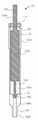
도 1은, 본 발명의 일 구현예에 따른 장치의 측단면도를 나타낸다. 장치는 저 용적, 저 변동 피펫팅을 수행하는 구성으로 나타나 있다.
도 2는 도 1의 장치의 측단면도를 나타낸다. 장치는, 상기 장치가 전이 구역(피펫팅 없음)에 있는 구성으로 나타나 있다.
도 3은 도 1에 나타낸 장치의 측단면도를 나타낸다. 장치는, 상기 장치가 고 용적 피펫팅을 수행할 수 있는 구성으로 나타나 있다.
도 4는 도 1에 나타낸 장치의 측단면도를 나타낸다. 장치는, 저 용적 피펫팅에 대해 불용 용적이 최소화되는 구성으로 나타나 있다.
도 5는, 셔크 플레이트를 갖는 상이한 장치의 측단면도를 나타낸다.
도 6은, 피스톤이 배럴의 팁으로부터 피펫 팁을 밀어내는 플런저로서 기능할 수 있는, 상이한 장치의 측단면도를 나타낸다.
도 7a는 그리퍼 매니폴드의 측면도이다.
도 7b는 그리퍼 매니폴드의 일부분의 분해도이다.
도면에서, 유사한 숫자는 유사한 요소를 나타내며, 일부 요소의 일부 설명은 반복되지 않을 수 있다.1 shows a cross-sectional side view of an apparatus according to an embodiment of the present invention. The device is shown in a configuration that performs low volume, low fluctuation pipetting.
FIG. 2 shows a cross-sectional side view of the device of FIG. 1; The device is shown in a configuration in which the device is in a transition zone (no pipetting).
3 shows a cross-sectional side view of the device shown in FIG. 1. The device is shown in a configuration in which the device is capable of performing high volume pipetting.
4 shows a cross-sectional side view of the device shown in FIG. 1. The device is shown in a configuration in which the insoluble volume is minimized for low volume pipetting.
5 shows a cross-sectional side view of a different device with a shuck plate.
6 shows a cross-sectional side view of a different device in which the piston can function as a plunger pushing the pipette tip from the tip of the barrel.
7A is a side view of the gripper manifold.
7B is an exploded view of a portion of the gripper manifold.
In the drawings, similar numbers indicate similar elements, and some descriptions of some elements may not be repeated.
본 발명의 구현예는, 고 용적 및 저 용적 모드에서 액체를 피펫팅하기 위한 장치 및 방법에 관한 것이다. 본 발명의 구현예에서, 단일 피펫 장치는, 두 개 이상의 별도의 피펫 장치를 필요로 하지 않으면서 고 정밀도 및 정확성으로 저 용적의 액체를 전달할 수 있는 능력을 여전히 제공하면서, 고 용적의 액체를 전달시킨다.Embodiments of the present invention relate to apparatus and methods for pipetting liquids in high volume and low volume modes. In embodiments of the present invention, a single pipette device delivers high volumes of liquid while still providing the ability to deliver low volumes of liquid with high precision and accuracy without the need for two or more separate pipette devices. Let it.
큰 용적의 액체 전달 모드는, 주요 샘플 흡인 및 DNA 추출용일 수 있다. 저 용적 액체 전달 모드는, 핵산 전달 및 PCR을 위한 준비에 사용될 수 있다.The large volume liquid delivery mode can be for primary sample aspiration and DNA extraction. The low volume liquid delivery mode can be used for nucleic acid delivery and preparation for PCR.
도 1은 본 발명의 일 구현예에 따른 장치(100)를 나타낸다. 장치(100)는, 상이한 용적으로 두 개 이상의 액체를 전달하기 위해 사용될 수 있다. 장치(100) 및 그 구성 요소는 임의의 적절한 치수를 포함할 수 있다. 예를 들어, 장치(100)의 길이는 일부 구현예에서 약 3 인치 이상일 수 있다.1 shows an
장치(100)는, 단차형 프로파일을 포함한 피스톤(104)을 포함할 수 있다. 피스톤(104)은 단일형 또는 모놀리식 부분일 수 있고, 체결부(104A), 구동 로드부(104B), 및 구동 로드부(104B)로부터 연장된 자유 말단부(104C)를 포함할 수 있다. 자유 말단부(104C)는 구동 로드부(104B)와 체결부(104A)보다 소형 직경을 갖는다. 체결부(104A)는 구동 로드부(104B)보다 소형 직경을 가질 수 있다. 체결부(104A)는, 약 0.5 인치 이상을 포함한 임의의 적절한 길이를 가질 수 있다.The
피스톤(104)은 임의의 적절한 재료를 포함할 수 있다. 예를 들어, 피스톤은 PTFE(폴리테트라플루오로에틸렌)와 같은 플라스틱을 포함할 수 있다.The
장치(100)는, 배럴 몸체(102A), 배럴 몸체(102A)에 의해 정의된 단차형 보어(108), 및 배럴 몸체(102A)에 형성된 팁(122)을 포함한 배럴(102)을 또한 포함할 수 있다. 단차형 보어(108)는, 축 방향 구멍(108A), 보어 부분(108C), 및 동축의 카운터보어(108B)를 포함한 다수의 개별 섹션을 가질 수 있다. 축 방향 구멍(108A)은 팁(122)을 통과한다. 나타낸 바와 같이, 배럴(102)은 소형 직경의 세그먼트(102B)를 갖는 단차형 외부 프로파일을 추가로 포함하고, 이는 팁(122)과 대형 직경의 세그먼트와 일치할 수 있고, 대형 직경의 세그먼트는 소형 직경의 세그먼트(102B)로부터 연장된 배럴 몸체(102A)의 대형 부분의 일부일 수 있다. 카운터보어(108B)는 대형 직경의 세그먼트 내에 배치된다.The
배럴(102)은 임의의 적절한 재료를 포함할 수 있다. 예를 들어, 배럴(102)은, PTFE(폴리테트라플루오로에틸렌)와 같은 플라스틱을 포함할 수 있다.
장치(100)는 다수의 밀봉 요소를 포함할 수 있다. 장치(100)는, 보어 부분(108C) 내에 있을 수 있고 배럴(102)과 피스톤(104)의 자유 말단부(104C) 사이에서 체결할 수 있는, 제1 밀봉 요소(112)를 포함한다. 보어 부분(108C)의 직경은, 카운터보어(108B)의 직경보다 작고, 축 방향 구멍(108A)의 직경보다 크다. 나타낸 바와 같이, 제1 밀봉 요소(112)는 보어 부분(108C) 내에 고정될 수 있다. 작은 용적의 액체를 피펫팅하기 위한 소형 챔버는, 축 방향 구멍(108A), 제1 밀봉 요소(112), 및 자유 말단부(104C)에 의해 형성될 수 있다. 제1 밀봉 요소(112)는, 약 0.05 인치 이상을 포함한 임의의 적절한 높이를 포함할 수 있다.
제2 밀봉 요소(114)는 장치(100)의 상단 근처일 수 있고, 피스톤(104)의 구동 로드부(104B)와 배럴(102) 사이에서 체결할 수 있다. 제2 밀봉 요소(114)는, 약 0.125 인치 이상을 포함한 임의의 적절한 높이를 포함할 수 있다.The
제1 및 제2 밀봉 요소(112, 114)는 임의의 적절한 재료를 포함할 수 있다. 예를 들어, 제1 및 제2 밀봉 요소(112, 114)는 고무를 포함할 수 있다.The first and
제1 밀봉 요소(112)와 제2 밀봉 요소(114) 중 최대 하나가 배럴(102)과 피스톤(104)을 체결하도록, 피스톤(104)을 배럴(102) 내에 배치한다.The
액추에이터(미도시)는 피스톤(104)의 체결부(104A)를 체결할 수 있다. 액추에이터는 피스톤(104)이 배럴(102) 내로 삽입되도록 이동하여, 장치(100)의 배럴(102) 내의 임의의 액체를 디스펜싱할 수 있다. 액추에이터는 또한 피스톤(104)이 장치(100)의 배럴(102)로부터 후퇴되도록 이동하여 장치(100)의 배럴(102) 내로 임의의 액체를 흡인할 수 있다.The actuator (not shown) may fasten the
장치(100)는, 고 용적 피펫팅 모드 및 저 용적 피펫팅 모드에서 임의의 적절한 용적의 액체를 피펫팅할 수 있다. 예를 들어, 고 용적 피펫팅 모드에서, 장치(100)는 약 0 내지 5000 μL의 액체를 피펫팅할 수 있다. 저 용적 피펫팅 모드에서, 장치(100)는 약 0 내지 60 μL의 액체를 피펫팅할 수 있다. 이들 양은 단지 예시적인 것이고, 저 용적 피펫팅 모드에서 피펫팅될 수 있는 액체의 양이, 고 용적 피펫팅 모드보다 적기만 하면, 장치(100)는 임의의 적절한 용적의 액체를 피펫팅할 수 있음을 유의한다.The
도 1의 장치(100)는 저 용적 피펫팅 모드로 나타나 있고, 여기서 축 방향 구멍(108A)만이 디스펜싱될 액체로 충진되어 있다. 제1 밀봉 요소(112)와 자유 말단부(104C)는, 임의의 액체가 저 용적 피펫팅 모드에서 동축의 카운터보어(108B)로 통과하는 것을 방지한다.The
도 2는 도 1의 장치(100)의 측단면도를 나타낸다. 장치(100)를 고 용적 피펫팅 모드로 전환하기 위해 장치가 전이 구역(피펫팅 없음)에 있는 구성으로 장치(100)를 나타낸다. 나타낸 바와 같이, 피스톤(104)의 자유 말단부(104C)의 말단은 제1 밀봉 요소(112) 위에 남아서, 제1 밀봉 요소가 자유 말단부(104C)와 체결하지 않는다. 구동 로드부(104B)는 또한 제2 밀봉 요소(114)와 체결하지 않는다. 그 결과, 피스톤(104)이 축 방향 구멍(108A)으로부터 멀리 이동하면, 액체가 동축의 카운터보어(108B) 내로 흡인될 수 있다. 피스톤(104)이 축 방향 구멍(108A)을 향해 이동해서 팁(122)으로부터 임의의 액체를 밀어내면, 액체가 동축의 카운터보어(108B)로부터 디스펜싱될 수 있다.2 shows a cross-sectional side view of the
도 3은 도 1에 나타낸 장치의 측단면도를 나타낸다. 장치는, 장치(100)가 고 용적 피펫팅을 수행할 수 있는 구성으로 나타나 있다. 도 3에 나타낸 바와 같이, 피스톤(104)은, 체결부(104A)에 결합될 수 있는 액추에이터(미도시)에 의해 위로 당겨진다. 이어서, 구동 로드부(104B)는 제2 밀봉 요소(114)와 밀봉부를 형성함으로써, 액체를 동축의 카운터보어(108B)와 축 방향 구멍(112)에 충진시킨다. 제1 밀봉 요소(112) 내의 밀봉 경로는 파손되는데, 그 이유는 자유 말단부(104C)가 제1 밀봉 요소(112) 내의 구멍을 채우지 않기 때문이다.3 shows a cross-sectional side view of the device shown in FIG. 1. The device is shown in a configuration in which
도 4는 도 1에 나타낸 장치의 측단면도를 나타낸다. 장치는, 저 용적 피펫팅에 대해 불용 용적이 최소화되는 구성으로 나타나 있다. 도 4에서, 구동 로드부(104B)는 동축의 카운터보어(108B)의 전체 하단부를 충진한다. 자유 말단부(104C)는 전체 축 방향 구멍(108A)을 충진한다.4 shows a cross-sectional side view of the device shown in FIG. 1. The device is shown in a configuration in which the insoluble volume is minimized for low volume pipetting. In Fig. 4, the
도 5는, 제1 피펫 팁(130)(예, 큰 용적의 피펫 팁)이 마찰 끼워맞춤을 통해 배럴 몸체(102A)의 팁(122)에 부착되는 경우에 장치(150) 일부분의 측단면도를 나타낸다. 피스톤(104)은 배럴(102) 내에 완전히 삽입되고, 피스톤(104)의 자유 말단부(104C)는 축 방향 구멍(108A)을 충진하지만, 자유 말단부(104C)의 말단을 지나 연장되지 않는다.5 is a side cross-sectional view of a portion of the
셔크 플레이트(142)는 제1 피펫 팁(130) 위에 놓인다. 셔크 플레이트(142)는, 팁(122)을 통과시킬 수 있지만 제1 피펫 팁(130)의 상부 말단부를 통과시킬 수 없는 치수를 갖는, 구멍을 갖는다.The
셔크 플레이트(142)는, 배럴 몸체(102A)의 팁(122)으로부터 제1 피펫 팁(130)을 제거하는 것을 보조할 수 있다. 일부 구현예에서, 셔크 플레이트(142)는 하향 이동하여 제1 피펫 팁(130)을 밀어서, 배럴 몸체(102A)의 팁(122)으로부터 이를 분리할 수 있다.The
도 5는, 제2 피펫 팁(132)(예, 저 용적의 피펫 팁)이 마찰 끼워맞춤을 통해 배럴 몸체(102A)의 팁(122)에 부착되는 경우에 장치(152)를 또한 나타낸다. 피스톤(104)은 배럴(102) 내에 완전히 삽입되고, 피스톤(104)의 자유 말단부(104C)는 축 방향 구멍(108A)을 충진하지만, 자유 말단부(104C)의 말단을 지나 연장되지 않는다. 제2 피펫 팁(132)은, 제1 피펫 팁(130)보다 상이한 크기 및 상이한 용적을 갖는다.5 also shows the
장치(150)와 유사하게, 셔크 플레이트(142)는 작은 용적의 피펫 팁(132) 위에 놓인다. 셔크 플레이트(142)는, 팁(122)을 통과시킬 수 있지만 작은 용적의 피펫 팁(132)의 상부 말단부를 통과시킬 수 없는 치수를 갖는, 구멍을 갖는다.Similar to
셔크 플레이트(142)는, 배럴 몸체(102A)의 팁(122)으로부터 작은 용적의 피펫 팁(132)을 제거하는 것을 보조할 수 있다. 일부 구현예에서, 셔크 플레이트(142)는 축방향으로 하향 이동하여 작은 용적의 피펫 팁(130)을 밀어서, 배럴 몸체(102A)의 팁(122)으로부터 이를 분리할 수 있다.The
도 6은 두 개의 장치(154, 156)를 나타낸다. 장치(154)는, 피스톤(104)의 자유 말단부(104B)의 말단이 팁(122)의 말단을 지나 연장되는 점을 제외하고, 도 3의 장치(150)와 실질적으로 유사하다.6 shows two
도 6은 또한 장치(156)를 나타낸다. 장치(156)는, 피스톤(104)의 자유 말단부(104B)의 말단이 팁(122)의 말단을 지나 연장되는 점을 제외하고, 도 3의 장치(152)와 유사하다. 자유 말단부(104B)의 길이는 축 방향 구멍(108A)의 길이보다 더 크다. 또한, 몸체(132A) 및 루멘(132B)을 포함하는 제2 피펫 팁(132)은 루멘(140) 내에 필터 배리어(140)를 갖는다.6 also shows
자유 말단부(104B)는 플런저로서 작용할 수 있다. 이는, 먼저 배럴(102) 팁(122)의 축 방향 구멍(108A) 내에 임의의 액체를 의도된 용기 내로 디스펜싱할 수 있다. 그 다음, 자유 말단부(104B)는 배리어(140) 바로 위에서 정지하고 팁 제거 스테이션(미도시)으로 이동할 수 있다. 그런 다음, 액추에이터(미도시)는 피스톤(104)을 더 아래로 밀어 자유 말단부(104B)의 말단이 필터 배리어(140)와 접촉하도록 할 수 있다. 필터 배리어(140)는 제2 피펫 팁(132)의 제2 부분(132B)에서 안정한 위치에 놓여서, 배럴(102)의 팁(122)으로부터 이를 분리하기 위해 전체 제2 피펫 팁(132)을 아래로 밀도록 할 것이다. 필터 배리어(140)는, 배럴(102)로부터 제2 피펫 팁(132)을 분리하기 위해 피스톤(104)에 의해 체결될 수 있는 구조체의 일례임을 주목한다. 피펫 팁(132)의 레지 등과 같은 다른 구조체는, 배럴(102)로부터 피펫 팁(132)을 분리하기 위해 피스톤(104)으로 체결될 수 있다.The
배럴(102)의 팁(122)은 제2 피펫 팁(132)과 체결하도록 구성되고, 제2 피펫 팁(132)은 루멘(132B)을 형성하는 몸체(132A), 및 루멘(132B)에 걸쳐 있는 배리어(140)를 갖고, 피펫 팁(130)은 배럴(102)과 체결한다. 장치(156)는, 배럴(102)의 팁(122)을 지나 자유 말단부(104B)를 돌출시키도록 구성될 수 있다. 제1 피펫 팁(132)이 배럴(102)에 체결되는 경우에, 자유 말단부(104B)의 말단은 배리어(140)와 접촉한다. 배럴(102)은, 배럴(102) 팁(122)의 소형 직경의 세그먼트에 걸쳐 끼워맞춤되는 크기의 제2 고 용적 피펫 팁(130)과 결합하도록 추가 구성된다.The
다수의 대안적인 구현예가 또한 가능하다. 일 구현예에서, 상기 전이 구역을 제거하고 작은 압력 축적을 허용하는 것이 가능한 반면, 상기 자유 말단부(즉, 소형 플런저)는 피펫팅을 위해 대형 플런저로 전이되거나 또는 그 반대이다. 다른 구현예에서, 두 개 이상의 피스톤 직경이 있을 수 있다. 피스톤은, 단일 피펫팅 장치에서 다수의 용적 피펫팅 모드를 생성하기 위해 원하는 만큼 여러 번 단차형이 될 것이다. 예를 들어, 도 1의 피스톤(104)은, 세 개의 상이한 용적의 액체가 단일 장치에서 피펫팅될 수 있도록, 두 개의 단차를 가질 수 있다. 또 다른 구현예에서, 고 용적의 밀봉부는 하단에 있을 수 있고, 저 용적의 밀봉부는 상단에 있을 수 있다. 또 다른 구현예에서, 두 개 이상의 맨드렐 기하학적 구조가 상이한 허브 크기에 사용될 수 있다. 또 다른 구현예에서, 밀봉부는 피스톤 상에 있을 수 있고 배럴 내부에 있는 대신에 피스톤과 함께 상하로 이동할 수 있다. 또 다른 구현예에서, 그리퍼 매니폴드(700)(도 7a)와 같은 액세서리는, 무엇보다 본원에 설명된 장치와 함께 사용될 마이크로역가 플레이트와 뚜껑을 파지하기 위해 사용될 수 있다. 그리퍼는, 도 7a의 폐쇄 위치에 나타낸 두 개의 그리퍼 핑거(702 및 704)를 포함한다. 그리퍼 핑거(702 및 704)는, 반경 방향 베어링(706 및 708)에 의해 형성된 회전 축을 중심으로 외측으로 회전한다. 그리퍼 핑거(702 및 704) 각각은, 반경 방향 베어링(706 및 708)에 의해 형성된 회전축을 중심으로 최대 약 180도까지 회전할 수 있다. 그리퍼는, 피스톤(104)을 이동시키는 데 사용되는 동일한 액추에이터에 의해 작동될 수 있어서, 피스톤(104) 및 그리퍼 핑거(702 및 704)의 이동을 담당하는 단일 액추에이터가 있다. 그리퍼 브래킷(710)은, 피스톤(104)을 이동시키기 위해 사용된 동일 액추에이터에 부착되는, 상부 플런저 플레이트(미도시)에 의해 위로 당겨진다. 그리퍼 브래킷(710)은 두 개의 기어 랙(712 및 714)에 부착되고, 그 중 단 하나만 도 7b에 나타나 있다. 기어 랙(712, 714)은 그리퍼 매니폴드(700) 내의 언더컷 특징부 내에 포함될 수 있고, 도 7b에 나타낸 바와 같이(718만 도시), 두 개의 피니언(716 및 718)을 회전시킬 수 있다. 그리퍼 핑거(702 및 704)(도 7b에서는 704만 도시)는 각각의 피니언(716, 718)에 부착된다. 제1 및 제2 반경 방향 베어링(720 및 722)은 피니언(716 및 718)의 각 원위 말단부(724 및 726)에 부착되어 기어 랙/피니언 구동부 상의 임의의 끌림을 감소시킬 수 있다. 그리퍼 핑거(702)와 연관된 제3 및 제4 반경 방향 베어링은 도 7b에 나타나 있지 않다. 그리퍼 매니폴드(700)는 비틀림 스프링(728 및 730)(도 7b에 730만 도시)을 추가로 포함할 수 있고, 이는, 피니언(716 및 718) 주위를 감싸서, 무엇보다도 사용하지 않는 경우에 핑거를 상향 위치에 보관시키고, 파지에 사용하기 위해 핑거가 작동되는 경우에 기어 랙/피니언 구동부의 히스테리시스를 제거할 수 있다. 그리퍼 핑거는, 각 핑거의 원위 말단부에 언더컷 특징부(732 및 734)를 가질 수 있다. 또한, 그리퍼 핑거(702, 704)는 마이크로역가 플레이트 및 뚜껑과 같은 것을 유지하기 위해, 대략 2 파운드 힘의 파지력을 가질 수 있다.A number of alternative implementations are also possible. In one embodiment, it is possible to remove the transition zone and allow small pressure build-up, while the free end (ie, small plunger) transitions to a large plunger for pipetting or vice versa. In other embodiments, there may be more than one piston diameter. The piston will be stepped as many times as desired to create multiple volumetric pipetting modes in a single pipetting device. For example, the
본 발명의 다른 구현예는 전술한 장치를 사용하기 위한 방법에 관한 것이다. 일부 구현예에서, 상기 방법은 장치를 사용하는 방법을 포함하고, 상기 장치는 (a) 피스톤(상기 피스톤은 단차형 프로파일, 구동 로드부, 및 상기 구동 로드부로부터 연장된 자유 말단부를 포함하고, 상기 자유 말단부는 구동 로드부보다 소형의 직경을 가짐); (b) 배럴(상기 배럴은 배럴 몸체, 상기 배럴 몸체에 의해 정의된 단차형 보어, 및 상기 배럴 몸체에 형성된 팁을 포함하고, 상기 단차형 보어는 축 방향 구멍 및 동축의 카운터보어를 갖고, 상기 축 방향 구멍은 팁을 통과함); (c) 상기 배럴과 상기 자유 말단부 사이에서 체결하는 제1 밀봉 요소; 및 (d) 상기 배럴과 상기 구동 로드부 사이에서 체결하는 제2 밀봉 요소를 포함한다.Another embodiment of the invention relates to a method for using the apparatus described above. In some embodiments, the method comprises a method of using an apparatus, the apparatus comprising: (a) a piston, the piston comprising a stepped profile, a drive rod portion, and a free end portion extending from the drive rod portion, The free end portion has a diameter smaller than that of the driving rod portion); (b) a barrel (the barrel comprises a barrel body, a stepped bore defined by the barrel body, and a tip formed in the barrel body, wherein the stepped bore has an axial hole and a coaxial counter bore, The axial hole passes through the tip); (c) a first sealing element engaging between the barrel and the free end; And (d) a second sealing element fastened between the barrel and the drive rod portion.
도 3을 참조하면, 상기 방법은, 제1 고 용적 피펫팅 모드에서는, 자유 말단부(104C)가 위에 있고 축 방향 구멍(108A)으로부터 멀리 이동하도록, 배럴(102)로부터 피스톤(104)을 후퇴시킴으로써 제1 용기 내에서 제1 액체를 흡인하는 단계를 포함한다. 상기 액체가 동축의 카운터보어(108B) 내에 있고 난 후에, 상기 제1 액체는, 자유 말단부(104C)가 축 방향 구멍(108A)을 향해 이동하도록 피스톤(104)을 배럴(102) 내에 삽입함으로써 디스펜싱된다. 이는, 동축의 카운터보어(108B) 및 축 방향 구멍(108A) 내의 제1 액체 중 어느 하나를 제2의 의도된 용기 내로 밀어낸다. 말단부 구성을 도 4에 나타낼 수 있다.3, the method, in a first high volume pipetting mode, by retracting the
상기 방법은, 제2 저 용적 피펫팅 모드에서는, 자유 말단부(104C)가 축 방향 구멍(108A)에 남아 있고 제1 밀봉 요소(112)와 밀봉부를 형성하도록, 배럴(102)로부터 피스톤(104)을 후퇴시킴으로써 제2 액체를 흡인하는 단계를 추가로 포함한다. 이러한 구성은 도 1에 나타나 있다. 제2 액체가 축 방향 공간(108A)을 충진한 이후에, 자유 말단부(104C)가 축 방향 구멍(108A) 내에 남아 있도록 배럴(102) 내에 피스톤(104)을 삽입함으로써, 제2 액체를 디스펜싱할 수 있다. 말단부 구성을 도 4에 나타낼 수 있다.The method comprises, in a second low volume pipetting mode, the
상기 설명은 예시적인 것이며 제약적이지 않다. 본 발명의 많은 변형이 본 개시의 검토 시 당업자에게 명백해질 것이다. 따라서, 본 발명의 범주는 상기 설명을 참조하여 결정되어서는 안되나, 그 대신에 이들의 전체 범주 또는 균등물과 함께 계류 중인 청구범위를 참조하여 결정되어야 한다.The above description is illustrative and not restrictive. Many variations of the invention will become apparent to those skilled in the art upon review of this disclosure. Accordingly, the scope of the invention should not be determined with reference to the above description, but instead should be determined with reference to the pending claims along with their entire scope or equivalents.
임의의 구현예로부터의 하나 이상의 특징부는, 본 발명의 범주를 벗어나지 않는다면, 임의의 다른 구현예의 하나 이상의 특징부와 조합될 수 있다.One or more features from any implementation may be combined with one or more features of any other implementation, provided that it does not depart from the scope of the invention.
단수("하나", "일" 또는 "특정한 하나")의 인용은 반대로 구체적으로 명시되지 않는 한 "하나 이상"을 의미하도록 의도된다.References in the singular ("a", "a" or "a particular one") are intended to mean "one or more" unless specifically stated to the contrary.
전술한 모든 특허, 특허 출원, 공개, 및 설명은 그 전체가 참조로서 본원에 포함된다.All of the foregoing patents, patent applications, publications, and descriptions are incorporated herein by reference in their entirety.
Claims (15)
Translated fromKorean피스톤(104); 및
배럴 몸체(102A)와 배럴 몸체(102A) 내에 형성된 팁(122)을 포함한 배럴(102)을 포함하고, 배럴(102)은 대형 직경의 세그먼트(102A)와 소형 직경의 세그먼트(102B)를 포함하되, 배럴(102)은 대형 직경의 세그먼트(102A) 위에 끼워맞춤되는 크기의 제1 피펫 팁(130)과 체결하도록 구성되고, 배럴(102)은 배럴(102)의 소형 직경의 세그먼트(102B) 위에 끼워맞춤되는 크기의 제2 피펫 팁(132)과 체결하도록 추가 구성되는, 장치.As a device for delivering liquid,
Piston 104; And
A barrel 102 comprising a barrel body 102A and a tip 122 formed within the barrel body 102A, wherein the barrel 102 comprises a large diameter segment 102A and a small diameter segment 102B. , The barrel 102 is configured to engage with a first pipette tip 130 sized to fit over the large diameter segment 102A, and the barrel 102 is over the small diameter segment 102B of the barrel 102. The device further configured to engage with a second pipette tip 132 of a size to be fitted.
피스톤(104)은 단차형 프로파일, 구동 로드부(104B), 및 구동 로드부(104B)로부터 연장된 자유 말단부(104C)를 포함하고, 자유 말단부(104C)는 구동 로드부(104B)와 상이한 직경을 갖고,
배럴(102)은 배럴 몸체(102A)에 의해 정의된 단차형 보어(108)를 포함하고, 단차형 보어(108)는 축 방향 구멍(108A) 및 동축의 카운터보어(108B)를 갖고, 축 방향 구멍(108A)은 팁(122)을 통과하고, 상기 장치는,
배럴(102)과 자유 말단부(104C) 사이에 체결하는 제1 밀봉 요소(112); 및
배럴(102)과 구동 로드부(104B) 사이에 체결하는 제2 밀봉 요소(114)를 추가로 포함하는, 장치.The method of claim 1,
The piston 104 includes a stepped profile, a drive rod portion 104B, and a free end portion 104C extending from the drive rod portion 104B, and the free end portion 104C has a different diameter than the drive rod portion 104B. Have,
The barrel 102 comprises a stepped bore 108 defined by the barrel body 102A, and the stepped bore 108 has an axial bore 108A and a coaxial counterbore 108B, and the axial direction Hole 108A passes through tip 122, and the device,
A first sealing element 112 fastening between the barrel 102 and the free end 104C; And
The device, further comprising a second sealing element (114) fastening between the barrel (102) and the drive rod portion (104B).
배럴(102) 주위에 배치되고 배럴(102)에 대해 축 방향으로 이동하도록 구성된 셔크 플레이트(142)를 추가로 포함하는 장치.The method according to any one of claims 2 to 5,
The apparatus further comprising a sherk plate 142 disposed around the barrel 102 and configured to move axially with respect to the barrel 102.
피스톤(104)을 상하로 이동시키기 위해 상기 피스톤에 결합된 액추에이터를 추가로 포함하는 장치.The method according to any one of claims 1 to 9,
The apparatus further comprising an actuator coupled to the piston to move the piston (104) up and down.
제1 고 용적 피펫팅 모드에서, 배럴(102)로부터 피스톤(104)을 후퇴시킴으로써 제1 액체를 흡인하고, 제1 피펫 팁(130)을 사용하여 상기 제1 액체를 디스펜싱하는 단계; 및
제2 저 용적 피펫팅 모드에서, 배럴(102)로부터 피스톤(104)을 후퇴시킴으로써 제2 액체를 흡인하고, 제2 피펫 팁(132)을 사용하여 상기 제2 액체를 디스펜싱하는 단계를 포함하는, 방법.A method of using a device for delivering a liquid, the device comprising: (a) a piston 104, and (b) a barrel 102 comprising a barrel body 102A and a tip 122 formed within the barrel body 102A. The barrel 102 includes a large diameter segment 102A and a small diameter segment 102B, wherein the barrel 102 is a first pipette tip sized to fit over the large diameter segment 102A. 130, wherein the barrel 102 is further configured to engage with a second pipette tip 132 sized to fit over the small diameter segment 102B of the barrel 102, the method comprising:
In a first high volume pipetting mode, aspirating the first liquid by retracting the piston 104 from the barrel 102, and dispensing the first liquid using the first pipette tip 130; And
In a second low volume pipetting mode, aspirating a second liquid by retracting the piston 104 from the barrel 102, and dispensing the second liquid using a second pipette tip (132). , Way.
제1 고 용적 피펫팅 모드에서, 자유 말단부(104C)가 위에 있고 축 방향 구멍(108A)으로부터 멀리 이동하도록, 배럴(102)로부터 피스톤(104)을 후퇴시킴으로써 상기 제1 액체를 흡인하고, 자유 말단부(104C)가 축 방향 구멍(108A)을 향해 이동하도록, 피스톤(104)을 배럴(102) 내에 삽입함으로써 상기 제1 액체를 디스펜싱하는 것에 의해 제1 액체를 디스펜싱하고,
제2 저 용적 피펫팅 모드에서, 자유 말단부(104C)가 축 방향 구멍(108A)에 남도록, 배럴(102)로부터 피스톤(104)을 후퇴시킴으로써 상기 제2 액체를 흡인하고, 자유 말단부(104C)가 축 방향 구멍(108A)에 남도록, 피스톤(104)을 배럴(102) 내에 삽입함으로써 상기 제2 액체를 디스펜싱하는, 방법.15. The method of claim 14, wherein the piston (104) comprises a stepped profile, a drive rod portion (104B), and a free end portion (104C) extending from the drive rod portion (104B), wherein the free end portion (104C) Having a different diameter than 104B, the barrel 102 comprises a stepped bore 108 defined by the barrel body 102A, and the stepped bore 108 has an axial bore 108A and a coaxial counter. It has a bore 108B, the axial hole 108A passes through the tip 122, the first sealing element 112 fastens between the barrel 102 and the free end 104C, and the second sealing element ( 114) is fastened between the barrel 102 and the driving rod portion 104B,
In a first high volume pipetting mode, the first liquid is aspirated by retracting the piston 104 from the barrel 102 such that the free end 104C is above and moves away from the axial bore 108A, and the free end Dispensing the first liquid by dispensing the first liquid by inserting the piston 104 into the barrel 102 so that 104C moves toward the axial hole 108A,
In the second low volume pipetting mode, the second liquid is aspirated by retracting the piston 104 from the barrel 102 so that the free end 104C remains in the axial hole 108A, and the free end 104C is The method of dispensing the second liquid by inserting the piston 104 into the barrel 102 so as to remain in the axial bore 108A.
Applications Claiming Priority (3)
| Application Number | Priority Date | Filing Date | Title |
|---|---|---|---|
| US201862726063P | 2018-08-31 | 2018-08-31 | |
| US62/726,063 | 2018-08-31 | ||
| PCT/US2019/049146WO2020047463A1 (en) | 2018-08-31 | 2019-08-30 | High and low volume precision pipettor |
Publications (2)
| Publication Number | Publication Date |
|---|---|
| KR20210052505Atrue KR20210052505A (en) | 2021-05-10 |
| KR102841550B1 KR102841550B1 (en) | 2025-07-31 |
Family
ID=67982167
Family Applications (1)
| Application Number | Title | Priority Date | Filing Date |
|---|---|---|---|
| KR1020217009266AActiveKR102841550B1 (en) | 2018-08-31 | 2019-08-30 | High and low volume precision pipette devices |
Country Status (10)
| Country | Link |
|---|---|
| US (1) | US11872552B2 (en) |
| EP (1) | EP3843899B1 (en) |
| JP (1) | JP7431805B2 (en) |
| KR (1) | KR102841550B1 (en) |
| CN (1) | CN112930229B (en) |
| AU (1) | AU2019331498B2 (en) |
| CA (1) | CA3110855A1 (en) |
| IL (1) | IL281139B2 (en) |
| SG (1) | SG11202103018QA (en) |
| WO (1) | WO2020047463A1 (en) |
Cited By (1)
| Publication number | Priority date | Publication date | Assignee | Title |
|---|---|---|---|---|
| US11872552B2 (en) | 2018-08-31 | 2024-01-16 | Beckman Coulter, Inc. | High and low volume precision pipettor with improved accuracy |
Families Citing this family (3)
| Publication number | Priority date | Publication date | Assignee | Title |
|---|---|---|---|---|
| WO2024049840A1 (en)* | 2022-08-31 | 2024-03-07 | DeNovix Inc. | Multi-tiered pipette tip holder and ejection mechanism for a dynamic broad volumetric range pipette |
| CN115501922B (en)* | 2022-11-01 | 2024-03-26 | 睿科生化科技(广东)有限公司 | High-precision liquid transfer pump capable of automatically switching capacity |
| CN116764712B (en)* | 2023-08-22 | 2023-10-20 | 福建鸿燕化工有限公司 | Acetic acid liquid taking device |
Citations (5)
| Publication number | Priority date | Publication date | Assignee | Title |
|---|---|---|---|---|
| US4593837A (en)* | 1985-03-15 | 1986-06-10 | Eastman Kodak Company | Variable volume pipette |
| US4679446A (en)* | 1985-09-09 | 1987-07-14 | Baxter Travenol Laboratories, Inc. | Multi-volume displacement pipette |
| JPH0587820A (en)* | 1991-09-27 | 1993-04-06 | Hitachi Electron Eng Co Ltd | Chip eject device |
| KR20170137801A (en)* | 2015-04-16 | 2017-12-13 | 인테그라 바이오사이언시즈 아게 | Volume adjustment for manual pipette |
| WO2018132376A1 (en)* | 2017-01-13 | 2018-07-19 | Beckman Coulter, Inc. | Motion systems for loading tips |
Family Cites Families (23)
| Publication number | Priority date | Publication date | Assignee | Title |
|---|---|---|---|---|
| US679446A (en)* | 1900-12-07 | 1901-07-30 | George A Wall | Automatic circuit-closer. |
| US3640434A (en) | 1970-05-15 | 1972-02-08 | Sherwood Medical Ind Inc | Variable capacity fluid-dispensing device |
| FI46688C (en) | 1971-06-23 | 1973-06-11 | Suovaniemi | Pipette |
| CH679015A5 (en) | 1989-06-01 | 1991-12-13 | Socorex Isba S A | Variable volume micropipette - has piston stroke regulator in form of coaxial cylindrical cams with thrust surfaces providing adjustment of piston stroke |
| DE4104831A1 (en) | 1991-02-16 | 1992-10-15 | Univ Schiller Jena | Piston-type dosing element - useful for manual or motor-driven dispensing or diluting pipette, has hollow cylindrical piston contg. axially displaceable piston in bore |
| DE4209620C1 (en) | 1992-03-25 | 1993-12-16 | Eppendorf Geraetebau Netheler | Method for correcting the volume error ïV in a pipetting system |
| FR2696110B1 (en)* | 1992-09-28 | 1994-12-09 | Gilson Medical Electronics Sa | Improvement to a pick-up and distribution pole for adjustable volumes of liquids. |
| CH695544A5 (en) | 2000-11-17 | 2006-06-30 | Tecan Trading Ag | Apparatus for dispensing or aspirating / dispensing liquid samples. |
| US20030223910A1 (en)* | 2002-02-12 | 2003-12-04 | Molecular Devices Corp. | Pipettor systems and components |
| JP5087820B2 (en) | 2004-05-25 | 2012-12-05 | 株式会社Jvcケンウッド | Display device |
| FR2895920B1 (en) | 2006-01-06 | 2008-04-18 | Gilson Sas Soc Par Actions Sim | MULTIVOLUM PIPETTE. |
| JP2007327765A (en) | 2006-06-06 | 2007-12-20 | Tamagawa Seiki Co Ltd | Dispensing structure in protein screening equipment |
| DE602007008562D1 (en) | 2006-06-13 | 2010-09-30 | Nordson Corp | LIQUID EDITION SYRINGE |
| KR20080044929A (en) | 2006-11-17 | 2008-05-22 | (주)바이오넥스 | Volume-Adjustable Pipettes and Pipette Systems |
| CN201329284Y (en) | 2008-11-14 | 2009-10-21 | 赵化欣 | Precise quantitative liquid transfer device with electronic timing function |
| US8231842B2 (en) | 2010-01-22 | 2012-07-31 | Tecan Trading Ag | Positive displacement pump with pressure sensor |
| US9527075B2 (en) | 2012-11-05 | 2016-12-27 | Austen Bioinnovation Institute In Akron | Low-volume syringe pipette |
| US9079178B2 (en) | 2013-02-06 | 2015-07-14 | Agilent Technologies, Inc. | Apparatus and methods for pipetting with interchangeability among different pipette tips |
| US9519002B2 (en) | 2013-04-11 | 2016-12-13 | Rarecyte, Inc. | Device, system, and method for selecting a target analyte |
| JP6205662B2 (en) | 2013-08-09 | 2017-10-04 | メディカテック株式会社 | Dispensing device |
| CN204051711U (en) | 2014-08-13 | 2014-12-31 | 青岛市第八人民医院 | A kind of pipettor |
| CN205274231U (en) | 2016-01-21 | 2016-06-01 | 山东省滨州畜牧兽医研究院 | Formula pipettor is adjusted in two accuses |
| EP3843899B1 (en) | 2018-08-31 | 2024-08-21 | Beckman Coulter, Inc. | High and low volume precision pipettor |
- 2019
- 2019-08-30EPEP19769652.9Apatent/EP3843899B1/enactiveActive
- 2019-08-30USUS17/271,278patent/US11872552B2/enactiveActive
- 2019-08-30CACA3110855Apatent/CA3110855A1/enactivePending
- 2019-08-30JPJP2021510447Apatent/JP7431805B2/enactiveActive
- 2019-08-30SGSG11202103018QApatent/SG11202103018QA/enunknown
- 2019-08-30KRKR1020217009266Apatent/KR102841550B1/enactiveActive
- 2019-08-30CNCN201980068563.5Apatent/CN112930229B/enactiveActive
- 2019-08-30AUAU2019331498Apatent/AU2019331498B2/enactiveActive
- 2019-08-30ILIL281139Apatent/IL281139B2/enunknown
- 2019-08-30WOPCT/US2019/049146patent/WO2020047463A1/ennot_activeCeased
Patent Citations (5)
| Publication number | Priority date | Publication date | Assignee | Title |
|---|---|---|---|---|
| US4593837A (en)* | 1985-03-15 | 1986-06-10 | Eastman Kodak Company | Variable volume pipette |
| US4679446A (en)* | 1985-09-09 | 1987-07-14 | Baxter Travenol Laboratories, Inc. | Multi-volume displacement pipette |
| JPH0587820A (en)* | 1991-09-27 | 1993-04-06 | Hitachi Electron Eng Co Ltd | Chip eject device |
| KR20170137801A (en)* | 2015-04-16 | 2017-12-13 | 인테그라 바이오사이언시즈 아게 | Volume adjustment for manual pipette |
| WO2018132376A1 (en)* | 2017-01-13 | 2018-07-19 | Beckman Coulter, Inc. | Motion systems for loading tips |
Cited By (1)
| Publication number | Priority date | Publication date | Assignee | Title |
|---|---|---|---|---|
| US11872552B2 (en) | 2018-08-31 | 2024-01-16 | Beckman Coulter, Inc. | High and low volume precision pipettor with improved accuracy |
Also Published As
| Publication number | Publication date |
|---|---|
| JP2021536350A (en) | 2021-12-27 |
| AU2019331498B2 (en) | 2024-06-20 |
| IL281139B2 (en) | 2025-09-01 |
| KR102841550B1 (en) | 2025-07-31 |
| IL281139B1 (en) | 2025-05-01 |
| IL281139A (en) | 2021-04-29 |
| EP3843899B1 (en) | 2024-08-21 |
| CN112930229A (en) | 2021-06-08 |
| WO2020047463A1 (en) | 2020-03-05 |
| CN112930229B (en) | 2022-09-16 |
| US11872552B2 (en) | 2024-01-16 |
| EP3843899A1 (en) | 2021-07-07 |
| US20210252497A1 (en) | 2021-08-19 |
| AU2019331498A1 (en) | 2021-03-25 |
| JP7431805B2 (en) | 2024-02-15 |
| CA3110855A1 (en) | 2020-03-05 |
| SG11202103018QA (en) | 2021-04-29 |
Similar Documents
| Publication | Publication Date | Title |
|---|---|---|
| KR102841550B1 (en) | High and low volume precision pipette devices | |
| US9649636B2 (en) | Pipette tip handling devices and methods | |
| JP7458791B2 (en) | Pipettes for use with pipette tips | |
| EP2359932B1 (en) | Positive displacement pump with pressure sensor | |
| US20100089938A1 (en) | Pipette tip handling devices and methods | |
| CN103874546A (en) | Positive-displacement pipette having an improved ejection function | |
| CN111408422B (en) | Pipette for use with a pipette tip | |
| EP4268960A3 (en) | Dynamic broad volumetric range pipette | |
| US7462328B2 (en) | Pipette for disposable tips of different size | |
| AU2008339620A1 (en) | Pipettes and a pipette actuating system | |
| HK40057144A (en) | High and low volume precision pipettor | |
| HK40057622A (en) | High and low volume precision pipettor | |
| HK40057144B (en) | High and low volume precision pipettor | |
| HK40057622B (en) | High and low volume precision pipettor |
Legal Events
| Date | Code | Title | Description |
|---|---|---|---|
| PA0105 | International application | St.27 status event code:A-0-1-A10-A15-nap-PA0105 | |
| PG1501 | Laying open of application | St.27 status event code:A-1-1-Q10-Q12-nap-PG1501 | |
| P11-X000 | Amendment of application requested | St.27 status event code:A-2-2-P10-P11-nap-X000 | |
| P13-X000 | Application amended | St.27 status event code:A-2-2-P10-P13-nap-X000 | |
| PA0201 | Request for examination | St.27 status event code:A-1-2-D10-D11-exm-PA0201 | |
| D13-X000 | Search requested | St.27 status event code:A-1-2-D10-D13-srh-X000 | |
| D14-X000 | Search report completed | St.27 status event code:A-1-2-D10-D14-srh-X000 | |
| E902 | Notification of reason for refusal | ||
| PE0902 | Notice of grounds for rejection | St.27 status event code:A-1-2-D10-D21-exm-PE0902 | |
| P11-X000 | Amendment of application requested | St.27 status event code:A-2-2-P10-P11-nap-X000 | |
| PE0701 | Decision of registration | St.27 status event code:A-1-2-D10-D22-exm-PE0701 | |
| PR0701 | Registration of establishment | St.27 status event code:A-2-4-F10-F11-exm-PR0701 | |
| PR1002 | Payment of registration fee | St.27 status event code:A-2-2-U10-U12-oth-PR1002 Fee payment year number:1 | |
| PG1601 | Publication of registration | St.27 status event code:A-4-4-Q10-Q13-nap-PG1601 |