KR20210049775A - Water washing treatment method for chlorine-containing powder and water washing treatment system for chlorine-containing powder - Google Patents
Water washing treatment method for chlorine-containing powder and water washing treatment system for chlorine-containing powderDownload PDFInfo
- Publication number
- KR20210049775A KR20210049775AKR1020217001386AKR20217001386AKR20210049775AKR 20210049775 AKR20210049775 AKR 20210049775AKR 1020217001386 AKR1020217001386 AKR 1020217001386AKR 20217001386 AKR20217001386 AKR 20217001386AKR 20210049775 AKR20210049775 AKR 20210049775A
- Authority
- KR
- South Korea
- Prior art keywords
- chlorine
- slurry
- containing powder
- treatment tank
- water washing
- Prior art date
- Legal status (The legal status is an assumption and is not a legal conclusion. Google has not performed a legal analysis and makes no representation as to the accuracy of the status listed.)
- Granted
Links
Images


Classifications
- B—PERFORMING OPERATIONS; TRANSPORTING
- B09—DISPOSAL OF SOLID WASTE; RECLAMATION OF CONTAMINATED SOIL
- B09B—DISPOSAL OF SOLID WASTE NOT OTHERWISE PROVIDED FOR
- B09B3/00—Destroying solid waste or transforming solid waste into something useful or harmless
- B—PERFORMING OPERATIONS; TRANSPORTING
- B01—PHYSICAL OR CHEMICAL PROCESSES OR APPARATUS IN GENERAL
- B01D—SEPARATION
- B01D25/00—Filters formed by clamping together several filtering elements or parts of such elements
- B01D25/12—Filter presses, i.e. of the plate or plate and frame type
- B09B3/0016—
- B09B3/0058—
- B—PERFORMING OPERATIONS; TRANSPORTING
- B09—DISPOSAL OF SOLID WASTE; RECLAMATION OF CONTAMINATED SOIL
- B09B—DISPOSAL OF SOLID WASTE NOT OTHERWISE PROVIDED FOR
- B09B3/00—Destroying solid waste or transforming solid waste into something useful or harmless
- B09B3/30—Destroying solid waste or transforming solid waste into something useful or harmless involving mechanical treatment
- B09B3/38—Stirring or kneading
- B—PERFORMING OPERATIONS; TRANSPORTING
- B09—DISPOSAL OF SOLID WASTE; RECLAMATION OF CONTAMINATED SOIL
- B09B—DISPOSAL OF SOLID WASTE NOT OTHERWISE PROVIDED FOR
- B09B3/00—Destroying solid waste or transforming solid waste into something useful or harmless
- B09B3/70—Chemical treatment, e.g. pH adjustment or oxidation
- B—PERFORMING OPERATIONS; TRANSPORTING
- B09—DISPOSAL OF SOLID WASTE; RECLAMATION OF CONTAMINATED SOIL
- B09B—DISPOSAL OF SOLID WASTE NOT OTHERWISE PROVIDED FOR
- B09B3/00—Destroying solid waste or transforming solid waste into something useful or harmless
- B09B3/80—Destroying solid waste or transforming solid waste into something useful or harmless involving an extraction step
- C—CHEMISTRY; METALLURGY
- C04—CEMENTS; CONCRETE; ARTIFICIAL STONE; CERAMICS; REFRACTORIES
- C04B—LIME, MAGNESIA; SLAG; CEMENTS; COMPOSITIONS THEREOF, e.g. MORTARS, CONCRETE OR LIKE BUILDING MATERIALS; ARTIFICIAL STONE; CERAMICS; REFRACTORIES; TREATMENT OF NATURAL STONE
- C04B7/00—Hydraulic cements
- C04B7/24—Cements from oil shales, residues or waste other than slag
- C04B7/26—Cements from oil shales, residues or waste other than slag from raw materials containing flue dust, i.e. fly ash
- C—CHEMISTRY; METALLURGY
- C04—CEMENTS; CONCRETE; ARTIFICIAL STONE; CERAMICS; REFRACTORIES
- C04B—LIME, MAGNESIA; SLAG; CEMENTS; COMPOSITIONS THEREOF, e.g. MORTARS, CONCRETE OR LIKE BUILDING MATERIALS; ARTIFICIAL STONE; CERAMICS; REFRACTORIES; TREATMENT OF NATURAL STONE
- C04B7/00—Hydraulic cements
- C04B7/36—Manufacture of hydraulic cements in general
- C04B7/38—Preparing or treating the raw materials individually or as batches, e.g. mixing with fuel
- C—CHEMISTRY; METALLURGY
- C04—CEMENTS; CONCRETE; ARTIFICIAL STONE; CERAMICS; REFRACTORIES
- C04B—LIME, MAGNESIA; SLAG; CEMENTS; COMPOSITIONS THEREOF, e.g. MORTARS, CONCRETE OR LIKE BUILDING MATERIALS; ARTIFICIAL STONE; CERAMICS; REFRACTORIES; TREATMENT OF NATURAL STONE
- C04B7/00—Hydraulic cements
- C04B7/36—Manufacture of hydraulic cements in general
- C04B7/60—Methods for eliminating alkali metals or compounds thereof, e.g. from the raw materials or during the burning process; methods for eliminating other harmful components
- B—PERFORMING OPERATIONS; TRANSPORTING
- B01—PHYSICAL OR CHEMICAL PROCESSES OR APPARATUS IN GENERAL
- B01D—SEPARATION
- B01D2257/00—Components to be removed
- B01D2257/20—Halogens or halogen compounds
- B01D2257/202—Single element halogens
- B01D2257/2025—Chlorine
- B—PERFORMING OPERATIONS; TRANSPORTING
- B09—DISPOSAL OF SOLID WASTE; RECLAMATION OF CONTAMINATED SOIL
- B09B—DISPOSAL OF SOLID WASTE NOT OTHERWISE PROVIDED FOR
- B09B2101/00—Type of solid waste
- B09B2101/30—Incineration ashes
- B09B2220/06—
- Y—GENERAL TAGGING OF NEW TECHNOLOGICAL DEVELOPMENTS; GENERAL TAGGING OF CROSS-SECTIONAL TECHNOLOGIES SPANNING OVER SEVERAL SECTIONS OF THE IPC; TECHNICAL SUBJECTS COVERED BY FORMER USPC CROSS-REFERENCE ART COLLECTIONS [XRACs] AND DIGESTS
- Y02—TECHNOLOGIES OR APPLICATIONS FOR MITIGATION OR ADAPTATION AGAINST CLIMATE CHANGE
- Y02P—CLIMATE CHANGE MITIGATION TECHNOLOGIES IN THE PRODUCTION OR PROCESSING OF GOODS
- Y02P40/00—Technologies relating to the processing of minerals
- Y02P40/10—Production of cement, e.g. improving or optimising the production methods; Cement grinding
- Y—GENERAL TAGGING OF NEW TECHNOLOGICAL DEVELOPMENTS; GENERAL TAGGING OF CROSS-SECTIONAL TECHNOLOGIES SPANNING OVER SEVERAL SECTIONS OF THE IPC; TECHNICAL SUBJECTS COVERED BY FORMER USPC CROSS-REFERENCE ART COLLECTIONS [XRACs] AND DIGESTS
- Y02—TECHNOLOGIES OR APPLICATIONS FOR MITIGATION OR ADAPTATION AGAINST CLIMATE CHANGE
- Y02W—CLIMATE CHANGE MITIGATION TECHNOLOGIES RELATED TO WASTEWATER TREATMENT OR WASTE MANAGEMENT
- Y02W30/00—Technologies for solid waste management
- Y02W30/20—Waste processing or separation
- Y—GENERAL TAGGING OF NEW TECHNOLOGICAL DEVELOPMENTS; GENERAL TAGGING OF CROSS-SECTIONAL TECHNOLOGIES SPANNING OVER SEVERAL SECTIONS OF THE IPC; TECHNICAL SUBJECTS COVERED BY FORMER USPC CROSS-REFERENCE ART COLLECTIONS [XRACs] AND DIGESTS
- Y02—TECHNOLOGIES OR APPLICATIONS FOR MITIGATION OR ADAPTATION AGAINST CLIMATE CHANGE
- Y02W—CLIMATE CHANGE MITIGATION TECHNOLOGIES RELATED TO WASTEWATER TREATMENT OR WASTE MANAGEMENT
- Y02W30/00—Technologies for solid waste management
- Y02W30/50—Reuse, recycling or recovery technologies
- Y02W30/91—Use of waste materials as fillers for mortars or concrete
Landscapes
- Chemical & Material Sciences (AREA)
- Engineering & Computer Science (AREA)
- Ceramic Engineering (AREA)
- Environmental & Geological Engineering (AREA)
- Materials Engineering (AREA)
- Structural Engineering (AREA)
- Organic Chemistry (AREA)
- Health & Medical Sciences (AREA)
- Toxicology (AREA)
- Chemical Kinetics & Catalysis (AREA)
- General Chemical & Material Sciences (AREA)
- General Health & Medical Sciences (AREA)
- Public Health (AREA)
- Processing Of Solid Wastes (AREA)
Abstract
Translated fromKorean
Description
Translated fromKorean본 발명은 소각재 등의 시멘트 원료화에 바람직하게 적용될 수 있는, 염소 함유 분체의 수세 처리 방법 및 염소 함유 분체의 수세 처리 시스템에 관한 것이다.The present invention relates to a water washing treatment method for chlorine-containing powder, and a water washing treatment system for chlorine-containing powder, which can be preferably applied to raw material for cement such as incineration ash.
시멘트 원료화에 의한 폐기물의 리사이클 처리에 있어서, 염소를 함유하는 폐기물은 그 염소에 의해 시멘트 제조 설비의 막힘 등의 문제를 일으킬 우려가 있다. 따라서 처리 대상의 폐기물로서 예를 들어 소각재나 시멘트 킬른 더스트(CKD) 등의 염소 함유 분체를 시멘트 원료화할 때에는 탈염 처리에 의해 함유 염소량을 저감시킨 후 사용하고 있다.In the recycling treatment of waste by converting cement into raw materials, waste containing chlorine may cause problems such as clogging of cement manufacturing facilities due to the chlorine. Therefore, when chlorine-containing powders such as incineration ash or cement kiln dust (CKD) are used as a waste material to be treated, when they are converted into cement raw materials, the amount of chlorine contained is reduced by desalting.
소각재 등의 탈염 처리에 관해서는, 예를 들어 특허문헌 1에는 소각재에 물을 첨가하여 염소를 용출시킨 후 탈수하는 방법이 개시되어 있다. 또한 특허문헌 2에는 물과의 혼합과 탈수를 반복함으로써 소각재를 여러 번 세정하여 탈염하는 방법이 개시되어 있다. 또한 특허문헌 3에는 재 또는 더스트의 세정 현탁액에 이산화탄소를 도입하여 재 또는 더스트에 포함되는 난용성의 프리델씨염(Friedel's salt)으로부터의 염소 이온의 용출을 촉진시키는 방법이 개시되어 있다.Regarding the desalting treatment of the incineration ash, for example,
일반적으로 소각재 등의 염소 함유 분체를 연속적으로 수세 처리할 때에는 소정 수용량을 갖는 처리조에, 적어도 물을 가하여 슬러리상으로 만든 염소 함유 분체를 수용하고, 교반익에 의한 교반과 함께, 염소 이온의 용출에 유리하게 작용하는 이산화탄소를 포함한 가스를 디스크형 디퓨저(산기반(散氣盤)) 등에서 기포로 만들어 주입하면서 수세하고 이러한 처리조로부터 오버플로우된 슬러리를 여별 분리하는 방법을 채용하고 있다. 그러나 본 발명자들의 지견에 의하면 이러한 방법으로 교반을 수행한 슬러리는 필터 프레스 등에서의 여별 분리에 비교적 시간을 요하는 문제가 있었다.In general, when chlorine-containing powders such as incineration ash are continuously washed with water, at least water is added to a treatment tank having a predetermined capacity to accommodate the chlorine-containing powder made into a slurry. A method of separating the overflowed slurry from the treatment tank by filter is adopted by washing with water while injecting the gas containing carbon dioxide which acts advantageously into bubbles in a disk-type diffuser (acid-based) or the like. However, according to the knowledge of the present inventors, there is a problem that the slurry obtained by stirring in this manner requires relatively time for filtering separation in a filter press or the like.
이에 본 발명의 목적은 소각재 등의 염소 함유 분체에 적어도 물을 가하여 이루어지는 슬러리를 여별 분리하는 데에 소요되는 시간을 단축하여 보다 효율적인 처리를 가능하게 하는 염소 함유 분체의 수세 처리 방법 및 염소 함유 분체의 수세 처리 시스템을 제공하는 것을 목적으로 한다.Accordingly, an object of the present invention is to reduce the time required to filter and separate the slurry formed by adding at least water to the chlorine-containing powder such as incineration ash, thereby enabling more efficient treatment. It aims to provide a flushing treatment system.
상기 목적을 달성하기 위해 본 발명은 1번째로,In order to achieve the above object, the present invention is the first,
염소 함유 분체에 적어도 물을 가하여 이루어지는 슬러리를, 소정 수용량을 갖는 처리조에 수용하는 염소 함유 분체 도입 공정과,A chlorine-containing powder introduction step of accommodating a slurry obtained by adding at least water to the chlorine-containing powder in a treatment tank having a predetermined capacity; and
상기 처리조에 수용한 상기 슬러리를 교반하여 상기 염소 함유 분체에 포함되는 염소를 액상 내에 용출하는 염소 용출 공정과,A chlorine elution step of stirring the slurry contained in the treatment tank to elute chlorine contained in the chlorine-containing powder into a liquid phase,
상기 염소 용출후의 상기 슬러리로부터 액상의 일부 또는 전부를 여별하여 탈염 케이크를 얻는 여별 분리 공정, 을 구비하고A filtration separation step for obtaining a desalted cake by filtration of part or all of the liquid from the slurry after elution of the chlorine,
상기 염소 용출 공정에서의 상기 슬러리의 교반을, 상기 처리조에 수용된 상기 슬러리에 이산화탄소를 포함한 가스를 주입하여 상기 수용된 슬러리의 하층 및 상층에 걸쳐 상기 가스가 상기 슬러리를 끌어들이면서 환류하는, 상기 가스와 상기 슬러리의 혼합 교반류를 형성시킴으로써 수행하는 염소 함유 분체의 수세 처리 방법을 제공하는 것이다.The gas in which the slurry is stirred in the chlorine elution process by injecting a gas containing carbon dioxide into the slurry accommodated in the treatment tank, and the gas is refluxed while attracting the slurry across the lower and upper layers of the contained slurry. It is to provide a method for washing with water of chlorine-containing powder, which is carried out by forming a mixing and stirring flow of the slurry.
상기 염소 함유 분체의 수세 처리 방법에 의하면, 염소 함유 분체에 적어도 물을 가하여 이루어지는 슬러리의 염소 용출 공정에서의 교반을, 처리조에 수용된 슬러리에 이산화탄소를 포함한 가스를 주입하여 처리조에 수용된 슬러리의 하층 및 상층에 걸쳐 상기 가스가 상기 슬러리를 끌어들이면서 환류하는, 상기 가스와 상기 슬러리의 혼합 교반류를 형성시킴으로써 수행하므로, 비교적 입도가 큰 고상 입자일지라도 처리조내의 저부측에 체류하지 않고 슬러리 전체에 잘 분산시킬 수 있다. 이에 의해, 슬러리에 포함되는 고상분의 고상 입자의 입도 분포가 넓고 또한 양호하게 분산된 상태가 형성되고, 염소 용출 공정 후의 여별 분리 공정 시에는 그 비교적 입도가 큰 고상 입자가 핵이 되어 비교적 입도가 작은 고상 입자도 함께 적당히 연통된 입자간 공극을 갖는 충전 구조가 되어 액상이 쉽게 빠져 나가게 된다. 그리고 염소 용출 공정을 거친 슬러리를 여별 분리하는데 소요되는 시간을 단축할 수 있다.According to the water washing treatment method of the chlorine-containing powder, stirring in the chlorine elution step of the slurry obtained by adding at least water to the chlorine-containing powder is performed, and the lower and upper layers of the slurry accommodated in the treatment tank by injecting a gas containing carbon dioxide into the slurry accommodated in the treatment tank. It is carried out by forming a mixed agitation flow of the gas and the slurry in which the gas draws in the slurry while refluxing over it, so that even solid particles of relatively large particle size do not stay at the bottom side of the treatment tank and are well dispersed throughout the slurry. I can make it. As a result, the particle size distribution of the solid particles contained in the slurry is wide and well dispersed, and in the filtration separation process after the chlorine elution process, the solid particles having a relatively large particle size become nuclei and have a relatively particle size. Even small solid particles form a packed structure having gaps between particles that are properly communicated with each other, so that the liquid phase easily escapes. And it is possible to shorten the time required for separating the slurry that has passed through the chlorine elution process by filtration.
상기 목적을 달성하기 위해 본 발명은 2번째로, 상기 염소 함유 분체의 수세 처리 방법에 있어서, 상기 처리조는 이 처리조에 수용된 상기 슬러리가, 추가적으로 도입되는 염소 함유 분체에 따라 오버플로우하여 상기 여별 분리 공정을 향해 반출되도록 구성되어 있는 상기 수세 처리 방법을 제공하는 것이다.In order to achieve the above object, the present invention is a second, in the water washing treatment method of the chlorine-containing powder, in the treatment tank, the slurry accommodated in the treatment tank overflows according to the additionally introduced chlorine-containing powder, and the filtration separation process It is to provide the water washing treatment method configured to be carried out toward.
상기의 구성에 의하면, 염소 용출 공정을 거친 슬러리의 처리조로부터의 반출을 위해 작업자들에 의한 특별한 작업을 요하지 않고, 추가적으로 도입되는 염소 함유 분체에 따른 연속적인 수세 처리가 가능하다.According to the above configuration, it is possible to continuously wash with water according to the additionally introduced chlorine-containing powder without requiring a special operation by workers for the removal of the slurry that has passed through the chlorine elution process from the treatment tank.
상기 목적을 달성하기 위해 본 발명은 3번째로, 상기 염소 함유 분체의 수세 처리 방법에 있어서, 상기 여별 분리 공정에서의 상기 액상의 분리를 필터 프레스에 의해 수행하는 상기 수세 처리 방법을 제공하는 것이다.In order to achieve the above object, the present invention provides a third, in the water washing treatment method of the chlorine-containing powder, the water washing treatment method in which the liquid phase in the filtration separation step is separated by a filter press.
상기의 구성에 의하면 여별 분리 공정에 있어서 보다 효율적으로 탈염 케이크를 얻을 수 있다.According to the above configuration, it is possible to obtain a desalting cake more efficiently in the filtration separation step.
상기 목적을 달성하기 위해 본 발명은 4번째로, 상기 염소 함유 분체의 수세 처리 방법에 있어서, 상기 염소 함유 분체가 소각 비산재, 용융 비산재 및 시멘트 킬른 더스트에서 선택된 1종 또는 2종 이상을 포함하는 상기 수세 처리 방법을 제공하는 것이다.In order to achieve the above object, the present invention is a fourth, in the water washing treatment method of the chlorine-containing powder, wherein the chlorine-containing powder comprises one or two or more selected from incineration fly ash, melt fly ash and cement kiln dust. It is to provide a method of washing water.
상기의 구성에 의하면, 염소를 함유하는 폐기물인, 소각 비산재, 용융 비산재, 시멘트 킬른 더스트 등을 탈염 처리하여 예를 들어 시멘트 원료 등으로서 유효 이용할 수 있다.According to the above configuration, wastes containing chlorine, such as incineration fly ash, molten fly ash, cement kiln dust, and the like can be desalted and effectively used, for example, as a cement raw material.
상기 목적을 달성하기 위해 본 발명은 5번째로, 상기 염소 함유 분체의 수세 처리 방법에 있어서, 연속적으로 도입되는 염소 함유 분체에 따라, 상기 수세 처리가 가능해지는 상기 수세 처리 방법을 제공하는 것이다.In order to achieve the above object, the present invention provides a fifth, in the water washing treatment method of the chlorine-containing powder, the water washing treatment method in which the water washing treatment is possible according to the chlorine-containing powder continuously introduced.
상기 목적을 달성하기 위해 본 발명은 6번째로,In order to achieve the above object, the present invention is the sixth,
염소 함유 분체에 적어도 물을 가하여 이루어지는 슬러리를 수용하기 위한, 소정 수용량을 갖는 처리조와,A treatment tank having a predetermined capacity for accommodating a slurry formed by adding at least water to the chlorine-containing powder,
상기 처리조에 부설되어, 상기 처리조에 수용된 상기 슬러리로 이산화탄소를 포함한 가스를 주입하여 상기 수용된 슬러리의 하층 및 상층에 걸쳐 상기 가스가 상기 슬러리를 끌어들이면서 환류하는, 상기 가스와 상기 슬러리의 혼합 교반류를 형성시키기 위한 통형 산기장치와,A mixed stirring flow of the gas and the slurry in which a gas including carbon dioxide is injected into the slurry contained in the treatment tank and refluxed while the gas attracts the slurry across the lower and upper layers of the contained slurry. A tubular diffuser device for forming
상기 처리조에서 꺼낸 상기 슬러리로부터 액상의 일부 또는 전부를 여별하여 탈염 케이크를 얻기 위한 여별 분리 장치, 를 구비한 염소 함유 분체의 수세 처리 시스템을 제공하는 것이다.It is to provide a water washing treatment system for chlorine-containing powder comprising a filtration separation device for obtaining a desalting cake by filtration of part or all of the liquid from the slurry taken out from the treatment tank.
상기 염소 함유 분체의 수세 처리 시스템에 의하면, 염소 함유 분체에 적어도 물을 가하여 이루어지는 슬러리를 교반하여 그 액상으로 염소를 용출시키는 염소 용출 공정에서의 그 교반을, 처리조에 부설된 통형 산기장치를 이용하여, 처리조에 수용된 슬러리로 이산화탄소를 포함한 가스를 주입하여 처리조에 수용된 슬러리의 하층 및 상층에 걸쳐 상기 가스가 상기 슬러리를 끌어들이면서 환류하는, 상기 가스와 상기 슬러리의 혼합 교반류를 형성시켜 수행할 수 있도록 했으므로, 슬러리의 교반시 비교적 입도가 큰 고상 입자일지라도 처리조내의 저부측에 체류하지 않고 슬러리 전체에 잘 분산시킬 수 있다. 이에 의해, 슬러리에 포함되는 고상분의 고상 입자의 입도 분포가 넓고 또한 양호하게 분산된 상태가 형성되고, 염소 용출 공정 후의 여별 분리 공정 시에는 그 비교적 입도가 큰 고상 입자가 핵이 되어 비교적 입도가 작은 고상 입자도 함께 적당히 연통된 입자간 공극을 갖는 충전 구조가 되어 액상이 쉽게 빠져 나가게 된다. 그리고 염소 용출 공정을 거친 슬러리를 여별 분리하는데 소요되는 시간을 단축할 수 있다.According to the water washing treatment system for the chlorine-containing powder, the agitation in the chlorine elution step in which at least water is added to the chlorine-containing powder is stirred and the chlorine is eluted in the liquid state by using a tubular air diffuser provided in the treatment tank. , By injecting a gas including carbon dioxide into the slurry contained in the treatment tank, and refluxing while the gas attracts the slurry across the lower and upper layers of the slurry contained in the treatment tank, it can be carried out by forming a mixed agitation flow of the gas and the slurry. Thus, when the slurry is agitated, even solid particles having a relatively large particle size can be well dispersed throughout the slurry without staying on the bottom side of the treatment tank. As a result, the particle size distribution of the solid particles contained in the slurry is wide and well dispersed, and in the filtration separation process after the chlorine elution process, the solid particles having a relatively large particle size become nuclei and have a relatively particle size. Even small solid particles form a packed structure having gaps between particles that are properly communicated with each other, so that the liquid phase easily escapes. And it is possible to shorten the time required for separating the slurry that has passed through the chlorine elution process by filtration.
상기 목적을 달성하기 위해 본 발명은 7번째로, 상기 염소 함유 분체의 수세 처리 시스템에 있어서, 상기 처리조는 이 처리조에 수용된 상기 슬러리가, 추가적으로 도입되는 염소 함유 분체에 따라 오버플로우하여 상기 여별 분리 장치를 향해 반출되도록 구성되어 있는, 상기 수세 처리 시스템을 제공하는 것이다.In order to achieve the above object, the present invention is seventh, in the water washing treatment system for the chlorine-containing powder, in the treatment tank, the slurry accommodated in the treatment tank overflows according to the additionally introduced chlorine-containing powder, and the filter separation device It is to provide the water washing treatment system, which is configured to be carried out toward.
상기의 구성에 의하면, 염소 용출 공정을 거친 슬러리의 처리조로부터의 반출을 위해 작업자들에 의한 특별한 작업을 필요로 하지 않고, 추가적으로 도입되는 염소 함유 분체에 따른 연속적인 수세 처리가 가능하다.According to the above configuration, it is possible to continuously wash with water according to the additionally introduced chlorine-containing powder, without requiring a special operation by workers for the removal of the slurry that has passed through the chlorine elution process from the treatment tank.
상기 목적을 달성하기 위해 본 발명은 8번째로, 상기 염소 함유 분체의 수세 처리 시스템에 있어서, 상기 여별 분리 장치는 필터 프레스인 상기 수세 처리 시스템을 제공하는 것이다.In order to achieve the above object, the present invention is an eighth aspect of the present invention to provide the water washing treatment system of the chlorine-containing powder, wherein the filtration separation device is a filter press.
상기의 구성에 의하면, 여별 분리 장치에 의한 여별 분리 공정에 있어서 보다 효율적으로 탈염 케이크를 얻을 수 있다.According to the above configuration, it is possible to obtain a desalting cake more efficiently in the filter separation process by the filter separation device.
상기 목적을 달성하기 위해 본 발명은 9번째로, 상기 염소 함유 분체의 수세 처리 시스템에 있어서, 얻어진 탈염 케이크를 시멘트 제조 설비로 반송하기 위한 반송 장치를 더 구비하는 상기 수세 처리 시스템을 제공하는 것이다.In order to achieve the above object, the present invention is a ninth aspect of the present invention to provide the water washing treatment system further comprising a transport device for transporting the obtained desalted cake to a cement manufacturing facility in the water washing treatment system for the chlorine-containing powder.
상기의 구성에 의하면, 염소를 함유하는 폐기물인, 예를 들어 소각 비산재, 용융 비산재, 시멘트 킬른 더스트 등을 탈염 처리하여 얻어진 탈염 케이크를 그대로 시멘트 제조 설비로 반송하여 시멘트 원료로서 유효 이용할 수 있다.According to the above configuration, the desalted cake obtained by desalting, for example, incineration fly ash, molten fly ash, cement kiln dust, etc., which are wastes containing chlorine, can be transported as it is to a cement production facility to be effectively used as a cement raw material.
상기 목적을 달성하기 위해 본 발명은 10번째로, 상기 염소 함유 분체의 수세 처리 시스템에 있어서, 연속적으로 도입되는 염소 함유 분체에 따라, 상기 수세 처리가 가능해지는 상기 수세 처리 시스템을 제공하는 것이다.In order to achieve the above object, the present invention is the tenth, in the water washing treatment system for the chlorine-containing powder, to provide the water washing treatment system in which the water washing treatment is possible according to the chlorine-containing powder continuously introduced.
본 발명에 의하면, 소각재 등의 염소 함유 분체에 적어도 물을 가하여 이루어지는 슬러리를 여별 분리하는데 소요되는 시간을 단축하여 보다 효율적인 처리를 가능하게 하는 염소 함유 분체의 수세 처리 방법 및 염소 함유 분체의 수세 처리 시스템을 제공할 수 있다. 따라서, 소각재 등의 폐기물을 효율적으로 탈염 처리하여 이것을 시멘트 원료 등으로서 유효 이용할 수 있다.According to the present invention, a water washing treatment method for chlorine-containing powders and a water washing treatment system for chlorine-containing powders that enable more efficient treatment by shortening the time required for filtering and separating a slurry obtained by adding at least water to chlorine-containing powders such as incineration ash. Can provide. Therefore, wastes such as incineration ash can be efficiently desalted, and this can be effectively used as a cement raw material or the like.
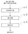
도 1은 본 발명에서 수행되는 수세 처리의 기본적 구성을 설명하는 플로우도이고,
도 2는 본 발명에 따른 염소 함유 분체의 수세 처리 시스템의 일례의 개략 구성 설명도이고,
도 3은 시험예 2에서 실시예 1 및 비교예 1 ~ 2에서 얻어진 탈염 케이크(C1)의 고상분의 입도 분포를 조사한 결과를 나타낸 그래프이다.1 is a flow diagram illustrating a basic configuration of a water washing process performed in the present invention,
2 is a schematic configuration explanatory diagram of an example of a water washing treatment system for chlorine-containing powder according to the present invention,
3 is a graph showing the results of examining the particle size distribution of the solid content of the desalted cake (C1) obtained in Example 1 and Comparative Examples 1 to 2 in Test Example 2. FIG.
본 발명의 처리 대상으로서는 염소를 함유하는 분체이면 가능하고 특별히 제한은 없으나 예를 들어 소각 비산재, 용융 비산재, 시멘트 킬른 더스트 등을 들 수 있다. 이것들은 종래에 탈염의 처리의 후 시멘트 원료로서 유효 이용되고 있는 폐기물로서, 전형적인 도시 쓰레기 소각 비산재, 즉 가정 쓰레기 폐기물을 소각 처리할 때에 발생하는 비산재(본 명세서에서는 단순히 “소각 비산재”로 칭하기로 함)에는 일반적으로 염소(Cl)가 10질량% ~ 30질량% 정도의 농도로 포함되어 있고, 또한 가스화 용융로로부터 발생한 비산재(본 명세서에서는 단순히 “용융 비산재”로 칭하기로 함)에는 일반적으로 염소가 10질량% ~ 40질량% 정도의 농도로 포함되어 있다. 한편, 시멘트 킬른 추기 가스에 포함되는 더스트인 시멘트 킬른 더스트에는 일반적으로 염소가 10질량% ~ 40질량% 정도의 농도로 포함되어 있다.The treatment object of the present invention can be as long as it is a powder containing chlorine, and is not particularly limited, but examples thereof include incineration fly ash, melt fly ash, cement kiln dust, and the like. These are wastes that have been effectively used as cement raw materials after desalting treatment, and fly ash generated when the typical municipal waste incineration, that is, household waste, is incinerated (in this specification, it is simply referred to as "incineration fly ash". ) Generally contains chlorine (Cl) in a concentration of about 10% by mass to 30% by mass, and in the fly ash generated from the gasification furnace (in this specification simply referred to as “melting fly ash”), chlorine is generally 10 It is contained in a concentration of about 40% by mass to 40% by mass. On the other hand, the cement kiln dust, which is the dust contained in the cement kiln additional gas, generally contains chlorine in a concentration of about 10% by mass to 40% by mass.
본 발명에 의하면, 상기와 같은 폐기물의 함유 염소량을 예를 들어 전형적으로는 0.1질량% ~ 3질량% 정도의 농도, 보다 전형적으로는 0.1질량% ~ 1.5질량% 정도의 농도까지 저감시킬 수 있다. 그리고 이와 같이 함유 염소량이 저감된 탈염 케이크는 시멘트 원료 등으로서 유효 이용하는 것이 가능하다.According to the present invention, the amount of chlorine contained in the waste can be reduced to, for example, a concentration of typically about 0.1% by mass to about 3% by mass, more typically about 0.1% by mass to about 1.5% by mass. And the desalting cake in which the amount of chlorine contained in this way is reduced can be effectively used as a cement raw material or the like.
염소 함유 분체의 염소의 농도는 주지의 방법으로 측정할 수 있고, 예를 들어 ISO 29581-2 Cement-Test methods-Part 2: Chemical analysis by X-ray fluorescence, 또는 시멘트협회 표준시험방법 JCAS I-05 “형광 X선 분석에 의한 시멘트 내의 염소의 정량 방법” 등을 준용한 형광 X선 분석법 등이 바람직하게 예시된다.The concentration of chlorine in the chlorine-containing powder can be measured by a known method, for example ISO 29581-2 Cement-Test methods-Part 2: Chemical analysis by X-ray fluorescence, or the Cement Association standard test method JCAS I-05 Fluorescent X-ray analysis and the like that applied mutatis mutandis such as "Method for quantifying chlorine in cement by fluorescent X-ray analysis" are preferably exemplified.
이하 본 발명에 대해 보다 구체적으로 설명하기 위해 도면을 참조하나, 본 발명은 이 도면들과 함께 설명하는 양태로 한정되는 것은 아니다.Reference is made to the drawings in order to describe the present invention in more detail below, but the present invention is not limited to the embodiments described together with the drawings.
도 1에는 본 발명에서 수행되는 수세 처리의 기본적 구성을 설명하는 플로우도를 도시하였다. 이 플로우도에 도시된 바와 같이 본 발명에 의한 수세 처리 방법은 염소 함유 분체에 적어도 물을 가하여 이루어지는 슬러리를, 소정 수용량을 갖는 처리조에 수용하는 염소 함유 분체 도입 공정(s-1)과, 처리조에 수용한 슬러리를 교반하여 염소 함유 분체에 포함된 염소를 액상 내로 용출시키는 염소 용출 공정(s-2)과, 염소 용출후의 상기 슬러리로부터 액상의 일부 또는 전부를 여별하여 탈염 케이크를 얻는 여별 분리 공정(s-3)을 구비한다.1 is a flow diagram illustrating a basic configuration of a water washing process performed in the present invention. As shown in this flow chart, the water washing treatment method according to the present invention includes a chlorine-containing powder introduction step (s-1) in which a slurry obtained by adding at least water to the chlorine-containing powder in a treatment tank having a predetermined capacity, and a treatment tank. A chlorine elution step (s-2) in which the received slurry is stirred to elute chlorine contained in the chlorine-containing powder into a liquid phase, and a filtration separation step for obtaining a desalted cake by filtering part or all of the liquid phase from the slurry after chlorine elution ( s-3).
그리고 본 발명에 의한 수세 처리 방법에서는 상기 염소 용출 공정에서의 슬러리의 교반을, 처리조에 수용된 슬러리에 이산화탄소를 포함한 가스를 주입하여 그 처리조에 수용된 슬러리의 하층 및 상층에 걸쳐 상기 가스가 상기 슬러리를 끌어들이면서 환류하는, 상기 슬러리와 상기 가스와의 혼합 교반류를 형성시킴으로써 수행한다. 이에 의해 비교적 입도가 큰 고상 입자일지라도 처리조내의 저부측에 체류하지 않고 슬러리 전체에 잘 분산시킬 수 있다. 또한 슬러리에 포함되는 고상분의 고상 입자의 입도 분포가 넓고 또한 양호하게 분산된 상태가 형성되고, 염소 용출 공정 후의 여별 분리 공정 시에는 그 비교적 입도가 큰 고상 입자가 핵이 되어 비교적 입도가 작은 고상 입자도 함께 적당히 연통된 입자간 공극을 갖는 충전 구조가 되어 양호한 여과 속도를 발현한다. 이 뛰어난 여과 속도에 의해 상기 여별 분리 공정에서의 소요 시간이 현저히 단축되어 염소 함유 분체의 수세 처리를 효율적으로 수행할 수 있게 된다.And in the water washing treatment method according to the present invention, the agitation of the slurry in the chlorine elution step is performed by injecting a gas containing carbon dioxide into the slurry accommodated in the treatment tank, and the gas draws the slurry across the lower and upper layers of the slurry accommodated in the treatment tank. It is carried out by forming a mixed stirring flow of the slurry and the gas, which is refluxed while entering. Thereby, even solid particles having a relatively large particle size can be well dispersed throughout the slurry without staying on the bottom side of the treatment tank. In addition, the particle size distribution of the solid particles of the solid content contained in the slurry is wide and well dispersed, and in the filtration separation process after the chlorine elution process, the relatively large solid particles become nuclei and thus the relatively small solid phase. The particles also have a packed structure having inter-particle voids that are properly communicated with each other, resulting in a good filtration rate. Due to this excellent filtration rate, the required time in the filtration separation process is remarkably shortened, so that the chlorine-containing powder can be efficiently washed with water.
또한 본 발명에 의한 수세 처리 방법에서는 연속적으로 도입되는 염소 함유 분체에 따라 그 수세 처리가 가능하다. 즉 일반적으로 상기의 염소 함유 분체의 도입은, 예를 들어 염소 함유 분체와 적어도 물을 포함한 탈염용 세정액을 처리조에 연속적으로 공급하는 것이 가능하나, 이어지는 여별 분리 공정에서는, 사용하는 여별 분리 장치의 사양에 의해 대체로 배치(batch)식 처리가 일반적인 바, 그 여별 분리 장치의 상류측에 염소 용출 공정으로부터 공급되는 슬러리의 버퍼 탱크를 구비하는 등에 의해 상기의 염소 함유 분체의 도입의 연속성을 방해하지 않고 그 수세 처리를 수행하는 것이 가능하다. 아울러 여기서 말하는 “연속성”은 반드시 수세 처리물이 시간축상 연속적으로 전혀 끊기지 않고 생성되는 것을 의미하는 것이 아니라, 조업상 상식적인 시간 범위에서 보았을 때, 전형적으로는 예를 들어 50분 ~ 100분 동안 정도의 시간 범위에서 보았을 때, 상기의 염소 함유 분체의 도입의 연속성에 의해 수세 처리물에 대해서도 그 생성이 끊기지 않는 것을 의미하는 것으로, 이에 의해 수세 처리의 조업상의 효율화를 충분히 도모할 수 있다.Further, in the water washing treatment method according to the present invention, the water washing treatment can be performed depending on the chlorine-containing powder continuously introduced. That is, in general, the introduction of the chlorine-containing powder can continuously supply the desalting cleaning liquid containing, for example, chlorine-containing powder and at least water to the treatment tank, but in the subsequent filtration separation process, the specifications of the filtration separation device to be used As a result, batch-type treatment is generally common. By providing a buffer tank for the slurry supplied from the chlorine elution process on the upstream side of the filtration separation device, it does not interfere with the continuity of the introduction of the chlorine-containing powder. It is possible to perform water washing treatment. In addition, the term “continuity” as used herein does not necessarily mean that the water-washed product is continuously produced without interruption on the time axis, but when viewed from a common sense time range in terms of operation, typically, for example, about 50 to 100 minutes. When viewed in the time range of, it means that the production of the washing treatment product does not cease due to the continuity of the introduction of the chlorine-containing powder described above, whereby the operational efficiency of the washing treatment can be sufficiently improved.
도 2에는 본 발명에 따른 염소 함유 분체의 수세 처리 시스템의 일례의 개략 구성 설명도를 도시하였다.Fig. 2 shows a schematic configuration diagram of an example of a water washing treatment system for chlorine-containing powder according to the present invention.
도 2에 도시된 바와 같이, 이 실시 형태에 따른 염소 함유 분체의 수세 처리 시스템(1)에는 처리조(2)가 구비되고, 그 처리조(2)에는 염소 함유 분체 공급 장치(21)로부터 공급되는 염소 함유 분체(P1)와 제1 탈염용 세정액 공급 장치(22)로부터 공급되는 제1 탈염용 세정액(W1)이 도입되고, 필요에 따라 pH 조정제 공급 장치(23)로부터 공급되는 pH 조정제(pH1)도 도입 가능하도록 되어 있다. 도 2에 도시된 실시 형태에서는 각 공급 장치(21 ~ 23)로부터는 각 슬러리 재료(P1, W1, pH1)가 처리조(2)로 연속적으로 공급되도록 하고 있고, 처리조(2)에서, 적어도 염소 함유 분체(P1)와 제1 탈염용 세정액(W1)을 혼합, 슬러리화하여 그 슬러리(S1)를 소정 시간 교반함으로써 염소 함유 분체(P1)에 함유된 염소를 액상으로 용해시켜 용출하도록 하고 있다. 아울러 도 2에 도시된 실시 형태에서는 적어도 염소 함유 분체(P1)와 제1 탈염용 세정액(W1)을 처리조(2)로 도입하여 혼합, 슬러리화하고 있으나, 별도로 슬러리화한 것을 처리조(2)로 도입하도록 해도 문제는 없다.As shown in FIG. 2, the water
또한 이 실시 형태에 따른 염소 함유 분체의 수세 처리 시스템(1)에서는 처리조(2)에서의 처리를 거친 슬러리(S2)는 슬러리 반송 장치(4)를 통해 여별 분리 장치(6)로 반송되도록 하고 있다. 여별 분리 장치(6)에서는 슬러리(S2)로부터 액상의 일부 또는 전부를 여별하여 함유 염소량이 저감된 탈염 케이크(C1)를 얻을 수 있다. 또한 여별 분리 장치(6)의 상류측에는 버퍼 탱크(5)를 구비하여 처리조(2)로부터 반송되는 슬러리(S2)를 일단 저장하고, 원하는 타이밍에 소정의 밸브 기구를 갖는 슬러리 공급 밸브(8a)를 열어 소정량씩 여별 분리 장치(6)로 공급하도록 하고 있다. 이러한 버퍼 탱크(5)를 구비함으로써 상술한 바와 같이 상기의 염소 함유 분체의 도입의 연속성을 방해하지 않고 그 수세 처리를 수행하는 것이 가능하다.In addition, in the water
상기한 바와 같이 처리조(2)에서는 적어도 염소 함유 분체(P1)와 제1 탈염용 세정액(W1)을 혼합, 슬러리화하나, 이 때의 염소 함유 분체(P1)와 제1 탈염용 세정액(W1)과의 질량비(W1/P1)는 4 ~ 10이 바람직하고, 4 ~ 7이 보다 바람직하고, 4 ~ 5가 특히 바람직하다. 질량비(W1/P1)가 4보다 작은 경우, 염소 함유 분체(P1)로부터 염소가 충분히 용출되지 않는 경우가 있다. 또한 질량비(W1/P1)가 10보다 큰 경우, 이어지는 여별 분리 공정에서 발생하는 여액량이 많아진다.As described above, in the
처리조(2)에서 염소 함유 분체(P1)와 혼합되어 슬러리(S1)를 구성하는 제1 탈염용 세정액(W1)의 염소 이온 농도는 3질량% 이하가 바람직하고, 2질량% 이하가 보다 바람직하고, 1질량% 이하가 특히 바람직하다. 하한은 특별히 설정되지 않으나, 통상 하천수나 지하수 등이 유래인 공업용수의 염소 농도가 0. 005질량% 정도이다. 제1 탈염용 세정액(W1)의 염소 이온 농도가 3질량%보다 큰 경우, 염소 함유 분체(P1)의 염소 함유량에 따라서는 염소 용출 공정에서 염소 함유 분체(P1)로부터의 염소의 용출 효율이 저하되는 경우가 있다.The chlorine ion concentration of the first desalting cleaning liquid (W1) that is mixed with the chlorine-containing powder (P1) in the treatment tank (2) to constitute the slurry (S1) is preferably 3% by mass or less, and more preferably 2% by mass or less. And 1% by mass or less is particularly preferable. The lower limit is not specifically set, but the chlorine concentration in industrial water derived from river water or groundwater is usually about 0.55% by mass. When the chlorine ion concentration of the first desalination cleaning liquid (W1) is greater than 3% by mass, the elution efficiency of chlorine from the chlorine-containing powder (P1) in the chlorine elution process decreases depending on the chlorine content of the chlorine-containing powder (P1). There are cases.
염소 용출 공정에서의 상기 슬러리(S1)의 pH는 바람직하게는 6 ~ 11, 보다 바람직하게는 6 ~ 10.5, 특히 바람직하게는 6 ~ 9이다. 여기서, 슬러리(S1)의 pH는 후술하는 바와 같이 이산화탄소를 포함한 가스를 주입하므로 그 가스중의 이산화탄소의 용해에 의해 7 이하로 하는 것이 가능하나, 슬러리(S1)에는 pH 조정제(pH1)를 첨가할 수도 있다. pH 조정제(pH1)를 첨가함으로써 슬러리(S1)의 pH를 6 ~ 9로 하여 재나 더스트에 포함되는 난용성의 프리델씨염으로부터의 염소 용출을 효과적으로 발생시킬 수 있다. pH 조정제(pH1)로서는 묽은 황산, 염산 등을 사용할 수 있다.The pH of the slurry (S1) in the chlorine elution step is preferably 6 to 11, more preferably 6 to 10.5, and particularly preferably 6 to 9. Here, the pH of the slurry (S1) can be set to 7 or less by dissolving the carbon dioxide in the gas, as a gas containing carbon dioxide is injected as described later. However, a pH adjuster (pH1) may be added to the slurry (S1). May be. By adding a pH adjuster (pH1), the pH of the slurry (S1) is set to 6 to 9, and chlorine elution from the poorly soluble Friedel's salt contained in ash or dust can be effectively generated. As the pH adjuster (pH1), dilute sulfuric acid, hydrochloric acid, or the like can be used.
도 2에 도시된 바와 같이, 이 실시 형태에 따른 염소 함유 분체의 수세 처리 시스템(1)에는 처리조(2)에 통형 산기장치(3)가 부설되어 있다. 통형 산기장치(3)는 이산화탄소를 포함한 가스(A1)를 공급하는 송기관(33)이 연통되어 이러한 가스(A1)를 주입하기 위한 노즐(31)과, 노즐(31)을 내부단에 배치하는 원통형의 원통관(32)으로 구성되어 있다. 그리고 노즐(31)을 통해 주입된 가스(A1)는 원통관(32)의 원통 내부의 슬러리를 끌어들이면서 그 슬러리와 함께 윗쪽으로 상승하여 가스(A1)와 슬러리(S1)의 혼합 분출류가 되어 원통관(32)의 상단 개구부(32a)를 통해 분출되도록 하고 있다. 한편, 원통관(32)의 하단 개구부(32b)를 통해서는, 원통 내부의 슬러리의 윗쪽으로의 상승에 따라 원통관(32)의 원통 내부의 하부측이 상부측에 비해 음압이 됨으로써, 처리조(2)의 저부측에 체류하는 슬러리가 원통관(32)의 원통 내부로 흡인되도록 하고 있다. 이러한 통형 산기장치(3)의 기구에 의해, 처리조(2)에 수용된 슬러리에는 그 하층 및 상층에 걸쳐 가스(A1)가 슬러리(S1)를 끌어들이면서 환류하는, 상기 슬러리와 상기 가스의 혼합 교반류가 형성되어, 처리조(2)에 수용된 슬러리 전체를 교반하도록 하고 있다.As shown in FIG. 2, in the water
상기 통형 산기장치(3)의 기구를 보다 구체적으로 설명하면, 노즐(31)을 통해 상기 가스(A1)를 주입함으로써 발생하는 에어 리프트 효과에 의해 원통관(32)의 원통 내부 및 원통 외부의 슬러리 간에 비중차가 형성되어 원통관(32)의 원통 내부에 상기 슬러리와 상기 가스의 혼합 분출류가 발생하는 것이다. 상기 혼합 분출류 내의 상기 가스의 형상은, 상기 슬러리에 주입하기 위한 노즐(31)의 형상이나 노즐(31)을 통해 주입될 때 또는 주입된 후에 상기 슬러리와 충돌함에 의한 전단 등에 기인하여 임의 직경의 기포상으로 되어 있다. 원통관(32)의 원통 내부를 흐르는 상기 혼합 교반류의 속도는 바람직하게는 1m/초 이상, 보다 바람직하게는 2m/초 이상, 특히 바람직하게는 3 m/초 이상이다. 이 혼합 교반류의 속도에 상한은 없으나, 처리조(2)로부터 슬러리(S1)가 돌발적으로 분출하는 것을 방지하기 위해서는 15m/초 이하가 바람직하다. 원통관(32)의 원통 내부를 흐르는 상기 혼합 교반류의 속도가 1m/초 미만인 경우, 형성되는 교반류가 약해져 처리조(2)에 수용된 슬러리(S1) 전체를 교반하는 것이 어려워지는 경우가 있다.The mechanism of the
또한 통형 산기장치(3)의 원통관(32)은 노즐(31)이 배치된 하단부측에서 상단 개구부(32a)를 향해 그 내경이 작아지는 대략 원뿔형의 구조를 채용할 수도 있다. 이에 의하면 상단 개구부(32a)를 통한 상기 혼합 분출류의 분출압을 보다 높일 수 있다.Further, the
나아가 통형 산기장치(3)의 원통관(32)의 원통 내부에는 상기 혼합 분출류의 흐름을 일부 차단하도록 돌기부나 스페이서 등의 구조체를 마련하여 그 구조체에 의해 난류 발생 수단이 이루어지도록 할 수도 있다. 이에 의하면 캐비테이션 효과에 의한 기포가 쉽게 발생하도록 할 수 있다.Further, a structure such as a protrusion or a spacer may be provided inside the cylinder of the
여기서, 캐비테이션 효과는 유체의 미크로한 국소 영역의 압력차에 의해 진공의 공동이 발생하고 이것이 미세 기포가 되는 현상으로, 널리 일반적으로 유체에 발생할 수 있는 현상이라고 할 수 있다. 따라서 이 캐비테이션 기포는 상기 구조체에 의한 특별한 난류 발생 수단이 없어도 통형 산기장치(3)의 노즐(31)이나 원통관(32)의 형상, 원통관(32)의 상단 개구부(32a)나 하단 개구부(32b)의 형상 등에 의해 상기 슬러리에 발생할 수 있다.Here, the cavitation effect is a phenomenon in which a vacuum cavity is generated due to a pressure difference in a micro-local region of the fluid, and this becomes a microbubble, and can be said to be a phenomenon that can occur in a fluid in general. Therefore, these cavitation bubbles are formed in the shape of the nozzle 31 or the
본 발명에서는 통형 산기장치(3)에서 형성시키는 상기 혼합 분출류나 이를 처리조(2)에 수용된 슬러리의 하층 및 상층에 걸쳐 환류시켜 이루어지는 상기 슬러리와 상기 가스의 혼합 교반류에는 상기 캐비테이션 효과에 의한 기포를 포함하고 있을 수 있다. 캐비테이션 효과에 의한 기포는 붕괴시에 수μm 오더의 국소적인 영역에 수GPa에 미치는 고충격압을 발생시키고, 또한 기포 붕괴시에 단열 압축에 의해 미시적으로는 수천℃의 온도가 발생한다. 따라서 이 캐비테이션 기포의 붕괴 충격력에 의해 슬러리(S1) 내에 존재하는 고상의 응집체를 파괴하는 효과가 있다. 또한 이 캐비테이션 기포의 붕괴시의 가온에 의해 염소 함유 분체(P1)로부터의 염소의 용출 효율을 향상시키는 효과가 있다.In the present invention, the mixed jet stream formed in the
처리조(2)에는 보다 효과적인 교반류를 형성하기 위해 상기와 같은 통형 산기장치(3)가 복수개 설치될 수도 있다. 이 경우, 이러한 복수의 통형 산기장치(3)에 의한 상기 혼합 분출류의 분출 방향을 처리조(2)의 상하 방향으로 통일시킴으로써 처리조(2) 내의 전체 교반을 효과적으로 수행할 수 있다. 또한 처리조(2)에는 통형 산기장치(3)를 부설함과 함께 나아가 범용의 교반익을 조합하여 설치할 수도 있다.A plurality of
처리조(2)로부터 슬러리(S1)를 버퍼 탱크(5)로 반송하기 위한 슬러리 반송 장치(4)로서는 스크류 펌프나 모노 펌프 등의 범용의 슬러리 펌프를 사용할 수도 있으나, 도 2에 도시된 실시 형태에서는 처리조(2)의 오버플로우가 발생하는 부위에 경사를 준 통을 설치하도록 하고 있다. 이렇게 함으로써, 처리조(2)로 연속적으로 공급될 수 있는 염소 함유 분체(P1) 및/또는 제1 탈염용 세정액(W1)에 의해 증량되어 가는 슬러리(S1)에 대해, 그 증량분에 대해 처리조(2)에서 오버플로우된 슬러리(S2)가 자동적으로 버퍼 탱크(5)로 반송된다.As the slurry conveying device 4 for conveying the slurry S1 from the
버퍼 탱크(5)는 소정량의 슬러리(S2)를 저장하고 적절히 여별 분리 장치(6)로 공급할 수 있는 것이면 그 기구, 재질은 한정되지 않는다.The buffer tank 5 is not limited in its mechanism and material as long as it can store a predetermined amount of slurry S2 and properly supply it to the
여별 분리 장치(6)로서는, 처리조(2)에서 처리된 슬러리(S2)로부터 액상의 일부 또는 전부를 여별할 수 있는 장치이면 가능하고, 예를 들어 필터 프레스 등이 바람직하게 예시된다. 도 2에 도시된 실시 형태에서도 여별 분리 장치(6)로서 필터 프레스가 사용되고 있다. 이러한 여별 분리 장치(6)(필터 프레스)에서는, 도입된 피처리물을 여포(filter cloth)에 의해 고액 분리하여 통상 50질량% 정도로 함수율이 감소되어 이루어지는 탈수 케이크를 얻을 수 있다. 이 때, 탈수 케이크의 두께나 수분 함량을 조정하기 위한 압착(피처리물의 도입시의 압착을 “1차 압착”이라고 칭하기도 함)에서의 압력은 0.2MPa ~ 2MPa일 수도 있고, 여포의 칸으로서는 입경 0.1μm 이상의 고상을 포집할 수 있는 것이면 가능하고, 압착 방식이나 여포의 종류 등은 특히 한정되지 않는다. 아울러 도 2에 도시된 실시 형태에서는 슬러리(S2)의 여별 분리 장치(6)(필터 프레스)로의 도입 시에는 소정의 펌프 기구를 갖는 슬러리 공급 펌프(7a)에 의해 슬러리(S2)를 가압하면서 수행할 수 있도록 되어 있다. 즉 피처리물의 압입을 가능하게 하고, 이에 의해 슬러리(S2)의 여별 분리 장치(6)(필터 프레스)로의 도입을 보다 신속하게 수행할 수 있다. 또한 이러한 여별 분리 장치(6)(필터 프레스)로의 슬러리(S2) 도입시에 제거되는 수분이 제1 여액(W3)으로서 배출되므로, 도 2에 도시된 실시 형태에서는 이것을 소정의 밸브 기구를 갖는 여액 배출 밸브(8c)를 열어 계외로 배출할 수 있도록 하고 있다.As the
또한 이러한 여별 분리 장치(6)(필터 프레스)에서는 일단 고액 분리하여 얻어진 함수율이 50질량% 정도인 탈수 케이크에 대해 제2 탈염용 세정액(W2)를 이용하여 세정을 수행하고, 이러한 탈수 케이크가 함유하는 액상의 거의 모두를 제2 탈염용 세정액(W2)으로 치환하는 처리를 수행한다(피처리물을 도입한 방향과 순방향으로 세정액을 유통시켜 세정하는 경우는 “정세정”이라고도 칭하고, 피처리물을 도입한 방향과 역방향으로 세정액을 유통시켜 세정하는 경우는 “역세정”이라고도 칭함). 이에 의해 탈수 케이크로부터의 탈염을 보다 확실히 할 수 있다. 제2 탈염용 세정액(W2)의 염소 이온 농도는 상기 제1 탈염용 세정액(W1)보다 염소 이온 농도가 낮은 것이 바람직하고, 보다 구체적으로는 0.5질량% 이하가 바람직하고, 0.3질량% 이하가 보다 바람직하고, 0.1질량% 이하가 특히 바람직하다. 하한은 특별히 설정되지 않으나, 일반적으로 하천수나 지하수 등이 유래인 공업용수의 염소 농도가 0.005질량% 정도이다.In addition, in this filtration separation device 6 (filter press), the dehydration cake having a water content of about 50% by mass obtained by separating solid-liquid once is washed with a second desalination cleaning solution (W2), and this dehydration cake is contained. Almost all of the liquid phase to be treated is replaced with the second desalination cleaning liquid (W2) (when cleaning by circulating the cleaning liquid in the direction in which the object to be treated was introduced and in the forward direction, it is also referred to as "clean cleaning", and the object to be treated is When cleaning is carried out by circulating the cleaning solution in the direction opposite to the introduced direction, it is also referred to as “reverse cleaning”). Thereby, desalination from the dehydration cake can be more reliably performed. The chlorine ion concentration of the second desalting cleaning liquid (W2) is preferably lower than that of the first desalting cleaning liquid (W1), more specifically, preferably 0.5% by mass or less, and more preferably 0.3% by mass or less. It is preferable, and 0.1 mass% or less is especially preferable. The lower limit is not specifically set, but in general, the chlorine concentration in industrial water derived from river water or groundwater is about 0.005% by mass.
도 2에 도시된 실시 형태에서는, 제2 탈염용 세정액(W2)은 여별 분리 장치(6)(필터 프레스)에 부설한 제2 탈염용 세정액 공급조(61)로부터, 원하는 타이밍에 소정의 밸브 기구를 갖는 제2 탈염용 세정액 공급 밸브(8b)를 엶으로써 공급되도록 하고 있다. 또한 이 때 소정의 펌프 기구를 갖는 제2 탈염용 세정액 공급 펌프(7b)에 의해 제2 탈염용 세정액(W2)를 가압하면서 수행할 수 있도록 되어 있다. 즉 제2 탈염용 세정액(W2)의 가압 도입을 가능하게 하고 이에 의해 제2 탈염용 세정액(W2)에 의한 탈수 케이크의 세정을 보다 신속하게 수행할 수 있다. 또한 제2 탈염용 세정액(W2)에 의한 세정시 또는 세정후에는 상기한 슬러리(S2)의 도입시의 1차 압착의 처리와 동일한 방법으로 탈수 케이크의 두께나 수분 함량을 조정하기 위한 압착을 실시할 수도 있다(탈수 케이크의 세정시 또는 세정후의 압착을 “2차 압착”이라 칭하는 경우도 있음).In the embodiment shown in Fig. 2, the second desalting washing liquid W2 is supplied from the second desalting washing
아울러 도 2에 도시된 실시 형태에서는 여별 분리 장치(6)에서 제2 탈염용 세정액(W2)에 의한 탈수 케이크의 세정으로 발생한 제2 여액(W4)은, 소정의 펌프 기구로 이루어지는 여액 반송 펌프(7c)에 의해 탈염용 세정액 공급 장치(22)의 저장부로 송액하여 제1 탈염용 세정액(W1)으로서 재이용하도록 하고 있다. 이에 의하면, 탈염용 세정액을 위한 물의 사용량을 절약할 수 있다. 그리고 여액의 재이용에 의해 염소 등의 농도가 상승한 경우에는, 소정의 밸브 기구로 이루어지는 여액 배출 밸브(8c)를 엶으로써 계외로 배출할 수 있도록 하고 있다. 아울러 상기한 바와 같이, 여별 분리 장치(6)(필터 프레스)로의 도입시에 발생하는 상기 제1 여액은 염소 등의 농도가 비교적 높아져 있어 기본적으로는 여액 배출 밸브(8c)를 엶으로써 계외로 배출하도록 하고 있으나, 경우에 따라서는 제2 여액(W4)과 같이 탈염용 세정액 공급 장치(22)의 저장부로 송액하여 제1 탈염용 세정액(W1)으로서 재이용할 수도 있다.In addition, in the embodiment shown in Fig. 2, the second filtrate W4 generated by washing the dehydration cake with the second desalination cleaning liquid W2 in the
또한 도 2에 도시된 바와 같이, 이 실시 형태에 따른 염소 함유 분체의 수세 처리 시스템(1)에서는 여별 분리 장치(6)에서 얻어진 탈염 케이크(C1)는 시멘트 제조 장치(9)로 반송하여 시멘트 원료로서 사용하도록 하고 있다. 이 때의 반송에는 함수율이 50질량% 정도의 케이크를 반송할 수 있는 예를 들어 벨트 컨베이어 등의 범용의 장치를 사용할 수 있다.In addition, as shown in Fig. 2, in the water
나아가 도 2에 도시된 바와 같이, 이 실시 형태에 따른 염소 함유 분체의 수세 처리 시스템(1)에서는 시멘트 제조 장치(9)로부터 배출되는 이산화탄소를 포함한 가스(A2)를 상기 통형 산기장치(3)로 공급하여, 이산화탄소를 포함한 가스(A1)의 일부 또는 전부로서 사용하도록 하고 있다. 이에 의하면 시멘트 제조 장치(9)로부터 배출되는 가스에 포함되는 열량에 의해 염소 용출 공정에서의 슬러리를 가온할 수 있어 염소 함유 분체(P1)로부터의 염소의 용출 효율을 양호하게 할 수 있다.Further, as shown in FIG. 2, in the water
이상 설명한 바와 같이, 본 발명에 의하면 염소 함유 분체에 적어도 물을 가하여 이루어지는 슬러리의 교반시 특정의 교반 수단을 채용하고 있으므로 비교적 입도가 큰 고상 입자일지라도 처리조(2) 내의 저부측에 체류하지 않고 처리조(2)에 수용된 슬러리(S1) 전체로 잘 분산시킬 수 있다. 이에 의해, 슬러리에 포함되는 고상분의 고상 입자의 입도 분포가 넓고 또한 양호하게 분산된 상태가 형성되고, 여별 분리 장치(6)에 의한 여별 분리 공정 시에는 그 비교적 입도가 큰 고상 입자가 핵이 되어 비교적 입도가 작은 고상 입자도 함께 적당히 연통된 입자간 공극을 갖는 충전 구조가 되어 양호한 여과 속도를 발현한다. 이 뛰어난 여과 속도에 의해 여별 분리 장치(6)에서의 소요 시간이 현저하게 단축되어 염소 함유 분체(P1)의 수세 처리를 효율적으로 수행할 수 있게 된다. 여기서, 이러한 고상 입자에는, 슬러리(S1)에 용해되어 있는 칼슘 성분과 슬러리(S1)에 주입된 가스(A1)중의 이산화탄소와의 화학반응에 의한 탄산칼슘이 포함되어 있을 수도 있다.As described above, according to the present invention, a specific stirring means is employed for stirring the slurry obtained by adding at least water to the chlorine-containing powder, so that even solid particles having a relatively large particle size do not stay on the bottom side of the
아울러 후술의 실시예에 의하면, 여별 분리 장치(6)로서 필터 프레스를 사용하는 경우, 슬러리의 압입, 정세정(수세), 1차 압착, 역세정(수세), 및 2차 압착까지의 소요 시간 중 그 압입과 역세정 공정에서의 소요 시간 단축이 현저했다. 따라서, 본 발명의 구성은 슬러리상의 조성물로부터 여포 등의 여별 분리 부재를 통해 탈수하는 과정에서 그 여과 속도를 향상시키는 데에 크게 기여하고 있는 것으로 보인다. 또한 그 소요 시간은 전형적으로는 예를 들어 25분 이하로 단축하는 것이 가능하고, 보다 전형적으로는 예를 들어 22분 이하로 단축하는 것이 가능하고, 보다 더 전형적으로는 20분 이하로 단축하는 것이 가능하고, 이에 의해 수세 처리의 조업상의 효율화를 충분히 도모할 수 있을 것으로 보인다.In addition, according to an embodiment to be described later, in the case of using a filter press as the
실시예Example
이하 본 발명에 대해 더욱 상세히 설명하기 위해 구체적인 시험예를 나타내나, 본 발명은 이 시험예들의 양태로 한정되는 것은 아니다.Hereinafter, specific test examples are shown to describe the present invention in more detail, but the present invention is not limited to the aspects of these test examples.
[시험예 1][Test Example 1]
도 2에 도시된 염소 함유 분체의 수세 처리 시스템(1)의 구성에서 처리조(2)의 염소 용출 공정의 설비 사양이 여별 분리 공정의 소요 시간에 어떠한 영향을 주는지에 대해 평가했다.In the configuration of the water
염소 함유 분체(P1)로서는 가스화 용융로로부터 발생한 용융 비산재(Cl: 12.8질량%, Pb: 2600ppm, Zn: 15600 ppm)를 사용했다(이하, “용융 비산재(P2)”라 함). 또한 용융 비산재(P2)를 슬러리화하기 위한 제1 탈염용 세정액(W1) 및 탈수 케이크를 세정하기 위한 제 2탈염용 세정액(W2)으로서는 수돗물을 사용했다. 또한 처리조(2)로서는 수용량 3.5m3의 것을 사용했다.As the chlorine-containing powder (P1), molten fly ash (Cl: 12.8 mass%, Pb: 2600 ppm, Zn: 15600 ppm) generated from the gasification furnace was used (hereinafter referred to as "melted fly ash (P2)"). In addition, tap water was used as the first cleaning liquid for desalting (W1) for slurrying the molten fly ash (P2) and the second cleaning liquid for desalting (W2) for cleaning the dehydration cake. In addition, as the
여별 분리 장치(6)에는 필터 프레스(여포의 통기도: 1000cm/분 , 여포의 두께: 1.8mm, 여포: 폴리프로필렌의 헤링본 직물)를 사용하고, 슬러리(S1)의 고액비(“제1 탈염용 세정액(W1)/용융 비산재(P2)”의 질량비)는 4로 하고, 여별 분리 장치(6)에서의, 제2 탈염용 세정액(W2)에 의한 세정시의 탈염 케이크(C1)의 고액비(“제2 탈염용 세정액(W2)/용융 비산재(P2)”의 질량비)는 1로 하고, 처리에 의해 얻어진 탈염 케이크(C1)의 함수율은 50질량%로 했다.Filter press (filter air permeability: 1000cm/min, filter thickness: 1.8mm, filter cloth: herringbone fabric made of polypropylene) was used for the
표 1에는 평가에 제공한 각 수준에 대해, 염소 용출 공정의 설비 사양과 각 사양의 경우의 슬러리의 pH를 정리하여 나타낸다. 구체적으로는 실시예 1로서는, 가스(A1)의 공급과 슬러리(S1)의 교반을 통형 산기장치(3)에 의해서만 수행하는 수준을 마련하고, 비교예 1로서는, 가스(A1)의 공급을, 통형 산기장치(3)에 대신하여 처리조(2) 내에 설치한 디스크형 산기반에 의해 미세 기포를 주입함으로써 수행하고, 슬러리(S1)의 교반을 처리조(2) 내에 배치한 교반익에 의해 수행하는 수준을 마련하고, 비교예 2로서는, 가스(A1)의 공급을 수행하지 않고, 슬러리(S1)의 교반만을 통형 산기장치(3)에 대신하여 처리조(2) 내에 배치한 교반익에 의해 수행하는 수준을 마련하여 각 설비 사양이 여별 분리 공정의 소요 시간에 어떠한 영향을 주는지에 대해 평가했다. 아울러 슬러리(S1)로의 가스(A1)의 공급에는, 실시예 1에서는 통형 산기장치(아쿠아블래스터 AL-1500, 아이엔스사)를, 비교예 1에서는 산기반(테라C형, ELASTOX사)을 사용했다. 나아가 교반익으로는 직경 600mm의 4개 날개식을 사용했다.Table 1 summarizes the equipment specifications of the chlorine elution process and the pH of the slurry in the case of each specification for each level provided for evaluation. Specifically, in Example 1, the supply of the gas A1 and the stirring of the slurry S1 are provided at a level in which only the
표 2에는 상기의 수준마다, 여별 분리 공정에서의 소요 시간과, 여별 분리에 따른 여포의 단위 면적(m2) 당 여과 속도(kg/hr)를 정리했다. 아울러 소요 시간은 필터 프레스의 작업 공정에 따른, 하기에 나타낸 압입, 정세정, 1차 압착, 역세정 및 2차 압착의 공정마다 정리했다.Table 2 summarizes the above levels, the time required in the filter-by-filter separation process, and the filtration rate (kg/hr) perunit area (m 2) of the filter according to the filter-by-filter separation. In addition, the required time was summarized for each process of press fitting, positive washing, primary pressing, back washing and secondary pressing shown below according to the working process of the filter press.
(압입)(Press fit)
필터 프레스의 여포로 둘러싸인 여별 분리실로, 그 여별 분리실의 여포의 둘레가 일부 풀린 도입구에 연결되는 배관을 통해 슬러리를 투입하고, 여포로 여과된 제1 여액(W3)을 배출구측을 통해 배출시키면서 소정의 가압으로 일정량의 슬러리를 가득 채우는 공정/이 시험예에서는 0.3MPa의 가압 조건으로 1개의 여별 분리실 당 대략 20L의 슬러리를 가득 채웠다.The filter press is surrounded by the filter cloth, and the slurry is injected through a pipe connected to the inlet port where the circumference of the filter cloth is partially unwound, and the first filtrate (W3) filtered through the filter cloth is discharged through the outlet side. The process of filling a certain amount of slurry with a predetermined pressurization while in the process/In this test example, approximately 20L of slurry was filled per one filter separation chamber under a pressurization condition of 0.3 MPa.
(정세정)(Jeongsejeong)
슬러리를 투입한 배관을 통해 제2 탈염용 세정액(W2)으로 세정하는 공정/이 시험예에서는 0.3MPa × 1분 동안으로 각 수준들에 고정 설정하였다.The process of cleaning with the second desalting cleaning liquid (W2) through the pipe into which the slurry was added/in this test example, 0.3 MPa × 1 minute was fixed at each level.
(1차 압착)(1st crimping)
필터 프레스의 여별 분리실을 둘러싸는 여포를 통해 케이크층을 개재하도록 배치된 여판에 소정이 압력을 가하여 탈수 케이크의 두께나 함수율을 조정하는 공정/이 시험예에서는 0.3MPa × 4분 동안으로 각 수준들에 고정 설정하였다.Process of adjusting the thickness or moisture content of the dehydration cake by applying a predetermined pressure to the filter plate arranged so that the cake layer is interposed through the filter cloth surrounding the filter separation chamber of the filter press/In this test example, each level is 0.3 MPa × 4 minutes. It was fixed on the field.
(역세정)(Reverse washing)
정세정과는 역방향으로, 필터 프레스의 여별 분리실로부터의 여액의 배출구측의 배관을 통해 제2 탈염용 세정액(W2)을 탈수 케이크에 도입하여 세정하는 공정/이 시험예에서는 제2 여액(W4)의 전기 전도율이 900mS/m가 될 때까지 역세정을 수행하였다(역세정의 여액이 상기 전기 전도율이 되면, 얻어지는 탈염 케이크(C1)의 염소 함유율은 약 0.5질량% 정도로 전망할 수 있음).In the opposite direction to the clean washing section, the second desalination cleaning liquid (W2) is introduced into the dehydration cake through a pipe on the outlet side of the filtrate from the filter press separation chamber to clean it./ In this test example, the second filtrate (W4) Backwashing was performed until the electrical conductivity of was 900mS/m (when the backwashing filtrate became the electrical conductivity, the chlorine content of the obtained desalting cake (C1) can be predicted to be about 0.5% by mass).
(2차 압착)(Secondary Crimping)
역세정 후에, 필터 프레스의 여별 분리실을 둘러싸는 여포를 통해 케이크층을 개재하도록 외측에 배치된 여판에 소정의 압력을 가하여 탈수 케이크의 두께나 수분량을 조정하는 공정/이 시험예에서는 0.7MPa × 4분 동안으로 각 수준들에 고정 설정하였다.After backwashing, a process of adjusting the thickness or moisture content of the dehydration cake by applying a predetermined pressure to the filter plate disposed outside so that the cake layer is interposed through the filter cloth surrounding the filter separation chamber of the filter press/In this test example, 0.7 MPa × Set fixed at each level for 4 minutes.
표 2에 도시된 바와 같이, 염소 용출 공정에서의 처리조(2)의 사양으로서 통형 산기장치(3)를 이용한 실시예 1에서는 필터 프레스에 의한 여별 분리 공정에서의 소요 시간이 압입에서 3분을 요하고, 역세정에서 8분을 요하여 전체 20분 동안이었음에 반해, 염소 용출 공정에서의 처리조(2)의 사양으로서 산기반과 교반익을 이용한 비교예 1에서는 압입에서 5분을 요하고, 역세정에서 13분을 요하여 전체 27분 동안으로, 보다 시간이 걸리고, 염소 용출 공정에서의 처리조(2)의 사양으로서 교반익만을 사용한 비교예 2에서는 압입에서 7분을 요하고, 역세정에서 16분을 요하여 전체 32분 동안으로, 보다 더 시간이 걸렸다. 또한 처리 능력의 지표인 여과 속도(kg/m2/hr)를 구한 바, 실시예 1이 14.1, 비교예 1이 10.1, 비교예 2가 9.4가 되어 염소 용출 공정에서의 처리조(2)에서의 슬러리(S1)의 교반과 가스(A1)의 공급을 통형 산기장치(3)를 이용하여 수행하면 염소 함유 분체의 수세 처리 능력이 현저히 향상됨이 밝혀졌다.As shown in Table 2, in Example 1 using the
[시험예 2][Test Example 2]
시험예 1의 각 수준에서 얻어진 탈염 케이크(C1)의 고상분에 대해 레이저 회절·산란식 입도 분포 측정 장치로 입도 분포를 조사했다. 결과를 도 3에 나타내었다.The particle size distribution of the solid content of the desalting cake (C1) obtained at each level of Test Example 1 was investigated with a laser diffraction/scattering particle size distribution measuring device. The results are shown in FIG. 3.
도 3에 도시된 바와 같이 비교예 1의 고상분에는 세립이 많고 또한 비교예 2의 고상분에는 조립이 많은 데에 반해, 실시예 1의 고상분의 고상 입자의 입도 분포는 상대적으로 비교예 1과 비교예 2의 중위에 위치하는 것이었다. 이는 비교예 1에서는 이산화탄소를 포함한 가스(A1)의 공급에 의해 발생하는 탄산칼슘이 비교적 입도가 미세한 입자인 바, 산기반과 교반익의 조합의 경우에는 처리조(2)의 전체가 충분히 교반되지 않아 처리조(2)로부터 오버플로우한 것에는 탄산칼슘 입자가 많이 포함되는 것에 기인하고, 비교예 2에서는 교반익만에 의한 교반의 경우에는 염소 함유 분체(P1)로서 사용된 용융 비산재(P2)를 포함한 고상분이 응집 상태 그대로인 것에 기인한 것으로 보였다. 이에 반해, 통형 산기장치(3)를 이용한 실시예 1에서는 첫번째로는, 처리조(2)에 수용된 슬러리(S1)의 하층 및 상층에 걸쳐 가스(A1)가 슬러리(S1)를 끌어들이면서 환류하는, 슬러리와 가스의 혼합 교반류가 형성되어 처리조(2)에 수용된 슬러리(S1) 전체를 충분히 교반시킬 수 있음에 의해, 나아가 두번째로는, 이산화탄소를 포함한 가스(A1)의 공급에 의해 탄산칼슘 입자가 발생함에 의해 처리조(2)로부터 오버플로우된 슬러리(S2)에는 고상분의 고상 입자의 입도 분포가 넓고 또한 양호하게 분산된 상태가 형성된 것으로 보였다.As shown in FIG. 3, the solid content of Comparative Example 1 has a large number of fine grains and the solid content of Comparative Example 2 has a large amount of granulation, whereas the particle size distribution of the solid particles of the solid content of Example 1 is relatively comparative example 1 And was located in the middle of Comparative Example 2. In Comparative Example 1, calcium carbonate generated by the supply of gas (A1) including carbon dioxide is a relatively fine particle.In the case of the combination of the acid base and the stirring blade, the
1 염소 함유 분체의 수세 처리 시스템
2 처리조
3 통형 산기장치
4 슬러리 반송 장치
5 버퍼 탱크
6 여별 분리 장치
7a 슬러리 공급 펌프
7b 제2 탈염용 세정액 공급 펌프
7c 여액 반송 펌프
8a 슬러리 공급 밸브
8b 제2 탈염용 세정액 공급 밸브
8c 여액 배출 밸브
9 시멘트 제조 장치
21 염소 함유 분체 공급 장치
22 제1 탈염용 세정액 공급 장치
23 pH 조정제 공급 장치
31 노즐
32 원통관
33 송기관
61 제2 탈염용 세정액 공급조
A1, A2 이산화탄소를 포함한 가스
P1 염소 함유 분체
P2 용융 비산재
S1, S2 슬러리
C1 탈염 케이크
W1 제1 탈염용 세정액
W2 제2 탈염용 세정액
W3 제1 여액
W4 제2 여액
pH1 pH 조정제1 Water washing treatment system for chlorine-containing powder
2 treatment tank
3 barrel type air diffuser
4 Slurry conveying device
5 buffer tank
6 Filter separation device
7a slurry feed pump
7b Second desalination cleaning liquid supply pump
7c filtrate return pump
8a slurry supply valve
8b Second desalination cleaning liquid supply valve
8c filtrate drain valve
9 Cement manufacturing equipment
21 Chlorine-containing powder supply device
22 First desalination cleaning liquid supply device
23 pH adjuster supply device
31 nozzles
32 cylinder
33 air pipe
61 Second desalination cleaning liquid supply tank
A1, A2 gas containing carbon dioxide
P1 chlorine-containing powder
P2 melt fly ash
S1, S2 slurry
C1 desalted cake
W1 first desalting cleaning solution
W2 2nd desalting cleaning solution
W3 1st filtrate
W4 second filtrate
pH1 pH adjuster
Claims (10)
Translated fromKorean상기 처리조에 수용한 상기 슬러리를 교반하여 상기 염소 함유 분체에 포함된 염소를 액상 내로 용출시키는 염소 용출 공정과,
상기 염소 용출후의 상기 슬러리로부터 액상의 일부 또는 전부를 여별하여 탈염 케이크를 얻는 여별 분리 공정, 을 구비하고
상기 염소 용출 공정에서의 상기 슬러리의 교반을, 상기 처리조에 수용된 상기 슬러리에 이산화탄소를 포함한 가스를 주입하여 상기 수용된 슬러리의 하층 및 상층에 걸쳐 상기 가스가 상기 슬러리를 끌어들이면서 환류하는, 상기 가스와 상기 슬러리의 혼합 교반류를 형성시킴으로써 수행하는, 염소 함유 분체의 수세 처리 방법.A chlorine-containing powder introduction step of accommodating a slurry obtained by adding at least water to the chlorine-containing powder in a treatment tank having a predetermined capacity; and
A chlorine elution step of stirring the slurry contained in the treatment tank to elute chlorine contained in the chlorine-containing powder into a liquid phase,
A filtration separation step for obtaining a desalted cake by filtration of part or all of the liquid from the slurry after elution of the chlorine,
The gas in which the slurry is stirred in the chlorine elution process by injecting a gas containing carbon dioxide into the slurry accommodated in the treatment tank, and the gas is refluxed while attracting the slurry across the lower and upper layers of the contained slurry. A method for washing with water of chlorine-containing powder, which is carried out by forming a mixing and stirring flow of the slurry.
상기 처리조는 이 처리조에 수용된 상기 슬러리가, 추가적으로 도입되는 염소 함유 분체에 따라 오버플로우하여 상기 여별 분리 공정을 향해 반출되도록 구성되어 있는, 염소 함유 분체의 수세 처리 방법.The method of claim 1,
The treatment tank is configured such that the slurry accommodated in the treatment tank overflows according to the additionally introduced chlorine-containing powder and is discharged toward the filtration separation step.
상기 여별 분리 공정에서의 상기 액상의 분리를 필터 프레스에 의해 수행하는, 염소 함유 분체의 수세 처리 방법.The method according to claim 1 or 2,
A water washing treatment method for chlorine-containing powder, wherein separation of the liquid phase in the filtration separation step is performed by a filter press.
상기 염소 함유 분체가 소각 비산재, 용융 비산재 및 시멘트 킬른 더스트에서 선택된 1종 또는 2종 이상을 포함하는, 염소 함유 분체의 수세 처리 방법.The method according to claim 1 or 2,
The method for washing with water for chlorine-containing powder, wherein the chlorine-containing powder contains one or two or more selected from incineration fly ash, melt fly ash, and cement kiln dust.
연속적으로 도입되는 염소 함유 분체에 따라, 상기 수세 처리가 가능해지는, 염소 함유 분체의 수세 처리 방법.The method according to claim 1 or 2,
The water washing treatment method of the chlorine-containing powder, wherein the water washing treatment is possible according to the chlorine-containing powder continuously introduced.
상기 처리조에 부설되어, 상기 처리조에 수용된 상기 슬러리에 이산화탄소를 포함한 가스를 주입하여 상기 수용된 슬러리의 하층 및 상층에 걸쳐 상기 가스가 상기 슬러리를 끌어들이면서 환류하는, 상기 가스와 상기 슬러리의 혼합 교반류를 형성시키기 위한 통형 산기장치와,
상기 처리조에서 꺼낸 상기 슬러리로부터 액상의 일부 또는 전부를 여별하여 탈염 케이크를 얻기 위한 여별 분리 장치, 를 구비한 염소 함유 분체의 수세 처리 시스템.A treatment tank having a predetermined capacity for accommodating a slurry formed by adding at least water to the chlorine-containing powder,
A mixed stirring flow of the gas and the slurry in which a gas including carbon dioxide is injected into the slurry accommodated in the treatment tank and refluxed while the gas attracts the slurry over the lower and upper layers of the contained slurry. And a tubular diffuser device for forming
A water washing treatment system for chlorine-containing powder, comprising: a filter-separating device for obtaining a desalting cake by filtering part or all of the liquid from the slurry taken out from the treatment tank.
상기 처리조는 이 처리조에 수용된 상기 슬러리가, 추가적으로 도입되는 염소 함유 분체에 따라 오버플로우하여 상기 여별 분리 장치를 향해 반출되도록 구성되어 있는, 염소 함유 분체의 수세 처리 시스템.The method of claim 6,
The treatment tank is a water washing treatment system for chlorine-containing powder, wherein the slurry accommodated in the treatment tank overflows according to the additionally introduced chlorine-containing powder and is carried out toward the filter separation device.
상기 여별 분리 장치는 필터 프레스인, 염소 함유 분체의 수세 처리 시스템.The method according to claim 6 or 7,
The filtration separation device is a filter press, a water washing treatment system for chlorine-containing powder.
얻어진 탈염 케이크를 시멘트 제조 설비로 반송하기 위한 반송 장치를 더 구비하는, 염소 함유 분체의 수세 처리 시스템.The method according to claim 6 or 7,
A water washing treatment system for chlorine-containing powder, further comprising a conveying device for conveying the obtained desalted cake to a cement manufacturing facility.
연속적으로 도입되는 염소 함유 분체에 따라, 상기 수세 처리가 가능해지는, 염소 함유 분체의 수세 처리 시스템.
The method according to claim 6 or 7,
A water washing treatment system for chlorine-containing powder, wherein the water washing treatment is possible according to the chlorine-containing powder continuously introduced.
Applications Claiming Priority (1)
| Application Number | Priority Date | Filing Date | Title |
|---|---|---|---|
| PCT/JP2018/033510WO2020053944A1 (en) | 2018-09-10 | 2018-09-10 | Washing treatment method for chlorine-containing powder, and washing treatment system for chlorine-containing powder |
Publications (2)
| Publication Number | Publication Date |
|---|---|
| KR20210049775Atrue KR20210049775A (en) | 2021-05-06 |
| KR102576793B1 KR102576793B1 (en) | 2023-09-08 |
Family
ID=69777678
Family Applications (1)
| Application Number | Title | Priority Date | Filing Date |
|---|---|---|---|
| KR1020217001386AActiveKR102576793B1 (en) | 2018-09-10 | 2018-09-10 | Water washing treatment method for chlorine-containing powder and water washing treatment system for chlorine-containing powder |
Country Status (5)
| Country | Link |
|---|---|
| JP (1) | JP7041278B2 (en) |
| KR (1) | KR102576793B1 (en) |
| CN (1) | CN112672833B (en) |
| SG (1) | SG11202101617RA (en) |
| WO (1) | WO2020053944A1 (en) |
Families Citing this family (3)
| Publication number | Priority date | Publication date | Assignee | Title |
|---|---|---|---|---|
| CN112495009A (en)* | 2020-12-21 | 2021-03-16 | 宝武集团环境资源科技有限公司 | Process system for realizing single-stage efficient washing solid-liquid separation |
| CN113233809B (en)* | 2021-06-01 | 2022-04-05 | 广州派安环保科技有限公司 | Resourceful treatment equipment for garbage fly ash |
| JP7237133B1 (en) | 2021-11-30 | 2023-03-10 | 太平洋セメント株式会社 | Method for desalting chlorine-containing powder |
Citations (8)
| Publication number | Priority date | Publication date | Assignee | Title |
|---|---|---|---|---|
| JPS5614795B1 (en)* | 1970-07-13 | 1981-04-06 | ||
| JPH09234479A (en)* | 1996-03-01 | 1997-09-09 | Chlorine Eng Corp Ltd | Ozone reaction tank |
| JPH11226558A (en)* | 1998-02-19 | 1999-08-24 | Techno Frontier:Kk | Process for integrated processing of fly ash detoxification, salt separation and resource recycling |
| JP2002338312A (en) | 1997-07-14 | 2002-11-27 | Taiheiyo Cement Corp | Treating method for making into cement raw material |
| JP2003211129A (en) | 2002-01-29 | 2003-07-29 | Ebara Corp | Method and apparatus for cleaning ash |
| JP2004313905A (en)* | 2003-04-15 | 2004-11-11 | Matsushita Electric Works Ltd | Structure of gas-liquid dissolving tank |
| JP2013176740A (en)* | 2012-02-29 | 2013-09-09 | Taiheiyo Cement Corp | Treatment method and treatment apparatus for refuse incineration ash |
| JP2018001147A (en)* | 2016-07-07 | 2018-01-11 | 株式会社サンエイ | Sewage treatment device |
Family Cites Families (10)
| Publication number | Priority date | Publication date | Assignee | Title |
|---|---|---|---|---|
| JP4074927B2 (en) | 1999-08-24 | 2008-04-16 | 東 利保 | Cleaning processing equipment |
| JP2005213527A (en) | 2004-01-27 | 2005-08-11 | Jfe Engineering Kk | Method for dechlorination of zinc hydroxide |
| JP2005289402A (en) | 2004-03-31 | 2005-10-20 | Mitsubishi Materials Corp | Slurry tank |
| JP5072179B2 (en) | 2004-12-24 | 2012-11-14 | 栗田工業株式会社 | Desalination cleaning method for waste |
| JP5085027B2 (en)* | 2005-10-17 | 2012-11-28 | 住友大阪セメント株式会社 | Method and apparatus for treating chlorine-containing waste |
| US8043426B2 (en) | 2008-05-13 | 2011-10-25 | Abdel-Mohsen Onsy Mohamed | Method for treating cement kiln dust |
| JP5614795B2 (en)* | 2010-01-20 | 2014-10-29 | 太平洋セメント株式会社 | Potassium chloride recovery device and recovery method |
| EP2537602B1 (en)* | 2010-02-16 | 2017-07-26 | Taiheiyo Cement Corporation | Method and system for washing incineration ash and dust contained in extracted cement kiln combustion gas |
| JP6603641B2 (en)* | 2016-09-27 | 2019-11-06 | 太平洋セメント株式会社 | Chlorine-containing powder processing method and chlorine-containing powder processing system |
| JP6252653B1 (en)* | 2016-10-31 | 2017-12-27 | 三菱マテリアル株式会社 | Method and system for treating chlorine-containing ash |
- 2018
- 2018-09-10SGSG11202101617RApatent/SG11202101617RA/enunknown
- 2018-09-10WOPCT/JP2018/033510patent/WO2020053944A1/ennot_activeCeased
- 2018-09-10JPJP2020546566Apatent/JP7041278B2/enactiveActive
- 2018-09-10CNCN201880097401.XApatent/CN112672833B/enactiveActive
- 2018-09-10KRKR1020217001386Apatent/KR102576793B1/enactiveActive
Patent Citations (8)
| Publication number | Priority date | Publication date | Assignee | Title |
|---|---|---|---|---|
| JPS5614795B1 (en)* | 1970-07-13 | 1981-04-06 | ||
| JPH09234479A (en)* | 1996-03-01 | 1997-09-09 | Chlorine Eng Corp Ltd | Ozone reaction tank |
| JP2002338312A (en) | 1997-07-14 | 2002-11-27 | Taiheiyo Cement Corp | Treating method for making into cement raw material |
| JPH11226558A (en)* | 1998-02-19 | 1999-08-24 | Techno Frontier:Kk | Process for integrated processing of fly ash detoxification, salt separation and resource recycling |
| JP2003211129A (en) | 2002-01-29 | 2003-07-29 | Ebara Corp | Method and apparatus for cleaning ash |
| JP2004313905A (en)* | 2003-04-15 | 2004-11-11 | Matsushita Electric Works Ltd | Structure of gas-liquid dissolving tank |
| JP2013176740A (en)* | 2012-02-29 | 2013-09-09 | Taiheiyo Cement Corp | Treatment method and treatment apparatus for refuse incineration ash |
| JP2018001147A (en)* | 2016-07-07 | 2018-01-11 | 株式会社サンエイ | Sewage treatment device |
Also Published As
| Publication number | Publication date |
|---|---|
| WO2020053944A1 (en) | 2020-03-19 |
| KR102576793B1 (en) | 2023-09-08 |
| JPWO2020053944A1 (en) | 2021-06-03 |
| CN112672833B (en) | 2023-04-04 |
| CN112672833A (en) | 2021-04-16 |
| JP7041278B2 (en) | 2022-03-23 |
| SG11202101617RA (en) | 2021-03-30 |
Similar Documents
| Publication | Publication Date | Title |
|---|---|---|
| KR20210049775A (en) | Water washing treatment method for chlorine-containing powder and water washing treatment system for chlorine-containing powder | |
| CN103899280B (en) | Well drilling waste reinjection system and method | |
| WO2008020507A1 (en) | Method of recovering abrasive from abrasive slurry waste liquid and apparatus therefor | |
| CN1344608A (en) | Method and equipment for recycling plastic products and cleaning crushed plastic | |
| CN210305011U (en) | Shield constructs construction dregs processing system | |
| CN211100741U (en) | Shield muck zero-emission treatment system | |
| CN112588806B (en) | Integrated high-efficiency leaching equipment for heavy metal contaminated soil | |
| KR20020050185A (en) | The method to manufacture break to sand by construction waste | |
| CN110757644A (en) | Brick making production line capable of recycling concrete cleaning waste | |
| CN110842017A (en) | Modularized mobile soil leaching system | |
| TW201940236A (en) | Desalting method for powder containing chlorine and desalting device for powder containing chlorine | |
| JP3816200B2 (en) | Method and apparatus for processing liquid containing fine particles | |
| US6010671A (en) | Process for selective recovery of uranium from sludge | |
| CN214639070U (en) | Integrated leaching equipment for heavy metal contaminated soil | |
| CN215614040U (en) | Shield muck lightweight treatment system | |
| CN210393743U (en) | Boron carbide recovery device | |
| CN212403889U (en) | Drying pretreatment system for sludge containing impurities | |
| CN212349873U (en) | Contaminated soil leaching and repairing system | |
| CN221244318U (en) | Sand and gravel separation recycling environmental protection system | |
| CN104925979A (en) | Sand-washing wastewater treating method | |
| CN204700029U (en) | A cyanogen-containing waste residue treatment system | |
| CA2867730C (en) | Filter media recycling system | |
| CN216501465U (en) | Building dregs resourceful treatment integrated equipment | |
| CN100588473C (en) | Method and system for removing chloride contained in bottom ash | |
| CN221473003U (en) | Leaching system for repairing multi-particle-size contaminated soil |
Legal Events
| Date | Code | Title | Description |
|---|---|---|---|
| PA0105 | International application | St.27 status event code:A-0-1-A10-A15-nap-PA0105 | |
| PG1501 | Laying open of application | St.27 status event code:A-1-1-Q10-Q12-nap-PG1501 | |
| A201 | Request for examination | ||
| PA0201 | Request for examination | St.27 status event code:A-1-2-D10-D11-exm-PA0201 | |
| P22-X000 | Classification modified | St.27 status event code:A-2-2-P10-P22-nap-X000 | |
| D13-X000 | Search requested | St.27 status event code:A-1-2-D10-D13-srh-X000 | |
| D14-X000 | Search report completed | St.27 status event code:A-1-2-D10-D14-srh-X000 | |
| E902 | Notification of reason for refusal | ||
| PE0902 | Notice of grounds for rejection | St.27 status event code:A-1-2-D10-D21-exm-PE0902 | |
| AMND | Amendment | ||
| P11-X000 | Amendment of application requested | St.27 status event code:A-2-2-P10-P11-nap-X000 | |
| P13-X000 | Application amended | St.27 status event code:A-2-2-P10-P13-nap-X000 | |
| E601 | Decision to refuse application | ||
| PE0601 | Decision on rejection of patent | St.27 status event code:N-2-6-B10-B15-exm-PE0601 | |
| AMND | Amendment | ||
| P11-X000 | Amendment of application requested | St.27 status event code:A-2-2-P10-P11-nap-X000 | |
| P13-X000 | Application amended | St.27 status event code:A-2-2-P10-P13-nap-X000 | |
| PX0901 | Re-examination | St.27 status event code:A-2-3-E10-E12-rex-PX0901 | |
| PX0701 | Decision of registration after re-examination | St.27 status event code:A-3-4-F10-F13-rex-PX0701 | |
| X701 | Decision to grant (after re-examination) | ||
| GRNT | Written decision to grant | ||
| PR0701 | Registration of establishment | St.27 status event code:A-2-4-F10-F11-exm-PR0701 | |
| PR1002 | Payment of registration fee | St.27 status event code:A-2-2-U10-U12-oth-PR1002 Fee payment year number:1 | |
| PG1601 | Publication of registration | St.27 status event code:A-4-4-Q10-Q13-nap-PG1601 | |
| P22-X000 | Classification modified | St.27 status event code:A-4-4-P10-P22-nap-X000 |