KR20210044313A - Broadband light source device and method of creating broadband light pulses - Google Patents
Broadband light source device and method of creating broadband light pulsesDownload PDFInfo
- Publication number
- KR20210044313A KR20210044313AKR1020217010918AKR20217010918AKR20210044313AKR 20210044313 AKR20210044313 AKR 20210044313AKR 1020217010918 AKR1020217010918 AKR 1020217010918AKR 20217010918 AKR20217010918 AKR 20217010918AKR 20210044313 AKR20210044313 AKR 20210044313A
- Authority
- KR
- South Korea
- Prior art keywords
- fiber
- mode
- core
- broadband
- source device
- Prior art date
- Legal status (The legal status is an assumption and is not a legal conclusion. Google has not performed a legal analysis and makes no representation as to the accuracy of the status listed.)
- Granted
Links
Images


Classifications
- H—ELECTRICITY
- H01—ELECTRIC ELEMENTS
- H01S—DEVICES USING THE PROCESS OF LIGHT AMPLIFICATION BY STIMULATED EMISSION OF RADIATION [LASER] TO AMPLIFY OR GENERATE LIGHT; DEVICES USING STIMULATED EMISSION OF ELECTROMAGNETIC RADIATION IN WAVE RANGES OTHER THAN OPTICAL
- H01S3/00—Lasers, i.e. devices using stimulated emission of electromagnetic radiation in the infrared, visible or ultraviolet wave range
- H01S3/005—Optical devices external to the laser cavity, specially adapted for lasers, e.g. for homogenisation of the beam or for manipulating laser pulses, e.g. pulse shaping
- H01S3/0092—Nonlinear frequency conversion, e.g. second harmonic generation [SHG] or sum- or difference-frequency generation outside the laser cavity
- G—PHYSICS
- G02—OPTICS
- G02B—OPTICAL ELEMENTS, SYSTEMS OR APPARATUS
- G02B6/00—Light guides; Structural details of arrangements comprising light guides and other optical elements, e.g. couplings
- G02B6/02—Optical fibres with cladding with or without a coating
- G02B6/02295—Microstructured optical fibre
- G02B6/02314—Plurality of longitudinal structures extending along optical fibre axis, e.g. holes
- G02B6/02319—Plurality of longitudinal structures extending along optical fibre axis, e.g. holes characterised by core or core-cladding interface features
- G02B6/02323—Core having lower refractive index than cladding, e.g. photonic band gap guiding
- G02B6/02328—Hollow or gas filled core
- G—PHYSICS
- G02—OPTICS
- G02B—OPTICAL ELEMENTS, SYSTEMS OR APPARATUS
- G02B6/00—Light guides; Structural details of arrangements comprising light guides and other optical elements, e.g. couplings
- G02B6/02—Optical fibres with cladding with or without a coating
- G02B6/02295—Microstructured optical fibre
- G02B6/02314—Plurality of longitudinal structures extending along optical fibre axis, e.g. holes
- G02B6/02342—Plurality of longitudinal structures extending along optical fibre axis, e.g. holes characterised by cladding features, i.e. light confining region
- G02B6/02357—Property of longitudinal structures or background material varies radially and/or azimuthally in the cladding, e.g. size, spacing, periodicity, shape, refractive index, graded index, quasiperiodic, quasicrystals
- G—PHYSICS
- G02—OPTICS
- G02F—OPTICAL DEVICES OR ARRANGEMENTS FOR THE CONTROL OF LIGHT BY MODIFICATION OF THE OPTICAL PROPERTIES OF THE MEDIA OF THE ELEMENTS INVOLVED THEREIN; NON-LINEAR OPTICS; FREQUENCY-CHANGING OF LIGHT; OPTICAL LOGIC ELEMENTS; OPTICAL ANALOGUE/DIGITAL CONVERTERS
- G02F1/00—Devices or arrangements for the control of the intensity, colour, phase, polarisation or direction of light arriving from an independent light source, e.g. switching, gating or modulating; Non-linear optics
- G02F1/35—Non-linear optics
- G02F1/3501—Constructional details or arrangements of non-linear optical devices, e.g. shape of non-linear crystals
- G—PHYSICS
- G02—OPTICS
- G02F—OPTICAL DEVICES OR ARRANGEMENTS FOR THE CONTROL OF LIGHT BY MODIFICATION OF THE OPTICAL PROPERTIES OF THE MEDIA OF THE ELEMENTS INVOLVED THEREIN; NON-LINEAR OPTICS; FREQUENCY-CHANGING OF LIGHT; OPTICAL LOGIC ELEMENTS; OPTICAL ANALOGUE/DIGITAL CONVERTERS
- G02F1/00—Devices or arrangements for the control of the intensity, colour, phase, polarisation or direction of light arriving from an independent light source, e.g. switching, gating or modulating; Non-linear optics
- G02F1/35—Non-linear optics
- G02F1/353—Frequency conversion, i.e. wherein a light beam is generated with frequency components different from those of the incident light beams
- G—PHYSICS
- G02—OPTICS
- G02F—OPTICAL DEVICES OR ARRANGEMENTS FOR THE CONTROL OF LIGHT BY MODIFICATION OF THE OPTICAL PROPERTIES OF THE MEDIA OF THE ELEMENTS INVOLVED THEREIN; NON-LINEAR OPTICS; FREQUENCY-CHANGING OF LIGHT; OPTICAL LOGIC ELEMENTS; OPTICAL ANALOGUE/DIGITAL CONVERTERS
- G02F1/00—Devices or arrangements for the control of the intensity, colour, phase, polarisation or direction of light arriving from an independent light source, e.g. switching, gating or modulating; Non-linear optics
- G02F1/35—Non-linear optics
- G02F1/355—Non-linear optics characterised by the materials used
- G—PHYSICS
- G02—OPTICS
- G02F—OPTICAL DEVICES OR ARRANGEMENTS FOR THE CONTROL OF LIGHT BY MODIFICATION OF THE OPTICAL PROPERTIES OF THE MEDIA OF THE ELEMENTS INVOLVED THEREIN; NON-LINEAR OPTICS; FREQUENCY-CHANGING OF LIGHT; OPTICAL LOGIC ELEMENTS; OPTICAL ANALOGUE/DIGITAL CONVERTERS
- G02F1/00—Devices or arrangements for the control of the intensity, colour, phase, polarisation or direction of light arriving from an independent light source, e.g. switching, gating or modulating; Non-linear optics
- G02F1/35—Non-linear optics
- G02F1/365—Non-linear optics in an optical waveguide structure
- G—PHYSICS
- G02—OPTICS
- G02F—OPTICAL DEVICES OR ARRANGEMENTS FOR THE CONTROL OF LIGHT BY MODIFICATION OF THE OPTICAL PROPERTIES OF THE MEDIA OF THE ELEMENTS INVOLVED THEREIN; NON-LINEAR OPTICS; FREQUENCY-CHANGING OF LIGHT; OPTICAL LOGIC ELEMENTS; OPTICAL ANALOGUE/DIGITAL CONVERTERS
- G02F1/00—Devices or arrangements for the control of the intensity, colour, phase, polarisation or direction of light arriving from an independent light source, e.g. switching, gating or modulating; Non-linear optics
- G02F1/35—Non-linear optics
- G02F1/3528—Non-linear optics for producing a supercontinuum
- H—ELECTRICITY
- H01—ELECTRIC ELEMENTS
- H01S—DEVICES USING THE PROCESS OF LIGHT AMPLIFICATION BY STIMULATED EMISSION OF RADIATION [LASER] TO AMPLIFY OR GENERATE LIGHT; DEVICES USING STIMULATED EMISSION OF ELECTROMAGNETIC RADIATION IN WAVE RANGES OTHER THAN OPTICAL
- H01S3/00—Lasers, i.e. devices using stimulated emission of electromagnetic radiation in the infrared, visible or ultraviolet wave range
- H01S3/02—Constructional details
- H01S3/04—Arrangements for thermal management
- H01S3/0407—Liquid cooling, e.g. by water
- H—ELECTRICITY
- H01—ELECTRIC ELEMENTS
- H01S—DEVICES USING THE PROCESS OF LIGHT AMPLIFICATION BY STIMULATED EMISSION OF RADIATION [LASER] TO AMPLIFY OR GENERATE LIGHT; DEVICES USING STIMULATED EMISSION OF ELECTROMAGNETIC RADIATION IN WAVE RANGES OTHER THAN OPTICAL
- H01S3/00—Lasers, i.e. devices using stimulated emission of electromagnetic radiation in the infrared, visible or ultraviolet wave range
- H01S3/10—Controlling the intensity, frequency, phase, polarisation or direction of the emitted radiation, e.g. switching, gating, modulating or demodulating
- H01S3/13—Stabilisation of laser output parameters, e.g. frequency or amplitude
- H01S3/1305—Feedback control systems
Landscapes
- Physics & Mathematics (AREA)
- Nonlinear Science (AREA)
- Optics & Photonics (AREA)
- General Physics & Mathematics (AREA)
- Electromagnetism (AREA)
- Engineering & Computer Science (AREA)
- Plasma & Fusion (AREA)
- Chemical & Material Sciences (AREA)
- Crystallography & Structural Chemistry (AREA)
- Automation & Control Theory (AREA)
- Lasers (AREA)
- Optical Modulation, Optical Deflection, Nonlinear Optics, Optical Demodulation, Optical Logic Elements (AREA)
- Optical Couplings Of Light Guides (AREA)
- Optical Communication System (AREA)
Abstract
Translated fromKoreanDescription
Translated fromKorean본 발명은 광대역 광 펄스를 생성하기 위한 광대역 광원장치에 관한 것으로, 특히 초단 레이저 펄스에 의해 펌핑되는 비밴드갭(non-bandgap) 타입(HC-ARF)의 가스 충전 중공코어 광결정 광섬유(photonic crystal fiber)를 포함하는 광대역 광원 장치에 관한 것이다. 또한, 본 발명은 특히 초단 펌프 레이저 펄스를 HC-ARF에 결합하고 광섬유 내에서 펌프 레이저 펄스의 광학 비선형 확장에 의해 광대역 광 펄스를 생성함으로써 광대역 광 펄스를 생성하는 방법에 관한 것이다. 또한, 본 발명은 광섬유 내의 충전가스에서 초단 펌프 레이저 펄스의 광학 비선형 확장에 의해 광대역 광 펄스를 생성하도록 구성된 중공코어 광결정 광섬유에 관한 것이다. 본 발명의 적용분야는 특히, 자외선(UV) 광 기반의 계측, 예를 들면 반도체 계측, 및 검사에 이용 가능하다The present invention relates to a broadband light source device for generating a broadband optical pulse, and in particular, a non-bandgap type (HC-ARF) gas-filled hollow core photonic crystal fiber pumped by an ultrashort laser pulse. It relates to a broadband light source device including ). In addition, the present invention relates in particular to a method of generating a broadband optical pulse by coupling an ultrashort pump laser pulse to an HC-ARF and generating a broadband optical pulse by optical nonlinear expansion of the pump laser pulse within an optical fiber. Further, the present invention relates to a hollow core photonic crystal optical fiber configured to generate a broadband optical pulse by optical nonlinear expansion of an ultrashort pump laser pulse in a filling gas in the optical fiber. The field of application of the present invention is particularly applicable to ultraviolet (UV) light-based measurement, for example semiconductor measurement, and inspection.
본 명세서에서는 본 발명의 기술적 배경을 예시하는 다음의 종래 기술이 참조된다:In this specification, reference is made to the following prior art to illustrate the technical background of the present invention:
[1] P.St.J.Russell 외, "Nature Photonics" 8, 278-286 (2014).[1] P.St.J.Russell et al., "Nature Photonics" 8, 278-286 (2014).
[2] 미국특허 US 9,160,137 B1.[2] US patent US 9,160,137 B1.
[3] F. Tani 외, "PRL" 111, 033902 (2013).[3] F. Tani et al., "PRL" 111, 033902 (2013).
[4] F. Belli 외, "Optica" 2, 292-300 (2015).[4] F. Belli et al., "Optica" 2, 292-300 (2015).
[5] N. M. Litchinitser 외, "Opt. Lett." 27, 1592-1594 (2002).[5] N. M. Litchinitser et al., "Opt. Lett." 27, 1592-1594 (2002).
[6] F. Gebert 외, "Opt. Exp." 22, 15388-15396 (2014).[6] F. Gebert et al., "Opt. Exp." 22, 15388-15396 (2014).
[7] P. Uebel 외, "Opt. Lett." 41, 1961-1964 (2016).[7] P. Uebel et al., "Opt. Lett." 41, 1961-1964 (2016).
[8] J. C. Travers 외, "J. Opt. Am." B 28 (2011), A11-A26.[8] J. C. Travers et al., "J. Opt. Am." B 28 (2011), A11-A26.
광 반도체 계측 또는 재료 검사 시스템은 전형적으로 진공 또는 원자외선(UV) 내지 근적외선(IR)까지의 광대역 방사선을 방출하는 밝은 광원에 의존하는 것이 일반적으로 알려져 있다. 광원 아키텍처는 종종 가스 방전 효과, 즉 이온화 가스(플라즈마)에서 방전(electric discharge)을 발생시키는 것을 기반으로 한다. 이들 광원의 단점은 방전 아크의 볼륨 내의 매우 많은 수의 광학 모드에 기인한 그 고유의 공간적 비일관성(spatial incoherence)일 수 있다. 계측 적용의 경우에, 샘플에 대한 액세스를 어렵게 하는 비교적 복잡한 광학계를 필요로 하는, 명확히 정의된 조명 경로가 요구된다. 또한 회절 제한 스폿(spot)으로의 집광(focusing)은 공간 필터링을 요하며, 이는 대부분의 스펙트럼 파워의 손실을 초래한다.It is generally known that optical semiconductor metrology or material inspection systems rely on bright light sources that emit broadband radiation, typically from vacuum or far-infrared (UV) to near-infrared (IR). Light source architectures are often based on generating a gas discharge effect, ie an electric discharge in an ionizing gas (plasma). The disadvantage of these light sources may be their inherent spatial incoherence due to the very large number of optical modes in the volume of the discharge arc. In the case of metrology applications, a clearly defined illumination path is required, requiring relatively complex optics that make access to the sample difficult. Also, focusing to the diffraction limiting spot requires spatial filtering, which leads to a loss of most of the spectral power.
대안으로서, 상이한 파장의 복수의 레이저 또는 백색광 레이저 소스가 제안되었다. 이 후자의 경우에, 중공코어 광섬유 내에서 충전가스를 광학적으로 펌핑함으로써 원자외선(deep UV) 내지 근적외선(near IR)에 걸친 범위 내의 광대역 펄스 방사선이 생성된다. 초단 펌프 레이저 펄스로부터 광대역 섬유 출력으로의 스펙트럼 변환은 비선형 프로세스, 특히 변조 불안정성(modulational instability), 솔리톤 분열(soliton fission), 및 분산파(dispersive wave) 발생의 결과이다(문헌 [1], [2], [3], 및 [4] 참조).As an alternative, multiple lasers or white light laser sources of different wavelengths have been proposed. In this latter case, broadband pulsed radiation in the range from deep UV to near IR is generated by optically pumping the filling gas within the hollow core optical fiber. The spectral conversion from ultrashort pump laser pulses to broadband fiber output is a result of nonlinear processes, particularly modulational instability, soliton fission, and dispersive wave generation (Documents [1], [2). ], [3], and [4]).
중공코어 광섬유는 물리적 유도 메커니즘에 따라 전형적으로 두 등급으로 구분된다: 중공코어 광 밴드갭 섬유(HC-PBF) 및 중공코어 반공진 반사 섬유(hollow-core anti-resonant-reflecting fibers)(HC ARF, 비밴드갭 타입의 섬유). 백색광 레이저 소스는, 광대역 펄스 방사선을 안내하는데 충분한 광대역 투과창(transmission window)을 갖는 HC-ARF의 사용을 필요로 한다.Hollow core optical fibers are typically divided into two classes according to their physical induction mechanism: hollow core optical bandgap fibers (HC-PBF) and hollow-core anti-resonant-reflecting fibers (HC ARF, Non-bandgap type fiber). White light laser sources require the use of HC-ARFs with a broadband transmission window sufficient to guide broadband pulsed radiation.
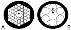
도 6과 도 7(종래기술, 새로운 주파수의 생성을 고려하지 않음)에 도시된 바와 같이, HC-ARF, 특히 카고메(Kagome) 또는 단일 링(single ring) 타입의 HC-ARF에서의 도광(light guiding) 메커니즘은 대체로 중공의 중앙 코어를 둘러싸는 벽으로부터의 광의 반공진 반사를 기초로 한다(예컨대, 문헌 [5] 참조). 이러한 2차원 한정은 횡방향 코어 모드의 형성을 유발하며, 반공진은 비교적 광대역의 안내 창(guiding window)를 가능케 한다.As shown in Figs. 6 and 7 (prior art, not taking into account the generation of new frequencies), light guide in HC-ARF, especially Kagome or single ring type HC-ARF. The guiding) mechanism is largely based on the anti-resonant reflection of light from the wall surrounding the hollow central core (see eg document [5]). This two-dimensional confinement causes the formation of a transverse core mode, and the anti-resonance enables a relatively broadband guiding window.
도 6a는 문헌 [6]에 기재된 바와 같은 카고메 타입의 HC-ARF의 횡단면을 도시하는데, 벽 내에서 안내되는 광의 벽 모드(wall mode)의 생성 및 코어 모드의 안내가 약 190mm 내지 약 295mm의 코어 벽 두께의 범위에 대해 검사되었다. 대안으로서, 도 6b에 도시된 바와 같은 단일 링 타입의 HC-ARF가 문헌 [7]에 기재되어 있는데, 단일 링 직경, 내부 코어 직경 및 벽 두께 t가 섬유 전송에 미치는 영향이 조사되었다.6A shows a cross-section of a Kagome type HC-ARF as described in [6], wherein the generation of a wall mode of light guided within the wall and guidance of the core mode is from about 190 mm to about 295 mm. Checked for a range of wall thicknesses. As an alternative, HC-ARF of a single ring type as shown in Fig. 6B is described in document [7], the effect of single ring diameter, inner core diameter and wall thickness t on fiber transmission was investigated.
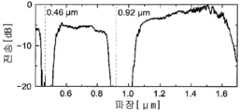
전술한 HC-ARF 결과의 단점은 도 7 및 도 3a(곡선 A2)에 예시적인 방식으로 도시된 바와 같이, HC-ARF의 전송에 대한 벽 모드 및 코어 모드의 공진의 영향에서 볼 수 있다. 예를 들어, 벽 두께 t=0.44μm인 60cm의 단일 링 섬유를 통한 전송은 제1(0.92μm에서, m=1) 및 제2(0.46μm에서, m=2) 코어 벽 공진을 보여주는데, 이는 섬유 전송 스펙트럼에서 전송 딥(transmission dip)으로 보여진다.The disadvantage of the aforementioned HC-ARF results can be seen in the influence of the resonance of the wall mode and the core mode on the transmission of the HC-ARF, as shown in an exemplary manner in FIGS. 7 and 3A (curve A2). For example, transmission through a 60 cm single ring fiber with a wall thickness t=0.44 μm shows first (at 0.92 μm, m=1) and second (at 0.46 μm, m=2) core wall resonances, which It is seen as a transmission dip in the fiber transmission spectrum.
다른 단점으로, 문헌 [6]에서는 HC-ARF를 통한 협대역(narrow-band) UV 광(예를 들면, 280nm의 단일 파장)의 전송이 조사되었는데, 단 몇 시간의 동작 후에도 전송 열화(degradation)가 발생할 수 있음이 밝혀졌다(도 3b(곡선 B2)에 도시된 것과 유사). 문헌 [6]에서는, 전송 손실이 코어를 둘러싸는 벽의 두께에 있어서의 가공 유발 변동으로 인해 초래될 수 있음이 제안되었다. 또한, 약 190nm 내지 약 290nm 범위의 소정의 벽 두께가 제공되고 두께의 변동이 회피되면, 연속파 광 필드의 전송 열화가 억제될 수 있음이 제안되었다.As another disadvantage, in literature [6], transmission of narrow-band UV light (for example, a single wavelength of 280 nm) through HC-ARF was investigated, but transmission degradation after only a few hours of operation was investigated. It has been found that can occur (similar to that shown in Fig. 3b (curve B2)). In document [6], it has been proposed that transmission loss can be caused by a processing-induced variation in the thickness of the wall surrounding the core. Further, it has been proposed that if a predetermined wall thickness in the range of about 190 nm to about 290 nm is provided and variations in thickness are avoided, the transmission deterioration of the continuous wave optical field can be suppressed.
또한, 전송 열화가 코어 벽 공진의 결과임이 문헌 [6]에서 확인되었는데, 코어 모드가 벽 모드와 위상 정합하는 파장은 다음의 수학식 1로 근사화될 수 있다.In addition, it has been confirmed in Document [6] that the transmission degradation is a result of the core wall resonance. The wavelength at which the core mode matches the wall mode in phase can be approximated by

여기서 nm은 모드 인덱스(충전가스의 굴절률로서, 약 1)이고, ng는 섬유 재료의 굴절률이며, hcw는 단일 링의 두께이고, 양의 정수 q는 섬유 벽에 의해 지지되는 횡방향 공진 차수를 정의한다. 도광(guided light)의 협대역 파장을 선택함으로써, 전송 열화가 회피될 수 있음이 문헌 [6]에서 밝혀졌다.Where nm is the mode index (refractive index of the filling gas, about 1), ng is the refractive index of the fiber material, hcw is the thickness of a single ring, and a positive integer q is the transverse resonance supported by the fiber wall. Define the order. It has been found in literature [6] that transmission degradation can be avoided by selecting the narrow-band wavelength of the guided light.
예를 들어 문헌 [1] 또는 [8]에 따르면, 백색광 발생을 위해 HC-ARF를 적용하고, 펌프 펄스와 빔 파라미터, 섬유 구조, 충전가스 타입 및 압력을 적절히 조절하면, 특히 UV 범위(전형적으로 350nm 미만의 파장)에서 광대역 출력 펄스 신호가 생성되어 섬유단(fiber end)으로 안내될 수 있다. 그러나, 상기의 HC-ARF에서의 전송 열화로 인해, UV 생성을 위한 섬유의 적용은 제한될 수 있다.For example, according to literature [1] or [8], if HC-ARF is applied for white light generation and the pump pulse and beam parameters, fiber structure, filling gas type and pressure are properly adjusted, in particular the UV range (typically At a wavelength of less than 350 nm), a broadband output pulse signal may be generated and guided to the fiber end. However, due to the transmission degradation in HC-ARF described above, the application of fibers for UV generation may be limited.
본 발명의 목적은 종래 기술의 단점을 회피하거나 저감할 수 있는, 개선된 광대역 광원 장치 및 광대역 광 펄스를 생성하는 개선된 방법을 제공하는 것이다. 특히, 광대역 광은 효율의 향상, 광섬유에서의 전송 손실의 저감 및/또는 장기적인 동작 안정성의 증가가 이루어지도록 생성된다.It is an object of the present invention to provide an improved broadband light source device and an improved method of generating broadband light pulses, which can avoid or reduce the drawbacks of the prior art. In particular, the broadband light is generated so as to improve the efficiency, reduce the transmission loss in the optical fiber, and/or increase the long-term operational stability.
이들 목적은 각각 청구범위의 독립항의 특징들을 포함하는 광대역 광원 장치, 광대역 광 펄스를 생성하는 방법, 또는 중공코어 섬유에 의해 해결된다. 본 발명의 바람직한 실시예 및 적용은 종속항에 명시된다.These objects are solved by a broadband light source device, a method of generating a broadband light pulse, or a hollow core fiber each comprising the features of the independent claims of the claims. Preferred embodiments and applications of the invention are specified in the dependent claims.
본 발명의 제1의 전체적인 양태에 따르면, 상기 목적은 비밴드갭(non-bandgap) 타입의 중공코어 섬유(중공코어 반공진 반사 섬유)와 펌프 레이저 소스 장치를 포함하는, 광대역 광 펄스를 생성하기 위한 광대역 광원 장치에 의해 해결된다.According to a first overall aspect of the present invention, the object is to generate a broadband optical pulse comprising a non-bandgap type of hollow core fiber (hollow core anti-resonant reflective fiber) and a pump laser source device. Is solved by a broadband light source device.
중공코어 섬유는 충전가스를 수용하고 펌프 레이저 펄스의 광학적 비선형 확장에 의해 광대역 광 펄스를 생성하는데 적합한 임의의 타입의 비밴드갭 중공 도광(light guiding) 섬유(HC-ARF)이다. 중공코어 섬유는 충전가스, 예를 들면 Ar, Ne, He, Kr, Xe와 같은 불활성 가스, H2, D2, N2와 같은 라만(Raman) 활성 가스, 또는 가스 혼합물을 포함하는 축방향 중공 도광 섬유 코어, 및 내부 섬유 구조를 구비한다. 중공 도광 섬유 코어는 도광 필드의 코어 모드를 지지한다. 내부 섬유 구조는 중공코어 섬유의 길이방향 연장부를 따라 연장되며 및 섬유 코어를 둘러싸는 내벽을 가지며, 도광 필드의 횡벽(transverse wall) 모드를 지원한다. 횡벽 모드는 기본 횡벽 모드와, 2차 이상의 횡벽 모드를 포함한다. 펌프 레이저 소스 장치는 중공코어 섬유의 입력측에서 초단 펌프 레이저 펄스(1ps 미만의 지속시간을 갖는 펌프 레이저 펄스)의 주기적인 시퀀스를 생성 및 제공하도록 배치된다.Hollow core fiber is any type of non-bandgap hollow light guiding fiber (HC-ARF) suitable for receiving fill gas and generating broadband light pulses by optical nonlinear expansion of pump laser pulses. The hollow core fiber is an axial hollow containing a filler gas, for example an inert gas such as Ar, Ne, He, Kr, Xe, aRaman active gas such as H 2, D 2 , N2 , or a gas mixture. It has a light guide fiber core, and an internal fiber structure. The hollow light guide fiber core supports the core mode of the light guide field. The inner fiber structure extends along the longitudinal extension of the hollow core fiber and has an inner wall surrounding the fiber core, and supports a transverse wall mode of the light guide field. The lateral wall mode includes a basic lateral wall mode and a second or higher lateral wall mode. The pump laser source device is arranged to generate and provide a periodic sequence of ultrashort pump laser pulses (pump laser pulses with a duration of less than 1 ps) at the input side of the hollow core fiber.
바람직하게는, 펌프 레이저 소스 장치는 높은 반복률, 예를 들면 100Hz 초과를 갖는 서브ps(ps 미만) 펄스를 제공하는데 적합하다. 펌프 레이저 소스 장치의 반복률은 펌프 소스의 선택에 따라 달라진다. 예를 들어, Ti:사파이어 기반의 펌프 소스는 전형적으로 1 kHz에서 동작하는데 반해, 섬유 기반의 펌프 소스는 단일 샷(single shot)으로부터 수십 HHz로 동작할 수 있다.Preferably, the pump laser source device is suitable for providing subps (less than ps) pulses with a high repetition rate, for example greater than 100 Hz. The repetition rate of the pump laser source device depends on the selection of the pump source. For example, Ti:sapphire based pump sources typically operate at 1 kHz, while fiber based pump sources can operate at tens of HHz from a single shot.
섬유에서 생성된 광 펄스의 시퀀스는 섬유 길이, 섬유 코어 직경, 펌프 레이저 펄스의 적어도 하나의 펌프 펄스 파라미터 및/또는 빔 파라미터, 및 충전가스의 적어도 하나의 가스 파라미터에 의해 결정되는 코어 모드 스펙트럼을 갖는다. 특히, 코어 모드 스펙트럼에 의해 커버되는 스펙트럼 범위는 섬유 길이와 섬유 코어 직경에 의해 결정된다. 펌프 펄스 파라미터는 예를 들면, 펄스 지속시간, 펄스 에너지, 펄스 형상 및 펄스 스펙트럼 중 적어도 하나를 포함한다. 빔 파라미터는 예를 들면, 펌프 레이저 펄스의 시퀀스에 의해 제공되는 레이저 빔(광 필드)의 모드 형상(modal shape), 지향 및 안정성 중 적어도 하나를 포함한다.The sequence of light pulses generated in the fiber has a core mode spectrum determined by the fiber length, fiber core diameter, at least one pump pulse parameter and/or beam parameter of the pump laser pulse, and at least one gas parameter of the fill gas. . In particular, the spectral range covered by the core mode spectrum is determined by the fiber length and fiber core diameter. Pump pulse parameters include, for example, at least one of pulse duration, pulse energy, pulse shape and pulse spectrum. The beam parameter comprises, for example, at least one of the modal shape, directivity and stability of the laser beam (light field) provided by a sequence of pump laser pulses.
본 발명에 따르면, 중공코어 섬유의 내부 섬유 구조는 횡벽 모드의 적어도 2차 이상의 횡벽 모드와 코어 모드 스펙트럼이 서로에 대해 스펙트럼 변위를 갖도록 구성된다. 즉, 중공코어 섬유의 내부 섬유 구조를 설계함으로써, 적어도 2차 이상의 공진 위치들은 코어 모드로 한정된 생성 광에 대해 스펙트럼적으로 변위된다. 따라서, 적어도 2차 이상의 횡벽 모드와 코어 모드 스펙트럼에 의해 커버되는 스펙트럼 범위 사이에는 스펙트럼 갭이 존재한다. 횡벽 모드는 코어 모드의 스펙트럼 분포와 중첩되지 않는다.According to the present invention, the inner fiber structure of the hollow core fiber is configured such that the transverse wall mode and the core mode spectrum of at least a second order or higher of the transverse wall mode have a spectral displacement with respect to each other. That is, by designing the internal fiber structure of the hollow core fiber, the resonant positions of at least secondary or higher are spectrally displaced with respect to the generated light limited to the core mode. Thus, there is a spectral gap between the transverse wall mode of at least the second or higher order and the spectral range covered by the core mode spectrum. The transverse wall mode does not overlap with the spectral distribution of the core mode.
본 발명의 제2의 전체적인 양태에 따르면, 상기 목적은 광대역 광 펄스를 생성하는 방법에 의해 해결되며, 펌프 레이저 펄스는 충전가스를 포함하는 비밴드갭 타입의 중공코어 섬유로 지향되고, 광대역 광 펄스는 중공코어 섬유에서 펌프 레이저 펄스의 광학 비선형 확장에 의해 생성된다. 중공코어 섬유는 횡벽 모드와 코어 모드 스펙트럼을 지지하는데, 코어 모드 스펙트럼은 섬유 길이, 섬유 코어 직경, 펌프 레이저 펄스의 적어도 하나의 펌프 펄스 파라미터 및/또는 빔 파라미터, 및 충전가스의 적어도 하나의 가스 파라미터에 의해 결정된다.According to a second overall aspect of the present invention, the above object is solved by a method of generating a broadband optical pulse, the pump laser pulse is directed to a non-bandgap type hollow core fiber containing a filling gas, and a broadband optical pulse Is produced by the optical nonlinear expansion of the pump laser pulse in the hollow core fiber. The hollow core fiber supports transverse wall mode and core mode spectrum, wherein the core mode spectrum includes fiber length, fiber core diameter, at least one pump pulse parameter and/or beam parameter of the pump laser pulse, and at least one gas parameter of the fill gas. Is determined by
본 발명에 따르면, 중공코어 섬유의 적어도 2차 이상의 횡벽 모드는 중공코어 섬유의 코어 모드 스펙트럼에 대해 스펙트럼적으로 변위된다. 따라서, 코어 모드 스펙트럼에 대해 벽 모드의 스펙트럼 변위를 제공하도록 설계된 HC-ARF가 사용된다. 바람직하게는, 광대역 광 레이저 펄스는 본 발명의 제1의 전체적인 양태에 따른 광대역 광원 장치에 의해 생성된다.According to the present invention, at least the secondary or higher transverse wall mode of the hollow core fiber is spectrally displaced with respect to the core mode spectrum of the hollow core fiber. Thus, HC-ARF designed to provide the spectral displacement of the wall mode with respect to the core mode spectrum is used. Preferably, the broadband optical laser pulse is generated by the broadband light source device according to the first overall aspect of the present invention.
유익하게는, 본 발명의 광대역 광원 장치 및 방법은 광대역의, 고휘도(high brightness) 방사선을 합성할 수 있다. 특히, 방사된 섬유 출력(광대역 광 펄스, UV-IR 펄스라고도 지칭됨)은 UV 파장 범위의 적어도 일부를 커버하는 스펙트럼을 갖는다. 바람직하게는, 방사된 스펙트럼은 원자외선(deep UV), 예를 들면 250nm 로부터 근적외선(near IR), 예를 들면 1100nm까지의 범위에 포함된다. 방사된 스펙트럼은 벽 모드와 코어 모드의 공진에 의해 결정되는 스펙트럼 특징이 없다. 또한, "광대역 광원 장치"라는 용어는 이 방사된 스펙트럼에 포함된 펄스 출력을 생성하는데 적합한 시스템을 의미한다. 광대역 광원 장치는 탁상(table-top) 장치로 구성될 수 있으며, 예를 들면 광학 계측(특히, 반도체 적용에서), 분광법, 또는 생명과학 응용분야에서 툴(tool)로 사용될 수 있다. 본 발명은 종래의 실리카 코어, 섬유 기반의 초연속체(supercontinuum) 시스템에 비교될 수 있으나 그 방사 스펙트럼을 원자외선(deep UV)까지 확장하는, 광대역 광 생성 성능을 제공한다. 종래의 광대역 램프와 비교하면, 방사 빔은 공간적으로 일관적이어서 스펙트럼 밝기가 극적으로 증가되고, 광섬유 출력은 매우 우수한 빔 지향 안정성을 제공한다.Advantageously, the broadband light source device and method of the present invention can synthesize broadband, high brightness radiation. In particular, the radiated fiber output (broadband light pulse, also referred to as UV-IR pulse) has a spectrum covering at least a portion of the UV wavelength range. Preferably, the radiated spectrum is included in the range from deep UV, for example 250 nm to near IR, for example 1100 nm. The radiated spectrum has no spectral features determined by the resonance of the wall mode and the core mode. Further, the term "broadband light source device" means a system suitable for generating a pulsed output contained in this radiated spectrum. The broadband light source device may be configured as a table-top device, and may be used as a tool in, for example, optical metrology (especially in semiconductor applications), spectroscopy, or life science applications. The present invention can be compared to a conventional silica core, fiber-based supercontinuum system, but provides a broadband light generation performance that extends its emission spectrum to deep UV. Compared with conventional broadband lamps, the radiation beam is spatially consistent so that the spectral brightness is dramatically increased, and the optical fiber output provides very good beam directing stability.
특히, 본 발명은 본 발명자들에 의한 이하의 고려사항에 기초한다. 첫째, 코어 모드와 벽 모드가 섬유 내에서 동일하거나 유사한 전파(propagation) 파라미터들을 갖는 공진 위치에서, UV 방사선은 섬유 코어로부터 강하게 누출되며, 섬유단(fiber end)에 도달하기 전에 강한 감쇠(attenuation)를 겪는다. 그 결과, 최종 사용자에게 강한 UV 신호를 제공하기 위해서는, 상대적으로 제한된 코어 모드와 비교하여 횡방향 필드 분포의 증대 및 공진이 회피되어야 한다. 둘째, 광대역 광의 UV 부분이 내부 섬유 구조의 일부이며 전형적으로 실리카로 구성되는 내벽과 강하게 중첩되면, 점차적인 섬유 열화가 발생할 가능성이 있다(솔러라이제이션(solarization)에 기인함). 이는 벽으로 누출되는 광을 억제함으로써 회피될 수 있다.In particular, the present invention is based on the following considerations by the inventors. First, at the resonant position where the core mode and the wall mode have the same or similar propagation parameters within the fiber, the UV radiation leaks strongly from the fiber core, and there is a strong attenuation before reaching the fiber end. Suffers. As a result, in order to provide a strong UV signal to the end user, the increase in the lateral field distribution and resonance must be avoided compared to the relatively limited core mode. Second, if the UV portion of the broadband light is part of the inner fiber structure and strongly overlaps the inner wall, which is typically composed of silica, there is a possibility of gradual fiber degradation (due to solarization). This can be avoided by suppressing light leaking into the wall.
따라서, 본질적인 이점으로서, 본 발명의 코어 모드와 적어도 2차 이상의 횡벽 모드의 분리에 의해, 코어 모드로부터 횡벽 모드로의 광의 공진 결합(resonant coupling)이 억제되어, 코어 모드의 구속이 증가되고, 생성된 스펙트럼이 전체적으로 더 평탄하고 수명이 더 길이진다.Therefore, as an essential advantage, by the separation of the core mode and the transverse wall mode of at least the second or higher order of the present invention, the resonant coupling of light from the core mode to the transverse wall mode is suppressed, so that the constraint of the core mode is increased, and The resulting spectrum is flatter overall and has a longer lifetime.
또한 광 필드 파워의 섬유의 내부 구조로의 누출이 저감된다. 본 발명자들은 섬유에 대한 파워 로드(power load)를 저감함으로써 섬유 벽 재료의 변화, 특히 광 흡수 섹션의 형성이 최소화될 수 있고, 그래서 장기적인 동작 안정성이 증가될 수 있다는 것을 찾아냈다.In addition, leakage of the optical field power into the internal structure of the fiber is reduced. The inventors have found that by reducing the power load on the fiber, changes in the fiber wall material, in particular the formation of the light absorbing section, can be minimized, so that long-term operational stability can be increased.
따라서, 자외선 스펙트럼 범위에서의 광대역 광의 발성을 위한 기존의 HC-ARF 기반의 방식과 비교하여, 본 발명은 자외선 스펙트럼 영역에서 장기적이며 안정적인 광의 발생과 함께 섬유의 열화가 크게 저감되게 함으로써 수명을 연장한다. 또한, 생성된 스펙트럼의 범위에서 섬유의 공진 저감 특성은 방사된 광대역 신호의 스펙트럼 평탄도를 증가시키며 동시에 균일한 횡방향 모드 프로파일을 발생시킨다Therefore, compared with the conventional HC-ARF-based method for vocalization of broadband light in the ultraviolet spectrum range, the present invention extends the lifespan by greatly reducing the deterioration of the fiber with the generation of long-term and stable light in the ultraviolet spectrum range. . In addition, the resonance reduction characteristics of the fiber in the range of the generated spectrum increase the spectral flatness of the radiated broadband signal and at the same time generate a uniform transverse mode profile.
상기 이점은 본 발명의 코어 모드와 2차 이상의 횡벽 모드의 디커플링에 의해 이미 얻어질 수 있다. 이는 본 발명의 발명자에 의한 하기의 이론적인 고려사항에 기인한다. 기본 공진은 고차 공진보다 더 긴 파장에서 발생한다. 그 결과, 솔러라이제이션이 발생할 가능성이 더 적은데, 이는 다중 광자 흡수가 필요하기 때문이다. 또한, 코어 모드와 기본 벽 모드 사이의 중첩 적분은 고차 공진과 비교하여 다르다. 그 결과, 코어 모드로부터 벽 모드로 더 적은 에너지가 전달될 수 있다. 마지막으로, 에너지 전달이 발생하는 스펙트럼 대역폭은 다르며, 코어 모드에 대한 벽 모드의 유효 지수(effective index)의 기울기 차이에 따라 달라진다. 기본 공진의 경우, 기울기 차이가 더 낮은데 이는 잠재적으로는 더 큰 스펙트럼 밴드폭을 초래할 수 있다This advantage can already be obtained by decoupling of the core mode of the present invention and the transverse wall mode of the second or higher order. This is due to the following theoretical considerations by the inventors of the present invention. The fundamental resonance occurs at a longer wavelength than the higher order resonance. As a result, solarization is less likely to occur because multiple photon absorption is required. Also, the superposition integral between the core mode and the basic wall mode is different compared to the higher order resonance. As a result, less energy can be transferred from the core mode to the wall mode. Finally, the spectral bandwidth at which energy transfer occurs is different and depends on the difference in slope of the effective index of the wall mode versus the core mode. For the fundamental resonance, the slope difference is lower, which could potentially lead to a larger spectral bandwidth.
하지만, 본 발명의 바람직한 실시예에 따르면, 모든 횡벽 모드, 즉 기본, 2차 이상의 횡벽 모드, 및 코어 모드 스펙트럼은 서로에 대해 스펙트럼 변위를 가지며, 코어 모드와 벽 모드의 공진 커플링의 전적인 억제가 얻어진다. 유익하게는, 섬유 구조는 제1의 코어 벽 공진이 생성된 스펙트럼의 최단 파장보다 아래에 놓이도록 설계된다. 본 발명에 따라 사용되는 섬유 구조는 UV에서 벽 재료, 예를 들면 유리와의 모드 중첩을 최소화하며, 그 결과 섬유의 손상을 예방하고 더 나아가서는 시스템의 수명을 연장시킨다However, according to a preferred embodiment of the present invention, all the transverse wall modes, i.e., the basic, second or higher order transverse wall modes, and the core mode spectra have spectral displacements with respect to each other, and the total suppression of the resonant coupling of the core mode and the wall mode is Is obtained. Advantageously, the fiber structure is designed such that the first core wall resonance lies below the shortest wavelength of the generated spectrum. The fiber structure used according to the invention minimizes the mode overlap with the wall material, e.g. glass, in UV, thereby preventing damage to the fiber and further extending the life of the system.
본 발명의 또 다른 바람직한 실시예에 따르면, 코어 모드와 벽 모드의 디커플링을 위한 중공섬유, 특히 HC-ARF의 내부 섬유 구조를 설계하는 것은 섬유 코어를 향하는 내부 섬유 구조의 섬유 벽의 벽 두께를 선택함으로써 얻어진다. 벽 두께는 적어도 2차 이상, 바람직하게는 모든 횡벽 모드가 코어 모드 스펙트럼에 대해 보다 짧은 파장으로 스펙트럼이 쉬프트(shift)되도록 적어도 섬유의 하류 부분을 따라 한계 벽 두께 미만이 되게 선택된다. 유익하게는, 벽 두께는 중공 섬유를 제작할 때 또는 그 제작 후에(예를 들면, 에칭함으로써) 쉽게 조절될 수 있는 섬유 파라미터이다. 놀라운 결과로서, 본 발명의 발명자들은 섬유 내에서 안내되는 광 필드 파워에 대한 민감도 또는 섬유 안정성을 해치지 않으면서, 중공 섬유가 중공코어에 인접한 내부 구조의 충분히 얇은 벽 두께를 구비할 수 있음을 찾아냈다.According to another preferred embodiment of the present invention, designing the internal fiber structure of the hollow fiber, in particular HC-ARF for decoupling of the core mode and the wall mode, selects the wall thickness of the fiber wall of the inner fiber structure facing the fiber core. It is obtained by doing. The wall thickness is selected to be at least a second order or higher, preferably less than the limiting wall thickness along the downstream portion of the fiber such that all transverse wall modes shift the spectrum to a shorter wavelength with respect to the core mode spectrum. Advantageously, the wall thickness is a fiber parameter that can be easily adjusted when making or after making the hollow fiber (eg, by etching). As a surprising result, the inventors of the present invention have found that the hollow fiber can have a sufficiently thin wall thickness of the internal structure adjacent the hollow core without compromising the sensitivity or fiber stability to the optical field power guided within the fiber. .
일례로서, 볼 발명의 발명자에 의한 실제 테스트는 벽 두께를 예를 들면, 0.32μm(종래의 중공 섬유)로부터 약 120nm로 줄이면, 전송 스펙트럼에서의 공진의 횟수(코어 모드와 벽 모드의 커플링을 나타냄)가 3개에서 약 0.25μm에서의 1개로 저감됨을 보여주었다. 광대역 스펙트럼의 장파장(long wavelength) 섹션에 이러한 잔류 공진이 있는 경우에도, 섬유 동작 지속시간의 상당한 증가가 얻어질 수 있다.As an example, an actual test by the inventor of the ball invention shows that reducing the wall thickness from, for example, 0.32 μm (conventional hollow fiber) to about 120 nm, reduces the number of resonances in the transmission spectrum (the coupling of the core mode and the wall mode). Shown) was reduced from 3 to 1 at about 0.25 μm. Even if there is such a residual resonance in the long wavelength section of the broadband spectrum, a significant increase in the fiber operating duration can be obtained.
중공 섬유는 그 길이를 따라서 벽 두께의 분포를 가질 수 있는데, 입력측에서의 더 큰 두께로부터 출력측 쪽으로의 두께 한계 벽 두께 미만의 두께로 변한다. 내부 섬유 구조의 섬유 벽이, 광대역 광 펄스가 생성되어 중공코어 섬유를 통해서 그 출력단 쪽으로 전송되는 중공코어 섬유의 종단면(longitudinal section)에서만 한계 벽 두께 미만의 선택된 벽 두께를 갖는 경우, 섬유의 상류 부분에서의 섬유 안정성의 측면에서 또 다른 이점이 얻어진다. 섬유가 펌프의 구속 손실을 저감시키기 위해 입력측에서 상대적으로 두꺼운 벽을 갖는 것이 유익할 수 있다.Hollow fibers may have a distribution of wall thickness along their length, varying from a greater thickness at the input side to a thickness less than the thickness limit wall thickness toward the output side. If the fiber wall of the internal fiber structure has a selected wall thickness less than the limit wall thickness only in the longitudinal section of the hollow core fiber, where a broadband light pulse is generated and transmitted to its output end through the hollow core fiber, the upstream portion of the fiber Another advantage is obtained in terms of fiber stability in It can be beneficial for the fibers to have relatively thick walls on the input side to reduce the confinement losses of the pump.
본 발명은 중공코어 및 중공코어에 인접한 내부 구조의 규칙적인 배열을 포함하는 임의의 타입의 전술한 비밴드갭 광자 섬유로 구현될 수 있다. 바람직하게, 내부 섬유 구조는 그 도광(light guiding) 특성에 대해 장기간 연구가 이루어진 단일 링 또는 카고메 구조를 포함한다. 단일 링 또는 카고메 타입의 HC-ARF의 경우, 섬유 코어를 향하는 섬유 벽은 바람직하게는 하기의 수학식 2와 같이 선택되는 벽 두께(t)를 갖는다:The present invention can be implemented with any type of the aforementioned non-bandgap photonic fibers comprising a hollow core and a regular arrangement of internal structures adjacent to the hollow core. Preferably, the inner fibrous structure comprises a single ring or kagome structure that has been studied for a long period of time for its light guiding properties. In the case of a single ring or kagome type HC-ARF, the fiber wall facing the fiber core preferably has a wall thickness t selected as in

여기서, λmin은 코어 모드 스펙트럼의 최단 파장이고, n1은 중공코어 섬유 내의 충전가스의 굴절률이며, n2는 내부 섬유 구조의 굴절률이다. 유익하게는, 상기 공식은 몇몇 알려진 파라미터에만 의존하여 설정될 수 있는 한계 벽 두께를 제공한다.Here, λmin is the shortest wavelength of the core mode spectrum, n1 is the refractive index of the filling gas in the hollow core fiber, and n2 is the refractive index of the internal fiber structure. Advantageously, the above formula provides a limiting wall thickness that can be set depending on only a few known parameters.
특히 바람직하게는, 벽 두께는 70nm 내지 300nm의 범위, 예를 들어, 중공 섬유가 유리(실리카)로 제작되면 특히 70nm 내지 150nm의 범위에서 선택된다. 하한치는 중공 섬유 및 그 내부 구조에 충분한 기계적 안정성을 제공하는 것이 밝혀졌다. 상한치는 유익하게는 코어 모드와 벽 모드의 공진의 억제를 제공한다. 상한치 150nm에 의해, 모든 벽 모드로부터의 스펙트럼 분리가 얻어진다. 또한, 중공 섬유는 바람직하게는 170nm 내지 250nm 범위의 최단 파장 λmin을 갖는 코어 모드 스펙트럼을 지지하는데 적합하다.Particularly preferably, the wall thickness is selected in the range of 70 nm to 300 nm, for example, particularly in the range of 70 nm to 150 nm if the hollow fiber is made of glass (silica). It has been found that the lower limit provides sufficient mechanical stability to the hollow fiber and its internal structure. The upper limit advantageously provides suppression of the resonance of the core mode and the wall mode. With an upper limit of 150 nm, spectral separation from all wall modes is obtained. Further, the hollow fiber is preferably suitable for supporting a core mode spectrum havinga shortest wavelength λ min in the range of 170 nm to 250 nm.
본 발명의 다른 바람직한 실시예에 의하면, 광대역 광원 장치는 적어도 하나의 펌프 펄스 및/또는 빔 파라미터 중 적어도 하나를 조정하는데 적합하게 이루어진 조정 장치를 더 포함한다. 실제 일상적인 사용을 위한 시스템에서, 펌프 레이저 소스 장치는 정확한 펄스 파라미터가 설정되도록 미리 구성될 수 있다. 이 경우에, 빔 파라미터 제어만이 제공된다. 유익하게는, 조정 장치는 예를 들면, 중공 섬유에 주입된 펌프 펄스의 빔 지향, 즉 섬유 중심에 대한 빔 중심을 변경할 수 있다. 특히 바람직하게는, 조정 장치는 가스 압력 및/또는 가스 타입과 같이, 선택적인 가스 공급 장치로부터 중공 섬유에 공급되는 충전가스의 적어도 하나의 가스 파라미터를 조정하는데 적합하게 이루어진 섹션을 더 포함한다.According to another preferred embodiment of the present invention, the broadband light source device further comprises an adjusting device adapted to adjust at least one of the at least one pump pulse and/or beam parameter. In a system for practical daily use, the pump laser source device can be pre-configured so that the correct pulse parameters are set. In this case, only beam parameter control is provided. Advantageously, the adjusting device can change the beam direction of the pump pulse injected into the hollow fiber, ie the beam center relative to the fiber center, for example. Particularly preferably, the adjusting device further comprises a section adapted to adjust at least one gas parameter of the fill gas supplied to the hollow fiber from an optional gas supply device, such as gas pressure and/or gas type.
본 발명의 다른 바람직한 실시예에 따르면, 광대역 광원 장치는 중공코어 섬유로부터 출력된 광대역 광 펄스의 코어 모드 스펙트럼의 적어도 일부를 모니터링하도록 배치된 모니터링 장치를 더 포함한다. 유익하게는, 모니터링 단계는 생성된 광대역 광 펄스의 온라인 측정 및 테스팅을 가능케 한다. 특히 바람직하게는, 모니터링 장치와 조정 장치를 포함하는 컨트롤 루프(control loop)가 제공된다. 컨트롤 루프는 횡벽 모드와 코어 모드 스펙트럼의 스펙트럼 변위가 광대역 광 펄스의 생성 동안에 유지되도록 조정 장치를 제어하기에 적합하게 이루어진다.According to another preferred embodiment of the present invention, the broadband light source device further comprises a monitoring device arranged to monitor at least a portion of the core mode spectrum of the broadband optical pulse output from the hollow core fiber. Advantageously, the monitoring step enables on-line measurement and testing of the generated broadband optical pulses. Particularly preferably, a control loop is provided comprising a monitoring device and an adjusting device. The control loop is adapted to control the adjustment device so that the spectral displacement of the transverse wall mode and the core mode spectrum is maintained during the generation of the broadband light pulse.
본 발명의 제3의 전체적인 양태에 따르면, 상기 목적은 충전가스에서 펌프 레이저 펄스의 광학 비선형 확장에 의해 광대역 광 펄스를 생성하는데 적합하게 이루어진 중공코어 섬유, 특히 HC-ARF에 의해 해결된다. 중공코어 섬유는 충전가스로 충전되며 광대역 광 펄스의 도광 필드의 코어 모드를 지지하는 축방향의 중공 섬유 코어와, 섬유 코어를 둘러싸며 도광 필드의 횡벽 모드를 지지하는 내부 섬유 구조를 갖는다. 횡벽 모드는 기본 횡벽 모드와 2차 이상의 횡벽 모드를 포함한다. 광대역 광 펄스는 펌프 레이저 펄스의 적어도 하나의 펌프 펄스 파라미터와 충전가스의 적어도 하나의 가스 파라미터에 의해 결정되는 코어 모드 스펙트럼을 갖는다. 본 발명에 따르면, 중공코어 섬유의 내부 섬유 구조는 적어도 2차 이상의 횡벽 모드와 코어 모드 스펙트럼이 서로에 대해 스펙트럼 변위를 갖도록 구성된다. 광대역 광 펄스를 생성하기 위해 중공코어 섬유를 사용하는 것은 본 발명의 다른 독립적인 주제를 나타낸다.According to a third overall aspect of the invention, the object is solved by a hollow core fiber, in particular HC-ARF, adapted to generate broadband optical pulses by optical nonlinear expansion of pump laser pulses in the filling gas. The hollow core fiber is filled with a filling gas and has an axial hollow fiber core supporting the core mode of the light guide field of the broadband light pulse, and an inner fiber structure surrounding the fiber core and supporting the transverse wall mode of the light guide field. The lateral wall mode includes a basic lateral wall mode and a second or higher lateral wall mode. The broadband light pulse has a core mode spectrum determined by at least one pump pulse parameter of the pump laser pulse and at least one gas parameter of the fill gas. According to the present invention, the internal fiber structure of the hollow core fiber is configured such that the transverse wall mode and the core mode spectrum of at least a second or higher order have a spectral displacement relative to each other. The use of hollow core fibers to generate broadband light pulses represents another independent subject matter of the present invention.
본 발명의 다른 구체사항 및 이점은 첨부된 도면을 참조하여 이하에 기술되어 있다.
도 1은 본 발명에 따른 광대역 광원 장치의 일 실시예의 개략도.
도 2와 도 3은 HC-ARF의 본 발명의 설계의 개략 예시도.
도 4는 본 발명에 따른 광대역 광원 장치의 일 실시예의 추가 상세사항을 도시하는 개략도.
도 5는 본 발명의 방법에 의해 생성된 광대역 광 펄스의 출력 스펙트럼.
도 6과 도 7은 종래의 HC-ARF와 그 전송 스펙트럼(종래기술)의 개략적인 예시도.Other embodiments and advantages of the present invention are described below with reference to the accompanying drawings.
1 is a schematic diagram of an embodiment of a broadband light source device according to the present invention.
2 and 3 are schematic illustrations of the inventive design of an HC-ARF.
4 is a schematic diagram showing further details of an embodiment of a broadband light source device according to the present invention.
5 is an output spectrum of a broadband optical pulse generated by the method of the present invention.
6 and 7 are schematic diagrams of a conventional HC-ARF and its transmission spectrum (prior art).
본 발명의 특징이 카고메(Kagome) 또는 단일 링 타입의 HC-ARF 및 특히 펌프 소스 장치와 가스 공급 장치를 조정하는 컨트롤 루프를 포함하는 UV 광원 장치에서의 광대역 광 펄스의 생성을 특히 참조하여 이하에서 설명된다. 본 발명은 이들 실시예에 국한되지 않으며, 오히려 다른 타입의 HC-ARF를 사용하여 및/또는 자동 컨트롤 루프 없이도 구현될 수 있다. 중공 섬유에서 펌프 펄스를 스펙트럼 확장하기 위한 광학적 비선형 프로세스의 구체사항은 종래기술로부터 알려져 있으므로 여기서는 설명되지 않는다.A feature of the invention is the generation of broadband light pulses in a Kagome or single ring type HC-ARF and in particular a UV light source device comprising a pump source device and a control loop for regulating the gas supply device, with reference to the following. Is explained. The invention is not limited to these embodiments, but rather can be implemented using other types of HC-ARF and/or without automatic control loops. The details of the optical nonlinear process for spectral broadening the pump pulse in hollow fibers are known from the prior art and are not described here.
도 1은 광대역 UV광(자외선) 발생을 위한 본 발명의 구성의 개략도를 보여준다. 광대역 광원 장치(100)는 중공코어 섬유(10)와 펌프 레이저 소스 장치(20)를 포함한다. 중공코어 섬유(10)는 예를 들면 단일 링 타입의 HC-ARF이며, 확대 횡단면도 및 도 2에 도시된 바와 같이, 중공코어(11)와 내부 섬유 구조(12)를 가지며 중공코어 섬유(10)의 입력측(13)으로부터 출력측(14)으로 일직선의 길이방향을 따라 연장된다. 횡단면도에 따르면, 내부 섬유 구조(12)는 예를 들면 입력측(13)과 출력측(14) 사이에서 튜브 형상으로 연장되는 벽(15)을 각각 갖는 6개의 박벽 모세관(thin-walled capillary)의 규칙적인 배열을 포함한다. 중공코어 섬유(10)는, 예를 들면 50cm의 길이와, 예를 들면 25μm의 코어 직경을 갖는다. 벽(15)은 예를 들면 300nm의 두께를 갖는다.1 shows a schematic diagram of the configuration of the present invention for generating broadband UV light (ultraviolet rays). The broadband
펌프 레이저 소스 장치(20)는 예를 들어, 5 fs 내지 1 ps 범위의 지속시간과, 200 내지 2000 nm 범위의 중심 파장, 및 0.001 kHz 내지 100 MHz 범위의 반복률을 갖는 일련의 펌프 펄스(2)를 방출하는 고체 상태(솔리드 스테이트) 또는 섬유 레이저 타입의 펄스 소스를 포함한다.The pump
중공코어 섬유(10)는, 예를 들면 Ar과 같은 충전가스를 수용하는 가스 셀을 포함하는 가스 공급 장치(34)에 고정 배치된다. 가스 셀은 제어 가능한 밸브를 통하여 가스 소스(도시하지 않음)에 연결될 수 있으며, 펌프 펄스(2)와 광대역 광 펄스(1)가 각각 투과하는 입력창(41)과 출력창(42)을 갖는다. 입력창(41)과 출력창(42)은 광학 품질을 갖는 유리로 제작된다. 상업적 용도의 실제 시스템에서는 외부 가스 소스가 필요치 않을 수도 있다. 예를 들어, 가스 셀은 제작시에 충전가스로 충전되어 밀봉될 수 있다.The
광대역 광 펄스(1)를 생성하기 위해, 펌프 레이저 펄스(2)의 빔은 입력창(41)을 통해서 중공 섬유(10)의 입력측으로 지향되어서는 그 중공섬유 코어(11)에 결합된다. 펌프 레이저 펄스(2)는 중공 섬유(10)의 길이방향 축과 일치하는 빔 경로를 따라서 주입된다. 중공 섬유(10)는 아래에서 도 5를 참조하여 예시적인 방식으로 기재되는 바와 같이, 도광 필드(guided light field)의 코어 모드를 지지한다. 또한 내부 섬유 구조(12)는 도광 필드의 횡벽(transverse wall) 모드를 지지한다. 중공 섬유 내에서, 예를 들면 위치(16) 주위에서 펌프 레이저 펄스(2)의 광학 비선형 확장에 의해 광대역 광 펄스(1)가 생성된다. 광대역 광 펄스(1)는 펌프 펄스 및 펌프 빔 파라미터, 충전가스의 타입 및 그 농도(압력)에 의존하는 광대역 코어 모드 스펙트럼을 갖는다. 횡벽 모드와 코어 모드 스펙트럼이 서로에 대해 스펙트럼적으로 변위되도록(spectrally displaced) 코어 모드 스펙트럼이 설정되고 중공 섬유가 구성된다.In order to generate the broadband
본 발명에 따르면, 섬유 벽 두께(t)가 상기 수학식 2로 주어지도록 섬유 구조가 선택된다. 생성되는 최소 파장은 섬유 구조와 길이, 펌프 펄스와 펌프 빔 파라미터, 및 가스 타입과 압력(충전가스의 굴절률에 영향을 미침)의 상호작용의 결과이다.According to the present invention, the fiber structure is selected so that the fiber wall thickness t is given by
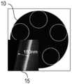
도 2는 주사전자 현미경 이미지로 예시된, 중공 섬유(10)의 다른 예를 보여준다. 단일 링 중공 섬유(10)는 HF 에칭에 의해 360nm 벽을 갖는 종래의 중공 섬유로부터 얻어진 150nm 벽(박벽)을 갖는다. 삽화는 벽(15)의 클로즈업 이미지를 보여준다.2 shows another example of a
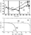
예를 들면 Ar과 같은 가스로 중공 섬유(10)를 충전하고 펌프 파라미터들을 조정함으로써, 펌프 펄스는 스펙트럼 확장이 이루어지며, 광대역 광 펄스의 측정된 스펙트럼이 도 3a(곡선 A1)에 도시되어 있다. 측정된 스펙트럼(곡선 A1)은 종래의 후벽(thick-walled) 섬유(곡선 A2)의 출력 스펙트럼과 대조적으로 공진 딥(resonance dip)을 나타내지 않는데, 종래의 후벽 섬유는 신호에서 2개의 뚜렷한 딥(760nm 근방에서 m=1, 및 390nm 근방에서 m=2)을 분명하게 보여준다.By filling the
시스템이 종래의 섬유을 이용하여 수 시간에 걸쳐서 작동되면, 출력 파워의 감쇠가 분명하게 드러난다(도 3b의 곡선 B2). 신호는 0.6 Wh에서 약 20%가 감소한다. 섬유가 본 발명에 따른 박벽을 가지면, 수명 테스트(도 3b의 곡선 B1)는 열화(degradation)가 300배 이상 개선되었음을 보여준다.When the system is operated over several hours using conventional fibers, the decay of the output power is evident (curve B2 in Fig. 3b). The signal decreases by about 20% at 0.6 Wh. If the fiber has a thin wall according to the present invention, the life test (curve B1 in Fig. 3b) shows that the degradation is improved by more than 300 times.
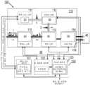
도 4는 광대역 광원 장치(100)의 추가 상세사항에 대한 블록도를 도시하는데, 광대역 광원 장치(100)는 광대역 광 펄스가 합성되어 사용자에게 제공되는 광 헤드(optical head)(110)와, 전자기기, 펌프 소스(20) 및 인터페이스의 제어부를 포함하는 제어 유닛(120)으로 구분될 수 있다.4 shows a block diagram of additional details of the broadband
광 헤드(110)는 펌프 소스(20), 전처리, 합성 및 후처리를 위한 개별 모듈(111 내지 115)을 포함한다. 모든 모듈(111 내지 115)은 안정성을 최적화하기 위해 상호적이며 견고한 베이스 플레이트 상의 단일 인클로저(single enclosure)에 통합된다. 실험실 환경에서, 광 헤드(110)는 전형적으로 광 테이블 상에 배치되며, 광대역 광 펄스(1)는 후처리 모듈(115)로부터 방출된다.The
펌프 소스 모듈(111)은, 수 0.001 kHz 내지 수 10 MHz(전자 제어식 변조기에 의해 조정 가능함) 사이의 반복률에서 수십 μJ의 에너지를 가짐으로써 최대 단지 몇 10W의 평균 파워를 갖게 되는 서브ps(sub-ps) 펄스를 방출하는 펌프 소스 장치(20)를 포함한다. 펌프 소스 장치(20)는 전형적으로 근적외선(near IR) 또는 해당 고조파(예를 들면, 녹색 또는 UV)의 중심 파장에서 동작하는 섬유 또는 박막 디스프(thin disk) 레이저이다.The
전처리 모듈(112)에서는, 광전자 수단(입력 체크)에 의해 펌프 펄스 및 펌프 빔 파라미터가 모니터링된다. 또한, 모듈(112)은 빔 안정성, 펄스 에너지, 평균 파워, 편광, 또는 빔 직경(빔 제어)과 같은 관련 특성을 성형(shape)하는 조정 장치(30)를 포함한다. 선택적으로, 펌프 펄스가 합성 모듈(113)에 전달되는 것을 방지하기 위해 전자 제어식 셔터가 삽입된다.In the
합성 모듈(113)은 전처리 모듈(112)에 의해 설계된 펌프 펄스(2)를 중공코어 광섬유(HC-ARF)(10)에 결합시키기 위해, 미러, 렌즈, 및/또는 편광 광학소자를 포함하는 광학 요소를 포함한다. 인커플링(incoupling)을 위한 광학 요소는 안정성 및 결합(커플링) 효율을 최적화하기 위해 선택된 홀더 및 메커니즘에 장착된다. 중공 섬유(10)는 선택적으로 제공된 유체 모듈(114)에 연결되는 하나 이상의 가스 셀(도 1 참조)에 통합된다. 가스 셀은 중공 섬유(10)가 유체(일반적으로, Ar, Ne, He, Kr, Xe와 같은 불활성 가스, H2와 같은 라만(Raman) 활성 가스, 또는 가스 혼합물)로 충전될 수 있도록 설계된다. (예를 들면, 중공 섬유(10)의 인커플링측 및 아웃커플링측에서) 수 개의 가스 셀을 사용하면, 섬유를 따라서 일정한 압력 분포 또는 상이한 압력이 설정된 경우에는 압력 구배(pressure gradient)가 얻어진다. 가스 셀의 단부(ends)는 입력/출력 펄스를 투과시키기 위한 적절한 창(도 1 참조) 또는 추가 셀을 연결하기 위한 내압 피팅(pressure-tight fitting)을 포함한다.The
유체 모듈(114)은 저진공(low vacuum) 내지 수 10 바(bar) 범위를 갖는 전자 압력 조절기를 포함하는 조정 장치(30)의 섹션을 포함한다. 모듈(114)은 또한 가스 저장소 및 진공 펌프(도시하지 않음)를 포함하는 가스 공급 장치(40)에 고압 및 진공 라인(116)을 통해 연결하기 위한 인터페이스를 포함할 수 있다.The
예를 들어, 평균 파워, 빔 지향 안정성, 스펙트럼, 빔 품질 또는 노이즈와 같은 합성 광대역 광 펄스(1)의 관련 파라미터는 후처리 모듈(115)에 포함된 모니터링 장치(50)로 모니터링된다. 중공 섬유(10)(출력 체크)로의 결합을 최적화하기 위해서 전처리 모듈(112)에 및 유체 모듈(114)에 피드백이 제공된다. 특히, 합성 스펙트럼의 일부 또는 전체가 모니터되며, 신호에 있어서의 분안정성이 전처리 모듈(112)의 빔 안정화 시스템에 의해 보상될 수 있다. 이러한 불안정성은 응력 또는 열 효과에 기인한 기계적인 오정렬(misalignment)의 결과일 수 있다. 또한, 스펙트럼은 평탄화되어 창을 통해 최종 사용자에게 제공된다.The relevant parameters of the composite broadband
본 시스템의 중요한 특징은 후처리 모듈(115)에 통합된 동적 피드백 기술인데, 이는 방출된 스펙트럼의 일부를 모니터링하며, UV 합성 프로세스를 최적화하기 위해 제어 유닛(120)을 포함하는 시스템 컨트롤 루프(60)를 통해 피드백 신호를 빔 안정화에 제공한다.An important feature of the system is the dynamic feedback technology integrated in the
제어 유닛(120)은 펌프 소스 장치(20), 빔 안정화(조정 장치(30)의 일부임), 가스 공급(조정 장치(30)의 다른 부분임) 및 전체 시스템을 위한 제어부(121 내지 123)로 구분된다. 모니터링 장치(50) 및 조정 장치(30)와 관련하여, 제어 유닛(120)은 장치 동작의 자동 조정을 위한 컨트롤 루프(60)를 제공한다. 제어 유닛(120)은 19인치(약 483mm) 랙 하우징에 장착되며, 제어 유닛이 광 헤드(110)로부터 수 미터 떨어져서 배치될 수 있도록 케이블은 충분히 길다.The
펌프 소스 제어부(121)는 펌프 소스 장치(20)의 동작을 제어하기 위해 전자장치, 광학장치, 및 선택적으로 냉각장치(chiller)를 포함한다. 빔 안정화 제어부(122)에 의해, 포함된 마이크로컨트롤러가 전처리 모듈(112) 내의 빔 안정화 시스템의 성능을 설정하고 중공 섬유(10)로의 결합을 최적화한다. 시스템 제어부(123)는 다양한 시스템 파라미터들을 모니터링 및 설정하기 위해 수개의 A/D 변환기 및 마이크로컨트롤러를 포함한다. 또한, 이 제어부(123)는 사용자가 시스템(대기 및 온/오프 스위치)과 상호작용할 수 있도록 하며, 광 헤드(110)를 제어 유닛(120)에 연결하기 위한 상이한 인터페이스뿐만 아니라 외부 컴퓨터 제어를 위한 인터페이스(RS232 및/또는 USB)를 제공한다.The pump
광대역 광원 장치(100)의 동작시에, 펌프 소스 모듈(111)에 의해 펌프 펄스(2)가 발생된다. 그리고 나서 펌프 펄스 빔이 전처리 모듈(112) 쪽으로의 자유 공간에 전달된다. 여기서, 상업적으로 이용 가능한 전자, 광학, 및 기계 요소들이 입력 체크 및 빔 제어에 사용된다. 자유공간 빔은 중공 섬유(10)의 코어에 결합되어 횡방향의, 기본 코어 코드를 여기시킨다. 펌프 펄스 파라미터(예를 들면, 수 100 fs의 펄스 지속시간)로 인해, 변조 불안정성(modulation instability: MI) 시스템이 펄스를 광학적으로 확장하기 위해 액세스된다(문헌 [8]). 스펙트럼적으로 확장된 출력 빔은 광학 소자에 의해 집속되고, 상업적으로 이용 가능한 전자, 광학, 및 기계 요소들을 사용하여 전처리 모듈(115)에 의해 성형되고는, 광대역 광 펄스(1)의 자유공간의, 평행 빔(collimated beam)으로서 최종 사용자에게 제공된다.During the operation of the broadband
실용적인 예로서, 동작 사양은 다음과 같다. 광대역 코어 모드 스펙트럼은 250nm 이하로부터 1100nm 이상까지의 파장 범위를 커버한다. 광대역 광 펄스(1)의 평균 출력 파워는 1W 이상이고, 스펙트럼 평탄도는 15 dB 미만(300 내지 1000nm 사이에서)이다. 도 5는 원자외선(deep UV)으로부터 근적외선(IR)에 이르는, 출력된 광대역 광 펄스(1)의 방사 스펙트럼(보정됨)의 일례를 도시한다. 삽화는 1.03μm에서의 빔 횡단면을 보여준다.As a practical example, the operating specifications are as follows. The broadband core mode spectrum covers a wavelength range from 250 nm or less to 1100 nm or more. The average output power of the broadband
상기 설명, 도면 및 특허청구범위에 개시된 본 발명의 특징은 그 다양한 실시예에서의 본 발명의 구현에 개별적으로, 조합 형태로 또는 하부 조합 형태로 중요할 수 있다.The features of the invention disclosed in the above description, drawings, and claims may be important to the implementation of the invention in its various embodiments, individually, in combination, or in sub-combination.
Claims (15)
Translated fromKorean충전가스를 포함하며, 펌프 레이저 펄스의 광학적 비선형 확장에 의해 상기 광대역 광 펄스를 생성하도록 구성된 중공코어 섬유 - 상기 중공코어 섬유는,
도광 필드(guided light field)의 코어 모드를 지지하도록 구성된 축방향의 중공 도광 섬유(axial hollow light guiding fiber core), 및
상기 섬유 코어를 둘러싸며, 상기 도광 필드의 횡벽(transverse wall) 모드를 지지하도록 구성된 내부 섬유 구조
를 포함함 - ; 및
상기 중공코어 섬유의 입력측에서 상기 펌프 레이저 펄스를 생성 및 제공하도록 구성된 펌프 레이저 소스 장치:
를 포함하며,
상기 횡벽 모드는 기본 횡벽 모드와 2차(second order) 이상의 횡벽 모드를 포함하는,
광대역 광원 장치.
A broadband light source device configured to generate a broadband light pulse, comprising:
A hollow core fiber comprising a filling gas and configured to generate the broadband optical pulse by optical nonlinear expansion of a pump laser pulse, the hollow core fiber comprising:
An axial hollow light guiding fiber core configured to support a core mode of a guided light field, and
An inner fiber structure surrounding the fiber core and configured to support a transverse wall mode of the light guide field
Including -; And
A pump laser source device configured to generate and provide the pump laser pulse at the input side of the hollow core fiber:
Including,
The lateral wall mode includes a basic lateral wall mode and a second order or more lateral wall mode,
Broadband light source device.
상기 섬유 코어를 향하는 상기 내부 섬유 구조의 섬유 벽은, 적어도 2차 이상의 횡벽 모드가 상기 코어 모드에 대해 보다 짧은 파장으로 스펙트럼 쉬프트(shift)되도록 벽 두께를 갖는,
광대역 광원 장치.
The method of claim 1,
The fiber wall of the inner fiber structure facing the fiber core has a wall thickness such that a transverse wall mode of at least a second order or higher is spectral shifted to a shorter wavelength with respect to the core mode,
Broadband light source device.
상기 중공코어 섬유의 내부 섬유 구조는 적어도 2차 이상의 횡벽 모드와 상기 코어 모드가 서로에 대해 스펙트럼 변위(spectral displacement)를 갖도록 구성되는,
광대역 광원 장치.
The method of claim 1,
The internal fiber structure of the hollow core fiber is configured such that the transverse wall mode of at least a second or higher order and the core mode have a spectral displacement with respect to each other,
Broadband light source device.
상기 중공코어 섬유의 내부 섬유 구조는, 모든 횡벽 모드와 상기 코어 모드가 서로에 대해 스펙트럼 변위를 갖도록 구성되는,
광대역 광원 장치.
The method of claim 3,
The internal fiber structure of the hollow core fiber is configured such that all transverse wall modes and the core mode have a spectral displacement with respect to each other,
Broadband light source device.
상기 코어 모드와 적어도 2차 이상의 횡벽 모드의 분리에 의해, 상기 코어 모드로부터 횡벽 모드로의 도광 필드의 공진 결합(resonant coupling)이 억제되는,
광대역 광원 장치.
The method of claim 1,
Resonant coupling of the light guide field from the core mode to the transverse wall mode is suppressed by the separation of the core mode and the transverse wall mode of at least a second order,
Broadband light source device.
상기 광대역 광 펄스의 방출 스펙트럼은 실질적으로 스펙트럼적으로 평탄한(spectrally flat),
광대역 광원 장치.
The method of claim 1,
The emission spectrum of the broadband optical pulse is substantially spectrally flat,
Broadband light source device.
상기 중공코어 섬유는 길이를 따라서 벽 두께의 분포를 포함하는,
광대역 광원 장치.
The method of claim 1,
The hollow core fiber comprises a distribution of wall thickness along its length,
Broadband light source device.
상기 벽 두께의 분포는, 상기 중공코어 섬유의 출력 측에 비해 상기 중공코어 섬유의 입력 측에서 더 큰 벽 두께를 포함하는,
광대역 광원 장치.
The method of claim 7,
The distribution of the wall thickness includes a larger wall thickness at the input side of the hollow core fiber compared to the output side of the hollow core fiber,
Broadband light source device.
상기 중공코어 섬유는 비밴드갭 타입인,
광대역 광원 장치.
The method of claim 1,
The hollow core fiber is a non-bandgap type,
Broadband light source device.
상기 중공코어 섬유는 반공진 반사(ARF) 섬유인,
광대역 광원 장치.
The method of claim 9,
The hollow core fiber is an anti-resonant reflection (ARF) fiber,
Broadband light source device.
상기 내부 섬유 구조는 대칭 배열을 포함하는,
광대역 광원 장치.
The method of claim 9,
The inner fibrous structure comprises a symmetrical arrangement,
Broadband light source device.
펌프 레이저 펄스를 충전가스를 포함하는 중공코어 섬유에 결합하는 단계 - 상기 중공코어 섬유는,
도광 필드(guided light field)의 코어 모드를 지지하도록 구성된 축방향의 중공 도광 섬유(axial hollow light guiding fiber core), 및
상기 섬유 코어를 둘러싸며, 상기 도광 필드의 횡벽(transverse wall) 모드를 지지하도록 구성된 내부 섬유 구조
를 포함하고, 상기 횡벽 모드는 기본 횡벽 모드와 2차(second order) 이상의 횡벽 모드를 포함함 - ; 및
상기 중공코어 섬유에서 상기 펌프 레이저 펄스의 광학적 비선형 확장에 의해 상기 광대역 광 펄스를 생성하는 단계:
를 포함하는,
광대역 광 펄스를 생성 방법.
As a method for generating a broadband optical pulse,
Coupling the pump laser pulse to the hollow core fiber containing the filling gas-The hollow core fiber,
An axial hollow light guiding fiber core configured to support a core mode of a guided light field, and
An inner fiber structure surrounding the fiber core and configured to support a transverse wall mode of the light guide field
Including, wherein the lateral wall mode includes a basic lateral wall mode and a second order or more lateral wall mode -; And
Generating the broadband optical pulse by optical nonlinear expansion of the pump laser pulse in the hollow core fiber:
Containing,
A method of generating broadband optical pulses.
상기 충전가스로 충전되고, 도광 필드의 코어 모드를 지지하도록 구성된 축방향의 중공 도광 섬유 코어; 및
상기 섬유 코어를 둘러싸며, 상기 도광 필드의 횡벽 모드를 지지하도록 구성된 내부 섬유 구조;
를 포함하고,
상기 횡벽 모드는 기본 횡벽 모드와 2차 이상의 횡벽 모드를 포함하는,
중공코어 섬유.
As a hollow core fiber for generating broadband optical pulses by optical nonlinear expansion of pump laser pulses in a filling gas,
An axial hollow light guiding fiber core filled with the filling gas and configured to support a core mode of a light guiding field; And
An internal fiber structure surrounding the fiber core and configured to support a transverse wall mode of the light guide field;
Including,
The lateral wall mode includes a basic lateral wall mode and a second or more lateral wall mode,
Hollow core fiber.
상기 중공코어 섬유는 길이를 따라서 벽 두께의 분포를 포함하는,
중공코어 섬유.
The method of claim 13,
The hollow core fiber comprises a distribution of wall thickness along its length,
Hollow core fiber.
상기 중공코어 섬유는 반공진 반사(ARF) 섬유인,
중공코어 섬유.The method of claim 14,
The hollow core fiber is an anti-resonant reflection (ARF) fiber,
Hollow core fiber.
Priority Applications (1)
| Application Number | Priority Date | Filing Date | Title |
|---|---|---|---|
| KR1020227021300AKR102592778B1 (en) | 2017-01-09 | 2017-01-09 | Broadband light source device and method of creating broadband light pulses |
Applications Claiming Priority (2)
| Application Number | Priority Date | Filing Date | Title |
|---|---|---|---|
| KR1020197023382AKR102242442B1 (en) | 2017-01-09 | 2017-01-09 | Broadband light source device and broadband optical pulse generation method |
| PCT/EP2017/000023WO2018127266A1 (en) | 2017-01-09 | 2017-01-09 | Broadband light source device and method of creating broadband light pulses |
Related Parent Applications (1)
| Application Number | Title | Priority Date | Filing Date |
|---|---|---|---|
| KR1020197023382ADivisionKR102242442B1 (en) | 2017-01-09 | 2017-01-09 | Broadband light source device and broadband optical pulse generation method |
Related Child Applications (1)
| Application Number | Title | Priority Date | Filing Date |
|---|---|---|---|
| KR1020227021300ADivisionKR102592778B1 (en) | 2017-01-09 | 2017-01-09 | Broadband light source device and method of creating broadband light pulses |
Publications (2)
| Publication Number | Publication Date |
|---|---|
| KR20210044313Atrue KR20210044313A (en) | 2021-04-22 |
| KR102413595B1 KR102413595B1 (en) | 2022-06-27 |
Family
ID=57882048
Family Applications (3)
| Application Number | Title | Priority Date | Filing Date |
|---|---|---|---|
| KR1020217010918AActiveKR102413595B1 (en) | 2017-01-09 | 2017-01-09 | Broadband light source device and method of creating broadband light pulses |
| KR1020227021300AActiveKR102592778B1 (en) | 2017-01-09 | 2017-01-09 | Broadband light source device and method of creating broadband light pulses |
| KR1020197023382AActiveKR102242442B1 (en) | 2017-01-09 | 2017-01-09 | Broadband light source device and broadband optical pulse generation method |
Family Applications After (2)
| Application Number | Title | Priority Date | Filing Date |
|---|---|---|---|
| KR1020227021300AActiveKR102592778B1 (en) | 2017-01-09 | 2017-01-09 | Broadband light source device and method of creating broadband light pulses |
| KR1020197023382AActiveKR102242442B1 (en) | 2017-01-09 | 2017-01-09 | Broadband light source device and broadband optical pulse generation method |
Country Status (7)
| Country | Link |
|---|---|
| US (4) | US10693271B2 (en) |
| EP (2) | EP3566097B1 (en) |
| JP (1) | JP6921195B2 (en) |
| KR (3) | KR102413595B1 (en) |
| CN (2) | CN116482912A (en) |
| IL (3) | IL319087A (en) |
| WO (1) | WO2018127266A1 (en) |
Families Citing this family (85)
| Publication number | Priority date | Publication date | Assignee | Title |
|---|---|---|---|---|
| KR100885565B1 (en)* | 2002-07-18 | 2009-02-24 | 엘지전자 주식회사 | LCD monitor mainframe unit |
| KR102413595B1 (en) | 2017-01-09 | 2022-06-27 | 막스-플랑크-게젤샤프트 츄어 푀르더룽 데어 비쎈샤프텐 에.파우. | Broadband light source device and method of creating broadband light pulses |
| CN108919418B (en)* | 2018-07-23 | 2019-09-27 | 燕山大学 | Single-layer hole low-loss hybrid light-guiding photonic crystal fiber |
| WO2020083624A1 (en)* | 2018-10-24 | 2020-04-30 | Asml Netherlands B.V. | Optical fibers and production methods therefor |
| CN109445020B (en)* | 2018-12-13 | 2020-05-05 | 云南电网有限责任公司电力科学研究院 | Optical fiber for detecting SF6 gas and its decomposition components and preparation method |
| EP3696606A1 (en)* | 2019-02-15 | 2020-08-19 | ASML Netherlands B.V. | A metrology apparatus with radiation source having multiple broadband outputs |
| CN109839785B (en)* | 2019-03-01 | 2021-04-02 | 杭州奕力科技有限公司 | Frequency up-conversion device of hollow anti-resonance optical fiber |
| EP3705942A1 (en)* | 2019-03-04 | 2020-09-09 | ASML Netherlands B.V. | Hollow-core photonic crystal fiber based optical component for broadband radiation generation |
| SG11202109821UA (en)* | 2019-03-25 | 2021-10-28 | Asml Netherlands Bv | Frequency broadening apparatus and method |
| EP3719551A1 (en)* | 2019-04-03 | 2020-10-07 | ASML Netherlands B.V. | Optical fiber |
| WO2020200637A1 (en)* | 2019-04-03 | 2020-10-08 | Asml Netherlands B.V. | Optical fiber |
| DK3754389T3 (en) | 2019-06-21 | 2025-09-08 | Asml Netherlands Bv | Assembled hollow core fiber device |
| EP3758168A1 (en) | 2019-06-25 | 2020-12-30 | ASML Netherlands B.V. | Hollow-core photonic crystal fiber based optical component for broadband radiation generation |
| IL320436A (en)* | 2019-07-24 | 2025-06-01 | Asml Netherlands Bv | Radiation source |
| WO2021037472A1 (en) | 2019-08-29 | 2021-03-04 | Asml Netherlands B.V. | End facet protection for a light source and a method for use in metrology applications |
| KR102718090B1 (en) | 2019-09-02 | 2024-10-18 | 에이에스엠엘 네델란즈 비.브이. | Mode control of broadband light sources based on photonic crystal fibers |
| EP3786702A1 (en) | 2019-09-02 | 2021-03-03 | ASML Netherlands B.V. | Mode control of photonic crystal fiber based broadband light sources |
| WO2021052801A1 (en)* | 2019-09-18 | 2021-03-25 | Asml Netherlands B.V. | Improved broadband radiation generation in hollow-core fibres |
| EP3839586A1 (en) | 2019-12-18 | 2021-06-23 | ASML Netherlands B.V. | Hollow-core photonic crystal fiber based optical component for broadband radiation generation |
| EP4365653A3 (en) | 2019-10-24 | 2024-07-24 | ASML Netherlands B.V. | Hollow-core photonic crystal fiber based optical component for broadband radiation generation |
| CN118495800A (en) | 2019-11-07 | 2024-08-16 | Asml荷兰有限公司 | Method for manufacturing capillary tube for hollow photon crystal optical fiber |
| EP3819266A1 (en) | 2019-11-07 | 2021-05-12 | ASML Netherlands B.V. | Method of manufacture of a capillary for a hollow-core photonic crystal fiber |
| CN110943360A (en)* | 2020-01-02 | 2020-03-31 | 英诺激光科技股份有限公司 | Hollow-core photonic crystal fiber-based super-continuum spectrum laser light source and detection system |
| WO2021144093A1 (en)* | 2020-01-15 | 2021-07-22 | Asml Netherlands B.V. | Method, assembly, and apparatus for improved control of broadband radiation generation |
| EP3889681A1 (en) | 2020-03-31 | 2021-10-06 | ASML Netherlands B.V. | An assembly including a non-linear element and a method of use thereof |
| EP3913429A1 (en) | 2020-05-19 | 2021-11-24 | ASML Netherlands B.V. | A supercontinuum radiation source and associated metrology devices |
| CN115769140B (en) | 2020-07-08 | 2025-07-15 | Asml荷兰有限公司 | Hollow-core fiber-based broadband radiation generator with extended fiber lifetime |
| EP3936936A1 (en) | 2020-07-08 | 2022-01-12 | ASML Netherlands B.V. | Hollow-core photonic crystal fiber based broadband radiation generator with extended fiber lifetime |
| CN111969399B (en)* | 2020-07-22 | 2021-09-14 | 中国科学院西安光学精密机械研究所 | Pulse self-compression system based on Kagome hollow photonic crystal fiber and coupling adjustment method thereof |
| EP3974899A1 (en) | 2020-09-28 | 2022-03-30 | ASML Netherlands B.V. | Method for generating broadband radiation and associated broadband source and metrology device |
| JP7514338B2 (en)* | 2020-08-03 | 2024-07-10 | エーエスエムエル ネザーランズ ビー.ブイ. | Method for generating broadband radiation and related broadband source and metrology devices - Patents.com |
| EP4001976A1 (en) | 2020-11-13 | 2022-05-25 | ASML Netherlands B.V. | Hollow core fiber light source and a method for manufacturing a hollow core fiber |
| WO2022028812A1 (en) | 2020-08-06 | 2022-02-10 | Asml Netherlands B.V. | Hollow core fiber light source and a method for manufacturing a hollow core fiber |
| EP3968090A1 (en) | 2020-09-11 | 2022-03-16 | ASML Netherlands B.V. | Radiation source arrangement and metrology device |
| WO2022048847A1 (en) | 2020-09-03 | 2022-03-10 | Asml Netherlands B.V. | Hollow-core photonic crystal fiber based broadband radiation generator |
| EP3988996A1 (en) | 2020-10-20 | 2022-04-27 | ASML Netherlands B.V. | Hollow-core photonic crystal fiber based broadband radiation generator |
| CN112582861A (en)* | 2020-10-21 | 2021-03-30 | 暨南大学 | Tunable laser generation device and generation method |
| CN112582860A (en)* | 2020-10-21 | 2021-03-30 | 暨南大学 | Super-continuum spectrum generation device and generation method |
| EP4012492A1 (en) | 2020-12-10 | 2022-06-15 | ASML Netherlands B.V. | Hollow-core photonic crystal fiber based broadband radiation generator |
| KR20230112653A (en) | 2020-12-10 | 2023-07-27 | 에이에스엠엘 네델란즈 비.브이. | Broadband radiation generator based on hollow core photonic crystal fiber |
| EP4030230A1 (en) | 2021-01-18 | 2022-07-20 | ASML Netherlands B.V. | Methods and apparatus for providing a broadband light source |
| IL303950A (en) | 2020-12-23 | 2023-08-01 | Asml Netherlands Bv | Methods and apparatus for providing a broadband light source |
| US20240053532A1 (en)* | 2021-01-27 | 2024-02-15 | Asml Netherlands B.V. | Hollow-core photonic crystal fiber |
| EP4067968A1 (en) | 2021-03-29 | 2022-10-05 | ASML Netherlands B.V. | Methods and apparatuses for spatially filtering optical pulses |
| WO2022167179A1 (en) | 2021-02-04 | 2022-08-11 | Asml Netherlands B.V. | Methods and apparatuses for spatially filtering optical pulses |
| US11719898B2 (en)* | 2021-03-03 | 2023-08-08 | Marvell Asia Pte Ltd. | Methods for co-packaging optical modules on switch package substrate |
| EP4086698A1 (en) | 2021-05-06 | 2022-11-09 | ASML Netherlands B.V. | Hollow-core optical fiber based radiation source |
| JP2024509518A (en) | 2021-03-16 | 2024-03-04 | エーエスエムエル ネザーランズ ビー.ブイ. | Hollow core optical fiber based radiation source |
| EP4060403A1 (en) | 2021-03-16 | 2022-09-21 | ASML Netherlands B.V. | Hollow-core photonic crystal fiber based multiple wavelength light source device |
| EP4112572A1 (en) | 2021-06-28 | 2023-01-04 | ASML Netherlands B.V. | Method of producing photonic crystal fibers |
| DE102021207626A1 (en) | 2021-07-16 | 2023-01-19 | Amphos GmbH | Pulsed laser light source and method for generating a pulsed output laser beam with laser pulses having predetermined properties |
| KR20240046486A (en) | 2021-08-25 | 2024-04-09 | 에이에스엠엘 네델란즈 비.브이. | Improved broadband radiation generation within photonic crystals or highly nonlinear fibers |
| EP4163715A1 (en) | 2021-10-05 | 2023-04-12 | ASML Netherlands B.V. | Improved broadband radiation generation in photonic crystal or highly non-linear fibres |
| CN113900183B (en)* | 2021-10-15 | 2022-07-15 | 西安邮电大学 | Terahertz polarization beam splitter based on double-core negative curvature optical fiber |
| EP4170430A1 (en) | 2021-10-25 | 2023-04-26 | ASML Netherlands B.V. | Metrology apparatus and metrology methods based on high harmonic generation from a diffractive structure |
| EP4174568A1 (en)* | 2021-11-01 | 2023-05-03 | ASML Netherlands B.V. | Hollow-core photonic crystal fiber based broadband radiation generator |
| EP4174567A1 (en) | 2021-11-02 | 2023-05-03 | ASML Netherlands B.V. | Hollow-core photonic crystal fiber based broadband radiation generator |
| US20240427216A1 (en) | 2021-11-02 | 2024-12-26 | Asml Netherlands B.V. | Hollow-core photonic crystal fiber based broadband radiation generator |
| DE102021128556A1 (en)* | 2021-11-03 | 2023-05-04 | Amphos GmbH | STED microscope |
| EP4202508A1 (en) | 2021-12-22 | 2023-06-28 | ASML Netherlands B.V. | Waveguides and manufacturing methods thereof |
| EP4231090A1 (en) | 2022-02-17 | 2023-08-23 | ASML Netherlands B.V. | A supercontinuum radiation source and associated metrology devices |
| WO2023160924A1 (en) | 2022-02-22 | 2023-08-31 | Asml Netherlands B.V. | Method and apparatus for reflecting pulsed radiation |
| DE102022104992A1 (en) | 2022-03-03 | 2023-09-07 | Trumpf Lasertechnik Gmbh | Device and method for the spectroscopic analysis of a process medium |
| DE102022104988A1 (en) | 2022-03-03 | 2023-09-07 | Amphos GmbH | Device with an operating microscope |
| JP2025512917A (en) | 2022-04-08 | 2025-04-22 | エーエスエムエル ネザーランズ ビー.ブイ. | Hollow-core optical fiber-based radiation source |
| EP4273622A1 (en) | 2022-05-02 | 2023-11-08 | ASML Netherlands B.V. | Hollow-core optical fiber based radiation source |
| EP4289798A1 (en) | 2022-06-07 | 2023-12-13 | ASML Netherlands B.V. | Method of producing photonic crystal fibers |
| EP4372462A1 (en) | 2022-11-16 | 2024-05-22 | ASML Netherlands B.V. | A broadband radiation source |
| EP4371951A1 (en) | 2022-11-17 | 2024-05-22 | ASML Netherlands B.V. | A method of producing photonic crystal fibers |
| EP4371949A1 (en) | 2022-11-17 | 2024-05-22 | ASML Netherlands B.V. | A fiber manufacturing intermediate product and method of producing photonic crystal fibers |
| KR20250114426A (en) | 2022-12-07 | 2025-07-29 | 에이에스엠엘 네델란즈 비.브이. | supercontinuum radiation source |
| EP4432007A1 (en) | 2023-03-13 | 2024-09-18 | ASML Netherlands B.V. | Hollow-core optical fiber based radiation source |
| WO2024199864A1 (en) | 2023-03-30 | 2024-10-03 | Asml Netherlands B.V. | Gas mixture for hollow core fiber used in generating broadband radiation |
| CN116506019A (en)* | 2023-04-21 | 2023-07-28 | 卫宪 | Gas core optical fiber optical amplification system and method for submarine waste optical cable communication |
| EP4474896A1 (en) | 2023-06-07 | 2024-12-11 | ASML Netherlands B.V. | Radiation source assembly for generating broadband radiation |
| EP4497730A1 (en) | 2023-07-28 | 2025-01-29 | ASML Netherlands B.V. | A method of manufacturing a preform for a hollow-core photonic crystal fiber |
| EP4497731A1 (en) | 2023-07-28 | 2025-01-29 | ASML Netherlands B.V. | Manufacturing a hollow core photonic crystal fiber |
| WO2025067839A1 (en) | 2023-09-28 | 2025-04-03 | Asml Netherlands B.V. | Height measurement system |
| EP4535071A1 (en) | 2023-10-02 | 2025-04-09 | ASML Netherlands B.V. | Radiation broadening system |
| WO2025073428A1 (en) | 2023-10-02 | 2025-04-10 | Asml Netherlands B.V. | Radiation spectrum configuration system |
| WO2025195633A1 (en)* | 2024-03-21 | 2025-09-25 | Nkt Photonics A/S | Laser system for operating in two modes |
| CN119029652A (en)* | 2024-08-19 | 2024-11-26 | 江苏集萃激光智能装备有限公司 | A tunable supercontinuum spectrum generating device and display system |
| CN119253396B (en)* | 2024-12-05 | 2025-03-21 | 中国人民解放军国防科技大学 | Pulsed Fiber Gas Laser |
| EP4628981A2 (en) | 2025-05-02 | 2025-10-08 | ASML Netherlands B.V. | Gas cell |
| EP4614223A2 (en) | 2025-06-25 | 2025-09-10 | ASML Netherlands B.V. | Broadband radiation source |
Citations (1)
| Publication number | Priority date | Publication date | Assignee | Title |
|---|---|---|---|---|
| US9160137B1 (en)* | 2014-05-09 | 2015-10-13 | Max-Planck-Gesellschaft zur Förderung der Wissenschaften e. V. | Method and device for creating supercontinuum light pulses |
Family Cites Families (31)
| Publication number | Priority date | Publication date | Assignee | Title |
|---|---|---|---|---|
| JP4474625B2 (en) | 1999-12-14 | 2010-06-09 | 独立行政法人科学技術振興機構 | Ultra-wideband variable wavelength multiplex pulse waveform shaping device |
| JP2002131710A (en) | 2000-10-27 | 2002-05-09 | Japan Science & Technology Corp | Combined ultra-wideband high-precision phase compensation and phase controller |
| WO2004106999A1 (en)* | 2003-05-28 | 2004-12-09 | Corning Incorporated | Methods of generating and transporting short wavelength radiation and apparati used therein |
| DE102004032463B4 (en)* | 2004-06-30 | 2011-05-19 | Jenoptik Laser Gmbh | Method and optical arrangement for generating a broadband spectrum by means of mode-locked picosecond laser pulses |
| US7295739B2 (en)* | 2004-10-20 | 2007-11-13 | Kla-Tencor Technologies Corporation | Coherent DUV illumination for semiconductor wafer inspection |
| US7283712B2 (en)* | 2005-05-03 | 2007-10-16 | United States Of America As Represented By The Secretary Of The Navy | Gas filled hollow core chalcogenide photonic bandgap fiber Raman device and method |
| US7519253B2 (en)* | 2005-11-18 | 2009-04-14 | Omni Sciences, Inc. | Broadband or mid-infrared fiber light sources |
| JP2008262004A (en)* | 2007-04-11 | 2008-10-30 | Sumitomo Electric Ind Ltd | Broadband light source device |
| GB0719376D0 (en)* | 2007-10-03 | 2007-11-14 | Univ Bath | Hollow-core photonic crystal fibre |
| WO2010115432A1 (en)* | 2009-04-08 | 2010-10-14 | Nkt Photonics A/S | Broadband high power light source |
| CN101764350B (en)* | 2009-07-24 | 2011-09-28 | 中国科学院安徽光学精密机械研究所 | Optical fiber type tunable gas Raman laser light source based on hollow-core photonic crystal fiber |
| US20120236881A1 (en) | 2009-08-28 | 2012-09-20 | Nkt Photonics As | Pulsed fiber laser |
| US8554037B2 (en)* | 2010-09-30 | 2013-10-08 | Raydiance, Inc. | Hybrid waveguide device in powerful laser systems |
| CN103502884A (en)* | 2011-03-14 | 2014-01-08 | Imra美国公司 | Broadband generation of mid IR, coherent continua with optical fibers |
| FR3006774B1 (en)* | 2013-06-10 | 2015-07-10 | Univ Limoges | HOLLOW HEART WAVE GUIDE WITH OPTIMIZED CONTOUR |
| GB2518419B (en)* | 2013-09-20 | 2019-05-29 | Univ Southampton | Hollow-core photonic bandgap fibers |
| WO2015066131A1 (en) | 2013-10-30 | 2015-05-07 | Max-Planck-Gesellschaft Zur Forderung Der Wissenschaften E.V. | Supercontinuum system with microstructured photonic crystal fibers based on fluoride glass |
| US9785033B2 (en)* | 2014-01-30 | 2017-10-10 | The United States Of America, As Represented By The Secretary Of The Navy | Compact infrared broadband source |
| CN103901699B (en)* | 2014-02-20 | 2016-05-11 | 中国科学院上海光学精密机械研究所 | Femtosecond laser pulse width compression device based on pulse division |
| EP2942847B1 (en) | 2014-05-09 | 2019-07-03 | Max-Planck-Gesellschaft zur Förderung der Wissenschaften e.V. | Method and device for creating supercontinuum light pulses |
| GB2526879A (en)* | 2014-06-06 | 2015-12-09 | Univ Southampton | Hollow-core optical fibers |
| US9964699B2 (en)* | 2015-05-05 | 2018-05-08 | The United States of America, as represented by the Administrator of the National Aeronautics and Space Administraion | System and method for using hollow core photonic crystal fibers |
| DK3136143T3 (en) | 2015-08-26 | 2020-05-18 | Max Planck Gesellschaft | Hollow-Core Fibre and Method of Manufacturing Thereof |
| JP6254985B2 (en)* | 2015-09-17 | 2017-12-27 | ファナック株式会社 | Laser processing system for monitoring impure gas in the laser beam path |
| SG11201804738SA (en)* | 2015-12-23 | 2018-07-30 | Nkt Photonics As | Hollow core optical fiber and a laser system |
| KR102413595B1 (en)* | 2017-01-09 | 2022-06-27 | 막스-플랑크-게젤샤프트 츄어 푀르더룽 데어 비쎈샤프텐 에.파우. | Broadband light source device and method of creating broadband light pulses |
| EP3404454B1 (en)* | 2017-05-17 | 2022-07-06 | Max-Planck-Gesellschaft zur Förderung der Wissenschaften e.V. | Hollow-core photonic crystal fiber and method of manufacturing thereof |
| GB201710813D0 (en)* | 2017-07-05 | 2017-08-16 | Univ Southampton | Method for fabricating an optical fibre preform |
| WO2020200637A1 (en)* | 2019-04-03 | 2020-10-08 | Asml Netherlands B.V. | Optical fiber |
| KR102718090B1 (en)* | 2019-09-02 | 2024-10-18 | 에이에스엠엘 네델란즈 비.브이. | Mode control of broadband light sources based on photonic crystal fibers |
| CN118495800A (en)* | 2019-11-07 | 2024-08-16 | Asml荷兰有限公司 | Method for manufacturing capillary tube for hollow photon crystal optical fiber |
- 2017
- 2017-01-09KRKR1020217010918Apatent/KR102413595B1/enactiveActive
- 2017-01-09EPEP17701267.1Apatent/EP3566097B1/enactiveActive
- 2017-01-09ILIL319087Apatent/IL319087A/enunknown
- 2017-01-09JPJP2019531651Apatent/JP6921195B2/enactiveActive
- 2017-01-09CNCN202310424425.4Apatent/CN116482912A/enactivePending
- 2017-01-09KRKR1020227021300Apatent/KR102592778B1/enactiveActive
- 2017-01-09ILIL299683Apatent/IL299683B2/enunknown
- 2017-01-09WOPCT/EP2017/000023patent/WO2018127266A1/ennot_activeCeased
- 2017-01-09KRKR1020197023382Apatent/KR102242442B1/enactiveActive
- 2017-01-09USUS16/471,035patent/US10693271B2/enactiveActive
- 2017-01-09EPEP22197149.2Apatent/EP4130866A1/enactivePending
- 2017-01-09CNCN201780082856.XApatent/CN110537144B/enactiveActive
- 2019
- 2019-06-25ILIL267624Apatent/IL267624B2/enunknown
- 2020
- 2020-05-15USUS16/875,699patent/US11205884B2/enactiveActive
- 2021
- 2021-10-21USUS17/507,283patent/US11688992B2/enactiveActive
- 2023
- 2023-04-12USUS18/133,597patent/US12184030B2/enactiveActive
Patent Citations (1)
| Publication number | Priority date | Publication date | Assignee | Title |
|---|---|---|---|---|
| US9160137B1 (en)* | 2014-05-09 | 2015-10-13 | Max-Planck-Gesellschaft zur Förderung der Wissenschaften e. V. | Method and device for creating supercontinuum light pulses |
Also Published As
| Publication number | Publication date |
|---|---|
| KR102592778B1 (en) | 2023-10-24 |
| WO2018127266A1 (en) | 2018-07-12 |
| US12184030B2 (en) | 2024-12-31 |
| US11205884B2 (en) | 2021-12-21 |
| EP3566097A1 (en) | 2019-11-13 |
| KR20220093267A (en) | 2022-07-05 |
| CN110537144B (en) | 2023-04-25 |
| US20200280159A1 (en) | 2020-09-03 |
| US11688992B2 (en) | 2023-06-27 |
| CN116482912A (en) | 2023-07-25 |
| US10693271B2 (en) | 2020-06-23 |
| US20220045470A1 (en) | 2022-02-10 |
| IL299683B1 (en) | 2025-04-01 |
| IL267624A (en) | 2019-08-29 |
| JP2020514785A (en) | 2020-05-21 |
| IL319087A (en) | 2025-04-01 |
| IL267624B2 (en) | 2023-06-01 |
| US20190319420A1 (en) | 2019-10-17 |
| CN110537144A (en) | 2019-12-03 |
| IL299683A (en) | 2023-03-01 |
| EP4130866A1 (en) | 2023-02-08 |
| WO2018127266A8 (en) | 2019-09-26 |
| US20230268706A1 (en) | 2023-08-24 |
| EP3566097B1 (en) | 2022-11-16 |
| KR102242442B1 (en) | 2021-04-21 |
| KR20190100404A (en) | 2019-08-28 |
| KR102413595B1 (en) | 2022-06-27 |
| IL299683B2 (en) | 2025-08-01 |
| JP6921195B2 (en) | 2021-08-18 |
Similar Documents
| Publication | Publication Date | Title |
|---|---|---|
| KR102242442B1 (en) | Broadband light source device and broadband optical pulse generation method | |
| TWI757486B (en) | Hollow-core photonic crystal fiber and method of manufacturing thereof | |
| JP6683775B2 (en) | Ultra-high power single mode fiber laser system with non-uniformly configured fiber-fiber rod multimode amplifier | |
| US8740432B2 (en) | Transmission of laser pulses with high output beam quality using step-index fibers having large cladding | |
| EP3531514A1 (en) | Method and device for creating supercontinuum light pulses | |
| JP2014219677A (en) | Method and pulse light source for generating soliton light pulse | |
| WO2004047339A2 (en) | Fiber amplifier having a non-doped inner core and at least one doped gain region | |
| US8982918B2 (en) | System, device and method for stabilizing the optical output power of an optical system | |
| CN102544999A (en) | All-fiber axisymmetric polarized beam laser and its generation method based on few-mode fiber grating | |
| EP4252068A1 (en) | Optical parametric oscillator system | |
| CA2835327A1 (en) | Excitation unit for a fibre laser | |
| US7903714B2 (en) | Guiding a beam from an unstable laser resonator | |
| US7848378B2 (en) | Apparatus and method for monitoring power of a UV laser | |
| US5488506A (en) | Enhanced power fiber laser with controllable output beam | |
| Marty et al. | All-fiber multi-purpose gas cells and their applications in spectroscopy | |
| Cooper | Multi-Kilowatt Fiber Laser Amplifiers and Hollow-Core Delivery Fibers | |
| EP4258052A1 (en) | Supercontinuum system with spectral detection | |
| Li et al. | Application of Hollow-Core Photonic Crystal Fibers in Gas Raman Lasers Operating at 1.7 µm. Crystals 2021, 11, 121 | |
| Drake et al. | Dynamic wavelength selection of 1, 1.5, and 1.9 µ m via gas switching in hollow-core fiber | |
| Bélanger et al. | High power and highly efficient Raman fiber laser based on broadband fiber Bragg gratings | |
| Jamier et al. | Prospects on Hollow-core Photonic Crystal Fibers for unconventional fibered laser sources |
Legal Events
| Date | Code | Title | Description |
|---|---|---|---|
| A107 | Divisional application of patent | ||
| PA0104 | Divisional application for international application | Comment text:Divisional Application for International Patent Patent event code:PA01041R01D Patent event date:20210413 Application number text:1020197023382 Filing date:20190808 | |
| PG1501 | Laying open of application | ||
| PA0201 | Request for examination | Patent event code:PA02012R01D Patent event date:20220107 Comment text:Request for Examination of Application | |
| E701 | Decision to grant or registration of patent right | ||
| PE0701 | Decision of registration | Patent event code:PE07011S01D Comment text:Decision to Grant Registration Patent event date:20220321 | |
| GRNT | Written decision to grant | ||
| PA0104 | Divisional application for international application | Comment text:Divisional Application for International Patent Patent event code:PA01041R01D Patent event date:20220622 Application number text:1020197023382 Filing date:20190808 | |
| PR0701 | Registration of establishment | Comment text:Registration of Establishment Patent event date:20220622 Patent event code:PR07011E01D | |
| PR1002 | Payment of registration fee | Payment date:20220623 End annual number:3 Start annual number:1 | |
| PG1601 | Publication of registration | ||
| PR1001 | Payment of annual fee | Payment date:20250610 Start annual number:4 End annual number:4 |