KR20210042939A - Equipment and process for electron beam mediated plasma etching and deposition process - Google Patents
Equipment and process for electron beam mediated plasma etching and deposition processDownload PDFInfo
- Publication number
- KR20210042939A KR20210042939AKR1020217006671AKR20217006671AKR20210042939AKR 20210042939 AKR20210042939 AKR 20210042939AKR 1020217006671 AKR1020217006671 AKR 1020217006671AKR 20217006671 AKR20217006671 AKR 20217006671AKR 20210042939 AKR20210042939 AKR 20210042939A
- Authority
- KR
- South Korea
- Prior art keywords
- electron beam
- substrate
- plasma
- bias
- process chamber
- Prior art date
- Legal status (The legal status is an assumption and is not a legal conclusion. Google has not performed a legal analysis and makes no representation as to the accuracy of the status listed.)
- Pending
Links
- 238000000034methodMethods0.000titleclaimsabstractdescription231
- 238000010894electron beam technologyMethods0.000titleclaimsabstractdescription98
- 238000005137deposition processMethods0.000titleclaimsabstractdescription31
- 238000001020plasma etchingMethods0.000titleclaimsabstractdescription26
- 230000008569processEffects0.000titleclaimsdescription166
- 230000001404mediated effectEffects0.000titledescription12
- 239000000758substrateSubstances0.000claimsabstractdescription92
- 239000000463materialSubstances0.000claimsabstractdescription60
- 238000004377microelectronicMethods0.000claimsabstractdescription34
- 238000005530etchingMethods0.000claimsabstractdescription20
- 238000000605extractionMethods0.000claimsabstractdescription10
- 238000000231atomic layer depositionMethods0.000claimsdescription17
- 239000002243precursorSubstances0.000claimsdescription14
- 230000004936stimulating effectEffects0.000claimsdescription6
- 230000004048modificationEffects0.000claimsdescription4
- 238000012986modificationMethods0.000claimsdescription4
- 238000002161passivationMethods0.000claimsdescription4
- 229920000642polymerPolymers0.000claimsdescription4
- 239000000126substanceSubstances0.000claimsdescription4
- 230000009471actionEffects0.000claimsdescription3
- 238000004544sputter depositionMethods0.000claimsdescription2
- 239000007789gasSubstances0.000description42
- 239000010410layerSubstances0.000description24
- 238000010586diagramMethods0.000description18
- 239000004065semiconductorSubstances0.000description12
- 238000000151depositionMethods0.000description7
- 230000008021depositionEffects0.000description7
- XUIMIQQOPSSXEZ-UHFFFAOYSA-NSiliconChemical group[Si]XUIMIQQOPSSXEZ-UHFFFAOYSA-N0.000description5
- 238000005516engineering processMethods0.000description5
- 125000004435hydrogen atomChemical class[H]*0.000description5
- 238000004519manufacturing processMethods0.000description5
- XKRFYHLGVUSROY-UHFFFAOYSA-NArgonChemical compound[Ar]XKRFYHLGVUSROY-UHFFFAOYSA-N0.000description4
- IJGRMHOSHXDMSA-UHFFFAOYSA-NAtomic nitrogenChemical compoundN#NIJGRMHOSHXDMSA-UHFFFAOYSA-N0.000description4
- 230000008901benefitEffects0.000description4
- 230000015572biosynthetic processEffects0.000description4
- 230000008878couplingEffects0.000description4
- 238000010168coupling processMethods0.000description4
- 238000005859coupling reactionMethods0.000description4
- 230000006870functionEffects0.000description4
- 238000000623plasma-assisted chemical vapour depositionMethods0.000description4
- 239000000376reactantSubstances0.000description4
- 229910052710siliconInorganic materials0.000description4
- 239000010703siliconSubstances0.000description4
- 235000012431wafersNutrition0.000description4
- 238000005229chemical vapour depositionMethods0.000description3
- 239000001257hydrogenSubstances0.000description3
- 229910052739hydrogenInorganic materials0.000description3
- 238000009616inductively coupled plasmaMethods0.000description3
- 238000002347injectionMethods0.000description3
- 239000007924injectionSubstances0.000description3
- 229910052751metalInorganic materials0.000description3
- 239000002184metalSubstances0.000description3
- 238000000059patterningMethods0.000description3
- 230000000638stimulationEffects0.000description3
- 229910052786argonInorganic materials0.000description2
- QVGXLLKOCUKJST-UHFFFAOYSA-Natomic oxygenChemical compound[O]QVGXLLKOCUKJST-UHFFFAOYSA-N0.000description2
- 238000003795desorptionMethods0.000description2
- 239000000284extractSubstances0.000description2
- -1fluorocarbonsChemical class0.000description2
- NBVXSUQYWXRMNV-UHFFFAOYSA-NfluoromethaneChemical compoundFCNBVXSUQYWXRMNV-UHFFFAOYSA-N0.000description2
- 239000011521glassSubstances0.000description2
- 229930195733hydrocarbonNatural products0.000description2
- 239000012212insulatorSubstances0.000description2
- 150000002500ionsChemical class0.000description2
- 229910052757nitrogenInorganic materials0.000description2
- 229910052760oxygenInorganic materials0.000description2
- 239000001301oxygenSubstances0.000description2
- 238000005240physical vapour depositionMethods0.000description2
- 230000001737promoting effectEffects0.000description2
- 239000000243solutionSubstances0.000description2
- 238000001179sorption measurementMethods0.000description2
- 239000010409thin filmSubstances0.000description2
- 238000011282treatmentMethods0.000description2
- 229910000838Al alloyInorganic materials0.000description1
- JBRZTFJDHDCESZ-UHFFFAOYSA-NAsGaChemical compound[As]#[Ga]JBRZTFJDHDCESZ-UHFFFAOYSA-N0.000description1
- WKBOTKDWSSQWDR-UHFFFAOYSA-NBromine atomChemical compound[Br]WKBOTKDWSSQWDR-UHFFFAOYSA-N0.000description1
- ZAMOUSCENKQFHK-UHFFFAOYSA-NChlorine atomChemical compound[Cl]ZAMOUSCENKQFHK-UHFFFAOYSA-N0.000description1
- PXGOKWXKJXAPGV-UHFFFAOYSA-NFluorineChemical compoundFFPXGOKWXKJXAPGV-UHFFFAOYSA-N0.000description1
- 229910002601GaNInorganic materials0.000description1
- 229910001218Gallium arsenideInorganic materials0.000description1
- JMASRVWKEDWRBT-UHFFFAOYSA-NGallium nitrideChemical compound[Ga]#NJMASRVWKEDWRBT-UHFFFAOYSA-N0.000description1
- GPXJNWSHGFTCBW-UHFFFAOYSA-NIndium phosphideChemical compound[In]#PGPXJNWSHGFTCBW-UHFFFAOYSA-N0.000description1
- 229910000577Silicon-germaniumInorganic materials0.000description1
- 229910052770UraniumInorganic materials0.000description1
- LEVVHYCKPQWKOP-UHFFFAOYSA-N[Si].[Ge]Chemical compound[Si].[Ge]LEVVHYCKPQWKOP-UHFFFAOYSA-N0.000description1
- 229910052782aluminiumInorganic materials0.000description1
- XAGFODPZIPBFFR-UHFFFAOYSA-NaluminiumChemical compound[Al]XAGFODPZIPBFFR-UHFFFAOYSA-N0.000description1
- PNEYBMLMFCGWSK-UHFFFAOYSA-Naluminium oxideInorganic materials[O-2].[O-2].[O-2].[Al+3].[Al+3]PNEYBMLMFCGWSK-UHFFFAOYSA-N0.000description1
- 238000004380ashingMethods0.000description1
- 125000004429atomChemical group0.000description1
- GDTBXPJZTBHREO-UHFFFAOYSA-NbromineSubstancesBrBrGDTBXPJZTBHREO-UHFFFAOYSA-N0.000description1
- 229910052794bromiumInorganic materials0.000description1
- 238000005660chlorination reactionMethods0.000description1
- 239000000460chlorineSubstances0.000description1
- 229910052801chlorineInorganic materials0.000description1
- 238000004140cleaningMethods0.000description1
- 239000004020conductorSubstances0.000description1
- 239000003989dielectric materialSubstances0.000description1
- 239000003085diluting agentSubstances0.000description1
- 230000008020evaporationEffects0.000description1
- 238000001704evaporationMethods0.000description1
- 238000001900extreme ultraviolet lithographyMethods0.000description1
- 239000010408filmSubstances0.000description1
- 239000011737fluorineSubstances0.000description1
- 229910052731fluorineInorganic materials0.000description1
- 230000004907fluxEffects0.000description1
- 229910052732germaniumInorganic materials0.000description1
- GNPVGFCGXDBREM-UHFFFAOYSA-Ngermanium atomChemical compound[Ge]GNPVGFCGXDBREM-UHFFFAOYSA-N0.000description1
- 150000002430hydrocarbonsChemical class0.000description1
- 238000011065in-situ storageMethods0.000description1
- 239000011261inert gasSubstances0.000description1
- 238000011068loading methodMethods0.000description1
- 230000005055memory storageEffects0.000description1
- 239000000203mixtureSubstances0.000description1
- 230000007935neutral effectEffects0.000description1
- 230000005693optoelectronicsEffects0.000description1
- 230000000737periodic effectEffects0.000description1
- 238000000206photolithographyMethods0.000description1
- 238000006116polymerization reactionMethods0.000description1
- 238000003672processing methodMethods0.000description1
- 239000003223protective agentSubstances0.000description1
- 239000011241protective layerSubstances0.000description1
- 238000010926purgeMethods0.000description1
- 239000010453quartzSubstances0.000description1
- 238000001552radio frequency sputter depositionMethods0.000description1
- 229910052594sapphireInorganic materials0.000description1
- 239000010980sapphireSubstances0.000description1
- VYPSYNLAJGMNEJ-UHFFFAOYSA-Nsilicon dioxideInorganic materialsO=[Si]=OVYPSYNLAJGMNEJ-UHFFFAOYSA-N0.000description1
- 239000002356single layerSubstances0.000description1
- 239000010935stainless steelSubstances0.000description1
- 229910001220stainless steelInorganic materials0.000description1
- 238000003860storageMethods0.000description1
- RUDFQVOCFDJEEF-UHFFFAOYSA-Nyttrium(III) oxideInorganic materials[O-2].[O-2].[O-2].[Y+3].[Y+3]RUDFQVOCFDJEEF-UHFFFAOYSA-N0.000description1
Images


Classifications
- H—ELECTRICITY
- H01—ELECTRIC ELEMENTS
- H01L—SEMICONDUCTOR DEVICES NOT COVERED BY CLASS H10
- H01L21/00—Processes or apparatus adapted for the manufacture or treatment of semiconductor or solid state devices or of parts thereof
- H01L21/02—Manufacture or treatment of semiconductor devices or of parts thereof
- H01L21/04—Manufacture or treatment of semiconductor devices or of parts thereof the devices having potential barriers, e.g. a PN junction, depletion layer or carrier concentration layer
- H01L21/18—Manufacture or treatment of semiconductor devices or of parts thereof the devices having potential barriers, e.g. a PN junction, depletion layer or carrier concentration layer the devices having semiconductor bodies comprising elements of Group IV of the Periodic Table or AIIIBV compounds with or without impurities, e.g. doping materials
- H01L21/30—Treatment of semiconductor bodies using processes or apparatus not provided for in groups H01L21/20 - H01L21/26
- H01L21/302—Treatment of semiconductor bodies using processes or apparatus not provided for in groups H01L21/20 - H01L21/26 to change their surface-physical characteristics or shape, e.g. etching, polishing, cutting
- H01L21/306—Chemical or electrical treatment, e.g. electrolytic etching
- H01L21/3065—Plasma etching; Reactive-ion etching
- H—ELECTRICITY
- H01—ELECTRIC ELEMENTS
- H01L—SEMICONDUCTOR DEVICES NOT COVERED BY CLASS H10
- H01L21/00—Processes or apparatus adapted for the manufacture or treatment of semiconductor or solid state devices or of parts thereof
- H01L21/67—Apparatus specially adapted for handling semiconductor or electric solid state devices during manufacture or treatment thereof; Apparatus specially adapted for handling wafers during manufacture or treatment of semiconductor or electric solid state devices or components ; Apparatus not specifically provided for elsewhere
- H01L21/683—Apparatus specially adapted for handling semiconductor or electric solid state devices during manufacture or treatment thereof; Apparatus specially adapted for handling wafers during manufacture or treatment of semiconductor or electric solid state devices or components ; Apparatus not specifically provided for elsewhere for supporting or gripping
- H01L21/687—Apparatus specially adapted for handling semiconductor or electric solid state devices during manufacture or treatment thereof; Apparatus specially adapted for handling wafers during manufacture or treatment of semiconductor or electric solid state devices or components ; Apparatus not specifically provided for elsewhere for supporting or gripping using mechanical means, e.g. chucks, clamps or pinches
- H01L21/68714—Apparatus specially adapted for handling semiconductor or electric solid state devices during manufacture or treatment thereof; Apparatus specially adapted for handling wafers during manufacture or treatment of semiconductor or electric solid state devices or components ; Apparatus not specifically provided for elsewhere for supporting or gripping using mechanical means, e.g. chucks, clamps or pinches the wafers being placed on a susceptor, stage or support
- H01L21/68785—Apparatus specially adapted for handling semiconductor or electric solid state devices during manufacture or treatment thereof; Apparatus specially adapted for handling wafers during manufacture or treatment of semiconductor or electric solid state devices or components ; Apparatus not specifically provided for elsewhere for supporting or gripping using mechanical means, e.g. chucks, clamps or pinches the wafers being placed on a susceptor, stage or support characterised by the mechanical construction of the susceptor, stage or support
- H—ELECTRICITY
- H01—ELECTRIC ELEMENTS
- H01L—SEMICONDUCTOR DEVICES NOT COVERED BY CLASS H10
- H01L21/00—Processes or apparatus adapted for the manufacture or treatment of semiconductor or solid state devices or of parts thereof
- H01L21/02—Manufacture or treatment of semiconductor devices or of parts thereof
- H01L21/04—Manufacture or treatment of semiconductor devices or of parts thereof the devices having potential barriers, e.g. a PN junction, depletion layer or carrier concentration layer
- H01L21/18—Manufacture or treatment of semiconductor devices or of parts thereof the devices having potential barriers, e.g. a PN junction, depletion layer or carrier concentration layer the devices having semiconductor bodies comprising elements of Group IV of the Periodic Table or AIIIBV compounds with or without impurities, e.g. doping materials
- H01L21/30—Treatment of semiconductor bodies using processes or apparatus not provided for in groups H01L21/20 - H01L21/26
- H01L21/322—Treatment of semiconductor bodies using processes or apparatus not provided for in groups H01L21/20 - H01L21/26 to modify their internal properties, e.g. to produce internal imperfections
- H01L21/3221—Treatment of semiconductor bodies using processes or apparatus not provided for in groups H01L21/20 - H01L21/26 to modify their internal properties, e.g. to produce internal imperfections of silicon bodies, e.g. for gettering
- H—ELECTRICITY
- H01—ELECTRIC ELEMENTS
- H01J—ELECTRIC DISCHARGE TUBES OR DISCHARGE LAMPS
- H01J37/00—Discharge tubes with provision for introducing objects or material to be exposed to the discharge, e.g. for the purpose of examination or processing thereof
- H01J37/02—Details
- H01J37/04—Arrangements of electrodes and associated parts for generating or controlling the discharge, e.g. electron-optical arrangement or ion-optical arrangement
- H01J37/06—Electron sources; Electron guns
- H01J37/077—Electron guns using discharge in gases or vapours as electron sources
- H—ELECTRICITY
- H01—ELECTRIC ELEMENTS
- H01J—ELECTRIC DISCHARGE TUBES OR DISCHARGE LAMPS
- H01J37/00—Discharge tubes with provision for introducing objects or material to be exposed to the discharge, e.g. for the purpose of examination or processing thereof
- H01J37/30—Electron-beam or ion-beam tubes for localised treatment of objects
- H01J37/305—Electron-beam or ion-beam tubes for localised treatment of objects for casting, melting, evaporating, or etching
- H01J37/3053—Electron-beam or ion-beam tubes for localised treatment of objects for casting, melting, evaporating, or etching for evaporating or etching
- H—ELECTRICITY
- H01—ELECTRIC ELEMENTS
- H01J—ELECTRIC DISCHARGE TUBES OR DISCHARGE LAMPS
- H01J37/00—Discharge tubes with provision for introducing objects or material to be exposed to the discharge, e.g. for the purpose of examination or processing thereof
- H01J37/30—Electron-beam or ion-beam tubes for localised treatment of objects
- H01J37/317—Electron-beam or ion-beam tubes for localised treatment of objects for changing properties of the objects or for applying thin layers thereon, e.g. for ion implantation
- H01J37/3178—Electron-beam or ion-beam tubes for localised treatment of objects for changing properties of the objects or for applying thin layers thereon, e.g. for ion implantation for applying thin layers on objects
- H—ELECTRICITY
- H01—ELECTRIC ELEMENTS
- H01J—ELECTRIC DISCHARGE TUBES OR DISCHARGE LAMPS
- H01J37/00—Discharge tubes with provision for introducing objects or material to be exposed to the discharge, e.g. for the purpose of examination or processing thereof
- H01J37/32—Gas-filled discharge tubes
- H01J37/32009—Arrangements for generation of plasma specially adapted for examination or treatment of objects, e.g. plasma sources
- H01J37/32082—Radio frequency generated discharge
- H01J37/32091—Radio frequency generated discharge the radio frequency energy being capacitively coupled to the plasma
- H—ELECTRICITY
- H01—ELECTRIC ELEMENTS
- H01J—ELECTRIC DISCHARGE TUBES OR DISCHARGE LAMPS
- H01J37/00—Discharge tubes with provision for introducing objects or material to be exposed to the discharge, e.g. for the purpose of examination or processing thereof
- H01J37/32—Gas-filled discharge tubes
- H01J37/32009—Arrangements for generation of plasma specially adapted for examination or treatment of objects, e.g. plasma sources
- H01J37/32082—Radio frequency generated discharge
- H01J37/32137—Radio frequency generated discharge controlling of the discharge by modulation of energy
- H01J37/32155—Frequency modulation
- H—ELECTRICITY
- H01—ELECTRIC ELEMENTS
- H01J—ELECTRIC DISCHARGE TUBES OR DISCHARGE LAMPS
- H01J37/00—Discharge tubes with provision for introducing objects or material to be exposed to the discharge, e.g. for the purpose of examination or processing thereof
- H01J37/32—Gas-filled discharge tubes
- H01J37/32009—Arrangements for generation of plasma specially adapted for examination or treatment of objects, e.g. plasma sources
- H01J37/32082—Radio frequency generated discharge
- H01J37/32174—Circuits specially adapted for controlling the RF discharge
- H—ELECTRICITY
- H01—ELECTRIC ELEMENTS
- H01J—ELECTRIC DISCHARGE TUBES OR DISCHARGE LAMPS
- H01J37/00—Discharge tubes with provision for introducing objects or material to be exposed to the discharge, e.g. for the purpose of examination or processing thereof
- H01J37/32—Gas-filled discharge tubes
- H01J37/32009—Arrangements for generation of plasma specially adapted for examination or treatment of objects, e.g. plasma sources
- H01J37/32366—Localised processing
- H—ELECTRICITY
- H01—ELECTRIC ELEMENTS
- H01J—ELECTRIC DISCHARGE TUBES OR DISCHARGE LAMPS
- H01J37/00—Discharge tubes with provision for introducing objects or material to be exposed to the discharge, e.g. for the purpose of examination or processing thereof
- H01J37/32—Gas-filled discharge tubes
- H01J37/32009—Arrangements for generation of plasma specially adapted for examination or treatment of objects, e.g. plasma sources
- H01J37/32422—Arrangement for selecting ions or species in the plasma
- H—ELECTRICITY
- H01—ELECTRIC ELEMENTS
- H01J—ELECTRIC DISCHARGE TUBES OR DISCHARGE LAMPS
- H01J37/00—Discharge tubes with provision for introducing objects or material to be exposed to the discharge, e.g. for the purpose of examination or processing thereof
- H01J37/32—Gas-filled discharge tubes
- H01J37/32431—Constructional details of the reactor
- H01J37/32697—Electrostatic control
- H01J37/32706—Polarising the substrate
- H—ELECTRICITY
- H01—ELECTRIC ELEMENTS
- H01L—SEMICONDUCTOR DEVICES NOT COVERED BY CLASS H10
- H01L21/00—Processes or apparatus adapted for the manufacture or treatment of semiconductor or solid state devices or of parts thereof
- H01L21/02—Manufacture or treatment of semiconductor devices or of parts thereof
- H01L21/02104—Forming layers
- H01L21/02107—Forming insulating materials on a substrate
- H01L21/02225—Forming insulating materials on a substrate characterised by the process for the formation of the insulating layer
- H01L21/0226—Forming insulating materials on a substrate characterised by the process for the formation of the insulating layer formation by a deposition process
- H01L21/02263—Forming insulating materials on a substrate characterised by the process for the formation of the insulating layer formation by a deposition process deposition from the gas or vapour phase
- H01L21/02271—Forming insulating materials on a substrate characterised by the process for the formation of the insulating layer formation by a deposition process deposition from the gas or vapour phase deposition by decomposition or reaction of gaseous or vapour phase compounds, i.e. chemical vapour deposition
- H01L21/02274—Forming insulating materials on a substrate characterised by the process for the formation of the insulating layer formation by a deposition process deposition from the gas or vapour phase deposition by decomposition or reaction of gaseous or vapour phase compounds, i.e. chemical vapour deposition in the presence of a plasma [PECVD]
- H—ELECTRICITY
- H01—ELECTRIC ELEMENTS
- H01L—SEMICONDUCTOR DEVICES NOT COVERED BY CLASS H10
- H01L21/00—Processes or apparatus adapted for the manufacture or treatment of semiconductor or solid state devices or of parts thereof
- H01L21/02—Manufacture or treatment of semiconductor devices or of parts thereof
- H01L21/02104—Forming layers
- H01L21/02107—Forming insulating materials on a substrate
- H01L21/02225—Forming insulating materials on a substrate characterised by the process for the formation of the insulating layer
- H01L21/0226—Forming insulating materials on a substrate characterised by the process for the formation of the insulating layer formation by a deposition process
- H01L21/02263—Forming insulating materials on a substrate characterised by the process for the formation of the insulating layer formation by a deposition process deposition from the gas or vapour phase
- H01L21/02271—Forming insulating materials on a substrate characterised by the process for the formation of the insulating layer formation by a deposition process deposition from the gas or vapour phase deposition by decomposition or reaction of gaseous or vapour phase compounds, i.e. chemical vapour deposition
- H01L21/0228—Forming insulating materials on a substrate characterised by the process for the formation of the insulating layer formation by a deposition process deposition from the gas or vapour phase deposition by decomposition or reaction of gaseous or vapour phase compounds, i.e. chemical vapour deposition deposition by cyclic CVD, e.g. ALD, ALE, pulsed CVD
- H—ELECTRICITY
- H01—ELECTRIC ELEMENTS
- H01L—SEMICONDUCTOR DEVICES NOT COVERED BY CLASS H10
- H01L21/00—Processes or apparatus adapted for the manufacture or treatment of semiconductor or solid state devices or of parts thereof
- H01L21/02—Manufacture or treatment of semiconductor devices or of parts thereof
- H01L21/027—Making masks on semiconductor bodies for further photolithographic processing not provided for in group H01L21/18 or H01L21/34
- H01L21/0271—Making masks on semiconductor bodies for further photolithographic processing not provided for in group H01L21/18 or H01L21/34 comprising organic layers
- H01L21/0273—Making masks on semiconductor bodies for further photolithographic processing not provided for in group H01L21/18 or H01L21/34 comprising organic layers characterised by the treatment of photoresist layers
- H01L21/0274—Photolithographic processes
- H01L21/0275—Photolithographic processes using lasers
- H—ELECTRICITY
- H01—ELECTRIC ELEMENTS
- H01L—SEMICONDUCTOR DEVICES NOT COVERED BY CLASS H10
- H01L21/00—Processes or apparatus adapted for the manufacture or treatment of semiconductor or solid state devices or of parts thereof
- H01L21/02—Manufacture or treatment of semiconductor devices or of parts thereof
- H01L21/04—Manufacture or treatment of semiconductor devices or of parts thereof the devices having potential barriers, e.g. a PN junction, depletion layer or carrier concentration layer
- H01L21/18—Manufacture or treatment of semiconductor devices or of parts thereof the devices having potential barriers, e.g. a PN junction, depletion layer or carrier concentration layer the devices having semiconductor bodies comprising elements of Group IV of the Periodic Table or AIIIBV compounds with or without impurities, e.g. doping materials
- H01L21/30—Treatment of semiconductor bodies using processes or apparatus not provided for in groups H01L21/20 - H01L21/26
- H01L21/31—Treatment of semiconductor bodies using processes or apparatus not provided for in groups H01L21/20 - H01L21/26 to form insulating layers thereon, e.g. for masking or by using photolithographic techniques; After treatment of these layers; Selection of materials for these layers
- H01L21/3105—After-treatment
- H01L21/311—Etching the insulating layers by chemical or physical means
- H01L21/31105—Etching inorganic layers
- H01L21/31111—Etching inorganic layers by chemical means
- H01L21/31116—Etching inorganic layers by chemical means by dry-etching
- H—ELECTRICITY
- H01—ELECTRIC ELEMENTS
- H01L—SEMICONDUCTOR DEVICES NOT COVERED BY CLASS H10
- H01L21/00—Processes or apparatus adapted for the manufacture or treatment of semiconductor or solid state devices or of parts thereof
- H01L21/02—Manufacture or treatment of semiconductor devices or of parts thereof
- H01L21/04—Manufacture or treatment of semiconductor devices or of parts thereof the devices having potential barriers, e.g. a PN junction, depletion layer or carrier concentration layer
- H01L21/18—Manufacture or treatment of semiconductor devices or of parts thereof the devices having potential barriers, e.g. a PN junction, depletion layer or carrier concentration layer the devices having semiconductor bodies comprising elements of Group IV of the Periodic Table or AIIIBV compounds with or without impurities, e.g. doping materials
- H01L21/30—Treatment of semiconductor bodies using processes or apparatus not provided for in groups H01L21/20 - H01L21/26
- H01L21/31—Treatment of semiconductor bodies using processes or apparatus not provided for in groups H01L21/20 - H01L21/26 to form insulating layers thereon, e.g. for masking or by using photolithographic techniques; After treatment of these layers; Selection of materials for these layers
- H01L21/3205—Deposition of non-insulating-, e.g. conductive- or resistive-, layers on insulating layers; After-treatment of these layers
- H01L21/321—After treatment
- H01L21/3213—Physical or chemical etching of the layers, e.g. to produce a patterned layer from a pre-deposited extensive layer
- H01L21/32133—Physical or chemical etching of the layers, e.g. to produce a patterned layer from a pre-deposited extensive layer by chemical means only
- H01L21/32135—Physical or chemical etching of the layers, e.g. to produce a patterned layer from a pre-deposited extensive layer by chemical means only by vapour etching only
- H01L21/32136—Physical or chemical etching of the layers, e.g. to produce a patterned layer from a pre-deposited extensive layer by chemical means only by vapour etching only using plasmas
- H—ELECTRICITY
- H05—ELECTRIC TECHNIQUES NOT OTHERWISE PROVIDED FOR
- H05H—PLASMA TECHNIQUE; PRODUCTION OF ACCELERATED ELECTRICALLY-CHARGED PARTICLES OR OF NEUTRONS; PRODUCTION OR ACCELERATION OF NEUTRAL MOLECULAR OR ATOMIC BEAMS
- H05H1/00—Generating plasma; Handling plasma
- H05H1/24—Generating plasma
- H05H1/46—Generating plasma using applied electromagnetic fields, e.g. high frequency or microwave energy
Landscapes
- Engineering & Computer Science (AREA)
- Physics & Mathematics (AREA)
- Chemical & Material Sciences (AREA)
- Plasma & Fusion (AREA)
- Condensed Matter Physics & Semiconductors (AREA)
- General Physics & Mathematics (AREA)
- Manufacturing & Machinery (AREA)
- Computer Hardware Design (AREA)
- Microelectronics & Electronic Packaging (AREA)
- Power Engineering (AREA)
- Analytical Chemistry (AREA)
- Chemical Kinetics & Catalysis (AREA)
- General Chemical & Material Sciences (AREA)
- Electromagnetism (AREA)
- Spectroscopy & Molecular Physics (AREA)
- Inorganic Chemistry (AREA)
- Optics & Photonics (AREA)
- Drying Of Semiconductors (AREA)
- Plasma Technology (AREA)
- Weting (AREA)
Abstract
Translated fromKoreanDescription
Translated fromKorean관련 출원Related application
본 출원은 이하의 공동 계류 중인 가출원에 대한 우선권을 주장하며, 이는 그 전체가 본원에 참조로 포함된다: "전자빔 매개 플라즈마 에칭 및 증착 공정을 위한 장치 및 공정"이라는 명칭으로 2018년 9월 5일자로 출원된 미국 가특허출원 일련번호 제62/727,132호, 및 "전자빔 매개 플라즈마 에칭 및 증착 공정을 위한 장치 및 공정"이라는 명칭으로 2018년 11월 13일자로 출원된 미국 가특허출원 일련번호 제62/760,383호.This application claims priority to the following co-pending provisional applications, which are incorporated herein by reference in their entirety: dated September 5, 2018 under the designation "Equipment and Process for Electron Beam Mediated Plasma Etching and Deposition Process" U.S. Provisional Patent Application Serial No. 62/727,132 filed as, and U.S. Provisional Patent Application Serial No. 62 filed on November 13, 2018 under the name of "Equipment and Process for Electron Beam Mediated Plasma Etching and Evaporation Process" /760,383.
본 개시물은 마이크로 전자 소재(microelectronic workpiece)의 제조를 위한 방법에 관한 것으로서, 구체적으로는, 마이크로 전자 소재 상의 재료층을 에칭하기 위한 방법에 관한 것이다.The present disclosure relates to a method for manufacturing a microelectronic workpiece, and in particular, to a method for etching a material layer on a microelectronic workpiece.
전형적으로, 마이크로 전자 소재 내의 소자 형성은, 기판 상의 다수의 재료층의 형성, 패터닝(patterning), 및 제거와 관련된 일련의 제조 기술을 포함한다. 현재 및 차세대 반도체 소자의 물리적 및 전기적 사양을 충족시키기 위해, 다양한 패터닝 공정에 대한 구조 무결성을 유지하면서 형상부(feature) 크기를 감소시키기 위한 공정 흐름이 요구되고 있다.Typically, device formation in microelectronic materials involves a series of fabrication techniques related to the formation, patterning, and removal of multiple layers of material on a substrate. In order to meet the physical and electrical specifications of current and next-generation semiconductor devices, there is a need for a process flow for reducing feature size while maintaining structural integrity for various patterning processes.
원자층 에칭(ALE) 및 원자층 증착(ALD)은, 플라즈마 공정 동안 마이크로 전자 소재를 위한 기판의 표면에서의 화학적 작용 제어를 필요로 한다. 플라즈마 발생 라디칼이 존재하더라도, 표면 공정은 본질적으로 열적이며, 공간 제어는 미시적으로(예를 들어, 형상부 내, 다이 위 등) 수행되든 거시적으로(예를 들어, 웨이퍼에 걸쳐서, 웨이퍼 에지에서 등) 수행되든 문제가 된다. 예를 들어, 이러한 문제는 준(quasi)-ALE 공정을 사용하는 자기-정렬 접점(SAC) 공정에서 폴리머 성장 동안 발생할 뿐만 아니라, 실리콘 구조물의 ALE 공정에서 측벽의 염소화 동안에도 발생한다. 이러한 문제는 다른 ALE 및 ALD 공정에서 발생할 뿐만 아니라, 마이크로 전자 소재의 제조를 위한 다른 에칭/증착 공정에서도 발생한다.Atomic Layer Etching (ALE) and Atomic Layer Deposition (ALD) require the control of chemical action at the surface of a substrate for microelectronic materials during plasma processing. Even if plasma-generating radicals are present, the surface process is inherently thermal, and spatial control is performed microscopically (e.g., within a feature, on a die, etc.) or macroscopically (e.g., across the wafer, at the wafer edge, etc.). ) It becomes a problem whether it is performed. For example, this problem occurs during polymer growth in a self-aligned contact (SAC) process using a quasi-ALE process, as well as during chlorination of the sidewalls in the ALE process of a silicon structure. This problem occurs not only in other ALE and ALD processes, but also in other etching/deposition processes for the manufacture of microelectronic materials.
플라즈마 에칭 및 증착 공정을 개선하기 위해 마이크로 전자 소재를 위한 기판에 전자빔을 인가하는 실시형태가 본원에서 설명된다. DC(직류) 바이어스, RF(무선 주파수) 플라즈마 소스, 및/또는 다른 전자빔 발생 및 제어 기술을 사용하여, 전자빔이 발생되어 기판 표면으로 지향된다. 특정 실시형태에서, DC 중첩(DCS) 또는 하이브리드 DC-RF 소스와 같은, DC-바이어스 RF 플라즈마 소스를 사용하여, DC-바이어스 전극에 대향하는 표면 상에 제어 가능한 전자빔을 제공한다. 추가적인 특정 실시형태에서, DC-바이어스 전극은 펄싱(pulsed)된다. 추가적인 일 실시예에서, 50 내지 100 밀리암페어(mA)의 전자빔 전류를 사용하여, 향상된 생산성을 제공한다. 또한, 제어 가능한 전자빔이 사용되는 공정 챔버는 예를 들어, 300 밀리미터(mm) 챔버일 수 있다. 또한, 전자빔은 외부 소스 및/또는 비-쌍극성(non-ambipolar) 소스로부터의 전자빔 추출을 통해 발생될 수도 있다. 또한, 개시된 기술은 추가적인 전자빔 소스 및/또는 추가적인 에칭 또는 증착 공정과 함께 사용될 수 있다. 또한, 상이한 또는 추가적인 특징, 변형, 및 실시형태가 구현될 수 있으며, 관련 시스템 및 방법도 사용될 수 있다.An embodiment of applying an electron beam to a substrate for a microelectronic material to improve the plasma etching and deposition process is described herein. Using a DC (direct current) bias, RF (radio frequency) plasma source, and/or other electron beam generation and control techniques, an electron beam is generated and directed to the substrate surface. In certain embodiments, a DC-biased RF plasma source, such as a DC superimposed (DCS) or hybrid DC-RF source, is used to provide a controllable electron beam on a surface opposite the DC-bias electrode. In a further specific embodiment, the DC-bias electrode is pulsed. In a further embodiment, an electron beam current of 50 to 100 milliamps (mA) is used to provide improved productivity. In addition, the process chamber in which the controllable electron beam is used may be, for example, a 300 millimeter (mm) chamber. Further, the electron beam may be generated through extraction of an electron beam from an external source and/or a non-ambipolar source. In addition, the disclosed techniques can be used with additional electron beam sources and/or additional etching or deposition processes. In addition, different or additional features, variations, and embodiments may be implemented, and related systems and methods may also be used.
일 실시형태에서, 마이크로 전자 소재를 처리하는 방법이 개시되고, 방법은, 전자빔을 발생시키는 단계; 공정 챔버 내의 마이크로 전자 소재를 위한 기판에 전자빔을 전달하는 단계; 및 마이크로 전자 소재의 표면에 대하여, 플라즈마 에칭 공정 또는 플라즈마 증착 공정 중 적어도 하나를 수행하는 단계를 포함한다.In one embodiment, a method of processing a microelectronic material is disclosed, the method comprising: generating an electron beam; Delivering an electron beam to a substrate for a microelectronic material in the process chamber; And performing at least one of a plasma etching process or a plasma deposition process on the surface of the microelectronic material.
추가적인 실시형태에서, 전달하는 단계는, 기판의 하나 이상의 선택된 영역에 전자빔을 전달하여, 하나 이상의 선택된 영역에 대해서만 전자 자극 화학적 작용(electron stimulated chemistry)이 유도되도록 하는 단계를 포함한다. 추가적인 실시형태에서, 방법은, 기판의 하나 이상의 선택된 영역을 결정하기 위한 하나 이상의 마스크를 사용하는 단계를 더 포함한다. 또 다른 실시형태에서, 전자 자극 화학적 작용은, 에칭 공정, 증착 공정, 또는 패시베이션 공정 중 적어도 하나를 촉진시키거나 억제시킨다.In a further embodiment, the step of delivering includes delivering an electron beam to one or more selected regions of the substrate such that electron stimulated chemistry is induced only for the one or more selected regions. In a further embodiment, the method further includes using one or more masks to determine one or more selected regions of the substrate. In yet another embodiment, the electron stimulating chemistry promotes or inhibits at least one of an etching process, a deposition process, or a passivation process.
추가적인 실시형태에서, 전달하는 단계는, 발생시키는 단계 또는 전달하는 단계 중 적어도 하나 동안, 직류(DC) 바이어스를 인가하는 단계를 포함한다. 또한 추가적인 실시형태에서, 방법은, 전달하는 단계 동안, 기판 홀더를 통하여 기판에 무선 주파수(RF) 바이어스를 인가하는 단계를 포함한다. 또 다른 추가적인 실시형태에서, 발생시키는 단계는, 50 내지 100 밀리암페어(mA)의 전자빔을 위한 전류를 발생시키는 단계를 포함한다.In a further embodiment, the transferring step includes applying a direct current (DC) bias during at least one of generating or transferring. In a further embodiment, the method includes, during the transferring step, applying a radio frequency (RF) bias to the substrate through the substrate holder. In yet a further embodiment, generating comprises generating a current for the electron beam of 50 to 100 milliamps (mA).
추가적인 실시형태에서, 발생시키는 단계는, 공정 챔버 내에서 수행되는 전자 추출을 통해 전자빔을 발생시키는 단계를 포함한다. 추가적인 실시형태에서, 방법은, 발생시키는 단계 동안, 소스 플라즈마 및 직류(DC) 바이어스를 사용하는 단계를 포함한다. 또한, DC 바이어스는 펄싱될 수 있다. 또 다른 실시형태에서, 방법은, 공정 챔버 내에서 플라즈마를 지속시키기 위해, 공정 챔버의 둘레에 위치된 코일에 전력을 공급하는 단계; 및 DC 바이어스, 코일로의 전력, 및 기판의 무선 주파수(RF) 바이어스를 교번하는 단계를 포함할 수 있다.In a further embodiment, generating includes generating an electron beam through electron extraction performed within the process chamber. In a further embodiment, the method includes, during the generating step, using a source plasma and a direct current (DC) bias. Also, the DC bias can be pulsed. In yet another embodiment, a method includes powering a coil positioned around the process chamber to sustain a plasma within the process chamber; And alternating DC bias, power to the coil, and radio frequency (RF) bias of the substrate.
추가적인 실시형태에서, 발생시키는 단계는, 공정 챔버의 외부에서 전자 추출을 통해 전자빔을 발생시키는 단계, 및 추출된 전자를 공정 챔버에 전달하는 단계를 포함한다. 추가적인 실시형태에서, 방법은, 발생시키는 단계 동안, 직류(DC) 바이어스를 사용하는 단계를 포함한다. 또 다른 실시형태에서, 방법은, 공정 챔버 내에서 플라즈마를 지속시키기 위해, 공정 챔버의 둘레에 위치된 코일에 전력을 공급하는 단계; 및 DC 바이어스, 코일로의 전력, 및 기판의 무선 주파수(RF) 바이어스를 교번하는 단계를 포함한다.In a further embodiment, the generating includes generating an electron beam through electron extraction outside of the process chamber, and transferring the extracted electrons to the process chamber. In a further embodiment, the method includes, during the generating step, using a direct current (DC) bias. In yet another embodiment, a method includes powering a coil positioned around the process chamber to sustain a plasma within the process chamber; And alternating DC bias, power to the coil, and radio frequency (RF) bias of the substrate.
추가적인 실시형태에서, 전달하는 단계 및 수행하는 단계는, 원자층 증착(ALD) 공정을 위해 사용된다. 추가적인 실시형태에서, 전달하는 단계는 전자빔의 DC-바이어스 전달을 포함하며; 수행하는 단계는 전구체 플라즈마 가스를 점화하는 단계를 포함하고; 전달하는 단계 및 수행하는 단계는 기판 상에 재료층을 증착하기 위해 교번된다.In a further embodiment, the delivering and performing steps are used for an atomic layer deposition (ALD) process. In a further embodiment, the delivering step comprises DC-bias delivery of the electron beam; Performing includes igniting a precursor plasma gas; The steps of transferring and performing are alternated to deposit a layer of material on the substrate.
추가적인 실시형태에서, 전달하는 단계 및 수행하는 단계는, 원자층 에칭(ALE) 공정을 위해 사용된다. 추가적인 실시형태에서, 전달하는 단계는 전자빔의 DC-바이어스 전달을 포함하며; 수행하는 단계는 반응성 이온 에칭(RIE) 또는 무선 주파수(RF) 스퍼터링 중 적어도 하나를 포함하고; 전달하는 단계 및 수행하는 단계는 기판 상에 재료층을 증착하기 위해 교번된다. 또 다른 실시형태에서, 수행하는 단계는, 전구체 플라즈마 가스를 점화하는 단계를 더 포함한다.In a further embodiment, the transferring and performing steps are used for an atomic layer etch (ALE) process. In a further embodiment, the delivering step comprises DC-bias delivery of the electron beam; Performing includes at least one of reactive ion etching (RIE) or radio frequency (RF) sputtering; The steps of transferring and performing are alternated to deposit a layer of material on the substrate. In yet another embodiment, the performing step further comprises igniting the precursor plasma gas.
추가적인 실시형태에서, 수행하는 단계는, 공정 가스를 공정 챔버에 전달하는 단계; 및 전달된 전자빔을 사용하여, 공정 가스의 화학적 작용에 기초하는 기판의 표면 변형을 자극하는 단계를 포함한다. 추가적인 실시형태에서, 수행하는 단계는 수직 폴리머 성장을 포함한다.In a further embodiment, the performing includes: delivering a process gas to a process chamber; And using the transmitted electron beam to stimulate a surface modification of the substrate based on the chemical action of the process gas. In a further embodiment, the step of performing includes vertical polymer growth.
첨부된 도면과 함께 고려되는 이하의 설명을 참조함으로써 본 발명 및 이의 이점을 더 완전히 이해할 수 있으며, 첨부된 도면에서 유사한 참조 번호는 유사한 특징부를 나타낸다. 그러나, 첨부된 도면은 개시된 개념의 예시적인 실시형태만을 도시하므로 범위를 제한하는 것으로 간주되어서는 안되며, 개시된 개념에 대해 동일하게 효과적인 다른 실시형태가 허용될 수 있음을 유의해야 한다.
도 1은 제조되는 마이크로 전자 소재를 위한 기판의 표면 상의 결합부에 대한 예시적인 실시형태의 도면이다.
도 2a는 전자빔 매개 공정 기술을 사용하여, 개선된 선택성 및 이방성이 달성되는 예시적인 실시형태의 도면이다.
도 2b는 처리되는 마이크로 전자 소재를 위한 기판에 전자빔이 전달됨으로써, 플라즈마 에칭/증착 공정을 개선하는 공정 챔버를 포함하는 예시적인 실시형태의 도면이다.
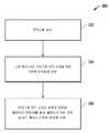
도 3은 공정 챔버 내의 플라즈마 공정을 촉진시키기 위해 전자빔이 사용되는 예시적인 실시형태의 공정 흐름도이다.
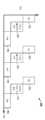
도 4a는 공정 단계 동안, 발생되어 마이크로 전자 소재를 위한 기판의 표면에 전달되는 전자빔을 통해 매개되어 개선되는 ALD 공정을 위한 예시적인 실시형태의 도면이다.
도 4b는 공정 단계 동안, 발생되어 마이크로 전자 소재를 위한 기판의 표면에 전달되는 전자빔을 통해 매개되어 개선되는 ALE 공정을 위한 예시적인 실시형태의 도면이다.
도 5a는 공정 챔버 내에서 전자를 추출하는 전자 소스를 사용하여, 전자빔이 발생되는 예시적인 실시형태의 도면이다.
도 5b는 공정 챔버의 외부에서 전자의 추출을 수행하는 외부 전자 소스를 사용하여, 전자빔이 발생되는 예시적인 실시형태의 도면이다.
도 6은 본원에 설명된 실시형태를 위한 공정 챔버로 사용될 수 있는, 플라즈마 공정 장치와 같은 소재 제조 시스템에 대한 예시적인 실시형태의 블록도이다.The invention and its advantages may be more fully understood by reference to the following description, which is considered in conjunction with the accompanying drawings, in which like reference numerals designate like features. However, it should be noted that the accompanying drawings show only exemplary embodiments of the disclosed concepts and should not be regarded as limiting the scope, and other embodiments that are equally effective for the disclosed concepts may be permitted.
1 is a diagram of an exemplary embodiment of a bonding portion on the surface of a substrate for a manufactured microelectronic material.
2A is a diagram of an exemplary embodiment in which improved selectivity and anisotropy are achieved using electron beam mediated processing techniques.
2B is a diagram of an exemplary embodiment including a process chamber that improves a plasma etch/deposition process by delivering an electron beam to a substrate for a microelectronic material being processed.
3 is a process flow diagram of an exemplary embodiment in which an electron beam is used to promote a plasma process within a process chamber.
4A is a diagram of an exemplary embodiment for an ALD process that is mediated through an electron beam generated during processing steps and delivered to the surface of a substrate for a microelectronic material.
4B is a diagram of an exemplary embodiment for an ALE process that is mediated through an electron beam generated during processing steps and delivered to the surface of a substrate for a microelectronic material.
5A is a diagram of an exemplary embodiment in which an electron beam is generated using an electron source to extract electrons within a process chamber.
5B is a diagram of an exemplary embodiment in which an electron beam is generated using an external electron source that extracts electrons outside of a process chamber.
6 is a block diagram of an exemplary embodiment for a material manufacturing system, such as a plasma processing apparatus, that can be used as a process chamber for the embodiments described herein.
본원에 설명된 바와 같이, 플라즈마 에칭 및 증착 공정을 개선하기 위해, 전자빔이 발생되어 제어되고, 마이크로 전자 소재를 위한 기판에 전달된다. 개시된 실시형태는, 이전의 플라즈마 에칭 및 증착 공정에서 겪었던 공간 제어 문제를 해결하기 위해, 복잡성이 감소된 개선된 방법 및 공정 장비 솔루션을 제공한다. 예를 들어, 개시된 실시형태는 ALE 공정, ALD 공정, 하이브리드 ALE/ALD 공정, 및/또는 다른 플라즈마 에칭 및/또는 증착 공정을 개선하기 위해 사용될 수 있다. 또한, 개시된 실시형태는, DCS, 유도성 결합 플라즈마(ICP), 반응성 이온 에칭(RIE), 및/또는 다른 에칭 또는 증착 기능과 같은, 다른 공정 챔버 기능과 함께 사용될 수 있다. 본원에 설명된 공정 기술을 여전히 이용하면서, 다른 이점도 달성될 수 있다.As described herein, to improve the plasma etching and deposition process, an electron beam is generated, controlled, and delivered to a substrate for a microelectronic material. The disclosed embodiments provide an improved method and process equipment solution with reduced complexity to solve the spatial control problems encountered in previous plasma etching and deposition processes. For example, the disclosed embodiments can be used to improve ALE processes, ALD processes, hybrid ALE/ALD processes, and/or other plasma etching and/or deposition processes. In addition, the disclosed embodiments may be used with other process chamber functions, such as DCS, inductively coupled plasma (ICP), reactive ion etching (RIE), and/or other etching or deposition functions. Other advantages may be achieved while still using the process techniques described herein.
본원의 실시형태에서 인식되는 바와 같이, 전자빔은 촉진되는 방향을 가지며, 예를 들어, 전기장 및 자기장을 사용하여 전자빔을 제어함으로써, 기판에 전달될 수 있다. 전자빔을 위한 전자는, 예를 들어, 이온(또는 전자)에 의해 충격이 가해진 표면으로부터의 2차 전자 방출을 통해, 외부에서 또는 공정 챔버 내에서 발생될 수 있다. 발생되면, 이러한 전자빔은 플라즈마 에칭 및/또는 플라즈마 증착 공정을 개선하도록 전달된다. 일 실시형태에서, 마이크로 전자 소재가 공정 챔버에 남아 있는 동안, 마이크로 전자 소재의 표면에 전자빔을 전달하기 위해, 전자빔의 원위치(in situ) 전달이 제공될 수 있음을 유의한다.As recognized in the embodiments herein, the electron beam has a direction in which it is promoted and can be delivered to the substrate, for example, by controlling the electron beam using electric and magnetic fields. The electrons for the electron beam can be generated externally or within a process chamber, for example through secondary electron emission from a surface impacted by ions (or electrons). When generated, these electron beams are delivered to improve the plasma etching and/or plasma deposition process. Note that in one embodiment, in situ delivery of the electron beam may be provided to deliver the electron beam to the surface of the microelectronic material while the microelectronic material remains in the process chamber.
도 1은 제조되는 마이크로 전자 소재를 위한 기판의 표면(105) 상의 결합부에 대한 예시적인 실시형태(100)의 도면이다. 표면(105) 상에 입사하는 전자(104)는, 결합 파괴를 통해, 또는 수소(H) 원자(106) 또는 다른 종의 자극된 탈착을 통해, 단글링 결합부(dangling bond)(114)를 생성한다. 이러한 지점은 플라즈마 중의 라디칼 또는 중성 종과 급속하게 반응되어, 플라즈마 에칭 및/또는 플라즈마 증착 공정을 촉진시킬 수 있다.1 is a diagram of an
도 1을 보다 상세히 살펴보면, H 원자(106)의 탈착(102)은, 표면(105) 상에 입사하는 전자(104)로 인해 야기된다. 이러한 탈착(102)은 단글링 결합부(114)를 남긴다. 이러한 단글링 결합부(114)는 재흡착 과정(110)에서 H 원자(112)를 재획득하거나/재획득할 수 있고, 반응물 흡착 과정(120)에서 반응물(R)(122)을 획득할 수 있다. 단글링 결합에 의해 흡착된 반응물(R')은, 후속 생성물 생성 과정(130) 동안 반응물 생성물(P)(132)이 생성되는 에칭 및/또는 증착 공정을 촉진시킬 수 있는 반응성 표면(134)을 형성한다. 따라서, 입사 전자(104)에 의해 표면(105) 상에 생성된 단글링 결합부(114)는 다양한 상황을 위해 유용하며, 이러한 단글링 결합부(114)는 에칭 또는 증착 공정의 선택성을 개선시킬 수 있다. 예를 들어, 표면(105)의 H-중단 부분은 플라즈마 에칭 공정에 의해 용이하게 에칭된다. 표면(105)의 R'-중단 부분은 플라즈마 증착 공정 동안 그 위에 용이하게 성장되는 반응성 표면을 제공한다. 또한, 표면(105)의 H-중단 부분은, 에칭 공정 동안 표면(105)의 R'-중단 부분보다 덜 휘발성일 수 있다. 더욱이, 표면(105)의 R'-중단 부분은 전자빔(e-빔)을 사용하여 변경될 수 있으므로, 이는 더 많은 R' 또는 다른 층이 성장될 수 있는 R''가 되도록 자극된다. 또한, 추가적인 및/또는 상이한 공정 및 환경은 본원에 설명된 전자빔 매개 기술을 사용할 수 있다.Referring to FIG. 1 in more detail, the
도 2a는 본원에 설명된 전자빔 매개 기술을 사용하여, 개선된 선택성 및 이방성이 달성되는 예시적인 실시형태(200)의 도면이다. 일 실시형태에서, 표면은 (예를 들어, 염소, 브롬, 불소, 불화탄소, 수소, 산소, 및/또는 다른 재료를 사용하여) 패시베이션될 수 있다. 그 다음, 예를 들어, 주기적 에칭 공정을 사용하여, 표면의 일부가 제거된다. 도시된 실시형태(200)에서, 패터닝된 구조물 또는 적층물(212)은, 하나 이상의 마스크 및 관련 공정 단계를 사용하여 기판 상에 사전에 형성된다. 마스크(210)의 일부는 보호층으로서 남겨지며, 입사 전자빔(206)은 하나 이상의 전자빔 소스를 사용하여 발생된다. 이러한 입사 전자빔(206)은 예를 들어, 마스크(210) 및/또는 적층물(212)의 표면에 대하여 수직 방향으로 지향될 수 있다. 그 다음, 이러한 전자빔(206)의 수직 입사로 인해, 선택된 영역(202)에서 전자 자극 화학적 작용이 유도된다. 마스크(210)를 위한 표면 영역(205)은 전자빔(206)에 의해 영향을 받지 않거나 최소한으로 영향을 받으며, 하나 이상의 추가적인 에칭 공정에 의해 제거될 수 있다. 마스크(210) 및 적층물(212)의 수직 표면 영역(204)은, 전자빔(206)의 방향으로 인해 전자 자극에 의해 영향을 받지 않거나 최소한으로 영향을 받는다. 기판의 수평 표면 영역(202)은 전자빔(206)으로부터의 전자 자극 화학적 작용에 의해 변형된다. 이러한 방식으로, 전자빔(206)은 기판의 하나 이상의 선택된 영역(202)에 전달되어, 하나 이상의 선택된 영역(202)에 대해 전자 자극 화학적 작용이 유도되도록 한다. 단일 마스크(210)가 도시되지만, 하나 이상의 마스크, 및 마스크 층의 관련 패터닝을 사용하여, 선택된 영역이 결정될 수 있다. 또한, 전자 자극 화학적 작용은, 에칭 공정, 증착 공정, 패시베이션 공정, 및/또는 다른 원하는 공정 중 하나 이상을 촉진시키거나 억제시킨다. 하나의 예시적인 구현예에서, 이러한 기술은, 전자 자극이 발생하는 표면 상에서 수직 선택성을 갖는 폴리머 성장을 촉진시키기 위해 사용될 수 있다. 또한, 예를 들어, e-빔 노출 후에 증착 또는 에천트 전구체 노출(순차적으로 또는 동시에)을 사용하여, 패시베이션이 달성될 수 있음을 유의한다. 본원에 설명된 전자빔 매개 기술을 여전히 이용하면서, 다른 변형예가 구현될 수도 있다.2A is a diagram of an
도 2b는 처리되는 마이크로 전자 소재를 위한 기판(255)에 전자빔(206)이 전달되는 공정 챔버(260)를 포함하는 예시적인 실시형태(250)의 도면이다. 일 실시형태에서, 기판(255)은 기판 홀더(256)에 의해 홀딩된다. 예시적인 일 실시형태에서, 기판 홀더(256)는 정전 척이다. 도시된 바와 같이, 전자빔 소스(252)는 전자빔(206)을 위한 전자를 발생시킨 다음, 전자빔(206)을 기판(255)의 표면에 전달한다. 바람직하게는, 음의 DC 바이어스(262)가 전자빔 소스(252)에 인가되고, 전자빔(206)의 발생, 및/또는 기판(255)으로의 전자빔(206)의 전달을 촉진시킨다. 또한, 공급 가스 및 불활성 가스(254)는, 공정 챔버(260) 내에서 수행되는 하나 이상의 공정에 사용되는 가스 화학 물질을 제공하기 위해 공정 챔버(260)에 전달된다. 예를 들어, 플라즈마 가스 화학 물질은, 플라즈마 에칭 공정 및/또는 플라즈마 증착 공정을 위해 공정 챔버(260)에 전달될 수 있다. 일 실시형태에서, 전자빔(206)이 기판(255)의 표면에 전달되면서, 증착 전구체가 공정 챔버(260) 내로 동시에 분사된다.2B is a diagram of an
플라즈마 공정을 위해, 고주파(HF) 기술, 초단파(VHF) 기술, ICP 기술, 및/또는 다른 플라즈마 발생 기술을 사용하여, 플라즈마가 점화되어 공정 챔버 내에 유지될 수 있음을 유의한다. 또한, RF 플라즈마 소스와 같은 DC-바이어스 또는 펄싱 DC-바이어스 플라즈마 소스가 전자빔 소스(252)로서 사용될 수 있음을 유의한다. 다른 전자 소스도 사용될 수 있다. 일 실시예로서, 700 평방 센티미터(cm2) 표면으로부터 112 mA(밀리암페어)의 전류를 사용하여, 1초 내에 기판 표면의 하나의 단분자층에 충돌하는 전자빔을 발생시킨다. 다른 실시예에서, 약 50 mA의 전류가 사용된다. 또한, 예를 들어, 기판 홀더(256)를 통하여, 무선 주파수(RF) 바이어스(258)가 마이크로 전자 소재를 위한 기판(255)에 인가될 수 있다. 이러한 RF 바이어스(258)는 전형적으로, 마이크로 전자 소재를 위한 기판(255)에서 RF가 오프되는 경우 최대 플럭스가 발생하기 때문에, 플라즈마 공정을 촉진시키거나/촉진시키고, 탄도 전자(ballistic electron)를 억제시키기 위해 사용될 수 있다. 본원에 설명된 전자빔 매개 기술을 여전히 이용하면서, 다른 변형예가 구현될 수도 있다.Note that for the plasma process, using high frequency (HF) technology, very high frequency (VHF) technology, ICP technology, and/or other plasma generation technology, the plasma can be ignited and held in the process chamber. Also note that a DC-biased or pulsing DC-bias plasma source such as an RF plasma source can be used as the
도 3은 공정 챔버 내의 플라즈마 공정을 촉진시키기 위해 전자빔이 사용되는 예시적인 실시형태(300)의 공정 흐름도이다. 블록(302)에서, 전자빔이 발생된다. 블록(304)에서, 전자빔은 공정 챔버 내의 마이크로 전자 소재를 위한 기판에 전달된다. 블록(306)에서, 마이크로 전자 소재의 표면에 대하여, 하나 이상의 플라즈마 공정이 수행된다. 플라즈마 공정은 예를 들어, 플라즈마 에칭 공정 또는 플라즈마 증착 공정 중 적어도 하나일 수 있다. 또한, 개시된 기술을 여전히 이용하면서, 추가적인 및/또는 상이한 공정 단계도 사용될 수 있음을 유의한다.3 is a process flow diagram of an
도 4a는 공정 단계 동안, 마이크로 전자 소재를 위한 기판의 표면에 전자빔을 전달하는 전자빔 소스를 통해 매개되어 개선되는 ALD 공정을 위한 예시적인 실시형태(400)의 도면이다. 도시된 예시적인 실시형태(400)에서, 일련의 DC-바이어스 e-빔 공정(DC)(402) 및 전구체 플라즈마 증착 공정(404)이 예시적인 ALD 공정을 위해 사용된다. DC-바이어스 e-빔 공정(402) 동안, DC-바이어스와 함께 전자빔 소스를 사용하여 전자빔을 발생시키고, 공정 챔버 내의 기판의 표면에 전자빔을 전달한다. 전구체 플라즈마 증착 공정(404)은, 전구체 가스 및 플라즈마 공정 단계를 사용하는 하나 이상의 층의 증착을 포함한다. 이러한 예시적인 ALD 공정의 경우, RF 바이어스는 사용되지 않으며, 퍼지 단계가 포함된다. 다른 변형예가 구현될 수도 있다.4A is a diagram of an
도 4b는 공정 단계 동안, 마이크로 전자 소재를 위한 기판의 표면에 전자빔을 전달하는 전자빔 소스를 통해 매개되어 개선되는 ALE 공정을 위한 예시적인 실시형태(450)의 도면이다. 도시된 예시적인 실시형태(450)에서, 일련의 DC-바이어스 e-빔 공정(DC)(452), 전구체 플라즈마 증착 공정(454), 및 플라즈마 에칭 공정(456)이 예시적인 ALE 공정을 위해 사용된다. DC-바이어스 e-빔 공정(452) 동안, DC-바이어스와 함께 전자빔 소스를 사용하여 전자빔을 발생시키고, 공정 챔버 내의 기판의 표면에 전자빔을 전달한다. 전구체 플라즈마 증착 공정(454)은, 전구체 가스 및 플라즈마 공정 단계를 사용하는 하나 이상의 층의 증착을 포함한다. 하나의 예시적인 ALE 공정에서, 에칭 공정(456)을 위해 RF 스퍼터링 및/또는 RIE가 사용되며, 플라즈마 에칭 공정(456)을 위한 선택성을 개선하기 위해, 전구체 증착 공정(454)이 사용된다. 또한, 하나의 예시적인 ALE 공정에서, 에칭 공정(456) 동안 기판으로부터 재료 제거를 촉진시키기 위해, 처리되는 마이크로 전자 소재를 위한 기판에 RF 바이어스가 인가될 수도 있다. 다른 변형예가 구현될 수도 있다.FIG. 4B is a diagram of an
도 5a는 공정 챔버(260) 내에서 전자를 추출하는 전자 소스(510)를 사용하여, 전자빔(206)이 발생되는 예시적인 실시형태(500)의 도면이다. 예를 들어, 전자빔 소스(252)를 위한 전자는 전자 소스(510)로서 대형 중공 캐소드로부터의 전자 추출을 통해 발생될 수 있으며, 소스 플라즈마(512)는 전자빔(206)을 전달하기 위해 사용될 수 있다. 또한, 전자빔(206)의 발생 및/또는 전달을 촉진시키기 위해, DC 바이어스(262)가 소스 플라즈마(512)에 인가될 수 있다. 예를 들어, 전자를 발생시켜서 전자빔(206)을 기판(255)에 전달하기 위해, 금속 또는 고도로 도핑된 실리콘(Si)에 대하여 DC 또는 펄싱-DC 기술이 사용될 수 있다. 일 실시형태에서, DC-바이어스 또는 펄싱 DC-바이어스 RF 플라즈마 소스가 전자빔(206)을 전달하기 위해 사용된다. 플라즈마 및/또는 다른 공정 가스(254)가 공정 챔버(260)에 전달되며, 기판(255)으로의 전자빔(206)의 전달을 촉진시키기 위해, 소스 플라즈마(512)가 점화될 수 있다. 또한, RF 바이어스(258)가 기판(255)에 인가될 수 있다. 또한, 선택적인 RF 전력이 발생될 수 있으며, 플라즈마 발생의 일부로서 공정 챔버(260)에 인가될 수 있다. 공정 챔버(260)는, 코일(506), 패러데이 차폐물(Faraday shield)(504), 및 석영 라이너(502)를 더 포함할 수 있다. 또한, DC 바이어스(262), RF 바이어스(258), 및 코일(506)은 교번하는 방식으로 작동될 수 있음을 유의한다. 코일(506)은 공정 챔버(260)의 둘레에 위치될 수 있으며, 공정 챔버(260) 내에서 플라즈마를 지속시키는 소스 전력을 발생시키기 위해 사용될 수 있음을 유의한다. 또한, 본원에서 설명된 기술을 여전히 이용하면서 다른 변형예가 구현될 수 있다.5A is a diagram of an
도 5b는 공정 챔버(260)의 외부에서 전자의 추출을 수행하는 외부 전자 소스(552)를 사용하여, 전자빔(206)이 발생되는 예시적인 실시형태(550)의 도면이다. 소스 플라즈마(512)는, 전자빔 소스(252)를 위한 전자빔(206)의 발생 및 전달을 촉진시키기 위해 사용될 수 있다. 또한, 공정 챔버(260) 내에서 빔 추출 플레이트(558)를 사용하여, 외부 전자 소스(552)에 의해 공정 챔버(260) 내에 주입된 전자를 흡착한 다음, 전자빔(206)을 기판(255)에 전달할 수 있다. 플라즈마 및/또는 다른 공정 가스(254)가 공정 챔버(260)에 전달되며, 소스 플라즈마(512)가 공정 챔버(260) 내에서 점화될 수 있다. 또한, RF 바이어스(258)가 기판(255)에 인가될 수 있다. 공정 챔버(260)는, 코일(506) 및 유전체 재료 라이너(554)를 더 포함할 수 있다. 전자 추출 홀 영역(560) 근처의 소스 플라즈마(512)에 DC 바이어스(262)가 인가될 수 있다. 또한, 본원에서 설명된 기술을 여전히 이용하면서 다른 변형예가 구현될 수 있다.5B is a diagram of an
본원에서 설명된 재료층을 형성하기 위해 하나 이상의 증착 공정이 사용될 수 있음을 유의한다. 예를 들어, 하나 이상의 증착은 화학 기상 증착(CVD), 플라즈마 강화 CVD(PECVD), 물리 기상 증착(PVD), 원자층 증착(ALD), 및/또는 다른 증착 공정을 사용하여 구현될 수 있다. 플라즈마 증착 공정의 경우, 다양한 압력, 전력, 유량 및 온도 조건에서 하나 이상의 희석 가스(예를 들어, 아르곤, 질소 등)와 조합하여, 탄화수소, 불화탄소, 또는 질소 함유 탄화수소를 포함하지만 이에 제한되지 않는 전구체 가스 혼합물이 사용될 수 있다. PR 층에 대한 리소그래피 공정은 광학 리소그래피, 극자외선(EUV) 리소그래피, 및/또는 다른 리소그래피 공정을 사용하여 구현될 수 있다. 에칭 공정은 플라즈마 에칭 공정, 방전 에칭 공정, 및/또는 다른 원하는 에칭 공정을 사용하여 구현될 수 있다. 예를 들어, 플라즈마 에칭 공정은 불화탄소, 산소, 질소, 수소, 아르곤, 및/또는 다른 가스를 포함하는 플라즈마를 사용하여 구현될 수 있다. 또한, 비아 형성 동안 비아에 대한 CD 목표 파라미터가 달성되도록 보장하기 위해, 공정 단계를 위한 작동 변수가 제어될 수 있다. 작동 변수는 예를 들어, 챔버 온도, 챔버 압력, 가스의 유량, 플라즈마의 발생 시에 전극 조립체에 인가되는 주파수 및/또는 전력, 및/또는 공정 단계를 위한 다른 작동 변수를 포함할 수 있다. 또한, 본원에서 설명된 기술을 여전히 이용하면서 변형예가 구현될 수 있다.It is noted that more than one deposition process may be used to form the material layer described herein. For example, one or more of the depositions may be implemented using chemical vapor deposition (CVD), plasma enhanced CVD (PECVD), physical vapor deposition (PVD), atomic layer deposition (ALD), and/or other deposition processes. For plasma deposition processes, including, but not limited to, hydrocarbons, fluorocarbons, or nitrogen-containing hydrocarbons in combination with one or more diluent gases (e.g., argon, nitrogen, etc.) under various pressure, power, flow and temperature conditions. A precursor gas mixture can be used. The lithographic process for the PR layer can be implemented using optical lithography, extreme ultraviolet (EUV) lithography, and/or other lithographic processes. The etch process can be implemented using a plasma etch process, a discharge etch process, and/or any other desired etch process. For example, the plasma etching process can be implemented using a plasma comprising fluorocarbon, oxygen, nitrogen, hydrogen, argon, and/or other gases. In addition, operating parameters for the process steps can be controlled to ensure that the CD target parameters for the vias are achieved during via formation. Operating parameters may include, for example, chamber temperature, chamber pressure, flow rate of gas, frequency and/or power applied to the electrode assembly upon generation of plasma, and/or other operating parameters for the process step. Further, variations may be implemented while still using the techniques described herein.
예시적인 플라즈마 에칭 공정 시스템에 대한 일 실시형태(600)가 도 6과 관련하여 설명된다. 그러나, 본원에 설명된 기술은 다양한 에칭 공정 시스템에 사용될 수 있으며, 실시형태(600)는 단지 하나의 예시적인 실시형태임을 유의한다.An
도 6은 본원에 설명된 실시형태를 위한 공정 챔버로 사용될 수 있는, 플라즈마 공정 장치와 같은 소재 제조 시스템에 대한 예시적인 실시형태(600)의 블록도이다. 보다 구체적으로, 도 6은 본원에 설명된 공정 기술을 구현하기 위해 사용될 수 있는 단지 예시적인 목적을 위한 플라즈마 공정 장치에 대한 하나의 예시적인 실시형태를 도시한다. 다른 플라즈마 공정 시스템 및 다른 에칭 공정 시스템이 본원에 설명된 기술을 동일하게 구현할 수 있음을 인식할 것이다. 도 6의 예시적인 실시형태(600)에서, 마이크로 전자 소재를 위한 에칭 챔버를 제공하는 공정 공간(PS)을 포함하는 용량성 결합 플라즈마 공정 장치에 대한 개략적인 단면도가 제공된다. 예를 들어, 유도성 결합 플라즈마 공정 장치, 마이크로파 플라즈마 공정 장치 등을 포함하지만 이에 제한되지 않는 대안적인 플라즈마 공정 장치가 사용될 수도 있다. 용량성 결합 플라즈마 공정 장치는, 이러한 장치의 전극 간격이 플라즈마 공간의 국부적인 영역으로의 가스의 유리한 제어를 가능하게 하므로, 기판 상의 국부적인 플라즈마 공정을 제공하기 때문에, 특히 적합할 수 있다.6 is a block diagram of an
플라즈마 공정 장치(600)는, 애싱(ashing), 에칭, 증착, 세척, 플라즈마 중합, 플라즈마 강화 화학 기상 증착(PECVD), 원자층 증착(ALD) 등을 포함하는 다수의 작업을 위해 사용될 수 있다. 플라즈마 공정 장치(600)의 구조는 잘 알려져 있으며, 본원에 제공된 특정 구조는 단지 예시적인 것일 뿐이다. 플라즈마 공정은, 알루미늄 또는 스테인리스 강과 같은 금속으로 제조된 진공 챔버일 수 있는 공정 챔버(601) 내에서 수행될 수 있다. 공정 챔버(601)는 플라즈마 발생을 위한 공정 공간(PS)을 제공하는 공정 용기를 한정한다. 공정 용기의 내벽은 알루미나, 이트리아(yttria), 또는 다른 보호제로 코팅될 수 있다. 공정 용기는 원통형 형상일 수 있거나, 다른 기하학적 구성을 가질 수 있다.The
공정 챔버(601) 내의 하부 중앙 영역에서, 서셉터(612)(디스크 형상일 수 있음)는 예를 들어, 처리될 기판(602)(예를 들어, 반도체 웨이퍼)이 장착될 수 있는 장착 테이블의 역할을 할 수 있다. 기판(602)은 로딩/언로딩 포트 및 게이트 밸브를 통하여 공정 챔버(601) 내로 이동될 수 있다. 서셉터(612)는, 기판(602)을 그 위에 장착하기 위한 장착 테이블로 작용하는 제2 전극의 일 실시예로서 하부 전극 조립체(620)의 일부를 형성한다. 서셉터(612)는 예를 들어, 알루미늄 합금으로 형성될 수 있다. 서셉터(612)는 기판(602)을 홀딩하기 위한 정전 척(하부 전극 조립체의 일부로서)을 그 위에 구비한다. 정전 척은 전극(635)을 구비한다. 전극(635)은 도시되지 않은 직류(DC) 전원에 전기적으로 연결된다. 정전 척은 DC 전원으로부터의 DC 전압이 전극(635)에 인가되는 경우 발생되는 정전기력을 통해 기판(602)을 이에 끌어당긴다. 서셉터(612)는 정합 장치를 통해 고주파 전원과 전기적으로 연결될 수 있다. 다른 실시형태 및 공정 챔버에서, 둘 이상의 전원이 사용될 수 있으며, 공정 챔버 내의 전극(635) 및/또는 다른 전극에 연결될 수 있다. 이러한 고주파 전원(제2 전원)은 예를 들어, 2 MHz(메가헤르츠) 내지 20 MHz 범위의 고주파 전압을 출력할 수 있다. 고주파 바이어스 전력을 인가함으로써, 공정 챔버(601)에서 발생된 플라즈마 중의 이온이 기판(602)에 끌어당겨지게 한다. 집속 링 조립체(638)는 정전 척을 둘러싸도록 서셉터(612)의 상부 표면 상에 제공된다.In the lower central region within the
가스 배기 장치에 연결되는 하나 이상의 배기 포트(도시되지 않음)를 통하여 배기 경로(633)가 형성될 수 있다. 가스 배기 장치는, 공정 챔버(601) 내의 플라즈마 공정 공간을 원하는 진공 상태로 펌핑하도록 구성된 터보 분자 펌프와 같은 진공 펌프를 포함할 수 있다. 가스 배기 장치는 공정 챔버(601)의 내부를 배기함으로써, 이의 내부 압력을 원하는 진공도까지 감압한다.An
상부 전극 조립체(670)는 제1 전극의 일 실시예이며, 하부 전극 조립체(620)와 평행하게 대향하도록 하부 전극 조립체(620) 위에 수직으로 위치된다. 플라즈마 발생 공간 또는 공정 공간(PS)은, 하부 전극 조립체(620)와 상부 전극 조립체(670) 사이에 한정된다. 상부 전극 조립체(670)는, 디스크 형상을 갖는 내측 상부 전극(671), 및 내측 상부 전극(671)의 주변부를 둘러싸고 환형일 수 있는 외측 상부 전극을 포함한다. 또한, 내측 상부 전극(671)은, 하부 전극 조립체(620) 상에 장착된 기판(602) 위의 공정 공간(PS)으로 특정 양의 공정 가스를 분사하기 위한 공정 가스 흡입구의 기능을 한다. 이에 따라, 상부 전극 조립체(670)는 샤워헤드를 형성한다. 보다 구체적으로, 내측 상부 전극(671)은 가스 분사 개구부(682)를 포함한다.The
상부 전극 조립체(670)는, 하나 이상의 완충(buffer) 챔버(들)(689A, 689B, 및 689C)를 포함할 수 있다. 완충 챔버는 공정 가스를 확산시키기 위해 사용되며, 디스크 형상의 공간을 한정할 수 있다. 공정 가스 공급 시스템(680)으로부터의 공정 가스는 상부 전극 조립체(670)에 가스를 공급한다. 공정 가스 공급 시스템(680)은, 막 형성, 에칭 등과 같은 특정 공정을 기판(602) 상에 수행하기 위한 공정 가스를 공급하도록 구성될 수 있다. 공정 가스 공급 시스템(680)은 공정 가스 공급 경로를 형성하는 가스 공급 라인(681A, 681B, 및 681C)에 연결된다. 가스 공급 라인은 내측 상부 전극(671)의 완충 챔버에 연결된다. 그 다음, 공정 가스는 완충 챔버로부터 이의 하부 표면의 가스 분사 개구부(682)로 이동할 수 있다. 완충 챔버(689A-C)로 유입되는 공정 가스의 유량은, 예를 들어, 질량 유량 제어기를 사용함으로써 조정될 수 있다. 또한, 유입된 공정 가스는, 전극 플레이트(샤워헤드 전극)의 가스 분사 개구부(682)로부터 공정 공간(PS)으로 배출된다. 내측 상부 전극(671)은 부분적으로 샤워헤드 전극 조립체를 제공하도록 기능한다.The
도 6에 도시된 바와 같이, 에지 완충 챔버(689A), 중간 완충 챔버(689B), 및 중앙 완충 챔버(689C)에 해당하는 3개의 완충 챔버(689A, 689B, 및 689C)가 제공된다. 유사하게, 가스 공급 라인(681A, 681B, 및 681C)은, 에지 가스 공급 라인(681A), 중간 가스 공급 라인(681B), 및 중앙 가스 공급 라인(681C)으로 구성될 수 있다. 완충 챔버는, 기판의 상이한 국부적인 영역(이 경우, 에지, 중간, 및 중앙)에 대응하는 방식으로 제공된다. 아래에 추가로 설명되는 바와 같이, 이러한 영역은, 기판(602)의 국부적인 영역을 위한 특정 공정 플라즈마 공정 조건에 해당할 수 있다. 3개의 국부적인 영역의 사용은 단지 예시적인 것일 뿐임을 인식할 것이다. 따라서, 플라즈마 공정 장치는, 기판의 임의의 수의 영역 상에 국부적인 플라즈마 공정 조건을 제공하도록 구성될 수 있다. 또한, 다양한 구성 중 어느 하나가 사용될 수 있으며, 본원에 설명된 기술은 공정 가스 공급 시스템(680)이 가스 흐름을 다양한 완충 챔버로 분할하도록 구성되는 방식으로 제한되지 않음을 다시 한 번 유의한다.As shown in Fig. 6, three
상부 전극 조립체(670)는 급전선(665) 및 정합 장치(668)를 통해 고주파 전원(도시되지 않음)(제1 고주파 전원)과 전기적으로 연결된다. 고주파 전원은, 40 MHz(메가헤르츠) 이상의 주파수(예를 들어, 60 MHz)를 갖는 고주파 전압을 출력할 수 있거나, 30 내지 300 MHz의 주파수를 갖는 초단파(VHF) 전압을 출력할 수 있다. 이러한 전원은 바이어스 전원 공급기와 비교하여, 주 전원 공급기로 지칭될 수 있다. 특정 실시형태의 경우, 상부 전극을 위한 전원이 없고, 2개의 전원이 하부 전극에 연결됨을 유의한다. 다른 변형예가 구현될 수도 있다.The
플라즈마 공정 장치의 구성 요소는 제어 장치에 연결되어 제어 장치에 의해 제어될 수 있으며, 제어 장치는 해당 메모리 저장 장치 및 사용자 인터페이스(모두 도시되지 않음)에 차례로 연결될 수 있다. 다양한 플라즈마 공정 작업이 사용자 인터페이스를 통해 실행될 수 있으며, 다양한 플라즈마 공정 방식 및 작업은 저장 장치에 저장될 수 있다. 따라서, 주어진 기판은 다양한 미세 가공 기술로 플라즈마 공정 챔버 내에서 처리될 수 있다. 작업 시에, 플라즈마 공정 장치는 상부 및 하부 전극을 사용하여, 공정 공간(PS)에 플라즈마를 발생시킨다. 그 다음, 이와 같이 발생된 플라즈마는, 플라즈마 에칭, 화학 기상 증착, 반도체 재료, 유리 재료, 및 박막 태양 전지, 다른 광전지와 같은 대형 패널, 및 평판 디스플레이를 위한 유기/무기 플레이트의 처리 등과 같은, 다양한 유형의 처리로 타겟 기판(예를 들어, 기판(602) 또는 처리될 임의의 재료)을 처리하기 위해 사용될 수 있다.Components of the plasma processing apparatus may be connected to the control apparatus and controlled by the control apparatus, and the control apparatus may be sequentially connected to a corresponding memory storage apparatus and a user interface (both not shown). Various plasma processing operations may be executed through a user interface, and various plasma processing methods and operations may be stored in a storage device. Thus, a given substrate can be processed within a plasma processing chamber with a variety of microfabrication techniques. During operation, the plasma processing apparatus generates plasma in the process space PS by using the upper and lower electrodes. The plasma thus generated is then subjected to various treatments such as plasma etching, chemical vapor deposition, semiconductor materials, glass materials, and large panels such as thin-film solar cells, other photovoltaic cells, and organic/inorganic plates for flat panel displays. It can be used to treat a target substrate (eg,
본 명세서 전반에 걸쳐서 "일 실시형태" 또는 "실시형태"라는 언급은 실시형태와 관련하여 설명된 구체적인 특징, 구조, 재료, 또는 특성이 본 발명의 적어도 하나의 실시형태에 포함됨을 의미하지만, 이들이 모든 실시형태에 존재한다는 것을 의미하지 않음을 유의한다. 따라서, 본 명세서 전반에 걸친 다양한 곳에서 "일 실시형태에서" 또는 "실시형태에서"라는 문구의 출현은 반드시 본 발명의 동일한 실시형태를 지칭하는 것은 아니다. 또한, 구체적인 특징, 구조, 재료, 또는 특성은 하나 이상의 실시형태에서 임의의 적합한 방식으로 조합될 수 있다. 다양한 추가적인 층 및/또는 구조물이 다른 실시형태에 포함될 수 있거나/포함될 수 있고, 설명된 특징이 다른 실시형태에서 생략될 수 있다.Reference throughout this specification to “one embodiment” or “an embodiment” means that a specific feature, structure, material, or characteristic described in connection with the embodiment is included in at least one embodiment of the present invention, but these Note that it is not meant to be present in all embodiments. Thus, the appearances of the phrases “in one embodiment” or “in an embodiment” in various places throughout this specification are not necessarily referring to the same embodiment of the invention. Further, specific features, structures, materials, or properties may be combined in any suitable manner in one or more embodiments. Various additional layers and/or structures may be included/included in other embodiments, and features described may be omitted in other embodiments.
본원에 사용된 바와 같은 "마이크로 전자 소재"는 일반적으로 본 발명에 따라 처리되는 대상물을 지칭한다. 마이크로 전자 소재는 소자, 특히 반도체 또는 다른 전자 소자의 임의의 재료 부분 또는 구조물을 포함할 수 있으며, 예를 들어, 반도체 기판과 같은 베이스 기판 구조물, 또는 박막과 같은 베이스 기판 구조물 위에 있거나 위에 놓이는 층일 수 있다. 따라서, 소재는, 패터닝된 또는 패터닝되지 않은 임의의 특정 베이스 구조물, 하부층 또는 상부층으로 제한되는 것으로 의도되는 것이 아니라, 오히려 임의의 그러한 층 또는 베이스 구조물, 그리고 층 및/또는 베이스 구조물의 임의의 조합물을 포함하는 것으로 고려된다. 아래의 설명은 특정 유형의 기판을 언급할 수 있지만, 이는 단지 예시적인 목적을 위한 것이며 제한 사항이 아니다.“Microelectronic material” as used herein generally refers to an object to be processed in accordance with the present invention. The microelectronic material may comprise any material part or structure of a device, in particular a semiconductor or other electronic device, and may be, for example, a base substrate structure, such as a semiconductor substrate, or a layer over or over a base substrate structure, such as a thin film. have. Thus, the material is not intended to be limited to any particular base structure, lower layer or top layer, patterned or unpatterned, but rather any such layer or base structure, and any combination of layers and/or base structures. It is considered to include. The description below may refer to certain types of substrates, but this is for illustrative purposes only and is not a limitation.
본원에 사용된 바와 같은 "기판"이라는 용어는 재료가 그 위에 형성된 기재 또는 구조물을 의미하고 포함한다. 기판은 단일 재료, 상이한 재료의 복수의 층, 그 안에 상이한 구조물 또는 상이한 재료의 영역을 갖는 층 또는 층들 등을 포함할 수 있음을 이해할 것이다. 이러한 재료는 반도체, 절연체, 전도체, 또는 이들의 조합물을 포함할 수 있다. 예를 들어, 기판은 반도체 기판, 지지 구조물 상의 베이스 반도체 층, 하나 이상의 층, 구조물 또는 영역이 그 위에 형성된 반도체 기판 또는 금속 전극일 수 있다. 기판은 통상적인 실리콘 기판, 또는 반도체 재료의 층을 포함하는 다른 벌크 기판일 수 있다. 본원에서 사용된 바와 같은 "벌크 기판"이라는 용어는 실리콘 웨이퍼 뿐만 아니라, 실리콘-온-글라스(“SOG”) 기판 및 실리콘-온-사파이어("SOS") 기판과 같은, 실리콘-온-절연체("SOI") 기판, 베이스 반도체 토대 상의 실리콘의 에피택셜 층, 그리고 실리콘-게르마늄, 게르마늄, 갈륨 비소, 질화 갈륨, 및 인화 인듐과 같은 다른 반도체 또는 광전자 재료를 의미하고 포함한다. 기판은 도핑될 수 있거나 도핑되지 않을 수 있다.The term “substrate” as used herein refers to and includes a substrate or structure on which a material is formed. It will be appreciated that a substrate may comprise a single material, a plurality of layers of different materials, a layer or layers having different structures or regions of different materials therein, and the like. Such materials may include semiconductors, insulators, conductors, or combinations thereof. For example, the substrate may be a semiconductor substrate, a base semiconductor layer on a support structure, a semiconductor substrate or a metal electrode on which one or more layers, structures or regions are formed. The substrate may be a conventional silicon substrate, or other bulk substrate comprising a layer of semiconductor material. The term "bulk substrate" as used herein refers to silicon wafers, as well as silicon-on-insulators, such as silicon-on-glass (“SOG”) substrates and silicon-on-sapphire (“SOS”) substrates. "SOI") means and includes an epitaxial layer of silicon on a substrate, a base semiconductor foundation, and other semiconductor or optoelectronic materials such as silicon-germanium, germanium, gallium arsenide, gallium nitride, and indium phosphide. The substrate may or may not be doped.
마이크로 전자 소재를 처리하기 위한 시스템 및 방법은 다양한 실시형태에서 설명된다. 관련 기술 분야의 당업자는 다양한 실시형태가 하나 이상의 구체적인 세부 사항 없이 실시될 수 있거나, 다른 대체 및/또는 추가적인 방법, 재료, 또는 구성 요소와 함께 실시될 수 있음을 인식할 것이다. 다른 경우에, 잘 알려진 구조, 재료, 또는 작업은 본 발명의 다양한 실시형태의 양태를 불명료하게 하는 것을 방지하기 위해 상세히 도시되거나 설명되지 않는다. 유사하게, 설명의 목적으로, 본 발명의 완전한 이해를 제공하기 위해 구체적인 수, 재료, 및 구성이 상술된다. 그럼에도 불구하고, 본 발명은 구체적인 세부 사항 없이 실시될 수 있다. 또한, 도면에 도시된 다양한 실시형태는 예시적인 표현이며, 반드시 일정한 비율로 도시된 것은 아니라는 점을 이해한다.Systems and methods for processing microelectronic materials are described in various embodiments. Those skilled in the art will recognize that the various embodiments may be practiced without one or more specific details, or may be practiced with other alternative and/or additional methods, materials, or components. In other instances, well-known structures, materials, or operations have not been shown or described in detail in order to avoid obscuring aspects of the various embodiments of the present invention. Similarly, for purposes of explanation, specific numbers, materials, and configurations are detailed to provide a thorough understanding of the invention. Nevertheless, the invention may be practiced without specific details. In addition, it is understood that the various embodiments shown in the drawings are illustrative representations and are not necessarily drawn to scale.
설명된 시스템 및 방법의 추가적인 변형예 및 대안적인 실시형태는 본 설명을 고려하는 당업자에게 명백할 것이다. 따라서, 설명된 시스템 및 방법은 이러한 예시적인 방식으로 제한되지 않음을 인식할 것이다. 본원에서 도시되고 설명된 시스템 및 방법의 형태는 예시적인 실시형태로 간주되어야 함을 이해해야 한다. 구현예에서 다양한 변경이 이루어질 수 있다. 따라서, 본 발명은 구체적인 실시형태를 참조하여 본원에 설명되지만, 본 발명의 범위를 벗어나지 않고 다양한 변형 및 변경이 이루어질 수 있다. 따라서, 명세서 및 도면은 제한적인 의미가 아니라 예시적인 의미로 간주되어야 하며, 이러한 변형은 본 발명의 범위 내에 포함되는 것으로 의도된다. 또한, 구체적인 실시형태와 관련하여 본원에서 설명된 문제에 대한 임의의 이점, 장점, 또는 솔루션은, 임의의 또는 모든 청구항의 중요한, 필요한 또는 필수적인 특징 또는 요소로 해석되도록 의도되지 않는다.Further variations and alternative embodiments of the described systems and methods will be apparent to those skilled in the art upon consideration of this description. Accordingly, it will be appreciated that the described systems and methods are not limited in this exemplary manner. It is to be understood that the forms of systems and methods shown and described herein are to be considered exemplary embodiments. Various changes can be made in the implementation. Accordingly, although the present invention is described herein with reference to specific embodiments, various modifications and changes can be made without departing from the scope of the present invention. Accordingly, the specification and drawings are to be regarded in an illustrative rather than a limiting sense, and such modifications are intended to be included within the scope of the present invention. Further, any advantage, advantage, or solution to a problem described herein in connection with a specific embodiment is not intended to be construed as an important, necessary or essential feature or element of any or all claims.
Claims (21)
Translated fromKorean전자빔을 발생시키는 단계;
공정 챔버 내의 마이크로 전자 소재를 위한 기판에 상기 전자빔을 전달하는 단계; 및
상기 마이크로 전자 소재의 표면에 대하여, 플라즈마 에칭 공정 또는 플라즈마 증착 공정 중 적어도 하나를 수행하는 단계를 포함하는,
마이크로 전자 소재를 처리하는 방법.As a method of processing microelectronic materials,
Generating an electron beam;
Delivering the electron beam to a substrate for a microelectronic material in a process chamber; And
Comprising the step of performing at least one of a plasma etching process or a plasma deposition process on the surface of the microelectronic material,
How to process microelectronic materials.
상기 전달하는 단계는, 상기 기판의 하나 이상의 선택된 영역에 상기 전자빔을 전달하여, 상기 하나 이상의 선택된 영역에 대해 전자 자극 화학적 작용이 유도되도록 하는 단계를 포함하는, 방법.The method of claim 1,
Wherein the step of delivering includes delivering the electron beam to one or more selected regions of the substrate such that an electron stimulating chemistry is induced on the one or more selected regions.
상기 기판의 상기 하나 이상의 선택된 영역을 결정하기 위한 하나 이상의 마스크를 사용하는 단계를 더 포함하는, 방법.The method of claim 2,
And using one or more masks to determine the one or more selected regions of the substrate.
상기 전자 자극 화학적 작용은, 에칭 공정, 증착 공정, 또는 패시베이션 공정 중 적어도 하나를 촉진시키거나 억제시키는, 방법.The method of claim 2,
Wherein the electron stimulating chemistry promotes or inhibits at least one of an etching process, a deposition process, or a passivation process.
상기 전달하는 단계는, 상기 발생시키는 단계 또는 상기 전달하는 단계 중 적어도 하나 동안, 직류(DC) 바이어스를 인가하는 단계를 포함하는, 방법.The method of claim 1,
Wherein said transferring comprises applying a direct current (DC) bias during at least one of said generating or said transferring.
상기 전달하는 단계 동안, 기판 홀더를 통하여 상기 기판에 무선 주파수(RF) 바이어스를 인가하는 단계를 더 포함하는, 방법.The method of claim 1,
During the transferring step, applying a radio frequency (RF) bias to the substrate through a substrate holder.
상기 발생시키는 단계는, 50 내지 100 밀리암페어(mA)의 상기 전자빔을 위한 전류를 발생시키는 단계를 포함하는, 방법.The method of claim 1,
The generating step comprises generating a current for the electron beam of 50 to 100 milliamps (mA).
상기 발생시키는 단계는, 상기 공정 챔버 내에서 수행되는 전자 추출을 통해 상기 전자빔을 발생시키는 단계를 포함하는, 방법.The method of claim 1,
The generating step includes generating the electron beam through electron extraction performed within the process chamber.
상기 발생시키는 단계 동안, 소스 플라즈마 및 직류(DC) 바이어스를 사용하는 단계를 더 포함하는, 방법.The method of claim 8,
And using a source plasma and direct current (DC) bias during the generating step.
상기 DC 바이어스는 펄싱되는, 방법.The method of claim 9,
The DC bias is pulsed.
상기 공정 챔버 내에서 플라즈마를 지속시키기 위해, 상기 공정 챔버의 둘레에 위치된 코일에 전력을 공급하는 단계; 및
상기 DC 바이어스, 상기 코일로의 전력, 및 상기 기판의 무선 주파수(RF) 바이어스를 교번하는 단계를 더 포함하는, 방법.The method of claim 9,
Supplying power to a coil positioned around the process chamber to sustain a plasma in the process chamber; And
Alternating the DC bias, power to the coil, and radio frequency (RF) bias of the substrate.
상기 발생시키는 단계는, 상기 공정 챔버의 외부에서 전자 추출을 통해 상기 전자빔을 발생시키는 단계, 및 상기 추출된 전자를 상기 공정 챔버에 전달하는 단계를 포함하는, 방법.The method of claim 1,
The generating step includes generating the electron beam through electron extraction outside the process chamber, and transferring the extracted electrons to the process chamber.
상기 발생시키는 단계 동안, 직류(DC) 바이어스를 사용하는 단계를 더 포함하는, 방법.The method of claim 12,
And during said generating step, using a direct current (DC) bias.
상기 공정 챔버 내에서 플라즈마를 지속시키기 위해, 상기 공정 챔버의 둘레에 위치된 코일에 전력을 공급하는 단계; 및
상기 DC 바이어스, 상기 코일로의 전력, 및 상기 기판의 무선 주파수(RF) 바이어스를 교번하는 단계를 더 포함하는, 방법.The method of claim 13,
Supplying power to a coil positioned around the process chamber to sustain a plasma in the process chamber; And
Alternating the DC bias, power to the coil, and radio frequency (RF) bias of the substrate.
상기 전달하는 단계 및 수행하는 단계는, 원자층 증착(ALD) 공정을 위해 사용되는, 방법.The method of claim 1,
The delivering and performing steps are used for an atomic layer deposition (ALD) process.
상기 전달하는 단계는 상기 전자빔의 DC-바이어스 전달을 포함하며,
상기 수행하는 단계는 전구체 플라즈마 가스를 점화하는 단계를 포함하고,
상기 전달하는 단계 및 상기 수행하는 단계는 상기 기판 상에 재료층을 증착하기 위해 교번되는, 방법.The method of claim 15,
The transferring step includes DC-bias transfer of the electron beam,
The performing step includes igniting a precursor plasma gas,
Wherein the transferring and performing steps are alternated to deposit a layer of material on the substrate.
상기 전달하는 단계 및 수행하는 단계는, 원자층 에칭(ALE) 공정을 위해 사용되는, 방법.The method of claim 1,
The transferring and performing steps are used for an atomic layer etching (ALE) process.
상기 전달하는 단계는 상기 전자빔의 DC-바이어스 전달을 포함하며,
상기 수행하는 단계는 반응성 이온 에칭(RIE) 또는 무선 주파수(RF) 스퍼터링 중 적어도 하나를 포함하고,
상기 전달하는 단계 및 상기 수행하는 단계는 상기 기판 상에 재료층을 증착하기 위해 교번되는, 방법.The method of claim 17,
The transferring step includes DC-bias transfer of the electron beam,
The performing step includes at least one of reactive ion etching (RIE) or radio frequency (RF) sputtering,
Wherein the transferring and performing steps are alternated to deposit a layer of material on the substrate.
상기 수행하는 단계는, 전구체 플라즈마 가스를 점화하는 단계를 더 포함하는, 방법.The method of claim 18,
The performing step further comprises igniting a precursor plasma gas.
상기 수행하는 단계는, 공정 가스를 상기 공정 챔버에 전달하는 단계; 및 상기 전달된 전자빔을 사용하여, 상기 공정 가스의 화학적 작용에 기초하는 상기 기판의 표면 변형을 자극하는 단계를 포함하는, 방법.The method of claim 1,
The performing may include: delivering a process gas to the process chamber; And using the transmitted electron beam to stimulate a surface modification of the substrate based on the chemical action of the process gas.
상기 수행하는 단계는 수직 폴리머 성장을 포함하는, 방법.The method of claim 20,
Wherein the performing step comprises vertical polymer growth.
Applications Claiming Priority (5)
| Application Number | Priority Date | Filing Date | Title |
|---|---|---|---|
| US201862727132P | 2018-09-05 | 2018-09-05 | |
| US62/727,132 | 2018-09-05 | ||
| US201862760383P | 2018-11-13 | 2018-11-13 | |
| US62/760,383 | 2018-11-13 | ||
| PCT/US2019/048838WO2020051064A1 (en) | 2018-09-05 | 2019-08-29 | Apparatus and process for electron beam mediated plasma etch and deposition processes |
Publications (1)
| Publication Number | Publication Date |
|---|---|
| KR20210042939Atrue KR20210042939A (en) | 2021-04-20 |
Family
ID=69641592
Family Applications (1)
| Application Number | Title | Priority Date | Filing Date |
|---|---|---|---|
| KR1020217006671APendingKR20210042939A (en) | 2018-09-05 | 2019-08-29 | Equipment and process for electron beam mediated plasma etching and deposition process |
Country Status (4)
| Country | Link |
|---|---|
| US (1) | US11257685B2 (en) |
| KR (1) | KR20210042939A (en) |
| TW (1) | TWI795589B (en) |
| WO (1) | WO2020051064A1 (en) |
Families Citing this family (25)
| Publication number | Priority date | Publication date | Assignee | Title |
|---|---|---|---|---|
| US10510575B2 (en) | 2017-09-20 | 2019-12-17 | Applied Materials, Inc. | Substrate support with multiple embedded electrodes |
| US11476145B2 (en) | 2018-11-20 | 2022-10-18 | Applied Materials, Inc. | Automatic ESC bias compensation when using pulsed DC bias |
| KR102827481B1 (en) | 2019-01-22 | 2025-06-30 | 어플라이드 머티어리얼스, 인코포레이티드 | Feedback loop to control pulse voltage waveform |
| US11508554B2 (en) | 2019-01-24 | 2022-11-22 | Applied Materials, Inc. | High voltage filter assembly |
| US11848176B2 (en) | 2020-07-31 | 2023-12-19 | Applied Materials, Inc. | Plasma processing using pulsed-voltage and radio-frequency power |
| US11798790B2 (en) | 2020-11-16 | 2023-10-24 | Applied Materials, Inc. | Apparatus and methods for controlling ion energy distribution |
| US11901157B2 (en) | 2020-11-16 | 2024-02-13 | Applied Materials, Inc. | Apparatus and methods for controlling ion energy distribution |
| US11495470B1 (en) | 2021-04-16 | 2022-11-08 | Applied Materials, Inc. | Method of enhancing etching selectivity using a pulsed plasma |
| US11791138B2 (en) | 2021-05-12 | 2023-10-17 | Applied Materials, Inc. | Automatic electrostatic chuck bias compensation during plasma processing |
| US11948780B2 (en) | 2021-05-12 | 2024-04-02 | Applied Materials, Inc. | Automatic electrostatic chuck bias compensation during plasma processing |
| TWI829156B (en)* | 2021-05-25 | 2024-01-11 | 大陸商北京屹唐半導體科技股份有限公司 | Plasma source array, plasma processing apparatus, plasma processing system and method for processing workpiece in plasma processing apparatus |
| US11967483B2 (en) | 2021-06-02 | 2024-04-23 | Applied Materials, Inc. | Plasma excitation with ion energy control |
| US12394596B2 (en) | 2021-06-09 | 2025-08-19 | Applied Materials, Inc. | Plasma uniformity control in pulsed DC plasma chamber |
| US20220399185A1 (en) | 2021-06-09 | 2022-12-15 | Applied Materials, Inc. | Plasma chamber and chamber component cleaning methods |
| US11810760B2 (en) | 2021-06-16 | 2023-11-07 | Applied Materials, Inc. | Apparatus and method of ion current compensation |
| JP7648307B2 (en)* | 2021-06-22 | 2025-03-18 | 東京エレクトロン株式会社 | Shower head and plasma processing apparatus |
| US11569066B2 (en) | 2021-06-23 | 2023-01-31 | Applied Materials, Inc. | Pulsed voltage source for plasma processing applications |
| US11476090B1 (en) | 2021-08-24 | 2022-10-18 | Applied Materials, Inc. | Voltage pulse time-domain multiplexing |
| US12106938B2 (en) | 2021-09-14 | 2024-10-01 | Applied Materials, Inc. | Distortion current mitigation in a radio frequency plasma processing chamber |
| US11694876B2 (en) | 2021-12-08 | 2023-07-04 | Applied Materials, Inc. | Apparatus and method for delivering a plurality of waveform signals during plasma processing |
| US11972924B2 (en) | 2022-06-08 | 2024-04-30 | Applied Materials, Inc. | Pulsed voltage source for plasma processing applications |
| US12315732B2 (en) | 2022-06-10 | 2025-05-27 | Applied Materials, Inc. | Method and apparatus for etching a semiconductor substrate in a plasma etch chamber |
| US12272524B2 (en) | 2022-09-19 | 2025-04-08 | Applied Materials, Inc. | Wideband variable impedance load for high volume manufacturing qualification and on-site diagnostics |
| WO2025054262A1 (en)* | 2023-09-08 | 2025-03-13 | Lam Research Corporation | Selective etching by removal of a volatilizable terminal functional group |
| US20250201631A1 (en)* | 2023-12-18 | 2025-06-19 | Applied Materials, Inc. | Apparatus and Methods for Bonding Materials |
Family Cites Families (17)
| Publication number | Priority date | Publication date | Assignee | Title |
|---|---|---|---|---|
| US20050040037A1 (en)* | 2003-08-20 | 2005-02-24 | Walton Scott G. | Electron beam enhanced large area deposition system |
| US7939450B2 (en)* | 2007-09-21 | 2011-05-10 | Tokyo Electron Limited | Method and apparatus for spacer-optimization (S-O) |
| US20110139748A1 (en)* | 2009-12-15 | 2011-06-16 | University Of Houston | Atomic layer etching with pulsed plasmas |
| US20110177694A1 (en) | 2010-01-15 | 2011-07-21 | Tokyo Electron Limited | Switchable Neutral Beam Source |
| US9111728B2 (en)* | 2011-04-11 | 2015-08-18 | Lam Research Corporation | E-beam enhanced decoupled source for semiconductor processing |
| US9147581B2 (en)* | 2013-07-11 | 2015-09-29 | Lam Research Corporation | Dual chamber plasma etcher with ion accelerator |
| US9978568B2 (en)* | 2013-08-12 | 2018-05-22 | Tokyo Electron Limited | Self-sustained non-ambipolar direct current (DC) plasma at low power |
| WO2015042527A1 (en)* | 2013-09-23 | 2015-03-26 | The Regents Of The University Of Colorado, A Body Corporate | Methods of growing thin films at low temperatures using electron stimulated desorption (esd) |
| US9520294B2 (en)* | 2014-08-29 | 2016-12-13 | Applied Materials, Inc. | Atomic layer etch process using an electron beam |
| US10475626B2 (en) | 2015-03-17 | 2019-11-12 | Applied Materials, Inc. | Ion-ion plasma atomic layer etch process and reactor |
| US9706634B2 (en)* | 2015-08-07 | 2017-07-11 | Varian Semiconductor Equipment Associates, Inc | Apparatus and techniques to treat substrates using directional plasma and reactive gas |
| US10538844B2 (en)* | 2015-09-11 | 2020-01-21 | Fei Company | Nanofabrication using a new class of electron beam induced surface processing techniques |
| US9799491B2 (en)* | 2015-10-29 | 2017-10-24 | Applied Materials, Inc. | Low electron temperature etch chamber with independent control over plasma density, radical composition and ion energy for atomic precision etching |
| US10490416B2 (en)* | 2015-11-16 | 2019-11-26 | Intel Corporation | Structures and methods for improved lithographic processing |
| WO2017120241A1 (en)* | 2016-01-07 | 2017-07-13 | Applied Materials, Inc. | Atomic layer etching system with remote plasma source and dc electrode |
| US10872760B2 (en)* | 2016-07-26 | 2020-12-22 | Taiwan Semiconductor Manufacturing Co., Ltd. | Cluster tool and manufacuturing method of semiconductor structure using the same |
| KR102453450B1 (en)* | 2017-10-23 | 2022-10-13 | 삼성전자주식회사 | apparatus for processing plasma, manufacturing system of semiconductor device and manufacturing method of the same |
- 2019
- 2019-08-29USUS16/555,643patent/US11257685B2/enactiveActive
- 2019-08-29KRKR1020217006671Apatent/KR20210042939A/enactivePending
- 2019-08-29WOPCT/US2019/048838patent/WO2020051064A1/ennot_activeCeased
- 2019-09-02TWTW108131486Apatent/TWI795589B/enactive
Also Published As
| Publication number | Publication date |
|---|---|
| US20200075346A1 (en) | 2020-03-05 |
| TW202022917A (en) | 2020-06-16 |
| TWI795589B (en) | 2023-03-11 |
| WO2020051064A1 (en) | 2020-03-12 |
| US11257685B2 (en) | 2022-02-22 |
Similar Documents
| Publication | Publication Date | Title |
|---|---|---|
| TWI795589B (en) | Method of processing microelectronic workpiece, and method of processing substrate | |
| US11410860B2 (en) | Process chamber for etching low k and other dielectric films | |
| US9972503B2 (en) | Etching method | |
| JP6689674B2 (en) | Etching method | |
| US9190290B2 (en) | Halogen-free gas-phase silicon etch | |
| KR102309941B1 (en) | Method of processing target object | |
| KR102311575B1 (en) | Workpiece processing method | |
| CN110419091A (en) | Deposition or treatment of diamond-like carbon in plasma reactors and plasma reactors | |
| JP6529357B2 (en) | Etching method | |
| KR20150104043A (en) | Plasma etching method and plasma etching apparatus | |
| US11075057B2 (en) | Device for treating an object with plasma | |
| TW201701331A (en) | Gate electrode material residual removal process | |
| US11264246B2 (en) | Plasma etching method for selectively etching silicon oxide with respect to silicon nitride | |
| US10991594B2 (en) | Method for area-selective etching of silicon nitride layers for the manufacture of microelectronic workpieces | |
| Pu | Plasma etch equipment | |
| JP2020177958A (en) | Substrate processing method and substrate processing equipment | |
| US9754797B2 (en) | Etching method for selectively etching silicon oxide with respect to silicon nitride | |
| KR20190137927A (en) | Manufacturing method for reducing surface particle impurities after the plasma process | |
| TWI895757B (en) | Carbon hardmask opening using boron nitride mask |
Legal Events
| Date | Code | Title | Description |
|---|---|---|---|
| PA0105 | International application | Patent event date:20210304 Patent event code:PA01051R01D Comment text:International Patent Application | |
| PG1501 | Laying open of application | ||
| A201 | Request for examination | ||
| PA0201 | Request for examination | Patent event code:PA02012R01D Patent event date:20220808 Comment text:Request for Examination of Application | |
| E902 | Notification of reason for refusal | ||
| PE0902 | Notice of grounds for rejection | Comment text:Notification of reason for refusal Patent event date:20240604 Patent event code:PE09021S01D | |
| E902 | Notification of reason for refusal | ||
| PE0902 | Notice of grounds for rejection | Comment text:Notification of reason for refusal Patent event date:20250226 Patent event code:PE09021S01D |