KR20210033557A - Method of signal generation and signal generating device - Google Patents
Method of signal generation and signal generating deviceDownload PDFInfo
- Publication number
- KR20210033557A KR20210033557AKR1020217008224AKR20217008224AKR20210033557AKR 20210033557 AKR20210033557 AKR 20210033557AKR 1020217008224 AKR1020217008224 AKR 1020217008224AKR 20217008224 AKR20217008224 AKR 20217008224AKR 20210033557 AKR20210033557 AKR 20210033557A
- Authority
- KR
- South Korea
- Prior art keywords
- signal
- phase
- phase change
- data
- symbol
- Prior art date
- Legal status (The legal status is an assumption and is not a legal conclusion. Google has not performed a legal analysis and makes no representation as to the accuracy of the status listed.)
- Granted
Links
Images


Classifications
- H—ELECTRICITY
- H04—ELECTRIC COMMUNICATION TECHNIQUE
- H04B—TRANSMISSION
- H04B7/00—Radio transmission systems, i.e. using radiation field
- H04B7/02—Diversity systems; Multi-antenna system, i.e. transmission or reception using multiple antennas
- H04B7/04—Diversity systems; Multi-antenna system, i.e. transmission or reception using multiple antennas using two or more spaced independent antennas
- H04B7/06—Diversity systems; Multi-antenna system, i.e. transmission or reception using multiple antennas using two or more spaced independent antennas at the transmitting station
- H04B7/0613—Diversity systems; Multi-antenna system, i.e. transmission or reception using multiple antennas using two or more spaced independent antennas at the transmitting station using simultaneous transmission
- H04B7/0667—Diversity systems; Multi-antenna system, i.e. transmission or reception using multiple antennas using two or more spaced independent antennas at the transmitting station using simultaneous transmission of delayed versions of same signal
- H—ELECTRICITY
- H04—ELECTRIC COMMUNICATION TECHNIQUE
- H04B—TRANSMISSION
- H04B7/00—Radio transmission systems, i.e. using radiation field
- H04B7/02—Diversity systems; Multi-antenna system, i.e. transmission or reception using multiple antennas
- H04B7/04—Diversity systems; Multi-antenna system, i.e. transmission or reception using multiple antennas using two or more spaced independent antennas
- H04B7/0404—Diversity systems; Multi-antenna system, i.e. transmission or reception using multiple antennas using two or more spaced independent antennas the mobile station comprising multiple antennas, e.g. to provide uplink diversity
- H—ELECTRICITY
- H04—ELECTRIC COMMUNICATION TECHNIQUE
- H04B—TRANSMISSION
- H04B7/00—Radio transmission systems, i.e. using radiation field
- H04B7/02—Diversity systems; Multi-antenna system, i.e. transmission or reception using multiple antennas
- H04B7/04—Diversity systems; Multi-antenna system, i.e. transmission or reception using multiple antennas using two or more spaced independent antennas
- H04B7/0413—MIMO systems
- H—ELECTRICITY
- H04—ELECTRIC COMMUNICATION TECHNIQUE
- H04B—TRANSMISSION
- H04B7/00—Radio transmission systems, i.e. using radiation field
- H04B7/02—Diversity systems; Multi-antenna system, i.e. transmission or reception using multiple antennas
- H04B7/04—Diversity systems; Multi-antenna system, i.e. transmission or reception using multiple antennas using two or more spaced independent antennas
- H04B7/06—Diversity systems; Multi-antenna system, i.e. transmission or reception using multiple antennas using two or more spaced independent antennas at the transmitting station
- H04B7/0613—Diversity systems; Multi-antenna system, i.e. transmission or reception using multiple antennas using two or more spaced independent antennas at the transmitting station using simultaneous transmission
- H04B7/0682—Diversity systems; Multi-antenna system, i.e. transmission or reception using multiple antennas using two or more spaced independent antennas at the transmitting station using simultaneous transmission using phase diversity (e.g. phase sweeping)
- H—ELECTRICITY
- H04—ELECTRIC COMMUNICATION TECHNIQUE
- H04B—TRANSMISSION
- H04B7/00—Radio transmission systems, i.e. using radiation field
- H04B7/02—Diversity systems; Multi-antenna system, i.e. transmission or reception using multiple antennas
- H04B7/04—Diversity systems; Multi-antenna system, i.e. transmission or reception using multiple antennas using two or more spaced independent antennas
- H04B7/06—Diversity systems; Multi-antenna system, i.e. transmission or reception using multiple antennas using two or more spaced independent antennas at the transmitting station
- H04B7/0697—Diversity systems; Multi-antenna system, i.e. transmission or reception using multiple antennas using two or more spaced independent antennas at the transmitting station using spatial multiplexing
- H—ELECTRICITY
- H04—ELECTRIC COMMUNICATION TECHNIQUE
- H04B—TRANSMISSION
- H04B7/00—Radio transmission systems, i.e. using radiation field
- H04B7/02—Diversity systems; Multi-antenna system, i.e. transmission or reception using multiple antennas
- H04B7/04—Diversity systems; Multi-antenna system, i.e. transmission or reception using multiple antennas using two or more spaced independent antennas
- H04B7/08—Diversity systems; Multi-antenna system, i.e. transmission or reception using multiple antennas using two or more spaced independent antennas at the receiving station
- H04B7/0837—Diversity systems; Multi-antenna system, i.e. transmission or reception using multiple antennas using two or more spaced independent antennas at the receiving station using pre-detection combining
- H04B7/0842—Weighted combining
- H—ELECTRICITY
- H04—ELECTRIC COMMUNICATION TECHNIQUE
- H04L—TRANSMISSION OF DIGITAL INFORMATION, e.g. TELEGRAPHIC COMMUNICATION
- H04L1/00—Arrangements for detecting or preventing errors in the information received
- H04L1/004—Arrangements for detecting or preventing errors in the information received by using forward error control
- H04L1/0045—Arrangements at the receiver end
- H04L1/0047—Decoding adapted to other signal detection operation
- H04L1/0048—Decoding adapted to other signal detection operation in conjunction with detection of multiuser or interfering signals, e.g. iteration between CDMA or MIMO detector and FEC decoder
- H—ELECTRICITY
- H04—ELECTRIC COMMUNICATION TECHNIQUE
- H04L—TRANSMISSION OF DIGITAL INFORMATION, e.g. TELEGRAPHIC COMMUNICATION
- H04L1/00—Arrangements for detecting or preventing errors in the information received
- H04L1/004—Arrangements for detecting or preventing errors in the information received by using forward error control
- H04L1/0056—Systems characterized by the type of code used
- H04L1/0071—Use of interleaving
- H—ELECTRICITY
- H04—ELECTRIC COMMUNICATION TECHNIQUE
- H04L—TRANSMISSION OF DIGITAL INFORMATION, e.g. TELEGRAPHIC COMMUNICATION
- H04L27/00—Modulated-carrier systems
- H04L27/18—Phase-modulated carrier systems, i.e. using phase-shift keying
- H04L27/20—Modulator circuits; Transmitter circuits
- H—ELECTRICITY
- H04—ELECTRIC COMMUNICATION TECHNIQUE
- H04L—TRANSMISSION OF DIGITAL INFORMATION, e.g. TELEGRAPHIC COMMUNICATION
- H04L27/00—Modulated-carrier systems
- H04L27/18—Phase-modulated carrier systems, i.e. using phase-shift keying
- H04L27/20—Modulator circuits; Transmitter circuits
- H04L27/2032—Modulator circuits; Transmitter circuits for discrete phase modulation, e.g. in which the phase of the carrier is modulated in a nominally instantaneous manner
- H04L27/2053—Modulator circuits; Transmitter circuits for discrete phase modulation, e.g. in which the phase of the carrier is modulated in a nominally instantaneous manner using more than one carrier, e.g. carriers with different phases
- H04L27/206—Modulator circuits; Transmitter circuits for discrete phase modulation, e.g. in which the phase of the carrier is modulated in a nominally instantaneous manner using more than one carrier, e.g. carriers with different phases using a pair of orthogonal carriers, e.g. quadrature carriers
- H—ELECTRICITY
- H04—ELECTRIC COMMUNICATION TECHNIQUE
- H04L—TRANSMISSION OF DIGITAL INFORMATION, e.g. TELEGRAPHIC COMMUNICATION
- H04L27/00—Modulated-carrier systems
- H04L27/26—Systems using multi-frequency codes
- H04L27/2601—Multicarrier modulation systems
- H04L27/2626—Arrangements specific to the transmitter only
- H04L27/2627—Modulators
- H04L27/2634—Inverse fast Fourier transform [IFFT] or inverse discrete Fourier transform [IDFT] modulators in combination with other circuits for modulation
- H—ELECTRICITY
- H04—ELECTRIC COMMUNICATION TECHNIQUE
- H04L—TRANSMISSION OF DIGITAL INFORMATION, e.g. TELEGRAPHIC COMMUNICATION
- H04L27/00—Modulated-carrier systems
- H04L27/26—Systems using multi-frequency codes
- H04L27/2601—Multicarrier modulation systems
- H04L27/2647—Arrangements specific to the receiver only
- H04L27/2649—Demodulators
- H04L27/26524—Fast Fourier transform [FFT] or discrete Fourier transform [DFT] demodulators in combination with other circuits for demodulation
- H—ELECTRICITY
- H04—ELECTRIC COMMUNICATION TECHNIQUE
- H04L—TRANSMISSION OF DIGITAL INFORMATION, e.g. TELEGRAPHIC COMMUNICATION
- H04L27/00—Modulated-carrier systems
- H04L27/32—Carrier systems characterised by combinations of two or more of the types covered by groups H04L27/02, H04L27/10, H04L27/18 or H04L27/26
- H04L27/34—Amplitude- and phase-modulated carrier systems, e.g. quadrature-amplitude modulated carrier systems
- H04L27/36—Modulator circuits; Transmitter circuits
- H04L27/366—Arrangements for compensating undesirable properties of the transmission path between the modulator and the demodulator
- H04L27/367—Arrangements for compensating undesirable properties of the transmission path between the modulator and the demodulator using predistortion
- H04L27/368—Arrangements for compensating undesirable properties of the transmission path between the modulator and the demodulator using predistortion adaptive predistortion
- H—ELECTRICITY
- H04—ELECTRIC COMMUNICATION TECHNIQUE
- H04L—TRANSMISSION OF DIGITAL INFORMATION, e.g. TELEGRAPHIC COMMUNICATION
- H04L5/00—Arrangements affording multiple use of the transmission path
- H04L5/0001—Arrangements for dividing the transmission path
- H04L5/0014—Three-dimensional division
- H04L5/0023—Time-frequency-space
- H—ELECTRICITY
- H04—ELECTRIC COMMUNICATION TECHNIQUE
- H04L—TRANSMISSION OF DIGITAL INFORMATION, e.g. TELEGRAPHIC COMMUNICATION
- H04L5/00—Arrangements affording multiple use of the transmission path
- H04L5/003—Arrangements for allocating sub-channels of the transmission path
- H04L5/0078—Timing of allocation
- H04L5/0082—Timing of allocation at predetermined intervals
- H—ELECTRICITY
- H04—ELECTRIC COMMUNICATION TECHNIQUE
- H04L—TRANSMISSION OF DIGITAL INFORMATION, e.g. TELEGRAPHIC COMMUNICATION
- H04L5/00—Arrangements affording multiple use of the transmission path
- H04L5/02—Channels characterised by the type of signal
- H04L5/12—Channels characterised by the type of signal the signals being represented by different phase modulations of a single carrier
Landscapes
- Engineering & Computer Science (AREA)
- Signal Processing (AREA)
- Computer Networks & Wireless Communication (AREA)
- Physics & Mathematics (AREA)
- Discrete Mathematics (AREA)
- General Physics & Mathematics (AREA)
- Mathematical Physics (AREA)
- Radio Transmission System (AREA)
- Reduction Or Emphasis Of Bandwidth Of Signals (AREA)
- Digital Transmission Methods That Use Modulated Carrier Waves (AREA)
- Stereo-Broadcasting Methods (AREA)
- Mobile Radio Communication Systems (AREA)
Abstract
Translated fromKoreanDescription
Translated fromKorean(관련 출원에 관한 언급) 2011년 2월 18일에 출원된 일본국 특허출원 2011-033771호, 2011년 3월 9일에 출원된 일본국 특허출원 2011-051842호, 2011년 4월 19일에 출원된 일본국 특허출원 2011-093544호 및 2011년 4월 28일에 출원된 일본국 특허출원 2011-102101호에 포함되는 특허청구범위, 명세서, 도면 및 요약서의 개시 내용은 모두 본원에 원용된다.(Reference on related applications) Japanese patent application 2011-033771 filed on February 18, 2011, Japanese patent application 2011-051842 filed on March 9, 2011, on April 19, 2011 The contents of the claims, specifications, drawings, and abstracts included in the Japanese Patent Application No. 2011-093544 and the Japanese Patent Application No. 2011-102101 filed on April 28, 2011 are incorporated herein by reference.
본 발명은 특히 멀티안테나를 이용한 통신을 실행하는 신호생성 방법과 장치 및 그 시스템에 관한 것이다.The present invention particularly relates to a signal generation method and apparatus and system for performing communication using multi-antennas.
종래, 멀티안테나를 이용한 통신방법으로 예를 들어 MIMO(Multiple-Input Multiple-Output)라고 불리는 통신방법이 있다. MIMO로 대표되는 멀티안테나 통신에서는 복수 계열의 송신데이터를 각각 변조하여, 각 변조신호를 다른 안테나로부터 동시에 송신함으로써 데이터의 통신속도를 높이게 되어 있다.Conventionally, as a communication method using a multi-antenna, for example, there is a communication method called MIMO (Multiple-Input Multiple-Output). In multi-antenna communication typified by MIMO, transmission data of a plurality of series are respectively modulated and each modulated signal is simultaneously transmitted from different antennas, thereby increasing the communication speed of data.
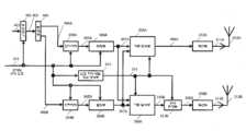
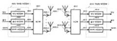
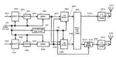
도 23은 송신안테나 수 2, 수신안테나 수 2, 송신변조신호(송신 스트림) 수 2일 때의 송수신장치의 구성의 일례를 나타내고 있다. 송신장치에서는 부호화된 데이터를 인터리브 하고, 인터리브 후의 데이터를 변조해서 주파수 변환 등을 실행하여 송신신호가 생성되며, 송신신호는 안테나로부터 송신된다. 이때, 송신안테나로부터 각각 다른 변조신호를 동일 시각에 동일 주파수로 송신하는 방식이 공간 다중 MIMO 방식이다.Fig. 23 shows an example of the configuration of a transmission/reception apparatus when the number of transmission antennas is 2, the number of reception antennas is 2, and the number of transmission modulated signals (transmission streams) is 2. In the transmission apparatus, the encoded data is interleaved, the interleaved data is modulated to perform frequency conversion, etc. to generate a transmission signal, and the transmission signal is transmitted from the antenna. At this time, the method of transmitting different modulated signals from the transmission antenna at the same time at the same frequency is the spatial multiplexing MIMO method.
이때, 특허문헌 1에서는 송신안테나마다 다른 인터리브 패턴을 구비하는 송신장치가 제안되어 있다. 즉, 도 23의 송신장치에서 2개의 인터리브 (πa,πb)가 서로 다른 인터리브 패턴을 가지고 있게 된다. 그리고 수신장치에 있어서 비 특허문헌 1, 비 특허문헌 2에 나타내고 있는 것과 같이 소프트 값을 이용한 검파방법(도 23에서의 MIMO detector)을 반복하여 실행함으로써 수신품질이 향상하게 된다.At this time, in
그러나 무선통신에서의 실제 전파환경의 모델로 레일리 페이딩(Rayleigh fading) 환경으로 대표되는 NLOS(Non-line of sight) 환경, 라이시안 페이딩(Rician fading) 환경으로 대표되는 LOS(Line of sight) 환경이 존재한다. 송신장치에서 싱글의 변조신호를 송신하고, 수신장치에서 복수의 안테나로 수신한 신호에 대해 최대 비 합성을 실행하여 최대 비 합성 후의 신호에 대해서 복조 및 복호를 실행하는 경우, LOS 환경, 특히 산란파의 수신전력에 대한 직접파의 수신전력의 크기를 나타내는 라이시안 팩터(Rician factor)가 큰 환경에서는 양호한 수신품질을 얻을 수 있다. 그러나 전송방식(예를 들어, 공간 다중 MIMO 전송방식)에 따라서는 라이시안 팩터가 커지면 수신품질이 열화한다고 하는 문제가 발생한다(비 특허문헌 3 참조).However, as a model of the actual radio wave environment in wireless communication, the NLOS (Non-line of sight) environment represented by the Rayleigh fading environment and the LOS (Line of sight) environment represented by the Rician fading environment are exist. When a transmission device transmits a single modulated signal, and a maximum ratio synthesis is performed on signals received by a plurality of antennas at the reception device, and demodulation and decoding are performed on the signal after the maximum ratio synthesis, the LOS environment, especially the scattered wave In an environment in which the Rician factor representing the magnitude of the reception power of the direct wave relative to the reception power is large, good reception quality can be obtained. However, depending on the transmission method (e.g., spatial multiplex MIMO transmission method), a problem arises that the reception quality deteriorates when the Rician factor increases (see Non-Patent Document 3).
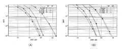
도 24의 (A), (B)는 레일리 페이딩 환경 및 라이시안 팩터 K=3, 10, 16dB의 라이시안 페이딩 환경에서 LDPC(low-density parity-check) 부호화된 데이터를 2×2(2 안테나 송신, 2 안테나 수신) 공간 다중 MIMO 전송한 경우의 BER(Bit Error Rate) 특성(세로축:BER, 가로축:SNR(Signal-to-Noise power Ratio))의 시뮬레이션 결과의 일례를 나타내고 있다. 도 24의 (A)는 반복 검파를 실행하지 않은 Max-log-APP(비 특허문헌 1, 비 특허문헌 2 참조)(APP:A Posterior Probability)의 BER 특성, 도 24의 (B)는 반복 검파를 실행한 Max-log-APP(비 특허문헌 1, 비 특허문헌 2 참조)(반복횟수 5회)의 BER 특성을 나타내고 있다. 도 24 (A), (B)로부터 알 수 있는 것과 같이, 반복 검파를 실행하거나 또는 실행하지 않거나에 관계없이 공간 다중 MIMO 시스템에서는 라이시안 팩터가 커지면 수신품질이 열화하는 것을 확인할 수 있다. 이로부터 「공간 다중 MIMO 시스템에서는 전파환경이 안정적이 되면 수신품질이 열화한다」라는 종래의 싱글 변조신호를 송신하는 시스템에는 없는 공간 다중 MIMO 시스템 고유의 과제를 갖는 것을 알 수 있다.24A and 24B show LDPC (low-density parity-check) encoded data in a Rayleigh fading environment and a Rician fading environment of Rician factor K=3, 10, and
방송이나 멀티캐스트통신은 다양한 전파환경에 대응해야 하는 서비스이며, 사용자가 소지하는 수신기와 방송국 사이의 전파 전파환경이 LOS 환경인 경우는 당연히 있을 수 있다. 상술의 과제를 갖는 공간 다중 MIMO 시스템을 방송이나 멀티캐스트통신에 이용한 경우, 수신기에 있어서 전파의 수신 전계 강도는 높으나, 수신품질의 열화에 의해 서비스를 받을 수 없다고 하는 현상이 발생할 가능성이 있다. 즉, 공간 다중 MIMO 시스템을 방송이나 멀티캐스트통신에서 이용하기 위해서는 NLOS 환경 및 LOS 환경의 어느 경우에 있어서도 어느 정도의 수신품질을 얻을 수 있는 MIMO 전송방식의 개발이 요청되고 있다.Broadcasting or multicast communication is a service that has to cope with various radio wave environments, and there may naturally be a case where the radio wave propagation environment between a receiver and a broadcasting station possessed by a user is an LOS environment. When the spatial multiplex MIMO system having the above-described problem is used for broadcasting or multicast communication, there is a possibility that the receiver cannot receive a service due to a high reception electric field strength of a radio wave, but the reception quality is deteriorated. That is, in order to use the spatial multiplex MIMO system in broadcasting or multicast communication, development of a MIMO transmission method capable of obtaining a certain level of reception quality in both NLOS environment and LOS environment is requested.
비 특허문헌 8에서는 통신 상대로부터의 피드백 정보로부터 프리코딩에 이용하는 코드 북(codebook, 프리코딩 행렬(프리코딩 웨이트 행렬이라고도 한다))을 선택하는 방법에 대해 기술되어 있으나, 상기와 같이 방송이나 멀티캐스트통신과 같이 통신 상대로부터의 피드백 정보를 얻을 수 없는 상황에서 프리코딩을 실행하는 방법에 대해서는 전혀 기재되어 있지 않다.Non-Patent
한편, 비 특허문헌 4에서는 피드백 정보가 없는 경우에도 적용할 수 있는, 시간과 함께 프리코딩 행렬을 전환하는 방법에 대해 기술되어 있다. 이 문헌에서는 프리코딩에 이용하는 행렬로 유니테리 행렬(unitary matrix)을 이용하는 것, 또, 유니테리 행렬(unitary matrix)을 랜덤하게 전환하는 것에 대해 기술되어 있으나, 상기에서 나타내는 LOS 환경에서의 수신품질의 열화에 대한 적용방법에 대해서는 전혀 기재되어 있지 않으며, 단지 랜덤하게 전환하는 것만이 기재되어 있다. 당연하나, LOS 환경의 수신품질의 열화를 개선하기 위한 프리코딩방법 및 프리코딩 행렬의 구성방법에 관한 기술은 일절 되어있지 않다.On the other hand, Non-Patent
본 발명은 복수의 안테나로부터 각각 다른 변조신호를 송신하는 무선 시스템에 넓게 적용할 수 있으며, 특히 제 1 송신부와 제 2 송신부를 구비하는 송신 및 수신 시스템의 효율성 높은 신호생성의 방법과, 그 신호 생성 시스템 및 신호생성장치를 제공하는 것을 목적으로 한다.The present invention can be widely applied to a wireless system that transmits different modulated signals from a plurality of antennas, and in particular, a method of generating a signal with high efficiency in a transmission and reception system having a first transmission unit and a second transmission unit, and the signal generation. It aims to provide a system and a signal generating device.
본 발명의 송신 시스템의 OFDM 신호생성방법은 송신 시스템이 제 1 송신부와 제 2 송신부를 구비하며, 복수의 제 1 변조신호 및 복수의 제 2 변조신호를 생성하고, 상기 제 2 변조신호는 상기 제 1 변조신호와 동일하며, 복수의 파일럿신호를 상기 제 1 변조신호 및 상기 제 2 변조신호에 삽입하고, 복수의 제 1 파일럿 삽입 후의 신호 및 복수의 제 2 파일럿 삽입 후의 신호를 각각 취득하며, 복수의 슬롯 각각에 대해 위상변경방식을 규칙적으로 변화시키면서 상기 제 1 파일럿 삽입 후의 신호 및 상기 제 2 파일럿 삽입 후의 신호로 위상변경을 실시하여, 복수의 제 1 송신신호 및 복수의 제 2 송신신호를 취득하고, 상기 생성, 상기 삽입, 상기 위상변경의 각각은 상기 제 1 송신부에 의해 또는 상기 제 1 송신부 및 상기 제 2 송신부에 의해 실시되고, 상기 제 1 송신부에 의해 상기 제 1 송신신호를 제 1 안테나로부터 제 1 기간에 제 1 주파수로 송신되는 제 1 OFDM 신호로 변환하며, 상기 제 2 송신부에 의해 상기 제 2 송신신호를 제 2 안테나로부터 상기 제 1 기간에 상기 제 1 주파수로 송신되는 제 2 OFDM 신호로 변환하는 것을 특징으로 한다.In the OFDM signal generation method of the transmission system of the present invention, the transmission system includes a first transmission unit and a second transmission unit, and generates a plurality of first modulated signals and a plurality of second modulated signals, and the second modulated signal is the second modulated signal. It is the same as one modulated signal, and a plurality of pilot signals are inserted into the first modulated signal and the second modulated signal, and a plurality of signals after the insertion of the first pilots and the signals after the insertion of the plurality of second pilots are obtained, respectively, and a plurality of A phase change method is regularly changed for each of the slots, and a phase change is performed with the signal after the insertion of the first pilot and the signal after the insertion of the second pilot to obtain a plurality of first transmission signals and a plurality of second transmission signals. And each of the generation, the insertion, and the phase change is performed by the first transmission unit or by the first transmission unit and the second transmission unit, and the first transmission signal is transmitted by the first transmission unit to a first antenna. A second OFDM signal that is converted into a first OFDM signal transmitted at a first frequency in a first period, and the second transmission signal is transmitted from a second antenna to the first frequency in the first period by the second transmission unit. It is characterized in that it converts into a signal.
본 발명의 OFDM 신호 생성 시스템은, 제 1 OFDM 신호 생성부와 제 2 OFDM 신호 생성부를 구비하고, 상기 제 1 OFDM 신호 생성부 및 상기 제 2 OFDM 신호 생성부는, 복수의 제 1 변조신호 및 복수의 제 2 변조신호를 생성하고, 상기 제 2 변조신호는 상기 제 1 변조신호와 동일하며,복수의 파일럿 신호를 상기 제 1 변조신호 및 상기 제 2 변조신호에 삽입하고, 복수의 제 1 파일럿 삽입 후의 신호 및 복수의 제 2 파일럿 삽입 후의 신호를 각각 취득하며, 복수의 슬롯 각각에 대해 위상변경방식을 규칙적으로 변화시키면서 상기 제 1 파일럿 삽입 후의 신호 및 상기 제 2 파일럿 삽입 후의 신호에 위상변경을 실시하고, 복수의 제 1 송신신호 및 복수의 제 2 송신신호를 취득하며, 상기 생성, 상기 삽입, 상기 위상변경 각각은 상기 제 1 OFDM 신호 생성부에 의해, 또는, 상기 제 1 OFDM 신호생성부 및 상기 제 2 OFDM 신호 생성부에 의해 실시되고, 상기 제 1 OFDM 신호 생성부는 상기 제 1 송신신호를 제 1 안테나로부터 제 1 기간에 제 1 주파수로 송신되는 제 1 OFDM 신호로 변환하며, 상기 제 2 OFDM 신호 생성부는 상기 제 2 송신신호를 제 2 안테나로부터 상기 제 1 기간에 상기 제 1 주파수로 송신되는 제 2 OFDM 신호로 변환하는 것을 특징으로 한다. The OFDM signal generation system of the present invention includes a first OFDM signal generation unit and a second OFDM signal generation unit, and the first OFDM signal generation unit and the second OFDM signal generation unit include a plurality of first modulated signals and a plurality of A second modulated signal is generated, the second modulated signal is the same as the first modulated signal, a plurality of pilot signals are inserted into the first modulated signal and the second modulated signal, and a plurality of first pilots are inserted. A signal and a signal after the insertion of a plurality of second pilots are each acquired, and a phase change is performed on the signal after the insertion of the first pilot and the signal after the insertion of the second pilot while regularly changing the phase change method for each of the plurality of slots. , A plurality of first transmission signals and a plurality of second transmission signals are acquired, and each of the generation, the insertion, and the phase change is performed by the first OFDM signal generation unit, or the first OFDM signal generation unit and the Implemented by a second OFDM signal generator, the first OFDM signal generator converts the first transmission signal into a first OFDM signal transmitted at a first frequency in a first period from a first antenna, and the second OFDM signal The signal generator may convert the second transmission signal from a second antenna into a second OFDM signal transmitted at the first frequency in the first period.
본 발명에 의한 수신장치의 수신 데이터 생성방법은, 제 1 송신부의 제 1 안테나로부터 제 1 기간에 제 1 주파수로 송신된 제 1 OFDM 신호와, 제 2 송신부의 제 2 안테나로부터 상기 제 1 기간에 상기 제 1 주파수로 송신된 제 2 OFDM 신호로부터 변환된 복수의 수신신호를 취득하고, 상기 제 1 OFDM 신호 및 상기 제 2 OFDM 신호는 소정의 신호 생성 처리를 이용하여 생성되는 신호이며, 상기 소정의 신호 생성 처리에 따른 소정의 복조처리를 이용하여 상기 수신신호를 수신 데이터로 복조하고, 상기 소정의 신호 생성 처리는, 복수의 제 1 변조신호 및 복수의 제 2 변조신호를 생성하고, 상기 제 2 변조신호는 상기 제 1 변조신호와 동일하며, 복수의 파일럿 신호를 상기 제 1 변조신호 및 상기 제 2 변조신호에 삽입하고, 복수의 제 1 파일럿 삽입 후의 신호 및 복수의 제 2 파일럿 삽입 후의 신호를 각각 취득하며, 복수의 슬롯 각각에 대해 위상변경방식을 규칙적으로 변화시키면서 상기 제 1 파일럿 삽입 후의 신호 및 상기 제 2 파일럿 삽입 후의 신호에 위상변경을 실시하고, 복수의 제 1 송신신호 및 복수의 제 2 송신신호를 취득하며, 상기 제 1 송신부에 의해 상기 제 1 송신신호를 상기 제 1 OFDM 신호로 변환하고, 상기 제 2 송신부에 의해 상기 제 2 송신신호를 상기 제 2 OFDM 신호로 변환하는 것을 특징으로 한다.The receiving data generating method of the receiving apparatus according to the present invention comprises: a first OFDM signal transmitted at a first frequency in a first period from a first antenna of a first transmitting unit, and a second antenna of a second transmitting unit in the first period. A plurality of received signals converted from the second OFDM signal transmitted at the first frequency are acquired, the first OFDM signal and the second OFDM signal are signals generated using a predetermined signal generation process, and the predetermined The received signal is demodulated into received data using a predetermined demodulation process according to a signal generation process, and the predetermined signal generation process generates a plurality of first modulated signals and a plurality of second modulated signals, and the second The modulated signal is the same as the first modulated signal, and a plurality of pilot signals are inserted into the first modulated signal and the second modulated signal, and a plurality of signals after the insertion of the first pilots and the signals after the insertion of the plurality of second pilots are Each is acquired, and a phase change is performed on the signal after the insertion of the first pilot and the signal after the insertion of the second pilot while regularly changing the phase change method for each of a plurality of slots. 2 acquiring a transmission signal, converting the first transmission signal into the first OFDM signal by the first transmission unit, and converting the second transmission signal into the second OFDM signal by the second transmission unit It is done.
또 본 발명에 의한 수신 데이터 생성장치는, 취득부와, 복조부를 구비하고, 상기 취득부는 제 1 송신부의 제 1 안테나로부터 제 1 기간에 제 1 주파수로 송신된 제 1 OFDM 신호와, 제 2 송신부의 제 2 안테나로부터 상기 제 1 기간에 상기 제 1 주파수로 송신된 제 2 OFDM 신호로부터 변환된 복수의 수신신호를 취득하며, 상기 제 1 OFDM 신호 및 상기 제 2 OFDM 신호는 소정의 신호 생성 처리를 이용하여 생성되는 신호이고, 상기 복조부는 상기 소정의 신호 생성 처리에 따른 소정의 복조처리를 이용하여 상기 수신신호를 수신 데이터로 복조하며, 상기 소정의 신호 생성 처리는, 복수의 제 1 변조신호 및 복수의 제 2 변조신호를 생성하고, 상기 제 2 변조신호는 상기 제 1 변조신호와 동일하며, 복수의 파일럿 신호를 상기 제 1 변조신호 및 상기 제 2 변조신호에 삽입하고, 복수의 제 1 파일럿 삽입 후의 신호 및 복수의 제 2 파일럿 삽입 후의 신호를 각각 취득하며, 복수의 슬롯 각각에 대해 위상변경방식을 규칙적으로 변화시키면서 상기 제 1 파일럿 삽입 후의 신호 및 상기 제 2 파일럿 삽입 후의 신호로 위상변경을 실시하고, 복수의 제 1 송신신호 및 복수의 제 2 송신신호를 취득하며, 상기 제 1 송신부에 의해 상기 제 1 송신신호를 상기 제 1 OFDM 신호로 변환하고, 상기 제 2 송신부에 의해 상기 제 2 송신신호를 상기 제 2 OFDM 신호로 변환하는 것을 특징으로 한다.Further, the receiving data generating apparatus according to the present invention includes an acquisition unit and a demodulation unit, wherein the acquisition unit includes a first OFDM signal transmitted at a first frequency in a first period from a first antenna of the first transmission unit, and a second transmission unit. Acquire a plurality of received signals converted from the second OFDM signal transmitted at the first frequency in the first period from the second antenna of, and the first OFDM signal and the second OFDM signal undergo a predetermined signal generation process. A signal generated by using, and the demodulator demodulates the received signal into received data by using a predetermined demodulation process according to the predetermined signal generation process, and the predetermined signal generation process includes: a plurality of first modulated signals and A plurality of second modulated signals are generated, the second modulated signal is the same as the first modulated signal, a plurality of pilot signals are inserted into the first modulated signal and the second modulated signal, and a plurality of first pilots The signal after the insertion and the signal after the insertion of the plurality of second pilots are each acquired, and the phase change is performed with the signal after the insertion of the first pilot and the signal after the insertion of the second pilot while regularly changing the phase change method for each of the plurality of slots. A plurality of first transmission signals and a plurality of second transmission signals are obtained, the first transmission signal is converted into the first OFDM signal by the first transmission unit, and the second transmission signal is performed by the second transmission unit. It is characterized in that the transmission signal is converted into the second OFDM signal.
이와 같이 본 발명에 의하면 LOS 환경에서의 수신품질의 열화를 개선하는 신호생성방법, 신호생성장치를 제공할 수 있으므로, 방송이나 멀티캐스트통신에서 송수신자 간에 대해 품질의 높은 서비스를 제공할 수 있다.As described above, according to the present invention, since it is possible to provide a signal generation method and a signal generation apparatus for improving the deterioration of reception quality in an LOS environment, it is possible to provide a high-quality service between a transmitter and a receiver in broadcast or multicast communication.
또한 본 발명은 복수의 안테나로부터 각각 다른 변조신호를 송신하는 무선 시스템에 넓게 적용할 수 있으며, 예를 들어 OFDM-MIMO 통신시스템에 적용하는 것에 매우 적합하다. 또, 복수의 송신 개소를 가지는 유선 통신시스템(예를 들어 PLC(Power Line Communication) 시스템, 광통신시스템, DSL(Digital Subscriber Line:디지털 가입자선) 시스템)에서 MIMO 전송을 실행하는 경우에 대해서도 적용할 수 있고, 송신장치에서 데이터의 수신품질이 향상되는 효과가 있다.In addition, the present invention can be widely applied to a wireless system that transmits different modulated signals from a plurality of antennas, and is very suitable for application to, for example, an OFDM-MIMO communication system. In addition, it can be applied to the case of performing MIMO transmission in a wired communication system having multiple transmission points (e.g., a PLC (Power Line Communication) system, an optical communication system, DSL (Digital Subscriber Line: digital subscriber line) system). In addition, there is an effect of improving the reception quality of data in the transmission device.
도 1은 공간 다중 MIMO 전송 시스템에서의 송수신장치의 구성의 예이다.
도 2는 프레임 구성의 일례이다.
도 3은 위상변경방법 적용 시의 송신장치의 구성의 예이다.
도 4는 위상변경방법 적용 시의 송신장치의 구성의 예이다.
도 5는 프레임 구성의 예이다.
도 6은 위상변경방법의 예이다.
도 7은 수신장치의 구성의 예이다.
도 8은 수신장치의 신호처리부의 구성의 예이다.
도 9는 수신장치의 신호처리부의 구성의 예이다.
도 10은 복호처리방법이다.
도 11은 수신상태의 예이다.
도 12는 위상변경방법 적용 시의 송신장치의 구성의 예이다.
도 13은 위상변경방법 적용 시의 송신장치의 구성의 예이다.
도 14는 프레임 구성의 예이다.
도 15는 프레임 구성의 예이다.
도 16은 프레임 구성의 예이다.
도 17은 프레임 구성의 예이다.
도 18은 프레임 구성의 예이다.
도 19는 매핑방법의 일례이다.
도 20은 매핑방법의 일례이다.
도 21은 가중합성부의 구성의 예이다.
도 22는 심벌의 정렬방법의 일례이다.
도 23은 공간 다중 MIMO 전송 시스템에서의 송수신장치의 구성의 예이다.
도 24는 BER 특성 예이다.
도 25는 위상변경방법의 예이다.
도 26은 위상변경방법의 예이다.
도 27은 위상변경방법의 예이다.
도 28은 위상변경방법의 예이다.
도 29는 위상변경방법의 예이다.
도 30은 높은 수신품질을 얻을 수 있는 변조신호의 심벌 배치 예이다.
도 31은 높은 수신품질을 얻을 수 있는 변조신호의 프레임 구성의 예이다.
도 32는 높은 수신품질을 얻을 수 있는 변조신호의 심벌 배치 예이다.
도 33은 높은 수신품질을 얻을 수 있는 변조신호의 심벌 배치 예이다.
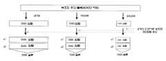
도 34는 블록부호를 이용한 경우의 하나의 부호화 후의 블록에 필요한 심벌 수, 슬롯 수의 변화 예이다.
도 35는 블록부호를 이용한 경우의 2개의 부호화 후의 블록에 필요한 심벌 수, 슬롯 수의 변화 예이다.
도 36은 디지털 방송용 시스템의 전체 구성도이다.
도 37은 수신기의 구성의 예를 나타내는 블록도이다.
도 38은 다중화데이터의 구성을 나타내는 도면이다.
도 39는 각 스트림이 다중화데이터에서 어떻게 다중화되어 있는가를 모식적으로 나타내는 도면이다.
도 40은 PES 패킷 열에 비디오 스트림이 어떻게 저장되어 있는가를 나타내는 상세도이다.
도 41은 다중화데이터에서의 TS패킷과 소스 패킷의 구조를 나타내는 도면이다.
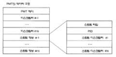
도 42는 PMT의 데이터 구성을 나타내는 도면이다.
도 43은 다중화데이터 정보의 내부 구성을 나타내는 도면이다.
도 44는 스트림 속성정보의 내부 구성을 나타내는 도면이다.
도 45는 영상 표시, 음성출력장치의 구성도이다.
도 46은 통신시스템의 구성의 일례이다.
도 47은 높은 수신품질을 얻을 수 있는 변조신호의 심벌 배치 예이다.
도 48은 높은 수신품질을 얻을 수 있는 변조신호의 심벌 배치 예이다.
도 49는 높은 수신품질을 얻을 수 있는 변조신호의 심벌 배치 예이다.
도 50은 높은 수신품질을 얻을 수 있는 변조신호의 심벌 배치 예이다.
도 51은 송신장치의 구성의 예이다.
도 52는 송신장치의 구성의 예이다.
도 53은 송신장치의 구성의 예이다.
도 54는 송신장치의 구성의 예이다.
도 55는 베이스밴드신호 교체부를 나타내는 도면이다.
도 56은 송신장치의 구성의 예이다.
도 57은 분배부의 동작의 일례이다.
도 58은 분배부의 동작의 다른 예이다.
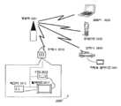
도 59는 기지국 및 단말의 관계를 나타내는 통신시스템의 일례이다.
도 60은 송신신호의 주파수 할당의 일례이다.
도 61은 송신신호의 주파수 할당의 일례이다.
도 62는 기지국과 중계기 및 단말의 관계를 나타내는 통신시스템의 일례이다.
도 63은 기지국으로부터의 송신신호의 주파수 할당의 일례이다.
도 64는 중계기로부터의 송신신호의 주파수 할당의 일례이다.
도 65는 중계기의 수신부와 송신부의 구성의 일례이다.
도 66은 기지국이 송신하는 신호의 데이터 포맷의 일례이다.
도 67은 송신장치의 구성의 예이다.
도 68은 베이스밴드신호 교체부를 나타내는 도면이다.
도 69는 가중 베이스밴드신호의 교체, 위상변경방법의 일례이다.
도 70은 OFDM 방식을 이용한 송신장치의 구성의 예이다.
도 71은 프레임 구성의 예이다.
도 72는 변조방식에 따른 슬롯 수와 위상변경 값의 예이다.
도 73은 변조방식에 따른 슬롯 수와 위상변경 값의 예이다.
도 74는 DVB-T2규격에서의 방송국이 송신하는 신호의 프레임 구성의 개요이다.
도 75는 동일 시각에 2종류 이상의 신호가 존재하는 예이다.
도 76은 송신장치의 구성의 예이다.
도 77은 프레임 구성의 예이다.
도 78은 프레임 구성의 예이다.
도 79는 프레임 구성의 예이다.
도 80은 I-Q평면에서의 16QAM인 경우의 신호 점 배치의 예이다.
도 81은 I-Q평면에서의 QPSK인 경우의 신호 점 배치의 예이다.
도 82는 수신장치가 얻는 대수 우도 비의 절대치를 모식적으로 나타내는 예이다.
도 83은 수신장치가 얻는 대수 우도 비의 절대치의 호적한 예이다.
도 84는 가중합성부에 관련한 신호처리부의 구성의 예이다.
도 85는 가중합성부에 관련한 신호처리부의 구성의 예이다.
도 86은 I-Q평면에서의 64QAM인 경우의 신호 점 배치의 예이다.
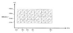
도 87은 시간별 변조방식, 파워 변경 값, 위상변경 값의 설정 예이다.
도 88은 시간별 변조방식, 파워 변경 값, 위상변경 값의 설정 예이다.
도 89는 가중합성부에 관련하는 신호처리부의 구성의 예이다.
도 90은 가중합성부에 관련하는 신호처리부의 구성의 예이다.
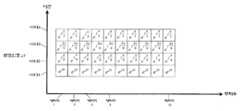
도 91은 시간별 변조방식, 파워 변경 값, 위상변경 값의 설정 예이다.
도 92는 시간별 변조방식, 파워 변경 값, 위상변경 값의 설정 예이다.
도 93은 가중합성부에 관련하는 신호처리부의 구성의 예이다.
도 94는 I-Q평면에서의 16QAM 및 QPSK의 신호 점 배치의 예이다.
도 95는 I-Q평면에서의 16QAM 및 QPSK의 신호 점 배치의 예이다.1 is an example of a configuration of a transmission/reception apparatus in a spatial multiplex MIMO transmission system.
2 is an example of a frame configuration.
3 is an example of a configuration of a transmission device when a phase change method is applied.
4 is an example of a configuration of a transmission apparatus when a phase change method is applied.
5 is an example of a frame configuration.
6 is an example of a phase change method.
7 is an example of a configuration of a receiving device.
8 is an example of a configuration of a signal processing unit of a receiving apparatus.
9 is an example of a configuration of a signal processing unit of a receiving apparatus.
10 is a decoding processing method.
11 is an example of a reception state.
12 is an example of a configuration of a transmission apparatus when a phase change method is applied.
13 is an example of a configuration of a transmission apparatus when a phase change method is applied.
14 is an example of a frame configuration.
15 is an example of a frame configuration.
16 is an example of a frame configuration.
17 is an example of a frame configuration.
18 is an example of a frame configuration.
19 is an example of a mapping method.
20 is an example of a mapping method.
21 is an example of a configuration of a weighting synthesis unit.
22 is an example of a method of arranging symbols.
23 is an example of a configuration of a transmission/reception apparatus in a spatial multiplex MIMO transmission system.
24 is an example of BER characteristics.
25 is an example of a phase change method.
26 is an example of a phase change method.
27 is an example of a phase change method.
28 is an example of a phase change method.
29 is an example of a phase change method.
30 is an example of symbol arrangement of a modulated signal capable of obtaining high reception quality.
31 is an example of a frame structure of a modulated signal capable of obtaining high reception quality.
32 is an example of symbol arrangement of a modulated signal capable of obtaining high reception quality.
33 is an example of symbol arrangement of a modulated signal capable of obtaining high reception quality.
34 is an example of changes in the number of symbols and slots required for a block after one encoding in the case of using a block code.
Fig. 35 is an example of changes in the number of symbols and slots required for two encoded blocks in the case of using a block code.
36 is an overall configuration diagram of a digital broadcasting system.
37 is a block diagram showing an example of a configuration of a receiver.
38 is a diagram showing the structure of multiplexed data.
39 is a diagram schematically showing how each stream is multiplexed in multiplexed data.
40 is a detailed diagram showing how a video stream is stored in a PES packet stream.
41 is a diagram showing the structure of a TS packet and a source packet in multiplexed data.
42 is a diagram showing a data structure of a PMT.
43 is a diagram showing an internal configuration of multiplexed data information.
44 is a diagram showing the internal structure of stream attribute information.
45 is a configuration diagram of a video display and audio output device.
46 is an example of the configuration of a communication system.
47 is an example of symbol arrangement of a modulated signal capable of obtaining high reception quality.
48 is an example of symbol arrangement of a modulated signal capable of obtaining high reception quality.
49 is an example of symbol arrangement of a modulated signal capable of obtaining high reception quality.
50 is an example of symbol arrangement of a modulated signal capable of obtaining high reception quality.
51 is an example of the configuration of a transmission device.
52 is an example of a configuration of a transmission device.
53 is an example of a configuration of a transmission device.
54 is an example of a configuration of a transmission device.
55 is a diagram illustrating a baseband signal replacement unit.
56 is an example of the configuration of a transmission device.
57 is an example of the operation of the distribution unit.
58 is another example of the operation of the distribution unit.
59 is an example of a communication system showing the relationship between a base station and a terminal.
60 is an example of frequency allocation of a transmission signal.
61 shows an example of frequency allocation of a transmission signal.
62 is an example of a communication system showing the relationship between a base station, a repeater, and a terminal.
63 is an example of frequency allocation of a transmission signal from a base station.
64 is an example of frequency allocation of a transmission signal from a repeater.
65 is an example of a configuration of a receiving unit and a transmitting unit of a repeater.
66 is an example of a data format of a signal transmitted by a base station.
67 is an example of the configuration of a transmission device.
68 is a diagram illustrating a baseband signal replacement unit.
69 is an example of a method of replacing a weighted baseband signal and changing a phase.
70 is an example of the configuration of a transmission apparatus using the OFDM scheme.
71 is an example of a frame configuration.
72 is an example of a number of slots and a phase change value according to a modulation method.
73 is an example of a number of slots and a phase change value according to a modulation method.
74 is an outline of a frame structure of a signal transmitted by a broadcasting station in the DVB-T2 standard.
75 is an example in which two or more types of signals exist at the same time.
76 is an example of the configuration of a transmission device.
77 is an example of a frame configuration.
78 is an example of a frame configuration.
79 is an example of a frame configuration.
80 is an example of arrangement of signal points in the case of 16QAM in the IQ plane.
81 is an example of signal point arrangement in the case of QPSK in the IQ plane.
82 is an example schematically showing the absolute value of the log likelihood ratio obtained by the receiving apparatus.
83 is a suitable example of the absolute value of the log likelihood ratio obtained by the receiving apparatus.
84 is an example of a configuration of a signal processing unit related to a weighting synthesis unit.
85 is an example of a configuration of a signal processing unit related to a weighting synthesis unit.
86 is an example of signal point arrangement in the case of 64QAM in the IQ plane.
87 is an example of setting a time-based modulation method, a power change value, and a phase change value.
88 is an example of setting a time-based modulation method, a power change value, and a phase change value.
89 is an example of a configuration of a signal processing unit related to a weighting synthesis unit.
90 is an example of a configuration of a signal processing unit related to a weighting synthesis unit.
91 is an example of setting a time-based modulation method, a power change value, and a phase change value.
92 is an example of setting a time-based modulation method, a power change value, and a phase change value.
93 is an example of a configuration of a signal processing unit related to a weighting synthesis unit.
94 is an example of arrangement of signal points of 16QAM and QPSK in the IQ plane.
95 is an example of arrangement of signal points of 16QAM and QPSK in the IQ plane.
이하, 본 발명의 실시형태에 대해 도면을 참조하여 상세하게 설명한다.Hereinafter, embodiments of the present invention will be described in detail with reference to the drawings.
(실시형태 1)(Embodiment 1)
본 실시형태의 송신방법, 송신장치, 수신방법, 수신장치에 대해 상세하게 설명한다.The transmission method, transmission device, reception method, and reception device of the present embodiment will be described in detail.
본 설명을 하기 전에 종래 시스템인 공간 다중 MIMO 전송 시스템에서의 송신방법, 복호방법의 개요에 대해서 설명한다.Before the present description, an overview of a transmission method and a decoding method in a conventional spatial multiplexing MIMO transmission system will be described.
Nt×Nr 공간 다중 MIMO 시스템의 구성을 도 1에 나타낸다. 정보벡터 z는 부호화 및 인터리브가 실시된다. 그리고 인터리브의 출력으로 부호화 후 비트의 벡터 u=(u1, …, uNt)를 얻을 수 있다. 단, ui=(ui1, …, uiM)으로 한다(M:심벌당 송신비트 수). 송신벡터 s=(s1, …, sNt)T로 하면 송신안테나 #i로부터 송신신호 si=map(ui)로 표시되고, 송신에너지를 정규화하면 E{|si|2}=Es/Nt로 표시된다(Es:채널당 총 에너지). 그리고 수신벡터를 y=(y1, …, yNr)T로 하면 식 (1)과 같이 표시된다.A configuration of an Nt ×Nr spatial multiplexing MIMO system is shown in FIG. 1. The information vector z is encoded and interleaved. In addition, a vector of bits u=(u1 , …, uNt ) can be obtained after encoding as the output of the interleaved. However, set ui =(ui1 , …, uiM ) (M: number of transmission bits per symbol). If the transmission vector s = (s1 , …, sNt )Tis expressed as the transmission signal s i =map(ui ) from the transmission antenna #i, and the transmission energy is normalized, E{|si |2 }=EIt is expressed as s /Nt(E s : total energy per channel). And if the received vector is y=(y1 , …, yNr )T , it is expressed as Equation (1).

이때, HNtNrdms 채널행렬(channel matrix) n=(n1, …, nNr)T는 노이즈 벡터이며, ni는 평균값 0, 분산 σ2의 i. i. d. 복소 가우스 잡음이다. 수신기에서 도입하는 송신심벌과 수신심벌의 관계로부터 수신벡터에 관한 확률은 식 (2)와 같이 다차원 가우스 분포로 줄 수 있다.At this time, HNtNrdms channel matrix n=(n1 , …, nNr )T is a noise vector, and ni is an iid complex Gaussian noise with an average value of 0 and variance σ2. From the relationship between the transmission symbol and the reception symbol introduced by the receiver, the probability for the reception vector can be given as a multidimensional Gaussian distribution as shown in Equation (2).

여기서 outer Soft-in/Soft-out 디코더와 MIMO 검파로 이루어지는 도 1과 같은 반복 복호를 실행하는 수신기를 생각한다. 도 1에서의 대수 우도 비(log-likelihood ratio)의 벡터(L-value)는 식 (3) - (5)와 같이 표시된다.Here, consider a receiver that performs repetitive decoding as shown in FIG. 1 comprising an outer soft-in/soft-out decoder and MIMO detection. The vector (L-value) of the log-likelihood ratio in FIG. 1 is expressed as Equations (3)-(5).


<반복 검파방법><Repeated detection method>
여기에서는 NtxNr 공간 다중 MIMO 시스템에서의 MIMO 신호의 반복 검파에 대해서 설명한다.Here, repetitive detection of a MIMO signal in anN txNr spatial multiplexing MIMO system will be described.
umn의 대수 우도 비를 식 (6)과 같이 정의한다.The logarithmic likelihood ratio of umn is defined as in Equation (6).

베이즈의 정리(Bayes' theorem)에 의해 식 (6)은 식 (7)과 같이 나타낼 수 있다.By Bayes' theorem, Equation (6) can be expressed as Equation (7).

단, Umn,±1={u|umn=±1}로 한다. 그리고 lnΣaj~ max ln aj로 근사하면 식 (7)은 식 (8)과 같이 근사할 수 있다. 또, 위의 「~」의 기호는 근사를 의미한다.However, let Umn,±1 ={u|umn =±1}. And if lnΣaj ~ max ln aj are approximated, Equation (7) can be approximated as Equation (8). In addition, the symbol of "~" above means approximation.

식 (8)에서의 P(u|umn)와 ln P(u|umn)은 이하와 같이 표시된다.P(u|umn ) and ln P(u|umn ) in Equation (8) are expressed as follows.


그러나 식 (2)에서 정의한 식의 대수 확률은 식 (12)과 같이 표시된다.However, the logarithmic probability of the equation defined in equation (2) is expressed as in equation (12).

따라서 식 (7), (13)으로부터 MAP 또는 APP(A Posteriori Probability)에서는 사후의 L-value는 이하와 같이 표시된다.Therefore, from Equations (7) and (13), in MAP or APP (A Posteriori Probability), the L-value after death is expressed as follows.

이하에서는 반복 APP 복호라고 부른다. 또, 식 (8), (12)로부터 Max-Log 근사에 의거하는 대수 우도 비(Max-Log APP)에서는 사후의 L-value는 이하와 같이 표시된다.Hereinafter, it is referred to as repeated APP decoding. In addition, in the logarithmic likelihood ratio (Max-Log?APP) based on the Max-Log approximation from Expressions (8) and (12), the L-value after the poster is expressed as follows.


이하에서는 반복 Max-log APP 복호라고 한다. 그리고 반복 복호의 시스템에서 필요로 하는 외부 정보는 식 (13) 또는 (14)에서 사전 입력을 감산함으로써 구할 수 있다.Hereinafter, it is referred to as repetitive Max-log APP decoding. And the external information required in the iterative decoding system can be obtained by subtracting the pre-input from Equation (13) or (14).
<시스템 모델><system model>
도 23에 이하의 설명에 연결되는 시스템의 기본 구성을 나타낸다. 여기에서는 2×2 공간 다중 MIMO 시스템으로 하고, 스트림 A, B에는 각각 outer인코더가 있으며, 2개의 outer인코더는 동일한 LDPC부호의 인코더로 한다(여기에서는 outer인코더로 LDPC부호의 인코더를 이용하는 구성을 예로 들어 설명하나, outer인코더가 이용하는 오류정정부호는 LDPC부호에 한정되는 것은 아니며, 터보부호(turbo coding), 돌림형 부호(convolutional coding), LDPC 돌림형 부호 등의 다른 오류정정부호를 이용해도 동일하게 실행할 수 있다. 또, outer인코더는 송신안테나마다 갖는 구성으로 하고 있으나, 이에 한정되는 것은 아니며, 송신안테나가 복수라도 outer인코더는 1개라도 좋고, 또, 송신안테나 수보다 많은 outer인코더를 가지고 있어도 좋다). 그리고 스트림 A, B에서는 각각 인터리버 (πa,πb)가 있다. 여기에서는 변조방식을 2h-QAM으로 한다(1 심벌로 h 비트를 송신하게 된다).Fig. 23 shows a basic configuration of a system connected to the following description. Here, a 2×2 spatial multiplexing MIMO system is used, and there are outer encoders in streams A and B, respectively, and the two outer encoders are encoders of the same LDPC code (here, the configuration using an LDPC coded encoder as an outer encoder is an example. However, the error correction code used by the outer encoder is not limited to the LDPC code, and other error correction codes such as turbo coding, convolutional coding, and LDPC convolutional code are used. In addition, the outer encoder is configured to have each transmission antenna, but it is not limited thereto. Even if there are multiple transmission antennas, one outer encoder may be used, and it is also possible to have more outer encoders than the number of transmission antennas. ). And in streams A and B, there are interleavers (πa and πb ), respectively. Here, the modulation scheme is a 2 -QAMh (h is a transmission bit to one symbol).
수신기에서는 상술한 설명의 MIMO 신호의 반복 검파(반복 APP(또는 Max-log APP) 복호)를 실행하는 것으로 한다. 그리고 LDPC부호의 복호로는 예를 들어 sum-product 복호를 실행하는 것으로 한다.It is assumed that the receiver performs repetitive detection (repetitive APP (or Max-log APP) decoding) of the MIMO signal described above. In addition, it is assumed that, for example, sum-product decoding is performed as the decoding of the LDPC code.
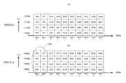
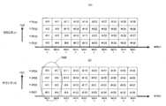
도 2는 프레임 구성을 나타내고 있으며, 인터리브 후의 심벌의 순번을 기재하고 있다. 이때, 이하의 식과 같이 (ia, ja), (ib, jb)를 나타내는 것으로 한다.Fig. 2 shows the frame structure, and describes the order of symbols after interleaving. At this time,it is assumed that (i a , ja ) and (ib , jb ) are expressed as in the following equation.


이때, ia, ib:인터리브 후의 심벌의 순서, ja, jb:변조방식에서의 비트 위치(ja, jb=1, …, h), πa,πb:스트림 A, B의 인터리버, Ωaia, ja,Ωbib, jb:스트림 A, B의 인터리브 전의 데이터의 순번을 나타내고 있다. 단, 도 2에서는 ia=ib일 때의 프레임 구성을 나타내고 있다.At this time, ia , ib : order of symbols after interleaving, ja , jb : bit position in the modulation method (ja , jb =1, …, h), πa , πb : streams A, B Interleaver, Ωaia, ja , Ωbib, jb : Indicates the order of data before interleaving of streams A and B. However, in FIG. 2, the frame structure wheni a = ib is shown.
<반복 복호><Repeat decoding>
여기에서는 수신기에서의 LDPC부호의 복호로 이용하는 sum-product 복호 및 MIMO 신호의 반복 검파의 알고리즘에 대해 상세하게 설명한다.Here, an algorithm of sum-product decoding and repetitive detection of a MIMO signal used for decoding an LDPC code in a receiver will be described in detail.
sum-product 복호sum-product decryption
2원 M x N 행렬 H={Hmn}을 복호대상으로 하는 LDPC부호의 검사행렬(check matrix)로 한다. 집합[1, N]={1, 2, …, N}의 부분 집합 A(m), B(n)를 다음 식과 같이 정의한다.The binary M x N matrix H = {Hmn } is set as the check matrix of the LDPC code to be decoded. Set[1, N]={1, 2,… The subsets A(m) and B(n) of, N} are defined by the following equation.


이때, A(m)은 검사행렬 H의 m행째에서 1인 열(列) 인덱스의 집합을 의미하고, B(n)은 검사행렬 H의 n행째에서 1인 행 인덱스의 집합이다. sum-product 복호의 알고리즘은 이하와 같다.Here, A(m) denotes a set of column indices that are 1 in the m-th row of the check matrix H, and B(n) is a set of row indices that are 1 in the n-th row of the check matrix H. The algorithm of sum-product decoding is as follows.
Step Aㆍ1 (초기화):Hmn=1을 만족하는 모든 조 (m, n)에 대해 사전 값 대수비 βmn=0으로 한다. 루프 변수(반복횟수) lsum=1로 하고, 루프 최대 횟수를 lsum,max로 설정한다.Step A·1 (initialization): Forall sets (m, n) satisfying H mn =1, set the prior value logarithmic ratio βmn = 0. Set the loop variable (number of iterations) to lsum = 1, and set the maximum number of loops to lsum andmax.
Step Aㆍ2(행 처리): m=1, 2, …, M의 순으로 Hmn=1을 만족하는 모든 조 (m, n)에 대해 이하의 갱신 식을 이용하여 외부 값 대수비 αmn을 갱신한다.Step A·2 (row processing): m=1, 2,… For all sets (m, n) satisfyingH mn =1 in the order of, M,the external value logarithmic ratio α mn is updated using the following update equation.


이때, f는 Gallager의 함수이다. 그리고 λn을 구하는 방법에 대해서는 이하에서 상세하게 설명한다.Here, f is a function of Gallager. And themethod of obtaining λ n will be described in detail below.
Step Aㆍ3(열 처리):n=1, 2, …, N의 순으로 Hmn=1을 만족하는 모든 조 (m, n)에 대해 이하의 갱신 식을 이용하여 외부 값 대수비 βmN을 갱신한다.Step A·3 (heat treatment): n=1, 2,… For all sets (m, n) satisfyingH mn =1 in the order of, N,the external value logarithmic ratio β mN is updated using the following update equation.

Step Aㆍ4 (대수 우도 비의 계산):n∈[1, N]에 대해 대수 우도 비 Ln을 이하와 같이 구한다.Step A·4 (Calculation of logarithmic likelihood ratio): Calculate the logarithmic likelihood ratio Ln for n∈[1, N] as follows.

Step Aㆍ5 (반복횟수의 카운트):만일 lsum<lsum, max이면 lsum을 인크리먼트(increment) 하고 step Aㆍ2로 되돌아간다. lsum=lsum, max인 경우, 이번 회의 sum-product 복호는 종료한다.Step A·5 (Repeat count): If lsum<lsum, max , increment lsum and return to step A·2. In the case of lsum = lsum, max , the sum-product decoding of this session is terminated.
이상이 1회의 sum-product 복호의 동작이다. 그 후, MIMO 신호의 반복 검파가 이루어진다. 상술한 sum-product 복호의 동작의 설명에서 이용한 변수 m, n,αmn,βmn,λn, Ln에 있어서 스트림 A에서의 변수를 ma, na,αamana,βamana,λna, Lna, 스트림 B에서의 변수를 mb, nb,αbmbnb,βbmbnb,λnb, Lnb로 나타내는 것으로 한다.This is the operation of one sum-product decoding. After that, iterative detection of the MIMO signal is performed.For the variables m, n, α mn , βmn ,λn and Ln used in the description of the operation of the sum-product decoding described above, the variables in stream A are ma , na , αamana , βamana , Letthe variables in λ na , Lna , and stream B be represented by mb , nb , αbmbnb , βbmbnb , λnb , and Lnb .
<MIMO 신호의 반복 검파><Repetitive detection of MIMO signals>
여기에서는 MIMO 신호의 반복 검파에서의 λn을 구하는 방법에 대해 상세하게 설명한다.Here, a method of obtaining λ n in repetitive detection of a MIMO signal will be described in detail.
식 (1)로부터 다음 식이 성립한다.From Equation (1), the following equation is established.

도 2의 프레임 구성에서 식 (16), (17)로부터 이하의 관계식이 성립한다.In the frame configuration of Fig. 2, the following relational expressions are established from equations (16) and (17).


이때, na, nb∈[1, N]이 된다. 이하에서는 MIMO 신호의 반복 검파의 반복횟수 k일 때의 λna, Lna,λnb, Lnb를 각각 λk, na, Lk,na,λk, nb, Lk, nb로 나타내는 것으로 한다.At this time, na , nb ∈[1, N].Hereinafter, λ na , Lna , λnb , and Lnb at the repetition number k of the MIMO signal repetition detection are represented by λk, na , Lk,na , λk, nb , Lk and nb , respectively. .
Step Bㆍ1 (초기 검파;k=0):초기 검파일 때, λ0, na, λ0, nb를 이하와 같이 구한다.Step B·1 (Initial detection; k=0): At the time of initial detection, λ0, na , λ0, nb are calculated as follows.
반복 APP 복호일 때:In case of repeated APP decoding:

반복 Max-log APP 복호일 때:For repeated Max-log APP decoding:


단, X=a, b로 한다. 그리고 MIMO 신호의 반복 검파의 반복횟수를 lmimo=0으로 하고, 반복횟수의 최대 횟수를 lmimo, max로 설정한다.However, let X=a, b. Then, the number of repetitions of the MIMO signal repetition detection is set to lmimo = 0, and the maximum number of repetitions is setto l mimo, max.
Step Bㆍ2(반복 검파;반복횟수 k):반복횟수 k일 때의 λk, na, λk, nb는 식 (11), (13)-(15),(16),(17)로부터 식 (31)-(34)와 같이 표시된다. 단, (X, Y)=(a, b)(b, a)가 된다.Step B·2 (Repeat detection; number of iterations k): λk, na , λk, nb at the number of iterations k is from equations (11), (13)-(15),(16),(17) It is expressed as Equations (31)-(34). However, (X, Y) = (a, b) (b, a).
반복 APP 복호일 때:In case of repeated APP decoding:


반복 Max-log APP 복호일 때:For repeated Max-log APP decoding:


Step Bㆍ3(반복횟수의 카운트, 부호어 추정): 만일 lmimo<lmimo, max이면 lmimo를 인크리먼트하고, step Bㆍ2로 되돌아간다. lmimo=lmimo, max의 경우, 추정 부호어를 이하와 같이 구한다.Step B·3 (Repeat count, code word estimation): If lmimo< lmimo, max, lmimo is incremented and it returns to step B·2. In the case of lmimo = lmimo, max , the estimated codeword is calculated as follows.

단, X=a, b로 한다.However, let X=a, b.
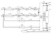
도 3은 본 실시형태에서의 송신장치(300)의 구성의 일례이다. 부호화부(302A)는 정보(데이터)(301A), 프레임 구성신호(313)을 입력으로 하여, 프레임 구성신호(313)(부호화부(302A)가 데이터의 오류정정 부호화에 사용하는 오류정정방식, 부호화율, 블록 길이의 정보가 포함되어 있고, 프레임 구성신호(313)가 지정한 방식을 이용하게 된다. 또, 오류정정방식은 전환해도 좋다)에 따라서 예를 들어 돌림형 부호, LDPC부호, 터보부호 등의 오류정정부호화를 실행하여, 부호화 후의 데이터(303A)를 출력한다.3 is an example of the configuration of the transmission device 300 in the present embodiment. The
인터리버(304A)는 부호화 후의 데이터(303A), 프레임 구성신호(313)을 입력으로 하여, 인터리브, 즉, 순번의 재배열을 실행하여 인터리브 후의 데이터(305A)를 출력한다(프레임 구성신호(313)에 의거하여 인터리브의 방법은 전환해도 좋다).The
매핑부(306A)는 인터리브 후의 데이터(305A), 프레임 구성신호(313)을 입력으로 하여, QPSK(Quadrature Phase Shift Keying), 16QAM(16Quadrature Amplitude Modulation), 64QAM(64Quadrature Amplitude Modulation) 등의 변조를 실시하여 베이스밴드신호(307A)를 출력한다(프레임 구성신호(313)에 의거하여 변조방식은 전환해도 좋다).The
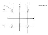
도 19는 QPSK 변조에서의 베이스밴드신호를 구성하는 동상 I성분와 직교 Q성분 IQ평면에서의 매핑방법의 일례로 하고 있다. 예를 들어, 도 19 (A)와 같이 입력 데이터가 「00」의 경우 I=1.0, Q=1.0이 출력되고, 이하와 마찬가지로 입력 데이터가 「01」의 경우 I=-1.0, Q=1.0이 출력되며, …이 출력된다. 도 19 (B)는 도 19 (A)와는 다른 QPSK 변조의 IQ평면에서의 매핑방법의 예이며, 도 19 (B)가 도 19 (A)와 다른 점은 도 19 (A)에서의 신호 점이 원점을 중심으로 회전시킴으로써 도 19 (B)의 신호 점을 얻을 수 있다. 이와 같은 성상 회전(Constellation rotation)방법에 대해서는 비 특허문헌 9, 비 특허문헌 10에 기재되어 있으며, 또, 비 특허문헌 9, 비 특허문헌 10에 나타내고 있는 Cyclic Q Delay를 적용해도 좋다. 도 19와는 다른 예로, 도 20에 16QAM일 때의 IQ평면에서의 신호 점 배치를 나타내고 있고, 도 19 (A)에 상당하는 예가 도 20 (A)이며, 도 19 (B)에 상당하는 예가 도 20 (B)가 된다.Fig. 19 shows an example of a mapping method in an in-phase I component and an orthogonal Q component IQ plane constituting a baseband signal in QPSK modulation. For example, as shown in Fig. 19(A), when the input data is “00”, I=1.0 and Q=1.0 are output, and when the input data is “01”, I=-1.0 and Q=1.0 are as follows. Is printed,… Is output. FIG. 19(B) is an example of a mapping method of QPSK modulation on the IQ plane different from FIG. 19(A). The difference in FIG. 19(B) from FIG. 19(A) is that the signal points in FIG. 19(A) are By rotating around the origin, the signal point in Fig. 19B can be obtained. For such a constellation rotation method, it is described in
부호화부(302B)는 정보(데이터)(301B), 프레임 구성신호(313)을 입력으로 하여, 프레임 구성신호(313)(사용하는 오류정정방식, 부호화율, 블록 길이의 정보가 포함되어 있으며, 프레임 구성신호(313)가 지정한 방식을 이용하게 된다. 또, 오류정정방식은 전환해도 좋다)에 따라서 예를 들어, 돌림형 부호, LDPC부호, 터보부호 등의 오류정정부호화를 실시하여 부호화 후의 데이터(303B)를 출력한다.The
인터리버(304B)는 부호화 후의 데이터(303B), 프레임 구성신호(313)을 입력으로 하여, 인터리브, 즉, 순번의 재배열을 실행하고, 인터리브 후의 데이터(305B)를 출력한다(프레임 구성신호(313)에 의거하여 인터리브의 방법은 전환해도 좋다).The
매핑부(306B)는 인터리브 후의 데이터(305B), 프레임 구성신호(313)을 입력으로 하여, QPSK(Quadrature Phase Shift Keying), 16QAM(16Quadrature Amplitude Modulation), 64QAM(64Quadrature Amplitude Modulation) 등의 변조를 실시하여 베이스밴드신호(307B)를 출력한다(프레임 구성신호(313)에 의거하여 변조방식은 전환해도 좋다).The
신호처리방법정보 생성부(314)는 프레임 구성신호(313)을 입력으로 하여 프레임 구성신호(313)에 의거하는 신호처리방법에 관한 정보(315)를 출력한다. 또, 신호처리방법에 관한 정보(315)는 어느 프리코딩 행렬을 고정적으로 이용하는지를 지정하는 정보와 위상을 변경하는 위상변경패턴의 정보를 포함한다.The signal processing method
가중합성부(308A)는 베이스밴드신호(307A), 베이스밴드신호(307B), 신호처리방법에 관한 정보(315)를 입력으로 하여, 신호처리방법에 관한 정보(315)에 의거하여 베이스밴드신호(307A) 및 베이스밴드신호(307B)를 가중합성하여 가중합성 후의 신호(309A)를 출력한다. 또, 가중합성방법의 상세에 대해서는 후에 상세하게 설명한다.The
무선부(310A)는 가중합성 후의 신호(309A)를 입력으로 하여, 직교 변조, 대역 제한, 주파수 변환, 증폭 등의 처리를 실시하여 송신신호(311A)를 출력하고, 송신신호(311A)는 안테나(312A)에서 전파로서 출력된다.The
가중합성부(308B)는 베이스밴드신호(307A), 베이스밴드신호(307B), 신호처리방법에 관한 정보(315)를 입력으로 하여, 신호처리방법에 관한 정보(315)에 의거하여 베이스밴드신호(307A) 및 베이스밴드신호(307B)를 가중합성하여 가중합성 후의 신호(316B)를 출력한다.The
도 21에 가중합성부(308A, 308B)의 구성을 나타낸다. 도 21에서 점선으로 둘러싸이는 영역이 가중합성부가 된다. 베이스밴드신호(307A)는 w11과 승산하여 w11, s1(t)를 생성하고, w21과 승산하여 w21, s1(t)를 생성한다. 마찬가지로 베이스밴드신호(307B)는 w12와 승산하여 w12, s2(t)를 생성하고, w22와 승산하여 w22, s2(t)를 생성한다. 다음에 z1(t)=w11, s1(t)+w12, s2(t), z2(t)=w21, s1(t)+w22, s2(t)를 얻는다. 이때, s1(t) 및 s2(t)는 상기 설명으로부터 알 수 있는 것과 같이 BPSK(Binary Phase Shift Keying), QPSK, 8PSK(8Phase Shift Keying), 16QAM, 32QAM(32Quadrature Amplitude Modulation), 64QAM, 256QAM, 16APSK(16Amplitude Phase Shift Keying) 등의 변조방식의 베이스밴드신호가 된다.Fig. 21 shows the configuration of the
여기서, 양 가중합성부는 고정의 프리코딩 행렬을 이용하여 가중을 실행하는 것으로 하며, 프리코딩 행렬로는 일례로 하기의 식 (37) 또는 식 (38)의 조건 하에 식 (36)을 이용하는 방법이 있다. 단, 이는 일례이며, α의 값은 식 (37), 식 (38)에 한정되는 것은 아니며, 다른 값, 예를 들어 α를 1로 해도 좋다.Here, both weighting and synthesizing units perform weighting using a fixed precoding matrix, and as an example, a method using Equation (36) under the conditions of Equation (37) or Equation (38) below is used as a precoding matrix. have. However, this is an example, and the value of α is not limited to Expressions (37) and (38), and other values, for example, α may be 1.
또, 프리코딩 행렬은Also, the precoding matrix

단, 상기 식 (36)에서 α는However, in the above formula (36), α is

이다.to be.
또는 상기 식 (36)에서 α는Or in the above formula (36) α is

이다.to be.
또, 프리코딩 행렬은 식 (36)에 한정되는 것은 아니며, 식 (39)에 나타내는 것을 이용해도 좋다.Incidentally, the precoding matrix is not limited to equation (36), and the one represented by equation (39) may be used.

이 식 (39)에서 a=Aejδ11, b=Bejδ12, c=Cejδ21, d=Dejδ22로 나타내면 좋다. 또, a, b, c, d의 어느 한쪽이 「0」이라도 좋다. 예를 들어, (1) a가 0이고 b, c, d는 0이 아니며, (2) b가 0이고 a, c, d는 0이 아니며, (3) c가 0이고 a, b, d는 0이 아니며, (4) d가 0이고 a, b, c는 0이 아닌 구성이라도 좋다.In this equation (39), a=Aejδ11 , b=Bejδ12 , c=Cejδ21 , and d=Dejδ22 may be expressed. Moreover, any one of a, b, c, and d may be "0". For example, (1) a is 0 and b, c, d are not 0, (2) b is 0 and a, c, d are not 0, (3) c is 0 and a, b, d Is not 0, and (4) d may be 0 and a, b, c may be non-zero.
또, 변조방식, 오류정정부호, 그 부호화율의 어느 한쪽을 변경한 때는 사용하는 프리코딩 행렬을 설정, 변경하여 그 프리코딩 행렬을 고정적으로 사용해도 좋다.In addition, when either of the modulation method, the error correction code, and the coding rate is changed, the precoding matrix to be used may be set and changed, and the precoding matrix may be fixedly used.
위상 변경부(317B)는 가중합성 후의 신호(316B) 및 신호처리방법에 관한 정보(315)를 입력으로 하여, 당해 신호(316B)의 위상을 규칙적으로 변경하여 출력한다. 규칙적으로 변경한다는 것은 미리 정해진 주기(예를 들어, n개의 심벌마다(n은 1 이상의 정수) 혹은 미리 정해진 시간마다), 미리 정해진 위상변경패턴에 따라 위상을 변경한다. 위상변경패턴의 상세에 대해서는 하기의 실시형태 4에서 설명한다.The
무선부(310B)는 위상변경 후의 신호(309B)를 입력으로 하여, 직교 변조, 대역 제한, 주파수 변환, 증폭 등의 처리를 하여 송신신호(311B)를 출력하고, 송신신호(311B)는 안테나(312B)에서 전파로서 출력된다.The
도 4는 도 3과는 다른 송신장치(400)의 구성의 예를 나타내고 있다. 도 4에서 도 3과 다른 부분에 대해서 설명한다.FIG. 4 shows an example of a configuration of a transmission device 400 different from that of FIG. 3. In FIG. 4, different parts from FIG. 3 will be described.
부호화부(402)는 정보(데이터)(401) 프레임 구성신호(313)을 입력으로 하여, 프레임 구성신호(313)에 의거하여 오류정정부호화를 실시하여 부호화 후의 데이터(402)를 출력한다.The
분배부(404)는 부호화 후의 데이터(403)을 입력으로 하여 분배 하며, 데이터(405A) 및 데이터(405B)를 출력한다. 또, 도 4에서는 부호화부가 하나인 경우를 기재하였으나, 이에 한정되는 것은 아니며, 부호화부를 m(m는 1 이상의 정수)로 하여, 각 부호화부에서 작성된 부호화 데이터를 분배부가 2 계통의 데이터로 나누어서 출력하는 경우에 대해서도 본 발명과 마찬가지로 실시할 수 있다.The
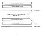
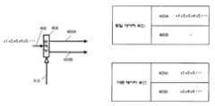
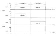
도 5는 본 실시형태에서의 송신장치의 시간 축에서의 프레임 구성의 일례를 나타내고 있다. 심벌(500-1)은 수신장치에 송신방법을 통지하기 위한 심벌이며, 예를 들어 데이터 심벌을 전송하기 위해 이용하는 오류정정방식, 그 부호화율의 정보, 데이터 심벌을 전송하기 위해 이용하는 변조방식의 정보 등을 전송한다.Fig. 5 shows an example of a frame structure on the time axis of the transmission device in this embodiment. The symbol 500-1 is a symbol for notifying a transmission method to a receiving device, for example, an error correction method used to transmit a data symbol, information on the coding rate, information on a modulation method used to transmit a data symbol And so on.
심벌(501-1)은 송신장치가 송신하는 변조신호 z1(t){단, t는 시간}의 채널변동을 추정하기 위한 심벌이다. 심벌(502-1)은 변조신호 z1(t)가 (시간 축에서의) 심벌번호 u에 송신하는 데이터 심벌, 심벌(503-1)은 변조신호 z1(t)가 심벌번호 u+1에 송신하는 데이터 심벌이다.The symbol 501-1 is a symbol for estimating the channel variation of the modulation signal z1(t) (where t is time) transmitted by the transmission device. Symbol 502-1 is a data symbol that the modulation signal z1(t) transmits to the symbol number u (on the time axis), and the symbol 503-1 is data that the modulation signal z1(t) transmits to the symbol
심벌(501-2)은 송신장치가 송신하는 변조신호 z2(t){단, t는 시간}의 채널변동을 추정하기 위한 심벌이다. 심벌(502-2)은 변조신호 z2(t)가 심벌번호 u에 송신하는 데이터 심벌, 심벌(503-2)은 변조신호 z2(t)가 심벌번호 u+1에 송신하는 데이터 심벌이다.The symbol 501-2 is a symbol for estimating the channel fluctuation of the modulation signal z2(t) (where t is time) transmitted by the transmission device. The symbol 502-2 is a data symbol transmitted by the modulation signal z2(t) to the symbol number u, and the symbol 503-2 is a data symbol transmitted by the modulation signal z2(t) to the symbol
이때, z1(t)에서의 심벌과 z2(t)에서의 심벌에서 동일 시각(동일시간)의 심벌은 동일(공통)의 주파수를 이용하여 송신안테나에서 송신되게 된다.At this time, the symbol at z1(t) and the symbol at the same time (same time) in the symbol at z2(t) are transmitted by the transmission antenna using the same (common) frequency.
송신장치가 송신하는 변조신호 z1(t)와 변조신호 z2(t) 및 수신장치에서의 수신신호 r1(t), r2(t)의 관계에 대하여 설명한다.The relationship between the modulated signal z1(t) and the modulated signal z2(t) transmitted by the transmitting device, and the received signals r1(t) and r2(t) in the receiving device will be described.
도 5에서 504#1, 504#2는 송신장치에서의 송신안테나, 505#1, 505#2는 수신장치에서의 수신안테나를 나타내고 있으며, 송신장치는 변조신호 z1(t)를 송신안테나(504#1), 변조신호 z2(t)를 송신안테나(504#2)로 송신한다. 이때, 변조신호 z1(t) 및 변조신호 z2(t)는 동일(공통의) 주파수(대역)를 점유하고 있는 것으로 한다. 송신장치의 각 송신안테나와 수신장치의 각 안테나의 채널변동을 각각 h11(t), h12(t), h21(t), h22(t)로 하고, 수신장치의 수신안테나(505#1)가 수신한 수신신호를 r1(t), 수신장치의 수신안테나(505#2)가 수신한 수신신호를 r2(t)로 하면 이하의 관계식이 성립한다.In Fig. 5, 504#1 and 504#2 denote transmission antennas in the transmitting device, 505#1 and 505#2 denote receiving antennas in the receiving apparatus, and the transmitting apparatus transmits the modulated signal z1(t) to the

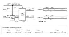
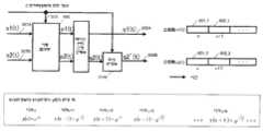
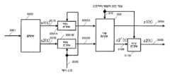
도 6은 본 실시형태에서의 가중방법(프리코딩(Precoding) 방법) 및 위상변경방법에 관한 도면이며, 가중합성부(600)은 도 3의 가중합성부(308A와 308B)의 양자를 통합한 가중합성부이다. 도 6에 나타내는 것과 같이 스트림 s1(t) 및 스트림 s2(t)는 도 3의 베이스밴드신호(307A 및 307B)에 상당하는 즉, QPSK, 16QAM, 64QAM 등의 변조방식의 매핑에 따른 베이스밴드신호 동상 I성분, 직교성분 Q이 된다. 그리고 도 6의 프레임 구성과 같이 스트림 s1(t)는 심벌번호 u의 신호를 s1 (u), 심벌번호 u+1의 신호를 s1 (u+1), …로 나타낸다. 마찬가지로 스트림 s2(t)는 심벌번호 u의 신호를 s2(u), 심벌번호 u+1의 신호를 s2(u+1), …로 나타낸다. 그리고 가중합성부(600)은 도 3에서의 베이스밴드신호(307A(s1(t)) 및 307B(s2(t))), 신호처리방법에 관한 정보(315)를 입력으로 하여 신호처리방법에 관한 정보(315)에 따른 가중을 실시해서 도 3의 가중합성 후의 신호(309A(z1(t)), 316B(z2'(t)))를 출력한다. 위상 변경부(317B)는 가중된 신호(316B(z2'(t)))의 위상을 변경하여 위상변경 후의 신호(309B(z2(t)))를 출력한다.6 is a diagram of a weighting method (precoding method) and a phase change method in the present embodiment, and the weighting and synthesizing
이때, z1(t)는 고정의 프리코딩 행렬 F에서의 제 1 행 벡터를 W1=(w11, w12)로 하면 이하의 식 (41)로 나타낼 수 있다.In this case, z1(t) can be expressed by the following equation (41) when the first row vector in the fixed precoding matrix F is W1 = (w11, w12).

한편, z2(t)는 고정의 프리코딩 행렬 F에서의 제 2 행 벡터를 W2=(w21, w22)로 하고, 위상 변경부에 따른 위상변경 식을 y(t)로 하면 이하의 식 (42)로 나타낼 수 있다.On the other hand, if z2(t) is the second row vector in the fixed precoding matrix F as W2 = (w21, w22) and the phase change equation according to the phase change unit is y(t), the following equation (42) Can be represented by ).

여기서, y(t)는 미리 정해진 방식에 따라서 위상을 변경하기 위한 식이며, 예를 들어, 주기를 4로 하면 시각 u의 위상변경 식은 예를 들어 식 (43)으로 나타낼 수 있다.Here, y(t) is an equation for changing the phase according to a predetermined method. For example, if the period is 4, the phase change equation of the time u can be expressed by, for example, equation (43).

과 같이 시각 u+1의 위상변경 식은 예를 들어 식 (44)로 나타낼 수 있다.As described above, the phase change equation at the time u+1 can be expressed by equation (44), for example.

즉, 시각 u+k의 위상변경 식은 식 (45)로 나타낼 수 있다.That is, the phase change equation of the time u+k can be expressed by Equation (45).

또, 식 (43) ~ (45)에 나타낸 규칙적인 위상변경 예는 일례에 지나지 않는다.In addition, examples of regular phase change shown in equations (43) to (45) are only examples.
규칙적인 위상변경의 주기는 4로 한정되는 것은 아니다. 이 주기의 수가 많아지면 그만큼 수신장치의 수신성능(더 정확하게는 오류정정성능)의 향상을 촉구할 수 있을 가능성이 있다(주기가 크면 좋다는 것은 아니나, 2와 같이 작은 값은 피하는 편이 좋을 가능성이 크다).The periodic phase change period is not limited to 4. If the number of these cycles increases, there is a possibility that the reception performance (more precisely, error correction performance) of the receiving device can be urged to be improved accordingly (it is not good if the cycle is large, but it is more likely that small values such as 2 are better to be avoided). ).
또, 상기 식 (43) ~ (45)에서 나타내는 위상변경 예에서는 순차 소정의 위상(상기 식에서는 π/2씩)만 회전시켜 가는 구성을 나타냈으나, 마찬가지로 위상량만 회전시키는 것이 아니라 랜덤하게 위상을 변경하는 것으로 해도 좋다. 예를 들어, y(t)는 미리 정해진 주기에 따라서 식 (46)이나 식 (47)에 나타내는 것과 같이 순차적으로 승산하는 위상이 변경되어도 좋다. 위상의 규칙적인 변경에서 중요해지는 것은 변조신호의 위상이 규칙적으로 변경되는 것이며, 변경되는 위상의 정도에 대해서는 가능한 한 균등하게 되는 예를 들어 -π라디안에서 π라디안에 대하여 일양 분포가 되는 것이 바람직하나 랜덤이라도 좋다.In addition, in the example of phase change represented by the above equations (43) to (45), a configuration in which only a predetermined phase (π/2 in the above equation) is rotated was shown, but similarly, not only the phase amount is rotated, but randomly. The phase may be changed. For example, y(t) may be changed in phase in which y(t) is sequentially multiplied as shown in Equation (46) or Equation (47) according to a predetermined period. What is important in the regular change of phase is that the phase of the modulated signal is regularly changed, and it is desirable to have a uniform distribution from -π radians to π radians, for example, to be as uniform as possible with respect to the degree of the changed phase. It may be random.


이와 같이, 도 6의 가중합성부(600)은 미리 정해진 고정의 프리코딩 웨이트를 이용해 프리코딩을 실행하고, 위상 변경부(317B)는 입력된 신호의 위상을 그 변경 정도를 규칙적으로 바꾸면서 변경한다.In this way, the
LOS 환경에서는 특수한 프리코딩 행렬을 이용하면 수신품질이 크게 개선될 가능성이 있으나, 직접파의 상황에 따라 그 특수한 프리코딩 행렬은 수신한 때의 직접파의 위상, 진폭성분에 따라 다르다. 그러나 LOS 환경에는 어떤 규칙이 있으며, 이 규칙에 따라 송신신호의 위상을 규칙적으로 변경하면 데이터의 수신품질이 크게 개선된다. 본 발명은 LOS 환경을 개선하는 신호처리방법을 제안하고 있다.In the LOS environment, if a special precoding matrix is used, the reception quality may be greatly improved, but depending on the situation of the direct wave, the special precoding matrix differs depending on the phase and amplitude components of the direct wave at the time of reception. However, there are certain rules in the LOS environment, and if the phase of the transmission signal is regularly changed according to these rules, the reception quality of data is greatly improved. The present invention proposes a signal processing method to improve the LOS environment.
도 7은 본 실시형태에서의 수신장치(700)의 구성의 일례를 나타내고 있다. 무선부(703-X)는 안테나(701-X)에서 수신된 수신신호(702-X)를 입력으로 하여, 주파수 변환, 직교 복조 등의 처리를 실시하여 베이스밴드신호(704-X)를 출력한다.7 shows an example of the configuration of the reception device 700 in the present embodiment. The wireless unit 703-X receives the received signal 702-X received from the antenna 701-X as an input, performs processing such as frequency conversion and orthogonal demodulation, and outputs the baseband signal 704-X. do.
송신장치에서 송신된 변조신호 z1에서의 채널변동 추정부(705-1)는 베이스밴드신호(704-X)를 입력으로 하여, 도 5에서의 채널 추정용의 레퍼런스 심벌(501-1)을 추출해서 식 (40)의 h11에 상당하는 값을 추정하여 채널추정신호(706-1)를 출력한다.The channel variation estimating unit 705-1 in the modulated signal z1 transmitted from the transmission device receives the baseband signal 704-X as an input, and extracts the reference symbol 501-1 for channel estimation in FIG.Then, a value corresponding to h 11 in Equation (40) is estimated, and a channel estimation signal 706-1 is output.
송신장치에서 송신된 변조신호 z2에서의 채널변동 추정부(705-2)는 베이스밴드신호(704-X)를 입력으로 하여, 도 5에서의 채널 추정용의 레퍼런스 심벌(501-2)를 추출해서 식 (40)의 h12에 상당하는 값을 추정하여 채널추정신호(706-2)를 출력한다.The channel fluctuation estimation unit 705-2 in the modulated signal z2 transmitted from the transmission device receives the baseband signal 704-X as an input, and extracts the reference symbol 501-2 for channel estimation in FIG.Then, a value corresponding to h 12 in Equation (40) is estimated, and a channel estimation signal 706-2 is output.
무선부(703-Y)는 안테나(701-Y)에서 수신된 수신신호(702-Y)를 입력으로 하여, 주파수 변환, 직교 복조 등의 처리를 실시하여 베이스밴드신호(704-Y)를 출력한다.The radio unit 703-Y receives the received signal 702-Y received from the antenna 701-Y as an input, performs frequency conversion, orthogonal demodulation, etc., and outputs the baseband signal 704-Y. do.
송신장치에서 송신된 변조신호 z1에서의 채널변동 추정부(707-1)는 베이스밴드신호(704-Y)를 입력으로 하여, 도 5에서의 채널 추정용의 레퍼런스 심벌(501-1)을 추출해서 식 (40)의 h21에 상당하는 값을 추정하여 채널추정신호(708-1)를 출력한다.The channel fluctuation estimation unit 707-1 in the modulated signal z1 transmitted from the transmission device receives the baseband signal 704-Y as an input, and extracts the reference symbol 501-1 for channel estimation in FIG.Then, a value corresponding to h 21 in Equation (40) is estimated, and a channel estimation signal 708-1 is output.
송신장치에서 송신된 변조신호 z2에서의 채널변동 추정부(707-2)는 베이스밴드신호(704-Y)를 입력으로 하여, 도 5에서의 채널 추정용의 레퍼런스 심벌(501-2)를 추출해서 식 (40)의 h22에 상당하는 값을 추정하여 채널추정신호(708-2)를 출력한다.The channel fluctuation estimation unit 707-2 in the modulated signal z2 transmitted from the transmission device receives the baseband signal 704-Y as an input, and extracts the reference symbol 501-2 for channel estimation in FIG.Then, a value corresponding to h 22 in Equation (40) is estimated, and a channel estimation signal 708-2 is output.
제어정보 복호부(709)는 베이스밴드신호(704-X 및 704-Y)를 입력으로 하여, 도 5의 송신방법을 통지하기 위한 심벌(500-1)을 검출하여, 송신장치가 통지한 송신방법의 정보에 관한 신호(710)를 출력한다.The control
신호처리부(711)는 베이스밴드신호(704-X, 704-Y), 채널추정신호(706-1, 706-2, 708-1, 708-2) 및 송신장치가 통지한 송신방법의 정보에 관한 신호(710)를 입력으로 해서 검파, 복호를 실시하여 수신데이터(712-1 및 712-2)를 출력한다.The
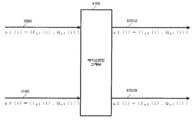
다음에, 도 7의 신호처리부(711)의 동작에 대해 상세하게 설명한다. 도 8은 본 실시형태에서의 신호처리부(711)의 구성의 일례를 나타내고 있다. 도 8은 주로 INNER MIMO 검파부와 Soft-in/Soft-out 디코더, 계수 생성부로 구성되어 있다. 이 구성에서의 반복 복호의 방법에 대해서는 비 특허문헌 2, 비 특허문헌 3에서 상세히 기술되어 있으나, 비 특허문헌 2, 비 특허문헌 3에 기재되어 있는 MIMO 전송방식은 공간 다중 MIMO 전송방식이나, 본 실시형태에서의 전송방식은 시간과 함께 신호의 위상을 규칙적으로 변경하고, 또한, 프리코딩 행렬이 사용되고 있는 MIMO 전송방식인 점이 비 특허문헌 2, 비 특허문헌 3과 다른 점이다. 식 (36)에서의 (채널)행렬을 H(t), 도 6에서의 프리코딩 웨이트 행렬을 F(여기서 프리코딩 행렬은 1의 수신신호 중에서 변경되지 않은 고정의 것이다), 도 6의 위상 변경부에 따른 위상변경 식의 행렬을 Y(t)(여기서 Y(t)는 t에 따라 변화한다), 수신벡터를 R(t)=(r1(t), r2(t))T, 스트림 벡터 S(t)=(s1(t), s2(t))T로 하면 이하의 관계식이 성립한다.Next, the operation of the

이때, 수신장치는 H(t)×Y(t)×F를 얻음으로써 수신벡터 R(t)에 대해서 비 특허문헌 2, 비 특허문헌 3의 복호방법을 적용할 수 있다.At this time, the receiving apparatus obtains H(t)×Y(t)×F, so that the decoding method of the
따라서 도 8의 계수 생성부(819)는 송신장치가 통지한 송신방법의 정보(이용한 고정의 프리코딩 행렬 및 위상을 변경하고 있었을 경우의 위상변경패턴을 특정하기 위한 정보)에 관한 신호(818)(도 7의 710에 상당)을 입력으로 하여, 신호처리방법의 정보에 관한 신호(820)를 출력한다.Therefore, the
INNER MIMO 검파부(803)는 신호처리방법의 정보에 관한 신호(820)를 입력으로 하여, 이 신호를 이용해서 식 (48)의 관계를 이용함으로써 반복 검파ㆍ복호를 실행하게 되며, 그 동작에 대해서 설명한다.The INNER
도 8에 나타내는 구성의 신호처리부에서는 반복 복호(반복 검파)를 실행하기 위해 도 10에 나타내는 것과 같은 처리방법을 실행할 필요가 있다. 먼저, 변조신호(스트림) s1의 1 부호어(또는 1 프레임) 및 변조신호(스트림) s2의 1 부호어(또는 1 프레임)의 복호를 실행한다. 그 결과, Soft-in/Soft-out 디코더로부터 변조신호(스트림) s1의 1 부호어(또는 1 프레임) 및 변조신호(스트림) s2의 1 부호어(또는 1 프레임)의 각 비트의 대수 우도 비(LLR:Log-Likelihood Ratio)를 얻을 수 있다. 그리고 그 LLR를 이용해서 재차 검파ㆍ복호를 한다. 이 조작이 복수 회 실행된다(이 조작을 반복 복호(반복 검파)라고 한다). 이하에서는 1 프레임에서의 특정의 시간의 심벌의 대수 우도 비(LLR)의 작성방법을 중심으로 설명한다.In the signal processing unit having the configuration shown in Fig. 8, it is necessary to execute a processing method as shown in Fig. 10 in order to perform repetitive decoding (repetitive detection). First, one codeword (or one frame) of the modulated signal (stream) s1 and one codeword (or one frame) of the modulated signal (stream) s2 are decoded. As a result, the log likelihood ratio of each bit of one codeword (or one frame) of the modulation signal (stream) s1 and one codeword (or one frame) of the modulation signal (stream) s2 from the Soft-in/Soft-out decoder (LLR: Log-Likelihood Ratio) can be obtained. Then, the LLR is used to detect and decode again. This operation is executed a plurality of times (this operation is referred to as repetitive decoding (repetitive detection)). Hereinafter, a description will be made focusing on a method of creating the logarithmic likelihood ratio (LLR) of symbols at a specific time in one frame.
도 8에서 기억부(815)는 베이스밴드신호(801X)(도 7의 베이스밴드신호(704-X)에 상당한다), 채널추정신호 군(802X)(도 7의 채널추정신호(706-1, 706-2)에 상당한다), 베이스밴드신호(801Y)(도 7의 베이스밴드신호(704-Y)에 상당한다), 채널추정신호 군(802Y)(도 7의 채널추정신호(708-1, 708-2)에 상당한다)을 입력으로 하여 반복 복호(반복 검파)를 실현하기 위해 식 (48)에서의 H(t)×Y(t)×F를 실행(산출)하고, 산출한 행렬을 변형 채널신호 값으로서 기억한다. 그리고 기억부(815)는 필요한 때에 상기 신호를 베이스밴드신호(816X), 변형 채널추정신호 군(817X), 베이스밴드신호(816Y), 변형 채널추정신호 군(817Y)으로서 출력한다.In Fig. 8, the
그 후의 동작에 대해서는 초기 검파의 경우와 반복 복호(반복 검파)의 경우를 나누어서 설명한다.The subsequent operation will be described by dividing the case of initial detection and the case of iterative decoding (repetitive detection).
<초기 검파의 경우><In case of initial detection>
INNER MIMO 검파부(803)는 베이스밴드신호(801X), 채널추정신호 군(802X), 베이스밴드신호(801Y), 채널추정신호 군(802Y)을 입력으로 한다. 여기에서는 변조신호(스트림) s1, 변조신호(스트림) s2의 변조방식을 16QAM으로 하여 설명한다.The
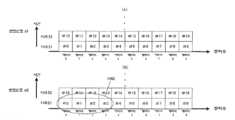
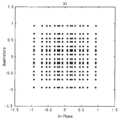
INNER MIMO 검파부(803)는 먼저 채널추정신호 군(802X), 채널추정신호 값(802Y)으로부터 H(t)×Y(t)×F를 실행하여 베이스밴드신호(801X)에 대응하는 후보신호 점을 구한다. 그때의 모습을 도 11에 나타낸다. 도 11에서 ●(검은 원)은 IQ평면에서의 후보신호 점이며, 변조방식이 16QAM이므로 후보신호 점은 256개 존재한다(단, 도 11에서는 이미지 도를 나타내고 있으므로 256개의 후보신호 점 모두를 나타내고 있지 않다). 여기서, 변조신호 s1로 전송하는 4비트를 b0, b1, b2, b3, 변조신호 s2로 전송하는 4비트를 b4, b5, b6, b7로 하면, 도 11에서 (b0, b1, b2, b3, b4, b5, b6, b7)에 대응하는 후보신호 점이 존재하게 된다. 그리고 수신신호 점(1101)(베이스밴드신호(801X)에 상당한다)과 후보신호 점 각각과의 2승 유클리드 거리(squared Euclidian distance)를 구한다. 그리고 각각의 2승 유클리드 거리를 노이즈의 분산σ2로 나눈다. 따라서 (b0, b1, b2, b3, b4, b5, b6, b7)에 대응하는 후보신호 점과 수신신호 점 2승 유클리드 거리를 노이즈의 분산으로 나눈 값을 EX(b0, b1, b2, b3, b4, b5, b6, b7)가 구하게 된다. 또, 각 베이스밴드신호, 변조신호 s1, s2는 복소 신호이다.The
마찬가지로 채널추정신호 군(802X), 채널추정신호 군(802Y)으로부터 H(t)×Y(t)×F를 실행하여 베이스밴드신호(801Y)에 대응하는 후보신호 점을 구하고, 수신신호 점(베이스밴드신호(801Y)에 상당한다)과의 2승 유클리드 거리를 구해서, 이 2승 유클리드 거리를 노이즈의 분산 σ2로 나눈다. 따라서 (b0, b1, b2, b3, b4, b5, b6, b7)에 대응하는 후보신호 점과 수신신호 점 2승 유클리드 거리를 노이즈의 분산으로 나눈 값을 EY(b0, b1, b2, b3, b4, b5, b6, b7)가 구하게 된다.Similarly, H(t)×Y(t)×F is executed from the channel
그리고 EX(b0, b1, b2, b3, b4, b5, b6, b7)+EY(b0, b1, b2, b3, b4, b5, b6, b7) = E(b0, b1, b2, b3, b4, b5, b6, b7)를 구한다.And EX (b0, b1, b2, b3, b4, b5, b6, b7) + EY (b0, b1, b2, b3, b4, b5, b6, b7) = E(b0, b1, b2, b3 , b4, b5, b6, b7).
INNER MIMO 검파부(803)는 E(b0, b1, b2, b3, b4, b5, b6, b7)를 신호(804)로 출력한다.The
대수 우도 산출부(805A)는 신호(804)를 입력으로 해서 비트 b0, b1, b2, b3의 대수 우도(Log Likelihood)를 산출하여, 대수 우도 신호(806A)를 출력한다. 단, 대수 우도의 산출에서는 “1”일 때의 대수 우도 및 “0”일 때의 대수 우도가 산출된다. 그 산출방법은 식 (28), 식 (29), 식 (30)에 나타낸 것과 같으며, 상세에 대해서는 비 특허문헌 2, 비 특허문헌 3에 기재되어 있다.The log
마찬가지로, 대수 우도 산출부(805B)는 신호(804)를 입력으로 해서 비트 b4, b5, b6, b7의 대수 우도를 산출하여, 대수 우도 신호(806B)를 출력한다.Similarly, the
디 인터리버(De-Interleaver)(807A)는 대수 우도 신호(806A)를 입력으로 해서 인터리버(도 3의 인터리버(304A))에 대응하는 디 인터리브(De-Interleave)를 실행하여 디 인터리브 후의 대수 우도 신호(808A)를 출력한다.The de-interleaver 807A receives the
마찬가지로, 디 인터리버(807B)는 대수 우도 신호(806B)를 입력으로 해서 인터리버(도 3의 인터리버(304B))에 대응하는 디 인터리브를 실행하여 디 인터리브 후의 대수 우도 신호(808B)를 출력한다.Similarly, the de-interleaver 807B receives the
대수 우도 비 산출부(809A)는 디 인터리브 후의 대수 우도 신호(808A)를 입력으로 해서 도 3의 부호화기(302A)에서 부호화된 비트의 대수 우도 비(LLR:Log-Likelihood Ratio)를 산출하여 대수 우도 비 신호(810A)를 출력한다.The log likelihood ratio calculation unit 809A receives the deinterleaved
마찬가지로, 대수 우도 비 산출부(809B)는 디 인터리브 후의 대수 우도 신호(808B)를 입력으로 해서 도 3의 부호화기(302B)에서 부호화된 비트의 대수 우도 비(LLR:Log-Likelihood Ratio)를 산출하여 대수 우도 비 신호 (810B)를 출력한다.Similarly, the log likelihood ratio calculation unit 809B receives the deinterleaved
Soft-in/Soft-out 디코더(811A)는 대수 우도 비 신호(810A)를 입력으로 해서 복호를 실행하여 복호 후의 대수 우도 비(812A)를 출력한다.The soft-in/soft-out decoder 811A receives the log
마찬가지로, Soft-in/Soft-out 디코더(811B)는 대수 우도 비 신호(810B)를 입력으로 해서 복호를 실행하여 복호 후의 대수 우도 비(812B)를 출력한다.Similarly, the Soft-in/Soft-out
<반복 복호(반복 검파)의 경우, 반복횟수 k><In the case of repetitive decoding (repeated detection), the number of repetitions k>
인터리버(813A)는 k-1회째의 Soft-in/Soft-out 디코드에서 얻은 복호 후의 대수 우도 비(812A)를 입력으로 해서 인터리브를 실행하여 인터리브 후의 대수 우도 비(814A)를 출력한다. 이때, 인터리브(813A)의 인터리브의 패턴은 도 3의 인터리버(304A)의 인터리브 패턴과 같다.The
인터리버(813B)는 k-1회째의 Soft-in/Soft-out 디코드에서 얻은 복호 후의 대수 우도 비(812B)를 입력으로 하여 인터리브를 실행해서 인터리브 후의 대수 우도 비(814B)를 출력한다. 이때, 인터리브(813B)의 인터리브의 패턴은 도 3의 인터리버(304B)의 인터리브 패턴과 같다.The
INNER MIMO 검파부(803)는 베이스밴드신호(816X), 변형 채널추정신호 군(817X), 베이스밴드신호(816Y), 변형 채널추정신호 군(817Y), 인터리브 후의 대수 우도 비(814A), 인터리브 후의 대수 우도 비(814B)를 입력으로 한다. 여기서, 베이스밴드신호(801X), 채널추정신호 군(802X), 베이스밴드신호(801Y), 채널추정신호 군(802Y)이 아니거나, 베이스밴드신호(816X), 변형 채널추정신호 군(817X), 베이스밴드신호(816Y), 변형 채널추정신호 군(817Y)을 이용하는 이유는 반복 복호이므로 지연 시간이 발생하고 있기 때문이다.The
INNER MIMO 검파부(803)의 반복 복호 시의 동작과 초기 검파 시의 동작의 차이점은 인터리브 후의 대수 우도 비(814A), 인터리브 후의 대수 우도 비(814B)를 신호처리 시에 이용하고 있는 점이다. INNER MIMO 검파부(803)는 먼저 초기 검파 때와 마찬가지로, E(b0, b1, b2, b3, b4, b5, b6, b7)를 구한다. 또, 인터리브 후의 대수 우도 비(814A), 인터리브 후의 대수 우도 비(814B)로부터 식 (11), 식 (32)에 상당하는 계수를 구한다. 그리고 E(b0, b1, b2, b3, b4, b5, b6, b7)의 값을 구한 계수를 이용해서 보정 하여, 그 값을 E'(b0, b1, b2, b3, b4, b5, b6, b7)로 하여 신호(804)로서 출력한다.The difference between the operation of the
대수 우도 산출부(805A)는 신호(804)를 입력으로 하여 비트 b0, b1, b2, b3의 대수 우도를 산출해서 대수 우도 신호(806A)를 출력한다. 단, 대수 우도의 산출에서는 “1”일 때의 대수 우도 및 “0”일 때의 대수 우도가 산출된다. 그 산출방법은 식 (31), 식 (32), 식 (33), 식 (34), 식 (35)에 나타낸 것과 같으며 비 특허문헌 2, 비 특허문헌 3에 나타내고 있다.The
마찬가지로, 대수 우도 산출부(805B)는 신호(804)를 입력으로 하여 비트 b4, b5, b6, b7의 대수 우도를 산출해서 대수 우도 신호(806B)를 출력한다. 디 인터리버 이후의 동작은 초기 검파와 동일하다.Similarly, the log
또, 도 8에서는 반복 검파를 실행하는 경우의 신호처리부의 구성에 대해서 나타내었으나, 반복 검파는 반드시 양호한 수신품질을 얻는데 있어서 필수의 구성은 아니며, 반복 검파에만 필요로 하는 구성 부분, 인터리버(813A, 813B)를 갖지 않은 구성이라도 좋다. 이때, INNER MIMO 검파부(803)는 반복적인 검파를 실행하지 않게 된다.Further, in Fig. 8, the configuration of the signal processing unit in the case of performing repetitive detection is shown, but repetitive detection is not necessarily an essential component to obtain good reception quality, and a component required only for repetitive detection, the
그리고 본 실시형태에서 중요한 부분은 H(t)×Y(t)×F의 연산을 실행하는 것이다. 또, 비 특허문헌 5 등에 나타내고 있는 것과 같이 QR분해를 이용하여 초기 검파, 반복 검파를 실행해도 좋다.And the important part in this embodiment is to execute the calculation of H(t)×Y(t)×F. Further, as shown in
또, 비 특허문헌 11에 나타내고 있는 것과 같이, H(t)×Y(t)×F에 의거하여 MMSE(Minimum Mean Square Error), ZF(Zero Forcing)의 선형 연산을 실행하여 초기 검파를 실행해도 좋다.In addition, as shown in
도 9는 도 8과 다른 신호처리부의 구성이며, 도 4의 송신장치가 송신한 변조신호를 위한 신호처리부이다. 도 8과 다른 점은 Soft-in/Soft-out 디코더의 수이며, Soft-in/Soft-out 디코더(901)는 대수 우도 비 신호(810A, 810B)를 입력으로 하여 복호를 실행해서 복호 후의 대수 우도 비(902)를 출력한다. 분배부(903)는 복호 후의 대수 우도 비(902)를 입력으로 하여 분배를 실행한다. 그 이외의 부분에 대해서는 도 8과 동일한 동작이 된다.9 is a configuration of a signal processing unit different from that of FIG. 8, and is a signal processing unit for a modulated signal transmitted by the transmission apparatus of FIG. 4. The difference from FIG. 8 is the number of Soft-in/Soft-out decoders, and the Soft-in/Soft-out
이상과 같이, 본 실시형태와 같이 MIMO 전송 시스템의 송신장치가 복수 안테나로부터 복수의 변조신호를 송신할 때, 프리코딩 행렬을 승산하는 동시에, 시간과 함께 위상을 변경하고 이 위상의 변경을 규칙적으로 실행함으로써 직접파가 지배적인 LOS 환경에서 종래의 공간 다중 MIMO 전송을 이용할 때와 비교하여 수신장치에서의 데이터의 수신품질이 향상한다는 효과를 얻을 수 있다.As described above, when the transmission apparatus of the MIMO transmission system transmits a plurality of modulated signals from a plurality of antennas as in the present embodiment, the phase is multiplied by the precoding matrix and the phase is changed with time, and this phase change is regularly By doing so, it is possible to obtain the effect of improving the reception quality of data in the receiving apparatus compared to the case of using the conventional spatial multiple MIMO transmission in the LOS environment where the direct wave is dominant.
본 실시형태에서, 특히, 수신장치의 구성에 대해서는 안테나 수를 한정하여 동작을 설명하였으나, 안테나 수가 증가해도 마찬가지로 실행할 수 있다. 즉, 수신장치에서의 안테나 수는 본 실시형태의 동작, 효과에 영향을 미치는 것은 아니다.In this embodiment, in particular, with respect to the configuration of the receiving apparatus, the operation has been described by limiting the number of antennas, but it can be similarly executed even if the number of antennas increases. That is, the number of antennas in the receiving device does not affect the operation and effect of the present embodiment.
또, 본 실시형태에서는 특히 LDPC부호를 예로 하여 설명하였으나, 이에 한정되는 것은 아니며, 또, 복호방법에 대해서도 Soft-in/Soft-out 디코더로 sum-product 복호를 예로 한정한 것은 아니며, 다른 Soft-in/Soft-out의 복호방법, 예를 들어 BCJR 알고리즘, SOVA 알고리즘, Max-log-MAP 알고리즘 등이 있다. 상세에 대해서는 비 특허문헌 6에 기재되어 있다.In addition, in the present embodiment, the LDPC code has been described as an example, but it is not limited thereto, and the decoding method is not limited to the sum-product decoding by the Soft-in/Soft-out decoder as an example. In/soft-out decoding methods, for example, BCJR algorithm, SOVA algorithm, and Max-log-MAP algorithm. Details are described in
또, 본 실시형태에서는 싱글 캐리어 방식을 예로 하여 설명하였으나, 이에 한정되는 것은 아니며, 멀티 캐리어 전송을 실행한 경우에서도 마찬가지로 실시할 수 있다. 따라서 예를 들어 스펙트럼 확산 통신방식, OFDM(Orthogonal Frequency-Division Multiplexing) 방식, SC-FDMA(Single Carrier Frequency Division Multiple Access), SC-OFDM(Single Carrier Orthogonal Frequency-Division Multiplexing) 방식, 비 특허문헌 7등에서 나타내고 있는 웨이브릿 OFDM 방식 등을 이용한 경우에 대해서도 마찬가지로 실시할 수 있다. 또, 본 실시형태에서는 데이터 심벌 이외의 심벌, 예를 들어, 파일럿심벌(프리앰블, 유니크 워드 등), 제어정보의 전송용 심벌 등이 프레임에 어떻게 배치되어 있어도 좋다.Further, in the present embodiment, a single-carrier method has been described as an example, but the present invention is not limited thereto, and the same can be performed even when multi-carrier transmission is performed. Therefore, for example, spread spectrum communication method, OFDM (Orthogonal Frequency-Division Multiplexing) method, SC-FDMA (Single Carrier Frequency Division Multiple Access), SC-OFDM (Single Carrier〖Frequency-Diplexing The same can be done for the case of using the illustrated wavelet OFDM system or the like. In the present embodiment, symbols other than data symbols, for example, pilot symbols (preamble, unique word, etc.), symbols for transmission of control information, and the like may be arranged in a frame.
이하에서는 멀티 캐리어 방식의 일례로 OFDM 방식을 이용한 때의 예를 설명한다.Hereinafter, an example in which the OFDM scheme is used as an example of the multi-carrier scheme will be described.
도 12는 OFDM 방식을 이용한 때의 송신장치의 구성을 나타내고 있다. 도 12에서 도 3과 마찬가지로 동작하는 것에 대해서는 동일 부호를 부여했다.Fig. 12 shows the configuration of a transmission apparatus when the OFDM system is used. In Fig. 12, the same reference numerals are assigned to those operating in the same manner as in Fig. 3.
OFDM 방식관련 처리부(1201A)는 가중 후의 신호(309A)를 입력으로 하여 OFDM 방식관련의 처리를 해서 송신신호(1202A)를 출력한다. 마찬가지로, OFDM 방식관련 처리부(1201B)는 위상변경 후의 신호(309B)를 입력으로 하여 송신신호(1202B)를 출력한다.The OFDM system related
도 13은 도 12의 OFDM 방식관련 처리부(1201A, 1201B) 이후의 구성의 일례를 나타내고 있으며, 도 12의 1201A에서 312A에 관련하는 부분이 1301A에서 1310A이며, 1201B에서 312B에 관련하는 부분이 1301B에서 1310B이다.FIG. 13 shows an example of a configuration after the OFDM scheme related
직병렬(Serial/Parallel) 변환부(1302A)는 가중 후의 신호(1301A)(도 12의 가중 후의 신호(309A)에 상당한다) 직병렬 변환을 실행하여 병렬신호(1303A)를 출력한다.The serial/
재배열부(1304A)는 병렬신호(1303A)를 입력으로 하여 재배열을 실행해서 재배열 후의 신호(1305A)를 출력한다. 또, 재배열에 대해서는 후에 상세하게 설명한다.The
역 고속 푸리에 변환부(1306A)는 재배열 후의 신호(1305A)를 입력으로 하여 역 고속 푸리에 변환을 실행하여 역 푸리에 변환 후의 신호(1307A)를 출력한다.The inverse fast
무선부(1308A)는 역 푸리에 변환 후의 신호(1307A)를 입력으로 하여 주파수 변환, 증폭 등의 처리를 실행하여 변조신호(1309A)를 출력하며, 변조신호(1309A)는 안테나(1310A)로부터 전파로서 출력된다.The
직병렬 변환부(1302B)는 가중되어 위상이 변경된 후의 신호(1301B)(도 12의 위상변경 후의 신호(309B)에 상당한다)에 대하여 직병렬 변환을 실행하여 병렬신호(1303B)를 출력한다.The serial-to-
재배열부(1304B)는 병렬신호(1303B)를 입력으로 하여 재배열을 실행하여 재배열 후의 신호(1305B)를 출력한다. 또, 재배열에 대해서는 후에 상세하게 설명한다.The
역 고속 푸리에 변환부(1306B)는 재배열 후의 신호(1305B)를 입력으로 하여 역 고속 푸리에 변환을 실행하여 역 푸리에 변환 후의 신호(1307B)를 출력한다.The inverse fast
무선부(1308B)는 역 푸리에 변환 후의 신호(1307B)를 입력으로 하여 주파수 변환, 증폭 등의 처리를 실행하여 변조신호(1309B)를 출력하며, 변조신호(1309B)는 안테나(1310B)로부터 전파로서 출력된다.The
도 3의 송신장치에서는 멀티 캐리어를 이용한 전송방식이 아니므로, 도 6과 같이 4 주기가 되도록 위상을 변경하여 위상변경 후의 심벌을 시간 축 방향에 배치하고 있다. 도 12에 나타내는 것과 같은 OFDM 방식과 같은 멀티 캐리어 전송방식을 이용하고 있는 경우, 당연히, 도 3과 같이 프리코딩 하여 위상을 변경한 후의 심벌을 시간 축 방향으로 배치하고, 그것을 각 (서브)캐리어마다 실행하는 방식을 생각할 수 있으나, 멀티 캐리어 전송방식의 경우, 주파수 축 방향, 또는 주파수 축ㆍ시간 축 양자를 이용하여 배치하는 방법을 생각할 수 있다. 이하에서는 이 점에 대하여 설명한다.Since the transmission apparatus of FIG. 3 is not a transmission method using a multi-carrier, the phase is changed to have 4 periods as shown in FIG. 6 and the symbols after the phase change are arranged in the direction of the time axis. In the case of using a multi-carrier transmission method such as the OFDM method as shown in FIG. 12, of course, symbols after precoding and phase change as shown in FIG. 3 are arranged in the time axis direction, and they are arranged for each (sub)carrier. A method to implement can be considered, but in the case of a multi-carrier transmission method, a method of arranging using both the frequency axis direction or the frequency axis and the time axis can be considered. Hereinafter, this point will be described.
도 14는 가로축 주파수, 세로축 시간에서의 도 13의 재배열부(1301A, 1301B)에서의 심벌의 재배열방법의 일례를 나타내고 있으며, 주파수 축은 (서브)캐리어 0에서 (서브)캐리어 9로 구성되어 있고, 변조신호 z1과 z2는 동일 시각(시간)에 동일한 주파수 대역을 사용하고 있으며, 도 14 (A)는 변조신호 z1의 심벌의 재배열방법, 도 14 (B)는 변조신호 z2의 심벌의 재배열방법을 나타내고 있다. 직병렬 변환부(1302A)가 입력으로 하는 가중 후의 신호(1301A)의 심벌에 대해 순번으로 #0, #1, #2, #3, …로 번호를 부여한다. 여기에서는 주기 4의 경우를 생각하고 있으므로 #0, #1, #2, #3이 1주기 분이 된다. 마찬가지로 생각하면 #4n, #4n+1, #4n+2, #4n+3(n은 0 이상의 정수)이 1주기 분이 된다.14 shows an example of a method of rearranging symbols in the
이때, 도 14 (a)와 같이 심벌 #0, #1, #2, #3, …을 캐리어 0부터 순번으로 배치하고, 심벌 #0에서 #9를 시각 $1에 배치하며, 그 후, 심벌 #10에서 #19를 시각 $2에 배치하는 것과 같이 규칙적으로 배치하는 것으로 한다. 또, 변조신호 z1과 z2는 복소 신호이다.At this time, as shown in Fig. 14 (a), the
마찬가지로, 직병렬 변환부(1302B)가 입력으로 하는 가중되어 위상이 변경된 후의 신호(1301B)의 심벌에 대해 순번으로 #0, #1, #2, #3, …라는 번호를 부여한다. 여기에서는 주기 4의 경우를 생각하고 있으므로, #0, #1, #2, #3은 각각 다른 위상변경을 실행하게 되고, #0, #1, #2, #3이 1주기 분이 된다. 마찬가지로 생각하면 #4n, #4n+1, #4n+2, #4n+3(n은 0 이상의 정수)은 각각 다른 위상변경을 실행하게 되고, #4n, #4n+1, #4n+2, #4n+3이 1주기 분이 된다.Similarly, the symbols of the
이때, 도 14 (b)와 같이, 심벌 #0, #1, #2, #3, …을 캐리어 0부터 순번으로 배치하고, 심벌 #0에서 #9를 시각 $1에 배치하며, 그 후, 심벌 #10에서 #19를 시각 $2에 배치하는 것과 같이 규칙적으로 배치하는 것으로 한다.At this time, as shown in Fig. 14(b),
그리고 도 14 (B)에 나타내는 심벌 값(1402)은 도 6에 나타내는 위상변경방법을 이용한 때의 1주기 분의 심벌이며, 심벌 #0은 도 6의 시각 u의 위상을 이용한 때의 심벌이고, 심벌 #1은 도 6의 시각 u+1의 위상을 이용한 때의 심벌이며, 심벌 #2는 도 6의 시각 u+2의 위상을 이용한 때의 심벌이고, 심벌 #3은 도 6의 시각 u+3의 위상을 이용한 때의 심벌이다. 따라서 심벌 #x에서 x mod 4가 0 (x를 4로 나누었을 때의 여분, 따라서 mod:modulo)일 때 심벌 #x는 도 6의 시각 u의 위상을 이용한 때의 심벌이며, x mod 4가 1일 때 심벌 #x는 도 6의 시각 u+1의 위상을 이용한 때의 심벌이고, x mod 4가 2일 때 심벌 #x는 도 6의 시각 u+2의 위상을 이용한 때의 심벌이며, x mod 4가 3일 때 심벌 #x는 도 6의 시각 u+3의 위상을 이용한 때의 심벌이다.And the
또, 본 실시형태에서는 도 14 (A)에 나타내는 변조신호 z1은 위상이 변경되어 있지 않다.In this embodiment, the phase of the modulated signal z1 shown in Fig. 14A is not changed.
이와 같이, OFDM 방식 등의 멀티 캐리어 전송방식을 이용한 경우, 싱글 캐리어 전송일 때와는 달리 심벌을 주파수 축 방향으로 배열할 수 있다는 특징을 가지게 된다. 그리고 심벌의 배열방법에 대해서는 도 14와 같은 배열방법에 한정되는 것은 아니다. 다른 예에 대해 도 15, 도 16을 이용하여 설명한다.As described above, when a multi-carrier transmission method such as an OFDM method is used, unlike in the case of single-carrier transmission, symbols can be arranged in the frequency axis direction. In addition, the arrangement method of symbols is not limited to the arrangement method shown in FIG. 14. Another example will be described with reference to FIGS. 15 and 16.
도 15는 도 14와는 다른 가로축 주파수, 세로축 시간에서의 도 13의 재배열부(1301A, 1301B)에서의 심벌의 재배열방법의 일례를 나타내고 있으며, 도 15 (A)는 변조신호 z1의 심벌의 재배열방법, 도 15 (B)는 변조신호 z2의 심벌의 재배열방법을 나타내고 있다. 도 15 (A), (B)가 도 14와 다른 점은 변조신호 z1의 심벌의 재배열방법과 변조신호 z2의 심벌의 재배열방법이 다른 점이며, 도 15 (B)에서는 심벌 #0부터 #5를 캐리어 4부터 캐리어 9에 배치하고, 심벌 #6부터 #9를 캐리어 0에서부터 3에 배치하며, 그 후, 동일한 규칙으로 심벌 #10에서 #19를 각 캐리어에 배치한다. 이때, 도 14 (B)와 마찬가지로, 도 15 (B)에 나타내는 심벌 군(1502)은 도 6이 나타내는 위상변경방법을 이용한 때의 1주기 분의 심벌이다.FIG. 15 shows an example of a method of rearranging symbols in the
도 16은 도 14와 다른 가로축 주파수, 세로축 시간에서의 도 13의 재배열부(1301A, 1301B)에서의 심벌의 재배열방법의 일례를 나타내고 있으며, 도 16 (A)는 변조신호 z1의 심벌의 재배열방법, 도 16 (B)는 변조신호 z2의 심벌의 재배열방법을 나타내고 있다. 도 16 (A), (B)가 도 14와 다른 점은 도 14에서는 심벌을 캐리어에 차례대로 배치하고 있는 것에 대해, 도 16에서는 심벌을 캐리어에 차례대로 배치하고 있지 않은 점이다. 당연하나, 도 16에서 도 15와 마찬가지로 변조신호 z1의 심벌의 재배열방법과 변조신호 z2의 재배열방법을 다르게 해도 좋다.FIG. 16 shows an example of a method of rearranging symbols in the
도 17은 도 14 ~ 16과는 다른 가로축 주파수, 세로축 시간에서의 도 13의 재배열부(1301A, 1301B)에서의 심벌의 재배열방법의 일례를 나타내고 있으며, 도 17 (A)는 변조신호 z1의 심벌의 재배열방법, 도 17 (B)는 변조신호 z2의 심벌의 재배열방법을 나타내고 있다. 도 14 ~ 16에서는 심벌을 주파수 축 방향으로 배열하고 있으나, 도 17에서는 심벌을 주파수, 시간 축의 양자를 이용하여 배치하고 있다.FIG. 17 shows an example of a method of rearranging symbols in the
도 6에서는 위상의 변경을 4 슬롯으로 전환하는 경우의 예로 하여 설명하였으나, 여기에서는 8 슬롯으로 전환하는 경우를 예로 하여 설명한다. 도 17에 나타내는 심벌 군(1702)은 위상변경방법을 이용한 때의 1주기 분의 심벌(따라서 8 심벌)이고, 심벌 #0은 시각 u의 위상을 이용한 때의 심벌이며, 심벌 #1은 시각 u+1의 위상을 이용한 때의 심벌이고, 심벌 #2는 시각 u+2의 위상을 이용한 때의 심벌이며, 심벌 #3은 시각 u+3의 위상을 이용한 때의 심벌이고, 심벌 #4는 시각 u+4의 위상을 이용한 때의 심벌이며, 심벌 #5는 시각 u+5의 위상을 이용한 때의 심벌이고, 심벌 #6은 시각 u+6의 위상을 이용한 때의 심벌이며, 심벌 #7은 시각 u+7의 위상을 이용한 때의 심벌이다. 따라서 심벌#x에서 x mod 8이 0일 때 심벌 #x는 시각 u의 위상을 이용한 때의 심벌이고, x mod 8이 1일 때 심벌 #x는 시각 u+1의 위상을 이용한 때의 심벌이며, x mod 8이 2일 때, 심벌 #x는 시각 u+2의 위상을 이용한 때의 심벌이고, x mod 8이 3일 때 심벌 #x는 시각 u+3의 위상을 이용한 때의 심벌이며, x mod 8이 4일 때 심벌 #x는 시각 u+4의 위상을 이용한 때의 심벌이고, x mod 8이 5일 때 심벌 #x는 시각 u+5의 위상을 이용한 때의 심벌이며, x mod 8이 6일 때 심벌 #x는 시각 u+6의 위상을 이용한 때의 심벌이고, x mod 8이 7일 때 심벌 #x는 시각 u+7의 위상을 이용한 때의 심벌이다. 도 17의 심벌의 배열방법에서는 시간 축 방향으로 4 슬롯, 주파수 축 방향으로 2 슬롯의 합계 4×2=8 슬롯을 이용하여 1주기 분의 심벌을 배치하고 있으나, 이때, 1주기 분의 심벌의 수를 m×n심벌(즉, 승산하는 위상은 m×n종류 존재한다) 1주기 분의 심벌을 배치하는데 사용하는 주파수 축 방향의 슬롯(캐리어 수)을 n, 시간 축 방향으로 사용하는 슬롯을 m으로 하면 m>n으로 하면 좋다. 이는 직접파의 위상은 시간 축 방향의 변동은 주파수 축 방향의 변동과 비교하여 완만하다. 따라서 정상적인 직접파의 영향을 작게 하기 위해 본 실시형태의 규칙적인 위상의 변경을 실행하므로, 위상의 변경을 실행하는 주기에서는 직접파의 변동을 작게 하려고 한다. 따라서 m>n으로 하면 좋다. 또, 이상의 점을 고려하면, 주파수 축 방향만 또는 시간 축 방향에만 심벌을 재배열하는 것보다, 도 17과 같이 주파수 축과 시간 축의 양자를 이용하여 재배열을 실행하는 편이 직접파는 정상적이 될 가능성이 크고, 본 발명의 효과를 얻기 쉽다는 효과를 얻을 수 있다. 단, 주파수 축 방향으로 배열하면 주파수 축의 변동이 급격하므로, 다이버시티 게인(Diversity Gain)을 얻을 수 있을 가능성이 있으므로, 반드시 주파수 축과 시간 축의 양자를 이용하여 재배열을 실행하는 방법이 최적인 방법이라고는 할 수 없다.In FIG. 6, the phase change has been described as an example of switching to 4 slots. Here, a case of switching to 8 slots will be described as an example. The
도 18은 도 17과는 다른 가로축 주파수, 세로축 시간에서의 도 13의 재배열부(1301A, 1301B)에서의 심벌의 재배열방법의 일례를 나타내고 있으며, 도 18 (A)는 변조신호 z1의 심벌의 재배열방법, 도 18 (B)는 변조신호 z2의 심벌의 재배열방법을 나타내고 있다. 도 18은 도 17과 마찬가지로 심벌을 주파수, 시간 축의 양자를 이용하여 배치하고 있으나, 도 17과 다른 점은 도 17에서는 주파수 방향을 먼저하고, 그 후에 시간 축 방향으로 심벌을 배치하고 있는데 반해, 도 18에서는 시간 축 방향을 먼저하고, 그 후에 시간 축 방향으로 심벌을 배치하고 있다는 점이다. 도 18에서 심벌 군(1802)은 위상변경방법을 이용한 때의 1주기 분의 심벌이다.FIG. 18 shows an example of a method of rearranging symbols in the
또, 도 17, 도 18에서는 도 15와 마찬가지로 변조신호 z1의 심벌의 배치방법과 변조신호 z2의 심벌 배치방법이 다르게 배치해도 마찬가지로 실시할 수 있으며, 또, 높은 수신품질을 얻을 수 있다는 효과를 얻을 수 있다. 또, 도 17, 도 18에서 도 16과 마찬가지로 심벌을 차례대로 배치하고 있지 않아도 마찬가지로 실시할 수 있으며, 또, 높은 수신품질을 얻을 수 있다는 효과를 얻을 수 있다.In Figs. 17 and 18, the same can be performed even if the symbol arrangement method of the modulation signal z1 and the symbol arrangement method of the modulation signal z2 are arranged differently as in Fig. 15, and the effect of obtaining high reception quality can be obtained. I can. In addition, in Figs. 17 and 18, similarly to Fig. 16, even if the symbols are not arranged in sequence, it can be performed in the same manner, and an effect that high reception quality can be obtained can be obtained.
도 22는 상기와는 다른 가로축 주파수, 세로축 시간에서의 도 13의 재배열부(1301A, 130B)에서의 심벌의 정렬방법의 일례를 나타내고 있다. 도 6의 시각 u ~ u+3과 같은 4 슬롯을 이용하여 규칙적으로 위상을 변경하는 경우를 생각한다. 도 22에서 특징적인 점은 주파수 축 방향으로 심벌을 차례로 배열하고 있으나, 시간 축 방향으로 진행한 경우, 사이클릭에 n(도 22의 예에서는 n=1) 심벌 사이클릭 시프트(Cyclic Shift) 시키고 있다는 점이다. 도 22에서의 주파수 축 방향의 심벌 군 (2210)에 나타낸 4 심벌에 있어서 도 6의 시각 u ~ u+3의 위상의 변경을 실행하는 것으로 한다.FIG. 22 shows an example of a method for aligning symbols in the
이때, #0의 심벌에서는 시각 u의 위상을 이용한 위상변경, #1에서는 시각 u+1의 위상을 이용한 위상변경, #2에서는 시각 u+2의 위상을 이용한 위상변경, 시각 u+3의 위상을 이용한 위상변경을 실행하는 것으로 한다.At this time, the phase change using the phase of time u at the
주파수 축 방향의 심벌 군(2220)에 대해서도 마찬가지로 #4의 심벌에서는 시각 u의 위상을 이용한 위상변경, #5에서는 시각 u+1의 위상을 이용한 위상변경, #6에서는 시각 u+2의 위상을 이용한 위상변경, #7에서는 시각 u+3의 위상을 이용한 위상변경을 실행하는 것으로 한다.Similarly for the
시간 $1의 심벌에서 상기와 같은 위상의 변경을 실행하였으나, 시간 축 방향에서 사이클릭 시프트(Cyclic Shift)를 하고 있으므로, 심벌 군(2201, 2202, 2203, 2204)에 대해서는 이하와 같이 위상의 변경을 실행하는 것으로 한다.The phase change as described above was performed in the symbol of time $1, but since a cyclic shift is performed in the direction of the time axis, the phase change for the
시간 축 방향의 심벌 군(2201)에서는 #0의 심벌에서는 시각 u의 위상을 이용한 위상변경, #9에서는 시각 u+1의 위상을 이용한 위상변경, #18에서는 시각 u+2의 위상을 이용한 위상변경, #27에서는 시각 u+3의 위상을 이용한 위상변경을 실행하는 것으로 한다.In the
시간 축 방향의 심벌 군(2202)에서는 #28의 심벌에서는 시각 u의 위상을 이용한 위상변경, #1에서는 시각 u+1의 위상을 이용한 위상변경, #10에서는 시각 u+2의 위상을 이용한 위상변경, #19에서는 시각 u+3의 위상을 이용한 위상변경을 실행하는 것으로 한다.In the
시간 축 방향의 심벌 군(2203)에서는 #20의 심벌에서는 시각 u의 위상을 이용한 위상변경, #29에서는 시각 u+1의 위상을 이용한 위상변경, #2에서는 시각 u+2의 위상을 이용한 위상변경, #11에서는 시각 u+3의 위상을 이용한 위상변경을 실행하는 것으로 한다.In the
시간 축 방향의 심벌 군(2204)에서는 #12의 심벌에서는 시각 u의 위상을 이용한 위상변경, #21에서는 시각 u+1의 위상을 이용한 위상변경, #30에서는 시각 u+2의 위상을 이용한 위상변경, #3에서는 시각 u+3의 위상을 이용한 위상변경을 실행하는 것으로 한다.In the
도 22에서의 특징은 예를 들어 #11의 심벌에 주목한 경우, 동일 시각의 주파수 축 방향의 좌우 양쪽의 심벌(#10과 #12)은 모두 #11과는 다른 위상을 이용하여 위상의 변경을 실행하고 있는 동시에, #11의 심벌의 동일 캐리어의 시간 축 방향의 좌우 양쪽의 심벌(#2와 #20)은 모두 #11과는 다른 위상을 이용하여 위상의 변경을 실행하고 있는 것이다. 그리고 이는 #11의 심벌에 한정되는 것은 아니며, 주파수 축 방향 및 시간 축 방향 모두 좌우 양쪽 이웃에 심벌이 존재하는 심벌 모두에 있어서 #11의 심벌과 같은 특징을 가지게 된다. 이에 의해 효과적으로 위상을 변경하고 있게 되며, 직접파의 정상적인 상황에 대한 영향을 받기 힘들어지므로 데이터의 수신품질이 개선될 가능성이 커진다.In Fig. 22, for example, when paying attention to the symbol of #11, both the left and right symbols (#10 and #12) in the direction of the frequency axis at the same time change the phase using a different phase from that of #11. At the same time, the
도 22에서는 n=1로 하여 설명하였으나, 이에 한정되는 것은 아니고, n=3으로 해도 동일하게 실행할 수 있다. 또, 도 22에서는 주파수 축에 심벌을 배열하고, 시간이 축 방향으로 진행하는 경우, 심벌의 배치 순번을 사이클릭 시프트(Cyclic Shift) 한다는 특징을 가지게 함으로써 상기 특징을 실현하였으나, 심벌을 랜덤(규칙적이라도 좋다)하게 배치함으로써 상기 특징을 실현하는 것과 같은 방법도 있다.In FIG. 22, the description is made with n=1, but the present invention is not limited thereto, and the same can be performed even if n=3. In addition, in FIG. 22, the above feature is realized by arranging symbols on the frequency axis and having the characteristic of cyclic shifting the arrangement order of symbols when time advances in the axial direction, but the symbols are random (regular There is also a method similar to that of realizing the above features by arranging them in a way that may be arranged.
(실시형태 2)(Embodiment 2)
상기 실시형태 1에서는 가중합성된(고정의 프리코딩 행렬로 프리코딩 된) 신호 z(t)의 위상을 변경하는 것으로 했다. 여기에서는 상기 실시형태 1과 동등한 효과를 얻을 수 있는 위상변경방법의 각종 실시형태에 대하여 설명한다.In the first embodiment, the phase of the weighted synthesized (precoded with a fixed precoding matrix) signal z(t) is changed. Here, various embodiments of the phase change method capable of obtaining an effect equivalent to that of the first embodiment will be described.
상기 실시형태에서, 도 3 및 도 6에 나타내는 것과 같이 위상 변경부(317B)는 가중합성부(600)로부터의 일방의 출력에 대해서만 위상의 변경을 실행하는 구성으로 되어 있다.In the above embodiment, as shown in Figs. 3 and 6, the
그러나 위상의 변경을 실행하는 타이밍으로는 가중합성부(600)에 의한 프리코딩 전에 실행하는 것으로 해도 좋고, 송신장치는 도 6에 나타낸 구성 대신에 도 25에 나타내는 것과 같이 위상 변경부(317B)를 가중합성부(600)의 전단에 구비하는 구성으로 해도 좋다.However, as the timing for performing the phase change, it may be performed before precoding by the
이 경우, 위상 변경부(317B)는 선택한 변조방식의 매핑에 따른 베이스밴드신호 s2(t)에 대하여 규칙적인 위상의 변경을 실행하고, s2'(t)=s2(t) y(t)(단, y(t)는 t에 의해 변경된다)를 출력하며, 가중합성부(600)은 s2'(t)에 대하여 프리코딩을 실행하고 z2(t)(=W2s2'(t))(식 (42) 참조)을 출력하여 이를 송신하는 구성으로 해도 좋다.In this case, the
또, 위상의 변경은 양 변조신호 s1(t), s2(t)의 쌍방에 대하여 실행해도 좋고, 송신장치는 도 6에 나타낸 구성을 대신하여 도 26에 나타내는 것과 같이 가중합성부(600)의 양방의 출력에 대해 위상 변경부를 구비하는 구성을 가져도 좋다.In addition, the phase change may be performed for both of the modulated signals s1(t) and s2(t), and the transmission apparatus replaces the configuration shown in FIG. You may have a structure including a phase change part for both outputs.
위상 변경부(317A)는 위상 변경부(317B)와 마찬가지로 입력된 신호의 위상을 규칙적으로 변경하는 것이며, 가중합성부로부터의 프리코딩 된 신호 z1'(t)의 위상을 변경하여 위상을 변경한 신호 z1(t)를 송신부에 출력한다.Like the
단, 위상 변경부(317A) 및 위상 변경부(317B)는 서로 위상을 변경하는 위상의 정도는 동일한 타이밍에서는 도 26에 나타내는 것과 같은 위상의 변경을 실행한다(단, 이하는 하나의 예이며 위상의 변경방법은 이에 한정되는 것은 아니다). 시각 u에서 도 26의 위상 변경부(317A)는 z1(t)=y1(t) z1'(t)가 되도록, 또, 위상 변경부(317B)는 z2(t)=y2(t) z2'(t)가 되도록 위상의 변경을 실행한다. 예를 들어, 도 26에 나타내는 것과 같이 시각 u에서 y1 (u)=ej0, y2(u)=e-jπ/2, 시각 u+1에서 y1 (u+1)=ejπ/4, y2(u+1)=e-j3π/4, …, 시각 u+k에서 y1 (u+k)=ejkπ/4, y2(u+k)=ej(-kπ/4-π/2) 로 하여 위상의 변경을 실행한다. 또, 위상을 규칙적으로 변경하는 주기는 위상 변경부(317A)와 위상 변경부(317B)에서 동일해도 좋고, 다른 것이라도 좋다.However, the
또, 상술한 것과 같이 위상을 변경하는 타이밍은 가중합성부에 의한 프리코딩의 실행 전이라도 좋고, 송신장치는 도 26에 나타내는 구성을 대신하여 도 27에 나타내는 구성으로 해도 좋다.In addition, as described above, the timing for changing the phase may be before the execution of precoding by the weighting synthesis unit, and the transmission apparatus may have the configuration shown in FIG. 27 instead of the configuration shown in FIG. 26.
양 변조신호의 위상을 규칙적으로 변경하는 경우에는 각각의 송신신호에는 예를 들어 제어정보로 각각의 위상변경패턴의 정보가 포함되는 것으로 하고, 수신장치는 이 제어정보를 얻음으로써 송신장치가 규칙적으로 전환한 위상변경방법, 즉, 위상변경패턴을 알 수 있으며, 이에 의해 올바른 복조 (검파)를 실행하는 것이 가능해진다.When the phase of both modulated signals is regularly changed, it is assumed that each transmission signal includes information of each phase change pattern as, for example, control information, and the receiving device obtains this control information so that the transmitting device regularly The switched phase change method, i.e., the phase change pattern, can be known, thereby making it possible to perform correct demodulation (detection).
다음에, 도 6, 도 25의 구성의 변형 예에 대해 도 28, 도 29를 이용하여 설명한다. 도 28이 도 6과 다른 점은 위상 변경 ON/OFF에 관한 정보(2800)가 존재하는 점 및 위상변경을 z1'(t), z2'(t)의 어느 한쪽에 위상변경을 실행하는(동일 시각, 또는 동일 주파수로 위상변경을 z1'(t), z2'(t)의 어느 한쪽에 대해 실시한다) 점이다. 따라서 위상변경을 z1'(t), z2'(t)의 어느 한쪽에 위상변경을 실행하게 되므로, 도 28의 위상 변경부(317A), 위상 변경부(317B)는 위상변경을 실행하는(ON) 경우와 위상변경을 실행하지 않은(OFF) 경우가 있다. 이 ON/OFF에 관한 제어정보가 위상 변경 ON/OFF에 관한 정보(2800)가 된다. 이 위상 변경 ON/OFF에 관한 정보(2800)은 도 3에 나타내는 신호처리방법 정보 생성부(314)로부터 출력된다.Next, a modified example of the configuration of FIGS. 6 and 25 will be described with reference to FIGS. 28 and 29. Fig. 28 is different from Fig. 6 in that there is
도 28의 위상 변경부(317A)는 z1(t)=y1(t) z1'(t)가 되도록, 또, 위상 변경부(317B)는 z2(t)=y2(t) z2'(t)가 되도록 위상의 변경을 실행하게 된다.The
이때, 예를 들어 z1'(t)는 주기 4로 위상변경을 실행하는 것으로 한다(이때, z2'(t)는 위상변경을 실행하지 않는다). 따라서 시각 u에서 y1 (u)=ej0, y2(u)=1, 시각 u+1에서 y1 (u+1)=ejπ/2, y2(u+1)=1, 시각 u+2에서 y1 (u+2)=ejπ, y2(u+2)=1, 시각 u+3에서 y1 (u+3)=ej3π/2, y2(u+3)=1로 하는 것으로 한다.At this time, for example, z1'(t) is assumed to perform a phase change in a period of 4 (at this time, z2'(t) does not perform a phase change). Therefore, y1 (u)=ej0 , y2 (u)=1 at time u, y1 (u+1)=ejπ/2 , y2 (u+1)=1 at time u+2, y1 (u+2)=e at time u+2It isassumed that jπ and y2 (u+2)=1 and y1 (u+3) = e j3π/2 and y2 (u+3)=1 at the
다음에, 예를 들어 z2'(t)는 주기 4로 위상변경을 실행하는 것으로 한다(이때, z1'(t)는 위상변경을 실행하지 않는다). 따라서 시각 u+4에서 y1 (u+4)=1, y2(u+4)=ej0, 시각 u+5에서 y1 (u+5)=1, y2(u+5)=ejπ/2, 시각 u+6에서 y1 (u+6)=1, y2(u+6)=ejπ, 시각 u+7에서 y1 (u+7)=1, y2(u+7)=ej3π/2로 하는 것으로 한다.Next, it is assumed that, for example, z2'(t) performs a phase change in a period of 4 (at this time, z1'(t) does not perform a phase change). Therefore, y1 (u+4)=1, y2 (u+4)=ej0 at time u+4, y1 (u+5)=1, y2 (u+5)=ejπ/2 at time u+6, y1 (u+6)=1 at time u+6 , y2 (u+6) = ejπ , y1 (u+7) = 1, y2 (u+7) = ej3π/2 at
따라서 상기의 예에서는So in the example above
시각 8k일 때 y1 (8k)=ej0, y2(8k)=1,At time 8k, y1 (8k)=ej0 , y2 (8k)=1,
시각 8k+1일 때 y1 (8k+1)=ejπ/2, y2(8k+1)=1,At
시각 8k+2일 때 y1 (8k+2)=ejπ, y2(8k+2)=1,At
시각 8k+3일 때 y1 (8k+3)=ej3π/2, y2(8k+3)=1,At
시각 8k+4일 때 y1 (8k+4)=1, y2(8k+4)=ej0,At time 8k+4 y1 (8k+4)=1, y2 (8k+4)=ej0 ,
시각 8k+5일 때 y1 (8k+5)=1, y2(8k+5)=ejπ/2,At
시각 8k+6일 때 y1 (8k+6)=1, y2(8k+6)=ejπ,At time 8k+6 y1 (8k+6)=1, y2 (8k+6)=ejπ ,
시각 8k+7일 때 y1 (8k+7)=1, y2(8k+7)=ej3π/2At time 8k+7 y1 (8k+7)=1, y2 (8k+7)=ej3π/2
가 된다.Becomes.
위에서 설명한 것과 같이, z1'(t)만 위상을 변경하는 시간과 z2'(t)만 위상을 변경하는 시간이 존재하도록 한다. 또, z1'(t)만 위상을 변경하는 시간과 z2'(t)만 위상을 변경하는 시간으로 위상변경의 주기를 구성한다. 또, 앞의 설명에서는 z1'(t)만 위상변경을 실행하는 경우의 주기와 z2'(t)만 위상변경을 실행하는 경우의 주기를 동일하게 하고 있으나, 이에 한정되는 것은 아니며, z1'(t)만 위상변경을 실행하는 경우의 주기와 z2'(t)만 위상변경을 실행하는 경우의 주기가 달라도 좋다. 또, 상술의 예에서는 z1'(t)를 4주기에 위상변경을 실행한 후에 z2'(t)를 4주기로 위상변경을 실행하도록 설명하고 있으나, 이에 한정되는 것은 아니며, z1'(t)의 위상변경과 z2'(t)의 위상변경의 순번을 어떻게 해도 좋다(예를 들어, z1'(t)의 위상변경과 z2'(t)의 위상변경을 교대로 해도 좋고, 어떤 규칙에 따른 순번이라도 좋으며, 순번은 랜덤이라도 좋다).As described above, a time for changing the phase of only z1'(t) and a time for changing the phase of only z2'(t) exist. In addition, a period of phase change is composed of a time when only z1'(t) changes the phase and a time when only z2'(t) changes the phase. In addition, in the above description, the period when the phase change is performed only z1'(t) and the period when the phase change is performed only z2'(t) are the same, but are not limited thereto, and z1′( The period when the phase change is performed only for t) and the period when the phase change is performed only for z2'(t) may be different. In addition, in the above example, the phase change is performed with z1'(t) in 4 cycles, and then z2'(t) with 4 cycles, but is not limited thereto. The order of the phase change and the phase change of z2'(t) may be performed (e.g., the phase change of z1'(t) and the phase change of z2'(t) may be alternated, and the order according to some rule It may be good, and the sequence number may be random).
도 29의 위상 변경부(317A)는 s1'(t)=y1(t) s1(t)가 되도록, 또, 위상 변경부(317B)는 s2'(t)=y2(t) s2(t)가 되도록 위상의 변경을 실행하게 된다.The
이때, 예를 들어, s1(t)는 주기 4로 위상변경을 실행하는 것으로 한다(이때, s2(t)는 위상변경을 실행하지 않는다). 따라서 시각 u에서 y1 (u)=ej0, y2(u)=1, 시각 u+1에서 y1 (u+1)=ejπ/2, y2(u+1)=1, 시각 u+2에서 y1 (u+2)=ejπ, y2(u+2)=1, 시각 u+3에서 y1 (u+3)=ej3π/2, y2(u+3)=1로 하는 것으로 한다.At this time, for example, it is assumed that s1(t) performs a phase change in a period of 4 (at this time, s2(t) does not perform a phase change). Therefore, y1 (u)=ej0 , y2 (u)=1 at time u, y1 (u+1)=ejπ/2 , y2 (u+1)=1 at time u+2, y1 (u+2)=e at time u+2It isassumed that jπ and y2 (u+2)=1 and y1 (u+3) = e j3π/2 and y2 (u+3)=1 at the
다음에, 예를 들어 s2(t)는 주기 4로 위상변경을 실행하는 것으로 한다(이때, s1(t)는 위상변경을 실행하지 않는다). 따라서 시각 u+4에서 y1 (u+4)=1, y2(u+4)=ej0, 시각 u+5에서 y1 (u+5)=1, y2(u+5)=ejπ/2, 시각 u+6에서 y1 (u+6)=1, y2(u+6)=ejπ, 시각 u+7에서 y1 (u+7)=1, y2(u+7)=ej3π/2로 하는 것으로 한다.Next, it is assumed that, for example, s2(t) performs a phase change in a period of 4 (at this time, s1(t) does not perform a phase change). Therefore, y1 (u+4)=1, y2 (u+4)=ej0 at time u+4, y1 (u+5)=1, y2 (u+5)=ejπ/2 at time u+6, y1 (u+6)=1 at time u+6 , y2 (u+6) = ejπ , y1 (u+7) = 1, y2 (u+7) = ej3π/2 at
따라서 상기의 예에서는So in the example above
시각 8k일 때 y1 (8k)=ej0, y2(8k)=1,At time 8k, y1 (8k)=ej0 , y2 (8k)=1,
시각 8k+1일 때 y1 (8k+1)=ejπ/2, y2(8k+1)=1,At
시각 8k+2일 때 y1 (8k+2)=ejπ, y2(8k+2)=1,At
시각 8k+3일 때 y1 (8k+3)=ej3π/2, y2(8k+3)=1,At
시각 8k+4일 때 y1 (8k+4)=1, y2(8k+4)=ej0,At time 8k+4 y1 (8k+4)=1, y2 (8k+4)=ej0 ,
시각 8k+5일 때 y1 (8k+5)=1, y2(8k+5)=ejπ/2,At
시각 8k+6일 때 y1 (8k+6)=1, y2(8k+6)=ejπ,At time 8k+6 y1 (8k+6)=1, y2 (8k+6)=ejπ ,
시각 8k+7일 때 y1 (8k+7)=1, y2(8k+7)=ej3π/2At time 8k+7 y1 (8k+7)=1, y2 (8k+7)=ej3π/2
가 된다.Becomes.
위에서 설명한 것과 같이, s1(t)만 위상을 변경하는 시간과 s2(t)만 위상을 변경하는 시간이 존재하도록 한다. 또, s1(t)만 위상을 변경하는 시간과 s2(t)만 위상을 변경하는 시간으로 위상변경의 주기를 구성한다. 또, 앞의 설명에서는 s1(t)만 위상변경을 실행하는 경우의 주기와 s2(t)만 위상변경을 실행하는 경우의 주기를 동일하게 하고 있으나, 이에 한정되는 것은 아니며, s1(t)만 위상변경을 실행하는 경우의 주기와 s2(t)만 위상변경을 실행하는 경우의 주기가 달라도 좋다. 또, 상술의 예에서는 s1(t)를 4주기에 위상변경을 실행한 후에 s2(t)를 4주기로 위상변경을 실행하도록 설명하고 있으나, 이에 한정되는 것은 아니며, s1(t)의 위상변경과 s2(t)의 위상변경의 순번을 어떻게 해도 좋다(예를 들어, s1(t)의 위상변경과 s2(t)의 위상변경을 교대로 해도 좋고, 어떤 규칙에 따른 순번이라도 좋으며, 순번은 랜덤이라도 좋다).As described above, there is a time when only s1(t) changes the phase and a time when only s2(t) changes the phase. In addition, a period of phase change is composed of a time when only s1(t) changes the phase and a time when only s2(t) changes the phase. In addition, in the preceding description, the period when the phase change is performed only for s1(t) and the period when the phase change is performed only for s2(t) are the same, but are not limited thereto, and only s1(t) The period when performing the phase change and the period when performing the phase change only in s2(t) may be different. In addition, in the above example, the phase change is performed with s1(t) in 4 cycles, and then s2(t) with 4 cycles, but is not limited thereto, and the phase change of s1(t) and The order of the phase change of s2(t) may be changed (e.g., the phase change of s1(t) and the phase change of s2(t) may be alternated, the order according to any rule may be used, and the order may be random. May be).
이에 의해 수신장치 측에서의 송신신호 z1(t) 및 z2(t)를 수신한 때의 각각의 수신상태를 균등하게 할 수 있는 동시에, 수신한 신호 z1(t) 및 z2(t) 각각의 심벌에 대해 위상이 주기적으로 전환할 수 있음으로써 오류정정부호 후의 오류정정능력을 향상시킬 수 있으므로, LOS 환경에서의 수신품질을 향상시킬 수 있다.This makes it possible to equalize each reception state when the transmission signals z1(t) and z2(t) are received from the receiving device side, and at the same time, for each symbol of the received signals z1(t) and z2(t). Since the phase can be changed periodically, the error correction capability after the error correction code can be improved, and the reception quality in the LOS environment can be improved.
이상, 실시형태 2에 나타낸 구성에서도 상기 실시형태 1과 동일한 효과를 얻을 수 있다.As described above, also in the configuration shown in the second embodiment, the same effects as in the first embodiment can be obtained.
본 실시형태에서는 싱글 캐리어 방식을 예로, 즉, 위상변경을 시간 축에 대하여 실행하는 경우에 대해서 설명하였으나, 이에 한정되는 것은 아니며, 멀티 캐리어 전송을 실행한 경우에서도 동일하게 실시할 수 있다. 따라서 예를 들어, 스펙트럼 확산 통신방식, OFDM(Orthogonal Frequency-Division Multiplexing) 방식, SC-FDMA(Single Carrier Frequency Division Multiple Access), SC-OFDM(Single Carrier Orthogonal Frequency-Division Multiplexing) 방식, 비 특허문헌 7등에서 설명하고 있는 웨이브릿 OFDM 방식 등을 이용한 경우에 대해서도 마찬가지로 실시할 수 있다. 상술한 것과 같이 본 실시형태에서는 위상변경을 실행하는 설명으로 시간 t축 방향으로 위상변경을 실행하는 경우로 하여 설명하였으나, 실시형태 1과 같이 주파수 축 방향으로 위상변경을 실행하는 즉, 본 실시형태에서 t방향에서의 위상변경의 설명에서 t를 f(f:주파수((서브)캐리어))로 치환하여 생각함으로써, 본 실시형태에서 설명한 위상변경방법을 주파수 방향으로 위상 변경에 적용할 수 있게 된다. 또, 본 실시형태의 위상변경방법은 실시형태 1의 설명과 마찬가지로 시간-주파수 방향에 대한 위상 변경에 대하여 적용하는 것도 가능하다.In this embodiment, a single-carrier method has been described as an example, that is, a case in which a phase change is performed on a time axis is described, but the present invention is not limited thereto, and the same can be performed even when multi-carrier transmission is performed. Therefore, for example, spread spectrum communication method, OFDM (Orthogonal Frequency-Division Multiplexing) method, SC-FDMA (Single Carrier Frequency Division Multiple Access), SC-OFDM(Single Frequency-Division Multiplexing), SC-FDMA (Single Carrier The same can be carried out for the case of using the wavelet OFDM method or the like described in E. As described above, in the present embodiment, a phase change is performed in the time t-axis direction as a description of performing a phase change. However, as in the first embodiment, a phase change is performed in the frequency axis direction, that is, this embodiment. In the description of the phase change in the t direction, t is replaced with f(f: frequency ((sub) carrier)), so that the phase change method described in this embodiment can be applied to the phase change in the frequency direction. . In addition, the phase change method of the present embodiment can be applied to the phase change in the time-frequency direction as described in the first embodiment.
따라서 도 6, 도 25, 도 26, 도 27에서는 시간 축 방향으로 위상변경을 실행하는 경우를 나타내고 있으나, 도 6, 도 25, 도 26, 도 27에서 시간 t를 캐리어 f로 치환하여 생각함으로써 주파수 방향에서의 위상변경을 실행하는 것에 상당하고, 시간 t를 시간 t, 주파수 f, 즉, (t)를 (t, f)로 치환하여 생각함으로써 시간 주파수의 블록으로 위상변경을 실행하는 것에 상당한다.Therefore, in Figs. 6, 25, 26, and 27, a case of performing a phase change in the direction of the time axis is shown, but in Figs. 6, 25, 26, and 27, the frequency It is equivalent to performing a phase change in the direction, and it is equivalent to performing a phase change in a block of time frequency by substituting time t for time t and frequency f, that is, (t) with (t, f). .
그리고 본 실시형태에서는 데이터 심벌 이외의 심벌, 예를 들어, 파일럿심벌(프리앰블, 유니크 워드 등), 제어정보의 전송용의 심벌 등이 프레임에 어떻게 배치되고 있어도 좋다.In this embodiment, symbols other than data symbols, for example, pilot symbols (preamble, unique word, etc.), symbols for transmission of control information, and the like may be arranged in a frame.
(실시형태 3)(Embodiment 3)
상기 실시형태 1 및 2에서는 위상을 규칙적으로 변경하는 것으로 했다. 본 실시형태 3에서는 송신장치에서 보아서 각처에 점재(點在)하게 되는 수신장치에서 수신장치가 어디에 배치되어 있어도 각 수신장치가 양호한 데이터의 수신품질을 얻기 위한 수법에 대하여 설명한다.In the first and second embodiments, the phase is changed regularly. In the third embodiment, a technique for obtaining good data reception quality by each receiving device no matter where the receiving device is located in the receiving device that is scattered in various places as viewed from the transmitting device will be described.
본 실시형태 3에서는 위상을 변경하여 얻을 수 있는 신호의 심벌 배치를 설명한다.In the third embodiment, the symbol arrangement of signals that can be obtained by changing the phase will be described.
도 31은 규칙적으로 위상을 변경하는 송신방식에서 OFDM 방식과 같은 멀티 캐리어 방식을 이용한 때의 시간-주파수 축에서의 신호의 일부인 심벌의 프레임 구성의 일례를 나타내고 있다.FIG. 31 shows an example of a frame structure of a symbol that is a part of a signal on a time-frequency axis when a multi-carrier method such as an OFDM method is used in a transmission method in which the phase is changed regularly.
먼저, 실시형태 1에서 설명한 2개의 프리코딩 후의 베이스밴드신호 중 일방의 베이스밴드신호(도 6 참조)로 위상변경을 실행한 경우의 예로 하여 설명한다.First, an example in which a phase change is performed with one baseband signal (see Fig. 6) of the two precoded baseband signals described in the first embodiment will be described.
(또, 도 6에서는 시간 축 방향으로 위상변경을 실행하는 경우를 나타내고 있으나, 도 6에서 시간 t를 캐리어 f로 치환하여 생각함으로써 주파수 방향으로의 위상변경을 실행하는 것에 상당하고, 시간 t를 시간 t, 주파수 f, 즉, (t)를 (t, f)로 치환하여 생각함으로써 시간 주파수의 블록으로 위상변경을 실행하는 것에 상당한다).(In addition, although Fig. 6 shows a case of performing a phase change in the direction of the time axis, it is equivalent to performing a phase change in the frequency direction by substituting the time t with the carrier f in Fig. 6, and the time t is time It is equivalent to performing a phase change in a block of time frequency by thinking by substituting t and frequency f, that is, (t) with (t, f)).
도 31은 도 12에 나타낸 위상 변경부(317B)의 입력인 변조신호 z2'의 프레임 구성을 나타내고 있으며, 1개의 사각이 심벌(단, 프리코딩을 실행하고 있으므로 s1과 s2의 양자의 신호를 포함하고 있는 것이 통상이나, 프리코딩 행렬의 구성에 따라 s1과 s2의 일방의 신호만인 경우도 있다)을 나타내고 있다.Fig. 31 shows the frame configuration of the modulated signal z2', which is the input of the
여기서, 도 31의 캐리어 2, 시각 $2의 심벌(3100)에 대하여 주목한다. 또, 여기에서는 캐리어라고 기재하고 있으나 서브 캐리어라고 호칭하는 경우도 있다.Here, attention is paid to the
캐리어 2에서 시각 $2에 시간적으로 가장 인접하는 심벌, 즉 캐리어 2의 시각 $1의 심벌(3103)과 시각 $3의 심벌(3101)의 각각의 채널상태는 캐리어 2, 시각 $2의 심벌(3100)의 채널상태와 매우 상관이 높다.Each channel state of the
마찬가지로 시각 $2에서 주파수 축 방향으로 캐리어 2에 가장 인접하고 있는 주파수의 심벌, 즉, 캐리어 1, 시각 $2의 심벌(3104)과 시각 $2, 캐리어 3의 심벌(3104)의 채널상태는 캐리어 2, 시각 $2의 심벌(3100)의 채널상태와 함께 매우 상관이 높다.Similarly, the channel state of the
상술한 것과 같이 심벌(3101, 3102, 3103, 3104)의 각각의 채널상태는 심벌 (3100)의 채널상태와의 매우 상관이 높다.As described above, each channel state of the
본 명세서에서 규칙적으로 위상을 변경하는 송신방법에서 승산하는 위상으로 N종류의 위상(단, n은 2 이상의 정수)을 준비하고 있는 것으로 한다. 도 31에 나타낸 심벌에는 예를 들어 「ej0」라는 기재를 부여하고 있으나, 이는 이 심벌에서의 도 6에서의 신호 z2'에 대해 「ej0」가 승산되어 위상이 변경된 것을 의미한다. 즉, 도 31의 각 심벌에 기재하고 있는 값은 식 (42)에서의 y(t) 및 실시형태 2에서 설명한 z2(t)=y2(t) z2'(t)에서의 y2(t)의 값이 된다.In the present specification, it is assumed that N types of phases (where n is an integer greater than or equal to 2) are prepared as phases multiplied in the transmission method of regularly changing the phase.A description of "e j0 " is given to the symbol shown in FIG. 31, for example, but this means that the phase is changed by multiplying the signal z2' in FIG. 6 in this symbol by "ej0". In other words, a value that describes each symbol of the 31 formula (42) y2 (t in the y (t) and carrying out z2 described in the form2 (t) = y 2 ( t) z2 '(t) in the ).
본 실시형태에서는 이 주파수 축 방향으로 서로 인접하는 심벌 및/또는 시간 축 방향으로 서로 인접하는 심벌의 채널상태의 상관성이 높은 것을 이용하여 수신장치 측에서 높은 데이터의 수신품질을 얻을 수 있는 위상이 변경된 심벌의 심벌 배치를 설명한다.In this embodiment, the phase at which the reception device side can obtain high data reception quality is changed by using the high correlation of the channel state of the symbols adjacent to each other in the frequency axis direction and/or the symbols adjacent to each other in the time axis direction. Explain the symbol layout of the symbol.
이 수신 측에서 높은 데이터의 수신품질을 얻을 수 있는 조건으로 아래에 기술하는 <조건 #1>과 <조건 #2>를 생각할 수 있다.As conditions in which high data reception quality can be obtained on the receiving side, <
<조건 #1><
도 6과 같이, 프리코딩 후의 베이스밴드신호 z2'에 대하여 규칙적으로 위상을 변경하는 송신방법에서 OFDM과 같은 멀티 캐리어 전송방식을 이용하고 있는 경우, 시간 Xㆍ캐리어 Y가 데이터 전송용의 심벌(이하, 데이터 심벌이라고 호칭한다)이고, 시간 축 방향으로 인접하는 심벌, 즉, 시간 X-1ㆍ캐리어 Y 및 시간 X+1ㆍ캐리어 Y가 모두 데이터 심벌이며, 이들 3개의 데이터 심벌에 대응하는 프리코딩 후의 베이스밴드신호 z2', 즉, 시간 Xㆍ캐리어 Y, 시간 X-1ㆍ캐리어 Y 및 시간 X+1ㆍ캐리어 Y에서의 각각의 프리코딩 후의 베이스밴드신호 z2'에서는 모두 다른 위상 변경이 실행된다.As shown in Fig. 6, when a multi-carrier transmission method such as OFDM is used in a transmission method that regularly changes the phase of the baseband signal z2' after precoding, time X and carrier Y are symbols for data transmission (hereinafter , Referred to as data symbols), and symbols adjacent in the time axis direction, that is, time X-1, carrier Y and time X+1, carrier Y are all data symbols, and the base after precoding corresponding to these three data symbols In the band signal z2', that is, the baseband signal z2' after each precoding at the time X·carrier Y, time X-1·carrier Y, and
<조건 #2><
도 6과 같이, 프리코딩 후의 베이스밴드신호 z2'에 대하여 규칙적으로 위상을 변경하는 송신방법에서 OFDM과 같은 멀티 캐리어 전송방식을 이용하고 있는 경우, 시간 Xㆍ캐리어 Y가 데이터 전송용의 심벌(이하, 데이터 심벌이라고 호칭한다)이고, 주파수 축 방향으로 인접하는 심벌, 즉, 시간 Xㆍ캐리어 Y-1 및 시간 Xㆍ캐리어 Y+1이 모두 데이터 심벌인 경우, 이들 3개의 데이터 심벌에 대응하는 프리코딩 후의 베이스밴드신호 z2', 즉, 시간 Xㆍ캐리어 Y, 시간 Xㆍ캐리어 Y-1 및 시간 Xㆍ캐리어 Y+1에서의 각각의 프리코딩 후의 베이스밴드신호 z2'에서는 모두 다른 위상 변경이 실행된다.As shown in Fig. 6, when a multi-carrier transmission method such as OFDM is used in a transmission method that regularly changes the phase of the baseband signal z2' after precoding, time X and carrier Y are symbols for data transmission (hereinafter (Referred to as data symbols), and if symbols adjacent in the frequency axis direction, that is, time X.carrier Y-1 and time X.carrier Y+1 are both data symbols, after precoding corresponding to these three data symbols In the baseband signal z2', i.e., the baseband signal z2' after each precoding at time X·carrier Y, time X·carrier Y-1, and time X·carrier Y+1, different phase changes are all performed.
그리고 <조건 #1>을 만족하는 데이터 심벌이 존재하면 좋다. 마찬가지로, <조건 2>를 만족하는 데이터 심벌이 존재하면 좋다.In addition, it is sufficient if there is a data symbol that satisfies the <
상기 <조건 #1> 및 <조건 #2>가 도출되는 이유는 이하와 같다.The reason why the <
송신신호에서 어떤 심벌(이후, 심벌 A라고 호칭한다)이 있고, 당해 심벌 A에 시간적으로 인접한 심벌 각각의 채널상태는 상술한 것과 같이 심벌 A의 채널상태와의 상관이 높다.There is a certain symbol (hereinafter, referred to as symbol A) in the transmission signal, and the channel state of each symbol temporally adjacent to the symbol A has a high correlation with the channel state of symbol A as described above.
따라서 시간적으로 인접한 3 심벌로 다른 위상을 이용하고 있으면 LOS 환경에서 심벌 A가 열악한 수신품질(SNR로는 높은 수신품질을 얻고 있으나, 직접파의 위상 관계가 열악한 상황이므로 수신품질이 나쁜 상태)이라도 나머지 심벌 A에 인접하는 2 심벌에서는 양호한 수신품질을 얻을 수 있을 가능성이 매우 높으며, 그 결과 오류정정 복호 후는 양호한 수신품질을 얻을 수 있다.Therefore, if a different phase is used with 3 symbols adjacent to each other in time, even if the symbol A has poor reception quality in the LOS environment (high reception quality is obtained with SNR, but the reception quality is bad because the phase relationship of the direct wave is poor), the remaining symbols It is highly possible that good reception quality can be obtained in two symbols adjacent to A, and as a result, good reception quality can be obtained after error correction decoding.
마찬가지로, 송신신호에서 어떤 심벌(이후, 심벌 A라고 호칭한다)이 있고, 이 심벌 A와 주파수적으로 인접한 심벌 각각의 채널상태는 상술한 것과 같이 심벌 A의 채널상태와의 상관이 높다.Likewise, there is a certain symbol (hereinafter, referred to as symbol A) in the transmission signal, and the channel state of each of the symbols frequency-adjacent to the symbol A has a high correlation with the channel state of the symbol A as described above.
따라서 주파수적으로 인접한 3 심벌로 다른 위상을 이용하고 있으면 LOS 환경에서 심벌 A가 열악한 수신품질(SNR로는 높은 수신품질을 얻고 있으나, 직접파의 위상 관계가 열악한 상황이므로 수신품질이 나쁜 상태)이라도 나머지 심벌 A와 인접하는 2 심벌에서는 양호한 수신품질을 얻을 수 있을 가능성이 매우 높으며, 그 결과 오류정정 복호 이후는 양호한 수신품질을 얻을 수 있다.Therefore, if a different phase is used with three adjacent symbols in frequency, even if the symbol A is in poor reception quality in the LOS environment (high reception quality is obtained with SNR, but the reception quality is bad because the phase relationship of the direct wave is poor) It is highly possible that good reception quality can be obtained in two symbols adjacent to symbol A, and as a result, good reception quality can be obtained after error correction decoding.
또, <조건 #1>과 <조건 #2>를 조합하면 수신장치에서 더욱 데이터의 수신품질을 향상시킬 수 있을 가능성이 있다. 따라서 이하의 <조건 #3>을 도출할 수 있다.In addition, if <
<조건 #3><
도 6과 같이 프리코딩 후의 베이스밴드신호 z2'에 대하여 규칙적으로 위상을 변경하는 송신방법에서 OFDM과 동일한 멀티 캐리어 전송방식을 이용하고 있는 경우, 시간 Xㆍ캐리어 Y가 데이터 전송용의 심벌(이하, 데이터 심벌이라고 호칭한다)이고, 시간 축 방향으로 인접하는 심벌, 즉, 시간 X-1ㆍ캐리어 Y 및 시간 X+1ㆍ캐리어 Y가 모두 데이터 심벌이며, 또한, 주파수 축 방향으로 인접하는 심벌, 즉, 시간 Xㆍ캐리어 Y-1 및 시간 Xㆍ캐리어 Y+1이 모두 데이터 심벌인 경우, 이들 5개의 데이터 심벌에 대응하는 프리코딩 후의 베이스밴드신호 z2', 즉, 시간 Xㆍ캐리어 Y 및 시간 X-1ㆍ캐리어 Y 및 시간 X+1ㆍ캐리어 Y, 시간 Xㆍ캐리어 Y-1, 시간 Xㆍ캐리어 Y+1에서의 각각의 프리코딩 후의 베이스밴드신호 z2'에서는 모두 다른 위상변경이 이루어진다.As shown in Fig. 6, in the case of using the same multi-carrier transmission method as OFDM in the transmission method of regularly changing the phase of the baseband signal z2' after precoding, time X and carrier Y are symbols for data transmission (hereinafter, Data symbols), and symbols adjacent in the time axis direction, that is, time X-1·carrier Y and
여기서, 「다른 위상 변경」에 대하여 보충을 한다. 위상변경은 0 라디안에서 2π라디안으로 정의되게 된다. 예를 들어, 시간 Xㆍ캐리어 Y에서 도 6의 프리코딩 후의 베이스밴드신호 z2'에 대하여 실시하는 위상변경을 ejθX, Y, 시간 X-1ㆍ캐리어 Y에서 도 6의 프리코딩 후의 베이스밴드신호 z2'에 대해서 실시하는 위상변경을 ejθX-1, Y, 시간 X+1ㆍ캐리어 Y에서 도 6의 프리코딩 후의 베이스밴드신호 z2'에 대해서 실시하는 위상변경을 ejθX+1, Y로 하면, 0 라디안≤θX, Y<2π, 0 라디안≤θX-1, Y<2π, 0 라디안≤θX+1, Y<2π가 된다. 따라서 <조건 #1>에서는 θX, Y≠θX-1, Y, 또한, θX, Y≠θX+1, Y, 또한, θX+1, Y≠θX-1, Y가 성립하게 된다. 마찬가지로 생각하면 <조건 #2>에서는 θX, Y≠θX, Y-1, 또한, θX, Y≠θX, Y+1, 또한, θX, Y-1≠θX-1, Y+1이 성립하게 되며, <조건 #3>에서는 θX, Y≠θX-1, Y, 또한, θX, Y≠θX+1, Y, 또한, θX, Y≠θX, Y-1, 또한, θX, Y≠θX, Y+1, 또한, θX-1, Y≠θX+1, Y, 또한, θX-1, Y≠θX, Y-1, 또한, θX-1, Y≠θX, Y+1, 또한, θX+1, Y≠θX, Y-1, 또한, θX+1, Y≠θX, Y+1, 또한, θX, Y-1≠θX, Y+1이 성립하게 된다.Here, supplementation is made for "another phase change". The phase change is defined from 0 radians to 2π radians. For example, the phase change performed on the baseband signal z2' after precoding in Fig. 6 at time X and carrier Y is ejθX, Y and the baseband signal after precoding in Fig. 6 at time X-1 and carrier Y. If the phase change performed on z2' is ejθX-1, Y ,
그리고 <조건 #3>을 만족하는 데이터 심벌이 존재하면 좋다.And it is good if there is a data symbol that satisfies the <
도 31은 <조건 #3>의 예이며 심벌 A에 해당하는 심벌(3100)에 해당하는 도 6의 프리코딩 후의 베이스밴드신호 z2'에 승산되어 있는 위상과 그 심벌(3100)에 시간적으로 인접하는 심벌(3101)에 해당하는 도 6의 프리코딩 후의 베이스밴드신호 z2', 심벌(3102)에 해당하는 도 6의 프리코딩 후의 베이스밴드신호 z2'에 승산되어 있는 위상과 주파수적으로 인접하는 심벌(3102)에 해당하는 도 6의 프리코딩 후의 베이스밴드신호 z2', 심벌(3104)에 해당하는 도 6의 프리코딩 후의 베이스밴드신호 z2'에 승산되어 있는 위상이 서로 다르게 배치되어 있으며, 이에 따라 수신 측에서의 심벌(3100)의 수신품질이 열악해도 그 인접하는 심벌의 수신품질은 매우 높아지므로 오류정정 복호 후의 높은 수신품질을 확보할 수 있다.FIG. 31 is an example of <
이 조건의 하에서 위상을 변경하여 얻을 수 있는 심벌의 배치 예를 도 32에 나타낸다.Fig. 32 shows an example of the arrangement of symbols that can be obtained by changing the phase under this condition.
도 32를 보면 알 수 있는 것과 같이, 어느 데이터 심벌에서도 그 위상이 주파수 축 방향 및 시간 축 방향의 쌍방에서 서로 인접하는 심벌에 대해서 변경된 위상의 정도는 서로 다른 위상변경량이 되어 있다. 이와 같이 함으로써 수신장치에서의 오류정정능력을 더욱 향상시킬 수 있다.As can be seen from FIG. 32, the phases of which data symbols are changed in both the frequency axis direction and the time axis direction with respect to the symbols adjacent to each other have different amounts of phase change. In this way, the error correction capability in the receiving device can be further improved.
즉, 도 32에서는 시간 축 방향으로 인접하는 심벌에 데이터 심벌이 존재하고 있는 경우 <조건 #1>이 모든 X, 모든 Y에서 성립하고 있다.That is, in FIG. 32, when data symbols exist in symbols adjacent in the time axis direction, <
마찬가지로, 도 32에서는 주파수 방향으로 인접하는 심벌에 데이터 심벌이 존재하고 있는 경우 <조건 #2>가 모든 X, 모든 Y에서 성립하고 있다.Similarly, in FIG. 32, when data symbols exist in symbols adjacent in the frequency direction, <
마찬가지로, 도 32에서는 주파수 방향으로 인접하는 심벌에 데이터 심벌이 존재하고, 또한, 시간 축 방향으로 인접하는 심벌에 데이터 심벌이 존재하고 있는 경우 <조건 #3>이 모든 X, 모든 Y에서 성립하고 있다.Similarly, in FIG. 32, when data symbols exist in symbols adjacent in the frequency direction, and data symbols exist in symbols adjacent in the time axis direction, <
다음에, 실시형태 2에서 설명한 2개의 프리코딩 후의 베이스밴드신호로 위상변경을 실행한 경우(도 26 참조)의 예로 설명한다.Next, a description will be given of an example in which the phase change is performed with the two precoded baseband signals described in the second embodiment (see Fig. 26).
도 26과 같이 프리코딩 후의 베이스밴드신호 z1' 및 프리코딩 후의 베이스밴드신호 z2'의 양자에 위상변경을 하는 경우, 위상변경방법에 대해 몇 가지 방법이 있다. 그 점에 대해 상세하게 설명한다.As shown in FIG. 26, when phase change is performed on both the precoding baseband signal z1' and the precoding baseband signal z2', there are several methods for the phase change method. This point will be described in detail.
방법 1로, 프리코딩 후의 베이스밴드신호 z2'의 위상변경은 상술한 것과 같이 도 32와 같이 위상변경을 실행하는 것으로 한다. 도 32에서의 프리코딩 후의 베이스밴드신호 z2'의 위상변경은 주기 10으로 하고 있다. 그러나 앞에서 설명한 것과 같이 <조건 #1>, <조건 #2>, <조건 #3>을 만족하도록 하기 위해 (서브)캐리어 1에서 프리코딩 후의 베이스밴드신호 z2'에 실시하는 위상변경을 시간과 함께 변경하고 있다(도 32에서는 이와 같은 변경을 하고 있으나, 주기 10으로 하는 다른 위상변경방법이라도 좋다). 그리고 프리코딩 후의 베이스밴드신호 z1'의 위상변경은 도 33과 같이 프리코딩 후의 베이스밴드신호 z2'의 위상변경은 주기 10의 1주기 분의 위상을 변경하는 값은 일정하게 한다. 도 33에서는 (프리코딩 후의 베이스밴드신호 z2'의 위상변경의) 1주기 분을 포함하는 시각 $1에서 프리코딩 후의 베이스밴드신호 z1'의 위상변경의 값은 ej0로 하고 있고, 다음의 (프리코딩 후의 베이스밴드신호 z2'의 위상변경의) 1주기 분을 포함하는 시각 $2에서 프리코딩 후의 베이스밴드신호 z1'의 위상변경의 값은 ejπ/9로 하고 있으며, …로 하고 있다.In
또, 도 33에 나타낸 심벌에는 예를 들어 「ej0」라는 기재를 부가하고 있으나, 이는 이 심벌에서의 도 26에서의 신호 z1'에 대해 「ej0」가 승산되어 위상이 변경된 것을 의미한다. 즉, 도 33의 각 심벌에 기재하고 있는 값은 실시형태 2에서 설명한 z1(t)=y1(t) z1'(t)에서의 y1(t)의 값이 된다.Further, a description of "e j0 " is added to the symbol shown in Fig. 33, for example, but this means that the phase is changed by multiplying the signal z1' in Fig. 26 in this symbol by "ej0". That is, the value described in each symbol in FIG. 33 becomes the value of y1(t) in z1(t)=y1(t) z1'(t) described in the second embodiment.
프리코딩 후의 베이스밴드신호 z1'의 위상변경은 도 33과 같이 프리코딩 후의 베이스밴드신호 z2'의 위상변경은 주기 10의 1주기 분의 위상을 변경하는 값은 일정으로 하고, 위상을 변경하는 값은 1주기 분의 번호와 함께 변경하도록 한다(위에서 설명한 것과 같이, 도 33에서는 제 1의 1주기 분으로는 ej0로 하고, 제 2의 1주기 분으로는 ejπ/9, …, 로 하고 있다).The phase change of the baseband signal z1' after precoding is a value for changing the phase of the baseband signal z2' after precoding as shown in FIG. Is to be changed together with the number for one cycle (as described above, in Fig. 33, ej0 is used for the first cycle, and ejπ/9 , …, for the second cycle is set to have).
이상과 같이 함으로써 프리코딩 후의 베이스밴드신호 z2'의 위상변경은 주기 10이나, 프리코딩 후의 베이스밴드신호 z1'의 위상변경과 프리코딩 후의 베이스밴드신호 z2'의 위상변경의 양자를 고려한 때의 주기는 10보다 크게 할 수 있다는 효과를 얻을 수 있다. 이에 의해 수신장치의 데이터의 수신품질이 향상할 가능성이 있다.As described above, the phase change of the baseband signal z2' after precoding is
방법 2로, 프리코딩 후의 베이스밴드신호 z2'의 위상변경은 상술한 것과 같이 도 32와 같이 위상변경을 실행하는 것으로 한다. 도 32에서 프리코딩 후의 베이스밴드신호 z2'의 위상변경은 주기 10으로 하고 있다. 그러나 앞에서 설명한 것과 같이 <조건 #1>, <조건 #2>, <조건 #3>을 만족시키기 위하여 (서브)캐리어 1에서 프리코딩 후의 베이스밴드신호 z2'에 실시하는 위상변경을 시간과 함께 변경하고 있다(도 32에서는 이와 같은 변경을 하고 있으나, 주기 10으로 하는 다른 위상변경방법이라도 좋다). 그리고 프리코딩 후의 베이스밴드신호 z1'의 위상변경은 도 30에 나타내는 것과 같이, 프리코딩 후의 베이스밴드신호 z2'의 위상변경은 주기 10과는 다른 주기 3에서의 위상변경을 실행한다.In
또, 도 30에 나타낸 심벌에는 예를 들어 「ej0」라는 기재를 부가하고 있으나, 이는 이 심벌에서의 도 26에서의 신호 z1'에 대해 「ej0」가 승산되어 위상이 변경된 것을 의미한다. 즉, 도 30의 각 심벌에 기재하고 있는 값은 실시형태 2에서 설명한 z1(t)=y1(t) z1'(t)에서의 y1(t)의 값이 된다.Further, a description of "e j0 " is added to the symbol shown in Fig. 30, for example, but this means that the phase is changed by multiplying the signal z1' in Fig. 26 in this symbol by "ej0". That is, the value described in each symbol in FIG. 30 becomes the value of y1(t) in z1(t)=y1(t) z1'(t) described in the second embodiment.
이상과 같이 함으로써 프리코딩 후의 베이스밴드신호 z2'의 위상변경은 주기 10이나, 프리코딩 후의 베이스밴드신호 z1'의 위상변경과 프리코딩 후의 베이스밴드신호 z2'의 위상변경의 양자를 고려한 때의 주기는 30이 되고, 프리코딩 후의 베이스밴드신호 z1'의 위상변경과 프리코딩 후의 베이스밴드신호 z2'의 위상변경의 양자를 고려한 때의 주기를 10보다 크게 할 수 있다는 효과를 얻을 수 있다. 이에 의해 수신장치의 데이터의 수신품질이 향상할 가능성이 있다. 방법 2의 하나의 유효한 방법으로는 프리코딩 후의 베이스밴드신호 z1'의 위상변경의 주기를 N으로 하고 프리코딩 후의 베이스밴드신호 z2'의 위상변경의 주기를 M으로 한 때, 특히, N과 M이 서로 소의 관계이면, 프리코딩 후의 베이스밴드신호 z1'의 위상변경과 프리코딩 후의 베이스밴드신호 z2'의 위상변경의 양자를 고려한 때의 주기는 N×M으로 용이하게 큰 주기로 설정할 수 있다는 이점이 있으나, N과 M이 서로 소의 관계라도 주기를 크게 하는 것은 가능하다.As described above, the phase change of the baseband signal z2' after precoding is
또, 본 실시형태 3의 위상변경방법은 일례이며, 이에 한정되는 것은 아니고, 실시형태 1, 실시형태 2에서 설명한 것과 같이 주파수 축 방향으로 위상변경을 실행하거나 시간 축 방향으로 위상변경을 실행하거나 시간-주파수의 블록으로 위상변경을 실행해도 동일하게 수신장치에서의 데이터의 수신품질을 향상시킬 수 있다는 효과를 갖게 된다.In addition, the phase change method of the third embodiment is an example, and is not limited thereto, and as described in the first and second embodiments, a phase change is performed in the frequency axis direction, a phase change is executed in the time axis direction, or time -Even if the phase change is performed with a block of frequency, it has the same effect that the reception quality of the data in the receiving device can be improved.
상기에서 설명한 프레임 구성 이외에도 데이터 심벌 간에 파일럿심벌(SP(Scattered Pilot))이나 제어정보를 전송하는 심벌 등이 삽입되는 것도 생각할 수 있다. 이 경우의 위상 변경에 대해 상세하게 설명한다.In addition to the above-described frame configuration, it is also conceivable that a pilot symbol (SP) or a symbol for transmitting control information is inserted between data symbols. The phase change in this case will be described in detail.
도 47은 변조신호(프리코딩 후의 베이스밴드신호) z1 또는 z1' 및 변조신호(프리코딩 후의 베이스밴드신호) z2'의 시간-주파수 축에서의 프레임 구성을 나타내고 있으며, 도 47 (A)는 변조신호(프리코딩 후의 베이스밴드신호) z1 또는 z1'의 시간-주파수 축에서의 프레임 구성, 도 47 (b)는 변조신호(프리코딩 후의 베이스밴드신호) z2'의 시간-주파수 축에서의 프레임 구성이다. 도 47에서 4701은 파일럿심벌, 4702는 데이터 심벌을 나타내고 있으며, 데이터 심벌(4702)은 프리코딩 또는 프리코딩과 위상변경을 실행한 심벌이 된다.Fig. 47 shows the frame structure in the time-frequency axis of the modulated signal (baseband signal after precoding) z1 or z1' and the modulated signal (baseband signal after precoding) z2', and Fig.47(A) is The frame structure in the time-frequency axis of the signal (baseband signal after precoding) z1 or z1', Fig.47(b) is the frame structure in the time-frequency axis of the modulated signal (baseband signal after precoding) z2' to be. In FIG. 47, 4701 denotes a pilot symbol, 4702 denotes a data symbol, and a data symbol 4702 becomes a symbol obtained by performing precoding or precoding and phase change.
도 47은 도 6과 같이 프리코딩 후의 베이스밴드신호 z2'에 대해 위상변경을 실행하는 경우의 심벌 배치를 나타내고 있다(프리코딩 후의 베이스밴드신호 z1에는 위상변경을 실행하지 않는다). (또, 도 6에서는 시간 축 방향으로 위상변경을 실행하는 경우를 나타내고 있으나, 도 6에서 시간 t를 캐리어 f로 치환하여 생각함으로써 주파수 방향에서의 위상변경을 실행하는 것에 상당하며, 시간 t를 시간 t, 주파수 f, 즉, (t)를 (t, f)로 치환하여 생각함으로써 시간 주파수의 블록으로 위상변경을 실행하는 것에 상당한다). 따라서 도 47의 프리코딩 후의 베이스밴드신호 z2'의 심벌에 기재되어 있는 수치는 위상의 변경 값을 나타내고 있다. 또, 도 47의 프리코딩 후의 베이스밴드신호 z1'(z1)의 심벌은 위상변경을 실행하지 않으므로 수치를 기재하고 있지 않다.Fig. 47 shows the symbol arrangement in the case of performing a phase change on the baseband signal z2' after precoding as shown in Fig. 6 (no phase change is performed on the baseband signal z1 after precoding). (In addition, although FIG. 6 shows a case of performing a phase change in the direction of the time axis, it is equivalent to performing a phase change in the frequency direction by replacing time t with a carrier f in FIG. 6, and time t is time It is equivalent to performing a phase change in a block of time frequency by thinking by substituting t and frequency f, that is, (t) with (t, f)). Therefore, the numerical value written in the symbol of the precoding baseband signal z2' in FIG. 47 represents a phase change value. In addition, since the symbol of the baseband signal z1'(z1) after precoding in Fig. 47 does not perform a phase change, a numerical value is not described.
도 47에서 중요한 점은 프리코딩 후의 베이스밴드신호 z2'에 대한 위상변경은 데이터 심벌, 즉, 프리코딩을 실시한 심벌에 대하여 실시하고 있다는 점이다(여기서, 심벌이라고 기재하나, 여기서 기재하고 있는 심벌에는 프리코딩이 실시되어 있으므로, s1의 심벌과 s2의 심벌의 양자를 포함하게 된다). 따라서 z2'에 삽입된 파일럿심벌에 대해서는 위상변경을 실행하지 않게 된다.An important point in FIG. 47 is that the phase change for the baseband signal z2' after precoding is performed on a data symbol, that is, a symbol subjected to precoding (here, it is described as a symbol, but the symbol described here is Since precoding is performed, both the symbol of s1 and the symbol of s2 are included). Therefore, the phase change is not performed for the pilot symbol inserted in z2'.
도 48은 변조신호(프리코딩 후의 베이스밴드신호) z1 또는 z1' 및 변조신호(프리코딩 후의 베이스밴드신호) z2'의 시간-주파수 축에서의 프레임 구성을 나타내고 있으며, 도 48 (a)는 변조신호(프리코딩 후의 베이스밴드신호) z1 또는 z1'의 시간-주파수 축에서의 프레임 구성, 도 48 (b)는 변조신호(프리코딩 후의 베이스밴드신호) z2'의 시간-주파수 축에서의 프레임 구성이다. 도 48에서 4701은 파일럿심벌, 4702는 데이터 심벌을 나타내고 있으며, 데이터 심벌(4702)은 프리코딩과 위상변경을 실행한 심벌이 된다.Figure 48 shows the frame structure in the time-frequency axis of the modulated signal (baseband signal after precoding) z1 or z1' and the modulated signal (baseband signal after precoding) z2'. The frame structure in the time-frequency axis of the signal (baseband signal after precoding) z1 or z1', Fig.48(b) shows the frame structure in the time-frequency axis of the modulated signal (baseband signal after precoding) z2' to be. In FIG. 48, 4701 denotes a pilot symbol, 4702 denotes a data symbol, and a data symbol 4702 becomes a symbol obtained by performing precoding and phase change.
도 48은 도 26과 같이 프리코딩 후의 베이스밴드신호 z1' 및 프리코딩 후의 베이스밴드신호 z2'에 대해 위상변경을 실행하는 경우의 심벌 배치를 나타내고 있다(또, 도 26에서는 시간 축 방향으로 위상변경을 실행하는 경우를 나타내고 있으나, 도 26에서 시간 t를 캐리어 f로 치환하여 생각함으로써 주파수 방향에서의 위상변경을 실행하는 것에 상당하며, 시간 t를 시간 t, 주파수 f, 즉, (t)를 (t, f)로 치환하여 생각함으로써 시간 주파수의 블록으로 위상변경을 실행하는 것에 상당한다). 따라서 도 48의 프리코딩 후의 베이스밴드신호 z1' 및 프리코딩 후의 베이스밴드신호 z2'의 심벌에 기재되어 있는 수치는 위상의 변경 값을 나타내고 있다.48 shows the symbol arrangement in the case of performing a phase change on the baseband signal z1' after precoding and the baseband signal z2' after precoding as shown in FIG. 26 (In addition, in FIG. 26, the phase is changed in the direction of the time axis. Although the case of executing is shown, in Fig. 26, it is equivalent to performing a phase change in the frequency direction by substituting the time t with the carrier f, and the time t is the time t, and the frequency f, i.e., (t) is ( By substituting t, f) and thinking, it is equivalent to performing a phase change in a block of time frequency). Accordingly, the numerical values described in the symbols of the precoded baseband signal z1' and the precoded baseband signal z2' in FIG. 48 represent a phase change value.
도 48에서 중요한 점은 프리코딩 후의 베이스밴드신호 z1'에 대한 위상변경은 데이터 심벌, 즉, 프리코딩을 실시한 심벌에 대하여 실시하고 있고, 또, 프리코딩 후의 베이스밴드신호 z2'에 대한 위상변경은 데이터 심벌, 즉, 프리코딩을 실시한 심벌에 대하여 실시하고 있다는 점이다(여기서, 심벌이라고 기재하고 있으나, 여기서 기재하고 있는 심벌에는 프리코딩이 실시되어 있으므로, s1의 심벌과 s2의 심벌의 양자를 포함하게 된다). 따라서 z1'에 삽입된 파일럿심벌에 대해서는 위상변경을 실행하지 않으며, 또, z2'에 삽입된 파일럿심벌에 대해서는 위상변경을 실행하지 않게 된다.The important point in FIG. 48 is that the phase change of the baseband signal z1' after precoding is performed on the data symbol, that is, the precoding symbol, and the phase change of the baseband signal z2' after precoding is Data symbols, i.e., pre-coded symbols, are implemented (here, they are described as symbols, but since precoding is performed on the symbols described here, both the s1 symbol and the s2 symbol are included. Is done). Therefore, the phase change is not performed for the pilot symbol inserted in z1', and the phase change is not performed for the pilot symbol inserted in z2'.
도 49는 변조신호(프리코딩 후의 베이스밴드신호) z1 또는 z1' 및 변조신호(프리코딩 후의 베이스밴드신호) z2'의 시간-주파수에서의 프레임 구성을 나타내고 있으며, 도 49 (a)는 변조신호(프리코딩 후의 베이스밴드신호) z1 또는 z1'의 시간-주파수 축에서의 프레임 구성, 도 49 (b)는 변조신호(프리코딩 후의 베이스밴드신호) z2'의 시간-주파수 축에서의 프레임 구성이다. 도 49에서 4701은 파일럿심벌, 4702는 데이터 심벌, 4901은 Null심벌이고, 베이스밴드신호의 동상성분 I=0이고 직교성분 Q=0이 된다. 이때, 데이터 심벌(4702)은 프리코딩 또는 프리코딩과 위상변경을 실행한 심벌이 된다. 도 49와 도 47의 차이는 데이터 심벌 이외의 심벌의 구성방법이며, 변조신호 z1'에서 파일럿심벌이 삽입되어 있는 시간과 캐리어에서 변조신호 z2'는 Null심벌이 되어 있고, 반대로 변조신호 z2'와 파일럿심벌이 삽입되어 있는 시간과 캐리어에서 변조신호 z1'는 Null심벌이 된다는 점이다.Figure 49 shows the frame structure at the time-frequency of the modulated signal (baseband signal after precoding) z1 or z1' and the modulated signal (baseband signal after precoding) z2'. (Baseband signal after precoding) The frame structure in the time-frequency axis of z1 or z1', FIG. 49(b) is the frame structure in the time-frequency axis of the modulated signal (baseband signal after precoding) z2' . In FIG. 49, 4701 is a pilot symbol, 4702 is a data symbol, 4901 is a null symbol, in-phase component I = 0 and orthogonal component Q = 0 of the baseband signal. At this time, the data symbol 4702 becomes a symbol obtained by performing precoding or precoding and phase change. The difference between FIG. 49 and FIG. 47 is a method of configuring symbols other than data symbols, and the modulation signal z2' in the carrier and the time at which the pilot symbol is inserted in the modulation signal z1' is a null symbol, and conversely, the modulation signal z2' The point is that the modulation signal z1' becomes a null symbol at the time at which the pilot symbol is inserted and the carrier.
도 49는 도 6과 같이 프리코딩 후의 베이스밴드신호 z2'에 대해 위상변경을 실행하는 경우의 심벌 배치를 나타내고 있다(프리코딩 후의 베이스밴드신호 z1에는 위상변경을 실행하지 않는다). (또, 도 6에서는 시간 축 방향으로 위상변경을 실행하는 경우를 나타내고 있으나, 도 6에서 시간 t를 캐리어 f로 치환하여 생각하는 함으로써 주파수 방향에서의 위상변경을 실행하는 것에 상당하며, 시간 t를 시간 t, 주파수 f, 즉, (t)를 (t, f)로 치환하여 생각하는 함으로써 시간 주파수의 블록으로 위상변경을 실행하는 것에 상당한다). 따라서 도 49의 프리코딩 후의 베이스밴드신호 z2'의 심벌에 기재되어 있는 수치는 위상의 변경 값을 나타내고 있다. 또, 도 49의 프리코딩 후의 베이스밴드신호 z1'(z1)의 심벌은 위상변경을 실행하지 않으므로 수치를 기재하고 있지 않다.Fig. 49 shows a symbol arrangement in the case of performing a phase change on the baseband signal z2' after precoding as shown in Fig. 6 (no phase change is performed on the baseband signal z1 after precoding). (In addition, although Fig. 6 shows a case of performing a phase change in the time axis direction, it is equivalent to performing a phase change in the frequency direction by substituting the time t with a carrier f in Fig. 6, and the time t Time t and frequency f, i.e., by substituting (t, f) for (t) and thinking, it is equivalent to performing a phase change in a block of time frequency). Accordingly, the numerical value written in the symbol of the precoding baseband signal z2' in FIG. 49 indicates a phase change value. In addition, since the symbol of the baseband signal z1'(z1) after precoding in Fig. 49 does not perform a phase change, a numerical value is not described.
도 49에서 중요한 점은 프리코딩 후의 베이스밴드신호 z2'에 대한 위상변경은 데이터 심벌, 즉, 프리코딩을 실시한 심벌에 대해 실시하고 있다는 점이다(여기서, 심벌이라고 기재하고 있으나, 여기서 기재하고 있는 심벌에는 프리코딩이 실시되어 있으므로, s1의 심벌과 s2의 심벌의 양자를 포함하게 된다). 따라서 z2'에 삽입된 파일럿심벌에 대해서는 위상변경을 실행하지 않게 된다.An important point in FIG. 49 is that the phase change for the baseband signal z2' after precoding is performed on a data symbol, that is, a symbol subjected to precoding (here, it is described as a symbol, but the symbol described here Since precoding is performed, both the symbol of s1 and the symbol of s2 are included). Therefore, the phase change is not performed for the pilot symbol inserted in z2'.
도 50은 변조신호(프리코딩 후의 베이스밴드신호) z1 또는 z1' 및 변조신호(프리코딩 후의 베이스밴드신호) z2'의 시간-주파수 축에서의 프레임 구성을 나타내고 있으며, 도 50 (A)는 변조신호(프리코딩 후의 베이스밴드신호) z1 또는 z1'의 시간-주파수 축에서의 프레임 구성, 도 50 (b)는 변조신호(프리코딩 후의 베이스밴드신호) z2'의 시간-주파수 축에서의 프레임 구성이다. 도 50에서 4701은 파일럿심벌, 4702는 데이터 심벌, 4901은 Null심벌이고, 베이스밴드신호의 동상성분 I=0이고 직교성분 Q=0이 된다. 이때, 데이터 심벌(4702)은 프리코딩 또는 프리코딩과 위상변경을 실행한 심벌이 된다. 도 50과 도 48의 차이는 데이터 심벌 이외의 심벌의 구성방법이며, 변조신호 z1'에서 파일럿심벌이 삽입되어 있는 시간과 캐리어에서 변조신호 z2'는 Null심벌이 되어 있으며, 반대로 변조신호 z2'에서 파일럿심벌이 삽입되어 있는 시간과 캐리어에서 변조신호 z1'는 Null 심벌이 된다는 점이다.Figure 50 shows the frame structure of the modulated signal (baseband signal after precoding) z1 or z1' and the modulated signal (baseband signal after precoding) z2' in the time-frequency axis. The frame structure in the time-frequency axis of the signal (baseband signal after precoding) z1 or z1', Fig.50(b) shows the frame structure in the time-frequency axis of the modulated signal (baseband signal after precoding) z2' to be. In FIG. 50, 4701 is a pilot symbol, 4702 is a data symbol, 4901 is a null symbol, in-phase component I = 0 and quadrature component Q = 0 of the baseband signal. At this time, the data symbol 4702 becomes a symbol obtained by performing precoding or precoding and phase change. The difference between FIG. 50 and FIG. 48 is a method of configuring symbols other than the data symbol. In the modulation signal z1', the modulation signal z2' is a null symbol at the time and the carrier at which the pilot symbol is inserted. Conversely, the modulation signal z2' The point is that the modulation signal z1' becomes a null symbol at the time at which the pilot symbol is inserted and the carrier.
도 50은 도 26과 같이 프리코딩 후의 베이스밴드신호 z1' 및 프리코딩 후의 베이스밴드신호 z2'에 대해 위상변경을 실행하는 경우의 심벌 배치를 나타내고 있다(또, 도 26에서는 시간 축 방향으로 위상변경을 실행하는 경우를 나타내고 있으나, 도 26에서 시간 t를 캐리어 f로 치환하여 생각함으로써 주파수 방향에서의 위상변경을 실행하는 것에 상당하고, 시간 t를 시간 t, 주파수 f, 즉, (t)를 (t, f)로 치환하여 생각함으로써 시간 주파수의 블록으로 위상변경을 실행하는 것에 상당한다). 따라서 도 50의 프리코딩 후의 베이스밴드신호 z1' 및 프리코딩 후의 베이스밴드신호 z2'의 심벌에 기재되어 있는 수치는 위상의 변경 값을 나타내고 있다.FIG. 50 shows the symbol arrangement in the case of performing a phase change on the baseband signal z1' after precoding and the baseband signal z2' after precoding as shown in FIG. 26 (In addition, in FIG. 26, the phase is changed in the direction of the time axis. Although the case of executing is shown, in Fig. 26, it is equivalent to performing a phase change in the frequency direction by substituting the time t with the carrier f, and the time t is the time t, and the frequency f, i.e., (t) is ( By substituting t, f) and thinking, it is equivalent to performing a phase change in a block of time frequency). Accordingly, the numerical values described in the symbols of the precoded baseband signal z1' and the precoded baseband signal z2' in FIG. 50 represent a phase change value.
도 50에서 중요한 점은 프리코딩 후의 베이스밴드신호 z1'에 대한 위상변경은 데이터 심벌, 즉, 프리코딩을 실시한 심벌에 대하여 실시하고 있고, 또, 프리코딩 후의 베이스밴드신호 z2'에 대한 위상변경은 데이터 심벌, 즉, 프리코딩을 실시한 심벌에 대하여 실시하고 있다는 점이다(여기서, 심벌이라고 기재하고 있으나, 여기서 기재하고 있는 심벌에는 프리코딩이 실시되어 있으므로, s1의 심벌과 s2의 심벌의 양자를 포함하게 된다). 따라서 z1'에 삽입된 파일럿심벌에 대해서는 위상변경을 실행하지 않으며, 또, z2'에 삽입된 파일럿심벌에 대해서는 위상변경을 실행하지 않게 된다.An important point in FIG. 50 is that the phase change of the baseband signal z1' after precoding is performed on the data symbol, that is, the precoding symbol, and the phase change of the baseband signal z2' after precoding is Data symbols, i.e., pre-coded symbols, are implemented (here, they are described as symbols, but since precoding is performed on the symbols described here, both the s1 symbol and the s2 symbol are included. Is done). Therefore, the phase change is not performed for the pilot symbol inserted in z1', and the phase change is not performed for the pilot symbol inserted in z2'.
도 51은 도 47, 도 49의 프레임 구성의 변조신호를 생성하여 송신하는 송신장치의 구성의 일례를 나타내고 있으며, 도 4와 동일하게 동작하는 것에 대해서는 동일 부호를 부여하고 있다.Fig. 51 shows an example of a configuration of a transmission device that generates and transmits a modulated signal having the frame configuration of Figs. 47 and 49, and the same reference numerals are assigned to those operating in the same manner as in Fig. 4.
도 51에서 가중합성부(308A, 308B) 및 위상 변경부(317B)는 프레임 구성신호 (313)가 데이터 심벌인 타이밍을 나타내고 있을 때만 동작하게 된다.In Fig. 51, the
도 51의 파일럿심벌(Null심벌 생성을 겸하는 것으로 한다) 생성부(5101)는 프레임 구성신호(313)가 파일럿심벌(또한 Null심벌)인 것을 나타내고 있은 경우, 파일럿심벌의 베이스밴드신호(5102A 및 5102B)를 출력한다.When the pilot symbol (assuming that it also generates a null symbol)
도 47부터 도 50의 프레임 구성에서는 나타내고 있지 않았으나, 프리코딩(및 위상회전을 하지 않는다)을 실시하지 않는, 예를 들어 1 안테나로부터 변조신호를 송신하는 방식(이 경우, 이미 일방의 안테나로부터는 신호를 전송하지 않게 된다), 또는 시공간부호(특히 시공간블록부호)를 이용한 전송방식을 이용하여 제어정보 심벌을 송신하는 경우 제어정보 심벌(5104)은 제어정보(5103), 프레임 구성신호 (313)을 입력으로 하여, 프레임 구성신호(313)가 제어정보 심벌임을 나타내고 있는 경우 제어정보 심벌의 베이스밴드신호(5102A, 5102B)를 출력한다.Although not shown in the frame configurations of Figs. 47 to 50, a method of transmitting a modulated signal from, for example, one antenna without precoding (and no phase rotation) (in this case, already one antenna When a control information symbol is transmitted using a transmission method using a space-time code (especially a space-time block code), the
도 51의 무선부(310A, 310B)는 입력이 되는 복수의 베이스밴드신호 중 프레임 구성신호(313)에 의거하여 복수의 베이스밴드신호로부터 소망의 베이스밴드신호를 선택한다. 그리고 OFDM 관련의 신호처리를 실행하여 프레임 구성에 따른 변조신호(311A, 311B)를 각각 출력한다.The
도 52는 도 48, 도 50의 프레임 구성의 변조신호를 생성하여 송신하는 송신장치의 구성의 일례를 나타내고 있으며, 도 4, 도 51과 동일하게 동작하는 것에 대해서는 동일 부호를 부여하고 있다. 도 51에 대하여 추가한 위상 변경부(317A)는 프레임 구성신호(313)가 데이터 심벌인 타이밍을 나타내고 있을 때만 동작하게 된다. 그 외에 대해서는 도 51과 동일한 동작이 된다.52 shows an example of a configuration of a transmission apparatus that generates and transmits a modulated signal in the frame configuration of FIGS. 48 and 50, and the same reference numerals are assigned to those operating in the same manner as in FIGS. 4 and 51. The
도 53은 도 51과는 다른 송신장치의 구성방법이다. 이하에서는 다른 점에 대하여 설명한다. 위상 변경부(317B)는 도 53과 같이 복수의 베이스밴드신호를 입력으로 한다. 그리고 프레임 구성신호(313)가 데이터 심벌임을 나타내고 있는 경우, 위상 변경부(317B)는 프리코딩 후의 베이스밴드신호(316B)에 대해 위상변경을 실행한다. 그리고 프레임 구성신호(313)가 파일럿심벌(또는 Null심벌) 또는 제어정보 심벌임을 나타내고 있는 경우, 위상 변경부(317B)는 위상변경의 동작을 정지하고 각 심벌의 베이스밴드신호를 그대로 출력한다(해석으로는 「ej0」에 상당하는 위상 회전을 강제적으로 실행하고 있다고 생각하면 좋다).53 is a configuration method of a transmission apparatus different from that of FIG. 51; Hereinafter, different points will be described. The
선택부(5301)는 복수의 베이스밴드신호를 입력으로 하여 프레임 구성신호(313)가 나타내는 심벌의 베이스밴드신호를 선택하여 출력한다.The
도 54는 도 52와는 다른 송신장치의 구성방법이다. 이하에서는 다른 점에 대하여 설명한다. 위상 변경부(317B)는 도 54와 같이 복수의 베이스밴드신호를 입력으로 한다. 그리고 프레임 구성신호(313)가 데이터 심벌임을 나타내고 있는 경우, 위상 변경부(317B)는 프리코딩 후의 베이스밴드신호(316B)에 대해 위상변경을 실행한다. 그리고 프레임 구성신호(313)가 파일럿심벌(또는 Null심벌) 또는 제어정보 심벌임을 나타내고 있는 경우, 위상 변경부(317B)는 위상변경의 동작을 정지하고 각 심벌의 베이스밴드신호를 그대로 출력한다(해석으로는 「ej0」에 상당하는 위상 회전을 강제적으로 실행하고 있다고 생각하면 좋다).Fig. 54 is a configuration method of a transmission apparatus different from that of Fig. 52; Hereinafter, different points will be described. The
마찬가지로 위상 변경부(5201)는 도 54와 같이 복수의 베이스밴드신호를 입력으로 한다. 그리고 프레임 구성신호(313)가 데이터 심벌임을 나타내고 있는 경우 위상 변경부(5201)는 프리코딩 후의 베이스밴드신호(309A)에 대해 위상변경을 실행한다. 그리고 프레임 구성신호(313)가 파일럿심벌(또는 Null심벌) 또는 제어정보 심벌임을 나타내고 있는 경우 위상 변경부(5201)는 위상변경의 동작을 정지하고 각 심벌의 베이스밴드신호를 그대로 출력한다(해석으로는 「ej0」에 상당하는 위상 회전을 강제적으로 실행하고 있다고 생각하면 좋다).Similarly, the
상술의 설명에서는 파일럿심벌과 제어심벌과 데이터 심벌을 예로 하여 설명하였으나, 이에 한정되는 것은 아니며, 프리코딩과는 다른 전송방법, 예를 들어 1 안테나 송신, 시공간블록부호를 이용한 전송방식 등을 이용하여 전송하는 심벌이면 동일하게 위상변경을 하지 않는 것이 중요해지며, 이와는 반대로 프리코딩을 실행한 심벌에 대해서는 위상변경을 실행하는 것이 본 발명에서는 중요한 것이 된다.In the above description, a pilot symbol, a control symbol, and a data symbol have been described as examples, but are not limited thereto, and a transmission method different from precoding, for example, one antenna transmission, a transmission method using a space-time block code, etc. It is important not to change the phase in the same way for symbols to be transmitted, and on the contrary, it is important in the present invention to perform phase change on the symbols for which precoding has been performed.
따라서 시간-주파수 축에서의 프레임 구성에서의 모든 심벌에서 위상변경을 하는 것은 아니며, 프리코딩을 실행한 신호에만 위상변경을 하는 점이 본 발명의 특징이 된다.Accordingly, it is a feature of the present invention that the phase is not changed in all symbols in the frame configuration on the time-frequency axis, and the phase is changed only on the signal subjected to precoding.
(실시형태 4)(Embodiment 4)
상기 실시형태 1 및 2에서는 위상을 규칙적으로 변경하는 것을, 실시형태 3에 서는 서로 이웃이 되는 심벌의 위상의 변경의 정도를 다르게 하는 것을 설명했다.In the first and second embodiments, the phases are regularly changed, and in the third embodiment, the degree of change of the phases of neighboring symbols is different.
본 실시형태 4에서는 위상변경방법이 송신장치가 사용하는 변조방식, 오류정정부호의 부호화율에 의해 달라도 좋은 것을 나타낸다.In the fourth embodiment, it is shown that the phase change method may be different depending on the modulation method used by the transmission device and the coding rate of the error correction code.
이하의 표 1에는 송신장치가 설정한 각종 설정 파라미터에 따라서 설정하는 위상변경방법의 일례를 나타내고 있다.Table 1 below shows an example of a phase change method set according to various setting parameters set by the transmission device.

표 1에서의 #1은 상기 실시형태 1의 변조신호 s1 (송신장치가 설정한 변조방식의 베이스밴드신호 s1), #2는 변조신호 s2(송신장치가 설정한 변조방식의 베이스밴드신호 s2)를 의미한다. 표 1에서의 부호화율의 예는 #1, #2의 변조방식에 대하여 오류정정부호가 설정한 부호화율을 나타내고 있다. 표 1에서의 위상변경패턴의 예는 실시형태 1부터 실시형태 3에서 설명한 것과 같이 프리코딩 후의 베이스밴드신호 z1 (z1'), z2(z2')에 대해서 실시하는 위상변경방법을 나타내고 있으며, 위상변경패턴을 A, B, C, D, E, …와 같이 설정하고 있으나, 이는 실제로는 위상을 변경하는 정도의 변화를 나타내는 정보이며, 예를 들어, 상기 식 (46)이나 식 (47)에 나타내는 것과 같은 변경패턴을 나타내는 것으로 한다. 또, 표 1에서의 위상변경패턴의 예에서 「」이라고 기재하고 있으나, 이는 위상변경을 실행하지 않는 것을 의미하고 있다.#1 in Table 1 is the modulation signal s1 of the first embodiment (baseband signal s1 of the modulation method set by the transmitter), #2 is the modulation signal s2 (baseband signal s2 of the modulation method set by the transmitter) Means. An example of the coding rate in Table 1 shows the coding rate set by the error correction code for the
또, 표 1에 나타낸 변조방식이나 부호화율의 조합은 일례이며, 표 1에 나타내는 변조방식 이외의 변조방식(예를 들어 128QAM나 256QAM 등)이나, 부호화율(예를 들어 7/8 등)이 포함되어도 좋다. 또, 실시형태 1에서 나타내는 것과 같이 오류정정부호는 s1, s2 각각에 설정해도 좋다(또, 표 1의 경우는 도 4와 같이 하나의 오류정정부호의 부호화를 실시하고 있는 경우로 하고 있다). 또, 동일한 변조방식 및 부호화율에 서로 다른 복수의 위상변경패턴을 대응시켜도 좋다. 송신장치는 각 위상패턴을 나타내는 정보를 수신장치에 대해 송신하고, 수신장치는 당해 정보와 표 1을 참조함으로써 위상변경패턴을 특정하여 복조 및 복호를 실행하게 된다. 또, 변조방식 및 오류정정방식에 대해 위상변경패턴이 고유하게 결정되는 경우, 송신장치는 변조방식과 오류정정방식의 정보를 수신장치에 송신하면 수신장치는 그 정보를 얻음으로써 위상변경패턴을 알 수 있으므로, 이 경우는 위상변경패턴의 정보는 반드시 필요로 하지 않는다.In addition, combinations of modulation methods and coding rates shown in Table 1 are examples, and modulation methods other than the modulation methods shown in Table 1 (for example, 128QAM or 256QAM) and coding rates (for example, 7/8, etc.) May be included. Further, as shown in the first embodiment, the error correction code may be set to each of s1 and s2 (in addition, in the case of Table 1, one error correction code is coded as shown in FIG. 4). Further, a plurality of different phase change patterns may be associated with the same modulation method and coding rate. The transmitting device transmits information indicating each phase pattern to the receiving device, and the receiving device performs demodulation and decoding by specifying a phase change pattern by referring to the information and Table 1. In addition, when the phase change pattern is uniquely determined for the modulation method and error correction method, the transmitting device transmits the information of the modulation method and error correction method to the receiving device, and the receiving device obtains the information to know the phase change pattern. Therefore, in this case, information on the phase change pattern is not necessarily required.
실시형태 1부터 실시형태 3에서는 프리코딩 후의 베이스밴드신호에 대해 위상변경을 실행하는 경우에 대하여 설명하였으나, 위상뿐만 아니라 진폭을 위상변경과 동일하게 주기를 가지고 규칙적으로 변경하는 것도 가능하다. 따라서 당해 표 1에 규칙적으로 변조신호의 진폭을 변경하는 진폭변경패턴도 대응시켜도 좋다. 이 경우, 송신장치에는 도 3이나 도 4의 가중합성부(308A)의 뒤에 진폭을 변경하는 진폭변경부, 또, 가중합성부(308B)의 뒤에 진폭을 변경하는 진폭변경부를 구비하면 좋다. 또, 프리코딩 후의 베이스밴드신호 z1(t), z2(t)의 일방에 대해 진폭변경을 실시해도 좋고(이 경우, 가중합성부(308A, 308B)의 어느 하나의 뒤에 진폭변경부를 구비하면 좋다), 양쪽 모두에 대하여 진폭변경을 실시해도 좋다.In
또, 상기 표 1에서는 나타내고 있지 않으나, 위상을 규칙적으로 변경하는 것이 아니라 매핑부에 의해 규칙적으로 매핑방법을 변경하는 구성으로 해도 좋다.In addition, although not shown in Table 1 above, a configuration may be employed in which the mapping method is regularly changed by the mapping unit rather than the phase being regularly changed.
즉, 변조신호 s1(t)의 매핑방식을 16QAM, 변조신호 s2(t)의 매핑방식을 16QAM이던 것을, 예를 들어 변조신호 s2(t)에 적용하는 매핑방식을 규칙적으로 16QAM → 16APSK(16 Amplitude Phase Shift Keying) → I-Q평면에서 16QAM, 16APSK와는 다른 신호 점 배치가 되는 제 1 매핑방법 → I-Q평면에서 16QAM, 16APSK와는 다른 신호 점 배치가 되는 제 2 매핑방법 → … 과 같이 변경함으로써 상술한 것과 같이 위상을 규칙적으로 변경하는 경우와 동일하게 수신장치에서 데이터의 수신품질을 향상시키는 효과를 얻을 수 있다.That is, the mapping method of the modulation signal s1(t) was 16QAM and the mapping method of the modulation signal s2(t) was 16QAM.For example, the mapping method applied to the modulation signal s2(t) is regularly 16QAM → 16APSK (16). Amplitude Phase Shift Keying) → The first mapping method in which signal points are arranged different from 16QAM and 16APSK in the IQ plane → The second mapping method in which signal points different from 16QAM and 16APSK are arranged in the IQ plane →… By changing as described above, it is possible to obtain an effect of improving the reception quality of data in the receiving apparatus, similar to the case where the phase is regularly changed as described above.
또, 본 발명은 위상을 규칙적으로 변경하는 방법, 매핑방법을 규칙적으로 변경하는 방법, 진폭을 변경하는 방법의 어느 하나의 조합이라도 좋고, 또, 그 모두를 고려하여 송신신호를 송신하는 구성으로 해도 좋다.In addition, the present invention may be any combination of a method of regularly changing a phase, a method of regularly changing a mapping method, and a method of changing an amplitude, and considering all of them, the transmission signal is transmitted. good.
본 실시형태에서는 싱글 캐리어 방식, 멀티 캐리어 전송 어느 경우에서도 실시할 수 있다. 따라서 예를 들어, 스펙트럼 확산 통신방식, OFDM(Orthogonal Frequency-Division Multiplexing) 방식, SC-FDMA(Single Carrier Frequency Division Multiple Access), SC-OFDM(Single Carrier Orthogonal Frequency-Division Multiplexing) 방식, 비 특허문헌 7 등에서 설명하는 웨이브릿 OFDM 방식 등을 이용한 경우에 대해서도 실시할 수 있다. 상술한 것과 같이 본 실시형태에서는 위상변경, 진폭변경, 매핑변경을 실행하는 설명으로 시간 t축 방향으로 위상변경, 진폭변경, 매핑 변경을 실행하는 경우로 설명하였으나, 실시형태 1과 동일하게 주파수 축 방향으로 위상변경을 실행할 때와 마찬가지로, 즉, 본 실시형태에서 t방향에서의 위상변경, 진폭변경, 매핑변경의 설명에서 t를 f(f:주파수((서브)캐리어))로 치환하여 생각함으로써 본 실시형태에서 설명한 위상변경, 진폭변경, 매핑변경을, 주파수 방향으로 위상변경, 진폭변경, 매핑변경으로 적용할 수 있게 된다. 또, 본 실시형태의 위상변경, 진폭변경, 매핑변경 방법은 실시형태 1의 설명과 마찬가지로 시간-주파수 방향에 대한 위상변경, 진폭변경, 매핑변경에 대하여 적용하는 것도 가능하다.In this embodiment, it can be implemented in either single-carrier system or multi-carrier transmission. Therefore, for example, spread spectrum communication method, OFDM (Orthogonal Frequency-Division Multiplexing) method, SC-FDMA (Single Carrier Frequency Division Multiple Access), SC-OFDM(Single Frequency-Division Multiplexing), SC-FDMA (Single Carrier This can also be carried out in the case of using the wavelet OFDM method or the like described in the following. As described above, in the present embodiment, the phase change, amplitude change, and mapping change are described in the case of performing phase change, amplitude change, and mapping change in the time t-axis direction. As in the case of performing the phase change in the direction, that is, in the description of the phase change, amplitude change, and mapping change in the t direction in this embodiment, t is replaced by f (f: frequency ((sub) carrier)). The phase change, amplitude change, and mapping change described in the present embodiment can be applied as a phase change, amplitude change, and mapping change in the frequency direction. In addition, the phase change, amplitude change, and mapping change method of the present embodiment can also be applied to the phase change, amplitude change, and mapping change in the time-frequency direction as described in the first embodiment.
그리고 본 실시형태에서는 데이터 심벌 이외의 심벌, 예를 들어, 파일럿심벌(프리앰블, 유니크 워드 등), 제어정보의 전송용의 심벌 등이 프레임에 어떻게 배치되어 있어도 좋다.In this embodiment, symbols other than data symbols, for example, pilot symbols (preambles, unique words, etc.), symbols for transmission of control information, and the like may be arranged in a frame.
(실시형태 A1)(Embodiment A1)
본 실시형태에서는 비 특허문헌 12 ~ 비 특허문헌 15에 나타내고 있는 것과 같이 QC(Quasi Cyclic) LDPC(Low-Density Prity-Check) 부호(QC-LDPC부호가 아닌 LDPC부호라도 좋다), LDPC부호와 BCH 부호(Bose-Chaudhuri-Hocquenghem code)의 연접부호, 테일 바이팅(tail-biting)을 이용한 터보부호 또는 Duo-Binary Turbo Code 등의 블록부호를 이용한 때의 규칙적으로 위상을 변경하는 방법에 대해 상세하게 설명한다. 여기에서는 일례로 s1, s2의 2개의 스트림을 송신하는 경우를 예로 하여 설명한다. 단, 블록부호를 이용하여 부호화를 실행한 때, 제어정보 등이 필요하지 않을 때, 부호화 후의 블록을 구성하는 비트 수는 블록부호를 구성하는 비트 수(단, 이 중에 이하에서 기재하는 것과 같은 제어정보 등이 포함되어 있어도 좋다)와 일치한다. 블록부호를 이용하여 부호화를 실행한 때, 제어정보 등(예를 들어, CRC(Cyclic Redundancy Check), 전송 파라미터 등)이 필요할 때, 부호화 후의 블록을 구성하는 비트 수는 블록부호를 구성하는 비트 수와 제어정보 등의 비트 수의 합인 경우도 있다.In this embodiment, as shown in
도 34는 블록부호를 이용한 때 1개의 부호화 후의 블록에 필요한 심벌 수, 슬롯 수의 변화를 나타낸 도면이다. 도 34는 예를 들어 도 4의 송신장치에 나타낸 것과 같이 s1, s2의 2개의 스트림을 송신하고, 또한, 송신장치가 1개의 부호화기를 보유하고 있는 경우의 「블록부호를 이용한 때 1개의 부호화 후의 블록에 필요한 심벌 수, 슬롯 수의 변화를 나타낸 도면」이다(이때, 전송방식으로는 싱글 캐리어 전송, OFDM과 같은 멀티 캐리어 전송 중 어느 하나를 이용해도 좋다)Fig. 34 is a diagram showing changes in the number of symbols and slots required for one block after encoding when using a block code. Fig. 34 shows, for example, when two streams s1 and s2 are transmitted as shown in the transmission device of Fig. 4, and the transmission device has one encoder. It is a diagram showing the change in the number of symbols and slots required for a block” (In this case, either single carrier transmission or multi-carrier transmission such as OFDM may be used as a transmission method).
도 34에 나타내는 것과 같이 블록부호에서의 1개의 부호화 후의 블록을 구성하는 비트 수를 6000비트로 한다. 이 6000비트를 송신하기 위해서는 변조방식이 QPSK일 때 3000 심벌, 16QAM일 때 1500 심벌, 64QAM일 때 1000 심벌이 필요하다.As shown in Fig. 34, the number of bits constituting one encoded block in the block code is 6000 bits. In order to transmit the 6000 bits, 3000 symbols when the modulation method is QPSK, 1500 symbols when 16QAM, and 1000 symbols when 64QAM are required.
그리고 도 4의 송신장치에서는 2개의 스트림을 동시에 송신하게 되므로, 변조방식이 QPSK일 때 상술한 설명의 3000 심벌은 s1에 1500 심벌, s2에 1500 심벌이 할당되게 되므로, s1로 송신하는 1500 심벌과 s2로 송신하는 1500 심벌을 송신하기 위해 1500슬롯(여기에서는 「슬롯」이라고 명명한다)이 필요하다.In addition, since the transmission device of FIG. 4 transmits two streams at the same time, when the modulation method is QPSK, the 3000 symbols in the above description are assigned 1500 symbols to s1 and 1500 symbols to s2. 1500 slots (referred to herein as "slots") are required to transmit 1500 symbols transmitted in s2.
마찬가지로 생각하면, 변조방식이 16QAM일 때 1개의 부호화 후의 블록을 구성하는 모든 비트를 송신하기 위해 750슬롯이 필요하고, 변조방식이 64QAM일 때 1 블록을 구성하는 모든 비트를 송신하기 위해 500슬롯이 필요하다.Similarly, when the modulation method is 16QAM, 750 slots are required to transmit all the bits constituting one block after encoding, and when the modulation method is 64QAM, 500 slots are required to transmit all the bits constituting one block. need.
다음에, 규칙적으로 위상을 변경하는 방법에서 상술에서 정의한 슬롯과 승산하는 위상과의 관계에 대하여 설명한다.Next, in the method of regularly changing the phase, the relationship between the above-described slot and the multiplied phase will be described.
여기에서는 규칙적으로 위상을 변경하는 방법을 위하여 준비하는 위상변경 값(또는 위상변경 세트)의 수를 5로 한다. 즉, 도 4의 송신장치의 위상 변경부를 위하여 5개의 위상변경 값(또는 위상변경 세트)을 준비한다(실시형태 1부터 실시형태 4에서의 「주기」가 된다)(도 6과 같이, 프리코딩 후의 베이스밴드신호 z2'에만 위상변경을 실행하는 경우 주기 5의 위상변경을 실행기 위하여 5개의 위상변경 값을 준비하면 좋다. 또, 도 26과 같이 프리코딩 후의 베이스밴드신호 z1' 및 z2'의 양자에 대해 위상변경을 실행하는 경우 1 슬롯을 위해 2개의 위상변경 값이 필요하다. 이 2개의 위상변경 값을 위상변경 세트라고 한다. 따라서 이 경우 주기 5의 위상변경을 실행하기 위해서는 5개의 위상변경 세트를 준비하면 좋다). 이 5개의 위상변경 값(또는 위상변경 세트)을 PHASE[0], PHASE[1], PHASE[2], PHASE[3], PHASE[4]로 나타내는 것으로 한다.Here, the number of phase change values (or phase change sets) prepared for a method of regularly changing the phase is set to 5. That is, five phase change values (or phase change sets) are prepared for the phase change unit of the transmission device of Fig. 4 (it becomes a "period" in the first to fourth embodiments) (as shown in Fig. 6, precoding When the phase change is performed only on the subsequent baseband signal z2', five phase change values may be prepared to perform the phase change of
변조방식이 QPSK일 때, 1개의 부호화 후의 블록을 구성하는 비트 수 6000비트를 송신하기 위한 상기에서 설명한 1500슬롯에서 위상 PHASE[0]을 사용하는 슬롯이 300슬롯, 위상 PHASE[1]을 사용하는 슬롯이 300슬롯, 위상 PHASE[2]를 사용하는 슬롯이 300슬롯, 위상 PHASE[3]을 사용하는 슬롯이 300슬롯, 위상 PHASE[4]를 사용하는 슬롯이 300슬롯일 필요가 있다. 이는 사용하는 위상에 편중이 있으면 많은 수를 사용한 위상의 영향이 크고, 수신장치에서 이 영향에 의존한 데이터의 수신품질이 되기 때문이다.When the modulation method is QPSK, in the 1500 slots described above for transmitting 6000 bits of the number of bits constituting one block after coding, 300 slots using phase PHASE[0] and 300 slots using phase PHASE[1]. It is necessary to have 300 slots, 300 slots using phase PHASE[2], 300 slots using phase PHASE[3], and 300 slots using phase PHASE[4]. This is because, if there is a bias in the used phase, the influence of the phase using a large number of phases is large, and the reception quality of the data depends on this effect in the receiving apparatus.
마찬가지로, 변조방식이 16QAM일 때, 1개의 부호화 후의 블록을 구성하는 비트 수 6000비트를 송신하기 위한 상기에서 설명한 750슬롯에서 위상 PHASE[0]을 사용하는 슬롯이 150슬롯, 위상 PHASE[1]을 사용하는 슬롯이 150슬롯, 위상 PHASE[2]를 사용하는 슬롯이 150슬롯, 위상 PHASE[3]을 사용하는 슬롯이 150슬롯, 위상 PHASE[4]를 사용하는 슬롯이 150슬롯일 필요가 있다.Similarly, when the modulation method is 16QAM, in the 750 slots described above for transmitting 6000 bits of the number of bits constituting one encoded block, the slot using the phase PHASE[0] is 150 slots and the phase PHASE[1] is It is necessary to have 150 slots for using, 150 slots for using phase PHASE[2], 150 slots for using phase PHASE[3], and 150 slots for using phase PHASE[4].
마찬가지로, 변조방식이 64QAM일 때, 1개의 부호화 후의 블록을 구성하는 비트 수 6000비트를 송신하기 위한 상기에서 설명한 500슬롯에 대해 위상 PHASE[0]을 사용하는 슬롯이 100슬롯, 위상 PHASE[1]을 사용하는 슬롯이 100슬롯, 위상 PHASE[2]를 사용하는 슬롯이 100슬롯, 위상 PHASE[3]을 사용하는 슬롯이 100슬롯, 위상 PHASE[4]를 사용하는 슬롯이 100슬롯일 필요가 있다.Likewise, when the modulation method is 64QAM, 100 slots using phase PHASE[0] for the 500 slots described above for transmitting 6000 bits of the number of bits constituting one block after encoding are 100 slots, and phase PHASE[1]. It is necessary to have 100 slots for a slot using PHASE[2], 100 slots for a slot using phase PHASE[3], 100 slots for a slot using phase PHASE[4], and 100 slots for a slot using phase PHASE[4]. .
이상과 같이, 규칙적으로 위상을 변경하는 방법에서 준비하는 위상변경 값(또는 위상변경 세트)을 N개(N개의 다른 위상을 PHASE[0], PHASE[1], PHASE[2], …, PHASE[N-2] , PHASE[N-1]로 나타내는 것으로 한다)로 한 때의 1개의 부호화 후의 블록을 구성하는 비트를 모두 송신할 때에 위상 PHASE[0]을 사용하는 슬롯 수를 K0, 위상 PHASE[1]을 사용하는 슬롯 수를 K1, 위상 PHASE[i]를 사용하는 슬롯 수를 Ki(i=0, 1, 2, …, N-1 (i는 0 이상 N-1 이하의 정수)), 위상 PHASE[N-1]을 사용하는 슬롯 수를 KN-1로 한 때,As described above, the phase change value (or phase change set) prepared by the method of regularly changing the phase is N (PHASE[0], PHASE[1], PHASE[2], …, PHASE for N different phases). [N-2] and PHASE[N-1]) when all the bits constituting a block after one encoding at a time are transmitted, the number of slots using the phase PHASE[0] is K 0 , the phase The number of slots using PHASE[1] is K1 , and the number of slots using phase PHASE[i] is Ki (i=0, 1, 2, …, N-1 (i is 0 or more and N-1 or less) Integer)), when the number of slots using the phase PHASE[N-1] is KN-1,
<조건 #A01><Condition #A01>
K0=K1=…=Ki=…=KN-1, 즉, Ka=Kb, (for∀a,∀b, 단, a, b=0, 1, 2, …, N-1 (a는 0 이상 N-1 이하의 정수, b는 0 이상 N-1 이하의 정수), a≠b)K0 =K1 =… =Ki =… =KN-1 , that is, Ka =Kb , (for∀a,∀b, but a, b=0, 1, 2, …, N-1 (a is an integer of 0 or more and N-1 or less , b is an integer of 0 or more and N-1 or less), a≠b)
라도 좋다.It can be done.
그리고 통신시스템이 복수의 변조방식을 지원하고 있고, 지원하고 있는 변조방식으로부터 선택하여 사용하는 경우, 지원하고 있는 변조방식에서 <조건 #A01>가 성립하면 좋아진다.In addition, when the communication system supports a plurality of modulation methods and selects and uses from among the supported modulation methods, it is better if <Condition #A01> is established in the supported modulation methods.
그러나 복수의 변조방식을 지원하고 있는 경우, 각 변조방식에 따라서 1 심벌로 송신할 수 있는 비트 수가 다른 것이 일반적이고(경우에 따라서는 동일해지는 경우도 있을 수 있다), 경우에 따라서는 <조건 #A01>를 만족시킬 수 없는 변조방식이 존재하는 경우도 있다. 이 경우, <조건 #A01>을 대신하여 이하의 조건을 만족하면 좋다.However, when multiple modulation methods are supported, the number of bits that can be transmitted in one symbol is generally different according to each modulation method (there may be the same in some cases), and in some cases, <Condition # There are cases where there is a modulation method that cannot satisfy A01>. In this case, instead of <Condition #A01>, the following conditions may be satisfied.
<조건 #A02><Condition #A02>
Ka와 Kb의 차이는 0 또는 1, 즉,|Ka-Kb|는 0 또는 1The difference between Ka and Kb is 0 or 1, i.e. |Ka- Kb | is 0 or 1
(for∀a, ∀b, 단, a, b=0, 1, 2, …, N-1 (a는 0 이상 N-1 이하의 정수, b는 0 이상 N-1 이하의 정수), a≠b)(for∀a, ∀b, however, a, b=0, 1, 2, …, N-1 (a is an integer of 0 or more and N-1, b is an integer of 0 or more and N-1), a ≠b)
도 35는 블록부호를 이용한 때 2개의 부호화 후의 블록에 필요한 심벌 수, 슬롯 수의 변화를 나타낸 도면이다. 도 35는 도 3의 송신장치 및 도 12의 송신장치에 나타낸 것과 같이 s1, s2의 2개의 스트림을 송신하며, 또한, 송신장치가 2개의 부호화기를 가지고 있는 경우의 「블록부호를 이용한 때 1개의 부호화 후의 블록에 필요한 심벌 수, 슬롯 수의 변화를 나타낸 도면」이다(이때, 전송방식으로는 싱글 캐리어 전송, OFDM과 같은 멀티 캐리어 전송의 어느 하나를 이용해도 좋다)FIG. 35 is a diagram illustrating a change in the number of symbols and slots required for two encoded blocks when using a block code. FIG. 35 shows two streams of s1 and s2 as shown in the transmission device of FIG. 3 and the transmission device of FIG. 12, and when the transmission device has two encoders, "one block code is used. It is a diagram showing the change in the number of symbols and slots required for a block after encoding” (In this case, either single-carrier transmission or multi-carrier transmission such as OFDM may be used as a transmission method.)
도 35에 나타내는 것과 같이, 블록부호에서의 1개의 부호화 후의 블록을 구성하는 비트 수를 6000비트로 한다. 이 6000비트를 송신하기 위해서는 변조방식이 QPSK일 때 3000 심벌, 16QAM일 때 1500 심벌, 64QAM일 때 1000 심벌이 필요하다.As shown in Fig. 35, the number of bits constituting one encoded block in the block code is 6000 bits. In order to transmit the 6000 bits, 3000 symbols when the modulation method is QPSK, 1500 symbols when 16QAM, and 1000 symbols when 64QAM are required.
그리고 도 3의 송신장치 및 도 12의 송신장치에서는 2개의 스트림을 동시에 송신하게 되며, 또, 2개의 부호화기가 존재하므로, 2개의 스트림에서는 다른 부호블록을 전송하게 된다. 따라서 변조방식이 QPSK일 때 s1, s2에 의해 2개의 부호화블록이 동일 구간 내에서 송신되는 점으로부터, 예를 들어 s1에 의해 제 1 부호화 후의 블록이 송신되고, s2에 의해 제 2 부호화블록이 송신되게 되므로, 제 1, 제 2 부호화 후의 블록을 송신하기 위해 3000슬롯이 필요하다.In addition, the transmission apparatus of FIG. 3 and the transmission apparatus of FIG. 12 transmit two streams at the same time, and since there are two encoders, different code blocks are transmitted in the two streams. Therefore, when the modulation method is QPSK, from the point that two coded blocks are transmitted within the same section by s1 and s2, for example, the block after the first coding is transmitted by s1, and the second coded block is transmitted by s2. Therefore, 3000 slots are required to transmit the blocks after the first and second encodings.
마찬가지로 생각하면, 변조방식이 16QAM일 때 2개의 부호화 후의 블록을 구성하는 모든 비트를 송신하기 위해 1500슬롯이 필요하고, 변조방식이 64QAM일 때 2개의 부호화 후의 블록을 구성하는 모든 비트를 송신하기 위해 1000슬롯이 필요하다.Similarly, when the modulation method is 16QAM, 1500 slots are required to transmit all the bits constituting the two encoded blocks, and when the modulation method is 64QAM, in order to transmit all the bits constituting the two encoded blocks. 1000 slots are required.
다음에, 규칙적으로 위상을 변경하는 방법에서 상술한 설명에서 정의한 슬롯과 승산하는 위상과의 관계에 대하여 설명한다.Next, in the method of regularly changing the phase, the relationship between the slot defined in the above description and the phase to be multiplied will be described.
여기에서는 규칙적으로 위상을 변경하는 방법을 위하여 준비하는 위상변경 값(또는 위상변경 세트)의 수를 5로 한다. 즉, 도 3 및 도 12의 송신장치의 위상 변경부를 위하여 5개의 위상변경 값(또는 위상변경 세트)을 준비하는 것으로 한다(실시형태 1부터 실시형태 4에서의 「주기」가 된다)(도 6과 같이 프리코딩 후의 베이스밴드신호 z2'에만 위상변경을 실행하는 경우, 주기 5의 위상변경을 실행하기 위해서는 5개의 위상변경 값을 준비하면 좋다. 또, 도 26과 같이 프리코딩 후의 베이스밴드신호 z1' 및 z2'의 양자에 대해 위상변경을 실행하는 경우 1 슬롯을 위하여 2개의 위상변경 값이 필요하다. 이 2개의 위상변경 값을 위상변경 세트라고 부른다. 따라서 이 경우, 주기 5의 위상변경을 실행하기 위해서는 5개의 위상변경 세트를 준비하면 좋다). 이 5개의 위상변경 값(또는 위상변경 세트)을 PHASE[0], PHASE[1], PHASE[2], PHASE[3], PHASE[4]로 나타내는 것으로 한다.Here, the number of phase change values (or phase change sets) prepared for a method of regularly changing the phase is set to 5. That is, it is assumed that five phase change values (or phase change sets) are prepared for the phase change unit of the transmission device of Figs. 3 and 12 (it becomes a "period" in the first to fourth embodiments) (Fig. 6 As shown in Fig. 26, when the phase change is performed only on the baseband signal z2' after precoding, five phase change values may be prepared in order to perform the phase change of the
변조방식이 QPSK일 때, 2개의 부호화 후의 블록을 구성하는 비트 수 6000×2 비트를 송신하기 위한 상기에서 설명한 3000슬롯에서 위상 PHASE[0]을 사용하는 슬롯이 600슬롯, 위상 PHASE[1]을 사용하는 슬롯이 600슬롯, 위상 PHASE[2]를 사용하는 슬롯이 600슬롯, 위상 PHASE[3]을 사용하는 슬롯이 600슬롯, 위상 PHASE[4]를 사용하는 슬롯이 600슬롯일 필요가 있다. 이는 사용하는 위상에 편중이 있으면 많은 수를 사용한 위상의 영향이 크고, 수신장치에서 이 영향에 의존한 데이터의 수신품질이 되기 때문이다.When the modulation method is QPSK, the number of bits constituting the two encoded blocks is 600 slots, and the phase PHASE[1] is 600 slots in the 3000 slots described above for transmitting 6000x2 bits. It is necessary to have 600 slots for a used slot, 600 slots for a phase PHASE[2], 600 slots for a phase PHASE[3], and 600 slots for a phase PHASE[4] slot. This is because, if there is a bias in the used phase, the influence of the phase using a large number of phases is large, and the reception quality of the data depends on this effect in the receiving apparatus.
또, 제 1 부호화블록을 송신하기 위해 위상 PHASE[0]을 사용하는 슬롯이 600회, 위상 PHASE[1]을 사용하는 슬롯이 600회, 위상 PHASE[2]를 사용하는 슬롯이 600회, 위상 PHASE[3]을 사용하는 슬롯이 600회, 위상 PHASE[4]를 사용하는 슬롯이 600회일 필요가 있으며, 또, 제 2 부호화블록을 송신하기 위해 위상 PHASE[0]을 사용하는 슬롯이 600회, 위상 PHASE[1]을 사용하는 슬롯이 600회, 위상 PHASE[2]를 사용하는 슬롯이 600회, 위상 PHASE[3]을 사용하는 슬롯이 600회, 위상 PHASE[4]를 사용하는 슬롯이 600회이면 좋다.In addition, 600 slots using phase PHASE[0] to transmit the first coded block, 600 slots using phase PHASE[1], 600 slots using phase PHASE[2] It is necessary to have 600 slots using PHASE[3] and 600 slots using phase PHASE[4], and 600 slots using phase PHASE[0] to transmit the second coded block. , A slot using phase PHASE[1] is 600 times, a slot using phase PHASE[2] is 600 times, a slot using phase PHASE[3] is 600 times, and a slot using phase PHASE[4] is 600 times is good.
마찬가지로, 변조방식이 16QAM일 때, 2개의 부호화 후의 블록을 구성하는 비트 수 6000×2 비트를 송신하기 위한 상기에서 설명한 1500슬롯에서 위상 PHASE[0]을 사용하는 슬롯이 300슬롯, 위상 PHASE[1]을 사용하는 슬롯이 300슬롯, 위상 PHASE[2]를 사용하는 슬롯이 300슬롯, 위상 PHASE[3]을 사용하는 슬롯이 300슬롯, 위상 PHASE[4]를 사용하는 슬롯이 300슬롯일 필요가 있다.Similarly, when the modulation method is 16QAM, in the 1500 slots described above for transmitting 6000×2 bits of the number of bits constituting the two encoded blocks, a slot using a phase PHASE[0] is 300 slots, and a phase PHASE[1]. ], the slot using phase PHASE[2] should be 300 slots, the slot using phase PHASE[3] should be 300 slots, and the slot using phase PHASE[4] should be 300 slots. have.
또, 제 1 부호화블록을 송신하기 위해 위상 PHASE[0]을 사용하는 슬롯이 300회, 위상 PHASE[1]을 사용하는 슬롯이 300회, 위상 PHASE[2]를 사용하는 슬롯이 300회, 위상 PHASE[3]을 사용하는 슬롯이 300회, 위상 PHASE[4]를 사용하는 슬롯이 300회일 필요가 있으며, 또, 제 2 부호화블록을 송신하기 위해 위상 PHASE[0]을 사용하는 슬롯이 300회, 위상 PHASE[1]을 사용하는 슬롯이 300회, 위상 PHASE[2]를 사용하는 슬롯이 300회, 위상 PHASE[3]을 사용하는 슬롯이 300회, 위상 PHASE[4]를 사용하는 슬롯이 300회이면 좋다.In addition, 300 slots using phase PHASE[0] to transmit the first coding block, 300 slots using phase PHASE[1], 300 slots using phase PHASE[2], phase It is necessary to have 300 slots using PHASE[3] and 300 slots using phase PHASE[4], and 300 slots using phase PHASE[0] to transmit the second coded block. , A slot using phase PHASE[1] is 300 times, a slot using phase PHASE[2] is 300 times, a slot using phase PHASE[3] is 300 times, and a slot using phase PHASE[4] is It's fine if it's 300 times.
마찬가지로, 변조방식이 64QAM일 때, 2개의 부호화 후의 블록을 구성하는 비트 수 6000×2 비트를 송신하기 위한 상기에서 설명한 1000슬롯에서 위상 PHASE[0]을 사용하는 슬롯이 200슬롯, 위상 PHASE[1]을 사용하는 슬롯이 200슬롯, 위상 PHASE[2]를 사용하는 슬롯이 200슬롯, 위상 PHASE[3]을 사용하는 슬롯이 200슬롯, 위상 PHASE[4]를 사용하는 슬롯이 200슬롯일 필요가 있다.Similarly, when the modulation method is 64QAM, in the 1000 slots described above for transmitting 6000×2 bits of the number of bits constituting the two encoded blocks, the slot using the phase PHASE[0] is 200 slots, and the phase PHASE[1] ], the slot using phase PHASE[2] should be 200 slots, the slot using phase PHASE[3] should be 200 slots, and the slot using phase PHASE[4] should be 200 slots. have.
또, 제 1 부호화블록을 송신하기 위해 위상 PHASE[0]을 사용하는 슬롯이 200회, 위상 PHASE[1]을 사용하는 슬롯이 200회, 위상 PHASE[2]를 사용하는 슬롯이 200회, 위상 PHASE[3]을 사용하는 슬롯이 200회, 위상 PHASE[4]를 사용하는 슬롯이 200회일 필요가 있으며, 또, 제 2 부호화블록을 송신하기 위해 위상 PHASE[0]을 사용하는 슬롯이 200회, 위상 PHASE[1]을 사용하는 슬롯이 200회, 위상 PHASE[2]를 사용하는 슬롯이 200회, 위상 PHASE[3]을 사용하는 슬롯이 200회, 위상 PHASE[4]를 사용하는 슬롯이 200회이면 좋다.In addition, 200 slots using phase PHASE[0] to transmit the first coded block, 200 slots using phase PHASE[1], 200 slots using phase PHASE[2] It is necessary to have 200 slots using PHASE[3] and 200 slots using phase PHASE[4], and 200 slots using phase PHASE[0] to transmit the second coded block. , 200 slots using phase PHASE[1], 200 slots using phase PHASE[2], 200 slots using phase PHASE[3], and slots using phase PHASE[4] 200 times is good.
이상과 같이, 규칙적으로 위상을 변경하는 방법에서 준비하는 위상변경 값(또는 위상변경 세트)을 PHASE[0], PHASE[1], PHASE[2], …, PHASE[N-2], PHASE[N-1]로 나타내는 것으로 한다)로 한 때, 2개의 부호화 후의 블록을 구성하는 비트를 모두 송신할 때에 위상 PHASE[0]을 사용하는 슬롯 수를 K0, 위상 PHASE[1]을 사용하는 슬롯 수를 K1, 위상 PHASE[i]를 사용하는 슬롯 수를 Ki(i=0, 1, 2, …, N-1 (i는 0 이상 N-1 이하의 정수)), 위상 PHASE[N-1]을 사용하는 슬롯 수를 KN-1로 한 때,As described above, PHASE[0], PHASE[1], PHASE[2], ... , PHASE[N-2], PHASE[N-1]), the number of slots using phase PHASE[0] when transmitting all the bits constituting the two encoded blocks is K0 , The number of slots using phase PHASE[1] is K1 , the number of slots using phase PHASE[i] is Ki (i=0, 1, 2, …, N-1 (i is 0 or more N-1 The following integer)), when the number of slots using the phase PHASE[N-1] is KN-1,
<조건 #A03><Condition #A03>
K0=K1= … =Ki= … =KN-1, 즉, Ka= Kb, (for∀a,∀b, 단, a, b=0, 1, 2, …, N-1 (a는 0 이상 N-1 이하의 정수, b는 0 이상 N-1 이하의 정수), a≠b)K0 =K1 =… =Ki =… =KN-1 , that is, Ka = Kb , (for∀a,∀b, provided that a, b=0, 1, 2, …, N-1 (a is an integer of 0 or more and N-1 or less , b is an integer of 0 or more and N-1 or less), a≠b)
이며, 제 1 부호화 후의 블록을 구성하는 비트를 모두 송신할 때에 위상 PHASE[0]을 사용하는 횟수를 K0,1, 위상 PHASE[1]을 사용하는 횟수를 K1, 1, 위상 PHASE[i]를 사용하는 횟수를 Ki, 1 (i=0, 1, 2, …, N-1 (i는 0 이상 N-1 이하의 정수)), 위상 PHASE[N-1]을 사용하는 횟수를 KN-1, 1로 한 때,When all the bits constituting the block after the first encoding are transmitted, the number of times phase PHASE[0] is used is K0,1, the number of times phase PHASE[1] is used is K1, 1 , and phase PHASE[i] ] The number of times to use Ki, 1 ( i=0, 1, 2, …, N-1 (i is an integer from 0 to N-1)), the number of times to use the phase PHASE[N-1] When KN-1, 1 is used,
<조건 #A04><Condition #A04>
K0, 1=K1, 1=…=Ki,1=…=KN-1, 1, 즉, Ka, 1=Kb, 1, (for∀a,∀b, 단, a, b=0, 1, 2, …, N-1 (a는 0 이상 N-1 이하의 정수, b는 0 이상 N-1 이하의 정수), a≠b)K0 , 1=K1 , 1=... =Ki,1 =… =KN-1, 1 , that is, Ka, 1 =Kb, 1 , (for∀a,∀b, but a, b=0, 1, 2, …, N-1 (a is 0 or more N-1 or less, b is an integer of 0 or more and N-1 or less), a≠b)
이며, 제 2 부호화 후의 블록을 구성하는 비트를 모두 송신할 때에 위상 PHASE[0]을 사용하는 횟수를 K0, 2, 위상 PHASE[1]을 사용하는 횟수를 K1, 2, 위상 PHASE[i]를 사용하는 횟수를 Ki, 2(i=0, 1, 2, …, N-1 (i는 0 이상 N-1 이하의 정수)), 위상 PHASE[N-1]을 사용하는 횟수를 KN-1, 2로 한 때,When all the bits constituting the block after the second encoding are transmitted, the number of times the phase PHASE[0] is used is K0, 2 , the number of times the phase PHASE[1] is used is K1, 2 , and the phase PHASE[i] The number of times to use Ki, 2 (i=0, 1, 2, …, N-1 (i is an integer from 0 to N-1)), the number of times to use the phase PHASE[N-1] When KN-1, 2 is used,
<조건 #A05><Condition #A05>
K0, 2=K1, 2=…=Ki, 2=…=KN-1, 2, 즉, Ka, 2=Kb, 2, (for∀a,∀b, 단, a, b=0, 1, 2, …, N-1 (a는 0 이상 N-1 이하의 정수, b는 0 이상 N-1 이하의 정수), a≠b)K0, 2 =K1, 2 =... =Ki, 2 =… =KN-1, 2 , that is, Ka, 2 =Kb, 2 , (for∀a,∀b, but a, b=0, 1, 2, …, N-1 (a is 0 or more N-1 or less, b is an integer of 0 or more and N-1 or less), a≠b)
라도 좋다.It can be done.
그리고 통신시스템이 복수의 변조방식을 지원하고 있고, 지원하고 있는 변조방식으로부터 선택해서 사용하는 경우, 지원하고 있는 변조방식에서 <조건 #A03>, <조건 #A04>, <조건 #A05>이 성립하면 좋아진다.And if the communication system supports multiple modulation methods and selects and uses from the supported modulation methods, <Condition #A03>, <Condition #A04>, and <Condition #A05> are established in the supported modulation methods. If you do, it gets better.
그러나 복수의 변조방식을 지원하고 있는 경우 각 변조방식에 의해 1 심벌로 송신할 수가 있는 비트 수가 다른 것이 일반적이고(경우에 따라서는 동일해지는 경우도 있을 수 있다), 경우에 따라서는 <조건 #A03>, <조건 #A04>, <조건 #A05>를 만족시킬 수 없는 변조방식이 존재하는 경우도 있다. 이 경우, <조건 #A03>, <조건 #A04>, <조건 #A05>를 대신하여 이하의 조건을 만족하면 좋다.However, when multiple modulation methods are supported, it is common that the number of bits that can be transmitted in one symbol is different according to each modulation method (in some cases, the number of bits may be the same), and in some cases, <Condition #A03 There are cases where there is a modulation method that cannot satisfy >, <Condition #A04>, and <Condition #A05>. In this case, instead of <Condition #A03>, <Condition #A04>, and <Condition #A05>, the following conditions may be satisfied.
<조건 #A06><Condition #A06>
Ka와 Kb의 차이는 0 또는 1, 즉,|Ka-Kb|는 0 또는 1The difference between Ka and Kb is 0 or 1, i.e. |Ka- Kb | is 0 or 1
(for∀a,∀b, 단, a, b=0, 1, 2, …, N-1 (a는 0 이상 N-1 이하의 정수, b는 0 이상 N-1 이하의 정수), a≠b)(for∀a,∀b, provided, however, a, b=0, 1, 2, …, N-1 (a is an integer of 0 or more and N-1 or less, b is an integer of 0 or more and N-1 or less), a ≠b)
<조건 #A07><Condition #A07>
Ka, 1과 Kb, 1의 차이는 0 또는 1, 즉,|Ka, 1-Kb, 1|은 0 또는 1The difference between Ka, 1 and Kb, 1 is 0 or 1, i.e. |Ka, 1- Kb, 1 | is 0 or 1
(for∀a,∀b, 단, a, b=0, 1, 2, …, N-1 (a는 0 이상 N-1 이하의 정수, b는 0 이상 N-1 이하의 정수), a≠b)(for∀a,∀b, provided, however, a, b=0, 1, 2, …, N-1 (a is an integer of 0 or more and N-1 or less, b is an integer of 0 or more and N-1 or less), a ≠b)
<조건 #A08><Condition #A08>
Ka, 2과 Kb, 2의 차이는 0 또는 1, 즉,|Ka, 2-Kb, 2|는 0 또는 1The difference between Ka, 2 and Kb, 2 is 0 or 1, i.e. |Ka, 2- Kb, 2 | is 0 or 1
(for∀a,∀b, 단, a, b=0, 1, 2, …, N-1 (a는 0 이상 N-1 이하의 정수, b는 0 이상 N-1 이하의 정수), a≠b)(for∀a,∀b, provided, however, a, b=0, 1, 2, …, N-1 (a is an integer of 0 or more and N-1 or less, b is an integer of 0 or more and N-1 or less), a ≠b)
이상과 같이, 부호화 후의 블록과 승산하는 위상의 관계를 갖는 것을 실행함으로써 부호화블록을 전송하기 위해 사용하는 위상에 편중이 없어지므로, 수신장치에서 데이터의 수신품질이 향상한다는 효과를 얻을 수 있다.As described above, since the phase used to transmit the coded block is not biased by performing the relationship of the phase to be multiplied by the coded block, the effect of improving the reception quality of data in the receiving apparatus can be obtained.
본 실시형태에서는 규칙적으로 위상을 변경하는 방법에서 주기 N의 위상변경방법을 위해서는 N개의 위상변경 값(또는 위상변경 세트)이 필요하게 된다. 이때, N개의 위상변경 값(또는 위상변경 세트)으로서 PHASE[0], PHASE[1], PHASE[2], …, PHASE[N-2], PHASE[N-1]을 준비하게 되나, 주파수 축 방향으로 PHASE[0], PHASE[1], PHASE[2], …, PHASE[N-2], PHASE[N-1]의 순서로 배열하는 방법도 있으나, 반드시 이에 한정되는 것은 아니며, N개의 위상변경 값(또는 위상변경 세트) PHASE[0], PHASE[1], PHASE[2], …, PHASE[N-2], PHASE[N-1]을 실시형태 1과 동일하게 시간 축, 주파수-시간 축의 블록에 대하여 심벌을 배치함으로써 위상을 변경할 수도 있다. 또, 주기 N의 위상변경방법으로 설명하고 있으나, N개의 위상변경 값(또는 위상변경 세트)을 랜덤하게 이용하도록 해도 동일한 효과를 얻을 수 있다, 즉, 반드시 규칙적인 주기를 가지도록 N개의 위상변경 값(또는 위상변경 세트)을 이용할 필요는 없으나, 상기에서 설명한 조건을 만족하는 것은 수신장치에서 높은 데이터의 수신품질을 얻는데 있어서는 중요하다.In the present embodiment, in the method of regularly changing the phase, N phase change values (or phase change sets) are required for the method of changing the phase of the period N. At this time, as N phase change values (or phase change set), PHASE[0], PHASE[1], PHASE[2], ... , PHASE[N-2], PHASE[N-1] are prepared, but PHASE[0], PHASE[1], PHASE[2],… in the direction of the frequency axis. , PHASE[N-2], PHASE[N-1], but is not limited thereto, and N phase change values (or phase change set) PHASE[0], PHASE[1] , PHASE[2],… , PHASE[N-2] and PHASE[N-1] can be changed in phase by arranging symbols for blocks on the time axis and frequency-time axis in the same manner as in the first embodiment. In addition, although it is described as a method of changing the phase of the period N, the same effect can be obtained even if the N number of phase change values (or phase change sets) are used at random, that is, N phases are changed to have a regular period. It is not necessary to use a value (or a phase change set), but satisfying the conditions described above is important in obtaining a high data reception quality in the receiving apparatus.
또, 공간 다중 MIMO 전송방식, 프리코딩 행렬이 고정된 MIMO 전송방식, 시공간블록부호화 방식, 1 스트림만 송신, 규칙적으로 위상을 변경하는 방법(실시형태 1부터 실시형태 4에서 설명한 송신방법)의 모드가 존재하며, 송신장치(방송국, 기지국)는 이와 같은 모드에서 어느 하나의 송신방법을 선택할 수 있도록 해도 좋다.In addition, a spatial multiplex MIMO transmission method, a MIMO transmission method with a fixed precoding matrix, a space-time block coding method, transmission of only one stream, and a method of regularly changing the phase (transmission methods described in the first to fourth embodiments). Is present, and the transmission apparatus (broadcasting station, base station) may be able to select any one transmission method in such a mode.
또, 공간 다중 MIMO 전송방식이란 비 특허문헌 3에 나타내고 있는 것과 같이 선택한 변조방식에서 매핑한 신호 s1, s2를 각각 다른 안테나에서 송신하는 방법이며, 프리코딩 행렬이 고정인 MIMO 전송방식이란 실시형태 1부터 실시형태 4에서 프리코딩만을 실행하는(위상변경을 실행하지 않는) 방식이다. 또, 시공간블록부호화 방식이란 비 특허문헌 9, 16, 17에 나타내고 있는 전송방식이다. 1 스트림만 송신이란 선택한 변조방식에서 매핑한 신호 s1의 신호를 소정의 처리를 실행하여 안테나에서 송신하는 방법이다.In addition, the spatial multiplex MIMO transmission method is a method in which signals s1 and s2 mapped in the selected modulation method as shown in
또, OFDM과 같은 멀티 캐리어의 전송방식을 이용하고 있으며, 복수의 캐리어로 구성된 제 1 캐리어 군, 복수의 캐리어로 구성된 제 1 캐리어 군과는 다른 제 2 캐리어 군, …과 같이 복수의 캐리어 군으로 멀티 캐리어 전송을 실현하고 있으며, 캐리어 군 마다 공간 다중 MIMO 전송방식, 프리코딩 행렬이 고정의 MIMO 전송방식, 시공간블록부호화 방식, 1 스트림만 송신, 규칙적으로 위상을 변경하는 방법의 어느 하나로 설정해도 좋고, 특히, 규칙적으로 위상을 변경하는 방법을 선택한 (서브)캐리어 군에서는 본 실시형태를 실시하면 좋다.In addition, a multi-carrier transmission method such as OFDM is used, and a first carrier group consisting of a plurality of carriers, a second carrier group different from the first carrier group consisting of a plurality of carriers, ... As described above, multi-carrier transmission is realized with a plurality of carrier groups.Spatial multiple MIMO transmission method for each carrier group, MIMO transmission method with a fixed precoding matrix, space-time block coding method, only one stream transmission, and phase change regularly Any one of the methods may be set, and in particular, the present embodiment may be implemented in the (sub)carrier group in which the method of regularly changing the phase is selected.
또, 일방의 프리코딩 후의 베이스밴드신호에 대해 위상변경을 실행하는 경우, 예를 들어 PHASE[i]의 위상변경 값을 「X라디안」으로 한 경우, 도 3, 도 4, 도 6, 도 12, 도 25, 도 29, 도 51, 도 53에서의 위상 변경부에서 ejX를 프리코딩 후의 베이스밴드신호 z2'에 승산하게 된다. 그리고 양자의 프리코딩 후의 베이스밴드신호에 대해 위상변경을 실행하는 경우, 예를 들어 PHASE[i]의 위상변경 세트를 「X라디안」 및 「Y라디안」으로 한 경우, 도 26, 도 27, 도 28, 도 52, 도 54에서의 위상 변경부에서 ejX를 프리코딩 후의 베이스밴드신호 z2'에 승산하게 되며, ejY를 프리코딩 후의 베이스밴드신호 z1'에 승산하게 된다.In the case of performing a phase change on the baseband signal after one precoding, for example, when the phase change value of PHASE[i] is set to "X radians", Figs. 3, 4, 6, and 12, E jX is multiplied by the baseband signal z2' after precoding in the phase change unit in FIGS. 25, 29, 51, and 53. In the case of performing phase change on the baseband signals after both precoding, for example, when the phase change set of PHASE[i] is set to "X radians" and "Y radians", Figs. 26, 27, and 28, 52, and 54, ejX is multiplied by the precoded baseband signal z2', andejY is multiplied by the precoded baseband signal z1'.
(실시형태 B1)(Embodiment B1)
이하에서는 상기 각 실시형태에서 설명한 송신방법 및 수신방법의 응용 예와 그를 이용한 시스템의 구성의 예를 설명한다.Hereinafter, examples of application of the transmission method and reception method described in each of the above embodiments, and examples of the configuration of a system using the same will be described.
도 36은 상기 실시형태에서 설명한 송신방법 및 수신방법을 실행하는 장치를 포함하는 시스템의 구성 예를 나타내는 도면이다. 상기 각 실시형태에서 설명한 송신방법 및 수신방법은 도 36에 나타내는 것과 같은 방송국과, 텔레비전(3611), DVD 레코더(3612), STB(Set Top Box)(3613), 컴퓨터(3620), 차량용의 텔레비전(3641) 및 휴대전화(3630) 등의 다양한 종류의 수신기를 포함하는 디지털방송용 시스템(3600)에서 실시된다. 구체적으로는 방송국(3601)이 영상데이터나 음성데이터 등이 다중화된 다중화데이터를 상기 각 실시형태에서 나타낸 송신방법을 이용하여 소정의 전송 대역으로 송신한다.Fig. 36 is a diagram showing an example of the configuration of a system including a device that executes the transmission method and the reception method described in the above embodiment. The transmission and reception methods described in each of the above embodiments include a broadcasting station as shown in Fig. 36, a television 3611, a DVD recorder 3612, a set top box (STB) 3713, a computer 3620, and a vehicle television. It is implemented in a
방송국(3601)으로부터 송신된 신호는 각 수신기에 내장되거나 또는 외부에 설치된 당해 수신기와 접속된 안테나(예를 들어 안테나(3660, 3640))로 수신된다. 각 수신기는 안테나에서 수신된 신호를 상기 각 실시형태에서 나타내는 수신방법을 이용해 복조하여 다중화데이터를 취득한다. 이에 의해 디지털 방송용 시스템(3600)은 상기 각 실시형태에서 설명한 본원 발명의 효과를 얻을 수 있다.The signal transmitted from the broadcasting station 3601 is received by an antenna (eg, antennas 3660 and 3640) connected to the corresponding receiver built in or installed outside each receiver. Each receiver acquires multiplexed data by demodulating the signal received by the antenna using the reception method shown in each of the above embodiments. Accordingly, the
여기서, 다중화데이터에 포함되는 영상데이터는 예를 들어 MPEG(Moving Picture Experts Group) 2, MPEG4-AVC(Advanced Video Coding), VC-1 등의 규격에 준거한 동영상 부호화방법을 이용하여 부호화되어 있다. 또, 다중화데이터에 포함되는 음성데이터는 예를 들어 돌비 AC(Audio Coding)-3, Dolby Digital Plus, MLP(Meridian Lossless Packing), DTS(Digital Theater Systems), DTS-HD, 리니어 PCM(Pulse Coding Modulation) 등의 음성 부호화방법으로 부호화되어 있다.Here, the video data included in the multiplexed data is encoded using a video encoding method conforming to standards such as MPEG (MovingPictureExpertsGroup) 2, MPEG4-AVC (AdvancedVideoCoding), VC-1, and the like. The voice data included in the multiplexed data is, for example, Dolby AC (Audio Coding)-3, Dolby Digital Plus, MLP (Meridian Lossless Packing), DTS (Digital Theater Systems), DTS-HD, Linear PCM (PulseMod Coding). ).
도 37은 상기 각 실시형태에서 설명한 수신방법을 실시하는 수신기(7900)의 구성의 일례를 나타내는 도면이다. 도 37에 나타내는 수신기(3700)은 도 36에 나타낸 텔레비전(3611), DVD 레코더(3612), STB(Set Top Box)(3613), 컴퓨터(3620), 차량용 텔레비전(3641) 및 휴대전화(3630) 등이 구비하는 구성에 상당한다. 수신기(3700)은 안테나(3760)에서 수신된 고주파신호를 베이스밴드신호로 변환하는 튜너(3701)와 주파수 변환된 베이스밴드신호를 복조하여 다중화데이터를 취득하는 복조부(3702)를 구비한다. 상기 각 실시형태에서 나타내는 수신방법은 복조부(3702)에서 실시되며, 이에 의해 상기 각 실시형태에서 설명한 본원 발명의 효과를 얻을 수 있다.37 is a diagram showing an example of a configuration of a receiver 7900 that implements the reception method described in each of the above embodiments. The receiver 3700 shown in FIG. 37 includes a television 3611, a DVD recorder 3612, an STB (Set Top Box) 3713, a computer 3620, a vehicle television 3642, and a mobile phone 3630 shown in FIG. 36. Corresponds to the configuration provided by the etc. The receiver 3700 includes a
또, 수신기(3700)은 복조부(3702)에서 얻은 다중화데이터로부터 영상데이터와 음성데이터를 분리하는 스트림 입출력부(3720)와, 분리된 영상데이터에 대응하는 동화상 복호방법을 이용하여 영상데이터를 영상신호로 복호하고, 분리된 음성데이터에 대응하는 음성 복호방법을 이용하여 음성데이터를 음성신호로 복호 하는 신호처리부(3704)와, 복호 된 음성신호를 출력하는 스피커 등의 음성출력부(3706), 복호 된 영상신호를 표시하는 디스플레이 등의 영상표시부(3707)를 갖는다.In addition, the receiver 3700 uses a stream input/output unit 3720 for separating video data and audio data from the multiplexed data obtained by the
예를 들어, 사용자는 리모컨(리모트 컨트롤러)(3750)을 이용하여 선국한 채널(선국한 (텔레비전) 프로그램, 선국한 음성방송)의 정보를 조작 입력부(3710)에 송신한다. 그러면 수신기(3700)은 안테나(3760)에서 수신한 수신신호에 대해 선국한 채널에 상당하는 신호를 복조, 오류정정 복호 등의 처리를 실행하여 수신데이터를 얻는다. 이때, 수신기(3700)은 선국한 채널에 상당하는 신호에 포함되는 전송방법(상기 실시형태에서 설명한 전송방식, 변조방식, 오류정정방식 등)(이에 대해서는 도 5, 도 41에 기재한 것과 같다)의 정보를 포함하는 제어심벌의 정보를 얻음으로써 수신동작, 복조 방법, 오류정정 복호 등의 방법을 올바르게 설정함으로써 방송국(기지국)에서 송신한 데이터 심벌에 포함되는 데이터를 얻는 것이 가능해진다. 상술한 설명에서는 사용자는 리모컨(3750)에 의해 채널을 선국하는 예를 설명하였으나, 수신기(3700)가 탑재하고 있는 선국 키를 이용하여 채널을 선국해도 상기와 동일한 동작이 된다.For example, the user transmits information of a channel (tuned (television) program, tuned voice broadcast) to the
상기의 구성에 의해 사용자는 수신기(3700)가 상기 각 실시형태에서 나타낸 수신방법에 의해 수신한 프로그램을 시청할 수 있다.With the above configuration, the user can view the program received by the receiver 3700 by the reception method shown in each of the above embodiments.
또, 본 실시형태의 수신기(3700)은 복조부(3702)에서 복조하고, 오류정정의 복호를 실시함으로써 얻어진 다중화데이터(경우에 따라서는 복조부(3702)에서 복조 되어 얻어진 신호에 대해 오류정정 복호를 실시하지 않을 수도 있다. 또, 수신기(3700)은 오류정정 복호 후에 다른 신호처리가 실시될 수도 있다. 이하에서 동일한 표현을 하고 있는 부분에 대해서도 이 점은 동일이다)에 포함되는 데이터 또는 그 데이터에 상당하는 데이터(예를 들어, 데이터를 압축함으로써 얻어진 데이터)나, 동영상, 음성을 가공하여 얻어진 데이터를 자기디스크, 광디스크, 불휘발성의 반도체메모리 등의 기록 미디어에 기록하는 기록부(드라이브)(3708)를 구비한다. 여기서 광디스크란 예를 들어 DVD(Digital Versatile Disc)나 BD(Blu-ray Disc) 등의 레이저광을 이용하여 정보의 기억과 판독이 이루어지는 기록 미디어이다. 자기 디스크란 예를 들어 FD(Floppy Disk)(등록상표)나 하드디스크(Hard Disk) 등의 자속을 이용하여 자성체를 자화함으로써 정보를 기억하는 기록 미디어이다. 불휘발성의 반도체메모리란 예를 들어 플래시메모리나 강유전체 메모리(Ferroelectric Random Access Memory) 등의 반도체소자에 의해 구성된 기록 미디어이며, 플래시메모리를 이용한 SD카드나 Flash SSD(Solid State Drive) 등을 예로 들 수 있다. 또, 여기서 든 기록 미디어의 종류는 어디까지나 그 일례이며, 상기의 기록 미디어 이외의 기록 미디어를 이용하여 기록을 실행해도 좋은 것은 말할 필요도 없다.In addition, the receiver 3700 of the present embodiment demodulates in the
상기의 구성에 의해 사용자는 수신기(3700)가 상기 각 실시형태에서 나타내는 수신방법에 의해 수신한 프로그램을 기록해서 보존하여, 프로그램이 방송되고 있는 시간 이후의 임의의 시간에 기록된 데이터를 판독하여 시청하는 것이 가능해진다.With the above configuration, the user records and stores the program received by the receiver 3700 by the reception method shown in each of the above embodiments, and reads and views the recorded data at an arbitrary time after the time the program is being broadcast. It becomes possible to do.
또, 상기 설명에서는 수신기(3700)은 복조부(3702)에서 복조하고, 오류정정의 복호를 실시함으로써 얻어진 다중화데이터를 기록부(3708)에서 기록하는 것으로 하였으나, 다중화데이터에 포함되는 데이터 중 일부의 데이터를 추출하여 기록해도 좋다. 예를 들어 복조부(3702)에서 복조하고, 오류정정의 복호를 실시함으로써 얻은 다중화데이터에 영상데이터나 음성데이터 이외의 데이터방송 서비스의 콘텐츠 등이 포함되는 경우, 기록부(3708)는 복조부(3702)에서 복조 된 다중화데이터에서 영상데이터나 음성데이터를 추출하여 다중화한 새로운 다중화데이터를 기록해도 좋다. 또, 기록부(3708)는 복조부(3702)에서 복조하고 오류정정의 복호를 실시함으로써 얻은 다중화데이터에 포함되는 영상데이터 및 음성데이터 중 어느 하나만을 다중화한 새로운 다중화데이터를 기록해도 좋다. 그리고 상기에서 설명한 다중화데이터에 포함되는 데이터방송 서비스의 콘텐츠를 기록부(3708)는 기록해도 좋다.In addition, in the above description, the receiver 3700 demodulates in the
또, 텔레비전, 기록장치(예를 들어, DVD 레코더, Blu-ray 레코더, HDD 레코더, SD카드 등), 휴대전화에 본 발명에서 설명한 수신기(3700)가 탑재되어 있는 경우, 복조부(3702)에서 복조하고 오류정정의 복호를 실시함으로써 얻은 다중화데이터에 텔레비전이나 기록장치를 동작시키는데 사용하는 소프트웨어의 결함(버그)을 수정하기 위한 데이터나 개인정보나 기록한 데이터의 유출을 막기 위한 소프트웨어의 결함(버그)을 수정하기 위한 데이터가 포함되어 있는 경우, 이와 같은 데이터를 인스톨함으로써 텔레비전이나 기록장치의 소프트웨어의 결함을 수정해도 좋다. 그리고 데이터에 수신기(3700)의 소프트웨어의 결함(버그)을 수정하기 위한 데이터가 포함되어 있는 경우 이 데이터에 의해 수신기(3700)의 결함을 수정할 수도 있다. 이에 의해 수신기(3700)가 탑재되어 있는 텔레비전, 기록장치, 휴대전화를 더 안정적으로 동작시키는 것이 가능해진다.Further, when the receiver 3700 described in the present invention is mounted in a television, a recording device (for example, a DVD recorder, a Blu-ray recorder, an HDD recorder, an SD card, etc.), or a mobile phone, the
여기서, 복조부(3702)에서 복조하고 오류정정의 복호를 실시함으로써 얻어진 다중화데이터에 포함되는 복수의 데이터에서 일부의 데이터를 추출하여 다중화하는 처리는 예를 들어 스트림 입출력부(3703)에서 실행하게 된다. 구체적으로는 스트림 입출력부(3703)가 도시하고 있지 않은 CPU 등의 제어부로부터의 지시에 의해 복조부(3702)에서 복조 된 다중화데이터를 영상데이터, 음성데이터, 데이터방송 서비스의 콘텐츠 등의 복수의 데이터로 분리하고, 분리 후의 데이터로부터 지정된 데이터만을 추출하여 다중화하여 새로운 다중화데이터를 생성한다. 또, 분리 후의 데이터로부터 어느 데이터를 추출할지에 대해서는 예를 들어 사용자가 결정해도 좋고, 기록 미디어의 종류마다 미리 결정되어 있어도 좋다.Here, a process of extracting and multiplexing some data from a plurality of data included in the multiplexed data obtained by demodulating in the
상기의 구성에 의해 수신기(3700)은 기록된 프로그램을 시청할 때에 필요한 데이터만을 추출하여 기록할 수 있으므로, 기록하는 데이터의 데이터 사이즈를 삭감할 수 있다.With the above configuration, since the receiver 3700 can extract and record only necessary data when viewing a recorded program, it is possible to reduce the data size of the recorded data.
또, 상기 설명에서는 기록부(3708)는 복조부(3702)에서 복조하고 오류정정의 복호를 실시함으로써 얻은 다중화데이터를 기록하는 것으로 하였으나, 복조부(3702)에서 복조하고 오류정정의 복호를 실행함으로써 얻은 다중화데이터에 포함되는 영상데이터를 당해 영상데이터에서 데이터 사이즈 또는 비트 레이트(Bit rate)가 낮아지도록 당해 영상데이터에 실시된 동화상 부호화방법과는 다른 동화상 부호화방법으로 부호화된 영상데이터로 변환하여, 변환 후의 영상데이터를 다중화한 새로운 다중화데이터를 기록해도 좋다. 이때, 원래의 영상데이터에 실시된 동화상 부호화방법과 변환 후의 영상데이터에 실시된 동화상 부호화방법은 서로 다른 규격에 준거하고 있어도 좋고, 동일한 규격에 준거하며 부호화 시에 사용하는 파라미터만이 달라도 좋다. 마찬가지로 기록부(3708)는 복조부(3702)에서 복조하고 오류정정의 복호를 실행함으로써 얻은 다중화데이터에 포함되는 음성데이터를 당해 음성데이터에서 데이터 사이즈 또는 비트 레이트가 낮아지도록 당해 음성데이터에 실시된 음성 부호화방법과는 다른 음성 부호화방법으로 부호화된 음성데이터로 변환하여 변환 후의 음성데이터를 다중화한 새로운 다중화데이터를 기록해도 좋다.In addition, in the above description, the
여기서, 복조부(3702)에서 복조하고 오류정정의 복호를 실행함으로써 얻어진 다중화데이터에 포함되는 영상데이터나 음성데이터를 데이터 사이즈 또는 비트 레이트가 다른 영상데이터나 음성데이터로 변환하는 처리는 예를 들어 스트림 입출력부(3703) 및 신호처리부(3704)에서 실행하게 된다. 구체적으로는 스트림 입출력부(3703)가 CPU 등의 제어부로부터의 지시에 의해 복조부(3702)에서 복조하고 오류정정의 복호를 실행함으로써 얻어진 다중화데이터를 영상데이터, 음성데이터, 데이터방송 서비스의 콘텐츠 등의 복수의 데이터로 분리한다. 신호처리부(3704)는 제어부로부터의 지시에 의해 분리 후의 영상데이터를 당해 영상데이터에 실시된 동화상 부호화방법과는 다른 동화상 부호화방법으로 부호화된 영상데이터로 변환하는 처리 및 분리 후의 음성데이터를 당해 음성데이터에 실시된 음성 부호화방법과는 다른 음성 부호화방법으로 부호화된 음성데이터로 변환하는 처리를 실행한다. 스트림 입출력부(3703)는 제어부로부터의 지시에 의해 변환 후의 영상데이터와 변환 후의 음성데이터를 다중화하여 새로운 다중화데이터를 생성한다. 또, 신호처리부(3704)는 제어부로부터의 지시에 의해 영상데이터와 음성데이터의 어느 한쪽에 대해서만 변환의 처리를 실행해도 좋고, 양방에 대해 변환의 처리를 실행해도 좋다. 또, 변환 후의 영상데이터 및 음성데이터의 데이터 사이즈 또는 비트레이트는 사용자가 결정해도 좋고, 기록 미디어의 종류마다 미리 결정되어 있어도 좋다.Here, the process of converting video data or audio data included in the multiplexed data obtained by demodulating in the
상기의 구성에 의해 수신기(3700)은 기록 미디어에 기록 가능한 데이터 사이즈나 기록부(3708)가 데이터의 기록 또는 판독을 실행하는 속도에 맞추어 영상데이터나 음성데이터의 데이터 사이즈 또는 비트 레이트를 변경하여 기록할 수 있다. 이에 의해 기록 미디어에 기록 가능한 데이터 사이즈가 복조부(3702)에서 복조하여 오류정정의 복호를 실행함으로써 얻어진 다중화데이터의 데이터 사이즈보다 작은 경우나, 기록부가 데이터의 기록 또는 판독을 실행하는 속도가 복조부(3702)에서 복조된 다중화데이터의 비트 레이트보다 낮은 경우에도 기록부가 프로그램을 기록하는 것이 가능해지므로, 사용자는 프로그램이 방송되고 있는 시간 이후의 임의의 시간에 기록된 데이터를 판독하여 시청하는 것이 가능해진다.With the above configuration, the receiver 3700 can change the data size or bit rate of video data or audio data according to the data size recordable on the recording medium or the speed at which the
또, 수신기(3700)은 복조부(3702)에서 복조 된 다중화데이터를 외부 기기에 대해서 통신매체(3730)를 개재하여 송신하는 스트림 출력 IF(Interface : 인터페이스)(3709)를 구비한다. 스트림 출력 IF(3709)의 일례로는 Wi-Fi(등록상표)(IEEE802. 11a, IEEE802. 11b, IEEE802. 11g, IEEE802. 11n 등), WiGiG, WirelessHD, Bluetooth, Zigbee 등의 무선통신 규격에 준거한 무선통신방법을 이용하여 변조한 다중화데이터를 무선매체(통신매체(3730)에 상당)를 개재하여 외부 기기에 송신하는 무선통신장치를 예로 들 수 있다. 또, 스트림 출력 IF(3709)는 이더넷(등록상표)이나 USB(Universal Serial Bus), PLC(Power Line Communication), HDMI(High-Definition Multimedia Interface) 등의 유선 통신규격에 준거한 통신방법을 이용하여 변조된 다중화데이터를 당해 스트림 출력 IF(3709)에 접속된 유선전송로(통신매체(3730)에 상당)를 개재하여 외부 기기에 송신하는 유선통신장치라도 좋다.Further, the receiver 3700 includes a stream output IF (Interface) 3709 for transmitting the multiplexed data demodulated by the
상기의 구성에 의해 사용자는 수신기(3700)가 상기 각 실시형태에서 나타낸 수신방법에 의해 수신한 다중화데이터를 외부 기기에서 이용할 수 있다. 여기서 설명하는 다중화데이터의 이용은 사용자가 외부 기기를 이용하여 다중화데이터를 리얼타임으로 시청하는 것이나, 외부 기기에 구비된 기록부에서 다중화데이터를 기록하는 것, 외부 기기로부터 또 다른 외부 기기에 대해서 다중화데이터를 송신하는 것 등을 포함한다.With the above configuration, the user can use the multiplexed data received by the receiver 3700 by the reception method shown in each of the above embodiments in an external device. The use of the multiplexed data described here means that the user views the multiplexed data in real time using an external device, records the multiplexed data in a recording unit provided in an external device, or multiplexed data from an external device to another external device. It includes transmitting, and the like.
또, 상기 설명에서는 수신기(3700)은 복조부(3702)에서 복조하여 오류정정의 복호를 실행함으로써 얻어진 다중화데이터를 스트림 출력 IF(3709)가 출력하는 것으로 하였으나, 다중화데이터에 포함되는 데이터 중 일부의 데이터를 추출하여 출력해도 좋다. 예를 들어 복조부(3702)에서 복조하여 오류정정의 복호를 실행함으로써 얻어진 다중화데이터에 영상데이터나 음성데이터 이외의 데이터방송 서비스의 콘텐츠 등이 포함되는 경우, 스트림 출력 IF(3709)는 복조부(3702)에서 복조하여 오류정정의 복호를 실행함으로써 얻어진 다중화데이터로부터 영상데이터나 음성데이터를 추출하여 다중화한 새로운 다중화데이터를 출력해도 좋다. 또, 스트림 출력 IF(3709)는 복조부(3702)에서 복조 된 다중화데이터에 포함되는 영상데이터 및 음성데이터 중 어느 한쪽만을 다중화한 새로운 다중화데이터를 출력해도 좋다.In addition, in the above description, the receiver 3700 outputs the multiplexed data obtained by demodulating in the
여기서, 복조부(3702)에서 복조하여 오류정정의 복호를 실행함으로써 얻어진 다중화데이터에 포함되는 복수의 데이터로부터 일부의 데이터를 추출하여 다중화하는 처리는 예를 들어 스트림 입출력부(3703)에서 실행하게 된다. 구체적으로는 스트림 입출력부(3703)가 도시하고 있지 않은 CPU(Central Processing Unit) 등의 제어부로부터의 지시에 의해 복조부(3702)에서 복조된 다중화데이터를 영상데이터, 음성데이터, 데이터방송 서비스의 콘텐츠 등의 복수의 데이터로 분리하고, 분리 후의 데이터로부터 지정된 데이터만을 추출하여 다중화하여 새로운 다중화데이터를 생성한다. 또, 분리 후의 데이터로부터 어느 데이터를 추출할지에 대해서는 예를 들어 사용자가 결정해도 좋고, 스트림 출력 IF(3709)의 종류마다 미리 결정되어 있어도 좋다.Here, the process of extracting and multiplexing some data from a plurality of data included in the multiplexed data obtained by demodulating in the
상기의 구성에 의해 수신기(3700)은 외부 기기가 필요한 데이터만을 추출하여 출력할 수 있으므로, 다중화데이터의 출력에 의해 소비되는 통신 대역을 삭감할 수 있다.With the above configuration, since the receiver 3700 can extract and output only necessary data from an external device, it is possible to reduce a communication bandwidth consumed by the output of the multiplexed data.
또, 상기 설명에서는 스트림 출력 IF(3709)는 복조부(3702)에서 복조하여 오류정정의 복호를 실행함으로써 얻어진 다중화데이터를 출력하는 것으로 하였으나, 복조부(3702)에서 복조하여 오류정정의 복호를 실행함으로써 얻어진 다중화데이터에 포함되는 영상데이터를 당해 영상데이터보다 데이터 사이즈 또는 비트 레이트가 낮아지도록 당해 영상데이터에 실시된 동화상 부호화방법과는 다른 동화상 부호화방법으로 부호화된 영상데이터로 변환하고, 변환 후의 영상데이터를 다중화한 새로운 다중화데이터를 출력해도 좋다. 이때, 원래의 영상데이터에 실시된 동화상 부호화방법과 변환 후의 영상데이터에 실시된 동화상 부호화방법이란 서로 다른 규격에 준거하고 있어도 좋고, 동일한 규격에 준거하며 부호화 시에 사용하는 파라미터만이 달라도 좋다. 마찬가지로, 스트림 출력 IF(3709)는 복조부(3702)에서 복조하여 오류정정의 복호를 실행함으로써 얻어진 다중화데이터에 포함되는 음성데이터를 당해 음성데이터에서 데이터 사이즈 또는 비트 레이트가 낮아지도록 당해 음성데이터에 실시된 음성 부호화방법과는 다른 음성 부호화방법으로 부호화된 음성데이터로 변환하여 변환 후의 음성데이터를 다중화한 새로운 다중화데이터를 출력해도 좋다.Also, in the above description, the stream output IF 3709 outputs the multiplexed data obtained by demodulating in the
여기서, 복조부(3702)에서 복조하여 오류정정의 복호를 실시함으로써 얻어진 다중화데이터에 포함되는 영상데이터나 음성데이터를 데이터 사이즈 또는 비트 레이트가 다른 영상데이터나 음성데이터로 변환하는 처리는 예를 들어 스트림 입출력부(3703) 및 신호처리부(3704)에서 실행하게 된다. 구체적으로는 스트림 입출력부(3703)가 제어부로부터의 지시에 의해 복조부(3702)에서 복조하여 오류정정의 복호를 실행함으로써 얻어진 다중화데이터를 영상데이터, 음성데이터, 데이터방송 서비스의 콘텐츠 등의 복수의 데이터로 분리한다. 신호처리부(3704)는 제어부로부터의 지시에 의해 분리 후의 영상데이터를 당해 영상데이터에 실시된 동화상 부호화방법과는 다른 동화상 부호화방법으로 부호화된 영상데이터로 변환하는 처리 및 분리 후의 음성데이터를 당해 음성데이터에 실시된 음성 부호화방법과는 다른 음성 부호화방법으로 부호화된 음성데이터로 변환하는 처리를 실행한다. 스트림 입출력부(3703)는 제어부로부터의 지시에 의해 변환 후의 영상데이터와 변환 후의 음성데이터를 다중화하여 새로운 다중화데이터를 생성한다. 또, 신호처리부(3704)는 제어부로부터의 지시에 따라서 영상데이터와 음성데이터 중 어느 한쪽에 대해서만 변환의 처리를 실행해도 좋고, 양방에 대해서 변환의 처리를 실행해도 좋다. 또, 변환 후의 영상데이터 및 음성데이터의 데이터 사이즈 또는 비트 레이트는 사용자가 결정해도 좋고, 스트림 출력 IF(3709)의 종류마다 미리 결정되어 있어도 좋다.Here, the process of converting video data or audio data included in the multiplexed data obtained by demodulating in the
상기의 구성에 의해 수신기(3700)은 외부 기기와의 사이의 통신속도에 맞추어 영상데이터나 음성데이터의 비트 레이트를 변경하여 출력할 수 있다. 이에 의해 외부 기기와의 사이의 통신속도가 복조부(3702)에서 복조하여 오류정정의 복호를 실행함으로써 얻어진 다중화데이터의 비트 레이트보다 낮은 경우에서도 스트림 출력 IF로부터 외부 기기에 새로운 다중화데이터를 출력할 수 있게 되므로, 사용자는 다른 통신장치에 대해 새로운 다중화데이터를 이용하는 것이 가능해진다.With the above configuration, the receiver 3700 can change and output the bit rate of video data or audio data according to the communication speed between the external device. Accordingly, new multiplexed data can be output from the stream output IF to the external device even when the communication speed between the external device is lower than the bit rate of the multiplexed data obtained by demodulating in the
또, 수신기(3700)은 외부 기기에 대해 신호처리부(3704)에서 복호 된 영상신호 및 음성신호를 외부의 통신매체에 대해 출력하는 AV(Audio and Visual) 출력 IF(Interface)(3711)를 구비한다. AV출력 IF(3711)의 일례로는 Wi-Fi(등록상표)(IEEE802. 11a, IEEE802. 11b, IEEE802. 11g, IEEE802. 11n 등), WiGiG, WirelessHD, Bluetooth, Gigbee 등의 무선통신규격에 준거한 무선통신방법을 이용하여 변조한 영상신호 및 음성신호를 무선매체를 개재하여 외부 기기에 송신하는 무선통신장치를 예로 들 수 있다. 또, 스트림 출력 IF(3709)는 이더넷(ethernet)(등록상표)나 USB, PLC, HDMI 등의 유선통신규격에 준거한 통신방법을 이용하여 변조된 영상신호 및 음성신호를 당해 스트림 출력 IF(3709)에 접속된 유선 전송로를 개재하여 외부 기기에 송신하는 유선통신장치라도 좋다. 또, 스트림 출력 IF(3709)는 영상신호 및 음성신호를 아날로그신호 그대로 출력하는 케이블을 접속하는 단자라도 좋다.In addition, the receiver 3700 is provided with an AV (Audio and Visual) output IF (Interface) 3711 for outputting an audio signal and an audio signal decoded by the
상기의 구성에 의해 사용자는 신호처리부(3704)에서 복호 된 영상신호 및 음성신호를 외부 기기로 이용할 수 있다.With the above configuration, the user can use the video signal and the audio signal decoded by the
더욱이 수신기(3700)은 사용자 조작의 입력을 받아들이는 조작 입력부(3710)를 구비한다. 수신기(3700)은 사용자의 조작에 따라서 조작 입력부(3710)에 입력되는 제어신호에 의거하여 전원의 ON/OFF의 변환이나 수신하는 채널의 전환, 자막 표시의 유무나 표시하는 언어의 변환, 음성 출력부(3706)로부터 출력되는 음량의 변경 등의 다양한 동작의 전환이나 수신 가능한 채널의 설정 등의 설정의 변경을 실행한다.Furthermore, the receiver 3700 includes an
또, 수신기(3700)은 당해 수신기(3700)에서 수신중의 신호의 수신품질을 나타내는 안테나 레벨을 표시하는 기능을 구비하고 있어도 좋다. 여기서, 안테나 레벨이란 예를 들어 수신기(3700)가 수신한 신호의 RSSI(Received Signal Strength Indication, Received Signal Strength Indicator, 수신신호 강도), 수신전계강도, C/N(Carrier-to-noise power ratio), BER(Bit Error Rate:비트 에러율), 패킷 에러율, 프레임 에러율, 채널상태정보(Channel State Information) 등에 의거하여 산출되는 수신품질을 나타내는 지표이며, 신호레벨, 신호의 우열을 나타내는 신호이다. 이 경우, 복조부(3702)는 수신한 신호의 RSSI, 수신전계강도, C/N, BER, 패킷 에러율, 프레임 에러율, 채널상태정보 등을 측정하는 수신품질 측정부를 구비하며, 수신기(3700)은 사용자의 조작에 따라서 안테나 레벨(신호레벨, 신호의 우열을 나타내는 신호)을 사용자가 식별 가능한 형식으로 영상 표시부(3707)에 표시한다. 안테나 레벨(신호레벨, 신호의 우열을 나타내는 신호)의 표시형식은 RSSI, 수신전계강도, C/N, BER, 패킷 에러율, 프레임 에러율, 채널상태정보 등에 따른 수치를 표시하는 것이라도 좋고, RSSI, 수신 전계 강도, C/N, BER, 패킷 에러율, 프레임 에러율, 채널상태정보 등에 따라서 다른 화상을 표시하는 것과 같은 것이라도 좋다. 또, 수신기(3700)은 상기 각 실시형태에서 나타내는 수신방법을 이용하여 수신하며, 분리된 복수의 스트림 s1, s2, …마다 구한 복수의 안테나 레벨(신호레벨, 신호의 우열을 나타내는 신호)을 표시해도 좋고, 복수의 스트림 s1, s2, …로부터 구한 1개의 안테나 레벨(신호레벨, 신호의 우열을 나타내는 신호)을 표시해도 좋다. 또, 프로그램을 구성하는 영상데이터나 음성데이터가 계층 전송방식을 이용하여 송신되고 있는 경우에는 계층마다 신호의 레벨(신호의 우열을 나타내는 신호)을 나타내는 것도 가능하다.Further, the receiver 3700 may have a function of displaying an antenna level indicating the reception quality of the signal being received by the receiver 3700. Here, the antenna level is, for example, RSSI (Received Signal Strength Indication, Received Signal Strength Indicator, received signal strength), received electric field strength, C/N (Carrier-to-noiseratio) of the signal received by the receiver 3700. , BER (Bit Error Rate: bit error rate), packet error rate, frame error rate, and channel status information (Channel State Information). In this case, the
상기 구성에 의해 사용자는 상기 각 실시형태에서 나타내는 수신방법을 이용하여 수신하는 경우의 안테나 레벨(신호레벨, 신호의 우열을 나타내는 신호)을 수치상으로 또는 시각적으로 파악할 수 있다.With the above configuration, the user can numerically or visually grasp the antenna level (signal level, signal indicating superiority or inferiority of the signal) when receiving using the reception method shown in each of the above embodiments.
또, 상기 설명에서는 수신기(3700)가 음성 출력부(3706), 영상 표시부 (3707), 기록부(3708), 스트림 출력 IF(3709) 및 AV출력 IF(3711)를 구비하고 있는 경우를 예로 들어 설명하였으나, 이와 같은 구성의 모두를 구비하고 있을 필요는 없다. 수신기(3700)가 상기의 구성의 중 적어도 어느 하나를 구비하고 있으면 사용자는 복조부(3702)에서 복조하여 오류정정의 복호를 실행함으로써 얻어진 다중화데이터를 이용할 수 있으므로, 각 수신기는 그 용도에 맞추어 상기의 구성을 임의로 조합하여 구비하고 있으면 좋다.In addition, in the above description, it is assumed that the receiver 3700 is provided with an
(다중화데이터)(Multiplexed data)
다음에, 다중화데이터의 구조의 일례에 대해 상세하게 설명한다. 방송에 이용되는 데이터 구조로는 MPEG2-트랜스포트 스트림(TS)이 일반적이며, 여기에서는 MPEG2-TS를 예로 들어 설명한다. 그러나 상기 각 실시형태에서 나타내는 송신방법 및 수신방법으로 전송되는 다중화데이터의 데이터 구조는 MPEG2-TS에 한정되지 않으며, 다른 어떤 데이터 구조라도 상기의 각 실시형태에서 설명한 효과를 얻을 수 있는 것은 말할 필요도 없다.Next, an example of the structure of the multiplexed data will be described in detail. As a data structure used for broadcasting, an MPEG2-transport stream (TS) is generally used. Here, an MPEG2-TS will be described as an example. However, the data structure of the multiplexed data transmitted by the transmission method and the reception method shown in each of the above embodiments is not limited to MPEG2-TS, and it is needless to say that any other data structure can obtain the effects described in each of the above embodiments. none.
도 38은 다중화데이터의 구성의 일례를 나타내는 도면이다. 도 38에 나타내는 것과 같이 다중화데이터는 각 서비스에서 현재 제공되고 있는 프로그램(Program 또는 그 일부인 Event)을 구성하는 요소이며, 예를 들어 비디오 스트림, 오디오 스트림, 프레젠테이션 그래픽스 스트림(PG), 인터랙티브 그래픽스 스트림(IG) 등의 엘리멘터리 스트림 중 하나 이상을 다중화함으로써 얻을 수 있다. 다중화데이터에서 제공되고 있는 프로그램이 영화인 경우, 비디오 스트림은 영화의 주 영상 및 부 영상을, 오디오 스트림은 영화의 주음성부분과 당해 주음성과 믹싱하는 부 음성을, 프레젠테이션 그래픽스 스트림은 영화의 자막을 각각 나타내고 있다. 여기서 주 영상이란 화면에 표시되는 통상의 영상을 나타내며, 부 영상이란 주 영상 안에 작은 화면으로 표시하는 영상(예를 들어, 영화의 개요를 나타낸 텍스트 데이터의 영상 등)이다. 또, 인터랙티브 그래픽스 스트림은 화면상에 GUI 부품을 배치함으로 대화화면을 나타내고 있다.38 is a diagram showing an example of a configuration of multiplexed data. As shown in Fig. 38, the multiplexed data is an element constituting a program (Program or an Event that is a part of it) currently provided by each service. For example, a video stream, an audio stream, a presentation graphics stream (PG), an interactive graphics stream ( It can be obtained by multiplexing one or more of elementary streams such as IG). When the program provided in the multiplexed data is a movie, the video stream is the main and sub-picture of the movie, the audio stream is the main audio part of the movie and the sub-audio mixed with the main audio, and the presentation graphics stream is the subtitle of the movie. Each is shown. Here, the main image refers to a normal image displayed on the screen, and the sub-image refers to an image displayed on a small screen in the main image (for example, an image of text data showing an outline of a movie, etc.). In addition, the interactive graphics stream displays a dialog screen by arranging GUI parts on the screen.
다중화데이터에 포함되는 각 스트림은 각 스트림에 할당된 식별자인 PID에 의해 식별된다. 예를 들어 영화의 영상에 이용하는 비디오 스트림에는 0x1011이, 오디오 스트림에는 0x1100에서 0x111F까지가 프레젠테이션 그래픽스에는 0x1200에서 0x121F까지가 인터랙티브 그래픽스 스트림에는 0x1400에서 0x141F까지가 영화의 부 영상에 이용하는 비디오 스트림에는 0x1B00에서 0x1B1F까지, 주음성과 믹싱하는 부 음성에 이용하는 오디오 스트림에는 0x1A00에서 0x1A1F가 각각 할당되어 있다.Each stream included in the multiplexed data is identified by a PID, which is an identifier assigned to each stream. For example, 0x1011 for video streams used for movie images, 0x1100 to 0x111F for audio streams, 0x1200 to 0x121F for presentation graphics, 0x1400 to 0x141F for interactive graphics streams, and 0x1B00 for video streams used for sub-pictures of movies. Up to 0x1B1F, 0x1A00 to 0x1A1F are respectively assigned to the audio stream used for the main audio and the sub audio to be mixed.
도 39는 다중화데이터가 어떻게 다중화되어 있는가의 일례를 모식적으로 나타내는 도면이다. 먼저, 복수의 비디오 프레임으로 이루어지는 비디오 스트림 (3901), 복수의 오디오 프레임으로 이루어지는 오디오 스트림(3904)을 각각 PES 패킷 열(3902 및 3905)로 변환하고, TS패킷(3903 및 3906)으로 변환한다. 마찬가지로 프레젠테이션 그래픽스 스트림(3911) 및 인터랙티브 그래픽스(3914)의 데이터를 각각 PES 패킷 열(3912 및 3915)로 변환하고, TS패킷(3913 및 3916)으로 더 변환한다. 다중화데이터(3917)는 이와 같은 TS패킷(3903, 3906, 3913, 3916)을 1개의 스트림에 다중화함으로써 구성된다.39 is a diagram schematically showing an example of how multiplexed data is multiplexed. First, a
도 40은 PES 패킷 열에 비디오 스트림이 어떻게 저장되는가를 더 상세하게 나타내고 있다. 도 40에서의 제 1 단째는 비디오 스트림의 비디오 프레임 열을 나타낸다. 제 2 단째는 PES 패킷 열을 나타낸다. 도 40의 화살표(yy1, yy2, yy3, yy4)로 나타내는 것과 같이, 비디오 스트림에서의 복수의 Video Presentation Unit인 I픽처, B픽처, P픽처는 픽처마다 분할되며 PES 패킷의 페이로드(Payload)에 저장된다. 각 PES 패킷은 PES 헤더를 가지며, PES 헤더에는 픽처의 표시 시각인 PTS(Presentation Time-Stamp)나 픽처의 복호 시각인 DTS(Decoding Time-Stamp)가 저장된다.40 shows in more detail how a video stream is stored in a PES packet stream. The first column in FIG. 40 shows a sequence of video frames of a video stream. The second row shows the PES packet sequence. As indicated by arrows (yy1, yy2, yy3, yy4) in FIG. 40, I-picture, B-picture, and P-picture, which are a plurality of Video Presentation units in the video stream, are divided for each picture, and are divided into the payload of the PES packet. Is saved. Each PES packet has a PES header, and the PES header stores a PTS (Presentation Time-Stamp), which is a display time of a picture, or a DTS (Decoding Time-Stamp), which is a decoding time of a picture.
도 41은 다중화데이터에 최종적으로 기입되는 TS패킷의 형식을 나타내고 있다. TS패킷은 스트림을 식별하는 PID 등의 정보를 가지는 4Byte의 TS헤더와 데이터를 저장하는 184Byte의 TS 페이로드로 구성되는 188Byte 고정길이의 패킷이며, 상기 PES 패킷은 분할되어 TS 페이로드에 저장된다. BD-ROM의 경우, TS패킷에는 4Byte의 TP-Extra-Header가 부여되며, 192Byte의 소스 패킷을 구성하여 다중화데이터에 기입된다. TP-Extra-Header에는 ATS(Arrival-Time-Stamp) 등의 정보가 기재된다. ATS는 당해 TS패킷의 디코더의 PID 필터로의 전송 개시시각을 나타낸다. 다중화데이터에는 도 41 하단에 나타내는 것과 같이 소스 패킷이 배열되게 되며, 다중화데이터의 선두로부터 인크리먼트하는 번호는 SPN(소스 패킷 넘버)이라고 불린다.41 shows the format of a TS packet finally written to the multiplexed data. The TS packet is a fixed-
또, 다중화데이터에 포함되는 TS패킷에는 비디오 스트림, 오디오 스트림, 프레젠테이션 그래픽스 스트림 등의 각 스트림 이외에도 PAT(Program Association Table), PMT(Program Map Table), PCR(Program Clock Reference) 등이 있다. PAT는 다중화데이터 중에 이용되는 PMT의 PID가 무엇인가를 나타내고, PAT 자체의 PID는 0으로 등록된다. PMT는 다중화데이터 중에 포함되는 영상ㆍ음성ㆍ자막 등의 각 스트림의 PID와 각 PID에 대응하는 스트림의 속성정보(프레임 레이트, 종횡비 등)를 가지며, 또 다중화데이터에 관한 각종 디스크립터(Descriptor)를 갖는다. 디스크립터에는 다중화데이터의 카피의 허가ㆍ불허가를 지시하는 카피컨트롤정보 등이 있다. PCR는 ATS의 시간 축인 ATC(Arrival Time Clock)와 PTSㆍDTS의 시간 축인 STC(System Time Clock)의 동기를 취하기 위해 그 PCR 패킷이 디코더에 전송되는 ATS에 대응하는 STC 시간의 정보를 가진다.In addition, TS packets included in the multiplexed data include PAT (Program Association Table), PMT (Program Map Table), PCR (Program Clock Reference), in addition to each stream such as a video stream, audio stream, and presentation graphics stream. The PAT indicates what is the PID of the PMT used in the multiplexed data, and the PID of the PAT itself is registered as 0. PMT has the PID of each stream, such as video, audio, and subtitles included in the multiplexed data, and attribute information (frame rate, aspect ratio, etc.) of the stream corresponding to each PID, and has various descriptors for the multiplexed data. . The descriptor includes copy control information that instructs permission or disallowance of copying of multiplexed data. PCR has STC time information corresponding to the ATS that the PCR packet is transmitted to the decoder in order to synchronize the ATS time axis ATC (Arrival Time Clock) and the PTS DTS time axis STC (System Time Clock).
도 42는 PMT의 데이터 구조를 상세하게 설명하는 도면이다. PMT의 선두에는 그 PMT에 포함되는 데이터의 길이 등을 기재한 PMT 헤더가 배치된다. 그 뒤에는 다중화데이터에 관한 디스크립터가 복수 배치된다. 상기 카피컨트롤정보 등이 디스크립터로 기재된다. 디스크립터의 뒤에는 다중화데이터에 포함되는 각 스트림에 관한 스트림 정보가 복수 배치된다. 스트림 정보는 스트림의 압축 코덱 등을 식별하기 위한 스트림 타입, 스트림의 PID, 스트림의 속성정보(프레임 레이트, 종횡비 등)가 기재된 스트림 디스크립터로 구성된다. 스트림 디스크립터는 다중화데이터에 존재하는 스트림의 수만큼 존재한다.42 is a diagram for explaining in detail the data structure of a PMT. At the head of the PMT, a PMT header describing the length of data included in the PMT, and the like is arranged. After that, a plurality of descriptors related to the multiplexed data are arranged. The copy control information and the like are described as a descriptor. After the descriptor, a plurality of stream information about each stream included in the multiplexed data is arranged. The stream information is composed of a stream descriptor in which the stream type for identifying the compression codec of the stream, the PID of the stream, and attribute information (frame rate, aspect ratio, etc.) of the stream are described. Stream descriptors exist as many as the number of streams present in the multiplexed data.
기록매체 등에 기록하는 경우에는 상기 다중화데이터는 다중화데이터 정보 파일과 함께 기록된다.In the case of recording on a recording medium or the like, the multiplexed data is recorded together with the multiplexed data information file.
도 43은 그 다중화데이터 정보 파일의 구성을 나타내는 도면이다. 다중화데이터 정보 파일은 도 43에 나타내는 것과 같이 다중화데이터의 관리정보이며, 다중화데이터와 1 대 1에 대응하여 다중화데이터 정보, 스트림 속성정보와 엔트리 맵으로 구성된다.43 is a diagram showing the configuration of the multiplexed data information file. As shown in Fig. 43, the multiplexed data information file is management information of multiplexed data, and is composed of multiplexed data information, stream attribute information, and entry map corresponding to multiplexed data and one-to-one.
다중화데이터 정보는 도 43에 나타내는 것과 같이 시스템 레이트, 재생개시시각, 재생종료시각으로 구성되어 있다. 시스템 레이트는 다중화데이터의 후술 하는 시스템 타깃 디코더의 PID 필터에의 최대 전송 레이트를 나타낸다. 다중화데이터 중에 포함되는 ATS의 간격은 시스템 레이트 이하가 되도록 설정되어 있다. 재생 개시시각은 다중화데이터의 선두의 비디오 프레임의 PTS이며, 재생종료시각은 다중화데이터의 종단의 비디오 프레임의 PTS에 1프레임 분의 재생 간격을 더한 것이 설정된다.As shown in Fig. 43, the multiplexed data information consists of a system rate, a playback start time, and a playback end time. The system rate represents the maximum transmission rate of the multiplexed data to the PID filter of the system target decoder to be described later. The ATS interval included in the multiplexed data is set to be less than or equal to the system rate. The reproduction start time is the PTS of the first video frame of the multiplexed data, and the reproduction end time is set by adding a reproduction interval for one frame to the PTS of the video frame at the end of the multiplexed data.
도 44는 다중화데이터 정보 파일에 포함되는 스트림 속성정보의 구성을 나타내는 도면이다. 스트림 속성정보는 도 44에 나타내는 것과 같이 다중화데이터에 포함되는 각 스트림에 대한 속성정보가 PID마다 등록된다. 속성정보는 비디오 스트림, 오디오 스트림, 프레젠테이션 그래픽스 스트림, 인터랙티브 그래픽스 스트림마다 다른 정보를 갖는다. 비디오 스트림 속성정보는 그 비디오 스트림이 어떤 압축 코덱으로 압축되었는가 비디오 스트림을 구성하는 개개의 픽처 데이터의 해상도가 얼마인가 종횡비는 얼마인가 프레임 레이트는 얼마인가 등의 정보를 갖는다. 오디오 스트림 속성정보는 그 오디오 스트림이 어떤 압축 코덱으로 압축되었는가 그 오디오 스트림에 포함되는 채널 수는 얼마인가 무슨 언어에 대응하는가 샘플링 주파수가 얼마인가 등의 정보를 갖는다. 이와 같은 정보는 플레이어가 재생하기 전의 디코더의 초기화 등에 이용된다.44 is a diagram showing the configuration of stream attribute information included in a multiplexed data information file. As for the stream attribute information, as shown in Fig. 44, attribute information for each stream included in the multiplexed data is registered for each PID. The attribute information has different information for each video stream, audio stream, presentation graphics stream, and interactive graphics stream. The video stream attribute information includes information such as what compression codec the video stream is compressed with, what is the resolution of individual picture data constituting the video stream, what is the aspect ratio, what is the frame rate, and so on. The audio stream attribute information includes information such as what compression codec the audio stream is compressed with, how many channels are included in the audio stream, what language corresponds to, and what is the sampling frequency. Such information is used for initialization of the decoder before the player plays it.
본 실시형태에서는 상기 다중화데이터 중 PMT에 포함되는 스트림 타입을 이용한다. 또, 기록매체에 다중화데이터가 기록되어 있는 경우에는 다중화데이터 정보에 포함되는 비디오 스트림 속성정보를 이용한다. 구체적으로는 상기 각 실시형태에서 나타내는 동화상 부호화방법 또는 장치에서 PMT에 포함되는 스트림 타입, 또는 비디오 스트림 속성정보에 대해 상기 각 실시형태에서 나타낸 동화상 부호화방법 또는 장치에 의해 생성된 영상데이터인 것을 나타내는 고유의 정보를 설정하는 스텝 또는 수단을 설치한다. 이 구성에 의해 상기 각 실시형태에서 나타내는 동화상 부호화방법 또는 장치에 의해 생성한 영상데이터와 다른 규격에 준거하는 영상데이터를 식별하는 것이 가능해진다.In this embodiment, a stream type included in the PMT is used among the multiplexed data. Further, when multiplexed data is recorded on the recording medium, video stream attribute information included in the multiplexed data information is used. Specifically, in the moving picture encoding method or apparatus shown in each of the above embodiments, the stream type included in the PMT or the video stream attribute information is unique indicating that the video data is generated by the moving picture encoding method or apparatus shown in the above embodiments. Install steps or means to set the information. With this configuration, it is possible to discriminate between video data generated by the moving picture encoding method or apparatus shown in each of the above embodiments and video data conforming to different standards.
도 45는 방송국(기지국)으로부터 송신된 영상 및 음성의 데이터 또는 데이터방송을 위한 데이터를 포함하는 변조신호를 수신하는 수신장치(4504)를 포함하는 영상 음성출력장치(4500)의 구성의 일례를 나타내고 있다. 또, 수신장치(4504)의 구성은 도 37의 수신장치(3700)에 상당한다. 영상 음성출력장치(4500)에는 예를 들어 OS(Operating System: 오퍼레이팅 시스템)가 탑재되어 있고, 또, 인터넷에 접속하기 위한 통신장치(4506)(예를 들어, 무선 LAN(Local Area Network)이나 이더넷을 위한 통신장치)가 탑재되어 있다. 이에 의해 영상을 표시하는 부분(4501)에서는 영상 및 음성의 데이터 또는 데이터방송을 위한 데이터에서의 영상(4502) 및 인터넷상에서 제공되는 하이퍼 텍스트(World Wide Web(월드 와이드 웹:WWW))(4503)을 동시에 표시하는 것이 가능해진다. 그리고 리모컨(휴대전화나 키보드라도 좋다)(4507)을 조작함으로써 데이터방송을 위한 데이터에서의 영상(4502), 인터넷상에서 제공되는 하이퍼 텍스트(4503)의 어느 하나를 선택하여 동작을 변경하게 된다. 예를 들어 인터넷상에서 제공되는 하이퍼 텍스트(4503)가 선택된 경우, 표시하고 있는 WWW의 사이트를 리모컨을 조작함으로써 변경하게 된다. 또, 영상 및 음성의 데이터 또는 데이터방송을 위한 데이터에서의 영상(4502)가 선택되어 있는 경우, 리모컨(4507)에 의해 선국한 채널(선국한 (텔레비전) 프로그램, 선국한 음성방송)의 정보를 송신한다. 그러면 IF(4505)는 리모컨에서 송신된 정보를 취득하고, 수신장치(4504)는 선국한 채널에 상당하는 신호를 복조, 오류정정 복호 등의 처리를 실행하여 수신데이터를 얻는다. 이때, 수신장치(4504)는 선국한 채널에 상당하는 신호에 포함되는 전송방법(이에 대해서는 도 5의 기재와 동일하다)의 정보를 포함하는 제어심벌의 정보를 얻음으로써 수신동작, 복조 방법, 오류정정 복호 등의 방법을 올바르게 설정함으로써 방송국(기지국)에서 송신한 데이터 심벌에 포함되는 데이터를 얻는 것이 가능해진다. 상술한 설명에서는 사용자는 리모컨(4507)에 의해 채널을 선국하는 예를 설명하였으나, 영상 음성출력장치(4500)가 탑재하고 있는 선국 키를 이용하여 채널을 선국해도 상기와 동일한 동작이 된다.45 shows an example of the configuration of a video and
또, 인터넷을 이용하여 영상 음성출력장치(4500)를 조작해도 좋다. 예를 들어 다른 인터넷에 접속하고 있는 단말로부터 영상 음성출력장치(4500)에 대해 녹화(기억)의 예약을 실행한다(따라서 영상 음성출력장치(4500)은 도 37과 같이 기록부(3708)를 가지고 있게 된다). 그리고 녹화를 개시하기 전에 채널을 선국하게 되며, 수신장치(4504)는 선국한 채널에 상당하는 신호를 복조, 오류정정 복호 등의 처리를 실행하여 수신데이터를 얻는다. 이때, 수신장치(4504)는 선국한 채널에 상당하는 신호에 포함되는 전송방법(상기 실시형태에서 설명한 전송방식, 변조방식, 오류정정방식 등)(이에 대해서는 도 5의 기재와 동일하다)의 정보를 포함하는 제어심벌의 정보를 얻음으로써 수신 동작, 복조 방법, 오류정정 복호 등의 방법을 올바르게 설정함으로써 방송국(기지국)에서 송신한 데이터 심벌에 포함되는 데이터를 얻는 것이 가능해진다.Further, the video and
(그 외 보충)(Other supplements)
본 명세서에서 송신장치를 구비하고 있는 것은 예를 들어, 방송국, 기지국, 액세스포인트, 단말, 휴대전화(Mobile phone) 등의 통신ㆍ방송기기인 것을 생각할 수 있으며, 수신장치를 구비하고 있는 것은 텔레비전, 라디오, 단말, 퍼스널컴퓨터, 휴대전화, 액세스포인트, 기지국 등의 통신기기인 것을 생각할 수 있다. 또, 본 발명에서의 송신장치, 수신장치는 통신 기능이 있는 기기이며, 그 기기가 텔레비전, 라디오, 퍼스널컴퓨터, 휴대전화 등의 애플리케이션을 실행하기 위한 장치에 어떤 인터페이스(예를 들어 USB)를 개재하여 접속할 수 있는 형태인 것도 생각할 수 있다.In the present specification, it is conceivable that the transmission device is, for example, a broadcasting station, a base station, an access point, a terminal, and a communication/broadcasting device such as a mobile phone, and the reception device is a television, It is conceivable to be a communication device such as a radio, a terminal, a personal computer, a mobile phone, an access point, and a base station. Further, in the present invention, the transmitting device and the receiving device are devices with a communication function, and the device is interposed with an interface (eg, USB) to a device for executing applications such as television, radio, personal computer, and mobile phone. It is also conceivable that it is a form that can be connected.
또, 본 실시형태에서는 데이터 심벌 이외의 심벌, 예를 들어, 파일럿심벌(파일럿심벌을 프리앰블, 유니크 워드, 포스트앰블, 레퍼런스 심벌, 분산 파일럿(Scattered pilot) 등이라고 불러도 좋다), 제어정보용의 심벌 등이 프레임에 어떻게 배치되어 있어도 좋다. 그리고 여기에서는 파일럿심벌, 제어정보용의 심벌이라고 명명하고 있으나, 어떤 명명법으로 해도 좋고, 기능 자체가 중요하다.In the present embodiment, symbols other than data symbols, for example, pilot symbols (the pilot symbol may be referred to as a preamble, a unique word, a postamble, a reference symbol, a scattered pilot, etc.), a symbol for control information. The back may be arranged in any way on the frame. In addition, although the pilot symbol and the symbol for control information are named here, any nomenclature may be used, and the function itself is important.
파일럿심벌은 예를 들어 송수신기에서 PSK 변조를 이용하여 변조한 기존의 심벌(또는 수신기가 동기를 취하는 것에 의해 수신기는 송신기가 송신한 심벌을 알 수 있어도 좋다)이면 좋고, 수신기는 이 심벌을 이용하여 주파수 동기, 시간 동기, (각 변조신호의) 채널 추정(CSI(Channel State Information)의 추정), 신호의 검출 등을 실행하게 된다.The pilot symbol may be, for example, an existing symbol modulated using PSK modulation in the transceiver (or the receiver may know the symbol transmitted by the transmitter by synchronizing the receiver), and the receiver uses this symbol. Frequency synchronization, time synchronization, channel estimation (of each modulated signal) (CSI (Channel State Information) estimation), signal detection, and the like are performed.
또, 제어정보용의 심벌은 (애플리케이션 등의) 데이터 이외의 통신을 실현하기 위한, 통신 상대에게 전송할 필요가 있는 정보(예를 들어, 통신에 이용하고 있는 변조방식ㆍ오류정정부호화 방식ㆍ오류정정부호화 방식의 부호화율, 상위층에서의 설정정보 등)를 전송하기 위한 심벌이다.In addition, the symbol for control information is information that needs to be transmitted to the communication partner in order to realize communication other than data (such as an application) (e.g., the modulation method used for communication, the error correction coding method, and error correction). It is a symbol for transmitting the coding rate of the coding method, setting information in the upper layer, etc.).
또, 본 발명은 모든 실시형태에 한정되지 않으며, 다양하게 변경하여 실시하는 것이 가능하다. 예를 들어, 상기 실시형태에서는 통신장치로서 실행하는 경우에 대해서 설명하고 있으나, 이에 한정되는 것은 아니며 이 통신방법을 소프트웨어로서 실행하는 것도 가능하다.In addition, the present invention is not limited to all the embodiments, and various modifications can be made to implement the present invention. For example, in the above embodiment, a case of executing as a communication device is described, but the present invention is not limited thereto, and this communication method may be executed as software.
또, 상기에서는 2개의 변조신호를 2개의 안테나로부터 송신하는 방법에서의 위상변경방법에 대해서 설명하였으나, 이에 한정되는 것은 아니며, 4개의 매핑 후의 신호에 대해 프리코딩을 실행하는 동시에 위상을 변경하고, 4개의 변조신호를 생성하여 4개의 안테나로부터 송신하는 방법, 즉, N개의 매핑 후의 신호에 대해 프리코딩을 실행하여 N개의 변조신호를 생성해서, N개의 안테나로부터 송신하는 방법에서도 동일하게 위상을 규칙적으로 변경하는 위상변경방법으로 해도 동일하게 실시할 수 있다.In addition, in the above, the phase change method in the method of transmitting two modulated signals from two antennas has been described, but the present invention is not limited thereto, and the phase is changed while performing precoding on the four mapped signals, In the method of generating 4 modulated signals and transmitting them from 4 antennas, i.e., performing precoding on N mapped signals to generate N modulated signals and transmitting them from N antennas, the phase is also regularized. The same can be done by using the phase change method to change to.
또, 상기 실시형태에 나타낸 시스템 예에서는 2개의 변조신호를 2개의 안테나로부터 송신하고, 각각을 2개의 안테나로 수신하는 MIMO 방식의 통신시스템을 설명하였으나, 본 발명은 당연히 MISO(Multiple Input Single Output) 방식의 통신시스템에도 적용할 수 있다. MISO 방식의 경우, 수신장치는 도 7에 나타내는 구성 중 안테나(701-Y), 무선부(703-Y), 변조신호 z1의 채널변동 추정부(707-1), 변조신호 z2의 채널변동 추정부(707-2)가 없는 구성이 되나, 이 경우에도 상기 실시형태 1에 나타낸 처리를 실행함으로써 r1, r2 각각을 추정할 수 있다. 또, 동일 주파수대, 동일시간에 있어서 송신된 복수의 신호를 1개의 안테나로 수신하여 복호 할 수 있는 것은 주지이며, 본 명세서에서는 신호처리부에서의 송신 측에서 변경된 위상을 되돌리기 위한 처리가 종래 기술에 추가되는 처리가 된다.In addition, in the system example shown in the above embodiment, a MIMO communication system in which two modulated signals are transmitted from two antennas and each of them is received through two antennas has been described, but the present invention is naturally MISO (Multiple Input Single Output). It can also be applied to the communication system of the method. In the case of the MISO method, the receiving apparatus includes an antenna 701-Y, a radio unit 703-Y, a channel variation estimation unit 707-1 of the modulated signal z1, and a channel variation weight of the modulated signal z2 among the configurations shown in FIG. Although the configuration has no positive and negative 707-2, each of r1 and r2 can be estimated by executing the processing shown in the first embodiment also in this case. In addition, it is well known that a plurality of signals transmitted in the same frequency band and at the same time can be received and decoded with one antenna, and in this specification, processing for reverting the phase changed at the transmitting side in the signal processing unit is added to the prior art. It becomes the processing that is done.
또, 본 발명의 설명에서 설명한 시스템 예에서는 2개의 변조신호를 2개의 안테나로부터 송신하고, 각각을 2개의 안테나로 수신하는 MIMO 방식의 통신시스템을 설명하였으나, 본 발명은 당연히 MISO(Multiple Input Single Output) 방식의 통신시스템에도 적용할 수 있다. MISO 방식의 경우, 송신장치에서 프리코딩과 위상변경을 적용하고 있는 점은 지금까지의 설명과 동일하다. 한편, 수신장치는 도 7에 나타내는 구성 중 안테나(701-Y), 무선부(703-Y), 변조신호 z1의 채널변동 추정부(707-1), 변조신호 z2의 채널변동 추정부(707-2)가 없는 구성이 되나, 이 경우에도 본 명세서 중에서 설명한 처리를 실행함으로써 송신장치가 송신한 데이터를 추정할 수 있다. 또, 동일 주파수대, 동일시간에서 송신된 복수의 신호를 1개의 안테나로 수신하여 복호 할 수 있는 것은 주지(1 안테나 수신에서 ML연산 등(Max-log APP 등)의 처리를 하면 좋다)이며, 본 발명에서는 도 7의 신호처리부(711)에서 송신 측에서 이용한 프리코딩과 위상변경을 고려한 복조 (검파)를 실행하면 좋아진다.In addition, in the system example described in the description of the present invention, a MIMO communication system in which two modulated signals are transmitted from two antennas and each of them is received through two antennas has been described, but the present invention is of course MISO (Multiple Input Single Output). ) Can also be applied to the communication system. In the case of the MISO method, the fact that the transmission apparatus applies precoding and phase change is the same as described so far. On the other hand, the receiving apparatus includes an antenna 701-Y, a radio unit 703-Y, a channel variation estimating unit 707-1 of the modulated signal z1, and a channel variation estimating unit 707 of the modulated signal z2. Although there is no -2) configuration, even in this case, the data transmitted by the transmission apparatus can be estimated by executing the processing described in this specification. Also, it is well known that a plurality of signals transmitted in the same frequency band and at the same time can be received and decoded by one antenna. In the present invention, it is better if the
본 명세서에서는 「프리코딩」, 「프리코딩 웨이트」, 「프리코딩 행렬」 등의 용어를 사용하고 있으나, 명명법 자체는 어떤 것이라도 좋고(예를 들어, 코드 북(Codebook)이고 불러도 좋다), 본 발명에서는 그 신호처리 자체가 중요하다.In this specification, terms such as "precoding", "precoding weight", and "precoding matrix" are used, but the nomenclature itself may be any (for example, it may be called a codebook), and this In the invention, the signal processing itself is important.
또, 본 명세서에서는 송신방법으로 OFDM 방식을 이용한 경우를 중심으로 설명하였으나, 이에 한정되는 것은 아니며, OFDM 방식 이외의, 멀티 캐리어 방식, 싱글 캐리어 방식을 이용한 경우에도 동일하게 실시할 수 있다. 이때, 스펙트럼 확산 통신방식을 이용해도 좋다. 또, 싱글 캐리어 방식을 이용하고 있는 경우, 위상변경은 시간 축 방향으로 위상변경을 하게 된다.In addition, in the present specification, a case in which the OFDM method is used as a transmission method has been mainly described, but the present disclosure is not limited thereto, and the same can be performed even when a multi-carrier method or a single carrier method other than the OFDM method is used. In this case, a spread spectrum communication method may be used. In addition, when the single carrier method is used, the phase change is performed in the direction of the time axis.
또, 본 명세서에서 수신장치에서 ML연산, APP, Max-log APP, ZF, MMSE 등을 이용하여 설명하고 있으나, 이 결과 송신장치가 송신한 데이터의 각 비트의 연판정(Soft decision) 결과(대수 우도, 대수 우도 비)나 경판정 결과(「0」또는 「1」)를 얻게 되나, 이들을 총칭하여 검파, 복조, 검출, 추정, 분리라고 불러도 좋다.In addition, in this specification, the receiving device describes using ML operation, APP, Max-log APP, ZF, MMSE, etc., but this result is a soft decision result (logarithmic) of each bit of data transmitted by the transmitting device. Likelihood, logarithmic likelihood ratio) and hard decision results ("0" or "1") are obtained, but these may be collectively referred to as detection, demodulation, detection, estimation, and separation.
스트림 s1(t), s2(t)(s1 (i), s2(i))에 의해 다른 데이터를 전송해도 좋고, 동일한 데이터를 전송해도 좋다.Different data may be transmitted by streams s1(t) and s2(t) (s1(i), s2(i)), or the same data may be transmitted.
또, 2 스트림의 베이스밴드신호 s1 (i), s2(i)(단, i는 (시간, 또는 주파수(캐리어)의) 순번을 나타낸다)에 대해 규칙적인 위상 변경 및 프리코딩을 실행하여(순번은 어느 쪽이 먼저라도 좋다) 생성된 양자의 신호처리 후의 베이스밴드신호 z1 (i), z2(i)에서 양자의 신호처리 후의 베이스밴드신호 z1 (i)의 동상 I성분을 I1 (i), 직교성분을 Q1 (i)로 하고, 양자의 신호처리 후의 베이스밴드신호 z2(i)의 동상 I성분을 I2(i), 직교성분을 Q2(i)로 한다. 이때, 베이스밴드 성분의 교체를 실행하여,In addition, the baseband signals s1 (i) and s2 (i) of two streams (where i represents the sequence number (of time or frequency (carrier))) are subjected to regular phase change and precoding (sequence The in-phase I component of the generated baseband signal z1 (i) and z2 (i) after both signal processing and the in-phase I component of the baseband signal z1 (i) after both signal processing is I1 (i), The orthogonal component is set to Q1 (i), the in-phase I component of the baseband signal z2(i) after signal processing is set to I2 (i), and the orthogonal component is set to Q2 (i). At this time, the baseband component is replaced,
ㆍ교체 후의 베이스밴드신호 r1 (i)의 동상성분을 I1 (i), 직교성분을 Q2(i), 교체 후의 베이스밴드신호 r2(i)의 동상성분을 I2(i), 직교성분을 Q1 (i)로 하여, 교체 후의 베이스밴드신호 r1 (i)에 상당하는 변조신호를 송신안테나 1, 교체 후의 베이스밴드신호 r2(i)에 상당하는 변조신호를 송신안테나 2로부터 동일 시각에 동일 주파수를 이용하여 송신하는 것과 같이, 교체 후의 베이스밴드신호 r1 (i)에 상당하는 변조신호와 교체 후의 베이스밴드신호 r2(i)를 다른 안테나로부터 동일 시각에 동일 주파수를 이용하여 송신하는 것으로 해도 좋다. 또,ㆍThe in-phase component of the baseband signal r1 (i) after replacement is I1 (i), the quadrature component is Q2 (i), the in-phase component of the baseband signal r2 (i) after replacement is I2 (i), and the quadrature component is As Q1 (i), the modulated signal corresponding to the replacement baseband signal r1 (i) is transmitted to the
ㆍ교체 후의 베이스밴드신호 r1 (i)의 동상성분을 I1 (i), 직교성분을 I2(i), 교체 후의 베이스밴드신호 r2(i)의 동상성분을 Q1 (i), 직교성분을 Q2(i)ㆍThe in-phase component of the baseband signal r1 (i) after replacement is I1 (i), the orthogonal component is I2 (i), the in-phase component of the baseband signal r2 (i) after replacement is Q1 (i), and the orthogonal component is Q.2 (i)
ㆍ교체 후의 베이스밴드신호 r1 (i)의 동상성분을 I2(i), 직교성분을 I1 (i), 교체 후의 베이스밴드신호 r2(i)의 동상성분을Q1 (i), 직교성분을 Q2(i)ㆍThe in-phase component of the baseband signal r1 (i) after replacement is I2 (i), the orthogonal component is I1 (i), the in-phase component of the baseband signal r2 (i) after replacement isQ1 ( i), and the orthogonal component is Q2 (i)
ㆍ교체 후의 베이스밴드신호 r1 (i)의 동상성분을 I1 (i), 직교성분을 I2(i), 교체 후의 베이스밴드신호 r2(i)의 동상성분을 Q2(i), 직교성분을 Q1 (i)Phase component of and after replacing the baseband signal r1 (i) I1 (i) , quadrature-phase component of I2 (i), the phase component of the baseband signalr 2 (i) Q 2 ( i) after the replacement, the quadrature component Q1 (i)
ㆍ교체 후의 베이스밴드신호 r1 (i)의 동상성분을 I2(i), 직교성분을 I1 (i), 교체 후의 베이스밴드신호 r2(i)의 동상성분을 Q2(i), 직교성분을 Q1 (i)ㆍThe in-phase component of the baseband signal r1 (i) after replacement is I2 (i), the orthogonal component is I1 (i), the in-phase component of thebaseband signal r 2(i) after replacement is Q 2 (i), and the quadrature component Q1 (i)
ㆍ교체 후의 베이스밴드신호 r1 (i)의 동상성분을 I1 (i), 직교성분을 Q2(i), 교체 후의 베이스밴드신호 r2(i)의 동상성분을 Q1 (i), 직교성분을 I2(i)ㆍThe in-phase component of the baseband signal r1 (i) after replacement is I1 (i), the quadrature component is Q2 (i), the in-phase component of the baseband signal r2 (i) after replacement is Q1 (i), and the quadrature component is I.2 (i)
ㆍ교체 후의 베이스밴드신호 r1 (i)의 동상성분을 Q2(i), 직교성분을 I1 (i), 교체 후의 베이스밴드신호 r2(i)의 동상성분을 I2(i), 직교성분을 Q1 (i)ㆍThe in-phase component of the baseband signal r1 (i) after replacement is Q2 (i), the orthogonal component is I1 (i), the in-phase component of the baseband signal r2 (i) after replacement is I2 (i), and the quadrature component is Q1 (i)
ㆍ교체 후의 베이스밴드신호 r1 (i)의 동상성분을 Q2(i), 직교성분을 I1 (i), 교체 후의 베이스밴드신호 r2(i)의 동상성분을 Q1 (i), 직교성분을 I2(i)ㆍThe in-phase component of the baseband signal r1 (i) after replacement is Q2 (i), the orthogonal component is I1 (i), the in-phase component of the baseband signal r2 (i) after replacement is Q1 (i), and the orthogonal component is I.2 (i)
ㆍ교체 후의 베이스밴드신호 r2(i)의 동상성분을 I1 (i), 직교성분을 I2(i), 교체 후의 베이스밴드신호 r1 (i)의 동상성분을 Q1 (i), 직교성분을 Q2(i)ㆍThe in-phase component of the baseband signal r2(i) after replacement is I1 (i), the orthogonal component is I2 (i), the in-phase component of the baseband signal r1 (i) after replacement is Q1 (i), and the orthogonal component is Q2 (i)
ㆍ교체 후의 베이스밴드신호 r2(i)의 동상성분을 I2(i), 직교성분을 I1 (i), 교체 후의 베이스밴드신호 r1 (i)의 동상성분을 Q1 (i), 직교성분을 Q2(i)ㆍThe in-phase component of the baseband signal r2(i) after replacement is I2 (i), the orthogonal component is I1 (i), the in-phase component of the baseband signal r1 (i) after replacement is Q1 (i), and the orthogonal component is Q.2 (i)
ㆍ교체 후의 베이스밴드신호 r2(i)의 동상성분을 I1 (i), 직교성분을 I2(i), 교체 후의 베이스밴드신호 r1 (i)의 동상성분을 Q2(i), 직교성분을 Q1 (i)ㆍThe in-phase component of the baseband signal r2(i) after replacement is I1 (i), the orthogonal component is I2 (i), the in-phase component of the baseband signal r1 (i) after replacement is Q2 (i), and the orthogonal component is Q1 (i)
ㆍ교체 후의 베이스밴드신호 r2(i)의 동상성분을 I2(i), 직교성분을 I1 (i), 교체 후의 베이스밴드신호 r1 (i)의 동상성분을 Q2(i), 직교성분을 Q1 (i)ㆍThe in-phase component of the baseband signal r2(i) after replacement is I2 (i), the orthogonal component is I1 (i), the in-phase component of the baseband signal r1 (i) after replacement is Q2 (i), and the orthogonal component is Q1 (i)
ㆍ교체 후의 베이스밴드신호 r2(i)의 동상성분을 I1 (i), 직교성분을 Q2(i), 교체 후의 베이스밴드신호 r1 (i)의 동상성분을 I2(i), 직교성분을 Q1 (i)ㆍThe in-phase component of the baseband signal r2(i) after replacement is I1 (i), the quadrature component is Q2 (i), the in-phase component of the baseband signal r1 (i) after replacement is I2 (i), and the quadrature component is Q1 (i)
ㆍ교체 후의 베이스밴드신호 r2(i)의 동상성분을 I1 (i), 직교성분을 Q2(i), 교체 후의 베이스밴드신호 r1 (i)의 동상성분을 Q1 (i), 직교성분을 I2(i)ㆍThe in-phase component of the baseband signal r2(i) after replacement is I1 (i), the quadrature component is Q2 (i), the in-phase component of the baseband signal r1 (i) after replacement is Q1 (i), and the quadrature component is I.2 (i)
ㆍ교체 후의 베이스밴드신호 r2(i)의 동상성분을 Q2(i), 직교성분을 I1 (i), 교체 후의 베이스밴드신호 r1 (i)의 동상성분을 I2(i), 직교성분을 Q1 (i)ㆍThe in-phase component of the baseband signal r2(i) after replacement is Q2 (i), the orthogonal component is I1 (i), the in-phase component of the baseband signal r1 (i) after replacement is I2 (i), and the quadrature component is Q1 (i)
ㆍ교체 후의 베이스밴드신호 r2(i)의 동상성분을 Q2(i), 직교성분을 I1 (i), 교체 후의 베이스밴드신호 r1 (i)의 동상성분을 Q1 (i), 직교성분을 I2(i)ㆍThe in-phase component of the baseband signal r2(i) after replacement is Q2 (i), the orthogonal component is I1 (i), the in-phase component of the baseband signal r1 (i) after replacement is Q1 (i), and the orthogonal component is I.2 (i)
로 해도 좋다. 또, 상술한 설명에서는 2 스트림의 신호에 대해 양자의 신호처리를 실행하고, 양자의 신호처리 후의 신호의 동상성분과 직교성분의 교체에 대해서 설명하였으나, 이에 한정되는 것은 아니며, 2 스트림보다 많은 신호에 대해 양자의 신호처리 후를 실행하고, 양자의 신호처리 후의 신호의 동상성분과 직교성분의 교체를 실행하는 것도 가능하다.You may do it. Further, in the above description, both signal processing is performed on signals of two streams, and replacement of the in-phase component and the orthogonal component of the signal after the signal processing of the two streams has been described, but the present invention is not limited thereto. It is also possible to perform the signal processing after both signals and to perform replacement of the in-phase component and the orthogonal component of the signal after the signal processing of both signals.
또, 상기의 예에서는 동일 시각(동일 주파수((서브)캐리어))의 베이스밴드신호의 교체를 설명하고 있으나, 동일 시각의 베이스밴드신호의 교체가 아니라도 좋다. 예로서 이하와 같이 기술할 수 있다Further, in the above example, replacement of the baseband signal at the same time (same frequency ((sub) carrier)) is described, but it is not necessary to replace the baseband signal at the same time. As an example, it can be described as follows
ㆍ교체 후의 베이스밴드신호 r1 (i)의 동상성분을 I1 (i+v), 직교성분을 Q2(i+w), 교체 후의 베이스밴드신호 r2(i)의 동상성분을 I2(i+w), 직교성분을 Q1 (i+v)ㆍThe in-phase component of the baseband signal r1 (i) after replacement is I1 (i+v), the quadrature component is Q2 (i+w), the in-phase component of the baseband signal r2(i) after replacement is I2 (i+w), and the quadrature component is Q1 (i+v)
ㆍ교체 후의 베이스밴드신호 r1 (i)의 동상성분을 I1 (i+v), 직교성분을 I2(i+w), 교체 후의 베이스밴드신호 r2(i)의 동상성분을 Q1 (i+v), 직교성분을 Q2(i+w)Phase component of and after replacing the baseband signal r1 (i) I1 (i + v), the quadrature-phase componentI 2 (i + w), Q1 (i + v) the phase component of the baseband signal r2 (i) and after replacement, Q the quadrature component2 (i+w)
ㆍ교체 후의 베이스밴드신호 r1 (i)의 동상성분을 I2(i+w), 직교성분을 I1 (i+v), 교체 후의 베이스밴드신호 r2(i)의 동상성분을 Q1 (i+v), 직교성분을 Q2(i+w)ㆍThe in-phase component of the baseband signal r1 (i) after replacement is I2 (i+w), the orthogonal component is I1 (i+v), the in-phase component of the baseband signal r2(i) after replacement is Q1 (i+v), and the quadrature component is Q.2 (i+w)
ㆍ교체 후의 베이스밴드신호 r1 (i)의 동상성분을 I1 (i+v), 직교성분을 I2(i+w), 교체 후의 베이스밴드신호 r2(i)의 동상성분을 Q2(i+w), 직교성분을 Q1 (i+v)ㆍThe in-phase component of the baseband signal r1 (i) after replacement is I1 (i+v), the orthogonal component is I2 (i+w), the in-phase component of the baseband signal r2 (i) after replacement is Q2 (i+w), and the quadrature component is Q1 (i+v)
ㆍ교체 후의 베이스밴드신호 r1 (i)의 동상성분을 I2(i+w), 직교성분을 I1 (i+v), 교체 후의 베이스밴드신호 r2(i)의 동상성분을 Q2(i+w), 직교성분을 Q1 (i+v)ㆍThe in-phase component of the baseband signal r1 (i) after replacement is I2 (i+w), the quadrature component is I1 (i+v), the in-phase component of the baseband signal r2 (i) after replacement is Q2 (i+w), and the quadrature component is Q1 (i+v)
ㆍ교체 후의 베이스밴드신호 r1 (i)의 동상성분을 I1 (i+v), 직교성분을 Q2(i+w), 교체 후의 베이스밴드신호 r2(i)의 동상성분을 Q1 (i+v), 직교성분을 I2(i+w)And the phase component of the baseband signal r1 (i) after the replacement I1 (i + v), the phase component of the quadrature-phase component Q2 (i + w), the baseband signal r2 (i) after the replacement Q1 (i + v), I phase component2 (i+w)
ㆍ교체 후의 베이스밴드신호 r1 (i)의 동상성분을 Q2(i+w), 직교성분을 I1 (i+v), 교체 후의 베이스밴드신호 r2(i)의 동상성분을 I2(i+w), 직교성분을 Q1 (i+v)ㆍThe in-phase component of the baseband signal r1 (i) after replacement is Q2 (i+w), the orthogonal component is I1 (i+v), the in-phase component of the baseband signal r2 (i) after replacement is I2 (i+w), and the quadrature component is Q1 (i+v)
ㆍ교체 후의 베이스밴드신호 r1 (i)의 동상성분을 Q2(i+w), 직교성분을 I1 (i+v), 교체 후의 베이스밴드신호 r2(i)의 동상성분을 Q1 (i+v), 직교성분을 I2(i+w)ㆍThe in-phase component of the baseband signal r1 (i) after replacement is Q2 (i+w), the orthogonal component is I1 (i+v), the in-phase component of the baseband signal r2 (i) after replacement is Q1 (i+v), and the orthogonal component is I.2 (i+w)
ㆍ교체 후의 베이스밴드신호 r2(i)의 동상성분을 I1 (i+v), 직교성분을 I2(i+w), 교체 후의 베이스밴드신호 r1 (i)의 동상성분을 Q1 (i+v), 직교성분을 Q2(i+w)Phase component of and after replacing the baseband signal r2 (i) I1 (i + v), the quadrature-phase componentI 2 (i + w), Q1 (i + v) the phase component of the baseband signal r1 (i) and after replacement, Q the quadrature component2 (i+w)
ㆍ교체 후의 베이스밴드신호 r2(i)의 동상성분을 I2(i+w), 직교성분을 I1 (i+v), 교체 후의 베이스밴드신호 r1 (i)의 동상성분을 Q1 (i+v), 직교성분을 Q2(i+w)ㆍThe in-phase component of the baseband signal r2(i) after replacement is I2 (i+w), the quadrature component is I1 (i+v), the in-phase component of the baseband signal r1 (i) after replacement is Q1 (i+v), and the quadrature component is Q.2 (i+w)
ㆍ교체 후의 베이스밴드신호 r2(i)의 동상성분을 I1 (i+v), 직교성분을 I2(i+w), 교체 후의 베이스밴드신호 r1 (i)의 동상성분을 Q2(i+w), 직교성분을 Q1 (i+v)And the phase component of the baseband signal r2 (i) after the replacement I1 (i + v), I 2 (i + w) a quadrature component, Q2 (i + w) phase component of the baseband signal r1 (i) after the replacement, the quadrature component Q1 (i+v)
ㆍ교체 후의 베이스밴드신호 r2(i)의 동상성분을 I2(i+w), 직교성분을 I1 (i+v), 교체 후의 베이스밴드신호 r1 (i)의 동상성분을 Q2(i+w), 직교성분을 Q1 (i+v)ㆍThe in-phase component of the baseband signal r2(i) after replacement is I2 (i+w), the quadrature component is I1 (i+v), the in-phase component of the baseband signal r1 (i) after replacement is Q2 (i+w), and the quadrature component is Q1 (i+v)
ㆍ교체 후의 베이스밴드신호 r2(i)의 동상성분을 I1 (i+v), 직교성분을 Q2(i+w), 교체 후의 베이스밴드신호 r1 (i)의 동상성분을 I2(i+w), 직교성분을 Q1 (i+v)And the phase component of the baseband signal r2 (i) after the replacement I1 (i + v), the phase component of the quadrature-phase component Q2 (i + w), the baseband signal r1 (i) after the replacement I2 (i + w), the quadrature component Q1 (i+v)
ㆍ교체 후의 베이스밴드신호 r2(i)의 동상성분을 I1 (i+v), 직교성분을 Q2(i+w), 교체 후의 베이스밴드신호 r1 (i)의 동상성분을 Q1 (i+v), 직교성분을 I2(i+w)And the phase component of the baseband signal r2 (i) after the replacement I1 (i + v), the phase component of the quadrature-phase component Q2 (i + w), the baseband signal r1 (i) after the replacement Q1 (i + v), I phase component2 (i+w)
ㆍ교체 후의 베이스밴드신호 r2(i)의 동상성분을 Q2(i+w), 직교성분을 I1 (i+v), 교체 후의 베이스밴드신호 r1 (i)의 동상성분을 I2(i+w), 직교성분을 Q1 (i+v)ㆍThe in-phase component of the baseband signal r2(i) after replacement is Q2 (i+w), the orthogonal component is I1 (i+v), the in-phase component of the baseband signal r1 (i) after replacement is I2 (i+w), and the quadrature component is Q1 (i+v)
ㆍ교체 후의 베이스밴드신호 r2(i)의 동상성분을 Q2(i+w), 직교성분을 I1 (i+v), 교체 후의 베이스밴드신호 r1 (i)의 동상성분을 Q1 (i+v), 직교성분을 I2(i+w).ㆍThe in-phase component of the baseband signal r2(i) after replacement is Q2 (i+w), the orthogonal component is I1 (i+v), the in-phase component of the baseband signal r1 (i) after replacement is Q1 (i+v), and the orthogonal component is I.2 (i+w).
도 55는 상기의 기재를 설명하기 위한 베이스밴드신호 교체부(5502)를 나타내는 도면이다. 도 55에 나타내는 것과 같이, 양자의 신호처리 후의 베이스밴드신호 z1 (i)(5501-1), z2(i)(5501-2)에서 양자의 신호처리 후의 베이스밴드신호 z1 (i)(5501-1)의 동상 I성분을 I1 (i), 직교성분을 Q1 (i)로 하고, 양자의 신호처리 후의 베이스밴드신호 z2(i)(5501-2)의 동상 I성분을 I2(i), 직교성분을 Q2(i)라 한다. 그리고 교체 후의 베이스밴드신호 r1 (i)(5503-1)의 동상성분을 Ir1 (i), 직교성분을 Qr1 (i), 교체 후의 베이스밴드신호 r2(i)(5503-2)의 동상성분을 Ir2(i), 직교성분을 Qr2(i)로 하면, 교체 후의 베이스밴드신호 r1 (i)(5503-1)의 동상 I성분r1 (i), 직교성분 Qr1 (i), 교체 후의 베이스밴드신호 r2(i)(5503-2)의 동상 I성분r2(i), 직교성분을 Qr2(i)는 앞에서 설명한 어느 하나로 나타내는 것으로 한다. 또, 이 예에서는 동일 시각(동일 주파수((서브)캐리어))의 양자의 신호처리 후의 베이스밴드신호의 교체에 대하여 설명하였으나, 위에서 설명한 것과 같이 다른 시각(다른 주파수((서브)캐리어))의 양자의 신호처리 후의 베이스밴드신호의 교체라도 좋다.55 is a diagram illustrating a baseband
송신장치의 송신안테나, 수신장치의 수신안테나 모두 도면에 기재되어 있는 1개의 안테나는 복수의 안테나에 의해 구성되어 있어도 좋다.The transmission antenna of the transmission apparatus and the reception antenna of the reception apparatus may be constituted by a plurality of antennas.
본 명세서에서 「∀」은 전칭기호(Universal quantifier)를 나타내고 있고, 「∃」은 존재기호(Existential quantifier)를 나타내고 있다.In this specification, "∀" represents a universal quantifier, and "∃" represents an Existential quantifier.
또, 본 명세서에서 복소 평면에서의, 예를 들어 편각과 같은 위상의 단위는 「라디안(radian)」으로 하고 있다.In addition, in this specification, the unit of a phase such as a declination angle in a complex plane is set to "radian".
복소 평면을 이용하면 복소수의 극좌표에 의한 표시로 극 형식으로 표시할 수 있다. 복소수 z = a + jb (a, b는 모두 실수이며, j는 허수 단위이다)에 복소 평면의 점 (a, b)를 대응시킨 때 이 점이 극좌표에서 [r, θ]로 표시되면,If a complex plane is used, it is possible to display in a polar form by displaying the polar coordinates of a complex number. When a complex number z = a + jb (a and b are all real numbers and j is an imaginary unit) is mapped to a point (a, b) on the complex plane, this point is expressed as [r, θ] in polar coordinates,
a=r×cosθ,a=r×cosθ,
b=r×sinθb=r×sinθ

이 성립되고, r은 z의 절대치 (r = |z|)이며, θ가 편각(Argument)이 된다. 그리고 z = a + jb는 rejθ로 표시된다.Is established, r is the absolute value of z (r = |z|), and θ is the declination (Argument). And z = a + jb is denoted byre jθ.
본 발명의 설명에서 베이스밴드신호 s1, s2, z1, z2는 복소 신호가 되나, 복소 신호란 동상신호를 I, 직교 신호를 Q로 한 때 복소 신호는 I + jQ(j는 허수 단위)로 나타내게 된다. 이때, I가 제로가 되어도 좋고, Q가 제로가 되어도 좋다.In the description of the present invention, the baseband signals s1, s2, z1, z2 are complex signals, but when the in-phase signal is I and the quadrature signal is Q, the complex signal is expressed as I + jQ (j is imaginary unit). do. At this time, I may be zero or Q may be zero.
본 명세서에서 설명한 위상변경방법을 이용한 방송시스템의 일례를 도 46에 나타낸다. 도 46에서 영상 부호화부(4601)는 영상을 입력으로 하여 영상 부호화를 실행하여 영상 부호화 후의 데이터(4602)를 출력한다. 음성 부호화부(4603)는 음성을 입력으로 하여 음성 부호화를 실행하여 음성 부호화 후의 데이터(4604)를 출력한다. 데이터 부호화부(4605)는 데이터를 입력으로 하여 데이터의 부호화(예를 들어, 데이터 압축)를 실행하여 데이터 부호화 후의 데이터(4606)를 출력한다. 이들을 합쳐서 정보원 부호화부(4600)라고 한다.46 shows an example of a broadcasting system using the phase change method described in this specification. In FIG. 46, the
송신부(4607)는 영상 부호화 후의 데이터(4602), 음성 부호화 후의 데이터(4604), 데이터 부호화 후의 데이터(4606)를 입력으로 하여, 이들 데이터의 어느 하나 또는 이들 데이터 모두를 송신데이터로 하여 오류정정부호화, 변조, 프리코딩, 위상변경 등의 처리(예를 들어, 도 3의 송신장치에서의 신호처리)를 실시하여 송신신호(4608-1에서 4608-N)을 출력한다. 그리고 송신신호(4608-1에서 4608-n)는 각각 안테나(4609-1에서 4609-N)에 의해 전파로서 송신된다.The transmission unit 4707 receives as inputs the
수신부(4612)는 안테나(4610-1에서 4610-M)에서 수신한 수신신호(4611-1에서 4611-M)를 입력으로 하여 주파수 변환, 위상변경, 프리코딩의 디코드, 대수 우도 비 산출, 오류정정 복호 등의 처리(예를 들어 도 7의 수신장치에서의 처리)를 실시하여 수신데이터(4613, 4615, 4617)를 출력한다. 정보원 복호부(4619)는 수신데이터(4613, 4615, 4617)를 입력으로 하여, 영상 부호화부(4614)는 수신데이터(4613) 입력으로 하여 영상용의 복호를 실행하여 영상신호를 출력하고, 영상은 텔레비전, 디스플레이에 표시된다. 또, 음성 부호화부(4616)는 수신데이터(4615)를 입력으로 하여 음성용의 복호를 실행하여 음성신호를 출력하며, 음성은 스피커에서 흘러나온다. 또, 데이터 부호화부(4618)는 수신데이터(4617)를 입력으로 하여 데이터용의 복호를 실행하여 데이터의 정보를 출력한다.The receiving
또, 본 발명의 설명을 하고 있는 실시형태에서, 이전에도 설명한 것과 같이 OFDM 방식과 같은 멀티 캐리어 전송방식에서 송신장치가 보유하고 있는 부호화기의 수는 몇 개라도 좋다. 따라서 예를 들어 도 4와 같이 송신장치가 부호화기를 1개 구비하고, 출력을 분배하는 방법을 OFDM 방식과 같은 멀티 캐리어 전송방식에도 적용하는 것도 당연히 가능하다. 이때, 도 4의 무선부(310A, 310B)를 도 12의 OFDM 방식관련 처리부(1301A, 1301B)로 치환하면 좋아진다. 이때, OFDM 방식관련 처리부의 설명은 실시형태 1과 같다.In addition, in the embodiment in which the present invention is described, as previously described, in a multi-carrier transmission method such as the OFDM method, the number of encoders held by the transmitting apparatus may be any number. Therefore, for example, as shown in FIG. 4, it is naturally possible for the transmission apparatus to have one encoder and apply the method of distributing the output to a multi-carrier transmission method such as the OFDM method. At this time, it is better if the
또, 실시형태 1에서 프리코딩 행렬의 예로 식 (36)을 주었으나 이와는 별도로 프리코딩 행렬로서 이하의 식을 이용하는 방법을 생각할 수 있다.In addition, although Equation (36) is given as an example of a precoding matrix in

또, 프리코딩 식 (36), 식 (50)에서 α의 값으로 식 (37), 식 (38)을 설정하는 것을 기재하였으나, 이에 한정되는 것은 아니며, α=1로 설정하면 간단한 프리코딩 행렬이 되므로 이 값도 유효한 값 중 하나이다.In addition, the precoding equations (36) and (50) describe setting equations (37) and (38) with the value of α, but is not limited thereto. If α=1, a simple precoding matrix This value is also one of the valid values.
또, 실시형태 A1에서 도 3, 도 4, 도 6, 도 12, 도 25, 도 29, 도 51, 도 53에서의 위상 변경부에서 주기 N을 위한 위상변경 값(도 3, 도 4, 도 6, 도 12, 도 25, 도 29, 도 51, 도 53에서는 일방의 베이스밴드신호에만 위상변경을 주게 되므로 위상변경 값이 된다)으로 PHASE[i](i=0, 1, 2, …, N-2, N-1 (i는 0 이상 N-1 이하의 정수))로 표현했다. 그리고 본 명세서에서 일방의 프리코딩 후의 베이스밴드신호에 대해 위상변경을 실행하는 경우(즉, 도 3, 도 4, 도 6, 도 12, 도 25, 도 29, 도 51, 도 53), 도 3, 도 4, 도 6, 도 12, 도 25, 도 29, 도 51, 도 53에서 프리코딩 후의 베이스밴드신호 z2'에만 위상변경을 하고 있다. 이때, PHASE[k]를 이하와 같이 된다.In addition, in the embodiment A1, the phase change value for the period N in the phase change unit in Figs. 3, 4, 6, 12, 25, 29, 51, and 53 (Fig. 3, Fig. 4, Fig. 6, in Figs. 12, 25, 29, 51, and 53, since the phase change is applied to only one baseband signal, the phase change value becomes PHASE[i] (i = 0, 1, 2, ..., It expressed by N-2 and N-1 (i is an integer of 0 or more and N-1 or less)). In the present specification, when a phase change is performed on the baseband signal after one precoding (ie, FIGS. 3, 4, 6, 12, 25, 29, 51, and 53), FIG. 3 4, 6, 12, 25, 29, 51, and 53, the phase change is performed only on the baseband signal z2' after precoding. At this time, PHASE[k] becomes as follows.

이때, k=0, 1, 2, …, N-2, N-1 (k는 0 이상 N-1 이하의 정수)로 한다. 그리고 N=5, 7, 9, 11, 15로 하면 수신장치에서 양호한 데이터의 수신품질을 얻을 수 있다.At this time, k=0, 1, 2,… , N-2, N-1 (k is an integer of 0 or more and N-1 or less). And if N=5, 7, 9, 11, and 15, the reception device can obtain good data reception quality.
또, 본 명세서에서는 2개의 변조신호를 복수의 안테나로 송신하는 경우에서의 위상변경방법에 대하여 상세하게 설명하였으나, 이에 한정되지 않으며, 3개 이상의 변조방식의 매핑을 실행한 베이스밴드신호에 대해 프리코딩, 위상변경을 실행하고, 프리코딩, 위상변경 후의 베이스밴드신호에 대해 소정의 처리를 실행하여 복수의 안테나에서 송신하는 경우에 대해서도 동일하게 실시할 수 있다.In addition, in the present specification, a phase change method in the case of transmitting two modulated signals through a plurality of antennas has been described in detail, but is not limited thereto. The same can be done for the case where coding and phase change are performed, and predetermined processing is performed on the baseband signal after precoding and phase change, and then transmitted from a plurality of antennas.
또, 예를 들어 상기 통신방법을 실행하는 프로그램을 미리 ROM(Read Only Memory)에 저장해 두고, 그 프로그램을 CPU(Central Processor Unit)에 의해 동작시키도록 해도 좋다.Further, for example, a program for executing the communication method may be previously stored in a ROM (Read Only Memory), and the program may be operated by a CPU (Central Processor Unit).
또, 상기 통신방법을 실행하는 프로그램을 컴퓨터로 판독가능한 기억매체에 저장하고, 기억매체에 저장된 프로그램을 컴퓨터의 RAM(Random Access Memory)에 기록하여, 컴퓨터를 그 프로그램에 따라서 동작시키도록 해도 좋다.Further, a program for executing the communication method may be stored in a storage medium readable by a computer, and a program stored in the storage medium may be recorded in RAM (Random Access Memory) of the computer, and the computer may be operated according to the program.
그리고 상기의 각 실시형태 등의 각 구성은 전형적으로는 집적회로인 LSI(Large Scale IntegratioN)으로 실현되어도 좋다. 이들은 개별적으로 1 칩화되어도 좋고, 각 실시형태의 모든 구성 또는 일부의 구성을 포함하도록 1 칩화되어도 좋다. 여기에는 LSI로 하였으나, 집적도의 차이에 따라서 IC(Integrated Circuit), 시스템 LSI, 슈퍼 LSI, 울트라 LSI로 불리는 경우도 있다. 또, 집적회로화의 수법은 LSI에 한정되는 것은 아니며, 전용 회로 또는 범용 프로세서로 실현되어도 좋다. LSI 제조 후에 프로그램할 수 있는 FPGA(Field Programmable Gate Array)나, LSI 내부의 회로 셀의 접속이나 설정을 재구성 가능한 리콘피규러블ㆍ프로세서(Reconfigurable Processor)를 이용해도 좋다.Further, each configuration of each of the above embodiments and the like may be realized by a LSI (Large Scale IntegratioN), which is typically an integrated circuit. These may be individually formed into one chip, or may be formed into one chip so as to include all or some of the configurations of each embodiment. Here, it is referred to as LSI, but depending on the degree of integration, it is sometimes referred to as IC (Integrated Circuit), system LSI, super LSI, and ultra LSI. Incidentally, the method of making an integrated circuit is not limited to LSI, and may be implemented with a dedicated circuit or a general-purpose processor. An FPGA (Field Programmable Gate Array) that can be programmed after the LSI is manufactured, or a Reconfigurable Processor capable of reconfiguring the connection and setting of circuit cells inside the LSI may be used.
나아가 반도체 기술의 진보 또는 파생하는 다른 기술에 의해 LSI에 대치되는 집적회로화 기술이 등장하면 당연히 그 기술을 이용하여 기능 블록의 집적화를 실행해도 좋다. 바이오 기술의 적용 등이 가능성으로 있을 수 있다.Furthermore, if an integrated circuit technology that is substituted for the LSI appears due to advances in semiconductor technology or other technology derived from it, it is of course possible to use that technology to integrate functional blocks. The application of biotechnology may be possible.
(실시형태 C1)(Embodiment C1)
본 실시형태에서는 실시형태 1에서 송신 파라미터를 변경한 때 사용하는 프리코딩 행렬을 전환하는 경우에 대해서 설명하였으나, 본 실시형태에서는 그 상세한 예에 대해 앞의 (그 외의 보충)에서 설명한 것과 같이 송신 파라미터로 스트림 s1(t), s2(t)에서 다른 데이터를 전송하는 경우와 동일한 데이터를 전송하는 경우로 전환할 때에 사용하는 프리코딩 행렬을 전환하는 방법 및 이에 수반하는 위상변경방법에 대해서 설명한다.In this embodiment, the case of switching the precoding matrix used when the transmission parameter is changed in the first embodiment has been described, but in this embodiment, the transmission parameter A method of switching the precoding matrix used when switching to the case of transmitting other data and the case of transmitting the same data in the raw streams s1(t) and s2(t), and a phase change method accompanying the same will be described.
본 실시형태의 예에서는 다른 2개의 송신안테나에서 각각 변조신호를 송신하는 경우, 각각의 변조신호에서 동일한 데이터를 포함하고 있는 경우와 각각의 변조신호에서 다른 데이터를 송신하는 경우를 전환할 때에 대해서 설명한다.In the example of this embodiment, a description will be given of the case of switching between the case of transmitting the modulated signal from two different transmission antennas, the case of containing the same data in each of the modulated signals, and the case of transmitting different data from each of the modulated signals. do.
도 56은 앞에서 설명한 것과 같이 송신방법을 전환하는 경우의 송신장치의 구성의 일례를 나타내고 있다. 도 56에서 도 54와 동일하게 동작하는 것에 대해서는 동일 부호를 부여하고 있다. 도 56에서 분배부(404)는 프레임 구성신호(313)을 입력으로 하여 있는 점이 도 54와 다른 점이 된다. 분배부(404)의 동작에 대해 도 57을 이용하여 설명한다.56 shows an example of the configuration of a transmission apparatus when the transmission method is switched as described above. In Fig. 56, the same reference numerals are assigned to those operating in the same manner as in Fig. 54. 56 differs from FIG. 54 in that the
도 57에 동일 데이터를 송신하는 경우와 다른 데이터를 송신하는 경우의 분배부(404)의 동작을 나타내고 있다. 도 57에 나타내는 것과 같이 부호화 후의 데이터를 x1, x2, x3, x4, x5, x6, …이라 하면, 동일 데이터를 송신하는 경우 분배 후의 데이터(405A)는 x1, x2, x3, x4, x5, x6, …으로 나타내며, 마찬가지로 분배 후의 데이터(405B)는 x1, x2, x3, x4, x5, x6, …으로 나타낸다.Fig. 57 shows the operation of the
한편, 다른 데이터를 송신하는 경우 분배 후의 데이터(405A)는 x1, x3, x5, x7, x9, …로 나타내며, 분배 후의 데이터(405B)는 x2, x4, x6, x8, x10, …으로 나타낸다.On the other hand, in the case of transmitting other data, the distributed
또, 분배부(404)는 입력신호인 프레임 구성신호(313)에 의해 송신 모드가 동일 데이터를 송신하는 경우와 다른 데이터를 송신하는 경우를 판단하게 된다.Further, the
상기와는 다른 방법으로는, 도 58과 같이 동일 데이터 송신을 실행하는 경우 분배부(404)는 분배 후의 데이터(405A)로 x1, x2, x3, x4, x5, x6, …을 출력하고, 분배 후의 데이터(405B)에는 출력을 하지 않는다. 따라서 프레임 구성신호(313)가 「동일 데이터 송신」을 나타내고 있는 경우 분배부(404)의 동작은 상술한 것과 동일하고, 또, 도 56에서의 인터리버(304B), 매핑부(306B)는 동작하지 않게 된다. 그리고 도 56에서의 매핑부(306A)의 출력인 베이스밴드신호(307A)만이 유효가 되며, 가중합성부 308A 및 308B의 양자가 입력신호가 된다.In a method different from the above, in the case of performing the same data transmission as shown in Fig. 58, the
본 실시형태에서 하나의 특징이 되는 점은 송신 모드를 동일 데이터를 송신하는 경우와 다른 데이터를 송신하는 경우의 전환을 실행하는 경우에 프리코딩 행렬을 전환하는 점이다. 실시형태 1의 식 (36), 식 (39)에서 나타내는 것과 같이 w11, w12, w21, w22로 구성되는 행렬로 나타낸 경우, 동일 데이터를 송신하는 경우의 프리코딩 행렬은 이하와 같이 나타내면 좋다.One characteristic feature of the present embodiment is that the precoding matrix is switched when the transmission mode is switched when the same data is transmitted and when different data is transmitted. When represented by a matrix consisting of w11, w12, w21, and w22 as shown in equations (36) and (39) of the first embodiment, the precoding matrix in the case of transmitting the same data may be expressed as follows.

식 (52)에서 a는 실수로 한다(a는 복소수라도 좋으나, 프리코딩에 의해 입력하는 베이스밴드신호에 위상변경을 실행하게 되므로, 회로 규모가 가능한 한 크고, 복잡해지지 않게 하는 것을 고려하면 실수인 편이 좋다). 또, a가 1인 경우 가중합성부(308A, 308B)는 가중합성의 동작을 하지 않으며, 입력신호를 그대로 출력하게 된다.In Equation (52), a is a real number (a may be a complex number, but a phase change is performed on the input baseband signal by precoding, so considering that the circuit size is as large as possible and not complicated, it is a real number. It's better). In addition, when a is 1, the
따라서 「동일 데이터를 송신하는」의 경우, 가중합성부(308A, 308B)의 출력 신호가 되는 가중합성 후의 베이스밴드신호(309A)와 가중합성 후의 베이스밴드신호(316B)는 동일한 신호가 된다.Therefore, in the case of "transmitting the same data", the weighted-synthesized
그리고 위상 변경부(5201)는 프레임 구성신호(313)가 「동일 데이터를 송신하는」 것을 나타내고 있는 경우, 가중합성 후의 베이스밴드신호(309A)에 위상변경을 하여 위상변경 후의 베이스밴드신호(5202)를 출력한다. 그리고 위상 변경부(317B)는 프레임 구성신호(313)가 「동일 데이터를 송신하는」 것을 나타내고 있는 경우, 가중합성 후의 베이스밴드신호(316B)에 위상변경을 하여 위상변경 후의 베이스밴드신호(309B)를 출력한다. 또, 위상 변경부(5201)에서 실시하는 위상변경을 ejA(t)(또는 ejA(f) 또는 ejA(t, f))(단, t는 시간, f는 주파수)로 하고(따라서 ejA(t)(또는 ejA(f) 또는 ejA(t, f))는 입력된 베이스밴드신호에 승산하는 값이다), 위상 변경부(317B)에서 실시하는 위상변경을 ejB(t)(또는 ejB(f) 또는 ejB(t, f))(단, t는 시간, f는 주파수)로 하며, (따라서 ejB(t)(또는 ejB(f) 또는 ejB(t, f))는 입력된 베이스밴드신호에 승산하는 값이다), 이하의 조건을 만족하는 것이 중요하다.In addition, when the

이와 같이 함으로써 송신신호는 멀티패스의 영향을 경감할 수 있으므로, 수신장치에서 데이터의 수신품질을 향상시킬 수 있다(단, 위상변경은 가중합성 후의 베이스밴드신호(309A)와 가중합성 후의 베이스밴드신호(316B) 중 일방에만 실행하는 구성으로 해도 좋다).In this way, since the transmission signal can reduce the effect of multipath, the reception quality of the data in the reception device can be improved (however, the phase change is the
또, 도 56에서 위상변경 후의 베이스밴드신호(5202)는 OFDM를 이용하고 있는 경우 IFFT, 주파수 변환 등의 처리를 실행하여 송신안테나로부터 송신된다(도 13 참조)(따라서 위상변경 후의 베이스밴드신호(5202)는 도 13의 신호(1301A)라고 생각하면 좋다). 마찬가지로 위상변경 후의 베이스밴드신호(309B)는 OFDM를 이용하고 있는 경우 IFFT, 주파수 변환 등의 처리를 하여 송신안테나로부터 송신된다(도 13 참조)(따라서 위상변경 후의 베이스밴드신호(309B)는 도 13의 신호(1301B)라고 생각하면 좋다).Further, in Fig. 56, the
한편, 송신 모드로 「다른 데이터를 송신한다」가 선택되어 있는 경우, 실시형태 1에서 설명한 것과 같이, 식 (36), 식 (39), 식 (50)의 어느 하나로 표시되는 것으로 한다. 이때, 도 56의 위상 변경부(5201, 317B)는 「동일한 데이터를 송신」하는 경우와는 다른 위상변경방법을 실행하는 것이 중요하다. 특히, 이 경우 실시형태 1에서 설명한 것과 같이 예를 들어 위상 변경부(5201)는 위상변경을 실행하고 위상 변경부(317B)는 위상변경을 실행하지 않거나, 또는 위상 변경부(5201)는 위상변경을 실행하지 않고 위상 변경부(317B)는 위상변경을 실행하는 것과 같이, 2개의 위상 변경부 중 어느 한쪽만 위상변경을 실행하는 것으로 하면 LOS 환경, NLOS 환경의 양자에서 수신장치는 양호한 데이터의 수신품질을 얻을 수 있다.On the other hand, when "transmitting other data" is selected as the transmission mode, as described in the first embodiment, it is assumed that it is expressed by any one of Equation (36), Equation (39), and Equation (50). At this time, it is important that the
또, 송신 모드로 「다른 데이터를 송신한다」가 선택되어 있는 경우, 프리코딩 행렬로 식 (52)를 이용해도 좋으나, 식 (36), 식 (50), 또는 식 (39)로 표시되게 되고, 또한, 식 (52)과 다른 프리코딩 행렬을 이용하면 수신장치에서, 특히 LOS 환경에서의 데이터의 수신품질을 한층 더 향상시킬 수 있을 가능성이 있다.In addition, when ``transmitting other data'' is selected as the transmission mode, Equation (52) may be used as the precoding matrix, but it is expressed as Equation (36), Equation (50), or Equation (39). Also, if a precoding matrix different from equation (52) is used, it is possible to further improve the reception quality of data in the receiving apparatus, especially in the LOS environment.
또, 본 실시형태는 송신방법으로 OFDM 방식을 이용한 경우를 예로 하여 설명하였으나, 이에 한정되는 것은 아니며, OFDM 방식 이외의, 멀티 캐리어 방식, 싱글 캐리어 방식을 이용한 경우에도 동일하게 실시하는 것은 가능하다. 이때, 스펙트럼 확산 통신방식을 이용하고 있어도 좋다. 또, 싱글 캐리어 방식을 이용하고 있는 경우, 위상변경은 시간 축 방향으로 위상변경을 하게 된다.In addition, the present embodiment has been described by taking the case of using the OFDM method as an example of the transmission method, but is not limited thereto, and the same can be carried out even when a multi-carrier method or a single-carrier method other than the OFDM method is used. At this time, a spread spectrum communication method may be used. In addition, when the single carrier method is used, the phase change is performed in the direction of the time axis.
또, 실시형태 3에서 설명한 것과 같이, 「다른 데이터를 송신하는」 송신방법의 경우 데이터 심벌에만 대해 위상변경을 실행하는 것으로 했다. 그러나 본 실시형태에서 설명한 「동일 데이터를 송신하는」 송신방법일 때, 위상변경은 데이터 심벌에 한정하지 않으며, 송신신호의 송신프레임에 삽입되어 있는 파일럿심벌이나 제어심벌 등의 심벌에 대해서도 위상변경을 실행하게 된다(단, 파일럿심벌이나 제어심벌 등의 심벌에 대해서도 위상변경을 실행하지 않아도 좋으나, 다이버시티 게인(Diversity Gain)을 얻기 위해서는 위상변경을 실행하면 좋다).In addition, as described in the third embodiment, in the case of the transmission method "transmitting other data", it is assumed that the phase change is performed only on the data symbols. However, in the transmission method of "transmitting the same data" described in this embodiment, the phase change is not limited to the data symbols, and the phase change is also performed for symbols such as pilot symbols and control symbols inserted in the transmission frame of the transmission signal. (However, it is not necessary to perform a phase change for symbols such as pilot symbols or control symbols, but it is good to perform a phase change to obtain diversity gain).
(실시형태 C2)(Embodiment C2)
본 실시형태에서는 실시형태 C1을 응용한 기지국의 구성방법에 대하여 설명한다.In this embodiment, a method of configuring a base station to which the embodiment C1 is applied will be described.
도 59에 기지국(방송국)과 단말의 관계를 나타내고 있다. 단말 P(5907)는 기지국 A(5902A)의 안테나(5904A)에서 송신된 송신신호(5903A)와 안테나(5906A)에서 송신된 송신신호(5905A)를 수신하고 소정의 처리를 실행하여 수신데이터를 얻고 있는 것으로 한다.Fig. 59 shows the relationship between the base station (broadcasting station) and the terminal. The
단말 Q(5908)는 기지국 A(5902A)의 안테나(5904A)로부터 송신된 송신신호(5903A)와 기지국 B(5902B)의 안테나(5904B)에서 송신된 송신신호(5903B)를 수신하고 소정의 처리를 실행하여 수신데이터를 얻고 있는 것으로 한다.The
도 60 및 도 61은 기지국 A(5902A)가 안테나(5904A), 안테나(5906A)에서 송신하는 송신신호(5903A), 송신신호(5905A)의 주파수 할당 및 기지국 B(5902B)가 안테나(5904B), 안테나(5906B)에서 송신하는 송신신호(5903B), 송신신호(5905B)의 주파수 할당을 나타내고 있다. 도 60, 도 61에서의 도면에서는 가로축을 주파수, 세로축을 송신파워로 한다.60 and 61 show that the
도 60에 나타내는 것과 같이, 기지국 A(5902A)가 송신하는 송신신호(5903A), 송신신호(5905A) 및 기지국 B(5902B)가 송신하는 송신신호(5903B, 송신신호(5905B)는 적어도 주파수 대역 X와 주파수 대역 Y를 사용하고 있으며, 주파수 대역 X를 이용하여 제 1 채널의 데이터의 전송을 실행하고 있고, 또, 주파수 대역 Y를 이용하여 제 2 채널의 데이터의 전송을 실행하고 있는 것으로 한다.As shown in Fig.60, the transmission signal 5905A and the transmission signal 5905A transmitted by the
따라서 단말 P(5907)는 기지국 A(5902A)의 안테나(5904A)에서 송신된 송신신호(5903A)와 안테나(5906A)에서 송신된 송신신호(5905A)를 수신해서 주파수 대역 X를 추출하여, 소정의 처리를 실행하여 제 1 채널의 데이터를 얻는다. 그리고 단말 Q(5908)는 기지국 A(5902A)의 안테나(5904A)에서 송신된 송신신호(5903A)와 기지국 B(5902B)의 안테나(5904B)에서 송신된 송신신호(5903B)를 수신해서 주파수 대역 Y를 추출하여, 소정의 처리를 실행하여 제 2 채널의 데이터를 얻는다.Accordingly, the
이때의 기지국 A(5902A) 및 기지국 B(5902B)의 구성 및 동작에 대하여 설명한다.The configuration and operation of the
기지국 A(5902A) 및 기지국 B(5902B) 모두 실시형태 C1에서 설명한 것과 같이도 56 및 도 13에서 구성된 송신장치를 구비하고 있다. 그리고 기지국 A(5902A)는, 도 60과 같이 송신하는 경우, 주파수 대역 X에서는 실시형태 C1에서 설명한 것과 같이 다른 2개의 변조신호를 생성하고(프리코딩, 위상변경을 실행한다), 2개의 변조신호를 각각 도 59의 안테나(5904A 및 5906A)에서 송신한다. 주파수 대역 Y에서는 기지국 A(5902A)는 도 56에서 인터리버(304A), 매핑부(306A), 가중합성부(308A), 위상 변경부(5201)를 동작시켜서 변조신호(5202)를 생성하여, 변조신호(5202)에 상당하는 송신신호를 도 13의 안테나(1310A), 즉, 도 59의 안테나(5904A)에서 송신한다. 마찬가지로 기지국 B(5902B)는 도 56에서 인터리버(304A), 매핑부(306A), 가중합성부(308A), 위상 변경부(5201)를 동작시켜서 변조신호(5202)를 생성하여, 변조신호(5202)에 상당하는 송신신호를 도 13의 안테나(1310A), 즉, 도 59의 안테나(5904B)에서 송신한다.Both the
또, 주파수 대역 Y의 부호화 후의 데이터의 작성에 대해서는 도 56과 같이 기지국이 개별적으로 부호화 후의 데이터를 생성해도 좋으나, 어느 한 기지국에서 작성한 부호화 후의 데이터를 다른 기지국에 전송해도 좋다. 또, 다른 방법으로는 변조신호를 어느 한 기지국이 생성하여 생성한 변조신호를 다른 기지국에 인계하는 구성으로 해도 좋다.In addition, as for the creation of the encoded data of the frequency band Y, the base station may individually generate the encoded data as shown in Fig. 56, but the encoded data created by one base station may be transmitted to another base station. As another method, one base station may generate the modulated signal and transfer the generated modulated signal to another base station.
또, 도 59에서 신호(5901)는 송신 모드(「동일한 데이터를 송신」 또는 「다른 데이터를 송신」)에 관한 정보를 포함하고 있게 되며, 기지국은 이 신호를 취득함으로써 각 주파수 대역에서의 변조신호의 생성방법을 전환하게 된다. 여기에서는 신호(5901)는 도 59와 같이 다른 기기 혹은 네트워크로부터 입력하고 있으나, 예를 들어, 기지국 A(5902A)이 마스터국이 되고, 기지국 B(5902 B)에 신호(5901)에 상당하는 신호를 인계하도록 해도 좋다.In addition, the
이상의 설명과 같이 기지국이 「다른 데이터를 송신」하는 경우, 그 송신방법에 적절한 프리코딩 행렬 및 위상변경방법을 설정하여 변조신호를 생성하게 된다.As described above, when the base station "transmits other data", a modulated signal is generated by setting a precoding matrix and a phase change method suitable for the transmission method.
한편, 「동일한 데이터를 송신」하는 경우, 2개의 기지국이 각각 변조신호를 생성하여 송신하게 된다. 이때, 각 기지국은 하나의 안테나에서 송신하기 위한 변조신호를 생성하는 것은 2개의 기지국을 함께 생각한 경우에는 2개의 기지국에서 식 (52)의 프리코딩 행렬을 설정한 것에 상당한다. 또, 위상변경방법에 대해서는 실시형태 C1에서 설명한 것과 같으며, 예를 들어 (수 53)의 조건을 만족하면 좋다.On the other hand, in the case of "transmitting the same data", two base stations each generate and transmit a modulated signal. At this time, each base station generates a modulated signal for transmission from one antenna, which is equivalent to setting the precoding matrix of equation (52) at the two base stations when two base stations are considered together. In addition, the phase change method is the same as that described in Embodiment C1, and for example, the condition of (Equation 53) may be satisfied.
또, 주파수 대역 X와 주파수 대역 Y는 시간과 함께 송신하는 방법을 변경해도 좋다. 따라서 도 61과 같이 시간이 경과하여 도 60과 같은 주파수 할당에서 도 61과 같은 주파수 할당으로 변경해도 좋다.Further, the method of transmitting the frequency band X and the frequency band Y with time may be changed. Accordingly, as time passes as shown in FIG. 61, the frequency allocation as shown in FIG. 60 may be changed to the frequency allocation as shown in FIG.
본 실시형태와 같이 함으로써 「동일한 데이터를 송신」, 「다른 데이터를 송신」의 어느 경우에 대해서도 수신장치에서 데이터의 수신품질을 향상시킬 수 있다는 효과를 얻을 수 있는 동시에, 송신장치에서 위상 변경부의 공유화를 실행할 수 있다는 이점이 있다.By doing the same as in the present embodiment, it is possible to obtain the effect that the receiving device can improve the reception quality of data in either the case of "sending the same data" or "transmitting different data", and at the same time, sharing the phase change part in the transmitting device. There is an advantage of being able to run it.
또, 본 실시형태는 송신방법으로 OFDM 방식을 이용한 경우를 예로 하여 설명하였으나, 이에 한정되는 것은 아니며, OFDM 방식 이외의, 멀티 캐리어 방식, 싱글 캐리어 방식을 이용한 경우에도 동일하게 실시하는 것은 가능하다. 이때, 스펙트럼 확산 통신방식을 이용하고 있어도 좋다. 또, 싱글 캐리어 방식을 이용하고 있는 경우 위상변경은 시간 축 방향으로 위상변경을 하게 된다.In addition, the present embodiment has been described by taking the case of using the OFDM method as an example of the transmission method, but is not limited thereto, and the same can be carried out even when a multi-carrier method or a single-carrier method other than the OFDM method is used. At this time, a spread spectrum communication method may be used. In addition, when the single carrier method is used, the phase change is performed in the direction of the time axis.
또, 실시형태 3에서 설명한 것과 같이 「다른 데이터를 송신하는」 송신방법의 경우, 데이터 심벌 만에 대해 위상변경을 실행하는 것으로 했다. 그러나 본 실시형태에서 설명한 「동일 데이터를 송신하는」 송신방법일 때, 위상변경은 데이터 심벌에 한정되지 않으며, 송신신호의 송신프레임에 삽입되어 있는 파일럿심벌이나 제어심벌 등의 심벌에 대해서도 위상변경을 실행하게 된다(단, 파일럿심벌이나 제어심벌 등의 심벌에 대해서도 위상변경을 실행하지 않게 해도 좋으나, 다이버시티 게인(Diversity Gain)을 얻기 위해서는 위상변경을 실행하면 좋다)In the case of the transmission method "transmitting other data" as described in the third embodiment, it is assumed that phase change is performed for only data symbols. However, in the transmission method of "transmitting the same data" described in this embodiment, the phase change is not limited to the data symbols, and the phase change is also performed for symbols such as pilot symbols and control symbols inserted in the transmission frame of the transmission signal. (However, the phase change may not be performed for symbols such as pilot symbols or control symbols, but it is good to perform phase change to obtain diversity gain)
(실시형태 C3)(Embodiment C3)
본 실시형태에서는 실시형태 C1을 응용한 중계기의 구성방법에 대하여 설명한다. 또, 중계기는 중계국이라고 호칭되는 경우도 있다.In this embodiment, a configuration method of a repeater to which the embodiment C1 is applied will be described. In addition, repeaters are sometimes referred to as relay stations.
도 62에 기지국(방송국), 중계기와 단말의 관계를 나타내고 있다. 기지국(6201)은 도 63에 나타내는 것과 같이 적어도 주파수 대역 X와 주파수 대역 Y의 변조신호를 송신한다. 기지국(6201)은 안테나(6202A) 및 안테나(6202B)에서 각각 변조신호를 송신한다. 이때의 송신방법에 대해서는 도 63을 이용하여 이후에 설명한다.62 shows the relationship between the base station (broadcasting station), the repeater and the terminal. As shown in Fig. 63, the
중계기 A(6203 A)는 수신안테나(6204A)에서 수신한 수신신호(6205A) 및 수신안테나(6206A)에서 수신한 수신신호(6207A)를 복조 등의 처리를 실시하여 수신데이터를 얻는다. 그리고 그 수신데이터를 단말에 전송하기 위해 송신 처리를 하여 변조신호(6209A 및 6211A)를 생성해서 각각 안테나(6210A 및 6212A)에서 송신한다.
마찬가지로, 중계기 B(6203B)는 수신안테나(6204B)에서 수신한 수신신호(6205B) 및 수신안테나(6206B)에서 수신한 수신신호(6207B)를 복조 등의 처리를 하여 수신데이터를 얻는다. 그리고 그 수신데이터를 단말에 전송하기 위해 송신처리를 하여 변조신호(6209B 및 6211B)를 생성해서 각각 안테나(6210B 및 6212B)로부터 송신한다. 또, 여기에서는 중계기 B(6203 B)는 마스터 중계기로 하고 제어신호(6208)를 출력하며, 중계기 A(6203A)는 이 신호를 입력으로 한다. 또, 반드시 마스터 중계기를 설치할 필요는 없고, 기지국(6201)이 중계기 A(6203 A), 중계기 B(6203 B)에 개별적으에서 제어정보를 전송하는 것으로 해도 좋다.Similarly, the
단말 P(5907)는 중계기 A(6203A)가 송신한 변조신호를 수신하여 데이터를 얻는다. 단말 Q(5908)는 중계기 A(6203A) 및 중계기 B(6203B)가 송신한 신호를 수신하여 데이터를 얻는다. 단말 R(6213)은 중계기 B(6203B)가 송신한 변조신호를 수신하여 데이터를 얻는다.
도 63은 기지국이 송신하는 송신신호 중 안테나(6202A)에서 송신하는 변조신호의 주파수 할당 및 안테나(6202B)에서 송신하는 변조신호의 주파수 할당을 나타내고 있다. 도 63에서 가로축을 주파수, 세로축을 송신파워로 한다.63 shows the frequency allocation of the modulated signal transmitted from the
도 63에 나타내는 것과 같이, 안테나(6202A)에서 송신하는 변조신호 및 안테나(6202B)에서 송신하는 변조신호는 적어도 주파수 대역 X와 주파수 대역 Y를 사용하고 있고, 주파수 대역 X를 이용하여 제 1 채널의 데이터의 전송을 실행하고 있으며, 또, 주파수 대역 Y를 이용하여 제 1 채널과는 다른 제 2 채널의 데이터의 전송을 실행하고 있는 것으로 한다.As shown in FIG. 63, the modulated signal transmitted from the
그리고 제 1 채널의 데이터는, 실시형태 C1에서 설명한 것과 같이, 주파수 대역 X를 이용하여 「다른 데이터를 송신」하는 모드로 전송한다. 따라서 도 63에 나타내는 것과 같이 안테나(6202A)에서 송신하는 변조신호 및 안테나(6202B)에서 송신하는 변조신호는 주파수 대역 X의 성분을 포함하게 된다. 그리고 주파수 대역 X의 성분은 중계기 A 및 중계기 B로 수신되게 된다. 따라서 주파수 대역 X의 변조신호는 실시형태 1, 실시형태 C1에서 설명한 것과 같이 매핑 후의 신호에 대해 프리코딩(가중합성) 및 위상변경이 실시되게 된다.Then, the data of the first channel is transmitted in a mode of "transmitting other data" using the frequency band X, as described in Embodiment C1. Accordingly, as shown in FIG. 63, the modulated signal transmitted from the
제 2 채널의 데이터는 도 63에서는 도 62의 안테나(6202A)에서 송신되는 주파수 대역 Y의 성분에 의해 데이터가 전송된다. 그리고 주파수 대역 Y의 성분은 중계기 A 및 중계기 B로 수신되게 된다.In FIG. 63, the data of the second channel is transmitted by the component of the frequency band Y transmitted from the
도 64는 중계기 A, 중계기 B가 송신하는 송신신호 중 중계기 A의 안테나(6210A)에서 송신하는 변조신호(6209A), 안테나(6212A)에서 송신하는 변조신호(6211A)의 주파수 할당 및 중계기 B의 안테나(6210B)에서 송신하는 변조신호(6209B), 안테나(6212B)에서 송신하는 변조신호(6211B)의 주파수 할당을 나타내고 있다. 도 64에서 가로축을 주파수, 세로축을 송신파워로 한다.64 shows the frequency allocation of the modulated
도 64에 나타내는 것과 같이, 안테나(6210A)에서 송신하는 변조신호(6209A) 및 안테나(6212A)에서 송신하는 변조신호(6211A)는 적어도 주파수 대역 X와 주파수 대역 Y를 사용하고 있고, 또, 안테나(6210B)에서 송신하는 변조신호 (6209B) 및 안테나(6212B)에서 송신하는 변조신호(6211B)는 적어도 주파수 대역 X와 주파수 대역 Y를 사용하고 있으며, 주파수 대역 X를 이용하여 제 1 채널의 데이터의 전송을 실행하고 있고, 또, 주파수 대역 Y를 이용하여 제 2 채널의 데이터의 전송을 실행하고 있는 것으로 한다.As shown in Fig. 64, the modulated
그리고 제 1 채널의 데이터는 실시형태 C1에서 설명한 것과 같이 주파수 대역 X를 이용하여 「다른 데이터를 송신」하는 모드로 전송한다. 따라서 도 64에 나타내는 것과 같이, 안테나(6210A)에서 송신하는 변조신호(6209A) 및 안테나(6212A)에서 송신하는 변조신호(6211A)는 주파수 대역 X의 성분을 포함하게 된다. 그리고 주파수 대역 X의 성분은 단말 P로 수신되게 된다. 마찬가지로, 도 64에 나타내는 것과 같이 안테나(6210B)에서 송신하는 변조신호(6209B) 및 안테나(6212B)에서 송신하는 변조신호(6211B)는 주파수 대역 X의 성분을 포함하게 된다. 그리고 주파수 대역 X의 성분은 단말 R로 수신되게 된다. 따라서 주파수 대역 X의 변조신호는 실시형태 1, 실시형태 C1에서 설명한 것과 같이 매핑 후의 신호에 대해 프리코딩(가중합성) 및 위상변경이 실시되게 된다.Then, the data of the first channel is transmitted in a mode of "transmitting other data" using the frequency band X as described in Embodiment C1. Therefore, as shown in Fig. 64, the modulated
제 2 채널의 데이터는 도 64에서는 도 62의 중계기 A(6203A)의 안테나(6210A) 및 중계기 B(6203B)의 안테나(6210B)에서 송신되는 변조신호의 주파수 대역 Y의 성분을 이용하여 전송되게 된다. 이때, 도 62의 중계기 A(6203A)의 안테나(6210A)에서 송신되는 변조신호(6209A)의 주파수 대역 Y의 성분 및 중계기 B(6203B)의 안테나(6210B)에서 송신되는 변조신호(6209B)의 주파수 대역 Y의 성분에 의해 실시형태 C1에서 설명한 「동일 데이터를 송신하는」 송신 모드를 사용하게 된다. 그리고 주파수 대역 Y의 성분은 단말 Q로 수신되게 된다.In FIG. 64, the data of the second channel is transmitted using a component of the frequency band Y of the modulated signal transmitted from the
다음에, 도 62에서의 중계기 A(6203A)와 중계기 B(6203B)의 구성을 도 65를 이용하여 설명한다.Next, the configurations of the
도 65는 중계기의 수신부와 송신부의 구성의 일례를 나타내고 있으며, 도 56과 동일하게 동작하는 것에 대해서는 동일 부호를 부여했다. 수신부(6203X)는 수신안테나(6501a)에서 수신한 수신신호(6502a) 및 수신안테나(6501b)에서 수신한 수신신호(6502b)를 입력으로 하여, 주파수 대역 X의 성분에 대하여 신호처리(신호의 분리 또는 합성, 오류정정 복호 등의 처리)를 실시하여 기지국이 주파수 대역 X를 이용하여 전송한 데이터(6204X)를 얻으며, 이를 분배부(404)에 출력하는 동시에 제어정보에 포함되는 송신방법의 정보를 얻어서(중계기가 송신할 때의 송신방법의 정보도 얻는다), 프레임 구성신호(313)을 출력한다.Fig. 65 shows an example of the configuration of the receiving unit and the transmitting unit of the repeater, and the same reference numerals are assigned to those operating in the same manner as in Fig. 56. The receiving
또, 수신부(6203X) 이후는 주파수 대역 X로 송신하기 위한 변조신호를 생성하기 위한 처리부가 된다. 또, 수신부에 대해서는, 도 65에서 나타내고 있는 것과 같이 주파수 대역 X의 수신부만이 아니라 다른 주파수 대역의 수신부를 그외에도 구비하고 있으며, 각 수신부에서는 그 주파수 대역을 이용하여 송신하기 위한 변조신호를 생성하기 위한 처리부를 구비하게 된다.Further, after the
분배부(404)의 동작의 개요는 실시형태 C2에서 설명한 기지국에서의 분배부의 동작과 동일하다.The outline of the operation of the
중계기 A(6203A)와 중계기 B(6203B)는, 도 64와 같이 송신하는 경우, 주파수 대역 X에서는 실시형태 C1에서 설명한 것과 같이 다른 2개의 변조신호를 생성하고(프리코딩, 위상변경을 실행한다), 2개의 변조신호를 각각 중계기 A(6203A)는 도 62의 안테나(6210A 및 6212A)에서, 중계기 B(6203 B)는 도 62의 안테나(6210B 및 6212B)에서 송신한다.When transmitting as shown in Fig. 64,
주파수 대역 Y에서는 중계기 A(6203A)는 도 65에서 주파수 대역 X에 관련하는 신호처리부(6500)에 대응하는 주파수 대역 Y에 관련하는 처리부(6500)에서(6500은 주파수 대역 X 관련의 신호처리부이나, 주파수 대역 Y에 대해서도 마찬가지로 신호처리부를 구비하므로, 6500 내의 부가한 번호로 설명한다), 인터리버(304A), 매핑부(306A), 가중합성부(308A), 위상 변경부(5201)를 동작시켜서 변조신호(5202)를 생성하여, 변조신호(5202)에 상당하는 송신신호를 도 13의 안테나(1310A), 즉, 도 62의 안테나(6210A)에서 송신한다. 마찬가지로 중계기 B(6203B)는 도 62에서 주파수 대역 Y에서의 인터리버(304A), 매핑부(306A), 가중합성부(308A), 위상 변경부(5201)를 동작시켜서 변조신호(5202)를 생성하여, 변조신호(5202)에 상당하는 송신신호를 도 13의 안테나(1310A), 즉, 도 62의 안테나(6210B)에서 송신한다.In the frequency band Y, the
또, 기지국은 도 66에 나타내는 것과 같이(도 66은 기지국이 송신하는 변조신호의 프레임 구성이며 가로축은 시간, 세로축은 주파수이다), 송신방법에 관한 정보(6601), 중계기가 실시하는 위상변경에 관한 정보(6602), 데이터 심벌(6603)을 송신하며, 중계기는 송신방법에 관한 정보(6601), 중계기가 실시하는 위상변경에 관한 정보(6602)를 얻음으로써 송신신호에 실시하는 위상변경의 방법을 결정할 수 있다. 또, 도 66에서의 중계기가 실시하는 위상변경에 관한 정보(6602)가 기지국이 송신한 신호에 포함되지 않은 경우에는 도 62에 나타내는 것과 같이 중계기 B(6203B)가 마스터가 되며, 중계기 A(6203A)에 위상변경방법의 지시를 해도 좋다.In addition, as shown in Fig. 66 (Fig. 66 is the frame configuration of the modulated signal transmitted by the base station, the horizontal axis is time, and the vertical axis is frequency), information about the
이상의 설명과 같이, 중계기가 「다른 데이터를 송신」하는 경우, 그 송신방법에 적절한 프리코딩 행렬 및 위상변경방법을 설정하여 변조신호를 생성하게 된다.As described above, when the repeater "transmits other data", a modulated signal is generated by setting a precoding matrix and a phase change method suitable for the transmission method.
한편, 「동일한 데이터를 송신」하는 경우, 2개의 중계기가 각각 변조신호를 생성하여 송신하게 된다. 이때, 각 중계기는 하나의 안테나로부터 송신하기 위한 변조신호를 생성하는 것은 2개의 중계기를 아울러서 생각한 경우, 2개의 중계기에서 식 (52)의 프리코딩 행렬을 설정한 것에 상당한다. 또, 위상변경방법에 대해서는 실시형태 C1에서 설명한 것과 같으며, 예를 들어 (수 53)의 조건을 만족하면 좋다.On the other hand, in the case of "transmitting the same data", two repeaters each generate and transmit a modulated signal. In this case, generating a modulated signal for transmission from one antenna by each repeater corresponds to setting the precoding matrix of equation (52) in the two repeaters when two repeaters are considered together. In addition, the phase change method is the same as that described in Embodiment C1, and for example, the condition of (Equation 53) may be satisfied.
또, 실시형태 C1에서 설명한 것과 같이, 주파수 대역 X와 같이 기지국, 중계기 모두 2개의 안테나에서 각각 변조신호를 송신하고, 2개의 안테나에서 동일한 데이터를 송신하도록 해도 좋다. 이때의 기지국 및 중계기의 동작에 대해서는 실시형태 C1에서 설명한 것과 같다.Further, as described in Embodiment C1, as in the frequency band X, the base station and the repeater may transmit modulated signals from two antennas, respectively, and the same data may be transmitted from the two antennas. The operations of the base station and the repeater at this time are the same as those described in Embodiment C1.
본 실시형태와 같이 함으로써 「동일한 데이터를 송신」, 「다른 데이터를 송신」의 어느 경우에 대해서도 수신장치에서 데이터의 수신품질을 향상시킬 수 있다는 효과를 얻을 수 있는 동시에 송신장치에서 위상 변경부의 공유화를 실행할 수 있다는 이점이 있다.By doing the same as in the present embodiment, it is possible to obtain the effect that the receiving device can improve the reception quality of the data in either the case of "sending the same data" or "transmitting different data", and at the same time, sharing the phase change part in the transmitting device. It has the advantage of being able to do so.
또, 본 실시형태는 송신방법으로 OFDM 방식을 이용한 경우를 예로 하여 설명하였으나, 이에 한정되는 것은 아니며, OFDM 방식 이외의, 멀티 캐리어 방식, 싱글 캐리어 방식을 이용한 경우에도 동일하게 실시할 수 있다. 이때, 스펙트럼 확산 통신방식을 이용하고 있어도 좋다. 또, 싱글 캐리어 방식을 이용하고 있는 경우, 위상변경은 시간 축 방향으로 위상변경을 하게 된다.In addition, the present embodiment has been described by taking the case of using the OFDM method as an example of the transmission method, but is not limited thereto, and the same can be carried out in the case of using a multi-carrier method or a single-carrier method other than the OFDM method. At this time, a spread spectrum communication method may be used. In addition, when the single carrier method is used, the phase change is performed in the direction of the time axis.
또, 실시형태 3에서 설명한 것과 같이 「다른 데이터를 송신하는」 송신방법의 경우, 데이터 심벌 만에 대해 위상변경을 실행하는 것으로 했다. 그러나 본 실시형태에서 설명한 「동일 데이터를 송신하는」 송신방법일 때, 위상변경은 데이터 심벌에 한정되지 않으며, 송신신호의 송신프레임에 삽입되어 있는 파일럿심벌이나 제어심벌 등의 심벌에 대해서도 위상변경을 실행하게 된다(단, 파일럿심벌이나 제어심벌 등의 심벌에 대해서도 위상변경을 실행하지 않게 해도 좋으나, 다이버시티 게인(Diversity Gain)을 얻기 위해서는 위상변경을 실행하면 좋다).In the case of the transmission method "transmitting other data" as described in the third embodiment, it is assumed that phase change is performed for only data symbols. However, in the transmission method of "transmitting the same data" described in this embodiment, the phase change is not limited to the data symbols, and the phase change is also performed for symbols such as pilot symbols and control symbols inserted in the transmission frame of the transmission signal. It is performed (however, the phase change may not be performed for symbols such as pilot symbols or control symbols, but the phase change may be performed to obtain diversity gain).
(실시형태 C4)(Embodiment C4)
본 실시형태에서는 「실시형태 1」, 「그 외 보충」에서 설명한 위상변경방법과는 다른 위상변경방법에 대하여 설명한다.In this embodiment, a phase change method different from the phase change method described in "
실시형태 1에서 프리코딩 행렬의 예로 식 (36)이 주어지고, 그 외 보충에서 프리코딩 행렬의 예로 식 (50)이 주어졌다. 그리고 실시형태 A1에서 도 3, 도 4, 도 6, 도 12, 도 25, 도 29, 도 51, 도 53에서의 위상 변경부에서 주기 N을 위한 위상변경 값(도 3, 도 4, 도 6, 도 12, 도 25, 도 29, 도 51, 도 53에서는 일방의 베이스밴드신호에만 위상변경을 주게 되므로, 위상변경 값이 된다)으로 PHASE[i](i=0, 1, 2, …, N-2, N-1 (i는 0 이상 N-1 이하의 정수))라고 표현했다. 그리고 본 명세서에서 일방의 프리코딩 후의 베이스밴드신호에 대해 위상변경을 실행하는 경우(즉, 도 3, 도 4, 도 6, 도 12, 도 25, 도 29, 도 51, 도 53), 도 3, 도 4, 도 6, 도 12, 도 25, 도 29, 도 51, 도 53에서 프리코딩 후의 베이스밴드신호 z2'에만 위상변경을 주고 있다. 이때 PHASE[k]를 이하와 같이 준다.Equation (36) is given as an example of a precoding matrix in

이때, k=0, 1, 2, …, N-2, N-1 (k는 0 이상 N-1 이하의 정수)로 한다.At this time, k=0, 1, 2,… , N-2, N-1 (k is an integer of 0 or more and N-1 or less).
이와 같이 하면, 수신장치에서, 특히, 전파 환경이 LOS 환경일 때 데이터의 수신품질이 향상한다는 효과를 얻을 수 있다. 이는 LOS 환경에서 위상변경을 실행하지 않는 경우에는 정상적인 위상 관계이던 것이 위상변경을 실행함으로써 위상 관계의 변경이 이루어지며, 이에 의해 버스트(Burst)적으로 전파환경이 나쁜 상황이 회피되기 때문이다. 또, 식 (54)과는 다른 방법으로 PHASE[k]를 이하와 같이 주어도 좋다.In this way, in the receiving apparatus, in particular, when the radio wave environment is an LOS environment, the effect of improving the reception quality of data can be obtained. This is because, when the phase change is not performed in the LOS environment, the phase relationship is changed by performing the phase change, which is a normal phase relationship, thereby avoiding a situation in which the propagation environment is bad due to a burst. In addition, PHASE[k] may be given as follows in a manner different from equation (54).

이때, k=0, 1, 2, …, N-2, N-1 (k는 0 이상 N-1 이하의 정수)로 한다.At this time, k=0, 1, 2,… , N-2, N-1 (k is an integer of 0 or more and N-1 or less).
또, 다른 위상변경방법으로 PHASE[k]를 이하와 같이 주어도 좋다.In addition, as another phase change method, PHASE[k] may be given as follows.

이때, k=0, 1, 2, …, N-2, N-1 (k는 0 이상 N-1 이하의 정수)로 하며, Z는 고정 값으로 한다.At this time, k=0, 1, 2,… , N-2, N-1 (k is an integer of 0 or more and N-1 or less), and Z is a fixed value.
또, 다른 위상변경방법으로 PHASE[k]를 이하와 같이 주어도 좋다.In addition, as another phase change method, PHASE[k] may be given as follows.

이때, k=0, 1, 2, …, N-2, N-1 (k는 0 이상 N-1 이하의 정수)로 하며, Z는 고정 값으로 한다.At this time, k=0, 1, 2,… , N-2, N-1 (k is an integer of 0 or more and N-1 or less), and Z is a fixed value.
이상과 같이, 본 실시형태와 같은 위상변경을 실행함으로써 수신장치는 양호한 수신품질을 얻을 수 있을 가능성이 커진다고 하는 효과를 얻을 수 있다.As described above, by performing the phase change as in the present embodiment, the reception apparatus can obtain an effect that the possibility of obtaining good reception quality increases.
본 실시형태의 위상변경은 싱글 캐리어 방식에의 적용에 한정되는 것은 아니며, 멀티 캐리어 전송의 경우도 적용할 수 있다. 따라서 예를 들어 스펙트럼 확산 통신방식, OFDM 방식, SC-FDMA, SC-OFDM 방식, 비 특허문헌 7 등에서 나타내고 있는 웨이브릿 OFDM 방식 등을 이용한 경우에 대해서도 동일하게 실시할 수 있다. 앞에서 설명한 것과 같이, 본 실시형태에서는 위상변경을 실행하는 설명으로 시간 t축 방향으로 위상변경을 실행하는 경우가 있으나, 실시형태 1과 마찬가지로 주파수 축 방향으로 위상변경을 실행할 때와 마찬가지로, 즉, 본 실시형태에서 t방향에서의 위상변경의 설명에서 t를 f(f:주파수((서브)캐리어))로 치환하여 생각함으로써 본 실시형태에서 설명한 위상변경을 주파수 방향으로의 위상 변경에 적용할 수 있게 된다. 또, 본 실시형태의 위상변경방법은 실시형태 1의 설명과 마찬가지로 시간-주파수 방향에 대한 위상 변경에 대하여 적용하는 것도 가능하다. 또, 본 실시형태에서 설명한 위상변경방법은 실시형태 A1에서 설명한 내용을 만족하면 수신장치에서 양호한 데이터 품질을 얻을 수 있을 가능성이 크다.The phase change of the present embodiment is not limited to application to the single carrier system, but can also be applied to multi-carrier transmission. Therefore, for example, the same can be carried out in the case of using the spread spectrum communication method, the OFDM method, the SC-FDMA method, the SC-OFDM method, the wavelet OFDM method shown in
(실시형태 C5)(Embodiment C5)
본 실시형태에서는 「실시형태 1」, 「그 외 보충」, 「실시형태 C4」에서 설명한 위상변경방법과는 다른 위상변경방법에 대하여 설명한다.In this embodiment, a phase change method different from the phase change method described in "
실시형태 1에서 프리코딩 행렬의 예로 식 (36)이 주어지고, 그 외 보충에 대하여 프리코딩 행렬의 예로 식 (50)이 주어졌다. 그리고 실시형태 A1에서 도 3, 도 4, 도 6, 도 12, 도 25, 도 29, 도 51, 도 53에서의 위상 변경부에서 주기 N을 위한 위상변경 값(도 3, 도 4, 도 6, 도 12, 도 25, 도 29, 도 51, 도 53에서는 일방의 베이스밴드신호에만 위상변경을 주게 되므로, 위상변경 값이 된다)로 PHASE[i](i=0, 1, 2, …, N-2, N-1 (i는 0 이상 N-1 이하의 정수))로 표현했다. 그리고 본 명세서에서 일방의 프리코딩 후의 베이스밴드신호에 대해 위상변경을 실행하는 경우(즉, 도 3, 도 4, 도 6, 도 12, 도 25, 도 29, 도 51, 도 53), 도 3, 도 4, 도 6, 도 12, 도 25, 도 29, 도 51, 도 53에서 프리코딩 후의 베이스밴드신호 z2'에만 위상변경을 주고 있다.In
본 실시형태에서의 위상변경방법의 특징적인 점은 주기 N=2n+1로 나타내는 점이다. 그리고 주기 N=2n+1을 실현하기 위해 준비하는 다른 위상변경 값은 n+1개가 된다. 그리고 n+1개의 다른 위상변경 값 중 n개의 위상변경 값은 1주기 내에서 각각 2회 이용되며, 1개의 위상변경 값은 1회 이용됨으로써 주기 N=2n+1이 실현된다. 이하에서는 이때의 위상변경 값에 대하여 상세하게 설명한다.A characteristic point of the phase change method in the present embodiment is the point indicated by the period N=2n+1. And the other phase change values prepared for realizing the period N=2n+1 are n+1. In addition, among n+1 different phase change values, n phase change values are each used twice within one period, and one phase change value is used once, thereby realizing the period N=2n+1. Hereinafter, the phase change value at this time will be described in detail.
주기 N=2n+1이 규칙적으로 위상변경 값을 전환하는 위상변경방법을 실현하기 위해 필요로 하는 n+1개의 다른 위상변경 값을 PHASE[0], PHASE[1], …, PHASE[i], …, PHASE[n-1], PHASE[n]으로 한다(i=0, 1, 2, …, n-2, n-1, n(i는 0 이상 n 이하의 정수)). 이때, n+1개의 다른 위상변경 값 PHASE[0], PHASE[1], …, PHASE[i], …, PHASE[n-1], PHASE[n]의 예를 이하와 같이 나타낸다.PHASE[0], PHASE[1], ... for n+1 different phase change values required to realize the phase change method in which the period N=2n+1 regularly switches the phase change value. , PHASE[i],… , PHASE[n-1], PHASE[n] (i=0, 1, 2, ..., n-2, n-1, n (i is an integer of 0 or more and n or less)). At this time, n+1 different phase change values PHASE[0], PHASE[1], ... , PHASE[i],… , PHASE[n-1], and PHASE[n] are shown as follows.

이때, k=0, 1, 2, …, n-2, n-1, n(k는 0 이상 n 이하의 정수)으로 한다. 식 (58)의 n+1개의 다른 위상변경 값 PHASE[0], PHASE[1], …, PHASE[i], …, PHASE[n-1], PHASE[n]에서 PHASE[0]을 1회 이용하고, 또한, PHASE[1] ~ PHASE[n]를 각각 2회 이용(PHASE[1]을 2회 이용하고 PHASE[2]를 2회 이용하며 …, PHASE[n-1]을 2회 이용하고 PHASE[n]를 2회 이용한다)함으로써, 주기 N=2n+1이 규칙적으로 위상변경 값을 전환하는 위상변경방법으로 함으로써 적은 위상변경 값으로 규칙적으로 위상변경 값을 전환하는 위상변경방법을 실현할 수 있으며, 수신장치는 양호한 데이터의 수신품질을 얻을 수 있다. 준비하는 위상변경 값이 적으므로, 송신장치, 수신장치의 효과를 삭감할 수 있다는 효과를 얻을 수 있다. 이상과 같이 수신장치에서, 특히 전파환경이 LOS 환경일 때 데이터의 수신품질이 향상하는 효과를 얻을 수 있다. 이는, LOS 환경에서 위상변경을 실행하지 않은 경우에는 정상적인 위상 관계였던 것이 위상변경을 실행함으로써 위상 관계의 변경이 이루어지며, 이에 의해 버스트적으로 전파환경이 나쁜 상황이 회피되기 때문이다. 또, 식 (58)과는 다른 방법으로 PHASE[k]를 이하와 같이 주어도 좋다.At this time, k=0, 1, 2,… , n-2, n-1, n (k is an integer of 0 or more and n or less). N+1 different phase change values of equation (58) PHASE[0], PHASE[1],… , PHASE[i],… , PHASE[0] is used once in PHASE[n-1] and PHASE[n], and PHASE[1] to PHASE[n] are used twice each (PHASE[1] is used twice and PHASE [2] is used twice, …, PHASE[n-1] is used twice and PHASE[n] is used twice), whereby the period N=2n+1 regularly changes the phase change value. By doing so, it is possible to realize a phase change method in which the phase change value is regularly switched with a small phase change value, and the receiving apparatus can obtain good data reception quality. Since the prepared phase change value is small, the effect of reducing the effect of the transmitting device and the receiving device can be obtained. As described above, in the receiving apparatus, particularly when the radio wave environment is an LOS environment, the effect of improving the reception quality of data can be obtained. This is because, when the phase change is not performed in the LOS environment, the phase relationship is changed by performing the phase change, which was a normal phase relationship, thereby avoiding a situation in which the propagation environment is bad due to burst. In addition, PHASE[k] may be given as follows in a manner different from equation (58).

이때, k=0, 1, 2, …, n-2, n-1, n(k는 0 이상 n 이하의 정수)로 한다.At this time, k=0, 1, 2,… , n-2, n-1, n (k is an integer of 0 or more and n or less).
식 (59)의 n+1개의 다른 위상변경 값 PHASE[0], PHASE[1], …, PHASE[i], …, PHASE[n-1], PHASE[n]에서 PHASE[0]을 1회 이용하고, 또한, PHASE[1] ~ PHASE[n]를 각각 2회 이용(PHASE[1]을 2회 이용하고 PHASE[2]를 2회 이용하며 …, PHASE[n-1]을 2회 이용하고 PHASE[n]를 2회 이용한다)함으로써 주기 N=2n+1의 규칙적으로 위상변경 값을 전환하는 위상변경방법으로 함으로써, 적은 위상변경 값으로 규칙적으로 위상변경 값을 전환하는 위상변경방법을 실현할 수 있으며, 수신장치는 양호한 데이터의 수신품질을 얻을 수 있다. 준비하는 위상변경 값이 적으므로 송신장치, 수신장치의 효과를 삭감할 수 있다는 효과를 얻을 수 있다.N+1 different phase change values of equation (59) PHASE[0], PHASE[1],… , PHASE[i],… , PHASE[0] is used once in PHASE[n-1] and PHASE[n], and PHASE[1] to PHASE[n] are used twice each (PHASE[1] is used twice and PHASE [2] is used twice, …, PHASE[n-1] is used twice, and PHASE[n] is used twice). By doing so, it is possible to realize a phase change method in which the phase change value is regularly switched with a small phase change value, and the receiving apparatus can obtain good data reception quality. Since the prepared phase change value is small, the effect of the transmitting device and the receiving device can be reduced.
또, 다른 방법으로 PHASE[k]를 이하와 같이 주어도 좋다.Alternatively, PHASE[k] may be given as follows.

이때, k=0, 1, 2, …, n-2, n-1, n(k는 0 이상 n 이하의 정수)로 하고, Z는 고정 값으로 한다.At this time, k=0, 1, 2,… , n-2, n-1, n (k is an integer of 0 or more and n or less), and Z is a fixed value.
식 (60)의 n+1개의 다른 위상변경 값 PHASE[0], PHASE[1], …, PHASE[i], …, PHASE[n-1], PHASE[n]에서, PHASE[0]을 1회 이용하고, 또한, PHASE[1] ~ PHASE[n]를 각각 2회 이용(PHASE[1]을 2회 이용하고 PHASE[2]를 2회 이용하며 …, PHASE[n-1]을 2회 이용하고 PHASE[n]를 2회 이용한다)함으로써 주기 N=2n+1의 규칙적으로 위상변경 값을 전환하는 위상변경방법으로 함으로써, 적은 위상변경 값으로 규칙적으로 위상변경 값을 전환하는 위상변경방법을 실현할 수 있으며, 수신장치는 양호한 데이터의 수신품질을 얻을 수 있다. 준비하는 위상변경 값이 적으므로 송신장치, 수신장치의 효과를 삭감할 수 있다는 효과를 얻을 수 있다.N+1 different phase change values of equation (60) PHASE[0], PHASE[1],… , PHASE[i],… , PHASE[n-1], PHASE[n], PHASE[0] is used once, and PHASE[1] to PHASE[n] are each used twice (PHASE[1] is used twice and PHASE[2] is used twice …, PHASE[n-1] is used twice and PHASE[n] is used twice) By doing so, it is possible to realize a phase change method in which the phase change value is regularly switched with a small phase change value, and the receiving apparatus can obtain good data reception quality. Since the prepared phase change value is small, the effect of the transmitting device and the receiving device can be reduced.
또, 다른 방법으로 PHASE[k]를 이하와 같이 주어도 좋다.Alternatively, PHASE[k] may be given as follows.

이때, k=0, 1, 2, …, n-2, n-1, n(k는 0 이상 n 이하의 정수)으로 하고, Z는 고정 값으로 한다.At this time, k=0, 1, 2,… , n-2, n-1, n (k is an integer of 0 or more and n or less), and Z is a fixed value.
식 (61)의 n+1개의 다른 위상변경 값 PHASE[0], PHASE[1], …, PHASE[i], …, PHASE[n-1], PHASE[n]에서 PHASE[0]을 1회 이용하고, 또한, PHASE[1] ~ PHASE[n]를 각각 2회 이용(PHASE[1]을 2회 이용하고 PHASE[2]를 2회 이용하며 …, PHASE[n-1]을 2회 이용하고 PHASE[n]를 2회 이용한다)함으로써 주기 N=2n+1의 규칙적으로 위상변경 값을 전환하는 위상변경방법으로 함으로써, 적은 위상변경 값으로 규칙적으로 위상변경 값을 전환하는 위상변경방법을 실현할 수 있으며, 수신장치는 양호한 데이터의 수신품질을 얻을 수 있다. 준비하는 위상변경 값이 적으므로 송신장치, 수신장치의 효과를 삭감할 수 있다는 효과를 얻을 수 있다.N+1 different phase change values of equation (61) PHASE[0], PHASE[1], ... , PHASE[i],… , PHASE[0] is used once in PHASE[n-1] and PHASE[n], and PHASE[1] to PHASE[n] are used twice each (PHASE[1] is used twice and PHASE [2] is used twice, …, PHASE[n-1] is used twice, and PHASE[n] is used twice). By doing so, it is possible to realize a phase change method in which the phase change value is regularly switched with a small phase change value, and the receiving apparatus can obtain good data reception quality. Since the prepared phase change value is small, the effect of the transmitting device and the receiving device can be reduced.
이상과 같이 본 실시형태와 같은 위상변경을 실행함으로써 수신장치는 양호한 수신품질을 얻을 수 있을 가능성이 커진다는 효과를 얻을 수 있다.As described above, by performing the phase change as in the present embodiment, it is possible to obtain the effect that the possibility that the reception apparatus can obtain good reception quality increases.
본 실시형태의 위상변경은 싱글 캐리어 방식에의 적용에 한정되는 것은 아니며, 멀티 캐리어 전송의 경우도 적용할 수 있다. 따라서 예를 들어 스펙트럼 확산 통신방식, OFDM 방식, SC-FDMA, SC-OFDM 방식, 비 특허문헌 7 등에서 나타나고 있는 웨이브릿 OFDM 방식 등을 이용한 경우에 대해서도 동일하게 실시할 수 있다. 앞에서 설명한 것과 같이, 본 실시형태에서는 위상변경을 실행하는 설명으로 시간 t축 방향에서 위상변경을 실행하는 경우가 있으나, 실시형태 1과 마찬가지로 주파수 축 방향으로 위상변경을 실행할 때와 마찬가지로, 즉, 본 실시형태에서 t방향에서의 위상변경의 설명에서 t를 f(f:주파수((서브)캐리어))로 치환하여 생각함으로써 본 실시형태에서 설명한 위상변경을 주파수 방향으로 위상 변경에 적용할 수 있게 된다. 또, 본 실시형태의 위상변경방법은 실시형태 1의 설명과 마찬가지로 시간-주파수 방향에 대한 위상 변경에 대하여 적용하는 것도 가능하다.The phase change of the present embodiment is not limited to application to the single carrier system, but can also be applied to multi-carrier transmission. Therefore, for example, the same can be carried out in the case of using the spread spectrum communication method, the OFDM method, the SC-FDMA method, the SC-OFDM method, the wavelet OFDM method shown in
(실시형태 C6)(Embodiment C6)
본 실시형태에서는 비 특허문헌 12 ~ 비 특허문헌 15에 나타내고 있는 것과 같이 QC(Quasi Cyclic) LDPC(Low-Density Prity-Check) 부호(단, QC-LDPC부호가 아닌 LDPC(블록) 부호라도 좋다), LDPC부호와 BCH 부호(Bose-Chaudhuri-Hocquenghem code)의 연접부호 등의 블록부호, 터보부호 또는 Duo-Binary Turbo Code 등의 블록부호를 이용한 때의, 특히 실시형태 C5에서 설명한 규칙적으로 위상변경 값을 전환하는 위상변경방법을 이용한 때에 대하여 상세하게 설명한다. 여기에서는 일례로 s1, s2의 2개의 스트림을 송신하는 경우를 예로 하여 설명한다. 단, 블록부호를 이용하여 부호화를 실행한 때, 제어정보 등이 필요하지 않을 때 부호화 후의 블록을 구성하는 비트 수는 블록부호를 구성하는 비트 수(단, 이 중에서 이하에서 기재하는 것과 같은 제어정보 등이 포함되어 있어도 좋다)와 일치한다. 블록부호를 이용하여 부호화를 실행한 때, 제어정보 등(예를 들어, CRC(cyclic redundancy check), 전송 파라미터 등)이 필요할 때, 부호화 후의 블록을 구성하는 비트 수는 블록부호를 구성하는 비트 수와 제어정보 등의 비트 수의 합인 경우도 있다.In this embodiment, as shown in
도 34는 블록부호를 이용한 때의 1개의 부호화 후의 블록에 필요한 심벌 수, 슬롯 수의 변화를 나타낸 도면이다. 도 34는 예를 들어 도 4의 송신장치에 나타낸 것과 같이 s1, s2의 2개의 스트림을 송신하고, 또한, 송신장치가 1개의 부호화기를 가지고 있는 경우의 「블록부호를 이용한 때의 1개의 부호화 후의 블록에 필요한 심벌 수, 슬롯 수의 변화를 나타낸 도면」이다(이때, 전송방식으로는 싱글 캐리어 전송, OFDM과 같은 멀티 캐리어 전송의 어느 하나를 이용해도 좋다).Fig. 34 is a diagram showing changes in the number of symbols and slots required for a block after one encoding when using a block code. Fig. 34 shows, for example, when two streams s1 and s2 are transmitted as shown in the transmission device of Fig. 4, and the transmission device has one encoder. It is a diagram showing the change in the number of symbols and the number of slots required for a block” (in this case, either single carrier transmission or multi-carrier transmission such as OFDM may be used as a transmission method).
도 34에 나타내는 것과 같이 블록부호에서의 1개의 부호화 후의 블록을 구성하는 비트 수를 6000비트로 한다. 이 6000비트를 송신하기 위해서는 변조방식이 QPSK일 때 3000 심벌, 16QAM일 때 1500 심벌, 64QAM일 때 1000 심벌이 필요하다.As shown in Fig. 34, the number of bits constituting one encoded block in the block code is 6000 bits. In order to transmit the 6000 bits, 3000 symbols when the modulation method is QPSK, 1500 symbols when 16QAM, and 1000 symbols when 64QAM are required.
그리고 도 4의 송신장치에서는 2개의 스트림을 동시에 송신하게 되므로, 변조방식이 QPSK일 때 앞에서 설명한 3000 심벌은 s1에 1500 심벌, s2에 1500 심벌이 할당되게 되므로, s1로 송신하는 1500 심벌과 s2로 송신하는 1500 심벌을 송신하기 위해 1500슬롯(여기에서는 「슬롯」이라고 명명한다)이 필요하다.In addition, since the transmission device of FIG. 4 transmits two streams at the same time, when the modulation method is QPSK, 1500 symbols are allocated to s1 and 1500 symbols to s2. Therefore, 1500 symbols transmitted to s1 and s2 are used. 1500 slots (referred to herein as "slots") are required to transmit 1500 symbols to be transmitted.
마찬가지로 생각하면, 변조방식이 16QAM일 때 1개의 부호화 후의 블록을 구성하는 모든 비트를 송신하기 위해 750슬롯이 필요하고, 변조방식이 64QAM일 때 1 블록을 구성하는 모든 비트를 송신하기 위해 500슬롯이 필요하다.Similarly, when the modulation method is 16QAM, 750 slots are required to transmit all the bits constituting one block after encoding, and when the modulation method is 64QAM, 500 slots are required to transmit all the bits constituting one block. need.
다음에, 규칙적으로 위상을 변경하는 방법에서 앞의 설명에서 정의한 슬롯과 위상의 관계에 대하여 설명한다.Next, in the method of regularly changing the phase, the relationship between the slot and the phase defined in the preceding description will be described.
여기에서는 주기 5의 규칙적으로 위상을 변경하는 방법을 위하여 준비하는 위상변경 값(또는 위상변경 세트)의 수를 5로 한다. 즉, 도 4의 송신장치의 위상 변경부를 위해 주기 5를 위한 5개의 위상변경 값(또는 위상변경 세트)을 준비하는 것으로 한다. 단, 실시형태 C5에서 설명한 것과 같이 다른 위상변경 값은 3개 존재하게 된다. 따라서 주기 5를 위한 5개의 위상변경 값 중에는 동일한 위상변경 값이 존재하게 된다(도 6과 같이, 프리코딩 후의 베이스밴드신호 z2'에만 위상변경을 실행하는 경우, 주기 5의 위상변경을 실행하기 위해서는 5개의 위상변경 값을 준비하면 좋다. 또, 도 26과 같이 프리코딩 후의 베이스밴드신호 z1' 및 z2'의 양자에 대해 위상변경을 실행하는 경우에는 1 슬롯을 위하여 2개의 위상변경 값이 필요하다. 이 2개의 위상변경 값을 위상변경 세트라고 한다. 따라서 이 경우 주기 5의 위상변경을 실행하기 위해서는 5개의 위상변경 세트를 준비하면 좋다). 주기 5를 위한 5개의 위상변경 값(또는 위상변경 세트)을 P[0], P[1], P[2], P[3], P[4]로 나타내는 것으로 한다.Here, the number of phase change values (or phase change sets) prepared for a method of regularly changing the phase of the
다음에, 규칙적으로 위상을 변경하는 방법에서 앞에서의 설명에서 정의한 슬롯과 위상의 관계에 대하여 설명한다.Next, in the method of regularly changing the phase, the relationship between the slot and the phase defined in the previous description will be described.
변조방식이 QPSK일 때, 1개의 부호화 후의 블록을 구성하는 비트 수 6000비트를 송신하기 위한 상기에서 설명한 1500슬롯에서 위상변경 값 P[0]을 사용하는 슬롯이 300슬롯, 위상변경 값 P[1]을 사용하는 슬롯이 300슬롯, 위상변경 값 P[2]를 사용하는 슬롯이 300슬롯, 위상변경 값 P[3]을 사용하는 슬롯이 300슬롯, 위상변경 값 P[4]를 사용하는 슬롯이 300슬롯일 필요가 있다. 이는 사용하는 위상변경 값에 편중이 있으면 많은 수를 사용한 위상변경 값의 영향이 큰 데이터의 수신품질이 되기 때문이다.When the modulation method is QPSK, in the 1500 slots described above for transmitting 6000 bits of the number of bits constituting one encoded block, 300 slots using the phase change value P[0] are 300 slots, and the phase change value P[1]. ] Is used for 300 slots, phase change value P[2] is used for 300 slots, phase change value P[3] is used for 300 slots, phase change value P[4] is used for 300 slots It needs to be 300 slots. This is because if there is a bias in the used phase change value, the influence of the phase change value using a large number of data becomes the reception quality of large data.
마찬가지로, 변조방식이 16QAM일 때, 1개의 부호화 후의 블록을 구성하는 비트 수 6000비트를 송신하기 위한 상기에서 설명한 750슬롯에서 위상변경 값 P[0]을 사용하는 슬롯이 150슬롯, 위상변경 값 P[1]을 사용하는 슬롯이 150슬롯, 위상변경 값 P[2]를 사용하는 슬롯이 150슬롯, 위상변경 값 P[3]을 사용하는 슬롯이 150슬롯, 위상변경 값 P[4]를 사용하는 슬롯이 150슬롯일 필요가 있다.Similarly, when the modulation method is 16QAM, in the 750 slots described above for transmitting 6000 bits of the number of bits constituting one encoded block, 150 slots using the phase change value P[0] are 150 slots, and the phase change value P The slot using [1] is 150 slots, the slot using the phase change value P[2] is 150 slots, the slot using the phase change value P[3] is 150 slots, the phase change value P[4] is used. There needs to be 150 slots.
마찬가지로, 변조방식이 64QAM일 때, 1개의 부호화 후의 블록을 구성하는 비트 수 6000비트를 송신하기 위한 상기에서 설명한 500슬롯에 대해, 위상변경 값 P[0]을 사용하는 슬롯이 100슬롯, 위상변경 값 P[1]을 사용하는 슬롯이 100슬롯, 위상변경 값 P[2]를 사용하는 슬롯이 100슬롯, 위상변경 값 P[3]을 사용하는 슬롯이 100슬롯, 위상변경 값 P[4]를 사용하는 슬롯이 100슬롯일 필요가 있다.Similarly, when the modulation method is 64QAM, for the 500 slots described above for transmitting 6000 bits of the number of bits constituting one encoded block, 100 slots using the phase change value P[0] are 100 slots, and the phase change is performed. 100 slots for the slot using the value P[1], 100 slots for the slot using the phase change value P[2], 100 slots for the slot using the phase change value P[3], and the phase change value P[4] It is necessary that the slots to use are 100 slots.
이상과 같이 실시형태 C5에서 설명한 규칙적으로 위상변경 값을 전환하는 위상변경방법에서 주기 N=2n+1을 실현하기 위한 위상변경 값 P[0], P[1], …, P[2n-1], P[2n](단, P[0], P[1], …, P[2n-1], P[2n]은 PHASE[0], PHASE[1], PHASE[2], …, PHASE[n-1], PHASE[n]으로 구성되어 있다(실시형태 C5참조))으로 한 때의 1개의 부호화 후의 블록을 구성하는 비트를 모두 송신할 때에 위상변경 값 P[0]을 사용하는 슬롯 수를 K0, 위상변경 값 P[1]을 사용하는 슬롯 수를 K1, 위상변경 값 P[i]를 사용하는 슬롯 수를 Ki(i=0, 1, 2, …, 2n-1, 2n(i는 0 이상 2n 이하의 정수)), 위상변경 값 P[2n] 을 사용하는 슬롯 수를 K2n로 한 때,As described above, the phase change values P[0], P[1], ... for realizing the period N=2n+1 in the phase change method of regularly switching the phase change values described in the embodiment C5. , P[2n-1], P[2n] (however, P[0], P[1], …, P[2n-1], P[2n] are PHASE[0], PHASE[1], PHASE Consists of [2], …, PHASE[n-1], and PHASE[n] (refer to Embodiment C5)), the phase change value P when all the bits constituting one encoded block at a time are transmitted. The number of slots using [0] is K0 , the number of slots using the phase change value P[1] is K1 , the number of slots using the phase change value P[i] is Ki (i=0, 1, 2, …, 2n-1, 2n (i is an integer of 0 or more and 2n or less)), when thenumber of slots using the phase change value P[2n] is K 2n,
<조건 #C01><Condition #C01>
K0=K1=…=Ki=…=K2n, 즉, Ka=Kb, (for∀a,∀b, 단, a, b=0, 1, 2, …, 2n-1, 2n(a는 0 이상 2n 이하의 정수, b는 0 이상 2n 이하의 정수), a≠b)K0 =K1 =… =Ki =… =K2n , that is, Ka =Kb , (for∀a,∀b, provided that a, b=0, 1, 2, …, 2n-1, 2n (a is an integer of 0 or more and 2n or less, b Is an integer of 0 or more and 2n or less), a≠b)
로 하면 좋다.It is good to do it.
실시형태 C5에서 설명한 규칙적으로 위상변경 값을 전환하는 위상변경방법에서 주기 N=2n+1을 실현하기 위한 다른 위상변경 값 PHASE[0], PHASE[1], PHASE[2], …, PHASE[n-1], PHASE[n]에서 1개의 부호화 후의 블록을 구성하는 비트를 모두 송신할 때에 위상변경 값 PHASE[0]을 사용하는 슬롯 수를 G0, 위상변경 값 PHASE[1]을 사용하는 슬롯 수를 G1, 위상변경 값 PHASE[i]를 사용하는 슬롯 수를 Gi(i=0, 1, 2, …, n-1, n(i는 0 이상 n 이하의 정수)), 위상변경 값 PHASE[n] 을 사용하는 슬롯 수를 Gn로 한 때 <조건 #C01>은 이하와 같이 나타낼 수 있다.Other phase change values PHASE[0], PHASE[1], PHASE[2], ... for realizing the period N=2n+1 in the phase change method of regularly switching the phase change values described in Embodiment C5. , PHASE[n-1], PHASE[n] is the number of slots using the phase change value PHASE[0] when transmitting all the bits constituting one encoded block, G0 , the phase change value PHASE[1] The number of slots using G1 and the number of slots using the phase change value PHASE[i] are Gi (i=0, 1, 2, …, n-1, n (i is an integer from 0 to n) ), when the number of slots using the phase change value PHASE[n] is Gn , <condition #C01> can be expressed as follows.
<조건 #C02><Condition #C02>
2×G0=G1=…=Gi=…=Gn, 즉, 2×G0=Ga, (for∀a, 단, a =1, 2, …, n-1, n(a는 1 이상 n 이하의 정수))2×G0 =G1 =... =Gi=… =Gn , that is, 2×G0 =Ga , (for∀a, provided that a =1, 2, …, n-1, n (a is an integer of 1 or more and n or less))
그리고 통신시스템이 복수의 변조방식을 지원하고 있고, 지원하고 있는 변조방식에서 선택하여 사용하는 경우, 지원하고 있는 변조방식에서 <조건 #C01>(<조건 #C02>)이 성립하면 좋아진다.In addition, when the communication system supports multiple modulation methods and selects and uses from the supported modulation methods, it is better if <Condition #C01> (<Condition #C02>) is established in the supported modulation methods.
그러나 복수의 변조방식을 지원하고 있는 경우, 각 변조방식에 따라서 1 심벌로 송신할 수 있는 비트 수가 다른 것이 일반적이며(경우에 따라서는 동일하게 되는 경우도 있을 수 있다), 경우에 따라서는 <조건 #C01>(<조건 #C02>)를 만족시킬 수 없는 변조방식이 존재하는 경우도 있다. 이 경우, <조건 #C01>을 대신하여 이하의 조건을 만족하면 좋다.However, when multiple modulation methods are supported, the number of bits that can be transmitted in one symbol is generally different according to each modulation method (there may be the same in some cases). In some cases, there is a modulation method that cannot satisfy #C01> (<condition #C02>). In this case, instead of <Condition #C01>, the following conditions may be satisfied.
<조건 #C03><Condition #C03>
Ka와 Kb의 차이는 0 또는 1, 즉,|Ka-Kb|는 0 또는 1The difference between Ka and Kb is 0 or 1, i.e. |Ka- Kb | is 0 or 1
(for∀a,∀b, 단, a, b=0, 1, 2, …, 2n-1, 2n(a는 0 이상 2n 이하의 정수, b는 0 이상 2n 이하의 정수), a≠b)(for∀a,∀b, however, a, b=0, 1, 2, …, 2n-1, 2n (a is an integer of 0 or more and 2n or less, b is an integer of 0 or more and 2n or less), a≠b )
<조건 #C03>를 다른 표현으로 하면 이하의 조건이 된다.If <Condition #C03> is expressed as another expression, the following conditions are obtained.
<조건 #C04><Condition #C04>
Ga와 Gb의 차이는 0 또는 1 또는 2, 즉,|Ga-Gb|는 0 또는 1 또는 2The difference between Ga and Gb is 0 or 1 or 2, i.e. |Ga- Gb | is 0 or 1 or 2
(for∀a,∀b, 단, a, b=1, 2, …, n-1, n(a는 1 이상 n 이하의 정수, b는 1 이상 n 이하의 정수), a≠b)(for∀a,∀b, provided that a, b=1, 2, …, n-1, n (a is an integer of 1 or more and n or less, b is an integer of 1 or more and n or less), a≠b)
및And
2×G0과 Ga의 차이는 0 또는 1 또는 2, 즉,|2×G0-Ga|는 0 또는 1 또는 2The difference between 2×G0 and Ga is 0 or 1 or 2, i.e. 2×G0- Ga | is 0 or 1 or 2
(for∀a, 단, a =1, 2, …, n-1, n(a는 1 이상 n 이하의 정수))(for∀a, however, a =1, 2, …, n-1, n (a is an integer of 1 or more and n or less))
도 35는 블록부호를 이용한 때의 2개의 부호화 후의 블록에 필요한 심벌 수, 슬롯 수의 변화를 나타낸 도면이다. 도 35는 도 3의 송신장치 및 도 12의 송신장치에 나타낸 것과 같이 s1, s2의 2개의 스트림을 송신하며, 또한, 송신장치가 2개의 부호화기를 가지고 있는 경우의 「블록부호를 이용한 때 1개의 부호화 후의 블록에 필요한 심벌 수, 슬롯 수의 변화를 나타낸 도면」이다(이때, 전송방식으로는 싱글 캐리어 전송, OFDM과 같은 멀티 캐리어 전송의 어느 하나를 이용해도 좋다).Fig. 35 is a diagram showing changes in the number of symbols and slots required for two encoded blocks when using a block code. FIG. 35 shows two streams of s1 and s2 as shown in the transmission device of FIG. 3 and the transmission device of FIG. 12, and when the transmission device has two encoders, "one block code is used. It is a diagram showing the change in the number of symbols and the number of slots required for a block after coding” (in this case, either single-carrier transmission or multi-carrier transmission such as OFDM may be used as a transmission method).
도 35에 나타내는 것과 같이, 블록부호에서의 1개의 부호화 후의 블록을 구성하는 비트 수를 6000비트로 한다. 이 6000비트를 송신하기 위해서는 변조방식이 QPSK일 때 3000 심벌, 16QAM일 때 1500 심벌, 64QAM일 때 1000 심벌이 필요하다.As shown in Fig. 35, the number of bits constituting one encoded block in the block code is 6000 bits. In order to transmit the 6000 bits, 3000 symbols when the modulation method is QPSK, 1500 symbols when 16QAM, and 1000 symbols when 64QAM are required.
그리고 도 3의 송신장치 및 도 12의 송신장치에서는 2개의 스트림을 동시에 송신하게 되며, 또, 2개의 부호화기가 존재하므로 2개의 스트림에서는 다른 부호블록을 전송하게 된다. 따라서 변조방식이 QPSK일 때 s1, s2에 의해 2개의 부호화블록이 동일 구간 내에서 송신되므로, 예를 들어 s1에 의해 제 1 부호화 후의 블록이 송신되고, s2에 의해 제 2 부호화블록이 송신되게 되므로, 제 1, 제 2 부호화 후의 블록을 송신하기 위해 3000슬롯이 필요하다.In addition, the transmission apparatus of FIG. 3 and the transmission apparatus of FIG. 12 transmit two streams at the same time, and since there are two encoders, different code blocks are transmitted in the two streams. Therefore, when the modulation method is QPSK, two coded blocks are transmitted within the same section by s1 and s2, for example, the block after the first coding is transmitted by s1, and the second coded block is transmitted by s2. , 3000 slots are required to transmit the blocks after the first and second encodings.
마찬가지로 생각하면, 변조방식이 16QAM일 때 2개의 부호화 후의 블록을 구성하는 모든 비트를 송신하기 위해 1500슬롯이 필요하며, 변조방식이 64QAM일 때 2 블록을 구성하는 모든 비트를 송신하기 위해 1000슬롯이 필요하다.Similarly, when the modulation method is 16QAM, 1500 slots are required to transmit all the bits constituting the two blocks after encoding, and when the modulation method is 64QAM, 1000 slots are required to transmit all the bits constituting the two blocks. need.
다음에, 규칙적으로 위상을 변경하는 방법에서 앞에서의 설명에서 정의한 슬롯과 위상의 관계에 대하여 설명한다.Next, in the method of regularly changing the phase, the relationship between the slot and the phase defined in the previous description will be described.
여기에서는 주기 5의 규칙적으로 위상을 변경하는 방법을 위하여 준비하는 위상변경 값(또는 위상변경 세트)의 수를 5로 한다. 즉, 도 4의 송신장치의 위상 변경부를 위하여 주기 5를 위한 5개의 위상변경 값(또는 위상변경 세트)을 준비하는 것으로 한다. 단, 실시형태 C5에서 설명한 것과 같이, 다른 위상변경 값은 3개가 존재하게 된다. 따라서 주기 5를 위한 5개의 위상변경 값 중에는 동일한 위상변경 값이 존재하게 된다(도 6과 같이, 프리코딩 후의 베이스밴드신호 z2'에만 위상변경을 실행하는 경우, 주기 5의 위상변경을 실행하기 위해서는 5개의 위상변경 값을 준비하면 좋다. 또, 도 26과 같이, 프리코딩 후의 베이스밴드신호 z1' 및 z2'의 양자에 대해 위상변경을 실행하는 경우에는 1 슬롯을 위하여 2개의 위상변경 값이 필요하다. 이 2개의 위상변경 값을 위상변경 세트라고 한다. 따라서 이 경우 주기 5의 위상변경을 실행하기 위해서는 5개의 위상변경 세트를 준비하면 좋다). 주기 5를 위한 5개의 위상변경 값(또는 위상변경 세트)을 P[0], P[1], P[2], P[3], P[4]로 나타내는 것으로 한다.Here, the number of phase change values (or phase change sets) prepared for a method of regularly changing the phase of the
변조방식이 QPSK일 때, 2개의 부호화 후의 블록을 구성하는 비트 수 6000×2 비트를 송신하기 위한 상기에서 설명한 3000슬롯에서 위상변경 값 P[0]을 사용하는 슬롯이 600슬롯, 위상변경 값 P[1]을 사용하는 슬롯이 600슬롯, 위상변경 값 P[2]를 사용하는 슬롯이 600슬롯, 위상변경 값 P[3]을 사용하는 슬롯이 600슬롯, 위상변경 값 P[4]를 사용하는 슬롯이 600슬롯일 필요가 있다. 이는 사용하는 위상변경 값에 편중이 있으면 많은 수를 사용한 위상변경 값의 영향이 큰 데이터의 수신품질이 되기 때문이다.When the modulation method is QPSK, the number of bits constituting the two encoded blocks is 600 slots, the phase change value P in the 3000 slots described above for transmitting 6000×2 bits, using the phase change value P[0]. The slot using [1] is 600 slots, the slot using the phase change value P[2] is 600 slots, the slot using the phase change value P[3] is 600 slots, the phase change value P[4] is used. There needs to be 600 slots. This is because if there is a bias in the used phase change value, the influence of the phase change value using a large number of data becomes the reception quality of large data.
또, 제 1 부호화블록을 송신하기 위해 위상변경 값 P[0]을 사용하는 슬롯이 600회, 위상변경 값 P[1]을 사용하는 슬롯이 600회, 위상변경 값 P[2]를 사용하는 슬롯이 600회, 위상변경 값 P[3]을 사용하는 슬롯이 600회, 위상변경 값 P[4]를 사용하는 슬롯이 600회일 필요가 있으며, 또, 제 2 부호화블록을 송신하기 위해 위상변경 값 P[0]을 사용하는 슬롯이 600회, 위상변경 값 P[1]을 사용하는 슬롯이 600회, 위상변경 값 P[2]를 사용하는 슬롯이 600회, 위상변경 값 P[3]을 사용하는 슬롯이 600회, 위상변경 값 P[4]를 사용하는 슬롯이 600회이면 좋다.In addition, 600 slots using a phase change value P[0] to transmit the first coded block, 600 slots using a phase change value P[1], and 600 times a phase change value P[2]. It is necessary to have 600 slots, 600 slots using phase change value P[3], and 600 slots using phase change value P[4], and change the phase to transmit the second encoded block. The slot using the value P[0] is 600 times, the slot using the phase change value P[1] 600 times, the slot using the phase change value P[2] 600 times, the phase change value P[3] It is good if there are 600 slots using P[4] and 600 slots using the phase change value P[4].
마찬가지로, 변조방식이 16QAM일 때, 2개의 부호화 후의 블록을 구성하는 비트 수 6000×2 비트를 송신하기 위한 상기에서 설명한 1500슬롯에서 위상변경 값 P[0]을 사용하는 슬롯이 300슬롯, 위상변경 값 P[1]을 사용하는 슬롯이 300슬롯, 위상변경 값 P[2]를 사용하는 슬롯이 300슬롯, 위상변경 값 P[3]을 사용하는 슬롯이 300슬롯, 위상변경 값 P[4]를 사용하는 슬롯이 300슬롯일 필요가 있다.Similarly, when the modulation method is 16QAM, in the 1500 slots described above for transmitting 6000×2 bits of the number of bits constituting the two encoded blocks, the slot using the phase change value P[0] is 300 slots, and the phase is changed. The slot using the value P[1] is 300 slots, the slot using the phase change value P[2] is 300 slots, the slot using the phase change value P[3] is 300 slots, the phase change value P[4] It is necessary that the slot to use is 300 slots.
또, 제 1 부호화블록을 송신하기 위해서는 위상변경 값 P[0]을 사용하는 슬롯이 300회, 위상변경 값 P[1]을 사용하는 슬롯이 300회, 위상변경 값 P[2]를 사용하는 슬롯이 300회, 위상변경 값 P[3]을 사용하는 슬롯이 300회, 위상변경 값 P[4]를 사용하는 슬롯이 300회일 필요가 있으며, 또, 제 2 부호화블록을 송신하기 위해 위상변경 값 P[0]을 사용하는 슬롯이 300회, 위상변경 값 P[1]을 사용하는 슬롯이 300회, 위상변경 값 P[2]를 사용하는 슬롯이 300회, 위상변경 값 P[3]을 사용하는 슬롯이 300회, 위상변경 값 P[4]를 사용하는 슬롯이 300회이면 좋다.In addition, to transmit the first coded block, the slots using the phase change value P[0] are 300 times, the slots using the phase change value P[1] are 300 times, and the phase change value P[2] is used. It is necessary to have 300 slots, 300 slots using a phase change value P[3], and 300 slots using a phase change value P[4], and also change the phase to transmit the second encoded block. The slot using the value P[0] is 300 times, the slot using the phase change value P[1] 300 times, the slot using the phase change value P[2] 300 times, the phase change value P[3] It is good if there are 300 slots using P[4] and 300 slots using the phase change value P[4].
마찬가지로, 변조방식이 64QAM일 때, 2개의 부호화 후의 블록을 구성하는 비트 수 6000×2 비트를 송신하기 위한 상기에서 설명한 1000슬롯에서 위상변경 값 P[0]을 사용하는 슬롯이 200슬롯, 위상변경 값 P[1]을 사용하는 슬롯이 200슬롯, 위상변경 값 P[2]를 사용하는 슬롯이 200슬롯, 위상변경 값 P[3]을 사용하는 슬롯이 200슬롯, 위상변경 값 P[4]를 사용하는 슬롯이 200슬롯일 필요가 있다.Similarly, when the modulation method is 64QAM, in the 1000 slots described above for transmitting the number of bits constituting the two encoded blocks 6000×2, 200 slots using the phase change value P[0], the phase change 200 slots for the slot using the value P[1], 200 slots for the slot using the phase change value P[2], 200 slots for the slot using the phase change value P[3], and the phase change value P[4] It is necessary that the slot to use is 200 slots.
또, 제 1 부호화블록을 송신하기 위해 위상변경 값 P[0]을 사용하는 슬롯이 200회, 위상변경 값 P[1]을 사용하는 슬롯이 200회, 위상변경 값 P[2]를 사용하는 슬롯이 200회, 위상변경 값 P[3]을 사용하는 슬롯이 200회, 위상변경 값 P[4]를 사용하는 슬롯이 200회일 필요가 있으며, 또, 제 2 부호화블록을 송신하기 위해 위상변경 값 P[0]을 사용하는 슬롯이 200회, 위상변경 값 P[1]을 사용하는 슬롯이 200회, 위상변경 값 P[2]를 사용하는 슬롯이 200회, 위상변경 값 P[3]을 사용하는 슬롯이 200회, 위상변경 값 P[4]를 사용하는 슬롯이 200회이면 좋다.In addition, 200 slots using a phase change value P[0] to transmit the first coded block, 200 slots using a phase change value P[1], and 200 times using a phase change value P[2]. It is necessary to have 200 slots, 200 slots using phase change value P[3], 200 slots using phase change value P[4], and change the phase to transmit the second coded block. 200 times for the slot using the value P[0], 200 times for the slot using the phase change value P[1], 200 times for the slot using the phase change value P[2], and the phase change value P[3] It is good if there are 200 slots using P[4] and 200 slots using the phase change value P[4].
이상과 같이, 실시형태 C5에서 설명한 규칙적으로 위상변경 값을 전환하는 위상변경방법에서 주기 N=2n+1을 실현하기 위한 위상변경 값 P[0], P[1], …, P[2n-1], P[2n](단, P[0], P[1], …, P[2n-1], P[2n]은 PHASE[0], PHASE[1], PHASE[2], …, PHASE[n-1], PHASE[n]으로 구성되어 있다(실시형태 C5참조))로 한 때, 2개의 부호화 후의 블록을 구성하는 비트를 모두 송신할 때에 위상변경 값 P[0]을 사용하는 슬롯 수를 K0, 위상변경 값 P[1]을 사용하는 슬롯 수를 K1, 위상변경 값 P[i]를 사용하는 슬롯 수를 Ki(i=0, 1, 2, …, 2n-1, 2n(i는 0 이상 2n 이하의 정수)), 위상변경 값 P[2n] 을 사용하는 슬롯 수를 K2n로 한 때,As described above, the phase change values P[0], P[1], ... for realizing the period N=2n+1 in the phase change method of regularly switching the phase change value described in the embodiment C5. , P[2n-1], P[2n] (however, P[0], P[1], …, P[2n-1], P[2n] are PHASE[0], PHASE[1], PHASE [2], ..., PHASE[n-1], PHASE[n] (refer to Embodiment C5)), when all the bits constituting the two encoded blocks are transmitted, the phase change value P The number of slots using [0] is K0 , the number of slots using the phase change value P[1] is K1 , the number of slots using the phase change value P[i] is Ki (i=0, 1, 2, …, 2n-1, 2n (i is an integer of 0 or more and 2n or less)), when thenumber of slots using the phase change value P[2n] is K 2n,
<조건 #C05><Condition #C05>
K0=K1=…=Ki=…=K2n, 즉, Ka=Kb, (for∀a,∀b, 단, a, b=0, 1, 2, …, 2n-1, 2n(a는 0 이상 2n 이하의 정수, b는 0 이상 2n 이하의 정수), a≠b)K0 =K1 =… =Ki =… =K2n , that is, Ka =Kb , (for∀a,∀b, provided that a, b=0, 1, 2, …, 2n-1, 2n (a is an integer of 0 or more and 2n or less, b Is an integer of 0 or more and 2n or less), a≠b)
이며, 제 1 부호화 후의 블록을 구성하는 비트를 모두 송신할 때에 위상변경 값 P[0]을 사용하는 횟수를 K0, 1, 위상변경 값 P[1]을 사용하는 횟수를 K1, 1, 위상변경 값 P[i]를 사용하는 횟수를 Ki, 1 (i=0, 1, 2, …, 2n-1, 2n(i는 0 이상 2n 이하의 정수)), 위상변경 값 P[2n] 을 사용하는 횟수를 K2n, 1로 한 때,When all the bits constituting the block after the first encoding are transmitted, the number of times the phase change value P[0] is used is K0, 1 , and the number of times the phase change value P[1] is used is K1, 1 , The number of times the phase change value P[i] is used is Ki, 1 ( i=0, 1, 2, …, 2n-1, 2n (i is an integer from 0 to 2n)), phase change value P[2n ] When the number of times to use is set to K2n, 1 ,
<조건 #C06><Condition #C06>
K0, 1=K1, 1=…=Ki, 1=…=K2n, 1, 즉, Ka, 1=Kb, 1, (for∀a,∀b, 단, a, b=0, 1, 2, …, 2n-1, 2n(a는 0 이상 2n 이하의 정수, b는 0 이상 2n 이하의 정수), a≠b)K0, 1 =K1, 1 =... =Ki, 1 =… =K2n, 1 , that is, Ka, 1 =Kb, 1 , (for∀a,∀b, but a, b=0, 1, 2, …, 2n-1, 2n (a is 0 or more An integer of 2n or less, b is an integer of 0 or more and 2n or less), a≠b)
이며, 제 2 부호화 후의 블록을 구성하는 비트를 모두 송신할 때에 위상변경 값 P[0]을 사용하는 횟수를 K0, 2, 위상변경 값 P[1]을 사용하는 횟수를 K1, 2, 위상변경 값 P[i]를 사용하는 횟수를 Ki, 2(i=0, 1, 2, …, 2n-1, 2n(i는 0 이상 2n 이하의 정수)), 위상변경 값 P[2n] 을 사용하는 횟수를 K2n, 2로 한 때,When all the bits constituting the block after the second encoding are transmitted, the number of times the phase change value P[0] is used is K0, 2 , and the number of times the phase change value P[1] is used is K1, 2 , The number of times the phase change value P[i] is used is Ki, 2 (i=0, 1, 2, …, 2n-1, 2n (i is an integer from 0 to 2n)), phase change value P[2n ] When the number of times to use is set to K2n, 2 ,
<조건 #C07><Condition #C07>
K0, 2=K1, 2=…=Ki, 2=…=K2n, 2, 즉, Ka, 2=Kb, 2, (for∀a,∀b, 단, a, b=0, 1, 2, …, 2n-1, 2n(a는 0 이상 2n 이하의 정수, b는 0 이상 2n 이하의 정수), a≠b)K0, 2 =K1, 2 =... =Ki, 2=… =K2n, 2 , that is, Ka , 2=Kb, 2 , (for∀a,∀b, but a, b=0, 1, 2, …, 2n-1, 2n (a is 0 or more An integer of 2n or less, b is an integer of 0 or more and 2n or less), a≠b)
이면 좋다.It is good if it is.
실시형태 C5에서 설명한 규칙적으로 위상변경 값을 전환하는 위상변경방법에서 주기 N=2n+1을 실현하기 위한 다른 위상변경 값 PHASE[0], PHASE[1], PHASE[2], …, PHASE[n-1], PHASE[n]에서 2개의 부호화 후의 블록을 구성하는 비트를 모두 송신할 때에 위상변경 값 PHASE[0]을 사용하는 슬롯 수를 G0, 위상변경 값 PHASE[1]을 사용하는 슬롯 수를 G1, 위상변경 값 PHASE[i]를 사용하는 슬롯 수를 Gi(i=0, 1, 2, …, n-1, n(i는 0 이상 n 이하의 정수)), 위상변경 값 PHASE[n] 을 사용하는 슬롯 수를 Gn로 한 때, <조건 #C05>는 이하와 같이 나타낼 수 있다.Other phase change values PHASE[0], PHASE[1], PHASE[2], ... for realizing the period N=2n+1 in the phase change method of regularly switching the phase change values described in Embodiment C5. , PHASE[n-1], PHASE[n] when transmitting all the bits constituting the two encoded blocks, the number of slots using the phase change value PHASE[0] is G0, and the phase change value PHASE[1] The number of slots using G1 and the number of slots using the phase change value PHASE[i] are Gi (i=0, 1, 2, …, n-1, n (i is an integer from 0 to n) ), when the number of slots using the phase change value PHASE[n] is Gn , <condition #C05> can be expressed as follows.
<조건 #C08><Condition #C08>
2×G0=G1=…=Gi=…=Gn, 즉, 2×G0=Ga, (for∀a, 단, a =1, 2, …, n-1, n(a는 1 이상 n 이하의 정수))2×G0 =G1 =... =Gi =… =Gn , that is, 2×G0 =Ga , (for∀a, provided that a =1, 2, …, n-1, n (a is an integer of 1 or more and n or less))
이며, 제 1 부호화 후의 블록을 구성하는 비트를 모두 송신할 때에 위상변경 값 PHASE[0]을 사용하는 횟수를 G0, 1, 위상변경 값 PHASE[1]을 사용하는 횟수를 K1, 1, 위상변경 값 PHASE[i]를 사용하는 횟수를 Gi, 1 (i=0, 1, 2, …, n-1, n(i는 0 이상 n 이하의 정수)), 위상변경 값 PHASE[n] 을 사용하는 횟수를 Gn, 1로 한 때,The number of times the phase change value PHASE[0] is used when all bits constituting the block after the first encoding are transmitted is G0, 1 , and the number of times the phase change value PHASE[1] is used is K1, 1 , The number of times the phase change value PHASE[i] is used is Gi, 1 ( i=0, 1, 2, …, n-1, n (i is an integer from 0 to n)), phase change value PHASE[n ] When the number of times to use is Gn, 1 ,
<조건 #C09><Condition #C09>
2×G0, 1=G1, 1=…=Gi, 1=…=Gn, 1, 즉, 2×G0, 1=Ga, 1, (for∀a, 단, a =1, 2, …, n-1, n(a는 1 이상 n 이하의 정수))2×G0, 1 =G1, 1 =... =Gi, 1 =… =Gn, 1 , that is, 2×G0, 1 =Ga, 1 , (for∀a, however, a =1, 2, …, n-1, n (a is an integer of 1 or more and n or less) )
이며, 제 2 부호화 후의 블록을 구성하는 비트를 모두 송신할 때에 위상변경 값 PHASE[0]을 사용하는 횟수를 G0, 2, 위상변경 값 PHASE[1]을 사용하는 횟수를 G1, 2, 위상변경 값 PHASE[i]를 사용하는 횟수를 Gi, 2(i=0, 1, 2, …, n-1, n(i는 0 이상 n 이하의 정수)), 위상변경 값 PHASE[n] 을 사용하는 횟수를 Gn, 2로 한 때,The number of times the phase change value PHASE[0] is used when all bits constituting the block after the second encoding are transmitted is G0, 2 , and the number of times the phase change value PHASE[1] is used is G1, 2 , The number of times the phase change value PHASE[i] is used is Gi, 2 (i=0, 1, 2, …, n-1, n (i is an integer from 0 to n)), phase change value PHASE[n ] When the number of times to use is Gn, 2 ,
<조건 #C10><Condition #C10>
2×G0, 2=G1, 2=…=Gi, 2=…=Gn, 2, 즉, 2×G0, 2=Ga, 2, (for∀a, 단, a =1, 2, …, n-1, n(a는 1 이상 n 이하의 정수))2×G0, 2 =G1, 2 =... =Gi, 2 =… =Gn, 2 , that is, 2×G0, 2 =Ga, 2 , (for∀a, however, a =1, 2, …, n-1, n (a is an integer of 1 or more and n or less) )
이면 좋다.It is good if it is.
그리고 통신시스템이 복수의 변조방식을 지원하고 있고, 지원하고 있는 변조방식으로부터 선택하여 사용하는 경우, 지원하고 있는 변조방식에서 <조건 #C05>, <조건 #C06>, <조건 #C07>(<조건 #C08>, <조건 #C09>, <조건 #C10>)이 성립하면 좋아진다.In addition, when the communication system supports multiple modulation methods and selects and uses from the supported modulation methods, the supported modulation methods are <Condition #C05>, <Condition #C06>, and <Condition #C07>(< It improves when condition #C08>, <condition #C09>, and <condition #C10>) are satisfied.
그러나 복수의 변조방식을 지원하고 있는 경우, 각 변조방식에 따라서 1 심벌로 송신할 수 있는 비트 수가 다른 것이 일반적이며(경우에 따라서는 동일한 경우도 있을 수 있다), 경우에 따라서는 <조건 #C05>, <조건 #C06>, <조건 #C07>(<조건 #C08>, <조건 #C09>, <조건 #C10>)를 만족시킬 수 없는 변조방식이 존재하는 경우도 있다. 이 경우, <조건 #C05>, <조건 #C06>, <조건 #C07>을 대신하여 이하의 조건을 만족하면 좋다.However, when multiple modulation methods are supported, the number of bits that can be transmitted in one symbol is generally different according to each modulation method (there may be the same case in some cases), and in some cases, <Condition #C05 In some cases, there is a modulation method that cannot satisfy >, <Condition #C06>, <Condition #C07> (<Condition #C08>, <Condition #C09>, <Condition #C10>). In this case, instead of <Condition #C05>, <Condition #C06>, and <Condition #C07>, the following conditions may be satisfied.
<조건 #C11><Condition #C11>
Ka와 Kb의 차이는 0 또는 1, 즉,|Ka-Kb|는 0 또는 1The difference between Ka and Kb is 0 or 1, i.e. |Ka- Kb | is 0 or 1
(for∀a,∀b, 단, a, b=0, 1, 2, …, 2n-1, 2n((a는 0 이상 2n 이하의 정수, b는 0 이상 2n 이하의 정수)), a≠b)(for∀a,∀b, however, a, b=0, 1, 2, …, 2n-1, 2n ((a is an integer of 0 or more and 2n or less, b is an integer of 0 or more and 2n or less)), a ≠b)
<조건 #C12><Condition #C12>
Ka, 1과 Kb, 1의 차이는 0 또는 1, 즉,|Ka, 1-Kb, 1|은 0 또는 1The difference between Ka, 1 and Kb, 1 is 0 or 1, i.e. |Ka, 1- Kb, 1 | is 0 or 1
(for∀a,∀b, 단, a, b=0, 1, 2, …, 2n-1, 2n((a는 0 이상 2n 이하의 정수, b는 0 이상 2n 이하의 정수)), a≠b)(for∀a,∀b, however, a, b=0, 1, 2, …, 2n-1, 2n ((a is an integer of 0 or more and 2n or less, b is an integer of 0 or more and 2n or less)), a ≠b)
<조건 #C13><Condition #C13>
Ka, 2와 Kb, 2의 차이는 0 또는 1, 즉,|Ka, 2-Kb, 2|는 0 또는 1The difference between Ka, 2 and Kb, 2 is 0 or 1, i.e. |Ka, 2- Kb, 2 | is 0 or 1
(for∀a,∀b, 단, a, b=0, 1, 2, …, 2n-1, 2n(a는 0 이상 2n 이하의 정수, b는 0 이상 2n 이하의 정수), a≠b)(for∀a,∀b, however, a, b=0, 1, 2, …, 2n-1, 2n (a is an integer of 0 or more and 2n or less, b is an integer of 0 or more and 2n or less), a≠b )
<조건 #C11>, <조건 #C12>, <조건 #C13>을 다른 표현으로 하면 이하의 조건이 된다.If <Condition #C11>, <Condition #C12>, and <Condition #C13> are expressed differently, the following conditions are obtained.
<조건 #C14><Condition #C14>
Ga와 Gb의 차이는 0, 1 또는 2, 즉,|Ga-Gb|는 0 또는 1 또는 2The difference between Ga and Gb is 0, 1 or 2, i.e. |Ga- Gb | is 0 or 1 or 2
(for∀a,∀b, 단, a, b=1, 2, …, n-1, n((a는 1 이상 n 이하의 정수, b는 1 이상 n 이하의 정수)), a≠b)(for∀a,∀b, provided that a, b=1, 2, …, n-1, n ((a is an integer of 1 or more and n or less, b is an integer of 1 or more and n or less)), a≠b )
및And
2×G0과 Ga의 차이는 0, 1 또는 2, 즉,|2×G0-Ga|는 0 또는 1 또는 2The difference between 2×G0 and Ga is 0, 1 or 2, i.e. 2×G0- Ga | is 0 or 1 or 2
(for∀a, 단, a =1, 2, …, n-1, n(a는 1 이상 n 이하의 정수))(for∀a, however, a =1, 2, …, n-1, n (a is an integer of 1 or more and n or less))
<조건 #C15><Condition #C15>
Ga, 1과 Gb, 1의 차이는 0, 1 또는 2, 즉,|Ga, 1-Gb, 1|은 0 또는 1 또는 2The difference between Ga, 1 and Gb, 1 is 0, 1 or 2, i.e. |Ga, 1- Gb, 1 | is 0 or 1 or 2
(for∀a,∀b, 단, a, b=1, 2, …, n-1, n(a는 1 이상 n 이하의 정수, b는 1 이상 n 이하의 정수), a≠b)(for∀a,∀b, provided that a, b=1, 2, …, n-1, n (a is an integer of 1 or more and n or less, b is an integer of 1 or more and n or less), a≠b)
및And
2×G0, 1과 Ga, 1의 차이는 0, 1 또는 2, 즉,|2×G0, 1-Ga, 1|은 0 또는 1 또는 2The difference between 2×G0, 1 and Ga, 1 is 0, 1 or 2, i.e. 2×G0, 1- Ga, 1 | is 0 or 1 or 2
(for∀a, 단, a =1, 2, …, n-1, n(a는 1 이상 n 이하의 정수))(for∀a, however, a =1, 2, …, n-1, n (a is an integer of 1 or more and n or less))
<조건 #C16><Condition #C16>
Ga, 2와 Gb, 2의 차이는 0, 1 또는 2, 즉,|Ga, 2-Gb, 2|는 0 또는 1 또는 2The difference between Ga, 2 and Gb, 2 is 0, 1 or 2, i.e. |Ga, 2- Gb, 2 | is 0 or 1 or 2
(for∀a,∀b, 단, a, b=1, 2, …, n-1, n(a는 1 이상 n 이하의 정수, b는 1 이상 n 이하의 정수), a≠b)(for∀a,∀b, provided that a, b=1, 2, …, n-1, n (a is an integer of 1 or more and n or less, b is an integer of 1 or more and n or less), a≠b)
및And
2×G0, 2와 Ga, 2의 차이는 0 또는 1 또는 2, 즉,|2×G0, 2-Ga, 2|는 0 또는 1 또는 2The difference between 2×G0, 2 and Ga, 2 is 0 or 1 or 2, i.e. 2×G0, 2- Ga, 2 | is 0 or 1 or 2
(for∀a, 단, a =1, 2, …, n-1, n(a는 1 이상 n 이하의 정수))(for∀a, however, a =1, 2, …, n-1, n (a is an integer of 1 or more and n or less))
이상과 같이, 부호화 후의 블록과 위상변경 값을 연관시킴으로써 부호화블록을 전송하기 위해 사용하는 위상변경 값에 편중이 없어지므로, 수신장치에서 데이터의 수신품질이 향상한다는 효과를 얻을 수 있다.As described above, by associating the coded block with the phase change value, there is no bias in the phase change value used to transmit the coded block, so that the receiving apparatus can obtain an effect that the reception quality of data is improved.
본 실시형태에서는 규칙적으로 위상을 변경하는 방법에서 주기 N의 위상변경방법을 위해서는 N개의 위상변경 값(또는 위상변경 세트)이 필요하다. 이때, N개의 위상변경 값(또는 위상변경 세트)으로 P[0], P[1], P[2], …, P[N-2], P[N-1]을 준비하게 되나, 주파수 축 방향으로 P[0], P[1], P[2], …, P[N-2], P[N-1]의 순으로 배열하는 방법도 있으나, 반드시 이에 한정되는 것은 아니며, N개의 위상변경 값(또는 위상변경 세트) P[0], P[1], P[2], …, P[N-2], P[N-1]을 실시형태 1과 마찬가지로 시간 축, 주파수-시간 축의 블록에 대하여 심벌을 배치함으로써 위상을 변경할 수도 있다. 또, 주기 N의 위상변경방법으로 설명하고 있으나, N개의 위상변경 값(또는 위상변경 세트)을 랜덤하게 이용하도록 해도 같은 효과를 얻을 수 있다, 즉, 반드시 규칙적인 주기를 가지도록 N개의 위상변경 값(또는 위상변경 세트)을 이용할 필요는 없으나, 상기에서 설명한 조건을 만족하는 것은 수신장치에서 높은 데이터의 수신품질을 얻는데 있어서는 중요하다.In this embodiment, in the method of regularly changing the phase, N phase change values (or phase change sets) are required for the method of changing the phase of the period N. At this time, P[0], P[1], P[2],… as N phase change values (or phase change set). , P[N-2], P[N-1] are prepared, but in the direction of the frequency axis P[0], P[1], P[2],… , P[N-2], P[N-1], but is not limited thereto, and N phase change values (or phase change set) P[0], P[1] , P[2],… , P[N-2], P[N-1] can also be changed in phase by arranging symbols for blocks on the time axis and frequency-time axis as in the first embodiment. In addition, although it is described as a method of changing the phase of the period N, the same effect can be obtained even if the N number of phase change values (or phase change sets) are used randomly, that is, the N phases are changed so that they always have a regular period. It is not necessary to use a value (or a phase change set), but satisfying the conditions described above is important in obtaining a high data reception quality in the receiving apparatus.
또, 공간 다중 MIMO 전송방식, 프리코딩 행렬이 고정의 MIMO 전송방식, 시공간블록부호화 방식, 1 스트림만 송신, 규칙적으로 위상을 변경하는 방법의 모드가 존재하며, 송신장치(방송국, 기지국)는 이와 같은 모드에서 어느 하나의 송신방법을 선택할 수 있도록 해도 좋다.In addition, there are spatial multiple MIMO transmission method, MIMO transmission method with a fixed precoding matrix, space-time block coding method, transmission of only one stream, and a method of regularly changing the phase. Any one of the transmission methods may be selected in the same mode.
또, 공간 다중 MIMO 전송방식이란, 비 특허문헌 3에 나타내고 있는 것과 같이 선택한 변조방식으로 매핑한 신호 s1, s2를 각각 다른 안테나에서 송신하는 방법이며, 프리코딩 행렬이 고정의 MIMO 전송방식이란, 프리코딩만을 실행하는(위상변경을 실행하지 않는) 방식이다. 또, 시공간블록부호화 방식이란, 비 특허문헌 9, 16, 17에 나타내고 있는 전송방식이다. 1 스트림만 송신이란, 선택한 변조방식에서 매핑한 신호 s1의 신호를 소정의 처리를 실행하여 안테나에서 송신하는 방법이다.In addition, the spatial multiplexing MIMO transmission method is a method in which signals s1 and s2 mapped with the selected modulation method as shown in
또, OFDM과 같은 멀티 캐리어의 전송방식을 이용하고 있고, 복수의 캐리어로 구성된 제 1 캐리어 군, 복수의 캐리어로 구성된 제 1 캐리어 군과는 다른 제 2 캐리어 군, …과 같이 복수의 캐리어 군으로 멀티 캐리어 전송을 실현하고 있고, 캐리어 군마다 공간 다중 MIMO 전송방식, 프리코딩 행렬이 고정의 MIMO 전송방식, 시공간블록부호화 방식, 1 스트림만 송신, 규칙적으로 위상을 변경하는 방법의 어느 하나에 설정해도 좋으며, 특히, 규칙적으로 위상을 변경하는 방법을 선택한 (서브)캐리어 군에서는 본 실시형태를 실시하면 좋다.In addition, a multi-carrier transmission method such as OFDM is used, and a first carrier group consisting of a plurality of carriers, a second carrier group different from the first carrier group consisting of a plurality of carriers, ... As described above, multi-carrier transmission is realized with a plurality of carrier groups, and a spatial multiplex MIMO transmission method for each carrier group, a MIMO transmission method with a fixed precoding matrix, a space-time block coding method, only one stream is transmitted, and the phase is changed regularly. Any of the methods may be set, and in particular, the present embodiment may be implemented in the (sub)carrier group in which a method of regularly changing the phase is selected.
또, 일방의 프리코딩 후의 베이스밴드신호에 대해 위상변경을 실행하는 경우, 예를 들어 P[i]의 위상변경 값을 「X라디안」으로 한 경우, 도 3, 도 4, 도 6, 도 12, 도 25, 도 29, 도 51, 도 53에서의 위상 변경부에서 ejX를 프리코딩 후의 베이스밴드신호 z2'에 승산하게 된다. 그리고 양자의 프리코딩 후의 베이스밴드신호에 대해 위상변경을 실행하는 경우, 예를 들어 P[i]의 위상변경 세트를 「X라디안」 및 「Y라디안」으로 한 경우, 도 26, 도 27, 도 28, 도 52, 도 54에서의 위상 변경부에서 ejX를 프리코딩 후의 베이스밴드신호 z2'에 승산하게 되며, ejY를 프리코딩 후의 베이스밴드신호 z1'에 승산하게 된다.In the case of performing a phase change on the baseband signal after one precoding, for example, when the phase change value of P[i] is set to "X radians", Figs. 3, 4, 6, and 12, E jX is multiplied by the baseband signal z2' after precoding in the phase change unit in FIGS. 25, 29, 51, and 53. In the case of performing phase change on the baseband signals after both precoding, for example, when the phase change set of P[i] is set to "X radians" and "Y radians", Figs. 26, 27, and 28, 52, and 54, ejX is multiplied by the precoded baseband signal z2', andejY is multiplied by the precoded baseband signal z1'.
(실시형태 C7)(Embodiment C7)
본 실시형태에서는 비 특허문헌 12 ~ 비 특허문헌 15에 나타내고 있는 것과 같이 QC(Quasi Cyclic) LDPC(Low-Density Prity-Check) 부호(단, QC-LDPC부호가 아닌 LDPC(블록) 부호라도 좋다), LDPC부호와 BCH 부호(Bose-Chaudhuri-Hocquenghem code)의 연접부호 등의 블록부호, 터보부호 또는 Duo-Binary Turbo Code 등의 블록부호를 이용한 때의 실시형태 A1, 실시형태 C6를 일반화시킨 경우에 대하여 설명한다. 여기에서는 일례로 s1, s2의 2개의 스트림을 송신하는 경우를 예로 하여 설명한다. 단, 블록부호를 이용하여 부호화를 실시한 때, 제어정보 등이 필요하지 않은 때, 부호화 후의 블록을 구성하는 비트 수는 블록부호를 구성하는 비트 수(단, 이 중에 이하에서 기재하는 것과 같은 제어정보 등이 포함되어 있어도 좋다)와 일치한다. 블록부호를 이용하여 부호화를 실시한 때, 제어정보 등 (예를 들어, CRC(cyclic redundancy check), 전송 파라미터 등)이 필요한 때, 부호화 후의 블록을 구성하는 비트 수는 블록부호를 구성하는 비트 수와 제어정보 등의 비트 수의 합인 경우도 있다.In this embodiment, as shown in
도 34는 블록부호를 이용한 때의 1개의 부호화 후의 블록에 필요한 심벌 수, 슬롯 수의 변화를 나타낸 도면이다. 도 34는, 예를 들어 도 4의 송신장치에 나타낸 것과 같이, s1, s2의 2개의 스트림을 송신하며, 또한, 송신장치가 1개의 부호화기를 가지고 있는 경우의 「블록부호를 이용한 때의 1개의 부호화 후의 블록에 필요한 심벌 수, 슬롯 수의 변화를 나타낸 도면」이다(이때, 전송방식으로는 싱글 캐리어 전송, OFDM과 같은 멀티 캐리어 전송 중 어느 하나를 이용해도 좋다).Fig. 34 is a diagram showing changes in the number of symbols and slots required for a block after one encoding when using a block code. FIG. 34 shows, for example, as shown in the transmission device of FIG. 4, when two streams s1 and s2 are transmitted, and when the transmission device has one encoder, "one when using a block code" It is a diagram showing the change in the number of symbols and the number of slots required for a block after coding” (in this case, either of single-carrier transmission and multi-carrier transmission such as OFDM may be used as a transmission method).
도 34에 나타내는 것과 같이 블록부호에서의 1개의 부호화 후의 블록을 구성하는 비트 수를 6000비트인 것으로 한다. 이 6000비트를 송신하기 위해서는 변조방식이 QPSK일 때 3000 심벌, 16QAM일 때 1500 심벌, 64QAM일 때 1000 심벌이 필요하다.As shown in Fig. 34, it is assumed that the number of bits constituting one encoded block in the block code is 6000 bits. In order to transmit the 6000 bits, 3000 symbols when the modulation method is QPSK, 1500 symbols when 16QAM, and 1000 symbols when 64QAM are required.
그리고 도 4의 송신장치에서는 2개의 스트림을 동시에 송신하게 되므로, 변조방식이 QPSK일 때 앞에서 설명한 3000 심벌은 s1에 1500 심벌 s2에 1500 심벌 할당할 수 있게 되므로, s1로 송신하는 1500 심벌과 s2로 송신하는 1500 심벌을 송신하기 위해 1500슬롯(여기에서는 「슬롯」이라고 명명한다)이 필요하다.In addition, since the transmission device of FIG. 4 transmits two streams at the same time, when the modulation method is QPSK, the 3000 symbols described above can be allocated to 1500 symbols to s2 and 1500 symbols to s1. Therefore, 1500 symbols transmitted to s1 and s2 are used. 1500 slots (referred to herein as "slots") are required to transmit 1500 symbols to be transmitted.
마찬가지로 생각하면, 변조방식이 16QAM일 때, 1개의 부호화 후의 블록을 구성하는 모든 비트를 송신하기 위해 750슬롯이 필요하며, 변조방식이 64QAM일 때, 1 블록을 구성하는 모든 비트를 송신하기 위해 500슬롯이 필요하다.Similarly, when the modulation method is 16QAM, 750 slots are required to transmit all the bits constituting one block after encoding, and when the modulation method is 64QAM, 500 to transmit all the bits constituting one block. I need a slot.
다음에, 규칙적으로 위상을 변경하는 방법에서 앞의 설명에서 정의한 슬롯과 위상의 관계에 대하여 설명한다.Next, in the method of regularly changing the phase, the relationship between the slot and the phase defined in the preceding description will be described.
여기에서는 주기 5의 규칙적으로 위상을 변경하는 방법을 위하여 준비하는 위상변경 값(또는 위상변경 세트)의 수를 5로 한다. 주기 5의 규칙적으로 위상을 변경하는 방법을 위하여 준비하는 위상변경 값(또는 위상변경 세트)을 P[0], P[1], P[2], P[3], P[4]로 한다. 단, P[0], P[1], P[2], P[3], P[4]에는 적어도 2개 이상의 다른 위상변경 값이 포함되어 있으면 좋다(P[0], P[1], P[2], P[3], P[4]에 동일한 위상변경 값이 포함되어 있어도 좋다). (도 6과 같이, 프리코딩 후의 베이스밴드신호 z2'에만 위상변경을 실행하는 경우, 주기 5의 위상변경을 실행하기 위해서는 5개의 위상변경 값을 준비하면 좋다. 또, 도 26과 같이, 프리코딩 후의 베이스밴드신호 z1' 및 z2'의 양자에 대해 위상변경을 실행하는 경우, 1 슬롯을 위하여 2개의 위상변경 값이 필요하다. 이 2개의 위상변경 값을 위상변경 세트라고 한다. 따라서 이 경우, 주기 5의 위상변경을 실행하기 위해서는 5개의 위상변경 세트를 준비하면 좋다).Here, the number of phase change values (or phase change sets) prepared for a method of regularly changing the phase of the
변조방식이 QPSK일 때, 1개의 부호화 후의 블록을 구성하는 비트 수 6000비트를 송신하기 위한 상기에서 설명한 1500슬롯에서 위상변경 값 P[0]을 사용하는 슬롯이 300슬롯, 위상변경 값 P[1]을 사용하는 슬롯이 300슬롯, 위상변경 값 P[2]를 사용하는 슬롯이 300슬롯, 위상변경 값 P[3]을 사용하는 슬롯이 300슬롯, 위상변경 값 P[4]를 사용하는 슬롯이 300슬롯일 필요가 있다. 이는 사용하는 위상변경 값에 편중이 있으면 많은 수를 사용한 위상변경 값의 영향이 큰 데이터의 수신품질이 되기 때문이다.When the modulation method is QPSK, in the 1500 slots described above for transmitting 6000 bits of the number of bits constituting one encoded block, 300 slots using the phase change value P[0] are 300 slots, and the phase change value P[1]. ] Is used for 300 slots, phase change value P[2] is used for 300 slots, phase change value P[3] is used for 300 slots, phase change value P[4] is used for 300 slots It needs to be 300 slots. This is because if there is a bias in the used phase change value, the influence of the phase change value using a large number of data becomes the reception quality of large data.
마찬가지로, 변조방식이 16QAM일 때, 1개의 부호화 후의 블록을 구성하는 비트 수 6000비트를 송신하기 위한 상기에서 설명한 750슬롯에서 위상변경 값 P[0]을 사용하는 슬롯이 150슬롯, 위상변경 값 P[1]을 사용하는 슬롯이 150슬롯, 위상변경 값 P[2]를 사용하는 슬롯이 150슬롯, 위상변경 값 P[3]을 사용하는 슬롯이 150슬롯, 위상변경 값 P[4]를 사용하는 슬롯이 150슬롯일 필요가 있다.Similarly, when the modulation method is 16QAM, in the 750 slots described above for transmitting 6000 bits of the number of bits constituting one encoded block, 150 slots using the phase change value P[0] are 150 slots, and the phase change value P The slot using [1] is 150 slots, the slot using the phase change value P[2] is 150 slots, the slot using the phase change value P[3] is 150 slots, the phase change value P[4] is used. There needs to be 150 slots.
마찬가지로, 변조방식이 64QAM일 때, 1개의 부호화 후의 블록을 구성하는 비트 수 6000비트를 송신하기 위한 상기에서 설명한 500슬롯에서 위상변경 값 P[0]을 사용하는 슬롯이 100슬롯, 위상변경 값 P[1]을 사용하는 슬롯이 100슬롯, 위상변경 값 P[2]를 사용하는 슬롯이 100슬롯, 위상변경 값 P[3]을 사용하는 슬롯이 100슬롯, 위상변경 값 P[4]를 사용하는 슬롯이 100슬롯일 필요가 있다.Similarly, when the modulation method is 64QAM, 100 slots using the phase change value P[0] in the 500 slots described above for transmitting 6000 bits of the number of bits constituting one block after encoding are 100 slots, and the phase
이상과 같이, 주기 N의 규칙적으로 위상변경 값을 전환하는 위상변경방법에서의 위상변경 값 P[0], P[1], …, P[N-2] , P[N-1]로 나타내는 것으로 한다. 단, P[0], P[1], …, P[N-2] , P[N-1]은 적어도 2개 이상의 다른 위상변경 값으로 구성되어 있는 것으로 한다(P[0], P[1], …, P[N-2] , P[N-1]에 동일한 위상변경 값이 포함되어 있어도 좋다). 1개의 부호화 후의 블록을 구성하는 비트를 모두 송신할 때에 위상변경 값 P[0]을 사용하는 슬롯 수를 K0, 위상변경 값 P[1]을 사용하는 슬롯 수를 K1, 위상변경 값 P[i]를 사용하는 슬롯 수를 Ki(i=0, 1, 2, …, N-1 (i는 0 이상 N-1 이하의 정수)), 위상변경 값 P[N-1]을 사용하는 슬롯 수를 KN-1로 한 때,As described above, the phase change values P[0], P[1], ... in the phase change method in which the phase change value of the period N is regularly switched. , P[N-2] and P[N-1]. However, P[0], P[1],… , P[N-2] and P[N-1] are assumed to be composed of at least two different phase change values (P[0], P[1], …, P[N-2], P The same phase change value may be included in [N-1]). When all the bits constituting a block after one encoding are transmitted, the number of slots using the phase change value P[0] is K0 , the number of slots using the phase change value P[1] is K1 , and the phase change value P The number of slots using [i] is Ki (i=0, 1, 2, …, N-1 (i is an integer of 0 or more and N-1)), and the phase change value P[N-1] is used. When the number of slots to be played is KN-1 ,
<조건 #C17><Condition #C17>
K0=K1=…=Ki=…=KN-1, 즉, Ka=Kb, (for∀a,∀b, 단, a, b=0, 1, 2, …, N-1 (a는 0 이상 N-1 이하의 정수, b는 0 이상 N-1 이하의 정수), a≠b)K0 =K1 =… =Ki =… =KN-1 , that is, Ka =Kb , (for∀a,∀b, but a, b=0, 1, 2, …, N-1 (a is an integer of 0 or more and N-1 or less , b is an integer of 0 or more and N-1 or less), a≠b)
이면 좋다.It is good if it is.
그리고 통신시스템이 복수의 변조방식을 지원하고 있고, 지원하고 있는 변조방식에서 선택하여 사용하는 경우, 지원하고 있는 변조방식에서 <조건 #C17>가 성립하면 좋아진다.In addition, when the communication system supports a plurality of modulation methods and selects and uses from the supported modulation methods, it is better if <Condition #C17> is established in the supported modulation methods.
그러나 복수의 변조방식을 지원하고 있는 경우, 각 변조방식에 따라서 1 심벌로 송신할 수 있는 비트 수가 다른 것이 일반적이며(경우에 따라서는 동일해지는 일도 있을 수 있다. ), 경우에 따라서는 <조건 #C17>를 만족시킬 수 없는 변조방식이 존재하는 경우도 있다. 이 경우, <조건 #C17>을 대신하여 이하의 조건을 만족하면 좋다.However, when multiple modulation methods are supported, the number of bits that can be transmitted in one symbol is generally different according to each modulation method (it may be the same in some cases), and in some cases <Condition ## There are cases where there is a modulation method that cannot satisfy C17>. In this case, instead of <Condition #C17>, the following conditions may be satisfied.
<조건 #C18><Condition #C18>
Ka와 Kb의 차이는 0 또는 1, 즉,|Ka-Kb|는 0 또는 1The difference between Ka and Kb is 0 or 1, i.e. |Ka- Kb | is 0 or 1
(for∀a,∀b, 단, a, b=0, 1, 2, …, N-1 (a는 0 이상 N-1 이하의 정수, b는 0 이상 N-1 이하의 정수), a≠b)(for∀a,∀b, provided, however, a, b=0, 1, 2, …, N-1 (a is an integer of 0 or more and N-1 or less, b is an integer of 0 or more and N-1 or less), a ≠b)
도 35는 블록부호를 이용한 때의 2개의 부호화 후의 블록에 필요한 심벌 수, 슬롯 수의 변화를 나타낸 도면이다. 도 35는 도 3의 송신장치 및 도 12의 송신장치에 나타낸 것과 같이 s1, s2의 2개의 스트림을 송신하며, 또한, 송신장치가 2개의 부호화기를 가지고 있는 경우의 「블록부호를 이용한 때의 1개의 부호화 후의 블록에 필요한 심벌 수, 슬롯 수의 변화를 나타낸 도면」이다(이때, 전송방식으로는 싱글 캐리어 전송, OFDM과 같은 멀티 캐리어 전송 중 어느 하나를 이용해도 좋다).Fig. 35 is a diagram showing changes in the number of symbols and slots required for two encoded blocks when using a block code. FIG. 35 is a case where two streams s1 and s2 are transmitted as shown in the transmission device of FIG. 3 and the transmission device of FIG. 12, and "1 when using a block code" when the transmission device has two encoders. It is a diagram showing the change in the number of symbols and the number of slots required for the blocks after the coded number of blocks” (in this case, either single carrier transmission or multi-carrier transmission such as OFDM may be used as a transmission method).
도 35에 나타내는 것과 같이, 블록부호에서의 1개의 부호화 후의 블록을 구성하는 비트 수를 6000비트로 한다. 이 6000비트를 송신하기 위해서는 변조방식이 QPSK일 때 3000 심벌, 16QAM일 때 1500 심벌, 64QAM일 때 1000 심벌이 필요하다.As shown in Fig. 35, the number of bits constituting one encoded block in the block code is 6000 bits. In order to transmit the 6000 bits, 3000 symbols when the modulation method is QPSK, 1500 symbols when 16QAM, and 1000 symbols when 64QAM are required.
그리고 도 3의 송신장치 및 도 12의 송신장치에서는 2개의 스트림을 동시에 송신하게 되고, 또 2개의 부호화기가 존재하므로 2개의 스트림에서는 다른 부호블록을 전송하게 된다. 따라서 변조방식이 QPSK일 때 s1, s2에 의해 2개의 부호화블록이 동일 구간 내에서 송신되는 것으로부터, 예를 들어 s1에 의해 제 1 부호화 후의 블록이 송신되며, s2에 의해 제 2 부호화블록이 송신되게 되므에서 제 1, 제 2 부호화 후의 블록을 송신하기 위해 3000슬롯이 필요하다.In addition, the transmission apparatus of FIG. 3 and the transmission apparatus of FIG. 12 transmit two streams at the same time, and since there are two encoders, different code blocks are transmitted in the two streams. Therefore, when the modulation method is QPSK, since two coded blocks are transmitted within the same section by s1 and s2, for example, the block after the first coding is transmitted by s1, and the second coded block is transmitted by s2. Therefore, 3000 slots are required to transmit the blocks after the first and second encodings.
마찬가지로 생각하면, 변조방식이 16QAM일 때 2개의 부호화 후의 블록을 구성하는 모든 비트를 송신하기 위해 1500슬롯이 필요하며, 변조방식이 64QAM일 때 2 블록을 구성하는 모든 비트를 송신하기 위해 1000슬롯이 필요하다.Similarly, when the modulation method is 16QAM, 1500 slots are required to transmit all the bits constituting the two blocks after encoding, and when the modulation method is 64QAM, 1000 slots are required to transmit all the bits constituting the two blocks. need.
다음에, 규칙적으로 위상을 변경하는 방법에서 앞의 설명에서 정의한 슬롯과 위상의 관계에 대하여 설명한다.Next, in the method of regularly changing the phase, the relationship between the slot and the phase defined in the preceding description will be described.
여기에서는 주기 5의 규칙적으로 위상을 변경하는 방법을 위하여 준비하는 위상변경 값(또는 위상변경 세트)의 수를 5로 한다. 즉, 도 4의 송신장치의 위상 변경부를 위하여 주기 5를 위한 5개의 위상변경 값(또는 위상변경 세트) P[0], P[1], P[2], P[3], P[4]를 준비하는 것으로 한다. 단, P[0], P[1], P[2], P[3], P[4]에는 적어도 2개 이상의 다른 위상변경 값이 포함되어 있으면 좋다(P[0], P[1], P[2], P[3], P[4]에 동일한 위상변경 값이 포함되어 있어도 좋다). (도 6과 같이, 프리코딩 후의 베이스밴드신호 z2'에만 위상변경을 실행하는 경우, 주기 5의 위상변경을 실행하기 위해서는 5개의 위상변경 값을 준비하면 좋다. 또, 도 26과 같이, 프리코딩 후의 베이스밴드신호 z1' 및 z2'의 양자에 대해 위상변경을 실행하는 경우, 1 슬롯을 위하여 2개의 위상변경 값이 필요하다. 이 2개의 위상변경 값을 위상변경 세트라고 한다. 따라서 이 경우, 주기 5의 위상변경을 실행하기 위해서는 5개의 위상변경 세트를 준비하면 좋다). 주기 5를 위한 5개의 위상변경 값(또는 위상변경 세트)을 P[0], P[1], P[2], P[3], P[4]로 나타내는 것으로 한다.Here, the number of phase change values (or phase change sets) prepared for a method of regularly changing the phase of the
변조방식이 QPSK일 때, 2개의 부호화 후의 블록을 구성하는 비트 수 6000×2 비트를 송신하기 위한 상기에서 설명한 3000슬롯에서 위상변경 값 P[0]을 사용하는 슬롯이 600슬롯, 위상변경 값 P[1]을 사용하는 슬롯이 600슬롯, 위상변경 값 P[2]를 사용하는 슬롯이 600슬롯, 위상변경 값 P[3]을 사용하는 슬롯이 600슬롯, 위상변경 값 P[4]를 사용하는 슬롯이 600슬롯일 필요가 있다. 이는 사용하는 위상변경 값에 편중이 있으면 많은 수를 사용한 위상변경 값의 영향이 큰 데이터의 수신품질이 되기 때문이다.When the modulation method is QPSK, the number of bits constituting the two encoded blocks is 600 slots, the phase change value P in the 3000 slots described above for transmitting 6000×2 bits, using the phase change value P[0]. The slot using [1] is 600 slots, the slot using the phase change value P[2] is 600 slots, the slot using the phase change value P[3] is 600 slots, the phase change value P[4] is used. There needs to be 600 slots. This is because if there is a bias in the used phase change value, the influence of the phase change value using a large number of data becomes the reception quality of large data.
또, 제 1 부호화블록을 송신하기 위해 위상변경 값 P[0]을 사용하는 슬롯이 600회, 위상변경 값 P[1]을 사용하는 슬롯이 600회, 위상변경 값 P[2]를 사용하는 슬롯이 600슬롯, 위상변경 값 P[3]을 사용하는 슬롯이 600회, 위상변경 값 P[4]를 사용하는 슬롯이 600회일 필요가 있으며, 또, 제 2 부호화블록을 송신하기 위해 위상변경 값 P[0]을 사용하는 슬롯이 600회, 위상변경 값 P[1]을 사용하는 슬롯이 600회, 위상변경 값 P[2]를 사용하는 슬롯이 600슬롯, 위상변경 값 P[3]을 사용하는 슬롯이 600회, 위상변경 값 P[4]를 사용하는 슬롯이 600회이면 좋다.In addition, 600 slots using a phase change value P[0] to transmit the first coded block, 600 slots using a phase change value P[1], and 600 times a phase change value P[2]. It is necessary to have 600 slots, 600 slots using phase change value P[3], 600 slots using phase change value P[4], and change the phase to transmit the second encoded block. 600 slots using the value P[0], 600 slots using the phase change value P[1], 600 slots using the phase change value P[2], phase change value P[3] It is good if there are 600 slots using P[4] and 600 slots using the phase change value P[4].
마찬가지로, 변조방식이 16QAM일 때, 2개의 부호화 후의 블록을 구성하는 비트 수 6000×2 비트를 송신하기 위한 상기에서 설명한 1500슬롯에서 위상변경 값 P[0]을 사용하는 슬롯이 300슬롯, 위상변경 값 P[1]을 사용하는 슬롯이 300슬롯, 위상변경 값 P[2]를 사용하는 슬롯이 300슬롯, 위상변경 값 P[3]을 사용하는 슬롯이 300슬롯, 위상변경 값 P[4]를 사용하는 슬롯이 300슬롯일 필요가 있다.Similarly, when the modulation method is 16QAM, in the 1500 slots described above for transmitting 6000×2 bits of the number of bits constituting the two encoded blocks, the slot using the phase change value P[0] is 300 slots, and the phase is changed. The slot using the value P[1] is 300 slots, the slot using the phase change value P[2] is 300 slots, the slot using the phase change value P[3] is 300 slots, the phase change value P[4] It is necessary that the slot to use is 300 slots.
또, 제 1 부호화블록을 송신하기 위해 위상변경 값 P[0]을 사용하는 슬롯이 300회, 위상변경 값 P[1]을 사용하는 슬롯이 300회, 위상변경 값 P[2]를 사용하는 슬롯이 300슬롯, 위상변경 값 P[3]을 사용하는 슬롯이 300회, 위상변경 값 P[4]를 사용하는 슬롯이 300회일 필요가 있으며, 또, 제 2 부호화블록을 송신하기 위해 위상변경 값 P[0]을 사용하는 슬롯이 300회, 위상변경 값 P[1]을 사용하는 슬롯이 300회, 위상변경 값 P[2]를 사용하는 슬롯이 300슬롯, 위상변경 값 P[3]을 사용하는 슬롯이 300회, 위상변경 값 P[4]를 사용하는 슬롯이 300회이면 좋다.In addition, to transmit the first coded block, the slots using the phase change value P[0] 300 times, the slots using the phase change value P[1] 300 times, and the phase change value P[2]. It is necessary to have 300 slots, 300 slots using phase change value P[3], 300 slots using phase change value P[4], and change the phase to transmit the second encoded block. 300 slots using the value P[0], 300 slots using the phase change value P[1], 300 slots using the phase change value P[2], phase change value P[3] It is good if there are 300 slots using P[4] and 300 slots using the phase change value P[4].
마찬가지로, 변조방식이 64QAM일 때, 2개의 부호화 후의 블록을 구성하는 비트 수 6000×2 비트를 송신하기 위한 상기에서 설명한 1000슬롯에서 위상변경 값 P[0]을 사용하는 슬롯이 200슬롯, 위상변경 값 P[1]을 사용하는 슬롯이 200슬롯, 위상변경 값 P[2]를 사용하는 슬롯이 200슬롯, 위상변경 값 P[3]을 사용하는 슬롯이 200슬롯, 위상변경 값 P[4]를 사용하는 슬롯이 200슬롯일 필요가 있다.Similarly, when the modulation method is 64QAM, in the 1000 slots described above for transmitting the number of bits constituting the two encoded blocks 6000×2, 200 slots using the phase change value P[0], the phase change 200 slots for the slot using the value P[1], 200 slots for the slot using the phase change value P[2], 200 slots for the slot using the phase change value P[3], and the phase change value P[4] It is necessary that the slot to use is 200 slots.
또, 제 1 부호화블록을 송신하기 위해 위상변경 값 P[0]을 사용하는 슬롯이 200회, 위상변경 값 P[1]을 사용하는 슬롯이 200회, 위상변경 값 P[2]를 사용하는 슬롯이 200슬롯, 위상변경 값 P[3]을 사용하는 슬롯이 200회, 위상변경 값 P[4]를 사용하는 슬롯이 200회일 필요가 있으며, 또, 제 2 부호화블록을 송신하기 위해 위상변경 값 P[0]을 사용하는 슬롯이 200회, 위상변경 값 P[1]을 사용하는 슬롯이 200회, 위상변경 값 P[2]를 사용하는 슬롯이 200슬롯, 위상변경 값 P[3]을 사용하는 슬롯이 200회, 위상변경 값 P[4]를 사용하는 슬롯이 200회이면 좋다.In addition, 200 slots using a phase change value P[0] to transmit the first coded block, 200 slots using a phase change value P[1], and 200 times using a phase change value P[2]. It is necessary to have 200 slots, 200 slots using the phase change value P[3], 200 slots using the phase change value P[4], and change the phase to transmit the second encoded block. 200 slots using the value P[0], 200 slots using the phase change value P[1], 200 slots using the phase change value P[2], phase change value P[3] It is good if there are 200 slots using P[4] and 200 slots using the phase change value P[4].
이상과 같이, 주기 N의 규칙적으로 위상변경 값을 전환하는 위상변경방법에서의 위상변경 값을 P[0], P[1], P[2], …, P[N-2] , P[N-1]로 나타내는 것으로 한다. 단, P[0], P[1], P[2], …, P[N-2] , P[N-1]은 적어도 2개 이상의 다른 위상변경 값으로 구성되어 있는 것으로 한다(P[0], P[1], P[2], …, P[N-2] , P[N-1]에 동일한 위상변경 값이 포함되어 있어도 좋다). 2개의 부호화 후의 블록을 구성하는 비트를 모두 송신할 때에 위상변경 값 P[0]을 사용하는 슬롯 수를 K0, 위상변경 값 P[1]을 사용하는 슬롯 수를 K1, 위상변경 값 P[i]를 사용하는 슬롯 수를 Ki(i=0, 1, 2, …, N-1 (i는 0 이상 N-1 이하의 정수)), 위상변경 값 P[N-1]을 사용하는 슬롯 수를 KN-1로 한 때,As described above, the phase change values in the phase change method of regularly switching the phase change value of the period N are P[0], P[1], P[2], ... , P[N-2] and P[N-1]. However, P[0], P[1], P[2],… , P[N-2] and P[N-1] are assumed to be composed of at least two different phase change values (P[0], P[1], P[2], …, P[N -2] and P[N-1] may contain the same phase change value). When all the bits constituting the two encoded blocks are transmitted, the number of slots using the phase change value P[0] is K0 , the number of slots using the phase change value P[1] is K1 , and the phase change value P The number of slots using [i] is Ki (i=0, 1, 2, …, N-1 (i is an integer of 0 or more and N-1)), and the phase change value P[N-1] is used. When the number of slots is set to KN-1
<조건 #C19><Condition #C19>
K0=K1=…=Ki=…=KN-1, 즉, Ka=Kb, (for∀a,∀b, 단, a, b=0, 1, 2, …, N-1 (a는 0 이상 N-1 이하의 정수, b는 0 이상 N-1 이하의 정수), a≠b)K0 =K1 =… =Ki =… =KN-1 , that is, Ka =Kb , (for∀a,∀b, but a, b=0, 1, 2, …, N-1 (a is an integer of 0 or more and N-1 or less , b is an integer of 0 or more and N-1 or less), a≠b)
이며, 제 1 부호화 후의 블록을 구성하는 비트를 모두 송신할 때에 위상변경 값 P[0]을 사용하는 횟수를 K0, 1, 위상변경 값 P[1]을 사용하는 횟수를 K1, 1, 위상변경 값 P[i]를 사용하는 횟수를 Ki, 1 (i=0, 1, 2, …, N-1 (i는 0 이상 N-1 이하의 정수)), 위상변경 값 P[N-1]을 사용하는 횟수를 KN-1, 1로 한 때,When all the bits constituting the block after the first encoding are transmitted, the number of times the phase change value P[0] is used is K0, 1 , and the number of times the phase change value P[1] is used is K1, 1 , The number of times the phase change value P[i] is used is Ki, 1 ( i=0, 1, 2, …, N-1 (i is an integer from 0 to N-1)), phase change value P[N -1] when the number of times to use is KN-1, 1 ,
<조건 #C20><Condition #C20>
K0, 1=K1, 1=…=Ki, 1=…=KN-1, 1, 즉, Ka, 1=Kb, 1, (for∀a,∀b, 단, a, b=0, 1, 2, …, N-1 (a는 0 이상 N-1 이하의 정수, b는 0 이상 N-1 이하의 정수), a≠b)K0, 1 =K1, 1 =... =Ki, 1 =… =KN-1, 1 , that is, Ka, 1 =Kb, 1 , (for∀a,∀b, but a, b=0, 1, 2, …, N-1 (a is 0 or more N-1 or less, b is an integer of 0 or more and N-1 or less), a≠b)
이며, 제 2 부호화 후의 블록을 구성하는 비트를 모두 송신할 때에 위상변경 값 P[0]을 사용하는 횟수를 K0, 2, 위상변경 값 P[1]을 사용하는 횟수를 K1, 2, 위상변경 값 P[i]를 사용하는 횟수를 Ki, 2(i=0, 1, 2, …, N-1 (i는 0 이상 N-1 이하의 정수)), 위상변경 값 P[N-1]을 사용하는 횟수를 KN-1, 2로 한 때,When all the bits constituting the block after the second encoding are transmitted, the number of times the phase change value P[0] is used is K0, 2 , and the number of times the phase change value P[1] is used is K1, 2 , The number of times the phase change value P[i] is used is Ki, 2 (i=0, 1, 2, …, N-1 (i is an integer from 0 to N-1)), phase change value P[N When the number of times to use -1] is KN-1, 2 ,
<조건 #C21><Condition #C21>
K0, 2=K1, 2=…=Ki, 2=…=KN-1, 2, 즉, Ka, 2=Kb, 2, (for∀a,∀b, 단, a, b=0, 1, 2, …, N-1 (a는 0 이상 N-1 이하의 정수, b는 0 이상 N-1 이하의 정수), a≠b)K0, 2 =K1, 2 =... =Ki, 2 =… =KN-1, 2 , that is, Ka, 2 =Kb, 2 , (for∀a,∀b, but a, b=0, 1, 2, …, N-1 (a is 0 or more N-1 or less, b is an integer of 0 or more and N-1 or less), a≠b)
이면 좋다.It is good if it is.
그리고 통신시스템이 복수의 변조방식을 지원하고 있고, 지원하고 있는 변조방식에서 선택하여 사용하는 경우, 지원하고 있는 변조방식에서 <조건 #C19>, <조건 #C20>, <조건 #C21>이 성립하면 좋아진다.And if the communication system supports multiple modulation methods and selects and uses from the supported modulation methods, <Condition #C19>, <Condition #C20>, and <Condition #C21> are established in the supported modulation methods. If you do, it gets better.
그러나 복수의 변조방식을 지원하고 있는 경우, 각 변조방식에 따라서 1 심벌로 송신할 수 있는 비트 수가 다른 것이 일반적이며(경우에 따라서는 동일한 경우도 있을 수 있다), 경우에 따라서는 <조건 #C19>, <조건 #C20>, <조건 #C21>를 만족시킬 수 없는 변조방식이 존재하는 경우도 있다. 이 경우, <조건 #C19>, <조건 #C20>, <조건 #C21>을 대신하여 이하의 조건을 만족하면 좋다.However, when multiple modulation methods are supported, the number of bits that can be transmitted in one symbol is generally different according to each modulation method (there may be the same case in some cases), and in some cases, <Condition #C19 There are cases where there is a modulation method that cannot satisfy >, <Condition #C20>, and <Condition #C21>. In this case, instead of <Condition #C19>, <Condition #C20>, and <Condition #C21>, the following conditions may be satisfied.
<조건 #C22><Condition #C22>
Ka와 Kb의 차이는 0 또는 1, 즉,|Ka-Kb|는 0 또는 1The difference between Ka and Kb is 0 or 1, i.e. |Ka- Kb | is 0 or 1
(for∀a,∀b, 단, a, b=0, 1, 2, …, N-1 (a는 0 이상 N-1 이하의 정수, b는 0 이상 N-1 이하의 정수), a≠b)(for∀a,∀b, provided, however, a, b=0, 1, 2, …, N-1 (a is an integer of 0 or more and N-1 or less, b is an integer of 0 or more and N-1 or less), a ≠b)
<조건 #C23><Condition #C23>
Ka, 1과 Kb, 1의 차이는 0 또는 1, 즉,|Ka, 1-Kb, 1|은 0 또는 1The difference between Ka, 1 and Kb, 1 is 0 or 1, i.e. |Ka, 1- Kb, 1 | is 0 or 1
(for∀a,∀b, 단, a, b=0, 1, 2, …, N-1 (a는 0 이상 N-1 이하의 정수, b는 0 이상 N-1 이하의 정수), a≠b)(for∀a,∀b, provided, however, a, b=0, 1, 2, …, N-1 (a is an integer of 0 or more and N-1 or less, b is an integer of 0 or more and N-1 or less), a ≠b)
<조건 #C24><Condition #C24>
Ka, 2와 Kb, 2의 차이는 0 또는 1, 즉,|Ka, 2-Kb, 2|는 0 또는 1The difference between Ka, 2 and Kb, 2 is 0 or 1, i.e. |Ka, 2- Kb, 2 | is 0 or 1
(for∀a,∀b, 단, a, b=0, 1, 2, …, N-1 (a는 0 이상 N-1 이하의 정수, b는 0 이상 N-1 이하의 정수), a≠b)(for∀a,∀b, provided, however, a, b=0, 1, 2, …, N-1 (a is an integer of 0 or more and N-1 or less, b is an integer of 0 or more and N-1 or less), a ≠b)
이상과 같이, 부호화 후의 블록과 위상변경 값을 연관시킴으로써 부호화블록을 전송하기 위해 사용하는 위상변경 값에 편중이 없어지므로, 수신장치에서 데이터의 수신품질이 향상한다는 효과를 얻을 수 있다.As described above, by associating the coded block with the phase change value, there is no bias in the phase change value used to transmit the coded block, so that the receiving apparatus can obtain an effect that the reception quality of data is improved.
본 실시형태에서는 규칙적으로 위상을 변경하는 방법에서 주기 N의 위상변경방법을 위해서는 N개의 위상변경 값(또는 위상변경 세트)이 필요하다. 이때, N개의 위상변경 값(또는 위상변경 세트)으로서 P[0], P[1], P[2], …, P[N-2], P[N-1]을 준비하게 되나, 주파수 축 방향으로 P[0], P[1], P[2], …, P[N-2], P[N-1]의 순으로 배열방법도 있으나, 반드시 이에 한정되는 것은 아니며, N개의 위상변경 값(또는 위상변경 세트) P[0], P[1], P[2], …, P[N-2], P[N-1]을 실시형태 1과 동일하게 시간 축, 주파수-시간 축의 블록에 대하여 심벌을 배치함으로써 위상을 변경할 수도 있다. 또, 주기 N의 위상변경방법으로 설명하고 있으나, N개의 위상변경 값(또는 위상변경 세트)을 랜덤하게 이용하도록 해도 동일한 효과를 얻을 수 있는, 즉, 반드시, 규칙적인 주기를 가지도록 N개의 위상변경 값(또는 위상변경 세트)을 이용할 필요는 없으나, 상기에서 설명한 조건을 만족하는 것은 수신장치에서 높은 데이터의 수신품질을 얻는데 있어서는 중요하다.In this embodiment, in the method of regularly changing the phase, N phase change values (or phase change sets) are required for the method of changing the phase of the period N. At this time, as N phase change values (or phase change set), P[0], P[1], P[2], ... , P[N-2], P[N-1] are prepared, but in the direction of the frequency axis P[0], P[1], P[2],… , P[N-2], P[N-1] are arranged in order, but are not limited thereto, and N phase change values (or phase change set) P[0], P[1], P[2],… , P[N-2], P[N-1] can also be changed in phase by arranging symbols for blocks on the time axis and frequency-time axis in the same manner as in the first embodiment. In addition, although it is described as a method of changing the phase of the period N, the same effect can be obtained even if the N number of phase change values (or phase change sets) are used randomly, that is, the N number of phases must have a regular period. It is not necessary to use a change value (or a phase change set), but satisfying the conditions described above is important in obtaining a high data reception quality in the receiving apparatus.
또, 공간 다중 MIMO 전송방식, 프리코딩 행렬이 고정의 MIMO 전송방식, 시공간블록부호화 방식, 1 스트림만 송신, 규칙적으로 위상을 변경하는 방법의 모드가 존재하며, 송신장치(방송국, 기지국)는 이와 같은 모드에서 어느 하나의 송신방법을 선택할 수 있도록 해도 좋다.In addition, there are spatial multiple MIMO transmission method, MIMO transmission method with a fixed precoding matrix, space-time block coding method, transmission of only one stream, and a method of regularly changing the phase. Any one of the transmission methods may be selected in the same mode.
또, 공간 다중 MIMO 전송방식이란, 비 특허문헌 3에 나타내고 있는 것과 같이 선택한 변조방식에서 매핑한 신호 s1, s2를 각각 다른 안테나로부터 송신하는 방법이며, 프리코딩 행렬이 고정의 MIMO 전송방식이란, 프리코딩만을 실행하는(위상변경을 실행하지 않는다) 방식이다. 또, 시공간블록부호화 방식이란, 비 특허문헌 9, 16, 17에 나타내고 있는 전송방식이다. 1 스트림만 송신이란, 선택한 변조방식에서 매핑한 신호 s1의 신호를 소정의 처리를 실행하여 안테나에서 송신하는 방법이다.In addition, the spatial multiplexing MIMO transmission method is a method of transmitting signals s1 and s2 mapped in the selected modulation method as shown in
또, OFDM과 같은 멀티 캐리어의 전송방식을 이용하고 있으며, 복수의 캐리어로 구성된 제 1 캐리어 군, 복수의 캐리어로 구성된 제 1 캐리어 군과는 다른 제 2 캐리어 군, …과 같이 복수의 캐리어 군으로 멀티 캐리어 전송을 실현하고 있고, 캐리어 군마다 공간 다중 MIMO 전송방식, 프리코딩 행렬이 고정의 MIMO 전송방식, 시공간블록부호화 방식, 1 스트림만 송신, 규칙적으로 위상을 변경하는 방법의 어느 한쪽으로 설정해도 좋으며, 특히, 규칙적으로 위상을 변경하는 방법을 선택한 (서브)캐리어 군에서는 본 실시형태를 실시하면 좋다.In addition, a multi-carrier transmission method such as OFDM is used, and a first carrier group consisting of a plurality of carriers, a second carrier group different from the first carrier group consisting of a plurality of carriers, ... As described above, multi-carrier transmission is realized with a plurality of carrier groups, and a spatial multiplex MIMO transmission method for each carrier group, a MIMO transmission method with a fixed precoding matrix, a space-time block coding method, only one stream is transmitted, and the phase is changed regularly. Any one of the methods may be used, and in particular, the present embodiment may be implemented in the (sub)carrier group in which the method of regularly changing the phase is selected.
또, 일방의 프리코딩 후의 베이스밴드신호에 대해 위상변경을 실행하는 경우, 예를 들어 P[i]의 위상변경 값을 「X라디안」으로 한 경우, 도 3, 도 4, 도 6, 도 12, 도 25, 도 29, 도 51, 도 53에서의 위상 변경부에서 ejX를 프리코딩 후의 베이스밴드신호 z2'에 승산하게 된다. 그리고 양자의 프리코딩 후의 베이스밴드신호에 대해 위상변경을 실행하는 경우, 예를 들어 P[i]의 위상변경 세트를 「X라디안」 및 「Y라디안」으로 한 경우, 도 26, 도 27, 도 28, 도 52, 도 54에서의 위상 변경부에서 ejX를 프리코딩 후의 베이스밴드신호 z2'에 승산하게 되며 ejY를 프리코딩 후의 베이스밴드신호 z1'에 승산하게 된다.In addition, when phase change is performed on the baseband signal after one precoding, for example, when the phase change value of P[i] is set to "X radians", Figs. 3, 4, 6, and 12, E jX is multiplied by the baseband signal z2' after precoding in the phase change unit in FIGS. 25, 29, 51, and 53. In the case of performing phase change on the baseband signals after both precoding, for example, when the phase change set of P[i] is set to "X radians" and "Y radians", Figs. 26, 27, and 28, 52, and 54, ejX is multiplied by the precoded baseband signal z2', andejY is multiplied by the precoded baseband signal z1'.
(실시형태 D1)(Embodiment D1)
본 실시형태에서는 먼저 실시형태 1의 변형 예에 대하여 설명한다. 도 67은 본 실시형태에서의 송신장치의 구성의 일례이며, 도 3과 동일하게 동작하는 것에 대해서는 동일 부호를 부여하고 있고, 또, 이하에서는 도 3에서의 설명과 동일하게 동작 부분에 대해서는 설명을 생략한다. 그리고 도 67이 도 3과 다른 점은 가중합성부의 직후에 베이스밴드신호 교체부(6702)가 삽입되어 있는 부분이다. 따라서 이하에서는 베이스밴드신호 교체부(6702) 주변 동작의 동작을 중심으로 설명을 한다.In this embodiment, first, a modified example of the first embodiment will be described. 67 is an example of the configuration of the transmission device in the present embodiment, and the same reference numerals are assigned to those that operate in the same manner as in FIG. 3, and in the following description, the operation parts will be described in the same manner as in FIG. Omit it. In addition, FIG. 67 differs from FIG. 3 in that the baseband
도 21에 가중합성부(308A, 308B)의 구성을 나타낸다. 도 21에서 점선으로 둘러싸이는 영역이 가중합성부가 된다. 베이스밴드신호(307A)는 w11과 승산하여 w11ㆍs1(t)를 생성하고, w21과 승산하여 w21ㆍs1(t)를 생성한다. 마찬가지로 베이스밴드신호(307B)는 w12와 승산하여 w12ㆍs2(t)를 생성하고, w22와 승산하여 w22ㆍs2(t)를 생성한다. 다음에, z1(t)=w11ㆍs1(t)+w12ㆍs2(t), z2(t)=w21ㆍs1(t)+w22ㆍs2(t)를 얻는다. 이때, s1(t) 및 s2(t)는, 실시형태 1의 설명에서 알 수 있는 것과 같이, BPSK(Binary Phase Shift Keying), QPSK, 8 PSK(8 Phase Shift Keying), 16QAM, 32 QAM(32 Quadrature Amplitude Modulation), 64QAM, 256QAM, 16APSK(16 Amplitude Phase Shift Keying) 등의 변조방식의 베이스밴드신호가 된다. 여기서, 양 가중합성부는 고정의 프리코딩 행렬을 이용하여 가중을 실행하는 것으로 하며, 프리코딩 행렬로는 일례로 아래와 같이 식 (63) 또는 식 (64)의 조건 하의 식 (62)를 이용하는 방법이 있다. 단, 이는 일례이며, α의 값은 식 (63), 식 (64)에 한정되는 것은 아니며, 다른 값, 예를 들어 α를 1로 해도 좋고, α는 0이라도 좋다(α는 0 이상의 실수라도 좋고, α는 허수라도 좋다).Fig. 21 shows the configuration of the
또, 프리코딩 행렬은Also, the precoding matrix

단, 상기 식 (62)에서 α는However, in the above formula (62), α is

이다.to be.
혹은 상기 식 (62)에서 α는Or in the above equation (62) α is

이다.to be.
또, 프리코딩 행렬은 식 (62)에 한정되는 것은 아니며,In addition, the precoding matrix is not limited to equation (62),

a=Aejδ11, b=Bejδ12, c=Cejδ21, d=Dejδ22로 나타내면 좋다. 또, a, b, c, d의 어느 하나가 「제로」라도 좋다. 예를 들어 (1) a가 제로이고 b, c, d는 제로가 아니거나, (2) b가 제로이며 a, c, d는 제로가 아니거나, (3) c가 제로이며 a, b, d는 제로가 아니거나, (4) d가 제로이며 a, b, c는 제로가 아니라도 좋다.It may be expressed as a=Aejδ11 , b=Bejδ12 , c=Cejδ21 , and d=Dejδ22. Moreover, any one of a, b, c, and d may be "zero". For example, (1) a is zero and b, c, d are not zero, (2) b is zero and a, c, d are not zero, or (3) c is zero and a, b, d may not be zero, or (4) d may be zero and a, b, c may not be zero.
또, a, b, c, d 중 2개의 값을 제로로 해도 좋다. 예를 들어, (1) a 및 d가 제로이며 b, c는 제로가 아니거나, (2) b 및 c가 제로이며 a, d는 제로가 아닌 방법이 유효하다.In addition, two of a, b, c, and d may be zero. For example, (1) a and d are zero and b and c are not zero, or (2) b and c are zero and a and d are not zero.
또, 변조방식, 오류정정부호, 그 부호화율의 어느 한쪽을 변경한 때는 사용하는 프리코딩 행렬을 설정, 변경하여 그 프리코딩 행렬을 고정적으로 사용해도 좋다.In addition, when either of the modulation method, the error correction code, and the coding rate is changed, the precoding matrix to be used may be set and changed, and the precoding matrix may be fixedly used.
다음에, 도 67에서의 베이스밴드신호 교체부(6702)에 대하여 설명한다. 베이스밴드신호 교체부(6702)는 가중합성 후의 신호(309A) 및 가중합성 후의 신호(316B)를 입력으로 하여 베이스밴드신호 교체를 실행해서, 교체 후 베이스밴드신호(6701A) 및 교체 후 베이스밴드신호(6701B)를 출력한다. 또, 베이스밴드신호의 교체의 상세에 대해서는 도 55를 이용하여 설명한 것과 동일하다. 본 실시형태의 베이스밴드신호의 교체는 베이스밴드신호의 교체하기 위한 신호가 도 55와 다르다. 이하에서는 본 실시형태의 베이스밴드신호의 교체에 대해 도 68을 이용하여 설명한다.Next, the baseband
도 68에서 가중합성 후의 신호(309A)(p1 (i))의 동상 I성분 Ip1 (i), 직교 Q성분을 Qp1 (i)로 나타내며, 가중합성 후의 신호(316B)(p2(i))의 동상 I성분을 Ip2(i), 직교 Q성분을 Qp2(i)로 나타낸다. 그리고 교체 후 베이스밴드신호(6701A)(q1 (i))의 동상 I성분을 Iq1 (i), 직교 Q성분을 Qq1 (i)로 나타내며, 교체 후 베이스밴드신호(6701B)(q2(i))의 동상 I성분을 Iq2(i), 직교 Q성분을 Qq2(i)로 나타낸다(단, i는 (시간, 또는 주파수(캐리어)의) 순번을 나타낸다. 도 67의 예에서는 i는 시간이 되나, 도 67을 도 12와 같이 OFDM 방식을 이용하고 있는 경우에 적용한 경우, i는 주파수(캐리어)라도 좋다. 나중에 이 점에 대하여 설명한다).In Fig. 68, the in-phase I component Ip1 ( i) and the orthogonal Q component of thesignal 309A (p1 (i)) after weighting synthesis are represented by Q p1 ( i), and the
이때, 베이스밴드신호 교체부(6702)는 베이스밴드 성분의 교체를 실행하여,At this time, the baseband
ㆍ교체 후의 베이스밴드신호 q1 (i)의 동상성분을 Ip1 (i), 직교성분을 Qp2(i), 교체 후의 베이스밴드신호 q2(i)의 동상성분을 Ip2(i), 직교성분을 Qp1 (i)로 하여, 교체 후의 베이스밴드신호 q1 (i)에 상당하는 변조신호를 송신안테나 1, 교체 후의 베이스밴드신호 q2(i)에 상당하는 변조신호를 송신안테나 2로부터 동일 시각에 동일 주파수를 이용하여 송신하는 것과 같이, 교체 후의 베이스밴드신호 q1 (i)에 상당하는 변조신호와 교체 후의 베이스밴드신호 q2(i)를 다른 안테나로부터 동일 시각에 동일 주파수를 이용하여 송신하는 것으로 해도 좋다. 또,ㆍThe in-phase component of the baseband signal q1 (i) after replacement is Ip1 ( i), the quadrature component is Qp2 (i), the in-phase component of the baseband signal q2 (i) after replacement is Ip2 (i), and the quadrature component With Qp1 ( i), the modulated signal corresponding to the replacement baseband signal q1 (i) is transmitted from the
ㆍ교체 후의 베이스밴드신호 q1 (i)의 동상성분을 Ip1 (i), 직교성분을 Ip2(i), 교체 후의 베이스밴드신호 q2(i)의 동상성분을 Qp1 (i), 직교성분을 Qp2(i),ㆍThe in-phase component of the baseband signal q1 (i) after replacement is Ip1 ( i), the orthogonal component is Ip2 (i), the in-phase component of the replaced baseband signal q2 (i) is Qp1 ( i), and the quadrature component Qp2 (i),
ㆍ교체 후의 베이스밴드신호 q1 (i)의 동상성분을 Ip2(i), 직교성분을 Ip1 (i), 교체 후의 베이스밴드신호 q2(i)의 동상성분을 Qp1 (i), 직교성분을 Qp2(i),ㆍThe in-phase component of the baseband signal q1 (i) after replacement is Ip2 (i), the orthogonal component is Ip1 ( i), the in-phase component of the baseband signal q2(i) after replacement is Qp1 ( i), and the quadrature component Qp2 (i),
ㆍ교체 후의 베이스밴드신호 q1 (i)의 동상성분을 Ip1 (i), 직교성분을 Ip2(i), 교체 후의 베이스밴드신호 q2(i)의 동상성분을 Qp2(i), 직교성분을 Qp1 (i),ㆍThe in-phase component of the baseband signal q1 (i) after replacement is Ip1 ( i), the orthogonal component is Ip2 (i), the in-phase component of the baseband signal q2 (i) after replacement is Qp2 (i), and the quadrature component Qp1 ( i),
ㆍ교체 후의 베이스밴드신호 q1 (i)의 동상성분을 Ip2(i), 직교성분을 Ip1 (i), 교체 후의 베이스밴드신호 q2(i)의 동상성분을 Qp2(i), 직교성분을 Qp1 (i),ㆍThe in-phase component of the baseband signal q1 (i) after replacement is Ip2 (i), the orthogonal component is Ip1 ( i), the in-phase component of the replaced baseband signal q2(i) is Qp2 (i), and the quadrature component Qp1 ( i),
ㆍ교체 후의 베이스밴드신호 q1 (i)의 동상성분을 Ip1 (i), 직교성분을 Qp2(i), 교체 후의 베이스밴드신호 q2(i)의 동상성분을 Qp1 (i), 직교성분을 Ip2(i),ㆍThe in-phase component of the baseband signal q1 (i) after replacement is Ip1 ( i), the quadrature component is Qp2 (i), the in-phase component of the baseband signal q2 (i) after replacement is Qp1 ( i), and the quadrature component Ip2 (i),
ㆍ교체 후의 베이스밴드신호 q1 (i)의 동상성분을 Qp2(i), 직교성분을 Ip1 (i), 교체 후의 베이스밴드신호 q2(i)의 동상성분을 Ip2(i), 직교성분을 Qp1 (i),ㆍThe in-phase component of the baseband signal q1 (i) after replacement is Qp2 (i), the orthogonal component is Ip1 ( i), the in-phase component of the baseband signal q2 (i) after replacement is Ip2 (i), and the quadrature component Qp1 ( i),
ㆍ교체 후의 베이스밴드신호 q1 (i)의 동상성분을 Qp2(i), 직교성분을 Ip1 (i), 교체 후의 베이스밴드신호 q2(i)의 동상성분을 Qp1 (i), 직교성분을 Ip2(i),ㆍThe in-phase component of the baseband signal q1 (i) after replacement is Qp2 (i), the orthogonal component is Ip1 ( i), the in-phase component of the baseband signal q2(i) after replacement is Qp1 ( i), and the quadrature component Ip2 (i),
ㆍ교체 후의 베이스밴드신호 q2(i)의 동상성분을 Ip1 (i), 직교성분을 Ip2(i), 교체 후의 베이스밴드신호 q1 (i)의 동상성분을 Qp1 (i), 직교성분을 Qp2(i),ㆍThe in-phase component of the baseband signal q2(i) after replacement is Ip1 ( i), the orthogonal component is Ip2 (i), the in-phase component of the baseband signal q1 (i) after replacement is Qp1 ( i), and the quadrature component Qp2(i),
ㆍ교체 후의 베이스밴드신호 q2(i)의 동상성분을 Ip2(i), 직교성분을 Ip1 (i), 교체 후의 베이스밴드신호 q1 (i)의 동상성분을 Qp1 (i), 직교성분을 Qp2(i),ㆍThe in-phase component of the baseband signal q2(i) after replacement is Ip2 (i), the orthogonal component is Ip1 ( i), the in-phase component of the replaced baseband signal q1 (i) is Qp1 ( i), and the quadrature component Qp2 (i),
ㆍ교체 후의 베이스밴드신호 q2(i)의 동상성분을 Ip1 (i), 직교성분을 Ip2(i), 교체 후의 베이스밴드신호 q1 (i)의 동상성분을 Qp2(i), 직교성분을 Qp1 (i),ㆍThe in-phase component of the baseband signal q2(i) after replacement is Ip1 ( i), the orthogonal component is Ip2 (i), the in-phase component of the baseband signal q1 (i) after replacement is Qp2 (i), and the quadrature component Qp1 ( i),
ㆍ교체 후의 베이스밴드신호 q2(i)의 동상성분을 Ip2(i), 직교성분을 Ip1 (i), 교체 후의 베이스밴드신호 q1 (i)의 동상성분을 Qp2(i), 직교성분을 Qp1 (i),ㆍThe in-phase component of the baseband signal q2(i) after replacement is Ip2 (i), the orthogonal component is Ip1 ( i), the in-phase component of the baseband signal q1 (i) after replacement is Qp2 (i), and the quadrature component Qp1 ( i),
ㆍ교체 후의 베이스밴드신호 q2(i)의 동상성분을 Ip1 (i), 직교성분을 Qp2(i), 교체 후의 베이스밴드신호 q1 (i)의 동상성분을 Ip2(i), 직교성분을 Qp1 (i),ㆍThe in-phase component of the baseband signal q2(i) after replacement is Ip1 ( i), the quadrature component is Qp2 (i), the in-phase component of the baseband signal q1 (i) after replacement is Ip2 (i), and the quadrature component Qp1 ( i),
ㆍ교체 후의 베이스밴드신호 q2(i)의 동상성분을 Ip1 (i), 직교성분을 Qp2(i), 교체 후의 베이스밴드신호 q1 (i)의 동상성분을 Qp1 (i), 직교성분을 Ip2(i),ㆍThe in-phase component of the baseband signal q2(i) after replacement is Ip1 ( i), the quadrature component is Qp2 (i), the in-phase component of the baseband signal q1 (i) after replacement is Qp1 ( i), and the quadrature component Ip2 (i),
ㆍ교체 후의 베이스밴드신호 q2(i)의 동상성분을 Qp2(i), 직교성분을 Ip1 (i), 교체 후의 베이스밴드신호 q1 (i)의 동상성분을 Ip2(i), 직교성분을 Qp1 (i),ㆍThe in-phase component of the baseband signal q2(i) after replacement is Qp2 (i), the orthogonal component is Ip1 ( i), the in-phase component of the baseband signal q1 (i) after replacement is Ip2 (i), and the quadrature component Qp1 ( i),
ㆍ교체 후의 베이스밴드신호 q2(i)의 동상성분을 Qp2(i), 직교성분을 Ip1 (i), 교체 후의 베이스밴드신호 q1 (i)의 동상성분을 Qp1 (i), 직교성분을 Ip2(i),ㆍThe in-phase component of the baseband signal q2(i) after replacement is Qp2 (i), the orthogonal component is Ip1 ( i), the in-phase component of the baseband signal q1 (i) after replacement is Qp1 ( i), and the quadrature component Ip2 (i),
로 해도 좋다. 또, 앞의 설명에서는 가중합성 후의 신호(309A) 및 가중합성 후의 신호(316B)의 동상성분과 직교성분의 교체에 대하여 설명하였으나, 이에 한정되는 것은 아니며, 2개의 신호보다 많은 신호 동상성분과 직교성분의 교체를 실행하는 것도 가능하다.You may do it. In addition, in the preceding description, the replacement of the in-phase component and the orthogonal component of the
또, 상기의 예에서는 동일 시각(동일 주파수((서브)캐리어))의 베이스밴드신호의 교체를 설명하고 있으나, 동일 시각(동일 주파수((서브)캐리어))의 베이스밴드신호의 교체가 아니라도 좋다. 예로 이하와 같이 기술할 수 있다.In addition, in the above example, the replacement of the baseband signal at the same time (same frequency ((sub)carrier)) is described, but even if the baseband signal at the same time (same frequency ((sub)carrier)) is not replaced. good. For example, it can be described as follows.
ㆍ교체 후의 베이스밴드신호 q1 (i)의 동상성분을 Ip1 (i+v), 직교성분을 Qp2(i+w), 교체 후의 베이스밴드신호 q2(i)의 동상성분을 Ip2(i+w), 직교성분을 Qp1 (i+v),ㆍThe in-phase component of the baseband signal q1 (i) after replacement is Ip1 ( i+v), the quadrature component is Qp2 (i+w), the in-phase component of the baseband signal q2 (i) after replacement is Ip2 (i+w), orthogonal component To Qp1 ( i+v),
ㆍ교체 후의 베이스밴드신호 q1 (i)의 동상성분을 Ip1 (i+v), 직교성분을 Ip2(i+w), 교체 후의 베이스밴드신호 q2(i)의 동상성분을 Qp1 (i+v), 직교성분을 Qp2(i+w),ㆍIn-phase component of baseband signal q1 (i) after replacement is Ip1 ( i+v), orthogonal component is Ip2 (i+w), in-phase component of baseband signal q2 (i) after replacement is Qp1 ( i+v), orthogonal component To Qp2 (i+w),
ㆍ교체 후의 베이스밴드신호 q1 (i)의 동상성분을 Ip2(i+w), 직교성분을 Ip1 (i+v), 교체 후의 베이스밴드신호 q2(i)의 동상성분을 Qp1 (i+v), 직교성분을 Qp2(i+w),ㆍThe in-phase component of the baseband signal q1 (i) after replacement is Ip2 (i+w), the orthogonal component is Ip1 ( i+v), the in-phase component of the baseband signal q2 (i) after replacement is Qp1 ( i+v), and the quadrature component To Qp2 (i+w),
ㆍ교체 후의 베이스밴드신호 q1 (i)의 동상성분을 Ip1 (i+v), 직교성분을 Ip2(i+w), 교체 후의 베이스밴드신호 q2(i)의 동상성분을 Qp2(i+w), 직교성분을 Qp1 (i+v),ㆍThe in-phase component of the baseband signal q1 (i) after replacement is Ip1 ( i+v), the orthogonal component is Ip2 (i+w), the in-phase component of the baseband signal q2 (i) after replacement is Qp2 (i+w), and the quadrature component To Qp1 ( i+v),
ㆍ교체 후의 베이스밴드신호 q1 (i)의 동상성분을 Ip2(i+w), 직교성분을 Ip1 (i+v), 교체 후의 베이스밴드신호 q2(i)의 동상성분을 Qp2(i+w), 직교성분을 Qp1 (i+v),ㆍThe in-phase component of the baseband signal q1 (i) after replacement is Ip2 (i+w), the orthogonal component is Ip1 ( i+v), the in-phase component of the baseband signal q2 (i) after replacement is Qp2 (i+w), and the quadrature component To Qp1 ( i+v),
ㆍ교체 후의 베이스밴드신호 q1 (i)의 동상성분을 Ip1 (i+v), 직교성분을 Qp2(i+w), 교체 후의 베이스밴드신호 q2(i)의 동상성분을 Qp1 (i+v), 직교성분을 Ip2(i+w),ㆍIn-phase component of baseband signal q1 (i) after replacement is Ip1 ( i+v), quadrature component is Qp2 (i+w), in-phase component of baseband signal q2(i) after replacement is Qp1 ( i+v), orthogonal component Ip2 (i+w),
ㆍ교체 후의 베이스밴드신호 q1 (i)의 동상성분을 Qp2(i+w), 직교성분을 Ip1 (i+v), 교체 후의 베이스밴드신호 q2(i)의 동상성분을 Ip2(i+w), 직교성분을 Qp1 (i+v),ㆍThe in-phase component of the baseband signal q1 (i) after replacement is Qp2 (i+w), the orthogonal component is Ip1 ( i+v), the in-phase component of the baseband signal q2 (i) after replacement is Ip2 (i+w), and the quadrature component To Qp1 ( i+v),
ㆍ교체 후의 베이스밴드신호 q1 (i)의 동상성분을 Qp2(i+w), 직교성분을 Ip1 (i+v), 교체 후의 베이스밴드신호 q2(i)의 동상성분을 Qp1 (i+v), 직교성분을 Ip2(i+w),ㆍThe in-phase component of the baseband signal q1 (i) after replacement is Qp2 (i+w), the orthogonal component is Ip1 ( i+v), the in-phase component of the baseband signal q2 (i) after replacement is Qp1 ( i+v), and the orthogonal component Ip2 (i+w),
ㆍ교체 후의 베이스밴드신호 q2(i)의 동상성분을 Ip1 (i+v), 직교성분을 Ip2(i+w), 교체 후의 베이스밴드신호 q1 (i)의 동상성분을 Qp1 (i+v), 직교성분을 Qp2(i+w),ㆍThe in-phase component of the baseband signal q2(i) after replacement is Ip1 ( i+v), the orthogonal component is Ip2 (i+w), the in-phase component of the baseband signal q1 (i) after replacement is Qp1 ( i+v), and the quadrature component To Qp2 (i+w),
ㆍ교체 후의 베이스밴드신호 q2(i)의 동상성분을 Ip2(i+w), 직교성분을 Ip1 (i+v), 교체 후의 베이스밴드신호 q1 (i)의 동상성분을 Qp1 (i+v), 직교성분을 Qp2(i+w),ㆍThe in-phase component of the baseband signal q2(i) after replacement is Ip2 (i+w), the orthogonal component is Ip1 ( i+v), the in-phase component of the baseband signal q1 (i) after replacement is Qp1 ( i+v), and the quadrature component To Qp2 (i+w),
ㆍ교체 후의 베이스밴드신호 q2(i)의 동상성분을 Ip1 (i+v), 직교성분을 Ip2(i+w), 교체 후의 베이스밴드신호 q1 (i)의 동상성분을 Qp2(i+w), 직교성분을 Qp1 (i+v),ㆍThe in-phase component of the baseband signal q2(i) after replacement is Ip1 ( i+v), the orthogonal component is Ip2 (i+w), the in-phase component of the baseband signal q1 (i) after replacement is Qp2 (i+w), and the quadrature component To Qp1 ( i+v),
ㆍ교체 후의 베이스밴드신호 q2(i)의 동상성분을 Ip2(i+w), 직교성분을 Ip1 (i+v), 교체 후의 베이스밴드신호 q1 (i)의 동상성분을 Qp2(i+w), 직교성분을 Qp1 (i+v),ㆍThe in-phase component of the baseband signal q2(i) after replacement is Ip2 (i+w), the orthogonal component is Ip1 ( i+v), the in-phase component of the baseband signal q1 (i) after replacement is Qp2 (i+w), and the quadrature component To Qp1 ( i+v),
ㆍ교체 후의 베이스밴드신호 q2(i)의 동상성분을 Ip1 (i+v), 직교성분을 Qp2(i+w), 교체 후의 베이스밴드신호 q1 (i)의 동상성분을 Ip2(i+w), 직교성분을 Qp1 (i+v),ㆍI p1 ( i+v) for the in-phase component of the baseband signal q2(i) after replacement, Q p2(i+w) for the quadrature component, I p2 (i+w) for the in-phase component of the baseband signal q1 (i) after replacement To Qp1 ( i+v),
ㆍ교체 후의 베이스밴드신호 q2(i)의 동상성분을 Ip1 (i+v), 직교성분을 Qp2(i+w), 교체 후의 베이스밴드신호 q1 (i)의 동상성분을 Qp1 (i+v), 직교성분을 Ip2(i+w),ㆍThe in-phase component of the baseband signal q2(i) after replacement is Ip1 ( i+v), the quadrature component is Qp2 (i+w), the in-phase component of the baseband signal q1 (i) after replacement is Qp1 ( i+v), orthogonal component Ip2 (i+w),
ㆍ교체 후의 베이스밴드신호 q2(i)의 동상성분을 Qp2(i+w), 직교성분을 Ip1 (i+v), 교체 후의 베이스밴드신호 q1 (i)의 동상성분을 Ip2(i+w), 직교성분을 Qp1 (i+v),ㆍThe in-phase component of the baseband signal q2(i) after replacement is Qp2 (i+w), the orthogonal component is Ip1 ( i+v), the in-phase component of the baseband signal q1 (i) after replacement is Ip2 (i+w), orthogonal component To Qp1 ( i+v),
ㆍ교체 후의 베이스밴드신호 q2(i)의 동상성분을 Qp2(i+w), 직교성분을 Ip1 (i+v), 교체 후의 베이스밴드신호 q1 (i)의 동상성분을 Qp1 (i+v), 직교성분을 Ip2(i+w),ㆍThe in-phase component of the baseband signal q2(i) after replacement is Qp2 (i+w), the orthogonal component is Ip1 ( i+v), the in-phase component of the baseband signal q1 (i) after replacement is Qp1 ( i+v), and the quadrature component Ip2 (i+w),
가중합성 후의 신호(309A)(p1 (i))의 동상 I성분을 Ip1 (i), 직교 Q성분을 Qp1 (i)로 나타내며, 가중합성 후의 신호(316B)(p2(i))의 동상 I성분을 Ip2(i), 직교 Q성분을 Qp2(i)로 나타낸다. 그리고 교체 후 베이스밴드신호(6701A)(q1 (i))의 동상 I성분을 Iq1 (i), 직교 Q성분을 Qq1 (i)로 나타내며, 교체 후 베이스밴드신호(6701B)(q2(i))의 동상 I성분을 Iq2(i), 직교 Q성분을 Qq2(i)로 나타낸다.The in-phase I component of the
도 68은 상기의 기재를 설명하기 위한 도면이며, 상술에 기재한 것과 같이 가중합성 후의 신호(309A)(p1 (i))의 동상 I성분을 Ip1 (i), 직교 Q성분을 Qp1 (i)로 나타내며, 가중합성 후의 신호(316B)(p2(i))의 동상 I성분을 Ip2(i), 직교 Q성분을 Qp2(i)로 나타낸다. 그리고 교체 후 베이스밴드신호(6701A)(q1 (i))의 동상 I성분을 Iq1 (i), 직교 Q성분을 Qq1 (i)로 나타내며, 교체 후 베이스밴드신호(6701B)(q2(i))의 동상 I성분을 Iq2(i), 직교 Q성분을 Qq2(i)로 나타낸다.68 is a diagram for explaining the above description, and as described above, the in-phase I component of the
그러면 교체 후 베이스밴드신호(6701A)(q1 (i))의 동상 I성분 Iq1 (i), 직교 Q성분 Qq1 (i) 및 교체 후 베이스밴드신호(6701B)(q2(i))의 동상 I성분 Iq2(i), 직교 Q성분 Qq2(i)를 앞에서 설명한 어느 하나로 표시되는 것으로 한다.Then, the in-phase I component I q1 ( i) of the baseband signal (6701A) (q1 (i)) after replacement, the quadrature Q component Qq1 ( i) and the in-phase baseband signal (6701B) (q2 (i)) after replacement It is assumed that the I component Iq2 (i) and the orthogonal Q component Qq2 (i) are represented by any one of the foregoing.
그리고 교체 후 베이스밴드신호(6701A)(q1 (i))에 상당하는 변조신호를 송신안테나(312A), 교체 후 베이스밴드신호(6701B)(q2(i))에 상당하는 변조신호를 송신안테나(312B)에서 동일 시각에 동일 주파수를 이용하여 송신하는 것과 같이, 교체 후 베이스밴드신호(6701A)(q1 (i))에 상당하는 변조신호와 교체 후 베이스밴드신호(6701B)(q2(i))에 상당하는 변조신호를 다른 안테나에서 동일 시각에 동일 주파수를 이용하여 송신하게 된다.After the replacement, the modulated signal corresponding to the
위상 변경부(317B)는 교체 후 베이스밴드신호(6701B) 및 신호처리방법에 관한 정보(315)를 입력으로 하여 당해 신호 교체 후 베이스밴드신호(6701B)의 위상을 규칙적으로 변경하여 출력한다. 규칙적으로 변경한다는 것은 미리 정해진 주기(예를 들어, n개의 심벌마다(n은 1 이상의 정수) 혹은 미리 정해진 시간마다)로 미리 정해진 위상변경패턴에 따라 위상을 변경한다. 위상변경패턴의 상세에 대해서는 실시형태 4에 대해서 설명한 것과 동일하다.The
무선부(310B)는 위상변경 후의 신호(309B)를 입력으로 하여, 직교 변조, 대역 제한, 주파수 변환, 증폭 등의 처리를 하여 송신신호(311B)를 출력하며, 송신신호(311B)는 안테나(312B)에서 전파로 출력된다.The
또, 도 67은 도 3과 같이, 부호화기가 복수인 경우로 설명하였으나, 도 67에 대하여, 도 4와 같이 부호화기와 분배부를 구비하고, 분배부가 출력하는 신호를 각각 인터리버의 입력신호로 하도록 하며, 그 이후는 도 67의 구성을 답습하는 경우에 대해서도 상술과 동일하게 동작시킬 수 있다.In addition, FIG. 67 has been described as a case where there are a plurality of encoders, as shown in FIG. 3, but with respect to FIG. 67, as shown in FIG. 4, an encoder and a distribution unit are provided, and signals output from the distribution unit are respectively input signals of the interleaver. After that, the same operation as described above can be performed even when the configuration of FIG. 67 is followed.
도 5는 본 실시형태에서의 송신장치의 시간 축에서의 프레임 구성의 일례를 나타내고 있다. 심벌(500-1)은 수신장치에 송신방법을 통지하기 위한 심벌이며, 예를 들어 데이터 심벌을 전송하기 위해 이용하는 오류정정방식, 그 부호화율의 정보, 데이터 심벌을 전송하기 위해 이용하는 변조방식의 정보 등을 전송한다.Fig. 5 shows an example of a frame structure on the time axis of the transmission device in this embodiment. The symbol 500-1 is a symbol for notifying a transmission method to a receiving device, for example, an error correction method used to transmit a data symbol, information on the coding rate, information on a modulation method used to transmit a data symbol And so on.
심벌(501-1)은 송신장치가 송신하는 변조신호 z1(t){단, t는 시간}의 채널변동을 추정하기 위한 심벌이다. 심벌(502-1)은 변조신호 z1(t)가(시간 축에서의) 심벌번호 u에 송신하는 데이터 심벌, 심벌(503-1)은 변조신호 z1(t)가 심벌번호 u+1에 송신하는 데이터 심벌이다.The symbol 501-1 is a symbol for estimating the channel variation of the modulation signal z1(t) (where t is time) transmitted by the transmission device. The symbol 502-1 is a data symbol that the modulation signal z1(t) transmits to the symbol number u (on the time axis), and the symbol 503-1 is the data that the modulation signal z1(t) transmits to the symbol
심벌(501-2)은 송신장치가 송신하는 변조신호 z2(t){단, t는 시간}의 채널변동을 추정하기 위한 심벌이다. 심벌(502-2)은 변조신호 z2(t)가 심벌번호 u에 송신하는 데이터 심벌, 심벌(503-2)은 변조신호 z2(t)가 심벌번호 u+1에 송신하는 데이터 심벌이다.The symbol 501-2 is a symbol for estimating the channel fluctuation of the modulation signal z2(t) (where t is time) transmitted by the transmission device. The symbol 502-2 is a data symbol transmitted by the modulation signal z2(t) to the symbol number u, and the symbol 503-2 is a data symbol transmitted by the modulation signal z2(t) to the symbol
이때, z1(t)에서의 심벌과 z2(t)에서의 심벌에서 동일 시각(동일시간)의 심벌은 동일(공통)의 주파수를 이용하여 송신안테나에서 송신되게 된다.At this time, the symbol at z1(t) and the symbol at the same time (same time) in the symbol at z2(t) are transmitted by the transmission antenna using the same (common) frequency.
송신장치가 송신하는 변조신호 z1(t)와 변조신호 z2(t) 및 수신장치에서의 수신신호 r1(t), r2(t)의 관계에 대하여 설명한다.The relationship between the modulated signal z1(t) and the modulated signal z2(t) transmitted by the transmitting device, and the received signals r1(t) and r2(t) in the receiving device will be described.
도 5에서 504#1, 504#2는 송신장치에서의 송신안테나, 505#1, 505#2는 수신장치에서의 수신안테나를 나타내고 있으며, 송신장치는 변조신호 z1(t)를 송신안테나(504#1), 변조신호 z2(t)를 송신안테나(504#2)에서 송신한다. 이때, 변조신호 z1(t) 및 변조신호 z2(t)는 동일(공통의) 주파수(대역)를 점유하고 있는 것으로 한다. 송신장치의 각 송신안테나와 수신장치의 각 안테나의 채널변동을 각각 h11(t), h12(t), h21(t), h22(t)로 하고, 수신장치의 수신안테나(505#1)가 수신한 수신신호를 r1(t), 수신장치의 수신안테나(505#2)가 수신한 수신신호를 r2(t)로 하면 이하의 관계식이 성립한다.In Fig. 5, 504#1 and 504#2 denote transmission antennas in the transmitting device, 505#1 and 505#2 denote receiving antennas in the receiving apparatus, and the transmitting apparatus transmits the modulated signal z1(t) to the

도 69는 본 실시형태에서의 가중방법(프리코딩(Precoding) 방법), 베이스밴드신호의 교체 및 위상변경방법에 관한 도면이며, 가중합성부(600)은 도 67의 가중합성부(308A와 308B)의 양자를 통합한 가중합성부이다. 도 69에 나타내는 것과 같이, 스트림 s1(t) 및 스트림 s2(t)는 도 3의 베이스밴드신호(307A 및 307B)에 상당한다, 즉, QPSK, 16QAM, 64QAM 등의 변조방식의 매핑에 의한 베이스밴드신호의 동상 I성분, 직교 Q성분이 된다. 그리고 도 69의 프레임 구성과 같이 스트림 s1(t)는 심벌번호 u의 신호를 s1 (u), 심벌번호 u+1의 신호를 s1 (u+1), …로 나타낸다. 마찬가지로, 스트림 s2(t)는 심벌번호 u의 신호를 s2(u), 심벌번호 u+1의 신호를 s2(u+1), …로 나타낸다. 그리고 가중합성부(600)은 도 67에서의 베이스밴드신호(307A)(s1(t)) 및 307B(s2(t)), 신호처리방법에 관한 정보(315)를 입력으로 하여 신호처리방법에 관한 정보(315)에 따른 가중을 하여, 도 67의 가중합성 후의 신호(309A(p1(t)), 316B(p2(t)))를 출력한다.69 is a diagram of a weighting method (precoding method) and a method of replacing and phase changing a baseband signal in the present embodiment, and the weighting and combining
이때, p1(t)는 고정의 프리코딩 행렬 F에서의 제 1행의 벡터를 W1=(w11, w12)로 하면 이하의 식 (67)로 나타낼 수 있다.At this time, p1(t) can be expressed by the following equation (67) when the vector of the first row in the fixed precoding matrix F is W1 = (w11, w12).

한편, p2(t)는 프리코딩 행렬 F에서의 제 2행의 벡터를 W2=(w21, w22)로 하면 이하의 식 (68)로 나타낼 수 있다.On the other hand, p2(t) can be expressed by the following equation (68) when the vector of the second row in the precoding matrix F is W2 = (w21, w22).

따라서 프리코딩 행렬 F는 다음 식으로 나타낼 수 있다.Therefore, the precoding matrix F can be expressed by the following equation.

베이스밴드신호의 교체를 실행한 후의 교체 후 베이스밴드신호(6701A)(q1 (i))의 동상 I성분 Iq1 (i), 직교 Q성분 Qq1 (i) 및 교체 후 베이스밴드신호(6701B)(q2(i))의 동상 I성분 Iq2(i), 직교 Q성분 Qq2(i)와 p1(t) 및 p2(t)의 관계는 앞에서 설명한 것과 동일하다. 그리고 위상 변경부에 의한 위상변경 식을 y(t)로 하면 위상변경 후의 베이스밴드신호(309B)(q2'(i))는 이하의 식 (70)으로 나타낼 수 있다.After replacement of the baseband signal, in-phase I component Iq1 ( i), orthogonal Q component Qq1 ( i) of the baseband signal (6701A)(q1 (i)) after replacement, and the baseband signal after replacement (6701B) The relationship between the in-phase I component Iq2 (i) and the orthogonal Q component Qq2 (i) of (q2(i)) and p1(t) and p2(t) is the same as previously described. If the phase change equation by the phase change unit is y(t), the

여기서, y(t)는 미리 정해진 방식에 의해 위상을 변경하기 위한 식이며, 예를 들어, 주기를 4로 하면, 시각 u의 위상변경 식은 예를 들어 식 (71)로 나타낼 수 있다.Here, y(t) is an equation for changing the phase by a predetermined method. For example, if the period is 4, the phase change equation at the time u can be expressed by, for example, equation (71).

마찬가지로, 시각 u+1의 위상변경 식은 예를 들어, 식 (72)로 나타낼 수 있다.Similarly, the phase change equation at the time u+1 can be expressed by equation (72), for example.

즉, 시각 u+k의 위상변경 식은 식 (73)으로 나타낼 수 있다.That is, the phase change equation of the time u+k can be expressed by Equation (73).

또, 식 (71) ~ (73)에 나타낸 규칙적인 위상변경 예는 일례에 지나지 않는다.In addition, examples of regular phase change shown in equations (71) to (73) are only examples.
규칙적인 위상변경의 주기는 4에 한정되는 것은 아니다. 이 주기의 수가 많아지면 그만큼 수신장치의 수신 성능(더 정확하게는 오류정정성능)의 향상을 도모할 수 있을 가능성이 있다(주기가 크면 좋다는 것은 아니나, 2와 같이 작은 값은 피하는 편이 좋을 가능성이 크다).The period of regular phase change is not limited to 4. If the number of these cycles increases, there is a possibility that the reception performance (more precisely, error correction performance) of the receiving device can be improved by that amount (it is not good if the cycle is large, but it is more likely that it is better to avoid a small value such as 2). ).
또, 상기 식 (71) ~ (73)으로 나타내는 위상변경 예에서는 순차 소정의 위상(상기 식에서는 π/2씩)만큼 회전시켜 가는 구성을 나타내었으나, 동일한 위상량만 회전시키는 것이 아니라 랜덤하게 위상을 변경하는 것으로 해도 좋다. 예를 들어, y(t)는 미리 정해진 주기에 의해 식 (74)나 식 (75)에 나타내는 것과 같은 순차적으로 승산하는 위상이 변경되어도 좋다. 위상의 규칙적인 변경에서 중요한 것은 변조신호의 위상이 규칙적으로 변경되는 것이며, 변경되는 위상의 정도에 대해서는 가능한 한 균등해지는, 예를 들어, -π라디안에서 π라디안에 대하여 일양 분포(一樣分布)가 되는 것이 바람직하나 랜덤이라도 좋다.In addition, in the example of phase change represented by the above equations (71) to (73), the configuration is sequentially rotated by a predetermined phase (π/2 in the above equation). May be changed. For example, y(t) may be changed in a phase that is sequentially multiplied by a predetermined period as shown in Equation (74) or Equation (75). The important thing in the regular change of phase is that the phase of the modulated signal is regularly changed, and the degree of phase change is as uniform as possible, e.g., a uniform distribution from -π radians to π radians. It is preferable to be, but may be random.


이와 같이, 도 6의 가중합성부(600)은 미리 정해진 고정의 프리코딩 웨이트를 이용하여 프리코딩을 실행하며, 베이스밴드신호 교체부는 앞에서 설명한 베이스밴드신호의 교체를 실행하고, 위상 변경부는 입력된 신호의 위상을 그 변경 정도를 규칙적으로 전환하면서 변경한다.In this way, the
LOS 환경에서는 특수한 프리코딩 행렬을 이용하면 수신품질이 크게 개선될 가능성이 있으나, 직접파의 상황에 따라 그 특수한 프리코딩 행렬은 수신한 때의 직접파의 위상, 진폭성분에 따라 다르다. 그러나 LOS 환경에는 어떤 규칙이 있으며, 이 규칙을 따라서 송신신호의 위상을 규칙적으로 변경하면 데이터의 수신품질이 크게 개선된다. 본 발명은 LOS 환경을 개선하는 신호처리방법을 제안하고 있다.In the LOS environment, if a special precoding matrix is used, the reception quality may be greatly improved, but depending on the situation of the direct wave, the special precoding matrix differs depending on the phase and amplitude components of the direct wave at the time of reception. However, there are certain rules in the LOS environment, and if the phase of the transmission signal is regularly changed according to these rules, the reception quality of data is greatly improved. The present invention proposes a signal processing method to improve the LOS environment.
도 7은 본 실시형태에서의 수신장치(700)의 구성의 일례를 나타내고 있다. 무선부(703-X)는 안테나(701-X)에서 수신된 수신신호(702-X)를 입력으로 하여, 주파수 변환, 직교 복조 등의 처리를 하여 베이스밴드신호(704-X)를 출력한다.7 shows an example of the configuration of the reception device 700 in the present embodiment. The radio unit 703-X receives the received signal 702-X received from the antenna 701-X as an input, performs frequency conversion, orthogonal demodulation, etc., and outputs the baseband signal 704-X. .
송신장치에서 송신된 변조신호 z1에서의 채널변동 추정부(705-1)는 베이스밴드신호(704-X)를 입력으로 하여, 도 5에서의 채널 추정용의 레퍼런스 심벌(501-1)을 추출해서 식 (66)의 h11에 상당하는 값을 추정하여 채널추정신호(706-1)를 출력한다.The channel variation estimating unit 705-1 in the modulated signal z1 transmitted from the transmission device receives the baseband signal 704-X as an input, and extracts the reference symbol 501-1 for channel estimation in FIG. Then, a value corresponding to h11 in equation (66) is estimated, and a channel estimation signal 706-1 is output.
송신장치에서 송신된 변조신호 z2에서의 채널변동 추정부(705-2)는 베이스밴드신호(704-X)를 입력으로 하여, 도 5에서의 채널 추정용의 레퍼런스 심벌(501-2)를 추출해서 식 (66)의 h12에 상당하는 값을 추정하여 채널추정신호 (706-2)를 출력한다.The channel fluctuation estimation unit 705-2 in the modulated signal z2 transmitted from the transmission device receives the baseband signal 704-X as an input, and extracts the reference symbol 501-2 for channel estimation in FIG. Then, a value corresponding to h12 in equation (66) is estimated, and a channel estimation signal 706-2 is output.
무선부(703-Y)는 안테나(701-Y)에서 수신된 수신신호(702-Y)를 입력으로 하여, 주파수 변환, 직교 복조 등의 처리를 실시하여 베이스밴드신호(704-Y)를 출력한다.The radio unit 703-Y receives the received signal 702-Y received from the antenna 701-Y as an input, performs frequency conversion, orthogonal demodulation, etc., and outputs the baseband signal 704-Y. do.
송신장치에서 송신된 변조신호 z1에서의 채널변동 추정부(707-1)는 베이스밴드신호(704-Y)를 입력으로 하여, 도 5에서의 채널 추정용의 레퍼런스 심벌( 501-1)을 추출해서 식 (66)의 h21에 상당하는 값을 추정하여 채널추정신호(708-1)를 출력한다.The channel fluctuation estimation unit 707-1 in the modulated signal z1 transmitted from the transmission device receives the baseband signal 704-Y as an input, and extracts the reference symbol 501-1 for channel estimation in FIG. 5. Then, a value corresponding to h21 in equation (66) is estimated, and a channel estimation signal 708-1 is output.
송신장치에서 송신된 변조신호 z2에서의 채널변동 추정부(707-2)는 베이스밴드신호(704-Y)를 입력으로 하여, 도 5에서의 채널 추정용의 레퍼런스 심벌(501-2)를 추출해서 식 (66)의 h22에 상당하는 값을 추정하여 채널추정신호(708-2)를 출력한다.The channel fluctuation estimation unit 707-2 in the modulated signal z2 transmitted from the transmission device receives the baseband signal 704-Y as an input, and extracts the reference symbol 501-2 for channel estimation in FIG. Then, a value corresponding to h22 in equation (66) is estimated, and a channel estimation signal 708-2 is output.
제어정보 복호부(709)는 베이스밴드신호(704-X 및 704-Y)를 입력으로 하여, 도 5의 송신방법을 통지하기 위한 심벌(500-1)을 검출하여, 송신장치가 통지한 송신방법의 정보에 관한 신호(710)를 출력한다.The control
신호처리부(711)는 베이스밴드신호(704-X, 704-Y), 채널추정신호(706-1, 706-2, 708-1, 708-2) 및 송신장치가 통지한 송신방법의 정보에 관한 신호(710)를 입력으로 해서 검파, 복호를 실행하여 수신데이터(712-1 및 712-2)를 출력한다.The
다음에, 도 7의 신호처리부(711)의 동작에 대해 상세하게 설명한다. 도 8은 본 실시형태에서의 신호처리부(711)의 구성의 일례를 나타내고 있다. 도 8은 주로 INNER MIMO 검파부와 Soft-in/Soft-out 디코더, 계수 생성부로 구성되어 있다. 이 구성에서의 반복 복호의 방법에 대해서는 비 특허문헌 2, 비 특허문헌 3에서 상세히 기술되어 있으나, 비 특허문헌 2, 비 특허문헌 3에 기재되어 있는 MIMO 전송방식은 공간 다중 MIMO 전송방식이나, 본 실시형태에서의 전송방식은 시간과 함께 신호의 위상을 규칙적으로 변경하고, 또한, 프리코딩 행렬이 사용되며, 또, 베이스밴드신호의 교체를 실행하고 있는 MIMO 전송방식인 점이 비 특허문헌 2, 비 특허문헌 3과 다른 점이다. 식 (66)에서의 (채널)행렬을 H(t), 도 69에서의 프리코딩 웨이트 행렬을 F(여기서 프리코딩 행렬은 1의 수신신호 중에서 변경되지 않는 고정의 것이다), 도 69의 위상 변경부에 의한 위상변경 식의 행렬을 Y(t)(여기서 Y(t)는 t에 의해 변화한다), 베이스밴드신호의 교체로부터 수신벡터를 R(t)=(r1(t), r2(t))T와 스트림 벡터 S(t)=(s1(t), s2(t))T의 관계를 도출하고, 수신벡터를 R(t)에 대해 비 특허문헌 2, 비 특허문헌 3의 복호방법을 적용할 수 있는 MIMO 검파를 실행할 수 있다.Next, the operation of the
따라서 도 8의 계수 생성부(819)는 송신장치가 통지한 송신방법의 정보(이용한 고정의 프리코딩 행렬 및 위상을 변경하고 있은 경우의 위상변경패턴을 특정하기 위한 정보)에 관한 신호(818)(도 7의 710에 상당)를 입력으로 하여 신호처리방법의 정보에 관한 신호(820)를 출력한다.Accordingly, the
INNER MIMO 검파부(803)는 신호처리방법의 정보에 관한 신호(820)를 입력으로 하여, 이 신호를 이용해서 반복 검파ㆍ복호를 실시하게 되나, 그 동작에 대하여 설명한다.The
도 8에 나타내는 구성의 신호처리부에서는 반복 복호(반복 검파)를 실행하므로 도 10에 나타내는 것과 같은 처리방법을 실행할 필요가 있다. 처음에, 변조신호(스트림) s1의 1 부호어(또는 1 프레임) 및 변조신호(스트림) s2의 1 부호어(또는 1 프레임)의 복호가 실행된다. 그 결과, Soft-in/Soft-out 디코더에서 변조신호(스트림) s1의 1 부호어(또는 1 프레임) 및 변조신호(스트림) s2의 1 부호어(또는 1 프레임)의 각 비트의 대수 우도 비(LLR:Log-Likelihood Ratio)를 얻을 수 있다. 그리고 그 LLR를 이용하여 재차 검파ㆍ복호가 실행된다. 이 조작이 복수 회 실행된다(이 조작을 반복 복호(반복 검파)라고 한다). 이하에서는 1 프레임에서의 특정의 시간의 심벌의 대수 우도 비(LLR)의 작성방법을 중심으로 설명한다.Since the signal processing unit having the configuration shown in Fig. 8 performs repetitive decoding (repetitive detection), it is necessary to execute a processing method similar to that shown in Fig. 10. First, one codeword (or one frame) of the modulated signal (stream) s1 and one codeword (or one frame) of the modulated signal (stream) s2 are decoded. As a result, in the Soft-in/Soft-out decoder, the logarithmic likelihood ratio of each bit of one codeword (or one frame) of the modulation signal (stream) s1 and one codeword (or one frame) of the modulation signal (stream) s2 (LLR: Log-Likelihood Ratio) can be obtained. Then, detection and decoding are performed again using the LLR. This operation is executed a plurality of times (this operation is referred to as repetitive decoding (repetitive detection)). Hereinafter, a description will be made focusing on a method of creating the logarithmic likelihood ratio (LLR) of symbols at a specific time in one frame.
도 8에서 기억부(815)는 베이스밴드신호(801X)(도 7의 베이스밴드신호(704-X)에 상당한다), 채널추정신호 군(802X)(도 7의 채널추정신호(706-1, 706-2)에 상당한다), 베이스밴드신호(801Y)(도 7의 베이스밴드신호(704-Y)에 상당한다), 채널추정신호 군(802Y)(도 7의 채널추정신호(708-1, 708-2)에 상당한다)을 입력으로 하여, 반복 복호(반복 검파)를 실현하기 위해 산출한 행렬을 변형 채널신호 군으로 기억한다. 그리고 기억부(815)는 필요한 때에 상기 신호를 베이스밴드신호(816X), 변형 채널추정신호 군(817X), 베이스밴드신호(816Y), 변형 채널추정신호 군(817Y)으로 출력한다.In Fig. 8, the
그 후의 동작에 대해서는 초기 검파의 경우와 반복 복호(반복 검파)의 경우를 나누어서 설명한다.The subsequent operation will be described by dividing the case of initial detection and the case of iterative decoding (repetitive detection).
<초기 검파의 경우><In case of initial detection>
INNER MIMO 검파부(803)는 베이스밴드신호(801X), 채널추정신호 군(802X), 베이스밴드신호(801Y), 채널추정신호 군(802Y)을 입력으로 한다. 여기에서는 변조신호(스트림) s1, 변조신호(스트림) s2의 변조방식이 16QAM으로 하여 설명한다.The
INNER MIMO 검파부(803)는 먼저 채널추정신호 군(802X), 채널추정신호 군(802Y)으로부터 베이스밴드신호(801X)에 대응하는 후보신호 점을 구한다. 그때의 모습을 도 11에 나타낸다. 도 11에 있어서 ●(검은 원)은 IQ평면에서의 후보신호 점이며, 변조방식이 16QAM이므로 후보신호 점은 256개가 존재한다(단, 도 11에서는 이미지 도를 나타내고 있으므로, 256개의 후보신호 점은 나타내지 않았다) 여기서, 변조신호 s1로 전송하는 4비트를 b0, b1, b2, b3, 변조신호 s2로 전송하는 4비트를 b4, b5, b6, b7로 하면, 도 11에서 (b0, b1, b2, b3, b4, b5, b6, b7) 대응하는 후보신호 점이 존재하게 된다. 그리고 수신신호 점(1101)(베이스밴드신호(801X)에 상당한다)과 후보신호 점 각각과의 2승 유클리드 거리(squared Euclidian distance)를 구한다. 그리고 각각의 2승 유클리드 거리(squared Euclidian distance)를 노이즈의 분산 σ2로 나눈다. 따라서 (b0, b1, b2, b3, b4, b5, b6, b7)에 대응하는 후보신호 점과 수신신호 점 2승 유클리드 거리(squared Euclidian distance)를 노이즈의 분산으로 나눈 값을 EX(b0, b1, b2, b3, b4, b5, b6, b7)가 구해지게 된다. 또, 각 베이스밴드신호, 변조신호 s1, s2는 복소 신호이다.The
마찬가지로, 채널추정신호 군(802X), 채널추정신호 군(802Y)으로부터 베이스밴드신호(801Y)에 대응하는 후보신호 점을 구하여 수신신호 점(베이스밴드신호(801Y)에 상당한다)과의 2승 유클리드 거리(squared Euclidian distance)를 구하고, 이 2승 유클리드 거리(squared Euclidian distance)를 노이즈의 분산 σ2로 나눈다. 따라서 (b0, b1, b2, b3, b4, b5, b6, b7)에 대응하는 후보신호 점과 수신신호 점 2승 유클리드 거리(squared Euclidian distance)를 노이즈의 분산으로 나눈 값을 EY(b0, b1, b2, b3, b4, b5, b6, b7)가 구해지게 된다.Similarly, a candidate signal point corresponding to the
그리고 EX(b0, b1, b2, b3, b4, b5, b6, b7)+EY(b0, b1, b2, b3, b4, b5, b6, b7) = E(b0, b1, b2, b3, b4, b5, b6, b7)를 구한다.And EX (b0, b1, b2, b3, b4, b5, b6, b7) + EY (b0, b1, b2, b3, b4, b5, b6, b7) = E(b0, b1, b2, b3 , b4, b5, b6, b7).
INNER MIMO 검파부(803)는 E(b0, b1, b2, b3, b4, b5, b6, b7)를 신호(804)로 출력한다.The
대수 우도 산출부(805A)는 신호(804)를 입력으로 해서 비트 b0, b1, b2, b3의 대수 우도(Log Likelihood)를 산출하여 대수 우도 신호(806A)를 출력한다. 단, 대수 우도의 산출에서는 “1”일 때의 대수 우도 및“0”일 때의 대수 우도가 산출된다. 그 산출방법은 식 (28), 식 (29), 식 (30)에 나타낸 것과 같으며, 상세에 대해서는 비 특허문헌 2, 비 특허문헌 3에 기재되어 있다.The
마찬가지로, 대수 우도 산출부(805B)는 신호(804)를 입력으로 해서 비트 b4, b5, b6, b7의 대수 우도를 산출하여 대수 우도 신호(806B)를 출력한다.Similarly, the
디 인터리버(De-Interleaver)(807A)는 대수 우도 신호(806A)를 입력으로 해서 인터리버(도 67의 인터리버(304 A))에 대응하는 디 인터리브를 실행하여 디 인터리브 후의 대수 우도 신호(808A)를 출력한다.The de-interleaver 807A receives the
마찬가지로, 디 인터리버(807B)는 대수 우도 신호(806B)를 입력으로 해서 인터리버(도 67의 인터리버(304B))에 대응하는 디 인터리브를 실행하여 디 인터리브 후의 대수 우도 신호(808B)를 출력한다.Similarly, the
대수 우도 비 산출부(809A)는 디 인터리브 후의 대수 우도 신호(808A)를 입력으로 해서 도 67의 부호화기(302A)에서 부호화된 비트의 대수 우도 비(LLR:Log-Likelihood Ratio)를 산출하여 대수 우도 비 신호(810A)를 출력한다.The log likelihood ratio calculation unit 809A receives the deinterleaved
마찬가지로 대수 우도 비 산출부(809B)는 디 인터리브 후의 대수 우도 신호(808B)를 입력으로 해서 도 67의 부호화기(302B)에서 부호화된 비트의 대수 우도 비(LLR:Log-Likelihood Ratio)를 산출하여 대수 우도 비 신호(810B)를 출력한다.Similarly, the log likelihood ratio calculation unit 809B receives the deinterleaved
Soft-in/Soft-out 디코더(811A)는 대수 우도 비 신호(810A)를 입력으로 하여 복호를 실행해서 복호 후의 대수 우도 비(812A)를 출력한다.The soft-in/soft-out decoder 811A receives the log
마찬가지로 Soft-in/Soft-out 디코더(811B)는 대수 우도 비 신호(810B)를 입력으로 하여 복호를 실행해서 복호 후의 대수 우도 비(812B)를 출력한다.Similarly, the Soft-in/Soft-out
<반복 복호(반복 검파)의 경우, 반복횟수 k><In the case of repetitive decoding (repeated detection), the number of repetitions k>
인터리버(813A)는 k-1회째의 Soft-in/Soft-out 디코드에서 얻은 복호 후의 대수 우도 비(812A)를 입력으로 해서 인터리브를 실행하여 인터리브 후의 대수 우도 비(814A)를 출력한다. 이때, 인터리브(813A)의 인터리브의 패턴은 도 67의 인터리버(304A)의 인터리브 패턴과 동일하다.The
인터리버(813B)는 k-1회째의 Soft-in/Soft-out 디코드에서 얻은 복호 후의 대수 우도 비(812B)를 입력으로 해서 인터리브를 실행하여 인터리브 후의 대수 우도 비(814B)를 출력한다. 이때, 인터리브(813B)의 인터리브의 패턴은 도 67의 인터리버(304B)의 인터리브 패턴과 동일하다.The
INNER MIMO 검파부(803)는 베이스밴드신호(816X), 변형 채널추정신호 군(817X), 베이스밴드신호(816Y), 변형 채널추정신호 군(817Y), 인터리브 후의 대수 우도 비(814A), 인터리브 후의 대수 우도 비(814B)를 입력으로 한다. 여기서, 베이스밴드신호(801X), 채널추정신호 군(802X), 베이스밴드신호(801Y), 채널추정신호 군(802Y)이 아니라, 베이스밴드신호(816X), 변형 채널추정신호 군(817X), 베이스밴드신호(816Y), 변형 채널추정신호 군(817Y)을 이용하고 있는 이유는 반복 복호이므로 지연 시간이 발생하고 있기 때문이다.The
INNER MIMO 검파부(803)의 반복 복호 시의 동작과 초기 검파시의 동작의 차이점은 인터리브 후의 대수 우도 비(814A), 인터리브 후의 대수 우도 비(814B)를 신호처리 시에 이용하고 있는 점이다. INNER MIMO 검파부(803)는 먼저 초기 검파 때와 동일하게 E(b0, b1, b2, b3, b4, b5, b6, b7)를 구한다. 또, 인터리브 후의 대수 우도 비(814A), 인터리브 후의 대수 우도 비(914B)로부터 식 (11), 식 (32)에 상당하는 계수를 구한다. 그리고 E(b0, b1, b2, b3, b4, b5, b6, b7)의 값을 구한 계수를 이용하여 보정 하여, 그 값을 E'(b0, b1, b2, b3, b4, b5, b6, b7)로 하여 신호(804)로 출력한다.The difference between the operation of the INNER
대수 우도 산출부(805A)는 신호(804)를 입력으로 하여 비트 b0, b1, b2, b3의 대수 우도(Log Likelihood)를 산출하여 대수 우도 신호(806A)를 출력한다. 단, 대수 우도의 산출에서는 “1”일 때의 대수 우도 및“0”일 때의 대수 우도가 산출된다. 그 산출방법은 식 (31), 식 (수 32), 식 (33), 식 (34), 식 (35)에 나타낸 것과 같으며, 비 특허문헌 2, 비 특허문헌 3에 나타내고 있다.The
마찬가지로, 대수 우도 산출부(805B)는 신호(804)를 입력으로 하여 비트 b4, b5, b6, b7의 대수 우도를 산출해서 대수 우도 신호(806B)를 출력한다. 디 인터리버 이후의 동작은 초기 검파와 동일하다.Similarly, the log
또, 도 8에서는 반복 검파를 실행하는 경우의 신호처리부의 구성에 대하여 나타내었으나, 반복 검파는 반드시 양호한 수신품질을 얻는데 있어서 필수의 구성은 아니며, 반복 검파 만에 필요로 하는 구성 부분, 인터리버(813A, 813B)를 갖지 않은 구성이라도 좋다. 이때, INNER MIMO 검파부(803)는 반복적인 검파를 실행하지 않게 된다.In addition, although Fig. 8 shows the configuration of the signal processing unit in the case of performing repetitive detection, repetitive detection is not necessarily an essential component to obtain good reception quality, and a component required only for repetitive detection, the
또, 비 특허문헌 5 등에 나타내고 있는 것과 같이, QR분해를 이용하여 초기 검파, 반복 검파를 실행해도 좋다. 또, 비 특허문헌 11에 나타내고 있는 것과 같이, MMSE(Minimum Mean Square Error), ZF(Zero Forcing)의 선형 연산을 실행하여 초기 검파를 실행해도 좋다.Further, as shown in
도 9는 도 8과 다른 신호처리부의 구성이며, 도 67에 대해 도 4의 부호화기, 분배부를 적용한 송신장치가 송신한 변조신호를 위한 신호처리부이다. 도 8과 다른 점은 Soft-in/Soft-out 디코더의 수이며, Soft-in/Soft-out 디코더(901)는 대수 우도 비 신호(810A, 810B)를 입력으로 하여 복호를 실행해서 복호 후의 대수 우도 비(902)를 출력한다. 분배부(903)는 복호 후의 대수 우도 비(902)를 입력으로 하여 분배를 실행한다. 그 이외의 부분에 대해서는 도 8과 동일한 동작이 된다.9 is a configuration of a signal processing unit different from that of FIG. 8, and is a signal processing unit for a modulated signal transmitted by a transmission apparatus to which the encoder and distribution unit of FIG. 4 are applied to FIG. 67. As shown in FIG. The difference from FIG. 8 is the number of Soft-in/Soft-out decoders, and the Soft-in/Soft-out
이상과 같이, 본 실시형태와 같이 MIMO 전송 시스템의 송신장치가 복수 안테나로부터 복수의 변조신호를 송신할 때, 프리코딩 행렬을 승산하는 동시에, 시간과 함께 위상을 변경하고, 당해 위상의 변경을 규칙적으로 실행함으로써 직접파가 지배적인 LOS 환경에서 종래의 공간 다중 MIMO 전송을 이용할 때와 비교하여 수신장치에서의 데이터의 수신품질이 향상한다는 효과를 얻을 수 있다.As described above, when the transmission apparatus of the MIMO transmission system transmits a plurality of modulated signals from a plurality of antennas as in the present embodiment, the precoding matrix is multiplied, the phase is changed with time, and the change of the phase is regularly performed. By implementing it as a direct wave, it is possible to obtain an effect of improving the reception quality of data in the receiving apparatus compared to the case of using the conventional spatial multiple MIMO transmission in the LOS environment where the direct wave is dominant.
본 실시형태에서, 특히 수신장치의 구성에 대해서는 안테나 수를 한정하여 동작을 설명하였으나, 안테나 수가 증가해도 동일하게 실행할 수 있다. 즉, 수신장치에서의 안테나 수는 본 실시형태의 동작, 효과에 영향을 미치는 것은 아니다.In this embodiment, in particular, with respect to the configuration of the receiving apparatus, the operation has been described by limiting the number of antennas, but the same can be performed even if the number of antennas increases. That is, the number of antennas in the receiving device does not affect the operation and effect of the present embodiment.
또, 본 실시형태에서는 부호화는 특히 LDPC부호에 한정되는 것은 아니며, 또, 복호방법에 대해서도 Soft-in/Soft-out 디코더로 하여 sum-product 복호를 예로 한정한 것은 아니며, 다른 Soft-in/Soft-out의 복호방법, 예를 들어, BCJR 알고리즘, SOVA 알고리즘, Max-log-MAP 알고리즘 등이 있다. 상세에 대해서는 비 특허문헌 6에 기재되어 있다.In this embodiment, the encoding is not particularly limited to the LDPC code, and the decoding method is not limited to the example of sum-product decoding using a Soft-in/Soft-out decoder, and other Soft-in/Soft -out decoding method, for example, BCJR algorithm, SOVA algorithm, and Max-log-MAP algorithm. Details are described in
또, 앞의 설명에서는 싱글 캐리어 방식을 예로 하여 설명하였으나, 이에 한정되는 것은 아니며, 멀티 캐리어 전송을 실행한 경우에서도 마찬가지로 실시할 수 있다. 따라서 예를 들어 스펙트럼 확산 통신방식, OFDM 방식, SC-FDMA, SC-OFDM 방식, 비 특허문헌 7 등에서 나타내고 있는 웨이브릿 OFDM 방식 등을 이용한 경우에 대해서도 마찬가지로 실시할 수 있다. 또, 본 실시형태에서는 데이터 심벌 이외의 심벌, 예를 들어 파일럿심벌(프리앰블, 유니크 워드 등), 제어정보의 전송용 심벌 등이 프레임에 어떻게 배치되어 있어도 좋다.Further, in the above description, a single carrier method has been described as an example, but the present invention is not limited thereto, and the same can be performed even when multi-carrier transmission is performed. Therefore, for example, the spread spectrum communication method, OFDM method, SC-FDMA, SC-OFDM method, wavelet OFDM method shown in
다음에, 멀티 캐리어 방식의 일례로서 OFDM 방식을 이용한 때의 예를 설명한다.Next, an example in which the OFDM system is used as an example of the multi-carrier system will be described.
도 70은 OFDM 방식을 이용한 때의 송신장치의 구성을 나타내고 있다. 도 70에서 도 3, 도 12, 도 67과 동일하게 동작하는 것에 대해서는 동일 부호를 부여했다.Fig. 70 shows the configuration of a transmission apparatus when the OFDM system is used. In Fig. 70, the same reference numerals are assigned to those operating in the same manner as in Figs. 3, 12, and 67. In Figs.
OFDM 방식관련 처리부(1201A)는 가중 후의 신호(309A)를 입력으로 하여 OFDM 방식관련의 처리를 하여 송신신호(1202A)를 출력한다. 마찬가지로, OFDM 방식관련 처리부(1201B)는 위상변경 후의 신호(309B)를 입력으로 하여 송신신호(1202B)를 출력한다.The OFDM system related
도 13은 도 70의 OFDM 방식관련 처리부(1201A, 1201B) 이후의 구성의 일례를 나타내고 있으며, 도 70의 1201A에서 312A에 관한 부분이 1301A에서 1310A이며, 1201B에서 312B에 관한 부분이 1301B에서 1310B이다.FIG. 13 shows an example of the configuration after the OFDM scheme related
직병렬 변환부(1302A)는 교체 후의 베이스밴드신호(1301A)(도 70의 교체 후의 베이스밴드신호(6701A)에 상당한다)에 직병렬 변환을 실행하여 병렬신호(1303A)를 출력한다.The serial-to-
재배열부(1304A)는 병렬신호(1303A)를 입력으로 하여 재배열을 실행해서 재배열 후의 신호(1305A)를 출력한다. 또, 재배열에 대해서는 후에 상세하게 설명한다.The
역 고속 푸리에 변환부(1306A)는 재배열 후의 신호(1305A)를 입력으로 하여 역 고속 푸리에 변환을 실행하여 역 푸리에 변환 후의 신호(1307A)를 출력한다.The inverse fast
무선부(1308A)는 역 푸리에 변환 후의 신호(1307A)를 입력으로 하여 주파수 변환, 증폭 등의 처리를 실행하여 변조신호(1309A)를 출력하며, 변조신호(1309A)는 안테나(1310A)에서 전파로서 출력된다.The
직병렬 변환부(1302B)는 위상이 변경된 후의 신호(1301B)(도 12의 위상변경 후의 신호(309B)에 상당한다)에 직병렬 변환을 실행하여 병렬신호(1303B)를 출력한다.The serial-to-
재배열부(1304B)는 병렬신호(1303B)를 입력으로 하여 재배열을 실행하여 재배열 후의 신호(1305B)를 출력한다. 또, 재배열에 대해서는 후에 상세하게 설명한다.The
역 고속 푸리에 변환부(1306B)는 재배열 후의 신호(1305B)를 입력으로 하여 역 고속 푸리에 변환을 실행하여 역 푸리에 변환 후의 신호(1307B)를 출력한다.The inverse fast
무선부(1308B)는 역 푸리에 변환 후의 신호(1307B)를 입력으로 하여 주파수 변환, 증폭 등의 처리를 실행하여 변조신호(1309B)를 출력하며, 변조신호(1309B)는 안테나(1310B)에서 전파로 출력된다.The
도 67의 송신장치에서는 멀티 캐리어를 이용한 전송방식이 아니므로, 도 69와 같이 4 주기가 되도록 위상을 변경하여 위상변경 후의 심벌을 시간 축 방향으로 배치하고 있다. 도 70에 나타내는 것과 같은 OFDM 방식과 동일한 멀티 캐리어 전송방식을 이용하고 있는 경우, 당연히, 도 67과 같이 프리코딩, 베이스밴드신호의 교체를 하고, 위상을 변경한 후의 심벌을 시간 축 방향으로 배치하여, 그것을 각 (서브)캐리어마다 실행하는 방식이 생각되나, 멀티 캐리어 전송방식의 경우 주파수 축 방향, 또는 주파수 축ㆍ시간 축 양자를 이용하여 배치하는 방법을 생각할 수 있다. 이하에서는 이 점에 대하여 설명한다.Since the transmission apparatus of FIG. 67 is not a transmission method using a multi-carrier, the phase is changed to have 4 periods as shown in FIG. 69, and symbols after the phase change are arranged in the direction of the time axis. When the same multi-carrier transmission method as the OFDM method as shown in FIG. 70 is used, of course, as shown in FIG. 67, precoding and baseband signals are replaced, and symbols after phase change are arranged in the direction of the time axis. In the case of a multi-carrier transmission method, a method of performing it for each (sub)carrier is considered, but a method of arranging it using both the frequency axis direction or the frequency axis and time axis can be considered in the case of a multi-carrier transmission method. Hereinafter, this point will be described.
도 14는 가로축 주파수, 세로축 시간에서의 도 13의 재배열부(1301A, 1301B)에서의 심벌의 재배열방법의 일례를 나타내고 있으며, 주파수 축은 (서브)캐리어 0에서 (서브)캐리어 9로 구성되어 있고, 변조신호 z1과 z2는 동일 시각(시간)에 동일한 주파수 대역을 사용하고 있으며, 도 14 (A)는 변조신호 z1의 심벌의 재배열방법, 도 14 (B)는 변조신호 z2의 심벌의 재배열방법을 나타내고 있다. 직병렬 변환부(1302A)가 입력으로 하는 교체 후의 베이스밴드신호(1301A)의 심벌에 대하여 순번으로 #0, #1, #2, #3, …으로 번호를 부여한다. 여기에서는 주기 4의 경우를 생각하고 있으므로, #0, #1, #2, #3이 1주기 분이 된다. 마찬가지로 생각하면 #4n, #4n+1, #4n+2, #4n+3(n은 0 이상의 정수)이 1주기 분이 된다.14 shows an example of a method of rearranging symbols in the
이때, 도 14 (a)와 같이 심벌 #0, #1, #2, #3, …을 캐리어 0에서부터 차례로 배치하고, 심벌#0에서 #9를 시각 $1에 배치하며, 그 후, 심벌#10에서 #19를 시각 $2에 배치하는 것과 같이 규칙적으로 배치하는 것으로 한다. 또, 변조신호 z1과 z2는 복소 신호이다.At this time, as shown in Fig. 14 (a), the
마찬가지로, 직병렬 변환부(1302B)가 입력으로 하는 위상이 변경된 후의 신호(1301B)의 심벌에 대해 순번으로 #0, #1, #2, #3, …로 번호를 부여한다. 여기에서는 주기 4의 경우를 생각하고 있으므로 #0, #1, #2, #3은 각각 다른 위상변경을 실행하게 되며, #0, #1, #2, #3이 1주기 분이 된다. 마찬가지로 생각하면 #4n, #4n+1, #4n+2, #4n+3(n은 0 이상의 정수)은 각각 다른 위상변경을 실행하게 되며, #4n, #4n+1, #4n+2, #4n+3이 1주기 분이 된다.Similarly, the symbols of the
이때, 도 14 (b)와 같이 심벌 #0, #1, #2, #3, …을 캐리어 0에서부터 차례로 배치하고, 심벌 #0에서 #9를 시각 $1에 배치하며, 그 후, 심벌 #10에서 #19를 시각 $2에 배치하는 것과 같이 규칙적으로 배치하는 것으로 한다.At this time, as shown in Fig. 14(b), the
그리고 도 14 (B)에 나타내는 심벌 군(1402)은 도 69에 나타내는 위상변경방법을 이용한 때의 1주기 분의 심벌이며, 심벌 #0은 도 69의 시각 u의 위상을 이용한 때의 심벌이고, 심벌#1은 도 69의 시각 u+1의 위상을 이용한 때의 심벌이고, 심벌 #2는 도 69의 시각 u+2의 위상을 이용한 때의 심벌이며, 심벌 #3은 도 69의 시각 u+3의 위상을 이용한 때의 심벌이다. 따라서 심벌#x에서 x mod 4(x를 4로 나눈 때의 나머지, 따라서 mod:modulo)가 0일 때 심벌 #x는 도 69의 시각 u의 위상을 이용한 때의 심벌이고, x mod 4가 1일 때 심벌 #x는 도 69의 시각 u+1의 위상을 이용한 때의 심벌이며, x mod 4가 2일 때 심벌#x는 도 69의 시각 u+2의 위상을 이용한 때의 심벌이며, x mod 4가 3일 때 심벌#x는 도 69의 시각 u+3의 위상을 이용한 때의 심벌이다.And the
또, 본 실시형태에 있어서는 도 14 (A)에 나타내는 변조신호 z1은 위상이 변경되어 있지 않다.In the present embodiment, the phase of the modulated signal z1 shown in Fig. 14A is not changed.
이와 같이 OFDM 방식 등의 멀티 캐리어 전송방식을 이용한 경우, 싱글 캐리어 전송 때와는 다르게 심벌을 주파수 축 방향으로 배열할 수 있다는 특징을 갖게 된다. 그리고 심벌의 배열방법에 대해서는 도 14와 같이 배열방법에 한정되는 것은 아니다. 다른 예에 대해 도 15, 도 16을 이용하여 설명한다.In the case of using a multi-carrier transmission method such as the OFDM method as described above, the symbol can be arranged in the frequency axis direction differently from the case of single-carrier transmission. In addition, the arrangement method of symbols is not limited to the arrangement method as shown in FIG. 14. Another example will be described with reference to FIGS. 15 and 16.
도 15는 도 14와는 다른 가로축 주파수, 세로축 시간에서의 도 13의 재배열부(1301A, 1301B)에서의 심벌의 재배열방법의 일례를 나타내고 있으며, 도 15 (A)는 변조신호 z1의 심벌의 재배열방법, 도 15 (B)는 변조신호 z2의 심벌의 재배열방법을 나타내고 있다. 도 15 (A), (B)가 도 14와 다른 점은 변조신호 z1의 심벌의 재배열방법과 변조신호 z2의 심벌의 재배열방법이 다른 점이며, 도 15 (B)에서는 심벌 #0에서 #5를 캐리어 4에서부터 캐리어 9에 배치하고, 심벌#6에서 #9를 캐리어 0에서부터 3에 배치하며, 그 후, 동일한 규칙으로 심벌 #10에서 #19를 각 캐리어에 배치한다. 이때, 도 14 (B)와 같이 도 15 (B)에 나타내는 심벌 군(1502)은 도 6에 나타내는 위상변경방법을 이용한 때의 1주기 분의 심벌이다.FIG. 15 shows an example of a method of rearranging symbols in the
도 16은 도 14와 다른, 가로축 주파수, 세로축 시간에서의 도 13의 재배열부(1301A, 1301B)에서의 심벌의 재배열방법의 일례를 나타내고 있으며, 도 16 (A)는 변조신호 z1의 심벌의 재배열방법, 도 16 (B)는 변조신호 z2의 심벌의 재배열방법을 나타내고 있다. 도 16 (A), (B)가 도 14와 다른 점은 도 14에서는 심벌을 캐리어에 차례로 배치하고 있는 것에 대해, 도 16에서는 심벌을 캐리어에 차례로 배치하고 있지 않다는 점이다. 당연하나, 도 16에서 도 15와 같이 변조신호 z1의 심벌의 재배열방법과 변조신호 z2의 재배열방법을 다르게 해도 좋다.FIG. 16 shows an example of a method of rearranging symbols in the
도 17은 도 14 ~ 16과는 다른 가로축 주파수, 세로축 시간에서의, 도 13의 재배열부(1301A, 1301B)에서의 심벌의 재배열방법의 일례를 나타내고 있으며, 도 17 (A)는 변조신호 z1의 심벌의 재배열방법, 도 17 (B)는 변조신호 z2의 심벌의 재배열방법을 나타내고 있다. 도 14 ~ 16에서는 심벌을 주파수 축 방향으로 배열하고 있으나, 도 17에서는 심벌을 주파수, 시간 축의 양자를 이용하여 배치하고 있다.FIG. 17 shows an example of a method of rearranging symbols in the
도 69에서는 위상의 변경을 4 슬롯으로 전환하는 경우의 예를 설명하였으나, 여기에서는 8 슬롯으로 전환하는 경우를 예로 하여 설명한다. 도 17에 나타내는 심벌 군(1702)은 위상변경방법을 이용한 때의 1주기 분의 심벌(따라서 8 심벌)이고, 심벌 #0은 시각 u의 위상을 이용한 때의 심벌이며, 심벌 #1은 시각 u+1의 위상을 이용한 때의 심벌이고, 심벌 #2는 시각 u+2의 위상을 이용한 때의 심벌이며, 심벌 #3은 시각 u+3의 위상을 이용한 때의 심벌이고, 심벌 #4는 시각 u+4의 위상을 이용한 때의 심벌이며, 심벌 #5는 시각 u+5의 위상을 이용한 때의 심벌이고, 심벌 #6은 시각 u+6의 위상을 이용한 때의 심벌이며, 심벌 #7은 시각 u+7의 위상을 이용한 때의 심벌이다. 따라서 심벌 #x에서 x mod 8이 0일 때 심벌 #x는 시각 u의 위상을 이용한 때의 심벌이고, x mod 8이 1일 때 심벌 #x는 시각 u+1의 위상을 이용한 때의 심벌이며, x mod 8이 2일 때 심벌 #x는 시각 u+2의 위상을 이용한 때의 심벌이고, x mod 8이 3일 때 심벌 #x는 시각 u+3의 위상을 이용한 때의 심벌이며, x mod 8이 4일 때 심벌 #x는 시각 u+4의 위상을 이용한 때의 심벌이며, x mod 8이 5일 때 심벌 #x는 시각 u+5의 위상을 이용한 때의 심벌이고, x mod 8이 6일 때 심벌 #x는 시각 u+6의 위상을 이용한 때의 심벌이며x mod 8이 7일 때 심벌 #x는 시각 u+7의 위상을 이용한 때의 심벌이다. 도 17의 심벌의 배열방법에서는 시간 축 방향으로 4 슬롯, 주파수 축 방향으로 2 슬롯의 합계 4×2=8 슬롯을 이용하여 1주기 분의 심벌을 배치하고 있으나, 이때, 1주기 분의 심벌의 수를 m×n심벌(즉, 승산하는 위상은 m×n종류 존재한다) 1주기 분의 심벌을 배치하는데 사용하는 주파수 축 방향의 슬롯(캐리어수)을 n, 시간 축 방향으로 사용하는 슬롯을 m으로 하면 m>n으로 하면 좋다. 이는 직접파의 위상은 시간 축 방향의 변동은 주파수 축 방향의 변동에 비해 완만하다. 따라서 정상적인 직접파의 영향을 작게 하기 위해 본 실시형태의 규칙적인 위상의 변경을 실행하므로, 위상의 변경을 실행하는 주기에서는 직접파의 변동을 작게 하고자 한다. 따라서 m>n으로 하면 좋다. 또, 이상의 점을 고려하면, 주파수 축 방향만 또는 시간 축 방향에만 심벌을 재배열하는 것보다, 도 17과 같이 주파수 축과 시간 축의 양자를 이용하여 재배열을 실행하는 편이 직접파는 정상적이 될 가능성이 크고, 본 발명의 효과를 얻기 쉽다는 효과를 얻을 수 있다. 단, 주파수 축 방향으로 배열하면 주파수 축의 변동이 급격하므로 다이버시티 게인(Diversity Gain)을 얻을 수 있을 가능성이 있으므로, 반드시 주파수 축과 시간 축의 양자를 이용하여 재배열을 실행하는 방법이 최적의 방법이라고는 할 수 없다.In FIG. 69, an example in which the phase change is switched to 4 slots has been described, but here, the case of switching to 8 slots is described as an example. The
도 18은 도 17과는 다른, 가로축 주파수, 세로축 시간에서의 도 13의 재배열부(1301A, 1301B)에서의 심벌의 재배열방법의 일례를 나타내고 있으며, 도 18 (A)는 변조신호 z1의 심벌의 재배열방법, 도 18 (B)는 변조신호 z2의 심벌의 재배열방법을 나타내고 있다. 도 18은 도 17과 동일하게 심벌을 주파수, 시간 축의 양자를 이용하여 배치하고 있으나, 도 17과 다른 점은 도 17에서는 주파수 방향을 우선하고, 그 후, 시간 축 방향으로 심벌을 배치하고 있는데 반해, 도 18에서는 시간 축 방향을 우선하고, 그 후, 시간 축 방향으로 심벌을 배치하고 있다는 점이다. 도 18에서 심벌 군(1802)은 위상변경방법을 이용한 때의 1주기 분의 심벌이다.FIG. 18 shows an example of a method of rearranging symbols in the
또, 도 17, 도 18에서는 도 15와 마찬가지로 변조신호 z1의 심벌의 배치방법과 변조신호 z2의 심벌 배치방법이 다르게 배치해도 동일하게 실행할 수 있으며, 또, 높은 수신품질을 얻을 수 있다는 효과를 얻을 수 있다. 또, 도 17, 도 18에서 도 16과 동일하게 심벌을 차례로 배치하고 있지 않아도 동일하게 실시할 수 있으며, 또, 높은 수신품질을 얻을 수 있다는 효과를 얻을 수 있다.In Figs. 17 and 18, as in Fig. 15, even if the symbol arrangement method of the modulated signal z1 and the symbol arrangement method of the modulated signal z2 are differently arranged, the same can be performed, and a high reception quality can be obtained. I can. In addition, in Figs. 17 and 18, the same can be performed even if the symbols are not sequentially arranged in the same manner as in Fig. 16, and it is possible to obtain an effect that high reception quality can be obtained.
도 22는 상기와는, 다른 가로축 주파수, 세로축 시간에서의 도 13의 재배열부(1301A, 130B)에서의 심벌의 정렬방법의 일례를 나타내고 있다. 도 69의 시각 u ~ u+3과 같은 4 슬롯을 이용하여 규칙적으로 위상을 변경하는 경우를 생각한다. 도 22에서의 특징적인 점은 주파수 축 방향으로 심벌을 차례로 배열하고 있으나, 시간 축 방향으로 진행한 경우, 사이클릭에 n(도 22의 예에서는 n=1) 심벌 사이클릭 시프트(Cyclic Shift) 시키고 있는 점이다. 도 22에서의 주파수 축 방향의 심벌 군(2210)에 나타낸 4 심벌에 있어서 도 69의 시각 u ~ u+3의 위상의 변경을 실행하는 것으로 한다.Fig. 22 shows an example of a method for aligning symbols in the
이때, #0의 심벌에서는 시각 u의 위상을 이용한 위상변경, #1에서는 시각 u+1의 위상을 이용한 위상변경, #2에서는 시각 u+2의 위상을 이용한 위상변경, #3에서는 시각 u+3의 위상을 이용한 위상변경을 실행하는 것으로 한다.At this time, the phase change using the phase of time u in the
주파수 축 방향의 심벌 군(2220)에 대해서도 동일하게 #4의 심벌에서는 시각 u의 위상을 이용한 위상변경, #5에서는 시각 u+1의 위상을 이용한 위상변경, #6에서는 시각 u+2의 위상을 이용한 위상변경, #7에서는 시각 u+3의 위상을 이용한 위상변경을 실행하는 것으로 한다.In the same way for the
시간 $1의 심벌에서 상기와 같은 위상의 변경을 실행하였으나, 시간 축 방향에서 사이클릭 시프트(Cyclic Shift)를 하고 있으므로 심벌 군(2201, 2202, 2203, 2204)에 대해서는 이하와 같이 위상의 변경을 실행하게 된다.The phase change as described above was performed in the symbol of time $1, but since the cyclic shift is performed in the direction of the time axis, the phase change for the
시간 축 방향의 심벌 군(2201)에서는 #0의 심벌에서는 시각 u의 위상을 이용한 위상변경, #9에서는 시각 u+1의 위상을 이용한 위상변경, #18에서는 시각 u+2의 위상을 이용한 위상변경, #27에서는 시각 u+3의 위상을 이용한 위상변경을 실행하는 것으로 한다.In the
시간 축 방향의 심벌 군(2202)에서는 #28의 심벌에서는 시각 u의 위상을 이용한 위상변경, #1에서는 시각 u+1의 위상을 이용한 위상변경, #10에서는 시각 u+2의 위상을 이용한 위상변경, #19에서는 시각 u+3의 위상을 이용한 위상변경을 실행하는 것으로 한다.In the
시간 축 방향의 심벌 군(2203)에서는 #20의 심벌에서는 시각 u의 위상을 이용한 위상변경, #29에서는 시각 u+1의 위상을 이용한 위상변경, #2에서는 시각 u+2의 위상을 이용한 위상변경, #11에서는 시각 u+3의 위상을 이용한 위상변경을 실행하는 것으로 한다.In the
시간 축 방향의 심벌 군(2204)에서는 #12의 심벌에서는 시각 u의 위상을 이용한 위상변경, #21에서는 시각 u+1의 위상을 이용한 위상변경, #30에서는 시각 u+2의 위상을 이용한 위상변경, #3에서는 시각 u+3의 위상을 이용한 위상변경을 실행하는 것으로 한다.In the
도 22에서의 특징은 예를 들어 #11의 심벌에 주목한 경우, 동일 시각의 주파수 축 방향의 양 이웃하는 심벌(#10과 #12)은 모두 #11과는 다른 위상을 이용하여 위상의 변경을 실행하고 있는 동시에, #11의 심벌의 동일 캐리어의 시간 축 방향의 양 이웃하는 심벌(#2과 #20)은 모두 #11과는 다른 위상을 이용하여 위상의 변경을 실행하고 있는 점이다. 그리고 이는 #11의 심벌에 한정되는 것은 아니며, 주파수 축 방향 및 시간 축 방향 모두 양 이하는 심벌이 존재하는 심벌 모두에 있어서 #11의 심벌과 같은 특징을 가지게 된다. 이에 의해 효과적으로 위상을 변경하고 있게 되며, 직접파의 정상적인 상황에 대한 영향을 받기 힘들어지므로, 데이터의 수신품질이 개선될 가능성이 커진다.The feature in FIG. 22 is, for example, when paying attention to the
도 22에서는 n=1로 하여 설명하였으나, 이에 한정되는 것은 아니며, n=3으로 해도 동일하게 실행할 수 있다. 또, 도 22에서는 주파수 축에 심벌을 배열하고, 시간이 축 방향으로 진행하는 경우, 심벌의 배치의 순번을 사이클릭 시프트(Cyclic Shift)를 한다는 특징을 가지게 함으로써 상기의 특징을 실현하였으나, 심벌을 랜덤(규칙적이라도 좋다)하게 배치함으로써 상기 특징을 실현하는 것과 같은 방법도 있다.In FIG. 22, the description is made with n=1, but the present invention is not limited thereto, and the same can be performed even if n=3. In Fig. 22, the above features are realized by arranging symbols on the frequency axis and having the characteristic of performing a cyclic shift in the order of arrangement of symbols when time advances in the axial direction. There is also a method such as realizing the above features by arranging them randomly (even if they are regular).
또, 본 실시형태에서는 실시형태 1의 변형 예로 위상 변경 전에 베이스밴드신호 교체부를 삽입하는 구성을 설명하였으나, 본 실시형태와 실시형태 2를 조합시켜서, 도 26, 도 28에서 위상변경을 실행하기 전에 베이스밴드신호의 교체부를 삽입하여 실시해도 좋다. 따라서 도 26에서 위상 변경부(317A)는 교체 후 베이스밴드신호(6701A)(q1 (i))를 입력으로 하고, 위상 변경부(317B)는 교체 후 베이스밴드신호(6701B)(q2(i))를 입력으로 하게 된다. 또, 도 28의 위상 변경부(317A) 및 위상 변경부(317B)에 대해서도 동일해진다.In addition, in this embodiment, a configuration in which the baseband signal replacement unit is inserted before the phase change has been described as a modified example of the first embodiment, but before performing the phase change in FIGS. 26 and 28 by combining the present embodiment and the second embodiment. It may be carried out by inserting a replacement part for the baseband signal. Therefore, in FIG. 26, the
다음에, 송신장치에서 봐서 각소에 점재하게 되는 수신장치에서 수신장치가 어디에 배치되어 있어도 각 수신장치가 양호한 데이터의 수신품질을 얻기 위한 수법에 대하여 개시한다.Next, a method for obtaining good data reception quality by each receiving device no matter where the receiving device is located in the receiving devices that are scattered in each place as viewed from the transmitting device will be described.
도 31은 규칙적으로 위상을 변경하는 송신방식에서 OFDM 방식과 같은 멀티 캐리어 방식을 이용한 때의 시간-주파수 축에서의 신호의 일부인 심벌의 프레임 구성의 일례를 나타내고 있다.FIG. 31 shows an example of a frame structure of a symbol that is a part of a signal on a time-frequency axis when a multi-carrier method such as an OFDM method is used in a transmission method in which the phase is changed regularly.
도 31은 도 67에 나타낸 위상 변경부(317B)의 입력인 교체 후의 베이스밴드신호에 대응하는 변조신호 z2'의 프레임 구성을 나타내고 있으며, 1개의 사각이 심벌(단, 프리코딩을 실행하고 있으므로 s1과 s2의 양자의 신호를 포함하고 있는 것이 통상이나, 프리코딩 행렬의 구성에 따라서는 s1과 s2의 일방의 신호 만인 경우도 있다)을 나타내고 있다.Fig. 31 shows the frame configuration of the modulated signal z2' corresponding to the replaced baseband signal, which is the input of the
여기서, 도 31의 캐리어 2, 시각 $2의 심벌(3100)에 대해 주목한다. 또, 여기에서는 캐리어라고 기재하고 있으나, 서브 캐리어라고 명명하는 경우도 있다.Here, attention is paid to the
캐리어 2에서 시각 $2에 시간적으로 가장 인접하는 심벌, 즉 캐리어 2의 시각 $1의 심벌(3103)과 시각 $3의 심벌(3101)의 각각의 채널상태는 캐리어 2, 시각 $2의 심벌(610a)의 채널상태와 매우 상관이 높다.Each channel state of the
마찬가지로 시각 $2에서 주파수 축 방향으로 캐리어 2에 가장 인접하고 있는 주파수의 심벌, 즉, 캐리어 1, 시각 $2의 심벌(3104)과 시각 $2, 캐리어 3의 심벌(3104)의 채널상태는 모두 캐리어 2, 시각 $2의 심벌(3100)의 채널상태와 매우 상관이 높다.Similarly, the channel state of the
앞에서 설명한 것과 같이 심벌 (3101, 3102, 3103, 3104)의 각각의 채널상태는 심벌 (3100)의 채널상태와 매우 상관이 높다.As described above, each channel state of the
본 명세서에서 규칙적으로 위상을 변경하는 송신방법에서 승산하는 위상으로 N종류의 위상(단, n은 2 이상의 정수)을 준비하고 있는 것으로 한다. 도 31에 나타낸 심벌에는 예를 들어 「ej0」라는 기재를 부가하고 있으나, 이는 이 심벌에서의 도 6에서의 신호 z2'에 대하여 「ej0」가 승산되어 위상이 변경된 것을 의미한다. 즉, 도 31의 각 심벌에 기재하고 있는 값은 식 (70)에서의 y(t)의 값이 된다.In the present specification, it is assumed that N types of phases (where n is an integer greater than or equal to 2) are prepared as phases multiplied in the transmission method of regularly changing the phase.A description of "e j0 " is added to the symbol shown in Fig. 31, for example, but this means that the phase is changed by multiplying the signal z2' in Fig. 6 in this symbol by "ej0". That is, the value described in each symbol in Fig. 31 becomes the value of y(t) in Equation (70).
본 실시형태에서는 이 주파수 축 방향으로 서로 인접하는 심벌 및/또는 시간 축 방향으로 서로 인접하는 심벌의 채널상태의 상관성이 높은 것을 이용하여 수신장치 측에서 높은 데이터의 수신품질을 얻을 수 있는 위상이 변경된 심벌의 심벌 배치를 개시한다.In this embodiment, the phase at which the reception device side can obtain high data reception quality is changed by using the high correlation of the channel state of the symbols adjacent to each other in the frequency axis direction and/or the symbols adjacent to each other in the time axis direction. Start symbol placement of symbols.
이 수신 측에서 높은 데이터의 수신품질을 얻을 수 있는 조건으로 조건 #D1-1, 조건 #D1-2를 생각할 수 있다.Conditions #D1-1 and #D1-2 can be considered as conditions for obtaining high data reception quality on the receiving side.
<조건 #D1-1><Condition #D1-1>
도 69와 같이 교체 후의 베이스밴드신호 q2에 대하여 규칙적으로 위상을 변경하는 송신방법에서 OFDM과 같은 멀티 캐리어 전송방식을 이용하고 있는 경우, 시간 Xㆍ캐리어 Y가 데이터 전송용의 심벌(이하, 데이터 심벌이라고 한다)로서, 시간 축 방향으로 인접하는 심벌, 즉, 시간 X-1ㆍ캐리어 Y 및 시간 X+1ㆍ캐리어 Y가 모두 데이터 심벌이며, 이들 3개의 데이터 심벌에 대응하는 교체 후의 베이스밴드신호 q2, 즉, 시간 Xㆍ캐리어 Y, 시간 X-1ㆍ캐리어 Y 및 시간 X+1ㆍ캐리어 Y에서의 각각의 교체 후의 베이스밴드신호 q2에서는 모두 다른 위상변경이 이루어진다.As shown in Fig. 69, when a multi-carrier transmission method such as OFDM is used in a transmission method that regularly changes the phase of the replaced baseband signal q2, time X and carrier Y are symbols for data transmission (hereinafter, data symbols ), the symbols adjacent in the time axis direction, that is, time X-1·carrier Y and
<조건 #D1-2><Condition #D1-2>
도 69와 같이, 교체 후의 베이스밴드신호 q2에 대하여 규칙적으로 위상을 변경하는 송신방법에서 OFDM과 같은 멀티 캐리어 전송방식을 이용하고 있는 경우, 시간 Xㆍ캐리어 Y가 데이터 전송용의 심벌(이하, 데이터 심벌이라고 한다)로서, 주파수 축 방향으로 인접하는 심벌, 즉, 시간 Xㆍ캐리어 Y-1 및 시간 Xㆍ캐리어 Y+1이 모두 데이터 심벌인 경우, 이들 3개의 데이터 심벌에 대응하는 교체 후의 베이스밴드신호 q2, 즉, 시간 Xㆍ캐리어 Y, 시간 Xㆍ캐리어 Y-1 및 시간 Xㆍ캐리어 Y+1에서의 각각의 교체 후의 베이스밴드신호 q2에서는 모두 다른 위상변경이 이루어진다.As shown in Fig. 69, when a multi-carrier transmission method such as OFDM is used in a transmission method that regularly changes the phase of the replaced baseband signal q2, time X and carrier Y are symbols for data transmission (hereinafter, data (Referred to as symbols), if symbols adjacent in the frequency axis direction, that is, time X·carrier Y-1 and time X·carrier Y+1 are both data symbols, the replaced baseband signal q2 corresponding to these three data symbols That is, in the baseband signal q2 after each replacement at time X·carrier Y, time X·carrier Y-1, and time X·carrier Y+1, different phase changes are all made.
그리고 <조건 #D1-1>을 만족하는 데이터 심벌이 존재하면 좋다. 마찬가지로 <조건 #D1-2>를 만족하는 데이터 심벌이 존재하면 좋다.In addition, it is sufficient if there is a data symbol that satisfies the <Condition #D1-1>. Similarly, it is sufficient if there is a data symbol that satisfies the <condition #D1-2>.
당해 <조건 #D1-1>, <조건 #D1-2>가 도출되는 이유는 이하와 같다.The reason why the said <condition #D1-1> and <condition #D1-2> is derived is as follows.
송신신호에서 어떤 심벌(이후, 심벌 A라고 호칭한다)이 있고, 당해 심벌 A에 시간적으로 인접한 심벌 각각의 채널상태는 앞에서 설명한 것과 같이 심벌 A의 채널상태와 상관이 높다.There is a certain symbol (hereinafter, referred to as symbol A) in the transmission signal, and the channel state of each symbol temporally adjacent to the symbol A has a high correlation with the channel state of symbol A as described above.
따라서 시간적으로 인접한 3 심벌에서 다른 위상을 이용하고 있으면 LOS 환경에서 심벌 A가 열악한 수신품질(SNR로는 높은 수신품질을 얻고 있으나, 직접파의 위상 관계가 열악한 상황이므로 수신품질이 나쁜 상태)이라도 나머지의 심벌 A에 인접하는 2 심벌에서는 양호한 수신품질을 얻을 수 있을 가능성이 매우 높고, 그 결과 오류정정 복호 후는 양호한 수신품질을 얻을 수 있다.Therefore, if three symbols adjacent in time use different phases, symbol A in the LOS environment is of poor reception quality (high reception quality is obtained with SNR, but the reception quality is poor because the phase relationship of the direct wave is poor). It is highly possible that good reception quality can be obtained in two symbols adjacent to symbol A, and as a result, good reception quality can be obtained after error correction decoding.
마찬가지로 송신신호에서 어떤 심벌(이후, 심벌 A라고 한다)이 있고, 당해 심벌 A에 주파수적으로 인접한 심벌 각각의 채널상태는 앞에서 설명한 것과 같이 심벌 A의 채널상태와 상관이 높다.Likewise, there is a certain symbol (hereinafter, referred to as symbol A) in the transmission signal, and the channel state of each of the symbols frequencywise adjacent to the symbol A has a high correlation with the channel state of the symbol A as described above.
따라서 주파수적으로 인접한 3 심벌로 다른 위상을 이용하고 있으면 LOS 환경에서 심벌 A가 열악한 수신품질(SNR로서는 높은 수신품질을 얻고 있으나, 직접파의 위상 관계가 열악한 상황이므로 수신품질이 나쁜 상태)이라도 나머지의 심벌 A에 인접하는 2 심벌에서는 양호한 수신품질을 얻을 수 있을 가능성이 매우 높고, 그 결과, 오류정정 복호 후는 양호한 수신품질을 얻을 수 있다.Therefore, if a different phase is used with 3 symbols adjacent to each other in frequency, even if the symbol A is in poor reception quality in the LOS environment (high reception quality is obtained as SNR, but the reception quality is bad because the phase relationship of the direct wave is poor). It is highly possible that good reception quality can be obtained in two symbols adjacent to the symbol A of, and as a result, good reception quality can be obtained after error correction decoding.
또, <조건 #D1-1>과 <조건 #D1-2>를 조합하면 수신장치에서, 보다 데이터의 수신품질을 향상시킬 수 있을 가능성이 있다. 따라서 이하의 조건을 도출할 수 있다.In addition, if <Condition #D1-1> and <Condition #D1-2> are combined, there is a possibility that the receiving apparatus can further improve the data reception quality. Therefore, the following conditions can be derived.
<조건 #D1-3><Condition #D1-3>
도 69와 같이 교체 후의 베이스밴드신호 q2에 대하여 규칙적으로 위상을 변경하는 송신방법에서 OFDM과 같은 멀티 캐리어 전송방식을 이용하고 있는 경우, 시간 Xㆍ캐리어 Y가 데이터 전송용의 심벌(이하, 데이터 심벌이라고 한다)이며, 시간 축 방향으로 인접하는 심벌, 즉, 시간 X-1ㆍ캐리어 Y 및 시간 X+1ㆍ캐리어 Y가 모두 데이터 심벌이며, 또한, 주파수 축 방향으로 인접하는 심벌, 즉, 시간 Xㆍ캐리어 Y-1 및 시간 Xㆍ캐리어 Y+1이 모두 데이터 심벌인 경우, 이들 5개의 데이터 심벌에 대응하는 교체 후의 베이스밴드신호 q2, 즉, 시간 Xㆍ캐리어 Y, 시간 X-1ㆍ캐리어 Y, 시간 X+1ㆍ캐리어 Y, 시간 Xㆍ캐리어 Y-1, 시간 Xㆍ캐리어 Y+1에서의 각각의 교체 후의 베이스밴드신호 q2에서는 모두 다른 위상변경이 이루어진다.As shown in Fig. 69, when a multi-carrier transmission method such as OFDM is used in a transmission method that regularly changes the phase of the replaced baseband signal q2, time X and carrier Y are symbols for data transmission (hereinafter, data symbols ), and symbols adjacent in the time axis direction, that is, time X-1·carrier Y and
여기서, 「다른 위상변경」에 대하여 보충을 한다. 위상변경은 0 라디안에서 2π라디안으로 정의되게 된다. 예를 들어 시간 Xㆍ캐리어 Y에서 도 69의 교체 후의 베이스밴드신호 q2에 대하여 실시하는 위상변경을 ejθX, Y, 시간 X-1ㆍ캐리어 Y에서 도 69의 교체 후의 베이스밴드신호 q2에 대하여 실시하는 위상변경을 ejθX-1,Y, 시간 X+1ㆍ캐리어 Y에서 도 69의 교체 후의 베이스밴드신호 q2에 대하여 실시하는 위상변경을 ejθX+1, Y로 하면 0 라디안≤θX, Y<2π, 0 라디안≤θX-1, Y<2π, 0 라디안≤θX+1, Y<2π가 된다. 따라서<조건 #D1-1>에서는 θX, Y≠θX-1, Y 또한, θX, Y≠θX+1, Y 또한, θX+1, Y≠θX-1, Y가 성립하게 된다. 마찬가지로 생각하면 <조건 #D1-2>에서는 θX, Y≠θX, Y-1, θX, Y≠θX, Y+1 또한, θX, Y-1≠θX-1, Y+1이 성립하게 되며, <조건 #D1-3>에서는 θX, Y≠θX-1, Y, θX, Y≠θX+1, Y, θX, Y≠θX, Y-1, θX, Y≠θX, Y+1, θX-1, Y≠θX+1, Y, θX-1, Y≠θX, Y-1, θX-1, Y≠θX, Y+1, θX+1, Y≠θX, Y-1, θX+1, Y≠θX, Y+1 또한, θX, Y-1≠θX, Y+1이 성립하게 된다.Here, supplementation is made for "another phase change". The phase change is defined from 0 radians to 2π radians. For example, the phase change to be performed on the baseband signal q2 after replacement in Fig. 69 at time X and carrier Y is performed on the baseband signal q2 after replacement in Fig. 69 at ejθX, Y, time X-1 and carrier Y. If the phase change to be performed on the baseband signal q2 after replacement in Fig. 69 ate jθX-1,Y, time X+1 and carrier Y is e jθX+1, Y , then 0 radians≦θX, Y< 2π, 0Radians≤θX-1, Y< 2π, 0 radians≤θX+1, and Y< 2π. Therefore, in <Condition #D1-1>, θX, Y ≠θX-1, Y , and θX, Y ≠θX+1, Y , and θX+1 , Y≠θX-1, Y are established. Similarly, in <Condition #D1-2>, θX, Y ≠θX, Y-1 , θX, Y ≠θX, Y+1 and θX, Y-1 ≠θX-1, Y+1 are established. In <Condition #D1-3>, θX, Y ≠θX-1, Y , θX, Y ≠θX+1, Y , θX, Y ≠θX, Y-1 , θX, Y ≠θX, Y+1 , θX-1, Y ≠θX+1, Y , θX-1, Y ≠θX, Y-1 , θX-1, Y ≠θX, Y+1 , θX+1, Y ≠θX, Y-1 , θX+1, Y ≠θX, Y+1 In addition, θX, Y-1 ≠θX, Y+1 hold.
그리고 <조건 #D1-3>을 만족하는 데이터 심벌이 존재하면 좋다.In addition, it is sufficient if there is a data symbol that satisfies the <condition #D1-3>.
도 31은 <조건 #D1-3>의 예이며, 심벌 A에 해당하는 심벌(3100)에 상당하는 도 69의 교체 후의 베이스밴드신호 q2에 승산되어 있는 위상과 그 심벌(3100)에 시간적으로 인접하는 심벌(3101)에 상당하는 도 69의 교체 후의 베이스밴드신호 q2, 3103에 상당하는 도 69의 교체 후의 베이스밴드신호 q2에 승산되어 있는 위상과 주파수적으로 인접하는 심벌(3102)에 상당하는 도 69의 교체 후의 베이스밴드신호 q2, 3104에 상당하는 도 69의 교체 후의 베이스밴드신호 q2에 승산되어 있는 위상이 서로 다르게 배치되고 있으며, 이에 의해 수신 측에서 심벌(3100)의 수신품질이 열악해도 그 인접하는 심벌의 수신품질은 매우 높아지므로, 오류정정 복호 후의 높은 수신품질을 확보할 수 있다.FIG. 31 is an example of <Condition #D1-3>, the phase multiplied by the baseband signal q2 after replacement in FIG. 69 corresponding to the
이 조건의 하에서 위상을 변경하여 얻을 수 있는 심벌의 배치 예를 도 32에 나타낸다.Fig. 32 shows an example of the arrangement of symbols that can be obtained by changing the phase under this condition.
도 32를 보면 알 수 있는 것과 같이, 어느 데이터 심벌에서도 그 위상이 주파수 축 방향 및 시간 축 방향의 쌍방에서 서로 인접하는 심벌에 대하여 변경된 위상의 정도는 서로 다른 위상변경량이 되어 있다. 이와 같이 함으로써 수신장치에서의 오류정정 능력을 더욱 향상시킬 수 있다.As can be seen from FIG. 32, in any data symbol, the phases of which the phases are changed with respect to the symbols adjacent to each other in the frequency axis direction and the time axis direction are different amounts of phase change. In this way, the error correction capability in the receiving device can be further improved.
즉, 도 32에서는 시간 축 방향으로 인접하는 심벌에 데이터 심벌이 존재하고 있는 경우, <조건 #D1-1>이 모든 X, 모든 Y에서 성립하고 있다.That is, in FIG. 32, when data symbols exist in symbols adjacent in the time axis direction, <condition #D1-1> holds in all X and all Ys.
마찬가지로, 도 32에서는 주파수 방향으로 인접하는 심벌에 데이터 심벌이 존재하고 있는 경우, <조건 #D1-2>가 모든 X, 모든 Y에서 성립하고 있다.Similarly, in Fig. 32, when data symbols exist in symbols adjacent in the frequency direction, <condition #D1-2> holds in all X and all Ys.
마찬가지로, 도 32에서는 주파수 방향으로 인접하는 심벌에 데이터 심벌이 존재하며, 또한, 시간 축 방향으로 인접하는 심벌에 데이터 심벌이 존재하고 있는 경우, <조건 #D1-3>이 모든 X, 모든 Y에서 성립하고 있다.Similarly, in FIG. 32, when data symbols exist in symbols adjacent in the frequency direction and data symbols exist in symbols adjacent in the time axis direction, <condition #D1-3> is applied to all X and all Ys. It holds.
다음에, 앞에서 설명한, 2개의 교체 후의 베이스밴드신호 q2로 위상변경을 실행한 경우(도 68 참조)의 예로 설명한다.Next, a description will be given of an example in which the phase change is performed with the baseband signals q2 after two replacements described above (see Fig. 68).
교체 후의 베이스밴드신호 q1 및 교체 후의 베이스밴드신호 q2의 양자에 위상변경을 주는 경우, 위상변경방법에 대하여 어느 하나의 방법이 있다. 그 점에 대하여 상세하게 설명한다.When a phase change is applied to both the replacement baseband signal q1 and the replacement baseband signal q2, there is one method for the phase change method. This point will be described in detail.
방법 1로, 교체 후의 베이스밴드신호 q2의 위상변경은 상술한 설명과 같이, 도 32와 같이 위상변경을 실행하는 것으로 한다. 도 32에서 교체 후의 베이스밴드신호 q2의 위상변경은 주기 10으로 하고 있다. 그러나 앞에서 설명한 것과 같이 <조건 #D1-1>, <조건 #D1-2>, <조건 #D1-3>을 만족하도록 하기 위해 (서브)캐리어 1에서 교체 후의 베이스밴드신호 q2에 실시하는 위상변경을 시간과 함께 변경하고 있다(도 32에서는 이와 같은 변경을 실행하고 있으나, 주기 10으로 하여, 다른 위상변경방법이라도 좋다). 그리고 교체 후의 베이스밴드신호 q1의 위상변경은 도 33과 같이 교체 후의 베이스밴드신호 q2의 위상변경은 주기 10의 1주기 분의 위상을 변경하는 값은 일정하게 한다. 도 33에서는 (교체 후의 베이스밴드신호 q2의 위상변경의) 1주기 분을 포함할 때 각 $1에서 교체 후의 베이스밴드신호 q1의 위상변경의 값은 ej0로 하고 있고, 다음의 (교체 후의 베이스밴드신호 q2의 위상변경의) 1주기 분을 포함할 때 각 $2에서 교체 후의 베이스밴드신호 q1의 위상변경의 값은 ejπ/9로 하고 있으며, …, 로 하고 있다.In
또, 도 33에 나타낸 심벌에는 예를 들어 「ej0」라는 기재를 부가하고 있으나, 이는 이 심벌에서의 도 26에서의 신호 q1에 대하여 「ej0」가 승산되어 위상이 변경된 것을 의미한다.Further, a description of "e j0 " is added to the symbol shown in FIG. 33, for example, but this means that the phase is changed by multiplying the signal q1 in FIG. 26 by "ej0" in this symbol.
교체 후의 베이스밴드신호 q1의 위상변경은 도 33과 같이 프리코딩 후의 교체 후의 베이스밴드신호 q2의 위상변경은 주기 10의 1주기 분의 위상을 변경하는 값은 일정으로 하고, 위상을 변경하는 값은 1주기 분의 번호와 함께 변경하도록 한다(위에서 설명한 것과 같이, 도 33에서는 제 1의 1주기 분으로는 ej0로 하고, 제 2의 1주기 분으로는 ejπ/9, …로 하고 있다).As for the phase change of the baseband signal q1 after replacement, as shown in FIG. 33, the phase change of the baseband signal q2 after precoding is a value for changing the phase for one period of the
이상과 같이 함으로써 교체 후의 베이스밴드신호 q2의 위상변경은 주기 10이나, 교체 후의 베이스밴드신호 q1의 위상변경과 교체 후의 베이스밴드신호 q2의 위상변경의 양자를 고려한 때의 주기는 10보다 크게 할 수 있다는 효과를 얻을 수 있다. 이에 의해 수신장치의 데이터의 수신품질이 향상할 가능성이 있다.As described above, the phase change of the baseband signal q2 after replacement is a period of 10, but the period when considering both the phase change of the baseband signal q1 after replacement and the phase change of the baseband signal q2 after replacement can be made larger than 10. There is an effect that can be obtained. As a result, there is a possibility that the reception quality of the data of the reception device is improved.
방법 2로, 교체 후의 베이스밴드신호 q2의 위상변경은 앞에서 설명한 것과 같이, 도 32와 같이 위상변경을 실행하는 것으로 한다. 도 32에서 교체 후의 베이스밴드신호 q2의 위상변경은 주기 10으로 하고 있다. 그러나 앞에서 설명한 것과 같이, <조건 #D1-1>, <조건 #D1-2>, <조건 #D1-3>을 만족하도록 하기 위해 (서브)캐리어 1로 교체 후의 베이스밴드신호 q2에 실시하는 위상변경을 시간과 함께 변경하고 있다(도 32에서는 이와 같은 변경을 실시하고 있으나, 주기 10으로 하고, 다른 위상변경방법이라도 좋다) 그리고 교체 후의 베이스밴드신호 q1의 위상변경은 도 30과 같이 교체 후의 베이스밴드신호 q2의 위상변경은 주기 10과는 다른 주기 3에서의 위상변경을 실행한다.In
또, 도 30에 나타낸 심벌에는 예를 들어 「ej0」라는 기재를 부가하고 있으나, 이는 이 심벌에서의 교체 후의 베이스밴드신호 q1에 대하여 「ej0」가 승산되어 위상이 변경된 것을 의미한다.In addition, a description of "e j0 " is added to the symbol shown in Fig. 30, for example, but this means that the phase is changed by multiplying the baseband signal q1 after replacement in this symbol by "ej0".
이상과 같이 함으로써 교체 후의 베이스밴드신호 q2의 위상변경은 주기 10이나, 교체 후의 베이스밴드신호 q1의 위상변경과 교체 후의 베이스밴드신호 q2의 위상변경의 양자를 고려한 때의 주기는 30이 되며, 교체 후의 베이스밴드신호 q1의 위상변경과 교체 후의 베이스밴드신호 q2의 위상변경의 양자를 고려한 때의 주기를 10보다 크게 할 수 있다는 효과를 얻을 수 있다. 이에 의해 수신장치의 데이터의 수신품질이 향상할 가능성이 있다. 방법 2의 하나의 유효한 방법으로는 교체 후의 베이스밴드신호 q1의 위상변경의 주기를 N으로 하고, 교체 후의 베이스밴드신호 q2의 위상변경의 주기를 M으로 한 때, 특히, N과 M이 서로 소의 관계이면 교체 후의 베이스밴드신호 q1의 위상변경과 교체 후의 베이스밴드신호 q2의 위상변경의 양자를 고려한 때의 주기는 N×M으로 용이하게 큰 주기로 설정할 수 있다는 이점이 있으나, N과 M이 서로 소의 관계에서도 주기를 크게 하는 것은 가능하다.As described above, the phase change of the baseband signal q2 after replacement is a period of 10, but the period when considering both the phase change of the baseband signal q1 after replacement and the phase change of the baseband signal q2 after replacement is 30. It is possible to obtain an effect that the period when considering both the phase change of the later baseband signal q1 and the phase change of the baseband signal q2 after replacement can be made larger than 10. As a result, there is a possibility that the reception quality of the data of the reception device is improved. One effective method of
또, 앞에서 설명한 위상변경방법은 일례이며, 이에 한정되는 것은 아니고, 주파수 축 방향으로 위상변경을 실행하거나, 시간 축 방향으로 위상변경을 실행하거나, 시간-주파수의 블록으로 위상변경을 실행해도 동일하게 수신장치에서의 데이터의 수신품질을 향상시킬 수 있다는 효과를 가지게 된다.In addition, the phase change method described above is an example, and is not limited thereto, and the same applies to performing a phase change in the frequency axis direction, a phase change in the time axis direction, or a phase change in a time-frequency block. It has the effect of improving the reception quality of data in the reception device.
상기에서 설명한 프레임 구성 이외에도 데이터 심벌 간에 파일럿심벌(SP(Scattered Pilot))이나 제어정보를 전송하는 심벌 등이 삽입되는 경우도 생각할 수 있다. 이 경우의 위상 변경에 대하여 상세하게 설명한다.In addition to the above-described frame configuration, it is also conceivable that a pilot symbol (SP) or a symbol for transmitting control information is inserted between data symbols. The phase change in this case will be described in detail.
도 47은 변조신호(교체 후의 베이스밴드신호 q1) z1 또는 z1' 및 변조신호(교체 후의 베이스밴드신호 q2) z2'의 시간-주파수 축에서의 프레임 구성을 나타내고 있으며, 도 47 (A)는 변조신호(교체 후의 베이스밴드신호 q1) z1 또는 z1' 의 시간-주파수 축에서의 프레임 구성, 도 47 (B)는 변조신호(교체 후의 베이스밴드신호 q2) z2'의 시간-주파수 축에서의 프레임 구성이다. 도 47에서 4701은 파일럿심벌, 4702는 데이터 심벌을 나타내고 있으며, 데이터 심벌(4702)은 교체 후의 베이스밴드신호 또는 교체 후의 베이스밴드신호와 위상변경을 한 심벌이 된다.Fig. 47 shows the frame structure in the time-frequency axis of the modulated signal (baseband signal q1 after replacement) z1 or z1' and the modulated signal (baseband signal q2 after replacement) z2'. The frame structure in the time-frequency axis of the signal (baseband signal q1 after replacement) z1 or z1', Fig.47(B) shows the frame structure in the time-frequency axis of the modulated signal (baseband signal q2 after replacement) z2' to be. In FIG. 47, 4701 denotes a pilot symbol, and 4702 denotes a data symbol, and a data symbol 4702 becomes a symbol obtained by changing a phase with a baseband signal after replacement or a baseband signal after replacement.
도 47은 도 69와 같이 교체 후의 베이스밴드신호 q2에 대해 위상변경을 실행하는 경우의 심벌 배치를 나타내고 있다(교체 후의 베이스밴드신호 q1에는 위상변경을 실행하지 않는다). (또, 도 69에서는 시간 축 방향으로 위상변경을 실행하는 경우를 나타내고 있으나, 도 69에서 시간 t를 캐리어 f로 치환하여 생각함으로써 주파수 방향에서의 위상변경을 실행하는 것에 상당하며, 시간 t를 시간 t, 주파수 f, 즉, (t)를 (t, f)로 치환하여 생각함으로써 시간 주파수의 블록으로 위상변경을 실행하는 것에 상당한다). 따라서 도 47의 교체 후의 베이스밴드신호 q2의 심벌에 기재되어 있는 수치는 위상의 변경 값을 나타내고 있다. 또, 도 47의 교체 후의 베이스밴드신호 q1 (z1)의 심벌은 위상변경을 실행하지 않으므로 수치를 기재하고 있지 않다.Fig. 47 shows the symbol arrangement in the case of performing a phase change on the baseband signal q2 after replacement as shown in Fig. 69 (no phase change is performed on the baseband signal q1 after replacement). (In addition, although FIG. 69 shows a case of performing a phase change in the direction of the time axis, it is equivalent to performing a phase change in the frequency direction by replacing time t with a carrier f in FIG. 69, and time t is time It is equivalent to performing a phase change in a block of time frequency by thinking by substituting t and frequency f, that is, (t) with (t, f)). Therefore, the numerical value described in the symbol of the baseband signal q2 after replacement in FIG. 47 represents a phase change value. In addition, since the symbol of the baseband signal q1 (z1) after replacement in Fig. 47 does not perform a phase change, a numerical value is not described.
도 47에서 중요한 점은 교체 후의 베이스밴드신호 q2에 대한 위상변경은 데이터 심벌, 즉, 프리코딩 및 베이스밴드신호 교체를 한 심벌에 대하여 실시하고 있다는 점이다(여기서, 심벌이라고 기재하고 있으나, 여기서 기재하고 있는 심벌에는 프리코딩이 실시되어 있으므로, s1의 심벌과 s2의 심벌의 양자를 포함하게 된다). 따라서 z2'에 삽입된 파일럿심벌에 대해서는 위상변경을 실행하지 않게 된다.An important point in FIG. 47 is that the phase change of the baseband signal q2 after replacement is performed on a data symbol, that is, a symbol in which precoding and baseband signal replacement are performed (here, it is described as a symbol, but it is described here. Since precoding is performed on the symbol being used, both the symbol of s1 and the symbol of s2 are included). Therefore, the phase change is not performed for the pilot symbol inserted in z2'.
도 48은 변조신호(교체 후의 베이스밴드신호 q1) z1 또는 z1' 및 변조신호(교체 후의 베이스밴드신호 q2) z2'의 시간-주파수 축에서의 프레임 구성을 나타내고 있으며, 도 48 (A)는 변조신호(교체 후의 베이스밴드신호 q1) z1 또는 z1' 의 시간-주파수 축에서의 프레임 구성, 도 48 (B)는 변조신호(교체 후의 베이스밴드신호 q2) z2'의 시간-주파수 축에서의 프레임 구성이다. 도 48에서 4701은 파일럿심벌, 4702는 데이터 심벌을 나타내고 있으며, 데이터 심벌(4702)은 프리코딩과 위상변경을 한 심벌이 된다.Fig. 48 shows the frame structure in the time-frequency axis of the modulated signal (baseband signal q1 after replacement) z1 or z1' and the modulated signal (baseband signal q2 after replacement) z2'. The frame structure in the time-frequency axis of the signal (baseband signal q1 after replacement) z1 or z1', Fig.48(B) shows the frame structure in the time-frequency axis of the modulated signal (baseband signal q2 after replacement) z2' to be. In FIG. 48, 4701 denotes a pilot symbol, 4702 denotes a data symbol, and a data symbol 4702 becomes a symbol obtained by precoding and phase change.
도 48은 교체 후의 베이스밴드신호 q1 및 교체 후의 베이스밴드신호 q2에 대해 위상변경을 실행하는 경우의 심벌 배치를 나타내고 있다. 따라서 도 48의 교체 후의 베이스밴드신호 q1 및 교체 후의 베이스밴드신호 q2의 심벌에 기재되어 있는 수치는 위상의 변경 값을 나타내고 있다.Fig. 48 shows symbol arrangements in the case of performing a phase change on the baseband signal q1 after replacement and the baseband signal q2 after replacement. Accordingly, the numerical values described in symbols of the replacement baseband signal q1 and the replacement baseband signal q2 in FIG. 48 represent a phase change value.
도 48에서 중요한 점은 교체 후의 베이스밴드신호 q1에 대한 위상변경은 데이터 심벌, 즉, 프리코딩 및 베이스밴드신호의 교체를 실행한 심벌에 대하여 실시하고 있는고, 또, 교체 후의 베이스밴드신호 q2에 대한 위상변경은 데이터 심벌, 즉, 프리코딩 및 베이스밴드신호의 교체를 실행한 심벌에 대하여 실시하고 있다는 점이다(여기서, 심벌이라고 기재하고 있으나, 여기서 기재하고 있는 심벌에는 프리코딩이 실시되어 있으므로, s1의 심벌과 s2의 심벌의 양자를 포함하게 된다). 따라서 z1'에 삽입된 파일럿심벌에 대해서는 위상변경을 실행하지 않으며, 또, z2'에 삽입된 파일럿심벌에 대해서는 위상변경을 실행하지 않게 된다.In Fig. 48, it is important to note that the phase change of the baseband signal q1 after replacement is performed on the data symbol, that is, the symbol obtained by precoding and replacement of the baseband signal, and the baseband signal q2 after replacement is performed. The phase change is performed on data symbols, that is, symbols in which precoding and baseband signals are replaced (here, they are described as symbols, but precoding is performed on the symbols described here, It includes both the symbol of s1 and the symbol of s2). Therefore, the phase change is not performed for the pilot symbol inserted in z1', and the phase change is not performed for the pilot symbol inserted in z2'.
도 49는 변조신호(교체 후의 베이스밴드신호 q1) z1 또는 z1' 및 변조신호(교체 후의 베이스밴드신호 q2) z2'의 시간-주파수 축에서의 프레임 구성을 나타내고 있으며, 도 49 (a)는 변조신호(교체 후의 베이스밴드신호 q1) z1 또는 z1'의 시간-주파수 축에서의 프레임 구성, 도 49 (b)는 변조신호(교체 후의 베이스밴드신호 q2) z2'의 시간-주파수 축에서의 프레임 구성이다. 도 49에서 4701은 파일럿심벌, 4702는 데이터 심벌, 4901은 Null심벌이며, 베이스밴드신호의 동상성분 I=0이며, 직교성분 Q=0이 된다. 이때, 데이터 심벌(4702)은 프리코딩 또는 프리코딩과 위상변경을 실행한 심벌이 된다. 도 49와 도 47의 차이는 데이터 심벌 이외의 심벌의 구성방법이며, 변조신호 z1'에서 파일럿심벌이 삽입되어 있는 시간과 캐리어에서 변조신호 z2'는 Null심벌이 되며, 반대로 변조신호 z2'에서 파일럿심벌이 삽입되어 있는 시간과 캐리어에서 변조신호 z1'는 Null심벌이 된다는 점이다.Fig. 49 shows the frame structure in the time-frequency axis of the modulated signal (baseband signal q1 after replacement) z1 or z1' and the modulated signal (baseband signal q2 after replacement) z2'. The frame structure in the time-frequency axis of the signal (baseband signal q1 after replacement) z1 or z1', Fig. 49(b) shows the frame structure in the time-frequency axis of the modulated signal (baseband signal q2 after replacement) z2' to be. In FIG. 49, 4701 is a pilot symbol, 4702 is a data symbol, 4901 is a null symbol, in-phase component I = 0 of the baseband signal, and quadrature component Q = 0. At this time, the data symbol 4702 becomes a symbol obtained by performing precoding or precoding and phase change. The difference between FIG. 49 and FIG. 47 is a method of configuring symbols other than data symbols. In the modulation signal z1', the modulation signal z2' becomes a null symbol at the time and the carrier at which the pilot symbol is inserted. The point is that the modulation signal z1' becomes a null symbol at the time and the carrier at which the symbol is inserted.
도 49는 도 69와 같이 교체 후의 베이스밴드신호 q2에 대해 위상변경을 실행하는 경우의 심벌 배치를 나타내고 있다(교체 후의 베이스밴드신호 q1에는 위상변경을 실행하지 않는다). (또, 도 69에서는 시간 축 방향으로 위상변경을 실행하는 경우를 나타내고 있으나, 도 6에서 시간 t를 캐리어 f로 치환하여 생각함으로써 주파수 방향에서의 위상변경을 실행하는 것에 상당하며, 시간 t를 시간 t, 주파수 f, 즉, (t)를 (t, f)로 치환하여 생각함으로써 시간 주파수의 블록으로 위상변경을 실행하는 것에 상당한다). 따라서 도 49의 교체 후의 베이스밴드신호 q2의 심벌에 기재되어 있는 수치는 위상의 변경 값을 나타내고 있다. 또, 도 49의 교체 후의 베이스밴드신호 q1의 심벌은 위상변경을 실행하지 않으므로 수치를 기재하고 있지 않다.Fig. 49 shows the symbol arrangement in the case of performing a phase change on the baseband signal q2 after replacement as shown in Fig. 69 (no phase change is performed on the baseband signal q1 after replacement). (In addition, although FIG. 69 shows a case of performing a phase change in the time axis direction, it is equivalent to performing a phase change in the frequency direction by replacing time t with a carrier f in FIG. 6, and time t is time It is equivalent to performing a phase change in a block of time frequency by thinking by substituting t and frequency f, that is, (t) with (t, f)). Therefore, the numerical value described in the symbol of the baseband signal q2 after replacement in FIG. 49 represents a phase change value. In addition, since the symbol of the baseband signal q1 after replacement in Fig. 49 does not perform a phase change, a numerical value is not described.
도 49에서 중요한 점은 교체 후의 베이스밴드신호 q2에 대한 위상변경은 데이터 심벌, 즉, 프리코딩 및 베이스밴드신호 교체를 실행한 심벌에 대하여 실시하고 있다는 점이다(여기서, 심벌이라고 기재하고 있으나, 여기서 기재하고 있는 심벌에는 프리코딩이 실시되어 있으므로, s1의 심벌과 s2의 심벌의 양자를 포함하게 된다). 따라서 z2'에 삽입된 파일럿심벌에 대해서는 위상변경을 하지 않게 된다.An important point in FIG. 49 is that the phase change of the baseband signal q2 after replacement is performed on a data symbol, that is, a symbol that has undergone precoding and baseband signal replacement (here, it is described as a symbol, but here Since precoding is performed on the described symbol, both the symbol of s1 and the symbol of s2 are included). Therefore, a phase change is not performed for the pilot symbol inserted in z2'.
도 50은 변조신호(교체 후의 베이스밴드신호 q1) z1 또는 z1' 및 변조신호(교체 후의 베이스밴드신호 q2) z2'의 시간-주파수 축에서의 프레임 구성을 나타내고 있으며, 도 50 (A)는 변조신호(교체 후의 베이스밴드신호 q1) z1 또는 z1'의 시간-주파수 축에서의 프레임 구성, 도 50 (B)는 변조신호(교체 후의 베이스밴드신호 q2) z2'의 시간-주파수 축에서의 프레임 구성이다. 도 50에서 4701은 파일럿심벌, 4702는 데이터 심벌, 4901은 Null심벌이며, 베이스밴드신호의 동상성분 I=0이며, 직교성분 Q=0이 된다. 이때, 데이터 심벌(4702)은 프리코딩 또는 프리코딩과 위상변경을 실행한 심벌이 된다. 도 50으로 도 48의 차이는 데이터 심벌 이외의 심벌의 구성방법이며, 변조신호 z1'에서 파일럿심벌이 삽입되어 있는 시간과 캐리어에서 변조신호 z2'는 Null심벌이 되며, 반대로 변조신호 z2'에서 파일럿심벌이 삽입되어 있는 시간과 캐리어에서 변조신호 z1'는 Null심벌이 된다는 점이다.Fig. 50 shows the frame structure in the time-frequency axis of the modulated signal (baseband signal q1 after replacement) z1 or z1' and the modulated signal (baseband signal q2 after replacement) z2'. The frame structure in the time-frequency axis of the signal (baseband signal q1 after replacement) z1 or z1', Fig.50(B) shows the frame structure in the time-frequency axis of the modulated signal (baseband signal q2 after replacement) z2' to be. In FIG. 50, 4701 is a pilot symbol, 4702 is a data symbol, 4901 is a null symbol, in-phase component I = 0 of the baseband signal, and quadrature component Q = 0. At this time, the data symbol 4702 becomes a symbol obtained by performing precoding or precoding and phase change. The difference between FIG. 50 and FIG. 48 is a method of configuring symbols other than the data symbol, and the modulation signal z2' in the carrier and the time at which the pilot symbol is inserted in the modulation signal z1' becomes a null symbol, and conversely, the pilot symbol in the modulation signal z2' The point is that the modulation signal z1' becomes a null symbol at the time at which the symbol is inserted and the carrier.
도 50은 교체 후의 베이스밴드신호 q1 및 교체 후의 베이스밴드신호 q2에 대해 위상변경을 실행하는 경우의 심벌 배치를 나타내고 있다. 따라서 도 50의 교체 후의 베이스밴드신호 q1 및 교체 후의 베이스밴드신호 q2의 심벌에 기재되어 있는 수치는 위상의 변경 값을 나타내고 있다.Fig. 50 shows symbol arrangements in the case of performing a phase change on the baseband signal q1 after replacement and the baseband signal q2 after replacement. Accordingly, the numerical values described in symbols of the replacement baseband signal q1 and the replacement baseband signal q2 in FIG. 50 represent a phase change value.
도 50에서 중요한 점은 교체 후의 베이스밴드신호 q1에 대한 위상변경은 데이터 심벌, 즉, 프리코딩 및 베이스밴드신호 교체를 한 심벌에 대하여 실시하고 있고, 또, 교체 후의 베이스밴드신호 q2에 대한 위상변경은 데이터 심벌, 즉, 프리코딩 및 베이스밴드신호 교체를 한 심벌에 대하여 실시하고 있다는 점이다(여기서, 심벌이라고 기재하고 있으나, 여기서 기재하고 있는 심벌에는 프리코딩이 실시되어 있으므로, s1의 심벌과 s2의 심벌의 양자를 포함하게 된다). 따라서 z1'에 삽입된 파일럿심벌에 대해서는 위상변경을 실행하지 않으며, 또, z2'에 삽입된 파일럿심벌에 대해서는 위상변경을 실행하지 않게 된다.An important point in FIG. 50 is that the phase change for the baseband signal q1 after replacement is performed for the data symbol, that is, the symbol that has been precoding and the baseband signal replaced, and the phase change for the baseband signal q2 after replacement Is a data symbol, that is, precoding and baseband signal replacement are performed on one symbol (here, it is described as a symbol, but since precoding is performed on the symbol described here, the symbol of s1 and the symbol of s2 are performed. It includes both of the symbols of). Therefore, the phase change is not performed for the pilot symbol inserted in z1', and the phase change is not performed for the pilot symbol inserted in z2'.
도 51은 도 47, 도 49의 프레임 구성의 변조신호를 생성하여 송신하는 송신장치의 구성의 일례를 나타내고 있으며, 도 4와 동일하게 동작하는 것에 대해서는 동일 부호를 부여하고 있다. 또, 도 51에서는 도 67이나 도 70에서 나타내는 베이스밴드신호 교체부를 도시하고 있지 않으나, 도 51에 대해 도 67이나 도 70과 같이 가중합성부와 위상 변경부의 사이에 베이스밴드신호 교체부를 삽입하면 좋다.Fig. 51 shows an example of a configuration of a transmission device that generates and transmits a modulated signal having the frame configuration of Figs. 47 and 49, and the same reference numerals are assigned to those operating in the same manner as in Fig. 4. In addition, although FIG. 51 does not show the baseband signal replacement unit shown in FIGS. 67 or 70, the baseband signal replacement unit may be inserted between the weighting synthesis unit and the phase change unit as shown in Figs. 67 or 70 with respect to Fig. 51. .
도 51에서 가중합성부(308A, 308B) 및 위상 변경부(317B) 및 베이스밴드신호 교체부는 프레임 구성신호(313)가 데이터 심벌인 타이밍을 나타내고 있을 때만 동작하게 된다.In FIG. 51, the
도 51의 파일럿심벌(Null심벌 생성을 겸하는 것으로 한다) 생성부(5101)는 프레임 구성신호(313)가 파일럿심벌(또한, Null심벌)인 것을 나타내고 있는 경우, 파일럿심벌의 베이스밴드신호(5102A 및 5102B)를 출력한다.51, the pilot symbol (which is assumed to also generate null symbols)
도 47에서 도 50의 프레임 구성에서는 나타내고 있지 않았으나, 프리코딩(및 위상 회전을 실시하지 않는다)를 실시하지 않는, 예를 들어 1 안테나로 변조신호를 송신하는 방식(이 경우, 다른 일방의 안테나로부터는 신호를 전송하지 않게 된다), 또는 시공간부호(특히, 시공간블록부호)를 이용한 전송방식을 이용하여 제어정보 심벌을 송신하는 경우, 제어정보 심벌(5104)은 제어정보(5103), 프레임 구성신호(313)을 입력으로 하여, 프레임 구성신호(313)가 제어정보 심벌임을 나타내고 있는 경우 제어정보 심벌의 베이스밴드신호(5102A, 5102B)를 출력한다.In FIG. 47, although not shown in the frame configuration of FIG. 50, a method of transmitting a modulated signal with one antenna, for example, without precoding (and no phase rotation) (in this case, from the other antenna) Does not transmit a signal), or when a control information symbol is transmitted using a transmission method using a space-time code (especially, a space-time block code), the
도 51의 무선부(310A, 310B)는 입력이 되는 복수의 베이스밴드신호 중 프레임 구성신호(313)에 의거하여 복수의 베이스밴드신호로부터 소망한 베이스밴드신호를 선택한다. 그리고 OFDM 관련의 신호처리를 하여 프레임 구성에 따른 변조신호(311A, 311B)를 각각 출력한다.The
도 52는 도 48, 도 50의 프레임 구성의 변조신호를 생성하여 송신하는 송신장치의 구성의 일례를 나타내고 있으며, 도 4, 도 51과 동일하게 동작하는 것에 대해서는 동일 부호를 부여하고 있다. 도 51에 대해서 추가한 위상 변경부(317A)는 프레임 구성신호(313)가 데이터 심벌인 타이밍을 나타내고 있을 때만 동작하게 된다. 그 외에 대해서는 도 51과 동일한 동작이 된다. 또, 도 52에서는 도 67이나 도 70에서 나타내는 베이스밴드신호 교체부를 도시하고 있지 않으나, 도 52에 대해 도 67이나 도 70과 같이 가중합성부와 위상 변경부의 사이에 베이스밴드신호 교체부를 삽입하면 좋다.52 shows an example of a configuration of a transmission apparatus that generates and transmits a modulated signal in the frame configuration of FIGS. 48 and 50, and the same reference numerals are assigned to those operating in the same manner as in FIGS. 4 and 51. The
도 53은 도 51과는 다른 송신장치의 구성방법이다. 또, 도 53에서는 도 67이나 도 70에서 나타내는 베이스밴드신호 교체부를 도시하고 있지 않으나, 도 53에 대해 도 67이나 도 70과 같이 가중합성부와 위상 변경부의 사이에 베이스밴드신호 교체부를 삽입하면 좋다. 이하에서는 다른 점에 대하여 설명한다. 위상 변경부(317B)는 도 53과 같이 복수의 베이스밴드신호를 입력으로 한다. 그리고 프레임 구성신호(313)가 데이터 심벌임을 나타내고 있는 경우 위상 변경부(317B)는 프리코딩 후의 베이스밴드신호(316B)에 대해 위상변경을 실행한다. 그리고 프레임 구성신호(313)가 파일럿심벌(또는 Null심벌), 또는 제어정보 심벌임을 나타내고 있는 경우 위상 변경부(317B)는 위상변경의 동작을 정지하고 각 심벌의 베이스밴드신호를 그대로 출력한다(해석으로는 「ej0」에 상당하는 위상 회전을 강제적으로 실행하고 있다고 생각하면 좋다).53 is a configuration method of a transmission apparatus different from that of FIG. 51; In addition, although FIG. 53 does not show the baseband signal replacement unit shown in FIGS. 67 or 70, the baseband signal replacement unit may be inserted between the weighting synthesis unit and the phase change unit as shown in Figs. 67 or 70 with respect to Fig. 53. . Hereinafter, different points will be described. The
선택부(5301)는 복수의 베이스밴드신호를 입력으로 하여, 프레임 구성신호 (313)가 나타내는 심벌의 베이스밴드신호를 선택하여 출력한다.The
도 54는 도 52와는 다른 송신장치의 구성방법이다. 또, 도 54에서는 도 67이나 도 70에서 나타내는 베이스밴드신호 교체부를 도시하고 있지 않으나, 도 54에 대하여, 도 67이나 도 70과 같이 가중합성부와 위상 변경부의 사이에 베이스밴드신호 교체부를 삽입하면 좋다. 이하에서는 다른 점에 대하여 설명한다. 위상 변경부(317B)는 도 54와 같이 복수의 베이스밴드신호를 입력으로 한다. 그리고 프레임 구성신호(313)가 데이터 심벌임을 나타내고 있는 경우 위상 변경부(317B)는 프리코딩 후의 베이스밴드신호(316B)에 대해 위상변경을 실행한다. 그리고 프레임 구성신호(313)가 파일럿심벌(또는 Null심벌), 또는 제어정보 심벌임을 나타내고 있는 경우 위상 변경부(317B)는 위상변경의 동작을 정지하고 각 심벌의 베이스밴드신호를 그대로 출력한다(해석으로는 「ej0」에 상당하는 위상 회전을 강제적으로 실행하고 있다고 생각하면 좋다).Fig. 54 is a configuration method of a transmission apparatus different from that of Fig. 52; In addition, although FIG. 54 does not show the baseband signal replacement unit shown in Figs. 67 or 70, with respect to Fig. 54, if the baseband signal replacement unit is inserted between the weighting synthesis unit and the phase change unit as shown in Figs. 67 or 70, good. Hereinafter, different points will be described. The
마찬가지로 위상 변경부(5201)는 도 54와 같이 복수의 베이스밴드신호를 입력으로 한다. 그리고 프레임 구성신호(313)가 데이터 심벌임을 나타내고 있는 경우 위상 변경부(5201)는 프리코딩 후의 베이스밴드신호(309A)에 대해 위상변경을 실행한다. 그리고 프레임 구성신호(313)가 파일럿심벌(또는 Null심벌), 또는 제어정보 심벌임을 나타내고 있는 경우 위상 변경부(5201)는 위상변경의 동작을 정지하고 각 심벌의 베이스밴드신호를 그대로 출력한다(해석으로는 「ej0」에 상당하는 위상 회전을 강제적으로 실행하고 있다고 생각하면 좋다).Similarly, the
상술의 설명에서는 파일럿심벌과 제어심벌과 데이터 심벌을 예로 하여 설명하였으나, 이에 한정되는 것은 아니며, 프리코딩과는 다른 전송방법, 예를 들어 1 안테나 송신, 시공간블록부호를 이용한 전송방식 등을 이용하여 전송하는 심벌이면 마찬가지로 위상변경을 실행하지 않는 것이 중요해지며, 이와는 반대로 프리코딩 및 베이스밴드신호 교체를 실행한 심벌에 대해서는 위상변경을 실행하는 것이 본 발명에서는 중요한 점이 된다.In the above description, a pilot symbol, a control symbol, and a data symbol have been described as examples, but are not limited thereto, and a transmission method different from precoding, for example, one antenna transmission, a transmission method using a space-time block code, etc. In the case of symbols to be transmitted, it is important not to perform a phase change as well. Conversely, it is an important point in the present invention to perform phase change on symbols that have undergone precoding and baseband signal replacement.
따라서 시간-주파수 축에서의 프레임 구성에서의 모든 심벌에서 위상변경을 하는 것은 아니며, 프리코딩 및 베이스밴드신호 교체를 실행한 신호에만 위상변경을 주는 점이 본 발명의 특징이 된다.Accordingly, it is a feature of the present invention that the phase change is not performed in all symbols in the frame configuration on the time-frequency axis, and the phase change is applied only to the signal subjected to precoding and baseband signal replacement.
다음에, 비 특허문헌 12 ~ 비 특허문헌 15에 나타내고 있는 것과 같이 QC(Quasi Cyclic) LDPC(Low-Density Prity-Check) 부호(QC-LDPC부호가 아닌 LDPC부호라도 좋다), LDPC부호와 BCH 부호(Bose-Chaudhuri-Hocquenghem code)의 연접부호, 테일 바이팅을 이용한 터보부호 또는 Duo-Binary Turbo Code 등의 블록부호를 이용한 때의 규칙적으로 위상을 변경하는 방법에 대하여 상세하게 설명한다. 여기에서는 일례로 s1, s2의 2개의 스트림을 송신하는 경우를 예로 하여 설명한다. 단, 블록부호를 이용해 부호화를 실시한 때, 제어정보 등이 필요하지 않을 때, 부호화 후의 블록을 구성하는 비트 수는 블록부호를 구성하는 비트 수(단, 이 중에 이하에서 기재하는 것과 같은 제어정보 등이 포함되어 있어도 좋다)와 일치한다. 블록부호를 이용하여 부호화를 실시한 때, 제어정보 등(예를 들어, CRC(cyclic redundancy check), 전송 파라미터 등)이 필요할 때, 부호화 후의 블록을 구성하는 비트 수는 블록부호를 구성하는 비트 수와 제어정보 등의 비트 수의 합인 경우도 있다.Next, as shown in
도 34는 블록부호를 이용한 때의 1개의 부호화 후의 블록에 필요한 심벌 수, 슬롯 수의 변화를 나타낸 도면이다. 도 34는 예를 들어 도 69, 도 70의 송신장치에 대해 도 4와 같은 부호기와 분배부를 적용하고, s1, s2의 2개의 스트림을 송신하며, 또한, 송신장치가 1개의 부호화기를 가지고 있는 경우의 「블록부호를 이용한 때의 1개의 부호화 후의 블록에 필요한 심벌 수, 슬롯 수의 변화를 나타낸 도면」이다(이때, 전송방식으로서는 싱글 캐리어 전송, OFDM과 같은 멀티 캐리어 전송 중 어느 하나를 이용해도 좋다).Fig. 34 is a diagram showing changes in the number of symbols and slots required for a block after one encoding when using a block code. FIG. 34 is a case in which, for example, an encoder and a distribution unit as in FIG. 4 are applied to the transmission devices of FIGS. 69 and 70, and two streams of s1 and s2 are transmitted, and the transmission device has one encoder. Is a diagram showing the change in the number of symbols and the number of slots required for a block after one encoding when using a block code (at this time, either single-carrier transmission or multi-carrier transmission such as OFDM may be used as the transmission method. ).
도 34에 나타내는 것과 같이, 블록부호에서의 1개의 부호화 후의 블록을 구성하는 비트 수를 6000비트로 한다. 이 6000비트를 송신하기 위해서는 변조방식이 QPSK일 때 3000 심벌, 16QAM일 때 1500 심벌, 64QAM일 때 1000 심벌이 필요하다.As shown in Fig. 34, the number of bits constituting one encoded block in the block code is 6000 bits. In order to transmit the 6000 bits, 3000 symbols when the modulation method is QPSK, 1500 symbols when 16QAM, and 1000 symbols when 64QAM are required.
그리고 앞에서 설명한 송신장치에서는 2개의 스트림을 동시에 송신하게 되기때문에, 변조방식이 QPSK일 때 상술의 3000 심벌은 s1에 1500 심벌, s2에 1500 심벌 할당할 수 있게 되므로, s1로 송신하는 1500 심벌과 s2로 송신하는 1500 심벌을 송신하기 위해 1500슬롯(여기에서는 「슬롯」이라고 명명한다)이 필요하다.And since the transmission apparatus described above transmits two streams at the same time, when the modulation method is QPSK, the above 3000 symbols can be allocated to s1 and 1500 symbols to s2. Therefore, 1500 symbols transmitted to s1 and s2 are transmitted. 1500 slots (referred to herein as "slots") are required to transmit 1500 symbols to be transmitted in the network.
마찬가지로 생각하면, 변조방식이 16QAM일 때 1개의 부호화 후의 블록을 구성하는 모든 비트를 송신하기 위해 750슬롯이 필요하며, 변조방식이 64QAM일 때 1 블록을 구성하는 모든 비트를 송신하기 위해 500슬롯이 필요하다.Similarly, when the modulation method is 16QAM, 750 slots are required to transmit all the bits constituting one block after encoding, and when the modulation method is 64QAM, 500 slots are required to transmit all the bits constituting one block. need.
다음에, 규칙적으로 위상을 변경하는 방법에 대하여 앞의 설명에서 정의한 슬롯과 승산하는 위상과의 관계에 대하여 설명한다.Next, the relationship between the slot defined in the preceding description and the phase multiplied by the method of regularly changing the phase will be described.
여기에서는 규칙적으로 위상을 변경하는 방법을 위하여 준비하는 위상변경 값(또는 위상변경 세트)의 수를 5로 한다. 즉, 앞에서 설명한 송신장치의 위상 변경부를 위하여 5개의 위상변경 값(또는 위상변경 세트)을 준비하는 것으로 한다(도 69와 같이, 교체 후의 베이스밴드신호 q2에만 위상변경을 실행하는 경우, 주기 5의 위상변경을 실행하기 위해서는 5개의 위상변경 값을 준비하면 좋다. 또, 교체 후의 베이스밴드신호 q1 및 교체 후의 베이스밴드신호 q2의 양자에 대해 위상변경을 실행하는 경우, 1 슬롯을 위하여 2개의 위상변경 값이 필요하다. 이 2개의 위상변경 값을 위상변경 세트라고 부른다. 따라서 이 경우, 주기 5의 위상변경을 실행하기 위해서는 5개의 위상변경 세트를 준비하면 좋다). 이 5개의 위상변경 값(또는 위상변경 세트)을 PHASE[0], PHASE[1], PHASE[2], PHASE[3], PHASE[4]로 나타내는 것으로 한다.Here, the number of phase change values (or phase change sets) prepared for a method of regularly changing the phase is set to 5. That is, it is assumed that five phase change values (or phase change sets) are prepared for the phase change unit of the transmission device described above (as shown in FIG. 69, when the phase change is performed only on the baseband signal q2 after replacement, the period of 5 In order to perform the phase change, it is good to prepare five phase change values, and when performing phase change for both the baseband signal q1 after replacement and the baseband signal q2 after replacement, two phase changes for one slot. These two phase change values are called a phase change set, so in this case, it is sufficient to prepare five phase change sets in order to perform the phase change of the period 5). Let these five phase change values (or phase change sets) be represented by PHASE[0], PHASE[1], PHASE[2], PHASE[3], and PHASE[4].
변조방식이 QPSK일 때, 1개의 부호화 후의 블록을 구성하는 비트 수 6000비트를 송신하기 위한 상기에서 설명한 1500슬롯에서 위상 PHASE[0]을 사용하는 슬롯이 300슬롯, 위상 PHASE[1]을 사용하는 슬롯이 300슬롯, 위상 PHASE[2]를 사용하는 슬롯이 300슬롯, 위상 PHASE[3]을 사용하는 슬롯이 300슬롯, 위상 PHASE[4]를 사용하는 슬롯이 300슬롯일 필요가 있다. 이는 사용하는 위상에 편중이 있으면 많은 수를 사용한 위상의 영향이 크고, 수신장치에서 이 영향에 의존한 데이터의 수신품질이 되기 때문이다.When the modulation method is QPSK, in the 1500 slots described above for transmitting 6000 bits of the number of bits constituting one block after coding, 300 slots using phase PHASE[0] and 300 slots using phase PHASE[1]. It is necessary to have 300 slots, 300 slots using phase PHASE[2], 300 slots using phase PHASE[3], and 300 slots using phase PHASE[4]. This is because, if there is a bias in the used phase, the influence of the phase using a large number of phases is large, and the reception quality of the data depends on this effect in the receiving apparatus.
마찬가지로, 변조방식이 16QAM일 때, 1개의 부호화 후의 블록을 구성하는 비트 수 6000비트를 송신하기 위한 상기에서 설명한 750슬롯에서 위상 PHASE[0]을 사용하는 슬롯이 150슬롯, 위상 PHASE[1]을 사용하는 슬롯이 150슬롯, 위상 PHASE[2]를 사용하는 슬롯이 150슬롯, 위상 PHASE[3]을 사용하는 슬롯이 150슬롯, 위상 PHASE[4]를 사용하는 슬롯이 150슬롯일 필요가 있다.Similarly, when the modulation method is 16QAM, in the 750 slots described above for transmitting 6000 bits of the number of bits constituting one encoded block, the slot using the phase PHASE[0] is 150 slots and the phase PHASE[1] is It is necessary to have 150 slots for using, 150 slots for using phase PHASE[2], 150 slots for using phase PHASE[3], and 150 slots for using phase PHASE[4].
마찬가지로, 변조방식이 64QAM일 때, 1개의 부호화 후의 블록을 구성하는 비트 수 6000비트를 송신하기 위한 상기에서 설명한 500슬롯에서 위상 PHASE[0]을 사용하는 슬롯이 100슬롯, 위상 PHASE[1]을 사용하는 슬롯이 100슬롯, 위상 PHASE[2]를 사용하는 슬롯이 100슬롯, 위상 PHASE[3]을 사용하는 슬롯이 100슬롯, 위상 PHASE[4]를 사용하는 슬롯이 100슬롯일 필요가 있다.Similarly, when the modulation method is 64QAM, in the 500 slots described above for transmitting 6000 bits of the number of bits constituting one encoded block, 100 slots using phase PHASE[0], and phase PHASE[1]. It is necessary that 100 slots are used for slots, 100 slots are used for phase PHASE[2], 100 slots for phase PHASE[3], and 100 slots for phase PHASE[4].
이상과 같이, 규칙적으로 위상을 변경하는 방법에서 준비하는 위상변경 값(또는 위상변경 세트)을 N개(N개의 다른 위상을 PHASE[0], PHASE[1], PHASE[2], …, PHASE[N-2] , PHASE[N-1]로 나타내는 것으로 한다)로 한 때의 1개의 부호화 후의 블록을 구성하는 비트를 모두 송신할 때에 위상 PHASE[0]을 사용하는 슬롯 수를 K0, 위상 PHASE[1]을 사용하는 슬롯 수를 K1, 위상 PHASE[i]를 사용하는 슬롯 수를 Ki(i=0, 1, 2, …, N-1 (i는 0 이상 N-1 이하의 정수)), 위상 PHASE[N-1]을 사용하는 슬롯 수를 KN-1로 한 때,As described above, the phase change value (or phase change set) prepared by the method of regularly changing the phase is N (PHASE[0], PHASE[1], PHASE[2], …, PHASE for N different phases). [N-2] and PHASE[N-1]) when all the bits constituting a block after one encoding at a time are transmitted, the number of slots using the phase PHASE[0] is K 0 , the phase The number of slots using PHASE[1] is K1 , and the number of slots using phase PHASE[i] is Ki (i=0, 1, 2, …, N-1 (i is 0 or more and N-1 or less) Integer)), when the number of slots using the phase PHASE[N-1] is KN-1,
<조건 #D1-4><Condition #D1-4>
K0=K1=…=Ki=…=KN-1, 즉, Ka=Kb, (for∀a,∀b, 단, a, b=0, 1, 2, …, N-1 (a는 0 이상 N-1 이하의 정수, b는 0 이상 N-1 이하의 정수), a≠b)K0 =K1 =… =Ki =… =KN-1 , that is, Ka =Kb , (for∀a,∀b, but a, b=0, 1, 2, …, N-1 (a is an integer of 0 or more and N-1 or less , b is an integer of 0 or more and N-1 or less), a≠b)
이면 좋다.It is good if it is.
그리고 통신시스템이 복수의 변조방식을 지원하고 있고, 지원하고 있는 변조방식으로부터 선택하여 사용하는 경우, 지원하고 있는 변조방식에서 <조건 #D1-4>가 성립하면 좋아진다.In addition, when the communication system supports a plurality of modulation methods and selects and uses from among the supported modulation methods, it is better if <Condition #D1-4> is established in the supported modulation methods.
그러나 복수의 변조방식을 지원하고 있는 경우, 각 변조방식에 따라서 1 심벌로 송신할 수 있는 비트 수가 다른 것이 일반적이며(경우에 따라서는 동일해지는 경우도 있을 수 있다), 경우에 따라서는 <조건 #D1-4>를 만족시킬 수 없는 변조방식이 존재하는 경우도 있다. 이 경우, <조건 #D1-4>을 대신하여 이하의 조건을 만족하면 좋다.However, when multiple modulation methods are supported, the number of bits that can be transmitted in one symbol is generally different according to each modulation method (there may be the same in some cases), and in some cases, <Condition # There are cases where there is a modulation method that cannot satisfy D1-4>. In this case, instead of <Condition #D1-4>, the following conditions may be satisfied.
<조건 #D1-5><Condition #D1-5>
Ka와 Kb의 차이는 0 또는 1, 즉,|Ka-Kb|는 0 또는 1The difference between Ka and Kb is 0 or 1, i.e. |Ka- Kb | is 0 or 1
(for∀a,∀b, 단, a, b=0, 1, 2, …, N-1 (a는 0 이상 N-1 이하의 정수, b는 0 이상 N-1 이하의 정수), a≠b)(for∀a,∀b, provided, however, a, b=0, 1, 2, …, N-1 (a is an integer of 0 or more and N-1 or less, b is an integer of 0 or more and N-1 or less), a ≠b)
도 35는 블록부호를 이용한 때의 2개의 부호화 후의 블록에 필요한 심벌 수, 슬롯 수의 변화를 나타낸 도면이다. 도 35는 도 67의 송신장치 및 도 70의 송신장치에 나타낸 것과 같이 s1, s2의 2개의 스트림을 송신하며, 또한, 송신장치가 2개의 부호화기를 가지고 있는 경우의 「블록부호를 이용한 때의 1개의 부호화 후의 블록에 필요한 심벌 수, 슬롯 수의 변화를 나타낸 도면」이다(이때, 전송방식으로는 싱글 캐리어 전송, OFDM과 같은 멀티 캐리어 전송 중 어느 하나를 이용해도 좋다).Fig. 35 is a diagram showing changes in the number of symbols and slots required for two encoded blocks when using a block code. Fig. 35 is a case where two streams s1 and s2 are transmitted as shown in the transmission device of Fig. 67 and the transmission device of Fig. 70, and "1 when using a block code" when the transmission device has two encoders. It is a diagram showing the change in the number of symbols and the number of slots required for the blocks after the coded number of blocks” (in this case, either single-carrier transmission or multi-carrier transmission such as OFDM may be used as a transmission method).
도 35에 나타내는 것과 같이, 블록부호에서의 1개의 부호화 후의 블록을 구성하는 비트 수를 6000비트로 한다. 이 6000비트를 송신하기 위해서는 변조방식이 QPSK일 때 3000 심벌, 16QAM일 때 1500 심벌, 64QAM일 때 1000 심벌이 필요하다.As shown in Fig. 35, the number of bits constituting one encoded block in the block code is 6000 bits. In order to transmit the 6000 bits, 3000 symbols when the modulation method is QPSK, 1500 symbols when 16QAM, and 1000 symbols when 64QAM are required.
그리고 도 67의 송신장치 및 도 70의 송신장치에서는 2개의 스트림을 동시에 송신하게 되며, 또, 2개의 부호화기가 존재하기 위해 2개의 스트림에서는 다른 부호블록을 전송하게 된다. 따라서 변조방식이 QPSK일 때, s1, s2에 의해 2개의 부호화블록이 동일 구간 내에서 송신되는 것으로부터, 예를 들어 s1에 의해 제 1 부호화 후의 블록이 송신되며, s2에 의해 제 2 부호화블록이 송신되게 되므로, 제 1, 제 2 부호화 후의 블록을 송신하기 위해 3000슬롯이 필요하다.In addition, the transmission apparatus of FIG. 67 and the transmission apparatus of FIG. 70 transmit two streams at the same time, and since two encoders exist, different code blocks are transmitted in the two streams. Therefore, when the modulation method is QPSK, since two coded blocks are transmitted within the same section by s1 and s2, for example, the block after the first coding is transmitted by s1, and the second coded block is transmitted by s2. Since it is transmitted, 3000 slots are required to transmit the blocks after the first and second encodings.
마찬가지로 생각하면, 변조방식이 16QAM일 때 2개의 부호화 후의 블록을 구성하는 모든 비트를 송신하기 위해 1500슬롯이 필요하며, 변조방식이 64QAM일 때 2개의 부호화블록을 구성하는 모든 비트를 송신하기 위해 1000슬롯이 필요하다.Similarly, when the modulation method is 16QAM, 1500 slots are required to transmit all the bits constituting the two encoded blocks, and when the modulation method is 64QAM, 1000 to transmit all the bits constituting the two encoded blocks. I need a slot.
다음에, 규칙적으로 위상을 변경하는 방법에서 앞의 설명에서 정의한 슬롯과 승산하는 위상과의 관계에 대하여 설명한다.Next, in the method of regularly changing the phase, the relationship between the slot defined in the preceding description and the phase to be multiplied will be described.
여기에서는 규칙적으로 위상을 변경하는 방법을 위하여 준비하는 위상변경 값(또는 위상변경 세트)의 수를 5로 한다. 즉, 도 67의 송신장치 및 도 70의 송신장치의 위상 변경부를 위하여 5개의 위상변경 값(또는 위상변경 세트)을 준비하는 것으로 한다(도 69와 같이, 교체 후의 베이스밴드신호 q2에만 위상변경을 실행하는 경우, 주기 5의 위상변경을 실행하기 위해서는 5개의 위상변경 값을 준비하면 좋다. 또, 교체 후의 베이스밴드신호 q1 및 교체 후의 베이스밴드신호 q2의 양자에 대해 위상변경을 실행하는 경우, 1 슬롯을 위하여 2개의 위상변경 값이 필요하다. 이 2개의 위상변경 값을 위상변경 세트라고 부른다. 따라서 이 경우, 주기 5의 위상변경을 실행하기 위해서는 5개의 위상변경 세트를 준비하면 좋다). 이 5개의 위상변경 값(또는 위상변경 세트)을 PHASE[0], PHASE[1], PHASE[2], PHASE[3], PHASE[4]로 나타내는 것으로 한다.Here, the number of phase change values (or phase change sets) prepared for a method of regularly changing the phase is set to 5. That is, it is assumed that five phase change values (or phase change sets) are prepared for the phase change unit of the transmission device of FIG. 67 and the transmission device of FIG. 70 (as shown in FIG. 69, the phase change is performed only on the baseband signal q2 after replacement). In the case of execution, it is sufficient to prepare five phase change values in order to perform a phase change of
변조방식이 QPSK일 때, 2개의 부호화 후의 블록을 구성하는 비트 수 6000×2 비트를 송신하기 위한 상기에서 설명한 3000슬롯에서 위상 PHASE[0]을 사용하는 슬롯이 600슬롯, 위상 PHASE[1]을 사용하는 슬롯이 600슬롯, 위상 PHASE[2]를 사용하는 슬롯이 600슬롯, 위상 PHASE[3]을 사용하는 슬롯이 600슬롯, 위상 PHASE[4]를 사용하는 슬롯이 600슬롯일 필요가 있다. 이는 사용하는 위상에 편중이 있으면 많은 수를 사용한 위상의 영향이 크고, 수신장치에서 이 영향에 의존한 데이터의 수신품질이 되기 때문이다.When the modulation method is QPSK, the number of bits constituting the two encoded blocks is 600 slots, and the phase PHASE[1] is 600 slots in the 3000 slots described above for transmitting 6000x2 bits. It is necessary to have 600 slots for a used slot, 600 slots for a phase PHASE[2], 600 slots for a phase PHASE[3], and 600 slots for a phase PHASE[4] slot. This is because, if there is a bias in the used phase, the influence of the phase using a large number of phases is large, and the reception quality of the data depends on this effect in the receiving apparatus.
또, 제 1 부호화블록을 송신하기 위해 위상 PHASE[0]을 사용하는 슬롯이 600회, 위상 PHASE[1]을 사용하는 슬롯이 600회, 위상 PHASE[2]를 사용하는 슬롯이 600회, 위상 PHASE[3]을 사용하는 슬롯이 600회, 위상 PHASE[4]를 사용하는 슬롯이 600회일 필요가 있으며, 또, 제 2 부호화블록을 송신하기 위해 위상 PHASE[0]을 사용하는 슬롯이 600회, 위상 PHASE[1]을 사용하는 슬롯이 600회, 위상 PHASE[2]를 사용하는 슬롯이 600회, 위상 PHASE[3]을 사용하는 슬롯이 600회, 위상 PHASE[4]를 사용하는 슬롯이 600회이면 좋다.In addition, 600 slots using phase PHASE[0] to transmit the first coded block, 600 slots using phase PHASE[1], 600 slots using phase PHASE[2] It is necessary to have 600 slots using PHASE[3] and 600 slots using phase PHASE[4], and 600 slots using phase PHASE[0] to transmit the second coded block. , A slot using phase PHASE[1] is 600 times, a slot using phase PHASE[2] is 600 times, a slot using phase PHASE[3] is 600 times, and a slot using phase PHASE[4] is 600 times is good.
마찬가지로, 변조방식이 16QAM일 때, 2개의 부호화 후의 블록을 구성하는 비트 수 6000×2 비트를 송신하기 위한 상기에서 설명한 1500슬롯에서 위상 PHASE[0]을 사용하는 슬롯이 300슬롯, 위상 PHASE[1]을 사용하는 슬롯이 300슬롯, 위상 PHASE[2]를 사용하는 슬롯이 300슬롯, 위상 PHASE[3]을 사용하는 슬롯이 300슬롯, 위상 PHASE[4]를 사용하는 슬롯이 300슬롯일 필요가 있다.Similarly, when the modulation method is 16QAM, in the 1500 slots described above for transmitting 6000×2 bits of the number of bits constituting the two encoded blocks, a slot using a phase PHASE[0] is 300 slots, and a phase PHASE[1]. ], the slot using phase PHASE[2] should be 300 slots, the slot using phase PHASE[3] should be 300 slots, and the slot using phase PHASE[4] should be 300 slots. have.
또, 제 1 부호화블록을 송신하기 위해 위상 PHASE[0]을 사용하는 슬롯이 300회, 위상 PHASE[1]을 사용하는 슬롯이 300회, 위상 PHASE[2]를 사용하는 슬롯이 300회, 위상 PHASE[3]을 사용하는 슬롯이 300회, 위상 PHASE[4]를 사용하는 슬롯이 300회일 필요가 있으며, 또, 제 2 부호화블록을 송신하기 위해 위상 PHASE[0]을 사용하는 슬롯이 300회, 위상 PHASE[1]을 사용하는 슬롯이 300회, 위상 PHASE[2]를 사용하는 슬롯이 300회, 위상 PHASE[3]을 사용하는 슬롯이 300회, 위상 PHASE[4]를 사용하는 슬롯이 300회이면 좋다.In addition, 300 slots using phase PHASE[0] to transmit the first coding block, 300 slots using phase PHASE[1], 300 slots using phase PHASE[2], phase It is necessary to have 300 slots using PHASE[3] and 300 slots using phase PHASE[4], and 300 slots using phase PHASE[0] to transmit the second coded block. , A slot using phase PHASE[1] is 300 times, a slot using phase PHASE[2] is 300 times, a slot using phase PHASE[3] is 300 times, and a slot using phase PHASE[4] is It's fine if it's 300 times.
마찬가지로, 변조방식이 64QAM일 때, 2개의 부호화 후의 블록을 구성하는 비트 수 6000×2 비트를 송신하기 위한 상기에서 설명한 1000슬롯에서 위상 PHASE[0]을 사용하는 슬롯이 200슬롯, 위상 PHASE[1]을 사용하는 슬롯이 200슬롯, 위상 PHASE[2]를 사용하는 슬롯이 200슬롯, 위상 PHASE[3]을 사용하는 슬롯이 200슬롯, 위상 PHASE[4]를 사용하는 슬롯이 200슬롯일 필요가 있다.Similarly, when the modulation method is 64QAM, in the 1000 slots described above for transmitting 6000×2 bits of the number of bits constituting the two encoded blocks, the slot using the phase PHASE[0] is 200 slots, and the phase PHASE[1] ], the slot using phase PHASE[2] should be 200 slots, the slot using phase PHASE[3] should be 200 slots, and the slot using phase PHASE[4] should be 200 slots. have.
또, 제 1 부호화블록을 송신하기 위해 위상 PHASE[0]을 사용하는 슬롯이 200회, 위상 PHASE[1]을 사용하는 슬롯이 200회, 위상 PHASE[2]를 사용하는 슬롯이 200회, 위상 PHASE[3]을 사용하는 슬롯이 200회, 위상 PHASE[4]를 사용하는 슬롯이 200회일 필요가 있으며, 또, 제 2 부호화블록을 송신하기 위해 위상 PHASE[0]을 사용하는 슬롯이 200회, 위상 PHASE[1]을 사용하는 슬롯이 200회, 위상 PHASE[2]를 사용하는 슬롯이 200회, 위상 PHASE[3]을 사용하는 슬롯이 200회, 위상 PHASE[4]를 사용하는 슬롯이 200회이면 좋다.In addition, 200 slots using phase PHASE[0] to transmit the first coded block, 200 slots using phase PHASE[1], 200 slots using phase PHASE[2] It is necessary to have 200 slots using PHASE[3] and 200 slots using phase PHASE[4], and 200 slots using phase PHASE[0] to transmit the second coded block. , 200 slots using phase PHASE[1], 200 slots using phase PHASE[2], 200 slots using phase PHASE[3], and slots using phase PHASE[4] 200 times is good.
이상과 같이, 규칙적으로 위상을 변경하는 방법에서 준비하는 위상변경 값(또는 위상변경 세트)을 N개(N개의 다른 위상을 PHASE[0], PHASE[1], PHASE[2], …, PHASE[N-2] , PHASE[N-1]로 나타내는 것으로 한다)로 한 때, 2개의 부호화 후의 블록을 구성하는 비트를 모두 송신할 때에 위상 PHASE[0]을 사용하는 슬롯 수를 K0, 위상 PHASE[1]을 사용하는 슬롯 수를 K1, 위상 PHASE[i]를 사용하는 슬롯 수를 Ki(i=0, 1, 2, …, N-1 (i는 0 이상 N-1 이하의 정수)), 위상 PHASE[N-1]을 사용하는 슬롯 수를 KN-1로 한 때,As described above, the phase change value (or phase change set) prepared by the method of regularly changing the phase is N (PHASE[0], PHASE[1], PHASE[2], …, PHASE for N different phases). When [N-2] and PHASE[N-1] are used), the number of slots using the phase PHASE[0] when transmitting all the bits constituting the two encoded blocks is K0 , the phase The number of slots using PHASE[1] is K1 , and the number of slots using phase PHASE[i] is Ki (i=0, 1, 2, …, N-1 (i is 0 or more and N-1 or less) Integer)), when the number of slots using the phase PHASE[N-1] is KN-1,
<조건 #D1-6><Condition #D1-6>
K0=K1=…=Ki=…=KN-1, 즉, Ka=Kb, (for∀a,∀b, 단, a, b=0, 1, 2, …, N-1 (a는 0 이상 N-1 이하의 정수, b는 0 이상 N-1 이하의 정수), a≠b)K0 =K1 =… =Ki =… =KN-1 , that is, Ka =Kb , (for∀a,∀b, but a, b=0, 1, 2, …, N-1 (a is an integer of 0 or more and N-1 or less , b is an integer of 0 or more and N-1 or less), a≠b)
이며, 제 1 부호화 후의 블록을 구성하는 비트를 모두 송신할 때에 위상 PHASE[0]을 사용하는 횟수를 K0, 1, 위상 PHASE[1]을 사용하는 횟수를 K1, 1, 위상 PHASE[i]를 사용하는 횟수를 Ki, 1 (i=0, 1, 2, …, N-1 (i는 0 이상 N-1 이하의 정수)), 위상 PHASE[N-1]을 사용하는 횟수를 KN-1, 1로 한 때,When all the bits constituting the block after the first encoding are transmitted, the number of times phase PHASE[0] is used is K0, 1 , the number of times phase PHASE[1] is used is K1, 1 , and phase PHASE[i] ] The number of times to use Ki, 1 ( i=0, 1, 2, …, N-1 (i is an integer from 0 to N-1)), the number of times to use the phase PHASE[N-1] When KN-1, 1 is used,
<조건 #D1-7><Condition #D1-7>
K0, 1=K1, 1=…=Ki, 1=…=KN-1, 1, 즉, Ka, 1=Kb, 1, (for∀a,∀b, 단, a, b=0, 1, 2, …, N-1 (a는 0 이상 N-1 이하의 정수, b는 0 이상 N-1 이하의 정수), a≠b)K0, 1 =K1, 1 =... =Ki, 1 =… =KN-1, 1 , that is, Ka, 1 =Kb, 1 , (for∀a,∀b, but a, b=0, 1, 2, …, N-1 (a is 0 or more N-1 or less, b is an integer of 0 or more and N-1 or less), a≠b)
이며, 제 2 부호화 후의 블록을 구성하는 비트를 모두 송신할 때에 위상 PHASE[0]을 사용하는 횟수를 K0, 2, 위상 PHASE[1]을 사용하는 횟수를 K1, 2, 위상 PHASE[i]를 사용하는 횟수를 Ki, 2(i=0, 1, 2, …, N-1 (i는 0 이상 N-1 이하의 정수)), 위상 PHASE[N-1]을 사용하는 횟수를 KN-1, 2로 한 때,When all the bits constituting the block after the second encoding are transmitted, the number of times the phase PHASE[0] is used is K0, 2 , the number of times the phase PHASE[1] is used is K1, 2 , and the phase PHASE[i] The number of times to use Ki, 2 (i=0, 1, 2, …, N-1 (i is an integer from 0 to N-1)), the number of times to use the phase PHASE[N-1] When KN-1, 2 is used,
<조건 #D1-8><Condition #D1-8>
K0, 2=K1, 2=…=Ki, 2=…=KN-1, 2, 즉, Ka, 2=Kb, 2, (for∀a,∀b, 단, a, b=0, 1, 2, …, N-1 (a는 0 이상 N-1 이하의 정수, b는 0 이상 N-1 이하의 정수), a≠b)K0, 2 =K1, 2 =... =Ki, 2 =… =KN-1, 2 , that is, Ka, 2 =Kb, 2 , (for∀a,∀b, but a, b=0, 1, 2, …, N-1 (a is 0 or more N-1 or less, b is an integer of 0 or more and N-1 or less), a≠b)
이면 좋다.It is good if it is.
그리고 통신시스템이 복수의 변조방식을 지원하고 있고, 지원하고 있는 변조방식으로부터 선택하여 사용하는 경우, 지원하고 있는 변조방식에서 <조건 #D1-6>, <조건 #D1-7>, <조건 #D1-8>이 성립하면 좋아진다.And if the communication system supports multiple modulation methods and selects and uses from the supported modulation methods, the supported modulation methods are <Condition #D1-6>, <Condition #D1-7>, and <Condition # It gets better when D1-8> is established.
그러나 복수의 변조방식을 지원하고 있는 경우, 각 변조방식에 따라서 1 심벌로 송신할 수 있는 비트 수가 다른 것이 일반적이며(경우에 따라서는 동일해지는 경우도 있을 수 있다), 경우에 따라서는 <조건 #D1-6>, <조건 #D1-7>, <조건 #D1-8>을 만족시킬 수 없는 변조방식이 존재하는 경우도 있다. 이 경우, <조건 #D1-6>, <조건 #D1-7>, <조건 #D1-8>을 대신하여 이하의 조건을 만족하면 좋다.However, when multiple modulation methods are supported, the number of bits that can be transmitted in one symbol is generally different according to each modulation method (there may be the same in some cases), and in some cases, <Condition # In some cases, there is a modulation method that cannot satisfy D1-6>, <Condition #D1-7>, and <Condition #D1-8>. In this case, instead of <Condition #D1-6>, <Condition #D1-7>, and <Condition #D1-8>, the following conditions may be satisfied.
<조건 #D1-9><Condition #D1-9>
Ka와 Kb의 차이는 0 또는 1, 즉,|Ka-Kb|는 0 또는 1The difference between Ka and Kb is 0 or 1, i.e. |Ka- Kb | is 0 or 1
(for∀a,∀b, 단, a, b=0, 1, 2, …, N-1 (a는 0 이상 N-1 이하의 정수, b는 0 이상 N-1 이하의 정수), a≠b)(for∀a,∀b, provided, however, a, b=0, 1, 2, …, N-1 (a is an integer of 0 or more and N-1 or less, b is an integer of 0 or more and N-1 or less), a ≠b)
<조건 #D1-10><Condition #D1-10>
Ka, 1과 Kb, 1의 차이는 0 또는 1, 즉,|Ka, 1-Kb, 1|은 0 또는 1The difference between Ka, 1 and Kb, 1 is 0 or 1, i.e. |Ka, 1- Kb, 1 | is 0 or 1
(for∀a,∀b, 단, a, b=0, 1, 2, …, N-1 (a는 0 이상 N-1 이하의 정수, b는 0 이상 N-1 이하의 정수), a≠b)(for∀a,∀b, provided, however, a, b=0, 1, 2, …, N-1 (a is an integer of 0 or more and N-1 or less, b is an integer of 0 or more and N-1 or less), a ≠b)
<조건 #D1-11><Condition #D1-11>
Ka, 2와 Kb, 2의 차이는 0 또는 1, 즉,|Ka, 2-Kb, 2|는 0 또는 1The difference between Ka, 2 and Kb, 2 is 0 or 1, i.e. |Ka, 2- Kb, 2 | is 0 or 1
(for∀a,∀b, 단, a, b=0, 1, 2, …, N-1 (a는 0 이상 N-1 이하의 정수, b는 0 이상 N-1 이하의 정수), a≠b)(for∀a,∀b, provided, however, a, b=0, 1, 2, …, N-1 (a is an integer of 0 or more and N-1 or less, b is an integer of 0 or more and N-1 or less), a ≠b)
이상과 같이, 부호화 후의 블록과 승산하는 위상의 관계설정을 실행함으로써 부호화블록을 전송하기 위해 사용하는 위상에 편중이 없어지므로, 수신장치에서 데이터의 수신품질이 향상한다는 효과를 얻을 수 있다.As described above, by performing the setting of the relationship between the encoded block and the phase multiplied by the phase, the phase used to transmit the encoded block is not biased, so that an effect of improving the reception quality of data in the receiving apparatus can be obtained.
상술한 설명에서는 규칙적으로 위상을 변경하는 방법에서 주기 N의 위상변경방법을 위해서는 N개의 위상변경 값(또는 위상변경 세트)이 필요하다. 이때, N개의 위상변경 값(또는 위상변경 세트)으로 PHASE[0], PHASE[1], PHASE[2], …, PHASE[N-2], PHASE[N-1]을 준비하게 되나, 주파수 축 방향으로 PHASE[0], PHASE[1], PHASE[2], …, PHASE[N-2], PHASE[N-1]의 순으로 배열방법도 있으나, 반드시 이에 한정되는 것은 아니며, N개의 위상변경 값(또는 위상변경 세트) PHASE[0], PHASE[1], PHASE[2], …, PHASE[N-2], PHASE[N-1]을 시간 축, 주파수-시간 축의 블록에 대하여 심벌을 배치함으로써 위상을 변경할 수도 있다. 또, 주기 N의 위상변경방법으로 설명하고 있으나, N개의 위상변경 값(또는 위상변경 세트)을 랜덤하게 이용하도록 해도 동일한 효과를 얻을 수 있다, 즉, 반드시, 규칙적인 주기를 가지도록 N개의 위상변경 값(또는 위상변경 세트)을 이용할 필요는 없으나, 상기에서 설명한 조건을 만족하는 것은 수신장치에서 높은 데이터의 수신품질을 얻는데 있어서는 중요하다.In the above description, in the method of regularly changing the phase, N phase change values (or phase change sets) are required for the method of changing the phase of the period N. At this time, PHASE[0], PHASE[1], PHASE[2],… as N phase change values (or phase change set). , PHASE[N-2], PHASE[N-1] are prepared, but PHASE[0], PHASE[1], PHASE[2],… in the direction of the frequency axis. , PHASE[N-2], PHASE[N-1] are arranged in order, but are not limited thereto, and N phase change values (or phase change set) PHASE[0], PHASE[1], PHASE[2],… , PHASE[N-2], PHASE[N-1] can be changed in phase by arranging symbols for blocks on the time axis and frequency-time axis. In addition, although it is described as a method of changing the phase of the period N, the same effect can be obtained even if the N number of phase change values (or phase change sets) are randomly used, that is, the N number of phases must have a regular period. It is not necessary to use a change value (or a phase change set), but satisfying the conditions described above is important in obtaining a high data reception quality in the receiving apparatus.
또, 공간 다중 MIMO 전송방식, 프리코딩 행렬이 고정의 MIMO 전송방식, 시공간블록부호화 방식, 1 스트림만 송신, 규칙적으로 위상을 변경하는 방법의 모드가 존재하며, 송신장치(방송국, 기지국)는 이와 같은 모드로부터 어느 하나의 송신방법을 선택할 수 있게 해도 좋다.In addition, there are spatial multiple MIMO transmission method, MIMO transmission method with a fixed precoding matrix, space-time block coding method, transmission of only one stream, and a method of regularly changing the phase. It may be possible to select any one transmission method from the same mode.
또, 공간 다중 MIMO 전송방식이란 비 특허문헌 3에 나타내고 있는 것과 같이 선택한 변조방식에서 매핑한 신호 s1, s2를 각각 다른 안테나로부터 송신하는 방법이며, 프리코딩 행렬이 고정의 MIMO 전송방식이란, 프리코딩만을 실행하는(위상변경을 실행하지 않는다) 방식이다. 또, 시공간블록부호화 방식이란, 비 특허문헌 9, 16, 17에 나타나고 있는 전송방식이다. 1 스트림만 송신이란, 선택한 변조방식에서 매핑한 신호 s1의 신호를 소정의 처리를 실행하여 안테나에서 송신하는 방법이다.In addition, the spatial multiplex MIMO transmission method is a method of transmitting signals s1 and s2 mapped in the selected modulation method as shown in
또, OFDM과 같은 멀티 캐리어의 전송방식을 이용하고 있고, 복수의 캐리어로 구성된 제 1 캐리어 군, 복수의 캐리어로 구성된 제 1 캐리어 군과는 다른 제 2 캐리어 군, …과 같이 복수의 캐리어 군으로 멀티 캐리어 전송을 실현하고 있으며, 캐리어 군마다 공간 다중 MIMO 전송방식, 프리코딩 행렬이 고정의 MIMO 전송방식, 시공간블록부호화 방식, 1 스트림만 송신, 규칙적으로 위상을 변경하는 방법의 어느 하나로 설정해도 좋으며, 특히, 규칙적으로 위상을 변경하는 방법을 선택한 (서브)캐리어 군에서는 상술한 것을 실시하면 좋다.In addition, a multi-carrier transmission method such as OFDM is used, and a first carrier group consisting of a plurality of carriers, a second carrier group different from the first carrier group consisting of a plurality of carriers, ... As described above, multi-carrier transmission is realized with a plurality of carrier groups, and a spatial multiple MIMO transmission method for each carrier group, a MIMO transmission method with a fixed precoding matrix, a space-time block coding method, only one stream is transmitted, and the phase is changed regularly. Any one of the methods may be set, and in particular, in the (sub)carrier group in which the method of regularly changing the phase, the above-described may be implemented.
또, 본 실시형태에서 설명한 프리코딩, 베이스밴드신호의 교체, 위상변경을 실행하는 송신장치와 본 명세서에서 설명한 내용은 조합하여 사용할 수 있으며, 특히, 본 실시형태에서 설명한 위상 변경부에 대해 본 명세서에서 설명한 모든 위상변경에 관한 내용을 조합하여 사용하는 것은 가능하다.In addition, the transmission apparatus for performing precoding, replacement of the baseband signal, and phase change described in the present embodiment can be used in combination, and in particular, the phase change unit described in the present embodiment is used in the present specification. It is possible to use a combination of all the contents of the phase change described in the above.
(실시형태 D2)(Embodiment D2)
본 실시형태에서는 도 4의 송신장치의 경우에 있어서 도 4의 송신장치에 대해 OFDM 방식과 같은 멀티 캐리어 방식으로 대응한 경우, 도 67, 도 70의 송신장치에 대해 도 4와 같이 하나의 부호화기와 분배부를 적용한 경우에 있어서 본 명세서 중에서 설명한 규칙적으로 위상변경을 실행한 경우의 위상변경의 이니셜라이즈(Initialize) 방법에 대하여 설명한다.In the present embodiment, in the case of the transmission device of FIG. 4, when the transmission device of FIG. 4 is supported by a multi-carrier method such as the OFDM system, a single encoder and a single encoder as shown in FIG. 4 are used for the transmission devices of FIGS. 67 and 70. In the case of applying the distribution unit, a method of initializing a phase change in the case of regularly performing a phase change described in the present specification will be described.
비 특허문헌 12 ~ 비 특허문헌 15에 나타내고 있는 것과 같이 QC(Quasi Cyclic) LDPC(Low-Density Prity-Check) 부호(QC-LDPC부호가 아니거나, LDPC부호라도 좋다), LDPC부호와 BCH 부호(Bose-Chaudhuri-Hocquenghem code)의 연접부호, 테일 바이팅을 이용한 터보부호 또는 Duo-Binary Turbo Code 등의 블록부호를 이용한 때의 규칙적으로 위상을 변경하는 경우를 생각한다.As shown in
여기에서는 일례로 s1, s2의 2개의 스트림을 송신하는 경우를 예로 하여 설명한다. 단, 블록부호를 이용해 부호화를 실시한 때, 제어정보 등이 필요하지 않을 때, 부호화 후의 블록을 구성하는 비트 수는 블록부호를 구성하는 비트 수(단, 이 중에 이하에서 기재하는 것과 같은 제어정보 등이 포함되어 있어도 좋다)와 일치한다. 블록부호를 이용하여 부호화를 실시한 때, 제어정보 등 (예를 들어, CRC(cyclic redundancy check), 전송 파라미터 등)이 필요할 때, 부호화 후의 블록을 구성하는 비트 수는 블록부호를 구성하는 비트 수와 제어정보 등의 비트 수의 합인 경우도 있다.Here, as an example, a case of transmitting two streams s1 and s2 will be described as an example. However, when coding is performed using a block code, control information, etc. are not required, the number of bits constituting the block after coding is the number of bits constituting the block code (however, control information such as those described below) May be included). When coding is performed using a block code, when control information (e.g., cyclic redundancy check (CRC), transmission parameter, etc.) is required, the number of bits constituting the block after coding is the number of bits constituting the block code and In some cases, it is the sum of the number of bits such as control information.
도 34는 블록부호를 이용한 때의 1개의 부호화 후의 블록에 필요한 심벌 수, 슬롯 수의 변화를 나타낸 도면이다. 도 34는 예를 들어 상술한 설명의 송신장치에 대해 s1, s2의 2개의 스트림을 송신하며, 또한, 송신장치가 1개의 부호화기를 가지고 있는 경우의 「블록부호를 이용한 때의 1개의 부호화 후의 블록에 필요한 심벌 수, 슬롯 수의 변화를 나타낸 도면」이다(이때, 전송방식으로는 싱글 캐리어 전송, OFDM과 같은 멀티 캐리어 전송 중 어느 하나를 이용해도 좋다).Fig. 34 is a diagram showing changes in the number of symbols and slots required for a block after one encoding when using a block code. Fig. 34 is, for example, in the case where two streams s1 and s2 are transmitted to the transmission device of the above description, and the transmission device has one encoder, "one coded block when using a block code" It is a diagram showing the change in the number of symbols and the number of slots required for "in this case, either single carrier transmission or multi-carrier transmission such as OFDM may be used as a transmission method).
도 34에 나타내는 것과 같이 블록부호에서의 1개의 부호화 후의 블록을 구성하는 비트 수를 6000비트로 한다. 이 6000비트를 송신하기 위해서는 변조방식이 QPSK일 때 3000 심벌, 16QAM일 때 1500 심벌, 64QAM일 때 1000 심벌이 필요하다.As shown in Fig. 34, the number of bits constituting one encoded block in the block code is 6000 bits. In order to transmit the 6000 bits, 3000 symbols when the modulation method is QPSK, 1500 symbols when 16QAM, and 1000 symbols when 64QAM are required.
그리고 상술한 설명의 송신장치에서는 2개의 스트림을 동시에 송신하게 되므로, 변조방식이 QPSK일 때 상술의 3000 심벌은 s1에 1500 심벌, s2에 1500 심벌 할당할 수 있게 되므로, s1로 송신하는 1500 심벌과 s2로 송신하는 1500 심벌을 송신하기 위해 1500슬롯(여기에서는 「슬롯」이라고 명명한다)이 필요하다.And since the transmission apparatus of the above description transmits two streams at the same time, when the modulation method is QPSK, the above 3000 symbols can be allocated to s1 and 1500 symbols, and to s2, 1500 symbols can be allocated. 1500 slots (referred to herein as "slots") are required to transmit 1500 symbols transmitted in s2.
마찬가지로 생각하면, 변조방식이 16QAM일 때 1개의 부호화 후의 블록을 구성하는 모든 비트를 송신하기 위해 750슬롯이 필요하며, 변조방식이 64QAM일 때 1 블록을 구성하는 모든 비트를 송신하기 위해 500슬롯이 필요하다.Similarly, when the modulation method is 16QAM, 750 slots are required to transmit all the bits constituting one block after encoding, and when the modulation method is 64QAM, 500 slots are required to transmit all the bits constituting one block. need.
다음에, 도 71과 같은 프레임 구성으로 송신장치가 변조신호를 송신하는 경우를 생각한다. 도 71 (A)는 변조신호 z1' 또는 z1 (안테나(312A)로 송신)의 시간 및 주파수 축에서의 프레임 구성을 나타내고 있다. 또, 도 71 (B)는 변조신호 z2(안테나(312B)로 송신)의 시간 및 주파수 축에서의 프레임 구성을 나타내고 있다. 이때, 변조신호 z1' 또는 z1이 이용하고 있는 주파수(주파수대)와 변조신호 z2가 이용하고 있는 주파수(주파수대)는 동일한 것으로 하며, 동일 시각에 변조신호 z1' 또는 z1과 변조신호 z2가 존재하게 된다.Next, a case in which the transmission apparatus transmits a modulated signal in the frame structure as shown in Fig. 71 is considered. Fig. 71(A) shows the frame structure in the time and frequency axes of the modulated signal z1' or z1 (transmitted to the
도 71 (a)에 나타내는 것과 같이 송신장치는 구간 A에서는 프리앰블(제어심벌)을 송신하고 있고, 통신 상대에게 제어정보를 전송하기 위한 심벌이며, 특히, 여기에서는 제 1, 제 2 부호화블록을 전송하기 위한 변조방식의 정보가 포함되어 있는 것으로 한다. 송신장치는 구간 B에서 제 1 부호화블록을 송신하게 된다. 송신장치는 구간 C에서 제 2 부호화블록을 송신하게 된다.As shown in Fig. 71 (a), the transmitting device transmits a preamble (control symbol) in section A, and is a symbol for transmitting control information to a communication partner. In particular, in this case, the first and second coded blocks are transmitted. It is assumed that information on the following modulation method is included. The transmission device transmits the first coded block in section B. The transmission device transmits the second coded block in section C.
송신장치는 구간 D에서는 프리앰블(제어심벌)을 송신하고 있고, 통신 상대에게 제어정보를 전송하기 위한 심벌이며, 특히, 여기에서는 제 3, 제 4, …, 부호화블록을 전송하기 위한 변조방식의 정보가 포함되어 있는 것으로 한다. 송신장치는 구간 E에서 제 3 부호화블록을 송신하게 된다. 송신장치는 구간 F에서 제 4 부호화블록을 송신하게 된다.The transmission device transmits a preamble (control symbol) in section D, and is a symbol for transmitting control information to a communication partner. In particular, in this case, the third, fourth, ... , It is assumed that information on the modulation method for transmitting the coded block is included. The transmission device transmits the third coded block in section E. The transmission device transmits the fourth coded block in the section F.
도 71 (b)에 나타내는 것과 같이 송신장치는 구간 A에서는 프리앰블(제어심벌)을 송신하고 있고, 통신 상대에게 제어정보를 전송하기 위한 심벌이며, 특히, 여기에서는 제 1, 제 2 부호화블록을 전송하기 위한 변조방식의 정보가 포함되어 있는 것으로 한다. 송신장치는 구간 B에서 제 1 부호화블록을 송신하게 된다. 송신장치는 구간 C에서 제 2 부호화블록을 송신하게 된다.As shown in Fig. 71(b), the transmitting device transmits a preamble (control symbol) in section A, and is a symbol for transmitting control information to a communication partner. In particular, in this case, the first and second coding blocks are transmitted. It is assumed that information on the following modulation method is included. The transmission device transmits the first coded block in section B. The transmission device transmits the second coded block in section C.
송신장치는 구간 D에서는 프리앰블(제어심벌)을 송신하고 있고, 통신 상대에게 제어정보를 전송하기 위한 심벌이며, 특히, 여기에서는 제 3, 제 4, …, 부호화블록을 전송하기 위한 변조방식의 정보가 포함되어 있는 것으로 한다. 송신장치는 구간 E에서 제 3 부호화블록을 송신하게 된다. 송신장치는 구간 F에서 제 4 부호화블록을 송신하게 된다.The transmission device transmits a preamble (control symbol) in section D, and is a symbol for transmitting control information to a communication partner. In particular, in this case, the third, fourth, ... , It is assumed that information on the modulation method for transmitting the coded block is included. The transmission device transmits the third coded block in section E. The transmission device transmits the fourth coded block in the section F.
도 72는 도 34와 같이 부호화블록을 전송하는 경우에 있어서, 특히 제 1 부호화블록에서는 변조방식으로 16QAM를 이용한 경우에 사용하는 슬롯 수를 나타내고 있으며, 제 1 부호화블록을 전송하기 위해서는 750슬롯이 필요하다.FIG. 72 shows the number of slots used in the case of transmitting the coded block as shown in FIG. 34, especially when 16QAM is used as a modulation method in the first coded block, and 750 slots are required to transmit the first coded block. Do.
마찬가지로, 제 2 부호화블록에서는 변조방식으로서 QPSK를 이용한 경우에 사용하는 슬롯 수를 나타내고 있으며, 제 2 부호화블록을 전송하기 위해서는 1500슬롯이 필요하다.Similarly, in the second coded block, the number of slots used when QPSK is used as a modulation method is indicated, and 1500 slots are required to transmit the second coded block.
도 73은 도 34와 같이 부호화블록을 전송하는 경우에 있어서, 특히 제 3 부호화블록에서는 변조방식으로서 QPSK를 이용한 경우에 사용하는 슬롯 수를 나타내고 있으며, 제 3 부호화블록을 전송하기 위해서는 1500슬롯이 필요하다.FIG. 73 shows the number of slots used in the case of transmitting the coded block as shown in FIG. 34, particularly when QPSK is used as a modulation method in the third coded block, and 1500 slots are required to transmit the third coded block. Do.
그리고 본 명세서에서 설명한 것과 같이 변조신호 z1 즉, 안테나(312A)로 송신하는 변조신호에 대해서는 위상변경을 실행하지 않으며, 변조신호 z2 즉, 안테나(312B)로 송신하는 변조신호에 대해서는 위상변경을 실행하는 경우를 생각한다. 이때, 도 72, 도 73에서는 위상변경을 실행하는 방법에 대하여 나타내고 있다.And, as described in the present specification, a phase change is not performed for the modulated signal z1, that is, a modulated signal transmitted to the
먼저, 전제로, 위상변경을 하기 위해 다른 위상변경 값을 7개 준비하고, 7개의 위상변경 값을 #0, #1, #2, #3, #4, #5, #6이라고 명명한다. 또, 위상변경은 규칙적이고, 또한 주기적으로 이용하는 것으로 한다. 즉, 위상변경 값은 #0, #1, #2, #3, #4, #5, #6, #0, #1, #2, #3, #4, #5, #6, #0, #1, #2, #3, #4, #5, #6, …과 같이 규칙적으로, 또한, 주기적으로 변경을 실행하는 것으로 한다.First, as a premise, seven different phase change values are prepared for phase change, and the seven phase change values are named #0, #1, #2, #3, #4, #5, and #6. In addition, it is assumed that the phase change is regularly and periodically used. That is, the phase change values are #0, #1, #2, #3, #4, #5, #6, #0, #1, #2, #3, #4, #5, #6, #0. , #1, #2, #3, #4, #5, #6,… Likewise, it is assumed that changes are performed regularly and periodically.
도 72에 나타내는 것과 같이, 먼저 제 1 블록부호화블록에서는 750슬롯 존재하므로, 위상변경 값을 #0부터 사용을 개시하면 #0, #1, #2, #3, #4, #5, #6, #0, #1, #2, …, #4, #5, #6, #0이 되며, 750번째의 슬롯은 #0을 이용하여 종료하게 된다.As shown in Fig. 72, since 750 slots exist in the first block encoding block first, if the phase change value is started from #0, #0, #1, #2, #3, #4, #5, and #6 are used. , #0, #1, #2,… , #4, #5, #6, and #0, and the 750th slot ends with #0.
다음에, 제 2 부호화블록의 각 슬롯에 대해 위상변경을 적용하게 된다. 본 명세서에서는 멀티캐스트통신, 방송에 적용하는 경우를 상정하고 있으므로, 어느 수신 단말은 제 1 부호화블록을 필요로 하지 않으며 제 2 부호화블록만 추출하는 경우를 생각할 수 있다. 이 경우, 제 1 부호화블록의 마지막 슬롯을 송신하기 위해 위상변경 값 #0을 이용하고, 제 2 부호화블록을 전송하기 위해 최초로 위상변경 값 #1을 이용한 것으로 한다. 그러면,Next, a phase change is applied to each slot of the second coding block. In the present specification, since it is assumed that the application is applied to multicast communication and broadcasting, a case in which a receiving terminal does not need the first coding block and extracts only the second coding block can be considered. In this case, it is assumed that the phase
(a):상술한 설명의 단말은 제 1 부호화블록이 어떻게 송신되는가를 감시하여, 즉, 제 1 부호화블록의 마지막 슬롯의 송신으로 위상변경 값이 어느 패턴인가를 감시하여 제 2 부호화블록의 최초의 슬롯에 사용하는 위상변경 값을 추정하는,(a): The terminal described above monitors how the first coded block is transmitted, that is, what pattern the phase change value is in the transmission of the last slot of the first coded block, and To estimate the phase change value used for the slot of,
(b):(a)를 실행하지 않기 위하여 송신장치는 제 2 부호화블록의 최초의 슬롯에 사용하는 위상변경 값의 정보를 전송하는(b): In order not to execute (a), the transmitting device transmits information on the phase change value used in the first slot of the second coding block.
이라는 방법을 생각할 수 있다. (a)의 경우, 단말은 제 1 부호화블록의 전송을 감시할 필요가 있으므로 소비 전력이 증대해 버리고, (b)의 경우 데이터의 전송 효율의 저하를 초래하게 된다.You can think of a way. In the case of (a), since the terminal needs to monitor the transmission of the first coded block, power consumption increases, and in the case of (b), the transmission efficiency of data decreases.
따라서 상술과 같은 위상변경 값의 할당에는 개선의 여지가 있다. 그래서, 각 부호화블록의 최초의 슬롯을 전송하기 위해 사용하는 위상변경 값을 고정으로 하는 방법을 제안한다. 따라서 도 72에 나타내는 것과 같이 제 2 부호화블록의 최초의 슬롯을 전송하기 위해 사용하는 위상변경 값은 제 1 부호화블록의 최초의 슬롯을 전송하기 위해 이용한 위상변경 값과 마찬가지로 #0으로 한다.Therefore, there is room for improvement in the allocation of the phase change value as described above. Therefore, a method of fixing the phase change value used to transmit the first slot of each coding block is proposed. Accordingly, as shown in FIG. 72, the phase change value used to transmit the first slot of the second coding block is set to #0, similar to the phase change value used to transmit the first slot of the first coding block.
마찬가지로, 도 73에 나타내는 것과 같이 제 3 부호화블록의 최초의 슬롯을 전송하기 위해 사용하는 위상변경 값은 #3으로 하는 것이 아니라, 제 1, 제 2 부호화블록의 최초의 슬롯을 전송하기 위해 사용하는 위상변경 값과 마찬가지로 #0으로 한다.Similarly, as shown in FIG. 73, the phase change value used to transmit the first slot of the third coding block is not set to #3, but is used to transmit the first slot of the first and second coding blocks. Like the phase change value, it is set to #0.
이상과 같이 함으로써 (a), (b)에서 발생하는 과제를 억제할 수 있다는 효과를 얻을 수 있다.By doing as described above, it is possible to obtain the effect of suppressing the problems occurring in (a) and (b).
또, 본 실시형태에서는 부호화블록마다 위상변경 값을 이니셜라이즈하는 방법, 즉, 어느 부호화블록의 최초의 슬롯에 사용하는 위상변경 값은 #0으로 고정하는 방법에 대하여 설명하였으나, 다른 방법으로, 프레임 단위로 실행하는 것도 가능하다. 예를 들어 프리앰블이나 제어심벌 전송 후의 정보를 전송하기 위한 심벌에서 최초의 슬롯에서 사용하는 위상변경 값은 #0으로 고정으로 해도 좋다.In addition, in this embodiment, a method of initializing a phase change value for each coding block, that is, a method of fixing a phase change value used in the first slot of a certain coding block to #0, has been described. It is also possible to run it in units. For example, in a symbol for transmitting information after transmission of a preamble or a control symbol, the phase change value used in the first slot may be fixed to #0.
(실시형태 D3)(Embodiment D3)
또, 상술의 각 실시형태에서는 가중합성부가 프리코딩에 사용하는 프리코딩 행렬을 복소수로 표현하고 있으나, 프리코딩 행렬을 실수로 표현할 수도 있다.In addition, in each of the above-described embodiments, the precoding matrix used by the weighting synthesis unit for precoding is expressed by a complex number, but the precoding matrix may be expressed by a real number.
즉, 예를 들어 2개의 매핑 후의(사용한 변조방식의) 베이스밴드신호를 s1 (i), s2(i)(단, i는 시간, 또는 주파수)로 하고, 프리코딩으로 얻어진 2개의 프리코딩 후의 베이스밴드신호를 z1 (i), z2(i)로 한다. 그리고 매핑 후의(사용한 변조방식의) 베이스밴드신호를 s1 (i)의 동상성분을 Is1 (i), 직교성분을 Qs1 (i), 매핑 후의(사용한 변조방식의) 베이스밴드신호를 s2(i)의 동상성분을 Is2(i), 직교성분을 Qs2(i), 프리코딩 후의 베이스밴드신호를 z1 (i)의 동상성분을 Iz1 (i), 직교성분을 Qz1 (i), 프리코딩 후의 베이스밴드신호를 z2(i)의 동상성분을 Iz2(i), 직교성분을 Qz2(i)로 하면, 실수로 구성된 프리코딩 행렬 Hr를 이용하면 이하의 관계식이 성립한다.That is, for example, the baseband signals after two mappings (of the modulation method used) are set as s1 (i) and s2 (i) (where i is time or frequency), and after two precoding obtained by precoding Let the baseband signals z1 (i) and z2 (i). In addition, the mapped (modulation method) baseband signal s1 (i) is the in-phase component of Is1 ( i), the quadrature component is Qs1 ( i), and the mapped (modulation method) baseband signal is s2 ( The in-phase component of i) is Is2 (i), the orthogonal component is Qs2 (i), the baseband signal after precoding is z1 (i) is the in-phase component of Iz1 ( i), and the orthogonal component is Qz1 ( i). , If the in-phase component ofz2 (i) is I z2 (i) and the quadrature component is Qz2 (i) for the baseband signal after precoding, the following relational expression is established by using the precoding matrix Hr composed of real numbers.

단, 실수로 구성된 프리코딩 행렬 Hr는 이하와 같이 표시된다.However, the precoding matrix Hr composed of real numbers is expressed as follows.

이때, a11, a12, a13, a14, a21, a22, a23, a24, a31, a32, a33, a34, a41, a42, a43, a44는 실수이다. 단, {a11=0, a12=0, a13=0 또한, a14=0}이 성립해서는 안 되며, {a21=0, a22=0, a23=0 또한, a24=0}이 성립해서는 안 되고, {a31=0, a32=0, a33=0 또한, a34=0}이 성립해서는 안 되며, {a41=0, a42=0, a43=0, a44=0}이 성립해서는 안 된다. 그리고 {a11=0, a21=0, a31=0이면서 a41=0}이 성립해서는 안 되며, {a12=0, a22=0, a32=0이면서 a42=0}이 성립해서는 안 되고, {a13=0, a23=0, a33=0이면서 a43=0}이 성립해서는 안 되며, {a14=0, a24=0, a34=0이면서 a44=0}이 성립해서는 안 된다.At this time, a11 , a12 , a13 , a14 , a21 , a22 , a23 , a24 , a31 , a32 , a33 , a34 , a41 , a42 , a43 , a44 are It's a mistake. However, {a11 =0, a12 =0, a13 =0 and a14 =0} must not be established, and {a21 =0, a22 =0, a23 =0 and a24 = 0} must not hold, {a31 =0, a32 =0, a33 =0, and a34 =0} must not hold, {a41 =0, a42 =0, a43 = 0, a44 = 0} must not hold. And {a11 =0, a21 =0, a31=0 while a41=0} should not be established, and {a12 =0, a22 =0, a32 =0 while a42 =0} No, {a13 =0, a23 =0, a33 =0 while a43 =0} must not be established, and {a14 =0, a24 =0, a34 =0 while a44 =0 } Should not be established.
(실시형태 E1)(Embodiment E1)
본 실시형태에서는 (1) 도 4의 송신장치의 경우, (2) 도 4의 송신장치에 대해 OFDM 방식과 같은 멀티 캐리어 방식으로 대응한 경우, (3) 도 67, 도 70의 송신장치에 대해 도 4와 같이 하나의 부호화기와 분배부를 적용한 경우의 3개의 경우의 모두에 적용할 수 있는, 본 명세서 중에서 설명한 규칙적으로 위상변경을 실행한 경우의 위상변경의 이니셜라이즈 방법에 대하여 설명한다.In this embodiment, (1) the transmission device of Fig. 4, (2) the transmission device of Fig. 4 is supported by a multi-carrier method such as the OFDM system, and (3) the transmission device of Figs. A method of initializing a phase change in the case of regularly performing phase change described in the present specification, which can be applied to all three cases when a single encoder and a distribution unit is applied as shown in FIG. 4 will be described.
비 특허문헌 12 ~ 비 특허문헌 15에 나타내고 있는 것과 같이, QC(Quasi Cyclic) LDPC(Low-Density Parity-Check) 부호(QC-LDPC부호가 아니거나, LDPC부호라도 좋다), LDPC부호와 BCH 부호(Bose-Chaudhuri-Hocquenghem code)의 연접부호, 테일 바이팅을 이용한 터보부호 또는 Duo-Binary Turbo Code 등의 블록부호를 이용한 때의 규칙적으로 위상을 변경하는 경우를 생각한다.As shown in
여기에서는 일례로 s1, s2의 2개의 스트림을 송신하는 경우를 예로 하여 설명한다. 단, 블록부호를 이용해 부호화를 실행한 때, 제어정보 등이 필요하지 않을 때, 부호화 후의 블록을 구성하는 비트 수는 블록부호를 구성하는 비트 수(단, 이 중에 이하로 기재하는 것과 같은 제어정보 등이 포함되어 있어도 좋다)와 일치한다. 블록부호를 이용하여 부호화를 실행한 때, 제어정보 등 (예를 들어, CRC(Cyclic Redundancy Check), 전송 파라미터 등)이 필요할 때, 부호화 후의 블록을 구성하는 비트 수는 블록부호를 구성하는 비트 수와 제어정보 등의 비트 수의 합인 경우도 있다.Here, as an example, a case of transmitting two streams s1 and s2 will be described as an example. However, when coding is performed using a block code, when control information, etc. is not required, the number of bits constituting the block after coding is the number of bits constituting the block code (however, control information such as those described below) Etc. may be included). When coding is performed using a block code, when control information (e.g., CRC (Cyclic Redundancy Check), transmission parameter, etc.) is required, the number of bits constituting the block after coding is the number of bits constituting the block code. In some cases, it is the sum of the number of bits such as and control information.
도 34는 블록부호를 이용한 때의 1개의 부호화 후의 블록에 필요한 심벌 수, 슬롯 수의 변화를 나타낸 도면이다. 도 34는 예를 들어 상술한 설명의 송신장치에 대해 s1, s2의 2개의 스트림을 송신하며, 또한, 송신장치가 1개의 부호화기를 가지고 있는 경우의 「블록부호를 이용한 때의 1개의 부호화 후의 블록에 필요한 심벌 수, 슬롯 수의 변화를 나타낸 도면」이다(이때, 전송방식으로는 싱글 캐리어 전송, OFDM과 같은 멀티 캐리어 전송 중 어느 하나를 이용해도 좋다).Fig. 34 is a diagram showing changes in the number of symbols and slots required for a block after one encoding when using a block code. Fig. 34 is, for example, in the case where two streams s1 and s2 are transmitted to the transmission device of the above description, and the transmission device has one encoder, "one coded block when using a block code" It is a diagram showing the change in the number of symbols and the number of slots required for "in this case, either single carrier transmission or multi-carrier transmission such as OFDM may be used as a transmission method).
도 34에 나타내는 것과 같이, 블록부호에서의 1개의 부호화 후의 블록을 구성하는 비트 수를 6000비트로 한다. 이 6000비트를 송신하기 위해서는 변조방식이 QPSK일 때 3000 심벌, 16QAM일 때 1500 심벌, 64QAM일 때 1000 심벌이 필요하다.As shown in Fig. 34, the number of bits constituting one encoded block in the block code is 6000 bits. In order to transmit the 6000 bits, 3000 symbols when the modulation method is QPSK, 1500 symbols when 16QAM, and 1000 symbols when 64QAM are required.
그리고 상술한 설명의 송신장치에서는 2개의 스트림을 동시에 송신하게 되므로, 변조방식이 QPSK일 때 상술한 설명의 3000 심벌은 s1에 1500 심벌, s2에 1500 심벌 할당할 수 있게 되므로, s1로 송신하는 1500 심벌과 s2로 송신하는 1500 심벌을 송신하기 위해 1500슬롯(여기에서는 「슬롯」이라고 명명한다)이 필요하다.And since the transmission apparatus of the above description transmits two streams simultaneously, when the modulation method is QPSK, 3000 symbols of the above description can be allocated to s1 and 1500 symbols to s2. In order to transmit the symbols and 1500 symbols transmitted in s2, 1500 slots (herein referred to as "slots") are required.
마찬가지로 생각하면, 변조방식이 16QAM일 때 1개의 부호화 후의 블록을 구성하는 모든 비트를 송신하기 위해 750슬롯이 필요하며, 변조방식이 64QAM일 때 1 블록을 구성하는 모든 비트를 송신하기 위해 500슬롯이 필요하다.Similarly, when the modulation method is 16QAM, 750 slots are required to transmit all the bits constituting one block after encoding, and when the modulation method is 64QAM, 500 slots are required to transmit all the bits constituting one block. need.
다음에, 도 71과 같은 프레임 구성으로 송신장치가 변조신호를 송신하는 경우를 생각한다. 도 71 (A)는 변조신호 z1' 또는 z1 (안테나(312A)로 송신)의 시간 및 주파수 축에서의 프레임 구성을 나타내고 있다. 또, 도 71 (B)는 변조신호 z2(안테나(312B)로 송신)의 시간 및 주파수 축에서의 프레임 구성을 나타내고 있다. 이때, 변조신호 z1' 또는 z1이 이용하고 있는 주파수(주파수대)와 변조신호 z2가 이용하고 있는 주파수(주파수대)는 동일한 것으로 하며, 동일 시각에 변조신호 z1' 또는 z1과 변조신호 z2가 존재하게 된다.Next, a case in which the transmission apparatus transmits a modulated signal in the frame structure as shown in Fig. 71 is considered. Fig. 71(A) shows the frame structure in the time and frequency axes of the modulated signal z1' or z1 (transmitted to the
도 71 (a)에 나타내는 것과 같이, 송신장치는 구간 A에서는 프리앰블(제어심벌)을 송신하고 있고, 통신 상대에게 제어정보를 전송하기 위한 심벌이며, 특히, 여기에서는 제 1, 제 2 부호화블록을 전송하기 위한 변조방식의 정보가 포함되어 있는 것으로 한다. 송신장치는 구간 B에서 제 1 부호화블록을 송신하게 된다. 송신장치는 구간 C에서 제 2 부호화블록을 송신하게 된다.As shown in Fig. 71(a), the transmission device transmits a preamble (control symbol) in section A, and is a symbol for transmitting control information to a communication partner. In particular, here, the first and second coding blocks are used. It is assumed that information on the modulation method for transmission is included. The transmission device transmits the first coded block in section B. The transmission device transmits the second coded block in section C.
송신장치는 구간 D에서는 프리앰블(제어심벌)을 송신하고 있고, 통신 상대에게 제어정보를 전송하기 위한 심벌이며, 특히, 여기에서는 제 3, 제 4, …, 부호화블록을 전송하기 위한 변조방식의 정보가 포함되어 있는 것으로 한다. 송신장치는 구간 E에서 제 3 부호화블록을 송신하게 된다. 송신장치는 구간 F에서 제 4 부호화블록을 송신하게 된다.The transmission device transmits a preamble (control symbol) in section D, and is a symbol for transmitting control information to a communication partner. In particular, in this case, the third, fourth, ... , It is assumed that information on the modulation method for transmitting the coded block is included. The transmission device transmits the third coded block in section E. The transmission device transmits the fourth coded block in the section F.
도 71 (b)에 나타내는 것과 같이, 송신장치는 구간 A에서는 프리앰블(제어심벌)을 송신하고 있고, 통신 상대에게 제어정보를 전송하기 위한 심벌이며, 특히, 여기에서는 제 1, 제 2 부호화블록을 전송하기 위한 변조방식의 정보가 포함되어 있는 것으로 한다. 송신장치는 구간 B에서 제 1 부호화블록을 송신하게 된다. 송신장치는 구간 C에서 제 2 부호화블록을 송신하게 된다.As shown in Fig. 71(b), the transmission device transmits a preamble (control symbol) in section A, and is a symbol for transmitting control information to a communication partner. In particular, here, the first and second coding blocks are used. It is assumed that information on the modulation method for transmission is included. The transmission device transmits the first coded block in section B. The transmission device transmits the second coded block in section C.
송신장치는 구간 D에서는 프리앰블(제어심벌)을 송신하고 있고, 통신 상대에게 제어정보를 전송하기 위한 심벌이며, 특히, 여기에서는 제 3, 제 4, …, 부호화블록을 전송하기 위한 변조방식의 정보가 포함되어 있는 것으로 한다. 송신장치는 구간 E에서 제 3 부호화블록을 송신하게 된다. 송신장치는 구간 F에서 제 4 부호화블록을 송신하게 된다.The transmission device transmits a preamble (control symbol) in section D, and is a symbol for transmitting control information to a communication partner. In particular, in this case, the third, fourth, ... , It is assumed that information on the modulation method for transmitting the coded block is included. The transmission device transmits the third coded block in section E. The transmission device transmits the fourth coded block in the section F.
도 72는 도 34와 같이 부호화블록을 전송하는 경우에 있어서, 특히 제 1 부호화블록에서는 변조방식으로 16QAM를 이용한 경우에 사용하는 슬롯 수를 나타내고 있으며, 제 1 부호화블록을 전송하기 위해서는 750슬롯이 필요하다.FIG. 72 shows the number of slots used in the case of transmitting the coded block as shown in FIG. 34, especially when 16QAM is used as a modulation method in the first coded block, and 750 slots are required to transmit the first coded block. Do.
마찬가지로, 제 2 부호화블록에서는 변조방식으로서 QPSK를 이용한 경우에 사용하는 슬롯 수를 나타내고 있으며, 제 2 부호화블록을 전송하기 위해서는 1500슬롯이 필요하다.Similarly, in the second coded block, the number of slots used when QPSK is used as a modulation method is indicated, and 1500 slots are required to transmit the second coded block.
도 73은 도 34와 같이 부호화블록을 전송하는 경우에 있어서, 특히 제 3 부호화블록에서는 변조방식으로 QPSK를 이용한 경우에 사용하는 슬롯 수를 나타내고 있으며, 제 3 부호화블록을 전송하기 위해서는 1500슬롯이 필요하다.FIG. 73 shows the number of slots used when a coding block is transmitted as shown in FIG. 34, particularly when QPSK is used as a modulation method in the third coded block, and 1500 slots are required to transmit the third coded block. Do.
그리고 본 명세서에서 설명한 것과 같이, 변조신호 z1, 즉, 안테나 (312A)로 송신하는 변조신호에 대해서는 위상변경을 실행하지 않으며, 변조신호 z2, 즉, 안테나(312B)로 송신하는 변조신호에 대해서는 위상변경을 실행하는 경우를 생각한다. 이때, 도 72, 도 73에서는 위상변경을 실행하는 방법에 대하여 나타내고 있다.And, as described in the present specification, the phase change is not performed on the modulated signal z1, that is, the modulated signal transmitted to the
먼저, 전제로 위상변경을 하기 위해 다른 위상변경 값을 7개 준비하며, 7개의 위상변경 값을 #0, #1, #2, #3, #4, #5, #6이라고 명명한다. 또, 위상변경은 규칙적이면서 주기적으로 이용하는 것으로 한다. 즉, 위상변경 값은 #0, #1, #2, #3, #4, #5, #6, #0, #1, #2, #3, #4, #5, #6, #0, #1, #2, #3, #4, #5, #6, …과 같이 규칙적이면서 주기적으로 변경을 실행하는 것으로 한다.First, as a premise, seven different phase change values are prepared for phase change, and the seven phase change values are named #0, #1, #2, #3, #4, #5, and #6. In addition, it is assumed that the phase change is used regularly and periodically. That is, the phase change values are #0, #1, #2, #3, #4, #5, #6, #0, #1, #2, #3, #4, #5, #6, #0. , #1, #2, #3, #4, #5, #6,… It is assumed that the change is carried out regularly and periodically as shown.
도 72에 나타내는 것과 같이, 먼저, 제 1 블록부호화블록에서는 750슬롯이 존재하므로 위상변경 값을 #0부터 사용을 개시하면, #0, #1, #2, #3, #4, #5, #6, #0, #1, #2, …, #4, #5, #6, #0이 되며, 750번째의 슬롯은 #0을 이용하여 종료하게 된다.As shown in Fig. 72, first, since there are 750 slots in the first block encoding block, if the phase change value is started from #0, #0, #1, #2, #3, #4, #5, and #6, #0, #1, #2,… , #4, #5, #6, and #0, and the 750th slot ends with #0.
다음에, 제 2 부호화블록의 각 슬롯에 대해 위상변경을 적용하게 된다. 본 명세서에서는 멀티캐스트통신, 방송에 적용하는 경우를 상정하고 있으므로, 어느 수신 단말은 제 1 부호화블록을 필요로 하지 않으며, 제 2 부호화블록만 추출하는 경우를 생각할 수 있다. 이 경우, 제 1 부호화블록의 마지막 슬롯을 송신하기 위해 위상변경 값 #0을 이용하고, 제 2 부호화블록을 전송하기 위해 최초로 위상변경 값 #1을 이용한 것으로 한다. 그러면Next, a phase change is applied to each slot of the second coding block. In the present specification, since it is assumed that the application is applied to multicast communication and broadcasting, a case in which a receiving terminal does not require the first coding block and extracts only the second coding block can be considered. In this case, it is assumed that the phase
(a) 상술한 설명의 단말은 제 1 부호화블록이 어떻게 송신되었는가를 감시, 즉, 제 1 부호화블록의 마지막 슬롯의 송신으로 위상변경 값이 어느 패턴인가를 감시하여 제 2 부호화블록의 최초의 슬롯에 사용하는 위상변경 값을 추정하는,(a) The terminal of the above description monitors how the first coded block was transmitted, that is, what pattern the phase change value is in the transmission of the last slot of the first coded block, and the first slot of the second coded block. To estimate the phase change value used for,
(b) (a)를 실행하지 않기 위하여, 송신장치는 제 2 부호화블록의 최초의 슬롯에 사용하는 위상변경 값의 정보를 전송하는(b) In order not to perform (a), the transmitting device transmits information on the phase change value used in the first slot of the second coding block.
의 방법을 생각할 수 있다. (a)의 경우, 단말은 제 1 부호화블록의 전송을 감시할 필요가 있으므로 소비 전력이 증대해 버리며, (b)의 경우, 데이터의 전송 효율의 저하를 초래하게 된다.I can think of a way. In the case of (a), since the terminal needs to monitor the transmission of the first coded block, power consumption increases, and in the case of (b), the transmission efficiency of data decreases.
따라서 상술의 설명과 같은 위상변경 값의 할당에는 개선의 여지가 있다. 그래서, 각 부호화블록의 최초의 슬롯을 전송하기 위해 사용하는 위상변경 값을 고정으로 하는 방법을 제안한다. 따라서 도 72에 나타내는 것과 같이 제 2 부호화블록의 최초의 슬롯을 전송하기 위해 사용하는 위상변경 값은 제 1 부호화블록의 최초의 슬롯을 전송하기 위해 이용한 위상변경 값과 마찬가지로 #0으로 한다.Therefore, there is room for improvement in the allocation of the phase change value as described above. Therefore, a method of fixing the phase change value used to transmit the first slot of each coding block is proposed. Accordingly, as shown in FIG. 72, the phase change value used to transmit the first slot of the second coding block is set to #0, similar to the phase change value used to transmit the first slot of the first coding block.
마찬가지로, 도 73에 나타내는 것과 같이, 제 3 부호화블록의 최초의 슬롯을 전송하기 위해 사용하는 위상변경 값은 #3으로 하는 것이 아니고, 제 1, 제 2 부호화블록의 최초의 슬롯을 전송하기 위해 사용하는 위상변경 값과 마찬가지로 #0으로 한다.Similarly, as shown in Fig. 73, the phase change value used to transmit the first slot of the third coding block is not set to #3, but is used to transmit the first slot of the first and second coding blocks. Like the phase change value, it is set to #0.
이상과 같이 함으로써 상술한 설명의 (a), (b)에서 발생하는 과제를 억제할 수 있다는 효과를 얻을 수 있다.By doing as described above, it is possible to obtain the effect of suppressing the problems occurring in (a) and (b) of the above description.
또, 본 실시형태에서는 부호화블록마다 위상변경 값을 이니셜라이즈 하는 방법, 즉, 어느 부호화블록의 최초의 슬롯에 사용하는 위상변경 값은 #0으로 고정하는 방법에 대하여 설명하였으나, 다른 방법으로 프레임 단위로 실행하는 것도 가능하다. 예를 들어 프리앰블이나 제어심벌 전송 후의 정보를 전송하기 위한 심벌에서 최초의 슬롯에서 사용하는 위상변경 값은 #0으로 고정해도 좋다.In addition, in this embodiment, a method of initializing a phase change value for each coding block, that is, a method of fixing a phase change value used in the first slot of a certain coding block to #0, has been described. It is also possible to run with. For example, in a symbol for transmitting information after transmission of a preamble or a control symbol, the phase change value used in the first slot may be fixed to #0.
예를 들어, 도 71에서 프레임이 프리앰블부터 개시되는 것으로 해석하면, 제 1 프레임에서 최초의 부호화블록은 제 1 부호화블록이 되고, 제 2 프레임에서 최초의 부호블록은 제 3 부호화블록이 되며, 도 72, 도 73을 이용하여 앞에서 설명한 것과 같이 한 경우 상술한 「프레임 단위로, 최초의 슬롯에서 사용하는 위상변경 값은 (#0으로) 고정」의 예로 되어 있다.For example, if the frame is interpreted as starting from the preamble in FIG. 71, the first coding block in the first frame becomes the first coding block, and the first coding block in the second frame becomes the third coding block, and FIG. 72, in the case of the case as described above with reference to FIG. 73, the above-described "Phase change value used in the first slot in a frame unit is fixed (to #0)".
다음에, DVB(Digital Video Broadcasting)-T2(T:Terrestrial) 규격을 이용한 방송시스템에 적용하는 경우에 대하여 설명한다. 먼저 DVB-T2규격을 이용한 방송시스템의 프레임 구성에 대하여 설명한다.Next, a case where it is applied to a broadcasting system using the DVB (Digital Video Broadcasting)-T2 (T: Terrestrial) standard will be described. First, a frame structure of a broadcasting system using the DVB-T2 standard will be described.
도 74는 DVB-T2규격에서의 방송국이 송신하는 신호의 프레임 구성의 개요를 나타내고 있다. DVB-T2규격에서는 OFDM 방식을 이용하고 있으므로 시간-주파수 축으로 프레임이 구성되어 있다. 도 74는 시간-주파수 축에서의 프레임 구성을 나타내고 있으며, 프레임은 P1 Signalling data(7401), L1 Pre-Signalling data(7402), L1 Post-Signalling data(7403), Common PLP(7404), PLP#1 ~ #N(7405-1~7405-N)으로 구성되어 있다(PLP:Physical Layer Pipe)(여기서, L1 Pre-Signalling data(7402), L1 Post-Signalling data(7403)을 P2심벌이라고 부른다). 이와 같이, P1 Signalling data(7401), L1 Pre-Signalling data(7402), L1 Post-Signalling data(7403), Common PLP(7404), PLP#1 ~ #N(7405-1 ~ 7405-N)으로 구성되어 있는 프레임을 T2프레임이라고 명명하고 있으며, 프레임 구성의 하나의 단위가 되어 있다.74 shows an outline of the frame structure of a signal transmitted by a broadcasting station in the DVB-T2 standard. Since the DVB-T2 standard uses the OFDM method, frames are composed on the time-frequency axis. 74 shows the frame structure in the time-frequency axis, and the frames are P1 Signaling data (7401), L1 Pre-Signalling data (7402), L1 Post-Signalling data (7403), Common PLP (7404), PLP# It consists of 1 to #N (7405-1 to 7405-N) (PLP: Physical Layer Pipe) (here, L1 Pre-Signalling data (7402) and L1 Post-Signalling data (7403) are called P2 symbols) . In this way, P1 Signaling data (7401), L1 Pre-Signalling data (7402), L1 Post-Signalling data (7403), Common PLP (7404),
P1 Signalling data(7401)에 의해 수신장치가 신호 검출, 주파수 동기(주파수 오프셋(offset) 추정도 포함한다)를 실행하기 위한 심벌인 동시에, 프레임에서의 FFT(Fast Fourier Transform) 사이즈의 정보, SISO(Single-Input Single-Output)/MISO(Multiple-Input Single-Output)의 어느 방식으로 변조신호를 송신하는가의 정보 등을 전송한다(SISO 방식의 경우, 하나의 변조신호를 송신하는 방식에서 MISO 방식의 경우 복수의 변조신호를 송신하는 방법이며, 또한, 비 특허문헌 9, 16, 17에 나타내고 있는 시공간 블록부호를 이용하고 있다).It is a symbol for the reception device to perform signal detection and frequency synchronization (including frequency offset estimation) based on the
L1 Pre-Signalling data(7402)에 의해 송신프레임에서 사용하는 가드 인터벌의 정보, PAPR(Peak to Average Power Ratio)를 삭감하기 위해 실행하는 신호처리방법에 관한 정보, L1 Post-Signalling data를 전송할 때의 변조방식, 오류정정방식 (FEC: Forward Error Correction), 오류정정방식의 부호화율의 정보, L1 Post-Signalling data의 사이즈 및 정보 사이즈의 정보, 파일럿 패턴의 정보, 셀(주파수 영역) 고유번호의 정보, 노멀 모드 및 확장 모드(노멀 모드와 확장 모드에서는 데이터 전송에 이용하는 서브 캐리어수가 다르다)의 어느 방식을 이용하고 있는가의 정보 등을 전송한다.Guard interval information used in the transmission frame by L1 Pre-Signalling data (7402), information on signal processing method to be executed to reduce the Peak to Average Power Ratio (PAPR), when transmitting L1 Post-Signalling data Modulation method, error correction method (FEC: Forward Error Correction), error correction method coding rate information, L1 Post-Signalling data size and information size information, pilot pattern information, cell (frequency domain) specific number information , Information on which method of the normal mode and the extended mode (the number of subcarriers used for data transmission is different in the normal mode and the extended mode) is used.
L1 Post-Signalling data(7403)에 의해 PLP의 수의 정보, 사용하는 주파수 영역에 관한 정보, 각 PLP의 고유번호의 정보, 각 PLP를 전송하는데 사용하는 변조방식, 오류정정방식, 오류정정방식의 부호화율의 정보, 각 PLP의 송신하는 블록수의 정보 등을 전송한다.L1 Post-Signalling data (7403) includes information on the number of PLPs, information on the frequency domain used, information on the unique number of each PLP, modulation method used to transmit each PLP, error correction method, and error correction method. Information on the coding rate, information on the number of blocks to be transmitted in each PLP, and the like are transmitted.
Common PLP(7404), PLP#1 ~ #N(7405-1 ~ 7405-n)은 데이터를 전송하기 위한 영역이다.
도 74의 프레임 구성에서는 P1 Signalling data(7401), L1 Pre-Signalling data(7402), L1 Post-Signalling data(7403), Common PLP(7404), PLP#1 ~ #N(7405-1 ~ 6105-N)은 시분할로 송신되고 있는 것으로 기재하고 있으나, 실제는 동일 시각에 2종류 이상의 신호가 존재하고 있다. 그 예를 도 75에 나타낸다. 도 75에 나타내는 것과 같이, 동일 시각에 L1 Pre-Signalling data, L1 Post-Signalling data, Common PLP가 존재하고 있거나, 동일 시각에 PLP#1, PLP#2가 존재하거나 하는 경우도 있다. 즉, 각 신호는 시분할 및 주파수 분할을 병용하여 프레임이 구성되어 있다.In the frame configuration of FIG. 74, P1 Signaling data (7401), L1 Pre-Signalling data (7402), L1 Post-Signalling data (7403), Common PLP (7404),
도 76은 DVB-T2규격에서의 (예를 들어, 방송국)의 송신장치에 대해 프리코딩 후(또는 프리코딩 및 베이스밴드신호 교체 후)의 신호로 위상변경을 실행하는 송신방법을 적용한 송신장치의 구성의 일례를 나타내고 있다.76 is a diagram of a transmission apparatus to which a transmission method for performing phase change with a signal after precoding (or after precoding and baseband signal replacement) is applied to a transmission apparatus of a (e.g., broadcasting station) according to the DVB-T2 standard. An example of the configuration is shown.
PLP 신호 생성부(7602)는 PLP용의 송신데이터(7601)(복수 PLP용의 데이터), 제어신호(7609)를 입력으로 하여, 제어신호(7609)에 포함되는 각 PLP의 오류정정부호화의 정보, 변조방식의 정보 등의 정보에 의거하여 오류정정부호화, 변조방식에 의거하는 매핑을 실행하여 PLP의(직교) 베이스밴드신호(7603)을 출력한다.The PLP
P2심벌 신호 생성부(7605)는 P2심벌용 송신데이터(7604), 제어신호( 7609)를 입력으로 하여, 제어신호(7609)에 포함되는 P2심벌의 오류정정의 정보, 변조방식의 정보 등의 정보에 의거하여 오류정정부호화, 변조방식에 의거하는 매핑을 실행하여 P2심벌의(직교) 베이스밴드신호(7606)를 출력한다.The P2 symbol
제어신호 생성부(7608)는 P1심벌용의 송신데이터(7607), P2심벌용 송신데이터(7604)를 입력으로 하여, 도 74에서의 각 심벌 군(P1 Signalling data(7401), L1 Pre-Signalling data(7402), L1 Post-Signalling data(7403), Common PLP(7404), PLP#1 ~ #N(7405-1 ~ 7405-N))의 송신방법(오류정정부호, 오류정정부호의 부호화율, 변조방식, 블록길이, 프레임 구성, 규칙적으로 프리코딩 행렬을 전환하는 송신방법을 포함하는 선택한 송신방법, 파일럿심벌 삽입방법, IFFT(Inverse Fast Fourier Transform)/FFT의 정보 등 , PAPR 삭감 방법의 정보, 가드 인터벌 삽입방법의 정보)의 정보를 제어신호(7609)로 출력한다.The control
프레임 구성부(7610)은 PLP의 베이스밴드신호(7603), P2심벌의 베이스밴드신호(7606), 제어신호(7609)를 입력으로 하여, 제어신호에 포함되는 프레임 구성의 정보에 의거하여 주파수, 시간 축에서의 재배열을 하여, 프레임 구성에 따른 스트림 1의(직교) 베이스밴드신호(7611-1)(매핑 후의 신호, 즉, 사용하는 변조방식에 근거하는 베이스밴드신호), 스트림 2의(직교) 베이스밴드신호(7611-2)(매핑 후의 신호, 즉, 사용하는 변조방식에 의거하는 베이스밴드신호)를 출력한다.The
신호처리부(7612)는 스트림 1의 베이스밴드신호(7611-1), 스트림 2의 베이스밴드신호(7611-2), 제어신호(7609)를 입력으로 하여, 제어신호(7609)에 포함되는 송신방법에 의거한 신호처리 후의 변조신호 1(7613-1) 및 신호처리 후의 변조신호 2(7613-2)를 출력한다.The
여기서 특징적인 점은, 송신방법으로 프리코딩 후(또는 프리코딩 및 베이스밴드신호 교체 후)의 신호로 위상변경을 실행하는 송신방법이 선택된 때, 신호처리부는 도 6, 도 25, 도 26, 도 27, 도 28, 도 29, 도 69와 동일하게 프리코딩 후(또는 프리코딩 및 베이스밴드신호 교체 후)의 신호로 위상변경을 실행하는 처리를 실행하며, 이 신호처리가 이루어진 신호가 신호처리 후의 변조신호 1(7613-1) 및 신호처리 후의 변조신호 2(7613-2)가 된다.Here, a characteristic point is that when a transmission method for performing phase change to a signal after precoding (or after precoding and baseband signal replacement) is selected as the transmission method, the signal processing unit is shown in Figs. 27, 28, 29, 69, a process of performing a phase change with a signal after precoding (or after precoding and replacement of the baseband signal) is executed, and the signal subjected to this signal processing is It becomes the modulated signal 1 (7613-1) and the modulated signal 2 (7613-2) after signal processing.
파일럿 삽입부(7614-1)는 신호처리 후의 변조신호 1(7613-1), 제어신호(7609)를 입력으로 하여, 제어신호(7609)에 포함되는 파일럿심벌의 삽입방법에 관한 정보에 의거하여 신호처리 후의 변조신호 1(7613-1)에 파일럿심벌을 삽입하고, 파일럿심벌 삽입 후의 변조신호(7615-1)를 출력한다.The pilot insertion unit 7614-1 receives as inputs the modulated signal 1 (7613-1) and the
파일럿 삽입부(7614-2)는 신호처리 후의 변조신호 2(7613-2), 제어신호(7609)를 입력으로 하여, 제어신호(7609)에 포함되는 파일럿심벌의 삽입방법에 관한 정보에 의거하여 신호처리 후의 변조신호 2(7613-2)에 파일럿심벌을 삽입하여 파일럿심벌 삽입 후의 변조신호(7615-2)를 출력한다.The pilot insertion unit 7614-2 receives as inputs the modulated
IFFT(Inverse Fast Fourier Transform)부(7616-1)는 파일럿심벌 삽입 후의 변조신호(7615-1), 제어신호(7609)를 입력으로 하여, 제어신호(7609)에 포함되는 IFFT의 방법의 정보에 의거하여 IFFT를 실시하여, IFFT 후의 신호(7617-1)를 출력한다.The IFFT (Inverse Fast Fourier Transform) unit 7616-1 inputs the modulated signal 7615-1 and the
IFFT부(7616-2)는 파일럿심벌 삽입 후의 변조신호(7615-2), 제어신호(7609)를 입력으로 하여, 제어신호(7609)에 포함되는 IFFT의 방법의 정보에 의거하여 IFFT를 실시하여, IFFT 후의 신호(7617-2)를 출력한다.The IFFT unit 7616-2 receives the modulated signal 7615-2 and the
PAPR 삭감부(7618-1)는 IFFT 후의 신호(7617-1), 제어신호(7609)를 입력으로 하여, 제어신호(7609)에 포함되는 PAPR 삭감에 관한 정보에 의거하여 IFFT 후의 신호(7617-1)에 PAPR 삭감을 위한 처리를 실시하고, PAPR 삭감 후의 신호(7619-1)를 출력한다.The PAPR reduction unit 7618-1 receives the IFFT-after signal 7715-1 and the
PAPR 삭감부(7618-2)는 IFFT 후의 신호(7617-2), 제어신호(7609)를 입력으로 하여, 제어신호(7609)에 포함되는 PAPR 삭감에 관한 정보에 의거하여 IFFT 후의 신호(7617-2)에 PAPR 삭감을 위한 처리를 실시하고, PAPR 삭감 후의 신호(7619-2)를 출력한다.The PAPR reduction unit 7618-2 receives the IFFT-after signal 7715-2 and the
가드 인터벌 삽입부(7620-1)는 PAPR 삭감 후의 신호(7619-1), 제어신호(7609)를 입력으로 하여, 제어신호(7609)에 포함되는 가드 인터벌의 삽입방법에 관한 정보에 의거하여 PAPR 삭감 후의 신호(7619-1)에 가드 인터벌을 삽입하고, 가드 인터벌 삽입 후의 신호(7621-1)를 출력한다.The guard interval inserting unit 7661-1 receives the PAPR-reduced signal 7619-1 and the
가드 인터벌 삽입부(7620-2)는 PAPR 삭감 후의 신호(7619-2), 제어신호(7609)를 입력으로 하여, 제어신호(7609)에 포함되는 가드 인터벌의 삽입방법에 관한 정보에 의거하여 PAPR 삭감 후의 신호(7619-2)에 가드 인터벌을 삽입하고, 가드 인터벌 삽입 후의 신호(7621-2)를 출력한다.The guard interval insertion unit 7620-2 receives the PAPR-reduced signal 7619-2 and the
P1심벌 삽입부(7622)는 가드 인터벌 삽입 후의 신호(7621-1), 가드 인터벌 삽입 후의 신호(7621-2), P1심벌용의 송신데이터(7607)를 입력으로 하여, P1심벌용의 송신데이터(7607)로부터 P1심벌의 신호를 생성하여, 가드 인터벌 삽입 후의 신호(7621-1)에 대해 P1심벌을 부가하고, P1심벌을 부가한 후의 신호(7623-1) 및 가드 인터벌 삽입 후의 신호(7621-2)에 대해 P1심벌을 부가하여 P1심벌을 부가한 후의 신호(7623-2)를 출력한다. 또, P1심벌의 신호는 P1심벌을 부가한 후의 신호(7623-1), P1심벌을 부가한 후의 신호(7623-2) 양방에 부가되어 있어도 좋고, 또, 어느 일방에 부가되어 있어도 좋다. 일방에 부가되어 있는 경우, 부가되어 있는 신호가 부가되어 있는 구간에서는 부가되어 있지 않은 신호에는 베이스밴드신호로 제로의 신호가 존재하게 된다.The P1
무선 처리부(7624-1)는 P1심벌을 부가한 후의 신호(7623-1), 제어신호(7609)를 입력으로 하여, 주파수 변환, 증폭 등의 처리가 실시되어 송신신호( 7625-1)를 출력한다. 그리고 송신신호(7625-1)는 안테나(7626-1)에서 전파로서 출력된다.The wireless processing unit 7624-1 receives the signal 7623-1 and the
무선 처리부(7624-2)는 P1심벌용 처리 후의 신호(7623-2), 제어신호(7609)를 입력으로 하여, 주파수 변환, 증폭 등의 처리가 실시되어 송신신호(7625-2)를 출력한다. 그리고 송신신호(7625-2)는 안테나(7626-2)에서 전파로서 출력된다.The wireless processing unit 7624-2 receives as inputs the signal 7623-2 and the
앞에서 설명한 것과 같이, P1심벌, P2심벌, 제어심벌 군에 의해 각 PLP의 전송방법(예를 들어, 하나의 변조신호를 송신하는 송신방법, 프리코딩 후(또는 프리코딩 및 베이스밴드신호 교체 후)의 신호로 위상변경을 실행하는 송신방법) 및 사용하고 있는 변조방식의 정보가 단말에 전송된다. 이때, 단말은 정보로서 필요한 PLP만을 잘라내고, 복조(신호 분리, 신호 검파를 포함한다), 오류정정 복호를 실행하면 단말의 소비 전력은 감소한다. 따라서 도 71 ~ 도 73을 이용하여 설명한 때와 마찬가지로, 전송방법으로 프리코딩 후(또는 프리코딩 및 베이스밴드신호 교체 후)의 신호에 규칙적으로 위상변경을 실행하는 송신방법을 이용하여 전송되는 PLP의 선두의 슬롯에서 사용하는 위상변경 값(#0으로)을 고정으로 하는 방법을 제안한다. 또, PLP의 전송방법은 상기에 한정되는 것은 아니며, 비 특허문헌 9, 비 특허문헌 16, 비 특허문헌 17에 나타내고 있는 것과 같은 시공간부호나 다른 송신방법을 지정하는 것도 가능하다.As described above, the transmission method of each PLP by P1 symbol, P2 symbol, and control symbol group (e.g., a transmission method of transmitting one modulated signal, after precoding (or after precoding and baseband signal replacement) The transmission method for performing a phase change with a signal of) and information on the modulation method being used are transmitted to the terminal. At this time, when the terminal cuts out only the PLP required as information, and performs demodulation (including signal separation and signal detection), and error correction decoding, the power consumption of the terminal decreases. Therefore, as in the case described with reference to FIGS. 71 to 73, the PLP transmitted using the transmission method that regularly performs phase change on the signal after precoding (or after precoding and baseband signal replacement) as a transmission method. A method of fixing the phase change value (to #0) used in the first slot is proposed. Further, the transmission method of the PLP is not limited to the above, and it is also possible to designate a space-time code or other transmission method as shown in
예를 들어, 도 74와 같은 프레임 구성에 의해 방송국이 각 심벌을 송신한 것으로 한다. 이때, 일례로 PLP(혼란을 피하기 위해 #1에서 $1로 변경한다) $1과 PLP $K를 방송국이 프리코딩 후(또는 프리코딩 및 베이스밴드신호 교체 후)의 신호로 위상변경을 이용하여 송신할 때의 주파수-시간 축에서의 프레임 구성을 도 77에 나타낸다.For example, it is assumed that each symbol is transmitted by a broadcasting station by the frame structure shown in FIG. 74. At this time, as an example, PLP (changes from #1 to $1 to avoid confusion) by using phase change to signals after precoding (or after precoding and baseband signal replacement) by the
또, 전제로, 이하의 설명에서는 일례로 프리코딩 후(또는 프리코딩 및 베이스밴드신호 교체 후)의 신호에 규칙적으로 위상변경을 실행하는 송신방법에서는 위상변경 값을 7개 준비하고, 7개의 위상변경 값을 #0, #1, #2, #3, #4, #5, #6이라고 명명한다. 또, 위상변경 값은 규칙적이면서도 주기적으로 이용하는 것으로 한다. 즉, 위상변경 값은 #0, #1, #2, #3, #4, #5, #6, #0, #1, #2, #3, #4, #5, #6, #0, #1, #2, #3, #4, #5, #6, …과 같이 규칙적이면서 또한 주기적으로 변경을 실행하는 것으로 한다.In addition, as a premise, in the following description, as an example, in the transmission method that regularly performs phase change on the signal after precoding (or after precoding and baseband signal replacement), 7 phase change values are prepared and 7 phases The changed values are named #0, #1, #2, #3, #4, #5, and #6. In addition, it is assumed that the phase change value is used regularly and periodically. That is, the phase change values are #0, #1, #2, #3, #4, #5, #6, #0, #1, #2, #3, #4, #5, #6, #0. , #1, #2, #3, #4, #5, #6,… Likewise, it is assumed that changes are carried out regularly and periodically.
도 77과 같이, PLP$1은 시각 T, 캐리어 3(도 77의 7701)을 슬롯의 선두로 하고, 시각 T+4, 캐리어 4를 슬롯의 최후(도 77의 7702)로 하여 슬롯(심벌)이 존재하고 있다(도 77 참조).As shown in Fig. 77,
즉, PLP$1에서 시각 T, 캐리어 3은 제 1번째의 슬롯이고, 제 2번째의 슬롯은 시각 T, 캐리어 4이며, 제 3번째의 슬롯은 시각 T, 캐리어 5이고, …, 제7번째의 슬롯은 시각 T+1, 캐리어 1이며, 제 8번째의 슬롯은 시각 T+1, 캐리어 2이고, 제 9번째의 슬롯은 시각 T+1, 캐리어 3이며, …, 제 14번째의 슬롯은 시각 T+1, 캐리어 8이고, 제 15번째의 슬롯은 시각 T+2, 캐리어 1이며, …가 된다.That is, in
그리고 PLP$K는 시각 S, 캐리어 4 (도 77의 7703)을 슬롯의 선두로 하고, 시각 S+8, 캐리어 4를 슬롯의 최후(도 77의 7704)로 하여 슬롯(심벌)이 존재하고 있다(도 77 참조).In the PLP\K, a slot (symbol) exists with time S and carrier 4 (7703 in Fig. 77) as the beginning of the slot, and time S+8 and
즉, PLP$K에 있어서, 시각 S, 캐리어 4는 제 1번째의 슬롯이고, 제 2번째의 슬롯은 시각 S, 캐리어 5이며, 제 3번째의 슬롯은 시각 S, 캐리어 6이고, …, 제 5번째의 슬롯은 시각 S, 캐리어 8이며, 제 9번째의 슬롯은 시각 S+1, 캐리어 1이고, 제 10번째의 슬롯은 시각 S+1, 캐리어 2이며, …, 제 16번째의 슬롯은 시각 S+1, 캐리어 8이고, 제 17번째의 슬롯은 시각 S+2, 캐리어 1이며, …가 된다.That is, in PLP\K, the time S and the
또, 각 PLP의 선두의 슬롯(심벌)의 정보와 마지막 슬롯(심벌)의 정보를 포함하는 각 PLP가 사용하고 있는 슬롯의 정보는 P1심벌, P2심벌, 제어심벌 군 등의 제어심벌에 의해 전송되게 된다.In addition, information on the slots used by each PLP including information on the first slot (symbol) and information on the last slot (symbol) of each PLP is transmitted by control symbols such as P1 symbol, P2 symbol, and control symbol group. It will be.
이때, 도 71 ~ 도 73을 이용하여 설명한 때와 같이 PLP$1의 선두의 슬롯인 시각 T, 캐리어 3(도 77의 7701)의 슬롯은 위상변경 값 #0을 이용하여 위상변경을 실행하는 것으로 한다. 마찬가지로 PLP$K-1의 마지막 슬롯인 시각 S, 캐리어 3(도 77의 7705)을 슬롯에서 이용하고 있는 위상변경 값의 번호에 관계없이 PLP$K의 선두의 슬롯인 시각 S, 캐리어 4 (도 77의 7703)의 슬롯은 프리코딩 행렬 #0을 이용하여 위상변경을 실행하는 것으로 한다(단, 지금까지 설명한 것과 같이, 위상변경을 실행하기 전에 프리코딩(또는 프리코딩 및 베이스밴드신호 전환)을 하고 있는 것으로 한다).At this time, as described with reference to Figs. 71 to 73, the time T, which is the first slot of the
또, 프리코딩 후(또는 프리코딩 및 베이스밴드신호 교체 후)의 신호에 규칙적으로 위상변경을 실행하는 송신방법을 이용하여 송신하는 다른 PLP의 선두의 슬롯은 프리코딩 행렬 #0을 이용하여 프리코딩을 실행하는 것으로 한다.In addition, the first slot of another PLP transmitted using a transmission method that regularly performs phase change on the signal after precoding (or after precoding and baseband signal replacement) is precoded using the
이상과 같이 함으로써 상술한 실시형태 D2에서 설명한 (a) 및 (b)의 과제를 억제할 수 있다는 효과를 얻을 수 있다.By doing as described above, the effect of suppressing the problems of (a) and (b) described in the above-described embodiment D2 can be obtained.
당연하나, 수신장치는 P1심벌, P2심벌, 제어심벌 군 등의 제어심벌에 포함하는 각 PLP가 사용하고 있는 슬롯의 정보로부터 필요로 하고 있는 PLP를 추출하여 복조(신호 분리, 신호 검파를 포함한다), 오류정정 복호를 실행하게 된다. 또, 수신장치는 프리코딩 후(또는 프리코딩 및 베이스밴드신호 교체 후)의 신호에 규칙적으로 위상변경을 실행하는 송신방법의 위상변경규칙에 대해, 미리 알고 있고(복수의 규칙이 있는 경우에는 송신장치가 사용하는 규칙의 정보를 전송하고, 수신장치는 그 정보를 얻어서 사용하고 있는 규칙을 알게 된다), 각 PLP의 선두의 슬롯의 번호에 의거하여 위상변경의 변환 규칙의 타이밍을 맞춤으로써 정보 심벌의 복조(신호 분리, 신호 검파를 포함한다)가 가능해진다.Of course, the receiving device extracts the PLP required from the information of the slot used by each PLP included in the control symbols such as P1 symbol, P2 symbol, and control symbol group, and demodulates it (including signal separation and signal detection). ), error correction decoding is executed. In addition, the receiving device knows in advance about the phase change rule of the transmission method that regularly performs phase change on the signal after precoding (or after precoding and baseband signal replacement). The information symbol is transmitted by transmitting the information of the rules used by the device, and the receiving device obtains the information and knows the rules being used), by aligning the timing of the phase change conversion rule based on the number of the first slot of each PLP. Demodulation (including signal separation and signal detection) is possible.
다음에, 도 78과 같은 프레임 구성에서(도 78의 심벌 군으로 구성되는 프레임을 메인프레임이라고 부른다) 방송국(기지국)이 변조신호를 송신하는 경우를 생각한다. 도 78에서 도 74와 같이 동작하는 것에 대해서는 동일 부호를 부여하고 있다. 특징적인 점은 (단말의) 수신장치에서 수신신호의 게인 컨트롤을 조정하기 쉽게 메인프레임에서 하나의 변조신호를 송신하는 서브 프레임과 복수의 변조신호를 송신하는 서브 프레임으로 분리되어 있다는 점이다. 또, 「하나의 변조신호를 송신한다」란, 하나의 변조신호를 하나의 안테나로부터 송신하는 경우와 동일한 변조신호를 복수 생성하여, 이 복수의 신호를 복수의 다른 안테나로부터 송신하는 경우도 포함하는 것으로 한다.Next, consider a case in which a broadcasting station (base station) transmits a modulated signal in the frame structure as shown in Fig. 78 (a frame composed of the symbol group in Fig. 78 is called a main frame). In Fig. 78, the same reference numerals are assigned to the operation as in Fig. 74. The characteristic point is that the main frame is divided into a sub-frame for transmitting a single modulated signal and a sub-frame for transmitting a plurality of modulated signals so that the receiving device (of the terminal) can easily adjust the gain control of the received signal. In addition, ``transmitting one modulated signal'' also includes a case where a plurality of modulated signals are generated and the plurality of signals are transmitted from a plurality of different antennas as in the case of transmitting one modulated signal from one antenna. It should be.
도 78에서 PLP#1(7405-1) ~ PLP#N(7405-N)에 의해 하나의 변조신호를 송신하는 서브 프레임(7800)을 구성하고 있으며, 서브 프레임(7800)은 PLP만으로 구성되어 있는 동시에, 복수 변조신호에 의해 송신하는 PLP는 존재하지 않는다. 그리고 PLP$1(7802-1) ~ PLP$M(7802-M)에 의해 복수의 변조신호를 송신하는 서브 프레임(7801)을 구성하고 있으며, 서브 프레임(7801)은 PLP만으로 구성되어 있는 동시에, 하나의 변조신호를 송신하는 PLP는 존재하지 않는다.In FIG. 78, a
이때, 지금까지 설명한 때와 마찬가지로, 서브 프레임(7801)에서 프리코딩 후(또는 프리코딩 및 베이스밴드신호 교체 후)의 신호에서 규칙적으로 위상변경을 실행하는 송신방법을 이용하고 있는 경우, PLP(PLP$1(7802-1) ~ PLP$M(7802-M))의 선두의 슬롯은 프리코딩 행렬 #0을 이용하여 프리코딩을 실행하는 것으로 한다(프리코딩 행렬의 이니셜라이즈라고 부른다). 단, PLP$1(7802-1) ~ PLP$M(7802-M)에서 다른 송신방법, 예를 들어 위상변경을 실행하지 않는 프리코딩방법을 이용하는 송신방법, 시공간블록부호를 이용하는 송신방법, 공간 다중 MIMO 전송방법(도 23 참조)의 어느 한쪽을 이용하고 있는 PLP는 상기에서 설명한 프리코딩 행렬의 이니셜라이즈는 관계없게 된다.At this time, as in the case of the previous description, in the case of using the transmission method of regularly performing phase change in the signal after precoding (or after precoding and baseband signal replacement) in the
또, 도 79와 같이, PLP$1은 제 X 메인프레임의 복수의 변조신호를 송신하는 서브 프레임의 최초의 PLP이며, PLP$1'는 제 Y(단 X와는 다르다) 메인프레임의 복수의 변조신호를 송신하는 서브 프레임의 최초의 PLP인 것으로 한다. 그리고 PLP$1, PLP$1' 모두 프리코딩 후(또는 프리코딩 및 베이스밴드신호 교체 후)의 신호에 규칙적으로 위상변경을 실행하는 송신방법을 이용하고 있는 것으로 한다. 또, 도 79에서 도 77과 같은 것은 동일 부호를 부여하고 있다.In addition, as shown in Fig. 79,
이때, 제 X 메인프레임의 복수의 변조신호를 송신하는 서브 프레임의 최초의 PLP인 PLP$1의 선두의 슬롯(도 79의 7701 (시각 T, 캐리어 3의 슬롯))은 위상변경 값 #0을 이용하여 위상변경을 실행하는 것으로 한다.At this time, the first slot of the
마찬가지로, 제 Y 메인프레임의 복수의 변조신호를 송신하는 서브 프레임의 최초의 PLP인 PLP$1'의 선두의 슬롯(도 79의 7901 (시각 T', 캐리어 7의 슬롯))은 위상변경 값 #0을 이용하여 위상변경을 실행하는 것으로 한다.Similarly, the first slot of the PLP#1', which is the first PLP of the subframe that transmits the plurality of modulated signals of the Y-th main frame (7901 in Fig. 79 (time T', slot of carrier 7)) is the phase change value # It is assumed that the phase change is performed using 0.
이상과 같이, 각 메인프레임에서 복수의 변조신호를 송신하는 서브 프레임의 최초의 PLP의 최초의 슬롯에서 위상변경 값 #0을 이용하여 위상변경을 실행하는 것을 특징으로 한다.As described above, it is characterized in that the phase change is performed using the phase
이와 같이 하는 경우도 실시형태 D2에서 설명한 (a) 및 (b)의 과제를 억제하기 위해서는 중요하다.In this case, it is also important to suppress the problems of (a) and (b) described in the embodiment D2.
또, PLP$1의 선두의 슬롯(도 79의 7701 (시각 T, 캐리어 3의 슬롯))은 위상변경 값 #0을 이용하여 위상변경을 실행하고 있으므로, 주파수 축으로 위상변경 값을 갱신하는 것으로 한 경우 시각 T, 캐리어 4의 슬롯은 위상변경 값 #1을 이용하여 위상변경을 실행하고, 시각 T, 캐리어 5의 슬롯은 위상변경 값 #2를 이용하여 위상변경을 실행하며, 시각 T, 캐리어 6의 슬롯은 위상변경 값 #3을 이용하여 위상변경을 실행하는 … 으로 한다.In addition, since the first slot of PLP#1 (7701 (time T, slot of carrier 3) in Fig. 79) performs phase change using the phase
마찬가지로 PLP$1'의 선두의 슬롯(도 79의 7901 (시각 T', 캐리어 7의 슬롯))은 위상변경 값 #0을 이용하여 위상변경을 실행하고 있으므로, 주파수 축으로 위상변경 값을 갱신하는 것으로 한 경우 시각 T', 캐리어 8의 슬롯은 위상변경 값#1을 이용하여 위상변경을 실행하며, 시각 T'+1, 캐리어 1의 슬롯은 위상변경 값 #2를 이용하여 위상변경을 실행하고, 시각 T'+2, 캐리어 1의 슬롯은 위상변경 값 #3을 이용하여 위상변경을 실행하며, 시각 T'+3, 캐리어 1의 슬롯은 위상변경 값 #4를 이용하여 위상변경을 실행하는 …, 으로 한다.Similarly, since the first slot of PLP#1' (7901 (time T', slot of carrier 7) in Fig. 79) performs phase change using the phase
또, 본 실시형태는, 도 4의 송신장치의 경우, 도 4의 송신장치에 대해 OFDM 방식과 같은 멀티 캐리어 방식에 대응한 경우, 도 67, 도 70의 송신장치에 대해 도 4와 같이 하나의 부호화기와 분배부를 적용한 경우를 예로 하여 설명하였으나, 도 3의 송신장치, 도 12의 송신장치, 도 67의 송신장치, 도 70의 송신장치와 같이 s1, s2의 2개의 스트림을 송신하며, 또한, 송신장치가 2개의 부호화기를 가지고 있는 경우에 대해서도 본 실시형태에서 설명한 위상변경 값의 이니셜라이즈를 적용하는 것은 가능하다.In addition, in the case of the transmission apparatus of FIG. 4, when the transmission apparatus of FIG. 4 corresponds to a multi-carrier system such as the OFDM system, one transmission apparatus of FIG. 67 and FIG. Although the case where the encoder and the distribution unit are applied has been described as an example, two streams s1 and s2 are transmitted as in the transmission device of FIG. 3, the transmission device of FIG. 12, the transmission device of FIG. 67, and the transmission device of FIG. 70, and, Even when the transmission device has two encoders, it is possible to apply the initialization of the phase change value described in this embodiment.
또, 본 명세서의 발명에 관한 송신장치의 도면인 도 3, 도 4, 도 12, 도 13, 도 51, 도 52, 도 67, 도 70, 도 76 등에서 2개의 송신안테나로부터 송신되는 변조신호를 각각 변조신호#1, 변조신호#2로 한 때, 변조신호#1의 평균 송신전력과 변조신호#2의 평균 송신전력은 어떻게 설정해도 좋다. 예를 들어, 양 변조신호의 평균 송신전력을 다르게 설정하는 경우, 일반적인 무선통신 시스템으로 이용되고 있는 송신전력제어의 기술을 적용함으로써 변조신호#1의 평균 송신전력과 변조신호#2의 평균 송신전력을 다르게 설정할 수 있다. 이때, 송신전력제어는 베이스밴드신호의 상태(예를 들어, 이용하는 변조방식의 매핑 시점에서 송신전력제어를 실행한다)로 신호의 전력 제어를 실행해도 좋고, 안테나의 바로 앞의 전력증폭기(파워 업)로 송신전력제어를 실행해도 좋다.In addition, in Figs. 3, 4, 12, 13, 51, 52, 67, 70, 76, etc., which are drawings of the transmission apparatus according to the invention of the present specification, the modulated signals transmitted from two transmission antennas are When the modulated
(실시형태 F1)(Embodiment F1)
실시형태 1-4, 실시형태 A1, 실시형태 C1 - C7, 실시형태 D1 - D3 및 실시형태 E1에서 설명한 프리코딩 후의 변조신호에 대해 규칙적으로 위상을 변경하는 방법은 I-Q평면에 매핑 된 임의의 베이스밴드신호 s1과 s2에 대하여 적용 가능하다. 그러므로, 실시형태 1-4, 실시형태 A1, 실시형태 C1-C7, 실시형태 D1-D3 및 실시형태 E1에서는 베이스밴드신호 s1과 s2에 대하여 상세하게 설명하고 있지 않다. 한편, 예를 들어 프리코딩 후의 변조신호에 대해 규칙적으로 위상을 변경하는 방법을 오류정정부호화 된 데이터로부터 생성된 베이스밴드신호 s1과 s2에 대하여 적용하는 경우, s1과 s2의 평균 전력(평균값)을 제어함으로써 한층 더 양호한 수신품질을 얻을 수 있을 가능성이 있다. 본 실시형태에서는 오류정정부호화 된 데이터로부터 생성된 베이스밴드신호 s1과 s2에 대하여 프리코딩 후의 변조신호에 대해 규칙적으로 위상을 변경하는 방법을 적용하는 경우의 s1과 s2의 평균 전력(평균값)의 설정방법에 대하여 설명한다.The method of regularly changing the phase of the modulated signal after precoding described in Embodiments 1-4, A1, C1 to C7, D1 to D3, and E1 is an arbitrary base mapped to the IQ plane. It is applicable to the band signals s1 and s2. Therefore, in Embodiment 1-4, Embodiment A1, Embodiment C1-C7, Embodiment D1-D3, and Embodiment E1, the baseband signals s1 and s2 are not described in detail. On the other hand, for example, if a method of regularly changing the phase of the modulated signal after precoding is applied to the baseband signals s1 and s2 generated from error-correction-encoded data, the average power (average value) of s1 and s2 is calculated. There is a possibility that even better reception quality can be obtained by controlling. In this embodiment, the average power (average value) of s1 and s2 is set when a method of regularly changing the phase of the modulated signal after precoding is applied to the baseband signals s1 and s2 generated from the error correction-encoded data. The method will be described.
여기에서는 일례로 베이스밴드신호 s1에 대하여 적용하는 변조방식이 QPSK, 베이스밴드신호 s2에 대하여 적용하는 변조방식이 16QAM으로 하여 설명한다.Here, as an example, the modulation method applied to the baseband signal s1 is QPSK, and the modulation method applied to the baseband signal s2 is 16QAM.
s1의 변조방식이 QPSK이므로 s1은 1 심벌당 2 비트의 데이터를 전송하게 된다. 이 전송하는 2 비트를 b0, b1라고 명명한다. 이에 대하여 s2의 변조방식은 16QAM이므로, s2는 1 심벌당 4비트의 데이터를 전송하게 된다. 이 전송하는 4비트를 b2, b3, b4, b5라고 명명한다. 송신장치는 s1의 1 심벌과 s2의 1 심벌로 구성되는 1 슬롯을 송신하므로, 1 슬롯당 b0, b1, b2, b3, b4, b5의 6 비트의 데이터를 전송하게 된다.Since the modulation method of s1 is QPSK, s1 transmits 2 bits of data per symbol. The 2 bits to be transmitted are referred to as b0 and b1. On the other hand, since the modulation method of s2 is 16QAM, s2 transmits 4 bits of data per symbol. The 4 bits to be transmitted are referred to as b2, b3, b4, and b5. Since the transmitting apparatus transmits 1 slot consisting of 1 symbol of s1 and 1 symbol of s2, 6 bits of data of b0, b1, b2, b3, b4, and b5 are transmitted per slot.
예를 들어 I-Q평면에서의 16QAM의 신호 점 배치의 일례인 도 80에서는 (b2, b3, b4, b5)=(0, 0, 0, 0)은 (I, Q)=(3×g, 3×g)에, (b2, b3, b4, b5)=(0, 0, 0, 1)는 (I, Q)=(3×g, 1×g)에, (b2, b3, b4, b5)=(0, 0, 1, 0)은 (I, Q)=(1×g, 3×g)에, (b2, b3, b4, b5)=(0, 0, 1, 1)는 (I, Q)=(1×g, 1×g)에, (b2, b3, b4, b5)=(0, 1, 0, 0)은 (I, Q)=(3×g,-3×g)에, …, (b2, b3, b4, b5)=(1, 1, 1, 0)은 (I, Q)=(-1×g,-3×g)에, (b2, b3, b4, b5)=(1, 1, 1, 1)는(I, Q)=(-1×g,-1×g)에 매핑 된다. 또, 도 80의 우측 상단에 나타내는 b2에서 b5는 각각 I-Q평면에 나타내는 수치의 각각의 비트와의 배열을 나타내고 있다.For example, in FIG. 80, which is an example of the arrangement of 16QAM signal points on the IQ plane, (b2, b3, b4, b5) = (0, 0, 0, 0) is (I, Q) = (3×g, 3). ×g), (b2, b3, b4, b5) = (0, 0, 0, 1) is (I, Q) = (3 × g, 1 × g), (b2, b3, b4, b5 )=(0, 0, 1, 0) means (I, Q)=(1×g, 3×g), (b2, b3, b4, b5)=(0, 0, 1, 1) is ( I, Q) = (1 × g, 1 × g), (b2, b3, b4, b5) = (0, 1, 0, 0) is (I, Q) = (3 × g, -3 × g) on,… , (b2, b3, b4, b5) = (1, 1, 1, 0) is (I, Q) = (-1 × g, -3 × g), (b2, b3, b4, b5) = (1, 1, 1, 1) maps to (I, Q) = (-1×g, -1×g). In addition, b2 to b5 shown in the upper right of FIG. 80 indicate the arrangement of the bits of the numerical values shown on the I-Q plane, respectively.
또, I-Q평면에서의 QPSK의 신호 점 배치의 일례인 도 81에서는 (b0, b1)=(0, 0)은 (I, Q)=(1×h, 1×h)에, (b0, b1)=(0, 1)는 (I, Q)=(1×h,-1×h)에, (b0, b1)=(1, 0)은 (I, Q)=(-1×h, 1×h)에, (b0, b1)=(1, 1)는 (I, Q)=(-1×h,-1×h)에 매핑 된다. 또, 도 81의 우측 상단에 나타내는 b0, b1은 각각 I-Q평면에 나타내는 수치의 각각의 비트와의 배열을 나타내고 있다.In Fig. 81, which is an example of the arrangement of QPSK signal points on the IQ plane, (b0, b1) = (0, 0) is (I, Q) = (1 × h, 1 × h), and (b0, b1) ) = (0, 1) is (I, Q) = (1 × h, -1 × h), (b0, b1) = (1, 0) is (I, Q) = (-1 × h, 1×h), (b0, b1) = (1, 1) is mapped to (I, Q) = (-1×h, -1×h). In addition, b0 and b1 shown in the upper right of Fig. 81 each indicate an arrangement with bits of the numerical values indicated on the I-Q plane.
여기서, s1의 평균 전력과 s2의 평균 전력을 동일하게 한 경우, 즉, 도 81에 나타내는 h가 아래와 같이 식 (78)으로 표시되게 되며, 도 80에 나타내는 g가 아래와 같이 식 (79)으로 표시되게 되는 경우를 가정한다.Here, when the average power of s1 and the average power of s2 are the same, that is, h shown in FIG. 81 is expressed by Equation (78) as follows, and g shown in FIG. 80 is expressed by Equation (79) as follows. Suppose the case will be.


이 경우의 수신장치가 얻는 대수 우도 비의 관계를 도 82에 나타낸다. 도 82는 수신장치가 대수 우도 비를 구한 때, 상기 b0에서 b5의 대수 우도 비의 절대치를 모식적으로 나타낸 도면이다. 도 82에서 8200은 b0의 대수 우도 비의 절대치, 8201은 b1의 대수 우도 비의 절대치, 8202는 b2의 대수 우도 비의 절대치, 8203은 b3의 대수 우도 비의 절대치, 8204는 b4의 대수 우도 비의 절대치, 8205는 b5의 대수 우도 비의 절대치이다. 이때, 도 82에 나타내는 것과 같이 QPSK에 의해 전송된 b0 및 b1의 대수 우도 비의 절대치와 16QAM에 의해 전송된 b2에서 b5의 대수 우도 비의 절대치를 비교하면, b0 및 b1의 대수 우도 비의 절대치는 b2에서 b5의 대수 우도 비의 절대치보다 크다. 이는, 즉, b0 및 b1의 수신장치에서의 신뢰도가 b2에서 b5의 수신장치에서의 신뢰도보다 높아진다. 이는 도 80에 대하여 g를 식 (79)와 같이 한 경우, QPSK의 I-Q평면에서의 신호 점의 최소 유클리드 거리(Euclidian distance)가,82 shows the relationship between the log likelihood ratio obtained by the reception device in this case. 82 is a diagram schematically showing the absolute values of the logarithmic likelihood ratios b0 to b5 when the reception device obtains the logarithmic likelihood ratio. In FIG.82, 8200 is the absolute value of the logarithmic likelihood ratio of b0, 8201 is the absolute value of the logarithmic likelihood ratio of b1, 8202 is the absolute value of the logarithmic likelihood ratio of b2, 8203 is the absolute value of the logarithmic likelihood ratio of b3, and 8204 is the logarithmic likelihood ratio of b4. The absolute value of, 8205 is the absolute value of the logarithmic likelihood ratio of b5. In this case, comparing the absolute values of the log likelihood ratios of b0 and b1 transmitted by QPSK and the logarithmic likelihood ratios of b2 to b5 transmitted by 16QAM as shown in FIG. 82, the absolute values of the logarithmic likelihood ratios of b0 and b1 Is greater than the absolute value of the logarithmic likelihood ratio of b2 to b5. That is, the reliability of the receiving apparatuses b0 and b1 is higher than that of the receiving apparatuses b2 to b5. This means that when g is expressed as Equation (79) for FIG. 80, the minimum Euclidian distance of a signal point in the I-Q plane of QPSK is,

인데 대하여, 도 81에서 h를 식 (78)과 같이 한 경우, QPSK의 I-Q평면에서의 신호 점의 최소 유클리드 거리는,On the other hand, when h is expressed as Equation (78) in Fig. 81, the minimum Euclidean distance of the signal point in the I-Q plane of QPSK is,

이 되기 때문이다.This is because it becomes.
수신장치가 이 상황에서 오류정정복호(예를 들어 통신시스템이 LDPC부호를 이용하고 있는 경우, Sum-product 복호 등의 신뢰도 전파 복호)를 실행한 경우, 「b0 및 b1의 대수 우도 비의 절대치가 b2에서 b5의 대수 우도 비의 절대치보다 크다」는 신뢰도의 차이에 의해, b2에서 b5의 대수 우도 비의 절대치의 영향을 받아 수신장치의 데이터의 수신품질이 열화 한다는 과제가 발생한다.When the receiving device performs error correction decoding (for example, when the communication system uses LDPC code, reliability radio wave decoding such as Sum-product decoding), ``the absolute value of the logarithmic likelihood ratio of b0 and b1 is Due to the difference in reliability that b2 to b5 is greater than the absolute value of the logarithmic likelihood ratio, a problem arises that the reception quality of data of the receiving device is deteriorated due to the influence of the absolute value of the logarithmic likelihood ratio of b2 to b5.
이 과제를 극복하기 위해서는, 도 83에 나타내는 것과 같이, 도 82와 비교하여 「b0 및 b1의 대수 우도 비의 절대치와 b2에서 b5의 대수 우도 비의 절대치의 차이를 작게」하면 좋다.In order to overcome this problem, as shown in FIG. 83, as compared with FIG. 82, "the difference between the absolute value of the logarithmic likelihood ratio of b0 and b1 and the absolute value of the logarithmic likelihood ratio of b2 to b5 is small".
그래서, 「s1의 평균 전력(평균값)과 s2의 평균 전력(평균값)을 다르게 하는」것을 생각한다. 도 84, 도 85에 파워 변경부(여기에서는 파워 변경부라고 부르고 있으나, 진폭변경부, 가중부라고 불러도 좋다) 및 가중합성(프리코딩) 부에 관련하는 신호처리부의 구성의 예를 나타내고 있다. 또, 도 84에서 도 3, 도 6과 동일하게 동작하는 것에 대해서는 동일 부호를 부여했다. 또, 도 85에서 도 3, 도 6, 도 84와 동일하게 동작하는 것에 대해서는 동일 부호를 부여했다.So, I think about "differing the average power (average value) of s1 and the average power (average value) of s2". 84 and 85 show examples of the configuration of a signal processing unit related to a power change unit (herein referred to as a power change unit, but may also be referred to as an amplitude change unit and a weight unit) and a weight synthesis (precoding) unit. In Fig. 84, the same reference numerals are assigned to those operating in the same manner as in Figs. 3 and 6. In addition, in FIG. 85, the same reference numerals were assigned to those operating in the same manner as in FIGS. 3, 6, and 84. FIG.
이하, 파워 변경부의 동작에 대하여 어느 하나의 예를 설명한다.Hereinafter, any one example of the operation of the power change unit will be described.
(예 1)(Example 1)
먼저, 도 84를 이용하여 동작의 일례를 설명한다. 또, s1(t)는 변조방식 QPSK의 베이스밴드신호(매핑 후의 신호)로 하고, 매핑방법은 도 81과 같으며, h는 식 (78) 과 같다. 또, s2(t)는 변조방식 16QAM의 베이스밴드신호(매핑 후의 신호)로 하고, 매핑방법은 도 80과 같으며, g는 식 (79)와 같다. 또, t는 시간이며, 본 실시형태에서는 시간 축 방향을 예로 하여 설명한다.First, an example of the operation will be described with reference to FIG. 84. Further, s1(t) is the baseband signal (a signal after mapping) of the modulation method QPSK, the mapping method is as shown in FIG. 81, and h is as in Equation (78). In addition, s2(t) is a baseband signal (a signal after mapping) of the modulation method 16QAM, the mapping method is as shown in FIG. 80, and g is as in Equation (79). In addition, t is time, and this embodiment demonstrates taking the time axis direction as an example.
파워 변경부(8401B)는 변조방식 16QAM의 베이스밴드신호(매핑 후의 신호)(307B), 제어신호(8400)를 입력으로 하여, 제어신호(8400)에 의거하여 설정한 파워 변경을 위한 값을 u로 하면, 변조방식 16QAM의 베이스밴드신호(매핑 후의 신호)(307B)를 u배 한 신호(8402B)를 출력한다. 또, u는 실수로 하고, u>1.0으로 한다. 프리코딩 후의 변조신호에 대해 규칙적으로 위상을 변경하는 방법에서의 프리코딩 행렬을 F, 규칙적으로 위상변경을 하기 위한 위상변경 값을 y(t)(y(t)는 절대치가 1인 허수(실수를 포함한다), 즉, ejθ(t)로 나타낼 수 있다)로 하면 다음 식이 성립한다.The

따라서 QPSK의 평균 전력과 16QAM의 평균 전력의 비는 1:u2로 설정하게 된다. 이에 의해 도 83에 나타내는 대수 우도 비의 절대치를 얻을 수 있는 수신상태가 되므로, 수신장치에서의 데이터의 수신품질을 향상시킬 수 있다.Therefore, the ratio of the average power of QPSK and the average power of 16QAM is set to1:u 2. As a result, the reception state in which the absolute value of the logarithmic likelihood ratio shown in FIG. 83 can be obtained is achieved, and the reception quality of data in the reception apparatus can be improved.
예를 들어, QPSK의 평균 전력과 16QAM의 평균 전력의 비 1:u2에 대하여 u를,For example, u for the ratio of the average power of QPSK and the average power of 16QAM 1:u2 ,

로 설정하면, QPSK의 I-Q평면에서의 신호 점의 최소 유클리드 거리와 16QAM의 I-Q평면에서의 신호 점의 최소 유클리드 거리를 동일하게 할 수 있고, 양호한 수신품질을 얻을 수 있을 가능성이 있다.If set to, the minimum Euclidean distance of the signal point in the I-Q plane of QPSK and the minimum Euclidean distance of the signal point in the I-Q plane of 16QAM can be the same, and there is a possibility that good reception quality can be obtained.
단, 2개의 다른 변조방식의 I-Q평면에서의 신호 점의 최소 유클리드 거리를 동일하게 한다는 조건은 어디까지나 QPSK의 평균 전력과 16QAM의 평균 전력과의 비를 설정하는 방법의 일례이다. 예를 들어, 오류정정부호화에 이용하는 오류정정부호의 부호길이나 부호화율 등의 그 외의 조건에 따라서는 파워 변경을 위한 값 u의 값을 2개의 다른 변조방식의 I-Q평면에서의 신호 점의 최소 유클리드 거리가 동일해지는 값과는 다른 값(큰 값이나 작은 값)으로 설정하는 편이 양호한 수신품질을 얻을 수 있을 가능성이 있다. 또, 수신시에 얻을 수 있는 후보신호 점의 최초 거리를 크게 하는 것을 생각하면 예를 들어,However, the condition that the minimum Euclidean distances of signal points in the I-Q plane of two different modulation schemes are the same is an example of a method of setting the ratio of the average power of QPSK and the average power of 16QAM. For example, depending on other conditions such as the code length or coding rate of the error correction code used for error correction coding, the value u for power change is the minimum Euclidean of the signal point in the IQ plane of two different modulation methods. There is a possibility that good reception quality can be obtained if the distance is set to a value different from the value (large value or small value). Also, if you consider increasing the initial distance of the candidate signal points that can be obtained at the time of reception, for example,

로 설정하는 방법을 일례로 생각할 수 있으나, 시스템에서 요구되는 요구조건에 따라 적절하게 설정되게 된다. 상세한 것에 대해서는 후술한다.The method of setting to can be considered as an example, but it is set appropriately according to the requirements required by the system. Details will be described later.
종래, 송신전력제어는 일반적으로 통신 상대로부터의 피드백 정보에 의거하여 송신전력의 제어를 실행하고 있다. 본 실시형태에서는 통신 상대로부터의 피드백 정보와는 관계없이 송신전력을 제어하고 있는 점이 본 발명의 특징이 되며, 이 점에 대하여 상세하게 설명한다.BACKGROUND ART In the conventional transmission power control, transmission power is generally controlled based on feedback information from a communication partner. In this embodiment, it is a feature of the present invention that the transmission power is controlled irrespective of the feedback information from the communication counterpart, and this point will be described in detail.
상술한 설명에서, 「제어신호(8400)에 의해 파워 변경을 위한 값 u를 설정하는」 것을 설명하였으나, 이하에서는 수신장치에서의 데이터의 수신품질을 한층 더 향상시키기 위한 제어신호(8400)에 의한 파워 변경을 위한 값 u의 설정수법에 대하여 상세하게 설명한다.In the above description, "setting the value u for power change by the
(예 1-1)(Example 1-1)
송신장치가 복수의 블록길이(부호화 후의 1 블록을 구성하고 있는 비트 수이며, 부호길이라고도 불린다)의 오류정정부호를 지원하고 있는 경우에 s1 및 s2의 생성에 이용되는 데이터에 실시된 오류정정부호의 블록길이에 따라서 s1 및 s2의 평균 전력(평균값)을 설정하는 방법에 대하여 설명한다.Error correction codes implemented on data used to generate s1 and s2 when the transmission device supports error correction codes of multiple block lengths (the number of bits constituting one block after encoding, also called code length). A method of setting the average power (average value) of s1 and s2 according to the block length of will be described.
오류정정부호로는 예를 들어 테일 바이팅을 실행한 터보부호 또는 듀오 바이너리 터보부호 및 LDPC부호와 같은 블록부호가 있으며, 많은 통신시스템 또는 방송시스템에서는 복수의 블록길이가 지원되고 있다. 지원되고 있는 복수의 블록길이로부터 선택된 블록길이의 오류정정부호화가 실시된 부호화 후의 데이터는 2 계통에 분배된다. 2 계통에 분배된 부호화 후의 데이터는 각각 s1의 변조방식과 s2의 변조방식으로 변조되어 베이스밴드신호(매핑 후의 신호) s1(t) 및 s2(t)가 생성된다.The error correction code includes, for example, a turbo code performed with tail biting or a block code such as a duo binary turbo code and an LDPC code, and a plurality of block lengths are supported in many communication systems or broadcasting systems. The coded data subjected to error correction coding of a block length selected from a plurality of supported block lengths is distributed to two systems. The encoded data distributed to the two systems are modulated by a modulation method of s1 and a modulation method of s2, respectively, to generate baseband signals (signals after mapping) s1(t) and s2(t).
제어신호(8400)는 상기의 선택한 오류정정부호의 블록길이를 나타내는 신호이며, 파워 변경부(8401B)는 제어신호(8400)에 응하여 파워 변경을 위한 값 u를 설정한다.The
본 발명의 특징은 파워 변경부(8401B)가 제어신호(8400)가 나타내는 선택된 블록길이에 따라서 파워 변경을 위한 값 u를 설정하는 것이다. 여기에서는 블록길이 X에 의한 파워 변경을 위한 값을 uLX라는 형태로 기재하는 것으로 한다.A feature of the present invention is that the
예를 들어 블록길이로 1000이 선택된 경우 파워 변경부(8401B)는 파워 변경을 위한 값 uL1000를 설정하고, 블록길이로 1500이 선택된 경우 파워 변경부(8401B)는 파워 변경을 위한 값 uL1500를 설정하며, 블록길이로 3000이 선택된 경우 파워 변경부(8401B)는 파워 변경을 위한 값 uL3000를 설정한다. 이때, 예를 들어, uL1000, uL1500, uL3000를 각각 다른 값으로 함으로써 각 부호길이일 때에 있어서 높은 오류정정 능력을 얻는 것이 가능한 경우가 있다. 단, 설정하는 부호길이에 따라서는 파워 변경을 위한 값을 변경해도 효과를 얻을 수 없는 경우가 있다. 그때는 부호길이를 변경해도 파워 변경을 위한 값을 변경할 필요는 없다(예를 들어, uL1000=uL1500인 경우도 있다. 중요한 것은 (uL1000, uL1500, uL3000)의 중에 2개 이상의 값이 존재하는 것이다).For example, when 1000 is selected as the block length, the
앞의 설명에서는 3개의 부호길이의 경우를 예로 설명하였으나, 이에 한정되는 것은 아니며, 송신장치에서 부호길이가 2개 이상 설정 가능한 때에 설정 가능한 파워 변경을 위한 값이 2개 이상 존재하며, 부호길이를 설정한 때, 송신장치는 복수의 설정 가능한 파워 변경을 위한 값 중에서 어느 하나의 파워 변경을 위한 값을 선택하여 파워 변경을 실행할 수 있는 것이 중요한 점이다.In the preceding description, the case of three code lengths has been described as an example, but is not limited thereto. When two or more code lengths can be set in the transmission device, there are two or more values for power change that can be set, and the code length is When set, it is an important point that the transmission device can perform power change by selecting any one power change value from among a plurality of settable power change values.
(예 1-2)(Example 1-2)
송신장치가 복수의 부호화율의 오류정정부호를 지원하고 있는 경우에 s1 및 s2의 생성에 이용되는 데이터에 실시된 오류정정부호의 부호화율에 따라 s1 및 s2의 평균 전력(평균값)을 설정하는 방법에 대하여 설명한다.A method of setting the average power (average value) of s1 and s2 according to the coding rate of the error correction codes applied to the data used for the generation of s1 and s2 when the transmission device supports multiple coded error correction codes It will be described.
오류정정부호로는 예를 들어 테일 바이팅을 실행한 터보부호 또는 듀오 바이너리 터보부호 및 LDPC부호와 같은 블록부호가 있으며, 많은 통신시스템 또는 방송시스템에서는 복수의 부호화율이 지원되고 있다. 지원되고 있는 복수의 부호화율에서 선택된 부호화율의 오류정정부호화가 실시된 부호화 후의 데이터는 2 계통에 분배된다. 2 계통에 분배된 부호화 후의 데이터는 각각 s1의 변조방식과 s2의 변조방식으로 변조되어 베이스밴드신호(매핑 후의 신호) s1(t) 및 s2(t)가 생성된다.The error correction code includes, for example, a turbo code performed with tail biting, a duo binary turbo code, and a block code such as an LDPC code, and a plurality of coding rates are supported in many communication systems or broadcasting systems. The coded data subjected to error correction coding of a code rate selected from a plurality of supported code rates is distributed to two systems. The encoded data distributed to the two systems are modulated by a modulation method of s1 and a modulation method of s2, respectively, to generate baseband signals (signals after mapping) s1(t) and s2(t).
제어신호(8400)는 상기의 선택한 오류정정부호의 부호화율을 나타내는 신호이며, 파워 변경부(8401B)는 제어신호(8400)에 의해 파워 변경을 위한 값 u를 설정한다.The
본 발명의 특징은 파워 변경부(8401B)가 제어신호(8400)가 나타내는 선택된 부호화율에 의해 파워 변경을 위한 값 u를 설정하는 것이다. 여기에서는 부호화율 rx에 의한 파워 변경을 위한 값을 urX라는 형태로 기재하는 것으로 한다.A feature of the present invention is that the
예를 들어, 부호화율로 r1이 선택된 경우, 파워 변경부(8401B)는 파워 변경을 위한 값 ur1을 설정하고, 부호화율로 r2가 선택된 경우, 파워 변경부(8401B)는 파워 변경을 위한 값 ur2를 설정하며, 부호화율로 r3이 선택된 경우, 파워 변경부(8401B)는 파워 변경을 위한 값 ur3을 설정한다. 이때, 예를 들어 ur1, ur2, ur3을 각각 다른 값으로 함으로써, 각 부호화율일 때에 높은 오류정정 능력을 얻는 것이 가능한 경우가 있다. 단, 설정하는 부호화율에 따라서는 파워 변경을 위한 값을 변경해도 효과를 얻을 수 없는 경우가 있다. 그때는 부호화율을 변경해도 파워 변경을 위한 값을 변경할 필요는 없다(예를 들어, ur1=ur2인 경우도 있다. 중요한 것은 (ur1, ur2, ur3) 중에 2개 이상의 값이 존재하는 것이다).For example, when r1 is selected as the coding rate, the
또, 상기 r1, r2, r3의 일례로는 오류정정부호가 LDPC부호의 경우에는 각각 1/2, 2/3, 3/4라는 부호화율인 것을 생각할 수 있다.In addition, as an example of r1, r2, and r3, it is conceivable that the error correction code is 1/2, 2/3, and 3/4, respectively, in the case of the LDPC code.
상술한 설명에서는 3개의 부호화율의 경우를 예로 설명하였으나, 이에 한정되는 것은 아니며, 송신장치에서 부호화율이 2개 이상 설정 가능한 때에 설정 가능한 파워 변경을 위한 값이 2개 이상 존재하며, 부호화율을 설정한 때 송신장치는 복수의 설정 가능한 파워 변경을 위한 값 중에서 어느 하나의 파워 변경을 위한 값을 선택하여 파워 변경을 실행할 수 있는 것이 중요한 점이다.In the above description, the case of three coding rates has been described as an example, but is not limited thereto, and there are two or more values for power change that can be set when two or more coding rates can be set in the transmission device, and the coding rate is When setting, it is important that the transmission device can perform power change by selecting any one power change value from among a plurality of settable power change values.
(예 1-3)(Example 1-3)
수신장치가 보다 좋은 데이터의 수신품질을 얻기 위해서는 이하를 실시하는 것이 중요하다.In order for the receiving device to obtain better data reception quality, it is important to do the following.
송신장치가 복수의 변조방식을 지원하고 있는 경우에 s1 및 s2의 생성에 이용되는 변조방식에 의해 s1 및 s2의 평균 전력(평균값)을 설정하는 방법에 대하여 설명한다.A method of setting the average power (average value) of s1 and s2 according to the modulation method used to generate s1 and s2 when the transmission apparatus supports a plurality of modulation methods will be described.
여기에서는 예로 s1의 변조방식을 QPSK에 고정하는 것으로 하고, 제어신호에 의해 s2의 변조방식을 16QAM에서 64QAM로 변경하는(또는 16QAM, 64QAM의 어느 하나로 설정 가능한) 경우에 대해 생각한다. 또, s2(t)의 변조방식을 64QAM로 하는 경우, s2(t)의 매핑방법으로는 도 86과 같으며, 도 86에 대하여 k는,Here, as an example, the modulation method of s1 is fixed to QPSK, and the modulation method of s2 is changed from 16QAM to 64QAM (or can be set to either 16QAM or 64QAM) by a control signal. In addition, when the modulation method of s2(t) is 64QAM, the mapping method of s2(t) is the same as in FIG. 86, and k for FIG. 86 is,

인 것으로 한다. 이와 같은 매핑을 실행하면, QPSK일 때에 도 81에 대해 h를 식 (78)로 한 때와 16QAM일 때 도 80에 대해 g를 식 (79)로 한 때의 평균 전력은 동일해진다. 또, 64QAM의 매핑은 6 비트의 입력으로부터 I, Q의 값이 결정되게 되며, 이 점에 대해서는 QPSK, 16QAM의 매핑의 설명과 마찬가지로 실시할 수 있다.It is assumed that it is. When such mapping is performed, the average power when h is expressed as Equation (78) for Fig. 81 in QPSK and when g is expressed as Equation (79) for Fig. 80 in 16QAM is the same. In addition, 64QAM mapping is to determine the values of I and Q from 6-bit inputs, and this point can be performed in the same manner as in the description of the mapping of QPSK and 16QAM.
즉, I-Q평면에서의 64QAM의 신호 점 배치의 일례인 도 86에서는 (b0, b1, b2, b3, b4, b5)=(0, 0, 0, 0, 0, 0)은 (I, Q)=(7×k, 7×k)에, (b0, b1, b2, b3, b4, b5)=(0, 0, 0, 0, 0, 1)는 (I, Q)=(7×k, 5×k)에, (b0, b1, b2, b3, b4, b5)=(0, 0, 0, 0, 1, 0) 는(I, Q)=(5×k, 7×k)에, (b0, b1, b2, b3, b4, b5)=(0, 0, 0, 0, 1, 1)는 (I, Q)=(5×k, 5×k)에, (b0, b1, b2, b3, b4, b5)=(0, 0, 0, 1, 0, 0) 는(I, Q)=(7×k, 1×k)에, …, (b0, b1, b2, b3, b4, b5)=(1, 1, 1, 1, 1, 0)은 (I, Q)=(-3×k,-1×k)에, (b0, b1, b2, b3, b4, b5)=(1, 1, 1, 1, 1, 1)은 (I, Q)=(-3×k,-3×k)에 매핑된다. 또, 도 86의 우측 상단에 나타내는 b0에서 b5는 각각 I-Q평면에 나타내는 수치의 각각의 비트와의 배열을 나타내고 있다.That is, in Fig.86, which is an example of the arrangement of 64QAM signal points on the IQ plane, (b0, b1, b2, b3, b4, b5) = (0, 0, 0, 0, 0, 0) is (I, Q) =(7×k, 7×k), (b0, b1, b2, b3, b4, b5) = (0, 0, 0, 0, 0, 1) is (I, Q) = (7×k , 5×k), (b0, b1, b2, b3, b4, b5) = (0, 0, 0, 0, 1, 0) is (I, Q) = (5×k, 7×k) In, (b0, b1, b2, b3, b4, b5) = (0, 0, 0, 0, 1, 1) is (I, Q) = (5×k, 5×k), (b0, b1, b2, b3, b4, b5) = (0, 0, 0, 1, 0, 0) to (I, Q) = (7×k, 1×k),… , (b0, b1, b2, b3, b4, b5) = (1, 1, 1, 1, 1, 0) is (I, Q) = (-3 × k, -1 × k), (b0 , b1, b2, b3, b4, b5) = (1, 1, 1, 1, 1, 1) is mapped to (I, Q) = (-3×k, -3×k). In addition, b0 to b5 shown in the upper right of Fig. 86 indicate the arrangement of the bits of the numerical values shown on the I-Q plane, respectively.
도 84에서 s2의 변조방식이 16QAM일 때 파워 변경부(8401B)는 u=u16로 설정하고, s2의 변조방식이 64QAM일 때 u=u64로 설정하는 것으로 한다. 이때, 최소 유클리드 거리의 관계로부터 u16<u64로 하면 s2의 변조방식이 16QAM, 64QAM 중 어느 경우라도 수신장치가 높은 데이터의 수신품질을 얻을 수 있다.In FIG. 84, it is assumed that the
또, 상술의 설명에서 「s1의 변조방식을 QPSK에 고정」하는 것으로 하여 설명하였으나, 「s2의 변조방식을 QPSK에 고정하는」 것을 생각할 수 있다. 이때, 고정의 변조방식(여기에서는 QPSK)에 대해서는 파워 변경을 실행하지 않고, 복수의 설정 가능한 변조방식(여기에서는 16QAM와 64QAM)에 대해서는 파워 변경을 실행하는 것으로 한다. 즉, 이 경우, 송신장치는 도 84에 나타내는 구성은 아니며, 도 84에 나타낸 구성에서 파워 변경부(8401B)를 제외하고, s1(t) 측에 파워 변경부를 구비하는 구성이 된다. 그러면 고정의 변조방식(여기에서는 QPSK)을 s2로 설정한 때 이하의 관계식 (86)이 성립한다.Further, in the above description, it was described as "fixing the modulation method of s1 to QPSK", but it is conceivable to "fix the modulation method of s2 to QPSK". At this time, it is assumed that the power change is not performed for a fixed modulation method (QPSK here), but a power change is performed for a plurality of configurable modulation methods (16QAM and 64QAM here). That is, in this case, the transmission apparatus is not the configuration shown in Fig. 84, and in the configuration shown in Fig. 84, except for the

그러면 「s2의 변조방식을 QPSK에 고정하고, s1의 변조방식을 16QAM에서 64QAM로 변경(16QAM, 64QAM 어느 한쪽에 설정)」해도 u16<u64로 하면 좋다(또, 16QAM일 때에 파워 변경을 위하여 승산된 값이 u16이고, 64QAM일 때에 파워 변경을 위하여 승산된 값이 u64이며, QPSK는 파워 변경을 하지 않는 것으로 한다).Then, even if ``the modulation method of s2 is fixed to QPSK and the modulation method of s1 is changed from 16QAM to 64QAM (set to either 16QAM or 64QAM)'', u16 <u64 may be used (also, power change in 16QAM).The multiplied value for power change is u 16 and the multiplied value for power change is u64 when the multiplied value is
또, (s1의 변조방식, s2의 변조방식) 세트를 (QPSK, 16QAM), (16QAM, QPSK), (QPSK, 64QAM) 또는 (64QAM, QPSK)의 어느 하나로 설정 가능한 경우, u16<u64의 관계를 만족하면 좋다.In addition, when the (s1 modulation method, s2 modulation method) set can be set to any of (QPSK, 16QAM), (16QAM, QPSK), (QPSK, 64QAM) or (64QAM, QPSK), u16 <u64 It is good if you are satisfied with the relationship.
이하, 상술한 설명의 내용을 일반화한 경우에 대하여 설명한다.Hereinafter, a case where the contents of the above description are generalized will be described.
s1의 변조방식을 고정으로 하고, I-Q평면에서의 신호 점의 수가 c개인 변조방식 C로 한다. 또, s2의 변조방식으로 I-Q평면에서의 신호 점의 수가 a개인 변조방식 A와 I-Q평면에서의 신호 점의 수가 b개인 변조방식 B(a>b>c)의 어느 하나로 설정 가능한 것으로 한다(단, 변조방식 A의 s2 시점의 평균 전력치(평균값)와 변조방식 B의 s2 시점의 평균 전력치(평균치)는 동일한 것으로 한다).The modulation method of s1 is fixed, and the modulation method C in which the number of signal points in the I-Q plane is c is set. In addition, it is assumed that the modulation method of s2 can be set to either modulation method A with a number of signal points on the IQ plane and modulation method B (a>b>c) with b number of signal points on the IQ plane (however, , The average power value (average value) at the time point s2 of the modulation method A and the average power value (average value) at the time point s2 of the modulation method B are assumed to be the same).
이때, s2의 변조방식으로 변조방식 A를 설정한 때에 설정하는 파워 변경을 위한 값을 ua로 한다. 또, s2의 변조방식으로 변조방식 B를 설정한 때에 설정하는 파워 변경을 위한 값을 ub로 한다. 이때, ub<ua로 하면 수신장치가 높은 데이터의 수신품질을 얻을 수 있다.At this time, the value for changing the power set when the modulation method A is set as the modulation method of s2 is set to ua . In addition, a value for changing the power set when the modulation method B is set as the modulation method of s2 is set to ub . At this time, if ub <ua , the receiving device can obtain high data reception quality.
고정의 변조방식(여기에서는 변조방식 C)에 대해서는 파워 변경을 실행하지 않으며, 복수의 설정 가능한 변조방식(여기에서는 변조방식 A와 변조방식 B)에 대하여 파워 변경을 실행하는 것으로 생각한다. 그러면 「s2의 변조방식을 변조방식 C에 고정으로 하고, s1의 변조방식을 변조방식 A에서 변조방식 B로 변경(변조방식 A, 변조방식 B 어느 하나에 설정)」하는 경우에서도 ub<ua로 하면 좋다. 또, (s1의 변조방식, s2의 변조방식) 세트를 (변조방식 C, 변조방식 A), (변조방식 A, 변조방식 C), (변조방식 C, 변조방식 B), 또는 (변조방식 B, 변조방식 C)의 어느 하나로 설정 가능한 경우 ub<ua의 관계를 만족하면 좋다.It is assumed that the power change is not performed for the fixed modulation method (modulation method C here), but the power change is performed for a plurality of configurable modulation methods (modulation method A and modulation method B here). Then, even when ``the modulation method of s2 is fixed to modulation method C, and the modulation method of s1 is changed from modulation method A to modulation method B (set to either modulation method A or modulation method B), ub <uIt should be a. In addition, the (modulation method C, modulation method A), (modulation method A, modulation method C), (modulation method C, modulation method B), or (modulation method B) set (modulation method of s1, modulation method of s2) If it is possible to set one of the modulation methods C), it is sufficient to satisfy the relationshipu b <ua.
(예 2)(Example 2)
도 84를 이용하여 예 1과는 다른 동작의 예를 설명한다. 또, s1(t)는 변조방식 64QAM의 베이스밴드신호(매핑 후의 신호)로 하고, 매핑방법은 도 86과 같으며, k는 식 (85)과 같다. 또, s2(t)는 변조방식 16QAM의 베이스밴드신호(매핑 후의 신호)로 하고, 매핑방법은 도 80과 같으며, g는 식 (79)와 같다. 또, t는 시간이며, 본 실시형태에서는 시간 축 방향을 예로 하여 설명한다.An example of an operation different from that of Example 1 will be described with reference to FIG. 84. Further, s1(t) is the baseband signal (a signal after mapping) of the modulation method 64QAM, the mapping method is as shown in FIG. 86, and k is as in Equation (85). In addition, s2(t) is a baseband signal (a signal after mapping) of the modulation method 16QAM, the mapping method is as shown in FIG. 80, and g is as in Equation (79). In addition, t is time, and this embodiment demonstrates taking the time axis direction as an example.
파워 변경부(8401B)는 변조방식 16QAM의 베이스밴드신호(매핑 후의 신호)(307B), 제어신호(8400)를 입력으로 하여, 제어신호(8400)에 의거하여 설정한 파워 변경을 위한 값을 u로 하면, 변조방식 16QAM의 베이스밴드신호(매핑 후의 신호)(307B)를 u배 한 신호(8402B)를 출력한다. 또, u는 실수로 하며, u<1.0으로 한다. 프리코딩 후의 변조신호에 대해 규칙적으로 위상을 변경하는 방법에서의 프리코딩 행렬을 F, 규칙적으로 위상변경을 하기 위한 위상변경 값을 y(t)(y(t)는 절대치가 1인 허수(실수를 포함한다), 즉, ejθ(t)로 나타낼 수 있다)로 하면 식 (82)가 성립한다.The
따라서 64QAM의 평균 전력과 16QAM의 평균 전력의 비는 1:u2로 설정하게 된다. 이에 의해 도 83과 같은 수신상태가 되므로, 수신장치에서의 데이터의 수신품질을 향상시킬 수 있다.Therefore, the average power and the ratio of the average power of the 16QAM 64QAM is 1 is set to2 u. As a result, the reception state as shown in FIG. 83 can be achieved, so that the reception quality of data in the reception device can be improved.
종래, 송신전력제어는 일반적으로는 통신 상대로부터의 피드백 정보에 의거하여 송신전력의 제어를 실행하고 있다. 본 실시형태에서는 통신 상대로부터의 피드백 정보와는 관계없이 송신전력을 제어하고 있는 점이 본 발명의 특징이 되며, 이 점에 대하여 상세하게 설명한다.Conventionally, in the transmission power control, transmission power is generally controlled based on feedback information from a communication partner. In this embodiment, it is a feature of the present invention that the transmission power is controlled irrespective of the feedback information from the communication counterpart, and this point will be described in detail.
상술한 성명에서 「제어신호(8400)에 의해 파워 변경을 위한 값 u를 설정하는」 것을 설명하였으나, 이하에서는 수신장치에서의 데이터의 수신품질을 한층 더 향상시키기 위한 제어신호(8400)에 의한 파워 변경을 위한 값 u의 설정수법에 대하여 상세하게 설명한다.In the above statement, "setting the value u for power change by the
(예 2-1)(Example 2-1)
송신장치가 복수의 블록길이(부호화 후의 1 블록을 구성하고 있는 비트 수이며, 부호길이라고도 불린다)의 오류정정부호를 지원하고 있는 경우에 s1 및 s2의 생성에 이용되는 데이터에 실시된 오류정정부호의 블록길이에 의해 s1 및 s2의 평균 전력(평균값)을 설정하는 방법에 대하여 설명한다.Error correction codes implemented on data used to generate s1 and s2 when the transmission device supports error correction codes of multiple block lengths (the number of bits constituting one block after encoding, also called code length). A method of setting the average power (average value) of s1 and s2 by the block length of will be described.
오류정정부호로는 예를 들어 테일 바이팅을 실시한 터보부호 또는 듀오 바이너리 터보부호 및 LDPC부호와 같은 블록부호가 있으며, 많은 통신시스템 또는 방송시스템에서는 복수의 블록길이가 지원되고 있다. 지원되고 있는 복수의 블록길이에서 선택된 블록길이의 오류정정부호화가 실시된 부호화 후의 데이터는 2 계통에 분배된다. 2 계통에 분배된 부호화 후의 데이터는 각각 s1의 변조방식과 s2의 변조방식으로 변조되어 베이스밴드신호(매핑 후의 신호) s1(t) 및 s2(t)가 생성된다.The error correction code includes, for example, a tail biting turbo code or a block code such as a duo binary turbo code and an LDPC code, and a plurality of block lengths are supported in many communication systems or broadcasting systems. The coded data after error correction coding of a block length selected from a plurality of supported block lengths is distributed to two systems. The encoded data distributed to the two systems are modulated by a modulation method of s1 and a modulation method of s2, respectively, to generate baseband signals (signals after mapping) s1(t) and s2(t).
제어신호(8400)는 상기의 선택한 오류정정부호의 블록길이를 나타내는 신호이며, 파워 변경부(8401B)는 제어신호(8400)에 의해 파워 변경을 위한 값 u를 설정한다.The
본 발명의 특징은 파워 변경부(8401B)가 제어신호(8400)가 나타내는 선택된 블록길이에 의해 파워 변경을 위한 값 u를 설정하는 것이다. 여기에서는 블록길이 X에 의한 파워 변경을 위한 값을 uLX라는 형태로 기재하는 것으로 한다.A feature of the present invention is that the
예를 들어, 블록길이로 1000이 선택된 경우, 파워 변경부(8401B)는 파워 변경을 위한 값 uL1000를 설정하고, 블록길이로 1500이 선택된 경우 파워 변경부(8401B)는 파워 변경을 위한 값L1500를 설정하며, 블록길이로 3000이 선택된 경우 파워 변경부(8401B)는 파워 변경을 위한 값 uL3000를 설정한다. 이때, 예를 들어 uL1000, uL1500, uL3000를 각각 다른 값으로 함으로써 각 부호길이일 때에서 높은 오류정정 능력을 얻는 것이 가능한 경우가 있다. 단, 설정하는 부호길이에 따라서는 파워 변경을 위한 값을 변경해도 효과를 얻을 수 없는 경우가 있다. 그때는 부호길이를 변경해도 파워 변경을 위한 값을 변경할 필요는 없다(예를 들어, uL1000=uL1500인 경우도 있다. 중요한 것은 (uL1000, uL1500, uL3000) 중에 2개 이상의 값이 존재하는 것이다).For example, when 1000 is selected as the block length, the
상술한 설명에서는 3개의 부호길이의 경우를 예로 설명하였으나, 이에 한정되는 것은 아니며, 송신장치에서 부호길이가 2개 이상 설정 가능한 때에 설정 가능한 파워 변경을 위한 값이 2개 이상 존재하며, 부호길이를 설정한 때, 송신장치는 복수의 설정 가능한 파워 변경을 위한 값 중에서 어느 하나의 파워 변경을 위한 값을 선택하여 파워 변경을 실행할 수 있는 것이 중요한 점이다.In the above description, the case of three code lengths has been described as an example, but the present invention is not limited thereto, and there are two or more values for power change that can be set when two or more code lengths can be set in the transmission device, and the code length is When set, it is an important point that the transmission device can perform power change by selecting any one power change value from among a plurality of settable power change values.
(예 2-2)(Example 2-2)
송신장치가 복수의 부호화율의 오류정정부호를 지원하고 있는 경우에, s1 및 s2의 생성에 이용되는 데이터에 실시된 오류정정부호의 부호화율에 의해 s1 및 s2의 평균 전력(평균값)을 설정하는 방법에 대하여 설명한다.When the transmission device supports error correction codes of a plurality of coding rates, the average power (average value) of s1 and s2 is set according to the coding rate of the error correction codes applied to the data used to generate s1 and s2. The method will be described.
오류정정부호로는 예를 들어 테일 바이팅을 실행한 터보부호 또는 듀오 바이너리 터보부호 및 LDPC부호와 같은 블록부호가 있으며, 많은 통신시스템 또는 방송시스템에서는 복수의 부호화율이 지원되고 있다. 지원되고 있는 복수의 부호화율에서 선택된 부호화율의 오류정정부호화가 실시된 부호화 후의 데이터는 2 계통에 분배된다. 2 계통에 분배된 부호화 후의 데이터는 각각 s1의 변조방식과 s2의 변조방식으로 변조되어 베이스밴드신호(매핑 후의 신호) s1(t) 및 s2(t)가 생성된다.The error correction code includes, for example, a turbo code performed with tail biting, a duo binary turbo code, and a block code such as an LDPC code, and a plurality of coding rates are supported in many communication systems or broadcasting systems. The coded data subjected to error correction coding of a code rate selected from a plurality of supported code rates is distributed to two systems. The encoded data distributed to the two systems are modulated by a modulation method of s1 and a modulation method of s2, respectively, to generate baseband signals (signals after mapping) s1(t) and s2(t).
제어신호(8400)는 상기의 선택한 오류정정부호의 부호화율을 나타내는 신호이며, 파워 변경부(8401B)는 제어신호(8400)에 의해 파워 변경을 위한 값 u를 설정한다.The
본 발명의 특징은 파워 변경부(8401B)가 제어신호(8400)가 나타내는 선택된 부호화율에 의해 파워 변경을 위한 값 u를 설정하는 것이다. 여기에서는 부호화율 rx에 의한 파워 변경을 위한 값을 urx라는 형태로 기재하는 것으로 한다.A feature of the present invention is that the
예를 들어, 부호화율로 r1이 선택된 경우 파워 변경부(8401B)는 파워 변경을 위한 값 ur1을 설정하고, 부호화율로 r2가 선택된 경우 파워 변경부(8401B)는 파워 변경을 위한 값 ur2를 설정하며, 부호화율로 r3이 선택된 경우 파워 변경부(8401B)는 파워 변경을 위한 값 ur3을 설정한다. 이때, 예를 들어 ur1, ur2, ur3를 각각 다른 값으로 함으로써 각 부호화율일 때에 있어서 높은 오류정정 능력을 얻는 것이 가능한 경우가 있다. 단, 설정하는 부호화율에 따라서는 파워 변경을 위한 값을 변경해도 효과를 얻을 수 없는 경우가 있다. 그때는 부호화율을 변경해도 파워 변경을 위한 값을 변경할 필요는 없다(예를 들어 ur1=ur2인 경우도 있다. 중요한 것은 (ur1, ur2, ur3) 중에 2개 이상의 값이 존재하는 것이다).For example, when r1 is selected as the code rate, the
또, 상기 r1, r2, r3의 일례로는 오류정정부호가 LDPC부호의 경우에는 각각 1/2, 2/3, 3/4라는 부호화율인 것을 생각할 수 있다.In addition, as an example of r1, r2, and r3, it is conceivable that the error correction code is 1/2, 2/3, and 3/4, respectively, in the case of the LDPC code.
앞의 설명에서는 3개의 부호화율의 경우를 예로 설명하였으나, 이에 한정되는 것은 아니며, 송신장치에서 부호화율이 2개 이상 설정 가능한 때에 설정 가능한 파워 변경을 위한 값이 2개 이상 존재하고, 부호화율을 설정한 때, 송신장치는 복수의 설정 가능한 파워 변경을 위한 값 중에서 어느 하나의 파워 변경을 위한 값을 선택하여 파워 변경을 실행할 수 있는 것이 중요한 점이다.In the above description, the case of three coding rates has been described as an example, but the present invention is not limited thereto, and there are two or more values for power change that can be set when two or more coding rates can be set in the transmission device, and the coding rate is When set, it is an important point that the transmission device can perform power change by selecting any one power change value from among a plurality of settable power change values.
(예 2-3)(Example 2-3)
수신장치가 보다 좋은 데이터의 수신품질을 얻기 위해서는 이하를 실시하는 것이 중요하다.In order for the receiving device to obtain better data reception quality, it is important to do the following.
송신장치가 복수의 변조방식을 지원하고 있는 경우에, s1 및 s2의 생성에 이용되는 변조방식에 의해 s1 및 s2의 평균 전력(평균값)을 설정하는 방법에 대하여 설명한다.When the transmission apparatus supports a plurality of modulation methods, a method of setting the average power (average value) of s1 and s2 by the modulation method used to generate s1 and s2 will be described.
여기에서는 예로 s1의 변조방식을 64QAM에 고정하는 것으로 하고, 제어신호에 의해 s2의 변조방식을 16QAM에서 QPSK로 변경하는(또는 16QAM, QPSK의 어느 하나로 설정 가능한) 경우에 대하여 생각한다. s1의 변조방식을 64QAM로 하는 경우 s1(t)의 매핑방법으로는 도 86과 같고, 도 86에서 k는 식 (85)이다. s2의 변조방식을 16QAM로 하는 경우 s2(t)의 매핑방법으로는 도 80과 같으며, 도 80에서 g는 식 (79)이며, 또, s2(t)의 변조방식을 QPSK로 하는 경우 s2(t)의 매핑방법으로는 도 81과 같으며, 도 81에서 h는 식 (78)인 것으로 한다.Here, as an example, a case where the modulation method of s1 is fixed to 64QAM and the modulation method of s2 is changed from 16QAM to QPSK by a control signal (or can be set to either 16QAM or QPSK) is considered. When the modulation method of s1 is 64QAM, the mapping method of s1(t) is as shown in FIG. 86, and k in FIG. 86 is Equation (85). When the modulation method of s2 is 16QAM, the mapping method of s2(t) is the same as in FIG. 80, where g is Equation (79), and s2 when the modulation method of s2(t) is QPSK. The mapping method of (t) is the same as in Fig. 81, and in Fig. 81, h is assumed to be Equation (78).
이와 같은 매핑을 실행하면 16QAM의 경우와 QPSK의 경우에서 평균 전력(평균값)은 동일해진다.When such mapping is executed, the average power (average value) is the same in the case of 16QAM and QPSK.
도 84에서 s2의 변조방식이 16QAM일 때 파워 변경부(8401B)는 u=u16로 설정하고, s2의 변조방식이 QPSK일 때 u=u4로 설정하는 것으로 한다. 이때, 최소 유클리드 거리의 관계로부터 u4<u16로 하면 s2의 변조방식이 16QAM, QPSK 중 어느 경우라도 수신장치가 높은 데이터의 수신품질을 얻을 수 있다.In FIG. 84, it is assumed that the
또, 상술의 설명에서 「s1의 변조방식을 64QAM으로 고정」으로 하여 설명하였으나, 「s2의 변조방식을 64QAM와 고정으로 하고, s1의 변조방식을 16QAM에서 QPSK로 변경(16QAM, QPSK 어느 하나에 설정)」해도, u4<u16로 하면 좋다(예 1-3에서의 설명과 마찬가지로 생각하면 좋다). (또, 16QAM일 때에 파워 변경을 위하여 승산된 값이 u16이고, QPSK일 때에 파워 변경을 위하여 승산된 값이 u4이며, 64QAM는 파워 변경을 하지 않는 것으로 한다). 또, (s1의 변조방식, s2의 변조방식) 세트를 (64QAM, 16QAM), (16QAM, 64QAM), (64QAM, QPSK), 또는 (QPSK, 64QAM)의 어느 하나로 설정 가능한 경우 u4<u16의 관계를 만족하면 좋다.Further, in the above description, ``the modulation method of s1 is fixed to 64QAM'', but the modulation method of s2 is fixed to 64QAM, and the modulation method of s1 is changed from 16QAM to QPSK (either 16QAM or QPSK Setting)", u4 <u16 may be used (think similarly to the description in Example 1-3). (In addition, in the case of 16QAM, the multiplied value for power change is u16 , in the case of QPSK, the multiplied value for power change is u4 , and 64QAM does not change the power). In addition, when the (s1 modulation method, s2 modulation method) set can be set to any of (64QAM, 16QAM), (16QAM, 64QAM), (64QAM, QPSK), or (QPSK, 64QAM) u4 <u16 It is good if you are satisfied with the relationship.
이하, 상술한 설명의 내용을 일반화한 경우에 대하여 설명한다.Hereinafter, a case where the contents of the above description are generalized will be described.
s1의 변조방식을 고정으로 하고, I-Q평면에서의 신호 점의 수가 c개인 변조방식 C로 한다. 또, s2의 변조방식으로 I-Q평면에서의 신호 점의 수가 a개인 변조방식 A와 I-Q평면에서의 신호 점의 수가 b개인 변조방식 B(c>b>a)의 어느 하나로 설정 가능한 것으로 한다(단, 변조방식 A의 s2 시점의 평균 전력 값(평균값)과 변조방식 B의 s2 시점의 평균 전력값(평균값)은 동일한 것으로 한다).The modulation method of s1 is fixed, and the modulation method C in which the number of signal points in the I-Q plane is c is set. In addition, it is assumed that the modulation method of s2 can be set to either modulation method A with a number of signal points on the IQ plane and modulation method B (c>b>a) with b number of signal points on the IQ plane (however, , It is assumed that the average power value (average value) at the time point s2 of the modulation method A and the average power value (average value) at the time point s2 of the modulation method B are the same).
이때, s2의 변조방식으로 변조방식 A를 설정한 때에 설정하는 파워 변경을 위한 값을 ua로 한다. 또, s2의 변조방식으로 변조방식 B를 설정한 때에 설정하는 파워 변경을 위한 값을 ub로 한다. 이때, ua<ub로 하면 수신장치가 높은 데이터의 수신품질을 얻을 수 있다.At this time, the value for changing the power set when the modulation method A is set as the modulation method of s2 is set to ua . In addition, a value for changing the power set when the modulation method B is set as the modulation method of s2 is set to ub . At this time, if ua <ub , the receiving device can obtain high data reception quality.
고정의 변조방식(여기에서는 변조방식 C)에 대해서는 파워 변경을 실행하지 않으며, 복수의 설정 가능한 변조방식(여기에서는 변조방식 A와 변조방식 B)에 대하여 파워 변경을 실행하는 것으로 생각한다. 그러면 「s2의 변조방식을 변조방식 C에 고정하고, s1의 변조방식을 변조방식 A에서 변조방식 B로 변경(변조방식 A, 변조방식 B 어느 한쪽에 설정)」하는 경우에서도 ua<ub로 하면 좋다. 또, (s1의 변조방식, s2의 변조방식) 세트를 (변조방식 C, 변조방식 A), (변조방식 A, 변조방식 C), (변조방식 C, 변조방식 B), 또는 (변조방식 B, 변조방식 C)의 어느 하나로 설정 가능한 경우, ua<ub의 관계를 만족하면 좋다.It is assumed that the power change is not performed for the fixed modulation method (modulation method C here), but the power change is performed for a plurality of configurable modulation methods (modulation method A and modulation method B here). Then, even when ``the modulation method of s2 is fixed to modulation method C, and the modulation method of s1 is changed from modulation method A to modulation method B (set to either modulation method A or modulation method B), ua <ub It is good to do it. In addition, the (modulation method C, modulation method A), (modulation method A, modulation method C), (modulation method C, modulation method B), or (modulation method B) set (modulation method of s1, modulation method of s2) , Modulation method C), it is sufficient to satisfy the relationship ofu a < ub.
(예 3)(Example 3)
도 84를 이용하여 예 1과는 다른 동작의 예를 설명한다. 또, s1(t)는 변조방식 16QAM의 베이스밴드신호(매핑 후의 신호)로 하고, 매핑방법은 도 80과 동일하며, g는 식 (79)와 같다. 또, s2(t)는 변조방식 64QAM의 베이스밴드신호(매핑 후의 신호)로 하고, 매핑방법은 도 86과 같으며, k는 식 (85)와 같다. 또, t는 시간이며, 본 실시형태에서는 시간 축 방향을 예로 하여 설명한다.An example of an operation different from that of Example 1 will be described with reference to FIG. 84. Further, s1(t) is a baseband signal (a signal after mapping) of the modulation method 16QAM, the mapping method is the same as in FIG. 80, and g is the same as in Equation (79). Further, s2(t) is a baseband signal (a signal after mapping) of the modulation method 64QAM, the mapping method is as shown in FIG. 86, and k is as in Equation (85). In addition, t is time, and this embodiment demonstrates taking the time axis direction as an example.
파워 변경부(8401B)는 변조방식 64QAM의 베이스밴드신호(매핑 후의 신호)(307B), 제어신호(8400)를 입력으로 하여, 제어신호(추가 400)에 의거하여 설정한 파워 변경을 위한 값을 u로 하면, 변조방식 64QAM의 베이스밴드신호(매핑 후의 신호)(307B)를 u배 한 신호(8402B)를 출력한다. 또, u는 실수로 하며, u>1.0으로 한다. 프리코딩 후의 변조신호에 대해 규칙적으로 위상을 변경하는 방법에서의 프리코딩 행렬을 F, 규칙적으로 위상변경을 하기 위한 위상변경 값을 y(t)(y(t)는 절대치가 1인 허수(실수를 포함한다), 즉, ejθ(t)로 나타낼 수 있다)로 하면 식 (82)가 성립한다.The
따라서 16QAM의 평균 전력과 64QAM의 평균 전력의 비는 1:u2로 설정하게 된다. 이에 의해 도 83과 같은 수신상태가 되므로 수신장치에서의 데이터의 수신품질을 향상시킬 수 있다.Therefore, the average power and the ratio of the average power of the 64QAM 16QAM is 1 is set to2 u. As a result, the reception state as shown in FIG. 83 can be achieved, so that the reception quality of data in the reception device can be improved.
종래, 송신전력제어는 일반적으로는 통신 상대로부터의 피드백 정보에 의거하여 송신전력의 제어를 실행하고 있다. 본 실시형태에서는 통신 상대로부터의 피드백 정보와는 관계없이 송신전력을 제어하고 있는 점이 본 발명의 특징이 되며, 이 점에 대하여 상세하게 설명한다.Conventionally, in the transmission power control, transmission power is generally controlled based on feedback information from a communication partner. In this embodiment, it is a feature of the present invention that the transmission power is controlled irrespective of the feedback information from the communication counterpart, and this point will be described in detail.
상술한 설명에서 「제어신호(8400)에 의해 파워 변경을 위한 값 u를 설정하는」 것을 설명하였으나, 이하에서는 수신장치에서의 데이터의 수신품질을 한층 더 향상시키기 위한 제어신호(8400)에 의한 파워 변경을 위한 값 u의 설정수법에 대하여 상세하게 설명한다.In the above description, "setting the value u for power change by the
(예 3-1)(Example 3-1)
송신장치가 복수의 블록길이(부호화 후의 1 블록을 구성하고 있는 비트 수이며, 부호길이라고도 불린다)의 오류정정부호를 지원하고 있는 경우에, s1 및 s2의 생성에 이용되는 데이터에 실시된 오류정정부호의 블록길이에 의해 s1 및 s2의 평균 전력(평균값)을 설정하는 방법에 대하여 설명한다.Error correction performed on the data used for the generation of s1 and s2 when the transmission device supports an error correction code of a plurality of block lengths (the number of bits constituting one block after encoding, and is also called the code length). A method of setting the average power (average value) of s1 and s2 according to the block length of the code will be described.
오류정정부호로는 예를 들어 테일 바이팅을 실행한 터보부호 또는 듀오 바이너리 터보부호 및 LDPC부호와 같은 블록부호가 있으며, 많은 통신시스템 또는 방송시스템에서는 복수의 블록길이가 지원되고 있다. 지원되고 있는 복수의 블록길이로부터 선택된 블록길이의 오류정정부호화가 실시된 부호화 후의 데이터는 2 계통에 분배된다. 2 계통에 분배된 부호화 후의 데이터는 각각 s1의 변조방식과 s2의 변조방식으로 변조되어 베이스밴드신호(매핑 후의 신호) s1(t) 및 s2(t)가 생성된다.The error correction code includes, for example, a turbo code performed with tail biting or a block code such as a duo binary turbo code and an LDPC code, and a plurality of block lengths are supported in many communication systems or broadcasting systems. The coded data subjected to error correction coding of a block length selected from a plurality of supported block lengths is distributed to two systems. The encoded data distributed to the two systems are modulated by a modulation method of s1 and a modulation method of s2, respectively, to generate baseband signals (signals after mapping) s1(t) and s2(t).
제어신호(8400)는 상기의 선택한 오류정정부호의 블록길이를 나타내는 신호이며, 파워 변경부(8401B)는 제어신호(8400)에 의해 파워 변경을 위한 값 u를 설정한다.The
본 발명의 특징은 파워 변경부(8401B)가 제어신호(8400)가 나타내는 선택된 블록길이에 의해 파워 변경을 위한 값 u를 설정하는 것이다. 여기에서는 블록길이 X에 의한 파워 변경을 위한 값을 uLX라는 형태로 기재하는 것으로 한다.A feature of the present invention is that the
예를 들어, 블록길이로 1000이 선택된 경우 파워 변경부(8401B)는 파워 변경을 위한 값 uL1000을 설정하고, 블록길이로 1500이 선택된 경우 파워 변경부(8401B)는 파워 변경을 위한 값 uL1500를 설정하며, 블록길이로 3000이 선택된 경우 파워 변경부(8401B)는 파워 변경을 위한 값 uL3000를 설정한다. 이때, 예를 들어 uL1000, uL1500, uL3000를 각각 다른 값으로 함으로써 각 부호길이일 때에 있어서 높은 오류정정 능력을 얻는 것이 가능한 경우가 있다. 단, 설정하는 부호길이에 따라서는 파워 변경을 위한 값을 변경해도 효과를 얻을 수 없는 경우가 있다. 그때는 부호길이를 변경해도 파워 변경을 위한 값을 변경할 필요는 없다(예를 들어, uL1000=uL1500인 경우도 있다. 중요한 것은 (uL1000, uL1500, uL3000) 중에 2개 이상의 값이 존재하는 것이다).For example, when 1000 is selected as the block length, the
앞의 설명에서는 3개의 부호길이의 경우를 예로 하여 설명하였으나, 이에 한정되는 것은 아니며, 송신장치에서 부호길이가 2개 이상 설정 가능한 때에 설정 가능한 파워 변경을 위한 값이 2개 이상 존재하며, 부호길이를 설정한 때, 송신장치는 복수의 설정 가능한 파워 변경을 위한 값 중에서 어느 하나의 파워 변경을 위한 값을 선택하여 파워 변경을 실행할 수 있는 것이 중요한 점이다.In the preceding description, the case of three code lengths has been described as an example, but is not limited thereto. When two or more code lengths can be set in the transmission device, there are two or more values for power change that can be set. When is set, it is an important point that the transmission device can perform power change by selecting any one power change value from among a plurality of settable power change values.
(예 3-2)(Example 3-2)
송신장치가 복수의 부호화율의 오류정정부호를 지원하고 있는 경우에, s1 및 s2의 생성에 이용되는 데이터에 실시된 오류정정부호의 부호화율에 의해 s1 및 s2의 평균 전력(평균값)을 설정하는 방법에 대하여 설명한다.When the transmission device supports error correction codes of a plurality of coding rates, the average power (average value) of s1 and s2 is set according to the coding rate of the error correction codes applied to the data used to generate s1 and s2. The method will be described.
오류정정부호로는 예를 들어 테일 바이팅을 실행한 터보부호 또는 듀오 바이너리 터보부호 및 LDPC부호와 같은 블록부호가 있으며, 많은 통신시스템 또는 방송시스템에서는 복수의 부호화율이 지원되고 있다. 지원되고 있는 복수의 부호화율에서 선택된 부호화율의 오류정정부호화가 실시된 부호화 후의 데이터는 2 계통에 분배된다. 2 계통에 분배된 부호화 후의 데이터는 각각 s1의 변조방식과 s2의 변조방식으로 변조되어 베이스밴드신호(매핑 후의 신호) s1(t) 및 s2(t)가 생성된다.The error correction code includes, for example, a turbo code performed with tail biting, a duo binary turbo code, and a block code such as an LDPC code, and a plurality of coding rates are supported in many communication systems or broadcasting systems. The coded data subjected to error correction coding of a code rate selected from a plurality of supported code rates is distributed to two systems. The encoded data distributed to the two systems are modulated by a modulation method of s1 and a modulation method of s2, respectively, to generate baseband signals (signals after mapping) s1(t) and s2(t).
제어신호(8400)는 상기의 선택한 오류정정부호의 부호화율을 나타내는 신호이며, 파워 변경부(8401B)는 제어신호(8400)에 의해 파워 변경을 위한 값 u를 설정한다.The
본 발명의 특징은 파워 변경부(8401B)가 제어신호(8400)가 나타내는 선택된 부호화율에 의해 파워 변경을 위한 값 u를 설정하는 것이다. 여기에서는 부호화율 rx에 의한 파워 변경을 위한 값을 urx라는 형태로 기재하는 것으로 한다.A feature of the present invention is that the
예를 들어, 부호화율로 r1이 선택된 경우 파워 변경부(8401B)는 파워 변경을 위한 값 ur1을 설정하고, 부호화율로 r2가 선택된 경우 파워 변경부(8401B)는 파워 변경을 위한 값 ur2를 설정하며, 부호화율로 r3이 선택된 경우 파워 변경부(8401B)는 파워 변경을 위한 값 ur3를 설정한다. 이때, 예를 들어 ur1, ur2, ur3를 각각 다른 값으로 함으로써 각 부호화율일 때에 있어서 높은 오류정정 능력을 얻는 것이 가능한 경우가 있다. 단, 설정하는 부호화율에 따라서는 파워 변경을 위한 값을 변경해도 효과를 얻을 수 없는 경우가 있다. 그때는 부호화율을 변경해도 파워 변경을 위한 값을 변경할 필요는 없다(예를 들어, ur1=ur2인 경우도 있다. 중요한 것은 (ur1, ur2, ur3) 중에 2개 이상의 값이 존재하는 것이다).For example, when r1 is selected as the code rate, the
또, 상기 r1, r2, r3의 일례로는 오류정정부호가 LDPC부호의 경우에는 각각 1/2, 2/3, 3/4라는 부호화율인 경우를 생각할 수 있다.In addition, as an example of r1, r2, and r3, when the error correction code is an LDPC code, it is possible to consider a case where the code rates are 1/2, 2/3, and 3/4, respectively.
앞의 설명에서는 3개의 부호화율의 경우를 예로 설명하였으나, 이에 한정되는 것은 아니고, 송신장치에 대해 부호화율이 2개 이상 설정 가능한 때에 설정 가능한 파워 변경을 위한 값이 2개 이상 존재하며, 부호화율을 설정한 때 송신장치는 복수의 설정 가능한 파워 변경을 위한 값 중에서 어느 하나의 파워 변경을 위한 값을 선택하여 파워 변경을 실행할 수 있는 것이 중요한 점이다.In the previous description, the case of three coding rates has been described as an example, but is not limited thereto, and there are two or more values for power change that can be set when two or more coding rates can be set for the transmission device. When is set, it is important that the transmission device can perform power change by selecting any one power change value from among a plurality of settable power change values.
(예 3-3)(Example 3-3)
수신장치가 보다 좋은 데이터의 수신품질을 얻기 위해서는 이하를 실시하는 것이 중요하다.In order for the receiving device to obtain better data reception quality, it is important to do the following.
송신장치가 복수의 변조방식을 지원하고 있는 경우에 s1 및 s2의 생성에 이용되는 변조방식에 의해 s1 및 s2의 평균 전력(평균값)을 설정하는 방법에 대하여 설명한다.A method of setting the average power (average value) of s1 and s2 according to the modulation method used to generate s1 and s2 when the transmission apparatus supports a plurality of modulation methods will be described.
여기에서는 예로 s1의 변조방식을 16QAM에 고정하는 것으로 하며, 제어신호에 의해 s2의 변조방식을 64QAM에서 QPSK로 변경하는(또는 64QAM, QPSK의 어느 하나로 설정 가능한) 경우에 대하여 생각한다. s1의 변조방식을 16QAM로 하는 경우, s2(t)의 매핑방법으로는 도 80과 동일하며, 도 80에서 g는 식 (79)이다. s2의 변조방식을 64QAM로 하는 경우, s1(t)의 매핑방법으로는 도 86과 동일하며, 도 86에서 k는 식 (85)이며, 또, s2(t)의 변조방식을 QPSK로 하는 경우, s2(t)의 매핑방법으로는 도 81과 동일하며, 도 81에서 h는 식 (78)인 것으로 한다.Here, as an example, the modulation method of s1 is fixed to 16QAM, and a case where the modulation method of s2 is changed from 64QAM to QPSK by a control signal (or can be set to either 64QAM or QPSK) is considered. When the modulation method of s1 is 16QAM, the mapping method of s2(t) is the same as that of FIG. 80, and g is Equation (79) in FIG. When the modulation method of s2 is 64QAM, the mapping method of s1(t) is the same as in Fig. 86, where k is Equation (85), and when the modulation method of s2(t) is QPSK The mapping method of, s2(t) is the same as in FIG. 81, and in FIG. 81, it is assumed that h is Equation (78).
이와 같은 매핑을 실행하면 16QAM의 경우와 QPSK의 경우로 평균 전력은 동일해진다.When such mapping is executed, the average power is the same in the case of 16QAM and the case of QPSK.
도 84에서 s2의 변조방식이 64QAM일 때 u=u64로 설정하며, s2의 변조방식이 QPSK일 때 u=u4로 설정하는 것으로 한다. 이때, 최소 유클리드 거리의 관계로부터 u4<u64로 하면, s2의 변조방식이 16QAM, 64QAM 어느 하나일 때도 수신장치가 높은 데이터의 수신품질을 얻을 수 있다.In FIG. 84, it is assumed thatu=u 64 is set when the modulation method of s2 is 64QAM,and u=u 4 is set when the modulation method of s2 is QPSK.At this time, if u 4 < u64 from the relationship of the minimum Euclidean distance, the receiving apparatus can obtain high data reception quality even when the modulation method of s2 is either 16QAM or 64QAM.
또, 상술의 설명에서 「s1의 변조방식을 16QAM에 고정」한다고 설명하였으나, 「s2의 변조방식을 16QAM에 고정하고, s1의 변조방식을 64QAM에서 QPSK로 변경(64QAM, QPSK 어느 한쪽에 설정)」한 경우라도 u4<u64로 하면 좋다(예 1-3에서의 설명과 마찬가지로 생각하면 좋다). (또, 64QAM일 때에 파워 변경을 위하여 승산된 값이 u64이며, QPSK일 때에 파워 변경을 위하여 승산된 값이 u4이며, 16QAM는 파워 변경을 하지 않는 것으로 한다). 또, (s1의 변조방식, s2의 변조방식) 세트를 (16QAM, 64QAM), (64QAM, 16QAM), (16QAM, QPSK) 또는 (QPSK, 16QAM)의 어느 하나로 설정 가능한 경우, u4<u64의 관계를 만족하면 좋다.In the above description, it has been described that "the modulation method of s1 is fixed to 16QAM", but "the modulation method of s2 is fixed to 16QAM, and the modulation method of s1 is changed from 64QAM to QPSK (set to either 64QAM or QPSK). Even in the case of "", it is good to set u4 <u64 (think similarly to the description in Example 1-3). (In addition, in the case of 64QAM, the multiplied value for power change is u64 , in the case of QPSK, the multiplied value for power change is u4 , and 16QAM does not change the power). In addition, when the (s1 modulation method, s2 modulation method) set can be set to any of (16QAM, 64QAM), (64QAM, 16QAM), (16QAM, QPSK) or (QPSK, 16QAM), u4 <u64 It is good if you are satisfied with the relationship.
이하, 상술의 내용을 일반화한 경우에 대하여 설명한다.Hereinafter, a case in which the above-described contents are generalized will be described.
s1의 변조방식을 고정으로 하고, I-Q평면에서의 신호 점의 수가 c개인 변조방식 C로 한다. 또, s2의 변조방식으로 I-Q평면에서의 신호 점의 수가 a개인 변조방식 A와 I-Q평면에서의 신호 점의 수가 b개인 변조방식 B(c>b>a)의 어느 하나로 설정 가능하다고 한다(단, 변조방식 A의 s2 시점의 평균 전력 값(평균값)과 변조방식 B의 s2 시점의 평균 전력 값(평균값)과는 동일한 것으로 한다).The modulation method of s1 is fixed, and the modulation method C in which the number of signal points in the I-Q plane is c is set. In addition, it is said that the modulation method of s2 can be set to either modulation method A with a number of signal points on the IQ plane and modulation method B (c>b>a) with b number of signal points on the IQ plane (however, , It is assumed that the average power value (average value) at the time point s2 of the modulation method A and the average power value (average value) at the time point s2 of the modulation method B are the same).
이때, s2의 변조방식으로서 변조방식 A를 설정한 때에 설정하는 파워 변경을 위한 값을 ua로 한다. 또, s2의 변조방식으로서 변조방식 B를 설정한 때에 설정하는 파워 변경을 위한 값을 ub로 한다. 이때, ua<ub로 하면 수신장치가 높은 데이터의 수신품질을 얻을 수 있다.At this time, the value for power change set when the modulation method A is set as the modulation method of s2 is set to ua . In addition, a value for changing the power set when the modulation method B is set as the modulation method of s2 is set to ub . At this time, if ua < ub , the receiving device can obtain high data reception quality.
고정의 변조방식(여기에서는 변조방식 C)에 대해서는 파워 변경을 실행하지 않으며, 복수의 설정 가능한 변조방식(여기에서는 변조방식 A와 변조방식 B)에 대하여 파워 변경을 실행하는 것으로 생각한다. 그러면 「s2의 변조방식을 변조방식 C에 고정하고, s1의 변조방식을 변조방식 A에서 변조방식 B로 변경(변조방식 A, 변조방식 B 어느 한쪽에 설정)」하는 경우에서도 ua<ub로 하면 좋다. 또, (s1의 변조방식, s2의 변조방식) 세트를 (변조방식 C, 변조방식 A), (변조방식 A, 변조방식 C), (변조방식 C, 변조방식 B), 또는 (변조방식 B, 변조방식 C)의 어느 하나로 설정 가능한 경우, ua<ub의 관계를 만족하면 좋다.It is assumed that the power change is not performed for the fixed modulation method (modulation method C here), but the power change is performed for a plurality of configurable modulation methods (modulation method A and modulation method B here). Then, even when ``the modulation method of s2 is fixed to modulation method C, and the modulation method of s1 is changed from modulation method A to modulation method B (set to either modulation method A or modulation method B), ua <ub It is good to do it. In addition, the (modulation method C, modulation method A), (modulation method A, modulation method C), (modulation method C, modulation method B), or (modulation method B) set (modulation method of s1, modulation method of s2) , Modulation method C), it is sufficient to satisfy the relationship ofu a <ub.
(예 4)(Example 4)
상술한 설명에서는 s1, s2 중 일방의 파워를 변경하는 경우에 대하여 설명하였으나, 여기에서는 s1, s2의 양자의 파워를 변경하는 경우에 대하여 설명한다.In the above description, a case of changing the power of one of s1 and s2 has been described. Here, a case of changing the power of both s1 and s2 will be described.
도 85를 이용하여 동작의 일례를 설명한다. 또, s1(t)는 변조방식 QPSK의 베이스밴드신호(매핑 후의 신호)로 하며, 매핑방법은 도 81과 동일하고, h는 식 (78)과 같다. 또, s2(t)는 변조방식 16QAM의 베이스밴드신호(매핑 후의 신호)로 하고, 매핑방법은 도 80과 동일하며, g는 식 (79)와 같다. 또, t는 시간이며, 본 실시형태에서는 시간 축 방향을 예로 하여 설명한다.An example of the operation will be described with reference to FIG. 85. Further, s1(t) is the baseband signal (a signal after mapping) of the modulation method QPSK, the mapping method is the same as in Fig. 81, and h is the same as in Equation (78). In addition, s2(t) is the baseband signal (a signal after mapping) of the modulation method 16QAM, the mapping method is the same as in FIG. 80, and g is the same as in Equation (79). In addition, t is time, and this embodiment demonstrates taking the time axis direction as an example.
파워 변경부(8401A)는 변조방식 QPSK의 베이스밴드신호(매핑 후의 신호) (307A), 제어신호(8400)를 입력으로 하여, 제어신호(8400)에 의거하여 설정한 파워 변경을 위한 값을 v로 하면, 변조방식 QPSK의 베이스밴드신호(매핑 후의 신호) (307A)를 v배가 된 신호(8402A)를 출력한다.The power change unit 8401A receives the baseband signal (a signal after mapping) 307A of the modulation method QPSK and the
파워 변경부(8401B)는 변조방식 16QAM의 베이스밴드신호(매핑 후의 신호) (307B), 제어신호(8400)를 입력으로 하여, 제어신호(8400)에 의거하여 설정한 파워 변경을 위한 값을 u로 하면, 변조방식 16QAM의 베이스밴드신호(매핑 후의 신호) (307B)를 u배 한 신호(8402B)를 출력한다. 그리고 u=v×w(w>1.0)으로 한다.The
규칙적으로 위상을 변경하는 방법에서의 프리코딩 행렬을 F[t]로 하면 다음 식 (87)이 성립한다.If the precoding matrix in the method of regularly changing the phase is F[t], the following equation (87) holds.
프리코딩 후의 변조신호에 대해 규칙적으로 위상을 변경하는 방법에서의 프리코딩 행렬을 F, 규칙적으로 위상변경을 하기 위한 위상변경 값을 y(t)(y(t)는 절대치가 1인 허수(실수를 포함한다), 즉 ejθ(t)로 나타낼 수 있다)로 하면, 다음 식 (87)이 성립한다.In the method of regularly changing the phase of the modulated signal after precoding, the precoding matrix is F, and the phase change value for regularly changing the phase is y(t) (y(t) is an imaginary number with an absolute value of 1 (real number). Is included), thatis, it can be expressed as e jθ(t) ), the following equation (87) holds.

따라서 QPSK의 평균 전력과 16QAM의 평균 전력의 비는 v2:u2=v2:v2×w2=1:w2로 설정하게 된다. 이에 의해 도 83과 같은 수신상태가 되므로, 수신장치에서의 데이터의 수신품질을 향상시킬 수 있다.Therefore, the ratio of the average power of QPSK and the average power of 16QAM is set as v2 :u2 =v2 :v2 ×w2 =1:w2 . As a result, the reception state as shown in FIG. 83 can be achieved, so that the reception quality of data in the reception device can be improved.
또, 식 (83), 식 (84)을 고려하면, QPSK의 평균 전력과 16QAM의 평균 전력의 비는 v2:u2=v2:v2×w2=1:w2=1:5 혹은 QPSK의 평균 전력과 16QAM의 평균 전력의 비는 v2:u2=v2:v2×w2=1:w2=1:2가 유효한 예로 생각되나, 시스템에서 요구되는 요구 조건에 의해 적당하게 설정하는 것이 가능하다.In addition, considering equations (83) and (84), the ratio of the average power of QPSK and the average power of 16QAM is v2 :u2 =v2 :v2 ×w2 =1:w2 =1:5 Or, the ratio of the average power of QPSK and the average power of 16QAM is considered to be a valid exampleof v 2 :u2 =v2 :v2 ×w2 =1:w2 =1:2. It is possible to set it appropriately.
종래, 송신전력제어는 일반적으로 통신 상대로부터의 피드백 정보에 의거하여 송신전력의 제어를 실행하고 있다. 본 실시형태에서는 통신 상대로부터의 피드백 정보와는 관계없이 송신전력을 제어하고 있는 점이 본 발명의 특징이 되며, 이 점에 대하여 상세하게 설명한다.BACKGROUND ART In the conventional transmission power control, transmission power is generally controlled based on feedback information from a communication partner. In this embodiment, it is a feature of the present invention that the transmission power is controlled irrespective of the feedback information from the communication counterpart, and this point will be described in detail.
앞의 설명에서 「제어신호(8400)에 의해 파워 변경을 위한 값 v, u를 설정하는」 것을 설명하였으나, 이하에서는 수신장치에서의 데이터의 수신품질을 한층 더 향상시키기 위한 제어신호(8400)에 의한 파워 변경을 위한 값 v, u를 설정하는 것에 대하여 상세하게 설명한다.In the previous description, "setting the values v and u for power change by the
(예 4-1)(Example 4-1)
송신장치가 복수의 블록길이(부호화 후의 1 블록을 구성하고 있는 비트 수이며, 부호길이라고도 불린다)의 오류정정부호를 지원하고 있는 경우에 s1 및 s2의 생성에 이용되는 데이터에 실시된 오류정정부호의 블록길이에 의해 s1 및 s2의 평균 전력(평균값)을 설정하는 방법에 대하여 설명한다.Error correction codes implemented on data used to generate s1 and s2 when the transmission device supports error correction codes of multiple block lengths (the number of bits constituting one block after encoding, also called code length). A method of setting the average power (average value) of s1 and s2 by the block length of will be described.
오류정정부호로는 예를 들어 테일 바이팅을 실행한 터보부호 또는 듀오 바이너리 터보부호 및 LDPC부호와 같은 블록부호가 있으며, 많은 통신시스템 또는 방송시스템에서는 복수의 블록길이가 지원되고 있다. 지원되고 있는 복수의 블록길이에서 선택된 블록길이의 오류정정부호화가 실시된 부호화 후의 데이터는 2 계통에 분배된다. 2 계통에 분배된 부호화 후의 데이터는 각각 s1의 변조방식과 s2의 변조방식으로 변조되어 베이스밴드신호(매핑 후의 신호) s1(t) 및 s2(t)가 생성된다.The error correction code includes, for example, a turbo code performed with tail biting or a block code such as a duo binary turbo code and an LDPC code, and a plurality of block lengths are supported in many communication systems or broadcasting systems. The coded data after error correction coding of a block length selected from a plurality of supported block lengths is distributed to two systems. The encoded data distributed to the two systems are modulated by a modulation method of s1 and a modulation method of s2, respectively, to generate baseband signals (signals after mapping) s1(t) and s2(t).
제어신호(8400)는 상기의 선택한 오류정정부호의 블록길이를 나타내는 신호이며, 파워 변경부(8401A)는 제어신호(8400)에 의해 파워 변경을 위한 값 v를 설정한다. 마찬가지로 파워 변경부(8401B)는 제어신호(8400)에 의해 파워 변경을 위한 값 u를 설정한다.The
본 발명의 특징은 파워 변경부(8401A, 8401B)가 제어신호(8400)가 나타내는 선택된 블록길이에 의해 파워 변경을 위한 값 v, u를 설정하는 것이다. 여기에서는 블록길이 X에 따른 파워 변경을 위한 값을 각각 vLX, uLX라는 형태로 기재하는 것으로 한다.A feature of the present invention is that the
예를 들어, 블록길이로 1000이 선택된 경우 파워 변경부(8401A)는 파워 변경을 위한 값 vL1000를 설정하고, 블록길이로 1500이 선택된 경우 파워 변경부(8401A)는 파워 변경을 위한 값vL1500를 설정하며, 블록길이로 3000이 선택된 경우 파워 변경부(8401A)는 파워 변경을 위한 값vL3000를 설정한다.For example, when 1000 is selected as the block length, the power change unit 8401Asets the value for power change v L1000 , and when 1500 is selected as the block length, the power change unit 8401A sets the value for power change vL1500. a set, and if 3000 is selected on a block-by-block length power changing section (8401A) sets the value vL3000 for power change.
한편, 블록길이로 1000이 선택된 경우 파워 변경부(8401B)는 파워 변경을 위한 값 uL1000를 설정하고, 블록길이로 1500이 선택된 경우 파워 변경부(8401B)는 파워 변경을 위한 값 uL1500를 설정하며, 블록길이로 3000이 선택된 경우 파워 변경부(8401B)는 파워 변경을 위한 값 uL3000를 설정한다.On the other hand, when 1000 is selected as the block length, the
이때, 예를 들어 vL1000,vL1500,vL3000를 각각 다른 값으로 함으로써 각 부호길이일 때에서 높은 오류정정 능력을 얻는 것이 가능한 경우가 있다. 마찬가지로 uL1000, uL1500, uL3000를 각각 다른 값으로 함으로써 각 부호길이일 때에서 높은 오류정정 능력을 얻는 것이 가능한 경우가 있다. 단, 설정하는 부호길이에 따라서는 파워 변경을 위한 값을 변경해도 효과를 얻을 수 없는 경우가 있다. 그때는 부호길이를 변경해도 파워 변경을 위한 값을 변경할 필요는 없다(예를 들어, uL1000=uL1500인 경우도 있으며, 또, vL1000=vL1500인 경우도 있다. 중요한 것은 (vL1000,vL1500,vL3000) 세트 중에 2개 이상의 값이 존재하는 것이다. 또, (vL1000,vL1500,vL3000) 세트 중에 2개 이상의 값이 존재하는 것이다) 또, vLX와 uLX가 평균 전력 값의 비 1:w2를 만족시키도록 설정되는 것은 앞에서 설명한 것과 동일하다.In this case, for example, vL1000,L1500 v, v in some cases be possible to get a standing high error correcting capability when the respective code length by theL3000 in different values. Similarly, there is a case capable of uL1000,L1500 u, uL3000, respectively to get the standing high error correcting capability when the code length of each by a different value. However, depending on the code length to be set, the effect may not be obtained even if the value for power change is changed. In that case, even if the code length is changed, it is not necessary to change the value for power change (for example, uL1000 = uL1500 in some cases, and vL1000 = vL1500 in some cases. The important thing is (vL1000 , vL1500, v is to have more than one value is present inL3000) set. in addition, (vL1000, vL1500, v to at least two values present in theL3000) set), or, v is the average powerLX and uLX value of ratio of 1: It is set so as to satisfy w2 are the same as those described earlier.
상술한 설명에서는 3개의 부호길이의 경우를 예로 설명하였으나, 이에 한정되는 것은 아니며, 송신장치에서 부호길이가 2개 이상 설정 가능한 때에 설정 가능한 파워 변경을 위한 값 uLX가 2개 이상이 존재하며, 부호길이를 설정한 때, 송신장치는 복수의 설정 가능한 파워 변경을 위한 값 uLX중에서 어느 하나의 파워 변경을 위한 값을 선택하여 파워 변경을 실행할 수 있는 것이 하나의 중요한 점이며, 또, 송신장치에서 부호길이가 2개 이상 설정 가능한 때에 설정 가능한 파워 변경을 위한 값 vLX가 2개 이상이 존재하며, 부호길이를 설정한 때, 송신장치는 복수의 설정 가능한 파워 변경을 위한 값 vLX중에서 어느 하나의 파워 변경을 위한 값을 선택하여 파워 변경을 실행할 수 있는 것도 중요한 점이다.In the above description, the case of three code lengths has been described as an example, but is not limited thereto, and there are two or more values uLX for power change that can be set when two or more code lengths can be set in the transmission device, When setting the code length, it is one important point that the transmission device can select any one power change value from among a plurality of settable power change values uLX and execute the power change. the value vLX is 2 or more for the configurable power change when the code length possible two or more settings exist in, and, when setting the code length, the transmitting apparatus which of the values vLX for the plurality of configurable power change It is also important to be able to execute the power change by selecting a value for one power change.
(예 4-2)(Example 4-2)
송신장치가 복수의 부호화율의 오류정정부호를 지원하고 있는 경우에, s1 및 s2의 생성에 이용되는 데이터에 실시된 오류정정부호의 부호화율에 의해 s1 및 s2의 평균 전력(평균값)을 설정하는 방법에 대하여 설명한다.When the transmission device supports error correction codes of a plurality of coding rates, the average power (average value) of s1 and s2 is set according to the coding rate of the error correction codes applied to the data used to generate s1 and s2. The method will be described.
오류정정부호로는 예를 들어 테일 바이팅을 실행한 터보부호 또는 듀오 바이너리 터보부호 및 LDPC부호와 같은 블록부호가 있으며, 많은 통신시스템 또는 방송시스템에서는 복수의 부호화율이 지원되고 있다. 지원되고 있는 복수의 부호화율에서 선택된 부호화율의 오류정정부호화가 실시된 부호화 후의 데이터는 2 계통에 분배된다. 2 계통에 분배된 부호화 후의 데이터는 각각 s1의 변조방식과 s2의 변조방식으로 변조되어 베이스밴드신호(매핑 후의 신호) s1(t) 및 s2(t)가 생성된다.The error correction code includes, for example, a turbo code performed with tail biting, a duo binary turbo code, and a block code such as an LDPC code, and a plurality of coding rates are supported in many communication systems or broadcasting systems. The coded data subjected to error correction coding of a code rate selected from a plurality of supported code rates is distributed to two systems. The encoded data distributed to the two systems are modulated by a modulation method of s1 and a modulation method of s2, respectively, to generate baseband signals (signals after mapping) s1(t) and s2(t).
제어신호(8400)는 상기의 선택한 오류정정부호의 부호화율을 나타내는 신호이며, 파워 변경부(8401A)는 제어신호(8400)에 의해 파워 변경을 위한 값 v를 설정한다. 또, 파워 변경부(8401B)는 제어신호(8400)에 의해 파워 변경을 위한 값 u를 설정한다.The
본 발명의 특징은 파워 변경부(8401A, 8401B)가 제어신호(8400)가 나타내는 선택된 부호화율에 의해 파워 변경을 위한 값 v, u를 설정하는 것이다. 여기에서는 부호화율 rx에 의한 파워 변경을 위한 값을 각각 vrx, urx라고 하는 형태로 기재하는 것으로 한다.A feature of the present invention is that the
예를 들어, 부호화율로 r1이 선택된 경우 파워 변경부(8401A)는 파워 변경을 위한 값 vr1을 설정하고, 부호화율로 r2가 선택된 경우 파워 변경부(8401A)는 파워 변경을 위한 값 vr2를 설정하며, 부호화율로 r3이 선택된 경우 파워 변경부(8401A)는 파워 변경을 위한 값 vr3을 설정한다.For example, when r1 is selected as the coding rate, the power change unit 8401Asets the value v r1 for power change, and when r2 is selected as the coding rate, the power change unit 8401A is the value vr2 for power change. Is set, and when r3 is selected as the coding rate, the power change unit 8401A setsa value v r3 for power change.
또, 부호화율로 r1이 선택된 경우 파워 변경부(8401B)는 파워 변경을 위한 값 ur1을 설정하고, 부호화율로 r2가 선택된 경우 파워 변경부(8401B)는 파워 변경을 위한 값 ur2를 설정하며, 부호화율로 r3이 선택된 경우 파워 변경부(8401B)는 파워 변경을 위한 값 ur3를 설정한다.In addition, when r1 is selected as the code rate, the
이때, 예를 들어 vr1,vr2,vr3를 각각 다른 값으로 함으로써 각 부호화율 때에 있어서 높은 오류정정 능력을 얻는 것이 가능한 경우가 있다. 마찬가지로, ur1, ur2, ur3를 각각 다른 값으로 함으로써 각 부호화율 때에 높은 오류정정 능력을 얻는 것이 가능한 경우가 있다. 단, 설정하는 부호화율에 따라서는 파워 변경을 위한 값을 변경해도 효과를 얻을 수 없는 경우가 있다. 그때는 부호화율을 변경해도 파워 변경을 위한 값을 변경할 필요는 없다(예를 들어, vr1=vr2인 경우도 있으며, 또, ur1=ur2인 경우도 있다. 중요한 것은 (vr1,vr2,vr3) 세트 중에 2개 이상의 값이 존재하는 것이다. 또, (ur1, ur2, ur3) 세트 중에 2개 이상의 값이 존재하는 것이다). 또, vrX와 urX가 평균 전력 값의 비 1:w2를 만족시키도록 설정되는 것은 상술한 설명과 동일하다.In this case, for example,r1 v, vr2, v, by ther3 are each different value is sometimes possible to obtain a high error correction capability in each of the time code rate. Similarly, by setting ur1, ur2, and ur3 to different values, it is sometimes possible to obtain high error correction capability at each coding rate. However, depending on the coding rate to be set, the effect may not be obtained even if the value for power change is changed. In that case, even if the code rate is changed, it is not necessary to change the value for power change (for example,in some cases, v r1 = vr2 , and in other cases ur1 = ur2 . The important thing is (vr1 , vr2 , vr3 ) two or more values exist in the set, and (ur1 , ur2 , ur3 ) two or more values exist in the set). In addition, it is the same as the above description thatv rX and urX are set so as to satisfy the ratio of the average power value of 1:w2.
또, 상기 r1, r2, r3의 일례로는 오류정정부호가 LDPC부호의 경우에는 각각 1/2, 2/3, 3/4라고 하는 부호화율인 것을 생각할 수 있다.In addition, as an example of r1, r2, and r3, it is conceivable that the error correction code is a coding rate of 1/2, 2/3, and 3/4, respectively, in the case of the LDPC code.
상술한 설명에서는 3개의 부호화율의 경우를 예로 설명하였으나, 이에 한정되는 것은 아니며, 송신장치에서 부호화율이 2개 이상 설정 가능한 때에 설정 가능한 파워 변경을 위한 값 urx가 2개 이상이 존재하며, 부호화율을 설정한 때 송신장치는 복수의 설정 가능한 파워 변경을 위한 값 urx중에서 어느 하나의 파워 변경을 위한 값을 선택하여 파워 변경을 실행할 수 있는 것이 중요한 점이며, 또, 송신장치에서 부호화율이 2개 이상 설정 가능한 때에 설정 가능한 파워 변경을 위한 값 vrX가 2개 이상이 존재하며, 부호화율을 설정한 때 송신장치는 복수의 설정 가능한 파워 변경을 위한 값 vrX중에서 어느 하나의 파워 변경을 위한 값을 선택하여 파워 변경을 실행할 수 있는 것도 중요한 점이다.In the above description, the case of three coding rates has been described as an example, but is not limited thereto, and there are two or more values urx for power change that can be set when two or more coding rates can be set in the transmission device, When setting the coding rate, it is an important point that the transmitting device can select any one power change value from among a plurality of settable power change values urx and execute the power change. values for the configurable power change as possible the two or more sets vrX exists two or more, and the transmitting apparatus when setting a coding rate is any one of a power change from the value vrX for a plurality of settable power change It is also important to be able to execute the power change by selecting a value for the.
(예 4-3)(Example 4-3)
수신장치가 보다 좋은 데이터의 수신품질을 얻기 위해서는 이하를 실시하는 것이 중요하다.In order for the receiving device to obtain better data reception quality, it is important to do the following.
송신장치가 복수의 변조방식을 지원하고 있는 경우에 s1 및 s2의 생성에 이용되는 변조방식에 의해 s1 및 s2의 평균 전력(평균값)을 설정하는 방법에 대하여 설명한다.A method of setting the average power (average value) of s1 and s2 according to the modulation method used to generate s1 and s2 when the transmission apparatus supports a plurality of modulation methods will be described.
여기에서는 예로서 s1의 변조방식을 QPSK에 고정으로 하며, 제어신호에 의해 s2의 변조방식을 16QAM에서 64QAM로 변경하는(또는 16QAM, 64QAM의 어느 하나로 설정 가능한) 경우에 대하여 생각한다. s1의 변조방식을 QPSK로 하는 경우, s1(t)의 매핑방법으로는 도 81과 동일하며, 도 81에서 h는 식 (78)이다. s2의 변조방식을 16QAM로 하는 경우, s2(t)의 매핑방법으로는 도 80과 동일하며, 도 80에서 g는 식 (79)이며, 또, s2(t)의 변조방식을 64QAM로 하는 경우, s2(t)의 매핑방법으로는 도 86과 동일하며, 도 86에서 k는 식 (85)인 것으로 한다.Here, as an example, a case in which the modulation method of s1 is fixed to QPSK and the modulation method of s2 is changed from 16QAM to 64QAM by a control signal (or can be set to either 16QAM or 64QAM) is considered. When the modulation method of s1 is QPSK, the mapping method of s1(t) is the same as in FIG. 81, and h in FIG. 81 is Equation (78). When the modulation method of s2 is 16QAM, the mapping method of s2(t) is the same as in FIG. 80, where g is Equation (79), and when the modulation method of s2(t) is 64QAM The mapping method of, s2(t) is the same as in FIG. 86, and in FIG. 86, it is assumed that k is Equation (85).
도 85에서 s1의 변조방식을 QPSK로 하고, s2의 변조방식이 16QAM로 한 때, v=α로 하여, u=α×w16 으로 설정하는 것으로 한다. 이때, QPSK의 평균 전력과 16QAM의 평균 전력의 비는 v2:u2=α2:α2×w162=1:w162가 된다.In Fig. 85, when the modulation method of s1 is set to QPSK and the modulation method of s2 is set to 16QAM, it is assumed thatv = α and u = α×w 16 is set. At this time, the ratio of the average power of QPSK and the average power of 16QAM is v2 :u2 =α2 :α2 ×w162 =1:w162 .
그리고 도 85에서 s1의 변조방식을 QPSK로 하며, s2의 변조방식이 64QAM로 한 때, v=β로 하여, u=β×w64로 설정하는 것으로 한다. 이때, QPSK의 평균 전력과 64QAM의 평균 전력의 비는v:u=β2:β2×w642=1:w642가 된다. 이때, 최소 유클리드 거리의 관계로부터 1.0<w16<w64로 하면, s2의 변조방식이 16QAM, 64QAM 어느 하나일 때도 수신장치가 높은 데이터의 수신품질을 얻을 수 있다.In Fig. 85, when the modulation method of s1 is set to QPSK and the modulation method of s2 is set to 64QAM, it is assumed thatv=β and u=β×w 64 are set. At this time, the ratio of the average power of QPSK and the average power of 64QAM is: u=β2 :β2 ×w642 =1:w642 . At this time, if 1.0<w16< w64 is set from the relationship of the minimum Euclidean distance, the receiving apparatus can obtain high data reception quality even when the modulation method of s2 is either 16QAM or 64QAM.
또, 상술의 설명에 대하여 「s1의 변조방식을 QPSK에 고정」한다고 설명하였으나, 「s2의 변조방식을 QPSK에 고정한다」는 것을 생각할 수 있다. 이때, 고정의 변조방식(여기에서는 QPSK)에 대해서는 파워 변경을 실행하지 않으며, 복수의 설정 가능한 변조방식(여기에서는 16QAM와 64QAM)에 대하여 파워 변경을 실행하는 것으로 한다. 그러면 고정의 변조방식(여기에서는 QPSK)을 s2로 설정한 때, 이하의 관계식 (88)이 성립한다.In addition, although the above description has been described that "the modulation method of s1 is fixed to QPSK", it is conceivable that "the modulation method of s2 is fixed to QPSK". At this time, it is assumed that power change is not performed for a fixed modulation method (QPSK here), and power change is performed for a plurality of configurable modulation methods (16QAM and 64QAM here). Then, when the fixed modulation method (QPSK here) is set to s2, the following relational expression (88) is established.

그러면 「s2의 변조방식을 QPSK에 고정하여, s1의 변조방식을 16QAM에서 64QAM로 변경(16QAM, 64QAM 어느 하나에 설정)」해도 1.0<w16<w64로 하면 좋다(또, 16QAM일 때에 파워 변경을 위하여 승산된 값이 u=α×w16이며, 64QAM일 때에 파워 변경을 위하여 승산된 값이 u=β×w64이고, QPSK의 파워 변경을 위한 값은 복수의 설정 가능한 변조방식이 16QAM일 때 v=α이며, 복수의 설정 가능한 변조방식이 64QAM일 때 v=β된다) 또, (s1의 변조방식, s2의 변조방식)세트를 (QPSK, 16QAM), (16QAM, QPSK), (QPSK, 64QAM) 또는 (64QAM, QPSK)의 어느 하나로 설정 가능한 경우, 1.0<w16<w64의 관계를 만족하면 좋다.Then, even if ``the modulation method of s2 is fixed to QPSK and the modulation method of s1 is changed from 16QAM to 64QAM (set to either 16QAM or 64QAM), it is good to set 1.0<w 16< w64 (and when 16QAM is used, the power The multiplied value for change is u=α×w16 , the multiplied value for power change is u=β×w64 when 64QAM, and the value for power change of QPSK is 16QAM with multiple configurable modulation methods. When v=α, and when multiple configurable modulation methods are 64QAM, v=β) In addition, the (s1 modulation method, s2 modulation method) set is set to (QPSK, 16QAM), (16QAM, QPSK), ( QPSK, 64QAM) or (64QAM, QPSK) can be set to any one of,the relationship of 1.0<w 16< w64 may be satisfied.
이하, 상술한 설명의 내용을 일반화한 경우에 대하여 설명한다.Hereinafter, a case where the contents of the above description are generalized will be described.
일반화한 경우, s1의 변조방식을 고정으로 하여 I-Q평면에서의 신호 점의 수가 c개인 변조방식 C로 한다. s2의 변조방식으로 I-Q평면에서의 신호 점의 수가 a개인 변조방식 A와 I-Q평면에서의 신호 점의 수가 b개인 변조방식 B(a>b>c)의 어느 하나로 설정 가능한 것으로 한다. 이때, s1의 변조방식이 변조방식 C로 그 평균 전력과 s2의 변조방식으로 변조방식 A를 설정한 때의 그 평균 전력의 비를 1:wa2로 한다. s1의 변조방식이 변조방식 C로 그 평균 전력과 s2의 변조방식으로서 변조방식 B를 설정한 때의 그 평균 전력의 비를 1:wb2로 한다. 이때, wb<wa로 하면 수신장치가 높은 데이터의 수신품질을 얻을 수 있다.In the case of generalization, the modulation method of s1 is fixed, and the modulation method C in which the number of signal points in the IQ plane is c is set. It is assumed that the modulation method of s2 can be set to either modulation method A with a number of signal points on the IQ plane and modulation method B (a>b>c) with b number of signal points on the IQ plane. At this time, the ratio of the average power when the modulation method C of s1 is the modulation method C and the average power when the modulation method A is set as the modulation method of s2 is 1:wa2 . and a wb2: the ratio of the average power of the time which the modulation mode of s1 set the modulation scheme B as the modulation scheme of the average power and a modulation
따라서 상술한 설명의 예에서는 「s1의 변조방식을 변조방식 C에 고정」한다고 설명하였으나, 「s2의 변조방식을 변조방식 C에 고정하여 s1의 변조방식을 변조방식 A에서 변조방식 B로 변경(변조방식 A, 변조방식 B 어느 한쪽에 설정)」한 경우라도 평균 전력에 관계되며, wb<wa로 하면 좋다(이때, 상술과 동일하게 변조방식 C의 평균 전력을 1로 한 경우, 변조방식 A의 평균 전력이 wa2이며, 변조방식 B의 평균 전력이 wb2이다) 또, (s1의 변조방식, s2의 변조방식) 세트를 (변조방식 C, 변조방식 A), (변조방식 A, 변조방식 C), (변조방식 C, 변조방식 B), (변조방식 B, 변조방식 C)의 어느 하나로 설정 가능한 경우, 평균 전력에 관계되며, wb<wa의 관계를 만족하면 좋다.Therefore, in the above-described example, it has been described that "the modulation method of s1 is fixed to the modulation method C", but the modulation method of s1 is changed from the modulation method A to the modulation method B by fixing the modulation method of s2 to the modulation method C ( Modulation method A or modulation method B)” is related to the average power, and wb < wa may be used.(At this time, if the average power of the modulation method C is set to 1 as described above, the modulation The average power of method A is wa2 , and the average power of modulation method B is wb2 ) In addition, the (modulation method C, modulation method A), (modulation method C, modulation method A), and the (modulation method C, modulation method s2) set If it can be set to any one of Method A, Modulation Method C), (Modulation Method C, Modulation Method B), (Modulation Method B, Modulation Method C), it is related to the average power, and if the relationship of wb < wa is satisfied good.
(예 5)(Example 5)
도 85를 이용하여 예 4와는 다른 동작의 예를 설명한다. 또, s1(t)는 변조방식 64QAM의 베이스밴드신호(매핑 후의 신호)로 하며, 매핑방법은 도 86과 동일하며 k는 식 (85)과 같다. 또, s2(t)는 변조방식 16QAM의 베이스밴드신호(매핑 후의 신호)로 하며, 매핑방법은 도 80과 동일하며 g는 식 (79)와 같다. 또, t는 시간이며, 본 실시형태에서는 시간 축 방향을 예로 하여 설명한다.An example of an operation different from that of Example 4 will be described with reference to FIG. 85. Further, s1(t) is a baseband signal (a signal after mapping) of the modulation method 64QAM, the mapping method is the same as in FIG. 86, and k is as in Equation (85). In addition, s2(t) is a baseband signal (a signal after mapping) of the modulation method 16QAM, the mapping method is the same as in FIG. 80, and g is as in Equation (79). In addition, t is time, and this embodiment demonstrates taking the time axis direction as an example.
파워 변경부(8401A)는 변조방식 64QAM의 베이스밴드신호(매핑 후의 신호)(307A), 제어신호(8400)를 입력으로 하여, 제어신호(8400)에 의거하여 설정한 파워 변경을 위한 값을 v로 하면 변조방식 64QAM의 베이스밴드신호(매핑 후의 신호)(307A)를 v배가 된 신호(8402A)를 출력한다.The power change unit 8401A receives the baseband signal (a signal after mapping) 307A of the modulation method 64QAM and a
파워 변경부(8401B)는 변조방식 16QAM의 베이스밴드신호(매핑 후의 신호) (307B), 제어신호(8400)를 입력으로 하여, 제어신호(8400)에 의거하여 설정한 파워 변경을 위한 값을 u로 하면 변조방식 16QAM의 베이스밴드신호(매핑 후의 신호) (307B)를 u배 한 신호(8402B)를 출력한다. 그리고 u=v×w(w<1.0)으로 한다.The
프리코딩 후의 변조신호에 대해 규칙적으로 위상을 변경하는 방법에서의 프리코딩 행렬을 F, 규칙적으로 위상변경을 하기 위한 위상변경 값을 y(t)(y(t)는 절대치가 1인 허수(실수를 포함한다), 즉 ejθ(t)로 나타낼 수 있다)로 하면 상술의 식 (87)이 성립한다.In the method of regularly changing the phase of the modulated signal after precoding, the precoding matrix is F, and the phase change value for regularly changing the phase is y(t) (y(t) is an imaginary number with an absolute value of 1 (real number). Is included), thatis, it can be expressed as e jθ(t) ), the above-described equation (87) holds.
따라서 64QAM의 평균 전력과 16QAM의 평균 전력의 비는 v2:u2=v2:v2×w2=1:w2로 설정하게 된다. 이에 의해 도 83과 같은 수신상태가 되므로, 수신장치에서의 데이터의 수신품질을 향상시킬 수 있다.Therefore, the ratio of the average power of 64QAM and the average power of 16QAM is set to v2 :u2 =v2 :v2 ×w2 =1:w2 . As a result, the reception state as shown in FIG. 83 can be achieved, so that the reception quality of data in the reception device can be improved.
종래, 송신전력제어는 일반적으로 통신 상대로부터의 피드백 정보에 의거하여 송신전력의 제어를 실행하고 있다. 본 실시형태에서는 통신 상대로부터의 피드백 정보와는 관계없이 송신전력을 제어하고 있는 점이 본 발명의 특징이 되며, 이 점에 대하여 상세하게 설명한다.BACKGROUND ART In the conventional transmission power control, transmission power is generally controlled based on feedback information from a communication partner. In this embodiment, it is a feature of the present invention that the transmission power is controlled irrespective of the feedback information from the communication counterpart, and this point will be described in detail.
상술한 설명으로 「제어신호(8400)에 의해 파워 변경을 위한 값 v, u를 설정하는」 것을 설명하였으나, 이하에서는 수신장치에서의 데이터의 수신품질을 한층 더 향상시키기 위한 제어신호(8400)에 의한 파워 변경을 위한 값 v, u를 설정하는 것에 대하여 상세하게 설명한다.In the above description, "setting values v and u for power change by the
(예 5-1)(Example 5-1)
송신장치가 복수의 블록길이(부호화 후의 1 블록을 구성하고 있는 비트 수이며, 부호길이라고도 불린다)의 오류정정부호를 지원하고 있는 경우에 s1 및 s2의 생성에 이용되는 데이터에 실시된 오류정정부호의 블록길이에 의해 s1 및 s2의 평균 전력(평균값)을 설정하는 방법에 대하여 설명한다.Error correction codes implemented on data used to generate s1 and s2 when the transmission device supports error correction codes of multiple block lengths (the number of bits constituting one block after encoding, also called code length). A method of setting the average power (average value) of s1 and s2 by the block length of will be described.
오류정정부호로는 예를 들어 테일 바이팅을 실행한 터보부호 또는 듀오 바이너리 터보부호 및 LDPC부호와 같은 블록부호가 있으며, 많은 통신시스템 또는 방송시스템에서는 복수의 블록길이가 지원되고 있다. 지원되고 있는 복수의 블록길이로부터 선택된 블록길이의 오류정정부호화가 실시된 부호화 후의 데이터는 2 계통에 분배된다. 2 계통에 분배된 부호화 후의 데이터는 각각 s1의 변조방식과 s2의 변조방식으로 변조되어 베이스밴드신호(매핑 후의 신호) s1(t) 및 s2(t)가 생성된다.The error correction code includes, for example, a turbo code performed with tail biting or a block code such as a duo binary turbo code and an LDPC code, and a plurality of block lengths are supported in many communication systems or broadcasting systems. The coded data subjected to error correction coding of a block length selected from a plurality of supported block lengths is distributed to two systems. The encoded data distributed to the two systems are modulated by a modulation method of s1 and a modulation method of s2, respectively, to generate baseband signals (signals after mapping) s1(t) and s2(t).
제어신호(8400)는 상기의 선택한 오류정정부호의 블록길이를 나타내는 신호이며, 파워 변경부(8401A)는 제어신호(8400)에 의해 파워 변경을 위한 값 v를 설정한다. 마찬가지로, 파워 변경부(8401B)는 제어신호(8400)에 의해 파워 변경을 위한 값 u를 설정한다.The
본 발명의 특징은 파워 변경부(8401A, 8401B)가 제어신호(8400)가 나타내는 선택된 블록길이에 의해 파워 변경을 위한 값 v, u를 설정하는 것이다. 여기에서는 블록길이 X에 의한 파워 변경을 위한 값을 각각 vLX, uLX라고 하는 형태로 기재하는 것으로 한다.A feature of the present invention is that the
예를 들어, 블록길이로 1000이 선택된 경우, 파워 변경부(8401A)는 파워 변경을 위한 값 vL1000를 설정하고, 블록길이로 1500이 선택된 경우, 파워 변경부(8401A)는 파워 변경을 위한 값 vL1500를 설정하며, 블록길이로 3000이 선택된 경우, 파워 변경부(8401A)는 파워 변경을 위한 값vL3000를 설정한다.For example, when 1000 is selected as the block length, the power change unit 8401Asets a value for power change v L1000 , and when 1500 is selected as the block length, the power change unit 8401A is a value for power change. v set and theL1500, and if 3000 is selected on a block-by-block length, the power changing section (8401A) is set the value of vL3000 for power change.
한편, 블록길이로 1000이 선택된 경우, 파워 변경부(8401B)는 파워 변경을 위한 값 uL1000를 설정하고, 블록길이로 1500이 선택된 경우, 파워 변경부(8401 B)는 파워 변경을 위한 값 uL1500를 설정하며, 블록길이로 3000이 선택된 경우, 파워 변경부(8401B)는 파워 변경을 위한 값 uL3000를 설정한다.On the other hand, when 1000 is selected as the block length, the
이때, 예를 들어, vL1000, vL1500,vL3000를 각각 다른 값으로 함으로써, 각 부호길이의 때에서 높은 오류정정 능력을 얻는 것이 가능한 경우가 있다. 마찬가지로, uL1000, uL1500, uL3000를 각각 다른 값으로 함으로써, 각 부호길이의 때에서 높은 오류정정 능력을 얻는 것이 가능한 경우가 있다. 단, 설정하는 부호길이에 따라서는 파워 변경을 위한 값을 변경해도 효과를 얻을 수 없는 경우가 있다. 그때는 부호길이를 변경해도 파워 변경을 위한 값을 변경할 필요는 없다(예를 들어, uL1000=uL1500인 경우도 있으며, 또,vL1000=vL1500인 경우도 있다. 중요한 것은 (vL1000, vL1500, vL3000) 세트 중에 2개 이상의 값이 존재하는 것이다. 또, (uL1000, uL1500, uL3000) 세트 중에 2개 이상의 값이 존재하는 것이다) 또, vLX와 uLX가 평균 전력치의 비 1:w2를 만족시키도록 설정되는 것은 앞에서 설명한 것과 동일하다.In this case, for example, vL1000,L1500 v, there is a case it is possible by thevL3000 in different values, to obtain a high error correcting capability from when each of the code length. Similarly, by the uL1000,L1500 u, uL3000 in different values, there are cases possible to obtain a standing high error correction capability at the time of each code length. However, depending on the code length to be set, the effect may not be obtained even if the value for power change is changed. In that case, even if the code length is changed, it is not necessary to change the value for power change (for example, uL1000 = uL1500 in some cases, and in other cases, “L1000 =”L1500 . The important thing is (vL1000 , vL1500, vL3000) to the at least two values present in the set. in addition, to the at least two values present in the (uL1000, uL1500, uL3000) set), or, v is the average powerLX and uLX value ratio 1: It is set so as to satisfy w2 are the same as those described earlier.
상술한 설명에서는 3개의 부호길이의 경우를 예로 설명하였으나, 이에 한정되는 것은 아니며, 송신장치에서 부호길이가 2개 이상 설정 가능한 때에, 설정 가능한 파워 변경을 위한 값 uLX가 2개 이상이 존재하며, 부호길이를 설정한 때, 송신장치는 복수의 설정 가능한 파워 변경을 위한 값 uLX중에서 어느 하나의 파워 변경을 위한 값을 선택하여 파워 변경을 실행할 수 있는 것이 하나의 중요한 점이며 또, 송신장치에서 부호길이가 2개 이상 설정 가능한 때에 설정 가능한 파워 변경을 위한 값 vLX가 2개 이상의 존재하며 부호길이를 설정한 때, 송신장치는 복수의 설정 가능한 파워 변경을 위한 값 vLX중에서 어느 하나의 파워 변경을 위한 값을 선택하여 파워 변경을 실행할 수 있는 것도 중요한 점이다.In the above description, the case of three code lengths has been described as an example, but is not limited thereto, and when two or more code lengths can be set in the transmission device, there are two or more values uLX for changing the settable power. , When setting the code length, it is one important point that the transmitting device can select any one power change value from among a plurality of settable power change values uLX and execute the power change. Value for power change that can be set when two or more code lengths can be set in vWhen there are two or more LXs and the code length is set, the transmission device is a value for changing multiple settable powers v Any one power amongLX It is also important to be able to execute the power change by selecting the value for the change.
(예 5-2)(Example 5-2)
송신장치가 복수의 부호화율의 오류정정부호를 지원하고 있는 경우에 s1 및 s2의 생성에 이용되는 데이터에 실시된 오류정정부호의 부호화율에 의해 s1 및 s2의 평균 전력(평균값)을 설정하는 방법에 대하여 설명한다.A method of setting the average power (average value) of s1 and s2 according to the coding rate of the error correction codes applied to the data used to generate s1 and s2 when the transmission device supports multiple code rate error correction codes It will be described.
오류정정부호로는 예를 들어 테일 바이팅을 실행한 터보부호 또는 듀오 바이너리 터보부호 및 LDPC부호와 같은 블록부호가 있으며, 많은 통신시스템 또는 방송시스템에서는 복수의 부호화율이 지원되고 있다. 지원되고 있는 복수의 부호화율에서 선택된 부호화율의 오류정정부호화가 실시된 부호화 후의 데이터는 2 계통에 분배된다. 2 계통에 분배된 부호화 후의 데이터는 각각 s1의 변조방식과 s2의 변조방식으로 변조되어 베이스밴드신호(매핑 후의 신호) s1(t) 및 s2(t)가 생성된다.The error correction code includes, for example, a turbo code performed with tail biting, a duo binary turbo code, and a block code such as an LDPC code, and a plurality of coding rates are supported in many communication systems or broadcasting systems. The coded data subjected to error correction coding of a code rate selected from a plurality of supported code rates is distributed to two systems. The encoded data distributed to the two systems are modulated by a modulation method of s1 and a modulation method of s2, respectively, to generate baseband signals (signals after mapping) s1(t) and s2(t).
제어신호(8400)는 상기의 선택한 오류정정부호의 부호화율을 나타내는 신호이며, 파워 변경부(8401A)는 제어신호(8400)에 의해 파워 변경을 위한 값 v를 설정한다. 또, 파워 변경부(8401B)는 제어신호(8400)에 의해 파워 변경을 위한 값 u를 설정한다.The
본 발명의 특징은 파워 변경부(8401A, 8401B)가 제어신호(8400)가 나타내는 선택된 부호화율에 의해 파워 변경을 위한 값 v, u를 설정하는 것이다. 여기에서는 부호화율 rx에 의한 파워 변경을 위한 값을 각각 vrx, urx라고 하는 형태로 기재하는 것으로 한다.A feature of the present invention is that the
예를 들어, 부호화율로 r1이 선택된 경우, 파워 변경부(8401A)는 파워 변경을 위한 값 vr1을 설정하고, 부호화율로 r2가 선택된 경우, 파워 변경부(8401A)는 파워 변경을 위한 값 vr2를 설정하며, 부호화율로 r3이 선택된 경우, 파워 변경부(8401A)는 파워 변경을 위한 값 vr3를 설정한다.For example, when r1 is selected as the coding rate, the power change unit 8401Asets a value for power change v r1 , and when r2 is selected as the coding rate, the power change unit 8401A is a value for power change. vr2 is set, and when r3 is selected as the coding rate, the power change unit 8401A setsa value v r3 for power change.
또, 부호화율로 r1이 선택된 경우, 파워 변경부(8401B)는 파워 변경을 위한 값 ur1을 설정하고, 부호화율로 r2가 선택된 경우, 파워 변경부(8401B)는 파워 변경을 위한 값 ur2를 설정하며, 부호화율로서 r3이 선택된 경우, 파워 변경부(8401B)는 파워 변경을 위한 값 ur3를 설정한다.In addition, when r1 is selected as the code rate, the
이때, 예를 들어, vr1, vr2, vr3를 각각 다른 값으로 함으로써, 각 부호화율일 때에서 높은 오류정정 능력을 얻는 것이 가능하다는 것이다. 마찬가지로, ur1, ur2, ur3를 각각 다른 값으로 함으로써, 각 부호화율일 때에서 높은 오류정정 능력을 얻는 것이 가능하다는 것이다. 단, 설정하는 부호화율에 따라서는 파워 변경을 위한 값을 변경해도 효과를 얻을 수 없는 경우가 있다. 그때는 부호화율을 변경해도 파워 변경을 위한 값을 변경할 필요는 없다(예를 들어, vr1=vr2인 경우도 있으며, 또, ur1=ur2인 것도 있다. 중요한 것은 (vr1, vr2, vr3) 세트 중에 2개 이상의 값이 존재하는 것이다. 또, (ur1, ur2, ur3) 세트 중에 2개 이상의 값이 존재하는 것이다) 또, vrX와 urX가 평균 전력 값의 비 1:w2를 만족시키도록 설정되는 것은 앞에서 설명한 것과 같다.In this case, for example, vr1,r2 v, v, by ther3 are each different value, that it is possible to obtain a high error correcting capability from when each encoding yulil. Similarly, by setting ur1 , ur2 , and ur3 to different values, it is possible to obtain high error correction capability at each coding rate. However, depending on the coding rate to be set, the effect may not be obtained even if the value for power change is changed. In that case, even if the code rate is changed, it is not necessary to change the value for power change (for example,in some cases, v r1 = vr2 , and in some cases ur1 = ur2 . The important thing is (vr1 , v)There are two or more values in the r2, vr3) set, and (u r1 , ur2 , ur3 ) two or more values in the set) Also, vrX and urX are the average power values. It is set to satisfy the ratio of 1:w2 as described above.
또, 상기 r1, r2, r3의 일례로는 오류정정부호가 LDPC부호의 경우에는 각각 1/2, 2/3, 3/4라는 부호화율인 것을 생각할 수 있다.In addition, as an example of r1, r2, and r3, it is conceivable that the error correction code is 1/2, 2/3, and 3/4, respectively, in the case of the LDPC code.
상술한 설명에서는 3개의 부호화율의 경우를 예로 설명하였으나, 이에 한정되는 것은 아니며, 송신장치에서 부호화율이 2개 이상 설정 가능한 때에 설정 가능한 파워 변경을 위한 값 urx가 2개 이상의 존재하며, 부호화율을 설정한 때 송신장치는 복수의 설정 가능한 파워 변경을 위한 값 urx중에서 어느 하나의 파워 변경을 위한 값을 선택하여 파워 변경을 실향할 수 있는 것이 중요한 점이며, 또, 송신장치에서 부호화율이 2개 이상 설정 가능한 때에 설정 가능한 파워 변경을 위한 값 vrX가 2개 이상의 존재하며, 부호화율을 설정한 때 송신장치는 복수의 설정 가능한 파워 변경을 위한 값 vrX중에서 어느 하나의 파워 변경을 위한 값을 선택하여 파워 변경을 실행할 수 있는 것도 중요한 점이다.In the above description, the case of three coding rates has been described as an example, but the present invention is not limited thereto, and there are two or morevalues u rx for power change that can be set when two or more coding rates can be set in the transmission device. When setting the rate, it is an important point that the transmitting device can select any one power change value among a plurality of configurable power change values urx to perform the power change. In addition, the coding rate in the transmitting device the two values v andrX is present two or more for the configurable power change as more capable than set, the transmission apparatus when setting a coding rate is any one of the power change from the value vrX for power changeable plurality of settings It is also important to be able to execute the power change by selecting a value for the
(예 5-3)(Example 5-3)
수신장치가 보다 좋은 데이터의 수신품질을 얻기 위해서는 이하를 실시하는 것이 중요하다.In order for the receiving device to obtain better data reception quality, it is important to do the following.
송신장치가 복수의 변조방식을 지원하고 있는 경우에 s1 및 s2의 생성에 이용되는 변조방식에 의해 s1 및 s2의 평균 전력(평균값)을 설정하는 방법에 대하여 설명한다.A method of setting the average power (average value) of s1 and s2 according to the modulation method used to generate s1 and s2 when the transmission apparatus supports a plurality of modulation methods will be described.
여기에서는 예로서 s1의 변조방식을 64QAM에 고정으로 하며, 제어신호에 의해 s2의 변조방식을 16QAM에서 QPSK로 변경하는(또는 16QAM, QPSK의 어느 하나로 설정 가능한) 경우에 대해 생각한다. s1의 변조방식을 64QAM로 하는 경우, s1(t)의 매핑방법으로는 도 86과 동일하며, 도 86에서 k는 식 (85)이다. s2의 변조방식을 16QAM로 하는 경우, s2(t)의 매핑방법으로는 도 80과 동일하며 도 80에서 g는 식 (79)이며, 또, s2(t)의 변조방식을 QPSK로 하는 경우, s2(t)의 매핑방법으로는 도 81과 동일하며 도 81에서 h는 식 (78)인 것으로 한다.Here, as an example, consider a case where the modulation method of s1 is fixed to 64QAM, and the modulation method of s2 is changed from 16QAM to QPSK (or can be set to either 16QAM or QPSK) by a control signal. When the modulation method of s1 is 64QAM, the mapping method of s1(t) is the same as that of FIG. 86, and k in FIG. 86 is Equation (85). When the modulation method of s2 is 16QAM, the mapping method of s2(t) is the same as in FIG. 80, where g is Equation (79), and when the modulation method of s2(t) is QPSK, The mapping method of s2(t) is the same as in FIG. 81, and in FIG. 81, it is assumed that h is Equation (78).
도 85에서 s1의 변조방식을 64QAM로 하며 s2의 변조방식이 16QAM로 한 때, v=α로 하여 u=α×w16 설정하는 것으로 한다. 이때, 64QAM의 평균 전력과 16QAM의 평균 전력의 비는 v2:u2=α2:α2×w162=1:w162가 된다.In Fig. 85, when the modulation method of s1 is 64QAM and the modulation method of s2 is 16QAM, it is assumed thatu=α×w 16 is set as v=α. At this time, the ratio of the average power of 64QAM and the average power of 16QAM is v2 :u2 =α2 :α2 ×w162 =1:w162 .
그리고 도 85에서 s1의 변조방식을 64QAM로 하며, s2의 변조방식이 QPSK로 한 때, v=β로 하여 u=β×w4 설정하는 것으로 한다. 이때, 64QAM의 평균 전력과 QPSK의 평균 전력의 비는 v2:u2=β2:β2×w42=1:w42가 된다. 이때, 최소 유클리드 거리의 관계로부터 w4<w16<1.0으로 하면 s2의 변조방식이 16QAM, QPSK 어느 하나일 때도 수신장치가 높은 데이터의 수신품질을 얻을 수 있다.In Fig. 85, when the modulation method of s1 is 64QAM and the modulation method of s2 is QPSK, it is assumed thatu=β×w 4 is set as v=β. At this time, the ratio of the average power of 64QAM and the average power of QPSK is v2 :u2 =β2 :β2 ×w42 =1:w42 .At this time, if w 4 < w16 < 1.0 from the relationship of the minimum Euclidean distance, the receiving apparatus can obtain high data reception quality even when the modulation method of s2 is either 16QAM or QPSK.
또, 상술의 설명에서 「s1의 변조방식을 64QAM에 고정」한다고 설명하였으나, 「s2의 변조방식을 64QAM에 고정하여, s1의 변조방식을 16QAM에서 QPSK로 변경(16QAM, QPSK 어느 한쪽에 설정)」해도 w4<w16<1.0으로 하면 좋다(예 4-3에서의 설명과 마찬가지로 생각하면 좋다). (또, 16QAM일 때에 파워 변경을 위하여 승산된 값이 u=α×w16이며, QPSK일 때에 파워 변경을 위하여 승산된 값이 u=β×w4이고, 64QAM의 파워 변경을 위한 값은 복수의 설정 가능한 변조방식이 16QAM일 때v=α이며, 복수의 설정 가능한 변조방식이 QPSK일 때 v=β된다. ) 또, (s1의 변조방식, s2의 변조방식) 세트를 (64QAM, 16QAM), (16QAM, 64QAM), (64QAM, QPSK) 또는 (QPSK, 64QAM)의 어느 하나로 설정 가능한 경우, w4<w16<1.0의 관계를 만족하면 좋다.In the above description, it was described that "the modulation method of s1 is fixed to 64QAM", but "the modulation method of s2 is fixed to 64QAM, and the modulation method of s1 is changed from 16QAM to QPSK (set to either 16QAM or QPSK). Even if it is, w4 < w16 < 1.0 may be used (think similarly to the description in Example 4-3). (In addition, in the case of 16QAM, the multiplied value for power change is u=α×w16 , and in QPSK, the multiplied value for power change is u=β×w4 , and the value for power change of 64QAM is plural. When the configurable modulation method of is 16QAM, v=α, and when the plurality of configurable modulation methods is QPSK, v=β.) In addition, set the (s1 modulation method, s2 modulation method) set (64QAM, 16QAM) , (16QAM, 64QAM), (64QAM, QPSK), or (QPSK, 64QAM) can be set to any one of,the relationship of w 4 < w16 < 1.0 may be satisfied.
이하, 상술한 설명의 내용을 일반화한 경우에 대하여 설명한다.Hereinafter, a case where the contents of the above description are generalized will be described.
일반화한 경우, s1의 변조방식을 고정으로 하여 I-Q평면에서의 신호 점의 수가 c개인 변조방식 C로 한다. s2의 변조방식으로서 I-Q평면에서의 신호 점의 수가 a개인 변조방식 A와 I-Q평면에서의 신호 점의 수가 b개인 변조방식 B(c>b>a)의 어느 하나로 설정 가능하다고 한다. 이때, s1의 변조방식이 변조방식 C로 그 평균 전력과 s2의 변조방식으로 변조방식 A를 설정한 때의 그 평균 전력의 비를 1:wa2로 한다. s1의 변조방식이 변조방식 C로 그 평균 전력과 s2의 변조방식으로 변조방식 B를 설정한 때의 그 평균 전력의 비를 1:wb2로 한다. 이때, wa<wb로 하면 수신장치가 높은 데이터의 수신품질을 얻을 수 있다.In the case of generalization, the modulation method of s1 is fixed, and the modulation method C in which the number of signal points in the IQ plane is c is set. It is assumed that the modulation method of s2 can be set to either modulation method A with a number of signal points on the IQ plane and modulation method B (c>b>a) with b number of signal points on the IQ plane. At this time, the ratio of the average power when the modulation method C of s1 is the modulation method C and the average power when the modulation method A is set as the modulation method of s2 is 1:wa2 . When the modulation method of s1 is modulation method C and the average power of the modulation method B is set as the modulation method of s2, the ratio of the average power is 1:wb2 . At this time, if wa < wb , the receiving device can obtain high data reception quality.
따라서 「s1의 변조방식을 변조방식 C에 고정」한다고 설명하였으나, 「s2의 변조방식을 변조방식 C에 고정하여 s1의 변조방식을 변조방식 A에서 변조방식 B로 변경(변조방식 A, 변조방식 B 어느 한쪽에 설정)」한 경우라도 평균 전력에 관계되며, wa<wb로 하면 좋다(이때, 상술한 설명과 동일하게 변조방식 C의 평균 전력을 1로 한 경우, 변조방식 A의 평균 전력이 wa2이며, 변조방식 B의 평균 전력이 wb2이다) 또, (s1의 변조방식, s2의 변조방식)세트를 (변조방식 C, 변조방식 A), (변조방식 A, 변조방식 C), (변조방식 C, 변조방식 B) 또는 (변조방식 B, 변조방식 C)의 어느 하나로 설정 가능한 경우, 평균 전력에 관계되며, wa<wb의 관계를 만족하면 좋다.Therefore, it was explained that ``the modulation method of s1 is fixed to the modulation method C'', but ``the modulation method of s2 is fixed to the modulation method C, and the modulation method of s1 is changed from modulation method A to modulation method B (modulation method A, modulation method). B)'', it is related to the average power, and wa < wb may be used.(At this time, as described above, when the average power of the modulation method C is set to 1, the average of the modulation method A The power is wa2 , and the average power of the modulation method B is wb2 ) In addition, the (modulation method C, modulation method A), (modulation method A, modulation method) set (modulation method C, modulation method s2) When it can be set to any one of method C), (modulation method C, modulation method B) or (modulation method B, modulation method C), it is related to the average power, and the relationship wa < wb is satisfied.
(예 6)(Example 6)
도 85를 이용하여 예 4와는 다른 동작의 예를 설명한다. 또, s1(t)는 변조방식 16QAM의 베이스밴드신호(매핑 후의 신호)로 하며, 매핑방법은 도 86과 동일하며 g는 식 (79) 과 같다. 또, s2(t)는 변조방식 64QAM의 베이스밴드신호(매핑 후의 신호)로 하며, 매핑방법은 도 86과 동일하며 k는 식 (85)과 같다. 또, t는 시간이며, 본 실시형태에서는 시간 축 방향을 예로 하여 설명한다.An example of an operation different from that of Example 4 will be described with reference to FIG. 85. In addition, s1(t) is a baseband signal (a signal after mapping) of the modulation method 16QAM, the mapping method is the same as in FIG. 86, and g is as Equation (79). Further, s2(t) is a baseband signal (a signal after mapping) of the modulation method 64QAM, the mapping method is the same as in FIG. 86, and k is as in Equation (85). In addition, t is time, and this embodiment demonstrates taking the time axis direction as an example.
파워 변경부(8401A)는 변조방식 16QAM의 베이스밴드신호(매핑 후의 신호)(307A), 제어신호(8400)를 입력으로 하여, 제어신호(8400)에 의거하여 설정한 파워 변경을 위한 값을 v로 하면 변조방식 16QAM의 베이스밴드신호(매핑 후의 신호)(307A)를, v배가 된 신호(8402A)를 출력한다.The power change unit 8401A receives the baseband signal (a signal after mapping) 307A of the modulation method 16QAM and the
파워 변경부(8401B)는 변조방식 64QAM의 베이스밴드신호(매핑 후의 신호)(307B), 제어신호(8400)를 입력으로 하여, 제어신호(8400)에 의거하여 설정한 파워 변경을 위한 값을 u로 하면, 변조방식 64QAM의 베이스밴드신호(매핑 후의 신호)(307B)를, u배 한 신호(8402B)를 출력한다. 그리고 u=v×w(w<1.0)으로 한다.The
프리코딩 후의 변조신호에 대해 규칙적으로 위상을 변경하는 방법에서의 프리코딩 행렬을 F, 규칙적으로 위상변경을 하기 위한 위상변경 값을 y(t)(y(t)는 절대치가 1인 허수(실수를 포함한다), 즉 ejθ(t)로 나타낼 수 있다)로 하면, 상술의 식 (87)이 성립한다.In the method of regularly changing the phase of the modulated signal after precoding, the precoding matrix is F, and the phase change value for regularly changing the phase is y(t) (y(t) is an imaginary number with an absolute value of 1 (real number). Is included), thatis, it can be expressed as e jθ(t) ), the above-described equation (87) holds.
따라서 64QAM의 평균 전력과 16QAM의 평균 전력의 비는 v2:u2=v2:v2×w2=1:w2로 설정하게 된다. 이에 의해 도 83과 같은 수신상태가 되므로, 수신장치에서의 데이터의 수신품질을 향상시킬 수 있다.Therefore, the ratio of the average power of 64QAM and the average power of 16QAM is set to v2 :u2 =v2 :v2 ×w2 =1:w2 . As a result, the reception state as shown in FIG. 83 can be achieved, so that the reception quality of data in the reception device can be improved.
종래, 송신전력제어는 일반적으로 통신 상대로부터의 피드백 정보에 의거하여 송신전력의 제어를 실행하고 있다. 본 실시형태에서는 통신 상대로부터의 피드백 정보와는 관계없이 송신전력을 제어하고 있는 점이 본 발명의 특징이 되며 이 점에 대하여 상세하게 설명한다.BACKGROUND ART In the conventional transmission power control, transmission power is generally controlled based on feedback information from a communication partner. In this embodiment, it is a feature of the present invention that the transmission power is controlled irrespective of the feedback information from the communication counterpart, and this point will be described in detail.
상술한 설명으로 「제어신호(8400)에 의해 파워 변경을 위한 값 v, u를 설정한다」는 것을 설명하였으나, 이하에서는 수신장치에서의 데이터의 수신품질을 한층 더 향상시키기 위한 제어신호(8400)에 의한 파워 변경을 위한 값 v, u를 설정하는 것에 대하여 상세하게 설명한다.In the above description, it has been described that "the values v and u for power change are set by the
(예 6-1)(Example 6-1)
송신장치가 복수의 블록길이(부호화 후의 1 블록을 구성하고 있는 비트 수이며, 부호길이라고도 불린다)의 오류정정부호를 지원하고 있는 경우에 s1 및 s2의 생성에 이용되는 데이터에 실시된 오류정정부호의 블록길이에 의해 s1 및 s2의 평균 전력(평균값)을 설정하는 방법에 대하여 설명한다.Error correction codes implemented on data used to generate s1 and s2 when the transmission device supports error correction codes of multiple block lengths (the number of bits constituting one block after encoding, also called code length). A method of setting the average power (average value) of s1 and s2 by the block length of will be described.
오류정정부호로는 예를 들어 테일 바이팅을 실행한 터보부호 또는 듀오 바이너리 터보부호 및 LDPC부호와 같은 블록부호가 있으며, 많은 통신시스템 또는 방송시스템에서는 복수의 블록길이가 지원되고 있다. 지원되고 있는 복수의 블록길이로부터 선택된 블록길이의 오류정정부호화가 실시된 부호화 후의 데이터는 2 계통에 분배된다. 2 계통에 분배된 부호화 후의 데이터는 각각 s1의 변조방식과 s2의 변조방식으로 변조되어 베이스밴드신호(매핑 후의 신호) s1(t) 및 s2(t)가 생성된다.The error correction code includes, for example, a turbo code performed with tail biting or a block code such as a duo binary turbo code and an LDPC code, and a plurality of block lengths are supported in many communication systems or broadcasting systems. The coded data subjected to error correction coding of a block length selected from a plurality of supported block lengths is distributed to two systems. The encoded data distributed to the two systems are modulated by a modulation method of s1 and a modulation method of s2, respectively, to generate baseband signals (signals after mapping) s1(t) and s2(t).
제어신호(8400)는 상기의 선택한 오류정정부호의 블록길이를 나타내는 신호이며, 파워 변경부(8401A)는 제어신호(8400)에 의해 파워 변경을 위한 값 v를 설정한다. 마찬가지로 파워 변경부(8401B)는 제어신호(8400)에 의해 파워 변경을 위한 값 u를 설정한다.The
본 발명의 특징은 파워 변경부(8401A, 8401B)가 제어신호(8400)가 나타내는 선택된 블록길이에 의해 파워 변경을 위한 값 v, u를 설정하는 것이다. 여기에서는 블록길이 X에 의한 파워 변경을 위한 값을 각각 vLX, uLX라고 하는 형태로 기재하는 것으로 한다.A feature of the present invention is that the
예를 들어, 블록길이로 1000이 선택된 경우, 파워 변경부(8401A)는 파워 변경을 위한 값 vL1000를 설정하고, 블록길이로 1500이 선택된 경우, 파워 변경부(8401A)는 파워 변경을 위한 값 vL1500를 설정하며, 블록길이로 3000이 선택된 경우, 파워 변경부(8401A)는 파워 변경을 위한 값vL3000를 설정한다.For example, when 1000 is selected as the block length, the power change unit 8401Asets a value for power change v L1000 , and when 1500 is selected as the block length, the power change unit 8401A is a value for power change. v set and theL1500, and if 3000 is selected on a block-by-block length, the power changing section (8401A) is set the value of vL3000 for power change.
한편, 블록길이로 1000이 선택된 경우, 파워 변경부(8401B)는 파워 변경을 위한 값 uL1000를 설정하고, 블록길이로 1500이 선택된 경우, 파워 변경부(8401B)는 파워 변경을 위한 값 uL1500를 설정하며, 블록길이로 3000이 선택된 경우, 파워 변경부(8401B)는 파워 변경을 위한 값 uL3000를 설정한다.On the other hand, when 1000 is selected as the block length, the
이때, 예를 들어, vL1000,vL1500,vL3000를 각각 다른 값으로 함으로써, 각 부호길이의 때에서 높은 오류정정 능력을 얻는 것이 가능한 경우가 있다. 같이 uL1000, uL1500, uL3000를 각각 다른 값으로 함으로써, 각 부호길이의 때에서 높은 오류정정 능력을 얻는 것이 가능하다는 것이다. 단, 설정하는 부호길이에 따라서는 파워 변경을 위한 값을 변경해도 효과를 얻을 수 없는 경우가 있다. 그때는 부호길이를 변경해도 파워 변경을 위한 값을 변경할 필요는 없다(예를 들어, uL1000=uL1500인 경우도 있으며, 또,vL1000=vL1500인 경우도 있다. 중요한 것은 (vL1000,vL1500,vL3000)세트 중에 2개 이상의 값이 존재하는 것이다. 또, (uL1000, uL1500, uL3000)세트안에 2개 이상의 값이 존재하는 것이다) 또, vLX와 uLX가 평균 전력 값의 비 1:w2를 만족시키도록 설정되는 것은 앞에서 설명한 것과 같다.In this case, for example, vL1000,L1500 v, v is sometimes possible to obtain a high error correcting capability from when each of the code length by theL3000 in different values. As shown by theL1000 u, uL1500,L3000 u value with each other, that it is possible to obtain a high error correcting capability from when each of the code length. However, depending on the code length to be set, the effect may not be obtained even if the value for power change is changed. In that case, even if the code length is changed, it is not necessary to change the value for power change (for example, uL1000 = uL1500 in some cases, and in other cases, “L1000 =”L1500 . The important thing is (vL1000 , vL1500, v is to have more than one value is present inL3000) set. in addition, to the two or more values are present in the (uL1000, uL1500, uL3000) set), or, v is the average powerLX and uLX value of ratio of 1: It is set so as to satisfy w2 are the same as those described above.
상술한 설명에서는 3개의 부호길이의 경우를 예로 설명하였으나, 이에 한정되는 것은 아니며, 송신장치에서 부호길이가 2개 이상 설정 가능한 때에 설정 가능한 파워 변경을 위한 값 uLX가 2개 이상이 존재하며, 부호길이를 설정한 때, 송신장치는 복수의 설정 가능한 파워 변경을 위한 값 uLX중에서 어느 하나의 파워 변경을 위한 값을 선택하여 파워 변경을 실행할 수 있는 것이 하나의 중요한 점이며, 또, 송신장치에서 부호길이가 2개 이상 설정 가능한 때에 설정 가능한 파워 변경을 위한 값 vLX가 2개 이상의 존재하며, 부호길이를 설정한 때, 송신장치는 복수의 설정 가능한 파워 변경을 위한 값 vLX 중에서 어느 하나의 파워 변경을 위한 값을 선택하여 파워 변경을 실행할 수 있는 것도 중요한 점이다.In the above description, the case of three code lengths has been described as an example, but is not limited thereto, and there are two or more values uLX for power change that can be set when two or more code lengths can be set in the transmission device, When setting the code length, it is one important point that the transmission device can select any one power change value from among a plurality of settable power change values uLX and execute the power change. Value for power change that can be set whentwo or more code lengths can be set in v When there are two or more LX , and when the code length is set, the transmission device is one of a plurality of settable power change values vLX . It is also important to be able to execute the power change by selecting the value for the power change of the.
(예 6-2)(Example 6-2)
송신장치가 복수의 부호화율의 오류정정부호를 지원하고 있는 경우에 s1 및 s2의 생성에 이용되는 데이터에 실시된 오류정정부호의 부호화율에 의해 s1 및 s2의 평균 전력을 설정하는 방법에 대하여 설명한다.Describes how to set the average power of s1 and s2 according to the coding rate of the error correction codes applied to the data used to generate s1 and s2 when the transmission device supports multiple code rate error correction codes. do.
오류정정부호로는 예를 들어 테일 바이팅을 실행한 터보부호 또는 듀오 바이너리 터보부호 및 LDPC부호와 같은 블록부호가 있으며, 많은 통신시스템 또는 방송시스템에서는 복수의 부호화율이 지원되고 있다. 지원되고 있는 복수의 부호화율에서 선택된 부호화율의 오류정정부호화가 실시된 부호화 후의 데이터는 2 계통에 분배된다. 2 계통에 분배된 부호화 후의 데이터는 각각 s1의 변조방식과 s2의 변조방식으로 변조되어 베이스밴드신호(매핑 후의 신호) s1(t) 및 s2(t)가 생성된다.The error correction code includes, for example, a turbo code performed with tail biting, a duo binary turbo code, and a block code such as an LDPC code, and a plurality of coding rates are supported in many communication systems or broadcasting systems. The coded data subjected to error correction coding of a code rate selected from a plurality of supported code rates is distributed to two systems. The encoded data distributed to the two systems are modulated by a modulation method of s1 and a modulation method of s2, respectively, to generate baseband signals (signals after mapping) s1(t) and s2(t).
제어신호(8400)는 상기의 선택한 오류정정부호의 부호화율을 나타내는 신호이며, 파워 변경부(8401A)는 제어신호(8400)에 의해 파워 변경을 위한 값 v를 설정한다. 또, 파워 변경부(8401B)는 제어신호(8400)에 의해 파워 변경을 위한 값 u를 설정한다.The
본 발명의 특징은 파워 변경부(8401A, 8401B)가 제어신호(8400)가 나타내는 선택된 부호화율에 의해 파워 변경을 위한 값 v, u를 설정하는 것이다. 여기에서는 부호화율 rx에 의한 파워 변경을 위한 값을 각각vrx, urx라고 하는 형태로 기재하는 것으로 한다.A feature of the present invention is that the
예를 들어, 부호화율로 r1이 선택된 경우, 파워 변경부(8401A)는 파워 변경을 위한 값 vr1을 설정하고, 부호화율로 r2가 선택된 경우, 파워 변경부(8401A)는 파워 변경을 위한 값 vr2를 설정하며, 부호화율로 r3이 선택된 경우, 파워 변경부(8401A)는 파워 변경을 위한 값 vr3를 설정한다.For example, when r1 is selected as the coding rate, the power change unit 8401Asets a value for power change v r1 , and when r2 is selected as the coding rate, the power change unit 8401A is a value for power change. vr2 is set, and when r3 is selected as the coding rate, the power change unit 8401A setsa value v r3 for power change.
또, 부호화율로 r1이 선택된 경우, 파워 변경부(8401B)는 파워 변경을 위한 값 ur1을 설정하며, 부호화율로 r2가 선택된 경우, 파워 변경부(8401B)는 파워 변경을 위한 값 ur2를 설정하며, 부호화율로 r3이 선택된 경우, 파워 변경부(8401B)는 파워 변경을 위한 값 ur3를 설정한다.In addition, when r1 is selected as the coding rate, the
이때, 예를 들어, vr1, vr2, vr3를 각각 다른 값으로 함으로써, 각 부호화율일 때에서 높은 오류정정 능력을 얻는 것이 가능하다는 것이다. 마찬가지로, ur1, ur2, ur3를 각각 다른 값으로 함으로써, 각 부호화율일 때에서 높은 오류정정 능력을 얻는 것이 가능하다는 것이다. 단, 설정하는 부호화율에 따라서는 파워 변경을 위한 값을 변경해도 효과를 얻을 수 없는 경우가 있다. 그때는 부호화율을 변경해도 파워 변경을 위한 값을 변경할 필요는 없다(예를 들어, vr1=vr2인 경우도 있으며, 또, ur1=ur2인 경우도 있다. 중요한 것은 (vr1, vr2, vr3) 세트 중에 2개 이상의 값이 존재하는 것이다. 또, (ur1, ur2, ur3) 세트 중에 2개 이상의 값이 존재하는 것이다) 또,vrX와 urX가 평균 전력 값의 비 1:w2를 만족시키도록 설정되는 것은 앞에서 설명한 것과 동일하다.In this case, for example, vr1,r2 v, v, by ther3 are each different value, that it is possible to obtain a high error correcting capability from when each encoding yulil. Similarly, by setting ur1 , ur2 , and ur3 to different values, it is possible to obtain high error correction capability at each coding rate. However, depending on the coding rate to be set, the effect may not be obtained even if the value for power change is changed. In that case, even if the code rate is changed, it is not necessary to change the value for power change (for example,in some cases, v r1 = vr2 , and in other cases ur1 = ur2 . The important thing is (vr1 , vr2 , vr3 ) two or more values exist in the set, and (ur1 , ur2 , ur3 ) two or more values exist in the set) and vrX and urX are the average power value of ratio of 1: It is set so as to satisfy w2 are the same as those described earlier.
또, 상기 r1, r2, r3의 일례로는 오류정정부호가 LDPC부호의 경우에는 각각 1/2, 2/3, 3/4라고 하는 부호화율인 것을 생각할 수 있다.In addition, as an example of r1, r2, and r3, it is conceivable that the error correction code is a coding rate of 1/2, 2/3, and 3/4, respectively, in the case of the LDPC code.
상술한 설명에서는 3개의 부호화율의 경우를 예로 설명하였으나, 이에 한정되는 것은 아니며, 송신장치에서 부호화율이 2개 이상 설정 가능한 때에 설정 가능한 파워 변경을 위한 값 urx가 2개 이상의 존재하며, 부호화율을 설정한 때 송신장치는 복수의 설정 가능한 파워 변경을 위한 값 urx중에서 어느 하나의 파워 변경을 위한 값을 선택하여 파워 변경을 실행할 수 있는 것이 중요한 점이며, 또, 송신장치에서 부호화율이 2개 이상 설정 가능한 때에 설정 가능한 파워 변경을 위한 값vrX가 2개 이상의 존재하며, 부호화율을 설정한 때 송신장치는 복수의 설정 가능한 파워 변경을 위한 값 vrX중에서 어느 하나의 파워 변경을 위한 값을 선택하여 파워 변경을 실행할 수 있는 것도 중요한 점이다.In the above description, the case of three coding rates has been described as an example, but the present invention is not limited thereto, and there are two or morevalues u rx for power change that can be set when two or more coding rates can be set in the transmission device. When setting the rate, it is an important point that the transmitting device can select any one power change value from among a plurality of settable power change values urx and execute the power change. When two or more valuescan be set, there are two or more values for changeable power v rX , and when the coding rate is set, the transmission device is a value for changing a plurality of configurable powers v for changing any one power amongrX. It is also important to be able to execute the power change by selecting a value.
(예 6-3)(Example 6-3)
수신장치가 보다 좋은 데이터의 수신품질을 얻기 위해서는 이하를 실시하는 것이 중요하다.In order for the receiving device to obtain better data reception quality, it is important to do the following.
송신장치가 복수의 변조방식을 지원하고 있는 경우에 s1 및 s2의 생성에 이용되는 변조방식에 의해 s1 및 s2의 평균 전력(평균값)을 설정하는 방법에 대하여 설명한다.A method of setting the average power (average value) of s1 and s2 according to the modulation method used to generate s1 and s2 when the transmission apparatus supports a plurality of modulation methods will be described.
여기에서는 예로서 s1의 변조방식을 16QAM에 고정으로 하며, 제어신호에 의해 s2의 변조방식을 64QAM에서 QPSK로 변경하는(또는 16QAM, QPSK의 어느 하나로 설정 가능한) 경우에 대하여 생각한다. s1의 변조방식을 16QAM로 하는 경우, s1(t)의 매핑방법으로는 도 80과 동일하며, 도 80에서 g는 식 (79)이다. s2의 변조방식을 64QAM로 하는 경우, s2(t)의 매핑방법으로는 도 86과 동일하며 도 86에서 k는 식 (85)이며, 또, s2(t)의 변조방식을 QPSK로 하는 경우, s2(t)의 매핑방법으로는 도 81과 동일하며 도 81에서 h는 식 (78)인 것으로 한다.Here, as an example, consider the case where the modulation method of s1 is fixed to 16QAM, and the modulation method of s2 is changed from 64QAM to QPSK (or can be set to either 16QAM or QPSK) by a control signal. When the modulation method of s1 is 16QAM, the mapping method of s1(t) is the same as that of FIG. 80, and in FIG. 80, g is Equation (79). When the modulation method of s2 is 64QAM, the mapping method of s2(t) is the same as that of FIG. 86, where k is Equation (85), and when the modulation method of s2(t) is QPSK, The mapping method of s2(t) is the same as in FIG. 81, and in FIG. 81, it is assumed that h is Equation (78).
도 85에서 s1의 변조방식을 16QAM로 하며, s2의 변조방식이 64QAM로 한 때, v=α로 하여 u=α×w64 설정하는 것으로 한다. 이때, 64QAM의 평균 전력과 16QAM의 평균 전력의 비는 v2:u2=α2:α2×w642=1:w642가 된다.In Fig. 85, when the modulation method of s1 is 16QAM and the modulation method of s2 is 64QAM, it is assumed thatu=α×w 64 is set as v=α. At this time, the ratio of the average power of 64QAM and the average power of 16QAM is v2 :u2 =α2 :α2 ×w642 =1:w642 .
그리고 도 85에서 s1의 변조방식을 16QAM로 하며, s2의 변조방식이 QPSK로 한 때, v=β로 하여 u=β×w4설정하는 것으로 한다. 이때, 64QAM의 평균 전력과 QPSK의 평균 전력의 비는 v2:u2=β2:β2×w42=1:w42가 된다. 이때, 최소 유클리드 거리의 관계로부터 w4<w64로 하면, s2의 변조방식이 64QAM, QPSK의 어느 하나일 때도 수신장치가 높은 데이터의 수신품질을 얻을 수 있다.In Fig. 85, when the modulation method of s1 is set to 16QAM and the modulation method of s2 is set to QPSK, it is assumed thatu=β×w 4 is set as V = β. At this time, the ratio of the average power of 64QAM and the average power of QPSK is v2 :u2 =β2 :β2 ×w42 =1:w42 .In this case, if w 4 < w64 from the relationship of the minimum Euclidean distance, the receiving apparatus can obtain high data reception quality even when the modulation method of s2 is either 64QAM or QPSK.
또, 상술의 설명에 대하여 「s1의 변조방식을 16QAM에 고정」한다고 설명하였으나, 「s2의 변조방식을 16QAM에 고정하여 s1의 변조방식을 64QAM에서 QPSK로 변경(16QAM, QPSK 어느 한쪽에 설정)」해도, w4<w64로 하면 좋다(예 4-3에서의 설명과 마찬가지로 생각하면 좋다). (또, 16QAM일 때에 파워 변경을 위하여 승산된 값이 u=α×w16이며, QPSK일 때에 파워 변경을 위하여 승산된 값이 u=β×w4이고, 64QAM의 파워 변경을 위한 값은 복수의 설정 가능한 변조방식이 16QAM일 때 v=α이며, 복수의 설정 가능한 변조방식이 QPSK일 때 v=β된다) 또, (s1의 변조방식, s2의 변조방식)세트를 (16QAM, 64QAM), (64QAM, 16QAM), (16QAM, QPSK) 또는 (QPSK, 16QAM)의 어느 하나로 설정 가능한 경우, w4<w64의 관계를 만족하면 좋다.In addition, although the above description has been described as "fixing the modulation method of s1 to 16QAM", "the modulation method of s2 is fixed to 16QAM, and the modulation method of s1 is changed from 64QAM to QPSK (set to either 16QAM or QPSK). Even if it is,it is good to set it as w 4 < w64 (you may think similarly to the description in Example 4-3). (In addition, in the case of 16QAM, the multiplied value for power change is u=α×w16 , and in QPSK, the multiplied value for power change is u=β×w4 , and the value for power change of 64QAM is plural. When the configurable modulation method of is 16QAM, v=α, and when multiple configurable modulation methods are QPSK, v=β) In addition, the (s1 modulation method, s2 modulation method) set is set to (16QAM, 64QAM), When any of (64QAM, 16QAM), (16QAM, QPSK), or (QPSK, 16QAM) can be set,the relationship w 4 < w64 may be satisfied.
이하, 상술의 내용을, 일반화한 경우에 대하여 설명한다.Hereinafter, a case where the above-described contents are generalized will be described.
일반화한 경우, s1의 변조방식을 고정으로 하여 I-Q평면에서의 신호 점의 수가 c개인 변조방식 C로 한다. s2의 변조방식으로서 I-Q평면에서의 신호 점의 수가 a개인 변조방식 A와 I-Q평면에서의 신호 점의 수가 b개인 변조방식 B(c>b>a)의 어느 하나로 설정 가능하다고 한다. 이때, s1의 변조방식이 변조방식 C로 그 평균 전력과 s2의 변조방식으로 변조방식 A를 설정한 때의 그 평균 전력의 비를 1:wa2로 한다. s1의 변조방식이 변조방식 C로 그 평균 전력과 s2의 변조방식으로 변조방식 B를 설정한 때의 그 평균 전력의 비를 1:wb2로 한다. 이때, wa<wb로 하면 수신장치가 높은 데이터의 수신품질을 얻을 수 있다.In the case of generalization, the modulation method of s1 is fixed, and the modulation method C in which the number of signal points in the IQ plane is c is set. It is assumed that the modulation method of s2 can be set to either modulation method A with a number of signal points on the IQ plane and modulation method B (c>b>a) with b number of signal points on the IQ plane. At this time, the ratio of the average power when the modulation method C of s1 is the modulation method C and the average power when the modulation method A is set as the modulation method of s2 is 1:wa2 . When the modulation method of s1 is modulation method C and the average power of the modulation method B is set as the modulation method of s2, the ratio of the average power is 1:wb2 . At this time, if wa < wb , the receiving device can obtain high data reception quality.
따라서 「s1의 변조방식을 변조방식 C에 고정」한다고 설명하였으나, 「s2의 변조방식을 변조방식 C에 고정하여 s1의 변조방식을 변조방식 A에서 변조방식 B로 변경(변조방식 A, 변조방식 B 어느 한쪽에 설정)」한 경우라도 평균 전력에 관계되며, wa<wb로 하면 좋다(이때, 상술한 설명과 동일하게 변조방식 C의 평균 전력을 1로 한 경우, 변조방식 A의 평균 전력이 wa2이며, 변조방식 B의 평균 전력이 wb2이다) 또, (s1의 변조방식, s2의 변조방식) 세트를 (변조방식 C, 변조방식 A), (변조방식 A, 변조방식 C), (변조방식 C, 변조방식 B) 또는 (변조방식 B, 변조방식 C)의 어느 하나로 설정 가능한 경우, 평균 전력에 관계되며, wa<wb의 관계를 만족하면 좋다.Therefore, it was explained that ``the modulation method of s1 is fixed to the modulation method C'', but ``the modulation method of s2 is fixed to the modulation method C, and the modulation method of s1 is changed from modulation method A to modulation method B (modulation method A, modulation method). B)'', it is related to the average power, and wa < wb may be used.(At this time, as described above, when the average power of the modulation method C is set to 1, the average of the modulation method A The power is wa2 , and the average power of the modulation method B is wb2 ) In addition, the (modulation method C, modulation method A) set (modulation method C, modulation method A), (modulation method A, modulation method) When it can be set to any one of method C), (modulation method C, modulation method B), or (modulation method B, modulation method C), it is related to average power, and it is sufficient if the relationship wa < wb is satisfied.
상기 「실시형태 1」등에 나타낸 본 명세서에서 규칙적으로 위상을 변경하는 방법으로 이용하는 프리코딩 행렬의 식 (36)에서 α=1로 설정하면 상기와 같이, 「s1의 변조방식과 s2의 변조방식이 다를 때, s1의 평균 전력과 s2의 평균 전력을 다르도록 한다」로 해도 z1의 평균 전력과 z2평균 전력은 동일해지며, 송신장치가 구비하는 송신전력 증폭기의 PAPR(Peak-to-Average Power Ratio)(피크 전력대 평균 전력비)를 크게 하는 것에 연결되지 않으므로, 송신장치의 소비 전력을 줄일 수 있다는 효과를 얻을 수 있다.If α=1 is set in Equation (36) of the precoding matrix used as a method of regularly changing the phase in this specification shown in the above "
단, α≠1에서도 PAPR에의 영향이 적은 규칙적으로 위상을 변경하는 방법으로 이용하는 프리코딩 행렬은 존재한다. 예를 들어, 실시형태 1에서의 식 (36)에서 나타나는 프리코딩 행렬을 이용하여 규칙적으로 위상을 변경하는 방법을 실현한 때, α≠1에서도 PAPR의 영향은 적다.However, even in α≠1, there is a precoding matrix used as a method of regularly changing the phase with little influence on PAPR. For example, when a method of regularly changing the phase using the precoding matrix shown in Equation (36) in the first embodiment is realized, the influence of PAPR is small even in α≠1.
(수신장치의 동작)(Operation of the receiving device)
다음에 수신장치의 동작에 대하여 설명한다. 수신장치의 동작에 대해서는 실시형태 1 등에서 설명한 것과 동일하며, 예를 들어, 수신장치의 구성은 도 7, 도 8, 도 9에 나타나고 있다.Next, the operation of the receiving device will be described. The operation of the reception device is the same as that described in
도 5의 관계로부터 수신신호 r1(t), r2(t)는 채널변동 값, h11(t), h12(t), h21(t), h22(t)를 이용하면 도 84, 도 85와 같이 송신장치가 변조신호를 송신한 경우, 이하의 2개의 식의 어느 하나의 관계가 성립한다.From the relationship of Fig. 5, the received signals r1(t) and r2(t) are channel fluctuation values, h11(t), h12(t), h21(t), and h22(t) as shown in Figs.84 and 85. When the transmission apparatus transmits the modulated signal, any one of the following two equations is established.
예 1, 예 2, 예 3의 경우, 도 5로부터 이하의 식 (89)에 나타내는 관계를 이끌 수가 있다.In the case of Example 1, Example 2, and Example 3, the relationship represented by the following equation (89) from FIG. 5 can be drawn.

또, 예 1, 예 2, 예 3에서 설명한 것과 같이 이하의 식 (90)과 같은 관계가 되는 경우도 있다.In addition, as described in Example 1, Example 2, and Example 3, there may be a relationship such as the following equation (90).

상기의 관계를 이용하여 수신장치는 복조 (검파)를 실행하게(송신장치가 송신한 비트의 추정을 실행하게) 된다(실시형태 1 등에서 설명한 경우와 동일하게 실시하면 좋아진다).Using the above relationship, the reception device performs demodulation (detection) (estimation of the bits transmitted by the transmission device) (it is better if it is carried out in the same manner as in the case described in
한편, 예 4, 예 5, 예 6의 경우, 도 5로부터 이하의 식 (91)에 나타내는 관계를 이끌 수가 있다.On the other hand, in the case of Example 4, Example 5, and Example 6, the relationship represented by the following equation (91) from FIG. 5 can be drawn.

또, 예 3, 예 4, 예 5에서 설명한 것과 같이 이하의 식 (92)과 같은 관계가 되는 경우도 있다.In addition, as described in Example 3, Example 4, and Example 5, there are cases where the relationship is similar to the following equation (92).

상기의 관계를 이용하여 수신장치는 복조 (검파)를 실행하게(송신장치가 송신한 비트의 추정을 실행하게) 된다(실시형태 1 등에서 설명한 경우와 동일하게 실시하면 좋아진다).Using the above relationship, the reception device performs demodulation (detection) (estimation of the bits transmitted by the transmission device) (it is better if it is carried out in the same manner as in the case described in
또, 예 1 ~ 예 6에서는 파워 변경부를 송신장치에 추가하는 구성을 나타냈으나, 매핑의 단계에서 파워 변경을 실행해도 좋다.Further, in Examples 1 to 6, a configuration in which the power change unit is added to the transmission device is shown, but the power may be changed in the step of mapping.
또, 예 1, 예 2, 예 3에서 설명한 것과 같이, 특히, 식 (89)에 나타낸 것과 같이, 도 3, 도 4의 매핑부(306B)가 u×s2(t)를 출력하는 경우도 있으며, 파워 변경부를 생략해도 좋다. 이 경우, 매핑 후의 신호 s1(t) 및 매핑 후의 신호 u×s2(t)에 대해 프리코딩 후의 변조신호에 대해 규칙적으로 위상을 변경하는 방법을 적용하게 된다.In addition, as described in Examples 1, 2, and 3, in particular, as shown in Equation (89), the
그리고 예 1, 예 2, 예 3에서 설명한 것과 같이, 특히, 식 (90)에 나타낸 것과 같이, 도 3, 도 4의 매핑부(306A)가 u×s1(t)를 출력하는 경우도 있으며, 파워 변경부를 생략해도 좋다. 이 경우, 매핑 후의 신호 u×s1(t) 및 매핑 후의 신호 s2(t)에 대해 프리코딩 후의 변조신호에 대해 규칙적으로 위상을 변경하는 방법을 적용하게 된다.And as described in Examples 1, 2, and 3, in particular, as shown in Equation (90), the
또, 예 4, 예 5, 예 6의 경우, 특히, 식 (91)에 나타낸 것과 같이 도 3, 도 4의 매핑부(306A)가 v×s1(t), 매핑부(306B)가 u×s2(t)를 출력하는 경우도 있으며, 모두 파워 변경부를 생략해도 좋다. 이 경우, 매핑 후의 신호 v×s1(t) 및 매핑 후의 신호 u×s2(t)에 대해 프리코딩 후의 변조신호에 대해 규칙적으로 위상을 변경하는 방법을 적용하고 있게 된다.In addition, in the case of Examples 4, 5, and 6, in particular, as shown in Equation (91), the
그리고 예 4, 예 5, 예 6의 경우, 특히, 식 (92)에 나타낸 것과 같이 도 3, 도 4의 매핑부(306A)가 u×s1(t), 매핑부(306B)가 v×s2(t)를 출력하는 경우도 있으며, 모두 파워 변경부를 생략해도 좋다. 이 경우, 매핑 후의 신호 u×s1(t) 및 매핑 후의 신호v×s2(t)에 대해 프리코딩 후의 변조신호에 대해 규칙적으로 위상을 변경하는 방법을 적용하게 된다.And in the case of Examples 4, 5, and 6, in particular, as shown in Equation (92), the
또, 식 (89) ~ (92)에 나타내는 F는 시간 t에 이용한 프리코딩 행렬이며, y(t)는 위상변경 값이다. 수신장치는 상술한 설명으로 나타내는 r1(t), r2(t)와 s1(t), s2(t)의 관계를 이용하여 복조 (검파)를 실행하게 된다(실시형태 1 등에서 설명한 경우와 동일하게 실시하면 좋아진다). 단, 상술한 설명으로 나타내는 식에는 잡음 성분, 주파수 오프셋(offset), 채널 추정 오차 등의 왜곡 성분은 식에 나타나지 않으며, 이들을 포함하는 형태로 복조 (검파)를 하게 된다. 또, 송신장치가 파워 변경을 실행하기 위해 사용하는 u,v의 값에 대해서는 송신장치가 이들에 관한 정보를 송신하는지, 또는 사용하는 송신 모드(송신방법, 변조방식, 오류정정방식 등)의 정보를 송신하고, 수신장치는 그 정보를 얻음으로써, 송신장치가 이용한 u,v의 값을 알 수 있으며, 이에 의해 상술한 설명으로 나타내는 관계식을 이끌며 복조 (검파)를 실행하게 된다.In addition, F shown in equations (89) to (92) is a precoding matrix used for time t, and y(t) is a phase change value. The receiving device performs demodulation (detection) using the relationship between r1(t), r2(t) and s1(t), s2(t) shown in the above description (same as in the case described in
본 실시형태에서는 시간 축 방향으로 프리코딩 후의 변조신호에 대해 위상변경 값을 전환하는 경우를 예로 하여 설명하였으나, 다른 실시형태의 설명과 동일하게 OFDM 방식과 같은 멀티 캐리어 전송을 이용하고 있는 경우, 주파수 축 방향으로 프리코딩 후의 변조신호에 대해 위상변경 값을 전환하는 경우에 대해서도 동일하게 실시할 수 있다. 이때, 본 실시형태로 이용하고 있는 t를 f(주파수((서브)캐리어))로 치환하게 된다.In this embodiment, a case of switching the phase change value for a modulated signal after precoding in the direction of the time axis has been described as an example. However, in the case of using multi-carrier transmission such as the OFDM method as described in other embodiments, the frequency The same can be done for the case of switching the phase change value for the modulated signal after precoding in the axial direction. At this time, t used in the present embodiment is substituted with f (frequency ((sub) carrier)).
따라서 시간 축 방향으로 프리코딩 후의 변조신호에 대해 위상변경 값을 전환하는 경우, z1(t), z2(t)에서 동일시간의 z1(t), z2(t)는 다른 안테나로부터 동일 주파수를 이용하여 송신되게 된다. 그리고 주파수 축 방향으로 프리코딩 후의 변조신호에 대해 위상변경 값을 전환하는 경우, z1 (f), z2(f)에서 동일 주파수(동일 서브 캐리어)의 z1 (f), z2(f)는 다른 안테나에서 동일시간을 이용하여 송신되게 된다.Therefore, in the case of switching the phase change value for the modulated signal after precoding in the direction of the time axis, z1(t) and z2(t) at the same time at z1(t) and z2(t) use the same frequency from other antennas. And transmitted. And when the phase change value is switched for the modulated signal after precoding in the direction of the frequency axis, z1 (f) and z2 (f) of the same frequency (same subcarrier) at z1 (f) and z2 (f) are different antennas. It will be transmitted using the same time.
또, 시간-주파수 축 방향으로 프리코딩 후의 변조신호에 대해 위상변경방법을 전환하는 경우에 대해서도 다른 실시형태로 말한 것과 같이 동일하게 실시하는 것이 가능하다. 또, 본 실시형태에서의 프리코딩 후의 변조신호에 대해 위상변경방법을 전환하는 방법은 본 명세서에서 설명한 프리코딩 후의 변조신호에 대해 위상변경방법을 전환하는 방법으로 한정되는 것은 아니다.In addition, it is possible to perform the same as described in the other embodiments in the case of switching the phase change method for the modulated signal after precoding in the direction of the time-frequency axis. In addition, the method of switching the phase changing method for the modulated signal after precoding in the present embodiment is not limited to the method of switching the phase changing method for the modulated signal after precoding described in this specification.
또, 2 스트림의 베이스밴드신호 s1 (i), s2(i)(단, i는 (시간, 또는 주파수(캐리어)의) 순번을 나타낸다)에 대하여 규칙적인 위상 변경 및 프리코딩을 실행하여(순번은 어느 쪽이 앞이라도 좋다) 생성된 양자의 신호처리 후의 베이스밴드신호 z1 (i), z2(i)에 대하여, 양자의 신호처리 후의 베이스밴드신호 z1 (i)의 동상 I성분을 I1 (i), 직교성분을 Q1 (i)로 하고, 양자의 신호처리 후의 베이스밴드신호 z2(i)의 동상 I성분을 I2(i), 직교성분을 Q2(i)로 한다. 이때, 베이스밴드 성분의 교체를 실행하며,In addition, the baseband signals s1 (i) and s2 (i) of two streams (where i represents the sequence (of time or frequency (carrier))) are subjected to regular phase change and precoding (sequence The in-phase I component of the baseband signal z1 (i) after both signal processing is I1 (i) with respect to the generated baseband signals z1 (i) and z2 (i) after both signal processing. ), the orthogonal component is set to Q1 (i), the in-phase I component of thebaseband signal z 2(i) after both signal processing is set to I 2 (i), and the orthogonal component is set to Q2 (i). At this time, replacement of the baseband component is performed,
ㆍ교체 후의 베이스밴드신호 r1 (i)의 동상성분을 I1 (i), 직교성분을 Q2(i), 교체 후의 베이스밴드신호 r2(i)의 동상성분을 I2(i), 직교성분을 Q1 (i)로 하며, 교체 후의 베이스밴드신호 r1 (i)에 상당하는 변조신호를 송신안테나 1, 교체 후의 베이스밴드신호 r2(i)에 상당하는 변조신호를 송신안테나 2에서 동일 시각에 동일 주파수를 이용하여 송신한다, 와 같이, 교체 후의 베이스밴드신호 r1 (i)에 상당하는 변조신호와 교체 후의 베이스밴드신호 r2(i)를 다른 안테나로부터 동일 시각에 동일 주파수를 이용해 송신한다고 해도 좋다. 또,And the phase component of the baseband signal r1 (i) after the replacement I1 (i), the quadrature component of Q2 (i), base band signals r-phase component of the2 (i) for I2 (i), quadrature-phase component after replacing Is set to Q1 (i), and the modulated signal equivalent to the baseband signal r1 (i) after replacement is the same at the same time as the transmit
ㆍ교체 후의 베이스밴드신호 r1 (i)의 동상성분을 I1 (i), 직교성분을 I2(i), 교체 후의 베이스밴드신호 r2(i)의 동상성분을 Q1 (i), 직교성분을 Q2(i)ㆍThe in-phase component of the baseband signal r1 (i) after replacement is I1 (i), the orthogonal component is I2 (i), the in-phase component of the baseband signal r2 (i) after replacement is Q1 (i), and the orthogonal component is Q.2 (i)
ㆍ교체 후의 베이스밴드신호 r1 (i)의 동상성분을 I2(i), 직교성분을 I1 (i), 교체 후의 베이스밴드신호 r2(i)의 동상성분을 Q1 (i), 직교성분을 Q2(i)ㆍThe in-phase component of the baseband signal r1 (i) after replacement is I2 (i), the orthogonal component is I1 (i), the in-phase component of the baseband signal r2 (i) after replacement is Q1 (i), and the orthogonal component is Q.2 (i)
ㆍ교체 후의 베이스밴드신호 r1 (i)의 동상성분을 I1 (i), 직교성분을 I2(i), 교체 후의 베이스밴드신호 r2(i)의 동상성분을 Q2(i), 직교성분을 Q1 (i)ㆍThe in-phase component of the baseband signal r1 (i) after replacement is I1 (i), the orthogonal component is I2 (i), the in-phase component of the baseband signal r2 (i) after replacement is Q2 (i), and the orthogonal component is Q1 (i)
ㆍ교체 후의 베이스밴드신호 r1 (i)의 동상성분을 I2(i), 직교성분을 I1 (i), 교체 후의 베이스밴드신호 r2(i)의 동상성분을 Q2(i), 직교성분을 Q1 (i)ㆍThe in-phase component of the baseband signal r1 (i) after replacement is I2 (i), the orthogonal component is I1 (i), the in-phase component of the baseband signal r2 (i) after replacement is Q2 (i), and the quadrature component is Q1 (i)
ㆍ교체 후의 베이스밴드신호 r1 (i)의 동상성분을 I1 (i), 직교성분을 Q2(i), 교체 후의 베이스밴드신호 r2(i)의 동상성분을 Q1 (i), 직교성분을 I2(i)ㆍThe in-phase component of the baseband signal r1 (i) after replacement is I1 (i), the quadrature component is Q2 (i), the in-phase component of the baseband signal r2 (i) after replacement is Q1 (i), and the orthogonal component is I2. (i)
ㆍ교체 후의 베이스밴드신호 r1 (i)의 동상성분을 Q2(i), 직교성분을 I1 (i), 교체 후의 베이스밴드신호 r2(i)의 동상성분을 I2(i), 직교성분을 Q1 (i)ㆍThe in-phase component of the baseband signal r1 (i) after replacement is Q2 (i), the orthogonal component is I1 (i), the in-phase component of the baseband signal r2 (i) after replacement is I2 (i), and the quadrature component is Q1 (i)
ㆍ교체 후의 베이스밴드신호 r1 (i)의 동상성분을 Q2(i), 직교성분을 I1 (i), 교체 후의 베이스밴드신호 r2(i)의 동상성분을 Q1 (i), 직교성분을 I2(i)ㆍThe in-phase component of the baseband signal r1 (i) after replacement is Q2 (i), the orthogonal component is I1 (i), the in-phase component of the baseband signal r2 (i) after replacement is Q1 (i), and the orthogonal component is I.2 (i)
ㆍ교체 후의 베이스밴드신호 r2(i)의 동상성분을 I1 (i), 직교성분을 I2(i), 교체 후의 베이스밴드신호 r1 (i)의 동상성분을 Q1 (i), 직교성분을 Q2(i)ㆍThe in-phase component of the baseband signal r2(i) after replacement is I1 (i), the orthogonal component is I2 (i), the in-phase component of the baseband signal r1 (i) after replacement is Q1 (i), and the orthogonal component is Q2. (i)
ㆍ교체 후의 베이스밴드신호 r2(i)의 동상성분을 I2(i), 직교성분을 I1 (i), 교체 후의 베이스밴드신호 r1 (i)의 동상성분을 Q1 (i), 직교성분을 Q2(i)ㆍThe in-phase component of the baseband signal r2(i) after replacement is I2 (i), the orthogonal component is I1 (i), the in-phase component of the baseband signal r1 (i) after replacement is Q1 (i), and the orthogonal component is Q.2 (i)
ㆍ교체 후의 베이스밴드신호 r2(i)의 동상성분을 I1 (i), 직교성분을 I2(i), 교체 후의 베이스밴드신호 r1 (i)의 동상성분을 Q2(i), 직교성분을 Q1 (i)ㆍThe in-phase component of the baseband signal r2(i) after replacement is I1 (i), the orthogonal component is I2 (i), the in-phase component of the baseband signal r1 (i) after replacement is Q2 (i), and the orthogonal component is Q1 (i)
ㆍ교체 후의 베이스밴드신호 r2(i)의 동상성분을 I2(i), 직교성분을 I1 (i), 교체 후의 베이스밴드신호 r1 (i)의 동상성분을 Q2(i), 직교성분을 Q1 (i)ㆍThe in-phase component of the baseband signal r2(i) after replacement is I2 (i), the orthogonal component is I1 (i), the in-phase component of the baseband signal r1 (i) after replacement is Q2 (i), and the orthogonal component is Q1 (i)
ㆍ교체 후의 베이스밴드신호 r2(i)의 동상성분을 I1 (i), 직교성분을 Q2(i), 교체 후의 베이스밴드신호 r1 (i)의 동상성분을 I2(i), 직교성분을 Q1 (i)ㆍThe in-phase component of the baseband signal r2(i) after replacement is I1 (i), the quadrature component is Q2 (i), the in-phase component of the baseband signal r1 (i) after replacement is I2 (i), and the quadrature component is Q1 (i)
ㆍ교체 후의 베이스밴드신호 r2(i)의 동상성분을 I1 (i), 직교성분을 Q2(i), 교체 후의 베이스밴드신호 r1 (i)의 동상성분을 Q1 (i), 직교성분을 I2(i)ㆍThe in-phase component of the baseband signal r2(i) after replacement is I1 (i), the quadrature component is Q2 (i), the in-phase component of the baseband signal r1 (i) after replacement is Q1 (i), and the quadrature component is I.2 (i)
ㆍ교체 후의 베이스밴드신호 r2(i)의 동상성분을 Q2(i), 직교성분을 I1 (i), 교체 후의 베이스밴드신호 r1 (i)의 동상성분을 I2(i), 직교성분을 Q1 (i)ㆍThe in-phase component of the baseband signal r2(i) after replacement is Q2 (i), the orthogonal component is I1 (i), the in-phase component of the baseband signal r1 (i) after replacement is I2 (i), and the quadrature component is Q1 (i)
ㆍ교체 후의 베이스밴드신호 r2(i)의 동상성분을 Q2(i), 직교성분을 I1 (i), 교체 후의 베이스밴드신호 r1 (i)의 동상성분을 Q1 (i), 직교성분을 I2(i)ㆍThe in-phase component of the baseband signal r2(i) after replacement is Q2 (i), the orthogonal component is I1 (i), the in-phase component of the baseband signal r1 (i) after replacement is Q1 (i), and the orthogonal component is I.2 (i)
로 해도 좋다. 또, 앞의 설명에서는 2 스트림의 신호에 대해 양자의 신호처리를 실행하여 양자의 신호처리 후의 신호의 동상성분과 직교성분의 교체에 대하여 설명하였으나, 이에 한정되는 것은 아니며, 2 스트림보다 많은 신호에 대해 양자의 신호처리 후를 실행하여 양자의 신호처리 후의 신호의 동상성분과 직교성분의 교체를 실행하는 것도 가능하다.You may do it. In addition, in the preceding description, the replacement of the in-phase component and the orthogonal component of the signal after the signal processing of the two streams is performed by performing both signal processing, but is not limited thereto. On the other hand, it is also possible to perform both signal processing and to perform replacement of the in-phase component and orthogonal component of the signal after both signal processing.
또, 이하와 같은 신호의 교체를 실행해도 좋다. 예를 들어,Further, the following signal replacement may be performed. E.g,
ㆍ교체 후의 베이스밴드신호 r1 (i)의 동상성분을 I2(i), 직교성분을 Q2(i), 교체 후의 베이스밴드신호 r2(i)의 동상성분을 I1 (i), 직교성분을 Q1 (i)ㆍThe in-phase component of the baseband signal r1 (i) after replacement is I2 (i), the quadrature component is Q2 (i), the in-phase component of the baseband signal r2 (i) after replacement is I1 (i), and the quadrature component is Q1 (i)
또, 이 교체에 대해서는 도 55의 구성에 의해 실현될 수 있다.Further, this replacement can be realized by the configuration of FIG. 55.
또, 상기의 예에서는 동일 시각(동일 주파수((서브)캐리어))의 베이스밴드신호의 교체를 설명하고 있으나, 동일 시각의 베이스밴드신호의 교체가 아니라도 좋다. 예로서 이하와 같이 기술할 수 있다Further, in the above example, replacement of the baseband signal at the same time (same frequency ((sub) carrier)) is described, but it is not necessary to replace the baseband signal at the same time. As an example, it can be described as follows
ㆍ교체 후의 베이스밴드신호 r1 (i)의 동상성분을 I1 (i+v), 직교성분을 Q2(i+w), 교체 후의 베이스밴드신호 r2(i)의 동상성분을 I2(i+w), 직교성분을 Q1 (i+v)ㆍThe in-phase component of the baseband signal r1 (i) after replacement is I1 (i+v), the quadrature component is Q2 (i+w), the in-phase component of the baseband signal r2(i) after replacement is I2 (i+w), and the quadrature component is Q1 (i+v)
ㆍ교체 후의 베이스밴드신호 r1 (i)의 동상성분을 I1 (i+v), 직교성분을 I2(i+w), 교체 후의 베이스밴드신호 r2(i)의 동상성분을 Q1 (i+v), 직교성분을 Q2(i+w)Phase component of and after replacing the baseband signal r1 (i) I1 (i + v), the quadrature-phase componentI 2 (i + w), Q1 (i + v) the phase component of the baseband signal r2 (i) and after replacement, Q the quadrature component2 (i+w)
ㆍ교체 후의 베이스밴드신호 r1 (i)의 동상성분을 I2(i+w), 직교성분을 I1 (i+v), 교체 후의 베이스밴드신호 r2(i)의 동상성분을 Q1 (i+v), 직교성분을 Q2(i+w)ㆍThe in-phase component of the baseband signal r1 (i) after replacement is I2(i+w), the orthogonal component is I1 (i+v), the in-phase component of the baseband signal r2(i) after replacement is Q1 (i+v), and the orthogonal component is Q2 ( i+w)
ㆍ교체 후의 베이스밴드신호 r1 (i)의 동상성분을 I1 (i+v), 직교성분을 I2(i+w), 교체 후의 베이스밴드신호 r2(i)의 동상성분을 Q2(i+w), 직교성분을 Q1 (i+v)ㆍThe in-phase component of the baseband signal r1 (i) after replacement is I1 (i+v), the orthogonal component is I2 (i+w), the in-phase component of the baseband signal r2 (i) after replacement is Q2 (i+w), and the quadrature component is Q1 (i+v)
ㆍ교체 후의 베이스밴드신호 r1 (i)의 동상성분을 I2(i+w), 직교성분을 I1 (i+v), 교체 후의 베이스밴드신호 r2(i)의 동상성분을 Q2(i+w), 직교성분을 Q1 (i+v)ㆍThe in-phase component of the baseband signal r1 (i) after replacement is I2 (i+w), the quadrature component is I1 (i+v), the in-phase component of the baseband signal r2 (i) after replacement is Q2 (i+w), and the quadrature component is Q1 (i+v)
ㆍ교체 후의 베이스밴드신호 r1 (i)의 동상성분을 I1 (i+v), 직교성분을 Q2(i+w), 교체 후의 베이스밴드신호 r2(i)의 동상성분을 Q1 (i+v), 직교성분을 I2(i+w)And the phase component of the baseband signal r1 (i) after the replacement I1 (i + v), the phase component of the quadrature-phase component Q2 (i + w), the baseband signal r2 (i) after the replacement Q1 (i + v), I phase component2 (i+w)
ㆍ교체 후의 베이스밴드신호 r1 (i)의 동상성분을 Q2(i+w), 직교성분을 I1 (i+v), 교체 후의 베이스밴드신호 r2(i)의 동상성분을 I2(i+w), 직교성분을 Q1 (i+v)ㆍThe in-phase component of the baseband signal r1 (i) after replacement is Q2 (i+w), the orthogonal component is I1 (i+v), the in-phase component of the baseband signal r2 (i) after replacement is I2 (i+w), and the quadrature component is Q1 (i+v)
ㆍ교체 후의 베이스밴드신호 r1 (i)의 동상성분을 Q2(i+w), 직교성분을 I1 (i+v), 교체 후의 베이스밴드신호 r2(i)의 동상성분을 Q1 (i+v), 직교성분을 I2(i+w)ㆍThe in-phase component of the baseband signal r1 (i) after replacement is Q2(i+w), the orthogonal component is I1 (i+v), the in-phase component of the baseband signal r2(i) after replacement is Q1 (i+v), and the orthogonal component is I2 ( i+w)
ㆍ교체 후의 베이스밴드신호 r2(i)의 동상성분을 I1 (i+v), 직교성분을 I2(i+w), 교체 후의 베이스밴드신호 r1 (i)의 동상성분을 Q1 (i+v), 직교성분을 Q2(i+w)Phase component of and after replacing the baseband signal r2 (i) I1 (i + v), the quadrature-phase componentI 2 (i + w), Q1 (i + v) the phase component of the baseband signal r1 (i) and after replacement, Q the quadrature component2 (i+w)
ㆍ교체 후의 베이스밴드신호 r2(i)의 동상성분을 I2(i+w), 직교성분을 I1 (i+v), 교체 후의 베이스밴드신호 r1 (i)의 동상성분을 Q1 (i+v), 직교성분을 Q2(i+w)ㆍThe in-phase component of the baseband signal r2(i) after replacement is I2 (i+w), the quadrature component is I1 (i+v), the in-phase component of the baseband signal r1 (i) after replacement is Q1 (i+v), and the quadrature component is Q.2 (i+w)
ㆍ교체 후의 베이스밴드신호 r2(i)의 동상성분을 I1 (i+v), 직교성분을 I2(i+w), 교체 후의 베이스밴드신호 r1 (i)의 동상성분을 Q2(i+w), 직교성분을 Q1 (i+v)And the phase component of the baseband signal r2 (i) after the replacement I1 (i + v), I 2 (i + w) a quadrature component, Q2 (i + w) phase component of the baseband signal r1 (i) after the replacement, the quadrature component Q1 (i+v)
ㆍ교체 후의 베이스밴드신호 r2(i)의 동상성분을 I2(i+w), 직교성분을 I1 (i+v), 교체 후의 베이스밴드신호 r1 (i)의 동상성분을 Q2(i+w), 직교성분을 Q1 (i+v)ㆍThe in-phase component of the baseband signal r2(i) after replacement is I2 (i+w), the quadrature component is I1 (i+v), the in-phase component of the baseband signal r1 (i) after replacement is Q2 (i+w), and the quadrature component is Q1 (i+v)
ㆍ교체 후의 베이스밴드신호 r2(i)의 동상성분을 I1 (i+v), 직교성분을 Q2(i+w), 교체 후의 베이스밴드신호 r1 (i)의 동상성분을 I2(i+w), 직교성분을 Q1 (i+v)And the phase component of the baseband signal r2 (i) after the replacement I1 (i + v), the phase component of the quadrature-phase component Q2 (i + w), the baseband signal r1 (i) after the replacement I2 (i + w), the quadrature component Q1 (i+v)
ㆍ교체 후의 베이스밴드신호 r2(i)의 동상성분을 I1 (i+v), 직교성분을 Q2(i+w), 교체 후의 베이스밴드신호 r1 (i)의 동상성분을 Q1 (i+v), 직교성분을 I2(i+w)And the phase component of the baseband signal r2 (i) after the replacement I1 (i + v), the phase component of the quadrature-phase component Q2 (i + w), the baseband signal r1 (i) after the replacement Q1 (i + v), I phase component2 (i+w)
ㆍ교체 후의 베이스밴드신호 r2(i)의 동상성분을 Q2(i+w), 직교성분을 I1 (i+v), 교체 후의 베이스밴드신호 r1 (i)의 동상성분을 I2(i+w), 직교성분을 Q1 (i+v)ㆍThe in-phase component of the baseband signal r2(i) after replacement is Q2 (i+w), the orthogonal component is I1 (i+v), the in-phase component of the baseband signal r1 (i) after replacement is I2 (i+w), and the quadrature component is Q1 (i+v)
ㆍ교체 후의 베이스밴드신호 r2(i)의 동상성분을 Q2(i+w), 직교성분을 I1 (i+v), 교체 후의 베이스밴드신호 r1 (i)의 동상성분을 Q1 (i+v), 직교성분을 I2(i+w)ㆍThe in-phase component of the baseband signal r2(i) after replacement is Q2 (i+w), the orthogonal component is I1 (i+v), the in-phase component of the baseband signal r1 (i) after replacement is Q1 (i+v), and the orthogonal component is I.2 (i+w)
또, 이하와 같은 신호의 교체를 실행해도 좋다. 예를 들어,Further, the following signal replacement may be performed. E.g,
ㆍ교체 후의 베이스밴드신호 r1 (i)의 동상성분을 I2(i+w), 직교성분을 Q2(i+w), 교체 후의 베이스밴드신호 r2(i)의 동상성분을 I1 (i+v), 직교성분을 Q1 (i+v)And the phase component of the baseband signal r1 (i) after the replacement I2 (i + w), the quadrature component Q2 (i + w), base band signalsr 2 (i) I1 (i + v) the phase component of the post-rotation, the quadrature component To Q1 (i+v)
또, 이에 대해서도 도 55의 구성에 의해 실현될 수 있다.In addition, this can also be realized by the configuration of FIG. 55.
도 55는 상기의 기재를 설명하기 위한 베이스밴드신호 교체부(5502)를 나타내는 도면이다. 도면 1에 나타내는 것과 같이, 양자의 신호처리 후의 베이스밴드신호 z1 (i)(5501-1), z2(i)(5501-2)에서 양자의 신호처리 후의 베이스밴드신호 z1 (i)(5501-1)의 동상 I성분을 I1 (i), 직교성분을 Q1 (i)로 하고, 양자의 신호처리 후의 베이스밴드신호 z2(i)(5501-2)의 동상 I성분을 I2(i), 직교성분을 Q2(i)로 한다. 그리고 교체 후의 베이스밴드신호 r1 (i)(5503-1)의 동상성분을 Ir1 (i), 직교성분을 Qr1 (i), 교체 후의 베이스밴드신호 r2(i)(5503-2)의 동상성분을 Ir2(i), 직교성분을 Qr2(i)로 하면, 교체 후의 베이스밴드신호 r1 (i)(5503-1)의 동상 I성분r1 (i), 직교성분 Qr1 (i), 교체 후의 베이스밴드신호 r2(i)(5503-2)의 동상 I성분r2(i), 직교성분을 Qr2(i)는 상술한 설명에서 설명하고 싶은 차이인가로 나타내는 것으로 한다. 또, 이 예에서는 동일 시각(동일 주파수((서브)캐리어))의 양자의 신호처리 후의 베이스밴드신호의 교체에 대해서 설명하였으나, 위에서 설명한 것과 같이, 다를 때 각(다른 주파수((서브)캐리어))의 양자의 신호처리 후의 베이스밴드신호의 교체라도 좋다.55 is a diagram illustrating a baseband
또, 상술의 교체는 규칙적으로 교체 방법을 전환해도 좋다.In addition, the above-described replacement may change the replacement method regularly.
예를 들어,E.g,
시간 0에서,At
교체 후의 베이스밴드신호 r1 (0)의 동상성분을 I1 (0), 직교성분을 Q1 (0), 교체 후의 베이스밴드신호 r2(0)의 동상성분을 I2(0), 직교성분을 Q2(0)The in-phase component of the baseband signal r1 (0) after replacement is I1 (0), the orthogonal component is Q1 (0), the in-phase component of the baseband signal r2 (0) after replacement is I2 (0), and the orthogonal component is Q2 (0)
시간 1에서,At
교체 후의 베이스밴드신호 r1 (1)의 동상성분을 I2(1), 직교성분을 Q2(1), 교체 후의 베이스밴드신호 r2(1)의 동상성분을 I1 (1), 직교성분을 Q1 (1)The in-phase component of the baseband signal r1 (1) after replacement is I2 (1), the orthogonal component is Q2 (1), the in-phase component of the baseband signal r2 (1) after replacement is I1 (1), and the orthogonal component is Q1. (One)
……
로 해도 좋은 즉,That is good to do with
시간 2k일 때(k는 정수),When time is 2k (k is an integer),
교체 후의 베이스밴드신호 r1 (2k)의 동상성분을 I1 (2k), 직교성분을 Q1 (2k), 교체 후의 베이스밴드신호 r2(2k)의 동상성분을 I2(2k), 직교성분을 Q2(2k)The in-phase component of the baseband signal r1 (2k) after replacement is I1 (2k), the quadrature component is Q1 (2k), the in-phase component of the baseband signal r2 (2k) after replacement is I2 (2k), and the quadrature component is Q2 (2k)
로 하고,And
시간 2k+1일 때(k는 정수),When time is 2k+1 (k is an integer),
교체 후의 베이스밴드신호 r1 (2k+1)의 동상성분을 I2(2k+1), 직교성분을 Q2(2k+1), 교체 후의 베이스밴드신호 r2(2k+1)의 동상성분을 I1 (2k+1), 직교성분을 Q1 (2k+1)The in-phase component of the baseband signal r1 (2k+1) after replacement is I2 (2k+1), the orthogonal component is Q2 (2k+1), the in-phase component of the baseband signal r2 (2k+1) after replacement is I1 (2k+1), and the orthogonal component is Q1. (2k+1)
로 해도 좋다.You may do it.
또,In addition,
시간 2k일 때(k는 정수),When time is 2k (k is an integer),
교체 후의 베이스밴드신호 r1 (2k)의 동상성분을 I2(2k), 직교성분을 Q2(2k), 교체 후의 베이스밴드신호 r2(2k)의 동상성분을 I1 (2k), 직교성분을 Q1 (2k)The in-phase component of the baseband signal r1 (2k) after replacement is I2 (2k), the quadrature component is Q2 (2k), the in-phase component of the baseband signal r2 (2k) after replacement is I1 (2k), and the quadrature component is Q1. (2k)
로 하고,And
시간 2k+1일 때(k는 정수),When time is 2k+1 (k is an integer),
교체 후의 베이스밴드신호 r1 (2k+1)의 동상성분을 I1 (2k+1), 직교성분을 Q1 (2k+1), 교체 후의 베이스밴드신호 r2(2k+1)의 동상성분을 I2(2k+1), 직교성분을 Q2(2k+1)The in-phase component of the baseband signal r1 (2k+1) after replacement is I1 (2k+1), the orthogonal component is Q1 (2k+1), the in-phase component of the baseband signal r2 (2k+1) after replacement is I2 (2k+1), and the orthogonal component is Q2 (2k+1)
로 해도 좋다.You may do it.
마찬가지로 주파수 축 방향으로 전환해도 좋다. 즉,Similarly, you may switch to the direction of the frequency axis. In other words,
주파수((서브)캐리어) 2k일 때(k는 정수),When the frequency ((sub)carrier) is 2k (k is an integer),
교체 후의 베이스밴드신호 r1 (2k)의 동상성분을 I1 (2k), 직교성분을 Q1 (2k), 교체 후의 베이스밴드신호 r2(2k)의 동상성분을 I2(2k), 직교성분을 Q2(2k)The in-phase component of the baseband signal r1 (2k) after replacement is I1 (2k), the quadrature component is Q1 (2k), the in-phase component of the baseband signal r2 (2k) after replacement is I2 (2k), and the quadrature component is Q2 (2k)
로 하고,And
주파수((서브)캐리어) 2k+1일 때(k는 정수),When frequency ((sub)carrier) is 2k+1 (k is an integer),
교체 후의 베이스밴드신호 r1 (2k+1)의 동상성분을 I2(2k+1), 직교성분을 Q2(2k+1), 교체 후의 베이스밴드신호 r2(2k+1)의 동상성분을 I1 (2k+1), 직교성분을 Q1 (2k+1)The in-phase component of the baseband signal r1 (2k+1) after replacement is I2 (2k+1), the orthogonal component is Q2 (2k+1), the in-phase component of the baseband signal r2 (2k+1) after replacement is I1 (2k+1), and the orthogonal component is Q1. (2k+1)
로 해도 좋다.You may do it.
또,In addition,
주파수((서브)캐리어) 2k일 때(k는 정수),When the frequency ((sub)carrier) is 2k (k is an integer),
교체 후의 베이스밴드신호 r1 (2k)의 동상성분을 I2(2k), 직교성분을 Q2(2k), 교체 후의 베이스밴드신호 r2(2k)의 동상성분을 I1 (2k), 직교성분을 Q1 (2k)The in-phase component of the baseband signal r1 (2k) after replacement is I2 (2k), the quadrature component is Q2 (2k), the in-phase component of the baseband signal r2 (2k) after replacement is I1 (2k), and the quadrature component is Q1. (2k)
로 하고,And
주파수((서브)캐리어) 2k+1일 때(k는 정수),When frequency ((sub)carrier) is 2k+1 (k is an integer),
교체 후의 베이스밴드신호 r1 (2k+1)의 동상성분을 I1 (2k+1), 직교성분을 Q1 (2k+1), 교체 후의 베이스밴드신호 r2(2k+1)의 동상성분을 I2(2k+1), 직교성분을 Q2(2k+1)The in-phase component of the baseband signal r1 (2k+1) after replacement is I1 (2k+1), the orthogonal component is Q1 (2k+1), the in-phase component of the baseband signal r2 (2k+1) after replacement is I2 (2k+1), and the orthogonal component is Q2 (2k+1)
로 해도 좋다.You may do it.
(실시형태 G1)(Embodiment G1)
본 실시형태에서는 일례로 QPSK의 매핑을 실시한 변조신호와 16QAM의 매핑을 실시한 변조신호를 송신하는 경우에 QPSK의 매핑을 실시한 변조신호의 평균 전력과 16QAM의 매핑을 실시한 변조신호의 평균 전력을 다르게 설정하는 방법의 실시형태 F1과 다른 방법에 대하여 설명한다.In this embodiment, as an example, when transmitting a modulated signal with QPSK mapping and a modulated signal with 16QAM mapping, the average power of the modulated signal with QPSK mapping and the average power of the modulated signal with 16QAM mapping is set differently. A method different from that of the embodiment F1 of the method will be described.
실시형태 F1에서 설명한 것과 같이, s1의 변조신호의 변조방식을 QPSK, s2의 변조신호의 변조방식을 16QAM(또는 s1의 변조신호의 변조방식을 16QAM, s2의 변조신호의 변조방식을 QPSK)로 하여 QPSK의 매핑을 실시한 변조신호의 평균 전력과 16QAM의 매핑을 실시한 변조신호의 평균 전력을 다르게 설정한 경우, 송신장치가 사용하는 프리코딩 행렬에 따라서는 송신장치가 구비하는 송신전력 증폭기의 PAPR(Peak-to-Average Power Ratio)(피크 전력 대 평균 전력비)가 커지며, 송신장치의 소비 전력이 커진다는 과제가 발생하는 경우가 있다.As described in Embodiment F1, the modulation method of the s1 modulation signal is QPSK, the modulation method of the s2 modulation signal is 16QAM (or the modulation method of the s1 modulation signal is 16QAM, and the modulation method of the s2 modulation signal is QPSK). Therefore, if the average power of the modulated signal mapped with QPSK and the average power of the modulated signal mapped with 16QAM are set differently, depending on the precoding matrix used by the transmitting device, the PAPR of the transmitting power amplifier provided by the transmitting device ( There is a problem that the peak-to-average power ratio (peak power to average power ratio) increases, and the power consumption of the transmission device increases.
본 실시형태에서는 「실시형태 1」등에 나타낸 본 명세서에서 규칙적으로 위상을 변경하는 방법으로 이용하는 프리코딩 행렬의 식 (36)에서 α≠1로 해도 PAPR에의 영향이 적은 프리코딩 후에 규칙적으로 위상변경을 실행하는 방법에 대하여 설명한다.In this embodiment, even if α ≠ 1 in equation (36) of the precoding matrix used as a method of regularly changing the phase in the present specification shown in ``Embodiment 1'' or the like, the phase change is regularly performed after precoding with little influence on PAPR. How to do it will be described.
본 실시형태에서는 일례로 s1, s2의 변조방식이 QPSK, 16QAM의 어느 하나일 때와 관계하여 설명을 실행한다.In the present embodiment, as an example, description is made regarding the case where the modulation method of s1 and s2 is either QPSK or 16QAM.
먼저, QPSK의 매핑 및 16QAM의 매핑방법에 대하여 설명을 실행한다. 또, 본 실시형태에서의 s1, s2는 이하에서 설명하는 QPSK의 매핑 또는 16QAM의 매핑 어느 한쪽에 기초를 두는 신호인 것으로 한다.First, the mapping method of QPSK and 16QAM will be described. Incidentally, s1 and s2 in the present embodiment are assumed to be signals based on either the mapping of QPSK or the mapping of 16QAM described below.
먼저, 16QAM의 매핑에 대해 도 80을 이용하여 설명한다. 도 80은 동상I-직교 Q평면에서의 16QAM의 신호 점 배치의 예를 나타내고 있다. 도 80의 신호 점 8000은 송신하는 비트(입력 비트)를 b0 ~ b3로 하면, 예를 들어, 송신하는 비트가(b0, b1, b2, b3)=(1, 0, 0, 0)(이값은 도 80에 기재되어 있는 값이다)일 때, 동상I-직교 Q평면에서의 좌표는 (I, Q)=(-3×g, 3×g)이며, 이 I, Q의 값이 매핑 후의 신호가 된다. 또, 송신하는 비트(b0, b1, b2, b3)가 다른 값일 때도 (b0, b1, b2, b3)에 의거하여 도 80에서 (I, Q)세트가 결정되며, I, Q의 값이 매핑 후의 신호(s1 및 s2)가 된다.First, 16QAM mapping will be described with reference to FIG. 80. 80 shows an example of arrangement of signal points of 16QAM in the in-phase I-orthogonal Q plane. The
다음에, QPSK의 매핑에 대해 도 81을 이용하여 설명한다. 도 81은 동상I-직교 Q평면에서의 QPSK의 신호 점 배치의 예를 나타내고 있다. 도 81의 신호 점 8100은 송신하는 비트(입력 비트)를 b0, b1로 하면, 예를 들어, 송신하는 비트가 (b0, b1)=(1, 0)(이값은 도 81에 기재되어 있는 값이다)일 때, 동상I-직교 Q평면에서의 좌표는 (I, Q)=(-1×h, 1×h)이며, 이 I, Q의 값이 매핑 후의 신호가 된다. 또, 송신하는 비트(b0, b1)가 다른 값일 때도 (b0, b1)에 의거하여 도 81에서 (I, Q)세트가 결정되며, I, Q의 값이 매핑 후의 신호(s1 및 s2)가 된다.Next, the mapping of QPSK will be described with reference to FIG. 81. 81 shows an example of the arrangement of QPSK signal points in the in-phase I-orthogonal Q plane. The
또, s1, s2의 변조방식이 QPSK, 16QAM의 어느 하나일 때, QPSK의 평균 전력과 16QAM의 평균 전력을 동일하게 하기 위해 h는 식 (78)이 되며, g는 식 (79)이 된다.In addition, when the modulation method of s1 and s2 is either QPSK or 16QAM, h is Equation (78) and g is Equation (79) in order to make the average power of QPSK and the average power of 16QAM equal.
도 85에 나타낸 프리코딩 관련의 신호처리부를 이용한 때, 변조방식, 파워 변경 값, 위상변경 값의, 시간 축(또는 주파수 축, 시간 및 주파수 축)에서의 변경 방법의 예를 도 87, 도 88에 나타낸다.When the precoding-related signal processing unit shown in FIG. 85 is used, examples of the method of changing the modulation method, power change value, and phase change value in the time axis (or frequency axis, time and frequency axis) are shown in FIGS. 87 and 88 Shown in.
도 87의 예에서는 시간 t=0에서 t=11에서의 각 시간의 설정하는 변조방식, 파워 변경 값(u,v), 위상변경 값(y[t])을 표로 나타내고 있다. 또, z1(t), z2(t)에서 동일시간의 z1(t), z2(t)는 다른 안테나에서 동일 주파수를 이용하여 송신되게 된다(도 87에서는 시간 축으로 기재하고 있으나, OFDM 방식과 같은 멀티 캐리어 전송방식을 이용하고 있을 때, 시간 축 방향으로 각종 방법(변조방식, 파워 변경 값, 위상변경 값)을 전환하는 것이 아니라, 주파수(서브 캐리어) 축 방향으로 각종 방법을 전환하는 것도 가능하다. 따라서 도 87에 나타내고 있는 것과 같이 t=0을 f=f0, t=1을 f=f1, …로 치환하여 생각하면 좋다(f는 주파수(서브 캐리어)를 나타내고 있으며, f0, f1, …는 사용하는 주파수(서브 캐리어)를 나타내고 있다) 이때, z1 (f), z2(f)에서 동일 주파수(동일 서브 캐리어)의 z1 (f), z2(f)는 다른 안테나에서 동일시간을 이용하여 송신되게 된다)In the example of Fig. 87, the modulation method, power change values (u,v), and phase change values (y[t]) to be set for each time from t=0 to t=11 are shown in a table. In addition, z1(t) and z2(t) at the same time in z1(t) and z2(t) are transmitted using the same frequency from different antennas. When using the same multi-carrier transmission method, it is possible to switch various methods in the direction of the frequency (subcarrier) axis instead of switching various methods (modulation method, power change value, phase change value) in the direction of the time axis. Therefore, as shown in Fig. 87, t=0 may be replaced with f=f0 and t=1 with f=f1, ... (f represents the frequency (subcarrier), and f0, f1, ... Represents the frequency (subcarrier) used) At this time, z1 (f) and z2 (f) of the same frequency (same subcarrier) at z1 (f) and z2 (f) are used at the same time in different antennas. Will be sent)
도 87에 나타내는 것과 같이, 변조방식이 QPSK일 때, QPSK의 변조신호에 대해서는 파워 변경부(여기에서, 파워 변경부라고 부르고 있으나, 진폭변경부, 가중부라고 불러도 좋다)에서는 a를 승산하게 된다(a는 실수). 그리고 변조방식이 16QAM일 때, 16QAM의 변조신호에 대해서는 파워 변경부(여기에서는 파워 변경부라고 부르고 있으나, 진폭변경부, 가중부라고 불러도 좋다. )에서는 b를 승산하게 된다(b는 실수).As shown in Fig. 87, when the modulation method is QPSK, the modulated signal of QPSK is multiplied by a in the power change unit (here, it is referred to as a power change unit, but may also be referred to as an amplitude change unit or weight unit). (a is a real number). In addition, when the modulation method is 16QAM, for the modulated signal of 16QAM, b is multiplied (b is a real number) in a power change unit (here, it is called a power change unit, but may be called an amplitude change unit or a weight unit).
도 87에서는 프리코딩 후에 규칙적으로 위상변경을 실행하는 방법으로 이용하는 위상변경 값으로 y[0], y[1], y[2]의 3 종류를 준비하며, 프리코딩 후에 규칙적으로 위상변경을 실행하는 방법으로서의 변환 주기는 3이 된다(t0 ~ t2, t3 ~ t5, … 그리고 주기를 형성하고 있다) 또, 본 실시형태에서는 도 85의 예와 같이 프리코딩 후에 일방의 프리코딩 후의 신호에 대해 위상변경을 실행하므로, y[i]는 절대치가 1의 복소수(따라서 y[i]는 ejθ로 나타낼 수 있다)를 다룬다. 그러나 본 명세서에 나타낸 것과 같이, 복수의 프리코딩 후의 신호로 위상변경을 하는 것도 가능하다. 이때, 위상변경 값은 복수의 프리코딩 후의 신호에 대해 각각 존재하게 된다.In FIG. 87, three types of phase change values y[0], y[1], and y[2] are prepared as phase change values used as a method of regularly performing phase change after precoding, and phase change is regularly executed after precoding. The conversion period as a method of performing is 3 (t0 to t2, t3 to t5, ... and the period is formed). In the present embodiment, as in the example of FIG. 85, the phase of the signal after one precoding is performed after precoding. By performing the change, y[i] deals with a complex number with an absolute value of 1 (hence y[i] can be representedby e jθ). However, as shown in the present specification, it is also possible to change the phase with a plurality of precoded signals. At this time, the phase change value exists for each of the plurality of precoded signals.
그리고 s1(t)의 변조방식은 t0 ~ t2에서는 QPSK, t3 ~ t5에서는 16QAM, …되고 있으며, s2(t)의 변조방식은 t0 ~ t2에서는 16QAM, t3 ~ t5에서는 QPSK, …되고 있다. 따라서 (s1(t)의 변조방식, s2(t)의 변조방식) 세트는 (QPSK, 16QAM) 또는 (16QAM, QPSK)이 되고 있다.And the modulation method of s1(t) is QPSK from t0 to t2, 16QAM from t3 to t5,… The modulation method of s2(t) is 16QAM at t0 to t2, QPSK at t3 to t5, ... Has become. Therefore, the (s1(t) modulation method, s2(t) modulation method) set is (QPSK, 16QAM) or (16QAM, QPSK).
이때, 중요해지는 점은At this time, the important point
「y[0]으로 위상변경을 실행할 때의 (s1(t)의 변조방식, s2(t)의 변조방식)세트가 (QPSK, 16QAM), (16QAM, QPSK)의 양자가 존재하고 있는 점이고, 마찬가지로 y[1]으로 위상변경을 실행할 때의 (s1(t)의 변조방식, s2(t)의 변조방식) 세트가 (QPSK, 16QAM), (16QAM, QPSK)의 양자가 존재하고 있으며, 또, 마찬가지로 y[2]로 위상변경을 실행할 때의 (s1(t)의 변조방식, s2(t)의 변조방식) 세트가 (QPSK, 16QAM), (16QAM, QPSK)의 양자가 존재한다.」The set of (s1(t) modulation method, s2(t) modulation method) when performing a phase change with “y[0] is a point in which both (QPSK, 16QAM) and (16QAM, QPSK) exist, Similarly, when the phase change is performed with y[1], the (s1(t) modulation method, s2(t) modulation method) set includes both (QPSK, 16QAM) and (16QAM, QPSK), and Likewise, when the phase change is performed at y[2], the (s1(t) modulation method, s2(t) modulation method) set includes both (QPSK, 16QAM) and (16QAM, QPSK).”
는 것이다.Is.
또, 파워 변경부(8501A)는 s1(t)의 변조방식이 QPSK일 때, s1(t)에 a를 승산하여 a×s1(t)를 출력하게 되며, s1(t)의 변조방식이 16QAM일 때, s1(t)에 b를 승산하여 b×s1(t)를 출력하게 된다.In addition, when the modulation method of s1(t) is QPSK, the
파워 변경부(8501B)는 s2(t)의 변조방식이 QPSK일 때, s2(t)에 a를 승산하여 a×s2(t)를 출력하게 되며, s2(t)의 변조방식이 16QAM일 때, s2(t)에 b를 승산하여 b×s2(t)를 출력하게 된다.When the modulation method of s2(t) is QPSK, the
또, QPSK의 매핑을 실시한 변조신호의 평균 전력과 16QAM의 매핑을 실시한 변조신호의 평균 전력을 다르도록(듯이) 설정하는 경우의 방법에 대해서는 실시형태 F1에서 설명한 것과 같다.In addition, the method in the case of setting the average power of the modulated signal mapped with QPSK to be different from the average power of the modulated signal mapped with 16QAM is the same as described in Embodiment F1.
따라서 (s1(t)의 변조방식, s2(t)의 변조방식)세트를 고려하면, 도 87에 나타내는 것과 같이, 위상변경과 변조방식 변환을 고려한 때의 주기는 6=3×2, (3:프리코딩 후에 규칙적으로 위상변경을 실행하는 방법으로 이용하는 위상변경 값으로 준비한 위상변경 값의 수, 2:각 위상변경 값에서 (s1(t)의 변조방식, s2(t)의 변조방식) 세트가 (QPSK, 16QAM), (16QAM, QPSK)의 양자가 존재한다)된다.Therefore, considering the set of (s1(t) modulation method, s2(t) modulation method), as shown in Fig. 87, the period when considering the phase change and modulation method conversion is 6=3×2, (3 : Number of phase change values prepared as a phase change value used as a method of regularly performing phase change after precoding, 2: Set (s1(t) modulation method, s2(t) modulation method) for each phase change value (QPSK, 16QAM) and (16QAM, QPSK) are both present).
이상과 같이, (s1(t)의 변조방식, s2(t)의 변조방식) 세트가 (QPSK, 16QAM), (16QAM, QPSK)가 존재하도록 하며, 또한, 프리코딩 후에 규칙적으로 위상변경을 실행하는 방법으로 이용하는 위상변경 값으로 준비한 위상변경 값의 각 위상 변경에서 (s1(t)의 변조방식, s2(t)의 변조방식) 세트가 (QPSK, 16QAM), (16QAM, QPSK)의 양자가 존재하도록 함으로써, QPSK의 평균 전력과 16QAM의 평균 전력이 다르게 설정해도 송신장치가 구비하는 송신전력 증폭기의 PAPR에게 주는 영향을 줄일 수가 있으며 송신장치의 소비 전력에 주는 영향을 줄일 수 있는 동시에, 본 명세서에서 설명한 것과 같이, LOS 환경에서의 수신장치에 있어서서의 데이터의 수신품질을 개선할 수 있다는 효과를 얻을 수 있다.As described above, make sure that (QPSK, 16QAM), (16QAM, QPSK) are present in the (s1(t) modulation method, s2(t) modulation method) set, and also perform phase change regularly after precoding. In each phase change of the phase change value prepared as a phase change value used as a method of performing the (s1(t) modulation method, s2(t) modulation method), the set of (QPSK, 16QAM) and (16QAM, QPSK) By making it exist, even if the average power of QPSK and the average power of 16QAM are set differently, the effect on the PAPR of the transmission power amplifier provided by the transmission device can be reduced, and the effect on the power consumption of the transmission device can be reduced. As described above, it is possible to obtain an effect of improving the reception quality of data in the reception apparatus in the LOS environment.
또, 상술의 설명에서 (s1(t)의 변조방식, s2(t)의 변조방식) 세트가 (QPSK, 16QAM), (16QAM, QPSK)인 경우에서 설명하였으나, 이에 한정되는 것은 아니며, (s1(t)의 변조방식, s2(t)의 변조방식) 세트가 (QPSK, 64QAM), (64QAM, QPSK), (s1(t)의 변조방식, s2(t)의 변조방식) 세트가 (16QAM, 64QAM), (64QAM, 16QAM), (s1(t)의 변조방식, s2(t)의 변조방식) 세트가 (128QAM, 64QAM), (64QAM, 128QAM), (s1(t)의 변조방식, s2(t)의 변조방식) 세트가 (256QAM, 64QAM), (64QAM, 256QAM) 등이라도 좋고, 즉, 다른 2개인 변조방식을 준비하여 s1(t)의 변조방식과 s2(t)의 변조방식을 다르게 설정하면 동일하게 실시할 수 있다.Further, in the above description, the (s1 (t) modulation method, s2 (t) modulation method) set was described in the case of (QPSK, 16QAM), (16QAM, QPSK), but is not limited thereto, and (s1 (t) modulation method, s2(t) modulation method) set is (QPSK, 64QAM), (64QAM, QPSK), (s1(t) modulation method, s2(t) modulation method) set is (16QAM) , 64QAM), (64QAM, 16QAM), (s1(t) modulation method, s2(t) modulation method) set is (128QAM, 64QAM), (64QAM, 128QAM), (s1(t) modulation method, The s2(t) modulation method) may be (256QAM, 64QAM), (64QAM, 256QAM), etc. If you set differently, you can do the same.
도 88은 시간 t=0에서 t=11에서의 각 시간의 설정하는 변조방식, 파워 변경 값, 위상변경 값을 표로서 나타내고 있다. 또, z1(t), z2(t)에서 동일시간의 z1(t), z2(t)는 다른 안테나에서 동일 주파수를 이용하여 송신되게 된다(도 88에서는 시간 축으로 기재하고 있으나, OFDM 방식과 같은 멀티 캐리어 전송방식을 이용하고 있을 때, 시간 축 방향으로 각종 방법을 전환하는 것이 아니라, 주파수(서브 캐리어) 축 방향으로 각종 방법을 전환하는 것도 가능하다. 따라서 도 88에 나타내고 있는 것과 같이, t=0을 f=f0, t=1을 f=f1, …로 치환하여 생각하면 좋다(f는 주파수(서브 캐리어)를 나타내고 있으며, f0, f1, …는 사용하는 주파수(서브 캐리어)를 나타내고 있다) 이때, z1 (f), z2(f)에서 동일 주파수(동일 서브 캐리어)의 z1 (f), z2(f)는 다른 안테나에서 동일시간을 이용하여 송신되게 된다) 또, 도 88은 도 87에서 설명한 요건을 만족하는 도 87과는 다른 예이다.Fig. 88 shows, as a table, the modulation method, power change value, and phase change value to be set for each time from time t=0 to t=11. In addition, z1(t) and z2(t) at the same time in z1(t) and z2(t) are transmitted using the same frequency from different antennas. When the same multi-carrier transmission method is used, it is possible to switch various methods in the direction of the frequency (subcarrier) axis instead of switching various methods in the direction of the time axis. You may consider replacing =0 with f=f0 and t=1 with f=f1, ... (f represents a frequency (subcarrier), and f0, f1, ... represents a used frequency (subcarrier). ) At this time, z1 (f) and z2 (f) of the same frequency (same subcarrier) at z1 (f) and z2 (f) are transmitted using the same time from different antennas. This is an example different from FIG. 87 that satisfies the requirements described in FIG.
도 88에 나타내는 것과 같이, 변조방식이 QPSK일 때, QPSK의 변조신호에 대해서는 파워 변경부(여기에서는 파워 변경부로 부르고 있으나, 진폭변경부, 가중부라고 불러도 좋다)에서는 a를 승산하게 된다(a는 실수). 그리고 변조방식이 16QAM일 때, 16QAM의 변조신호에 대해서는 파워 변경부(여기에서는 파워 변경부라고 부르고 있으나, 진폭변경부, 가중부라고 불러도 좋다. )에서는 b를 승산하게 된다(b는 실수).As shown in Fig. 88, when the modulation method is QPSK, the modulated signal of QPSK is multiplied by a in the power change unit (here, it is referred to as a power change unit, but may also be referred to as an amplitude change unit or weight unit) (a Is a mistake). In addition, when the modulation method is 16QAM, for the modulated signal of 16QAM, b is multiplied (b is a real number) in a power change unit (here, it is called a power change unit, but may be called an amplitude change unit or a weight unit).
도 88에서는 프리코딩 후에 규칙적으로 위상변경을 실행하는 방법으로 이용하는 위상변경 값으로서 y[0], y[1], y[2]의 3 종류를 준비하며, 프리코딩 후에 규칙적으로 위상변경을 실행하는 방법으로서의 변환 주기는 3이 된다(t0 ~ t2, t3 ~ t5, …그리고 주기를 형성하고 있다)In FIG. 88, three types of y[0], y[1], and y[2] are prepared as phase change values used as a method of regularly performing phase change after precoding, and phase change is regularly executed after precoding. The conversion period as a method of doing so is 3 (t0 ~ t2, t3 ~ t5, …and forming a period)
그리고 s1(t)의 변조방식은 시간 축에서 QPSK와 16QAM가 교대로 설정되게 되어 있으며, 또, 이 점에 대해서는 s2(t)에 대해서도 동일하다. 그리고 (s1(t)의 변조방식, s2(t)의 변조방식) 세트는 (QPSK, 16QAM) 또는 (16QAM, QPSK)이 되고 있다.The modulation method of s1(t) is that QPSK and 16QAM are alternately set on the time axis, and the same is true for s2(t) in this regard. The (s1(t) modulation method, s2(t) modulation method) set is (QPSK, 16QAM) or (16QAM, QPSK).
이때, 중요해지는 점은At this time, the important point
「y[0]으로 위상변경을 실행할 때의 (s1(t)의 변조방식, s2(t)의 변조방식) 세트가 (QPSK, 16QAM), (16QAM, QPSK)의 양자가 존재하고 있는 점이고, 마찬가지로 y[1]으로 위상변경을 실행할 때의 (s1(t)의 변조방식, s2(t)의 변조방식) 세트가 (QPSK, 16QAM), (16QAM, QPSK)의 양자가 존재하고 있으며, 또, 마찬가지로 y[2]로 위상변경을 실행할 때의 (s1(t)의 변조방식, s2(t)의 변조방식) 세트가 (QPSK, 16QAM), (16QAM, QPSK)의 양자가 존재한다.」"The (s1(t) modulation method, s2(t) modulation method) set when performing a phase change with "y[0] is a point in which both (QPSK, 16QAM) and (16QAM, QPSK) exist, Similarly, when the phase change is performed with y[1], the (s1(t) modulation method, s2(t) modulation method) set includes both (QPSK, 16QAM) and (16QAM, QPSK), and Likewise, when the phase change is performed at y[2], the (s1(t) modulation method, s2(t) modulation method) set includes both (QPSK, 16QAM) and (16QAM, QPSK).”
이다.to be.
또, 파워 변경부(8501A)는 s1(t)의 변조방식이 QPSK일 때, s1(t)에 a를 승산하여 a×s1(t)를 출력하게 되며, s1(t)의 변조방식이 16QAM일 때, s1(t)에 b를 승산하여 b×s1(t)를 출력하게 된다.In addition, when the modulation method of s1(t) is QPSK, the
파워 변경부(8501B)는 s2(t)의 변조방식이 QPSK일 때, s2(t)에 a를 승산하여 a×s2(t)를 출력하게 되며, s2(t)의 변조방식이 16QAM일 때, s2(t)에 b를 승산하여 b×s2(t)를 출력하게 된다.When the modulation method of s2(t) is QPSK, the
따라서 (s1(t)의 변조방식, s2(t)의 변조방식) 세트를 고려하면, 도 88에 나타내는 것과 같이, 위상변경과 변조방식 변환을 고려한 때의 주기는 6=3×2, (3:프리코딩 후에 규칙적으로 위상변경을 실행하는 방법으로 이용하는 위상변경 값으로 준비한 위상변경 값의 수, 2:각 위상변경 값에서 (s1(t)의 변조방식, s2(t)의 변조방식) 세트가 (QPSK, 16QAM), (16QAM, QPSK)의 양자가 존재한다)된다.Therefore, considering the (s1(t) modulation method, s2(t) modulation method) set, as shown in Fig. 88, the period when the phase change and modulation method conversion are considered is 6=3×2, (3) : Number of phase change values prepared as a phase change value used as a method of regularly performing phase change after precoding, 2: Set (s1(t) modulation method, s2(t) modulation method) for each phase change value (QPSK, 16QAM) and (16QAM, QPSK) are both present).
이상과 같이, (s1(t)의 변조방식, s2(t)의 변조방식) 세트가 (QPSK, 16QAM), (16QAM, QPSK)가 존재하도록 하며, 또한, 프리코딩 후에 규칙적으로 위상변경을 실행하는 방법으로 이용하는 위상변경 값으로 준비한 위상변경 값의 각 위상변경 값에서 (s1(t)의 변조방식, s2(t)의 변조방식) 세트가 (QPSK, 16QAM), (16QAM, QPSK)의 양자가 존재하도록 함으로써, QPSK의 평균 전력과 16QAM의 평균 전력이 다르게 설정해도 송신장치가 구비하는 송신전력 증폭기의 PAPR에게 주는 영향을 줄일 수 있으며, 송신장치의 소비 전력에 주는 영향을 줄일 수 있는 동시에 본 명세서에서 설명한 것과 같이, LOS 환경에서의 수신장치에서의 데이터의 수신품질을 개선할 수 있다는 효과를 얻을 수 있다.As described above, make sure that (QPSK, 16QAM), (16QAM, QPSK) are present in the (s1(t) modulation method, s2(t) modulation method) set, and also perform phase change regularly after precoding. In each phase change value of the phase change value prepared as a phase change value to be used as a method, the (s1(t) modulation method, s2(t) modulation method) set is both (QPSK, 16QAM), (16QAM, QPSK). Even if the average power of QPSK and the average power of 16QAM are set differently, the effect on the PAPR of the transmission power amplifier provided by the transmission device can be reduced, and the effect on the power consumption of the transmission device can be reduced. As described in the specification, it is possible to obtain an effect of improving the reception quality of data in the reception device in the LOS environment.
또, 상술의 설명에 대하여 (s1(t)의 변조방식, s2(t)의 변조방식)세트가(QPSK, 16QAM), (16QAM, QPSK)의 경우에서 설명하였으나, 이에 한정되는 것은 아니며, (s1(t)의 변조방식, s2(t)의 변조방식) 세트가(QPSK, 64QAM), (64QAM, QPSK), (s1(t)의 변조방식, s2(t)의 변조방식) 세트가(16QAM, 64QAM), (64QAM, 16QAM), (s1(t)의 변조방식, s2(t)의 변조방식) 세트가(128QAM, 64QAM), (64QAM, 128QAM), (s1(t)의 변조방식, s2(t)의 변조방식) 세트가(256QAM, 64QAM), (64QAM, 256QAM) 등이라도 좋고, 즉, 다른 2개인 변조방식을 준비하여 s1(t)의 변조방식과 s2(t)의 변조방식을 다르게 설정하면 동일하게 실시할 수 있다.In addition, although the above description has been described in the case of (QPSK, 16QAM) and (16QAM, QPSK), the set of (s1(t) modulation method, s2(t) modulation method) is not limited thereto, and ( s1(t) modulation method, s2(t) modulation method) set (QPSK, 64QAM), (64QAM, QPSK), (s1(t) modulation method, s2(t) modulation method) set is ( 16QAM, 64QAM), (64QAM, 16QAM), (s1(t) modulation method, s2(t) modulation method) set is (128QAM, 64QAM), (64QAM, 128QAM), (s1(t) modulation method , modulation method of s2(t)) may be (256QAM, 64QAM), (64QAM, 256QAM), etc., that is, by preparing two different modulation methods, the modulation method of s1(t) and the modulation of s2(t) If the method is set differently, the same can be performed.
또, 각 시간(각 주파수)의 설정하는 변조방식, 파워 변경 값, 위상변경 값의 관계는 도 87, 도 88에 한정되는 것은 아니다.In addition, the relationship between the modulation method, the power change value, and the phase change value to be set for each time (each frequency) is not limited to FIGS. 87 and 88.
이상을 정리하면, 이하의 점이 중요하다.In summary, the following points are important.
(s1(t)의 변조방식, s2(t)의 변조방식) 세트가 (변조방식 A, 변조방식 B), (변조방식 B, 변조방식 A)가 존재하도록 하며, 변조방식 A의 평균 전력과 변조방식 B의 평균 전력이 다르게 설정한다.(Modulation method of s1(t), modulation method of s2(t)) Make sure that (Modulation Method A, Modulation Method B) and (Modulation Method B, Modulation Method A) exist, and the average power of modulation method A and The average power of modulation method B is set differently.
그리고 파워 변경부(8501A)는 s1(t)의 변조방식이 변조방식 A일 때, s1(t)에 a를 승산하여 a×s1(t)를 출력하게 되며, s1(t)의 변조방식이 변조방식 B일 때, s1(t)에 b를 승산하여 b×s1(t)를 출력한다. 마찬가지로 파워 변경부(8501B)는 s2(t)의 변조방식이 변조방식 A일 때, s2(t)에 a를 승산하여, a×s2(t)를 출력하게 되며, s2(t)의 변조방식이 변조방식 B일 때, s2(t)에 b를 승산하여 b×s2(t)를 출력한다.And when the modulation method of s1(t) is modulation method A, the
또, 프리코딩 후에 규칙적으로 위상변경을 실행하는 방법으로 이용하는 위상변경 값으로 준비한 위상변경 값으로서 y[0], y[1], …, y[N-2], y[N-1](즉, y[k]에서 k는 0 이상 N-1 이하)이 존재하는 것으로 한다. 그리고 y[k]에서 (s1(t)의 변조방식, s2(t)의 변조방식) 세트가 (변조방식 A, 변조방식 B), (변조방식 B, 변조방식 A)의 양자가 존재하는 것으로 한다(이때, 「모든 k로, y[k]에서 (s1(t)의 변조방식, s2(t)의 변조방식) 세트가 (변조방식 A, 변조방식 B), (변조방식 B, 변조방식 A)의 양자가 존재한다」로 해도 좋고, 또, 「y[k]에서 (s1(t)의 변조방식, s2(t)의 변조방식) 세트가 (변조방식 A, 변조방식 B), (변조방식 B, 변조방식 A)의 양자가 존재하는 k가 존재한다」로 해도 좋다)In addition, as a phase change value prepared as a phase change value used as a method of regularly performing phase change after precoding, y[0], y[1], ... , y[N-2], y[N-1] (that is, k is 0 or more and N-1 or less in y[k]). And in y[k], (modulation method of s1(t), modulation method of s2(t)) set has both (modulation method A, modulation method B) and (modulation method B, modulation method A). (At this time, ``all k, y[k] to (s1(t) modulation method, s2(t) modulation method) set is (modulation method A, modulation method B), (modulation method B, modulation method) Both of A) may exist", and the set of (modulation method A, modulation method B), (modulation method A, modulation method B) and ( It is good to say that there is k in which both of the modulation method B and the modulation method A) exist")
이상과 같이, (s1(t)의 변조방식, s2(t)의 변조방식) 세트가 (변조방식 A, 변조방식 B), (변조방식 B, 변조방식 A)가 존재하도록 하며, 또한, 프리코딩 후에 규칙적으로 위상변경을 실행하는 방법으로 이용하는 위상변경 값으로 준비한 위상변경 값의 각 위상변경 값에서 (s1(t)의 변조방식, s2(t)의 변조방식) 세트가 (변조방식 A, 변조방식 B), (변조방식 B, 변조방식 A)의 양자가 존재하도록 함으로써, 변조방식 A의 평균 전력과 변조방식 B의 평균 전력이 다르게 설정해도 송신장치가 구비하는 송신전력 증폭기의 PAPR에게 주는 영향을 줄일 수 있으며, 송신장치의 소비 전력에 주는 영향을 줄일 수 있는 동시에, 본 명세서에서 설명한 것과 같이, LOS 환경에서의 수신장치에서의 데이터의 수신품질을 개선할 수 있다는 효과를 얻을 수 있다.As described above, the (modulation method A, modulation method B), and (modulation method B, modulation method A) are present in the (modulation method of s1(t), modulation method of s2(t)). (Modulation method A, modulation method A, modulation method of s2(t)) at each phase change value of the phase change value prepared as a phase change value used as a method of regularly performing phase change after coding. By ensuring that both modulation method B) and (modulation method B, modulation method A) exist, even if the average power of the modulation method A and the average power of the modulation method B are set differently, it is given to the PAPR of the transmission power amplifier provided by the transmitting device. It is possible to reduce the influence, reduce the influence on the power consumption of the transmission device, and at the same time, as described in the present specification, it is possible to obtain an effect of improving the reception quality of data in the reception device in the LOS environment.
상기에 관련하여 이하에서는 s1(t), s2(t)의 생성방법에 대하여 설명한다. 도 3, 도 4에 나타낸 것과 같이, s1(t)는 매핑부(306A), s2(t)는 매핑부(306B)에 의해 생성된다. 따라서 상기의 예에서는 도 87, 도 88에 의해 매핑부(306A, 306B)는 QPSK의 매핑을 실행하는 경우와 16QAM의 매핑을 실행하는 경우의 전환을 실행하게 된다.In connection with the above, a method of generating s1(t) and s2(t) will be described below. 3 and 4, s1(t) is generated by the
또, 도 3, 도 4에서는 s1(t)를 생성하기 위한 매핑부와 s2(t)를 생성하기 위한 매핑부를 각각 설치하고 있으나, 반드시 이에 한정되는 것은 아니며, 예를 들어, 도 89와 같이 매핑부(8902)는 디지털 데이터(8901)를 입력으로 하여, 예를 들어, 도 87, 도 88에 따라서 s1(t), s2(t)를 생성하여 s1(t)를 매핑 후의 신호(307A)로 출력하며, 또, s2(t)를 매핑 후의 신호(307B)로 출력한다.In addition, in FIGS. 3 and 4, a mapping unit for generating s1(t) and a mapping unit for generating s2(t) are respectively installed, but are not limited thereto, for example, mapping as shown in FIG. 89 The
도 90은 도 85, 도 89와는 다른 가중합성부(프리코딩부) 주변의 구성의 일례를 나타내고 있다. 도 90에서 도 3, 도 85와 동일하게 동작하는 것에 대해서는 동일 부호를 부여하고 있다. 그리고 도 91은 도 90에 대하여 시간 t=0에서 t=11에 서의 각 시간의 설정하는 변조방식, 파워 변경 값, 위상변경 값을 표로 나타내고 있다. 또, z1(t), z2(t)에서 동일시간의 z1(t), z2(t)는 다른 안테나에서 동일 주파수를 이용하여 송신되게 된다(도 91에서는 시간 축으로 기재하고 있으나, OFDM 방식과 같은 멀티 캐리어 전송방식을 이용하고 있을 때, 시간 축 방향으로 각종 방법을 전환하는 것이 아니라, 주파수(서브 캐리어) 축 방향으로 각종 방법을 전환하는 것도 가능하다. 따라서 도 91에 나타내고 있는 것과 같이, t=0을 f=f0, t=1을 f=f1, …로 치환하여 생각하면 좋다(f는 주파수(서브 캐리어)를 나타내고 있으며, f0, f1, …는 사용하는 주파수(서브 캐리어)를 나타내고 있다) 이때, z1 (f), z2(f)에서 동일 주파수(동일 서브 캐리어)의 z1 (f), z2(f)는 다른 안테나에서 동일시간을 이용하여 송신되게 된다)FIG. 90 shows an example of a configuration around a weighting synthesis unit (precoding unit) different from those of FIGS. 85 and 89. In FIG. 90, the same reference numerals are assigned to those operating in the same manner as in FIGS. 3 and 85. In addition, FIG. 91 shows in a table the modulation method, power change value, and phase change value to be set for each time from time t=0 to t=11 with respect to FIG. In addition, z1(t) and z2(t) at the same time in z1(t) and z2(t) are transmitted using the same frequency from different antennas. When the same multi-carrier transmission method is used, it is possible to switch various methods in the frequency (subcarrier) axis direction instead of switching various methods in the time axis direction. You may consider replacing =0 with f=f0 and t=1 with f=f1, ... (f represents the frequency (subcarrier), and f0, f1, ... represents the frequency (subcarrier) to be used. ) At this time, z1 (f) and z2 (f) of the same frequency (same subcarrier) at z1 (f) and z2 (f) are transmitted using the same time from different antennas)
도 91에 나타내는 것과 같이, 변조방식이 QPSK일 때, QPSK의 변조신호에 대해서는 파워 변경부(여기에서는 파워 변경부라고 부르고 있으나, 진폭변경부, 가중부라고 불러도 좋다)에서는 a를 승산하게 된다(a는 실수). 그리고 변조방식이 16QAM일 때, 16QAM의 변조신호에 대해서는 파워 변경부(여기에서는 파워 변경부라고 부르고 있으나, 진폭변경부, 가중부라고 불러도 좋다)에서는 b를 승산하게 된다(b는 실수).As shown in Fig. 91, when the modulation method is QPSK, the modulated signal of QPSK is multiplied by a in the power change unit (here, it is referred to as a power change unit, but may also be referred to as an amplitude change unit or weight unit) ( a is a real number). In addition, when the modulation method is 16QAM, for the modulated signal of 16QAM, b is multiplied (b is a real number) in a power change unit (here, it is referred to as a power change unit, but may be referred to as an amplitude change unit or a weight unit).
도 91에서는 프리코딩 후에 규칙적으로 위상변경을 실행하는 방법으로 이용하는 위상변경 값으로 y[0], y[1], y[2]의 3 종류를 준비하며, 프리코딩 후에 규칙적으로 위상변경을 실행하는 방법으로서의 변환 주기는 3이 된다(t0 ~ t2, t3 ~ t5, …그리고 주기를 형성하고 있다)In FIG. 91, three types of phase change values y[0], y[1], and y[2] are prepared as phase change values used as a method of regularly performing phase change after precoding, and phase change is regularly executed after precoding. The conversion period as a method of doing so is 3 (t0 ~ t2, t3 ~ t5, …and forming a period)
그리고 s1(t)의 변조방식은 QPSK로 고정되어 있으며, s2(t)의 변조방식은 16QAM로 고정되어 있다. 그리고 도 90의 신호 교체부(9001)는 매핑 후의 신호(307A, 307B) 및 제어신호(8500)를 입력으로 하여, 제어신호(8500)에 의거하여 매핑 후의 신호(307A, 307B)에 대하여 교체(교체를 실행하지 않는 경우도 있다)를 실행하여 교체 후의 신호(9002A:Ω1(t)) 및 교체 후의 신호(9002B:Ω2(t))를 출력한다.In addition, the modulation method of s1(t) is fixed to QPSK, and the modulation method of s2(t) is fixed to 16QAM. In addition, the
이때, 중요해지는 점은At this time, the important point
「y[0]으로 위상변경을 실행할 때의 (Ω1(t)의 변조방식, Ω2(t)의 변조방식) 세트가 (QPSK, 16QAM), (16QAM, QPSK)의 양자가 존재하고 있는 점이며, 마찬가지로 y[1]로 위상변경을 실행할 때의 (Ω1(t)의 변조방식, Ω2(t)의 변조방식) 세트가 (QPSK, 16QAM), (16QAM, QPSK)의 양자가 존재하고 있으며, 또, 마찬가지로 y[2]로 위상변경을 실행할 때의 (Ω1(t)의 변조방식, Ω2(t)의 변조방식) 세트가 (QPSK, 16QAM), (16QAM, QPSK)의 양자가 존재한다.」“The (Ω1(t) modulation method, Ω2(t) modulation method) set when performing a phase change with “y[0]” is a point where both (QPSK, 16QAM) and (16QAM, QPSK) exist. Likewise, when the phase change is performed with y[1], the (Ω1(t) modulation method, Ω2(t) modulation method) set includes both (QPSK, 16QAM) and (16QAM, QPSK), In the same way, when the phase change is performed at y[2], both of (QPSK, 16QAM) and (16QAM, QPSK) are present in the (Ω1(t) modulation method, Ω2(t) modulation method). 」
는 것이다.Is.
또, 파워 변경부(8501A)는 Ω1(t)의 변조방식이 QPSK일 때, Ω1(t)에 a를 승산하여 a×Ω1(t)을 출력하게 되며, Ω1(t)의 변조방식이 16QAM일 때, Ω1(t)에 b를 승산하여 b×Ω1(t)을 출력하게 된다.In addition, when the modulation method of Ω1(t) is QPSK, the
파워 변경부(8501B)는 Ω2(t)의 변조방식이 QPSK일 때, Ω2(t)에 a를 승산하여 a×Ω2(t)를 출력하게 되며, Ω2(t)의 변조방식이 16QAM일 때, Ω2(t)에 b를 승산하여 b×Ω2(t)를 출력하게 된다.When the modulation method of Ω2(t) is QPSK, the
또, QPSK의 매핑을 실시한 변조신호의 평균 전력과 16QAM의 매핑을 실시한 변조신호의 평균 전력을 다르게 설정하는 경우의 방법에 대해서는 실시형태 F1에서 설명한 것과 동일하다.In addition, the method of setting differently the average power of the modulated signal subjected to QPSK mapping and the average power of the modulated signal subjected to 16QAM mapping is the same as that described in Embodiment F1.
따라서 (Ω1(t)의 변조방식, Ω2(t)의 변조방식) 세트를 고려하면, 도 91에 나타내는 것과 같이, 위상변경과 변조방식 변환을 고려한 때의 주기는 6=3×2, (3:프리코딩 후에 규칙적으로 위상변경을 실행하는 방법으로 이용하는 위상변경 값으로 준비한 위상변경 값의 수, 2:각 위상변경 값에서 (Ω1(t)의 변조방식, Ω2(t)의 변조방식) 세트가 (QPSK, 16QAM), (16QAM, QPSK)의 양자가 존재한다)된다.Therefore, considering the set (modulation method of Ω1(t), modulation method of Ω2(t)), as shown in Fig. 91, the period when considering the phase change and the modulation method conversion is 6=3×2, (3 : Number of phase change values prepared as a phase change value used as a method of regularly performing phase change after precoding, 2: Set (Ω1(t) modulation method, Ω2(t) modulation method) for each phase change value (QPSK, 16QAM) and (16QAM, QPSK) are both present).
이상과 같이, (Ω1(t)의 변조방식,Ω2(t)의 변조방식) 세트가 (QPSK, 16QAM), (16QAM, QPSK)가 존재하도록 하며, 또한, 프리코딩 후에 규칙적으로 위상변경을 실행하는 방법으로 이용하는 위상변경 값으로 준비한 위상변경 값의 각 위상변경 값에서 (Ω1(t)의 변조방식,Ω2(t)의 변조방식) 세트가 (QPSK, 16QAM), (16QAM, QPSK)의 양자가 존재하도록 함으로써, QPSK의 평균 전력과 16QAM의 평균 전력이 다르게 설정해도 송신장치가 구비하는 송신전력 증폭기의 PAPR에게 주는 영향을 줄일 수 있으며, 송신장치의 소비 전력에 주는 영향을 줄일 수 있는 동시에, 본 명세서에서 설명한 것과 같이 LOS 환경에서의 수신장치에서의 데이터의 수신품질을 개선할 수 있다는 효과를 얻을 수 있다.As described above, make sure that (QPSK, 16QAM), (16QAM, QPSK) exist in the (Ω1(t) modulation method, Ω2(t) modulation method) set, and also perform phase change regularly after precoding. The (Ω1(t) modulation method, Ω2(t) modulation method) set is both (QPSK, 16QAM), (16QAM, QPSK) at each phase change value of the phase change value prepared as a phase change value to be used as a method. By enabling the presence of QPSK, even if the average power of QPSK and the average power of 16QAM are set differently, the effect on the PAPR of the transmission power amplifier provided by the transmission device can be reduced, and the effect on the power consumption of the transmission device can be reduced. As described in the present specification, it is possible to obtain an effect of improving the reception quality of data in the reception device in the LOS environment.
또, 상술의 설명에서 (Ω1(t)의 변조방식,Ω2(t)의 변조방식) 세트가 (QPSK, 16QAM), (16QAM, QPSK)인 경우에서 설명하였으나, 이에 한정되는 것은 아니며, (Ω1(t)의 변조방식,Ω2(t)의 변조방식) 세트가 (QPSK, 64QAM), (64QAM, QPSK), (Ω1(t)의 변조방식,Ω2(t)의 변조방식) 세트가 (16QAM, 64QAM), (64QAM, 16QAM), (Ω1(t)의 변조방식,Ω2(t)의 변조방식) 세트가 (128QAM, 64QAM), (64QAM, 128QAM), (Ω1(t)의 변조방식,Ω2(t)의 변조방식) 세트가 (256QAM, 64QAM), (64QAM, 256QAM) 등이라도 좋고, 즉, 다른 2개인 변조방식을 준비하여 Ω1(t)의 변조방식과 Ω2(t)의 변조방식을 다르게 설정하면 동일하게 실시할 수 있다.In addition, in the above description, the (Ω1(t) modulation method, Ω2(t) modulation method) set was described in the case of (QPSK, 16QAM), (16QAM, QPSK), but is not limited thereto, and (Ω1 (t) modulation method, Ω2(t) modulation method) set is (QPSK, 64QAM), (64QAM, QPSK), (Ω1(t) modulation method, Ω2(t) modulation method) set is (16QAM) , 64QAM), (64QAM, 16QAM), (Ω1(t) modulation method, Ω2(t) modulation method) set is (128QAM, 64QAM), (64QAM, 128QAM), (Ω1(t) modulation method, Modulation method of Ω2(t)) may be (256QAM, 64QAM), (64QAM, 256QAM), etc., that is, prepare two different modulation methods and a modulation method of Ω1(t) and a modulation method of Ω2(t) If you set differently, you can do the same.
도 92는 도 90에 대하여 시간 t=0에서 t=11에서의 각 시간의 설정하는 변조방식, 파워 변경 값, 위상변경 값을 표로 나타내고 있으며, 도 91과 다른 표이다. 또, z1(t), z2(t)에서 동일시간의 z1(t), z2(t)는 다른 안테나에서 동일 주파수를 이용하여 송신되게 된다(도 92에서는 시간 축으로 기재하고 있으나, OFDM 방식과 같은 멀티 캐리어 전송방식을 이용하고 있을 때, 시간 축 방향으로 각종 방법을 전환하는 것이 아니라, 주파수(서브 캐리어) 축 방향으로, 각종 방법을 전환하는 것도 가능하다. 따라서 도 92에 나타내고 있는 것과 같이 t=0을 f=f0, t=1을 f=f1, …로 치환하여 생각하면 좋다(f는 주파수(서브 캐리어)를 나타내고 있으며, f0, f1, …는 사용하는 주파수(서브 캐리어)를 나타내고 있다) 이때, z1 (f), z2(f)에서 동일 주파수(동일 서브 캐리어)의 z1 (f), z2(f)는 다른 안테나에서 동일시간을 이용하여 송신되게 된다).FIG. 92 shows in a table the modulation method, power change value, and phase change value to be set for each time from t=0 to t=11 with respect to FIG. 90, and is a table different from that of FIG. 91. In addition, z1(t) and z2(t) at the same time in z1(t) and z2(t) are transmitted using the same frequency from different antennas. When the same multi-carrier transmission method is used, it is possible to switch various methods in the frequency (subcarrier) axis direction instead of switching various methods in the time axis direction. You may consider replacing =0 with f=f0 and t=1 with f=f1, ... (f represents the frequency (subcarrier), and f0, f1, ... represents the frequency (subcarrier) to be used. ) At this time, z1 (f) and z2 (f) of the same frequency (same subcarrier) at z1 (f) and z2 (f) are transmitted using the same time from different antennas).
도 92에 나타내는 것과 같이, 변조방식이 QPSK일 때, QPSK의 변조신호에 대해서는 파워 변경부(여기에서는 파워 변경부라고 부르고 있으나, 진폭변경부, 가중부라고 불러도 좋다. )에서는 a를 승산하게 된다(a는 실수). 그리고 변조방식이 16QAM일 때, 16QAM의 변조신호에 대해서는 파워 변경부(여기에서는 파워 변경부라고 부르고 있으나, 진폭변경부, 가중부라고 불러도 좋다)에서는 b를 승산하게 된다(b는 실수).As shown in Fig. 92, when the modulation method is QPSK, the modulated signal of QPSK is multiplied by a in the power change unit (here, it is referred to as a power change unit, but may also be referred to as an amplitude change unit and weight unit). (a is a real number). In addition, when the modulation method is 16QAM, for the modulated signal of 16QAM, b is multiplied (b is a real number) in a power change unit (here, it is referred to as a power change unit, but may be referred to as an amplitude change unit or a weight unit).
도 92에서는 프리코딩 후에 규칙적으로 위상변경을 실행하는 방법으로 이용하는 위상변경 값으로 y[0], y[1], y[2]의 3 종류를 준비하며, 프리코딩 후에 규칙적으로 위상변경을 실행하는 방법으로서의 변환 주기는 3이 된다(t0 ~ t2, t3 ~ t5, …그리고 주기를 형성하고 있다).In FIG. 92, three types of phase change values y[0], y[1], and y[2] are prepared as phase change values used as a method of regularly performing phase change after precoding, and phase change is regularly executed after precoding. As a method of doing so, the conversion period is 3 (t0 to t2, t3 to t5,… and a period is formed).
그리고 s1(t)의 변조방식은 QPSK로 고정되어 있으며, s2(t)의 변조방식은 16QAM로 고정되어 있다. 그리고 도 90의 신호 교체부(9001)는 매핑 후의 신호(307A, 307B) 및 제어신호(8500)를 입력으로 하여, 제어신호(8500)에 의거하여 매핑 후의 신호(307A, 307B)에 대하여 교체(교체를 실행하지 않는 경우도 있다)를 실행하여 교체 후의 신호(9002A:Ω1(t)) 및 교체 후의 신호(9002B:Ω2(t))를 출력한다.In addition, the modulation method of s1(t) is fixed to QPSK, and the modulation method of s2(t) is fixed to 16QAM. In addition, the
이때, 중요해지는 점은At this time, the important point
「y[0]으로 위상변경을 실시할 때 것(Ω1(t)의 변조방식,Ω2(t)의 변조방식)세트가(QPSK, 16QAM), (16QAM, QPSK)의 양자가 존재하고 있는 점이며, 마찬가지로 y[1]으로 위상변경을 실행할 때의 (Ω1(t)의 변조방식, Ω2(t)의 변조방식)세트가 (QPSK, 16QAM), (16QAM, QPSK)의 양자가 존재하고 있으며, 또, 마찬가지로 y[2]로 위상변경을 실행할 때의 (Ω1(t)의 변조방식, Ω2(t)의 변조방식) 세트가 (QPSK, 16QAM), (16QAM, QPSK)의 양자가 존재한다.」“When the phase is changed to y[0] (Ω1(t) modulation method, Ω2(t) modulation method), both (QPSK, 16QAM) and (16QAM, QPSK) exist. Similarly, when the phase change is performed with y[1], the (Ω1(t) modulation method, Ω2(t) modulation method) set includes both (QPSK, 16QAM) and (16QAM, QPSK). , In the same way, (QPSK, 16QAM) and (16QAM, QPSK) are present in the (Ω1(t) modulation method, Ω2(t) modulation method) when performing a phase change with y[2]. .」
는 것이다.Is.
또, 파워 변경부(8501A)는 Ω1(t)의 변조방식이 QPSK일 때, Ω1(t)에 a를 승산하여 a×Ω1(t)을 출력하게 되며, Ω1(t)의 변조방식이 16QAM일 때, Ω1(t)에 b를 승산하여 b×Ω1(t)을 출력하게 된다.In addition, when the modulation method of Ω1(t) is QPSK, the
파워 변경부(8501 B)는 Ω2(t)의 변조방식이 QPSK일 때, Ω2(t)에 a를 승산하여 a×Ω2(t)를 출력하게 되며, Ω2(t)의 변조방식이 16QAM일 때, Ω2(t)에 b를 승산하여 b×Ω2(t)를 출력하게 된다.When the modulation method of Ω2(t) is QPSK, the
또, QPSK의 매핑을 실시한 변조신호의 평균 전력과 16QAM의 매핑을 실시한 변조신호의 평균 전력을 다르게 설정하는 경우의 방법에 대해서는 실시형태 F1에서 설명한 것과 동일하다.In addition, the method of setting differently the average power of the modulated signal subjected to QPSK mapping and the average power of the modulated signal subjected to 16QAM mapping is the same as that described in Embodiment F1.
따라서 (Ω1(t)의 변조방식,Ω2(t)의 변조방식) 세트를 고려하면 도 92에 나타내는 것과 같이, 위상변경과 변조방식 변환을 고려한 때의 주기는 6=3×2, (3:프리코딩 후에 규칙적으로 위상변경을 실행하는 방법으로 이용하는 위상변경 값으로 준비한 위상변경 값의 수, 2:각 위상변경 값에서 (Ω1(t)의 변조방식,Ω2(t)의 변조방식) 세트가 (QPSK, 16QAM), (16QAM, QPSK)의 양자가 존재한다)된다.Therefore, considering the (Ω1(t) modulation method, Ω2(t) modulation method) set, as shown in Fig. 92, the period when the phase change and modulation method conversion are considered is 6=3×2, (3: The number of phase change values prepared as a phase change value used as a method of regularly performing phase change after precoding, 2: For each phase change value, the (Ω1(t) modulation method, Ω2(t) modulation method) set (QPSK, 16QAM) and (16QAM, QPSK) are both present).
이상과 같이, (Ω1(t)의 변조방식,Ω2(t)의 변조방식) 세트가 (QPSK, 16QAM), (16QAM, QPSK)가 존재하도록 하며, 또한, 프리코딩 후에 규칙적으로 위상변경을 실행하는 방법으로 이용하는 위상변경 값으로 준비한 위상변경 값의 각 위상변경 값에서 (Ω1(t)의 변조방식,Ω2(t)의 변조방식) 세트가 (QPSK, 16QAM), (16QAM, QPSK)의 양자가 존재하도록 함으로써, QPSK의 평균 전력과 16QAM의 평균 전력이 다르게 설정해도 송신장치가 구비하는 송신전력 증폭기의 PAPR에게 주는 영향을 줄일 수 있으며, 송신장치의 소비 전력에 주는 영향을 줄일 수 있는 동시에, 본 명세서에서 설명한 것과 같이 LOS 환경에서의 수신장치에서의 데이터의 수신품질을 개선할 수 있다는 효과를 얻을 수 있다.As described above, make sure that (QPSK, 16QAM), (16QAM, QPSK) exist in the (Ω1(t) modulation method, Ω2(t) modulation method) set, and also perform phase change regularly after precoding. The (Ω1(t) modulation method, Ω2(t) modulation method) set is both (QPSK, 16QAM), (16QAM, QPSK) at each phase change value of the phase change value prepared as a phase change value to be used as a method. By enabling the presence of QPSK, even if the average power of QPSK and the average power of 16QAM are set differently, the effect on the PAPR of the transmission power amplifier provided by the transmission device can be reduced, and the effect on the power consumption of the transmission device can be reduced. As described in the present specification, it is possible to obtain an effect of improving the reception quality of data in the reception device in the LOS environment.
또, 상술의 설명에서 (Ω1(t)의 변조방식,Ω2(t)의 변조방식) 세트가 (QPSK, 16QAM), (16QAM, QPSK)의 경우에서 설명하였으나, 이에 한정되는 것은 아니며, (Ω1(t)의 변조방식,Ω2(t)의 변조방식) 세트가 (QPSK, 64QAM), (64QAM, QPSK), (Ω1(t)의 변조방식,Ω2(t)의 변조방식) 세트가 (16QAM, 64QAM), (64QAM, 16QAM), (Ω1(t)의 변조방식,Ω2(t)의 변조방식) 세트가 (128QAM, 64QAM), (64QAM, 128QAM), (Ω1(t)의 변조방식,Ω2(t)의 변조방식) 세트가 (256QAM, 64QAM), (64QAM, 256QAM) 등이라도 좋고, 즉, 다른 2개인 변조방식을 준비하여 Ω1(t)의 변조방식과 Ω2(t)의 변조방식을 다르게 설정하면 동일하게 실시할 수 있다.In addition, in the above description, the (Ω1(t) modulation method, Ω2(t) modulation method) set has been described in the case of (QPSK, 16QAM), (16QAM, QPSK), but is not limited thereto, and (Ω1 (t) modulation method, Ω2(t) modulation method) set is (QPSK, 64QAM), (64QAM, QPSK), (Ω1(t) modulation method, Ω2(t) modulation method) set is (16QAM) , 64QAM), (64QAM, 16QAM), (Ω1(t) modulation method, Ω2(t) modulation method) set is (128QAM, 64QAM), (64QAM, 128QAM), (Ω1(t) modulation method, Modulation method of Ω2(t)) may be (256QAM, 64QAM), (64QAM, 256QAM), etc., that is, prepare two different modulation methods and a modulation method of Ω1(t) and a modulation method of Ω2(t) If you set differently, you can do the same.
또, 각 시간(각 주파수)의 설정하는 변조방식, 파워 변경 값, 위상변경 값의 관계는 도 91, 도 92에 한정되는 것은 아니다.Further, the relationship between the modulation method, power change value, and phase change value to be set for each time (each frequency) is not limited to FIGS. 91 and 92.
이상을 정리하면, 이하의 점이 중요하다.In summary, the following points are important.
(Ω1(t)의 변조방식,Ω2(t)의 변조방식) 세트가 (변조방식 A, 변조방식 B), (변조방식 B, 변조방식 A)가 존재하도록 하며, 변조방식 A의 평균 전력과 변조방식 B의 평균 전력이 다르게 설정한다.(Modulation method of Ω1(t), modulation method of Ω2(t)) Make sure that (Modulation Method A, Modulation Method B), (Modulation Method B, Modulation Method A) exist, and the average power of modulation method A and The average power of modulation method B is set differently.
그리고 파워 변경부(8501A)는 Ω1(t)의 변조방식이 변조방식 A일 때, Ω1(t)에 a를 승산하여 a×Ω1(t)을 출력하게 되며, Ω1(t)의 변조방식이 변조방식 B일 때, Ω1(t)에 b를 승산하여 b×Ω1(t)을 출력한다. 마찬가지로 파워 변경부(8501B)는 Ω2(t)의 변조방식이 변조방식 A일 때, Ω2(t)에 a를 승산하여 a×Ω2(t)를 출력하게 되며, Ω2(t)의 변조방식이 변조방식 B일 때, Ω2(t)에 b를 승산하여 b×Ω2(t)를 출력한다.And when the modulation method of Ω1(t) is the modulation method A, the
또, 프리코딩 후에 규칙적으로 위상변경을 실행하는 방법으로 이용하는 위상변경 값으로 준비한 위상변경 값으로서 y[0], y[1], …, y[N-2], y[N-1](즉, y[k]에서 k는 0 이상 N-1 이하)이 존재하는 것으로 한다. 그리고 y[k]에서 (Ω1(t)의 변조방식, Ω2(t)의 변조방식) 세트가 (변조방식 A, 변조방식 B), (변조방식 B, 변조방식 A)의 양자가 존재하는 것으로 한다(이때, 「모든 k로 y[k]에서 (Ω1(t)의 변조방식, Ω2(t)의 변조방식) 세트가 (변조방식 A, 변조방식 B), (변조방식 B, 변조방식 A)의 양자가 존재한다」로 해도 좋고, 또, 「y[k]에 서 (Ω1(t)의 변조방식, Ω2(t)의 변조방식) 세트가 (변조방식 A, 변조방식 B), (변조방식 B, 변조방식 A)의 양자가 존재하는 k가 존재한다」로 해도 좋다. )In addition, as a phase change value prepared as a phase change value used as a method of regularly performing phase change after precoding, y[0], y[1], ... , y[N-2], y[N-1] (that is, k is 0 or more and N-1 or less in y[k]). And in y[k], the set of (modulation method of Ω1(t), modulation method of Ω2(t)) has both (modulation method A, modulation method B) and (modulation method B, modulation method A). (At this time, the set of (modulation method of Ω1(t), modulation method of Ω2(t)) at y[k] with all k is (modulation method A, modulation method B), (modulation method B, modulation method A) ) May be present”, and the (modulation method A, modulation method B), (modulation method A, modulation method B) and ( It is good to say that there is k in which both of the modulation method B and the modulation method A) exist.)
이상과 같이, (Ω1(t)의 변조방식, Ω2(t)의 변조방식) 세트가 (변조방식 A, 변조방식 B), (변조방식 B, 변조방식 A)가 존재하도록 하며, 또한, 프리코딩 후에 규칙적으로 위상변경을 실행하는 방법으로 이용하는 위상변경 값으로 준비한 위상변경 값의 각 위상변경 값에서 (Ω1(t)의 변조방식, Ω2(t)의 변조방식) 세트가 (변조방식 A, 변조방식 B), (변조방식 B, 변조방식 A)의 양자가 존재하도록 함으로써, 변조방식 A의 평균 전력과 변조방식 B의 평균 전력이 다르게 설정해도 송신장치가 구비하는 송신전력 증폭기의 PAPR에게 주는 영향을 줄일 수 있으며, 송신장치의 소비 전력에 주는 영향을 줄일 수 있는 동시에, 본 명세서에서 설명한 것과 같이, LOS 환경에서의 수신장치에서의 데이터의 수신품질을 개선할 수 있다는 효과를 얻을 수 있다.As described above, the (modulation method of Ω1(t), modulation method of Ω2(t)) is set to have (modulation method A, modulation method B), (modulation method B, modulation method A), and free (Modulation method of Ω1(t), modulation method of Ω2(t)) at each phase change value of the phase change value prepared as a phase change value used as a method of regularly performing phase change after coding is set to (Modulation method A, By ensuring that both modulation method B) and (modulation method B, modulation method A) exist, even if the average power of the modulation method A and the average power of the modulation method B are set differently, it is given to the PAPR of the transmission power amplifier provided by the transmitting device. It is possible to reduce the influence, reduce the influence on the power consumption of the transmission device, and at the same time, as described in the present specification, it is possible to obtain an effect of improving the reception quality of data in the reception device in the LOS environment.
다음에, 수신장치의 동작에 대하여 설명한다. 수신장치의 동작에 대해서는 실시형태 1 등에서 설명한 대로이며, 예를 들어, 수신장치의 구성은 도 7, 도 8, 도 9에 나타나고 있다.Next, the operation of the receiving device will be described. The operation of the reception device is as described in the first embodiment and the like, and, for example, the configuration of the reception device is shown in Figs. 7, 8 and 9.
도 5의 관계로부터 수신신호 r1(t), r2(t)는 채널변동 값, h11(t), h12(t), h21(t), h22(t)를 이용하면, 도 87, 도 88, 도 91, 도 92와 같이 송신장치가 변조신호를 송신한 경우, 이하의 2개의 식의 어느 하나의 관계가 성립한다.From the relationship of FIG. 5, the received signals r1(t) and r2(t) are channel fluctuation values, h11(t), h12(t), h21(t), h22(t). When the transmission apparatus transmits the modulated signal as shown in Figs. 91 and 92, any one of the following two equations is established.


단, 식 (G1), 식 (G2)에 나타내는 F는 시간 t에 이용한 프리코딩 행렬이며, y(t)는 위상변경 값이다. 수신장치는 상기 2개의 식의 관계를 이용하여 복조 (검파)를 실시하게 된다(실시형태 1의 설명과 동일하게 실시하면 좋아진다). 단, 상기 2개의 식에는 잡음 성분, 주파수 오프셋(offset), 채널 추정 오차 등의 왜곡 성분은 식에 나타나지 않으며, 이들을 포함하는 형태로 복조 (검파)를 하게 된다. 또, 송신장치가 파워 변경을 실행하기 위해 사용하는 u,v의 값에 대해서는 송신장치가 이들에 관한 정보를 송신하는지, 또는 사용하는 송신 모드(송신방법, 변조방식, 오류정정방식 등)의 정보를 송신하고, 수신장치는 그 정보를 얻음으로써, 송신장치가 이용한 u,v의 값을 알 수 있으며, 이에 의해 상기 2개의 관계식을 이끌며 복조 (검파)를 실행하게 된다.However, F shown in Expressions (G1) and (G2) is a precoding matrix used for time t, and y(t) is a phase change value. The reception device demodulates (detects) using the relationship between the two equations (it is better if it is carried out in the same manner as in the description of the first embodiment). However, in the above two equations, distortion components such as noise components, frequency offsets, and channel estimation errors are not shown in the equations, and demodulation (detection) is performed in a form including them. In addition, for the values of u and v used by the transmitting device to change the power, information on whether the transmitting device transmits information about them or the transmission mode used (transmission method, modulation method, error correction method, etc.). Is transmitted, and the receiving device obtains the information, it is possible to know the values of u and v used by the transmitting device, thereby performing demodulation (detection) while leading the two relational expressions.
본 실시형태에서는 시간 축 방향으로 위상변경 값을 전환하는 경우를 예로서 설명하였으나, 다른 실시형태의 설명과 동일하게, OFDM 방식과 같은 멀티 캐리어 전송을 이용하고 있는 경우, 주파수 축 방향으로 위상변경 값을 전환하는 경우에 대해서도 동일하게 실시할 수 있다. 이때, 본 실시형태로 이용하고 있는 t를 f(주파수((서브)캐리어))로 치환하게 된다. 또, 시간-주파수 축 방향으로 위상변경 값을 전환하는 경우에 대해서도 마찬가지로 실시하는 것이 가능하다. 또, 본 실시형태에서의 프리코딩 후에 규칙적으로 위상변경을 실행하는 방법은 본 명세서에서 설명한 프리코딩 후에 규칙적으로 위상변경을 실행하는 방법으로 한정되는 것은 아니며, 또, 위상변경을 실행하지 않고 프리코딩을 실행하는 방식에 대해 본 실시형태를 적용해도 PAPR에의 영향이 적다는 효과를 얻을 수 있다.In this embodiment, a case of switching the phase change value in the direction of the time axis has been described as an example, but as in the description of other embodiments, when the multi-carrier transmission such as the OFDM method is used, the phase change value in the direction of the frequency axis The same can be carried out for the case of switching to. At this time, t used in the present embodiment is substituted with f (frequency ((sub) carrier)). In addition, it is possible to perform similarly in the case of switching the phase change value in the direction of the time-frequency axis. In addition, the method of regularly performing phase change after precoding in this embodiment is not limited to the method of regularly performing phase change after precoding described in this specification, and precoding without performing phase change Even if the present embodiment is applied to the method of executing the method, the effect that the influence on the PAPR is small can be obtained.
(실시형태 G2)(Embodiment G2)
본 실시형태에서는 방송(또는 통신) 시스템이, s1의 변조방식이 QPSK, s2의 변조방식이 16QAM의 경우와 s1의 변조방식이 16QAM, s2의 변조방식이 16QAM의 경우를 지원하고 있는 경우, 회로 규모를 삭감할 수 있는 프리코딩 후에 규칙적으로 위상변경을 실행하는 방법에 대하여 설명한다.In the present embodiment, when the broadcasting (or communication) system supports the case where the modulation method of s1 is QPSK, the modulation method of s2 is 16QAM, the modulation method of s1 is 16QAM, and the modulation method of s2 is 16QAM, the circuit A method of regularly performing phase change after precoding, which can reduce the scale, will be described.
먼저, s1의 변조방식이 16QAM, s2의 변조방식이 16QAM의 경우의 프리코딩 후에 규칙적으로 위상변경을 실행하는 방법에 대하여 설명한다.First, a description will be given of a method of regularly performing phase change after precoding when the modulation method of s1 is 16QAM and the modulation method of s2 is 16QAM.
s1의 변조방식이 16QAM, s2의 변조방식이 16QAM의 경우의 프리코딩 후에 규칙적으로 위상변경을 실행하는 방법으로 이용하는 프리코딩 행렬의 예를 실시형태 1로 나타내고 있다. 프리코딩 행렬 F는 다음 식에서 나타나게 된다.

이하에서는 s1의 변조방식이 16QAM, s2의 변조방식이 16QAM의 경우의 프리코딩 후에 규칙적으로 위상변경을 실행하는 방법의 프리코딩 행렬로 식 (G3)을 이용하는 경우를 예로 하여 설명한다.Hereinafter, when the modulation method of s1 is 16QAM and the modulation method of s2 is 16QAM, a case where Equation (G3) is used as a precoding matrix for a method of regularly performing phase change after precoding will be described as an example.
본 실시형태에서의 s1의 변조방식이 QPSK, s2의 변조방식이 16QAM의 경우와 s1의 변조방식이 16QAM, s2의 변조방식이 16QAM의 경우를 지원하고 있는 경우의 가중합성(프리코딩)부 주변의 구성을 도 93에 나타낸다. 도 93에서 도 3, 도 6, 도 85와 동일하게 동작하는 것에 대해서는 동일 부호를 부여하며, 여기에서는 설명을 생략한다.In the present embodiment, the weighted synthesis (precoding) section is around when the s1 modulation method is QPSK, the s2 modulation method is 16QAM, and the s1 modulation method is 16QAM and s2 is 16QAM. 93 shows the configuration of. In FIG. 93, the same reference numerals are assigned to those operating in the same manner as in FIGS. 3, 6, and 85, and a description thereof is omitted here.
도 93의 베이스밴드신호 교체부(9301)는 프리코딩 후의 신호(309 A(z1(t))) 및 프리코딩ㆍ위상변경 후의 신호(309B(z2(t))), 제어신호(8500)를 입력으로 하여, 제어신호(8500)가 「신호의 교체를 실행하지 않는다」라는 것을 나타내고 있는 경우, 신호(9302A(r1(t)))로 프리코딩 후의 신호(309A(z1(t)))를 출력하며, 신호(9302B(r2(t)))로 프리코딩ㆍ위상변경 후의 신호(309B(z2(t)))를 출력한다.The baseband
그리고 제어신호(8500)이 「신호의 교체를 실행한다」라는 것을 나타내고 있는 경우, 베이스밴드신호 교체부(8501)는And when the
시간 2k일 때(k는 정수)When time is 2k (k is an integer)
신호(9302A(r1 (2k)))로 프리코딩 후의 신호(309A(z1 (2k)))를 출력하고, 신호(9302B(r2(2k)))로 프리코딩ㆍ위상변경 후의 신호(309B(z2(2k)))를 출력한다The
로 하고,And
시간 2k+1일 때(k는 정수)When time is 2k+1 (k is an integer)
신호(9302A(r1 (2k+1)))로 프리코딩ㆍ위상변경 후의 신호(309B(z2(2k+1)))를 출력하고, 신호(9302B(r2(2k+1)))로 프리코딩 후의 신호(309A(z1 (2k+1)))를 출력한다.The
또,In addition,
시간 2k일 때(k는 정수)When time is 2k (k is an integer)
신호(9302A(r1 (2k)))로 프리코딩ㆍ위상변경 후의 신호(309B(z2(2k)))를 출력하고, 신호(9302B(r2(2k)))로 프리코딩 후의 신호(309A(z1 (2k)))를 출력한다The
로 하며,And
시간 2k+1일 때(k는 정수)When time is 2k+1 (k is an integer)
신호(9302A(r1 (2k+1)))로 프리코딩 후의 신호(309A(z1 (2k+1)))를 출력하고, 신호 (9302B(r2(2k+1)))로 프리코딩ㆍ위상변경 후의 신호(309B(z2(2k+1)))를 출력한다(단, 상술한 설명의 신호의 교체는 하나의 예로 이에 한정되는 것은 아니며, 「신호의 교체를 실행한다」고 된 경우, 신호의 교체를 실행하는 경우가 있다고 하는 것이 중요하다)The
그리고 도 3, 도 4, 도 5, 도 12, 도 13 등에서 설명한 것과 같이, 신호( 9302A(r1(t)))는 z1(t)을 대신하여 안테나에서 송신된다(단, 도 3, 도 4, 도 5, 도 12, 도 13 등으로 나타내는 것과 같이 소정의 처리를 한다). 또, 신호(9302 B(r2(t)))는 z2(t)를 대신하여 안테나에서 송신된다(단, 도 3, 도 4, 도 5, 도 12, 도 13 등으로 나타내는 것과 같이 소정의 처리를 한다). 이때, 신호(9302A(r1(t)))와 신호(9302B(r2(t)))는 다른 안테나에서 송신되게 된다.And, as described in Figs. 3, 4, 5, 12, 13, etc., the
또, 이 신호 교체는 프리코딩을 실행하고 있는 심벌에 대하여 실행되는 것이며, 다른 삽입 되고 있는 심벌, 예를 들어, 파일럿심벌이나 프리코딩을 실행하지 않는 정보를 전송하기 위한 심벌(예를 들어, 제어정보 심벌)에는 적용되지 않는 것으로 한다. 또, 상술한 설명에서는 시간 축 방향으로 프리코딩 후에 규칙적으로 위상변경을 실행하는 방법을 적용하는 경우에 대하여 설명하고 있으나, 이에 한정되는 것은 아니며, 주파수 축에서 또는 시간-주파수 축에서 프리코딩 후에 규칙적으로 위상변경을 실행하는 방법을 적용하는 경우에서도 마찬가지로 본 실시형태를 적용할 수 있으며, 또, 신호 교체에 대해서도 상술한 설명에서는 시간 축 방법으로 설명을 하고 있으나, 주파수 축에서 또는 시간-주파수 축에서 신호 교체를 실행해도 좋다.In addition, this signal replacement is performed for a symbol that is performing precoding, and other inserted symbols, for example, a pilot symbol or a symbol for transmitting information not performing precoding (e.g., control Information symbol). In addition, the above description describes a case in which a method of regularly performing phase change after precoding in the time axis direction is applied, but is not limited thereto. In the case of applying the method of performing the phase change in the same way, the present embodiment can be applied, and the signal replacement is also described in the time axis method in the above description, but in the frequency axis or in the time-frequency axis. Signal replacement may be performed.
다음에, s1의 변조방식이 16QAM, s2의 변조방식이 16QAM의 경우의 도 93의 각 부의 동작에 대하여 설명한다.Next, the operation of each unit in FIG. 93 in the case where the modulation method s1 is 16QAM and the modulation method s2 is 16QAM will be described.
s1(t) 및 s2(t)는 변조방식 16QAM의 베이스밴드신호(매핑 후의 신호)이므로 매핑방법은 도 80과 동일하며, g는 식 (79)와 같다.Since s1(t) and s2(t) are baseband signals of the modulation method 16QAM (a signal after mapping), the mapping method is the same as in FIG. 80, and g is the same as in Equation (79).
파워 변경부(8501A)는 변조방식 16QAM의 베이스밴드신호(매핑 후의 신호)(307A), 제어신호(8500)를 입력으로 하여, 제어신호(8500)에 의거하여 설정한 파워 변경을 위한 값을 v로 하면, 변조방식 16QAM의 베이스밴드신호(매핑 후의 신호)(307A)를 v배 한 신호(파워 변경 후의 신호:8502A)를 출력한다.The
파워 변경부(8501B)는 변조방식 16QAM의 베이스밴드신호(매핑 후의 신호)(307B), 제어신호(8500)를 입력으로 하여, 제어신호(8500)에 의거하여 설정한 파워 변경을 위한 값을 u로 하면, 변조방식 16QAM의 베이스밴드신호(매핑 후의 신호)(307B)를 u배 한 신호(파워 변경 후의 신호:8502B)를 출력한다.The
이때, v=u=Ω이며, v2:u2=1:1로 한다. 이에 의해 수신장치는 높은 데이터의 수신품질을 얻을 수 있게 된다.And at this time, v = u = Ω, v 2: to a 1: u2 = 1. As a result, the receiving device can obtain a high data reception quality.
가중합성부(600)은 파워 변경 후의 신호(8502A)(변조방식 16QAM의 베이스밴드신호(매핑 후의 신호)(307A)를 v배 한 신호) 및 파워 변경 후의 신호 8502 B(변조방식 16QAM의 베이스밴드신호(매핑 후의 신호)(307B)를 u배 한 신호), 신호처리방법에 관한 정보(315)를 입력으로 하여, 가중합성 방법에 관한 정보(315)의 정보에 의거하여 프리코딩 행렬을 결정하며, 프리코딩을 하여 프리코딩 후의 신호(309A(z1(t))) 및 프리코딩 후의 신호(316B(z2'(t)))를 출력한다.The
위상 변경부(317B)는 프리코딩 후의 신호(316B(z2'(t))), 신호처리방법에 관한 정보(315)를 입력으로 하여, 프리코딩 후의 신호(316B(z2'(t)))에 대하여 신호처리방법에 관한 정보(315)에 의거하는 위상변경방법을 실시하여 프리코딩ㆍ위상변경 후의 신호(309B(z2(t)))를 출력한다.The
이때, 프리코딩 후에 규칙적으로 위상변경을 실행하는 방법에서의 프리코딩 행렬을 F, 위상변경 값을 y(t)로 하면 이하의 관계식이 성립한다.At this time, in the method of regularly performing phase change after precoding, if the precoding matrix is F and the phase change value is y(t), the following relational expression is established.

단, y(t)는 절대치가 1의 복소수(따라서 y(t)는 ejθ로 나타낼 수 있다)이다.However, y(t) is a complex number with an absolute value of 1 (thus y(t) can be expressed ase jθ).
s1의 변조방식이 16QAM, s2의 변조방식이 16QAM일 때, 프리코딩 후에 규칙적으로 위상변경을 실행하는 방법을 적용한 때의 프리코딩 행렬 F가 식 (G3)에서 나타내게 된 때, 실시형태 1로 나타내는 것과 같이, α로 식 (37)이 적합한 값이 된다. α가 식 (37)에서 나타내게 된 때, z1(t), z2(t) 모두, 도 94와 같이, I-Q평면에서 256점의 어느 하나의 신호 점에 상당하는 베이스밴드신호가 된다. 또, 도 94는 일례이며, 원점을 중심으로 위상을 회전시킨 형태의 256점의 신호 점 배치가 될 수도 있다.When the modulation method of s1 is 16QAM and the modulation method of s2 is 16QAM, the precoding matrix F when the method of regularly performing phase change after precoding is applied is expressed in Equation (G3). As such, equation (37) becomes a suitable value with α. When α is represented by Equation (37), both z1(t) and z2(t) become baseband signals corresponding to any one signal point of 256 points in the I-Q plane, as shown in FIG. 94. In addition, FIG. 94 is an example, and the arrangement of 256 signal points in a form in which the phase is rotated around the origin may be used.
s1의 변조방식이 16QAM, s2의 변조방식이 16QAM이므로, 가중합성 및 위상 변경된 신호인 z1(t), z2(t)는 모두, 16QAM로 4비트, 16QAM로 4비트의 합계 8 비트가 전송되고 있으므로, 도 94와 같이 256점의 신호 점이 되나, 이때, 신호 점의 최소 유클리드 거리가 크므로, 수신장치에서 보다 좋은 데이터의 수신품질을 얻을 수 있게 된다.Since the modulation method of s1 is 16QAM and the modulation method of s2 is 16QAM, all of the weighted synthesized and phase-changed signals z1(t) and z2(t) are transmitted with a total of 8 bits of 4 bits with 16QAM and 4 bits with 16QAM. Therefore, as shown in FIG. 94, the signal points are 256 points, but at this time, since the minimum Euclidean distance between the signal points is large, the receiving apparatus can obtain better data reception quality.
베이스밴드신호 교체부(9301)는 프리코딩 후의 신호(309A(z1(t))) 및 프리코딩ㆍ위상변경 후의 신호(309B(z2(t))), 제어신호(8500)를 입력으로 하여, s1의 변조방식이 16QAM, s2의 변조방식이 16QAM이므로, 제어신호(8500)가 「신호의 교체를 실행하지 않는다」라는 것을 나타내고 있으며, 따라서 신호(9302A(r1(t)))로 프리코딩 후의 신호(309A(z1(t)))를 출력하고, 신호(9302B(r2(t)))로 프리코딩ㆍ위상변경 후의 신호(309B(z2(t)))를 출력한다.The baseband
다음에, s1의 변조방식이 QPSK, s2의 변조방식이 16QAM의 경우의 도 116의 각 부의 동작에 대하여 설명한다.Next, the operation of each unit in Fig. 116 when the modulation method s1 is QPSK and the modulation method s2 is 16QAM will be described.
s1(t)는 변조방식 QPSK의 베이스밴드신호(매핑 후의 신호)로 하고, 매핑방법은 도 81과 동일하며 h는 식 (78)과 같다. s2(t)는 변조방식 16QAM의 베이스밴드신호(매핑 후의 신호)이므로, 매핑방법은 도 80과 동일하며, g는 식 (79)와 같다.s1(t) is the baseband signal (a signal after mapping) of the modulation method QPSK, the mapping method is the same as in FIG. 81, and h is as Equation (78). Since s2(t) is the baseband signal of the modulation method 16QAM (a signal after mapping), the mapping method is the same as in FIG. 80, and g is the same as in Equation (79).
파워 변경부(8501A)는 변조방식 QPSK의 베이스밴드신호(매핑 후의 신호)(307A), 제어신호(8500)를 입력으로 하여, 제어신호(8500)에 의거하여 설정한 파워 변경을 위한 값을 v로 하면, 변조방식 QPSK의 베이스밴드신호(매핑 후의 신호)(307A)를 v배 한 신호(파워 변경 후의 신호:8502A)를 출력한다.The
파워 변경부(8501B)는 변조방식 16QAM의 베이스밴드신호(매핑 후의 신호)(307B), 제어신호(8500)를 입력으로 하여, 제어신호(8500)에 의거하여 설정한 파워 변경을 위한 값을 u로 하면, 변조방식 16QAM의 베이스밴드신호(매핑 후의 신호)(307B)를 u배 한 신호(파워 변경 후의 신호:8502B)를 출력한다.The
이때, 실시형태 F1에서 「QPSK의 평균 전력과 16QAM의 평균 전력의 비는v2:u2=1:5」로 하면 하나의 좋은 예인 것을 나타냈다(이에 의해 수신장치는 높은 데이터의 수신품질을 얻을 수 있게 된다) 이때의 프리코딩 후에 규칙적으로 위상변경을 실행하는 방법에 대하여 이하에서 설명한다.At this time, in the embodiment F1 "average power and the ratio of the average power of the 16QAM of the QPSK isv 2: u 2 = 1: 5 " when a indicated that one good example of the (whereby the receiving device to obtain the reception quality of high data A method of regularly performing phase change after precoding at this time will be described below.
가중합성부(600)은 파워 변경 후의 신호(8502A)(변조방식 QPSK의 베이스밴드신호(매핑 후의 신호)(307A)를 v배 한 신호) 및 파워 변경 후의 신호(8502B)(변조방식 16QAM의 베이스밴드신호(매핑 후의 신호)(307B)를 u배 한 신호), 신호처리방법에 관한 정보(315)를 입력으로 하여, 신호처리방법에 관한 정보(315)의 정보에 의거하여 프리코딩을 하며, 프리코딩 후의 신호(309A(z1(t))) 및 프리코딩 후의 신호(316B(z2'(t)))를 출력한다.The
이때, 프리코딩 후에 규칙적으로 위상변경을 실행하는 방법에서의 프리코딩 행렬을 F, 위상변경 값을 y(t)로 하면 이하의 관계식이 성립한다.At this time, in the method of regularly performing phase change after precoding, if the precoding matrix is F and the phase change value is y(t), the following relational expression is established.

단, y(t)는 절대치가 1의 복소수(따라서 y(t)는 ejθ로 나타낼 수 있다)이다.However, y(t) is a complex number with an absolute value of 1 (thus y(t) can be expressed ase jθ).
s1의 변조방식이 QPSK, s2의 변조방식이 16QAM일 때, 프리코딩 후에 규칙적으로 위상변경을 실행하는 방법을 적용한 때의 프리코딩 행렬 F가 식 (G3)에 나타낸 때, s1의 변조방식이 16QAM, s2의 변조방식이 16QAM일 때와 동일하게 α로 식 (37)이 적합한 값이 된다. 그 이유에 대하여 설명한다.When the modulation method of s1 is QPSK and the modulation method of s2 is 16QAM, and the precoding matrix F when the method of regularly performing phase change after precoding is shown in Equation (G3), the modulation method of s1 is 16QAM. , As in the case where the modulation method of s2 is 16QAM, equation (37) becomes a suitable value. The reason will be described.
도 95는 상술한 설명의 송신 상태에서의 16QAM의 I-Q평면에서의 16점의 신호 점과 QPSK의 I-Q평면에서의 4점의 신호 점의 위치의 관계를 나타내고 있으며, ○은 16QAM의 신호 점, ●은 QPSK의 신호 점이다. 도 95로부터 알 수 있는 것과 같이, 16QAM의 16개의 신호 점 중의 4개와 QPSK의 4개의 신호 점은 중첩되는 상태가 된다. 이와 같은 상황으로, 프리코딩 후에 규칙적으로 위상변경을 실행하는 방법을 적용한 때의 프리코딩 행렬 F가 식 (G3)에서 나타내게 되며, α로 식 (37)으로 한 경우, z1(t) 및 z2(t)는 모두 s1의 변조방식이 16QAM, s2의 변조방식이 16QAM일 때의 도 94의 256점의 신호 점에 대하여 64점을 추출한 신호 점에 상당하는 베이스밴드신호가 된다. 또, 도 94는 일례이며, 원점을 중심으로 위상을 회전시킨 형태의 256점의 신호 점 배치가 될 수도 있다.95 shows the relationship between the positions of the 16 signal points on the IQ plane of the 16QAM and the 4 signal points on the IQ plane of the QPSK in the transmission state as described above, where ○ is the 16QAM signal point, Is the signal point of QPSK. As can be seen from FIG. 95, 4 of 16 signal points of 16QAM and 4 signal points of QPSK are in an overlapping state. In such a situation, the precoding matrix F when the method of regularly performing phase change after precoding is applied is expressed in equation (G3), and in the case of α as equation (37), z1(t) and z2( All of t) is a baseband signal corresponding to a signal point obtained by extracting 64 points from the 256 points of FIG. 94 when the modulation method of s1 is 16QAM and the modulation method of s2 is 16QAM. In addition, FIG. 94 is an example, and the arrangement of 256 signal points in a form in which the phase is rotated around the origin may be used.
s1의 변조방식이 QPSK, s2의 변조방식이 16QAM이므로, 가중합성ㆍ위상 변경된 신호인 z1(t), z2(t)는 QPSK2 비트, 16QAM로 4비트의 합계 6 비트가 전송되고 있으므로, 64점의 신호 점이 되나, 이때, 앞에서 설명한 것과 같은 64점의 신호 점이 되기 때문에, 신호 점의 최소 유클리드 거리가 크므로 수신장치에서 보다 좋은 데이터의 수신품질을 얻을 수 있게 된다.Since the modulation method of s1 is QPSK and the modulation method of s2 is 16QAM, the weighted synthesis/phase-changed signals z1(t) and z2(t) are QPSK2 bits, and 16QAM transmits 6 bits in total of 4 bits, so 64 points. However, since the signal points are 64 points as described above, the minimum Euclidean distance of the signal points is large, so that better data reception quality can be obtained in the receiving device.
베이스밴드신호 교체부(9301)는 프리코딩 후의 신호(309A(z1(t))) 및 프리코딩ㆍ위상변경 후의 신호(309B(z2(t))), 제어신호(8500)를 입력으로 하여, s1의 변조방식이 QPSK, s2의 변조방식이 16QAM이므로, 제어신호(8500)이 「신호의 교체를 실행한다」라는 것을 나타내고 있으므로 베이스밴드신호 교체부(9301)는 예를 들어,The baseband
시간 2k일 때(k는 정수)When time is 2k (k is an integer)
신호(9302A(r1 (2k)))로 프리코딩 후의 신호(309A(z1 (2k)))를 출력하고, 신호(9302B(r2(2k)))로 프리코딩ㆍ위상변경 후의 신호(309B(z2(2k)))를 출력한다The
로 하고,And
시간 2k+1일 때(k는 정수)When time is 2k+1 (k is an integer)
신호(9302A(r1 (2k+1)))로 프리코딩ㆍ위상변경 후의 신호(309B(z2(2k+1)))를 출력하고, 신호(9302B(r2(2k+1)))로 프리코딩 후의 신호(309A(z1 (2k+1)))를 출력한다.The
또,In addition,
시간 2k일 때(k는 정수)When time is 2k (k is an integer)
신호(9302A(r1 (2k)))로 프리코딩ㆍ위상변경 후의 신호(309B(z2(2k)))를 출력하고, 신호(9302B(r2(2k)))로 프리코딩 후의 신호(309A(z1 (2k)))를 출력한다The
로 하며,And
시간 2k+1일 때(k는 정수)When time is 2k+1 (k is an integer)
신호(9302A(r1 (2k+1)))로 프리코딩 후의 신호(309A(z1 (2k+1)))를 출력하고, 신호(9302B(r2(2k+1)))로 프리코딩ㆍ위상변경 후의 신호(309B(z2(2k+1)))를 출력한다.The
또, 상술한 설명에서는 s1의 변조방식이 QPSK, s2의 변조방식이 16QAM일 때, 신호 교체를 실행하는 것으로 하고 있다. 이와 같이 함으로써, 실시형태 F1로 기재한 것과 같이 PAPR의 삭감이 가능하므로, 송신장치의 소비 전력을 억제할 수 있다는 효과를 얻을 수 있다. 단, 송신장치의 소비 전력을 문제로 하지 않는 경우, s1의 변조방식이 16QAM, s2의 변조방식이 16QAM일 때와 동일하게 신호의 교체를 실행하지 않는다고 해도 좋다.In the above description, when the modulation method of s1 is QPSK and the modulation method of s2 is 16QAM, it is assumed that signal replacement is performed. By doing in this way, since PAPR can be reduced as described in Embodiment F1, the effect of suppressing power consumption of the transmission device can be obtained. However, when the power consumption of the transmission device is not a problem, it may be assumed that signal replacement is not performed in the same manner as when the modulation method of s1 is 16QAM and the modulation method of s2 is 16QAM.
또, s1의 변조방식이 QPSK, s2의 변조방식이 16QAM일 때,v2:u2=1:5로 한 경우가 좋은 예이므로, 이때를 예에 설명하였으나,v2<u2라고 하는 조건으로, s1의 변조방식이 QPSK, s2의 변조방식이 16QAM의 경우의 프리코딩 후에 규칙적으로 위상변경을 실시하는 방법과 s1의 변조방식이 16QAM, s2의 변조방식이 16QAM의 경우의 프리코딩 후에 규칙적으로 위상변경을 실시하는 방법을 동일로서 양자의 경우로, 양호한 수신품질을 얻을 수 있는 경우는 존재한다. 따라서v2:u2=1:5에 한정되는 것은 아니다.In addition, when the modulation method of s1 is QPSK and the modulation method of s2 is 16QAM, it is a good example to set 2:u2=1:5. If the modulation method is QPSK and the modulation method of s2 is 16QAM, the phase change is regularly performed after precoding, and the modulation method of s1 is 16QAM and the modulation method of s2 is 16QAM. There is a case where the method to be implemented is the same, and in both cases, a case where good reception quality can be obtained. Therefore, it is not limited to v2:u2=1:5.
이상과 같이, s1의 변조방식이 QPSK, s2의 변조방식이 16QAM의 경우의 프리코딩 후에 규칙적으로 위상변경을 실행하는 방법과 s1의 변조방식이 16QAM, s2의 변조방식이 16QAM의 경우의 프리코딩 후에 규칙적으로 위상변경을 실행하는 방법을 동일한 방법으로 함으로써, 송신장치의 회로 규모를 삭감할 수가 있는 동시에, 식 (G4) 및 식 (G5), 신호 교체 방법에 의거하여 수신장치는 복조를 실행하게 되나, 상기와 같이 신호 점을 공유하고 있으므로, 수신 후보신호 점을 요구하는 연산부의 공유가 가능해지기 때문에, 수신장치에서 회로 규모를 삭감할 수 있다는 효과를 얻을 수 있다.As described above, a method of regularly performing phase change after precoding when the modulation method of s1 is QPSK and the modulation method of s2 is 16QAM, and precoding when the modulation method of s1 is 16QAM and the modulation method of s2 is 16QAM. By following the method of regularly performing phase change in the same way, the circuit size of the transmitting device can be reduced, and the receiving device must perform demodulation according to the equations (G4) and (G5), and the signal replacement method. However, since the signal points are shared as described above, it is possible to share the operation unit requesting the reception candidate signal points, and thus the effect of reducing the circuit scale in the receiving apparatus can be obtained.
또, 본 실시형태에서는 식 (G3)을 이용한 프리코딩 후에 규칙적으로 위상변경을 실행하는 방법을 예에 설명하였으나, 프리코딩 후에 규칙적으로 위상변경을 실행하는 방법은 이에 한정되는 것은 아니다.Further, in the present embodiment, a method of regularly performing phase change after precoding using Equation (G3) has been described as an example, but a method of regularly performing phase change after precoding is not limited thereto.
본 발명과 포인트가 되는 점은 이하와 같이 된다.The point which becomes the point with this invention is as follows.
ㆍs1의 변조방식이 QPSK, s2의 변조방식이 16QAM의 경우와 s1의 변조방식이 16QAM, s2의 변조방식이 16QAM의 경우를 지원하고 있는 경우, 양자의 경우로 사용하는 프리코딩 후에 규칙적으로 위상변경을 실행하는 방법을 동일한 것으로 한다.ㆍIf the modulation method of s1 is QPSK, the modulation method of s2 is 16QAM, the modulation method of s1 supports 16QAM, and the modulation method of s2 supports 16QAM, the phase is regularly phased after precoding used in both cases. The method of implementing the change is the same.
ㆍs1의 변조방식이 16QAM, s2의 변조방식이 16QAM의 경우v2=u2이며, s1의 변조방식이 QPSK, s2의 변조방식이 16QAM의 경우, v2<u2의 조건을 만족시킨다ㆍIf the modulation method of s1 is 16QAM and the modulation method of s2 is 16QAM,2 =u2 , and if the modulation method of s1 is QPSK and the modulation method of s2 is 16QAM, the condition ofv 2 < u2 is satisfied.
는 것이 된다.Becomes.
또, 수신장치에서 양호한 수신품질을 얻을 수 있는 좋은 예로는Also, a good example for obtaining good reception quality from the receiving device is
예 1 (이하의 2개의 항목을 만족시킨다. ):Example 1 (The following two items are satisfied.):
ㆍs1의 변조방식이 16QAM, s2의 변조방식이 16QAM의 경우v2=u2이며, s1의 변조방식이 QPSK, s2의 변조방식이 16QAM의 경우, v2:u2=1:5의 조건을 만족시킨다.ㆍIf the modulation method of s1 is 16QAM and the modulation method of s2 is 16QAM,2 =u2 , and the modulation method of s1 is QPSK, and the modulation method of s2 is 16QAM,the condition is 2 :u2 =1:5 Satisfies
ㆍs1의 변조방식이 16QAM, s2의 변조방식이 16QAM의 경우, s1의 변조방식이 QPSK, s2의 변조방식이 16QAM의 경우, 어느 경우도, 동일한 프리코딩 후에 규칙적으로 위상변경을 실행하는 방법을 이용한다.ㆍIf the modulation method of s1 is 16QAM, the modulation method of s2 is 16QAM, the modulation method of s1 is QPSK, and the modulation method of s2 is 16QAM, in any case, a method of regularly performing phase change after the same precoding. Use.
예 2(이하의 2개의 항목을 만족시킨다. ):Example 2 (the following two items are satisfied.):
ㆍs1의 변조방식이 16QAM, s2의 변조방식이 16QAM의 경우 v2=u2이며, s1의 변조방식이 QPSK, s2의 변조방식이 16QAM의 경우, v2<u2의 조건을 만족시킨다.And if the modulation scheme is the modulation scheme of 16QAM, s2 of s1 it is 16QAM v2 = a u2, the modulation mode of s1 for the modulation scheme of QPSK, s2 16QAM,
ㆍs1의 변조방식이 QPSK, s2의 변조방식이 16QAM의 경우와 s1의 변조방식이 16QAM, s2의 변조방식이 16QAM의 경우를 지원하고 있는 경우, 양자의 경우로 사용하는 프리코딩 후에 규칙적으로 위상변경을 실행하는 방법은 동일하며, 프리코딩 행렬은 식 (G3)에서 나타난다.ㆍIf the modulation method of s1 is QPSK, the modulation method of s2 is 16QAM, the modulation method of s1 supports 16QAM, and the modulation method of s2 supports 16QAM, the phase is regularly phased after precoding used in both cases. The method of implementing the change is the same, and the precoding matrix is shown in equation (G3).
예 3(이하의 2개의 항목을 만족시킨다. ):Example 3 (the following two items are satisfied.):
ㆍs1의 변조방식이 16QAM, s2의 변조방식이 16QAM의 경우 v2=u2이며, s1의 변조방식이 QPSK, s2의 변조방식이 16QAM의 경우, v2<u2의 조건을 만족시킨다.And if the modulation scheme is the modulation scheme of 16QAM, s2 of s1 it is 16QAM v2 = a u2, the modulation mode of s1 for the modulation scheme of QPSK, s2 16QAM,
ㆍs1의 변조방식이 QPSK, s2의 변조방식이 16QAM의 경우와 s1의 변조방식이 16QAM, s2의 변조방식이 16QAM의 경우를 지원하고 있는 경우, 양자의 경우로 사용하는 프리코딩 후에 규칙적으로 위상변경을 실행하는 방법은 동일하며, 프리코딩 행렬은 식 (G3)에서 나타나α는 식 (37)에서 나타난다.ㆍIf the modulation method of s1 is QPSK, the modulation method of s2 is 16QAM, the modulation method of s1 supports 16QAM, and the modulation method of s2 supports 16QAM, the phase is regularly phased after precoding used in both cases. The method of implementing the change is the same, and the precoding matrix is shown in equation (G3) and α is shown in equation (37).
예 4 (이하의 2개의 항목을 만족시킨다. ):Example 4 (The following two items are satisfied.):
ㆍs1의 변조방식이 16QAM, s2의 변조방식이 16QAM의 경우 v2=u2이며, s1의 변조방식이 QPSK, s2의 변조방식이 16QAM의 경우, v2:u2=1:5의 조건을 만족시킨다.ㆍIf the modulation method of s1 is 16QAM and the modulation method of s2 is 16QAM, v2 =u2 , and the modulation method of s1 is QPSK, and the modulation method of s2 is 16QAM,the condition of v 2 :u2 =1:5 Satisfies
ㆍs1의 변조방식이 QPSK, s2의 변조방식이 16QAM의 경우와 s1의 변조방식이 16QAM, s2의 변조방식이 16QAM의 경우를 지원하고 있는 경우, 양자의 경우로 사용하는 프리코딩 후에 규칙적으로 위상변경을 실행하는 방법은 동일하고, 프리코딩 행렬은 식 (G3)에서 나타내게 되며, α는 식 (37)에서 나타난다.ㆍIf the modulation method of s1 is QPSK, the modulation method of s2 is 16QAM, the modulation method of s1 supports 16QAM, and the modulation method of s2 supports 16QAM, the phase is regularly phased after precoding used in both cases. The method of implementing the change is the same, the precoding matrix is expressed in Equation (G3), and α is expressed in Equation (37).
또, 본 실시형태는 변조방식을 QPSK 및 16QAM일 때를 예에 설명하였으나, 이에 한정되는 것은 아니다. 따라서 본 실시형태를 확장하면 이하와 같이 생각할 수 있다. 변조방식 A와 변조방식 B가 있으며, 변조방식 A의 I-Q평면에서의 신호 점수를 a, 변조방식 B의 I-Q평면에서의 신호 점의 수를 b로 하고, a<b로 한다. 그러면 본 발명의 포인트는 이하와 같이 줄 수 있다.In addition, in the present embodiment, the modulation method is described in the case of QPSK and 16QAM, but is not limited thereto. Therefore, if this embodiment is expanded, it can think as follows. There are modulation method A and modulation method B. The number of signal points in the I-Q plane of modulation method A is a, and the number of signal points in the I-Q plane of modulation method B is b, and a<b. Then, the points of the present invention can be given as follows.
이하의 2개의 항목을 만족시킨다.The following two items are satisfied.
ㆍs1의 변조방식이 변조방식 A, s2의 변조방식이 변조방식 B의 경우와 s1의 변조방식이 변조방식 B, s2의 변조방식이 변조방식 B의 경우를 지원하고 있는 경우, 양자의 경우로 사용하는 프리코딩 후에 규칙적으로 위상변경을 실행하는 방법을 동일한 것으로 한다.ㆍIf the modulation method of s1 supports the modulation method A, the modulation method of s2 is the modulation method B, and the modulation method of s1 supports the modulation method B, the modulation method of s2 supports the case of the modulation method B, in both cases. It is assumed that the method of regularly performing phase change after precoding to be used is the same.
ㆍs1의 변조방식이 변조방식 B, s2의 변조방식이 변조방식 B의 경우 v2=u2이며, s1의 변조방식이 변조방식 A, s2의 변조방식이 변조방식 B의 경우, v2<u2의 조건을 만족시킨다.ㆍIf the modulation method of s1 is modulation method B, and the modulation method of s2 is modulation method B, v2 =u2 , and if the modulation method of s1 is modulation method A and the modulation method of s2 is modulation method B, v2< The condition of u2 is satisfied.
이때, 도 93을 이용하여 설명한 베이스밴드신호 교체는 실시해도 좋고, 실시하지 않아도 좋다. 단, s1의 변조방식이 변조방식 A, s2의 변조방식이 변조방식 B의 경우, PAPR의 영향을 고려하면, 상기에서 설명한 베이스밴드신호 교체를 실시하면 좋다.At this time, the baseband signal replacement described with reference to FIG. 93 may or may not be performed. However, when the modulation method of s1 is the modulation method A and the modulation method of s2 is the modulation method B, considering the influence of PAPR, the baseband signal replacement described above may be performed.
또는 이하의 2개의 항목을 만족시킨다.Or, the following two items are satisfied.
ㆍs1의 변조방식이 변조방식 A, s2의 변조방식이 변조방식 B의 경우와 s1의 변조방식이 변조방식 B, s2의 변조방식이 변조방식 B의 경우를 지원하고 있는 경우, 양자의 경우로 프리코딩 후에 규칙적으로 위상변경을 실행하는 방법은 동일하며, 프리코딩 행렬은 식 (G3)에서 나타난다.ㆍIf the modulation method of s1 supports the modulation method A, the modulation method of s2 is the modulation method B, and the modulation method of s1 supports the modulation method B, the modulation method of s2 supports the case of the modulation method B, in both cases. The method of regularly performing phase change after precoding is the same, and the precoding matrix is shown in Equation (G3).
ㆍs1의 변조방식이 변조방식 B, s2의 변조방식이 변조방식 B의 경우 v2=u2이며, s1의 변조방식이 변조방식 A, s2의 변조방식이 변조방식 B의 경우 v2<u2의 조건을 만족시킨다.ㆍIf the modulation method of s1 is modulation method B, and the modulation method of s2 is modulation method B, v2 =u2 , and if the modulation method of s1 is modulation method A, and the modulation method of s2 is modulation method B, v2< uIt satisfies the condition of 2.
이때, 도 93을 이용하여 설명한 베이스밴드신호 교체는 실시해도 좋고, 실시하지 않아도 되다. 단, s1의 변조방식이 변조방식 A, s2의 변조방식이 변조방식 B의 경우, PAPR의 영향을 고려하면 상기에서 설명한 베이스밴드신호 교체를 실시하면 좋다.At this time, the replacement of the baseband signal described with reference to FIG. 93 may or may not be performed. However, when the modulation method of s1 is the modulation method A and the modulation method of s2 is the modulation method B, considering the influence of PAPR, the baseband signal replacement described above may be performed.
변조방식 A와 변조방식 B세트로는 (변조방식 A, 변조방식 B)가 (QPSK, 16QAM), (16QAM, 64QAM), (64QAM, 128QAM), (64QAM, 256QAM) 등이 있다.Modulation method A and modulation method B sets include (QPSK, 16QAM), (16QAM, 64QAM), (64QAM, 128QAM), (64QAM, 256QAM) for (Modulation Method A, Modulation Method B).
상술의 설명에서는 일방의 프리코딩 후의 신호에 대해 위상변경을 실행하는 경우를 예로 설명하고 있으나, 이에 한정되는 것은 아니며, 본 명세서에 나타낸 것과 같이, 복수의 프리코딩 후의 신호로 위상변경을 하는 경우에 대해서도 본 실시형태를 실시할 수 있어 앞에서 설명한 변조신호세트와 프리코딩 행렬의 관계(본 발명과 포인트가 되는 점)를 만족하면 좋다.In the above description, a case of performing a phase change on a signal after one precoding is described as an example, but is not limited thereto, and as shown in the present specification, when a phase change is performed with a plurality of signals after precoding Also, the present embodiment can be implemented, and the relationship between the modulated signal set and the precoding matrix described above (points to the present invention) should be satisfied.
또, 본 실시형태에서는 프리코딩 행렬 F를 식 (G3)에서 설명하였으나, 이에 한정되는 것은 아니며, 예를 들어,In addition, in the present embodiment, the precoding matrix F has been described in Equation (G3), but is not limited thereto, for example,


의 어느 한쪽에 설정해도 좋다. 단, 식 (G9), 식 (G10)에서 θ11, θ21, λ은 고정 값이다(단위는 라디안).You may set it to either of. However, in Equations (G9) and (G10), θ11, θ21, and λ are fixed values (units are radians).
본 실시형태에서는 시간 축 방향으로 위상변경 값을 전환하는 경우를 예로서 설명하였으나, 다른 실시형태의 설명과 동일하게 OFDM 방식과 같은 멀티 캐리어 전송을 이용하고 있는 경우, 주파수 축 방향으로 위상변경 값을 전환하는 경우에 대해서도 동일하게 실행할 수 있다. 이때, 본 실시형태로 이용하고 있는 t를 f(주파수((서브)캐리어))로 치환하게 된다. 또, 시간-주파수 축 방향으로 위상변경 값을 전환하는 경우에 대해서도 마찬가지로 실행하는 것이 가능하다. 또, 본 실시형태에서의 프리코딩 후에 규칙적으로 위상변경을 실행하는 방법은 본 명세서에서 설명한 프리코딩 후에 규칙적으로 위상변경을 실행하는 방법으로 한정되는 것은 아니다.In this embodiment, the case of switching the phase change value in the direction of the time axis has been described as an example. However, when the multi-carrier transmission such as the OFDM method is used as described in other embodiments, the phase change value is changed in the direction of the frequency axis. The same can be done for the case of switching. At this time, t used in the present embodiment is substituted with f (frequency ((sub) carrier)). In addition, it is possible to perform similarly in the case of switching the phase change value in the direction of the time-frequency axis. In addition, the method of regularly performing phase change after precoding in the present embodiment is not limited to the method of regularly performing phase change after precoding described in the present specification.
또, 수신장치는 본 실시형태에서의 2개인 변조방식의 설정 패턴의 어느 하나에서도 실시형태 F1로 말한 수신방법을 이용하여 복조, 검파를 하게 된다.In addition, the receiving device demodulates and detects by using the receiving method described in the embodiment F1 in either of the setting patterns of the two modulation methods in the present embodiment.
본 발명은 복수의 안테나로부터 각각 다른 변조신호를 송신하는 무선 시스템에 넓게 적용할 수 있으며, 예를 들어 OFDM-MIMO 통신시스템에 적용하여 매우 적합하다. 또, 복수의 송신 개소를 가지는 유선 통신시스템(예를 들어 PLC(Power Line Communication) 시스템, 광통신시스템, DSL(Digital Subscriber Line:디지털 가입자선) 시스템)에서 MIMO 전송을 실행하는 경우에 대해서도 적용할 수 있으며, 이때, 복수의 송신 개소를 이용하여 본 발명에서 설명한 것과 같은 복수의 변조신호를 송신하게 된다. 또, 변조신호는 복수의 송신 개소로부터 송신되어도 좋다.The present invention can be widely applied to a wireless system that transmits different modulated signals from a plurality of antennas, and is suitable, for example, to an OFDM-MIMO communication system. In addition, it is applicable to the case of performing MIMO transmission in a wired communication system having multiple transmission points (for example, a PLC (Power Line Communication) system, an optical communication system, DSL (Digital Subscriber Line: digital subscriber line) system). In this case, a plurality of modulated signals as described in the present invention are transmitted using a plurality of transmission points. Further, the modulated signal may be transmitted from a plurality of transmission points.
302A, 302B 화기
304A, 304B 리버
306A, 306B매핑부
314 신호처리방법 정보 생성부
308A, 308B 가중합성부
310A, 310B 무선부
312A, 312B 안테나
317A, 317B 위상 변경부
402 부호화기
404 분배부
504#1, 504#2 송신안테나
505#1, 505#2 수신안테나
600 가중합성부
701-X, 701-Y 안테나
703-X, 703-Y 무선부
705-1 채널변동 추정부
705-2 채널변동 추정부
707-1 채널변동 추정부
707-2 채널변동 추정부
709 제어정보 복호부
711 신호처리부
803 INNER MIMO 검파부
805A, 805B 대수 우도 산출부
807A, 807B 디 인터리버
809A, 809B 대수 우도 비산출부
811A, 811B Soft-in/Soft-out 디코더
813A, 813B 인터리버
815 기억부
819 계수 생성부
901 Soft-in/Soft-out 디코더
903 분배부
1201A, 1201BOFDM 방식관련 처리부
1302A, 1302A직병렬 변환부
1304A, 1304B 재배열부
1306A, 1306B 역 고속 푸리에 변환부
1308A, 1308B 무선부302A, 302B firearms
304A, 304B River
306A, 306B mapping section
314 Signal processing method information generator
308A, 308B weighted synthesis unit
310A, 310B radio
312A, 312B antenna
317A, 317B phase change section
402 encoder
404 distribution
504#1, 504#2 transmitting antenna
505#1, 505#2 receiving antenna
600 weighted synthesis unit
701-X, 701-Y antenna
703-X, 703-Y radio
705-1 channel fluctuation estimation unit
705-2 channel fluctuation estimation unit
707-1 Channel fluctuation estimation unit
707-2 Channel fluctuation estimation unit
709 Control information decoding unit
711 Signal processing unit
803 I NNER MIMO detector
805A, 805B log likelihood calculator
807A, 807B De-Interleaver
809A, 809B logarithmic likelihood non-calculation part
811A, 811B Soft-in/Soft-out decoder
813A, 813B interleaver
815 Memory
819 coefficient generator
901 Soft-in/Soft-out decoder
903 distribution
1201A, 1201B OFDM method related processing unit
1302A, 1302A serial-to-parallel converter
1304A, 1304B rearrangement
1306A, 1306B inverse fast Fourier transform section
1308A, 1308B radio
Claims (2)
Translated fromKorean복수의 제 1 변조신호 및 복수의 제 2 변조신호를 생성하고, 상기 제 2 변조신호는 상기 제 1 변조신호와 동일하며,
복수의 파일럿신호를 상기 제 1 변조신호 및 상기 제 2 변조신호에 삽입하고, 복수의 제 1 파일럿 삽입 후의 신호 및 복수의 제 2 파일럿 삽입 후의 신호를 각각 취득하며,
상기 제 1 파일럿 삽입 후의 신호 및 상기 제 2 파일럿 삽입 후의 신호에 위상변경을 실시하여, 복수의 제 1 송신신호 및 복수의 제 2 송신신호를 취득하고, 상기 위상변경은 복수의 위상변경패턴 후보로부터 선택된 위상변경패턴에 따라 위상변경량을 전환하여 모든 변조신호에 적용되며, 상기 복수의 위상변경패턴 후보는 연속하는 2개의 위상변경 값의 차이가 고정이 아닌 제 1 위상변경패턴을 포함하고,
상기 생성, 상기 삽입, 상기 위상변경의 각각은, 상기 제 1 송신부에 의해 또는 상기 제 1 송신부 및 상기 제 2 송신부에 의해 실시되며,
상기 제 1 송신부에 의해, 상기 제 1 송신신호를 제 1 안테나로부터 제 1 기간에 제 1 주파수로 송신되는 제 1 OFDM 신호로 변환하고,
상기 제 2 송신부에 의해, 상기 제 2 송신신호를 제 2 안테나로부터 상기 제 1 기간에 상기 제 1 주파수로 송신되는 제 2 OFDM 신호로 변환하는 것을 특징으로 하는 OFDM 신호생성방법.An OFDM signal generation method of a transmission system including a first transmission unit and a second transmission unit,
Generating a plurality of first modulated signals and a plurality of second modulated signals, the second modulated signal is the same as the first modulated signal,
Inserting a plurality of pilot signals into the first modulated signal and the second modulated signal, and obtaining a plurality of signals after the insertion of the first pilots and the signals after the insertion of the plurality of second pilots, respectively,
A phase change is performed on the signal after the insertion of the first pilot and the signal after the insertion of the second pilot to obtain a plurality of first transmission signals and a plurality of second transmission signals, and the phase change is performed from a plurality of phase change pattern candidates. The phase change amount is switched according to the selected phase change pattern and applied to all modulated signals, and the plurality of phase change pattern candidates include a first phase change pattern in which the difference between two consecutive phase change values is not fixed,
Each of the generation, the insertion, and the phase change is performed by the first transmission unit or by the first transmission unit and the second transmission unit,
The first transmission unit converts the first transmission signal from a first antenna into a first OFDM signal transmitted at a first frequency in a first period,
And converting, by the second transmission unit, the second transmission signal from a second antenna into a second OFDM signal transmitted at the first frequency in the first period.
제 1 OFDM 신호 생성부와,
제 2 OFDM 신호 생성부를 구비하고,
상기 제 1 OFDM 신호 생성부 및 상기 제 2 OFDM 신호 생성부는,
복수의 제 1 변조신호 및 복수의 제 2 변조신호를 생성하고, 상기 제 2 변조신호는 상기 제 1 변조신호와 동일하며,
복수의 파일럿 신호를 상기 제 1 변조신호 및 상기 제 2 변조신호에 삽입하고, 복수의 제 1 파일럿 삽입 후의 신호 및 복수의 제 2 파일럿 삽입 후의 신호를 각각 취득하며,
상기 제 1 파일럿 삽입 후의 신호 및 상기 제 2 파일럿 삽입 후의 신호에 위상변경을 실시하여, 복수의 제 1 송신신호 및 복수의 제 2 송신신호를 취득하고, 상기 위상변경은 복수의 위상변경패턴 후보로부터 선택된 위상변경패턴에 따라 위상변경량을 전환하여 모든 변조신호에 적용되며, 상기 복수의 위상변경패턴 후보는 연속하는 2개의 위상변경 값의 차이가 고정이 아닌 제 1 위상변경패턴을 포함하고,
상기 생성, 상기 삽입, 상기 위상변경의 각각은, 상기 제 1 OFDM 신호 생성부에 의해 또는 상기 제 1 OFDM 신호 생성부 및 상기 제 2 OFDM 신호 생성부에 의해 실시되며,
상기 제 1 OFDM 신호 생성부는, 상기 제 1 송신신호를 제 1 안테나로부터 제 1 기간에 제 1 주파수로 송신되는 제 1 OFDM 신호로 변환하고,
상기 제 2 OFDM 신호 생성부는, 상기 제 2 송신신호를 제 2 안테나로부터 상기 제 1 기간에 상기 제 1 주파수로 송신되는 제 2 OFDM 신호로 변환하는 것을 특징으로 하는 OFDM 신호 생성 시스템.OFDM signal generation system,
A first OFDM signal generation unit,
It has a second OFDM signal generator,
The first OFDM signal generator and the second OFDM signal generator,
Generating a plurality of first modulated signals and a plurality of second modulated signals, the second modulated signal is the same as the first modulated signal,
Inserting a plurality of pilot signals into the first modulated signal and the second modulated signal, and obtaining a plurality of signals after the insertion of the first pilots and the signals after the insertion of the plurality of second pilots, respectively,
A phase change is performed on the signal after the insertion of the first pilot and the signal after the insertion of the second pilot to obtain a plurality of first transmission signals and a plurality of second transmission signals, and the phase change is performed from a plurality of phase change pattern candidates. The phase change amount is switched according to the selected phase change pattern and applied to all modulated signals, and the plurality of phase change pattern candidates include a first phase change pattern in which the difference between two consecutive phase change values is not fixed,
Each of the generation, the insertion, and the phase change is performed by the first OFDM signal generation unit or by the first OFDM signal generation unit and the second OFDM signal generation unit,
The first OFDM signal generator converts the first transmission signal into a first OFDM signal transmitted at a first frequency in a first period from a first antenna,
And the second OFDM signal generator converts the second transmission signal from a second antenna into a second OFDM signal transmitted at the first frequency in the first period.
Priority Applications (1)
| Application Number | Priority Date | Filing Date | Title |
|---|---|---|---|
| KR1020227010732AKR102427003B1 (en) | 2011-02-18 | 2012-01-20 | Method of signal generation and signal generating device |
Applications Claiming Priority (10)
| Application Number | Priority Date | Filing Date | Title |
|---|---|---|---|
| JP2011033771 | 2011-02-18 | ||
| JPJP-P-2011-033771 | 2011-02-18 | ||
| JP2011051842 | 2011-03-09 | ||
| JPJP-P-2011-051842 | 2011-03-09 | ||
| JP2011093544 | 2011-04-19 | ||
| JPJP-P-2011-093544 | 2011-04-19 | ||
| JP2011102101 | 2011-04-28 | ||
| JPJP-P-2011-102101 | 2011-04-28 | ||
| KR1020207019572AKR20200085931A (en) | 2011-02-18 | 2012-01-20 | Method of signal generation and signal generating device |
| PCT/JP2012/000352WO2012111256A1 (en) | 2011-02-18 | 2012-01-20 | Method of signal generation and signal generating device |
Related Parent Applications (1)
| Application Number | Title | Priority Date | Filing Date |
|---|---|---|---|
| KR1020207019572ADivisionKR20200085931A (en) | 2011-02-18 | 2012-01-20 | Method of signal generation and signal generating device |
Related Child Applications (1)
| Application Number | Title | Priority Date | Filing Date |
|---|---|---|---|
| KR1020227010732ADivisionKR102427003B1 (en) | 2011-02-18 | 2012-01-20 | Method of signal generation and signal generating device |
Publications (2)
| Publication Number | Publication Date |
|---|---|
| KR20210033557Atrue KR20210033557A (en) | 2021-03-26 |
| KR102382798B1 KR102382798B1 (en) | 2022-04-04 |
Family
ID=46672205
Family Applications (7)
| Application Number | Title | Priority Date | Filing Date |
|---|---|---|---|
| KR1020207019572ACeasedKR20200085931A (en) | 2011-02-18 | 2012-01-20 | Method of signal generation and signal generating device |
| KR1020137001013AActiveKR102026652B1 (en) | 2011-02-18 | 2012-01-20 | Method of signal generation and signal generating device |
| KR1020227010732AActiveKR102427003B1 (en) | 2011-02-18 | 2012-01-20 | Method of signal generation and signal generating device |
| KR1020197027755AActiveKR102133354B1 (en) | 2011-02-18 | 2012-01-20 | Method of signal generation and signal generating device |
| KR1020237016525AActiveKR102729965B1 (en) | 2011-02-18 | 2012-01-20 | Method of signal generation and signal generating device |
| KR1020217008224AActiveKR102382798B1 (en) | 2011-02-18 | 2012-01-20 | Method of signal generation and signal generating device |
| KR1020227025902AActiveKR102534519B1 (en) | 2011-02-18 | 2012-01-20 | Method of signal generation and signal generating device |
Family Applications Before (5)
| Application Number | Title | Priority Date | Filing Date |
|---|---|---|---|
| KR1020207019572ACeasedKR20200085931A (en) | 2011-02-18 | 2012-01-20 | Method of signal generation and signal generating device |
| KR1020137001013AActiveKR102026652B1 (en) | 2011-02-18 | 2012-01-20 | Method of signal generation and signal generating device |
| KR1020227010732AActiveKR102427003B1 (en) | 2011-02-18 | 2012-01-20 | Method of signal generation and signal generating device |
| KR1020197027755AActiveKR102133354B1 (en) | 2011-02-18 | 2012-01-20 | Method of signal generation and signal generating device |
| KR1020237016525AActiveKR102729965B1 (en) | 2011-02-18 | 2012-01-20 | Method of signal generation and signal generating device |
Family Applications After (1)
| Application Number | Title | Priority Date | Filing Date |
|---|---|---|---|
| KR1020227025902AActiveKR102534519B1 (en) | 2011-02-18 | 2012-01-20 | Method of signal generation and signal generating device |
Country Status (19)
| Country | Link |
|---|---|
| US (11) | US8885596B2 (en) |
| EP (1) | EP2677676A4 (en) |
| JP (5) | JP5984062B2 (en) |
| KR (7) | KR20200085931A (en) |
| CN (5) | CN107659351B (en) |
| AR (1) | AR090008A1 (en) |
| AU (5) | AU2012218953B2 (en) |
| BR (1) | BR112013002605B1 (en) |
| CA (3) | CA3020241C (en) |
| CL (1) | CL2013000508A1 (en) |
| IL (1) | IL223918A (en) |
| MX (5) | MX2013000953A (en) |
| MY (1) | MY168825A (en) |
| PE (1) | PE20131092A1 (en) |
| PH (2) | PH12013500212A1 (en) |
| RU (1) | RU2593381C2 (en) |
| SG (1) | SG187030A1 (en) |
| TW (1) | TWI578732B (en) |
| WO (1) | WO2012111256A1 (en) |
Families Citing this family (22)
| Publication number | Priority date | Publication date | Assignee | Title |
|---|---|---|---|---|
| JP5578619B2 (en) | 2010-12-10 | 2014-08-27 | パナソニック インテレクチュアル プロパティ コーポレーション オブ アメリカ | Transmitter and receiver |
| EP3358755B1 (en) | 2011-04-19 | 2019-09-04 | Sun Patent Trust | Transmission and reception method and apparatus |
| CN102916923B (en)* | 2012-10-11 | 2015-07-22 | 华中科技大学 | Information transmission method capable of reducing PAPR of multicarrier system |
| WO2014087674A1 (en) | 2012-12-07 | 2014-06-12 | パナソニック株式会社 | Signal generation method, transmission device, reception method, and reception device |
| KR102205229B1 (en) | 2013-01-11 | 2021-01-19 | 선 페이턴트 트러스트 | Data processing, precoding method and communication device |
| EP3020174A4 (en)* | 2013-07-10 | 2017-02-15 | LG Electronics Inc. | Apparatus for transmitting broadcast signals, apparatus for receiving broadcast signals, method for transmitting broadcast signals and method for receiving broadcast signals |
| KR102121947B1 (en)* | 2013-09-27 | 2020-06-11 | 삼성전자주식회사 | Signal processing apparatus and signal processing method thereof |
| EP3525369B1 (en) | 2013-10-31 | 2020-12-02 | Panasonic Intellectual Property Corporation of America | Transmission method |
| CN105634696B (en)* | 2014-10-31 | 2019-02-22 | 富士通株式会社 | Bit allocation method, device and system for multi-carrier modulated signal |
| JP6643626B2 (en)* | 2015-02-09 | 2020-02-12 | サン パテント トラスト | Transmitter and receiver |
| JP7002185B2 (en) | 2015-07-30 | 2022-01-20 | パナソニック インテレクチュアル プロパティ コーポレーション オブ アメリカ | Transmission method, transmitter, receiver, receiver |
| CN105450273B (en)* | 2015-08-24 | 2016-11-23 | 电信科学技术研究院 | A kind of coding indication information and method and apparatus determining pre-coding matrix of transmitting |
| CN113630362B (en)* | 2016-07-14 | 2025-03-14 | 苹果公司 | Transmitting method, transmitting device, receiving method and receiving device |
| CN108023632B (en)* | 2016-11-04 | 2022-06-28 | 华为技术有限公司 | Data processing method and transmitting device |
| EP3537623B1 (en)* | 2016-11-04 | 2021-12-22 | Panasonic Intellectual Property Corporation of America | Transmitting device, transmitting method, receiving device and receiving method |
| JP7092682B2 (en)* | 2016-12-12 | 2022-06-28 | パナソニック インテレクチュアル プロパティ コーポレーション オブ アメリカ | Transmitter and transmission method |
| RU178755U1 (en)* | 2017-07-04 | 2018-04-18 | Федеральное государственное бюджетное образовательное учреждение высшего образования "Рязанский государственный радиотехнический университет" | LDPC CODE DECODING DEVICE |
| CN112671681B (en)* | 2020-02-03 | 2022-03-01 | 腾讯科技(深圳)有限公司 | Sideband suppression method and device, computer equipment and storage medium |
| WO2021181278A1 (en) | 2020-03-10 | 2021-09-16 | Ntwine, Llc | Bandwidth constrained communication systems with frequency domain information processing |
| CN111970027B (en)* | 2020-07-09 | 2021-06-08 | 珠海中慧微电子有限公司 | Method for sending beacon signal of broadband carrier communication network |
| US11990922B2 (en) | 2021-01-11 | 2024-05-21 | Ntwine, Llc | Bandwidth constrained communication systems with neural network based detection |
| CN112468423B (en)* | 2021-02-04 | 2021-05-18 | 北京紫光青藤微系统有限公司 | Signal decoding method, signal decoding device, electronic equipment and storage medium |
Citations (6)
| Publication number | Priority date | Publication date | Assignee | Title |
|---|---|---|---|---|
| WO2005050885A1 (en) | 2003-11-21 | 2005-06-02 | Matsushita Electric Industrial Co., Ltd. | Multi-antenna receiving apparatus, multi-antenna receiving method, multi-antenna transmitting apparatus, and multi-antenna communication system |
| WO2007072822A1 (en)* | 2005-12-20 | 2007-06-28 | Sharp Kabushiki Kaisha | Transmitter |
| US20070153934A1 (en)* | 2005-12-29 | 2007-07-05 | Samsung Electronics Co., Ltd. | Constant uneven power loading in beamforming systems for high throughput wireless communications |
| US20070191066A1 (en)* | 2006-02-14 | 2007-08-16 | Mohammad Ali Khojastepour | Structured codebook and successive beamforming for multiple-antenna systems |
| WO2010016183A1 (en)* | 2008-08-05 | 2010-02-11 | パナソニック株式会社 | Radio communication device and radio communication method |
| WO2010076854A1 (en)* | 2009-01-05 | 2010-07-08 | 富士通株式会社 | Communication device, mobile station, and communication control method |
Family Cites Families (208)
| Publication number | Priority date | Publication date | Assignee | Title |
|---|---|---|---|---|
| US3750175A (en)* | 1967-12-14 | 1973-07-31 | Texas Instruments Inc | Modular electronics communication system |
| US3647945A (en)* | 1969-09-30 | 1972-03-07 | Rca Corp | Color encoding system utilizing two filters alternately for minimizing effects of image misregistration and image pickup device lag |
| US3747098A (en)* | 1970-07-23 | 1973-07-17 | Univ Syracuse Res Corp | Phased array antenna |
| US4227194A (en)* | 1971-01-04 | 1980-10-07 | Hughes Aircraft Company | Synthetic array processor |
| US4217587A (en)* | 1978-08-14 | 1980-08-12 | Westinghouse Electric Corp. | Antenna beam steering controller |
| NL7901865A (en)* | 1979-03-08 | 1980-09-10 | Philips Nv | MULTI-LEVEL DATA TRANSMISSION SYSTEM USING AN ANGLE MODULATED CONSTANT AMPLITUDE CARRIER. |
| US4521779A (en)* | 1980-04-24 | 1985-06-04 | The United States Of America As Represented By The Secretary Of The Navy | Pulse compression system |
| JPS6212814A (en)* | 1985-07-10 | 1987-01-21 | Canon Inc | Rotary encoder |
| JP2554511B2 (en)* | 1987-11-30 | 1996-11-13 | 日本ヒューレット・パッカード株式会社 | Vector ammeter |
| US5149255A (en)* | 1990-02-20 | 1992-09-22 | Arthur D. Little, Inc. | Gearing system having interdigital concave-convex teeth formed as invalutes or multi-faceted polygons |
| JPH0677737A (en)* | 1992-07-08 | 1994-03-18 | Toshiba Corp | Phase detector and phase detection system used for the same |
| JP2734955B2 (en)* | 1993-12-24 | 1998-04-02 | 日本電気株式会社 | Wireless data communication device |
| JPH07234382A (en)* | 1994-02-24 | 1995-09-05 | Matsushita Electric Ind Co Ltd | Super-resolution scanning optical device |
| EP0743768B1 (en)* | 1994-12-05 | 2004-05-12 | Ntt Mobile Communications Network Inc. | Device and method for multiplexing signal |
| JP3444001B2 (en)* | 1995-02-10 | 2003-09-08 | ソニー株式会社 | Sign detection circuit |
| US6034987A (en)* | 1996-12-17 | 2000-03-07 | Ericsson Inc. | System for improving the quality of a received radio signal |
| US6359923B1 (en)* | 1997-12-18 | 2002-03-19 | At&T Wireless Services, Inc. | Highly bandwidth efficient communications |
| US6175550B1 (en)* | 1997-04-01 | 2001-01-16 | Lucent Technologies, Inc. | Orthogonal frequency division multiplexing system with dynamically scalable operating parameters and method thereof |
| US6026117A (en)* | 1997-10-23 | 2000-02-15 | Interdigital Technology Corporation | Method and apparatus for generating complex four-phase sequences for a CDMA communication system |
| US20030138058A1 (en)* | 1998-02-06 | 2003-07-24 | Dakshi Agrawal | Diversity coded OFDM for high data-rate communication |
| US6463096B1 (en)* | 1998-06-12 | 2002-10-08 | Cisco Systems, Inc | MAC protocol employing multiple data rates |
| US7110444B1 (en)* | 1999-08-04 | 2006-09-19 | Parkervision, Inc. | Wireless local area network (WLAN) using universal frequency translation technology including multi-phase embodiments and circuit implementations |
| JP3552622B2 (en)* | 1999-12-24 | 2004-08-11 | 日本電気株式会社 | Infinite phase shifter using PLD and adjustment method thereof |
| US7106821B2 (en)* | 2000-03-15 | 2006-09-12 | Sony Corporation | Data modulation method, data modulation device and communication device |
| US6967993B1 (en)* | 2000-05-26 | 2005-11-22 | Freescale Semiconductor, Inc. | Ultrawide bandwidth system and method for fast synchronization using sub-code spins |
| JP4326673B2 (en)* | 2000-06-06 | 2009-09-09 | 富士通株式会社 | Method for starting communication apparatus having nonlinear distortion compensation apparatus |
| DE10039666B4 (en)* | 2000-08-14 | 2011-08-11 | Rohde & Schwarz GmbH & Co. KG, 81671 | Method and device for estimating the frequency and / or the phase of a digital signal |
| US6928120B1 (en)* | 2000-09-25 | 2005-08-09 | Cingular Wireless Ii, Llc | Methods and apparatus for use in reducing residual phase error in OFDM communication signals |
| US6996418B2 (en)* | 2000-12-29 | 2006-02-07 | Nortel Networks Limited | Apparatus and method for OFDM data communications |
| JP3714910B2 (en)* | 2001-02-20 | 2005-11-09 | 株式会社エヌ・ティ・ティ・ドコモ | Turbo receiving method and receiver thereof |
| US6859503B2 (en)* | 2001-04-07 | 2005-02-22 | Motorola, Inc. | Method and system in a transceiver for controlling a multiple-input, multiple-output communications channel |
| KR100510434B1 (en)* | 2001-04-09 | 2005-08-26 | 니폰덴신뎅와 가부시키가이샤 | OFDM signal transmission system, OFDM signal transmission apparatus and OFDM signal receiver |
| FR2824206A1 (en)* | 2001-04-27 | 2002-10-31 | Thomson Csf | METHOD FOR GENERATING FREQUENCY DIVISION MODULATION FOLLOWING FREQUENCY MULITPLICATION |
| JP2003087218A (en) | 2001-06-29 | 2003-03-20 | Matsushita Electric Ind Co Ltd | Multicarrier transmitting device, multicarrier receiving device, and multicarrier wireless communication method |
| US7409012B2 (en)* | 2001-07-06 | 2008-08-05 | Motorola, Inc. | Modulator and signaling method |
| US20050201473A1 (en)* | 2001-12-06 | 2005-09-15 | Ismail Lakkis | Systems and methods for receiving data in a wireless communication network |
| US7224742B2 (en)* | 2001-12-14 | 2007-05-29 | Samsung Electronics Co., Ltd. | Apparatus and method for reducing the peak-to-average power ratio of OFDM/OFDMA signals |
| US6693589B2 (en)* | 2002-01-30 | 2004-02-17 | Raytheon Company | Digital beam stabilization techniques for wide-bandwidth electronically scanned antennas |
| JP3407254B1 (en)* | 2002-01-31 | 2003-05-19 | 富士通株式会社 | Data transmission system and data transmission control method |
| US8325590B2 (en)* | 2002-02-27 | 2012-12-04 | Apple Inc. | OFDM communications system |
| EP1494381B1 (en)* | 2002-04-09 | 2013-06-12 | Panasonic Mobile Communications Co., Ltd. | Ofdm communication method and ofdm communication device |
| FI20021013A0 (en)* | 2002-05-29 | 2002-05-29 | Nokia Corp | Procedure for data communication and data transmission systems |
| US8457230B2 (en)* | 2002-08-21 | 2013-06-04 | Broadcom Corporation | Reconfigurable orthogonal frequency division multiplexing (OFDM) chip supporting single weight diversity |
| US7263385B2 (en)* | 2002-08-23 | 2007-08-28 | Qualcomm Incorporated | System and method for beamforming with data rate control feedback |
| JP3672196B2 (en)* | 2002-10-07 | 2005-07-13 | 松下電器産業株式会社 | Antenna device |
| US7986742B2 (en)* | 2002-10-25 | 2011-07-26 | Qualcomm Incorporated | Pilots for MIMO communication system |
| US8320301B2 (en)* | 2002-10-25 | 2012-11-27 | Qualcomm Incorporated | MIMO WLAN system |
| US7308063B2 (en)* | 2002-12-20 | 2007-12-11 | Nokia Corporation | Apparatus, and associated method, for effectuating post-FFT correction of fine frequency offset |
| JP4091854B2 (en)* | 2003-01-31 | 2008-05-28 | 富士通株式会社 | Array antenna control method and apparatus, and array antenna control program |
| US8422380B2 (en)* | 2003-03-26 | 2013-04-16 | Sharp Laboratories Of America, Inc. | Dynamically reconfigurable wired network |
| JP2004336564A (en)* | 2003-05-09 | 2004-11-25 | Matsushita Electric Ind Co Ltd | Multicarrier transmitting apparatus, base station apparatus and mobile communication terminal apparatus |
| US7761059B2 (en)* | 2003-05-28 | 2010-07-20 | Alcatel-Lucent Usa Inc. | Method of transmitting or receiving with constrained feedback information |
| KR100689382B1 (en) | 2003-06-20 | 2007-03-02 | 삼성전자주식회사 | Transmission apparatus and method in mobile communication system based on orthogonal multiplexing |
| US7031678B2 (en)* | 2003-07-15 | 2006-04-18 | Qualcomm Inc. | Wireless speech and data transmission |
| JP4436323B2 (en)* | 2003-07-16 | 2010-03-24 | 日本電信電話株式会社 | OPTICAL COMMUNICATION SYSTEM USING OPTICAL FREQUENCY CODE, OPTICAL TRANSMITTER AND OPTICAL RECEIVING APPARATUS, REFLECTIVE OPTICAL COMMUNICATION APPARATUS |
| JP2005050885A (en) | 2003-07-29 | 2005-02-24 | Kyocera Corp | Wiring board and manufacturing method thereof |
| KR100640461B1 (en)* | 2003-07-30 | 2006-10-30 | 삼성전자주식회사 | Apparatus and method for subchannel allocation in mobile communication system using orthogonal frequency division multiple access |
| US7356089B2 (en)* | 2003-09-05 | 2008-04-08 | Nortel Networks Limited | Phase offset spatial multiplexing |
| JP2005086781A (en)* | 2003-09-11 | 2005-03-31 | Regents Of The Univ Of Minnesota | Adaptive modulation for multi-antenna transmission with partial channel recognition |
| WO2005039095A1 (en)* | 2003-10-21 | 2005-04-28 | Koninklijke Philips Electronics N.V. | Mimo transmitter and receiver for low-scattering environments |
| US7616698B2 (en)* | 2003-11-04 | 2009-11-10 | Atheros Communications, Inc. | Multiple-input multiple output system and method |
| KR100584439B1 (en)* | 2003-11-05 | 2006-05-26 | 삼성전자주식회사 | Apparatus and Method for Eliminating Interference Signals in Orthogonal Frequency Division Multiplexing System Using Multiple Antennas |
| JP2005184730A (en)* | 2003-12-24 | 2005-07-07 | Sony Corp | Wireless communication system, wireless communication apparatus, wireless communication method, and computer program |
| US7308047B2 (en)* | 2003-12-31 | 2007-12-11 | Intel Corporation | Symbol de-mapping methods in multiple-input multiple-output systems |
| US7995667B2 (en)* | 2004-02-13 | 2011-08-09 | Broadcom Corporation | Reduced latency concatenated reed solomon-convolutional coding for MIMO wireless LAN |
| US7668227B2 (en)* | 2004-03-05 | 2010-02-23 | Telefonaktiebolaget Lm Ericsson (Publ) | Method and apparatus for reducing interference in spread spectrum signals using spreading code cross-correlations |
| US7447268B2 (en)* | 2004-03-31 | 2008-11-04 | Intel Corporation | OFDM system with per subcarrier phase rotation |
| US7633994B2 (en)* | 2004-07-30 | 2009-12-15 | Rearden, LLC. | System and method for distributed input-distributed output wireless communications |
| JP4513400B2 (en)* | 2004-04-27 | 2010-07-28 | ソニー株式会社 | Wireless communication system, wireless communication apparatus, wireless communication method, and computer program |
| JP4604798B2 (en) | 2004-05-10 | 2011-01-05 | ソニー株式会社 | Wireless communication system, wireless communication apparatus, wireless communication method, and computer program |
| US8233555B2 (en)* | 2004-05-17 | 2012-07-31 | Qualcomm Incorporated | Time varying delay diversity of OFDM |
| JP4256301B2 (en)* | 2004-05-28 | 2009-04-22 | 株式会社東芝 | Wireless communication device |
| US7327983B2 (en)* | 2004-06-25 | 2008-02-05 | Mitsubishi Electric Research Laboratories, Inc. | RF-based antenna selection in MIMO systems |
| US7324794B2 (en)* | 2004-09-29 | 2008-01-29 | Tzero Technologies, Inc. | Phase combining diversity |
| US7522562B2 (en)* | 2004-10-06 | 2009-04-21 | Broadcom Corporation | Method and system for channel estimation in a spatial multiplexing MIMO system |
| US8098776B2 (en)* | 2004-10-06 | 2012-01-17 | Broadcom Corporation | Method and system for pre-equalization in a single weight spatial multiplexing MIMO system |
| US7366465B2 (en)* | 2004-11-19 | 2008-04-29 | Sirit Technologies Inc. | Homodyne RFID receiver and method |
| US7643444B2 (en)* | 2005-03-10 | 2010-01-05 | Broadcom Corporation | Method and system for parsing bits in an interleaver for adaptive modulations in a multiple input multiple output (MIMO) wireless local area network (WLAN) system |
| US7787843B2 (en)* | 2005-03-29 | 2010-08-31 | Broadcom Corporation | Multiple band direct conversion radio frequency transceiver integrated circuit |
| US20060227891A1 (en)* | 2005-04-07 | 2006-10-12 | Samsung Electronics Co., Ltd. | Method of channel estimation for MIMO-OFDM using phase rotated low overhead preamble |
| KR20060124090A (en)* | 2005-05-30 | 2006-12-05 | 삼성전자주식회사 | 3-band single antenna sharing unit |
| WO2007022630A1 (en)* | 2005-08-23 | 2007-03-01 | Nortel Networks Limited | Methods and systems for ofdm multiple zone partitioning |
| JP5002215B2 (en)* | 2005-08-24 | 2012-08-15 | パナソニック株式会社 | MIMO receiving apparatus and MIMO receiving method |
| TR201904500T4 (en)* | 2005-09-27 | 2019-05-21 | Nokia Technologies Oy | Pilot structure for multi-carrier transmissions. |
| JP4528236B2 (en)* | 2005-09-29 | 2010-08-18 | 株式会社日立製作所 | Radio base station apparatus and communication method |
| JP4079964B2 (en)* | 2005-09-30 | 2008-04-23 | Necエレクトロニクス株式会社 | Radio receiving apparatus and antenna verification method |
| JP4939888B2 (en)* | 2005-10-05 | 2012-05-30 | パナソニック株式会社 | Wireless communication device |
| CN1953361B (en)* | 2005-10-18 | 2010-05-05 | 大唐移动通信设备有限公司 | A method and system for sending multiple carrier frequency signal |
| US7817641B1 (en)* | 2005-10-20 | 2010-10-19 | Amir Keyvan Khandani | Methods for spatial multiplexing of wireless two-way channels |
| JP4748311B2 (en)* | 2005-10-31 | 2011-08-17 | 日本電気株式会社 | Method and apparatus for measuring optical power of weak light, and optical communication system using the same |
| ES2367138T3 (en)* | 2005-10-31 | 2011-10-28 | Sharp Kabushiki Kaisha | WIRELESS TRANSMITTER. |
| KR101165629B1 (en)* | 2005-11-03 | 2012-07-17 | 엘지전자 주식회사 | Method and apparatus for producing/recovering OFDM signals |
| JP4680036B2 (en)* | 2005-11-09 | 2011-05-11 | 独立行政法人情報通信研究機構 | Receiving apparatus and receiving method |
| US8072943B2 (en)* | 2005-12-09 | 2011-12-06 | Samsung Electronics Co., Ltd. | Wireless communication system and methodology for communicating via multiple information streams |
| GB2433681B (en)* | 2005-12-21 | 2009-05-06 | Iti Scotland Ltd | Communication system and method |
| US8014415B2 (en)* | 2005-12-30 | 2011-09-06 | Meshnetworks, Inc. | Apparatus, system and method for communicating information in a wireless communication network |
| JP4958565B2 (en)* | 2006-01-06 | 2012-06-20 | パナソニック株式会社 | Wireless communication device |
| JP4758781B2 (en)* | 2006-01-31 | 2011-08-31 | 富士通株式会社 | DC offset correction apparatus and method |
| US7710319B2 (en)* | 2006-02-14 | 2010-05-04 | Sibeam, Inc. | Adaptive beam-steering methods to maximize wireless link budget and reduce delay-spread using multiple transmit and receive antennas |
| KR100817497B1 (en)* | 2006-03-10 | 2008-03-27 | 한국전자통신연구원 | Apparatus and method for generating simbol for multiple antennas |
| CN101039136B (en)* | 2006-03-15 | 2011-09-14 | 华为技术有限公司 | Space-frequency coding-based multi-antenna transmitter diversity method and system thereof |
| US7961591B2 (en)* | 2006-03-20 | 2011-06-14 | Fujitsu Limited | OFDM communication systems, transmitters and methods |
| CN101043298B (en)* | 2006-03-20 | 2011-07-27 | 华为技术有限公司 | Method and system for transmitting signal in multi-antenna communication |
| US7672388B2 (en)* | 2006-03-23 | 2010-03-02 | Motorola, Inc. | Method of providing signal diversity in an OFDM system |
| US7787547B2 (en)* | 2006-03-24 | 2010-08-31 | Broadcom Corporation | Hybrid radio frequency transmitter |
| JP2009535942A (en)* | 2006-04-27 | 2009-10-01 | レイスパン コーポレーション | Antennas, devices, and systems based on metamaterial structures |
| KR100894992B1 (en)* | 2006-05-09 | 2009-04-24 | 삼성전자주식회사 | Detection complexity reduction apparatus and method in multi-antenna system |
| KR20070113967A (en)* | 2006-05-26 | 2007-11-29 | 엘지전자 주식회사 | Phase shift based precoding method and tranceiver supporting the same |
| MX2009000066A (en)* | 2006-07-06 | 2009-02-17 | Lg Electronics Inc | Method and apparatus for correcting errors in a multiple subcarriers communication system using multiple antennas. |
| WO2008004823A1 (en)* | 2006-07-07 | 2008-01-10 | Electronics And Telecommunications Research Institute | Method and apparatus for transmitting signal in communication system |
| JP2008048092A (en)* | 2006-08-14 | 2008-02-28 | Toshiba Corp | Wireless transmission method, transmitter and receiver using OFDM |
| JP4740065B2 (en)* | 2006-08-22 | 2011-08-03 | 株式会社エヌ・ティ・ティ・ドコモ | Base station, mobile station, and pilot channel generation method |
| KR20080022033A (en)* | 2006-09-05 | 2008-03-10 | 엘지전자 주식회사 | Precoding Information Feedback Method and Precoding Method |
| KR20080026010A (en)* | 2006-09-19 | 2008-03-24 | 엘지전자 주식회사 | Data transmission method using phase shift based precoding and transmitting and receiving device |
| KR20080026019A (en) | 2006-09-19 | 2008-03-24 | 엘지전자 주식회사 | Phase Shift-Based Precoding Method and Transceivers Supporting It |
| US7746766B2 (en)* | 2006-09-21 | 2010-06-29 | Sharp Laboratories Of America, Inc. | Systems and methods for obtaining an optimum transmission format of reference signals to maximize capacity and minimize peak to average power ratio |
| KR101356508B1 (en)* | 2006-11-06 | 2014-01-29 | 엘지전자 주식회사 | A method of data transmission in wireless communication system |
| KR100939738B1 (en)* | 2006-12-21 | 2010-01-29 | 삼성전자주식회사 | Cyclic delay diversity apparatus and method in multi-antenna wireless communication system |
| JP5182884B2 (en)* | 2006-12-28 | 2013-04-17 | パナソニック株式会社 | Wireless communication apparatus and retransmission control method |
| US8422581B2 (en)* | 2007-01-19 | 2013-04-16 | Panasonic Corporation | Multi-antenna transmission device, multi-antenna reception device, multi-antenna transmission method, multi-antenna reception method, terminal device, and base station device |
| US8155235B2 (en)* | 2007-01-30 | 2012-04-10 | Panasonic Corporation | Modulation device and demodulation device |
| FI20075083A0 (en)* | 2007-02-06 | 2007-02-06 | Nokia Corp | Detection Method and Device for Multi-Flow MIMO |
| US8780771B2 (en)* | 2007-02-06 | 2014-07-15 | Qualcomm Incorporated | Cyclic delay diversity and precoding for wireless communication |
| US7995671B2 (en)* | 2007-02-09 | 2011-08-09 | Qualcomm Incorporated | Multiple-input multiple-output (MIMO) transmission with rank-dependent precoding |
| JP5111524B2 (en)* | 2007-02-14 | 2013-01-09 | エルジー エレクトロニクス インコーポレイティド | Data transmission / reception method using phase transition based precoding and transceiver supporting the same |
| WO2008103317A2 (en)* | 2007-02-16 | 2008-08-28 | Interdigital Technology Corporation | Precoded pilot transmission for multi-user and single user mimo communications |
| WO2008115508A1 (en)* | 2007-03-19 | 2008-09-25 | Interdigital Technology Corporation | Combined precoding vector switch and frequency switch transmit diversity for secondary synchronization channel in evolved utra |
| US8170617B2 (en)* | 2007-03-26 | 2012-05-01 | Sibeam, Inc. | Extensions to adaptive beam-steering method |
| KR20080101023A (en)* | 2007-05-15 | 2008-11-21 | 삼성전자주식회사 | Apparatus and method for reducing maximum power versus average power based on tile structure in broadband wireless communication system |
| JP5126224B2 (en)* | 2007-05-16 | 2013-01-23 | 富士通株式会社 | Wireless communication apparatus and wireless communication method |
| US8107544B2 (en)* | 2007-05-16 | 2012-01-31 | Motorola Mobility, Inc. | Method and apparatus for feedback in closed loop transmitting |
| US8160177B2 (en)* | 2007-06-25 | 2012-04-17 | Samsung Electronics Co., Ltd. | Transmit methods with delay diversity and space-frequency diversity |
| US8139531B2 (en)* | 2007-07-09 | 2012-03-20 | Qualcomm Incorporated | Methods for sending small packets in a peer-to-peer (P2P) network |
| KR101421251B1 (en)* | 2007-08-14 | 2014-07-18 | 한국과학기술원 | Apparatus and method for cooperative relay in repeater-based multi-antenna wireless communication system |
| JP2009077023A (en)* | 2007-09-19 | 2009-04-09 | Sharp Corp | Tuner and diversity reception system including the same |
| KR20090030200A (en)* | 2007-09-19 | 2009-03-24 | 엘지전자 주식회사 | Data Transceiving Method Using Phase-Transition-Based Precoding and Transceivers Supporting It |
| US9137806B2 (en)* | 2007-09-21 | 2015-09-15 | Qualcomm Incorporated | Interference management employing fractional time reuse |
| JP2009088649A (en) | 2007-09-27 | 2009-04-23 | Toshiba Corp | Wireless communication apparatus, wireless communication apparatus control method, and wireless communication apparatus control program |
| KR101413309B1 (en)* | 2007-10-08 | 2014-06-27 | 엘지전자 주식회사 | Transmitter and data transmission method for reducing channel selectivity |
| US8130847B2 (en)* | 2007-11-09 | 2012-03-06 | Motorola Mobility, Inc. | Closed-loop transmission feedback in wireless communication systems |
| CN101437007A (en)* | 2007-11-12 | 2009-05-20 | 华为技术有限公司 | Method, apparatus and equipment for sending and receiving data of MIMO system |
| US7729724B2 (en)* | 2007-11-19 | 2010-06-01 | Broadcom Corporation | RF front-end and applications thereof |
| KR101048437B1 (en)* | 2007-11-30 | 2011-07-11 | 삼성전자주식회사 | Method and apparatus for time varying cyclic delay diversity in wireless communication system |
| US8626079B2 (en)* | 2007-12-12 | 2014-01-07 | Electronics And Telecommunications Research Institute | Link adaptation method and apparatus in wireless communication system |
| JP2009152688A (en)* | 2007-12-18 | 2009-07-09 | Toshiba Corp | Terminal device, base station, wireless communication method and communication program |
| JP5244381B2 (en)* | 2007-12-26 | 2013-07-24 | 株式会社東芝 | Wireless communication apparatus, wireless communication method, and communication program |
| US8537924B2 (en)* | 2008-01-14 | 2013-09-17 | Telefonaktiebolaget Lm Ericsson (Publ) | Open loop precoder cycling in MIMO communications |
| KR101409730B1 (en)* | 2008-01-17 | 2014-06-19 | 알까뗄 루슨트 | Method and device for cyclic delay mapping for the signal in the multi-antenna transmitter |
| US20090185630A1 (en)* | 2008-01-23 | 2009-07-23 | Mediatek Inc. | Method and apparatus for estimating the channel impulse response of multi-carrier communicating systems |
| US8009685B2 (en)* | 2008-02-01 | 2011-08-30 | Nokia Corporation | Signalling the presence of extension frames |
| KR100937429B1 (en)* | 2008-02-04 | 2010-01-18 | 엘지전자 주식회사 | Signal transmitting and receiving method and signal transmitting and receiving device |
| JP5047834B2 (en)* | 2008-02-15 | 2012-10-10 | 株式会社エヌ・ティ・ティ・ドコモ | Wireless communication apparatus and wireless communication method |
| JP2009193905A (en)* | 2008-02-18 | 2009-08-27 | Panasonic Corp | Panel switch |
| WO2009104927A2 (en)* | 2008-02-21 | 2009-08-27 | Samsung Electronics Co., Ltd. | Apparatus and method for transmitting and receiving a frame including control information in a broadcasting system |
| JP5215416B2 (en)* | 2008-02-25 | 2013-06-19 | テレフオンアクチーボラゲット エル エム エリクソン(パブル) | Method and apparatus for precoding transmission data signals in a wireless MIMO communication system |
| KR101455393B1 (en)* | 2008-03-03 | 2014-10-27 | 삼성전자주식회사 | Method and apparatus for transmitting and receiving control information in a wireless communication system |
| US20090231196A1 (en)* | 2008-03-11 | 2009-09-17 | Huaning Niu | Mmwave wpan communication system with fast adaptive beam tracking |
| US8014686B2 (en)* | 2008-03-20 | 2011-09-06 | Infinera Corporation | Polarization demultiplexing optical receiver using polarization oversampling and electronic polarization tracking |
| WO2009153978A1 (en)* | 2008-06-17 | 2009-12-23 | パナソニック株式会社 | Radio transmission device and radio transmission method |
| WO2010000297A1 (en)* | 2008-06-30 | 2010-01-07 | Telefonaktiebolaget Lm Ericsson (Publ) | Iq-imbalance compensation in presence of carrier offset |
| US20100010901A1 (en)* | 2008-07-11 | 2010-01-14 | Marshall Charles T | Point-of-sale transaction management |
| KR20100017039A (en)* | 2008-08-05 | 2010-02-16 | 엘지전자 주식회사 | Method for transmitting data in multiple antenna system |
| KR101268687B1 (en)* | 2008-08-18 | 2013-05-29 | 한국전자통신연구원 | Communication system including basestations and terminal for multi-cell cooperative communication |
| US8331310B2 (en)* | 2008-08-22 | 2012-12-11 | Qualcomm Incorporated | Systems and methods employing multiple input multiple output (MIMO) techniques |
| JP5149111B2 (en)* | 2008-09-09 | 2013-02-20 | 株式会社エヌ・ティ・ティ・ドコモ | Radio relay apparatus and radio relay method |
| JP2010074417A (en)* | 2008-09-17 | 2010-04-02 | Fujitsu Ltd | Radio transmitter, receiver, and radio transmission method |
| KR101497928B1 (en)* | 2008-09-25 | 2015-03-03 | 삼성전자주식회사 | Apparatus for transmitting and receiving signal in multi-input multi-output system, and mehtod the same |
| EP2347470A4 (en)* | 2008-10-13 | 2012-04-11 | Elektrobit Wireless Comm Oy | Antenna beam |
| WO2010062230A1 (en)* | 2008-11-27 | 2010-06-03 | Telefonaktiebolaget L M Ericsson (Publ) | Methods and arrangements for peak to average power ratio reduction |
| GB0823593D0 (en)* | 2008-12-30 | 2009-01-28 | Astrium Ltd | Calibration apparatus and method |
| US8116819B2 (en)* | 2008-12-31 | 2012-02-14 | Intel Corporation | Arrangements for beam refinement in a wireless network |
| CN101771648B (en) | 2009-01-06 | 2018-03-23 | 中兴通讯股份有限公司 | A kind of multi-antenna signal processing system and method |
| JP4587004B2 (en)* | 2009-01-07 | 2010-11-24 | 岩崎通信機株式会社 | Wireless communication method, wireless communication system, and wireless communication apparatus using multi-antenna |
| US8457026B1 (en)* | 2009-02-03 | 2013-06-04 | Sibeam, Inc. | Enhanced wireless data rates using multiple beams |
| JP5420275B2 (en)* | 2009-03-03 | 2014-02-19 | 株式会社Nttドコモ | Code multiplex transmission method, transmitter, and receiver |
| US8537785B2 (en)* | 2009-03-05 | 2013-09-17 | Huawei Technologies Co., Ltd | Method and apparatus for cell/sector coverage of a public channel through multiple antennas |
| US8358718B2 (en)* | 2009-04-02 | 2013-01-22 | Samsung Electronics Co., Ltd. | Apparatus and method for determining optimum integer perturbation vector of low complexity in multiple antenna system |
| KR101527110B1 (en)* | 2009-04-13 | 2015-06-16 | 삼성전자주식회사 | Power control apparatus and method in a distributed MIMO wireless communication system |
| US8208434B2 (en)* | 2009-04-28 | 2012-06-26 | Motorola Mobility, Inc. | Method of signaling particular types of resource elements in a wireless communication system |
| CN101540751B (en)* | 2009-04-30 | 2013-01-02 | 北京邮电大学 | Demodulating method for multi-stream data and system thereof |
| JP5653914B2 (en)* | 2009-05-11 | 2015-01-14 | パナソニック インテレクチュアル プロパティ コーポレーション オブアメリカPanasonic Intellectual Property Corporation of America | Antenna evaluation apparatus and method |
| CN102461036A (en)* | 2009-06-12 | 2012-05-16 | 三菱电机株式会社 | Communication apparatus |
| US8520753B2 (en)* | 2009-06-19 | 2013-08-27 | Acer Incorporated | Systems and methods for code sequence extension over transmission in wireless communication environments |
| US8433008B2 (en)* | 2009-08-07 | 2013-04-30 | The Aerospace Corporation | Receiver for detecting signals in the presence of high power interference |
| JP5446671B2 (en)* | 2009-09-29 | 2014-03-19 | ソニー株式会社 | Wireless transmission system and wireless communication method |
| US8923905B2 (en)* | 2009-09-30 | 2014-12-30 | Qualcomm Incorporated | Scrambling sequence initialization for coordinated multi-point transmissions |
| JP5039110B2 (en)* | 2009-10-05 | 2012-10-03 | 株式会社エヌ・ティ・ティ・ドコモ | Base station apparatus, mobile station apparatus, and transmission power control method |
| US8902873B2 (en)* | 2009-10-08 | 2014-12-02 | Qualcomm Incorporated | Efficient signaling for closed-loop transmit diversity |
| US8873650B2 (en)* | 2009-10-12 | 2014-10-28 | Motorola Mobility Llc | Configurable spatial channel information feedback in wireless communication system |
| US8599777B2 (en)* | 2009-11-17 | 2013-12-03 | Qualcomm Incorporated | Channel quality indicator design for multiple-user multiple-input and multiple-output in high-speed packet access systems |
| JP5280991B2 (en)* | 2009-11-30 | 2013-09-04 | 株式会社エヌ・ティ・ティ・ドコモ | Mobile station apparatus, base station apparatus, MIMO system, and data transmission method |
| JP5540733B2 (en)* | 2010-01-29 | 2014-07-02 | 富士通セミコンダクター株式会社 | Signal processing apparatus, signal processing method, and receiving apparatus having the same |
| US9191966B2 (en)* | 2010-03-30 | 2015-11-17 | Intel Mobile Communications GmbH | Communication device and method for communicating in a communication mode using a frequency range according to a frame structure |
| US9444577B1 (en)* | 2010-04-05 | 2016-09-13 | Marvell International Ltd. | Calibration correction for implicit beamformer using an explicit beamforming technique in a wireless MIMO communication system |
| US8520572B2 (en)* | 2010-05-05 | 2013-08-27 | Motorola Mobility Llc | Multiplexing control and data on multilayer uplink transmissions |
| US9083393B2 (en)* | 2010-06-01 | 2015-07-14 | Lg Electronics Inc. | User equipment for simultaneously transmitting signals to which different wireless communication systems are applied through a plurality of frequency bands |
| ES2651485T3 (en) | 2010-06-17 | 2018-01-26 | Sun Patent Trust | Method and precoding transmitter |
| US8472399B2 (en)* | 2010-07-06 | 2013-06-25 | Apple Inc. | Ranging channel structures and methods |
| US8948305B2 (en)* | 2010-11-16 | 2015-02-03 | Panasonic Intellectual Property Corporation Of America | Transmission method, transmission apparatus, reception method and reception apparatus |
| EP2641341A4 (en)* | 2010-11-18 | 2014-06-25 | Ericsson Telefon Ab L M | Methods and devices for configuring antenna mode for uplink communication |
| US20120127034A1 (en)* | 2010-11-19 | 2012-05-24 | Raysat Antenna Systems, L.L.C. | Phased Array Antenna with Reduced Component Count |
| EP3965324A3 (en)* | 2010-12-10 | 2022-03-23 | Sun Patent Trust | Signal generation method and signal generation device |
| JP5578619B2 (en)* | 2010-12-10 | 2014-08-27 | パナソニック インテレクチュアル プロパティ コーポレーション オブ アメリカ | Transmitter and receiver |
| KR101921178B1 (en)* | 2010-12-14 | 2018-11-22 | 엘지전자 주식회사 | Broadcast signal transmitter/receiver and broadcast signal transmitting/receiving method |
| US20120224651A1 (en)* | 2011-03-03 | 2012-09-06 | Yutaka Murakami | Signal generation method and signal generation apparatus |
| US9054757B2 (en)* | 2011-09-08 | 2015-06-09 | Panasonic Intellectual Property Corporation Of America | Signal generating method and signal generating apparatus |
| US8576951B2 (en)* | 2011-10-24 | 2013-11-05 | Sigear Europe Sarl | Mixed-signal radio frequency receiver implementing multi-mode spur avoidance |
| KR101880990B1 (en)* | 2011-11-16 | 2018-08-24 | 삼성전자주식회사 | Method and apparatus for transmitting and receiving signals in multi-antenna system |
- 2012
- 2012-01-20KRKR1020207019572Apatent/KR20200085931A/ennot_activeCeased
- 2012-01-20MXMX2013000953Apatent/MX2013000953A/enactiveIP Right Grant
- 2012-01-20EPEP12747257.9Apatent/EP2677676A4/ennot_activeCeased
- 2012-01-20KRKR1020137001013Apatent/KR102026652B1/enactiveActive
- 2012-01-20MXMX2016000042Apatent/MX342312B/enunknown
- 2012-01-20USUS13/811,064patent/US8885596B2/enactiveActive
- 2012-01-20CNCN201711010644.9Apatent/CN107659351B/enactiveActive
- 2012-01-20MXMX2019011372Apatent/MX395064B/enunknown
- 2012-01-20SGSG2013002217Apatent/SG187030A1/enunknown
- 2012-01-20RURU2013104166/07Apatent/RU2593381C2/enactive
- 2012-01-20CACA3020241Apatent/CA3020241C/enactiveActive
- 2012-01-20MXMX2016012433Apatent/MX368299B/enunknown
- 2012-01-20CNCN201711007446.7Apatent/CN107566023B/enactiveActive
- 2012-01-20CNCN201710160473.1Apatent/CN107070522B/enactiveActive
- 2012-01-20JPJP2012557809Apatent/JP5984062B2/enactiveActive
- 2012-01-20PEPE2013000177Apatent/PE20131092A1/enactiveIP Right Grant
- 2012-01-20PHPH1/2013/500212Apatent/PH12013500212A1/enunknown
- 2012-01-20WOPCT/JP2012/000352patent/WO2012111256A1/enactiveApplication Filing
- 2012-01-20KRKR1020227010732Apatent/KR102427003B1/enactiveActive
- 2012-01-20KRKR1020197027755Apatent/KR102133354B1/enactiveActive
- 2012-01-20BRBR112013002605-7Apatent/BR112013002605B1/enactiveIP Right Grant
- 2012-01-20CACA3168049Apatent/CA3168049A1/enactivePending
- 2012-01-20KRKR1020237016525Apatent/KR102729965B1/enactiveActive
- 2012-01-20CNCN2012800020663Apatent/CN103109482A/enactivePending
- 2012-01-20KRKR1020217008224Apatent/KR102382798B1/enactiveActive
- 2012-01-20MYMYPI2013000190Apatent/MY168825A/enunknown
- 2012-01-20CNCN201711007411.3Apatent/CN107612597B/enactiveActive
- 2012-01-20MXMX2015003256Apatent/MX336169B/enunknown
- 2012-01-20AUAU2012218953Apatent/AU2012218953B2/enactiveActive
- 2012-01-20CACA2802654Apatent/CA2802654C/enactiveActive
- 2012-01-20KRKR1020227025902Apatent/KR102534519B1/enactiveActive
- 2012-02-17TWTW101105291Apatent/TWI578732B/enactive
- 2012-02-17ARARP120100544Apatent/AR090008A1/enactiveIP Right Grant
- 2012-12-27ILIL223918Apatent/IL223918A/enactiveIP Right Grant
- 2013
- 2013-02-22CLCL2013000508Apatent/CL2013000508A1/enunknown
- 2014
- 2014-09-30USUS14/501,780patent/US9667333B2/enactiveActive
- 2016
- 2016-07-21JPJP2016143614Apatent/JP6331160B2/enactiveActive
- 2017
- 2017-01-30AUAU2017200598Apatent/AU2017200598B2/enactiveActive
- 2017-04-25USUS15/496,406patent/US10009207B2/enactiveActive
- 2017-08-07PHPH12017501410Apatent/PH12017501410A1/enunknown
- 2018
- 2018-04-12JPJP2018077053Apatent/JP6489454B2/enactiveActive
- 2018-05-23USUS15/987,016patent/US10225123B2/enactiveActive
- 2019
- 2019-01-03USUS16/239,145patent/US10476720B2/enactiveActive
- 2019-02-14JPJP2019024070Apatent/JP6883789B2/enactiveActive
- 2019-03-19AUAU2019201897Apatent/AU2019201897A1/ennot_activeAbandoned
- 2019-09-25USUS16/582,644patent/US11063805B2/enactiveActive
- 2021
- 2021-02-10AUAU2021200843Apatent/AU2021200843B2/enactiveActive
- 2021-04-20JPJP2021070960Apatent/JP7117506B2/enactiveActive
- 2021-06-03USUS17/338,092patent/US11240084B2/enactiveActive
- 2021-12-15USUS17/551,984patent/US20220109599A1/ennot_activeAbandoned
- 2022
- 2022-10-14AUAU2022252818Apatent/AU2022252818B2/enactiveActive
- 2023
- 2023-01-27USUS18/102,338patent/US11943032B2/enactiveActive
- 2024
- 2024-02-22USUS18/584,567patent/US12362808B2/enactiveActive
- 2025
- 2025-06-11USUS19/234,938patent/US20250309965A1/enactivePending
Patent Citations (7)
| Publication number | Priority date | Publication date | Assignee | Title |
|---|---|---|---|---|
| WO2005050885A1 (en) | 2003-11-21 | 2005-06-02 | Matsushita Electric Industrial Co., Ltd. | Multi-antenna receiving apparatus, multi-antenna receiving method, multi-antenna transmitting apparatus, and multi-antenna communication system |
| WO2007072822A1 (en)* | 2005-12-20 | 2007-06-28 | Sharp Kabushiki Kaisha | Transmitter |
| US20100311358A1 (en)* | 2005-12-20 | 2010-12-09 | Toshizo Nogami | Transmitter for communications system |
| US20070153934A1 (en)* | 2005-12-29 | 2007-07-05 | Samsung Electronics Co., Ltd. | Constant uneven power loading in beamforming systems for high throughput wireless communications |
| US20070191066A1 (en)* | 2006-02-14 | 2007-08-16 | Mohammad Ali Khojastepour | Structured codebook and successive beamforming for multiple-antenna systems |
| WO2010016183A1 (en)* | 2008-08-05 | 2010-02-11 | パナソニック株式会社 | Radio communication device and radio communication method |
| WO2010076854A1 (en)* | 2009-01-05 | 2010-07-08 | 富士通株式会社 | Communication device, mobile station, and communication control method |
Non-Patent Citations (18)
| Title |
|---|
| "Achieving near-capacity on a multiple-antenna channel" IEEE Transaction on communications, vol. 51, no. 3, pp. 389-399, March 2003. |
| "Advanced signal processing for PLCs: Wavelet-OFDM," Proc. of IEEE International symposium on ISPLC 2008, pp. 187-192, 2008. |
| "BER performance evaluation in 2x2 MIMO spatial multiplexing systems under Rician fading channels," IEICE Trans. Fundamentals, vol. E91-A, no. 10, pp. 2798-2807, Oct. 2008. |
| "Likelihood function for QR-MLD suitable for soft-decision turbo decoding and its performance," IEICE Trans. Commun. , vol. E88-B, no. 1, pp. 47-57, Jan. 2004. |
| "Performance analysis and design optimization of LDPC-coded MIMO OFDM systems" IEEE Trans. Signal Processing. , vol. 52, no. 2, pp. 348-361, Feb. 2004. |
| "Turbo space-time codes with time varying linear transformations,"IEEE Trans. Wireless communications, vol. 6, no. 2, pp. 486-493, Feb. 2007. |
| 「Shannon 한계에의 도표:"Parallel concatenated (Turbo) coding", "Turbo (iterative) decoding"과 그 주변」 전자정보통신학회, 신학기법 IT98-51 |
| 3GPP R1-084166** |
| D. J. C. Mackay, "Good error-correcting codes based on very sparse matrices," IEEE Trans. Inform. Theory, vol. 45, no. 2, pp399-431, March 1999. |
| D. J. Love, and R. W. heath, Jr., "Limited feedback unitary precoding for spatial multiplexing systems," IEEE Trans. Inf. Theory, vol. 51, no. 8, pp. 2967-1976, Aug. 2005. |
| DVB Document A122, Framing structure, channel coding and modulation for a second generation digital terrestrial television broadcasting syste, m (DVB-T2), June 2008. |
| ETSI EN 302 307, "Second generation framing structure, channel coding and modulation systems for broadcasting, interactive services, news gathering and other broadband satellite applications,"v. 1. 1. 2, June 2006. |
| L. Vangelista, N. Benvenuto, and S. Tomasin, "Key technologies for next-generation terrestrial digital television standard DVB-T2," IEEE Commun. Magazine, vo. 47, no. 10, pp. 146-153, Oct. 2009. |
| R. G. Gallager, "Low-density parity-check codes," IRE Trans. Inform. Theory, IT-8, pp-21-28, 1962. |
| S. M. Alamouti, "A simple transmit diversity technique for wireless communications,"IEEE J. Select. Areas Commun. , vol. 16, no. 8, pp. 1451-1458, Oct 1998. |
| T. Ohgane, T. Nishimura, and Y. Ogawa, "Application of space division multiplexing and those performance in a MIMO channel," IEICE Trans. Commun. , vo. 88-B, no. 5, pp. 1843-1851, May 2005. |
| V. Tarokh, H. Jafrkhani, and A. R. Calderbank, "Space-time block coding for wireless communications: Performance results,"IEEE J. Select. Areas Commun. , vol. 17, no. 3, no. 3, pp. 451-460, March 1999. |
| Y. -L. Ueng, and C. -C. Cheng, "a fast-convergence decoding method and memory-efficient VLSI decoder architecture for irregular LDPC codes in the IEEE 802. 16e standards," IEEE VTC-2007 Fall, pp. 1255-1259. |
Also Published As
Similar Documents
| Publication | Publication Date | Title |
|---|---|---|
| JP7117506B2 (en) | SIGNAL GENERATING METHOD AND SIGNAL GENERATING DEVICE | |
| JP6593612B2 (en) | Transmitting apparatus, transmitting method, receiving apparatus, and receiving method | |
| JP5833215B2 (en) | Signal generation method and signal generation apparatus | |
| KR101869357B1 (en) | Signal generation method and signal generation device | |
| JP6115844B2 (en) | Transmitting apparatus, transmitting method, receiving apparatus, and receiving method | |
| JP6176543B2 (en) | Transmitting apparatus, transmitting method, receiving apparatus, and receiving method |
Legal Events
| Date | Code | Title | Description |
|---|---|---|---|
| A107 | Divisional application of patent | ||
| PA0104 | Divisional application for international application | Comment text:Divisional Application for International Patent Patent event code:PA01041R01D Patent event date:20210319 Application number text:1020207019572 Filing date:20200707 | |
| PA0201 | Request for examination | ||
| PG1501 | Laying open of application | ||
| E902 | Notification of reason for refusal | ||
| PE0902 | Notice of grounds for rejection | Comment text:Notification of reason for refusal Patent event date:20210406 Patent event code:PE09021S01D | |
| AMND | Amendment | ||
| E601 | Decision to refuse application | ||
| PE0601 | Decision on rejection of patent | Patent event date:20211125 Comment text:Decision to Refuse Application Patent event code:PE06012S01D Patent event date:20210406 Comment text:Notification of reason for refusal Patent event code:PE06011S01I | |
| X091 | Application refused [patent] | ||
| AMND | Amendment | ||
| PX0901 | Re-examination | Patent event code:PX09011S01I Patent event date:20211125 Comment text:Decision to Refuse Application Patent event code:PX09012R01I Patent event date:20210702 Comment text:Amendment to Specification, etc. | |
| PX0701 | Decision of registration after re-examination | Patent event date:20220104 Comment text:Decision to Grant Registration Patent event code:PX07013S01D Patent event date:20211220 Comment text:Amendment to Specification, etc. Patent event code:PX07012R01I Patent event date:20211125 Comment text:Decision to Refuse Application Patent event code:PX07011S01I Patent event date:20210702 Comment text:Amendment to Specification, etc. Patent event code:PX07012R01I | |
| X701 | Decision to grant (after re-examination) | ||
| GRNT | Written decision to grant | ||
| PR0701 | Registration of establishment | Comment text:Registration of Establishment Patent event date:20220331 Patent event code:PR07011E01D | |
| PR1002 | Payment of registration fee | Payment date:20220331 End annual number:3 Start annual number:1 | |
| PG1601 | Publication of registration | ||
| PR1001 | Payment of annual fee | Payment date:20250218 Start annual number:4 End annual number:4 |