KR20210031579A - Hybrid powertrain - Google Patents
Hybrid powertrainDownload PDFInfo
- Publication number
- KR20210031579A KR20210031579AKR1020190112923AKR20190112923AKR20210031579AKR 20210031579 AKR20210031579 AKR 20210031579AKR 1020190112923 AKR1020190112923 AKR 1020190112923AKR 20190112923 AKR20190112923 AKR 20190112923AKR 20210031579 AKR20210031579 AKR 20210031579A
- Authority
- KR
- South Korea
- Prior art keywords
- gear
- input shaft
- output shaft
- stage
- motor
- Prior art date
- Legal status (The legal status is an assumption and is not a legal conclusion. Google has not performed a legal analysis and makes no representation as to the accuracy of the status listed.)
- Granted
Links
Images


Classifications
- F—MECHANICAL ENGINEERING; LIGHTING; HEATING; WEAPONS; BLASTING
- F16—ENGINEERING ELEMENTS AND UNITS; GENERAL MEASURES FOR PRODUCING AND MAINTAINING EFFECTIVE FUNCTIONING OF MACHINES OR INSTALLATIONS; THERMAL INSULATION IN GENERAL
- F16H—GEARING
- F16H57/00—General details of gearing
- F16H57/02—Gearboxes; Mounting gearing therein
- F16H57/023—Mounting or installation of gears or shafts in the gearboxes, e.g. methods or means for assembly
- B—PERFORMING OPERATIONS; TRANSPORTING
- B60—VEHICLES IN GENERAL
- B60K—ARRANGEMENT OR MOUNTING OF PROPULSION UNITS OR OF TRANSMISSIONS IN VEHICLES; ARRANGEMENT OR MOUNTING OF PLURAL DIVERSE PRIME-MOVERS IN VEHICLES; AUXILIARY DRIVES FOR VEHICLES; INSTRUMENTATION OR DASHBOARDS FOR VEHICLES; ARRANGEMENTS IN CONNECTION WITH COOLING, AIR INTAKE, GAS EXHAUST OR FUEL SUPPLY OF PROPULSION UNITS IN VEHICLES
- B60K6/00—Arrangement or mounting of plural diverse prime-movers for mutual or common propulsion, e.g. hybrid propulsion systems comprising electric motors and internal combustion engines
- B60K6/20—Arrangement or mounting of plural diverse prime-movers for mutual or common propulsion, e.g. hybrid propulsion systems comprising electric motors and internal combustion engines the prime-movers consisting of electric motors and internal combustion engines, e.g. HEVs
- B60K6/22—Arrangement or mounting of plural diverse prime-movers for mutual or common propulsion, e.g. hybrid propulsion systems comprising electric motors and internal combustion engines the prime-movers consisting of electric motors and internal combustion engines, e.g. HEVs characterised by apparatus, components or means specially adapted for HEVs
- B60K6/24—Arrangement or mounting of plural diverse prime-movers for mutual or common propulsion, e.g. hybrid propulsion systems comprising electric motors and internal combustion engines the prime-movers consisting of electric motors and internal combustion engines, e.g. HEVs characterised by apparatus, components or means specially adapted for HEVs characterised by the combustion engines
- B—PERFORMING OPERATIONS; TRANSPORTING
- B60—VEHICLES IN GENERAL
- B60K—ARRANGEMENT OR MOUNTING OF PROPULSION UNITS OR OF TRANSMISSIONS IN VEHICLES; ARRANGEMENT OR MOUNTING OF PLURAL DIVERSE PRIME-MOVERS IN VEHICLES; AUXILIARY DRIVES FOR VEHICLES; INSTRUMENTATION OR DASHBOARDS FOR VEHICLES; ARRANGEMENTS IN CONNECTION WITH COOLING, AIR INTAKE, GAS EXHAUST OR FUEL SUPPLY OF PROPULSION UNITS IN VEHICLES
- B60K6/00—Arrangement or mounting of plural diverse prime-movers for mutual or common propulsion, e.g. hybrid propulsion systems comprising electric motors and internal combustion engines
- B60K6/20—Arrangement or mounting of plural diverse prime-movers for mutual or common propulsion, e.g. hybrid propulsion systems comprising electric motors and internal combustion engines the prime-movers consisting of electric motors and internal combustion engines, e.g. HEVs
- B60K6/22—Arrangement or mounting of plural diverse prime-movers for mutual or common propulsion, e.g. hybrid propulsion systems comprising electric motors and internal combustion engines the prime-movers consisting of electric motors and internal combustion engines, e.g. HEVs characterised by apparatus, components or means specially adapted for HEVs
- B60K6/26—Arrangement or mounting of plural diverse prime-movers for mutual or common propulsion, e.g. hybrid propulsion systems comprising electric motors and internal combustion engines the prime-movers consisting of electric motors and internal combustion engines, e.g. HEVs characterised by apparatus, components or means specially adapted for HEVs characterised by the motors or the generators
- B—PERFORMING OPERATIONS; TRANSPORTING
- B60—VEHICLES IN GENERAL
- B60K—ARRANGEMENT OR MOUNTING OF PROPULSION UNITS OR OF TRANSMISSIONS IN VEHICLES; ARRANGEMENT OR MOUNTING OF PLURAL DIVERSE PRIME-MOVERS IN VEHICLES; AUXILIARY DRIVES FOR VEHICLES; INSTRUMENTATION OR DASHBOARDS FOR VEHICLES; ARRANGEMENTS IN CONNECTION WITH COOLING, AIR INTAKE, GAS EXHAUST OR FUEL SUPPLY OF PROPULSION UNITS IN VEHICLES
- B60K6/00—Arrangement or mounting of plural diverse prime-movers for mutual or common propulsion, e.g. hybrid propulsion systems comprising electric motors and internal combustion engines
- B60K6/20—Arrangement or mounting of plural diverse prime-movers for mutual or common propulsion, e.g. hybrid propulsion systems comprising electric motors and internal combustion engines the prime-movers consisting of electric motors and internal combustion engines, e.g. HEVs
- B60K6/22—Arrangement or mounting of plural diverse prime-movers for mutual or common propulsion, e.g. hybrid propulsion systems comprising electric motors and internal combustion engines the prime-movers consisting of electric motors and internal combustion engines, e.g. HEVs characterised by apparatus, components or means specially adapted for HEVs
- B60K6/36—Arrangement or mounting of plural diverse prime-movers for mutual or common propulsion, e.g. hybrid propulsion systems comprising electric motors and internal combustion engines the prime-movers consisting of electric motors and internal combustion engines, e.g. HEVs characterised by apparatus, components or means specially adapted for HEVs characterised by the transmission gearings
- B—PERFORMING OPERATIONS; TRANSPORTING
- B60—VEHICLES IN GENERAL
- B60K—ARRANGEMENT OR MOUNTING OF PROPULSION UNITS OR OF TRANSMISSIONS IN VEHICLES; ARRANGEMENT OR MOUNTING OF PLURAL DIVERSE PRIME-MOVERS IN VEHICLES; AUXILIARY DRIVES FOR VEHICLES; INSTRUMENTATION OR DASHBOARDS FOR VEHICLES; ARRANGEMENTS IN CONNECTION WITH COOLING, AIR INTAKE, GAS EXHAUST OR FUEL SUPPLY OF PROPULSION UNITS IN VEHICLES
- B60K6/00—Arrangement or mounting of plural diverse prime-movers for mutual or common propulsion, e.g. hybrid propulsion systems comprising electric motors and internal combustion engines
- B60K6/20—Arrangement or mounting of plural diverse prime-movers for mutual or common propulsion, e.g. hybrid propulsion systems comprising electric motors and internal combustion engines the prime-movers consisting of electric motors and internal combustion engines, e.g. HEVs
- B60K6/22—Arrangement or mounting of plural diverse prime-movers for mutual or common propulsion, e.g. hybrid propulsion systems comprising electric motors and internal combustion engines the prime-movers consisting of electric motors and internal combustion engines, e.g. HEVs characterised by apparatus, components or means specially adapted for HEVs
- B60K6/38—Arrangement or mounting of plural diverse prime-movers for mutual or common propulsion, e.g. hybrid propulsion systems comprising electric motors and internal combustion engines the prime-movers consisting of electric motors and internal combustion engines, e.g. HEVs characterised by apparatus, components or means specially adapted for HEVs characterised by the driveline clutches
- B60K6/387—Actuated clutches, i.e. clutches engaged or disengaged by electric, hydraulic or mechanical actuating means
- B—PERFORMING OPERATIONS; TRANSPORTING
- B60—VEHICLES IN GENERAL
- B60K—ARRANGEMENT OR MOUNTING OF PROPULSION UNITS OR OF TRANSMISSIONS IN VEHICLES; ARRANGEMENT OR MOUNTING OF PLURAL DIVERSE PRIME-MOVERS IN VEHICLES; AUXILIARY DRIVES FOR VEHICLES; INSTRUMENTATION OR DASHBOARDS FOR VEHICLES; ARRANGEMENTS IN CONNECTION WITH COOLING, AIR INTAKE, GAS EXHAUST OR FUEL SUPPLY OF PROPULSION UNITS IN VEHICLES
- B60K6/00—Arrangement or mounting of plural diverse prime-movers for mutual or common propulsion, e.g. hybrid propulsion systems comprising electric motors and internal combustion engines
- B60K6/20—Arrangement or mounting of plural diverse prime-movers for mutual or common propulsion, e.g. hybrid propulsion systems comprising electric motors and internal combustion engines the prime-movers consisting of electric motors and internal combustion engines, e.g. HEVs
- B60K6/22—Arrangement or mounting of plural diverse prime-movers for mutual or common propulsion, e.g. hybrid propulsion systems comprising electric motors and internal combustion engines the prime-movers consisting of electric motors and internal combustion engines, e.g. HEVs characterised by apparatus, components or means specially adapted for HEVs
- B60K6/40—Arrangement or mounting of plural diverse prime-movers for mutual or common propulsion, e.g. hybrid propulsion systems comprising electric motors and internal combustion engines the prime-movers consisting of electric motors and internal combustion engines, e.g. HEVs characterised by apparatus, components or means specially adapted for HEVs characterised by the assembly or relative disposition of components
- B—PERFORMING OPERATIONS; TRANSPORTING
- B60—VEHICLES IN GENERAL
- B60K—ARRANGEMENT OR MOUNTING OF PROPULSION UNITS OR OF TRANSMISSIONS IN VEHICLES; ARRANGEMENT OR MOUNTING OF PLURAL DIVERSE PRIME-MOVERS IN VEHICLES; AUXILIARY DRIVES FOR VEHICLES; INSTRUMENTATION OR DASHBOARDS FOR VEHICLES; ARRANGEMENTS IN CONNECTION WITH COOLING, AIR INTAKE, GAS EXHAUST OR FUEL SUPPLY OF PROPULSION UNITS IN VEHICLES
- B60K6/00—Arrangement or mounting of plural diverse prime-movers for mutual or common propulsion, e.g. hybrid propulsion systems comprising electric motors and internal combustion engines
- B60K6/20—Arrangement or mounting of plural diverse prime-movers for mutual or common propulsion, e.g. hybrid propulsion systems comprising electric motors and internal combustion engines the prime-movers consisting of electric motors and internal combustion engines, e.g. HEVs
- B60K6/42—Arrangement or mounting of plural diverse prime-movers for mutual or common propulsion, e.g. hybrid propulsion systems comprising electric motors and internal combustion engines the prime-movers consisting of electric motors and internal combustion engines, e.g. HEVs characterised by the architecture of the hybrid electric vehicle
- B60K6/48—Parallel type
- B—PERFORMING OPERATIONS; TRANSPORTING
- B60—VEHICLES IN GENERAL
- B60K—ARRANGEMENT OR MOUNTING OF PROPULSION UNITS OR OF TRANSMISSIONS IN VEHICLES; ARRANGEMENT OR MOUNTING OF PLURAL DIVERSE PRIME-MOVERS IN VEHICLES; AUXILIARY DRIVES FOR VEHICLES; INSTRUMENTATION OR DASHBOARDS FOR VEHICLES; ARRANGEMENTS IN CONNECTION WITH COOLING, AIR INTAKE, GAS EXHAUST OR FUEL SUPPLY OF PROPULSION UNITS IN VEHICLES
- B60K6/00—Arrangement or mounting of plural diverse prime-movers for mutual or common propulsion, e.g. hybrid propulsion systems comprising electric motors and internal combustion engines
- B60K6/20—Arrangement or mounting of plural diverse prime-movers for mutual or common propulsion, e.g. hybrid propulsion systems comprising electric motors and internal combustion engines the prime-movers consisting of electric motors and internal combustion engines, e.g. HEVs
- B60K6/50—Architecture of the driveline characterised by arrangement or kind of transmission units
- B60K6/54—Transmission for changing ratio
- B60K6/543—Transmission for changing ratio the transmission being a continuously variable transmission
- B—PERFORMING OPERATIONS; TRANSPORTING
- B60—VEHICLES IN GENERAL
- B60K—ARRANGEMENT OR MOUNTING OF PROPULSION UNITS OR OF TRANSMISSIONS IN VEHICLES; ARRANGEMENT OR MOUNTING OF PLURAL DIVERSE PRIME-MOVERS IN VEHICLES; AUXILIARY DRIVES FOR VEHICLES; INSTRUMENTATION OR DASHBOARDS FOR VEHICLES; ARRANGEMENTS IN CONNECTION WITH COOLING, AIR INTAKE, GAS EXHAUST OR FUEL SUPPLY OF PROPULSION UNITS IN VEHICLES
- B60K6/00—Arrangement or mounting of plural diverse prime-movers for mutual or common propulsion, e.g. hybrid propulsion systems comprising electric motors and internal combustion engines
- B60K6/20—Arrangement or mounting of plural diverse prime-movers for mutual or common propulsion, e.g. hybrid propulsion systems comprising electric motors and internal combustion engines the prime-movers consisting of electric motors and internal combustion engines, e.g. HEVs
- B60K6/50—Architecture of the driveline characterised by arrangement or kind of transmission units
- B60K6/54—Transmission for changing ratio
- B60K6/547—Transmission for changing ratio the transmission being a stepped gearing
- F—MECHANICAL ENGINEERING; LIGHTING; HEATING; WEAPONS; BLASTING
- F16—ENGINEERING ELEMENTS AND UNITS; GENERAL MEASURES FOR PRODUCING AND MAINTAINING EFFECTIVE FUNCTIONING OF MACHINES OR INSTALLATIONS; THERMAL INSULATION IN GENERAL
- F16H—GEARING
- F16H3/00—Toothed gearings for conveying rotary motion with variable gear ratio or for reversing rotary motion
- F16H3/006—Toothed gearings for conveying rotary motion with variable gear ratio or for reversing rotary motion power being selectively transmitted by parallel flow paths, e.g. dual clutch transmissions
- F—MECHANICAL ENGINEERING; LIGHTING; HEATING; WEAPONS; BLASTING
- F16—ENGINEERING ELEMENTS AND UNITS; GENERAL MEASURES FOR PRODUCING AND MAINTAINING EFFECTIVE FUNCTIONING OF MACHINES OR INSTALLATIONS; THERMAL INSULATION IN GENERAL
- F16H—GEARING
- F16H3/00—Toothed gearings for conveying rotary motion with variable gear ratio or for reversing rotary motion
- F16H3/02—Toothed gearings for conveying rotary motion with variable gear ratio or for reversing rotary motion without gears having orbital motion
- F16H3/08—Toothed gearings for conveying rotary motion with variable gear ratio or for reversing rotary motion without gears having orbital motion exclusively or essentially with continuously meshing gears, that can be disengaged from their shafts
- F16H3/085—Toothed gearings for conveying rotary motion with variable gear ratio or for reversing rotary motion without gears having orbital motion exclusively or essentially with continuously meshing gears, that can be disengaged from their shafts with more than one output shaft
- F—MECHANICAL ENGINEERING; LIGHTING; HEATING; WEAPONS; BLASTING
- F16—ENGINEERING ELEMENTS AND UNITS; GENERAL MEASURES FOR PRODUCING AND MAINTAINING EFFECTIVE FUNCTIONING OF MACHINES OR INSTALLATIONS; THERMAL INSULATION IN GENERAL
- F16H—GEARING
- F16H3/00—Toothed gearings for conveying rotary motion with variable gear ratio or for reversing rotary motion
- F16H3/02—Toothed gearings for conveying rotary motion with variable gear ratio or for reversing rotary motion without gears having orbital motion
- F16H3/08—Toothed gearings for conveying rotary motion with variable gear ratio or for reversing rotary motion without gears having orbital motion exclusively or essentially with continuously meshing gears, that can be disengaged from their shafts
- F16H3/087—Toothed gearings for conveying rotary motion with variable gear ratio or for reversing rotary motion without gears having orbital motion exclusively or essentially with continuously meshing gears, that can be disengaged from their shafts characterised by the disposition of the gears
- F16H3/093—Toothed gearings for conveying rotary motion with variable gear ratio or for reversing rotary motion without gears having orbital motion exclusively or essentially with continuously meshing gears, that can be disengaged from their shafts characterised by the disposition of the gears with two or more countershafts
- F—MECHANICAL ENGINEERING; LIGHTING; HEATING; WEAPONS; BLASTING
- F16—ENGINEERING ELEMENTS AND UNITS; GENERAL MEASURES FOR PRODUCING AND MAINTAINING EFFECTIVE FUNCTIONING OF MACHINES OR INSTALLATIONS; THERMAL INSULATION IN GENERAL
- F16H—GEARING
- F16H3/00—Toothed gearings for conveying rotary motion with variable gear ratio or for reversing rotary motion
- F16H3/02—Toothed gearings for conveying rotary motion with variable gear ratio or for reversing rotary motion without gears having orbital motion
- F16H3/08—Toothed gearings for conveying rotary motion with variable gear ratio or for reversing rotary motion without gears having orbital motion exclusively or essentially with continuously meshing gears, that can be disengaged from their shafts
- F16H3/12—Toothed gearings for conveying rotary motion with variable gear ratio or for reversing rotary motion without gears having orbital motion exclusively or essentially with continuously meshing gears, that can be disengaged from their shafts with means for synchronisation not incorporated in the clutches
- F16H3/126—Toothed gearings for conveying rotary motion with variable gear ratio or for reversing rotary motion without gears having orbital motion exclusively or essentially with continuously meshing gears, that can be disengaged from their shafts with means for synchronisation not incorporated in the clutches using an electric drive
- F—MECHANICAL ENGINEERING; LIGHTING; HEATING; WEAPONS; BLASTING
- F16—ENGINEERING ELEMENTS AND UNITS; GENERAL MEASURES FOR PRODUCING AND MAINTAINING EFFECTIVE FUNCTIONING OF MACHINES OR INSTALLATIONS; THERMAL INSULATION IN GENERAL
- F16H—GEARING
- F16H3/00—Toothed gearings for conveying rotary motion with variable gear ratio or for reversing rotary motion
- F16H3/44—Toothed gearings for conveying rotary motion with variable gear ratio or for reversing rotary motion using gears having orbital motion
- B—PERFORMING OPERATIONS; TRANSPORTING
- B60—VEHICLES IN GENERAL
- B60K—ARRANGEMENT OR MOUNTING OF PROPULSION UNITS OR OF TRANSMISSIONS IN VEHICLES; ARRANGEMENT OR MOUNTING OF PLURAL DIVERSE PRIME-MOVERS IN VEHICLES; AUXILIARY DRIVES FOR VEHICLES; INSTRUMENTATION OR DASHBOARDS FOR VEHICLES; ARRANGEMENTS IN CONNECTION WITH COOLING, AIR INTAKE, GAS EXHAUST OR FUEL SUPPLY OF PROPULSION UNITS IN VEHICLES
- B60K6/00—Arrangement or mounting of plural diverse prime-movers for mutual or common propulsion, e.g. hybrid propulsion systems comprising electric motors and internal combustion engines
- B60K6/20—Arrangement or mounting of plural diverse prime-movers for mutual or common propulsion, e.g. hybrid propulsion systems comprising electric motors and internal combustion engines the prime-movers consisting of electric motors and internal combustion engines, e.g. HEVs
- B60K6/42—Arrangement or mounting of plural diverse prime-movers for mutual or common propulsion, e.g. hybrid propulsion systems comprising electric motors and internal combustion engines the prime-movers consisting of electric motors and internal combustion engines, e.g. HEVs characterised by the architecture of the hybrid electric vehicle
- B60K6/48—Parallel type
- B60K2006/4825—Electric machine connected or connectable to gearbox input shaft
- B—PERFORMING OPERATIONS; TRANSPORTING
- B60—VEHICLES IN GENERAL
- B60K—ARRANGEMENT OR MOUNTING OF PROPULSION UNITS OR OF TRANSMISSIONS IN VEHICLES; ARRANGEMENT OR MOUNTING OF PLURAL DIVERSE PRIME-MOVERS IN VEHICLES; AUXILIARY DRIVES FOR VEHICLES; INSTRUMENTATION OR DASHBOARDS FOR VEHICLES; ARRANGEMENTS IN CONNECTION WITH COOLING, AIR INTAKE, GAS EXHAUST OR FUEL SUPPLY OF PROPULSION UNITS IN VEHICLES
- B60K6/00—Arrangement or mounting of plural diverse prime-movers for mutual or common propulsion, e.g. hybrid propulsion systems comprising electric motors and internal combustion engines
- B60K6/20—Arrangement or mounting of plural diverse prime-movers for mutual or common propulsion, e.g. hybrid propulsion systems comprising electric motors and internal combustion engines the prime-movers consisting of electric motors and internal combustion engines, e.g. HEVs
- B60K6/42—Arrangement or mounting of plural diverse prime-movers for mutual or common propulsion, e.g. hybrid propulsion systems comprising electric motors and internal combustion engines the prime-movers consisting of electric motors and internal combustion engines, e.g. HEVs characterised by the architecture of the hybrid electric vehicle
- B60K6/48—Parallel type
- B60K2006/4833—Step up or reduction gearing driving generator, e.g. to operate generator in most efficient speed range
- B—PERFORMING OPERATIONS; TRANSPORTING
- B60—VEHICLES IN GENERAL
- B60K—ARRANGEMENT OR MOUNTING OF PROPULSION UNITS OR OF TRANSMISSIONS IN VEHICLES; ARRANGEMENT OR MOUNTING OF PLURAL DIVERSE PRIME-MOVERS IN VEHICLES; AUXILIARY DRIVES FOR VEHICLES; INSTRUMENTATION OR DASHBOARDS FOR VEHICLES; ARRANGEMENTS IN CONNECTION WITH COOLING, AIR INTAKE, GAS EXHAUST OR FUEL SUPPLY OF PROPULSION UNITS IN VEHICLES
- B60K6/00—Arrangement or mounting of plural diverse prime-movers for mutual or common propulsion, e.g. hybrid propulsion systems comprising electric motors and internal combustion engines
- B60K6/20—Arrangement or mounting of plural diverse prime-movers for mutual or common propulsion, e.g. hybrid propulsion systems comprising electric motors and internal combustion engines the prime-movers consisting of electric motors and internal combustion engines, e.g. HEVs
- B60K6/22—Arrangement or mounting of plural diverse prime-movers for mutual or common propulsion, e.g. hybrid propulsion systems comprising electric motors and internal combustion engines the prime-movers consisting of electric motors and internal combustion engines, e.g. HEVs characterised by apparatus, components or means specially adapted for HEVs
- B60K6/36—Arrangement or mounting of plural diverse prime-movers for mutual or common propulsion, e.g. hybrid propulsion systems comprising electric motors and internal combustion engines the prime-movers consisting of electric motors and internal combustion engines, e.g. HEVs characterised by apparatus, components or means specially adapted for HEVs characterised by the transmission gearings
- B60K6/365—Arrangement or mounting of plural diverse prime-movers for mutual or common propulsion, e.g. hybrid propulsion systems comprising electric motors and internal combustion engines the prime-movers consisting of electric motors and internal combustion engines, e.g. HEVs characterised by apparatus, components or means specially adapted for HEVs characterised by the transmission gearings with the gears having orbital motion
- B—PERFORMING OPERATIONS; TRANSPORTING
- B60—VEHICLES IN GENERAL
- B60Y—INDEXING SCHEME RELATING TO ASPECTS CROSS-CUTTING VEHICLE TECHNOLOGY
- B60Y2200/00—Type of vehicle
- B60Y2200/90—Vehicles comprising electric prime movers
- B60Y2200/92—Hybrid vehicles
- B—PERFORMING OPERATIONS; TRANSPORTING
- B60—VEHICLES IN GENERAL
- B60Y—INDEXING SCHEME RELATING TO ASPECTS CROSS-CUTTING VEHICLE TECHNOLOGY
- B60Y2400/00—Special features of vehicle units
- B60Y2400/42—Clutches or brakes
- B60Y2400/421—Dog type clutches or brakes
- F—MECHANICAL ENGINEERING; LIGHTING; HEATING; WEAPONS; BLASTING
- F16—ENGINEERING ELEMENTS AND UNITS; GENERAL MEASURES FOR PRODUCING AND MAINTAINING EFFECTIVE FUNCTIONING OF MACHINES OR INSTALLATIONS; THERMAL INSULATION IN GENERAL
- F16H—GEARING
- F16H3/00—Toothed gearings for conveying rotary motion with variable gear ratio or for reversing rotary motion
- F16H3/006—Toothed gearings for conveying rotary motion with variable gear ratio or for reversing rotary motion power being selectively transmitted by parallel flow paths, e.g. dual clutch transmissions
- F16H2003/007—Toothed gearings for conveying rotary motion with variable gear ratio or for reversing rotary motion power being selectively transmitted by parallel flow paths, e.g. dual clutch transmissions with two flow paths, one being directly connected to the input, the other being connected to the input through a clutch
- F—MECHANICAL ENGINEERING; LIGHTING; HEATING; WEAPONS; BLASTING
- F16—ENGINEERING ELEMENTS AND UNITS; GENERAL MEASURES FOR PRODUCING AND MAINTAINING EFFECTIVE FUNCTIONING OF MACHINES OR INSTALLATIONS; THERMAL INSULATION IN GENERAL
- F16H—GEARING
- F16H2200/00—Transmissions for multiple ratios
- F16H2200/003—Transmissions for multiple ratios characterised by the number of forward speeds
- F16H2200/0052—Transmissions for multiple ratios characterised by the number of forward speeds the gear ratios comprising six forward speeds
- F—MECHANICAL ENGINEERING; LIGHTING; HEATING; WEAPONS; BLASTING
- F16—ENGINEERING ELEMENTS AND UNITS; GENERAL MEASURES FOR PRODUCING AND MAINTAINING EFFECTIVE FUNCTIONING OF MACHINES OR INSTALLATIONS; THERMAL INSULATION IN GENERAL
- F16H—GEARING
- F16H2200/00—Transmissions for multiple ratios
- F16H2200/20—Transmissions using gears with orbital motion
- F16H2200/203—Transmissions using gears with orbital motion characterised by the engaging friction means not of the freewheel type, e.g. friction clutches or brakes
- F16H2200/2046—Transmissions using gears with orbital motion characterised by the engaging friction means not of the freewheel type, e.g. friction clutches or brakes with six engaging means
- F—MECHANICAL ENGINEERING; LIGHTING; HEATING; WEAPONS; BLASTING
- F16—ENGINEERING ELEMENTS AND UNITS; GENERAL MEASURES FOR PRODUCING AND MAINTAINING EFFECTIVE FUNCTIONING OF MACHINES OR INSTALLATIONS; THERMAL INSULATION IN GENERAL
- F16H—GEARING
- F16H2200/00—Transmissions for multiple ratios
- F16H2200/20—Transmissions using gears with orbital motion
- F16H2200/203—Transmissions using gears with orbital motion characterised by the engaging friction means not of the freewheel type, e.g. friction clutches or brakes
- F16H2200/2064—Transmissions using gears with orbital motion characterised by the engaging friction means not of the freewheel type, e.g. friction clutches or brakes using at least one positive clutch, e.g. dog clutch
- Y—GENERAL TAGGING OF NEW TECHNOLOGICAL DEVELOPMENTS; GENERAL TAGGING OF CROSS-SECTIONAL TECHNOLOGIES SPANNING OVER SEVERAL SECTIONS OF THE IPC; TECHNICAL SUBJECTS COVERED BY FORMER USPC CROSS-REFERENCE ART COLLECTIONS [XRACs] AND DIGESTS
- Y02—TECHNOLOGIES OR APPLICATIONS FOR MITIGATION OR ADAPTATION AGAINST CLIMATE CHANGE
- Y02T—CLIMATE CHANGE MITIGATION TECHNOLOGIES RELATED TO TRANSPORTATION
- Y02T10/00—Road transport of goods or passengers
- Y02T10/60—Other road transportation technologies with climate change mitigation effect
- Y02T10/62—Hybrid vehicles
Landscapes
- Engineering & Computer Science (AREA)
- Mechanical Engineering (AREA)
- General Engineering & Computer Science (AREA)
- Chemical & Material Sciences (AREA)
- Combustion & Propulsion (AREA)
- Transportation (AREA)
- Structure Of Transmissions (AREA)
- Hybrid Electric Vehicles (AREA)
Abstract
Translated fromKoreanDescription
Translated fromKorean본 발명은 차량에 적용될 수 있는 하이브리드 파워트레인의 레이아웃에 관한 기술이다.The present invention is a technology related to the layout of a hybrid powertrain that can be applied to a vehicle.
AMT(Automated Manual Transmission)는 자동화 변속기 중 원가, 재료비, 연비 측면에서 가장 경쟁력이 있는 변속기로 평가될 수 있지만, 변속 중 발생되는 토크인터럽션(Torque Interruption)으로 인해 차량의 상품성을 저해하여 널리 보급되지는 못하고 있다.AMT (Automated Manual Transmission) can be evaluated as the most competitive transmission in terms of cost, material cost, and fuel economy among automatic transmissions, but it is not widely distributed because torque interruption generated during shifting hinders the marketability of the vehicle. Is not.
상기 발명의 배경이 되는 기술로서 설명된 사항들은 본 발명의 배경에 대한 이해 증진을 위한 것일 뿐, 이 기술분야에서 통상의 지식을 가진 자에게 이미 알려진 종래기술에 해당함을 인정하는 것으로 받아들여져서는 안 될 것이다.The matters described as the background technology of the present invention are only for enhancing an understanding of the background of the present invention, and should not be taken as acknowledging that they correspond to the prior art already known to those of ordinary skill in the art. Will be.
본 발명은 모터를 사용하여 AMT의 장점을 살리면서, AMT의 단점인 토크인터럽션을 해결하여 변속감을 향상시키고, 종래에 엔진과 변속기 사이에 모터가 위치하는 방식의 하이브리드 파워트레인에서 요구되는 모터와 엔진 사이의 클러치를 배제할 수 있어서, 변속기의 전장 축소로 차량 탑재성을 향상시킴은 물론 중량과 원가의 저감이 가능하며, 차량의 연비 향상에 더욱 기여할 수 있도록 한 하이브리드 파워트레인을 제공함에 그 목적이 있다.The present invention uses a motor to improve the sense of speed by solving the torque interruption, which is a disadvantage of AMT, while utilizing a motor, and a motor required in a hybrid powertrain in which the motor is located between the engine and the transmission. Since the clutch between the engines can be eliminated, it is possible to improve vehicle mountability by reducing the overall length of the transmission, as well as reduce weight and cost, and to provide a hybrid powertrain that can further contribute to the improvement of vehicle fuel economy. There is this.
상기한 바와 같은 목적을 달성하기 위한 본 발명 하이브리드 파워트레인은,The present invention hybrid powertrain for achieving the above object,
엔진과 메인클러치를 통해 연결되는 엔진입력축;An engine input shaft connected to the engine through the main clutch;
상기 엔진입력축과 동심축을 이루어 배치되며 모터가 연결된 모터입력축;A motor input shaft formed concentric with the engine input shaft and connected to a motor;
상기 엔진입력축과 모터입력축을 단속할 수 있도록 설치된 센터싱크로;A center sync installed to regulate the engine input shaft and the motor input shaft;
상기 엔진입력축에 평행하게 배치된 제1출력축 및 제2출력축;A first output shaft and a second output shaft disposed parallel to the engine input shaft;
상기 모터입력축과 제1출력축 사이, 상기 엔진입력축과 제1출력축 사이, 및 상기 엔진입력축과 제2출력축 사이에 서로 다른 기어비를 형성하도록 설치된 다수의 외접기어쌍;A plurality of external gear pairs installed to form different gear ratios between the motor input shaft and the first output shaft, between the engine input shaft and the first output shaft, and between the engine input shaft and the second output shaft;
상기 모터입력축과 제1출력축 사이에 설치된 외접기어쌍들 중의 어느 하나를 구성하도록 상기 모터입력축에 회전 가능하게 설치된 제1연결기어와 상기 센터싱크로 사이에 설치되고, 상기 센터싱크로의 슬리브에 의해 구동되어, 상기 제1연결기어와 상기 모터입력축 사이에 전달되는 토크의 연속적인 변화를 구현하도록 구비된 콘클러치;It is installed between the first connection gear rotatably installed on the motor input shaft and the center sync to form one of external gear pairs installed between the motor input shaft and the first output shaft, and is driven by the sleeve of the center sync. A cone clutch provided to implement a continuous change in torque transmitted between the first connection gear and the motor input shaft;
를 포함하여 구성된 것을 특징으로 한다.It characterized in that it is configured to include.
상기 모터입력축과 제1출력축에 설치된 상기 외접기어쌍들은, 일련의 변속단들 중 1단을 구현하기 위한 1단구동기어와 1단피동기어, 및 2단을 구현하기 위한 2단구동기어와 2단피동기어를 포함하고;The external gear pairs installed on the motor input shaft and the first output shaft are a first-stage driving gear and a first-stage driven gear for implementing one of a series of shift stages, and a two-stage driving gear and two-stage driven gear for implementing the second stage. Including gears;
상기 제1출력축에는 상기 제1연결기어에 치합되는 제2연결기어가 구비되며;A second connection gear engaged with the first connection gear is provided on the first output shaft;
상기 제1연결기어와 제2연결기어가 형성하는 기어비는 상기 2단구동기어와 2단피동기어가 형성하는 2단기어비 보다 작게 형성될 수 있다.A gear ratio formed by the first connection gear and the second connection gear may be formed to be smaller than a second gear ratio formed by the two-stage driving gear and the second-stage driven gear.
상기 제1출력축에는 상기 1단피동기어를 상기 제1출력축에 단속시킬 수 있는 동기장치와, 상기 2단피동기어를 상기 제1출력축에 단속시킬 수 있는 도그클러치가 양쪽에 각각 구비된 제1클러치모듈이 구비될 수 있다.A first clutch provided on both sides of the first output shaft with a synchronous device capable of interrupting the first-stage driven gear to the first output shaft and a dog clutch capable of interrupting the second-stage driven gear to the first output shaft Modules may be provided.
상기 엔진입력축에는 상기 외접기어쌍들 중 2개씩의 외접기어쌍 구현에 공통적으로 사용되는 제1공통기어와 제2공통기어가 회전이 구속된 상태로 구비되고;The engine input shaft is provided with a first common gear and a second common gear, which are commonly used to implement two of the external gear pairs, in a state in which rotation is restricted;
상기 제1공통기어에는 상기 센터싱크로의 슬리브에 치합되는 클러치기어가 일체로 구비될 수 있다.The first common gear may be integrally provided with a clutch gear engaged with the sleeve of the center sink.
상기 제1공통기어는 상기 제1출력축의 6단피동기어와 치합되어 외접기어쌍을 이룸과 동시에 상기 제2출력축의 4단피동기어와 치합되어 외접기어쌍을 이룰 수 있다.The first common gear may be engaged with the six-stage driven gear of the first output shaft to form an external gear pair, and at the same time, the first common gear may be meshed with the four-stage driven gear of the second output shaft to form an external gear pair.
상기 제2공통기어는 상기 제1출력축의 5단피동기어와 치합되어 외접기어쌍을 이룸과 동시에 상기 제2출력축의 3단피동기어와 치합되어 외접기어쌍을 이룰 수 있다.The second common gear may be engaged with the 5-stage driven gear of the first output shaft to form an external gear pair, and at the same time, the second common gear may be meshed with the 3-stage driven gear of the second output shaft to form an external gear pair.
상기 제1출력축의 5단피동기어와 6단피동기어 사이에는 상기 5단피동기어를 제1출력축에 단속시킬 수 있는 동기장치와 상기 6단피동기어를 상기 제1출력축에 단속시킬 수 있는 동기장치가 양쪽에 각각 구비된 제2클러치모듈이 구비될 수 있다.Between the fifth driven gear and the sixth driven gear of the first output shaft, a synchronous device capable of interrupting the five-stage driven gear to the first output shaft and a synchronous device capable of intercepting the sixth-stage driven gear to the first output shaft A second clutch module may be provided respectively provided on both sides.
상기 제2출력축의 3단피동기어와 4단피동기어 사이에는 상기 3단피동기어를 제2출력축에 단속시킬 수 있는 동기장치와 상기 4단피동기어를 상기 제2출력축에 단속시킬 수 있는 동기장치가 양쪽에 각각 구비된 제3클러치모듈이 구비될 수 있다.Between the three-stage driven gear and the fourth-stage driven gear of the second output shaft, a synchronous device capable of interrupting the three-stage driven gear to the second output shaft and a synchronous device capable of intercepting the fourth-stage driven gear to the second output shaft A third clutch module may be provided on both sides.
상기 모터입력축과 제1출력축 사이에 설치된 외접기어쌍들은 구현하고자 하는 일련의 변속단들 중 차례로 기어비가 가장 큰 2개의 기어비를 구현하기 위한 것들일 수 있다.The external gear pairs installed between the motor input shaft and the first output shaft may be ones for implementing two gear ratios having the largest gear ratios among a series of shift stages to be implemented.
상기 모터는 상기 모터입력축의 1단구동기어 또는 2단구동기어에 치합된 감속구동기어를 통해 상기 모터입력축으로 동력을 전달하도록 설치될 수 있다.The motor may be installed to transmit power to the motor input shaft through a reduction drive gear meshed with a first-stage drive gear or a second-stage drive gear of the motor input shaft.
상기 모터와 모터입력축 사이에는 모터의 동력을 감속하여 상기 모터입력축으로 전달하는 유성기어장치가 구비될 수 있다.A planetary gear device may be provided between the motor and the motor input shaft to reduce the power of the motor and transmit it to the motor input shaft.
또한, 상기한 바와 같은 목적을 달성하기 위한 본 발명 하이브리드 파워트레인은,In addition, the present invention hybrid powertrain for achieving the above object,
모터가 직결된 모터입력축을 구비하고, 일련의 변속단들 중 차례로 기어비가 가장 큰 2개의 변속단을 형성할 수 있도록 구비된 제1변속모듈;A first shift module having a motor input shaft to which a motor is directly connected, and configured to sequentially form two shift stages having the largest gear ratio among a series of shift stages;
상기 모터입력축에 동심축을 이루며 메인클러치를 통해 엔진과 연결되는 엔진입력축을 구비하고, 상기 일련의 변속단들 중 나머지 변속단을 형성할 수 있도록 구비된 제2변속모듈;A second shift module configured to form a concentric shaft with the motor input shaft and having an engine input shaft connected to the engine through a main clutch, and configured to form the remaining shift stages among the series of shift stages;
상기 모터입력축과 상기 엔진입력축을 단속할 수 있도록 설치된 센터싱크로;A center sync installed to regulate the motor input shaft and the engine input shaft;
상기 제1변속모듈이 연속적으로 제어되는 마찰력에 의해, 상기 제1변속모듈의 변속단들 중 기어비가 작은 변속단보다 더 작은 기어비를 형성하는 상태를 구현할 수 있도록 구비된 연속가변장치;A continuously variable device provided to realize a state in which the first transmission module forms a smaller gear ratio than the gear ratio of the gears of the first transmission module by the frictional force continuously controlled;
를 포함하여 구성된 것을 특징으로 한다.It characterized in that it is configured to include.
상기 연속가변장치는 상기 센터싱크로의 슬리브에 의해 마찰력이 연속적으로 제어되도록 구성될 수 있다.The continuously variable device may be configured such that frictional force is continuously controlled by the sleeve of the center sync.
상기 제1변속모듈은The first transmission module
상기 모터입력축에 평행하게 설치된 제1출력축과;A first output shaft installed parallel to the motor input shaft;
1단을 구현하기 위해 상기 모터입력축에 설치된 1단구동기어와 상기 제1출력축에 설치된 1단피동기어;A first-stage driving gear installed on the motor input shaft and a first-stage driven gear installed on the first output shaft to implement a first stage;
2단을 구현하기 위해 상기 모터입력축에 설치된 2단구동기어와 상기 제1출력축에 설치된 2단피동기어;A two-stage driving gear installed on the motor input shaft and a two-stage driven gear installed on the first output shaft to implement a second stage;
상기 1단피동기어를 상기 제1출력축에 단속시킬 수 있는 동기장치와, 상기 2단피동기어를 상기 제1출력축에 단속시킬 수 있는 도그클러치가 양쪽에 각각 구비된 제1클러치모듈;A first clutch module having a synchronizing device capable of interrupting the first-stage driven gear to the first output shaft, and a dog clutch capable of interrupting the second-stage driven gear to the first output shaft, respectively;
을 포함하여 구성될 수 있다.It can be configured to include.
상기 연속가변장치는The continuously variable device
상기 모터입력축에 회전가능하게 설치된 제1연결기어;A first connection gear rotatably installed on the motor input shaft;
상기 제1출력축에 회전이 구속되게 설치된 제2연결기어;A second connection gear installed on the first output shaft to restrict rotation;
상기 센터싱크로의 슬리브에 의해 구동되어, 연속적으로 제어되는 마찰력에 의해 상기 제1연결기어와 상기 모터입력축 사이에 전달되는 토크의 연속적인 변화를 구현하도록 구비된 콘클러치;A cone clutch that is driven by the sleeve of the center sync and is provided to implement a continuous change of torque transmitted between the first connection gear and the motor input shaft by a continuously controlled friction force;
를 포함하여 구성될 수 있다.It can be configured to include.
본 발명은 모터를 사용하여 AMT의 장점을 살리면서, AMT의 단점인 토크인터럽션을 해결하여 변속감을 향상시키고, 종래에 엔진과 변속기 사이에 모터가 위치하는 방식의 하이브리드 파워트레인에서 요구되는 모터와 엔진 사이의 클러치를 배제할 수 있어서, 변속기의 전장 축소로 차량 탑재성을 향상시킴은 물론 중량과 원가의 저감이 가능하며, 차량의 연비 향상에 더욱 기여할 수 있도록 한다.The present invention uses a motor to improve the sense of speed by solving the torque interruption, which is a disadvantage of AMT, while utilizing a motor, and a motor required in a hybrid powertrain in which the motor is located between the engine and the transmission. Since the clutch between the engines can be eliminated, it is possible to improve vehicle mountability by reducing the overall length of the transmission, as well as reducing weight and cost, and further contributing to the improvement of fuel efficiency of the vehicle.
도 1은 본 발명에 따른 하이브리드 파워트레인의 구성을 도시한 도면,
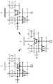
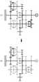
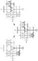
도 2 내지 도 4는 도 1의 파워트레인이 1단에서 2단으로 파워온 업쉬프트를 수행하는 것을 차례로 설명한 도면,
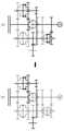
도 5와 도 6은 도 1의 파워트레인이 2단에서 3단으로 파워온 업쉬프트를 수행하는 것을 차례로 설명한 도면,
도 7과 도 8은 도 1의 파워트레인이 3단에서 4단으로 파워온 업쉬프트를 수행하는 것을 차례로 설명한 도면,
도 9와 도 10은 도 1의 파워트레인이 4단에서 5단으로 파워온 업쉬프트를 수행하는 것을 차례로 설명한 도면,
도 11과 도 12는 도 1의 파워트레인이 5단에서 6단으로 파워온 업쉬프트를 수행하는 것을 차례로 설명한 도면,
도 13과 도 14는 도 1의 파워트레인이 3단에서 2단으로 파워온 다운쉬프트를 수행하는 것을 차례로 설명한 도면,
도 15 내지 도 17은 도 1의 파워트레인이 2단에서 1단으로 파워온 다운쉬프트를 수행하는 것을 차례로 설명한 도면,
도 18과 도 19는 도 1의 파워트레인이 전기차 모드에서 1단에서 2단으로 파워온 업쉬프트를 수행하는 것을 차례로 설명한 도면,
도 20과 도 21은 도 1의 파워트레인이 전기차 모드에서 2단에서 1단으로 파워온 다운쉬프트를 수행하는 것을 차례로 설명한 도면,
도 22는 본 발명의 제2실시예를 도시한 도면,
도 23은 본 발명의 제3실시예를 도시한 도면이다.1 is a diagram showing the configuration of a hybrid powertrain according to the present invention;
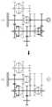
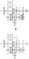
2 to 4 are views sequentially explaining that the power train of FIG. 1 performs a power-on upshift from
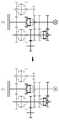
5 and 6 are views sequentially explaining that the power train of FIG. 1 performs a power-on upshift from a second stage to a third stage;
7 and 8 are views sequentially explaining that the powertrain of FIG. 1 performs a power-on upshift from 3rd to 4th;
9 and 10 are views sequentially explaining that the powertrain of FIG. 1 performs a power-on upshift from 4th stage to 5th stage;
11 and 12 are views sequentially explaining that the powertrain of FIG. 1 performs a power-on upshift from 5th to 6th;
13 and 14 are views sequentially explaining that the powertrain of FIG. 1 performs a power-on downshift from stage 3 to stage 2;
15 to 17 are views sequentially explaining that the powertrain of FIG. 1 performs a power-on downshift from stage 2 to
18 and 19 are views sequentially explaining that the power train of FIG. 1 performs a power-on upshift from
20 and 21 are views sequentially explaining that the power train of FIG. 1 performs a power-on downshift from the second stage to the first stage in the electric vehicle mode;
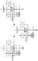
22 is a diagram showing a second embodiment of the present invention;
23 is a diagram showing a third embodiment of the present invention.
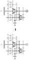
도 1을 참조하면, 본 발명 하이브리드 파워트레인의 실시예는, 엔진(E)과 메인클러치(MC)를 통해 연결되는 엔진입력축(EI); 상기 엔진입력축(EI)과 동심축을 이루어 배치되며 모터(M)가 연결된 모터입력축(MI); 상기 엔진입력축(EI)과 모터입력축(MI)을 단속할 수 있도록 설치된 센터싱크로(CS); 상기 엔진입력축(EI)에 평행하게 배치된 제1출력축(OUT1) 및 제2출력축(OUT2); 상기 모터입력축(MI)과 제1출력축(OUT1) 사이, 상기 엔진입력축(EI)과 제1출력축(OUT1) 사이, 및 상기 엔진입력축(EI)과 제2출력축(OUT2) 사이에 서로 다른 기어비를 형성하도록 설치된 다수의 외접기어쌍; 상기 모터입력축(MI)과 제1출력축(OUT1) 사이에 설치된 외접기어쌍들 중의 어느 하나를 구성하도록 상기 모터입력축(MI)에 회전 가능하게 설치된 제1연결기어(CG1)와 상기 센터싱크로(CS) 사이에 설치되고, 상기 센터싱크로(CS)의 슬리브에 의해 구동되어, 상기 제1연결기어(CG1)와 상기 모터입력축(MI) 사이에 전달되는 토크의 연속적인 변화를 구현하도록 구비된 콘클러치(CC)를 포함하여 구성된다.Referring to Figure 1, an embodiment of the present invention hybrid powertrain, the engine input shaft (EI) connected through the engine (E) and the main clutch (MC); A motor input shaft (MI) disposed concentric with the engine input shaft (EI) and connected to a motor (M); A center synchro (CS) installed to regulate the engine input shaft (EI) and the motor input shaft (MI); A first output shaft OUT1 and a second output shaft OUT2 disposed parallel to the engine input shaft EI; Different gear ratios are provided between the motor input shaft MI and the first output shaft OUT1, between the engine input shaft EI and the first output shaft OUT1, and between the engine input shaft EI and the second output shaft OUT2. A plurality of external gear pairs installed to form; A first connection gear (CG1) rotatably installed on the motor input shaft (MI) and the center synchro (CS) to form one of external gear pairs installed between the motor input shaft (MI) and the first output shaft (OUT1). ) Installed between, and driven by the sleeve of the center synchro (CS), the cone clutch provided to implement a continuous change in torque transmitted between the first connection gear (CG1) and the motor input shaft (MI) (CC) is included.
즉, 본 실시예는 도면 상 우측의 제1변속모듈(MD1)과 좌측의 제2변속모듈(MD2)이 중앙의 센터싱크로(CS)에 의해서 서로 연결될 수 있는 구성으로서, 상기 제1출력축(OUT1)은 상기 제1변속모듈(MD1) 및 제2변속모듈(MD2) 모두에 공통적으로 사용되어 제1출력기어(OG1)를 통해 동력을 디퍼렌셜(DF)로 출력할 수 있도록 설치되어 있으며, 상기 제2출력축(OUT2)은 상기 제2변속모듈(MD2)에서 전달되는 동력을 제2출력기어(OG2)를 통해 상기 디퍼렌셜(DF)로 출력할 수 있도록 설치된 것이다.That is, this embodiment is a configuration in which the first transmission module MD1 on the right and the second transmission module MD2 on the left are connected to each other by a center synchro CS in the drawing, and the first output shaft OUT1 ) Is commonly used for both the first transmission module MD1 and the second transmission module MD2, and is installed to output power to the differential DF through the first output gear OG1, and The second output shaft OUT2 is installed to output the power transmitted from the second transmission module MD2 to the differential DF through the second output gear OG2.
상기 제1출력축(OUT1)에는 상기 제1연결기어(CG1)에 치합되는 제2연결기어(CG2)가 구비된다.The first output shaft OUT1 is provided with a second connection gear CG2 that meshes with the first connection gear CG1.
따라서, 상기 모터입력축(MI)과 제1출력축(OUT1)에 설치된 상기 외접기어쌍들은, 일련의 변속단들 중 1단을 구현하기 위한 1단구동기어(1D)와 1단피동기어(1P); 2단을 구현하기 위한 2단구동기어(2D)와 2단피동기어(2P); 및 상기 제1연결기어(CG1)와 제2연결기어(CG2)로 이루어진다.Accordingly, the external gear pairs installed on the motor input shaft MI and the first output shaft OUT1 include a first-stage driving gear (1D) and a first-stage driven gear (1P) for implementing one of a series of shift stages; A two-stage driving gear (2D) and a two-stage driven gear (2P) for implementing two stages; And the first connection gear CG1 and the second connection gear CG2.
상기 제1연결기어(CG1)와 제2연결기어(CG2)가 형성하는 기어비는 상기 2단구동기어(2D)와 2단피동기어(2P)가 형성하는 2단기어비 보다 약간 작게 형성된다. 예컨대 2단기어비 보다 0.01 내지 0.05의 범위 정도로 작게 형성되는 것이 바람직하다.The gear ratio formed by the first coupling gear CG1 and the second coupling gear CG2 is slightly smaller than the two-stage gear ratio formed by the two-
또한, 상기 제1출력축(OUT1)에는 상기 1단피동기어(1P)를 상기 제1출력축(OUT1)에 단속시킬 수 있는 동기장치와, 상기 2단피동기어(2P)를 상기 제1출력축(OUT1)에 단속시킬 수 있는 도그클러치(DC)가 양쪽에 각각 구비된 제1클러치모듈(CLM1)이 구비된다.In addition, the first output shaft OUT1 has a synchronization device capable of intermittently controlling the first-stage driven
상기 제1연결기어(CG1)와 제2연결기어(CG2)가 형성하는 기어비를 상기 2단구동기어(2D)와 2단피동기어(2P)가 형성하는 2단기어비 보다 약간 작게 형성하면, 2단 구동상태에서 토크인터럽션 없이 다른 변속단으로의 변속을 위해 상기 콘클러치(CC)를 체결하면서 상기 도그클러치(DC)를 해제할 때, 충격이나 과도한 조작력을 요구하지 않고 원활하게 상기 도그클러치(DC)의 해제가 이루어진다.If the gear ratio formed by the first connecting gear (CG1) and the second connecting gear (CG2) is slightly smaller than that formed by the 2-stage driving gear (2D) and the 2-stage driven gear (2P), the second stage When releasing the dog clutch (DC) while tightening the cone clutch (CC) for shifting to another speed without torque interruption in the driving state, the dog clutch (DC) smoothly without requiring an impact or excessive operating force. ) Is canceled.
이는, 상기 콘클러치(CC)를 체결하면, 상기와 같은 기어비 차이에 의해, 상기 모터입력축(MI)으로부터 제1출력축(OUT1)으로 토크를 상기 2단구동기어(2D)와 2단피동기어(2P)를 통해 전달하던 상태로부터, 상기 제1연결기어(CG1)와 제2연결기어(CG2)를 통해 전달하는 상태로 전환될 수 있어서, 이때 상기 2단피동기어(2P)로부터 도그클러치(DC)를 해제하면 용이하게 도그클러치(DC)의 해제가 이루어지는 것이다.This is, when the cone clutch CC is fastened, torque is transferred from the motor input shaft MI to the first output shaft OUT1 due to the difference in gear ratio as described above, the two-
또한, 상기 제1클러치모듈(CLM1)에서 상기 2단피동기어(2P)를 제1출력축(OUT1)에 단속시키기 위한 장치로 도그클러치(DC)를 사용하는 이유는, 상기와 같이 제1연결기어(CG1)와 제2연결기어(CG2)의 기어비와 2단 기어비 사이의 기어비 차이가 있으면, 상기 콘클러치(CC)를 체결하여 토크인터럽션을 제거하면서 다른 변속단으로부터 2단으로의 변속 시, 상기 제1클러치모듈(CLM1)의 슬리브와 상기 2단피동기어(2P) 사이에는 상기 기어비 차이에 의해 약간의 상대속도가 발생하는데, 동기장치를 구성하는 싱크로나이저링의 용량으로는 이 상대속도를 극복하고 동기시키기 어렵고 오히려 상기 상대속도에 의해 슬리브와 2단피동기어(2P)의 클러치기어 사이의 치합이 불가능하게 하기 때문이다.In addition, the reason for using a dog clutch (DC) as a device for intercepting the two-stage driven gear (2P) to the first output shaft (OUT1) in the first clutch module (CLM1) is, as described above, the first connection gear If there is a difference in the gear ratio between the gear ratio of (CG1) and the second connecting gear (CG2) and the second gear ratio, when shifting from the other gear to the second gear while removing the torque interrupt by tightening the cone clutch (CC), A slight relative speed is generated between the sleeve of the first clutch module CLM1 and the two-stage driven
따라서, 상기 기어비 차이는 상술한 바와 같이 매우 작은 범위에서만 차이가 발생하도록 하여, 상기 콘클러치(CC)가 체결된 상태에서는 약간의 상대속도는 발생하지만 거의 동기가 되도록 하여, 상기 제1클러치모듈(CLM1)의 슬리브를 2단피동기어(2P)의 클러치기어에 그대로 치합시킬 수 있도록 하는 것이 바람직한 것이다.Therefore, the difference in the gear ratio is made to occur only in a very small range as described above, so that a slight relative speed occurs when the cone clutch CC is fastened, but is almost synchronized, so that the first clutch module ( It is desirable to be able to engage the sleeve of CLM1) with the clutch gear of the two-stage driven
참고로, 여기서 "동기장치"란 허브에 대해 축방향으로 슬라이딩하는 슬리브가 변속단을 형성하기 위한 변속단기어에 일체로 연결된 클러치기어에 치합되려고 할 때, 먼저 슬리브와 클러치기어의 속도를 동기시키도록 상기 허브와 클러치기어 사이에 설치되는 싱크로나이저링을 포함한 장치를 말하고, "도그클러치"는 상기와 같은 동기장치의 구성에서 상기 동기작용을 하는 싱크로나이저링이 배제된 장치를 말하며, 이들의 구성은 공지기술이다.For reference, when a sleeve sliding in the axial direction with respect to the hub tries to engage the clutch gear integrally connected to the gearshift gear for forming the shift gear, the speed of the sleeve and the clutch gear are first synchronized. It refers to a device including a synchronizer ring installed between the hub and the clutch gear, and "dog clutch" refers to a device in which the synchronizer ring for synchronizing action is excluded from the configuration of the synchronization device as described above. Is a known technique.
본 실시예에서, 상기 엔진입력축(EI)에는 상기 외접기어쌍들 중 2개씩의 외접기어쌍 구현에 공통적으로 사용되는 제1공통기어(CMG1)와 제2공통기어(CMG2)가 회전이 구속된 상태로 구비되고, 상기 제1공통기어(CMG1)에는 상기 센터싱크로(CS)의 슬리브에 치합되는 클러치기어가 일체로 구비된다.In this embodiment, the engine input shaft EI includes a first common gear CMG1 and a second common gear CMG2 commonly used to implement two of the external gear pairs. The first common gear CMG1 is integrally provided with a clutch gear engaged with the sleeve of the center synchro CS.
따라서, 상기 센터싱크로(CS)가 슬리브를 상기 제1공통기어(CMG1)의 클러치기어에 치합시키면, 상기 모터입력축(MI)과 엔진입력축(EI)이 하나로 연결되는 것이다.Accordingly, when the center synchro CS engages the sleeve with the clutch gear of the first common gear CMG1, the motor input shaft MI and the engine input shaft EI are connected as one.
상기 제1공통기어(CMG1)는 상기 제1출력축(OUT1)의 6단피동기어(6P)와 치합되어 외접기어쌍을 이룸과 동시에 상기 제2출력축(OUT2)의 4단피동기어(4P)와 치합되어 외접기어쌍을 이룬다.The first common gear (CMG1) is engaged with the six-stage driven gear (6P) of the first output shaft (OUT1) to form an external gear pair, and at the same time, the four-stage driven gear (4P) of the second output shaft (OUT2) and They are meshed to form an external gear pair.
또한, 상기 제2공통기어(CMG2)는 상기 제1출력축(OUT1)의 5단피동기어(5P)와 치합되어 외접기어쌍을 이룸과 동시에 상기 제2출력축(OUT2)의 3단피동기어(3P)와 치합되어 외접기어쌍을 이룬다.In addition, the second common gear (CMG2) is engaged with the 5-stage driven gear (5P) of the first output shaft (OUT1) to form an external gear pair and at the same time, the 3-stage driven gear (3P) of the second output shaft (OUT2). ) And form an external gear pair.
따라서, 상대적으로 적은 수의 기어를 사용하여 변속에 필요한 외접기어쌍들을 구성할 수 있다.Therefore, it is possible to configure external gear pairs required for shifting by using a relatively small number of gears.
상기 제1출력축(OUT1)의 5단피동기어(5P)와 6단피동기어(6P) 사이에는 상기 5단피동기어(5P)를 제1출력축(OUT1)에 단속시킬 수 있는 동기장치와 상기 6단피동기어(6P)를 상기 제1출력축(OUT1)에 단속시킬 수 있는 동기장치가 양쪽에 각각 구비된 제2클러치모듈(CLM2)이 구비된다.Between the fifth driven
따라서, 상기 제2클러치모듈(CLM2)의 슬리브를 이동시켜서 5단 또는 6단을 구현할 수 있다.Accordingly, 5th or 6th steps may be implemented by moving the sleeve of the second clutch module CLM2.
상기 제2출력축(OUT2)의 3단피동기어(3P)와 4단피동기어(4P) 사이에는 상기 3단피동기어(3P)를 제2출력축(OUT2)에 단속시킬 수 있는 동기장치와 상기 4단피동기어(4P)를 상기 제2출력축(OUT2)에 단속시킬 수 있는 동기장치가 양쪽에 각각 구비된 제3클러치모듈(CLM3)이 구비된다.Between the three-stage driven gear (3P) and the fourth-stage driven gear (4P) of the second output shaft (OUT2), a synchronization device capable of interrupting the three-stage driven gear (3P) to the second output shaft (OUT2) and the fourth A third clutch module CLM3 provided on both sides of a synchronization device capable of interrupting the single driven
따라서, 상기 제3클러치모듈(CLM3)의 슬리브를 이동시켜서 3단 또는 4단을 구현할 수 있다.Accordingly, by moving the sleeve of the third clutch module CLM3, it is possible to implement a third or fourth stage.
한편, 상기 모터입력축(MI)과 제1출력축(OUT1) 사이에 설치된 외접기어쌍들은 구현하고자 하는 일련의 변속단들 중 차례로 기어비가 가장 큰 2개의 기어비를 구현하기 위한 것들이다.Meanwhile, the pairs of external gears installed between the motor input shaft MI and the first output shaft OUT1 are for implementing two gear ratios having the largest gear ratios among a series of shift stages to be implemented.
즉, 상기 모터입력축(MI)과 제1출력축(OUT1) 사이에 설치된 외접기어쌍들은 1단 기어비와 2단 기어비를 구현하기 위한 것들인 것이다.That is, the external gear pairs installed between the motor input shaft MI and the first output shaft OUT1 are for implementing the first gear ratio and the second gear ratio.
상기한 바와 같은 본 발명은 다음과 같이 표현할 수도 있을 것이다.The present invention as described above may be expressed as follows.
즉, 본 발명 하이브리드 파워트레인은, 모터(M)가 직결된 모터입력축(MI)을 구비하고, 일련의 변속단들 중 차례로 기어비가 가장 큰 2개의 변속단을 형성할 수 있도록 구비된 제1변속모듈(MD1); 상기 모터입력축(MI)에 동심축을 이루며 메인클러치(MC)를 통해 엔진(E)과 연결되는 엔진입력축(EI)을 구비하고, 상기 일련의 변속단들 중 나머지 변속단을 형성할 수 있도록 구비된 제2변속모듈(MD2); 상기 모터입력축(MI)과 상기 엔진입력축(EI)을 단속할 수 있도록 설치된 센터싱크로(CS); 상기 제1변속모듈(MD1)이 연속적으로 제어되는 마찰력에 의해, 상기 제1변속모듈(MD1)의 변속단들 중 기어비가 작은 변속단보다 더 작은 기어비를 형성하는 상태를 구현할 수 있도록 구비된 연속가변장치를 포함하여 구성된다.That is, the hybrid powertrain of the present invention includes a motor input shaft MI to which a motor M is directly connected, and a first shift provided to form two shift stages with the largest gear ratio in sequence among a series of shift stages. Module MD1; Concentric with the motor input shaft MI and provided with an engine input shaft EI that is connected to the engine E through a main clutch MC, and is provided to form the remaining gear stages among the series of shift stages. A second transmission module MD2; A center synchro (CS) installed to regulate the motor input shaft (MI) and the engine input shaft (EI); The first transmission module MD1 is provided to realize a state in which a smaller gear ratio is formed than a gear ratio of a small gear ratio among the gear stages of the first transmission module MD1 by the frictional force that is continuously controlled. It is configured to include a variable device.
여기서, 상기 연속가변장치(CHD)는 상기 센터싱크로(CS)의 슬리브에 의해 마찰력이 연속적으로 제어되도록 구성된다.Here, the continuously variable device CHD is configured to continuously control the frictional force by the sleeve of the center synchro CS.
한편, 상기 제1변속모듈(MD1)은 상기 모터입력축(MI)에 평행하게 설치된 제1출력축(OUT1)과; 1단을 구현하기 위해 상기 모터입력축(MI)에 설치된 1단구동기어(1D)와 상기 제1출력축(OUT1)에 설치된 1단피동기어(1P); 2단을 구현하기 위해 상기 모터입력축(MI)에 설치된 2단구동기어(2D)와 상기 제1출력축(OUT1)에 설치된 2단피동기어(2P); 상기 1단피동기어(1P)를 상기 제1출력축(OUT1)에 단속시킬 수 있는 동기장치와, 상기 2단피동기어(2P)를 상기 제1출력축(OUT1)에 단속시킬 수 있는 도그클러치(DC)가 양쪽에 각각 구비된 제1클러치모듈(CLM1)을 포함하여 구성된다.Meanwhile, the first transmission module MD1 includes a first output shaft OUT1 installed parallel to the motor input shaft MI; A first-stage driving gear (1D) installed on the motor input shaft (MI) and a first-stage driven gear (1P) installed on the first output shaft (OUT1) to implement a first stage; A two-stage driven gear (2D) installed on the motor input shaft (MI) and a two-stage driven gear (2P) installed on the first output shaft (OUT1) to implement a second stage; A synchronizing device capable of interrupting the first-stage driven
여기서, 상기 연속가변장치(CHD)는 상기 모터입력축(MI)에 회전가능하게 설치된 제1연결기어(CG1); 상기 제1출력축(OUT1)에 회전이 구속되게 설치된 제2연결기어(CG2); 상기 센터싱크로(CS)의 슬리브에 의해 구동되어, 연속적으로 제어되는 마찰력에 의해 상기 제1연결기어(CG1)와 상기 모터입력축(MI) 사이에 전달되는 토크의 연속적인 변화를 구현하도록 구비된 콘클러치(CC)를 포함하여 구성된다.Here, the continuous variable device (CHD) includes a first connection gear (CG1) rotatably installed on the motor input shaft (MI); A second connection gear (CG2) installed on the first output shaft (OUT1) to restrict rotation; Cone provided to implement a continuous change of torque transmitted between the first connection gear CG1 and the motor input shaft MI by a continuously controlled frictional force driven by the sleeve of the center synchro CS It is configured to include a clutch (CC).
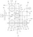
한편, 도 22는 본 발명에 따른 하이브리드 파워트레인의 제2실시예를 도시한 것으로서, 다른 구성은 도 1과 동일하고 상기 모터(M)가 상기 모터입력축(MI)의 2단구동기어(2D)에 치합된 감속구동기어(RD)를 통해 상기 모터입력축(MI)으로 동력을 전달하도록 설치된 구성이다.On the other hand, Figure 22 shows a second embodiment of the hybrid powertrain according to the present invention, the other configuration is the same as in Figure 1, and the motor (M) is connected to the two-stage driving gear (2D) of the motor input shaft (MI). It is a configuration installed to transmit power to the motor input shaft MI through the geared reduction drive gear RD.
물론, 상기 감속구동기어(RD)는 1단구동기어(1D)에 치합되도록 배치할 수도 있을 것이다.Of course, the reduction drive gear RD may be arranged so as to mesh with the first
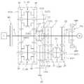
도 23은 본 발명에 따른 하이브리드 파워트레인의 제3실시예를 도시한 것으로서, 다른 구성은 도 1과 동일하고, 상기 모터(M)와 모터입력축(MI) 사이에는 모터(M)의 동력을 감속하여 상기 모터입력축(MI)으로 전달하는 유성기어장치(PG)가 구비된 구성이다.23 shows a third embodiment of a hybrid powertrain according to the present invention, the other configuration is the same as that of FIG. 1, and the power of the motor M is reduced between the motor M and the motor input shaft MI. Thus, the planetary gear device PG that is transmitted to the motor input shaft MI is provided.
상기 제2실시예와 제3실시예 모두 모터(M)의 동력을 감속하여 상기 모터입력축(MI)으로 제공함으로써, 상대적으로 모터(M)의 용량을 축소하는 것이 가능하다.In both the second and third embodiments, the power of the motor M is reduced and provided to the motor input shaft MI, so that the capacity of the motor M can be relatively reduced.
도 2 내지 도 4는 도 1의 파워트레인이 1단에서 2단으로 파워온 업쉬프트를 수행하는 것을 차례로 설명한 것으로서, 이 과정들을 살펴본다.2 to 4 are sequential explanations of performing a power-on upshift from the first stage to the second stage by the powertrain of FIG. 1, and these processes will be described.
참고로, 동력이 작용하는 부분을 굵은 선으로 표시하고 있다.For reference, the part where the power acts is indicated by a thick line.
A는 엔진의 동력이 엔진입력축(EI)은 물론 센터싱크로(CS)를 통해 모터입력축(MI)을 함께 구동하고 있으며, 상기 제1클러치유닛의 동기장치가 1단을 형성하고 있어서, 상기 모터입력축(MI)의 동력은 상기 1단구동기어(1D)와 1단피동기어(1P)를 통해 제1출력축(OUT1)으로 전달되어 제1출력기어(OG1)를 통해 디퍼렌셜(DF)로 인출되는 상태이다.In A, the engine power is driving the motor input shaft MI through the center synchro CS as well as the engine input shaft EI, and the synchronizing device of the first clutch unit forms the first stage, so that the motor input shaft The power of (MI) is transferred to the first output shaft OUT1 through the first-
B는 A상태로부터 2단으로의 변속지령 발생 시, 모터(M)를 함께 구동하는 상태이다.B is a state in which the motor (M) is driven together when a shift command is generated from the A state to the second stage.
C는 모터(M)에 의해 1단 주행을 계속하면서 메인클러치(MC)를 해제하고, 상기 콘클러치(CC)를 체결하는 상태를 나타낸다. 상기 센터싱크로(CS)의 슬리브가 상기 콘클러치(CC)를 작동시키므로 당연히 상기 센터싱크로(CS)는 해제되어 상기 엔진입력축(EI)과 모터입력축(MI)은 분리된다.C denotes a state in which the main clutch MC is released and the cone clutch CC is fastened while continuing the first-stage driving by the motor M. Since the sleeve of the center synchro CS operates the cone clutch CC, of course, the center synchro CS is released so that the engine input shaft EI and the motor input shaft MI are separated.
D는 제1클러치유닛의 동기장치가 1단을 해제한 상태로서, 동력은 상기 콘클러치(CC)와 제1연결기어(CG1) 및 제2연결기어(CG2)를 통해 제1출력축(OUT1)으로 계속해서 전달되면서 토크인터럽션을 방지한다.D is a state in which the first stage of the synchronization device of the first clutch unit is released, and the power is the first output shaft (OUT1) through the cone clutch (CC), the first connecting gear (CG1), and the second connecting gear (CG2). It is continuously transmitted to prevent torque interruption.
E는 상기 제1클러치유닛의 도그클러치(DC)를 체결하는 것으로서, 상술한 바와 같이, 상기 콘클러치(CC)에 의해 동력이 전달되고 있는 D 상태에서 상기 2단피동기어(2P)와 제1클러치유닛의 슬리브 사이에는 상기 제1연결기어(CG1)와 제2연결기어(CG2)의 기어비와 2단기어비 사이의 기어비 차이에 의한 약간의 상대속도가 발생하므로, 싱크로나이저링이 없는 도그클러치(DC)를 사용하여 상기 제1클러치유닛의 슬리브를 2단피동기어(2P)의 클러치기어에 치합하도록 하는 것이다.E is for fastening the dog clutch DC of the first clutch unit, and as described above, the two-stage driven
F는 상기 콘클러치(CC)를 해제하고 모터(M)에 의해 2속 주행이 이루어지는 상태이다.F is a state in which the cone clutch CC is released and two-speed travel is performed by the motor M.
G는 상기 센터싱크로(CS)를 체결하여 엔진입력축(EI)과 모터입력축(MI)을 연결한 후 상기 메인클러치(MC)를 체결하여, 상기 제1출력축(OUT1)에 엔진의 동력과 모터(M)의 동력이 모두 전달되어 2속 주행이 이루어지는 상태이다.G denotes the engine input shaft (EI) and the motor input shaft (MI) by connecting the center synchro (CS), and then the main clutch (MC), and the engine power and the motor ( All of the power of M) has been transmitted and the 2nd speed driving is achieved.
H는 G상태에서 모터(M)가 동력을 발생시키지 않도록 하여 엔진에 의한 2속 주행이 이루어지는 상태이다.H is a state in which the motor M does not generate power in the G state, so that the engine is driven at two speeds.
도 5와 도 6은 도 1의 파워트레인이 2단에서 3단으로 파워온 업쉬프트를 수행하는 것을 차례로 설명한 도면들로서, 이 과정들을 살펴본다.5 and 6 are views sequentially explaining that the powertrain of FIG. 1 performs a power-on upshift from stage 2 to stage 3, and these processes are described.
A는 엔진에 의해 2속 주행이 이루어지고 있는 상태로서, 이 상태에서 3속으로의 변속지령이 발생하면, B와 같이 모터(M)를 함께 구동하면서 2속 주행상태를 형성한다.A is a state in which the engine is running at two speeds, and when a shift command to the third speed is generated in this state, the motor M is driven together as in B to form a second speed driving state.
C는 상기 메인클러치(MC) 및 센터싱크로(CS)를 해제하여 엔진입력축(EI)을 모터입력축(MI)과 분리한 상태로서, 차량의 모터(M)에 의해 여전히 2속 주행상태를 형성한다.C is a state in which the engine input shaft EI is separated from the motor input shaft MI by releasing the main clutch MC and the center synchro CS, and a two-speed driving state is still formed by the motor M of the vehicle. .
D는 상기 제3클러치모듈(CLM3)의 동기장치로 제3피동기어를 제2출력축(OUT2)에 연결시키고, 상기 메인클러치(MC)를 결합하여 엔진에 의한 3속 주행이 이루어지고 있고, 모터(M)의 동력도 디퍼렌셜(DF)로 전달되고 있는 상황이다.D denotes a synchronizing device of the third clutch module CLM3, which connects the third driven gear to the second output shaft OUT2, and combines the main clutch MC to perform three-speed driving by the engine, and the motor The power of (M) is also being transmitted to the differential (DF).
E는 상기 D의 상태에서 상기 모터(M)의 동력을 해제하여 엔진만에 의한 3속 주행상태가 형성된 것이다.E denotes a three-speed driving state by only the engine by releasing the power of the motor (M) in the state of D.
이상과 같이 2단에서 3단으로의 변속 시에도 토크인터럽션은 발생하지 않는다.As described above, torque interruption does not occur even when shifting from 2nd to 3rd gear.
도 7과 도 8은 도 1의 파워트레인이 3단에서 4단으로 파워온 업쉬프트를 수행하는 것을 차례로 설명한 도면으로서, 이하에서 살펴본다.7 and 8 are views sequentially explaining that the power train of FIG. 1 performs a power-on up-shift from the 3rd stage to the 4th stage, which will be described below.
A 상태는 엔진만의 동력으로 3속 주행 중인 상태로서, 4단으로의 변속 지령이 발생하면, B와 같이 모터(M)를 구동하여 모터(M)에 의한 동력도 디퍼렌셜(DF)로 전달되도록 한다.A state is a state in which the engine is driving at 3 speeds only with the power of the engine, and when a shift command to the fourth gear occurs, the motor (M) is driven as in B so that the power by the motor (M) is also transmitted to the differential (DF) do.
C는 메인클러치(MC)를 해제하여 모터(M)만에 의해 3속 주행이 이루어지고 있는 상태이다.C is a state in which the main clutch MC is released and the three-speed driving is performed only by the motor M.
D는 상기 제3클러치모듈(CLM3)의 동기장치로 제4피동기어를 제2출력축(OUT2)에 연결시키고, 상기 메인클러치(MC)를 결합하여 엔진에 의한 4속 주행이 이루어지고 있고, 모터(M)의 동력도 디퍼렌셜(DF)로 전달되고 있는 상황이다.D denotes a synchronizing device of the third clutch module CLM3, which connects the fourth driven gear to the second output shaft OUT2, and combines the main clutch MC to perform four-speed driving by the engine, and the motor The power of (M) is also being transmitted to the differential (DF).
E는 상기 D의 상태에서 상기 모터(M)의 동력을 해제하여 엔진만에 의한 4속 주행상태가 형성된 것이다.In the state of D, the power of the motor M is released to form a four-speed driving state by only the engine.
이와 같이 본 변속 과정에서도 토크인터럽션은 발생하지 않으며, 이는 상기 모터(M)가 상기 제2구동기어와 제2피동기어를 통해 동력을 전달하고 있는 동안, 상기 메인클러치(MC)를 해제하고 상기 제3클러치모듈(CLM3)로 3단피동기어(3P) 대신 4단피동기어(4P)를 상기 제2출력축(OUT2)에 연결시키도록 전환할 수 있기 때문이다.As described above, torque interruption does not occur even in the main shifting process. This is because the main clutch MC is released while the motor M is transmitting power through the second driving gear and the second driven gear. This is because the third clutch module CLM3 can be switched to connect the four-stage driven
물론, 이때 모터(M)의 속도는 각 변속단 속도에 맞게 조절하는 것이다.Of course, at this time, the speed of the motor (M) is adjusted to suit the speed of each shift stage.
도 9와 도 10은 도 1의 파워트레인이 4단에서 5단으로 파워온 업쉬프트를 수행하는 것을 차례로 설명한 도면으로서, 제3클러치모듈(CLM3)의 동기장치로 4단을 해제하고 상기 제2클러치모듈(CLM2)의 동기장치로 5단을 체결하는 것만 다르고, 나머지는 상기 3단에서 4단으로의 변속과 동일하므로 상세한 설명은 생략한다.9 and 10 are views sequentially explaining that the power train of FIG. 1 performs a power-on upshift from 4th to 5th, and the 4th gear is released by the synchronizing device of the 3rd clutch module CLM3 and the 2nd The only difference is that the 5th gear is fastened with the synchronizing device of the clutch module CLM2, and the rest is the same as the shift from the 3rd to the 4th, so a detailed description will be omitted.
도 11과 도 12는 도 1의 파워트레인이 5단에서 6단으로 파워온 업쉬프트를 수행하는 것을 차례로 설명한 도면으로서, 상기 제2클러치모듈(CLM2)의 동기장치로 5단을 해제하고 6단을 체결하는 것만 다르고, 나머지는 상기 3단에서 4단으로의 변속과 동일하므로 상세한 설명은 생략한다.11 and 12 are views sequentially explaining that the power train of FIG. 1 performs a power-on up-shift from 5th to 6th gear, and the 5th gear is released by the synchronization device of the second clutch module CLM2 and the 6th gear is Only the fastening is different, and the rest is the same as the shift from the 3rd to the 4th, so a detailed description will be omitted.
도 13과 도 14는 도 1의 파워트레인이 3단에서 2단으로 파워온 다운쉬프트를 수행하는 것을 차례로 설명한 도면이다. 이를 살펴본다.13 and 14 are views sequentially explaining that the power train of FIG. 1 performs a power-on downshift from the third stage to the second stage. Take a look at this.
A는 엔진에 의한 3속 주행상태로서, 2속으로의 변속지령이 발생하면, B와 같이 모터(M)를 구동하여 모터(M)에 의해서도 제1출력축(OUT1)으로 3속 동력이 제공되도록 한다.A is the three-speed driving state by the engine, and when a shift command to the second speed occurs, the motor (M) is driven as in B so that the third-speed power is also provided by the motor (M) to the first output shaft (OUT1). do.
C는 메인클러치(MC)를 해제하고, 상기 제3클러치모듈(CLM3)의 동기장치를 중립으로 해제하여, 차량은 모터(M)만에 의해 구동되는 상태로 모터(M)의 속도 조절로 2속 상태로 주행하게 된다.C is to release the main clutch (MC), release the synchronization device of the third clutch module (CLM3) to neutral, the vehicle is driven by only the motor (M), 2 by adjusting the speed of the motor (M). You will drive in the inner state.
D는 센터싱크로(CS)를 체결한 후 메인클러치(MC)를 결합하여 엔진의 동력도 함께 제1출력축(OUT1)을 통해 디퍼렌셜(DF)로 전달되도록 하는 상태이다.D is a state in which the engine power is also transferred to the differential DF through the first output shaft OUT1 by coupling the main clutch MC after the center synchro CS is fastened.
E는 모터(M)의 동력을 해제하여 엔진만에 의한 2속 주행상태가 구현된 상태이다.E is a state in which the power of the motor M is released to realize a two-speed driving state by only the engine.
상술한 바와 같이 이 변속 과정에서도 토크인터럽션은 발생하지 않는다.As described above, torque interruption does not occur even in this shifting process.
도 15 내지 도 17은 도 1의 파워트레인이 2단에서 1단으로 파워온 다운쉬프트를 수행하는 것을 차례로 설명한 도면이다. 이를 살펴본다.15 to 17 are views sequentially explaining that the powertrain of FIG. 1 performs a power-on downshift from the second stage to the first stage. Take a look at this.
A는 엔진에 의한 2속 주행 상태로서, 1속으로의 변속지령이 발생하면, B와 같이 모터(M)를 구동하여 엔진과 모터(M)가 함께 1속을 구현하는 상태가 되도록 한다.A is a two-speed driving state by the engine, and when a shift command to the first speed is generated, the motor M is driven as in B so that the engine and the motor M are in a state in which the engine and the motor M realize the first speed together.
C는 메인클러치(MC)를 해제하고 센터싱크로(CS)를 해제한 후 상기 콘클러치(CC)를 마찰시키는 상태이다. 상술한 바와 같이 상기 제1연결기어(CG1)와 제2연결기어(CG2)의 기어비가 상기 2단 기어비 보다 약간 작게 구성되어 있어서, 상기 콘클러치(CC)를 결합하면, 상기 모터(M)의 동력은 2단구동기어(2D)와 2단피동기어(2P)를 통해 제1출력축(OUT1)으로 전달되던 상태로부터 상기 제1연결기어(CG1)와 제2연결기어(CG2)를 통해 전달되는 상태가 되므로, 상기 2단피동기어(2P)로부터 상기 도그클러치(DC)를 용이하게 해제할 수 있다.C is a state in which the main clutch MC is released and the center synchro CS is released, and the cone clutch CC is rubbed. As described above, the gear ratio of the first connection gear (CG1) and the second connection gear (CG2) is configured to be slightly smaller than the second gear ratio, so when the cone clutch (CC) is coupled, the motor (M) Power is transferred from the first output shaft (OUT1) through the two-stage driving gear (2D) and the two-stage driven gear (2P) to the first connection gear (CG1) and the second connection gear (CG2). Therefore, the dog clutch DC can be easily released from the two-stage driven
D는 이와 같이 상기 제1클러치모듈(CLM1)의 도그클러치(DC)가 해제된 상태이다.D is a state in which the dog clutch DC of the first clutch module CLM1 is released as described above.
만약에, 상기 제1연결기어(CG1)와 제2연결기어(CG2)의 기어비가 2단기어비와 동일하거나 그 보다 크게 설정되어 있었다면, 상기와 같은 콘클러치(CC)의 체결 시에도 여전히 2단피동기어(2P)를 통해 동력이 전달되고 있는 상태가 유지되므로, 도그클러치(DC)의 해제가 용이하지 않고 해제된다고 하더라도 충격이나 소음이 발생하게 된다.If the gear ratio of the first connection gear (CG1) and the second connection gear (CG2) is set equal to or greater than the second gear ratio, even when the cone clutch (CC) is fastened as described above, the second gear Since the state in which power is being transmitted through the driven
E는 모터(M)의 속도를 1속으로 조절하여 상기 제1클러치모듈(CLM1)의 동기장치로 1단피동기어(1P)를 제1출력축(OUT1)에 연결한 상태이다.E is a state in which the first driven
F는 상기 콘클러치(CC)를 해제하고 센터싱크로(CS)를 체결한 후 메인클러치(MC)를 체결하여 엔진의 동력이 상기 1단구동기어(1D)와 1단피동기어(1P)를 통해 제1출력축(OUT1)으로 함께 공급되는 상태이다.F is for releasing the cone clutch (CC), fastening the center synchro (CS), and then fastening the main clutch (MC) to control the power of the engine through the first-stage driving gear (1D) and the first-stage driven gear (1P). It is supplied to the output shaft (OUT1) together.
G는 모터(M)의 동력을 해제하여 엔진만에 의해 1속 구동상태를 형성한 것으로서, 역시 토크인터럽션 없이 변속이 완료된 것이다.G denotes a one-speed driving state by releasing the power of the motor M by only the engine, and shifting is completed without torque interruption.
도 18과 도 19는 도 1의 파워트레인이 전기차 모드에서 1단에서 2단으로 파워온 업쉬프트를 수행하는 것을 차례로 설명한 도면이다. 이를 살펴본다.18 and 19 are views sequentially explaining that the power train of FIG. 1 performs a power-on upshift from the first stage to the second stage in the electric vehicle mode. Take a look at this.
A와 같은 모터(M)만에 의한 전기차 모드 1단 주행상태에서 2단으로의 변속지령이 발생하면, B와 같이 콘클러치(CC)의 마찰력을 발생시키면서, C와 같이 상기 제1클러치모듈(CLM1)의 동기장치를 해제하여 1단피동기어(1P)와 제1출력축(OUT1)의 연결상태를 해제한다.When a shift command to the second stage occurs in the electric vehicle mode 1st stage driving state by only the motor M such as A, while generating the frictional force of the cone clutch CC as shown in B, the first clutch module ( By releasing the synchronizing device of CLM1), the connection state between the first-stage driven
D는 상기 제1클러치모듈(CLM1)의 슬리브를 이동시켜서 도그클러치(DC)를 체결함으로써, 2단피동기어(2P)를 제1출력축(OUT1)과 연결시킨 상태이다.D is a state in which the two-stage driven
E는 상기 콘클러치(CC)를 해제하여 2단구동기어(2D)와 2단피동기어(2P)만에 의해 모터(M)의 동력이 제1출력축(OUT1)으로 전달되어 전기차 모드 2속 주행이 이루어지는 상태이다.E is to release the cone clutch (CC), the power of the motor (M) is transmitted to the first output shaft (OUT1) only by the two-stage drive gear (2D) and the two-stage driven gear (2P), so that the electric vehicle mode 2 speed driving is possible. It is a state of being achieved.
이 변속과정 역시 토크인터럽션이 발생하지 않음을 확인할 수 있다.It can be seen that torque interruption does not occur in this shifting process as well.
도 20과 도 21은 도 1의 파워트레인이 전기차 모드에서 2단에서 1단으로 파워온 다운쉬프트를 수행하는 것을 차례로 설명한 도면이다. 이를 살펴본다.20 and 21 are views sequentially explaining that the power train of FIG. 1 performs a power-on downshift from the second stage to the first stage in the electric vehicle mode. Take a look at this.
A와 같은 모터(M)만에 의한 전기차 모드 2단 주행상태에서, 1단으로의 변속지령이 발생하면, B와 같이 콘클러치(CC)의 마찰력을 발생시키고, C와 같이 도그클러치(DC)를 해제한다.In the electric vehicle mode 2nd driving state by only the motor (M) like A, when a shift command to the 1st gear occurs, it generates frictional force of the cone clutch (CC) as shown in B, and the dog clutch (DC) as shown in C. Release.
D는 모터(M)의 속도를 1속으로 조절한 후 상기 제1클러치모듈(CLM1)의 동기장치를 체결하여 상기 1단피동기어(1P)를 상기 제1출력축(OUT1)과 연결시킨 상태이다.D is a state in which the first driven
E는 상기 콘클러치(CC)를 해제하여, 모터(M)의 동력이 상기 1단구동기어(1D)와 1단피동기어(1P)만을 통해 제1출력축(OUT1)으로 전달되면서 1속을 형성하는 상태를 도시한 것으로서, 역시 토크인터럽션이 없이 변속이 완료됨을 확인할 수 있다.E is to release the cone clutch (CC), the power of the motor (M) is transmitted to the first output shaft (OUT1) only through the first-stage driving gear (1D) and the first-stage driven gear (1P) to form the first speed. As showing the state, it can also be confirmed that the shift is completed without torque interruption.
이상과 같이 본 발명은 모터(M)를 사용하여 AMT의 원가, 재료비, 연비 등과 같은 장점을 살리면서, AMT의 단점인 토크인터럽션을 해결하여 변속감을 향상시키고, 종래에 엔진과 변속기 사이에 모터(M)가 위치하는 방식의 하이브리드 파워트레인에서 요구되는 모터(M)와 엔진 사이의 클러치를 배제할 수 있어서, 변속기의 전장 축소로 차량 탑재성을 향상시킴은 물론 중량과 원가의 저감이 가능하다.As described above, the present invention uses a motor (M) to improve the sense of speed by solving the torque interruption, which is a disadvantage of AMT, while taking advantage of the AMT cost, material cost, and fuel economy. Since the clutch between the motor (M) and the engine required in the hybrid powertrain in which the (M) is located can be eliminated, it is possible to reduce the weight and cost as well as improve the vehicle mountability by reducing the overall length of the transmission. .
본 발명은 특정한 실시예에 관련하여 도시하고 설명하였지만, 이하의 특허청구범위에 의해 제공되는 본 발명의 기술적 사상을 벗어나지 않는 한도 내에서, 본 발명이 다양하게 개량 및 변화될 수 있다는 것은 당업계에서 통상의 지식을 가진 자에게 있어서 자명할 것이다.Although the present invention has been illustrated and described in connection with specific embodiments, it is understood in the art that the present invention can be variously improved and changed within the scope of the technical spirit of the present invention provided by the following claims. It will be obvious to those of ordinary skill.
E; 엔진
MC; 메인클러치
EI; 엔진입력축
M; 모터
MI; 모터입력축
CS; 센터싱크로
OUT1; 제1출력축
OUT2; 제2출력축
CG1; 제1연결기어
CC; 콘클러치
MD1; 제1변속모듈
MD2; 제2변속모듈
OG1; 제1출력기어
DF; 디퍼렌셜
OG2; 제2출력기어
CG2; 제2연결기어
1D; 1단구동기어
1P; 1단피동기어
2D; 2단구동기어
2P; 2단피동기어
DC; 도그클러치
CLM1; 제1클러치모듈
CMG1; 제1공통기어
CMG2; 제2공통기어
6P; 6단피동기어
4P; 4단피동기어
5P; 5단피동기어
3P; 3단피동기어
CLM2; 제2클러치모듈
CLM3; 제3클러치모듈
CHD; 연속가변장치
RD; 감속구동기어
PG; 유성기어장치E; engine
MC; Main clutch
EI; Engine input shaft
M; motor
MI; Motor input shaft
CS; Center Synchro
OUT1; 1st output shaft
OUT2; 2nd output shaft
CG1; First connecting gear
CC; Corn clutch
MD1; 1st shift module
MD2; 2nd shift module
OG1; 1st output gear
DF; Differential
OG2; 2nd output gear
CG2; 2nd connecting gear
1D; 1-stage drive gear
1P; 1-stage driven gear
2D; 2-stage drive gear
2P; 2-stage driven gear
DC; Dog Clutch
CLM1; 1st clutch module
CMG1; 1st common gear
CMG2; 2nd common gear
6P; 6-speed driven gear
4P; 4-speed driven gear
5P; 5-speed driven gear
3P; 3-speed driven gear
CLM2; 2nd clutch module
CLM3; 3rd clutch module
CHD; Continuous variable device
RD; Reduction gear
PG; Planetary gear device
Claims (15)
Translated fromKorean상기 엔진입력축과 동심축을 이루어 배치되며 모터가 연결된 모터입력축;
상기 엔진입력축과 모터입력축을 단속할 수 있도록 설치된 센터싱크로;
상기 엔진입력축에 평행하게 배치된 제1출력축 및 제2출력축;
상기 모터입력축과 제1출력축 사이, 상기 엔진입력축과 제1출력축 사이, 및 상기 엔진입력축과 제2출력축 사이에 서로 다른 기어비를 형성하도록 설치된 다수의 외접기어쌍;
상기 모터입력축과 제1출력축 사이에 설치된 외접기어쌍들 중의 어느 하나를 구성하도록 상기 모터입력축에 회전 가능하게 설치된 제1연결기어와 상기 센터싱크로 사이에 설치되고, 상기 센터싱크로의 슬리브에 의해 구동되어, 상기 제1연결기어와 상기 모터입력축 사이에 전달되는 토크의 연속적인 변화를 구현하도록 구비된 콘클러치;
를 포함하여 구성된 것을 특징으로 하는 하이브리드 파워트레인.An engine input shaft connected to the engine through the main clutch;
A motor input shaft formed concentric with the engine input shaft and connected to a motor;
A center sync installed to regulate the engine input shaft and the motor input shaft;
A first output shaft and a second output shaft disposed parallel to the engine input shaft;
A plurality of external gear pairs installed to form different gear ratios between the motor input shaft and the first output shaft, between the engine input shaft and the first output shaft, and between the engine input shaft and the second output shaft;
It is installed between the first connection gear rotatably installed on the motor input shaft and the center sync to form one of external gear pairs installed between the motor input shaft and the first output shaft, and is driven by the sleeve of the center sync. A cone clutch provided to implement a continuous change in torque transmitted between the first connection gear and the motor input shaft;
Hybrid powertrain, characterized in that configured to include.
상기 모터입력축과 제1출력축에 설치된 상기 외접기어쌍들은, 일련의 변속단들 중 1단을 구현하기 위한 1단구동기어와 1단피동기어, 및 2단을 구현하기 위한 2단구동기어와 2단피동기어를 포함하고;
상기 제1출력축에는 상기 제1연결기어에 치합되는 제2연결기어가 구비되며;
상기 제1연결기어와 제2연결기어가 형성하는 기어비는 상기 2단구동기어와 2단피동기어가 형성하는 2단기어비 보다 작게 형성된 것
을 특징으로 하는 하이브리드 파워트레인.The method according to claim 1,
The external gear pairs installed on the motor input shaft and the first output shaft are a first-stage driving gear and a first-stage driven gear for implementing the first of a series of shift stages, and a two-stage driving gear and a second-stage driven gear for implementing the second stage. Including gears;
A second connection gear engaged with the first connection gear is provided on the first output shaft;
The gear ratio formed by the first connection gear and the second connection gear is formed to be smaller than the second gear ratio formed by the two-stage driving gear and the second-stage driven gear
Hybrid powertrain characterized by a.
상기 제1출력축에는 상기 1단피동기어를 상기 제1출력축에 단속시킬 수 있는 동기장치와, 상기 2단피동기어를 상기 제1출력축에 단속시킬 수 있는 도그클러치가 양쪽에 각각 구비된 제1클러치모듈이 구비된 것
을 특징으로 하는 하이브리드 파워트레인.The method according to claim 2,
A first clutch provided on both sides of the first output shaft with a synchronous device capable of interrupting the first-stage driven gear to the first output shaft and a dog clutch capable of interrupting the second-stage driven gear to the first output shaft With modules
Hybrid powertrain characterized by a.
상기 엔진입력축에는 상기 외접기어쌍들 중 2개씩의 외접기어쌍 구현에 공통적으로 사용되는 제1공통기어와 제2공통기어가 회전이 구속된 상태로 구비되고;
상기 제1공통기어에는 상기 센터싱크로의 슬리브에 치합되는 클러치기어가 일체로 구비된 것
을 특징으로 하는 하이브리드 파워트레인.The method of claim 3,
The engine input shaft is provided with a first common gear and a second common gear, which are commonly used to implement two of the external gear pairs, in a state in which rotation is restricted;
The first common gear is integrally provided with a clutch gear engaged with the sleeve of the center sync.
Hybrid powertrain characterized by a.
상기 제1공통기어는 상기 제1출력축의 6단피동기어와 치합되어 외접기어쌍을 이룸과 동시에 상기 제2출력축의 4단피동기어와 치합되어 외접기어쌍을 이루는 것
을 특징으로 하는 하이브리드 파워트레인.The method of claim 4,
The first common gear is meshed with the six-stage driven gear of the first output shaft to form an external gear pair, and at the same time, the first common gear is meshed with the four-stage driven gear of the second output shaft to form an external gear pair.
Hybrid powertrain characterized by a.
상기 제2공통기어는 상기 제1출력축의 5단피동기어와 치합되어 외접기어쌍을 이룸과 동시에 상기 제2출력축의 3단피동기어와 치합되어 외접기어쌍을 이루는 것
을 특징으로 하는 하이브리드 파워트레인.The method of claim 5,
The second common gear meshes with the 5-stage driven gear of the first output shaft to form an external gear pair and at the same time meshes with the 3-stage driven gear of the second output shaft to form an external gear pair
Hybrid powertrain characterized by a.
상기 제1출력축의 5단피동기어와 6단피동기어 사이에는 상기 5단피동기어를 제1출력축에 단속시킬 수 있는 동기장치와 상기 6단피동기어를 상기 제1출력축에 단속시킬 수 있는 동기장치가 양쪽에 각각 구비된 제2클러치모듈이 구비된 것
을 특징으로 하는 하이브리드 파워트레인.The method of claim 6,
Between the fifth driven gear and the sixth driven gear of the first output shaft, a synchronization device capable of interrupting the fifth driven gear to the first output shaft and a synchronization device capable of interrupting the sixth driven gear to the first output shaft Equipped with second clutch modules each provided on both sides
Hybrid powertrain characterized by a.
상기 제2출력축의 3단피동기어와 4단피동기어 사이에는 상기 3단피동기어를 제2출력축에 단속시킬 수 있는 동기장치와 상기 4단피동기어를 상기 제2출력축에 단속시킬 수 있는 동기장치가 양쪽에 각각 구비된 제3클러치모듈이 구비된 것
을 특징으로 하는 하이브리드 파워트레인.The method of claim 7,
Between the three-stage driven gear and the fourth-stage driven gear of the second output shaft, a synchronous device capable of interrupting the three-stage driven gear to the second output shaft, and a synchronous device capable of intercepting the fourth-stage driven gear to the second output shaft With a third clutch module provided on each side of the
Hybrid powertrain characterized by a.
상기 모터입력축과 제1출력축 사이에 설치된 외접기어쌍들은 구현하고자 하는 일련의 변속단들 중 차례로 기어비가 가장 큰 2개의 기어비를 구현하기 위한 것들인 것
을 특징으로 하는 하이브리드 파워트레인.The method according to claim 1,
The external gear pairs installed between the motor input shaft and the first output shaft are those for implementing two gear ratios having the largest gear ratio in turn among a series of shift stages to be implemented.
Hybrid powertrain characterized by a.
상기 모터는 상기 모터입력축의 1단구동기어 또는 2단구동기어에 치합된 감속구동기어를 통해 상기 모터입력축으로 동력을 전달하도록 설치된 것
을 특징으로 하는 하이브리드 파워트레인.The method according to claim 1,
The motor is installed to transmit power to the motor input shaft through a reduction drive gear engaged with a first-stage drive gear or a second-stage drive gear of the motor input shaft.
Hybrid powertrain characterized by a.
상기 모터와 모터입력축 사이에는 모터의 동력을 감속하여 상기 모터입력축으로 전달하는 유성기어장치가 구비된 것
을 특징으로 하는 하이브리드 파워트레인.The method according to claim 1,
A planetary gear device is provided between the motor and the motor input shaft to reduce the power of the motor and transmit it to the motor input shaft.
Hybrid powertrain characterized by a.
상기 모터입력축에 동심축을 이루며 메인클러치를 통해 엔진과 연결되는 엔진입력축을 구비하고, 상기 일련의 변속단들 중 나머지 변속단을 형성할 수 있도록 구비된 제2변속모듈;
상기 모터입력축과 상기 엔진입력축을 단속할 수 있도록 설치된 센터싱크로;
상기 제1변속모듈이 연속적으로 제어되는 마찰력에 의해, 상기 제1변속모듈의 변속단들 중 기어비가 작은 변속단보다 더 작은 기어비를 형성하는 상태를 구현할 수 있도록 구비된 연속가변장치;
를 포함하여 구성된 것을 특징으로 하는 하이브리드 파워트레인.A first shift module having a motor input shaft to which a motor is directly connected, and configured to sequentially form two shift stages having the largest gear ratio among a series of shift stages;
A second shift module configured to form a concentric shaft with the motor input shaft and having an engine input shaft connected to the engine through a main clutch, and configured to form the remaining shift stages among the series of shift stages;
A center sync installed to regulate the motor input shaft and the engine input shaft;
A continuously variable device provided to implement a state in which the first transmission module forms a smaller gear ratio than the gear ratio of the gear ratios of the gears of the first transmission module by the frictional force continuously controlled;
Hybrid powertrain, characterized in that configured to include.
상기 연속가변장치는 상기 센터싱크로의 슬리브에 의해 마찰력이 연속적으로 제어되도록 구성된 것
을 특징으로 하는 하이브리드 파워트레인.The method of claim 12,
The continuously variable device is configured to continuously control frictional force by the sleeve of the center sync.
Hybrid powertrain characterized by a.
상기 제1변속모듈은
상기 모터입력축에 평행하게 설치된 제1출력축과;
1단을 구현하기 위해 상기 모터입력축에 설치된 1단구동기어와 상기 제1출력축에 설치된 1단피동기어;
2단을 구현하기 위해 상기 모터입력축에 설치된 2단구동기어와 상기 제1출력축에 설치된 2단피동기어;
상기 1단피동기어를 상기 제1출력축에 단속시킬 수 있는 동기장치와, 상기 2단피동기어를 상기 제1출력축에 단속시킬 수 있는 도그클러치가 양쪽에 각각 구비된 제1클러치모듈;
을 포함하여 구성된 것을 특징으로 하는 하이브리드 파워트레인.The method of claim 13,
The first transmission module
A first output shaft installed parallel to the motor input shaft;
A first-stage driving gear installed on the motor input shaft and a first-stage driven gear installed on the first output shaft to implement a first stage;
A two-stage driving gear installed on the motor input shaft and a two-stage driven gear installed on the first output shaft to implement a second stage;
A first clutch module having a synchronizing device capable of interrupting the first-stage driven gear to the first output shaft, and a dog clutch capable of interrupting the second-stage driven gear to the first output shaft, respectively;
Hybrid powertrain, characterized in that configured to include.
상기 연속가변장치는
상기 모터입력축에 회전가능하게 설치된 제1연결기어;
상기 제1출력축에 회전이 구속되게 설치된 제2연결기어;
상기 센터싱크로의 슬리브에 의해 구동되어, 연속적으로 제어되는 마찰력에 의해 상기 제1연결기어와 상기 모터입력축 사이에 전달되는 토크의 연속적인 변화를 구현하도록 구비된 콘클러치;
를 포함하여 구성된 것을 특징으로 하는 하이브리드 파워트레인.The method of claim 14,
The continuously variable device
A first connection gear rotatably installed on the motor input shaft;
A second connection gear installed on the first output shaft to restrict rotation;
A cone clutch that is driven by the sleeve of the center sync and provided to implement a continuous change of torque transmitted between the first connection gear and the motor input shaft by a continuously controlled frictional force;
Hybrid powertrain, characterized in that configured to include.
Priority Applications (3)
| Application Number | Priority Date | Filing Date | Title |
|---|---|---|---|
| KR1020190112923AKR102785690B1 (en) | 2019-09-11 | 2019-09-11 | Hybrid powertrain |
| US16/744,966US11364789B2 (en) | 2019-09-11 | 2020-01-16 | Hybrid powertrain |
| CN202010245202.8ACN112477581B (en) | 2019-09-11 | 2020-03-31 | Hybrid power assembly |
Applications Claiming Priority (1)
| Application Number | Priority Date | Filing Date | Title |
|---|---|---|---|
| KR1020190112923AKR102785690B1 (en) | 2019-09-11 | 2019-09-11 | Hybrid powertrain |
Publications (2)
| Publication Number | Publication Date |
|---|---|
| KR20210031579Atrue KR20210031579A (en) | 2021-03-22 |
| KR102785690B1 KR102785690B1 (en) | 2025-03-24 |
Family
ID=74850763
Family Applications (1)
| Application Number | Title | Priority Date | Filing Date |
|---|---|---|---|
| KR1020190112923AActiveKR102785690B1 (en) | 2019-09-11 | 2019-09-11 | Hybrid powertrain |
Country Status (3)
| Country | Link |
|---|---|
| US (1) | US11364789B2 (en) |
| KR (1) | KR102785690B1 (en) |
| CN (1) | CN112477581B (en) |
Families Citing this family (2)
| Publication number | Priority date | Publication date | Assignee | Title |
|---|---|---|---|---|
| JP7279453B2 (en)* | 2019-03-25 | 2023-05-23 | いすゞ自動車株式会社 | automatic transmission |
| KR102785690B1 (en)* | 2019-09-11 | 2025-03-24 | 현대자동차주식회사 | Hybrid powertrain |
Citations (5)
| Publication number | Priority date | Publication date | Assignee | Title |
|---|---|---|---|---|
| US20120234133A1 (en)* | 2009-10-05 | 2012-09-20 | Honda Motor Co., Ltd. | Vehicle driving system |
| KR20150069194A (en) | 2013-12-13 | 2015-06-23 | 현대자동차주식회사 | Hybrid transmission for vehicle |
| KR20160134967A (en)* | 2015-05-14 | 2016-11-24 | 현대자동차주식회사 | Hybrid transmission for vehicle |
| KR101755818B1 (en)* | 2015-08-07 | 2017-07-20 | 현대자동차주식회사 | Transmission for electric vehicle |
| JP2019026094A (en)* | 2017-07-31 | 2019-02-21 | 平岩 一美 | Automobile driving device |
Family Cites Families (19)
| Publication number | Priority date | Publication date | Assignee | Title |
|---|---|---|---|---|
| JP2003278913A (en)* | 2002-03-27 | 2003-10-02 | Suzuki Motor Corp | Automatic transmission for vehicle |
| JP2004293665A (en)* | 2003-03-27 | 2004-10-21 | Fuji Heavy Ind Ltd | Transmission control device for automatic transmission |
| JP2007177925A (en)* | 2005-12-28 | 2007-07-12 | Hitachi Ltd | Automobile control device, control method, and automatic transmission |
| BRPI1015562A2 (en)* | 2009-06-25 | 2016-08-16 | Honda Motor Co Ltd | power output device |
| DE102012201685A1 (en)* | 2012-02-06 | 2013-08-08 | Zf Friedrichshafen Ag | Multi-speed transmission |
| DE102012207028A1 (en)* | 2012-04-27 | 2013-10-31 | Zf Friedrichshafen Ag | Power-shiftable multi-speed transmission |
| KR101543086B1 (en)* | 2013-10-29 | 2015-08-07 | 현대자동차주식회사 | Hybrid power train for vehicle |
| KR101500204B1 (en)* | 2013-11-25 | 2015-03-06 | 현대자동차주식회사 | Hybrid power train for vehicle |
| JP6069244B2 (en)* | 2014-03-17 | 2017-02-01 | 本田技研工業株式会社 | transmission |
| KR101637687B1 (en)* | 2014-09-29 | 2016-07-08 | 현대자동차주식회사 | Hybrid transmission for vehicle |
| CN105857053B (en)* | 2015-01-23 | 2018-11-23 | 广州汽车集团股份有限公司 | Hybrid power system and hybrid vehicle |
| KR101684057B1 (en)* | 2015-01-30 | 2016-12-08 | 현대자동차주식회사 | Transmission for vehicle |
| JP6343596B2 (en)* | 2015-10-06 | 2018-06-13 | 本田技研工業株式会社 | Dual clutch transmission |
| JP6743374B2 (en)* | 2015-11-27 | 2020-08-19 | いすゞ自動車株式会社 | Dual clutch transmission control device |
| US10414263B2 (en)* | 2016-04-08 | 2019-09-17 | Hyundai Motor Company | Transmission for vehicle |
| EP3249263B1 (en)* | 2016-05-24 | 2019-11-06 | Kyowa Metal Works Co., Ltd | Parallel axis type transmission |
| DE112017004080T5 (en)* | 2016-10-31 | 2019-05-02 | Aisin Aw Co., Ltd. | VEHICLE DRIVE DEVICE |
| KR102712325B1 (en)* | 2019-02-27 | 2024-10-02 | 현대자동차주식회사 | Dct for vehicle |
| KR102785690B1 (en)* | 2019-09-11 | 2025-03-24 | 현대자동차주식회사 | Hybrid powertrain |
- 2019
- 2019-09-11KRKR1020190112923Apatent/KR102785690B1/enactiveActive
- 2020
- 2020-01-16USUS16/744,966patent/US11364789B2/enactiveActive
- 2020-03-31CNCN202010245202.8Apatent/CN112477581B/enactiveActive
Patent Citations (5)
| Publication number | Priority date | Publication date | Assignee | Title |
|---|---|---|---|---|
| US20120234133A1 (en)* | 2009-10-05 | 2012-09-20 | Honda Motor Co., Ltd. | Vehicle driving system |
| KR20150069194A (en) | 2013-12-13 | 2015-06-23 | 현대자동차주식회사 | Hybrid transmission for vehicle |
| KR20160134967A (en)* | 2015-05-14 | 2016-11-24 | 현대자동차주식회사 | Hybrid transmission for vehicle |
| KR101755818B1 (en)* | 2015-08-07 | 2017-07-20 | 현대자동차주식회사 | Transmission for electric vehicle |
| JP2019026094A (en)* | 2017-07-31 | 2019-02-21 | 平岩 一美 | Automobile driving device |
Also Published As
| Publication number | Publication date |
|---|---|
| US11364789B2 (en) | 2022-06-21 |
| CN112477581B (en) | 2025-08-15 |
| CN112477581A (en) | 2021-03-12 |
| KR102785690B1 (en) | 2025-03-24 |
| US20210070162A1 (en) | 2021-03-11 |
Similar Documents
| Publication | Publication Date | Title |
|---|---|---|
| KR101519295B1 (en) | Powertrain for hybrid vehicle | |
| KR101543164B1 (en) | Powertrain for hybrid vehicle | |
| KR101755833B1 (en) | Transmission for vehicle | |
| US8066606B2 (en) | Multi-group transmission of a motor vehicle | |
| KR101550984B1 (en) | Automated manual transmission for vehicle | |
| KR101500354B1 (en) | Power transmission apparatus for vehicle | |
| CN107559413B (en) | Transmission for hybrid vehicle | |
| KR101704203B1 (en) | 10-stage dct for vehicle | |
| KR102855906B1 (en) | Hybrid powertrain for vehicle | |
| US9309971B2 (en) | Powershift transmission and method for operation thereof | |
| KR20160134967A (en) | Hybrid transmission for vehicle | |
| KR101063654B1 (en) | Powertrain of Double Clutch Transmission | |
| US8359948B2 (en) | Transmission for industrial vehicle | |
| KR102651622B1 (en) | Dual clutch transmission for vehicle | |
| KR102845723B1 (en) | Hybrid powertrain for vehicle | |
| KR102785690B1 (en) | Hybrid powertrain | |
| KR102845712B1 (en) | Hybrid powertrain for vehicle | |
| KR101637280B1 (en) | Power transmission apparatus for hybrid electric vehicle | |
| KR20200104955A (en) | Dct for vehicle | |
| KR101550983B1 (en) | Automated manual transmission for vehicle | |
| KR102845714B1 (en) | Hybrid powertrain for vehicle | |
| CN105864369A (en) | Transmission for vehicle | |
| KR20200016046A (en) | Hybrid powertrain for vehicle | |
| KR101063616B1 (en) | Double Clutch Transmission Powertrain | |
| KR102730542B1 (en) | Hybrid powertrain for vehicle |
Legal Events
| Date | Code | Title | Description |
|---|---|---|---|
| PA0109 | Patent application | Patent event code:PA01091R01D Comment text:Patent Application Patent event date:20190911 | |
| PG1501 | Laying open of application | ||
| PA0201 | Request for examination | Patent event code:PA02012R01D Patent event date:20220908 Comment text:Request for Examination of Application Patent event code:PA02011R01I Patent event date:20190911 Comment text:Patent Application | |
| E902 | Notification of reason for refusal | ||
| PE0902 | Notice of grounds for rejection | Comment text:Notification of reason for refusal Patent event date:20240430 Patent event code:PE09021S01D | |
| E701 | Decision to grant or registration of patent right | ||
| PE0701 | Decision of registration | Patent event code:PE07011S01D Comment text:Decision to Grant Registration Patent event date:20241224 | |
| GRNT | Written decision to grant | ||
| PR0701 | Registration of establishment | Comment text:Registration of Establishment Patent event date:20250319 Patent event code:PR07011E01D | |
| PR1002 | Payment of registration fee | Payment date:20250319 End annual number:3 Start annual number:1 | |
| PG1601 | Publication of registration |