KR20210028602A - Virtual Canvas Extension - Google Patents
Virtual Canvas ExtensionDownload PDFInfo
- Publication number
- KR20210028602A KR20210028602AKR1020207031467AKR20207031467AKR20210028602AKR 20210028602 AKR20210028602 AKR 20210028602AKR 1020207031467 AKR1020207031467 AKR 1020207031467AKR 20207031467 AKR20207031467 AKR 20207031467AKR 20210028602 AKR20210028602 AKR 20210028602A
- Authority
- KR
- South Korea
- Prior art keywords
- line
- shift
- slice
- radiation
- canvas
- Prior art date
- Legal status (The legal status is an assumption and is not a legal conclusion. Google has not performed a legal analysis and makes no representation as to the accuracy of the status listed.)
- Withdrawn
Links
Images


Classifications
- G—PHYSICS
- G06—COMPUTING OR CALCULATING; COUNTING
- G06T—IMAGE DATA PROCESSING OR GENERATION, IN GENERAL
- G06T11/00—2D [Two Dimensional] image generation
- G06T11/60—Editing figures and text; Combining figures or text
- G—PHYSICS
- G06—COMPUTING OR CALCULATING; COUNTING
- G06F—ELECTRIC DIGITAL DATA PROCESSING
- G06F3/00—Input arrangements for transferring data to be processed into a form capable of being handled by the computer; Output arrangements for transferring data from processing unit to output unit, e.g. interface arrangements
- G06F3/01—Input arrangements or combined input and output arrangements for interaction between user and computer
- G06F3/048—Interaction techniques based on graphical user interfaces [GUI]
- G06F3/0484—Interaction techniques based on graphical user interfaces [GUI] for the control of specific functions or operations, e.g. selecting or manipulating an object, an image or a displayed text element, setting a parameter value or selecting a range
- G06F3/04845—Interaction techniques based on graphical user interfaces [GUI] for the control of specific functions or operations, e.g. selecting or manipulating an object, an image or a displayed text element, setting a parameter value or selecting a range for image manipulation, e.g. dragging, rotation, expansion or change of colour
- G—PHYSICS
- G06—COMPUTING OR CALCULATING; COUNTING
- G06F—ELECTRIC DIGITAL DATA PROCESSING
- G06F3/00—Input arrangements for transferring data to be processed into a form capable of being handled by the computer; Output arrangements for transferring data from processing unit to output unit, e.g. interface arrangements
- G06F3/01—Input arrangements or combined input and output arrangements for interaction between user and computer
- G06F3/03—Arrangements for converting the position or the displacement of a member into a coded form
- G06F3/033—Pointing devices displaced or positioned by the user, e.g. mice, trackballs, pens or joysticks; Accessories therefor
- G06F3/0354—Pointing devices displaced or positioned by the user, e.g. mice, trackballs, pens or joysticks; Accessories therefor with detection of 2D relative movements between the device, or an operating part thereof, and a plane or surface, e.g. 2D mice, trackballs, pens or pucks
- G06F3/03545—Pens or stylus
- G—PHYSICS
- G06—COMPUTING OR CALCULATING; COUNTING
- G06F—ELECTRIC DIGITAL DATA PROCESSING
- G06F3/00—Input arrangements for transferring data to be processed into a form capable of being handled by the computer; Output arrangements for transferring data from processing unit to output unit, e.g. interface arrangements
- G06F3/01—Input arrangements or combined input and output arrangements for interaction between user and computer
- G06F3/03—Arrangements for converting the position or the displacement of a member into a coded form
- G06F3/033—Pointing devices displaced or positioned by the user, e.g. mice, trackballs, pens or joysticks; Accessories therefor
- G06F3/0354—Pointing devices displaced or positioned by the user, e.g. mice, trackballs, pens or joysticks; Accessories therefor with detection of 2D relative movements between the device, or an operating part thereof, and a plane or surface, e.g. 2D mice, trackballs, pens or pucks
- G06F3/03542—Light pens for emitting or receiving light
- G—PHYSICS
- G06—COMPUTING OR CALCULATING; COUNTING
- G06F—ELECTRIC DIGITAL DATA PROCESSING
- G06F3/00—Input arrangements for transferring data to be processed into a form capable of being handled by the computer; Output arrangements for transferring data from processing unit to output unit, e.g. interface arrangements
- G06F3/01—Input arrangements or combined input and output arrangements for interaction between user and computer
- G06F3/03—Arrangements for converting the position or the displacement of a member into a coded form
- G06F3/041—Digitisers, e.g. for touch screens or touch pads, characterised by the transducing means
- G06F3/042—Digitisers, e.g. for touch screens or touch pads, characterised by the transducing means by opto-electronic means
- G06F3/0421—Digitisers, e.g. for touch screens or touch pads, characterised by the transducing means by opto-electronic means by interrupting or reflecting a light beam, e.g. optical touch-screen
- G—PHYSICS
- G06—COMPUTING OR CALCULATING; COUNTING
- G06F—ELECTRIC DIGITAL DATA PROCESSING
- G06F3/00—Input arrangements for transferring data to be processed into a form capable of being handled by the computer; Output arrangements for transferring data from processing unit to output unit, e.g. interface arrangements
- G06F3/01—Input arrangements or combined input and output arrangements for interaction between user and computer
- G06F3/03—Arrangements for converting the position or the displacement of a member into a coded form
- G06F3/041—Digitisers, e.g. for touch screens or touch pads, characterised by the transducing means
- G06F3/044—Digitisers, e.g. for touch screens or touch pads, characterised by the transducing means by capacitive means
- G—PHYSICS
- G06—COMPUTING OR CALCULATING; COUNTING
- G06F—ELECTRIC DIGITAL DATA PROCESSING
- G06F3/00—Input arrangements for transferring data to be processed into a form capable of being handled by the computer; Output arrangements for transferring data from processing unit to output unit, e.g. interface arrangements
- G06F3/01—Input arrangements or combined input and output arrangements for interaction between user and computer
- G06F3/048—Interaction techniques based on graphical user interfaces [GUI]
- G06F3/0487—Interaction techniques based on graphical user interfaces [GUI] using specific features provided by the input device, e.g. functions controlled by the rotation of a mouse with dual sensing arrangements, or of the nature of the input device, e.g. tap gestures based on pressure sensed by a digitiser
- G06F3/0488—Interaction techniques based on graphical user interfaces [GUI] using specific features provided by the input device, e.g. functions controlled by the rotation of a mouse with dual sensing arrangements, or of the nature of the input device, e.g. tap gestures based on pressure sensed by a digitiser using a touch-screen or digitiser, e.g. input of commands through traced gestures
- G06F3/04883—Interaction techniques based on graphical user interfaces [GUI] using specific features provided by the input device, e.g. functions controlled by the rotation of a mouse with dual sensing arrangements, or of the nature of the input device, e.g. tap gestures based on pressure sensed by a digitiser using a touch-screen or digitiser, e.g. input of commands through traced gestures for inputting data by handwriting, e.g. gesture or text
- G—PHYSICS
- G06—COMPUTING OR CALCULATING; COUNTING
- G06T—IMAGE DATA PROCESSING OR GENERATION, IN GENERAL
- G06T11/00—2D [Two Dimensional] image generation
- G06T11/20—Drawing from basic elements, e.g. lines or circles
- G06T11/203—Drawing of straight lines or curves
- G—PHYSICS
- G06—COMPUTING OR CALCULATING; COUNTING
- G06T—IMAGE DATA PROCESSING OR GENERATION, IN GENERAL
- G06T3/00—Geometric image transformations in the plane of the image
- G06T3/20—Linear translation of whole images or parts thereof, e.g. panning
- G—PHYSICS
- G06—COMPUTING OR CALCULATING; COUNTING
- G06F—ELECTRIC DIGITAL DATA PROCESSING
- G06F2203/00—Indexing scheme relating to G06F3/00 - G06F3/048
- G06F2203/041—Indexing scheme relating to G06F3/041 - G06F3/045
- G06F2203/04106—Multi-sensing digitiser, i.e. digitiser using at least two different sensing technologies simultaneously or alternatively, e.g. for detecting pen and finger, for saving power or for improving position detection
- G—PHYSICS
- G06—COMPUTING OR CALCULATING; COUNTING
- G06T—IMAGE DATA PROCESSING OR GENERATION, IN GENERAL
- G06T2200/00—Indexing scheme for image data processing or generation, in general
- G06T2200/24—Indexing scheme for image data processing or generation, in general involving graphical user interfaces [GUIs]
Landscapes
- Engineering & Computer Science (AREA)
- Theoretical Computer Science (AREA)
- General Engineering & Computer Science (AREA)
- Physics & Mathematics (AREA)
- General Physics & Mathematics (AREA)
- Human Computer Interaction (AREA)
- User Interface Of Digital Computer (AREA)
- Processing Or Creating Images (AREA)
Abstract
Translated fromKoreanDescription
Translated fromKorean설명된 실시예들은 일반적으로 컴퓨터 그래픽스 분야에 관한 것으로, 보다 구체적으로, 본 발명은 가상 캔버스를 갖는 드로잉 애플리케이션들에 관련한 것이다.The described embodiments generally relate to the field of computer graphics, and more specifically, the present invention relates to drawing applications having a virtual canvas.
아티스트 및 다른 시각적 콘텐츠 제작자는 종종 가상 캔버스를 구비한 컴퓨터 상에서 드로잉 애플리케이션을 사용한다. 이러한 드로잉 애플리케이션들은 통상적으로 캔버스 조각 상에 드로잉하는 물리적 (비가상) 행동과 유사한 인터페이스에 의존한다.Artists and other visual content creators often use drawing applications on computers with virtual canvases. These drawing applications typically rely on an interface similar to the physical (non-virtual) behavior of drawing on a piece of canvas.
이러한 드로잉 애플리케이션들은 비트맵 방식의 캔버스를 제공할 수 있으며, 캔버스는 각각이 그 픽셀과 연관된 컬러 값을 포함하는 픽셀들의 2차원 어레이로 표현된다. 인치당 픽셀(ppi)(또는 센티미터당 픽셀)의 해상도에 기초하여, 비트맵 방식의 이미지는 주밍될 때 왜곡 또는 픽셀화될 수 있다.These drawing applications can provide a bitmapped canvas, which is represented by a two-dimensional array of pixels each containing a color value associated with that pixel. Based on the resolution of pixels per inch (ppi) (or pixels per centimeter), bitmapped images may be distorted or pixelated when zoomed.
대안적으로, 드로잉 애플리케이션은 벡터 기반 드로잉 캔버스를 제공할 수 있다. 벡터 기반 드로잉 캔버스 애플리케이션들은 캔버스 상에 디스플레이되는 형상들을 표현하기 위해 기하학적 공식에 의존한다.Alternatively, the drawing application can provide a vector-based drawing canvas. Vector-based drawing canvas applications rely on geometric formulas to represent shapes displayed on the canvas.
비트맵 방식 및 벡터 경우 양자 모두에서, 캔버스를 확장하기 위한 전통적인 방법은 기존의 캔버스의 에지들에 새로운 캔버스를 추가하는 것이다. 이것은 새로운 캔버스 조각이 에지들에 부가될 수 있는 물리적 드로잉 프로세스와 유사하다.In both the bitmap method and the vector case, the traditional way to extend the canvas is to add a new canvas to the edges of the existing canvas. This is similar to the physical drawing process in which a new canvas piece can be added to the edges.
제1 양태에서, 본 발명의 일부 실시예들은 디지털 캔버스를 확장하는 방법을 제공하며, 이 방법은 디지털 캔버스를 제공하는 단계; 슬라이스 제스처를 포함하는 제1 사용자 입력을 수신하는 단계; 슬라이스 제스처에 대응하는 디지털 캔버스 상의 슬라이스 라인을 결정하는 단계; 슬라이스 라인에 기초하여 디지털 캔버스를 확장하는 단계를 포함하고, 슬라이스 라인은 시작점 및 종료점을 포함한다.In a first aspect, some embodiments of the present invention provide a method of extending a digital canvas, the method comprising: providing a digital canvas; Receiving a first user input including a slice gesture; Determining a slice line on the digital canvas corresponding to the slice gesture; Expanding the digital canvas based on the slice line, wherein the slice line includes a start point and an end point.
일부 실시예들에서, 디지털 캔버스를 확장하는 방법은 슬라이스 라인에 수직인 방향으로 슬라이스 라인을 따라 디지털 캔버스를 확장하는 단계를 포함할 수 있다.In some embodiments, the method of expanding the digital canvas may include expanding the digital canvas along the slice line in a direction perpendicular to the slice line.
일부 실시예들에서, 슬라이스 라인은 슬라이스 제스처에 대응하는 디지털 캔버스 상의 슬라이스 라인을 포함할 수 있고, 슬라이스 라인은 시작점과 종료점 양자 모두로부터 양 방향으로 디지털 캔버스에 투영될 수 있다.In some embodiments, the slice line may include a slice line on the digital canvas corresponding to the slice gesture, and the slice line may be projected onto the digital canvas in both directions from both the start point and the end point.
일부 실시예들에서, 방법은 제1 시프트 제스처를 포함하는 제2 사용자 입력을 수신하는 단계; 제1 시프트 제스처에 대응하는 디지털 캔버스 상의 제1 시프트 라인을 결정하는 단계; 제1 시프트 라인의 방향으로 슬라이스 라인을 따라 디지털 캔버스를 확장하는 단계를 더 포함할 수 있다.In some embodiments, the method includes receiving a second user input including a first shift gesture; Determining a first shift line on the digital canvas corresponding to the first shift gesture; The method may further include expanding the digital canvas along the slice line in the direction of the first shift line.
일부 실시예들에서, 방법은 제1 시프트 제스처와 대체로 반대 방향인 제2 시프트 제스처를 포함하는 제3 사용자 입력을 수신하는 단계; 제2 시프트 제스처에 대응하는 디지털 캔버스 상의 제2 시프트 라인을 결정하는 단계; 제1 시프트 라인의 방향으로 슬라이스 라인을 따라 디지털 캔버스를 확장하는 단계; 및 제2 시프트 라인의 방향으로 슬라이스 라인을 따라 디지털 캔버스를 확장하는 단계를 더 포함할 수 있다.In some embodiments, the method further includes receiving a third user input including a second shift gesture that is in a generally opposite direction to the first shift gesture; Determining a second shift line on the digital canvas corresponding to the second shift gesture; Expanding the digital canvas along the slice line in the direction of the first shift line; And extending the digital canvas along the slice line in the direction of the second shift line.
일부 실시예들에서, 디지털 캔버스를 확장하는 단계는, 슬라이스 라인의 시작점으로부터 형성되고 제1 시프트 라인에 평행하게 제1 시프트 라인의 길이만큼 연장하는 라인을 포함하는 제1 경계 라인을 결정하고; 제1 경계 라인의 단부로부터 형성되고 슬라이스 라인에 평행하게 슬라이스 라인의 길이만큼 연장하는 라인을 포함하는 제2 경계 라인을 결정하고; 제2 경계 라인의 종료점과 슬라이스 라인의 종료점으로부터 형성되는 라인을 포함하는 제3 경계 라인을 결정하고; 슬라이스 라인의 종료점으로부터 형성되고 제2 시프트 라인에 평행하게 제2 시프트 라인의 길이만큼 연장하는 라인을 포함하는 제4 경계 라인을 결정하고; 제4 경계 라인의 단부로부터 형성되고 슬라이스 라인에 평행하게 슬라이스 라인의 길이만큼 연장하는 라인을 포함하는 제5 경계 라인을 결정하고; 제5 경계 라인의 단부 및 슬라이스 라인의 시작점으로부터 형성된 라인을 포함하는 제6 경계 라인을 결정함으로써 경계 설정된 디지털 캔버스에 캔버스의 일부를 추가하는 단계를 포함할 수 있다.In some embodiments, expanding the digital canvas comprises: determining a first boundary line including a line formed from a starting point of the slice line and extending a length of the first shift line parallel to the first shift line; Determining a second boundary line including a line formed from an end of the first boundary line and extending by a length of the slice line parallel to the slice line; Determining a third boundary line including a line formed from an ending point of the second boundary line and an ending point of the slice line; Determining a fourth boundary line including a line formed from an end point of the slice line and extending by a length of the second shift line parallel to the second shift line; Determining a fifth boundary line including a line formed from an end of the fourth boundary line and extending by a length of the slice line parallel to the slice line; It may include the step of adding a part of the canvas to the bounded digital canvas by determining a sixth boundary line including a line formed from an end of the fifth boundary line and a start point of the slice line.
일부 실시예들에서, 방법은 슬라이스 라인의 시작점으로부터 형성되고 제1 시프트 라인의 방향으로 제1 시프트 라인에 평행하게 투영된 제1 투영 라인; 슬라이스 라인의 종료점으로부터 형성되고 제1 시프트 라인의 방향으로 제1 시프트 라인에 평행하게 투영된 제2 투영 라인; 및 슬라이스 라인에 의해 경계 설정된 시프트 영역 내부에서 디지털 캔버스 상에 위치한 제1 형상을 제공하는 단계를 더 포함할 수 있고, 디지털 캔버스를 확장하는 단계는 객체를 제1 시프트 라인의 방향으로 제1 시프트 라인의 길이만큼 병진시키는 단계를 더 포함한다.In some embodiments, a method includes: a first projection line formed from a starting point of a slice line and projected parallel to the first shift line in the direction of the first shift line; A second projection line formed from an end point of the slice line and projected parallel to the first shift line in the direction of the first shift line; And providing a first shape located on the digital canvas within the shift area bounded by the slice line, wherein the expanding the digital canvas includes moving the object to the first shift line in the direction of the first shift line. It further comprises the step of translating by the length of.
일부 실시예들에서, 방법은 시프트 영역 외부의 디지털 캔버스 상에 위치하는 제2 형상을 제공하는 단계를 더 포함하고; 디지털 캔버스를 확장하는 단계는 제2 형상의 위치를 유지하는 단계를 더 포함한다.In some embodiments, the method further comprises providing a second shape positioned on the digital canvas outside the shift area; Expanding the digital canvas further includes maintaining the position of the second shape.
일부 실시예들에서, 방법은 적어도 2개의 지점을 포함하는 제3 형상을 제공하는 단계를 더 포함할 수 있고, 적어도 2개의 지점 중 적어도 하나의 지점은 시프트 영역 내부의 디지털 캔버스 상에 위치되고; 디지털 캔버스를 확장하는 단계는 제1 시프트 라인의 방향으로 제1 시프트 라인의 길이에서 제3 형상의 적어도 하나의 지점을 병진시키는 단계를 더 포함한다.In some embodiments, the method may further comprise providing a third shape comprising at least two points, wherein at least one of the at least two points is located on the digital canvas inside the shift area; Expanding the digital canvas further includes translating at least one point of the third shape in the length of the first shift line in the direction of the first shift line.
일부 실시예들에서, 방법은 적어도 2개의 지점을 포함하는 제4 형상을 제공하는 단계를 포함하고, 적어도 2개의 지점 중 적어도 하나의 지점은 시프트 영역 내부의 디지털 캔버스 상에 위치될 수 있고; 디지털 캔버스를 확장하는 단계는 시프트 영역 외부에 제4 형상의 적어도 2개의 지점 중 적어도 하나의 지점을 포함하는 제5 형상을 생성하는 단계; 시프트 영역 내부에 제4 형상의 적어도 2개의 지점 중 적어도 하나의 지점을 포함할 수 있는 제6 형상을 생성하는 단계; 및 제6 형상을 제1 시프트 라인의 방향으로 제1 시프트 라인의 길이로 병진시키는 단계를 더 포함할 수 있다.In some embodiments, the method includes providing a fourth shape comprising at least two points, wherein at least one of the at least two points may be located on the digital canvas inside the shift area; Expanding the digital canvas may include creating a fifth shape including at least one of at least two points of the fourth shape outside the shift area; Generating a sixth shape that may include at least one of at least two points of the fourth shape within the shift area; And translating the sixth shape to the length of the first shift line in the direction of the first shift line.
다른 광범위한 양태에서, 확장 가능한 디지털 캔버스를 위한 시스템이 제공되고, 이는 컴퓨터를 포함하고, 컴퓨터는 프로세서; 메모리; 입력 디바이스; 디스플레이를 포함하며; 디스플레이는 디지털 캔버스를 표시하고; 프로세서는, 디지털 캔버스를 제공하도록; 슬라이스 제스처를 포함하는 제1 사용자 입력을 수신하도록; 슬라이스 제스처에 대응하는 디지털 캔버스 상의 슬라이스 라인을 결정하도록; 슬라이스 라인에 기초하여 디지털 캔버스를 확장하도록 동작하고; 슬라이스 라인은 시작점 및 종료점을 포함한다.In another broad aspect, a system for an expandable digital canvas is provided, comprising a computer, the computer comprising: a processor; Memory; Input device; Includes a display; The display displays a digital canvas; The processor is configured to provide a digital canvas; Receive a first user input including a slice gesture; Determine a slice line on the digital canvas corresponding to the slice gesture; Operate to expand the digital canvas based on the slice line; The slice line contains a start point and an end point.
일부 실시예들에서, 프로세서는 제1 시프트 제스처를 포함하는 제2 사용자 입력을 수신하도록; 제1 시프트 제스처에 대응하는 디지털 캔버스 상의 제1 시프트 라인을 결정하도록; 제1 시프트 라인의 방향으로 슬라이스 라인을 따라 디지털 캔버스를 확장시키도록 추가로 동작할 수 있다.In some embodiments, the processor is configured to receive a second user input comprising a first shift gesture; Determine a first shift line on the digital canvas corresponding to the first shift gesture; It may be further operated to expand the digital canvas along the slice line in the direction of the first shift line.
일부 실시예들에서, 프로세서는 제1 시프트 제스처와 대체로 반대 방향인 제2 시프트 제스처를 포함하는 제3 사용자 입력을 수신하도록; 제2 시프트 제스처에 대응하는 디지털 캔버스 상의 제2 시프트 라인을 결정하도록; 제1 시프트 라인의 방향으로 슬라이스 라인을 따라 디지털 캔버스를 확장하도록; 및 제2 시프트 라인의 방향으로 슬라이스 라인을 따라 디지털 캔버스를 확장하도록 추가로 동작할 수 있다.In some embodiments, the processor is configured to receive a third user input comprising a second shift gesture that is generally opposite to the first shift gesture; Determine a second shift line on the digital canvas corresponding to the second shift gesture; Extending the digital canvas along the slice line in the direction of the first shift line; And further operable to expand the digital canvas along the slice line in the direction of the second shift line.
일부 실시예들에서, 프로세서는 슬라이스 라인의 시작점으로부터 형성되고 제1 시프트 라인의 방향으로 제1 시프트 라인에 평행하게 투영된 제1 투영 라인; 슬라이스 라인의 종료점으로부터 형성되고 제1 시프트 라인의 방향으로 제1 시프트 라인에 평행하게 투영된 제2 투영 라인; 및 슬라이스 라인에 의해 경계 설정된 시프트 영역 내부에서 디지털 캔버스 상에 위치한 제1 형상을 제공하도록 추가로 동작할 수 있고, 디지털 캔버스를 확장하는 것은 객체를 제1 시프트 라인의 방향으로 제1 시프트 라인의 길이만큼 병진시키는 것을 더 포함한다.In some embodiments, the processor includes: a first projection line formed from a starting point of the slice line and projected parallel to the first shift line in the direction of the first shift line; A second projection line formed from an end point of the slice line and projected parallel to the first shift line in the direction of the first shift line; And a first shape located on the digital canvas within the shift area bounded by the slice line, wherein expanding the digital canvas brings the object to the length of the first shift line in the direction of the first shift line. It further includes translating by.
일부 실시예들에서, 입력 디바이스는 터치 스크린을 포함할 수 있다.In some embodiments, the input device may comprise a touch screen.
일부 실시예들에서, 터치 스크린은 정전식 터치 스크린을 포함할 수 있다.In some embodiments, the touch screen may comprise a capacitive touch screen.
일부 실시예들에서, 터치 스크린은 디스플레이, 프레임, 및 프레임에 장착된 적어도 3개의 방사선 센서들- 적어도 3개의 방사선 센서들은 제1 방사선 센서, 제2 방사선 센서 및 제3 방사선 센서를 포함하고, 제1, 제2 및 제3 방사선 센서들은 서로 이격됨 -; 프레임에 장착된 복수의 방사선 소스를 포함할 수 있고, 방사선 소스들 중 적어도 일부는 방사선 센서들 각각에 가시적이고; 프로세서는 방사선 소스들 및 방사선 센서들에 결합되고; 프로세서는 방사선 차단 물체의 위치를 감지하고 적어도 하나의 제스처를 포함하는 사용자 입력을 전송한다.In some embodiments, the touch screen comprises a display, a frame, and at least three radiation sensors mounted on the frame- the at least three radiation sensors comprise a first radiation sensor, a second radiation sensor and a third radiation sensor, and The first, second and third radiation sensors are spaced apart from each other -; A plurality of radiation sources mounted to the frame, at least some of which are visible to each of the radiation sensors; The processor is coupled to radiation sources and radiation sensors; The processor detects the position of the radiation blocking object and transmits a user input including at least one gesture.
일부 실시예들에서, 시스템은 스타일러스를 포함하고, 스타일러스는 핸들; 핸들로부터 방사상으로 연장되는 방사선 차단 부재; 접촉 부분을 갖는, 핸들로부터 대향하여 연장하는 팁을 포함하고; 및 접촉 부분은 디스플레이와 슬라이딩 가능하게 접촉하고, 팁의 높이는 디스플레이 위의 광학 평면의 높이에 대응하고; 스타일러스는 터치 스크린과 협력하여 사용자 입력을 생성한다.In some embodiments, the system includes a stylus, the stylus comprising a handle; A radiation blocking member extending radially from the handle; A tip extending oppositely from the handle, having a contact portion; And the contact portion slidably contacts the display, and the height of the tip corresponds to the height of the optical plane above the display; The stylus works with the touch screen to generate user input.
이제, 본 발명의 바람직한 실시예에 대해 도면을 참조로 상세히 설명한다.
도 1은 예시적인 실시예에 따른 캔버스 및 복수의 형상의 사용자 인터페이스 도면이다.
도 2는 예시적인 실시예에 따른 디스플레이 디바이스의 시스템 도면이다.
도 3a 및 도 3b는 예시적인 실시예에 따른 캔버스의 사용자 인터페이스 도면이다.
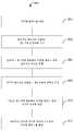
도 4는 예시적인 실시예에 따른 디지털 캔버스를 확장하는 방법을 도시하는 흐름도이다.
도 5a 및 도 5b는 예시적인 실시예에 따른 캔버스의 사용자 인터페이스 도면이다.
도 6은 예시적인 실시예에 따른 디지털 캔버스를 확장하는 방법을 도시하는 흐름도이다.
도 7a 및 도 7b는 예시적인 실시예에 따른 캔버스의 사용자 인터페이스 도면이다.
도 8은 예시적인 실시예에 따른 디지털 캔버스를 확장하는 방법을 도시하는 흐름도이다.
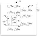
도 9a 및 도 9b는 예시적인 실시예에 따른 캔버스의 사용자 인터페이스 도면이다.
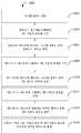
도 10은 예시적인 실시예에 따른 디지털 캔버스를 확장하는 방법을 도시하는 흐름도이다.
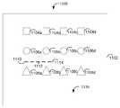
도 11a 및 도 11b는 예시적인 실시예에 따른 캔버스의 사용자 인터페이스 도면이다.
도 12a는 예시적인 실시예에 따른 디지털 캔버스를 확장하는 시스템을 예시하는 도면이다.
도 12b는 예시적인 실시예에 따른 방사선 강도 신호를 예시한다.
도 13은 스타일러스의 실시예를 예시한다.
도 14는 방사선 차단 요소가 도 12a의 시스템의 광학 평면을 차단하는 것을 예시한다.Now, a preferred embodiment of the present invention will be described in detail with reference to the drawings.
Fig. 1 is a diagram of a canvas and a user interface having a plurality of shapes according to an exemplary embodiment.
Fig. 2 is a system diagram of a display device according to an exemplary embodiment.
3A and 3B are diagrams of a user interface of a canvas according to an exemplary embodiment.
Fig. 4 is a flow chart showing a method of expanding a digital canvas according to an exemplary embodiment.
5A and 5B are diagrams of a user interface of a canvas according to an exemplary embodiment.
Fig. 6 is a flow chart showing a method of expanding a digital canvas according to an exemplary embodiment.
7A and 7B are diagrams of a user interface of a canvas according to an exemplary embodiment.
Fig. 8 is a flow chart showing a method of expanding a digital canvas according to an exemplary embodiment.
9A and 9B are diagrams of a user interface of a canvas according to an exemplary embodiment.
Fig. 10 is a flow chart showing a method of expanding a digital canvas according to an exemplary embodiment.
11A and 11B are diagrams of a user interface of a canvas according to an exemplary embodiment.
Fig. 12A is a diagram illustrating a system for expanding a digital canvas according to an exemplary embodiment.
12B illustrates a radiation intensity signal according to an exemplary embodiment.
13 illustrates an embodiment of a stylus.
14 illustrates the radiation blocking element blocking the optical plane of the system of FIG. 12A.
본 명세서에 설명된 다양한 실시예들은 일반적으로 캔버스 확장을 위한 방법들(및 방법들을 구현하도록 구성된 연관된 시스템들)에 관련한 것이다.The various embodiments described herein generally relate to methods for canvas extension (and associated systems configured to implement the methods).
드로잉 애플리케이션들은 일반적으로 사용자의 작업을 표현하기 위해 디지털 캔버스를 사용할 수 있다. 본 명세서에 개시된 캔버스 확장 시스템들 및 방법들은 사용자들이, 교육 목적을 위해, 예컨대, 미술반에서, 각각이 드로잉 애플리케이션을 갖는 디스플레이 디바이스를 구비하는 복수의 사용자들 사이의 협업 작업을 위해, 드로잉할 수 있게 해주는 데 사용될 수 있다. 드로잉 애플리케이션들은 비트맵 방식 드로잉 또는 벡터 드로잉 애플리케이션들을 지칭할 수 있다.Drawing applications can generally use a digital canvas to represent the user's work. The canvas expansion systems and methods disclosed herein allow users to draw for educational purposes, for example, in an art class, for collaborative work between a plurality of users each having a display device having a drawing application. Can be used to do. Drawing applications may refer to bitmapped drawing or vector drawing applications.
본 명세서에 설명된 바와 같은 드로잉 애플리케이션은 복수의 상이한 유형의 입력을 갖는 다양한 상이한 디스플레이 디바이스들에서 실행될 수 있다. 예를 들어, 디스플레이 디바이스는 애플 iPhone 또는 iPad, 안드로이드 디바이스, 데스크톱 컴퓨터, 랩톱 컴퓨터, 또는 텔레비전에 접속된 게임 콘솔과 같은 모바일 디바이스일 수 있다. 정전식 LCD 터치 스크린 등, 마우스, 키보드, 트랙패드, 또는 임의의 다른 입력 디바이스를 포함하는 다양한 상이한 입력 디바이스들이 드로잉 앱과 함께 사용될 수 있다. 스크린 및 입력 디바이스는 예를 들어 정전식 터치 디스플레이와 조합하여 제공될 수 있다. 본 명세서에서 사용될 수 있는 표면 터치 감지 시스템들 및 방법들에 대한 추가적인 설명은 2013년 3월 3일자로 출원된 미국 특허 제9,582,116호, "Systems and methods for sensing and tracking radiation blocking objects on a surface", 2013년 8월 27일에 출원된 미국 특허 제9,453,726호 "Systems and methods for sensing and tracking radiation blocking objects on a surface", 2012년 12월 2일자로 출원된 미국 특허 제9,395,185호, "Modular position sensing systems and methods", 2011년 12월 16일자로 출원된 미국 특허 제8,969,822호 "Two-dimensional and three-dimensional position sensing systems and sensors therefor", 2012년 12월 2일자로 출원된 미국 특허 제9,395,185호, "Modular position sensing systems and methods", 2011년 12월 16일자로 출원된 미국 특허 번호 제8,969,769호 "Two-dimensional position sensing systems and sensors therefor", 2013년 3월 25일자로 출원된, 미국 특허 제8,928,873호 "Sensors, systems and methods for position sensing", 및 2011년 3월 18일자로 출원된 미국 특허 제8,405,824호 "Sensors, systems and methods for position sensing"에서 찾을 수 있다.A drawing application as described herein can be run on a variety of different display devices having a plurality of different types of inputs. For example, the display device may be a mobile device such as an Apple iPhone or iPad, an Android device, a desktop computer, a laptop computer, or a game console connected to a television. A variety of different input devices can be used with the drawing app, including a mouse, keyboard, trackpad, or any other input device, such as a capacitive LCD touch screen. The screen and input device can be provided, for example, in combination with a capacitive touch display. Further description of surface touch sensing systems and methods that can be used in the present specification can be found in U.S. Patent No. 9,582,116, filed March 3, 2013, "Systems and methods for sensing and tracking radiation blocking objects on a surface", US Patent No. 9,453,726 filed on August 27, 2013 "Systems and methods for sensing and tracking radiation blocking objects on a surface", US Patent No. 9,395,185 filed on December 2, 2012, "Modular position sensing systems and methods", US Patent No. 8,969,822 filed December 16, 2011 "Two-dimensional and three-dimensional position sensing systems and sensors therefor", US Patent No. 9,395,185 filed December 2, 2012, " Modular position sensing systems and methods", US Patent No. 8,969,769 filed December 16, 2011 "Two-dimensional position sensing systems and sensors therefor", US Patent No. 8,928,873 filed March 25, 2013 "Sensors, systems and methods for position sensing", and U.S. Patent No. 8,405,824, filed March 18, 2011, "Sensors, systems and methods for position sensing".
먼저, 복수의 형상 및 디지털 캔버스(102)를 도시하는 사용자 인터페이스(100)를 예시하는 도 1을 참조한다. 복수의 정사각형(104a, 104b, 104c 및 104d)이 캔버스 상에 도시되어 있다. 복수의 원(106a, 106b, 106c 및 106d)이 캔버스 상에 도시되어 있다. 복수의 삼각형(108a, 108b, 108c 및 108d)이 캔버스 상에 도시되어 있다. 사용자는 터치 스크린 또는 트랙 패드와 같은 터치 인터페이스를 사용하여 디지털 캔버스와 상호작용할 수 있거나, 마우스, 트랙볼, 또는 트랙패드와 같은 포인팅 디바이스를 사용할 수 있다. 터치 인터페이스를 사용하는 상호작용은 사용자의 손가락 또는 손가락들, 스타일러스, 또는 다른 보조 디바이스로 행해질 수 있다.First, reference is made to FIG. 1 illustrating a
일 실시예에 따른 디스플레이 디바이스 시스템(200)을 도시하는 도 2를 참조한다. 디스플레이 디바이스 시스템은 프로세서(202), 메모리(204), 비디오 인터페이스(206), 입력 인터페이스(210), 네트워크 인터페이스(214) 및 디스플레이(212)를 포함한다. 디스플레이(212)는 LCD, CRT, LED, OLED, 또는 플라즈마 스크린일 수 있다. 비디오 인터페이스(206)는 디스플레이(212)를 디스플레이 디바이스에 연결할 수 있고, 캔버스를 렌더링하도록 동작가능할 수 있다. 스크린(202) 및 입력 디바이스(208)는, 예를 들어, 참가자 손가락 또는 손가락들을 사용하는 정전식 터치 디스플레이 시스템을 사용하여, 그리고, 선택적으로 스타일러스를 사용하여 조합될 수 있다. 프로세서(202)는 임의의 알려진 프로세서, 예를 들어, IntelTM x86 또는 x86_64 아키텍처, ARMTM 마이크로프로세서, QualcommTM SnapdragonTM, 또는 가상화 환경에 의해 제공되는 프로세서를 사용하는 프로세서일 수 있다. 입력 인터페이스(210)는 마우스, 키보드, 제어기, 터치 스크린, 눈 초점 추적 디바이스, 트랙패드, 모션 감지 가속도계, 트랙볼, 마이크로폰 등을 변위 디바이스에 접속할 수 있다. 디스플레이 디바이스(200)는 모바일 폰, 태블릿 디바이스, 데스크톱 컴퓨터, 랩톱 컴퓨터, GoogleTM Glass와 같은 착용식 컴퓨터, SonyTM Playstation VRTM 또는 OculusTM RiftTM 와 같은 가상 현실 디바이스, 또는 임의의 다른 적절한 디바이스와 같은 모바일 디바이스일 수 있다. 메모리(204)는 휘발성 또는 비휘발성 저장소 또는 이 둘의 조합일 수 있다. 네트워크(104)는 TCP/IP 교환 네트워크, LAN 네트워크, WAN 네트워크, 또는 인터넷일 수 있다. 디스플레이 디바이스는 네트워크에 접속될 수 있고, 접속은 이더넷, 파이어와이어, 블루투스, 무선(802.11 등), 모뎀, 또는 디지털 가입자 회선 접속과 같은 접속 기술을 사용하여 네트워크 인터페이스(214)에 의해 제공될 수 있다.Reference is made to FIG. 2 illustrating a
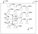
사용자 인터페이스(300)를 예시하는 도 3a를 참조한다. 사용자 인터페이스(300)는 복수의 정사각형들(304a, 304b, 304c 및 304d), 복수의 원들(306a, 306b, 306c 및 306d), 및 복수의 삼각형들(308a, 208b, 308c 및 308d)을 포함하는, 복수의 객체들이 그 위에 디스플레이되어 있는 캔버스 표면(316)을 갖는 뷰포트(302)를 갖는다. 사용자는 슬라이스 라인에 대응하는 사용자 입력을 입력함으로써 사용자 인터페이스(300)와 상호작용한다. 사용자 입력은 일련의 지점들을 포함할 수 있다. 캔버스(316) 상에서, 사용자는 시작점(310) 및 종료점(314)을 포함하는 일련의 지점들을 나타내는 슬라이스 라인(312)을 입력한다. 캔버스(316)는 뷰포트(302)보다 클 수 있고, 사용자는 스크롤할 수 있다.See FIG. 3A illustrating a
캔버스 확장들(354 및 356)을 예시하는 도 3b를 참조한다. 캔버스 확장(354)은 일반적으로 시작점(310), 종료점(314)을 포함하는 직사각형으로서 정의되며, 직사각형 폭은 시프트 라인(358)의 길이이다. 유사하게, 제2 캔버스 확장(356)은 일반적으로 시작점(310), 종료점(314)을 포함하는 직사각형으로서 정의되며, 직사각형 폭은 시프트 라인(360)의 길이이다. 이 실시예에서, 시프트 라인들(358 및 360)은 일정한 길이이고, 사용자는 단순히 슬라이스 라인(312) 사용자 입력에 의해 캔버스(316)를 확장할 수 있다.See FIG. 3B, which illustrates
시프트가 적용되고 캔버스가 354 및 356에서 확장될 때, 정사각형들(304a 및 304b) 및 원들(306a 및 306b)은 또한 캔버스 확장(354)에 따라 병진한다는 점에 유의한다. 삼각형들(308a 및 308b)은 캔버스 확장(356)에 따라 객체들(304a, 304b, 306a 및 306b)과 반대 방향으로 병진한다. 전술한 바와 같이, 캔버스(316)는 뷰포트(352)보다 클 수 있고, 캔버스의 확장은 뷰포트(352) 내부로부터 뷰포트 외부로 영역을 연장할 수 있다. 슬라이스 라인(312)은 일반적으로 수평인 것으로 도시되지만, 임의의 크기 또는 방향일 수 있다. 정사각형들(304c, 304d), 원들(306c, 306d) 및 삼각형들(308c 및 308d)을 포함하는 객체들은 캔버스 확장들(358 및 360)에 기초하여 병진하지 않고 유지된다.Note that when a shift is applied and the canvas expands at 354 and 356, the
도 3a 및 도 3b에 도시된 캔버스 확장 방법에 대한 흐름도를 예시하는 도 4를 참조한다. 402에서, 사용자가 다양한 상이한 입력 방법들을 사용하여 상호작용할 수 있는 디지털 캔버스가 제공된다. 디지털 캔버스는 입력 디바이스를 디스플레이 디바이스와 조합할 수 있다. 캔버스는 디스플레이 디바이스 상의 뷰포트를 통해 보여질 수 있지만, 캔버스는 뷰포트 자체보다 클 수 있다. 캔버스의 확장은 또한 캔버스의 형상을 변화시킬 수 있고, 뷰포트 내부의 캔버스의 일부를 뷰포트 외부로 병진시킬 수 있다.Reference is made to FIG. 4 illustrating a flowchart of a method for expanding the canvas illustrated in FIGS. 3A and 3B. At 402, a digital canvas is provided through which a user can interact using a variety of different input methods. The digital canvas can combine an input device with a display device. The canvas can be viewed through the viewport on the display device, but the canvas can be larger than the viewport itself. Expanding the canvas can also change the shape of the canvas and translate a portion of the canvas inside the viewport to the outside of the viewport.
404에서, 사용자는 사용자 입력 디바이스를 사용하여 디스플레이 디바이스와 상호작용한다. 상호작용은 드로잉 애플리케이션에 의해 인식되는 슬라이스 제스처일 수 있다. 제1 사용자 입력은 슬라이스 제스처일 수 있고, 스와이프와 같은 터치 표면 상의 모션일 수 있거나, 마우스와 같은 포인팅 디바이스로부터의 제스처일 수 있다. 슬라이스 제스처가 포인팅 디바이스를 사용하여 이루어지는 경우, 시작점은 마우스 버튼 다운 이벤트에 의해 결정될 수 있고 종료점은 마우스 버튼 업 이벤트로부터 결정될 수 있다. 제1 사용자 입력은 제1 사용자 입력과 연관된 일련의 지점들일 수 있다.At 404, the user interacts with the display device using the user input device. The interaction can be a slice gesture recognized by the drawing application. The first user input may be a slice gesture, may be a motion on a touch surface such as a swipe, or may be a gesture from a pointing device such as a mouse. When the slice gesture is made using a pointing device, the starting point can be determined by a mouse button down event and the end point can be determined from the mouse button up event. The first user input may be a series of points associated with the first user input.
406에서, 슬라이스 라인이 슬라이스 제스처로부터 캔버스 상에서 결정된다. 제1 사용자 입력은 시작점 및 종료점을 포함하는 뷰포트 내의 일련의 지점들일 수 있고, 이들 지점들은 슬라이스 라인을 기술하도록 동작할 수 있다. 슬라이스 라인은 일반적으로 직선이거나 만곡될 수 있다.At 406, a slice line is determined on the canvas from the slice gesture. The first user input may be a series of points in the viewport including a start point and an end point, and these points may operate to describe a slice line. The slice line can generally be straight or curved.
408에서, 캔버스는 슬라이스 라인의 지점에서 슬라이스 라인에 대해 직교 방향으로 고정된 거리만큼 확장된다. 슬라이스 라인에 대한 직교 라인은 시프트 라인이라고 불릴 수 있다. 슬라이스 라인이 만곡되는 경우, 시프트 라인은 일련의 지점들의 평균화된 라인 또는 선형 회귀에 기초할 수 있다. 고정된 거리는 드로잉 애플리케이션에서 구성가능할 수 있다.At 408, the canvas is extended by a fixed distance in a direction orthogonal to the slice line at the point of the slice line. The orthogonal line to the slice line may be referred to as a shift line. If the slice line is curved, the shift line may be based on an averaged line or linear regression of a series of points. The fixed distance may be configurable in the drawing application.
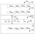
도 5a 및 도 5b를 참조하면, 디지털 캔버스(520)를 확장하는 제2 방법에 관여하는 사용자 인터페이스가 예시되어 있다. 사용자는 시작점(510) 및 종료점(514)을 포함하는 슬라이스 라인(512)에 대응하는 슬라이스 제스처를 입력한다. 디지털 캔버스를 확장하는 이러한 제2 방법에서, 라인 투영(516)은 슬라이스 라인(512)의 회귀 라인의 투영에 기초하여 시작점(510)으로부터 연장된다. 라인 투영(518)은 슬라이스 라인(512)의 회귀 라인의 투영에 기초하여 종료점(514)으로부터 연장된다.5A and 5B, a user interface involved in a second method of expanding the
도 5b는 슬라이스 라인(512)에 기초한 캔버스 확장들(562 및 564)을 도시한다. 본 방법의 이 실시예에서, 라인 투영들(516 및 518)은 뷰포트(552)의 에지로의 캔버스 확장들(562 및 564)을 정의한다. 라인 투영(516), 슬라이스 라인(512), 라인 투영(518) 및 시프트 라인(574)은 캔버스 확장(562)의 제1 직사각형 영역을 정의한다. 라인 투영(516), 슬라이스 라인(512), 라인 투영(518) 및 시프트 라인(574)은 캔버스 확장(564)의 제2 직사각형 영역을 정의한다. 제1 직사각형 캔버스 확장은 라인 투영(516), 슬라이스 라인(512), 라인 투영(518), 뷰포트 에지들, 및 라인(570)에 의해 경계 설정된다. 라인(570)은 시프트 라인(574)에 직교한다. 이 예에서 시프트 라인들(574 및 576)은 고정 길이이지만, 아래에 설명되는 바와 같이, 이들은 사용자에 의해 제공되는 시프트 제스처에 의해 정의될 수 있다. 다른 실시예에서, 라인 투영들(516 및 518)은 대신에 캔버스(520) 자체의 에지까지 연장될 수 있고, 캔버스 투영은 유사하게 전체 캔버스를 가로질러 연장될 수 있다.5B shows
정사각형들(504a, 504b, 504c, 504d), 원들(506a, 506b, 506c, 506d)을 포함하는 객체들은 캔버스가 캔버스 확장(562)에 기초하여 확장됨에 따라 뷰포트에 대해 상향 병진한다. 유사하게, 삼각형들(508a, 508b, 508c, 508d)을 포함하는 객체들은 캔버스가 캔버스 확장(564)에 기초하여 확장됨에 따라 뷰포트에 대해 하향 병진한다.
도 6을 참조하면, 도 5a 및 도 5b에 도시된 캔버스 확장 방법에 대한 흐름도(600)가 예시되어 있다. 602에서, 사용자가 다양한 상이한 입력 방법들을 사용하여 상호작용할 수 있는 디지털 캔버스가 제공된다. 디지털 캔버스는 입력 디바이스를 디스플레이 디바이스와 조합할 수 있다. 캔버스는 디스플레이 디바이스 상의 뷰포트를 통해 보여질 수 있지만, 캔버스는 뷰포트 자체보다 클 수 있다. 캔버스의 확장은 또한 캔버스의 형상을 변화시킬 수 있고, 뷰포트 내부의 캔버스의 일부를 뷰포트 외부로 병진시킬 수 있다.Referring to FIG. 6, a
604에서, 사용자는 사용자 입력 디바이스를 사용하여 디스플레이 디바이스와 상호작용한다. 제1 사용자 입력은 드로잉 애플리케이션에 의해 인식되는 슬라이스 제스처일 수 있다. 슬라이스 제스처는 스와이프와 같은 터치 표면 상의 모션이거나, 마우스와 같은 포인팅 디바이스로부터의 제스처일 수 있다. 슬라이스 제스처가 포인팅 디바이스를 사용하여 이루어지는 경우, 시작점은 마우스 버튼 다운 이벤트에 의해 결정될 수 있고 종료점은 마우스 버튼 업 이벤트로부터 결정될 수 있다. 제1 사용자 입력은 제스처와 연관된 일련의 지점들일 수 있다.At 604, the user interacts with the display device using the user input device. The first user input may be a slice gesture recognized by the drawing application. The slice gesture can be a motion on a touch surface, such as a swipe, or a gesture from a pointing device, such as a mouse. When the slice gesture is made using a pointing device, the starting point can be determined by a mouse button down event and the end point can be determined from the mouse button up event. The first user input may be a series of points associated with the gesture.
606에서, 제1 사용자 입력으로부터 캔버스 상에서 슬라이스 라인이 결정된다. 제1 사용자 입력은 시작점 및 종료점을 포함하는 뷰포트 내의 일련의 지점들일 수 있고, 이들 지점들은 슬라이스 라인을 기술하도록 동작할 수 있다. 슬라이스 라인은 일반적으로 직선이거나 만곡될 수 있다.At 606, a slice line is determined on the canvas from the first user input. The first user input may be a series of points in the viewport including a start point and an end point, and these points may operate to describe a slice line. The slice line can generally be straight or curved.
608에서, 슬라이스 라인의 제1 부분은 뷰포트의 에지를 향해 투영될 수 있다. 제1 부분은 슬라이스 라인의 시작점에서 시작하고, 슬라이스 라인 내의 지점들의 선형 회귀에 기초하여 라인을 따라 뷰포트의 에지를 향해 투영된다. 선택적으로, 슬라이스 라인의 제1 부분은 뷰포트의 에지 대신에 캔버스의 에지를 향해 투영될 수 있다.At 608, the first portion of the slice line may be projected toward the edge of the viewport. The first portion starts at the starting point of the slice line and is projected along the line toward the edge of the viewport based on a linear regression of the points within the slice line. Optionally, the first portion of the slice line may be projected towards the edge of the canvas instead of the edge of the viewport.
610에서, 슬라이스 라인의 제2 부분이 뷰포트의 에지를 향해 투영될 수 있다. 제2 부분은 슬라이스 라인의 종료점에서 시작하고, 슬라이스 라인 내의 지점들의 선형 회귀에 기초하여 라인을 따라 뷰포트의 에지를 향해 투영된다. 선택적으로, 슬라이스 라인의 제2 부분은 뷰포트의 에지 대신에 캔버스의 에지를 향해 투영될 수 있다.At 610, a second portion of the slice line may be projected toward the edge of the viewport. The second portion starts at the end of the slice line and is projected along the line toward the edge of the viewport based on a linear regression of points within the slice line. Optionally, the second portion of the slice line may be projected towards the edge of the canvas instead of the edge of the viewport.
612에서, 캔버스는 슬라이스 라인의 지점에서 슬라이스 라인에 대해 직교 방향으로 고정된 거리만큼 확장된다. 슬라이스 라인에 대한 직교 라인은 시프트 라인이라고 불릴 수 있다. 슬라이스 라인이 만곡되는 경우, 시프트 라인은 일련의 지점들의 평균화된 라인 또는 선형 회귀에 기초할 수 있다. 고정된 거리는 드로잉 애플리케이션에서 구성가능할 수 있다.At 612, the canvas is extended by a fixed distance in a direction orthogonal to the slice line at the point of the slice line. The orthogonal line to the slice line may be referred to as a shift line. If the slice line is curved, the shift line may be based on an averaged line or linear regression of a series of points. The fixed distance may be configurable in the drawing application.
선택적으로, 아래에 설명되는 바와 같이, 사용자는 시프트 제스처에 기초하여 시프트 라인을 입력할 수 있다.Optionally, as described below, the user may enter a shift line based on the shift gesture.
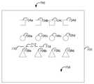
디지털 캔버스(716)를 확장하는 제3 방법에 관여하는 사용자 인터페이스를 예시하는 도 7a 및 도 7b를 참조한다. 사용자는 시작점(710) 및 종료점(714)을 포함하는 슬라이스 라인(712)에 대응하는 슬라이스 제스처를 입력한다. 디지털 캔버스를 확장하는 이 제3 방법에서, 슬라이스 제스처 후에, 사용자는 시프트 제스처를 사용할 수 있다. 시프트 라인(758)은 길이 및 방향이 시프트 제스처에 비례적으로 대응한다. 이러한 방식으로, 사용자는 절단한 다음 슬라이스 라인으로부터 새로운 캔버스를 밀거나 당기는 것에 의해 캔버스를 확장하는 것처럼 보일 수 있다.See FIGS. 7A and 7B illustrating a user interface involved in a third method of expanding the
도 7b에서, 캔버스 확장(754)은 슬라이스 라인에 의해 한 측면 상에 정의되고, 시프트 라인의 길이에 의해 폭이 정의되는 직사각형이다. 캔버스 확장(754)에 대해 직사각형이 도시되어 있지만, 캔버스 확장은 시프트 라인의 배향에 따라 평행사변형 또는 사다리꼴 형상일 수 있다는 것이 인식된다.In Fig. 7B, the
슬라이스 제스처가 행해지고 나면, 사용자 인터페이스는 뷰포트(752)에 슬라이스 라인을 디스플레이할 수 있다. 디스플레이되고 나면, 사용자는 다른 제스처를 사용하여 캔버스를 확장할 수 있다. 사용자가 시프트 제스처를 완료하기 전에 캔버스 확장에 관련한 시각적 피드백을 수신할 수 있도록, 확장이 애니메이션화될 수 있다.After the slice gesture is made, the user interface can display the slice line in the
시프트가 적용되고 캔버스가 754에서 확장될 때, 정사각형들(704a 및 704b) 및 원들(706a 및 706b)도 역시 캔버스 확장(754)에 따라 병진한다는 점에 유의한다. 전술한 바와 같이, 캔버스(716)는 뷰포트(752)보다 클 수 있고, 캔버스의 확장은 뷰포트(752) 내부로부터 뷰포트 외부로 영역을 연장할 수 있다. 슬라이스 라인(712)은 일반적으로 수평인 것으로 도시되지만, 임의의 크기 또는 방향일 수 있다. 정사각형들(704c, 704d), 원들(706c, 706d), 및 삼각형들(708a, 708b, 708c, 및 708d)을 포함하는 객체들은 캔버스 확장(754)에 따라 병진하지 않고 유지된다.Note that when a shift is applied and the canvas expands at 754, the
도 7a 내지 도 7b에 도시된 캔버스 확장 방법에 대한 흐름도를 예시하는 도 8을 참조한다. 802에서, 사용자가 다양한 상이한 입력 방법들을 사용하여 상호작용할 수 있는 디지털 캔버스가 제공된다. 디지털 캔버스는 입력 디바이스를 디스플레이 디바이스와 조합할 수 있다. 캔버스는 디스플레이 디바이스 상의 뷰포트를 통해 보여질 수 있지만, 캔버스는 뷰포트 자체보다 클 수 있다. 캔버스의 확장은 또한 캔버스의 형상을 변화시킬 수 있고, 뷰포트 내부의 캔버스의 일부를 뷰포트 외부로 병진시킬 수 있다.Reference is made to FIG. 8 illustrating a flowchart of the method for expanding the canvas illustrated in FIGS. 7A to 7B. At 802, a digital canvas is provided through which a user can interact using a variety of different input methods. The digital canvas can combine an input device with a display device. The canvas can be viewed through the viewport on the display device, but the canvas can be larger than the viewport itself. Expanding the canvas can also change the shape of the canvas and translate a portion of the canvas inside the viewport to the outside of the viewport.
804에서, 사용자는 사용자 입력 디바이스를 사용하여 디스플레이 디바이스와 상호작용한다. 제1 사용자 입력은 드로잉 애플리케이션에 의해 인식되는 슬라이스 제스처일 수 있다. 슬라이스 제스처는 스와이프와 같은 터치 표면 상의 모션이거나, 마우스와 같은 포인팅 디바이스로부터의 제스처일 수 있다. 슬라이스 제스처가 포인팅 디바이스를 사용하여 이루어지는 경우, 시작점은 마우스 버튼 다운 이벤트에 의해 결정될 수 있고 종료점은 마우스 버튼 업 이벤트로부터 결정될 수 있다. 제1 사용자 입력은 제스처와 연관된 일련의 지점들일 수 있다.At 804, the user interacts with the display device using the user input device. The first user input may be a slice gesture recognized by the drawing application. The slice gesture can be a motion on a touch surface, such as a swipe, or a gesture from a pointing device, such as a mouse. When the slice gesture is made using a pointing device, the starting point can be determined by a mouse button down event and the end point can be determined from the mouse button up event. The first user input may be a series of points associated with the gesture.
806에서, 슬라이스 라인은 제1 사용자 입력으로부터 캔버스 상에서 결정될 수 있다. 제1 사용자 입력은 시작점 및 종료점을 포함하는 뷰포트 내의 일련의 지점들일 수 있고, 이들 지점들은 슬라이스 라인을 기술하도록 동작할 수 있다. 슬라이스 라인은 일반적으로 직선이거나 만곡될 수 있다.At 806, the slice line may be determined on the canvas from the first user input. The first user input may be a series of points in the viewport including a start point and an end point, and these points may operate to describe a slice line. The slice line can generally be straight or curved.
808에서, 사용자는 사용자 입력 디바이스를 사용하여 디스플레이 디바이스와 상호작용한다. 제2 사용자 입력은 드로잉 애플리케이션에 의해 인식되는 시프트 제스처일 수 있다. 시프트 제스처는 스와이프 또는 확장된 사용자 터치 이벤트와 같은 터치 표면 상의 모션일 수 있거나, 마우스와 같은 포인팅 디바이스로부터의 제스처일 수 있다. 슬라이스 제스처가 포인팅 디바이스를 사용하여 이루어지는 경우, 시작점은 마우스 버튼 다운 이벤트에 의해 결정될 수 있고 종료점은 마우스 버튼 업 이벤트로부터 결정될 수 있다. 제2 사용자 입력은 제스처와 연관된 일련의 지점들일 수 있다.At 808, the user interacts with the display device using the user input device. The second user input may be a shift gesture recognized by the drawing application. The shift gesture may be a motion on the touch surface, such as a swipe or extended user touch event, or it may be a gesture from a pointing device such as a mouse. When the slice gesture is made using a pointing device, the starting point can be determined by a mouse button down event and the end point can be determined from the mouse button up event. The second user input may be a series of points associated with the gesture.
810에서, 시프트 라인은 제2 사용자 입력으로부터의 캔버스 상에서 결정될 수 있다. 제2 사용자 입력은 시작점 및 종료점을 포함하는 뷰포트 내의 일련의 지점들일 수 있고, 이들 지점들은 시프트 라인을 기술하도록 동작할 수 있다. 시프트 라인의 결정은 제2 사용자 입력과 연관된 일련의 지점들의 선형 회귀를 수반할 수 있다. 이와 같이, 시프트 라인은 일반적으로 직선일 수 있다.At 810, a shift line may be determined on the canvas from the second user input. The second user input may be a series of points in the viewport including a start point and an end point, and these points may operate to describe the shift line. Determination of the shift line may involve a linear regression of the series of points associated with the second user input. As such, the shift line may be generally straight.
812에서, 캔버스는 슬라이스 라인의 길이와 대체로 동일한 길이 및 시프트 라인의 길이와 대체로 동일한 폭을 갖는 캔버스 확장에 의해 슬라이스 라인을 따라 확장된다. 따라서, 캔버스 확장의 크기는 시프트 제스처에 기초하여 사용자에 의해 선택될 수 있다. 캔버스는 제2 입력 제스처 동안 동적으로 업데이트될 수 있고, 따라서 사용자는 터치 이벤트 동안 캔버스 확장으로부터 얻어지는 캔버스를 미리 볼 수 있다.At 812, the canvas is extended along the slice line by a canvas extension having a length approximately equal to the length of the slice line and a width approximately equal to the length of the shift line. Thus, the size of the canvas extension can be selected by the user based on the shift gesture. The canvas can be dynamically updated during the second input gesture, so the user can preview the canvas resulting from the canvas extension during the touch event.
이제 디지털 캔버스(916)를 확장하는 제4 방법에 관여하는 사용자 인터페이스를 예시하는 도 9a 및 도 9b를 참조한다. 사용자는 시작점(910) 및 종료점(914)을 포함하는 슬라이스 라인(912)에 대응하는 슬라이스 제스처를 입력한다. 디지털 캔버스를 확장하는 이 제4 방법에서, 슬라이스 제스처 후에, 사용자는 터치 인터페이스 상에서의 2개의 손가락을 사용하는 핀치 제스처와 같은 한 쌍의 시프트 제스처를 사용할 수 있다. 핀치 제스처는 실질적으로 동시에 양쪽 시프트 제스처들에 대해 입력 디바이스로부터 입력을 수신하는 것을 수반할 수 있고, 따라서 제1 시프트 라인(958) 및 제2 시프트 라인(962)의 동시 결정을 요구할 수 있다. 제1 시프트 라인(958)은 길이 및 방향이 핀치 제스처의 단일 손가락 입력에 비례적으로 대응할 수 있다. 제2 시프트 라인(962)은 길이 및 방향이 핀치 제스처의 단일 손가락 입력에 비례적으로 대응할 수 있다. 제2 시프트 라인(962)은 방향이 제1 시프트 라인(958)의 방향에 대체로 반대일 수 있다. 이러한 방식으로, 사용자는 슬라이스 라인으로부터 새로운 캔버스를 절단한 다음 핀칭함으로써 캔버스를 확장하는 것으로 보일 수 있다.Reference is now made to FIGS. 9A and 9B illustrating a user interface involved in a fourth method of expanding the
도 9b에서, 캔버스 확장(952)은 한 측면 상에서 슬라이스 라인(912)에 의해 정의되고, 폭이 제1 시프트 라인(958)의 길이에 의해 정의되는 직사각형일 수 있다. 캔버스 확장(956)은 한 측면이 슬라이스 라인(912)에 의해 정의되고 폭이 제2 시프트 라인(962)의 길이에 의해 정의되는 직사각형일 수 있다. 캔버스 확장들(952, 956)에 대해 직사각형이 도시되어 있지만, 캔버스 확장이 시프트 라인의 배향에 따라 평행사변형 또는 사다리꼴 형상일 수 있다는 것이 인식된다.In FIG. 9B, the
슬라이스 제스처가 행해지고 나면, 사용자 인터페이스는 뷰포트(952)에 슬라이스 라인(912)을 디스플레이할 수 있다. 디스플레이되고 나면, 사용자는 다른 제스처를 사용하여 캔버스를 확장할 수 있다. 사용자가 시프트 제스처들을 완료하기 전에 캔버스 확장들에 대한 시각적 피드백을 수신할 수 있도록, 확장이 애니메이션화될 수 있다.After the slice gesture is performed, the user interface can display the
시프트가 적용되고 캔버스가 952 및 956에서 확장될 때, 정사각형들(904a 및 904b) 및 원들(906a 및 906b)은 캔버스 확장(952)에 따라 병진할 수 있다는 점에 유의한다. 유사하게, 삼각형들(908a 및 908b)은 또한 캔버스 확장(956)에 따라 병진할 수 있다. 전술한 바와 같이, 캔버스(916)는 뷰포트(952)보다 클 수 있고, 캔버스의 확장은 뷰포트(952) 내부로부터 뷰포트 외부로 영역을 연장할 수 있다. 슬라이스 라인(912)은 일반적으로 수평인 것으로 도시되지만, 임의의 크기 또는 방향일 수 있다. 정사각형들(904c, 904d), 원들(906c, 906d) 및 삼각형들(908c, 및 908d)을 포함하는 객체들은 캔버스 확장들(952 및 956)에 따라 병진하지 않고 유지된다.Note that when a shift is applied and the canvas expands at 952 and 956, the squares 904a and 904b and
도 9a 및 도 9b에 도시된 캔버스 확장 방법에 대한 흐름도를 예시하는 도 10을 참조한다. 1002에서, 사용자가 다양한 상이한 입력 방법들을 사용하여 상호작용할 수 있는 디지털 캔버스가 제공된다. 디지털 캔버스는 입력 디바이스를 디스플레이 디바이스와 조합할 수 있다. 캔버스는 디스플레이 디바이스 상의 뷰포트를 통해 보여질 수 있지만, 캔버스는 뷰포트 자체보다 클 수 있다. 캔버스의 확장은 또한 캔버스의 형상을 변화시킬 수 있고, 뷰포트 내부의 캔버스의 일부를 뷰포트 외부로 병진시킬 수 있다.Reference is made to FIG. 10 illustrating a flowchart of a method for expanding the canvas illustrated in FIGS. 9A and 9B. At 1002, a digital canvas is provided through which a user can interact using a variety of different input methods. The digital canvas can combine an input device with a display device. The canvas can be viewed through the viewport on the display device, but the canvas can be larger than the viewport itself. Expanding the canvas can also change the shape of the canvas and translate a portion of the canvas inside the viewport to the outside of the viewport.
1004에서, 사용자는 사용자 입력 디바이스를 사용하여 디스플레이 디바이스와 상호작용한다. 제1 사용자 입력은 드로잉 애플리케이션에 의해 인식되는 슬라이스 제스처일 수 있다. 슬라이스 제스처는 스와이프와 같은 터치 표면 상의 모션이거나, 마우스와 같은 포인팅 디바이스로부터의 제스처일 수 있다. 슬라이스 제스처가 포인팅 디바이스를 사용하여 이루어지는 경우, 시작점은 마우스 버튼 다운 이벤트에 의해 결정될 수 있고 종료점은 마우스 버튼 업 이벤트로부터 결정될 수 있다. 제1 사용자 입력은 제스처와 연관된 일련의 지점들일 수 있다.At 1004, the user interacts with the display device using the user input device. The first user input may be a slice gesture recognized by the drawing application. The slice gesture can be a motion on a touch surface, such as a swipe, or a gesture from a pointing device, such as a mouse. When the slice gesture is made using a pointing device, the starting point can be determined by a mouse button down event and the end point can be determined from the mouse button up event. The first user input may be a series of points associated with the gesture.
1006에서, 슬라이스 라인은 제1 사용자 입력으로부터 캔버스 상에서 결정될 수 있다. 제1 사용자 입력은 시작점 및 종료점을 포함하는 뷰포트 내의 일련의 지점들일 수 있고, 이들 지점들은 슬라이스 라인을 기술하도록 동작할 수 있다. 슬라이스 라인은 일반적으로 직선이거나 만곡될 수 있다.At 1006, the slice line may be determined on the canvas from the first user input. The first user input may be a series of points in the viewport including a start point and an end point, and these points may operate to describe a slice line. The slice line can generally be straight or curved.
1008에서, 사용자는 사용자 입력 디바이스를 사용하여 디스플레이 디바이스와 상호작용한다. 제2 사용자 입력은 드로잉 애플리케이션에 의해 인식되는 제1 시프트 제스처일 수 있다. 제1 시프트 제스처는 스와이프 또는 확장된 사용자 터치 이벤트와 같은 터치 표면 상의 모션일 수 있거나, 마우스와 같은 포인팅 디바이스로부터의 제스처일 수 있다. 제1 슬라이스 제스처가 포인팅 디바이스를 사용하여 이루어지는 경우, 시작점은 마우스 버튼 다운 이벤트에 의해 결정될 수 있고 종료점은 마우스 버튼 업 이벤트로부터 결정될 수 있다. 제2 사용자 입력은 제스처와 연관된 일련의 지점들일 수 있다.At 1008, the user interacts with the display device using the user input device. The second user input may be a first shift gesture recognized by the drawing application. The first shift gesture may be a motion on the touch surface, such as a swipe or an extended user touch event, or may be a gesture from a pointing device such as a mouse. When the first slice gesture is made using the pointing device, the start point may be determined by a mouse button down event and the end point may be determined from the mouse button up event. The second user input may be a series of points associated with the gesture.
1010에서, 제1 시프트 라인은 제2 사용자 입력으로부터의 캔버스 상에서 결정될 수 있다. 제2 사용자 입력은 시작점 및 종료점을 포함하는 뷰포트 내의 일련의 지점들일 수 있고, 이들 지점들은 제1 시프트 라인을 기술하도록 동작할 수 있다. 제1 시프트 라인의 결정은 제2 사용자 입력과 연관된 일련의 지점들의 선형 회귀를 수반할 수 있다. 이와 같이, 제1 시프트 라인은 일반적으로 직선일 수 있다.At 1010, a first shift line may be determined on the canvas from a second user input. The second user input may be a series of points in the viewport including a start point and an end point, and these points may operate to describe the first shift line. Determination of the first shift line may involve a linear regression of the series of points associated with the second user input. As such, the first shift line may be generally straight.
1012에서, 사용자는 사용자 입력 디바이스를 사용하여 디스플레이 디바이스와 상호작용한다. 제3 사용자 입력은 드로잉 애플리케이션에 의해 인식되는 제2 시프트 제스처일 수 있다. 제2 시프트 제스처는 스와이프 또는 확장된 사용자 터치 이벤트와 같은 터치 표면 상의 모션일 수 있거나, 마우스와 같은 포인팅 디바이스로부터의 제스처일 수 있다. 제2 슬라이스 제스처가 포인팅 디바이스를 사용하여 이루어지는 경우, 시작점은 마우스 버튼 다운 이벤트에 의해 결정될 수 있고 종료점은 마우스 버튼 업 이벤트로부터 결정될 수 있다. 제3 사용자 입력은 제스처와 연관된 일련의 지점들일 수 있다.At 1012, the user interacts with the display device using the user input device. The third user input may be a second shift gesture recognized by the drawing application. The second shift gesture may be a motion on the touch surface, such as a swipe or an extended user touch event, or may be a gesture from a pointing device such as a mouse. When the second slice gesture is made using the pointing device, the start point may be determined by a mouse button down event and the end point may be determined from the mouse button up event. The third user input may be a series of points associated with the gesture.
1014에서, 제2 시프트 라인은 제3 사용자 입력으로부터의 캔버스 상에서 결정될 수 있다. 제3 사용자 입력은 시작점 및 종료점을 포함하는 뷰포트 내의 일련의 지점들일 수 있고, 이들 지점들은 제2 시프트 라인을 기술하도록 동작할 수 있다. 제2 시프트 라인의 결정은 제3 사용자 입력과 연관된 일련의 지점들의 선형 회귀를 수반할 수 있다. 이와 같이, 제2 시프트 라인은 일반적으로 직선일 수 있다.At 1014, a second shift line may be determined on the canvas from a third user input. The third user input may be a series of points in the viewport including a start point and an end point, and these points may operate to describe a second shift line. Determination of the second shift line may involve a linear regression of the series of points associated with the third user input. As such, the second shift line may be generally straight.
선택적으로, 터치 인터페이스의 경우, 제2 사용자 입력 및 제3 사용자 입력은 실질적으로 동시에, 즉, 사용자가 2개의 손가락을 터치 표면 상에 배치한 다음 이들을 떨어지게 이동시키는 "핀치" 제스처에서 발생할 수 있다. 따라서, 도 10에서, 일부 단계들은 사용자가 동시에 제1 시프트 제스처 및 제2 시프트 제스처를 행할 수 있게 하도록 동시에 기능할 수 있다.Optionally, in the case of a touch interface, the second user input and the third user input may occur substantially simultaneously, ie in a "pinch" gesture in which the user places two fingers on the touch surface and then moves them apart. Thus, in FIG. 10, some steps may function simultaneously to enable the user to perform the first shift gesture and the second shift gesture at the same time.
1016에서, 캔버스는 슬라이스 라인의 길이와 대체로 동일한 길이 및 제1 시프트 라인의 길이와 대체로 동일한 폭을 갖는 제1 캔버스 확장에 의해 슬라이스 라인을 따라 확장될 수 있다. 캔버스는 또한 슬라이스 라인의 길이와 대체로 동일한 길이 및 제2 시프트 라인의 길이와 대체로 동일한 폭을 갖는 제2 캔버스 확장에 의해 슬라이스 라인을 따라 확장될 수 있다. 제1 시프트 라인 및 제2 시프트 라인은 일반적으로 반대 방향들일 수 있다. 따라서, 제1 캔버스 확장 및 제2 캔버스 확장의 크기는 제1 시프트 제스처 및 제2 시프트 제스처에 기초하여 사용자에 의해 선택될 수 있다. 제1 캔버스 확장 및 제2 캔버스 확장은 사용자 선호도에 따라 상이한 크기일 수 있다. 캔버스는 제1 시프트 제스처 및 제2 시프트 제스처 동안 동적으로 업데이트될 수 있고, 따라서 사용자는 터치 이벤트 동안 캔버스 확장으로부터 얻어지는 캔버스를 미리 볼 수 있다.At 1016, the canvas may be expanded along the slice line by a first canvas expansion having a length substantially equal to the length of the slice line and a width substantially equal to the length of the first shift line. The canvas may also be extended along the slice line by a second canvas extension having a length generally equal to the length of the slice line and a width approximately equal to the length of the second shift line. The first shift line and the second shift line may generally be in opposite directions. Accordingly, the sizes of the first canvas extension and the second canvas extension may be selected by the user based on the first shift gesture and the second shift gesture. The first canvas extension and the second canvas extension may have different sizes according to user preference. The canvas can be dynamically updated during the first shift gesture and the second shift gesture, so that the user can preview the canvas resulting from the canvas expansion during the touch event.
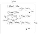
이제 디지털 캔버스(1116)를 확장하는 제5 방법에 관여하는 사용자 인터페이스를 예시하는 도 11a 및 도 11b를 참조한다. 사용자는 시작점(1110) 및 종료점(1114)을 포함하는 슬라이스 라인(1112)에 대응하는 슬라이스 제스처를 입력한다. 디지털 캔버스를 확장하는 이 제5 방법에서, 슬라이스 제스처 후에, 사용자는 터치 인터페이스 상에서의 2개의 손가락을 사용하는 핀치 제스처와 같은 한 쌍의 시프트 제스처를 사용할 수 있다. 핀치 제스처는 실질적으로 동시에 양쪽 시프트 제스처들에 대해 입력 디바이스로부터 입력을 수신하는 것을 수반할 수 있고, 따라서 제1 시프트 라인(1160) 및 제2 시프트 라인(1162)의 동시 결정을 요구할 수 있다. 제1 시프트 라인(1160)은 길이 및 방향이 핀치 제스처의 단일 손가락 입력에 비례적으로 대응할 수 있다. 제2 시프트 라인(1162)은 길이 및 방향이 핀치 제스처의 단일 손가락 입력에 비례적으로 대응할 수 있다. 도 11b의 제2 시프트 라인(1162)은 제1 시프트 라인(1160)에 대향하는 라인으로부터 오프셋될 수 있고, 캔버스 확장(1158)은 평행사변형일 수 있다. 이러한 방식으로, 사용자는 슬라이스 라인으로부터 새로운 캔버스를 절단한 다음 핀칭함으로써 캔버스를 확장하는 것으로 보일 수 있다.Reference is now made to FIGS. 11A and 11B illustrating a user interface involved in a fifth method of expanding the
도 11b에서, 캔버스 확장(1158)은 한 측면에서 슬라이스 라인(1112)에 의해 정의되고 폭이 제1 시프트 라인(1160)의 길이에 의해 정의되는 평행사변형(parallelogram) 일 수 있다. 제2 시프트 라인에 대향하는 라인으로부터의 제1 시프트 라인(1160)의 오프셋 각도는 유사하게 평행사변형의 형상을 정의할 수 있다. 캔버스 확장(1156)은 한 측면 상에서 슬라이스 라인(1112)에 의해 정의되고 폭이 제2 시프트 라인(1162)의 길이에 의해 정의되는 직사각형일 수 있다. 캔버스 확장(1156)에 대해 직사각형이 도시되어 있지만, 캔버스 확장이 제2 시프트 라인의 배향에 따라 평행사변형 또는 사다리꼴 형상일 수 있다는 것이 인식된다.In FIG. 11B, the
슬라이스 제스처가 행해지면, 사용자 인터페이스는 뷰포트(1152)에 슬라이스 라인(1112)을 디스플레이할 수 있다. 디스플레이되고 나면, 사용자는 다른 제스처를 사용하여 캔버스를 확장할 수 있다. 사용자가 시프트 제스처들을 완료하기 전에 캔버스 확장들에 대한 시각적 피드백을 수신할 수 있도록, 확장이 애니메이션화될 수 있다.When the slice gesture is performed, the user interface may display the
시프트가 적용되고 캔버스가 1156 및 1158에서 확장될 때, 정사각형들(1104b 및 1104c) 및 원(1106b)은 캔버스 확장(1158)에 따라 병진할 수 있다는 점에 유의한다. 유사하게, 삼각형들(1108a 및 1108b)도 캔버스 확장(1156)에 따라 병진할 수 있다. 전술한 바와 같이, 캔버스(1116)는 뷰포트(1152)보다 클 수 있고, 캔버스의 확장은 뷰포트(1152) 내부로부터 뷰포트 외부로 영역을 확장할 수 있다. 슬라이스 라인(1112)은 일반적으로 수평인 것으로 도시되지만, 임의의 크기 또는 방향일 수 있다. 정사각형들(1104a 및 1104d), 원들(1106a, 1106c 및 1106d) 및 삼각형들(1108c 및 1108d)을 포함하는 객체들은 캔버스 확장들(1156 및 1158)에 따라 병진하지 않고 유지된다.Note that when a shift is applied and the canvas expands at 1156 and 1158, the
선택적으로, 정사각형, 직사각형, 또는 삼각형 등과 같은 형상은 적어도 2개의 지점으로 구성될 수 있다. 디지털 캔버스 상의 객체 또는 형상은 캔버스 확장에 의해 영향을 받는 캔버스의 일부에 걸쳐 있을 수 있다. 일 실시예에서, 캔버스 확장은 형상 내의 적어도 2개의 지점 중 적어도 하나의 병진을 초래할 수 있고 객체 또는 형상은 형상이 신장될 수 있다.Optionally, a shape such as a square, a rectangle, or a triangle may consist of at least two points. An object or shape on a digital canvas can span a portion of the canvas that is affected by the canvas extension. In one embodiment, canvas expansion may result in translation of at least one of at least two points in the shape and the object or shape may be elongated in shape.
선택적으로, 정사각형, 직사각형, 또는 삼각형 등과 같은 형상은 적어도 2개의 지점으로 구성될 수 있다. 디지털 캔버스 상의 객체 또는 형상은 캔버스 확장에 의해 영향을 받는 캔버스의 일부에 걸쳐 있을 수 있다. 다른 실시예에서, 캔버스 확장은 경계 라인을 따라 객체를 전단하고 절단된 객체의 2개의 절반을 포함하는 2개의 새로운 객체를 생성할 수 있다.Optionally, a shape such as a square, a rectangle, or a triangle may consist of at least two points. An object or shape on a digital canvas can span a portion of the canvas that is affected by the canvas extension. In another embodiment, the canvas extension may shear the object along a boundary line and create two new objects comprising two halves of the cut object.
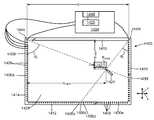
캔버스를 확장하기 위한 시스템이 개시되는 도 12a, 도 12b, 도 13 및 도 14를 참조한다. 이 시스템은 스타일러스 또는 손가락과 같은 방사선 차단 부재의 위치를 결정하기 위해 디스플레이 디바이스 및 복수의 방사선 센서 주위에 배열된 방사선 강도 신호들을 사용할 수 있다.See FIGS. 12A, 12B, 13 and 14, in which a system for expanding the canvas is disclosed. The system may use radiation intensity signals arranged around a display device and a plurality of radiation sensors to determine the location of a radiation blocking member such as a stylus or finger.
도 12a는 방사선 차단 물체(1424)의 위치를 감지 또는 추정하기 위한 시스템(1400)을 예시한다. 시스템(1400)은 한 쌍의 방사선 센서들(1402a, 1402b), 제어기(1404) 및 프레임 또는 하우징(1408) 상에 장착된 복수의 방사선 소스(1406)를 포함한다. 프레임(1408)은 상단 측면(1410), 하단 측면(1412), 좌측 측면(1414) 및 우측 측면(1416)을 갖는다. 이 실시예에서, 방사선 소스들(1406)은 프레임(1408)의 좌측 측면, 하단 측면 및 우측 측면에 장착된다. 방사선 센서(1402a)는 프레임(1408)의 좌측 상단 모서리에 장착되고, 방사선 센서(1402b)는 프레임(1408)의 우측 상단 모서리에 장착된다.12A illustrates a
프레임(1408)은 표면(1428)을 둘러싼다. 다양한 실시예에서, 표면(1428)은 디스플레이 스크린의 표면, 기입 표면 또는 다른 표면일 수 있다. 이 실시예에서, 프레임(1408)은 표면(1428)의 에지들에 베젤을 제공한다. 방사선 소스들(1406) 및 방사선 센서들(1402)은 베젤 내에 장착된다. 일부 실시예들에서, 프레임은 표면을 부분적으로만 둘러싸거나 에워쌀 수 있는데, 예를 들어, 프레임은, 어떠한 방사선 센서들 또는 소스들도 상부 에지 인접하게 장착되지 않은 경우, 표면의 상부 에지를 에워싸지 않을 수 있다. 다른 실시예들에서, 프레임은 표면을 지지하지만 에워싸지는 않을 수 있다. 예를 들어, 프레임은 표면, 방사선 센서들 및 방사선 소스들에 대한 지지를 제공할 수 있지만, 표면을 둘러싸는 베젤 또는 다른 요소를 갖지 않을 수 있다. 다른 실시예들에서, 프레임은 그 자체로 표면의 일부 또는 전부를 제공할 수 있다. 예를 들어, 프레임은 그의 에지들 사이에 고체 표면을 가질 수 있고, 방사선 차단 물체들은 시스템(1400)이 사용중일 때 고체 표면 상에 배치될 수 있다. 통상적으로, 이 예들에서와 같이, 표면은 프레임에 장착될 것이다.
프레임(1408)의 좌측 상단 모서리는 도 12a에서 절취되어 방사선 센서(1402a) 및 수 개의 방사선 소스(1406)를 드러낸다. 프레임(1408)의 우측 하단 모서리는 또한 방사선 소스들(1406) 중 일부를 드러내기 위해 절취되어 있다. 이 실시예에서, 각각의 방사선 소스(1406)는 적외선 스펙트럼 내의 방사선을 방출하는 LED이다. 다른 실시예들에서, 방사선 소스는 가시광 스펙트럼 및 UV 스펙트럼을 비롯한 다른 스펙트럼 내의 방사선을 방출하는 다양한 유형의 소스일 수 있다. 방사선 소스들(1406)은 방사선 소스들로부터의 방사선이 방사선 센서들(1402) 중 하나 또는 양쪽 모두에 도달하도록 프레임(1408) 상에 장착된다. 이 실시예에서, 방사선 소스들은 프레임(1408)의 좌측, 하단 및 우측 측면들을 따라 동등하게 이격되어 있다. 이 실시예에서, 프레임(1408)은 직각 모서리들을 갖는 직사각형이다. 프레임(1408)의 측면들은 x-y 평면의 축들에 평행하다. 일부 실시예들에서, 방사선 소스들은 동등하게 이격되지 않을 수 있다. 일부 실시예들에서, 프레임은 비-직사각형 형상을 가질 수 있다.The upper left corner of the
제어기(1404)는 프로세서(1420)를 포함하고, 이는 하드웨어 컴포넌트, 소프트웨어 컴포넌트, 또는 하드웨어 및 소프트웨어 또는 펌웨어 양자 모두 또는 하드웨어와 소프트웨어 및 펌웨어 양자 모두를 포함하는 컴포넌트를 포함하는 시스템(1400)을 동작시킬 수 있는 임의의 타입의 디바이스 또는 컴포넌트일 수 있다. 예를 들어, 프로세서(1420)는 마이크로프로세서, 마이크로컨트롤러, 게이트 어레이, 또는 임의의 타입의 데이터 처리 또는 컴퓨팅 디바이스일 수 있다. 프로세서는 시스템(1400) 및 그의 컴포넌트들을 동작시키도록 그리고 외부 디바이스들과 통신하도록 프로그래밍되거나 구성되어 있을 수 있다. 제어기(1404)는 또한 프로세서(1420)에 의해 액세스될 수 있는 메모리(1421)를 포함할 수 있다. 프로세서(1420)는 제어기(1404) 및 시스템(1400)의 동작을 제어한다. 명령어들이 메모리(1421)에 기록될 수 있고, 프로세서 내로 로딩되어 아래에 설명되는 바와 같이 제어기(1404) 및 시스템(1400)의 동작을 제어하기 위한 제어, 데이터 처리, 데이터 변환 및 통신 동작들을 수행하도록 프로세서를 구성할 수 있다. 제어기(1404)는 각각의 방사선 소스(1406)에 결합된다. 이들 접속들 중 일부만이 도 12a에 예시되어 있다. 제어기(1404)는 하나의 방사선 소스가 활성화되거나 또는 온(on)될 때(즉, 방사선을 방출할 때), 나머지 방사선 소스들이 활성화되지 않거나 오프(off)되도록(즉, 방사선을 방출하지 않도록) 각 방사선 소스(1406)를 독립적으로 활성화할 수 있다.The
이 실시예에서, 각 방사선 센서(1402)는 프레임(1408)의 2개의 대향 측면들 상의 방사선 소스들(1406)에 의해 방출된 방사선을 감지할 수 있는 PIN 포토다이오드이다. 방사선 센서(1402a)는 프레임(1408)의 하단 및 우측 측면 상의 방사선 소스들(1406)에 의해 방출되는 방사선을 감지한다. 방사선 센서(1402b)는 프레임(1408)의 하단 및 좌측 측면 상의 방사선 소스들(1406)에 의해 방출되는 방사선을 감지한다. 각 방사선 센서(1402)는 제어기(1404)에 결합되고 임의의 특정 시간에 방사선 센서(1402)에 들어오는 방사선의 강도에 대응하는 방사선 강도 레벨을 제어기에 제공한다. 방사선 강도 레벨은 대응하는 방사선 센서(1402)가 방사선 소스(1406)로부터 방사선을 수신하고 있을 때 상대적으로 높은 값을 갖고, 대응하는 방사선 센서(1402)가 방사선 소스(1406)로부터 방사선을 수신하고 있지 않을 때 상대적으로 낮은 값을 갖는다. 방사선 소스들(1406)에 대응하는 일련의 방사선 강도 레벨들은 방사선 차단 물체(1424)의 위치를 추정하는 데 사용될 수 있는 방사선 강도 신호로 조합될 수 있다. 이것은 아래에서 설명된다.In this embodiment, each radiation sensor 1402 is a PIN photodiode capable of sensing radiation emitted by
다른 실시예들에서, 각 방사선 센서는 방사선 소스들에 의해 방출된 방사선에 응답하고 센서에 입사하는 방사선에 대응하는 방사선 강도 레벨을 제공할 수 있는 임의의 디바이스일 수 있다. 예를 들어, 포토센서, 포토다이오드, 광전지, 태양 전지 또는 광발전 전지(photovoltaic cell)와 같은 광 감지 요소를 사용하여 방사선 강도 레벨들을 제공할 수 있다. 방사선 센서는 디지털 또는 아날로그 포맷을 포함하는, 제어기(1404)와 호환가능한 임의의 포맷으로 출력 방사선 강도 레벨을 제공할 수 있다.In other embodiments, each radiation sensor may be any device capable of providing a radiation intensity level corresponding to radiation incident on the sensor and responsive to radiation emitted by the radiation sources. For example, a light sensing element such as a photosensor, photodiode, photovoltaic cell, solar cell or photovoltaic cell can be used to provide radiation intensity levels. The radiation sensor can provide the output radiation intensity level in any format compatible with the
제어기(1404)는 프레임(1408)의 치수들, 각각의 방사선 소스(1406)의 위치 및 각각의 방사선 센서(1402)의 위치들로 프로그래밍된다. 이 예에서, 제어기(1404)는 다음의 정보로 프로그래밍된다:The
-센서들(1402a 및 1402b)은 거리 d만큼 분리된다. 방사선 센서(1402a)는 x-y 평면 상의 (0, 0) 위치에 있고, 방사선 센서(1402b)는 x-평면 상의(d, 0) 위치에 있다.-The
-프레임(1408)의 하단 또는 우측 측면 상의 각각의 방사선 소스에 대해, 프레임의 좌측 측면(또는 방사선 센서(1402a)의 위치에 따라 프레임의 좌측 측면에 평행한 라인)과 방사선 센서(1402a)와 방사선 소스 사이의 경로 사이의 각도 또는 이 각도에 대응하는 값.-For each radiation source on the lower or right side of the
-프레임(1408)의 왼쪽 또는 하단 측면 상의 각 방사선 소스에 대해, 방사선 센서(1402b)와 방사선 소스 사이의 경로와, 프레임의 우측 측면(또는 방사선 센서(1402b)의 위치에 따라, 프레임의 우측 측면에 평행한 라인) 사이의 각도, 또는 각도에 대응하는 값.-For each radiation source on the left or bottom side of the
제어기(1404)의 제어 하에서, 시스템(1400)은 방사선 차단 물체(1424)의 물리적 위치 P1424a(x1424a, y1424a)를 추정하도록 동작가능하다. 도 12a에서, 방사선 차단 물체(1424)는 스타일러스로서 예시된다. 스타일러스의 팁은 여기에 논의된 물리적 위치 P1424a 및 아래에 논의된 픽셀 위치 P1424d에 대응하는 지점 P1424에서 표면(1428)과 접촉한다.Under the control of the
동작 시에, 제어기(1404)는 방사선 소스들(1406)을 순차적으로 활성화한다. 방사선 소스(1406)가 활성화되는 동안, 제어기(1404)는 각 방사선 센서(1402)에 입사하는 방사선의 강도에 대응하는 방사선 강도 레벨을 획득하기 위해 방사선 센서들(1402) 중 하나 또는 양쪽 모두로부터의 출력을 샘플링한다. 통상적으로, 방사선 소스와 각각의 방사선 센서 사이의 경로는 차단되거나, 부분적으로 차단되거나(즉, 부분적으로 감쇠되거나), 열려있을 것이다. 일부 실시예들에서, 방사선 소스(1406)가 활성화되는 동안, 제어기는 오직 방사선 소스(1406)와 방사선 센서(1402) 사이에 직접 경로가 존재하는 경우에만 방사선 센서(1402)에 대한 방사선 강도 레벨을 확인할 수 있다. 예를 들어, 프레임(1408)의 하단 측면(1412) 및 우측 측면(1416) 상의 방사선 소스들(1406)과 방사선 센서(1402a) 사이에 직접 경로가 존재한다. 유사하게, 프레임(1408)의 좌측 측면(1414) 및 하단 측면(1412) 상의 방사선 소스들(1406)과 방사선 소스(1402b) 사이에 직접 경로가 존재한다. 다른 실시예들에서, 제어기(1404)는 활성화된 방사선 소스(1406)가 방사선 센서에 대한 직접 경로를 갖지 않을 때에도 방사선 센서(1402)에서의 방사선 강도 레벨을 확인할 수 있다.In operation, the
이 프로세스를 수행하기 위한 명령어들이 메모리(1421)에 기록된다. 프로세서(1420)는 메모리(1421) 내의 명령어들에 액세스하고, 명령어들을 실행하여, 위에 설명된 프로세스 및 아래에 설명되는 프로세스를 수행한다. 프로세서(1420)는 또한 이 프로세스의 수행 동안 메모리(1421)에 데이터를 기록할 수 있다.Instructions for performing this process are written to the
다른 실시예들에서, 방사선 소스들 및 방사선 센서들의 특정 배치와, 프레임의 형상(직사각형일 필요가 없고 다른 형상을 가질 수 있음)은 어느 방사선 소스들이 어느 방사선 센서들에 대해 직접 경로를 갖는지에 영향을 줄 것이다.In other embodiments, the specific arrangement of radiation sources and radiation sensors, and the shape of the frame (which need not be rectangular and may have other shapes) influence which radiation sources have a direct path to which radiation sensors. Will give you.
본 실시예로 돌아가서, 방사선 소스(1406a)가 활성화될 때, 제어기(1404)는 방사선 강도 레벨을 획득하기 위해 방사선 센서(1402a)를 샘플링할 필요가 없는데, 그 이유는 방사선 소스(1406a)와 다른 방사선 소스들(1406)에 의해 방해받지 않는 방사선 센서(1402a) 사이에 직접 경로가 없기 때문이다. 제어기(1404)는 방사선 소스(1406a)와 방사선 센서(1402b) 사이의 경로가 열려 있거나, 또는 차단되지 않음을 표시하는 상대적으로 높은 값을 표시하는, 방사선 센서(1402b)에 의해 제공되는 방사선 강도 레벨을 샘플링할 것이다.Returning to this embodiment, when the
방사선 소스(1406c)가 활성화될 때, 제어기(1404)는 방사선 센서들(1402a 및 1402b) 둘 다를 샘플링한다. 방사선 센서(1402a)로부터의 방사선 강도 레벨은 상대적으로 높고, 이것은 방사선 소스(1406c)와 방사선 센서(1402a) 사이의 경로가 열려 있음을 표시한다. 방사선 센서(1402b)로부터의 방사선 강도 레벨은 상대적으로 낮고, 이것은 방사선 소스(1406c)와 방사선 센서(1402b) 사이의 경로가, 이 예에서는, 방사선 차단 물체(1424)에 의해 차단됨을 표시한다.When the
방사선 소스(1406e)가 활성화될 때, 방사선 센서들(1402a 및 1402b) 각각으로부터의 방사선 강도 레벨들은 제각기 방사선 소스(1406e)와 방사선 센서들(1402a 및 1402b) 사이의 경로들이 열려 있다는 것을 표시한다.When the
방사선 소스(1406f)가 활성화될 때, 제어기(1404)는 방사선 소스(1406f)와 방사선 센서(1402a) 사이의 경로가 방사선 차단 물체(1424)에 의해 차단됨을 표시하는, 방사선 소스(1402a)로부터의 방사선 강도 레벨을 샘플링한다. 제어기(1404)는 방사선 소스(1406f)와 방사선 센서(1402a) 사이의 경로가 열려 있음을 표시하는, 방사선 센서(1402b)로부터의 방사선 강도 레벨을 샘플링한다.When the
제어기(1404)가 방사선 소스들을 순차적으로 활성화하고 각각의 방사선 소스(1406)에 대응하는 방사선 강도 레벨들을 샘플링함에 따라, 제어기(1404)는 다음과 같이 결과들을 기록한다:As the

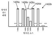
도 12a 및 12b를 참조한다. 다른 실시예에서, 제어기(1404)는 상이한 방식으로 방사선 차단 물체(1424)의 위치 P1424a를 추정하도록 상이하게 구성되거나 프로그래밍된다. 이 실시예에서, 강도 신호들(1422)은 각각의 방사선 센서(1402) 및 프레임(1408)의 측면에 대한 방사선 차단 물체(1424)의 각도 위치를 보다 정확하게 추정하는 데 사용된다.See Figures 12A and 12B. In another embodiment, the
도 12b는 이 실시예에 따라 제어기(1404)가 구성될 때의 방사선 강도 신호(1422b)의 일부를 예시한다. 이 실시예에서, 제어기(1404)는 각 방사선 센서와 조합하여 각 방사선 소스에 대한 기준선 강도 레벨을 설정한다. 각 방사선 소스에 대해, 제어기(1404)는 기준선 강도 레벨(1426)을 생성하기 위해 방사선 소스가 온 상태인 동안 및 방사선 차단 물체가 없을 때 방사선 센서(1402b)로부터의 방사선 강도 레벨을 샘플링한다. 방사선 소스(1406a 및 1406b-106d)에 대한 기준선 강도 레벨들이 도시되어 있다.12B illustrates a portion of the
이 실시예에서, 시스템의 시동 동안, 방사선 소스가 가시적인 각 방사선 센서에 관하여(즉, 방사선 소스와 방사선 센서 사이의 직접 경로가 존재하는 경우), 기준선 강도 레벨이 초기에 각 방사선 소스에 대해 결정된다. 강도 신호의 샘플들의 초기 세트는 시스템 시동 동안 폐기된다. 이 초기 시동 기간 다음의 선택된 시간 기간에 대하여, 방사선 소스가 온 상태인 동안 방사선 강도 레벨이 샘플링된다. 방사선 강도 레벨이 기록되고 평균 강도 레벨이 각 방사선 센서에서 방사선 소스에 대해 결정된다. 예를 들어, 각 방사선 소스가 초당 50회 활성화되는 경우, 기준선 강도 레벨은 1초의 절반(half of a second)을 나타내는, 각 방사선 센서에서, 각 방사선 소스에 대해 처음 25 샘플들을 사용하여 계산될 수 있다. 다른 실시예들에서, 기준선 강도 레벨은 더 많거나 더 적은 샘플들에 대해, 또는 더 긴 기간 또는 더 짧은 기간에 걸쳐 계산될 수 있다. 각 방사선 센서에 대한 기준선 강도 레벨은 특정 방사선 소스가 스위치 온(switch on)될 때 방사선 센서에 도달하는 방사선의 양에 영향을 미치는 주변의 및 다른 조건들을 본질적으로 고려한다. 이러한 다른 조건들은 각 방사선 소스에 의해 방출된 방사선의 양, 방사선 소스와 방사선 센서 사이의 물리적 거리를 포함하고, 또한 시스템(1400)이 사용되는 방식을 포함할 수 있다.In this embodiment, during startup of the system, for each radiation sensor in which the radiation source is visible (i.e., if there is a direct path between the radiation source and the radiation sensor), the baseline intensity level is initially determined for each radiation source. do. The initial set of samples of the strength signal is discarded during system startup. For a selected time period following this initial start-up period, the radiation intensity level is sampled while the radiation source is on. The radiation intensity level is recorded and an average intensity level is determined for the radiation source at each radiation sensor. For example, if each radiation source is activated 50 times per second, the baseline intensity level can be calculated using the first 25 samples for each radiation source, at each radiation sensor, representing half of a second. have. In other embodiments, the baseline intensity level may be calculated for more or fewer samples, or over a longer or shorter period of time. The baseline intensity level for each radiation sensor essentially takes into account ambient and other conditions that affect the amount of radiation reaching the radiation sensor when a particular radiation source is switched on. These other conditions include the amount of radiation emitted by each radiation source, the physical distance between the radiation source and the radiation sensor, and may also include how the
각 방사선 센서(1402)에 대하여, 각 방사선 소스(1406)에 대해 계산된 기준선 강도 레벨은 경시적으로 업데이트될 수 있다. 예를 들어, 최근의 시간 기간에 대한 방사선 강도 판독치들 중 일부의 이동 평균(moving average)을 계산하여 주변의 및 다른 조건들이 변화할 때 기준선 레벨을 정제할 수 있다. 일부 방사선 강도 판독치들은 업데이트된 기준선 강도 레벨을 계산하는 데 사용되지 않을 수 있다. 예를 들어, 매 10번째 또는 20번째 방사선 강도 판독치를 사용하여 각 기준선 강도 레벨에 대한 이동 평균을 계산할 수 있다. 이것은 더 긴 시간 기간에 대응하는 기준선 강도 레벨을 계산하기 위해 저장되어야 하는 데이터의 양을 감소시키고, 또한 이 태스크를 처리하기 위해 제어기에서 요구되는 계산 시간을 감소시킨다. 통상적으로, 기준선 강도 레벨은 1초 미만에서 수초 또는 수십초까지 최근의 기간에 대해 계산될 것이다. 방사선 소스(1406)와 방사선 센서(1402) 사이의 경로가 차단될 때, 주변 방사선 및 일부 방사선이 여전히 방사선 차단 물체 주위의 방사선 센서에 도달할 수 있더라도, 그 센서에서의 그 소스에 대한 방사선 강도 레벨은 상당히 감소할 것이다. 제어기는 아래 더 설명되는 바와 같이 기준선 강도를 정제할 때 현재의 기준선 강도 레벨에 비해 특정 임계값 아래의 방사선 강도 레벨들을 배제할 수 있다. 각 방사선 센서에서의 각 방사선 소스에 대한 기준선 강도 레벨을 계산하는 다양한 다른 방법들이 또한 사용될 수 있다. 일부 실시예들에서, 방사선 센서들의 그룹 또는 전부에 대해 하나의 기준선 강도 레벨이 계산될 수 있다. 다른 실시예들에서, 미리-결정된 강도 레벨이 방사선 소스들의 일부 또는 전부에 대한 기준선 강도 레벨로서 사용될 수 있다.For each radiation sensor 1402, the calculated baseline intensity level for each
이 실시예에서, 방사선 소스(1406)가 활성화될 때마다, 방사선 소스가 가시적인 각 방사선 센서(1402)로부터의 방사선 강도 레벨은 샘플링되어 그 방사선 센서에서의 그 방사선 소스에 대한 기존의 기준선 강도 레벨과 비교된다. 현재의 강도 레벨이 기준선 강도 레벨 아래 일부 임계값보다 더 클 때, 기준선 레벨로부터의 백분율 차이(percentage difference)가 계산된다. 예를 들어, 임계값은 기준선 강도 레벨의 90%일 수 있다. 현재의 강도 레벨이 기준선 레벨의 90%보다 크면, 현재의 강도 레벨을 사용하여 기준선 레벨을 더 정제할 수 있거나, 현재의 강도 레벨이 폐기될 수 있다. 현재의 강도 레벨이 기준선 레벨의 90%보다 작으면, 프로세서는 방사선 소스(1406)와 방사선 센서(1402) 사이의 경로가 적어도 부분적으로 차단된다고 가정한다. 다른 실시예들에서, 다른 임계값 레벨들이 사용될 수 있다.In this embodiment, each time the
제어기는 순환 프로세스에서 방사선 소스들을 연속적으로 활성화한다. 방사선 소스들(1406)을 스위치 온하고 방사선 소스들에 대한 각 방사선 센서로부터의 방사선 강도 레벨을 측정하는 각각의 사이클 후에, 제어기는 방사선 차단 물체의 위치를 추정한다.The controller continuously activates the radiation sources in the circulating process. After each cycle of switching on the
도 12b는 그 각각의 기준선 레벨들(1426)에 대한 몇몇 방사선 소스들(1406)의 감쇠를 예시한다. 방사선 센서(1402)에서 측정되는 바와 같은, 방사선 소스(106a)에 대한 현재의 강도 레벨은 기준선 강도 레벨(1426a)의 90%보다 커서, 그것은 방사선 차단 물체(1424)의 위치를 추정할 목적에 대해서는 무시되지만, 현재의 강도 레벨을 사용하여 방사선 센서(1402b)에서 측정되는 바와 같은 방사선 소스(1406a)에 대한 기준선 레벨을 정제할 수 있다. 유사하게, 방사선 소스(1406b)에 대한 현재의 강도 레벨은 기준선 강도 레벨(1426b)의 90%보다 커서, 방사선 차단 요소의 위치를 추정할 목적에 대해서는 무시되지만, 기준선 레벨을 정제하는 데 사용될 수 있고, 기준선 레벨은 그 다음에 약간 더 높아질 수 있다.12B illustrates the attenuation of
방사선 소스들(1406c 및 1460d)에 대한 현재 강도 레벨들은 그 각각의 기준선 강도 레벨들(1426c 및 1426d)의 90% 미만이다. 방사선 소스(1406c)에 대한 현재의 강도 레벨은 기준선 강도 레벨(1426c)의 53%에 있다. 방사선 소스(1406d)에 대한 현재의 강도 레벨은 기준선 강도 레벨(1426d)의 31%에 있다. 제어기(1404)는 이러한 편차들을 총 100%에 대해 정규화하고: 방사선 소스(1406c)로부터의 방사선의 상대적 감쇠는 총 감쇠의 63%(31%/84%= 63%)를 나타내고; 방사선 소스(1406d)로부터의 방사선의 상대적 감쇠는 총 감쇠의 37%를 나타낸다.Current intensity levels for
방사선 소스(1402b)와 방사선 차단 물체(1424) 사이의 라인(1432)과 우측 측면(1416) 사이의 각도(φ)는 이어서 다음과 같이 추정된다. 방사선 소스(1406c)에 대한 각도 φc는 44°이다. 방사선 소스(1406d)에 대응하는 각도 φd(도시되지 않음)는 42°이다. 이 실시예에서, 각도들 자체를 기록하기보다는, 각각의 각도의 탄젠트가 기록된다. 프레임(108)의 좌측 측면과 방사선 센서(1402b)와 방사선 차단 물체(1424) 사이의 경로 사이의 각도 φ124의 탄젠트는 이 때, 다음과 같이 추정될 수 있다:The angle φ between the
Tan(φ124))= 0.63●tan(44°) + 0.37●tan(42°)Tan(φ124 )) = 0.63tan(44°) + 0.37tan(42°)
= 0.9415.= 0.9415.
각도 φ124는 43.27°이다.The angle φ124 is 43.27°.
각도들 자체가 기록되는 실시예에서, 각도 φ124는 다음과 같이 추정될 수 있다:In the embodiment in which the angles themselves are recorded, the angle φ124 can be estimated as follows:
φ124= 0.63●44° + 0.37●42°φ124 = 0.63●44° + 0.37●42°
= 43.26°= 43.26°
각도 φ124의 추정치는 각도와 그의 탄젠트 사이의 비-선형성으로 인해 다르다.The estimate of the angle φ124 differs due to the non-linearity between the angle and its tangent.
좌측 측면(1414)과 방사선 센서(1402a)와 방사선 차단 물체(1424) 사이의 라인 사이의 각도에 대해 각도 θ124가 계산된다. 2개의 계산된 각도들 φ124 및 θ124는 방사선 차단 물체(1424)의 위치(xb, yb)를 추정하는 데 사용된다.An angle θ 124 is calculated for the angle between the
이러한 방식으로, 제어기(1404)는 상이한 방사선 소스들의 상대적 감쇠들을 정규화하고 나서 방사선 센서 및 프레임의 관련 측면으로부터의 이들 소스들의 각도의 가중 평균을 계산함으로써 프레임(1408)의 좌측 또는 우측 측면 및 방사선 센서들(1402) 중 하나에 대한 방사선 차단 물체의 각도 위치를 추정하기 위해 방사선 센서들 중 하나에서 측정되는 바와 같은 2개 이상의 방사선 소스의 감쇠를 사용할 수 있다.In this way, the
이 실시예는 방사선 소스들(1406)이 배치되는 특정 각도들 사이에 각도들 θ 및 φ가 추정될 수 있게 함으로써 방사선 차단 물체(1424)의 위치가 제1 실시예보다 더욱 정확하게 추정될 수 있게 할 수 있다.This embodiment allows the angles θ and φ to be estimated between specific angles at which the
일부 실시예들에서, 주변 방사선을 고려하기 위해 각 방사선 소스에 대한 강도의 기준선 범위를 생성하는 것이 바람직할 수 있다. 예를 들어, 일부 실시예들에서, 주변 방사선은 방사선 센서에 의해 감지될 수 있으며, 결과적으로 방사선 센서에 의해 제공되는 방사선 강도 레벨은 방사선 소스로부터의 방사선 및 주변 방사선 둘 다를 측정할 수 있다. 제어기(1404)는 모든 방사선 소스들(1406)이 스위치 오프되는 동안 각각의 방사선 센서(1402)에서의 방사선 강도 레벨을 결정하고, 그에 의해 각각의 방사선 센서(1402)에 대한 주변 방사선 레벨을 설정하도록 구성될 수 있다. 각각의 주변 방사선 레벨은 샘플들의 그룹의 평균일 수 있거나, 최근 획득된 샘플들의 이동 평균일 수 있거나, 다른 방식으로 계산될 수 있다. 일부 경우들에 있어서, 방사선 센서에 입사하는 주변 방사선의 양은 시간이 지남에 따라 변화할 수 있다. 각각의 방사선 센서에서 주변 방사선을 주기적으로 샘플링하여 주변 방사선 레벨을 업데이트하는 것이 바람직할 수 있다. 일부 실시예들에서는, 방사선 소스가 턴온된 상태에서 방사선 강도 레벨을 획득하기 직전에(또는 직후에) 모든 방사선 소스들이 오프된 상태에서 각각의 방사선 센서에 대한 주변 방사선 레벨을 획득하는 것이 바람직할 수 있다.In some embodiments, it may be desirable to create a baseline range of intensity for each radiation source to account for ambient radiation. For example, in some embodiments, ambient radiation may be detected by a radiation sensor, and consequently the radiation intensity level provided by the radiation sensor may measure both radiation from the radiation source and ambient radiation. The
주변 방사선 레벨을 사용하여 방사선 강도 레벨을 스케일링(scale) 또는 달리 조정해서 방사선 차단 물체의 추정된 위치들에 대한 주변 방사선의 영향을 제거하거나 감소시킬 수 있다. 예를 들어, 주변 방사선 레벨(또는 주변 방사선 레벨에 기초하는 양)은 방사선 강도 신호를 분석하고 방사선 차단 물체의 위치를 추정하기 전에 기준선 강도 레벨(1426) 및 각각의 방사선 소스에 대한 측정된 방사선 강도 레벨 양자로부터 감산될 수 있다.The ambient radiation level can be used to scale or otherwise adjust the radiation intensity level to eliminate or reduce the effect of ambient radiation on the estimated locations of the radiation blocking object. For example, the ambient radiation level (or amount based on the ambient radiation level) is determined by the baseline intensity level 1426 and the measured radiation intensity for each radiation source before analyzing the radiation intensity signal and estimating the position of the radiation blocking object. It can be subtracted from both levels.
시스템(1400)은 다양한 타입들의 방사선 차단 물체(1424)의 위치를 식별하기 위해 다양한 구성으로 사용될 수 있다. 예를 들어, 시스템(1400)은 화이트보드 또는 다른 디스플레이 표면과 사용될 수 있다. 프레임(1408)은 화이트보드의 에지 또는 프레임에 부착될 수 있거나, 또는 화이트보드의 프레임일 수도 있다. 방사선 차단 물체(1424)는 화이트보드 상에 기입하는 데 사용되는 펜일 수 있고, 펜이 화이트보드의 표면에 대해 이동할 때, 그의 위치가 제어기(1404)에 의해 추정된다. 제어기(1404)는 펜의 위치의 추정치들을 기록하기 위한 화이트보드 시스템에 결합될 수 있다(또는 화이트보드 시스템의 부분일 수 있다). 펜의 위치의 연속적인 추정치들을 기록함으로써, 화이트보드에 대한 정보는 전자 형태로 재생성될 수 있고, 후속 사용을 위해 기록될 수 있고, 그것은 디스플레이 또는 인쇄될 수 있다. 화이트보드 시스템은 추정된 위치들 사이의 펜의 이동 경로를 계산하고 계산된 경로를 평활화(smooth)하기 위해 소프트웨어를 포함할 수 있다.
펜이 화이트보드 상에 기입하는 데 사용될 때, 화이트보드 상의 잉크는 방사선 센서(1402)에 반사되는 주변 광의 양을 변화시킬 수 있고, 또한 방사선 소스(1406)로부터 방사선 센서(1402)로 전파되는 방사선의 양을 변화시킬 수 있으며, 그에 의해 방사선 소스들(1406)의 일부 또는 전부에 대해 측정된 방사선 강도의 레벨에 영향을 준다. 이러한 실시예들에서, 방사선 소스들의 일부 또는 전부에 대한 기준선 강도 레벨을 주기적으로 업데이트하는 것은 방사선 차단 물체의 위치의 추정치들의 정확도를 개선시킬 수 있다.When the pen is used to write on the whiteboard, the ink on the whiteboard can change the amount of ambient light reflected by the radiation sensor 1402, and also the radiation that propagates from the
다른 실시예들에서, 시스템(1400)은 터치스크린을 형성하기 위해 디스플레이 모니터 또는 스크린과 사용될 수 있다. 프레임(1408)은 디스플레이 모니터에 장착될 수 있거나, 디스플레이 모니터의 하우징의 부분일 수 있다. 이러한 경우 방사선 차단 물체(1424)는 손가락일 수 있고, 사람이 디스플레이 모니터 상으로 또는 밖으로 그 손가락을 이동할 때, 손가락의 존재가 검출되고 디스플레이 스크린 상의 그 위치가 제어기(1404)에 의해 추정된다. 제어기(1404)는(디스플레이 모니터를 포함할 수도 있는) 터치 스크린 시스템에 결합될 수 있고(또는 터치 스크린의 부분일 수 있고), 터치 스크린 시스템에 손가락의 위치의 추정치들을 제공할 수 있다. 손가락이 디스플레이 스크린에서 이동할 때, 손가락의 이동에 대한 전자 기록을 제공하기 위해 손가락의 위치의 연속적인 추정치들이 터치 스크린 시스템에 기록될 수 있고, 추정된 위치들이 디스플레이 모니터 상에 디스플레이될 수 있다. 터치 스크린 시스템은 그의 연속적인 추정된 위치들 사이의 손가락의 이동 경로를 계산하고 계산된 경로를 평활화하기 위해 소프트웨어 또는 다른 컴포넌트들을 포함할 수 있다. 이러한 터치 스크린 시스템은 시스템(1400)과 조합하여, 사용자가 사람의 손가락을 사용하여 효과적으로 디스플레이 모니터 상에 기입하거나 그릴 수 있게 하거나, 디스플레이 모니터 상에 디스플레이된 객체들을 조작할 수 있게 할 것이다.In other embodiments,
터치 스크린 시스템에서, 방사선 소스들(106) 및 방사선 센서들(1402)은 디스플레이 스크린에 상대적으로 근접하게 위치될 수 있고, 방사선 센서들에 입사하는 방사선의 양은 디스플레이 스크린 상에 디스플레이된 정보가 변화함에 따라 달라질 수 있다. 이러한 실시예들에서, 방사선 소스들의 일부 또는 전부에 대한 기준선 강도 레벨을 업데이트하는 것이 또한 유익할 수 있다.In a touch screen system, radiation sources 106 and radiation sensors 1402 may be positioned relatively close to the display screen, and the amount of radiation incident on the radiation sensors varies as the information displayed on the display screen changes. It can be different. In such embodiments, it may also be beneficial to update the baseline intensity level for some or all of the radiation sources.
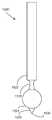
도 13을 참조하면, 본 명세서에 설명된 적어도 일부 실시예에 따른 방사선 차단 스타일러스(1500)를 예시하는 측면도가 제공되어 있다. 방사선 차단 스타일러스(1500)는 그립 부분(1522) 및 좁은 부분(1528)을 포함하는 핸들, 방사선 차단 부재(1524), 및 접촉 부분(1530)을 포함하는 팁(1526)을 포함한다. 방사선 차단 부재(1524)는 형상이 변화할 수 있고, (도시된 바와 같은) 구체, 원기둥, 정사각형 박스, 직사각형 박스, 타원체, 환상체, 또는 임의의 다른 적절한 형상의 설계를 포함할 수 있다. 도 12a의 시스템을 다시 참조하면, 스타일러스 접촉 부분(1530)은 표면(1428)과 슬라이딩 가능하게 맞물릴 수 있다. 방사선 차단 부재의 높이는 구체의 중심이 일반적으로 복수의 방사선 센서들(1402) 중 하나와 복수의 방사선 소스들(1406) 사이에 형성된 광학 평면과 교차하도록 하는 것이다. 접촉 부분(1530)은 표면(1428)에 대한 손상을 방지하기 위해 라운딩 처리될 수 있다. 구형 방사선 차단 부재(1524)가 이러한 경우에 선택되는데, 그 이유는 표면(1428)에 평행한 광학 평면을 차단하는 그의 단면적이 스타일러스가 방사선 차단 부재의 중심에 대해 회전, 피치 및 요를 변경할 때 일반적으로 일정하기 때문이다. 본 명세서에 개시된 구성들에서 복수의 방사선 소스(1406) 및 복수의 방사선 센서(1402)를 포함하는 본 명세서에 개시된 시스템은 복수의 광학 평면 각각에서의 광학 평면의 일관된 단면 폐색을 관찰할 수 있다. 이와 유사하게, 본 명세서에 개시된 시스템은 방사선 차단 부재(1524)에 대한 신호의 방향에 관계없이 복수의 광학 평면들에 걸쳐 송신된 광 신호들의 일관된 감쇠를 관찰한다. 단면적은 표면(1428)으로부터 멀어지거나 표면(1428)을 향하는 z-축 방향으로의 병진으로 인해 변화할 수 있다. z-축 병진으로 인한 단면적의 이러한 변화는 측정가능할 수 있고, 제어기(1404)는 감쇠 프로파일을 결정하는데 이를 사용할 수 있다. 제어기(1404)에 의해 결정되는 구형 방사선 차단 부재의 감쇠 프로파일은 표면(1428)에 대한 스타일러스의 z-축 변위와 복수의 소스(1406)와 복수의 센서(1402) 사이의 광 신호의 감쇠의 관찰가능한 변화들을 상관시킬 수 있다. 일단 감쇠 프로파일이 교정되면, 관찰된 감쇠에 기초하여 스타일러스의 z-축 병진을 결정하는 것이 가능할 수 있다. 이 감쇠 프로파일은 근사치 스타일러스 압력을 결정하기 위해 제어기(1404)에 의해 추가로 사용될 수 있다.Referring to FIG. 13, there is provided a side view illustrating a
방사선 차단 스타일러스는 사용자가 손으로 잡을 수 있는 핸들을 포함한다. 핸들은 그립 부분(1522) 및 좁은 부분(1528)을 포함한다. 좁은 부분(1528)은 그립 부분(1522) 및 방사선 차단 부재(1524)에 비해 감소된 반경을 갖는 형상을 가질 수 있다.The radiation shielding stylus includes a handle that can be held by the user by hand. The handle includes a
방사선 차단 스타일러스의 팁(1526)은 광학적 투명 재료로 만들어질 수 있다.The
방사선 차단 스타일러스의 좁은 부분(1528)은 광학적 투명 재료로 만들어질 수 있다.The
도 14를 참조하면, 방사선 차단 스타일러스의 방사선 차단 부재(1524)가 광학 평면(1614)을 완전히 차단(또는 폐색)하고 소스(1606c)와 센서(1602b) 사이의 신호를 완전히 감쇠시키는 도 12a의 추적 시스템의 단면도가 도시되어 있다. 팁(1526)의 접촉 부분(1530)은 스크린(1628)의 커버 부분(1604)과 슬라이딩 가능하게 접촉한다. 제어기(1404)는 x-축 및 y-축 위치 결정에 추가로 근사치 z-축 위치를 결정하기 위해 감쇠 프로파일을 사용할 수 있다.Referring to FIG. 14, the trace of FIG. 12A where the
도 13의 스타일러스는 디지털 캔버스를 확장시키기 위한 시스템을 제공하기 위해 도 12a의 시스템과 함께 사용될 수 있다. 사용자는 자신의 손가락 또는 도 13의 스타일러스를 도 14에 도시된 광학 평면 내로 이동시킴으로써 사용자 입력을 제공할 수 있다. 사용자 입력은 시작점 및 종료점을 포함하는 일련의 지점들을 포함할 수 있다. 시작점은 스타일러스 또는 손가락이 도 14에서의 광학 평면(1614)을 차단하기 시작하는 지점을 반영할 수 있다. 종료점은 손가락의 스타일러스가 도 14의 광학 평면(1614)의 차단을 완료하는 지점을 반영할 수 있다.The stylus of FIG. 13 can be used in conjunction with the system of FIG. 12A to provide a system for expanding the digital canvas. The user may provide user input by moving his or her finger or the stylus of FIG. 13 into the optical plane shown in FIG. 14. The user input may include a series of points including a start point and an end point. The starting point may reflect the point at which the stylus or finger begins to block the
도 13의 스타일러스는 또한 스타일러스 상의 버튼 또는 버튼들의 사용을 통해 시작 및 종료점들을 나타낼 수 있다.The stylus of FIG. 13 may also indicate start and end points through the use of buttons or buttons on the stylus.
본 명세서에 설명된 예시적인 실시예들의 철저한 이해를 제공하기 위해 다수의 특정 상세가 설명된다는 것을 알 것이다. 그러나, 관련 기술 분야의 통상의 기술자들은 본 명세서에 설명된 실시예들이 이러한 특정 상세들 없이도 실시될 수 있다는 것을 이해할 것이다. 다른 경우들에서, 본 명세서에 설명되는 실시예들을 모호하게 하지 않기 위해 잘 알려진 방법들, 절차들 및 컴포넌트들은 상세히 설명되지 않았다. 또한, 본 설명 및 도면들은 본 명세서에 설명되는 실시예들의 범위를 어떠한 식으로든 한정하는 것이 아니라, 본 명세서에 설명되는 다양한 실시예들의 구현을 설명할 뿐인 것으로 고려되어야 한다.It will be appreciated that a number of specific details are set forth in order to provide a thorough understanding of the exemplary embodiments described herein. However, those skilled in the art will understand that the embodiments described herein may be practiced without these specific details. In other instances, well-known methods, procedures, and components have not been described in detail in order not to obscure the embodiments described herein. In addition, it should be considered that the description and drawings do not limit the scope of the embodiments described herein in any way, but merely describe implementations of the various embodiments described herein.
"실질적으로(substantially)", "약(about)" 및 "대략(approximately)"과 같은 정도의 용어들은 본 명세서에서 사용될 때 최종 결과가 현저히 변경되지 않도록 피수식어의 합리적인 편차의 양을 의미한다는 점에 유의해야 한다. 이들 정도에 대한 용어들은 이 편차가 그것이 수식하는 용어의 의미를 부정하지 않는 경우 피수식어의 편차를 포함하는 것으로 해석되어야 한다.It is noted that terms of the degree "substantially", "about" and "approximately" when used herein mean an amount of reasonable deviation of the modifier word so that the final result is not significantly altered. Be careful. Terms of these degrees are to be interpreted as including deviations from the modulated word provided that this deviation does not negate the meaning of the term it modifies.
또한, 본 명세서에서 사용될 때, "및/또는"이라는 단어는 포괄적 논리합(inclusive-or)을 나타내는 것을 의도한다. 즉, "X 및/또는 Y"는 예를 들어 X 또는 Y 또는 양자 모두를 의미하도록 의도된다. 추가적 예로서, "X, Y 및/또는 Z"는 X 또는 Y 또는 Z 또는 이들의 임의의 조합을 의미하도록 의도된다.Further, as used herein, the word "and/or" is intended to represent an inclusive-or. That is, “X and/or Y” is intended to mean, for example, X or Y or both. As a further example, “X, Y and/or Z” is intended to mean X or Y or Z or any combination thereof.
본 명세서에 설명되는 시스템들 및 방법들의 실시예들은 하드웨어 또는 소프트웨어 또는 양자의 조합으로 구현될 수 있다. 이 실시예들은 프로그램가능 컴퓨터들 상에서 실행되는 컴퓨터 프로그램들에서 구현될 수 있으며, 각각의 컴퓨터는 적어도 하나의 프로세서, 데이터 저장 시스템(휘발성 메모리 또는 비휘발성 메모리 또는 다른 데이터 저장 요소들 또는 이들의 조합을 포함함), 및 적어도 하나의 통신 인터페이스를 포함한다. 예를 들어, 그리고 제한 없이, 프로그램가능 컴퓨터들(아래에서 컴퓨팅 디바이스들로 지칭됨)은 서버, 네트워크 어플라이언스, 임베디드 디바이스, 컴퓨터 확장 모듈, 개인용 컴퓨터, 랩톱, 개인 데이터 어시스턴트, 셀룰러 전화, 스마트폰 디바이스, 태블릿 컴퓨터, 무선 디바이스 또는 본 명세서에 설명된 방법들을 수행하도록 구성될 수 있는 임의의 다른 컴퓨팅 디바이스일 수 있다.Embodiments of the systems and methods described herein may be implemented in hardware or software or a combination of both. These embodiments may be implemented in computer programs running on programmable computers, each computer having at least one processor, a data storage system (volatile memory or nonvolatile memory or other data storage elements or a combination thereof). Included), and at least one communication interface. For example, and without limitation, programmable computers (referred to below as computing devices) include servers, network appliances, embedded devices, computer expansion modules, personal computers, laptops, personal data assistants, cellular phones, smartphone devices. , A tablet computer, a wireless device, or any other computing device that may be configured to perform the methods described herein.
일부 실시예들에서, 통신 인터페이스는 네트워크 통신 인터페이스일 수 있다. 요소들이 조합되는 실시예들에서, 통신 인터페이스는 IPC(inter-process communication)와 같은 소프트웨어 통신 인터페이스일 수 있다. 또 다른 실시예들에서, 하드웨어, 소프트웨어, 및 이들의 조합으로서 구현되는 통신 인터페이스들의 조합이 있을 수 있다.In some embodiments, the communication interface may be a network communication interface. In embodiments in which elements are combined, the communication interface may be a software communication interface such as inter-process communication (IPC). In still other embodiments, there may be a combination of communication interfaces implemented as hardware, software, and combinations thereof.
프로그램 코드는 입력 데이터에 적용되어, 본 명세서에 설명된 기능들을 수행하고 출력 정보를 생성할 수 있다. 출력 정보는 공지된 방식으로 하나 이상의 출력 디바이스에 적용된다.Program code can be applied to input data to perform functions described herein and generate output information. The output information is applied to one or more output devices in a known manner.
각각의 프로그램은 컴퓨터 시스템과 통신하기 위해 하이 레벨 프로시저 또는 객체 지향 프로그래밍 및/또는 스크립팅 언어, 또는 둘 다로 구현될 수 있다. 그러나, 프로그램은 원한다면 어셈블리 또는 기계 언어로 구현될 수 있다. 임의의 경우에, 이 언어는 컴파일형 또는 해석형 언어일 수 있다. 각각의 이러한 컴퓨터 프로그램은, 저장 매체 또는 디바이스가 본 명세서에 설명된 절차들을 수행하기 위해 컴퓨터에 의해 판독될 때 컴퓨터를 구성하고 동작시키기 위해, 범용 또는 특수 목적 프로그램가능 컴퓨터에 의해 판독가능한 저장 매체 또는 디바이스(예를 들어, ROM, 자기 디스크, 광 디스크) 상에 저장될 수 있다. 시스템의 실시예들은 또한 컴퓨터 프로그램으로 구성된 비일시적 컴퓨터 판독가능 저장 매체로서 구현되는 것으로 고려될 수 있으며, 여기서 그렇게 구성된 저장 매체는 컴퓨터로 하여금 본 명세서에 설명되는 기능들을 수행하기 위해 구체적이고 미리 정의된 방식으로 동작하게 한다.Each program may be implemented in a high level procedure or object oriented programming and/or scripting language, or both, to communicate with a computer system. However, the program can be implemented in assembly or machine language if desired. In any case, this language may be a compiled or interpreted language. Each such computer program is a storage medium readable by a general purpose or special purpose programmable computer for configuring and operating a computer when the storage medium or device is read by a computer to perform the procedures described herein, or It can be stored on a device (eg, ROM, magnetic disk, optical disk). Embodiments of the system may also be considered to be implemented as a non-transitory computer-readable storage medium configured with a computer program, wherein the storage medium so configured is a specific and predefined storage medium for causing a computer to perform the functions described herein. Behave in a way.
또한, 설명된 실시예들의 시스템, 프로세스들 및 방법들은 하나 이상의 프로세서를 위한 컴퓨터 사용가능 명령어들을 지니는 컴퓨터 판독가능 매체를 포함하는 컴퓨터 프로그램 제품으로 배포될 수 있다. 매체는 하나 이상의 디스켓, 콤팩트 디스크, 테이프, 칩, 유선 송신, 위성 송신, 인터넷 송신 또는 다운로드, 자기 및 전자 저장 매체, 디지털 및 아날로그 신호 등을 포함하는 다양한 형태들로 제공될 수 있다. 컴퓨터 사용가능 명령어들은 또한 컴파일된 코드 및 컴파일되지 않은 코드를 포함하는 다양한 형태들로 되어 있을 수 있다.Further, the systems, processes, and methods of the described embodiments may be distributed as a computer program product including a computer readable medium carrying computer usable instructions for one or more processors. The media may be provided in various forms including one or more diskettes, compact disks, tapes, chips, wired transmissions, satellite transmissions, Internet transmissions or downloads, magnetic and electronic storage media, digital and analog signals, and the like. Computer-usable instructions may also be in various forms, including compiled and uncompiled code.
다양한 실시예들은 단지 예로서 본 명세서에 설명되었다. 첨부된 청구항들에 의해서만 한정되는 본 발명의 사상 및 범위로부터 벗어나지 않고 이러한 예시적인 실시예들에 대한 다양한 수정 및 변형이 이루어질 수 있다. 또한, 도면들에 예시된 다양한 사용자 인터페이스들에서, 예시된 사용자 인터페이스 텍스트 및 컨트롤들은 단지 예들로서 제공되며, 제한하려는 것이 아니라는 것을 이해할 것이다. 다른 적절한 사용자 인터페이스 요소들이 가능할 수 있다.Various embodiments have been described herein by way of example only. Various modifications and variations can be made to these exemplary embodiments without departing from the spirit and scope of the present invention, which is limited only by the appended claims. Further, it will be appreciated that in the various user interfaces illustrated in the figures, the illustrated user interface text and controls are provided as examples only and are not intended to be limiting. Other suitable user interface elements may be possible.
Claims (18)
Translated fromKorean-디지털 캔버스를 제공하는 단계;
-슬라이스 제스처를 포함하는 제1 사용자 입력을 수신하는 단계;
-상기 슬라이스 제스처에 대응하는 상기 디지털 캔버스 상의 슬라이스 라인을 결정하는 단계;
-상기 슬라이스 라인에 기초하여 상기 디지털 캔버스를 확장하는 단계를 포함하고,
-상기 슬라이스 라인은 시작점 및 종료점을 포함하는, 방법.As a way to expand the digital canvas,
-Providing a digital canvas;
-Receiving a first user input including a slice gesture;
-Determining a slice line on the digital canvas corresponding to the slice gesture;
-Expanding the digital canvas based on the slice line,
-The slice line comprises a starting point and an ending point.
-제1 시프트 제스처를 포함하는 제2 사용자 입력을 수신하는 단계;
-상기 제1 시프트 제스처에 대응하는 상기 디지털 캔버스 상의 제1 시프트 라인을 결정하는 단계;
-상기 제1 시프트 라인의 방향으로 상기 슬라이스 라인을 따라 상기 디지털 캔버스를 확장하는 단계를 더 포함하는, 방법.The method of claim 1,
-Receiving a second user input comprising a first shift gesture;
-Determining a first shift line on the digital canvas corresponding to the first shift gesture;
-Extending the digital canvas along the slice line in the direction of the first shift line.
-상기 제1 시프트 제스처와 대체로 반대 방향인 제2 시프트 제스처를 포함하는 제3 사용자 입력을 수신하는 단계;
-상기 제2 시프트 제스처에 대응하는 상기 디지털 캔버스 상의 제2 시프트 라인을 결정하는 단계;
-상기 제1 시프트 라인의 방향으로 상기 슬라이스 라인을 따라 상기 디지털 캔버스를 확장하는 단계; 및
-상기 제2 시프트 라인의 방향으로 상기 슬라이스 라인을 따라 상기 디지털 캔버스를 확장하는 단계를 더 포함하는, 방법.The method of claim 4,
-Receiving a third user input comprising a second shift gesture substantially opposite to the first shift gesture;
-Determining a second shift line on the digital canvas corresponding to the second shift gesture;
-Extending the digital canvas along the slice line in the direction of the first shift line; And
-Extending the digital canvas along the slice line in the direction of the second shift line.
- 상기 슬라이스 라인의 상기 시작점으로부터 형성되고 상기 제1 시프트 라인에 평행하게 상기 제1 시프트 라인의 길이만큼 연장하는 상기 라인을 포함하는 제1 경계 라인을 결정하고;
-상기 제1 경계 라인의 단부로부터 형성되고 상기 슬라이스 라인에 평행하게 상기 슬라이스 라인의 길이만큼 연장하는 라인을 포함하는 제2 경계 라인을 결정하고;
-상기 제2 경계 라인의 종료점과 상기 슬라이스 라인의 종료점으로부터 형성되는 라인을 포함하는 제3 경계 라인을 결정하고;
-상기 슬라이스 라인의 상기 종료점으로부터 형성되고 상기 제2 시프트 라인에 평행하게 상기 제2 시프트 라인의 길이만큼 연장하는 라인을 포함하는 제4 경계 라인을 결정하고;
-상기 제4 경계 라인의 단부로부터 형성되고 상기 슬라이스 라인에 평행하게 상기 슬라이스 라인의 길이만큼 연장하는 라인을 포함하는 제5 경계 라인을 결정하고; 및
- 상기 제5 경계 라인의 단부 및 상기 슬라이스 라인의 상기 시작점으로부터 형성된 상기 라인을 포함하는 제6 경계 라인을 결정함으로써 경계 설정된 상기 디지털 캔버스에 캔버스의 일부를 추가하는 단계를 포함하는, 방법.The method of claim 5, wherein expanding the digital canvas
-Determining a first boundary line including the line formed from the starting point of the slice line and extending by a length of the first shift line parallel to the first shift line;
-Determining a second boundary line comprising a line formed from an end of the first boundary line and extending parallel to the slice line by the length of the slice line;
-Determining a third boundary line including a line formed from an ending point of the second boundary line and an ending point of the slice line;
-Determining a fourth boundary line comprising a line formed from the end point of the slice line and extending by a length of the second shift line parallel to the second shift line;
-Determining a fifth boundary line including a line formed from an end of the fourth boundary line and extending parallel to the slice line by the length of the slice line; And
-Adding a portion of the canvas to the bounded digital canvas by determining a sixth boundary line including the line formed from the end of the fifth boundary line and the starting point of the slice line.
-시프트 영역 내에서 상기 디지털 캔버스 상에 위치하는 제1 형상을 제공하는 단계를 더 포함하고, 상기 시프트 영역은
- 상기 슬라이스 라인의 상기 시작점으로부터 형성되고 상기 제1 시프트 라인의 방향으로 상기 제1 시프트 라인에 평행하게 투영된 제1 투영 라인;
-상기 슬라이스 라인의 상기 종료점으로부터 형성되고 상기 제1 시프트 라인의 방향으로 상기 제1 시프트 라인에 평행하게 투영된 제2 투영 라인; 및
-상기 슬라이스 라인에 의해 경계 설정되고;
-상기 디지털 캔버스를 확장하는 단계는 객체를 상기 제1 시프트 라인의 방향으로 상기 제1 시프트 라인의 길이만큼 병진시키는 단계를 더 포함하는, 방법.The method of claim 5,
-Providing a first shape located on the digital canvas within a shift area, the shift area
-A first projection line formed from the starting point of the slice line and projected parallel to the first shift line in the direction of the first shift line;
-A second projection line formed from the end point of the slice line and projected parallel to the first shift line in the direction of the first shift line; And
-Demarcated by the slice line;
-Expanding the digital canvas further comprising translating an object in a direction of the first shift line by a length of the first shift line.
-상기 시프트 영역 외부의 상기 디지털 캔버스 상에 위치하는 제2 형상을 제공하는 단계를 더 포함하고;
-상기 디지털 캔버스를 확장하는 단계는 상기 제2 형상의 위치를 유지하는 단계를 더 포함하는, 방법.The method of claim 7,
-Providing a second shape located on the digital canvas outside the shift area;
-Expanding the digital canvas further comprising maintaining the position of the second shape.
-적어도 2개의 지점을 포함하는 제3 형상을 제공하는 단계를 포함하고;
-상기 적어도 2개의 지점 중 적어도 하나의 지점은 상기 시프트 영역 내부의 상기 디지털 캔버스 상에 위치되고;
-상기 디지털 캔버스를 확장하는 단계는 상기 제1 시프트 라인의 방향으로 상기 제1 시프트 라인의 길이에서 상기 제3 형상의 상기 적어도 하나의 지점을 병진시키는 단계를 더 포함하는, 방법.The method of claim 7,
-Providing a third shape comprising at least two points;
-At least one of the at least two points is located on the digital canvas inside the shift area;
-Expanding the digital canvas further comprises translating the at least one point of the third shape in a length of the first shift line in the direction of the first shift line.
-적어도 2개의 지점을 포함하는 제4 형상을 제공하는 단계를 포함하고;
-상기 적어도 2개의 지점 중 적어도 하나의 지점은 상기 시프트 영역 내부의 상기 디지털 캔버스 상에 위치되고;
-상기 디지털 캔버스를 확장하는 단계는
-상기 시프트 영역 외부의 상기 제4 형상의 상기 적어도 2개의 지점 중 적어도 하나의 지점을 포함하는 제5 형상을 생성하는 단계;
-상기 시프트 영역 내부의 상기 제4 형상의 상기 적어도 2개의 지점 중 적어도 하나의 지점을 포함하는 제6 형상을 생성하는 단계;
-상기 제6 형상을 상기 제1 시프트 라인의 방향으로 상기 제1 시프트 라인의 길이로 병진시키는 단계를 더 포함하는, 방법.The method of claim 7,
-Providing a fourth shape comprising at least two points;
-At least one of the at least two points is located on the digital canvas inside the shift area;
-The step of expanding the digital canvas
-Generating a fifth shape including at least one of the at least two points of the fourth shape outside the shift area;
-Generating a sixth shape including at least one of the at least two points of the fourth shape within the shift area;
-Translating the sixth shape into a length of the first shift line in the direction of the first shift line.
컴퓨터를 포함하고, 상기 컴퓨터는
-프로세서;
-메모리;
-입력 디바이스;
-디스플레이를 포함하며;
-상기 프로세서는,
-상기 디스플레이 상에 디지털 캔버스를 표시하며;
-슬라이스 제스처를 포함하는 제1 사용자 입력을 수신하도록;
-상기 슬라이스 제스처에 대응하는 상기 디지털 캔버스 상의 슬라이스 라인을 결정하도록;
-상기 슬라이스 라인에 기초하여 상기 디지털 캔버스를 확장하도록 동작하고;
-상기 슬라이스 라인은 시작점 및 종료점을 포함하는, 시스템.As a system for an expandable digital canvas,
Comprising a computer, the computer
-Processor;
- Memory;
-Input device;
-Includes a display;
-The processor,
-Displaying a digital canvas on the display;
-To receive a first user input comprising a slice gesture;
-To determine a slice line on the digital canvas corresponding to the slice gesture;
-Operate to expand the digital canvas based on the slice line;
-The slice line includes a starting point and an ending point.
-제1 시프트 제스처를 포함하는 제2 사용자 입력을 수신하도록;
-상기 제1 시프트 제스처에 대응하는 상기 디지털 캔버스 상의 제1 시프트 라인을 결정하도록;
-상기 제1 시프트 라인의 방향으로 상기 슬라이스 라인을 따라 상기 디지털 캔버스를 확장시키도록 추가로 동작할 수 있는, 시스템.The method of claim 11, wherein the processor,
-To receive a second user input comprising a first shift gesture;
-Determine a first shift line on the digital canvas corresponding to the first shift gesture;
-A system further operable to extend the digital canvas along the slice line in the direction of the first shift line.
-상기 제1 시프트 제스처와 대체로 반대 방향인 제2 시프트 제스처를 포함하는 제3 사용자 입력을 수신하도록;
-상기 제2 시프트 제스처에 대응하는 상기 디지털 캔버스 상의 제2 시프트 라인을 결정하도록;
-상기 제1 시프트 라인의 방향으로 상기 슬라이스 라인을 따라 상기 디지털 캔버스를 확장하도록; 및
-상기 제2 시프트 라인의 방향으로 상기 슬라이스 라인을 따라 상기 디지털 캔버스를 확장하도록 추가로 동작할 수 있는, 시스템.The method of claim 12, wherein the processor,
-To receive a third user input comprising a second shift gesture in a direction generally opposite to the first shift gesture;
-Determine a second shift line on the digital canvas corresponding to the second shift gesture;
-Extending the digital canvas along the slice line in the direction of the first shift line; And
-A system further operable to extend the digital canvas along the slice line in the direction of the second shift line.
-시프트 영역 내에서 상기 디지털 캔버스 상에 위치하는 제1 형상을 제공하도록 추가로 동작할 수 있고, 상기 시프트 영역은
- 상기 슬라이스 라인의 상기 시작점으로부터 형성되고 상기 제1 시프트 라인의 방향으로 상기 제1 시프트 라인에 평행하게 투영된 제1 투영 라인;
-상기 슬라이스 라인의 상기 종료점으로부터 형성되고 상기 제1 시프트 라인의 방향으로 상기 제1 시프트 라인에 평행하게 투영된 제2 투영 라인; 및
-상기 슬라이스 라인에 의해 경계 설정되고;
-상기 디지털 캔버스를 확장하는 것은 객체를 상기 제1 시프트 라인의 방향으로 상기 제1 시프트 라인의 길이만큼 병진시키는 것을 더 포함하는, 시스템.The method of claim 13, wherein the processor,
-Further operable to provide a first shape located on the digital canvas within a shift area, the shift area
-A first projection line formed from the starting point of the slice line and projected parallel to the first shift line in the direction of the first shift line;
-A second projection line formed from the end point of the slice line and projected parallel to the first shift line in the direction of the first shift line; And
-Demarcated by the slice line;
-Expanding the digital canvas further comprises translating an object in the direction of the first shift line by a length of the first shift line.
-디스플레이,
-프레임,
-상기 프레임에 장착된 적어도 3개의 방사선 센서들- 상기 적어도 3개의 방사선 센서들은 제1 방사선 센서, 제2 방사선 센서 및 제3 방사선 센서를 포함하고, 상기 제1, 제2 및 제3 방사선 센서들은 서로 이격됨 -;
-상기 프레임에 장착된 복수의 방사선 소스- 상기 방사선 소스들 중 적어도 일부는 상기 방사선 센서들 각각에 가시적임 -를 포함할 수 있고; 및
-상기 프로세서는 상기 방사선 소스들 및 상기 방사선 센서들에 결합되고;
-상기 프로세서는 방사선 차단 물체의 위치를 감지하고 적어도 하나의 제스처를 포함하는 사용자 입력을 전송하는, 시스템.The method of claim 15, wherein the touch screen,
- display,
- frame,
-At least three radiation sensors mounted on the frame-The at least three radiation sensors include a first radiation sensor, a second radiation sensor and a third radiation sensor, and the first, second and third radiation sensors Separated from each other -;
-A plurality of radiation sources mounted on the frame-at least some of the radiation sources are visible to each of the radiation sensors; And
-The processor is coupled to the radiation sources and the radiation sensors;
-The processor detects the position of the radiation shielding object and transmits a user input comprising at least one gesture.
-스타일러스를 더 포함하고, 상기 스타일러스는
- 핸들;
- 상기 핸들로부터 방사상으로 연장되는 방사선 차단 부재;
- 접촉 부분을 갖는, 상기 핸들로부터 대향하여 연장하는 팁을 포함하고;
- 상기 접촉 부분은 상기 디스플레이와 슬라이딩 가능하게 접촉하고, 상기 팁의 높이는 상기 디스플레이 위의 광학 평면의 높이에 대응하고;
-상기 스타일러스는 상기 터치 스크린과 협력하여 사용자 입력을 생성하는, 시스템.The method of claim 17,
-Further comprising a stylus, the stylus
- handle;
-A radiation blocking member extending radially from the handle;
-Comprising a tip extending oppositely from the handle, having a contact portion;
The contact portion slidably contacts the display, and the height of the tip corresponds to the height of the optical plane above the display;
-The stylus cooperates with the touch screen to generate user input.
Applications Claiming Priority (3)
| Application Number | Priority Date | Filing Date | Title |
|---|---|---|---|
| US201862651086P | 2018-03-31 | 2018-03-31 | |
| US62/651,086 | 2018-03-31 | ||
| PCT/CA2019/050392WO2019183735A1 (en) | 2018-03-31 | 2019-04-01 | Expanding a virtual canvas |
Publications (1)
| Publication Number | Publication Date |
|---|---|
| KR20210028602Atrue KR20210028602A (en) | 2021-03-12 |
Family
ID=68059439
Family Applications (1)
| Application Number | Title | Priority Date | Filing Date |
|---|---|---|---|
| KR1020207031467AWithdrawnKR20210028602A (en) | 2018-03-31 | 2019-04-01 | Virtual Canvas Extension |
Country Status (9)
| Country | Link |
|---|---|
| US (1) | US11615568B2 (en) |
| JP (1) | JP2021519469A (en) |
| KR (1) | KR20210028602A (en) |
| CN (1) | CN112384886A (en) |
| AU (1) | AU2019243692A1 (en) |
| CA (1) | CA3095328A1 (en) |
| DE (1) | DE112019001696T5 (en) |
| GB (1) | GB2586726B (en) |
| WO (1) | WO2019183735A1 (en) |
Family Cites Families (5)
| Publication number | Priority date | Publication date | Assignee | Title |
|---|---|---|---|---|
| US8261206B2 (en)* | 2009-02-27 | 2012-09-04 | International Business Machines Corporation | Digital map having user-defined zoom areas |
| US8799827B2 (en)* | 2010-02-19 | 2014-08-05 | Microsoft Corporation | Page manipulations using on and off-screen gestures |
| WO2012116429A1 (en)* | 2011-02-28 | 2012-09-07 | Baanto International Ltd. | Systems and methods for sensing and tracking radiation blocking objects on a surface |
| KR101780792B1 (en)* | 2015-03-20 | 2017-10-10 | 네이버 주식회사 | Apparatus, method, and computer program for creating catoon data, and apparatus for viewing catoon data |
| JP6147830B2 (en)* | 2015-10-28 | 2017-06-14 | 京セラ株式会社 | Portable electronic device and display method of portable electronic device |
- 2019
- 2019-04-01KRKR1020207031467Apatent/KR20210028602A/ennot_activeWithdrawn
- 2019-04-01GBGB2015523.0Apatent/GB2586726B/ennot_activeExpired - Fee Related
- 2019-04-01JPJP2020553531Apatent/JP2021519469A/ennot_activeWithdrawn
- 2019-04-01AUAU2019243692Apatent/AU2019243692A1/ennot_activeAbandoned
- 2019-04-01CNCN201980035257.1Apatent/CN112384886A/enactivePending
- 2019-04-01CACA3095328Apatent/CA3095328A1/enactivePending
- 2019-04-01DEDE112019001696.2Tpatent/DE112019001696T5/ennot_activeWithdrawn
- 2019-04-01WOPCT/CA2019/050392patent/WO2019183735A1/ennot_activeCeased
- 2020
- 2020-09-25USUS17/031,916patent/US11615568B2/enactiveActive
Also Published As
| Publication number | Publication date |
|---|---|
| GB202015523D0 (en) | 2020-11-11 |
| US11615568B2 (en) | 2023-03-28 |
| AU2019243692A1 (en) | 2020-11-26 |
| US20210209823A1 (en) | 2021-07-08 |
| DE112019001696T5 (en) | 2021-02-25 |
| GB2586726B (en) | 2023-03-01 |
| CA3095328A1 (en) | 2019-10-03 |
| WO2019183735A1 (en) | 2019-10-03 |
| CN112384886A (en) | 2021-02-19 |
| JP2021519469A (en) | 2021-08-10 |
| GB2586726A (en) | 2021-03-03 |
Similar Documents
| Publication | Publication Date | Title |
|---|---|---|
| JP5951776B2 (en) | Soft keyboard interface | |
| US8860675B2 (en) | Drawing aid system for multi-touch devices | |
| US20100229090A1 (en) | Systems and Methods for Interacting With Touch Displays Using Single-Touch and Multi-Touch Gestures | |
| US9189088B2 (en) | Electronic device and touch operating method thereof | |
| US20150153897A1 (en) | User interface adaptation from an input source identifier change | |
| US20150160779A1 (en) | Controlling interactions based on touch screen contact area | |
| US20130019191A1 (en) | Dynamically customizable touch screen keyboard for adapting to user physiology | |
| US20110205155A1 (en) | Methods and Systems for Position Detection Using an Interactive Volume | |
| US20150160794A1 (en) | Resolving ambiguous touches to a touch screen interface | |
| EP2840478B1 (en) | Method and apparatus for providing user interface for medical diagnostic apparatus | |
| US20130343607A1 (en) | Method for touchless control of a device | |
| WO2012137861A1 (en) | Electronic device, display method, and display program | |
| US10089000B2 (en) | Auto targeting assistance for input devices | |
| CN110663017B (en) | Multi-stroke intelligent ink gesture language | |
| US20170103557A1 (en) | Localized brush stroke preview | |
| CN104346072A (en) | Display control apparatus and control method thereof | |
| US10146424B2 (en) | Display of objects on a touch screen and their selection | |
| JP6219100B2 (en) | Image display device capable of displaying software keyboard and control method thereof | |
| US10379639B2 (en) | Single-hand, full-screen interaction on a mobile device | |
| KR20210028602A (en) | Virtual Canvas Extension | |
| KR102086863B1 (en) | Terminal controlled by touch input and method thereof | |
| CN103869941B (en) | Electronic device with virtual touch service and virtual touch real-time calibration method | |
| KR20170104819A (en) | Electronic device for guiding gesture and gesture guiding method for the same | |
| KR20140086805A (en) | Electronic apparatus, method for controlling the same and computer-readable recording medium | |
| KR102516422B1 (en) | Terminal controlled by touch input and method thereof |
Legal Events
| Date | Code | Title | Description |
|---|---|---|---|
| PA0105 | International application | St.27 status event code:A-0-1-A10-A15-nap-PA0105 | |
| T11-X000 | Administrative time limit extension requested | St.27 status event code:U-3-3-T10-T11-oth-X000 | |
| P11-X000 | Amendment of application requested | St.27 status event code:A-2-2-P10-P11-nap-X000 | |
| P13-X000 | Application amended | St.27 status event code:A-2-2-P10-P13-nap-X000 | |
| PG1501 | Laying open of application | St.27 status event code:A-1-1-Q10-Q12-nap-PG1501 | |
| A201 | Request for examination | ||
| PA0201 | Request for examination | St.27 status event code:A-1-2-D10-D11-exm-PA0201 | |
| PC1202 | Submission of document of withdrawal before decision of registration | St.27 status event code:N-1-6-B10-B11-nap-PC1202 |