KR20210027450A - Vascular and aortic grafts and deployment tools - Google Patents
Vascular and aortic grafts and deployment toolsDownload PDFInfo
- Publication number
- KR20210027450A KR20210027450AKR1020217003231AKR20217003231AKR20210027450AKR 20210027450 AKR20210027450 AKR 20210027450AKR 1020217003231 AKR1020217003231 AKR 1020217003231AKR 20217003231 AKR20217003231 AKR 20217003231AKR 20210027450 AKR20210027450 AKR 20210027450A
- Authority
- KR
- South Korea
- Prior art keywords
- graft
- jumper
- sheath
- aortic
- central section
- Prior art date
- Legal status (The legal status is an assumption and is not a legal conclusion. Google has not performed a legal analysis and makes no representation as to the accuracy of the status listed.)
- Ceased
Links
Images


Classifications
- A—HUMAN NECESSITIES
- A61—MEDICAL OR VETERINARY SCIENCE; HYGIENE
- A61F—FILTERS IMPLANTABLE INTO BLOOD VESSELS; PROSTHESES; DEVICES PROVIDING PATENCY TO, OR PREVENTING COLLAPSING OF, TUBULAR STRUCTURES OF THE BODY, e.g. STENTS; ORTHOPAEDIC, NURSING OR CONTRACEPTIVE DEVICES; FOMENTATION; TREATMENT OR PROTECTION OF EYES OR EARS; BANDAGES, DRESSINGS OR ABSORBENT PADS; FIRST-AID KITS
- A61F2/00—Filters implantable into blood vessels; Prostheses, i.e. artificial substitutes or replacements for parts of the body; Appliances for connecting them with the body; Devices providing patency to, or preventing collapsing of, tubular structures of the body, e.g. stents
- A61F2/95—Instruments specially adapted for placement or removal of stents or stent-grafts
- A61F2/962—Instruments specially adapted for placement or removal of stents or stent-grafts having an outer sleeve
- A61F2/97—Instruments specially adapted for placement or removal of stents or stent-grafts having an outer sleeve the outer sleeve being splittable
- A—HUMAN NECESSITIES
- A61—MEDICAL OR VETERINARY SCIENCE; HYGIENE
- A61F—FILTERS IMPLANTABLE INTO BLOOD VESSELS; PROSTHESES; DEVICES PROVIDING PATENCY TO, OR PREVENTING COLLAPSING OF, TUBULAR STRUCTURES OF THE BODY, e.g. STENTS; ORTHOPAEDIC, NURSING OR CONTRACEPTIVE DEVICES; FOMENTATION; TREATMENT OR PROTECTION OF EYES OR EARS; BANDAGES, DRESSINGS OR ABSORBENT PADS; FIRST-AID KITS
- A61F2/00—Filters implantable into blood vessels; Prostheses, i.e. artificial substitutes or replacements for parts of the body; Appliances for connecting them with the body; Devices providing patency to, or preventing collapsing of, tubular structures of the body, e.g. stents
- A61F2/02—Prostheses implantable into the body
- A61F2/04—Hollow or tubular parts of organs, e.g. bladders, tracheae, bronchi or bile ducts
- A61F2/06—Blood vessels
- A61F2/064—Blood vessels with special features to facilitate anastomotic coupling
- A—HUMAN NECESSITIES
- A61—MEDICAL OR VETERINARY SCIENCE; HYGIENE
- A61F—FILTERS IMPLANTABLE INTO BLOOD VESSELS; PROSTHESES; DEVICES PROVIDING PATENCY TO, OR PREVENTING COLLAPSING OF, TUBULAR STRUCTURES OF THE BODY, e.g. STENTS; ORTHOPAEDIC, NURSING OR CONTRACEPTIVE DEVICES; FOMENTATION; TREATMENT OR PROTECTION OF EYES OR EARS; BANDAGES, DRESSINGS OR ABSORBENT PADS; FIRST-AID KITS
- A61F2/00—Filters implantable into blood vessels; Prostheses, i.e. artificial substitutes or replacements for parts of the body; Appliances for connecting them with the body; Devices providing patency to, or preventing collapsing of, tubular structures of the body, e.g. stents
- A61F2/02—Prostheses implantable into the body
- A61F2/04—Hollow or tubular parts of organs, e.g. bladders, tracheae, bronchi or bile ducts
- A61F2/06—Blood vessels
- A61F2/07—Stent-grafts
- A—HUMAN NECESSITIES
- A61—MEDICAL OR VETERINARY SCIENCE; HYGIENE
- A61F—FILTERS IMPLANTABLE INTO BLOOD VESSELS; PROSTHESES; DEVICES PROVIDING PATENCY TO, OR PREVENTING COLLAPSING OF, TUBULAR STRUCTURES OF THE BODY, e.g. STENTS; ORTHOPAEDIC, NURSING OR CONTRACEPTIVE DEVICES; FOMENTATION; TREATMENT OR PROTECTION OF EYES OR EARS; BANDAGES, DRESSINGS OR ABSORBENT PADS; FIRST-AID KITS
- A61F2/00—Filters implantable into blood vessels; Prostheses, i.e. artificial substitutes or replacements for parts of the body; Appliances for connecting them with the body; Devices providing patency to, or preventing collapsing of, tubular structures of the body, e.g. stents
- A61F2/82—Devices providing patency to, or preventing collapsing of, tubular structures of the body, e.g. stents
- A61F2/86—Stents in a form characterised by the wire-like elements; Stents in the form characterised by a net-like or mesh-like structure
- A61F2/89—Stents in a form characterised by the wire-like elements; Stents in the form characterised by a net-like or mesh-like structure the wire-like elements comprising two or more adjacent rings flexibly connected by separate members
- A—HUMAN NECESSITIES
- A61—MEDICAL OR VETERINARY SCIENCE; HYGIENE
- A61F—FILTERS IMPLANTABLE INTO BLOOD VESSELS; PROSTHESES; DEVICES PROVIDING PATENCY TO, OR PREVENTING COLLAPSING OF, TUBULAR STRUCTURES OF THE BODY, e.g. STENTS; ORTHOPAEDIC, NURSING OR CONTRACEPTIVE DEVICES; FOMENTATION; TREATMENT OR PROTECTION OF EYES OR EARS; BANDAGES, DRESSINGS OR ABSORBENT PADS; FIRST-AID KITS
- A61F2/00—Filters implantable into blood vessels; Prostheses, i.e. artificial substitutes or replacements for parts of the body; Appliances for connecting them with the body; Devices providing patency to, or preventing collapsing of, tubular structures of the body, e.g. stents
- A61F2/82—Devices providing patency to, or preventing collapsing of, tubular structures of the body, e.g. stents
- A61F2/86—Stents in a form characterised by the wire-like elements; Stents in the form characterised by a net-like or mesh-like structure
- A61F2/90—Stents in a form characterised by the wire-like elements; Stents in the form characterised by a net-like or mesh-like structure characterised by a net-like or mesh-like structure
- A—HUMAN NECESSITIES
- A61—MEDICAL OR VETERINARY SCIENCE; HYGIENE
- A61F—FILTERS IMPLANTABLE INTO BLOOD VESSELS; PROSTHESES; DEVICES PROVIDING PATENCY TO, OR PREVENTING COLLAPSING OF, TUBULAR STRUCTURES OF THE BODY, e.g. STENTS; ORTHOPAEDIC, NURSING OR CONTRACEPTIVE DEVICES; FOMENTATION; TREATMENT OR PROTECTION OF EYES OR EARS; BANDAGES, DRESSINGS OR ABSORBENT PADS; FIRST-AID KITS
- A61F2/00—Filters implantable into blood vessels; Prostheses, i.e. artificial substitutes or replacements for parts of the body; Appliances for connecting them with the body; Devices providing patency to, or preventing collapsing of, tubular structures of the body, e.g. stents
- A61F2/95—Instruments specially adapted for placement or removal of stents or stent-grafts
- A61F2/958—Inflatable balloons for placing stents or stent-grafts
- A—HUMAN NECESSITIES
- A61—MEDICAL OR VETERINARY SCIENCE; HYGIENE
- A61F—FILTERS IMPLANTABLE INTO BLOOD VESSELS; PROSTHESES; DEVICES PROVIDING PATENCY TO, OR PREVENTING COLLAPSING OF, TUBULAR STRUCTURES OF THE BODY, e.g. STENTS; ORTHOPAEDIC, NURSING OR CONTRACEPTIVE DEVICES; FOMENTATION; TREATMENT OR PROTECTION OF EYES OR EARS; BANDAGES, DRESSINGS OR ABSORBENT PADS; FIRST-AID KITS
- A61F2/00—Filters implantable into blood vessels; Prostheses, i.e. artificial substitutes or replacements for parts of the body; Appliances for connecting them with the body; Devices providing patency to, or preventing collapsing of, tubular structures of the body, e.g. stents
- A61F2/95—Instruments specially adapted for placement or removal of stents or stent-grafts
- A61F2/962—Instruments specially adapted for placement or removal of stents or stent-grafts having an outer sleeve
- A61F2/966—Instruments specially adapted for placement or removal of stents or stent-grafts having an outer sleeve with relative longitudinal movement between outer sleeve and prosthesis, e.g. using a push rod
- A—HUMAN NECESSITIES
- A61—MEDICAL OR VETERINARY SCIENCE; HYGIENE
- A61L—METHODS OR APPARATUS FOR STERILISING MATERIALS OR OBJECTS IN GENERAL; DISINFECTION, STERILISATION OR DEODORISATION OF AIR; CHEMICAL ASPECTS OF BANDAGES, DRESSINGS, ABSORBENT PADS OR SURGICAL ARTICLES; MATERIALS FOR BANDAGES, DRESSINGS, ABSORBENT PADS OR SURGICAL ARTICLES
- A61L31/00—Materials for other surgical articles, e.g. stents, stent-grafts, shunts, surgical drapes, guide wires, materials for adhesion prevention, occluding devices, surgical gloves, tissue fixation devices
- A61L31/04—Macromolecular materials
- A—HUMAN NECESSITIES
- A61—MEDICAL OR VETERINARY SCIENCE; HYGIENE
- A61F—FILTERS IMPLANTABLE INTO BLOOD VESSELS; PROSTHESES; DEVICES PROVIDING PATENCY TO, OR PREVENTING COLLAPSING OF, TUBULAR STRUCTURES OF THE BODY, e.g. STENTS; ORTHOPAEDIC, NURSING OR CONTRACEPTIVE DEVICES; FOMENTATION; TREATMENT OR PROTECTION OF EYES OR EARS; BANDAGES, DRESSINGS OR ABSORBENT PADS; FIRST-AID KITS
- A61F2/00—Filters implantable into blood vessels; Prostheses, i.e. artificial substitutes or replacements for parts of the body; Appliances for connecting them with the body; Devices providing patency to, or preventing collapsing of, tubular structures of the body, e.g. stents
- A61F2/02—Prostheses implantable into the body
- A61F2/04—Hollow or tubular parts of organs, e.g. bladders, tracheae, bronchi or bile ducts
- A61F2/06—Blood vessels
- A61F2002/061—Blood vessels provided with means for allowing access to secondary lumens
- A—HUMAN NECESSITIES
- A61—MEDICAL OR VETERINARY SCIENCE; HYGIENE
- A61F—FILTERS IMPLANTABLE INTO BLOOD VESSELS; PROSTHESES; DEVICES PROVIDING PATENCY TO, OR PREVENTING COLLAPSING OF, TUBULAR STRUCTURES OF THE BODY, e.g. STENTS; ORTHOPAEDIC, NURSING OR CONTRACEPTIVE DEVICES; FOMENTATION; TREATMENT OR PROTECTION OF EYES OR EARS; BANDAGES, DRESSINGS OR ABSORBENT PADS; FIRST-AID KITS
- A61F2/00—Filters implantable into blood vessels; Prostheses, i.e. artificial substitutes or replacements for parts of the body; Appliances for connecting them with the body; Devices providing patency to, or preventing collapsing of, tubular structures of the body, e.g. stents
- A61F2/95—Instruments specially adapted for placement or removal of stents or stent-grafts
- A61F2002/9505—Instruments specially adapted for placement or removal of stents or stent-grafts having retaining means other than an outer sleeve, e.g. male-female connector between stent and instrument
- A61F2002/9511—Instruments specially adapted for placement or removal of stents or stent-grafts having retaining means other than an outer sleeve, e.g. male-female connector between stent and instrument the retaining means being filaments or wires
- A—HUMAN NECESSITIES
- A61—MEDICAL OR VETERINARY SCIENCE; HYGIENE
- A61F—FILTERS IMPLANTABLE INTO BLOOD VESSELS; PROSTHESES; DEVICES PROVIDING PATENCY TO, OR PREVENTING COLLAPSING OF, TUBULAR STRUCTURES OF THE BODY, e.g. STENTS; ORTHOPAEDIC, NURSING OR CONTRACEPTIVE DEVICES; FOMENTATION; TREATMENT OR PROTECTION OF EYES OR EARS; BANDAGES, DRESSINGS OR ABSORBENT PADS; FIRST-AID KITS
- A61F2220/00—Fixations or connections for prostheses classified in groups A61F2/00 - A61F2/26 or A61F2/82 or A61F9/00 or A61F11/00 or subgroups thereof
- A61F2220/0008—Fixation appliances for connecting prostheses to the body
- A—HUMAN NECESSITIES
- A61—MEDICAL OR VETERINARY SCIENCE; HYGIENE
- A61F—FILTERS IMPLANTABLE INTO BLOOD VESSELS; PROSTHESES; DEVICES PROVIDING PATENCY TO, OR PREVENTING COLLAPSING OF, TUBULAR STRUCTURES OF THE BODY, e.g. STENTS; ORTHOPAEDIC, NURSING OR CONTRACEPTIVE DEVICES; FOMENTATION; TREATMENT OR PROTECTION OF EYES OR EARS; BANDAGES, DRESSINGS OR ABSORBENT PADS; FIRST-AID KITS
- A61F2220/00—Fixations or connections for prostheses classified in groups A61F2/00 - A61F2/26 or A61F2/82 or A61F9/00 or A61F11/00 or subgroups thereof
- A61F2220/0025—Connections or couplings between prosthetic parts, e.g. between modular parts; Connecting elements
- A61F2220/0075—Connections or couplings between prosthetic parts, e.g. between modular parts; Connecting elements sutured, ligatured or stitched, retained or tied with a rope, string, thread, wire or cable
- A—HUMAN NECESSITIES
- A61—MEDICAL OR VETERINARY SCIENCE; HYGIENE
- A61F—FILTERS IMPLANTABLE INTO BLOOD VESSELS; PROSTHESES; DEVICES PROVIDING PATENCY TO, OR PREVENTING COLLAPSING OF, TUBULAR STRUCTURES OF THE BODY, e.g. STENTS; ORTHOPAEDIC, NURSING OR CONTRACEPTIVE DEVICES; FOMENTATION; TREATMENT OR PROTECTION OF EYES OR EARS; BANDAGES, DRESSINGS OR ABSORBENT PADS; FIRST-AID KITS
- A61F2230/00—Geometry of prostheses classified in groups A61F2/00 - A61F2/26 or A61F2/82 or A61F9/00 or A61F11/00 or subgroups thereof
- A61F2230/0002—Two-dimensional shapes, e.g. cross-sections
- A61F2230/0004—Rounded shapes, e.g. with rounded corners
Landscapes
- Health & Medical Sciences (AREA)
- Engineering & Computer Science (AREA)
- Biomedical Technology (AREA)
- Veterinary Medicine (AREA)
- General Health & Medical Sciences (AREA)
- Public Health (AREA)
- Heart & Thoracic Surgery (AREA)
- Vascular Medicine (AREA)
- Life Sciences & Earth Sciences (AREA)
- Animal Behavior & Ethology (AREA)
- Oral & Maxillofacial Surgery (AREA)
- Transplantation (AREA)
- Cardiology (AREA)
- Gastroenterology & Hepatology (AREA)
- Pulmonology (AREA)
- Surgery (AREA)
- Epidemiology (AREA)
- Prostheses (AREA)
- Media Introduction/Drainage Providing Device (AREA)
Abstract
Translated fromKorean
Description
Translated fromKorean관련 출원Related application
본 출원은 참조에 의해 본 명세서에 통합되는 2018년 7월 3일자 출원된 미국특허 가출원 제62/693,897호에 대해 우선권을 주장한다.This application claims priority to U.S. Provisional Application No. 62/693,897, filed July 3, 2018, which is incorporated herein by reference.
본 발명은 일반적으로 혈관과 대동맥 이식편, 및 하나 이상의 이러한 이식편을 위한 전개 도구에 관한 것이다.The present invention relates generally to vascular and aortic grafts, and to deployment tools for one or more such grafts.
순환계는 대동맥 및 다른 큰 지름의 혈관뿐만 아니라 작은 지름의 혈관과 모세 혈관을 포함한다. 다른 혈관에 영향을 미치는 질병 및 다른 상태가 심각할 수 있을지라도, 대동맥에 영향을 미치는 질병 및 다른 상태는 대동맥을 통해 펌핑되는 혈액의 용적과 압력으로 인해 더 심각하고 환자 사망을 초래할 수 있다.The circulatory system includes the aorta and other large diameter blood vessels as well as small diameter blood vessels and capillaries. Although diseases and other conditions affecting other blood vessels can be serious, diseases and other conditions affecting the aorta are more severe due to the volume and pressure of blood pumped through the aorta and can lead to patient death.
복합 흉부 대동맥 질환은 급성(AAD) 및 만성 A형 박리(CAD)뿐만 아니라 상행 및 하행 대동맥의 침범 여부에 관계없이 대동맥궁 동맥류(TAA)를 망라한다.Complex thoracic aortic disease encompasses acute (AAD) and chronic type A dissection (CAD), as well as aortic arch aneurysm (TAA) with or without involvement of the ascending and descending aorta.
대동맥 박리는 대동맥의 벽의 층들로 들어가 층들의 분리로 이어지는 벽의 내부 층에서의 파열이 원인이다. 급성 대동맥 박리는 초기 파열 후 처음 2주 이내에 확인되는 것으로서 정의되며, 만성 박리는 2주보다 긴 시간 후에 확인되는 것으로 정의된다. 대동맥 박리는 흉부 대동맥의 위치와 참여 정도에 따라 분류된다. 스탠포드 A형 박리(Stanford Type A dissection)는 상행 대동맥에 영향을 미치며, 궁 및 하행 흉부 대동맥까지 확장될 수 있다. 스탠포드 B형 박리는 상행 대동맥에 영향을 미치지 않고, 전형적으로 왼빗장밑 동맥(left subclavian artery)의 기점(origin)의 원위에 있는 하행 흉부 대동맥을 포함한다. 대동맥 박리의 약 2/3는 스탠포드 A형이다.Aortic dissection is caused by a rupture in the inner layer of the wall leading to the separation of the layers by entering the layers of the aortic wall. Acute aortic dissection is defined as confirmed within the first 2 weeks after the initial rupture, and chronic dissection is defined as confirmed after a time longer than 2 weeks. Aortic dissection is classified according to the location and degree of involvement of the thoracic aorta. Stanford Type A dissection affects the ascending aorta and can extend to the arch and descending thoracic aorta. Stanford type B dissection does not affect the ascending aorta and typically involves the descending thoracic aorta distal to the origin of the left subclavian artery. About two-thirds of aortic dissections are Stanford type A.
급성 박리가 있는 환자는 전형적으로 통증이 있으며, 대동맥의 벽을 파열하고, 대동맥 판막의 완전성에 영향을 미치고, 관상 동맥의 기점의 수반을 통해 심근의 관류(perfusion)에 영향을 미치는 박리의 위험성으로 인해 응급 상황으로서 분류된다.Patients with acute dissection are typically painful, due to the risk of dissection, which ruptures the walls of the aorta, affects the integrity of the aortic valve, and affects perfusion of the myocardium through the accompanying origin of the coronary artery. It is classified as an emergency situation due to.
대동맥류(aortic aneurysm)는 대동맥의 임의의 세그먼트에 영향을 미칠 수 있는 심각한 상태이다. 복부에서의 대동맥류는 복부 대동맥류 또는 AAA로서 지칭되며; 흉강에서의 대동맥류는 흉부 대동맥류로서 지칭되며, 대동맥궁 상의 흉강에서의 동맥류는 대동맥궁 동맥류로서 지칭될 수 있다. 대동맥류는 치료받지 않거나 심한 고혈압, 흡연, 마판 증후군(Marfan's syndrome)과 같은 일반 질환, 대동맥 벽의 퇴행성 확장과 같은 다양한 원인으로 인해 발생할 수 있다. 흉부 대동맥류는 대동맥 벽의 약화로 인해 발생하여 국부적인 확장으로 이어지며 생명 위협 상태이다. 흉부 동맥류가 있는 환자는 종종 동맥류가 확장될 때까지 증상이 없다. 가장 흔한 증상은 통증과 대동맥 파열이다. 파열된 동맥류는 심각한 내부 출혈을 유발하고, 이는 빠르게 쇼크 또는 사망으로 이어질 수 있다.Aortic aneurysm is a serious condition that can affect any segment of the aorta. Aortic aneurysms in the abdomen are referred to as abdominal aortic aneurysms or AAA; An aortic aneurysm in the thoracic cavity is referred to as a thoracic aortic aneurysm, and an aneurysm in the thoracic cavity on the aortic arch may be referred to as an aortic arch aneurysm. Aortic aneurysms can be untreated or caused by a variety of causes, such as severe hypertension, smoking, common conditions such as Marfan's syndrome, and degenerative dilatation of the aortic wall. Thoracic aortic aneurysms occur due to weakening of the aortic wall, leading to local expansion and are life threatening. Patients with a thoracic aneurysm are often asymptomatic until the aneurysm has dilated. The most common symptoms are pain and aortic rupture. A ruptured aneurysm causes severe internal bleeding, which can quickly lead to shock or death.
복합 흉부 대동맥 질환의 치료는 일반적으로 길고 복잡한 개복 수술을 요구한다. 이러한 수술 동안, 환자는 전형적으로 심폐 바이패스 펌프(cardiopulmonary bypass pump)에 배치되고, 심장은 대동맥이 클램핑되고 수술될 수 있도록 정지된다. 환자가 심폐 우회술을 받는 동안, 환자는 일반적으로 저체온증의 상태로 차갑게 된다. 환자가 수술에서 생존할 수 없는 위험성은 환자가 펌프 및 저체온 상태에서 보내는 시간과 직접적으로 관련된다.Treatment of complex thoracic aortic disease generally requires long and complex open surgery. During such surgery, the patient is typically placed on a cardiopulmonary bypass pump, and the heart is stopped so that the aorta is clamped and can be operated. While the patient undergoes cardiopulmonary bypass surgery, the patient usually becomes cold with hypothermia. The risk of a patient's inability to survive surgery is directly related to the amount of time the patient spends in pumps and hypothermia.
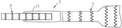
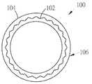
도 1은 예시적인 혈관 이식편의 측면도이다.
도 2는 삽입 구성에 있는 도 1의 예시적인 혈관 이식편의 측면도이다.
도 3은 제1 전개 단계 후의 도 1의 예시적인 혈관 이식편의 측면도이다.
도 4는 제2 전개 단계 후의 도 1의 예시적인 혈관 이식편의 측면도이다.
도 5는 제3 전개 단계 후의 도 1의 예시적인 혈관 이식편의 측면도이다.
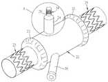
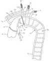
도 6은 대동맥 이식편의 예시적인 중앙 섹션의 사시도이다.
도 6a는 대동맥 이식편의 제2 예시적인 중앙 섹션의 사시도이다.
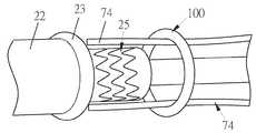
도 7은 도 6에 도시된 점퍼 이식편(jumper graft)의 상세도이다.
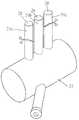
도 8은 대동맥 이식편의 제3 예시적인 중앙 섹션의 사시도이다.
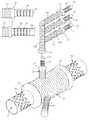
도 9는 대동맥 이식편의 제4 예시적인 중앙 섹션의 사시도이다.
도 9a는 대동맥 이식편의 제5 예시적인 중앙 섹션의 사시도이다.
도 10은 복수의 제1 예시적인 점퍼의 측면도이다.
도 11은 복수의 예시적인 제2 점퍼의 측면도이다.
도 12는 대동맥 이식편의 예시적인 중앙 섹션의 실시예의 예시적인 제1 이식의 측면도이다.
도 12a는 예시적인 차이를 가지는 도 12의 예시적인 이식의 측면도이다.
도 12b는 예시적인 차이를 가지는 도 12a의 예시적인 이식의 측면도이다.
도 13은 예시적인 이중 자동 관류기(dual auto-perfuser)의 측면도이다.
도 14는 대동맥 이식편의 예시적인 중앙 섹션의 실시예의 예시적인 제2 예시적인 이식의 측면도이다.
도 15는 제1 정상 상태에 있는 부유술 봉합 링(floating suture ring)의 측면도이다.
도 16은 제2 확장 상태에 있는 도 15의 부유술 봉합 링의 측면도이다.
도 17은 제3의 조정된 상태에 있는 도 16의 부유술 봉합 링의 측면도이다.
도 18은 도 17의 부유술 봉합 링의 정면도이다.
도 19는 도 15의 부유술 봉합 링의 사시도이다.
도 20은 대동맥 이식편의 이식을 위한 예시적인 시스템의 사시도이다.
도 21은 가요성 내시경 시스템의 사시도이다.
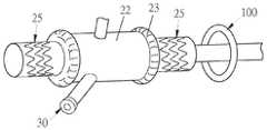
도 22는 단일 관류 카테터의 사시도이다.
도 23은 도 22의 단일 관류 카테터에 삽입된 도 21의 가요성 내시경 시스템의 사시도이다.
도 24는 도 20의 시스템의 작동 단계에서의 사시도이다.
도 25는 도 20의 시스템의 작동에서의 다른 단계의 사시도이다.
도 26은 도 20의 시스템의 작동에서의 다른 단계의 사시도이다.
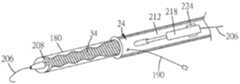
도 27은 제1 상태에 있는 전개 도구의 부분 절개 사시도이다.
도 28은 제2 상태에 있는 도 27의 전개 도구의 부분 절개 사시도이다.
도 29는 제3 상태에 있는 도 27의 전개 도구의 부분 절개 사시도이다.
도 30은 제4 상태에 있는 도 27의 전개 도구의 부분 절개 사시도이다.
도 31은 제1 상태에 있는 봉합 커프(suture cuff)를 가지는 혈관 이식편의 측면도이다.
도 32는 봉합 커프가 혈관 벽에 근접한, 제1 상태에 있는 봉합 커프를 가지는 도 31의 혈관 이식편의 측면도이다.
도 33은 혈관 벽에 대해 제2 상태에 있는 봉합 커프를 가지는 도 32의 혈관 이식편의 측면도이다.
도 34는 평평한 구성에 있는 봉쇄 외장(containment shith)의 측면도이다.
도 35는 압축 상태에 있는 혈관 이식편 주위에 배치된 도 34의 봉쇄 외장의 절개 측면도이다.
도 36은 혈관 이식편을 압축 상태로 압축하는 도 35의 봉쇄 외장의 절개 측면도이다.
도 37은 압축 상태에서 봉쇄 외장을 홀딩하는 당김 와이어를 도시하는, 혈관 이식편을 압축 상태로 압축하는 도 36의 봉쇄 외장의 절개 사시도이다.
도 38은 당김 와이어가 빼내짐에 따라서 혈관 이식편이 자체 확장되는 것을 가능하게 하는 도 37의 봉쇄 외장의 절개 측면도이다.
도 39는 하이브리드 이식편을 형성하기 위해 스텐트(stent)에 연결된 이식편의 실시예의 측면도이다.
도 40은 슬리브의 측면도이다.
도 41은 도 40의 슬리브와 조합된 도 39의 하이브리드 이식편의 측면도이다.
도 42는 하이브리드 이식편의 실시예의 제조 단계의 측면도이다.
도 43은 도 42의 하이브리드 이식편의 실시예의 다른 제조 단계의 측면도이다.
도 44는 혈관 내로의 도 42 및 도 43의 하이브리드 이식편의 배치 단계의 측면도이다.
도 45는 혈관 내로의 도 42 및 도 43의 하이브리드 이식편의 다른 배치 단계의 측면도이다.
도 46은 하이브리드 이식편과 함께 사용 가능한 외장을 포함하는 예시적인 전개 도구의 실시예의 사시도이다.
도 47은 도 46의 예시적인 외장의 측면도이다.
도 48은 도 47의 외장의 저면도이다.
도 49는 도 46 및 도 47의 외장의 정면도이다.
도 50은 하이브리드 이식편의 전개의 시작 동안 도 46의 전개 도구의 사시도이다.
도 51은 초기 구성에서, 하이브리드 이식편과 함께 사용 가능한 외장 전개 슬라이더를 포함하는 예시적인 전개 도구의 사시도이다.
도 52는 제2 구성에서, 도 51의 전개 도구의 사시도이다.
도 53은 전개 도구의 구조를 도시하기 위해 하이브리드 이식편이 제거된 도 52의 전개 도구의 사시도이다.
도 54는 봉합 플랩(suture flap)들을 이용하는 하이브리드 이식편의 실시예의 사시도이다.
도 55는 제1 구성에 있는 전개 도구의 다른 예시적인 실시예의 사시도이다.
도 56은 제2 구성에 있는 도 55의 전개 도구의 사시도이다.
도 57은 제3 구성에 있는 도 55의 전개 도구의 사시도이다.
상이한 도면들에서 동일한 도면 부호의 사용은 유사하거나 동일한 물품을 나타낸다.1 is a side view of an exemplary vascular graft.
2 is a side view of the exemplary vascular graft of FIG. 1 in an implantable configuration.
3 is a side view of the exemplary vascular graft of FIG. 1 after a first deployment step.
4 is a side view of the exemplary vascular graft of FIG. 1 after a second deployment step.
5 is a side view of the exemplary vascular graft of FIG. 1 after a third deployment step.
6 is a perspective view of an exemplary central section of an aortic graft.
6A is a perspective view of a second exemplary central section of an aortic graft.
7 is a detailed view of the jumper graft shown in FIG. 6.
8 is a perspective view of a third exemplary central section of an aortic graft.
9 is a perspective view of a fourth exemplary central section of an aortic graft.
9A is a perspective view of a fifth exemplary central section of an aortic graft.
10 is a side view of a plurality of first exemplary jumpers.
11 is a side view of a plurality of exemplary second jumpers.
12 is a side view of an exemplary first graft of an embodiment of an exemplary central section of an aortic graft.
12A is a side view of the exemplary implant of FIG. 12 with exemplary differences.
12B is a side view of the exemplary implant of FIG. 12A with exemplary differences.
13 is a side view of an exemplary dual auto-perfuser.
14 is a side view of an exemplary second exemplary graft of an embodiment of an exemplary central section of an aortic graft.
15 is a side view of a floating suture ring in a first normal state.
Fig. 16 is a side view of the floatation suture ring of Fig. 15 in a second extended state.
FIG. 17 is a side view of the floatation suture ring of FIG. 16 in a third adjusted state.
18 is a front view of the floatation suture ring of FIG. 17.
19 is a perspective view of the floatation suture ring of FIG. 15.
20 is a perspective view of an exemplary system for implantation of an aortic graft.
21 is a perspective view of a flexible endoscope system.
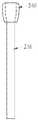
22 is a perspective view of a single perfusion catheter.
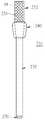
FIG. 23 is a perspective view of the flexible endoscopic system of FIG. 21 inserted into the single perfusion catheter of FIG. 22.
Fig. 24 is a perspective view of the system of Fig. 20 at an operating stage.
25 is a perspective view of another step in operation of the system of FIG. 20;
26 is a perspective view of another step in operation of the system of FIG. 20;
Fig. 27 is a partially cut-away perspective view of the deployment tool in a first state.
Fig. 28 is a partially cutaway perspective view of the deployment tool of Fig. 27 in a second state.
Fig. 29 is a partially cut-away perspective view of the deployment tool of Fig. 27 in a third state.
Fig. 30 is a partially cut-away perspective view of the deployment tool of Fig. 27 in a fourth state.
31 is a side view of a vascular graft having a suture cuff in a first state.
FIG. 32 is a side view of the vascular graft of FIG. 31 with the suture cuff in a first state, with the suture cuff proximate the vessel wall.
33 is a side view of the vascular graft of FIG. 32 with a sutured cuff in a second state with respect to the vessel wall.
34 is a side view of a containment shith in a flat configuration.
FIG. 35 is a cutaway side view of the containment sheath of FIG. 34 disposed around a vascular graft in a compressed state.
FIG. 36 is a cutaway side view of the containment sheath of FIG. 35 for compressing a vascular graft in a compressed state.
FIG. 37 is a cut-away perspective view of the containment sheath of FIG. 36 compressing a vascular graft in a compressed state, showing a pull wire for holding the containment sheath in a compressed state.
FIG. 38 is a cutaway side view of the containment sheath of FIG. 37 allowing the vascular graft to self-expand as the pull wire is withdrawn.
39 is a side view of an embodiment of a graft connected to a stent to form a hybrid graft.
40 is a side view of the sleeve.
41 is a side view of the hybrid graft of FIG. 39 in combination with the sleeve of FIG. 40;
42 is a side view of the manufacturing steps of an embodiment of a hybrid graft.
43 is a side view of another manufacturing step of the embodiment of the hybrid graft of FIG. 42.
FIG. 44 is a side view of a step of placing the hybrid graft of FIGS. 42 and 43 into a blood vessel.
45 is a side view of another stage of placement of the hybrid graft of FIGS. 42 and 43 into a blood vessel.
46 is a perspective view of an embodiment of an exemplary deployment tool including a sheath usable with a hybrid implant.
47 is a side view of the exemplary sheath of FIG. 46;
Fig. 48 is a bottom view of the exterior of Fig. 47;
49 is a front view of the exterior of FIGS. 46 and 47;
50 is a perspective view of the deployment tool of FIG. 46 during the start of deployment of the hybrid graft.
51 is a perspective view of an exemplary deployment tool including an exterior deployment slider usable with a hybrid implant, in an initial configuration.
52 is a perspective view of the deployment tool of FIG. 51 in a second configuration.
FIG. 53 is a perspective view of the deployment tool of FIG. 52 with the hybrid graft removed to show the structure of the deployment tool.
54 is a perspective view of an embodiment of a hybrid graft utilizing suture flaps.
55 is a perspective view of another exemplary embodiment of a deployment tool in a first configuration.
FIG. 56 is a perspective view of the deployment tool of FIG. 55 in a second configuration.
Fig. 57 is a perspective view of the deployment tool of Fig. 55 in a third configuration.
The use of the same reference numbers in different drawings indicates similar or identical articles.
혈관 이식편Vascular graft
도 1을 참조하면, 혈관 이식편(2)이 도시되어 있다. 혈관 이식편(2)은 한쪽 단부에 있는 제1 이식편 앵커(4), 및 다른쪽 단부에 있는 제2 이식편 앵커(6)를 포함한다. 제1 이식편 앵커(4)는 제2 이식편 앵커(6)로부터 길이 방향으로 이격된다. 커버(10)는 혈관 이식편(2)의 실질적으로 전체 길이를 따라서 연장되어, 제1 이식편 앵커(4) 및 제2 이식편 앵커(6)의 실질적으로 모든 외부 표면을 덮는다. 대안적으로, 제1 이식편 앵커(4, 6)의 단부와 같은 제1 이식편 앵커(4) 및/또는 제2 이식편 앵커(6)의 적어도 일부는 커버(10)에 의해 덮이지 않을 수 있다. 대안적으로, 하나 이상의 커버(10)가 사용되어서, 커버(10)는 다수의 층을 가질 수 있거나, 또는 혈관 이식편(2)의 길이를 따라서 2개 이상의 중첩 세그먼트를 포함할 수 있다. 커버(10)는 폴리테트라플루오르에틸렌(PTFE)과 같지만 이에 제한되지 않는 임의의 적합한 재료 또는 재료들로 제작될 수 있다.1, a
2개의 이식편 앵커(4, 6)들 사이에서, 중앙 세그먼트(12)는 내부 구조에 의해 지지되지 않는 커버(10)를 포함할 수 있다. 이러한 방식으로, 이식편 앵커(4, 6)들 사이의 거리는 상이한 혈관 해부학적 구조들을 수용하기 위해 삽입 동안 및 사용시에 변경될 수 있다. 이식편 앵커(4, 6)들 사이의 거리는 고정되지 않고 조정 가능하다. 다른 실시예에서, 중앙 세그먼트(12)는 삽입 및 전개 동안 이식편 앵커(4, 6)들 사이의 거리를 조정하는 능력을 방해하지 않는 구조에 의해 지지될 수 있다.Between the two
제1 이식편 앵커(4) 및 제2 이식편 앵커(6)는 제1 삽입 지름으로부터 제2 전개 지름으로 확장 가능하다. 각각의 이식편 앵커(4, 6)의 길이는 전개 구성으로 확장되는 동안 실질적으로 변하지 않는다. 대안적으로, 적어도 하나의 이식편 앵커(4, 6)는 전개 구성으로 확장되는 동안 길이가 변할 수 있다. 이식편 앵커(4, 6)들은, 제1 삽입 지름으로부터 제2 전개 지름으로 확장을 허용하고 전개 상태에서 혈관 내부에 이식편 앵커(4, 6)들을 견고하게 홀딩하는 임의의 구조를 가질 수 있다. 하나의 예로서, 각각의 이식편 앵커(4, 6)는 혈관 이식편(2) 주위에서 원주 방향으로 연장되는 복수의 후프(8)를 포함할 수 있다. 후프(8)들은 길이 방향으로 이격될 수 있으며; 그러하면, 인접한 후프(8)들은 하나 이상의 타이 바(14)에 의해 연결될 수 있다. 대안적으로, 이격된 후프(8)들은 커버(10)가 아닌 다른 것에 의해 상호 연결되지 않는다. 대안적으로, 적어도 2개의 인접한 후프(8)는 이격되지 않고, 대신에 서로 접하거나 중첩된다. 이러한 구성에서, 이러한 인접한 후프(8)들은 예를 들어 레이저 용접에 의해 서로 고정될 수 있다. 후프(8)들은 금속 또는 다른 재료로 제작될 수 있다. 각각의 후프(8)는 후프(8)가 와이어로 제작되거나, 또는 튜브로부터 레이저 절단된 복합 형상을 가질 수 있거나, 그렇지 않으면 후프(8)가 지그재그, 반복되는 Z 형상, 구불구불한 곡선 또는 다른 형상과 같은 복합 형상을 가지도록 제조될 수 있다. 이러한 형상은 후프(8)가 삽입 지름으로부터 전개 지름으로 확장되는 것을 가능하게 한다. 적어도 하나의 후프(8)의 지그재그 패턴은 연속적으로 곡선화될 수 있거나, 또는 곡선 세그먼트에 의해 연결된 직선 세그먼트들을 포함할 수 있다. 한 실시예에서, 후프(8)들의 지그재그 패턴은 그 전체 내용이 참조에 의해 본 명세서에 통합되는 만료된 미국 특허 제4,580,568호에 제시된 바와 같을 수 있다. 그러나, 적어도 하나의 후프(8)가 상이하게 구성될 수 있다.The
한 실시예에서, 상이한 후프(8)들은 상이한 재료들로 제작될 수 있다. 예를 들어, 적어도 하나의 후프(8)는 니켈-티타늄 합금과 같은 초탄성 재료로 제작될 수 있고, 적어도 하나의 다른 후프(8)는 316L 스테인리스강과 같은 소성 변형 가능한 재료로 제작될 수 있다. 인접한 후프(8)들은 어떠한 후프(8)도 동일한 재료로 구성된 후프에 인접하지 않도록 상이한 재료들 사이에서 교대할 수 있다. 다른 실시예에서, 동일한 재료로 구성된 몇몇 후프(8)들은 함께 그룹화될 수 있고, 상이한 재료로 구성된 적어도 하나의 후프(8)는 이 그룹에 인접할 수 있다. 예를 들어, 이식편 앵커(4, 6)의 외측 단부에 있는 후프(8)는 스테인리스강으로 구성될 수 있고, 나머지 후프(8)들은 니켈-티타늄 합금과 같은 초탄성 재료로 구성될 수 있다. 상이한 재료로 제작된 후프(8)를 사용하는 것에 의해, 혈관 이식편(2)은 이들 상이한 재료의 상이한 특성들을 이용하는 이점을 취한다. 예를 들어, 초탄성 재료로 제작된 하나 이상의 후프(8)는 이식편 앵커(4, 6)를 확장하는데 유용하며; 이러한 초탄성 후프(8)들 내부의 표준 중재 벌룬 카테터에 의해 가해지는 외향력은 이러한 후프(8)를 마르텐사이트와 오스테나이트 상 사이에서 압박하여, 이들 후프(8)가 더 큰 지름의 구성으로 자체 확장되게 한다. 316L 스테인리스강과 같은 소성 변형 가능한 재료로 제작된 하나 이상의 추가 후프(8)는, 이러한 재료가 후프 응력에 보다 큰 저항을 가지고 확장 후에 다른 결정상으로의 복귀에 민감하지 않기 때문에 각각의 앵커(4, 6)의 루멘을 개방 상태로 유지하는데 유용하다. 본 명세서에서 "후프"라는 용어가 사용되었을지라도, 후프(8)들은 단부에서 보았을 때 완벽하게 원형일 필요는 없으며, 특정 용도에 적합한 다른 형상과 곡률을 가질 수 있다. 일부 실시예에서, 후프(8)들은 단부에서 보았을 때 실질적으로 원형이다.In one embodiment, the
한 실시예에서, 이식편 앵커(4, 6)들은 전개 상태에서 동일하거나 유사한 지름으로 각각 확장된다. 다른 실시예에서, 제1 이식편 앵커(4)는 전개 상태에서 제2 이식편 앵커(6)와 상이한 지름으로 확장된다. 유사하게, 일부 실시예에서, 제1 이식편 앵커(4)는 삽입 상태에서 제2 이식편 앵커(6)와 상이한 지름을 가진다. 이러한 방식으로, 혈관 이식편(2)의 전개가 촉진될 수 있고, 및/또는 환자의 특정 혈관 조직에서 혈관 이식편(2)의 보다 양호한 맞춤이 촉진될 수 있다. 제1 이식편 앵커(4)와 제2 이식편 앵커(6)의 지름에서의 차이는 제1 이식편 앵커(4)에서의 후프(8)들의 지름을 제2 이식편 앵커(6)의 후프(8)들의 지름과 다르게 제어하는 것에 의해, 상이한 이식 앵커(4, 6)들에서의 상이한 재료를 후프(8)들의 상이한 혼합에 제공하는 것에 의해, 또는 임의의 다른 적절한 방식으로 제어될 수 있다.In one embodiment, the graft anchors 4 and 6 each expand to the same or similar diameter in the deployed state. In another embodiment, the
수술 - 혈관 이식편Surgery-vascular graft
도 2를 참조하면, 혈관 이식편(2)은 환자의 혈관 구조 내로 도입하기 위한 삽입 구성에 있다. 제2 이식편 앵커(6)는 제1 이식편 앵커(4)를 향해 이동되고, 중앙 세그먼트(12)는 제2 이식편 앵커(6) 위에서 뒤집힌다(evert). 이식편 앵커(4, 6)들은 선택적으로 삽입 구성에서 인접에 근접할 수 있고, 커버(10)의 두께만큼 분리된다.Referring to Fig. 2, the
삽입 구성에서의 혈관 이식편(2)은 예를 들어 표준 대퇴골 절개를 통하여 임의의 적절한 방식으로 혈관 구조 내로 삽입된다. 삽입 동안, 혈관 이식편(2)은 카테터의 루멘 내에 홀딩될 수 있고, 가이드 와이어는 혈관 이식편의 루멘을 통해 연장될 수 있다. 혈관 이식편(2)은 표준 방식으로 가이드 와이어 및 카테터를 사용하여 혈관 구조를 통해 치료 부위로 전진되거나, 또는 임의의 다른 적절한 방식으로 혈관 구조를 통해 전진된다.The
도 3을 참조하면, 혈관 이식편(2)이 치료 부위에 도달할 때, 표준 중재 벌룬이 제1 이식편 앵커(4) 내에서 확장된다. 벌룬의 확장은 제1 이식편 앵커(4)의 후프(8)들이 큰 지름 구성으로 확장되게 한다. 후프(8)들 중 적어도 하나가 초탄성 재료로 구성되는 경우에, 벌룬의 확장은 이러한 적어도 하나의 후프(8)를 마르텐사이트와 오스테나이트 상 사이에 압박하여, 이러한 적어도 하나의 후프(8)가 더 큰 지름 구성으로 자체 확장되게 한다.Referring to FIG. 3, when the
도 4를 참조하면, 제1 이식편 앵커(4)가 전개 지름으로 확장된 후에, 제2 이식편 앵커(6)는 희망 전개 위치로 제1 이식편 앵커(4)로부터 멀어지게 근위로 당겨진다. 중앙 세그먼트(12)의 유연성은 이식편 앵커(4, 6)들 사이의 거리의 이러한 조정을 허용한다. 도 4에서 알 수 있는 바와 같이, 중앙 세그먼트(12)의 지름은 제1 이식편 앵커(4)의 지름보다 작을 수 있다. 마지막으로, 도 5를 참조하면, 표준 중재 벌룬은 제1 이식편 앵커(4)와 관련하여 위에서 설명된 것과 동일한 방식으로 확장되는 제2 이식편 앵커(6) 내에서 확장된다. 위에서 설명한 바와 같이, 제1 이식편 앵커(4)의 확장된 지름은 제2 이식편 앵커(6)의 확장된 지름과 실질적으로 동일하거나 또는 이와 다를 수 있다. 중재 벌룬, 가이드 와이어, 카테터 및/또는 다른 중재 디바이스들은 치료 부위로부터 빼내지고, 혈관 이식편(2)은 전개 상태 및 전개 위치에서 유지된다.Referring to FIG. 4, after the
대동맥 이식편Aortic graft
도 6 및 도 7을 참조하면, 대동맥 이식편(20)의 중앙 섹션(22)이 도시된다. 도 12 및 도 14를 참조하면, 전체 대동맥 이식편(20)이 도시되고, 다음에 더욱 상세히 설명된다. 대동맥 이식편(20)의 중앙 섹션(22)은 수술 동안 상행 대동맥 및/또는 대동맥궁을 보강하거나 대체한다. 중앙 섹션(22)을 포함하는 대동맥 이식편(20)은 전형적으로 Delaware의 Wilmington에 소재하는 E. I. Du Pont De Nemours and Company로부터 시판중인 DACRON® 브랜드 폴리에스테르로서 때때로 공지된 폴리에틸렌 테레프탈레이트(PET)와 같은 폴리에스테르로 제작된다. 유리하게, 중앙 섹션(22)을 포함하는 대동맥 이식편(20)은 환자 자신의 조직이 대동맥 이식편(20) 내로 성장하도록 장려하는 콜라겐이 함침된다. 대안적으로, 필요하면, 대동맥 이식편(20)은 강하고 유연하며 누출 방지성인 임의의 다른 생체 적합성 재료로 제작될 수 있다.6 and 7, the
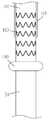
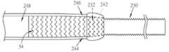
대동맥 이식편(20)의 중앙 섹션(22)은 3개의 점퍼 이식편(24a, 24b, 24c)을 포함할 수 있다. 3개의 점퍼 이식편(24a, 24b, 24c)은 대동맥궁에서 발생하는 3개의 동맥, 즉 팔머리 동맥(brachiocephalic trunk), 좌측 총경동맥(common carotid artery) 및 왼빗장밑 동맥에 대응한다. 3개의 점퍼 이식편(24a, 24b, 24c)은 대동맥 이식편(20)의 중앙 섹션(22)으로부터 기원하는, 혈액이 통과하는 것을 가능하게 하는 내부 루멘을 각각 포함한다. 각각의 점퍼 이식편(24a, 24b, 24c)의 베이스(26)는 유리하게 대동맥 이식편(20)의 중앙 섹션(22)에 고정된다. 일부 실시예에서, 적어도 하나의 점퍼 이식편(24a, 24b, 24c)은 PTFE로 제작되고, 대동맥 이식편(20)의 중앙 섹션(22)에 부착된다. 다른 실시예에서, 적어도 하나의 점퍼 이식편(24a, 24b, 24c)은 대동맥 이식편(20)과 일체이며, 또한 대동맥 이식편(20)의 중앙 섹션(22)과 동일한 재료로 제작된다. 각각의 점퍼 이식편(24a, 24b, 24c)의 팁(28)은 일반적으로 관형이고 이를 통해 한정된 루멘을 가지는 확장 가능한 메쉬(34)를 포함할 수 있다. 일부 실시예에서, 확장 가능한 메쉬(34)는 그 전체 길이를 따라서 실질적으로 동일한 지름을 가진다. 다른 실시예에서, 확장 가능한 메쉬(34)의 원위 단부는. 일부 실시예에서, 적어도 하나의 확장 가능한 메쉬(34)의 근위 단부는 대응하는 점퍼 이식편(24a, 24b, 24c)의 팁에 재봉되거나 또는 그렇지 않으면 고정될 수 있다. 일부 실시예에서, 적어도 하나의 확장 가능한 메쉬(34)는 적어도 하나의 이식편 앵커(4, 6)와 동일하거나 유사한 방식으로 제작될 수 있고, 더 작은 길이 및 지름으로 축소될 수 있다. 확장 가능한 메쉬(34)는 유리하게 자체 확장형이며; 다른 예로서, 확장 가능한 메쉬(34)는 니티놀과 같은 초탄성 재료로 제작될 수 있으며; 다른 예로서, 확장 가능한 메쉬(34)는 그 탄성 한계 이하의 양으로 압축된 스테인리스강과 같은 소성 변형 가능한 재료로 제작될 수 있으며, 그런 다음, 그 압축이 제거되어 확장 가능한 메쉬(34)가 적소로 자체 확장되는 것을 가능하게 한다.The
대동맥 이식편(20)의 중앙 섹션(22)은 유리하게 접근 포트(30)를 포함한다. 접근 포트(30)는 기기 및/또는 가이드 와이어가 대동맥 이식편(20)의 중앙 섹션(22) 내로 삽입되고 이를 통해 중앙 섹션의 밖으로 빼내지는 것을 가능하게 하는 내부 루멘을 포함한다. 일부 실시예에서, 접근 포트(30)는 PTFE로 제작되고, 대동맥 이식편(20)의 중앙 섹션(22)에 부착된다. 이러한 방식으로, 접근 포트(30)는 대동맥 이식편(20)의 이식이 완료된 후에 용이하게 밀봉 및/또는 제거될 수 있다. 다른 실시예에서, 접근 포트(30)는 대동맥 이식편(20)과 일체이고, 또한 대동맥 이식편(20)의 중앙 섹션(22)과 동일한 재료로 제작된다. 접근 포트(30)의 한쪽 단부는 대동맥 이식편(20)의 중앙 섹션(22)에 연결되며; 접근 포트(30)의 다른쪽 단부는 혈액이 대동맥 이식편(20)의 중앙 섹션(22)을 통해 흐르는 동안 기기들 및/또는 가이드 와이어가 접근 포트(30)에 들어가고 나오는 것을 가능하게 하는 지혈 밸브(hemostasis valve)(32)를 포함한다.The
또한 도 6a를 참조하면, 대동맥 이식편(20)의 중앙 섹션(22)의 또 다른 예시적인 실시예가 도시되어 있다. 도 6a의 예시적인 실시예에서, 봉합 밴드(23)는 중앙 섹션(22)의 한쪽 또는 양쪽 단부에 또는 그 근처에 제공된다. 각각의 봉합 밴드(23)는 중앙 섹션(22)의 벽의 더 두꺼운 섹션일 수 있거나, 또는 금속 또는 비금속 메쉬와 같이 중앙 섹션(22)에 고정되는 별도의 물품일 수 있다. 다음에 더욱 상세히 설명되는 바와 같이, 각각의 봉합 밴드(23)는 대동맥 또는 다른 조직에 봉합될 수 있는 중앙 섹션(22) 상에, 이식시에 봉합사와 맞물리고 중앙 섹션(22)을 적소에 홀딩하는데 훨씬 큰 적합성을 가지는 영역을 제공한다. 다른 실시예에서, 추가 봉합 링(23)이 제공될 수 있거나, 또는 더 큰 봉합 영역(23)들이 중앙 섹션(22)에 제공될 수 있다. 봉합 링 또는 링(23)들에 추가하여, 선택적으로 하나 이상의 중앙 섹션 앵커(25)가 중앙 섹션(22)에 부착될 수 있다. 각각의 중앙 섹션 앵커(25)는 자체 확장될 수 있으며; 예를 들어, 적어도 하나의 중앙 섹션 앵커(25)는 니티놀과 같은 초탄성 재료로 제작될 수 있으며; 다른 예로서, 적어도 하나의 중앙 섹션 앵커(25)는 그 탄성 한계 이하의 양으로 압축된 스테인리스강과 같은 소성 변형 가능한 재료로 제작될 수 있고, 그런 다음 압축이 제거되어 중앙 섹션 앵커(25)가 적소로 자체 확장되는 것을 허용한다. 각각의 중앙 섹션 앵커(25)는 몰딩, 접착제 또는 와이어와 같은 임의의 적절한 방식으로 중앙 섹션(22)에 부착될 수 있다. 선택적으로, 적어도 하나의 중앙 섹션 앵커(25)는 대응하는 봉합 밴드(23)에 고정될 수 있고, 봉합 밴드(23)와 중앙 섹션(22) 사이의 부착은 차례로 그 중앙 섹션 앵커(25)를 중앙 섹션(22)에 부착한다. 대안적으로, 중앙 섹션 앵커(25)들은 중앙 섹션(22)에 부착될 수 있고, 하나 이상의 봉합 링(23)은 생략될 수 있다.Referring also to FIG. 6A, another exemplary embodiment of the
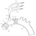
또한 도 8을 참조하면, 대동맥 이식편(20)의 중앙 섹션(22)의 또 다른 예시적인 실시예가 도시되어 있다. 도 8의 예시적인 실시예에서, 점퍼 이식편(24a, 24b, 24c)들은 PTFE 또는 유사한 재료로 제작되고, 도 7의 예시적인 실시예의 것들보다 더 길다. 이러한 점퍼 이식편(24a, 24b, 24c)들이 도 7의 실시예에서의 것들보다 길기 때문에, 외과의는 신체에서 필요함에 따라 점퍼들을 절단하거나 배치하도록 보다 큰 유연성을 가진다. 각각의 점퍼 이식편(24a, 24b, 24c)의 팁(28)은 도 7과 관련하여 위에서 설명된 바와 같이 확장 가능한 메쉬(34)를 포함하지 않고; 오히려, 각각의 점퍼 이식편(24a, 24b, 24c)의 팁은 단순히 튜브의 단부이다.Referring also to FIG. 8, another exemplary embodiment of the
또한 도 9를 참조하면, 대동맥 이식편(20)의 중앙 섹션(22)의 또 다른 예시적인 실시예가 도시되어 있다. 도 9의 예시적인 실시예에서, 분지형 이식편(27)은 대동맥 이식편(20)의 중앙 섹션(22)으로부터 연장되는 매니폴드(24d)를 포함한다. 매니폴드(24d)는 중앙 섹션(22)에 고정될 수 있거나, 또는 전술한 것과 유사한 방식으로 중앙 섹션(22)에 고정되는 점퍼 이식편(24)에 연결될 수 있다. 점퍼 이식편(24a, 24b, 24c)들은 매니폴드(24d)로부터 연장되고, 매니폴드(24d) 및 중앙 섹션(22)의 루멘과 유체 연통한다. 이러한 구성은 특정 해부학적 구조에 대해 추가적인 다양성을 제공할 수 있다. 도 9의 예시적인 실시예에서, 점퍼 이식편(24a, 24b, 24c)들은 그렇지 않으면 도 7 또는 도 8과 관련하여 설명된 바와 같이 구성될 수 있고, 적어도 하나의 점퍼 이식편(24a, 24b, 24c)의 팁(28)에서 확장 가능한 메쉬(34)를 포함하거나 배제할 수 있다. 중앙 섹션(22)의 상이한 실시예에서 설명된 특징부들은 대동맥 이식편(20)에서 필요에 따라 조합될 수 있다는 것이 명백할 것이다. 또한 점퍼 이식편(24)들 및 혈관 이식편(2)들은임상의의 재량에 따라 상호 교환적으로 사용될 수 있고, 본 명세서에서 "점퍼 이식편" 및 "혈관 이식편"이라는 문구를 상호 교환적으로 사용될 수 있다는 점에 유의한다.Referring also to FIG. 9, another exemplary embodiment of the
또한 도 9a를 참조하면, 대동맥 이식편(20)의 중앙 섹션(22)의 또 다른 예시적인 실시예가 도시되어 있다. 중앙 섹션(22)은 일반적으로 도 6a와 관련하여 위에서 설명된 바와 같다. 중앙 섹션(22)은 주름지고 대체로 꼬임 방지 재료로 제작될 수 있다. 주름은 선택적으로 중앙 섹션(22)의 이식시에 임상의가 원하는대로 중앙 섹션(22)이 늘려지거나 단축되는 것을 가능하게 한다. 중앙 섹션은 이로부터 연장되는 단일 점퍼 이식편(24)을 포함하며, 이는 또한 주름지고 대체로 꼬임 방지 재료로 제작될 수 있다. 주름은 선택적으로 점퍼 이식편(24)이 임상의가 원하는대로 늘려지거나 또는 단축되는 것을 가능하게 한다. 도 6a와 관련하여 전술한 바와 같은 봉합 밴드(23)는 메쉬 구조(34)와 점퍼 이식편(24)의 나머지 사이에서 메쉬 구조(34)에 근접하게 위치될 수 있다.Referring also to FIG. 9A, another exemplary embodiment of the
분지형 이식편(27)은 도 9와 관련하여 설명된 바와 같이, 매니폴드(24d) 및 이로부터 연장되는 점퍼 이식편(24a, 24b 24c)들을 포함한다. 매니폴드(24d) 및 점퍼 이식편(24a, 24b, 24c)들 중 적어도 하나는 주름지고 대체로 꼬임 방지 재료로 제작될 수 있다. 주름은 선택적으로 매니폴드(24d) 및/또는 적어도 하나의 점퍼 이식편(24a, 24b, 24c)이 매니폴드(24d) 및 점퍼 이식편(24a, 24b, 24c)들의 이식시에 임상의가 원하는대로 늘려지거나 또는 단축되는 것을 가능하게 한다. 도 6a와 관련하여 전술한 바와 같은 봉합 밴드(23)는 점퍼 이식편(24)의 봉합 밴드에 대응하는 매니폴드(24d)의 자유 단부에 위치될 수 있다. 매니폴드(24d)가 점퍼 이식편(24)에 부착될 때, 매니폴드(24d)의 봉합 밴드(23) 및 점퍼 이식편(24)은 이러한 것들을 연결하기 위해 또는 확장 메쉬(34)의 확장에 의해 만들어진 둘 사이의 연결부를 보강하기 위해 함께 봉합될 수 있다. 유사하게, 봉합 밴드(23)는 점퍼 이식편(24a, 24b, 24c)들 중 적어도 하나의 팁(28)에 근접하게 위치될 수 있다. 각각의 봉합 밴드(23)는 도 6a와 관련하여 전술한 바와 같을 수 있고, 메쉬 구조(34)와 점퍼 이식편(24a, 24b, 24c)의 나머지 사이에서 메쉬 구조(34)에 근접하게 위치될 수 있다. 봉합 밴드(23)는 점퍼 이식편(24a, 24b, 24c)의 단부를 혈관(29)에 봉합하는 것을 용이하게 하여, 봉합을 위해 강하고 접근 가능한 위치를 제공한다. 그 봉합은 혈관(29) 내에서 확장 가능한 메쉬(34)의 확장에 의해 만들어진 점퍼 이식편(24a, 24b, 24c)에 대한 연결을 보강하기 위해 사용될 수 있다. 또한, 다음에 설명된 바와 같은 추가 점퍼(40, 50)가 추가 길이를 위해 점퍼 이식편(24a, 24b, 24c)의 팁에 부착되면, 그 점퍼(40, 50)의 근위 단부는 추가 점퍼(40, 50) 내에서 확장 가능한 메쉬(34)의 확장에 의해 만들어진 점퍼 이식편(24a, 24b, 24c)에 대한 연결을 보강하기 위해 점퍼 이식편(24a, 24b, 24c)의 단부에서 봉합 밴드(23)에 봉합될 수 있다.The
또한 도 31 내지 도 33을 참조하면, 일부 실시예에 따르면, 적어도 하나의 점퍼 이식편(24a, 24b, 24c)의 단부는 봉합 커프(160)를 포함할 수 있다. 봉합 커프(160)는 초기에 양말의 커프처럼 말린(rolled) 구성에 있는 재료의 세그먼트이다. 봉합 커프(160)는 점퍼 이식편(24)의 외부 커버링과 통합될 수 있고, 완전히 풀린 구성에서 점퍼 이식편(24)보다 길 수 있고, 초기에 길이가 점퍼 이식편(24a, 24b, 24c)과 거의 동일할 수 있다. 대안적으로, 봉합 커프(160)는 점퍼 이식편(24)의 단부에 재봉되거나 또는 그렇지 않으면 부착되는 재료의 별도의 부분일 수 있다.Also referring to FIGS. 31 to 33, according to some embodiments, ends of at least one
다음에 더욱 상세히 설명되는 바와 같이, 봉합 커프(160)는 점퍼 이식편(24)이 연결된 혈관의 벽을 만나기 위하여, 또한 혈관 벽에 대한 더 단단한 연결을 제공하기 위해 그 혈관 벽(165)에 점퍼 이식편(24)을 봉합하도록 수술의가 이용할 수 있는 재료의 링을 제공하기 위해 점퍼 이식편(24)의 단부로부터 대칭적으로 또는 비대칭적으로 풀릴 수 있다. 점퍼 이식편(24)은 원통형 스캐폴드(scaffold)(163) 주위에 외부 커버(161)를 포함할 수 있다. 외부 커버(161)는 Delaware, Wilmington의 E. I. Du Pont De Nemours and Company로부터 시판중인 DACRON® 브랜드 폴리에스테르로서 때때로 공지된 폴리에틸렌 테레프탈레이트(PET)과 같은 폴리테트라플루오르에틸렌(PTFE) 또는 폴리에스테르와 같지만 이에 제한되지 않는 임의의 적절한 생체 적합성 재료로 제작될 수 있다. 스캐폴드(163)는 니켈-티타늄 합금, 스프링강 또는 임의의 다른 적절한 생체 적합성 재료로 제작될 수 있다. 스캐폴드(163)는 외부 커버(161)보다 길이 방향으로 짧을 수 있고, 스캐폴드(163)의 단부로부터 길이 방향 외측으로 연장되는 외부 커버(161)의 섹션은 봉합 커프(160)를 형성할 수 있다. 즉, 초기에 스캐폴드(163)에 대한 외부 커버(161)의 잉여 길이는 스캐폴드(163)의 한쪽 단부에서 스캐폴드(163)의 길이 방향 중심선 주위에서 링 내로 말릴 수 있다. 봉합 커프(160)가 본 명세서에서 점퍼 이식편(24)과 함께 그 사용과 관련하여 설명되었지만, 봉합 커프(160)는 본 명세서에서 설명된 임의의 다른 점퍼 이식편 또는 앵커와 함께 적절하게 사용될 수 있다.As described in more detail below, the
도 34 내지 도 38을 또한 참조하면, 봉쇄 외장(180)은 전개 전에 봉쇄된 초기 구성으로 적어도 하나의 자체 확장 메쉬(34)를 홀딩하기 위해 이용될 수 있다. 봉쇄 외장(180)은 Delaware, Wilmington에 소재하는 E. I. Du Pont De Nemours and Company로부터 시판중인 DACRON® 브랜드 폴리에스테르로서 때때로 공지된 폴리에틸렌 테레프탈레이트(PET)과 같은 폴리테트라플루오르에틸렌(PTFE) 또는 폴리에스테르와 같지만 이에 제한되지 않는 임의의 적절한 생체 적합성 재료로 제작될 수 있다. 다음에 더욱 상세히 설명되는 바와 같이, 유리하게 봉쇄 외장(180)은 신체에 남지 않는다. 도 34를 참조하면, 봉쇄 외장(180)은 조립 전에 평평한 구성으로 도시되어 있다. 봉쇄 외장(180)의 측면 가장자리(182)들은 정현파 또는 대체로 정현파 패턴으로 곡선화되고, 봉쇄 외장(180)이 점퍼 이식편(24) 주위로 말릴 때 봉쇄 외장(180)의 한쪽 측면 가장자리(l82a) 상의 봉우리(peak)(184)들이 다른쪽 측면 가장자리(l82b)의 골짜기(valley)(186)들과 일치하도록 서로 오프셋된다. 각각의 봉우리(184)에 근접한 측면에는 구멍(188)이 있다. 대안적으로, 구멍(188)들은 몇몇 쌍의 봉우리(184)에 근접하여 위치하며, 여기에서, 봉우리(184)들의 쌍은 측 방향으로 이격될지라도 서로 길이 방향으로 가장 가까운 2개의 봉우리(184)로서 정의된다.Referring also to FIGS. 34 to 38, the
또한 도 35를 참조하면, 봉쇄 외장(180)은 초기 압축 구성에서 점퍼 이식편(24) 주위로 말리며, 점퍼 이식편(24)을 삽입 지름으로 압축한다. 도 36 및 도 37을 또한 참조하면, 당김 와이어(190)는 말린 봉쇄 외장(180)에 있는 길이 방향으로 인접한 구멍(188)들을 통과한다. 이러한 방식으로, 당김 와이어(190)는 봉쇄 외장(180)의 인접한 가장자리(182a, l82b)들을 함께 홀딩한다. 당김 와이어(190)의 근위 단부(192)는 전개 도구(200)를 따라서 근위로 연장될 수 있다. 다음의 도 27 내지 도 30에서 더욱 상세히 설명되는 바와 같이, 당김 와이어(190)는 봉쇄 외장(180)을 개방하고 자체 확장 메쉬(34)가 점퍼 이식편(24)에서 확장되는 것을 가능하게 하기 위하여 구멍(188)들로부터 근위 방향으로 후퇴될 수 있다. 당김 와이어(190)는 스테인리스강 와이어와 같은 임의의 적절한 재료로 제작될 수 있다. 대안적으로, 당김 와이어(190)는 나일론 또는 생체 적합성 직물과 같은 생체 적합성 비금속 재료로 제작될 수 있다. 봉쇄 외장(180)이 점퍼 이식편(24)과 함께 그 사용과 관련하여 본 명세서에 설명되었지만, 봉쇄 외장(180)은 본 명세서에 설명된 임의의 다른 점퍼, 이식편 또는 앵커와 함께 적절하게 사용될 수 있다.Also, referring to FIG. 35, the
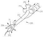
또한 도 27을 참조하면, 예시적인 전개 도구(200)가 도시되어 있다. 전개 도구(200)의 원위 단부에는 뭉툭한 확장기 팁(202)이 있다. 확장기 팁(202)은 다음에 더욱 상세히 설명되는 바와 같이 혈관에서 만들어진 절개부 또는 개구를 확장하기 위해 크기화되고 형상화된다. 통로(204)는 확장기 팁(202)을 통해 한정된다. 유리하게, 통로(204)는 직선이고, 전개 도구(200)의 길이 방향 중심선과 실질적으로 동축이다. 대안적으로, 통로(204)는 전개 도구(200)에 대해 상이하게 형상화될 수 있고 및/또는 상이하게 배향될 수 있다. 가이드 와이어(206)는 통로(204)를 통해 연장되고 및/또는 통로 내로 후퇴 가능할 수 있다. 도 27, 도 29 및 도 30에 도시된 바와 같이, 유리하게 가이드 와이어(206)는 가이드 와이어(206)가 통로(204)를 빠져나갈 때 곡선화되도록 구성된다. 즉, 통로(204)를 빠져나갈 때, 가이드 와이어(206)의 원위 단부는 도 27, 도 29 및 도 30에 도시된 바와 같이 한쪽 측면으로든 다시 근위 방향을 향하든 전개 도구(200)의 길이 방향 중심선으로부터 멀어지게 곡선화된다. 대안적으로, 가이드 와이어(206)의 원위 단부가 확장기 팁(202)의 원위 단부로부터 이격되도록 가이드 와이어(206)의 원위 단부가 원위로 전진된 후에, 가이드 와이어(206)의 원위 단부는 전개 도구(200)의 길이 방향 중심선으로부터 멀어지게 곡선화되기 시작한다. 또한, 도 28을 참조하면, 바늘(210)은 중립 위치에서 확장기 팁(202)을 통해 통로(204) 내에 위치될 수 있다. 바늘(210)은 환자의 신체에 있는 혈관을 뚫기 위해 확장기 팁(202)에 대해 전진 가능할 수 있다. 유리하게, 바늘(210)은 가이드 와이어(206)가 바늘(210)을 통과할 수 있도록 중공체이다.Referring also to FIG. 27, an
도 27을 참조하면, 확장기 팁(202)에 근접한 전개 도구(200)는 맨드릴(208)을 포함한다. 자체 확장 메쉬(34)는 맨드릴(208) 주위를 감싸며, 봉쇄 외장(180)에 의해 맨드릴(208)에 대해 적어도 부분적으로 압축된다. 전술한 바와 같이, 도 36을 또한 참조하면, 당김 와이어(190)는 길이 방향으로 인접한 구멍(188)들을 통해 연장되고, 이에 의해 봉쇄 외장(180)의 측면 가장자리(182)들을 함께 홀딩한다. 이러한 방식으로, 자체 확장 메쉬(34)는 봉쇄 외장(180)에 의해 맨드릴(208)에 대해 압축된다. 자체 확장 메쉬(34)는 확장기 팁(202)에 근접하게 위치된다. 대안적으로,자체 확장 메쉬(34)의 원위 단부는 확장기 팁(202)의 원위 단부에 근접하게 위치될 수 있다. 점퍼 이식편(24)은 전술한 바와 같이 봉합 커프(160)를 포함할 수 있다. 봉합 커프(160)는 전개 도구(200)에 대해, 점퍼 이식편(24)의 근위 단부에 위치될 수 있다. 대안적으로, 봉합 커프(160)는 전개 도구(200)에 대해, 점퍼 이식편(24)의 원위 단부에 위치될 수 있다.Referring to FIG. 27, the
또한 도 27을 참조하면, 핸들(212)은 점퍼 이식편(24) 내의 맨드릴(208)의 근위 단부에 연결된다. 맨드릴(208)은 핸들(212)과 별도로 제작되어 핸들(212)에 부착될 수 있거나, 또는 맨드릴(208) 및 핸들(212)은 일체로 제작될 수 있다. 핸들(212)은 임의의 적절한 재료로 제작될 수 있다. 도 27의 부분 단면도에서 알 수 있는 바와 같이, 루멘(214)은 핸들(212)뿐만 아니라 맨드릴(208)을 통해 실질적으로 길이 방향으로 연장될 수 있다. 루멘(214)은 대체로 원형 단면을 가질 수 있거나, 또는 임의의 다른 적절한 단면 형상을 가질 수 있다. 측면 포트(216)는 핸들(212)을 통해 루멘(214)까지 측 방향으로 연장될 수 있다. 당김 와이어(190)는 루멘(214) 내로 근위로 연장되고, 그런 다음 측면 포트(216)를 통해 외측으로 연장될 수 있다. 루멘(214)의 근위 섹션은 루멘(214)의 원위 섹션보다 넓을 수 있다. 루멘(214)의 더 넓은 섹션은 스프링 수용부(218)로서 지칭될 수 있다. 스프링 수용부(218)는 대체로 원형 단면을 가질 수 있거나, 또는 임의의 다른 적절한 단면을 가질 수 있다. 융기부(220)는 스프링 수용부(218)의 근위 단부에 위치될 수 있으며, 여기에서 루멘(214)의 폭이 넓어진다. 압축 스프링(222)이 스프링 수용부(218) 내에 위치될 수 있다. 압축 스프링(222)의 원위 단부는 융기부(220)에 안착될 수 있으며, 이는 압축 스프링(222)의 원위 단부가 융기부(220)에 대해 원위로 이동하는 것을 방지한다. 바늘 전진 버튼(224)은 압축 스프링(222)에 근접하게 위치된다. 바늘 전진 버튼(224)의 근위 단부는 압축 스프링(222)에 직접적으로 또는 간접적으로 연결되어서, 바늘 전진 버튼(224)의 원위 운동은 압축 스프링(222)을 압축한다. 바늘 전진 버튼(224)은 바늘 전개 제어기(228)에 부착되거나 또는 그렇지 않으면 결합된다. 바늘 전개 제어기(228)는 루멘(214)을 통해 연장되고, 바늘(210)에 부착되거나 또는 그렇지 않으면 바늘에 결합된다. 바늘 전개 제어기(228)는 대체로 강성 와이어일 수 있거나, 또는 압축력을 견디고 그 힘을 원위로 전달할 수 있는 임의의 다른 구조일 수 있다. 대안적으로, 바늘 전개 제어기(228)는 예를 들어 적어도 하나의 중간 메커니즘을 통해 바늘(210)에 선택적으로 결합 및 결합 해제될 수 있다. 압축 스프링(222)은 바늘 전진 버튼(224)을 근위로 편향시키고, 이에 의해 바늘 전개 제어기(228)를 통해 확장기 팁(202)에 있는 통로(204) 내로 바늘(210)을 근위로 편향시킨다. 바늘(210)이 확장기 팁(202)에 있는 통로(204) 내로 편향될 때, 바늘(210) 및 바늘 전개 제어기(228)는 중립 상태에 있다. 원위 방향으로의 바늘 전개 제어기(228)의 누름은 다음에 더욱 상세히 설명되는 바와 같이, 확장기 팁(202)으로부터 원위로 바늘(210)을 전진시킨다.Referring also to FIG. 27, handle 212 is connected to the proximal end of
바늘 전진 버튼(224)은 버튼을 통해 일반적으로 길이 방향으로 연장되는 루멘(226)을 포함한다. 이러한 방식으로, 가이드 와이어(206)는 맨드릴(208) 및 핸들(212)의 루멘(214), 및 또한 바늘 전진 버튼(224)의 루멘(226)을 통해, 그런 다음 바늘 전진 버튼(224)의 근위 단부의 밖으로 연장될 수 있다.The
전개 도구(200)가 점퍼 이식편(24)과의 사용과 관련하여 본 명세서에서 설명되지만, 전개 도구(200)는 적절하게 본 명세서에서 설명된 임의의 다른 점퍼 이식편 또는 앵커와 함께 사용될 수 있다.While
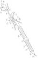
또한 도 10을 참조하면, 상이한 내경을 가지는 점퍼 이식편(40)들이 도시되어 있다. 점퍼 이식편(40a)은 실질적으로 9 ㎜의 내경을 가질 수 있고, 점퍼 이식편(40b)은 실질적으로 11 ㎜의 내경을 가질 수 있으며, 점퍼 이식편(40c)은 실질적으로 13 ㎜의 내경을 가질 수 있다. 다른 내경을 가진 점퍼 이식편(40)들이 제공될 수 있다. 점퍼 이식편(40)은 임의로 길 수 있다. 점퍼 이식편(40)의 확장 단부(42)는 전술한 바와 같이 이식편 앵커(4, 6)와 실질적으로 동일한 방식으로 구성될 수 있어서, 확장 단부(42)는 삽입 상태(도 10에 도시됨)에서 지름이 작고 확장 상태에서 지름이 더 크다. 전술한 혈관 이식편(2)에서와 같이, 점퍼 이식편(40)의 확장 단부(42)는 PTFE 또는 임의의 다른 적절한 재료로 제작될 수 있는 커버(44)에 연결되고 및/또는 덮여질 수 있다. 점퍼 이식편(40)의 고정 단부(46)는 점퍼 이식편(40)의 확장 단부(42)에 연결되지 않는 커버(44)의 단부일 수 있다. 유리하게, 외과의, 간호사 또는 다른 수술실 전문가가 환자에게 이식 전에 수술실에서 환자의 해부학적 구조에 적합한 길이로 점퍼(40)를 절단하는 것을 가능하게 하기 위해, 점퍼 이식편(40)이 고정 단부(44)와 확장 단부(42) 사이에서 절단될 수 있기 때문에, 어떠한 앵커 또는 다른 하드웨어도 점퍼 이식편(40)의 고정 단부(46)에 고정되지 않는다. 커버(44)는 그 측면을 통해 가이드 와이어(47) 또는 캐뉼라(도시되지 않음)를 수용하여, 가이드 와이어가 점퍼 이식편(40)의 고정 단부(46)에 있는 개구를 통하지 않고 점퍼 이식편(40)의 루멘에 접근하는 것을 가능하게 한다. 가이드 와이어(47)는 간단히 커버(44)를 뚫을 수 있어서, 가이드 와이어(47)가 제거된 후에, 커버(44)의 구멍은 봉합되어 폐쇄되거나 또는 그렇지 않으면 폐쇄될 수 있다. 대안적으로, 지혈 포트(도시되지 않음) 또는 다른 포트가 커버(44)의 측면에 제공되어, 점퍼 이식편(40) 내로 가이드 와이어(47)의 진입 지점을 폐쇄하기 위해 추가의 작용을 수행함이 없이 가이드 와이어(47)가 점퍼 이식편(40)의 내부 루멘으로부터 빼내지는 것을 가능하게 한다. 다음에 더 상세하게 설명되는 바와 같이, 그 의도된 위치로 점퍼 이식편(40)의 확장 단부의 삽입을 용이하게 하기 위해, 확장 단부(32)가 삽입 상태에 있을 때, 노즈콘(nosecone)(도시되지 않음)이 점퍼 이식편(40)의 확장 단부(32) 위에 이 배치될 수 있다.Referring also to FIG. 10,
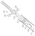
또한 도 11을 참조하면, 상이한 내경을 가지는 고정된 길이의 점퍼 이식편(50)들이 도시된다. 점퍼 이식편(50a)은 실질적으로 9 ㎜의 내경을 가질 수 있고, 점퍼 이식편(50b)는 실질적으로 11 ㎜의 내경을 가질 수 있으며, 점퍼 이식편(50c)은 실질적으로 13 ㎜의 내경을 가질 수 있다. 다른 내경을 가지는 점퍼 이식편(50)들이 제공될 수 있다. 각각의 점퍼 이식편(50)은 10 내지 20 cm의 범위에 있을 수 있는 고정된 길이로 제공된다. 다른 실시예에 따르면, 점퍼 이식편(50)들은 5 내지 10 cm의 범위로 제공될 수 있다. 다른 실시예에 따르면, 점퍼 이식편(50)들은 20 내지 30 cm의 범위로 제공될 수 있다. 다른 실시예에 따르면, 점퍼 이식편(50)들은 5 내지 20 cm의 범위로 제공될 수 있다. 다른 실시예에 따르면, 점퍼 이식편(50)들은 10 내지 30 cm의 범위로 제공될 수 있다. 특정 점퍼 이식편(50)은 임의의 적절한 길이로 제공될 수 있다. 점퍼 이식편(50)들은 전술한 혈관 앵커(2)와 실질적으로 동일한 방식으로 구성될 수 있다. 점퍼 이식편(50)의 확장 단부(52)는 전술한 바와 같이 이식편 앵커(4, 6)와 실질적으로 동일한 방식으로 구성될 수 있어서, 확장 단부(52)는 삽입 상태(도 11에 도시됨)에서 지름이 작고, 확장 상태에서 지름이 더 크다. 전술한 혈관 이식편(2)과 마찬가지로, 점퍼 이식편(50)의 확장 단부(52)는 PTFE 또는 임의의 다른 적절한 재료로 제작될 수 있는 커버(54)에 연결되고 및/또는 커버에 의해 덮여질 수 있다. 점퍼 이식편(50)의 고정 단부(56)는 점퍼 이식편(50)의 확장 단부(52)에 연결되지 않는 커버(54)의 단부일 수 있다. 도 11에 도시된 바와 같이, 점퍼 이식편(50)의 고정 단부(56)는 실질적으로 확장 상태에서 외경이 16 ㎜일 수 있다. 한 실시예에서, 고정 단부(56)는 혈관 이식편(2)과 관련하여 전술한 바와 같이 삽입 상태로부터 확장 상태(도 11에 도시됨)로 확장 가능하다. 다른 실시예에서, 고정 단부(56)는 실질적으로 확장 가능하지 않으며, 실질적으로 고정된 외경을 가진다. 커버(54)는 그 측면을 통해 가이드 와이어(47)를 수용하여, 가이드 와이어가 점퍼 이식편(50)의 고정 단부(56)에 있는 개구를 통하지 않고 점퍼 이식편(50)의 루멘에 접근하는 것을 가능하게 한다. 점퍼 이식편(50)의 루멘에 대한 가이드 와이어 및/또는 캐뉼라 접근은 실질적으로 도 10의 점퍼 이식편(40)들에 대해 전술한 바와 같다.Referring also to FIG. 11, fixed
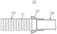
도 39 내지 도 41을 참조하면, 일부 실시예에 따르면, 적어도 하나의 점퍼 이식편(24a, 24b, 24c)은 하이브리드 이식편(231)일 수 있다. 도 39를 참조하면, 하이브리드 이식편(231)은 함께 부착된 제1 섹션(230) 및 제2 섹션(232)을 포함할 수 있다. 제1 섹션(230)은 확장된 폴리테트라플루오르에틸렌(ePTFE)으로 제작된 이식편일 수 있다. 제2 섹션(232)은 폴리테트라플루오르에틸렌(PTFE) 또는 다른 적절한 재료로 제작될 수 있는 커버(236)로 캡슐화된 자체 확장 메쉬 스텐트(34)일 수 있다. 자체 확장 메쉬 스텐트(34)는 유리하게 자체 확장되며; 예를 들어, 자체 확장 메쉬 스텐트(34)는 니티놀과 같은 초탄성 재료로 제작될 수 있으며; 다른 예로서, 자체 확장 메쉬 스텐트(34)는 탄성 한계 이하의 양으로 압축된 스테인리스강과 같은 소성 변형 가능한 재료로 제작될 수 있으며, 그 압축은 그런 다음 제거되어 확장 가능한 메쉬(34)가 적소로 자체적으로 확장하는 것을 가능하게 한다. 제1 섹션(230)은 당업계에 공지된 것과 같은 소결 공정을 사용하여 제2 섹션(232)으로 소결될 수 있다. 대안적으로, 제1 섹션(230)은 임의의 다른 적절한 방식으로 제2 섹션(232)에 고정되거나 부착될 수 있다.39-41, according to some embodiments, at least one
도 40 및 도 41에 도시된 바와 같이, 이러한 점퍼 이식편(241, 24b, 24c)은 또한 슬리브(238)를 포함할 수 있다. 슬리브(238)는 그 내부에 제1 섹션(230)의 적어도 일부를 수용할 수 있어서, 제1 섹션(230)이 슬리브(238)의 루멘 내로 부분적으로 슬라이딩한다. 다른 실시예에 따르면, 슬리브(238)는 그 내부에 모든 제1 섹션(230)을 수용할 수 있고, 또한 그 내부에 제2 섹션(232)의 적어도 일부를 수용할 수 있다. 슬리브(238)는 폴리에스테르 및/또는 임의의 다른 적절한 재료로 제작될 수 있다. 슬리브(238)의 적어도 일부는 커프(240)를 형성하기 위해 제1 섹션(230)을 향해 말릴 수 있다. 도 41에 도시된 바와 같이, 제2 섹션(232)의 적어도 단부는 커프(240)의 밖으로 연장될 수 있고, 제1 섹션(230)의 적어도 단부는 커프(240) 반대편의 슬리브(238)의 단부의 밖으로 연장될 수 있다. 대안적으로, 제1 섹션(230) 및 제2 섹션(232) 중 적어도 하나는 슬리브(238)의 루멘 내에 완전히 잔류할 수 있다. 하이브리드 이식편(231) 및 슬리브(238)는 다음에 더욱 상세히 설명되는 바와 같이 전달 디바이스와 결합될 수 있다.As shown in FIGS. 40 and 41, these
도 42 및 도 43에 도시된 바와 같이, 적어도 하나의 하이브리드 이식편(231)은 제1 섹션(230)이 제2 섹션(232)의 자체 확장 메쉬 스텐트(34)보다 작은 지름을 가지는 이식편이도록 구성될 수 있다. 더 작은 지름의 제1 섹션(230)에 대한 더 큰 지름의 제2 섹션(232)의 부착을 수용하기 위해, 제1 섹션(230)의 단부는 커프(242)를 형성하기 위해 자체적으로 말린(뒤집힌)다. 그런 다음, 제2 섹션(232)의 단부는 커프(242)에 봉합되거나 또는 그렇지 않으면 부착된다. 커프(242)의 적어도 일부는 봉합 전에 제2 섹션(232)의 단부에 걸쳐서 신장될 수 있으며, 필요하면, 제1 섹션(230)은 적절하게 신장 가능한 재료로 구성될 수 있다. 일부 실시예에 따르면, 제2 섹션(232)의 단부는 커프(242)에 대한 제2 섹션(232)의 그 단부의 봉합 또는 다른 부착이 용이하게 되도록 제2 섹션(232)의 나머지보다 작은 지름으로 테이퍼질 수 있다. 또한 도 43을 참조하면, 커프(242)는 그런 다음 제2 섹션(232)의 외부 표면 위에서 부분적으로 또는 전체적으로 풀릴 수 있다.42 and 43, at least one
또한 도 44를 참조하면, 봉합 커프(242)가 제2 섹션(232)의 표면 상으로 완전히 풀리지 않은 경우에, 제2 섹션(232)의 자체 확장 메쉬 스텐트(34)의 자유 단부는 혈관(244)의 내강(248) 내로 삽입될 수 있다. 도 45를 참조하면, 커프(242)는 혈관(244)의 벽(246)들의 외부 표면에 위에서 부분적으로 또는 전체적으로 풀릴 수 있고, 혈관(244)의 벽(246)들 상에 재봉될 수 있다. 일부 실시예에 따르면, 커프(242)는 혈관(244) 상으로 커프(242)를 풀기 전에 혈관(244)의 벽(246)들에 재봉될 수 있고; 다른 실시예에 따르면, 커프(242)는 혈관(244) 상으로 커프(242)를 푼 후에 혈관(244)의 벽(246)들에 재봉될 수 있다.Referring also to FIG. 44, when the
또한 도 54를 참조하면, 일부 실시예에 따르면, 커프(242) 대신, 2개 이상의 봉합 플랩(280)이 이용된다. 유리하게, 2개 내지 5개의 봉합 플랩(280)이 제공된다. 대안적으로, 6개 이상의 봉합 플랩(280)이 제공된다. 적어도 2개의 인접한 봉합 플랩(280)의 단부가 사용 시에 함께 봉합되거나 서로 인접할 수 있을지라도, 봉합 플랩(280)들은 도 54에 도시된 바와 같이 그 자유 단부에서 서로로부터 원주 방향으로 분리된다. 커프(242)의 단부의 뒤집힘보다는 각각의 봉합 플랩(280)이 이식편(230)을 향해 다시 접혀진다. 봉합 플랩(280)들은 전술한 바와 같이 커프(242)와 유사한 방식으로 이용될 수 있다. 자체 확장 메쉬 스텐트(34)의 자유 단부는 혈관(244)의 내강(248) 내로 삽입될 수 있다. 봉합 플랩(280)들은 혈관(244)의 벽(246)들의 외부 표면 위에서 부분적으로 또는 전체적으로 펼쳐질 수 있으며, 혈관(244)의 벽(246)들에 재봉된다.Also referring to FIG. 54, according to some embodiments, two or more suture flaps 280 are used instead of the
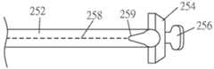
또한 도 46을 참조하면, 예시적인 전개 도구(250)가 도시된다. 전개 도구(250)는 특히 전술한 하이브리드 이식편(231)과 함께 사용하는데 적합하다. 다른 실시예에 따르면, 전개 도구(250)는 본 명세서에 설명된 점퍼 이식편(24a, 24b, 24c)들의 다른 실시예와 함께 사용될 수 있다. 전개 도구(250)는 외장(252)을 포함한다. 외장(252)은 DACRON® 브랜드 폴리에스테르와 같은 PTFE, ePTFE 또는 PET 메쉬와 같은 임의의 적절한 재료로 제작될 수 있다. 도 47 내지 도 49를 또한 참조하면, 탭(254)은 외장(252)의 근위 단부에서 또는 그 근처에서 외장(252)에 부착될 수 있다. 대안적으로, 탭(254)은 외장(252)의 원위 단부에서 또는 그 근처에서 또는 외장(252)를 따라서 임의의 다른 적절한 위치에서 외장(252)에 부착될 수 있다. 탭(254)은 탭(254)의 일부가 외장(252)의 양쪽 측면에서 외장(252)에 대해 측 방향으로 연장되도록 대체로 분기될 수 있고, 탭(254)은 외장(252)의 상부뿐만 아니라 외장9252)의 양쪽 측면에서 외장(252)에 부착될 수 있다. 탭(254)은 접착제, 용접 또는 소결과 같은 임의의 적절한 방식으로 외장(252)에 부착될 수 있다. 대안적으로, 탭(254)은 외장(252)과 일체로 제작될 수 있다. 탭(254)은 사용자에 의해 당겨지도록 구성된 당김부(256)를 포함할 수 있다. 당김부(256)는 사용자가 당김부(256)를 잡아 당기는 것을 용이하게 하도록 형상화 및/또는 질감화될 수 있다. 당김부(256)는 도 47에서 가장 명확하게 알 수 있는 바와 같이 외장(252)의 길이 방향 중심선으로부터 근위 방향으로 위를 향해 각이 질 수 있다. 또한 도 48을 참조하면, 외장(252)은 분리 라인(258)을 포함할 수 있으며, 외장(252)은 당김부(256)가 잡혀 당겨질 때 우선적으로 분리 라인을 따라서 분리된다. 분리 라인(258)은 대체로 선형이고, 대체로 외장(252)의 길이 방향 중심선에 평행할 수 있다. 대안적으로, 분리 라인(258)은 외장(252)을 따르는 임의의 다른 적절한 경로를 설명할 수 있다. 한 실시예에 따르면, 분리 라인(258)은 외장(252)을 따르는 한 세트의 구멍을 포함한다. 다른 실시예에 따르면, 분리 라인(258)은 외장(252)을 따르는 한 세트의 슬릿을 포함한다. 다른 실시예에 따르면, 분리 라인(258)은 외장(252)의 나머지의 두께보다 작은 두께를 가지는 외장(252)을 따라는 라인이어서, 외장(252)의 분리는 분리 라인(258)을 따라서 우선적으로 발생한다. 다른 실시예에 따르면, 분리 라인(258)은 임의의 다른 적절한 방식으로 구성될 수 있다. 분리 라인(258)의 근위 단부에서, 외장(252)은 V-자 형상 또는 다르게 형상화된 절개부(259)를 포함할 수 있으며, 이는 근위로부터 원위 방향으로 외장(252)의 분리를 용이하게 한다. 절개부(259)는 유리하게 그 원위 단부에서보다, 외장(252)의 근위 단부와 거의 유사할 수 있는 그 근위 단부에서 더 넓다.Referring also to FIG. 46, an
도 46 및 도 50를 또한 참조하면, 전개 도구(250)는 그 원위 단부에 확장기 팁(202)이 있는 맨드릴(208)을 포함한다. 확장기 팁(202)은 혈관에서 만들어진 절개부 또는 개구를 확장하기 위해 크기화되고 형상화된다. 통로(204)는 확장기 팁(202)을 통해 한정된다. 유리하게, 통로(204)는 직선이고, 전개 도구(200)의 길이 방향 중심선과 실질적으로 동축이다. 대안적으로, 통로(204)는 전개 도구(200)에 대해 상이하게 형성될 수 있고 및/또는 상이하게 배향될 수 있다. 가이드 와이어(206)는 통로(204)를 통해 연장 가능하고 및/또는 통로 내로 후퇴 가능할 수 있다. 가이드 와이어(206)의 단부는 가이드 와이어(206)가 통로(204)를 빠져 나갈 때 곡선화되도록 구성될 수 있다. 즉, 통로(204)를 빠져 나갈 때, 가이드 와이어(206)의 원위 단부는 한쪽 측면으로든 다시 근위 방향을 향하든 전개 도구(200)의 길이 방향 중심선으로부터 멀어지게 곡선화된다.Referring also to FIGS. 46 and 50, the
하이브리드 이식편(231)은 맨드릴(208) 주위를 감쌀 수 있다. 대안적으로, 점퍼 이식편(24)의 다른 실시예가 맨드릴(208) 주위를 감쌀 수 있다. 하이브리드 이식편(231)은 스텐트(234)를 포함하는 제2 섹션(232)이 맨드릴(208)의 원위 단부에 또는 그 근처에 위치되도록 맨드릴(208) 상에 배향될 수 있어서, 스텐트(234)의 원위 단부는 확장기 팁(202)의 근위 단부에 인접하거나 그 주위에 있을 수 있다. 하이브리드 이식편(231)의 제1 섹션(230)의 원위 단부는 탭(254)과 외장(252) 사이의 접합부에 실질적으로 위치될 수 있다. 대안적으로, 하이브리드 이식편(231)의 제1 섹션(230)의 원위 단부는 탭(254)에 대해 다른 위치에 위치될 수 있다. 외장(252)은 하이브리드 이식편(231)의 제2 섹션(232)의 전부 또는 일부 주위를 감싸고, 이는 차례로 맨드릴(208) 주위를 감싼다. 외장(252)은 맨드릴(208) 반대쪽으로 또는 이를 향해 하이브리드 이식편(231)의 제2 섹션(232)의 적어도 일부를 압축한다. 분리 라인(258)은 사용자가 분리 라인(258)을 따라서 외장(252)를 찢을 수 있을만큼 충분히 약하지만, 제2 섹션(232)이 맨드릴(208) 반대쪽으로 또는 이를 향해 압축되는 동안 하이브리드 이식편(231)의 제2 섹션(232)에 의해 가해지는 외향력을 견딜만큼 충분히 강하다.
또한 도 50을 참조하면, 사용자는 가이드 와이어(206)를 혈관(도 44에 도시된 혈관(244)과 같은)의 단부 또는 혈관(대동맥과 같은)의 측면 내로 삽입한다. 확장기 팁(202)은 그런 다음 확장기 팁(202), 그런 다음 적어도 외장(252)의 원위 단부가 혈관에 들어갈 때까지 외장(252)과 함께 가이드 와이어(206)를 따라서 슬라이딩된다. 외장(252)(및 하이브리드 이식편(231)의 제2 섹션(232)과 함께)은 사용자에 의해 선택된 적절한 거리만큼 혈관 내로 슬라이딩된다. 하이브리드 이식편(231)이 적소에 있으면, 사용자는 당김부(256)를 잡고 맨드릴(208)로부터 멀어지게 근위 방향으로 힘을 가한다. 외장(252)은 분리 라인(258)을 따라서 분리되고, 근위 단부로부터 원위 단부를 향해 하이브리드 이식편(231)으로부터 벗겨진다. 절개부(259)는 먼저 당김부(256)(그러므로 탭(254))의 운동으로부터의 힘을 분리 라인(258)의 근위 단부를 향해 지향시킨다. 그러므로, 사용자가 맨드릴(208)로부터 근위로 그리고 멀리 당김부(256)를 계속 당김에 따라서, 분리 라인(258)은 원위 방향을 향해 계속 분리된다. 외장(252)이 분리됨에 따라서, 외장은 더 이상 맨드릴(208) 반대쪽으로 또는 이를 향해 하이브리드 이식편(231)의 제2 섹션(232)을 압축하지 않으며, 제2 섹션(232)의 스텐트(234)는 외측으로 확장된다. 분리 라인(258)이 그 원위 단부에서 분리되면, 스텐트(234)는 그 외향 확장을 완료하고, 외장(252)은 하이브리드 이식편(231)으로부터 멀어지게 당겨진다. 혈관 내부에 남아있는 외장(252)의 임의의 부분은 혈관 밖으로 당겨지며, 하이브리드 이식편(231)은 적소에 있다.Referring also to FIG. 50, the user inserts the
또한 도 51을 참조하면, 예시적인 전개 도구(260)가 도시되어 있다. 전개 도구(260)는 특히 전술한 하이브리드 이식편(231)과 함께 사용하는데 적합하다. 다른 실시예에 따르면, 전개 도구(260)는 본 명세서에 설명된 점퍼 이식편(24a, 24b, 24c)들의 다른 실시예와 함께 사용될 수 있다. 다른 실시예에 따르면, 전개 도구(250)는 본 명세서에 설명된 점퍼 이식편(24a, 24b, 24c)들의 다른 실시예와 함께 사용될 수 있다. 전개 도구(260)는 실질적으로 전개 도구(260)와 관련하여 전술한 바와 같을 수 있고 도 47 내지 도 49에 도시된 바와 같은 외장(252)을 포함한다. 또한, 전개 도구(260)는 맨드릴(208), 및 전개 도구(260)와 관련하여 실질적으로 전술한 바와 같을 수 있고 도 46 및 도 50에 도시된 바와 같은 가이드 와이어(206)를 수용하도록 구성된 확장기 팁(202)을 포함한다. 바늘(210)은 확장기 팁(202)을 통해 후퇴 가능하게 연장될 수 있고, 전개 도구(260) 상에 보다 근접하게 위치된 바늘 제어기(277)에 결합될 수 있다. 바늘(210)은 링크 또는 임의의 다른 적절한 구조 또는 메커니즘을 통해 바늘 제어기(277)에 결합될 수 있다. 바늘(210)은 바늘 제어기(277)의 근위 운동에 의해 확장기 팁(202) 내로 후퇴될 수 있고, 바늘 제어기(277)의 원위 운동에 의해 확장기 팁(202)의 밖으로 연장될 수 있다. 바늘(210)은 관통 구멍을 포함할 수 있으며, 가이드 와이어(206)는 관통 구멍을 통과할 수 있다. 선택적으로, 도 53에 도시된 바와 같이, 맨드릴(208)은 리브형일 수 있다. 하이브리드 이식편(231)은 전개 도구(260)의 맨드릴(208)에 장착될 수 있고, 전개 도구(250)에 대해 실질적으로 전술한 바와 같이 외장(252)에 의해 적소에 홀딩될 수 있다.Referring also to FIG. 51, an
전개 도구(260)는 또한 일반적으로 전개 도구(250)와 관련하여 위에서 설명된 바와 같을 수 있고 도 47 내지 도 49에 도시된 바와 같이 탭(254)을 포함한다. 탭(254)은 외장(252)의 근위 단부에서 또는 그 근처에서 외장(252)에 압축력을 가한다. 도 51 내지 도 53을 참조하면, 탭(254)은 대체로 U-자 형상일 수 있다. 하나 이상의 날개부(262)는 탭(254)으로부터 연장될 수 있다. 날개부(262)들은 탭(254)에 부착될수 있거나 또는 탭(254)과 일체로 형성될 수 있다. 날개부(262)들은 각각 탭(254)으로부터 외측으로 각이 진다. 탭(254) 자체는 각각의 날개부(262)의 접합부와 탭(254) 사이에서 그 내부에 한정된 리빙 힌지(living hinge)를 포함할 수 있다. 날개부(262)들은 예를 들어, 사용자의 손의 꼬집는 동작 및 꼬집는 힘의 적용에 의해 서로를 향하는 날개부(262)들의 운동이 탭(254)의 자유 단부(264)들로 하여금 다음에 더욱 상세히 설명되는 바와 같이 서로로부터 멀어지게 움직이게 하도록 구성된다.
아암(266)은 탭(254)으로부터 근위로 연장될 수 있다. 아암(266)은 탭(254)에 부착되거나, 탭(254)과 일체로 제작되거나, 또는 임의의 적절한 방식으로 탭(254)에 연결될 수 있다. 아암(266)은 실질적으로 원통형일 수 있거나, 또는 임의의 다른 적절한 형상 및/또는 단면을 가질 수 있다. 유리하게, 아암(266)은 강성일 수 있다. 대안적으로, 아암(266)은 가요성이도록 구성될 수 있다. 아암(266)의 원위 단부는 탭(254)에 연결될 수 있는 반면에, 아암(266)의 근위 단부는 힌지(268)에 연결될 수 있다. 아암(266)과 힌지(268) 사이의 연결은 아암(266)이 힌지를 중심으로 회전하는 것을 가능하게 하여서, 아암(266)의 회전은 다음에 더 상세하게 설명되는 바와 같이, 탭(254)이 외장(252)의 길이 방향 중심선으로부터 위쪽으로, 그리고 또한 근위로 원호를 따라서 이동하게 한다. 힌지(268)는 지지 부재(272)에 부착되거나 또는 지지 부재의 일부일 수 있다. 도 53을 참조하면, 지지 부재(272)의 원위 단부는 맨드릴(208)의 근위 단부에 연결될 수 있다. 맨드릴(208)은 지지 부재(272)에 부착되거나 또는 그 일부에 부착될 수 있다. 지지 부재(272)는 실질적으로 강성일 수 있다. 선택적으로, 파지부(270)는 임의의 적절한 방식으로 아암(266)에 부착될 수 있다. 예를 들어, 파지부(270)는 아암(266)을 수용하기 위해 관통하여 한정된 구멍(274)을 포함할 수 있고, 파지부(270)는 아암(266)에 대해 슬라이딩 가능할 수 있다. 대안적으로, 아암(266)은 탭(254)에 압입 끼워맞춤되거나, 탭(254)에 접착되거나, 탭(254)에 용접되거나, 또는 그렇지 않으면 탭(254)에 고정될 수 있다. 파지 날개부(276)들은 구멍(274)으로부터 측 방향으로 또는 임의의 다른 적절한 방향으로 연장될 수 있다. 파지 날개부(276)들은 일반적으로 평평하고 직사각형일 수 있거나, 또는 임의의 적절한 형상을 가질 수 있다. 사용자는 다음에 더욱 상세히 설명되는 바와 같이 맨드릴(208)로부터 탭(254)을 멀어지게 들어올리기 위해 파지부(270)를 이용할 수 있다. 파지부(270)는 아암(266)에 대한 파지부(270)의 근위 운동이 외장(252)이 분할되게 할 수 있도록 외장(252)에 부착될 수 있다.
또한 도 51을 참조하면, 사용자는 가이드 와이어(206)를 혈관(도 44에 도시된 혈관(244)과 같은)의 단부 또는 혈관(대동맥과 같은)의 측면 내로 삽입한다. 바늘(210)은 원위로 연장되고, 혈관의 측면을 뚫도록 사용된다. 확장기 팁(202)은 그런 다음 구멍 내로 밀어 넣어져 이를 확장하고, 바늘(210)은 바늘 제어기(277)의 근위 운동에 의해 확장기 팁(202) 내로 근위로 빼내진다. 가이드 와이어(206)는 그런 다음 확장기 팁(202)을 통해, 선택적으로 바늘(210)에 있는 구멍(현재 확장기 팁(202)에 있고 더 이상 노출되지 않는)을 통해 혈관 내로 슬라이딩된다. 확장기 팁(202)은 그런 다음 확장기 팁(202), 및 그런 다음 적어도 외장(252)의 원위 단부가 혈관에 들어갈 때까지 외장(252)과 함께 가이드 와이어(206)를 따라서 슬라이딩된다. 외장(252)(및 하이브리드 이식편(231)의 제2 섹션(232)와 함께)는 사용자에 의해 선택된 적절한 거리만큼 혈관 내로 슬라이딩된다. 하이브리드 이식편(231)이 적소에 있으면, 사용자는 날개부(262)들을 잡고 날개부들을 함께 압축한다. 서로를 향한 날개부(262)의 운동은 탭(254)의 자유 단부(264)들이 서로 떨어져 이동하게 한다. 탭(254)이 리빙 힌지를 포함하는 경우에, 이 리빙 힌지는 서로로부터 멀어지는 탭(254)의 자유 단부(264)들의 운동을 용이하게 한다. 그러므로, 탭(254)은 더 이상 맨드릴(208)에 대해 외장(252)을 압축하지 않는다.Referring also to FIG. 51, the user inserts the
사용자는 그런 다음 전개 도구(250)와 관련하여 위에서 설명된 바와 유사한 방식으로, 파지부(270)를 잡아서 아암(266)을 따라서 근위로 잡아 당기고, 근위 단부에서 시작하는 외장(252)을 분할한다. 외장(252)은 분리 라인 포함할 수 있으며, 외장(252)은 분리 라인을 따라서 분리된다. 파지부(270)가 근위로 이동함에 따라서, 외장(252)의 분할은 계속된다. 외장(252)이 분리됨에 따라서, 외장은 더 이상 하이브리드 이식편(231)의 제2 섹션(232)을 맨드릴(208)에 대해 또는 맨드릴을 향해 압축하지 않으며, 제2 섹션(232)의 스텐트(234)는 외측으로 확장된다. 외장(252)이 그 원위 단부에서 분리되었으면, 스텐트(234)는 그 외향 확장을 마치고, 외장(252)은 하이브리드 이식편(231)으로부터 멀어지게 당겨진다. 아암(266)은 그런 다음 힌지(268)를 중심으로 회전되어, 방해가 안되도록 파지부(270)를 이동시키며, 파지부(270)는 전개 도구(260)의 근위 단부에 근접한 위치로 이동될 수 있다. 혈관 내부에 남아있는 외장(252)의 임의의 부분은 도 52에 도시된 바와 같이 혈관 밖으로 당겨지고, 하이브리드 이식편(231)은 적소에 있다.The user then grasps the
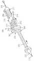
또한 도 55를 참조하면, 다른 예시적인 전개 도구(290)가 도시되어 있다. 전개 도구(290)는 이중 스텐트 이식편(292)과 함께 사용될 수 있다. 이중 스텐트 이식편(292)은 일반적으로 위에서 설명된 하이브리드 이식편(231)과 동일한 방식으로 제작될 수 있으며, 차이는 다음에 설명된다. 이중 스텐트 이식편은 2개의 스텐트(234)를 이용하며, 스텐트들은 일반적으로 그 길이 방향 중심선을 따라서 서로 정렬될 수 있고, 서로 연결되거나 또는 서로 부착될 수 있다. 대안적으로, 2개의 스텐트(234)는 일반적으로 이중 스텐트 이식편(292)의 길이를 따라서 연장되는 하나의 단일 스텐트(234)일 수 있다. 대안적으로, 2개의 스텐트(234)는 이중 스텐트 이식편(292)의 보다 큰 유연성을 허용하기 위해 서로로부터 길이 방향으로 분리될 수 있다. 외장(252)은 2개의 분리된 외장(252a, 252b)을 포함할 수 있으며, 외장(252a)은 외장(252b)의 원위에 위치된다. 각각의 외장(252s, 252b)은 전술한 바와 같이 분리 라인을 따라서 분할되도록 구성될 수 있다. 2개의 탭(294)이 각각의 외장(252a, 252b)의 단부에 부착될 수 있다. 대안적으로, 하나의 탭(294) 또는 3개 이상의 탭(294)은 각각의 외장(252a, 252b)의 단부에 부착될 수 있다. 탭(294)들은 일반적으로 원형일 수 있거나 또는 타원형 또는 다각형과 같은 임의의 다른 적절한 방식으로 형상화될 수 있다. 대안적으로, 탭(294)은 실질적으로 선형일 수 있거나, 또는 곡선으로 이루어질 수 있다. 탭(294)들은 일반적으로 서로로부터 원주 방향으로 이격된 90°로 배향될 수 있다. 대안적으로, 탭(294)들은 임의의 다른 적절한 방식으로 서로에 대해 배향되고 이격될 수 있다. 모든 탭(294)은 전개 도구(290)에 대해 대체로 동일한 길이 방향 위치에 위치될 수 있다. 대안적으로, 제1 외장(252a)과 관련된 탭(294)들은 제2 외장(252b)과 관련된 탭(294)들로부터 길이 방향으로 이격될 수 있다. 후술하는 바와 같이, 외장(252a, 252b)들은 서로 반대 방향으로 길이 방향으로 분할되도록 구성된다. 각각의 외장(252a, 252b)은 그 외장(252a, 252b)의 자유 단부를 향하는 방향으로 분할될 수 있다.Referring also to FIG. 55, another
전개 도구(290)는 전술한 하이브리드 이식편(231)과 함께 사용될 수 있다. 다른 실시예에 따르면, 전개 도구(290)는 본 명세서에서 설명된 점퍼 이식편(24a, 24b, 24c)들의 다른 실시예와 함께 사용될 수 있다. 다른 실시예에 따르면, 전개 도구(290)는 본 명세서에서 설명된 점퍼 이식편(24a, 24b, 24c)들의 다른 실시예와 함께 사용될 수 있다. 전개 도구(290)는 실질적으로 전개 도구(250)와 관련하여 전술한 바와 같을 수 있고 도 47 내지 도 49에 도시된 바와 같은 외장(252)을 포함한다. 또한, 전개 도구(290)는 맨드릴(208), 및 전개 도구(250) 및 전개 도구(260)에 대해 실질적으로 전술한 바와 같을 수 있고 도 46 및 도 50에 도시된 바와 같은 가이드 와이어(206)를 수용하도록 구성된 확장기 팁(202)을 포함한다. 선택적으로, 도 53에 도시된 바와 같이, 맨드릴(208)은 리브형일 수 있다. 이중 스텐트 이식편(292)은 전개 도구(290)의 맨드릴(208)에 장착될 수 있고, 실질적으로 전개 도구(250) 및 전개 도구(260)와 관련하여 전술한 바와 같이 외장(252)에 의해 적소에 홀딩될 수 있다.The
또한 도 55를 참조하면, 사용자는 혈관의 측면 또는 단부 내로 가이드 와이어(206)를 삽입한다. 확장기 팁(202)은 그런 다음 확장기 팁(202)과 그런 다음 적어도 외장(252)의 원위 단부가 혈관에 들어갈 때까지 외장(252)과 함께 가이드 와이어(206)를 따라서 슬라이딩된다. 외장(252)(그리고 이와 함께, 이중 스텐트 이식편(292)의 원위 단부)는 사용자에 의해 선택된 적절한 거리만큼 혈관(244) 내로 슬라이딩된다. 또한 도 56을 참조하면, 이중 스텐트 이식편(292)이 적소에 있으면, 사용자는 제1 외장(252a)에 부착된 탭(294)들을 잡고 이들을 서로 떼어내서 제1 외장(252a)을 분할한다. 제1 외장(252a)은 분리됨에 따라서 더 이상 맨드릴(208) 반대쪽으로 또는 이를 향해 이중 스텐트 이식편(292)의 원위 단부를 압축하지 않으며, 이중 스텐트 이식편(292)의 원위 단부에서 스텐트(234) 또는 스텐트(234)의 원위 부분은 외측으로 확장된다. 제1 외장(252a)이 그 원위 단부에서 분리되었으면, 스텐트(234) 또는 스텐트(234)의 원위 부분은 그 외향 확장을 완료하고, 제1 외장(252a)은 이중 스텐트 이식편(292)으로부터 멀어지게 당겨진다. 혈관 내부에 남아있는 제1 외장(252a)의 임의의 부분은 도 52에 도시된 바와 같이 혈관의 밖으로 당겨지고, 이중 스텐트 이식편(292)의 원위 단부는 적소에 있다. 가이드 와이어(206)는 그런 다음 이중 스텐트 이식편(292)의 루멘을 통해 혈관(244)으로부터 빼내질 수 있다.Also, referring to FIG. 55, the user inserts the
다음으로, 또한 도 57을 참조하면, 사용자는 이중 스텐트 이식편(292)의 근위 단부 위에서 혈관 이식편(296)을 당길 수 있다. 혈관 이식편(296)의 단부는 나머지 탭(294)들과 근접하게 당겨질 수 있다. 혈관 이식편(296)이 이중 스텐트 이식편(292) 상의 적소에 있으면, 사용자는 제2 외장(252b)에 부착된 탭(294)들을 잡고 이들을 서로 떼어내어 제2 외장(252b)을 분할한다. 외장(252b)은 분리됨에 따라서 더 이상 맨드릴(208) 반대쪽으로 또는 이를 향해 이중 스텐트 이식편(292)의 근위 단부를 압축하지 않으며, 이중 스텐트 이식편(292)의 근위 단부에서 스텐트(234) 또는 스텐트(234)의 일부는 외측으로 확장된다. 제2 외장(252b)이 근위 단부에서 분리되었으면, 스텐트(234) 또는 스텐트(234)의 근위 부분은 그 외향 확장을 완료하고, 제2 외장(252b)은 혈관 이식편(296)의 단부 밖으로 이중 스텐트 이식편(292)으로부터 멀어지게 당겨진다.Next, referring also to FIG. 57, the user can pull the
수술 - 대동맥 이식편Surgery-Aortic Graft
도 12를 참조하면, 중앙 섹션(22)을 가지는 대동맥 이식편(20)을 이식하는 예시적인 방법이 도시되어 있다. 환자는 심폐 바이패스 펌프에 배치되고, 심장은 정지되고, 클램프는 상행 대동맥으로부터 이격된 대동맥(60)에 배치된다. 절개부(62)들이 상행 대동맥을 분리하기 위해 대동맥(60)에서 만들어지고, 상행 대동맥이 제거된다. 대동맥 이식편(20)의 중앙 섹션(22)은 그런 다음 절개부(62)에서 또는 그 근처에서 대동맥 절주(aortic stump)(70)의 근위 단부에 봉합된다. 이러한 방식으로, 대동맥 이식편(20)의 중앙 섹션(22)의 루멘은 용이하게 접근 가능하다.Referring to FIG. 12, an exemplary method of implanting an
도 12에 도시된 바와 같이, 매니폴드(24d)는 대동맥 이식편(20)의 중앙 섹션(22)에 고정되고, 3개의 점퍼 이식편(24a, 24b, 24c)은 매니폴드(24d)로부터 연장된다. 대안적으로, 3개의 점퍼 이식편(24)이 중앙 섹션(22)에 제공되는 경우에, 3개의 점퍼(40, 50)가 선택된다. 점퍼(40)들 중 하나가 선택되는 경우에, 점퍼(40)는 그대로 이용될 수 있거나, 점퍼(40)는 더 짧은 길이로 절단될 수 있다. 그 길이는 대동맥 이식편(20)의 중앙 섹션(22)과 연결될 동맥(64, 66, 68) 사이의 거리에 기초하여 임상의에 의해 선택된다. 점퍼(50)들 중 하나가 선택되는 경우에, 그 길이는 고정되고, 그 점퍼(50)는 더 짧은 길이로 절단되지 않는다. 대부분의 점퍼(40, 50)가 점퍼 이식편(24)을 통해 당겨질 때까지, 선택된 점퍼(40, 50)는 점퍼 이식편(24) 중 하나를 통해 대동맥 이식편(20)의 중앙 섹션(22)의 루멘 내로 삽입된다. 점퍼(50)가 사용되는 경우에, 유리하게 점퍼(50)의 고정 단부(56)의 적어도 일부가 점퍼 이식편(24)의 확장 가능한 메쉬(34) 내에 위치될 때까지, 점퍼(50)는 점퍼 이식편(24)을 통해 당겨진다. 점퍼(40, 50)는 가이드 와이어를 사용하여 대응하는 점퍼 이식편(24)을 통해 당겨지거나 밀릴 수 있다. 유리하게, 표준 중재 벌룬(도시되지 않음)은 점퍼(40, 50)의 고정 단부(46, 56) 내에 위치되고, 벌룬은 팽창된다. 이 팽창은 고정 단부(46, 56)를 확장 상태로 확장하고, 또한 확장 가능한 메쉬(34)를 확장 상태로 확장한다. 이러한 방식으로, 점퍼(40, 50)의 고정 단부(46, 56)는 대응하는 확장 가능한 메쉬(34)에 압입 끼워맞춤된다. 가이드 와이어 및 중재 벌룬은 빼내진다. 대안적으로, 점퍼(40, 50)가 대동맥 이식편(20)의 중앙 섹션(22)과 일체로 제작되는 경우에, 점퍼(40, 50)의 선택 및 대동맥 이식편(20)의 중앙 섹션(22) 내로의 그 삽입은 생략된다. 대안적으로, 점퍼(40, 50) 중 적어도 하나는 그 점퍼(40, 50)를 대동맥 이식편(20)의 중앙 섹션(22)에 연결하기 전에 대응하는 동맥(64, 66, 68) 내로 삽입될 수 있다.As shown in FIG. 12, the
다음으로, 대동맥 이식편(20)의 나머지(20a)는 하행 대동맥(74) 내로 삽입된다. 이러한 나머지는 대동맥 이식편(20)의 중앙 섹션(22)에 고정될 수 있거나, 또는 대동맥 이식편(20)의 중앙 섹션(22)에 연결된 별도의 구성 요소일 수 있다. 일부 실시예에서, 대동맥 이식편(20)의 중앙 섹션(22)은 먼저 절개부(62)에서 또는 그 근처에서 하행 대동맥(74)에 봉합된다. 대동맥 이식편(20)의 나머지(20a)는 지혈 밸브(32)를 통해 접근 포트(30) 내로 삽입되고, 그런 다음 예를 들어 지혈 밸브(32)를 통하고 접근 포트(30)를 통해 삽입된 가이드 와이어(도시되지 않음)를 통해, 중앙 섹션(22)의 루멘을 통해 하행 대동맥(72) 내로 삽입된다. 대동맥 이식편(20)의 나머지(20a)는 표준 중재 벌룬의 팽창과 같은 임의의 적절한 방식으로 전개될 수 있다. 다른 실시예에서, 대동맥 이식편(20)의 나머지(20a)는 자체 확장할 수 있다. 필요에 따라, 대동맥 이식편(20)의 나머지(20a)는 대동맥 이식편(20)의 나머지(20a)가 적소에 남아있는 것을 보장하도록 하행 대동맥(60 및 62)에 봉합될 수 있다. 대안적으로, 이러한 봉합을 수행될 필요가 없다. 또한, 대동맥 이식편(20)의 나머지(20a)는 대동맥 이식편(20)의 중앙 섹션(22)에 봉합되거나 또는 그렇지 않으면 부착될 수 있다. 다른 실시예에 따르면, 대동맥 이식편(20)의 나머지(20a)는 하행 대동맥(74) 내로 삽입되고, 그런 다음, 중앙 섹션(22)은 하행 대동맥(60)에 봉합된다. 대동맥 이식편(20)의 나머지(20a)가 고정되는 것으로, 접근 포트(30)를 통해 삽입된 가이드 와이어, 중재 벌룬, 및/또는 다른 메커니즘 또는 디바이스는 지혈 밸브(32)를 통해 빼내진다. 심장은 그런 다음 재기동되고, 환자는 표준 관행에 따라 심폐 우회술로부터 옮겨진다.Next, the
적어도 하나의 점퍼 이식편(24)은 전개 도구(200)를 이용하는 것에 의해 이식될 수 있다. 도 27을 참조하면, 위에서 설명된 바와 같이, 점퍼 이식편(24)은 초기에 전개 도구(200)의 맨드릴(208) 주위를 감싼다. 전술한 바와 같이, 또한 도 35를 참조하면, 봉쇄 외장(180)은 초기 압축 구성으로 점퍼 이식편(24) 주위로 말린다. 도 36 및 도 37을 또한 참조하면, 당김 와이어(190)는 말린 봉쇄 외장(180)에서 길이 방향으로 인접한 구멍(188)들을 통과한다. 이러한 방식으로, 당김 와이어(190)는 봉쇄 외장(180)의 인접한 가장자리(l82a, l82b)들을 함께 홀딩하고, 이에 의해 봉쇄 외장(180)은 맨드릴(208)에 대해 점퍼 이식편(24)을 압축한다.At least one
전개 과정을 시작하기 위해, 사용자는 전개 도구(200)의 핸들(212)을 잡고 바늘 전진 버튼(224)을 작동시킨다. 사용자에 의해 바늘 전진 버튼(224)에 가해진 원위력(distal force)이 바늘 전개 제어기(228)를 원위로 전진시키는 것과 동시에, 사용자에 의해 바늘 전진 버튼(224)에 가해진 원위력은 바늘 전진 버튼에 결합된 압축 스프링(222)을 압축한다. 또한 도 28을 참조하면, 바늘 전개 제어기(228)가 바늘(210)에 부착되거나 또는 그렇지 않으면 결합되기 때문에, 바늘 전개 제어기(228)의 원위 전진은 바늘(210)이 확장기 팁(202)을 통해 통로(204)의 밖으로 원위로 전진하게 한다. 유리하게, 가이드 와이어(206)는 바늘(210)의 전진에 앞서 실질적으로 1 내지 2 ㎝의 거리만큼 확장기 팁(202)을 통해 통로(204)의 밖으로 연장된다. 대안적으로, 가이드 와이어(206)는 통로(204)의 밖으로 상이한 거리만큼 연장될 수 있거나, 또는 바늘(210)의 전진에 앞서 통로(204)의 밖으로 전혀 연장되지 않을 수 있다. 전술한 바와 같이, 유리하게 바늘(210)은 중공체이고, 가이드 와이어(206)는 바늘을 통과한다. 그러므로, 바늘(210)이 원위로 전진하고 가이드 와이어(206)가 실질적으로 길이 방향으로 고정되어 있음에 따라서, 바늘(210)은 곡선형 가이드 와이어(206)를 일시적으로 직선화한다. 바늘(210)은 그 원위 단부가 가이드 와이어의 원위 단부에 원위에 위치될 때까지 원위로 계속 전진한다. 이러한 방식으로, 가이드 와이어(206)의 원위 단부는 조직을 뚫는 바늘(210)의 능력을 방해하지 않는다. 환자의 조직과의 접촉으로부터 이전에 보호되었던 바늘(210)은 이제 노출된다.To start the deployment process, the user holds the
사용자는 그런 다음 사용자가 점퍼 이식편(24)을 삽입하고자 하는 위치에서 바늘(210)로 환자의 혈관을 뚫는다. 바늘(210)이 혈관을 뚫은 후에, 사용자는 바늘 전진 버튼(224)을 해제한다. 압축 스프링(222)에 저장된 에너지는 그런 다음 바늘 전진 버튼(224)을 근위로 압박하고, 이에 의해, 바늘 전진 버튼(224)에 부착되거나 또는 그렇지 않으면 결합된 바늘 전개 제어기(228)가 근위로 이동하게 한다. 그러므로, 바늘 전개 제어기(228)는 차례로 바늘(210)을 확장기 팁(202)에 있는 통로(204) 내로 다시 근위로 이동시킨다. 바늘(210)이 근위로 이동하고 가이드 와이어(206)가 실질적으로 길이 방향으로 고정되어 있음에 따라서, 가이드 와이어(206)의 원위 단부(206)는 노출되어 혈관의 내강 내에 남는다. 또한 도 29를 참조하면, 전술한 바와 같이, 가이드 와이어(206)의 원위 팁이 근위로 곡선화되어서, 가이드 와이어(206)는 혈관의 내부에 대해 비외상성이다.The user then pierces the patient's blood vessel with the
가이드 와이어(206)는 그런 다음 대략 점퍼 이식편(24)의 길이만큼 혈관의 내강으로 더윽 전진된다. 이러한 전진은 전개 도구(200)의 근위 단부의 밖으로 연장되는 가이드 와이어(206)의 근위 단부를 미는 것에 의해 수동으로 수행될 수 있다. 대안적으로, 이러한 전진은 전개 도구(200)에 있는 메커니즘에 의해 수행될 수 있다. 사용자는 그런 다음 가이드 와이어(206)를 따라서 전개 도구(200)를 전진시킨다. 확장기 팁(202)은 뭉툭하고, 바늘(210)에 의해 만들어진 혈관에서의 구멍에 대해 밀려짐에 따라서 확장된 구멍을 통해 혈관의 내강 내로 이동한다. 전개 도구(200)가 확장된 구멍을 통해 계속 전진함에 따라서, 압축된 점퍼(24)는 혈관의 내강으로 들어간다. 사용자는 점퍼 이식편(24)의 봉합 커프(160)가 혈관의 구멍에 근접할 때까지 전개 도구(200)를 계속 전진시키고, 이러한 지점에서, 사용자는 전개 도구(200)의 전진을 중단한다.The
점퍼 이식편(24)은 그런 다음 전개된다. 당김 와이어(190)는 근위로 후퇴된다. 사용자는 당김 와이어(190)의 근위 부분을 잡고 근위로 당길 수 있다. 대안적으로, 이러한 후퇴는 전개 도구(200)에 있는 메커니즘에 의해 수행될 수 있다. 당김 와이어(190)가 근위로 후퇴됨에 따라서, 당김 와이어(190)는 최원위 구멍(188)으로 시작하여 봉쇄 외장(180)에 있는 구멍(188)들로부터 순차적으로 빼내진다. 전술한 바와 같이, 봉쇄 외장(180)은 구멍(188)들을 통한 당김 와이어(190)의 통과에 의해 점퍼 이식편(24) 주위에서 압축되고, 이는 압축 위치에서 봉쇄 외장(180)을 홀딩한다. 당김 와이어(190)가 구멍(188)의 밖으로 근위로 후퇴됨에 따라서, 봉쇄 외장(180)의 가장자리(182)들은 봉쇄 외장(180)의 원위 단부에서 시작하여 서로 분리되어 자유롭게 이동한다. 그러므로, 봉쇄 외장(180)에 의해 압축된 점퍼 이식편(24)은 점퍼 이식편(24)의 원위 단부에서 시작하여 당김 와이어(190)가 후퇴됨에 따라서 반경 방향으로 확장될 수 있다. 점퍼 이식편(24)은 당김 와이어(190)가 봉쇄 외장(180)의 최근위 구멍(188)으로부터 제거되었을 때까지 원위로부터 근위로 반경 방향으로 확장된다. 점퍼 이식편(24)은 그런 다음 혈관의 내강 내에서 반경 방향으로 완전히 확장된다. 당김 와이어(190)는 그런 다음 아직 분리되지 않았으면 전개 도구(200)로부터 완전히 분리된다. 점퍼 이식편(24)은 더 이상 전개 도구(200)의 맨드릴(208) 주위에서 압축되지 않아서, 전개 도구(200)의 맨드릴(208)은 점퍼 이식편(24)의 루멘으로부터 용이하게 빼내질 수 있다. 전개 도구(200)는 점퍼 이식편(24)의 루멘의 밖으로 근위로 이동되어, 혈관에 대해 적소에 점퍼 이식편(24)을 남긴다.The
봉합 커프(160)는 이용되면 혈관(165)의 벽을 만나도록 조정될 수 있다. 점퍼 이식편(24)은 혈관(165)의 길이 방향 중심선에 대해 일정 각도로 혈관(165)에서 확장된 구멍을 통해 외측으로 연장된다. 그러므로, 봉합 커프(160)는 혈관(165)의 벽(167)과 만나도록 점퍼 이식편(24)의 양쪽 측면에서 차등적으로 풀릴 수 있다. 즉, 혈관(165)에 대해 둔각을 형성하는 점퍼 이식편(24)의 측면에서, 봉합 커프(160)는 혈관(165)에 대해 예각을 형성하는 점퍼 이식편(24)의 측면보다 더 큰 정도로 풀릴 수 있다. 실제로, 점퍼 이식편(24)은 혈관(165)의 내강 내로 전진될 수 있어서, 봉합 커프(160)는 초기에 혈관(165)에 대해 예각을 형성하는 점퍼 이식편(24)의 측면에서 혈관(165)의 벽과 접촉한다. 봉합 커프(160)는 봉합 커프(160)가 봉합 커프(160)의 원주 주위의 조직과 실질적으로 결합될 때까지 차등적으로 풀린다. 그런 다음, 임상의는 혈관(165)에 점퍼 이식편(24)을 고정하기 위해 혈관(165)의 벽(167)에 봉합 커프(160)를 봉합한다. 봉합 커프(160)는 점퍼 이식편(24)과 혈관(165) 사이의 견고한 봉합 연결을 허용하기 위해 봉합되는 두꺼운 영역을 제공한다. 봉합이 완료되었을 때, 점퍼 이식편(24)은 혈관(165)에 고정된다.The
심장의 재기동과 관련하여, 점퍼 이식편(24a, 24b, 24c)들 또는 매니폴드(24d)는 처치의 다음 부분 동안 대동맥 혈액이 이를 통해 누출되는 것을 방지하기 위해 클램핑된다. 일부 실시예에 따르면, 하나 이상의 점퍼 이식편(24)은 전술한 바와 같이 전개 도구(200)를 이용하여 대응하는 동맥(64, 66, 68)들에 연결된다. 다른 실시예에 따르면, 점퍼 이식편(24a, 24b, 24c)들은 대동맥궁으로부터 발생하는 대응하는 동맥, 즉 팔머리 동맥(64), 왼쪽 총경동맥(66), 및 왼빗장밑 동맥(68) 내로 삽입된다. 선택된 점퍼(40, 50)의 확장 단부(42, 52)의 지름보다 짧거나 실질적으로 동일한 길이를 가지는 동맥(64, 66, 68)들 중 하나에서 절개부가 만들어진다. 선택된 점퍼 이식편(24a, 24b, 24c)의 확장 단부(42, 52)는 삽입 상태에서 그 절개부를 통해 삽입된다. 이러한 삽입은 개방 처치에서 직접적인 육안으로 수행되거나, 또는 전체적으로 또는 부분적으로 경피적으로 수행될 수 있다. 노즈콘(도시되지 않음)은 테이퍼형일 수 있으며, 절개부를 통해 선택된 동맥(64, 66, 68)의 내강 내로 확장 단부(42, 52)의 진입을 용이하게 하기 위해 확장 단부(42, 52)의 원위에 위치될 수 있다. 가이드 와이어는 선택된 점퍼 이식편(24a, 24b, 24c)의 내강 내로, 그리고 확장 단부(42, 52)를 통해 노즈콘으로 연장되고; 이러한 가이드 와이어는 유리하게 그 점퍼 이식편(24a, 24b, 24c)의 커버(44, 54)를 통하기 보다는 오히려 선택된 점퍼 이식편(24a, 24b, 24c)의 근위 단부의 밖으로 연장된다. 확장 단부(42, 52)는 대응하는 동맥(64, 66, 68)의 내강에 배치된다. 유리하게, 표준 중재 벌룬(도시되지 않음)은 점퍼 이식편(24a, 24b, 24c)의 확장 단부(42, 52) 내에 위치되고 그 벌룬은 팽창된다. 이러한 팽창은 확장 단부(42, 52)를 확장 상태로 확장하고, 이는 위치된 대응하는 동맥(64, 66, 68)의 내경보다 큰 지름을 가진다. 이러한 방식으로, 확장 단부(42, 52)는 대응하는 동맥(64, 66, 68)에 압입 끼워맞춤된다. 가이드 와이어 및 중재 벌룬은 빼내진다. 각각의 동맥(64, 66, 68)으로의 점퍼 이식편(24a, 24b, 24c)의 연결은 그런 다음 다른 2개의 동맥(64, 66, 68)에 대해 수행된다.In connection with the restart of the heart,
도 12a를 참조하면, 중앙 섹션(22)을 가지는 대동맥 이식편(20)을 이식하는 또 다른 예시적인 방법이 도시되어 있다. 방법은 이 단락에 설명된 차이점을 제외하고 실질적으로 도 12와 관련하여 위에서 설명된 바와 같이 수행된다. 상행 대동맥이 제거된 후에, 대동맥 이식편(20)의 중앙 섹션(22)의 단부는 대동맥 절주(70) 내로 삽입된다. 중앙 섹션(22)은 중앙 섹션(22)을 적소에 홀딩하는 것을 돕도록 대동맥 절주(70) 내에서 자체 확장하는 중앙 섹션 앵커(25)를 포함한다. 대안적으로, 표준 중재 벌룬은 중앙 섹션 앵커(25)를 확장하거나 확장하는 것을 돕도록 사용될 수 있다. 대동맥 절주(70)에 배치된 중앙 섹션 앵커(25)는 근위 중앙 섹션 앵커(25)로서 지칭될 수 있다. 대동맥 이식편(20)의 중앙 섹션(22)의 그 단부는 그런 다음 절개부(62)에서 또는 그 근처에서 대동맥 절주(70)에 봉합된다. 중앙 섹션(22)은 봉합 밴드(23)를 포함하고, 임상의는 추가의 안전을 위해 대동맥 절주(70)를 봉합 밴드(23)에 봉합한다. 대동맥 이식편(20)의 중앙 섹션(22)의 단부는 하행 대동맥(72) 내로 삽입된다. 중앙 섹션(22)은 중앙 섹션(22)을 적소에 홀딩하는 것을 돕기 위해 하행 대동맥(72) 내에서 자체 확장되는 중앙 섹션 앵커(25)를 포함한다. 대안적으로, 표준 중재 벌룬은 중앙 섹션 앵커(25)를 확장하거나 확장하는 것을 돕도록 사용될 수 있다. 하행 대동맥(72)에 배치된 중앙 섹션 앵커(25)는 원위 중앙 섹션 앵커(25)로서 지칭될 수 있다. 대동맥 이식편(20)의 중앙 섹션(22)의 단부는 그런 다음 절개부(62)에서 또는 그 근처에서 하행 대동맥(72)에 봉합된다. 중앙 섹션(22)은 봉합 밴드(23)를 포함하고, 임상의는 추가의 안전을 위해 하행 대동맥(72)을 봉합 밴드(23)에 봉합한다. 심장은 그런 다음 재기동되고, 환자는 표준 관행에 따라 심폐 우회술로부터 옮겨진다.Referring to FIG. 12A, another exemplary method of implanting an
다음으로, 단일 매니폴드(24d)가 대동맥 이식편(20)의 중앙 섹션 상의 점퍼 이식편(24)에 연결된다. 유리하게, 표준 중재 벌룬(도시되지 않음)은 점퍼 이식편(24)의 확장 가능한 메쉬(34) 내에 위치되고, 이 벌룬은 팽창된다. 이러한 팽창은 확장 가능한 메쉬(34)를 확장 상태로 확장한다. 이러한 방식으로, 단일 매니폴드(24d)의 고정 단부는 대응하는 확장 가능한 메쉬(34)에 압입 끼워맞춤된다. 도 9에 도시된 바와 같이, 개별 점퍼 이식편(24a, 24b, 24c)은 매니폴드(24d)로부터 연장되고, 점퍼 이식편(24)으로의 매니폴드(24d)의 연결 후에 중앙 구조(22)의 루멘과 유체 연통한다.Next, a
도 12b를 참조하면, 중앙 섹션(22)을 가지는 대동맥 이식편(20)을 이식하는 또 다른 예시적인 방법이 도시되어 있다. 방법은 이 단락에서 설명된 차이점을 제외하고 도 12a와 관련하여 위에서 설명된 바와 같이 실질적으로 수행된다. 대동맥의 나머지 부분으로의 중앙 섹션(22)의 양쪽 단부의 연결 후에, 환자의 심장은 재기동된다. 매니폴드(24d)는 전술한 바와 같이 중앙 섹션(22)에 연결된 점퍼 이식편(24)에 연결된다. 이러한 실시예에서, 매니폴드는 이와 연결된 2개의 개별 점퍼 이식편(24a, 24c), 및 점퍼 이식편(24c)으로부터 분기되는 제3 점퍼 이식편(24b)을 포함한다. 대안적으로, 점퍼 이식편(24b)은 점퍼 이식편(24a)으로부터 분기될 수 있다. 임상의는 이들 점퍼 이식편(24a, 24b, 24c)이 환자의 희망 위치에 도달하도록 충분히 긴지의 여부를 결정한다. 그렇지 않으면, 도 10과 관련하여 설명된 바와 같은 점퍼 이식편(24a, 24b, 24c)이 사용될 수 있다. 점퍼 이식편(24a, 24b, 24c)의 고정 단부(46)는 임의의 적절한 길이로 절단되고, 그런 다음 너무 짧은 점퍼 이식편(24c)의 원위 단부에 있는 확장 가능한 메쉬(34) 위에 배치될 수 있다. 이러한 점퍼(40)는 점퍼 이식편(24a, 24b, 24c)들 중 일부 또는 모두와 함께 사용될 수 있다. 유리하게, 표준 중재 벌룬(도시되지 않음)은 확장 가능한 메쉬(34) 내에 위치되고 이 벌룬은 팽창된다. 이러한 팽창은 확장 가능한 메쉬(34)를 확장 상태로 확장한다. 이러한 방식으로, 이식편(24a, 24b, 24c)의 고정 단부(46)는 대응하는 확장 가능한 메쉬(34)에 압입 끼워맞춤된다.Referring to FIG. 12B, another exemplary method of implanting an
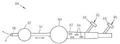
도 13 및 도 14를 참조하면, 중앙 섹션(22)을 가지는 대동맥 이식편(20)을 이식하는 다른 예시적인 방법이 도시되어 있다. 이러한 방법은 "따뜻한 엘리펀트 트렁크(warm elephant trunk)" 방법으로서 지칭될 수 있다. 따뜻한 엘리펀트 트렁크 방법은 도 13에 도시된 바와 같은 이중 자동 관류기 디바이스(80)를 사용한다. 이중 자동 관류기(80)는 루멘이 관통하여 한정된 가요성 캐뉼라(82)와, 루멘으로부터 외부 표면까지 캐뉼라(82)를 통해 한정된 하나 이상의 구멍(84)을 포함한다. 적어도 하나의 접근 포트(86)가 캐뉼라(82)에 연결된다. 접근 포트(86)는 기구 및/또는 가이드 와이어가 캐뉼라(82)의 루멘 내로 삽입되고 그 외부로 빼내지는 것을 가능하게 하는 루멘을 포함한다. 접근 포트(86)의 한쪽 단부는 캐뉼라(82)에 연결되며; 접근 포트(86)의 다른쪽 단부는 혈액이 캐뉼라(82)의 루멘을 통해 흐르는 동안 기구 및/또는 가이드 와이어가 접근 포트(86)에 들어가고 나가는 것을 가능하게 하는 지혈 밸브(88)를 선택적으로 포함한다. 하나 이상의 접근 포트(86)가 제공될 수 있다. 각각의 접근 포트(86)는 접근 포트(86)의 길이 방향 중심선이 캐뉼라(82)의 길이 방향 중심선에 대해 각이 지도록 축에서 벗어난, 또는 캐뉼라(82)의 길이 방향 중심선과 실질적으로 동일하도록 축 상의 캐뉼라(82)에 연결될 수 있다.13 and 14, another exemplary method of implanting an
이중 자동 관류기(80)의 제1 벌룬(90)은 이를 통해 혈액의 유동을 허용하도록 실질적으로 중공체일 수 있다. 대안적으로, 튜브(도시되지 않음)는 제1 벌룬(90)의 양쪽 측면 사이에서 연장되고, 제1 벌룬(90)을 가로지르는 튜브를 통한 혈액 유동을 허용하기 위해 캐뉼라(82)에 연결된다. 가교 튜브(94)는 제1 벌룬(90), 및 제1 벌룬으로부터 이격된 제2 벌룬(92)에 연결된다. 제1 벌룬(90) 및/또는 제2 벌룬(92)은, 벌룬(90, 92)들에 압입 끼워맞춤될 수 있는 가교 튜브(94)에 대해 슬라이딩 가능하다. 양쪽 단부에 있는 플랜지(도시되지 않음)들 또는 다른 적절한 구조 특징부들은 가교 튜브(94)가 벌룬(90, 92)들의 밖으로 당겨지는 것을 방지할 수 있다. 가교 튜브(94)는 제1 벌룬(90) 및/또는 제2 벌룬(92)이 가교 튜브(94)에 대해 슬라이딩되는 것을 가능하게 하는 동시에 가교 튜브(94)와 벌룬(90, 92) 사이의 각각의 경계면에서 누출을 실질적으로 방지하기 위하여, 벌룬(90, 92)들 및/또는 벌룬(90, 92)들 내의 튜브들에 압입 끼워맞춤 또는 선간 끼워맞춤(line-to-line fit)될 수 있다.The
이중 자동 관류기(80)의 제2 벌룬(92)은 이를 통한 혈액의 유동을 허용하도록 실질적으로 중공체일 수 있다. 대안적으로, 튜브(도시되지 않음)는 제2 벌룬(92)의 양쪽 측면 사이에서 연장되고, 가교 튜브(94)에 연결되어, 제2 벌룬(92)을 가로지르는 튜브를 통한 혈액 유동을 허용한다. 출구 튜브(96)는 제2 벌룬(92)에 연결되고, 혈액은 제2 벌룬을 통해 유동하고, 이중 자동 관류기(80)를 빠져나간다.The
처치를 시작하기 위해, 환자는 심폐 바이패스 펌프에 배치되고, 심장이 정지되며, 클램프들이 상행 대동맥으로부터 이격된 대동맥(60)에 배치된다. 절개부(62)들이 상행 대동맥을 분리하기 위해 대동맥(60)에서 만들어지고, 상행 대동맥이 제거된다. 대동맥 이식편(20)의 중앙 섹션(22)은 그런 다음 절개부(62)에서 또는 이에 근접하여 대동맥 절주(70)의 근위 단부에 봉합된다. 이러한 방식으로, 대동맥 이식편(20)의 중앙 섹션(22)의 루멘은 용이하게 접근 가능하다.To begin treatment, the patient is placed in a cardiopulmonary bypass pump, the heart is stopped, and clamps are placed in the
이중 자동 관류기(80)는 대동맥 이식편(20)의 중앙 섹션(22)의 루멘을 통하고, 지혈 밸브(32)를 통해 접근 포트(30) 내로 삽입된다. 이중 자동 관류기(80)는, 제1 벌룬(90)이 대동맥 이식편(20)의 중앙 섹션(22)의 개방 단부에 근접하여 대동맥 이식편(20)의 중앙 섹션(22) 내에 위치되고; 그런 다음, 제2 벌룬(92)이 대동맥 이식편(20)의 중앙 섹션(22)의 루멘 외부에 위치될 때까지 접근 포트(30)를 통해 전진된다. 제1 벌룬(90)은 그런 다음 팽창된다.The dual
심장이 그런 다음 재기동되고, 환자는 표준 관행에 따라 심폐 우회술로부터 옮겨진다. 심장이 재기동되는 동안 또는 심장을 재기동하기 전에, 대동맥 이식편(20)의 나머지(20a)는 하행 대동맥(74) 내로 삽입되고; 제2 벌룬(92)은 대동맥 이식편의 나머지(20a) 내의 하행 대동맥(74) 내로 삽입되고, 제2 벌룬(92)은 팽창된다. 그런 다음 자동 관류는 이중 자동 관류기(80)를 통해 시작된다. 예를 들어, 상류의 구멍(84)은 처음에 슬라이딩 튜브에 의해 차단되고, 그런 다음 구멍으로부터 멀어지게 슬라이딩 튜브를 이동시키는 것에 의해 자동 관류를 시작하도록 선택된 시간에 차단 해제된다. 혈액은 대동맥 이식편(20)의 이식이 완료되는 동안 대동맥을 통한 순환을 허용하기 위해 벌룬(90, 92)들 사이의 가교 튜브(94)를 통해 유동한다. 점퍼(40, 50)들이 선택되어, 팔머리 동맥(64), 좌측 총경동맥(66) 및, 왼빗장밑 동맥(68)에 연결되고, 실질적으로 도 12와 관련하여 전술한 바와 같이 대동맥 이식편(20)의 중앙 섹션(22)에 고정된다. 이러한 방식으로, 폐 우회술과 관련된 환자 부작용에서의 대응하는 감소와 함께, 환자가 심폐 우회술에 있는 시간은 감소된다.The heart is then restarted, and the patient is removed from cardiopulmonary bypass surgery according to standard practice. During or prior to restarting the heart, the
필요에 따라, 대동맥 이식편(20)의 나머지(20a)는 대동맥 이식편(20)의 나머지(20a)가 적소에 남아있는 것을 보장하도록 하행 대동맥(72)에 봉합될 수 있다. 대안적으로, 이러한 봉합은 수행될 필요가 없다. 대동맥 이식편(20)의 나머지(20a)는 봉합되거나 또는 그렇지 않으면 대동맥 이식편(20)의 중앙 섹션(22)에 부착될 수 있다. 다른 실시예에 따르면, 대동맥 이식편(20)의 나머지(20a)는 하행 대동맥(74) 내로 삽입되고, 그런 다음 중앙 섹션(22)은 하행 대동맥(74)에 봉합된다. 대동맥 이식편(20)의 나머지(20a)가 고정된 상태에서, 벌룬(90, 92)은 수축되고, 이중 자동 관류기(80)는 지혈 밸브(32)를 통해 빼내진다.If necessary, the
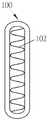
도 15 내지 도 19를 참조하면, 부유술 봉합 링(100)이 도시되어 있다. 부유술 봉합 링(100)은 완전한 원형일 필요는 없고, 임의의 다른 적절한 방식으로 곡선화될 수 있다. 도 15를 참조하면, 부유술 봉합 링(100)은 초기에 제1 상태에 있다.부유술 봉합 링(100)은 도 16에 도시된 바와 같이 제1 상태로부터 제2 상태로 부유술 봉합 링(100)의 확장을 돕는 스프링 요소(102)를 포함한다. 스프링 요소(102)는 직물 커버(104)에 의해 적어도 부분적으로 덮여질 수 있다. 일부 실시예에서, 직물 커버는 DACRON® 브랜드 폴리에스테르와 같은 PET 메쉬일 수 있다. 스프링 요소(102)는 니켈-티타늄 합금과 같은 초탄성 재료로 제작될 수 있어서, 스프링 요소(102)에 반경 방향 힘을 가하는 것은 그 스프링 요소(102)가 마르텐사이트 상과 오스테나이트 상 사이에서 전환되어 제2 상태로 확장되게 한다. 다른 실시예에서, 스프링 요소(102)는 처음에 제1 상태에서 압축되고, 그런 다음 제2 상태로 자체 확장하거나, 제1 상태로부터 제2 상태로 전환되도록 소성적으로 변형되는 스테인리스강과 같은 탄성 재료로 제작될 수 있다. 스프링 요소(102)는 대체로 원형일 수 있거나, 또는 임의의 다른 적절한 형상을 가질 수 있다. 도 17 및 도 18을 참조하면, 부유술 봉합 링(100)은 선택적으로 조정 가능한 섹션(106)을 포함할 수 있다. 조정 가능한 섹션(106)은 수동으로 조정 가능한 스프링 요소(102)의 주름 또는 아코디언 형상 섹션이거나, 또는 수동으로 조정 가능한 다른 구성일 수 있다. 조정 가능한 섹션(106)은 선택적으로 스프링 요소(102)의 나머지와 다른 재료로 제작되고 스프링 요소(102)에 부착된다. 조정 가능한 섹션(106)은 다음에 더욱 상세히 설명되는 바와 같이 환자에게 맞추는 수동 조정을 허용한다. 도 19는 제1 상태에서 도 15의 부유술 봉합 링(100)을 사시도로 도시한다.15 to 19, a floating
도 20을 참조하면, 대동맥 이식편(20)을 이식하기 위한 시스템(110)이 도시되어 있다. 시스템(110)을 이용하여 이식된 대동맥 이식편(20)은 전술한 바와 같이 임의의 대동맥 이식편(20)들일 수 있다. 대동맥 이식편(20)은 도 6a와 관련하여 전술한 바와 같이 접근 포트(30)를 포함하는 중앙 섹션(22), 적어도 하나의 봉합 밴드(23), 및 적어도 하나의 중앙 섹션 앵커(25)를 포함할 수 있다. 하나 이상의 점퍼 이식편은 중앙 섹션(22)으로부터 연장될 수 있거나, 또는 단일 매니폴드(24d)가 중앙 섹션(22)으로부터 연장될 수 있고, 하나 이상의 점퍼 이식편(24a, 24b, 24c)은 이로부터 연장될 수 있다. 하나 이상의 부유술 봉합 링(100)이 대동맥 이식편(20)과 관련하여 시스템(100)에 포함될 수 있다. 또한 도 21을 참조하면, 가요성 내시경 시스템(112)은 접근 포트(30)를 통해 대동맥 이식편(20)의 단부의 밖으로 연장될 수 있다. 가요성 내시경 시스템(112)은 조명 및 카메라를 포함하는 가요성 내시경 본체(118)의 단부에 시각화 헤드(114)를 포함할 수 있고, 이러한 시각화 헤드(114)는 당업계에 공지된 바와 같이 구성될 수 있다. 카메라(120)는 시각화 헤드(114)에 근접하고 이로부터 이격되어 위치될 수 있어서, 시각화 헤드(114)는 해상도를 위해 내시경 본체(118)를 따라서 이미지를 카메라(120)로 전달하는 하나 이상의 렌즈를 포함한다. 가요성 내시경 시스템(112)은 또한 시각화 헤드(114)로부터의 뷰를 사용자에게 디스플레이하는 콘솔(116)에 연결될 수 있으며; 이러한 콘솔은 당업계에 공지되어 있다. 선택적으로, 가요성 내시경 시스템(112)은 표준화됨에 따라서 투관침(118)을 통해 환자에게 삽입될 수 있다.Referring to FIG. 20, a
도 20 및 도 22를 참조하면, 단일 관류 카테터(130)가 도시되어 있다. 단일 관류 카테터(130)는 카테터 외장(132) 내에서 루멘을 한정한다. 카테터 외장(132)의 원위 단부에 또는 그 근처에는 팽장 상태로 팽창 가능하고 수축 상태로 수축 가능한 폐색 벌룬(142)이 있다. 폐색 벌룬(12)에 근접하여, 하나 이상의 관류 포트(134)가 카테터 외장(132)을 통해 루멘으로 연장된다. 벌룬 주입 포트(140)는 관류 포트 또는 포트(134)들에 근접하여 위치되며, 폐색 벌룬(12)의 팽창을 허용한다. 카테터 외장(132)의 근위 단부에서, 허브(136) 및 밀봉부(138)가 단일 관류 카테터(130)의 단부를 폐쇄하는 한편, 표준대로 이를 통한 도구의 통과를 허용한다. 도 23은 단일 관류 카테터(130)를 통해 허브(136) 및 밀봉부(138)를 통해 삽입된 가요성 내시경 시스템(112)을 도시하고, 가요성 내시경 시스템(112)의 원위 단부는 단일 관류 카테터(130)의 원위 단부의 밖으로 연장된다.20 and 22, a
도 20을 참조하면, 시스템(110)은 환자에게 대동맥 이식편(20)을 배치하는데 사용된다. 이러한 이식은 일반적으로 위에서 설명된 바와 같이 수행되며, 본 명세서에서 설명된 특정 변경 사항이 있다. 시스템(110)은 임상의가 하행 대동맥(74)에 있는 거짓 루멘(false lumen)(150) 내로 대동맥 이식편(20)의 부주의한 삽입으로 인한 합병증을 피하는 것을 돕는다. 절개는 대동맥(60)의 내막의 찢어짐이 매질 내로의 혈액의 누출을 허용할 때 일어난다. 이러한 것은 혈액의 정상적인 통로인 실제 루멘(true lumen)(152)과, 새로 생성된 통로인 거짓 루멘(150)의 혈액을 위한 2개의 통로를 생성한다. 대동맥 이식편(20)이 거짓 루멘(150) 내로 삽입되면, 심각한 합병증이 초래될 수 있다.Referring to Figure 20, the
또한 도 24를 참조하면, 부유술 봉합 링(100)은 대동맥(74)의 각각의 나머지 부분의 단부 위에서 슬라이딩된다. 대동맥 이식편(20)의 근위 단부는 전술한 바와 같이 대동맥 절주(70)에 부착될 수 있다. 근위 중앙 섹션 앵커(25)가 대동맥 절주(70)에 봉합된 후에, 근위 부유술 봉합 링(100)은 근위 중앙 섹션 앵커(25) 위에서 중앙 섹션(22)을 향해 슬라이딩된다. 이러한 것은 부유술 봉합 링(100)과 근위 중앙 섹션 앵커(25) 사이에서 대동맥 벽을 압축한다. 근위 부유술 봉합 링(100)은 근위 중앙 섹션 앵커(25) 위에서 슬라이딩되는 것을 허용하기 위해 그 제2 상태로 확장될 수 있다. 근위 부유술 봉합 링(100)의 조정 가능한 섹션(106)은 그런 다음 부유술 봉합 링(100)이 확장 상태에서 너무 느슨한 경우에 부유술 봉합 링(100)을 조이도록 조정될 수 있다. 근위 부유술 봉합 링(100)은 그런 다음 근위 중앙 섹션 앵커(25)에 봉합된다.Also referring to FIG. 24, the floating
도 23에 도시된 바와 같이, 가요성 내시경 시스템(112)과 단일 관류 카테터(130)의 조합의 일부는 대동맥 이식편(20)의 중앙 섹션(22)의 접근 포트(30)를 통해 삽입된다. 가요성 내시경 시스템(112)의 원위 단부는 그런 다음 하행 대동맥(74) 내로 전진된다. 임상의는 가요성 내시경 시스템(112)의 원위 단부가 하행 대동맥(74)의 실제 루멘(152) 또는 거짓 루멘(150)에 위치되는지의 여부를 결정하도록 가요성 내시경 시스템(112)으로부터의 이미지를 이용한다. 가요성 내시경 시스템(112)의 원위 단부가 거짓 루멘(150)에 위치되면, 가요성 내시경 시스템(112)은 빼내지고, 임상의는 이를 다시 전진시키고, 가요성 내시경 시스템(112)의 원위 단부의 위치 결정을 반복한다. 가요성 내시경 시스템(112)의 원위 단부가 실제 루멘(152)에 위치되면, 과정은 계속된다. 가요성 내시경 시스템(112)은 빼내진다. 심장은 그런 다음 재기동되고, 환자는 표준 관행에 따라 심폐 우회술로부터 옮겨진다. 점퍼 이식편(24a, 24b, 24c)들은 환자의 대뇌 동맥에 연결되고, 뇌로의 혈액 유동이 회복된다.As shown in FIG. 23, a portion of the combination of the flexible
대동맥 이식편(20)의 원위 단부는 전술한 바와 같이 하행 대동맥(74)에 부착될 수 있다. 이러한 것은 대신 점퍼 이식편(24a, 24b, 24c)들이 임상의의 선택에 따라 대뇌 동맥에 연결되기 전에 수행될 수 있다. 또한 도 25를 참조하면, 원위 중앙 섹션 앵커(25)가 대동맥(74)의 나머지 부분에 봉합된 후에, 원위 부유술 봉합 링(100)은 원위 중앙 섹션 앵커(25) 위에서 중앙 섹션(22)을 향해 슬라이딩된다. 이러한 것은 부유술 봉합 링(100)과 원위 중앙 섹션 앵커(25) 사이에서 대동맥 벽을 압축한다. 원위 부유술 봉합 링(100)은 원위 중앙 섹션 앵커(25) 위에서 슬라이딩되는 것을 허용하기 위해 제2 상태로 확장될 수 있다. 원위 부유술 봉합 링(100)의 조정 가능한 섹션(106)은 그런 다음 부유술 봉합 링(100)이 확장 상태에서 너무 느슨한 경우에 부유술 봉합 링(100)을 조이도록 조정될 수 있다. 원위 부유술 봉합 링(100)은 그런 다음 도 26에 도시된 바와 같이 원위 중앙 섹션 앵커(25)에 봉합된다.The distal end of the
본 명세서에서 사용되고 당업계에서 관례적으로 사용되는 바와 같이, "실질적으로"라는 단어 및 유사한 근사 용어는 제조 공차 및 다른 제조 부정확성에 기인하는 완제품의 치수 및 다른 특성의 정상적인 변화를 나타낸다.As used herein and customarily used in the art, the word “substantially” and similar approximate terms refer to normal changes in dimensions and other properties of the finished product due to manufacturing tolerances and other manufacturing inaccuracies.
본 발명이 상세하게 설명되었지만, 본 발명을 벗어남이 없이 다양한 변경 및 변형이 만들어질 수 있고 균등물이 사용될 수 있다는 것은 당업자에게 자명할 것이다. 본 발명이 구성의 세부 사항, 구성 요소의 배열 및/또는 상기 상세한 설명에 설명되거나 도면에 도시된 방법으로 제한되지 않음을 이해해야 한다. 본 명세서의 요약서에 있는 진술과 본 명세서에서의 임의의 요약 진술은 단지 예시일뿐이며; 이러한 것들은 청구항의 범위를 제한하는 것이 아니며 제한으로서 해석될 수 없다. 또한, 도면은 예시일뿐 제한이 아니다. 표제 제목과 부제목은 독자의 편의를 위한 것이다. 이러한 것들은 실질적인 중요성, 의미 또는 해석을 가지는 것으로 해석되지 않아야 하고 해석될 수 없으며, 임의의 특정 요지와 관련된 모든 정보가 임의이 특정 표제 또는 부제목 아래에서 찾아지거나 제한된다는 것을 나타내는 것으로 간주되어서는 안된다. 그러므로, 본 발명은 다음 청구항 및 그 법적 등가물에 따르는 경우를 제외하고는 제한되거나 제한되지 않는다.Although the present invention has been described in detail, it will be apparent to those skilled in the art that various changes and modifications can be made and equivalents can be used without departing from the present invention. It is to be understood that the invention is not limited to the details of construction, arrangement of components, and/or methods described in the above detailed description or shown in the drawings. The statements in the Abstracts herein and any summary statements herein are by way of example only; These do not limit the scope of the claims and cannot be construed as limitations. In addition, the drawings are only examples and are not limiting. The heading title and subtitle are for the convenience of the reader. These should not be construed as having substantial importance, meaning or interpretation, and should not be construed as indicating that any information relating to any particular subject matter is found or limited under any particular heading or subheading. Therefore, the invention is not limited or limited except in accordance with the following claims and their legal equivalents.
Claims (19)
Translated fromKorean2개의 측면 가장자리를 가지는 외장;
상기 외장을 통해 한정되고, 상기 외장의 측면 가장자리들에 근접하고 길이 방향 축을 따라서 서로로부터 길이 방향으로 이격되는 복수의 구멍; 및
상기 구멍들을 통해 연장되는 당김 와이어를 포함하는, 봉쇄 구조물.As a containment structure for use with a workpiece vascular graft,
A sheath having two side edges;
A plurality of holes defined through the sheath, adjacent to side edges of the sheath, and spaced from each other in a longitudinal direction along a longitudinal axis; And
A containment structure comprising a pull wire extending through the holes.
삽입 상태로부터 전개 상태로 자체 확장 가능한 혈관 이식편; 및
상기 혈관 이식편의 한쪽 단부에 위치된 봉합 커프(suture cuff)를 포함하는, 의료 장치.As a medical device,
A vascular graft capable of self-expanding from the inserted state to the deployed state; And
A medical device comprising a suture cuff positioned at one end of the vascular graft.
Applications Claiming Priority (3)
| Application Number | Priority Date | Filing Date | Title |
|---|---|---|---|
| US201862693897P | 2018-07-03 | 2018-07-03 | |
| US62/693,897 | 2018-07-03 | ||
| PCT/US2019/040566WO2020010237A1 (en) | 2018-07-03 | 2019-07-03 | Vascular and aortic grafts and deployment tool |
Publications (1)
| Publication Number | Publication Date |
|---|---|
| KR20210027450Atrue KR20210027450A (en) | 2021-03-10 |
Family
ID=67587938
Family Applications (1)
| Application Number | Title | Priority Date | Filing Date |
|---|---|---|---|
| KR1020217003231ACeasedKR20210027450A (en) | 2018-07-03 | 2019-07-03 | Vascular and aortic grafts and deployment tools |
Country Status (10)
| Country | Link |
|---|---|
| US (5) | US20200008927A1 (en) |
| EP (1) | EP3817692A1 (en) |
| JP (1) | JP2021528219A (en) |
| KR (1) | KR20210027450A (en) |
| CN (1) | CN112996463A (en) |
| AU (2) | AU2019297439B2 (en) |
| CA (1) | CA3105480A1 (en) |
| IL (1) | IL279841A (en) |
| TW (5) | TWI836494B (en) |
| WO (1) | WO2020010237A1 (en) |
Families Citing this family (8)
| Publication number | Priority date | Publication date | Assignee | Title |
|---|---|---|---|---|
| US11304832B2 (en)* | 2018-04-23 | 2022-04-19 | Washington University | Fenestrated stent system and method of use |
| CN112996463A (en) | 2018-07-03 | 2021-06-18 | 艾奎登医疗公司 | Vascular and aortic grafts and deployment tools |
| JP7463499B2 (en) | 2019-09-25 | 2024-04-08 | アキューデオン・メディカル・インコーポレイテッド | Vascular and aortic grafts and deployment tools |
| TW202145975A (en) | 2020-03-04 | 2021-12-16 | 美商艾奎登生醫股份有限公司 | Vascular and aortic connectors with telescoping sheath and deployment methods thereof |
| CN113893444B (en)* | 2020-06-22 | 2025-02-07 | 上海微创心脉医疗科技(集团)股份有限公司 | A medical device |
| CN112494172A (en)* | 2020-12-14 | 2021-03-16 | 首都医科大学附属北京安贞医院 | Artificial blood vessel with contraction function and artificial blood vessel device |
| CN112933382B (en)* | 2021-02-03 | 2022-07-12 | 温州医科大学附属第二医院(温州医科大学附属育英儿童医院) | A uterine cavity drug infusion device |
| CN113368326B (en)* | 2021-06-04 | 2022-08-05 | 中国医学科学院阜外医院深圳医院(深圳市孙逸仙心血管医院) | Aorta cannula for external ventricular assist system |
Family Cites Families (35)
| Publication number | Priority date | Publication date | Assignee | Title |
|---|---|---|---|---|
| US4580568A (en) | 1984-10-01 | 1986-04-08 | Cook, Incorporated | Percutaneous endovascular stent and method for insertion thereof |
| FR2688401B1 (en)* | 1992-03-12 | 1998-02-27 | Thierry Richard | EXPANDABLE STENT FOR HUMAN OR ANIMAL TUBULAR MEMBER, AND IMPLEMENTATION TOOL. |
| US6042605A (en)* | 1995-12-14 | 2000-03-28 | Gore Enterprose Holdings, Inc. | Kink resistant stent-graft |
| US6352561B1 (en)* | 1996-12-23 | 2002-03-05 | W. L. Gore & Associates | Implant deployment apparatus |
| US6152956A (en)* | 1997-01-28 | 2000-11-28 | Pierce; George E. | Prosthesis for endovascular repair of abdominal aortic aneurysms |
| US6254593B1 (en)* | 1999-12-10 | 2001-07-03 | Advanced Cardiovascular Systems, Inc. | Bifurcated stent delivery system having retractable sheath |
| US7018404B2 (en)* | 2002-01-24 | 2006-03-28 | St. Jude Medical, Inc. | Conduit for aorta or pulmonary artery replacement |
| CA2536368A1 (en)* | 2003-08-19 | 2005-03-03 | Nmt Medical, Inc. | Expandable sheath tubing |
| US7993384B2 (en)* | 2003-09-12 | 2011-08-09 | Abbott Cardiovascular Systems Inc. | Delivery system for medical devices |
| US9044311B2 (en)* | 2006-11-30 | 2015-06-02 | Cook Medical Technologies Llc | Aortic graft device |
| US20090125097A1 (en)* | 2007-11-13 | 2009-05-14 | Medtronic Vascular, Inc. | Device and Method for Stent Graft Fenestration in Situ |
| DE102008021060A1 (en) | 2008-04-26 | 2009-10-29 | Biotronik Vi Patent Ag | An insertion device with a release device for releasing an article carried by a catheter and a release device of an insertion device |
| US20130310853A1 (en) | 2009-01-09 | 2013-11-21 | Abbott Cardiovascular Systems Inc. | Method and apparatus for percutaneous treatment of a blood vessel |
| CN102802720B (en) | 2009-05-12 | 2015-11-25 | 埃克赛斯科技有限公司 | With the access to plant of valve |
| US9168163B2 (en) | 2010-02-18 | 2015-10-27 | P Tech, Llc | Anatomic needle system |
| US8870937B2 (en) | 2010-02-26 | 2014-10-28 | ProMed, Inc. | Method for vessel access closure |
| US20120130475A1 (en)* | 2010-11-16 | 2012-05-24 | Shaw Edward E | Sleeves for expandable medical devices |
| US8641752B1 (en)* | 2011-01-20 | 2014-02-04 | W. L. Gore & Associates, Inc. | Integrated sheath and deployment |
| US9375308B2 (en)* | 2012-03-13 | 2016-06-28 | W. L. Gore & Associates, Inc. | External steerable fiber for use in endoluminal deployment of expandable devices |
| US9381101B2 (en)* | 2012-04-23 | 2016-07-05 | The Charlotte-Mecklenburg Hospital Authority | Hybrid graft for therapy of aortic pathology and associated method |
| US9763819B1 (en)* | 2013-03-05 | 2017-09-19 | W. L. Gore & Associates, Inc. | Tapered sleeve |
| US9855160B2 (en)* | 2013-03-14 | 2018-01-02 | W. L. Gore & Associates, Inc. | Endoprosthesis delivery systems with deployment aids |
| US9770352B2 (en)* | 2013-03-14 | 2017-09-26 | W. L. Gore & Associates, Inc. | Inflatable balloon and cover |
| DE102013106463A1 (en)* | 2013-06-20 | 2014-12-24 | Jotec Gmbh | stent graft |
| US10758387B2 (en)* | 2014-10-16 | 2020-09-01 | Cook Medical Technologies Llc | Endovascular stent graft assembly and delivery device |
| US20180000619A1 (en) | 2015-01-29 | 2018-01-04 | Intact Vascular, Inc. | Delivery device and method of delivery |
| US9192500B1 (en) | 2015-01-29 | 2015-11-24 | Intact Vascular, Inc. | Delivery device and method of delivery |
| US11898005B2 (en)* | 2015-06-18 | 2024-02-13 | Tissium Sa | Sealant composition |
| US10821009B2 (en)* | 2016-05-26 | 2020-11-03 | Swiss Capital—Engineering AG | Vascular medical device, system and method |
| FI3528717T3 (en) | 2016-10-24 | 2024-08-09 | Inari Medical Inc | Devices for treating vascular occlusion |
| WO2018125802A1 (en)* | 2016-12-29 | 2018-07-05 | Boston Scientific Scimed, Inc. | Method for loading a stent into a delivery device |
| ES2954897T3 (en)* | 2017-02-24 | 2023-11-27 | Bolton Medical Inc | Constrained Wrap Stent Graft Delivery System |
| US10595874B2 (en) | 2017-09-21 | 2020-03-24 | W. L. Gore & Associates, Inc. | Multiple inflation endovascular medical device |
| CN112996463A (en) | 2018-07-03 | 2021-06-18 | 艾奎登医疗公司 | Vascular and aortic grafts and deployment tools |
| JP7463499B2 (en) | 2019-09-25 | 2024-04-08 | アキューデオン・メディカル・インコーポレイテッド | Vascular and aortic grafts and deployment tools |
- 2019
- 2019-07-03CNCN201980057495.2Apatent/CN112996463A/enactivePending
- 2019-07-03TWTW111124865Apatent/TWI836494B/enactive
- 2019-07-03AUAU2019297439Apatent/AU2019297439B2/enactiveActive
- 2019-07-03TWTW108123442Apatent/TW202019353A/enunknown
- 2019-07-03JPJP2021521939Apatent/JP2021528219A/enactivePending
- 2019-07-03TWTW111124863Apatent/TW202241364A/enunknown
- 2019-07-03KRKR1020217003231Apatent/KR20210027450A/ennot_activeCeased
- 2019-07-03USUS16/502,539patent/US20200008927A1/ennot_activeAbandoned
- 2019-07-03CACA3105480Apatent/CA3105480A1/enactivePending
- 2019-07-03WOPCT/US2019/040566patent/WO2020010237A1/ennot_activeCeased
- 2019-07-03TWTW111124864Apatent/TW202241365A/enunknown
- 2019-07-03TWTW111124862Apatent/TW202241363A/enunknown
- 2019-07-03EPEP19752588.4Apatent/EP3817692A1/ennot_activeWithdrawn
- 2020
- 2020-04-10USUS16/845,466patent/US20200261208A1/ennot_activeAbandoned
- 2020-04-10USUS16/845,492patent/US20200246128A1/ennot_activeAbandoned
- 2020-04-10USUS16/845,504patent/US12029639B2/enactiveActive
- 2020-04-10USUS16/845,478patent/US20200253711A1/ennot_activeAbandoned
- 2020-12-29ILIL279841Apatent/IL279841A/enunknown
- 2022
- 2022-09-23AUAU2022235608Apatent/AU2022235608A1/ennot_activeAbandoned
Also Published As
| Publication number | Publication date |
|---|---|
| CN112996463A (en) | 2021-06-18 |
| US20200246128A1 (en) | 2020-08-06 |
| IL279841A (en) | 2021-03-01 |
| US20200261208A1 (en) | 2020-08-20 |
| TW202019353A (en) | 2020-06-01 |
| US20200253711A1 (en) | 2020-08-13 |
| AU2022235608A1 (en) | 2022-10-13 |
| JP2021528219A (en) | 2021-10-21 |
| AU2019297439A1 (en) | 2021-01-21 |
| TW202241365A (en) | 2022-11-01 |
| WO2020010237A1 (en) | 2020-01-09 |
| US20200008927A1 (en) | 2020-01-09 |
| EP3817692A1 (en) | 2021-05-12 |
| CA3105480A1 (en) | 2020-01-09 |
| US12029639B2 (en) | 2024-07-09 |
| TW202241364A (en) | 2022-11-01 |
| US20200268501A1 (en) | 2020-08-27 |
| TWI836494B (en) | 2024-03-21 |
| TW202241366A (en) | 2022-11-01 |
| TW202241363A (en) | 2022-11-01 |
| AU2019297439B2 (en) | 2022-06-23 |
Similar Documents
| Publication | Publication Date | Title |
|---|---|---|
| AU2019297439B2 (en) | Vascular and aortic grafts and deployment tool | |
| EP2429452B1 (en) | Endoluminal prosthesis system | |
| US20020138129A1 (en) | Method of producing low profile stent and graft combination | |
| US8747449B2 (en) | Endoscopic delivery device | |
| JP7463499B2 (en) | Vascular and aortic grafts and deployment tools |
Legal Events
| Date | Code | Title | Description |
|---|---|---|---|
| PA0105 | International application | St.27 status event code:A-0-1-A10-A15-nap-PA0105 | |
| PG1501 | Laying open of application | St.27 status event code:A-1-1-Q10-Q12-nap-PG1501 | |
| PA0201 | Request for examination | St.27 status event code:A-1-2-D10-D11-exm-PA0201 | |
| D13-X000 | Search requested | St.27 status event code:A-1-2-D10-D13-srh-X000 | |
| D14-X000 | Search report completed | St.27 status event code:A-1-2-D10-D14-srh-X000 | |
| E902 | Notification of reason for refusal | ||
| PE0902 | Notice of grounds for rejection | St.27 status event code:A-1-2-D10-D21-exm-PE0902 | |
| E601 | Decision to refuse application | ||
| PE0601 | Decision on rejection of patent | St.27 status event code:N-2-6-B10-B15-exm-PE0601 | |
| P22-X000 | Classification modified | St.27 status event code:A-2-2-P10-P22-nap-X000 |