KR20210027170A - Prism for Optical Imaging System - Google Patents
Prism for Optical Imaging SystemDownload PDFInfo
- Publication number
- KR20210027170A KR20210027170AKR1020200108987AKR20200108987AKR20210027170AKR 20210027170 AKR20210027170 AKR 20210027170AKR 1020200108987 AKR1020200108987 AKR 1020200108987AKR 20200108987 AKR20200108987 AKR 20200108987AKR 20210027170 AKR20210027170 AKR 20210027170A
- Authority
- KR
- South Korea
- Prior art keywords
- prism
- protrusion
- optical system
- light
- incident
- Prior art date
- Legal status (The legal status is an assumption and is not a legal conclusion. Google has not performed a legal analysis and makes no representation as to the accuracy of the status listed.)
- Granted
Links
Images


Classifications
- G—PHYSICS
- G02—OPTICS
- G02B—OPTICAL ELEMENTS, SYSTEMS OR APPARATUS
- G02B5/00—Optical elements other than lenses
- G02B5/04—Prisms
- G02B5/045—Prism arrays
- G—PHYSICS
- G02—OPTICS
- G02B—OPTICAL ELEMENTS, SYSTEMS OR APPARATUS
- G02B5/00—Optical elements other than lenses
- G02B5/04—Prisms
- G—PHYSICS
- G02—OPTICS
- G02B—OPTICAL ELEMENTS, SYSTEMS OR APPARATUS
- G02B1/00—Optical elements characterised by the material of which they are made; Optical coatings for optical elements
- G02B1/10—Optical coatings produced by application to, or surface treatment of, optical elements
- G02B1/11—Anti-reflection coatings
- G—PHYSICS
- G02—OPTICS
- G02B—OPTICAL ELEMENTS, SYSTEMS OR APPARATUS
- G02B27/00—Optical systems or apparatus not provided for by any of the groups G02B1/00 - G02B26/00, G02B30/00
- G02B27/0018—Optical systems or apparatus not provided for by any of the groups G02B1/00 - G02B26/00, G02B30/00 with means for preventing ghost images
- G—PHYSICS
- G02—OPTICS
- G02B—OPTICAL ELEMENTS, SYSTEMS OR APPARATUS
- G02B5/00—Optical elements other than lenses
- G02B5/20—Filters
- G02B5/208—Filters for use with infrared or ultraviolet radiation, e.g. for separating visible light from infrared and/or ultraviolet radiation
- G—PHYSICS
- G02—OPTICS
- G02B—OPTICAL ELEMENTS, SYSTEMS OR APPARATUS
- G02B13/00—Optical objectives specially designed for the purposes specified below
- G02B13/001—Miniaturised objectives for electronic devices, e.g. portable telephones, webcams, PDAs, small digital cameras
- G02B13/0055—Miniaturised objectives for electronic devices, e.g. portable telephones, webcams, PDAs, small digital cameras employing a special optical element
- G02B13/0065—Miniaturised objectives for electronic devices, e.g. portable telephones, webcams, PDAs, small digital cameras employing a special optical element having a beam-folding prism or mirror
- G—PHYSICS
- G02—OPTICS
- G02B—OPTICAL ELEMENTS, SYSTEMS OR APPARATUS
- G02B7/00—Mountings, adjusting means, or light-tight connections, for optical elements
- G02B7/18—Mountings, adjusting means, or light-tight connections, for optical elements for prisms; for mirrors
- G02B7/1805—Mountings, adjusting means, or light-tight connections, for optical elements for prisms; for mirrors for prisms
- H—ELECTRICITY
- H04—ELECTRIC COMMUNICATION TECHNIQUE
- H04N—PICTORIAL COMMUNICATION, e.g. TELEVISION
- H04N23/00—Cameras or camera modules comprising electronic image sensors; Control thereof
- H04N23/50—Constructional details
Landscapes
- Physics & Mathematics (AREA)
- General Physics & Mathematics (AREA)
- Optics & Photonics (AREA)
- Health & Medical Sciences (AREA)
- Toxicology (AREA)
- Engineering & Computer Science (AREA)
- Multimedia (AREA)
- Signal Processing (AREA)
- Optical Elements Other Than Lenses (AREA)
- Studio Devices (AREA)
- Lenses (AREA)
Abstract
Translated fromKoreanDescription
Translated fromKorean본 발명은 촬상 광학계의 광 경로를 변경하도록 구성된 프리즘에 관한 것이다.The present invention relates to a prism configured to change the optical path of an imaging optical system.
촬상 광학계는 휴대용 단말기에 탑재될 수 있다. 그러나 스마트폰과 같은 형태의 휴대용 단말기는 대체로 박형화된 구조이므로, 긴 초점거리를 갖는 촬상 광학계의 탑재가 용이하지 않다. 굴곡형 촬상 광학계는 이러한 문제를 해소시킬 수 있도록 구성되었다. 예를 들어, 굴곡형 촬상 광학계는 프리즘을 이용하여 다수의 렌즈를 휴대용 단말기의 길이방향으로 배치시킬 수 있다. 그러나 이러한 촬상 광학계에 사용되기 위한 프리즘은 크기가 매우 작으므로 성형가공을 통한 제작이 어렵다. 따라서, 제작이 용이하면서 신뢰할 수 있는 광투과율 및 반사율을 갖는 프리즘이 요청된다.The optical system may be mounted on a portable terminal. However, since a portable terminal in the form of a smart phone has a generally thinner structure, it is not easy to mount an imaging optical system having a long focal length. The curved imaging optical system is configured to solve this problem. For example, in the curved imaging optical system, a plurality of lenses may be disposed in the longitudinal direction of the portable terminal using a prism. However, since the prism for use in such an optical system is very small, it is difficult to manufacture it through molding. Therefore, a prism having a light transmittance and reflectance that is easy to manufacture and reliable is required.
본 발명은 상기와 같은 문제점을 해결하기 위한 것으로서, 제작이 용이하면서 신뢰할 수 있는 광투과율과 반사율을 갖는 프리즘을 제공하는데 그 목적이 있다.The present invention is to solve the above problems, and an object thereof is to provide a prism having a reliable light transmittance and reflectance while being easy to manufacture.
상기 목적을 달성하기 위한 본 발명의 일 실시 예에 따른 촬상 광학계용 프리즘은 빛의 입사가 이루어지는 입사면; 빛의 출사가 이루어지는 출사면; 상기 입사면을 통해 입사되는 빛을 상기 출사면으로 반사시키도록 구성되는 반사면; 및 상기 입사면과 상기 반사면의 경계부 또는 상기 출사면과 상기 반사면의 경계부에 형성되는 불연속부;를 포함한다.A prism for an optical system according to an embodiment of the present invention for achieving the above object comprises: an incident surface on which light is incident; An exit surface where light exits; A reflective surface configured to reflect light incident through the incident surface to the exit surface; And a discontinuity formed at a boundary between the incident surface and the reflective surface or a boundary between the emission surface and the reflective surface.
본 발명은 제작이 용이하면서 신뢰할 수 있는 광투과율과 반사율을 갖는 프리즘을 제공할 수 있다.The present invention can provide a prism having a reliable light transmittance and reflectance while being easy to manufacture.
도 1은 본 발명의 제1실시 예에 따른 촬상 광학계용 프리즘의 사시도
도 2는 도 1에 도시된 프리즘의 측면도
도 3은 도 1에 도시된 프리즘의 다른 형태에 따른 측면도
도 4는 본 발명의 제2실시 예에 따른 촬상 광학계용 프리즘의 사시도
도 5는 본 발명의 제3실시 예에 따른 촬상 광학계용 프리즘의 사시도
도 6은 본 발명의 제4실시 예에 따른 촬상 광학계용 프리즘의 사시도
도 7은 본 발명의 제5실시 예에 따른 촬상 광학계용 프리즘의 사시도
도 8은 도 7에 도시된 프리즘의 정면도
도 9 내지 도 11은 도 6에 도시된 프리즘과 카메라 모듈의 브래킷 간의 결합관계를 나타낸 구성도1 is a perspective view of a prism for an optical system according to a first embodiment of the present invention
Figure 2 is a side view of the prism shown in Figure 1
3 is a side view according to another form of the prism shown in FIG. 1
4 is a perspective view of a prism for an optical system according to a second embodiment of the present invention
5 is a perspective view of a prism for an optical system according to a third embodiment of the present invention
6 is a perspective view of a prism for an optical system according to a fourth embodiment of the present invention
7 is a perspective view of a prism for an optical system according to a fifth embodiment of the present invention
8 is a front view of the prism shown in FIG. 7
9 to 11 are configuration diagrams showing a coupling relationship between the prism shown in FIG. 6 and the bracket of the camera module
이하, 본 발명의 바람직한 실시 예를 첨부된 예시도면에 의거하여 상세히 설명한다.Hereinafter, a preferred embodiment of the present invention will be described in detail on the basis of the accompanying exemplary drawings.
아래에서 본 발명을 설명함에 있어서, 본 발명의 구성요소를 지칭하는 용어들은 각각의 구성요소들의 기능을 고려하여 명명된 것이므로, 본 발명의 기술적 구성요소를 한정하는 의미로 이해되어서는 안 될 것이다.In the following description of the present invention, terms referring to the constituent elements of the present invention are named in consideration of the functions of the respective constituent elements, and thus, should not be understood as limiting the technical constituents of the present invention.
아울러, 명세서 전체에서, 어떤 구성이 다른 구성과 '연결'되어 있다 함은 이들 구성들이 '직접적으로 연결'되어 있는 경우뿐만 아니라, 다른 구성을 사이에 두고 '간접적으로 연결'되어 있는 경우도 포함하는 것을 의미한다. 또한, 어떤 구성요소를 '포함'한다는 것은, 특별히 반대되는 기재가 없는 한 다른 구성요소를 제외하는 것이 아니라 다른 구성요소를 더 포함할 수 있다는 것을 의미한다.In addition, throughout the specification, that a certain configuration is'connected' to another configuration includes not only the case where these configurations are'directly connected', but also the case where the other configurations are'indirectly connected'. Means that. In addition, "including" a certain component means that other components may be further included rather than excluding other components unless otherwise stated.
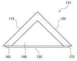
도 1 내지 도 3을 참조하여 제1실시 예에 따른 촬상 광학계용 프리즘을 설명한다.A prism for an optical system according to a first embodiment will be described with reference to FIGS. 1 to 3.
본 실시 예에 따른 프리즘(101)은 대체로 직육면체 또는 정육면체를 대각 방향으로 이등분한 형태를 가진다. 프리즘(101)은 사각형상의 3개 면과 삼각형상의 2개 면을 포함한다. 예를 들어, 프리즘(101)의 입사면(110), 출사면(120), 반사면(130)은 사각형상이고, 프리즘(101)의 양 측면은 삼각형상이다.The
프리즘(101)은 소정의 재질로 이루어질 수 있다. 예를 들어, 프리즘(101)은 제조 및 가공이 용이하도록 플라스틱 재질로 이루어질 수 있다. 그러나 프리즘(101)의 재질이 플라스틱으로 한정되는 것은 아니다. 예를 들어, 휴대용 단말기에 장착 가능한 크기로 제작할 수 있는 범위에서, 프리즘(101)을 유리 재질로 제작할 수도 있다.The
본 실시 예에 따른 프리즘(101)은 소정의 공정으로 제작될 수 있다. 예를 들어, 프리즘(101)은 가공품질을 신뢰할 수 있는 범위에서 사출성형에 의해 제작할 수 있다. 이와 같이 제작된 프리즘(101)은 별도의 연마 공정을 생략할 수 있으므로 프리즘(101)의 제조공정을 간소화시킬 수 있다.The
프리즘(101)은 카메라 모듈에 장착이 용이하도록 구성될 수 있다. 예를 들어, 프리즘(101)의 양 측면(140, 150)에는 카메라 모듈의 하우징 또는 브래킷과 결합할 수 있는 제1돌출부(146)가 형성된다. 제1돌출부(146)는 양 측면(140, 150)과 닮은 꼴 형태일 수 있다. 예를 들어, 제1돌출부(146)의 단면형상은 측면(140, 150)과 마찬가지로 삼각형일 수 있다. 제1돌출부(146)는 반사면(130)과 대체로 동일한 높이로 형성될 수 있다. 예를 들어, 제1돌출부(146)의 일단은 도 3에 도시된 바와 같이 반사면(130)과 연속되도록 형성될 수 있다.The
프리즘(101)은 양 측면(140, 150)을 기준으로 반사면(130)의 위치를 조정할 수 있도록 구성될 수 있다. 예를 들어, 프리즘(101)은 양 측면(140, 150)에 형성된 제1돌출부(146)를 중심으로 회전되어, 입사면(110)으로 입사되는 입사광의 각도 또는 출사면(120)으로부터 투사되는 투사광의 각도를 조정할 수 있다.The
프리즘(101)은 사출성형에 따른 특유의 형상을 포함할 수 있다. 예를 들어, 도 2에 도시된 바와 같이 반사면(130)과 입사면(110)이 연결되는 경계부 및 반사면(130)과 출사면(120)이 연결되는 경계부에는 불연속부(170)가 형성될 수 있다. 불연속부(170)는 프리즘(101)의 폭 방향을 따라 길게 형성될 수 있다. 불연속부(170)는 소정의 단차를 갖는 단턱 또는 미세한 높이를 갖는 돌기 또는 선 형태일 수 있다.The
참고로, 본 명세서 및 도면에서는 불연속부(170)가 반사면(130)의 가장자리에 형성되는 것으로 기재 및 도시되었으나, 프리즘(101)을 사출성형하는 금형의 유형에 따라 입사면(110)의 가장자리 또는 출사면(120)의 가장자리에 형성될 수도 있다.For reference, in the present specification and drawings, the
프리즘(101)은 소정의 파면수차를 갖도록 형성될 수 있다. 예를 들어, 입사면(110) 및 출사면(120)은 대체로 동일한 크기의 파면수차를 갖도록 형성되고, 반사면(130)은 입사면(110) 및 출사면(120)보다 작은 파면수차를 갖도록 형성될 수 있다. 바람직하게는, 프리즘(101)의 입사면(110) 및 출사면(120)은 1/2λ의 파면수차를 갖도록 형성되고, 프리즘(101)의 반사면(130)은 1/4λ의 파면수차를 갖도록 형성될 수 있다. 즉, 반사면(130)의 파면수차는 입사면(110) 및 출사면(120)의 파면수차의 1/2 크기로 형성될 수 있다. 이와 같이 구성된 프리즘(101)은 광 변로를 굴곡시킴에 따라 야기될 수 있는 수차를 경감시킬 수 있다.The
본 실시 예에 따른 프리즘(101)은 도 3에 도시된 바와 같이 복수의 코팅층을 포함할 수 있다. 일 예로, 프리즘(101)의 입사면(110) 및 출사면(120)에는 반사방지층(220)이 형성될 수 있다. 다른 예로, 프리즘(101)의 반사면(130)에는 반사방지 및 적외선차단을 동시에 수행할 수 있는 코팅층(230)이 형성될 수 있다.The
다음에서는 본 발명에 따른 촬상 광학계용 프리즘의 다른 형태를 설명한다. 참고로, 이하의 설명에서 전술된 실시 예와 동일 또는 유사한 구성은 전술된 실시 예와 동일한 도면부호를 사용하며, 해당 구성요소에 대한 상세한 설명은 생략한다.Next, another form of the prism for an optical system according to the present invention will be described. For reference, in the following description, configurations that are the same as or similar to those of the above-described embodiment are denoted by the same reference numerals as the above-described embodiments, and detailed descriptions of corresponding components are omitted.
먼저, 도 4를 참조하여 제2실시 예에 따른 촬상 광학계용 프리즘을 설명한다.First, a prism for an optical system according to a second embodiment will be described with reference to FIG. 4.
본 실시 예에 따른 프리즘(102)은 대체로 직육면체 또는 정육면체를 대각 방향으로 이등분한 형태를 가진다. 프리즘(102)은 사각형상의 3개 면과 삼각형상의 2개 면을 포함한다. 예를 들어, 프리즘(102)의 입사면(110), 출사면(120), 반사면(130)은 사각형상이고, 프리즘(102)의 양 측면은 삼각형상이다.The
본 실시 예에 따른 프리즘(102)은 복수의 모깍기 영역을 포함한다. 예를 들어, 입사면(110)과 반사면(130)이 연결되는 부분(131)과 반사면(130)과 출사면(120)이 연결되는 부분(132)은 소정의 각도(θ1, θ2)를 갖도록 형성된다. 상기 부분들(131, 132)은 도 2에 도시된 바와 같이 경사면(130)에 대해 둔각이 되도록 가공될 수 있다. 일 예로, 상기 부분들(131, 132)과 입사면(110) 및 출사면(120)이 형성하는 제1각도(θ1)는 90도일 수 있다. 다른 예로, 상기 부분들(131, 132)과 경사면(130)이 형성하는 제2각도(θ2)는 135도일 수 있다.The
상기 부분들(131, 132)은 플레어 현상을 야기하지 않도록 형성될 수 있다. 일 예로, 상기 부분들(131, 132)에는 차광필름이 부착되거나 또는 차광도료가 도포될 수 있다. 다른 예로, 상기 부분들(131, 132)은 빛의 산란이 이루어질 수 있도록 거칠기를 갖는 형태로 가공될 수 있다.The
프리즘(102)은 제1돌출부(146)를 포함할 수 있다. 예를 들어, 제1돌출부(146)는 프리즘(102)의 양 측면(140, 150)에 형성될 수 있다. 제1돌출부(146)는 프리즘(102)을 고정 부재에 거치시키기 위한 수단으로 이용될 수 있다. 예를 들어, 제1돌출부(146)는 카메라 모듈의 브래킷에 형성된 단턱 또는 홈에 끼워질 수 있다.The
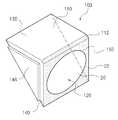
도 5를 참조하여 제3실시 예에 따른 촬상 광학계용 프리즘을 설명한다.A prism for an optical system according to a third embodiment will be described with reference to FIG. 5.
본 실시 예에 따른 프리즘(103)은 대체로 직육면체 또는 정육면체를 대각 방향으로 이등분한 형태를 가진다. 프리즘(103)은 사각형상의 3개 면과 삼각형상의 2개 면을 포함한다. 예를 들어, 프리즘(103)의 입사면(110), 출사면(120), 반사면(130)은 사각형상이고, 프리즘(103)의 양 측면은 삼각형상이다.The
프리즘(103)은 하나 이상의 모깍기 영역을 포함할 수 있다. 예를 들어, 입사면(110)과 출사면(120)이 연결되는 부분(112)은 입사면(110) 또는 출사면(120)에 대해 둔각이 되도록 가공될 수 있다.The
상기 부분(112)은 플레어 현상을 야기하지 않도록 형성될 수 있다. 일 예로, 상기 부분(112)에는 차광필름이 부착되거나 또는 차광도료가 도포될 수 있다. 다른 예로, 상기 부분(112)은 빛의 산란이 이루어질 수 있도록 거칠기를 갖는 형태로 가공될 수 있다.The
아울러, 본 실시 예에 따른 프리즘(103)은 빛의 출사영역을 한정할 수 있도록 구성될 수 있다. 예를 들어, 프리즘(103)의 출사면(120)은 도 5에 도시된 바와 같이 빛의 입사가 가능한 투광영역(20)과 빛의 입사를 차단할 수 있는 차광영역(22)을 포함할 수 있다.In addition, the
투광영역(20)은 촬상 광학계를 구성하는 렌즈의 단면 형상과 대체로 동일 또는 유사하게 형성될 수 있다. 구체적으로는, 투광영역(20)은 촬상 광학계에서 물체 측에 가장 가깝게 배치되는 렌즈(이하 제1렌즈라고 함)의 유효영역과 동일 또는 유사하게 형성될 수 있다. 일 예로, 제1렌즈의 유효영역이 원형이면, 투광영역(20)도 원형으로 형성될 수 있다. 다른 예로, 제1렌즈의 유효영역이 타원 또는 양끝 부분적으로 절개된 원형이면, 투광영역(20)은 타원형으로 형성될 수 있다. 그러나 투광영역(20)의 형상이 제1렌즈의 유효영역의 형상으로 한정되는 것은 아니다. 일 예로, 투광영역(20)은 제1렌즈의 유효영역의 형상과 관계없이 원형으로 형성될 수도 있다.The light-transmitting
차광영역(22)은 출사면(120)에서 투광영역(20)을 제외한 부분에 형성될 수 있다. 차광영역(22)은 차광필름, 차광도료 등에 의해 형성될 수 있다. 이와 같이 형성된 차광영역(22)은 사진촬영에 불필요한 빛이 출사면(120)을 통해 출사 또는 반사되는 현상을 경감시킬 수 있다.The
프리즘(103)은 제1돌출부(146)를 포함할 수 있다. 예를 들어, 제1돌출부(146)는 프리즘(102)의 양 측면(140, 150)에 형성될 수 있다. 제1돌출부(146)는 프리즘(102)을 고정 부재에 거치시키기 위한 수단으로 이용될 수 있다. 예를 들어, 제1돌출부(146)는 카메라 모듈의 브래킷에 형성된 단턱 또는 홈에 끼워질 수 있다.The
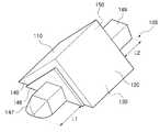
도 6을 참조하여 제4실시 예에 따른 촬상 광학계용 프리즘을 설명한다.A prism for an optical system according to a fourth embodiment will be described with reference to FIG. 6.
본 실시 예에 따른 프리즘(104)은 대체로 직육면체 또는 정육면체를 대각 방향으로 이등분한 형태를 가진다. 프리즘(104)은 사각형상의 3개 면과 삼각형상의 2개 면을 포함한다. 예를 들어, 프리즘(104)의 입사면(110), 출사면(120), 반사면(130)은 사각형상이고, 프리즘(104)의 양 측면은 삼각형상이다.The
프리즘(104)은 측면(140, 150)에 복수의 돌출부(146, 148)가 형성된다. 측면(140, 150)에는 프리즘(104)의 폭 방향으로 연장되는 제1돌출부(146)가 형성되고, 제1돌출부(146)에는 제1돌출부(146)와 동일 방향으로 연장되는 제2돌출부(148)가 형성된다.The
제1돌출부(146)와 제2돌출부(148)는 서로 다른 크기를 가질 수 있다. 일 예로, 제1돌출부(146)의 면적은 제2돌출부(148)의 면적보다 클 수 있다. 다른 예로, 제1돌출부(146)의 길이(h1)는 제2돌출부(148)의 길이(h2)보다 클 수 있다. 제1돌출부(146)와 제2돌출부(148) 중 하나 이상은 카메라 모듈의 하우징 또는 프리즘 지지용 브래킷과 결합할 수 있다. 예를 들어, 제1돌출부(146)와 제2돌출부(148)는 카메라 모듈의 하우징 또는 브래킷에 형성된 복수의 단턱 또는 복수의 홈에 각각 끼워져, 하우징 또는 브래킷과 프리즘(104) 간의 견고한 결합을 형성할 수 있다.The
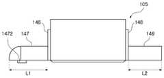
도 7 및 도 8을 참조하여 제5실시 예에 따른 촬상 광학계용 프리즘을 설명한다.A prism for an optical system according to a fifth embodiment will be described with reference to FIGS. 7 and 8.
본 실시 예에 따른 프리즘(105)은 대체로 직육면체 또는 정육면체를 대각 방향으로 이등분한 형태를 가진다. 프리즘(105)은 사각형상의 3개 면과 삼각형상의 2개 면을 포함한다. 예를 들어, 프리즘(105)의 입사면(110), 출사면(120), 반사면(130)은 사각형상이고, 프리즘(153)의 양 측면은 삼각형상이다.The
프리즘(105)은 측면(140, 150)에 복수의 돌출부(146, 147, 149)가 형성된다. 측면(140, 150)에는 프리즘(105)의 폭 방향으로 연장되는 동일 형상의 제1돌출부(146)가 형성된다. 제1돌출부(146)에는 서로 다른 형상의 제2돌출부(147, 149)가 형성된다. 예를 들어, 제2돌출부(147)와 제2돌출부(149)의 단부 형상은 서로 상이할 수 있다. 예를 들어, 제2돌출부(147)의 단부는 곡면을 포함한 형태이고, 제2돌출부(149)의 단부는 제2돌출부(147)의 단부는 곡면을 포함하지 않는 형태일 수 있다. 본 실시 예에 따른 제2돌출부(147)의 단부는 대체로 반구 형상이다. 아울러, 제2돌출부(147)는 일 측으로 돌출된 돌기(1472)를 포함할 수 있다. 제2돌출부(149)의 단부는 평탄한 형태일 수 있다. 제2돌출부(147, 149)는 서로 다른 크기를 가질 수 있다. 예를 들어, 제2돌출부(147)의 길이(L1)는 제2돌출부(149)의 길이(L2)와 다를 수 있다. 본 실시 예에서 제2돌출부(147)의 길이(L1)는 제2돌출부(149)의 길이(L2)보다 길다.The
다음에서는 도 9 내지 도 11을 참조하여 일 실시 예에 따른 프리즘과 카메라 모듈의 결합구조를 설명한다.Next, a combination structure of a prism and a camera module according to an exemplary embodiment will be described with reference to FIGS. 9 to 11.
일 실시 예에 따른 프리즘(104)은 카메라 모듈에 탑재될 수 있다. 예를 들어, 프리즘(104)은 카메라 모듈에 구비된 전용 브래킷(200)에 장착될 수 있다. 브래킷(200)에는 프리즘(104)을 수용하기 위한 수용공간(250)이 형성된다. 수용공간(250)은 대체로 프리즘(104)과 동일 또는 유사한 형상과 크기를 가질 수 있다. 브래킷(200)의 측면에는 하나 이상의 제1구동수단(260)이 형성된다. 제1구동수단(260)은 프리즘(104)을 움직이기 위한 구동력을 발생시킬 수 있다. 참고로, 첨부된 도면에는 도시되어 있지 않으나, 프리즘(104)의 측면 또는 반사면에는 구동수단(260)과 상호 작용하기 위한 제2구동수단이 형성될 수 있다. 제1구동수단 및 제2구동수단은 자석과 코일을 포함할 수 있다.The
브래킷(200)의 수용공간(210)에는 프리즘(104)의 돌출부와 결합하기 위한 구성이 형성될 수 있다. 예를 들어, 수용공간(210)의 양 측면에는 도 11에 도시된 바와 같이 홈(240)이 형성될 수 있다. 상기 홈(240)은 프리즘(104)의 제2돌출부(148)와 결합하여, 프리즘(104)의 안적정인 장착을 가능케 할 수 있다.In the receiving
본 발명은 이상에서 설명되는 실시 예에만 한정되는 것은 아니며, 본 발명이 속하는 기술분야에서 통상의 지식을 가진 자라면 이하의 특허청구범위에 기재된 본 발명의 기술적 사상의 요지를 벗어나지 않는 범위에서 얼마든지 다양하게 변경하여 실시할 수 있을 것이다. 예를 들어, 전술된 실시형태에 기재된 다양한 특징사항은 그와 반대되는 설명이 명시적으로 기재되지 않는 한 다른 실시형태에 결합하여 적용될 수 있다.The present invention is not limited only to the embodiments described above, and those of ordinary skill in the art to which the present invention pertains, within the scope not departing from the gist of the technical idea of the present invention described in the following claims. It will be possible to implement various changes. For example, various features described in the above-described embodiments may be applied in combination with other embodiments unless a description to the contrary is explicitly stated.
102프리즘
110(프리즘의) 입사면
120(프리즘의) 출사면
130(프리즘의) 반사면
140, 150(프리즘의) 측면102 prism
110 (of the prism) entrance plane
120 (of the prism) exit plane
130 (of the prism) reflective surface
140, 150 (of the prism) side
Claims (12)
Translated fromKorean빛의 출사가 이루어지는 출사면;
상기 입사면을 통해 입사되는 빛을 상기 출사면으로 반사시키도록 구성되는 반사면; 및
상기 입사면과 상기 반사면의 경계부 또는 상기 출사면과 상기 반사면의 경계부에 형성되는 불연속부;
를 포함하는 촬상 광학계용 프리즘.An incidence surface on which light is incident;
An exit surface where light exits;
A reflective surface configured to reflect light incident through the incident surface to the exit surface; And
A discontinuity formed at a boundary between the incident surface and the reflective surface, or a boundary between the emission surface and the reflective surface;
Prism for an optical system comprising a.
상기 불연속부는 단자를 갖는 단턱 또는 높이를 갖는 돌기 또는 선 형태인 촬상 광학계용 프리즘.The method of claim 1,
The discontinuous portion is a prism for an optical system in the form of a stepped step having a terminal or a protrusion or line having a height.
상기 입사면 및 상기 출사면에는 반사방지층이 형성되는 촬상 광학계용 프리즘.The method of claim 1,
A prism for an imaging optical system in which an antireflection layer is formed on the incident surface and the exit surface.
상기 반사면에는 반사방지층과 적외선차단층이 형성되는 촬상 광학계용 프리즘.The method of claim 1,
A prism for an imaging optical system in which an antireflection layer and an infrared blocking layer are formed on the reflective surface.
상기 반사면은 상기 입사면 및 상기 출사면과 다른 파면수차를 갖도록 형성되는 촬상 광학계용 프리즘.The method of claim 1,
The reflective surface is formed to have a wavefront aberration different from that of the incident surface and the emission surface.
상기 입사면 및 상기 출사면과 상기 반사면이 연결되는 부분은 플레어 현상을 야기하지 않도록 차광도료로 도색되거나 또는 거칠기를 갖는 형태로 가공되는 촬상 광학계용 프리즘.The method of claim 1,
A prism for an imaging optical system wherein the incidence surface and a portion connected to the emission surface and the reflective surface are painted with a light-shielding paint or processed into a shape having a roughness so as not to cause a flare phenomenon.
상기 출사면은 투광영역과 차광영역을 포함하는 촬상 광학계용 프리즘.The method of claim 1,
The emission surface is a prism for an optical system including a light-transmitting area and a light-blocking area.
상기 투광영역은 원형 또는 타원형으로 형성되는 촬상 광학계용 프리즘.The method of claim 7,
The light-transmitting area is a prism for an optical system that is formed in a circular or elliptical shape.
양 측면에 카메라 모듈의 하우징 또는 브래킷과 결합하도록 구성되는 제1돌출부가 형성되는 촬상 광학계용 프리즘.The method of claim 1,
A prism for an imaging optical system having first protrusions configured to be coupled to the housing or bracket of the camera module on both sides.
상기 제1돌출부에 형성되고, 상기 제1돌출부와 동일 방향으로 연장되는 제2돌출부를 더 포함하는 촬상 광학계용 프리즘.The method of claim 9,
A prism for an imaging optical system further comprising a second protrusion formed on the first protrusion and extending in the same direction as the first protrusion.
상기 제1돌출부의 면적은 상기 제2돌출부의 면적보다 큰 촬상 광학계용 프리즘.The method of claim 10,
An area of the first protrusion is larger than an area of the second protrusion.
상기 제1돌출부의 길이는 상기 제2돌출부의 길이보다 큰 촬상 광학계용 프리즘.
The method of claim 10,
A prism for an imaging optical system having a length of the first protrusion greater than a length of the second protrusion.
Priority Applications (1)
| Application Number | Priority Date | Filing Date | Title |
|---|---|---|---|
| KR1020220156623AKR102724889B1 (en) | 2019-08-30 | 2022-11-21 | Prism for Optical Imaging System |
Applications Claiming Priority (2)
| Application Number | Priority Date | Filing Date | Title |
|---|---|---|---|
| KR1020190107438 | 2019-08-30 | ||
| KR20190107438 | 2019-08-30 |
Related Child Applications (1)
| Application Number | Title | Priority Date | Filing Date |
|---|---|---|---|
| KR1020220156623ADivisionKR102724889B1 (en) | 2019-08-30 | 2022-11-21 | Prism for Optical Imaging System |
Publications (2)
| Publication Number | Publication Date |
|---|---|
| KR20210027170Atrue KR20210027170A (en) | 2021-03-10 |
| KR102496139B1 KR102496139B1 (en) | 2023-02-07 |
Family
ID=74679627
Family Applications (2)
| Application Number | Title | Priority Date | Filing Date |
|---|---|---|---|
| KR1020200108987AActiveKR102496139B1 (en) | 2019-08-30 | 2020-08-28 | Prism for Optical Imaging System |
| KR1020220156623AActiveKR102724889B1 (en) | 2019-08-30 | 2022-11-21 | Prism for Optical Imaging System |
Family Applications After (1)
| Application Number | Title | Priority Date | Filing Date |
|---|---|---|---|
| KR1020220156623AActiveKR102724889B1 (en) | 2019-08-30 | 2022-11-21 | Prism for Optical Imaging System |
Country Status (4)
| Country | Link |
|---|---|
| US (1) | US12379530B2 (en) |
| KR (2) | KR102496139B1 (en) |
| CN (2) | CN112444896A (en) |
| TW (2) | TWI869900B (en) |
Cited By (1)
| Publication number | Priority date | Publication date | Assignee | Title |
|---|---|---|---|---|
| WO2025033653A1 (en)* | 2023-08-04 | 2025-02-13 | 삼성전자주식회사 | Reflector, camera module including reflector, and electronic device including camera module |
Families Citing this family (4)
| Publication number | Priority date | Publication date | Assignee | Title |
|---|---|---|---|---|
| US12379530B2 (en)* | 2019-08-30 | 2025-08-05 | Samsung Electro-Mechanics Co., Ltd. | Prism for optical imaging system having protrusion on side surfaces |
| CN211741813U (en)* | 2020-03-12 | 2020-10-23 | 中强光电股份有限公司 | Optical element and projection device using the same |
| TWI850175B (en)* | 2022-10-20 | 2024-07-21 | 大立光電股份有限公司 | Optical folding element, imaging lens module and electronic device |
| CN119781145B (en)* | 2025-03-10 | 2025-06-27 | 宁波舜宇光电信息有限公司 | Reflection module and periscope type camera module thereof |
Citations (7)
| Publication number | Priority date | Publication date | Assignee | Title |
|---|---|---|---|---|
| JPH0277001A (en)* | 1988-09-12 | 1990-03-16 | Iiyama Koshina:Kk | Prism for video camera |
| JP2006091344A (en)* | 2004-09-22 | 2006-04-06 | Fuji Photo Film Co Ltd | Lens unit, method for assembling lens device, imaging apparatus and optical device |
| JP2006227322A (en)* | 2005-02-17 | 2006-08-31 | Konica Minolta Opto Inc | Imaging optical system, imaging lens device and digital apparatus |
| JP2007328191A (en)* | 2006-06-08 | 2007-12-20 | Matsushita Electric Ind Co Ltd | Optical element and optical device |
| JP2009122640A (en)* | 2007-10-25 | 2009-06-04 | Ricoh Co Ltd | Imaging device |
| KR20120031435A (en)* | 2010-09-24 | 2012-04-03 | 호야 가부시키가이샤 | Imaging optical system and imaging apparatus |
| JP2012230349A (en)* | 2011-04-13 | 2012-11-22 | Ricoh Opt Ind Co Ltd | Reflection optical element and reflection optical system |
Family Cites Families (16)
| Publication number | Priority date | Publication date | Assignee | Title |
|---|---|---|---|---|
| JP3168770B2 (en) | 1993-06-03 | 2001-05-21 | 松下電器産業株式会社 | Polarizing device and projection display device using the polarizing device |
| JP2002048904A (en) | 2000-08-03 | 2002-02-15 | Canon Inc | Resin molded prism and its mold |
| WO2006123188A1 (en)* | 2005-05-20 | 2006-11-23 | Eads Astrium Limited | Thermal control film for spacecraft |
| JP4860268B2 (en) | 2006-01-13 | 2012-01-25 | 富士フイルム株式会社 | Prism manufacturing method, prism, optical pickup, and liquid crystal projector |
| JP4288329B2 (en) | 2006-03-31 | 2009-07-01 | 日本ゼオン株式会社 | Optical prism |
| CN100485448C (en) | 2006-06-29 | 2009-05-06 | 贾怀昌 | Visual optical prism with free-form surface and total reflection |
| JP2008077064A (en) | 2006-08-23 | 2008-04-03 | Calsonic Kansei Corp | Prism and prism coupling object |
| CN101248981A (en) | 2008-04-03 | 2008-08-27 | 上海交通大学 | Visual Optical Analysis System Based on Wavefront Aberration |
| JP2009260887A (en)* | 2008-04-21 | 2009-11-05 | Funai Electric Co Ltd | Image capturing device |
| JP5558058B2 (en)* | 2008-09-19 | 2014-07-23 | オリンパスメディカルシステムズ株式会社 | Endoscopic endoscope |
| WO2018180269A1 (en) | 2017-03-31 | 2018-10-04 | Agc株式会社 | Optical element and manufacturing method for optical element |
| KR20190054472A (en) | 2017-11-13 | 2019-05-22 | 삼성전자주식회사 | Total internal reflection prism unit, total internal reflection prism assembly including the same and apparatus for forming a line beam including the same |
| US11181735B2 (en)* | 2018-02-15 | 2021-11-23 | Tdg Acquisition Company, Llc | Optic and assembly for reduced reflections |
| JP2019144515A (en)* | 2018-02-23 | 2019-08-29 | セイコーエプソン株式会社 | Virtual image display unit |
| KR102662948B1 (en)* | 2018-05-21 | 2024-05-07 | 엘지전자 주식회사 | Camera, and terminal including the same |
| US12379530B2 (en)* | 2019-08-30 | 2025-08-05 | Samsung Electro-Mechanics Co., Ltd. | Prism for optical imaging system having protrusion on side surfaces |
- 2020
- 2020-08-27USUS17/004,197patent/US12379530B2/enactiveActive
- 2020-08-28TWTW112123575Apatent/TWI869900B/enactive
- 2020-08-28KRKR1020200108987Apatent/KR102496139B1/enactiveActive
- 2020-08-28CNCN202010886057.1Apatent/CN112444896A/enactivePending
- 2020-08-28CNCN202021848633.5Upatent/CN212905549U/enactiveActive
- 2020-08-28TWTW109129567Apatent/TWI809305B/enactive
- 2022
- 2022-11-21KRKR1020220156623Apatent/KR102724889B1/enactiveActive
Patent Citations (7)
| Publication number | Priority date | Publication date | Assignee | Title |
|---|---|---|---|---|
| JPH0277001A (en)* | 1988-09-12 | 1990-03-16 | Iiyama Koshina:Kk | Prism for video camera |
| JP2006091344A (en)* | 2004-09-22 | 2006-04-06 | Fuji Photo Film Co Ltd | Lens unit, method for assembling lens device, imaging apparatus and optical device |
| JP2006227322A (en)* | 2005-02-17 | 2006-08-31 | Konica Minolta Opto Inc | Imaging optical system, imaging lens device and digital apparatus |
| JP2007328191A (en)* | 2006-06-08 | 2007-12-20 | Matsushita Electric Ind Co Ltd | Optical element and optical device |
| JP2009122640A (en)* | 2007-10-25 | 2009-06-04 | Ricoh Co Ltd | Imaging device |
| KR20120031435A (en)* | 2010-09-24 | 2012-04-03 | 호야 가부시키가이샤 | Imaging optical system and imaging apparatus |
| JP2012230349A (en)* | 2011-04-13 | 2012-11-22 | Ricoh Opt Ind Co Ltd | Reflection optical element and reflection optical system |
Cited By (1)
| Publication number | Priority date | Publication date | Assignee | Title |
|---|---|---|---|---|
| WO2025033653A1 (en)* | 2023-08-04 | 2025-02-13 | 삼성전자주식회사 | Reflector, camera module including reflector, and electronic device including camera module |
Also Published As
| Publication number | Publication date |
|---|---|
| KR102724889B1 (en) | 2024-11-01 |
| TW202340757A (en) | 2023-10-16 |
| US12379530B2 (en) | 2025-08-05 |
| KR20220161238A (en) | 2022-12-06 |
| US20210063616A1 (en) | 2021-03-04 |
| TWI869900B (en) | 2025-01-11 |
| TWI809305B (en) | 2023-07-21 |
| CN212905549U (en) | 2021-04-06 |
| KR102496139B1 (en) | 2023-02-07 |
| TW202122830A (en) | 2021-06-16 |
| CN112444896A (en) | 2021-03-05 |
Similar Documents
| Publication | Publication Date | Title |
|---|---|---|
| KR102724889B1 (en) | Prism for Optical Imaging System | |
| KR20210027171A (en) | Prism for Optical Imaging System | |
| TWI890518B (en) | Optical imaging system | |
| JP2020509420A (en) | Bend camera prism design to prevent stray light | |
| KR102854166B1 (en) | Reflection member and Reflection module including the same | |
| KR20210027197A (en) | Camera module | |
| TWI740308B (en) | Optical lens, lens module using the optical lens and electronic device | |
| US12069359B2 (en) | Reflection module including a holder and a reflective member and a camera module including a reflection module | |
| KR20210093144A (en) | Reflection module and camera module including the same | |
| KR102868173B1 (en) | Reflection module and camera module including the same | |
| US20250199274A1 (en) | Reflective member and reflective module including the same | |
| TW202532919A (en) | Reflective member, reflective module and protable electronic device | |
| WO2024109683A1 (en) | Camera module |
Legal Events
| Date | Code | Title | Description |
|---|---|---|---|
| PA0109 | Patent application | Patent event code:PA01091R01D Comment text:Patent Application Patent event date:20200828 | |
| PA0201 | Request for examination | ||
| PG1501 | Laying open of application | ||
| E902 | Notification of reason for refusal | ||
| PE0902 | Notice of grounds for rejection | Comment text:Notification of reason for refusal Patent event date:20220124 Patent event code:PE09021S01D | |
| AMND | Amendment | ||
| E601 | Decision to refuse application | ||
| PE0601 | Decision on rejection of patent | Patent event date:20220721 Comment text:Decision to Refuse Application Patent event code:PE06012S01D Patent event date:20220124 Comment text:Notification of reason for refusal Patent event code:PE06011S01I | |
| AMND | Amendment | ||
| PX0901 | Re-examination | Patent event code:PX09011S01I Patent event date:20220721 Comment text:Decision to Refuse Application Patent event code:PX09012R01I Patent event date:20220324 Comment text:Amendment to Specification, etc. | |
| PX0701 | Decision of registration after re-examination | Patent event date:20221107 Comment text:Decision to Grant Registration Patent event code:PX07013S01D Patent event date:20221021 Comment text:Amendment to Specification, etc. Patent event code:PX07012R01I Patent event date:20220721 Comment text:Decision to Refuse Application Patent event code:PX07011S01I Patent event date:20220324 Comment text:Amendment to Specification, etc. Patent event code:PX07012R01I | |
| X701 | Decision to grant (after re-examination) | ||
| PA0107 | Divisional application | Comment text:Divisional Application of Patent Patent event date:20221121 Patent event code:PA01071R01D | |
| GRNT | Written decision to grant | ||
| PR0701 | Registration of establishment | Comment text:Registration of Establishment Patent event date:20230201 Patent event code:PR07011E01D | |
| PR1002 | Payment of registration fee | Payment date:20230202 End annual number:3 Start annual number:1 | |
| PG1601 | Publication of registration |