KR20210022660A - Devices, assemblies and methods for use in tendon closure - Google Patents
Devices, assemblies and methods for use in tendon closureDownload PDFInfo
- Publication number
- KR20210022660A KR20210022660AKR1020217001387AKR20217001387AKR20210022660AKR 20210022660 AKR20210022660 AKR 20210022660AKR 1020217001387 AKR1020217001387 AKR 1020217001387AKR 20217001387 AKR20217001387 AKR 20217001387AKR 20210022660 AKR20210022660 AKR 20210022660A
- Authority
- KR
- South Korea
- Prior art keywords
- liner
- hay
- needle
- lumen
- threading element
- Prior art date
- Legal status (The legal status is an assumption and is not a legal conclusion. Google has not performed a legal analysis and makes no representation as to the accuracy of the status listed.)
- Granted
Links
- 238000000034methodMethods0.000titleclaimsdescription126
- 210000002435tendonAnatomy0.000titleclaimsdescription123
- 230000000712assemblyEffects0.000titledescription7
- 238000000429assemblyMethods0.000titledescription7
- 230000000284resting effectEffects0.000claimsabstractdescription9
- 238000005520cutting processMethods0.000claimsdescription40
- 230000007704transitionEffects0.000claimsdescription29
- 230000006378damageEffects0.000claimsdescription26
- 238000003780insertionMethods0.000claimsdescription20
- 230000037431insertionEffects0.000claimsdescription20
- 239000000463materialSubstances0.000claimsdescription20
- 238000003776cleavage reactionMethods0.000claimsdescription15
- 230000007017scissionEffects0.000claimsdescription15
- 230000008878couplingEffects0.000claimsdescription12
- 238000010168coupling processMethods0.000claimsdescription12
- 238000005859coupling reactionMethods0.000claimsdescription12
- 230000000149penetrating effectEffects0.000claimsdescription11
- 238000002266amputationMethods0.000claimsdescription10
- 230000002829reductive effectEffects0.000claimsdescription4
- 230000032258transportEffects0.000description43
- 208000027418Wounds and injuryDiseases0.000description13
- 239000004033plasticSubstances0.000description10
- 229920003023plasticPolymers0.000description10
- 229920000642polymerPolymers0.000description10
- 206010043248Tendon ruptureDiseases0.000description8
- 229910052751metalInorganic materials0.000description8
- 239000002184metalSubstances0.000description8
- 238000001356surgical procedureMethods0.000description8
- 229910001092metal group alloyInorganic materials0.000description7
- 230000008901benefitEffects0.000description6
- 208000014674injuryDiseases0.000description6
- 230000000670limiting effectEffects0.000description6
- 239000013536elastomeric materialSubstances0.000description5
- 238000007789sealingMethods0.000description5
- 238000010586diagramMethods0.000description4
- 238000012546transferMethods0.000description4
- 238000004804windingMethods0.000description4
- 241001465754MetazoaSpecies0.000description3
- 239000000956alloySubstances0.000description3
- 230000006870functionEffects0.000description3
- 230000035876healingEffects0.000description3
- 150000002739metalsChemical class0.000description3
- 239000002861polymer materialSubstances0.000description3
- 238000011084recoveryMethods0.000description3
- 230000000472traumatic effectEffects0.000description3
- 238000003466weldingMethods0.000description3
- 208000011092Hand injuryDiseases0.000description2
- 239000004743PolypropyleneSubstances0.000description2
- 208000021945Tendon injuryDiseases0.000description2
- 230000000747cardiac effectEffects0.000description2
- 238000002788crimpingMethods0.000description2
- 230000001419dependent effectEffects0.000description2
- 230000005489elastic deformationEffects0.000description2
- 238000005304joiningMethods0.000description2
- -1polypropylenePolymers0.000description2
- 229920001155polypropylenePolymers0.000description2
- 229920001296polysiloxanePolymers0.000description2
- 230000008439repair processEffects0.000description2
- 238000000926separation methodMethods0.000description2
- 239000010935stainless steelSubstances0.000description2
- 229910001220stainless steelInorganic materials0.000description2
- 239000003356suture materialSubstances0.000description2
- 206010002329AneurysmDiseases0.000description1
- 208000031872Body RemainsDiseases0.000description1
- 208000025962Crush injuryDiseases0.000description1
- 206010016654FibrosisDiseases0.000description1
- 208000012880Finger injuryDiseases0.000description1
- 206010060932Postoperative adhesionDiseases0.000description1
- 229910000831SteelInorganic materials0.000description1
- 239000000853adhesiveSubstances0.000description1
- 230000001070adhesive effectEffects0.000description1
- 238000005452bendingMethods0.000description1
- 230000006835compressionEffects0.000description1
- 238000007906compressionMethods0.000description1
- 230000008602contractionEffects0.000description1
- 238000012937correctionMethods0.000description1
- 238000002316cosmetic surgeryMethods0.000description1
- 230000004761fibrosisEffects0.000description1
- 238000002683hand surgeryMethods0.000description1
- 230000006872improvementEffects0.000description1
- 210000004283incisorAnatomy0.000description1
- 230000002452interceptive effectEffects0.000description1
- 229920001684low density polyethylenePolymers0.000description1
- 239000004702low-density polyethyleneSubstances0.000description1
- 238000004519manufacturing processMethods0.000description1
- 230000013011matingEffects0.000description1
- 239000000203mixtureSubstances0.000description1
- 238000012986modificationMethods0.000description1
- 230000004048modificationEffects0.000description1
- HLXZNVUGXRDIFK-UHFFFAOYSA-Nnickel titaniumChemical compound[Ti].[Ti].[Ti].[Ti].[Ti].[Ti].[Ti].[Ti].[Ti].[Ti].[Ti].[Ni].[Ni].[Ni].[Ni].[Ni].[Ni].[Ni].[Ni].[Ni].[Ni].[Ni].[Ni].[Ni].[Ni]HLXZNVUGXRDIFK-UHFFFAOYSA-N0.000description1
- 229910001000nickel titaniumInorganic materials0.000description1
- 238000002360preparation methodMethods0.000description1
- 238000003825pressingMethods0.000description1
- 238000011160researchMethods0.000description1
- 230000000452restraining effectEffects0.000description1
- 238000012552reviewMethods0.000description1
- 238000007493shaping processMethods0.000description1
- 229920000260silasticPolymers0.000description1
- 239000010959steelSubstances0.000description1
- 230000008733traumaEffects0.000description1
Images


Classifications
- A—HUMAN NECESSITIES
- A61—MEDICAL OR VETERINARY SCIENCE; HYGIENE
- A61B—DIAGNOSIS; SURGERY; IDENTIFICATION
- A61B17/00—Surgical instruments, devices or methods
- A61B17/04—Surgical instruments, devices or methods for suturing wounds; Holders or packages for needles or suture materials
- A61B17/0493—Protective devices for suturing, i.e. for protecting the patient's organs or the operator
- A—HUMAN NECESSITIES
- A61—MEDICAL OR VETERINARY SCIENCE; HYGIENE
- A61B—DIAGNOSIS; SURGERY; IDENTIFICATION
- A61B17/00—Surgical instruments, devices or methods
- A61B17/04—Surgical instruments, devices or methods for suturing wounds; Holders or packages for needles or suture materials
- A61B17/0482—Needle or suture guides
- A—HUMAN NECESSITIES
- A61—MEDICAL OR VETERINARY SCIENCE; HYGIENE
- A61B—DIAGNOSIS; SURGERY; IDENTIFICATION
- A61B17/00—Surgical instruments, devices or methods
- A61B17/04—Surgical instruments, devices or methods for suturing wounds; Holders or packages for needles or suture materials
- A61B17/06—Needles ; Sutures; Needle-suture combinations; Holders or packages for needles or suture materials
- A61B17/06066—Needles, e.g. needle tip configurations
- A—HUMAN NECESSITIES
- A61—MEDICAL OR VETERINARY SCIENCE; HYGIENE
- A61B—DIAGNOSIS; SURGERY; IDENTIFICATION
- A61B17/00—Surgical instruments, devices or methods
- A61B17/11—Surgical instruments, devices or methods for performing anastomosis; Buttons for anastomosis
- A61B17/1146—Surgical instruments, devices or methods for performing anastomosis; Buttons for anastomosis of tendons
- A—HUMAN NECESSITIES
- A61—MEDICAL OR VETERINARY SCIENCE; HYGIENE
- A61B—DIAGNOSIS; SURGERY; IDENTIFICATION
- A61B17/00—Surgical instruments, devices or methods
- A61B17/00234—Surgical instruments, devices or methods for minimally invasive surgery
- A61B2017/00292—Surgical instruments, devices or methods for minimally invasive surgery mounted on or guided by flexible, e.g. catheter-like, means
- A61B2017/00336—Surgical instruments, devices or methods for minimally invasive surgery mounted on or guided by flexible, e.g. catheter-like, means with a protective sleeve, e.g. retractable or slidable
- A—HUMAN NECESSITIES
- A61—MEDICAL OR VETERINARY SCIENCE; HYGIENE
- A61B—DIAGNOSIS; SURGERY; IDENTIFICATION
- A61B17/00—Surgical instruments, devices or methods
- A61B2017/00831—Material properties
- A61B2017/00862—Material properties elastic or resilient
- A—HUMAN NECESSITIES
- A61—MEDICAL OR VETERINARY SCIENCE; HYGIENE
- A61B—DIAGNOSIS; SURGERY; IDENTIFICATION
- A61B17/00—Surgical instruments, devices or methods
- A61B2017/00831—Material properties
- A61B2017/00946—Material properties malleable
- A—HUMAN NECESSITIES
- A61—MEDICAL OR VETERINARY SCIENCE; HYGIENE
- A61B—DIAGNOSIS; SURGERY; IDENTIFICATION
- A61B17/00—Surgical instruments, devices or methods
- A61B17/04—Surgical instruments, devices or methods for suturing wounds; Holders or packages for needles or suture materials
- A61B17/0401—Suture anchors, buttons or pledgets, i.e. means for attaching sutures to bone, cartilage or soft tissue; Instruments for applying or removing suture anchors
- A61B2017/0464—Suture anchors, buttons or pledgets, i.e. means for attaching sutures to bone, cartilage or soft tissue; Instruments for applying or removing suture anchors for soft tissue
- A—HUMAN NECESSITIES
- A61—MEDICAL OR VETERINARY SCIENCE; HYGIENE
- A61B—DIAGNOSIS; SURGERY; IDENTIFICATION
- A61B17/00—Surgical instruments, devices or methods
- A61B17/04—Surgical instruments, devices or methods for suturing wounds; Holders or packages for needles or suture materials
- A61B17/06—Needles ; Sutures; Needle-suture combinations; Holders or packages for needles or suture materials
- A61B2017/06052—Needle-suture combinations in which a suture is extending inside a hollow tubular needle, e.g. over the entire length of the needle
- A—HUMAN NECESSITIES
- A61—MEDICAL OR VETERINARY SCIENCE; HYGIENE
- A61B—DIAGNOSIS; SURGERY; IDENTIFICATION
- A61B17/00—Surgical instruments, devices or methods
- A61B17/04—Surgical instruments, devices or methods for suturing wounds; Holders or packages for needles or suture materials
- A61B17/06—Needles ; Sutures; Needle-suture combinations; Holders or packages for needles or suture materials
- A61B17/06066—Needles, e.g. needle tip configurations
- A61B2017/0608—J-shaped
- A—HUMAN NECESSITIES
- A61—MEDICAL OR VETERINARY SCIENCE; HYGIENE
- A61B—DIAGNOSIS; SURGERY; IDENTIFICATION
- A61B17/00—Surgical instruments, devices or methods
- A61B17/04—Surgical instruments, devices or methods for suturing wounds; Holders or packages for needles or suture materials
- A61B17/06—Needles ; Sutures; Needle-suture combinations; Holders or packages for needles or suture materials
- A61B17/06066—Needles, e.g. needle tip configurations
- A61B2017/06085—Needles, e.g. needle tip configurations having a blunt tip
- A—HUMAN NECESSITIES
- A61—MEDICAL OR VETERINARY SCIENCE; HYGIENE
- A61B—DIAGNOSIS; SURGERY; IDENTIFICATION
- A61B17/00—Surgical instruments, devices or methods
- A61B17/04—Surgical instruments, devices or methods for suturing wounds; Holders or packages for needles or suture materials
- A61B17/06—Needles ; Sutures; Needle-suture combinations; Holders or packages for needles or suture materials
- A61B17/06066—Needles, e.g. needle tip configurations
- A61B2017/06095—Needles, e.g. needle tip configurations pliable
- A—HUMAN NECESSITIES
- A61—MEDICAL OR VETERINARY SCIENCE; HYGIENE
- A61B—DIAGNOSIS; SURGERY; IDENTIFICATION
- A61B17/00—Surgical instruments, devices or methods
- A61B17/11—Surgical instruments, devices or methods for performing anastomosis; Buttons for anastomosis
- A61B2017/1132—End-to-end connections
- A—HUMAN NECESSITIES
- A61—MEDICAL OR VETERINARY SCIENCE; HYGIENE
- A61B—DIAGNOSIS; SURGERY; IDENTIFICATION
- A61B90/00—Instruments, implements or accessories specially adapted for surgery or diagnosis and not covered by any of the groups A61B1/00 - A61B50/00, e.g. for luxation treatment or for protecting wound edges
- A61B90/08—Accessories or related features not otherwise provided for
- A61B2090/0801—Prevention of accidental cutting or pricking
- A61B2090/08021—Prevention of accidental cutting or pricking of the patient or his organs
- A—HUMAN NECESSITIES
- A61—MEDICAL OR VETERINARY SCIENCE; HYGIENE
- A61B—DIAGNOSIS; SURGERY; IDENTIFICATION
- A61B90/00—Instruments, implements or accessories specially adapted for surgery or diagnosis and not covered by any of the groups A61B1/00 - A61B50/00, e.g. for luxation treatment or for protecting wound edges
- A61B90/08—Accessories or related features not otherwise provided for
- A61B2090/0815—Implantable devices for insertion in between organs or other soft tissues
Landscapes
- Health & Medical Sciences (AREA)
- Surgery (AREA)
- Life Sciences & Earth Sciences (AREA)
- Heart & Thoracic Surgery (AREA)
- Molecular Biology (AREA)
- Veterinary Medicine (AREA)
- Engineering & Computer Science (AREA)
- Biomedical Technology (AREA)
- Public Health (AREA)
- Medical Informatics (AREA)
- Nuclear Medicine, Radiotherapy & Molecular Imaging (AREA)
- Animal Behavior & Ethology (AREA)
- General Health & Medical Sciences (AREA)
- Orthopedic Medicine & Surgery (AREA)
- Rheumatology (AREA)
- Surgical Instruments (AREA)
- Lining Or Joining Of Plastics Or The Like (AREA)
Abstract
Translated fromKoreanDescription
Translated fromKorean본 발명은 바늘을 커버하고 건초(tendon sheath) 내에서 바늘을 운반하기 위한 바늘 커버 및 운반 디바이스에 관한 것이다. 본 발명은 또한 절단된 건(tendon)을 봉합(repairing)하는 데 사용을 위한 조립체로서, 조립체는 바늘 및 바늘 커버 및 운반 디바이스를 포함하는, 조립체 및 절단된 건을 봉합하는 방법에 관한 것이다.The present invention relates to a needle cover and conveying device for covering the needle and for conveying the needle in a hay (tendon sheath). The invention also relates to an assembly for use in repairing a severed tendon, the assembly comprising a needle and a needle cover and a conveying device, and a method of suturing a severed tendon.
손의 부상은 통상적이다. 러지(Rudge)와 제임스(James)(2014)는 이들의 연구 [Flexor "Tendon Injuries in the Hand: A UK Survey of Repair Techniques and Suture Materials - Are We Following the Evidence?" (ISRN Plastic Surgery)]에서 손 부상이 영국의 대부분의 병원의 응급실로의 모든 프레젠테이션의 약 5분의 1을 차지하고, 치료를 위해 연간 1억 파운드 초과의 비용이 든다고 언급하고 있다.Hand injuries are common. Rudge and James (2014) review their study [Flexor "Tendon Injuries in the Hand: A UK Survey of Repair Techniques and Suture Materials-Are We Following the Evidence?" (ISRN Plastic Surgery)] states that hand injuries account for about a fifth of all presentations to the emergency room of most hospitals in the UK and cost in excess of £100 million per year for treatment.
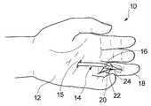
손의 굴근건(flexor tendon) 및 신근건(extension tendon)은 건초를 통해 연장되고, 이 건초 내에서 건들은 손이 굴곡함에 따라 이동 가능하다. 인간의 손의 부상은 종종 건 손상을 초래하며, 빈번히 하나 이상의 건의 절단을 수반한다.The flexor tendon and extension tendon of the hand extend through the hay, within which the tendons are movable as the hand flexes. Injuries to the human hand often result in tendon damage and frequently involve amputation of one or more tendons.
건 부상은 손의 5개의 상이한 구역(Zones) 중 하나로 분류된다. 구역 1은 심지굴근(flexor digitorum profundus: FDP) 건 원위측으로부터 천지굴근(flexor digitorum superficialis: FDS) 건의 삽입부까지를 포함한다. 구역 2("무인지대(no man's land)")는 FDS 건의 삽입부로부터 A1 활차(pulley)의 근위 에지까지를 포함하는데, 이 활차는 건이 그 아래에 놓이는 십자형 구조이다. 구역 3은 손바닥에 있고, A1 활차의 근위 에지로부터 수근굴(carpal tunnel)의 원위 에지까지를 포함한다.Tendon injuries are classified into one of five different zones of the hand.
손가락 부상이 발생하여, 구역 1 또는 구역 2에서 건이 절단될 때, 건은 손바닥을 향해 수축하는 경향이 있다(구역 3). 건의 절단된 부분은 건이 절단된 영역을 넘어 손가락 내의 건초 내에 잔류한다. 절단된 건에 봉합을 수행하는 것은, 손가락 내에 잔류하는 건 부분의 절단단(stump)에 봉합되기 전에, 수축된 건의 절단단이 건초를 따라 뒤로 당겨지는 것을 요구한다.When a finger injury occurs and the tendon is amputated in
양호하게 발달된 수술 기술과 봉합 재료가 이용 가능함에도 불구하고, 손의 구역 2 내의 굴근 건의 부상은 여전히 손 외과 의사에게 중요한 과제를 나타낸다. 수술 커뮤니티 내에서 성과를 향상시키기 위한 기술에 대한 활발한 관심이 존재한다.Despite the availability of well-developed surgical techniques and suture materials, the injury of the flexor tendon in
문헌 [Ozturk et al., in the Annals of Surgical Innovation and Research 2013, 7:11]은 근위 건 절단단의 밀킹(milking)(Kleinert, 1975 [1]), 흡인(Pennington, 1977 [2]), 강성 및 가요성 건 회수기(retrievers)의 사용(Ersek & Gadaria, 1985 [3]), 피부 후크(Kamath & Bhardwa, 2007 [4]), 강 와이어(Iwuagwu & Gupta, 2004 [5]), 동맥류 바늘(Hettiaratchy & Titley, 2002 [6]), 카테터에 대해 측측으로(side to side) 건 봉합(Sourmelis & McGrouther, 1987 [7]) 및 내시경 건 회수(Hill, Wells & Prevel [8])를 포함하여, 봉합 부위로의 수축된 근위 건 절단단의 전달을 위한 문헌에 설명되어 있는 다양한 기술에 대해 보고하고 의견을 제시하고 있다.Ozturk et al., in the Annals of Surgical Innovation and Research 2013, 7:11, milking of the proximal tendon amputation (Kleinert, 1975 [1]), aspiration (Pennington, 1977 [2]), Use of rigid and flexible tendon retrievers (Ersek & Gadaria, 1985 [3]), skin hooks (Kamath & Bhardwa, 2007 [4]), steel wires (Iwuagwu & Gupta, 2004 [5]), aneurysmal needles (Hettiaratchy & Titley, 2002 [6]), including side to side tendon sutures to the catheter (Sourmelis & McGrouther, 1987 [7]) and endoscopic tendon retrieval (Hill, Wells & Prevel [8]). , Reports and comments on various techniques described in the literature for delivery of the contracted proximal tendon amputation to the suture site.
구역 2의 굴근 건 봉합은, 이 구역에서 유착이 없는 건 치유의 문제가 있는 성질에 기인하여, 건 절단단의 지나치게 세심한 취급과 주위 건초의 최소 손상을 갖는 비외상성 건 회수 기술을 요구한다. 건 활차 아래의 굴근 건 회수에 대해 설명된 다양한 기술이 존재한다. 강성 및 가요성 건 회수기는 절단된 건 절단단에 부가의 압궤 손상(crush injury)을 생성하는 것으로 판명되었는데, 이는 부가의 섬유증과 변형된 건 치유를 유발한다는 것을 발견하였다(Kamath & Bhardwa, 2007; Iwuagwu & Gupta, 2004).
Hettiaratchy와 Titley는 건 절단단에 코어 봉합사를 배치하고 활차를 통해 봉합사를 스레딩하기 위해 동맥류 바늘을 사용하고, 봉합사로 건을 인출하는 것을 설명하고 있다. 이 기술은 손바닥 내로 수축된 건에 사용하기에 적합하지 않을 수도 있고, 건초의 부가의 윈도잉(windowing)을 요구하는데, 이는 부가의 손상을 야기한다.Hettiaratchy and Titley describe placing a core suture at the tendon incision, using an aneurysm needle to thread the suture through the pulley, and pulling the tendon into the suture. This technique may not be suitable for use with a gun that is contracted into the palm of the hand, and requires additional windowing of the hay, which causes additional damage.
건초를 통해 실라스틱(silastic) 튜브를 통과시키고 이어서 근위 건 절단단을 튜브에 측측으로 그리고 단단으로(end to end) 봉합하거나, 또는 대안적으로 그 루멘 내에 건을 배치하는 것을 수반하는 다른 방법이 설명되어 있다(Sourmelis & McGrouther 1987; Hill, Wells & Prevel 1997; Kilgore, Adams & Newmeyer, 1971 [9]). 그러나, 이들 방법의 모두는 잠재적으로 부피가 큰 질량체를 생성하는데, 이는 그를 따른 통과 중에 건초를 손상시킬 수도 있다. 또한, 이들 방법의 모두는 건 절단단이 다수회 봉합되는 것을 요구하는데, 이는 건 팁을 마모시켜 봉합이 더 어려워지게 할 수도 있다.Other methods involve passing a silastic tube through hay and then suturing the proximal tendon incision to the tube laterally and end to end, or alternatively placing the tendon within its lumen. (Sourmelis & McGrouther 1987; Hill, Wells & Prevel 1997; Kilgore, Adams & Newmeyer, 1971 [9]). However, all of these methods create potentially bulky masses, which may damage the hay during its passage. In addition, all of these methods require that the tendon cut end be sutured multiple times, which may wear out the gun tip, making suturing more difficult.
양호한 결과가 달성되게 하기 위해, 이 영역에서 수술 후 유착 및 파열을 방지하기 위해, 절단된 건 절단단의 비외상적 취급 및 건초의 최소 손상을 갖고 수술적 봉합이 수행되는 것이 중요하다. 이에 따라, 결정적 봉합(definitive repair)의 부분으로서 계속될 수 있는 '바늘식(needled)' 봉합사로 그 건초를 통해 건을 당기는 것이 가능한 것이 매우 바람직하다.In order to achieve good results, it is important that surgical sutures are performed with minimal damage to the hay and non-traumatic handling of the amputated tendon incision in order to prevent post-operative adhesion and rupture in this area. Accordingly, it is highly desirable to be able to pull the tendon through the hay with a'needled' suture that can be continued as part of a definitive repair.
Bhatti & Adeniran(2006) [10]은 직선형 바늘과 폴리프로필렌 봉합사로 원위 손바닥 주름에서 근위 건 절단단을 봉합하고, 손가락으로의 직선형 바늘의 통과를 위한 도관처럼 작용하는, 탐침(stylet)을 갖는 14-게이지 플라스틱 캐뉼러를 사용하는 기술을 설명하고 있다. 봉합사 단부의 견인력(traction)은 절단된 건 절단단의 전달을 야기한다. 그러나, 직선형 바늘은 수술실에서 항상 이용 가능한 것은 아니다. 더 중요한 주목할 점은, 직선형 바늘을 사용하는 수정된 케슬러 스티치(Kessler stitch), 또는 곡선형 바늘을 사용하는 다수의 다른 인기 있는 건 봉합 기술을 완료하는 것이 어렵다는 것이다.Bhatti & Adeniran (2006) [10] sutures the proximal tendon incision in the distal palmar fold with a straight needle and polypropylene suture, 14 with a stylet that acts like a conduit for the passage of the straight needle into the finger. -Describes the technique of using a gauge plastic cannula. The traction of the suture end causes the transfer of the amputated tendon cut end. However, straight needles are not always available in the operating room. More important notably, it is difficult to complete a modified Kessler stitch using a straight needle, or a number of other popular tendon suture techniques using a curved needle.
Ozturk 등(2013)은 구역 2의 활차를 통한 수축된 굴근 건의 통과를 용이하게 하는 간단하고 비교적 비외상성 기술을 제시하고 있다. 저자는 3-0 폴리프로필렌 봉합사로 원위 손바닥 주름에서 근위 건 절단단을 봉합하고, 손가락으로의 직선화된 바늘의 통과를 위한 도관처럼 작용하는, 14-게이지 플라스틱 이송 튜브를 사용하였다.Ozturk et al. (2013) present a simple and relatively non-traumatic technique that facilitates the passage of the contracted flexor tendon through the pulley in
미국 특허 출원 공개 US-2013/0144310A1호는 절단된 건 절단단을 손에 재부착하기 위한 장치를 개시하고 있다. 개시된 장치(도 1 참조)는 복잡하고 커넥터에 의해 플랜지 카테터(flanged catheter)에 연결되는 활차 카테터를 포함하는 수많은 부품을 포함한다. 활차 카테터는 충분한 강성을 갖는(건 활차를 통해 압박될 수 있도록) 폴리머 재료로 이루어지고, 플랜지 카테터는 실리콘과 같은 더 연성의 폴리머 재료로 이루어진다. 또한, 장치는 멀티필라멘트 케이블의 단부에 부착된 짧은 직선형 바늘을 포함하는 건 앵커(anchor)를 또한 포함하고, 케이블은 케이블의 중간 지점에 위치된 슬리브로부터 개별 봉합사로 풀린다. 곡선형 바늘(라벨 114a 내지 114g 참조)이 각각의 봉합사의 단부에 부착된다. 사용시, 활차 카테터는 손바닥의 절개부 내로 그리고 건 활차 아래의 건초를 따라 이송된다(도 2a 참조). 플랜지 카테터는 이어서 활차 카테터에 연결되고 건초 내로 부분적으로 당겨진다(도 2b 참조). 손바닥의 건 절단단이 이어서 표면으로 전달되고 건 앵커의 직선형 바늘이 절단단 내에 배치되고 그를 통해 견인된다. 곡선형 바늘은 이어서 건 봉합 디바이스를 절단단에 스티칭하는 데 사용되고, 한 쌍의 봉합사는 매듭으로 묶이고 다른 곡선형 바늘 및 봉합사를 사용하여 형성된 십자형 로킹 스티치를 사용하여 건에 스티칭된다. 과잉 봉합 재료와 곡선형 바늘이 이어서 제거된다(도 2d 및 도 2e 참조). 직선형 바늘은 이어서 플랜지 카테터의 플랜지 내에 삽입되고 건 절단단이 플랜지 부분에 있을 때까지 전진한다. 외과 의사는 이어서 직선형 바늘을 파지하고 바늘, 부착된 케이블, 플랜지 카테터 및 건 절단단을 활차 건초템을 통해 손가락 내의 상처 외부로 견인한다. 유사한 구조의 다른 건 앵커가 전술된 것과 동일한 방식으로 손가락의 건 절단단에 부착되고, 2개의 앵커의 바늘이 커넥터의 보어를 통해 삽입되어 대향 방향으로 통과한다. 견인력이 이어서 건 절단단에 인가되어 건 단부에 매립된 커넥터와 함께 이들 건 절단단을 견인한다. 크림핑 도구가 이어서 커넥터를 크림핑하는 데 사용되고, 케이블의 여분의 길이가 절단된다. 활차 카테터와 같은 장치가 또한 개시되어 있고, 전체 카테터가 활차 건초템을 통해 압박되도록 충분히 강성이 되게 하고 이들의 자연 크기에 대해 활차를 확장시키기 위한 역할을 하기 위해 충분한 벽 두께를 갖는 확장 카테터로서 설명되어 있다.US Patent Application Publication No. US-2013/0144310A1 discloses an apparatus for reattaching a cut gun cutting end to a hand. The disclosed device (see Fig. 1) is complex and includes a number of components including a pulley catheter that is connected to a flanged catheter by a connector. The pulley catheter is made of a polymer material with sufficient rigidity (so that it can be pressed through the key pulley), and the flange catheter is made of a softer polymer material such as silicone. In addition, the device also includes a gun anchor comprising a short straight needle attached to the end of the multifilament cable, the cable being unwound with individual sutures from a sleeve positioned at the midpoint of the cable. A curved needle (see labels 114a-114g) is attached to the end of each suture. In use, the pulley catheter is transported into the incision in the palm of the hand and along the hay under the pulley (see Fig. 2A). The flange catheter is then connected to the pulley catheter and partially pulled into the hay (see Figure 2B). The tendon cut end of the palm is then transferred to the surface and the straight needle of the gun anchor is placed in and pulled through the cut end. The curved needle is then used to stitch the tendon suture device to the incisal end, and a pair of sutures are tied in a knot and stitched to the key using a cross-shaped locking stitch formed using another curved needle and suture. Excess suture material and curved needles are then removed (see FIGS. 2D and 2E). The straight needle is then inserted into the flange of the flange catheter and advanced until the tendon cut end is in the flange portion. The surgeon then grasps the straight needle and pulls the needle, attached cable, flange catheter, and tendon cut through the pulley tendon to the outside of the wound in the finger. Another key anchor of similar structure is attached to the key cutting end of the finger in the same manner as described above, and the needles of the two anchors are inserted through the bore of the connector and passed in opposite directions. A traction force is then applied to the gun cut ends to pull these gun cut ends with a connector embedded in the gun end. A crimping tool is then used to crimp the connector, and the excess length of the cable is cut off. A device such as a pulley catheter is also disclosed and described as an expansion catheter having sufficient wall thickness to serve to expand the pulley to its natural size and to make the entire catheter stiff enough to be compressed through the pulley haytem. Has been.
US-2013/0144310A1호에 개시된 장치는 복잡하고 설명된 건 봉합을 위한 절차는 성가시다. 건초템은 수많은 단점을 겪는다. 이들 단점은, 건 앵커가 조립이 복잡하고, 수술 절차에서 그 사용이 복잡하고 시간 소모적인 것을 포함한다. 건 절단단을 통해 삽입하기 위해 직선형 바늘과 후단(trailing) 케이블을 조작하는 것은 어렵고, 건 절단단을 제자리에 유지하기 위해 다양한 클램프의 사용을 요구한다. 플랜지 카테터를 따라 건 앵커를 전진시키는 것도 또한 어려운데, 이는 카테터를 통해 이를 전진시키기 위해 바늘에 연결된 케이블을 사용해야 할 필요가 있기 때문이다. 더욱이, 절단단에 건 앵커를 연결하기 위한 절차를 방해하지 않고 이러한 것을 달성하기 위해 케이블을 충분히 강성이 되게 하는 것은 어렵다. 플랜지 카테터는 비교적 연성 폴리머 재료로 이루어지기 때문에, 이는 카테터를 따라 전진할 때 바늘에 의해 카테터가 찔리는 심각한 위험을 제시하는데, 이는 바늘이 카테터 내에서 재밍되게 하고, 잠재적으로 주위 조직 내로 잘못 지향되게 할 수 있다. 활차 카테터는 통상적으로 120 mm 길이이고, 비교적 작은 외경(통상적으로 2 mm)을 갖고, 0.5 mm의 벽 두께를 갖고 따라서 1 mm의 내경을 갖는다(단락 0070 참조). 케이블로 상기 치수의 활차 카테터를 통해 직선형 바늘을 압박하는 것은 어려울 것이다. 건 앵커의 슬리브와, 2개의 앵커의 케이블을 연결하는 데 사용되는 커넥터는 모두 건 절단단 내에 매립되어 있다. 따라서, 이들 부품은 건 절단단 내에 영구적으로 위치되는데, 이는 조직 내성장과 건의 효과적인 봉합을 방해할 수 있다. 확장 카테터(도 13a 내지 도 13c, 및 도 14a 내지 도 14e 참조)를 사용할 때, 사용자가 활차를 과확장하여, 활차의 잠재적인 손상 및 파열을 야기하게 될 것이 가능하다. 활차가 과도하게 확장될 위험과 활차로의 가능한 결과적인 손상의 위험과는 별개로, 건초 내에 남아 있는 확장 섹션은 활차의 의도된 확장을 달성하는 데 필요한 강성을 그에 부여하기 위해 충분한 두께를 가져야 한다. 상기 확장 섹션이 접힘 가능하면, 활차를 확장하기 위해 이를 사용하는 것이 가능하지 않을 것이다. 이 특정 특징은 이하에 나타내는 바와 같이 본 개시내용과 관련이 있다.The device disclosed in US-2013/0144310A1 is complex and the procedure for suturing the described tendon is cumbersome. Haytem suffers from a number of disadvantages. These drawbacks include that the tendon anchor is complex to assemble, and that its use in surgical procedures is complex and time consuming. It is difficult to manipulate a straight needle and trailing cable for insertion through the key cut end, and requires the use of various clamps to hold the key cut end in place. Advancing the gun anchor along the flange catheter is also difficult, as it is necessary to use a cable connected to the needle to advance it through the catheter. Moreover, it is difficult to make the cable sufficiently rigid to achieve this without interfering with the procedure for attaching the gun anchor to the cut end. Because the flanged catheter is made of a relatively soft polymeric material, this presents a serious risk of being punctured by the needle when advancing along the catheter, which will cause the needle to jam within the catheter and potentially misorient into the surrounding tissue. I can. The pulley catheter is typically 120 mm long, has a relatively small outer diameter (typically 2 mm), has a wall thickness of 0.5 mm and thus has an inner diameter of 1 mm (see paragraph 0070). It would be difficult to press a straight needle through the pulley catheter of this dimension with a cable. Both the sleeve of the gun anchor and the connector used to connect the cables of the two anchors are embedded in the gun cutting end. Thus, these parts are permanently located within the tendon incision, which can interfere with tissue ingrowth and effective suturing of the tendon. When using an expansion catheter (see FIGS. 13A-13C, and 14A-14E), it is possible for the user to overextend the pulley, causing potential damage and rupture of the pulley. Apart from the risk of overextending the pulley and the risk of possible consequential damage to the runway, the extension section remaining in the hay must have sufficient thickness to give it the stiffness necessary to achieve the intended extension of the pulley. . If the extension section is collapsible, it will not be possible to use it to extend the pulley. This particular feature relates to the present disclosure as indicated below.
상기로부터, 건 봉합에 채용되는 기존의 디바이스 및 수술 기술에 대한 향상에 대한 요구가 존재한다는 것이 자명하다.From the above, it is apparent that there is a need for improvement of existing devices and surgical techniques employed in tendon sutures.
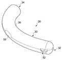
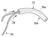
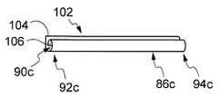
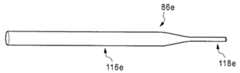
본 개시내용의 제1 양태에 따르면, 곡선형 바늘을 커버하고 건초의 루멘 내에서 바늘을 운반하기 위한 바늘 커버 및 운반 디바이스가 제공되며, 디바이스는 세장형 요소를 포함하고, 세장형 요소는According to a first aspect of the present disclosure, there is provided a needle cover and conveying device for covering a curved needle and for conveying the needle within a lumen of hay, the device comprising an elongate element, wherein the elongate element
제1 단부;A first end;
제1 단부에 대향하는 제2 단부; 및A second end opposite the first end; And
제1 단부와 제2 단부 사이에서 연장하는 본체로서, 본체는 건초 내에서 바늘의 통과 중에 팁과의 접촉을 통한 손상으로부터 건초를 보호하기 위해, 적어도 바늘의 관통 팁이 본체 내에 배치되도록 곡선형 바늘을 수용하기 위한 내부 공동을 형성하는, 본체를 갖고;A body extending between a first end and a second end, the body being curved needle such that at least a penetrating tip of the needle is disposed within the body to protect the hay from damage through contact with the tip during passage of the needle in the hay. Having a body, defining an inner cavity for receiving;
본체는The body is
A. 곡선형 바늘을 수용할 수 있도록 곡선 형상을 갖는 실질적으로 강성이고; 또는A. Substantially rigid with a curved shape to accommodate curved needles; or
B. 변형 가능하고, 곡선형 바늘을 수용할 수 있도록 곡선 형상으로 변형되는 것이 가능하다.B. It is deformable and can be transformed into a curved shape to accommodate a curved needle.
본 발명의 제2 양태에 따르면, 곡선형 바늘을 커버하고 건초의 루멘 내에서 바늘을 운반하기 위한 바늘 커버 및 운반 디바이스가 제공되며, 디바이스는 세장형 요소를 포함하고, 세장형 요소는According to a second aspect of the invention, there is provided a needle cover and conveying device for covering a curved needle and for conveying the needle within the lumen of the hay, the device comprising an elongate element, the elongate element
제1 단부;A first end;
제1 단부에 대향하는 제2 단부; 및A second end opposite the first end; And
제1 단부와 제2 단부 사이에서 연장하는 본체로서, 본체는 건초 내에서 바늘의 통과 중에 팁과의 접촉을 통한 손상으로부터 건초를 보호하기 위해, 적어도 바늘의 관통 팁이 본체 내에 배치되도록 곡선형 바늘을 수용하기 위한 내부 공동을 형성하는, 본체를 갖고;A body extending between a first end and a second end, the body being curved needle such that at least a penetrating tip of the needle is disposed within the body to protect the hay from damage through contact with the tip during passage of the needle in the hay. Having a body, defining an inner cavity for receiving;
본체의 적어도 일부는 곡선형 바늘을 수용하기 위해 미리 만곡되거나 변형 가능하고 곡선형 바늘을 수용할 수 있도록 곡선 형상으로 변형되는 것이 가능하다.At least a portion of the body is bent or deformable in advance to accommodate the curved needle, and it is possible to deform into a curved shape to accommodate the curved needle.
특히, 손의 손상된 건의 봉합을 위한 수술 기술은 곡선형 바늘의 사용으로부터 상당히 이익을 얻을 것이다. 예를 들어, 곡선형 바늘의 사용은 절단된 건의 절단단을 함께 봉합하는 외과 의사의 능력을 향상시킨다.In particular, surgical techniques for suturing damaged tendons of the hand will benefit significantly from the use of curved needles. For example, the use of a curved needle improves the surgeon's ability to suture the amputations of a severed tendon together.
본 출원은 바늘과의 접촉을 통한 건초에 대한 손상을 제한하거나 심지어 회피하면서 건초 내의 곡선형 니들의 통과를 용이하게 하는 실시예를 개시한다. 바늘은 건 절단단이 끌려가는 건초를 통해 당겨질 수 있어, 절단단이 건의 제2 부분의 절단단에 봉합될 수 있게 된다. 손의 건 봉합 수술에서, 건의 제2 부분은 손가락 내에 존재할 수도 있다.The present application discloses an embodiment that facilitates the passage of curved needles in hay while limiting or even avoiding damage to the hay through contact with the needle. The needle can be pulled through the hay being pulled by the tendon cleavage end, such that the cleavage end can be sutured to the cleavage end of the second portion of the gun. In hand tendon suture surgery, a second portion of the tendon may be present within the finger.
이하의 텍스트는 본 개시내용의 제1 및/또는 제2 양태의 디바이스의 선택적 추가 특징을 정의한다.The following text defines optional additional features of the device of the first and/or second aspect of the present disclosure.
본 명세서에서는 곡선형 바늘을 커버하고 건초 내에서 바늘을 운반하기 위한 바늘 커버 및 운반 디바이스를 참조한다. 건초는 인간(또는 동물) 신체에서 발견되는 다수의 상이한 건초, 덕트 또는 도관 중 하나일 수도 있다는 것이 이해될 수 있을 것이다. 그러나, 개시된 실시예는 손 수술과 관련하여 특정 용도를 가지며, 여기서 건초는 손에서 발견되는 건(예를 들어, FDP 또는 FDS 건)의 건초일 것이다.Reference is made herein to a needle cover and conveying device for covering curved needles and conveying needles in hay. It will be appreciated that hay may be one of a number of different hay, ducts or conduits found in the human (or animal) body. However, the disclosed embodiments have specific uses in connection with hand surgery, where the hay will be the hay of a tendon found in the hand (eg, FDP or FDS gun).
디바이스, 특히 공동은 전체 바늘을 수용하도록 구성될 수도 있다. 디바이스는 바늘용 인벨로프(envelope) 또는 슈라우드(shroud)를 형성할 수도 있다.The device, in particular the cavity, may be configured to receive the entire needle. The device may also form an envelope or shroud for the needle.
공동은 디바이스의 제1 단부로부터 디바이스의 제2 단부까지 연장될 수도 있다.The cavity may extend from a first end of the device to a second end of the device.
본체의 제1 단부는 선단 단부(leading end)일 수도 있고, 제2 단부는 후단 단부(trailing end)일 수도 있다. 제1 및 제2 단부 중 적어도 하나는 개방되거나 또는 적어도 부분적으로 개방될 수도 있고, 공동과 연통할 수도 있다. 이는 개방 단부를 통해 공동 내로의 바늘의 삽입을 용이하게 할 수도 있고, 그리고/또는 바늘에 연결된 봉합사가 본체를 빠져나가게 할 수도 있다.The first end of the body may be a leading end, and the second end may be a trailing end. At least one of the first and second ends may be open or at least partially open, and may communicate with the cavity. This may facilitate insertion of the needle into the cavity through the open end and/or may allow the suture connected to the needle to exit the body.
본체는 건초를 따라 또는 그 내에서 바늘을 수송하는 역할을 할 수도 있다. 제1 단부는 건초 내에 삽입되고 이를 따라 지향되도록 구성될 수도 있다. 본체는 건초를 따라 운송하도록 구성된 스레딩 요소(이하, 스레더라 칭함)를 형성할 수도 있다. 사용시, 본체는 스레더를 형성하는 부분 및 바늘용 커버를 형성하는 부분을 포함할 수도 있다. 스레더 부분은 실질적으로 직선형일 수도 있고, 이는 건초 내에서의 운송을 용이하게 할 수도 있다. 옵션 A에서, 커버부는 곡선 형상을 가질 수도 있다. 옵션 B에서, 커버부는 곡선 형상으로 변형되는 것이 가능할 수도 있다. 커버는 스레딩 요소를 형성하는 본체의 부분보다 더 가요성일 수도 있다.The body may serve to transport needles along or within the hay. The first end may be configured to be inserted into and directed along the hay. The body may form a threading element (hereinafter referred to as a threader) configured to transport along the hay. In use, the body may include a portion forming a threader and a portion forming a cover for the needle. The threaded portion may be substantially straight, which may facilitate transportation in the hay. In option A, the cover may have a curved shape. In option B, it may be possible to deform the cover portion into a curved shape. The cover may be more flexible than the portion of the body forming the threading element.
공동은 본체의 길이를 따라 부분적으로 연장될 수도 있다. 공동은 제1 및 제2 단부 중 하나로부터 제1 및 제2 단부 중 다른 하나를 향하는 방향으로 연장될 수도 있다. 제2 단부가 후단 단부인 경우, 공동은 제2 단부로부터 제1 단부를 향해 연장될 수도 있다.The cavity may extend partially along the length of the body. The cavity may extend in a direction from one of the first and second ends toward the other of the first and second ends. When the second end is the trailing end, the cavity may extend from the second end toward the first end.
공동은 제1 및 제2 단부 사이에 배치될 수도 있다.The cavity may be disposed between the first and second ends.
본체는 건초 내에서 디바이스를 수송하는 데 사용되는 수송 조립체에 디바이스를 연결하기 위한 결합부를 포함할 수도 있다. 수송 조립체는 세장형 스레딩 요소(스레더) 및 스레더에 연결된 가요성 연결 부품을 포함할 수도 있고, 연결 부품은 본체의 결합부에 연결되도록 구성된다. 연결 부품은 가요성일 수도 있고, 코드, 와이어, 필라멘트 등일 수도 있으며, 봉합사일 수도 있다. 결합부는 본체에 장착되거나 연결된 아이(eye), 후프(hoop) 등일 수도 있다.The body may include a coupling for connecting the device to a transport assembly used to transport the device within the hay. The transport assembly may comprise an elongated threading element (threader) and a flexible connection component connected to the threader, the connection component being configured to be connected to a mating portion of the body. The connecting part may be flexible, may be a cord, a wire, a filament, or the like, or may be a suture. The coupling portion may be an eye mounted or connected to the main body, a hoop, or the like.
본체는 일반적으로 관형일 수도 있다. 본체는 일반적으로 원통형일 수도 있고, 원형 형상의 단면을 가질 수도 있다.The body may also be generally tubular. The main body may be generally cylindrical or may have a circular cross-section.
디바이스는 외장, 슬리브 또는 커버를 포함할 수도 있다. 외장은 건초 내의 디바이스의 통과를 용이하게 할 수도 있다. 외장은 플라스틱(적합하게는 폴리머) 또는 탄성중합 재료일 수도 있는데, 이 재료들은 건초 내의 디바이스의 통과를 용이하게 하기 위해 낮은 마찰 계수를 가질 수도 있다. 외장은 본체의 외부면과 접촉하여 배치되는 내부면을 가질 수도 있다. 외장은 관형일 수도 있다. 외장은 본체의 길이를 따라 적어도 부분적으로 연장할 수도 있다. 외장은 디바이스의 제1 및 제2 단부 중 하나로부터 제1 및 제2 단부 중 다른 하나를 향하는 방향으로 연장될 수도 있다. 제1 단부가 선단 단부인 경우, 외장은 제1 단부로부터 본체를 따라 제2 단부를 향하는 방향으로 연장될 수도 있다. 외장은 제1 단부를 커버할 수도 있다. 제2 단부가 후단 단부인 경우, 제2 단부는 노출될 수도 있고, 따라서 외장에 의해 커버되지 않을 수도 있다. 본체의 부분은 공동을 형성할 수도 있다. 부분은 노출될 수도 있고, 따라서 외장에 의해 커버되지 않을 수도 있다. 따라서, 외장은 제1 단부로부터 본체를 따라 상기 부분까지 연장될 수도 있다.The device may include a sheath, sleeve or cover. The sheath may also facilitate the passage of the device in the hay. The sheath may be a plastic (suitably a polymer) or elastomeric material, which may have a low coefficient of friction to facilitate the passage of the device in the hay. The exterior may have an interior surface disposed in contact with the exterior surface of the body. The sheath may also be tubular. The sheath may extend at least partially along the length of the body. The sheath may extend in a direction from one of the first and second ends of the device toward the other of the first and second ends. When the first end is the tip end, the sheath may extend in a direction from the first end to the second end along the body. The sheath may cover the first end. When the second end is the rear end, the second end may be exposed and thus may not be covered by the sheath. A portion of the body may form a cavity. The part may be exposed and thus may not be covered by the sheath. Thus, the sheath may extend from the first end to the portion along the body.
옵션 A에 따른 바늘 커버 및 운반 디바이스는 이하의 특징 중 하나 이상을 가질 수도 있다.The needle cover and conveying device according to option A may have one or more of the following features.
공동은 곡선형일 수도 있다. 공동은 곡선형 바늘의 것과 실질적으로 정합하는 곡선 형상을 가질 수도 있다. 바늘은 곡률 반경을 가질 수도 있고, 공동은 곡률 반경을 가질 수도 있다. 공동의 곡률 반경은 바늘의 것과 실질적으로 정합할 수도 있다.The cavity may be curved. The cavity may have a curved shape that substantially matches that of the curved needle. The needle may have a radius of curvature, and the cavity may have a radius of curvature. The radius of curvature of the cavity may substantially match that of the needle.
본체는 제1 본체부, 및 제1 본체부에 연결되는 제2 본체부를 포함할 수도 있다. 제1 및 제2 본체부는 연결될 때 본체를 형성할 수도 있다. 제1 및 제2 본체부 중 적어도 하나는 제1 및 제2 본체부 중 다른 하나에 대해 이동 가능할 수도 있고, 바늘이 공동 내에 삽입될 수 있는 개방 위치와 공동이 폐쇄되는 폐쇄 위치 사이에서 이동 가능할 수도 있다. 본체는 폐쇄 위치에 로킹 가능할 수도 있다. 디바이스는 폐쇄 위치에 본체를 로킹하기 위한 클립, 클램프 또는 로킹 장치를 포함할 수도 있다. 제1 및 제2 본체부 중 적어도 하나는 예로서 힌지를 통해 제1 및 제2 본체부 중 다른 하나에 대해 피벗 가능할 수도 있다. 힌지는 리빙 힌지(living hinge)일 수도 있다.The body may include a first body portion and a second body portion connected to the first body portion. When the first and second body parts are connected, they may form a body. At least one of the first and second body parts may be movable with respect to the other one of the first and second body parts, and may be movable between an open position in which a needle can be inserted into the cavity and a closed position in which the cavity is closed. have. The body may be lockable in the closed position. The device may comprise a clip, clamp or locking device for locking the body in the closed position. At least one of the first and second body parts may be pivotable with respect to the other one of the first and second body parts through a hinge, for example. The hinge may also be a living hinge.
본체를 위한 적합한 재료는: 플라스틱, 적합하게는 폴리머 재료; 금속; 및 금속 합금을 포함하는 그룹으로부터 선택될 수도 있다.Suitable materials for the body include: plastics, suitably polymeric materials; metal; And metal alloys.
옵션 B에 따른 바늘 커버 및 운반 디바이스는 이하의 특징 중 하나 이상을 가질 수도 있다.The needle cover and conveying device according to option B may have one or more of the following features.
디바이스 본체의 적어도 일부 또는 선택적으로 디바이스 본체의 단지 일부는 소성 변형 가능할 수도 있다. 공동을 형성하는 본체의 부분은 소성 변형 가능할 수도 있다. 전체 본체가 소성 변형 가능할 수도 있다. 디바이스는 요구된 형상으로 굴곡되는 것이 가능할 수도 있는데(곡선형 바늘을 수용하기 위해), 이는 공동 내로의 바늘의 삽입시에, 또는 특정 바늘에 적합한 형상을 갖도록 본체의 적절한 조작에 의해서와 같이 미리 발생할 수도 있다.At least a portion of the device body or optionally only a portion of the device body may be plastically deformable. The portion of the body forming the cavity may be plastically deformable. The entire body may be plastically deformable. The device may be capable of being bent into a desired shape (to accommodate a curved needle), which may occur in advance, such as upon insertion of the needle into the cavity, or by appropriate manipulation of the body to have a shape suitable for a particular needle. May be.
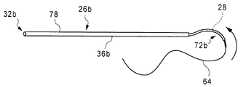
디바이스 본체의 적어도 일부 또는 선택적으로 디바이스 본체의 단지 일부는 탄성 변형 가능할 수도 있다. 공동을 형성하는 본체의 부분은 탄성 변형 가능할 수도 있다. 전체 본체가 탄성 변형 가능할 수도 있다. 디바이스는 바늘이 공동 내에 삽입될 때 곡선 형상을 채택하는 것이 가능할 수도 있다. 본체는 실질적으로 직선형 및/또는 무응력 구성일 수도 있는 비변형 또는 시작 구성으로부터 곡선형 구성일 수도 있는 변형 또는 전개 구성으로 탄성 변형 가능할 수도 있다. 본체는 바늘이 공동으로부터 제거될 때 비변형 구성으로 복귀할 수도 있다. 본체는 금속 또는 금속 합금 재료일 수도 있다.At least a portion of the device body or optionally only a portion of the device body may be elastically deformable. The portion of the body forming the cavity may be elastically deformable. The entire body may be elastically deformable. The device may be capable of adopting a curved shape when the needle is inserted into the cavity. The body may be elastically deformable from a non-deformable or starting configuration, which may be a substantially straight and/or stress-free configuration, to a deformable or deployed configuration, which may be a curved configuration. The body may return to a non-deformable configuration when the needle is removed from the cavity. The body may be a metal or metal alloy material.
본체 및 선택적으로 디바이스는 스프링의 형태를 취할 수도 있다. 스프링은 인장 스프링 또는 스프링 부재일 수도 있다. 스프링은 나선형으로 권취될 수도 있다. 스프링은 복수의 턴 또는 코일을 포함할 수도 있는데, 이는 턴 또는 코일이 적어도 휴지 상태에서 맞접(밀접 맞접할 수도 있음) 상태에 있도록 배열될 수도 있다. 스프링은 금속 또는 스테인리스 강 재료와 같은 금속 합금 재료일 수도 있지만, 플라스틱(적합하게는 폴리머) 재료가 적합할 수도 있다. 특히, 스프링의 형태를 취하는 본체는 본체의 주축에 대해 다중 방향으로 변형 가능할 수도 있다(비변형 상태). 따라서, 본체는 주축으로부터 이격하는 임의의 원하는 방향(예를 들어, 반경방향)으로 편향 가능할 수도 있다. 따라서, 본체는 고도의 컴플라이언스(compliance)를 나타낼 수도 있다.The body and optionally the device may take the form of a spring. The spring may be a tension spring or a spring member. The spring can also be wound in a spiral. The spring may comprise a plurality of turns or coils, which may be arranged such that the turns or coils are at least in a mated (may be tightly mated) state at least in a resting state. The spring may be a metal alloy material, such as a metal or stainless steel material, but a plastic (suitably polymer) material may be suitable. In particular, the body taking the form of a spring may be deformable in multiple directions with respect to the main axis of the body (non-deformed state). Thus, the body may be deflectable in any desired direction (eg, radial) away from the main axis. Thus, the body may exhibit a high degree of compliance.
곡선형 바늘을 수용하는 본체의 적어도 일부는 미리 만곡될 수도 있다.At least a portion of the body receiving the curved needle may be pre-curved.
본체는 측벽을 포함할 수도 있다. 공동과 연통하는 개구가 측벽에 형성될 수도 있다. 바늘은 개구를 통해 공동 내로 삽입 가능할 수도 있다.The body may also include side walls. An opening communicating with the cavity may be formed in the side wall. The needle may be insertable into the cavity through the opening.
본 개시내용의 제1 및/또는 제2 양태의 바늘 커버 및 운반 디바이스의 추가의 특징은, 특히 본 개시내용의 제3 및 제4 양태의 수술 조립체에서 또는 이를 참조하여, 본 문서의 다른 부분에서 설명된 텍스트로부터 유도될 수도 있다.Additional features of the needle cover and delivery device of the first and/or second aspect of the present disclosure are described elsewhere in this document, particularly in or with reference to the surgical assembly of the third and fourth aspect of the present disclosure. It may also be derived from the described text.
본 개시내용의 제3 양태에 따르면, 절단된 건을 봉합하는 데 사용을 위한 조립체가 제공되고, 조립체는According to a third aspect of the present disclosure, an assembly for use in suturing a severed gun is provided, the assembly comprising:
곡선형 바늘; 및Curved needles; And
곡선형 바늘을 커버하고 건초의 루멘 내에서 바늘을 운반하기 위한 바늘 커버 및 운반 디바이스를 포함하고, 바늘 커버 및 운반 디바이스는 세장형 요소를 포함하고, 세장형 요소는Covering the curved needle and comprising a needle cover and a conveying device for conveying the needle within the lumen of the hay, the needle cover and conveying device comprising an elongate element, the elongated element
제1 단부;A first end;
제1 단부에 대향하는 제2 단부; 및A second end opposite the first end; And
제1 단부와 제2 단부 사이에서 연장하는 본체로서, 본체는 건초 내에서 바늘의 통과 중에 팁과의 접촉을 통한 손상으로부터 건초를 보호하기 위해, 적어도 바늘의 관통 팁이 본체 내에 배치되도록 곡선형 바늘을 수용하기 위한 내부 공동을 형성하는, 본체를 갖고;A body extending between a first end and a second end, the body being curved needle such that at least a penetrating tip of the needle is disposed within the body to protect the hay from damage through contact with the tip during passage of the needle in the hay. Having a body, defining an inner cavity for receiving;
본체는The body is
A. 곡선형 바늘을 수용할 수 있도록 곡선 형상을 갖는 실질적으로 강성이고; 또는A. Substantially rigid with a curved shape to accommodate curved needles; or
B. 변형 가능하고, 곡선형 바늘을 수용할 수 있도록 곡선 형상으로 변형되는 것이 가능하다.B. It is deformable and can be transformed into a curved shape to accommodate a curved needle.
특히, 바늘 커버 및 운반 디바이스의 본 개시내용의 제3 양태의 조립체의 추가의 특징은 특히 본 개시내용의 제1 및/또는 제2 양태의 바늘 커버 및 운반 디바이스에서 또는 이를 참조하여, 본 문서의 다른 부분에서 설명된 텍스트로부터 유도될 수도 있다.In particular, further features of the assembly of the third aspect of the present disclosure of the needle cover and transport device are described in this document, particularly in or with reference to the needle cover and transport device of the first and/or second aspect of the present disclosure. It may also be derived from text described elsewhere.
본 개시내용의 제4 양태에 따르면, 절단된 건을 봉합하는 데 사용을 위한 조립체가 제공되고, 조립체는According to a fourth aspect of the present disclosure, an assembly for use in suturing a severed gun is provided, the assembly comprising:
건초의 루멘을 따라 운송하도록 구성된 스레딩 요소; 및A threading element configured to transport along the lumen of the hay; And
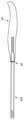
건초의 내부면을 라이닝하기 위한 라이너로서, 라이너는 건 절단단이 루멘을 따른 운송 중에 그를 따라 통과할 수 있는 내부 통로를 형성하고, 라이너는 건 절단단과 건초의 내부면 사이의 접촉을 제한하도록 작용하는, 라이너를 포함하고;As a liner for lining the inner surface of the hay, the liner forms an inner passage through which the gun cut end can pass during transport along the lumen, and the liner acts to limit contact between the gun cut end and the inner surface of the hay. Comprising a liner;
라이너는 스레딩 요소에 의해 건초 내로 당겨지고 루멘 내에 위치되고, 이어서 루멘 내에 존재하기 위해 스레딩 요소로부터 해제될 수 있도록 스레딩 요소에 해제 가능하게 결합되도록 구성된다.The liner is configured to be pulled into the hay by the threading element, positioned within the lumen, and then releasably coupled to the threading element such that it can be released from the threading element to be present within the lumen.
적절한 성형(예를 들어, 세장형이고 비교적 작은 직경 또는 폭을 가짐) 및/또는 재료의 선택(예를 들어, 소성 변형 가능/가단성 또는 탄성 변형 가능)에 의해, 건초의 좁은 루멘을 따라 통과하고 따라서 라이너가 끌려가는 건초를 운송하도록 구성되는 요소인 스레딩 요소가 참조된다.By suitable shaping (e.g., elongated and having a relatively small diameter or width) and/or material selection (e.g., plastically deformable/ malleable or elastically deformable), it passes along the narrow lumen of the hay and Thus, reference is made to the threading element, which is the element that the liner is configured to transport the dragged hay.
스레딩 요소는 라이너를 건초의 루멘 내로 당기는 역할을 할 수도 있고, 이어서 라이너가 루멘 내에 배치될 수 있도록 라이너로부터 해제될 수도 있으며, 이 위치에서 라이너는 건 절단단과 건초의 내부면 사이의 접촉을 제한하는(선택적으로 내지 완전히 방지함) 역할을 할 수도 있다. 이는 루멘을 따른 운송 중에 건 절단단에 대한 손상을 제한할 수도 있는데(잠재적으로 회피함), 이는 그렇지 않으면 마모되어, 전술된 유형의 건 봉합 절차에서 건의 다른 절단단으로의 후속의 연결을 어렵게 할 수 있다.The threading element may serve to pull the liner into the lumen of the hay, and may then be released from the liner so that the liner can be placed within the lumen, in which position the liner restricts contact between the gun cut and the inner surface of the hay. It can also play a role (optionally or completely preventing). This may limit (potentially avoid) damage to the gun cut end during transport along the lumen, which would otherwise wear out, making subsequent connection of the gun to the other cut end in the aforementioned type of gun closure procedure difficult. I can.
라이너는 건 절단단과 건초의 내부면 사이의 접촉을 제한하는데(선택적으로 접촉을 방지함) 특정 용도를 갖지만, 라이너는 또한 이에 한정되는 것은 아니지만, 예를 들어 루멘을 따른 복귀 운송 중에 스레딩 요소 자체를 포함하여, 다른 물체와 건초의 내부면 사이의 접촉을 제한하는(잠재적으로 회피함) 역할을 할 수도 있다.The liner has a specific use in limiting (optionally preventing contact) contact between the gun cut and the inner surface of the hay, but the liner also has, but is not limited to, the threading element itself during return transport along the lumen, for example. Including, it may also serve to limit (potentially avoid) contact between other objects and the inner surface of the hay.
조립체는 곡선형 바늘을 커버하고 건초의 루멘 내에서 바늘을 운반하기 위한 바늘 커버 및 운반 디바이스를 포함할 수도 있다. 바늘 커버 및 운반 디바이스는 세장형 요소를 포함할 수도 있고, 세장형 요소는The assembly may include a needle cover and a conveying device to cover the curved needle and to convey the needle within the lumen of the hay. The needle cover and conveying device may comprise an elongate element, the elongate element
제1 단부;A first end;
제1 단부에 대향하는 제2 단부; 및A second end opposite the first end; And
제1 단부와 제2 단부 사이에서 연장하는 본체로서, 본체는 건초 내에서 바늘의 통과 중에 팁과의 접촉을 통한 손상으로부터 건초를 보호하기 위해, 적어도 바늘의 관통 팁이 본체 내에 배치되도록 곡선형 바늘을 수용하기 위한 내부 공동을 형성하는, 본체를 갖는다.A body extending between a first end and a second end, the body being curved needle such that at least a penetrating tip of the needle is disposed within the body to protect the hay from damage through contact with the tip during passage of the needle in the hay. It has a body, forming an inner cavity for receiving.
본체는 변형 가능하고, 곡선형 바늘을 수용할 수 있도록 곡선 형상으로 변형되는 것이 가능할 수도 있다. 본체는 곡선형 바늘을 수용할 수 있도록 곡선 형상을 갖는 실질적으로 강성일 수도 있다.The body is deformable and may be capable of being deformed into a curved shape to accommodate a curved needle. The body may be substantially rigid with a curved shape to accommodate a curved needle.
본체는 스레딩 요소를 형성할 수도 있다. 사용시, 본체는 스레딩 요소를 형성하는 부분 및 바늘용 커버를 형성하는 부분을 포함할 수도 있다.The body may also form a threading element. In use, the body may comprise a portion forming a threading element and a portion forming a cover for the needle.
라이너는 세장형일 수도 있다. 라이너는 건초의 형태를 취할 수도 있다. 라이너는 실질적으로 관형일 수도 있고, 임의의 적합한 단면 형상을 가질 수도 있다. 라이너는 접힘 가능하고 그리고/또는 건초의 루멘 내로의 용이한 삽입 및 그를 따른 운송을 위해 평탄화되도록 구성될 수도 있다. 이는 라이너를 위한 적합한 재료의 선택, 및 접힘/평탄화를 위해 적합한 벽 두께를 갖는 라이너의 제공에 의해 달성될 수도 있다. 라이너는 건초의 내부면과 접촉하도록 구성된 외부면, 및 내부 통로를 형성하고 루멘을 따른 운송 중에 건 절단단에 의해 접촉될 수도 있는 내부면을 포함할 수도 있다.The liner may also be elongate. The liner can also take the form of hay. The liner may be substantially tubular and may have any suitable cross-sectional shape. The liner may be configured to be collapsible and/or leveled for easy insertion and transport of hay into the lumen. This may be achieved by selection of a suitable material for the liner, and the provision of a liner having a suitable wall thickness for folding/flattening. The liner may include an outer surface configured to contact the inner surface of the hay, and an inner surface that forms an inner passage and may be contacted by the gun cut end during transport along the lumen.
라이너는 슬릿을 포함할 수도 있고, 제1 축방향 단부로부터 제2 축방향 단부까지 라이너의 전체 길이를 따라 길게 절결될 수도 있다. 이러한 슬릿을 갖는 라이너의 제공은, 건 절단단이 절단된 건의 기능을 복원하도록 연결되는 건 봉합 절차의 완료 후에 루멘으로부터 라이너의 제거를 용이하게 할 수도 있고, 슬릿은 라이너를 봉합된 건 위로 당겨질 수 있게 하여 건을 건초의 루멘 내에 제위치에 남겨둔다. 라이너는 내부 통로를 형성하기 위해, 예를 들어 종축 둘레로 말리거나(rolled) 또는 감기도록(coiled) 구성될 수도 있다. 라이너의 말림 또는 감김은 이를 튜브의 형상으로 형성할 수도 있다. 라이너가 길게 절결되는 경우, 라이너는 제1 측방향 에지 및 제2 측방향 에지를 포함할 수도 있다. 라이너가 말리거나 감기는 경우, 측방향 에지들 중 하나를 포함하는 라이너의 부분은 다른 측방향 에지를 포함하는 라이너의 부분과 중첩할 수도 있다. 라이너는 플라스틱(적합하게는 폴리머) 또는 탄성중합 재료일 수도 있는데, 이 재료들은 건초의 루멘 내로의 삽입 및 라이너의 내부 통로를 따른 건 절단단의 운송을 용이하게 하기 위해 낮은 마찰 계수를 가질 수도 있다.The liner may include a slit, and may be cut elongated along the entire length of the liner from the first axial end to the second axial end. Providing a liner having such a slit may facilitate removal of the liner from the lumen after completion of a key sealing procedure in which the gun cleavage ends are connected to restore the function of the cut gun, and the slit can be pulled over the closed key. To leave the gun in place within the lumen of the hay. The liner may be configured to be rolled or coiled, for example around a longitudinal axis to form an inner passageway. The curling or winding of the liner may form it in the shape of a tube. When the liner is cut long, the liner may include a first lateral edge and a second lateral edge. When the liner is curled or wound, a portion of the liner comprising one of the lateral edges may overlap a portion of the liner comprising the other lateral edge. The liner may be a plastic (suitably polymer) or elastomeric material, which may have a low coefficient of friction to facilitate insertion of the hay into the lumen and transport of the key cut along the inner passage of the liner. .
라이너는 건초의 루멘 내에 위치되도록 구성된 건초 라이닝부, 및 루멘 라이닝부로부터 연장하고 건초 라이닝부를 루멘 내로 그리고 루멘을 따라 견인하는 데 사용되도록 구성되는 견인부를 포함할 수도 있다. 견인부는 건초 라이닝부의 길이보다 크거나 실질적으로 동일한 길이를 가질 수도 있다. 스레딩 요소는 견인부에 결합되도록 구성될 수도 있고, 견인부를 루멘 내로 당기는 데 사용될 수도 있다. 견인부는 이후에 루멘 외부로 견인부의 단부를 당김으로써, 건초 라이닝부를 루멘 내로 당기는 데 사용될 수도 있다. 견인부는 건초 라이닝부를 루멘 내로 견인하기 위해 사용자에 의해 파지되도록 구성될 수도 있다. 건초 라이닝부는 실질적으로 관형일 수도 있다(슬릿을 포함하고 전술된 바와 같이 감기는 경우를 포함함). 견인부는 실질적으로 관형 루멘 라이닝부로부터 연장될 수도 있는 하나 이상의 세장형 스트립, 레그 등을 포함할 수도 있다. 대안적으로, 견인부는 또한 관형일 수도 있고, 루멘 라이닝부보다 작은 직경 또는 폭을 가질 수도 있다. 견인부는 루멘 라이닝부와 일체형일 수도 있다.The liner may include a hay lining portion configured to be positioned within the lumen of the hay, and a pull portion extending from the lumen lining portion and configured to be used to pull the hay lining portion into and along the lumen. The tow portion may have a length greater than or substantially equal to the length of the hay lining portion. The threading element may be configured to engage the pull portion or may be used to pull the pull portion into the lumen. The tow may then be used to pull the hay lining into the lumen by pulling the end of the tow out of the lumen. The pulling portion may be configured to be gripped by the user to pull the hay lining portion into the lumen. The hay lining may be substantially tubular (including slits and windings as described above). The retractor may include one or more elongate strips, legs, etc. that may extend substantially from the tubular lumen lining. Alternatively, the retractor may also be tubular and may have a smaller diameter or width than the lumen lining. The traction portion may be integral with the lumen lining portion.
조립체는 추가 건초의 내부면을 라이닝하기 위한 적어도 하나의 추가 라이너를 포함할 수도 있다. 추가 라이너는 또한 스레딩 요소에 해제 가능하게 결합되도록 구성될 수도 있어, 스레딩 요소에 의해 추가 건초 내로 당겨지고 추가 건초의 루멘 내에 위치될 수 있게 되고, 이어서 스레딩 요소로부터 해제되어 루멘 내에 존재하게 될 수 있다. 추가 라이너는 예를 들어 동일한 손가락 또는 제2(및 선택적으로 다른) 손가락에서, 추가 건의 건 봉합 절차에 사용될 수도 있다.The assembly may include at least one additional liner for lining the inner surface of the additional hay. The additional liner may also be configured to be releasably coupled to the threading element, such that it can be pulled into additional hay by the threading element and placed within the lumen of the additional hay, which can then be released from the threading element and present in the lumen. . Additional liners may be used in tendon closure procedures of additional tendons, for example on the same finger or on a second (and optionally different) finger.
스레딩 요소는 스프링의 형태를 취할 수도 있다. 스프링은 인장 스프링 또는 스프링 부재일 수도 있다. 스프링은 나선형으로 권취될 수도 있다. 스프링은 복수의 턴 또는 코일을 포함할 수도 있는데, 이는 턴 또는 코일이 적어도 휴지 상태에서 맞접(밀접 맞접할 수도 있음) 상태에 있도록 배열될 수도 있다. 스프링은 금속 또는 스테인리스 강 재료와 같은 금속 합금 재료일 수도 있지만, 플라스틱(적합하게는 폴리머) 재료가 적합할 수도 있다.The threading element can also take the form of a spring. The spring may be a tension spring or a spring member. The spring can also be wound in a spiral. The spring may comprise a plurality of turns or coils, which may be arranged such that the turns or coils are at least in a mated (may be tightly mated) state at least in a resting state. The spring may be a metal alloy material, such as a metal or stainless steel material, but a plastic (suitably polymer) material may be suitable.
스레딩 요소는 외장, 슬리브 또는 커버를 포함할 수도 있다. 외장은 건초 내의 스레딩 요소의 통과를 용이하게 할 수도 있다. 외장은 플라스틱(적합하게는 폴리머) 또는 탄성중합 재료일 수도 있는데, 이 재료들은 건초 내의 디바이스의 통과를 용이하게 하기 위해 낮은 마찰 계수를 가질 수도 있다. 외장은 본체의 외부면과 접촉하여 배치되는 내부면을 가질 수도 있다.The threading element may comprise a sheath, sleeve or cover. The sheath may also facilitate the passage of threading elements in the hay. The sheath may be a plastic (suitably a polymer) or elastomeric material, which may have a low coefficient of friction to facilitate the passage of the device in the hay. The exterior may have an interior surface disposed in contact with the exterior surface of the body.
전술된 바와 같이, 본체는 스레딩 요소를 형성하는 부분 및 바늘용 커버를 형성하는 부분을 포함할 수도 있다. 커버는 스레딩 요소의 것과 동일한 구조를 가질 수도 있고 그와 연속적일 수도 있다. 스레딩 요소가 전술된 바와 같이(선택적으로 복수의 코일을 포함하는) 스프링으로 형성되는 경우, 외장(커버)은 건초의 루멘을 통해 압박될 수 있도록 스레딩 요소에 강성 정도를 제공할 수도 있다. 외장에 의해 커버된 스레딩 요소의 부분의 강성 또는 굴곡 계수는 외장에 의해 커버되지 않은 부분보다 클 수도 있다. 따라서, 외장에 의해 커버된 스레딩 요소의 부분은 커버되지 않은 부분보다 더 강성일 수도 있다.As described above, the body may include a portion forming a threading element and a portion forming a cover for the needle. The cover may have the same structure as that of the threading element or may be continuous with it. When the threading element is formed of a spring as described above (optionally comprising a plurality of coils), the sheath (cover) may provide a degree of stiffness to the threading element so that it can be pressed through the lumen of the hay. The stiffness or flexural modulus of the part of the threading element covered by the sheath may be greater than that of the part not covered by the sheath. Thus, the portion of the threading element covered by the sheath may be more rigid than the portion that is not covered.
조립체는 스레딩 요소를 라이너에 해제 가능하게 연결하기 위한 가요성 연결 부품을 포함할 수도 있다. 가요성 연결 부품은 코드, 와이어, 필라멘트 등일 수도 있고, 봉합사일 수도 있다. 조립체가 바늘 커버 및 운반 디바이스를 포함하는 경우(디바이스의 본체가 스레딩 요소를 형성함), 가요성 연결 부품은 바늘에 연결된 봉합사일 수도 있다. 적합하게는, 봉합사가 라이너를 건초의 루멘 내로 당기는 데 사용되기 전에 바늘이 커버 및 운반 디바이스로부터 제거될 것이다.The assembly may include a flexible connecting part for releasably connecting the threading element to the liner. The flexible connecting part may be a cord, a wire, a filament, or the like, or may be a suture. If the assembly includes a needle cover and a conveying device (the body of the device forms a threading element), the flexible connecting part may be a suture connected to the needle. Suitably, the needle will be removed from the cover and conveying device before the suture is used to pull the liner into the lumen of the hay.
가요성 연결 부품은, 스레딩 요소에/스레딩 요소 주위에 연결 부품을 휘핑(whipping)함으로써와 같이, 묶음으로써 스레딩 요소에 해제 가능하게 연결될 수도 있다. 스레딩 요소가 외장을 포함하는 경우, 가요성 연결 부품은 본체의 외부면과 외장의 내부면 사이에 연결 부품의 부분을 포획함으로써 스레딩 요소에 해제 가능하게 연결될 수도 있다. 스레딩 요소가 스프링의 형태를 취하는 경우, 스프링은 내부 통로를 형성할 수도 있고 개방 단부를 가질 수도 있으며, 가요성 연결 부품은 개방 단부로부터 빠져나가고 스프링의 외부면과 외장의 내부면 사이에서 개방 단부로부터 이격하여 통과하기 전에, 스프링의 개방 단부로 스프링의 내부 통로를 따라 위로 통과할 수도 있다.The flexible connecting part may be releasably connected to the threading element by bundling, such as by whipping the connecting part to/around the threading element. When the threading element comprises a sheath, the flexible connecting part may be releasably connected to the threading element by capturing a portion of the connecting part between the outer surface of the body and the inner surface of the sheath. When the threading element takes the form of a spring, the spring may form an inner passage or have an open end, and the flexible connecting part exits from the open end and between the outer surface of the spring and the inner surface of the sheath from the open end. It may pass upward along the inner passageway of the spring to the open end of the spring prior to passing at a distance.
가요성 연결 부품은 루프로 형성될 수도 있다. 라이너, 특히 견인부(예를 들어, 하나 이상의 세장형 스트립 중 적어도 하나)는 루프 위로 절첩될 수도 있고, 가요성 연결 부품은 라이너에/라이너 주위에 연결 부품을 휘핑함으로써와 같이, 묶음으로써 라이너에 대해 고정될 수도 있다.The flexible connecting part can also be formed as a loop. The liner, in particular the pull (e.g., at least one of the one or more elongate strips) may be folded over the loop, and the flexible connecting part is attached to the liner by bundling, such as by whipping the connecting part to/around the liner. It can also be fixed against.
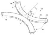
라이너는 2개의 건초 라이닝부를 형성하도록 스레딩 요소에 결합될 수도 있다. 라이너는 제1 단부 및 제2 단부를 가질 수도 있고, 적합하게는 라이너의 중간점에서 또는 그에 근접하여, 제1 및 제2 단부 사이에 라이너의 길이를 따른 지점에서 라이너를 스레딩 요소에 연결함으로써 결합이 달성될 수도 있다. 결합은 스레딩 요소 또는 연결 부품 둘레에/연결 부품에 상기 지점에서 라이너를 절첩함으로써 달성될 수도 있다. 각각의 건초 라이닝부의 길이는 실질적으로 동일할 수도 있지만, 이들이 건초(또는 수술용 개구 사이로 연장하는 건초의 적어도 일부)를 라이닝하기에 충분히 길면, 길이는 상이할 수 있다. 건초 라이닝부는 각각의 건의 건 절단단을 수용하는 역할을 할 수도 있다. 손가락의 건초가 하나 초과의 건을 수용할 수 있다는 것은 잘 알려져 있다. 따라서, 조립체는 2개의 건초 라이닝부가 양 손가락 건이 봉합될 위치에서 사용을 위해, 단일의 건초 내에 위치되는 것을 가능하게 할 수도 있다.The liner may be coupled to the threading element to form two hay linings. The liner may have a first end and a second end, suitably joined by connecting the liner to the threading element at or near the midpoint of the liner, at a point along the length of the liner between the first and second ends. This may be achieved. The bonding may also be achieved by folding the liner at this point around/to the threading element or connecting piece. The length of each hay lining may be substantially the same, but if they are long enough to line the hay (or at least a portion of the hay extending between the surgical openings), the lengths can be different. The hay lining may serve to accommodate the key cutting ends of each key. It is well known that hay on a finger can accommodate more than one. Thus, the assembly may enable the two hay linings to be positioned within a single hay, for use in the location where the two finger guns will be sutured.
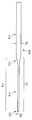
라이너는 제1 단부, 제2 단부, 및 제1 및 제2 단부 사이에서 연장하는 본체를 포함할 수도 있다. 라이너는 제1 단부로부터 제1 및 제2 단부 사이에 배치된 라이너의 부분을 향해 연장하는 제1 건초 라이닝부, 및 제2 단부로부터 제1 및 제2 단부 사이에 배치된 부분을 향해 연장하는 제2 건초 라이닝부를 포함할 수도 있다. 제1 및 제2 건초 라이닝부는 각각 폭을 가질 수도 있고, 상기 부분은 제1 및 제2 건초 라이닝부의 폭보다 작은 폭을 가질 수도 있다. 제1 건초 라이닝부의 폭은 제2 건초 라이닝부의 폭과 동일할 수도 있다(또는 실질적으로 동일함). 상기 부분은 실질적으로 일정한 폭의 주요 섹션; 주요 섹션과 제1 건초 라이닝부 사이에서 연장하는 제1 전이 섹션; 및 주요 섹션과 제2 건초 라이닝부 사이에서 연장하는 제2 전이 섹션을 포함할 수도 있다. 전이 섹션은 주요 섹션의 폭으로부터 각각의 건초 라이닝부의 폭까지 점진적으로 증가하는 폭을 가질 수도 있다. 상기 부분은 제1 건초 라이닝부로부터 연장하는 제1 전이 섹션; 및 제2 건초 라이닝부로부터 연장하고 제1 전이 섹션에 결합되는 제2 전이 섹션을 포함할 수도 있다. 전이 섹션은 전이 섹션 사이의 교차점에서 또는 교차점에 의해 규정된 폭으로부터 각각의 건초 라이닝부의 폭까지 점진적으로 증가하는 폭을 가질 수도 있다.The liner may include a first end, a second end, and a body extending between the first and second ends. The liner includes a first hay lining portion extending from a first end toward a portion of the liner disposed between the first and second ends, and a first hay lining portion extending from the second end toward a portion disposed between the first and second ends. It may also include two hay linings. Each of the first and second hay lining portions may have a width, and the portion may have a width smaller than that of the first and second hay lining portions. The width of the first hay lining portion may be the same (or substantially the same) as the width of the second hay lining portion. The portion comprises a major section of substantially constant width; A first transition section extending between the main section and the first hay lining; And a second transition section extending between the main section and the second hay lining. The transition section may have a width that gradually increases from the width of the main section to the width of each hay lining. The portion includes a first transition section extending from the first hay lining portion; And a second transition section extending from the second hay lining and coupled to the first transition section. The transition section may have a width that gradually increases from the width defined by the intersection or at the intersection between the transition sections to the width of each hay lining.
라이너는 상기 부분 내에 또는 상기 부분에서, 스레딩 요소(특히 가요성 연결 부품)에 해제 가능하게 결합되도록 구성될 수도 있다. 가요성 연결 부품이 루프로 형성되는 경우, 라이너는 상기 부분에서 또는 그 둘레에서 루프 위로 절첩함으로써 스레딩 요소에 해제 가능하게 결합 가능할 수도 있다. 제1 및 제2 건초 라이닝 섹션은 적합하게는 상기 부분을 제거하기 위해 라이너를 절단함으로써 서로로부터 분리되도록 구성될 수도 있다.The liner may be configured to be releasably coupled to a threading element (in particular a flexible connection part) in or in said part. When the flexible connecting part is formed into a loop, the liner may be releasably engageable to the threading element by folding over the loop at or around said portion. The first and second hay lining sections may suitably be configured to be separated from each other by cutting the liner to remove the portion.
특히, 스레딩 요소 및 바늘 커버 및 운반 디바이스의 본 개시내용의 제4 양태의 조립체의 추가의 특징은 특히 본 개시내용의 제1 및/또는 제2 양태의 바늘 커버 및 운반 디바이스 및 본 개시내용의 제3 양태의 조립체, 또는 제5 내지 제9 양태에 규정된 방법 및 조립체에서 또는 이들을 참조하여, 본 문서의 다른 부분에서 설명된 텍스트로부터 유도될 수도 있다.In particular, additional features of the assembly of the fourth aspect of the present disclosure of the threading element and the needle cover and the conveying device are in particular the needle cover and conveying device of the first and/or second aspect of the present disclosure and the article of the present disclosure. The assembly of the three aspects, or in or with reference to the methods and assemblies defined in the fifth to ninth aspects, may be derived from the text described elsewhere in this document.
본 개시내용의 제5 양태에 따르면, 절단된 건을 봉합하는 방법의 부분일 수도 있는, 절단된 건의 건 절단단을 회수하는 방법이 제공되고, 방법은According to a fifth aspect of the present disclosure, there is provided a method of recovering a tendon cut end of a cut tendon, which may be part of a method of suturing a cut tendon, the method comprising:
봉합사를 제1 건 절단단에 연결하기 위해, 봉합사에 연결된 곡선형 바늘을 제1 건 절단단을 통해 통과시키는 단계;Passing a curved needle connected to the suture through the first tendon cleavage end to connect the suture to the first tendon cleavage end;
제1 단부, 제1 단부에 대향하는 제2 단부, 및 제1 및 제2 단부 사이에서 연장하는 본체로서, 본체는 내부 공동을 형성하는, 본체를 갖는 세장형 요소를 포함하는 바늘 커버 및 운반 디바이스를 제공하는 단계;A first end, a second end opposite the first end, and a body extending between the first and second ends, the body forming an inner cavity, a needle cover and a conveying device comprising an elongate element having a body Providing a;
팁이 디바이스에 커버되도록, 본체에 의해 형성된 공동 내에 곡선형 바늘의 적어도 관통 팁을 위치시키는 단계;Positioning at least the penetrating tip of the curved needle within the cavity defined by the body such that the tip is covered by the device;
세장형 요소의 제1 단부를 건초 내에 삽입하는 단계;Inserting the first end of the elongate element into the hay;
제1 건 절단단으로부터 건초를 따라 이격된 제2 건 절단단을 향해, 바늘 및 봉합사를 운반하는 건초를 따라 세장형 요소를 지향시키는 단계;Directing the elongate element along the hay carrying the needle and suture from the first key cut end toward a second key cut end spaced along the hay;
건초로부터 바늘 커버 및 운반 디바이스를 제거하는 단계;Removing the needle cover and conveying device from the hay;
본체 내의 공동으로부터 바늘을 제거하는 단계;Removing the needle from the cavity in the body;
건 절단단이 연결될 수 있도록, 제2 건 절단단에 근접한 위치로 봉합사를 사용하여 건초를 따라 제1 건 절단단을 당기는 단계를 포함한다.Pulling the first key cut end along the hay using a suture to a position proximate the second key cut end so that the key cut end can be connected.
방법은 본체에 의해 형성된 공동 내에 봉합사의 자유 단부를 위치시키는 단계를 포함할 수도 있다. 건초로부터 세장형 요소의 제거 후에, 방법은 선택적으로 건초를 따라 제1 건 절단단을 당기기 전에, 본체의 공동으로부터 바늘과 봉합사의 단부를 제거하는 단계를 포함할 수도 있다.The method may include positioning the free end of the suture within a cavity defined by the body. After removal of the elongate element from the hay, the method may optionally include removing the ends of the needle and suture from the cavity of the body prior to pulling the first key cut along the hay.
방법은 봉합사를 제2 건 절단단에 연결하기 위해, 봉합사에 연결된 곡선형 바늘을 제2 건 절단단을 통해 통과시키는 단계; 및 제1 건 절단단을 제2 건 절단단에 연결하여 이에 의해 절단된 건을 봉합하기 위해 봉합사를 조작하는 단계를 포함할 수도 있다.The method includes passing a curved needle connected to the suture through the second tendon cleavage end to connect the suture to the second tendon cleavage end; And connecting the first key cutting end to the second key cutting end and manipulating the suture to suture the cut tendon.
방법은 전체 바늘이 디바이스에 의해 커버되도록 전체 바늘(따라서 봉합사에 결합될 수도 있는 바늘의 후단 단부를 포함함)을 공동 내에 위치시키는 단계를 포함할 수도 있다.The method may include placing the entire needle (and thus including the trailing end of the needle that may be coupled to the suture) within the cavity such that the entire needle is covered by the device.
방법은 절단단을 노출시키기 위해 건초로부터 제1 건 절단단을 제거하고, 이어서 봉합사를 제1 절단단에 연결하는 단계를 포함할 수도 있다. 방법은 절단단을 노출시키기 위해 건초로부터 제2 건 절단단을 제거하고, 이어서 봉합사를 제2 절단단에 연결하는 단계를 포함할 수도 있다.The method may include removing the first key cut end from the hay to expose the cut end, and then connecting the suture to the first cut end. The method may include removing the second key cut end from the hay to expose the cut end, and then connecting the suture to the second cut end.
방법은 스레더의 본체의 공동 내로 전체 바늘을 삽입하는 단계를 포함할 수도 있다. 봉합사는 제2 단부에 또는 제2 단부에 의해 제공될 수도 있는 개구를 통해 본체 외부로 통과할 수도 있다.The method may include inserting the entire needle into the cavity of the body of the threader. The suture may pass out of the body through an opening that may be provided at or by the second end.
건초로부터 디바이스를 제거하는 단계는 디바이스의 제2 단부를 건초 외부로 당기는 단계를 포함할 수도 있다.Removing the device from the hay may include pulling the second end of the device out of the hay.
본 문서에서는 건의 건초를 참조한다. 건초는 함께 건초를 형성하는 다수의 건초 부분 또는 부분들을 포함할 수도 있다는 것이 이해될 수 있을 것이다. 이는 특히 손상된 건이 액세스될 수 있도록 구멍이 건초에 형성될 수도 있는 수술 절차에 성립할 수도 있다.In this document, we refer to the hay of the gun. It will be appreciated that hay may include multiple hay portions or portions that together form hay. This may be particularly true for surgical procedures in which a hole may be formed in the hay so that the damaged tendon can be accessed.
제1 건 절단단은 근위 절단단일 수도 있고, 제2 건 절단단은 원위 절단단일 수도 있다. 인간의 손의 맥락에서, 원위 단부는 건을 포함하는 손가락의 팁에 더 가깝게 배치될 수도 있다. 조립체 및 방법은 발과 같은 인간 또는 동물 신체의 다른 부분에 대한 수술에 사용될 수도 있다.The first key cut end may be a proximal cut end, and the second key cut end may be a distal cut end. In the context of a human hand, the distal end may be positioned closer to the tip of the finger containing the tendon. The assembly and method may be used for surgery on other parts of the human or animal body, such as the foot.
본 문서에서는 제2 건 절단단에 근접한 위치로의 제1 건 절단단의 당김을 참조한다. 이는 통상적으로 절단단이 함께 봉합될 수 있는 제2 건 절단단에 충분히 가까운 위치로 제1 건 절단단이 이동되는 것을 의미하도록 취해져야 한다는 것이 이해될 수 있을 것이다. 이는 일반적으로 제2 건 절단단 부근의 건초로부터 제1 건 절단단을 제거하는 것을 수반할 것이다.In this document, reference is made to the pulling of the first key cut end to a position close to the second key cut end. It will be appreciated that this should typically be taken to mean that the first key cut end is moved to a position sufficiently close to the second key cut end that the cut ends may be sutured together. This will generally involve removing the first key cut from the hay near the second key cut.
방법은 건초의 내부면을 라이너로 라이닝하는 단계를 포함할 수도 있고, 라이너는 제1 건 절단단이 건초를 따른 운송 중에 그를 따라 통과할 수 있는 내부 통로를 형성한다. 건초는 본체에 의해 형성된 공동 내에 적어도 곡선형 바늘의 관통 팁을 위치시키는 단계를 수행하기 전에 라이닝될 수도 있고, 제1 건 절단단을 통해 봉합사가 끌려가는 곡선형 바늘을 통과시키는 단계를 수행하기 전에 수행될 수도 있다.The method may include lining the inner surface of the hay with a liner, the liner defining an inner passageway through which the first key cut can pass during transport along the hay. Hay may be lined prior to performing the step of locating the piercing tip of the curved needle at least within the cavity formed by the body, and prior to performing the step of passing the curved needle to which the suture is drawn through the first key cut end. It can also be done.
라이너는 건초의 루멘을 따라 운송될 수 있는 스레딩 요소에 의해 건초 내로 당겨질 수도 있다. 스레딩 요소는 커버 및 운반 디바이스의 본체에 의해 형성될 수도 있다. 방법은 라이너를 스레딩 요소에 해제 가능하게 결합하는 단계를 포함할 수도 있다. 라이너는 루멘 내의 위치 후에 스레딩 요소로부터 해제될 수도 있다.The liner may be pulled into the hay by a threading element that can be transported along the lumen of the hay. The threading element may be formed by the cover and the body of the conveying device. The method may include releasably coupling the liner to the threading element. The liner may be released from the threading element after positioning in the lumen.
세장형 요소의 제1 단부를 건초 내에 삽입하는 단계는 제1 단부를 라이너의 내부 통로 내에 삽입하는 단계를 포함할 수도 있다. 바늘 및 봉합사를 운반하는 건초를 따라 세장형 요소를 지향시키는 단계는 라이너의 내부 통로를 따라 세장형 요소를 지향시키는 단계를 포함할 수도 있다. 바늘 커버 및 운반 디바이스를 건초로부터 제거하는 단계는 라이너의 내부 통로로부터 세장형 요소를 제거하는 단계를 포함할 수도 있다.Inserting the first end of the elongate element into the hay may include inserting the first end into the inner passageway of the liner. Directing the elongate element along the hay carrying the needle and suture may include directing the elongate element along the inner passageway of the liner. Removing the needle cover and transport device from the hay may include removing the elongate element from the inner passageway of the liner.
방법은 제2 건 절단단을 통한 봉합사에 연결된 곡선형 바늘의 통과 후에 건초로부터 라이너를 제거하는 단계를 포함할 수도 있다. 라이너는 제1 건 절단단을 제2 건 절단단에 연결하여 이에 의해 절단된 건을 봉합하기 위해 봉합사의 조작 후에만 제거될 수도 있다. 라이너는 제1 축방향 단부로부터 제2 축방향 단부까지 라이너의 전체 길이를 따라 연장할 수도 있는 슬릿을 포함할 수도 있고, 슬릿은 루멘으로부터 라이너의 제거를 용이하게 한다. 라이너는 건이 슬릿을 통해 또는 그 외부로 통과하도록, 건에 대해 이를 측방향으로 활주시킴으로써 제거될 수도 있다.The method may include removing the liner from the hay after passage of the curved needle connected to the suture through the second tendon cut end. The liner may be removed only after manipulation of the suture to connect the first key cut end to the second key cut end to seal the cut tendon. The liner may include a slit that may extend along the entire length of the liner from the first axial end to the second axial end, the slit facilitating removal of the liner from the lumen. The liner may be removed by sliding it laterally relative to the gun, such that the gun passes through or out of the slit.
방법은 2개의 건초 라이닝부를 형성하기 위해 스레딩 요소에 결합된 라이너로 건초의 내부면을 라이닝하는 단계를 포함할 수도 있다. 라이너는 제1 단부 및 제2 단부를 가질 수도 있고, 적합하게는 라이너의 중간점에서 또는 그에 근접하여, 제1 및 제2 단부 사이에 라이너의 길이를 따른 지점에서 스레딩 요소에 결합될 수도 있다. 건초 라이닝부는 각각의 건의 건 절단단을 수용하는 역할을 할 수도 있다. 따라서, 방법은 2개의 절단된 건을 봉합하기 위한 것일 수도 있고, 이 건들은 일반적으로 단일 건초 내에 위치된다.The method may include lining the inner surface of the hay with a liner coupled to the threading element to form two hay linings. The liner may have a first end and a second end and may suitably be coupled to the threading element at a point along the length of the liner between the first and second ends, at or near the midpoint of the liner. The hay lining may serve to accommodate the key cutting ends of each key. Thus, the method may be for suturing two severed tendons, these tendons being generally placed within a single hay.
특히 바늘 커버 및 운반 디바이스에 관한 본 개시내용의 제5 양태의 방법의 추가의 특징은 특히 본 개시내용의 제1 내지 제4 양태의 바늘 커버 및 운반 디바이스 및 조립체, 또는 제6 내지 제9 양태에 규정된 방법 및 조립체에서 또는 이들을 참조하여, 본 문서의 다른 부분에서 설명된 텍스트로부터 유도될 수도 있다.Further features of the method of the fifth aspect of the present disclosure, in particular with respect to the needle cover and conveying device, are in particular to the needle covers and conveying devices and assemblies of the first to fourth aspects of the present disclosure, or to the sixth to ninth aspects. In or with reference to defined methods and assemblies, it may be derived from text described elsewhere in this document.
본 개시내용의 제6 양태에 따르면, 건 봉합 절차를 수행하기 위한 준비시에 절단된 건의 건초를 라이닝하는 방법이 제공되고, 방법은According to a sixth aspect of the present disclosure, there is provided a method of lining hay of a cut tendon in preparation for performing a tendon suturing procedure, the method comprising:
스레딩 요소를 내부 통로를 형성하는 라이너에 해제 가능하게 결합하는 단계;Releasably coupling the threading element to the liner defining the inner passageway;
스레딩 요소를 라이너가 그 후방에 끌려가는 건초의 루멘 내에 삽입하는 단계;Inserting the threading element into the lumen of the hay being dragged behind the liner;
라이너를 루멘 내로 당기기 위해 건초의 루멘을 따라 스레딩 요소를 지향시키는 단계;Directing the threading element along the lumen of the hay to pull the liner into the lumen;
건초의 내부면을 라이닝하도록 라이너를 건초 내에 위치시키는 단계;Positioning the liner within the hay to line the inner surface of the hay;
건초의 루멘으로부터 스레딩 요소를 제거하는 단계; 및Removing the threading element from the lumen of the hay; And
라이너를 스레딩 요소로부터 해제하여 라이너를 건초의 루멘 내에 제자리에 남겨두는 단계로서, 라이너는 후속의 건 봉합 절차 중에 절단된 건의 건 절단단과 건초의 내부면 사이의 접촉을 제한하는 역할을 하는, 단계를 포함한다.Releasing the liner from the threading element to leave the liner in place within the lumen of the hay, the liner serving to limit contact between the key cut end of the cut gun and the inner surface of the hay during a subsequent key sealing procedure. Includes.
본 개시내용의 제6 양태의 방법의 추가의 특징은 특히 본 개시내용의 제1 내지 제4 양태의 바늘 커버 및 운반 디바이스 및 조립체, 및 본 개시내용의 제5 양태의 방법, 또는 제6 내지 제9 양태에 규정된 조립체 및 방법에서 또는 이들을 참조하여, 본 문서의 다른 부분에서 설명된 텍스트로부터 유도될 수도 있다.Further features of the method of the sixth aspect of the present disclosure are, in particular, the needle covers and delivery devices and assemblies of the first to fourth aspects of the present disclosure, and the method of the fifth aspect of the present disclosure, or the sixth to the fourth aspect of the present disclosure. In or with reference to the assemblies and methods defined in the nine aspects, it may be derived from text described elsewhere in this document.
본 개시내용의 제7 양태에 따르면, 절단된 건을 봉합하는 데 사용을 위한 조립체가 제공되고, 조립체는According to a seventh aspect of the present disclosure, an assembly for use in suturing a severed gun is provided, the assembly comprising:
곡선형 바늘을 커버하고 건초의 루멘 내에서 바늘을 운반하기 위해, 건초의 루멘을 따라 운송하도록 구성된 세장형 스레딩 요소로서, 세장형 스레딩 요소는An elongate threading element configured to transport along the lumen of the hay, to cover the curved needle and transport the needle within the lumen of the hay, wherein the elongate threading element is
제1 단부;A first end;
제1 단부에 대향하는 제2 단부; 및A second end opposite the first end; And
제1 단부와 제2 단부 사이에서 연장하는 본체로서, 본체는 건초 내에서 바늘의 통과 중에 바늘과의 접촉을 통한 손상으로부터 건초를 보호하기 위해 곡선형 바늘을 수용하기 위한 내부 공동을 형성하고, 본체는 곡선형 바늘을 수용할 수 있도록 곡선 형상으로 변형 가능하고, 본체는 선택적으로 복수의 코일을 갖는 스프링을 포함하는, 본체를 갖는, 세장형 스레딩 요소;A body extending between a first end and a second end, the body forming an inner cavity for receiving a curved needle to protect the hay from damage through contact with the needle during passage of the needle in the hay, and the body An elongate threading element having a body, deformable into a curved shape to accommodate a curved needle, the body optionally comprising a spring having a plurality of coils;
건초의 내부면을 라이닝하기 위한 라이너로서, 라이너는 곡선형 바늘에 결합된 건 절단단이 루멘을 따른 운송 중에 그를 따라 통과할 수 있는 내부 통로를 형성하고, 라이너는 건 절단단과 건초의 내부면 사이의 접촉을 방지하고, 라이너는 선택적으로As a liner for lining the inner surface of hay, the liner forms an inner passage through which a key cut end coupled to a curved needle can pass along it during transport along the lumen, and the liner is between the key cut end and the inner surface of the hay To prevent contact, and the liner optionally
라이너가 건초의 루멘 내에 삽입되도록 구성되는 접혀진 휴지 구성; 및A folded tissue configuration in which the liner is configured to be inserted into the lumen of the hay; And
팽창된 동작 구성을 갖고, 라이너는 건 절단단과의 접촉에 의해 팽창 구성으로 이동 가능한, 라이너를 포함하고;Having an expanded operating configuration, the liner including a liner movable in the expanded configuration by contact with the gun cut end;
라이너는 스레딩 요소에 의해 건초 내로 당겨지고 루멘 내에 위치되고, 이어서 루멘 내에 존재하기 위해 스레딩 요소로부터 해제될 수 있도록 세장형 스레딩 요소에 해제 가능하게 결합되도록 구성되고;The liner is configured to be pulled into the hay by the threading element and positioned within the lumen, and then releasably coupled to the elongate threading element such that it can be released from the threading element to be present within the lumen;
세장형 스레딩 요소는, 일단 라이너로부터 해제되면, 곡선형 바늘을 커버하여 라이너를 통해 그리고 연결된 건 절단단이 끌려가는 건초의 루멘을 따라 운반하기 위해, 곡선형 바늘을 수용하도록 구성된다.The elongate threading element is configured to receive the curved needle, once released from the liner, to cover the curved needle and carry it through the liner and along the lumen of the hay being pulled by the connected key cutting end.
본체는 스프링에 의해 형성될 수도 있다. 본체는 외부면을 가질 수도 있고, 세장형 스레딩 요소는 본체의 외부면과 접촉(선택적으로 밀접 접촉)하여 배치되는 내부면을 갖는 외부 슬리브를 포함할 수도 있다. 외부 슬리브는 제1 단부로부터 본체의 길이를 따라 부분적으로 연장될 수도 있다. 외부 슬리브는 본체에 소정 정도의 강성을 제공할 수도 있는데(건초의 루멘을 따라 운송하도록 변형하는 그 능력을 과도하게 제한하지 않고), 이는 건초 내로의 본체의 삽입, 및 루멘을 따른 본체의 압박을 용이하게 할 수도 있다.The body may be formed by a spring. The body may have an outer surface, and the elongate threading element may comprise an outer sleeve having an inner surface disposed in contact (optionally in close contact) with the outer surface of the body. The outer sleeve may extend partially along the length of the body from the first end. The outer sleeve may provide the body with some degree of stiffness (without unduly limiting its ability to deform to transport along the lumen of the hay), which prevents insertion of the body into the hay and compression of the body along the lumen. You can also do it easily.
제2 단부를 포함하는 본체의 부분은 곡선형 바늘을 수용하도록 구성될 수도 있고, 외부 슬리브는 상기 부분이 외부 슬리브에 의해 커버되지 않도록 제1 단부로부터 본체의 상기 부분으로 연장될 수도 있다. 본체의 상기 부분을 외부 슬리브에 의해 미커버된 체로 남겨두는 것은 본체의 커버된 부분보다 더 큰 가요성을 부분에 제공할 수도 있어, 이는 곡선형 바늘을 수용하도록 더 용이하게 변형될 수 있게 된다.The portion of the body comprising the second end may be configured to receive a curved needle, and the outer sleeve may extend from the first end to the portion of the body such that the portion is not covered by the outer sleeve. Leaving this portion of the body uncovered by the outer sleeve may provide the portion with greater flexibility than the covered portion of the body, which can be more easily deformed to accommodate the curved needle.
라이너는 접힘 구성에서, 실질적으로 편평할 수도 있고 편평하게 펼쳐진(lay-flat) 튜브일 수도 있다. 라이너는 접힘 구성에서, 폭과 높이를 가질 수도 있는데, 폭은 높이보다 크다. 폭은 높이보다 상당히 클 수도 있다. 높이 대 폭의 비는 약 1:100 내지 약 1:10의 범위일 수도 있다.The liner, in a folded configuration, may be substantially flat or may be a lay-flat tube. The liner may have a width and a height in a folded configuration, the width being greater than the height. The width may be significantly greater than the height. The ratio of height to width may range from about 1:100 to about 1:10.
조립체는 스레딩 요소를 라이너에 해제 가능하게 연결하기 위한 가요성 연결 부품을 포함할 수도 있다. 가요성 연결 부품은 스레딩 요소로부터 연장되는 루프로 형성될 수도 있다. 라이너는 루프 위로 라이너를 절첩하고 라이너의 절첩된 부분을 라이너의 주요 부분에 결합함으로써 스레딩 요소에 결합될 수 있다.The assembly may include a flexible connecting part for releasably connecting the threading element to the liner. The flexible connecting part may be formed as a loop extending from the threading element. The liner can be joined to the threading element by folding the liner over the loop and joining the folded portion of the liner to the main portion of the liner.
본체의 제2 단부는 후단 단부일 수도 있고, 스프링은 본체의 제2 단부를 형성하는 개방 단부를 가질 수도 있다. 스프링은 본체의 내부 공동을 형성할 수도 있고, 가요성 연결 부품은 내부 공동을 따라 개방 단부 내로 통과한다.The second end of the body may be a rear end, and the spring may have an open end forming a second end of the body. The spring may form an inner cavity of the body, and the flexible connecting part passes along the inner cavity and into the open end.
본체의 제1 단부는 선단 단부일 수도 있고, 스프링은 본체의 제1 단부를 형성하는 다른 개방 단부를 가질 수도 있다. 가요성 연결 요소는 내부 공동을 따라 스프링의 다른 개방 단부까지 연장될 수도 있어, 다른 개방 단부로부터 스프링을 빠져나가 스프링의 외부면과 외부 슬리브의 내부면 사이의 개방 단부로부터 이격하여 통과한다.The first end of the body may be a proximal end, and the spring may have another open end forming the first end of the body. The flexible connection element may extend along the inner cavity to the other open end of the spring, exiting the spring from the other open end and passing away from the open end between the outer surface of the spring and the inner surface of the outer sleeve.
라이너는 건초의 루멘 내에 위치되도록 구성된 건초 라이닝부, 및 루멘 라이닝부로부터 연장하고 건초 라이닝부를 루멘 내로 그리고 루멘을 따라 견인하는 데 사용되도록 구성되는 견인부를 포함할 수도 있다. 건초 라이닝부는 실질적으로 관형일 수도 있고, 견인부는 건초 라이닝부로부터 연장되는 하나 이상의 레그를 포함할 수도 있다.The liner may include a hay lining portion configured to be positioned within the lumen of the hay, and a pull portion extending from the lumen lining portion and configured to be used to pull the hay lining portion into and along the lumen. The hay lining may be substantially tubular and the tow may include one or more legs extending from the hay lining.
스프링은 일반적으로 관형일 수도 있고, 나선형으로 권취된 스프링일 수도 있다.The spring may be generally tubular or may be a spiral wound spring.
본 개시내용의 제4 또는 제7 양태의 조립체 및 상기에 정의된 유형일 수도 있는 적어도 하나의 추가 라이너를 포함하는 키트가 제공될 수도 있다. 추가 라이너는 예를 들어 동일한 손가락 또는 제2(및 선택적으로 다른) 손가락에서, 추가 건의 건 봉합 절차에 사용될 수도 있다.A kit may be provided comprising an assembly of the fourth or seventh aspect of the present disclosure and at least one additional liner that may be of the type defined above. Additional liners may be used in tendon closure procedures of additional tendons, for example on the same finger or on a second (and optionally different) finger.
라이너의 '나머지' 구성을 참조한다. 이러한 것은 라이너를 팽창하도록 작용할 수도 있는 라이너에 의해 형성된 내부 통로를 따라 통과하는 건 절단단의 힘과 같은, 외력의 부재(absence)시에 라이너가 채택하는 구성일 수도 있다는 것이 이해될 수 있을 것이다. 라이너에 적합한 재료는 본 문서의 다른 부분에서 설명된 것들을 포함한다.Refers to the'remaining' composition of the liner. It will be appreciated that this may be a configuration that the liner adopts in the absence of an external force, such as the force of the key cutting end passing along the inner passageway formed by the liner that may act to expand the liner. Suitable materials for the liner include those described elsewhere in this document.
본 개시내용의 제8 양태에 따르면, 절단된 건의 건 절단단을 회수하는 방법이 제공되고, 방법은According to an eighth aspect of the present disclosure, there is provided a method of recovering a key cut end of a cut gun, the method comprising:
제1 단부, 제1 단부에 대향하는 제2 단부, 및 제1 및 제2 단부 사이에서 연장하고 내부 공동을 갖는 본체를 갖는 세장형 스레딩 요소를 제공하는 단계로서, 본체는 곡선 형상으로 변형 가능하고, 본체는 선택적으로 복수의 코일을 갖는 스프링을 포함하는, 세장형 스레딩 요소 제공 단계;Providing an elongate threading element having a first end, a second end opposite the first end, and a body extending between the first and second ends and having an inner cavity, wherein the body is deformable into a curved shape, and Providing an elongate threading element, wherein the body optionally comprises a spring having a plurality of coils;
세장형 스레딩 요소를 내부 통로를 형성하는 라이너에 해제 가능하게 결합하는 단계로서, 라이너는 선택적으로 접혀진 휴지 구성 및 팽창된 동작 구성을 갖는, 결합 단계;Releasably coupling the elongated threading element to a liner defining an inner passageway, the liner having an optionally folded resting configuration and an expanded operating configuration;
선택적으로 라이너가 접힘 구성에 있는 상태, 세장형 스레딩 요소를 라이너가 그 후방에 끌려가는 건초의 루멘 내에 삽입하는 단계;Optionally with the liner in the folded configuration, inserting the elongate threading element into the lumen of the hay being dragged behind the liner;
라이너를 루멘 내로 당기기 위해 건초의 루멘을 따라 세장형 스레딩 요소를 지향시키는 단계, 및 건초의 내부면을 라이닝할 수 있도록 라이너를 건초 내에 위치시키는 단계;Directing the elongate threading element along the lumen of the hay to pull the liner into the lumen, and placing the liner in the hay so as to be able to line the inner surface of the hay;
건초의 루멘으로부터 세장형 스레딩 요소를 제거하고 스레딩 요소로부터 라이너를 해제하여 라이너를 루멘 내에 제자리에 남겨두는 단계;Removing the elongated threading element from the lumen of the hay and releasing the liner from the threading element to leave the liner in place in the lumen;
봉합사를 제1 건 절단단에 연결하기 위해, 봉합사가 끌려가는 곡선형 바늘을 제1 건 절단단을 통해 통과시키는 단계;Passing a curved needle to which the suture is drawn through the first key cutting end to connect the suture to the first key cutting end;
바늘이 본체에 의해 커버되고 본체가 바늘에 의해 곡선 형상으로 변형되도록 내부 공동 내에 곡선형 바늘을 위치시키는 단계;Positioning the curved needle in the inner cavity such that the needle is covered by the body and the body is deformed into a curved shape by the needle;
세장형 스레딩 요소의 제1 단부를 라이너의 내부 통로 내에 삽입하고, 바늘 및 끌려가는 봉합사를 운반하는 내부 통로를 따라 스레딩 요소를 제1 건 절단단으로부터 건초를 따라 이격된 제2 건 절단단을 향해 지향시키는 단계;Insert the first end of the elongate threading element into the inner passageway of the liner, and along the inner passageway carrying the needle and suture being pulled, the threading element from the first key cut end toward a second gun cut end spaced along the hay. Directing;
건 절단단이 연결될 수 있도록, 제2 건 절단단에 근접한 위치로 봉합사를 사용하여 라이너의 내부 통로를 따라 제1 건 절단단을 당기는 단계로서, 제1 건 절단단은 선택적으로 내부 통로를 따른 이동 중에 라이너를 팽창 구성으로 이동시키는, 당기는 단계를 포함한다.Pulling the first key cut end along the inner passage of the liner using a suture to a position close to the second gun cut end so that the gun cut end can be connected, the first key cut end selectively moving along the inner passage Pulling, moving the liner in the expanded configuration.
본 개시내용의 제7 양태의 조립체 및 제8 양태의 방법(및 본 명세서에 개시된 다른 것들)은 종래 기술의, 특히 US-2013/0144310A1호의 하나 이상의 문제점을 해결한다. 조립체는 US-2013/0144310A1호의 복잡한 건 앵커를 요구하지 않고 쉽게 모아지고 절단된 건을 봉합하는 절차를 가속화한다. 곡선형 바늘은 봉합사를 건 절단단에 연결하는 능력을 크게 향상시키고, 절단단을 유지하기 위해 성가신 클램프를 사용하는 요구를 회피한다. 스프링을 포함하는 스레딩 요소는 건초의 루멘을 따른 요소(건 절단단이 끌려가는)의 통과를 용이하게 한다. 곡선형 바늘은 바늘을 수용하기 위해 변형될 수 있는, 스레딩 요소의 본체(스프링 내의)에 의해 형성된 공동 내에 포함된다. 이는 바늘과 건초 사이의 접촉을 방지하고, 따라서 루멘을 따른 통과 중에 건초의 손상, 및 바늘의 오지향을 회피한다. 라이너는 건초의 내부면을 라이닝하는 작용을 하여, 루멘을 따른 통과 중에 건 절단단과 내부면 사이의 접촉을 방지한다. 이는 건 절단단의 마모의 위험을 감소시킨다. 또한, 봉합된 건에 매립되게 되는 슬리브 및 커넥터의 사용(US-2013/0144310A1호에 설명되는 바와 같은)이 회피되어, 조직 내성장과 환자의 회복을 향상시킨다.The assembly of the seventh aspect of the present disclosure and the method of the eighth aspect (and others disclosed herein) solve one or more problems of the prior art, in particular US-2013/0144310A1. The assembly speeds up the procedure of suturing easily collected and cut guns without requiring the complicated gun anchors of US-2013/0144310A1. The curved needle greatly improves the ability to connect the suture to the tendon cut end, and avoids the need to use cumbersome clamps to hold the cut end. A threading element comprising a spring facilitates the passage of the element (to which the gun cut is pulled) along the lumen of the hay. The curved needle is contained within a cavity formed by the body (in the spring) of the threading element, which can be deformed to receive the needle. This prevents contact between the needle and the hay, and thus avoids damage to the hay, and backing of the needle during passage along the lumen. The liner acts to line the inner surface of the hay, preventing contact between the key cutting edge and the inner surface during passage along the lumen. This reduces the risk of wear of the gun cutting edge. In addition, the use of sleeves and connectors (as described in US-2013/0144310A1) that are to be embedded in the sutured tendon is avoided, improving tissue ingrowth and patient recovery.
일반적으로, 곡선형 바늘을 건초를 통해 또는 설명된 라이너를 통해 통과시키는 능력은, 일반적인 수술 실시에서 필요한 건 절단단의 다중 봉합에 대한 필요성을 제거한다는 점에서 건 봉합의 절차를 상당히 향상시킨다. 봉합 절차에 하나의 봉합사를 사용하는 것은 건 절단단에 대한 적은 외상을 의미하는데, 이는 건 봉합의 치유 및 이어서 환자의 회복을 촉진할 것이다.In general, the ability to pass a curved needle through the hay or through the described liner significantly improves the procedure of tendon suturing in that it eliminates the need for multiple suturing of the tendon incisions required in typical surgical practice. Using one suture in the suture procedure means less trauma to the tendon amputation, which will facilitate healing of the tendon suture and subsequently recovery of the patient.
본 방법은 건초로부터 세장형 스레딩 요소를 제거하는 단계; 세장형 스레딩 요소의 본체 내의 공동으로부터 바늘을 제거하는 단계; 및 제1 건 절단단이 제2 건 절단단에 연결될 수 있도록, 제2 건 절단단에 봉합사를 연결하기 위해, 봉합사가 끌려가는 곡선형 바늘을 제2 건 절단단을 통해 통과시키는 단계를 더 포함할 수도 있다.The method includes removing the elongate threading element from the hay; Removing the needle from the cavity in the body of the elongate threading element; And passing a curved needle drawn by the suture through the second key cutting end to connect the suture to the second key cutting end so that the first key cutting end can be connected to the second key cutting end. You may.
본 방법은 건초의 루멘을 따라 세장형 스레딩 요소를 지향시키기 전에 세장형 스레딩 요소의 본체에 의해 형성된 공동 내에 봉합사의 자유 단부를 위치시키는 단계를 더 포함할 수도 있다. 스레딩 요소는 부분적으로 루멘 내에 삽입될 수도 있어, 본체의 제2 단부가 루멘으로부터 노출 유지되게 되고, 곡선형 바늘이 이어서 본체에 의해 형성된 공동 내에 삽입되게 된다.The method may further include positioning the free end of the suture within a cavity defined by the body of the elongate threading element prior to directing the elongate threading element along the lumen of the hay. The threading element may be partially inserted into the lumen, such that the second end of the body remains exposed from the lumen, and the curved needle is then inserted into the cavity formed by the body.
라이너의 내부 통로를 따라 제1 건 절단단을 당기는 단계는 라이너에 대해 제1 건 절단단을 병진하는 단계를 포함할 수도 있다.Pulling the first key cut end along the inner passageway of the liner may include translating the first key cut end relative to the liner.
방법은 라이너의 내부 통로를 따라 제2 건 절단단에 근접한 위치로 제1 건 절단단의 당김 후에 건초로부터 라이너를 제거하는 단계를 포함할 수도 있다.The method may include removing the liner from the hay after pulling the first key cut end along the inner passageway of the liner to a location proximate the second key cut end.
세장형 스레딩 요소는 스레딩 요소와 라이너 사이에서 연장하는 가요성 연결 부품을 통해 라이너에 해제 가능하게 결합될 수도 있다. 스레딩 요소로부터 라이너를 해제하는 단계는 라이너의 잔여부로부터 가요성 연결 부품에 연결된 라이너의 부분을 절단하는 단계(라이너를 루멘 내에 제자리에 남겨둠), 및 스레딩 요소로부터 가요성 연결 부품을 해제하는 단계를 포함할 수도 있다.The elongate threading element may be releasably coupled to the liner via a flexible connecting part extending between the threading element and the liner. The steps of releasing the liner from the threading element include cutting a portion of the liner connected to the flexible connecting part from the remainder of the liner (leaving the liner in place in the lumen), and releasing the flexible connecting part from the threading element. It may also include.
본 개시내용의 제7 양태의 조립체는 본 개시내용의 제4 양태의 조립체와, 본 개시내용의 제1/제2 양태의 바늘 커버 및 운반 디바이스/본 개시내용의 제3 양태의 조립체의 특징의 조합을 효과적으로 포함한다. 제7 양태의 조립체의 추가 특징은 특히 본 개시내용의 제1, 제2, 제3 및/또는 제4 양태에서 또는 이들을 참조하여, 본 문서의 다른 부분에서 설명된 텍스트로부터 유도될 수도 있다. 유사하게, 제1 내지 제4 양태의 디바이스 및 조립체의 특징은 본 개시내용의 제7 양태의 조립체에 관한 텍스트로부터 유도될 수도 있다.The assembly of the seventh aspect of the present disclosure includes features of the assembly of the fourth aspect of the present disclosure and the needle cover and delivery device of the first/second aspect of the present disclosure/assembly of the third aspect of the present disclosure. Includes a combination effectively. Additional features of the assembly of the seventh aspect may be derived from text described elsewhere in this document, particularly in or with reference to the first, second, third and/or fourth aspect of the present disclosure. Similarly, features of the devices and assemblies of the first to fourth aspects may be derived from text relating to the assembly of the seventh aspect of the present disclosure.
본 개시내용의 제8 양태의 방법은 본 개시내용의 제6 양태의 방법과 본 개시내용의 제5 양태의 방법의 특징의 조합을 효과적으로 포함한다. 제8 양태의 방법의 추가 특징은 특히 본 개시내용의 제5, 제6, 및/또는 제7 양태에서 또는 이들을 참조하여, 본 문서의 다른 부분에서 설명된 텍스트로부터 유도될 수도 있다. 유사하게, 본 개시내용의 제5 및 제6 양태의 방법의 특징은 본 개시내용의 제7 및/또는 제8 양태의 방법에 관한 텍스트로부터 유도될 수도 있다.The method of the eighth aspect of the present disclosure effectively comprises a combination of features of the method of the sixth aspect of the present disclosure and the method of the fifth aspect of the present disclosure. Additional features of the method of the eighth aspect may be derived from text described elsewhere in this document, particularly in or with reference to the fifth, sixth, and/or seventh aspect of the present disclosure. Similarly, features of the methods of the fifth and sixth aspects of the present disclosure may be derived from text relating to the methods of the seventh and/or eighth aspects of the present disclosure.
본 개시내용의 제9 양태에서, 청구항 43에 청구된 바와 같은 방법이 제공된다. 방법의 선택적 추가 특징은 종속 청구항에 정의된다.In a ninth aspect of the present disclosure, a method as claimed in claim 43 is provided. Optional additional features of the method are defined in the dependent claims.
본 개시내용의 제10 양태에서, 청구항 52에 청구된 바와 같은 절단된 건을 봉합하는 데 사용을 위한 키트가 제공된다. 키트의 선택적 추가 특징은 종속 청구항에 정의된다.In a tenth aspect of the present disclosure, a kit for use in suturing a severed tendon as claimed in
본 개시내용의 실시예가 이제 첨부 도면을 참조하여 단지 예로서만 설명될 것이다.
도 1은 구역 1에서 심지굴근(FDP) 건의 절단을 야기하는 부상을 겪은, 손바닥을 향해 본, 환자의 손의 도면이다.
도 2는 건을 포함하는 건초를 노출하기 위해 개방된 건과 연관된 손가락을 도시하고 있는, 도 1과 유사한 도면이다.
도 3은 본 개시내용의 실시예에 따른, 바늘 커버 및 운반 디바이스를 채용하여 절단된 건을 봉합하는 방법의 단계를 도시하고 있는, 도 2와 유사한 도면이다.
도 4, 도 5 및 도 6은 본 개시내용의 실시예에 따른 바늘 커버 및 운반 디바이스의 상이한 각도로부터 취한 사시도이다.
도 7은 개방 구성에서 도시되어 있는 바늘 커버 및 운반 디바이스의 사시도이다.
도 8은 바늘 커버 및 운반 디바이스를 채용하는 방법의 추가 단계를 도시하고 있는, 도 3과 유사한 도면이다.
도 9는 본 개시내용의 다른 실시예에 따른 바늘 커버 및 운반 디바이스의 측면도이다.
도 10 및 도 11은 디바이스 내로의 바늘의 삽입을 도시하고 있는, 도 9에 도시되어 있는 바늘 커버 및 운반 디바이스의 부분의 확대 사시도이다.
도 12는 본 개시내용의 다른 실시예에 따른 바늘 커버 및 운반 디바이스의 측면도이다.
도 13은 본 개시내용의 실시예에 따른, 조립체를 채용하여 건초를 라이닝하는 방법의 단계를 도시하고 있는, 도 2에 도시되어 있는 것에 대응하는 환자의 손의 도면이다.
도 14는 도 13에 도시되어 있는 조립체의 부분을 형성하는 라이너의 측면도이다.
도 15는 대안적인 라이너의 측면도이다.
도 16 및 도 17은 방법의 추가 단계를 도시하고 있는, 도 13에 도시되어 있는 손의 도면이다.
도 18은 도 13에 도시되어 있는 조립체의 부분을 형성하는 스레딩 요소의 측면도이다.
도 19(도 13과 동일한 시트 상에 제시되어 있음)는 가요성 연결 요소에 결합된 것으로 도시되어 있는, 손과 별도로 도시되어 있는 라이너의 사시도이다.
도 20 및 도 21은 조립체의 가요성 연결 요소를 스레딩 요소에 결합하는 대안적인 방법의 측면도이다.
도 22 및 도 23a는 다른 대안적인 라이너의 측면도이다.
도 23b는 라이너에 결합된 가요성 연결 요소를 도시하고 있는, 도 23a에 도시되어 있는 라이너의 도면이다.
도 24a는 다른 대안적인 라이너의 측면도이다.
도 24b는 라이너에 결합된 가요성 연결 요소를 도시하고 있는, 도 24a에 도시되어 있는 라이너의 도면이다.
도 24c는 도 24a에 도시되어 있는 라이너의 변형예의 측면도이다.
도 25 및 도 26은 조립체의 상이한 특징을 도시하고 있는, 본 개시내용의 다른 실시예에 따른 조립체의 측면도이다.
도 25a 및 도 25b는 도 25에 도시되어 있는 조립체의 부분을 형성하는 라이너의 확대 사시도이다.
도 27 내지 도 30은 도 25 및 도 26의 조립체를 채용하는, 본 개시내용의 실시예에 따른, 절단된 건의 건 절단단을 회수하는 방법의 단계를 도시하고 있는, 도 2에 도시되어 있는 것에 대응하는 환자의 손의 도면이다.Embodiments of the present disclosure will now be described by way of example only with reference to the accompanying drawings.
1 is a view of a patient's hand, viewed toward the palm, undergoing an injury resulting in amputation of the flexor cardiac (FDP) tendon in
FIG. 2 is a view similar to FIG. 1 showing a finger associated with a key opened to expose the hay containing the key.
FIG. 3 is a view similar to FIG. 2 showing the steps of a method of suturing a severed gun employing a needle cover and delivery device, according to an embodiment of the present disclosure.
4, 5 and 6 are perspective views taken from different angles of a needle cover and conveying device according to an embodiment of the present disclosure.
7 is a perspective view of the needle cover and conveying device shown in an open configuration.
FIG. 8 is a view similar to FIG. 3, showing additional steps in the method of employing the needle cover and conveying device.
9 is a side view of a needle cover and delivery device according to another embodiment of the present disclosure.
10 and 11 are enlarged perspective views of a portion of the conveying device and the needle cover shown in FIG. 9 showing insertion of a needle into the device.
12 is a side view of a needle cover and delivery device according to another embodiment of the present disclosure.
FIG. 13 is a diagram of a patient's hand corresponding to that shown in FIG. 2, illustrating steps in a method of lining hay with an assembly, in accordance with an embodiment of the present disclosure.
14 is a side view of a liner forming part of the assembly shown in FIG. 13;
15 is a side view of an alternative liner.
16 and 17 are diagrams of the hand shown in FIG. 13, showing further steps of the method.
18 is a side view of a threading element forming part of the assembly shown in FIG. 13;
FIG. 19 (shown on the same sheet as FIG. 13) is a perspective view of a liner, shown separately from the hand, shown coupled to a flexible connection element.
20 and 21 are side views of an alternative method of coupling a flexible connection element of an assembly to a threading element.
22 and 23A are side views of another alternative liner.
23B is a view of the liner shown in FIG. 23A showing a flexible connection element coupled to the liner.
24A is a side view of another alternative liner.
FIG. 24B is a view of the liner shown in FIG. 24A showing a flexible connection element coupled to the liner.
Fig. 24C is a side view of a modified example of the liner shown in Fig. 24A.
25 and 26 are side views of an assembly according to another embodiment of the present disclosure, showing different features of the assembly.
25A and 25B are enlarged perspective views of a liner forming part of the assembly shown in FIG. 25;
27-30 illustrate the steps shown in FIG. 2, illustrating steps in a method of recovering a key cut end of a severed gun, according to an embodiment of the present disclosure, employing the assembly of FIGS. 25 and 26. It is a drawing of the corresponding patient's hand.
먼저 도 1을 참조하면, 구역 1에서 심지굴근(FDP) 건(14)의 절단을 야기하는 부상을 겪은, 손바닥(12)을 향해 본, 환자의 손(10)의 도면이 도시되어 있다. FDP 건(14)의 절단은 손바닥(12) 내로의 건의 근위부의 수축을 야기하였다. 이 도면은 수술용 개구(15)를 통해 피부의 외부로 수축된 건(14)의 근위부를 도시하고 있고, 부상의 위치에서 제1 절단단(16)을 갖는 건의 근위부를 도시하고 있다. 도 2는 건을 포함하는 건초(20)를 노출시키기 위해 수술적으로 개방된 건(14)과 연관된 손가락(18)을 도시하고 있는 도 1과 유사한 도면이다. 이 도면은 또한 손가락(18)에 잔류하는 말단 건 부분(24)의 제2 절단단(22)을 도시하고 있다. 절단된 건(14)을 봉합하기 위한 수술 절차는 제1 건 절단단(16)을 제2 건 절단단(22)에 연결하는 것을 수반한다. 이는 건(14) 및 따라서 그 굴곡 운동이 건에 의해 제어되는 손가락(18)의 기능을 복원한다.Referring first to FIG. 1, there is shown a view of the patient's
이제 도 3을 참조하면, 도 2와 유사하지만, 본 개시내용의 실시예에 따른, 바늘 커버 및 운반 디바이스를 채용하여 절단된 건을 봉합하는 방법의 단계를 도시하고 있는 도면이 도시되어 있다. 바늘 커버 및 운반 디바이스는 상이한 각도로부터 취한 도 4, 도 5 및 도 6의 사시도에 도시되어 있고, 일반적으로 참조 번호 26으로 지시된다. 디바이스(26)는 도 3에 도시되어 있는 곡선형 바늘(28)을 커버하는 역할을 할 뿐만 아니라, 도 2 및 도 3에 도시되어 있는 건초(20)의 경우에, 건초의 루멘 내에 바늘을 운반하는 역할을 한다.Turning now to FIG. 3, a diagram similar to FIG. 2 is shown showing the steps of a method of suturing a severed gun employing a needle cover and a delivery device in accordance with an embodiment of the present disclosure. The needle cover and conveying device are shown in perspective views of FIGS. 4, 5 and 6 taken from different angles and are generally indicated by
예시된 실시예에서 디바이스(26)는 제1 단부(32)(적합하게 라운딩되거나 테이퍼짐), 제1 단부에 대향하는 제2 단부(34), 및 제1 단부와 제2 단부 사이에서 연장하는 본체(36)를 갖는 세장형 요소(30)를 포함한다. 특정 실시예에서, 본체(36)는 일반적으로 원통형 관형 형상을 갖고, 일반적으로 원형 단면이다. 그러나, 본체(36)는 직사각형 단면(도면에 도시되어 있지 않음)을 포함하는 다른 형상을 가질 수 있다. 본체(36)는 적어도 바늘의 관통 팁(40)이 본체(36) 내에 배치되도록 곡선형 바늘(28)을 적어도 부분적으로 또는 전체적으로 수용하기 위한 내부 공동(38)을 형성하는데, 공동은 개방 위치에서 본체의 사시도인 도 7에 도시되어 있다(이하에 상세히 설명될 것임). 이는 건초 내에서 바늘(28)의 통과 중에 바늘(28)(특히 팁(40))과의 접촉을 통한 손상으로부터 건초(20)를 보호하는 역할을 한다.In the illustrated embodiment the
도 4 내지 도 7에 도시되어 있는 디바이스(26)에서, 본체는 실질적으로 강성이고, 곡선형 바늘(28)을 수용하기에 적합한 곡선 형상을 갖는다. 공동(38)은 전체 바늘(28)을 수용하도록 성형되어, 바늘이 본체에 의해 가려지거나 봉입되게 된다. 공동(38)은 바람직하게는 디바이스(26)의 제1 단부(32)로부터 제2 단부(34)까지 연장되고, 제1 단부는 디바이스의 선단 단부를 형성하고 제2 단부는 디바이스의 후단 단부를 형성한다. 예시된 실시예에서, 제1 단부(32)는 폐쇄되고, 제2 단부(34)는 개방되어 공동(38)과 연통한다. 이 방식으로, 이하에 설명되는 바와 같이, 바늘(28)에 결합된 봉합사는 공동(38) 외부로 통과되고 따라서 본체(36)를 빠져나갈 수 있다. 그러나, 개방된 제2 단부(34)는 부가적으로 또는 대안적으로 개방 단부를 통해 공동(38) 내로의 바늘(28)의 삽입을 용이하게 할 수도 있다.In the
본체(36)는 건초(20) 내에서 바늘(28)을 수송하는 역할을 하는데, 이는 본체의 제1 단부(32)를 건초(20) 내에 삽입하고 이를 건초를 따라 지향시킴으로써 달성된다. 건초(20)를 따른 본체(36)의 수송은 디바이스(26)를 채용하는 방법의 추가 단계를 도시하고 있는 도 3과 유사한 도면인 도 8에 도시되어 있는 바와 같이, 수송 조립체를 사용하여 달성된다. 수송 조립체는 일반적으로 참조 번호 42에 의해 지시되고, 세장형 스레딩 요소(또는 스레더)(44) 및 스레더에 연결된 가요성 연결 부품(46)을 포함한다. 특정 실시예에서, 스레더(44)는 적합하게는 무딘(라운딩된) 단부(48)(건초에 대한 손상의 위험을 감소시키면서 건초(20)를 따른 통과를 용이하게함) 및 연결 부품(46)에 결합하기 위한 아이(eye) 또는 링(50)(또는 유사한 결합 요소)을 갖는 로드 또는 와이어의 형태를 취한다. 특정 실시예에서 연결 부품(46)은 가요성이고, 적합하게는 코드, 와이어, 필라멘트 등, 특히 의료용 봉합사의 형태를 취한다. 연결 부품(46)의 일 단부는 예로서 연결 부품의 단부를 아이 또는 링(50)에 묶음으로써 아이 또는 링(50)에 고정될 수 있다. 본체(36)는 예를 들어, 본체 상에 장착되거나 본체의 부분으로서 일체로 형성된 아이 또는 후프 또는 링의 형태를 취할 수 있는 결합부(52)(도 7)를 포함한다. 아이(52)는 예로서, 연결 부품(46)의 인접 단부를 아이(52)를 통해 스레딩하고 연결 부품의 그 단부를 묶음으로써, 디바이스(26)를 수송 조립체(42), 특히 연결 부품(46)(예를 들어, 봉합사)에 연결하는 역할을 한다. 이 방식으로, 이하에 설명되는 바와 같이, 디바이스(26)는, 그 후방에 디바이스(26)가 끌려가는 스레더(44)를 건초를 통해 통과시킴으로써, 연결 부품(46)에 의해 스레더에 연결되어 있는 수송 디바이스(42)를 사용하여 건초(20)를 통해 당겨질 수 있다.The
도 7로부터 알 수 있는 바와 같이, 공동(38)은 만곡되고, 바늘(28)의 것과 실질적으로 정합하는 곡선 형상을 갖는다. 구체적으로, 바늘(28)은 곡률 반경(R1)(도 3)을 갖고, 반면 공동(38)은 공동의 중심선(54)으로 취해질 수도 있는 곡률 반경(R2)(도 7)을 갖는다. 공동(38)의 곡률 반경(R2)은 바늘(28)의 곡률 반경(R1)과 실질적으로 정합하여, 공동이 바늘을 수월하게 수용할 수 있게 된다. 그러나, 이들 반경의 작은 차이는 바늘(28)이 공동(38) 내에 수용되는 것을 방지하지 않을 것이라는 것이 이해될 수 있을 것이다.As can be seen from FIG. 7, the
도 7에 도시되어 있는 바와 같이, 예시된 실시예의 본체(36)는 제1 본체부(56) 및 제1 본체부에 피벗 가능하게 결합되는 제2 본체부(58)를 포함한다. 제1 및 제2 본체부(56, 58)는 결합될 때 함께 본체(36)를 형성한다. 제1 및 제2 본체부(56, 58)는 바늘(28)이 공동(38) 내에 삽입될 수 있는 개방 위치(도 7)와, 건초(20)의 루멘 내의 통과 중에 공동 내에 바늘을 단단히 수납하도록 공동이 폐쇄되는 폐쇄 위치(도 4) 사이에서 서로에 대해 피벗 가능하다. 서로에 대한 제1 및 제2 본체부(56, 58)의 피벗 운동은 제1 및 제2 본체부를 서로 결합하는, 적합하게는 리빙 힌지의 형태를 취할 수도 있는 힌지(59)에 의해 용이하게 된다.As shown in Fig. 7, the
본체(36)는 제1 본체부(56)의 리세스(62)에 맞물리는 제2 본체부(58) 상의 탭(60)을 포함하는 로킹 장치에 의해 그 폐쇄 위치에서 로킹될 수 있다. 탭(60) 및 리세스(62)는 탭 및 리세스의 적절한 치수설정에 의해(예를 들어, 탭이 리세스 내에 배치될 때 서로에 대한 본체부(54, 56)의 피벗 운동에 저항하는 길이의 탭(60)을 제공함으로써), 그리고/또는 리세스(62) 내에 위치될 때 본체부(56)에 구속력을 부여하도록 탭(60)을 탄성이 되게 함으로써 본체(36)를 그 폐쇄 위치에 로킹할 수도 있다. 탭(60)은 잠금 장치를 언로킹하여 개방 위치로의 제1 및 제2 본체부의 피벗을 허용하도록 수동으로 눌러지거나 리세스(62)와의 맞물림을 해제하여 이동될 수 있다. 본체에 적합한 재료는 플라스틱, 특히 폴리머 재료, 금속 및 금속 합금을 포함한다.The
디바이스(24)를 채용하여 건(14)을 봉합하는 방법이 이제 더 상세히 설명될 것이다.The method of employing the
제1 단계에서, 건(14)의 근위부는 도 1에 도시되어 있는 바와 같이, 피부 외부에 제1 절단단(16)을 노출시키기 위해 개구(15)를 통해 수축된다. 손가락(18)은 이어서 도 2에 도시되어 있는 바와 같이, 하나 이상의 절개부를 만들고 피부를 박리함으로써 절개되고, 제2 건 절단단(22)이 위치된다. 곡선형 바늘(28)은 통상적으로 봉합사(64)가 제1 단부(66)에서 바늘에 고정된 상태로(예를 들어, 봉합사의 단부 주위에 바늘을 크림핑함으로써) 공급되고, 봉합사는 도 3의 확대 상세도에 도시되어 있는 제2 자유 단부(68)를 갖는다. 봉합사(64)가 끌려가는 바늘(28)은 이어서 도 3의 확대된 상세도에 또한 도시되어 있는 바와 같이, 제1 건 절단단을 통과한다. 이 방식으로, 봉합사(64)는 제1 건 절단단(16)에 연결된다.In a first step, the proximal portion of the
바늘 운반 디바이스(26)의 본체(36)는 이어서, 도 7에 도시되어 있는 개방 위치를 향해 본체부(54, 56)를 서로에 대해 피벗함으로써 개방 위치로 이동된다. 바늘(28)은 이어서 본체부 중 하나에 의해 형성된 공동(38)의 부분 내에 위치되고, 바늘로부터 끌려가는 봉합사(64)는 개방된 제2 단부(34)를 통해 본체 외부로 통과한다. 봉합사(64)의 자유 단부(68)는 이어서 또한 공동(38) 내에 배치되어, 개방된 제2 단부(34) 외부로 끌려나온다. 따라서, 봉합사(64)는 바늘(28)로부터 그리고 본체(36) 외부로, 제1 건 절단단(16)을 통해 이어서 다시 본체(36) 내로 끌려가는 루프로 형성된다. 본체(36)는 이어서 폐쇄되어, 곡선형 바늘(28) 및 봉합사(64)의 제2 단부(68)를 본체에 의해 형성된 공동(38) 내에 보유한다. 이 방식으로, 특히 바늘(28)의 날카로운 관통 팁(40)은 디바이스(26)에 의해 커버된다. 대안 실시예에서, 본체(36)는 바늘(28)을 수용하도록 크기 설정된 하나의 공동 및 봉합사(64)의 자유 단부(68)를 수용하도록 크기 설정된 다른 공동과 같은 다수의 공동(38)을 포함할 수 있다. 다른 실시예에서, 봉합사(64)의 자유 단부(68)는 디바이스(26)의 내부에 배치될 필요는 없고, 대신에 봉합사(64)가 바늘(28)로부터 연장하는 루프를 여전히 형성하도록 디바이스의 외부 상의 위치에 다른 방식으로 고정될 수 있다.The
스레더(44)의 무딘 단부(48)는 이어서 손바닥(12)의 개구(15)를 통해 삽입되고, 건초(20) 내로 지향된다. 제1 건 절단단(14)을 후퇴시켜 노출시키기 위해, 구멍(도시되어 있지 않음)이 건초에 형성될 필요가 있을 수도 있다는 것이 이해될 수 있을 것이다. 통상적으로, 스레더(44)는 그 구멍을 통해 건초(20) 내로 지향될 것이다.The
봉합사(46)에 의해 스레더(44)에 연결되는 디바이스(26)의 제1 단부(32)는 손바닥(18)에 포함된 건초의 부분 내의 구멍을 통해 건초(20) 내로 이송된다. 스레더(44)는 건초(20)를 통해 제2 건 절단단(22) 부근으로 통과되고, 다른 수술적으로 형성된 다른 구멍(70)(도 8)을 통해 건초 외부로 지향된다. 스레더(44)는 연결 부품(46)을 거쳐, 건초(20)를 통해 디바이스(26)를 운반한다. 스레더(44)는 이어서 건초로부터 이격하여 견인되어, 도 8에 도시되어 있는 바와 같이, 곡선형 바늘(28) 및 봉합사(64)의 제2 단부(68)를 포함하는 디바이스(26)를 건초 외부로 당긴다.The
제2 건 절단단(22)은 손가락(18)으로부터 노출되어, 제1 건 절단단(16)에 연결할 준비가 된다. 바늘(28) 및 봉합사(64)의 제2 단부(68)는 이어서 본체(36)의 공동(38)으로부터 제거될 수 있다. 봉합사(64)는 이어서 건초(20)를 통해 제1 건 절단단(16)을 당기는 데 사용되고, 이는 손바닥(12)에 포함된 건초의 부분 내의 구멍 내로의 절단단의 적합한 조작을 요구할 것이다. 제1 건 절단단(16)은 건초(20)를 따라 구멍(70) 외부로 당겨져서, 제2 건 절단단(22)(이는 또한 노출되어 제1 절단단에 연결할 준비가 됨)에 근접하여 손가락(18)으로부터 노출되게 된다.The second
봉합사(64)가 끌려가는 곡선형 바늘(28)은 이어서 봉합사를 제2 건 절단단에 연결하기 위해, 적합한 스티칭 패턴(예를 들어, 수정된 케슬러 스티치)을 사용하여 제2 건 절단단(22)을 통과한다. 봉합사(64) 및 바늘(28)은 이어서 스티치를 조이고 제1 건 절단단(16)을 제2 건 절단단(22)에 단단히 연결하도록 조작되어, 이에 의해 절단된 건(14)을 봉합하는데, 이는 건초(20) 내의 위치로 다시 조작될 수 있다. 동작은 이어서 조직에 임의의 요구되는 교정을 수행(건초, 활차 등의 부분을 재위치설정)함으로써 완료될 수 있고, 손바닥(12) 및 손가락(18) 내의 개구(또는 절개부)가 이어서 폐쇄될 수 있다.The
이제, 도 9를 참조하면, 본 발명의 다른 실시예에 따른 바늘 커버 및 운반 디바이스의 측면도가 도시되어 있고, 디바이스는 일반적으로 참조 번호 26a에 의해 지시된다. 도 4 내지 도 8에 도시되어 있는 디바이스(26)와 유사한 도 9에 도시되어 있는 디바이스(26a)의 부품은 접미사 'a'가 추가된 동일한 참조 번호를 공유한다. 디바이스(26a)와 디바이스(26) 사이의 단지 실질적인 차이만이 여기서 상세히 설명될 것이다.Referring now to Fig. 9, a side view of a needle cover and conveying device according to another embodiment of the present invention is shown, the device being indicated generally by
디바이스(26a)는 제1 단부(32a), 제1 단부에 대향하는 제2 단부(34a), 및 제1 및 제2 단부 사이에서 연장하는 본체(36a)를 포함한다. 제1 단부(32a)는 건초(20) 내로의 진입 및 그를 따른 통과를 용이하게 하기 위해, 적합하게 테이퍼지거나 라운딩된다. 본체(36a)는 디바이스(26)와 관련하여 전술된 방식으로, 곡선형 바늘(28) 및 봉합사(64)의 후단 단부(68)를 수용하기 위한 공동 또는 루멘(38a)을 형성한다. 대안 실시예에서, 본체(36a)는 바늘(28) 및 봉합사의 후단 단부(68)를 각각 수용하기 위한 개별 공동 또는 루멘을 가질 수 있다. 본체(36a)의 부분(72)은 공동(38a)을 형성하고 소성 변형 가능하다. 그러나, 선택적으로 전체 본체(36a)는 소성 변형 가능할 수 있다. 따라서, 디바이스(26a)는 수동으로 그리고/또는 하나 이상의 도구를 사용하여 곡선형 바늘(28)을 수용하기 위해, 요구된 형상으로 굴곡되는 것이 가능하다. 이는 공동(38a) 내로의 바늘(28)의 삽입시에, 또는 특정 바늘에 적합한 형상을 갖도록 본체의 적절한 조작에 의해서와 같이 미리 발생할 수도 있다. 부분(72) 및 선택적으로 전체 본체(36a)를 형성하기 위한 적합한 소성 변형 가능 재료는 특히 금속 및 금속 합금을 포함한다.The
본체(36a)의 적어도 부분(72), 적합하게는 전체 본체는 관형이고 일반적으로 원통형 관형일 수도 있다. 바늘(28) 및 봉합사(64)의 후단 단부(68)는 모두 도 9에 도시되어 있는 바와 같이 개방된 제2 단부(34a)를 통해 공동(38a) 내에 삽입된다. 바늘(28)과 후단 단부(68)의 삽입은 공동(38a) 내의 이들 부분의 점진적인 삽입을 도시하고 있는 도 10 및 도 11의 확대된 사시도에 도시되어 있다. 일단 바늘(28) 및 후단 단부(68)가 공동(38a) 내에 위치되면, 디바이스(26a)는 디바이스(26)와 관련하여 전술된 바와 같이 건초 내에 삽입될 수 있다.At least a
디바이스(26a)는 디바이스(26)의 결합 아이(52)와 같은 결합부를 포함할 수 있다. 그러나, 디바이스(26a)는 수송 조립체(42) 없이 사용되는 것이 가능할 수도 있다. 이를 위해, 본체(36a)는 건초(20)를 따라 운송하도록 구성된 스레딩 요소(스레더)를 형성할 수도 있다. 따라서, 예시된 실시예의 본체(36a)는 바늘(28)을 위한 커버를 형성하는 스레딩 부분(74) 및 부분(72)을 포함한다. 스레딩 부분(74)은 바람직하게는 실질적으로 직선형이고, 이는 건초(20)를 따라 운송하는 것을 용이하게 할 수도 있다. 커버부(72)는 곡선형 바늘(28)을 수용하기 위해 요구된 곡선 형상으로 변형되는 것이 가능하지만, 전체 본체(36a)는 제조를 용이하게 하기 위해 소성 변형 가능할 수 있는 것으로 고려된다.
이제, 도 12를 참조하면, 본 발명의 다른 실시예에 따른 바늘 커버 및 운반 디바이스의 측면도가 도시되어 있고, 디바이스는 일반적으로 참조 번호 26b에 의해 지시된다. 도 4 내지 도 8에 도시되어 있는 디바이스(26), 또는 도 9 내지 도 11에 도시되어 있는 디바이스(26a)와 유사한 도 12에 도시되어 있는 디바이스(26b)의 부품은 적절하게 접미사 'b'가 추가되거나, 접미사 'a'가 접미사 'b'로 대체된 동일한 참조 번호를 공유한다. 디바이스(26b)와 디바이스(26, 26a) 사이의 단지 실질적인 차이만이 여기서 상세히 설명될 것이다.Referring now to Fig. 12, a side view of a needle cover and conveying device according to another embodiment of the present invention is shown, the device being indicated generally by
디바이스(26b)는 제1 단부(32b), 제1 단부에 대향하는 제2 단부(34b), 및 제1 및 제2 단부 사이에서 연장하는 본체(36b)를 포함한다. 제1 단부(32b)는 건초(20) 내로의 진입 및 그를 따른 통과를 용이하게 하기 위해, 재차 테이퍼지거나 라운딩된다. 본체(36b)는 디바이스(26)와 관련하여 전술된 방식으로, 곡선형 바늘(28) 및 봉합사(64)의 후단 단부(68)를 수용하기 위한 공동(38b)(또는 다수의 공동)을 형성한다. 본체(36b)의 부분(72b)은 공동(38b)을 형성하고 탄성 변형 가능하다. 그러나, 선택적으로 전체 본체(36b)는 탄성 변형 가능할 수 있다. 따라서, 디바이스(26b)는 바늘(28)이 공동(38b) 내에 삽입될 때 곡선 형상을 채택하는 것이 가능하다.The
부분(72b)(및 선택적으로 전체 본체(36b))은 실질적으로 직선형 및/또는 무응력 구성일 수도 있는 비변형 또는 시작 구성으로부터 곡선형 구성인 도 12에 도시되어 있는 변형 또는 전개 구성으로 탄성 변형 가능하다. 부분(72b)은 바늘(28)이 공동(38b)으로부터 제거될 때 비변형 구성으로 복귀할 것이다. 부분(72b) 및 적합하게는 전체 본체(36b)를 형성하기 위한 적합한 재료는 특히 금속 및 금속 합금을 포함한다.The
특정 실시예에서, 부분(72b) 및 적합하게는 전체 본체(36b)는 복수의 턴 또는 코일(76)을 포함하는 스프링, 특히 나선형으로 권취된 인장 스프링의 형태를 취한다. 코일(76)은 통상적으로 이들이 적어도 휴지 상태에서 밀접하게 맞접되어 코일 사이에서 조직의 진입을 저항할 수도 있도록 배열된다. 대안 실시예에서, 본체(36b) 또는 단지 부분(72b)은 튜브의 굴곡을 용이하게 하기 위해 축방향 및/또는 원주방향 슬롯을 갖고 형성될 수 있는 탄성 변형 가능한 폴리머 튜브(예를 들어, 의료용 등급 실리콘 배관) 또는 형상 기억 금속(예를 들어, 니티놀)으로부터 형성된 튜브를 포함할 수 있다.In a particular embodiment, the
디바이스(26b)는 건초(20) 내의 디바이스의 통과를 용이하게 하는 외장, 슬리브 또는 커버(78)를 또한 포함한다. 외장(78)은 플라스틱(적합하게는 폴리머; 예를 들어, 열 수축 폴리머의 층) 또는 탄성중합 재료일 수도 있는데, 이 재료들은 건초(20)를 따른 디바이스의 통과를 용이하게 하기 위해 낮은 마찰 계수를 가질 수도 있다. 외장(78)은 본체(36b)의 외부면(82), 특히 스프링과 접촉하여 배치되는 내부면(80)을 갖는다. 이 방식으로, 스프링의 코일(76)은 조직 진입을 저항하기 위해 커버되어 있다. 외장(78)은 관형이고, 스프링(36b)의 길이를 따라 부분적으로 연장된다. 외장(78)은 제1 선단 단부(32b)로부터 제2 후단 단부(34b)를 향하는 방향으로 연장한다. 외장(78)은 공동(38b)을 형성하는 부분(72b)에 못미쳐 정지하여, 제2 단부(34b)가 노출되게 된다. 이는 외장(78)이 곡선형 바늘(28)을 수용하기 위해 요구되는 부분(72b)의 탄성 변형을 제한하지 않는 것을 보장하기 때문에 바람직하다. 그러나, 예시된 실시예의 변형예에서, 외장은 스프링(36b)의 전체 길이 또는 실제로는 도시되어 있는 것보다 더 짧은 거리로 연장될 수도 있어, 단지 선단 단부(32b) 및 스프링의 소형 인접부만을 커버하게 된다는 것이 이해될 수 있을 것이다. 통상적으로, 스레딩 요소(26b)는 약 150 mm의 길이를 가질 것이고, 그 대략 85 내지 100 mm가 외장(78)에 의해 커버될 것이다. 대략 50 내지 65 mm 길이인 잔여부(부분(72b)를 형성함)는 곡선형 바늘(28)을 수용하기 위한 부분의 변형을 용이하게 하기 위해 미커버된다.
사용시, 디바이스(26b)는 조립체(42)와 같은 수송 조립체를 사용하여 건초(20)를 따라 당겨질 수도 있거나, 또는 디바이스(26a)와 관련하여 설명된 바와 같이 스레더(74b)를 형성할 수 있다. 외장(78)은 건초(20)를 따른 운송 중에 탄성 변형에 저항하도록 디바이스를 보강하고, 뿐만 아니라 스프링 코일 내로의 조직의 진입에 저항하고 저마찰 외피를 제공함으로써 통과를 용이하게 하는 역할을 할 수도 있다.In use,
이제 도 13을 참조하면, 본 개시내용의 실시예에 따른, 조립체를 채용하여 건초를 라이닝하는 방법의 단계를 도시하고 있는, 도 2에 도시되어 있는 바와 같은 환자의 손(10)의 도면이 도시되어 있다. 건초를 라이닝하는 방법은 또한 도 1 내지 도 12에 도시되어 있고 전술된 절단된 건을 봉합하는 방법에 대한 준비 단계를 형성할 수도 있다.Referring now to FIG. 13, a diagram of a patient's
예시된 실시예에서, 조립체는 건초(20)의 루멘(84)을 따라 운송하도록 구성된 스레딩 요소(26b)를 포함한다. 본 실시예에서, 스레딩 요소(26b)는 도 12에 도시되고 전술된 바늘 커버 및 운반 디바이스에 의해 제공되고, 따라서 동일한 참조 번호에 의해 지시된다. 스레딩 요소(26b)의 추가 특징은 상기에 개략 설명되어 있다는 것이 이해될 수 있을 것이다. 도 9에 도시되어 있는 스레딩 요소(26a)를 포함하는 다른 스레딩 요소가 채용될 수도 있다. 동등하게, 방법은 도 1 내지 도 8에 도시되고 설명된 조립체를 사용할 수도 있다.In the illustrated embodiment, the assembly includes a
조립체는 건초(20)의 내부면(88)을 라이닝하기 위한 라이너(86)를 또한 포함하고, 라이너는 건 절단단이 루멘(84)을 따른 운송 중에 그를 따라 통과할 수 있는 내부 통로(90)를 형성한다. 라이너(86)는 건 절단단과 건초(20)의 내부면(88) 사이의 접촉을 방지하는 작용을 한다. 라이너(86)는 도 14에 별도로 도시되어 있고, 반면 도 15는 일반적으로 참조 번호 86c에 의해 지시된 라이너의 대안 실시예를 도시하고 있다. 라이너(86, 86c)는 이하에 더 상세히 설명될 것이다.The assembly also includes a
라이너(86)는 스레딩 요소(26b)에 해제 가능하게 결합되도록 구성되어, 스레딩 요소에 의해 건초(20) 내로 당겨지고 루멘(84) 내에 위치되게 되고, 이어서 스레딩 요소로부터 해제되어 루멘 내에 존재하게 될 수 있다. 도 16은 건초(20)의 루멘(84) 내의 위치를 따르는 라이너(86)를 도시하고 있고, 라이너(86)는 일 단부에서 손바닥(12) 내의 개구(15)로부터 돌출하고 다른 단부에서 손가락(18) 내의 구멍(70)으로부터 돌출한다. 따라서, 라이너(86)는 라이너가 개구(15)와 구멍(70) 사이에서 연장하는 건초의 전체 길이를 따라 통과할 수 있도록 선택된 길이를 갖고, 라이너(86)의 제1 및 제2 개방 단부(92, 94)는 각각 손바닥(12) 및 손가락(18)으로부터 노출된다.The
건초(20)의 내부면(88)을 라이닝하도록 하는 루멘(84) 내의 라이너(86)의 위치는, 전술되고 도 1 내지 도 12에 도시되어 있는 봉합 절차에서 건초(20)를 따라 당겨질 때 라이너가 건(14)의 제1 절단단(16)에 대한 손상을 제한하고 잠재적으로 완전히 회피하는 장점을 제공한다. 이는 건초(20)의 내부면(88)과의 접촉 및 걸림에 기인하여 건 절단단(16)이 마모될 가능성을 감소시키는데, 이는 그렇지 않으면 손가락(18)으로부터 노출된 제2 건 절단단(22)에 제1 건 절단단(16)을 봉합하는 것을 어렵게 함으로써 봉합 절차를 방해할 수 있다. 그러나, 부가적으로, 봉합 방법의 추가 단계를 도시하고 있는 도 17을 또한 참조하여 이제 설명되는 바와 같이, 라이너(86)는 스레더가 봉합 절차에서 건초(20)의 루멘(84)을 따라 다시 통과될 때, 이에 한정되는 것은 아니지만 스레더(26b) 자체를 포함하여, 다른 물체와 건초(20)의 내부면(88) 사이의 접촉을 제한한다.The position of the
조립체는 스레딩 요소(26b)를 라이너(86)에 해제 가능하게 연결하기 위한 가요성 연결 부품을 더 포함하고, 연결 부품은 도 13에 도시되어 있고 참조 번호 96이 주어진다. 연결 부품(96)은 통상적으로 의료용 봉합사의 형태를 취하지만, 임의의 적합한 코드, 와이어, 필라멘트 등을 포함할 수도 있다. 봉합사(96)는 도 18의 확대도에 도시되어 있는 바와 같이, 예로서 스레딩 요소 주위에 봉합사를 휘핑함으로써 스레딩 요소(26b)에 고정될 수 있고, 휘핑부는 도면에 98로 지시되어 있다. 이는 라이너(86)가 끌려가는 건초(20)의 루멘(84)을 따라 당겨질 때 스레딩 요소(26b)의 길이를 따른 이동에 대해 봉합사(96)를 고정한다.The assembly further comprises a flexible connecting piece for releasably connecting the
봉합사(96)는 루프로 형성될 수 있고, 도 19의 상세도에 도시되어 있는 바와 같이, 예로서 휘핑에 의해 라이너(86)에 또한 연결될 수도 있고, 휘핑부는 번호 100에 의해 도시되어 있다. 휘핑부(100)는 바람직하게는 제1 개방 단부(92)로부터 이격된 위치에서 라이너(86) 주위에 고정된다. 개방 단부(92)와 휘핑부(100) 사이에서 연장하는 라이너(86)의 부분은 이어서 도 13에 도시되어 있는 위치로 그 자체로 다시 절첩될 수 있다. 이는 개방 단부(92)가 그 자체로 절첩되어, 루멘(84)을 따른 라이너(86)의 통과를 원활하게 하고, 운송의 방향으로부터 이격하여 에지 표면을 지향함으로써 개방 단부(92)에서 라이너(86)의 에지 표면 사이의 접촉을 제한하는 장점을 제공한다.The
예시된 실시예에서 라이너(86)는 도 14에 도시되어 있는 바와 같이, 건초의 형태를 취하는 세장형이고 일반적으로 관형이다. 라이너(86)는 관형이고 일반적으로 단면이 원형인 것으로서 도시되어 있지만, 임의의 적합한 단면 형상을 가질 수도 있다는 것이 이해될 수 있을 것이다. 라이너(86)는 바람직하게는 루멘(84) 내로의 용이한 삽입 및 그를 따른 운송을 위해 접힘 가능하도록 형성되거나, 또는 평탄화되도록 구성된다. 이는 폴리머 및 탄성중합 재료를 포함하는 라이너를 위해 적합한 가요성 재료의 선택에 의해, 그리고/또는 접힘/평탄화를 촉진하기 위해 적합한 벽 두께를 라이너에 제공함으로써 달성된다. 적합한 벽 두께는 몇분의 1 밀리미터 정도일 수도 있다.In the illustrated embodiment the
봉합사(96)를 사용하여 라이너(86)로의 스레딩 요소(26b)의 연결 후에, 스레딩 요소(26b)의 선단 단부(32b)는 손가락(18)의 구멍(70)에서 루멘(84) 내로 삽입될 수 있다. 스레딩 요소(26b)는 이어서 선단 단부(32b)가 손바닥(12)의 개구(15)로부터 돌출될 때까지 루멘(84)을 따라 압박될 수 있다. 스레딩 요소(26b)는 적합하게는 스레딩 요소가 개구(15)와 구멍(70) 사이에서 연장하는 건초(20)의 전체 길이에 걸쳐 있도록 하는 길이일 수 있다. 이에 따라, 스레딩 요소(26b)의 후단 단부(34b)는 선단 단부(32b)가 손바닥(12)의 개구(15)를 통해 루멘(84)을 빠져나간 후에 손가락(18)의 개구(70)로부터 돌출될 것이다. 이는 선단 단부(32b)를 파지하고 스레딩 요소를 견인함으로써 스레딩 요소(26b)가 건초(20) 외부로 당겨지는 것을 가능하게 한다.After connection of the
건초(20)의 루멘(84)을 따른 스레딩 요소(26b)의 운송은 봉합사(96)를 통한 스레딩 요소로의 그 연결에 기인하여, 손가락(18)의 개구(70)를 향해 라이너(86)를 이동시키는 작용을 한다. 건초(20) 내에 라이너(86)를 위치시키기 위해, 외과 의사는 적합하게는 라이너의 절첩된 부분을 아래로 유지하도록 의료용 집게 또는 겸자를 사용하여 개구(70) 내로 라이너(86)를 당기고 절첩된 부분을 개구(70)에서 루멘(84) 내로 조작하기 위해, 손바닥(12)에서 노출되어 있는 봉합사(96)의 부분을 파지하고 봉합사를 견인할 수 있다. 외과 의사는 이어서 봉합사(96)를 견인하여 라이너(86)를 도 16에 도시되어 있는 위치로 전진시킬 수 있는데, 여기서 봉합사는 전술된 바와 같이 개구(15) 및 구멍(70)에 걸쳐 있다.The transport of the
스레딩 요소(26b)는 이어서 적합하게는 봉합사(96)를 절단하고 스레딩 요소(26b)에 결합된 봉합사의 임의의 부분을 제거함으로써 라이너(86)로부터 해제될 수 있다. 부가적으로, 외과 의사는 절첩되어 휘핑된 부분을 제거하여, 이에 의해 라이너(86)를 재개방하기 위해, 개방된 제1 단부(92) 이어서 휘핑부(100)로부터 더 멀리 이격되어 있는 위치에서 라이너(86)를 절단할 수 있다. 그러나, 대안적으로, 휘핑부(100)는 라이너(86)를 재개방하기 위해 제거될 수 있다.The
외과 의사는 이어서 곡선형 바늘(28)(도 16에 도시되어 있지 않음)을 사용하여 봉합사(64)를 건 절단단(16)에 고정하고, 곡선형 바늘과 봉합사(64)의 제2 자유 단부(68)를 스레딩 요소(26b)의 변형 가능 부분(72b) 내에 위치시킬 수 있다. 변형 가능 부분(72b) 내에 곡선형 바늘(28)을 위치시키는 것은 변형 가능 부분이 도 16에 도시되어 있는 변형된 위치를 채택하게 한다. 스레딩 요소(26b)는 이어서 선단 단부(32b)를 라이너(86)의 개방 단부(92) 내로 통과시킴으로써 루멘(84) 내로 다시 삽입될 수 있고, 스레딩 요소는 라이너에 의해 형성된 내부 통로(90)를 따라 통과될 수 있다. 스레딩 요소(26b)는 건초(20)를 따라 운송하여 봉합사(64)를 견인하고, 손가락(18)의 구멍(70)에서 건초를 빠져나간다. 전술된 바와 같이, 라이너(86)는 스레딩 요소(26b)와 건초 표면 사이의 접촉을 방지하기 위해, 건초(20)의 내부면(88)을 라이닝한다.The surgeon then secures the
곡선형 바늘(28) 및 봉합사(64)의 자유 단부(68)는 이어서 도 17에 도시되어 있는 바와 같이, 스레딩 요소(26b)의 변형 가능 부분(72b)으로부터 제거될 수 있다. 봉합사(64)는 이어서 도면에 도시되어 있는 바와 같이, 건 절단단을 라이너 개구(92) 내로 조작함으로써, 라이너(82)에 의해 형성된 내부 통로(90) 내로 제1 건 절단단(16)을 당기는 데 사용될 수 있다. 제1 건 절단단(16)은 이어서 건초(20)를 따라 당겨지고, 라이너(86)는 유사하게 건 절단단(16)과 건초 표면(88) 사이의 접촉을 제한하는 역할을 한다. 이는 제1 건 절단단(16)이 손가락(18)의 개구(70)로부터 나올 때까지 계속된다. 라이너(86)는 이어서 루멘 내에 위치된 건의 부분의 외부면 위로, 그리고 봉합사(64) 및 바늘(28) 위로 라이너를 활주시킴으로써 건초(20)의 루멘(84)으로부터 후퇴될 수 있다. 건 절단단(16, 22)은 이어서 상기에 상세히 설명된 절차에 따라, 건(14)의 기능을 복원하기 위해 함께 봉합될 수 있다. 변형예에서, 라이너(86)는 절단단(16, 22)이 봉합된 후까지 루멘(84) 내에 잔류할 수도 있고, 이어서 라이너를 견인하고 구멍(70)으로부터 노출될 때 이를 절단함으로써 제거된다.The
루멘(84)으로부터 라이너의 제거는 도 15에 도시되어 있는 라이너(86c)를 채용함으로써 용이하게 될 수 있다. 도 14의 라이너(86)와 유사한 라이너(86c)의 부품은 접미사 'c'가 추가된 동일한 참조 번호를 공유한다. 라이너(86c)는 그 제1 단부(92c)로부터 그 제2 단부(94c)까지 라이너의 전체 길이를 따라 연장하는 슬릿(102)을 포함한다. 라이너(86c)는 내부 통로(90c)를 형성하기 위해, 그 길이방향 축을 중심으로 튜브의 형상으로 말리거나 감길 수 있다. 라이너(86c)는 제2 종방향 에지(106)와 중첩하도록 제1 종방향 에지(104)를 배열함으로써 튜브 형상으로 말릴 수 있다. 이러한 슬릿(102)을 갖는 라이너(86c)의 제공은, 슬릿(102)이 라이너(86c)를 봉합된 건 위로 당겨질 수 있게 하여 건을 루멘(84) 내에 제위치에 남겨두기 때문에, 건 절단단(16, 20)이 연결되는 건 봉합 절차의 완료 후에 루멘(84)으로부터 라이너의 제거를 용이하게 한다. 대안 실시예에서, 라이너(86c)는 말리거나 감길 필요가 없고, 대신에 제1 종방향 에지(104)는 제2 종방향 에지(106)에 맞접하거나 근접할 수 있다.Removal of the liner from the
봉합사(96)를 스레딩 요소(26b)에 결합하는 방법의 변형예가 도 18, 도 20 및 도 21에 도시되어 있다. 도 18에서, 봉합사는 스레딩 요소를 커버하는 외장의 외부면에 휘핑되고 단단히 매듭지어진다. 도 20에서, 봉합사(96)는 스프링(36b)의 외부면(82)에 직접 휘핑되고, 외장(78)은 휘핑부(98) 위에 위치되어 외부면(82)과 외장(78)의 내부면(80) 사이에 봉합사를 포획한다. 예를 들어, 스프링(36b)을 따라 또는 주위로 연장하는 봉합사(96)의 적어도 일부는, 외장이 스프링 주위에 열 수축 폴리머의 층으로부터 형성될 때 스프링과 외장(78) 사이에 포획될 수 있다. 도 21에서, 봉합사(96) 단부(108, 110)는 스프링(36b)에 의해 형성된 내부 통로(112)를 통해 그리고 스프링의 개방 단부(114)를 통해 삽입되고, 이어서 스프링의 외부면(82)을 따라 개방 단부로부터 이격하여 통과된다. 외장(78)은 이어서 봉합사 단부(108, 110) 위에 위치되어, 스프링(36b)의 외부면(82)과 외장(78)의 내부면(80) 사이에 이들 봉합사 단부를 포획한다. 도 20에 도시되어 있는 옵션의 변형예에서, 봉합사(96)의 단부는 스프링(36b)의 외부면(82)을 따라 위치될 수 있고(스프링에 휘핑되지 않고) 건초(78)에 의해 포획된다. 도 21에 도시되어 있는 옵션의 변형예에서, 봉합사 단부(108, 110)는 또한 개방 단부(114)를 빠져나온 후에 스프링(36b)에 휘핑될 수도 있다. 추가의 변형예가 전술된 옵션의 조합에 기초하여 고려될 수 있다.Variations of the method of coupling
전술된 방법에서, 동일한 스레딩 요소(26b)가 건초 내에 라이너(86)를 위치시키고 라이너(86)를 통해 바늘 및 봉합사(64)를 스레딩하기 위해 사용된다. 그러나, 대안 실시예에서, 2개의 스레딩 요소(26b)가 이들 2개의 단계를 수행하기 위해 사용될 수 있다. 더욱이, 다른 대안 실시예에서, 라이너를 통해 바늘 및 봉합사를 스레딩하는 데 사용되는 것과는 상이한 유형의 스레딩 요소가 건초 내에 라이너(86)를 위치시키는 데 사용될 수 있다. 예를 들어, 건초 내에 라이너(86)를 위치시키는 데 사용되는 스레딩 요소는 바늘이 스레딩된 요소 내에 삽입될 때 곡선 형상을 형성하도록 변형 가능한 부분 또는 곡선형 부분을 가질 필요가 없다. 따라서, 건초 내에 라이너(86)를 위치시키는 데 사용되는 스레딩 요소는 세장형 본체(예를 들어, 관형 본체) 및 세장형 본체에 연결된 연결 부품(예를 들어, 루프의 형태와 같은 봉합사 또는 와이어)을 포함할 수 있고, 여기서, 연결 부품은 본 명세서에 설명된 바와 같이 라이너에 해제 가능하게 결합되도록 구성된다.In the method described above, the
도 22 및 도 23a, 도 23b 및 도 24는 대안적인 라이너(86d, 86e)를 도시하고 있다. 도 13 내지 도 17에 도시되어 있고 전술된 라이너(86)와 유사한 라이너(86d, 86e)의 부품은 접미사 'd' 및 'e'가 각각 추가된 동일한 참조 번호를 공유한다.22 and 23A, 23B and 24 show
라이너(86d)는 건초(20)를 라이닝하기 위해 루멘(84) 내에 위치되도록 구성된 건초 라이닝부(116) 및 루멘 라이닝부로부터 연장하는 견인부(118)를 포함한다. 견인부(118)는 절단되기 전에 루멘(84) 내로 그리고 그를 따라 건초 라이닝부(116)를 견인하여, 루멘 내에 라이닝부를 남겨두는 데 사용될 수 있다. 견인부(118)는 건초 라이닝부(116)의 길이보다 크거나 실질적으로 동일한 길이를 가질 수 있다. 스레딩 요소(26b)는 예로서 전술된 바와 같은 연결 부품(96)을 사용하여 견인부(118)에 결합될 수 있고, 전술된 방식으로 루멘(84) 내로 견인부를 당기는 데 사용될 수 있다. 견인부(118)는 이어서 루멘(84) 외부로 견인부(118)의 단부(120)를 견인함으로써, 건초 라이닝부(116)를 루멘(84) 내로 당기는 데 사용된다. 견인부(118)는 외과 의사에 의해 파지되고 건초 라이닝부(116)를 루멘(84) 내로 견인하는 데 사용될 수 있다. 건초 라이닝부(116)는 실질적으로 관형일 수 있고, 견인부(118)는 관형 루멘 라이닝부로부터 연장되고 라이닝부와 일체로 제공될 수 있는 하나 이상의 세장형 스트립, 레그 등을 포함할 수 있다. 특정 실시예에서, 라이너(86d)는, 연결 부품(96)에 의해 형성된 루프 내로 라이너(86d)를 부분적으로 삽입하고, 예로서 부분(116, 118) 사이의 테이퍼진 전이 섹션(122) 상의 또는 인접한 위치에서, 부분(118)을 부분(116)에 대해 루프 위로 절첩함으로써, 스레딩 요소(26b)에 결합될 수 있다.The
견인부(118)는 라이닝부(116e)의 폭(WL)에 비교하여 감소된 폭(WP)을 가질 수 있는데, 이는 건초(20)의 루멘(84) 내로의 라이너(86d)의 삽입, 및 루멘을 따른 라이너의 운송을 용이하게 할 수도 있다. 이는 통상적으로 라이너(86d)의 관형 구조의 섹션(119, 121)을 절단 제거함으로써 달성된다. 선택적으로, 견인부(118)를 형성하는 레그의 에지는, 예를 들어 고온 나이프를 사용하여 절단 절차를 미리 형성함으로써 함께 밀봉될 수 있다. 에지를 밀봉하는 것은 루멘(84) 내로의 라이너(86d)의 삽입, 및 건초를 따른 운송을 더 용이하게 할 수도 있다. 이 방식으로 레그의 에지를 밀봉하는 것은 견인부(118)의 영역에서 라이너(86d)를 폐쇄할 수도 있다. 그러나, 견인부(118)는 라이너 통로(90)를 재개방하기 위해(건 절단단(16) 및 스레딩 요소(26b)를 수용할 수 있도록) 이후에 절단 제거될 수 있다는 것이 이해될 수 있을 것이다.The
도 23a는 견인부(118e)의 길이가 건초 라이닝부(116e)의 길이보다 작은 라이너(86d)의 변형예인 라이너(86e)를 도시하고 있다. 도 23b는 선택적으로 개방 단부(92e)를 포함하는 라이너의 부분을 절첩하고 절첩된 부분 주위를 통과하는 휘핑부(124, 126)를 사용하여 절첩된 부분을 고정함으로써 라이너(86e)에 결합된 봉합사(96)를 도시하고 있다. 라이너(86e)는 견인부(118e)의 영역에서 절첩되는데, 이는 라이너(86e)의 단부에서 감소된 폭(도 22의 WP)을 유지하여 건초(20)의 루멘(84) 내로의 삽입 및 그를 따른 운송을 용이하게 한다. 이 방식으로 라이너(86e)의 절첩을 수반하지 않을 수도 있는 다른 결합 방법이 채용될 수도 있다는 것이 이해될 수 있을 것이다.FIG. 23A shows a
도 24a 및 도 24b는 2개의 절단된 건의 봉합에 사용될 수도 있는 대안적인 라이너를 도시하고 있다. 라이너는 참조 번호 86f로 지시되어 있다. 도 13 내지 도 17에 도시되어 있고 전술된 라이너(86)와 유사한 라이너(86f)의 부품은 접미사 'f'가 추가된 동일한 참조 번호를 공유한다.24A and 24B illustrate an alternative liner that may be used to suture two severed tendons. The liner is indicated by the
라이너(86f)는 2개의 건초 라이닝부(138, 140)를 형성하기 위해 스레딩 요소(예를 들어, 스레딩 요소(26b))의 연결 부품(96)에 결합될 수 있다. 라이너(86f)는 제1 단부(142) 및 제2 단부(144)를 갖고, 적합하게는 라이너의 중간점에서 또는 그에 근접하여, 제1 및 제2 단부 사이에 라이너의 길이를 따른 지점(146)에서 라이너를 연결 부품(96)에 연결함으로써 결합이 달성된다. 각각의 건초 라이닝부(138, 140)의 길이는 실질적으로 동일하지만, 이들이 건초(20)(또는 수술용 개구(15, 70) 사이로 연장하는 건초의 적어도 일부)를 라이닝하기에 충분히 길면, 길이는 상이할 수 있다. 건초 라이닝부(138, 140)는 일반적으로 건초(20) 내에 위치되는 각각의 건의 건 절단단을 수용하는 역할을 한다. 손가락(18)의 건초(20)가 하나 초과의 건을 수용하는 것은 잘 알려져 있다. 따라서, 라이너(86f)를 포함하는 조립체는 2개의 건초 라이닝부(138, 140)가 양 손가락 건이 봉합될 위치에서 사용을 위해, 건초(20) 내에 위치되는 것을 가능하게 할 수 있다.The
라이너(86f)는 제1 및 제2 단부(142, 144) 사이에서 연장하는 본체(148)를 또한 포함한다. 제1 건초 라이닝부(138)는 제1 단부(142)로부터 제1 및 제2 단부 사이에 배치된 라이너의 부분(118f)을 향해 연장되고, 이는 견인부를 형성할 것이다. 제2 건초 라이닝부(140)는 제2 단부(144)로부터 부분(118f)을 향해 연장된다. 제1 및 제2 건초 라이닝부(138, 140)는 각각 폭(WL2)을 갖고, 부분(118f)은 제1 및 제2 건초 라이닝부의 폭보다 작은 폭(WP2)을 갖는다. 제1 건초 라이닝부(138)의 폭은 적합하게는 제2 건초 라이닝부(140)의 폭과 동일하다(또는 실질적으로 동일함).The
덜 바람직하지만, 대안 실시예에서, 라이너(86f)는 제1 단부(142)로부터 제2 단부(144)까지 일정한 폭 또는 실질적으로 일정한 폭을 가질 수 있다.Although less preferred, in alternative embodiments,
부분(118f)은 실질적으로 일정한 폭의 주요 섹션(150), 주요 섹션(150)과 제1 건초 라이닝부(138) 사이에서 연장하는 제1 전이 섹션(152), 및 주요 섹션(150)과 제2 건초 라이닝부(140) 사이에서 연장하는 제2 전이 섹션(154)을 포함한다. 전이 섹션(152, 154)은 주요 섹션(150)의 폭(WP2)으로부터 각각의 건초 라이닝부(138, 140)의 폭(WL2)까지 점진적으로 증가하는 폭을 갖는다. 통상적으로, 이는 전술된 바와 같이, 라이너(86f)의 관형 구조의 섹션을 절단 제거함으로써 달성될 것이다.
라이너(86f)는 부분(118f)에서, 스레딩 요소(26b), 특히 가요성 연결 부품(96)에 해제 가능하게 결합되도록 구성된다. 가요성 연결 부품(96)이 루프로 형성되는 경우, 라이너(86f)는 부분(118f)에서 루프 위로 절첩함으로써 스레딩 요소에 해제 가능하게 결합된다. 라이너(86f)는 이어서 전술된 바와 같이 건초(20) 내로 당겨진다. 제1 및 제2 건초 라이닝부(138, 140)는 이어서 적합하게는 라이너(86f)를 절단함으로써 서로로부터 분리될 수 있다. 이는 예를 들어 위치(158)에서 라이너를 절단함으로써, 도 24b의 전이부(152, 154)의 좌측으로 부분(118f)을 제거함으로써 달성될 수도 있다.The
도 24c에 도시되어 있는 라이너(86f)의 변형예에서, 부분(118f)은 제1 건초 라이닝부(138)로부터 연장하는 제1 전이 섹션(152), 및 제2 건초 라이닝부(140)로부터 연장하는 제2 전이 섹션(154)을 포함하고, 제2 전이 섹션은 제1 전이 섹션에 결합된다. 전이 섹션(152, 154)은 전이 섹션 사이의 교차점(156)에서 규정된 폭(WI)으로부터 각각의 건초 라이닝부(138, 140)의 폭(WL2)까지 점진적으로 증가하는 폭을 갖는다.In a variant of the
도 24a 내지 도 24c에 도시되어 있는 라이너 실시예(86f)는 2개의 전이 섹션(152, 154)에 의해 단일로 대칭적으로 연결된 2개의 관형 라이너를 효과적으로 포함하여, 도 22, 도 23a 및 도 23b에 118로서 도시되어 있는 견인부의 것과 유사하게, 균일한 폭의 섹션(118f)을 형성하도록 폭이 감소한다. 도 24b는 라이너(86f)가 스레딩 요소(26b)에 연결된 루프(96)에 어떻게 결합되는지를 도시하고 있다. 라이너(86f)는 기다란 관형 라이너의 중간부로부터 재료를 제거함으로써 형성될 수도 있다. 또한, 도 24a 및 도 24b에 도시되어 있는 좁아진 섹션(118f)을 갖지 않고, 도 24c에서와 같이 단지 전이 섹션(152, 154)만을 포함하는 것이 허용 가능하다. 본 실시예는 2개의 장점을 갖는데: (i) 스레딩 바늘로부터 연장하는 루프에 대한 라이너의 더 간단한 결합 및 결합 해제; 및 (ii) 2개의 전체 길이 라이너가 건초의 루멘에 배치될 것이 때문에, 동일한 손가락에서 2개의 파열된 건을 봉합하는 것이 가능하고(이는 소정 빈도로 발생함), 이 경우 각각의 라이너는, 재차 다른 부분에서 설명되어 있는 절차에 따라, 손바닥으로부터 손가락 팁으로 한 번에 하나의 건 절단단의 전달을 용이하게 할 것이다.The
이제 도 25 및 도 26을 참조하면, 본 개시내용의 다른 실시예에 따른 조립체의 측면도가 도시되어 있다. 조립체는 절단된 건의 건 절단단을 회수하는 방법에 채용될 수도 있는데, 이는 절단된 건을 봉합하기 위한 준비 단계로서 건초를 라이닝하는 것을 수반한다. 조립체 및 방법은 전술된 바와 같이, 손의 절단된 건의 봉합을 참조하여 설명될 것이다.Referring now to FIGS. 25 and 26, a side view of an assembly according to another embodiment of the present disclosure is shown. The assembly may be employed in a method of retrieving the key cut end of a cut key, which involves lining the hay as a preparatory step for sealing the cut key. The assembly and method will be described with reference to the suturing of the severed tendon of the hand, as described above.
예시된 실시예에서, 조립체는 건초(20)의 루멘(84)을 따라 운송하도록 구성된 스레딩 요소(26b)를 포함한다. 스레딩 요소(26b)는 도 12에 도시되고 전술된 바늘 커버 및 운반 디바이스에 의해 제공되고, 따라서 동일한 참조 번호에 의해 지시된다. 스레딩 요소(26b)의 추가 특징은 상기에 개략 설명되어 있다는 것이 이해될 수 있을 것이다. 그러나, 다른 스레딩 요소가 채용될 수도 있다.In the illustrated embodiment, the assembly includes a
조립체는 재차 건초(20)의 내부면(88)을 라이닝하기 위한 라이너를 포함하고, 라이너는 일반적으로 참조 번호 86f로 지시되어 있다. 라이너(86 내지 86e)와 유사한 라이너(86f)의 구성요소는 접미사 'f'가 추가된 동일한 참조 번호를 공유한다. 라이너(86f)는 건 절단단이 루멘(84)을 따른 운송 중에 그를 따라 통과할 수 있는 내부 통로(90f)를 형성하고, 재차 건 절단단과 건초(20)의 내부면(88) 사이의 접촉을 방지하도록 작용한다.The assembly again includes a liner for lining the
라이너(86f)는 도 13 내지 도 24에 도시되어 있고 전술된 라이너(86 내지 86e)와 유사하지만, 스레딩 요소(26b)에 상이한 방식으로 연결된다. 구체적으로, 라이너(86f)는 루멘(84) 내에 위치되도록 구성된 건초 라이닝부(116f)(건초(20)를 라이닝하기 위한), 및 루멘 라이닝부로부터 연장하는 견인부(118f)를 포함한다. 본 실시예에서, 견인부(118f)는 봉합사(96)에 의해 형성된 루프 위에 절첩되지만, 적합하게는 도 25에 132로 도시되어 있는 바와 같이, 용접(예를 들어, 열의 인가)에 의해 또는 접착제를 사용하여, 라이너(86f)의 주요 부분(130)에 견인부(118f)의 절첩된 부분(128)를 고정함으로써 고정된다.The
라이너(86f)는 건초의 루멘 내에 삽입되도록 구성되는 접혀진 휴지 구성 및 팽창된 동작 구성을 갖는다. 이는 또한 본 명세서에 개시된 다른 라이너에 대한 경우에도 성립할 수 있다는 것이 이해될 수 있을 것이다. 라이너(86f)는 도 25a의 사시도에 접혀진 휴지 구성으로 도시되어 있고, 도 25b에는 팽창된 동작 구성으로 도시되어 있다. 라이너(86f)는, 건초(20)의 루멘(84)을 따라 이동함에 따라, 건 절단단, 이 경우에 손바닥의 제1 건 절단단(16)과의 접촉에 의해 반경방향 팽창 구성으로 이동 가능하다.The
접힘 구성에서, 라이너(86f)는 실질적으로 편평하고(선택적으로, 편평하게 펼쳐진 튜브의 형태를 취함), 폭(W) 및 높이(H)를 가지며, 폭이 높이보다 크다. 반경방향 팽창 구성으로 이동 중에, 라이너(86f)에 의해 형성된 내부 통로(90f)는 확대되거나 확장되어, 라이너가 더 둥근(원형 또는 타원형) 형상이 되게 된다. 이는 폭(W)이 감소되고 높이(H)가 증가되게 한다. 이는 예를 들어 스레딩 요소(26b)에 연결하기 전에 라이너를 릴에 권취함으로써, 라이너(86f)를 평탄화함으로써 달성될 수도 있다. 이는 라이너가 라이너의 주계 주위로 이격된 종방향으로 연장하는 이음매 또는 절첩 라인(134, 136)을 갖게 할 수도 있어(이음매는 예를 들어 사용되면, 릴 상에 권취 전에 의도적으로 형성될 수도 있음), 라이너가 풀려질 때 편평한 테이프처럼 보이게 된다.In the folded configuration, the
라이너(86f)의 '편평하게 펼쳐진' 구조는, 문헌에 개시된 강성 확장 카테터를 사용할 때 발생할 수 있는 건 활차의 과확장을 회피하여, 이에 의해 활차의 손상/파열의 위험을 감소시키는 점에서, US-2013/0144310A1호에 개시된 확장 카테터에 비해 상당한 장점을 제공한다.The'flattened' structure of the
통상적으로, 특정 실시예에서, 라이너(68f)는 약 0.05 내지 약 0.2 mm의 범위의 벽 두께를 가질 수 있고, 따라서 그 접혀진(편평한) 휴지 구성에서의 높이(H)는 예를 들어 약 0.1 내지 약 0.4 mm의 범위에서(예를 들어, 얼마나 많은 통로(90f)가 접힘 구성에서 폐쇄되어 있는지에 따라, 잠재적으로 최대 약 0.5 mm) 비교적 작을 수도 있다. 이는 라이너(86f)가 루멘(84)의 단지 작은 부분만을 점유하고, 따라서 루멘을 따른 건 절단단(16)의 수송과 간섭하거나 구속하지 않는 것을 보장한다. 특정 실시예에서, 폭(W)은 비교시에 약 5 내지 약 10 mm의 범위일 수 있다. 라이너(86f)를 위한 적합한 재료는, 스레딩 요소(26b)에 라이너를 연결하기 위한 열 용접을 위해 적합할 수도 있고 튜브의 평탄화를 용이하게 할 수도 있는 폴리머 재료, 특히 저밀도 폴리에틸렌을 포함한다. 특정 실시예에서, 높이(H) 대 폭(W)의 비는 약 1:100 내지 약 1:10의 범위일 수 있다(여기서 W는 5 내지 10 mm이고 H는 0.1 mm 내지 0.5 mm임).Typically, in certain embodiments, liner 68f may have a wall thickness in the range of about 0.05 to about 0.2 mm, so the height H in its folded (flat) resting configuration is, for example, about 0.1 to about 0.2 mm. It may be relatively small in the range of about 0.4 mm (eg, potentially up to about 0.5 mm, depending on how
접힌 구성을 갖도록 라이너(86f)를 형성하는 것은, 이 구성에 있을 때, 높이(H)가 비교적 작고 폭(W)보다 상당히 작다는 점에서, 건초(20)의 루멘(84) 내로의 라이너의 삽입을 용이하게 할 수 있다. 팽창 구성으로의 라이너(86f)의 후속 이동(건 절단단(16)이 내부 통로(90f)를 따라 통과할 때)은, 라이너가 건초(20)의 내부면(88) 또는 활차와 접촉하지 않는 것을 보장하면서 라이너를 따른 절단단(16)의 통과를 가능하게 하고, 라이너는 따라서 내부면을 라이닝하는 작용을 한다.Forming the
도 26은 라이너(86f)(건초(20)의 루멘(84)에 존재함)의 분리 후, 그리고 봉합사(64)가 끌려가는 본체(36b)를 형성하는 스프링의 부분(72b) 내의 곡선형 바늘(28)의 위치 후에 조립체를 도시하고 있다. 도시되어 있는 바와 같이, 스프링에 의해 형성된 본체(36b)의 제1 단부(32b)는 루멘(84)을 따른 네비게이션을 보조하기 위해 라운딩된다. 이는 외부 슬리브(78)의 적합한 처리, 예를 들어 열의 인가에 의해 달성될 수도 있다.Figure 26 shows a curved needle in the
도 27 내지 도 30은 도 25 및 도 26의 조립체를 채용하여, 손바닥(12)으로부터 손가락(18) 내의 제2 건 절단단(22)(이들 도면에는 도시되어 있지 않음)에 근접한 위치로 건 절단단(16)을 회수하는 방법의 단계를 도시하고 있다. 이 방법은 도 13 및 도 21에 도시되어 있고 전술된 방법의 관련 단계와 유사하다.Figures 27 to 30 employ the assembly of Figures 25 and 26, cutting the gun from the
도 27은 봉합사(96)를 통해 스레딩 요소(26b)에 연결된 라이너(86f)를 갖는 조립체를 도시하고 있고, 스레딩 요소는 건초(20)의 루멘(84) 내로 라이너를 당기는 데 사용된다. 도 28은 스레딩 요소(26b)로부터 라이너의 분리 후(예를 들어, 용접/접착 지점(132)으로부터 라이너를 따라 더 멀리 이격된 위치에서 견인부(118f)를 절단하고 이어서 스레딩 요소로부터 봉합사(96)를 제거함으로써), 곡선형 바늘(28)을 사용하여 건 절단단으로의 봉합사(64)의 연결 후에, 그리고 내부 공동(38) 내의 바늘(28) 및 봉합사(64)의 후단 단부의 위치 후에(건 절단단(16)은 도 28에서 라이너(86f) 후방에 위치되어 있음) 루멘 내에 위치된 라이너(86f)를 도시하고 있다. 도 29는 건 절단단(16)이 끌려가는 라이너(86)(건초(20)의 루멘(84) 내에 위치됨)에 의해 형성된 내부 통로(90f) 내에 삽입되고 그를 따라 지향되는 스레딩 요소(26b)를 도시하고 있다. 도 30은 건 절단단(16)이 라이너(86f)의 내부 통로(90f)를 따라 당겨지고, 스레딩 요소(26b)는 손가락(18)의 구멍(70)을 빠져나가는 것으로 도시하고 있다. 상기 설명으로부터 이해될 수 있는 바와 같이, 건 절단단(16)은 이어서 손가락(18)의 건 절단단(22)(이들 도면에 도시되어 있지 않음)에 봉합되어 봉합 절차를 완료할 수 있다.27 shows an assembly with a
본 발명의 사상 또는 범주로부터 벗어나지 않고 상기 설명에 대한 다양한 수정이 이루어질 수도 있다.Various modifications may be made to the above description without departing from the spirit or scope of the present invention.
예를 들어, 본체는 측벽을 포함할 수도 있다. 공동과 연통하는 개구가 측벽에 형성될 수도 있다. 바늘은 개구를 통해 공동 내로 삽입 가능할 수도 있다.For example, the body may include sidewalls. An opening communicating with the cavity may be formed in the side wall. The needle may be insertable into the cavity through the opening.
공동은 본체의 길이를 따라 부분적으로 연장될 수도 있다. 공동은 제1 및 제2 단부 중 하나로부터 제1 및 제2 단부 중 다른 하나를 향하는 방향으로 연장될 수도 있다. 제2 단부가 후단 단부인 경우, 공동은 제2 단부로부터 제1 단부를 향해 연장될 수도 있다.The cavity may extend partially along the length of the body. The cavity may extend in a direction from one of the first and second ends toward the other of the first and second ends. When the second end is the trailing end, the cavity may extend from the second end toward the first end.
본 발명의 디바이스는 손의 손상된 건(특히, 이에 한정되는 것은 아니지만, 절단된 건)의 봉합에 사용 중에 개시되었다. 그러나, 본 문서에 개시된 디바이스 및 방법은 인간 또는 동물 신체의 다른 건의 봉합에 사용될 수 있다는 것이 이해될 수 있을 것이다. 일반적으로, 디바이스 및 방법은, 건 절단단을 함께 부착하여 따라서 건을 봉합하기 위해 곡선형 바늘의 사용으로부터 이익을 얻을 것이고 건초의 루멘 내의 바늘의 통과를 요구하는 임의의 수술적 건 봉합 기술에 사용될 수도 있다.The device of the present invention has been disclosed during use for the suturing of damaged tendons (particularly, but not limited to, cut tendons) of the hand. However, it will be appreciated that the devices and methods disclosed herein may be used for suturing other tendons of a human or animal body. In general, the device and method will be used in any surgical tendon closure technique that attaches the tendon cleavage ends together and thus will benefit from the use of a curved needle to suture the tendon and require passage of the needle within the lumen of the hay. May be.
Claims (61)
Translated fromKorean제1 단부;
제1 단부에 대향하는 제2 단부; 및
제1 단부와 제2 단부 사이에서 연장하는 본체로서, 본체는 건초 내에서 바늘의 통과 중에 팁과의 접촉을 통한 손상으로부터 건초를 보호하기 위해, 적어도 바늘의 관통 팁이 본체 내에 배치되도록 곡선형 바늘을 수용하기 위한 내부 공동을 형성하는, 본체를 갖고;
본체의 적어도 일부는 곡선형 바늘을 수용하기 위해 미리 만곡되거나 변형 가능하고 곡선형 바늘을 수용할 수 있도록 곡선 형상으로 변형되는 것이 가능한, 디바이스.A needle cover and conveying device for covering a curved needle and carrying the needle within the lumen of the hay, the device comprising an elongate element, the elongate element
A first end;
A second end opposite the first end; And
A body extending between a first end and a second end, the body being curved needle such that at least a penetrating tip of the needle is disposed within the body to protect the hay from damage through contact with the tip during passage of the needle in the hay. Having a body, defining an inner cavity for receiving;
The device, wherein at least a portion of the body is pre-curved or deformable to accommodate a curved needle and capable of being deformed into a curved shape to accommodate a curved needle.
건초의 루멘을 따라 운송하도록 구성된 스레딩 요소; 및
건초의 내부면을 라이닝하기 위한 라이너로서, 라이너는 건 절단단이 루멘을 따른 운송 중에 그를 따라 통과할 수 있는 내부 통로를 형성하고, 라이너는 건 절단단과 건초의 내부면 사이의 접촉을 제한하도록 작용하는, 라이너를 포함하고;
라이너는 스레딩 요소에 의해 건초 내로 당겨지고 루멘 내에 위치되고, 이어서 루멘 내에 존재하기 위해 스레딩 요소로부터 해제될 수 있도록 스레딩 요소에 해제 가능하게 결합되도록 구성되는, 조립체.An assembly intended for use in suturing a severed gun,
A threading element configured to transport along the lumen of the hay; And
As a liner for lining the inner surface of the hay, the liner forms an inner passage through which the gun cut end can pass during transport along the lumen, and the liner acts to limit contact between the gun cut end and the inner surface of the hay. Comprising a liner;
The assembly, wherein the liner is configured to be pulled into the hay by the threading element, positioned within the lumen, and then releasably coupled to the threading element such that it can be released from the threading element to be present within the lumen.
제1 단부;
제1 단부에 대향하는 제2 단부; 및
제1 단부와 제2 단부 사이에서 연장하는 본체로서, 본체는 건초 내에서 바늘의 통과 중에 팁과의 접촉을 통한 손상으로부터 건초를 보호하기 위해, 적어도 바늘의 관통 팁이 본체 내에 배치되도록 곡선형 바늘을 수용하기 위한 내부 공동을 형성하는, 본체를 갖는, 조립체.The method of claim 12, comprising a needle cover and a conveying device for covering the curved needle and for conveying the needle within the lumen of the hay, the needle cover and conveying device comprising an elongated element, the elongated element
A first end;
A second end opposite the first end; And
A body extending between a first end and a second end, the body being curved needle such that at least a penetrating tip of the needle is disposed within the body to protect the hay from damage through contact with the tip during passage of the needle in the hay. The assembly, having a body, defining an interior cavity for receiving.
봉합사를 제1 건 절단단에 연결하기 위해, 봉합사에 연결된 곡선형 바늘을 제1 건 절단단을 통해 통과시키는 단계;
제1 단부, 제1 단부에 대향하는 제2 단부, 및 제1 및 제2 단부 사이에서 연장하는 본체로서, 본체는 내부 공동을 형성하는, 본체를 갖는 세장형 요소를 포함하는 바늘 커버 및 운반 디바이스를 제공하는 단계;
팁이 디바이스에 의해 커버되도록, 본체에 의해 형성된 공동 내에 곡선형 바늘의 적어도 관통 팁을 위치시키는 단계;
세장형 요소의 제1 단부를 건초 내에 삽입하는 단계;
제1 건 절단단으로부터 건초를 따라 이격된 제2 건 절단단을 향해, 바늘 및 봉합사를 운반하는 건초를 따라 세장형 요소를 지향시키는 단계;
건초로부터 바늘 커버 및 운반 디바이스를 제거하는 단계;
본체 내의 공동으로부터 바늘을 제거하는 단계;
건 절단단이 연결될 수 있도록, 제2 건 절단단에 근접한 위치로 봉합사를 사용하여 건초를 따라 제1 건 절단단을 당기는 단계를 포함하는, 방법.It is a method of recovering the cut edge of the cut gun,
Passing a curved needle connected to the suture through the first tendon cleavage end to connect the suture to the first tendon cleavage end;
A first end, a second end opposite the first end, and a body extending between the first and second ends, the body forming an inner cavity, a needle cover and a conveying device comprising an elongate element having a body Providing a;
Positioning at least the penetrating tip of the curved needle within the cavity defined by the body such that the tip is covered by the device;
Inserting the first end of the elongate element into the hay;
Directing the elongate element along the hay carrying the needle and suture from the first key cut end toward a second key cut end spaced along the hay;
Removing the needle cover and conveying device from the hay;
Removing the needle from the cavity in the body;
And pulling the first key cut end along the hay using a suture to a location proximate the second key cut end such that the key cut end can be connected.
세장형 스레딩 요소를 내부 통로를 형성하는 라이너에 해제 가능하게 결합하는 단계;
세장형 스레딩 요소를 라이너가 그 후방에 끌려가는 건초의 루멘 내에 삽입하는 단계; 및
라이너를 루멘 내로 당기기 위해 건초의 루멘을 따라 세장형 스레딩 요소를 지향시키는 단계, 및 건초의 내부면을 라이닝하도록 라이너를 건초 내에 위치시키는 단계를 포함하는, 방법.The method of claim 32 or 33, wherein prior to insertion of the elongate threading element into the lumen, the method comprises:
Releasably coupling the elongated threading element to a liner defining an inner passageway;
Inserting an elongated threading element into the lumen of hay being dragged behind the liner; And
And directing the elongated threading element along the lumen of the hay to pull the liner into the lumen, and positioning the liner within the hay to line the inner surface of the hay.
세장형 스레딩 요소의 제1 단부를 라이너의 내부 통로 내에 삽입하고, 바늘 및 봉합사를 운반하는 내부 통로를 따라 스레딩 요소를 제2 건 절단단을 향해 지향시키는 단계;
이어서, 봉합사를 사용하여 라이너의 내부 통로를 따라 제1 건 절단단을 제2 건 절단단에 근접한 위치로 당기는 단계를 포함하는, 방법.The method of claim 35, wherein after positioning the curved needle within the inner cavity, the method comprises:
Inserting the first end of the elongate threading element into the inner passageway of the liner and directing the threading element toward the second key cut end along the inner passageway carrying the needle and suture;
And then pulling the first key cut end along the inner passageway of the liner to a position proximate the second key cut end using a suture.
라이너가 건초의 제1 단부에 있는 제1 개구로부터 건초의 제2 단부에 있는 제2 개구까지 건초의 길이로 연장하도록 건초의 루멘을 통해 라이너를 전진시키는 단계;
라이너를 통해 바늘을 전진시키는 단계를 포함하고, 바늘은 봉합사에 의해 제1 건 절단단에 연결되는, 방법.Is the way,
Advancing the liner through the lumen of the hay such that the liner extends the length of the hay from a first opening at the first end of the hay to a second opening at the second end of the hay;
Advancing the needle through the liner, wherein the needle is connected to the first key cut end by a suture.
라이너를 절첩하는 단계는 스레딩 요소에 의해 루멘을 통해 당겨지는 제1 및 제2 라이너 부분을 형성하고;
루멘을 통해 제1 및 제2 라이너 부분을 당긴 후에, 제1 및 제2 라이너 부분을 서로로부터 분리하고;
라이너를 통해 바늘을 전진시키는 단계는 바늘이 제1 봉합사에 의해 제1 건 절단단에 연결되는 동안 제1 라이너 부분을 통해 바늘을 전진시키는 단계를 포함하고, 그 후에 제1 건 절단단은 루멘을 통해 당겨지고 이어서 제2 건 절단단에 봉합되는, 방법.The method of claim 46,
Folding the liner comprises forming first and second liner portions that are pulled through the lumen by the threading element;
After pulling the first and second liner portions through the lumen, separating the first and second liner portions from each other;
Advancing the needle through the liner includes advancing the needle through the first liner portion while the needle is connected to the first key cut end by the first suture, after which the first key cut end extends the lumen. Being pulled through and then sutured to the second tendon cut end.
바늘은 곡선형이고;
라이너를 통해 바늘을 전진시키는 단계는 바늘의 관통 팁이 디바이스에 의해 커버되도록 바늘 커버 및 운반 디바이스의 단부 부분 내에 바늘을 삽입하는 단계로서, 디바이스의 단부 부분은 바늘을 수용하기 위해 미리 만곡되거나 곡선형 구성으로 변형 가능한, 바늘 삽입 단계, 및 라이너를 통해 바늘과 함께 디바이스를 전진시키는 단계를 포함하는, 방법.The method of claim 43,
The needle is curved;
Advancing the needle through the liner comprises inserting the needle into the needle cover and the end portion of the conveying device such that the penetrating tip of the needle is covered by the device, the end portion of the device being pre-curved or curved to receive the needle. A method comprising: inserting a needle, deformable in configuration, and advancing the device with the needle through the liner.
건초의 루멘을 통해 라이너를 전진시키는 단계는 라이너를 바늘 커버 및 운반 디바이스에 결합하고 루멘을 통해 라이너를 당기도록 루멘을 통해 디바이스를 전진시키는 단계;
라이너로부터 디바이스를 제거하고, 이후에 라이너를 통해 바늘을 전진시키도록 디바이스를 사용하는 단계를 포함하는, 방법.The method of claim 49,
Advancing the liner through the lumen of the hay includes: coupling the liner to the needle cover and conveying device and advancing the device through the lumen to pull the liner through the lumen;
Removing the device from the liner and subsequently using the device to advance the needle through the liner.
루멘을 형성하는 세장형 관형 라이너를 포함하고, 라이너는 건초를 통한 삽입을 위해 감소된 직경으로 반경방향으로 접힘 가능하거나 절첩 가능하고 라이너가 건초 내에 위치될 때 라이너를 통해 전진된 바늘을 수용하도록 팽창 가능한, 키트.Kit for use in suturing a cut tendon,
Includes an elongated tubular liner defining a lumen, the liner being radially foldable or collapsible with a reduced diameter for insertion through the hay and expands to receive the needle advanced through the liner when the liner is placed in the hay. Available, kit.
Applications Claiming Priority (9)
| Application Number | Priority Date | Filing Date | Title |
|---|---|---|---|
| GBGB1809949.9AGB201809949D0 (en) | 2018-06-18 | 2018-06-18 | Device, assembly and method for use in tendon repair |
| GB1809949.9 | 2018-06-18 | ||
| GB1820699.5 | 2018-12-19 | ||
| GBGB1820699.5AGB201820699D0 (en) | 2018-12-19 | 2018-12-19 | Device. Assembly and method for use in tendon repair |
| GB1901357.2 | 2019-01-31 | ||
| GBGB1901357.2AGB201901357D0 (en) | 2019-01-31 | 2019-01-31 | Device, assembly and method for use in tendon repair |
| US16/401,929 | 2019-05-02 | ||
| US16/401,929US11259810B2 (en) | 2018-06-18 | 2019-05-02 | Device, assembly and method for use in tendon repair |
| PCT/GB2019/051686WO2019243793A2 (en) | 2018-06-18 | 2019-06-17 | Device, assembly and method for use in tendon repair |
Publications (2)
| Publication Number | Publication Date |
|---|---|
| KR20210022660Atrue KR20210022660A (en) | 2021-03-03 |
| KR102794154B1 KR102794154B1 (en) | 2025-04-14 |
Family
ID=68838661
Family Applications (1)
| Application Number | Title | Priority Date | Filing Date |
|---|---|---|---|
| KR1020217001387AActiveKR102794154B1 (en) | 2018-06-18 | 2019-06-17 | Devices, assemblies and methods for use in suturing |
Country Status (8)
| Country | Link |
|---|---|
| US (1) | US11259810B2 (en) |
| EP (1) | EP3806753B1 (en) |
| JP (1) | JP7411584B2 (en) |
| KR (1) | KR102794154B1 (en) |
| CN (1) | CN112533545B (en) |
| AU (1) | AU2019291279B2 (en) |
| CA (1) | CA3104216A1 (en) |
| WO (1) | WO2019243793A2 (en) |
Families Citing this family (1)
| Publication number | Priority date | Publication date | Assignee | Title |
|---|---|---|---|---|
| US20230103592A1 (en)* | 2021-10-01 | 2023-04-06 | Ahmadreza Afshar | Surgical device and method for repairing damaged flexor tendons |
Citations (2)
| Publication number | Priority date | Publication date | Assignee | Title |
|---|---|---|---|---|
| US5741299A (en)* | 1997-03-05 | 1998-04-21 | Rudt; Louis L. | Puncture-proof suture needle assembly |
| US20130144310A1 (en)* | 2010-02-12 | 2013-06-06 | Core Essence Orthopaedics, Inc. | Method and apparatus for repairing a tendon or ligament |
Family Cites Families (32)
| Publication number | Priority date | Publication date | Assignee | Title |
|---|---|---|---|---|
| US5236443A (en) | 1992-05-21 | 1993-08-17 | Sidney Sontag | Suturing assembly and method |
| US5549629A (en) | 1994-03-10 | 1996-08-27 | Thomas; Stacy I. | Apparatus for covering a surgical needle to protect the user |
| US6984241B2 (en)* | 1996-09-13 | 2006-01-10 | Tendon Technology, Ltd. | Apparatus and methods for tendon or ligament repair |
| JPH10201783A (en)* | 1997-01-20 | 1998-08-04 | Masanori Kobayashi | Finger tendon protector |
| US6143004A (en)* | 1998-08-18 | 2000-11-07 | Atrion Medical Products, Inc. | Suturing device |
| US6342060B1 (en)* | 1998-12-08 | 2002-01-29 | Brian D. Adams | Tendon passing device and method |
| NZ518148A (en)* | 1999-10-18 | 2004-01-30 | Tendon Technology Ltd | Apparatus and methods for tendon or ligament repair |
| US7122040B2 (en)* | 2001-06-15 | 2006-10-17 | J. Donald Hill | Suture placement apparatus |
| DE10133207A1 (en) | 2001-06-29 | 2003-01-23 | Herzzentrum Dresden Gmbh Unive | Transport device for use in endoscopic surgery |
| GB2385791B (en)* | 2002-02-28 | 2005-03-30 | Alexander Craig Wille Campbell | Surgical device |
| US7842046B1 (en)* | 2004-05-26 | 2010-11-30 | Granit Medical Innovations, Llc | Endoscopic sewing device and associated method |
| US8075575B2 (en)* | 2007-08-14 | 2011-12-13 | Toby Orthopaedics, Llc | Device and method for assisting in flexor tendon repair and rehabilitation |
| EP2194913A1 (en)* | 2007-09-21 | 2010-06-16 | AMS Research Corporation | Pelvic floor treatments and related tools and implants |
| US20090131980A1 (en)* | 2007-11-20 | 2009-05-21 | Wiesman Irvin M | Tendon Cap and method for tendon repair |
| US20090259251A1 (en)* | 2008-04-11 | 2009-10-15 | Cohen Matthew D | Loop suture |
| CN201189184Y (en)* | 2008-04-30 | 2009-02-04 | 刘照华 | Tendon tension suturing device |
| JP5625142B2 (en) | 2008-06-12 | 2014-11-19 | ポンティス オーソペディクス エルエルシーPontis Orthopaedics,Llc | Repair device for repairing tendons or ligaments and apparatus comprising the repair device |
| US20110087248A1 (en) | 2009-10-14 | 2011-04-14 | Steffen Dennis L | Flexor Tendon Suture Passer |
| US8425411B2 (en) | 2009-11-10 | 2013-04-23 | Dennis L. Steffen | Windowed flexor tendon sheath retractor and dilator |
| US20110172706A1 (en)* | 2010-01-13 | 2011-07-14 | Boston Scientific Scimed, Inc. | Tool delivery systems and methods of use |
| US8936611B2 (en)* | 2010-05-27 | 2015-01-20 | Raptor Surgical, LLC | Apparatus and methods for achilles tendon repair |
| EP2425799B1 (en)* | 2010-09-03 | 2012-11-07 | Tornier, Inc. | Surgical device for soft tissue repair and surgical kit including such a device |
| US20120071975A1 (en)* | 2010-09-10 | 2012-03-22 | Eduardo Gonzalez-Hernandez | Device and method for assisting in flexor tendon repair and rehabilitation |
| AU2012275965A1 (en) | 2011-06-06 | 2014-05-15 | Core Essence Orthopaedics, Inc. | Method and apparatus for repairing a tendon or ligament |
| US20130041451A1 (en)* | 2011-08-09 | 2013-02-14 | Cook Medical Technologies Llc | Prosthesis deployment system for open surgical repair |
| US9149354B2 (en) | 2012-07-20 | 2015-10-06 | Anthony E. Sudekum | Flexor tendon repair device |
| WO2016096003A1 (en)* | 2014-12-17 | 2016-06-23 | Oetiker Schweiz Ag | Tool for fastening a clamp |
| EP3410949A4 (en) | 2016-02-05 | 2019-10-09 | Dura Tap LLC | DEVICES AND METHODS FOR SUTURE PLACEMENT |
| CN205569148U (en) | 2016-03-16 | 2016-09-14 | 苏州瑞华医院有限公司 | Cracked brace after prevention musculus flexor tendon repair technique |
| CN106038018A (en) | 2016-07-01 | 2016-10-26 | 南京富帆健康管理咨询服务有限公司 | Rehabilitation orthosis for rupture of finger flexor tendon |
| WO2018109494A1 (en) | 2016-12-16 | 2018-06-21 | Xiros Limited | Medical probe, assembly and method |
| CN106976240B (en) | 2017-04-07 | 2019-09-06 | 新疆大学 | Design and preparation method of a customized fixation brace after finger flexor tendon injury repair |
- 2019
- 2019-05-02USUS16/401,929patent/US11259810B2/enactiveActive
- 2019-06-17CNCN201980047610.8Apatent/CN112533545B/enactiveActive
- 2019-06-17KRKR1020217001387Apatent/KR102794154B1/enactiveActive
- 2019-06-17AUAU2019291279Apatent/AU2019291279B2/enactiveActive
- 2019-06-17WOPCT/GB2019/051686patent/WO2019243793A2/ennot_activeCeased
- 2019-06-17JPJP2020570548Apatent/JP7411584B2/enactiveActive
- 2019-06-17CACA3104216Apatent/CA3104216A1/enactivePending
- 2019-06-17EPEP19732109.4Apatent/EP3806753B1/enactiveActive
Patent Citations (2)
| Publication number | Priority date | Publication date | Assignee | Title |
|---|---|---|---|---|
| US5741299A (en)* | 1997-03-05 | 1998-04-21 | Rudt; Louis L. | Puncture-proof suture needle assembly |
| US20130144310A1 (en)* | 2010-02-12 | 2013-06-06 | Core Essence Orthopaedics, Inc. | Method and apparatus for repairing a tendon or ligament |
Also Published As
| Publication number | Publication date |
|---|---|
| US11259810B2 (en) | 2022-03-01 |
| JP2021527507A (en) | 2021-10-14 |
| JP7411584B2 (en) | 2024-01-11 |
| EP3806753B1 (en) | 2025-08-06 |
| US20190380713A1 (en) | 2019-12-19 |
| CN112533545B (en) | 2024-06-28 |
| EP3806753A2 (en) | 2021-04-21 |
| CN112533545A (en) | 2021-03-19 |
| AU2019291279A1 (en) | 2021-02-04 |
| KR102794154B1 (en) | 2025-04-14 |
| AU2019291279B2 (en) | 2025-02-13 |
| CA3104216A1 (en) | 2019-12-26 |
| WO2019243793A2 (en) | 2019-12-26 |
| WO2019243793A3 (en) | 2020-02-06 |
Similar Documents
| Publication | Publication Date | Title |
|---|---|---|
| CN113329719B (en) | Heart repair device | |
| US20190239872A1 (en) | Devices and methods for termination | |
| US7074232B2 (en) | Advanced wound site management systems and methods | |
| US20170086817A1 (en) | Endoscopic Suture Cinch System | |
| JP2009504250A (en) | Method and apparatus for deploying a tissue anchor | |
| US10987210B2 (en) | Medical implant delivery system and related methods | |
| JP2005529643A (en) | Suburethral support assembly for the treatment of stress urinary incontinence in women | |
| CN102770080A (en) | Systems, implants, tools and methods for treating pelvic disease | |
| JP2010533557A (en) | Rivet introduction system | |
| JP5842036B2 (en) | Delivery sleeve for pelvic floor implants | |
| US9788838B2 (en) | Tissue device | |
| US20180280017A1 (en) | Finger-mounted surgical instruments | |
| JP2012511403A (en) | Apparatus and method for controlled release of anchoring devices | |
| KR102794154B1 (en) | Devices, assemblies and methods for use in suturing | |
| JP6405375B2 (en) | Device for delivering implants | |
| US20230285018A1 (en) | Closing device for tissue openings | |
| US20160213372A1 (en) | A device and method for suturing hollow organs | |
| CN114271878B (en) | Resilient intestinal ligature lifting belt | |
| KR20250116706A (en) | Anchor devices, systems, and methods for non-adhesive anatomical structures | |
| CN120693113A (en) | Systems and methods for maintaining and manipulating acute incisions |
Legal Events
| Date | Code | Title | Description |
|---|---|---|---|
| PA0105 | International application | Patent event date:20210115 Patent event code:PA01051R01D Comment text:International Patent Application | |
| PG1501 | Laying open of application | ||
| PA0201 | Request for examination | Patent event code:PA02012R01D Patent event date:20220330 Comment text:Request for Examination of Application | |
| E902 | Notification of reason for refusal | ||
| PE0902 | Notice of grounds for rejection | Comment text:Notification of reason for refusal Patent event date:20240409 Patent event code:PE09021S01D | |
| E701 | Decision to grant or registration of patent right | ||
| PE0701 | Decision of registration | Patent event code:PE07011S01D Comment text:Decision to Grant Registration Patent event date:20250117 | |
| GRNT | Written decision to grant | ||
| PR0701 | Registration of establishment | Comment text:Registration of Establishment Patent event date:20250407 Patent event code:PR07011E01D | |
| PR1002 | Payment of registration fee | Payment date:20250408 End annual number:3 Start annual number:1 | |
| PG1601 | Publication of registration |