KR20210018771A - Micromixer - Google Patents
MicromixerDownload PDFInfo
- Publication number
- KR20210018771A KR20210018771AKR1020200097847AKR20200097847AKR20210018771AKR 20210018771 AKR20210018771 AKR 20210018771AKR 1020200097847 AKR1020200097847 AKR 1020200097847AKR 20200097847 AKR20200097847 AKR 20200097847AKR 20210018771 AKR20210018771 AKR 20210018771A
- Authority
- KR
- South Korea
- Prior art keywords
- channel
- blood
- main channel
- chamber
- microfluidic
- Prior art date
- Legal status (The legal status is an assumption and is not a legal conclusion. Google has not performed a legal analysis and makes no representation as to the accuracy of the status listed.)
- Pending
Links
Images


Classifications
- B—PERFORMING OPERATIONS; TRANSPORTING
- B01—PHYSICAL OR CHEMICAL PROCESSES OR APPARATUS IN GENERAL
- B01L—CHEMICAL OR PHYSICAL LABORATORY APPARATUS FOR GENERAL USE
- B01L3/00—Containers or dishes for laboratory use, e.g. laboratory glassware; Droppers
- B01L3/50—Containers for the purpose of retaining a material to be analysed, e.g. test tubes
- B01L3/502—Containers for the purpose of retaining a material to be analysed, e.g. test tubes with fluid transport, e.g. in multi-compartment structures
- B01L3/5027—Containers for the purpose of retaining a material to be analysed, e.g. test tubes with fluid transport, e.g. in multi-compartment structures by integrated microfluidic structures, i.e. dimensions of channels and chambers are such that surface tension forces are important, e.g. lab-on-a-chip
- B01L3/502715—Containers for the purpose of retaining a material to be analysed, e.g. test tubes with fluid transport, e.g. in multi-compartment structures by integrated microfluidic structures, i.e. dimensions of channels and chambers are such that surface tension forces are important, e.g. lab-on-a-chip characterised by interfacing components, e.g. fluidic, electrical, optical or mechanical interfaces
- A—HUMAN NECESSITIES
- A61—MEDICAL OR VETERINARY SCIENCE; HYGIENE
- A61B—DIAGNOSIS; SURGERY; IDENTIFICATION
- A61B5/00—Measuring for diagnostic purposes; Identification of persons
- A61B5/0059—Measuring for diagnostic purposes; Identification of persons using light, e.g. diagnosis by transillumination, diascopy, fluorescence
- A—HUMAN NECESSITIES
- A61—MEDICAL OR VETERINARY SCIENCE; HYGIENE
- A61B—DIAGNOSIS; SURGERY; IDENTIFICATION
- A61B5/00—Measuring for diagnostic purposes; Identification of persons
- A61B5/145—Measuring characteristics of blood in vivo, e.g. gas concentration or pH-value ; Measuring characteristics of body fluids or tissues, e.g. interstitial fluid or cerebral tissue
- A61B5/1455—Measuring characteristics of blood in vivo, e.g. gas concentration or pH-value ; Measuring characteristics of body fluids or tissues, e.g. interstitial fluid or cerebral tissue using optical sensors, e.g. spectral photometrical oximeters
- A—HUMAN NECESSITIES
- A61—MEDICAL OR VETERINARY SCIENCE; HYGIENE
- A61B—DIAGNOSIS; SURGERY; IDENTIFICATION
- A61B5/00—Measuring for diagnostic purposes; Identification of persons
- A61B5/145—Measuring characteristics of blood in vivo, e.g. gas concentration or pH-value ; Measuring characteristics of body fluids or tissues, e.g. interstitial fluid or cerebral tissue
- A61B5/1468—Measuring characteristics of blood in vivo, e.g. gas concentration or pH-value ; Measuring characteristics of body fluids or tissues, e.g. interstitial fluid or cerebral tissue using chemical or electrochemical methods, e.g. by polarographic means
- A61B5/1486—Measuring characteristics of blood in vivo, e.g. gas concentration or pH-value ; Measuring characteristics of body fluids or tissues, e.g. interstitial fluid or cerebral tissue using chemical or electrochemical methods, e.g. by polarographic means using enzyme electrodes, e.g. with immobilised oxidase
- A—HUMAN NECESSITIES
- A61—MEDICAL OR VETERINARY SCIENCE; HYGIENE
- A61B—DIAGNOSIS; SURGERY; IDENTIFICATION
- A61B5/00—Measuring for diagnostic purposes; Identification of persons
- A61B5/68—Arrangements of detecting, measuring or recording means, e.g. sensors, in relation to patient
- A61B5/6887—Arrangements of detecting, measuring or recording means, e.g. sensors, in relation to patient mounted on external non-worn devices, e.g. non-medical devices
- B—PERFORMING OPERATIONS; TRANSPORTING
- B01—PHYSICAL OR CHEMICAL PROCESSES OR APPARATUS IN GENERAL
- B01F—MIXING, e.g. DISSOLVING, EMULSIFYING OR DISPERSING
- B01F33/00—Other mixers; Mixing plants; Combinations of mixers
- B01F33/30—Micromixers
- B—PERFORMING OPERATIONS; TRANSPORTING
- B01—PHYSICAL OR CHEMICAL PROCESSES OR APPARATUS IN GENERAL
- B01L—CHEMICAL OR PHYSICAL LABORATORY APPARATUS FOR GENERAL USE
- B01L3/00—Containers or dishes for laboratory use, e.g. laboratory glassware; Droppers
- B01L3/50—Containers for the purpose of retaining a material to be analysed, e.g. test tubes
- B01L3/502—Containers for the purpose of retaining a material to be analysed, e.g. test tubes with fluid transport, e.g. in multi-compartment structures
- B01L3/5027—Containers for the purpose of retaining a material to be analysed, e.g. test tubes with fluid transport, e.g. in multi-compartment structures by integrated microfluidic structures, i.e. dimensions of channels and chambers are such that surface tension forces are important, e.g. lab-on-a-chip
- B01L3/50273—Containers for the purpose of retaining a material to be analysed, e.g. test tubes with fluid transport, e.g. in multi-compartment structures by integrated microfluidic structures, i.e. dimensions of channels and chambers are such that surface tension forces are important, e.g. lab-on-a-chip characterised by the means or forces applied to move the fluids
- B—PERFORMING OPERATIONS; TRANSPORTING
- B01—PHYSICAL OR CHEMICAL PROCESSES OR APPARATUS IN GENERAL
- B01L—CHEMICAL OR PHYSICAL LABORATORY APPARATUS FOR GENERAL USE
- B01L3/00—Containers or dishes for laboratory use, e.g. laboratory glassware; Droppers
- B01L3/50—Containers for the purpose of retaining a material to be analysed, e.g. test tubes
- B01L3/505—Containers for the purpose of retaining a material to be analysed, e.g. test tubes flexible containers not provided for above
- C—CHEMISTRY; METALLURGY
- C12—BIOCHEMISTRY; BEER; SPIRITS; WINE; VINEGAR; MICROBIOLOGY; ENZYMOLOGY; MUTATION OR GENETIC ENGINEERING
- C12M—APPARATUS FOR ENZYMOLOGY OR MICROBIOLOGY; APPARATUS FOR CULTURING MICROORGANISMS FOR PRODUCING BIOMASS, FOR GROWING CELLS OR FOR OBTAINING FERMENTATION OR METABOLIC PRODUCTS, i.e. BIOREACTORS OR FERMENTERS
- C12M27/00—Means for mixing, agitating or circulating fluids in the vessel
- C12M27/18—Flow directing inserts
- C12M27/22—Perforated plates, discs or walls
- G—PHYSICS
- G01—MEASURING; TESTING
- G01N—INVESTIGATING OR ANALYSING MATERIALS BY DETERMINING THEIR CHEMICAL OR PHYSICAL PROPERTIES
- G01N15/00—Investigating characteristics of particles; Investigating permeability, pore-volume or surface-area of porous materials
- G01N15/10—Investigating individual particles
- G01N15/14—Optical investigation techniques, e.g. flow cytometry
- G01N15/1429—Signal processing
- G01N15/1433—Signal processing using image recognition
- G—PHYSICS
- G01—MEASURING; TESTING
- G01N—INVESTIGATING OR ANALYSING MATERIALS BY DETERMINING THEIR CHEMICAL OR PHYSICAL PROPERTIES
- G01N21/00—Investigating or analysing materials by the use of optical means, i.e. using sub-millimetre waves, infrared, visible or ultraviolet light
- G01N21/01—Arrangements or apparatus for facilitating the optical investigation
- G01N21/03—Cuvette constructions
- G01N21/05—Flow-through cuvettes
- G—PHYSICS
- G01—MEASURING; TESTING
- G01N—INVESTIGATING OR ANALYSING MATERIALS BY DETERMINING THEIR CHEMICAL OR PHYSICAL PROPERTIES
- G01N21/00—Investigating or analysing materials by the use of optical means, i.e. using sub-millimetre waves, infrared, visible or ultraviolet light
- G01N21/75—Systems in which material is subjected to a chemical reaction, the progress or the result of the reaction being investigated
- G—PHYSICS
- G01—MEASURING; TESTING
- G01N—INVESTIGATING OR ANALYSING MATERIALS BY DETERMINING THEIR CHEMICAL OR PHYSICAL PROPERTIES
- G01N27/00—Investigating or analysing materials by the use of electric, electrochemical, or magnetic means
- G01N27/26—Investigating or analysing materials by the use of electric, electrochemical, or magnetic means by investigating electrochemical variables; by using electrolysis or electrophoresis
- G01N27/27—Association of two or more measuring systems or cells, each measuring a different parameter, where the measurement results may be either used independently, the systems or cells being physically associated, or combined to produce a value for a further parameter
- A—HUMAN NECESSITIES
- A61—MEDICAL OR VETERINARY SCIENCE; HYGIENE
- A61B—DIAGNOSIS; SURGERY; IDENTIFICATION
- A61B2562/00—Details of sensors; Constructional details of sensor housings or probes; Accessories for sensors
- A61B2562/02—Details of sensors specially adapted for in-vivo measurements
- A61B2562/0295—Strip shaped analyte sensors for apparatus classified in A61B5/145 or A61B5/157
- B—PERFORMING OPERATIONS; TRANSPORTING
- B01—PHYSICAL OR CHEMICAL PROCESSES OR APPARATUS IN GENERAL
- B01L—CHEMICAL OR PHYSICAL LABORATORY APPARATUS FOR GENERAL USE
- B01L2300/00—Additional constructional details
- B01L2300/02—Identification, exchange or storage of information
- B01L2300/023—Sending and receiving of information, e.g. using bluetooth
- B—PERFORMING OPERATIONS; TRANSPORTING
- B01—PHYSICAL OR CHEMICAL PROCESSES OR APPARATUS IN GENERAL
- B01L—CHEMICAL OR PHYSICAL LABORATORY APPARATUS FOR GENERAL USE
- B01L2300/00—Additional constructional details
- B01L2300/06—Auxiliary integrated devices, integrated components
- B01L2300/0627—Sensor or part of a sensor is integrated
- B01L2300/0645—Electrodes
- B—PERFORMING OPERATIONS; TRANSPORTING
- B01—PHYSICAL OR CHEMICAL PROCESSES OR APPARATUS IN GENERAL
- B01L—CHEMICAL OR PHYSICAL LABORATORY APPARATUS FOR GENERAL USE
- B01L2300/00—Additional constructional details
- B01L2300/08—Geometry, shape and general structure
- B01L2300/0809—Geometry, shape and general structure rectangular shaped
- B01L2300/0816—Cards, e.g. flat sample carriers usually with flow in two horizontal directions
- B—PERFORMING OPERATIONS; TRANSPORTING
- B01—PHYSICAL OR CHEMICAL PROCESSES OR APPARATUS IN GENERAL
- B01L—CHEMICAL OR PHYSICAL LABORATORY APPARATUS FOR GENERAL USE
- B01L2300/00—Additional constructional details
- B01L2300/08—Geometry, shape and general structure
- B01L2300/0809—Geometry, shape and general structure rectangular shaped
- B01L2300/0819—Microarrays; Biochips
- B—PERFORMING OPERATIONS; TRANSPORTING
- B01—PHYSICAL OR CHEMICAL PROCESSES OR APPARATUS IN GENERAL
- B01L—CHEMICAL OR PHYSICAL LABORATORY APPARATUS FOR GENERAL USE
- B01L2300/00—Additional constructional details
- B01L2300/08—Geometry, shape and general structure
- B01L2300/0809—Geometry, shape and general structure rectangular shaped
- B01L2300/0822—Slides
- B—PERFORMING OPERATIONS; TRANSPORTING
- B01—PHYSICAL OR CHEMICAL PROCESSES OR APPARATUS IN GENERAL
- B01L—CHEMICAL OR PHYSICAL LABORATORY APPARATUS FOR GENERAL USE
- B01L2300/00—Additional constructional details
- B01L2300/08—Geometry, shape and general structure
- B01L2300/0861—Configuration of multiple channels and/or chambers in a single devices
- B01L2300/0867—Multiple inlets and one sample wells, e.g. mixing, dilution
- B—PERFORMING OPERATIONS; TRANSPORTING
- B01—PHYSICAL OR CHEMICAL PROCESSES OR APPARATUS IN GENERAL
- B01L—CHEMICAL OR PHYSICAL LABORATORY APPARATUS FOR GENERAL USE
- B01L2300/00—Additional constructional details
- B01L2300/08—Geometry, shape and general structure
- B01L2300/0861—Configuration of multiple channels and/or chambers in a single devices
- B01L2300/0874—Three dimensional network
- B—PERFORMING OPERATIONS; TRANSPORTING
- B01—PHYSICAL OR CHEMICAL PROCESSES OR APPARATUS IN GENERAL
- B01L—CHEMICAL OR PHYSICAL LABORATORY APPARATUS FOR GENERAL USE
- B01L2400/00—Moving or stopping fluids
- B01L2400/04—Moving fluids with specific forces or mechanical means
- B01L2400/0403—Moving fluids with specific forces or mechanical means specific forces
- B01L2400/0406—Moving fluids with specific forces or mechanical means specific forces capillary forces
- B—PERFORMING OPERATIONS; TRANSPORTING
- B01—PHYSICAL OR CHEMICAL PROCESSES OR APPARATUS IN GENERAL
- B01L—CHEMICAL OR PHYSICAL LABORATORY APPARATUS FOR GENERAL USE
- B01L2400/00—Moving or stopping fluids
- B01L2400/04—Moving fluids with specific forces or mechanical means
- B01L2400/0475—Moving fluids with specific forces or mechanical means specific mechanical means and fluid pressure
- B01L2400/0481—Moving fluids with specific forces or mechanical means specific mechanical means and fluid pressure squeezing of channels or chambers
- G—PHYSICS
- G01—MEASURING; TESTING
- G01N—INVESTIGATING OR ANALYSING MATERIALS BY DETERMINING THEIR CHEMICAL OR PHYSICAL PROPERTIES
- G01N15/00—Investigating characteristics of particles; Investigating permeability, pore-volume or surface-area of porous materials
- G01N15/01—Investigating characteristics of particles; Investigating permeability, pore-volume or surface-area of porous materials specially adapted for biological cells, e.g. blood cells
- G01N2015/012—Red blood cells
- G—PHYSICS
- G01—MEASURING; TESTING
- G01N—INVESTIGATING OR ANALYSING MATERIALS BY DETERMINING THEIR CHEMICAL OR PHYSICAL PROPERTIES
- G01N15/00—Investigating characteristics of particles; Investigating permeability, pore-volume or surface-area of porous materials
- G01N15/01—Investigating characteristics of particles; Investigating permeability, pore-volume or surface-area of porous materials specially adapted for biological cells, e.g. blood cells
- G01N2015/016—White blood cells
- Y—GENERAL TAGGING OF NEW TECHNOLOGICAL DEVELOPMENTS; GENERAL TAGGING OF CROSS-SECTIONAL TECHNOLOGIES SPANNING OVER SEVERAL SECTIONS OF THE IPC; TECHNICAL SUBJECTS COVERED BY FORMER USPC CROSS-REFERENCE ART COLLECTIONS [XRACs] AND DIGESTS
- Y02—TECHNOLOGIES OR APPLICATIONS FOR MITIGATION OR ADAPTATION AGAINST CLIMATE CHANGE
- Y02A—TECHNOLOGIES FOR ADAPTATION TO CLIMATE CHANGE
- Y02A50/00—TECHNOLOGIES FOR ADAPTATION TO CLIMATE CHANGE in human health protection, e.g. against extreme weather
- Y02A50/30—Against vector-borne diseases, e.g. mosquito-borne, fly-borne, tick-borne or waterborne diseases whose impact is exacerbated by climate change
- Y—GENERAL TAGGING OF NEW TECHNOLOGICAL DEVELOPMENTS; GENERAL TAGGING OF CROSS-SECTIONAL TECHNOLOGIES SPANNING OVER SEVERAL SECTIONS OF THE IPC; TECHNICAL SUBJECTS COVERED BY FORMER USPC CROSS-REFERENCE ART COLLECTIONS [XRACs] AND DIGESTS
- Y02—TECHNOLOGIES OR APPLICATIONS FOR MITIGATION OR ADAPTATION AGAINST CLIMATE CHANGE
- Y02A—TECHNOLOGIES FOR ADAPTATION TO CLIMATE CHANGE
- Y02A90/00—Technologies having an indirect contribution to adaptation to climate change
- Y02A90/10—Information and communication technologies [ICT] supporting adaptation to climate change, e.g. for weather forecasting or climate simulation
Landscapes
- Health & Medical Sciences (AREA)
- Life Sciences & Earth Sciences (AREA)
- Chemical & Material Sciences (AREA)
- Physics & Mathematics (AREA)
- General Health & Medical Sciences (AREA)
- Pathology (AREA)
- Chemical Kinetics & Catalysis (AREA)
- Engineering & Computer Science (AREA)
- Analytical Chemistry (AREA)
- Molecular Biology (AREA)
- Biomedical Technology (AREA)
- Biophysics (AREA)
- Veterinary Medicine (AREA)
- Animal Behavior & Ethology (AREA)
- Public Health (AREA)
- Heart & Thoracic Surgery (AREA)
- Medical Informatics (AREA)
- Surgery (AREA)
- Dispersion Chemistry (AREA)
- Optics & Photonics (AREA)
- Biochemistry (AREA)
- Hematology (AREA)
- Clinical Laboratory Science (AREA)
- General Physics & Mathematics (AREA)
- Immunology (AREA)
- General Chemical & Material Sciences (AREA)
- Wood Science & Technology (AREA)
- Zoology (AREA)
- Bioinformatics & Cheminformatics (AREA)
- Organic Chemistry (AREA)
- Spectroscopy & Molecular Physics (AREA)
- Electrochemistry (AREA)
- Signal Processing (AREA)
- Biotechnology (AREA)
- Sustainable Development (AREA)
- General Engineering & Computer Science (AREA)
- Genetics & Genomics (AREA)
- Microbiology (AREA)
- Plasma & Fusion (AREA)
- Investigating Or Analysing Biological Materials (AREA)
Abstract
Translated fromKoreanDescription
Translated fromKorean[상호 관련 참조][Mutual related reference]
본 발명은 휴대용 디지털 진단 장치(Personal Digital Diagnostic Device)라는 제목으로 2017년 2월 6일 출원된 미국 가출원번호 US 62/454,933 와 관련되고 이를 우선권으로 주장하여 동 제목으로 2018년 2월 6일 출원된 국제 특허출원번호 PCT/IL2018/050132의 후속 출원이며, 상기 언급된 각각의 특허는 그 전체 내용이 본원에 참조로 인용된다.The present invention relates to U.S. Provisional Application No. US 62/454,933 filed on February 6, 2017 under the title of Personal Digital Diagnostic Device and claimed priority and filed on February 6, 2018 under the same title. It is a subsequent application of International Patent Application No. PCT/IL2018/050132, each of the above-mentioned patents, the entire contents of which are incorporated herein by reference.
[기술분야][Technical field]
본 발명은 현장(onsite) 질병 진단을 위한 휴대용 장치에 관한 것이다.The present invention relates to a portable device for onsite disease diagnosis.
수많은 임상 검사는 진단의 제공을 위해 혈액 샘플을 채취할 필요가 있다. 현재의 경우에는 환자가 현장 또는 외부에서 혈액 샘플을 제공한 다음 테스트 결과를 받으려면 장시간이 소요되는데, 왜냐하면 이러한 혈액 샘플이 검사실로 와서 숙련된 직원이 수행하는 현미경 검사에 의한 분석을 거쳐기 위해서는 시간이 걸리기 때문이다. 혈액 샘플의 취득은 주사기, 나비침(butterfly needle), 혈액 튜브(blood tube) 및 기타 혈액 수집 장치들을 사용하여 숙련된 직원에 의해 수행되어야 한다. 혈액 수집 장치는 오염되지 않도록 적절한 보관과 더불어 위생적으로 유지되어야 하는데, 그렇지 않을 경우 사용할 수 없다. 또한, 혈액 샘플이 현미경 사용(숙련)자에 도착한 후, 현미경 검사 또는 기타 분석에 사용하기 위해서는 적절한 스미어 처리(smeared)를 거쳐야만 한다.Many clinical tests require blood samples to be taken to provide a diagnosis. In the present case, it takes a long time for a patient to provide a blood sample on-site or outside and then receive the test results, because it takes time for these blood samples to come to the laboratory and undergo analysis by microscopy performed by skilled staff. Because it gets caught. Acquisition of blood samples should be performed by skilled personnel using syringes, butterfly needles, blood tubes and other blood collection devices. The blood collection device must be kept hygienic with proper storage to avoid contamination, otherwise it cannot be used. In addition, after the blood sample arrives at the microscopy (skilled) person, it must undergo an appropriate smeared treatment for use in microscopy or other analysis.
현미경 검사는 검사실 분석에 있어 가장 기본이 되는 검사 방법이다. 전 세계의 50 % 이상의 지역에서 현미경 검사 장비를 갖춘 클리닉은 드물며, 또한 현미경 장비를 구동시키는 한편 혈액 또는 조직 샘플의 진단을 제공하도록 훈련된 현미경 숙련자는 더욱 드물다. 또한, 현미경 검사로부터 테스트 결과를 얻기 위해서는 어느 정도 시간이 걸리며, 현미경 숙련자가 의료 클리닉, 병원 등과 같이 현장에 있는 경우에 있어서도 검사가 즉각적으로 이루어지지 않을 수도 있으며 지연되는 경우가 많다. 또한, 세계의 많은 지역의 경우 숙련된 현미경 사용자와 더불어 현미경 사용자에게 적합한 현미경 검사 장비를 갖춘 검사실은 매우 제한되어 있는데다, 더욱이 시골 오지 거주자와 같이 다양한 지역의 사람들로부터는 더욱 멀리 떨어져 있으므로, 현미경 검사에 의해 결정된 결과를 수반하는 혈액 검사의 수행에 있어 어려움을 가중시키고 있다.Microscopic examination is the most basic examination method in laboratory analysis. In more than 50% of the world, clinics equipped with microscopy equipment are rare, and even fewer are microscopic skilled workers trained to provide diagnostics of blood or tissue samples while running microscopy equipment. In addition, it takes some time to obtain a test result from a microscopic examination, and even when a microscope expert is in a field such as a medical clinic or a hospital, the examination may not be performed immediately, and there are many cases of delay. In addition, in many parts of the world, laboratories equipped with microscopy equipment suitable for both experienced microscopy users and microscopy users are very limited, and furthermore, since they are farther away from people in various regions such as rural residents, microscopy It adds to the difficulty in performing blood tests involving results determined by
혈액 샘플을 현미경 검사실로 운반하는 것과 관련된 문제도 있는데, 환자로부터 검사실로 샘플을 수송하는 중, 샘플의 부적절한 취급, 날씨와 시간에 따른 샘플의 파손 등으로 인한 문제들이 발생할 수 있다. 이러한 혈액 검사는 전세계의 대다수 사람들에게도 매우 고가이므로 많은 사람들은 이러한 검사 수행을 고려하고 있지 않다. 또한, 현장 밖인 경우 즉각적인 결과 확인이 어려운 한편, 통계 연구에 필요한 환자들을 걸러내지 못할 수 있고, 즉각적인 치료가 필요한 감염 환자를 신속하게 찾아내지 못할 수도 있다.There are also problems associated with the transport of blood samples to the microscopy laboratory. During transport of the sample from the patient to the laboratory, problems may arise due to improper handling of the sample and damage to the sample over time and weather. These blood tests are also very expensive for most people around the world, so many people are not considering performing these tests. In addition, while outside the field, it is difficult to check the immediate results, and while it may not be possible to filter out patients necessary for statistical research, it may not be possible to quickly find infected patients who require immediate treatment.
RDT(Rapid Diagnostic Tests)는 즉각적인 진단 결과를 제공한다. 그러나, 많은 질병들의 경우 이들에 대한 RDT 자료가 없고, RDT 자료가 있더라도 질병의 조기 검출에 필요한 민감도가 떨어지는데, 즉 일반적으로 특이성 검출이 약하다. 이러한 RDT 장치는 정확성과 신뢰성 유지를 위해 올바르게 보관하고 처리해야 한다. 또한, 시중에는 많은 RDT 제조업자들이 있으며 RDT의 품질도 제조업체마다 크게 다르다.Rapid Diagnostic Tests (RDT) provide immediate diagnostic results. However, in the case of many diseases, there is no RDT data for them, and even if there is RDT data, the sensitivity required for early detection of the disease is low, that is, the specificity detection is generally weak. These RDT devices must be properly stored and handled to maintain accuracy and reliability. In addition, there are many RDT manufacturers on the market, and the quality of RDT varies greatly from manufacturer to manufacturer.
질병이 빠르게 확산됨에 따라 이들 질병을 신속하게 조기 진단하는 것이 중요하다. 이를 통해 환자를 신속하게 치료함으로써 환자의 건강을 유지하는 한편 질병의 확산을 예방할 수 있다. 그러나 전세계 많은 지역의 경우 검사실 시설이 부족하고 질병을 올바르게 식별할 수 있는 훈련된 전문가가 없기 때문에 이는 불가능하다.As diseases spread rapidly, it is important to diagnose them quickly and early. Through this, it is possible to prevent the spread of disease while maintaining the patient's health by promptly treating the patient. However, in many parts of the world this is not possible because laboratory facilities are scarce and there are no trained experts who can correctly identify diseases.
또한 말라리아와 같은 일부 질병의 경우, (말라리아 제거 및 근절을 위한 WHO 지침에 근거하여) 가장 안전하고 적절한 치료 방법을 결정하기 위해서는 G6PD(Glucose-6-phosphate Dehydrogenase) 결핍 검사와 같은 추가 검사가 필요하다. 말라리아 진단과 더불어 이러한 검사는 일반적으로 전 세계의 많은 시골 지역 및 외딴 지역에서는 이용하기 어렵우며 접근이 용이하지 않다.Also, for some diseases, such as malaria, additional tests, such as a G6PD (Glucose-6-phosphate Dehydrogenase) deficiency test, are needed to determine the safest and most appropriate treatment (based on WHO guidelines for malaria removal and eradication). . In addition to diagnosing malaria, these tests are generally difficult and not accessible in many rural and remote areas around the world.
본 발명의 목적은 현미경 검사 및 전기 화학적 검사를 현장으로 가져올 수 있는, 예컨대 실시간으로 즉각적인 결과의 수령이 가능한 현장 테스트용 컴퓨터 장치를 제공하는 것이다. 이러한 장치는 의사뿐만 아니라 지역 사회 보건 종사자, 간호사, 기술자 등과 같이 최소한의 훈련을 받은 작업자도 사용 가능하도록 구성된다.It is an object of the present invention to provide a computer device for field testing that can bring microscopic examinations and electrochemical examinations to the field, for example, which can receive immediate results in real time. These devices are designed to be used not only by doctors, but also by workers with minimal training such as community health workers, nurses, and technicians.
본 발명에 따른 컴퓨터 장치는 손으로 휴대 가능한 장치로서 원격 지역으로 용이하게 운반 가능하며, 이에 의해 수많은 사람들이 이전에는 이들이 전혀 겪어보지 못한 건강 관리법(healthcare)에 접근할 수 있는 기회를 제공한다. 즉각적인 결과의 획득은 물론, 질병 및 그에 대한 상태가 그 자리에서 확실하게 제공되기 때문에, 불필요한 항생제 및/또는 항말라리아제와 같은 불필요한 약물의 사용(불필요한 투여)을 방지할 수 있다. 또한 질병 및 그에 대한 상태가 즉시 감지되므로, 치료 관련 프로토콜이 즉시 개시됨으로써 치명적인 질병의 감염 및 그의 확산을 방지할 수 있다.The computer device according to the present invention is a hand-carryable device that can be easily transported to a remote area, thereby providing an opportunity for a large number of people to access health care that they have never experienced before. The use of unnecessary drugs (unnecessary administration) such as unnecessary antibiotics and/or antimalarials can be avoided, as the disease and the condition for it are reliably provided on the spot, as well as the acquisition of immediate results. In addition, since the disease and its condition are immediately detected, treatment-related protocols are immediately initiated, thereby preventing infection and spread of fatal diseases.
본 발명에 따른 컴퓨터 장치는 이중 채널(dual channel)을 구비한 장치로서, 이중 한쪽은 영상 또는 현미경 검사용 (광학) 채널이고 다른 한쪽은 전기 화학용 (신호) 채널이다. 이러한 2개 채널들로부터의 결과를 기반으로, 현장에서 진단 가능한 것보다 더 정확하고 효과적인 진단이 이루어질 수 있다. 이를 통해 신속하고 안전하게 환자를 치료하는 한편 질병의 추적에 의해 질병의 확산을 억제할 수 있는데, 즉 실시간으로 환자를 매핑(mapping)함으로써, 질병의 움직임을 실시간으로 추적하고 보건 당국, 연구 기관 등의 즉각적이고 효과적인 개입을 위한 추가 데이터의 획득이 가능하도록 구성된다. 본 장치는 예컨대, 실습식 컴퓨터 플랫폼(lab-on-hand computerized platform)이며 동일한 RevDx 하드웨어 플랫폼을 기반으로 하는 다양한 의료 진단용 응용 프로그램을 위한 프로그래밍이 가능하다.The computer apparatus according to the present invention is a device having dual channels, one of which is an imaging or microscopic examination (optical) channel and the other is an electrochemical (signal) channel. Based on the results from these two channels, a more accurate and effective diagnosis can be made than can be diagnosed in the field. Through this, it is possible to treat patients quickly and safely while suppressing the spread of disease by tracking the disease. In other words, by mapping the patient in real time, the movement of the disease can be tracked in real time, and It is configured to enable the acquisition of additional data for immediate and effective intervention. The device is, for example, a lab-on-hand computerized platform and can be programmed for various medical diagnostic applications based on the same RevDx hardware platform.
개시된 장치는 사용자 또는 의료진의 손가락 채혈(finger prick)에 의해 거의 훈련 없이도 또는 조금의 훈련만으로도 혈액 샘플의 수령이 가능하도록 구성되며, 숙련된 의료진을 필요로 하지 않는다. 개시된 장치는 혈액 샘플을 분석하고 현장에서 실시간으로 즉시 진단을 제공하도록 디자인된 장치를 구비한 모바일 장치(스마트폰 등) 또는 모바일 컴퓨터에 연결하도록 구성된다. 각각의 장치는 기계 학습 등의 기술 및 원격 의료(telemedicine)와 같은 추가 네트워크 연결에 의해 그의 분석을 수행하며, 이때 혈액 샘플의 이미지는 인터넷과 같은 네트워크를 통해 원격 위치의 숙련된 의료진에게 전송된다.The disclosed device is configured to enable receipt of a blood sample with little or little training by a finger prick of a user or medical staff, and does not require skilled medical personnel. The disclosed device is configured to connect to a mobile device (such as a smartphone) or a mobile computer having a device designed to analyze a blood sample and provide an immediate diagnosis in real time in the field. Each device performs its analysis by technology such as machine learning and an additional network connection such as telemedicine, where an image of the blood sample is transmitted to a skilled medical staff at a remote location via a network such as the Internet.
이와 같이 민감하고 정확한 진단 결과를 즉시 획득함으로써 기존에 비해 환자의 치료를 더욱 빨리 수행함으로써, 환자의 건강을 회복 유지하는 한편 전염성이 있는 곳에서 질병의 확산을 방지할 수 있다.By immediately acquiring such a sensitive and accurate diagnosis result, the patient's treatment can be performed faster than before, thereby recovering and maintaining the patient's health and preventing the spread of the disease in infectious areas.
본 발명은 미세 유체 기술(microfluidic technologies)에 기초한 일회용 샘플 준비 키트 및/또는 대응 판독 및 분석 시스템을 구비한 바이오 센서 스트립(biosensor strip)/전기 화학 스트립(electrochemistry strip)를 사용하여, 일반적으로 현장에서 질병의 상이한 양태 또는 이중적 양태를 진단하도록 구성된다. 예컨대, 말라리아의 경우 판독 및 분석 기능을 갖춘 미세 유체 칩(microfluidic chip)에 의해 높은 감도와 특별 감지 기능으로 말라리아 기생충 유형을 감지하는 한편, (말라리아의 상위 단계와 비교할 때) 기생충 밀도가 낮은 초기 단계에서 말라리아의 감지가 가능하도록 구성된다. 바이오 센서 스트립 및 판독 채널은 G6PD 결핍을 탐지하는 데 사용된다. 이들은 말라리아 기생충 "Plasmodium vivax"에 사용되는 약물 항원충제(drug primaquine)에 의한 치료가 안전하게 투여되도록 보장하는 데 있어 필수적이다. 또한, 항원충제는 또 다른 말라리아 기생충 유형의 전염을 막기 위해서도 사용된다. 바이오 센서 판독 채널은 포도당 레벨의 모니터링에도 사용된다. 말라리아가 저혈당(위험하게 낮은 레벨의 포도당)을 유발할 수 있기 때문에 어느 환자가 병원에 입원해야 하는지를 결정하는 데 도움이 된다.The present invention uses a biosensor strip/electrochemistry strip with a disposable sample preparation kit and/or a corresponding reading and analysis system based on microfluidic technologies, generally in the field. Configured to diagnose different or dual aspects of the disease. For example, in the case of malaria, the type of malaria parasite is detected with high sensitivity and special detection by a microfluidic chip with reading and analysis functions, while the initial stage with low parasite density (compared to the upper stage of malaria). Is configured to enable detection of malaria in Biosensor strips and readout channels are used to detect G6PD deficiency. They are essential to ensure that treatment with the drug primaquine used for the malaria parasite "Plasmodium vivax" is safely administered. Antiprotozoal agents are also used to prevent transmission of another type of malaria parasite. The biosensor readout channel is also used for monitoring glucose levels. Because malaria can cause hypoglycemia (dangerously low levels of glucose), it can help determine which patients should be hospitalized.
또한, 미세 유체 칩 및 바이오 센서 스트립은 모두 일회용이며 테스트시에 혈액 샘플을 받으므로, 질병이 검사 대상 환자들 사이로 전파되지 못하고 혈액 파손 가능성도 없어 공정이 매우 위생적이고 정확하며, 최소한의 훈련을 받거나 훈련받지 않은 의료진이라 할지라도 많은 환자를 적은 시간에 검사할 수 있다. 또한, 미세 유체 칩 및 바이오 센서 스트립은 혈액 도말 표본(blood smear)으로 사용할 수 있는 소량의 혈액을 요구한다. 혈액은 예컨대 손가락 채혈에 의해 얻어지는데, 이는 최소한의 의료 훈련을 거친 사용자는 물론 의료 훈련을 전혀 받지 않은 사용자 또는 누군가에 의해서도 수행될 수 있다.In addition, since both microfluidic chips and biosensor strips are disposable and blood samples are received during testing, the process is very hygienic and accurate, and the process is very hygienic and accurate as there is no possibility of blood breakage and the disease cannot spread between the patients being tested. Even untrained medical staff can examine many patients in less time. In addition, microfluidic chips and biosensor strips require a small amount of blood that can be used as a blood smear. Blood is obtained, for example, by bleeding a finger, which can be performed by a user who has undergone minimal medical training as well as a user or someone who has never received medical training.
또한, 미세 유체 칩 및 바이오 센서 스트립은 가격이 저렴하므로 공정도 단순하며, 한번 구매한 장치를 여러 번 사용하는 것도 가능하다.In addition, since the microfluidic chip and biosensor strip are inexpensive, the process is simple, and it is possible to use the device purchased once several times.
본 발명의 실시예는 질병 상태를 분석하기 위한 장치에 관한 것이다. 본 장치는 관찰 가능한 샘플을 제공하도록 구성된 영상 채널; 및 신호 분석기를 포함하는 신호 채널;을 포함하며, 이에 의해 샘플에 반응한 전극으로부터 방출된 전기 화학적 반응에 기반하여 수신된 신호를 분석함으로써 질병 상태의 존재 여부를 결정한다.An embodiment of the present invention relates to an apparatus for analyzing a disease state. The apparatus includes an image channel configured to provide an observable sample; And a signal channel including a signal analyzer, and by analyzing the received signal based on the electrochemical reaction emitted from the electrode reacted to the sample, the presence or absence of a disease state is determined.
선택적으로, 상기 장치는 관찰 가능한 샘플의 이미지를 스캔하고 이러한 스캔된 이미지로부터 질병 상태의 존재 여부를 결정하도록 구성된 분석 모듈을 추가로 포함한다.Optionally, the device further comprises an analysis module configured to scan an image of the observable sample and determine the presence or absence of a disease state from the scanned image.
선택적으로, 분석 모듈은 스캔된 이미지로부터 다음과 같은 그룹, 즉 G6PD 결핍 출력, 혈당 레벨, 말라리아 기생충(P. falciparum, P. vivax, P. malaria, P. ovale, P. knowlesi를 포함) 및 질병 단계, 완전한 혈구 수, 회귀열(relapsing fever) 및 사상충(Filarias)을 포함한 다중 기생충, 결핵, 자궁 경부 세포진 검사, 소변 검사 및/또는 분석 및 수의학 질병 등으로 구성된 그룹으로부터 선택된 질병 상태의 존재 여부를 결정하도록 구성된다.Optionally, the analysis module includes the following groups from the scanned images: G6PD deficiency output, blood glucose levels, malaria parasites (including P. falciparum, P. vivax, P. malaria, P. ovale, P. knowlesi) and disease Stage, complete blood count, multiple parasites including relapsing fever and Filarias, tuberculosis, cervical smear, urinalysis and/or analysis and determination of the presence of a disease state selected from the group consisting of veterinary diseases, etc. Is configured to
선택적으로, 상기 장치는 샘플을 확대 및 스캔하기 위한 광학 기계 시스템을 추가로 포함하며, 이러한 광학 기계 시스템은 분석 모듈과 통신하도록 구성된다.Optionally, the device further comprises an optical mechanical system for magnifying and scanning the sample, which optical mechanical system is configured to communicate with the analysis module.
선택적으로, 상기 장치는 질병 상태에 대한 치료를 결정하도록 프로그램된 프로세서를 추가로 포함하며, 이러한 프로세서는 분석 모듈과 통신하도록 구성된다.Optionally, the device further comprises a processor programmed to determine treatment for the disease condition, the processor configured to communicate with the analysis module.
선택적으로, 상기 장치는 질병 상태에 대한 치료를 결정하도록 프로그램된 프로세서를 추가로 포함하며, 이러한 프로세서는 분석 모듈 및 신호 모듈과 통신하도록 구성된다.Optionally, the device further comprises a processor programmed to determine treatment for the disease condition, which processor is configured to communicate with the analysis module and the signal module.
선택적으로, 영상 채널 및 신호 채널은 질병 상태의 존재 여부에 대한 결정을 실시간으로 출력하도록 구성된다.Optionally, the video channel and the signal channel are configured to output in real time a determination of the presence or absence of a disease state.
선택적으로, 상기 장치는 영상 채널 및 신호 채널과 통신하는 디스플레이를 포함한다.Optionally, the device comprises a display in communication with the video channel and the signal channel.
선택적으로, 디스플레이는 1) 스크린 디스플레이 및 2) 외부 컴퓨터 장치의 이미지 센서와 통신하도록 구성된 디스플레이 출력 장치 중 하나 이상을 포함함으로써, 외부 컴퓨터 장치의 디스플레이 화면에 그래픽을 표시하도록 구성된다.Optionally, the display is configured to display a graphic on a display screen of the external computer device by including one or more of 1) a screen display and 2) a display output device configured to communicate with an image sensor of the external computer device.
선택적으로, 영상 채널은 샘플을 수용하기 위한 제 1 단부, 및 디스플레이와 연관된 대향 배치식 제 2 단부를 포함한다.Optionally, the imaging channel includes a first end for receiving a sample, and an oppositely disposed second end associated with the display.
선택적으로, 상기 장치는 신호 분석기와 통신하는 아날로그-디지털 신호 변환기(ADC); 및 샘플과 반응한 전극으로부터 방출된 전기 화학적 신호(예컨대, 아날로그 신호)를 판독하기 위한 신호 판독기;를 포함하며, 신호 판독기는 아날로그-디지털 신호 변환기(ADC)와 통신하도록 구성된다.Optionally, the device comprises an analog-to-digital signal converter (ADC) in communication with a signal analyzer; And a signal reader for reading an electrochemical signal (eg, an analog signal) emitted from the electrode reacted with the sample, wherein the signal reader is configured to communicate with an analog-to-digital signal converter (ADC).
선택적으로, 신호 분석기는 다음과 같은 그룹, 즉 G6PD 출력, 혈당 레벨, 말라리아 기생충(P. falciparum, P. vivax, P. malaria, P. ovale을 포함) 및 질병 단계, 완전한 혈구 수, 회귀열 및 사상충을 포함한 다중 기생충, 결핵, 자궁 경부 세포진 검사, 및 수의학 질병 등으로 구성된 그룹으로부터 선택된 질병 상태를 결정하는 신호를 분석하도록 구성된다.Optionally, the signal analyzer was used in the following groups: G6PD output, blood sugar levels, malaria parasites (including P. falciparum, P. vivax, P. malaria, P. ovale) and disease stage, complete blood count, recurrent fever and worms. And multiple parasites, tuberculosis, cervical smear, and veterinary diseases, and the like.
선택적으로, 상기 장치는 디스플레이에 데이터를 전송하도록 프로그램된 프로세서를 추가로 포함함으로써, 이에 의해 질병 상태의 존재 여부를 유저 인터페이스(UI, User Interface) 그래픽 디스플레이로 표시하도록 구성된다.Optionally, the device is configured to further include a processor programmed to transmit data to the display, whereby the presence or absence of a disease state is displayed on a user interface (UI) graphical display.
선택적으로, 상기 장치는 영상 채널 또는 신호 채널 중 적어도 하나와 통신하는 위치 모듈을 추가로 포함하며, 상기 위치 모듈은 GPS(Global Positioning System) 매핑에 기초하여 질병 상태 검출에 대한 실시간 위치 정보를 표시하도록 구성된다.Optionally, the device further comprises a location module that communicates with at least one of an image channel or a signal channel, wherein the location module displays real-time location information for disease state detection based on a Global Positioning System (GPS) mapping. Is composed.
선택적으로, 상기 장치는 영상 채널에서 관찰 가능하도록 샘플을 유지하는 미세 유체 칩을 수용하기 위한 제 1 포트; 및 신호 채널에서 샘플을 유지하는 전극을 수용하기 위한 제 2 포트;를 포함한다.Optionally, the device comprises: a first port for receiving a microfluidic chip holding a sample to be observable in the imaging channel; And a second port for receiving an electrode holding a sample in the signal channel.
선택적으로, 상기 장치는 제 1 포트에 수용하기 위한 샘플 준비용 미세 유체 칩을 추가로 포함한다.Optionally, the device further comprises a microfluidic chip for sample preparation for receiving in the first port.
선택적으로, 상기 장치는 제 2 포트에 수용되는 한편, 샘플과 접촉시 전기 화학적 응답을 생성하기 위한 전극을 포함하는 바이오 센서 스트립을 추가로 포함한다.Optionally, the device further comprises a biosensor strip comprising an electrode for generating an electrochemical response upon contact with the sample while being received in the second port.
선택적으로, 샘플은 상기 언급된 동일한 샘플의 일부를 포함하며, 샘플은 혈액, 소변 및 피부 조직 중 하나 이상을 포함한다.Optionally, the sample comprises a portion of the same sample mentioned above, and the sample comprises one or more of blood, urine and skin tissue.
선택적으로, 미세 유체 칩은 샘플을 하나 이상의 착색제, 영상 증강제 및 희석제와 혼합하도록 구성된다.Optionally, the microfluidic chip is configured to mix the sample with one or more colorants, image enhancers and diluents.
본 발명의 실시예는 예컨대 질병 상태를 자동으로 분석하는 방법에 관한 것이다. 상기 방법은 디스플레이상에서 관찰 가능한 디스플레이를 포함하는 장치의 영상 채널에 샘플을 제공하는 단계; 및 장치의 신호 채널에 샘플을 제공하는 단계;를 포함하며, 이때 장치는 신호 분석기를 포함하고, 신호 분석기는 샘플에 반응한 전극으로부터 방출된 전기 화학적 반응에 기초하여 수신된 신호를 분석함으로써 질병 상태의 존재 여부를 결정하도록 구성된다.An embodiment of the present invention relates to a method for automatically analyzing a disease state, for example. The method comprises providing a sample to an image channel of a device comprising a display observable on the display; And providing a sample to the signal channel of the device, wherein the device comprises a signal analyzer, wherein the signal analyzer analyzes the received signal based on the electrochemical reaction emitted from the electrode responsive to the sample to determine the disease state. Is configured to determine the presence or absence of.
선택적으로, 상기 방법은 신호 분석기에 의해 검출된 질병 상태에 관한 정보가 디스플레이 상에 표시될 수 있도록 구성된다Optionally, the method is configured such that information regarding the disease state detected by the signal analyzer can be displayed on the display.
선택적으로, 상기 방법은 영상 채널에 제공된 샘플 및 신호 채널에 제공된 샘플이 동일한 샘플의 일부분을 포함하며, 이때 샘플은 혈액, 소변 및 피부 조직 중 적어도 하나를 포함한다.Optionally, the method comprises a portion of a sample in which the sample provided to the imaging channel and the sample provided to the signal channel comprise a portion of the same sample, wherein the sample comprises at least one of blood, urine and skin tissue.
본 발명의 실시예는 미세 유체 칩 또는 칩으로도 알려진 미세 유체 장치에 관한 것이다. 미세 유체 장치는 대향 배치된 제 1 및 제 2 측면을 포함하는 기판; 제 1 측면으로부터 제 2 측면으로 베이스(base)까지 기판 내로 연장되는 챔버(챔버는 챔버의 벽을 형성하는 돌출부를 포함); 및 챔버의 베이스를 따라, 챔버의 벽의 적어도 일부를 따라 연장되는 메인 채널;을 포함한다.Embodiments of the present invention relate to microfluidic devices, also known as microfluidic chips or chips. The microfluidic device includes: a substrate including first and second side surfaces disposed oppositely; A chamber extending into the substrate from the first side to the second side to the base (the chamber includes a protrusion forming a wall of the chamber); And a main channel extending along at least a portion of the wall of the chamber along the base of the chamber.
선택적으로, 미세 유체 장치는 메인 채널로부터 연장되는 적어도 하나의 채널을 포함하며, 이때 적어도 하나의 채널은 장치의 광학부와 정렬됨으로써 기판의 관찰이 가능하도록 구성된다.Optionally, the microfluidic device comprises at least one channel extending from the main channel, wherein the at least one channel is configured to allow viewing of the substrate by being aligned with the optics of the device.
선택적으로, 미세 유체 장치의 챔버는 원뿔형이 되도록 구성되며, 즉 챔버는 제 1 측면에서 제 2 측면으로 갈수록 안쪽으로 테이퍼진다Optionally, the chamber of the microfluidic device is configured to be conical, i.e. the chamber tapers inward from the first side to the second side.
선택적으로, 미세 유체 장치의 돌출 부재는 챔버의 벽을 형성하기 위한 다수의 중첩 플레이트를 포함하도록 구성된다.Optionally, the protruding member of the microfluidic device is configured to include a plurality of overlapping plates for forming a wall of the chamber.
선택적으로, 미세 유체 장치의 플레이트들은 가요성 및 탄성을 갖는 재료로 구성된다.Optionally, the plates of the microfluidic device are constructed of a flexible and resilient material.
선택적으로, 미세 유체 장치의 메인 채널은 벽과 베이스를 형성하는 플레이트의 중간에 (상승하여) 위치한다Optionally, the main channel of the microfluidic device is located (rising) in the middle of the plate forming the wall and the base.
선택적으로, 미세 유체 장치의 메인 채널은 C-자형이며 챔버 벽의 주변부 모양에 부합하도록 구성된다.Optionally, the main channel of the microfluidic device is C-shaped and configured to conform to the shape of the periphery of the chamber wall.
선택적으로, 미세 유체 장치의 메인 채널은 대향 배치식 상부 및 하부 벽을 포함하며, 이때 상부 및 하부 벽의 중간에 외벽을 갖도록 구성된다.Optionally, the main channel of the microfluidic device comprises oppositely disposed upper and lower walls, wherein the main channels are configured to have outer walls intermediate the upper and lower walls.
선택적으로, 미세 유체 장치의 메인 채널에서 외벽은 대향 배치식 상부 및 하부 벽에 실질적으로 직각이 되도록 구성된다.Optionally, the outer walls in the main channel of the microfluidic device are configured to be substantially perpendicular to the oppositely disposed upper and lower walls.
선택적으로, 미세 유체 장치의 메인 채널은 메인 채널을 통한 액체의 이동을 위한 모세관 작용을 용이하게 하도록 크기가 정해진다.Optionally, the main channel of the microfluidic device is sized to facilitate capillary action for the movement of liquid through the main channel.
선택적으로, 미세 유체 장치의 제 1 측면은 소정의 표면을 포함하고, 챔버는 표면으로부터 기판 내로 연장되도록 구성된다.Optionally, the first side of the microfluidic device comprises a surface and the chamber is configured to extend from the surface into the substrate.
선택적으로, 미세 유체 장치의 메인 채널로부터 연장되는 적어도 하나의 채널은 개방 가능식 개구를 통해 주변 환경과 연통됨으로써, 이러한 주변 환경과의 연통에 의해 메인 채널로부터 연장된 적어도 하나의 채널이 메인 채널로부터 유입된 액체(유체)로 충진되도록 구성된다.Optionally, the at least one channel extending from the main channel of the microfluidic device is in communication with the surrounding environment through the openable opening, such that at least one channel extending from the main channel by communication with the surrounding environment is from the main channel. It is configured to be filled with the introduced liquid (fluid).
본 문서 전체에서, 상부, 하부, 상단, 하단, 내부, 외부 및 그 파생어와 같은 방향들이 언급된다. 이들 방향에 대한 언급은 단지 예시적인 것이고, 예시된 실시예들을 설명하기 위해 사용되는 것으로서, 이로 인해 어떤 식으로도 본 발명의 범위를 제한하지 않도록 의도된다.Throughout this document, directions such as top, bottom, top, bottom, interior, exterior and their derivatives are referred to. References to these directions are illustrative only, and are used to describe the illustrated embodiments, and are not intended to limit the scope of the invention in any way thereby.
달리 정의되지 않는 한, 본원에 사용된 모든 기술 및/또는 과학 용어는 본 발명이 속하는 기술 분야의 통상의 기술자에 의해 일반적으로 이해되는 것과 동일한 의미를 갖는다. 예시적인 방법 및/또는 재료가 아래에 설명되나, 이외에도 본원에 기술된 것과 유사하거나 동등한 방법 및 재료가 본 발명의 실시예들의 시행 또는 시험 등에 사용될 수 있다. 상충되는 경우, 개념 정의를 포함한 특허 명세서가 우선한다. 또한, 본원에 기술된 재료, 방법 및 실시예들은 단지 예시적인 것이며 본 발명의 범위를 제한하지 않도록 의도된다.Unless otherwise defined, all technical and/or scientific terms used herein have the same meaning as commonly understood by one of ordinary skill in the art to which this invention belongs. Exemplary methods and/or materials are described below, but in addition, methods and materials similar or equivalent to those described herein may be used in the practice or testing of embodiments of the present invention. In case of conflict, the patent specification, including definitions of concepts, shall prevail. In addition, the materials, methods, and examples described herein are illustrative only and are not intended to limit the scope of the invention.
본 발명에 따라 현미경 검사 및 전기 화학적 검사를 현장으로 가져올 수 있는 컴퓨터 장치가 제공되며, 이에 의해 실시간으로 즉각적인 결과를 얻을 수 있는 현장 검사가 가능하도록 구성된다. 이러한 장치는 의사뿐만 아니라 지역 사회 보건 종사자, 간호사, 기술자 등과 같이 최소한의 훈련을 받은 작업자도 사용 가능하도록 구성된다.According to the present invention, a computer device capable of bringing a microscopic examination and an electrochemical examination to the field is provided, thereby being configured to enable a field inspection capable of obtaining an immediate result in real time. These devices are designed to be used not only by doctors, but also by workers with minimal training such as community health workers, nurses, and technicians.
본원에서 본 발명의 일부 실시예들이 첨부 도면들을 참조하여 단지 예로서만 설명되며, 여기서 동일한 참조 번호 또는 문자는 대응되는 부재 또는 동일한 부재를 나타낸다. 이제 도면을 구체적으로 참조하면, 도시된 세부 사항들은 예로서 및 본 발명의 실시예들의 예시적인 논의의 목적으로 제시된다. 이와 관련하여, 도면과 함께 동반된 설명은 본 발명의 실시예가 어떻게 실시될 수 있는지를 당업자에게 명백하게 제시한다.
도면에서 동일한 참조 번호 또는 문자는 대응되는 부재 동일한 부재를 나타낸다는 것에 주의한다. 도면은 다음과 같다.
도 1은 본 발명의 실시예들이 수행되는 예시적인 환경을 도시한 도면이다.
도 2는 조합되어 사용되는 베이스 및 컴퓨터 장치의 블록도이며, 이들 장치들이 네트워크들과 어떻게 링크되어 있는지를 도시한다.
도 3은 조합되어 사용되는 베이스 및 컴퓨터 장치의 개략도이다.
도 4a는 본 발명의 현미경 검사를 위한 예시적인 프로세스에 대한 흐름도이다.
도 4b는 본 발명의 전기 화학적 검사를 위한 예시적인 프로세스에 대한 흐름도이다.
도 5a는 본 발명의 실시예들에 따른 독립형 컴퓨터 장치의 블록도이다.
도 5b는 본 발명의 실시예들에 따른 또 다른 독립형 컴퓨터 장치의 블록도이다.
도 5c는 도 5b의 장치에 대한 사시도이다.
도 6a 내지 6d는 개시된 장치들을 위한 예시적인 미세 유체 장치들이다.
도 6ea 및 6eb는 개시된 장치들을 위한 미세 유체 장치의 상부 사시도이다.
도 6ec는 개시된 장치들을 위한 미세 유체 장치의 저면도이다.
도 6ed은 도 6eb의 미세 유체 장치의 6aa-6aa 라인을 따라 취한 단면도이다.
도 6ee는 도 6eb의 미세 유체 장치의 6xx-6xx 라인을 따라 취한 단면도로서, 상세한 섹션들을 수반하고 있다.
도 6ef는 도 6eb의 미세 유체 장치의 6yy-6yy 라인을 따라 취한 단면도로서, 상세한 섹션들을 수반하고 있다.
도 6eg은 도 6ea의 미세 유체 장치를 바닥 또는 제 2 측면에서 취한 사시도이다.
도 6f는 개시된 장치들을 위한 미세 유체 장치의 평면도이다.
도 6g는 개시된 장치들을 위한 라운드형(round) 미세 유체 장치의 평면도이다.
도 7은 개시된 장치들에 의해 수행되는 프로세스의 흐름도로서, 말라리아를 결정하는 단계, 및 말라리아의 검출시 치료 프로토콜을 발행하는 단계를 포함한다.
도 8a 내지 도 8d는 도 5b 및 도 5c의 장치의 작동 시의 스크린 다이어그램이다.Some embodiments of the present invention are described herein by way of example only with reference to the accompanying drawings, wherein the same reference numerals or letters denote corresponding members or identical members. Referring now specifically to the drawings, the details shown are presented by way of example and for purposes of illustrative discussion of embodiments of the invention. In this regard, the description accompanying the drawings clearly shows to those skilled in the art how the embodiments of the present invention may be practiced.
It is noted that the same reference numbers or letters in the drawings indicate corresponding members and identical members. The drawings are as follows.
1 is a diagram illustrating an exemplary environment in which embodiments of the present invention are performed.
Figure 2 is a block diagram of a base and computer device used in combination and shows how these devices are linked with networks.
3 is a schematic diagram of a base and a computer device used in combination.
4A is a flow diagram of an exemplary process for microscopic examination of the present invention.
4B is a flow diagram of an exemplary process for electrochemical testing of the present invention.
5A is a block diagram of a standalone computer device according to embodiments of the present invention.
5B is a block diagram of another standalone computer device according to embodiments of the present invention.
5C is a perspective view of the device of FIG. 5B.
6A-6D are exemplary microfluidic devices for the disclosed devices.
6ea and 6eb are top perspective views of a microfluidic device for the disclosed devices.
6ec is a bottom view of a microfluidic device for the disclosed devices.
6E is a cross-sectional view taken along the line 6aa-6aa of the microfluidic device of FIG. 6eb.
FIG. 6E is a cross-sectional view taken along the line 6xx-6xx of the microfluidic device of FIG. 6eb, with detailed sections.
FIG. 6ef is a cross-sectional view taken along the line 6yy-6yy of the microfluidic device of FIG. 6eb, with detailed sections.
6eg is a perspective view of the microfluidic device of FIG. 6ea taken from the bottom or from the second side.
6F is a top view of a microfluidic device for the disclosed devices.
6G is a plan view of a round microfluidic device for the disclosed devices.
7 is a flow diagram of a process performed by the disclosed devices, including determining malaria and issuing a treatment protocol upon detection of malaria.
8A to 8D are screen diagrams during operation of the device of FIGS. 5B and 5C.
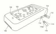
도 1은 본 발명의 예시적인 실시예를 도시하며, 베이스 형태의 전자 장치(100)(전자 장치[100]는 또한 베이스로도 알려져 있으며, 이들 용어는 본원에서 상호 교환 가능하게 사용됨)는 모바일 컴퓨터 장치, 예컨대 기계적 결합에 의해 디스플레이 스크린(103)을 구비한 스마트 폰(102)을 수용하며, 이에 의해 광학부에 직접 연결되는 한편 상호 전자 및/또는 데이터 통신을 하도록 구성된다. 베이스(100)와 스마트 폰(102)은 또한 광대역 네트워크 또는 인터넷과 같은 공공 네트워크 등의 통신 네트워크를 통해 서로 연결될 수 있다. 또한, 근거리 통신 및 기타의 전자 통신 포맷을 통한 링크 및 통신 모듈(254)(도 2)의 입출력(I/O) 포트를 통한 직접 링크가 제공될 수도 있다.1 shows an exemplary embodiment of the present invention, wherein an
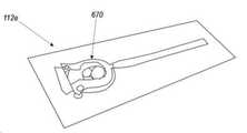
베이스(100)는 미세 유체 기술에 기반한 일회용 샘플 준비용 칩/카세트(112)(이 위에 분석용 혈액 샘플이 배치됨)를 수용하기 위한 제 1 포트(110), 및 바이오 센서 스트립(116)(전극[116b] 상의 작동 단부[116a]에서 혈액 샘플을 수용함)을 수용하기 위한 제 2 포트(114)를 포함한다. 이들 포트(110, 114)는 채널들과 연관되는데, 제 1 포트(110)의 경우 현미경 검사 또는 영상 또는 현미경 채널(본원에서는 "영상 채널", "현미경 채널" 및 "광/광학 채널"이라는 용어가 상호 교환적으로 사용됨)을 위한 입구 역할을 하며, 예컨대 말라리아의 경우 특정 기생충(말라리아)의 유형과 단계를 식별하도록 구성되는 한편, 온혈구 검사(CBC, Complete Blood Count)를 수행하도록 구성된다. 제 2 포트(114)의 경우 바이오 센서 스트립(116)의 전극(116b) 상의 혈액 샘플로부터 입수된 전기 화학적 신호를 분석하기 위한 신호 채널 또는 전기 화학 채널(본원에서는 "신호 채널" 및 "전기 화학 채널"이 상호 교환 가능하게 사용됨)로서 기능하며, 예컨대 말라리아 감염 환자의 경우, G6PD 결핍이 있는지 여부를 확인 후 이에 따라 적절하고 정확한 약물 투여 방법을 결정하도록 구성된다.The
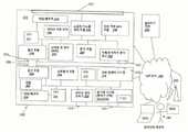
도 2는 베이스(100) 및 스마트 폰(102)의 블록도를 도시한다. 베이스(100)와 스마트 폰(102)은 서로 직접 연결된 것으로 도시되어 있으며, 이들은 LAN(Local Area Network) 및 인터넷, 셀룰러 네트워크 및 기타 통신 네트워크 등의 공용 네트워크를 포함하는 광역 네트워크(WAN)와 같은 하나 이상의 네트워크(200)에 링크되어 있다.2 shows a block diagram of the
양쪽 채널, 즉 제 1 포트(110)로부터 입수된 영상 채널 및 제 2 포트(114)로부터 입수된 신호 채널은 모두, 저장/메모리(204), 베이스용 전원(206) 및 통신 모듈(208)이 연결된 공통의 중앙 처리 장치(CPU)(202)를 사용하며, 통신 모듈(208)로부터는 USB(male type) 커넥터(209) 또는 기타 유사한 커넥터가 연장되도록 구성된다.Both channels, i.e., the video channel obtained from the
중앙 처리 장치(CPU)(202)는 CPU(202)에 의해 실행될 기계적 실행 명령을 저장하는 저장/메모리(204)와 전자적으로 데이터 통신하는 하나 이상의 프로세서로 구성됨으로써 양쪽 채널의 프로세스를 모두 수행하도록 구성된다. 전원(206)은 배터리 또는 플러그인 전원이다. 통신 모듈(208)은 베이스(100)와의 네트워크(예컨대, 인터넷) 연결 및 통신 기능을 제공하는 외에도, 베이스(100)와 스마트 폰(102) 사이의 전자 및 데이터 통신을 위한 직접 연결 기능을 제공하도록 구성된다.The central processing unit (CPU) 202 is configured to perform both channels of processes by being composed of one or more processors in electronic data communication with a storage/
영상 채널은 포트(110)를 포함하며, 포트(110)는 미세 유체 장치로도 알려진 미세 유체 칩(112)(도 1)을 수용한다. 미세 유체 칩(110)은 광 기계 시스템(212) 및 광학 릴레이 시스템(214)을 포함하는 광학부(308)(도 3)에 의해 가시화되며, 이미지가 전송되는 광학 모듈 렌즈(216)에서 종결된다. 광학부(308), 예컨대, 광 기계 시스템(212)은 샘플을 확대하는 한편, 이미지들을 포함하는 시각적 표현 능력을 증강시키도록 구성된다(미크론 단위의 고해상도로 구현 가능).The imaging channel includes a
미세 유체 칩(112)은 모세관 작용에 기초하여 작동하며, 수용된 혈액을 운반하고 착색함으로써 이들이 적절히 관찰되도록 구성된다. 제어기(212a)를 구비한 광 기계 시스템(212)은 현미경 관찰을 위해 광학 모듈 렌즈(216)에서 종결되는 광학 릴레이 시스템(214)에 의해 미세 유체 칩(112)을 스캐닝하도록 구성되는데, 즉 제어기(212a)에 의해 스캐닝 장치(304)(도 3) 상의 스탠드/드로어(302)의 이동에 의해 스캐닝이 가능하도록 구성된다. 또한, 광 기계 시스템(212)의 일부로서 광(LT)(217)이 제공되며, 이러한 광은 스위치, 버튼(도시되지 않음) 등을 통해 수동으로 조작될 수도 있거나 또는 제어기(212a)에 의해 자동으로 조작될 수도 있다. 광 기계 시스템(212) 및 광 릴레이 시스템(214)은 CPU(202), 저장/메모리 (204), 전원(206) 및 통신 모듈(208)과 직접 또는 간접적으로 전자 및/또는 데이터 통신을 하도록 구성된다.The
도 6a 내지 6g는 본 발명에 따른 다양한 실시예의 미세 유체 칩(112)(미세 유체 장치)(112a-112g)을 도시한다. 이들 미세 유체 칩(112a-112g)은 개시된 장치(100, 500, 500')의 포트(110) 내에 수용된다. 도 6a 내지 6g에 도시된 미세 유체 칩(112a-112g)은 예컨대, 혈액 및/또는 소변과 같은 기타 체액(액체)을 지지하기에 적합한 글라스(glass) 또는 중합체(polymer) 또는 둘 다로 구성되거나 또는 친수성 코팅을 갖거나 갖지 않는 기타 물질로 이루어진 기판(601, 664)을 포함하며, 이들은 또한 다른 성분들, 예컨대 현미경용 스테인(stain), 및 파단 가능한 캡슐로 제조된 분말 등의 다른 물질들(고체, 액체 또는 기체)을 포함할 수 있다. 다른 성분들과 혼합된 전술한 유체(액체) 및/또는 유체(액체)는 개시된 장치(100, 500, 500')에 의해 분석 및/또는 디스플레이된다.6A-6G show microfluidic chips 112 (microfluidic devices) 112a-112g of various embodiments in accordance with the present invention. These
도 6a에 도시된 미세 유체 칩(112a)은 예컨대, 혈액 및/또는 소변과 같은 기타 체액(액체)을 지지하기에 적합한 글라스 또는 중합체 또는 둘 다로 구성되거나 또는 친수성 코팅을 갖거나 갖지 않는 기타 물질로 이루어진 기판(601, 664)을 포함하며, 이들은 또한 다른 성분들, 예컨대 현미경용 스테인, 및 파단 가능한 캡슐로 제조된 분말 등의 다른 물질들(고체, 액체 또는 기체)을 포함할 수 있다. 기판(601)에는 혈액 유입구(602), 및 기판(601)의 일단부(601a)에서 블리스터(패킷)(604)로 둘러싸인 스테인이 제공된다. 사용이 필요할 때, 블리스터(604)에 가해지는 압력에 의해 터널 측면으로부터 블리스터(604)를 파열시키는 한편 미세 유체 터널(606)을 통해 스테인을 가압하도록 구성된다. 혈액 및/또는 희석된 혈액 및 스테인은 제 1 미세 유체 채널(606)을 거쳐 혈액과 스테인의 혼합 영역(610)으로 기능하는 구불 구불한 모양의 제 2 미세 유체 채널(608)로 이동한다. 결합된 혈액 및 스테인은 계속 이동하여 기판의 대향 단부(601b)에서 제 3 미세 유체 채널(612)을 거쳐 관찰 챔버(614)로 이동한다. 관찰 영역(614)은 기판(601) 상에서 장치(100, 500)의 광 기계 시스템(212)의 광학부(308)와 정렬되도록 구성된다.The
도 6b에 도시된 미세 유체 칩(112b)은 혈액 및 다른 성분들, 예컨대 현미경용 스테인, 세척 용액을 지지하기 위한 기판(601)을 포함한다. 기판(601) 상에는 혈액 유입구(622), 블리스터(패킷)(624)로 둘러싸인 스테인, 및 기판(601a)의 일단부에서 블리스터(패킷)(626)로 둘러싸인 세척 용액이 제공된다. 사용이 필요할 때, 혈액 유입구(622)로부터 유입된 혈액을 미세 유체 채널(628)을 거쳐 유동시킴으로써, 혈액 세포를 미세 유체 채널(628)의 벽에 부착시키도록 구성된다. 블리스터(624)에 가해지는 압력에 의해 블리스터(624)를 파열시킨 후, 스테인을 미세 유체 채널(628)을 거쳐 상기 부착된 혈액 세포 위로 유동시킴으로써, 스테인 및 세포를 기판(601) 상의 착색 및 관찰 영역(630)에 도달시킨다. 착색 및 관찰 영역(630)은 기판(601) 상에서 장치(100, 500)의 광 기계 시스템(212)의 광학부(308)와 정렬되도록 구성된다. 그럼 다음, 블리스터(626)에 대한 압력에 의해 블리스터(626)를 파열시킨 후, 세척 용액으로 하여금 미세 유체 채널(628)을 거쳐 유동시킴으로써 임의의 잔류 스테인을 제거하는 한편 혈액-스테인 혼합물을 희석시킨다.The microfluidic chip 112b shown in FIG. 6B includes a
도 6c에 도시된 미세 유체 칩(112c)은 혈액 및 다른 성분들, 예컨대 현미경용 스테인을 지지하기 위한 기판(601)을 포함한다. 기판(601)의 일단부(601a)에는 미세 유체 채널(644)의 단부에 배치된 혈액 유입구(642)가 제공되며, 기판(601)의 타단부(601b)에는 착색 및 관찰 챔버(646)가 제공된다. 착색 및 관찰 챔버(646)는 기판(601) 상에서 장치(100, 500, 500')의 광 기계 시스템(212)의 광학부(308)와 정렬되도록 구성된다. 건조 상태의 스테인이 미세 유체 채널(644)의 벽에 포함됨으로써, 혈액 또는 희석된 혈액(647)이 미세 유체 채널(644)을 거쳐 착색 및 관찰 영역으로 유동함에 따라, 혈액(647)이 스테인을 픽업하도록 구성된다. 이러한 미세 유체 칩(112)은 일반적으로 단일 적혈구의 관찰을 위해 사용된다. 혈액이 희석되지 않기 때문에, 미세 유체 채널의 직경은 약 10 마이크로미터 정도로 얕게 구성된다.The
도 6d에 도시된 미세 유체 칩(112d)은 혈액 및 다른 성분들을 지지하기 위한 기판(601)을 포함한다. 기판(601)은 그 일단부(601a)에서 샘플 유입구(652)를 지지하고, 이러한 유입구는 미세 유체 채널(654)과 연결되며, 그런 다음 기판(601)의 타단부(601b)에서 관찰 챔버(656)와 연결 및 종결된다. 스테인(657)과 혼합된 희석 또는 비희석 혈액 샘플이 샘플 입구(652)에 배치된 후, 스테인 샘플은 관찰 영역(656)으로 유동한다. 관찰 챔버(656)는 기판(601) 상에서 장치(100, 500, 500')의 광 기계 시스템(212)의 광학부(308)와 정렬되도록 구성된다.The
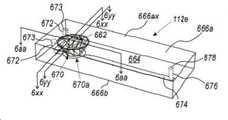
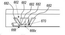
도 6ea, 6eb, 6ec, 6ed, 6ee, 6ef 및 6eg는 장치(100, 500, 500')를 위한 또 다른 미세 유체 칩(112e)을 도시한다. 혼합 챔버(662)는 제 1 측면(666a), 예컨대 상부 표면(666ax)의 상부(상단)에서 베이스(668)까지 기판(본체)(664) 내로 연장된다. 베이스(668)는 제 2 측면(666b), 예컨대 하부(하단)에서 메인 채널(670)에 의해 부분적으로 둘러싸여 있다. 베이스(668)는 혼합 챔버(662)의 연장부이며, 예컨대 과량의 혈액-스테인 혼합물의 수집을 위한 압력 균형 저장소로서 기능한다. 기저부(668x)는 메인 채널(670)에 의해 둘러싸여 있으며, 혈액-스테인의 혼합시 연통 용기로서 기능한다. 메인 채널(670)은 실질적으로 U 자형이며, 메인 C-자형 부분(670a)과 더불어 바깥쪽으로 연장되는 부분(670b)을 가지며, 이에 의해 채널 (670)의 개시부를 형성하고, 예컨대 혈액 및 기타 유체의 수용 영역으로서 기능한다. 제 1 측면(666a)과 제 2 측면(666b)은 예컨대 서로 대향하여 배치된다.Figures 6ea, 6eb, 6ec, 6ed, 6ee, 6ef and 6eg show another
입/출구 채널(672)은 개구(673)에서 종결되는 한편, 각각 메인 채널(670)의 각각의 연장부(670b)로부터 연장된다. 작동시, 혈액/유체는 개구(673)로부터 채널(672)을 거쳐 삽입되며, 이에 따라 모세관력에 의해 구동되는 메인 채널(670)에 혈액/유체가 충진되도록 구성된다.The inlet/
각각의 장치(100, 500, 500')의 광 기계 시스템의 광학부(308)와 정렬되도록 구성된 스캐닝 채널(674)은 메인 채널(670)로부터 기판 (664)을 거쳐 압력 출구 채널(676)로 연장된다. 스캐닝 채널(674)은 예컨대, 압력 출구 채널(676)에 대해 수직 또는 실질적으로 수직으로 배향된다. 압력 출구 채널(676)은 초기에 밀봉(폐쇄)되는 개구(678)에서 종결된다. 작동시 개구(678)가 천공되면, 예컨대 주변 압력에서 주변 환경으로 개방시키는 역할을 하는 공기 입/출구가 생성됨으로써, 혈액(또는 액체) 및/또는 혈액(또는 액체)/스테인 혼합물(이하에 후술되는 바와 같이, 파단 가능한 캡슐로부터 획득 가능한 다른 물질을 포함할 수 있음)이 스캐닝 채널(674)을 충진하도록 구성된다.A
혼합 챔버(662)는 안쪽, 즉 제 1 측면(666a)에서 제 2 측면(666b)으로 테이퍼진 잘린 원추형의 형태로 기판(664) 내로 연장되는데, 이들 모양은 예컨대 둥글거나, 원형 또는 실질적으로 원형이며, 안쪽으로 테이퍼진 다른 형태도 또한 허용된다. 혼합 챔버(662)의 벽(680)은 중첩식 플레이트(682) 또는 돌출부로 형성된다. 플레이트(682)는 파단 가능한 또는 분쇄 가능한 캡슐과 같은 부재가 혼합 챔버(662) 내에 배치될 때, 혼합을 위한 트랙션(traction)을 제공한다.The mixing
벽(680)은 기판(664) 내로 연장됨으로써, 플레이트(682)가 메인 채널(670)의 제 1 벽 또는 상부 벽(684)에서 종결되도록 구성된다. 메인 채널(670)은 또한, 베이스(668)와 연결되는 외벽(685)을 포함하고, 베이스(668)는 채널(670)의 제 3 벽 또는 하부 벽을 형성하는데, 이러한 제 3 벽(668)은 제 1 벽(684)과 대향하여 배치된다. 도 6ee 및 6ef에 도시된 바와 같이, 외벽(685)은 제 1 벽(684) 및 베이스(668)에 수직 또는 실질적으로 수직으로 배치됨으로써 메인 채널(670)이 일측면을 따라 개방되도록 구성된다. 이와 같이 3개의 벽(684; 제 1 벽 또는 상부 벽, 685; 제 2 벽 또는 외부 벽, 668; 제 3 벽 또는 하부 벽)으로 이루어진 구성에 의해, 메인 채널(670)로 하여금 모세관 작용 및/또는 표면 장력에 의해 혈액 및/또는 다른 액체를 보유할 수 있도록 구성된다. 유사하게, 스캐닝 채널(674)은 또한 모세관 작용에 의해 혈액/액체의 이동을 용이하게 하는 역할을 하도록 구성된다.The
기판(664)은 플라스틱 재료로 제조되며, 광학적으로 반투명하거나 또는 투명하다. 챔버 벽(680)을 형성하는 플레이트(682)는 예컨대 가요성 및 탄성을 갖는 엘라스토머 재료로 제조된다. 전술한 모든 재료들은 열 등에 의해 살균될 수 있다.The
도 6eg은 미세 유체 칩(112e)의 제 2 측면(666b)에 대한 사시도로서, 모세관 작용에 의해 메인 채널(670)이 혈액 및/또는 액체(스테인 및/또는 기타 물질을 포함할 수 있음)로 충진된 상태를 도시한다.6eg is a perspective view of the
도 6f는 기판(640)을 포함하는 미세 유체 칩(112f)의 또 다른 실시예를 도시한다. 이러한 미세 유체 칩(112f)의 구성은 도 6ea 내지 6eg의 칩(112e)과 유사하며, 해당 구조는 구체적으로 지시된 경우를 제외하고는 전술한 미세 유체 칩(112e)에 대해 설명된 것과 동일한 참조 부호 및 기능을 갖는다. 이러한 미세 유체 칩(112f)은 전술한 미세 유체 칩(112e)에 대해 기술된 바와 같이 2개의 혼합 챔버(662) 및 채널 구조를 포함하지만, 여기에 더해 유체 유입구(686)가 추가된다. 유체(액체) 유입구(686)는 기준 채널(682 및 688a)과 유체 연통하며, 이들은 각각의 혼합 챔버(662)의 메인 채널(670)로 이어진다. 스캐닝 채널(674)은 각각의 장치(100, 500, 500')의 광 기계 시스템의 광학부(308)와 정렬되도록 구성된다. 스캐닝 채널(674)은 전술한 미세 유체 칩(112e)에 대해 기술된 바와 같이, 압력 채널(도시되지 않음, 개구[678]에서 종결됨)에서 종결된다.6F shows another embodiment of a
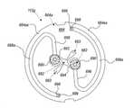
도 6g는 둥근 형태로 구성된 미세 유체 칩(112g)의 또 다른 실시예를 도시한다. 해당 구조는 구체적으로 지시된 경우를 제외하고는 전술한 미세 유체 칩(112e, 112f)에 대해 설명된 것과 동일한 참조 부호 및 기능을 갖는다. 미세 유체 칩(112g)은 기판(664)으로 형성되며, 이들은 외부 연장부를 갖는 U-자형이기 때문에 전술한 메인 채널(670)과 유사한 메인 채널(690) 위에 놓이는 2개의 혼합 챔버(662)를 갖도록 구성된다. 혈액/액체는 기준 채널(693)과 유체 연통하는 액체 유입구(692)에 수용되며, 액체 유입구는 각각의 혼합 챔버(662)의 메인 채널(690)과 차례로 유체 연통한다. 기준 채널이기도 한 테스트 채널(694)은 각각의 기준 채널(693)과 연통한다.6G shows another embodiment of a
메인 채널(690)은 스캐닝 채널(696)과 유체 연통하고, 혼합 챔버(662)로부터 연장된다. 그런 다음, 미세 유체 칩(112g) 및 기판(642)의 둥근 형상에 따라 라운드부(696a)을 구비한 스캐닝 채널(696)도 둥근 형상을 갖도록 구성된다. 스캐닝 채널(696)(라운드부[696a] 포함)은 각 장치의 광 기계 시스템의 광학부와 정렬되도록 구성된다. 압력 배출 채널(698)은 라운드부(696a)의 스캐닝 채널(696)로부터 연장된다. 압력 배출 채널(694)은 예컨대, 스캐닝 채널(696)에 수직 또는 실질적으로 수직으로 배향된다. 압력 배출 채널(698) 각각은 전술한 개구(678)와 같이, 개방될 때까지 밀봉되는 개구(699)에서 종결된다.The
다시 도 6ea 내지 6eg을 참조하여, 미세 유체 칩(112e)을 예시적으로 설명하면 다음과 같다. 후술한 미세 유체 칩들(112f, 112g)은 유사하게 작동하며, 전술한 미세 유체 칩(112e)의 동작에 대한 설명은 이들 후술한 미세 유체 칩들(112f, 112g)에도 적용 가능하다. 초기에, 혈액 또는 기타 액체(이하 예시적인 동작을 설명하도록 혈액을 지칭함)가 획득된 후, 메인 채널(670), 즉 미세 유체 칩(112f)의 유체 유입구(686) 및 미세 유체 칩(112g)의 유체 유입구(682)에 배치된다. 일단 메인 채널(670)에서, 혈액은 모세관 작용에 의해 이동함으로써 메인 채널(670)을 충진한다.Referring again to FIGS. 6ea to 6eg, the
파단 가능한 캡슐 또는 기타 물질이 혼합 챔버(662) 내에 배치된 후, 이들은 예컨대 혼합 챔버(662)에 가해지는 압력에 의해 분쇄된다. 캡슐화된 시약은 메인 채널(670) 내의 혈액과 혼합된다. 각각의 압력 배출 채널(676)의 개구(678)가 주변 압력과 동일하게 되도록 개방됨에 따라, 혼합 혈액/물질이 유동하여 스캐닝 채널(674)을 충진함으로써, 장치(100, 500, 500')의 광학부에 의한 분석을 관찰할 수 있도록 구성된다.After the breakable capsules or other materials are placed in the mixing
신호 채널은 포트(114)에서 시작하고, 바이오 센서 스트립 판독기(222)를 포함하는데, 상기 판독기는 예컨대 바이오 센서 스트립(116)의 작동 단부(116a)의 일회용 바이오 센서 전극(116b)으로부터 수신된 전기 응답 신호(샘플과 전극[116b] 사이의 전기 화학적 반응으로부터 발생된 전류, 아날로그 신호로서 전극[116b]/바이오 센서 스트립[116]으로부터 유입된 출력값)를 판독하는 한편, 질병의 존재, 상태, 측정값 등에 대한 전기 응답의 아날로그 신호, 전기 화학적 반응을 나타내는 아날로그 신호를 증폭시킨다. 판독기(222)로부터 입수된 아날로그 신호를 디지털 신호로 변환하는 아날로그-디지털 변환기(ADC)(224) 및 신호 분석 소프트웨어 모듈(226)이 제공되며, 이러한 분석 모듈은 디지털 신호를 분석하여 이러한 샘플에 G6PD 결핍이 있는지 여부를 결정하는 한편, 통신 모듈(208)과 통신하여 신호를 스마트 폰(102)에 전송함으로써 추가 분석을 하도록 구성된다.The signal channel starts at
대안적으로, 신호 채널은 혈당 레벨의 검출을 위해 사용될 수 있다. 바이오 센서 스트립 판독기(222)는 일회용 바이오 센서 전극(예컨대, 바이오 센서 스트립[116])의 전기 응답 신호로부터 생성된 아날로그 신호(들)를 증폭하도록 추가로 구성된다. 아날로그 신호는 혈당 레벨에 해당한다. 아날로그-디지털 변환기(ADC) (224)는 판독기(222)로부터 입수된 아날로그 신호를 디지털 신호로 변환하고, 신호 분석 모듈(226)은 ADC(224)로부터 수신된 디지털 신호를 분석함으로써 혈액 샘플에서 혈당 레벨을 결정한다. 이러한 혈당 레벨은 혈당에 대한 표준 측정 방법에 따라 통신 모듈(208)에 출력되며, 추가 분석을 위해 신호를 스마트 폰(102)에 전송함으로써 스마트 폰(102) 또는 독립형 장치(500, 500')(도 5a 및 5b)의 디스플레이 스크린에 표시되도록 구성된다.Alternatively, a signal channel can be used for detection of blood glucose levels. The biosensor strip reader 222 is further configured to amplify the analog signal(s) generated from the electrical response signal of the disposable biosensor electrode (eg, biosensor strip 116). The analog signal corresponds to the blood sugar level. The analog-to-digital converter (ADC) 224 converts the analog signal obtained from the reader 222 into a digital signal, and the
대안적으로, 바이오 센서 스트립(116)은 전기적 응답을 생성하는 한편, 판독 가능한 신호로 변환 가능한 전극을 포함하는 다수의 바이오 센서 전극(116b)을 포함함으로써, 예컨대 G6PD 결핍 및 혈당 레벨을 동시에 일괄 검출하도록 구성된다.Alternatively, the
다른 대안예에서, 신호 채널은 다른 질병, 병원체 또는 바이오마커(biomarker)와 같은 다른 조건에도 사용될 수 있다. 바이오 센서 스트립 판독기(222)는 추가로 일회용 바이오 센서 스트립 상의 전극으로부터 입수된 전기 응답 신호(전기 화학적 응답 신호)에 의해 생성된 아날로그 신호를 증폭 또는 수정하도록 구성된다. 바이오 센서 스트립의 전극은 조건에 따라 샘플과 접촉시 전기 화학적 반응을 일으키고, 전기 화학적 반응은 이러한 조건에 대한 전류 및 상응하는 아날로그 신호를 생성하는데, 바이오 센서 스트립 판독기는 이러한 조건의 전기 화학적 사인(또는 전기 화학적 응답 신호)을 인식하고 전기 화학적 응답 신호에 의해 야기된 최종 아날로그 신호를 증폭하도록 구성된다. 아날로그-디지털 변환기(ADC)(224)는 판독기(222)로부터 입수된 아날로그 신호를 디지털 신호로 변환하고, 신호 분석 모듈(226)(예컨대, 존재의 여부에 대한 조건을 결정하도록 프로그램됨)은 ADC(224)로부터 수신된 디지털 신호를 분석함으로써 상기 조건을 결정한다. 이러한 조건에 대한 결정은 통신 모듈(208)에 출력되며, 이러한 결정에 대한 신호를 스마트 폰(102)에 전송함으로써 스마트 폰(102) 또는 독립형 장치(500, 500')(도 5a 및 5b)의 디스플레이 스크린에 표시되도록 구성된다.In other alternatives, the signal channels can also be used for other conditions such as other diseases, pathogens or biomarkers. The biosensor strip reader 222 is further configured to amplify or modify an analog signal generated by an electrical response signal (electrochemical response signal) obtained from an electrode on the disposable biosensor strip. Depending on the conditions, the electrodes of the biosensor strip cause an electrochemical reaction when in contact with the sample, and the electrochemical reaction generates a current and a corresponding analog signal for these conditions. Electrochemical response signal) and amplify the final analog signal caused by the electrochemical response signal. An analog-to-digital converter (ADC) 224 converts the analog signal obtained from the reader 222 into a digital signal, and the signal analysis module 226 (e.g., programmed to determine a condition for presence) is an ADC The condition is determined by analyzing the digital signal received from 224. The determination of these conditions is output to the
장치, 예컨대 스마트 폰(102)은 현미경 채널 및 신호 채널 모두의 일부분을 포함한다. 스마트 폰(102)은 스토리지/메모리(244)가 연결된 공통 중앙 처리 장치(CPU)(242), 스마트 폰(102)의 스크린 디스플레이(103)를 제어하기 위한 로직을 포함하는 스크린 디스플레이 모듈(246), GPS(Global Positioning System) 모듈(248), RAM(Random Access Memory)과 같은 데이터 스토리지(250), 내부 측정 장치(IMU)를 형성하기 위한 자이로미터, 온도계, 자력계 및 가속도계와 같은 센서(252), 및 전자 및/또는 데이터 통신에서 볼록형 커넥터(209)를 수용하기 위한 오목형 USB(범용 직렬 버스) 커넥터(255) 또는 기타 유사한 커넥터를 포함하는 통신 모듈(254)을 포함한다. GPS 또는 위치 모듈(248)은 말라리아와 같은 질병에 대한 실시간 매핑, 역학적 제어 및 학습에 사용될 질병의 매핑에 의해, 스마트 폰(102)의 통합 GPS 유닛 또는 독립형 GPS 장치 또는 위치 모듈(548)의 일부인 통합 GPS 유닛에 기초하여 실시간 위치에 대한 표시를 디스플레이 상에 제공하는 기능을 한다.The device, such as a
또한, 카메라 이미지를 스크린 디스플레이 모듈(246)을 통해 스크린 디스플레이(103) 상에 디스플레이하기 위한 신호로 변환하기 위한 카메라/이미지 센서 유닛(260), 및 예컨대 말라리아 기생충의 유형(예컨대, Plasmodium. falciparum, P. vivax, P. malaria. P. ovale, P. Knowlesi 및 해당 질병 단계)을 검출하기 위한 이미지 분석 모듈(264)이 제공됨으로써, 특정 혈액 샘플과 관련된 데이터의 태깅(tagging)을 수행하도록 구성된다. 대안적으로, 분석 모듈(264)은 완전한 혈구수, 다중 기생충(예컨대 회귀열, 사상충), 결핵 가래 현미경 검사, 소변 분석 검사, 자궁 경부 세포진 검사, 수의학 질병 및 상태를 포함하는 다른 질병 및 그의 상태를 분석 및 검출하도록 프로그래밍될 수 있다Further, a camera/image sensor unit 260 for converting the camera image into a signal for display on the
베이스(100)와 스마트 폰(102)은 모두 네트워크(200)를 통해 클라우드 서버 (270)에 연결되며, 말라리아 기생충에 대한 각 프레임 샘플이 데이터 저장 장치(250)로 직접 전송되거나 또는 데이터 저장 장치(250)로부터 전송됨으로써 분석 모듈(264)의 기계적 학습을 누적적으로 업데이트하도록 구성된다. 각각의 새로운 이미지 프레임 샘플과 함께, 클라우드 서버(270)는 업데이트된 기계적 학습 결과를 분석 모듈(264)에 전송함으로써 말라리아 기생충에 대한 검출 능력을 제고시키도록 구성된다. 이러한 내용은 온라인 또는 오프라인으로 자동적으로 수행되거나 또는 요청에 따라 가능한 경우 연결 및 수행되도록 구성된다. 클라우드 서버(270)는 또한 예컨대, 기생충 및 G6PD 둘 다에 대한 각각의 테스트 기록, 시간, 위치, 환자 관련 진단 정보 및 증상(기계[102] 및 선택적으로 원격 의료 제공자[280]로부터 입수된 진단 결과 등), 화면 표시 및 기타 정보를 저장하는 한편, 말라리아 관련 케이스들에 대해 실시간으로 매핑할 수 있도록 구성된다. 베이스(100), 스마트 폰(102), 클라우드 서버(270), 원격 의료 제공자의 컴퓨터(280a, 280b) 사이의 네트워크(200)를 통한 모든 데이터 저장 및 데이터 전송은 HIPAA(Health Insurance Portability and Accountability Act) 규격에 따른다.Both the
베이스(100) 및 스마트 폰(102)은 또한 네트워크(들)(200)를 통해 셀룰러 타워(282)를 거쳐 원격 의료 제공자(280)의 예컨대, 컴퓨터(280a) 또는 스마트 폰(280b)에 링크된다. 원격 의료 제공자(280)는 진단 내용을 제공할 수 있으며, 이러한 정보를 클라우드 서버(270)로 보내거나 스마트 폰(102)의 분석 모듈(246)로 재전송한다.
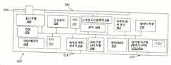
도 3은 영상 채널 및 신호 채널의 개략도를 도시한다. 이들 채널은 베이스(100)와 스마트 폰(102) 모두에 부분적으로 존재한다.3 shows a schematic diagram of a video channel and a signal channel. These channels are partially present in both the
현미경 채널은 미세 유체 칩(112)을 수용하는 포트(110)에서 시작된다. 이러한 칩(112)은 모세 혈관 작용을 이용하여 혈액 샘플을 분배하는 한편 이를 적절하게 착색한 다음 혈액 세포를 분리시킨다. 광 기계 시스템(212)은 미세 유체 칩(112)을 유지하는 스탠드 또는 드로어(302)를 포함한다. 스탠드/드로어(302)는 제어기(212a)에 의해 제어되는 스캐닝 장치(304) 상에 배치되며, 이에 의해 칩(112)으로 하여금 다양한 위치(이중 타원 화살표[306]로 표시됨)로 조작 가능하게 함으로써 렌즈(216) 등에서 종결되는 광학 릴레이 시스템(214)의 광학부(308)에 의한 관찰이 가능하도록 구성된다. 스탠드/드로어(302) 및 스캐닝 장치(304)에 의해 형성된 스크린 장치는 예컨대 드로어(302)의 움직임에 기초하여, 또는 예컨대 광학 릴레이 시스템(214)의 일부인 거울 또는 프리즘을 사용하는 광학적 설계에 기초하여 광학적으로 스크리닝될 수 있다.The microscope channel starts at the
광학 릴레이 시스템(214)의 광학부(308)(전술한 광[217]과 유사한 광[309]을 포함)로부터 입수된 이미지는 스마트 폰(102)의 카메라(260)의 렌즈(320) 또는 독립형 장치의 경우 독립형 이미지 센서로 전송된다. 카메라(260)로부터 입수된 이미지는 이미지 센서 유닛(262)에 의해 신호로 변환되며, 이러한 출력 신호는 분석 모듈(264)에 입력된다. 또한, 출력 신호가 분석 모듈(264)로부터 스크린 디스플레이 모듈(246)로 이동함에 따라, 혈액 샘플을 디스플레이 스크린(103) 상에 디스플레이하도록 구성된다.The image obtained from the optics 308 of the optical relay system 214 (including the light [309] similar to the light [217] described above) is a
이미지 분석, 기계적 학습 및 인공 지능(AI)을 포함하는 프로세스에 의해 훈련된 분석 모듈(264)은 질병의 검출 또는 그의 상태를 결정하는 한편 검출된 질병 또는 그의 상태에 대한 진단 및/또는 치료용 프로토콜을 제공한다. 또한, CPU(202)는 검출된 질병 또는 그의 상태에 대한 진단 및/또는 치료용 프로토콜을 제공하는 기능을 한다. 이와 같은 질병 및/또는 그의 상태의 검출 및/또는 진단은 상이한 단계 및 유형에서 예컨대, 기생충의 형태학적 "바이오 마커(biomarker)" 분석에 기초하여 수행된다. 제어기(212a)에 의해 실행되는 알고리즘은 이미지 처리 능력(소프트웨어 및/또는 하드웨어), 분할 기능(소프트웨어 및/또는 하드웨어), 필터 및 RevDx 시스템으로부터 공지되고 수집된 데이터와의 특정 형태 비교를 포함한다. 결과 진단 데이터는 데이터 저장 유닛(250) 및/또는 클라우드 서버(270)에 저장된다. 또한, 이들은 원격 진료 제공자(280)에게도 전송되어 확인을 거친다.
신호 채널은 포트(114)에서 시작된다. 바이오 센서 스트립(116) 상의 혈액 샘플이 포트(114) 내에 배치되면, 전기 화학적 반응으로부터 유도된 전기 응답 신호(전기 화학적 응답 신호)에 의해 관련된 아날로그 신호를 생성한다. 이러한 아날로그 신호는 바이오 센서 판독기(222)에 의해 판독되는 한편, 증폭된다. 바이오 센서 판독기(222)는 아날로그-디지털 변환기(ADC)(224)에 의해 디지털 신호로 변환되는 아날로그 신호를 증폭하는 한편 일부 경우에는 필터링하도록 구성된다. 디지털 신호(들)의 ADC(224) 출력값은 신호 분석 모듈(226)로 입력되며, 이에 따라 예컨대 G6PD 결핍에 대한 디지털 신호 입력값을 분석한다. 샘플로부터 입수된 G6PD의 존재 여부에 관한 데이터는 신호 분석 모듈(226)에 의해 통신 모듈(208)로 전송된 다음 스마트 폰(112)의 통신 모듈(254)로 전송된다. 그런 다음 스마트 폰(112)의 통신 모듈(254)로부터 데이터가 분석 모듈(264)로 전송됨으로써 공지된 치료 절차에 기초하여 권장 의약품 및 치료 방법이 분석된다. 분석 모듈(264)은 스크린 디스플레이 모듈(246)에 신호를 송부하여 G6PD 결핍, 말라리아 기생충의 종류, 해당 종, 밀도, 단계 및 기타 인자가 존재하는지 여부 등을 나타내는 그래픽을 디스플레이 스크린(103) 상에 디스플레이하도록 구성된다.The signal channel starts at
대안적으로, 신호 채널이 상술한 바와 같이 혈당 판독 결과를 제공하도록 구성될 경우, 이러한 혈당 판독 결과는 G6PD 출력값 또는 그에 따른 별도의 출력값으로 획득될 수 있으며, 바이오 센서 스트립(116) 상의 전극(들)(116b)에 따라 달라진다. 예컨대, 포도당 레벨과 결합된 G6DP 결과물이 CPU(202)에 의해 분석됨으로써 예컨대, 도 7에 도시된 바와 같은 치료용 프로토콜을 결정하도록 구성된다. 치료용 프로토콜 및 질병의 존재 여부 또는 그 상태는 개시된 장치(100, 500, 500')의 CPU(202)에 의해 지시되는 바와 같이, 디스플레이 스크린, 스마트 폰(103) 또는 독립형 장치(500, 500') 상에 사용자 인터페이스(UI) 형태로 디스플레이된다.Alternatively, when the signal channel is configured to provide a blood glucose reading result as described above, this blood glucose reading result may be obtained as a G6PD output value or a separate output value accordingly, and the electrode(s) on the biosensor strip 116 ) Depends on (116b). For example, the G6DP output associated with the glucose level is analyzed by the
말라리아가 탐지된 경우, 말라리아 치료용 프로토콜에 대한 궁극적인 결정은 현미경 채널과 신호 채널 모두의 분석을 기반으로 수행되도록 구성된다. 이러한 분석은 예컨대 CPU(202)에 의해 실행되는 알고리즘에 의해 몇 분 내에 현장에서 자동으로 수행되며, 일부 불확실한 경우에는 데이터가 인터넷을 거쳐 원격 의료 제공자(280)로 전송됨으로써 네트워크(200)를 통해 원격으로 분석될 수도 있다.When malaria is detected, the ultimate decision on a protocol for treatment of malaria is configured to be made based on analysis of both the microscopic and signal channels. Such an analysis is automatically performed in the field within a few minutes by, for example, an algorithm executed by the
유사하게, 신호 채널은 G6PD 출력, 혈당 또는 소변 검사를 포함하여 혈액으로부터 질병의 존재 여부 및 그 상태에 대한 또 다른 판독 결과를 제공하도록 구성된다. 전술한 것 중 하나 이상이 CPU(202)에 프로그래밍된 바와 같이 함께 분석됨으로써 처리용 프로토콜을 결정하도록 구성된다.Similarly, the signal channel is configured to provide another reading of the condition and the presence of a disease from the blood, including a G6PD output, blood glucose or urine test. One or more of the foregoing are analyzed together as programmed into
이제 도 4a 및 4b를 참조하면, 본 발명의 실시예에 따른 컴퓨터 구현식 프로세스를 상세히 설명하는 흐름도를 도시한다. 도 1 내지 3에 도시된 부재들에 부여된 것과 동일한 참조부호가 부여된다. 도 4a 및 4b에 개시된 프로세스 및 서브 프로세스는 본 발명의 시스템에 의해 수행되는 컴퓨터화된 프로세스이며, 이들은 예컨대 수동, 자동 또는 이들의 조합으로 수행되는 한편, 실시간으로 수행되도록 구성된다.Referring now to Figures 4A and 4B, a flow chart is shown detailing a computer-implemented process in accordance with an embodiment of the present invention. The same reference numerals as those assigned to the members shown in Figs. 1 to 3 are given. The processes and sub-processes disclosed in Figs. 4A and 4B are computerized processes performed by the system of the present invention, and they are configured to be performed in real time, while being performed manually, automatically, or a combination thereof, for example.
도 4a는 본 발명의 현미경 채널에 대한 예시적인 현미경 검사 프로세스의 흐름도이다. 가장 먼저 402 블록에서, 혈액 샘플이 획득된 후 이들은 전술한 미세 유체 칩(112) 상에 배치되며, 이러한 미세 유체 칩(112)은 포트(110)를 통해 베이스(100)에 배치됨으로써 혈액이 착색된다. 404 블록에서, 광학 릴레이 시스템(광 릴레이)(214)을 거쳐, 미세 유체 칩에서 착색된 혈액 샘플의 현미경 이미지가 스마트 폰의 카메라(260) 또는 독립형 장치(102)에 도달한다. 406 블록에서, 카메라/이미지 센서 유닛(260)의 이미지는 디지털 데이터, 예컨대 디지털 신호로 변환된다. 408 블록에서, 디지털 데이터는 기계적 학습 및 인공 지능(AI)의 사용에 의해 소프트웨어 분석 모듈(264)에 의해 분석된다. 420 블록에서, 분석 모듈(264)은 진단 결과를 보고한다. 또한 420 블록에서, 혈액 샘플의 이미지가 스크린 디스플레이 모듈(246)을 거쳐 스크린 디스플레이(103) 상에 디스플레이된다. 프로세스는 408 블록으로부터 470 블록으로 이동하여 종결될 수 있다.4A is a flow diagram of an exemplary microscopy process for the microscope channel of the present invention. First in block 402, after blood samples are obtained, they are placed on the
프로세스가 420 블록으로부터 430 블록으로 이동할 경우, 시각적 이미지를 포함하는 혈액 샘플에 대한 데이터가 분석 모듈(264)에 의해 선택적으로 태깅될 수 있다.When the process moves from block 420 to block 430, data for a blood sample including a visual image may be selectively tagged by the
프로세스는 430 블록으로부터, 440 시리즈 블럭, 450 시리즈 블럭 및 460 시리즈 블록으로 정의된 3개의 선택적인 경로 중 하나 이상으로 이동될 수 있다.The process may travel from block 430 to one or more of three optional paths defined as 440 series blocks, 450 series blocks, and 460 series blocks.
프로세스가 430 블록에서 440 블록으로 이동할 경우, 태깅된 샘플 데이터는 예컨대 데이터 저장 장치(250)에 저장될 수 있다. 그런 다음, 태깅된 데이터는 저장 장치로부터 클라우드 서버(270)와 같은 클라우드 서버로 전송되거나(440 블럭), 또는 클라우드 서버(270)로 직접 전송될 수도 있다(430 블록에서 442 블록으로). 442 블록에서, 이미지에 대한 데이터 및 진단 결과를 수반하는 기계적 학습, 인공 지능(AI)을 클라우드 서버(270)에서 업데이트한다. 프로세스가 444 블록으로 이동할 경우, 분석 모듈(264)은 이러한 새로운 데이터로 업데이트된다. 그 후 프로세스는 470 블록으로 이동하여 종결된다.When the process moves from block 430 to block 440, the tagged sample data may be stored, for example, in the data storage device 250. Then, the tagged data may be transmitted from the storage device to a cloud server such as the cloud server 270 (block 440), or may be directly transmitted to the cloud server 270 (block 430 to block 442). In block 442, machine learning, artificial intelligence (AI) accompanying the data and diagnostic results for the image is updated in the
프로세스가 430 블록에서 450 블록으로 이동할 경우, 태깅된 샘플 데이터 또는 저장된 태킹 샘플 데이터(440 블록)는 예컨대 네트워크(200)를 통해 원격 의료 전문가(280)의 컴퓨터(280a) 또는 스마트 폰, 태블릿 컴퓨터, 랩톱 컴퓨터(280b) 등으로 전송될 수 있다. 452 블럭에서, 예컨대 스마트 폰(102)에서 원격 의료 제공자(280)로부터 진단 결과를 수령한 다음, 470 블럭으로 이동하여 또는 클라우드 서버(270)에서 프로세스가 종결된다. 일단 클라우드 서버(270)에서 수신되면, 프로세스는 444 블록으로 이동하여 분석 모듈(264)을 이러한 새로운 데이터로 업데이트하거나, 또는 아래에 상세히 설명되는 460 블록으로 프로세스가 이동할 수도 있다. 프로세스는 444 블록에서 470 블록으로 이동하여 종결된다.When the process moves from block 430 to block 450, the tagged sample data or stored tagging sample data (block 440) is, for example, via the network 200, the
430 블록 또는 452 블록으로부터 도달된 460 블록에서, 샘플은 GPS 태그 및 타임 스탬프에 기초하여 예컨대, 클라우드 서버(270)에 의해 선택적으로 매핑될 수 있다. 프로세스는 선택적 프로세스인 462 블럭으로 이동할 수 있으며, 여기서 클라우드 서버(270)는 모든 테스트 결과에 대한 맵을 제공하도록 구성된다. 그런 다음 프로세스는 470 블록으로 이동하여 종결된다. 프로세스는 또한, 460 블록에서 470 블록으로 이동하여 종결될 수도 있다.At block 430 or block 460 reached from block 452, the samples may be selectively mapped by, for example,
도 4b는 본 발명의 신호 채널에 대한 예시적인 신호 처리 프로세스의 흐름도이다. 먼저 412 블럭에서, 혈액 샘플이 획득된 후 이들은 전술한 바이오 센서 스트립(116)과 같은 바이오 센서 스트립 상에 배치된다. 402 블럭에서, 바이오 센서 스트립(116)은 포트(114)를 거쳐 베이스(100)에 배치된다. 414 블럭에서, 혈액 샘플은 전기 화학적 반응을 일으키며, 이에 의해 전기 응답 신호를 바이오 센서 판독기(222)에 의해 판독되는 아날로그 신호(들)로 출력한다. 416 블럭에서, 이와 같이 예컨대 바이오 센서 판독기(222)에 의해 증폭된 아날로그 신호 출력값은 아날로그-디지털 변환기(ADC)(224)로 입력되며, 이에 의해 아날로그 신호를 디지털 신호로 변환하도록 구성된다. 418 블록에서, 디지털 신호는 신호 분석 모듈(226)에 입력되며, 여기서 신호가 분석된다. 그런 다음 420' 블럭에서, 신호가 분석 모듈(264)로 전송됨으로써 진단 결과를 보고한다. 또한, 420' 블럭에서, G6PD 결함의 상태를 나타내는 그래픽 및 절대 수치가 스크린 디스플레이 모듈(246)을 통해 스크린 디스플레이(103) 상에 표시된다. 프로세스는 418 블럭에서 470 블록으로 이동하여 종결된다.4B is a flow diagram of an exemplary signal processing process for a signal channel of the present invention. First at block 412, after blood samples are obtained, they are placed on a biosensor strip, such as the
프로세스는 420' 블럭으로부터 430, 440, 442, 444, 450, 452, 460, 462 블럭과 같은 선택적 프로세스로 이동한 다음 전술한 바와 같이 470 블럭에서 종결될 수 있다.The process may move from block 420' to an optional process such as blocks 430, 440, 442, 444, 450, 452, 460, 462 and then terminate at block 470, as described above.
도 5a 및 5b는 현미경 채널 및 신호 채널을 통해 개시된 프로세스를 수행하기 위한 대안적인 형태의 모바일 컴퓨팅 장치(500, 500')를 도시한다. 본 장치들(500, 500')은 도 2의 장치(100)와 동일하거나 유사한 구성요소들을 포함하고 동일한 참조 부호를 갖는데, 이들에 대한 설명은 전술한 것에 따른다. 스크린 디스플레이 모듈(546)(장치[500]의 스크린 디스플레이[503], 예컨대 터치 스크린을 제어함), 위치 기반 GPS 모듈(548), 데이터 저장 장치(550), 센서(IMU)(552), 이미지 센서 유닛(562) 및 분석 모듈(564)을 포함하는 구성요소들은 도 2의 스마트 폰(102) 상의 해당 구성 요소들과 동일하거나 유사하지만, 참조부호가 도 2와 같이 200번 단위가 아니고 500번 단위로 표기되는 점이 상이하다. 분석 모듈(564)은 이미지 식별, 인공 지능 등에 의해 스캔된 샘플 또는 측정값(예컨대, 혈당 레벨 및 완전한 혈구 수)을 분석함으로써 질병의 존재 여부 및/또는 그 상태(예컨대, 말라리아 기생충 진단)를 결정하도록 구성된다. 광학 릴레이 시스템(214)은 선택적인 사항으로, 렌즈(216) 및 광학 릴레이 시스템(214)이 필요하지 않은 경우에는 장치(500)(도 5a)가 독립형 장치로서 작동하도록 구성되며, 반대로 렌즈(216) 및 광학 릴레이 시스템(214)이 필요한 경우에는 장치가 스마트 폰 또는 다른 장치와 함께 작동하도록 구성된다. 도 5b의 장치(500')는 렌즈(216) 및 광학 릴레이 시스템(214)이 결여되어 있으므로, 따라서 독립형 장치로서 독점적으로 작동한다.5A and 5B illustrate an alternative form of
도 5c는 스크린 샷(580)을 나타내는 스크린 디스플레이(503)를 포함하는 독립형 유닛으로서의 장치(500')를 도시한다. 본 장치(500')는 휴대용이므로 착탈식 배터리 옵션뿐만 아니라 외부 전원 공급 및 태양 에너지로부터의 재충전 옵션도 제공한다.5C shows the
도 7은 예컨대, 치료 결정 지원용 장치(100, 500 및 500')(예컨대 치료 방법 권고, 치료 프로토콜 등을 제공)의 CPU(202)에 프로그래밍되고 그에 의해 수행되는 의사 결정의 흐름에 대한 프로세스를 도시한다. 치료 방법 권고 및 치료 프로토콜은 예컨대, 후술되는 도 8a 내지 8d에 도시된 스크린 디스플레이(스크린 샷)과 같은 독립형 장치(500')의 스크린 디스플레이(503) 상에 유저 인터페이스(UI)로서 표시된다.FIG. 7 shows a process for the flow of decision-making programmed in and performed by the
제1단계의 프로세스에서 말라리아 임상 테스트를 수행하여, 열대열 말라리아(Falciparum malaria)가 검출된 경우를 가정한다(702 블럭). 혈당 검사를 수행하여 저혈당 여부를 확인한다(704 블럭). 예일 경우, 아르테미시닌 병용 요법(ACT, artemisinin combination therapy) 치료가 제안된다(706 블럭). 추가 전염의 방지를 위해 프라마퀸(primaquine)이 사용될 경우, 본원에 개시된 장치(100, 500, 500')를 통한 G6PD 결핍 테스트가 치료 전에 사용될 수 있다(708 블럭).It is assumed that a malaria clinical test is performed in the process of the first step, and a case where Falciparum malaria is detected (block 702). A blood sugar test is performed to determine whether there is hypoglycemia (block 704). In the case of yes, artemisinin combination therapy (ACT) treatment is proposed (block 706). If primaquine is used to prevent further transmission, a G6PD deficiency test via the
제2단계의 프로세스에서 말라리아 임상 테스트를 수행하여, 비열대열 말라리아 또는 혼합 감염 사례가 검출된 경우를 가정한다(712 블럭). 본원에 개시된 장치(100, 500, 500')를 통한 ACT 또는 클로로퀸뿐만 아니라 G6PD 테스트가 제안된다(714 블럭). G6PD가 음성이면, 프리마퀸 처리가 제안된다(716 블럭).It is assumed that a malaria clinical test is performed in the second stage of the process and a case of non-tropical malaria or mixed infection is detected (block 712). G6PD testing as well as ACT or chloroquine via the
제3단계의 프로세스에서 말라리아 임상 테스트를 수행하여, 열대열 말라리아 및 비열대열 말라리아에 대해 음성 판정이 나왔을지라도 환자에게 높은 임상적 의혹이 드는 경우, 전술한 바와 같은 본원에 개시된 장치(100, 500, 500')에 의한 테스트가 수행되도록 제안될 수 있다(722 블럭).In the case of performing a malaria clinical test in the third stage of the process, and the patient has high clinical suspicion even though negative tests for tropical and non-tropical malaria, the devices disclosed herein (100, 500, 500 as described above) ') may be proposed to be performed (block 722).
도 8a는 말라리아 검사의 결과를 도시하는 한편 치료 프로토콜을 제안하는 스크린 샷(580a)을 포함하는 장치(500')를 도시한다. 도 8b는 말라리아 테스트의 결과를 도시하는 한편 CPU(202) 또는 클라우드 서버(270)로부터 제공될 수 있는 의약품 관련 정보를 제공하는 스크린 샷(580b)을 포함하는 장치(500')를 도시한다. 도 8c는 백혈구 수를 상세히 기술하는 스크린 샷(580c)을 포함하는 장치(500')를 도시한다. 도 8d는 적혈구 수를 상세히 기술하는 스크린 샷(580d)을 포함하는 장치(500')를 도시한다.8A shows the device 500' including a
상기 개시된 장치들 및 방법들은 말라리아와 같은 질병과 관련이 있지만, 이들 장치는 또한 백/적혈구를 인식 및 분석하도록 프로그램된 다양한 모듈과 함께 백/적혈구 수 및 백혈구 분화와 같은 기타 질병 상태 및 혈구 수를 진단하는데에도 적합하게 사용될 수 있다.Although the devices and methods disclosed above are related to diseases such as malaria, these devices also monitor blood cell counts and other disease states such as white/erythrocyte counts and leukocyte differentiation with various modules programmed to recognize and analyze white/erythrocytes. It can be suitably used for diagnosis.
본 발명의 실시예들의 수행 방법 및/또는 시스템의 구현은 선택된 작업들을 수동, 자동 또는 이들의 조합으로 수행 또는 완료하는 것을 포함할 수 있다. 더욱이, 본 발명의 실시예들의 수행 방법 및/또는 시스템을 위한 실제 기기 및 장비에 따르면, 선택된 여러 작업들은 운영 체제를 사용하는 하드웨어, 소프트웨어 또는 펌웨어 또는 이들의 조합에 의해 구현될 수 있다.Implementation of a method and/or system for performing embodiments of the present invention may include performing or completing selected tasks manually, automatically, or a combination thereof. Moreover, according to the actual device and equipment for the method and/or system for performing the embodiments of the present invention, several selected tasks may be implemented by hardware, software or firmware using an operating system, or a combination thereof.
예컨대, 본 발명의 실시예들에 따라 선택된 작업들을 수행하기 위한 하드웨어는 칩 또는 회로로서 구현될 수 있다. 소프트웨어의 경우, 본 발명의 실시예들에 따라 선택된 작업들은 임의의 적절한 운영 시스템을 사용하는 컴퓨터에 의해 실행되는 다수의 소프트웨어 명령으로서 구현될 수 있다. 본 발명의 예시적인 실시예에서, 본원에 기술된 방법 및/또는 시스템의 예시적인 실시예에 따른 하나 이상의 작업은 다수의 명령을 실행하기 위한 컴퓨팅 플랫폼(computing platform)과 같은 데이터 프로세서(data processor)에 의해 수행된다. 선택적으로, 데이터 프로세서는 명령 및/또는 데이터를 저장하기 위한 휘발성 메모리, 및/또는 예컨대 명령 및/또는 데이터를 저장하기 위한 자기식 하드 디스크 및/또는 제거 가능식 매체와 같은 비일시적 저장 매체와 같은 비휘발성 저장 장치를 포함한다. 선택적으로, 네트워크 연결도 제공된다. 디스플레이, 및/또는 키보드 및 마우스 또는 프린터와 같은 사용자 입력 장치도 선택적으로 제공된다.For example, hardware for performing selected tasks according to embodiments of the present invention may be implemented as a chip or a circuit. In the case of software, tasks selected according to embodiments of the present invention may be implemented as a number of software instructions executed by a computer using any suitable operating system. In an exemplary embodiment of the present invention, one or more tasks according to exemplary embodiments of the methods and/or systems described herein may be performed by a data processor such as a computing platform for executing multiple instructions. Carried out by Optionally, the data processor is a volatile memory for storing instructions and/or data, and/or a non-transitory storage medium such as a magnetic hard disk and/or a removable medium for storing instructions and/or data. Includes non-volatile storage devices. Optionally, a network connection is also provided. A display and/or a keyboard and a user input device such as a mouse or printer are also optionally provided.
예컨대, 하나 이상의 비일시적 컴퓨터 판독 가능(저장) 매체(들)에 대한 임의의 조합이 본 발명의 상기 열거된 실시예들에 따라 이용될 수 있다. 비일시적 컴퓨터 판독 가능(저장) 매체는 컴퓨터 판독 가능 신호 매체 또는 컴퓨터 판독 가능 저장 매체일 수 있다. 컴퓨터 판독 가능 저장 매체는 예컨대, 전자, 자기, 광학, 전자기, 적외선 또는 반도체 시스템, 기구 또는 장치, 또는 전술한 것들의 임의의 적절한 조합일 수 있지만 이에 제한되지 않는다. 컴퓨터 판독 가능 저장 매체의 보다 구체적인 예(비제한적인 리스트)로는 하나 이상의 와이어를 갖는 전기 접속 장치, 휴대용 컴퓨터 디스켓, 하드 디스크, RAM(random access memory), ROM(read-only memor), 소거 가능식 ROM(EPROM 또는 플래시 메모리), 광섬유, 휴대용 CD-ROM, 광학 저장 장치, 자기 저장 장치 또는 기타 상기 기술된 것들의 적절한 조합을 포함한다. 본 문서의 맥락에서, 컴퓨터 판독 가능 저장 매체는 명령 실행 시스템, 기구 또는 장치에 의해 또는 이와 관련하여 사용하기 위한 프로그램을 포함하거나 저장할 수 있는 임의의 유형의 매체일 수 있다.For example, any combination of one or more non-transitory computer-readable (storage) media(s) may be used in accordance with the above-listed embodiments of the present invention. The non-transitory computer-readable (storage) medium may be a computer-readable signal medium or a computer-readable storage medium. The computer-readable storage medium may be, for example, but not limited to, an electronic, magnetic, optical, electromagnetic, infrared or semiconductor system, apparatus or device, or any suitable combination of the foregoing. More specific examples (non-limiting list) of computer-readable storage media include electrical connections with one or more wires, portable computer diskettes, hard disks, random access memory (RAM), read-only memory (ROM), and erasable types. ROM (EPROM or flash memory), optical fiber, portable CD-ROM, optical storage, magnetic storage, or any other suitable combination of those described above. In the context of this document, a computer-readable storage medium may be any tangible medium that can contain or store a program for use by or in connection with an instruction execution system, apparatus or device.
컴퓨터 판독 가능 신호 매체는 그 안에 내재된 컴퓨터 판독 가능 프로그램 코드에 의해 예컨대, 기저 대역에서 또는 반송파의 일부로서 전파된 데이터 신호를 포함할 수 있다. 이러한 전파 신호는 전자기, 광학 또는 이들의 임의의 적절한 조합을 포함하지만 이에 제한되지 않는 임의의 다양한 형태를 취할 수 있다. 컴퓨터 판독 가능 신호 매체는 컴퓨터 판독 가능 저장 매체가 아니며, 명령 실행 시스템, 기구 또는 장치에 의해 또는 이와 관련하여 사용하기 위한 프로그램을 통신, 전파 또는 수송할 수 있는 임의의 컴퓨터 판독 가능 매체일 수 있다.The computer-readable signal medium may include a data signal propagated by computer-readable program code embodied therein, for example in baseband or as part of a carrier wave. Such propagated signals can take any of a variety of forms including, but not limited to, electromagnetic, optical, or any suitable combination thereof. The computer-readable signal medium is not a computer-readable storage medium, and may be any computer-readable medium capable of communicating, propagating or transporting a program for use by or in connection with an instruction execution system, apparatus, or device.
상기 제공된 설명 및 참조 도면들을 참조하여 이해되는 바와 같이, 다양한 실시예의 컴퓨터 구현식 수행 방법들이 본원에 제공되며, 그 중 일부는 본원에 기술된 다양한 실시예의 장치 및 시스템에 의해 수행될 수 있고, 또 그 일부는 본원에 기술된 비일시적 컴퓨터 판독 가능 저장 매체에 저장된 명령에 따라 수행될 수도 있다. 또한, 본원에 제공된 일부 실시예의 컴퓨터 구현식 수행 방법은 다른 장치 또는 시스템에 의해 수행될 수도 있고, 본원에 기술된 것 이외의 컴퓨터 판독 가능 저장 매체에 저장된 명령에 따라 수행될 수도 있는데, 이러한 내용들은 본원에 기술된 실시예들을 참조하여 당업자에게 명백할 것이다. 아래의 컴퓨터 구현식 수행 방법들과 관련한 시스템 및 컴퓨터 판독 가능 저장 매체에 대한 언급은 설명을 위해 제공되는 것으로, 전술한 실시예의 컴퓨터 구현식 수행 방법들과 관련한 임의의 시스템 및 임의의 비일시적 컴퓨터 판독 가능 저장 매체를 제한하도록 의도되지 않는다. 마찬가지로, 시스템 및 컴퓨터 판독 가능 저장 매체와 관련한 아래의 컴퓨터 구현식 수행 방법에 대한 언급은 설명의 목적으로 제공되며, 본원에 개시된 임의의 컴퓨터 구현식 수행 방법들을 제한하도록 의도되지 않는다.As will be understood with reference to the description provided above and reference figures, various embodiments of computer-implemented methods of performing are provided herein, some of which may be performed by the various embodiments of the apparatus and systems described herein, and Some of them may be performed according to instructions stored on a non-transitory computer-readable storage medium described herein. In addition, the computer-implemented method of performing some embodiments provided herein may be performed by other devices or systems, or may be performed according to instructions stored in a computer-readable storage medium other than those described herein. It will be apparent to those skilled in the art with reference to the embodiments described herein. References to the system and the computer-readable storage medium in relation to the computer-implemented execution methods below are provided for illustration, and any system and any non-transitory computer-readable storage medium related to the computer-implemented execution methods of the above-described embodiments. It is not intended to limit possible storage media. Likewise, the following references to computer-implemented methods of performing with respect to systems and computer-readable storage media are provided for purposes of explanation and are not intended to limit any of the computer-implemented methods of performing disclosed herein.
도면들에 개시된 흐름도 및 블록도는 본 발명의 다양한 실시예들에 따른 시스템, 방법 및 컴퓨터 프로그램 제품의 가능한 구현에 대한 구조, 기능 및 동작을 도시한다. 이와 관련하여, 흐름도 또는 블록도의 각 블록은 지정된 논리 기능(들)을 구현하기 위한 하나 이상의 실행 가능한 명령을 포함하는 모듈, 세그먼트 또는 코드의 일부를 나타낼 수 있다. 일부 대안적인 구현예에서, 블록에서 언급된 기능들은 또한 도면들에서 언급된 순서를 벗어나서 실행될 수도 있음에 유의해야 한다. 예컨대, 연속으로 도시된 2개의 블록은 실제로는 실질적으로 동시에 실행될 수 있거나, 또는 이러한 블록들은 관련된 기능에 따라 때때로 역순으로 실행될 수도 있다. 또한, 블록도 및/또는 흐름도의 각 블록 및 블록도 및/또는 흐름도의 블록들의 조합은 특정 기능 또는 동작을 수행하는 특수 목적의 하드웨어 기반 시스템, 또는 특수 목적의 하드웨어 및 컴퓨터 명령의 조합에 의해 구현될 수 있다.The flow charts and block diagrams disclosed in the drawings illustrate the structure, function, and operation of possible implementations of systems, methods, and computer program products in accordance with various embodiments of the present invention. In this regard, each block of the flowchart or block diagram may represent a module, segment, or portion of code that includes one or more executable instructions for implementing the specified logical function(s). It should be noted that, in some alternative implementations, the functions mentioned in the blocks may also be executed out of the order mentioned in the figures. For example, two blocks shown in succession may actually be executed substantially simultaneously, or such blocks may sometimes be executed in the reverse order depending on the function involved. In addition, each block of the block diagram and/or the flowchart and the combination of the blocks of the block diagram and/or the flowchart are implemented by a special purpose hardware-based system that performs a specific function or operation, or a combination of special purpose hardware and computer instructions Can be.
본 발명의 다양한 실시예들에 대한 설명은 예시의 목적으로 제공되었지만, 개시된 실시예들로 한정 또는 제한되도록 의도되지 않는다. 전술한 실시예들의 범위 및 사상을 벗어나지 않는 많은 수정 및 변형이 당업자에게 명백할 것이다. 본원에서 사용된 용어들은 실시예들의 원리, 시중에서 발견된 기술들에 대한 실질적인 적용 내용 또는 기술적 개선 사항을 가장 잘 설명하도록 선택되는 한편, 당업자가 본원에 개시된 실시예들을 보다 잘 이해할 수 있도록 선택되었다.The description of various embodiments of the present invention has been provided for purposes of illustration, but is not intended to be limited or limited to the disclosed embodiments. Many modifications and variations will be apparent to those skilled in the art without departing from the scope and spirit of the above-described embodiments. The terms used herein are selected to best describe the principles of the embodiments, practical applications to technologies found on the market, or technical improvements, while being selected so that those skilled in the art can better understand the embodiments disclosed herein. .
본원에서 사용된 단수 형태의 표기 및 "상기" 등의 표현은 문맥상 명백하게 달리 지시되지 않는 한 복수도 포함하는 것으로 언급된다.As used herein, notations in the singular form and expressions such as “above” are referred to as including the plural unless the context clearly dictates otherwise.
"예시적인"이라는 단어는 본원에서 "실예, 사례로서 제공됨"을 의미하는 것으로 사용된다. "예시적인" 것으로 기술된 임의의 실시예는 다른 실시예들보다 바람직하거나 유리한 것으로 해석되지 않으며, 및/또는 다른 실시예들로부터의 특징들에 대한 통합을 배제하는 것은 아니다.The word “exemplary” is used herein to mean “to serve as an example, an example”. Any embodiment described as “exemplary” is not to be construed as preferred or advantageous over other embodiments, and/or does not exclude incorporation of features from other embodiments.
명확성을 위해, 별도의 실시예들과 관련하여 설명된 본 발명의 특정 특징들은 또한, 단일 실시예에서도 조합하여 제공될 수 있다는 것이 이해되어야 한다. 반대로, 간결성을 위해 단일 실시예와 관련하여 설명된 본 발명의 다양한 특징들은 개별적으로 또는 임의의 적절한 하위 조합으로 제공되거나 또는 본 발명의 임의의 다른 실시예에서 적합하게 제공될 수도 있다. 다양한 실시예들과 관련하여 설명된 특정 특징들은, 실시예들이 그러한 구성 요소들 없이 동작되지 않는 경우를 제외하고는, 이들 실시예들의 필수적인 특징으로 간주되지 않아야 한다.For clarity, it should be understood that certain features of the present invention described in connection with separate embodiments may also be provided in combination in a single embodiment. Conversely, for the sake of brevity, the various features of the invention described in connection with a single embodiment may be provided individually or in any suitable subcombination, or may be suitably provided in any other embodiment of the invention. Certain features described in connection with various embodiments should not be regarded as essential features of these embodiments, unless the embodiments are operated without such components.
전술한 프로세스 및 그 일부는 소프트웨어, 하드웨어 및 이들의 조합에 의해 수행될 수 있다. 이들 프로세스 및 그 일부는 컴퓨터, 컴퓨터형 장치, 워크 스테이션, 프로세서, 마이크로 프로세서, 기타 전자 검색 툴 및 메모리 및 이와 관련된 기타의 비일시적 저장 장치에 의해 수행될 수 있다. 또한, 이들 프로세스 및 그 일부는 프로그램 가능한 비일시적 저장 매체, 예컨대 컴팩트 디스크(CD) 또는 자기, 광학 등을 포함하는 기계 등에 의해 판독될 수 있는 기타 디스크, 또는 자기, 광학 또는 반도체 저장 장치, 또는 다른 전자 신호원을 포함하는 기타 컴퓨터 사용 가능 저장 매체에 의해 구현될 수 있다.The above-described processes and portions thereof may be performed by software, hardware, and combinations thereof. These processes, and portions thereof, may be performed by computers, computerized devices, workstations, processors, microprocessors, other electronic retrieval tools and memory and other non-transitory storage devices associated therewith. In addition, these processes and parts thereof are programmable non-transitory storage media, such as compact disks (CDs) or other disks that can be read by machines including magnetic, optical, etc., or magnetic, optical or semiconductor storage devices, or other It may be implemented by other computer usable storage media including electronic signal sources.
본원의 구성 요소들을 포함하는 프로세스(방법) 및 시스템은 특정 하드웨어 및 소프트웨어를 예시적으로 참조하여 설명되었다. 프로세스(방법)는 예시적인 것으로 설명되었으며, 여기서 특정 단계들 및 이들의 순서는 당업자에 의해 생략 및/또는 변경됨으로써 이들 실시예들이 과도한 시행착오 없이 적절히 실시되도록 구성된다. 프로세스(방법) 및 시스템은 당업자가 다른 하드웨어 및 소프트웨어를 용이하게 채택할 수 있는 방식으로 설명되었으며, 이에 의해 과도한 사행착오 없이 종래의 기술을 사용하여 임의의 실시예들을 실시하도록 구성된다.Processes (methods) and systems including the components herein have been described with reference to specific hardware and software by way of example. The process (method) has been described as illustrative, where certain steps and their order are omitted and/or changed by those skilled in the art so that these embodiments are configured to be properly implemented without undue trial and error. The process (method) and system have been described in such a way that other hardware and software can be readily adopted by those skilled in the art, thereby being configured to practice certain embodiments using conventional techniques without undue speculation.
본 발명이 특정 실시예들과 관련하여 설명되었지만, 많은 대안, 수정 및 변형이 당업자에게 명백할 것이다. 따라서, 첨부된 청구 범위의 사상 및 넓은 범위 내에 속하는 모든 그러한 대안, 수정 및 변형을 포함하도록 의도된다.While the present invention has been described in connection with specific embodiments, many alternatives, modifications and variations will be apparent to those skilled in the art. Accordingly, it is intended to cover all such alternatives, modifications and variations that fall within the spirit and broad scope of the appended claims.
Claims (12)
Translated fromKorean대향 배치된 제 1 및 제 2 측면을 포함하는 기판;
제 1 측면으로부터 제 2 측면을 향하여 베이스(base)까지 기판 내로 연장되는 챔버 - 상기 챔버는 챔버의 벽을 형성하는 돌출부를 포함함 -; 및
챔버의 베이스를 따라, 챔버의 벽의 적어도 일부를 따라 연장되는 메인 채널;을 포함하는 미세 유체 장치.In a microfluidic apparatus,
A substrate including first and second side surfaces disposed opposite to each other;
A chamber extending into the substrate from the first side toward the second side to the base, the chamber comprising a protrusion forming a wall of the chamber; And
And a main channel extending along at least a portion of the wall of the chamber, along the base of the chamber.
상기 장치는 메인 채널로부터 연장되는 적어도 하나의 채널을 더 포함하며, 이때 적어도 하나의 채널은 장치의 광학부와 정렬됨으로써 기판의 관찰이 가능하도록 구성되는 것을 특징으로 하는 미세 유체 장치.The method of claim 1,
The device further comprises at least one channel extending from the main channel, wherein the at least one channel is configured to enable observation of the substrate by being aligned with the optics of the device.
챔버는 원뿔형이며, 챔버는 제 1 측면에서 제 2 측면으로 갈수록 안쪽으로 테이퍼지는 것을 특징으로 하는 미세 유체 장치.The method of claim 1,
The microfluidic device, wherein the chamber is conical, and the chamber tapers inward from the first side to the second side.
돌출 부재는 챔버의 벽을 형성하기 위한 다수의 중첩 플레이트를 포함하는 것을 특징으로 하는 미세 유체 장치.The method of claim 3,
The microfluidic device, characterized in that the protruding member comprises a plurality of overlapping plates for forming a wall of the chamber.
플레이트들은 가요성 및 탄성을 갖는 재료로 구성되는 것을 특징으로 하는 미세 유체 장치.The method of claim 4,
Microfluidic device, characterized in that the plates are made of a flexible and resilient material.
메인 채널은 벽과 베이스를 형성하는 플레이트의 중간에 위치하는 것을 특징으로 하는 미세 유체 장치.The method of claim 4,
The microfluidic device, characterized in that the main channel is located between the wall and the plate forming the base.
메인 채널은 C-자형이며 챔버 벽의 주변부 모양에 부합하도록 구성되는 것을 특징으로 하는 미세 유체 장치.The method of claim 6,
The microfluidic device, characterized in that the main channel is C-shaped and configured to conform to the shape of the periphery of the chamber wall.
메인 채널은 대향 배치식 상부 및 하부 벽을 포함하며, 이때 상부 및 하부 벽의 중간에 외벽을 갖도록 구성되는 것을 특징으로 하는 미세 유체 장치.The method of claim 7,
A microfluidic device, characterized in that the main channel comprises oppositely disposed upper and lower walls, wherein the main channel is configured to have an outer wall intermediate the upper and lower walls.
메인 채널의 외벽은 대향 배치식 상부 및 하부 벽에 실질적으로 직각이 되도록 구성되는 것을 특징으로 하는 미세 유체 장치.The method of claim 8,
A microfluidic device, characterized in that the outer wall of the main channel is configured to be substantially perpendicular to the oppositely disposed upper and lower walls.
메인 채널은 메인 채널을 통한 액체의 이동을 위한 모세관 작용을 용이하게 하도록 크기가 정해지는 것을 특징으로 하는 미세 유체 장치.The method of claim 9,
A microfluidic device, characterized in that the main channel is sized to facilitate capillary action for movement of liquid through the main channel.
제 1 측면은 소정의 표면을 포함하고, 챔버는 표면으로부터 기판 내로 연장되도록 구성되는 것을 특징으로 하는 미세 유체 장치.The method of claim 1,
The microfluidic device, characterized in that the first side comprises a surface and the chamber is configured to extend from the surface into the substrate.
메인 채널로부터 연장되는 적어도 하나의 채널이 개방 가능식 개구를 통해 주변 환경과 연통됨으로써, 이러한 주변 환경과의 연통에 의해 메인 채널로부터 연장된 적어도 하나의 채널이 메인 채널로부터 유입된 액체로 충진되도록 구성되는 것을 특징으로 하는 미세 유체 장치.The method of claim 2,
At least one channel extending from the main channel communicates with the surrounding environment through an openable opening, so that at least one channel extending from the main channel is filled with liquid introduced from the main channel by communication with the surrounding environment. Microfluidic device, characterized in that.
Applications Claiming Priority (3)
| Application Number | Priority Date | Filing Date | Title |
|---|---|---|---|
| US201762454933P | 2017-02-06 | 2017-02-06 | |
| US16/532,558 | 2019-08-06 | ||
| US16/532,558US11400447B2 (en) | 2017-02-06 | 2019-08-06 | Micromixer |
Publications (1)
| Publication Number | Publication Date |
|---|---|
| KR20210018771Atrue KR20210018771A (en) | 2021-02-18 |
Family
ID=63040321
Family Applications (2)
| Application Number | Title | Priority Date | Filing Date |
|---|---|---|---|
| KR1020197025536AActiveKR102537664B1 (en) | 2017-02-06 | 2018-02-06 | handheld digital diagnostic device |
| KR1020200097847APendingKR20210018771A (en) | 2017-02-06 | 2020-08-05 | Micromixer |
Family Applications Before (1)
| Application Number | Title | Priority Date | Filing Date |
|---|---|---|---|
| KR1020197025536AActiveKR102537664B1 (en) | 2017-02-06 | 2018-02-06 | handheld digital diagnostic device |
Country Status (10)
| Country | Link |
|---|---|
| US (4) | US11865537B2 (en) |
| EP (1) | EP3576881A4 (en) |
| JP (2) | JP7004333B2 (en) |
| KR (2) | KR102537664B1 (en) |
| CN (2) | CN110475613A (en) |
| AU (2) | AU2018215821B2 (en) |
| IL (4) | IL268548B2 (en) |
| RU (1) | RU2019126721A (en) |
| WO (1) | WO2018142415A1 (en) |
| ZA (2) | ZA201905893B (en) |
Families Citing this family (5)
| Publication number | Priority date | Publication date | Assignee | Title |
|---|---|---|---|---|
| CN110475613A (en) | 2017-02-06 | 2019-11-19 | Efa-全部取向工程公司 | Portable digital diagnostic device |
| WO2020038461A1 (en)* | 2018-08-23 | 2020-02-27 | Sanwa Biotech Ltd | Portable diagnostic apparatus and the method thereof |
| US11735310B2 (en)* | 2020-12-29 | 2023-08-22 | Kpn Innovations, Llc. | Systems and methods for generating a parasitic infection nutrition program |
| CN115015530B (en)* | 2022-05-30 | 2025-01-24 | 杉木(深圳)生物科技有限公司 | Automatic puncture device for urine tester reagent capsule |
| WO2023234602A1 (en)* | 2022-06-02 | 2023-12-07 | (주)유아이엠디 | Method for providing image analysis information of blood sample |
Family Cites Families (78)
| Publication number | Priority date | Publication date | Assignee | Title |
|---|---|---|---|---|
| US5051237A (en)* | 1988-06-23 | 1991-09-24 | P B Diagnostic Systems, Inc. | Liquid transport system |
| US5073857A (en)* | 1989-06-01 | 1991-12-17 | Accuron Corporation | Method and apparatus for cell analysis |
| GB9218118D0 (en) | 1992-08-26 | 1992-10-14 | Hypoguard Uk Ltd | Device |
| US5732150A (en)* | 1995-09-19 | 1998-03-24 | Ihc Health Services, Inc. | Method and system for multiple wavelength microscopy image analysis |
| US20010055812A1 (en)* | 1995-12-05 | 2001-12-27 | Alec Mian | Devices and method for using centripetal acceleration to drive fluid movement in a microfluidics system with on-board informatics |
| FI107080B (en)* | 1997-10-27 | 2001-05-31 | Nokia Mobile Phones Ltd | measuring device |
| US6558320B1 (en)* | 2000-01-20 | 2003-05-06 | Medtronic Minimed, Inc. | Handheld personal data assistant (PDA) with a medical device and method of using the same |
| JP4216434B2 (en)* | 2000-02-02 | 2009-01-28 | 大塚製薬株式会社 | Test strip measuring device |
| US6494830B1 (en)* | 2000-06-22 | 2002-12-17 | Guidance Interactive Technologies, Inc. | Handheld controller for monitoring/using medical parameters |
| US7195465B2 (en)* | 2000-08-29 | 2007-03-27 | David Kane | Reciprocating microfluidic pump system for chemical or biological agents |
| JP2002214241A (en)* | 2000-11-20 | 2002-07-31 | Minolta Co Ltd | Microchip |
| EP1382968B1 (en)* | 2002-07-18 | 2008-11-19 | Panasonic Corporation | Measuring apparatus with a biosensor |
| US7387889B2 (en)* | 2002-08-22 | 2008-06-17 | Massachusetts Institute Of Technology | Measurement of concentrations and binding energetics |
| WO2004074827A1 (en) | 2003-02-21 | 2004-09-02 | Matsushita Electric Industrial Co., Ltd. | Measuring instrument for biosensor and measuring method using same |
| US20050096518A1 (en)* | 2003-10-31 | 2005-05-05 | Yu-Hong Chang | Biological test system |
| JP2005169218A (en)* | 2003-12-09 | 2005-06-30 | Tama Tlo Kk | Micro mixer |
| US7384791B2 (en)* | 2004-01-21 | 2008-06-10 | Hewlett-Packard Development Company, L.P. | Method of analyzing blood |
| EP1725973A4 (en)* | 2004-03-05 | 2013-12-11 | Siemens Healthcare Diagnostics | PORTABLE DIAGNOSTIC DEVICE COMPRISING A SET OF IMAGING SYSTEMS |
| US7887750B2 (en) | 2004-05-05 | 2011-02-15 | Bayer Healthcare Llc | Analytical systems, devices, and cartridges therefor |
| EP3026874B1 (en)* | 2005-04-01 | 2019-11-06 | Polymer Technology Systems, Inc. | Body fluid testing component for analyte detection |
| RU2423073C2 (en) | 2005-07-14 | 2011-07-10 | Нано-Дайтек Корпорейшн | Nicrofluidic devices and methods of their preparation and application |
| WO2007075920A2 (en)* | 2005-12-22 | 2007-07-05 | Honeywell International Inc. | Hematological analyzer system with removable cartridge |
| US20080058678A1 (en)* | 2006-09-05 | 2008-03-06 | Shinichi Miyata | Kit for the determination of an analyte in a bodily fluid sample that includes a meter with a display-based tutorial module |
| US20080058626A1 (en)* | 2006-09-05 | 2008-03-06 | Shinichi Miyata | Analytical meter with display-based tutorial module |
| GB0625309D0 (en) | 2006-12-19 | 2007-01-24 | Inverness Medical Switzerland | Device |
| US7738094B2 (en)* | 2007-01-26 | 2010-06-15 | Becton, Dickinson And Company | Method, system, and compositions for cell counting and analysis |
| ES2687620T3 (en)* | 2007-05-04 | 2018-10-26 | Opko Diagnostics, Llc | Device and method for analysis in microfluidic systems |
| JP2009042148A (en)* | 2007-08-10 | 2009-02-26 | Konica Minolta Medical & Graphic Inc | Micro inspection chip and inspection apparatus |
| US20100279309A1 (en) | 2007-11-19 | 2010-11-04 | Florida Atlantic University | Microfluidic chips and systems for analyzing protein expression, and methods of use thereof |
| JP5340760B2 (en)* | 2009-02-12 | 2013-11-13 | 倉敷紡績株式会社 | Fluid control method and fluid control apparatus |
| US20100331652A1 (en)* | 2009-06-29 | 2010-12-30 | Roche Diagnostics Operations, Inc. | Modular diabetes management systems |
| US20110184653A1 (en)* | 2010-01-22 | 2011-07-28 | Lifescan, Inc. | Analyte testing method and system |
| US20110312078A1 (en)* | 2010-06-17 | 2011-12-22 | Geneasys Pty Ltd | Microfluidic device for detecting target nucleic acid sequences in mitochondrial dna |
| KR101177353B1 (en) | 2010-10-08 | 2012-11-15 | 주식회사 메디센서 | Diagnostic Apparatus and Diagnostic Method Using the Same |
| US9568723B2 (en) | 2010-11-07 | 2017-02-14 | Csir | On-chip 4D lightfield microscope |
| JP5062370B2 (en)* | 2010-12-13 | 2012-10-31 | コニカミノルタホールディングス株式会社 | Micromixer and microfluidic chip |
| WO2012122379A2 (en) | 2011-03-08 | 2012-09-13 | Colorado State University Research Foundation | Microfluidic cytochemical staining system |
| EP2688672A2 (en) | 2011-03-24 | 2014-01-29 | Boehringer Ingelheim Microparts GmbH | Device and method for filtering blood |
| US20130006536A1 (en)* | 2011-06-28 | 2013-01-03 | Lifescan, Inc. | Hand-held test meter with unpowered usb connection detection circuit |
| US9103766B2 (en)* | 2011-10-18 | 2015-08-11 | Breath Diagnostics, Llc | Device and method for monitoring and quantifying analytes |
| US8804105B2 (en) | 2012-03-27 | 2014-08-12 | E. I. Spectra, Llc | Combined optical imaging and electrical detection to characterize particles carried in a fluid |
| WO2013158506A2 (en) | 2012-04-17 | 2013-10-24 | Ehrenkranz Joel R L | Device for performing a blood, cell, and/or pathogen count and methods for use thereof |
| US9488663B2 (en)* | 2013-03-14 | 2016-11-08 | Abbott Point Of Care Inc. | Electrochemical methods and devices for amending urine samples for immunosensor detection |
| KR102529007B1 (en)* | 2013-03-15 | 2023-05-03 | 나노바이오심 인크. | Systems and methods for mobile device analysis of nucleic acids and proteins |
| CA2910734C (en) | 2013-04-30 | 2018-11-06 | Hewlett-Packard Development Company, L.P. | Microfluidic sensing device and system |
| IL227276A0 (en)* | 2013-07-01 | 2014-03-06 | Parasight Ltd | A method and system for preparing a monolayer of cells, particularly suitable for diagnosis |
| US9383332B2 (en) | 2013-09-24 | 2016-07-05 | Lifescan Scotland Limited | Analytical test strip with integrated battery |
| WO2015077632A1 (en)* | 2013-11-21 | 2015-05-28 | Avails Medical, Inc. | Electrical biosensor for detecting a substance in a bodily fluid, and method and system for same |
| WO2015105870A1 (en)* | 2014-01-08 | 2015-07-16 | The General Hospital Corporation | Method and apparatus for microscopic imaging |
| US9658217B2 (en)* | 2014-02-17 | 2017-05-23 | Ixensor Co., Ltd | Measuring physical and biochemical parameters with mobile devices |
| US9807543B2 (en)* | 2014-04-17 | 2017-10-31 | Z-Integrated Digital Technologies, Inc. | Electronic test device data communication |
| IN2014CH02432A (en) | 2014-05-15 | 2016-01-15 | Indian Institute Of Science | |
| CN103969262A (en) | 2014-05-20 | 2014-08-06 | 杨征 | Liquid detection diagnosis system |
| JP6359348B2 (en)* | 2014-06-06 | 2018-07-18 | キヤノンメディカルシステムズ株式会社 | Sensor chip and liquid supply method to sensor chip |
| WO2015192038A1 (en)* | 2014-06-12 | 2015-12-17 | University Of Notre Dame | Microfluidic devices, systems, and methods for evaluating tissue samples |
| WO2015195352A1 (en) | 2014-06-20 | 2015-12-23 | Abbott Diabetes Care Inc. | Test strip, meter, and method for assaying enzyme activity |
| US9858328B2 (en) | 2014-07-17 | 2018-01-02 | Verily Life Sciences, LLC | Data tagging |
| US9658152B2 (en)* | 2014-08-05 | 2017-05-23 | Siemens Healthcare Diagnostics Inc. | Optical interpretation of assay results |
| US9598722B2 (en)* | 2014-11-11 | 2017-03-21 | Genmark Diagnostics, Inc. | Cartridge for performing assays in a closed sample preparation and reaction system |
| US11478789B2 (en)* | 2014-11-26 | 2022-10-25 | Medica Corporation | Automated microscopic cell analysis |
| US9702847B2 (en)* | 2014-12-30 | 2017-07-11 | Avails Medical, Inc. | Systems and methods for detecting a substance in bodily fluid |
| KR101691349B1 (en)* | 2015-04-30 | 2017-01-02 | 계명대학교 산학협력단 | Portable apparatus for detecting insulin resistance and diagnosis method thereof same |
| CN106324064A (en) | 2015-06-23 | 2017-01-11 | 中国科学院上海应用物理研究所 | Electrochemical bio-sensing system |
| KR20190057445A (en)* | 2015-09-14 | 2019-05-28 | 에센릭스 코프. | Device and system for analyzing a sample, particularly blood, as well as methods of using the same |
| CA2944820A1 (en)* | 2015-10-09 | 2017-04-09 | University Of Guelph | Electrochemical biosensor for metabolic disease of cattle |
| US10436773B2 (en)* | 2016-01-18 | 2019-10-08 | Jana Care, Inc. | Mobile device based multi-analyte testing analyzer for use in medical diagnostic monitoring and screening |
| US20160144358A1 (en) | 2016-01-28 | 2016-05-26 | Nilesh Patel | Dynamic Lab on a Chip Based Point-Of-Care Device For Analysis of Pluripotent Stem Cells, Tumor Cells, Drug Metabolites, Immunological Response, Glucose Monitoring, Hospital Based Infectious Diseases, and Drone Delivery Point-of-Care Systems |
| JP2019518223A (en)* | 2016-03-24 | 2019-06-27 | バイオロジカル ダイナミクス,インク. | Disposable fluid cartridges and components |
| US20170341077A1 (en)* | 2016-05-31 | 2017-11-30 | University Of Guelph | Microfluidic biosensor for allergen detection |
| EP3482189B1 (en) | 2016-07-08 | 2025-02-26 | Medica Corporation | Automated microscopic cell analysis |
| US10585094B2 (en)* | 2016-09-01 | 2020-03-10 | The Governors Of The University Of Alberta | Devices and methods for nanoparticle enhanced impedance-based molecular sensing |
| CN109789417A (en)* | 2016-10-07 | 2019-05-21 | 勃林格殷格翰维特梅迪卡有限公司 | Analysis system and method for test sample |
| CN110475613A (en)* | 2017-02-06 | 2019-11-19 | Efa-全部取向工程公司 | Portable digital diagnostic device |
| CN108722504A (en) | 2017-04-19 | 2018-11-02 | 光宝电子(广州)有限公司 | Detection device and its injection mouth structure |
| CN110869746B (en)* | 2017-08-17 | 2023-08-11 | 雅培医护站股份有限公司 | Techniques for Performing Optical and Electrochemical Assays Using Common Circuit Systems |
| US11067526B2 (en)* | 2017-08-17 | 2021-07-20 | Abbott Point Of Care Inc. | Devices, systems, and methods for performing optical and electrochemical assays |
| CN208224274U (en)* | 2018-04-27 | 2018-12-11 | 广州万孚生物技术股份有限公司 | A kind of micro-fluidic chip and the analysis instrument with the micro-fluidic chip |
| US20220252538A1 (en)* | 2021-02-11 | 2022-08-11 | Pelican Diagnostics Inc. | Portable devices and methods for detecting and identifying compounds in a fluid sample |
- 2018
- 2018-02-06CNCN201880010387.5Apatent/CN110475613A/enactivePending
- 2018-02-06AUAU2018215821Apatent/AU2018215821B2/enactiveActive
- 2018-02-06ILIL268548Apatent/IL268548B2/enunknown
- 2018-02-06USUS16/483,775patent/US11865537B2/enactiveActive
- 2018-02-06ILIL312536Apatent/IL312536B2/enunknown
- 2018-02-06JPJP2019539851Apatent/JP7004333B2/enactiveActive
- 2018-02-06KRKR1020197025536Apatent/KR102537664B1/enactiveActive
- 2018-02-06RURU2019126721Apatent/RU2019126721A/ennot_activeApplication Discontinuation
- 2018-02-06WOPCT/IL2018/050132patent/WO2018142415A1/ennot_activeCeased
- 2018-02-06EPEP18748298.9Apatent/EP3576881A4/enactivePending
- 2019
- 2019-08-06USUS16/532,558patent/US11400447B2/enactiveActive
- 2019-09-06ZAZA2019/05893Apatent/ZA201905893B/enunknown
- 2020
- 2020-07-15JPJP2020121494Apatent/JP7553936B2/enactiveActive
- 2020-07-29CNCN202010741802.3Apatent/CN112337515B/enactiveActive
- 2020-08-04AUAU2020213291Apatent/AU2020213291A1/enactivePending
- 2020-08-05ZAZA2020/04841Apatent/ZA202004841B/enunknown
- 2020-08-05KRKR1020200097847Apatent/KR20210018771A/enactivePending
- 2020-08-06ILIL276558Apatent/IL276558B2/enunknown
- 2022
- 2022-06-28USUS17/851,276patent/US12023669B2/enactiveActive
- 2023
- 2023-11-22USUS18/516,992patent/US12115531B2/enactiveActive
- 2024
- 2024-11-26ILIL317276Apatent/IL317276A/enunknown
Also Published As
Similar Documents
| Publication | Publication Date | Title |
|---|---|---|
| US12023669B2 (en) | Micromixer | |
| US9322767B2 (en) | Device for performing a blood, cell, and/or pathogen count and methods for use thereof | |
| US11898961B2 (en) | System and method for detecting a periprosthetic infection | |
| EP3772371A1 (en) | Micromixer | |
| RU2817814C2 (en) | Microfluidic device for blood sample preparation for analysis | |
| Knowlton et al. | Magnetic levitation coupled with portable imaging and analysis for disease diagnostics | |
| CN112113895A (en) | A blood cell analyzer | |
| US20250033040A1 (en) | Micromixer and Method for Concentration Measurement of Unknown Sample | |
| JP7496430B2 (en) | Clinical Decision Support for Clinical Analysts | |
| EP4426490A1 (en) | Micromixer and method for concentration measurement of unknown sample | |
| CN102183670B (en) | Multi-parameter in-vitro real-time automatic detection and analysis device | |
| US20250177972A1 (en) | Integrated analysis system for the rapid measuring and recording of data from a host | |
| EP2594923A1 (en) | Preliminary diagnostic system | |
| US20200386587A1 (en) | Environmental Monitoring Embodiment Comprising Multiple Analyzing, Assessment and Monitoring Components | |
| CN113341118A (en) | Method for testing clinical test items | |
| JP5694726B2 (en) | Inspection method and apparatus | |
| JP2015108638A (en) | Inspection method |
Legal Events
| Date | Code | Title | Description |
|---|---|---|---|
| PA0109 | Patent application | St.27 status event code:A-0-1-A10-A12-nap-PA0109 | |
| PG1501 | Laying open of application | St.27 status event code:A-1-1-Q10-Q12-nap-PG1501 | |
| A201 | Request for examination | ||
| PA0201 | Request for examination | St.27 status event code:A-1-2-D10-D11-exm-PA0201 | |
| PE0902 | Notice of grounds for rejection | St.27 status event code:A-1-2-D10-D21-exm-PE0902 |