KR20210018626A - Smart clothing with luminescent and heating applications - Google Patents
Smart clothing with luminescent and heating applicationsDownload PDFInfo
- Publication number
- KR20210018626A KR20210018626AKR1020190095944AKR20190095944AKR20210018626AKR 20210018626 AKR20210018626 AKR 20210018626AKR 1020190095944 AKR1020190095944 AKR 1020190095944AKR 20190095944 AKR20190095944 AKR 20190095944AKR 20210018626 AKR20210018626 AKR 20210018626A
- Authority
- KR
- South Korea
- Prior art keywords
- heating element
- clothing
- power supply
- supply unit
- heating
- Prior art date
- Legal status (The legal status is an assumption and is not a legal conclusion. Google has not performed a legal analysis and makes no representation as to the accuracy of the status listed.)
- Granted
Links
Images


Classifications
- A—HUMAN NECESSITIES
- A41—WEARING APPAREL
- A41D—OUTERWEAR; PROTECTIVE GARMENTS; ACCESSORIES
- A41D13/00—Professional, industrial or sporting protective garments, e.g. surgeons' gowns or garments protecting against blows or punches
- A41D13/002—Professional, industrial or sporting protective garments, e.g. surgeons' gowns or garments protecting against blows or punches with controlled internal environment
- A41D13/005—Professional, industrial or sporting protective garments, e.g. surgeons' gowns or garments protecting against blows or punches with controlled internal environment with controlled temperature
- A41D13/0051—Heated garments
- A—HUMAN NECESSITIES
- A41—WEARING APPAREL
- A41D—OUTERWEAR; PROTECTIVE GARMENTS; ACCESSORIES
- A41D1/00—Garments
- A41D1/002—Garments adapted to accommodate electronic equipment
- A41D1/005—Garments adapted to accommodate electronic equipment with embedded cable or connector
- A—HUMAN NECESSITIES
- A41—WEARING APPAREL
- A41D—OUTERWEAR; PROTECTIVE GARMENTS; ACCESSORIES
- A41D13/00—Professional, industrial or sporting protective garments, e.g. surgeons' gowns or garments protecting against blows or punches
- A41D13/01—Professional, industrial or sporting protective garments, e.g. surgeons' gowns or garments protecting against blows or punches with reflective or luminous safety means
- A—HUMAN NECESSITIES
- A41—WEARING APPAREL
- A41D—OUTERWEAR; PROTECTIVE GARMENTS; ACCESSORIES
- A41D27/00—Details of garments or of their making
- A41D27/08—Trimmings; Ornaments
- A41D27/085—Luminous ornaments
- F—MECHANICAL ENGINEERING; LIGHTING; HEATING; WEAPONS; BLASTING
- F21—LIGHTING
- F21V—FUNCTIONAL FEATURES OR DETAILS OF LIGHTING DEVICES OR SYSTEMS THEREOF; STRUCTURAL COMBINATIONS OF LIGHTING DEVICES WITH OTHER ARTICLES, NOT OTHERWISE PROVIDED FOR
- F21V33/00—Structural combinations of lighting devices with other articles, not otherwise provided for
- F21V33/0004—Personal or domestic articles
- F21V33/0008—Clothing or clothing accessories, e.g. scarfs, gloves or belts
- H—ELECTRICITY
- H01—ELECTRIC ELEMENTS
- H01R—ELECTRICALLY-CONDUCTIVE CONNECTIONS; STRUCTURAL ASSOCIATIONS OF A PLURALITY OF MUTUALLY-INSULATED ELECTRICAL CONNECTING ELEMENTS; COUPLING DEVICES; CURRENT COLLECTORS
- H01R24/00—Two-part coupling devices, or either of their cooperating parts, characterised by their overall structure
- H01R24/60—Contacts spaced along planar side wall transverse to longitudinal axis of engagement
- H—ELECTRICITY
- H02—GENERATION; CONVERSION OR DISTRIBUTION OF ELECTRIC POWER
- H02J—CIRCUIT ARRANGEMENTS OR SYSTEMS FOR SUPPLYING OR DISTRIBUTING ELECTRIC POWER; SYSTEMS FOR STORING ELECTRIC ENERGY
- H02J7/00—Circuit arrangements for charging or depolarising batteries or for supplying loads from batteries
- H—ELECTRICITY
- H05—ELECTRIC TECHNIQUES NOT OTHERWISE PROVIDED FOR
- H05B—ELECTRIC HEATING; ELECTRIC LIGHT SOURCES NOT OTHERWISE PROVIDED FOR; CIRCUIT ARRANGEMENTS FOR ELECTRIC LIGHT SOURCES, IN GENERAL
- H05B6/00—Heating by electric, magnetic or electromagnetic fields
- H05B6/02—Induction heating
- H05B6/36—Coil arrangements
- A—HUMAN NECESSITIES
- A41—WEARING APPAREL
- A41D—OUTERWEAR; PROTECTIVE GARMENTS; ACCESSORIES
- A41D2400/00—Functions or special features of garments
- A41D2400/10—Heat retention or warming
- A41D2400/12—Heat retention or warming using temperature-controlled means
- A—HUMAN NECESSITIES
- A41—WEARING APPAREL
- A41D—OUTERWEAR; PROTECTIVE GARMENTS; ACCESSORIES
- A41D2600/00—Uses of garments specially adapted for specific purposes
- A41D2600/20—Uses of garments specially adapted for specific purposes for working activities
- F—MECHANICAL ENGINEERING; LIGHTING; HEATING; WEAPONS; BLASTING
- F21—LIGHTING
- F21V—FUNCTIONAL FEATURES OR DETAILS OF LIGHTING DEVICES OR SYSTEMS THEREOF; STRUCTURAL COMBINATIONS OF LIGHTING DEVICES WITH OTHER ARTICLES, NOT OTHERWISE PROVIDED FOR
- F21V2200/00—Use of light guides, e.g. fibre optic devices, in lighting devices or systems
- F21V2200/10—Use of light guides, e.g. fibre optic devices, in lighting devices or systems of light guides of the optical fibres type
- F—MECHANICAL ENGINEERING; LIGHTING; HEATING; WEAPONS; BLASTING
- F21—LIGHTING
- F21Y—INDEXING SCHEME ASSOCIATED WITH SUBCLASSES F21K, F21L, F21S and F21V, RELATING TO THE FORM OR THE KIND OF THE LIGHT SOURCES OR OF THE COLOUR OF THE LIGHT EMITTED
- F21Y2115/00—Light-generating elements of semiconductor light sources
- F21Y2115/10—Light-emitting diodes [LED]
Landscapes
- Engineering & Computer Science (AREA)
- Textile Engineering (AREA)
- Health & Medical Sciences (AREA)
- General Health & Medical Sciences (AREA)
- Physical Education & Sports Medicine (AREA)
- Physics & Mathematics (AREA)
- Electromagnetism (AREA)
- Environmental & Geological Engineering (AREA)
- General Engineering & Computer Science (AREA)
- Power Engineering (AREA)
- Professional, Industrial, Or Sporting Protective Garments (AREA)
- Outerwear In General, And Traditional Japanese Garments (AREA)
Abstract
Description
Translated fromKorean본 발명은 발광체 및 발열체가 적용된 스마트 의류에 관한 것으로서, 보다 구체적으로는, 방수가 가능하면서도 유연한 라인 형태의 발광체를 이용하여 의류의 외곽 라인을 따라 포인트 또는 특정 문자, 문양 형태로 발광되도록 하고, 또한 신축이 가능한 면상 발열체를 상의 또는 하의의 특정 영역(예컨대, 등, 복부)에 위치시킨 후 사용자 조작을 통해 발열 상태, 발열 온도, 발열 시간 등이 조절되도록 하는 발광체 및 발열체가 적용된 스마트 의류에 관한 것이다.The present invention relates to a smart clothing to which a luminous body and a heating element are applied, and more specifically, by using a luminous body in the form of a waterproof and flexible line, to emit light in the form of a point or a specific character or pattern along the outer line of the clothing, and It relates to a smart clothing to which a luminous element and a heating element are applied so that a heating state, a heating temperature, a heating time, etc. are controlled through a user manipulation after a planar heating element that can be stretched is placed in a specific area of the top or bottom (eg, back, abdomen). .
일반적으로, 동절기와 같은 극한 분위기에서 등산, 낚시, 골프등의 야외활동을 하는 사람들이나, 외부에서 작업하는 작업자, 교통경찰 또는 군인과 같은 외부경계 근무자들은 활동을 원활히 하기 위하여 자신의 체온을 유지하는 것이 필수 적이다. 종래에는 일반적으로 체온을 보존하고 외부의 차가운 공기를 막기 위해 두껍고 비싼 소재를 사용하여 방한 섬유 제품을 제조하곤 하였다. 이러한 종류의 방한 섬유 제품은, 내부에 보온부재 등을 내장시키고 안감과 겉감에 찬 공기가 스며들지 않도록 화학 처리된 피복지를 중첩시키는 방법으로 제조되었다. 그러나 이렇게 제조된 섬 유 제품은 무겁고 부피가 큰 단점이 있으며, 별도의 발열층이 없기 때문에 낮은 온도에 장시간 방치되는 경우 보온 효과를 발휘할 수 없다는 한계점이 있다.In general, people who engage in outdoor activities such as mountain climbing, fishing, golf, etc. in an extreme atmosphere such as winter, workers working outside, traffic police, or outside border workers such as soldiers maintain their body temperature in order to facilitate their activities. Is essential. Conventionally, in order to preserve body temperature and prevent cold air from outside, thick and expensive materials were used to manufacture cold-resistant textile products. This kind of cold-resistant textile product was manufactured by a method of embedding a heat-insulating member or the like inside and overlapping the coated paper with chemical treatment so that cold air does not penetrate into the lining and the outer material. However, the fiber products manufactured in this way have the disadvantages of being heavy and bulky, and since there is no separate heating layer, there is a limitation in that the thermal insulation effect cannot be exhibited when left at a low temperature for a long time.
종래에는 이러한 한계점을 보완하기 위하여, 의류 내에 발열 패드를 마련한 방한용 의류가 개발되고 있는데, 종래의 방한용 의류는 발열 패드를 구성하는 금속 박판 혹은 금속 코일의 형태적 특성 상 유연성이 떨어지기 때문에 방한용 의류를 착용한 사용자가 불편함을 느끼게 된다.Conventionally, in order to compensate for these limitations, cold-weather clothing in which a heating pad is provided in the clothing has been developed. The conventional cold-warm clothing is less flexible due to the morphological characteristics of the metal sheet or metal coil constituting the heating pad. The worn user feels uncomfortable.
한편, 오토바이, 자전거, 인라인 스케이트, 달리기 등의 레포츠를 즐기는 사람들은 해당 레포츠에 전문화 된 의류를 착용한다. 이와 같은 레포츠용 의류는 다양한 기능성이 부가되어 해당 레포츠를 즐기는데 있어 착용자에게 편의를 제공하지만, 야간, 비가 오는 날씨, 안개가 심하게 낀 상태, 숲이 우거진 산속 등 시계가 불량한 상황에서는 타인에 의하여 인식되지 못하게 되는 문제점이 있다. 특히, 야간에는 보행자나 운전자의 눈에 잘 띄지 않고, 또한 빠른 속도로 이동하게 되는 오토바이, 자전거, 인라인 스케이트, 달리기 등의 운동을 하는 경우 이러한 시인성 부족은 보행자나 차량과의 충돌사고로 이어지기도 한다. 따라서 레포츠용 의류는 시계가 불량한 야간 등의 조건에서도 의류 착용자가 보행자나 운전자에게 잘 인식될 수 있도록 하여 충돌에 의한 인명이나 장비의 손상을 미연에 방지하도록 하는 기술이 요구되고 있는 실정이다.On the other hand, people who enjoy sports such as motorcycles, bicycles, inline skating, and running wear clothing specialized in the sports. While various functionalities are added to the wearer's convenience in enjoying the sports, it is not recognized by others when the visibility is poor, such as at night, in rainy weather, in heavy fog, and in forested mountains. There is a problem that cannot be done. In particular, in the case of sports such as motorcycles, bicycles, inline skating, running, etc., which are invisible to pedestrians or drivers at night, and move at high speed, such lack of visibility may lead to collisions with pedestrians or vehicles. . Accordingly, there is a demand for a technology to prevent damage to people or equipment due to collision by allowing the wearer of the clothing to be recognized well by pedestrians or drivers even in conditions such as at night with poor visibility.
본 발명은 상기의 문제점을 해결하기 위함으로써, 방수가 가능하면서도 유연한 라인 형태의 발광체를 이용하여 의류의 외곽 라인을 따라 포인트 또는 특정 문자, 문양 형태로 발광되도록 함으로써 시계가 불량한 야간 등의 조건에서도 의류 착용자가 보행자나 운전자에게 잘 인식될 수 있도록 하여 충돌에 의한 인명이나 장비의 손상을 미연에 방지할 수 있도록 한 발광체 및 발열체가 적용된 스마트 의류에 관한 것이다.In order to solve the above problems, the present invention uses a waterproof and flexible line-shaped illuminant to emit light in the form of points or specific characters or patterns along the outer line of the clothing. The present invention relates to smart clothing to which a light emitting element and a heating element are applied so that the wearer can be easily recognized by a pedestrian or a driver to prevent damage to life or equipment caused by a collision in advance.
또한 본 발명은 신축이 가능한 면상 발열체를 상의 또는 하의의 특정 영역(예컨대, 등, 복부)에 위치시킨 후 사용자 조작을 통해 발열 상태, 발열 온도, 발열 시간 등이 조절되도록 하는 발광체 및 발열체가 적용된 스마트 의류에 관한 것이다.In addition, the present invention is a smart heating element and a heating element that allows the heating state, heating temperature, heating time, etc. to be adjusted through user manipulation after placing a stretchable planar heating element in a specific area of the top or bottom (eg, back, abdomen). It's about clothing.
본 발명의 일 실시예에 따른 발광체 및 발열체가 적용된 스마트 의류는 사용자에 착용 가능한 의류의 내측면에 마련되는 발열체, 상기 의류의 외측면에 마련되며, 특정 패턴에 따라 빛을 발산하는 발광체, 상기 발열체 및 상기 발광체에 전력을 공급하는 전원부 및 상기 발열체 및 상기 발광체의 동작 상태를 제어하는 제어부를 포함할 수 있다.Smart clothing to which a light emitting element and a heating element according to an embodiment of the present invention are applied is a heating element provided on an inner side of a user wearable clothing, a light emitting element provided on an outer side of the clothing, and emitting light according to a specific pattern, and the heating element And a power supply unit for supplying power to the light-emitting element, and a control unit for controlling an operation state of the heating element and the light-emitting element.
일 실시예에서, 상기 발열체는 물결무늬 형태로 패턴화 된 면상 발열체에 해당하며, 상기 의류의 등 부분 및 복부 부분 내측에 마련되는 것을 특징으로 할 수 있다.In one embodiment, the heating element corresponds to a planar heating element patterned in a wave pattern, and may be provided inside the back and abdomen of the clothing.
일 실시예에서, 상기 발열체는 상기 전원부로부터 공급되는 5V 전압을 통해 40도 내지 49도의 온도로 발열되며, 상기 전원부로부터 분리가 가능하도록 구성되되 상기 전원부와의 연결영역은 수밀을 위한 실링이 마련되는 것을 특징으로 할 수 있다.In one embodiment, the heating element generates heat at a temperature of 40°C to 49°C through a 5V voltage supplied from the power supply unit, and is configured to be separated from the power supply unit, but the connection region with the power supply unit is provided with a sealing for watertightness. It can be characterized.
일 실시예에서, 상기 발광체는 특정 길이를 가진 광케이블 및 상기 광케이블에 빛을 발산하는 LED 모듈을 포함하며, 상기 광케이블의 측면 방향으로 돌출된 봉제용 날개가 상기 의류를 구성하는 원단의 봉제선 사이에 끼워진 상태에서 상기 원단이 봉제됨에 따라, 상기 광케이블이 상기 의류에 고정되고, 또한 상기 발광체는 상기 전원부로부터 분리가 가능하도록 구성되되 상기 전원부와의 연결영역은 수밀을 위한 실링이 마련되는 것을 특징으로 할 수 있다.In one embodiment, the luminous body includes an optical cable having a specific length and an LED module emitting light to the optical cable, and sewing wings protruding in the lateral direction of the optical cable are sandwiched between seams of fabrics constituting the clothing. As the fabric is sewn in the state, the optical cable is fixed to the clothing, and the luminous body is configured to be detachable from the power supply unit, but a sealing area for watertightness is provided in the connection area with the power supply unit. have.
일 실시예에서, 상기 발광체는 면 발광용 광섬유 패드 및 상기 면 발광용 광섬유 패드에 빛을 발산하는 LED 모듈을 포함하며, 상기 면 발광용 광섬유 패드의 일측 방향으로 돌출된 봉제용 날개가 상기 의류를 구성하는 원단에 봉제됨에 따라, 상기 면 발광용 광섬유 패드가 상기 의류에 고정되고, 또한 상기 발광체는 상기 전원부로부터 분리가 가능하도록 구성되되 상기 전원부와의 연결영역은 수밀을 위한 실링이 마련되는 것을 특징으로 할 수 있다.In one embodiment, the light-emitting body includes an optical fiber pad for surface-emission and an LED module that emits light to the optical fiber pad for surface-emission, and sewing wings protruding in one direction of the surface-emission optical fiber pad to the garment As the fabric is sewn, the surface-emitting optical fiber pad is fixed to the clothing, and the light-emitting body is configured to be detachable from the power supply unit, and the connection area with the power supply unit is provided with a seal for watertightness. You can do it.
일 실시예에서, 상기 전원부는 1만 암페어 용량을 가진 충전용 배터리가 내장되며, 상기 배터리로부터 연장된 USB케이블 단자는 상기 제어부와 전기적으로 연결되는 것을 특징으로 할 수 있다.In one embodiment, the power unit may have a built-in rechargeable battery having a capacity of 10,000 amps, and a USB cable terminal extending from the battery may be electrically connected to the control unit.
일 실시예에서, 상기 USB케이블 단자는 상기 제어부를 통해 상기 발열체에 5V 전압의 전력을 공급하기 위한 제1 및 제2 핀과, 상기 제어부를 통해 상기 발광체에 3V 전압의 전력을 공급하기 위한 제3 및 제4 핀을 포함하는 것을 특징으로 할 수 있다.In one embodiment, the USB cable terminal includes first and second pins for supplying power of 5V voltage to the heating element through the control unit, and third pins for supplying power of 3V voltage to the light emitting element through the control unit. And it may be characterized in that it comprises a fourth pin.
일 실시예에서, 상기 제어부는 상기 제1 및 제2 핀을 통해 공급되는 5V 전압의 전력을 상기 발열체에 인가하되, 사용자 조작을 통해 상기 발열체의 발열 온도가 40도, 45도 및 49도로 3단계로 나뉘어 발열되도록 하기 위한 온도 제어 수단이 마련되는 것을 특징으로 할 수 있다.In one embodiment, the control unit applies power of 5V voltage supplied through the first and second pins to the heating element, but the heating temperature of the heating element is 40 degrees, 45 degrees, and 49 degrees through user manipulation in three steps. It may be characterized in that a temperature control means for dividing into and generating heat is provided.
일 실시예에서, 상기 의류의 일측에는 사용자 조작을 통해 상기 제3 및 제4 핀을 통해 우선적으로 공급되는 5V 전압의 전력을 3V 전압으로 감압하기 위한 저항이 포함된 저항 제어 수단이 마련되는 것을 특징으로 할 수 있다.In one embodiment, a resistance control means including a resistance for reducing power of a 5V voltage preferentially supplied through the third and fourth pins to a 3V voltage through a user manipulation is provided on one side of the clothing. You can do it.
본 발명의 일 측면에 따르면, 방수가 가능하면서도 유연한 라인 형태의 발광체를 이용하여 의류의 외곽 라인을 따라 포인트 또는 특정 문자, 문양 형태로 발광되도록 함으로써 시계가 불량한 야간 등의 조건에서도 의류 착용자가 보행자나 운전자에게 잘 인식될 수 있도록 하여 충돌에 의한 인명이나 장비의 손상을 미연에 방지할 수 있는 이점을 가진다.According to an aspect of the present invention, by using a waterproof and flexible line-shaped luminous body to emit light in the form of points, specific characters, or patterns along the outer line of the clothing, the wearer of the clothing is It has the advantage of being able to prevent damage to people or equipment in advance by making it well recognized by the driver.
또한 본 발명의 일 측면에 따르면, 신축이 가능한 면상 발열체를 상의 또는 하의의 특정 영역(예컨대, 등, 복부)에 위치시킨 후 사용자 조작을 통해 발열 상태, 발열 온도, 발열 시간 등이 조절되도록 함으로써, 착용자의 유연한 활동에 제약이 없도록 하여 착용자로 하여금 불편함을 느끼지 않도록 하는 이점을 가진다.In addition, according to an aspect of the present invention, by placing an elastic planar heating element in a specific area (eg, back, abdomen) of a top or bottom, and then controlling the heating state, the heating temperature, the heating time, etc. through user manipulation, It has the advantage of preventing the wearer from feeling uncomfortable by not limiting the wearer's flexible activities.
또한 본 발명의 일 측면에 따르면, 발광체, 발열체와 전원부 간의 분리가 가능하기 때문에, 전원부를 분리한 후 물 세척을 통해 청결한 상태를 유지할 수 있는 이점을 가진다.In addition, according to an aspect of the present invention, since it is possible to separate the light emitting element, the heating element, and the power supply unit, there is an advantage of maintaining a clean state through water washing after separating the power supply unit.
또한 본 발명의 일 측면에 따르면, 의류에 팔 부분에는 터치 혹은 간편한 조작을 통해 발광체의 온오프 동작을 제어하기 위한 발광체 제어 수단이 마련됨에 따라, 예컨대, 오토바이를 운행중인 착용자가 팔 부분에 마련된 발광체 제어 수단을 간단히 터치하거나 누른 동작만으로 신속하게 발광체가 발광되도록 하는 이점을 가진다.In addition, according to an aspect of the present invention, as a light-emitting body control means for controlling the on-off operation of the light-emitting body through touch or simple manipulation is provided on the arm portion of the clothing, for example, a light-emitting body provided on the arm of a wearer who is driving a motorcycle It has the advantage of allowing the luminous body to emit light quickly by simply touching or pressing the control means.
도 1은 본 발명의 일 실시예에 따른 발광체 및 발열체가 적용된 스마트 의류(100)의 구성을 도시한 도면이다.
도 2는 도 1에 도시된 발열체를 보다 구체적으로 도시한 도면이다.
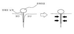
도 3은 도 1에 도시된 발광체가 의류에 봉제된 상태를 도시한 도면이다.
도 4는 도 1에 도시된 전원부(130)를 보다 구체적으로 도시한 도면이다.1 is a diagram showing the configuration of a
2 is a view showing the heating element shown in FIG. 1 in more detail.
FIG. 3 is a diagram illustrating a state in which the light-emitting body shown in FIG. 1 is sewn onto clothing.
FIG. 4 is a diagram illustrating the
이하, 본 발명의 이해를 돕기 위하여 바람직한 실시예를 제시한다. 그러나 하기의 실시예는 본 발명을 보다 쉽게 이해하기 위하여 제공되는 것일 뿐, 실시예에 의해 본 발명의 내용이 한정되는 것은 아니다.Hereinafter, a preferred embodiment is presented to aid the understanding of the present invention. However, the following examples are provided for easier understanding of the present invention, and the contents of the present invention are not limited by the examples.
도 1은 본 발명의 일 실시예에 따른 발광체 및 발열체가 적용된 스마트 의류(100)의 구성을 도시한 도면이다.1 is a diagram showing the configuration of a
도 1을 살펴보면, 본 발명의 일 실시예에 따른 발광체 및 발열체가 적용된 스마트 의류(100)는 크게 발열체(110), 발광체(120), 전원부(130) 및 제어부(미도시)를 포함하여 구성될 수 있다.Referring to FIG. 1, a
발열체(110)는 사용자에 착용 가능한 의류(예컨대, 상의 또는 하의)의 내측면에 마련되며, 신축성을 가진 면상 발열체가 적용될 수 있다. 이에 관해서는 도 2를 통해 보다 구체적으로 살펴보기로 한다.The
도 2는 도 1에 도시된 발열체를 보다 구체적으로 도시한 도면이다.FIG. 2 is a view showing the heating element shown in FIG. 1 in more detail.
도 2를 살펴보면, 발열체(110)는 물결무늬 형태로 패턴화 된 면상 발열체가 적용된다. 이러한 발열체(110)는 의류의 등 부분 혹은 복부 부분 내측에 마련되며, 도 1에서의 전원부(130)로부터 5V 전압의 전력을 공급받아 발열하게 된다.Referring to FIG. 2, the
이때, 전원부(130)는 의류의 일측(예컨대, 옆구리 측에 마련된 별도 포켓)에 위치되며, 발열체(110)와 전원부(130)는 신축성을 가진 케이블을 통해 전기적으로 연결된다. 따라서, 착용자가 움직이더라도 착용자의 활동에 제약이 없어 유연성을 확보할 수 있다.At this time, the
이러한 발열체(110)는 전원부(130)로부터 공급되는 5V 전압의 전력을 통해 40도 내지 49도 온도로 발열되는데, 발열체(110)와 전원부(130)는 서로 분리가 가능하도록 구성된다. 특히, 발열체(110)와 전원부(130)를 서로 연결하는 연결부위에는 수밀을 위한 실링 혹은 패킹이 적용됨에 따라, 전원부(130)를 발열체(110)로부터 분리시킨 후 의류를 물 세척하여 항시 청결한 상태를 유지하거나 오염물질을 제거할 수 있다.The
발광체(120)는 의류의 외측면에서 특히 봉제선을 따라 마련되며, 특정 패턴에 따라 빛을 발산하는 역할을 한다. 이에 관해서는 도 3을 통해 살펴보기로 한다.The light-emitting
도 3은 도 1에 도시된 발광체가 의류에 봉제된 상태를 도시한 도면이다.FIG. 3 is a diagram illustrating a state in which the light-emitting body shown in FIG. 1 is sewn onto clothing.
도 2 및 도 3을 살펴보면, 발광체는 크게 2개의 타입으로 나뉘는데, 특정 길이를 따라 문양을 나타내는 선 형태의 발광체와, 면 형태의 발광체로 나뉠 수 있다.2 and 3, the luminous body is largely divided into two types, a line-shaped luminous body representing a pattern along a specific length, and a surface-shaped luminous body.
선 형태의 발광체는 특정 길이를 가지는 광케이블 및 광케이블에 빛을 발산하는 LED 모듈을 포함하며, 광케이블의 측면 방향으로 돌출된 봉제용 날개가 의류를 구성하는 원단의 봉제선 사이에 끼워진 상태에서 원단이 봉제된다. 따라서, 봉제용 날개가 원단과 원단 사이에 봉제되기 때문에 광케이블을 가리는 어떠한 가림막이 없기 때문에 광케이블을 통한 발광효과가 극대화될 수 있다. 이때, 광케이블을 통해서는 특정 형태의 라인, 글자, 패턴 등을 표현할 수 있다.The line-shaped luminous body includes an optical cable having a specific length and an LED module that emits light to the optical cable, and the fabric is sewn while the sewing wings protruding in the lateral direction of the optical cable are sandwiched between the seams of the fabric constituting the clothing. . Therefore, since the sewing wings are sewn between the fabric and the fabric, there is no shielding film covering the optical cable, so that the luminous effect through the optical cable can be maximized. At this time, a specific type of line, letter, pattern, etc. can be expressed through an optical cable.
다른 한편으로, 면 형태의 발광체는 면 발광용 광섬유 패드 및 이러한 면 발광용 광섬유 패드에 빛을 발산하는 LED 모듈을 포함할 수 있다.On the other hand, the surface-shaped light-emitting body may include an optical fiber pad for surface-emission and an LED module that emits light to the optical fiber pad for surface-emission.
면 발광용 광섬유 패드에는 일측 방향으로 돌출된 봉제용 날개가 마련된다. 이러한 봉제용 날개는 마찬가지로 의류를 구성하는 원단과 원단 사이에 끼워져 함께 봉제되기 때문에, 면 발광용 광섬유 패드를 가리는 어떠한 가림막이 없어 면 발광용 광섬유 패드를 통한 발광효과가 극대화될 수 있다. 이때, 면 발광용 광섬유 패드를 통해서는 특정 형태의 문자, 문양, 도형, 글자, 패턴 등을 표현할 수 있다.The surface-emitting optical fiber pad is provided with wings for sewing protruding in one direction. Since these sewing wings are similarly sandwiched between the fabric constituting the garment and the fabric and sewn together, there is no shielding film covering the surface-emitting optical fiber pad, so that the luminous effect through the cotton-emitting optical fiber pad can be maximized. At this time, a specific type of character, pattern, figure, character, pattern, etc. can be expressed through the surface-emitting optical fiber pad.
한편, 이러한 발광체는 전원부(130)로부터 분리가 가능하도록 구성되되, 전원부(130)와의 연결영역은 기본적으로 수밀을 위한 실링 혹은 패킹이 적용된다. 따라서, 발광체가 적용된 의류는 물세척이 가능하게 된다.On the other hand, such a light emitter is configured to be separated from the
전원부(130)는 1만 암페어의 용량을 가지는 충전용 배터리가 적용되며, 외부 전원과의 전기적 연결을 통해 다회 충전이 가능하게 된다.The
이러한 전원부(130)에서는 USB케이블 단자가 연장되며, 연장된 USB케이블 단자는 발열체(110) 및 발광체(120)와 연결된다.In the
도 4는 도 1에 도시된 전원부(130)를 보다 구체적으로 도시한 도면이다.FIG. 4 is a diagram illustrating the
도 4를 살펴보면, 전원부(130)로부터 연장되는 USB케이블 단자에는 발열체에 5V 전압의 전력을 공급하기 위한 제1 및 제2 핀과, 발광체에 3V 전압의 전력을 공급하기 위한 제3 및 제4 핀이 마련된다.Referring to FIG. 4, the USB cable terminal extending from the
이때, 제어부에서는 제1 및 제2 핀을 통해 공급되는 5V 전압이 발열체에 인가되도록 하되, 온도 제어 수단을 통해 발열체의 발열 온도가 40도, 45도, 29도로 3단계로 나뉘어 발열되도록 한다.At this time, the control unit applies the 5V voltage supplied through the first and second pins to the heating element, and the heating temperature of the heating element is divided into three steps of 40 degrees, 45 degrees, and 29 degrees to generate heat through the temperature control means.
이때, 전원부(130)에는 온도 제어 수단에 의해 발열체(110)의 발열 온도에 따라 서로 다른 색상을 발광하는 상태 표시용 LED가 마련된다. 상태 표시용 LED는 발열체(110)의 발열 온도가 40도일 경우 청색(BLUE), 45도일 경우 녹색(GREEN), 49도일 경우 적색(RED)로 발광할 수 있다.At this time, the
한편, 의류의 일측에는 USB케이블 단자의 제3 및 제4 핀을 통해 우선적으로 공급되는 5V 전압을 3V로 감압하기 위한 저항과, 사용자 조작을 통해 발광체(120)의 온오프 동작을 제어하기 위한 스위치 역할을 하는 발광체 제어 수단(스위치)을 더 포함한다.On the other hand, on one side of the clothing, a resistor for reducing the 5V voltage preferentially supplied through the third and fourth pins of the USB cable terminal to 3V, and a switch for controlling the on-off operation of the
저항은 제3 및 제4 핀에서 출력되는 5V 전압을 3V로 감압시켜 발광체(120)로 인가하는 역할을 하며, 의류의 팔 부분에 마련되는 발광체 제어 수단은 사용자의 터치 혹은 누름 동작을 통해 발광체(120)의 온 또는 오프가 동작되도록 한다.The resistor serves to reduce the 5V voltage output from the third and fourth pins to 3V and apply it to the
상기에서는 본 발명의 바람직한 실시예를 참조하여 설명하였지만, 해당 기술 분야의 숙련된 당업자는 하기의 특허 청구의 범위에 기재된 본 발명의 사상 및 영역으로부터 벗어나지 않는 범위 내에서 본 발명을 다양하게 수정 및 변경시킬 수 있음을 이해할 수 있을 것이다.Although the above has been described with reference to preferred embodiments of the present invention, those skilled in the art will variously modify and change the present invention within the scope not departing from the spirit and scope of the present invention described in the following claims. You will understand that you can do it.
100: 발광체 및 발열체가 적용된 스마트 의류
110: 발열체
120: 발광체
130: 전원부100: smart clothing with a luminous element and a heating element
110: heating element
120: luminous body
130: power supply
Claims (10)
Translated fromKorean상기 의류의 외측면에 마련되며, 특정 패턴에 따라 빛을 발산하는 발광체;
상기 발열체 및 상기 발광체에 전력을 공급하는 전원부; 및
상기 발열체 및 상기 발광체의 동작 상태를 제어하는 제어부;를 포함하는 것을 특징으로 하는, 발광체 및 발열체가 적용된 스마트 의류.
A heating element provided on the inner side of the user's wearable clothing;
A light emitter provided on the outer surface of the clothing and emitting light according to a specific pattern;
A power supply for supplying power to the heating element and the light emitting element; And
A control unit for controlling the operating state of the heating element and the light emitting element; characterized in that, including the light emitting element and the heating element applied smart clothing.
상기 발열체는,
물결무늬 형태로 패턴화 된 면상 발열체에 해당하며, 상기 의류의 등 부분 및 복부 부분 내측에 마련되는 것을 특징으로 하는, 발광체 및 발열체가 적용된 스마트 의류.
The method of claim 1,
The heating element,
Smart clothing to which a light emitting element and a heating element are applied, which corresponds to a planar heating element patterned in a wave pattern, and is provided inside the back and abdomen portions of the clothing.
상기 발열체는,
상기 전원부로부터 공급되는 5V 전압의 전력을 통해 40도 내지 49도의 온도로 발열되며, 상기 전원부로부터 분리가 가능하도록 구성되되 상기 전원부와의 연결영역은 수밀을 위한 실링이 마련되는 것을 특징으로 하는, 발광체 및 발열체가 적용된 스마트 의류.
The method of claim 1,
The heating element,
It generates heat at a temperature of 40°C to 49°C through power of 5V voltage supplied from the power supply unit, and is configured to be separated from the power supply unit, but the connection area with the power supply unit is provided with a seal for watertightness. And smart clothing with heating elements.
상기 발광체는,
특정 길이를 가진 광케이블; 및
상기 광케이블에 빛을 발산하는 LED 모듈;을 포함하며,
상기 광케이블의 측면 방향으로 돌출된 봉제용 날개가 상기 의류를 구성하는 원단의 봉제선 사이에 끼워진 상태에서 상기 원단이 봉제됨에 따라, 상기 광케이블이 상기 의류에 고정되고, 또한
상기 발광체는 상기 전원부로부터 분리가 가능하도록 구성되되 상기 전원부와의 연결영역은 수밀을 위한 실링이 마련되는 것을 특징으로 하는, 발광체 및 발열체가 적용된 스마트 의류.
The method of claim 1,
The luminous body,
Optical cables of a certain length; And
Including; an LED module for emitting light to the optical cable,
As the fabric is sewn while the sewing wings protruding in the lateral direction of the optical cable are sandwiched between the seams of the fabric constituting the clothing, the optical cable is fixed to the clothing, and
The luminous body is configured to be separated from the power supply unit, and the connection area with the power supply unit is provided with a sealing for watertightness.
상기 발광체는,
면 발광용 광섬유 패드; 및
상기 면 발광용 광섬유 패드에 빛을 발산하는 LED 모듈;을 포함하며,
상기 면 발광용 광섬유 패드의 일측 방향으로 돌출된 봉제용 날개가 상기 의류를 구성하는 원단에 봉제됨에 따라, 상기 면 발광용 광섬유 패드가 상기 의류에 고정되는 것을 특징으로 하는, 발광체 및 발열체가 적용된 스마트 의류.
The method of claim 1,
The luminous body,
An optical fiber pad for surface light emission; And
Including; an LED module for emitting light to the surface-emitting optical fiber pad,
As the sewing wings protruding in one direction of the surface-emitting optical fiber pad are sewn to the fabric constituting the clothing, the surface-emitting optical fiber pad is fixed to the clothing, and a light emitting element and a heating element are applied smart clothing.
상기 발광체는 상기 전원부로부터 분리가 가능하도록 구성되되 상기 전원부와의 연결영역은 수밀을 위한 실링이 마련되는 것을 특징으로 하는, 발광체 및 발열체가 적용된 스마트 의류.
The method of claim 4,
The luminous body is configured to be separated from the power supply unit, and the connection area with the power supply unit is provided with a sealing for watertightness.
상기 전원부는,
1만 암페어 용량을 가진 충전용 배터리가 내장되며,
상기 배터리로부터 연장된 USB케이블 단자는 상기 제어부와 전기적으로 연결되는 것을 특징으로 하는, 발광체 및 발열체가 적용된 스마트 의류.
The method of claim 1,
The power supply unit,
Built-in rechargeable battery with a capacity of 10,000 amps,
The USB cable terminal extending from the battery is electrically connected to the control unit, wherein the light emitting element and the heating element are applied.
상기 USB케이블 단자는,
상기 발열체에 5V 전압의 전력을 공급하기 위한 제1 및 제2 핀과, 상기 발광체에 3V 전압의 전력을 공급하기 위한 제3 및 제4 핀을 포함하는 것을 특징으로 하는, 발광체 및 발열체가 적용된 스마트 의류.
The method of claim 7,
The USB cable terminal,
A smart light emitting element and a heating element, characterized in that it comprises first and second pins for supplying power of 5V voltage to the heating element, and third and fourth pins for supplying power of 3V voltage to the luminous element clothing.
상기 제어부는,
상기 제1 및 제2 핀을 통해 공급되는 5V 전압의 전력이 상기 발열체에 인가되도록 하되, 사용자 조작을 통해 상기 발열체의 발열 온도가 40도, 45도 및 49도로 3단계로 나뉘어 발열되도록 하기 위한 온도 제어 수단이 마련되며,
상기 전원부에는 상기 온도 제어 수단에 의한 상기 발열체의 발열 온도에 따라 서로 다른 색상을 발광하는 상태 표시용 LED가 마련되는 것을 특징으로 하는, 발광체 및 발열체가 적용된 스마트 의류.
The method of claim 8,
The control unit,
A temperature for allowing the power of the 5V voltage supplied through the first and second pins to be applied to the heating element, but the heating temperature of the heating element is divided into three steps of 40 degrees, 45 degrees, and 49 degrees to generate heat through user manipulation. Control means are provided,
The power supply unit is characterized in that the LED for emitting different colors according to the heating temperature of the heating element by the temperature control means is provided with a state display LED, the light emitting element and the heating element applied smart clothing.
상기 의류의 일측에는 상기 제3 및 제4 핀을 통해 우선적으로 공급되는 5V 전압의 전력을 3V 전압으로 감압하기 위한 저항; 및
사용자 조작을 통해 상기 발광체의 온오프 동작을 제어하기 위한 발광체 제어 수단;을 더 포함하는 것을 특징으로 하는, 발광체 및 발열체가 적용된 스마트 의류.The method of claim 8,
At one side of the clothing, a resistor for reducing power of a 5V voltage preferentially supplied through the third and fourth pins to a 3V voltage; And
A luminous body control means for controlling an on/off operation of the luminous body through user manipulation.
Priority Applications (1)
| Application Number | Priority Date | Filing Date | Title |
|---|---|---|---|
| KR1020190095944AKR102292927B1 (en) | 2019-08-07 | 2019-08-07 | Smart clothing with luminescent and heating applications |
Applications Claiming Priority (1)
| Application Number | Priority Date | Filing Date | Title |
|---|---|---|---|
| KR1020190095944AKR102292927B1 (en) | 2019-08-07 | 2019-08-07 | Smart clothing with luminescent and heating applications |
Publications (2)
| Publication Number | Publication Date |
|---|---|
| KR20210018626Atrue KR20210018626A (en) | 2021-02-18 |
| KR102292927B1 KR102292927B1 (en) | 2021-08-25 |
Family
ID=74688574
Family Applications (1)
| Application Number | Title | Priority Date | Filing Date |
|---|---|---|---|
| KR1020190095944AExpired - Fee RelatedKR102292927B1 (en) | 2019-08-07 | 2019-08-07 | Smart clothing with luminescent and heating applications |
Country Status (1)
| Country | Link |
|---|---|
| KR (1) | KR102292927B1 (en) |
Families Citing this family (1)
| Publication number | Priority date | Publication date | Assignee | Title |
|---|---|---|---|---|
| CN218848643U (en)* | 2022-10-13 | 2023-04-11 | 深圳库森科技贸易有限公司 | Heating control circuit |
Citations (4)
| Publication number | Priority date | Publication date | Assignee | Title |
|---|---|---|---|---|
| KR20070000026U (en)* | 2006-12-14 | 2007-01-04 | 신경하 | Clothing Accessories Using Optical Fiber |
| KR20110036973A (en)* | 2009-10-05 | 2011-04-13 | 이윤희 | Winter clothes |
| KR101381860B1 (en) | 2012-08-10 | 2014-04-04 | 동아대학교 산학협력단 | Smart garment having light emitting function |
| KR101496908B1 (en)* | 2013-10-02 | 2015-03-02 | 주식회사 필룩스 | Multi functional clothing |
- 2019
- 2019-08-07KRKR1020190095944Apatent/KR102292927B1/ennot_activeExpired - Fee Related
Patent Citations (4)
| Publication number | Priority date | Publication date | Assignee | Title |
|---|---|---|---|---|
| KR20070000026U (en)* | 2006-12-14 | 2007-01-04 | 신경하 | Clothing Accessories Using Optical Fiber |
| KR20110036973A (en)* | 2009-10-05 | 2011-04-13 | 이윤희 | Winter clothes |
| KR101381860B1 (en) | 2012-08-10 | 2014-04-04 | 동아대학교 산학협력단 | Smart garment having light emitting function |
| KR101496908B1 (en)* | 2013-10-02 | 2015-03-02 | 주식회사 필룩스 | Multi functional clothing |
Also Published As
| Publication number | Publication date |
|---|---|
| KR102292927B1 (en) | 2021-08-25 |
Similar Documents
| Publication | Publication Date | Title |
|---|---|---|
| US6106130A (en) | Personal lighted and reflective safety system with shoulder straps for pedestrians | |
| JP6758303B2 (en) | Visibility enhancement device | |
| US7144127B2 (en) | Single assembly EL lighting for garments | |
| US10123396B2 (en) | System for displaying information on interactive illuminated apparel and accessories | |
| US20120099298A1 (en) | Light-emitting clothing structure | |
| US20070064413A1 (en) | Electroluminescent wire light source on a baseball cap | |
| KR101035442B1 (en) | Safety Clothing with Flexible LED Board | |
| US20080117624A1 (en) | Lighted apparel and footwear | |
| WO2016085993A1 (en) | Flexible water-resistant optical fiber light display | |
| US11903429B2 (en) | Turn direction indicator garment | |
| US20130215604A1 (en) | Light emitting ribbon | |
| WO2017222756A1 (en) | Luminous attire | |
| KR101381860B1 (en) | Smart garment having light emitting function | |
| US20160088890A1 (en) | Illuminated sweat band | |
| KR102367244B1 (en) | Smart clothing with luminescent | |
| KR102292927B1 (en) | Smart clothing with luminescent and heating applications | |
| US12201170B2 (en) | Turn direction indicator garment | |
| KR200486717Y1 (en) | Jacket Having Hood | |
| KR101806909B1 (en) | Multi-functional fabric with metal thread pattern | |
| KR20090117210A (en) | Clothing with light emitting device | |
| KR200283119Y1 (en) | Clothes having light emitting diode | |
| KR102124173B1 (en) | Self-customized micro LED lighting to change color and pattern like TV screen | |
| KR20130131848A (en) | Boardless type led light emitting apparatus for safety clothes using conductive thread and safety wear using the same | |
| CN207885731U (en) | Dress ornament with LED light | |
| KR102861987B1 (en) | Light emitting cover of lead for companion animal |
Legal Events
| Date | Code | Title | Description |
|---|---|---|---|
| PA0109 | Patent application | St.27 status event code:A-0-1-A10-A12-nap-PA0109 | |
| PA0201 | Request for examination | St.27 status event code:A-1-2-D10-D11-exm-PA0201 | |
| P22-X000 | Classification modified | St.27 status event code:A-2-2-P10-P22-nap-X000 | |
| PE0902 | Notice of grounds for rejection | St.27 status event code:A-1-2-D10-D21-exm-PE0902 | |
| T11-X000 | Administrative time limit extension requested | St.27 status event code:U-3-3-T10-T11-oth-X000 | |
| PG1501 | Laying open of application | St.27 status event code:A-1-1-Q10-Q12-nap-PG1501 | |
| E13-X000 | Pre-grant limitation requested | St.27 status event code:A-2-3-E10-E13-lim-X000 | |
| P11-X000 | Amendment of application requested | St.27 status event code:A-2-2-P10-P11-nap-X000 | |
| P13-X000 | Application amended | St.27 status event code:A-2-2-P10-P13-nap-X000 | |
| E701 | Decision to grant or registration of patent right | ||
| PE0701 | Decision of registration | St.27 status event code:A-1-2-D10-D22-exm-PE0701 | |
| P11-X000 | Amendment of application requested | St.27 status event code:A-2-2-P10-P11-nap-X000 | |
| P13-X000 | Application amended | St.27 status event code:A-2-2-P10-P13-nap-X000 | |
| R15-X000 | Change to inventor requested | St.27 status event code:A-3-3-R10-R15-oth-X000 | |
| R16-X000 | Change to inventor recorded | St.27 status event code:A-3-3-R10-R16-oth-X000 | |
| GRNT | Written decision to grant | ||
| PR0701 | Registration of establishment | St.27 status event code:A-2-4-F10-F11-exm-PR0701 | |
| PR1002 | Payment of registration fee | St.27 status event code:A-2-2-U10-U11-oth-PR1002 Fee payment year number:1 | |
| PG1601 | Publication of registration | St.27 status event code:A-4-4-Q10-Q13-nap-PG1601 | |
| R18-X000 | Changes to party contact information recorded | St.27 status event code:A-5-5-R10-R18-oth-X000 | |
| PC1903 | Unpaid annual fee | St.27 status event code:A-4-4-U10-U13-oth-PC1903 Not in force date:20240819 Payment event data comment text:Termination Category : DEFAULT_OF_REGISTRATION_FEE | |
| K11-X000 | Ip right revival requested | St.27 status event code:A-6-4-K10-K11-oth-X000 | |
| K12-X000 | Request for ip right revival rejected | St.27 status event code:A-6-4-K10-K12-oth-X000 | |
| PC1903 | Unpaid annual fee | St.27 status event code:N-4-6-H10-H13-oth-PC1903 Ip right cessation event data comment text:Termination Category : DEFAULT_OF_REGISTRATION_FEE Not in force date:20240819 |