KR20210018198A - Image display device - Google Patents
Image display deviceDownload PDFInfo
- Publication number
- KR20210018198A KR20210018198AKR1020207030242AKR20207030242AKR20210018198AKR 20210018198 AKR20210018198 AKR 20210018198AKR 1020207030242 AKR1020207030242 AKR 1020207030242AKR 20207030242 AKR20207030242 AKR 20207030242AKR 20210018198 AKR20210018198 AKR 20210018198A
- Authority
- KR
- South Korea
- Prior art keywords
- unit
- diffraction
- display device
- image display
- diffractive
- Prior art date
- Legal status (The legal status is an assumption and is not a legal conclusion. Google has not performed a legal analysis and makes no representation as to the accuracy of the status listed.)
- Granted
Links
- 230000003287optical effectEffects0.000claimsabstractdescription116
- 230000004075alterationEffects0.000claimsabstractdescription54
- 210000001747pupilAnatomy0.000claimsabstractdescription38
- 238000001514detection methodMethods0.000claimsdescription32
- 238000000034methodMethods0.000claimsdescription31
- 201000009310astigmatismDiseases0.000claimsdescription16
- 230000005540biological transmissionEffects0.000claimsdescription9
- 210000005252bulbus oculiAnatomy0.000claimsdescription6
- 238000010586diagramMethods0.000description45
- 238000003384imaging methodMethods0.000description19
- 230000000694effectsEffects0.000description12
- 210000001508eyeAnatomy0.000description12
- 230000000052comparative effectEffects0.000description10
- 238000005516engineering processMethods0.000description4
- 239000003086colorantSubstances0.000description3
- 230000004048modificationEffects0.000description3
- 238000012986modificationMethods0.000description3
- 230000009471actionEffects0.000description1
- 238000005452bendingMethods0.000description1
- 230000008859changeEffects0.000description1
- 210000003128headAnatomy0.000description1
Images


Classifications
- G—PHYSICS
- G02—OPTICS
- G02B—OPTICAL ELEMENTS, SYSTEMS OR APPARATUS
- G02B26/00—Optical devices or arrangements for the control of light using movable or deformable optical elements
- G02B26/08—Optical devices or arrangements for the control of light using movable or deformable optical elements for controlling the direction of light
- G02B26/10—Scanning systems
- G02B26/101—Scanning systems with both horizontal and vertical deflecting means, e.g. raster or XY scanners
- G—PHYSICS
- G02—OPTICS
- G02B—OPTICAL ELEMENTS, SYSTEMS OR APPARATUS
- G02B13/00—Optical objectives specially designed for the purposes specified below
- G02B13/0095—Relay lenses or rod lenses
- G—PHYSICS
- G02—OPTICS
- G02B—OPTICAL ELEMENTS, SYSTEMS OR APPARATUS
- G02B26/00—Optical devices or arrangements for the control of light using movable or deformable optical elements
- G02B26/08—Optical devices or arrangements for the control of light using movable or deformable optical elements for controlling the direction of light
- G02B26/0816—Optical devices or arrangements for the control of light using movable or deformable optical elements for controlling the direction of light by means of one or more reflecting elements
- G02B26/0833—Optical devices or arrangements for the control of light using movable or deformable optical elements for controlling the direction of light by means of one or more reflecting elements the reflecting element being a micromechanical device, e.g. a MEMS mirror, DMD
- G—PHYSICS
- G02—OPTICS
- G02B—OPTICAL ELEMENTS, SYSTEMS OR APPARATUS
- G02B26/00—Optical devices or arrangements for the control of light using movable or deformable optical elements
- G02B26/08—Optical devices or arrangements for the control of light using movable or deformable optical elements for controlling the direction of light
- G02B26/10—Scanning systems
- G—PHYSICS
- G02—OPTICS
- G02B—OPTICAL ELEMENTS, SYSTEMS OR APPARATUS
- G02B27/00—Optical systems or apparatus not provided for by any of the groups G02B1/00 - G02B26/00, G02B30/00
- G02B27/0025—Optical systems or apparatus not provided for by any of the groups G02B1/00 - G02B26/00, G02B30/00 for optical correction, e.g. distorsion, aberration
- G—PHYSICS
- G02—OPTICS
- G02B—OPTICAL ELEMENTS, SYSTEMS OR APPARATUS
- G02B27/00—Optical systems or apparatus not provided for by any of the groups G02B1/00 - G02B26/00, G02B30/00
- G02B27/0093—Optical systems or apparatus not provided for by any of the groups G02B1/00 - G02B26/00, G02B30/00 with means for monitoring data relating to the user, e.g. head-tracking, eye-tracking
- G—PHYSICS
- G02—OPTICS
- G02B—OPTICAL ELEMENTS, SYSTEMS OR APPARATUS
- G02B27/00—Optical systems or apparatus not provided for by any of the groups G02B1/00 - G02B26/00, G02B30/00
- G02B27/01—Head-up displays
- G02B27/017—Head mounted
- G02B27/0172—Head mounted characterised by optical features
- G—PHYSICS
- G02—OPTICS
- G02B—OPTICAL ELEMENTS, SYSTEMS OR APPARATUS
- G02B27/00—Optical systems or apparatus not provided for by any of the groups G02B1/00 - G02B26/00, G02B30/00
- G02B27/01—Head-up displays
- G02B27/0179—Display position adjusting means not related to the information to be displayed
- G—PHYSICS
- G02—OPTICS
- G02B—OPTICAL ELEMENTS, SYSTEMS OR APPARATUS
- G02B27/00—Optical systems or apparatus not provided for by any of the groups G02B1/00 - G02B26/00, G02B30/00
- G02B27/42—Diffraction optics, i.e. systems including a diffractive element being designed for providing a diffractive effect
- G02B27/4205—Diffraction optics, i.e. systems including a diffractive element being designed for providing a diffractive effect having a diffractive optical element [DOE] contributing to image formation, e.g. whereby modulation transfer function MTF or optical aberrations are relevant
- G02B27/4227—Diffraction optics, i.e. systems including a diffractive element being designed for providing a diffractive effect having a diffractive optical element [DOE] contributing to image formation, e.g. whereby modulation transfer function MTF or optical aberrations are relevant in image scanning systems
- G—PHYSICS
- G02—OPTICS
- G02B—OPTICAL ELEMENTS, SYSTEMS OR APPARATUS
- G02B27/00—Optical systems or apparatus not provided for by any of the groups G02B1/00 - G02B26/00, G02B30/00
- G02B27/42—Diffraction optics, i.e. systems including a diffractive element being designed for providing a diffractive effect
- G02B27/4272—Diffraction optics, i.e. systems including a diffractive element being designed for providing a diffractive effect having plural diffractive elements positioned sequentially along the optical path
- G—PHYSICS
- G02—OPTICS
- G02B—OPTICAL ELEMENTS, SYSTEMS OR APPARATUS
- G02B5/00—Optical elements other than lenses
- G02B5/18—Diffraction gratings
- G02B5/1814—Diffraction gratings structurally combined with one or more further optical elements, e.g. lenses, mirrors, prisms or other diffraction gratings
- G02B5/1819—Plural gratings positioned on the same surface, e.g. array of gratings
- G02B5/1823—Plural gratings positioned on the same surface, e.g. array of gratings in an overlapping or superposed manner
- G—PHYSICS
- G02—OPTICS
- G02B—OPTICAL ELEMENTS, SYSTEMS OR APPARATUS
- G02B5/00—Optical elements other than lenses
- G02B5/18—Diffraction gratings
- G02B5/1861—Reflection gratings characterised by their structure, e.g. step profile, contours of substrate or grooves, pitch variations, materials
- G—PHYSICS
- G02—OPTICS
- G02B—OPTICAL ELEMENTS, SYSTEMS OR APPARATUS
- G02B5/00—Optical elements other than lenses
- G02B5/18—Diffraction gratings
- G02B5/1866—Transmission gratings characterised by their structure, e.g. step profile, contours of substrate or grooves, pitch variations, materials
- G—PHYSICS
- G02—OPTICS
- G02C—SPECTACLES; SUNGLASSES OR GOGGLES INSOFAR AS THEY HAVE THE SAME FEATURES AS SPECTACLES; CONTACT LENSES
- G02C7/00—Optical parts
- G02C7/02—Lenses; Lens systems ; Methods of designing lenses
- G02C7/08—Auxiliary lenses; Arrangements for varying focal length
- G02C7/081—Ophthalmic lenses with variable focal length
- G02C7/083—Electrooptic lenses
- G—PHYSICS
- G02—OPTICS
- G02B—OPTICAL ELEMENTS, SYSTEMS OR APPARATUS
- G02B27/00—Optical systems or apparatus not provided for by any of the groups G02B1/00 - G02B26/00, G02B30/00
- G02B27/01—Head-up displays
- G02B27/0101—Head-up displays characterised by optical features
- G02B2027/0112—Head-up displays characterised by optical features comprising device for genereting colour display
- G02B2027/0116—Head-up displays characterised by optical features comprising device for genereting colour display comprising devices for correcting chromatic aberration
- G—PHYSICS
- G02—OPTICS
- G02B—OPTICAL ELEMENTS, SYSTEMS OR APPARATUS
- G02B27/00—Optical systems or apparatus not provided for by any of the groups G02B1/00 - G02B26/00, G02B30/00
- G02B27/01—Head-up displays
- G02B27/017—Head mounted
- G02B27/0172—Head mounted characterised by optical features
- G02B2027/0174—Head mounted characterised by optical features holographic
- G—PHYSICS
- G02—OPTICS
- G02B—OPTICAL ELEMENTS, SYSTEMS OR APPARATUS
- G02B27/00—Optical systems or apparatus not provided for by any of the groups G02B1/00 - G02B26/00, G02B30/00
- G02B27/01—Head-up displays
- G02B27/0179—Display position adjusting means not related to the information to be displayed
- G02B2027/0181—Adaptation to the pilot/driver
- G—PHYSICS
- G02—OPTICS
- G02B—OPTICAL ELEMENTS, SYSTEMS OR APPARATUS
- G02B27/00—Optical systems or apparatus not provided for by any of the groups G02B1/00 - G02B26/00, G02B30/00
- G02B27/01—Head-up displays
- G02B27/0179—Display position adjusting means not related to the information to be displayed
- G02B2027/0187—Display position adjusting means not related to the information to be displayed slaved to motion of at least a part of the body of the user, e.g. head, eye
- G—PHYSICS
- G02—OPTICS
- G02C—SPECTACLES; SUNGLASSES OR GOGGLES INSOFAR AS THEY HAVE THE SAME FEATURES AS SPECTACLES; CONTACT LENSES
- G02C2202/00—Generic optical aspects applicable to one or more of the subgroups of G02C7/00
- G02C2202/22—Correction of higher order and chromatic aberrations, wave front measurement and calculation
Landscapes
- Physics & Mathematics (AREA)
- General Physics & Mathematics (AREA)
- Optics & Photonics (AREA)
- Health & Medical Sciences (AREA)
- Ophthalmology & Optometry (AREA)
- General Health & Medical Sciences (AREA)
- Lenses (AREA)
Abstract
Translated fromKorean
Description
Translated fromKorean본 개시는, 화상광(image light)을 관찰자의 눈동자로 가이드하는 화상 표시 장치에 관한 것이다.The present disclosure relates to an image display device that guides image light to an observer's pupils.
화상광을 관찰자의 눈동자로 가이드하는 화상 표시 장치가 개발되고 있다. 이러한 화상 표시 장치는, 예를 들면 헤드마운트 디스플레이로서 이용되고 있다(특허문헌 1, 2 참조). 예를 들면, 광원으로부터의 광을 주사 유닛으로 주사함으로써 화상광을 생성하고, 생성된 화상광을 관찰자의 눈동자로 가이드하는 화상 표시 장치가 개발되고 있다.An image display device is being developed that guides image light to the observer's pupils. Such an image display device is used as, for example, a head mounted display (refer to Patent Documents 1 and 2). For example, image display devices have been developed that generate image light by scanning light from a light source with a scanning unit, and guide the generated image light to the pupil of the observer.
상기 화상 표시 장치에서는, 화상광을 관찰자의 눈동자로 가이드하기까지의 광학계의 구성에 따른 여러 수차(收差), 예를 들면 색 수차가 발생하여, 화질이 저하될 수 있다.In the image display device, various aberrations, for example, chromatic aberrations depending on the configuration of the optical system until guiding the image light to the pupil of the observer, may occur, and the image quality may be deteriorated.
색 수차가 억제된 고화질의 화상 표시를 하는 것이 가능한 화상 표시 장치를 제공하는 것이 바람직하다.It is desirable to provide an image display device capable of displaying high-quality images with suppressed chromatic aberration.
본 개시의 일 실시형태에 따른 화상 표시 장치는, 화상광을 출사하는 화상광 형성부와, 적어도 하나의 회절 소자를 갖는 제1 회절부와, 화상광을 관찰자의 동공 위치에 수속시키는 제2 회절부를 포함하고, 제1 회절부가, 제2 회절부에서 발생하는 색 수차를 보정하는 특성을 갖는 회절 광학계와, 제2 회절부보다 화상광 형성부 측에 배치되고, 제2 회절부에서 발생하는 색 수차를 보정하도록, 화상광을 제2 회절부에 릴레이(relay)하는 릴레이 광학계를 구비한다.An image display device according to an embodiment of the present disclosure includes an image light forming unit that emits image light, a first diffraction unit having at least one diffractive element, and a second diffraction unit that converges image light to a pupil position of an observer. A diffraction optical system having a characteristic of correcting chromatic aberration occurring in the second diffraction portion, the first diffraction portion, and a color that is disposed on the side of the image light forming portion than the second diffraction portion, A relay optical system for relaying image light to a second diffraction unit is provided to correct aberration.
본 개시의 일 실시형태에 따른 화상 표시 장치에서는, 제2 회절부에서 발생하는 색 수차가 제1 회절부와 릴레이 광학계에 의해 보정된다.In the image display device according to the embodiment of the present disclosure, chromatic aberration occurring in the second diffraction portion is corrected by the first diffraction portion and the relay optical system.
도 1은 비교예에 따른 화상 표시 장치의 개요를 나타내는 구성도이다.
도 2는 비교예에 따른 화상 표시 장치의 결상 성능을 나타내는 스폿 다이어그램이다.
도 3은 본 개시의 제1 실시형태에 따른 화상 표시 장치의 개요를 나타내는 구성도이다.
도 4는 제1 실시형태에 따른 화상 표시 장치에 있어서 발생하는 색 수차의 개요를 나타내는 설명도이다.
도 5는 제1 실시형태에 따른 화상 표시 장치에서 발생하는 상면 만곡의 개요를 나타내는 설명도이다.
도 6은 제1 실시형태에 따른 화상 표시 장치에서 발생하는 비점 수차의 개요를 나타내는 설명도이다.
도 7은 제1 실시형태에 따른 화상 표시 장치에서 발생하는 구면 수차의 개요를 나타내는 설명도이다.
도 8은 제1 실시형태에 따른 화상 표시 장치에서 발생하는 색 수차, 및 비점 수차의 보정 방법의 개요를 나타내는 설명도이다.
도 9는 제1 실시형태에 따른 화상 표시 장치에서 발생하는 상면 만곡의 보정 방법의 개요를 나타내는 설명도이다.
도 10은 제1 실시형태에 따른 화상 표시 장치의 제1 구체예를 나타내는 구성도이다.
도 11은 제1 구체예에 따른 화상 표시 장치의 결상 성능을 나타내는 스폿 다이어그램이다.
도 12는 제1 구체예에 따른 화상 표시 장치의 결상 성능을 나타내는 스폿 다이어그램이다.
도 13은 제1 구체예에 따른 화상 표시 장치의 결상 성능을 나타내는 스폿 다이어그램이다.
도 14는 제1 구체예에 따른 화상 표시 장치의 결상 성능을 나타내는 스폿 다이어그램이다.
도 15는 제1 구체예에 따른 화상 표시 장치의 결상 성능을 나타내는 스폿 다이어그램이다.
도 16은 제1 실시형태에 따른 화상 표시 장치의 제2 구체예를 나타내는 구성도이다.
도 17은 제1 실시형태에 따른 화상 표시 장치의 제3 구체예를 나타내는 구성도이다.
도 18은 제3 구체예에 따른 화상 표시 장치의 결상 성능을 나타내는 스폿 다이어그램이다.
도 19는 제1 실시형태에 따른 화상 표시 장치의 제4 구체예를 나타내는 구성도이다.
도 20은 제4 구체예에 따른 화상 표시 장치의 결상 성능을 나타내는 스폿 다이어그램이다.
도 21은 제1 실시형태에 따른 화상 표시 장치의 제5 구체예를 나타내는 구성도이다.
도 22는 제1 실시형태에 따른 화상 표시 장치의 제6 구체예를 나타내는 구성도이다.
도 23은 제1 실시형태에 따른 화상 표시 장치의 제7 구체예를 나타내는 구성도이다.
도 24는 제2 실시형태에 따른 화상 표시 장치의 제1 구체예를 나타내는 구성도이다.
도 25는 제2 실시형태에 따른 화상 표시 장치의 제2 구체예를 나타내는 구성도이다.
도 26은 제2 실시형태에 따른 화상 표시 장치의 제3 구체예를 나타내는 구성도이다.
도 27은 제3 실시형태에 따른 화상 표시 장치의 개요를 나타내는 구성도이다.
도 28은 제3 실시형태에 따른 화상 표시 장치의 제1 구체예를 나타내는 구성도이다.
도 29는 제3 실시형태에 따른 화상 표시 장치의 제2 구체예를 나타내는 구성도이다.
도 30은 제3 실시형태에 따른 화상 표시 장치의 제3 구체예를 나타내는 구성도이다.
도 31은 제3 실시형태에 따른 화상 표시 장치의 제4 구체예를 나타내는 구성도이다.
도 32는 제3 실시형태에 따른 화상 표시 장치의 변형예를 나타내는 구성도이다.1 is a configuration diagram showing an outline of an image display device according to a comparative example.
2 is a spot diagram showing imaging performance of an image display device according to a comparative example.
3 is a configuration diagram showing an outline of an image display device according to a first embodiment of the present disclosure.
Fig. 4 is an explanatory diagram showing an outline of chromatic aberration occurring in the image display device according to the first embodiment.
5 is an explanatory diagram showing an outline of a curvature of a top surface occurring in the image display device according to the first embodiment.
6 is an explanatory diagram showing an outline of astigmatism occurring in the image display device according to the first embodiment.
7 is an explanatory diagram showing an outline of spherical aberration occurring in the image display device according to the first embodiment.
8 is an explanatory diagram showing an outline of a method for correcting chromatic aberration and astigmatism occurring in the image display device according to the first embodiment.
9 is an explanatory diagram showing an outline of a method of correcting an image surface curvature occurring in the image display device according to the first embodiment.
10 is a configuration diagram showing a first specific example of the image display device according to the first embodiment.
11 is a spot diagram showing the imaging performance of the image display device according to the first specific example.
12 is a spot diagram showing the imaging performance of the image display device according to the first embodiment.
13 is a spot diagram showing the imaging performance of the image display device according to the first specific example.
14 is a spot diagram showing the imaging performance of the image display device according to the first specific example.
15 is a spot diagram showing the imaging performance of the image display device according to the first specific example.
16 is a configuration diagram showing a second specific example of the image display device according to the first embodiment.
17 is a configuration diagram showing a third specific example of the image display device according to the first embodiment.
18 is a spot diagram showing the imaging performance of the image display device according to the third specific example.
19 is a configuration diagram showing a fourth specific example of the image display device according to the first embodiment.
20 is a spot diagram showing the imaging performance of the image display device according to the fourth specific example.
21 is a configuration diagram showing a fifth specific example of the image display device according to the first embodiment.
22 is a configuration diagram showing a sixth specific example of the image display device according to the first embodiment.
23 is a configuration diagram showing a seventh specific example of the image display device according to the first embodiment.
24 is a configuration diagram showing a first specific example of the image display device according to the second embodiment.
25 is a configuration diagram showing a second specific example of the image display device according to the second embodiment.
26 is a configuration diagram showing a third specific example of the image display device according to the second embodiment.
Fig. 27 is a configuration diagram showing an outline of an image display device according to a third embodiment.
28 is a configuration diagram showing a first specific example of an image display device according to a third embodiment.
29 is a configuration diagram showing a second specific example of the image display device according to the third embodiment.
30 is a configuration diagram showing a third specific example of the image display device according to the third embodiment.
31 is a configuration diagram showing a fourth specific example of the image display device according to the third embodiment.
32 is a configuration diagram showing a modified example of the image display device according to the third embodiment.
이하, 본 개시의 실시형태에 대해 도면을 참조하여 상세하게 설명한다. 한편, 설명은 이하의 순서로 한다.Hereinafter, embodiments of the present disclosure will be described in detail with reference to the drawings. On the other hand, description is made in the following order.
1. 제1 실시형태(수차 보정이 이루어진 화상 표시 장치)1. First embodiment (image display device with aberration correction)
1.0 비교예(도 1~도 2)1.0 Comparative Example (Figs. 1 to 2)
1.1 제1 실시형태에 따른 화상 표시 장치의 개요(도 3~도 9)1.1 Overview of the image display device according to the first embodiment (Figs. 3 to 9)
1.2 제1 실시형태에 따른 화상 표시 장치의 구체예(도 10~도 23)1.2 Specific examples of the image display device according to the first embodiment (Figs. 10-23)
1.3 효과1.3 Effect
2. 제2 실시형태(관찰자의 동공 위치에 따라 표시하는 화상 표시 장치) (도 24~도 26)2. Second embodiment (image display device displayed according to the pupil position of the observer) (Figs. 24 to 26)
3. 제3 실시형태(제1 회절부에 복수의 회절 소자를 사용한 화상 표시 장치)3. Third embodiment (image display device using a plurality of diffractive elements in the first diffractive portion)
3.1 제3 실시형태에 따른 화상 표시 장치의 개요(도 27)3.1 Overview of the image display device according to the third embodiment (Fig. 27)
3.2 제3 실시형태에 따른 화상 표시 장치의 구체예(도 28~도 31)3.2 Specific examples of the image display device according to the third embodiment (Figs. 28 to 31)
3.3 제3 실시형태에 따른 화상 표시 장치의 변형예(도 32)3.3 Modified example of the image display device according to the third embodiment (Fig. 32)
3.4 효과3.4 effect
4. 그 밖의 실시형태4. Other embodiments
<1. 제1 실시형태><1. First embodiment>
[1.0 비교예][1.0 Comparative Example]
(비교예에 따른 화상 표시 장치의 개요와 과제)(Summary and Problems of Image Display Device According to Comparative Example)
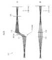
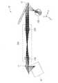
도 1은, 비교예에 따른 화상 표시 장치(101)의 개요를 나타내고 있다.1 shows an outline of an
한편, 도 1에서는, 관찰자의 눈(100)의 깊이 방향을 Z방향으로 하고, Z방향에 직교하는 2개의 방향을 X방향, 및 Y방향으로 하고 있다. 또한, X방향과 Y방향은 서로 직교한다. 예를 들면 X방향은 관찰자의 시야의 수평 방향, Y방향은 시야의 수직 방향에 상당한다. 화상 표시 장치(101)에서의 광로(광축)의 방향은 Z방향에 상당한다. 한편, 후술하는 각 실시형태에 있어서의 화상 표시 장치에서도 마찬가지이다.On the other hand, in Fig. 1, the depth direction of the observer's
도 1에는, 특허문헌 1(일본특허공개 2008-83539호 공보)에 기재된 기술에 기초한 화상 표시 장치(101)의 구성을 간략화하여 나타내고 있다. 도 1의 상단(A)에는 XZ면 내에 있어서의 구성, 도 1의 하단(B)에는 YZ면 내에 있어서의 구성을 나타낸다.In Fig. 1, the configuration of an
특허문헌 1에는, 도광판에 제1 회절부(111)와 제2 회절부(112)를 배치하고, 제1 회절부(111)를 통해 도광판에 화상광을 입사하는 구성이 기재되어 있다. 도광판에 입사한 화상광은, 도광판의 내부에서 중간상(intermediate image)을 형성한 후, 도광판에 의해 제2 회절부(112)로 가이드 되어, 제2 회절부(112)로부터 관찰자의 눈(100)을 향해 출사된다.In Patent Document 1, a configuration in which the
비교예에 따른 화상 표시 장치(101)에서는, 제1 회절부(111)의 뒤에 형성되는 중간상을 중심으로 하여 좌우 대칭인 위치에 제2 회절부(112)를 배치하여, 제1 회절부(111)에서 발생하는 단일 파장 대역의 상면 만곡과 구면 수차를 보정하고 있다.In the
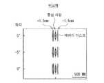
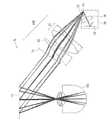
도 2는, 비교예에 따른 화상 표시 장치(101)의 결상 성능을 나타내는 스폿 다이어그램이다. 도 2에는, 관찰자의 눈(100)을 이상적인 렌즈로 가정하고, 그 이상적인 렌즈를 통과한 후의 상면(image plane)에서의 스폿 다이어그램을 나타낸다. 한편, 후술하는 다른 도면에 나타내는 스폿 다이어그램에 대해서도 마찬가지이다.2 is a spot diagram showing the imaging performance of the
도 2에는, 단일 파장 대역에 대해, 중심 파장의 광과, 중심 파장에 대해 ±1.5nm의 파장의 광의 스폿 다이어그램을 나타낸다. 비교예에 따른 화상 표시 장치(101)에서는, 제1 회절부(111)에서, 하나의 광원이 발하는 단일 파장 대역에 대해 색 수차가 발생한다. 비교예에 따른 화상 표시 장치(101)에서는, 이 색 수차를 보정할 수 없으며, 도 2에 나타낸 바와 같이 상면에서 상이 깨어져, 화질이 저하된다.Fig. 2 shows a spot diagram of light having a center wavelength and a wavelength of ±1.5 nm with respect to a single wavelength band. In the
또한, 특허문헌 2(일본특허공개 평11-194295호 공보(도 4))에는, 색이 다른 복수의 광원을 배치함으로써 발생하는 색 수차를, 회절 광학 소자 등의 색 수차 발생 수단으로 보정하는 기술이 개시되어 있다. 그러나, 특허문헌 2에 기재된 기술에서는, 하나의 광원이 발하는 동일한 색(단일 파장 대역)에서의 다른 파장 간의 색 수차를 보정하는 것은 곤란하다.In addition, in Patent Document 2 (Japanese Patent Laid-Open No. 11-194295 (Fig. 4)), a technique for correcting chromatic aberration caused by disposing a plurality of light sources of different colors with chromatic aberration generating means such as a diffractive optical element Is disclosed. However, in the technique described in Patent Document 2, it is difficult to correct chromatic aberration between different wavelengths in the same color (single wavelength band) emitted by one light source.
이에, 본 개시에서는, 단일 파장 대역에 있어서의 색 수차를 억제하는 것이 가능한 기술을 제공한다. 이와 함께, 비점 수차 및 상면 만곡을 억제하는 것이 가능한 기술을 제공한다. 이에 의해, 고화질의 화상 표시를 하는 것이 가능한 화상 표시 장치를 제공한다.Thus, the present disclosure provides a technique capable of suppressing chromatic aberration in a single wavelength band. In addition, a technique capable of suppressing astigmatism and curvature of the image surface is provided. Thereby, an image display device capable of displaying high-quality images is provided.
[1.1 제1 실시형태에 따른 화상 표시 장치의 개요][1.1 Outline of the image display device according to the first embodiment]
(화상 표시 장치의 개요)(Overview of image display device)
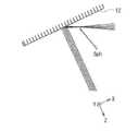
도 3은, 본 개시의 제1 실시형태에 따른 화상 표시 장치(1)의 개요를 나타내고 있다. 도 3에는, XZ면 내에 있어서의 구성을 나타낸다.3 shows an outline of the image display device 1 according to the first embodiment of the present disclosure. 3 shows the structure in the XZ plane.
제1 실시형태에 따른 화상 표시 장치(1)는, 화상광을 생성하여 출사하는 화상광 형성부(30)를 구비하고 있다. 또한, 화상 표시 장치(1)는, 제1 회절부(11)와, 제2 회절부(12)와, 릴레이 광학계(20)와, 화상광 형성부(30)를, 더 구비하고 있다.The image display device 1 according to the first embodiment includes an image
화상 표시 장치(1)는, 화상광 형성부(30)에 의해 생성된 화상광을 관찰자의 눈(100)의 동공 위치로 가이드하는 장치이며, 예를 들면 헤드마운트 디스플레이로서 이용 가능하다.The image display device 1 is a device that guides the image light generated by the image
화상광 형성부(30)는, 화상광의 소스가 되는 광원과, 광원으로부터 사출된 광속을 주사함으로써 화상광을 형성하는 주사 광학 소자를 갖고 있다.The image
한편, 도 3에는, 화상광의 광로로서, 단일 파장 대역의 3개 파장의 광(제1 파장광(λg1), 제2 파장광(λg2), 제3 파장광(λg3))의 광로를 도시하고 있다. 또한, 통상, 단일 파장 대역의 광으로서는 ±1.5nm 정도의 광이 상정되지만, 도 3에서는 수차를 보기 쉽게 하기 위해 파장폭을 크게 설정하여 도시하고 있다. 도 3에는, 제2 파장광(λg2)을 중심 파장의 광으로 하고, 중심 파장에 대해 ±10nm의 파장의 광을 제1 파장광(λg1) 및 제3 파장광(λg3)으로서 도시하고 있다. 제2 파장광(λg2)은 예를 들면 517.1nm의 광, 제1 파장광(λg1)은 예를 들면 527.1nm의 광, 제3 파장광(λg3)은 예를 들면 507.1nm의 광이다.On the other hand, Fig. 3 shows an optical path of three wavelengths of light in a single wavelength band (first wavelength light (λg1), second wavelength light (λg2), and third wavelength light (λg3)) as an optical path of image light. have. In addition, normally, light of about ±1.5 nm is assumed as light in a single wavelength band, but in FIG. 3, the wavelength width is set to be large to make the aberration easier to see. In FIG. 3, the second wavelength light λg2 is used as the light of the center wavelength, and light having a wavelength of ±10 nm with respect to the center wavelength is shown as the first wavelength light λg1 and the third wavelength light λg3. The second wavelength light λg2 is light of, for example, 517.1 nm, the first wavelength light λg1 is light of, for example, 527.1 nm, and the third wavelength light λg3 is light of, for example, 507.1 nm.
제1 회절부(11)는, 제2 회절부(12)에 발생하는 색 수차를 보정하는 특성을 갖는다. 제1 회절부(11)는, 예를 들면 홀로그래픽 광학 소자(HOE)이어도 된다. 또한, 제1 회절부(11)는, 예를 들면 회절 격자(DOE)이어도 된다.The
제2 회절부(12)는, 화상광을 관찰자의 동공 위치에 수속시키는 역할을 갖는다. 제2 회절부(12)는, 예를 들면 홀로그래픽 광학 소자이어도 된다. 또한, 제2 회절부(12)는, 예를 들면 회절 격자이어도 된다.The
릴레이 광학계(20)는, 제2 회절부(12)보다 화상광 형성부(30) 측에 배치되어 있다. 또한, 릴레이 광학계(20)는, 제2 회절부(12)에서 발생하는 색 수차를 보정하도록, 화상광을 제1 회절부(11)로부터 제2 회절부(12)로 릴레이하는 역할을 갖는다. 릴레이 광학계(20)는, 제1 릴레이 렌즈(21)와, 제2 릴레이 렌즈(22)를 갖고 있다.The relay
(화상 표시 장치(1)에서 발생하는 수차의 개요)(Summary of aberrations occurring in the image display device 1)
도 4는, 화상 표시 장치(1)에서 발생하는 색 수차의 개요를 나타내고 있다. 도 5는, 화상 표시 장치(1)에서 발생하는 상면 만곡의 개요를 나타내고 있다. 도 6은, 화상 표시 장치(1)에서 발생하는 비점 수차의 개요를 나타내고 있다. 도 6의 상단에는 XZ면 내에 있어서의 구성, 도 6의 하단에는 YZ면 내에 있어서의 구성을 나타낸다. 도 7은, 화상 표시 장치(1)에서 발생하는 구면 수차의 개요를 나타내고 있다.4 shows an overview of chromatic aberration occurring in the image display device 1. 5 shows an outline of the curvature of the image surface generated in the image display device 1. 6 shows an overview of astigmatism occurring in the image display device 1. The configuration in the XZ plane is shown in the upper part of FIG. 6, and the structure in the YZ plane is shown in the lower part of FIG. 7 shows an overview of spherical aberration occurring in the image display device 1.
색 수차는, 제2 회절부(12)에서 화상광이 파장마다 다른 방향으로 편향됨으로써 발생한다(도 4 참조). 관찰자의 눈(100)에는, 각 파장의 광이 정렬된 상태로 입사하는 것이 바람직하다.Chromatic aberration occurs when image light is deflected in different directions for each wavelength in the second diffraction unit 12 (see Fig. 4). It is preferable that light of each wavelength is incident on the observer's
상면 만곡은, 상면(결상점)(42)(도 5 참조)이 주광선에 대해 경사짐으로써 발생한다.The image surface curvature occurs when the image surface (image point) 42 (see Fig. 5) is inclined with respect to the main ray.
화상 표시 장치(1)는, 편심 광학계의 구성으로 되어 있다. 편심 광학계에서의 회절 소자에서는, 편심면으로 입사한 광과 편심면 이외의 면으로 입사한 광 사이에서, 상이한 파워를 갖는다. 이 때문에, XZ면 내에 있어서의 결상 위치와 YZ면 내에 있어서의 결상 위치의 차이가 발생하여, 비점 수차가 된다. 예를 들면, 도 6에 나타낸 바와 같이, 제2 회절부(12)로부터 결상점까지의 XZ면 내에 있어서의 거리(dxz)와 YZ면 내에 있어서의 거리(dyz)가 상이함으로써, 비점 수차가 된다.The image display device 1 has a configuration of an eccentric optical system. The diffraction element in an eccentric optical system has a different power between light incident on an eccentric surface and light incident on a surface other than the eccentric surface. For this reason, a difference between the imaging position in the XZ plane and the imaging position in the YZ plane occurs, resulting in astigmatism. For example, as shown in Fig. 6, astigmatism is caused by the difference in the distance dxz in the XZ plane from the
화상 표시 장치(1)에 있어서, 구면 수차(Sph)는, 상이한 높이로 입사한 광이 XZ면 내에서 하나의 점에서 결상하지 않음으로써 발생한다.In the image display device 1, the spherical aberration Sph occurs when light incident at different heights does not form an image at one point in the XZ plane.
(화상 표시 장치(1)에서 발생하는 수차의 보정 방법의 개요)(Summary of correction method for aberration occurring in image display device 1)
도 8은, 화상 표시 장치(1)에 있어서 발생하는 색 수차, 및 비점 수차의 보정 방법의 개요를 나타내고 있다. 도 9는, 화상 표시 장치(1)에 있어서 발생하는 상면 만곡의 보정 방법의 개요를 나타내고 있다. 또한, 도 8 및 도 9에서는, 제2 파장광(λg2)을 중심 파장의 광으로 하고, 중심 파장에 대해 ±1.5nm의 파장의 광을 제1 파장광(λg1) 및 제3 파장광(λg3)으로 하여 도시하고 있다. 제2 파장광(λg2)은 예를 들면 517.1nm의 광, 제1 파장광(λg1)은 예를 들면 518.6nm의 광, 제3 파장광(λg3)은 예를 들면 515.6nm의 광이다.FIG. 8 shows an outline of a method for correcting chromatic aberration and astigmatism occurring in the image display device 1. 9 shows an outline of a method of correcting the curvature of the image surface generated in the image display device 1. In addition, in Figs. 8 and 9, the second wavelength light λg2 is used as the center wavelength light, and the light having a wavelength of ±1.5 nm relative to the center wavelength is used as the first wavelength light λg1 and the third wavelength light λg3. ). The second wavelength light λg2 is light of 517.1 nm, the first wavelength light λg1 is light of 518.6 nm, and the third wavelength light λg3 is light of 515.6 nm, for example.
(색 수차의 보정)(Correction of chromatic aberration)
제1 회절부(11)에, 제2 회절부(12)로 입사하는 적어도 일부의 광(예를 들면 화상의 중심을 형성하는 광)에 대해, 제2 회절부(12)와는 광학적으로 대칭인 색 수차를 발생시키는 특성을 갖게 한다. 또한, 도 8에 나타낸 바와 같이, 제1 회절부(11), 릴레이 광학계(20), 및 제2 회절부(12)를, 색 수차를 보정하는 배치로 한다. 릴레이 광학계(20)는, 제1 회절부(11)에 의한 상을 제2 회절부(12)로 릴레이하는 광학계로 되어 있다. 제1 회절부(11)와 제2 회절부(12)의 각각으로부터 본 광선의 입사각이 같게 되도록, 제1 회절부(11), 릴레이 광학계(20), 및 제2 회절부(12)를 배치한다. 이에 의해, 빔 웨이스트(bw)의 위치에 관계없이, 색 수차가 보정된다.With respect to at least some light incident on the
(비점 수차의 보정)(Correction of astigmatism)
제1 회절부(11)에 입사하는 빔 형상(빔 직경, 빔 발산각)을 조정함으로써, 비점 수차를 보정할 수 있다. 예를 들면, XZ면 내 및 YZ면 내에 있어서의 빔 웨이스트(bw)의 위치를 조정함으로써, 비점 수차를 보정할 수 있다.The astigmatism can be corrected by adjusting the shape of the beam (beam diameter, beam divergence angle) incident on the
(상면 만곡의 보정)(Correction of top surface curvature)
도 9에 나타낸 바와 같이, 제1 회절부(11)측에 상면(41), 제2 회절부(12)측에 상면(42)이 형성된다. 제1 회절부(11)와 릴레이 광학계(20)를, 제2 회절부(12)측의 상면 만곡이 보정되도록 배치함으로써, 제2 회절부(12)측의 상면 만곡을 보정할 수 있다.As shown in Fig. 9, an upper surface 41 is formed on the side of the first
[1.2 제1 실시형태에 따른 화상 표시 장치의 구체예][1.2 Specific Examples of the Image Display Device According to the First Embodiment]
(제1 구체예)(First specific example)
도 10은, 제1 실시형태에 있어서의 제1 구체예에 따른 화상 표시 장치(1A)의 구성을 나타내고 있다.10 shows a configuration of an image display device 1A according to a first specific example in the first embodiment.
제1 구체예에 따른 화상 표시 장치(1A)는, 화상광 형성부(30)가, 복수의 광학 소자를 갖고, 복수의 광학 소자의 일부를, 제1 회절부(11)와 제2 회절부(12)의 사이에 배치한 구성으로 되어 있다.In the image display device 1A according to the first specific example, the image
화상광 형성부(30)는, 복수의 광학 소자와, 광원(34)을 갖고 있다. 화상광 형성부(30)는, 복수의 광학 소자로서, 주사 미러(31)를 갖고 있다.The image
또한, 화상광 형성부(30)는, 복수의 광학 소자로서, 보정 렌즈(32)를 갖고 있어도 된다. 보정 렌즈(32)는, 제2 회절부(12)에서 발생하는 비점 수차를 보정하는 보정 광학 소자이다. 보정 렌즈(32)는, 광원(34)과 주사 미러(31)의 사이의 임의의 위치에 배치할 수 있다.Further, the image
광원(34)은, 예를 들면 레이저 다이오드로 이루어지는 레이저 광원이다.The
주사 미러(31)는, 화상광을 형성하는 주사 광학 소자이다. 주사 미러(31)는, 예를 들면 MEMS(Micro Electro Mechanical Systems) 미러로 구성되어 있다. 주사 미러(31)는, 광원(34)으로부터의 레이저광을 화상 데이터에 기초하여 2차원적으로 주사함으로써, 2차원적인 화상광을 생성한다. 주사 미러(31)의 주사 방향 및 주사 타이밍은, 화상 데이터에 기초하여 제어된다.The
주사 미러(31)는, 제1 회절부(11)와 제2 회절부(12)의 사이에 배치되어 있다. 또한, 주사 미러(31)는, 릴레이 광학계(20)에 있어서의 제1 릴레이 렌즈(21)와 제2 릴레이 렌즈(22)의 사이에 배치되어 있다. 제1 릴레이 렌즈(21)는, 제1 회절부(11)와 주사 미러(31)의 사이에 배치되어 있다.The
이와 같이, 제1 구체예에 따른 화상 표시 장치(1A)에서는, 복수의 광학 소자의 일부로서 주사 미러(31)가, 제1 회절부(11)와 제2 회절부(12)의 사이에 배치된 구성으로 되어 있다.As described above, in the image display device 1A according to the first specific example, the
제1 구체예에 따른 화상 표시 장치(1A)에서는, 화상광 형성부(30) 내의 보정 렌즈(32)에 의해, 제1 회절부(11)에 입사하는 빔 형상(빔 직경, 빔 발산각)을 조정함으로써, 비점 수차를 보정할 수 있다. 예를 들면, XZ면 내 및 YZ면 내에 있어서의 빔 웨이스트(bw)의 위치를 조정함으로써, 비점 수차를 보정할 수 있다.In the image display device 1A according to the first specific example, the beam shape (beam diameter, beam divergence angle) incident on the
제1 구체예에 따른 화상 표시 장치(1A)에서는, 제1 회절부(11)는, 릴레이 광학계(20)의 제1 릴레이 렌즈(21) 및 제2 릴레이 렌즈(22)와 함께 결상계의 일부로서, 색 수차를 보정하는 역할을 갖는다.In the image display device 1A according to the first specific example, the
제1 구체예에 따른 화상 표시 장치(1A)에서는, 릴레이 광학계(20)의 제2 릴레이 렌즈(22)가, 제2 회절부(12)의 상면 만곡을 보정하는 역할을 갖는다. 제2 릴레이 렌즈(22)는, 제2 회절부(12)로부터 보아, 각 화각의 광이 최적인 결상 위치가 되고, 상면(42)의 기울기가 최적이 되는 위치 및 기울기로 배치되어 있는 것이 바람직하다.In the image display device 1A according to the first specific example, the
제2 릴레이 렌즈(22)와 제2 회절부(12)의 거리(D1)는, 관찰자의 시야에 제2 회절부(12)로부터의 광 이외의 광이 입사하지 않는 값으로 설정하는 것이 바람직하다. 이에 의해, 관찰자의 시야에 제2 릴레이 렌즈(22)가 보이지 않도록 하는 것이 바람직하다. 또한, 거리(D1)는, 관찰자의 머리부와 화상 표시 장치(1A)의 광학계가 간섭하지 않도록 설정하는 것이 바람직하다.The distance D1 between the
제1 구체예에 따른 화상 표시 장치(1A)의 입사동(entrance pupil)은 예를 들면 0.5mm이다. 화각은 예를 들면 ±20°이다.The entrance pupil of the image display device 1A according to the first specific example is, for example, 0.5 mm. The angle of view is, for example, ±20°.
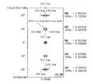
도 11~도 15는, 제1 구체예에 따른 화상 표시 장치(1A)의 결상 성능을 나타내는 스폿 다이어그램이다. 도 11에는 화각 -20°, 도 12에는 화각 -10°, 도 13에는 화각 0°, 도 14에는 화각 +10°, 도 15에는 화각 +20°에서의 스폿 다이어그램을 나타낸다. 한편, 여기에서 말하는 화각은, 도 10에 있어서의 X방향의 화각(ω)을 나타낸다. 화각(ω)은, 도 10에 나타낸 바와 같이, Z방향의 축(광축)에 대해 좌측으로부터 관찰자의 눈(100)에 입사하는 광선의 각도를 -(마이너스), 우측으로부터 관찰자의 눈(100)에 입사하는 광선의 각도를 +(플러스)로 한다. 도 11~도 15에는, 단일 파장 대역에 대해, 중심 파장(517.1nm)의 광과, 중심 파장에 대해 ±1.5nm의 파장의 광의 스폿 다이어그램을 나타낸다.11 to 15 are spot diagrams showing the imaging performance of the image display device 1A according to the first specific example. FIG. 11 shows a spot diagram at a view angle of -20°, a view angle of -10° in FIG. 12, a view angle of 0° in FIG. 13, a view angle of +10° in FIG. 14, and a view angle of +20° in FIG. On the other hand, the angle of view referred to herein indicates the angle of view (ω) in the X direction in FIG. 10. As shown in FIG. 10, the angle of view (ω) is the angle of the light rays incident on the observer's
도 11~도 15에 나타낸 바와 같이, 제1 구체예에 따른 화상 표시 장치(1A)에 의하면, 색 수차가 양호하게 보정되어 있다.As shown in Figs. 11 to 15, according to the image display device 1A according to the first specific example, chromatic aberration is satisfactorily corrected.
(제2 구체예)(2nd specific example)
도 16은, 제1 실시형태에 있어서의 제2 구체예에 따른 화상 표시 장치(1B)의 구성을 나타내고 있다.16 shows a configuration of an
제2 구체예에 따른 화상 표시 장치(1B)는, 제1 구체예에 따른 화상 표시 장치(1A)에 대해, 릴레이 광학계(20)로부터 출사된 화상광을 제2 회절부(12)로 가이드하는 도광판(13)을 구비하고 있다.The
도광판(13)은, 서로 대향하는 제1 면(13A) 및 제2 면(13B)을 갖고 있다.The
도광판(13)의 제2 면(13B)에는, 프리즘(14)이 배치되어 있다. 프리즘(14)은, 화상광을 도광판(13)에 입사시키는 역할을 갖는다. 프리즘(14)에는, 각 화소의 광로 길이를 조정하는 역할을 갖게 할 수 있다.A
제2 회절부(12)는, 도광판의 제1 면(13A) 및 제2 면(13B) 중 어느 일방의 면에 배치되어 있다. 도 16에서는, 제1 면(13A)에 제2 회절부(12)를 배치하고 있다.The
그 밖의 구성은, 제1 구체예에 따른 화상 표시 장치(1A)와 대략 마찬가지여도 된다.Other configurations may be substantially the same as those of the image display device 1A according to the first specific example.
(제3 구체예)(Third specific example)
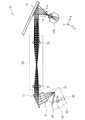
도 17은, 제1 실시형태에 있어서의 제3 구체예에 따른 화상 표시 장치(1C)의 구성을 나타내고 있다.17 shows the configuration of an image display device 1C according to a third specific example in the first embodiment.
제3 구체예에 따른 화상 표시 장치(1C)는, 제1 구체예에 따른 화상 표시 장치(1A)에 대해, 화상광 형성부(30)의 전체를, 관찰자로부터 보아 제1 회절부(11)와 제2 회절부(12)보다 먼 곳에 배치한 구성으로 되어 있다.In the image display device 1C according to the third specific example, in the image display device 1A according to the first specific example, the entire image
제3 구체예에 따른 화상 표시 장치(1C)에서는, 복수의 광학 소자로서, 주사 미러(31)와, 보정 렌즈(32)와, 반사 미러(33)를 갖고 있다.In the image display device 1C according to the third specific example, a
반사 미러(33)는, 광원(34)으로부터의 광을 주사 미러(31)를 향해 반사하는 역할을 갖는다.The
제3 구체예에 따른 화상 표시 장치(1C)에서는, 주사 미러(31)는, 제1 회절부(11)보다도 전방(관찰자로부터 보아 먼 곳)에 배치된 구성으로 되어 있다. 제3 구체예에 따른 화상 표시 장치(1C)에서는, 제1 회절부(11)에 주사 미러(31)로부터 출사된 후의 화상광이 입사한다.In the image display device 1C according to the third specific example, the
제3 구체예에 따른 화상 표시 장치(1C)에서는, 제1 회절부(11)와 제2 회절부(12)를 광학적으로 동일한 작용을 갖는 회절 소자로 구성하고, XZ면 내에서 좌우 대칭적으로 배치함으로써, 색 수차를 양호하게 보정할 수 있다.In the image display device 1C according to the third specific example, the first
제3 구체예에 따른 화상 표시 장치(1C)의 입사동은 예를 들면 0.5mm이다. 화각은 예를 들면 ±20°이다.The entrance pupil of the image display device 1C according to the third specific example is 0.5 mm, for example. The angle of view is, for example, ±20°.
도 18은, 제3 구체예에 따른 화상 표시 장치(1C)의 결상 성능을 나타내는 스폿 다이어그램이다. 도 18에는, 단일 파장 대역에 대해, 중심 파장(517.1nm)의 광과, 중심 파장에 대해 ±1.5nm의 파장의 광의 스폿 다이어그램을 나타낸다. 도 18에는 화각 -20°~+20°의 범위에 있어서의 스폿 다이어그램을 나타낸다. 한편, 여기서 말하는 화각은, 도 17에 있어서의 X방향의 화각(ω)을 나타낸다. 화각(ω)은, 도 17에 나타낸 바와 같이, Z방향의 축(광축)에 대해 좌측으로부터 관찰자의 눈(100)에 입사하는 광선의 각도를 -(마이너스), 우측으로부터 관찰자의 눈(100)에 입사하는 광선의 각도를 +(플러스)로 한다.18 is a spot diagram showing the imaging performance of the image display device 1C according to the third specific example. Fig. 18 shows a spot diagram of light having a center wavelength (517.1 nm) and light having a wavelength of ±1.5 nm with respect to a single wavelength band. Fig. 18 shows a spot diagram in the range of -20° to +20° angle of view. On the other hand, the angle of view referred to herein represents the angle of view (ω) in the X direction in FIG. 17. As shown in FIG. 17, the angle of view ω is the angle of the light rays incident on the observer's
도 18에 나타낸 바와 같이, 제3 구체예에 따른 화상 표시 장치(1C)에 의하면, 색 수차가 양호하게 보정되어 있다.As shown in Fig. 18, according to the image display device 1C according to the third specific example, chromatic aberration is satisfactorily corrected.
그 밖의 구성은, 제1 구체예에 따른 화상 표시 장치(1A)와 대략 마찬가지여도 된다.Other configurations may be substantially the same as those of the image display device 1A according to the first specific example.
(제4 구체예)(4th specific example)
도 19는, 제1 실시형태에 있어서의 제4 구체예에 따른 화상 표시 장치(1D)의 구성을 나타내고 있다.19 shows a configuration of an image display device 1D according to a fourth specific example in the first embodiment.
제4 구체예에 따른 화상 표시 장치(1D)는, 제3 구체예에 따른 화상 표시 장치(1C)에 대해, 화상광 형성부(30)(주사 미러(31))와 제1 회절부(11)의 사이에, 콜리메이터 렌즈(51)를 배치한 구성으로 되어 있다.The image display device 1D according to the fourth specific example includes an image light forming unit 30 (scanning mirror 31) and a
제1 회절부(11)가 평행광을 평행광으로 회절하는 소자이기 때문에, 콜리메이터 렌즈(51)는, 주사 미러(31)에 의해 형성된 화상광을 평행광으로 하는 역할을 갖는다.Since the
제4 구체예에 따른 화상 표시 장치(1D)의 입사동은 예를 들면 0.5mm이다. 화각은 예를 들면 ±20°이다.The entrance pupil of the image display device 1D according to the fourth specific example is 0.5 mm, for example. The angle of view is, for example, ±20°.
도 20은, 제4 구체예에 따른 화상 표시 장치(1D)의 결상 성능을 나타내는 스폿 다이어그램이다. 도 20에는, 단일 파장 대역에 대해, 중심 파장(517.1nm)의 광과, 중심 파장에 대해 ±1.5nm의 파장의 광의 스폿 다이어그램을 나타낸다. 도 20에는 화각 -20°~+20°의 범위에 있어서의 스폿 다이어그램을 나타낸다. 한편, 여기에서 말하는 화각은, 도 19에 있어서의 X방향의 화각(ω)을 나타낸다. 화각(ω)은, 도 19에 나타낸 바와 같이, Z방향의 축(광축)에 대해 좌측으로부터 관찰자의 눈(100)에 입사하는 광선의 각도를 -(마이너스), 우측으로부터 관찰자의 눈(100)에 입사하는 광선의 각도를 +(플러스)로 한다.20 is a spot diagram showing the imaging performance of the image display device 1D according to the fourth specific example. In Fig. 20, spot diagrams of light having a center wavelength (517.1 nm) and light having a wavelength of ±1.5 nm with respect to a single wavelength band are shown. Fig. 20 shows a spot diagram in the range of -20° to +20° angle of view. In addition, the angle of view referred to here represents the angle of view (ω) in the X direction in FIG. 19. As shown in FIG. 19, the angle of view ω is the angle of the light rays incident on the observer's
도 20에 나타낸 바와 같이, 제4 구체예에 따른 화상 표시 장치(1D)에 의하면, 색 수차가 양호하게 보정되어 있다.As shown in Fig. 20, according to the image display device 1D according to the fourth specific example, chromatic aberration is satisfactorily corrected.
그 밖의 구성은, 제3 구체예에 따른 화상 표시 장치(1C)와 대략 마찬가지여도 된다.Other configurations may be substantially the same as those of the image display device 1C according to the third specific example.
(제5 구체예)(Fifth specific example)
도 21은, 제1 실시형태에 있어서의 제5 구체예에 따른 화상 표시 장치(1E)의 구성을 나타내고 있다.21 shows the configuration of an
제5 구체예에 따른 화상 표시 장치(1E)는, 제3 구체예에 따른 화상 표시 장치(1C)에 대해, 릴레이 광학계(20) 대신에 릴레이 광학계(20A)를 구비하고 있다.The
제3 구체예에 따른 화상 표시 장치(1C)에 있어서의 릴레이 광학계(20)는, 제1 릴레이 렌즈(21)와 제2 릴레이 렌즈(22)가 등배율의 광학계로 되어 있다. 이에 대해, 제5 구체예에 따른 화상 표시 장치(1E)에 있어서의 릴레이 광학계(20A)는, 제1 릴레이 렌즈(21A)와 제2 릴레이 렌즈(22A)가 확대 광학계로 되어 있다.In the relay
제5 구체예에 따른 화상 표시 장치(1E)에서는, 예를 들면, 화상광 형성부(30)에 의해 ±20°의 화각의 화상광을 형성한다. 릴레이 광학계(20A)는, 화각을 예를 들면 ±40°로 확대한다. 이에 의해, 광화각화를 도모한다.In the
그 밖의 구성은, 제3 구체예에 따른 화상 표시 장치(1C)와 대략 마찬가지여도 된다.Other configurations may be substantially the same as those of the image display device 1C according to the third specific example.
(제6 구체예)(6th specific example)
도 22는, 제1 실시형태에 있어서의 제6 구체예에 따른 화상 표시 장치(1F)의 구성을 나타내고 있다.22 shows a configuration of an
제6 구체예에 따른 화상 표시 장치(1F)는, 제3 구체예에 따른 화상 표시 장치(1C)에 대해, 릴레이 광학계(20) 대신에 릴레이 광학계(20B)를 구비하고 있다.The
제6 구체예에 따른 화상 표시 장치(1F)에 있어서의 릴레이 광학계(20B)는, 제1 릴레이 렌즈(21)와 제2 릴레이 렌즈(22)의 사이에, 광로를 접는 반사 광학 소자(23) 및 반사 광학 소자(24)를 구비하고 있다. 반사 광학 소자(23) 및 반사 광학 소자(24)는, 예를 들면, 반사 미러나 프리즘으로 구성할 수 있다.The relay
제6 구체예에 따른 화상 표시 장치(1F)에 의하면, 반사 광학 소자(23) 및 반사 광학 소자(24)에 의해, 광로를 접음으로써, 소형화를 도모할 수 있다. 또한, 예를 들면, 헤드 마운트 디스플레이에 적용하였을 경우, 관찰자의 얼굴 주위에 맞는 구성으로 하는 것이 용이하게 된다.According to the
그 밖의 구성은, 제3 구체예에 따른 화상 표시 장치(1C)와 대략 마찬가지여도 된다.Other configurations may be substantially the same as those of the image display device 1C according to the third specific example.
(제7 구체예)(7th specific example)
도 23은, 제1 실시형태에 있어서의 제7 구체예에 따른 화상 표시 장치(1G)의 구성을 나타내고 있다.23 shows a configuration of an image display device 1G according to a seventh specific example in the first embodiment.
제7 구체예에 따른 화상 표시 장치(1G)는, 예를 들면 R(적), G(녹), B(청)의 풀 컬러 표시에 대응한 구성으로 되어 있다.The image display device 1G according to the seventh specific example has a configuration corresponding to full color display of R (red), G (green), and B (blue), for example.
제7 구체예에 따른 화상 표시 장치(1G)는, 제3 구체예에 따른 화상 표시 장치(1C)에 대해, 릴레이 광학계(20) 대신에 릴레이 광학계(20C)를 구비하고 있다.The image display device 1G according to the seventh specific example is provided with a relay optical system 20C instead of the relay
릴레이 광학계(20C)는, 풀 컬러 표시에 대응한 제1 릴레이 렌즈(21B)와 제2 릴레이 렌즈(22B)를 갖고 있다. 제1 릴레이 렌즈(21B)와 제2 릴레이 렌즈(22B)는, 아크로마트 렌즈(achromatic lens)로 구성되며, 복수의 색 간의 수차를 보정하는 작용을 갖고 있다.The relay optical system 20C has a first relay lens 21B and a second relay lens 22B corresponding to full color display. The first relay lens 21B and the second relay lens 22B are constituted by an achromatic lens, and have an action of correcting aberrations between a plurality of colors.
또한, 제7 구체예에 따른 화상 표시 장치(1G)에서는, 제1 회절부(11)와 제2 회절부(12)는 각각, 풀 컬러 표시에 대응한 서로 파장 대역이 다른 복수의 색의 화상광을 관찰자의 동공 위치를 향해 수속시키도록, 각각이 복수의 회절 패턴을 적층화한 구조, 또는 복수의 회절 패턴을 다중화한 구조, 또는 이들 적층화한 구조와 다중화한 구조를 조합시킨 구조를 갖고 있다.In addition, in the image display device 1G according to the seventh specific example, the first
그 밖의 구성은, 제3 구체예에 따른 화상 표시 장치(1C)와 대략 마찬가지여도 된다.Other configurations may be substantially the same as those of the image display device 1C according to the third specific example.
[1.3 효과][1.3 Effect]
이상 설명한 바와 같이, 제1 실시형태에 따른 화상 표시 장치에 의하면, 제2 회절부(12)에서 발생하는 색 수차를 제1 회절부(11)와 릴레이 광학계(20)에 의해 보정하도록 하였기 때문에, 색 수차가 억제된 고화질의 화상 표시를 하는 것이 가능하게 된다.As described above, according to the image display device according to the first embodiment, since the chromatic aberration occurring in the
그 밖에, 제1 실시형태에 따른 화상 표시 장치에 의하면, 이하와 같은 효과를 갖는다.In addition, the image display device according to the first embodiment has the following effects.
제2 회절부(12)에서 발생하는 상면 만곡을 보정하고, 고화질의 영상을 얻을 수 있다.The curvature of the image surface generated in the
제1 회절부(11)와 제2 회절부(12)의 사이에 화상광 형성부(30)의 일부를 배치함으로써, 광학계의 소형화가 가능하게 된다(도 10 등). 또한, 제2 회절부(12)에서 발생하는 비점 수차를 보정하여 고화질의 영상을 얻을 수 있다. 또한, 릴레이 광학계(20A)의 배율을 조정함으로써, 화상광 형성부(30)로부터 사출되는 화각을 넓게 할 수 있다(도 21). 또한, 광학계를 반사 소자를 사용하여 접어 구부림으로써, 아이웨어(eyewear)에 적합한 형상으로 할 수 있다(도 22). 또한, 릴레이 광학계(20)의 배율이나 릴레이 렌즈의 촛점거리를 조정함으로써, 릴레이 광학계(20)의 길이를 짧게 할 수 있어, 소형화가 가능하게 된다.By disposing a part of the image
한편, 본 명세서에 기재된 효과는 어디까지나 예시이며 한정되는 것이 아니고, 또한 다른 효과가 있어도 된다. 이후의 다른 실시형태의 효과에 대해서도 마찬가지이다.In addition, the effect described in this specification is an illustration to the last, and is not limited, Moreover, another effect may exist. The same applies to the effects of the other embodiments later.
<2. 제2 실시형태><2. Second embodiment>
다음으로, 본 개시의 제2 실시형태에 따른 화상 표시 장치에 대해 설명한다. 한편, 이하에서는, 상기 제1 실시형태에 따른 화상 표시 장치의 구성요소와 대략 같은 부분에 대해서는, 동일부호를 붙여 적절히 설명을 생략한다.Next, an image display device according to a second embodiment of the present disclosure will be described. In the following, parts that are substantially the same as those of the image display device according to the first embodiment are denoted by the same reference numerals, and descriptions thereof are omitted as appropriate.
제2 실시형태에 따른 화상 표시 장치는, 상기 제1 실시형태에 따른 화상 표시 장치에 대해, 눈동자 위치의 이동에 따른 화상 표시를 가능하도록 한 구성예에 관한 것이다.The image display device according to the second embodiment relates to a configuration example in which an image display device according to the first embodiment enables image display according to movement of the pupil position.
제2 실시형태에 따른 화상 표시 장치는, 관찰자의 동공 위치를 검출하는 검출부와, 검출부의 검출 결과에 기초하여 화상광의 수속(收束; convergence) 위치를 관찰자의 동공 위치로 이동시키는 제어부를 더 구비하고 있다. 이하, 구체적인 구성예를 설명한다.The image display device according to the second embodiment further includes a detection unit for detecting a pupil position of an observer, and a control unit for moving a convergence position of image light to a pupil position of the observer based on a detection result of the detection unit. Are doing. Hereinafter, a specific configuration example will be described.
(제1 구체예)(First specific example)
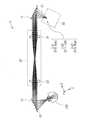
도 24는, 제2 실시형태에 있어서의 제1 구체예에 따른 화상 표시 장치(1H)의 구성을 나타내고 있다.Fig. 24 shows a configuration of an image display device 1H according to a first specific example in the second embodiment.
제1 구체예에 따른 화상 표시 장치(1H)는, 위치 검출부(61)와, 구동 제어부(62)를 구비하고 있다.The image display device 1H according to the first specific example includes a
위치 검출부(61)는, 관찰자의 동공 위치를 검출하는 검출부이다.The
구동 제어부(62)는, 위치 검출부(61)의 검출 결과에 기초하여 화상광의 수속 위치를 관찰자의 동공 위치로 이동시키는 제어부이다. 구동 제어부(62)는, 제2 회절부(12)를 관찰자의 시야의 수평 방향, 관찰자의 시야의 수직 방향, 및 관찰자의 안구의 깊이 방향에 대응하는 적어도 하나의 이동 방향으로 이동시킴으로써, 화상광의 수속 위치를 관찰자의 동공 위치로 이동시킨다.The driving
도 24에 있어서, Lb는, 하나의 집광점에 대해 사용하는 제2 회절부(12)의 영역을 나타낸다. db는, 제2 회절부(12)의 이동량(=집광점의 이동량)을 나타낸다. dc는, 제2 회절부(12)의 Z방향의 이동량(=집광점의 Z방향의 이동량)을 나타낸다.In Fig. 24, Lb denotes a region of the
그 밖의 구성, 동작 및 효과는, 상기 제1 실시형태에 따른 화상 표시 장치와 거의 마찬가지여도 된다.Other configurations, operations, and effects may be substantially the same as those of the image display device according to the first embodiment.
(제2 구체예)(2nd specific example)
도 25는, 제2 실시형태에 있어서의 제2 구체예에 따른 화상 표시 장치(1I)의 구성을 나타내고 있다.Fig. 25 shows the configuration of an image display device 1I according to a second specific example in the second embodiment.
제2 구체예에 따른 화상 표시 장치(1I)는, 위치 검출부(61)와, 구동 제어부(63)를 구비하고 있다.The image display device 1I according to the second specific example includes a
구동 제어부(63)는, 위치 검출부(61)의 검출 결과에 기초하여 화상광의 수속 위치를 관찰자의 동공 위치로 이동시키는 제어부이다. 구동 제어부(63)는, 화상광 형성부(30)(화상광 형성부(30) 전체, 또는 주사 미러(31))를, 관찰자의 시야의 수평 방향, 관찰자의 시야의 수직 방향, 및 관찰자의 안구의 깊이 방향에 대응하는 적어도 하나의 이동 방향으로 이동시킴으로써, 화상광의 수속 위치를 관찰자의 동공 위치로 이동시킨다.The
도 25에 있어서, da는 화상 형성부(30)에 있어서의 집광점의 이동량을 나타낸다.In FIG. 25, da denotes the amount of movement of the light-converging point in the
그 밖의 구성, 동작 및 효과는, 상기 제1 실시형태에 따른 화상 표시 장치와 거의 마찬가지여도 된다.Other configurations, operations, and effects may be substantially the same as those of the image display device according to the first embodiment.
(제3 구체예)(Third specific example)
도 26은, 제2 실시형태에 있어서의 제3 구체예에 따른 화상 표시 장치(1J)의 구성을 나타내고 있다.26 shows the configuration of an
제3 구체예에 따른 화상 표시 장치(1J)는, 위치 검출부(61)와, 구동 제어부(64)를 구비하고 있다. 또한, 화상 표시 장치(1J)는, 가동 반사 미러(35)를 구비하고 있다.The
가동 반사 미러(35)는, 배치 각도를 변화시킴으로써, 화상광의 수속 위치를 이동시키는 것이 가능한 가동 반사 소자이다. 가동 반사 미러(35)는, 화상광 형성부(30)로부터 출사된 화상광의 광로 상에 배치되어 있다. 가동 반사 미러(35)는, 화상광 형성부(30)와 제2 회절부(12)의 사이에 배치되어 있다.The
구동 제어부(64)는, 위치 검출부(61)의 검출 결과에 기초하여 가동 반사 미러(35)의 배치 각도를 변화시킴으로써, 화상광의 수속 위치를 관찰자의 동공 위치로 이동시킨다.The
그 밖의 구성, 동작 및 효과는, 상기 제1 실시형태에 따른 화상 표시 장치와 거의 마찬가지여도 된다.Other configurations, operations, and effects may be substantially the same as those of the image display device according to the first embodiment.
<3. 제3 실시형태><3. Third embodiment>
다음으로, 본 개시의 제3 실시형태에 따른 화상 표시 장치에 대해 설명한다. 한편, 이하에서는, 상기 제1 또는 제2 실시형태에 따른 화상 표시 장치의 구성요소와 거의 같은 부분에 대해서는, 동일부호를 붙여, 적절히 설명을 생략한다.Next, an image display device according to a third embodiment of the present disclosure will be described. In the following, parts that are substantially the same as those of the image display device according to the first or second embodiment are denoted by the same reference numerals, and descriptions thereof will be omitted as appropriate.
[3.1 제3 실시형태에 따른 화상 표시 장치의 개요][3.1 Overview of the image display device according to the third embodiment]
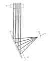
도 27은, 본 개시의 제3 실시형태에 따른 화상 표시 장치(1K)의 개요를 나타내고 있다.Fig. 27 shows an overview of an
제3 실시형태에 따른 화상 표시 장치(1K)는, 제1 실시형태에 따른 화상 표시 장치(1)(도 3)에 대해, 제1 회절부(11)를, 제1 회절 소자(71)와 제2 회절 소자(72)로 구성하고 있다. 또한, 제3 실시형태에 따른 화상 표시 장치(1K)는, 제1 회절 소자(71)와 제2 회절 소자(72)의 사이의 광로 상에 콜리메이터 렌즈(80)를 구비한다.In the
제1 회절 소자(71)는, 제2 회절부(12)에서 발생하는 색 수차를 보정하는 특성을 갖는다. 제1 회절 소자(71)는, 투과형의 회절 소자이다. 제1 회절 소자(71)는, 예를 들면 홀로그래픽 광학 소자이어도 된다. 또한, 제1 회절 소자(71)는, 예를 들면 회절 격자(DOE)이어도 된다.The first
제2 회절 소자(72)는, 제1 회절 소자(71)와 제2 회절부(12)의 사이의 광로 상에 배치되며, 제1 회절 소자(71)로부터 출사된 화상광을 수속시키는 작용을 갖는다. 제2 회절 소자(72)는, 투과형의 회절 소자이다. 제2 회절 소자(72)는, 예를 들면 홀로그래픽 광학 소자이어도 된다. 또한, 제2 회절 소자(72)는, 예를 들면 회절 격자이어도 된다.The
콜리메이터 렌즈(80)와 제2 회절 소자(72)는, 화상광 형성부(30)로부터의 화상광을 제1 회절 소자(71)로부터 제2 회절부(12)로 릴레이하는 릴레이 광학계(20D)를 구성하고 있다. 즉, 제2 회절 소자(72)는, 릴레이 광학계(20D)의 일부를 구성하고 있다.The
제1 실시형태에 따른 화상 표시 장치(1)에서는, 제1 회절부(11)를 제2 회절부(12)에 대해 공역인 위치에 배치할 필요가 있다. 이에 대해, 제3 실시형태에 따른 화상 표시 장치(1K)에서는, 제1 회절부(11)를 제1 회절 소자(71)와 제2 회절 소자(72)로 구성함으로써, 제1 회절 소자(71)를 공역인 위치에 배치할 필요는 없게 된다.In the image display device 1 according to the first embodiment, it is necessary to arrange the first
제2 회절부(12)에 의해 반사된 광은, 모든 파장이 평행하게 된 상태로 관찰자의 눈으로 들어갈 필요가 있다. 이를 위해서는, 제2 회절부(12)에 입사하는 광의 각도를, 파장마다 적절하게 바꿀 필요가 있다. 제3 실시형태에 따른 화상 표시 장치(1K)에서는, 화상광 형성부(30)로부터의 화상광이 제1 회절 소자(71)에 의해, 제2 회절부(12)에서 발생하는 색 수차를 상쇄하도록 분산된다. 도 27에서는 분산된 파장 성분의 예로서, 제1 파장광(λg1), 제2 파장광(λg2), 및 제3 파장광(λg3)을 나타낸다. 이들 분산된 광은, 콜리메이터 렌즈(80)와 제2 회절 소자(72)에 의해, 제2 회절부(12)에 대해 파장마다 적절한 입사각도가 되도록 각도가 조정된다.The light reflected by the
[3.2 제3 실시형태에 따른 화상 표시 장치의 구체예][3.2 Specific Example of the Image Display Device According to the Third Embodiment]
이하에서는, 도 27에 나타낸 화상 표시 장치(1K)의 구성요소와 거의 같은 부분에 대해서는, 동일부호를 붙여, 적절히 설명을 생략한다.In the following, parts that are substantially the same as those of the
(제1 구체예)(First specific example)
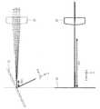
도 28은, 제3 실시형태에 있어서의 제1 구체예에 따른 화상 표시 장치(1L)의 구성을 나타내고 있다.28 shows a configuration of an
제1 구체예에 따른 화상 표시 장치(1L)에 있어서, 화상광 형성부(30)는, 도시하지 않은 광원과, 주사 미러(31)와, 반사 미러(33)와, 렌즈(36)를 갖고 있다. 렌즈(36)는, 예를 들면 토로이달 렌즈(toroidal lens)이다.In the
또한, 제1 구체예에 따른 화상 표시 장치(1L)에 있어서, 제1 회절 소자(71)와 제2 회절 소자(72)의 사이의 광로 상에는, 결상 렌즈(81)와 프리즘(82)이 배치되어 있다. 제1 회절 소자(71)는, 주사 미러(31)와 결상 렌즈(82)의 사이의 광로 상에 배치되어 있다. 제2 회절 소자(72), 결상 렌즈(81) 및 프리즘(82)는 릴레이 광학계(20E)를 구성하고 있다. 제1 구체예에 따른 화상 표시 장치(1L)에 있어서, 제1 회절 소자(71)와 제2 회절 소자(72)는 각각, 투과형의 회절 소자로 되어 있다.Further, in the
(제2 구체예)(2nd specific example)
도 29는, 제3 실시형태에 있어서의 제2 구체예에 따른 화상 표시 장치(1M)의 구성을 나타내고 있다.29 shows a configuration of an
도 29에 나타낸 바와 같이, 도 28에 나타낸 제1 구체예에 따른 화상 표시 장치(1L)의 구성에 대해, 제1 회절 소자(71)를 투과형의 회절 소자로 하고, 제2 회절 소자(72)를 반사형의 회절 소자로 하는 구성도 가능하다. 그 밖의 구성은, 도 28에 나타낸 제1 구체예에 따른 화상 표시 장치(1L)의 구성과 거의 마찬가지여도 된다.As shown in Fig. 29, with respect to the configuration of the
(제3 구체예)(Third specific example)
도 30은, 제3 실시형태에 있어서의 제3 구체예에 따른 화상 표시 장치(1N)의 구성을 나타내고 있다.30 shows a configuration of an image display device 1N according to a third specific example in the third embodiment.
도 30에 나타낸 바와 같이, 도 28에 나타낸 제1 구체예에 따른 화상 표시 장치(1L)의 구성에 대해, 제1 회절 소자(71)를, 화상광 형성부(30)에 있어서의 주사 미러(31) 앞에 배치하는 구성도 가능하다. 그 밖의 구성은, 도 28에 나타낸 제1 구체예에 따른 화상 표시 장치(1L)의 구성과 거의 마찬가지여도 된다.As shown in Fig. 30, with respect to the configuration of the
(제4 구체예)(4th specific example)
도 31은, 제3 실시형태에 있어서의 제4 구체예에 따른 화상 표시 장치(1O)의 구성을 나타내고 있다.Fig. 31 shows a configuration of an
도 28에 나타낸 제1 구체예에 따른 화상 표시 장치(1L)의 구성에 대해, 구면 미러 광학계를 사용한 구성도 가능하다. 예를 들면 도 31에 나타낸 바와 같이, 복수의 오목면 미러(83A, 83B, 83C)를 사용한 구성도 가능하다. 제4 구체예에 따른 화상 표시 장치(1O)에 있어서, 제1 회절 소자(71)는, 도시하지 않은 광원과 주사 미러(31)의 사이의 광로 상에 배치되어 있다. 제4 구체예에 따른 화상 표시 장치(1O)에 있어서, 제1 회절 소자(71)는 반사형의 회절 소자, 제2 회절 소자(72)는 투과형의 회절 소자로 되어 있다. 또한, 제4 구체예에 따른 화상 표시 장치(1O)에 있어서, 주사 미러(31)와 제2 회절 소자(72)의 사이의 광로 상에는, 복수의 오목면 미러(83A, 83B, 83C)가 배치되어 있다. 제2 회절 소자(72)와 복수의 오목면 미러(83A, 83B, 83C)는 릴레이 광학계(20F)를 구성하고 있다.With respect to the configuration of the
[3.3 제3 실시형태에 따른 화상 표시 장치의 변형예][3.3 Modified Example of the Image Display Device According to the Third Embodiment]
도 32는, 도 27에 나타낸 제3 실시형태에 따른 화상 표시 장치(1K)에 대한 변형예에 관한 화상 표시 장치(1P)의 개요를 나타내고 있다.FIG. 32 shows an outline of an
본 개시에 의한 기술에 있어서, 제1 회절부(11)를 3 이상의 회절 소자로 구성하는 것도 가능하다. 도 32에는, 제1 회절부(11)를, 제1 회절 소자(71)와 제2 회절 소자(72)와 제3 회절 소자(73)로 구성한 예를 나타낸다. 제1 내지 제3 회절 소자(71~73)는, 투과형의 회절 소자이다. 제1 내지 제3 회절 소자(71~73)는, 예를 들면 홀로그래픽 광학 소자이어도 된다.In the technique according to the present disclosure, it is also possible to configure the first
도 32에 나타낸 변형예에 관한 화상 표시 장치(1P)에 있어서, 제2 회절 소자(72)와 제3 회절 소자(73)는, 제1 회절 소자(71)로부터 출사된 화상광을 수속시키는 작용을 갖는다.In the
[3.4 효과][3.4 Effect]
이상 설명한 바와 같이, 제3 실시형태에 따른 화상 표시 장치에 의하면, 제1 회절부(11)를 복수의 회절 소자로 구성하도록 하였기 때문에, 설계 자유도를 제공하면서 색 수차를 개선하여, 보다 이미지 품질을 향상시킬 수 있다. 제3 실시형태에 따른 화상 표시 장치에 의하면, 광학 설계 자유도가 증가하기 때문에, 광학계의 소형화가 실현 가능하게 된다.As described above, according to the image display device according to the third embodiment, since the
그 밖의 구성, 동작 및 효과는, 상기 제1 또는 제2 실시형태에 따른 화상 표시 장치와 거의 마찬가지여도 된다.Other configurations, operations, and effects may be substantially the same as those of the image display device according to the first or second embodiment.
<4. 그 밖의 실시형태><4. Other embodiments>
본 개시에 의한 기술은, 상기 각 실시형태의 설명에 한정되지 않으며 다양한 변형 실시가 가능하다.The technology according to the present disclosure is not limited to the description of each of the above embodiments, and various modifications are possible.
예를 들면 도 16에 나타낸 화상 표시 장치(1B)의 구성에 대해, 제2 회절부(12)를 복수 설치하도록 하여도 된다. 예를 들면, 다른 파장 대역용의 복수의 제2 회절부(12)를 설치하도록 하여도 된다. 예를 들면, 도광판(13)의 제1 면(13A) 및 제2 면(13B) 중 어느 일방의 면에, 적색 표시용의 제2 회절부(12)를 배치하고, 타방의 면에, 녹색 및 청색 표시용의 제2 회절부(12)를 배치하여도 된다.For example, with respect to the configuration of the
또한, 본 개시에 의한 기술은, 헤드 마운트 디스플레이에 한하지 않고, 프로젝터 등에도 적용 가능하다.In addition, the technology according to the present disclosure is not limited to a head mounted display, but can also be applied to a projector or the like.
예를 들면, 본 기술은 이하와 같은 구성을 취할 수도 있다.For example, the present technology may have the following configuration.
이하의 구성 본 기술에 의하면, 제2 회절부에서 발생하는 색 수차를 제1 회절부와 릴레이 광학계에 의해 보정하도록 하였기 때문에, 색 수차가 억제된 고화질의 화상 표시를 하는 것이 가능해진다.The following configuration According to the present technology, since the chromatic aberration occurring in the second diffraction section is corrected by the first diffraction section and the relay optical system, it becomes possible to display a high-quality image in which chromatic aberration is suppressed.
(1)(One)
화상광을 출사하는 화상광 형성부와,An image light forming unit that emits image light,
적어도 하나의 회절 소자를 갖는 제1 회절부와, 상기 화상광을 관찰자의 동공 위치에 수속시키는 제2 회절부를 포함하고, 상기 제1 회절부가, 상기 제2 회절부에서 발생하는 색 수차를 보정하는 특성을 갖는 회절 광학계와,A first diffraction unit having at least one diffractive element; and a second diffraction unit for converging the image light to a pupil position of an observer, and the first diffraction unit corrects chromatic aberration occurring in the second diffraction unit A diffraction optical system having characteristics,
상기 제2 회절부보다도 상기 화상광 형성부 측에 배치되고, 상기 제2 회절부에서 발생하는 색 수차를 보정하도록 상기 화상광을 상기 제2 회절부로 릴레이하는 릴레이 광학계를 구비하는 화상 표시 장치.An image display device comprising: a relay optical system disposed on a side of the image light forming unit rather than the second diffraction unit, and relaying the image light to the second diffraction unit so as to correct chromatic aberration occurring in the second diffraction unit.
(2)(2)
상기 제1 회절부는, 상기 제2 회절부에 입사하는 적어도 일부의 광에 대해, 상기 제2 회절부와는 광학적으로 대칭인 색 수차를 발생시키는 특성을 갖는 상기(1)에 기재된 화상 표시 장치.The image display device according to (1), wherein the first diffraction portion has a characteristic of generating chromatic aberration optically symmetrical to the second diffraction portion with respect to at least a portion of light incident on the second diffraction portion.
(3)(3)
상기 화상광 형성부는, 복수의 광학 소자를 갖고, 상기 복수의 광학 소자의 일부가 상기 제1 회절부와 상기 제2 회절부의 사이에 배치되어 있는 상기(1) 또는 (2)에 기재된 화상 표시 장치.The image display device according to (1) or (2), wherein the image light forming unit has a plurality of optical elements, and a part of the plurality of optical elements is disposed between the first diffraction unit and the second diffraction unit. .
(4)(4)
상기 화상광 형성부는, 상기 복수의 광학 소자로서 상기 화상광을 형성하는 주사 광학 소자를 갖고, 상기 주사 광학 소자가 상기 제1 회절부와 상기 제2 회절부의 사이에 배치되어 있는 상기(3)에 기재된 화상 표시 장치.The image light forming portion has a scanning optical element for forming the image light as the plurality of optical elements, and the scanning optical element is disposed between the first and second diffractive portions. The described image display device.
(5)(5)
상기 화상광 형성부는, 전체가, 상기 관찰자로부터 보아 상기 제1 회절부와 상기 제2 회절부보다 먼 곳에 배치되어 있는 상기(1) 또는 (2)에 기재된 화상 표시 장치.The image display device according to (1) or (2), wherein the image light forming unit is disposed in a position farther than the first and second diffraction units as viewed from the observer.
(6)(6)
상기 화상광 형성부는, 상기 제2 회절부에서 발생하는 비점 수차를 보정하는 보정 광학 소자를 갖는 상기(1) 내지 (5) 중 어느 하나에 기재된 화상 표시 장치.The image display device according to any one of (1) to (5), wherein the image light forming unit includes a correcting optical element for correcting astigmatism occurring in the second diffraction unit.
(7)(7)
상기 제1 회절부와 상기 제2 회절부는 각각, 서로 파장 대역의 다른 복수의 화상광을 상기 관찰자의 동공 위치를 향해 수속시키도록, 각각이 복수의 회절 패턴을 적층화한 구조, 또는 복수의 회절 패턴을 다중화한 구조, 또는 이들 적층화한 구조와 다중화한 구조를 조합시킨 구조를 갖는 상기(1) 내지 (6) 중 어느 하나에 기재된 화상 표시 장치.A structure in which a plurality of diffraction patterns are stacked, or a plurality of diffraction patterns, respectively, so that the first diffractive unit and the second diffractive unit respectively converge a plurality of image lights of different wavelength bands toward the pupil position of the observer. The image display device according to any one of the above (1) to (6), having a structure in which patterns are multiplexed or a structure in which the layered structure and the multiplexed structure are combined.
(8)(8)
상기 관찰자의 동공 위치를 검출하는 검출부와,A detection unit that detects the position of the pupil of the observer,
상기 검출부의 검출 결과에 기초하여, 상기 제2 회절부를, 상기 관찰자의 시야의 수평 방향, 상기 관찰자의 시야의 수직 방향, 및 상기 관찰자의 안구의 깊이 방향에 대응하는 적어도 하나의 이동 방향으로 이동시킴으로써, 상기 화상광의 수속 위치를 상기 관찰자의 동공 위치로 이동시키는 제어부를 더 구비하는 상기(1) 내지 (7) 중 어느 하나에 기재된 화상 표시 장치.Based on the detection result of the detection unit, by moving the second diffraction unit in at least one movement direction corresponding to the horizontal direction of the observer's field of view, the vertical direction of the observer's field of view, and the depth direction of the observer's eyeball. And a control unit for moving the converging position of the image light to the pupil position of the observer. The image display device according to any one of (1) to (7) above.
(9)(9)
상기 관찰자의 동공 위치를 검출하는 검출부와,A detection unit that detects the position of the pupil of the observer,
상기 검출부의 검출 결과에 기초하여, 상기 화상광 형성부를, 상기 관찰자의 시야의 수평 방향, 상기 관찰자의 시야의 수직 방향, 및 상기 관찰자의 안구의 깊이 방향에 대응하는 적어도 하나의 이동 방향으로 이동시킴으로써, 상기 화상광의 수속 위치를 상기 관찰자의 동공 위치로 이동시키는 제어부를 더 구비하는 상기(1) 내지 (7) 중 어느 하나에 기재된 화상 표시 장치.Based on the detection result of the detection unit, the image light forming unit is moved in at least one moving direction corresponding to the horizontal direction of the observer's field of view, the vertical direction of the observer's field of view, and the depth direction of the observer's eyeball. And a control unit for moving the converging position of the image light to the pupil position of the observer. The image display device according to any one of (1) to (7) above.
(10)(10)
상기 화상광 형성부는,The image light forming unit,
광원과,Light source,
상기 광원으로부터 사출된 광속을 주사함으로써 상기 화상광을 형성하는 주사 광학 소자를 갖는 상기(1) 내지 (9) 중 어느 하나에 기재된 화상 표시 장치.The image display device according to any one of (1) to (9), comprising a scanning optical element that forms the image light by scanning a beam of light emitted from the light source.
(11)(11)
배치 각도를 변화시킴으로써, 상기 화상광의 수속 위치를 이동시키는 것이 가능한 가동 반사 소자를 더 구비하는 상기(1) 내지 (10) 중 어느 하나에 기재된 화상 표시 장치.The image display device according to any one of (1) to (10), further comprising a movable reflective element capable of moving the converging position of the image light by changing the arrangement angle.
(12)(12)
상기 관찰자의 동공 위치를 검출하는 검출부와,A detection unit that detects the position of the pupil of the observer,
상기 검출부의 검출 결과에 기초하여, 상기 가동 반사 소자의 배치 각도를 변화시킴으로써, 상기 화상광의 수속 위치를 상기 관찰자의 동공 위치로 이동시키는 제어부를 더 구비하는 상기(11)에 기재된 화상 표시 장치.The image display device according to (11), further comprising a control unit for moving the converging position of the image light to the pupil position of the observer by changing the arrangement angle of the movable reflective element based on the detection result of the detection unit.
(13)(13)
상기 가동 반사 소자는, 상기 화상광 형성부로부터 출사된 상기 화상광의 광로 상에 배치되어 있는 상기(11) 또는 (12)에 기재된 화상 표시 장치.The image display device according to (11) or (12), wherein the movable reflective element is disposed on an optical path of the image light emitted from the image light forming unit.
(14)(14)
상기 가동 반사 소자는, 상기 화상광 형성부와 상기 제2 회절부의 사이에 배치되어 있는 상기(13)에 기재된 화상 표시 장치.The image display device according to (13), wherein the movable reflective element is disposed between the image light forming portion and the second diffractive portion.
(15)(15)
상기 릴레이 광학계로부터 출사된 상기 화상광을 상기 제2 회절부로 가이드하는 도광판을 더 구비하는 상기(1) 내지 (14) 중 어느 하나에 기재된 화상 표시 장치.The image display device according to any one of (1) to (14), further comprising a light guide plate for guiding the image light emitted from the relay optical system to the second diffraction unit.
(16)(16)
상기 도광판은, 서로 대향하는 제1 면 및 제2 면을 갖고,The light guide plate has a first surface and a second surface facing each other,
상기 제2 회절부는, 상기 도광판의 상기 제1 면 및 상기 제2 면 중 적어도 일방의 면에 배치되어 있는 상기(15)에 기재된 화상 표시 장치.The image display device according to (15), wherein the second diffractive portion is disposed on at least one of the first surface and the second surface of the light guide plate.
(17)(17)
상기 제1 회절부는,The first diffraction unit,
상기 제2 회절부에서 발생하는 색 수차를 보정하는 특성을 갖는 제1 회절 소자와,A first diffraction element having a characteristic of correcting chromatic aberration occurring in the second diffraction unit,
상기 제1 회절 소자와 상기 제2 회절부의 사이의 광로 상에 배치되고, 상기 제1 회절 소자로부터 출사된 상기 화상광을 수속시키는 제2 회절 소자를 갖는 상기(1) 또는 (2)에 기재된 화상 표시 장치.The image described in (1) or (2) above, which has a second diffractive element disposed on an optical path between the first diffractive element and the second diffractive part and converging the image light emitted from the first diffractive element. Display device.
(18)(18)
상기 제2 회절 소자는, 상기 릴레이 광학계의 일부를 구성하고 있는 상기(17)에 기재된 화상 표시 장치.The image display device according to (17), wherein the second diffractive element constitutes a part of the relay optical system.
(19)(19)
상기 제1 회절 소자는, 투과형의 회절 소자이며,The first diffraction element is a transmission type diffraction element,
상기 제2 회절 소자는, 투과형 또는 반사형의 회절 소자인 상기(17) 또는 (18)에 기재된 화상 표시 장치.The image display device according to (17) or (18), wherein the second diffractive element is a transmission type or reflection type diffractive element.
(20)(20)
상기 제1 회절 소자는, 반사형의 회절 소자이며,The first diffractive element is a reflective diffractive element,
상기 제2 회절 소자는, 투과형 또는 반사형의 회절 소자인 상기(17) 또는 (18)에 기재된 화상 표시 장치.The image display device according to (17) or (18), wherein the second diffractive element is a transmission-type or reflection-type diffraction element.
본 출원은, 일본 특허청에 2018년 6월 8일에 출원된 일본 특허출원번호 제2018-110305호, 및 2019년 5월 7일에 출원된 일본 특허출원번호 제2019-87456호를 기초로 하여 우선권을 주장하는 것이며, 이 출원의 모든 내용을 참조에 의해 본 출원에 원용한다.This application has priority based on Japanese Patent Application No. 2018-110305 filed with the Japan Intellectual Property Office on June 8, 2018, and Japanese Patent Application No. 2019-87456 filed on May 7, 2019. All the contents of this application are incorporated in this application by reference.
당업자라면, 설계상의 요건이나 다른 요인에 따라, 다양한 수정, 콤비네이션, 서브 콤비네이션, 및 변경을 생각해 낼 수 있으며, 이들은 첨부의 청구의 범위나 그 균등물의 범위에 포함되는 것으로 이해된다.Those skilled in the art can conceive of various modifications, combinations, sub-combinations, and changes according to design requirements or other factors, which are understood to be included in the scope of the appended claims and their equivalents.
Claims (20)
Translated fromKorean적어도 하나의 회절 소자를 갖는 제1 회절부와, 상기 화상광을 관찰자의 동공 위치에 수속시키는 제2 회절부를 포함하고, 상기 제1 회절부가 상기 제2 회절부에서 발생하는 색 수차를 보정하는 특성을 갖는 회절 광학계와,
상기 제2 회절부보다도 상기 화상광 형성부 측에 배치되고, 상기 제2 회절부에서 발생하는 색 수차를 보정하도록 상기 화상광을 상기 제2 회절부로 릴레이(relay)하는 릴레이 광학계를 구비하는 화상 표시 장치.An image light forming unit that emits image light,
A first diffraction unit having at least one diffractive element; and a second diffraction unit for converging the image light to a pupil position of an observer; and the first diffraction unit corrects chromatic aberration occurring in the second diffraction unit A diffraction optical system having
An image display comprising a relay optical system disposed on the side of the image light forming part rather than the second diffraction part, and relaying the image light to the second diffraction part to correct chromatic aberration occurring in the second diffraction part Device.
상기 제1 회절부는, 상기 제2 회절부에 입사하는 적어도 일부의 광에 대해, 상기 제2 회절부와는 광학적으로 대칭인 색 수차를 발생시키는 특성을 갖는 화상 표시 장치.The method of claim 1,
The first diffraction unit has a characteristic of generating chromatic aberration optically symmetrical to the second diffraction unit with respect to at least a portion of light incident on the second diffraction unit.
상기 화상광 형성부는, 복수의 광학 소자를 갖고, 상기 복수의 광학 소자의 일부가 상기 제1 회절부와 상기 제2 회절부의 사이에 배치되어 있는 화상 표시 장치.The method of claim 1,
The image light forming unit includes a plurality of optical elements, and a part of the plurality of optical elements is disposed between the first diffractive unit and the second diffractive unit.
상기 화상광 형성부는, 상기 복수의 광학 소자로서 상기 화상광을 형성하는 주사 광학 소자를 갖고, 상기 주사 광학 소자가 상기 제1 회절부와 상기 제2 회절부의 사이에 배치되어 있는 화상 표시 장치.The method of claim 3,
The image light forming unit has a scanning optical element that forms the image light as the plurality of optical elements, and the scanning optical element is disposed between the first diffractive unit and the second diffractive unit.
상기 화상광 형성부는, 전체가 상기 관찰자로부터 보아 상기 제1 회절부와 상기 제2 회절부보다 먼 곳에 배치되어 있는 화상 표시 장치.The method of claim 1,
An image display device in which the image light forming unit is disposed as a whole farther than the first and second diffractive units as viewed from the observer.
상기 화상광 형성부는, 상기 제2 회절부에서 발생하는 비점 수차를 보정하는 보정 광학 소자를 갖는 화상 표시 장치.The method of claim 1,
The image light forming unit includes a correction optical element for correcting astigmatism occurring in the second diffraction unit.
상기 제1 회절부와 상기 제2 회절부는 각각, 서로 파장 대역의 다른 복수의 화상광을 상기 관찰자의 동공 위치를 향해 수속시키도록, 각각이 복수의 회절 패턴을 적층화한 구조, 또는 복수의 회절 패턴을 다중화한 구조, 또는 이들 적층화한 구조와 다중화한 구조를 조합시킨 구조를 갖는 화상 표시 장치.The method of claim 1,
A structure in which a plurality of diffraction patterns are stacked, or a plurality of diffraction patterns, respectively, so that the first diffractive unit and the second diffractive unit respectively converge a plurality of image lights of different wavelength bands toward the pupil position of the observer. An image display device having a structure in which patterns are multiplexed, or a structure in which a layered structure and a multiplexed structure are combined.
상기 관찰자의 동공 위치를 검출하는 검출부와,
상기 검출부의 검출 결과에 기초하여, 상기 제2 회절부를, 상기 관찰자의 시야의 수평 방향, 상기 관찰자의 시야의 수직 방향, 및 상기 관찰자의 안구의 깊이 방향에 대응하는 적어도 하나의 이동 방향으로 이동시킴으로써, 상기 화상광의 수속 위치를 상기 관찰자의 동공 위치로 이동시키는 제어부를 더 구비하는 화상 표시 장치.The method of claim 1,
A detection unit that detects the position of the pupil of the observer,
Based on the detection result of the detection unit, by moving the second diffraction unit in at least one movement direction corresponding to the horizontal direction of the observer's field of view, the vertical direction of the observer's field of view, and the depth direction of the observer's eyeball. And a control unit for moving the convergence position of the image light to the pupil position of the observer.
상기 관찰자의 동공 위치를 검출하는 검출부와,
상기 검출부의 검출 결과에 기초하여, 상기 화상광 형성부를, 상기 관찰자의 시야의 수평 방향, 상기 관찰자의 시야의 수직 방향, 및 상기 관찰자의 안구의 깊이 방향에 대응하는 적어도 하나의 이동 방향으로 이동시킴으로써, 상기 화상광의 수속 위치를 상기 관찰자의 동공 위치로 이동시키는 제어부를 더 구비하는 화상 표시 장치.The method of claim 1,
A detection unit that detects the position of the pupil of the observer,
Based on the detection result of the detection unit, the image light forming unit is moved in at least one moving direction corresponding to the horizontal direction of the observer's field of view, the vertical direction of the observer's field of view, and the depth direction of the observer's eyeball. And a control unit for moving the convergence position of the image light to the pupil position of the observer.
상기 화상광 형성부는,
광원과,
상기 광원으로부터 사출된 광속을 주사함으로써 상기 화상광을 형성하는 주사 광학 소자를 갖는 화상 표시 장치.The method of claim 1,
The image light forming unit,
Light source,
An image display device having a scanning optical element for forming the image light by scanning a beam of light emitted from the light source.
배치 각도를 변화시킴으로써, 상기 화상광의 수속 위치를 이동시키는 것이 가능한 가동 반사 소자를 더 구비하는 화상 표시 장치.The method of claim 1,
An image display device further comprising a movable reflective element capable of moving the converging position of the image light by changing an arrangement angle.
상기 관찰자의 동공 위치를 검출하는 검출부와,
상기 검출부의 검출 결과에 기초하여, 상기 가동 반사 소자의 배치 각도를 변화시킴으로써, 상기 화상광의 수속 위치를 상기 관찰자의 동공 위치로 이동시키는 제어부를 더 구비하는 화상 표시 장치.The method of claim 11,
A detection unit that detects the position of the pupil of the observer,
An image display device further comprising a control unit for moving the converging position of the image light to the pupil position of the observer by changing an arrangement angle of the movable reflective element based on a detection result of the detection unit.
상기 가동 반사 소자는, 상기 화상광 형성부로부터 출사된 상기 화상광의 광로 상에 배치되어 있는 화상 표시 장치.The method of claim 11,
The movable reflective element is disposed on an optical path of the image light emitted from the image light forming unit.
상기 가동 반사 소자는, 상기 화상광 형성부와 상기 제2 회절부의 사이에 배치되어 있는 화상 표시 장치.The method of claim 13,
The movable reflective element is disposed between the image light forming unit and the second diffractive unit.
상기 릴레이 광학계로부터 출사된 상기 화상광을 상기 제2 회절부로 가이드하는 도광판을 더 구비하는 화상 표시 장치.The method of claim 1,
An image display device further comprising a light guide plate for guiding the image light emitted from the relay optical system to the second diffraction unit.
상기 도광판은, 서로 대향하는 제1 면 및 제2 면을 갖고,
상기 제2 회절부는, 상기 도광판의 상기 제1 면 및 상기 제2 면 중 적어도 일방의 면에 배치되어 있는 화상 표시 장치.The method of claim 15,
The light guide plate has a first surface and a second surface facing each other,
The second diffractive portion is disposed on at least one of the first surface and the second surface of the light guide plate.
상기 제1 회절부는,
상기 제2 회절부에서 발생하는 색 수차를 보정하는 특성을 갖는 제1 회절 소자와,
상기 제1 회절 소자와 상기 제2 회절부의 사이의 광로 상에 배치되고, 상기 제1 회절 소자로부터 출사된 상기 화상광을 수속시키는 제2 회절 소자를 갖는 화상 표시 장치.The method of claim 1,
The first diffraction unit,
A first diffraction element having a characteristic of correcting chromatic aberration occurring in the second diffraction unit,
An image display device having a second diffractive element disposed on an optical path between the first diffractive element and the second diffractive part, and converging the image light emitted from the first diffractive element.
상기 제2 회절 소자는, 상기 릴레이 광학계의 일부를 구성하고 있는 화상 표시 장치.The method of claim 17,
The second diffractive element constitutes a part of the relay optical system.
상기 제1 회절 소자는, 투과형의 회절 소자이며,
상기 제2 회절 소자는, 투과형 또는 반사형의 회절 소자인 화상 표시 장치.The method of claim 17,
The first diffraction element is a transmission type diffraction element,
The second diffractive element is a transmissive or reflective diffractive element.
상기 제1 회절 소자는, 반사형의 회절 소자이며,
상기 제2 회절 소자는, 투과형 또는 반사형의 회절 소자인 화상 표시 장치.The method of claim 17,
The first diffractive element is a reflective diffractive element,
The second diffractive element is a transmissive or reflective diffractive element.
Applications Claiming Priority (5)
| Application Number | Priority Date | Filing Date | Title |
|---|---|---|---|
| JP2018110305 | 2018-06-08 | ||
| JPJP-P-2018-110305 | 2018-06-08 | ||
| JPJP-P-2019-087456 | 2019-05-07 | ||
| JP2019087456 | 2019-05-07 | ||
| PCT/JP2019/021293WO2019235320A1 (en) | 2018-06-08 | 2019-05-29 | Image display device |
Publications (2)
| Publication Number | Publication Date |
|---|---|
| KR20210018198Atrue KR20210018198A (en) | 2021-02-17 |
| KR102785589B1 KR102785589B1 (en) | 2025-03-21 |
Family
ID=68769521
Family Applications (1)
| Application Number | Title | Priority Date | Filing Date |
|---|---|---|---|
| KR1020207030242AActiveKR102785589B1 (en) | 2018-06-08 | 2019-05-29 | Video display device |
Country Status (6)
| Country | Link |
|---|---|
| US (1) | US12025810B2 (en) |
| EP (1) | EP3805847A4 (en) |
| JP (1) | JPWO2019235320A1 (en) |
| KR (1) | KR102785589B1 (en) |
| CN (1) | CN112219152B (en) |
| WO (1) | WO2019235320A1 (en) |
Families Citing this family (1)
| Publication number | Priority date | Publication date | Assignee | Title |
|---|---|---|---|---|
| WO2021220638A1 (en)* | 2020-04-28 | 2021-11-04 | ソニーグループ株式会社 | Display device |
Citations (6)
| Publication number | Priority date | Publication date | Assignee | Title |
|---|---|---|---|---|
| JP2008083539A (en) | 2006-09-28 | 2008-04-10 | Brother Ind Ltd | Optical system for light beam transfer, and retinal scanning display using the same |
| JP2008145701A (en)* | 2006-12-08 | 2008-06-26 | Canon Inc | Image display device and image display system |
| JP2010117542A (en)* | 2008-11-13 | 2010-05-27 | Panasonic Corp | Beam scanning-type display device |
| JP2017167181A (en)* | 2016-03-14 | 2017-09-21 | セイコーエプソン株式会社 | Display device and light guide device |
| WO2018043625A1 (en)* | 2016-08-31 | 2018-03-08 | パナソニックIpマネジメント株式会社 | Display device |
| JP2018087949A (en)* | 2016-11-30 | 2018-06-07 | セイコーエプソン株式会社 | Video display device and light guide device |
Family Cites Families (14)
| Publication number | Priority date | Publication date | Assignee | Title |
|---|---|---|---|---|
| JPH11194295A (en) | 1997-11-06 | 1999-07-21 | Olympus Optical Co Ltd | Optical system |
| JP2001264685A (en) | 2000-03-23 | 2001-09-26 | Canon Inc | Image display device and image display system |
| JP4082075B2 (en)* | 2002-04-22 | 2008-04-30 | ブラザー工業株式会社 | Image display device |
| JP6111864B2 (en) | 2013-05-24 | 2017-04-12 | 富士通株式会社 | Image display device and image display method |
| JP6413291B2 (en)* | 2014-03-27 | 2018-10-31 | セイコーエプソン株式会社 | Virtual image display device and head mounted display |
| US9529196B1 (en)* | 2014-06-05 | 2016-12-27 | Iphysicist Ltd. | Image guide optics for near eye displays |
| JP2016170203A (en) | 2015-03-11 | 2016-09-23 | コニカミノルタ株式会社 | Image displaying apparatus |
| US9904057B2 (en) | 2015-08-31 | 2018-02-27 | Seiko Epson Corporation | Light guide device and virtual image display apparatus |
| JP2017058400A (en) | 2015-09-14 | 2017-03-23 | コニカミノルタ株式会社 | Image display device |
| WO2018031634A1 (en)* | 2016-08-10 | 2018-02-15 | FictionArt, Inc. | Volume phase holographic waveguide for display |
| CN106646870B (en)* | 2016-09-27 | 2018-12-28 | 东南大学 | A kind of holographical wave guide display system and display methods |
| JP2018054978A (en) | 2016-09-30 | 2018-04-05 | セイコーエプソン株式会社 | Virtual image display device and manufacturing method thereof |
| JP6620737B2 (en) | 2016-12-28 | 2019-12-18 | 京セラドキュメントソリューションズ株式会社 | Image forming apparatus |
| JP2019087456A (en) | 2017-11-08 | 2019-06-06 | ホシデン株式会社 | connector |
- 2019
- 2019-05-29KRKR1020207030242Apatent/KR102785589B1/enactiveActive
- 2019-05-29JPJP2020523656Apatent/JPWO2019235320A1/enactivePending
- 2019-05-29CNCN201980036892.1Apatent/CN112219152B/enactiveActive
- 2019-05-29WOPCT/JP2019/021293patent/WO2019235320A1/ennot_activeCeased
- 2019-05-29EPEP19815671.3Apatent/EP3805847A4/enactivePending
- 2019-05-29USUS15/733,984patent/US12025810B2/enactiveActive
Patent Citations (6)
| Publication number | Priority date | Publication date | Assignee | Title |
|---|---|---|---|---|
| JP2008083539A (en) | 2006-09-28 | 2008-04-10 | Brother Ind Ltd | Optical system for light beam transfer, and retinal scanning display using the same |
| JP2008145701A (en)* | 2006-12-08 | 2008-06-26 | Canon Inc | Image display device and image display system |
| JP2010117542A (en)* | 2008-11-13 | 2010-05-27 | Panasonic Corp | Beam scanning-type display device |
| JP2017167181A (en)* | 2016-03-14 | 2017-09-21 | セイコーエプソン株式会社 | Display device and light guide device |
| WO2018043625A1 (en)* | 2016-08-31 | 2018-03-08 | パナソニックIpマネジメント株式会社 | Display device |
| JP2018087949A (en)* | 2016-11-30 | 2018-06-07 | セイコーエプソン株式会社 | Video display device and light guide device |
Also Published As
| Publication number | Publication date |
|---|---|
| CN112219152B (en) | 2023-10-03 |
| US12025810B2 (en) | 2024-07-02 |
| WO2019235320A1 (en) | 2019-12-12 |
| KR102785589B1 (en) | 2025-03-21 |
| EP3805847A1 (en) | 2021-04-14 |
| CN112219152A (en) | 2021-01-12 |
| JPWO2019235320A1 (en) | 2021-06-24 |
| EP3805847A4 (en) | 2021-10-27 |
| US20210215939A1 (en) | 2021-07-15 |
Similar Documents
| Publication | Publication Date | Title |
|---|---|---|
| JP6424552B2 (en) | Image display device | |
| US11520158B2 (en) | Display device | |
| JP5229327B2 (en) | Video display device, head-mounted display, and head-up display | |
| JP4893200B2 (en) | Optical system for light beam transfer, and retinal scanning display using the same | |
| US10921598B2 (en) | Image projection device | |
| JP2020501199A (en) | Wearable display for near-eye viewing | |
| US11796830B2 (en) | Display device | |
| JP2019133132A (en) | Display unit | |
| JP6468206B2 (en) | Head-up display device | |
| EP2945005A1 (en) | Laser projection system for reducing speckle noise | |
| US11467417B2 (en) | Display device | |
| JP4082075B2 (en) | Image display device | |
| KR20210153087A (en) | Optical arrangement for display | |
| WO2016185992A1 (en) | Display device | |
| KR102785589B1 (en) | Video display device | |
| JP2013148609A (en) | Retina projection display device | |
| US10942431B2 (en) | Virtual image display apparatus | |
| JP2018194820A (en) | Virtual image forming apparatus and moving body | |
| WO2024262391A1 (en) | Image display device and image display method |
Legal Events
| Date | Code | Title | Description |
|---|---|---|---|
| PA0105 | International application | Patent event date:20201021 Patent event code:PA01051R01D Comment text:International Patent Application | |
| PG1501 | Laying open of application | ||
| A201 | Request for examination | ||
| PA0201 | Request for examination | Patent event code:PA02012R01D Patent event date:20220418 Comment text:Request for Examination of Application | |
| E902 | Notification of reason for refusal | ||
| PE0902 | Notice of grounds for rejection | Comment text:Notification of reason for refusal Patent event date:20240514 Patent event code:PE09021S01D | |
| E701 | Decision to grant or registration of patent right | ||
| PE0701 | Decision of registration | Patent event code:PE07011S01D Comment text:Decision to Grant Registration Patent event date:20241219 | |
| GRNT | Written decision to grant | ||
| PR0701 | Registration of establishment | Comment text:Registration of Establishment Patent event date:20250319 Patent event code:PR07011E01D | |
| PR1002 | Payment of registration fee | Payment date:20250319 End annual number:3 Start annual number:1 | |
| PG1601 | Publication of registration |