KR20210016304A - Physiological signal monitoring device - Google Patents
Physiological signal monitoring deviceDownload PDFInfo
- Publication number
- KR20210016304A KR20210016304AKR1020200096692AKR20200096692AKR20210016304AKR 20210016304 AKR20210016304 AKR 20210016304AKR 1020200096692 AKR1020200096692 AKR 1020200096692AKR 20200096692 AKR20200096692 AKR 20200096692AKR 20210016304 AKR20210016304 AKR 20210016304A
- Authority
- KR
- South Korea
- Prior art keywords
- sensing member
- socket
- circuit board
- conduction
- signal
- Prior art date
- Legal status (The legal status is an assumption and is not a legal conclusion. Google has not performed a legal analysis and makes no representation as to the accuracy of the status listed.)
- Granted
Links
- 238000012806monitoring deviceMethods0.000titleclaimsabstractdescription20
- 230000005540biological transmissionEffects0.000claimsdescription29
- 238000000034methodMethods0.000claimsdescription26
- 238000012545processingMethods0.000claimsdescription18
- 229910000831SteelInorganic materials0.000claimsdescription10
- 239000010959steelSubstances0.000claimsdescription10
- 239000012491analyteSubstances0.000claimsdescription9
- 239000002184metalSubstances0.000claimsdescription8
- 230000008569processEffects0.000claimsdescription6
- 238000004891communicationMethods0.000claimsdescription2
- 238000001514detection methodMethods0.000claimsdescription2
- 230000008054signal transmissionEffects0.000abstractdescription4
- 238000012986modificationMethods0.000description9
- 230000004048modificationEffects0.000description9
- 238000012544monitoring processMethods0.000description9
- WQZGKKKJIJFFOK-GASJEMHNSA-NGlucoseNatural productsOC[C@H]1OC(O)[C@H](O)[C@@H](O)[C@@H]1OWQZGKKKJIJFFOK-GASJEMHNSA-N0.000description5
- 239000008103glucoseSubstances0.000description5
- 210000003722extracellular fluidAnatomy0.000description3
- 238000005259measurementMethods0.000description3
- 238000012546transferMethods0.000description3
- 239000000853adhesiveSubstances0.000description2
- 230000001070adhesive effectEffects0.000description2
- 239000008280bloodSubstances0.000description2
- 210000004369bloodAnatomy0.000description2
- 238000006243chemical reactionMethods0.000description2
- 238000010586diagramMethods0.000description2
- 230000003213activating effectEffects0.000description1
- 230000002457bidirectional effectEffects0.000description1
- 238000004364calculation methodMethods0.000description1
- 230000000295complement effectEffects0.000description1
- 239000004020conductorSubstances0.000description1
- 238000012937correctionMethods0.000description1
- 230000008878couplingEffects0.000description1
- 238000010168coupling processMethods0.000description1
- 238000005859coupling reactionMethods0.000description1
- 230000009977dual effectEffects0.000description1
- 239000013013elastic materialSubstances0.000description1
- 238000005516engineering processMethods0.000description1
- 238000003780insertionMethods0.000description1
- 230000037431insertionEffects0.000description1
- 238000004519manufacturing processMethods0.000description1
Images


Classifications
- A—HUMAN NECESSITIES
- A61—MEDICAL OR VETERINARY SCIENCE; HYGIENE
- A61B—DIAGNOSIS; SURGERY; IDENTIFICATION
- A61B5/00—Measuring for diagnostic purposes; Identification of persons
- A61B5/145—Measuring characteristics of blood in vivo, e.g. gas concentration or pH-value ; Measuring characteristics of body fluids or tissues, e.g. interstitial fluid or cerebral tissue
- A61B5/1468—Measuring characteristics of blood in vivo, e.g. gas concentration or pH-value ; Measuring characteristics of body fluids or tissues, e.g. interstitial fluid or cerebral tissue using chemical or electrochemical methods, e.g. by polarographic means
- A61B5/1473—Measuring characteristics of blood in vivo, e.g. gas concentration or pH-value ; Measuring characteristics of body fluids or tissues, e.g. interstitial fluid or cerebral tissue using chemical or electrochemical methods, e.g. by polarographic means invasive, e.g. introduced into the body by a catheter
- A—HUMAN NECESSITIES
- A61—MEDICAL OR VETERINARY SCIENCE; HYGIENE
- A61B—DIAGNOSIS; SURGERY; IDENTIFICATION
- A61B5/00—Measuring for diagnostic purposes; Identification of persons
- A61B5/145—Measuring characteristics of blood in vivo, e.g. gas concentration or pH-value ; Measuring characteristics of body fluids or tissues, e.g. interstitial fluid or cerebral tissue
- A61B5/14532—Measuring characteristics of blood in vivo, e.g. gas concentration or pH-value ; Measuring characteristics of body fluids or tissues, e.g. interstitial fluid or cerebral tissue for measuring glucose, e.g. by tissue impedance measurement
- A—HUMAN NECESSITIES
- A61—MEDICAL OR VETERINARY SCIENCE; HYGIENE
- A61B—DIAGNOSIS; SURGERY; IDENTIFICATION
- A61B5/00—Measuring for diagnostic purposes; Identification of persons
- A61B5/0002—Remote monitoring of patients using telemetry, e.g. transmission of vital signals via a communication network
- A61B5/0031—Implanted circuitry
- A—HUMAN NECESSITIES
- A61—MEDICAL OR VETERINARY SCIENCE; HYGIENE
- A61B—DIAGNOSIS; SURGERY; IDENTIFICATION
- A61B5/00—Measuring for diagnostic purposes; Identification of persons
- A61B5/145—Measuring characteristics of blood in vivo, e.g. gas concentration or pH-value ; Measuring characteristics of body fluids or tissues, e.g. interstitial fluid or cerebral tissue
- A61B5/14503—Measuring characteristics of blood in vivo, e.g. gas concentration or pH-value ; Measuring characteristics of body fluids or tissues, e.g. interstitial fluid or cerebral tissue invasive, e.g. introduced into the body by a catheter or needle or using implanted sensors
- A—HUMAN NECESSITIES
- A61—MEDICAL OR VETERINARY SCIENCE; HYGIENE
- A61B—DIAGNOSIS; SURGERY; IDENTIFICATION
- A61B5/00—Measuring for diagnostic purposes; Identification of persons
- A61B5/145—Measuring characteristics of blood in vivo, e.g. gas concentration or pH-value ; Measuring characteristics of body fluids or tissues, e.g. interstitial fluid or cerebral tissue
- A61B5/14507—Measuring characteristics of blood in vivo, e.g. gas concentration or pH-value ; Measuring characteristics of body fluids or tissues, e.g. interstitial fluid or cerebral tissue specially adapted for measuring characteristics of body fluids other than blood
- A61B5/1451—Measuring characteristics of blood in vivo, e.g. gas concentration or pH-value ; Measuring characteristics of body fluids or tissues, e.g. interstitial fluid or cerebral tissue specially adapted for measuring characteristics of body fluids other than blood for interstitial fluid
- A—HUMAN NECESSITIES
- A61—MEDICAL OR VETERINARY SCIENCE; HYGIENE
- A61B—DIAGNOSIS; SURGERY; IDENTIFICATION
- A61B5/00—Measuring for diagnostic purposes; Identification of persons
- A61B5/15—Devices for taking samples of blood
- A61B5/150007—Details
- A61B5/150847—Communication to or from blood sampling device
- A—HUMAN NECESSITIES
- A61—MEDICAL OR VETERINARY SCIENCE; HYGIENE
- A61B—DIAGNOSIS; SURGERY; IDENTIFICATION
- A61B5/00—Measuring for diagnostic purposes; Identification of persons
- A61B5/15—Devices for taking samples of blood
- A61B5/155—Devices specially adapted for continuous or multiple sampling, e.g. at predetermined intervals
- A—HUMAN NECESSITIES
- A61—MEDICAL OR VETERINARY SCIENCE; HYGIENE
- A61B—DIAGNOSIS; SURGERY; IDENTIFICATION
- A61B5/00—Measuring for diagnostic purposes; Identification of persons
- A61B5/68—Arrangements of detecting, measuring or recording means, e.g. sensors, in relation to patient
- A61B5/6801—Arrangements of detecting, measuring or recording means, e.g. sensors, in relation to patient specially adapted to be attached to or worn on the body surface
- A61B5/683—Means for maintaining contact with the body
- A61B5/6832—Means for maintaining contact with the body using adhesives
- A61B5/6833—Adhesive patches
- A—HUMAN NECESSITIES
- A61—MEDICAL OR VETERINARY SCIENCE; HYGIENE
- A61B—DIAGNOSIS; SURGERY; IDENTIFICATION
- A61B5/00—Measuring for diagnostic purposes; Identification of persons
- A61B5/68—Arrangements of detecting, measuring or recording means, e.g. sensors, in relation to patient
- A61B5/6846—Arrangements of detecting, measuring or recording means, e.g. sensors, in relation to patient specially adapted to be brought in contact with an internal body part, i.e. invasive
- A61B5/6847—Arrangements of detecting, measuring or recording means, e.g. sensors, in relation to patient specially adapted to be brought in contact with an internal body part, i.e. invasive mounted on an invasive device
- A61B5/6848—Needles
- A61B5/6849—Needles in combination with a needle set
- H—ELECTRICITY
- H01—ELECTRIC ELEMENTS
- H01R—ELECTRICALLY-CONDUCTIVE CONNECTIONS; STRUCTURAL ASSOCIATIONS OF A PLURALITY OF MUTUALLY-INSULATED ELECTRICAL CONNECTING ELEMENTS; COUPLING DEVICES; CURRENT COLLECTORS
- H01R12/00—Structural associations of a plurality of mutually-insulated electrical connecting elements, specially adapted for printed circuits, e.g. printed circuit boards [PCB], flat or ribbon cables, or like generally planar structures, e.g. terminal strips, terminal blocks; Coupling devices specially adapted for printed circuits, flat or ribbon cables, or like generally planar structures; Terminals specially adapted for contact with, or insertion into, printed circuits, flat or ribbon cables, or like generally planar structures
- H01R12/70—Coupling devices
- H01R12/71—Coupling devices for rigid printing circuits or like structures
- H01R12/712—Coupling devices for rigid printing circuits or like structures co-operating with the surface of the printed circuit or with a coupling device exclusively provided on the surface of the printed circuit
- H01R12/716—Coupling device provided on the PCB
- H—ELECTRICITY
- H01—ELECTRIC ELEMENTS
- H01R—ELECTRICALLY-CONDUCTIVE CONNECTIONS; STRUCTURAL ASSOCIATIONS OF A PLURALITY OF MUTUALLY-INSULATED ELECTRICAL CONNECTING ELEMENTS; COUPLING DEVICES; CURRENT COLLECTORS
- H01R13/00—Details of coupling devices of the kinds covered by groups H01R12/70 or H01R24/00 - H01R33/00
- H01R13/02—Contact members
- H01R13/10—Sockets for co-operation with pins or blades
- H01R13/11—Resilient sockets
- H—ELECTRICITY
- H01—ELECTRIC ELEMENTS
- H01R—ELECTRICALLY-CONDUCTIVE CONNECTIONS; STRUCTURAL ASSOCIATIONS OF A PLURALITY OF MUTUALLY-INSULATED ELECTRICAL CONNECTING ELEMENTS; COUPLING DEVICES; CURRENT COLLECTORS
- H01R13/00—Details of coupling devices of the kinds covered by groups H01R12/70 or H01R24/00 - H01R33/00
- H01R13/02—Contact members
- H01R13/10—Sockets for co-operation with pins or blades
- H01R13/14—Resiliently-mounted rigid sockets
- H—ELECTRICITY
- H05—ELECTRIC TECHNIQUES NOT OTHERWISE PROVIDED FOR
- H05K—PRINTED CIRCUITS; CASINGS OR CONSTRUCTIONAL DETAILS OF ELECTRIC APPARATUS; MANUFACTURE OF ASSEMBLAGES OF ELECTRICAL COMPONENTS
- H05K1/00—Printed circuits
- H05K1/18—Printed circuits structurally associated with non-printed electric components
- H05K1/181—Printed circuits structurally associated with non-printed electric components associated with surface mounted components
- A—HUMAN NECESSITIES
- A61—MEDICAL OR VETERINARY SCIENCE; HYGIENE
- A61B—DIAGNOSIS; SURGERY; IDENTIFICATION
- A61B2560/00—Constructional details of operational features of apparatus; Accessories for medical measuring apparatus
- A61B2560/04—Constructional details of apparatus
- A61B2560/0443—Modular apparatus
- A61B2560/045—Modular apparatus with a separable interface unit, e.g. for communication
- A—HUMAN NECESSITIES
- A61—MEDICAL OR VETERINARY SCIENCE; HYGIENE
- A61B—DIAGNOSIS; SURGERY; IDENTIFICATION
- A61B2562/00—Details of sensors; Constructional details of sensor housings or probes; Accessories for sensors
- A61B2562/22—Arrangements of medical sensors with cables or leads; Connectors or couplings specifically adapted for medical sensors
- A61B2562/225—Connectors or couplings
- A61B2562/227—Sensors with electrical connectors
- A—HUMAN NECESSITIES
- A61—MEDICAL OR VETERINARY SCIENCE; HYGIENE
- A61B—DIAGNOSIS; SURGERY; IDENTIFICATION
- A61B5/00—Measuring for diagnostic purposes; Identification of persons
- A61B5/145—Measuring characteristics of blood in vivo, e.g. gas concentration or pH-value ; Measuring characteristics of body fluids or tissues, e.g. interstitial fluid or cerebral tissue
- A61B5/1468—Measuring characteristics of blood in vivo, e.g. gas concentration or pH-value ; Measuring characteristics of body fluids or tissues, e.g. interstitial fluid or cerebral tissue using chemical or electrochemical methods, e.g. by polarographic means
- A61B5/1486—Measuring characteristics of blood in vivo, e.g. gas concentration or pH-value ; Measuring characteristics of body fluids or tissues, e.g. interstitial fluid or cerebral tissue using chemical or electrochemical methods, e.g. by polarographic means using enzyme electrodes, e.g. with immobilised oxidase
- A61B5/14865—Measuring characteristics of blood in vivo, e.g. gas concentration or pH-value ; Measuring characteristics of body fluids or tissues, e.g. interstitial fluid or cerebral tissue using chemical or electrochemical methods, e.g. by polarographic means using enzyme electrodes, e.g. with immobilised oxidase invasive, e.g. introduced into the body by a catheter or needle or using implanted sensors
- A—HUMAN NECESSITIES
- A61—MEDICAL OR VETERINARY SCIENCE; HYGIENE
- A61B—DIAGNOSIS; SURGERY; IDENTIFICATION
- A61B5/00—Measuring for diagnostic purposes; Identification of persons
- A61B5/68—Arrangements of detecting, measuring or recording means, e.g. sensors, in relation to patient
- A61B5/6846—Arrangements of detecting, measuring or recording means, e.g. sensors, in relation to patient specially adapted to be brought in contact with an internal body part, i.e. invasive
- A61B5/6847—Arrangements of detecting, measuring or recording means, e.g. sensors, in relation to patient specially adapted to be brought in contact with an internal body part, i.e. invasive mounted on an invasive device
- A61B5/6848—Needles
- H—ELECTRICITY
- H01—ELECTRIC ELEMENTS
- H01R—ELECTRICALLY-CONDUCTIVE CONNECTIONS; STRUCTURAL ASSOCIATIONS OF A PLURALITY OF MUTUALLY-INSULATED ELECTRICAL CONNECTING ELEMENTS; COUPLING DEVICES; CURRENT COLLECTORS
- H01R2201/00—Connectors or connections adapted for particular applications
- H01R2201/12—Connectors or connections adapted for particular applications for medicine and surgery
- H—ELECTRICITY
- H05—ELECTRIC TECHNIQUES NOT OTHERWISE PROVIDED FOR
- H05K—PRINTED CIRCUITS; CASINGS OR CONSTRUCTIONAL DETAILS OF ELECTRIC APPARATUS; MANUFACTURE OF ASSEMBLAGES OF ELECTRICAL COMPONENTS
- H05K2201/00—Indexing scheme relating to printed circuits covered by H05K1/00
- H05K2201/10—Details of components or other objects attached to or integrated in a printed circuit board
- H05K2201/10007—Types of components
- H05K2201/10189—Non-printed connector
Landscapes
- Health & Medical Sciences (AREA)
- Life Sciences & Earth Sciences (AREA)
- Physics & Mathematics (AREA)
- Engineering & Computer Science (AREA)
- Animal Behavior & Ethology (AREA)
- Veterinary Medicine (AREA)
- Biophysics (AREA)
- Biomedical Technology (AREA)
- Heart & Thoracic Surgery (AREA)
- Medical Informatics (AREA)
- Molecular Biology (AREA)
- Surgery (AREA)
- Pathology (AREA)
- General Health & Medical Sciences (AREA)
- Public Health (AREA)
- Optics & Photonics (AREA)
- Hematology (AREA)
- Computer Networks & Wireless Communication (AREA)
- Emergency Medicine (AREA)
- Microelectronics & Electronic Packaging (AREA)
- Chemical & Material Sciences (AREA)
- Chemical Kinetics & Catalysis (AREA)
- General Chemical & Material Sciences (AREA)
- Measuring And Recording Apparatus For Diagnosis (AREA)
- Measurement Of The Respiration, Hearing Ability, Form, And Blood Characteristics Of Living Organisms (AREA)
Abstract
Description
Translated fromKorean본 개시는 센서에 관한 것으로, 특히 생체 신호 모니터링 장치에 관한 것이다.The present disclosure relates to a sensor, and more particularly, to a biological signal monitoring device.
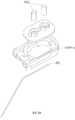
도 23을 참조하면, 미국 특허 번호 7899511에 개시된 종래의 감지 장치(900)는 베이스(92), 베이스(92)를 호스트의 피부(도시되지 않음)에 접착하도록 구성된 접착 베이스(91), 베이스(92)에 장착된 바이오 센서(93) 및 베이스(92)에 장착되고 바이오 센서(93)에 연결되는 트랜스듀서(94)를 포함한다. 바이오 센서(93)는 혈당 농도 수준에 상응하는 생체 신호를 측정하기 위해 호스트의 피부 아래에 삽입되고 트랜스듀서(94)는 바이오 센서(93)로부터 생체 신호를 수신하고 외부 장치(도시되지 않음)로 생체 신호를 전달한다.Referring to FIG. 23, a
또한, 도 24를 참조하면, 바이오 센서(93)는 고정 시트(931), 고정 시트(931)에 고정적으로 장착되는 세장형 감지 부재(elongated sensing member)(932) 및 고정 시트(931)에 고정 장착되고 감지 부재(932)와 접촉하는 2개의 접촉기 헤드(933)를 포함한다. 트랜스듀서(94)에 장착될 베이스(92)를 트랜스듀서(94)가 덮을 때, 트랜스듀서(94)의 하단에 있는 접촉점(도시되지 않음)은 트랜스듀서(94)와 감지 부재(932) 사이의 전기적 연결을 가능하게 하기 위해 접촉기 헤드(933)와 직접 접촉해야 한다. 그렇지만, 변환기(94)와 감지 부재(932)가 결합 방향으로 이격되고 접촉기 헤드(933)가 그 사이의 전기적 연결을 가능하게 하는 동일한 방향으로 연장되기 때문에, 접촉기 헤드(933) 각각의 두께(결합 방향의 길이)는 트랜스듀서(94)와 감지 부재(932) 사이의 거리보다 작을 수 없다. 따라서 접촉기 헤드(933)에 대한 최소 두께 제한은 감지 장치(900)의 전체 두께를 줄이는 것을 어렵게 한다. 또한, 접촉기 헤드(933)의 오정렬과 같은 제조 상의 오류로 인해, 또는 접촉기 헤드(933)가 트랜스듀서(94)와 감지 부재(932) 사이의 거리와 다른 두께를 가지는 것으로 인해, 접촉기 헤드(933)는 바이오 센서(93)와 변환기(94) 사이의 전기적 연결을 적절하게 활성화하지 못할 수 있다.In addition, referring to FIG. 24, the
따라서, 본 발명의 목적은 종래 기술의 단점을 완화할 수 있는 생체 신호 모니터링 장치를 제공하는 것이다.Accordingly, an object of the present invention is to provide a bio-signal monitoring apparatus capable of alleviating the disadvantages of the prior art.
본 개시에 따르면, 생체 신호 모니터링 장치는 호스트의 분석물에서 생체 신호를 감지하기 위한 것으로, 감지 부재와 전송기를 포함한다. 감지 부재는 생체 신호를 감지하기 위해 호스트의 피부 아래에 삽입되도록 구성된 신호 감지단과 생리 신호를 출력하기 위한 신호 출력단을 포함한다. 전송기는 생체 신호를 수신, 처리 및 전송하기 위해 감지 부재에 연결되며, 회로 기판과 연결 포트를 포함한다. 회로 기판은 복수의 전기 접촉부를 가진다. 연결 포트는 회로 기판에 연결되고 회로 기판에 연통되는 소켓 및 연결 포트 내에 수용되는 복수의 전도 스프링을 가진다. 전도 스프링은 소켓의 두 대향 측면에 배치된다. 감지 부재는 소켓에 제거 가능하게 삽입된다. 각각의 전도 스프링은 회로 기판의 전기 접촉부 각각에 전기적으로 연결된 일 측면 및 각각의 전기 접촉부와 신호 출력단 사이의 전기적 연결을 위해 감지 부재의 신호 출력단에 전기적으로 연결된 다른 측면을 가지고 있다. 각각의 전도 스프링은 감지 부재를 소켓에 삽입하고 감지 부재를 소켓으로부터 제거하는 동안 감지 부재에 의해 마찰 회전된다.According to the present disclosure, a biosignal monitoring device is for detecting a biosignal from an analyte of a host, and includes a sensing member and a transmitter. The sensing member includes a signal sensing terminal configured to be inserted under the skin of the host to detect a physiological signal and a signal output terminal for outputting a physiological signal. The transmitter is connected to the sensing member to receive, process, and transmit bio-signals, and includes a circuit board and a connection port. The circuit board has a plurality of electrical contacts. The connection port has a socket connected to the circuit board and in communication with the circuit board and a plurality of conduction springs received in the connection port. The conduction springs are arranged on two opposite sides of the socket. The sensing member is removably inserted into the socket. Each conduction spring has one side electrically connected to each of the electrical contacts of the circuit board and the other side electrically connected to the signal output end of the sensing member for electrical connection between each electrical contact and the signal output end. Each conduction spring is frictionally rotated by the sensing member while inserting the sensing member into the socket and removing the sensing member from the socket.
본 개시의 다른 특징 및 이점은 첨부된 도면을 참조하여 실시예의 다음의 상세한 설명에서 명백해질 것이다.
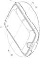
도 1은 본 발명에 따른 생체 신호 모니터링 장치의 제1 실시예의 사시도이다.
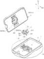
도 2는 제1 실시예의 분해 사시도이다.
도 3은 제1 실시예의 전송기의 분해 사시도이다.
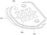
도 4는 제1 실시예의 변형의 전송기의 하부 케이싱 및 연결 포트의 부분 분해 사시도이다.
도 5는 도 4의 연결 포트의 부분 확대 사시도이다.
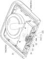
도 6은 도 1의 VI-VI 선을 따라 취한 부분 단면도이다.
도 7은 제1 실시예의 단면 사시도이다.
도 8은 제1 실시예의 다른 변형의 부분 단면도이다.
도 9는 제1 실시예의 또 다른 변형의 부분 단면도이다.
도 10 및 도 11은 바이오 센서에 결합되기 전과 후의 전송기를 각각 도시하는 제1 실시예의 회로도.
도 12 내지 14는 제1 실시예의 감지 부재 및 연결 포트의 다양한 변형의 회로도이다.
도 15는 생체 신호 모니터링 장치의 제2 실시예의 부분 단면도이다.
도 16은 도 15의 확대도이다.
도 17은 생체 신호 모니터링 장치의 제3 실시예의 확대 부분 단면도이다.
도 18은 생체 신호 모니터링 장치의 제4 실시예의 확대 부분 단면도이다.
도 19 및 20은 제4 실시예의 다양한 변형의 확대 부분 단면도이다.
도 21은 제1 실시예의 또 다른 변형의 부분 단면도이다.
도 22는 제2 실시예의 변형의 부분 단면도이다.
도 23은 종래의 감지 장치의 분해 사시도이다.
도 24는 종래의 센싱 장치의 바이오 센서의 분해 사시도이다.Other features and advantages of the present disclosure will become apparent in the following detailed description of embodiments with reference to the accompanying drawings.
1 is a perspective view of a first embodiment of a biosignal monitoring apparatus according to the present invention.
2 is an exploded perspective view of the first embodiment.
3 is an exploded perspective view of the transmitter of the first embodiment.
Fig. 4 is a partially exploded perspective view of a lower casing and a connection port of a modified transmitter of the first embodiment.
5 is a partially enlarged perspective view of the connection port of FIG. 4.
6 is a partial cross-sectional view taken along line VI-VI of FIG. 1.
7 is a cross-sectional perspective view of the first embodiment.
8 is a partial cross-sectional view of another modification of the first embodiment.
9 is a partial cross-sectional view of still another modification of the first embodiment.
10 and 11 are circuit diagrams of the first embodiment each showing a transmitter before and after being coupled to a biosensor.
12 to 14 are circuit diagrams of various modifications of the sensing member and the connection port of the first embodiment.
15 is a partial cross-sectional view of a biological signal monitoring apparatus according to a second embodiment.
16 is an enlarged view of FIG. 15.
17 is an enlarged partial cross-sectional view of a biosignal monitoring apparatus according to a third embodiment.
18 is an enlarged partial cross-sectional view of a biosignal monitoring apparatus according to a fourth embodiment.
19 and 20 are enlarged partial cross-sectional views of various modifications of the fourth embodiment.
Fig. 21 is a partial cross-sectional view of still another modification of the first embodiment.
22 is a partial cross-sectional view of a modification of the second embodiment.
23 is an exploded perspective view of a conventional sensing device.
24 is an exploded perspective view of a biosensor of a conventional sensing device.
본 개시가 더 상세하게 설명되기 전에, 적절한 것으로 고려되는 경우, 참조 번호 또는 참조 번호의 말단 부분은 선택적으로 유사한 특성을 가질 수 있는 대응 요소 또는 유사한 요소를 나타내기 위해 도면 사이에서 반복되었다는 점에 유의해야 한다.Before the present disclosure is described in more detail, it is noted that, where considered appropriate, a reference number or a distal portion of a reference number has been repeated between the drawings to indicate corresponding elements or similar elements that may optionally have similar properties. Should be.
또한, 본 명세서의 설명에서 "위", "아래", "상단", "하단"이라는 용어는 본 발명의 요소들 간의 상대적인 위치를 의미하는 것으로, 실제 구현의 각각의 요소의 실제 위치를 의미하는 것은 아니다. 유사하게, 본 명세서에서 개시되는 다양한 축은 본 개시에서 서로 수직으로 정의되지만 실제 구현에서 반드시 수직일 필요는 없다.In addition, in the description of the present specification, the terms "top", "bottom", "top", and "bottom" refer to the relative positions between the elements of the present invention, and refer to the actual positions of each element of the actual implementation. It is not. Similarly, the various axes disclosed herein are defined perpendicular to each other in this disclosure, but do not necessarily have to be perpendicular in an actual implementation.
도 1 내지 도 7을 참조하면, 본 개시에 따른 생체 신호 모니터링 장치의 제1 실시예는 호스트(도시되지 않음)의 피부 표면에 장착되도록 구성되고, 호스트의 적어도 하나의 분석물을 측정하고 해당 유형의 생체 신호를 감지하기 위해 구성된다. 본 실시예에서, 생체 신호 모니터링 장치는 호스트의 간질 액(interstitial fluid, ISF)에서 혈당 농도(blood glucose)를 측정하기 위한 것으로, 2주 동안 피부 표면에 장착되는 것을 의미하지만 이에 제한되지 않는다.1 to 7, the first embodiment of the biosignal monitoring apparatus according to the present disclosure is configured to be mounted on the skin surface of a host (not shown), and measures at least one analyte of the host and Is configured to detect vital signs. In this embodiment, the biological signal monitoring device is for measuring blood glucose concentration in the interstitial fluid (ISF) of the host, which means that it is mounted on the skin surface for 2 weeks, but is not limited thereto.
다시 도 1 및 도 2를 참조하면, 생체 신호 모니터링 장치는 호스트의 피부 표면에 장착되도록 구성된 베이스(1), 베이스(1)에 장착되고 호스트의 피부 표면 아래에 부분적으로 삽입되도록 구성된 바이오 센서(2), 및 제1 축(D1) 방향으로 베이스(1)를 덮고 제거 가능하게 결합되고 바이오 센서(2)에 연결되는 전송기(3)를 포함한다. 바이오 센서(2)는 호스트의 적어도 하나의 분석물을 측정하고 대응하는 생체 신호를 전송기(3)에 전송하는 한편, 전송기(3)는 모니터링 목적을 위해 생체 신호를 수신, 처리 및 외부 장치(도시되지 않음)로 출력한다. 장기간 사용 후 생체 신호 모니터링 장치를 교체해야 하는 경우 전송기(3)를 바이오 센서(2) 및 베이스(1)에서 분리하여 새로운 세트의 베이스(1) 및 바이오 센서(2)와 함께 재사용할 수 있다.Referring back to FIGS. 1 and 2, the biosignal monitoring device includes a
베이스(1)는 베이스 바디(11) 및 베이스 바디(11)의 하부 표면(116)(도 6 참조)에 장착되고 베이스 바디(11)를 호스트의 피부 표면에 부착하게 하는 접착 패드(16)를 포함한다. 바이오 센서(2)는 베이스 바디(11)에 장착되는 고정 시트(21), 및 고정 시트(21)에 장착되고 베이스 바디(11)를 통해 연장하는 감지 부재(22)를 포함한다. 고정 시트(21)는 전송기(3)가 베이스(1)에 결합될 때 전송기(3)와 베이스(1) 사이에 장착된다.The
고정 시트(21)는 하부 표면(211)과 상부 표면(212)을 가진다. 감지 부재(22)는 호스트의 생체 신호를 측정하기 위해 호스트의 피부 표면 아래에 삽입되도록 구성된 신호 감지단(signal sensing end)(222) 및 신호 감지단(222)으로부터 수신된 생체 신호를 출력하도록 구성된 신호 출력단(221)을 가진다. 신호 감지단(222)은 고정 시트(21)의 하부 표면(211)으로부터 돌출하고, 신호 출력단(221)은 고정 시트(21)의 상부 표면(212)으로부터 돌출한다.The
도 2 및 도 11을 참조하면, 감지 부재(22)는 베이스 보드(225), 베이스 보드(225)의 표면에 장착된 복수의 전극(226) 및 전극(226)과 베이스 보드(225)의 표면을 덮는 분석물 감지 층(도시되지 않음)을 포함한다. 분석물 감지 층은 호스트의 적어도 하나의 분석물과 반응하기 위해 제공되며, 전극(226)은 반응의 결과를 감지하는 신호 수신 전극과 반응의 결과를 나타내는 전기 신호를 생성하는 신호 전송 전극을 포함한다. 이 실시예에서, 전기 신호는 간질 액의 포도당 수준을 나타내는 생체 신호이다. 전극(226)의 구체적인 역할은 나중에 설명될 것이다.2 and 11, the
다시 도 2, 도 3 및 도 6을 참조하면, 전송기(3)는 베이스 바디(11)에 근접한 하부 케이싱(31), 내부 공간(30)을 정의하기 위해 하부 케이싱(31)에 장착되는 상부 케이싱(32), 내부 공간(30)에 배치되는 회로 기판(33), 회로 기판(33)에 장착된 처리 유닛(34)(도 10 및 도 111 참조), 내부 공간(30)에 배치되는 배터리(35) 및 회로 기판(33)의 하부 표면에 연결되고 베이스 바디(11)를 내부 공간(30)을 향해 바깥쪽으로 연장하는 연결 포트(36)를 포함한다.Referring back to FIGS. 2, 3 and 6, the
회로 기판(33)은 인쇄 회로 기판(printed circuit board, PCB) 또는 연성 인쇄 회로(flexible print circuit, FPC)이도록 허용되며, 금속판으로 만들어질 수 있는 지지 부재(support member)(37)를 통해 하부 케이싱(31)에 고정적으로 위치한다. 회로 기판(33)은 연결 포트(36)에 위치가 대응하는 복수의 전기 접촉부(331)를 가진다. 이 실시예에서, 전기 접촉부(331)의 수는 8개이다. 처리 유닛(34)은 생체 신호를 수신, 처리 및 전송하기 위해 제공되고 전기 접촉부(331)에 연결된다. 배터리(35)는 회로 기판(33)의 전기 접촉부(331)에 연결된다.The
도 3, 도 6 및 도 7을 다시 참조하면, 연결 포트(36)는 회로 기판(33)의 하부 표면에 장착되고 하부 케이싱(31)의 하부 표면(311)을 향하여 제1 축(D1) 방향으로 아래쪽으로 연장하는 포트 케이싱(361) 및 포트 케이싱(361) 내에 수용되는 복수의 이격된 전도 부재(spaced-apart conducting member)(364)를 포함한다. 이 실시예에서, 전도 부재(364)의 수는 8개이다.3, 6 and 7 again, the
포트 케이싱(361)은 회로 기판(33)을 향하여 개방되고 내부에 전도 부재(364)를 각각 수용하는 복수의 홈(366), 및 베이스 바디(11)를 향하여 제1 축(D1) 방향으로 연장되고 복수의 홈(366)과 연통하는 소켓(367)으로 형성된다. 전도 부재(364)는 홈(366) 내에 각각 회전 가능하게 수용된다. 소켓(367)은 감지 부재(22)의 신호 출력단(221)를 유지하도록 제공된다.The
도 4 및 도 5를 다시 참조하면, 제1 실시예의 변형 예에서, 제1 축(D1)에 수직인 홈(336)의 외주의 단면은 실질적으로 도브테일 형상(dovetail-shape)이고, 각각의 홈(336)은 각각의 전도 부재(364)가 각각의 홈(336)을 빠져나가는 것을 방지하도록 소켓(367)을 향해 테이퍼링되어 있다.4 and 5 again, in a modified example of the first embodiment, a cross section of the outer periphery of the groove 336 perpendicular to the first axis D1 is substantially dovetail-shape, and each groove 336 is tapered toward
전도 부재(364)는 탄성이고 소켓(367)의 양측에 배치된다. 이 실시예에서, 전도 부재(364)는 전도 코일 스프링이다. 각각의 전도 부재(364)는 제1 방향을 따라 일 측면에서 회로 기판(33)과 접촉하고, 제2 방향을 따라 다른 측면에서 감지 부재(22)와 접촉하며, 제1 방향은 제2 방향과 평행하지 않다. 따라서, 회로 기판(33)의 전기 접촉부(331)와 감지 부재(22)의 신호 출력단(221) 사이의 전기적 연결은 감지 부재(22)가 소켓(367)에 삽입될 때 제공된다. 구체적으로, 각각의 전도 부재(364)는 제1 축(D1)의 방향(즉, 제1 방향)으로 회로 기판(33)의 각각의 전기 접촉부(331)와 접촉하는 (그리고 전기적으로 연결되는) 일 측면 및 제2 축(D2) 방향(즉, 제2 방향)으로 감지 부재(22)의 신호 출력단(221) 상의 전극(226)과 접촉하는 (그리고 전기적으로 연결되는) 다른 측면을 가지므로 소켓(367)에 삽입될 때 감지 부재(22)를 위치시키고 회로 기판(33)의 전기 접촉부(331)와 감지 부재(22)의 신호 출력단(221) 사이의 전기적 연결을 가능하게 할 수 있다. 이 실시예에서, 제1 및 제2 축(D1, D2)은 실질적으로 서로에 대해 수직이지만, 다른 실시예에서는 그렇게 제한되지 않을 수도 있다. 전도성 코일 스프링은 각각의 전도 부재(364)가 소켓(367)에 감지 부재(22)를 삽입하고 제1 축(D1)을 따라 소켓(367)으로부터 감지 부재(22)를 제거하는 동안 홈(366)에 대해 회전하도록 높은 자유도(degrees of freedom)를 가지며, 이에 의해, 소켓(367)과 감지 부재(22) 사이의 마찰을 감소시키고 전송기(3)의 재사용을 용이하게 한다.The
이 실시예에서, 각각의 전도 부재(364)는 각각의 전도 부재(364)의 일단이 각각의 홈(366)에 고정되도록 포트 케이싱(361)에 용접된 일단을 가진다는 점에 유의해야 한다. 또한, 전도 부재(364)가 전도 코일 스프링이기 때문에, 각각의 전도 부재(364)는 다음과 같은 특성을 가진다: 그 와이어 직경은 1밀리미터(mm) 미만, 바람직하게는 0.1mm이고; 그 외경은 0.5mm 내지 1.8mm, 바람직하게는 1.1mm 범위이고; 그 자유 길이는 0.2mm 내지 0.8mm, 바람직하게는 0.44mm 내지 0.56mm이다. 각각의 전도 부재(364)는 2 내지 6 회전(본 실시예에서는 3 회전)을 가지는 나선형 부분(365a)을 가지며, 이에 따라 회로 기판(33)의 각각의 전기 접촉부(331) 및 감지 부재(22)의 신호 출력단(221)을 다점(multi-point) 접촉부에 제공한다. 전도 부재(364)의 탄성을 고려하여, 각각의 전도 부재(364)의 와이어 직경 및 회전 수와 같은 파라미터가 설계되며, 각각의 전도 부재(364)의 외경 및 자유 길이(free length)는 각각의 전도 부재(364)가 각각의 홈(366)의 공간보다 약간 더 크게 되도록 설계되어, 전도 부재(364)는 회로 기판(33)의 전기 접촉부(331) 및 감지 부재(22)의 신호 출력단(221)상의 전극(226)과 안정적으로 접촉할 수 있다는 것에 유의해야 한다(도 2 및 도 11 참조).It should be noted that in this embodiment, each
도 8을 참조하면, 제1 실시예의 다른 변형 예에서, 제1 실시예에서 원래 전도성 코일 스프링이었던 연결 포트(36)의 전도 부재(364)는 대신 강철 볼 또는 강철 링(즉, 강성 부품)이다. 또한, 연결 포트(36)는 각각의 홈(366)에 각각 장착되고 포트 케이싱(361)과 각각의 전도 부재(364) 사이에 장착되는 복수의 탄성 부재(369)를 더 포함한다. 탄성 부재(369)는 고무와 같은 탄성 재료로 만들어지며, 각각의 전도 부재(364)는 각각의 탄성 부재(369)와 접촉하는 일 측면 및 제2 축(D2)에 평행한 축을 따라 신호 출력단(221)의 전극(226)과 접촉하는 다른 측면을 가진다. 전반적으로, 이 변형 예의 전도 부재(364)는 제1 실시예의 것과 유사하게 기능한다: 전기 접촉부(331)와 신호 출력단(221) 사이의 전기적 연결을 가능하게 하고, 감지 부재(22)에 의해 마찰 이동되어 홈(366)에서 회전한다. 탄성 부재(369)는 전도 부재(364)가 제1 축(D1) 및 제2 축(D2)에 평행한 방향을 따라 감지 부재(22) 및 회로 기판(33)과 안정적으로 접촉하도록 보장한다.8, in another variant of the first embodiment, the
도 9를 참조하면, 제1 실시예의 또 다른 변형 예에서, 전도 부재(364)는 전도 코일 스트링이고, 전도 코일 스트링 각각은 포트 케이싱(361)의 내부 표면을 따라 회로 기판(33)을 향해 연장하고, 제1 축(D1)의 방향으로 각각의 전기 접촉부(331)에 연결되는 연장 섹션(extended section)(365b)을 가진다.9, in another modified example of the first embodiment, the
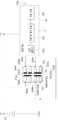
도 10 및 도 11을 참조하면, 제1 실시예에서, 처리 유닛(34)은 감지 부재(22)로부터 전기 신호를 수신하고 대응하는 생체 신호를 전송한다. 처리 유닛(34)은 전기 신호를 수신 및 증폭하는 신호 증폭기(341), 증폭된 전기 신호를 포도당 수준에 상응하는 생체 신호로 순차적으로 변환하는 측정 및 계산 모듈(342) 및 안테나(344)를 통해 외부 장치(도시되지 않은)에 생체 디지털 신호를 전송하는 전송 모듈(343)을 포함한다. 본 개시에서, 포도당 수준에 대응하는 전술한 생체 신호는 전류라는 것을 주목해야 한다.10 and 11, in the first embodiment, the
전술한 바와 같이, 전도 부재(364)의 수는 본 실시예에서 8개이다. 전도 부재(364)는 전도 코일 스프링이고 2개의 전력 공급 전도 부재(364a), 4개의 감지 전도 부재(364b) 및 2개의 전달 전도 부재(364c)를 포함한다. 감지 부재(22)의 전극(226)은 전도 부재(364)와 접촉하여 전력 공급, 감지 및 데이터 전송을 위해 회로 기판(33)의 전기 접촉부(331)에 각각 전기적으로 연결된다.As described above, the number of
전력 공급 전도 부재(364a)와 전극(226)은 협력해서 스위치를 형성한다. 감지 전도 부재(364b)는 처리 유닛(34)에 연결된다. 전송 전도 부재(364c)는 처리 유닛(34)에도 연결되고, 전송 모듈(343) 및 안테나(344)를 통해 외부 장치로 데이터를 전송한다. 이 실시예에서, 데이터 전송의 유형은 무선 전송(Bluetooth, Wifi, NFC)일 수 있지만 다른 실시예에서는 유선 전송(USB 케이블)일 수 있다.The power
이 실시예에서, 감지 부재(22)의 전극(226)의 수는 5개이다. 전극(226)은 작동 전극(226a), 기준 전극(226b), 전력 공급 전극(226e) 및 2개의 전기 접촉부(226d)를 포함한다.In this embodiment, the number of
감지 부재(22)가 연결 포트(36)의 소켓(367)에 삽입되지 않은 경우, 전도 부재(364a)에 의해 형성된 스위치는 개방 회로 상태가 되어 배터리(35)는 비 전력 공급 상태가 된다.When the sensing
감지 부재(22)가 소켓(367)에 삽입되면 감지 부재(22)의 전력 공급 전극(226e)은 전력 공급 도체(364a)와 접촉하여 회로 기판(33)의 전기 접촉부(331)와 전기적으로 연결되므로, 스위치는 폐쇄 회로 상태이고 배터리(35)는 전력 공급 상태로 전환되어 분석물의 측정을 수행하기 위해 감지 부재(22) 및 처리 유닛(34)에 전력을 공급한다. 동시에, 각각의 작동 및 기준 전극(226a, 226b)은 감지 전도 부재(364b) 중 대응하는 2개의 감지 전도 부재(364b)와 접촉하여 회로 기판(33)의 전기 접촉부(331)에 전기적으로 연결되므로, 처리 유닛(34)은 생체 신호를 수신하고 처리하고 외부 장치로 전송한다. 전기 접촉 섹션(226d)은 각각 전송 전도 부재(364c)에 각각 전기적으로 연결되는 것이 허용된다. 이 실시예에서, 전기 접촉부(226d)는 신호 수신 및 신호 전송 전극을 가진다.When the sensing
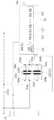
전송기(3)의 회로 레이아웃은 제품의 다양한 요구 사항에 따라 변경될 수 있다. 예를 들어, 도 12를 참조하면, 감지 부재(22)가 소켓(367)에 삽입될 때 감지 부재(22)는 처리 유닛(34)에 의한 전력 제어 없이 호스트의 생체 신호의 측정을 시작한다. 전원에 관한 회로는 다른 실시예에서 재배열될 수 있으므로 여기서 더 자세한 설명이 없다.The circuit layout of the
또한, 연결 포트(36)의 소켓(367)은 추가 전송 장치(도시되지 않음) 또는 충전 장치(도시되지 않음)가 삽입될 수 있도록 구성된다. 예를 들어, 전송기(3)가 (바이오 센서(2) 및 베이스(1)에 연결되기 전에) 제조된 후, 추가 전송 장치의 커넥터(또는 전극)가 소켓(367)에 삽입되어 전송 전도 부재(364c)를 통해 처리 유닛(34) 및 추가 전송 장치 사이에서 전기적 연결 및 데이터 전송을 제공할 수 있다. 다시 말해, 이 실시예에서, 전송 전도 부재(364c)는 전송기(3)가 바이오 센서(2) 및 베이스(1)에 연결되기 전에 데이터(기본 데이터 또는 보정 데이터)를 교환하기 위해 추가 전송 장치에 전기적으로 연결되는 것이 허용된다. 또한, 전송기(3)가 반복 사용을 위해 바이오 센서 및 베이스(1)로부터 분리될 때, 충전 장치는 소켓(367)에 삽입되어 전력 공급 전도 부재(364a)를 통해 전송기(3)를 재충전할 수 있으며, 이는 회로 기판(33)의 전기 접촉부(331) 및 충전 장치를 전기적으로 상호 연결한다.Further, the
도 13을 참조하면, 제1 실시예의 감지 부재(22) 및 소켓(36)의 다른 변형예에서, 감지 부재(22)의 전극(226)은 작동 전극(226a), 카운터 전극(226f), 전력 공급 전극(226e) 및 2개의 전기 접촉부(226d)를 포함하고, 전송기(3)의 전도 부재(364)의 수는 6개이다. 전도 부재(364)는 전도 코일 스프링이고 2개의 전력 공급 전도 부재(364a), 2개의 감지 전도 부재(364b) 및 2개의 전달 전도 부재(364c)를 포함한다. 감지 부재(22)가 연결 포트(36)의 소켓(367)에 삽입될 때, 감지 부재(22)의 전력 공급 전극(226e)은 전력 공급 전도 부재(364a)와 접촉하여 회로 기판(33)의 전기 접촉부(331)와 전기적으로 연결된다. 동시에, 작동 및 카운터 전극(226a, 226f) 각각은 감지 전도 부재(364b) 각각과 접촉하여 회로 기판(33)의 전기 접촉부(331)에 전기적으로 연결되므로 처리 유닛(34)은 생체 신호를 수신, 처리 및 외부 장치로 전송한다. 전기 접촉부(226d)는 각각 전송 전도 부재(364c)에 전기적으로 연결되는 것이 허용된다.13, in another modification of the sensing
도 14를 참조하면, 제1 실시예의 감지 부재(22) 및 소켓(36)의 또 다른 변형예에서, 감지 부재(22)의 전극(226)은 작동 전극(226a), 카운터 전극(226f) 및 2개의 전력 공급 전극(226e)을 포함하고, 전송기(3)의 전송 부재(364)의 개수는 4개이다. 전도 부재(364)는 전도 코일 스프링이고 2개의 전력 공급 전도 부재(364a) 및 2개의 감지 전도 부재(364b)를 포함한다. 감지 부재(22)가 연결 포트(36)의 소켓(367)에 삽입되면, 감지 부재(22)의 전력 공급 전극(226e)은 각각의 전력 공급 전도 부재(364a)와 접촉하여 회로 기판(33)의 전기 접촉부(331)와 전기적으로 연결된다. 동시에, 작동 및 카운터 전극(226a, 226f) 각각은 감지 전도 부재(364b) 각각과 접촉하여 회로 기판(33)의 전기 접촉부(331)에 전기적으로 연결되므로, 처리 유닛(34)은 생체 신호를 수신, 처리 및 외부 장치로 전송한다.Referring to FIG. 14, in another modification of the sensing
전술한 제1 실시예의 감지 부재(22) 및 소켓(36)의 변형예를 이용함으로써, 회로 기판(33)의 전기 접촉부(331) 및 감지 부재(22)의 전극(226)이 전기적으로 연결되어 처리 유닛(34)을 활성화할 수 있다. 전술한 변형의 전도성 코일 스프링은 다른 형태의 전도성 부품일 수 있다는 점에 유의해야 한다.By using the modified example of the sensing
상기 실시예에서, 전송기(3)는 베이스(1)에 조립된 바이오 센서(2)에 결합되고, 베이스(1)는 호스트 피부에 부착된다. 따라서, 바이오 센서(2)의 감지 부재(22)는 분석물의 측정을 위해 전송기(3)의 소켓(367)에 삽입된다.In the above embodiment, the
전반적으로 생리 신호 모니터링 장치의 제1 실시예는 다음과 같은 이점을 제공한다:Overall, the first embodiment of the physiological signal monitoring device provides the following advantages:
1) 감지 부재(22)가 전송기(3)에 삽입되고, 각각의 전도 부재(364)는 제1 축(D1)의 방향 및 제2 축(D2)의 방향을 따라 감지 부재(22)의 전극(226) 및 회로 기판(33)의 전기 접촉부(331)와 양방향으로 접촉한다. 따라서, 감지 부재(22)는 탄성 전도 부재(364)에 의해 소켓(367) 내에 안정적으로 유지되어 회로 기판(33)과 감지 부재(22) 사이의 안정적인 전기적 연결 및 신호 전송을 제공한다.1) The sensing
2) 또한, 전도 부재(364)는 감지 부재(22)와 회로 기판(33) 사이의 견고성을 높기 위해 탄성 코일 전도 스프링이거나 탄성 부재(369)에 의해 보완된 강철 부재일 수 있어 신뢰성 있는 전기 연결 및 신호 전송이 제공된다. 감지 부재(22)와 소켓(367) 사이의 보완적인 조립으로 인해, 장치의 수직 크기가 감소될 수 있다. 또한, 이 실시예에서, 전도 부재(364)는 홈(366)에서 높은 자유도를 갖기 때문에, 각각의 전도 부재(364)는 감지 부재(22)를 소켓(367)에 삽입하고 감지 부재(22)를 소켓(367)으로부터 제거하는 동안 홈(366)에 대해 회전하도록 붙게 되며, 이에 의해 소켓(367)과 감지 부재(22) 사이의 마찰 저항을 감소시키고 전송기(3)의 재사용을 용이하게 한다.2) In addition, the
3) 감지 부재(22)가 연결 포트(36)의 소켓(367)에 삽입될 때까지 배터리(35)가 턴 온 되지 않았기에, 생체 신호 모니터링 장치를 활성화하기 전에 전력 소모를 방지한다. 또한, 소켓(367)은 데이터 전송 및 전력 충전을 위해 각각 추가 전송 장치 또는 충전 장치가 삽입되도록 추가로 구성될 수 있다. 구체적으로, 충전 장치의 전력 공급 전극은 전원 충전을 위한 전력 공급 전도 부재(364a)를 통해 회로 기판(33)의 전기 접촉부(331)와 전기적으로 연결될 수 있고; 추가 전송 장치의 전기 접촉 섹션(226d)은 데이터 전송을 위해 전송 전도 부재(364c)를 통해 회로 기판(33)의 전기 접촉부(331)와 전기적으로 연결될 수 있다.3) Since the
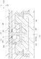
도 15 및 도 16은 제1 실시예와 제2 실시예의 차이점을 다음과 같이 설명하는 생체 신호 모니터링 장치의 제2 실시예를 도시한다.15 and 16 show a second embodiment of a bio-signal monitoring apparatus explaining the difference between the first embodiment and the second embodiment as follows.
연결 포트(36)의 포트 케이싱(361)은 홈(366)에 각각 배치되고 회로 기판(33) 및 감지 부재(22)에 대향하는 복수의 경사면(368)을 가진다. 따라서, 전도 부재(364)는 경사진 표면(368)에 의해 제공된 힘 벡터로 회로 기판(33) 및 감지 장치(22)에 붙게 되어 회로 기판(33)과 감지 장치(22) 사이의 접촉을 보장하고 전도 부재(364)의 이동성을 향상시킨다. 또한, 전도 부재(364)는 경사진 표면(368) 때문에 소켓(367)으로부터 감지 부재(22)를 제거한 후에 미리 결정된 위치로 복귀할 수 있으므로 전도 부재(364)와 감지 부재(22) 사이의 전기적 단절을 야기하는 접촉 문제가 해결될 수 있다. 다른 실시예에서, 전도 부재(364)는 전도 부재(364)와 경사진 표면(368) 사이에 구성된 탄성 부재(369)를 가지는 경질 구성 요소(예를 들어, 강철 볼 또는 강철 링)로서 변형될 수 있다.The
도 17은 제1 실시예와 제3 실시예의 차이점을 다음과 같이 설명하는 생체 신호 모니터링 장치의 제3 실시예를 도시한다.Fig. 17 shows a third embodiment of a bio-signal monitoring device explaining the difference between the first embodiment and the third embodiment as follows.
이 실시예에서, 연결 포트(36)의 각각의 전도 부재(364)는 일단이 제1 축(D1)을 따라 회로 기판(33)의 대응하는 전기 접촉부(331)와 접촉하고 타단이 제2 축(D2)을 따라 감지 부재(22)의 전극(226)과 접촉하는 판 스프링(leaf spring)이다. 따라서, 감지 부재(22)는 판 스프링(364)에 의해 소켓(367) 내에 안정적으로 유지되어 회로 기판(33)과 감지 부재(22) 사이의 안정적인 전기 연결 및 신호 전송을 제공한다.In this embodiment, each
도 18은 제1 실시예와 제4 실시예의 차이점을 다음과 같이 설명하는 생체 신호 모니터링 장치의 제4 실시예를 도시한다.Fig. 18 shows a fourth embodiment of the biosignal monitoring apparatus, explaining the difference between the first embodiment and the fourth embodiment as follows.
전도 부재(364)는 전도 코일 스프링이다. 연결 포트(36)는 전기 접촉부(331)에 각각 연결된 복수의 금속 플레이트(370)를 더 포함한다. 이 실시예에서, 금속 플레이트(370)는 표면 실장 기술(surface mount technology, SMT)을 통해 전기 접촉부(331)에 용접되고 홈(366)을 향해 연장된다. 따라서, 각각의 전도 부재(364)는 제2 축(D2)에 평행한 축을 따라 각각의 금속판(370) 및 감지 부재(22)의 전극(226)과 동축으로 접촉하여 회로 기판(33)과 감지 부재(22) 사이에 신뢰성 있는 전기적 연결을 제공한다.The conducting
도 19 및 도 20은 전도 부재(364)가 강철 볼 또는 강철 링인 제4 실시예의 다른 변형을 도시하며, 여기서 금속판(370)은 도 19에 도시된 표면 실장 기술(SMT) 또는 도 20에 도시된 듀얼 인라인 패키지(dual inline package, DIP)를 통해 전기 접촉부(331)에 용접된다.19 and 20 show another variation of the fourth embodiment in which the conducting
상기 언급된 실시예에서, 연결 포트(36)의 전도 부재(364)는 소켓(367)의 두 대향 측면에 배치된다는 점에 유의해야 한다. 그러나 다른 실시예에서, 연결 포트(36)의 전도 부재(364)는 대신에 소켓(367)의 한 측면에 배치될 수 있어서, 감지 부재(22)의 단지 한 측면만이 전도 부재(364)에 접한다. 도 21 및 도 22를 참조하면, 감지 부재(22)는 탄성 전도 부재(364) 및 포트 케이싱(361)에 의해 소켓(367) 내에 안정적으로 유지되어 회로 기판(33)과 감지 부재(22) 사이에 신뢰성 있는 전기적 연결을 제공한다.It should be noted that in the above-mentioned embodiment, the
결과적으로, 전도 부재(364)는 전송기(3)가 바이오 센서(2)에 결합된 후 감지 부재(22)의 전극(226) 및 회로 기판(33)의 전기 접촉부(331)와 접촉하도록 소켓(367)에서 측면으로 구성되어 이들 간에 신뢰성 있는 전기적 연결을 제공하고 감지 부재(22)를 유지한다. 또한, 전도 부재(364)는 소켓(367)으로부터 감지 부재(22)의 삽입 또는 제거 중에 홈(366)에 대해 회전되어 전도 부재(364)와 감지 부재(22) 사이의 마찰 저항을 감소시키고 전송기(3)의 재사용을 용이하게 한다. 또한, 전도 부재(364)는 감지 부재(22)와 회로 기판(33) 사이의 양방향 또는 동축 연결을 제공하기 위해 탄성 부재(369) 또는 금속판(370)을 가지는 코일 스프링, 강철 볼/링일 수 있다. 따라서, 다양한 기능의 전극(226)은 싱글 연결 포트(36)의 전기 접촉부(331)와 전기적으로 연결되어 전력 공급 장치, 신호 감지 및 데이트 전송을 활성화한다.As a result, the
전술한 실시예에 더하여, 본 개시는 특허청구범위에 의해 정의된 복수의 실시예를 추가로 개시하고, 각각의 실시예는 각각의 청구항의 청구항 요소(들) 및 각각의 청구항이 의존하는 임의의 청구항의 청구항 요소(들)를 포함한다.In addition to the foregoing embodiments, the present disclosure further discloses a plurality of embodiments defined by the claims, each embodiment being the claim element(s) of each claim and any of the claims on which each claim depends. It contains the claim element(s) of the claim.
이상의 설명에서, 설명의 목적으로, 실시예의 완전한 이해를 제공하기 위해 다수의 특정 세부 사항이 제시되었다. 그렇지만, 당업자에게는 하나 이상의 다른 실시예가 이러한 특정 세부 사항 중 일부가 없이도 실시될 수 있다는 것은 명백할 것이다. 또한, 본 명세서 전반에 걸쳐 "일 실시예", "실시예", 서수 등의 표시가 있는 실시예에 대한 언급은 특별한 특징, 구조 또는 특성이 본 개시의 실행에 포함될 수 있음을 의미한다는 것을 이해해야 한다. 설명에서, 다양한 특징은 때때로 개시를 합리화하고 다양한 발명적 측면의 이해를 돕기 위해 단일 실시예, 도면 또는 그의 설명에서 함께 그룹화되며, 하나 이상의 특징 또는 일 실시예로부터의 특정 세부 사항은 적절한 경우 본 개시의 실행에서 하나 이상의 특징 또는 다른 실시예의 특정 세부 사항과 함께 실행될 수 있다.In the above description, for purposes of explanation, a number of specific details have been set forth in order to provide a thorough understanding of the embodiments. However, it will be apparent to those skilled in the art that one or more other embodiments may be practiced without some of these specific details. In addition, it should be understood that throughout this specification, reference to an embodiment marked with “one embodiment”, “an embodiment”, ordinal number, etc. means that a particular feature, structure, or characteristic may be included in the practice of the present disclosure. do. In the description, various features are sometimes grouped together in a single embodiment, drawing, or description thereof to streamline the disclosure and to aid in understanding the various inventive aspects, and one or more features or specific details from one embodiment, where appropriate, the present disclosure. It may be implemented with one or more features or specific details of other embodiments.
본 개시는 예시적인 실시예로 간주되는 것과 관련하여 설명되었지만, 본 개시는 개시된 실시예에 제한되지 않고 가장 넓은 해석의 사상 및 범위 내에 포함되는 다양한 배열을 포괄하여 그러한 모든 수정 및 동등한 배치를 망라하도록 의도된 것으로 이해된다.While the present disclosure has been described in connection with what is to be regarded as exemplary embodiments, the present disclosure is not limited to the disclosed embodiments and is intended to cover various arrangements included within the spirit and scope of the broadest interpretation so as to cover all such modifications and equivalent arrangements. It is understood to be intended.
Claims (20)
Translated fromKorean감지 부재 및 전송기를 포함하며,
상기 감지 부재는:
상기 생체 신호를 감지하기 위해 상기 호스트의 피부 아래에 삽입되는 신호 감지단, 및
상기 생체 신호를 출력하는 신호 출력단
을 포함하고,
상기 생체 신호를 수신, 처리 및 전송하기 위해 상기 감지 부재에 연결된 상기 전송기는:
복수의 전기 접촉부를 가지는 회로 기판, 및
상기 회로 기판에 연결되고 상기 회로 기판에 연통되는 소켓을 가지는 연결 포트
를 포함하며,
상기 연결 포트 내에 복수의 전도 스프링이 수용되며;
상기 감지 부재는 상기 소켓에 제거 가능하게 삽입되고;
상기 전도 스프링 각각은, 상기 전기 접촉부 각각과 상기 신호 출력단 사이의 전기적 연결을 위해, 상기 회로 기판의 상기 전기 접촉부 각각에 전기적으로 연결된 일 측면 및 상기 감지 부재의 상기 신호 출력단에 전기적으로 연결된 다른 측면을 가지며; 그리고
상기 전도 스프링은 상기 감지 부재를 상기 소켓에 삽입하고 상기 감지 부재를 상기 소켓으로부터 제거하는 동안 상기 감지 부재에 의해 마찰 회전되는, 생체 신호 모니터링 장치.A biosignal monitoring device for detecting a biosignal from an analyte of a host,
Including a sensing member and a transmitter,
The sensing member is:
A signal detection terminal inserted under the skin of the host to detect the bio-signal, and
Signal output terminal for outputting the bio-signal
Including,
The transmitter connected to the sensing member to receive, process and transmit the bio-signal comprises:
A circuit board having a plurality of electrical contacts, and
A connection port connected to the circuit board and having a socket in communication with the circuit board
Including,
A plurality of conduction springs are accommodated in the connection port;
The sensing member is removably inserted into the socket;
Each of the conduction springs has one side electrically connected to each of the electrical contacts of the circuit board and the other side electrically connected to the signal output terminal of the sensing member for electrical connection between each of the electrical contacts and the signal output terminal. Have; And
The conduction spring is frictionally rotated by the sensing member while inserting the sensing member into the socket and removing the sensing member from the socket.
상기 연결 포트는 상기 회로 기판 상에 장착되고 상기 소켓과 함께 형성된 포트 케이싱(port casing)을 더 포함하고, 상기 포트 케이싱은 상기 회로 기판 및 상기 감지 부재에 대향하는 복수의 경사면(slanted surface)을 가지며, 이에 의해 상기 전도 스프링이 상기 회로 기판 및 상기 감지 부재(22)에 붙게 되는, 생체 신호 모니터링 장치.The method of claim 1,
The connection port further comprises a port casing mounted on the circuit board and formed with the socket, the port casing having a plurality of slanted surfaces facing the circuit board and the sensing member , Whereby the conduction spring is attached to the circuit board and the sensing member (22).
상기 연결 포트는 상기 회로 기판에 장착되고 상기 소켓과 함께 형성된 포트 케이싱, 및 상기 전도 스프링을 수용하기 위해 상기 소켓과 연통되는 복수의 홈을 더 포함하는, 생체 신호 모니터링 장치.The method of claim 1,
The connection port further includes a port casing mounted on the circuit board and formed with the socket, and a plurality of grooves communicating with the socket to receive the conduction spring.
상기 연결 포트의 상기 홈 각각은 상기 소켓을 향해 테이퍼링되는, 생체 신호 모니터링 장치.The method of claim 3,
Each of the grooves of the connection port is tapered toward the socket.
상기 연결 포트의 상기 전도 스프링은 상기 소켓의 일 측면에 배치되는, 생체 신호 모니터링 장치.The method of claim 3,
The conductive spring of the connection port is disposed on one side of the socket.
상기 연결 포트의 상기 전도 스프링은 상기 소켓의 두 대향 측면에 배치되는, 생체 신호 모니터링 장치.The method of claim 3,
The conductive spring of the connection port is disposed on two opposite sides of the socket.
상기 전도 스프링 각각은 상기 회로 기판을 향해 상기 포트 케이싱의 내부 표면을 따라 연장되고 상기 전기 접촉부 각각에 연결되는 연장 섹션(extended section)을 가지는, 생체 신호 모니터링 장치.The method of claim 3,
Each of the conduction springs has an extended section extending along the inner surface of the port casing toward the circuit board and connected to each of the electrical contacts.
상기 전도 스프링 각각은 상기 홈 각각에 고정된 일단(one end)을 가지는, 생체 신호 모니터링 장치.The method of claim 3,
Each of the conduction springs has one end fixed to each of the grooves.
상기 전도 스프링 각각은 상기 일 측면이 제1 축의 방향을 따라 상기 전기 접촉부 각각과 접촉하고 상기 다른 측면이 제2 축의 방향을 따라 상기 신호 출력단과 접촉하는, 생체 신호 모니터링 장치.The method of claim 1,
Each of the conduction springs, wherein the one side contacts each of the electrical contacts along the direction of the first axis and the other side contacts the signal output terminal along the direction of the second axis.
상기 연결 포트는 상기 스틸 볼(steel ball)이 상기 감지 부재에 붙도록 상기 전기 접촉부에 각각 연결된 복수의 금속 플레이트를 더 포함하고, 상기 스틸 볼 각각은 각각의 상기 금속 플레이트 및 상기 감지 부재의 상기 신호 출력단에 동축으로 접촉하는, 생체 신호 모니터링 장치.The method of claim 1,
The connection port further includes a plurality of metal plates each connected to the electrical contact portion so that the steel ball is attached to the sensing member, each of the steel balls being the respective metal plate and the signal of the sensing member Bio-signal monitoring device that coaxially contacts the output.
상기 감지 부재는 상기 전도 스프링과 접촉하는 복수의 전극을 가지며, 상기 복수의 전극은 작동 전극, 기준 전극 및 카운터 전극 및 이들의 조합으로 구성된 그룹으로부터 선택된 전극 및 전력 공급 전극을 포함하고; 그리고
상기 전도 스프링은 감지 전도 스프링 및 전력 공급 전도 스프링을 포함하는, 생체 신호 모니터링 장치.The method of claim 1,
The sensing member has a plurality of electrodes in contact with the conduction spring, the plurality of electrodes including an electrode and a power supply electrode selected from the group consisting of a working electrode, a reference electrode, and a counter electrode, and combinations thereof; And
The conduction spring comprises a sensing conduction spring and a power supply conduction spring.
상기 전도 스프링은 복수의 전달 전도 스프링을 더 포함하는, 생체 신호 모니터링 장치.The method of claim 11,
The conduction spring further comprises a plurality of transmission conduction springs, biological signal monitoring device.
상기 전송기는 상기 전력 공급 전도 스프링을 통해 상기 전기 접촉부에 연결된 배터리를 더 포함하고, 상기 전극들 및 상기 전력 공급 전도 스프링은 스위치를 형성하며;
상기 스위치는 개방 회로 상태에 있고, 상기 배터리는 상기 감지 부재가 상기 연결 포트의 상기 소켓에 삽입되지 않을 때 비 전력 공급 상태(non-power supplying state)에 있으며; 그리고
상기 스위치는 폐쇄 회로 상태에 있고, 상기 배터리는 상기 감지 부재의 상기 전력 공급 전극과 상기 전력 공급 전도 스프링 사이에 전기적 연결을 제공하도록 상기 감지 부재가 상기 연결 포트의 상기 소켓에 삽입될 때 전력 공급 상태에 있는, 생체 신호 모니터링 장치.The method of claim 11,
The transmitter further comprises a battery connected to the electrical contact through the power supply conduction spring, the electrodes and the power supply conduction spring forming a switch;
The switch is in an open circuit state, and the battery is in a non-power supplying state when the sensing member is not inserted into the socket of the connection port; And
The switch is in a closed circuit state, and the battery is in a powered state when the sensing member is inserted into the socket of the connection port to provide an electrical connection between the power supply electrode of the sensing member and the power supply conduction spring. In the, vital signs monitoring device.
상기 전송기는 상기 전기 접촉부에 연결된 처리 유닛을 더 포함하고; 그리고
상기 작동 전극, 상기 기준 전극 및 상기 카운터 전극 중 적어도 하나는 상기 감지 부재가 상기 연결 포트의 상기 소켓에 삽입될 때 상기 처리 유닛에 생체 신호를 전달하기 위해 상기 감지 전도 스프링(364b)과 접촉하는, 생체 신호 모니터링 장치.The method of claim 11,
The transmitter further comprises a processing unit connected to the electrical contact; And
At least one of the working electrode, the reference electrode and the counter electrode is in contact with the sensing conduction spring 364b to transmit a bio-signal to the processing unit when the sensing member is inserted into the socket of the connection port, Vital signal monitoring device.
상기 전송기는 상기 전기 접촉부에 연결된 처리 유닛을 더 포함하고; 그리고
상기 연결 포트의 상기 소켓은 추가 전송 장치가 삽입되도록 추가로 구성되어 있어 상기 전송 전도 스프링을 통해 상기 처리 유닛과 상기 추가 전송 장치 사이에 전기적 연결 및 데이터 전송을 제공하는, 생체 신호 모니터링 장치.The method of claim 12,
The transmitter further comprises a processing unit connected to the electrical contact; And
The socket of the connection port is further configured to insert an additional transmission device to provide electrical connection and data transmission between the processing unit and the additional transmission device via the transmission conduction spring.
상기 전도 스프링 각각은 복수의 회전을 가지는 헬리셜 부분(helicial portion)을 포함하여, 상기 회로 기판의 각각의 상기 전기 접촉부 및 상기 감지 부재의 상기 신호 출력단을 다점 접촉부(multi-point contact)에 제공하는, 생체 신호 모니터링 장치.The method of claim 1,
Each of the conduction springs includes a helicial portion having a plurality of rotations, providing each of the electrical contact portions of the circuit board and the signal output terminals of the sensing member to a multi-point contact. , Vital signs monitoring device.
상기 전도 스프링은 판 스프링(leaf spring)인, 생체 신호 모니터링 장치.The method of claim 1,
The conduction spring is a leaf spring, a biosignal monitoring device.
상기 감지 부재는 제1 축을 따라 상기 소켓에 삽입되고, 상기 감지 부재의 상기 신호 출력단은 제2 축을 따라 상기 전도 부재 각각에 전기적으로 연결되는, 생체 신호 모니터링 장치.The method of claim 1,
The sensing member is inserted into the socket along a first axis, and the signal output end of the sensing member is electrically connected to each of the conductive members along a second axis.
고정 시트(fixed seat)를 더 포함하고, 상기 감지 부재는 상기 고정 시트 내에 유지되는, 생체 신호 모니터링 장치.The method of claim 1,
The biosignal monitoring device further comprising a fixed seat, wherein the sensing member is held in the fixed seat.
상기 전송기에 제거 가능하게 결합되는 베이스(base)를 더 포함하고, 상기 고정 시트는 상기 전송기와 상기 베이스 사이에 장착되고, 상기 감지 부재의 상기 신호 감지단은 상기 고정 시트의 하부 표면으로부터 돌출하는, 생체 신호 모니터링 장치.The method of claim 19,
Further comprising a base (base) removably coupled to the transmitter, the fixed sheet is mounted between the transmitter and the base, the signal sensing end of the sensing member protrudes from the lower surface of the fixed sheet, Vital signal monitoring device.
Applications Claiming Priority (8)
| Application Number | Priority Date | Filing Date | Title |
|---|---|---|---|
| US201962882140P | 2019-08-02 | 2019-08-02 | |
| US62/882,140 | 2019-08-02 | ||
| TW109100852 | 2020-01-10 | ||
| TW109100968ATWI735138B (en) | 2019-08-02 | 2020-01-10 | Physiological signal sensing device |
| TW109100852ATWI731545B (en) | 2019-08-02 | 2020-01-10 | Physiological signal sensing device |
| TW109100968 | 2020-01-10 | ||
| TW109109245ATWI737224B (en) | 2019-08-02 | 2020-03-19 | Physiological signal sensing device |
| TW109109245 | 2020-03-19 |
Publications (2)
| Publication Number | Publication Date |
|---|---|
| KR20210016304Atrue KR20210016304A (en) | 2021-02-15 |
| KR102443001B1 KR102443001B1 (en) | 2022-09-13 |
Family
ID=71899620
Family Applications (1)
| Application Number | Title | Priority Date | Filing Date |
|---|---|---|---|
| KR1020200096692AActiveKR102443001B1 (en) | 2019-08-02 | 2020-08-03 | biosignal monitoring device |
Country Status (7)
| Country | Link |
|---|---|
| US (1) | US11717198B2 (en) |
| EP (1) | EP3771407B1 (en) |
| JP (1) | JP7014865B2 (en) |
| KR (1) | KR102443001B1 (en) |
| AU (1) | AU2020213273B2 (en) |
| CA (1) | CA3088595C (en) |
| WO (1) | WO2021024128A1 (en) |
Families Citing this family (4)
| Publication number | Priority date | Publication date | Assignee | Title |
|---|---|---|---|---|
| CN115251910A (en)* | 2021-04-29 | 2022-11-01 | 杭州微策生物技术股份有限公司 | Safety self-locking needle assisting device |
| TWD226582S (en)* | 2022-08-31 | 2023-07-21 | 華廣生技股份有限公司 | Physiological signal monitoring patch |
| TWD226583S (en)* | 2022-08-31 | 2023-07-21 | 華廣生技股份有限公司 | Physiological signal monitoring patch |
| TWD226584S (en)* | 2022-08-31 | 2023-07-21 | 華廣生技股份有限公司 | Physiological signal monitoring patch |
Citations (4)
| Publication number | Priority date | Publication date | Assignee | Title |
|---|---|---|---|---|
| US20060195029A1 (en)* | 2004-07-13 | 2006-08-31 | Shults Mark C | Low oxygen in vivo analyte sensor |
| CN107949314A (en)* | 2015-12-30 | 2018-04-20 | 德克斯康公司 | Transdermal Analyte Sensor Systems and Methods |
| US20180317820A1 (en)* | 2011-12-11 | 2018-11-08 | Abbott Diabetes Care Inc. | Analyte sensor devices, connections, and methods |
| KR20180132554A (en)* | 2017-06-02 | 2018-12-12 | 주식회사 아이센스 | Sensor and applicator assembly for continuous glucose monitoring system |
Family Cites Families (32)
| Publication number | Priority date | Publication date | Assignee | Title |
|---|---|---|---|---|
| US8465425B2 (en) | 1998-04-30 | 2013-06-18 | Abbott Diabetes Care Inc. | Analyte monitoring device and methods of use |
| WO2000049942A2 (en)* | 1999-02-25 | 2000-08-31 | Minimed, Inc. | Test plug and cable for a glucose monitor |
| EP1381408A4 (en) | 2001-02-22 | 2007-06-13 | Insulet Corp | Modular infusion device and method |
| US7920906B2 (en) | 2005-03-10 | 2011-04-05 | Dexcom, Inc. | System and methods for processing analyte sensor data for sensor calibration |
| US8792955B2 (en) | 2004-05-03 | 2014-07-29 | Dexcom, Inc. | Transcutaneous analyte sensor |
| US8886272B2 (en) | 2004-07-13 | 2014-11-11 | Dexcom, Inc. | Analyte sensor |
| US7654956B2 (en)* | 2004-07-13 | 2010-02-02 | Dexcom, Inc. | Transcutaneous analyte sensor |
| WO2008105768A1 (en) | 2007-03-01 | 2008-09-04 | Dexcom, Inc. | Analyte sensor |
| BRPI0909361A2 (en)* | 2008-03-17 | 2015-09-29 | Isense Corp | analyte sensor subset and methods and apparatus for inserting an analyte sensor associated with it |
| TWI503101B (en) | 2008-12-15 | 2015-10-11 | Proteus Digital Health Inc | Body-associated receiver and method |
| EP3001194B1 (en) | 2009-08-31 | 2019-04-17 | Abbott Diabetes Care, Inc. | Medical devices and methods |
| US10918298B2 (en) | 2009-12-16 | 2021-02-16 | The Board Of Trustees Of The University Of Illinois | High-speed, high-resolution electrophysiology in-vivo using conformal electronics |
| TWI439689B (en) | 2010-09-23 | 2014-06-01 | Bionime Corp | Electrochemical test specimen |
| WO2012097879A1 (en) | 2011-01-21 | 2012-07-26 | St. Jude Medical Ab | Implantable device with improved surface characteristics |
| TWI569773B (en) | 2011-05-26 | 2017-02-11 | 華廣生技股份有限公司 | System and method of measuring a physiological parameter therein |
| TWI452997B (en) | 2011-10-05 | 2014-09-21 | Univ Kun Shan | Biosensor chip with nano-structures |
| US9931065B2 (en) | 2012-04-04 | 2018-04-03 | Dexcom, Inc. | Transcutaneous analyte sensors, applicators therefor, and associated methods |
| KR20160009541A (en)* | 2013-03-15 | 2016-01-26 | 프로메데온 파마, 엘엘씨 | Devices, systems, and methods for transdermal delivery of compounds |
| CN104887242B (en) | 2014-03-07 | 2018-08-28 | 上海移宇科技股份有限公司 | Analyte sensing system |
| CA2956945C (en) | 2014-08-01 | 2024-05-21 | Tricord Holdings, L.L.C. | Modular physiologic monitoring systems, kits, and methods |
| EP3207871B1 (en) | 2014-10-27 | 2021-07-21 | Glutalor Medical Inc | Continuous glucose collecting apparatus |
| US20180192952A1 (en) | 2015-07-02 | 2018-07-12 | The Board Of Trustees Of The University Of Illinois | Fully implantable soft medical devices for interfacing with biological tissue |
| CA3002841C (en) | 2015-10-21 | 2024-03-19 | NeuSpera Medical Inc. | Devices, systems, and methods for stimulation therapy |
| EP3195795B1 (en)* | 2016-01-19 | 2023-08-23 | Roche Diabetes Care GmbH | Sensor assembly and method for detecting at least one analyte in a body fluid |
| HRP20241610T1 (en) | 2016-02-05 | 2025-01-31 | F. Hoffmann - La Roche Ag | MEDICAL DEVICE FOR DETECTING AT LEAST ONE ANALYTE IN A BODY FLUID |
| WO2017156246A1 (en) | 2016-03-09 | 2017-09-14 | Peerbridge Health, Inc. | System and method for monitoring conditions of a subject based on wireless sensor data |
| US10765369B2 (en)* | 2016-04-08 | 2020-09-08 | Medtronic Minimed, Inc. | Analyte sensor |
| US10631787B2 (en) | 2016-04-08 | 2020-04-28 | Medtronic Minimed, Inc. | Sensor and transmitter product |
| WO2018222012A1 (en)* | 2017-06-02 | 2018-12-06 | 주식회사 아이센스 | Sensor applicator assembly for continuous glucose monitoring system |
| CN111601540B (en) | 2017-10-27 | 2023-08-08 | 豪夫迈·罗氏有限公司 | Apparatus and method for detecting at least one analyte in a user's bodily fluid |
| US11026751B2 (en) | 2017-12-28 | 2021-06-08 | Cilag Gmbh International | Display of alignment of staple cartridge to prior linear staple line |
| CN208926382U (en) | 2018-03-29 | 2019-06-04 | 全康科技股份有限公司 | percutaneous microneedle array patch |
- 2020
- 2020-07-31EPEP20188961.5Apatent/EP3771407B1/enactiveActive
- 2020-07-31USUS16/944,830patent/US11717198B2/enactiveActive
- 2020-07-31WOPCT/IB2020/057252patent/WO2021024128A1/ennot_activeCeased
- 2020-07-31CACA3088595Apatent/CA3088595C/enactiveActive
- 2020-08-03KRKR1020200096692Apatent/KR102443001B1/enactiveActive
- 2020-08-03AUAU2020213273Apatent/AU2020213273B2/enactiveActive
- 2020-08-03JPJP2020131796Apatent/JP7014865B2/enactiveActive
Patent Citations (4)
| Publication number | Priority date | Publication date | Assignee | Title |
|---|---|---|---|---|
| US20060195029A1 (en)* | 2004-07-13 | 2006-08-31 | Shults Mark C | Low oxygen in vivo analyte sensor |
| US20180317820A1 (en)* | 2011-12-11 | 2018-11-08 | Abbott Diabetes Care Inc. | Analyte sensor devices, connections, and methods |
| CN107949314A (en)* | 2015-12-30 | 2018-04-20 | 德克斯康公司 | Transdermal Analyte Sensor Systems and Methods |
| KR20180132554A (en)* | 2017-06-02 | 2018-12-12 | 주식회사 아이센스 | Sensor and applicator assembly for continuous glucose monitoring system |
Also Published As
| Publication number | Publication date |
|---|---|
| CA3088595A1 (en) | 2021-02-02 |
| CA3088595C (en) | 2023-04-04 |
| WO2021024128A1 (en) | 2021-02-11 |
| AU2020213273B2 (en) | 2021-04-08 |
| EP3771407A1 (en) | 2021-02-03 |
| JP2021023820A (en) | 2021-02-22 |
| US11717198B2 (en) | 2023-08-08 |
| JP7014865B2 (en) | 2022-02-01 |
| EP3771407C0 (en) | 2024-10-23 |
| AU2020213273A1 (en) | 2021-02-18 |
| EP3771407B1 (en) | 2024-10-23 |
| KR102443001B1 (en) | 2022-09-13 |
| US20210030315A1 (en) | 2021-02-04 |
Similar Documents
| Publication | Publication Date | Title |
|---|---|---|
| KR102443002B1 (en) | biosignal monitoring device | |
| TWI737223B (en) | Physiological signal sensing device | |
| KR102443001B1 (en) | biosignal monitoring device | |
| EP3771428B1 (en) | Physiological signal monitoring device | |
| US20230329603A1 (en) | Physiological signal monitoring device | |
| US7373196B2 (en) | Physiological signal detection module, multi-channel connector module and physiological signal detection apparatus using the same | |
| CN112294305B (en) | Physiological signal sensing device |
Legal Events
| Date | Code | Title | Description |
|---|---|---|---|
| PA0109 | Patent application | Patent event code:PA01091R01D Comment text:Patent Application Patent event date:20200803 | |
| PA0201 | Request for examination | Patent event code:PA02012R01D Patent event date:20200929 Comment text:Request for Examination of Application Patent event code:PA02011R01I Patent event date:20200803 Comment text:Patent Application | |
| PG1501 | Laying open of application | ||
| E902 | Notification of reason for refusal | ||
| PE0902 | Notice of grounds for rejection | Comment text:Notification of reason for refusal Patent event date:20211029 Patent event code:PE09021S01D | |
| E701 | Decision to grant or registration of patent right | ||
| PE0701 | Decision of registration | Patent event code:PE07011S01D Comment text:Decision to Grant Registration Patent event date:20220628 | |
| GRNT | Written decision to grant | ||
| PR0701 | Registration of establishment | Comment text:Registration of Establishment Patent event date:20220907 Patent event code:PR07011E01D | |
| PR1002 | Payment of registration fee | Payment date:20220907 End annual number:3 Start annual number:1 | |
| PG1601 | Publication of registration |