KR20210016202A - Paper drain board installing equipment with mandrel pressure measuring system using load cell - Google Patents
Paper drain board installing equipment with mandrel pressure measuring system using load cellDownload PDFInfo
- Publication number
- KR20210016202A KR20210016202AKR1020190094234AKR20190094234AKR20210016202AKR 20210016202 AKR20210016202 AKR 20210016202AKR 1020190094234 AKR1020190094234 AKR 1020190094234AKR 20190094234 AKR20190094234 AKR 20190094234AKR 20210016202 AKR20210016202 AKR 20210016202A
- Authority
- KR
- South Korea
- Prior art keywords
- drain
- drain casing
- casing
- load cell
- depth
- Prior art date
- Legal status (The legal status is an assumption and is not a legal conclusion. Google has not performed a legal analysis and makes no representation as to the accuracy of the status listed.)
- Granted
Links
Images


Classifications
- E—FIXED CONSTRUCTIONS
- E02—HYDRAULIC ENGINEERING; FOUNDATIONS; SOIL SHIFTING
- E02D—FOUNDATIONS; EXCAVATIONS; EMBANKMENTS; UNDERGROUND OR UNDERWATER STRUCTURES
- E02D3/00—Improving or preserving soil or rock, e.g. preserving permafrost soil
- E02D3/02—Improving by compacting
- E02D3/10—Improving by compacting by watering, draining, de-aerating or blasting, e.g. by installing sand or wick drains
- E—FIXED CONSTRUCTIONS
- E02—HYDRAULIC ENGINEERING; FOUNDATIONS; SOIL SHIFTING
- E02D—FOUNDATIONS; EXCAVATIONS; EMBANKMENTS; UNDERGROUND OR UNDERWATER STRUCTURES
- E02D2250/00—Production methods
- E—FIXED CONSTRUCTIONS
- E02—HYDRAULIC ENGINEERING; FOUNDATIONS; SOIL SHIFTING
- E02D—FOUNDATIONS; EXCAVATIONS; EMBANKMENTS; UNDERGROUND OR UNDERWATER STRUCTURES
- E02D2600/00—Miscellaneous
- E02D2600/10—Miscellaneous comprising sensor means
Landscapes
- Engineering & Computer Science (AREA)
- Life Sciences & Earth Sciences (AREA)
- Structural Engineering (AREA)
- Agronomy & Crop Science (AREA)
- Environmental & Geological Engineering (AREA)
- Soil Sciences (AREA)
- General Life Sciences & Earth Sciences (AREA)
- Mining & Mineral Resources (AREA)
- Paleontology (AREA)
- Civil Engineering (AREA)
- General Engineering & Computer Science (AREA)
- Investigation Of Foundation Soil And Reinforcement Of Foundation Soil By Compacting Or Drainage (AREA)
Abstract
Description
Translated fromKorean본 발명은 연약지반이나 습지 등을 개량하는데 이용되는 드레인재를 지중에 수직으로 삽입하여 매설하는 드레인재 타설장치에 관련된 것이고, 더 상세히는 드레인재를 지중에 삽입할 때 위성항법장치(GPS:global position system)와 로드셀 기반의 관입력 측정시스템을 결합하여 드레인재의 삽입 시공의 정확성과 시공의 품질관리를 효과적으로 할 수 있도록 하는 드레인재 타설장치에 관한 것이다.The present invention relates to a drain material pouring device that vertically inserts and bury a drain material used to improve soft ground or wetland, etc., and more specifically, a satellite navigation device (GPS: global navigation system) when the drain material is inserted into the ground. position system) and a load cell-based pipe input measurement system to effectively control the accuracy of drainage insertion and construction and quality control of construction.
일반적으로 연약지반이나 습지를 개량하기 위한 공법 중 하나로 드레인 공법이 알려져 있다.In general, the drain method is known as one of the methods for improving soft ground or wetlands.
드레인 공법은 연약지반 내에 함유된 과잉 공극수를 배출하여 지반을 강화하는 일반적인 기술이다.The drain method is a general technique for reinforcing the ground by discharging excess pore water contained in the soft ground.
드레인 공법을 이용한 연약지반 내의 공극수 배출은 도 1, 도 2와 같이 작업 대상지역(A)을 일정 영역(A1,A2,A3,A4...)으로 구획하고 각 구획된 영역마다 샘플 시추공을 뚫어 그 토질 시추공 데이터에 의해 얻어진 지반 조건에 맞추어 드레인재의 삽입 깊이 및 삽입 위치를 표시하는 작업 시방서를 제작하고 그 시방서에 따라 각 구획된 영역에 드레인재(P1,P2,P3,P4...)를 삽입 시공한다.For the discharge of pore water in the soft ground using the drain method, as shown in Figs. 1 and 2, the target area A is divided into certain areas (A1, A2, A3, A4...), and sample boreholes are drilled for each divided area. In accordance with the ground conditions obtained from the soil borehole data, a work specification was prepared to indicate the insertion depth and insertion position of the drain material, and the drain material (P1, P2, P3, P4...) in each divided area according to the specification. Insert and construct.
상기 지중에 삽입된 드레인재(P1,P2,P3,P4...)는 연약지반(9) 상에 포설된 배수층(11) 및 복토층(10) 등의 하중 압력과 드레인재의 모세관 현상에 의하여 지중의 공극수를 지상의 배수층(11)으로 배출하게 되고, 결국 시간이 경과함에 따라 연약지반(9)이 침하 경화되면서 지지력이 강화된다.The drain material (P1, P2, P3, P4...) inserted into the ground is caused by the load pressure of the
그러나 극소수의 샘플링에 의하여 얻어진 토질 시추공 데이터를 기준으로 드레인재를 삽입하는 경우 어떤 지점에서는 지반 상태가 시추공 데이터와 불일치하여 드레인재 삽입 시공의 품질이 떨어지는 단점이 있다.However, when the drain material is inserted based on the soil borehole data obtained by a very small number of sampling, there is a disadvantage in that the ground condition is inconsistent with the borehole data at some points, resulting in poor quality of the drain material insertion construction.
상기와 같은 문제점을 개선하기 위하여 대한민국 특허공개번호 10-2008-0056353호에는 연약지반 개량 공사를 시공하는 장비에 관입 심도를 측정하는 심도 측정센서, 관입용 케이싱 파이프에 가해지는 인장이나 압축 또는 회전력을 측정하는 로드셀 또는 토크메타와 컨트롤러로 구성된 일량 측정장치를 개시하고 있다.In order to improve the above problems, Korean Patent Publication No. 10-2008-0056353 discloses a depth measurement sensor that measures the depth of penetration into equipment that constructs soft ground improvement works, and the tension, compression, or rotational force applied to the penetration casing pipe. Disclosed is a workload measuring device composed of a load cell to measure or a torque meter and a controller.
상기 종래 일량 측정장치는 샘플링에 의하여 얻어진 토질 시추공 데이터와 실재 드레인재 삽입 시공을 하면서 얻어진 관입력 측정장치의 데이터를 비교하여 관입량을 보정할 수 있도록 하는 것을 요지로 하고 있다.The point of the conventional work quantity measurement apparatus is to compensate the penetration quantity by comparing the soil borehole data obtained by sampling with the data of the pipe input measurement apparatus obtained during the actual drain material insertion construction.
그러나 연약지반 개량 공사를 시공하는 장비에 구성되는 종래 일량 측정장치는, 관입력 측정의 오차 변수를 줄이는 점에 중점을 두고 있기 때문에 데이터의 비교 분석에 대한 효율성이 떨어지고, 시공에 대한 사후 관리 데이터로 활용되지 못하는 구조적인 문제점이 있다.However, since the conventional labor measurement device, which is composed of equipment for constructing soft ground improvement construction, focuses on reducing the error variable of pipe input measurement, the efficiency of comparative analysis of data decreases, and it is used as post management data for construction. There is a structural problem that cannot be utilized.
또, 도 3과 같이 드레인재(P: paper drain board)를 이용하여 연약지반(9)을 개량하는 경우 드레인재(P)를 지중으로 끌고 들어가는 드레인 케이싱(204)의 삽입 깊이만 데이터로 활용하므로 드레인재(P)의 공상 현상(드레인재(P)가 지중에 삽입된 후 그 드레인재의 단부가 앙카플레이트(12)에 의하여 심도 바닥에 앙카링되지 못하고 드레인 케이싱(204)과 함께 화살표 방향을 따라 위로 올라오는 현상)의 변수가 데이터에 반영되지 못하는 문제점이 있다.In addition, in the case of improving the
또, 작업 대상 영역이 넓은 경우 작업자가 미리 드레인재 삽입지점을 표시해 주어야 하므로 표시작업에 따른 작업 공수 및 인력이 과도하게 소요되고 드레인재 삽입 지점의 표시를 작업 시방서에 의존하여 작업자가 직접 표시하기 때문에 삽입 지점의 편차 및 표시 오류가 발생하여 시공 불량으로 이어질 수 있는 단점이 있다.In addition, since the operator has to mark the drain material insertion point in advance when the work target area is wide, the work man-hour and manpower required for the marking work are excessive, and the operator directly displays the indication of the drain material insertion point depending on the work specification. There is a disadvantage that may lead to poor construction due to deviation of the insertion point and display error.
본 발명은 상기와 같은 문제점을 해결하기 위하여 안출된 것으로서, 드레인재의 삽입 위치를 자동으로 정확히 특정할 수 있고, 각 시공 지점마다 토질 시추공 데이터와 비교 분석하여 현장에서 즉시 드레인 케이싱의 삽입 위치 및 심도의 보완시공이 가능하도록 함으로써 시공 품질을 향상할 수 있는 드레인재 타설장치를 제공하는 것을 목적으로 한다.The present invention was devised to solve the above problems, and the insertion location of the drain material can be automatically and accurately specified, and the insertion location and depth of the drain casing immediately at the site by comparing and analyzing the soil borehole data for each construction point It is an object of the present invention to provide a drain material pouring device capable of improving the construction quality by enabling the supplementary construction of
본 발명의 다른 목적은 드레인재의 앙카링을 촉진하고 드레인재의 공상 현상을 줄여 시공의 품질 향상과 사후 관리 데이터로 활용할 수 있도록 하는 것에 있다.Another object of the present invention is to facilitate anchoring of the drain material and reduce the fancy phenomenon of the drain material to improve the quality of construction and use it as post management data.
상기 목적 달성을 위하여 본 발명의 드레인재 타설장치는, 리더를 따라 승강 이동이 가능하도록 구성되는 드레인 케이싱 고정홀더와, 상기 드레인 케이싱 고정홀더에 장착되고 내부에 통공부를 갖는 드레인 케이싱과, 상기 드레인 케이싱의 통공부를 통하여 드레인재를 공급하는 릴 장치와, 상기 드레인 케이싱의 관입력 측정 시스템을 구비하고,In order to achieve the above object, the drain material pouring apparatus of the present invention includes a drain casing fixing holder configured to move up and down along a leader, a drain casing mounted on the drain casing fixing holder and having a through hole therein, and the drain A reel device for supplying a drain material through the through hole of the casing, and a pipe input measuring system of the drain casing,
상기 드레인 케이싱의 관입력 측정 시스템은, 상기 드레인 케이싱이 지중으로 인입 또는 인발시 그 드레인 케이싱에 걸리는 압력을 측정하는 무선 로드셀과,The pipe input measurement system of the drain casing includes a wireless load cell for measuring a pressure applied to the drain casing when the drain casing is brought into or pulled out into the ground,
상기 드레인 케이싱의 심도 측정기와, 상기 드레인 케이싱의 심도 측정기 및 무선 로드셀로부터 수신되는 실측 데이터와, 외부로부터 입력된 토질 시추공 데이터를 비교 연산하는 제어부와, 상기 비교 연산된 데이터를 맵핑하여 디스플레이하는 표시부를 포함하되,A control unit for comparing and calculating the depth meter of the drain casing, the measured data received from the depth meter of the drain casing and the wireless load cell, and soil borehole data input from the outside, and a display unit for mapping and displaying the comparison calculated data Include,
상기 드레인 케이싱의 목표 심도 도달 후 그 드레인 케이싱의 관입 압력이 상기 토질 시추공 데이터의 관입 압력보다 작을 경우 상기 드레인 케이싱을 추가 관입하도록 구성되는 것을 특징으로 한다.When the penetration pressure of the drain casing is smaller than the penetration pressure of the soil borehole data after reaching the target depth of the drain casing, the drain casing is further penetrated.
또, 상기 드레인 케이싱의 추가 관입은 상기 토질 시추공 데이터의 관입 압력에 도달하는 깊이까지 이루어지는 것을 특징으로 한다.Further, it is characterized in that the additional penetration of the drain casing is made to a depth reaching the penetration pressure of the soil borehole data.
또, 상기 드레인재 타설장치에는 위성항법장치가 설치되는 것을 특징으로 한다.In addition, the drain material placement device is characterized in that the satellite navigation device is installed.
또, 상기 드레인 케이싱에는 드레인재의 앙카링 심도 측정유닛이 설치되는 것을 특징으로 한다.In addition, the drain casing is characterized in that the anchoring depth measuring unit of the drain material is installed.
또, 상기 드레인재의 앙카링 심도 측정유닛은 상기 드레인 케이싱의 인발시 그 드레인 케이싱의 단부로부터 상기 드레인재를 지지하는 앙카플레이트의 이탈을 감지할 수 있도록 구성되는 것을 특징으로 한다.In addition, the anchoring depth measurement unit of the drain material is characterized in that it is configured to detect the separation of the anchor plate supporting the drain material from the end of the drain casing when the drain casing is pulled out.
또, 상기 드레인재의 앙카링 심도 측정유닛은 적어도 진동장치를 포함하는 것을 특징으로 한다.In addition, the unit for measuring anchoring depth of the drain material is characterized in that it includes at least a vibration device.
또, 상기 진동장치는 상기 드레인 케이싱의 단부로 노출되도록 구성되는 접촉감지부를 구비하고, 상기 접촉감지부는 상기 앙카플레이트와 접촉 가능하도록 구성되는 것을 특징으로 한다.In addition, the vibration device may include a contact sensing unit configured to be exposed to an end portion of the drain casing, and the contact sensing unit may be configured to be in contact with the anchor plate.
또, 상기 접촉감지부는 압력 감지센서로 구성되는 것을 특징으로 한다.In addition, the contact sensing unit is characterized in that it is composed of a pressure sensing sensor.
또, 상기 드레인 케이싱의 심도 측정기, 상기 무선 로드셀, 상기 드레인재의 앙카링 심도 측정유닛으로부터 수신되는 실측 데이터와, 상기 토질 시추공 데이터를 비교 연산하도록 구성되는 것을 특징으로 한다.In addition, it is characterized in that it is configured to compare and calculate the measured data received from the depth measuring device of the drain casing, the wireless load cell, and the anchoring depth measuring unit of the drain material and the soil borehole data.
본 발명의 드레인재 타설장치는, 리더를 따라 승강 이동이 가능하도록 구성되는 드레인 케이싱 고정홀더와, 상기 드레인 케이싱 고정홀더에 장착되고 내부에 통공부를 갖는 드레인 케이싱과, 상기 드레인 케이싱의 통공부를 통하여 드레인재를 공급하는 릴 장치와, 상기 드레인 케이싱의 관입력 측정시스템을 구비하고,The drain material pouring apparatus of the present invention includes a drain casing fixing holder configured to move up and down along a leader, a drain casing mounted on the drain casing fixing holder and having a through hole therein, and a through hole of the drain casing. A reel device for supplying a drain material through the drain casing, and a tube input measurement system for the drain casing,
상기 관입력 측정시스템은, 상기 드레인 케이싱이 지중으로 인입 또는 인발시 그 드레인 케이싱에 걸리는 압력을 측정하는 무선 로드셀과,The pipe input measuring system includes a wireless load cell for measuring a pressure applied to the drain casing when the drain casing is brought into or pulled out of the ground,
상기 드레인 케이싱의 심도 측정기와, 상기 드레인 케이싱의 심도 측정기 및 무선 로드셀로부터 수신되는 실측 데이터와, 외부로부터 입력된 토질 시추공 데이터를 비교 연산하는 제어부와, 상기 비교 연산된 데이터를 맵핑하여 디스플레이하는 표시부를 포함하고,A control unit for comparing and calculating the depth meter of the drain casing, the measured data received from the depth meter of the drain casing and the wireless load cell, and soil borehole data input from the outside, and a display unit for mapping and displaying the comparison calculated data Including,
상기 드레인 케이싱의 목표 심도 도달 후 그 드레인 케이싱의 관입 압력이 상기 토질 시추공 데이터의 관입 압력보다 작을 경우 상기 드레인 케이싱을 추가 관입할 수 있도록 제어됨으로써,When the penetration pressure of the drain casing is less than the penetration pressure of the soil borehole data after reaching the target depth of the drain casing, it is controlled to further penetrate the drain casing,
현장에서 즉시 드레인 케이싱의 삽입 심도의 보완시공이 가능하고, 드레인재의 삽입 위치를 지반의 상태에 따라 정확히 특정하여 작업할 수 있는 효과를 얻을 수 있다.In the field, it is possible to immediately supplement the depth of insertion of the drain casing, and it is possible to obtain the effect of accurately specifying the insertion position of the drain material according to the condition of the ground.
또, 드레인 케이싱의 인발시 그 드레인 케이싱의 단부로부터 상기 드레인재를 지지하는 앙카플레이트의 이탈을 촉진하고 감지할 수 있도록 진동장치 및 앙카플레이트의 접촉감지부로 구성된 드레인재의 앙카링 심도 측정유닛을 구비함으로써, 드레인 케이싱의 인발 직전에 드레인재의 단부를 지중에 고정하는 앙카플레이트의 앙카링 및 드레인 케이싱과 앙카플레이트의 분리를 촉진할 수 있고, 동시에 드레인재의 앙카링 심도를 측정하는 효과를 얻을 수 있다.In addition, an anchoring depth measurement unit consisting of a vibration device and a contact sensing unit of the anchor plate is provided to facilitate and detect the separation of the anchor plate supporting the drain material from the end of the drain casing when the drain casing is pulled out. By doing so, it is possible to promote the anchoring of the anchor plate that fixes the end of the drain material to the ground immediately before the drain casing is drawn out, and the separation of the drain casing and the anchor plate, and at the same time, the effect of measuring the anchoring depth of the drain material can be obtained. have.
도 1은 일반적인 연약지반 개량을 위한 드레인재 삽입 대상지역을 구획하여 나타내는 평면도이다.
도 2는 일반적인 연약지반에 드레인재가 삽입된 상태를 나타내는 단면도이다.
도 3은 일반적인 드레인재의 공상현상을 설명하기 위한 도면이다.
도 4는 본 발명의 로드셀 기반의 관입력 측정시스템이 구비된 드레인재 타설장치의 구조를 설명하기 위한 도면이다.
도 5는 본 발명의 로드셀 기반의 관입력 측정시스템을 설명하기 위한 블록도이다.
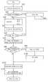
도 6은 본 발명의 로드셀 기반의 관입력 측정시스템이 구비된 드레인재 타설장치의 동작을 설명하기 위한 플로차트이다.
도 7은 본 발명의 드레인재의 앙카링 심도 측정유닛을 설명하기 위한 입체도 이다.
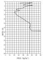
도 8은 본 발명의 드레인 케이싱(1204)의 지중 삽입시 드레인 케이싱에 가해지는 압력 변화를 나타내는 그래프이다.
도 9 내지 도 11은 본 발명의 드레인재의 앙카링 심도 측정유닛의 동작을 설명하기 위한 단면도이다.1 is a plan view showing an area to be inserted into a drain material for improvement of a general soft ground.
2 is a cross-sectional view showing a state in which a drain material is inserted into a general soft ground.
3 is a view for explaining the fancy phenomenon of a general drain material.
4 is a view for explaining the structure of a drain material pouring apparatus equipped with a load cell-based tube input measurement system of the present invention.
5 is a block diagram illustrating a load cell-based tube input measurement system of the present invention.
6 is a flowchart for explaining the operation of the drain material pouring apparatus equipped with the load cell-based tube input measuring system of the present invention.
7 is a three-dimensional view for explaining the anchoring depth measurement unit of the drain material of the present invention.
8 is a graph showing a change in pressure applied to the drain casing when the
9 to 11 are cross-sectional views for explaining the operation of the anchoring depth measuring unit of the drain material of the present invention.
본 발명의 로드셀 기반의 관입력 측정시스템(1230)이 구비된 드레인재 타설장치(1201)는 도 4와 같이 리더(1202)와 드레인 케이싱 고정홀더(1203), 드레인 케이싱(1204), 드레인재(P)가 감겨있는 릴 장치(1206)를 구비한다. 릴 장치(1206)는 설정된 장력(한 예로 2~10kg) 이상의 힘으로 당길 경우 릴 장치의 릴이 역회전 가능하도록 구성된다. 릴 장치의 릴을 역회전 가능하도록 구성하는 이유는 도 9에 도시한 것처럼 지상에서 앙카플레이트(12)에 드레인재(P)를 고정하였을 때는 드레인재(P)에 장력이 작용하여 앙카플레이트(12)가 드레인 케이싱(1204)의 단부로부터 이탈되지 않도록 하고, 드레인 케이싱(1204)을 하강시켜 지중으로 삽입할 때는 드레인재(P)가 릴 장치로부터 풀려 드레인 케이싱과 함께 내려가도록 하기 위한 것이다.The drain
상기 리더(1202)는 드레인재 타설장치의 본체에 각도 조정이 가능한 상태로 입설되고, 그 리더의 상하 방향을 따라 상기 드레인 케이싱 고정홀더(1203)가 승강 이동 가능하도록 구성된다. 상기 드레인 케이싱 고정홀더는 와이어(1233)가 권선된 활차(1244)에 고정되어 유압실린더(1245)로 간접 구동하거나, 와이어 없이 드레인 케이싱 고정홀더에 유압실린더를 직접 고정하여 구동할 수 있다. 상기 활차(1244)의 회전에 의하여 이동되는 드레인 케이싱(1204)의 승강 길이는 활차의 회전수 등을 감지하는 센서(도시생략)에 의하여 측정할 수 있다. 활차의 회전수 등을 감지하는 센서는 도 5에 도시된 본 발명의 드레인 케이싱의 심도측정기(1225)로 기능 한다.The
또, 본 발명의 드레인재 타설장치(1201)는, 도 5와 같이 무선 로드셀(280), 드레인 케이싱의 심도측정기(1225), 위성항법장치(1224:GPS(global position system)), 드레인재의 앙카링 심도측정유닛(1250), 기준 데이터 입력부(1120), 표시부(1115), 제어부(1110)로 이루어진 드레인 케이싱(1204)의 관입력 측정시스템(1230)을 구비한다.In addition, the drain
상기 무선 로드셀(280)은 드레인 케이싱 고정홀더(1203)에 고정된 드레인 케이싱(1204)이 지중으로 인입되는 과정에서 그 드레인 케이싱(1204)에 가해지는 하중 압력을 측정하기 위해 드레인 케이싱 고정홀더(1203)와 와이어(1223) 사이에 설치된다.The
상기 위성항법장치(1224)로부터 측정되는 드레인 케이싱(1204)의 위치 좌표 데이터, 무선 로드셀(280)으로부터 수신되는 데이터, 드레인 케이싱의 심도 측정기(1225)로부터 수신되는 데이터, 드레인재의 앙카링 심도측정유닛(1250)으로 부터 수신되는 데이터는 기준데이터 입력부(1120)를 통하여 외부로부터 입력된 토질 시추공 데이터와 비교 판단되고, 그 결과가 실시간으로 표시부(1115)를 통하여 디스플레이됨으로써, 드레인재 타설장치를 운전하는 오퍼레이터가 드레인 케이싱(1204)의 위치 좌표 및 심도, 드레인재의 앙카링 심도, 지중 상태 등의 정보를 제공 받을 수 있다.Position coordinate data of the
상기 드레인 케이싱 고정홀더(1203)에는 도 7과 같이 드레인 케이싱(1204)이 착탈 가능한 상태로 고정되고, 드레인 케이싱(1204)은 내부 중심축을 따라 릴 장치(1206)를 통하여 드레인재(P)가 공급되는 통공부(1208)가 형성된다.A
한편, 본 발명의 드레인재의 앙카링 심도측정유닛(1250)은, 통공부(1208) 중심축을 따라 릴 장치(1206)를 통하여 드레인재(P)가 공급되는 드레인 케이싱(1204)에 구성된다.On the other hand, the anchoring
본 발명의 드레인재의 앙카링 심도측정유닛(1250)은, 적어도 1개 이상의 진동장치(1251,1252)와, 상기 드레인 케이싱(1204)의 하단부로 노출되도록 상기 진동장치(1251,1252)와 연결된 압력 감지센서(1251a,1252a)로 구성된다. 상기 압력 감지센서(1251a,1252a)는 각 진동장치마다 복수개 구성할 수 있다. 압력 감지센서(1251a,1252a)는 드레인 케이싱(1204)의 단부에 지지되는 앙카프레이트(12)와 접촉 가능하도록 구성됨으로써 앙카플레이트가 어느 심도에서 드레인 케이싱(1204)의 단부와 분리되었는지를 감지할 수 있다.The anchoring
상기 진동장치(1251,1252)와 압력 감지센서(1251a,1252a)는 드레인 케이싱(1204)의 단부로 노출되므로 드레인재(P)를 고정하는 앙카플레이트(12)와 직접 접촉 가능한 상태가 된다. 즉, 압력 감지센서(1251a,1252a)와 앙카프레이트(12)와의 접촉이 없어 압력감지가 않되면 그 순간의 드레인 케이싱(1204)의 단부 위치를 앙카프레이트(12)의 앙카링 위치로 판단한다.Since the
본 발명에서는 드레인 케이싱의 단부에 진동장치(1251,1252)를 양쪽에 설치한 구조를 예시하였으나 1개만 구성하여도 된다. 상기 진동장치(1251,1252)는 전원 또는 에어압에 의하여 구동되도록 구성할 수 있고, 전원선(1251b,1252b) 또는 에어 공급용 호스는 매우 적은 체적을 차지하므로 드레인 케이싱의 통공부(1208)를 통하여 배선될 수 있다. 상기 진동장치는 드레인 케이싱의 하단부에 강한 진동을 줄 수 있도록 하는 것이므로 공지의 진동장치 중 어느 것을 이용하더라도 관계없다. 상기 진동장치에 결합되는 압력 감지센서(1251a,1252a)는 진동장치의 구동시 함께 연동되어 진동을 전달할 수 있도록 구성된다. 압력 감지센서(1251a,1252a)의 신호는 별도의 유선 라인(도시 생략)을 통하여 제어부(1110)에 전송할 수 있다.In the present invention, the structure in which the
상기 압력 감지센서(1251a,1252a)는 표면이 딱딱한 앙카플레이트(12)와 접촉된 상태에서는 그 진동 압력이 크고, 앙카플레이트(12)와 접촉되지 않는 상태에서는 그 진동 압력이 작거나 없기 때문에 그 진동 압력차이를 감지하여 앙카링 위치를 정확히 알 수 있다.The pressure sensor (1251a, 1252a) has a high vibration pressure when the surface is in contact with the
또, 상기 압력 감지센서(1251a,1252a)는 진동장치 내부로부터 도시되지 않은 스프링 등에 탄지되어 진동장치의 단부보다 약간(0.5~1cm) 돌출된 상태를 유지하도록 구성함으로써, 과도한 압력으로부터 압력 감지센서를 보호할 수 있다. 상기 진동장치는 드레인 케이싱의 인발과 동시에 구동되어 일정 시간 지속되지만 압력 감지센서에 의하여 앙카플레이트의 분리가 확인되면 진동장치의 구동은 즉시 멈출 수 있다.In addition, the
상기 드레인 케이싱의 단부에 구성되는 진동장치(1251,1252) 외에 드레인 케이싱의 인발시 상하 또는 좌우 방향의 진동을 더 추가하기 위하여 드레인 케이싱의 상단에 부착되는 보조 진동장치(1253)을 더 구성할 수 있다.In addition to the
진동장치(1251,1252) 및 보조 진동장치(1253)는 전원선(1251b,1252b,1253b) 또는 어에 호스를 개재하여 드레인 케이싱 고정홀더(1203)에 설치된 진동 동력전달장치(1255)와 연결된다.The
상기와 같이 구성되는 본 발명의 드레인재 타설장치(1201)의 구동 과정은 도 5 및 도 6을 주로 참고하여 설명한다.The driving process of the drain
먼저 드레인재 타설장치(1201)의 전원을 온(on)하여 운전 가능한 상태가 되도록 한다(S10).First, the power of the drain
이어서, 기준 데이터 입력부(1120)를 통하여 토질 시추공 데이터 등이 입력된 작업 시방서 상의 관입 위치와, 드레인 케이싱(1204)의 시공 위치가 일치하는지 GPS(1224) 데이터를 수신하여 표시부(1115) 맵핑한다(S20).Subsequently, the
작업 시방서 상의 관입 위치와, 드레인 케이싱(1204)의 시공 위치가 일치하지 않는 경우, 드레인재 타설장치(1201)를 위치 이동시키고(S30), 위치가 일치하는 경우 심도1 에서 심도 n까지 드레인 케이싱(1204)을 지중에 관입시킨다(S40).If the intrusion position on the work specification and the construction position of the
드레인 케이싱(1204)의 관입 과정에서 각 심도별 관입 압력이 무선 로드셀(280)에 의하여 측정된다(S50).During the intrusion process of the
이어서, 드레인 케이싱(1204)의 관입과정에서 목표 심도에 도달하였는지 드레인 케이싱의 심도 측정기(1225)를 통하여 판단하고(S60), 목표 심도에 도달한 경우 드레인 케이싱의 관입 압력 데이터와 토질 시추공의 관입 압력 데이터를 제어부(1110)가 비교 연산하여 표시부(1115)에 매핑하여 표시한다(S70).Subsequently, it is determined through the
이어서, 제어부(1110)는 심도별로 드레인 케이싱(1204)의 관입 시공 데이터의 압력이 토질 시추공 데이터의 압력보다 큰가를 판단(S80)하고,Subsequently, the
드레인 케이싱(1204)의 관입 시공 데이터의 종말 압력이 토질 시추공 데이터의 종말 압력보다 큰 경우에는 드레인재의 앙카링 심도 측정유닛(1250)을 통하여 드레인재의 앙카링 심도를 측정하는(S110)단계로 이동하고, 관입 시공 데이터의 종말 압력이 토질 시추공 데이터의 종말 압력보다 작은 경우에는 목표 심도를 변경한다(S90). 상기 목표 심도 변경은 토질 시추공 데이터의 종말 압력에 이를 때까지 드레인 케이싱(1204)을 추가 관입할 수 있고, 그 종말 압력과 관계없이 2~5m의 일정 깊이를 더 관입할 수 있도록 설정할 수 있다.If the end pressure of the intrusion construction data of the
상기 드레인 케이싱(1204)의 관입 시공에 있어서 종말 압력은 도 8과 같이 예를 들어 목표 심도인 34m 근처에 도달하였을 때 압력을 가하더라도 드레인 케이싱(1204)이 더 이상 관입되지 않고 압력 수치만 증가하는 구간(단단한 지반층 구간)을 말한다.In the penetration construction of the
드레인재(P)의 앙카링 심도측정이 이루어지면, 드레인 케이싱의 심도 측정기(1225), 무선 로드셀(280), 드레인재의 앙카링 심도 측정유닛(1250)으로부터 수신되는 실측 데이터와, 기준 데이터 입력부(1120)에 미리 입력된 토질 시추공 데이터를 비교 연산하여 표시부(115)에 맵핑하여 디스플레이할 수 있도록 한다(S120). 상기와 같이 드레인재의 앙카링 심도 위치를 드레인 케이싱의 심도 위치와 비교하여 나타냄으로써 드레인재의 삽입 시공의 품질을 정확하게 파악할 수 있는 장점이 있다.When the anchoring depth measurement of the drain material P is made, the actual measurement data received from the
상기와 같은 특징을 갖는 본 발명의 드레인재의 앙카링 심도 측정유닛(1250)의 기술 구성 및 작용은 도 9 내지 도 11을 참고하여 설명한다.The technical configuration and operation of the anchoring
먼저, 도 9와 같이 드레인 케이싱(1204)의 통공부(1208)을 통하여 릴 장치(1206)에 감겨있는 드레인재(P)의 단부를 인출한 후 그 단부에 앙카플레이트(12)를 고정한다. 드레인재의 단부에 고정된 앙카플레이트(12)를 놓으면 릴 장치의 장력이 작용하므로 드레인 케이싱(1204)의 하단부에 걸리는 앙카플레이트(12)에 의하여 드레인재(P)가 더 이상 딸려 올라가지 않고 드레인 케이싱(1204)의 단부에 지지된다. 드레인재(P)는 파이프형 또는 판형 중 어느 것을 이용하여도 되고, 그 이용되는 드레인재에 작합한 앙카플레이트를 사용하면 된다.First, as shown in FIG. 9, the end of the drain material P wound around the
앙카플레이트(12)가 드레인 케이싱(1204)의 하단에 고정된 상태에서 도 10과 같이 드레인 케이싱(1204)을 하강시켜 연약지반(9)으로 소정 심도까지 삽입한다. 드레인 케이싱(1204)이 목표 작업 심도까지 삽입된 후에는 그 드레인 케이싱(1204)을 인발하기 직전에 본 발명의 드레인재의 앙카링 심도 측정유닛(1250)을 구성하는 진동장치(1251,1252) 및 보조 진동장치(1253)를 선택적으로 구동시켜 앙카플레이트(12)에 좌우 또는 상하 방향으로 진동을 일정시간(약5~20초) 부여한다.With the
상기 진동에 의하여 앙카플레이트(12)에 진동파가 전해지면 진동장치 및 압력 감지센서(1251a,1252a)가 앙카플레이트의 요동을 촉진하므로 앙카플레이트(12)의 단부가 연약지반의 홀 측벽을 쉽게 파고들어(도 10참조) 앙카링이 이루어지기 시작한다.When a vibration wave is transmitted to the
이어서, 진동장치가 구동되는 상태에서 도 10과 같이 드레인 케이싱(1204)이 지중으로부터 지상 쪽으로 인발되면 드레인 케이싱(1204)과 앙카플레이트(12)가 분리되고, 연약지반(9)의 홀 측벽으로부터 토압이 순간적으로 작용하여 앙카플레이트(12) 전체가 지중의 토사에 매몰되어 앙카링이 확실하게 이루어지므로 드레인재(P)가 드레인 케이싱(1204)의 인발 방향으로 더 이상 따라 올라가지 않게 된다.Then, when the
드레인 케이싱(1204)의 인발 중에 앙카플레이트(12)가 드레인 케이싱(1204)의 단부로부터 분리되면 압력 감지센서(1251a,1252a)는 앙카플레이트(12)와의 접촉 해제 신호를 감지하여 드레인 케이싱의 단부가 위치하는 심도를 연산함으로써 드레인재의 단부가 앙카링되는 심도 위치를 감지할 수 있다.When the
즉, 본 발명의 드레인재의 앙카링 심도 측정유닛(1250)은 앙카플레이트(12)의 앙카링을 촉진하는 기능뿐만 아니라 앙카링 위치를 정확히 감지하는 기능을 동시에 갖도록 구성되어 있어 시공의 품질 관리에 매우 유용하게 활용할 수 있다.That is, the anchoring
이상 설명한 본 발명의 드레인재 타설장치(1201)은 상기 예시된 도면 구조 및 설명 내용에 한정되는 것은 아니고 본 발명의 청구범위와 목적의 범주 내에서 다양하게 변형하여 실시할 수 있다.The drain
본 발명은 드레인재를 지중에 수직 삽입하는 드레인재 타설장치에 관한 것으로 연약지반이나 습지 등을 개량하는데 이용된다.The present invention relates to a drain material pouring apparatus for vertically inserting a drain material into the ground, and is used to improve soft ground or wetlands.
9 - 연약지반 10 - 복토층
11 - 배수층 12 - 앙카플레이트
P,P1,P2,P3,P4 - 드레인재
280 - 무선 로드셀 1110 -제어부
1115 - 표시부 1120 - 기준 데이터 입력부
1201 - 드레인재 타설장치 1202 - 리더
1203 - 드레인 케이싱 고정홀더 204, 1204 - 드레인 케이싱
1206 - 릴 장치 1208 - 드레인 케이싱의 통공부
1224 - GPS 1230 - 관입력 측정시스템
1233 - 와이어 1244 - 활차
1245 - 유압실린더 1250 - 드레인재의 앙카링 심도 측정유닛
1251,1252 - 진동장치 1253 - 보조 진동장치
1251a,1252a - 압력 센서 1251b,1252b,1253b - 전원선
1255 - 진동 동력전달장치9-Soft ground 10-Covered layer
11-Drainage layer 12-Anchor plate
P,P1,P2,P3,P4-drain material
280-wireless load cell 1110-control unit
1115-Display 1120-Reference data input
1201-Drain material pouring device 1202-Leader
1203-Drain
1206-Reel unit 1208-Through hole in drain casing
1224-GPS 1230-Pipe input measurement system
1233-wire 1244-pulley
1245-Hydraulic cylinder 1250-Measuring unit for anchoring depth of drain material
1251,1252-vibrating device 1253-auxiliary vibrating device
1251a,1252a-
1255-Vibrating power train
Claims (9)
Translated fromKorean상기 드레인 케이싱의 관입력 측정 시스템은, 상기 드레인 케이싱이 지중으로 인입 또는 인발시 그 드레인 케이싱에 걸리는 압력을 측정하는 무선 로드셀과,
상기 드레인 케이싱의 심도 측정기와, 상기 드레인 케이싱의 심도 측정기 및 무선 로드셀로부터 수신되는 실측 데이터와, 외부로부터 입력된 토질 시추공 데이터를 비교 연산하는 제어부와, 상기 비교 연산된 데이터를 맵핑하여 디스플레이하는 표시부를 포함하되,
상기 드레인 케이싱의 목표 심도 도달 후 그 드레인 케이싱의 관입 압력이 상기 토질 시추공 데이터의 관입 압력보다 작을 경우 상기 드레인 케이싱을 추가 관입하도록 구성되는 것을 특징으로 하는 로드셀 기반의 관입력 측정시스템이 구비된 드레인재 타설장치.A drain casing fixing holder configured to move up and down along a leader, a drain casing mounted on the drain casing fixing holder and having a through hole therein, and a reel device supplying a drain material through the through hole of the drain casing; , Having a tube input measurement system of the drain casing,
The pipe input measurement system of the drain casing includes a wireless load cell for measuring a pressure applied to the drain casing when the drain casing is brought into or withdrawn into the ground,
A control unit for comparing and calculating the depth meter of the drain casing, the measured data received from the depth meter of the drain casing and the wireless load cell, and soil borehole data input from the outside, and a display unit for mapping and displaying the comparison calculated data Include,
A drain material provided with a load cell-based pipe input measuring system, characterized in that, when the penetration pressure of the drain casing is less than the penetration pressure of the soil borehole data after reaching the target depth of the drain casing, the drain casing is additionally penetrated. Pouring device.
상기 드레인 케이싱의 추가 관입은 상기 토질 시추공 데이터의 관입 압력에 도달하는 깊이까지 이루어지는 것을 특징으로 하는 로드셀 기반의 관입력 측정시스템이 구비된 드레인재 타설장치.The method of claim 1,
Additional penetration of the drain casing is made up to a depth reaching the penetration pressure of the soil borehole data, a drain material pouring apparatus provided with a pipe input measurement system based on a load cell.
상기 드레인재 타설장치에는 위성항법장치가 설치되는 것을 특징으로 하는 로드셀 기반의 관입력 측정시스템이 구비된 드레인재 타설장치.The method of claim 1,
The drain material placing device provided with a load cell-based pipe input measurement system, characterized in that the satellite navigation device is installed.
상기 드레인 케이싱에는 드레인재의 앙카링 심도 측정유닛이 설치되는 것을 특징으로 하는 로드셀 기반의 관입력 측정시스템이 구비된 드레인재 타설장치.The method of claim 1,
A drain material pouring device provided with a load cell-based pipe input measurement system, characterized in that the drain casing is provided with an anchoring depth measurement unit of the drain material.
상기 드레인재의 앙카링 심도 측정유닛은 상기 드레인 케이싱의 인발시 그 드레인 케이싱의 단부로부터 상기 드레인재를 지지하는 앙카플레이트의 이탈을 감지할 수 있도록 구성되는 것을 특징으로 하는 로드셀 기반의 관입력 측정시스템이 구비된 드레인재 타설장치.The method of claim 4,
The anchoring depth measurement unit of the drain material is configured to detect the separation of the anchor plate supporting the drain material from the end of the drain casing when the drain casing is pulled out. Drain material pouring device provided.
상기 드레인재의 앙카링 심도 측정유닛은 적어도 진동장치를 포함하는 것을 특징으로 하는 로드셀 기반의 관입력 측정시스템이 구비된 드레인재 타설장치.The method of claim 4,
The drain material pouring device provided with a load cell-based pipe input measurement system, characterized in that the unit for measuring anchoring depth of the drain material includes at least a vibration device.
상기 진동장치는 상기 드레인 케이싱의 단부로 노출되도록 구성되는 접촉감지부를 구비하고, 상기 접촉감지부는 상기 앙카플레이트와 접촉 가능하도록 구성되는 것을 특징으로 하는 로드셀 기반의 관입력 측정시스템이 구비된 드레인재 타설장치.The method of claim 6,
The vibration device includes a contact sensing unit configured to be exposed to an end of the drain casing, and the contact sensing unit is configured to contact the anchor plate, wherein the drain material is poured with a load cell-based tube input measuring system. Device.
상기 접촉감지부는 압력 감지센서로 구성되는 것을 특징으로 하는 로드셀 기반의 관입력 측정시스템이 구비된 드레인재 타설장치.The method of claim 7,
The drain material pouring device provided with a load cell-based tube input measurement system, characterized in that the contact detection unit is composed of a pressure sensor.
상기 드레인 케이싱의 심도 측정기, 상기 무선 로드셀, 상기 드레인재의 앙카링 심도 측정유닛으로부터 수신되는 실측 데이터와, 상기 토질 시추공 데이터를 비교 연산하도록 구성되는 것을 특징으로 하는 로드셀 기반의 관입력 측정시스템이 구비된 드레인재 타설장치.The method of claim 4,
A load cell-based pipe input measurement system, characterized in that it is configured to compare and calculate the measured data received from the depth measuring device of the drain casing, the wireless load cell, and the anchoring depth measuring unit of the drain material and the soil borehole data. Drain material pouring device.
Priority Applications (2)
| Application Number | Priority Date | Filing Date | Title |
|---|---|---|---|
| KR1020190094234AKR102570024B1 (en) | 2019-08-02 | 2019-08-02 | Paper drain board installing equipment with mandrel pressure measuring system using load cell |
| SG10201909819TASG10201909819TA (en) | 2019-08-02 | 2019-10-21 | Drain material installation apparatus equipped with load cell-based intrusive force measurement system |
Applications Claiming Priority (1)
| Application Number | Priority Date | Filing Date | Title |
|---|---|---|---|
| KR1020190094234AKR102570024B1 (en) | 2019-08-02 | 2019-08-02 | Paper drain board installing equipment with mandrel pressure measuring system using load cell |
Publications (2)
| Publication Number | Publication Date |
|---|---|
| KR20210016202Atrue KR20210016202A (en) | 2021-02-15 |
| KR102570024B1 KR102570024B1 (en) | 2023-08-24 |
Family
ID=74560555
Family Applications (1)
| Application Number | Title | Priority Date | Filing Date |
|---|---|---|---|
| KR1020190094234AActiveKR102570024B1 (en) | 2019-08-02 | 2019-08-02 | Paper drain board installing equipment with mandrel pressure measuring system using load cell |
Country Status (2)
| Country | Link |
|---|---|
| KR (1) | KR102570024B1 (en) |
| SG (1) | SG10201909819TA (en) |
Cited By (2)
| Publication number | Priority date | Publication date | Assignee | Title |
|---|---|---|---|---|
| CN114777995A (en)* | 2022-04-20 | 2022-07-22 | 交通运输部天津水运工程科学研究所 | A single-hole multi-point deep soil vacuum degree monitoring device and method |
| KR20220141522A (en)* | 2021-04-13 | 2022-10-20 | 이서준 | Soft ground improvement method and soft ground improvement device |
Citations (4)
| Publication number | Priority date | Publication date | Assignee | Title |
|---|---|---|---|---|
| KR20000006507U (en)* | 1998-09-15 | 2000-04-15 | 최균용 | Drain paper laying guide for soft ground improvement |
| KR20050089097A (en)* | 2004-03-03 | 2005-09-07 | 삼성물산 주식회사 | Installer of drain board |
| KR20080056353A (en) | 2006-12-18 | 2008-06-23 | 이상휘 | Measurement method and application of copper-yen value of underground drilling equipment |
| JP2009243057A (en)* | 2008-03-28 | 2009-10-22 | Aomi Construction Co Ltd | Sand compaction pile method |
- 2019
- 2019-08-02KRKR1020190094234Apatent/KR102570024B1/enactiveActive
- 2019-10-21SGSG10201909819TApatent/SG10201909819TA/enunknown
Patent Citations (4)
| Publication number | Priority date | Publication date | Assignee | Title |
|---|---|---|---|---|
| KR20000006507U (en)* | 1998-09-15 | 2000-04-15 | 최균용 | Drain paper laying guide for soft ground improvement |
| KR20050089097A (en)* | 2004-03-03 | 2005-09-07 | 삼성물산 주식회사 | Installer of drain board |
| KR20080056353A (en) | 2006-12-18 | 2008-06-23 | 이상휘 | Measurement method and application of copper-yen value of underground drilling equipment |
| JP2009243057A (en)* | 2008-03-28 | 2009-10-22 | Aomi Construction Co Ltd | Sand compaction pile method |
Cited By (2)
| Publication number | Priority date | Publication date | Assignee | Title |
|---|---|---|---|---|
| KR20220141522A (en)* | 2021-04-13 | 2022-10-20 | 이서준 | Soft ground improvement method and soft ground improvement device |
| CN114777995A (en)* | 2022-04-20 | 2022-07-22 | 交通运输部天津水运工程科学研究所 | A single-hole multi-point deep soil vacuum degree monitoring device and method |
Also Published As
| Publication number | Publication date |
|---|---|
| SG10201909819TA (en) | 2021-03-30 |
| KR102570024B1 (en) | 2023-08-24 |
Similar Documents
| Publication | Publication Date | Title |
|---|---|---|
| CN102878893B (en) | Landslide depth displacement monitoring system and method | |
| CN104329076B (en) | A kind of deviational survey hole osmotic pressure counter device and installation method | |
| KR100955599B1 (en) | Apparatus for auto measuring underground water level | |
| CN107675734B (en) | A kind of underwater directional vehicle construction dynamic monitoring method | |
| KR102433682B1 (en) | Multipurpose total inspection device and digital construction method of multi-step grouting with steel pipe using the same | |
| CN101430199A (en) | Method and apparatus for monitoring soft soil base sedimentation | |
| CN112197806B (en) | Method for installing equipment for monitoring movement deformation, hydrology and stress of coal mining subsidence area | |
| CN210238470U (en) | Sliding type inclination measuring device with settlement observation function | |
| CN2851352Y (en) | Quick detector for compaction degree of earth-filling subgrade | |
| CN102162234A (en) | Device and method for monitoring surface displacement of rock-soil body in real time | |
| CN108343432A (en) | A kind of drilling pouring pile hole quality detection device and its detection method | |
| CN107102378B (en) | Utilize the method for hole pressure touching methods measurement artesian aquifer water level and head height | |
| CN107630469A (en) | Manhole cover detecting and positioning device and installation method and construction method thereof | |
| KR20210016202A (en) | Paper drain board installing equipment with mandrel pressure measuring system using load cell | |
| CN205636706U (en) | Normal position soil pressure test device | |
| KR101710499B1 (en) | Automatic apparatus for sinking measuring of soft ground | |
| CN114016489A (en) | Reference point fixing device for settlement monitoring | |
| CN107192427A (en) | A kind of foundation soil condition monitoring device and its method | |
| CN103438933B (en) | Side slope surface displacement and shallow-layer deviational survey integration apparatus | |
| CN101270972A (en) | Soil internal deformation test device | |
| CN109989433A (en) | A kind of device and its detection method of the superfilled height of real-time detection cast-in-situ bored pile | |
| CN109162280A (en) | A kind of underwater gliders absolute altitude automation control method | |
| CN106643649B (en) | Device and method for measuring deep settlement and pore water pressure of soil body | |
| CN102102358B (en) | Method for measuring deep settlement deformation of foundation by wireless conduction type water pressure meter | |
| CN112187843A (en) | BIM-based system and method for automatically monitoring capital construction risks of deep foundation pit |
Legal Events
| Date | Code | Title | Description |
|---|---|---|---|
| PA0109 | Patent application | St.27 status event code:A-0-1-A10-A12-nap-PA0109 | |
| PG1501 | Laying open of application | St.27 status event code:A-1-1-Q10-Q12-nap-PG1501 | |
| PA0201 | Request for examination | St.27 status event code:A-1-2-D10-D11-exm-PA0201 | |
| R17-X000 | Change to representative recorded | St.27 status event code:A-3-3-R10-R17-oth-X000 | |
| D13-X000 | Search requested | St.27 status event code:A-1-2-D10-D13-srh-X000 | |
| D14-X000 | Search report completed | St.27 status event code:A-1-2-D10-D14-srh-X000 | |
| E902 | Notification of reason for refusal | ||
| PE0902 | Notice of grounds for rejection | St.27 status event code:A-1-2-D10-D21-exm-PE0902 | |
| E13-X000 | Pre-grant limitation requested | St.27 status event code:A-2-3-E10-E13-lim-X000 | |
| P11-X000 | Amendment of application requested | St.27 status event code:A-2-2-P10-P11-nap-X000 | |
| P13-X000 | Application amended | St.27 status event code:A-2-2-P10-P13-nap-X000 | |
| E701 | Decision to grant or registration of patent right | ||
| PE0701 | Decision of registration | St.27 status event code:A-1-2-D10-D22-exm-PE0701 | |
| PR0701 | Registration of establishment | St.27 status event code:A-2-4-F10-F11-exm-PR0701 | |
| PR1002 | Payment of registration fee | St.27 status event code:A-2-2-U10-U11-oth-PR1002 Fee payment year number:1 | |
| PG1601 | Publication of registration | St.27 status event code:A-4-4-Q10-Q13-nap-PG1601 |