KR20210014997A - Loading a blood-collecting machine - Google Patents
Loading a blood-collecting machineDownload PDFInfo
- Publication number
- KR20210014997A KR20210014997AKR1020190093188AKR20190093188AKR20210014997AKR 20210014997 AKR20210014997 AKR 20210014997AKR 1020190093188 AKR1020190093188 AKR 1020190093188AKR 20190093188 AKR20190093188 AKR 20190093188AKR 20210014997 AKR20210014997 AKR 20210014997A
- Authority
- KR
- South Korea
- Prior art keywords
- jig
- lancet
- switch
- jig part
- striking rod
- Prior art date
- Legal status (The legal status is an assumption and is not a legal conclusion. Google has not performed a legal analysis and makes no representation as to the accuracy of the status listed.)
- Abandoned
Links
- 239000008280bloodSubstances0.000claimsabstractdescription35
- 210000004369bloodAnatomy0.000claimsabstractdescription35
- 230000006835compressionEffects0.000claimsabstractdescription17
- 238000007906compressionMethods0.000claimsabstractdescription17
- 238000000034methodMethods0.000claimsabstractdescription10
- WQZGKKKJIJFFOK-GASJEMHNSA-NGlucoseNatural productsOC[C@H]1OC(O)[C@H](O)[C@@H](O)[C@@H]1OWQZGKKKJIJFFOK-GASJEMHNSA-N0.000description2
- 239000008103glucoseSubstances0.000description2
- 238000010008shearingMethods0.000description2
- 208000031872Body RemainsDiseases0.000description1
- 230000001684chronic effectEffects0.000description1
- 230000007423decreaseEffects0.000description1
- 206010012601diabetes mellitusDiseases0.000description1
- 201000010099diseaseDiseases0.000description1
- 208000037265diseases, disorders, signs and symptomsDiseases0.000description1
- 230000003203everyday effectEffects0.000description1
- 230000037368penetrate the skinEffects0.000description1
- 230000000149penetrating effectEffects0.000description1
- 230000035515penetrationEffects0.000description1
- 238000009527percussionMethods0.000description1
- 230000002093peripheral effectEffects0.000description1
- 230000001681protective effectEffects0.000description1
Images


Classifications
- A—HUMAN NECESSITIES
- A61—MEDICAL OR VETERINARY SCIENCE; HYGIENE
- A61B—DIAGNOSIS; SURGERY; IDENTIFICATION
- A61B5/00—Measuring for diagnostic purposes; Identification of persons
- A61B5/15—Devices for taking samples of blood
- A61B5/151—Devices specially adapted for taking samples of capillary blood, e.g. by lancets, needles or blades
- A61B5/15186—Devices loaded with a single lancet, i.e. a single lancet with or without a casing is loaded into a reusable drive device and then discarded after use; drive devices reloadable for multiple use
- A—HUMAN NECESSITIES
- A61—MEDICAL OR VETERINARY SCIENCE; HYGIENE
- A61B—DIAGNOSIS; SURGERY; IDENTIFICATION
- A61B5/00—Measuring for diagnostic purposes; Identification of persons
- A61B5/15—Devices for taking samples of blood
- A61B5/151—Devices specially adapted for taking samples of capillary blood, e.g. by lancets, needles or blades
- A61B5/15101—Details
Landscapes
- Health & Medical Sciences (AREA)
- Life Sciences & Earth Sciences (AREA)
- Heart & Thoracic Surgery (AREA)
- Medical Informatics (AREA)
- Biophysics (AREA)
- Pathology (AREA)
- Engineering & Computer Science (AREA)
- Biomedical Technology (AREA)
- Hematology (AREA)
- Physics & Mathematics (AREA)
- Molecular Biology (AREA)
- Surgery (AREA)
- Animal Behavior & Ethology (AREA)
- General Health & Medical Sciences (AREA)
- Public Health (AREA)
- Veterinary Medicine (AREA)
- Measurement Of The Respiration, Hearing Ability, Form, And Blood Characteristics Of Living Organisms (AREA)
Abstract
Description
Translated fromKorean본 발명은 채혈기에 관한 것으로서, 더욱 상세하게는 몸체 전방으로 노출된 지그부가 몸체의 지그수용홈 내로 진입되면서 란셋의 외면을 물어 고정하도록 함으로써, 란셋을 채혈기에 보다 쉽고 편리하게 체결할 수 있도록 제작한 장전식 채혈기에 관한 것이다.The present invention relates to a blood collection device, and more specifically, a jig portion exposed to the front of the body is made to bite and fix the outer surface of the lancet while entering into the jig receiving groove of the body, thereby making it easier and more convenient to fasten the lancet to the blood collection device. It is about a reloadable blood drawer.
일반적으로, 만성 당뇨병 환자는 매일 집에서 혈당검사를 스스로 실시하여 혈당치를 측정하고, 혈당치를 일정하게 유지하도록 질환관리를 해야한다.In general, patients with chronic diabetes should conduct a blood sugar test every day at home, measure their blood sugar level, and manage diseases to keep the blood sugar level constant.
이때, 혈당검사를 행하기 위해서는 혈액을 채취해야 하는데, 통상 손가락 등의 신체부위를 일회용 란셋(lancet)으로 피부를 관통하여 소량의 모세 혈액을 채취한 후 스트립(strip)에 묻히고 스트립이 장착되는 혈당검사계를 사용하여 혈당치를 측정하게 된다.At this time, blood must be collected to perform a blood glucose test. Usually, a small amount of capillary blood is collected by penetrating the skin with a disposable lancet through a body part such as a finger, and then buried in a strip and the blood sugar on which the strip is mounted. Blood glucose levels are measured using a test system.
여기서, 혈액을 채취하기 위한 수단으로는 채혈장치(lancing device)를 주로 사용하고 있다. 이와 같은 채혈장치는 일회용 란셋이 장착되는 장전유닛, 예컨대 탄성체 및 격발레버를 포함한 장전체를 구비된 란셋홀더(lancet holder), 상기 란셋홀더에 설치되며 란셋을 덮고 피부관통을 위해 침의 첨부만이 돌출되는 구멍이 형성된 엔드캡(end cap)으로 구성된다.Here, as a means for collecting blood, a lancing device is mainly used. Such a blood collection device includes a loading unit on which a disposable lancet is mounted, for example, a lancet holder having a loader including an elastic body and a percussion lever, and is installed on the lancet holder, covering the lancet and only attaching a needle for skin penetration. It consists of a protruding hole formed end cap (end cap).
아울러, 상기 일회용 란셋은 소정길이를 갖는 란셋바디의 일단에 채혈침이 구비되고 이러한 채혈침에는 보호용캡이 결합되어 구성된다.In addition, the disposable lancet includes a blood collection needle at one end of a lancet body having a predetermined length, and a protective cap is coupled to the blood collection needle.
특허문헌 1은 종래의 채혈기를 나타낸 것으로서, 이를 참조하면, 저면이 개구된 중공형상으로, 상면에 눌림작동되는 트리거를 형성한 상부케이스와, 상면이 개구된 중공형상으로, 상부케이스와 마주보도록 결합되는 하부케이스, 상, 하부케이스 내에 삽입 결합되어 전단에 침바디홀더를 형성한 장전바디, 상, 하부케이스 내측 후단과 장전바디 사이에 설치되어 장전바디를 전방으로 밀어내는 발사스프링, 장전바디의 침바디홀더 내로 삽입 되는 침바디, 상, 하부케이스 전단을 마감하도록 체결되어, 침바디를 전단을 감싸 커버하는 침바디보호캡으로 구성된다.Patent Document 1 shows a conventional blood collection device, and referring to this, the upper case has a hollow shape with an open bottom surface, a trigger that is pressed on the upper surface, and a hollow shape with an open upper surface, and is coupled to face the upper case. The loading body that is inserted and coupled into the lower case, the upper and lower cases to form a needle body holder at the front end, the launch spring that is installed between the rear end and the loading body inside the upper and lower cases to push the loading body forward, and the needle of the loading body The needle body inserted into the body holder is fastened to close the front end of the upper and lower case, and is composed of a needle body protection cap that covers the front end of the needle body.
여기서, 침바디는 그 전단에 바늘을 형성하고 있고, 이 바늘은 침바디보호캡의 전면에 형성된 소직경홀을 통과하여 침바디보호캡 전방으로 노출된다.Here, the needle body has a needle formed at its front end, and the needle is exposed to the front of the needle body protection cap through a small diameter hole formed in the front surface of the needle body protection cap.
먼저, 침바디를 침바디홀더에 삽입하고, 그 상태에서 장전바디를 후퇴이동시켜 발사스프링이 압축되도록 함과 동시에 트리거에 장전바디 외면이 걸림되도록 한다.First, insert the chim body into the chim body holder, and in that state, the loading body is retracted so that the launch spring is compressed and the outer surface of the loading body is caught in the trigger.
그리고, 침바디보호캡을 상, 하부케이스의 상, 하부연장부에 삽입 체결하여, 침바디보호캡이 침바디를 커버하도록 한다.Then, the needle body protection cap is inserted into the upper and lower extension portions of the upper and lower cases so that the needle body protection cap covers the needle body.
그러면, 침바디의 바늘이 침바디보호캡 내측에 위치되고, 이때, 트리거를 눌러 장전바디가 트리거에서 이탈되도록 하면, 발사스프링의 복원력에 의해 장전바디가 전방으로 이동되면서 침바디를 침바디보호캡 방향으로 누름 가압하고, 이에따라, 침바디의 바늘이 침바디보호캡의 소직경홀을 통과하여 침바디보호캡 외부로 노출된 상태에서 피부를 뚫고 들어가는 것이다.Then, the needle of the needle body is located inside the needle body protection cap. At this time, if the trigger is pressed and the loading body is disengaged from the trigger, the loading body is moved forward by the resilience of the launch spring and the needle body is moved to the needle body protection cap. Press and press in the direction, and accordingly, the needle of the needle body penetrates the skin while being exposed to the outside of the needle body protection cap through the small diameter hole of the needle body protection cap.
하지만, 상기와 같은 특허문헌 1은, 침바디보호캡을 탈, 부착하여 침바디홀더에 침바디를 결합해야 하는 불편함이 있고, 침바디보호캡을 분리한 상태에서 장전바디를 트리거에 걸림되도록 한 후 재 결합해야 하는 절차가 매우 번거로우며, 특히, 장전된 장전바디에 침바디를 결합하는 과정에서 장전바디의 잠금이 해제되어 침바디의 바늘이 피부를 뚫고 들어갈 우려가 있고, 또한, 사용한 침바디를 침바디 홀더에서 분리하는 과정에서 바늘에 찔림과 동시에 이 바늘에 뭍어있는 혈액이 피부내로 침투될 우려가 있으며, 사용된 침바디의 바늘이 침바디보호캡 외부로 노출된 상태로 유지되어, 바늘에 주변 사람 또는 사용자 본인이 상해를 입을 수 있고, 이에따라, 위생 상태 관리가 제대로 이루어지지 못해 제품의 신뢰성이 저하되는 문제점이 있다.However, Patent Literature 1 as described above has the inconvenience of attaching the needle body to the needle body holder by removing and attaching the needle body protection cap, and the loading body is caught by the trigger while the needle body protection cap is removed. It is very cumbersome to re-join the loaded body and, in particular, in the process of combining the needle body with the loaded body, there is a risk that the needle of the needle body may penetrate the skin due to the unlocking of the loading body. In the process of separating the body from the needle body holder, there is a risk that the blood on the needle may penetrate into the skin at the same time as the needle is pierced, and the needle of the used needle body remains exposed to the outside of the needle body protection cap. The needle may injure a nearby person or the user himself, and accordingly, there is a problem in that the reliability of the product is deteriorated due to poor hygiene management.
본 발명은 상술한 바와 같은 문제점을 해결하기 위한 것으로서, 본 발명의 목적은 전단에 지그수용홈을 형성하고, 외면에 타격스위치를 형성한 몸체를 구비하고, 이 몸체 내에 서로 대칭되게 형성되되, 몸체의 지그수용홈에 밀착되어 란셋을 물어 고정하는 지그부를 결합하며, 몸체 후단에 지그부의 말단과 연결되는 스위치를 결합하고, 외면에 걸림돌기를 형성한 타격봉의 타단이 지그부 사이에 위치되도록, 타격봉의 일단을 스위치에 슬라이딩 결합하며, 몸체외 지그부 사이에 탄성스프링을 결합하고, 타격봉의 일단과 스위치 사이에 압축스프링을 결합하여, 스위치를 눌러 지그부가 몸체 전방으로 노출되도록 하고, 이 지그부 전단 사이에 란셋을 위치시켜 스위치 누름을 해제하여 탄성스프링에 의해 지그부가 지그수용홈 내로 진입되면서 란셋 외면을 물어 고정하도록 하며, 스위치를 몸체 반대 방향으로 당기면서 압축스프링을 인장하되, 타격봉의 걸림돌기가 타격스위치에 걸림되도록 한 후, 타격스위치를 누름에 따라 걸림돌기가 타격스위치에서 이탈되되, 이때, 압축스프링의 복원력에 의해 타격봉이 전방으로 이동되면서 란셋의 중앙부를 타격하여, 란셋의 바늘이 전방으로 노출되었다가 란셋 내로 재 진입되는 장전식 채혈기를 제공하는 것이다.The present invention is to solve the problems as described above, the object of the present invention is to form a jig receiving groove in the front end, and having a body having a hitting switch formed on the outer surface, and are formed symmetrically to each other in the body, the body The jig part that is in close contact with the jig receiving groove of the lancet and fixes the lancet is combined, and a switch connected to the end of the jig part is connected to the rear end of the body, and the other end of the striking rod with a locking protrusion formed on the outer surface is positioned between the jig part. One end is slidingly coupled to the switch, an elastic spring is coupled between the jig portion outside the body, and a compression spring is coupled between the one end of the striking rod and the switch, so that the jig portion is exposed to the front of the body by pressing the switch. Position the lancet to release the switch, and the jig part enters into the jig receiving groove by the elastic spring to bite the outer surface of the lancet to fix it. Pull the switch in the opposite direction to the compression spring, but the locking protrusion of the hitting rod is the hitting switch. After the hitting switch is pressed, the hitting protrusion is separated from the hitting switch. At this time, the hitting rod moves forward by the restoring force of the compression spring and strikes the center of the lancet, so that the needle of the lancet is exposed forward. It is to provide a reloadable blood drawer that re-enters the lancet.
상기와 같은 본 발명의 목적을 달성하기 위하여, 본 발명에 따른 장전식 채혈기는, 전, 후가 개방된 중공형상으로, 전단에 함몰형성된 지그수용홈을 형성하고, 외면에 타격스위치를 형성한 몸체와; 서로 대칭되게 적어도 2개 이상으로 형성되고, 상기 몸체 내로 삽입 결합되되, 상기 몸체의 지그수용홈에 밀착되어 란셋을 물어 고정하는 지그부; 상기 몸체의 후단에 삽입결합되고, 상기 지그부의 말단과 연결되어 상기 지그부가 상기 몸체 전단으로 노출되도록 상기 지그부를 누름 가압하는 스위치; 바 형상으로 일단이 상기 스위치를 통과하도록 슬라이딩 결합되고, 타단이 상기 지그부의 정 중앙부를 통과하여 상기 지그부 사이에 위치되며, 외면에 상기 타격스위치에 걸림되는 걸림돌기를 형성한 타격봉; 상기 몸체와 상기 지그부 사이에 상기 몸체 전단으로 노출된 상기 지그부가 상기 몸체 내측으로 삽입되도록 강제하는 탄성스프링; 상기 타격봉의 일단과 상기 스위치 사이에 설치되어 상기 타격봉을 상기 몸체의 전단 방향으로 당기는 압축스프링;으로 구성된 것을 특징으로 한다.In order to achieve the object of the present invention as described above, the loaded blood collection device according to the present invention has a hollow shape in which the front and rear ends are opened, a body having a jig receiving groove recessed at the front end, and a strike switch formed on the outer surface Wow; A jig portion formed in at least two symmetrically to each other and inserted into the body, the jig portion being in close contact with the jig receiving groove of the body to bite and fix the lancet; A switch inserted into the rear end of the body and connected to an end of the jig portion to press and press the jig portion so that the jig portion is exposed to the front end of the body; A striking rod having one end slidingly coupled to pass through the switch in a bar shape, the other end passing through the central portion of the jig portion and positioned between the jig portions, and forming a locking protrusion on an outer surface thereof to be caught by the striking switch; An elastic spring forcing the jig portion exposed through the front end of the body to be inserted into the body between the body and the jig portion; And a compression spring installed between one end of the striking rod and the switch to pull the striking rod in the shear direction of the body.
본 발명에 따른 장전식 채혈기에 있어서, 상기 지그부는, 바 형상으로 상기 몸체 내로 삽입결합되어 상기 스위치에 연결되는 연결바와; 상기 연결바 말단에서 서로 마주보는 반대 방향으로 벌어지도록 형성되어 상기 란셋을 물어 고정하는 란셋지그;로 구성된 것을 특징으로 한다.In the reloadable blood collection device according to the present invention, the jig portion includes: a connection bar inserted into the body in a bar shape and connected to the switch; It characterized in that it consists of a; lancet jig is formed so as to open in opposite directions facing each other at the end of the connecting bar to bite and fix the lancet.
본 발명에 따른 장전식 채혈기에 있어서, 상기 연결바는, 상기 스위치에서 상기 몸체의 전방을 향해 방사상으로 벌어지도록 경사지게 형성된 것을 특징으로 한다.In the reloadable blood collection device according to the present invention, the connection bar is formed to be inclined to spread radially toward the front of the body by the switch.
본 발명에 따른 장전식 채혈기에 있어서, 상기 란셋지그는, 서로 마주보는 면에 상기 란셋의 외면에 밀착되어, 상기 란셋이 상기 란셋지그에서 미끄러져 이탈되는 것을 방지하는 복수개의 미끄럼 방지 돌기를 더 형성한 것을 특징으로 한다.In the reloadable blood collection device according to the present invention, the lancet jig further forms a plurality of anti-slip protrusions to prevent the lancet from slipping off the lancet jig by being in close contact with the outer surface of the lancet on surfaces facing each other It is characterized by one.
본 발명에 따른 장전식 채혈기에 있어서, 상기 몸체는 내주면에 탄성스프링의 일단이 걸림되는 전단걸림턱을 형성하고, 상기 지그부의 연결바는 외주면에 탄성스프링의 타단이 걸림되는 후단걸림턱을 형성한 것을 특징으로 한다.In the reloadable blood collection device according to the present invention, the body has a shear engaging jaw in which one end of the elastic spring is caught on the inner circumferential surface, and the connecting bar of the jig portion has a rear engaging jaw in which the other end of the elastic spring is caught on the outer circumferential surface. It features.
본 발명에 따른 장전식 채혈기에 있어서, 상기 스위치는 내측에 상기 타격봉의 일단이 슬라이딩 이동하는 것을 안내하는 안내홈을 더 형성한 것을 특징으로 한다.In the reloadable blood collection device according to the present invention, the switch is characterized in that further forming a guide groove for guiding the sliding movement of one end of the striking rod inside.
본 발명에 따르면, 몸체 전방으로 노출되었다가 지그수용홈으로 진입되는 지그부 사이에 란셋을 고정하여, 몸체 전방에 란셋을 견고하게 고정할 수 있고, 스위치를 눌렀다가 해제하면서 지그부 사이에 란셋이 고정되도록 하여 란셋의 탈, 부착을 신속하게 진행할 수 있으며, 또한, 스위치를 누르는 원터치 방식에 의해 란셋이 지그부에 고정되어 손쉬운 사용이 가능하고, 지그부에 란셋을 고정한 상태에서 스위치를 후퇴이동시키는 단순동작으로 타격봉을 안전하게 장전할 수 있고, 타격스위치 누름해제로 타격봉이 란셋 중앙부를 자동 타격하여 사용이 간편하며, 특히, 스위치를 가압하는 동작으로 지그부 사이에 고정된 란셋이 지그부에서 이탈되도록 하여, 사용된 란셋을 사용자가 직접 분리할 필요가 없고, 이에따라, 위생 상태가 매우 우수하여 제품의 신뢰성이 향상되는 장점이 있다.According to the present invention, by fixing the lancet between the jig portions exposed to the front of the body and entering the jig receiving groove, the lancet can be firmly fixed in the front of the body, and the lancet is formed between the jig portions while pressing and releasing the switch. The lancet can be removed and attached quickly by being fixed. In addition, the lancet is fixed to the jig part by the one-touch method of pressing the switch for easy use, and the switch is retracted while the lancet is fixed in the jig part. The striking rod can be safely loaded with a simple operation, and the striking rod automatically hits the center of the lancet by releasing the pressing of the striking switch, making it easy to use. In particular, the lancet fixed between the jig parts is separated from the jig part by pressing the switch As a result, there is no need for the user to directly separate the used lancet, and thus, the hygiene condition is very excellent, and the reliability of the product is improved.
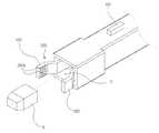
도 1은 본 발명에 따른 장전식 채혈기를 나타낸 사시도.
도 2는 도 1의 분해 사시도.
도 3은 본 발명에 따른 장전식 채혈기의 지그부에 란셋을 고정하는 사시도.
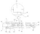
도 4 내지 도 5는 본 발명에 다른 장전식 채결기의 타격봉으로 란셋을 타격하는 측 단면도.1 is a perspective view showing a loaded blood collection device according to the present invention.
Figure 2 is an exploded perspective view of Figure 1;
Figure 3 is a perspective view of fixing the lancet to the jig portion of the loaded blood collection device according to the present invention.
4 to 5 are side cross-sectional views for striking the lancet with the striking rod of another loaded fastening machine according to the present invention.
이하, 본 발명의 실시예를 첨부된 도면을 참조하여 더욱 상세하게 설명한다.Hereinafter, embodiments of the present invention will be described in more detail with reference to the accompanying drawings.
도 1 내지 도 5를 참조하면, 몸체(100)는 전, 후가 개방된 중공형상으로, 전단에 함몰형성된 지그수용홈(101)을 형성하고, 외면에 타격스위치(102)를 형성한다.1 to 5, the
상기 몸체(100)는 내주면에 탄성스프링(500)의 일단이 걸림되는 전단걸림턱(100a)을 형성한다.The
상기 전단걸림턱(100a)은 상기 몸체(100)의 내주면에서 서로 대칭되게 형성되는 것이 바람직하다.The shearing jaw (100a) is preferably formed to be symmetrical to each other on the inner peripheral surface of the body (100).
상기 전단걸림턱(100a)은 상기 지그부(200)의 후단걸림턱(201a)에 의해 상기 탄성스프링(500)이 압축되는 것을 지지한다.The shear
상기 지그수용홈(101)은 상기 지그부(200) 형상에 대응하도록 전단에서 후단으로 갈수록 그 직경이 좁아지도록 테이퍼지게 형성된다.The
상기 지그수용홈(101)은 내벽면에 상기 지그부(200)의 란셋지그(202)가 밀착되도록 하여, 상기 지그부(200)가 상기 몸체(100) 내측으로 정해진 깊이 이상 진입되는 것을 차단한다.The
상기 타격스위치(102)는 상기 타격봉(400)의 걸림돌기(401)가 걸림되도록 허용하여, 상기 타격봉(400)을 장전된 상태로 유지시킨다.The
상기 타격스위치(102)는 일 방향으로 기울어지도록 회전되면서, 상기 걸림돌기(401)를 누름 가압하여, 상기 타격스위치(102)에서 이탈되도록 한다.The
지그부(200)는 서로 대칭되게 적어도 2개 이상으로 형성되고, 상기 몸체(100) 내로 삽입 결합되되, 상기 몸체(100)의 지그수용홈(101)에 밀착되어 란셋(R)을 물어 고정한다.The
상기 지그부(200)는 상기 스위치(300)에 가해지는 가압력에 의해 전방으로 슬라이딩 이동한다.The
상기 지그부(200)는 상기 몸체(100) 전방으로 노출되면서 서로 마주보는 반대 방향을 향해 방사상으로 벌어지고, 상기 탄성스프링(500)에 의해 상기 몸체(100)의 지그수용홈(101) 내로 진입되면서 서로 마주보는 방향으로 좁혀져 상기 란셋(R)의 외면을 물어 고정한다.The
상기 지그부(200)는 바 형상으로 상기 몸체(100) 내로 삽입결합되어 상기 스위치(300)에 연결되는 연결바(201)와, 상기 연결바(201) 말단에서 서로 마주보는 반대 방향으로 벌어지도록 형성되어 상기 란셋(R)을 물어 고정하는 란셋지그(202)로 구성된다.The
상기 연결바(201)는 상기 스위치(300)에 의해 슬라이딩 이동되어 상기 란셋지그(202)를 상기 몸체(100) 전방으로 노출시킨다.The
상기 연결바(201)는 상기 스위치(300)에서 상기 몸체(100)의 전방을 향해 방사상으로 벌어지도록 경사지게 형성된다.The
상기 연결바(201)는 방사상으로 벌어지려는 복원력에 의해 상기 몸체(100) 전방으로 노출된 상기 란셋지그(202)를 서로 마주보는 반대 방향으로 벌어지도록 한다.The
상기 연결바(201)는 상기 지그수용홈(101)으로 진입되면서 상기 지그수용홈(101) 직경에 비례하도록 좁혀지는 란셋지그(202)에 의해 서로 마주보는 방향으로 좁혀진다.The connecting
상기 란셋지그(202)는 서로 마주보는 면에 상기 란셋(R)의 외면에 밀착되어, 상기 란셋(R)이 상기 란셋지그(202)에서 미끄러져 이탈되는 것을 방지하는 복수개의 미끄럼 방지 돌기(202a)를 더 형성한다.The
상기 미끄럼 방지돌기(202a)는 란셋(R)의 외면에 걸림되어, 타격봉(400)에 의해 타격되는 상기 란셋(R)이 상기 란셋지그(202)에서 이탈되는 것을 방지한다.The
상기 지그부(200)의 연결바(201)는 외주면에 탄성스프링(500)의 타단이 걸림되는 후단걸림턱(201a)을 형성한다.The connecting
상기 후단걸림턱(201a)은 상기 연결바(201)에 의해 상기 몸체(100) 전방으로 이동하면서 상기 탄성스프링(500)을 눌러 압축한다.The rear
스위치(300)는 상기 몸체(100)의 후단에 삽입결합되고, 상기 지그부(200)의 말단과 연결되어 상기 지그부(200)가 상기 몸체(100) 전단으로 노출되도록 상기 지그부(200)를 누름 가압한다.The
상기 스위치(300)는 상기 타격봉(400)의 일단 외주면을 따라 슬라이딩 이동하면서 상기 지그부(200)를 전방으로 이동시킨다.The
상기 스위치(300)는 상기 몸체(100)와 반대되는 방향으로 당겨지면서 상기 타격봉(400)의 일단을 당겨, 상기 타격봉(400)의 걸림돌기(401)가 상기 타격스위치(102)에 걸림되도록 한다.The
상기 스위치(300)는 상기 지그수용홈(101) 내벽면에 밀착 걸림되는 상기 란셋지그(202)에 의해 상기 몸체(100)의 후방으로 정해진 거리 이상 이격되는 것이 차단되어, 상기 압축스프링(600)을 인장하면서 상기 타격봉(400)의 스프링지지판(402)에서 정해진 거리 이격된 상태로 유지된다.The
상기 스위치(300)는 내측에 상기 타격봉(400)의 일단이 슬라이딩 이동하는 것을 안내하는 안내홈(301)을 더 형성한다.The
상기 안내홈(301)의 직경은 상기 압축스프링(600)의 직경보다 상대적으로 더 크게 형성되는 것이 바람직하다.It is preferable that the diameter of the
타격봉(400)은 바 형상으로 일단이 상기 스위치(300)를 통과하도록 슬라이딩 결합되고, 타단이 상기 지그부(200)의 정 중앙부를 통과하여 상기 지그부(200) 사이에 위치되며, 외면에 상기 타격스위치(102)에 걸림되는 걸림돌기(401)를 형성한다.The
상기 타격봉(400)은 상기 스위치(300)에 의해 당겨져 후퇴이동한다.The
상기 타격봉(400)은 그 일단에 상기 압축스프링(600)을 지지하는 스프링지지판(402)을 더 형성한다.The
상기 걸림돌기(401)는 상기 타격스위치(102)에 걸림되면서 상기 압축스프링(600)을 상기 스위치(300)에서 인장된 상태로 유지시킨다.The locking
상기 걸림돌기(401)는 눌림 작동되는 상기 타격스위치(102)에서 이탈되어 상기 타격봉(400)이 상기 몸체(100) 전방측으로 이동하도록 한다.The locking
탄성스프링(500)은 상기 몸체(100)와 상기 지그부(200) 사이에 상기 몸체(100) 전단으로 노출된 상기 지그부(200)가 상기 몸체(100) 내측으로 삽입되도록 강제한다.The
상기 탄성스프링(500)은 양단이 각각의 상기 전단걸림턱(100a) 및 후단걸림턱(201a)에 걸림 고정된다.Both ends of the
압축스프링(600)은 상기 타격봉(400)의 일단과 상기 스위치(300) 사이에 설치되어 상기 타격봉(400)을 상기 몸체(100)의 전단 방향으로 당긴다.The
상기 압축스프링(600)은 상기 타격스위치(102)에서 상기 걸림돌기(401) 이탈시, 원상태로 복원되려는 탄성력에 의해 상기 타격봉(400)의 일단을 상기 몸체(100)의 전단 방향으로 당겨, 상기 타격봉(400)이 상기 란셋(R)을 타격하도록 한다.The
상기 압축스프링(600)의 일단은 상기 스프링지지판(402)에 연결 고정되고, 타단은 상기 스위치의 안내홈 내벽면에 연결 고정된다.One end of the
상기와 같이 구성되는 본 발명에 따른 장전식 채혈기는 다음과 같이 사용된다.The loaded blood collection device according to the present invention configured as described above is used as follows.
이하의 설명에서, 상기 란셋(R)은 그 내부에 바늘(N)을 수용하고, 이 바늘(N)은 상기 란셋(R) 내부에서 슬라이딩 이동되어 전방으로 노출되거나 혹은 상기 란셋(R) 내부로 재 진입되는 것을 예로 들어 설명하도록 한다.In the following description, the lancet (R) accommodates a needle (N) therein, and the needle (N) is slid and moved inside the lancet (R) to be exposed forward or inside the lancet (R). The re-entry will be described as an example.
먼저, 몸체(100)의 후단에 설치된 스위치(300)를 전방으로 누름 가압하여, 상기 지그부(200)의 연결바(201)를 상기 몸체(100) 전방으로 슬라이딩 이동시킨다.First, by pressing and pressing the
그러면, 상기 연결바(201)의 타단에 형성된 란셋지그(202)가 상기 몸체(100) 전방으로 노출되고, 이때, 상기 란셋지그(202)가 서로 마주보는 반대방향을 향해 방사상으로 벌어진다.Then, the
이때, 상기 몸체(100)의 전단걸림턱(100a)과 상기 연결바(201)의 후단걸림턱(201a) 사이에 설치된 탄성스프링(500)은 상기 후단걸림턱(201a)에 눌려 압축된 상태를 유지한다.At this time, the
즉, 상기 연결바(201)는 상기 지그수용홈(101)의 내벽면에 밀착되는 상기 지그부(200)의 란셋지그(202)에 의해 서로 마주보는 방향으로 좁혀진 상태로 유지되고, 상기 란셋지그(202)가 상기 지그수용홈(101)에서 이탈되는 순간 탄성력에 의해 서로 마주보는 방향으로 벌어지면서 상기 란셋지그(202)를 서로 마주보는 방향으로 벌어지도록 한다.That is, the
이때, 상기 연결바(201)는 상기 스위치(300)에서 상기 몸체(100) 전방 방향으로 방사상으로 벌어지도록 경사지게 형성됨으로써, 서로 마주보는 방향으로 벌어지는 탄성력을 갖는다.At this time, the
여기서, 서로 마주보도록 벌어진 상태의 상기 란셋지그(202) 사이에 란셋(R)을 위치시키고, 그 상태에서 상기 스위치(300)를 누르는 압입력을 해제하게 되면, 상기 탄성스프링(500)의 복원력에 의해 상기 연결바(201)의 후단걸림턱(201a)이 밀려나고, 이에따라, 상기 연결바(201)가 상기 몸체(100)의 후방측으로 슬라이딩 이동한다.Here, when the lancet (R) is positioned between the
이때, 상기 연결바(201)에 의해 상기 몸체(100)의 지그수용홈(101) 내로 진입되는 상기 란셋지그(202)는, 상기 지그수용홈(101) 내벽면 직경에 대응하도록 서로 마주보는 방향으로 좁혀지고, 이와 동시에 상기 란셋지그(202) 사이에 위치된 상기 란셋(R)이 상기 란셋지그(202)에 물려 상기 란셋지그(202) 사이에 견고하게 고정된다.At this time, the
특히, 상기 란셋지그(202)는 서로 마주보는 면에 복수개로 형성된 미끄럼 방지돌기(202a)가 상기 란셋(R)의 외면에 걸림되도록 함으로써, 상기 란셋(R)이 상기 란셋지그(202)에서 견고하게 물림 고정되어, 상기 란셋지그(202)에서 이탈되는 것이 방지된다.In particular, the
이후, 상기 스위치(300)를 후방으로 당겨 상기 스위치(300)의 안내홈(301)이 상기 타격봉(400)의 일단 외주면을 따라 후퇴 이동하도록 하되, 이때, 상기 안내홈(301)의 내측면이 상기 타격봉(400)의 스프링지지판(402)을 후방으로 가압하여, 상기 타격봉(400)을 후퇴이동시킨다.Thereafter, the
그러면, 상기 타격봉(400)이 상기 스위치(300)에 의해 후퇴 이동하되, 상기 타격봉(400)에 형성된 걸림돌기(401)가 상기 타격스위치(102)에 걸림 고정된다.Then, the
이때, 상기 스위치(300)의 당김력을 해제하면, 상기 타격봉(400)의 스프링지지판(402)이 상기 안내홈(301) 내측면에서 정해진 거리 이격된 상태로 유지되되, 상기 스위치(300)가 상기 스프링지지판(402)에서 정해진 거리 이격되어, 상기 압축스프링(600)이 인장된 상태로 유지된다.At this time, when the pulling force of the
여기서, 상기 스위치(300)는 상기 지그수용홈(101) 내벽면에 걸림되는 상기 란셋지그(202)에 의해 상기 몸체(100) 후방으로 정해진 거리 이상 당겨지는 것이 차단되어, 상기 타격봉(400)의 스프링지지판(402)에서 정해진 거리 이격되도록 위치된다.Here, the
이어서, 상기 타격스위치(102)를 누름 작동시켜, 상기 타격스위치(102)에서 상기 걸림돌기(401)를 해제시키면, 상기 압축스프링(600)의 복원력에 의해 상기 스프링지지판(402)이 상기 스위치(300) 방향으로 당겨지고, 이때, 상기 타격봉(400)이 전방으로 이동하면서 상기 란셋지그(202) 사이에 고정된 상기 란셋(R)의 후면 중앙부를 타격하여, 상기 란셋(R) 내에서 슬라이딩 가능하게 설치된 바늘(N)이 상기 란셋(N) 전방으로 노출된다.Subsequently, when the hitting
즉, 상기 란셋(R)의 전단을 사용자의 피부(예컨대, 손가락)에 밀착시킨 상태에서, 상기 타격스위치(102)를 누름 작동시켜 상기 란셋(R) 전방으로 바늘(N)이 노출되도록 하면, 상기 바늘(N)이 피부를 뚫고 진입하여 피부에 핏방울이 맺히도록 하는 것이다.That is, in a state in which the front end of the lancet R is in close contact with the user's skin (eg, a finger), by pressing and operating the hitting
이후, 상기 란셋(R) 전방으로 노출된 바늘(N)은 피부를 뚫고 침투되었다가 상기 란셋(R) 내로 재 진입된다.Thereafter, the needle (N) exposed to the front of the lancet (R) penetrates through the skin and then re-enters the lancet (R).
그리고, 사용된 상기 란셋(R)을 제거하고자 하는 경우에는, 상기와 같이 상기 스위치(300)를 전방으로 가압하여, 상기 란셋(R)이 몸체(100) 전방으로 노출되도록 하면, 상기 란셋지그(202)가 방사상으로 벌어지면서 상기 란셋지그(202)에 고정되어 있던 상기 란셋(R)이 상기 란셋지그(202)에서 이탈되어, 상기 란셋(R)을 분리할 수 있다.And, when it is desired to remove the used lancet (R), by pressing the
상기와 같이 스위치(300)의 누름 작동에 의해 몸체(100) 전방으로 노출된 지그부(200) 사이에 란셋(R)을 위치시키되, 스위치(300) 누름 해제로 몸체(100)의 지그수용홈(101) 내로 진입되는 지그부(200) 사이에 란셋(R)의 외면이 물림 고정되도록 하는 구조는, 몸체(100) 전방으로 노출되었다가 지그수용홈(101)으로 진입되는 지그부(200) 사이에 란셋(ㄲ)을 고정하여, 몸체(100) 전방에 란셋(R)을 견고하게 고정할 수 있고, 스위치(300)를 눌렀다가 해제하면서 지그부(200) 사이에 란셋(R)이 고정되도록 하여 란셋(R)의 탈, 부착을 신속하게 진행할 수 있으며, 또한, 스위치(300)를 누르는 원터치 방식에 의해 란셋(R)이 지그부(200)에 고정되어 손쉬운 사용이 가능하고, 지그부(200)에 란셋(R)을 고정한 상태에서 스위치(300)를 후퇴이동시키는 단순동작으로 타격봉(400)을 안전하게 장전할 수 있고, 타격스위치(102) 누름해제로 타격봉(400)이 란셋(R) 중앙부를 자동 타격하여 사용이 간편하다.The lancet (R) is positioned between the
이상에서 설명한 본 발명에 따른 장전식 채혈기는 상기한 실시예에 한정되지 않고, 이하의 청구범위에서 청구하는 본 발명의 요지를 벗어남이 없이 본 발명이 속하는 분야에서 통상의 지식을 가진 자라면 누구든지 다양하게 변경하여 실시할 수 있는 범위까지 그 기술적 정신이 있다.The loaded blood collection device according to the present invention described above is not limited to the above-described embodiments, and anyone with ordinary knowledge in the field to which the present invention belongs without departing from the gist of the present invention claimed in the following claims It has its technical spirit to the extent that it can be implemented with various changes.
100 : 몸체100a : 전단걸림턱
101 : 지그수용홈102 : 타격스위치
200 : 지그부201 : 연결바
201a : 후단걸림턱202 : 란셋지그
202a : 미끄럼 방지 돌기300 : 스위치
301 : 안내홈400 : 타격봉
401 : 걸림돌기402 : 스프링지지판
500 : 탄성스프링600 : 압축스프링
R : 란셋N : 바늘100:
101: jig receiving groove 102: hitting switch
200: jig part 201: connecting bar
201a: rear engaging jaw 202: lancet jig
202a: non-slip protrusion 300: switch
301: guide groove 400: striking rod
401: stopping protrusion 402: spring support plate
500: elastic spring 600: compression spring
R: lancet N: needle
Claims (6)
Translated fromKorean서로 대칭되게 적어도 2개 이상으로 형성되고, 상기 몸체(100) 내로 삽입 결합되되, 상기 몸체(100)의 지그수용홈(101)에 밀착되어 란셋(R)을 물어 고정하는 지그부(200);
상기 몸체(100)의 후단에 삽입결합되고, 상기 지그부(200)의 말단과 연결되어 상기 지그부(200)가 상기 몸체(100) 전단으로 노출되도록 상기 지그부(200)를 누름 가압하는 스위치(300);
바 형상으로 일단이 상기 스위치(300)를 통과하도록 슬라이딩 결합되고, 타단이 상기 지그부(200)의 정 중앙부를 통과하여 상기 지그부(200) 사이에 위치되며, 외면에 상기 타격스위치(102)에 걸림되는 걸림돌기(401)를 형성한 타격봉(400);
상기 몸체(100)와 상기 지그부(200) 사이에 상기 몸체(100) 전단으로 노출된 상기 지그부(200)가 상기 몸체(100) 내측으로 삽입되도록 강제하는 탄성스프링(500);
상기 타격봉(400)의 일단과 상기 스위치(300) 사이에 설치되어 상기 타격봉(400)을 상기 몸체(100)의 전단 방향으로 당기는 압축스프링(600);
으로 구성된 것을 특징으로 하는 장전식 채혈기.A body 100 having a hollow shape in which the front and rear sides are opened, forming a jig receiving groove 101 recessed in the front end, and forming a striking switch 102 on an outer surface thereof;
A jig portion 200 which is formed in at least two symmetrically to each other and is inserted into the body 100 and is in close contact with the jig receiving groove 101 of the body 100 to bite and fix the lancet (R);
A switch that is inserted into the rear end of the body 100 and connected to the end of the jig part 200 to press and press the jig part 200 so that the jig part 200 is exposed to the front end of the body 100 (300);
One end is slidingly coupled to pass through the switch 300 in a bar shape, and the other end passes through the center portion of the jig portion 200 and is positioned between the jig portion 200, and the strike switch 102 on the outer surface Strike rod 400 formed with a locking protrusion 401 that is caught in the;
An elastic spring 500 forcing the jig portion 200 exposed to the front end of the body 100 to be inserted into the body 100 between the body 100 and the jig portion 200;
A compression spring 600 installed between one end of the striking rod 400 and the switch 300 to pull the striking rod 400 in the shear direction of the body 100;
Loaded blood collection device, characterized in that consisting of.
상기 지그부(200)는,
바 형상으로 상기 몸체(100) 내로 삽입결합되어 상기 스위치(300)에 연결되는 연결바(201)와;
상기 연결바(201) 말단에서 서로 마주보는 반대 방향으로 벌어지도록 형성되어 상기 란셋(R)을 물어 고정하는 란셋지그(202);
로 구성된 것을 특징으로 하는 장전식 채혈기.The method of claim 1,
The jig part 200,
A connecting bar 201 inserted into the body 100 in a bar shape and connected to the switch 300;
A lancet jig 202 formed to open in opposite directions facing each other at the end of the connection bar 201 to bite and fix the lancet R;
Loaded blood collection device, characterized in that consisting of.
상기 연결바(201)는,
상기 스위치(300)에서 상기 몸체(100)의 전방을 향해 방사상으로 벌어지도록 경사지게 형성된 것을 특징으로 하는 장전식 채혈기.The method of claim 2,
The connection bar 201 is,
A charged blood collection device, characterized in that the switch (300) is formed to be inclined to spread radially toward the front of the body (100).
상기 란셋지그(202)는,
서로 마주보는 면에 상기 란셋(R)의 외면에 밀착되어, 상기 란셋(R)이 상기 란셋지그(202)에서 미끄러져 이탈되는 것을 방지하는 복수개의 미끄럼 방지 돌기(202a)를 더 형성한 것을 특징으로 장전식 채혈기.The method of claim 2,
The lancet jig 202,
A plurality of anti-slip protrusions (202a) are further formed on the surfaces facing each other to prevent the lancet (R) from slipping away from the lancet jig 202 by being in close contact with the outer surface of the lancet (R). As a reloadable blood drawer.
상기 몸체(100)는 내주면에 탄성스프링(500)의 일단이 걸림되는 전단걸림턱(100a)을 형성하고,
상기 지그부(200)의 연결바(201)는 외주면에 탄성스프링(500)의 타단이 걸림되는 후단걸림턱(201a)을 형성한 것을 특징으로 하는 장전식 채혈기.The method of claim 2,
The body 100 forms a shear engaging jaw (100a) in which one end of the elastic spring 500 is caught on the inner circumferential surface,
The connecting bar 201 of the jig part 200 has a rear end engaging jaw 201a formed on an outer circumferential surface of the other end of the elastic spring 500.
상기 스위치(300)는 내측에 상기 타격봉(400)의 일단이 슬라이딩 이동하는 것을 안내하는 안내홈(301)을 더 형성한 것을 특징으로 하는 장전식 채혈기.The method of claim 1,
The switch 300 is a loaded blood collection device, characterized in that further formed with a guide groove 301 for guiding the sliding movement of one end of the hitting rod 400 inside.
Priority Applications (1)
| Application Number | Priority Date | Filing Date | Title |
|---|---|---|---|
| KR1020190093188AKR20210014997A (en) | 2019-07-31 | 2019-07-31 | Loading a blood-collecting machine |
Applications Claiming Priority (1)
| Application Number | Priority Date | Filing Date | Title |
|---|---|---|---|
| KR1020190093188AKR20210014997A (en) | 2019-07-31 | 2019-07-31 | Loading a blood-collecting machine |
Publications (1)
| Publication Number | Publication Date |
|---|---|
| KR20210014997Atrue KR20210014997A (en) | 2021-02-10 |
Family
ID=74561154
Family Applications (1)
| Application Number | Title | Priority Date | Filing Date |
|---|---|---|---|
| KR1020190093188AAbandonedKR20210014997A (en) | 2019-07-31 | 2019-07-31 | Loading a blood-collecting machine |
Country Status (1)
| Country | Link |
|---|---|
| KR (1) | KR20210014997A (en) |
Cited By (1)
| Publication number | Priority date | Publication date | Assignee | Title |
|---|---|---|---|---|
| CN115399767A (en)* | 2021-08-09 | 2022-11-29 | 天津华鸿科技股份有限公司 | a blood collection pen |
Citations (1)
| Publication number | Priority date | Publication date | Assignee | Title |
|---|---|---|---|---|
| KR20190055856A (en) | 2017-11-15 | 2019-05-24 | (주) 로아메드 | Lancet Device For Diabetic Patients Only |
- 2019
- 2019-07-31KRKR1020190093188Apatent/KR20210014997A/ennot_activeAbandoned
Patent Citations (1)
| Publication number | Priority date | Publication date | Assignee | Title |
|---|---|---|---|---|
| KR20190055856A (en) | 2017-11-15 | 2019-05-24 | (주) 로아메드 | Lancet Device For Diabetic Patients Only |
Cited By (1)
| Publication number | Priority date | Publication date | Assignee | Title |
|---|---|---|---|---|
| CN115399767A (en)* | 2021-08-09 | 2022-11-29 | 天津华鸿科技股份有限公司 | a blood collection pen |
Similar Documents
| Publication | Publication Date | Title |
|---|---|---|
| KR101177189B1 (en) | Patient's skin puncturing device | |
| CA2314859C (en) | Lancer | |
| EP2836123B1 (en) | Push-to-charge lancing device | |
| JP4486729B2 (en) | Puncture device with reduced pain | |
| CN106859669B (en) | Disposable safety blood taking needle, assembling method and using method | |
| KR101551311B1 (en) | Pistol type biopsy device | |
| US20070185516A1 (en) | Puncture aid with protection against reuse | |
| EP1031319A1 (en) | Lancing device having a releasable connector | |
| JPH03210250A (en) | Disposable biopsy device for pulpsy tissue | |
| CN108514422B (en) | Blood sampling pen with needle unloading protection | |
| TW201008551A (en) | Prime and fire lancing device with contact bias drive and method | |
| JPS587260A (en) | Lancet syringe | |
| KR20150042702A (en) | Blood collecting apparatus, lancet and lancing device | |
| EP0500082B1 (en) | Piercing apparatus | |
| KR101462447B1 (en) | Safety Blood Lancet Device | |
| EP2050393A1 (en) | Lancing device | |
| US8114109B2 (en) | Single-use skin pricking device | |
| KR20210014997A (en) | Loading a blood-collecting machine | |
| KR101021922B1 (en) | Lansing Device | |
| KR101491812B1 (en) | Blood lancet device | |
| KR101120364B1 (en) | Lancing device for blood-gathering | |
| US20240057910A1 (en) | Disposable blood collecting device | |
| KR102769910B1 (en) | A Safty Lancet For Anti Reuse | |
| CN109512438B (en) | Shooting rod split type blood sampling pen | |
| KR20230076130A (en) | Lancing device and how to use it |
Legal Events
| Date | Code | Title | Description |
|---|---|---|---|
| PA0109 | Patent application | Patent event code:PA01091R01D Comment text:Patent Application Patent event date:20190731 | |
| PA0201 | Request for examination | ||
| E701 | Decision to grant or registration of patent right | ||
| PE0701 | Decision of registration | Patent event code:PE07011S01D Comment text:Decision to Grant Registration Patent event date:20210129 | |
| PG1501 | Laying open of application | ||
| PC1904 | Unpaid initial registration fee |