KR20210012810A - An optimal antenna setting method in multiple connection environment and electronic device using it - Google Patents
An optimal antenna setting method in multiple connection environment and electronic device using itDownload PDFInfo
- Publication number
- KR20210012810A KR20210012810AKR1020190091161AKR20190091161AKR20210012810AKR 20210012810 AKR20210012810 AKR 20210012810AKR 1020190091161 AKR1020190091161 AKR 1020190091161AKR 20190091161 AKR20190091161 AKR 20190091161AKR 20210012810 AKR20210012810 AKR 20210012810A
- Authority
- KR
- South Korea
- Prior art keywords
- antenna
- mode
- electronic device
- frequency band
- transition condition
- Prior art date
- Legal status (The legal status is an assumption and is not a legal conclusion. Google has not performed a legal analysis and makes no representation as to the accuracy of the status listed.)
- Granted
Links
Images


Classifications
- H—ELECTRICITY
- H04—ELECTRIC COMMUNICATION TECHNIQUE
- H04L—TRANSMISSION OF DIGITAL INFORMATION, e.g. TELEGRAPHIC COMMUNICATION
- H04L5/00—Arrangements affording multiple use of the transmission path
- H04L5/0091—Signalling for the administration of the divided path, e.g. signalling of configuration information
- H04L5/0096—Indication of changes in allocation
- H04L5/0098—Signalling of the activation or deactivation of component carriers, subcarriers or frequency bands
- H—ELECTRICITY
- H04—ELECTRIC COMMUNICATION TECHNIQUE
- H04B—TRANSMISSION
- H04B1/00—Details of transmission systems, not covered by a single one of groups H04B3/00 - H04B13/00; Details of transmission systems not characterised by the medium used for transmission
- H04B1/005—Details of transmission systems, not covered by a single one of groups H04B3/00 - H04B13/00; Details of transmission systems not characterised by the medium used for transmission adapting radio receivers, transmitters andtransceivers for operation on two or more bands, i.e. frequency ranges
- H04B1/0053—Details of transmission systems, not covered by a single one of groups H04B3/00 - H04B13/00; Details of transmission systems not characterised by the medium used for transmission adapting radio receivers, transmitters andtransceivers for operation on two or more bands, i.e. frequency ranges with common antenna for more than one band
- H04B1/006—Details of transmission systems, not covered by a single one of groups H04B3/00 - H04B13/00; Details of transmission systems not characterised by the medium used for transmission adapting radio receivers, transmitters andtransceivers for operation on two or more bands, i.e. frequency ranges with common antenna for more than one band using switches for selecting the desired band
- H—ELECTRICITY
- H04—ELECTRIC COMMUNICATION TECHNIQUE
- H04B—TRANSMISSION
- H04B1/00—Details of transmission systems, not covered by a single one of groups H04B3/00 - H04B13/00; Details of transmission systems not characterised by the medium used for transmission
- H04B1/38—Transceivers, i.e. devices in which transmitter and receiver form a structural unit and in which at least one part is used for functions of transmitting and receiving
- H04B1/40—Circuits
- H04B1/401—Circuits for selecting or indicating operating mode
- H—ELECTRICITY
- H04—ELECTRIC COMMUNICATION TECHNIQUE
- H04B—TRANSMISSION
- H04B1/00—Details of transmission systems, not covered by a single one of groups H04B3/00 - H04B13/00; Details of transmission systems not characterised by the medium used for transmission
- H—ELECTRICITY
- H04—ELECTRIC COMMUNICATION TECHNIQUE
- H04B—TRANSMISSION
- H04B1/00—Details of transmission systems, not covered by a single one of groups H04B3/00 - H04B13/00; Details of transmission systems not characterised by the medium used for transmission
- H04B1/005—Details of transmission systems, not covered by a single one of groups H04B3/00 - H04B13/00; Details of transmission systems not characterised by the medium used for transmission adapting radio receivers, transmitters andtransceivers for operation on two or more bands, i.e. frequency ranges
- H04B1/0053—Details of transmission systems, not covered by a single one of groups H04B3/00 - H04B13/00; Details of transmission systems not characterised by the medium used for transmission adapting radio receivers, transmitters andtransceivers for operation on two or more bands, i.e. frequency ranges with common antenna for more than one band
- H—ELECTRICITY
- H04—ELECTRIC COMMUNICATION TECHNIQUE
- H04B—TRANSMISSION
- H04B1/00—Details of transmission systems, not covered by a single one of groups H04B3/00 - H04B13/00; Details of transmission systems not characterised by the medium used for transmission
- H04B1/005—Details of transmission systems, not covered by a single one of groups H04B3/00 - H04B13/00; Details of transmission systems not characterised by the medium used for transmission adapting radio receivers, transmitters andtransceivers for operation on two or more bands, i.e. frequency ranges
- H04B1/0064—Details of transmission systems, not covered by a single one of groups H04B3/00 - H04B13/00; Details of transmission systems not characterised by the medium used for transmission adapting radio receivers, transmitters andtransceivers for operation on two or more bands, i.e. frequency ranges with separate antennas for the more than one band
- H—ELECTRICITY
- H04—ELECTRIC COMMUNICATION TECHNIQUE
- H04B—TRANSMISSION
- H04B1/00—Details of transmission systems, not covered by a single one of groups H04B3/00 - H04B13/00; Details of transmission systems not characterised by the medium used for transmission
- H04B1/38—Transceivers, i.e. devices in which transmitter and receiver form a structural unit and in which at least one part is used for functions of transmitting and receiving
- H04B1/40—Circuits
- H04B1/44—Transmit/receive switching
- H—ELECTRICITY
- H04—ELECTRIC COMMUNICATION TECHNIQUE
- H04B—TRANSMISSION
- H04B17/00—Monitoring; Testing
- H04B17/10—Monitoring; Testing of transmitters
- H—ELECTRICITY
- H04—ELECTRIC COMMUNICATION TECHNIQUE
- H04B—TRANSMISSION
- H04B17/00—Monitoring; Testing
- H04B17/10—Monitoring; Testing of transmitters
- H04B17/101—Monitoring; Testing of transmitters for measurement of specific parameters of the transmitter or components thereof
- H04B17/103—Reflected power, e.g. return loss
- H—ELECTRICITY
- H04—ELECTRIC COMMUNICATION TECHNIQUE
- H04B—TRANSMISSION
- H04B17/00—Monitoring; Testing
- H04B17/30—Monitoring; Testing of propagation channels
- H04B17/309—Measuring or estimating channel quality parameters
- H—ELECTRICITY
- H04—ELECTRIC COMMUNICATION TECHNIQUE
- H04L—TRANSMISSION OF DIGITAL INFORMATION, e.g. TELEGRAPHIC COMMUNICATION
- H04L5/00—Arrangements affording multiple use of the transmission path
- H04L5/003—Arrangements for allocating sub-channels of the transmission path
- H04L5/0048—Allocation of pilot signals, i.e. of signals known to the receiver
- H—ELECTRICITY
- H04—ELECTRIC COMMUNICATION TECHNIQUE
- H04L—TRANSMISSION OF DIGITAL INFORMATION, e.g. TELEGRAPHIC COMMUNICATION
- H04L5/00—Arrangements affording multiple use of the transmission path
- H04L5/003—Arrangements for allocating sub-channels of the transmission path
- H04L5/0053—Allocation of signalling, i.e. of overhead other than pilot signals
- H—ELECTRICITY
- H04—ELECTRIC COMMUNICATION TECHNIQUE
- H04L—TRANSMISSION OF DIGITAL INFORMATION, e.g. TELEGRAPHIC COMMUNICATION
- H04L5/00—Arrangements affording multiple use of the transmission path
- H04L5/0091—Signalling for the administration of the divided path, e.g. signalling of configuration information
- H04L5/0092—Indication of how the channel is divided
- H—ELECTRICITY
- H04—ELECTRIC COMMUNICATION TECHNIQUE
- H04W—WIRELESS COMMUNICATION NETWORKS
- H04W88/00—Devices specially adapted for wireless communication networks, e.g. terminals, base stations or access point devices
- H04W88/02—Terminal devices
- H04W88/06—Terminal devices adapted for operation in multiple networks or having at least two operational modes, e.g. multi-mode terminals
Landscapes
- Engineering & Computer Science (AREA)
- Signal Processing (AREA)
- Computer Networks & Wireless Communication (AREA)
- Physics & Mathematics (AREA)
- Electromagnetism (AREA)
- Quality & Reliability (AREA)
- Mobile Radio Communication Systems (AREA)
- Telephone Function (AREA)
Abstract
Translated fromKoreanDescription
Translated fromKorean다양한 실시 예는 다중 연결 환경에서 안테나를 최적화하는 방법 및 이를 이용하는 전자 장치에 관한 것이다.Various embodiments relate to a method of optimizing an antenna in a multiple connection environment and an electronic device using the same.
최근 디지털 기술의 발달과 함께 이동통신 단말기, 스마트폰(smart phone), 태블릿(tablet) PC(personal computer), 전자수첩, PDA(personal digital assistant), 또는 웨어러블 장치(wearable device) 와 같은 다양한 유형의 전자 장치가 널리 사용되고 있다.With the recent development of digital technology, various types of mobile communication terminals, smart phones, tablet PCs (personal computers), electronic notebooks, personal digital assistants (PDAs), or wearable devices. Electronic devices are widely used.
4G(4th generation) 통신 시스템 상용화 이후 증가 추세에 있는 무선 데이터 트래픽 수요를 충족시키기 위해, 5G(5th generation) 통신 시스템 또는 pre-5G 통신 시스템을 개발하기 위한 노력이 이루어지고 있다. 이러한 이유로, 5G 통신 시스템 또는 pre-5G 통신 시스템은 4G 네트워크 이후(Beyond 4G Network) 통신 시스템 또는 LTE(Long Term Evolution) 시스템 이후(Post LTE) 시스템이라 불리어지고 있다.Efforts are being made to develop a 5G (5th generation) communication system or a pre-5G communication system in order to meet the increasing demand for wireless data traffic since the commercialization of 4G (4th generation) communication systems. For this reason, the 5G communication system or the pre-5G communication system is called a Beyond 4G Network communication system or a Long Term Evolution (LTE) system (Post LTE) system.
높은 데이터 전송률을 달성하기 위해, 5G 통신 시스템은 고주파(mmWave) 대역(예를 들어, 60기가(60GHz) 대역과 같은)에서의 구현이 고려되고 있다. 고주파 대역에서의 전파의 경로손실 완화 및 전파의 전달 거리를 증가시키기 위해, 5G 통신 시스템에서는 빔포밍(beamforming), 거대 배열 다중 입출력(massive MIMO), 전차원 다중입출력(Full Dimensional MIMO, FD-MIMO), 안테나 어레이(array antenna), 아날로그 빔형성(analog beam-forming), 및 대규모 안테나(large scale antenna) 기술들이 논의되고 있다.In order to achieve a high data rate, 5G communication systems are being considered for implementation in a high frequency (mmWave) band (eg, such as a 60 gigabyte (60 GHz) band). In order to mitigate the path loss of radio waves in the high frequency band and increase the transmission distance of radio waves, in 5G communication systems, beamforming, massive array multiple input/output (MIMO), and full-dimensional multiple input/output (FD-MIMO) ), antenna array, analog beam-forming, and large scale antenna technologies are being discussed.
또한, 높은 데이터 전송률을 달성하기 위해, CA(carrier aggregation), 5G 통신 시스템과 LTE가 공존하는 NSA(non-standalone) 방식과 같은 다중 무선 통신 방법도 제시되어 왔다.In addition, in order to achieve a high data rate, multiple wireless communication methods such as carrier aggregation (CA) and a non-standalone (NSA) method in which a 5G communication system and LTE coexist have been proposed.
복수의 무선망에 동시에 연결된 다중 연결 환경에서 프라이머리 셀(primary cell) 신호 및 세컨더리 셀(secondary cell) 신호의 다중 신호가 고려되는 경우, 단말에는 다중 연결에서의 주파수 성능 확보를 위한 안테나 스위치 로직(logic)의 설정이 필요할 수 있다. 이러한 안테나 설정은 단일 연결을 가지는 경우와 비교하였을 때, 단말의 송신 및 수신 성능 관점의 트레이드오프(trade-off)를 가지고, 프라이머리 셀의 방사 성능에 영향을 줄 수 있다.When multiple signals of a primary cell signal and a secondary cell signal are considered in a multiple connection environment connected to a plurality of wireless networks at the same time, the terminal has an antenna switch logic ( logic) may be required. This antenna configuration may have a trade-off in terms of transmission and reception performance of the terminal compared to the case of having a single connection, and may affect the radiation performance of the primary cell.
송신 및/또는 수신 신호의 세기가 강한 강전계에서는 트레이드오프가 단말 성능에 큰 영향을 미치지 않지만, 송신 및/또는 수신 신호의 세기 약한 약전계 또는 음영지역에서는 단말이 연결된 다중 무선망에서 신호를 정상적으로 모두 수신한 경우라도, 프라이머리 셀 성능의 트레이드오프로 인해 HARQ 정보와 같은 제어 정보가 기지국까지 도달하지 못할 수 있고, 이에 따라, 지속적인 재전송이 발생하여 데이터 응답 느림, 속도 느림과 같은 단말 통신 성능 저하 현상이 발생할 수 있다.In a strong electric field with strong transmission and/or reception signal strength, the tradeoff does not significantly affect the terminal performance, but in a weak electric field or shaded area where the strength of the transmission and/or reception signal is weak, the signal is normally transmitted in multiple wireless networks to which the terminal is connected. Even if all of them are received, control information such as HARQ information may not reach the base station due to the tradeoff of primary cell performance, and accordingly, continuous retransmission occurs, resulting in slow data response and poor terminal communication performance such as slow speed. Symptoms may occur.
본 발명의 다양한 실시 예는 단말의 통신 조건을 판단하고, 프라이머리 셀과 세컨더리 셀의 안테나 설정을 동적으로 분기하여, 제어 정보를 전달하는 셀의 전송 성능을 보강할 수 있다.According to various embodiments of the present disclosure, a communication condition of a terminal may be determined, and antenna configurations of a primary cell and a secondary cell may be dynamically branched to enhance transmission performance of a cell transmitting control information.
본 문서에서 이루고자 하는 기술적 과제는 이상에서 언급한 기술적 과제로 제한되지 않으며, 언급되지 않은 또 다른 기술적 과제들은 아래의 기재로부터 본 발명이 속하는 기술분야에서 통상의 지식을 가진 자에게 명확하게 이해될 수 있을 것이다.The technical problems to be achieved in this document are not limited to the technical problems mentioned above, and other technical problems that are not mentioned can be clearly understood by those of ordinary skill in the technical field to which the present invention belongs from the following description. There will be.
본 발명의 다양한 실시 예들에 따르면, 전자 장치는 무선 신호를 송, 수신하는 적어도 하나의 안테나 모듈, 상기 적어도 하나의 안테나 모듈과 작동적으로 연결되는 적어도 하나의 프로세서 및 상기 적어도 하나의 프로세서와 작동적으로 연결되는 적어도 하나의 메모리를 포함하고, 상기 적어도 하나의 메모리는, 실행 시에, 상기 적어도 하나의 프로세서가, 다중 주파수 대역 연결이 설정되었는지를 판단하고, 상기 판단 결과, 다중 주파수 대역 연결이 설정된 경우, 상기 연결된 다중 주파수 대역 중 제어 정보를 전송하는 주파수 대역을 식별하고, 상기 식별된 제어 정보를 전송하는 주파수 대역에 대한 신호 품질 정보를 획득하고, 상기 획득한 신호 품질 정보에 기초하여, 안테나 모드 변경 여부를 결정하고, 상기 결정에 기초하여, 상기 적어도 하나의 안테나 모듈을 제어하여 안테나 모드를 변경하도록 하는 인스트럭션들을 저장하도록 할 수 있다.According to various embodiments of the present disclosure, an electronic device includes at least one antenna module for transmitting and receiving a radio signal, at least one processor operatively connected to the at least one antenna module, and operatively with the at least one processor. And at least one memory connected to each other, the at least one memory, when executed, the at least one processor determines whether a multi-frequency band connection is established, and as a result of the determination, a multi-frequency band connection is established. In case, the frequency band for transmitting control information is identified among the connected multiple frequency bands, signal quality information for the frequency band for transmitting the identified control information is obtained, and based on the obtained signal quality information, an antenna mode It is possible to determine whether to change, and to store instructions for changing an antenna mode by controlling the at least one antenna module based on the determination.
본 발명의 다양한 실시 예들에 따르면, 전자 장치의 동작 방법은 다중 주파수 대역 연결이 설정되었는지를 판단하는 동작, 상기 판단 결과, 다중 주파수 대역 연결이 설정된 경우, 상기 연결된 다중 주파수 대역 중 제어 정보를 전송하는 주파수 대역을 식별하는 동작, 상기 식별된 제어 정보를 전송하는 주파수 대역에 대한 신호 품질 정보를 획득하는 동작, 상기 획득한 신호 품질 정보에 기초하여, 안테나 모드 변경 여부를 결정하는 동작 및 상기 결정에 기초하여, 적어도 하나의 안테나 모듈을 제어하여 안테나 모드를 변경하는 동작을 포함할 수 있다.According to various embodiments of the present disclosure, a method of operating an electronic device includes determining whether a multi-frequency band connection is established, and when a multi-frequency band connection is established as a result of the determination, control information is transmitted among the connected multi-frequency bands. An operation of identifying a frequency band, an operation of obtaining signal quality information for a frequency band transmitting the identified control information, an operation of determining whether to change an antenna mode based on the obtained signal quality information, and the determination Thus, an operation of changing an antenna mode by controlling at least one antenna module may be included.
다양한 실시 예들에 따라 제어 정보를 전달하는 셀의 전송 성능을 보강함으로써, 단말은 제어 정보의 전송 실패 가능성을 낮출 수 있다.According to various embodiments, by reinforcing the transmission performance of a cell that transmits control information, the terminal may reduce the possibility of a transmission failure of control information.
또한, 다양한 실시 예들에 따라, HARQ 전송 실패 가능성을 낮춤으로써, 재전송에 의해 야기되는 데이터 응답 느림, 속도 느림과 같은 단말 통신 성능 저하 현상을 방지할 수 있다.In addition, according to various embodiments, by reducing the possibility of HARQ transmission failure, it is possible to prevent deterioration in terminal communication performance such as slow data response and slow speed caused by retransmission.
본 개시에서 얻을 수 있는 효과는 이상에서 언급한 효과들로 제한되지 않으며, 언급하지 않은 또 다른 효과들은 아래의 기재로부터 본 개시가 속하는 기술 분야에서 통상의 지식을 가진 자에게 명확하게 이해될 수 있을 것이다.The effects obtainable in the present disclosure are not limited to the above-mentioned effects, and other effects not mentioned may be clearly understood by those of ordinary skill in the technical field to which the present disclosure belongs from the following description. will be.
도 1은 다양한 실시 예들에 따른, 네트워크 환경 내의 전자 장치의 블록도이다.
도 2는 일 실시 예에 따른 안테나를 통해 신호를 송, 수신하기 위한 안테나 모듈의 구조를 도시한 도면이다.
도 3은 일 실시 예에 따른 안테나의 특성으로서 반사손실 및 정재파비를 도시한 도면이다.
도 4는 다양한 실시 예들에 따른 전자 장치의 기능적 구성의 예를 도시하는 블록도이다.
도 5a 및 5b는 다양한 실시 예에 따라 안테나를 설정하는 예들을 도시한 도면이다.
도 6은 다양한 실시 예들에 따른 전자 장치에서 안테나 설정을 변경하는 동작을 도시한 흐름도이다.
도 7은 다양한 실시 예들에 따른 안테나 모드 변경 여부를 판단하는 동작을 도시한 흐름도이다.
도면의 설명과 관련하여, 동일 또는 유사한 구성요소에 대해서는 동일 또는 유사한 참조 부호가 사용될 수 있다.1 is a block diagram of an electronic device in a network environment, according to various embodiments.
2 is a diagram illustrating a structure of an antenna module for transmitting and receiving signals through an antenna according to an exemplary embodiment.
3 is a diagram illustrating a return loss and a standing wave ratio as characteristics of an antenna according to an exemplary embodiment.
4 is a block diagram illustrating an example of a functional configuration of an electronic device according to various embodiments of the present disclosure.
5A and 5B are diagrams illustrating examples of setting an antenna according to various embodiments.
6 is a flowchart illustrating an operation of changing an antenna setting in an electronic device according to various embodiments of the present disclosure.
7 is a flowchart illustrating an operation of determining whether to change an antenna mode according to various embodiments.
In connection with the description of the drawings, the same or similar reference numerals may be used for the same or similar components.
이하 다양한 실시 예들이 첨부된 도면을 참고하여 상세히 설명된다.Hereinafter, various embodiments will be described in detail with reference to the accompanying drawings.
도 1은 다양한 실시 예들에 따른 네트워크 환경(100) 내의 전자 장치(101)의 블록도이다. 도 1을 참고하면, 네트워크 환경(100)에서 전자 장치(101)는 제1 네트워크(198)(예: 근거리 무선 통신 네트워크)를 통하여 전자 장치(102)와 통신하거나, 또는 제2 네트워크(199)(예: 원거리 무선 통신 네트워크)를 통하여 전자 장치(104) 또는 서버(108)와 통신할 수 있다. 일 실시 예에 따르면, 전자 장치(101)는 서버(108)를 통하여 전자 장치(104)와 통신할 수 있다. 일 실시 예에 따르면, 전자 장치(101)는 프로세서(120), 메모리(130), 입력 장치(150), 음향 출력 장치(155), 표시 장치(160), 오디오 모듈(170), 센서 모듈(176), 인터페이스(177), 햅틱 모듈(179), 카메라 모듈(180), 전력 관리 모듈(188), 배터리(189), 통신 모듈(190), 가입자 식별 모듈(196), 또는 안테나 모듈(197)을 포함할 수 있다. 어떤 실시 예에서는, 전자 장치(101)에는, 이 구성요소들 중 적어도 하나(예: 표시 장치(160) 또는 카메라 모듈(180))가 생략되거나, 하나 이상의 다른 구성요소가 추가될 수 있다. 어떤 실시 예에서는, 이 구성요소들 중 일부들은 하나의 통합된 회로로 구현될 수 있다. 예를 들면, 센서 모듈(176)(예: 지문 센서, 홍채 센서, 또는 조도 센서)은 표시 장치(160)(예: 디스플레이)에 임베디드(embedded) 된 채 구현될 수 있다1 is a block diagram of an electronic device 101 in a
프로세서(120)는, 예를 들면, 소프트웨어(예: 프로그램(140))를 실행하여 프로세서(120)에 연결된 전자 장치(101)의 적어도 하나의 다른 구성요소(예: 하드웨어 또는 소프트웨어 구성요소)를 제어할 수 있고, 다양한 데이터 처리 또는 연산을 수행할 수 있다. 일 실시 예에 따르면, 데이터 처리 또는 연산의 적어도 일부로서, 프로세서(120)는 다른 구성요소(예: 센서 모듈(176) 또는 통신 모듈(190))로부터 수신된 명령 또는 데이터를 휘발성 메모리(132)에 로드하고, 휘발성 메모리(132)에 저장된 명령 또는 데이터를 처리하고, 결과 데이터를 비휘발성 메모리(134)에 저장할 수 있다. 일 실시 예에 따르면, 프로세서(120)는 메인 프로세서(121)(예: 중앙 처리 장치 또는 어플리케이션 프로세서), 및 이와는 독립적으로 또는 함께 운영 가능한 보조 프로세서(123)(예: 그래픽 처리 장치, 이미지 시그널 프로세서, 센서 허브 프로세서, 또는 커뮤니케이션 프로세서)를 포함할 수 있다. 추가적으로 또는 대체적으로, 보조 프로세서(123)는 메인 프로세서(121)보다 저전력을 사용하거나, 또는 지정된 기능에 특화되도록 설정될 수 있다. 보조 프로세서(123)는 메인 프로세서(121)와 별개로, 또는 그 일부로서 구현될 수 있다.The
보조 프로세서(123)는, 예를 들면, 메인 프로세서(121)가 인액티브(예: 슬립) 상태에 있는 동안 메인 프로세서(121)를 대신하여, 또는 메인 프로세서(121)가 액티브(예: 어플리케이션 실행) 상태에 있는 동안 메인 프로세서(121)와 함께, 전자 장치(101)의 구성요소들 중 적어도 하나의 구성요소(예: 표시 장치(160), 센서 모듈(176), 또는 통신 모듈(190))와 관련된 기능 또는 상태들의 적어도 일부를 제어할 수 있다. 일 실시 예에 따르면, 보조 프로세서(123)(예: 이미지 시그널 프로세서 또는 커뮤니케이션 프로세서)는 기능적으로 관련 있는 다른 구성요소(예: 카메라 모듈(180) 또는 통신 모듈(190))의 일부로서 구현될 수 있다.The coprocessor 123 is, for example, on behalf of the main processor 121 while the main processor 121 is in an inactive (eg, sleep) state, or the main processor 121 is active (eg, an application is executed). ) While in the state, together with the main processor 121, at least one of the components of the electronic device 101 (for example, the display device 160, the
메모리(130)는, 전자 장치(101)의 적어도 하나의 구성요소(예: 프로세서(120) 또는 센서 모듈(176))에 의해 사용되는 다양한 데이터를 저장할 수 있다. 데이터는, 예를 들어, 소프트웨어(예: 프로그램(140)) 및, 이와 관련된 명령에 대한 입력 데이터 또는 출력 데이터를 포함할 수 있다. 메모리(130)는, 휘발성 메모리(132) 또는 비휘발성 메모리(134)를 포함할 수 있다.The
프로그램(140)은 메모리(130)에 소프트웨어로서 저장될 수 있으며, 예를 들면, 운영 체제(142), 미들웨어(144) 또는 어플리케이션(146)을 포함할 수 있다.The program 140 may be stored as software in the
입력 장치(150)는, 전자 장치(101)의 구성요소(예: 프로세서(120))에 사용될 명령 또는 데이터를 전자 장치(101)의 외부(예: 사용자)로부터 수신할 수 있다. 입력 장치(150)는, 예를 들면, 마이크, 마우스, 키보드 또는 디지털 펜(예: 스타일러스 펜)을 포함할 수 있다.The
음향 출력 장치(155)는 음향 신호를 전자 장치(101)의 외부로 출력할 수 있다. 음향 출력 장치(155)는, 예를 들면, 스피커 또는 리시버를 포함할 수 있다. 스피커는 멀티미디어 재생 또는 녹음 재생과 같이 일반적인 용도로 사용될 수 있고, 리시버는 착신 전화를 수신하기 위해 사용될 수 있다. 일 실시 예에 따르면, 리시버는 스피커와 별개로, 또는 그 일부로서 구현될 수 있다.The
표시 장치(160)는 전자 장치(101)의 외부(예: 사용자)로 정보를 시각적으로 제공할 수 있다. 표시 장치(160)는, 예를 들면, 디스플레이, 홀로그램 장치, 또는 프로젝터 및 해당 장치를 제어하기 위한 제어 회로를 포함할 수 있다. 일 실시 예에 따르면, 표시 장치(160)는 터치를 감지하도록 설정된 터치 회로(touch circuitry), 또는 터치에 의해 발생되는 힘의 세기를 측정하도록 설정된 센서 회로(예: 압력 센서)를 포함할 수 있다.The display device 160 may visually provide information to the outside of the electronic device 101 (eg, a user). The display device 160 may include, for example, a display, a hologram device, or a projector and a control circuit for controlling the device. According to an embodiment, the display device 160 may include a touch circuitry set to sense a touch, or a sensor circuit (eg, a pressure sensor) set to measure the strength of a force generated by the touch. .
오디오 모듈(170)은 소리를 전기 신호로 변환시키거나, 반대로 전기 신호를 소리로 변환시킬 수 있다. 일 실시 예에 따르면, 오디오 모듈(170)은, 입력 장치(150)를 통해 소리를 획득하거나, 음향 출력 장치(155), 또는 전자 장치(101)와 직접 또는 무선으로 연결된 외부 전자 장치(예: 전자 장치(102))(예: 스피커 또는 헤드폰))를 통해 소리를 출력할 수 있다.The
센서 모듈(176)은 전자 장치(101)의 작동 상태(예: 전력 또는 온도), 또는 외부의 환경 상태(예: 사용자 상태)를 감지하고, 감지된 상태에 대응하는 전기 신호 또는 데이터 값을 생성할 수 있다. 일 실시 예에 따르면, 센서 모듈(176)은, 예를 들면, 제스처 센서, 자이로 센서, 기압 센서, 마그네틱 센서, 가속도 센서, 그립 센서, 근접 센서, 컬러 센서, IR(infrared) 센서, 생체 센서, 온도 센서, 습도 센서, 또는 조도 센서를 포함할 수 있다.The
인터페이스(177)는 전자 장치(101)가 외부 전자 장치(예: 전자 장치(102))와 직접 또는 무선으로 연결되기 위해 사용될 수 있는 적어도 하나의 지정된 프로토콜들을 지원할 수 있다. 일 실시 예에 따르면, 인터페이스(177)는, 예를 들면, HDMI(high definition multimedia interface), USB(universal serial bus) 인터페이스, SD 카드 인터페이스, 또는 오디오 인터페이스를 포함할 수 있다.The
연결 단자(178)는, 그를 통해서 전자 장치(101)가 외부 전자 장치(예: 전자 장치(102))와 물리적으로 연결될 수 있는 커넥터를 포함할 수 있다. 일 실시 예에 따르면, 연결 단자(178)는, 예를 들면, HDMI 커넥터, USB 커넥터, SD 카드 커넥터, 또는 오디오 커넥터(예: 헤드폰 커넥터)를 포함할 수 있다.The
햅틱 모듈(179)은 전기적 신호를 사용자가 촉각 또는 운동 감각을 통해서 인지할 수 있는 기계적인 자극(예: 진동 또는 움직임) 또는 전기적인 자극으로 변환할 수 있다. 일 실시 예에 따르면, 햅틱 모듈(179)은, 예를 들면, 모터, 압전 소자, 또는 전기 자극 장치를 포함할 수 있다.The haptic module 179 may convert an electrical signal into a mechanical stimulus (eg, vibration or movement) or an electrical stimulus that a user can perceive through a tactile or motor sense. According to an embodiment, the haptic module 179 may include, for example, a motor, a piezoelectric element, or an electrical stimulation device.
카메라 모듈(180)은 정지 영상 및 동영상을 촬영할 수 있다. 일 실시 예에 따르면, 카메라 모듈(180)은 적어도 하나의 렌즈들, 이미지 센서들, 이미지 시그널 프로세서들, 또는 플래시들을 포함할 수 있다.The
전력 관리 모듈(188)은 전자 장치(101)에 공급되는 전력을 관리할 수 있다. 일 실시 예에 따르면, 전력 관리 모듈(188)은, 예를 들면, PMIC(power management integrated circuit)의 적어도 일부로서 구현될 수 있다.The
배터리(189)는 전자 장치(101)의 적어도 하나의 구성요소에 전력을 공급할 수 있다. 일 실시 예에 따르면, 배터리(189)는, 예를 들면, 재충전 불가능한 1차 전지, 재충전 가능한 2차 전지 또는 연료 전지를 포함할 수 있다.The battery 189 may supply power to at least one component of the electronic device 101. According to an embodiment, the battery 189 may include, for example, a non-rechargeable primary cell, a rechargeable secondary cell, or a fuel cell.
통신 모듈(190)은 전자 장치(101)와 외부 전자 장치(예: 전자 장치(102), 전자 장치(104), 또는 서버(108))간의 직접(예: 유선) 통신 채널 또는 무선 통신 채널의 수립, 및 수립된 통신 채널을 통한 통신 수행을 지원할 수 있다. 통신 모듈(190)은 프로세서(120)(예: 어플리케이션 프로세서)와 독립적으로 운영되고, 직접(예: 유선) 통신 또는 무선 통신을 지원하는 적어도 하나의 커뮤니케이션 프로세서를 포함할 수 있다. 일 실시 예에 따르면, 통신 모듈(190)은 무선 통신 모듈(192)(예: 셀룰러 통신 모듈, 근거리 무선 통신 모듈, 또는 GNSS(global navigation satellite system) 통신 모듈) 또는 유선 통신 모듈(194)(예: LAN(local area network) 통신 모듈, 또는 전력선 통신 모듈)을 포함할 수 있다. 이들 통신 모듈 중 해당하는 통신 모듈은 제1 네트워크(198)(예: 블루투스, WiFi direct 또는 IrDA(infrared data association) 같은 근거리 통신 네트워크) 또는 제2 네트워크(199)(예: 셀룰러 네트워크, 인터넷, 또는 컴퓨터 네트워크(예: LAN 또는 WAN)와 같은 원거리 통신 네트워크)를 통하여 외부 전자 장치(104)와 통신할 수 있다. 이런 여러 종류의 통신 모듈들은 하나의 구성요소(예: 단일 칩)으로 통합되거나, 또는 서로 별도의 복수의 구성요소들(예: 복수 칩들)로 구현될 수 있다. 무선 통신 모듈(192)은 가입자 식별 모듈(196)에 저장된 가입자 정보(예: 국제 모바일 가입자 식별자(IMSI))를 이용하여 제1 네트워크(198) 또는 제2 네트워크(199)와 같은 통신 네트워크 내에서 전자 장치(101)를 확인 및 인증할 수 있다.The communication module 190 is a direct (eg, wired) communication channel or a wireless communication channel between the electronic device 101 and an external electronic device (eg,
안테나 모듈(197)은 신호 또는 전력을 외부(예: 외부 전자 장치)로 송신하거나 외부로부터 수신할 수 있다. 일 실시 예에 따르면, 안테나 모듈은 서브스트레이트(예: PCB) 위에 형성된 도전체 또는 도전성 패턴으로 이루어진 방사체를 포함하는 하나의 안테나를 포함할 수 있다. 일 실시 예에 따르면, 안테나 모듈(197)은 복수의 안테나들을 포함할 수 있다. 이런 경우, 제1 네트워크(198) 또는 제2 네트워크(199)와 같은 통신 네트워크에서 사용되는 통신 방식에 적합한 적어도 하나의 안테나가, 예를 들면, 통신 모듈(190)에 의하여 상기 복수의 안테나들로부터 선택될 수 있다. 신호 또는 전력은 상기 선택된 적어도 하나의 안테나를 통하여 통신 모듈(190)과 외부 전자 장치 간에 송신되거나 수신될 수 있다. 어떤 실시 예에 따르면, 방사체 이외에 다른 부품(예: RFIC)이 추가로 안테나 모듈(197)의 일부로 형성될 수 있다.The
상기 구성요소들 중 적어도 일부는 주변 기기들간 통신 방식(예: 버스, GPIO(general purpose input and output), SPI(serial peripheral interface), 또는 MIPI(mobile industry processor interface))을 통해 서로 연결되고 신호(예: 명령 또는 데이터)를 상호간에 교환할 수 있다.At least some of the components are connected to each other through a communication method (e.g., bus, general purpose input and output (GPIO), serial peripheral interface (SPI), or mobile industry processor interface (MIPI))) between peripheral devices and signals ( E.g. commands or data) can be exchanged with each other.
일 실시 예에 따르면, 명령 또는 데이터는 제2 네트워크(199)에 연결된 서버(108)를 통해서 전자 장치(101)와 외부의 전자 장치(104)간에 송신 또는 수신될 수 있다. 외부 전자 장치(102, 104) 각각은 전자 장치(101)와 동일한 또는 다른 종류의 장치일 수 있다. 일 실시 예에 따르면, 전자 장치(101)에서 실행되는 동작들의 전부 또는 일부는 외부 전자 장치들(102, 104, 또는 108) 중 적어도 하나의 외부 전자 장치들에서 실행될 수 있다. 예를 들면, 전자 장치(101)가 어떤 기능이나 서비스를 자동으로, 또는 사용자 또는 다른 장치로부터의 요청에 반응하여 수행해야 할 경우에, 전자 장치(101)는 기능 또는 서비스를 자체적으로 실행시키는 대신에 또는 추가적으로, 적어도 하나의 외부 전자 장치들에게 그 기능 또는 그 서비스의 적어도 일부를 수행하라고 요청할 수 있다. 요청을 수신한 적어도 하나의 외부 전자 장치들은 요청된 기능 또는 서비스의 적어도 일부, 또는 요청과 관련된 추가 기능 또는 서비스를 실행하고, 그 실행의 결과를 전자 장치(101)로 전달할 수 있다. 전자 장치(101)는 결과를, 그대로 또는 추가적으로 처리하여, 요청에 대한 응답의 적어도 일부로서 제공할 수 있다. 이를 위하여, 예를 들면, 클라우드 컴퓨팅, 분산 컴퓨팅, 또는 클라이언트-서버 컴퓨팅 기술이 이용될 수 있다. According to an embodiment, the command or data may be transmitted or received between the electronic device 101 and the external electronic device 104 through the
도 2는 다양한 실시예들에 따른, 복수개의 셀룰러 네트워크들을 포함하는 네트워크 환경에서의 전자 장치(101)의 블록도(200)이다. 도 2를 참조하면, 전자 장치(101)는 제 1 커뮤니케이션 프로세서(212), 제 2 커뮤니케이션 프로세서(214), 제 1 radio frequency integrated circuit(RFIC)(222), 제 2 RFIC(224), 제 3 RFIC(226), 제 4 RFIC(228), 제 1 radio frequency front end(RFFE)(232), 제 2 RFFE(234), 제 1 안테나 모듈(242), 제 2 안테나 모듈(244), 및 안테나(248)을 포함할 수 있다. 전자 장치(101)는 프로세서(120) 및 메모리(130)를 더 포함할 수 있다. 제 2 네트워크(199)는 제 1 셀룰러 네트워크(292)와 제 2 셀룰러 네트워크(294)를 포함할 수 있다. 다른 실시예에 따르면, 전자 장치(101)는 도1에 기재된 부품들 중 적어도 하나의 부품을 더 포함할 수 있고, 제 2 네트워크(199)는 적어도 하나의 다른 네트워크를 더 포함할 수 있다. 일실시예에 따르면, 제 1 커뮤니케이션 프로세서(212), 제 2 커뮤니케이션 프로세서(214), 제 1 RFIC(222), 제 2 RFIC(224), 제 4 RFIC(228), 제 1 RFFE(232), 및 제 2 RFFE(234)는 무선 통신 모듈(192)의 적어도 일부를 형성할 수 있다. 다른 실시예에 따르면, 제 4 RFIC(228)는 생략되거나, 제 3 RFIC(226)의 일부로서 포함될 수 있다.2 is a block diagram 200 of an electronic device 101 in a network environment including a plurality of cellular networks, according to various embodiments. Referring to FIG. 2, the electronic device 101 includes a first communication processor 212, a second communication processor 214, a first radio frequency integrated circuit (RFIC) 222, a
제 1 커뮤니케이션 프로세서(212)는 제 1 셀룰러 네트워크(292)와의 무선 통신에 사용될 대역의 통신 채널의 수립, 및 수립된 통신 채널을 통한 레거시 네트워크 통신을 지원할 수 있다. 다양한 실시예들에 따르면, 제 1 셀룰러 네트워크는 2세대(2G), 3G, 4G, 또는 long term evolution(LTE) 네트워크를 포함하는 레거시 네트워크일 수 있다. 제 2 커뮤니케이션 프로세서(214)는 제 2 셀룰러 네트워크(294)와의 무선 통신에 사용될 대역 중 지정된 대역(예: 약 6GHz ~ 약 60GHz)에 대응하는 통신 채널의 수립, 및 수립된 통신 채널을 통한 5G 네크워크 통신을 지원할 수 있다. 다양한 실시예들에 따르면, 제 2 셀룰러 네트워크(294)는 3GPP에서 정의하는 5G 네트워크일 수 있다. 추가적으로, 일실시예에 따르면, 제 1 커뮤니케이션 프로세서(212) 또는 제 2 커뮤니케이션 프로세서(214)는 제 2 셀룰러 네트워크(294)와의 무선 통신에 사용될 대역 중 다른 지정된 대역(예: 약 6GHz 이하)에 대응하는 통신 채널의 수립, 및 수립된 통신 채널을 통한 5G 네크워크 통신을 지원할 수 있다. 일실시예에 따르면, 제 1 커뮤니케이션 프로세서(212)와 제 2 커뮤니케이션 프로세서(214)는 단일(single) 칩 또는 단일 패키지 내에 구현될 수 있다. 다양한 실시예들에 따르면, 제 1 커뮤니케이션 프로세서(212) 또는 제 2 커뮤니케이션 프로세서(214)는 프로세서(120), 보조 프로세서(123), 또는 통신 모듈(190)과 단일 칩 또는 단일 패키지 내에 형성될 수 있다. 일실시예에 따르면, 제 1 커뮤니케이션 프로세서(212)와 제 2 커뮤니케이션 프로세서(214)는 인터페이스(미도시)에 의해 직접적으로 또는 간접적으로 서로 연결되어, 어느 한 방향으로 또는 양 방향으로 데이터 또는 제어 신호를 제공하거나 받을 수 있다.The first communication processor 212 may support establishment of a communication channel of a band to be used for wireless communication with the first
제 1 RFIC(222)는, 송신 시에, 제 1 커뮤니케이션 프로세서(212)에 의해 생성된 기저대역(baseband) 신호를 제 1 셀룰러 네트워크(292)(예: 레거시 네트워크)에 사용되는 약 700MHz 내지 약 3GHz의 라디오 주파수(RF) 신호로 변환할 수 있다. 수신 시에는, RF 신호가 안테나(예: 제 1 안테나 모듈(242))를 통해 제 1 셀룰러 네트워크(292)(예: 레거시 네트워크)로부터 획득되고, RFFE(예: 제 1 RFFE(232))를 통해 전처리(preprocess)될 수 있다. 제 1 RFIC(222)는 전처리된 RF 신호를 제 1 커뮤니케이션 프로세서(212)에 의해 처리될 수 있도록 기저대역 신호로 변환할 수 있다.The first RFIC 222, when transmitting, transmits a baseband signal generated by the first communication processor 212 to about 700 MHz used for the first cellular network 292 (eg, a legacy network). It can be converted into a 3GHz radio frequency (RF) signal. Upon reception, an RF signal is obtained from the first cellular network 292 (eg, a legacy network) through an antenna (eg, the first antenna module 242), and an RFFE (eg, the first RFFE 232) is It can be preprocessed through. The first RFIC 222 may convert the preprocessed RF signal into a baseband signal so that it can be processed by the first communication processor 212.
제 2 RFIC(224)는, 송신 시에, 제 1 커뮤니케이션 프로세서(212) 또는 제 2 커뮤니케이션 프로세서(214)에 의해 생성된 기저대역 신호를 제 2 셀룰러 네트워크(294)(예: 5G 네트워크)에 사용되는 Sub6 대역(예: 약 6GHz 이하)의 RF 신호(이하, 5G Sub6 RF 신호)로 변환할 수 있다. 수신 시에는, 5G Sub6 RF 신호가 안테나(예: 제 2 안테나 모듈(244))를 통해 제 2 셀룰러 네트워크(294)(예: 5G 네트워크)로부터 획득되고, RFFE(예: 제 2 RFFE(234))를 통해 전처리될 수 있다. 제 2 RFIC(224)는 전처리된 5G Sub6 RF 신호를 제 1 커뮤니케이션 프로세서(212) 또는 제 2 커뮤니케이션 프로세서(214) 중 대응하는 커뮤니케이션 프로세서에 의해 처리될 수 있도록 기저대역 신호로 변환할 수 있다.The
제 3 RFIC(226)는 제 2 커뮤니케이션 프로세서(214)에 의해 생성된 기저대역 신호를 제 2 셀룰러 네트워크(294)(예: 5G 네트워크)에서 사용될 5G Above6 대역(예: 약 6GHz ~ 약 60GHz)의 RF 신호(이하, 5G Above6 RF 신호)로 변환할 수 있다. 수신 시에는, 5G Above6 RF 신호가 안테나(예: 안테나(248))를 통해 제 2 셀룰러 네트워크(294)(예: 5G 네트워크)로부터 획득되고 제 3 RFFE(236)를 통해 전처리될 수 있다. 제 3 RFIC(226)는 전처리된 5G Above6 RF 신호를 제 2 커뮤니케이션 프로세서(214)에 의해 처리될 수 있도록 기저대역 신호로 변환할 수 있다. 일실시예에 따르면, 제 3 RFFE(236)는 제 3 RFIC(226)의 일부로서 형성될 수 있다.The third RFIC 226 transmits the baseband signal generated by the second communication processor 214 to the 5G Above6 band (eg, about 6 GHz to about 60 GHz) to be used in the second cellular network 294 (eg, 5G network). It can be converted into an RF signal (hereinafter, 5G Above6 RF signal). Upon reception, a 5G Above6 RF signal may be obtained from the second cellular network 294 (eg, 5G network) through an antenna (eg, antenna 248) and preprocessed through the third RFFE 236. The third RFIC 226 may convert the preprocessed 5G Above6 RF signal into a baseband signal to be processed by the second communication processor 214. According to one embodiment, the third RFFE 236 may be formed as part of the third RFIC 226.
전자 장치(101)는, 일실시예에 따르면, 제 3 RFIC(226)와 별개로 또는 적어도 그 일부로서, 제 4 RFIC(228)를 포함할 수 있다. 이런 경우, 제 4 RFIC(228)는 제 2 커뮤니케이션 프로세서(214)에 의해 생성된 기저대역 신호를 중간(intermediate) 주파수 대역(예: 약 9GHz ~ 약 11GHz)의 RF 신호(이하, IF 신호)로 변환한 뒤, 상기 IF 신호를 제 3 RFIC(226)로 전달할 수 있다. 제 3 RFIC(226)는 IF 신호를 5G Above6 RF 신호로 변환할 수 있다. 수신 시에, 5G Above6 RF 신호가 안테나(예: 안테나(248))를 통해 제 2 셀룰러 네트워크(294)(예: 5G 네트워크)로부터 수신되고 제 3 RFIC(226)에 의해 IF 신호로 변환될 수 있다. 제 4 RFIC(228)는 IF 신호를 제 2 커뮤니케이션 프로세서(214)가 처리할 수 있도록 기저대역 신호로 변환할 수 있다.According to an embodiment, the electronic device 101 may include a
일시예에 따르면, 제 1 RFIC(222)와 제 2 RFIC(224)는 단일 칩 또는 단일 패키지의 적어도 일부로 구현될 수 있다. 일실시예에 따르면, 제 1 RFFE(232)와 제 2 RFFE(234)는 단일 칩 또는 단일 패키지의 적어도 일부로 구현될 수 있다. 일시예에 따르면, 제 1 안테나 모듈(242) 또는 제 2 안테나 모듈(244)중 적어도 하나의 안테나 모듈은 생략되거나 다른 안테나 모듈과 결합되어 대응하는 복수의 대역들의 RF 신호들을 처리할 수 있다. 일 실시 예에 따르면, 제1 안테나 모듈(242) 또는 제2 안테나 모듈(244)은 튜너블 안테나일 수 있으며, 제1 커뮤니케이션 프로세서(212) 또는 제2 커뮤니케이션 프로세서(214)의 설정에 의해 튜닝될 수 있다.According to an example, the first RFIC 222 and the
일실시예에 따르면, 제 3 RFIC(226)와 안테나(248)는 동일한 서브스트레이트에 배치되어 제 3 안테나 모듈(246)을 형성할 수 있다. 예를 들어, 무선 통신 모듈(192) 또는 프로세서(120)가 제 1 서브스트레이트(예: main PCB)에 배치될 수 있다. 이런 경우, 제 1 서브스트레이트와 별도의 제 2 서브스트레이트(예: sub PCB)의 일부 영역(예: 하면)에 제 3 RFIC(226)가, 다른 일부 영역(예: 상면)에 안테나(248)가 배치되어, 제 3 안테나 모듈(246)이 형성될 수 있다. 제 3 RFIC(226)와 안테나(248)를 동일한 서브스트레이트에 배치함으로써 그 사이의 전송 선로의 길이를 줄이는 것이 가능하다. 이는, 예를 들면, 5G 네트워크 통신에 사용되는 고주파 대역(예: 약 6GHz ~ 약 60GHz)의 신호가 전송 선로에 의해 손실(예: 감쇄)되는 것을 줄일 수 있다. 이로 인해, 전자 장치(101)는 제 2 셀룰러 네트워크(294)(예: 5G 네트워크)와의 통신의 품질 또는 속도를 향상시킬 수 있다.According to an embodiment, the third RFIC 226 and the
일시예에 따르면, 안테나(248)는 빔포밍에 사용될 수 있는 복수개의 안테나 엘레멘트들을 포함하는 안테나 어레이로 형성될 수 있다. 이런 경우, 제 3 RFIC(226)는, 예를 들면, 제 3 RFFE(236)의 일부로서, 복수개의 안테나 엘레멘트들에 대응하는 복수개의 위상 변환기(phase shifter)(238)들을 포함할 수 있다. 송신 시에, 복수개의 위상 변환기(238)들 각각은 대응하는 안테나 엘레멘트를 통해 전자 장치(101)의 외부(예: 5G 네트워크의 베이스 스테이션)로 송신될 5G Above6 RF 신호의 위상을 변환할 수 있다. 수신 시에, 복수개의 위상 변환기(238)들 각각은 대응하는 안테나 엘레멘트를 통해 상기 외부로부터 수신된 5G Above6 RF 신호의 위상을 동일한 또는 실질적으로 동일한 위상으로 변환할 수 있다. 이것은 전자 장치(101)와 상기 외부 간의 빔포밍을 통한 송신 또는 수신을 가능하게 한다.According to one example, the
제 2 셀룰러 네트워크(294)(예: 5G 네트워크)는 제 1 셀룰러 네트워크(292)(예: 레거시 네트워크)와 독립적으로 운영되거나(예: Stand-Alone (SA)), 연결되어 운영될 수 있다(예: Non-Stand Alone (NSA)). 예를 들면, 5G 네트워크에는 액세스 네트워크(예: 5G radio access network(RAN) 또는 next generation RAN(NG RAN))만 있고, 코어 네트워크(예: next generation core(NGC))는 없을 수 있다. 이런 경우, 전자 장치(101)는 5G 네트워크의 액세스 네트워크에 액세스한 후, 레거시 네트워크의 코어 네트워크(예: evolved packed core(EPC))의 제어 하에 외부 네트워크(예: 인터넷)에 액세스할 수 있다. 레거시 네트워크와 통신을 위한 프로토콜 정보(예: LTE 프로토콜 정보) 또는 5G 네트워크와 통신을 위한 프로토콜 정보(예: New Radio(NR) 프로토콜 정보)는 메모리(230)에 저장되어, 다른 부품(예: 프로세서(120), 제 1 커뮤니케이션 프로세서(212), 또는 제 2 커뮤니케이션 프로세서(214))에 의해 액세스될 수 있다.The second cellular network 294 (e.g., a 5G network) can be operated independently from the first cellular network 292 (e.g., a legacy network) (e.g., Stand-Alone (SA)) or connected and operated ( Example: Non-Stand Alone (NSA)). For example, a 5G network may have only an access network (eg, 5G radio access network (RAN) or next generation RAN (NG RAN)) and no core network (eg, next generation core (NGC)). In this case, after accessing the access network of the 5G network, the electronic device 101 may access an external network (eg, the Internet) under the control of the core network (eg, evolved packed core (EPC)) of the legacy network. Protocol information (eg, LTE protocol information) for communication with a legacy network or protocol information (eg, New Radio (NR) protocol information) for communication with a 5G network is stored in the memory 230 and other components (eg, processor information) 120, the first communication processor 212, or the second communication processor 214.
도 3은 다양한 실시 예에 따른 RFFE 및 튜너블 안테나의 구조를 도시한 도면(300)이다.3 is a diagram 300 illustrating a structure of an RFFE and a tunable antenna according to various embodiments.
도 3을 참조하면, 전자 장치(예: 도 1의 전자 장치(101))는 라디오 주파수(radio frequency) 대역의 신호를 송, 수신하기 위하여, RFIC(radio frequency integrated chip)(310)(예: 도 2의 RFIC(222, 224)), 수신 경로(321), 송신 경로(323), 스위치(325)를 포함하는 RFFE(320)(예: 도 2의 RFFE(232, 234)), 튜너(330) 및 안테나(340)(예: 도 2의 안테나 모듈(242, 244))를 포함할 수 있다. 일 실시예에 따르면, 튜너(330) 및 안테나(340)는 안테나 모듈(242,244)에 포함될 수도 있다.Referring to FIG. 3, an electronic device (eg, the electronic device 101 of FIG. 1) transmits and receives a signal in a radio frequency band, and a radio frequency integrated chip (RFIC) 310 (eg: RFIC (222, 224) of Figure 2), a receive
RFIC(310)는 기저대역 신호를 라디오 주파수 신호로 변환하거나 역으로 라디오 주파수 신호를 기저대역 신호로 변환할 수 있다.The
수신경로(321)는 안테나(340)를 통해 수신한 신호를 RFIC(310)로 전달하는 기능을 수행하며, 필터, 저잡음 증폭기(low noise amplifier, LNA) 및/또는 믹서(mixer)를 포함할 수 있다.The
송신 경로(323)는 RFIC(310)가 송신하는 신호를 스위치(340)로 전달하는 기능을 수행하며, 드라이버(driver), 전력증폭기(power amplifier, PA) 및/또는 필터를 포함할 수 있다.The
스위치(325)는 안테나(340)를 수신 경로(321) 또는 송신 경로(323)와 연결시켜 주는 기능을 수행하여, 전자 장치(101)가 신호를 수신하는 경우에는 안테나(340)와 수신 경로(321)를 연결하고, 전자 장치(101)가 신호를 송신하는 경우에는 안테나(340)와 송신 경로(323)를 연결시킬 수 있다.The
튜너(330)는 안테나(340)와 스위치(325) 사이에 구비될 수 있고, 안테나(340)가 동작 주파수 대역에서 성능이 최적화되도록 설정할 수 있다. 일 실시 예로, 안테나(340)가 LTE 주파수 대역과 5G 통신용 주파수 대역을 모두 지원하여야 하는 경우, 튜너(330)를 제어하여 안테나(340)가 LTE 주파수 대역에서 성능이 최적화되도록 하거나, 또는 5G 통신용 주파수 대역에서 성능이 최적화되도록 하거나 또는 LTE 주파수 대역 및 5G 통신용 주파수 대역 모두에서 성능이 최적화되도록 설정할 수 있다.The
다양한 실시 예에 따르면, 도 2의 프로세서(예: 제1 커뮤니케이션 프로세서(212) 또는 제2 커뮤니케이션 프로세서(214))는 튜너에 제어 신호를 제공함으로써 안테나를 설정할 수 있다. 안테나를 설정하는 것은 이하 도 4에서 설명하는 바와 같이 안테나의 주파수대별 반사 손실이 요구하는 값이 되도록 설정하는 것을 의미할 수 있다. 프로세서(212, 214)는 미리 설정된 복수의 튜너블 코드를 가지고 있으며, 원하는 주파수대별 반사 손실을 가지도록 안테나를 설정하기 위하여 미리 설정된(또는, 저장된) 복수의 튜너블 코드 중 하나를 선택하여 튜너(330)를 제어할 수 있다.According to various embodiments, the processor of FIG. 2 (eg, the first communication processor 212 or the second communication processor 214) may set an antenna by providing a control signal to the tuner. Setting the antenna may mean setting the return loss for each frequency band of the antenna to a required value, as described in FIG. 4 below. The processors 212 and 214 have a plurality of preset tunable codes, and select one of a plurality of preset (or stored) tunable codes to set the antenna to have a desired return loss for each frequency band, and the tuner ( 330) can be controlled.
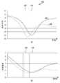
도 4는 일 실시 예에 따른 안테나의 특성으로서 반사손실 및 정재파비를 도시한 도면(400)이다.4 is a diagram 400 illustrating a return loss and a standing wave ratio as characteristics of an antenna according to an exemplary embodiment.
도 4의 (a)는 일 실시예에 따른 안테나의 주파수에 따른 반사손실(return loss)을 도시한 것으로 반사손실은 안테나를 통해 송신되는 신호 또는 수신되는 신호가 반사에 의하여 손실되는 지를 나타내는 것으로 반사손실이 작을수록 더 작은 신호 전력이 반사되고, 더 많은 신호 전력이 송신되거나 수신될 수 있다.4A is a diagram showing a return loss according to a frequency of an antenna according to an embodiment. The return loss indicates whether a signal transmitted through the antenna or a signal received is lost by reflection. The smaller the loss, the less signal power is reflected, and more signal power can be transmitted or received.
도 4의 (b)는 일 실시예에 따른 안테나(340)의 주파수에 따른 정재파비(voltage standing wave ratio, VSWR)를 도시한 것이다. 정재파비는 반사손실을 다르게 표현한 값으로, 반사에 의해 생성되는 정재파의 높이비를 의미할 수 있다. 정재파란, 어떤 파동이 진행하다가 다른 매질을 만나서 반사되어 나온 파동과 합쳐지면서 생기는 고정된 파형을 의미하고, 반사량이 많을수록 고정된 정재파의 크기가 커질 수 있다.FIG. 4B shows a voltage standing wave ratio (VSWR) according to a frequency of the
반사손실 및/또는 정재파비는 특정 주파수에서의 안테나(340)의 성능을 나타내는 지표로 사용될 수 있으며, 안테나(340)의 운용 주파수 대역에서는 반사손실 및/또는 정재파비가 작아야만 반사에 의한 손실을 줄이고 더 많은 전력이 송신되거나 수신될 수 있다. 도 4의 예를 참조하면, 송신을 위한 주파수 대역(410)과 수신을 위한 주파수 대역(420)이 다른 FDD(frequency division duplex)에서 튜너(330)는 안테나(340)의 반사 손실 및/또는 정재파비가 송신을 위한 주파수 대역(410)과 수신을 위한 주파수 대역(420) 모두에서 작게 되도록 설정할 수 있다. 일 실시 예로, 각 주파수 대역에서의 반사손실(430)이 도 4에 도시된 것처럼 송신을 위한 주파수 대역(410)과 수신을 위한 주파수 대역(420)의 중간 주파수에서 반사손실이 최소가 되도록 설정할 수 있다.The return loss and/or standing wave ratio can be used as an index indicating the performance of the
다른 실시 예에 따라 LTE와 NR(next generation)의 이중 연결을 지원하는 NSA(non-standalone) EN-DC(enhanced dual connectivity), NR에서의 이중 연결을 지원하는 NR-DC, NGEN-DC(NG-RAN - E-UTRA DC), NE-DC(NR - E-UTRA DC)를 포함하는 MR-DC(multi radio access technology dual connectivity)에서와 같이 전자 장치(101)가 두 개의 무선망에 연결이 되어 있고, 연결된 두 개의 무선망이 사용하는 주파수 대역(410, 420)이 도 4의 (a) 및/또는 (b)에 도시된 것이고, 하나의 안테나로 2개의 무선망에 모두 연결하는 경우에도 튜너(330)를 제어하여 두 개의 주파수 대역(410, 420) 모두에서 반사손실이 가능한 작아지도록 설정할 필요가 있다. 그에 따라, 전자 장치(101)는 튜너(330)를 제어하여 각 주파수 대역에서의 반사손실(430)이 도 4에 도시된 것처럼 두 개의 주파수 대역(410, 420)의 중간 주파수에서 반사손실이 최소가 되도록 설정할 수 있다.According to another embodiment, non-standalone (NSA) EN-DC (enhanced dual connectivity) supporting dual connectivity of LTE and next generation (NR), NR-DC supporting dual connectivity in NR, and NGEN-DC (NG -RAN-E-UTRA DC), NE-DC (NR-E-UTRA DC), as in MR-DC (multi radio access technology dual connectivity), the electronic device 101 is connected to two wireless networks. And the
다른 실시 예에 따라 전자 장치(101)가 하나의 무선망에서 CA(carrier aggregation) 또는 DC(dual connectivity)에 의해 두 개의 주파수 대역을 사용하는 경우, 사용되는 두 개의 주파수 대역(410, 420)이 도 4의 (a) 및/또는 (b)에 도시된 것이고, 하나의 안테나로 두 개의 주파수 대역에 모두 연결하는 경우에도 튜너(330)를 제어하여 두 개의 주파수 대역(410, 420) 모두에서 반사손실이 가능한 작아지도록 설정할 필요가 있다. 그에 따라, 전자 장치(101)는 튜너(330)를 제어하여 각 주파수 대역에서의 반사손실(430)이 도 3에 도시된 것처럼 두 개의 주파수 대역(410, 420)의 중간 주파수에서 반사손실이 최소가 되도록 설정할 수 있다. 이러한 설정의 결과로 두 개의 주파수 대역(410, 420) 모두에서 상대적으로 낮은 반사손실을 가지도록 할 수 있다.According to another embodiment, when the electronic device 101 uses two frequency bands by carrier aggregation (CA) or dual connectivity (DC) in one wireless network, the two
다른 실시 예에 따라 전자 장치(101)가 MR-DC로 두 개의 무선망에 연결되어 있고, 각 무선망에서도 SA 또는 DC로 연결됨에 의하여 두 개 이상의 주파수 대역을 사용하는 경우에도, 하나의 안테나에서 신호를 송, 수신하는 모든 주파수 대역에 대해 반사손실이 최소화되도록 설정할 수 있다.According to another embodiment, even when the electronic device 101 is connected to two wireless networks by MR-DC, and is connected by SA or DC in each wireless network, even when two or more frequency bands are used, one antenna It can be set to minimize return loss for all frequency bands that transmit and receive signals.
상술 설명에 기초하여의한 안테나 설정에 의하여, 도 4의 반사손실(430)이 획득되는 경우, 전자 장치(101)는 운용되는 전체 주파수 대역에서 일정한 성능을 유지할 수 있다. 한편 일반적으로 기지국은 높은 전력으로 신호를 방사할 수 있는 반면에 전자 장치(101)는 신호를 방사하기 위해 사용할 수 있는 전력이 제한되어 있기 때문에, 전자 장치(101)가 약전계 또는 음영지역에 있는 경우, 전자 장치(101)는 다중 망의 기지국으로부터 오는 신호는 정상적으로 모두 수신할 가능성이 높은 반면에, 전자 장치(101)가 송신하는 신호를 다중 망의 기지국이 수신할 가능성은 상대적으로 낮을 수 있다. 그리고 전자 장치(101)가 송신하는 신호 중에 제어 신호의 전송 실패는 전자 장치(101)의 데이터 전송 성능에 큰 영향을 미칠 수 있다. 일 비교예로, 전자 장치(101)가 데이터 수신을 하였는 지 또는 데이터 수신을 실패하였는 지를 알려주는 HARQ(hybrid automatic retransmission request) 정보를 포함하는 신호를 기지국이 제대로 수신하지 못한다면 전자 장치(101)가 데이터 수신을 하였더라도, 동일한 데이터를 반복적으로 재전송할 수 있어, 무선 자원의 낭비를 초래하고, 데이터 응답 느림, 속도 느림과 같은 전자 장치(101)의 통신 성능 저하 현상이 발생할 수 있다.When the
본 발명의 다양한 실시예들은 다중 연결된 전자 장치(101)에서 제어 정보를 전송하는 주파수 대역에서의 반사 손실이 최소화하도록(예: 도 4의 반사손실(440)) 안테나(340)를 설정하는 방법 및 이 방법을 사용하는 전자 장치를 제안한다.Various embodiments of the present invention provide a method of setting the
다양한 실시 예들에 따르면, 도 2에 도시된 바와 같이 무선 통신 모듈(192)은 전자 장치(101)가 연결된 무선망(292, 294)과의 통신을 위한 신호를 송신하고 수신할 수 있다. 전자 장치(101)가 서로 다른 무선망에 다중 연결된 경우, 무선 통신 모듈(192)은 적어도 하나 이상의 안테나를 이용하여 서로 다른 무선망과 연결될 수 있다. 일 실시 예로 무선 통신 모듈(192)이 5G 무선망(294)과 LTE 무선망(292)에 다중 연결된 경우, 각각의 무선망을 위한 신호는 별개의 안테나(예: 안테나 모듈(242, 244)를 통해 송신되거나 수신될 수 있으며, 또는 하나의 안테나(예: 안테나(340))를 통해 송신되거나 수신될 수 있다. According to various embodiments, as illustrated in FIG. 2, the wireless communication module 192 may transmit and receive signals for communication with
다양한 실시 예들에 따르면, 도 3에 도시된 바와 같이 신호를 송신 및/또는 수신하는 안테나(340)는 튜너(330)를 포함하는 튜너블(tunable) 안테나이고, 튜너(330)를 제어하여 안테나(340)의 중심 주파수, 다시 말하면 반사 손실이 가장 작게 되는 주파수가 변경 가능한 안테나일 수 있다.According to various embodiments, an
다양한 실시 예들에 따르면, 프로세서(예: 제1 커뮤니케이션 프로세서(212) 또는 제2 커뮤니케이션 프로세서(214))는 CA 또는 EN-DC가 설정되어 다중 주파수 대역을 이용하여 통신하는 전자 장치(101)에서, 튜너블 안테나(340)의 중심 주파수를 조정할 수 있다.According to various embodiments, the processor (for example, the first communication processor 212 or the second communication processor 214) is set to CA or EN-DC and communicates using multiple frequency bands in the electronic device 101, The center frequency of the
다양한 실시 예들에 따르면, 프로세서(212, 214)는 전자 장치(101)가 다중 주파수 대역을 이용하는 지를 판단하고, 또한, 전자 장치(101)가 약전계 또는 음영 지역에 있는 지를 판단하여, 그 결과를 기초로, 안테나(340) 설정을 일반 모드 또는 최적화 모드로 설정할 수 있다. 최적화 모드는 제어 신호를 전송하는 주파수 대역이 가장 작은 반사 손실을 가지도록 안테나(340)를 설정하는 모드이고, 일반 모드는 통상적인 방법에 따라 운용하는 주파수 대역 전체가 비교적 작은 반사 손실을 가지도록 안테나(340)를 설정하는 모드일 수 있다. 일 실시 예로, HARQ를 포함하는 제어 신호를 전송하는 주파수 대역이 212 또는 214인 경우, 일반 모드는 도 4의 반사손실(430)을 가지도록 안테나(340)를 설정할 수 있고, 최적화 모드는 도 4의 반사 손실(440)을 가지도록 안테나(340)를 설정할 수 있다.According to various embodiments, the processors 212 and 214 determine whether the electronic device 101 uses multiple frequency bands, and determine whether the electronic device 101 is in a weak electric field or a shaded area, and calculate the result. As a basis, the
다양한 실시 예들에 따르면, 프로세서(212 또는 214)는 전자 장치(101)가 다중 주파수 대역을 이용하는 지 판단하고, 다중 주파수 대역을 이용하는 것으로 식별되면, 제어 정보를 전달하는 주파수 대역을 식별하고, 제어 정보를 전달하는 주파수 대역에서 전송되는 신호 관련 정보, 예를 들면, 송신 전력, 상향/하향 블록 에러율(block error rate, BLER), RSRP(reference signal received power), RSRQ(reference signal received quality)와 같은 신호 수신 품질, 상향 데이터 전송 시 동시에 여러 개의 TTI를 사용하여 동일한 데이터를 전송하도록 하는 TTI 번들링(bundling) 활성화 여부, 대역폭, MCS(modulation and coding scheme), BSR 인덱스(buffer status report index) 중 적어도 일부의 정보를 수집하고, 이를 바탕으로 안테나 모드 변화가 필요한지를 판단할 수 있다. 프로세서(212 또는 214)는 일반 모드에서 최적화 모드로 변화시키는 조건과, 최적화 모드에서 일반 모드로 변화시키는 조건을 다르게 설정함으로써 히스테리시스(hysteresis)를 줄 수 있고, 이에 의하여 일반 모드와 최적화 모드를 반복적으로 변경하게 되는 가능성을 줄일 수 있다.According to various embodiments, the processor 212 or 214 determines whether the electronic device 101 uses multiple frequency bands, and when it is identified as using the multiple frequency bands, identifies a frequency band that transmits control information, and controls the control information. Signal-related information transmitted in a frequency band that transmits a signal such as transmission power, uplink/downlink block error rate (BLER), reference signal received power (RSRP), and reference signal received quality (RSRQ). At least some of the reception quality, whether TTI bundling to transmit the same data using multiple TTIs simultaneously when transmitting uplink data, bandwidth, modulation and coding scheme (MCS), and buffer status report index (BSR) Information is collected, and based on this, it is possible to determine whether an antenna mode change is necessary. The processor 212 or 214 may give hysteresis by setting a condition for changing from a normal mode to an optimization mode and a condition for changing from an optimization mode to a normal mode differently, thereby repeatedly changing the normal mode and the optimization mode. You can reduce the likelihood of making changes.
다양한 실시 예들에 따르면, 프로세서(212 또는 214)는 일반 모드에서 최적화 모드로 천이하는 조건으로 전송 전력 및/또는 상향 BLER이 일정 값 이상일 때, TTIB가 활성화되었을 때, 또는 수신 신호의 품질이 일정 값 이하일 때 중 적어도 하나를 고려할 수 있다. 또한, 프로세서(212 또는 214)는 최적화 모드에서 일반 모드로 천이하는 조건으로 전송 전력 및/또는 상향 BLER이 일정 값 이하일 때, TTIB가 비활성화 되었을 때, 수신 신호의 품질이 일정 값 이상일 때 중 적어도 하나를 고려할 수 있다. 또한, 프로세서(212 또는 214)는 현재 데이터 통신이 수행되고 있는 지 아니면 음성 통신이 수행되고 있는 지에 따라 조건을 다르게 설정할 수도 있다.According to various embodiments, the processor 212 or 214 is a condition in which the transmission power and/or the uplink BLER is more than a certain value, TTIB is activated, or the quality of the received signal is a certain value under the condition of transitioning from the normal mode to the optimization mode. At least one of the following cases may be considered. In addition, the processor 212 or 214 is at least one of when the transmission power and/or the uplink BLER is less than a certain value, the TTIB is deactivated, and the quality of the received signal is more than a certain value under the condition of transitioning from the optimization mode to the normal mode. Can be considered. Further, the processor 212 or 214 may set different conditions depending on whether data communication is currently being performed or voice communication is being performed.
일 실시 예로, 프로세서(212 또는 214)는 데이터 통신 시에 일반 모드에서 최적화 모드로 천이하는 조건으로 RSRP가 -80dBm보다 작거나 같은 경우, 전송 전력이 20dBm보다 크거나 같은 경우, BSR 인덱스가 3초 이상 30%이상 유지되고 있는 경우, BLER이 50% 이상인 경우 중 적어도 하나로 설정할 수 있다.As an example, when the processor 212 or 214 transitions from the normal mode to the optimization mode during data communication, when the RSRP is less than or equal to -80dBm, the transmission power is greater than or equal to 20dBm, the BSR index is 3 seconds. It can be set to at least one of the cases where the BLER is more than 50% when it is maintained above 30%.
다른 일 실시 예로, 프로세서(212 또는 214)는 VoLTE(voice over LTE)와 같은 음성 통신이 수행되고 있는 경우, 일반 모드에서 최적화 모드로 천이하는 조건으로 RSRP가 -100dBM 이하인 경우, 전송 전력이 24dBm 이상인 경우, BSR 인덱스가 2초 이상 40%이상으로 유지되는 경우, BLER이 10% 이상인 경우 중 적어도 하나로 설정할 수 있다.In another embodiment, when voice communication such as VoLTE (voice over LTE) is being performed, the processor 212 or 214 has a transmission power of 24 dBm or more when RSRP is -100 dBM or less under the condition of transitioning from a normal mode to an optimization mode. In this case, when the BSR index is maintained at 40% or more for 2 seconds or more, it may be set to at least one of when the BLER is 10% or more.
도 5a 및 5b는 다양한 실시 예에 따라 안테나를 설정하는 예들을 도시한 도면(500, 550)이다.5A and 5B are diagrams 500 and 550 illustrating examples of setting an antenna according to various embodiments.
다양한 실시 예에 따라, 전자 장치(101)가 하나의 안테나를 이용하여 복수의 주파수 대역을 통해 신호를 송, 수신하는 경우, 일반 모드에서는 복수의 주파수 대역 전체에서 반사손실이 비교적 작게 설정하는 반면에 최적화 모드에서는 제어 신호를 전송하는 주파수 대역에서 가장 작은 반사손실을 가지도록 안테나를 설정할 수 있다.According to various embodiments, when the electronic device 101 transmits and receives signals through a plurality of frequency bands using a single antenna, in the normal mode, the return loss is set relatively small across the plurality of frequency bands. In the optimization mode, the antenna can be set to have the smallest return loss in a frequency band transmitting a control signal.
일 실시 예에 따라, CA에 의해 동일 안테나를 이용하여 2개의 주파수 대역을 통해 신호 송, 수신을 하는 경우, 일 실시 예로, LTE B1 주파수 대역(2.1GHz 대역)이 PCC(primary component carrier)로 사용되고 LTE B3 주파수 대역(1.8GHz 대역)이 SCC(secondary component carrier)로 사용되는 경우, 프로세서(212 또는 214)는 일반 모드에는 B1 주파수 대역 및 B3 주파수 대역 모두에서 반사손실이 작도록 안테나의 반사손실이 가장 적은 중심주파수를 두 대역의 중간주파수(예: 1.95GHz)로 설정할 수 있다. 또한, 프로세서(212 또는 214)는 최적화 모드에서는 제어 신호를 전송하는 PCC가 되는 B1 주파수 대역에서 반사손실이 최소가 되도록 안테나를 설정할 수 있다.According to an embodiment, when signals are transmitted and received through two frequency bands using the same antenna by CA, as an example, an LTE B1 frequency band (2.1 GHz band) is used as a primary component carrier (PCC). When the LTE B3 frequency band (1.8 GHz band) is used as a secondary component carrier (SCC), the processor 212 or 214 reduces the return loss of the antenna so that the return loss is small in both the B1 frequency band and the B3 frequency band in the normal mode. The lowest center frequency can be set as the intermediate frequency of the two bands (eg 1.95 GHz). In addition, in the optimization mode, the processor 212 or 214 may set the antenna so that the return loss is minimized in the B1 frequency band, which becomes the PCC transmitting the control signal.
다른 일 실시 예로, 도 5a를 참고하면, 전자 장치(101)는 하나의 안테나를 이용하고 4개의 주파수 대역(501, 503, 505, 507)을 사용하도록 CA되어 있을 수 있다. 4개의 주파수 대역 중 2번째 주파수 대역(503)이 HARQ 정보를 포함하는 제어 정보를 전송하는 주파수 대역일 수 있다. 그러면, 프로세서(212 또는 214)는 일반 모드에서는 4개의 주파수 대역(501, 503, 505, 507)의 가운데 주파수에서 반사손실이 최소가 되도록 안테나를 설정(509)할 수 있고, 최적화 모드에서는 2번째 주파수 대역(503)에서 반산 손실이 최소가 되도록 안테나를 설정(511))할 수 있다.As another example, referring to FIG. 5A, the electronic device 101 may be CA to use one antenna and four
다양한 실시 예에 따라, 전자 장치(101)가 다중 무선망에 다중 연결되고, 연결된 각각의 무선망은 각각 서로 다른 안테나를 이용하여 신호를 송, 수신하는 것을 가정하자. 이때, 각 무선망과의 연결도 다중 연결로서 다중 주파수 대역을 사용할 수 있다. 일 실시 예로, EN-DC에 의하여 전자 장치(101)가 LTE 무선망과 5G 무선망에 모두 연결되어 있고, LTE 무선망과의 신호 송, 수신을 위한 안테나와 5G 무선망과의 신호 송, 수신을 위한 안테나가 상이한 안테나를 사용할 수 있다. 그리고 각 무선망은 다중 연결되어 있을 수 있다. LTE 무선망에서 하나의 안테나를 이용하여 하나의 P셀(Primary cell)과 적어도 하나의 S셀(secondary cell)과 연결될 수 있다. 5G 무선망에서도 하나의 안테나를 이용하여 하나의 P셀(Primary cell)과 적어도 하나의 S셀(secondary cell)과 연결될 수 있다. 그리고 제어 정보는 각각의 무선망에서 별개로 동작할 수 있다. 이와 같은 환경에서 프로세서(212 또는 214)는 각각의 안테나에 대해 별개로 일반 모드 또는 최적화 모드를 설정할 수 있다. 일 실시 예로, 프로세서(212 또는 214)는 LTE 무선망에 연결된 제1 안테나의 통신 상태 특성을 수집하여 일반 모드로 동작할 지 또는 최적화 모드로 동작할 지를 결정할 수 있다. 프로세서(212 또는 214)는 일반 모드로 동작하는 것으로 결정한 경우, LTE 무선망의 하나의 P셀(Primary cell)과 적어도 하나의 S셀(secondary cell) 전체가 사용하는 주파수 대역에서 반사손실이 가능한 작아지도록 제1 안테나를 설정(예: 도 5a의 509)할 수 있고, 최적화 모드로 동작하는 것으로 결정한 경우 P셀이 사용하는 주파수 대역에서 반사손실이 최소화되도록 제1 안테나를 설정할(예: 도 5a의 511) 수 있다. 다른 예를 들어, 프로세서(212 또는 214)는 5G 무선망에 연결된 제2 안테나의 통신 상태 특성을 수집하여 일반 모드로 동작할 지 또는 최적화 모드로 동작할 지를 결정할 수 있다. 프로세서(212 또는 214)는 일반 모드로 동작하는 것으로 결정한 경우, 5G 무선망의 하나의 P셀(Primary cell)과 적어도 하나의 S셀(secondary cell) 전체가 사용하는 주파수 대역에서 반사손실이 가능한 작아지도록 제2 안테나를 설정(예: 도 5a의 509)할 수 있고, 최적화 모드로 동작하는 것으로 결정한 경우 P셀이 사용하는 주파수 대역에서 반사손실이 최소화되도록 제2 안테나를 설정(예: 도 5a의 511) 할 수 있다.According to various embodiments, it is assumed that the electronic device 101 is connected to multiple wireless networks, and each of the connected wireless networks transmits and receives signals using different antennas. In this case, the connection to each wireless network is also multiple connections, and multiple frequency bands can be used. As an example, the electronic device 101 is connected to both the LTE wireless network and the 5G wireless network by EN-DC, and transmits and receives signals between the antenna and the 5G wireless network for signal transmission and reception with the LTE wireless network. Different antennas for antennas may be used. And each wireless network may have multiple connections. In the LTE wireless network, one primary cell and at least one secondary cell may be connected using one antenna. Even in a 5G wireless network, one primary cell and at least one secondary cell may be connected using one antenna. In addition, the control information can be operated separately in each wireless network. In such an environment, the processor 212 or 214 may separately set a normal mode or an optimization mode for each antenna. As an example, the processor 212 or 214 may determine whether to operate in a normal mode or an optimization mode by collecting communication state characteristics of the first antenna connected to the LTE wireless network. When it is determined that the processor 212 or 214 operates in the normal mode, the return loss is as small as possible in the frequency band used by one primary cell and at least one secondary cell of the LTE wireless network. The first antenna can be set (eg, 509 in FIG. 5A) to be configured, and when it is determined to operate in the optimization mode, the first antenna is set so that the return loss is minimized in the frequency band used by the P cell (eg, 509 in FIG. 5A ). 511) Can. For another example, the processor 212 or 214 may determine whether to operate in a normal mode or an optimization mode by collecting communication state characteristics of the second antenna connected to the 5G wireless network. When it is determined that the processor 212 or 214 operates in the normal mode, the return loss is as small as possible in the frequency band used by one primary cell and at least one secondary cell of the 5G wireless network. The second antenna can be set (eg, 509 in FIG. 5A) to be used, and when it is determined to operate in the optimization mode, the second antenna is set so that the return loss is minimized in the frequency band used by the P cell (eg, 509 in FIG. 5A ). 511) You can.
다른 일 실시 예로, 상술한 바와 같이 2개의 무선망과 2개의 서로 다른 안테나를 통해 연결되었지만, 제어 정보의 전송은 특정 무선망만을 이용하는 경우, 제어 정보가 전송되지 않는 무선망을 위한 안테나는 최적화 모드로 설정되지 않을 수 있고, 제어 정보를 전송하는 무선망을 위한 안테나에서 상술한 동작을 기초로 안테나를 일반 모드 또는 최적화 모드로 설정할 수 있다.In another embodiment, as described above, when the connection is made through two wireless networks and two different antennas, but only a specific wireless network is used for transmission of control information, an antenna for a wireless network in which control information is not transmitted is an optimization mode. It may not be set to, and the antenna for a wireless network transmitting control information may be set to a normal mode or an optimization mode based on the above-described operation.
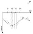
다양한 실시 예에 따라, 전자 장치(101)가 하나의 안테나를 이용하여 다중 무선망에 다중 연결된 경우를 가정한다. 이 경우, 연결된 다중 무선망 각각으로 별도의 제어 신호를 전송하여야 하는 경우, 프로세서(212 또는 214)는 각 무선망 별 제어 신호를 전송하여야 하는 주파수 대역(예: 도 5b의 551, 557)을 식별하고, 각 무선망 별 제어 신호를 전송하여야 하는 주파수 대역 전체에서 가능한한 작은 반사손실을 가지도록 제어할 수 있다.According to various embodiments, it is assumed that the electronic device 101 is connected to multiple wireless networks using a single antenna. In this case, when a separate control signal is to be transmitted to each of the connected multiple wireless networks, the processor 212 or 214 identifies a frequency band (e.g., 551, 557 in FIG. 5B) in which the control signal for each wireless network is to be transmitted. And, it is possible to control to have as little return loss as possible in the entire frequency band in which the control signal for each wireless network should be transmitted.
도 5b를 참고하면, 전자 장치(101)는 두 개의 무선망과 다중 연결되어 있고, 각 무선망과도 신호 송, 수신을 위하여 다중 주파수 대역을 사용할 수 있다. 일 실시 예로 전자 장치(101)는 LTE 무선망과 5G 무선망과 다중 연결되어 있으며, LTE 무선망과는 주파수 대역(551, 553, 555)를 이용하여 신호를 송, 수신하며, 5G 무선망과는 주파수 대역(557, 559, 561)을 이용하여 신호를 송, 수신할 수 있다.Referring to FIG. 5B, the electronic device 101 is multiplexed with two wireless networks, and may use multiple frequency bands for signal transmission and reception with each wireless network. In an embodiment, the electronic device 101 is multiplexed with an LTE wireless network and a 5G wireless network, transmits and receives signals using
이러한 환경에서 프로세서(212 또는 214)는 튜너(330)를 제어하여 일반 모드에서는 신호의 송, 수신에 사용되는 전체 주파수 대역에서 작은 반사손실을 가지도록 안테나를 설정(예: 도 5b의 571)할 수 있다. 프로세서(212 또는 214)는 최적화 모드에서는 일 실시 예로, HARQ 정보와 같은 제어 정보를 송신하는 데 사용되는 주파수 대역(예: 도 5의 551, 557)을 포함하는 주파수 대역에서 작은 반사손실을 가지도록 안테나를 설정(예: 도 5b의 573)할 수 있다. 또 다른 실시 예로, 프로세서(212 또는 214)는 최적화 모드에서 제어 정보가 전송되는 주파수 대역들 중에서 대역폭이 크거나 MCS가 높은 쪽의 주파수 대역이 가장 작은 반사손실을 가지도록 안테나를 설정(예: 도 5b의 575)할 수 있다. 이 실시 예에 따른 방법은 상술한 첫번째 방법에 의하여 원하는 충분한 결과를 획득하지 못하는 경우, 예를 들면, 재전송이 많이 발생하는 현상이 여전히 계속되는 경우에 적용할 수 있다.In this environment, the processor 212 or 214 controls the
다양한 실시 예들에 따르면, 메모리(130)는 상술한 동작을 수행하기 위하여 프로세서(212 또는 214)가 실행할 인스트럭션들을 저장할 수 있다. 또한, 메모리(130)는 안테나 설정을 위한 튜너블 코드를 저장하고 있을 수 있다. 설정 가능한 튜너블 코드는 일반 모드에서의 튜너블 코드 및/또는 최적화 모드에서의 튜너블 코드를 포함할 수 있다. 튜너블 코드의 변경에 의하여 안테나의 각 주파수 대역별 반사 손실의 특징이 변경될 수 있다.According to various embodiments, the
다양한 실시 예들에 따르면 전자 장치(101)의 프로세서(212 또는 214)는 안테나 설정을 현재의 수집한 상황에 맞추어 능동적으로 바꾸어 줌으로써, 주변 환경에 적응적으로 대응하여 전자 장치(101)의 성능을 높일 수 있다.According to various embodiments, the processor 212 or 214 of the electronic device 101 actively changes the antenna setting according to the current collected situation, thereby adaptively responding to the surrounding environment to increase the performance of the electronic device 101. I can.
다양한 실시 예들에 따르면, 프로세서(212 또는 214)는 신호의 전송 환경에 맞추어 안테나 설정을 능동적으로 변경하여 줌으로써 HARQ 미수신에 의한 재전송을 방지하여 전자 장치(101)의 무선 성능을 향상시킬 수 있고, 약전계 또는 음영지역 사용자에게 발생할 수 있는 데이터 응답 느림, 데이터 전송 속도 느림과 같은 통신 성능 저하 현상을 개선할 수 있다.According to various embodiments, the processor 212 or 214 can improve the wireless performance of the electronic device 101 by actively changing the antenna setting according to the signal transmission environment to prevent retransmission due to non-reception of HARQ, and about It is possible to improve communication performance degradation such as slow data response and slow data transmission speed that may occur to users in electric fields or shadow areas.
다양한 실시 예들에 따르면, 상술한 프로세서(212 또는 214)의 동작은 무선 통신 모듈(420)에서 수행될 수도 있다. 일 실시 예로, 무선 통신 모듈(420)은 프로세서(212 또는 214)로부터 일반 모드에서 최적화 모드로의 천이 조건 및/또는 최적화 모드에서 일반 모드로의 천이 조건을 획득하고, 이를 기초로, 상술한 프로세서(212 또는 214)가 수행하여야 할 동작을 수행하고, 그 결과를 바탕으로 안테나(340)의 튜너(330)를 제어하여 안테나(340)를 일반 모드로 동작하도록 설정하거나 최적화 모드로 동작하도록 설정할 수 있다.According to various embodiments, the operation of the processor 212 or 214 described above may be performed by the
다양한 실시 예들에 따르면, 전자 장치(예: 도 1의 전자 장치(101))는 무선 신호를 송, 수신하는 적어도 하나의 안테나 모듈(예: 도 1의 안테나 모듈(197) 또는 도 2의 안테나 모듈(242, 244) 또는 도 3의 안테나 모듈(330과 340)), 상기 적어도 하나의 안테나 모듈과 작동적으로 연결되는 적어도 하나의 프로세서(예: 도 1의 프로세서(120) 또는 도 2의 프로세서(212 또는 214)) 및 상기 적어도 하나의 프로세서와 작동적으로 연결되는 적어도 하나의 메모리(예: 도 1의 메모리(130))를 포함하고, 상기 적어도 하나의 메모리는, 실행 시에, 상기 적어도 하나의 프로세서가, 다중 주파수 대역 연결이 설정되었는 지를 판단하고, 상기 판단 결과, 다중 주파수 대역 연결이 설정된 경우, 상기 연결된 다중 주파수 대역 중 제어 정보를 전송하는 주파수 대역을 식별하고, 상기 식별된 제어 정보를 전송하는 주파수 대역에 대한 통신 상태 정보를 획득하고, 상기 획득한 통신 상태 정보에 기초하여, 안테나 모드를 결정하고, 상기 결정된 안테나 모드에 기초하여, 상기 적어도 하나의 안테나 모듈을 설정하도록 하는 인스트럭션들을 저장하도록 할 수 있다.According to various embodiments, the electronic device (for example, the electronic device 101 of FIG. 1) transmits and receives a wireless signal, at least one antenna module (for example, the
다양한 실시 예들에 따르면, 상기 안테나 모드는 상기 연결된 다중 주파수 대역 전체의 반사손실을 작게 하도록 하는 일반 모드 및 상기 식별된 제어 정보를 전송하는 주파수 대역의 반사손실을 작게 하도록 하는 최적화 모드를 포함할 수 있다.According to various embodiments, the antenna mode may include a general mode for reducing the return loss of the entire connected multi-frequency band, and an optimization mode for reducing the return loss of a frequency band transmitting the identified control information. .
다양한 실시 예들에 따르면, 상기 인스트럭션들은 상기 적어도 하나의 프로세서가,According to various embodiments, the instructions include the at least one processor,
전송하는 패킷이 음성 패킷인지 또는 데이터 패킷인지에 따라 다른 천이 조건을 사용하여 상기 안테나 모드 변경 여부를 결정하도록 할 수 있다.It is possible to determine whether to change the antenna mode using a different transition condition depending on whether the transmitted packet is a voice packet or a data packet.
다양한 실시 예들에 따르면, 상기 인스트럭션들은 상기 적어도 하나의 프로세서가 전송하는 패킷이 음성 패킷이고, 안테나 모드가 상기 일반 모드인 경우 제1 천이 조건에 따라 상기 최적화 모드로 천이하고, 전송하는 패킷이 음성 패킷이고, 안테나 모드가 상기 최적화 모드인 경우 제2 천이 조건에 따라 상기 일반 모드로 천이하고, 전송하는 패킷이 데이터 패킷이고, 안테나 모드가 상기 일반 모드인 경우 제3 천이 조건에 따라 상기 최적화 모드로 천이하고, 전송하는 패킷이 데이터 패킷이고, 안테나 모드가 상기 최적화 모드인 경우 제4 천이 조건에 따라 상기 일반 모드로 천이하도록 하고, 상기 제1 천이 조건과 상기 제2 천이 조건을 다르게 설정하고, 상기 제3 천이 조건과 상기 제4 천이 조건을 다르게 설정하여 히스테리시스(hysteresis)를 주도록 할 수 있다.According to various embodiments, in the instructions, when the packet transmitted by the at least one processor is a voice packet, and the antenna mode is the normal mode, transition to the optimization mode according to a first transition condition, and the transmitted packet is a voice packet. And, when the antenna mode is the optimization mode, transitions to the normal mode according to a second transition condition, and when the transmitted packet is a data packet, and when the antenna mode is the general mode, transition to the optimization mode according to a third transition condition And, when the transmitted packet is a data packet and the antenna mode is the optimization mode, a transition to the normal mode is performed according to a fourth transition condition, and the first transition condition and the second transition condition are set differently, and the second transition condition Hysteresis may be applied by setting the 3 transition condition and the fourth transition condition differently.
다양한 실시 예들에 따르면, 상기 각 천이 조건은 하향링크 신호의 수신 품질, 신호 송신시에 사용하는 송신 전력, 전송할 데이터의 양을 나타내는 BSR 인덱스(buffer status report index) 또는 전송한 패킷 중에 전송을 완료하지 못한 패킷의 비율을 나타내는 블록 에러율(BLER), 복수 개의 자원을 이용하여 동일한 패킷을 복수 회 송신하도록 하는 TTIB(transmit time interval bundling)의 활성화 여부 중의 적어도 하나를 기준으로 할 수 있다.According to various embodiments, each of the transition conditions is a reception quality of a downlink signal, a transmission power used when transmitting a signal, a buffer status report index (BSR) indicating an amount of data to be transmitted, or a transmission not complete among transmitted packets. It may be based on at least one of a block error rate (BLER) indicating a rate of unsuccessful packets, and whether or not a transmit time interval bundling (TTIB), which transmits the same packet multiple times using a plurality of resources, is activated.
다양한 실시 예들에 따르면, 상기 제1 천이 조건은 RSRP(reference signal received power)가 -110dBm보다 작거나 같은 경우, 송신 전력이 20dBm보다 큰 경우, BSR 인덱스가 2초 동안 40%이상인 경우, BLER이 10%보다 큰 경우, TTIB가 활성화된 경우 중의 적어도 하나를 포함하고, 상기 제2 천이 조건은 BLER이 10%보다 작은 경우를 포함할 수 있다.According to various embodiments, the first transition condition is when the reference signal received power (RSRP) is less than or equal to -110dBm, the transmission power is greater than 20dBm, the BSR index is 40% or more for 2 seconds, and the BLER is 10. When it is greater than %, at least one of cases in which TTIB is activated may be included, and the second transition condition may include a case in which BLER is less than 10%.
다양한 실시 예들에 따르면, 상기 제3 천이 조건은 RSRP(reference signal received power)가 -80dBm보다 작거나 같은 경우, 송신 전력이 20dBm보다 큰 경우, BSR 인덱스가 3초 동안 30%이상인 경우, BLER이 30%보다 큰 경우, TTIB가 활성화된 경우 중의 적어도 하나를 포함하고, 상기 제4 천이 조건은 BLER이 30%보다 작은 경우를 포함할 수 있다.According to various embodiments, the third transition condition is when the reference signal received power (RSRP) is less than or equal to -80dBm, the transmission power is greater than 20dBm, the BSR index is 30% or more for 3 seconds, the BLER is 30 When it is greater than %, at least one of cases in which TTIB is activated may be included, and the fourth transition condition may include a case in which BLER is less than 30%.
다양한 실시 예들에 따르면, 상기 인스트럭션들은 상기 적어도 하나의 프로세서가, 상기 식별된 제어 정보를 전송하는 주파수 대역이 두 개 이상의 주파수 대역인 경우, 상기 최적화 모드로서 상기 두 개 이상의 주파수 대역을 포함하는 주파수 대역에서 반사손실을 작게 하도록 하거나 또는 상기 두 개 이상의 주파수 대역 중에서 하나의 주파수 대역을 선정하고, 선정된 주파수 대역의 반사손실을 작게 하도록 할 수 있다.According to various embodiments, when the at least one processor transmits the identified control information is two or more frequency bands, the instructions are a frequency band including the two or more frequency bands as the optimization mode. In this case, the return loss may be reduced or one frequency band may be selected from among the two or more frequency bands, and the return loss of the selected frequency band may be reduced.
다양한 실시 예들에 따르면, 상기 안테나 모듈은 안테나 및 튜너를 포함하고, 상기 인스트럭션들은 상기 적어도 하나의 프로세서가, 상기 안테나 모드에 따라 상기 튜너를 제어하여, 상기 안테나의 반사손실 특성을 조정하도록 할 수 있다.According to various embodiments, the antenna module may include an antenna and a tuner, and the instructions may allow the at least one processor to control the tuner according to the antenna mode to adjust the return loss characteristic of the antenna. .
다양한 실시 예들에 따르면, 상기 인스트럭션들은 상기 적어도 하나의 프로세서가, 상기 결정된 안테나 모드가 상기 최적화 모드인 경우에도, 상기 제어 정보를 전달하지 않는 시간 구간에서는 상기 일반 모드에 따라 상기 안테나 모듈을 설정하고, 상기 제어 정보를 전달하는 시간 구간에는 상기 최적화 모드에 따라 상기 안테나 모듈을 설정하도록 할 수 있다.According to various embodiments, in the instructions, the at least one processor sets the antenna module according to the general mode in a time period in which the control information is not transmitted even when the determined antenna mode is the optimization mode, In a time period in which the control information is transmitted, the antenna module may be set according to the optimization mode.
이하 상술한 전자 장치(101)가 안테나 설정을 변경하는 동작에 대하여 설명한다.Hereinafter, an operation of changing the antenna setting by the electronic device 101 described above will be described.
도 6은 다양한 실시 예들에 따른 전자 장치에서 안테나 설정을 변경하는 동작을 도시한 흐름도(600)이다. 도 6에 예시된 흐름도(600)의 동작 주체는 전자 장치(예: 도 1의 전자 장치(101)) 또는 전자 장치의 프로세서(예: 도 1의 프로세서(120), 또는 도 2의 커뮤니케이션 프로세서(212 또는 214))로 이해될 수 있다.6 is a
다양한 실시 예들에 따르면, 동작 601에서, 전자 장치(101)는 초기 안테나 설정을 수행할 수 있다. 전자 장치(101)가 무선망에 연결되는 경우 초기에는 하나의 주파수 대역을 이용하여 신호를 송, 수신할 수 있다. 이후, CA 및/또는 EN-DC가 활성화되면서 다중 연결이 가능할 수 있다. 따라서, 전자 장치(101)는 최초 무선망 연결 시에는 일반 모드로서 사용하는 하나의 주파수 대역에서 반사손실이 최소가 되도록 안테나를 설정할 수 있다.According to various embodiments, in
다양한 실시 예들에 따르면, 동작 603에서, 전자 장치(101)는 사용 주파수 대역 구성을 식별할 수 있다. 일 실시 예로, 전자 장치(101)는 단일 주파수 대역을 사용하는 지 아니면 다중 주파수 대역을 사용하는 지를 식별할 수 있다. 전자 장치(101)는 하나의 무선망에 연결된 이후, CA 기능을 활성화하여 동일한 무선망에서 2개 이상의 주파수 대역을 사용할 수 있고, 또는 EN-DC 기능이 활성화되어 서로 다른 무선망에서 2개 이상의 주파수 대역을 사용할 수 있다. 전자 장치(101)는 이와 같이 다중 주파수 대역의 사용을 요구하는 기능들의 활성화 정보에 기초하여 또는 이러한 기능들에 의해 실현된 주파수 대역 사용 정보에 기초하여 사용 주파수 대역 구성을 식별할 수 있다.According to various embodiments, in
다양한 실시 예들에 따르면, 동작 605에서, 전자 장치(101)는 다중 주파수 대역을 사용하는 지를 판단한다. 다중 주파수 대역을 사용하지 않는 경우에는 다시 사용 주파수 대역 구성을 식별할 수 있다. 동작 605에서 판단은 주기적으로 수행하거나, 동작 603에 의하여 사용 주파수 대역 구성이 변경되었다는 것을 알게 된 경우에 수행될 수 있다.According to various embodiments, in
다양한 실시 예들에 따르면, 다중 주파수 대역을 사용하지 않는 것으로 판단된 경우(605-아니오), 다시 동작 603으로 돌아가 사용 주파수 대역 구성을 식별할 수 있다.According to various embodiments, when it is determined that the multi-frequency band is not used (605-No), it is possible to return to
다양한 실시 예들에 따르면, 다중 주파수 대역을 사용하는 것으로 판단된 경우(605-예), 동작 607에서, 전자 장치(101)는 제어 정보를 전송하는 주파수 대역 정보를 획득할 수 있다. 일 실시 예로, 일반적인 LTE 환경에서는 주로 P셀이 사용하는 주파수 대역을 통해 HARQ 정보를 포함하는 제어 정보가 전달될 수 있는 바, 전자 장치(101)는 P셀의 사용 주파수 대역을 제어 정보를 전송하는 주파수 대역으로 식별할 수 있다. 다른 일 실시 예로, LTE Inter Band UL-CA의 경우에는 2개의 상향 링크(uplink, UL) 전송 주파수 대역 중 한 곳으로 제어 정보를 송신할 수 있다. 이 경우, 전자 장치(101)는 기지국으로부터 오는 DCI(downlink control information)를 기초로 제어 정보가 전송되는 주파수 대역을 식별할 수 있다.According to various embodiments, when it is determined that the multiple frequency bands are used (605-Yes), in
다른 실시 예로, 전자 장치(101)가 5G 무선망의 EN-DC로 연결되는 경우, 송신 베어러(bearer) 설정에 따라, LTE 무선망용 주파수 대역뿐만 아니라 5G 통신 시스템의 주파수 대역에서도 추가로 제어 정보를 송신할 수 있다. 이 경우에는 제어 정보를 송신하는 주파수 대역을 하나 또는 두 개로 식별할 수 있다.In another embodiment, when the electronic device 101 is connected to the EN-DC of the 5G wireless network, additional control information is provided not only in the frequency band for the LTE wireless network but also in the frequency band of the 5G communication system according to the transmission bearer setting. Can send. In this case, one or two frequency bands for transmitting control information can be identified.
다양한 실시 예들에 따르면, 동작 609에서, 전자 장치(101)는 식별된 제어 정보를 전송하는 주파수 대역에 대한 통신 상태 관련 정보를 획득할 수 있다. 통신 상태 관련 정보는 신호 송신 시의 송신 전력 또는 목표 전력, 상향링크 및/또는 하향링크의 블록 오류율(block error rate, BLER), RSRP, RSRQ와 같은 수신 신호 품질, TTI 번들링 활성화 여부, 제어 정보를 전송하기 위해 할당된 대역폭 및/또는 MCS, 또는 전송을 대기하고 있는 데이터의 량을 나타내는 BSR 인덱스(buffer status report index) 중 적어도 하나를 포함할 수 있다.According to various embodiments, in
다양한 실시 예들에 따르면, 동작 611에서, 전자 장치(101)는 안테나 모드 변경의 필요 여부를 판단할 수 있다. 일 실시 예로 전자 장치(101)는 약전계 또는 음영 지역에 있는 지를 판단하여 안테나 모드 변경의 필요 여부를 판단할 수 있다. 전자 장치(101)는 동작 609에서 획득한 통신 상태 관련 정보를 기초로 약전계 또는 음영 지역에 있는 지를 판단할 수 있다. 일 실시 예로 안테나 모드는 일반 모드 또는 최적화 모드에 있을 수 있다. 최적화 모드는 제어 신호를 전송하는 주파수 대역이 가장 작은 반사 손실을 가지도록 하는 모드이고, 일반 모드는 통상적인 방법에 따라 운용하는 주파수 대역 전체가 비교적 작은 반사 손실을 가지도록 하는 모드일 수 있다.According to various embodiments, in
다양한 실시 예들에 따르면, 전자 장치(101)는 일반 모드에서 최적화 모드로 변화시키는 조건과, 최적화 모드에서 일반 모드로 변화시키는 조건을 다르게 설정함으로써 히스테리시스(hysteresis)를 줄 수 있고, 이에 의하여 일반 모드와 최적화 모드를 반복적으로 변경하게 되는 가능성을 줄일 수 있다.According to various embodiments, the electronic device 101 may provide hysteresis by setting a condition for changing from a normal mode to an optimization mode and a condition for changing from an optimization mode to a normal mode differently, thereby providing hysteresis. You can reduce the possibility of repeatedly changing the optimization mode.
다양한 실시 예들에 따르면, 전자 장치(101)는 일반 모드에서 최적화 모드로 천이하는 조건으로 전송 전력 및/또는 상향 BLER이 일정 값 이상일 때, TTIB가 활성화되었을 때, 또는 수신 신호의 품질이 일정 값 이하일 때를 고려할 수 있다. 또한, 전자 장치(101)는 최적화 모드에서 일반 모드로 천이하는 조건으로 전송 전력 및/또는 상향 BLER이 일정 값 이하일 때, TTIB가 비활성화 되었을 때, 수신 신호의 품질이 일정 값 이상일 때를 고려할 수 있다. 또한, 전자 장치(101)는 현재 데이터 통신이 수행되고 있는 지 아니면 음성 통신이 수행되고 있는 지에 따라 조건을 다르게 설정할 수도 있다.According to various embodiments, the electronic device 101 is a condition that transitions from a normal mode to an optimization mode when transmission power and/or uplink BLER is greater than or equal to a certain value, when TTIB is activated, or when the quality of a received signal is less than or equal to a certain value. You can consider when. In addition, the electronic device 101 may consider when the transmission power and/or the uplink BLER are less than a certain value, when the TTIB is deactivated, and when the quality of the received signal is more than a certain value as a condition for transitioning from the optimization mode to the normal mode. . Also, the electronic device 101 may set different conditions depending on whether data communication is currently being performed or voice communication is being performed.
일 실시 예로, 전자 장치(101)는 데이터 통신 시에 일반 모드에서 최적화 모드로 천이하는 조건으로 RSRP가 -80dBm보다 작거나 같은 경우, 전송 전력이 20dBm보다 크거나 같은 경우, BSR 인덱스가 3초 이상 30%이상 유지되고 있는 경우, BLER이 50% 이상인 경우 중 적어도 하나로 설정할 수 있다. 다른 일 실시 예로, 프로세서(212 또는 214)는 Volte(voice over LTE)와 같은 음성 통신이 수행되고 있는 경우, 일반 모드에서 최적화 모드로 천이하는 조건으로 RSRP가 -100dBm 이하인 경우, 전송 전력이 24dBm 이상인 경우, BSR 인덱스가 2초 이상 40%이상으로 유지되는 경우, BLER이 10% 이상인 경우 중 적어도 하나로 설정할 수 있다.As an example, when the electronic device 101 transitions from the normal mode to the optimization mode during data communication, when the RSRP is less than or equal to -80dBm, the transmission power is greater than or equal to 20dBm, the BSR index is 3 seconds or more. If it is maintained above 30%, it can be set to at least one of the cases where BLER is above 50%. In another embodiment, the processor 212 or 214 is in the case that voice communication such as voice over LTE (Volte) is being performed, when the RSRP is -100dBm or less under the condition of transitioning from the normal mode to the optimization mode, the transmission power is 24dBm or more. In this case, when the BSR index is maintained at 40% or more for 2 seconds or more, it may be set to at least one of when the BLER is 10% or more.
다양한 실시 예들에 따르면, 동작 611의 판단 결과 안테나 모드 변경이 필요 없다고 판단되면, 전자 장치(101)는 동작 603으로 진행하여 다시 사용 주파수 대역 구성을 식별할 수 있고, 안테나 모드 변경이 필요하다고 판단되면 동작 613을 수행할 수 있다.According to various embodiments, if it is determined that the antenna mode change is not necessary as a result of the determination in
다양한 실시 예들에 따르면, 동작 613에서, 전자 장치(101)는 안테나 모드를 일반 모드에서 최적화 모드로 또는 최적화 모드에서 일반 모드로 변경할 수 있다.According to various embodiments, in
다양한 실시 예들에 따르면, 전자 장치(101)는 도 6에 도시된 흐름도(600)에 따른 동작을 주기적으로 반복하여 수행하거나, 또는 CA나 DC가 새롭게 설정되거나 해제되는 것과 같은 이벤트에 트리거링되어 수행할 수 있다.According to various embodiments, the electronic device 101 periodically repeatedly performs the operation according to the
다양한 실시 예들에 따르면, 전자 장치(101)는 최적화 모드로 동작하고 있는 경우라도 제어 정보를 전달하지 않는 시간 구간에는 일반 모드에 따라 안테나를 설정하고, 전달할 제어 정보가 있는 시간 구간에서만 최적화 모드에 따라 안테나를 설정할 수 있다.According to various embodiments, the electronic device 101 sets an antenna according to a general mode in a time period in which control information is not transmitted even when operating in the optimization mode, and only in a time period in which control information to be transmitted is present, according to the optimization mode. You can set the antenna.
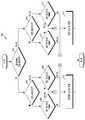
도 7은 다양한 실시 예들에 따른 안테나 모드 변경 여부를 판단하는 동작을 도시한 흐름도(700)이다. 도 7에 예시된 흐름도(700)의 동작 주체는 전자 장치(예: 도 1의 전자 장치(101)) 또는 전자 장치의 프로세서(예: 도 1의 프로세서(120) 또는 도 2의 커뮤니케이션 프로세서(212 또는 214))로 이해될 수 있다. 도 7의 동작은 도 6의 동작 611의 일 실시 예일 수 있다.7 is a
다양한 실시 예들에 따르면, 동작 701에서, 전자 장치(101)는 음성 패킷을 전송 중인지를 판단할 수 있다. 음성 패킷을 전송 중인지 아니면 데이터 패킷을 전송 중인 지에 따라 모드 변경의 판단 조건이 달라질 수 있기 때문에 먼저 전자 장치(101)가 음성 패킷을 전송 중인지, 아니면 데이터 패킷을 전송 중인지를 판단할 수 있다.According to various embodiments, in
다양한 실시 예들에 따르면, 전송 중인 패킷이 음성 패킷인 경우(701-예), 동작 703에서, 현재의 안테나 모드가 일반 모드인지 아니면 최적화 모드인지를 판단할 수 있다. 일반 모드이면(703-예) 동작 707에서, 제1 천이 조건을 만족하는 지를 판단하여 제1 천이 조건을 만족하면(707-예) 동작 715에서, 최적화 모드의 설정을 결정하고, 제1 천이 조건을 만족하지 못하면(707-아니오) 그대로 일반 모드의 설정을 유지할 수 있다. 동작 703의 판단 결과 최적화 모드(703-아니오)이면, 동작 709에서 제2 천이 조건을 만족하는 지 판단하고, 제2 천이 조건을 만족(709-예)하면 일반 모드의 설정을 결정하고, 제2 천이 조건을 만족하지 않는다고 판단하면(709-아니오), 그대로 최적화 모드의 설정을 유지할 수 있다. 여기서, 제1 천이 조건과 제2 천이 조건을 다르게 설정함으로 인하여 계속적인 천이를 방지하기 위한 히스테리시스를 줄 수 있다. 일 실시 예에 따르면 제1 천이 조건은 RSRP가 -110dBm보다 작거나 같은 경우, 송신 전력이 20dBm보다 큰 경우, BSR 인덱스가 2초 동안 40%이상인 경우, BLER이 10%보다 큰 경우 TTIB가 활성화된 경우 중의 적어도 하나를 포함할 수 있다. 제2 천이 조건은 BLER이 10%보다 작아지는 경우일 수 있다.According to various embodiments, when the packet being transmitted is a voice packet (701-Yes), in
다양한 실시 예들에 따르면, 동작 701의 판단에 따라 전송 중인 패킷이 데이터 패킷인 경우(701-아니오), 동작 705에서, 현재의 안테나 모드가 일반 모드인지 아니면 최적화 모드인지를 판단할 수 있다. 일반 모드이면(705-예), 동작 711에서, 제3 천이 조건을 만족하는 지를 판단하여 제3 천이 조건을 만족하면(711-예) 최적화 모드의 설정을 결정하고, 제3 천이 조건을 만족하지 못하면(711-아니오) 그대로 일반 모드의 설정을 유지할 수 있다. 동작 705의 판단 결과 최적화 모드이면(705-아니오), 동작 713에서 제4 천이 조건을 만족하는 지 판단하고, 제4 천이 조건을 만족하면(713-예) 일반 모드의 설정을 결정하고, 제4 천이 조건을 만족하지 않는다고 판단하면(713-아니오), 그대로 최적화 모드의 설정을 유지할 수 있다. 여기서, 제3 천이 조건과 제4 천이 조건을 다르게 설정함으로 인하여 계속적인 천이를 방지하기 위한 히스테리시스를 줄 수 있다. 일 실시 예에 따르면 제3 천이 조건은 RSRP가 -80dBm보다 작거나 같은 경우, 송신 전력이 20dBm보다 큰 경우, BSR 인덱스가 3초 동안 30%이상인 경우, BLER이 30%보다 큰 경우 중의 적어도 하나를 포함할 수 있다. 제4 천이 조건은 BLER이 30%보다 작아지는 경우일 수 있다.According to various embodiments, when the packet being transmitted is a data packet according to the determination in operation 701 (701-No), in
다양한 실시 예들에 따르면, 전자 장치(예: 도 1의 전자 장치(101))의 동작 방법은 다중 주파수 대역 연결이 설정되었는 지를 판단하는 동작, 상기 판단 결과, 다중 주파수 대역 연결이 설정된 경우, 상기 연결된 다중 주파수 대역 중 제어 정보를 전송하는 주파수 대역을 식별하는 동작, 상기 식별된 제어 정보를 전송하는 주파수 대역에 대한 통신 상태 정보를 획득하는 동작, 상기 획득한 통신 상태 정보에 기초하여, 안테나 모드를 결정하는 동작 및 상기 결정된 안테나 모드에 기초하여, 적어도 하나의 안테나 모듈을 설정하는 동작을 포함할 수 있다.According to various embodiments, the operation method of the electronic device (eg, the electronic device 101 of FIG. 1) is an operation of determining whether a multi-frequency band connection is established, and as a result of the determination, when a multi-frequency band connection is established, the connected An operation of identifying a frequency band for transmitting control information among multiple frequency bands, an operation of obtaining communication state information for a frequency band transmitting the identified control information, and determining an antenna mode based on the obtained communication state information And setting at least one antenna module based on the determined antenna mode.
다양한 실시 예들에 따르면, 상기 안테나 모드는 상기 연결된 다중 주파수 대역 전체의 반사손실을 작게 하도록 하는 일반 모드 및 상기 식별된 제어 정보를 전송하는 주파수 대역의 반사손실을 작게 하도록 하는 최적화 모드를 포함할 수 있다.According to various embodiments, the antenna mode may include a general mode for reducing the return loss of the entire connected multi-frequency band, and an optimization mode for reducing the return loss of a frequency band transmitting the identified control information. .
다양한 실시 예들에 따르면, 상기 안테나 모드 변경 여부를 결정하는 동작은 전송하는 패킷이 음성 패킷인지 또는 데이터 패킷인지에 따라 다른 천이 조건을 사용하여 상기 안테나 모드 변경 여부를 결정하는 동작을 포함할 수 있다.According to various embodiments, determining whether to change the antenna mode may include determining whether to change the antenna mode using different transition conditions depending on whether a transmitted packet is a voice packet or a data packet.
다양한 실시 예들에 따르면, 상기 안테나 모드 변경 여부를 결정하는 동작은 전송하는 패킷이 음성 패킷이고, 안테나 모드가 상기 일반 모드인 경우 제1 천이 조건에 따라 상기 최적화 모드로 천이하는 동작, 전송하는 패킷이 음성 패킷이고, 안테나 모드가 상기 최적화 모드인 경우 제2 천이 조건에 따라 상기 일반 모드로 천이하는 동작, 전송하는 패킷이 데이터 패킷이고, 안테나 모드가 상기 일반 모드인 경우 제3 천이 조건에 따라 상기 최적화 모드로 천이하는 동작, 및 전송하는 패킷이 데이터 패킷이고, 안테나 모드가 상기 최적화 모드인 경우 제4 천이 조건에 따라 상기 일반 모드로 천이하는 동작을 포함하고,According to various embodiments, the operation of determining whether to change the antenna mode is an operation of transitioning to the optimization mode according to a first transition condition when the transmitted packet is a voice packet and the antenna mode is the general mode, and the transmitted packet is When it is a voice packet and the antenna mode is the optimization mode, the operation of transitioning to the normal mode according to the second transition condition. When the transmitted packet is a data packet and the antenna mode is the general mode, the optimization according to a third transition condition An operation of transitioning to a mode, and an operation of transitioning to the normal mode according to a fourth transition condition when the transmitted packet is a data packet and the antenna mode is the optimization mode,
상기 제1 천이 조건과 상기 제2 천이 조건을 다르게 설정하고, 상기 제3 천이 조건과 상기 제4 천이 조건을 다르게 설정하여 히스테리시스(hysteresis)를 줄 수 있다.Hysteresis may be provided by setting the first transition condition and the second transition condition differently, and setting the third transition condition and the fourth transition condition differently.
다양한 실시 예들에 따르면, 상기 각 천이 조건은 하향링크 신호의 수신 품질, 신호 송신시에 사용하는 송신 전력, 전송할 데이터의 양을 나타내는 BSR 인덱스(buffer status report index) 또는 전송한 패킷 중에 전송을 완료하지 못한 패킷의 비율을 나타내는 블록 에러율(BLER), 복수 개의 자원을 이용하여 동일한 패킷을 복수 회 송신하도록 하는 TTIB(transmit time interval bundling)의 활성화 여부 중의 적어도 하나를 기준으로 할 수 있다.According to various embodiments, each of the transition conditions is a reception quality of a downlink signal, a transmission power used when transmitting a signal, a buffer status report index (BSR) indicating an amount of data to be transmitted, or a transmission not complete among transmitted packets. It may be based on at least one of a block error rate (BLER) indicating a rate of unsuccessful packets, and whether or not a transmit time interval bundling (TTIB), which transmits the same packet multiple times using a plurality of resources, is activated.
다양한 실시 예들에 따르면, 상기 제1 천이 조건은 RSRP(reference signal received power)가 -110dBm보다 작거나 같은 경우, 송신 전력이 20dBm보다 큰 경우, BSR 인덱스가 2초 동안 40%이상인 경우, BLER이 10%보다 큰 경우, TTIB가 활성화된 경우 중의 적어도 하나를 포함하고, 상기 제2 천이 조건은 BLER이 10%보다 작은 경우를 포함할 수 있다.According to various embodiments, the first transition condition is when the reference signal received power (RSRP) is less than or equal to -110dBm, the transmission power is greater than 20dBm, the BSR index is 40% or more for 2 seconds, and the BLER is 10. When it is greater than %, at least one of cases in which TTIB is activated may be included, and the second transition condition may include a case in which BLER is less than 10%.
다양한 실시 예들에 따르면, 상기 제3 천이 조건은 RSRP(reference signal received power)가 -80dBm보다 작거나 같은 경우, 송신 전력이 20dBm보다 큰 경우, BSR 인덱스가 3초 동안 30%이상인 경우, BLER이 30%보다 큰 경우, TTIB가 활성화된 경우 중의 적어도 하나를 포함하고, 상기 제4 천이 조건은 BLER이 30%보다 작은 경우를 포함할 수 있다.According to various embodiments, the third transition condition is when the reference signal received power (RSRP) is less than or equal to -80dBm, the transmission power is greater than 20dBm, the BSR index is 30% or more for 3 seconds, the BLER is 30 When it is greater than %, at least one of cases in which TTIB is activated may be included, and the fourth transition condition may include a case in which BLER is less than 30%.
다양한 실시 예들에 따르면, 상기 식별된 제어 정보를 전송하는 주파수 대역이 두 개 이상의 주파수 대역인 경우, 상기 최적화 모드는 상기 두 개 이상의 주파수 대역을 포함하는 주파수 대역에서 반사손실을 작게 하거나 또는 상기 두 개 이상의 주파수 대역 중에서 하나의 주파수 대역을 선정하고, 선정된 주파수 대역의 반사손실을 작게 하도록 할 수 있다.According to various embodiments, when the frequency band transmitting the identified control information is two or more frequency bands, the optimization mode is to reduce the return loss in the frequency band including the two or more frequency bands, or the two or more frequency bands. One of the above frequency bands may be selected, and the return loss of the selected frequency band may be reduced.
다양한 실시 예들에 따르면, 상기 안테나 모드를 설정하는 동작은 상기 결정된 안테나 모드에 따라, 상기 안테나 모듈에 포함된 튜너를 제어하여 안테나의 반사손실 특성을 조정하는 동작을 포함할 수 있다.According to various embodiments, the setting of the antenna mode may include an operation of adjusting a return loss characteristic of an antenna by controlling a tuner included in the antenna module according to the determined antenna mode.
다양한 실시 예들에 따르면, 상기 결정된 안테나 모드가 상기 최적화 모드인 경우에도, 상기 제어 정보를 전달하지 않는 시간 구간에서는 상기 일반 모드에 따라 상기 안테나 모듈을 설정하고, 상기 제어 정보를 전달하는 시간 구간에서는 상기 최적화 모드에 따라 상기 안테나 모듈을 설정하는 동작을 더 포함할 수 있다.According to various embodiments, even when the determined antenna mode is the optimization mode, the antenna module is set according to the general mode in a time interval in which the control information is not transmitted, and the antenna module is configured in a time interval in which the control information is transmitted. It may further include an operation of setting the antenna module according to the optimization mode.
다양한 실시 예들에 따르면, 상기 적어도 하나의 안테나 모듈이 두 개 이상의 안테나 모듈인 경우, 상기 안테나 모드 변경 여부를 결정하는 동작은, 상기 두 개 이상의 안테나 모듈 각각에 대하여 독립적으로 안테나 모드 변경 여부를 결정하는 동작을 포함하고, 상기 적어도 하나의 안테나 모듈을 제어하여 안테나 모드를 변경하는 동작은, 상기 결정에 기초하여 상기 두 개 이상의 안테나 모듈 각각을 제어하여 상기 두 개 이상의 안테나 모듈 각각의 안테나 모드를 변경하는 동작을 포함할 수 있다.According to various embodiments, when the at least one antenna module is two or more antenna modules, the determining whether to change the antenna mode includes independently determining whether to change the antenna mode for each of the two or more antenna modules. Including an operation, the operation of changing the antenna mode by controlling the at least one antenna module comprises: changing the antenna mode of each of the two or more antenna modules by controlling each of the two or more antenna modules based on the determination. May include actions.
상술한 다양한 실시 예들에 따라 안테나의 모드를 일반 모드 또는 최적화 모드로 능동적으로 변경함에 의해 제어 정보가 전송되는 주파수 대역에서의 전송 성능을 보강함으로써 제어 정보의 전송 실패 가능성을 낮추고, HARQ 전송 실패에 따른 재전송에 의해 야기되는 데이터 응답 느림, 속도 느림과 같은 전자 장치의 통신 성능 저하 현상을 방지할 수 있다.According to the various embodiments described above, the possibility of transmission failure of control information is reduced by reinforcing the transmission performance in the frequency band in which control information is transmitted by actively changing the mode of the antenna to a normal mode or an optimization mode, and according to HARQ transmission failure. It is possible to prevent deterioration of communication performance of an electronic device such as slow data response and slow speed caused by retransmission.
본 문서에 개시된 다양한 실시 예들에 따른 전자 장치는 다양한 형태의 장치가 될 수 있다. 전자 장치는, 예를 들면, 휴대용 통신 장치(예: 스마트폰), 컴퓨터 장치, 노트북, PDA, 휴대용 멀티미디어 장치, 휴대용 의료 기기를 포함할 수 있다. 본 문서의 실시 예에 따른 전자 장치는 전술한 기기들에 한정되지 않는다.Electronic devices according to various embodiments disclosed in this document may be devices of various types. The electronic device may include, for example, a portable communication device (eg, a smart phone), a computer device, a notebook computer, a PDA, a portable multimedia device, and a portable medical device. The electronic device according to the embodiment of the present document is not limited to the above-described devices.
본 문서의 다양한 실시 예들 및 이에 사용된 용어들은 본 문서에 기재된 기술적 특징들을 특정한 실시 예들로 한정하려는 것이 아니며, 해당 실시 예의 다양한 변경, 균등물, 또는 대체물을 포함하는 것으로 이해되어야 한다. 도면의 설명과 관련하여, 유사한 또는 관련된 구성요소에 대해서는 유사한 참조 부호가 사용될 수 있다. 아이템에 대응하는 명사의 단수 형은 관련된 문맥상 명백하게 다르게 지시하지 않는 한, 아이템 한 개 또는 복수 개를 포함할 수 있다. 본 문서에서, "A 또는 B", "A 및 B 중 적어도 하나",“A 또는 B 중 적어도 하나”, "A, B 또는 C", "A, B 및 C 중 적어도 하나” 및 “A, B, 또는 C 중 적어도 하나"와 같은 문구들 각각은 그 문구들 중 해당하는 문구에 함께 나열된 항목들 중 어느 하나, 또는 그들의 모든 가능한 조합을 포함할 수 있다. "제1", "제2", 또는 "첫째" 또는 "둘째"와 같은 용어들은 단순히 해당 구성요소를 다른 해당 구성요소와 구분하기 위해 사용될 수 있으며, 해당 구성요소들을 다른 측면(예: 중요성 또는 순서)에서 한정하지 않는다. 어떤(예: 제1) 구성요소가 다른(예: 제2) 구성요소에, “기능적으로” 또는 “통신적으로”라는 용어와 함께 또는 이런 용어 없이, “커플드” 또는 “커넥티드”라고 언급된 경우, 그것은 어떤 구성요소가 다른 구성요소에 직접적으로(예: 유선으로), 무선으로, 또는 제3 구성요소를 통하여 연결될 수 있다는 것을 의미한다.Various embodiments of the present document and terms used therein are not intended to limit the technical features described in this document to specific embodiments, and should be understood to include various modifications, equivalents, or substitutes of the corresponding embodiments. In connection with the description of the drawings, similar reference numerals may be used for similar or related components. The singular form of a noun corresponding to an item may include one item or a plurality of items, unless clearly indicated otherwise in the related context. In this document, “A or B”, “at least one of A and B”, “at least one of A or B”, “A, B or C”, “at least one of A, B and C” and “A, Each of phrases such as "at least one of B or C" may include any one of the items listed together in the corresponding one of the phrases, or all possible combinations thereof. Terms such as "first", "second", or "first" or "second" may be used simply to distinguish the component from other corresponding components, and the components may be referred to in other aspects (eg, importance or Order) is not limited. Some (eg, first) component is referred to as “coupled” or “connected” to another (eg, second) component, with or without the terms “functionally” or “communicatively”. When mentioned, it means that certain components can be connected to other components directly (eg by wire), wirelessly, or via a third component.
본 문서에서 사용된 용어 "모듈"은 하드웨어, 소프트웨어 또는 펌웨어로 구현된 유닛을 포함할 수 있으며, 예를 들면, 로직, 논리 블록, 부품, 또는 회로와 같은 용어와 상호 호환적으로 사용될 수 있다. 모듈은, 일체로 구성된 부품 또는 하나 또는 그 이상의 기능을 수행하는, 부품의 최소 단위 또는 그 일부가 될 수 있다. 예를 들면, 일 실시 예에 따르면, 모듈은 ASIC(application-specific integrated circuit)의 형태로 구현될 수 있다.The term "module" used in this document may include a unit implemented in hardware, software, or firmware, and may be used interchangeably with terms such as logic, logic blocks, parts, or circuits. The module may be an integrally configured part or a smallest unit of a part or a part thereof that performs one or more functions. For example, according to an embodiment, the module may be implemented in the form of an application-specific integrated circuit (ASIC).
본 문서의 다양한 실시 예들은 기기(machine)(예: 전자 장치(101)) 의해 읽을 수 있는 저장 매체(storage medium)(예: 내장 메모리(136) 또는 외장 메모리(138))에 저장된 적어도 하나의 명령어들을 포함하는 소프트웨어(예: 프로그램(140))로서 구현될 수 있다. 예를 들면, 기기(예: 전자 장치(101))의 프로세서(예: 프로세서(120))는, 저장 매체로부터 저장된 하나 이상의 명령어들 중 적어도 하나의 명령을 호출하고, 그것을 실행할 수 있다. 이것은 기기가 상기 호출된 적어도 하나의 명령어에 따라 적어도 하나의 기능을 수행하도록 운영되는 것을 가능하게 한다. 상기 하나 이상의 명령어들은 컴파일러에 의해 생성된 코드 또는 인터프리터에 의해 실행될 수 있는 코드를 포함할 수 있다. 기기로 읽을 수 있는 저장 매체는, 비일시적(non-transitory) 저장 매체의 형태로 제공될 수 있다. 여기서, ‘비일시적’은 저장 매체가 실재(tangible)하는 장치이고, 신호(signal)(예: 전자기파)를 포함하지 않는다는 것을 의미할 뿐이며, 이 용어는 데이터가 저장 매체에 반영구적으로 저장되는 경우와 임시적으로 저장되는 경우를 구분하지 않는다.Various embodiments of the present document include at least one stored in a storage medium (eg, internal memory 136 or external memory 138) that can be read by a machine (eg, electronic device 101). It may be implemented as software (eg, program 140) including instructions. For example, the processor (eg, the processor 120) of the device (eg, the electronic device 101) may call and execute at least one command among one or more commands stored from a storage medium. This makes it possible for the device to be operated to perform at least one function according to the at least one command invoked. The one or more instructions may include code generated by a compiler or code executable by an interpreter. The device-readable storage medium may be provided in the form of a non-transitory storage medium. Here,'non-transient' only means that the storage medium is a tangible device and does not contain a signal (e.g., electromagnetic waves), and this term refers to the case where data is semi-permanently stored in the storage medium. It does not distinguish between temporary storage cases.
일 실시 예에 따르면, 본 문서에 개시된 다양한 실시 예들에 따른 방법은 컴퓨터 프로그램 제품(computer program product)에 포함되어 제공될 수 있다. 컴퓨터 프로그램 제품은 상품으로서 판매자 및 구매자 간에 거래될 수 있다. 컴퓨터 프로그램 제품은 기기로 읽을 수 있는 저장 매체(예: CD-ROM(compact disc read only memory))의 형태로 배포되거나, 또는 애플리케이션 스토어(예: 플레이 스토어TM)를 통해 또는 두개의 사용자 장치들(예: 스마트폰들) 간에 직접, 온라인으로 배포(예: 다운로드 또는 업로드)될 수 있다. 온라인 배포의 경우에, 컴퓨터 프로그램 제품의 적어도 일부는 제조사의 서버, 애플리케이션 스토어의 서버, 또는 중계 서버의 메모리와 같은 기기로 읽을 수 있는 저장 매체에 적어도 일시 저장되거나, 임시적으로 생성될 수 있다.According to an embodiment, a method according to various embodiments disclosed in this document may be provided in a computer program product. Computer program products can be traded between sellers and buyers as commodities. Computer program products are distributed in the form of a device-readable storage medium (e.g., compact disc read only memory (CD-ROM)), or through an application store (e.g. Play StoreTM ) or two user devices (e.g. It can be distributed (e.g., downloaded or uploaded) directly between, e.g. smartphones). In the case of online distribution, at least a portion of the computer program product may be temporarily stored or temporarily created in a storage medium that can be read by a device such as a server of a manufacturer, a server of an application store, or a memory of a relay server.
다양한 실시 예들에 따르면, 상기 기술한 구성요소들의 각각의 구성요소(예: 모듈 또는 프로그램)는 단수 또는 복수의 개체를 포함할 수 있다. 다양한 실시 예들에 따르면, 전술한 해당 구성요소들 중 하나 이상의 구성요소들 또는 동작들이 생략되거나, 또는 하나 이상의 다른 구성요소들 또는 동작들이 추가될 수 있다. 대체적으로 또는 추가적으로, 복수의 구성요소들(예: 모듈 또는 프로그램)은 하나의 구성요소로 통합될 수 있다. 이런 경우, 통합된 구성요소는 상기 복수의 구성요소들 각각의 구성요소의 하나 이상의 기능들을 통합 이전에 상기 복수의 구성요소들 중 해당 구성요소에 의해 수행되는 것과 동일 또는 유사하게 수행할 수 있다. 다양한 실시 예들에 따르면, 모듈, 프로그램 또는 다른 구성요소에 의해 수행되는 동작들은 순차적으로, 병렬적으로, 반복적으로, 또는 휴리스틱(heuristic)하게 실행되거나, 상기 동작들 중 하나 이상이 다른 순서로 실행되거나, 생략되거나, 또는 하나 이상의 다른 동작들이 추가될 수 있다.According to various embodiments, each component (eg, module or program) of the above-described components may include a singular number or a plurality of entities. According to various embodiments, one or more components or operations among the above-described corresponding components may be omitted, or one or more other components or operations may be added. Alternatively or additionally, a plurality of components (eg, a module or a program) may be integrated into one component. In this case, the integrated component may perform one or more functions of each component of the plurality of components in the same or similar to that performed by the corresponding component among the plurality of components prior to integration. According to various embodiments, operations performed by a module, program, or other component may be sequentially, parallel, repetitively or heuristically executed, or one or more of the operations may be executed in a different order. , Omitted, or one or more other operations may be added.
Claims (20)
Translated fromKorean무선 신호를 송, 수신하는 적어도 하나의 안테나 모듈;
상기 적어도 하나의 안테나 모듈과 작동적으로 연결되는 적어도 하나의 프로세서; 및
상기 적어도 하나의 프로세서와 작동적으로 연결되는 적어도 하나의 메모리를 포함하고,
상기 적어도 하나의 메모리는, 실행 시에, 상기 적어도 하나의 프로세서가,
다중 주파수 대역 연결이 설정되었는 지를 판단하고,
상기 판단 결과, 다중 주파수 대역 연결이 설정된 경우, 상기 연결된 다중 주파수 대역 중 제어 정보를 전송하는 주파수 대역을 식별하고,
상기 식별된 제어 정보를 전송하는 주파수 대역에 대한 통신 상태 정보를 획득하고,
상기 획득한 통신 상태 정보에 기초하여, 안테나 모드를 결정하고,
상기 결정된 안테나 모드에 기초하여, 상기 적어도 하나의 안테나 모듈을 설정하도록 하는 인스트럭션들을 저장하는, 전자 장치.
In the electronic device,
At least one antenna module for transmitting and receiving a radio signal;
At least one processor operatively connected to the at least one antenna module; And
Including at least one memory operatively connected to the at least one processor,
The at least one memory, when executed, the at least one processor,
Judging whether a multi-frequency band connection has been established,
As a result of the determination, when a multi-frequency band connection is established, a frequency band transmitting control information among the connected multi-frequency bands is identified, and
Acquiring communication state information on a frequency band transmitting the identified control information,
Based on the obtained communication state information, determine an antenna mode,
An electronic device that stores instructions for setting the at least one antenna module based on the determined antenna mode.
상기 연결된 다중 주파수 대역 전체의 반사손실을 작게 하도록 하는 일반 모드; 및
상기 식별된 제어 정보를 전송하는 주파수 대역의 반사손실을 작게 하도록 하는 최적화 모드를 포함하는, 전자 장치.
The method of claim 1, wherein the antenna mode is
A normal mode for reducing the return loss of the entire connected multiple frequency bands; And
An electronic device comprising an optimization mode for reducing a return loss of a frequency band transmitting the identified control information.
상기 인스트럭션들은 상기 적어도 하나의 프로세서가,
전송하는 패킷이 음성 패킷인지 또는 데이터 패킷인지에 따라 다른 천이 조건을 사용하여 상기 안테나 모드 변경 여부를 결정하도록 하는, 전자 장치.
The method of claim 2,
The instructions are the at least one processor,
An electronic device configured to determine whether to change the antenna mode using different transition conditions according to whether a transmitted packet is a voice packet or a data packet.
상기 인스트럭션들은 상기 적어도 하나의 프로세서가,
전송하는 패킷이 음성 패킷이고, 안테나 모드가 상기 일반 모드인 경우 제1 천이 조건에 따라 상기 최적화 모드로 천이하고,
전송하는 패킷이 음성 패킷이고, 안테나 모드가 상기 최적화 모드인 경우 제2 천이 조건에 따라 상기 일반 모드로 천이하고,
전송하는 패킷이 데이터 패킷이고, 안테나 모드가 상기 일반 모드인 경우 제3 천이 조건에 따라 상기 최적화 모드로 천이하고,
전송하는 패킷이 데이터 패킷이고, 안테나 모드가 상기 최적화 모드인 경우 제4 천이 조건에 따라 상기 일반 모드로 천이하도록 하고,
상기 제1 천이 조건과 상기 제2 천이 조건을 다르게 설정하고, 상기 제3 천이 조건과 상기 제4 천이 조건을 다르게 설정하여 히스테리시스(hysteresis)를 주도록 하는, 전자 장치.
The method of claim 3,
The instructions are the at least one processor,
When the transmitted packet is a voice packet and the antenna mode is the general mode, transition to the optimization mode according to a first transition condition,
When the transmitted packet is a voice packet and the antenna mode is the optimization mode, transition to the normal mode according to a second transition condition,
When the transmitted packet is a data packet and the antenna mode is the normal mode, transition to the optimization mode according to a third transition condition,
When the transmitted packet is a data packet and the antenna mode is the optimization mode, transition to the normal mode according to a fourth transition condition,
The electronic device, wherein the first transition condition and the second transition condition are set differently, and the third transition condition and the fourth transition condition are set differently to give hysteresis.
상기 각 천이 조건은 하향링크 신호의 수신 품질, 신호 송신시에 사용하는 송신 전력, 전송할 데이터의 양을 나타내는 BSR 인덱스(buffer status report index) 또는 전송한 패킷 중에 전송을 완료하지 못한 패킷의 비율을 나타내는 블록 에러율(BLER), 복수 개의 자원을 이용하여 동일한 패킷을 복수 회 송신하도록 하는 TTIB(transmit time interval bundling)의 활성화 여부 중의 적어도 하나를 기준으로 하는, 전자 장치.
The method of claim 4,
Each of the transition conditions is the reception quality of the downlink signal, the transmission power used when transmitting the signal, the buffer status report index (BSR) indicating the amount of data to be transmitted, or the percentage of packets that have not completed transmission among the transmitted packets. An electronic device based on at least one of a block error rate (BLER) and whether or not a transmit time interval bundling (TTIB) for transmitting the same packet multiple times using a plurality of resources is activated.
상기 제1 천이 조건은 RSRP(reference signal received power)가 -110dBm보다 작거나 같은 경우, 송신 전력이 20dBm보다 큰 경우, BSR 인덱스가 2초 동안 40%이상인 경우, BLER이 10%보다 큰 경우, TTIB가 활성화된 경우 중의 적어도 하나를 포함하고,
상기 제2 천이 조건은 BLER이 10%보다 작은 경우를 포함하는, 전자 장치.
The method of claim 5,
The first transition condition is when the reference signal received power (RSRP) is less than or equal to -110dBm, the transmission power is greater than 20dBm, the BSR index is 40% or more for 2 seconds, the BLER is greater than 10%, and the TTIB. Includes at least one of the cases where is activated,
The electronic device, wherein the second transition condition includes a case where BLER is less than 10%.
상기 제3 천이 조건은 RSRP(reference signal received power)가 -80dBm보다 작거나 같은 경우, 송신 전력이 20dBm보다 큰 경우, BSR 인덱스가 3초 동안 30%이상인 경우, BLER이 30%보다 큰 경우, TTIB가 활성화된 경우 중의 적어도 하나를 포함하고,
상기 제4 천이 조건은 BLER이 30%보다 작은 경우를 포함하는, 전자 장치.
The method of claim 5,
The third transition condition is when the reference signal received power (RSRP) is less than or equal to -80dBm, the transmission power is greater than 20dBm, the BSR index is 30% or more for 3 seconds, the BLER is greater than 30%, and the TTIB. Includes at least one of the cases where is activated,
The fourth transition condition includes a case where BLER is less than 30%.
상기 인스트럭션들은 상기 적어도 하나의 프로세서가,
상기 식별된 제어 정보를 전송하는 주파수 대역이 두 개 이상의 주파수 대역인 경우, 상기 최적화 모드로서 상기 두 개 이상의 주파수 대역을 포함하는 주파수 대역에서 반사손실을 작게 하도록 하거나 또는 상기 두 개 이상의 주파수 대역 중에서 하나의 주파수 대역을 선정하고, 선정된 주파수 대역의 반사손실을 작게 하도록 하는, 전자 장치.
The method of claim 2,
The instructions are the at least one processor,
When the frequency band transmitting the identified control information is two or more frequency bands, as the optimization mode, the return loss is reduced in a frequency band including the two or more frequency bands, or one of the two or more frequency bands. An electronic device that selects a frequency band of and reduces the return loss of the selected frequency band.
상기 안테나 모듈은,
안테나 및 튜너를 포함하고,
상기 인스트럭션들은 상기 적어도 하나의 프로세서가,
상기 안테나 모드에 따라 상기 튜너를 제어하여, 상기 안테나의 반사손실 특성을 조정하도록 하는, 전자 장치, 전자 장치.
The method of claim 1,
The antenna module,
Including an antenna and a tuner,
The instructions are the at least one processor,
An electronic device or an electronic device configured to control the tuner according to the antenna mode to adjust a return loss characteristic of the antenna.
상기 인스트럭션들은 상기 적어도 하나의 프로세서가,
상기 결정된 안테나 모드가 상기 최적화 모드인 경우에도,
상기 제어 정보를 전달하지 않는 시간 구간에서는 상기 일반 모드에 따라 상기 안테나 모듈을 설정하고, 상기 제어 정보를 전달하는 시간 구간에는 상기 최적화 모드에 따라 상기 안테나 모듈을 설정하도록 하는, 전자 장치.
The method of claim 2,
The instructions are the at least one processor,
Even when the determined antenna mode is the optimization mode,
The electronic device, wherein the antenna module is set according to the general mode in a time interval in which the control information is not transmitted, and the antenna module is set according to the optimization mode in a time interval in which the control information is transmitted.
다중 주파수 대역 연결이 설정되었는 지를 판단하는 동작;
상기 판단 결과, 다중 주파수 대역 연결이 설정된 경우, 상기 연결된 다중 주파수 대역 중 제어 정보를 전송하는 주파수 대역을 식별하는 동작;
상기 식별된 제어 정보를 전송하는 주파수 대역에 대한 통신 상태 정보를 획득하는 동작;
상기 획득한 통신 상태 정보에 기초하여, 안테나 모드를 결정하는 동작; 및
상기 결정된 안테나 모드에 기초하여, 적어도 하나의 안테나 모듈을 설정하는 동작을 포함하는, 방법.
In the method of operating an electronic device,
Determining whether a multi-frequency band connection has been established;
When a multi-frequency band connection is established as a result of the determination, identifying a frequency band transmitting control information among the connected multi-frequency bands;
Obtaining communication state information for a frequency band transmitting the identified control information;
Determining an antenna mode based on the obtained communication state information; And
And setting at least one antenna module based on the determined antenna mode.
상기 연결된 다중 주파수 대역 전체의 반사손실을 작게 하도록 하는 일반 모드; 및
상기 식별된 제어 정보를 전송하는 주파수 대역의 반사손실을 작게 하도록 하는 최적화 모드를 포함하는, 방법.
The method of claim 11, wherein the antenna mode is
A normal mode for reducing the return loss of the entire connected multiple frequency bands; And
And an optimization mode to reduce the return loss of the frequency band transmitting the identified control information.
상기 안테나 모드 변경 여부를 결정하는 동작은,
전송하는 패킷이 음성 패킷인지 또는 데이터 패킷인지에 따라 다른 천이 조건을 사용하여 상기 안테나 모드 변경 여부를 결정하는 동작을 포함하는, 방법.
The method of claim 12,
The operation of determining whether to change the antenna mode,
And determining whether to change the antenna mode using a different transition condition depending on whether the transmitted packet is a voice packet or a data packet.
상기 안테나 모드 변경 여부를 결정하는 동작은,
전송하는 패킷이 음성 패킷이고, 안테나 모드가 상기 일반 모드인 경우 제1 천이 조건에 따라 상기 최적화 모드로 천이하는 동작;
전송하는 패킷이 음성 패킷이고, 안테나 모드가 상기 최적화 모드인 경우 제2 천이 조건에 따라 상기 일반 모드로 천이하는 동작;
전송하는 패킷이 데이터 패킷이고, 안테나 모드가 상기 일반 모드인 경우 제3 천이 조건에 따라 상기 최적화 모드로 천이하는 동작; 및
전송하는 패킷이 데이터 패킷이고, 안테나 모드가 상기 최적화 모드인 경우 제4 천이 조건에 따라 상기 일반 모드로 천이하는 동작을 포함하고,
상기 제1 천이 조건과 상기 제2 천이 조건을 다르게 설정하고, 상기 제3 천이 조건과 상기 제4 천이 조건을 다르게 설정하여 히스테리시스(hysteresis)를 주는, 방법.
The method of claim 13,
The operation of determining whether to change the antenna mode,
Transitioning to the optimization mode according to a first transition condition when the transmitted packet is a voice packet and the antenna mode is the normal mode;
Transitioning to the normal mode according to a second transition condition when the transmitted packet is a voice packet and the antenna mode is the optimized mode;
Transitioning to the optimization mode according to a third transition condition when the transmitted packet is a data packet and the antenna mode is the normal mode; And
When the transmitted packet is a data packet and the antenna mode is the optimization mode, transitioning to the normal mode according to a fourth transition condition is included,
The method of claim 1, wherein the first transition condition and the second transition condition are set differently, and the third transition condition and the fourth transition condition are set differently to give hysteresis.
상기 각 천이 조건은 하향링크 신호의 수신 품질, 신호 송신시에 사용하는 송신 전력, 전송할 데이터의 양을 나타내는 BSR 인덱스(buffer status report index) 또는 전송한 패킷 중에 전송을 완료하지 못한 패킷의 비율을 나타내는 블록 에러율(BLER), 복수 개의 자원을 이용하여 동일한 패킷을 복수 회 송신하도록 하는 TTIB(transmit time interval bundling)의 활성화 여부 중의 적어도 하나를 기준으로 하는, 방법.
The method of claim 14,
Each of the transition conditions is the reception quality of the downlink signal, the transmission power used when transmitting the signal, the buffer status report index (BSR) indicating the amount of data to be transmitted, or the percentage of packets that have not completed transmission among the transmitted packets. A method based on at least one of a block error rate (BLER) and whether or not a transmit time interval bundling (TTIB), which transmits the same packet multiple times using a plurality of resources, is activated.
상기 제1 천이 조건은 RSRP(reference signal received power)가 -110dBm보다 작거나 같은 경우, 송신 전력이 20dBm보다 큰 경우, BSR 인덱스가 2초 동안 40%이상인 경우, BLER이 10%보다 큰 경우, TTIB가 활성화된 경우 중의 적어도 하나를 포함하고,
상기 제2 천이 조건은 BLER이 10%보다 작은 경우를 포함하는, 방법.
The method of claim 15,
The first transition condition is when the reference signal received power (RSRP) is less than or equal to -110dBm, the transmission power is greater than 20dBm, the BSR index is 40% or more for 2 seconds, the BLER is greater than 10%, and the TTIB. Includes at least one of the cases where is activated,
Wherein the second transition condition includes the case where the BLER is less than 10%.
상기 제3 천이 조건은 RSRP(reference signal received power)가 -80dBm보다 작거나 같은 경우, 송신 전력이 20dBm보다 큰 경우, BSR 인덱스가 3초 동안 30%이상인 경우, BLER이 30%보다 큰 경우, TTIB가 활성화된 경우 중의 적어도 하나를 포함하고,
상기 제4 천이 조건은 BLER이 30%보다 작은 경우를 포함하는, 방법.
The method of claim 15,
The third transition condition is when the reference signal received power (RSRP) is less than or equal to -80dBm, the transmission power is greater than 20dBm, the BSR index is 30% or more for 3 seconds, the BLER is greater than 30%, and the TTIB. Includes at least one of the cases where is activated,
Wherein the fourth transition condition includes the case where the BLER is less than 30%.
상기 식별된 제어 정보를 전송하는 주파수 대역이 두 개 이상의 주파수 대역인 경우, 상기 최적화 모드는 상기 두 개 이상의 주파수 대역을 포함하는 주파수 대역에서 반사손실을 작게 하거나 또는 상기 두 개 이상의 주파수 대역 중에서 하나의 주파수 대역을 선정하고, 선정된 주파수 대역의 반사손실을 작게 하는, 방법.
The method of claim 12,
When the frequency band transmitting the identified control information is two or more frequency bands, the optimization mode reduces return loss in a frequency band including the two or more frequency bands, or one of the two or more frequency bands. A method of selecting a frequency band and reducing the return loss of the selected frequency band.
상기 안테나 모드를 설정하는 동작은,
상기 결정된 안테나 모드에 따라, 상기 안테나 모듈에 포함된 튜너를 제어하여 안테나의 반사손실 특성을 조정하는 동작을 포함하는, 방법.
The method of claim 11,
The operation of setting the antenna mode,
And adjusting a return loss characteristic of an antenna by controlling a tuner included in the antenna module according to the determined antenna mode.
상기 결정된 안테나 모드가 상기 최적화 모드인 경우에도,
상기 제어 정보를 전달하지 않는 시간 구간에서는 상기 일반 모드에 따라 상기 안테나 모듈을 설정하고, 상기 제어 정보를 전달하는 시간 구간에서는 상기 최적화 모드에 따라 상기 안테나 모듈을 설정하는 동작을 더 포함하는, 방법.The method of claim 12,
Even when the determined antenna mode is the optimization mode,
The method further comprising setting the antenna module according to the general mode in a time period in which the control information is not transmitted, and setting the antenna module according to the optimization mode in a time period in which the control information is transmitted.
Priority Applications (3)
| Application Number | Priority Date | Filing Date | Title |
|---|---|---|---|
| KR1020190091161AKR102710392B1 (en) | 2019-07-26 | 2019-07-26 | An optimal antenna setting method in multiple connection environment and electronic device using it |
| PCT/KR2020/009242WO2021020769A1 (en) | 2019-07-26 | 2020-07-14 | Antenna optimization method in multiple connection environment and electronic device using same |
| US17/584,897US12184588B2 (en) | 2019-07-26 | 2022-01-26 | Antenna optimization method in multiple connection environment and electronic device using same |
Applications Claiming Priority (1)
| Application Number | Priority Date | Filing Date | Title |
|---|---|---|---|
| KR1020190091161AKR102710392B1 (en) | 2019-07-26 | 2019-07-26 | An optimal antenna setting method in multiple connection environment and electronic device using it |
Publications (2)
| Publication Number | Publication Date |
|---|---|
| KR20210012810Atrue KR20210012810A (en) | 2021-02-03 |
| KR102710392B1 KR102710392B1 (en) | 2024-09-26 |
Family
ID=74229723
Family Applications (1)
| Application Number | Title | Priority Date | Filing Date |
|---|---|---|---|
| KR1020190091161AActiveKR102710392B1 (en) | 2019-07-26 | 2019-07-26 | An optimal antenna setting method in multiple connection environment and electronic device using it |
Country Status (3)
| Country | Link |
|---|---|
| US (1) | US12184588B2 (en) |
| KR (1) | KR102710392B1 (en) |
| WO (1) | WO2021020769A1 (en) |
Cited By (1)
| Publication number | Priority date | Publication date | Assignee | Title |
|---|---|---|---|---|
| US12335762B2 (en) | 2021-07-14 | 2025-06-17 | Samsung Electronics Co., Ltd. | Electronic device performing measurement on measurement object of inter-rat and method for operating the same |
Families Citing this family (2)
| Publication number | Priority date | Publication date | Assignee | Title |
|---|---|---|---|---|
| WO2022160326A1 (en)* | 2021-02-01 | 2022-08-04 | Qualcomm Incorporated | Dynamic bandwidth part switching for control message monitoring |
| US12010631B2 (en)* | 2022-08-01 | 2024-06-11 | Apple Inc. | Dynamic activation of network hardware based on real-time conditions |
Citations (8)
| Publication number | Priority date | Publication date | Assignee | Title |
|---|---|---|---|---|
| KR20110091760A (en)* | 2008-11-12 | 2011-08-12 | 노키아 코포레이션 | Multimode Antenna Switching Methods, Apparatus and Computer-readable Storage Media |
| KR101203591B1 (en)* | 2006-07-07 | 2012-11-21 | 콸콤 인코포레이티드 | Dynamic frequency allocation and modulation scheme for control information |
| KR20140087790A (en)* | 2012-12-31 | 2014-07-09 | 삼성전자주식회사 | Circuit, apparatus and method for antenna mode steering |
| KR20160145449A (en)* | 2015-06-10 | 2016-12-20 | 삼성전자주식회사 | An electronic device and a method for controlling one or more antennas thereof |
| KR101699860B1 (en)* | 2009-10-01 | 2017-01-25 | 삼성전자주식회사 | Method and apparatus for the UE to set the activation/deactivation of carrier aggregation in cellular communication systems |
| KR20170097920A (en)* | 2016-02-19 | 2017-08-29 | 삼성전자주식회사 | Method and Apparatus for Selecting Rx Antenna Set |
| US20180084540A1 (en)* | 2015-04-02 | 2018-03-22 | Ntt Docomo, Inc. | User terminal, radio base station and radio communication method |
| KR20190066810A (en)* | 2017-12-06 | 2019-06-14 | 삼성전자주식회사 | Electronic device for controlling clock frequency and operating method thereof |
Family Cites Families (9)
| Publication number | Priority date | Publication date | Assignee | Title |
|---|---|---|---|---|
| US8369796B2 (en) | 2006-12-22 | 2013-02-05 | Intel Corporation | Multi-band tunable frequency reconfigurable antennas using higher order resonances |
| US8126410B2 (en) | 2007-06-07 | 2012-02-28 | Vishay Intertechnology, Inc. | Miniature sub-resonant multi-band VHF-UHF antenna |
| KR20100088554A (en)* | 2009-01-30 | 2010-08-09 | 엘지전자 주식회사 | Method and apparatus of receiving and transmitting signal in wireless communication system |
| CN101777703B (en)* | 2009-12-25 | 2012-10-03 | 中国科学院光电技术研究所 | Manufacturing method of high-gain high-power antenna based on low-refractive-index material |
| KR101424535B1 (en) | 2013-02-06 | 2014-08-01 | 주식회사 하이딥 | Multiband antenna apparatus and transmission method using the same |
| US9554359B2 (en) | 2014-02-07 | 2017-01-24 | Apple Inc. | Dynamic antenna tuner setting for carrier aggregation scenarios |
| FR3018973B1 (en) | 2014-03-20 | 2018-05-25 | Samsung Electronics Co., Ltd. | RADIO COMMUNICATION USING TUNABLE ANTENNAS AND ANTENNA TUNING APPARATUS |
| FR3021813B1 (en) | 2014-05-28 | 2017-12-08 | Tekcem | RADIO COMMUNICATION USING A PLURALITY OF SELECTED ANTENNAS |
| US20170317709A1 (en)* | 2016-05-02 | 2017-11-02 | Dell Products L.P. | Information Handling System Antenna Sharing with Distributed Tuning Control |
- 2019
- 2019-07-26KRKR1020190091161Apatent/KR102710392B1/enactiveActive
- 2020
- 2020-07-14WOPCT/KR2020/009242patent/WO2021020769A1/ennot_activeCeased
- 2022
- 2022-01-26USUS17/584,897patent/US12184588B2/enactiveActive
Patent Citations (8)
| Publication number | Priority date | Publication date | Assignee | Title |
|---|---|---|---|---|
| KR101203591B1 (en)* | 2006-07-07 | 2012-11-21 | 콸콤 인코포레이티드 | Dynamic frequency allocation and modulation scheme for control information |
| KR20110091760A (en)* | 2008-11-12 | 2011-08-12 | 노키아 코포레이션 | Multimode Antenna Switching Methods, Apparatus and Computer-readable Storage Media |
| KR101699860B1 (en)* | 2009-10-01 | 2017-01-25 | 삼성전자주식회사 | Method and apparatus for the UE to set the activation/deactivation of carrier aggregation in cellular communication systems |
| KR20140087790A (en)* | 2012-12-31 | 2014-07-09 | 삼성전자주식회사 | Circuit, apparatus and method for antenna mode steering |
| US20180084540A1 (en)* | 2015-04-02 | 2018-03-22 | Ntt Docomo, Inc. | User terminal, radio base station and radio communication method |
| KR20160145449A (en)* | 2015-06-10 | 2016-12-20 | 삼성전자주식회사 | An electronic device and a method for controlling one or more antennas thereof |
| KR20170097920A (en)* | 2016-02-19 | 2017-08-29 | 삼성전자주식회사 | Method and Apparatus for Selecting Rx Antenna Set |
| KR20190066810A (en)* | 2017-12-06 | 2019-06-14 | 삼성전자주식회사 | Electronic device for controlling clock frequency and operating method thereof |
Cited By (1)
| Publication number | Priority date | Publication date | Assignee | Title |
|---|---|---|---|---|
| US12335762B2 (en) | 2021-07-14 | 2025-06-17 | Samsung Electronics Co., Ltd. | Electronic device performing measurement on measurement object of inter-rat and method for operating the same |
Also Published As
| Publication number | Publication date |
|---|---|
| US20220150038A1 (en) | 2022-05-12 |
| US12184588B2 (en) | 2024-12-31 |
| WO2021020769A1 (en) | 2021-02-04 |
| KR102710392B1 (en) | 2024-09-26 |
Similar Documents
| Publication | Publication Date | Title |
|---|---|---|
| KR102709851B1 (en) | Electronic device for backing-off transmission power based on sar and method for operating thereof | |
| KR102745007B1 (en) | Electronic device and method for setting a path of a transmission signal in the electronic device | |
| US12184588B2 (en) | Antenna optimization method in multiple connection environment and electronic device using same | |
| EP4373001A1 (en) | Electronic device, and method for controlling setting of antenna in electronic device comprising plurality of antennas | |
| KR20210017157A (en) | Transmission power controlling method in multiple connection environment and electronic device using it | |
| KR20210011166A (en) | Electronic device and method for controlling data throughput based on overheat of the electronic device | |
| KR102615984B1 (en) | Electronic device for adjusting antenna setting and method for operating thereof | |
| EP4336962A1 (en) | Electronic device for switching cellular connection or operation mode of cellular connection on basis of state of electronic device, and method for operating electronic device | |
| KR20230023220A (en) | Electroni device and method for congrilling tramsmission power of antenna thereof | |
| KR20230106478A (en) | Electronic device changing radio frequency path based on sar and method for operating thereof | |
| KR20220134904A (en) | Electronic device and method for controlling setting of annenna in the electronic device comprising a plurality of antennas | |
| KR20220147418A (en) | Antenna structure and method for improving radiation performance | |
| KR20220106531A (en) | Electronic device for establishing communication connection with external electronic device and operating mehtod thereof | |
| KR20220036560A (en) | Electronic device and method for transmitting a reference signal in the electronic device | |
| KR20220103400A (en) | Electronic device for reducing harmonic interference and operating method thereof | |
| US20240357518A1 (en) | Electronic device and operation method for changing radio frequency path on basis of electromagnetic wave absorption rate | |
| KR20250140410A (en) | Electronic device for controlling transmission power and operating method thereof | |
| EP4561198A1 (en) | Method and device for power adjustment | |
| KR20240039555A (en) | Method and apparatus for adjusting power | |
| KR20250131189A (en) | Electronic device and method for transmitting a transmission signal in the electronic device supporting multiple sim | |
| KR20250149096A (en) | Electronic device for transmitting reference signal and operating method thereof | |
| KR20240043020A (en) | Method for controlling setting of antenna in electronic device comprising plurality of antennas and electronic device supporting the same | |
| CN117882488A (en) | Electronic device for switching cellular connection or operation mode of cellular connection based on state of electronic device and method of operating electronic device | |
| KR20240025433A (en) | Electronic device for transmitting ue capability information and method for the same | |
| KR20240076642A (en) | Electronic device for performing time average specific absorption rate and method for the same |
Legal Events
| Date | Code | Title | Description |
|---|---|---|---|
| PA0109 | Patent application | Patent event code:PA01091R01D Comment text:Patent Application Patent event date:20190726 | |
| PG1501 | Laying open of application | ||
| A201 | Request for examination | ||
| PA0201 | Request for examination | Patent event code:PA02012R01D Patent event date:20220726 Comment text:Request for Examination of Application Patent event code:PA02011R01I Patent event date:20190726 Comment text:Patent Application | |
| E902 | Notification of reason for refusal | ||
| PE0902 | Notice of grounds for rejection | Comment text:Notification of reason for refusal Patent event date:20231207 Patent event code:PE09021S01D | |
| E701 | Decision to grant or registration of patent right | ||
| PE0701 | Decision of registration | Patent event code:PE07011S01D Comment text:Decision to Grant Registration Patent event date:20240724 | |
| GRNT | Written decision to grant | ||
| PR0701 | Registration of establishment | Comment text:Registration of Establishment Patent event date:20240923 Patent event code:PR07011E01D | |
| PR1002 | Payment of registration fee | Payment date:20240924 End annual number:3 Start annual number:1 | |
| PG1601 | Publication of registration |