KR20210008122A - Refrigerator - Google Patents
RefrigeratorDownload PDFInfo
- Publication number
- KR20210008122A KR20210008122AKR1020210003859AKR20210003859AKR20210008122AKR 20210008122 AKR20210008122 AKR 20210008122AKR 1020210003859 AKR1020210003859 AKR 1020210003859AKR 20210003859 AKR20210003859 AKR 20210003859AKR 20210008122 AKR20210008122 AKR 20210008122A
- Authority
- KR
- South Korea
- Prior art keywords
- door
- sub
- opening
- lamp
- lighting unit
- Prior art date
- Legal status (The legal status is an assumption and is not a legal conclusion. Google has not performed a legal analysis and makes no representation as to the accuracy of the status listed.)
- Granted
Links
Images


Classifications
- F—MECHANICAL ENGINEERING; LIGHTING; HEATING; WEAPONS; BLASTING
- F25—REFRIGERATION OR COOLING; COMBINED HEATING AND REFRIGERATION SYSTEMS; HEAT PUMP SYSTEMS; MANUFACTURE OR STORAGE OF ICE; LIQUEFACTION SOLIDIFICATION OF GASES
- F25D—REFRIGERATORS; COLD ROOMS; ICE-BOXES; COOLING OR FREEZING APPARATUS NOT OTHERWISE PROVIDED FOR
- F25D27/00—Lighting arrangements
- F—MECHANICAL ENGINEERING; LIGHTING; HEATING; WEAPONS; BLASTING
- F25—REFRIGERATION OR COOLING; COMBINED HEATING AND REFRIGERATION SYSTEMS; HEAT PUMP SYSTEMS; MANUFACTURE OR STORAGE OF ICE; LIQUEFACTION SOLIDIFICATION OF GASES
- F25D—REFRIGERATORS; COLD ROOMS; ICE-BOXES; COOLING OR FREEZING APPARATUS NOT OTHERWISE PROVIDED FOR
- F25D23/00—General constructional features
- F25D23/02—Doors; Covers
- F25D23/028—Details
- E—FIXED CONSTRUCTIONS
- E05—LOCKS; KEYS; WINDOW OR DOOR FITTINGS; SAFES
- E05D—HINGES OR SUSPENSION DEVICES FOR DOORS, WINDOWS OR WINGS
- E05D11/00—Additional features or accessories of hinges
- E05D11/0054—Covers, e.g. for protection
- E—FIXED CONSTRUCTIONS
- E05—LOCKS; KEYS; WINDOW OR DOOR FITTINGS; SAFES
- E05D—HINGES OR SUSPENSION DEVICES FOR DOORS, WINDOWS OR WINGS
- E05D7/00—Hinges or pivots of special construction
- E05D7/08—Hinges or pivots of special construction for use in suspensions comprising two spigots placed at opposite edges of the wing, especially at the top and the bottom, e.g. trunnions
- E05D7/081—Hinges or pivots of special construction for use in suspensions comprising two spigots placed at opposite edges of the wing, especially at the top and the bottom, e.g. trunnions the pivot axis of the wing being situated near one edge of the wing, especially at the top and bottom, e.g. trunnions
- F—MECHANICAL ENGINEERING; LIGHTING; HEATING; WEAPONS; BLASTING
- F25—REFRIGERATION OR COOLING; COMBINED HEATING AND REFRIGERATION SYSTEMS; HEAT PUMP SYSTEMS; MANUFACTURE OR STORAGE OF ICE; LIQUEFACTION SOLIDIFICATION OF GASES
- F25D—REFRIGERATORS; COLD ROOMS; ICE-BOXES; COOLING OR FREEZING APPARATUS NOT OTHERWISE PROVIDED FOR
- F25D23/00—General constructional features
- F25D23/02—Doors; Covers
- F25D23/04—Doors; Covers with special compartments, e.g. butter conditioners
- F—MECHANICAL ENGINEERING; LIGHTING; HEATING; WEAPONS; BLASTING
- F25—REFRIGERATION OR COOLING; COMBINED HEATING AND REFRIGERATION SYSTEMS; HEAT PUMP SYSTEMS; MANUFACTURE OR STORAGE OF ICE; LIQUEFACTION SOLIDIFICATION OF GASES
- F25D—REFRIGERATORS; COLD ROOMS; ICE-BOXES; COOLING OR FREEZING APPARATUS NOT OTHERWISE PROVIDED FOR
- F25D23/00—General constructional features
- F25D23/06—Walls
- F25D23/062—Walls defining a cabinet
- F25D23/063—Walls defining a cabinet formed by an assembly of panels
- F—MECHANICAL ENGINEERING; LIGHTING; HEATING; WEAPONS; BLASTING
- F25—REFRIGERATION OR COOLING; COMBINED HEATING AND REFRIGERATION SYSTEMS; HEAT PUMP SYSTEMS; MANUFACTURE OR STORAGE OF ICE; LIQUEFACTION SOLIDIFICATION OF GASES
- F25D—REFRIGERATORS; COLD ROOMS; ICE-BOXES; COOLING OR FREEZING APPARATUS NOT OTHERWISE PROVIDED FOR
- F25D25/00—Charging, supporting, and discharging the articles to be cooled
- F25D25/02—Charging, supporting, and discharging the articles to be cooled by shelves
- F25D25/022—Baskets
- F—MECHANICAL ENGINEERING; LIGHTING; HEATING; WEAPONS; BLASTING
- F25—REFRIGERATION OR COOLING; COMBINED HEATING AND REFRIGERATION SYSTEMS; HEAT PUMP SYSTEMS; MANUFACTURE OR STORAGE OF ICE; LIQUEFACTION SOLIDIFICATION OF GASES
- F25D—REFRIGERATORS; COLD ROOMS; ICE-BOXES; COOLING OR FREEZING APPARATUS NOT OTHERWISE PROVIDED FOR
- F25D2323/00—General constructional features not provided for in other groups of this subclass
- F25D2323/02—Details of doors or covers not otherwise covered
- F25D2323/021—French doors
- F—MECHANICAL ENGINEERING; LIGHTING; HEATING; WEAPONS; BLASTING
- F25—REFRIGERATION OR COOLING; COMBINED HEATING AND REFRIGERATION SYSTEMS; HEAT PUMP SYSTEMS; MANUFACTURE OR STORAGE OF ICE; LIQUEFACTION SOLIDIFICATION OF GASES
- F25D—REFRIGERATORS; COLD ROOMS; ICE-BOXES; COOLING OR FREEZING APPARATUS NOT OTHERWISE PROVIDED FOR
- F25D2323/00—General constructional features not provided for in other groups of this subclass
- F25D2323/02—Details of doors or covers not otherwise covered
- F25D2323/023—Door in door constructions
- F—MECHANICAL ENGINEERING; LIGHTING; HEATING; WEAPONS; BLASTING
- F25—REFRIGERATION OR COOLING; COMBINED HEATING AND REFRIGERATION SYSTEMS; HEAT PUMP SYSTEMS; MANUFACTURE OR STORAGE OF ICE; LIQUEFACTION SOLIDIFICATION OF GASES
- F25D—REFRIGERATORS; COLD ROOMS; ICE-BOXES; COOLING OR FREEZING APPARATUS NOT OTHERWISE PROVIDED FOR
- F25D2323/00—General constructional features not provided for in other groups of this subclass
- F25D2323/02—Details of doors or covers not otherwise covered
- F25D2323/024—Door hinges
- F—MECHANICAL ENGINEERING; LIGHTING; HEATING; WEAPONS; BLASTING
- F25—REFRIGERATION OR COOLING; COMBINED HEATING AND REFRIGERATION SYSTEMS; HEAT PUMP SYSTEMS; MANUFACTURE OR STORAGE OF ICE; LIQUEFACTION SOLIDIFICATION OF GASES
- F25D—REFRIGERATORS; COLD ROOMS; ICE-BOXES; COOLING OR FREEZING APPARATUS NOT OTHERWISE PROVIDED FOR
- F25D2400/00—General features of, or devices for refrigerators, cold rooms, ice-boxes, or for cooling or freezing apparatus not covered by any other subclass
- F25D2400/18—Aesthetic features
- F—MECHANICAL ENGINEERING; LIGHTING; HEATING; WEAPONS; BLASTING
- F25—REFRIGERATION OR COOLING; COMBINED HEATING AND REFRIGERATION SYSTEMS; HEAT PUMP SYSTEMS; MANUFACTURE OR STORAGE OF ICE; LIQUEFACTION SOLIDIFICATION OF GASES
- F25D—REFRIGERATORS; COLD ROOMS; ICE-BOXES; COOLING OR FREEZING APPARATUS NOT OTHERWISE PROVIDED FOR
- F25D2400/00—General features of, or devices for refrigerators, cold rooms, ice-boxes, or for cooling or freezing apparatus not covered by any other subclass
- F25D2400/40—Refrigerating devices characterised by electrical wiring
- F—MECHANICAL ENGINEERING; LIGHTING; HEATING; WEAPONS; BLASTING
- F25—REFRIGERATION OR COOLING; COMBINED HEATING AND REFRIGERATION SYSTEMS; HEAT PUMP SYSTEMS; MANUFACTURE OR STORAGE OF ICE; LIQUEFACTION SOLIDIFICATION OF GASES
- F25D—REFRIGERATORS; COLD ROOMS; ICE-BOXES; COOLING OR FREEZING APPARATUS NOT OTHERWISE PROVIDED FOR
- F25D2700/00—Means for sensing or measuring; Sensors therefor
- F25D2700/04—Sensors detecting the presence of a person
- Y—GENERAL TAGGING OF NEW TECHNOLOGICAL DEVELOPMENTS; GENERAL TAGGING OF CROSS-SECTIONAL TECHNOLOGIES SPANNING OVER SEVERAL SECTIONS OF THE IPC; TECHNICAL SUBJECTS COVERED BY FORMER USPC CROSS-REFERENCE ART COLLECTIONS [XRACs] AND DIGESTS
- Y02—TECHNOLOGIES OR APPLICATIONS FOR MITIGATION OR ADAPTATION AGAINST CLIMATE CHANGE
- Y02B—CLIMATE CHANGE MITIGATION TECHNOLOGIES RELATED TO BUILDINGS, e.g. HOUSING, HOUSE APPLIANCES OR RELATED END-USER APPLICATIONS
- Y02B40/00—Technologies aiming at improving the efficiency of home appliances, e.g. induction cooking or efficient technologies for refrigerators, freezers or dish washers
Landscapes
- Engineering & Computer Science (AREA)
- Mechanical Engineering (AREA)
- Chemical & Material Sciences (AREA)
- Combustion & Propulsion (AREA)
- Physics & Mathematics (AREA)
- Thermal Sciences (AREA)
- General Engineering & Computer Science (AREA)
- Refrigerator Housings (AREA)
- Devices That Are Associated With Refrigeration Equipment (AREA)
Abstract
Translated fromKoreanDescription
Translated fromKorean본 발명은 냉장고에 관한 것이다.The present invention relates to a refrigerator.
일반적으로 냉장고는 도어에 의해 차폐되는 내부의 저장공간에 음식물을 저온 저장할 수 있도록 하는 가전 기기이다. 이를 위해 냉장고는 냉동사이클을 순환하는 냉매와의 열교환을 통해 발생하는 냉기를 이용하여 저장공간의 내부를 냉각함으로써 저장된 음식물들을 최적상태로 보관할 수 있도록 구성된다.In general, refrigerators are home appliances that allow low-temperature storage of food in an internal storage space that is shielded by a door. To this end, the refrigerator is configured to store the stored food in an optimal state by cooling the interior of the storage space using cold air generated through heat exchange with the refrigerant circulating through the refrigeration cycle.
최근의 냉장고는 식생활의 변화 및 제품의 고급화의 추세에 따라 점차 대형화 다기능화되고 있는 추세이며, 사용자의 편의 및 내부 공간을 효율적으로 사용할 수 있도록 하는 다양한 구조 및 편의장치를 구비한 냉장고가 출시되고 있다.Recent refrigerators are gradually becoming larger and multifunctional in accordance with changes in dietary life and the trend of high-end products, and refrigerators with various structures and convenience devices that enable users' convenience and efficient use of internal space are being released. .
냉장고의 저장 공간은 도어에 의해 개폐될 수 있다. 그리고, 상기 저장 공간의 배치형태와 상기 저장공간을 개폐하는 도어의 구조에 따라서 다양한 형태의 냉장고로 분류될 수 있다.The storage space of the refrigerator can be opened and closed by a door. In addition, it may be classified into various types of refrigerators according to the arrangement of the storage space and the structure of the door opening and closing the storage space.
그리고, 상기 냉장고의 도어에는 외부에서 접근 가능한 별도의 수납 공간이 제공될 수 있다. 이와 같은 수납 공간을 통해서 냉장고 도어 전체를 개방하지 않고 일부의 보조 도어 또는 홈바 도어를 개방하여 수납 공간에 접근할 수 있다.In addition, a separate storage space accessible from the outside may be provided on the door of the refrigerator. Through this storage space, the storage space can be accessed by opening some auxiliary doors or home bar doors without opening the entire refrigerator door.
따라서, 빈번하게 사용되는 식품들은 상기 냉장고 도어에 제공되는 별도의 수납공간에 수납할 수 있다. 그리고, 식품의 수납을 위해 상기 냉장고 도어 전체를 개방하지 않기 때문에 고내의 냉기가 외부로 유출되는 것을 최소화 할 수 있는 이점이 있다.Accordingly, frequently used foods can be stored in a separate storage space provided in the refrigerator door. In addition, since the entire refrigerator door is not opened for the storage of food, there is an advantage of minimizing the outflow of cold air inside the container.
하지만 이와 같은 구조에서도 근본적으로 냉장고 도어를 열지 않으면 내부의 식품을 확인할 수 없다는 문제가 있다. 즉, 원하는 식품이 고내의 공간에 수납되어 있는지, 도어에 제공된 별도의 수납공간에 있는지를 확인하기 위해서는 도어를 개방하여야만 한다. 그리고, 만약 보조 도어 또는 홈바의 개방시 원하는 식품이 없는 경우 다시 메인 도어를 개방하여야 하는 등의 불편이 있으며, 이때 냉기의 불필요한 유출이 발생할 수 있는 문제가 있다.However, even in such a structure, there is a problem in that food inside cannot be checked unless the refrigerator door is opened. That is, the door must be opened to check whether the desired food is stored in the interior space or in a separate storage space provided on the door. In addition, if there is no food desired when opening the auxiliary door or the home bar, there is inconvenience, such as having to open the main door again, and at this time, there is a problem that unnecessary leakage of cold air may occur.
이러한 문제의 해결을 위하여 상기 냉장고 도어의 전면 일부를 투명한 소재로 형성할 수도 있으나, 이와 같은 경우에는 고내의 단열문제가 발생될 수 있다. 그리고 냉장고를 사용하지 않는 동안에도 내부를 투시할 수 있게 되는 경우 음식물이 그대로 외부로 노출되어 외관상 매우 좋지 않은 문제가 있다.In order to solve this problem, a part of the front of the refrigerator door may be formed of a transparent material, but in this case, an insulation problem in the interior may occur. In addition, when the inside can be seen even while the refrigerator is not in use, food is exposed to the outside as it is, and there is a problem that is very bad in appearance.
본 발명의 실시 예는 냉장고 도어의 적어도 일부가 사용자의 조작에 의해 선택적으로 투명하게 될 수 있도록 하여 상기 냉장고 도어가 닫힌 상태에서 고내를 투시할 수 있도록 하는 냉장고를 제공하는 것을 목적으로 한다.An object of the present invention is to provide a refrigerator that allows at least a part of a refrigerator door to be selectively made transparent by a user's manipulation so that the inside of the refrigerator can be seen in a closed state.
본 발명의 실시 예는 유리소재의 패널 플레이트가 도어에 견고하게 고정 장착될 수 있으며, 장착 상태에서 단차와 틈새를 최소화할 수 있는 냉장고를 제공하는 것을 목적으로 한다.An object of the present invention is to provide a refrigerator in which a panel plate made of a glass material can be firmly fixedly mounted on a door and can minimize steps and gaps in the mounted state.
본 발명의 실시 예는 고내를 투시할 수 있는 패널 어셈블리가 도어의 아웃 플레이트와 일체감 있게 장착될 수 있도록 하는 것을 목적으로 한다.An object of the present invention is to allow a panel assembly capable of seeing the interior of a container to be integrally mounted with an out plate of a door.
본 발명의 실시 예는 도어 내부에 단열재가 완전히 충진될 수 있도록 하는 냉장고를 제공하는 것을 목적으로 한다.An object of the present invention is to provide a refrigerator in which an insulating material can be completely filled inside a door.
본 발명의 실시 예에 따른 냉장고는, 저장공간을 구비하는 캐비닛; 상기 캐비닛에 회전 가능하게 연결되어 상기 저장공간을 개폐하며, 개구부를 구비하는 메인 도어; 및 상기 메인 도어에 대해서 회전 가능하며, 상기 개구부를 개폐하는 서브 도어를 포함한다.A refrigerator according to an embodiment of the present invention includes a cabinet having a storage space; A main door rotatably connected to the cabinet to open and close the storage space and having an opening; And a sub door rotatable with respect to the main door and opening and closing the opening.
상기 서브 도어는, 개구를 포함하는 도어 프레임과, 상기 개구를 커버하며, 글래스 재질의 전면 패널과, 상기 전면 패널과 이격되는 단열 패널을 포함하는 패널 어셈블리와, 상기 도어 프레임에 설치되며, 상기 메인 도어의 개구부 측으로 광으로 조사하기 위한 도어 라이팅 유닛을 포함한다.The sub-door includes a door frame including an opening, a panel assembly that covers the opening, and includes a front panel made of glass, and an insulating panel spaced apart from the front panel, and is installed on the door frame, and the main And a door lighting unit for irradiating with light toward the opening of the door.
상기 도어 프레임은, 아웃 플레이트; 상기 아웃 플레이트와 이격되는 도어 라이너; 및 상기 서브 도어의 상면과 하면을 형성하는 어퍼 캡데코와 로어 캡데코를 포함할 수 있다. 상기 도어 라이팅 유닛은 상기 도어 라이너에 설치된다.The door frame, an out plate; A door liner spaced apart from the out plate; And an upper cap deco and a lower cap deco forming upper and lower surfaces of the sub-door. The door lighting unit is installed on the door liner.
상기 도어 라이너는, 라이너 개구를 포함하고, 상기 패널 어셈블리는 상기 라이너 개구를 커버할 수 있다.The door liner may include a liner opening, and the panel assembly may cover the liner opening.
상기 도어 라이너에서 상기 라이너 개구의 상측에는 상기 도어 라이팅 유닛이 장착되는 라이팅 유닛 장착부가 형성될 수 있다.In the door liner, a lighting unit mounting portion to which the door lighting unit is mounted may be formed above the liner opening.
상기 도어 라이팅 유닛은, 상기 도어 라이너에 장착되는 램프 케이스와, 상기 램프 케이스의 내부에 수용되며 다수의 엘이디가 배치되는 램프 피시비와, 상기 램프 케이스의 개구된 하면을 차폐하며 상기 개구로 노출되는 램프 커버를 포함할 수 있다.The door lighting unit includes: a lamp case mounted on the door liner, a lamp PCB accommodated in the lamp case and on which a plurality of LEDs are disposed, and a lamp that is exposed to the opening by shielding an opened lower surface of the lamp case It may include a cover.
상기 도어 라이너에서, 상기 라이팅 유닛 장착부의 양단에는 케이스 고정부가 형성될 수 있다. 상기 램프 케이스의 양단에는 상기 케이스 고정부와 걸림 구속되기 위하여 돌출되는 케이스 리브가 구비될 수 있다.In the door liner, case fixing portions may be formed at both ends of the lighting unit mounting portion. Both ends of the lamp case may be provided with case ribs protruding to engage and restrain the case fixing part.
상기 램프 케이스는, 상기 도어 라이너를 따라 좌우 방향으로 길게 연장 형성되며, 내부에 상기 램프 피시비를 수용할 수 있도록 함몰된 공간을 형성하는 함몰부를 포함할 수 있다. 상기 램프 커버는 상기 함몰부를 커버할 수 있다.The lamp case may include a recessed portion extending in a horizontal direction along the door liner and forming a recessed space to accommodate the lamp PCB therein. The lamp cover may cover the depression.
상기 램프 케이스는, 상기 램프 피시비가 장착되는 램프 피시비 장착부와, 상기 램프 피시비 장착부에서 연장되며, 상기 다수의 엘이디에서 조사되는 빛을 반사하는 라운드면을 포함할 수 있다.The lamp case may include a lamp PCB mounting portion on which the lamp PCB is mounted, and a round surface extending from the lamp PCB mounting portion and reflecting light irradiated from the plurality of LEDs.
상기 라운드면은, 상기 램프 피시비에서 상기 패널 어셈블리와 멀어지는 방향으로 갈수록 하측으로 라운드질 수 있다.The round surface may be rounded downward toward the lamp PCB in a direction away from the panel assembly.
상기 램프 피시비 장착부는 상기 램프 피시비가 상기 램프 케이스의 내측에서 상기 램프 커버와 교차되는 방향으로 고정 장착될 수 있도록 배치될 수 있다.The lamp PCB mounting unit may be disposed so that the lamp PCB may be fixedly mounted in a direction crossing the lamp cover from the inside of the lamp case.
상기 램프 피시비 장착부의 일측에는 상기 램프 피시비와 연결되는 전선이 출입되는 전선 출입구가 구비될 수 있다.One side of the lamp PCB mounting part may be provided with a wire entrance through which a wire connected to the lamp PCB enters and exits.
상기 서브 도어가 닫히면 상기 도어 라이팅 유닛은 상기 메인 도어의 개구부에 위치될 수 있다.When the sub-door is closed, the door lighting unit may be located in the opening of the main door.
상기 도어 프레임에는 이격되는 복수의 발포액 주입구가 구비될 수 있다.The door frame may be provided with a plurality of spaced apart foam injection ports.
상기 도어 프레임에서, 상기 발포액 주입구는 상기 개구를 기준으로 상기 도어 라이팅 유닛의 반대편에 위치될 수 있다.In the door frame, the foaming liquid injection port may be located on the opposite side of the door lighting unit based on the opening.
제안되는 실시 예에 따른 냉장고에서는 다음과 같은 효과를 기대할 수 있다.In the refrigerator according to the proposed embodiment, the following effects can be expected.
본 발명의 실시 예에 의한 냉장고에서는 도어의 일부에 선택적으로 빛을 투과 및 반사하는 패널 어셈블리가 구비되고, 도어 내부에는 사용자의 조작에 의해 온오프 되는 도어 라이팅 유닛이 구비되어 상기 도어가 닫힌 상태에서 사용자의 조작에 의해 상기 라이팅 유닛을 점등하여 고내를 투시할 수 있게 된다.In a refrigerator according to an embodiment of the present invention, a panel assembly that selectively transmits and reflects light is provided on a part of the door, and a door lighting unit that is turned on and off by a user's operation is provided inside the door, and the door is closed. The lighting unit is turned on by the user's operation, so that the interior of the container can be seen through.
따라서, 도어를 개방하지 않은 상태에서도 고내의 공간을 확인할 수 있으며 식품의 위치를 용이하게 확인할 수 있게 되어 사용 편의성이 향상될 수 있다. 또한 상기 도어의 불필요한 개폐를 방지할 수 있게 되어 냉기의 손실을 방지하여 소비전력의 개선 및 저장성능의 향상의 효과를 기대할 수 있다.Therefore, even when the door is not opened, the space inside the container can be checked, and the location of the food can be easily checked, so that the convenience of use can be improved. In addition, since unnecessary opening and closing of the door can be prevented, loss of cold air can be prevented, thereby improving power consumption and improving storage performance.
그리고, 이종의 아웃 패널와 패널 어셈블리가 서포트 프레임에 의해 함께 고정되는 구조를 가지며, 간단한 구조로 상기 패널 어셈블리가 상기 아웃 플레이트와 밀착 고정될 수 있어 단차나 틈새 발생을 최소화하여 외관을 더욱 돋보이게 할 수 있다.In addition, it has a structure in which heterogeneous out panels and panel assemblies are fixed together by a support frame, and the panel assembly can be closely fixed to the out plate with a simple structure, thereby minimizing the occurrence of steps or gaps to further enhance the appearance. .
또한 쌍기 서포트 프레임에는 플레이트 절곡부와 고정 결합되는 구조를 가지며, 발포액의 충진시 프레임 삽입부 내측까지 발포액이 효과적으로 유입될 수 있도록 하여 발포액이 미충진 되는 것을 방지할 수 있게 된다.In addition, the twin support frame has a structure that is fixedly coupled to the plate bent, and when the foaming liquid is filled, the foaming liquid can be effectively introduced to the inside of the frame insertion part, thereby preventing the foaming liquid from being unfilled.
그리고, 상기 서포트 프레임에 의해 상기 패널 어셈블리의 전면 가장자리를 가열하기 위한 히터를 고정시킬 수 있게 된다. 따라서 간단한 구조로 상기 아웃 플레이트와 패널 플레이트 및 히터의 고정이 하나의 구성으로 가능하게 되어 생산성 및 조립성이 향상될 수 있다.In addition, a heater for heating the front edge of the panel assembly can be fixed by the support frame. Therefore, it is possible to fix the out plate, the panel plate, and the heater in a single configuration with a simple structure, thereby improving productivity and assembly.
또한 상기 히터에 의해 상기 패널 어셈블리의 가장자리의 결로에 취약한 간봉 외측 부분의 표면 온도를 높게 하여 결로를 방지할 수 있게 된다.In addition, condensation can be prevented by increasing the surface temperature of the outer portion of the gap bar that is vulnerable to condensation at the edge of the panel assembly by the heater.
도 1은 본 발명의 실시 예에 의한 냉장고의 사시도이다.
도 2는 상기 냉장고의 서브 도어가 개방된 사시도이다.
도 3은 상기 냉장고의 메인 도어가 개방된 사시도이다.
도 4는 상기 메인 도어와 서브 도어의 결합 구조를 보인 분해 사시도이다.
도 5는 상기 메인 도어와 서브 도어 상단의 힌지 결합 구조를 보인 부분 사시도이다.
도 6은 상기 메인 도어와 서브 도어에 힌지 커버가 장착된 모습을 보인 부분 사시도이다.
도 7은 상기 메인 도어 하단의 힌지 결합 구조를 보인 부분 사시도이다.
도 8은 상기 냉장고의 냉장실 도어를 후방에서 본 사시도이다.
도 9는 본 발명의 실시 예에 의한 도어 바스켓의 사시도이다.
도 10은 상기 도어 바스켓의 분해 사시도이다.
도 11은 상기 도어 바스켓의 디바이딩 부재의 사용 상태를 보인 사시도이다.
도 12는 상기 서브 도어의 정면도이다.
도 13은 상기 서브 도어의 분해 사시도이다.
도 14는 본 발명의 실시 예에 의한 도어 라이팅 유닛의 분해 사시도이다.
도 15는 도 1의 15-15' 단면도이다.
도 16은 도 12의 16-16' 단면도이다.
도 17은 본 발명의 실시예에 의한 서포트 프레임의 사시도이다.
도 18은 상기 서포트 프레임 상부의 결합 구조를 보인 분해 사시도이다.
도 19는 상기 서포트 프레임을 구성하는 어퍼 프레임의 사시도이다.
도 20은 상기 서포트 프레임을 구성하는 사이드 프레임을 전방에서 본 사시도이다.
도 21은 상기 서포트 프레임을 구성하는 사이드 프레임을 후방에서 본 사시도이다.
도 22는 상기 서포트 프레임 하부의 결합 구조를 보인 분해 사시도이다.
도 23은 상기 서포트 프레임을 구성하는 로어 프레임의 사시도이다.
도 24는 도 12의 24-24' 단면도이다.
도 25는 도 12의 25-25' 단면도이다.
도 26는 도 12의 26-26' 단면도이다.
도 27은 도 12의 27-27' 단면도이다.
도 28은 본 발명의 실시 예에 의한 노크 감지장치의 결합 구조를 전방에서 본 분해 사시도이다.
도 29는 본 발명의 실시 예에 의한 노크 감지장치의 결합 구조를 후방에서 본 분해 사시도이다.
도 30는 상기 노크 감지장치의 분해 사시도이다.
도 31은 상기 노크 감지장치의 마이크 구조를 보인 단면도이다.
도 32은 도 12의 32-32' 단면도이다.
도 33은 도 12의 33-33' 단면도이다.
도 34는 상기 냉장고의 제어 신호의 흐름을 보인 블럭도이다.
도 35은 상기 냉장고의 서브 도어 조작을 순차적으로 나타낸 순서도이다.
도 36는 상기 냉장고의 노크 조작 전 상태의 사시도이다.
도 37는 상기 냉장고의 노크 조작 후 상태의 사시도이다.1 is a perspective view of a refrigerator according to an embodiment of the present invention.
2 is a perspective view of the refrigerator in which the sub-door is opened.
3 is a perspective view of the refrigerator in which the main door is opened.
4 is an exploded perspective view showing a coupling structure between the main door and the sub door.
5 is a partial perspective view showing a hinge coupling structure of an upper end of the main door and the sub door.
6 is a partial perspective view showing a state in which a hinge cover is mounted on the main door and the sub door.
7 is a partial perspective view showing the hinged structure of the lower end of the main door.
8 is a perspective view of the refrigerator compartment door as viewed from the rear.
9 is a perspective view of a door basket according to an embodiment of the present invention.
10 is an exploded perspective view of the door basket.
11 is a perspective view showing a state of use of the dividing member of the door basket.
12 is a front view of the sub-door.
13 is an exploded perspective view of the sub door.
14 is an exploded perspective view of a door lighting unit according to an embodiment of the present invention.
15 is a cross-sectional view of 15-15' of FIG. 1.
16 is a sectional view 16-16' of FIG. 12.
17 is a perspective view of a support frame according to an embodiment of the present invention.
18 is an exploded perspective view showing a coupling structure of an upper portion of the support frame.
19 is a perspective view of an upper frame constituting the support frame.
Fig. 20 is a perspective view of a side frame constituting the support frame as viewed from the front.
21 is a perspective view of a side frame constituting the support frame as viewed from the rear.
22 is an exploded perspective view showing a coupling structure under the support frame.
23 is a perspective view of a lower frame constituting the support frame.
24 is a cross-sectional view of FIG. 12 24-24'.
25 is a cross-sectional view 25-25' of FIG. 12.
26 is a cross-sectional view 26-26' of FIG. 12;
27 is a cross-sectional view 27-27' of FIG. 12.
28 is an exploded perspective view as viewed from the front of a coupling structure of a knock detection device according to an embodiment of the present invention.
29 is an exploded perspective view of a coupling structure of a knock detection device according to an embodiment of the present invention as viewed from the rear.
30 is an exploded perspective view of the knock detection device.
31 is a cross-sectional view showing a microphone structure of the knock detection device.
FIG. 32 is a cross-sectional view 32-32' of FIG. 12.
33 is a cross-sectional view 33-33' of FIG. 12.
34 is a block diagram showing a flow of a control signal of the refrigerator.
35 is a flowchart sequentially showing operation of the sub-door of the refrigerator.
36 is a perspective view of the refrigerator before a knock operation.
37 is a perspective view of the refrigerator after a knock operation.
이하에서는 본 발명의 구체적인 실시 예를 도면과 함께 상세히 설명하도록 한다. 그러나 본 발명은 본 발명의 사상이 제시되는 실시 예에 제한된다고 할 수 없으며, 또 다른 구성요소의 추가, 변경, 삭제 등에 의해서 퇴보적인 다른 발명이나 본 발명의 사상범위 내에 포함되는 다른 실시 예를 용이하게 제안할 수 있다.Hereinafter, specific embodiments of the present invention will be described in detail together with the drawings. However, the present invention cannot be said to be limited to the embodiments in which the spirit of the present invention is presented, and other inventions that are regressive by addition, change, deletion, etc. of other components, or other embodiments included within the scope of the present invention can be easily performed Can be suggested.
도 1은 본 발명의 실시 예에 의한 냉장고의 사시도이다. 그리고, 도 2는 상기 냉장고의 서브 도어가 개방된 사시도이다. 그리고, 도 3은 상기 냉장고의 메인 도어가 개방된 사시도이다.1 is a perspective view of a refrigerator according to an embodiment of the present invention. And, FIG. 2 is a perspective view of the refrigerator in which the sub-door is opened. 3 is a perspective view of the refrigerator in which the main door is opened.
도면에 도시된 것과 같이, 본 발명의 실시 예에 의한 냉장고(1)는 저장공간을 형성하는 캐비닛(10)과, 상기 저장공간을 개폐하는 도어에 의해 외형이 형성될 수 있다.As shown in the drawings, the
상기 캐비닛(10)의 내부는 베리어(11)에 의해 상하로 구획될 수 있으며, 상기 캐비닛(10)의 상부에는 냉장실(12)이 형성될 수 있고 상기 캐비닛(10)의 하부에는 냉동실(13)이 형성될 수 있다.The interior of the
상기 도어는 냉장실 도어(20)와 냉동실 도어(30)로 구성될 수 있다. 상기 냉장실 도어(20)는 상기 냉장실(12)의 개구된 전면을 회동에 의해 개폐하며, 상기 냉동실 도어(30)는 상기 냉동실(13)의 개구된 전면을 회동에 의해 개폐하도록 구성될 수 있다.The door may include a
그리고, 상기 냉장실 도어(20)는 좌우 한쌍이 구비되어 한쌍의 도어에 의해 상기 냉장실(12)이 차폐되도록 구성될 수 있다. 그리고, 상기 냉동실 도어(30)는 서랍식으로 인출될 수 있으며, 인출입에 의해 상기 냉동실(13)을 개폐하도록 구성될 수 있다.In addition, the refrigerating
그리고, 상기 냉장실(12)과 냉동실(13)의 내부에는 선반, 서랍 또는 바스켓과 같은 다양한 수납부재가 구비될 수 있다. 상기 수납부재는 필요에 따라서 상기 냉장실 도어(20)와 냉동실 도어(30)가 개방된 상태에서 인출입 될 수도 있으며, 인출입에 의해 식품을 수납 저장할 수 있게 된다.In addition, various storage members such as shelves, drawers, or baskets may be provided in the refrigerating
한편, 본 발명의 실시 예에서는 냉동실이 하방에 구비되는 바텀 프리즈 타입의 냉장고에 하나의 공간을 한쌍의 도어가 회동되어 각각 개폐되는 프렌치 타입의 도어가 적용된 냉장고를 예를 들어 설명하고 있으나, 본 발명은 냉장고의 형태에 구애받지 않고 도어가 구비되는 모든 타입의 냉장고에 적용될 수 있을 것이다.On the other hand, in the embodiment of the present invention, a refrigerator with a French-type door in which a pair of doors is rotated to open and close one space in a bottom freeze-type refrigerator provided with a freezer below is described as an example. Silver may be applied to all types of refrigerators equipped with doors regardless of the shape of the refrigerator.
상기 냉장실 도어(20)와 냉동실 도어(30)는 전방에서 보았을 때 전체적인 외관을 형성하며 금속 소재로 외관이 형성되어, 상기 냉장고(1) 전체가 금속 소재의 질감을 가지도록 할 수 있다. 그리고, 필요에 따라서 상기 냉장실 도어(20)에는 물 또는 얼음의 취출을 위한 디스펜서(22)가 구비될 수 있다.When viewed from the front, the refrigerating
한편, 한쌍의 냉장실 도어(20) 중 우측(도 1에서 볼 때)의 냉장실 도어(20)는 이중으로 개폐될 수 있도록 구성될 수 있다. 상세히, 우측에 위치되는 상기 냉장실 도어(20)는 상기 냉장실(12)을 개폐하는 메인 도어(40)와, 상기 메인 도어(40)에 회동 가능하게 배치되어 상기 메인 도어(40)에 형성된 개구부(403)를 개폐하는 서브 도어(50)로 구성될 수 있다. 상기 메인 도어(40)에서 외형을 형성하는 부분을 메인 도어 프레임이라 이름할 수 있다.On the other hand, the refrigerating
상기 메인 도어(40)는 한쌍의 냉장실 도어(20) 중 좌측(도 1에서 볼 때)의 상기 냉장실 도어(20)와 동일한 크기로 형성될 수 있으며, 어퍼 힌지(401) 및 로어 힌지(402)에 의해 상기 캐비닛(10)에 회동 가능하게 장착되어 상기 냉장실(12)의 적어도 일부를 개폐하게 된다.The
그리고, 상기 메인 도어(40)에는 소정의 크기로 개구된 개구부(403)가 형성된다. 상기 개구부(403)의 내측을 비롯한 상기 메인 도어(40)의 배면에는 도어 바스켓(43)이 장착된다. 따라서, 사용자는 상기 개구부(403)를 통해서 상기 메인 도어(40)를 개방하지 않고도 상기 도어 바스켓(43)으로의 접근이 가능하게 된다. 이때, 상기 개구부(403)의 크기는 상기 메인 도어(40)의 둘레 일부를 제외한 상기 메인 도어(40)의 전면 대부분을 차지할 수 있다.In addition, an
상기 서브 도어(50)는 상기 메인 도어(40)의 전면에 회동 가능하게 장착되어 상기 개구부(403)를 개폐하게 된다. 따라서 상기 서브 도어(50)의 개방을 통해서도 상기 개구부(403)로의 접근이 가능하게 구성된다.The
상기 서브 도어(50)의 크기는 상기 메인 도어(40)의 크기와 동일하게 형성되어 상기 메인 도어(40)의 전면 전체를 차폐하도록 구성될 수 있다. 그리고, 상기 서브 도어(50)가 닫힌 상태에서는 상기 메인 도어(40)와 서브 도어(50)는 결합된 상태가 되어 좌측에 형성된 냉장실 도어(20)와 그 크기와 형상이 동일하도록 구성될 수 있다. 그리고, 상기 서브 도어(50)의 배면에는 서브 가스켓(591)이 구비되어 상기 메인 도어(40)와 서브 도어(50)의 사이를 기밀할 수 있다.The size of the sub-door 50 may be formed equal to the size of the
상기 서브 도어(50)는 중앙에는 유리와 같은 투명 소재로 형성된 패널 어셈블리(54)가 구비된다. 따라서, 서브 도어(50)가 닫힌 상태에서도 상기 개구부(403)의 내측을 투시할 수 있게 된다. 상기 서브 도어(50)는 씨스루 도어(See-through door)라 불릴 수 있다.The sub-door 50 has a
그리고, 상기 패널 어셈블리(54)는 빛의 투과율과 반사율이 조절될 수 있도록 구성된다. 따라서, 사용자의 조작에 따라 선택적으로 투명 또는 불투명 상태의 변화가 가능하도록 구성될 수 있다. 따라서, 사용자가 원하는 상태에서만 투명하게 되어 고내를 가시화시키고 그렇지 않은 상태에서는 불투명한 상태를 유지할 수 있다.In addition, the
상기 서브 도어(50)는 상단과 하단에 각각 서브 어퍼 힌지(51)와 서브 로어 힌지(52)가 구비되어 상기 메인 도어(40)의 전면에 회동 가능하게 장착될 수 있다. 따라서, 상기 서브 도어(50)는 상기 메인 도어(40)가 닫힌 상태에서 독립적으로 회동하여 상기 개구부(403)를 개폐할 수 있도록 구성될 수 있다.The sub-door 50 may have a
상기 냉장실 도어(20)의 전면에는 핸들(23)이 구비될 수 있다. 상기 핸들(23)은 한쌍의 상기 냉장실 도어(20)가 서로 인접한 단부에 각각 형성될 수 있다. 한편, 우측에 위치되는 상기 냉장실 도어(20)의 핸들(23)은 상기 서브 도어(50)의 전면에 구비될 수 있다.A
그리고, 상기 핸들(23)에는 조작 버튼(231)이 구비되며, 상기 서브 도어(50)에는 상기 조작 버튼(231)에 의해 동작되는 록킹유닛(232)이 구비된다. 상기 록킹유닛(232)은 상기 서브 도어(50)의 후방으로 돌출되며, 상기 조작 버튼(231)의 조작에 의해 상기 메인 도어의 구속부재(404)와 선택적으로 분리될 수 있다.In addition, an
따라서, 상기 서브 도어(50)가 닫힌 상태에서는 상기 록킹유닛(232)이 상기 구속부재(404)와 결합된 상태를 유지하게 되며, 이와 같은 상태에서는 상기 핸들(23)을 잡고 당기게 되면 상기 메인 도어(40)가 회동되면서 상기 냉장실(12)을 개방할 수 있다.Therefore, when the sub-door 50 is closed, the
그리고, 상기 서브 도어(50)가 닫힌 상태에서 사용자가 상기 조작버튼(231)를 누르면, 상기 록킹유닛(232)은 상기 구속부재(404)와 분리된 상태가 되어 상기 서브 도어(50)만 회전될 수 있게 된다. 상기 서브 도어(50)의 회전에 의해 상기 개구부(403)가 개방될 수 있다.And, when the user presses the
한편, 상기 메인 도어(40)의 배면에는 수납 케이스(41)가 형성된다. 상기 수납 케이스(41)는 상기 메인 도어(40) 배면의 수납 공간을 정의하는 것으로, 내부에는 다수의 도어 바스켓(43)이 배치된다.Meanwhile, a
도 4는 상기 메인 도어와 서브 도어의 결합 구조를 보인 분해 사시도이다. 그리고, 도 5는 상기 메인 도어와 서브 도어 상단의 힌지 결합 구조를 보인 부분 사시도이다. 그리고, 도 6은 상기 메인 도어와 서브 도어에 힌지 커버가 장착된 모습을 보인 부분 사시도이다.4 is an exploded perspective view showing a coupling structure between the main door and the sub door. And, Figure 5 is a partial perspective view showing the hinged structure of the upper end of the main door and the sub door. And, Figure 6 is a partial perspective view showing a state that the hinge cover is mounted on the main door and the sub door.
도면에 도시된 것과 같이, 상기 메인 도어(40)의 상단에는 어퍼 힌지(401)가 장착되는 어퍼 힌지 장착부(405)(또는 메인 도어 장착부)가 함몰 형성된다. 상기 어퍼 힌지(401)는 상기 캐비닛(10)에 고정 장착되며, 힌지축(4011)이 상기 어퍼 힌지 장착부(405)의 힌지 홀(4051)에 삽입되어 상기 메인 도어(40)가 상기 캐비닛(10)에 회동 가능하게 장착되도록 한다.As shown in the drawing, an upper hinge mounting portion 405 (or a main door mounting portion) on which an
그리고, 서브 도어(50)의 상단에는 상기 서브 어퍼 힌지(51)가 장착되는 서브 어퍼 힌지 장착부(501)가 함몰된다. 상기 서브 어퍼 힌지(51)는 상기 어퍼 힌지 장착부(405)에 고정 장착되며, 힌지축(511)이 서브 어퍼 힌지 장착부(501)의 힌지 홀(5011)에 삽입되어 상기 서브 도어(50)가 상기 메인 도어(40)에 회동 가능하게 장착되도록 한다.Further, a sub upper
이때, 상기 서브 어퍼 힌지(51)의 힌지축(511)은 일측이 개구된 단면을 가지는 튜브 형상으로 형성될 수 있다. 이와 같은 단면 구조는 보다 확장된 상기 힌지축(511) 내부의 공간을 제공하게 된다. 따라서, 상기 서브 도어(50)에 구비되는 전장부품(아래에서 설명할 히터, 노크 감지장치, 도어 라이팅 유닛)과 연결된 전선(L)들은 상기 서브 어퍼 힌지(51)의 힌지축(511)을 통해 상기 서브 도어(50) 외측으로 안내되어 상기 캐비닛(10) 상의 메인 제어부(2)에 연결될 수 있도록 한다.In this case, the
상기 어퍼 힌지(401)(또는 메인 도어 힌지)와 서브 어퍼 힌지(51)(또는 서브 도어 힌지)는 메인 힌지 커버(45)와 서브 힌지 커버(53)에 의해 차폐된다. 상기 메인 힌지 커버(45)와 서브 힌지 커버(53)는 서로 연결되는 구조를 가지며, 상기 서브 어퍼 힌지(51)를 통해 외부로 안내되는 전선(L)이 상기 서브 힌지 커버(53)를 지나 상기 메인 힌지 커버(45)의 내측을 통해 상기 메인 제어부(2) 측으로 안내될 수 있다.The upper hinge 401 (or the main door hinge) and the sub upper hinge 51 (or the sub door hinge) are shielded by the
상세히, 상기 메인 힌지 커버(45)는 하방이 개구되며, 내측에 함몰되는 공간이 형성되어 상기 어퍼 힌지(401) 전체를 수용할 수 있도록 형성된다. 그리고, 상기 메인 힌지 커버(45)의 내측에는 상기 서브 도어(50) 측의 전장 부품을 컨트롤하기 위한 별도의 피시비가 수용될 수도 있다.In detail, the
상기 메인 힌지 커버(45)는 상기 캐비닛(10)의 일측에 형합구조 또는 별도의 결합부재에 의한 결합 구조로 고정 장착될 수 있다. 그리고, 상기 메인 힌지 커버(45)의 일부는 상기 메인 도어(40)의 어퍼 힌지 장착부(405)측으로 연장 형성된다.The
상기 메인 힌지 커버(45)의 일측에는 상기 어퍼 힌지(401)의 회전축 방향으로 연장되는 연장부(451)가 더 형성될 수 있다. 그리고, 상기 연장부(451)의 단부에는 메인 연결부(452)가 형성될 수 있다. 상기 메인 연결부(452)는 상기 연장부(451)의 단부에서 하방으로 단차지게 형성될 수 있다. 그리고, 상기 메인 연결부(452)는 원형으로 형성되며, 상기 메인 연결부(452)의 중앙은 상기 어퍼 힌지(401)의 힌지축(4011)과 동일 연장선상에 위치될 수 있다. 그리고, 상기 메인 연결부(452)의 상면에는 연결부 홀(453)이 개구되어 상기 전선(L)이 출입될 수 있도록 한다.An
상기 서브 힌지 커버(53)는 상기 하방이 개구되며, 내측에 함몰되는 공간이 형성되어 상기 서브 어퍼 힌지(51) 전체를 수용할 수 있도록 형성된다. 상기 서브 힌지 커버(53)는 상기 어퍼 힌지 장착부(405)에 고정 장착될 수 있다. 그리고, 상기 서브 힌지 커버(53)의 일부는 상기 서브 어퍼 힌지 장착부(501) 측으로 연장되어 상기 서브 어퍼 힌지(51)를 차폐할 수 있다.The
상기 서브 어퍼 힌지(51)의 일측에는 하방으로 함몰된 커버 고정부(531)가 형성되며, 스크류와 같은 결합부재가 상기 커버 고정부(531)를 관통하여 상기 서브 어퍼 힌지 장착부(501)에 체결되어 상기 서브 힌지 커버(53)를 고정시킬 수 있다.A
한편, 상기 서브 힌지 커버(53)의 형상은 상기 서브 도어(50)가 닫힌 상태에서 상기 서브 어퍼 힌지 장착부(501)와 상기 메인 힌지 커버(45)의 사이 공간과 대응하는 형상으로 형성되어 상기 서브 도어(50)와 메인 도어(40)의 개폐시 간섭되지 않도록 한다.On the other hand, the shape of the
그리고, 상기 서브 힌지 커버(53)의 일측에는 서브 연결부(532)가 형성된다. 상기 서브 연결부(532)는 상기 메인 도어(40) 측으로 연장 형성되며, 상기 메인 연결부(452)의 상면에 안착된다. 이때, 상기 서브 연결부(532)의 하면은 개구되며 따라서 상기 서브 연결부(532)의 내측은 상기 연결부 홀(453)에 의해 상기 메인 연결부(452)의 내측과 연통될 수 있다.상기 서브 연결부(532)는 상기 메인 연결부(452)와 같이 원형 단면을 가지도록 형성되며, 상기 어퍼 힌지(401)의 회전 축의 중심과 동일 연장선상에 위치된다.In addition, a
즉, 상기 어퍼 힌지(401)의 회전 축의 중심과, 상기 메인 연결부(452) 및 서브 연결부(532)의 중심은 모두 동심이 된다. 따라서, 상기 메인 도어(40) 및 서브 도어(50)가 회전되는 상황에서 상기 어퍼 힌지(401)의 회전축과 상기 메인 연결부(452) 및 서브 연결부(532)는 유동되지 않고 안정적인 회전이 가능하게 된다. 그리고, 상기 메인 도어(40) 또는 서브 도어(50)가 회전되는 상황에서도 상기 서브 힌지 커버(53)를 통해 안내되는 전선이 상기 서브 연결부(532)와 메인 연결부(452)를 차례로 지나 상기 메인 힌지 커버(45)의 내측으로 안내될 수 있다. That is, the center of the rotation axis of the
그리고, 상기 전선(L)은 커넥터(502,406)에 의해 연결될 수 있으며, 상기 커넥터(502,406)는 상기 서브 힌지 커버(53)의 내측에 위치될 수 있다. 따라서, 상기 서브 어퍼 힌지(51)의 회전축을 통해 외부로 노출된 전선(L)의 단부에 연결된 서브 커넥터(502)와, 상기 메인 제어부(2)에 연결되며 상기 메인 힌지 커버(45)를 통해 상기 서브 어퍼 힌지 장착부(501) 측으로 안내된 전선(L)의 메인 커넥터(406)를 서로 연결한 후 상기 서브 힌지 커버(53)를 덮어 이들 전선(L)과 커넥터(502,406) 및 상기 서브 어퍼 힌지(51)를 차폐할 수 있게 된다.In addition, the wires L may be connected by
한편, 상기 캐비닛(10)의 전면 일측에는 상기 메인 도어(40)의 하단을 지지하기 위한 로어 힌지(402)가 장착된다. 그리고, 상기 메인 도어(40)의 하단에는 상기 서브 도어(50)를 지지하기 위한 서브 로어 힌지(52)가 장착된다.Meanwhile, a
도 7은 상기 메인 도어 하단의 힌지 결합 구조를 보인 부분 사시도이다.7 is a partial perspective view showing the hinged structure of the lower end of the main door.
도면에 도시된 것과 같이, 상기 로어 힌지(402)는 상기 캐비닛(10)의 전면에 장착되며, 상기 메인 도어(40)가 회전 가능하게 지지될 수 있도록 한다.As shown in the drawing, the
상기 로어 힌지(402)는 상기 캐비닛(10)의 전면에 고정되는 메인 고정부(4021)와, 상기 메인 고정부(4021)에서 수직하게 절곡되어 상기 메인 도어(40)의 하단을 지지하는 메인 지지부(4022) 그리고 상기 메인 지지부(4022)에서 상방으로 연장되어 상기 메인 도어(40)에 삽입되는 힌지축(4023)으로 구성될 수 있다. 따라서, 상기 메인 도어(40)의 하단은 상기 로어 힌지(402)에 의해 지지되며, 상기 힌지축(4023)을 중심으로 상기 메인 도어(40)가 회전될 수 있다.The
그리고, 상기 서브 로어 힌지(52)는 상기 로어 힌지(402)의 전방에 위치되며, 상기 메인 도어(40)의 하단에 구비된다. 상기 서브 로어 힌지(52)는 상기 메인 도어(40)의 전면 하단에 함몰된 서브 로어 힌지 장착부(407)에 장착될 수 있다.In addition, the
상기 서브 로어 힌지(52)는 상기 서브 로어 힌지 장착부(407)에 고정되는 서브 고정부(521)와 상기 서브 고정부(521)의 하단에서 절곡되어 전방으로 연장되는 서브 지지부(522) 그리고 상기 서브 지지부(522)에서 상방으로 연장되어 상기 서브 도어(50)에 삽입되는 힌지축(523)으로 구성될 수 있다. 따라서, 상기 서브 도어(50)의 하단은 상기 서브 로어 힌지(52)에 의해 지지되며, 상기 힌지축(523)을 중심으로 상기 서브 도어(50)가 회전될 수 있다.The
도 8은 상기 냉장고의 냉장실 도어를 후방에서 본 사시도이다.8 is a perspective view of the refrigerator compartment door as viewed from the rear.
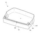
도면에 도시된 것과 같이, 상기 수납 케이스(41)는 전면이 개구되며, 상기 수납 케이스(41)의 개구된 전면은 상기 개구부(403)의 크기와 대응하게 형성될 수 있다. 따라서, 상기 서브 도어(50)의 개방시 상기 개구부(403)가 노출되며, 상기 개구부(403)를 통해서 상기 수납 케이스(41) 내부의 상기 도어 바스켓(43)으로 접근할 수 있다.As shown in the drawing, the front surface of the
그리고, 상기 수납 케이스(41)의 배면에는 회동에 의해 개폐되는 케이스 도어(42)가 구비될 수 있다. 따라서 상기 메인 도어(40)가 개방된 상태에서 상기 케이스 도어(42)를 개방하여 상기 도어 바스켓(43)으로 접근할 수 있다.Further, a
상기 수납 케이스(41)와 상기 케이스 도어(42)에는 고내의 냉기가 상기 수납 케이스(41) 내측으로 유입될수 있도록 하는 케이스 개구(432)와 도어 개구(421)가 형성될 수 있다. 따라서 상기 수납 케이스(41) 내부의 온도는 상기 냉장실(12) 내부의 온도와 동일하게 유지될 수 있다.A
그리고, 상기 메인 도어(40)의 배면 보다 상세하게는 상기 개구부(403)의 양측면에는 상기 도어 바스켓(43)이 장착될 수 있는 성형단이 형성될 수 있다. 상기 성형단은 요철 구조로 형성될 수 있으며, 상기 도어 바스켓(43)의 탈착이 가능하도록 구성될 수 있다.Further, more specifically, on the rear surface of the
도 9는 본 발명의 실시 예에 의한 도어 바스켓의 사시도이다. 그리고, 도 10은 상기 도어 바스켓의 분해 사시도이다. 그리고, 도 11은 상기 도어 바스켓의 디바이딩 부재의 사용 상태를 보인 사시도이다.9 is a perspective view of a door basket according to an embodiment of the present invention. And, Figure 10 is an exploded perspective view of the door basket. And, Figure 11 is a perspective view showing a state of use of the dividing member of the door basket.
도면에 도시된 것과 같이, 상기 도어 바스켓(43)은 상면이 개구되도록 형성되며 상기 개구부(403)의 내측에 배치되는 장착부(431)가 형성된다. 상기 장착부(431)는 상기 개구부(403)의 폭과 대응하는 폭을 가지며, 양측면에 상기 개구부(403)의 성형단과 결합되는 장착홈(4311)이 형성될 수 있다.As shown in the drawing, the
상기 서브 도어(50)의 배면을 향하는 상기 장착부(431)의 후면(도 9에서 전면)은 경사지게 형성될 수 있다. 따라서, 상기 서브 도어(50)의 배면과 상기 장착부(431)의 후면 사이에는 소정의 간격이 형성될 수 있으며, 아래에서 설명할 도어 라이팅 유닛(49)에서 조사되는 빛을 가리지 않고 상기 개구부(403) 전체를 밝힐 수 있게 된다.The rear (front in FIG. 9) of the mounting
그리고, 상기 도어 바스켓(43)에는 디바이딩 부재(432)와 상기 디바이딩 부재(432)가 설정 각도에서 고정될 수 있도록 하는 스토퍼(433) 그리고 상기 스토퍼(433)의 장착을 위한 스토퍼 캡(434)을 포함하여 구성될 수 있다.In addition, the
상기 디바이딩 부재(432)는 와이어 또는 봉재로 형성될 수 있으며, 소정의 직경을 가지는 원형 단면을 가질 수 있다. 그리고, 상기 디바이딩 부재(432)는 상기 장착부(431)를 가로지르도록 연장되는 구획부(4321)와, 상기 구획부(4321)의 양단에서 수직하게 절곡되는 제 1 절곡부(4322)와, 상기 제 1 절곡부(4322)에서 다시 수직하게 절곡되는 제 2 절곡부(4323) 그리고, 제 2 절곡부(4323)의 양단에서 외측으로 절곡되어 상기 스토퍼(433)에 삽입되는 삽입부(4324)로 구성될 수 있다.The dividing
상기 스토퍼(433)는 상기 장착부(431)의 내측면에 장착되며, 좌우 양측면에 배치되어 상기 디바이딩 부재(432)를 고정하게 된다. 상기 스토퍼(433)는 원통 형상으로 형성될 수 있으며, 상기 장착부(431)와 접하는 일측면에는 상기 스토퍼 캡(434)이 장착되는 캡 삽입구(4331)가 형성될 수 있다. 그리고, 상기 캡 삽입구(4331)의 외측에는 상기 스토퍼(433)를 상기 장착부(431)에 고정하기 위한 스토퍼 후크(4332)가 형성될 수 있다.The
그리고, 양측에 배치된 상기 스토퍼(433)의 마주보는 면의 중앙에는 상기 디바이딩 부재(432)의 삽입부(4324)가 삽입되는 센터 홀(4333)이 형성될 수 있다. 그리고, 상기 센터 홀(4333)을 중심으로 상기 스토퍼(433)의 둘레는 내측으로 함몰된 고정홈이 형성될 수 있다. 상기 고정홈은 상기 디바이딩 부재(432)의 외측면 형상과 대응하는 형상으로 형성되어 상기 디바이딩 부재(432)의 제 2 절곡부(4323)를 수용하여 고정한다.In addition, a
상기 고정홈은 상기 디바이딩 부재(432)가 제 1 위치에 위치할 수 있도록 하는 제 1 고정홈(4334)과 제 2 위치에 위치할 수 있도록 하는 제 2 고정홈(4335) 그리고 제 3 위치에 위치할 수 있도록 하는 제 3 고정홈(4336)으로 구성될 수 있다. 상기 제 1 고정홈(4334)과 제 3 고정홈(4336)은 상기 스토퍼(433)의 상하 방향으로 마주보는 위치에 형성되며, 상기 제 2 고정홈(4335)은 상기 제 1 고정홈(4334)과 제 3 고정홈(4336)의 사이의 중간 지점에 형성될 수 있다. 상기 고정홈들은 각각 90°각도로 회전된 지점에 배치될 수 있으며, 상기 디바이딩 부재(432)를 각각 90°각도만큼 고정된 위치에서 고정시킬 수 있다.The fixing groove is in a
즉, 상기 제 1 위치는 상기 제 2 절곡부(4323)가 제 1 고정홈(4334)에 삽입된 상태가 된다. 이와 같은 상태에서는 도 9에서와 같이 상기 디바이딩 부재(432)의 구획부(4321)가 상기 도어 바스켓(43)의 내측 벽면에 밀착되는 구조가 되어 상기 도어 바스켓(43) 내부의 공간 전체를 하나의 수납 공간으로 사용할 수 있다.That is, the first position is a state in which the second
그리고, 상기 제 2 위치는 상기 제 2 절곡부(4323)가 제 2 고정홈(4335)에 삽입된 상태가 된다. 이와 같은 상태에서는 상기 디바이딩 부재(432)의 구획부(4321)가 상기 도어 바스켓(43)의 내측 벽면으로부터 떨어진 위치에 위치하여 상기 도어 바스켓(43)의 내부 공간을 두개의 공간으로 구획하게 된다. 이때, 상기 구획부(4321)의 위치는 상기 스토퍼(433)의 위치에서 상기 제 2 절곡부(4323)의 길이만큼 더 떨어진 위치에 위치하여 공간을 구획하게 된다.In addition, the second position is a state in which the second
그리고, 상기 제 3 위치는 상기 제 2 절곡부(4323)가 제 3 고정홈(4336)에 삽입된 상태가 된다. 이와 같은 상태에서는 제 2 위치에서와 마찬가지로 상기 디바이딩 부재(432)의 구획부(4321)가 상기 도어 바스켓(43)의 내측 벽면으로부터 떨어진 위치에 위치하여 상기 도어 바스켓(43)의 내부 공간을 두개의 공간으로 구획하게 된다.Further, the third position is a state in which the second
이때, 상기 구획부(4321)의 위치는 상기 스토퍼(433)의 위치에서 상기 제 1 절곡부(4322)의 길이만큼 더 떨어진 위치에 위치하여 공간을 구획하게 된다. 상기 제 1 절곡부(4322)와 제 2 절곡부(4323)의 길이가 다르게 형성되므로, 사용자는 상기 제 1 절곡부(4322)와 제 2 절곡부(4323)의 길이 차이만큼 생기는 공간의 구획 정도에 따라 선택하여 사용할 수 있게 된다.In this case, the
특히, 도 11에서 도시된 것과 같이 제 2 위치와 제 3 위치에 상기 디바이딩 부재(432)를 위치시켜 상기 도어 바스켓(43)의 내부 공간을 2개로 구획하게 되는 경우 폭이 좁고 높이가 높아 쓰러지기 쉬운 소스 병 또는 튜브 용기들이 효과적으로 보관될 수 있다.In particular, as shown in FIG. 11, when the dividing
한편, 상기 장착부(431)의 양측면에는 스토퍼 고정홀(435)이 형성된다. 상기 스토퍼 고정홀(435)에는 고정홈(4351)이 더 형성되며, 상기 스토퍼 후크(4332)가 걸림 구속될 수 있도록 한다. 따라서, 상기 장착부(431)의 내측면에는 상기 스토퍼(433)가 회전되지 않도록 고정될 수 있다. 그리고, 상기 장착부(431)의 외측에 상기 스토퍼 캡(434)이 구비될 수 있다. 상기 스토퍼 캡(434)은 상기 스토퍼 고정홀(435)에 장착되며, 상기 스토퍼 캡(434) 중앙의 캡 후크(4341)는 상기 스토퍼 고정홀(435)을 관통하여 상기 캡 삽입구(4331)에 걸림 구속된다. 따라서, 상기 스토퍼(433)는 상기 스토퍼 캡(434)에 의해 한층 더 견고하게 고정될 수 있게 된다.Meanwhile,
도 12는 상기 서브 도어의 정면도이다. 그리고, 도 13은 상기 서브 도어의 분해 사시도이다.12 is a front view of the sub-door. And, Figure 13 is an exploded perspective view of the sub-door.
도면에 도시된 것과 같이, 상기 서브 도어(50)는 외관을 형성하는 아웃 플레이트(55)와 상기 아웃 플레이트(55)의 개구에 장착되는 패널 어셈블리(54) 그리고, 상기 아웃 플레이트(55)와 이격 장착되는 도어 라이너(58) 그리고, 상기 서브 도어(50)의 상면과 하면을 형성하는 어퍼 캡데코(56)와 로어 캡데코(57)로 구성될 수 있다. 본 명세서에서 상기 아웃 플레이트(55)와 상기 도어 라이너(58)와 캡데코(56, 57)를 통칭하여 도어 프레임이라 이름할 수 있다.As shown in the drawing, the sub-door 50 is spaced apart from an
상기 아웃 플레이트(55)는 서브 어퍼 힌지 장착부(501)의 전방에 위치되어 상기 서브 어퍼 힌지 장착부(501)를 커버한다.The
상기 아웃 플레이트(55)는 상기 서브 도어(50)의 전면 외관 및 둘레면 일부를 형성하는 것으로 스테인레스 소재로 형성될 수 있다. 그리고, 상기 아웃 플레이트(55)의 중앙에는 상기 패널 어셈블리(54)가 형성되는 패널 장착구(551)(또는 제 1 개구)가 형성된다. 상기 패널 장착구(551)는 상기 메인 도어(40)의 개구부(403) 내측을 투시하기 위한 공간으로 상기 개구부(403)의 크기와 동일 또는 유사하게 형성될 수 있다. 그리고, 상기 패널 장착구(551)의 둘레를 따라서 내측으로 수직하게 절곡된 플레이트 절곡부(552)가 형성된다. 상기 플레이트 절곡부(552)는 아래에서 설명할 서포트 프레임(60)에 삽입될 수 있도록 절곡되며, 상기 플레이트 절곡부(552)에는 일정간격으로 개구된 플레이트 홀(5521)이 연속 형성될 수 있다.The
상기 패널 어셈블리(54)는 상기 패널 장착구(551)를 차폐할 수 있도록 형성되며, 상기 패널 어셈블리(54)가 장착된 상태에서 상기 패널 어셈블리(54)의 전면은 상기 아웃 플레이트(55)의 전면과 동일 평면으로 형성될 수 있다. 상기 패널 어셈블리(54)는 도어 라이팅 유닛(49)의 온/오프에 따라서 선택적으로 투명하게 보일 수 있으며, 상기 개구부(403)의 내부를 선택적으로 투시할 수 있도록 구성된다. 상기 패널 어셈블리(54)의 구성은 아래에서 보다 상세하게 살펴보기로 한다.The
상기 어퍼 캡데코(56)는 상기 서브 도어(50)의 상면을 형성하는 것으로 상기 아웃 플레이트(55)와 상기 도어 라이너(58) 상단에 결합된다. 그리고, 상기 어퍼 캡데코(56)의 일단에는 상기 서브 어퍼 힌지 장착부(501)가 형성되며, 상기 서브 어퍼 힌지 장착부(501)에는 상기 어퍼 힌지(401)의 힌지축(523)이 삽입되는 어퍼 보스(5012)가 장착될 수 있다.The
상기 로어 캡데코(57)는 상기 서브 도어(50)의 하면을 형성하는 것으로 상기 아웃 플레이트(55)와 상기 도어 라이너(58) 하단에 결합된다. 그리고, 상기 로어 캡데코(57)에는 상기 서브 로어 힌지(52)가 장착되는 위치에 힌지 플레이트(571)가 장착되며, 상기 힌지 플레이트(571)에는 상기 서브 로어 힌지(52)의 힌지축(523)이 삽입되는 로어 보스(572)가 장착될 수 있다.The
한편, 상기 로어 캡데코(57)에는 두개의 발포액 주입구(573)가 형성될 수 있다. 상기 발포액 주입구(573)는 상기 서브 도어(50)의 내측 공간 중 상기 패널 어셈블리(54)의 둘레 측에 단열재를 형성하기 위한 발포액을 주입하기 위해 개구된다. 이때, 상기 서브 도어(50) 내측에 발포액을 원활하게 주입하기 위해서는 상기 패널 어셈블리(54)의 외측과 상기 서브 도어(50)의 내측면 사이의 공간과 대응하는 수직 하방에 개구되도록 형성된다. 따라서, 상기 발포액의 주입시 발포액이 주위의 간섭에 의해 역류되거나 미충되지 않고 효과적으로 주입될 수 있다. 그리고, 상기 발포액 주입구(573)는 상기 로어 캡데코(57)에 장착되는 주입구 캡(574)에 의해 차폐될 수 있다.Meanwhile, two foaming
상기 도어 라이너(58)는 상기 서브 도어(50)의 배면을 형성하는 것으로, 상기 패널 어셈블리(54)가 배치되는 영역에 라이너 개구(581)(또는 제 2 개구)가 형성된다. 그리고, 상기 도어 라이너(58)의 둘레에는 상기 도어 라이너(58)의 형상을 유지하기 위한 라이너 홈(582)이 상기 라이너 개구(581)를 따라 형성될 수 있으며, 상기 라이너 홈(582)은 상기 서브 도어(50)의 배면에서 함몰되어 상기 서브 도어(50)와 상기 메인 도어(40)의 사이를 기밀시키는 서브 가스켓(591)이 장착될 수 있다. 상기 패널 어셈블리(54)는 상기 도어 라이너(58)의 라이너 개구(581)를 커버할 수 있다. 상기 제 2 개구의 크기는 상기 제 1 개구의 크기 보다 작다.The
그리고, 상기 도어 라이너(58)의 일측에는 상기 록킹유닛(232)이 장착될 수 있으며, 아래에서 상세하게 설명할 노크 감지장치(82)와 도어 개방 보조장치(588)가 장착될 수도 있다.In addition, the
한편, 상기 서브 도어(50)의 내측에는 히터(59)가 구비될 수 있다. 상기 히터(59)는 상기 패널 어셈블리(54)의 배면 둘레를 따라 배치된다. 상세히, 상기 히터(59)는 상기 패널 어셈블리(54)의 전면을 형성하는 전면 패널(541)의 배면에 배치될 수 있으며, 상기 전면 패널(541)의 둘레에 형성된 베젤(5411)의 영역에 장착되어 외부로 노출되지 않도록 장착된다.Meanwhile, a
그리고, 상기 아웃 플레이트(55)의 배면에는 상기 패널 장착구(551)의 둘레를 따라 상기 아웃 플레이트(55)와 상기 패널 어셈블리(54)를 고정하기 위한 서포트 프레임(60)이 구비된다. 상기 서포트 프레임(60)은 어퍼 프레임(61)과 로어 프레임(63) 그리고 한쌍의 사이드 프레임(62)의 결합에 의해 구성될 수 있다. 그리고, 상기 패널 장착구(551)의 가장자리를 따라 형성되어 상기 플레이트 절곡부(552)를 수용하고 상기 패널 어셈블리(54)의 배면에 접착될 수 있다. 그리고, 상기 패널 어셈블리(54)의 배면에 배치되는 상기 히터(59)를 고정할 수도 있다. 상기 서포트 프레임(60)에 대해서는 아래에서 보다 상세하게 살펴보기로 한다.In addition, a
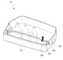
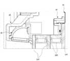
한편, 상기 라이너 개구(581)의 상단에는 도어 라이팅 유닛(49)이 장착될 수 있다. 상기 도어 라이팅 유닛(49)은 상기 메인 도어(40)에 장착되는 다수의 도어 바스켓(43)이 배치되는 부분을 밝힐 수 있으며, 고내측이 고외측보다 더 밝게 보이도록 하여 상기 패널 어셈블리(54)가 투명하게 보일 수 있도록 한다.Meanwhile, a
상기 도어 라이팅 유닛(49)은, 상기 도어 라이너(58)에 장착되는 램프 케이스(491)와, 상기 램프 케이스(491)의 내부에 수용되며 다수의 엘이디(4921)가 배치되는 램프 피시비(492)와, 상기 램프 케이스(491)의 개구된 하면을 차폐하며 상기 개구로 노출되는 램프 커버(493)를 포함하여 구성될 수 있다The
도 14는 본 발명의 실시 예에 의한 도어 라이팅 유닛의 분해 사시도이다. 그리고, 도 15는 도 1의 15-15' 단면도이다. 그리고, 도 16은 도 12의 16-16' 단면도이다.14 is an exploded perspective view of a door lighting unit according to an embodiment of the present invention. And, FIG. 15 is a cross-sectional view of 15-15' of FIG. 1. And, FIG. 16 is a cross-sectional view of 16-16' of FIG. 12.
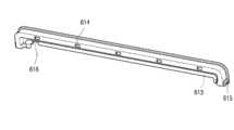
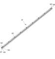
도면을 참조하여 상기 도어 라이팅 유닛(49)에 관하여 보다 상세하게 살펴보면, 상기 도어 라이팅 유닛(49)은 상기 도어 라이너(58)의 라이너 개구(581)의 상단에 형성되는 라이팅 유닛 장착부(583)에 장착될 수 있다.Looking in more detail with respect to the
상기 라이팅 유닛 장착부(583)의 양단에는 케이스 고정부(5831)가 형성되며, 상기 램프 케이스(491)의 양단에서 돌출되는 케이스 리브(4911)가 상기 케이스 고정부(5831)에 걸림 구속되어 상기 도어 라이팅 유닛(49)이 고정 장착될 수 있도록 한다.
상기 램프 케이스(491)는 상기 도어 라이너(58)를 따라 길게 연장 형성되며, 내부에 상기 램프 피시비(492)를 수용할 수 있도록 함몰된 공간을 형성하는 함몰부(4912)를 포함한다. 상세히, 상기 함몰부(4912)는 상기 램프 피시비(492)와 마주보는 면이 라운드지게 형성될 수 있으며, 소정의 곡률을 가지는 라운드면(4913)을 통해 상기 램프 피시비(492)에서 조사되는 빛이 반사되어 상기 램프 케이스(491)로 향하게 된다. 그리고, 상기 함몰부(4912)의 내측면 특히 상기 라운드면(4913)에는 빛의 반사율을 높이기 위한 필름이 부착되거나 코팅이 실시될 수 있다.The
상기 라운드면(4913)과 마주보는 일면에는 상기 램프 피시비(492)가 장착되는 램프 피시비 장착부(4914)가 형성된다. 상기 램프 피시비 장착부(4914)는 상기 램프 피시비(492)가 상기 램프 케이스의 내측에서 상기 램프 커버(493)와 교차되는 방향으로 고정 장착될 수 있도록 형성된다.A lamp
그리고, 램프 피시비 장착부(4914)의 일측에는 상기 램프 피시비(492)와 연결되는 전선(L)이 출입되는 전선 출입구(4915)가 형성될 수 있다. 상기 전선 출입구(4915)는 상기 서브 도어(50)의 내측 공간으로 안내될 수 있으며, 상기 서브 어퍼 힌지(51)의 힌지축(523)을 통해 출입될 수 있다.In addition, an
상기 램프 커버(493)는 상기 함몰부(4912)의 라운드면(4913)에서 반사되는 빛이 투과될 수 있도록 형성되며, 상기 함몰부(4912)의 개구를 차폐한다. 상기 램프 커버(493)는 상기 라운드면(4913)에서 반사되어 고르게 퍼지는 빛이 투과될 수 있도록 투명 또는 반투명하게 형성된다. 따라서, 상기 램프 커버(493)를 통과하는 빛은 간접 조명 방식으로 고내측을 밝히게 되며 면발광과 같은 효과를 가지게 된다.The
그리고, 상기 램프 커버(493)는 보다 효과적으로 빛을 확산시키기 위해 필름이 부착되거나, 코팅처리될 수 있다. 그리고, 필요에 따라 상기 램프 커버(493)의 사출 성형시 빛을 확산시키는 입자 또는 소재가 첨가될 수도 있다.In addition, the
상기 도어 라이팅 유닛이 장착되는 상기 라이팅 유닛 장착부는 상기 개구부의 내측으로 연장되며, 상기 램프 커버는 상기 도어 라이팅 유닛의 장착시 상기 개구부의 상단에서 하방으로 빛을 조사하게 된다.The lighting unit mounting portion on which the door lighting unit is mounted extends to the inside of the opening, and the lamp cover irradiates light downward from the upper end of the opening when the door lighting unit is mounted.
상기 개구부(403) 상에 장착되는 다수의 상기 도어 바스켓(43)의 후단은 상기 서브 도어(50)의 배면과 이격되며, 상기 도어 라이팅 유닛(49)보다 더 고내측에 위치하게 된다. 따라서, 도 15에 도시된 것과 같이, 상기 도어 라이팅 유닛(49)에서 하방으로 조사되는 빛이 상기 도어 바스켓(43) 또는 상기 도어 바스켓(43)에 수납된 식품에 의해 가려지는 것을 방지하게 된다.The rear ends of the plurality of
그리고, 상기 패널 어셈블리(54)의 후단과 인접하는 상기 도어 바스켓(43)의 전면은 경사지게 형성되어 상기 도어 라이팅 유닛(49)에 의해 하방으로 조사되는 빛이 간섭되지 않고 상기 개구부 전체를 밝힐 수 있도록 구성될 수 있다.In addition, the front side of the
상기 도어 라이팅 유닛(49)은 사용자의 조작에 따라서 선택적으로 온/오프(ON/OFF) 될 수 있으며, 상기 도어 라이팅 유닛(49)이 온 되면 상기 메인 도어(40)에 형성되는 수납 공간이 밝혀지게 된다. 상기 도어 라이팅 유닛(49)의 점등에 의해 상기 메인 도어(40)의 수납 공간 즉 고내측이 고외측보다 밝아지게 되면 상기 도어 라이팅 유닛(49)에 의해 조사되는 빛은 상기 서브 도어(50)를 투과하게 된다. 따라서, 사용자는 상기 서브 도어(50)를 투명하게 인식할 수 있으며 상기 메인 도어(40) 내측의 수납 공간을 외부에서 상기 서브 도어(50)를 통해 볼 수 있게 된다.The
한편, 상기 패널 어셈블리(54)는 상기 서포트 프레임(60)에 의해 상기 서브 도어(50) 상에 고정 장착될 수 있게 된다. 상기 서포트 프레임(60)은 일측이 상기 아웃 플레이트(55)에 고정될 수 있으며, 다른 일측이 상기 패널 어셈블리(54)와 접착되어 상기 패널 어셈블리(54)가 상기 패널 장착구(551) 상에 고정될 수 있도록 한다.Meanwhile, the
상기 패널 어셈블리(54)에 관하여 보다 상세하게 살펴보면, 상기 패널 어셈블리(54)는 전면 패널(541)과 상기 전면 패널(541)의 후방에 배치되는 적어도 하나 이상의 단열 패널(542) 그리고, 상기 전면 패널(541)과 단열 패널(542) 및 복수의 단열 패널(542) 사이를 지지하는 간봉(543)을 포함하여 구성될 수 있다.Looking in more detail with respect to the
상기 전면 패널(541)은 빛의 투과율 및 반사율에 따라서 내부의 선택적인 투시가 가능한 유리 소재로 형성될 수 있으며, 하프 미러라 부를 수 있다.The
즉, 상기 도어 라이팅 유닛(49)이 켜진 상태에서는 고내측의 빛이 상기 전면 패널(541)을 투과하면서 상기 전면 패널(541)이 투명하게 보이게 된다. 따라서 상기 서브 도어(50) 후방의 고내 공간 또는 상기 메인 도어(40)에 형성된 수납 공간을 상기 서브 도어(50)가 닫힌 상태에서 외부에서 볼 수 있게 된다.That is, when the
그리고, 상기 도어 라이팅 유닛(49)이 꺼진 상태에서는 빛이 상기 전면 패널(541)을 투과하지 못하고 반사되며 따라서 상기 전면 패널(541)은 거울면과 같이 된다. 이와 같은 상태에서는 상기 서브 도어(50) 후방의 고내 공간 또는 상기 메인 도어(40)에 형성된 수납 공간을 외부에서 볼 수 없게 된다.In addition, when the
상기 전면 패널(541)이 하프 미러와 같은 효과를 가질 수 있도록 상기 전면 패널(541)에는 다양한 표면 처리가 될 수 있다. 예를 들어, 상기 전면 패널(541)을 구성하는 유리층의 전면에 티탄화합물을 진공 증착할 수 있다.Various surface treatments may be applied to the
또한, 상기 전면 패널을 구성하는 유리층의 배면에 티탄화합물(TiO2)을 주성분으로 하여 점도조절용 수지와 유기용제 및 첨가제를 포함하여 구성되는 인쇄잉크를 이용하여 실크스크린 인쇄하여 세라믹 인쇄층을 형성할 수도 있다.In addition, a ceramic printed layer is formed by silkscreen printing using a printing ink composed of a resin for viscosity control, an organic solvent, and an additive made mainly of a titanium compound (TiO2 ) on the back of the glass layer constituting the front panel You may.
또한, 전면 패널을 구성하는 유리층의 배면에 철(Iron), 코발트(cobalt), 크롬(chrome)의 3중 레이어로 구성된 하드 코팅층을 대기화학기상증착(APCAVD : Atmospheric Pressure Cemical Vapor Deposition)법에 의해 형성할 수도 있고, 액체 상태의 코팅 물질을 분사하는 스프레이 방식으로 형성할 수도 있다.In addition, a hard coating layer composed of three layers of iron, cobalt, and chrome is applied to the back of the glass layer constituting the front panel by the Atmospheric Pressure Cemical Vapor Deposition (APCAVD) method. Alternatively, it may be formed by spraying a coating material in a liquid state.
상기 유리층의 배면에 세라믹 인쇄층 또는 하드코팅층이 형성되는 경우에는 상기 전면 패널(541)은 상기 전면 패널(541) 외측에서의 빛의 투과율이 20%~30%를 가지도록 형성될 수 있다. 이때, 상기 투과율이 20% 이하가 되면 도어 라이팅 유닛(49)이 온 된 상태에서도 외부에서 볼 때 내부의 투시가 쉽지 않게 되며, 상기 투과율이 30% 이상이 되면 상기 도어 라이팅 유닛(49)이 오프 된 상태에서도 외부에서 볼 때 상기 패널 어셈블리(54)의 전면이 거울면과 같이 보이지 못하고 고내측이 일부 투시될 수 있게 된다.When a ceramic printing layer or a hard coating layer is formed on the rear surface of the glass layer, the
한편, 상기 전면 패널(541)의 배면 둘레를 따라서 형성되는 상기 베젤(5411)은 빛의 투과가 불가능하도록 형성될 수 있으며, 상기 베젤(5411)이 형성되는 상기 전면 패널(541)의 가장자리는 상기 단열 패널(542)보다 더 외측으로 연장되도록 구성된다. 따라서, 베젤(5411)이 형성되는 상기 전면 패널(541)의 배면에는 서포트 프레임(60)과 히터(59) 및 간봉(543)이 상기 전면 패널(541)을 통해 전방으로 노출되지 않도록 한다.Meanwhile, the
그리고, 상기 전면 패널(541)의 하단에 형성된 베젤(5411)에는 상기 노크 감지장치(82)가 배치될 수도 있다. 따라서, 상기 노크 감지장치(82) 또한 외부로 노출되지 않도록 상기 베젤(5411)에 의해 커버될 수 있다.In addition, the
상세히, 상기 베젤(5411)의 영역에는 상기 서포트 프레임(60)이 배치되어 상기 패널 어셈블리(54)를 고정할 수 있다. 그리고, 상기 서포트 프레임(60)에 의해 고정되는 상기 히터(59) 또한 상기 베젤(5411)의 영역에 위치될 수 있게 된다. 따라서, 상기 패널 어셈블리(54)의 가장자리를 따라서 배치되는 히터(59)와 서포트 프레임(60)이 모두 베젤(5411)에 가려지게 되어 외부로 노출되지 않게 된다.In detail, the
그리고, 상기 전면 패널(541)의 배면 둘레에는 간봉(543)이 형성된다. 상기 간봉(543)은 상기 전면 패널(541)과 단열 패널(542)을 서로 이격시키게 되며, 상기 전면 패널(541)과 단열 패널(542)이 서로 이격되도록 하며, 그 사이가 밀봉될 수 있도록 한다.In addition, a
상기 간봉(543)은 복수의 상기 단열 패널(542)의 사이에도 배치될 수 있다. 그리고, 상기 전면 패널(541)과 단열 패널(542) 그리고 복수의 간봉(543)은 접착제에 의해 서로 부착될 수 있으며, 실런트가 도포되어 상기 전면 패널(541)과 단열 패널(542) 그리고 간봉(543)의 사이와 상기 패널 어셈블리(54)의 외측면이 기밀 상태를 유지할 수 있도록 한다. The
상기 단열 패널(542)은 상기 전면 패널(541)보다 크기가 더 작게 형성되어 상기 전면 패널(541)의 내측 영역에 위치될 수 있다. 그리고, 상기 단열 패널(542)은 유리전이온도 이상에서 유리를 전해질 용액에 담가서 화학적으로 강화시킨 화학강화 유리인 것이 바람직하다.The insulating
그리고, 상기 단열 패널(542)의 후면에는 복사에 의한 저장실 내로의 열전달을 줄이기 위한 저방사코팅층이 형성될 수 있다. 상기 저방사코팅층이 형성된 유리를 로이 유리(Low-ε Glass)라고 하는데, 유리의 표면에 보통 은 등을 스퍼터링(Sputtering) 등으로 증착함으로써 저방사코팅층을 형성할 수 있다.In addition, a low-emissivity coating layer may be formed on the rear surface of the
그리고, 상기 간봉(543)에 의해서 형성되는 상기 전면 패널(541)과 단열 패널(542) 사이의 밀폐된 공간 및 복수의 단열 패널 사이의 밀폐된 공간 사이는 진공 상태로 형성되어 단열되도록 할 수 있다.In addition, the sealed space between the
필요에 따라 상기 전면 패널(541)과 단열 패널(542) 사이의 밀폐된 공간 및 복수의 단열 패널(542) 사이의 밀폐된 공간 사이에는 단열을 위한 아르곤 가스와 같은 비활성 기체가 충전될 수 있다. 비활성 기체는 일반 공기에 비해 단열 특성이 더욱 우수하다. 이러한 이유로, 전면 패널(541)과 단열 패널(542) 사이 그리고 복수의 단열 패널(542) 사이에 비활성 기체가 충전되는 소정 공간을 형성하여 단열 성능을 확보하는 것이 가능하다.If necessary, an inert gas such as argon gas for insulation may be filled between the sealed space between the
상기 단열 패널(542)은 단일 패널로 형성되어 상기 전면 패널(541)과 이격되도록 장착될 수도 있으며, 필요에 따라서는 2개 이상의 상기 단열 패널(542)이 이격 배치되도록 구성되는 것도 가능할 것이다.The insulating
도 17은 본 발명의 실시예에 의한 서포트 프레임의 사시도이다.17 is a perspective view of a support frame according to an embodiment of the present invention.
도면에 도시된 것과 같이, 상기 서포트 프레임(60)은 어퍼 프레임(61)과 로어 프레임(63)의 상하방에 배치되며, 상기 어퍼 프레임(61)과 로어 프레임(63)의 사이를 한쌍의 사이드 프레임(62)이 연결하여 사각형 형상을 형성하도록 구성될 수 있다.As shown in the drawing, the
상기 서포트 프레임(60)은 플라스틱 소재로 사출 형성될 수 있다. 상기 서포트 프레임(60)은 조립된 상태에서 상기 아웃 플레이트(55)의 플레이트 절곡부(552)가 삽입될 수 있도록 형성될 수 있으며, 동시에 상기 히터(59)가 고정될 수 있도록 구성될 수 있다.The
상세히, 조립된 상태의 상기 서포트 프레임(60)에는 상기 플레이트 절곡부(552)가 삽입되는 플레이트 삽입부(611,621,631)가 형성될 수 있으며, 상기 플레이트 삽입부(611,621,631)는 상기 서포트 프레임(60) 둘레 전체를 따라 형성될 수 있다. 그리고, 상기 플레이트 삽입부(611,621,631)에는 구속돌기(612,622,632)가 일정 간격으로 다수개 형성될 수 있다. 상기 구속돌기(612,622,632)와 대응하는 상기 플레이트 삽입부(611,621,631) 상에는 다수의 홀(614,624,634)이 형성되어 상기 플레이트 삽입부(611,621,631)로의 발포액 유입을 용이하게 한다. 그리고, 상기 구속돌기(612,622,632)는 상기 다수의 홀(614,624,634)과 대응하는 위치에 형성됨으로써 사출 성형시 상기 구속돌기(612,622,632)의 성형을 용이하게 한다.In detail, the
그리고, 상기 서포트 프레임(60)에는 상기 히터(59)의 배치와 대응하도록 히터 홈(613,623,633)이 형성되어 상기 히터(59)가 장착될 수 있도록 한다.In addition,
상기 서포트 프레임(60)의 전체 폭은 상기 패널 어셈블리(54)가 구비되는 베젤(5411)에 의해 가려질 수 있도록 형성된다. 그리고, 상기 단열 패널(542)의 외측단까지 연장 형성될 수 있다.The entire width of the
이하에서는 상기 서포트 프레임을 구성하는 각 구성을 도면을 참조하여 보다 상세하게 살펴보기로 한다.Hereinafter, each component constituting the support frame will be described in more detail with reference to the drawings.
도 18은 상기 서포트 프레임 상부의 결합 구조를 보인 분해 사시도이다. 그리고, 도 19는 상기 서포트 프레임을 구성하는 어퍼 프레임의 사시도이다.18 is an exploded perspective view showing a coupling structure of an upper portion of the support frame. And, Fig. 19 is a perspective view of an upper frame constituting the support frame.
도면에 도시된 것과 같이, 상기 어퍼 프레임(61)은 상기 서포트 프레임(60)의 상부를 형성한다. 상기 어퍼 프레임(61)의 양단은 하방으로 절곡되며, 상기 사이드 프레임(62)의 상단과 결합될 수 있다. 이를 위해 상기 어퍼 프레임(61)의 양단은 하방으로 절곡된 후 개구될 수 있다. 그리고, 상기 어퍼 프레임(61)의 양단에는 사이드 프레임(62)의 상단에 형성되는 사이드 후크(625)가 삽입되는 어퍼 후크 홈(615)이 형성될 수 있다.As shown in the drawing, the
그리고, 상기 아웃 플레이트(55)의 배면과 접하는 상기 어퍼 프레임(61)의 일면에는 상기 어퍼 삽입부(611)가 함몰 형성될 수 있다. 상기 어퍼 삽입부(611)는 상기 플레이트 절곡부(552) 중 상기 패널 장착구(551)의 상단을 형성하는 부분이 삽입될 수 있도록 형성된다.In addition, the
이때, 상기 어퍼 삽입부(611)는 상기 아웃 플레이트(55)의 두께 및 상기 어퍼 삽입부(611)에 형성되는 어퍼 구속돌기(612)의 돌출된 높이보다 더 두꺼운 두께로 형성될 수 있다. 따라서, 상기 어퍼 삽입부(611)로 상기 플레이트 절곡부(552)가 삽입될 수 있으며, 삽입 후 상기 플레이트 홀(5521)에 상기 어퍼 구속돌기(612)가 삽입되어 상기 아웃 플레이트(55)와 어퍼 프레임(61)이 서로 결합될 수 있다.In this case, the
그리고, 상기 어퍼 삽입부(611) 보다 더 내측 즉, 상기 서포트 프레임(60)의 개구측에는 어퍼 히터 홈(613)이 형성되어 상기 전면 패널(541)의 가장자리를 따라 배치되는 히터(59) 중 상부의 부분을 수용할 수 있도록 한다. 그리고, 상기 어퍼 히터 홈(613)의 일측에는 전선 출입부(616)가 개구되어 상기 히터(59)와 연결되는 전선(L)이 출입될 수 있다.Further, an
한편, 상기 어퍼 구속돌기(612)와 대응하는 상기 어퍼 삽입부(611) 상에는 어퍼 홀(614)이 더 형성되며, 상기 어퍼 홀(614)의 사이로 단열재를 형성하기 위한 발포액이 출입될 수 있게 되어 상기 어퍼 프레임(61)의 어퍼 삽입부(611) 내부까지 빈틈없이 발포액이 채워질 수 있다.On the other hand, an
도 20은 상기 서포트 프레임을 구성하는 사이드 프레임을 전방에서 본 사시도이다. 그리고, 도 21은 상기 서포트 프레임을 구성하는 사이드 프레임을 후방에서 본 사시도이다.Fig. 20 is a perspective view of a side frame constituting the support frame as viewed from the front. And, Fig. 21 is a perspective view of a side frame constituting the support frame as viewed from the rear.
도면에 도시된 것과 같이, 상기 사이드 프레임(62)은 상기 서포트 프레임(60)의 양측면을 형성한다. 상기 사이드 프레임(62)은 상기 어퍼 프레임(61)과 로어 프레임(63)의 사이를 연결할 수 있는 길이로 형성된다. 이를 위해 상기 사이드 프레임(62)의 상단과 하단에는 사이드 후크(625)가 형성된다. 그리고 상기 사이드 후크(625)는 상기 어퍼 프레임(61)의 어퍼 후크 홈(615) 그리고 로어 프레임(63)의 로어 후크 홈(635)과 결합될 수 있다.As shown in the drawing, the
그리고, 상기 사이드 프레임(62)의 상단과 하단에는 상기 어퍼 프레임(61)의 어퍼 삽입부(611)와 로어 프레임(63)의 로어 삽입부(631)에 삽입될 수 있는 사이드 리브(626)가 형성될 수 있다. 따라서, 상기 사이드 프레임(62)과 상기 어퍼 프레임(61) 및 로어 프레임(63)이 서로 안정적인 결합상태를 유지할 수 있도록 한다.In addition, a
그리고, 상기 아웃 플레이트(55)의 배면과 접하는 상기 사이드 프레임(62)의 일면에는 상기 사이드 삽입부(621)가 함몰 형성될 수 있다. 상기 사이드 삽입부(621)는 상기 플레이트 절곡부(552) 중 상기 패널 장착구(551)의 양측단을 형성하는 부분이 삽입될 수 있도록 형성된다.In addition, the
이때, 상기 사이드 삽입부(621)는 상기 아웃 플레이트(55)의 두께 및 상기 사이드 삽입부(621)에 형성되는 사이드 구속돌기(622)의 돌출된 높이보다 더 두꺼운 두께로 형성될 수 있다. 따라서, 상기 사이드 삽입부(621)로 상기 플레이트 절곡부(552)가 삽입될 수 있으며, 삽입 후 상기 플레이트 홀(5521)에 상기 사이드 구속돌기(622)가 삽입되어 상기 아웃 플레이트(55)와 사이드 프레임(62)이 서로 결합될 수 있다.In this case, the
그리고, 상기 사이드 삽입부(621) 보다 더 내측에는 사이드 히터 홈(623)이 형성되어 상기 전면 패널(541)의 가장자리를 따라 배치되는 히터(59) 중 측면부를 수용할 수 있도록 한다.Further, a
한편, 상기 사이드 구속돌기(622)와 대응하는 상기 사이드 삽입부(621) 상에는 사이드 홀(624)이 더 형성되며, 상기 사이드 홀(624)의 사이로 발포액이 출입될 수 있게 되어 상기 사이드 프레임(62)의 사이드 삽입부(621) 내부까지 빈틈없이 발포액이 채워질 수 있다.On the other hand, a
도 22는 상기 서포트 프레임 하부의 결합 구조를 보인 분해 사시도이다. 그리고, 도 23은 상기 서포트 프레임을 구성하는 로어 프레임의 사시도이다.22 is an exploded perspective view showing a coupling structure under the support frame. And, Fig. 23 is a perspective view of a lower frame constituting the support frame.
도면에 도시된 것과 같이, 상기 로어 프레임(63)은 상기 서포트 프레임(60)의 하부를 형성한다. 상기 로어 프레임(63)의 양단은 상방으로 절곡되며, 상기 사이드 프레임(62)의 하단과 결합될 수 있다. 이를 위해 상기 로어 프레임(63)의 양단은 상방으로 절곡된 후 개구될 수 있다. 그리고, 상기 로어 프레임(63)의 양단에는 사이드 프레임(62)의 하단에 형성되는 사이드 후크(625)가 삽입되는 로어 후크 홈(635)이 형성될 수 있다.As shown in the drawing, the
그리고, 상기 아웃 플레이트(55)의 배면과 접하는 상기 로어 프레임(63)의 일면에는 상기 로어 삽입부(631)가 함몰 형성될 수 있다. 상기 로어 삽입부(631)는 상기 플레이트 절곡부(552) 중 상기 패널 장착구(551)의 하단을 형성하는 부분이 삽입될 수 있도록 형성된다.In addition, the
이때, 상기 로어 삽입부(631)는 상기 아웃 플레이트(55)의 두께 및 상기 로어 삽입부(631)에 형성되는 로어 구속돌기(632)의 돌출된 높이보다 더 두꺼운 두께로 형성될 수 있다. 따라서, 상기 로어 삽입부(631)로 상기 플레이트 절곡부(552)가 삽입될 수 있으며, 삽입 후 상기 플레이트 홀(5521)에 상기 로어 구속돌기(632)가 삽입되어 상기 아웃 플레이트(55)와 로어 프레임(63)이 서로 결합될 수 있다.In this case, the
그리고, 상기 로어 삽입부(631) 보다 더 내측에는 로어 히터 홈(633)이 형성되어 상기 전면 패널(541)의 가장자리를 따라 배치되는 히터(59) 중 하단부를 수용할 수 있도록 한다.In addition, a
한편, 상기 로어 구속돌기(632)와 대응하는 상기 로어 삽입부(631) 상에는 로어 홀(634)이 더 형성되며, 상기 로어 홀(634)의 사이로 발포액이 출입될 수 있게 되어 상기 로어 프레임(63)의 로어 삽입부(631) 내부까지 빈틈없이 발포액이 채워지고 단열재가 형성될 수 있다.On the other hand, a
그리고, 상기 로어 프레임(63)의 일측에는 아래에서 상세하게 설명할 노크 감지장치(82)가 노출되는 감지장치 홀(636)이 형성된다. 따라서, 상기 노크 감지장치(82)는 상기 로어 프레임(63)의 후방에 구비되되 상기 감지장치 홀(636)을 통해 상기 전면 패널(541)의 배면에 밀착될 수 있게 된다.Further, a
도 24는 도 12의 24-24' 단면도이다. 그리고, 도 25는 도 12의 25-25' 단면도이다. 그리고, 도 26는 도 12의 26-26' 단면도이다. 그리고, 도 27은 도 12의 27-27' 단면도이다.24 is a cross-sectional view of FIG. 12 24-24'. And, FIG. 25 is a cross-sectional view 25-25' of FIG. 12. And, FIG. 26 is a cross-sectional view 26-26' of FIG. 12. And, FIG. 27 is a cross-sectional view 27-27' of FIG. 12.
이들 도면을 참조하면, 상기 어퍼 프레임(61)과 사이드 프레임(62) 그리고 로어 프레임(63)은 모두 상기 전면 패널(541)의 돌출된 가장자리에 부착된다. 상기 베젤(5411)이 형성된 상기 전면 패널(541)의 배면에 상기 어퍼 프레임(61)과 사이드 프레임(62) 그리고 로어 프레임(63)이 접착시트(5412) 또는 접착제에 의해 부착될 수 있다.Referring to these drawings, the
그리고, 상기 어퍼 프레임(61)과 사이드 프레임(62) 그리고 로어 프레임(63)의 단부는 상기 단열 패널(542)의 외측단까지 연장될 수 있으며, 상기 어퍼 프레임(61)과 사이드 프레임(62) 그리고 로어 프레임(63)의 단부에 어퍼 히터 홈(613)과 사이드 히터 홈(623) 및 로어 히터 홈(633)이 형성되어 전면에 비해 상대적으로 배면의 온도가 낮은 상기 전면 패널(541)의 가장자리를 가열하게 된다. 그리고, 상기 히터(59)와 상기 전면 패널(541)의 사이에는 소정의 폭을 가지는 알루미늄 시트(5413)가 배치될 수 있다. 따라서 상기 히터(59)의 발열시 상기 전면 패널(541)의 베젤(5411)이 형성된 영역을 고르게 가열할 수 있다.In addition, ends of the
그리고, 상기 전면 패널(541)에 부착된 상태의 상기 어퍼 프레임(61)과 사이드 프레임(62) 그리고 로어 프레임(63)의 상기 어퍼 삽입부(611)와 사이드 삽입부(621) 및 로어 삽입부(631)에는 상기 아웃 플레이트(55)의 플레이트 절곡부(552)가 삽입된다.And, the
상기 플레이트 절곡부(552)는 도 24에 도시된 것과 같이, 상기 사이드 삽입부(621)의 내측에 삽입된 상태에서 상기 전면 패널(541) 측으로 밀착된다. 그리고 상기 플레이트 절곡부(552)의 플레이트 홀(5521)은 상기 사이드 구속돌기(622)와 걸림 구속되어 상기 아웃 플레이트(55)와 상기 사이드 프레임(62)이 고정 결합될 수 있도록 한다. 즉, 상기 플레이트 절곡부(552)가 형성하는 영역 내에 상기 전면 패널(541)이 위치될 수 있다.As shown in FIG. 24, the plate
그리고, 상기 사이드 홀(624)을 통해 발포액이 상기 사이드 삽입부(621) 내측으로 유입될 수 있으며, 유입되는 발포액은 상기 플레이트 절곡부(552)를 상기 전면 패널(541)측으로 밀어 밀착시키게 된다.In addition, the foaming liquid may be introduced into the
이와 같은 구조로 인하여 상기 아웃 플레이트(55)에 형성되는 상기 플레이트 절곡부(552)는 상기 전면 패널(541)의 외측단에 밀착될 수 있게 된다. 따라서, 전방에서 볼 때 상기 패널 장착구(551)를 형성하는 상기 아웃 플레이트(55)의 단부와 상기 전면 패널(541)의 외측단 사이는 틈새 간격이 최소화 될 수 있다.Due to this structure, the plate
한편, 도 24를 참조하여 상기 서포트 프레임의 일 구성인 사이드 프레임(62)의 구조를 다시 한 번 살펴보면, 상기 사이드 프레임(62)은 상기 사이드 삽입부(621)의 내측면에 상기 플레이트 절곡부(522)와 접하여 지지하는 제 1 면이 형성되고, 상기 전면 패널(541)의 배면을 지지하는 제 2 면이 형성되며, 상기 아웃 플레이트(55)의 배면을 지지하는 제 3 면이 형성된다. 그리고, 상기 제 2 면과 제 3 면은 서로 평행하게 배치되고, 상기 제 1 면과 제 2 면은 서로 교차되도록 배치되는 구조를 가짐을 알 수 있다. 상기 제 1 면과 제 3 면의 용어는 상호 변경 가능하다.Meanwhile, referring to FIG. 24, looking at the structure of the
상기 제 2 면은 상기 간봉과 상기 플레이트 절곡부(522) 사이에 위치될 수 있다. 상기 제 2 면은 상기 전면 패널(541)의 베젤(5411)과 대응되는 위치에 배치될 수 있다. 상기 플레이트 절곡부(522)는 상기 제 1 면과 제 2 면 사이에 위치될 수 있다.The second surface may be positioned between the gap rod and the plate
상기 전면 패널(541)과 단열 패널은 제1방향으로 배열될 수 있다. 상기 전면 패널(541)은 전면과, 배면과, 전면과 배면을 연결하는 측면을 포함할 수 있다.The
상기 플레이트 절곡부(522)의 상기 제1방향으로의 길이는 상기 전면 패널(541)의 상기 제1방향으로의 길이 보다 길다.A length of the plate
본 실시 예에서 상기 사이드 프레임(62)에서 상기 제 2 면을 포함하는 부분은 제 1 부분이라 하고, 상기 제 3 면을 포함하는 부분을 제 2 부분이라 할 수 있다. 상기 홀(624)을 포함하는 부분을 제 3 부분이라 할 수 있다.In the present exemplary embodiment, a portion of the
도면을 참조하면, 상기 사이드 프레임(62)의 제 1 부분은 상기 전면 패널(541)의 배면에 대응되고, 상기 제 2 부분은 상기 아웃 플레이트(55)의 일면과 대응된다. 일 예로, 상기 아웃 플레이트(55)의 일면은 배면이며, 상기 제 2 부분은 상기 아웃 플레이트(55)의 배면과 접촉할 수 있다.Referring to the drawings, a first portion of the
상기 사이드 프레임(62)의 제 1 부분은 상기 제 2 부분에 비하여 저장공간에 더 가깝게 위치될 수 있다. 상기 플레이트 삽입부(611)는 상기 제 1 부분과 상기 제 2 부분 사이에 위치될 수 있다. 상기 제 1 부분은 일 예로 상기 전면 패널(541)의 베젤(5411)에 접촉될 수 있다.The first portion of the
상기 사이드 프레임(62)의 제 3 부분은, 상기 아웃 플레이트(55)의 배면을 바라보도록 배치될 수 있다. 상기 도어의 전후 방향을 기준으로 상기 제 1 부분과 상기 제 3 부분은 오프셋 되어 있다. 즉, 상기 제 1 부분과 상기 제 3 부분은 전후 방향으로 이격되어 배치될 수 있다.The third portion of the
상기 아웃 플레이트(55), 상기 도어 라이너(58) 및 상기 패널 어셈블리(54)는 단열재를 형성하기 위한 발포액이 채워지는 단열 공간을 형성할 수 있다. 상기 서포트 프레임(60)은 상기 단열 공간 내에 위치될 수 있다.The
상기 단열재는 상기 사이드 프레임(62)과 접촉할 수 있다. 일 예로 상기 단열재는 상기 제 1 부분 내지 제 3 부분과 접촉할 수 있다.The insulating material may contact the
이와 같은 구조는 상기 사이드 프레임(62) 뿐만 아니라 상기 어퍼 프레임(61)과 로어 프레임(63)도 동일하며, 설명의 중복을 방지하기 위해 그 상세한 설명은 생략하기로 한다.In this structure, not only the
도 28은 본 발명의 실시 예에 의한 노크 감지장치의 결합 구조를 전방에서 본 분해 사시도이다. 그리고, 도 29는 본 발명의 실시 예에 의한 노크 감지장치의 결합 구조를 후방에서 본 분해 사시도이다.28 is an exploded perspective view as viewed from the front of a coupling structure of a knock detection device according to an embodiment of the present invention. And, FIG. 29 is an exploded perspective view of a coupling structure of a knock detection device according to an embodiment of the present invention as viewed from the rear.
도면에 도시된 것과 같이, 상기 도어 라이너(58)의 하부에는 상기 노크 감지장치(82)가 삽입될 수 있는 센서 개구(584)가 형성된다. 상기 센서 개구(584)는 상기 노크 감지장치(82)를 외측에서 삽입 장착할 수 있도록 형성된다. 그리고, 상기 노크 감지장치(82)의 노크 감지 신호를 처리하기 위한 감지장치 피시비(83)가 장착되는 인서트 커버(585)와 대응하는 형상으로 형성되어 상기 인서트 커버(585)에 의해 차폐될 수 있도록 형성된다.As shown in the drawing, a
상기 인서트 커버(585)는 장착된 상태에서 외측면이 상기 도어 라이너(58)의 외측면과 동일 형상을 가지도록 한다. 따라서, 상기 도어 라이너(58)에 형성된 라이너 홈(582)이 지나는 위치에 상기 인서트 커버(585)가 장착되며, 따라서 상기 인서트 커버(585)에는 상기 라이너 홈(582)과 연결되는 커버 홈(5854)이 형성된다. 따라서 상기 서브 가스켓(591)은 상기 라이너 홈(582)과 상기 커버 홈(5854)을 지나도록 장착될 수 있다.The
상기 센서 개구(584)의 둘레를 따라 감지장치 수용부(586)가 형성될 수 있다. 상기 감지장치 수용부(586)는 상기 노크 감지장치(82)를 수용하는 공간 일부를 형성하는 것으로 상기 아웃 플레이트(55)측으로 연장 형성되며, 수용부 케이스(587)와 결합되어 상기 노크 감지장치(82)가 수용되는 공간을 형성하게 된다.A sensing
상기 수용부 케이스(587)는 상기 감지장치 수용부(586)의 전단과 결합되어 상기 노크 감지장치(82)를 수용하는 나머지 공간을 형성하게 된다. 그리고, 상기 수용부 케이스(587)의 양단에는 스크류가 체결되는 상기 케이스 결합부(5871)가 형성되어 상기 수용부 케이스(587)가 상기 감지장치 수용부(586)에 결합 고정될 수 있도록 한다.The receiving
그리고, 상기 수용부 케이스(587)는 노크 감지장치(82)의 전단이 삽입되는 감지장치 삽입부(5872)가 형성된다. 그리고, 상기 감지장치 삽입부(5872)의 전면은 삽입부 홀(5873)이 개구되며, 상기 감지장치 삽입부(5872)는 상기 로어 프레임(63)의 감지장치 홀(636)에 삽입된다. 따라서, 상기 감지장치 삽입부(5872) 내측에 삽입된 상기 노크 감지장치(82)는 그 전면이 상기 삽입부 홀(5873)과 상기 감지장치 홀(636)을 지나 상기 전면 패널(541)의 배면에 밀착될 수 있게 된다.In addition, the
서로 접하는 상기 감지장치 수용부(586)의 단부와 수용부 케이스(587)의 단부는 서로 대응하는 경사를 가지는 구조로 형성되어 방향성을 가지고 서로 결합될 수 있도록 한다. 그리고, 상기 감지장치 수용부(586)와 수용부 케이스(587)의 결합에 의해 상기 노크 감지장치(82) 및 상기 감지장치 피시비(83)가 장착될 수 있는 공간이 상기 서브 도어(50)의 내부에 형성된다.The end portions of the sensing
상기 감지장치 수용부(586)와 상기 수용부 케이스(587)는 서로 결합된 상태에서는 상기 서브 도어(50)의 내측에 발포액이 주입되는 공간과는 독립된 공간을 형성하게 된다. 따라서 사용자는 상기 서브 도어(50)에 발포를 실시한 후 상기 센서 개구(584)를 통해서 상기 노크 감지장치(82)를 삽입 장착할 수 있다.When the sensing
한편, 상기 인서트 커버(585)는 상기 센서 개구(584)를 차폐하는 커버부(5851)와 상기 감지장치 피시비(83)가 장착된 피시비 삽입부(5852)로 구성될 수 있다. 상기 커버부(5851)는 상기 센서 개구(584)와 대응하는 형상으로 형성되어 상기 센서 개구(584)를 차폐하고 상기 도어 라이너(58)의 외관 일부를 형성하게 된다. 그리고, 상기 커버부(5851)의 일측에는 스크류 홀(5853)이 형성되어 스크류에 의해 상기 도어 라이너(58)에 고정될 수 있다.Meanwhile, the
그리고, 상기 피시비 삽입부(5852)는 상기 커버부(5851)에서 연장 형성되며, 상기 인서트 커버(585)의 장착시 상기 감지장치 수용부(586)의 내측으로 삽입될 수 있도록 형성된다. 그리고, 상기 커버부(5851)는 상기 감지장치 피시비(83)의 크기와 대응하게 형성되어 상기 감지장치 피시비(83)가 장착된 상태에서 상기 인서트 커버(585)가 상기 센서 개구(584)에 삽입 장착되도록 할 수 있다. 그리고 상세하게 도시되지는 않았지만 상기 노크 감지장치(82)와 연결된 전선(L)은 인접한 위치의 상기 감지장치 피시비(83)와 연결될 수 있다. 상기 감지장치 피시비(83)는 상기 노크 감지장치(82)의 측방에 배치될 수 있으므로, 상기 감지장치 피시비(83)는 상기 노크 감지장치(82)와 인접 거리에서 연결될 수 있게 된다.Further, the
신호를 처리하는 피시비가 원거리에 위치하게 되는 경우, 감지된 신호가 처리되기 위해서 신호선을 통해 이동하게 될 때 발생되는 노이즈가 증가될 수 있는 문제가 있다. 하지만, 상기 감지장치 피시비(83)를 노크 감지장치(82)가 장착되는 위치에 함께 배치함으로써 메인 제어부(2)는 유효한 노크 온 신호 입력 여부만 수신하게 된다. 이를 통해, 메인 제어부(2)와 감지장치 피시비(83) 사이의 신호선에 의한 노이즈 영향을 최소화할 수 있다. 즉, 상기 메인 제어부(2)는 상기 감지장치 피시비(83)를 통해 노이즈가 최소화된 신호를 입력받게 된다. 따라서, 정확한 인식률의 확보가 가능하게 된다.When a PCB processing signal is located at a long distance, there is a problem in that noise generated when a detected signal is moved through a signal line to be processed may increase. However, by arranging the
특히, 상기 노크 감지장치(82)의 경우 마이크(8211)에 의해 출력되는 신호는 mV 단위임에 비해 냉장고의 전체적인 구동을 제어하는 메인 제어부(2)는 기본적으로 V 단위의 신호를 입력받는 것이 일반적이다. 따라서, 이러한 물리적인 신호의 스케일 차이로 인해 메인 제어부(2)에서 정상적인 노크 온 신호인지를 판단하는 것은 바람직하지 않다. In particular, in the case of the
냉장고는 대전압/대전류를 사용하는 전자기기이다. 따라서, 전기적인 노이즈 발생량이 상대적으로 크다. 이는 마이크(8211)에 의해 출력되는 mV 단위의 신호가 전기적인 노이즈에 더욱 취약할 수 있음을 의미하게 된다.Refrigerators are electronic devices that use high voltage/high current. Therefore, the amount of electrical noise generated is relatively large. This means that the signal in mV output by the
따라서, 상기 감지장치 피시비(83)를 상기 노크 감지장치(82)와 인접한 위치에 배치함으로서 노이즈의 획기적인 감소와 이로 인한 인식률의 향상이 가능하게 된다.Therefore, by arranging the
도 30는 상기 노크 감지장치의 분해 사시도이다. 그리고, 도 31은 상기 노크 감지장치의 마이크 구조를 보인 단면도이다. 그리고, 도 32은 도 12의 32-32' 단면도이다. 그리고, 도 33은 도 12의 33-33' 단면도이다.30 is an exploded perspective view of the knock detection device. And, Figure 31 is a cross-sectional view showing the structure of the microphone of the knock detection device. And, FIG. 32 is a cross-sectional view 32-32' of FIG. 12. And, FIG. 33 is a cross-sectional view 33-33' of FIG. 12.
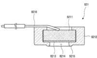
도면을 참조하여 상기 노크 감지장치(82)의 구조에 관하여 상세하게 살펴보면, 상기 노크 감지장치(82)는 사용자에 의한 상기 서브 도어(50)의 노크 조작을 감지하기 위한 장치이다.Looking in detail with respect to the structure of the
상기 노크 감지장치(82)는, 노크 온 신호를 감지하는 마이크 모듈(821)과, 상기 마이크 모듈(821)이 수용되는 홀더(823) 그리고 상기 홀더(823) 및 마이크 모듈(821)을 상기 전면 패널(541)측으로 가압 밀착시키는 탄성부재(824) 그리고, 상기 탄성부재(824) 및 상기 홀더(823)를 지지하는 지지부재(825)를 포함하여 구성될 수 있다.The
상기 마이크 모듈(821)은 음파를 직접 센싱하는 마이크(8211)와 상기 마이크(8211)를 수용하는 마이크 수용부(8212)를 포함한다. 상기 마이크(8211)는 음파의 직접적인 센싱을 하며, 소정의 두께를 가지는 원형으로 형성되어 상기 마이크 모듈(821)의 내부에 고정 장착된다. 상기 마이크(8211)의 일면은 음파를 수용하는 음파 수신부(8213)라 할 수 있으며, 상기 음파 수신부(8213)는 상기 마이크 수용부(8212)의 개구(8214)를 향하도록 배치된다. 그리고, 상기 마이크(8211)의 타측에는 신호선(8216)이 연결되어 있으며, 상기 신호선(8216)은 상기 감지장치 피시비(83)와 연결될 수 있다.The
상기 마이크 수용부(8212)는 고무와 같은 탄성 소재로 형성되며, 상기 전면 패널(541)에 밀착될 수 있도록 형성된다. 이를 위해 상기 마이크 수용부(8212)에는 상기 마이크 수용부(8212) 내부에 장착된 마이크(8211)와 인접하는 일측에 개구(8214)가 형성되며, 상기 개구(8214)의 둘레에는 원형의 돌기(8215)가 형성될 수 있다. 그리고, 상기 돌기(8215)는 상기 마이크 수용부(8212)가 상기 전면 패널(541)에 밀착될 때 일방향으로 기울어지지 않고 상기 개구부(403)의 개구된 전면이 전체적으로 상기 전면 패널(541)에 밀착된 상태를 유지하도록 한다.The microphone
상기 돌기(8215)에 의해 밀착되는 개구(8214)와 상기 음파 수신부(8213) 사이에는 밀폐된 소정의 공간이 형성될 수 있다. 따라서, 상기 밀착 공간의 전방은 매질 즉, 전면 패널(541)에 의해 밀폐된다. 따라서, 상기 매질 내부를 통해 전달되는 진동이 상기 소정 공간 내의 공기를 진동시키게 되고, 이러한 진동에 의한 음파가 상기 마이크(8211)에서 수신될 수 있다.A sealed predetermined space may be formed between the
이러한 밀폐로 인해 외부 소음이나 진동이 상기 소정 공간으로 유입되는 것을 최소화할 수 있게 된다. 이는 외부 노이즈로 인해 노크 온 판단 오류, 오작동을 현저히 줄일 수 있고, 노크 온 인식률을 매우 정확하게 확보할 수 있도록 한다. 즉, 노크 온 입력이 가해졌을 때 이를 노크 온으로 판단하는 정확성을 획기적으로 증가시킬 수 있게 된다.Due to this sealing, it is possible to minimize the introduction of external noise or vibration into the predetermined space. This can significantly reduce knock-on judgment errors and malfunctions due to external noise, and ensure a very accurate knock-on recognition rate. That is, when a knock-on input is applied, it is possible to dramatically increase the accuracy of determining that the knock-on input is knock-on.
상기 홀더(823)는 상기 마이크 모듈(821)을 수용하며, 상기 전면 패널(541)을 향하여 개구된 모듈 안착부(8231)가 형성될 수 있다. 상기 마이크 모듈(821)은 상기 모듈 안착부(8231)에 안착된 상태에서 적어도 상기 돌기(8215)가 상기 홀더(823)의 전면보다 더 돌출되도롤 형성될 수 있다.The
그리고, 상기 홀더(823)에는 상기 마이크(8211)와 연결된 상기 신호선이 출입되는 홀더 슬롯(8232)이 형성된다. 상기 홀더 슬롯(8232)은 상기 모듈 안착부(8231)의 일측에서 개구되도록 형성된다.In addition, a
또한, 상기 홀더(823)의 배면에는 상기 탄성부재(824)가 고정 장착되도록 돌출되는 제 1 탄성부재 고정부(8233)가 형성된다. 상기 제 1 탄성부재 고정부(8233)는 코일 형상의 상기 탄성부재(824)의 일단을 관통하도록 연장 형성될 수 있다.In addition, a first elastic
그리고, 상기 홀더(823)의 양측에는 후크형상으로 형성되어 상기 지지부재(825)와 결합되는 홀더 결합부(8234)가 형성된다. 상기 홀더 결합부(8234)에 의해 상기 홀더(823)는 상기 지지부재(825)에 의해 탈거되지 않도록 결합된다. 그리고 상기 홀더 결합부(8234)의 후크 형상에 의해 상기 홀더(823)는 상기 지지부재(825)의 내측으로 삽입되는 방향으로의 이동은 제한받지 않게 된다.Further,
상기 지지부재(825)는 전면이 개구되도록 형성되며, 상기 홀더(823)가 개구된 전면을 통해 삽입될 수 있도록 형성된다. 그리고, 상기 홀더(823)의 내측에는 상기 탄성부재(824)가 고정 장착되도록 돌출되는 제 2 탄성부재 고정부(8251)가 형성될 수 있다. 상기 제 2 탄성부재 고정부(8251)는 상기 제 1 탄성부재 고정부(8233)와 동일 연장선상에 위치하여 상기 탄성부재(824)의 일단을 관통하도록 삽입된다.The
따라서, 상기 홀더(823)를 가압하기 위해 상기 탄성부재(824)가 압축되더라도 상기 탄성부재(824)는 좌굴되지 않고 안정적으로 상기 홀더(823)를 상기 전면 패널(541)방향으로 가압할 수 있게 된다.Therefore, even if the
상기 탄성부재(824)에 의해 상기 마이크 모듈(821)은 상기 전면 패널(541)에 밀착된 상태를 유지하게 되며, 특히 상기 메인 도어(40)와 서브 도어(50)의 개폐시에 발생되는 충격 또는 상기 메인 도어(40) 및 서브 도어(50) 회동시의 관성에 의해서도 상기 마이크 모듈(821)은 위치가 변경되지 않고 상기 전면 패널(541)에 항상 밀착된 상태를 유지할 수 있게 된다.By the
상기 지지부재(825)의 일측에는 지지부재 슬롯(8252)이 형성될 수 있다. 상기 지지부재 슬롯(8252)은 상기 홀더 슬롯(8232)과 동일 연장선상에 형성될 수 있다. 따라서, 상기 홀더 슬롯(8232)을 통과하는 신호선이 상기 지지부재 슬롯(8252)을 통과하여 상기 감지장치 피시비(83)와 연결될 수 있다.A
상기 지지부재(825)의 다른 일측에는 지지부재 고정부(8254)가 형성된다. 상기 지지부재 고정부(8254)는 외측으로 연장 형성되며, 상기 수용부 케이스(587)상의 감지장치 결합 보스(5874)에 스크류에 의해 고정 장착될 수 있다. 상기 감지장치 결합 보스는 상기 센서 개구를 통해 노출될 수 있도록 형성되어 상기 감지장치의 삽입 후 상기 센서 개구를 통핸 상기 노크 감지장치의 고정 장착이 가능하게 된다.A support
한편, 상기 노크 감지장치(82)는 상기 전면 패널(541)의 가장자리 부분에 위치하게 되지만, 사용자의 노크 조작의 유효 입력 부분이 이에 한정되는 것은 아니다. 진동 자체가 아닌 진동에 의한 음파를 감지하는 마이크(8211)의 특성상 매질에 밀착되어 있는 환경에서는 어느 위치를 노크 조작하더라도 연속되는 동일 매질을 통해 음파가 전달되어 유효하게 감지될 수 있게 된다. 따라서 노크 감지장치(82)의 위치는 전선의 배치와 상기 서브 도어(50)의 가시화 면적을 최대로 할 수 있는 일단으로 배치할 수 있게 된다. 동시에 사용자는 전면 패널(541)의 어느 지점을 노크 조작하게 되더라도 동일 매질상에 밀착된 상기 마이크(8211)를 통한 감지가 가능하게 된다.Meanwhile, the
상세히, 사용자가 노크 입력을 가하는 영역은 전면 패널(541)의 전면이 정의하는 영역 모두일 수 있다. 그리고, 테두리 부분을 제외한 상기 전면 패널(541)의 대부분은 실질적으로 선택적으로 투명하게 되는 시스루 영역으로 상기 노크 온 감지장치가 배치될 수 없다.In detail, the area to which the user applies the knock input may be all areas defined by the front surface of the
따라서, 상기 노크 감지장치(82)는 상기 전면 패널(541) 중 상기 베젤(5411) 영역에 위치되는 것이 바람직하다. 특히, 전면 패널(541)의 좌우양측 보다는 하단에 위치하는 것이 상기 전면 패널(541) 좌우 양측과 상단의 베젤을 최소화시킬 수 있는 방법이 될 수 있다. 이와 같은 상기 베젤(5411)의 형상에 의해 상기 시스루 영역을 확장시킬 수 있으며, 사용자의 시선이 상대적으로 많이 가지 않는 하단부에 위치하게 되어 사용자에게 시스루 영역이 보다 넓게 보이도록 할 수 있다.Accordingly, it is preferable that the
상기 노크 감지장치(82)는 상기 베젤(5411)의 영역에 위치되어 외부로 노출되지 않게 되지만, 상기 전면 패널(541)에 밀착되는 구조를 가지게 되므로 사용자는 상기 전면 패널(541)의 어느 위치를 노크하더라도 사용자의 노크를 감지하는 것이 가능하게 된다.The
한편, 노크 조작 외에도 전면 패널(541)의 전면에 진동을 가하는 환경 요소는 매우 많이 발생될 수 있다. 상기 메인 도어(40) 및 서브 도어(50)의 열고 닫음에 따른 충격, 외부의 강한 소음 등에 의해 상기 패널 어셈블리(54) 전면이 진동할 수 있고, 이러한 외부 환경에 의한 입력을 노크 신호로 판단될 여지도 있다.On the other hand, in addition to the knock operation, many environmental factors that apply vibration to the front surface of the
따라서, 상기 감지장치 피시비(83)에서는 사용자가 패널 어셈블리(54) 전면을 복수 회 두드리는 것을 정상적인 노크 입력으로 판단하도록 할 수 있다. 더욱 구체적으로는 소정 시간 간격을 두고 복수 회 두드리는 것을 정상적인 노크 입력으로 판단할 수 있다.Accordingly, the
일례로, 사용자가 소정 시간 내에 상기 패널 어셈블리(54) 전면을 2 회 두드리는 경우 정상적인 노크 입력으로 판단하도록 할 수 있다. 일반적인 사용자의 노크 패턴을 분석하면 첫번째 노크와 두번째 노크 사이의 간격은 약 600 ms 미만임을 알 수 있다. 즉, 1 초(s)가 1000 ms 임을 감안하며, 1초 미만의 간격을 두고 첫번째 노크와 두번째 노크가 발생됨을 정상적인 노크 입력으로 판단하도록 할 수 있다.For example, when the user taps the front surface of the
따라서, 이러한 시간 간격을 설정함으로써 비정상적인 입력을 노크 신호로 오인하는 것을 현저히 방지할 수 있다.Therefore, by setting such a time interval, it is possible to significantly prevent an abnormal input from being mistaken as a knock signal.
한편, 노크의 강도는 사용자마다 편차가 있을 수 있다. 그러나, 매질이 동일하기 때문에 이러한 강도의 편차는 클 수 있으나, 진동 패턴의 편차는 매우 작음을 알 수 있다. 따라서, 노크의 강도 편차는 알고리즘을 통해서 상쇄시킬 수 있으며, 노크 입력의 패턴과 노크 사이의 시간 간격을 인자로 하여 정상적인 노크 입력을 효과적으로 인식할 수 있게 된다.Meanwhile, the knock intensity may vary for each user. However, since the medium is the same, the variation in intensity may be large, but it can be seen that the variation in the vibration pattern is very small. Accordingly, the deviation of the knock intensity can be canceled through an algorithm, and a normal knock input can be effectively recognized by using the knock input pattern and the time interval between the knock as a factor.
이는 반대로, 비정상적인 입력을 노크 입력으로 인식하는 것을 현저히 줄일 수 있음을 의미하게 된다.On the contrary, this means that recognizing an abnormal input as a knock input can be significantly reduced.
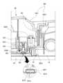
한편, 상기 도어 라이너(58)의 하부에는 도어 개방 보조장치(588)가 구비된다. 상기 도어 개방 보조장치(588)는 상기 도어 라이너(58)의 내측으로 함몰된 탄성부재 수용부(5881)와 상기 탄성부재 수용부(5881)에 수용되는 상기 탄성부재(824), 그리고 상기 탄성부재(5882)에 의해 지지되는 가압부재(5883)로 구성될 수있다.Meanwhile, a door
상기 가압부재(5883)는 외력이 가해지지 않는 상태에서는 도 33에서와 같이 상기 탄성부재(5882)에 의해 지지되어 상기 도어 라이너(58)에서 돌출된다. 따라서 상기 서브 도어(50)가 닫히게 되면 상기 가압부재(5883)는 상기 메인 도어(40)와 접하여 상기 탄성부재(5882)를 압축하게 된다. 상기 서브 도어(50)가 닫힌 상태에서 사용자가 서브 도어(50)를 개방하기 위해 상기 핸들(23)의 조작 버튼(231)을 조작하게 되면, 상기 록킹유닛(232)과 구속부재(404)의 결합이 해제되고, 상기 탄성부재(5882)의 탄성력에 의해 상기 서브 도어(50)는 회동 및 개방된다.In a state where no external force is applied, the pressing
이하에서는 상기와 같은 구성을 가지는 냉장고의 작용에 관하여 살펴보기로 한다.Hereinafter, the operation of the refrigerator having the above configuration will be described.
도 34는 상기 냉장고의 제어 신호의 흐름을 보인 블럭도이다. 그리고, 도 35은 상기 냉장고의 서브 도어 조작을 순차적으로 나타낸 순서도이다. 그리고, 도 36는 상기 냉장고의 노크 조작 전 상태의 사시도이다. 그리고, 도 37는 상기 냉장고의 노크 조작 후 상태의 사시도이다.34 is a block diagram showing a flow of a control signal of the refrigerator. And, FIG. 35 is a flow chart sequentially showing operation of the sub-door of the refrigerator. And, FIG. 36 is a perspective view of the refrigerator before a knock operation. And, FIG. 37 is a perspective view of the refrigerator after a knock operation.
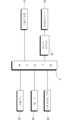
도면에 도시된 것과 같이, 상기 냉장고(1)는 냉장고의 동작을 제어하는 메인 제어부(2)를 포함하며, 상기 메인 제어부(2)는 도어 스위치(21)와 연결될 수 있다. 상기 도어 스위치(21)는 상기 캐비닛(10)에 구비되어 상기 냉장실 도어(20) 또는 메인 도어(40)의 개방을 감지할 수 있으며, 상기 메인 도어(40)에 구비되어 상기 서브 도어(50)의 개방을 감지할 수도 있다.As shown in the drawing, the
그리고, 상기 메인 제어부(2)는 상기 도어 라이팅 유닛(49)과 연결되어 상기 서브 도어(50)의 개방시 또는 노크 온 신호의 입력시 점등되도록 할 수 있다. 그리고, 상기 메인 제어부(2)는 상기 노크 감지장치(82)와 연결된 상기 감지장치 피시비(83)와 연결될 수 있다.In addition, the
한편, 상기 냉장고(1)는 별도의 조작이 없는 일반적인 상황에서는 도 36에 도시된 것과 같이, 상기 패널 어셈블리(54)가 불투명한 상태로 거울면과 같은 상태가 될 수 있다. 이와 같은 상태에서는 고내의 투시가 불가능한 상태가 된다.Meanwhile, the
그리고 이와 같은 상태에서 상기 노크 감지장치(82)는 활성화된 상태로 언제든지 사용자의 조작 입력이 가능한 상태를 유지하게 된다. [S110]In this state, the
이와 같은 상태에서 사용자가 고내의 식품 저장 상태를 확인하기 위해서는 상기 냉장고의 전방에서 상기 서브 도어(50)의 전면 즉, 상기 전면 패널(541)을 두드리게 되는 노크 온 조작을 하게 되면 상기 노크 감지장치(82)에서는 이를 감지하게 되고, 상기 감지장치 피시비(83)에서는 노크 온 조작이 유효 조작인지를 판단하게 된다.In such a state, in order for the user to check the food storage state in the refrigerator, when a knock-on operation in which the front of the sub-door 50 is knocked, that is, the
상세히, 사용자가 상기 전면 패널(541)을 두드리게 되면 이때 발생되는 진동에 의한 파장이 동일 매질인 상기 전면 패널(541)을 따라 이동되며 상기 전면 패널(541)과 밀착된 마이크(8211)에서 음파를 수신하게 된다.In detail, when the user taps the
수신된 음파는 상기 필터와 증폭기를 지나면서 필터링 및 증폭되어 상기 감지장치 피시비(83)로 전달되며, 상기 감지장치 피시비(83)는 노크 신호를 감지할 수 있도록 수집 분석된 신호로 노크를 판단하게 된다.The received sound wave is filtered and amplified while passing through the filter and amplifier, and transmitted to the
즉, 고내 또는 고외측의 소음이나 충격에 의해 발생되는 음파의 경우 노크에 의해 발생되는 음파와 그 특성에 차이가 있으며, 따라서 상기 감지장치 피시비(83)는 노크 신호의 특성에 해당하는 신호를 통해 사용자의 노크 여부를 판단하게 된다.That is, in the case of a sound wave generated by noise or impact inside or outside the chamber, there is a difference between the sound wave generated by knock and its characteristics, and therefore, the
물론, 특정한 상황에서 노크 신호와 유사한 신호가 발생될 수도 있으며, 사용자의 부주의 또는 조작 미숙에 의해 상기 전면 패널(541)에 노크와 유사한 충격이 발생될 수도 있고, 외부 소음이 노크 신호의 파장과 유사한 신호로 인식될 수도 있을 것이다.Of course, a signal similar to the knock signal may be generated in a specific situation, an impact similar to the knock may be generated on the
이러한 특수 상황에서의 오인식을 방지하기 위하여 상기 감지장치 피시비(83)는 상기 노크 신호가 설정된 패턴에 의해 연속적으로 발생되는지를 확인하고, 이러한 패턴이 설정시간 내에 이루어지는지를 판단하게 된다.In order to prevent misrecognition in such a special situation, the
예를 들어, 유효한 노크 온 신호로 감지되기 위해서는 노크로 인식되는 신호가 1초 이내에 두번 발생되는 것으로 설정될 수 있다. 통상 일반적인 사용자의 노크 패턴을 분석하여 본 결과 연속 2회 노크를 실시하고 그 시간 간격은 1초 이내에 해당하므로 이와 같이 설정할 경우 특수 상황에서의 오인식을 방지할 수 있을 뿐만 아니라 사용자의 노크 조작을 정확하게 인식할 수 있게 된다. 물론, 이와 같은 유효 노크 온 신호로 판단되기 위한 노크 신호의 횟수와 설정시간은 다양하게 변경 가능할 것이다.For example, in order to be detected as a valid knock-on signal, a signal recognized as knock may be set to be generated twice within 1 second. Usually, as a result of analyzing the knock pattern of a general user, knocking is performed twice in a row, and the time interval falls within 1 second, so if you set this way, you can prevent misrecognition in special situations and accurately recognize the user's knock operation. You can do it. Of course, the number of knock signals and the set time to be determined as such an effective knock-on signal may be variously changed.
상기 노크 감지장치(82)를 통해 유효 노크 온 신호가 발생되지 않은 것으로 판단되는 경우 상기 메인 제어부(2)는 별도의 제어 동작을 실시하지 않고 대기상태를 유지하게 된다.When it is determined that an effective knock-on signal has not been generated through the
그리고, 상기 메인 도어(40) 또는 서브 도어(50)가 개방된 상태에서는 노크 감지장치(82)가 비활성화 되도록 하거나, 입력되는 신호를 무시하도록 하여 오작동을 방지하도록 할 수 있다. [S120]In addition, when the
한편, 유효 노크 온 신호가 감지되어 상기 감지장치 피시비(83)에서 상기 메인 제어부(2)로 유효 신호를 전달하게 되면, 상기 메인 제어부(2)는 상기 도어 라이팅 유닛(49)을 온 시키게 된다.On the other hand, when an effective knock-on signal is detected and the effective signal is transmitted from the
상기 도어 라이팅 유닛(49)이 켜지게 되면 상기 개구부(403)의 내측이 밝아지게 되고, 상기 고내측의 빛이 상기 패널 어셈블리(54)를 통과하게 된다. 특히, 상기 전면 패널(541)을 통과하게 되면서 상기 전면 패널(541)은 투명하게 되어 도 37에서와 같이 내부의 투시가 가능하게 된다.When the
상기 서브 도어(50)가 투명하게 되면 사용자가 상기 메인 도어(40) 내부의 수납공간 또는 고내 공간을 확인할 수 있으며, 식품을 수납하기 위해 서브 도어(50)를 개방하거나 필요한 작업을 실시하게 된다. [S130]When the sub-door 50 becomes transparent, the user can check the storage space or the interior space of the
점등된 상기 도어 라이팅 유닛(49)은 설정된 시간 예를 들어 10초 동안 점등 상태가 유지되도록 하여 사용자가 충분히 고내의 상태를 확인할 수 있도록 한다.The lighted
그리고, 상기 도어 라이팅 유닛(49)이 온 된 상태에서 설정된 시간이 경과 되었는지를 판단하여, 설정시간이 경과된 경우 상기 도어 라이팅 유닛(49)을 오프 시키게 된다. [S140]In addition, it is determined whether a set time has elapsed while the
그리고, 상기 도어 라이팅 유닛(49)이 온 된 상태에서 설정된 시간이 경과되기 전에 사용자에 의해 유효 노크 온 조작 신호가 입력될 수도 있다.In addition, an effective knock-on operation signal may be input by a user before a set time elapses while the
즉, 사용자가 고내를 확인하기 위해 노크 온 조작을 하여 고내를 확인한 후 별도의 작업이 필요하지 않은 경우에는 설정시간이 지나기 전에 상기 도어 라이팅 유닛(49)을 오프시킬 수 있다.That is, when a user performs a knock-on operation to check the interior of the interior and does not require a separate operation after checking the interior of the interior, the
예를 들어 상기 도어 라이팅 유닛(49)이 온 된 후 5초 이내에 사용자가 고내의 수납상태를 확인한 상태에서 상기 서브 도어(50)가 불투명한 상태가 되도록 하고자 한다면, 다시 상기 서브 도어(50)의 전면 즉 상기 전면 패널(541)을 노크 조작하게 된다.For example, if the user wants to make the sub-door 50 opaque within 5 seconds after the
이때의 노크 조작이 유효한 것으로 판단되면 상기 도어 라이팅 유닛(49)은 설정된 시간이 경과되기 전에 오프 될 수 있다. 물론, 이때의 노크 조작의 유효성 판단은 [S120]에서와 동일하게 설정될 수도 있으며, 필요에 따라서 다른 노크 입력 패턴으로 설정될 수도 있다. [S150]If it is determined that the knock operation at this time is effective, the
상기 도어 라이팅 유닛(49)이 온 된 후 설정시간이 경과 되거나 유효 노크 온 신호가 입력되는 경우 상기 도어 라이팅 유닛(49)은 오프될 수 있다.When a set time elapses after the
상기 도어 라이팅 유닛(49)이 오프되면 고내측은 어두워지게 되고, 고 외측이 밝은 상태가 된다. 이와 같은 상태에서는 고외측의 빛이 전면 패널(541)에서 반사되어 상기 서브 도어(50)의 전면은 거울과 같은 상태로 내부의 투시가 불가능한 상태가 된다. 따라서, 상기 서브 도어(50)는 새로운 조작이 입력될 때까지 불투명한 상태를 유지하게 된다. [S160]When the
Claims (13)
Translated fromKorean상기 캐비닛에 회전 가능하게 연결되어 상기 저장공간을 개폐하며, 개구부를 구비하는 메인 도어; 및
상기 메인 도어에 대해서 회전 가능하며, 상기 개구부를 개폐하는 서브 도어를 포함하고,
상기 서브 도어는, 개구를 포함하는 도어 프레임과,
상기 개구를 커버하며, 글래스 재질의 전면 패널과, 상기 전면 패널과 이격되는 단열 패널을 포함하는 패널 어셈블리와,
상기 도어 프레임에 설치되며, 상기 메인 도어의 개구부 측으로 광으로 조사하기 위한 도어 라이팅 유닛을 포함하는 냉장고.A cabinet having a storage space;
A main door rotatably connected to the cabinet to open and close the storage space and having an opening; And
It is rotatable with respect to the main door and includes a sub-door that opens and closes the opening,
The sub-door includes a door frame including an opening,
A panel assembly covering the opening and including a front panel made of a glass material and an insulating panel spaced apart from the front panel,
A refrigerator installed on the door frame and including a door lighting unit for irradiating with light toward an opening of the main door.
상기 도어 프레임은, 아웃 플레이트;
상기 아웃 플레이트와 이격되는 도어 라이너; 및
상기 서브 도어의 상면과 하면을 형성하는 어퍼 캡데코와 로어 캡데코를 포함하고,
상기 도어 라이팅 유닛은 상기 도어 라이너에 설치되는 냉장고.The method of claim 1,
The door frame, an out plate;
A door liner spaced apart from the out plate; And
Including an upper cap deco and a lower cap deco forming the upper and lower surfaces of the sub-door,
The door lighting unit is a refrigerator installed on the door liner.
상기 도어 라이너는, 라이너 개구를 포함하고,
상기 패널 어셈블리는 상기 라이너 개구를 커버하며,
상기 도어 라이너에서 상기 라이너 개구의 상측에는 상기 도어 라이팅 유닛이 장착되는 라이팅 유닛 장착부가 형성되는 냉장고.The method of claim 2,
The door liner includes a liner opening,
The panel assembly covers the liner opening,
A refrigerator in which a lighting unit mounting portion to which the door lighting unit is mounted is formed above the opening of the liner in the door liner.
상기 도어 라이팅 유닛은, 상기 도어 라이너에 장착되는 램프 케이스와,
상기 램프 케이스의 내부에 수용되며 다수의 엘이디가 배치되는 램프 피시비와,
상기 램프 케이스의 개구된 하면을 차폐하며 상기 개구로 노출되는 램프 커버를 포함하는 냉장고.The method of claim 3,
The door lighting unit includes a lamp case mounted on the door liner,
A lamp PCB accommodated in the lamp case and in which a plurality of LEDs are disposed,
A refrigerator comprising a lamp cover that shields an opened lower surface of the lamp case and is exposed through the opening.
상기 도어 라이너에서, 상기 라이팅 유닛 장착부의 양단에는 케이스 고정부가 형성되며,
상기 램프 케이스의 양단에는 상기 케이스 고정부와 걸림 구속되기 위하여 돌출되는 케이스 리브가 구비되는 냉장고.The method of claim 4,
In the door liner, case fixing portions are formed at both ends of the lighting unit mounting portion,
A refrigerator having a case rib protruding at both ends of the lamp case so as to be engaged with the case fixing part.
상기 램프 케이스는, 상기 도어 라이너를 따라 좌우 방향으로 길게 연장 형성되며, 내부에 상기 램프 피시비를 수용할 수 있도록 함몰된 공간을 형성하는 함몰부를 포함하고,
상기 램프 커버는 상기 함몰부를 커버하는 냉장고.The method of claim 4,
The lamp case is formed to extend in a left and right direction along the door liner, and includes a recessed portion forming a recessed space to accommodate the lamp PCB,
The lamp cover covers the depression.
상기 램프 케이스는, 상기 램프 피시비가 장착되는 램프 피시비 장착부와, 상기 램프 피시비 장착부에서 연장되며, 상기 다수의 엘이디에서 조사되는 빛을 반사하는 라운드면을 포함하는 냉장고.The method of claim 4,
The lamp case includes a lamp PCB mounting portion on which the lamp PCB is mounted, and a round surface extending from the lamp PCB mounting portion and reflecting light irradiated from the plurality of LEDs.
상기 라운드면은, 상기 램프 피시비에서 상기 패널 어셈블리와 멀어지는 방향으로 갈수록 하측으로 라운드지는 냉장고.The method of claim 7,
The round surface is rounded downward toward a direction away from the panel assembly from the lamp PCB.
상기 램프 피시비 장착부는 상기 램프 피시비가 상기 램프 케이스의 내측에서 상기 램프 커버와 교차되는 방향으로 고정 장착될 수 있도록 배치되는 냉장고.The method of claim 7,
The lamp PCB mounting unit is disposed so that the lamp PCB can be fixedly mounted in a direction crossing the lamp cover from the inside of the lamp case.
상기 램프 피시비 장착부의 일측에는 상기 램프 피시비와 연결되는 전선이 출입되는 전선 출입구가 구비되는 냉장고.The method of claim 7,
A refrigerator having an electric wire entrance through which an electric wire connected to the lamp PCB enters and exits at one side of the lamp PCB mounting part.
상기 서브 도어가 닫히면 상기 도어 라이팅 유닛은 상기 메인 도어의 개구부에 위치되는 냉장고.The method of claim 1,
When the sub-door is closed, the door lighting unit is located in an opening of the main door.
상기 도어 프레임에는 이격되는 복수의 발포액 주입구가 구비되는 냉장고.The method of claim 1,
A refrigerator having a plurality of foaming liquid injection ports spaced apart from the door frame.
상기 도어 프레임에서, 상기 발포액 주입구는 상기 개구를 기준으로 상기 도어 라이팅 유닛의 반대편에 위치되는 냉장고.The method of claim 12,
In the door frame, the foaming liquid injection port is located on the opposite side of the door lighting unit with respect to the opening.
Priority Applications (11)
| Application Number | Priority Date | Filing Date | Title |
|---|---|---|---|
| KR1020210003859AKR102327687B1 (en) | 2020-01-13 | 2021-01-12 | Refrigerator |
| KR1020210136411AKR102386577B1 (en) | 2021-01-12 | 2021-10-14 | Refrigerator |
| KR1020220040212AKR102447525B1 (en) | 2021-01-12 | 2022-03-31 | refrigerator |
| KR1020220119184AKR102567058B1 (en) | 2021-01-12 | 2022-09-21 | Home appliance and Refrigerator |
| KR1020220183060AKR102645862B1 (en) | 2021-01-12 | 2022-12-23 | Home appliance and Refrigerator |
| KR1020230083316AKR102761593B1 (en) | 2021-01-12 | 2023-06-28 | Home appliance and Refrigerator |
| KR1020230083319AKR102645864B1 (en) | 2021-01-12 | 2023-06-28 | Home appliance and Refrigerator |
| KR1020230094380AKR102705279B1 (en) | 2021-01-12 | 2023-07-20 | Home appliance and Refrigerator |
| KR1020240059674AKR102858726B1 (en) | 2021-01-12 | 2024-05-07 | Home appliance and Refrigerator |
| KR1020250008374AKR20250019716A (en) | 2021-01-12 | 2025-01-20 | Home appliance and Refrigerator |
| KR1020250116118AKR20250133617A (en) | 2021-01-12 | 2025-08-20 | Home appliance and Refrigerator |
Applications Claiming Priority (2)
| Application Number | Priority Date | Filing Date | Title |
|---|---|---|---|
| KR1020200004358AKR102206063B1 (en) | 2020-01-13 | 2020-01-13 | Refrigerator |
| KR1020210003859AKR102327687B1 (en) | 2020-01-13 | 2021-01-12 | Refrigerator |
Related Parent Applications (1)
| Application Number | Title | Priority Date | Filing Date |
|---|---|---|---|
| KR1020200004358ADivisionKR102206063B1 (en) | 2020-01-13 | 2020-01-13 | Refrigerator |
Related Child Applications (1)
| Application Number | Title | Priority Date | Filing Date |
|---|---|---|---|
| KR1020210136411ADivisionKR102386577B1 (en) | 2021-01-12 | 2021-10-14 | Refrigerator |
Publications (2)
| Publication Number | Publication Date |
|---|---|
| KR20210008122Atrue KR20210008122A (en) | 2021-01-20 |
| KR102327687B1 KR102327687B1 (en) | 2021-11-17 |
Family
ID=74304675
Family Applications (11)
| Application Number | Title | Priority Date | Filing Date |
|---|---|---|---|
| KR1020210003859AActiveKR102327687B1 (en) | 2020-01-13 | 2021-01-12 | Refrigerator |
| KR1020210136411AActiveKR102386577B1 (en) | 2021-01-12 | 2021-10-14 | Refrigerator |
| KR1020220040212AActiveKR102447525B1 (en) | 2021-01-12 | 2022-03-31 | refrigerator |
| KR1020220119184AActiveKR102567058B1 (en) | 2021-01-12 | 2022-09-21 | Home appliance and Refrigerator |
| KR1020220183060AActiveKR102645862B1 (en) | 2021-01-12 | 2022-12-23 | Home appliance and Refrigerator |
| KR1020230083316AActiveKR102761593B1 (en) | 2021-01-12 | 2023-06-28 | Home appliance and Refrigerator |
| KR1020230083319AActiveKR102645864B1 (en) | 2021-01-12 | 2023-06-28 | Home appliance and Refrigerator |
| KR1020230094380AActiveKR102705279B1 (en) | 2021-01-12 | 2023-07-20 | Home appliance and Refrigerator |
| KR1020240059674AActiveKR102858726B1 (en) | 2021-01-12 | 2024-05-07 | Home appliance and Refrigerator |
| KR1020250008374APendingKR20250019716A (en) | 2021-01-12 | 2025-01-20 | Home appliance and Refrigerator |
| KR1020250116118APendingKR20250133617A (en) | 2021-01-12 | 2025-08-20 | Home appliance and Refrigerator |
Family Applications After (10)
| Application Number | Title | Priority Date | Filing Date |
|---|---|---|---|
| KR1020210136411AActiveKR102386577B1 (en) | 2021-01-12 | 2021-10-14 | Refrigerator |
| KR1020220040212AActiveKR102447525B1 (en) | 2021-01-12 | 2022-03-31 | refrigerator |
| KR1020220119184AActiveKR102567058B1 (en) | 2021-01-12 | 2022-09-21 | Home appliance and Refrigerator |
| KR1020220183060AActiveKR102645862B1 (en) | 2021-01-12 | 2022-12-23 | Home appliance and Refrigerator |
| KR1020230083316AActiveKR102761593B1 (en) | 2021-01-12 | 2023-06-28 | Home appliance and Refrigerator |
| KR1020230083319AActiveKR102645864B1 (en) | 2021-01-12 | 2023-06-28 | Home appliance and Refrigerator |
| KR1020230094380AActiveKR102705279B1 (en) | 2021-01-12 | 2023-07-20 | Home appliance and Refrigerator |
| KR1020240059674AActiveKR102858726B1 (en) | 2021-01-12 | 2024-05-07 | Home appliance and Refrigerator |
| KR1020250008374APendingKR20250019716A (en) | 2021-01-12 | 2025-01-20 | Home appliance and Refrigerator |
| KR1020250116118APendingKR20250133617A (en) | 2021-01-12 | 2025-08-20 | Home appliance and Refrigerator |
Country Status (1)
| Country | Link |
|---|---|
| KR (11) | KR102327687B1 (en) |
Cited By (1)
| Publication number | Priority date | Publication date | Assignee | Title |
|---|---|---|---|---|
| KR102407440B1 (en)* | 2021-02-01 | 2022-06-10 | 엘지전자 주식회사 | Antimicrobial plastic article and refrigerator comprising the same |
Families Citing this family (2)
| Publication number | Priority date | Publication date | Assignee | Title |
|---|---|---|---|---|
| KR20240109529A (en)* | 2023-01-04 | 2024-07-11 | 삼성전자주식회사 | Refrigerator |
| CN119507759B (en)* | 2024-11-22 | 2025-10-03 | 安徽万朗磁塑股份有限公司 | Hinge structure and refrigeration equipment |
Citations (7)
| Publication number | Priority date | Publication date | Assignee | Title |
|---|---|---|---|---|
| KR19990015883U (en)* | 1997-10-21 | 1999-05-15 | 전주범 | Showcase Door Structure |
| KR200174778Y1 (en)* | 1999-10-08 | 2000-03-15 | 삼성전자주식회사 | Refrigerator |
| JP2008522122A (en)* | 2004-11-29 | 2008-06-26 | リープヘル−ハウスゲレーテ オクセンハウゼン ゲーエムベーハー | Refrigerator and / or freezer |
| KR20110089534A (en)* | 2010-02-01 | 2011-08-09 | 엘지전자 주식회사 | Refrigerator |
| KR20120115615A (en)* | 2011-04-11 | 2012-10-19 | 삼성전자주식회사 | Refrigerator |
| WO2012154236A1 (en)* | 2011-05-10 | 2012-11-15 | Anthony, Inc. | Refrigerated display case door with transparent lcd panel |
| KR20150123493A (en)* | 2014-04-25 | 2015-11-04 | 삼성전자주식회사 | Method of processing input and electronic device thereof |
Family Cites Families (2)
| Publication number | Priority date | Publication date | Assignee | Title |
|---|---|---|---|---|
| KR20130115586A (en)* | 2012-04-12 | 2013-10-22 | (주)에스앤지그룹 | Smart refrgerator comprising transparent display pannel for providing digital contents |
| KR102109405B1 (en)* | 2013-04-25 | 2020-05-12 | 엘지전자 주식회사 | Refrigerator |
- 2021
- 2021-01-12KRKR1020210003859Apatent/KR102327687B1/enactiveActive
- 2021-10-14KRKR1020210136411Apatent/KR102386577B1/enactiveActive
- 2022
- 2022-03-31KRKR1020220040212Apatent/KR102447525B1/enactiveActive
- 2022-09-21KRKR1020220119184Apatent/KR102567058B1/enactiveActive
- 2022-12-23KRKR1020220183060Apatent/KR102645862B1/enactiveActive
- 2023
- 2023-06-28KRKR1020230083316Apatent/KR102761593B1/enactiveActive
- 2023-06-28KRKR1020230083319Apatent/KR102645864B1/enactiveActive
- 2023-07-20KRKR1020230094380Apatent/KR102705279B1/enactiveActive
- 2024
- 2024-05-07KRKR1020240059674Apatent/KR102858726B1/enactiveActive
- 2025
- 2025-01-20KRKR1020250008374Apatent/KR20250019716A/enactivePending
- 2025-08-20KRKR1020250116118Apatent/KR20250133617A/enactivePending
Patent Citations (7)
| Publication number | Priority date | Publication date | Assignee | Title |
|---|---|---|---|---|
| KR19990015883U (en)* | 1997-10-21 | 1999-05-15 | 전주범 | Showcase Door Structure |
| KR200174778Y1 (en)* | 1999-10-08 | 2000-03-15 | 삼성전자주식회사 | Refrigerator |
| JP2008522122A (en)* | 2004-11-29 | 2008-06-26 | リープヘル−ハウスゲレーテ オクセンハウゼン ゲーエムベーハー | Refrigerator and / or freezer |
| KR20110089534A (en)* | 2010-02-01 | 2011-08-09 | 엘지전자 주식회사 | Refrigerator |
| KR20120115615A (en)* | 2011-04-11 | 2012-10-19 | 삼성전자주식회사 | Refrigerator |
| WO2012154236A1 (en)* | 2011-05-10 | 2012-11-15 | Anthony, Inc. | Refrigerated display case door with transparent lcd panel |
| KR20150123493A (en)* | 2014-04-25 | 2015-11-04 | 삼성전자주식회사 | Method of processing input and electronic device thereof |
Cited By (2)
| Publication number | Priority date | Publication date | Assignee | Title |
|---|---|---|---|---|
| KR102407440B1 (en)* | 2021-02-01 | 2022-06-10 | 엘지전자 주식회사 | Antimicrobial plastic article and refrigerator comprising the same |
| WO2022164138A1 (en)* | 2021-02-01 | 2022-08-04 | 엘지전자 주식회사 | Plastic molded article having antibacterial and antiviral functions, and refrigerator including same |
Also Published As
| Publication number | Publication date |
|---|---|
| KR102645864B1 (en) | 2024-03-11 |
| KR20230116754A (en) | 2023-08-04 |
| KR20240072973A (en) | 2024-05-24 |
| KR20210128960A (en) | 2021-10-27 |
| KR102567058B1 (en) | 2023-08-16 |
| KR102858726B1 (en) | 2025-09-11 |
| KR20220132508A (en) | 2022-09-30 |
| KR102327687B1 (en) | 2021-11-17 |
| KR20230106544A (en) | 2023-07-13 |
| KR102645862B1 (en) | 2024-03-11 |
| KR102761593B1 (en) | 2025-02-03 |
| KR102705279B1 (en) | 2024-09-11 |
| KR20250019716A (en) | 2025-02-10 |
| KR102447525B1 (en) | 2022-09-26 |
| KR20230007284A (en) | 2023-01-12 |
| KR20220047229A (en) | 2022-04-15 |
| KR102386577B1 (en) | 2022-04-15 |
| KR20230107487A (en) | 2023-07-17 |
| KR20250133617A (en) | 2025-09-08 |
Similar Documents
| Publication | Publication Date | Title |
|---|---|---|
| KR101862564B1 (en) | Refrigerator | |
| US11300350B2 (en) | Refrigerator | |
| KR102597666B1 (en) | Refirgerator | |
| KR102447525B1 (en) | refrigerator | |
| KR102067743B1 (en) | Refrigerator | |
| KR102012462B1 (en) | Refrigerator | |
| KR102206063B1 (en) | Refrigerator | |
| KR102167549B1 (en) | Refrigerator | |
| KR102087685B1 (en) | Refrigerator |
Legal Events
| Date | Code | Title | Description |
|---|---|---|---|
| A107 | Divisional application of patent | ||
| PA0107 | Divisional application | St.27 status event code:A-0-1-A10-A18-div-PA0107 St.27 status event code:A-0-1-A10-A16-div-PA0107 | |
| PA0201 | Request for examination | St.27 status event code:A-1-2-D10-D11-exm-PA0201 | |
| PG1501 | Laying open of application | St.27 status event code:A-1-1-Q10-Q12-nap-PG1501 | |
| E902 | Notification of reason for refusal | ||
| PE0902 | Notice of grounds for rejection | St.27 status event code:A-1-2-D10-D21-exm-PE0902 | |
| E13-X000 | Pre-grant limitation requested | St.27 status event code:A-2-3-E10-E13-lim-X000 | |
| P11-X000 | Amendment of application requested | St.27 status event code:A-2-2-P10-P11-nap-X000 | |
| P13-X000 | Application amended | St.27 status event code:A-2-2-P10-P13-nap-X000 | |
| E701 | Decision to grant or registration of patent right | ||
| PE0701 | Decision of registration | St.27 status event code:A-1-2-D10-D22-exm-PE0701 | |
| PA0107 | Divisional application | St.27 status event code:A-0-1-A10-A18-div-PA0107 St.27 status event code:A-0-1-A10-A16-div-PA0107 | |
| PR0701 | Registration of establishment | St.27 status event code:A-2-4-F10-F11-exm-PR0701 | |
| PR1002 | Payment of registration fee | St.27 status event code:A-2-2-U10-U11-oth-PR1002 Fee payment year number:1 | |
| PG1601 | Publication of registration | St.27 status event code:A-4-4-Q10-Q13-nap-PG1601 | |
| PR1001 | Payment of annual fee | St.27 status event code:A-4-4-U10-U11-oth-PR1001 Fee payment year number:4 | |
| L13-X000 | Limitation or reissue of ip right requested | St.27 status event code:A-2-3-L10-L13-lim-X000 |