KR20210005659A - Calibration in digital workflow - Google Patents
Calibration in digital workflowDownload PDFInfo
- Publication number
- KR20210005659A KR20210005659AKR1020207033602AKR20207033602AKR20210005659AKR 20210005659 AKR20210005659 AKR 20210005659AKR 1020207033602 AKR1020207033602 AKR 1020207033602AKR 20207033602 AKR20207033602 AKR 20207033602AKR 20210005659 AKR20210005659 AKR 20210005659A
- Authority
- KR
- South Korea
- Prior art keywords
- test body
- negative
- positive
- data set
- digital data
- Prior art date
- Legal status (The legal status is an assumption and is not a legal conclusion. Google has not performed a legal analysis and makes no representation as to the accuracy of the status listed.)
- Withdrawn
Links
Images


Classifications
- G—PHYSICS
- G06—COMPUTING OR CALCULATING; COUNTING
- G06F—ELECTRIC DIGITAL DATA PROCESSING
- G06F30/00—Computer-aided design [CAD]
- G06F30/10—Geometric CAD
- A—HUMAN NECESSITIES
- A61—MEDICAL OR VETERINARY SCIENCE; HYGIENE
- A61C—DENTISTRY; APPARATUS OR METHODS FOR ORAL OR DENTAL HYGIENE
- A61C13/00—Dental prostheses; Making same
- A61C13/0003—Making bridge-work, inlays, implants or the like
- A61C13/0004—Computer-assisted sizing or machining of dental prostheses
- A—HUMAN NECESSITIES
- A61—MEDICAL OR VETERINARY SCIENCE; HYGIENE
- A61C—DENTISTRY; APPARATUS OR METHODS FOR ORAL OR DENTAL HYGIENE
- A61C13/00—Dental prostheses; Making same
- A61C13/0003—Making bridge-work, inlays, implants or the like
- A61C13/0006—Production methods
- A—HUMAN NECESSITIES
- A61—MEDICAL OR VETERINARY SCIENCE; HYGIENE
- A61C—DENTISTRY; APPARATUS OR METHODS FOR ORAL OR DENTAL HYGIENE
- A61C9/00—Impression cups, i.e. impression trays; Impression methods
- A61C9/004—Means or methods for taking digitized impressions
- A—HUMAN NECESSITIES
- A61—MEDICAL OR VETERINARY SCIENCE; HYGIENE
- A61C—DENTISTRY; APPARATUS OR METHODS FOR ORAL OR DENTAL HYGIENE
- A61C9/00—Impression cups, i.e. impression trays; Impression methods
- A61C9/004—Means or methods for taking digitized impressions
- A61C9/0046—Data acquisition means or methods
- G—PHYSICS
- G01—MEASURING; TESTING
- G01B—MEASURING LENGTH, THICKNESS OR SIMILAR LINEAR DIMENSIONS; MEASURING ANGLES; MEASURING AREAS; MEASURING IRREGULARITIES OF SURFACES OR CONTOURS
- G01B11/00—Measuring arrangements characterised by the use of optical techniques
- G01B11/24—Measuring arrangements characterised by the use of optical techniques for measuring contours or curvatures
- G—PHYSICS
- G01—MEASURING; TESTING
- G01B—MEASURING LENGTH, THICKNESS OR SIMILAR LINEAR DIMENSIONS; MEASURING ANGLES; MEASURING AREAS; MEASURING IRREGULARITIES OF SURFACES OR CONTOURS
- G01B21/00—Measuring arrangements or details thereof, where the measuring technique is not covered by the other groups of this subclass, unspecified or not relevant
- G01B21/02—Measuring arrangements or details thereof, where the measuring technique is not covered by the other groups of this subclass, unspecified or not relevant for measuring length, width, or thickness
- G01B21/04—Measuring arrangements or details thereof, where the measuring technique is not covered by the other groups of this subclass, unspecified or not relevant for measuring length, width, or thickness by measuring coordinates of points
- G01B21/042—Calibration or calibration artifacts
- G—PHYSICS
- G06—COMPUTING OR CALCULATING; COUNTING
- G06F—ELECTRIC DIGITAL DATA PROCESSING
- G06F30/00—Computer-aided design [CAD]
- G—PHYSICS
- G06—COMPUTING OR CALCULATING; COUNTING
- G06T—IMAGE DATA PROCESSING OR GENERATION, IN GENERAL
- G06T17/00—Three dimensional [3D] modelling, e.g. data description of 3D objects
- G—PHYSICS
- G09—EDUCATION; CRYPTOGRAPHY; DISPLAY; ADVERTISING; SEALS
- G09B—EDUCATIONAL OR DEMONSTRATION APPLIANCES; APPLIANCES FOR TEACHING, OR COMMUNICATING WITH, THE BLIND, DEAF OR MUTE; MODELS; PLANETARIA; GLOBES; MAPS; DIAGRAMS
- G09B23/00—Models for scientific, medical, or mathematical purposes, e.g. full-sized devices for demonstration purposes
- G09B23/28—Models for scientific, medical, or mathematical purposes, e.g. full-sized devices for demonstration purposes for medicine
- G09B23/283—Models for scientific, medical, or mathematical purposes, e.g. full-sized devices for demonstration purposes for medicine for dentistry or oral hygiene
- A—HUMAN NECESSITIES
- A61—MEDICAL OR VETERINARY SCIENCE; HYGIENE
- A61C—DENTISTRY; APPARATUS OR METHODS FOR ORAL OR DENTAL HYGIENE
- A61C13/00—Dental prostheses; Making same
- A61C13/0003—Making bridge-work, inlays, implants or the like
- A61C13/0006—Production methods
- A61C13/0018—Production methods using laser
- A—HUMAN NECESSITIES
- A61—MEDICAL OR VETERINARY SCIENCE; HYGIENE
- A61C—DENTISTRY; APPARATUS OR METHODS FOR ORAL OR DENTAL HYGIENE
- A61C13/00—Dental prostheses; Making same
- A61C13/0003—Making bridge-work, inlays, implants or the like
- A61C13/0006—Production methods
- A61C13/0019—Production methods using three dimensional printing
Landscapes
- Health & Medical Sciences (AREA)
- Physics & Mathematics (AREA)
- Engineering & Computer Science (AREA)
- General Physics & Mathematics (AREA)
- General Health & Medical Sciences (AREA)
- Epidemiology (AREA)
- Oral & Maxillofacial Surgery (AREA)
- Public Health (AREA)
- Dentistry (AREA)
- Veterinary Medicine (AREA)
- Life Sciences & Earth Sciences (AREA)
- Animal Behavior & Ethology (AREA)
- Theoretical Computer Science (AREA)
- Geometry (AREA)
- Computational Mathematics (AREA)
- Pure & Applied Mathematics (AREA)
- Mathematical Optimization (AREA)
- Mathematical Analysis (AREA)
- Computer Hardware Design (AREA)
- General Engineering & Computer Science (AREA)
- Evolutionary Computation (AREA)
- Chemical & Material Sciences (AREA)
- Medical Informatics (AREA)
- Medicinal Chemistry (AREA)
- Algebra (AREA)
- Mathematical Physics (AREA)
- Business, Economics & Management (AREA)
- Educational Administration (AREA)
- Educational Technology (AREA)
- Manufacturing & Machinery (AREA)
- Computer Graphics (AREA)
- Software Systems (AREA)
- Length Measuring Devices With Unspecified Measuring Means (AREA)
- Dental Tools And Instruments Or Auxiliary Dental Instruments (AREA)
Abstract
Translated fromKoreanDescription
Translated fromKorean본 발명은 디지털 워크플로우에서 다양한 장치가 서로 최적으로 매칭될 수 있도록 하여, 생산 공정이 끝날 때 가능한 한 정확하게 맞춰지는 공작물이 생성되도록 하는, 교정 방법에 관한 것이다. 특히, 본 발명은 데이터 획득 장치 및 주변 장치(특히 CAD 밀링머신, 3D 프린터 또는 레이저 소결용 레이저)를 교정하기 위한 방법, 이 방법을 수행하기 위해 개발된 시험체, 및 이들 시험체 및 가능하게는 시험체의 디지털 데이터 세트와 매칭되는 시험 핀을 포함하는 세트에 관한 것이다.The present invention relates to a calibration method that allows various devices to be optimally matched with each other in a digital workflow, resulting in a work piece that fits as accurately as possible at the end of the production process. In particular, the present invention relates to a method for calibrating a data acquisition device and a peripheral device (especially a CAD milling machine, a 3D printer or a laser for laser sintering), a test body developed to carry out this method, and these test bodies and possibly the test body. It relates to a set comprising test pins that match the digital data set.
치과 복원 의학 분야에서 CAD/CAM 기술은 분명한 혁신을 이루었다. 디지털 기술은 치과 진료실뿐만 아니라 치과 기공소에서도 확립되었으며 진단, 계획, 및 치료에 중요한 변화를 가져 왔다. 디지털 이미징, 수술 및 보철 조치의 가상 계획뿐만 아니라 CAD/CAM 지원 제조 방법은 구강 이식술뿐만 아니라 자연 치아에 대한 고전적인 복원 요법에 적용되는 완전한 디지털 워크플로우를 형성한다. 디지털 워크플로우의 장점은 예를 들면, 이산화 지르코늄과 같이 독점적인 산업 방식으로 처리될 수 있는 고품질 재료의 적용에 있다. 여기서, 디지털 스캔은 치과 진료실에서 이루어지며 데이터는 CAD 계획, 공작물의 CAM(컴퓨터 지원 제조) 및 맞춤(fit) 제어를 담당하는 실험실로 전송된다. 복원의 적용은 이후 치과 진료에서 이루어진다.In the field of dental restoration medicine, CAD/CAM technology has made a clear breakthrough. Digital technology has been established not only in dental offices, but also in dental laboratories, and has brought important changes in diagnosis, planning, and treatment. Digital imaging, virtual planning of surgical and prosthetic measures, as well as CAD/CAM-assisted manufacturing methods form a complete digital workflow that is applied not only to oral implants, but also to classical restoration therapy for natural teeth. The advantage of the digital workflow lies in the application of high-quality materials that can be processed in a proprietary industrial manner, for example zirconium dioxide. Here, digital scans are made in the dental office and the data is sent to the laboratory responsible for CAD planning, CAM (computer aided manufacturing) and fit control of the workpiece. The application of restoration is then made in dental practice.
생산된 공작물의 품질과 정확성은 데이터 획득(스캐너) 및 생산(CAD 밀링머신 또는 3D 프린터)에 적용되는 장치의 공차에 의해 영향을 받는다. 이러한 공차는 공작물의 해부학적 구조에 대한 이상적인 맞춤을 손상시키거나 불가능하게 만들 수도 있다. 무엇보다도 제조된 공작물의 정밀도는 획득 장치에서 기본 데이터를 얻는 주변 장치에 따라 달라진다. 주변 장치는 기계적 생산으로 제조된다. 이 생산은 제한된 범위(공차)로만 정확하다. 공차는 장치의 기계적 구성과 전자 데이터에서 3차원 몸체를 생성하는 기계적 용량때문이다. 기본 원칙은 각각의 장치가 다르게 생산되고, 각각의 장치가 고유하다는 것이다.The quality and accuracy of the produced workpiece is influenced by the tolerances of the equipment applied to data acquisition (scanner) and production (CAD milling machine or 3D printer). These tolerances may impair or render the ideal fit to the anatomical structure of the workpiece. First of all, the precision of the manufactured workpiece depends on the peripheral device from which the acquisition device obtains basic data. Peripheral devices are manufactured by mechanical production. This production is only accurate to a limited extent (tolerance). Tolerance is due to the mechanical configuration of the device and the mechanical capacity to create a three-dimensional body from electronic data. The basic principle is that each device is produced differently, and each device is unique.
특허 출원 DE 10 2004 022 750 A1호는 치수 측정 장치를 측정하고 검사하기 위한 마이크로 시험체에 관한 것이다. 시험체에는 실리콘 웨이퍼에 에칭된 피라미드 배열을 임프레싱(impressing)하여 생성한 표면에 배열된 수 개의 피라미드가 있다. 시험체는 양의 부품(positive part)과 음의 부품(negative part)의 맞물림 후 시험체의 표면으로 테이퍼지는 비스듬한 접촉 표면을 형성하는 구조가 없어서 치과, 보철 공작물의 제조와 관련된 장치의 교정에 최적이지는 않다.The
특히 치과 의료 및 치과 기술 생산 공정에서 높은 정밀도가 필요하다. 치과 진료에서 종래의 임프레션 기법(impression technique)이나 스캐닝 방법의 최적화에도 불구하고 모델 생성 및 지금까지 보철 공작물의 제조 공정에 대한 부정확성을 고려해야했기 때문에 이러한 렌더링에는 수동 사후-기계 가공이 필요하다. 지금까지 디지털 워크 플로에서 공작물의 수동 사후-기계 가공은 피할 수 없는 필수 요건이었으며, 디지털 워크플로우가 석고 모델 스캔까지 시작되지 않더라도 고전적인 임프레싱 및 모델 생성 기법을 조합하여 수행된다. 이러한 조합 기법은 지금까지 90%의 사례에서 실행되었다. 고정밀 임프레션 매스의 임프레싱은 아날로그 형태의 해부학적 구조의 실제 데이터 획득을 나타내며 석고 모델 생성의 기초 역할을 한다. 스캐너를 통해 석고 모델을 스캐닝하는 방식으로 디지털 데이터 세트가 생성되는 것은 단지 그 모델에서 시작된다. 아날로그 석고 모델은 실제 해부학적 구조(변형, 수축 확장 등)와 동일한 정도로 상당한 차이를 나타낼 수 있다. 그러나 이러한 부정확성은 직접적인 방법, 즉 구강내 스캔으로도 생성할 수 있다. 순전히 디지털이든 아날로그 및 디지털의 조합이든 선택한 절차에 관계없이, 지금까지는 마진과 맞춤을 최적화하기 위해 수동 사후-기계 가공이 필요하였다. 대조적으로 디지털 또는 아날로그-디지털 생산으로부터의 공작물은 반가공 부품으로 불릴 필요가 있으며, 이는 정밀도를 최적화하려면 수동 수정이 필수적이기 때문이다. 그러나 광범위한 수동 사후-기계 가공은 피하거나 최소한으로 줄여야 하는데, 이는 제조 비용과 제조 시간을 증가시키고 품질을 크게 저하시킬 수 있기 때문이다. 이와 관련하여, 가장 중요한 문제는 치수가 너무 작아서 자연 또는 임플란트 포스트 위로 밀리는 것을 방지하는 공작물 또는 치수가 너무 커서 캐비티 또는 음의 형상에 응력없이 삽입할 수 없는 공작물이다. 따라서 맞춤은 부품을 넓히거나(내부 연삭) 축소(외부 연삭)하는 방법으로만 달성될 수 있다. 소프트웨어 및 CAD 설계에 지정된 최소 재료 두께는 이 측정으로 인해 부족해 질 수 없다. 또한, 회전 움직임과 틸팅 움직임으로부터 공작물을 보호하는 안정성 형상의 절충이 가능하다.In particular, high precision is required in the production process of dental medicine and dental technology. Despite the optimization of the conventional impression technique or scanning method in dental practice, manual post-machining is required for such rendering because the model generation and inaccuracies in the manufacturing process of the prosthetic workpiece have been considered. Until now, manual post-machining of workpieces in digital workflows has been an unavoidable prerequisite, and even if the digital workflow does not start up to the gypsum model scan, it is performed using a combination of classical impressing and model generation techniques. This combination technique has been implemented in 90% of cases so far. Impression of a high-precision impression mass represents the acquisition of real data of an anatomical structure in analog form and serves as the basis for the creation of a gypsum model. The creation of a digital data set by scanning a gypsum model through a scanner only starts with that model. Analog gypsum models can exhibit significant differences to the same extent as actual anatomical structures (deformation, contraction, expansion, etc.). However, these inaccuracies can also be produced by direct methods, i.e. intraoral scanning. Regardless of the procedure chosen, whether purely digital or a combination of analog and digital, manual post-machining has so far been required to optimize margins and fit. In contrast, workpieces from digital or analog-to-digital production need to be referred to as semi-finished parts, since manual correction is essential to optimize precision. However, extensive manual post-machining should be avoided or reduced to a minimum, as this can increase manufacturing costs and manufacturing time and significantly reduce quality. In this regard, the most important problem is a workpiece whose dimensions are too small to prevent being pushed over the natural or implant post, or workpieces that are too large to be inserted without stress into the cavity or negative shape. Thus, fit can only be achieved by widening the part (internal grinding) or by reducing (external grinding) the part. The minimum material thickness specified in the software and CAD design cannot be insufficient due to this measurement. In addition, it is possible to compromise the stability shape that protects the workpiece from rotational and tilting movements.
수동 사후-기계 가공으로, 연삭을 통해 공작물이 변경된다. 상대적으로 제어되지 않은 재료 제거는 때때로 정밀도(마진)를 향상시킬 수 있지만, 동시에 계획에서 정의되고 생산 공정에서 구현되는 재료 두께의 감소로 이어진다. 정의된 재료 두께와 공차는 공작물의 기계적 강도와 공작물의 최적의 맞춤, 장기 성공을 위한 2개의 기본 전제 조건을 보장한다. 공작물이 수동으로 기계 가공되면, 앞서 언급한 2개의 기준의 제어가 손실된다.With manual post-machining, the workpiece is changed through grinding. Relatively uncontrolled material removal can sometimes improve precision (margin), but at the same time lead to a reduction in material thickness defined in the plan and implemented in the production process. Defined material thicknesses and tolerances ensure the mechanical strength of the workpiece and the optimum fit of the workpiece and two basic prerequisites for long-term success. If the workpiece is machined manually, control of the two criteria mentioned above is lost.
생산된 공작물의 맞춤 정확도는 접합 또는 본딩 기술을 통해 각각의 해부학적 구조상으로 또는 해부학적 구조 내로 밀어 넣을 수 있기 때문에 가장 중요한다. 이 연결이 영구적으로 기능하려면, 과학적 증거에 따라 50미크론의 맞춤 간격이 필요하다. 간격이 너무 크거나 작으면, 접합 방법 또는 본딩 방법의 장기 성공이 손상된다.The accuracy of the fit of the produced workpiece is of utmost importance as it can be pushed into or into the respective anatomical structure via bonding or bonding techniques. For this connection to function permanently, according to scientific evidence, a 50 micron fit gap is required. If the spacing is too large or too small, the long-term success of the bonding method or bonding method is impaired.
본 발명자는 부정확성이 발생하는 이유는 조합 장치가 반드시 원하는 제조 정밀도를 제공하지 않고 미세 조정된 장치 간의 매칭이 절대적으로 필요하다는 사실에 있음을 알 수 있었다. 각각의 장치는 특성 공차, 즉 개별 정밀도 및 제조 전략의 편차를 가지며, 상기 편차는 각각의 장치에 따라 다르다. 이러한 상황은 디지털 워크플로우의 모든 장치(데이터 획득 장치 및 주변 장치)와 관련된다. 이는 각 장치 자체가 올바르게 설정되고 올바르게 작동하더라도 이러한 장치가 함께 작동할 때 필연적으로 제어할 수 없는 최종 결과로 이어진다.The inventors have found that the reason for the inaccuracies arises from the fact that the combination device does not necessarily provide the desired manufacturing precision and that matching between finely tuned devices is absolutely necessary. Each device has characteristic tolerances, i.e. individual precision and deviations in manufacturing strategy, which are different for each device. This situation relates to all devices in the digital workflow (data acquisition devices and peripheral devices). This leads to the end result that, even though each device itself is set up correctly and functioning correctly, when these devices work together, they will inevitably lose control.
본 발명자는 다른 장치들의 매칭에 적합한 특별한 교정 방법을 개발할 수 있었다. 이 방법은 제어되고 표준화된 제조 공정을 통해 보다 정밀한 공작물을 보장하는 것이다. 이를 통해, 공작물의 수동 사후-기계 가공의 필요성이 최소로 감소될 수 있고 품질을 크게 향상시킬 수 있다. 따라서 본 발명의 목적은 표준화된 교정 및 파라미터화를 통해 데이터 획득 장치와 다양한 주변 장치의 매칭 또는 코디네이트(coordination)를 허용하는 것이다.The inventor was able to develop a special calibration method suitable for matching different devices. This method ensures a more precise workpiece through a controlled and standardized manufacturing process. In this way, the need for manual post-machining of the workpiece can be reduced to a minimum and the quality can be greatly improved. Accordingly, an object of the present invention is to allow matching or coordination of a data acquisition device and various peripheral devices through standardized calibration and parameterization.
상기 목적은 데이터 획득 장치 및 주변 장치, 특히 CAD 밀링머신, 3D 프린터, 또는 레이저 소결 장치를 교정하기 위한 방법에 의해 달성되며, 상기 방법은The above object is achieved by a data acquisition device and a method for calibrating a peripheral device, in particular a CAD milling machine, a 3D printer, or a laser sintering device, the method comprising:
a) 양의 부품과 음의 부품으로 구성되는 표준화된 시험체로서, 형상 마스터로서 상기 시험체의 음의 부품의 3차원 데이터의 표준화된 디지털 데이터 세트를 포함하는, 표준화된 시험체를 제공하는 단계;a) providing a standardized test body including a standardized digital data set of three-dimensional data of the negative part of the test body as a shape master as a standardized test body composed of a positive part and a negative part;
b) 교정될 상기 데이터 획득 장치에 의해 상기 표준화된 시험체의 양의 부품의 3차원 데이터를 획득하고 상기 표준화된 시험체의 양의 부품의 해당하는 디지털 데이터 세트를 발생시키는 단계;b) obtaining three-dimensional data of the positive part of the standardized test body by the data acquisition device to be calibrated and generating a corresponding digital data set of the positive part of the standardized test body;
c) b)로부터의 상기 디지털 데이터 세트를 CAD 소프트웨어로 가져오고 a)로부터 표준화된 디지털 데이터 세트를 로딩하는 단계;c) importing the digital data set from b) into CAD software and loading the standardized digital data set from a);
d) b)로부터의 디지털 데이터 세트, a)로부터의 표준화된 디지털 데이터 세트, 및 c)로부터의 CAD 소프트웨어를 사용하여 음의 부품을 설계하는 단계;d) designing a negative part using a digital data set from b), a standardized digital data set from a), and a CAD software from c);
e) d)로부터의 설계와 교정될 주변 장치를 사용하는 동안 음의 부품을 생산하는 단계; 및e) producing negative parts while using the design from d) and the peripheral to be calibrated; And
f) 단계 e)로부터의 음의 부품과 상기 표준화된 시험체의 양의 부품 사이의 맞춤 정확도(fitting accuracy)를 검사하는 단계를 포함한다.f) checking the fitting accuracy between the negative part from step e) and the positive part of the standardized test specimen.
본 발명에 따른 방법은 데이터 획득 장치와 주변 장치 사이의 매칭 또는 코디네이트를 허용한다. 본원의 교정될 데이터 획득 장치와 주변 장치는 미래의 생산 시퀀스가 주어진 경우에도 상호 작용하는 한 쌍 또는 유닛을 형성한다. 이러한 매칭이 필요하므로, 정밀하게 맞춰지는 공작물이 적절한 정밀도로 만들어질 수 있다. 본 발명에 따른 방법은 매우 특정한 장치 조합에 대한 정확한(최적화된) 파라미터 또는 세팅의 획득을 허용하는 것이다.The method according to the invention allows for matching or coordination between a data acquisition device and a peripheral device. The data acquisition device and the peripheral device to be calibrated herein form a pair or unit that interacts even given a future production sequence. Since such matching is required, a precisely fitted workpiece can be made with appropriate precision. The method according to the invention is one that allows the acquisition of accurate (optimized) parameters or settings for very specific device combinations.
본 발명에 따른 방법은 치과 의학의 디지털 워크플로우에서 장치를 교정하는 데 특히 적합한다. 이러한 이유로, 바람직한 데이터 획득 장치는 스캐너, 무엇보다도 컴퓨터 단층 촬영기뿐만 아니라 3D 스캐너, 특히 디지털 볼륨 단층 촬영(DVT)용 장치이다. 바람직한 주변 장치는 첨가물 또는 축소물 제조를 위한 장치 또는 설비이며 CAD 밀링머신, 3D 프린터, 및 레이저, 특히 레이저 소결 또는 선택적 레이저 용융에 적합한 레이저, 및 전자 빔 소결 설비로 구성된 그룹을 포함한다. 일반적으로, 본 발명의 맥락에서 "데이터 획득 장치(data acquisition device)"라는 용어는 현실에 충실한 물체의 모델링과 3차원 형상 및 외관에 대한 데이터 획득을 허용하는 모든 장치를 포함한다. 본 명세서에서 사용되는 용어 "주변 장치(peripheral device)"는 이 공작물의 디지털 3D 모델로부터 공작물을 생성하는 데 사용되는 모든 장치를 의미한다.The method according to the invention is particularly suitable for calibrating devices in a digital workflow in dental medicine. For this reason, preferred data acquisition devices are scanners, above all computed tomographs, as well as 3D scanners, in particular devices for digital volume tomography (DVT). Preferred peripheral devices are devices or equipment for the manufacture of additives or scales and include the group consisting of CAD milling machines, 3D printers, and lasers, especially those suitable for laser sintering or selective laser melting, and electron beam sintering equipment. In general, the term "data acquisition device" in the context of the present invention includes any device that allows modeling of objects faithful to reality and acquisition of data on three-dimensional shapes and appearances. The term "peripheral device" as used herein refers to any device used to create a work piece from a digital 3D model of this work piece.
특히, 데이터 획득 또는 스캔 공정이 생산 센터(예: 치과 기공소, 밀링 센터)에서 데이터가 처리되는 외부 고객(예: 치과 진료)에서 수행되는 경우(두 장치와 이들의 장치 그룹은 동일한 방에 있지 않고 상이한 사람에 의해 작동된다) 서로간에 장치를 교정하는 것이 성공에 결정적이다.In particular, if the data acquisition or scanning process is performed by an external customer (e.g. dental practice) where data is processed in a production center (e.g. dental lab, milling center) (both devices and their device groups are not in the same room) It is operated by different people) calibrating devices between each other is crucial to success.
매칭과 관련하여, 데이터 획득 장치와 주변 장치의 세팅 파라미터와 공차는 서로 최적화된다. 장치의 각각의 소프트웨어 모듈에 있는 수많은 세팅 파라미터가 공차 값을 담당한다. 세팅 파라미터의 조정은 장치 제조업체가 예상하고 원하는 것이다. 광학 요소 및 기계 요소와 같은 기타 장치-별 특성과 이들의 상호 작용은 장치의 작동 방식에 상당한 영향을 미친다. 서로에 대한 모든 세팅의 합계는 최종 제품의 품질을 결정한다.With regard to matching, the setting parameters and tolerances of the data acquisition device and the peripheral device are optimized with each other. A number of setting parameters in each software module of the device are responsible for the tolerance values. Adjustment of the setting parameters is expected and desired by the device manufacturer. Other device-specific properties, such as optical and mechanical elements, and their interactions have a significant impact on how the device works. The sum of all settings for each other determines the quality of the final product.
교정은 표준화된 시험체를 통해 수행된다. 이것은 바람직하게는 2개의 솔리드 몸체, 양의 부품 및 음의 부품으로 구성된다. 수형 부품(male part)과 암형 부품(female part)으로서의 양의 부품 및 음의 부품은 가능한 한 정확히 맞추는 방식으로 서로 맞물린다. 또한, 시험체의 두 부품의 표준화된 디지털 데이터 세트도 형상 마스터로서 제공된다. 이들은 각각 설계 소프트웨어에 로드되어 사용자가 화면에서 효율적으로 생산될 공작물을 설계할 수 있도록 한다. 이를 위해, 바람직하게는 소위 매칭 방법이 사용되며, 시험체의 일부(예: 양의 부품)의 디지털 사진 및 이에 매칭되는 카운터-피스의 형상 마스터(예: 음의 부품)는 서로 코디네이트되고 함께 접합된다. 형상 마스터는 이후에 설계 소프트웨어에서 요구하는 파라미터 내에서 크기 및 설계와 관련하여 변경될 수 있다. 형상 마스터의 형상, 크기, 및 설계는 제조될 공작물에 맞게 조정할 수 있다. 본 명세서에 기술된 교정 방법을 위해 특별히 개발된 적합한 시험체는 본 발명의 추가 양태이며 아래에서 상세한 방식으로 더 기술된다. 또한, 본 명세서에 기재된 시험체 중 하나가 사용되는 본 발명에 따른 방법이 바람직하다.Calibration is performed through standardized specimens. It preferably consists of two solid bodies, a positive part and a negative part. Positive and negative parts, as male and female parts, are interlocked with each other in a way that fits as accurately as possible. In addition, a standardized digital data set of the two parts of the specimen is also provided as a shape master. Each of these is loaded into the design software, allowing the user to design the workpiece to be produced efficiently on the screen. For this purpose, a so-called matching method is preferably used, and a digital photograph of a part of the test object (e.g. a positive part) and a shape master of a counter-piece matching it (e.g. negative part) are coordinated with each other and joined together. . The shape master can later be changed in terms of size and design within the parameters required by the design software. The shape, size, and design of the shape master can be adapted to the workpiece to be manufactured. Suitable test specimens developed specifically for the calibration methods described herein are a further aspect of the invention and are further described in a detailed manner below. Also preferred is the method according to the invention in which one of the test bodies described herein is used.
적합한 시험체는 항상 양의 부품(수형 부품)과 음의 부품(암형 부품)의 두 부품으로 구성된다. 여기서, 양의 부품 또는 수형 부품은 음의 부품 또는 암형 부품에 대한 카운터-피스(counter-piece)이다. 예를 들어, 둘다 서로 맞물리는 구조를 포함할 수 있다. 양의 부품 및 음의 부품이 정확히 맞춰지는 방식으로 서로 맞물리는 것이 바람직한다. 양의 부품 및 음의 부품은 바람직하게는 고정밀도(최대 0.050mm 편차 및 부품간 간격 폭)로 서로 맞춰지거나 서로 맞물려야 하며, 더욱더 바람직하게는 최대한 가능한 기계적 정밀도로 서로 맞춰지거나 맞물려야 한다(최대 0.010mm 편차 또는 부품간 간격 폭). 설계 및 재료와 관련하여, 두 부품(양의 부품 및 음의 부품)의 서로에 대한 공차가 0.1mm이하, 바람직하게는 0.05mm 이하, 특히 바람직하게는 0.010mm 이하가 되도록 몸체가 제작된다.A suitable test object always consists of two parts: the positive part (male part) and the negative part (female part). Here, the positive part or the male part is a counter-piece for the negative part or the female part. For example, both may include structures that interlock with each other. It is desirable that the positive and negative parts fit together in such a way that they fit correctly. The positive and negative parts should preferably be fitted or interlocked with each other with high precision (maximum 0.050 mm deviation and inter-part gap width), even more preferably with the greatest possible mechanical precision (maximum 0.010mm deviation or gap width between parts). Regarding design and material, the body is fabricated such that the tolerance of the two parts (positive and negative) to each other is 0.1 mm or less, preferably 0.05 mm or less, particularly preferably 0.010 mm or less.
상기 방법은 단계 b)에서 시험체의 양의 부품 또는 음의 부품의 3차원 데이터가 획득되었는지 여부에 관계없이 기본적으로 기능한다. 이러한 이유로, 본 발명의 추가 실시예는 데이터 획득 장치 및 주변 장치(CAD 밀링머신 및 3D 프린터 또는 주변 장치의 개발)를 교정하기 위한 방법이고, 상기 방법은The method basically functions irrespective of whether three-dimensional data of the positive or negative part of the test object was obtained in step b). For this reason, a further embodiment of the present invention is a method for calibrating a data acquisition device and a peripheral device (the development of a CAD milling machine and a 3D printer or a peripheral device), the method
a) 양의 부품과 음의 부품으로 구성된 표준화된 시험체와, 형상 마스터로서 시험체의 양의 부품의 3차원 데이터를 포함하는 표준화된 디지털 데이터 세트를 제공하는 단계;a) providing a standardized digital data set including a standardized test body composed of positive and negative parts, and three-dimensional data of the positive parts of the test body as a shape master;
b) 교정될 데이터 획득 장치를 사용하여 a)로부터 표준화된 시험체의 음의 부품의 3차원 데이터를 획득하고 표준화된 시험체의 음의 부품의 해당 디지털 데이터 세트를 발생시키는 단계;b) using the data acquisition device to be calibrated to obtain three-dimensional data of the negative parts of the standardized test body from a) and generating a corresponding digital data set of the negative parts of the standardized test body;
c) b)로부터의 디지털 데이터 세트를 CAD 소프트웨어로 가져오고 a)로부터 표준화된 디지털 데이터 세트를 로딩하는 단계;c) importing the digital data set from b) into the CAD software and loading the standardized digital data set from a);
d) b)로부터의 디지털 데이터 세트, a)로부터의 표준화된 디지털 데이터 세트, 및 c)로부터 CAD 소프트웨어를 사용하여 양의 부품을 설계하는 단계;d) designing a positive part using a digital data set from b), a standardized digital data set from a), and a CAD software from c);
e) d)로부터의 설계와 교정될 주변 장치를 사용하는 동안 양의 부품을 생산하는 단계; 및e) producing positive parts while using the design from d) and the peripheral to be calibrated; And
f) 단계 e)로부터 양의 부품과 a)로부터의 표준화된 시험체의 음의 부품 사이의 맞춤 정확도를 검사하는 단계를 포함한다.f) checking the fit accuracy between the positive part from step e) and the negative part of the standardized specimen from a).
데이터 획득 장치와 주변 장치를 교정하는 대신, 파라미터화에 대해 말할 수도 있다. 본 발명에 따른 방법에서, 교정될 장치 쌍의 세팅 또는 파라미터는 두 장치가 서로 최적으로 매칭될 때까지 조정되어 생산 유닛(예: 스캐너 및 3D 프린터 또는 스캐너와 CAD 밀링머신)으로서 기능한다.Instead of calibrating data acquisition devices and peripherals, one could talk about parameterization. In the method according to the invention, the settings or parameters of the pair of devices to be calibrated are adjusted until the two devices are optimally matched with each other to function as a production unit (eg scanner and 3D printer or scanner and CAD milling machine).
이러한 이유로, 본 발명에 따른 방법의 바람직한 실시예는 추가 후속 단계 g) 및/또는 후속 단계 h):For this reason, a preferred embodiment of the method according to the invention is a further subsequent step g) and/or a subsequent step h):
g) 단계 c) 내지 f)를 반복하고 여기서 단계 f)의 맞춤 정확도가 미리 정의된 공차 범위 내에 있을 때까지 CAD 소프트웨어의 파라미터 및 장치 파라미터를 조정하거나 최적화하는 단계, 및g) repeating steps c) to f), wherein adjusting or optimizing parameters and device parameters of the CAD software until the fit accuracy of step f) is within a predefined tolerance range, and
h) 조정되거나 최적화된 파라미터를 획득하고 저장하는 단계에 관한 것이다.h) obtaining and storing the adjusted or optimized parameters.
조정되고 최적화되어 공식화되고 저장된 파라미터는 CAD 소프트웨어의 파라미터가 될 수 있다. 그러나 교정될 각각의 장치, 특히 주변 장치의 파라미터일 수도 있다. 본 발명에 따른 방법(단계 a) 내지 f))의 첫 번째 실행으로 맞춤 정확도가 이미 달성된 한, 미리 정의된 공차 범위에 속하므로 단계 g)는 제거되고 단계 h)는 단계 f)에 바로 후속될 수 있다. 결과적으로, 단계 g)는 선택 사항이거나 미리 정의된 맞춤 정확도의 공차가 달성되지 않는 한, 단지 필요하다. 단계 h)는 마찬가지로 선택 사항이다. 주변 장치가 특정 데이터 획득 장치(그 중 일부)로부터 단지 데이터를 가져 오기 때문에, 파라미터는 CAD 소프트웨어 및 주변 장치에서 변경되지 않은 상태로 유지될 수도 있다. 유사하게, 비록 다소 더 복잡하더라도, 새로운 생산 전에 각 장치 수리를 위한 새로운 교정을 위해 본 발명에 따른 방법을 수행하는 것이 가능하다. 따라서 교정(또는 대안적으로 매칭)은 데이터 획득 장치와 주변 장치의 특정 장치 쌍이 서로간에 교정되도록 실행된다. 각각의 장치에는 자체 공차가 있으므로, 전체 장치 그룹에 대한 일반적인 교정은 성공으로 이어지지 않는다.Adjusted, optimized, formulated and stored parameters can be parameters of the CAD software. However, it may also be a parameter of each device to be calibrated, in particular a peripheral device. As long as the fit accuracy has already been achieved with the first run of the method according to the invention (steps a) to f)), step g) is eliminated and step h) is immediately followed by step f) as it falls within the predefined tolerance range. I can. Consequently, step g) is optional or only necessary unless a predefined tolerance of fit accuracy is achieved. Step h) is likewise optional. Since the peripheral device only fetches data from a specific data acquisition device (some of them), the parameters may remain unchanged in the CAD software and the peripheral device. Similarly, although somewhat more complicated, it is possible to carry out the method according to the invention for a new calibration for each device repair before new production. Thus, calibration (or alternatively matching) is performed such that a particular device pair of the data acquisition device and the peripheral device is calibrated to each other. Since each device has its own tolerance, a general calibration for the entire device group does not lead to success.
여기서, 특정 스캐너는(예를 들어, 다른 생산 시설에서) 다른 주변 장치에 결합될 수 있으며, 이러한 상상할 수 있는 각각의 집합체(constellation)에 대해 교정/파라미터화를 수행할 수 있다는 점에 유의해야 한다. 반대로, 주어진 주변 장치는 다른 스캐너에 의해 "제공(served)"될 수 있다. 이 경우에도, 스캐너는 특정 세팅을 수행할 수 있다. 따라서, 본 발명에 따른 교정 방법은 장치의 소프트웨어 모듈 또는 장치 자체에서 설정 가능성을 조정하는 방식으로 장치 매칭을 포함한다. 여기서, 상기 방법은 장치에 특정한 작동 방식을 고려할 수 있다.Here, it should be noted that certain scanners can be coupled to different peripherals (e.g. in different production facilities), and calibration/parameterization can be performed for each of these conceivable constellations. . Conversely, a given peripheral device can be "served" by another scanner. Even in this case, the scanner can perform certain settings. Thus, the calibration method according to the invention involves device matching in a manner that adjusts the configurability in the software module of the device or in the device itself. Here, the method may take into account a device-specific manner of operation.
이러한 성공을 위해 주변 장치의 운영자는 특정 장치 쌍의 조정되거나 최적화된 파라미터를 데이터 뱅크에 저장하고 파라미터에 의지할 수 있다. 이것은 주문 및 해당 디지털 데이터를 제출하면 수신 데이터가 감지된 장치와 매칭되는 최적화된 파라미터가 빠르고 복잡하지 않은 방식으로 사용될 수 있는 것을 의미한다.For this success, the operator of the peripheral device can store the adjusted or optimized parameters of a particular device pair in a data bank and rely on the parameters. This means that upon submission of the order and the corresponding digital data, the optimized parameters matching the received data to the sensed device can be used in a fast and uncomplicated manner.
본 발명에 따른 방법의 바람직한 실시예와 관련하여, 단계 b)에서, 음의 부품 또는 양의 부품의 3차원 데이터의 획득은 스캐닝에 의해 수행된다(바람직하게는 3D 스캐너의 도움으로). 시험체의 매칭 부품(양의 부품 또는 음의 부품)에 대한 선택은 사용자가 자유롭게 수행할 수 있다. 그러나, 한 부품을 선호를 이끄는 상황이나 프로젝트가 있다. 구강 상황의 직접 스캔 또는 구강 상황의 간접 스캔이 모두 교정될 데이터 획득 장치에 의해 나중에 수행되는 경우 양의 부품의 스캐닝이 바람직하다. 직접 스캔과 관련하여서는, 그것이 오로지, 임프레션 매스(impression mass)를 통해 아날로그 임프레션을 만들지 않고 구강내 스캐너를 통해 생성되는 디지털 데이터 세트인 반면, 간접 스캔에서는 석고 모델이 먼저 생성되고 이어서 스캐닝된다. 석고 모델과 관련하여, 구강 상황의 임프레션은 임프레션 매스를 통해 미리 만들어지고, 그런 다음 발생하는 임프레션(음의 형상)이 석고(양의 형상)로 캐스팅된 다음 이어서 스캐닝된다. 일반적인 임프레션 매스는 실리콘 또는 폴리에테르를 기반으로하는 엘라스토머이다.With regard to a preferred embodiment of the method according to the invention, in step b), the acquisition of three-dimensional data of negative or positive parts is carried out by scanning (preferably with the aid of a 3D scanner). The selection of the matching part (positive part or negative part) of the test object can be freely performed by the user. However, there are situations or projects that drive preference for one part. Scanning of positive parts is preferred if both direct scanning of the oral situation or indirect scanning of the oral situation are performed later by the data acquisition device to be corrected. With respect to direct scans, it is only a digital data set that is created via an intraoral scanner without creating analog impressions via an impression mass, whereas in indirect scans a gypsum model is created first and then scanned. Regarding the gypsum model, the impression of the oral situation is pre-made through the impression mass, and then the resulting impression (negative shape) is cast into gypsum (positive shape) and then scanned. Typical impression masses are elastomers based on silicone or polyethers.
스캔된 구강 상황의 모델이 3D 프린팅으로 생산되는 경우 음의 부품의 스캔이 바람직하다. 이 경우, 임프레션이 없고 석고 모델이 생산되지 않는다. 구강 상황의 스캔 데이터는 3D 인쇄 모델(양의 형상)로 직접 변환된다. 인쇄된 모델은 시험체의 음의 부품을 통해 검사된다. 시험체의 음의 부품이 인쇄된 모델에 정확하게 접합될 수 있다면, 이는 3D 프린터가 올바르게 작동한다는 것을 증명하여 정확한 양의 부품이 생성된다. 따라서 교정될 주변 장치가 CAD 밀링머신라면, 표준화된 시험체의 양의 부품이 스캔되고 시험체의 양의 부품과 매칭되는 음의 부품이 생산되는 경우가 더 많다. 3D 프린터를 검사하고 교정할 때, 스캐닝되는 표준화된 시험체의 음의 부품과 생산되는 시험체의 음의 부품과 매칭되는 양의 부품이 되는 경향이 있다.When a model of the scanned oral situation is produced by 3D printing, scanning of negative parts is desirable. In this case, there is no impression and no gypsum model is produced. The scan data of the oral situation is directly converted into a 3D printed model (a positive shape). The printed model is inspected through the negative part of the specimen. If the negative part of the test object can be accurately bonded to the printed model, this proves that the 3D printer works correctly, resulting in the correct positive part. Therefore, if the peripheral device to be calibrated is a CAD milling machine, more often the positive parts of the standardized specimen are scanned and negative parts that match the positive parts of the specimen are produced. When inspecting and calibrating a 3D printer, it tends to be the negative part of the standardized test object being scanned and the positive part that matches the negative part of the test object being produced.
본 발명에 따른 방법의 단계 b)는 디지털 데이터 세트의 발생을 더 포함한다. 데이터 획득 장치 또는 스캐너는 센서를 사용하여 스캔될 시험체 부품의 물리적 모델의 아날로그 데이터를 획득한 다음 A/D 변환기를 사용하여 아날로그 데이터를 디지털 형태로 변환한다. 이 디지털 데이터 세트, 즉 표준화된 시험체의 스캔된 부품의 발생된 디지털 3D 모델은 다양한 파일 포맷으로 내보내고 다른 장치로 송신하고 임의의 CAD 및 3D 프로그램으로 추가 처리될 수 있다. 이 디지털 데이터 세트는 STL 포맷(스테레오 리소그래피 또는 표준 테셀레이션 언어(tessellation language) 포맷)으로 존재하거나 생성하는 것이 바람직하다.Step b) of the method according to the invention further comprises the generation of a digital data set. The data acquisition device or scanner uses a sensor to acquire analog data of a physical model of the part under test to be scanned, and then converts the analog data to digital form using an A/D converter. This digital data set, i.e. the generated digital 3D model of the scanned part of the standardized test object, can be exported to various file formats, sent to other devices and further processed with arbitrary CAD and 3D programs. This digital data set is preferably present or created in STL format (stereo lithography or standard tessellation language format).
따라서, b)에서 생성된 디지털 데이터 세트 및 표준화된 데이터 세트가 존재하고 STL 포맷으로 전송되는 본 발명에 따른 방법이 바람직하다. b)에서 생성된 디지털 데이터 세트는 획득 위치(예 : 치과 진료)에서 임의의 생산 위치(예 : 치과 기공소)로 전송될 수 있다.Thus, the method according to the invention in which the digital data set and standardized data set generated in b) exist and are transmitted in STL format is preferred. The digital data set created in b) can be transmitted from an acquisition location (eg dental clinic) to an arbitrary production location (eg dental laboratory).
STL 포맷은 삼각형면(테셀레이션)을 사용하여 3D 바디의 표면을 설명한다. 각각의 삼각형면은 세 개의 모서리 점과 삼각형의 연관된 표면 법선을 특징으로 한다. 그러나, VRML 포맷 또는 AMF(Additive Manufacturing File Format)와 같이 3D 데이터를 설명하고 CAD 프로그램에서 판독한 다른 포맷도 가능하다.The STL format uses a triangular plane (tessellation) to describe the surface of a 3D body. Each triangular face is characterized by three corner points and the associated surface normal of the triangle. However, other formats that describe 3D data and read from a CAD program are possible, such as VRML format or Additive Manufacturing File Format (AMF).
본 발명에 따른 방법의 b)로부터의 디지털 데이터 세트는 임의의 CAD 소프트웨어에 의해 처리될 수 있다. 치과 의학 분야에서 일반적으로 사용되는 프로그램은 Excocat, 3Shape, Dental Wings, Planmec 및 이를 기반으로 한 추가 제품이다. 일반적으로 CAD(computer-aided design) 소프트웨어라는 용어는 컴퓨터에서 기술 도면의 생성을 허용하는 컴퓨터 프로그램을 나타낸다. 예를 들어, 각각의 프로그램을 사용하여 건물 계획 및 회로 계획을 그리거나 구성 요소의 3D 모델을 생성할 수 있다. 이러한 적용의 맥락에서, "CAD 소프트웨어(CAD software)"라는 용어는 정확한 맞춤 방식으로 서로 삽입될 수 있는 카운터-피스의 생산을 위해 기하학적 모델의 컴퓨터 지원 생성 및 수정을 허용하는 모든 소프트웨어 솔루션을 나타낸다. 소프트웨어 제품은 자유롭게 선택할 수 있지만 주변 장치 제조업체의 사양과 매칭되어야 한다. 기본적으로 모든 설계 소프트웨어 제품은 파라미터화에 적합한다. 그러나 사용되는 장치의 교정을 위한 소프트웨어가 사용되는 것이 바람직하며, 그 결과 실제 생산 공정이 제어된다. 따라서 본 명세서의 하나의 양태는 보철 공작물의 계획 및 제조를 위한 컴퓨터-구현 방법에 관한 것이다.The digital data set from b) of the method according to the invention can be processed by any CAD software. Programs commonly used in the field of dental medicine are Excocat, 3Shape, Dental Wings, Planmec and additional products based on them. In general, the term computer-aided design (CAD) software refers to a computer program that allows the creation of technical drawings on a computer. For example, each program can be used to draw building plans and circuit plans, or to create 3D models of components. In the context of this application, the term "CAD software" refers to any software solution that allows the computer-aided creation and modification of geometrical models for the production of counter-pieces that can be inserted into one another in an exact custom manner. The software product is free to choose, but it must match the peripheral manufacturer's specifications. Basically, all design software products are suitable for parameterization. However, it is preferred that software for calibration of the devices used is used, as a result of which the actual production process is controlled. Thus, one aspect of the present specification relates to a computer-implemented method for planning and manufacturing a prosthetic workpiece.
표준화된 시험체의 양의 부품 및 음의 부품의 3차원 데이터의 표준화된 디지털 데이터 세트는 적용된 CAD 소프트웨어에 저장되어야 한다. 이러한 표준화된 디지털 데이터 세트는 바람직하게는 시험체와 함께 사용할 수 있어야 하며 b)에서 생성된 데이터 세트와 동일한 데이터 포맷(바람직하게는 STL)에 존재하는 것이 바람직하다. 표준화된 디지털 데이터 세트는 바람직하게는 관련 시험체의 모든 3D 파라미터를 포함한다.A standardized digital data set of three-dimensional data of the positive and negative parts of the standardized specimen should be stored in the applied CAD software. This standardized digital data set should preferably be usable with the test object and is preferably in the same data format (preferably STL) as the data set generated in b). The standardized digital data set preferably contains all 3D parameters of the relevant test object.
본 발명에 따른 방법의 단계 c) 후, 적어도 다음 데이터 세트가 사용된 CAD 소프트웨어에 존재한다:After step c) of the method according to the invention, at least the following data sets are present in the CAD software used:
* 교정될 데이터 획득 장치를 통해 표준화된 시험체의 각각의 양의 부품 또는 음의 부품을 스캔할 때 생산된 표준화된 시험체의 양의 부품 또는 음의 부품의 디지털 데이터 세트(본 발명에 따른 방법의 스캔-절차/단계 b)) 및* Digital data set of the positive or negative parts of the standardized test body produced when each positive or negative part of the standardized test body is scanned through the data acquisition device to be calibrated (scan of the method according to the invention -Procedure/step b)) and
* 표준화된 시험체의 카운터-피스의 3차원 데이터의 표준화된 디지털 데이터 세트.* Standardized digital data set of three-dimensional data of the counter-piece of the standardized specimen.
본 발명에 따른 방법 동안, 단계 b)의 카운터-피스에서, 표준화된 시험체의 양의 부품은 음의 부품의 생산을 위해 스캔되고 표준화된 시험체의 음의 부품은 양의 부품의 제조를 위해 스캔된다. 또한, 음의 부품의 표준화된 디지털 데이터 세트는 음의 부품의 생산을 위해 로드되고 표준화된 시험체의 양의 부품의 표준화된 디지털 데이터 세트는 양의 부품의 생산을 위해 로드된다. 본 발명에 따른 방법의 단계 d)에서, 생산될 공작물의 최종 설계는 이러한 데이터 세트의 도움으로 그리고 CAD 소프트웨어의 사용 중에 생성된다. 최종 설계의 디지털 데이터는 주변 장치에서 판독될 수 있으며 공작물(음의 부품 또는 양의 부품)의 생산의 기반으로서 기능한다.During the method according to the invention, in the counter-piece of step b), the positive part of the standardized test body is scanned for the production of negative parts and the negative part of the standardized test body is scanned for the production of the positive part. . In addition, a standardized digital data set of negative parts is loaded for production of negative parts, and a standardized digital data set of positive parts of a standardized test object is loaded for production of positive parts. In step d) of the method according to the invention, the final design of the workpiece to be produced is created with the aid of this data set and during use of the CAD software. The digital data of the final design can be read from the peripheral device and serve as the basis for the production of the workpiece (negative or positive).
본 발명의 다른 실시예는 데이터 획득 장치 및 주변 장치를 교정하기 위한 방법에 관한 것으로, 단계 d)는 a)로부터의 3차원 디지털 데이터와 b)로부터의 표준화된 디지털 데이터 세트의 매칭을 포함한다. 상기 매칭은 b)로부터의 데이터 세트와 a)로부터의 표준화된 데이터 세트를 서로 매칭시키거나 병합하는 것이다. 이 실시예에서, 단계 d)는 또한 다음과 같을 수 있다:Another embodiment of the present invention relates to a data acquisition device and a method for calibrating a peripheral device, wherein step d) comprises matching three-dimensional digital data from a) with a standardized digital data set from b). The matching is to match or merge the data set from b) and the standardized data set from a) with each other. In this embodiment, step d) may also be as follows:
d) b)로부터의 디지털 데이터 세트와 a)로부터의 표준화된 시험체의 양의 부품의 표준화된 디지털 데이터 세트를 c)로부터의 CAD 소프트웨어를 사용하여 매칭( "코디네이트")시키고 CAD 소프트웨어를 통한 음의 부품의 설계 생성을 위한 추가 설계 단계를 수행하는 단계; 또는d) The digital data set from b) and the standardized digital data set of the positive parts of the standardized specimen from a) are matched (“coordinated”) using the CAD software from c) and negative via the CAD software. Performing an additional design step for creating a design of the part; or
d) b)로부터의 제 1 디지털 데이터 세트와 c)로부터의 CAD 소프트웨어를 사용하여 a)로부터의 표준화된 시험체의 음의 부품의 표준화된 디지털 데이터 세트를 매칭("코디네이트")시키고 CAD 소프트웨어를 통해 양의 부품의 설계를 생성하기 위한 추가 설계 단계를 수행하는 단계.d) Match ("coordinate") the first digital data set from b) and the standardized digital data set of negative parts of the standardized specimen from a) using CAD software from c) and via CAD software. Performing additional design steps to create a positive part design.
매칭은 생산된 공작물의 설계가 형상 마스터에서 발생하도록 한다. 이를 통해, 공정도 더 효율적이 된다. 표준화된 디지털 데이터 세트는 생산될 공작물의 기본 형상을 제공한다. 매칭에 이어 모든 생산 파라미터가 CAD 설계 과정에서 공작물의 최종 설계에 추가된다. 이것으로 설계가 완전하고 개성있게 된다. 후속 생산은 설계 프로그램에 지정되는 이러한 작동 방식으로 인해 정밀하게 가변적이다. 따라서, 이 절차는 모든 설계 소프트웨어에서 제공된다. 작업 단계 d)까지는 공작물의 파라미터화 및 생산이 허용된다. 개별적으로 설정 가능한 파라미터의 원하는 표준화가 발생한다.Matching allows the design of the produced workpiece to take place in the shape master. Through this, the process is also more efficient. The standardized digital data set provides the basic shape of the workpiece to be produced. Following matching, all production parameters are added to the final design of the workpiece during the CAD design process. This makes the design complete and individual. Subsequent production is precisely variable due to this method of operation specified in the design program. Therefore, this procedure is provided in all design software. Until work step d), the parameterization and production of the workpiece is permitted. The desired standardization of individually configurable parameters takes place.
단계 d)에서 그리고 가능하게는 매칭 후에 형상 마스터의 추가 설계 단계 동안 그리고 설계 소프트웨어 모듈에서 변수 세팅을 사용하는 동안 실제 공작물(양의 부품 또는 음의 부품)이 형성될 수 있다.In step d) and possibly after matching, the actual workpiece (positive part or negative part) can be formed during the further design phase of the shape master and while using the variable setting in the design software module.
d) 단계에서 생성된 설계는 주변 장치에 디지털 데이터(바람직하게는 STL 파일)로 전송되고 생산을 위해 준비될 수 있다. 주변 장치에서, 공작물의 위치는 예를 들면, 소위 "네스팅"에 의해, 재료 블랭크(원재료 표시)에 지정된다. 밀링 전략은 사용자가 정의하고 최적화한다. 이 작업 단계에서, 추가 파라미터가 설계로 이어지는데, 이러한 파라미터는 생산된 공작물에 상당한 영향을 미칠 수 있다. 따라서 장치별 특성이 공작물의 최종 형상에 통합된다. 첫째, 사용자는 자신의 표준 세팅을 기반으로 교정될 주변 장치의 파라미터를 선택하거나 자신의 일상이나 경험을 기반으로 파라미터를 선택할 수 있다. 이러한 파라미터는 미리 정의된 공차 범위가 더 이상 초과되지 않을 때까지 단계 c)에서 e)(선택적 단계 h)에 해당)의 반복이 주어지면 추가로 조정된다. 여기에서, 사용자는 장치 및 해당 파라미터에 대한 지식에 의지한다. 특히 제 1 교정에서는 특정 테스트 및 시행 착오를 거의 피할 수 없다.The design created in step d) can be transferred to the peripheral device as digital data (preferably an STL file) and ready for production. In the peripheral device, the position of the workpiece is assigned to the material blank (indicating raw material), for example by so-called "nesting". The milling strategy is user defined and optimized. At this stage of work, additional parameters lead to the design, which can have a significant influence on the produced workpiece. Thus, device-specific properties are incorporated into the final shape of the workpiece. First, the user can select a parameter of a peripheral device to be calibrated based on his or her standard setting, or select a parameter based on his or her daily life or experience. These parameters are further adjusted if a repetition of steps c) to e) (corresponding to optional step h)) is given until the predefined tolerance range is no longer exceeded. Here, the user relies on knowledge of the device and its parameters. Particularly in the first calibration, certain tests and trials and errors are hardly avoided.
따라서 바람직한 방법은 다음과 같이 정의되는 단계 e)를 포함하는 본 발명에 따른 방법에 관한 것이다:The preferred method thus relates to a method according to the invention comprising step e) defined as follows:
e) 교정될 주변 장치의 추가 변수 파라미터 세팅을 포함하여 교정될 주변 장치 및 d)로부터의 설계를 사용하는 동안 음의 부품 또는 양의 부품의 생산.e) Production of negative or positive parts while using the peripheral to be calibrated and the design from d), including setting additional variable parameters of the peripheral to be calibrated.
따라서 수행된 설계 후, 원하는 공작물(양의 부품 또는 음의 부품)이 지정된 방식으로 제조되고, 필요한 처리를 거쳐 실제 생산 또는 제조 공정에서 예상되는 최종 형태가 된다. 따라서, 본 발명에 따른 방법의 단계 e)에서, 교정될 주변 장치의 도움으로 단계 d)로부터의 설계에 기초하여 공작물이 생산된다. 여기서, 공작물은 b) 단계에서 스캐닝되는 시험체 부품의 카운터-피스에 해당하며, 음의 부품이 스캔되면, 생산된 공작물은 양의 부품이고 양의 부품이 스캔되면, 생산된 공작물은 음의 부품이다. 여기서, 적어도 교정될 주변 장치에 의해 또는 주변 장치와 함께 수행되는 생산 단계 또는 처리 단계가 수행되어야 한다. 실제로 모든 처리 단계가 수행되는 것은 아니며, 따라서 맞춤 정확도는 미가공 상태 또는 미완성 상태에 있는 공작물에서 테스트된다. 그러나 바람직한 방법은 다음과 같이 정의되는 단계 e)를 포함하는 본 발명에 따른 방법에 관한 것이다:Therefore, after the design performed, the desired work piece (positive or negative part) is manufactured in a specified manner, undergoes necessary processing, and becomes the final shape expected in the actual production or manufacturing process. Thus, in step e) of the method according to the invention, a workpiece is produced on the basis of the design from step d) with the aid of the peripheral device to be calibrated. Here, the work piece corresponds to the counter-piece of the test body part scanned in step b), and when a negative part is scanned, the produced work is a positive part and when a positive part is scanned, the produced work is a negative part. . Here, at least a production step or a processing step performed by or in conjunction with the peripheral device to be calibrated must be performed. In practice not all processing steps are carried out, so the fit accuracy is tested on a workpiece in a raw or unfinished condition. However, a preferred method relates to a method according to the invention comprising step e) defined as follows:
e) d)로부터의 설계의 사용하는 동안 모든 처리 단계를 포함하는 음의 부품 또는 양의 부품 및 교정되어야 하는 주변 장치의 생산, 또는e) the production of negative or positive parts and peripherals to be calibrated, including all processing steps during use of the design from d), or
e) d)로부터의 설계를 사용하는 동안 모든 처리 단계를 포함하는 음의 부품 또는 양의 부품 및 교정되어야 하는 주변 장치의 추가 변수 파라미터 세팅을 포함하여 교정되어야 하는 주변 장치의 생산.e) During use of the design from d) the production of negative or positive parts containing all processing steps and the peripheral device to be calibrated, including parameter setting of additional parameters of the peripheral to be calibrated.
특히 주변 장치가 CAD 밀링머신에서 교정되어야 하는 경우, 모든 추가 처리 단계를 완료하지 않거나 별도로 검사하는 것도 유용할 수 있다. f) 단계의 맞춤 정확도 검사는 무엇보다도 밀링 정확도의 제어를 나타낸다. 이러한 경우, 단계 e)는 바람직하게는 소결과 같은 추가 처리 단계를 포함하지 않는다. 사용된 재료에 따라 또는 동일한 재료(예: 이산화 지르코늄)의 시판된 마크 제품에 따라 밀링된 공작물은 후속 소결 공정이 완료된 후보다 18%, 19% 또는 20% 더 커져서 자체적으로 제시된다. 후속 소결과 독립적으로 그리고 후속 소결에 따라 밀링머신를 교정될 수 있도록, 경험에 따라 소결시 공작물이 수축되는 부피 백분율 크기만큼 더 큰 시험체(및 해당 표준화된 디지털 데이터 세트)가 가능하게는 선택되어야 한다. 따라서 시험체는 원시 상태에 있는 공작물과 대응하여야 한다. 이와 함께, 교정될 밀링 장치의 순수 밀링 정밀도는 후속 작업 단계(소결)가 이러한 결과에 영향을 주지 않고, 직접 방식으로 결정되고 조정될 수 있다.It may also be useful to not complete all additional processing steps or to inspect them separately, especially if the peripheral device needs to be calibrated on a CAD milling machine. The fit accuracy check of step f) represents, among other things, the control of milling accuracy. In this case, step e) preferably does not comprise an additional processing step such as sintering. Workpieces milled according to the material used or according to a commercially marked product of the same material (e.g. zirconium dioxide) are presented themselves with 18%, 19% or 20% larger than after the completion of the subsequent sintering process. In order that the milling machine can be calibrated independently of the subsequent sintering and according to the subsequent sintering, according to experience, specimens (and corresponding standardized digital data sets) that are possibly larger by the volume percentage size by which the workpiece shrinks upon sintering should be chosen. Therefore, the specimen must correspond to the workpiece in its raw state. Along with this, the pure milling precision of the milling device to be calibrated can be determined and adjusted in a direct manner, without the subsequent working steps (sintering) affecting this result.
공작물은 재료에 따라 크게 다를 수 있는 생산 조건하에서 제조된다. 공작물 요소의 연결 위치뿐만 아니라 필요한 최소 층 두께는 본 발명에 따른 방법으로 기계적 강도 및 형상 안정성과 관련하여 테스트될 수 있다. 또한 소결 또는 열처리와 같은 추가 후속 생산 단계와 그 과정 및 온도 세팅도 검토 할 수 있다.Workpieces are manufactured under production conditions that can vary widely depending on the material. The connection positions of the workpiece elements as well as the required minimum layer thickness can be tested in terms of mechanical strength and shape stability with the method according to the invention. You can also review additional subsequent production steps, such as sintering or heat treatment, as well as the process and temperature settings.
따라서 e) 단계의 생산은 재료에 따라 다르다. 이산화 지르코늄 공작물과 관련하여, 공작물은 설계 후 블랭크 또는 잉곳에서 밀링된다. 필요한 공작물의 높이에 따라, 블랭크를 다양한 두께와 직경으로 사용할 수 있다. 원료 지르콘, 착색 안료 및 기타 첨가제와 세라믹 결정이 이 블랭크에서 고압으로 완전히 혼합되고 압착된다. 밀링되고 소결되지 않은 원료 피스는 매우 깨지기 쉽다(부딪쳐 파손되기 쉽다). 더욱이 원료 지르콘, 착색 안료 및 기타 첨가제와 세라믹 결정은 과도하게 치수화되고, 예상 공작물보다 18~20% 더 크다. 각각의 블랭크에는 정확한 수축 계수가 있는 바코드가 있다. 주변 장치는 수축 계수를 판독하고 등록하고 여기에서 밀링 전략의 일부를 도출한다. 이러한 원시 공작물(공동 소결로 인해 정확한 맞춤 결과를 방지하는 공작물에 남아 있는 밀링 먼지)을 주의 깊게 청소한 후, 후자는 복잡한 열처리를 거친다. 이 처리를 소결(함께 용융, 함께 유동)이라고 하고, 이 기회가 주어지면, 공작물이 함께 녹고 언급된 수축 계수만큼 부피가 줄어든다. 이를 위해서는 특수 소결로가 필요한다. 이산화 지르코늄 재료는 소결을 통해 최대 1400 Mp 까지의 경도와 최종 부피를 얻는다.Therefore, the production of step e) is material dependent. With regard to zirconium dioxide workpieces, the workpieces are milled in blanks or ingots after design. Depending on the required height of the workpiece, blanks can be used in different thicknesses and diameters. The raw zircon, coloring pigments and other additives and ceramic crystals are thoroughly mixed and pressed at high pressure in this blank. Raw pieces that have not been milled and sintered are very fragile (prone to bump and break). Moreover, the raw zircon, coloring pigments and other additives and ceramic crystals are over-dimensioned and 18-20% larger than the expected workpiece. Each blank has a barcode with the correct shrinkage factor. The peripheral device reads and registers the shrinkage coefficient and derives part of the milling strategy from it. After careful cleaning of these raw workpieces (milling dust left on the workpieces that prevent accurate fit results due to co-sintering), the latter undergoes complex heat treatment. This treatment is called sintering (melting together, flowing together), and given this opportunity, the workpieces melt together and reduce their volume by the stated shrinkage factor. This requires a special sintering furnace. Zirconium dioxide materials are sintered to obtain hardness and final volume of up to 1400 Mp.
제 1 작업 동작에서 정밀하게 맞추어진 금속 프레임워크(치과 기술자가 손으로 세라믹으로 축성)를 제조하기 위한 레이저 소결에는 레이저 빔을 통해 분쇄된 재료를 서로 적층하는 단계를 포함한다. 이 가장 작은 금속 볼은 견고하고 매우 섬세한 몸체로 성형된다. 이것은 생성적인 컴퓨터-지원 계층화 방법이다.Laser sintering to produce a precisely tailored metal framework (layered with ceramic by hand by a dental technician) in a first working operation involves laminating the pulverized materials together via a laser beam. These smallest metal balls are molded into a sturdy, very delicate body. This is a generative computer-assisted layering method.
경화를 위해 레이저 소결 방식으로 제조된 금속 가공물은 먼저 약 960℃(금속 기준에 따라 다름)의 온도에서 발생하는 응력 제거 소성(산화 소성)을 받는다. 이 작업 절차를 통해, 금속의 결정 구조가 완화된다. 이완으로 인해, 이 작업 단계에서 프레임워크 구조의 큰 왜곡이 발생한다. 프레임워크는 기계적 처리/기계 가공을 통해 다시 정확히 맞추어지도록 렌더링되어야 한다. 제어되지 않은 변형을 최소화하는 형상은 본 발명에 따른 교정 방법에 의해 레이저 소결체에 제공될 수 있다. 왜곡의 크기와 정도는 재료에 따라 다르다.Metal workpieces manufactured by laser sintering for curing are first subjected to stress relief firing (oxidation firing) occurring at a temperature of about 960°C (depending on metal standards). Through this working procedure, the crystal structure of the metal is relaxed. Due to relaxation, a large distortion of the framework structure occurs at this stage of work. The framework has to be mechanically processed/mechanized to be rendered to fit correctly again. A shape that minimizes uncontrolled deformation can be provided to the laser sintered body by the calibration method according to the present invention. The amount and degree of distortion depend on the material.
생산된 공작물과 제공된 표준화된 시험체의 카운터-피스를 서로 내로 삽입하여 또는 서로 그 위에 배치함으로써 제조된 공작물(단계 e)로부터의 음의 부품 또는 양의 부품)의 필요한 추가 작업 단계(재료의 소결, 경화)에 후속적으로 맞춤이 발생한다. 따라서 단계 e)로부터의 양의 부품(또는 음의 부품)과 단계 a)로부터의 표준화된 시험체의 음의 부품(또는 양의 부품) 사이의 맞춤 정확도 검사는 단계 f)에서 수행된다. 본 명세서에서 "맞춤 정확도의 검사(examining of the fitting accuracy)"는 서로 접합하거나 제조된 공작물(단계 e)로부터의 음의 부품 또는 양의 부품)과 제공된 표준화된 시험체의 카운터-피스를 함께 배치 및 서로 접합되거나 함께 놓이는 두 부품 사이의 가능한 거리, 여유 공간, 또는 간격의 획득/스캐닝 및 가능한 측정을 포함한다. 더욱이, 미리 정의된 공차 범위와 이 단계로부터 검출되거나 측정된 데이터의 비교는 본 발명에 따른 방법의 단계 f)에 대한 부품 단계일 수 있다.The necessary additional working steps (sintering of the material, the sintering of the material) of the manufactured workpiece (negative or positive part from step e) by inserting the produced workpiece and counter-pieces of the supplied standardized specimen into each other or placing them on top of each other. Hardening) subsequent fit occurs. Thus, the fit accuracy check between the positive part (or negative part) from step e) and the negative part (or positive part) of the standardized specimen from step a) is performed in step f). In the present specification, "examining of the fitting accuracy" refers to a work piece (negative or positive part from step e) that is bonded to each other or manufactured, and a counter-piece of a standardized test specimen provided together and It includes the acquisition/scanning and possible measurements of possible distances, clearances, or gaps between two parts that are bonded together or placed together. Moreover, the comparison of the predefined tolerance range and the data detected or measured from this step can be a component step to step f) of the method according to the invention.
따라서 단계 f)의 대체 공식(formulation)은 단계 e)로부터의 음의 부품과 a)로부터의 표준화된 시험체의 양의 부품을 접합하고 맞춤을 평가하는 것이다. 단계의 추가 공식(교체된 부품 포함)은 단계 e)로부터의 양의 부품과 a)로부터의 표준화된 시험체의 음의 부품을 접합하고 맞춤을 평가하는 것이다.Therefore, the alternative formulation of step f) is to bond the negative part from step e) and the positive part of the standardized specimen from a) and evaluate the fit. The additional formula for step (including replaced parts) is to join the positive part from step e) and the negative part of the standardized specimen from a) and evaluate the fit.
여기에서, 맞춤으로 표시되는 것은 서로 맞출 두 부품 사이의 치수 관계이다. 접합 위치의 이러한 부품은 일단 내부 형상(양의 부품)으로서 그리고 외부 형상(음의 부품)으로서 동일한 윤곽을 갖는다. 두 윤곽의 치수는 동일한 공칭 치수를 갖는다. 다른 점은 제조시 발생하는 실제 치수이다. 공칭 치수와의 편차는 f) 단계에서 감지되며 미리 정의된 공차와 비교된다.Here, what is marked as fit is the dimensional relationship between the two parts that will fit together. These parts in the bonding position once have the same contour as the inner shape (positive part) and as the outer shape (negative part). The dimensions of both contours have the same nominal dimensions. The difference is the actual dimensions that occur during manufacturing. Deviations from the nominal dimensions are detected in step f) and compared to predefined tolerances.
단계 f)는 바람직하게는 다음 부품 단계들을 포함한다:Step f) preferably comprises the following component steps:
f).1 단계 e)로부터 생성된 음의 부품 또는 양의 부품과 단계 a)로부터 표준화된 시험체의 양의 부품 또는 음의 부품을 서로 접합하거나 함께 놓는 단계f).1 joining or putting together the negative or negative parts of the test specimen standardized from step a) with the negative or positive parts generated from step e).
f).2 서로 접합하거나 함께 놓이는 f).1로부터 2개의 부품들 사이의 가능한 거리, 여유 공간, 또는 간격들을 획득하고 바람직하게는 또한 측정하는 단계.f).2 Obtaining and preferably also measuring possible distances, clearances, or gaps between the two parts from f).1 that are joined together or placed together.
f).3 f).2에서 획득하거나 측정한 거리, 여유 공간 또는 간격을 미리 정의된 공차 범위와 비교하는 단계.f).3 Comparing the distance, clearance or spacing obtained or measured in f).2 with a predefined tolerance range.
따라서 본 발명의 바람직한 방법은 데이터 획득 장치 및 주변 장치를 교정하는 방법에 관한 것으로, 상기 방법은Therefore, the preferred method of the present invention relates to a method of calibrating a data acquisition device and a peripheral device, the method
a) 양의 부품과 음의 부품으로 구성된 표준화된 시험체와 시험체의 음의 부품의 3차원 데이터의 표준화된 디지털 데이터 세트를 형상 마스터로 제공하는 단계;a) providing a standardized digital data set of three-dimensional data of a standardized test body composed of positive and negative parts and negative parts of the test body to a shape master;
b) 교정될 데이터 획득 장치를 사용하여 a)로부터 표준화된 시험체의 양의 부품에 대한 3차원 데이터를 획득하고 표준화된 시험체의 양의 부품의 대응 디지털 데이터 세트를 발생시키는 단계;b) using the data acquisition device to be calibrated to obtain three-dimensional data for the normalized positive part of the test body from a) and generating a corresponding digital data set of the normalized positive part of the test body;
c) b)로부터 CAD 소프트웨어로 디지털 데이터 세트를 가져오고 a)로부터 표준화된 디지털 데이터 세트를 로딩하는 단계;c) importing the digital data set from b) into the CAD software and loading the standardized digital data set from a);
d) b)로부터의 디지털 데이터 세트, a)로부터의 표준화된 디지털 데이터 세트, 및 c)로부터의 CAD 소프트웨어의 도움으로 음의 부품을 설계하는 단계;d) designing a negative part with the aid of a digital data set from b), a standardized digital data set from a), and a CAD software from c);
e) d)로부터의 설계 및 교정될 주변 장치의 사용 중에 음의 부품을 생산하는 단계;e) producing negative parts during use of the peripheral device to be designed and calibrated from d);
f).1 단계 e)로부터 생성된 음의 부품과 a)로부터 표준화된 시험체의 양의 부품을 서로 접합하거나 함께 놓는 단계;f).1 bonding the negative part generated from step e) and the positive part of the test specimen standardized from a) to each other or putting them together;
f).2 f).1로부터 부품들 사이의 가능한 거리, 여유 공간, 또는 간격을 획득하고 측정하는 단계; 및f).2 obtaining and measuring possible distances, clearances, or spacing between parts from f).1; And
f).3 f).2에서 획득하거나 측정되는 거리, 여유 공간, 또는 간격을 미리 정의된 공차 범위와 비교하는 단계를 포함한다.f).3 Comparing the distance, clearance, or spacing obtained or measured in f).2 with a predefined tolerance range.
이러한 맞춤은 정밀도 및 안정성과 관련하여 미리 정의된 요구 사항에 부합해야 한다. 편차가 측정되고 등록될 수 있다. 측정된 편차가 미리 정의된 공차 범위 내에 있으면 교정이 완료된다. 부정확하거나 부적합한 맞춤 정확도 또는 맞춤이 주어지면, 사용자는 본 발명에 따른 방법의 단계 c) 내지 f)의 반복의 프레임워크 내에서 장치 세팅 또는 설계 소프트웨어의 변경을 통해 최종 결과를 최적화할 수 있다(피팅에 대한 세팅, 에지 형성, 간격 형성, 등). 새로운 공작물의 반복적인 생산을 통해, 사용자는 미리 정의된 공차 범위가 더 이상 초과되지 않고 미래 제품의 예측 가능한 정밀도가 발생하도록 장치의 세팅을 조정할 수 있다.This fit must meet predefined requirements with regard to precision and stability. Deviations can be measured and registered. If the measured deviation is within the predefined tolerance range, calibration is complete. Given inaccurate or inadequate fit accuracy or fit, the user can optimize the final result by changing the device settings or design software within the framework of the iteration of steps c) to f) of the method according to the invention (fitting Settings for, edge formation, gap formation, etc.). Through repetitive production of new workpieces, the user can adjust the settings of the device so that the predefined tolerance range is no longer exceeded and the predictable precision of the future product occurs.
따라서, 본 발명에 따른 방법의 추가 실시예는 CAD 소프트웨어의 파라미터 세팅 및 표준화된 시험체 부품과 제조된 카운터-피스 사이의 원하는 맞춤 정확도가 달성될 때까지 조정되는 주변 장치의 파라미터에 관한 것이다. 따라서 단계 h)는 본 발명에 따른 방법의 단계 c) 내지 f)의 반복에 관한 것으로, 여기서 CAD 소프트웨어의 파라미터 및/또는 주변 장치의 파라미터의 조정은 맞춤 정확도가 미리 정의된 공차 내에 있을 때까지 발생한다. 본 발명에 따른 교정 방법이 완료되고, 데이터 획득 장치 및 주변 장치의 장치 쌍이 교정된다. 이제 실제 생산은 교정 방법에서 결정된 세팅 및/또는 파라미터로 시작할 수 있다.Accordingly, a further embodiment of the method according to the invention relates to the parameter setting of the CAD software and the parameters of the peripheral device which are adjusted until the desired accuracy of fit between the standardized specimen part and the manufactured counter-piece is achieved. Thus, step h) relates to an iteration of steps c) to f) of the method according to the invention, wherein the adjustment of the parameters of the CAD software and/or the parameters of the peripheral device occurs until the fit accuracy is within the predefined tolerances. do. The calibration method according to the invention is completed, and the data acquisition device and the device pair of the peripheral device are calibrated. The actual production can now start with the settings and/or parameters determined in the calibration method.
모든 생산 공정이 똑같이 부정확해지는 경향이 있는 것은 아니며, 이러한 이유 때문에 생산될 공작물에 따라 사용자가 맞춤 정확도에 대한 공차 범위를 다르게 정의할 수 있다. 임플란트를 구강 내로 가져 오기 위한 치과 부목 및 수술 보조 템플릿은 예를 들어 입안의 임플란트에 나사로 조이거나 시멘트로 결속되는 고정 치아 대체물보다 더 큰 공차를 허용한다. 가능한 부정확도를 보상하기 위해, 이들의 기계적 강도에 의해 자연적인 해부학적 구조에 비해 뼈에 단단히 고정되어 있어 움직임 공간을 제공하지 않기 때문에 공작물의 훨씬 더 정밀한 생산을 요구하는 임플란트(티타늄 또는 지르콘의 인공 치아 뿌리) 작업에도 동일하게 적용된다. 이러한 조건하에서 맞춤 부정확성은 생물학적 및 생체 역학적으로 특히 문제가 되는 영향을 미친다. 이러한 이유때문에, 본 발명에 따른 방법의 단계 c) 내지 f)는 단계 e)로부터의 공작물(양의 부품 또는 음의 부품)과 표준화된 시험체의 카운터-피스 사이의 맞춤 정확도는 미리 정의된 공차 영역에 있으며, 이는 두 개의 카운터-피스가 충분히 정밀한 방식으로 서로 매칭될 때까지 의미한다.Not all production processes tend to be equally inaccurate, and for this reason, the user can define different tolerance ranges for custom accuracy depending on the workpiece being produced. Dental splints and surgical aids templates for bringing the implant into the oral cavity allow for greater tolerances than fixed tooth substitutes, for example screwed or cemented to the implant in the mouth. To compensate for possible inaccuracies, due to their mechanical strength, implants (artificial titanium or zircon) that require much more precise production of the workpiece as they are firmly fixed to the bone compared to the natural anatomical structure and do not provide space for movement. The same applies to tooth root) work. The fit inaccuracy under these conditions has a particularly problematic effect biologically and biomechanically. For this reason, steps c) to f) of the method according to the invention require that the accuracy of the fit between the workpiece (positive or negative part) from step e) and the counter-piece of the standardized test specimen is determined by the predefined tolerance area. And this means until the two counter-pieces match each other in a sufficiently precise manner.
일반적으로 치과 의학 분야에서는, 구강 상황의 스캔된 해부학적 구조를 가능한 정확하게 재현해야 한다. 현재 공정과 관련하여, 50 내지 100 미크론의 공차가 종종 허용된다. 최신 기술에 공지된 방법을 사용하면, 편차가 ±50-100 마이크론인 공차 범위가 치과 산업 표준으로 지배적이었다. 오늘날, 주변 장치 제조업체는 장치의 정밀도에 대한 사양으로 100 미크론의 공차를 지정한다. 이전에는 아날로그 워크플로우(수공예)에서 50미크론이었다. 이러한 이유때문에, 디지털 워크플로우에서도 50 마이크로미터 이하의 공차 범위를 추구한다. 본 발명의 근거가 되는 연구에 따르면 현재 디지털 워크플로우의 공차가 0.1mm 미만이 아니라는 사실은 무엇보다도 장치 쌍의 교정이 없기 때문이다. 데이터 획득 장치 및 주변 장치의 교정은 0.05 이하의 공차 범위가 가능할 정도로 생산되는 공작물의 맞춤 정확도를 향상시킬 수 있다. 따라서, 본 발명에 따른 방법의 맥락에서, 미리 정의된 공차 범위가 ±0.1mm, 더욱 바람직하게는 ±0.05mm, 특히 바람직하게는 ±0.01mm인 것이 바람직하다.In general, in the field of dental medicine, it is necessary to reproduce the scanned anatomy of the oral situation as accurately as possible. With respect to the current process, tolerances of 50 to 100 microns are often allowed. Using methods known in the state of the art, tolerance ranges with deviations of ±50-100 microns have been the dominant dental industry standard. Today, peripheral device manufacturers specify a tolerance of 100 microns as a specification for the precision of the device. Previously, it was 50 microns in analog workflows (handicraft). For this reason, the digital workflow also pursues a tolerance range of 50 micrometers or less. According to the research on which the present invention is based, the fact that the tolerance of the current digital workflow is not less than 0.1mm is, first of all, because there is no calibration of the device pair. Calibration of the data acquisition device and peripheral devices can improve the fit accuracy of the produced workpiece to the extent that tolerance ranges of 0.05 or less are possible. Thus, in the context of the method according to the invention, it is preferred that the predefined tolerance range is ±0.1 mm, more preferably ±0.05 mm and particularly preferably ±0.01 mm.
본 발명에 따른 방법 중 하나에 의한 교정은 임의로 자주 반복될 수 있다. 데이터 획득 장치와 주변 장치의 특정 장치 쌍에 대한 교정은 항상 반복해서 필요할 수 있다. 본 발명에 따른 방법은 장치 쌍 및 이에 정합하는 파라미터를 검사하거나 새로 조정하기 위해 언제든지 반복될 수 있다. 근본적인 것이 변경된 경우 항상 그러한 검사 또는 반복을 적용하는 것이 추천된다. 따라서Calibration by one of the methods according to the invention can be repeated as often as desired. Calibration for a particular device pair of data acquisition devices and peripherals may always be required over and over again. The method according to the invention can be repeated at any time to check or re-adjust device pairs and parameters matching them. It is recommended to apply such a test or repetition whenever the fundamental has changed. therefore
* 새로운 스캐너 또는 스캐너의 새로운 광학 장치가 적용되는 경우,* When a new scanner or scanner's new optics are applied,
* 새로운 주변 장치 또는 새로 교정된 주변 장치의 중요한 구성 요소가 교체되었고, 예를 들면, 새로운 밀링 세트가 적용되는 경우,* If a new peripheral or a critical component of a newly calibrated peripheral has been replaced, for example a new milling set is applied,
* 동일하거나 상이하거나 새로운 재료가 남아있는 관련 장치가 생산에 적용되는 경우,* When the relevant device is applied in production, with the same, different or new material remaining,
본 발명에 따른 방법을 통해 내부 생산 체인을 조사하는 것이 바람직하다.It is desirable to investigate the internal production chain via the method according to the invention.
표준화된 시험체의 파손 또는 기타 손상이 있는 경우, 새로운 시험체를 확보해야 한다. 이러한 경우, 장치의 새로운 교정도 마찬가지로 수행되어야 한다.In case of breakage or other damage to the standardized specimen, a new specimen should be obtained. In this case, a new calibration of the device must likewise be carried out.
본 발명의 또 다른 양태는 데이터 획득 장치 및 주변 장치를 교정하기 위한 본 발명에 따른 방법을 수행하기에 적합한 시험체에 관한 것이다. 또한, 본 발명은 교정을 위한 본 발명에 따른 방법을 포함하며, 여기서 이하에 설명되는 시험체 중 적어도 하나가 적용된다.Another aspect of the invention relates to a test body suitable for carrying out the method according to the invention for calibrating a data acquisition device and a peripheral device. In addition, the invention includes a method according to the invention for calibration, in which at least one of the test bodies described below is applied.
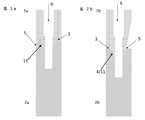
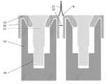
본 발명의 일 실시예는 시험체가 양의 부품(수형 부품)과 음의 부품(암형 부품)으로 구성되고 양의 부품과 음의 부품이 적어도 하나의 수평 접촉 표면, 모스(Morse) 테이퍼 및 시험체의 표면(바람직하게는 외부 표면)에 테이퍼지는 비스듬한 접촉 표면이 발생하도록 서로 맞물리는 것을 특징으로 하는 시험체에 관한 것이다. 이러한 시험체는 데이터 획득 장치 및 주변 장치를 교정하는 데 적합해야 한다. 본 발명에 따른 시험체는 데이터 획득 장치 및 주변 장치를 교정하기 위한 본 발명에 따른 방법에 사용하기에 특히 적합하다.In one embodiment of the present invention, the test body is composed of a positive part (male part) and a negative part (female part), and the positive part and negative part are at least one horizontal contact surface, Morse taper, and It relates to a test specimen characterized in that they engage each other so as to produce an oblique contact surface that tapers on the surface (preferably the outer surface). These specimens should be suitable for calibrating data acquisition devices and peripherals. The test body according to the invention is particularly suitable for use in the method according to the invention for calibrating data acquisition devices and peripheral devices.
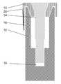
본 명세서에서 사용되는 "모스 테이퍼(Morse taper)"라는 용어는 시험체의 2개의 카운터-피스 중 하나가 기계 도구의 도구 리시버에 있는 도구를 클램핑하기 위한 도구 테이퍼의 표준화된 형상에 해당하는 원뿔을 포함한다고 설명한다(여기서는 해당 카운터-피스의 중공 원뿔). 자기 잠금, 이에 따라 마찰에 의해 야기되고, 서로 지탱하거나 서로에 놓이는 카운터-피스의 비틀림 또는 미끄러짐에 대한 저항은 양의 부품의 중공 원뿔과 그 안에 클램핑하는 음의 부품의 원뿔(또는 그 반대) 사이에 존재한다. 여기서 자기 잠금은 경사각, 접촉 표면의 표면 거칠기, 재료 쌍, 및 가열에 의해 영향을 받는다. 모스 테이퍼로 설명되는 구조와 관련하여, 시험체의 카운터-피스 중 하나에 관해서는, 원뿔 또는 원뿔대이고 해당 카운터-피스에서는 자체 잠금이 정상 조건(실온, 윤활유 없음) 하에서 존재하도록 있는 원뿔 또는 원뿔대가 맞추어지는 내부 원뿔이다. 모스 테이퍼가 원뿔대로 설계된 경우, 원뿔대의 덮개 표면에 해당하는 수평 접촉 표면(스탠드 표면에 수평)을 형성한다. 모스 테이퍼의 측면이 여기에 연결된다. 그런 다음 내부 원뿔의 비스듬한 표면으로 둘러싸인 수평 접촉 표면이 마찬가지로 카운터-피스에 위치한다.The term "Morse taper" as used herein includes a cone in which one of the two counter-pieces of the test body corresponds to the standardized shape of the tool taper for clamping the tool in the tool receiver of the machine tool. (Here, the hollow cone of the counter-piece). Self-locking, thus caused by friction, and the resistance to twisting or slipping of counter-pieces bearing each other or lying on each other is between the hollow cone of the positive part and the cone of the negative part clamping therein (or vice versa). Exists in Here, the magnetic lock is affected by the angle of inclination, the surface roughness of the contact surface, the material pair, and heating. Regarding the structure described by the morse taper, with respect to one of the counter-pieces of the test object, a cone or truncated cone, which is a cone or truncated cone, and in that counter-piece the self-locking is fitted under normal conditions (room temperature, no lubricant). The branch is an inner cone. If the morse taper is designed as a truncated cone, it forms a horizontal contact surface (level to the stand surface) corresponding to the cover surface of the truncated cone. The side of the morse taper is connected here. Then the horizontal contact surface surrounded by the beveled surface of the inner cone is likewise placed on the counter-piece.
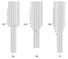
"수평 접촉 표면(horizontal contact surface)"으로 표시된 접촉 표면은 스탠드 표면 또는 양 또는 음의 부품의 바닥 몸체(base body)에 수평이어야 한다. 시험체의 표면으로 테이퍼지는 비스듬한 접촉 표면은 스탠드 표면에 수평하지 않은 양의 부품과 음의 부품 사이의 접촉 표면이다. 비스듬한 접촉 표면은 스탠드 표면과 관련하여 기울기 또는 구배를 갖는다. 이것은 비스듬한 접촉 표면의 상상된 확장이 시험체의 스탠드 표면과 교차한다는 것을 의미한다. 비스듬한 접촉 표면은 바람직하게는 5도 초과 45도 미만, 특히 바람직하게는 10 내지 35도의 구배각을 갖는다. 접촉 표면이 시험체의 표면까지 테이퍼진다는 사실은 접촉 표면이 시험체의 표면에서 끝남을 의미한다(함께 접합된 양의 부품과 음의 부품으로 구성됨). 여기서, 바람직하게는 채널 내에 위치하는 표면이 아닌 시험체의 외부 표면의 경우이다. 따라서 접촉 표면은 바람직하게는 시험체의 포스트에서 바깥쪽으로 비스듬하게 움직이는 표면이다. 시험체의 표면까지 도달하는 비스듬한 접촉 표면은 바람직하게는 시험체의 측면 또는 단면의 주변에서 시험체의 2개의 부품 중 적어도 하나에서 끝난다. 즉, 비스듬한 접촉 표면은 시험체의 두 부품 중 적어도 하나의 주변 또는 측면과 공통 모서리를 형성한다. 바람직한 실시예는 시험체의 표면까지 도달하는 비스듬한 접촉 표면이 시험체(함께 접합된 양의 부품과 음의 부품으로 구성됨)의 주변 또는 또는 그 측면에서 끝나는 것을 특징으로 하는 본 발명에 따른 시험체에 관한 것이다.The contact surface marked "horizontal contact surface" shall be horizontal to the stand surface or the base body of the positive or negative part. The oblique contact surface tapering to the surface of the specimen is the contact surface between the positive and negative parts that are not horizontal to the stand surface. The oblique contact surface has a slope or gradient with respect to the stand surface. This means that the imagined extension of the oblique contact surface intersects the stand surface of the specimen. The oblique contact surface preferably has a draft angle of more than 5 degrees and less than 45 degrees, particularly preferably of 10 to 35 degrees. The fact that the contact surface tapers to the surface of the test object means that the contact surface ends at the surface of the test object (consisting of positive and negative parts joined together). Here, it is preferably the case of the outer surface of the test body, not the surface located in the channel. Thus, the contact surface is preferably a surface that moves obliquely outward from the post of the test body. The oblique contact surface reaching up to the surface of the test body preferably ends at at least one of the two parts of the test body at the periphery of the side or cross section of the test body. That is, the oblique contact surface forms a common edge with the periphery or side of at least one of the two parts of the specimen. A preferred embodiment relates to a test body according to the invention, characterized in that the oblique contact surface reaching the surface of the test body ends at or on the periphery of the test body (consisting of positive and negative parts bonded together).
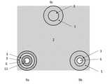
시험체의 2개의 카운터-피스에 대해 바람직하며, 따라서 음의 부품 및 양의 부품은 각각 본체 및 적어도 하나의 포스트를 포함하고, 음의 부품 및 양의 부품은 바람직하게는 적어도 하나의 포스트를 통해 서로 맞물린다. 따라서, 본 발명에 따른 시험체의 카운터-피스의 접촉 표면은 바람직하게는 적어도 하나의 포스트에 놓인다. 따라서, 바닥 몸체에서 멀어지는 측(side)에 있는 포스트의 표면 또는 표면들이 접촉 표면(페이스(face) 측)을 형성한다. 여러 개의 포스트가 있으면, 카운터-피스는 모든 포스트 내에서 서로 맞물리는 것이 바람직한다. 여러 포스트가 있는 실시예와 관련하여, 바닥 몸체는 커넥터 또는 연결 피스로서 설계될 수도 있다. 이 경우, 포스트가 바닥 몸체에 서있지 않고 바닥 몸체가 적어도 2개의 포스트들 사이에 배열되어 이들을 연결한다.It is preferred for two counter-pieces of the test body, so the negative part and the positive part each comprise a body and at least one post, and the negative part and the positive part are preferably each other via at least one post. Interlock. Thus, the contact surface of the counter-piece of the test body according to the invention preferably rests on at least one post. Thus, the surface or surfaces of the post on the side away from the bottom body form a contact surface (face side). If there are multiple posts, it is desirable that the counter-pieces interlock with each other within all posts. In connection with the multi-post embodiment, the bottom body may also be designed as a connector or connecting piece. In this case, the posts do not stand on the floor body and the floor body is arranged between at least two posts to connect them.
바람직한 실시예는 동일한 지오메트리(geometry)를 갖는 적어도 2개의 포스트를 포함하는 것을 특징으로 하는 본 발명에 따른 시험체를 포함한다. 포스트는 임의의 단면을 가질 수 있다. 단면은 예를 들어 정사각형, 직사각형, 마름모꼴, 육각형, 팔각형, 타원형, 또는 삼각형일 수 있다. 그러나, 적어도 하나의 포스트의 단면과 모든 추가 포스트는 둥근 것이 바람직한다. 포스트의 직경은 2~8mm가 바람직한다. 2개의 포스트 사이의 거리는 1~12mm 큰 것이 바람직한다. 포스트의 바람직한 높이는 3~15mm이다. 시험체의 바닥 몸체는 임의의 방식으로 형성될 수 있다. 시험체의 바닥 몸체는 예를 들면, 직육면체, 정육면체, 마름모꼴, 프리즘, 쐐기, 원통 또는 원형 원통일 수 있다. 바닥 몸체는 바람직하게는 직육면체 또는 정육면체이다. 정육면체는 바람직하게는 에지 길이가 5 내지 30mm이고, 직육면체는 바람직하게 1 내지 15mm의 높이, 5 내지 30mm의 폭, 및 1 내지 30mm의 깊이를 갖는다. 적어도 2개의 포스트를 갖는 실시예와 관련하여, 포스트의 접촉 표면이 상이한 높이에 놓이는 것이 더 바람직하며, 따라서 양의 부품과 음의 부품이 상이한 높이(예를 들어, 다르게 상승된 수평 접촉 표면)에서 서로 맞물린다. 이것은 양의 부품의 포스트가 서로 다른 높이를 가지며 음의 부품의 포스트도 그에 따라 또한 다른 높이를 가지며 음의 부품의 낮은(짧은) 포스트가 양의 부품의 높은 포스트에 해당함을 의미한다.A preferred embodiment comprises a test body according to the invention, characterized in that it comprises at least two posts of the same geometry. Posts can have any cross-section. The cross section can be, for example, square, rectangular, rhombic, hexagonal, octagonal, oval, or triangular. However, it is preferred that the cross section of at least one post and all additional posts are round. The diameter of the post is preferably 2 to 8 mm. It is preferable that the distance between the two posts is 1 to 12 mm larger. The preferred height of the post is 3 to 15 mm. The bottom body of the test specimen can be formed in any way. The bottom body of the test body may be, for example, a rectangular parallelepiped, a cube, a rhombus, a prism, a wedge, a cylinder or a circular cylinder. The bottom body is preferably a cuboid or a cube. The cube preferably has an edge length of 5 to 30 mm, and the rectangular parallelepiped preferably has a height of 1 to 15 mm, a width of 5 to 30 mm, and a depth of 1 to 30 mm. With respect to embodiments with at least two posts, it is more preferable that the contact surfaces of the posts lie at different heights, so that the positive and negative parts are at different heights (e.g., differently raised horizontal contact surfaces). Interlocking This means that the posts of the positive part have different heights, the posts of the negative part also have different heights accordingly, and the low (short) post of the negative part corresponds to the high post of the positive part.
양의 부품(수형 부품) 및 음의 부품(암형 부품)은 각각 유닛, 특히 본 발명에 따른 시험체를 형성한다. 양의 부품 및 음의 부품은 서로 맞물리는 것을 의미하는 고정밀도로 서로 피팅되도록 성형되는 카운터-피스이다. 2개의 카운터-피스가 서로 접합되도록 함께 정합되면, 카운터-피스의 표면(시험체의 양의 부품 및 음의 부품) 사이에 발생할 수 있는 간격은 0.1mm 이하, 바람직하게는 0.5mm 이하, 특히 0.05mm 이하이어야 한다. 이것은 특히 간격 폭과 관련이 있지만 간격 길이와는 독립적이다. 시험체는 바람직하게는 블랭크로 밀링된다.The positive part (male part) and the negative part (female part) each form a unit, in particular the test body according to the invention. The positive part and the negative part are counter-pieces that are molded to fit together with high precision meaning that they interlock. If the two counter-pieces are mated together so that they are joined together, the spacing that can occur between the surfaces of the counter-pieces (positive and negative parts of the test object) is 0.1 mm or less, preferably 0.5 mm or less, especially 0.05 mm. Should be less than or equal to This is particularly related to the gap width, but is independent of the gap length. The test body is preferably milled into blanks.
다양한 제품 시리즈의 시험체는 다를 수 있다. 따라서 다른 생산 시리즈의 시험체 또는 시험체의 카운터-피스가 항상 호환된다는 보장은 없다. 이 때문에, 시험체에는 배치 번호가 제공되어야 한다. 각각의 장치 쌍이 동일한 배치 번호의 시험체 또는 시험체의 카운터-피스로 교정된다는 점에 주의해야 한다. 시험체가 파손되면, 항상 교환되어야 하는 시험체 부품 또는 각각의 장치 쌍의 적용된 시험체 쌍이다.Specimens for various product series may be different. Therefore, there is no guarantee that specimens of different production series or counter-pieces of specimens will always be compatible. For this reason, the batch number must be provided for the specimen. It should be noted that each pair of devices is calibrated with the same batch number of specimens or counter-pieces of specimens. If the test object fails, it is either the test body part that must always be replaced or the applied test body pair of each device pair.
따라서 본 발명에 따른 시험체의 양의 부품과 음의 부품은 공통 제조 공정으로 제조되는 것이 바람직하다.Therefore, it is preferable that the positive and negative parts of the test body according to the present invention are manufactured by a common manufacturing process.
본 발명에 따른 시험체는 바람직하게는 형태가 안정된 재료로 구성된다. 시험체의 재료는 외부 하중으로 인해 가능한 한 영구적인 변형이 발생하지 않도록 선택되어야 한다. 따라서 변형률이 낮아야한다. 특히, 낮은 소성 변형성이 바람직하다. 그러나 탄성도 낮아야 한다. 일반적으로 적합한 부서지기 쉬운 재료이다. 본 발명에 따른 시험체의 재료가 유리, 화강암, 토날라이트(tonalite), 또는 현무암과 같은 단단한 암석(높은 내마모성), Cr-Co 합금과 같은 금속 합금, 이산화 지르코늄 또는 리튬 디실리케이트(고강도 유리 세라믹), 세라믹 복합재, PMMA, PEEK, 및 폴리 카보네이트와 같은 세라믹으로 구성된 그룹에서 선택되는 것이 바람직한다. 여기서 특히 바람직한 것은 Cr-Co 합금과 같은 금속 합금, 이산화 지르코늄 또는 리튬 디실리케이트와 같은 세라믹(고강도 유리 세라믹) 및 PEEK이다.The test body according to the present invention is preferably made of a material having a stable shape. The material of the specimen should be selected so as not to cause permanent deformation as much as possible due to external loads. Therefore, the strain should be low. In particular, low plastic deformability is preferred. However, the elasticity must also be low. It is a generally suitable brittle material. The material of the test body according to the present invention is a hard rock such as glass, granite, tonalite, or basalt (high wear resistance), a metal alloy such as Cr-Co alloy, zirconium dioxide or lithium disilicate (high strength glass ceramic), It is preferred to be selected from the group consisting of ceramic composites, PMMA, PEEK, and ceramics such as polycarbonate. Particularly preferred here are metal alloys such as Cr-Co alloys, ceramics such as zirconium dioxide or lithium disilicate (high strength glass ceramics) and PEEK.
교정될 장치와 적용되는 재료(예: 입자 크기)에 따라 제조 고유의 생산된 일부 공작물에는 이상적인 모서리나 각도가 없다. 이 때문에, 바람직한 시험체는 둥글거나 챔버형 모서리, 에지, 및/또는 각도를 포함할 수 있다. 여기서, 반경 ≤0.5mm가 바람직하고, 더욱 바람직하게는 반경 ≤0.1mm이다. 대안적으로, 그에 따라 공차 범위를 미리 정의할 수도 있다. 수평, 사선, 또는 경사 평면 또는 표면이 합쳐질 때 형성되는 각도와 에지는 반경 ≤0.2mm의 라운딩을 가지는 것이 바람직하다. 이러한 라운딩은 일반적인 CAD 밀링머신의 지오메트리 및 적층 방법의 재료의 입자 크기에 맞게 조정될 수 있다.Depending on the device to be calibrated and the material to be applied (eg particle size), some manufactured workpieces inherent in manufacturing do not have ideal edges or angles. For this reason, preferred specimens may include rounded or chambered edges, edges, and/or angles. Here, a radius ≤ 0.5 mm is preferable, and a radius ≤ 0.1 mm is more preferable. Alternatively, it is also possible to predefine the tolerance range accordingly. It is preferable that the angle and edge formed when the horizontal, oblique, or inclined planes or surfaces merge have a rounding of a radius ≤ 0.2mm. This rounding can be tailored to the geometry of a typical CAD milling machine and the particle size of the material of the lamination method.
본 발명의 다른 실시예는 시험체의 양의 부품과 음의 부품이 상이한 재료로 제조된 것을 특징으로 하는 본 발명에 따른 시험체에 관한 것이다. 이를 통해, 교정된 장치를 통해 발생하는 향후 생산을 수용할 수 있다. 시험체가 미래의 제품도 제조되는 재료로 제조된다면 유리할 수 있다.Another embodiment of the present invention relates to a test body according to the invention, characterized in that the positive and negative parts of the test body are made of different materials. This allows for future production to be accommodated through calibrated devices. It may be advantageous if the test body is made of materials from which future products are also manufactured.
본 발명에 따른 시험체의 추가 실시예에서, 시험체는 적어도 하나의 채널을 포함한다. 채널은 바람직하게는 시험체의 중간 지점 또는 시험체의 포스트 주위에 위치한다. 또한, 모스 테이퍼는 도관 주위에 동심원으로 배열되는 것이 바람직한다. 적어도 하나의 채널이 음의 부품과 양의 부품의 시험체에 시험 핀을 삽입할 수 있도록 하는 것이 바람직한다. 적어도 하나의 채널은 시험 핀이 양의 부품뿐만 아니라 음의 부품에도 삽입될 수 있거나, 채널이 시험체의 두 개의 카운터-피스를 통합한 후 2개의 카운터-피스에서 생성되도록 배열되어야 한다. 시험 핀을 삽입하면 구멍 공차를 설정하고 조정할 수 있다. 적어도 하나의 채널은 바람직하게는 1 내지 7mm 길이 또는 깊이이고 바람직하게는 1 내지 4mm의 직경을 갖는다.In a further embodiment of the test body according to the invention, the test body comprises at least one channel. The channel is preferably located at the midpoint of the specimen or around the posts of the specimen. Further, it is preferred that the morse taper is arranged concentrically around the conduit. It is desirable that at least one channel allows the insertion of the test pins in the negative and positive component specimens. At least one channel shall be arranged such that the test pin can be inserted into the negative as well as the positive part, or the channel is created in the two counter-pieces after integrating the two counter-pieces of the test object. The hole tolerance can be set and adjusted by inserting the test pin. The at least one channel is preferably 1 to 7 mm long or deep and preferably has a diameter of 1 to 4 mm.
또한, 본 발명의 바람직한 실시예는 그 코스의 적어도 하나의 채널이 내부에 단차를 포함하는 것을 특징으로 하는 시험체에 관한 것이다. 이 단차는 바람직하게는 시험체의 기립 표면에 수평으로 형성되는 접촉 표면을 형성한다. 이것은 단차가 90도 각도를 형성한다는 것을 의미한다. 그러나 단차는 실제로 다른 각도를 가질 수도 있다. 선호하는 각도는 ≥90 도이다. 특히 바람직한 각도는 90도, 135도, 150도, 및 160도이다. 본 발명에 따르면, 90 도의 각도를 갖는 단차가 매우 특히 바람직하다. 채널의 직경은 단차에 의해 바람직하게는 0.5-3mm 감소한다.Further, a preferred embodiment of the present invention relates to a test body, characterized in that at least one channel of the course includes a step inside. This step preferably forms a contact surface formed horizontally on the standing surface of the test body. This means that the steps form a 90 degree angle. However, the steps may actually have different angles. The preferred angle is ≥90 degrees. Particularly preferred angles are 90 degrees, 135 degrees, 150 degrees, and 160 degrees. According to the invention, a step with an angle of 90 degrees is very particularly preferred. The diameter of the channel is preferably reduced by 0.5-3 mm by the step.
본 발명의 다른 양태는 본 발명에 따른 시험체 및 시험체의 적어도 하나의 채널에 삽입될 수 있는 적어도 하나의 시험 핀으로 구성된 세트에 관한 것이다. 시험 핀의 외경은 시험체의 채널 내경보다 훨씬 작은 만것이 바람직한다. 따라서 시험 핀은 채널에서 가능한 현재 단차를 복제한다. 시험 핀은 일반적으로 정확히 맞춰지는 방식으로 시험체의 채널에 삽입될 수 있도록 설계된다. 본 발명에 따른 세트는 또한 시험체가 상이한 코스(예를 들어, 상이한 직경 또는 상이하게 형성된 단계)를 갖는 채널을 포함하는 경우에 특히 유용한 여러 시험 핀을 포함할 수있다.Another aspect of the invention relates to a set consisting of a test body according to the invention and at least one test pin that can be inserted into at least one channel of the test body. It is preferable that the outer diameter of the test pin is much smaller than the inner diameter of the channel of the specimen. Therefore, the test pin duplicates the current step possible in the channel. The test pins are generally designed so that they can be inserted into the channel of the test object in an exact fit. The set according to the invention may also comprise several test pins which are particularly useful when the test body comprises channels with different courses (eg different diameters or differently formed steps).
본 발명에 따른 세트는 추가로 시험체의 양의 부품의 적어도 하나의 표준화된 디지털 데이터 세트 및 시험체의 음의 부품의 적어도 하나의 표준화된 디지털 데이터 세트를 더 포함할 수 있다.The set according to the invention may further comprise at least one standardized digital data set of positive parts of the test body and at least one standardized digital data set of negative parts of the test body.
본 발명의 또 다른 양태는 보철 공작물을 계획하기 위한 컴퓨터-구현 방법에 관한 것으로, 상기 방법은Another aspect of the present invention relates to a computer-implemented method for planning a prosthetic workpiece, the method comprising:
I) 복원 또는 교체될 치아와 관련된 환자-관련 데이터를 디지털 또는 디지털 형태로 제공하는 단계;I) providing patient-related data related to the tooth to be restored or replaced in digital or digital form;
II) 디지털 데이터의 형태로 형상 마스터를 제공하는 단계;II) providing a shape master in the form of digital data;
III) 복원 또는 교체될 치아에 대한 생물학적 및 해부학적 평균값을 제공하는 단계;III) providing a biological and anatomical mean value for the tooth to be restored or replaced;
IV) CAD 밀링머신 또는 보철 공작물의 적층 제조를 위한 장치의 모델 역할을 할 수 있는 디지털 데이터 세트를 계산하는 단계로서, II)로부터의 데이터는 I) 및 III)으로 부터의 데이터를 사용하여 개인화되고 최적화하는, 단계를 포함한다.IV) Calculating a digital data set that can serve as a model of a CAD milling machine or a device for additive manufacturing of a prosthetic workpiece, where the data from II) is personalized using data from I) and III). Optimizing, including steps.
치료가 필요한 치아의 부재 부품의 또는 치아 교체 제조를 위한 재구성은 단계 IV)의 계산 및 최적화에 의해 결정되는 데이터 세트를 기반으로 한다. 물리적 치아 교체 부품 또는 물리적 치아 복원물은 단계 IV)에서 얻은 데이터 세트에 따라 제어되는 기계를 통해 제조된다. 따라서, 본 발명의 다른 양태는 상기 단계 I)-IV)를 포함하는 보철 공작물의 제조를 위한 컴퓨터-구현 방법에 관한 것이다. 계획 또는 제조될 보철 공작물은 치아 교체 부품, 부착 부품(핀 부착물, 임플란트 부착물 또는 교각치(abutment)), 임플란트 크라운, 웨브, 치과 크라운, 부목, 드릴링 템플릿 및 브리지로 구성된 그룹으로 구성된다. 본 발명은 또한 전술한 방법을 수행하도록 설계된 소프트웨어(설계 도구)에 관한 것이다.The reconstruction of the missing part of the tooth in need of treatment or for the manufacture of a tooth replacement is based on a data set determined by calculation and optimization of step IV). The physical tooth replacement part or physical tooth restoration is manufactured through a machine controlled according to the data set obtained in step IV). Accordingly, another aspect of the present invention relates to a computer-implemented method for manufacturing a prosthetic workpiece comprising steps I)-IV) above. The prosthetic workpiece to be planned or manufactured consists of a group consisting of tooth replacement parts, attachment parts (pin attachments, implant attachments or abutments), implant crowns, webs, dental crowns, splints, drilling templates and bridges. The invention also relates to software (design tool) designed to perform the above-described method.
컴퓨터-구현 방법은 다음 단계 하위-단계 중 적어도 하나를 더 포함할 수 있다.The computer-implemented method may further include at least one of the following sub-steps.
- 나머지 파라미터 또는 치수의 자동 조정으로 개별 파라미터 또는 치수를 수동 변경.-Manually change individual parameters or dimensions with automatic adjustment of the remaining parameters or dimensions.
보철 공작물의 하위-구조를 수동으로 수정하는 동안(컴퓨터 화면에서), 나머지 구조는 순전히 숫자 방식으로 조정된다. 이는 II) 및 III)으로부터 저장된 데이터를 기반으로 한다. 목표는 생물학적 또는 해부학적으로 의미있고 환자에게 적합한 전체 구조의 형성을 항상 허용하는 것이다.While manually modifying the sub-structure of the prosthetic workpiece (on the computer screen), the rest of the structure is adjusted purely numerically. It is based on the data stored from II) and III). The goal is to always allow the formation of a whole structure that is biologically or anatomically meaningful and suitable for the patient.
- 크라운 에지까지 점막하 영역의 크라운 구조 외삽-Extrapolation of the crown structure of the submucosal area to the crown edge
이것은 단계 IV)의 하위-단계일 수 있다. 외삽은 무엇보다도 개별 치아 위치와 연조직의 출현 선 윤곽을 기반으로 하며 계획된 보철 공작물에 의해 교체 또는 복원될 치아의 저장된 평균 치수를 고려한다. 또한, 중간 부재의 접촉 영역과 접촉점 구역의 위치 및 확장이 고려될 수 있다.This may be a sub-step of step IV). Extrapolation is, among other things, based on the individual tooth position and the contours of the emergence lines of soft tissue and takes into account the stored average dimensions of the teeth to be replaced or restored by the planned prosthetic workpiece. Further, the location and extension of the contact area and the contact point area of the intermediate member can be considered.
- 특정 영역의 표면 특성의 결정.-Determination of the surface properties of a specific area.
여기서, 적어도 일부 구역 및/또는 미세 구조의 거칠기가 결정될 수 있다. 이를 통해, 환자에게 삽입한 후 주변 조직에 공작물이 최적화된 접촉의 보장에 성공한다.Here, the roughness of at least some regions and/or microstructures can be determined. In this way, after being inserted into the patient, it succeeds in ensuring the optimal contact of the workpiece to the surrounding tissue.
환자-관련 데이터는 스캐너(예: 구강 스캐너), 사진 장치(환자의 얼굴 및 입술보기의 디지털 사진), 디지털 컴퓨터 단층 촬영 또는 디지털 볼륨 단층 촬영(골 구조에 대한 정보)을 통해 생산될 수 있다. 데이터는 무엇보다도 인접 치아의 치수, 반대쪽 치아의 미러링, 대항(counter)-턱의 교합선 과정, 뼈 구조 및 연조직의 치수와 관련이 있다.Patient-related data can be produced through scanners (eg oral scanners), photographic devices (digital photographs of a patient's face and lip views), digital computed tomography or digital volume tomography (information on bone structure). The data relate, among other things, to the dimensions of the adjacent teeth, the mirroring of the opposite tooth, the counter-jaw occlusal process, the bone structure and the dimensions of the soft tissue.
형상 마스터는 자연치 형상, 획득 가능한 임플란트, 보조 부품, 및 일반적인 크라운 모양의 데이터 뱅크를 기반으로하며 공작물 설계를 생성하기 위한 모델로서 기능한다. 계획된 공작물의 디지털 사진에서 시작하여, 임플란트 위치와 임플란트 기울기가 결정될 수 있으며 이에 매칭되는 공작물의 설계를 계산하고 디지털로 표현될 수 있다.The shape master is based on a data bank of natural tooth shapes, obtainable implants, auxiliary parts, and common crown shapes and functions as a model for creating a workpiece design. Starting from a digital photo of the planned work piece, the implant position and implant inclination can be determined, and the design of the matching work piece can be calculated and represented digitally.
공작물의 설계 성형에 대한 원칙은 소프트웨어에 저장되며 계획 단계에서 이미 활성화될 수 있다. 이 프로그램은 다양한 설계 구성 요소를 계산하고 그 안에 저장된 해부학, 생물학 및 생체 역학 관련 규칙에 따라 해부학적 형상의 공작물에 자동으로 결합하여 최적의 맞춤과 최적의 성형을 조합할 수 있다. 또한 특정 구역의 표면 특성(거칠기, 미세 구조)을 설정할 수 있는 도구를 가질 수 있다. 이것으로, 생물학적 환경과의 접촉을 고려할 때 가능한 최상의 효과를 얻을 수 있도록 공작물의 표면의 설계에 성공하였다.The principles for shaping the design of the workpiece are stored in the software and can already be activated in the planning stage. The program calculates various design components and automatically combines them into anatomically shaped workpieces according to the anatomical, biological and biomechanical rules stored therein to combine optimal fit and optimal molding. You can also have tools to set the surface properties (roughness, microstructure) of a specific area. With this, we have succeeded in designing the surface of the workpiece to obtain the best possible effect when considering the contact with the biological environment.
생물학적 및 해부학적 평균 값은 예를 들어 시멘트질-법랑질 접합부에서 법랑질 캡의 코스와 윤곽, 생물학적 폭(고랑, 상피 부착 및 연결 조직 교각치의 세 영역으로 구성된 연조직 구획의 평균 값), 치아 및 치아 위치의 생체 역학적 값, 공작물 제조에 사용되는 재료, 연조직 윤곽, 축 경사, 크라운 길이 및 폭, 접점 구역의 위치 및 확장 또는 중간 부재의 접촉 영역과 같은 해부학적 특징에 관련된다.The biological and anatomical mean values are, for example, the course and contour of the enamel cap at the cementitious-enamel junction, the biological width (average value of the soft tissue compartment consisting of three areas: furrow, epithelial attachment and connective tissue bridge tooth), tooth and tooth position. Biomechanical values, materials used in the manufacture of the workpiece, soft tissue contours, axial tilt, crown length and width, the location of the contact area, and anatomic features such as the contact area of the extension or intermediate member.
본 발명에 따른 컴퓨터-구현 방법은 임플란트에 대한 상부 구조 또는 부착 부품의 전이를 최적으로 설계하는데 특히 적합하다. 이 방법은 통합될 임플란트(들)의 위치, 기울기, 직경, 길이, 유형(TL 대 BL) 및 재료(티타늄, 티타늄-지르콘, 지르코니아)와 같은 중요한 임플란트 파라미터를 결정하는데 특히 적합하여, 예후, 기능, 및 미학과 관련하여 턱의 해부학과 계획된 상부 구조를 최적의 방식으로 고려한다. 임플란트의 부착 부품(존재하는 한), 또한 턱뼈의 다른쪽에 있고 연조직으로 둘러싸이도록 구성된 임플란트의 해당 영역이 환자에게 최적으로 매칭될 수 있다. 이를 위해 턱의 해부학, 연조직 높이, 및 연조직 카운터, 임플란트 부착물 선택에 사용할 수 있는 형상 마스터가 고려된다. 특히 이로 인해 임플란트 부착물이 생산 후 재료 두께가 수동으로 감소되는 것을 방지한다는 사실에 의해, 임플란트로 전환할 때 교각치와 크라운의 최적화된 형상과 표면 설계의 유용성이 크다. 또한 배럴 링(WO 2018/215616호에 설명된 바와 같이) 형상의 연결 부품이 제공되는 푸시-오버 크라운(pushed-over crown)이 설계에 지정된 재료 두께가 안정성을 위해 더 이상 부족하지 않도록 하는 것이 중요한다. 이를 통해서만 기계적 안정성을 보장할 수 있다.The computer-implemented method according to the invention is particularly suitable for optimally designing the transition of a superstructure or attachment part to an implant. This method is particularly suitable for determining important implant parameters such as the location, slope, diameter, length, type (TL vs. BL) and material (titanium, titanium-zircon, zirconia) of the implant(s) to be integrated, and therefore prognosis, function. Considering the anatomy of the jaw and the planned superstructure in an optimal way with respect to, and aesthetics. The attachment part of the implant (as long as it exists), as well as that area of the implant on the other side of the jawbone and configured to be surrounded by soft tissue, can be optimally matched to the patient. For this, the anatomy of the jaw, the height of the soft tissue, and the soft tissue counter, a shape master that can be used to select the implant attachment, are considered. In particular, due to the fact that this prevents the implant attachment from being manually reduced in material thickness after production, the optimal shape and surface design of piers and crowns when converting to implants is of great utility. It is also important that a push-over crown, provided with a barrel-ring (as described in WO 2018/215616) shaped connection part, is no longer short of the material thickness specified in the design for stability. do. Only in this way can the mechanical stability be guaranteed.
또한, 연조직에 최적인 표면 구조 및 표면 거칠기가 결정되고 제조시 구현될 수 있다. 이 구조를 수동으로 2차 기계 가공하는 경우, 공작물은 컴퓨터에서 계획된 일부 특성을 잃을 수 있다. 이러한 맥락에서, 침착된 세라믹은 다공성이고 연조직의 최상의 통합을 위한 최적의 표면을 제공하지 않기 때문에, 치과 기공사가 개선된 윤곽을 위해 세라믹의 후속 침착이 방지되어야 한다.In addition, the optimal surface structure and surface roughness for the soft tissue can be determined and implemented during manufacture. In the case of manual secondary machining of this structure, the workpiece may lose some of the computer-planned properties. In this context, since the deposited ceramic is porous and does not provide an optimum surface for the best integration of soft tissue, the dental technician must prevent subsequent deposition of ceramic for an improved contour.
본 발명에 따른 시험체는 아래 도면을 통해 더욱 상세하게 설명된다.
도 1a: 본 발명에 따른 시험체의 양의 부품(2a)을 종단면으로 도시한다.
도 1b: 본 발명에 따른 시험체의 추가 양의 부품(2b)을 종단면으로 도시한다.
도 2a: 매칭되는 음의 부품(1a)과 함께 정합되고 본 발명에 따른 시험체를 함께 형성하는 도 1a의 양의 부품(2a)을 도시한다.
도 2b: 매칭되는 음의 부품(1b)과 함께 정합되고 본 발명에 따른 시험체를 함께 형성하는 도 1b의 양의 부품(2b)을 도시한다.
도 3a: 시험 핀(8)이 삽입된 도 2a의 발명에 따른 시험체를 도시한다.
도 3b: 시험 핀(8)이 삽입된 도 2b의 발명에 따른 시험체를 도시한다.
도 4: 2개의 포스트(9a, 9b)를 포함하는 본 발명에 따른 시험체의 양의 부품(2)을 종단면으로 도시한다.
도 5: 매칭되는 음의 부품(1)과 함께 결합되고 본 발명에 따른 시험체를 함께 형성하는 도 4의 양의 부품(2)을 도시한다.
도 6: 2개의 시험 핀(8)이 삽입되는 도 5의 발명에 따른 시험체를 도시한다.
도 7a: 본 발명에 따른 시험체의 음의 부품(1, 위)(저면도) 및 양의 부품(2, 아래)을 도시한다.
도 7b: 음의 부품(1) 및 양의 부품(2)이 서로 맞물린 후의 도 7a의 시험체를 도시한 평면도이다.
도 8: 3개의 포스트(9a, 9b, 및 9c)를 구비한 양의 부품(2)을 도시한 평면도이다.
도 9: 세 개의 포스트(9a, 9b, 및 9c)를 구비한 추가 양의 부품(2)을 도시한 평면도이다.
도 10: 적어도 3개의 포스트를 갖는 본 발명에 따른 시험체에서 발생할 수 있는 2개의 가능한 포스트 변형예(9a, 9b)를 도시한다.
도 11: 3개의 포스트(9a, 9b, 및 9c)를 구비한 추가 양의 부품(2)을 도시한 평면도이다.
도 12: 4개의 포스트(9a, 9b, 9c, 및 9d)를 구비한 양의 부품(2)을 도시한 평면도이다.
도 13: 4개의 포스트(9a, 9b, 9c, 및 9d)를 구비한 양의 부품(2)을 도시한 평면도로서, 포스트의 배열은 도 12와 상이하다.
도 14: 3개의 포스트(9a, 9b, 및 9c)를 구비한 본 발명에 따른 시험체(양의 부품 및 음의 부품)를 도시한 평면도이다.
도 15: 3개의 포스트(9a, 9b, 및 9c)를 구비한 본 발명에 따른 추가 시험체(양의 부품(2) 및 음의 부품(1)를 도시한 평면도이고, 여기서 포스트(9a, 9b, 및 9c)의 배열 및 음의 부품(1)의 바닥 몸체의 형상이 도 14와 상이하다.
도 16: 4개의 포스트(9a, 9b, 9c, 및 9d)를 구비한 본 발명에 따른 시험체(양의 부품(2) 및 음의 부품(1))를 도시한 평면도이다.
도 17: 4개의 포스트(9a, 9b, 9c, 및 9d)를 구비한 본 발명에 따른 추가 시험체(양의 부품(2) 및 음의 부품(1))를 도시한 평면도이며, 음의 부분(1)의 바닥 몸체의 형상이 도 16과 상이하다.
도 18: 본 발명에 따른 시험체와 조합하여 사용될 수 있는 3개의 다른 시험 핀(8)을 도시한다.
도 19: 본 발명에 따른 컴퓨터-구현 방법의 도움으로 최적화될 수 있는 치과용 임플란트 시스템의 하나의 양태를 도시한다.
도 20: 본 발명에 따른 컴퓨터-구현 방법의 도움으로 최적화될 수 있는 치과용 임플란트 시스템의 추가 양태를 도시한다.
도 21: 본 발명에 따른 컴퓨터-구현 방법의 도움으로 최적화될 수 있는 치과용 임플란트 시스템의 하나의 양태를 도시한다.
도 22: 본 발명에 따른 컴퓨터-구현 방법의 도움으로 최적화될 수있는 치과용 임플란트 시스템의 하나의 양태를 도시한다.The test body according to the present invention is described in more detail through the drawings below.
Fig. 1a: A
Figure 1b: A further quantity of
Fig. 2a: shows the
Fig. 2b: shows the
Fig. 3a: shows a test body according to the invention of Fig. 2a in which the test pins 8 are inserted.
Fig. 3b: shows a test body according to the invention of Fig. 2b with a
Fig. 4: A
5: shows the
Fig. 6: shows a test body according to the invention of Fig. 5 into which two
Fig. 7A: shows the negative part 1 (top) (bottom view) and the positive part 2 (bottom) of a test body according to the invention.
Fig. 7B: A plan view showing the test body of Fig. 7A after the
Figure 8: A plan view showing a
Figure 9: A plan view showing an additional amount of
Figure 10: Shows two
Figure 11: A plan view showing an additional amount of
Figure 12: A plan view showing a
Fig. 13: A plan view showing a
Fig. 14: A plan view showing a test body (positive part and negative part) according to the present invention with three
Figure 15: A plan view showing an additional test body according to the invention (
Fig. 16: A plan view showing a test body (
Fig. 17: A plan view showing an additional test body (
Figure 18: shows three
Figure 19: shows one aspect of a dental implant system that can be optimized with the aid of a computer-implemented method according to the invention.
Figure 20 shows a further aspect of a dental implant system that can be optimized with the aid of a computer-implemented method according to the invention.
Figure 21: shows one aspect of a dental implant system that can be optimized with the aid of a computer-implemented method according to the present invention.
Figure 22: shows one aspect of a dental implant system that can be optimized with the aid of a computer-implemented method according to the present invention.
도 1a 내지 도 3b는 본 발명에 따른 시험체의 단순하게 설계된 2개의 예로서 그 구성뿐만 아니라 가장 중요한 구성 요소 및 특징을 보여준다. 일반적으로 위에서 더 설명되었고 도 2에서 명백한 바와 같이, 본 발명에 따른 시험체는 양의 부품(2) 및 음의 부품(1)을 포함하고, 여기서 양의 부품(2) 및 음의 부품(1) 끝면에서 각각의 해당 수평(3) 및 비스듬한 내부(4) 및/또는 외부(5) 접촉 표면과 서로 맞물린다. 도 1a에 도시된 바와 같은 양의 부품(2a)은 본질적으로 둥근 단면을 가진 컬럼이며, 예를 들어 타원형, 정사각형, 직사각형, 또는 불규칙한 단면과 같은 다른 단면도 가능한다. 상단에는 비스듬히 바깥쪽으로 테이퍼지는 표면(5)이 있다. 이것은 치과 치료 및 TL 임플란트(조직 수준 임플란트)에 일반적으로 사용되는 지오메트리에 관한 것이다. 주변에서 비스듬하게 바깥쪽으로 테이퍼지는 표면(5)은 경사각을 갑자기 변경한다. 도시된 종단면에서, 이것은 외부로 다른 가파른 구간을 따르는 수평 접촉 표면을 통해 인식되어야 한다. 양의 부품에는 추가로 모스 테이퍼 또는 중공 원뿔(11)이 있고 중앙에는 z축 방향(나사 구멍과 유사)으로 중앙 채널(6)을 갖는다. 도 1b에 표시된 양의 부품(2b)은 기본적으로 마찬가지로 둥근 컬럼이다. 사면 없이 평면 끝면/접촉 표면을 포함한다. 단차 준비 및 맞대기 조인트 연결 또는 헤드-투-헤드 연결을 하는 임플란트의 일반적인 지오메트리에 맞게 조정된다. 양의 부품(2b)도 마찬가지로 중공 원뿔(11)과 중앙에서 형성되는 채널(6)을 갖는다.1A to 3B are two simple designed examples of the test body according to the present invention, and show the most important components and features as well as the configuration thereof. In general, as further described above and apparent from Fig. 2, the test body according to the invention comprises a
종단면의 도 2a 및 도 2b는 도 1a 및 도 2b의 양의 부품(2a, 2b)과 매칭되는 음의 부품(1a, 1b)을 함께 도시한다. 양의 부품 및 관련 음의 부품은 함께 각각 본 발명에 따른 시험체를 형성한다. 도 2a 및 도 2b에서 명백한 바와 같이, 양의 부품(2a, 2b) 및 음의 부품(1a, 1b)은 서로 맞물리도록 설계된다. 양의 부분(2a, 2b) 및 음의 부분(1a, 1b)은 접촉 표면이 간격을 형성하지 않고 짝을 이루도록 정확하게 맞춰지는 방식으로 서로 맞물리는 것이 바람직한다. 제조 및 시험체가 제조되는 재료에 따라, 이것이 항상 가능한 것은 아니다. 카운터-피스의 접촉 표면(시험체의 양의 부품과 음의 부품) 사이에 발생할 수 있는 간격은 바람직하게는 0.1mm이하, 더욱 바람직하게는 0.5mm이하, 특히 0.05mm이하이어야 한다.Figures 2a and 2b in longitudinal section together show the
도 2a 및 도 2b에 따른 시험체의 양쪽 카운터-피스, 이에 따른 양의 부품(2a, 2b)과 음의 부품(1a, 1b)은 서로 피팅되는 외부 표면의 단면을 가지며, 상기 단면은 수평으로 시험체의 스탠드 표면에 형성되어 양 카운터-피스를 함께 접합할 때 수평 접촉 표면(3)이 발생한다. 도 2a의 발명에 따른 시험체는 또한 2개의 비스듬하게 형성되는 접촉 표면(5)을 가지며, 둘다 시험체의 외부 표면까지 형성된다. 이 2개의 경사면은 상이한 경사각을 갖는다. 도 2b의 발명에 따른 시험체는 시험체의 표면까지 형성되면서 동시에 모스 테이퍼의 부분을 형성하는 비스듬하게 형성되는 접촉 표면(5)을 갖는다.Both counter-pieces of the test body according to Figs. 2a and 2b, thus the
대응하는 양의 부품의 접촉 표면에 맞물리는 표면의 음의 부품(1a, 1b)은 자체 잠금이 발생하도록 양의 부품(2a 또는 2b)의 모스 테이퍼에 맞춰지는 모스 테이퍼를 포함한다. 이에 대해 중요한 것은 경사각이지만 표면 거칠기와 온도도 영향을 미친다. 모스 테이퍼 또는 내부 원뿔(11)과 시험체 표면까지 테이퍼지는 비스듬한 접촉 표면(5)은 주변 정확도 및 수축 보상의 평가를 허용한다. 도 2a 및 도 2b에 따른 또는 도 3a 및 도 3b에 따른 시험체는 각각의 음의 부품(1a, 1b)을 통과하고 양의 부품(2a, 2b) 내로 돌출하는 중앙 채널(6)을 포함한다. 채널에는 단차(7) 또는 경로에 숄더가 있다. 이 단차(7)에서 채널의 직경이 감소한다. 채널은 바람직하게 둥근 단면을 갖지만 타원형 또는 다각형일 수도 있다.The
도 3a 및 도 3b에서, 도 2a 및 도 2b의 시험체는 삽입된 시험 핀(8)과 함께 표시된다. 시험 핀(8)은 단지 채널(6)의 내경보다 훨씬 작은 외경을 갖는다. 따라서 시험 핀은 또한 가능한 한 정확하게 맞춰지는 방식으로 시험체에 맞춰진다. 도 3a 및 도 3b에 따른 실시예와 관련하여, 채널은 각각 단차(7)를 포함한다. 결과적으로, 시험 핀(8)에는 시험 핀(8)의 단면 직경이 시험체의 채널(6) 직경에 따라 감소하는 단차(반대로 형성되는)도 있어야 한다. 표시된 단차는 90° 각도를 형성한다(여기서는 항상 수평 접촉 표면에 대한 각도로 지정됨). 본 발명에 따른 시험체에 시험 핀을 삽입하면 구멍 공차를 설정하고 조정할 수 있다. 채널(6) 내부의 단차(7)와 매칭되는 핀 구성은 내부 구성의 올바른 안착을 테스트하는 데 사용되는 소위 셰필드 테스트(Sheffield test)를 허용한다.In Figs. 3A and 3B, the test body of Figs. 2A and 2B is indicated with an inserted
도 4 내지 도 6은 종방향 단면으로서 본 발명에 따른 시험체의 바람직한 실시예를 도시한다. 동일한 요소에는 이전 도면에서와 동일한 참조 번호가 제공된다. 도 4에 도시되는 양의 부품(2)은 직육면체 바닥 몸체(10)와 두 개의 포스트(9a, 9b)를 가지고 있다. 이 포스트는 임의의 단면을 가진 컬럼으로 설계될 수 있다. 바람직한 실시예에서, 두 컬럼은 원형 단면을 갖는다. 카운터-피스(양의 부품 및 음의 부품)의 접촉 표면은 포스트에 의해 형성된다. 도 4에 도시된 양의 부품(2)은 치과 분야의 임플란트 포스트 및 자연 포스트의 일반적인 지오메트리에 맞게 지오메트리가 조정된 2개의 브리지 포스트를 시뮬레이션한다. 따라서 2개의 포스트(9a, 9b) 사이의 거리는 바람직하게는 5 내지 7mm이고 소구치의 폭과 대략 대응한다. 2개의 포스트(9a, 9b)는 서로 평행하게 정렬된다(평행, 수직 축선). 중앙 채널(6)이 각각의 포스트에서 형성된다. 주변에서 도면의 왼쪽에 있는 포스트(9a)는 접촉 표면의 설계나 카운터-피스와의 접촉 표면에서 변경된다. 이것은 본 발명에 따른 시험체의 모든 실시예에서 가능하다. 도시된 종단면에서, 이는 수평 접촉 표면 뒤에 서로 다른 가파른 구간이 뒤따른다는 점에서 인식될 수 있다. 경사진 접촉 표면의 구배 변화는 바람직하게는 2개의 위치에서 발생하는 단차로 설계된다. 여기에서 단면의 이러한 단차는 직접 반대 방향으로 배열될 수 있으므로(원형 단면을 통과하는 직선에 놓임) 180 이후 더 얕고 더 짧은 사면까지 더 가파르고 더 긴 사면 사이의 변화가 발생한다. 그러나 경사진 접촉 표면은 지속적으로 변화하는 구배로 설계될 수도 있다. 또한, 컬럼 주위에 나선형 또는 나사선형의 형태로 형성될 수도 있다. 또한, 포스트(9a)는 수평 접촉 표면(3)과 내부 원뿔(1)을 포함한다.4 to 6 show a preferred embodiment of the test body according to the invention in longitudinal section. Identical elements are given the same reference numbers as in the previous drawings. The
오른쪽에 배열된 포스트(9b)는 사면이 없는 평면 단면(수평 접촉 표면(3))을 포함하고 마찬가지로 중공 원뿔(11)과 중앙에서 형성되는 채널(6)을 갖는다. 양의 부품(2)의 포스트(9a 및 9b)는 다르게 높다. 이것은 입안의 임플란트 숄더(implant shoulders)가 매우 자주 다른 수준으로 놓이기 때문에 선택된다. 이러한 수준 차이는 본 발명에 따른 시험체로 시험될 수 있는 최적의 맞춤과 관련하여 어려움을 나타낸다.The
도 5의 음의 부품(1)은 정확히 맞춰지는 방식으로 양의 부품(2)에 의해 수신되는 3개 부품 브리지를 시뮬레이션한다. 여기에서 커넥터로 설계된 음의 부분의 바닥 몸체(10)는 두 포스트 사이에 배열된 직육면체 형상을 갖는다. 포스트는 단면이 바람직하게는 둥근 컬럼이다. 본 발명에 따른 음의 부분의 접촉 표면은 양의 부분의 접촉 표면에 대응하는 형상을 갖도록 설계된다. 음의 부분의 접촉 표면은 바람직하게는 양의 부품의 접촉 표면과 포지티브 연결(positive connection)을 가정한다. 접촉 표면은 시험체의 카운터-피스의 접촉 표면을 형성한다. 음의 부품(1)의 바닥 몸체의 높이는 바람직하게는 약 4mm이고, 바람직하게는 약 2.25mm 폭을 갖는다. 따라서, 이 바람직한 실시예의 단면은 3개-부품 브리지가 주어진 브리지 커넥터의 정확한 치수를 위한 권장 사항에 대략 일치한다. 음의 부품(1)에서 바람직한 포스트 거리와 연결 영역의 바람직한 치수를 조합하면 소결 공정을 통해 시험체의 비틀림 강성과 가능한 형상 굽힘을 테스트할 수 있으며, 이는 소결 공정으로 Z축선(교합적으로 굽힘)으로 관찰될 수 있다.The
음의 부품(1)의 전체 높이는 바람직하게는 4~8mm 사이이며 임상적으로 일반적인 재료 두께를 시뮬레이션한다. 시험체에 정확한 시멘트 간격의 세팅을 잘 테스트할 수 있게하는 필요한 강도를 제공한다.The overall height of the
도 6에서, 도 5의 시험체는 두 개의 시험 핀(8)이 삽입된 상태로 도시된다. 2개의 시험 핀(8) 각각은 단지 시험체의 각각의 채널(6)의 내부 직경보다 훨씬 작은 외부 직경을 가지고 있다.In Fig. 6, the test body of Fig. 5 is shown with two
본 발명에 따른 시험체의 음의 부품(1, 위)(저면도)과 양의 부품(2, 바닥)이 도 7a에서 평면도로 도시된다. 음의 부품(1)의 저면도는 시험체의 배열을 조치로서 사용하기 때문에 아래에서 음의 부품을 고려한다. 따라서, 시험체의 2개의 부품에 대한 도 7a는 대응하고 시험체에서 서로 위에 놓이게 되며 그에 따라 접합된 시험체 내부에 위치하는 접촉 표면을 도시한다. 채널(6)은 음의 부품(1)의 2개의 둥근 포스트 각각에서 중앙에 보여진다. 모스 테이퍼(4)는 두 포스트에서 이 채널을 직접 둘러싸고 있다. 차례로 수평 접촉 표면(3)이 모스 테이퍼의 측면에 연결된다. 포스트(9b)에서, 모스 테이퍼의 측면은 수평 접촉 표면(3)에 의해 주변의 절반으로 둘러싸여 있다. 바깥 쪽을 향하는 포스트(9b)의 측면에서, 음의 부품의 모스 테이퍼의 측면은 포스트의 외부 측면으로 더 형성된다. 사면이 컬럼의 측면까지 그리고 시험체의 표면까지 도달하는 비스듬한 접촉 표면(5)이 포스트(9a)의 외측으로 배열된다. 이 접촉 표면(5)은 컬럼 주변의 경사각(점선으로 표시됨)을 변경한다.The negative part 1 (top) (bottom view) and the positive part 2 (bottom) of the test body according to the invention are shown in plan view in FIG. 7A. Since the bottom view of the negative part (1) uses the arrangement of the test object as a measure, consider the negative part below. Thus, Fig. 7A for the two parts of the test body shows the contact surfaces that correspond and lie on top of each other in the test body and thus are located inside the bonded test body. The
도시된 양의 부품(2)의 표면은 이에 대응하여 설계된다. 채널(6)은 또한 양의 부품(2)의 2개의 둥근 포스트 각각에서 볼 수 있으며, 상기 채널은 음의 부품의 하부도에서 채널(6)과 표면에서 동일한 단면을 갖는다. 모스 테이퍼(11)의 측면이 채널(6)에 (동심원으로) 연결된다. 두 포스트에서 모스 테이퍼는 비스듬한 접촉 표면이 직접적인 방식으로 채널(6)에 연결되도록 설계된다. 두 포스트의 모스 테이퍼(11)의 측면은 수평 접촉 표면(3)으로 둘러싸여 있다. 도면의 좌측에 배열된 포스트(9a)에서, 사면이 시험체의 외부 표면에 도달하는 비스듬한 접촉 표면(5)이 포스트의 아주 외부에 배치된다. 점선은 180° 후 이 표면의 사면이 갑자기 변경됨을 표시한다. 따라서 표면은 내부보다 외부로 훨씬 더 큰 구배를 갖는다.The surface of the
도 7b는 접합된 시험체를 평면도로 도시한다. 음의 부품(1)과 양의 부품(2)을 제외하고, 각각의 포스트에서 상기 코스에서 단차(7)가 있는 채널(6)을 볼 수 있으며, 단차는 음의 부품에 있다. 채널의 직경은 바람직하게는 이 단차에서 갑작스럽게 감소하여 수평면이 평면도에서 보여진다. 본 발명에 따르면, 단면의 반경이 변하는 단차는 채널의 코스에서 양의 부품 또는 음의 부품에 존재할 수 있다. 이 단차는 양의 부품에서 음의 부품으로의 전환과 정확하게 일치할 수도 있다. 이러한 경우, 음의 부품과 양의 부품의 채널은 서로 다르게 큰 반경을 가질 것이며, 여기서 음의 부품의 반경은 더 크고 음의 부품의 채널은 연속적인 방식으로 형성되어, 도 6에 도시된 바와 같이 시험 핀이 음의 부품에서 결합 시험체에 삽입될 수 있다. 음의 부품으로부터 시험 핀을 삽입하는 능력은 일반적으로 본 발명에 따른 시험체의 맥락에서 바람직하다.7B shows the bonded test body in a plan view. With the exception of the
도 8은 도면에 3개의 둥근 포스트(9a, 9b, 및 9c)를 갖는 본 발명에 따른 시험체의 양의 부품(2)을 도시한 평면도이다. 2개 이상의 포스트를 갖는 실시예의 경우, 적어도 하나의 포스트가 도 2a 또는 도 2b에 도시된 것과 동일한 접촉 표면을 갖는 것이 바람직하다. 도 2a에 도시된 바와 같이, 적어도 하나의 포스트가 음의 부품에 대해 동일한 접촉 표면을 갖는 것이 더 바람직하고, 추가 포스트가 도 2b에 도시된 바와 같이, 음의 부품에 대해 동일한 접촉 표면을 갖는 것이 더욱 바람직하다. 바닥 몸체는 정사각형 바닥 표면을 가지고 있으며 세 개의 포스트(9a, 9b, 및 9c)가 부착되어 정삼각형(컬럼의 중간 축선이 정삼각형의 모서리 지점을 통과함)을 형성하고, 여기서 포스트들 중 하나(9c)는 정사각형 베이스 표면의 측면 중 하나의 중앙에 배열된다. 그러나, 포스트가 대체 배열을 가질 수도 있다. 여기서, 삼각형을 형성하는 것이 바람직하기 때문에 일렬로 배열되지 않는다. 그러나 포스트(9a, 9b, 및 9c)는 또한 다른 바닥 표면을 갖는 바닥 몸체 또는 바닥 몸체 상에 그에 따라 배열되는 포스트에 의해 비대칭 삼각형 형상을 형성할 수 있다. 개별 포스트(9a, 9b, 및 9c) 서로간의 거리는 서로 독립적으로 1mm 내지 12mm이다. 3개의 도시된 포스트(9a, 9b, 및 9c) 모두 채널(6)을 포함한다. 2개의 포스트(9a 및 9c)는 접촉 표면의 동일한 구조로 제공된다. 모스 테이퍼(11) 또는 내부 비스듬한 접촉 표면이 채널(6)에 연결된다. 이것은 수평 접촉 표면(3)과 구배가 전체 주변에 걸쳐 변하지 않는 비스듬한 접촉 표면(5)을 동심원으로 따라간다. 채널(6)에 인접한 제 3 포스트(9b)는 수평 접촉 표면(5)이 뒤따르는 모스 테이퍼(11)를 보여준다.Fig. 8 is a plan view showing a
도 9는 도면에 3개의 포스트(9a, 9b, 및 9c)를 갖는 본 발명에 따른 시험체의 추가 양의 부품(2)을 도시한 평면도이다. 도 8에 비해, 도면에서 상단에 배열되는 양의 부품(2)의 포스트(9c)는 채널(6) 없이 설계되었으며 중앙에 비스듬한 접촉 표면(5)이 후속하는 모스 테이퍼(11)를 포함한다. 왼쪽 하단에 도시된 포스트(9a)는 외부 비스듬한 접촉 표면(5)이 180 후에 경사를 변경하는 것을 제외하고는 도 8의 포스트(9a)에 해당한다. 포스트(9b)는 도 8의 포스트(9b)에 해당한다.9 is a plan view showing an additional amount of
2개 초과의 포스트를 사용하면, 특정 포스트에 의해 형성된 접촉 표면 또는 나머지 표면의 변형 가능성이 증가한다. 따라서 포스트의 개별 접촉 표면은 더 간단한 방식으로 설계될 수 있지만, 포스트는 시험체의 양의 부품 또는 음의 부품 내에서 더 크게 변한다. 도 10에는, 매우 간단하게 설계된 2개의 포스트 변형(9a, 9b)이 표시되어 있으며, 여기에서 양의 부품의 포스트와 음의 부품의 해당 포스트가 표시된다. 해당 시험 핀(8)도 포스트(9b)에 표시된다. 두 포스트 모두 시험 핀(8)에 대한 단차(7)가 있는 채널(6)을 포함한다. 포스트(9a)에서, 단차(7)는 90도 초과의 각도로 설계되었고(도면에서 분명하지 않음), 포스트(9b)에서 단차(7)는 90° 각도를 형성한다. 포스트(9a)의 접촉 표면은 비스듬하게(5) 바깥쪽으로, 그리고 수평으로 안쪽으로(2) 설계되어 있다. 포스트(9b)에는 수평 접촉 표면(3)만 갖는다. 이론적으로는 내부 또는 외부로 기울어진 비스듬한 접촉 표면만 존재할 수 있다.Using more than two posts increases the likelihood of deformation of the contact surface or the remaining surfaces formed by a particular post. Thus, the individual contact surfaces of the post can be designed in a simpler manner, but the post varies more greatly within the positive or negative part of the specimen. In Fig. 10, two
도 11은 마찬가지로 도면에 3개의 포스트(9a, 9b, 및 9c)를 갖는 본 발명에 따른 시험체의 양의 부품(2)을 도시한 평면도이다. 포스트(9a, 9b, 및 9c)은 정육면체 형상의 바닥 몸체의 각각의 모서리에 각각 부착되어 이등변 삼각형을 형성한다. 삼각형 배열은 바람직하게는 턱에서 발견되는 바와 같이 전치 및 어금니 분포의 형상을 미러링하도록 적용된다.Fig. 11 is a plan view showing the
도 12는 도면에 4개의 포스트(9a, 9b, 9c, 및 9d)가 있는 양의 부품(2)을 도시한 평면도이다. 포스트는 바닥 몸체에 직사각형 형상으로 배열된다. 개별 포스트의 거리는 1~12mm가 바람직한다. 도 12에 도시된 양의 부품(2)의 포스트는 각각 각각의 참조 번호로 표시되는 서로 다른 접촉 표면 또는 나머지 표면을 갖는다.12 is a plan view showing a
도 13은 도면에 4개의 포스트(9a, 9b, 9c, 및 9d)를 갖는 본 발명에 따른 시험체의 양의 부품(2)을 도시한 평면도로서, 포스트의 배열은 도 12에 비해 다양하다. 도시된 배열은 사다리꼴에 해당한다. 그러나, 기본적으로 포스트의 배열은 임의적이다. 기본적으로 각각의 포스트의 적어도 일 표면이 해당 음의 부품에 해당 접촉 표면을 갖는 것이 바람직하다. 본 명세서에 도시된 포스트의 배열은 턱 반쪽 중 하나에서 종종 발생하는 배열에 대략 대응하고 치과-의료 일상에서 주로 치열궁의 세팅에 대응한다. 이 배열은 음의 형상(소결 동작-소결 오븐이 주어진 오븐 세팅 완료)에서 공작물의 치수 재현을 담당하는 변수의 올바른 세팅 테스트를 허용하고 공작물의 부피 동작 및 압축에 대한 정보를 허용한다( 경로 단축).13 is a plan view showing a
도 14는 3개의 포스트(9a, 9b, 및 9c)를 갖는 본 발명에 따른 시험체(양의 부품(2) 및 음의 부품(1))를 도시한 평면도이다. 3개의 포스트(9a, 9b, 및 9c)는 단차(7)가 있는 중앙 채널(6)을 포함한다. 양의 부품(2)은 정육면체 모양이다. 음의 부품(1)은 음의 부품의 바닥 몸체를 형성하는 두 개의 커넥터를 통해 서로 연결되는 세 개의 포스트(9a, 9b, 및 9c)로 구성된다. 도시된 시험체는 두 개의 턱 중 하나에서 실제로 발생하는 포스트 분포에 해당하는 배열의 3개의 포스트로 구성된다. 2개의 커넥터를 포함하지만 3개의 포스트 중 2개 사이에 바닥 몸체를 포함하지 않는 음의 부품은 재료의 소결 거동을 추가로 제어할 수 있다. 이러한 유형의 포스트 배열은 소위 브리지 부품이 제공되는 넓은 스패닝 또는 긴 스패닝 톱니 간격으로 매우 자주 사용된다.Fig. 14 is a plan view showing a test body (
도 15는 3개의 포스트(9a, 9b, 및 9c)를 갖는 본 발명에 따른 추가 시험체(양의 부품(2) 및 음의 부품(1))를 도시한 평면도이며, 음의 부분의 바닥 몸체의 형상은 상이하다. 3개의 포스트(9a, 9b, 및 9c) 모두는 단차(7)가 있는 중앙 채널(6)을 포함하며, 채널은 베이스 본체를 통해 도달한다. 음의 부품(1)은 음의 부품의 바닥 몸체를 형성하는 커넥터를 통해 서로 연결되는 3개의 포스트(9a, 9b, 및 9c)로 구성된다.15 is a plan view showing an additional test body according to the invention (
도 16은 4개의 포스트를 갖는 본 발명에 따른 시험체(양의 부품(2) 및 음의 부품(1))를 도시한 평면도이다. 모든 4개의 포스트(9a, 9b, 9c, 및 9d)는 단차(7)가 있는 중앙 채널(6)을 포함한다. 양의 부품(2)은 직사각형 베이스 형상이다. 음의 부품(1)은 음의 부품의 바닥 몸체를 형성하는 3개의 커넥터를 통해 서로 연결되는 4개의 포스트(9a, 9b, 9c, 및 9d)로 구성된다.Fig. 16 is a plan view showing a test body (
도 17은 4개의 포스트(9a, 9b, 9c, 및 9d)를 갖는 본 발명에 따른 추가 시험체(양의 부품(2) 및 음의 부품(1))를 도시한 평면도이다. 음의 부품(1)은 음의 부품의 바닥 몸체를 형성하는 4개의 커넥터를 통해 서로 연결된 4개의 포스트(9a, 9b, 9c, 및 9d)로 구성된다.Fig. 17 is a plan view showing a further test body according to the invention (
도 18은 본 발명에 따른 시험체와 조합하여 사용될 수 있는 3개의 다른 시험 핀(8a, 8b, 8c)을 보여준다. 시험 핀(8a)은 90°의 각도(여기서는 항상 수평 접촉 표면에 대한 각도로 지정됨)로 형성되는 단차(7)를 포함한다. 이러한 시험 핀은 시험체의 채널(6)이 90° 각도(내부 각도 또는 180° 외부 각도)의 해당 단차(7)를 포함하는 경우에 사용된다. 시험 핀(8b)에는 135° 각도로 형성되는 테이퍼링이 있고 시험 핀(8c)에는 160° 단차를 갖는다. 두 시험 핀은 시험체의 채널(6)에 해당 단차가 있는 경우에만 적용될 수 있다.Fig. 18 shows three
도 19는 임플란트(12) 및 보철 구성 요소(13)뿐만 아니라 체결 수단(14)을 포함하는 치과 임플란트 시스템(1)을 도시하며, 체결 수단을 통해 보철 구성 요소(13)가 임플란트(12)에 체결된다. 도시된 예에서, 체결 수단(14)은 나사로 설계되고, 이 나사는 예를 들면 나사산으로 설계된 임플란트(12)의 체결 수단 리세스(19)에 맞물린다. 여기 보철 구성 요소는 단지 양식화되고 부분적으로 도시된다. 여기서, 보철 구성 요소는 교각치, 크라운, 또는 외부 슬리브일 수 있다.19 shows a
이 예에서 교각치로 설계된 보철 구성 요소(13)는 소위 재킷을 포함하며, 이에 따라 외부로부터 임플란트(12)를 둘러싸는 정점 연장 영역을 포함한다. 이러한 재킷은 임플란트(12)와 교각치(13) 사이의 간격을 정밀하게 정의하고 오버-캡핑(over-capping) 정도를 결정하기 위해 사용될 수 있다. 본 발명에 따른 컴퓨터-구현 방법은 보철 구성 요소(13)의 재킷(20)의 최적의 수직 윤곽(16)을 결정하는데 사용될 수있다. 이는 환자의 입, 예를 들면, 잇몸 에지와 크라운 윤곽에 상황에 적용되어야 한다.The
수평 윤곽(17)은 도 20에 개략적으로 도시되어 있으며 이것은 본 발명에 따른 컴퓨터-구현 방법으로 결정될 수 있는 추가 파라미터다. 파라미터로서 여기에 추가되는 것은, 도 21에 도시된 바와 같이, 재킷(20)의 주변에서도 변할 수도 있는 오버-캡핑 또는 푸시-오버의 정도 또는 길이이다.The
또 다른 중요한 파라미터가 도 22의 개략도에 예시되어 있다. 본 발명에 따른 컴퓨터-구현 방법은 또한 2개의 인접한 치아 또는 치아 교체 구조 사이의 중간 공간 설계(18)를 계획하는 역할을 할 수 있다. 여기서, 인접 구조물의 대응점 거리(22), 턱뼈의 높이 및 근사면(21)의 형성으로서 역할을 한다. 거리(22)는 중간 공간(잇몸 유두)에서 조화된 연조직을 성형하기 위한 임계 최소값 아래로 떨어지지 않을 수 있으며, 이는 그렇지 않으면 경조직과 연조직이 너무 크게 압축될 것이다. 이 "생물학적 폭(biological width)"의 타협은 필연적으로 조직의 손실을 동반하는 염증을 유발한다. 인접한 구조 사이의 거리(22)가 증가하면, 중간 공간(18)이 크라운의 대응 돌출 윤곽에 의해 좁아지지 않으면 유두 봉우리없이 연조직의 매우 평평한 코스의 위험이 사라진다. 이를 통해 연조직이 측 방향으로 지지되고 인접한 구조의 크라운들 사이의 접촉점까지 끌어 올릴 수 있기 때문에 중간 공간(18)의 적절한 조임이 바람직하다. 컴퓨터-구현 방법은 해부학적 유두의 성형에 필요한 파라미터(예를 들면: 거리(22), 뼈 높이, 근사 영역의 크라운 윤곽)가 서로 적절한 상호 관계에 있는 것을 보장한다.Another important parameter is illustrated in the schematic diagram of FIG. 22. The computer-implemented method according to the invention can also serve to plan the design of the
Claims (15)
Translated fromKoreana) 양의 부품과 음의 부품으로 구성되고 형상 마스터로서 시험체의 음의 부품의 3차원 데이터의 표준화된 디지털 데이터 세트를 포함하는 표준화된 시험체를 제공하는 단계;
b) 교정될 상기 데이터 획득 장치에 의해 a)로부터 표준화된 시험체의 양의 부품의 3차원 데이터를 획득하고 상기 표준화된 시험체의 양의 부품의 해당하는 디지털 데이터 세트를 발생시키는 단계;
c) b)로부터의 상기 디지털 데이터 세트를 CAD 소프트웨어로 가져오고 a)로부터 표준화된 디지털 데이터 세트를 로딩하는 단계;
d) b)로부터의 디지털 데이터 세트, a)로부터의 표준화된 디지털 데이터 세트, 및 c)로부터의 CAD 소프트웨어를 사용하여 상기 음의 부품을 설계하는 단계;
e) d)로부터의 설계와 교정될 주변 장치를 사용하는 동안 상기 음의 부품을 생산하는 단계; 및
f) 단계 e)로부터의 음의 부품 및 a)로부터의 표준화된 시험체의 양의 부품 사이의 맞춤 정확도를 검사하는 단계를 포함하는, 방법.A method for calibrating a data acquisition device and a peripheral device, comprising:
a) providing a standardized test body comprising a standardized digital data set of three-dimensional data of the negative part of the test body as a shape master and consisting of a positive part and a negative part;
b) obtaining, by the data acquisition device to be calibrated, three-dimensional data of the normalized positive part of the test body from a) and generating a corresponding digital data set of the normalized positive part of the test body;
c) importing the digital data set from b) into CAD software and loading the standardized digital data set from a);
d) designing the negative part using a digital data set from b), a standardized digital data set from a), and a CAD software from c);
e) producing the negative part while using the design from d) and the peripheral to be calibrated; And
f) checking the fit accuracy between the negative part from step e) and the positive part of the normalized test body from a).
a) 양의 부품과 음의 부품으로 구성된 표준화된 시험체와, 형상 마스터로서 시험체의 양의 부품의 3차원 데이터를 포함하는 표준화된 디지털 데이터 세트를 제공하는 단계;
b) 교정될 데이터 획득 장치를 사용하여 표준화된 시험체의 음의 부품의 3차원 데이터를 수집하고 상기 표준화된 시험체의 음의 부품의 해당 디지털 데이터 세트를 발생시키는 단계;
c) b)로부터의 디지털 테이터 세트를 CAD 소프트웨어로 가져오고 a)로부터의 표준화된 디지털 데이터 세트를 로딩하는 단계;
d) b)로부터의 디지털 데이터 세트, a)로부터의 표준화된 디지털 데이터 세트 및 c)로부터 CAD 소프트웨어를 사용하여 상기 양의 부품을 설계하는 단계;
e) d)로부터의 설계와 교정될 주변 장치를 사용하는 동안 양의 부품을 생산하는 단계; 및
f) 단계 e)로부터의 상기 양의 부품과 a)로부터의 상기 표준화된 시험체의 음의 부품 사이의 맞춤 정확도를 검사하는 단계를 포함하는, 방법.A method for calibrating a data acquisition device and a peripheral device, comprising:
a) providing a standardized digital data set including a standardized test body composed of positive and negative parts, and three-dimensional data of the positive parts of the test body as a shape master;
b) using a data acquisition device to be calibrated to collect three-dimensional data of the negative part of the standardized test object and generating a corresponding digital data set of the negative part of the standardized test object;
c) importing the digital data set from b) into the CAD software and loading the standardized digital data set from a);
d) designing the quantity of parts using a digital data set from b), a standardized digital data set from a) and a CAD software from c);
e) producing positive parts while using the design from d) and the peripheral to be calibrated; And
f) checking the fit accuracy between the positive part from step e) and the negative part of the normalized test body from a).
g) 단계 c) 내지 f)를 반복하고 여기서 단계 f)의 맞춤 정확도가 미리 정의 된 공차 범위 내에 있을 때까지 상기 CAD 소프트웨어의 파라미터 및 장치 파라미터를 조정하거나 최적화하는 단계, 및
h) 상기 CAD 소프트웨어 및 상기 교정된 장치의 조정된 파라미터를 획득하고 저장하는 단계를 더 포함하는, 방법.The method according to claim 1 or 2,
g) repeating steps c) to f), wherein adjusting or optimizing parameters and device parameters of the CAD software until the fit accuracy of step f) is within a predefined tolerance range, and
h) obtaining and storing adjusted parameters of the CAD software and the calibrated device.
단계 b)에서, 상기 음의 부품 또는 상기 양의 부품의 3차원 데이터의 획득이 스캐닝에 의해 수행되는, 방법.The method according to any one of claims 1 to 3,
In step b), the acquisition of three-dimensional data of the negative part or the positive part is performed by scanning.
b)에서 생성된 상기 디지털 데이터 세트 및 상기 표준화된 데이터 세트가 존재하고 .stl 포맷으로 전송되는, 방법.The method according to any one of claims 1 to 4,
The digital data set and the standardized data set created in b) are present and transmitted in a .stl format.
단계 d)는 b)로부터의 상기 3차원, 디지털 데이터 및 a)로부터의 상기 표준화된 디지털 데이터 세트의 매칭을 포함하는, 방법.The method according to any one of claims 1 to 5,
Step d) comprises matching the three-dimensional, digital data from b) and the standardized digital data set from a).
양의 부분(2)과 음의 부분(1)으로 구성되고, 상기 양의 부분(2)과 음의 부분(1)은 적어도 하나의 수평 접촉 표면(3), 모스 테이퍼(4), 및 비스듬한 접촉 표면(5)이 존재하도록 서로 맞물리며 상기 비스듬한 접촉 표면(5)이 상기 시험체의 표면에 도달하는 것을 특징으로 하는, 시험체.In the test body for calibrating the data acquisition device and the peripheral device,
Consisting of a positive portion (2) and a negative portion (1), the positive portion (2) and the negative portion (1) have at least one horizontal contact surface (3), a morse taper (4), and an oblique A test body, characterized in that the contact surfaces (5) are engaged with each other so that the presence of the oblique contact surface (5) reaches the surface of the test body.
상기 비스듬한 접촉 표면이 상기 시험체의 주변에서 끝나는 것을 특징으로 하는, 시험체.The method of claim 7,
The test body, characterized in that the oblique contact surface ends around the test body.
상기 시험체가 형상-안정 재료로 구성되는 것을 특징으로 하는, 시험체.The method according to claim 7 or 8,
The test body, characterized in that the test body is composed of a shape-stable material.
상기 시험체의 양의 부품(2) 및 음의 부품(1)은 상이한 재료로 제조되는 것을 특징으로 하는, 시험체.The method according to any one of claims 7 to 9,
A test body, characterized in that the positive part (2) and the negative part (1) of the test body are made of different materials.
상기 시험체는 상기 양의 부품(2) 및 상기 음의 부품(1)의 시험체 내로 시험 핀(8)을 삽입할 수 있는 적어도 하나의 채널(6)을 포함하는 것을 특징으로 하는, 시험체.The method according to any one of claims 7 to 10,
The test body, characterized in that it comprises at least one channel (6) through which test pins (8) can be inserted into the test body of the positive component (2) and the negative component (1).
코스 내의 적어도 하나의 채널(6)은 내부에 단차(7)를 갖는 것을 특징으로 하는, 시험체.The method of claim 11,
Test body, characterized in that at least one channel (6) in the course has a step (7) therein.
상기 양의 부품(2) 및 상기 음의 부품(2)은 바닥 몸체(10) 및 적어도 하나의 포스트(9)를 포함하는 것을 특징으로 하는, 시험체.The method according to any one of claims 7 to 12,
The test body, characterized in that the positive component (2) and the negative component (2) comprise a bottom body (10) and at least one post (9).
상기 시험체의 양의 부품의 적어도 하나의 표준화된 디지털 데이터 세트 및 상기 시험체의 음의 부품의 적어도 하나의 표준화된 디지털 데이터 세트를 더 포함하는, 세트.The method of claim 14,
A set further comprising at least one standardized digital data set of the positive part of the test body and at least one standardized digital data set of the negative part of the test body.
Applications Claiming Priority (3)
| Application Number | Priority Date | Filing Date | Title |
|---|---|---|---|
| CH00522/18 | 2018-04-23 | ||
| CH5222018ACH714924A1 (en) | 2018-04-23 | 2018-04-23 | Calibration of various devices in the digital workflow of a production process. |
| PCT/EP2019/060277WO2019206856A1 (en) | 2018-04-23 | 2019-04-23 | Calibration in a digital work flow |
Publications (1)
| Publication Number | Publication Date |
|---|---|
| KR20210005659Atrue KR20210005659A (en) | 2021-01-14 |
Family
ID=62116146
Family Applications (1)
| Application Number | Title | Priority Date | Filing Date |
|---|---|---|---|
| KR1020207033602AWithdrawnKR20210005659A (en) | 2018-04-23 | 2019-04-23 | Calibration in digital workflow |
Country Status (7)
| Country | Link |
|---|---|
| US (1) | US20210097212A1 (en) |
| EP (1) | EP3784982A1 (en) |
| JP (1) | JP2021522480A (en) |
| KR (1) | KR20210005659A (en) |
| CN (1) | CN112313474A (en) |
| CH (1) | CH714924A1 (en) |
| WO (1) | WO2019206856A1 (en) |
Families Citing this family (3)
| Publication number | Priority date | Publication date | Assignee | Title |
|---|---|---|---|---|
| US12285305B2 (en)* | 2021-09-01 | 2025-04-29 | Exocad Gmbh | Compensating deviations using a full manufacturing result |
| US12201488B2 (en) | 2021-09-01 | 2025-01-21 | Exocad Gmbh | Compensating deviations using a partial manufacturing result |
| US12201489B2 (en) | 2021-09-01 | 2025-01-21 | Exocad Gmbh | Compensating deviations using a simulation of a manufacturing |
Family Cites Families (13)
| Publication number | Priority date | Publication date | Assignee | Title |
|---|---|---|---|---|
| GB2274526A (en)* | 1993-01-21 | 1994-07-27 | Motorola Inc | Verifying geometry of a part |
| DE29812907U1 (en)* | 1998-07-11 | 1999-08-12 | GFaI Gesellschaft zur Förderung angewandter Informatik eV, 12489 Berlin | Arrangement for the production of virtual, three-dimensional models, in particular jaw models |
| WO2004040231A2 (en)* | 2002-10-29 | 2004-05-13 | Metron Systems, Inc. | Calibration for 3d measurement system |
| DE102004022750B4 (en)* | 2004-05-07 | 2007-04-19 | Bundesrepublik Deutschland, vertr. d. d. Bundesministerium für Wirtschaft und Technologie, dieses vertr. d. d. Präsidenten der Physikalisch-Technischen Bundesanstalt | Method for producing a micro test piece |
| JP4451275B2 (en)* | 2004-10-29 | 2010-04-14 | 株式会社ジーシー | Method for creating three-dimensional shape data of dental prosthesis |
| US9522046B2 (en)* | 2010-08-23 | 2016-12-20 | Gip | Robotic surgery system |
| FR2972625B1 (en)* | 2011-03-15 | 2014-02-28 | Biotech Internat | DENTAL IMPLANT |
| CN103211661B (en)* | 2013-04-17 | 2015-09-09 | 深圳市康泰健牙科器材有限公司 | A kind of check lower jaw to be engaged verifying attachment and the method for inspection |
| CN205659000U (en)* | 2016-04-21 | 2016-10-26 | 南昌大学抚州医学院 | Moon tooth form slot kind implant |
| AT518176B1 (en)* | 2016-06-09 | 2017-08-15 | Steger Heinrich | Method for operating a CNC machine |
| CN106580509B (en)* | 2016-12-02 | 2018-03-16 | 浙江工业大学 | Any Quasi dynamic orthodontic force measuring method and device for rescuing the moment can be simulated |
| CH713805A2 (en) | 2017-05-26 | 2018-11-30 | Denta Vision Gmbh | Dental implant system. |
| CN107744409A (en)* | 2017-10-23 | 2018-03-02 | 中山大学附属口腔医院 | A kind of sensor-based system and method being used for the detection of 3D printing tooth-implanting snap-in force |
- 2018
- 2018-04-23CHCH5222018Apatent/CH714924A1/ennot_activeApplication Discontinuation
- 2019
- 2019-04-23CNCN201980040711.2Apatent/CN112313474A/enactivePending
- 2019-04-23JPJP2020558875Apatent/JP2021522480A/enactivePending
- 2019-04-23EPEP19721566.8Apatent/EP3784982A1/ennot_activeWithdrawn
- 2019-04-23USUS17/049,392patent/US20210097212A1/ennot_activeAbandoned
- 2019-04-23WOPCT/EP2019/060277patent/WO2019206856A1/ennot_activeCeased
- 2019-04-23KRKR1020207033602Apatent/KR20210005659A/ennot_activeWithdrawn
Also Published As
| Publication number | Publication date |
|---|---|
| EP3784982A1 (en) | 2021-03-03 |
| WO2019206856A1 (en) | 2019-10-31 |
| CN112313474A (en) | 2021-02-02 |
| JP2021522480A (en) | 2021-08-30 |
| US20210097212A1 (en) | 2021-04-01 |
| CH714924A1 (en) | 2019-10-31 |
Similar Documents
| Publication | Publication Date | Title |
|---|---|---|
| Sim et al. | Comparing the accuracy (trueness and precision) of models of fixed dental prostheses fabricated by digital and conventional workflows | |
| Dutton et al. | The effect different substrates have on the trueness and precision of eight different intraoral scanners | |
| US6970760B2 (en) | Production of replacement teeth from a three-dimensionally determined and digitized positive model | |
| Kohorst et al. | Different CAD/CAM-processing routes for zirconia restorations: influence on fitting accuracy | |
| US8403669B2 (en) | Artificial tooth | |
| US10426711B2 (en) | Dental implant framework | |
| EP3975919B1 (en) | Scannable healing components | |
| Özçelik et al. | Marginal Adaptation of Provisional CAD/CAM Restorations Fabricated Using Various Simulated Digital Cement Space Settings. | |
| WO2018090579A2 (en) | Concurrent fixed-movable joint repair method | |
| WO2018065984A1 (en) | Scan post, bite pillar, reference pillar and related methods for recording dental implant position | |
| Örtorp et al. | Photogrammetry and conventional impressions for recording implant positions: a comparative laboratory study | |
| JP2002224142A (en) | Method for making dental prosthesis | |
| Rues et al. | Fit of anterior restorations made of 3D-printed and milled zirconia: An in-vitro study | |
| Liu et al. | Accuracy of multi-implant impressions using 3D-printing custom trays and splinting versus conventional techniques for complete arches. | |
| Braian et al. | Tolerance measurements on internal-and external-hexagon implants. | |
| KR20210005659A (en) | Calibration in digital workflow | |
| EP1974689B1 (en) | Production method of zirconia-made implant bridge | |
| US11364101B2 (en) | Dental implant framework | |
| Kim et al. | Three-dimensional evaluation of the reproducibility of presintered zirconia single copings fabricated with the subtractive method | |
| US20200253692A1 (en) | System and method for production of dental restorations | |
| Izadi et al. | Evaluation of dimensional accuracy of dental bridges manufactured with conventional casting technique and CAD/CAM system with Ceramill Sintron blocks using CMM | |
| Limpiwatana et al. | Intaglio surface adaptation of removable partial denture framework fabricated by various data acquisition techniques and fabrication approaches | |
| Kobayashi et al. | Effect of wall thickness on shape accuracy of hollow zirconia artificial teeth fabricated by a 3D printer | |
| El Gohary et al. | Evaluation of vertical marginal gap of long span implant supported fixed dental prostheses fabricated with different CAD/CAM materials | |
| CN110099650A (en) | Artificial tooth |
Legal Events
| Date | Code | Title | Description |
|---|---|---|---|
| PA0105 | International application | Patent event date:20201120 Patent event code:PA01051R01D Comment text:International Patent Application | |
| PG1501 | Laying open of application | ||
| PC1203 | Withdrawal of no request for examination |