KR20210005038A - System and method for fixing and restricting gastrointestinal prosthesis - Google Patents
System and method for fixing and restricting gastrointestinal prosthesisDownload PDFInfo
- Publication number
- KR20210005038A KR20210005038AKR1020207031440AKR20207031440AKR20210005038AKR 20210005038 AKR20210005038 AKR 20210005038AKR 1020207031440 AKR1020207031440 AKR 1020207031440AKR 20207031440 AKR20207031440 AKR 20207031440AKR 20210005038 AKR20210005038 AKR 20210005038A
- Authority
- KR
- South Korea
- Prior art keywords
- implant
- locator
- distal
- proximal
- capsule
- Prior art date
- Legal status (The legal status is an assumption and is not a legal conclusion. Google has not performed a legal analysis and makes no representation as to the accuracy of the status listed.)
- Ceased
Links
Images


Classifications
- A—HUMAN NECESSITIES
- A61—MEDICAL OR VETERINARY SCIENCE; HYGIENE
- A61F—FILTERS IMPLANTABLE INTO BLOOD VESSELS; PROSTHESES; DEVICES PROVIDING PATENCY TO, OR PREVENTING COLLAPSING OF, TUBULAR STRUCTURES OF THE BODY, e.g. STENTS; ORTHOPAEDIC, NURSING OR CONTRACEPTIVE DEVICES; FOMENTATION; TREATMENT OR PROTECTION OF EYES OR EARS; BANDAGES, DRESSINGS OR ABSORBENT PADS; FIRST-AID KITS
- A61F5/00—Orthopaedic methods or devices for non-surgical treatment of bones or joints; Nursing devices ; Anti-rape devices
- A61F5/0003—Apparatus for the treatment of obesity; Anti-eating devices
- A61F5/0013—Implantable devices or invasive measures
- A61F5/0076—Implantable devices or invasive measures preventing normal digestion, e.g. Bariatric or gastric sleeves
- A61F5/0079—Pyloric or esophageal obstructions
- A—HUMAN NECESSITIES
- A61—MEDICAL OR VETERINARY SCIENCE; HYGIENE
- A61F—FILTERS IMPLANTABLE INTO BLOOD VESSELS; PROSTHESES; DEVICES PROVIDING PATENCY TO, OR PREVENTING COLLAPSING OF, TUBULAR STRUCTURES OF THE BODY, e.g. STENTS; ORTHOPAEDIC, NURSING OR CONTRACEPTIVE DEVICES; FOMENTATION; TREATMENT OR PROTECTION OF EYES OR EARS; BANDAGES, DRESSINGS OR ABSORBENT PADS; FIRST-AID KITS
- A61F2/00—Filters implantable into blood vessels; Prostheses, i.e. artificial substitutes or replacements for parts of the body; Appliances for connecting them with the body; Devices providing patency to, or preventing collapsing of, tubular structures of the body, e.g. stents
- A61F2/02—Prostheses implantable into the body
- A61F2/04—Hollow or tubular parts of organs, e.g. bladders, tracheae, bronchi or bile ducts
- A—HUMAN NECESSITIES
- A61—MEDICAL OR VETERINARY SCIENCE; HYGIENE
- A61F—FILTERS IMPLANTABLE INTO BLOOD VESSELS; PROSTHESES; DEVICES PROVIDING PATENCY TO, OR PREVENTING COLLAPSING OF, TUBULAR STRUCTURES OF THE BODY, e.g. STENTS; ORTHOPAEDIC, NURSING OR CONTRACEPTIVE DEVICES; FOMENTATION; TREATMENT OR PROTECTION OF EYES OR EARS; BANDAGES, DRESSINGS OR ABSORBENT PADS; FIRST-AID KITS
- A61F5/00—Orthopaedic methods or devices for non-surgical treatment of bones or joints; Nursing devices ; Anti-rape devices
- A61F5/0003—Apparatus for the treatment of obesity; Anti-eating devices
- A61F5/0013—Implantable devices or invasive measures
- A61F5/0036—Intragastrical devices
- A—HUMAN NECESSITIES
- A61—MEDICAL OR VETERINARY SCIENCE; HYGIENE
- A61F—FILTERS IMPLANTABLE INTO BLOOD VESSELS; PROSTHESES; DEVICES PROVIDING PATENCY TO, OR PREVENTING COLLAPSING OF, TUBULAR STRUCTURES OF THE BODY, e.g. STENTS; ORTHOPAEDIC, NURSING OR CONTRACEPTIVE DEVICES; FOMENTATION; TREATMENT OR PROTECTION OF EYES OR EARS; BANDAGES, DRESSINGS OR ABSORBENT PADS; FIRST-AID KITS
- A61F5/00—Orthopaedic methods or devices for non-surgical treatment of bones or joints; Nursing devices ; Anti-rape devices
- A61F5/0003—Apparatus for the treatment of obesity; Anti-eating devices
- A61F5/0013—Implantable devices or invasive measures
- A61F5/0076—Implantable devices or invasive measures preventing normal digestion, e.g. Bariatric or gastric sleeves
- A—HUMAN NECESSITIES
- A61—MEDICAL OR VETERINARY SCIENCE; HYGIENE
- A61F—FILTERS IMPLANTABLE INTO BLOOD VESSELS; PROSTHESES; DEVICES PROVIDING PATENCY TO, OR PREVENTING COLLAPSING OF, TUBULAR STRUCTURES OF THE BODY, e.g. STENTS; ORTHOPAEDIC, NURSING OR CONTRACEPTIVE DEVICES; FOMENTATION; TREATMENT OR PROTECTION OF EYES OR EARS; BANDAGES, DRESSINGS OR ABSORBENT PADS; FIRST-AID KITS
- A61F5/00—Orthopaedic methods or devices for non-surgical treatment of bones or joints; Nursing devices ; Anti-rape devices
- A61F5/0003—Apparatus for the treatment of obesity; Anti-eating devices
- A61F5/0089—Instruments for placement or removal
- A—HUMAN NECESSITIES
- A61—MEDICAL OR VETERINARY SCIENCE; HYGIENE
- A61F—FILTERS IMPLANTABLE INTO BLOOD VESSELS; PROSTHESES; DEVICES PROVIDING PATENCY TO, OR PREVENTING COLLAPSING OF, TUBULAR STRUCTURES OF THE BODY, e.g. STENTS; ORTHOPAEDIC, NURSING OR CONTRACEPTIVE DEVICES; FOMENTATION; TREATMENT OR PROTECTION OF EYES OR EARS; BANDAGES, DRESSINGS OR ABSORBENT PADS; FIRST-AID KITS
- A61F2/00—Filters implantable into blood vessels; Prostheses, i.e. artificial substitutes or replacements for parts of the body; Appliances for connecting them with the body; Devices providing patency to, or preventing collapsing of, tubular structures of the body, e.g. stents
- A61F2/82—Devices providing patency to, or preventing collapsing of, tubular structures of the body, e.g. stents
- A61F2/86—Stents in a form characterised by the wire-like elements; Stents in the form characterised by a net-like or mesh-like structure
- A61F2/90—Stents in a form characterised by the wire-like elements; Stents in the form characterised by a net-like or mesh-like structure characterised by a net-like or mesh-like structure
- A—HUMAN NECESSITIES
- A61—MEDICAL OR VETERINARY SCIENCE; HYGIENE
- A61F—FILTERS IMPLANTABLE INTO BLOOD VESSELS; PROSTHESES; DEVICES PROVIDING PATENCY TO, OR PREVENTING COLLAPSING OF, TUBULAR STRUCTURES OF THE BODY, e.g. STENTS; ORTHOPAEDIC, NURSING OR CONTRACEPTIVE DEVICES; FOMENTATION; TREATMENT OR PROTECTION OF EYES OR EARS; BANDAGES, DRESSINGS OR ABSORBENT PADS; FIRST-AID KITS
- A61F2/00—Filters implantable into blood vessels; Prostheses, i.e. artificial substitutes or replacements for parts of the body; Appliances for connecting them with the body; Devices providing patency to, or preventing collapsing of, tubular structures of the body, e.g. stents
- A61F2/02—Prostheses implantable into the body
- A61F2/04—Hollow or tubular parts of organs, e.g. bladders, tracheae, bronchi or bile ducts
- A61F2002/045—Stomach, intestines
- A—HUMAN NECESSITIES
- A61—MEDICAL OR VETERINARY SCIENCE; HYGIENE
- A61F—FILTERS IMPLANTABLE INTO BLOOD VESSELS; PROSTHESES; DEVICES PROVIDING PATENCY TO, OR PREVENTING COLLAPSING OF, TUBULAR STRUCTURES OF THE BODY, e.g. STENTS; ORTHOPAEDIC, NURSING OR CONTRACEPTIVE DEVICES; FOMENTATION; TREATMENT OR PROTECTION OF EYES OR EARS; BANDAGES, DRESSINGS OR ABSORBENT PADS; FIRST-AID KITS
- A61F2220/00—Fixations or connections for prostheses classified in groups A61F2/00 - A61F2/26 or A61F2/82 or A61F9/00 or A61F11/00 or subgroups thereof
- A61F2220/0008—Fixation appliances for connecting prostheses to the body
- A—HUMAN NECESSITIES
- A61—MEDICAL OR VETERINARY SCIENCE; HYGIENE
- A61F—FILTERS IMPLANTABLE INTO BLOOD VESSELS; PROSTHESES; DEVICES PROVIDING PATENCY TO, OR PREVENTING COLLAPSING OF, TUBULAR STRUCTURES OF THE BODY, e.g. STENTS; ORTHOPAEDIC, NURSING OR CONTRACEPTIVE DEVICES; FOMENTATION; TREATMENT OR PROTECTION OF EYES OR EARS; BANDAGES, DRESSINGS OR ABSORBENT PADS; FIRST-AID KITS
- A61F2250/00—Special features of prostheses classified in groups A61F2/00 - A61F2/26 or A61F2/82 or A61F9/00 or A61F11/00 or subgroups thereof
- A61F2250/0014—Special features of prostheses classified in groups A61F2/00 - A61F2/26 or A61F2/82 or A61F9/00 or A61F11/00 or subgroups thereof having different values of a given property or geometrical feature, e.g. mechanical property or material property, at different locations within the same prosthesis
- A61F2250/0039—Special features of prostheses classified in groups A61F2/00 - A61F2/26 or A61F2/82 or A61F9/00 or A61F11/00 or subgroups thereof having different values of a given property or geometrical feature, e.g. mechanical property or material property, at different locations within the same prosthesis differing in diameter
Landscapes
- Health & Medical Sciences (AREA)
- Animal Behavior & Ethology (AREA)
- General Health & Medical Sciences (AREA)
- Veterinary Medicine (AREA)
- Public Health (AREA)
- Engineering & Computer Science (AREA)
- Biomedical Technology (AREA)
- Heart & Thoracic Surgery (AREA)
- Vascular Medicine (AREA)
- Life Sciences & Earth Sciences (AREA)
- Obesity (AREA)
- Orthopedic Medicine & Surgery (AREA)
- Child & Adolescent Psychology (AREA)
- Nursing (AREA)
- Gastroenterology & Hepatology (AREA)
- Pulmonology (AREA)
- Cardiology (AREA)
- Oral & Maxillofacial Surgery (AREA)
- Transplantation (AREA)
- Prostheses (AREA)
Abstract
Translated fromKorean
Description
Translated fromKorean본 출원은 2018년 3월 30일에 출원된 미국 가 특허 출원 번호 62/650,923의 이익을 주장하며, 이는 그 전체가 참고로 여기에 통합된다.This application claims the benefit of US Provisional Patent Application No. 62/650,923, filed on March 30, 2018, which is incorporated herein by reference in its entirety.
본 개시 내용은 개괄적으로 위장 및 소장을 포함하는 위장관 내에 배치되는 이식물들에 관한 것이다. 보다 구체적으로, 이는 비만, 당뇨병, 비-알코올성 지방간 질환 (NAFLD), 위 마비 및 기타 위장 질환들의 처치를 위한 내시경 기술들을 사용하여 이식 가능하고 제거 가능한 구성요소들을 갖는 시스템들을 이식 및 회수하기 위한 디바이스들 및 방법들에 관한 것이다.The present disclosure generally relates to implants disposed within the gastrointestinal tract, including the stomach and small intestine. More specifically, it is a device for implanting and retrieving systems with implantable and removable components using endoscopic techniques for the treatment of obesity, diabetes, non-alcoholic fatty liver disease (NAFLD), gastric paralysis and other gastrointestinal diseases. And methods.
소매 위 절제술, Roux-en-Y 위 우회(RYGB) 및 담즙-췌장 전환(BPD)과 같은 비만 수술 절차, 음식 섭취 및/또는 위장 시스템 내 흡수를 수정하여 비만 환자의 체중 감소를 달성한다. 이러한 절차는 특정 자연 경로를 단락시키거나 섭취된 음식, 소화관, 분비물 및 음식 섭취와 신진 대사를 조절하는 신경 호르몬 시스템 사이에 서로 다른 상호 작용을 생성함으로써 위장 시스템 내의 대사 과정에 영향을 미친다. 지난 몇 년 동안 비만 수술을 받은 비만 환자가 시술 직후 제2 형 당뇨병(T2DM)의 현저한 해결을 보게 된다는 임상적 합의가 증가했다. RYGB 및 BPD 후 당뇨병의 현저한 해결은 일반적으로 너무 빨리 발생하여 체중 감량만으로는 설명할 수 없으며 이는 포도당 항상성에 직접적인 영향을 미칠 수 있음을 시사한다. T2DM의 이러한 해결 메커니즘은 잘 알려져 있지 않으며 여러 메커니즘이 관련될 가능성이 높다.Obesity surgical procedures such as sleeve gastrectomy, Roux-en-Y gastric bypass (RYGB) and bile-pancreatic diversion (BPD), food intake and/or absorption in the gastrointestinal system are modified to achieve weight loss in obese patients. These procedures affect metabolic processes within the gastrointestinal system by shorting certain natural pathways or by creating different interactions between the food ingested, the digestive tract, secretions, and the nervous hormone system that regulates food intake and metabolism. In the past few years, there has been increasing clinical consensus that obese patients who have undergone obesity surgery will see a significant resolution of type 2 diabetes (T2DM) immediately after the procedure. Significant resolution of diabetes after RYGB and BPD generally occurs so quickly that weight loss alone cannot explain it, suggesting that it may have a direct impact on glucose homeostasis. The mechanisms of T2DM's resolution are not well known, and several mechanisms are likely to be involved.
비만 수술 절차의 단점 중 하나는 잠재적으로 심각한 합병증과 긴 환자 회복 기간을 가진 상당히 침습적인 수술이 필요하다는 것이다. 최근 몇 년 동안 비만 수술의 효과를 모방하기 위해 최소 침습적 절차를 개발하려는 노력이 증가했다. 이러한 많은 절차에는 음식 및 장기 분비물의 수송 및 흡수를 수정하는 위장 또는 소장 내의 위장 이식물 사용이 포함된다. 이러한 절차의 주요 과제 중 하나는 위장관 내에서 간헐적이고 복잡한 연동 운동으로 인해 위장관의 동적 환경에서 이식물을 안전하게 고정하는 데 어려움이 있다는 것이다. 봉합사, 스테이플 및 미늘과 같은 수단으로 위장관 내 이식물을 고정하려는 시도가 있었다. 예를 들어, U.S. Pat. No. 7,476,256은 고정 바브를 구비한 관형 슬리브를 갖는 이식물을 설명하며, 이는 소장 벽을 관통한다. 그러나, 미국 특허 번호 7,476,256에 설명된 미늘과 같은 활성 고정 수단을 갖는 스텐트는 위 또는 소장의 벽을 침투하여 주변 조직으로 침투하여 잠재적으로 조직 괴사와 조직을 통한 이식물의 침식을 유발할 수 있다. 이러한 시스템은 또한 위 또는 소장의 벽을 관통하여 위장관 내부의 비 멸균 환경에서 복강 내 다양한 기관의 멸균 환경으로 세균이 전이되는 경로를 설정하는 위험과 관련이 있다. 이것은 간 및 췌장과 같은 주변 기관의 감염 위험을 증가시키고 매우 심각한 건강 위험을 초래할 수 있으며 수술을 포함한 적극적인 치료가 필요할 수 있다.One of the drawbacks of the obesity surgical procedure is the need for a highly invasive surgery with potentially serious complications and long patient recovery periods. In recent years, there has been an increased effort to develop minimally invasive procedures to mimic the effects of obesity surgery. Many of these procedures include the use of gastrointestinal implants in the stomach or small intestine to modify the transport and absorption of food and organ secretions. One of the major challenges of this procedure is that it is difficult to securely fix implants in the dynamic environment of the gastrointestinal tract due to intermittent and complex peristalsis within the gastrointestinal tract. Attempts have been made to fix implants in the gastrointestinal tract by means such as sutures, staples and barbs. For example, U.S. Pat. No. 7,476,256 describe an implant having a tubular sleeve with a fixing barb, which penetrates the small intestine wall. However, stents with active fixation means such as barbs described in U.S. Patent No. 7,476,256 can penetrate the walls of the stomach or small intestine and penetrate into surrounding tissues, potentially causing tissue necrosis and erosion of the implant through the tissue. These systems are also associated with the risk of establishing a pathway for the transfer of bacteria from a non-sterile environment inside the gastrointestinal tract to a sterile environment of various organs in the abdominal cavity through the walls of the stomach or small intestine. This increases the risk of infection of surrounding organs such as the liver and pancreas, can pose very serious health risks, and may require aggressive treatment, including surgery.
본 발명의 목적은 배경 기술에서 언급되는 종래 기술의 문제점을 해결하기 위한 것이다.It is an object of the present invention to solve the problems of the prior art mentioned in the background art.
일례("예 1")에 따르면 위장 이식물 시스템은 환자의 유문 내에 이식되도록 구성된 이식물로서, 상기 이식물은 근위부(proximal portion), 원위부(distal portion) 및 상기 근위부와 상기 원위부 사이에 위치되는 목 부분(neck portion)을 가지며, 상기 목 부분은 이식될 때 상기 유문의 유문 괄약근에 걸쳐 이어지도록 구성되는, 상기 이식물, 세장형 요소(elongate element), 상기 세장형 요소에 결합되는 제1 유지 피처(특징부)(retention feature) 및 상기 세장형 요소에 결합되는 제2 유지 피처를 포함하는 이동 방지 앵커(anti-migration anchor)로서, 상기 세장형 요소가 상기 이식물의 상기 목 부분에 걸쳐 이어지도록 작동 가능하여 상기 제1 유지 피처가 상기 이식물의 상기 근위부에 대해 근위에 위치 가능하고 제2 유지 피처가 상기 이식물의 상기 원위부에 대해 원위에 위치 가능하게 되도록 구성되는, 상기 이동 방지 앵커를 포함한다.According to an example ("Example 1"), the gastrointestinal implant system is an implant configured to be implanted within the pylorus of a patient, the implant being positioned between the proximal portion, the distal portion, and the proximal portion and the distal portion. The implant, an elongate element, a first retainer coupled to the elongate element, having a neck portion, wherein the neck portion is configured to extend over the pyloric sphincter of the pylorus when implanted. An anti-migration anchor comprising a retention feature and a second retention feature coupled to the elongate element, wherein the elongate element extends over the neck portion of the implant. And the anti-motion anchor configured to be operable such that the first retention feature is positioned proximally relative to the proximal portion of the implant and a second retention feature is configured to be positioned distal relative to the distal portion of the implant.
예 1에 덧붙여 다른 예("예 2")에 따르면, 상기 제1 유지 피처 및 상기 제2 유지 피처는 전달 구성(delivery configuration)과 전개 구성(deployed configuration)간을 전환하도록 구성된다.According to another example ("Example 2") in addition to Example 1, the first maintenance feature and the second maintenance feature are configured to switch between a delivery configuration and a deployed configuration.
예 2에 덧붙여 다른 예("예 3")에 따르면, 상기 전달 구성에서, 상기 제1 유지 피처 및 상기 제2 유지 피처는 상기 세장형 요소를 따라 연장되고, 상기 전개 구성에서, 상기 제1 유지 피처 및 상기 제2 유지 피처는 상기 세장형 요소를 가로질러 연장된다.According to another example ("Example 3") in addition to Example 2, in the transfer configuration, the first retaining feature and the second retaining feature extend along the elongate element, and in the unfolding configuration, the first retaining feature The feature and the second retaining feature extend across the elongate element.
예 2 또는 3 중 어느 한 예에 덧붙여 다른 예("예 4")에 따르면, 상기 제1 유지 피처는 제1 단부, 제2 단부 및 상기 제1 단부와 상기 제2 단부 사이에 위치되는 중간 부분을 포함하고, 상기 세장형 요소가 상기 중간 부분에 결합된다.According to another example ("Example 4") in addition to any one of Examples 2 or 3, the first retaining feature comprises a first end, a second end, and an intermediate portion positioned between the first and second ends. And the elongate element is coupled to the intermediate portion.
예 2 내지 4 중 어느 한 예에 덧붙여 다른 예("예 5")에 따르면, 상기 제1 유지 피처 및 상기 제2 유지 피처 중 하나 이상은 제약을 받지 않을 때 상기 전달 구성으로 전환하도록 편향된다.According to another example ("Example 5") in addition to any one of Examples 2-4, at least one of the first retention feature and the second retention feature is biased to switch to the delivery configuration when not constrained.
이전 예들 중 어느 한 예에 덧붙여 다른 예("예 6")에 따르면, 상기 이동 방지 앵커는 상기 이식물의 상기 근위부와 상기 원위부 사이에 위치되는 조직을 통해 연장되도록 구성됨으로써, 상기 이식물을 상기 조직에 고정시킨다.According to another example ("Example 6") in addition to any of the previous examples, the anti-migration anchor is configured to extend through a tissue positioned between the proximal and distal portions of the implant, thereby transferring the implant to the tissue. Fixed on
예 6에 덧붙여 다른 예("예 7")에 따르면, 상기 이식물의 상기 근위부 및 상기 원위부 및 상기 목 부분이 상기 이식물을 상기 조직에 고정시키기 위한 일차 앵커를 형성하고 상기 이동 방지 앵커가 상기 이식물을 상기 조직에 고정시키기 위한 이차 앵커를 형성한다.According to another example ("Example 7") in addition to Example 6, the proximal and distal parts of the implant and the neck form a primary anchor for fixing the implant to the tissue, and the anti-migration anchor is the implant. A secondary anchor for fixing water to the tissue is formed.
이전 예들 중 어느 한 예에 덧붙여 다른 예("예 8")에 따르면, 상기 이동 방지 앵커는 상기 이식물의 기하학적 구조를 유지하는 것을 돕도록 작동한다.According to another example ("Example 8") in addition to any of the previous examples, the anti-movement anchor is operative to help maintain the geometry of the implant.
예 8에 덧붙여 다른 예("예 9")에 따르면, 상기 이동 방지 앵커는 상기 이식물의 상기 근위부와 상기 원위부간 길이를 제한함으로써 상기 이식물의 상기 근위부와 상기 원위부간 상대 앵귤레이션(relative angulation)의 양을 최소화하도록 작동한다.According to another example ("Example 9") in addition to Example 8, the anti-migration anchor is the amount of relative angulation between the proximal and distal parts of the implant by limiting the length between the proximal and distal parts of the implant. Works to minimize
예 8 또는 9 중 어느 한 예에 덧붙여 다른 예("예 10")에 따르면, 상기 이동 방지 앵커는 상기 이식물의 상기 근위부 및 상기 원위부 중 하나 이상의 변형량을 제한한다.According to another example ("Example 10") in addition to any one of Examples 8 or 9, the anti-migration anchor limits the amount of deformation of one or more of the proximal and distal portions of the implant.
이전 예들 중 어느 한 예에 덧붙여 다른 예("예 11")에 따르면, 상기 이동 방지 앵커의 상기 제1 유지 피처 및 상기 제2 유지 피처는 그것들이 단지 상기 이식물의 상기 근위부 및 상기 원위부와 접촉할 수 있고 상기 유문 조직과 직접 접촉할 수 없도록 구성된다.According to another example ("Example 11") in addition to any of the previous examples, the first retaining feature and the second retaining feature of the anti-movement anchor will only be in contact with the proximal and distal parts of the implant. And is configured to be in direct contact with the pyloric tissue.
이전 예들 중 어느 한 예에 덧붙여 다른 예("예 12")에 따르면, 상기 이동 방지 앵커는 이식될 때 상기 이식물을 상기 유문에 묶도록 작동한다.According to another example ("Example 12") in addition to any of the previous examples, the anti-migration anchor is operative to bind the implant to the pylorus when implanted.
이전 예들 중 어느 한 예에 덧붙여 다른 예("예 13")에 따르면, 상기 이동 방지 앵커는 이식될 때 상기 이식물을 상기 유문에 단단히 붙이도록 작동한다.According to another example ("Example 13") in addition to any of the previous examples, the anti-migration anchor operates to securely attach the implant to the pylorus when implanted.
이전 예들 중 어느 한 예에 덧붙여 다른 예("예 14")에 따르면, 상기 이동 방지 앵커는 상기 이식물이 이식된 후 이식 가능하다.According to another example ("Example 14") in addition to any of the previous examples, the anti-migration anchor is implantable after the implant is implanted.
이전 예들 중 어느 한 예에 덧붙여 다른 예("예 15")에 따르면, 상기 이동 방지 앵커는 상기 이식물에서 제거 가능하다.According to another example ("Example 15") in addition to any of the previous examples, the anti-migration anchor is removable from the implant.
다른 예("예 16")에 따르면 환자의 유문에 이식되는 위장 이식물를 유지시키기 위한 이동 방지 장치는 세장형 요소, 상기 세장형 요소에 결합되는 제1 유지 피처 및 상기 세장형 요소에 결합되는 제2 유지 피처를 포함하는 복수의 유지 탭으로서, 상기 제1 유지 피처는 전달 구성과 전개 구성간을 전환하도록 작동 가능하고, 상기 세장형 요소는 상기 제1 유지 피처가 위장 디바이스의 근위부에 대해 근위에 위치 가능하고 상기 제2 유지 피처가 상기 위장 디바이스의 원위부에 대해 원위에 위치 가능하도록 상기 위장 디바이스의 상기 근위부와 상기 원위부 사이에 걸쳐 이어지도록 구성되는, 상기 복수의 유지 탭을 포함한다.According to another example ("Example 16"), a movement preventing device for holding a gastrointestinal implant to be implanted in a patient's pylorus includes an elongated element, a first retaining feature coupled to the elongated element, and an agent coupled to the elongated element. A plurality of retaining tabs comprising two retaining features, wherein the first retaining feature is operable to switch between a delivery configuration and a deployed configuration, the elongate element having the first retaining feature proximal to the proximal portion of the gastrointestinal device. And a plurality of retaining tabs configured to extend between the proximal and distal portions of the gastrointestinal device such that the second retaining feature is positionable distal to the distal portion of the gastrointestinal device.
다른 예("예 17")에 따르면 환자의 유문 내에 위장 이식물를 고정시키는 방법은 근위부, 원위부 및 상기 근위부와 상기 원위부 사이에 위치되는 목 부분을 갖는 이식물을 제공하는 단계, 목 부분이 상기 유문에 걸쳐 이어지며 상기 이식물의 상기 근위부가 상기 유문에 대해 근위에 위치되고 상기 원위부가 상기 유문에 대해 원위에 위치되도록 상기 유문 내에 상기 이식물을 전개시키는 단계, 세장형 요소, 상기 세장형 요소에 결합되는 제1 유지 피처 및 상기 세장형 요소에 결합되는 제2 유지 피처를 포함하는 이동 방지 앵커를 제공하는 단계, 상기 이식물을 전개한 후, 상기 이동 방지 앵커가 상기 이식물의 상기 목 부분에 걸쳐 이어지고 상기 이식물의 상기 근위부 및 상기 원위부에 관통하도록, 그리고 상기 제1 유지 피처가 상기 이식물의 상기 근위부에 대해 근위에 위치되고 제2 유지 피처가 상기 이식물의 상기 원위부에 대해 원위에 위치되도록 상기 이동 방지 앵커를 전개시키는 단계를 포함한다.According to another example ("Example 17"), a method of fixing a gastrointestinal implant within a patient's pylorus includes providing an implant having a proximal portion, a distal portion, and a neck portion positioned between the proximal portion and the distal portion, wherein the neck portion is the pylorus. Deploying the implant within the pylorus such that the proximal portion of the implant is located proximal to the pylorus and the distal portion is located distal to the pylorus, elongate element, and bonded to the elongate element. Providing an anti-movement anchor comprising a first retaining feature to be formed and a second retaining feature coupled to the elongate element, wherein after deploying the implant, the anti-migration anchor extends over the neck portion of the implant The anti-movement anchor so as to penetrate the proximal and distal portions of the implant, and such that the first retention feature is positioned proximal to the proximal portion of the implant and a second retention feature is positioned distal to the distal portion of the implant. And deploying.
예 17에 덧붙여 다른 예("예 18")에 따르면, 상기 방법은 상기 유문의 조직이 상기 목 부분에 근접하게 그리고 상기 이식물의 상기 근위부와 상기 원위부 사이에 위치되도록 상기 이식물을 상기 유문 내에 전개시키는 단계를 더 포함한다.According to another example ("Example 18") in addition to Example 17, the method includes deploying the implant within the pylorus such that the pyloric tissue is positioned proximate the neck portion and between the proximal and distal portions of the implant. It further includes the step of making.
예 17 내지 18 중 어느 한 예에 덧붙여 다른 예("예 19")에 따르면, 상기 방법은 상기 이동 방지 앵커가 상기 유문의 상기 조직을 천공하나 주변 복강으로 위장 또는 소장의 벽에는 관통하지 않도록 상기 이동 방지 앵커를 전개시키는 단계를 더 포함한다.According to another example ("Example 19") in addition to any one of Examples 17 to 18, the method is such that the anti-migration anchor perforates the tissue of the pylorus, but does not penetrate the wall of the stomach or small intestine into the surrounding abdominal cavity. Further comprising deploying the anti-movement anchor.
예 17 내지 19 중 어느 한 예에 덧붙여 다른 예("예 20")에 따르면, 상기 방법은 복수의 이동 방지 앵커를 전개시키는 단계를 더 포함한다.According to another example ("Example 20") in addition to any one of Examples 17-19, the method further comprises deploying a plurality of anti-movement anchors.
예 17 내지 20 중 어느 한 예에 덧붙여 다른 예("예 21")에 따르면, 상기 방법은 각 이동 방지 앵커가 상기 조직을 천공하도록 상기 복수의 이동 방지 앵커를 전개시키는 단계를 더 포함한다.According to another example ("Example 21") in addition to any one of Examples 17-20, the method further comprises deploying the plurality of anti-motion anchors such that each anti-motion anchor pierces the tissue.
다른 예("예 22")에 따르면 전달 구성 및 전개 구성간에서 전환 가능한 이동 방지 앵커 전달 시스템은 제1 카테터, 상기 제1 카테터에 결합되는 위치 탐지기 시스템(locator system)으로서, 상기 전달 구성에서 제1 연장 가능 아암이 위치 탐지기 캡슐 내에 집어넣어지고, 상기 전개 구성에서 상기 제1 연장 가능 아암이 상기 위치 탐지기 캡슐로부터 밖으로 향하여 방사상으로 돌출하도록 상기 위치 탐지기 캡슐 및 상기 위치 탐지기 캡슐로부터 밖으로 향하여 방사상으로 연장되도록 구성되는 상기 제1 연장 가능 아암을 포함하는, 상기 위치 탐지기 시스템, 제1 연장 가능 암에 결합되는 제2 카테터로서, 상기 제2 카테터는 환자의 신체 구조(anatomy) 내에 전개되는 이식물에 이동 방지 앵커를 전달하도록 구성되며, 전달 구성에서 상기 제2 카테터는 위치 탐지기 캡슐에 대해 제1 방사상 위치에 위치되며 전개 구성에서 상기 제2 카테터는 위치 탐지기 캡슐에 대해 제2 방사상 위치에 위치되는, 제2 카테터를 포함한다.According to another example ("Example 22"), the anti-movement anchor delivery system switchable between a delivery configuration and a deployment configuration is a first catheter, a locator system coupled to the first catheter, wherein 1 extendable arm is retracted within the locator capsule, and radially extends outward from the locator capsule and the locator capsule such that in the deployed configuration the first extendable arm projects radially outward from the locator capsule. The position detector system, comprising the first extendable arm configured to be a second catheter coupled to the first extendable arm, wherein the second catheter is moved to an implant deployed within a patient's anatomy A second catheter in a delivery configuration wherein the second catheter is located in a first radial position relative to the locator capsule and in a deployed configuration the second catheter is located in a second radial position relative to the locator capsule. Includes 2 catheters.
예 22에 덧붙여 다른 예("예 23")에 따르면, 상기 위치 탐지기 캡슐은 상기 제1 카테터의 원위 단부에 위치된다.According to another example ("Example 23") in addition to Example 22, the locator capsule is located at the distal end of the first catheter.
예 22 내지 23 중 어느 한 예에 덧붙여 다른 예("예 24")에 따르면, 상기 제2 방사상 위치는 상기 제1 방사상 위치에 있는 것보다 상기 위치 탐지기 캡슐의 종축으로부터 방사상 더 먼 방사상 위치이다.According to another example ("Example 24") in addition to any one of Examples 22 to 23, the second radial position is a radial position radially farther from the longitudinal axis of the locator capsule than that in the first radial position.
예 22 내지 24 중 어느 한 예에 덧붙여 다른 예("예 25")에 따르면, 상기 위치 탐지기 시스템은 상기 제1 연장 가능 아암에 대해 원위인 제2 연장 가능 아암을 더 포함하며, 상기 제2 연장 가능 아암은 상기 전달 구성에서 제2 연장 가능 아암이 상기 위치 탐지기 캡슐 내에 집어넣어지고, 상기 전개 구성에서 상기 제2 연장 가능 아암이 상기 위치 탐지기 캡슐로부터 밖으로 향하여 방사상으로 돌출하도록 상기 위치 탐지기 캡슐로부터 밖으로 향하여 방사상으로 연장되도록 구성된다.According to another example ("Example 25") in addition to any one of Examples 22 to 24, the locator system further comprises a second extendable arm distal to the first extendable arm, wherein the second extension The enable arm is out from the locator capsule such that in the delivery configuration a second extendable arm is retracted into the locator capsule, and in the deployed configuration the second extendable arm protrudes radially outward from the locator capsule It is configured to extend radially toward.
예 25에 덧붙여 다른 예("예 26")에 따르면, 상기 전달 구성에서 상기 제1 연장 가능 아암 및 상기 제2 연장 가능 아암은 서로 제1 종방향 거리에 위치되고, 상기 전개 구성에서 상기 제1 연장 가능 아암 및 상기 제2 연장 가능 아암은 서로 제2 종방향 거리에 위치되게 된다.According to another example ("Example 26") in addition to Example 25, the first extendable arm and the second extendable arm in the transfer configuration are located at a first longitudinal distance from each other, and the first extendable arm in the deployable configuration The extendable arm and the second extendable arm are positioned at a second longitudinal distance from each other.
예 26에 덧붙여 다른 예("예 27")에 따르면, 상기 제2 종방향 거리는 상기 제1 종방향 거리보다 짧다.According to another example ("Example 27") in addition to Example 26, the second longitudinal distance is shorter than the first longitudinal distance.
다른 예("예 28")에 따르면 이동 방지 앵커 전달 시스템은 제1 카테터, 상기 제1 카테터의 원위 단부에 결합되는 위치 탐지기 시스템으로서, 상기 위치 탐지기 시스템은 위치 탐지기 캡슐 및 상기 제1 카테터 위치 탐지기 캡슐로부터 밖으로 향하여 방사상으로 연장되는 후드를 포함하며, 상기 후드는 상기 위치 탐지기 캡슐에 근위에 위치되는, 상기 위치 탐지기 시스템, 환자의 신체 구조 내에 전개되는 이식물에 이동 방지 앵커를 전달하도록 구성된 제2 카테터로서, 상기 제2 카테터는 상기 후드가 상기 제2 카테터를 상기 위치 탐지기 캡슐의 종방향 축에 관해 지정된 방사상 위치로 제한하도록 상기 위치 탐지기 시스템의 상기 후드 및 내시경을 통해 전진되도록 구성되는, 상기 제2 카테터를 포함한다.According to another example ("Example 28"), the anti-movement anchor delivery system is a first catheter, a locator system coupled to the distal end of the first catheter, wherein the locator system comprises a locator capsule and the first catheter locator A hood extending radially outward from the capsule, the hood being positioned proximal to the locator capsule, the locator system, a second configured to deliver an anti-movement anchor to an implant deployed within the body structure of the patient A catheter, wherein the second catheter is configured to advance through the hood and endoscope of the locator system such that the hood restricts the second catheter to a designated radial position with respect to the longitudinal axis of the locator capsule. Includes 2 catheters.
다수의 실시예가 개시되지만, 해당 기술분야의 통상의 기술자들에게 예시적인 실시예들을 도시하고 설명하는 다음의 상세한 설명으로부터 다른 실시예들이 명백해질 것이다. 따라서, 도면 및 상세한 설명은 사실상 예시적이고 제한적이지 않은 것으로 간주되어야 한다.While a number of embodiments are disclosed, other embodiments will become apparent from the following detailed description, which shows and describes exemplary embodiments to those skilled in the art. Accordingly, the drawings and detailed description should be regarded as illustrative and non-limiting in nature.
본 발명은 배경 기술에서 언급되는 종래 기술의 문제점을 해결하는 효과가 있다.The present invention has the effect of solving the problems of the prior art mentioned in the background art.
첨부 도면들은 본 개시의 추가 이해를 제공하기 위해 포함되고 본 명세서에 포함되고 본 명세서의 일부를 구성하며, 실시예들을 도시하며, 설명과 함께 본 개시의 원리들을 설명하는 역할을 한다.
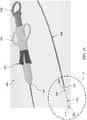
도 1은 일부 실시예에 따른, 위장 디바이스가 유문 내에 위치된 인체의 소화관 일부의 단면도이다;
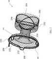
도 2는 일부 실시예에 따른, 위장 디바이스의 개략도이다;
도 3은 일부 실시예에 따른, 위장 디바이스가 유문에 이식된 인체의 소화관 일부의 단면도이다;
도 4a는 일부 실시예에 따른, 봉합사의 정면 사시도이다;
도 4b는 일부 실시예에 따른, 봉합사의 정면 사시도이다;
도 5는 일부 실시예에 따른, 위장 디바이스 및 봉합사가 유문에 이식된 인체의 소화관 일부의 단면도이다;
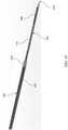
도 6은 일부 실시예에 따른, 전달 시스템의 정면 사시도이다;
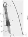
도 7은 일부 실시예에 따른, 도 6의 전달 시스템의 확대도이다;
도 8은 일부 실시예에 따른, 라인 8―8을 따라 취해진 도 6의 전달 시스템의 일부의 단면도이다;
도 9는 일부 실시예에 따른, 도 6의 전달 시스템의 확대도이다;
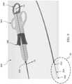
도 10은 일부 실시예에 따른, 도 9의 원(10)의 확대도이다;
도 11은 일부 실시예에 따른, 도 6의 전달 시스템의 확대도이다;
도 12는 일부 실시예에 따른, 도 6의 전달 시스템의 확대도이다;
도 13은 일부 실시예에 따른, 도 12의 원(13)의 확대도이다;
도 14는 일부 실시예에 따른, 도 6의 전달 시스템의 확대도이다;
도 15는 일부 실시예에 따른, 도 6의 전달 시스템의 확대도이다;
도 16은 일부 실시예에 따른, 도 15의 원(16)의 확대도이다;
도 17은 일부 실시예에 따른, 위장 디바이스가 유문에 걸쳐 위치된 인체의 소화관 일부의 단면도이다;
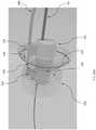
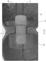
도 18은 일부 실시예에 따른, 위장 디바이스가 유문에 걸쳐 위치된 인체의 소화관 일부의 단면도이다;
도 19는 일부 실시예에 따른, 위장 디바이스가 유문에 걸쳐 위치된 인체의 소화관 일부의 단면도이다; 그리고
도 20a는 일부 실시예에 따른, 위장 이식물 전달 시스템을 도시한다.
도 20b는 일부 실시예에 따른, 위장 이식물 전달 시스템의 종축을 따라 취해진 단면도이다.
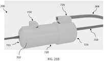
도 21a 내지 도 21e는 일부 실시예에 따른, 위장 이식물 전달 시스템을 도시한다.
도 22는 일부 실시예에 따른, 위장 이식물 전달 시스템을 도시한다.
도 23a 내지 도 23b는 일부 실시예에 따른, 위장 이식물 전달 시스템을 위장 디바이스와 조합하여 도시한다.
도 24a 내지 도 24b는 일부 실시예에 따른, 위장 디바이스와 조합하여 위장 이식물 전달 시스템을 갖는 인체의 소화관 일부의 단면도이다.
도 25는 일부 실시예에 따른, 위장 디바이스가 유문에 걸쳐 위치된 인체의 소화관 일부의 단면도이다.BRIEF DESCRIPTION OF THE DRAWINGS The accompanying drawings are included to provide a further understanding of the present disclosure and are incorporated into and constitute a part of this specification, illustrate embodiments, and together with the description serve to explain the principles of the disclosure.
1 is a cross-sectional view of a portion of the digestive tract of the human body with a gastrointestinal device positioned within the pylorus, in accordance with some embodiments;
2 is a schematic diagram of a gastrointestinal device, according to some embodiments;
3 is a cross-sectional view of a portion of the digestive tract of the human body with a gastrointestinal device implanted in the pylorus, according to some embodiments;
4A is a front perspective view of a suture, in accordance with some embodiments;
4B is a front perspective view of a suture, in accordance with some embodiments;
5 is a cross-sectional view of a portion of the digestive tract of a human body with a gastrointestinal device and a suture implanted in the pylorus, according to some embodiments;
6 is a front perspective view of a delivery system, in accordance with some embodiments;
7 is an enlarged view of the delivery system of FIG. 6, in accordance with some embodiments;
8 is a cross-sectional view of a portion of the delivery system of FIG. 6 taken along line 8-8, in accordance with some embodiments;
9 is an enlarged view of the delivery system of FIG. 6, in accordance with some embodiments;
10 is an enlarged view of
11 is an enlarged view of the delivery system of FIG. 6, in accordance with some embodiments;
12 is an enlarged view of the delivery system of FIG. 6, in accordance with some embodiments;
13 is an enlarged view of the
14 is an enlarged view of the delivery system of FIG. 6, in accordance with some embodiments;
15 is an enlarged view of the delivery system of FIG. 6 in accordance with some embodiments;
16 is an enlarged view of
17 is a cross-sectional view of a portion of the digestive tract of the human body with a gastrointestinal device positioned over the pylorus, in accordance with some embodiments;
18 is a cross-sectional view of a portion of the digestive tract of the human body with a gastrointestinal device positioned over the pylorus, in accordance with some embodiments;
19 is a cross-sectional view of a portion of the digestive tract of the human body with a gastrointestinal device positioned over the pylorus, in accordance with some embodiments; And
20A depicts a gastrointestinal implant delivery system, in accordance with some embodiments.
20B is a cross-sectional view taken along the longitudinal axis of the gastrointestinal implant delivery system, in accordance with some embodiments.
21A-21E illustrate a gastrointestinal implant delivery system, according to some embodiments.
22 depicts a gastrointestinal implant delivery system, according to some embodiments.
23A-23B illustrate a gastrointestinal implant delivery system in combination with a gastrointestinal device, in accordance with some embodiments.
24A-24B are cross-sectional views of a portion of the digestive tract of a human body having a gastrointestinal implant delivery system in combination with a gastrointestinal device, in accordance with some embodiments.
25 is a cross-sectional view of a portion of the digestive tract of the human body with a gastrointestinal device positioned over the pylorus, in accordance with some embodiments.
해당 기술분야의 통상의 기술자는 본 개시의 다양한 양태가 의도된 기능들을 수행하도록 구성된 임의의 수의 방법 및 장치에 의해 실현될 수 있다는 것을 쉽게 이해할 것이다. 또한, 여기서 참조되는 첨부 도면들은 반드시 일정한 비율로 그려진 것은 아니지만, 본 개시의 다양한 양태를 예시하기 위해 과장될 수 있고, 그러한 점에서 도면들은 제한하는 것으로 해석되어서는 안 된다는 점에 유의해야 한다.One of ordinary skill in the art will readily appreciate that various aspects of the present disclosure may be realized by any number of methods and apparatus configured to perform the intended functions. In addition, it should be noted that the accompanying drawings referred to herein are not necessarily drawn to scale, but may be exaggerated to illustrate various aspects of the present disclosure, and in that respect, the drawings should not be construed as limiting.
본 개시는 환자의 신체 구조 내에 장치들 및 시스템들을 배치하고 제거하기 위한 장치들, 시스템들 및 방법들에 관한 것이다. 여기에 개시된 장치들, 시스템들 및 방법들을 사용하여, 이식 가능한 디바이스가 환자의 신체 구조 내에 배치(예를 들어, 전달 및/또는 전개) 및/또는 그로부터 회수될 수 있다. 다양한 실시예에서, 그러한 시술들은 입, 인후, 위 및 장을 통해 내시경으로 수행된다. 일부 예는 환자의 위장관, 이를테면 환자의 유문 공동, 유문, 십이지장 및/또는 공장(jejunum) 내에 이식형 의료 디바이스를 배치 및/또는 그로부터 회수하기 위한 장치들, 시스템들 및 방법들에 관한 것이다. 다양한 예에서, 그러한 의료 디바이스들은 하나 이상의 카테터를 통해 전달될 수 있음을 이해할 것이다.The present disclosure relates to devices, systems and methods for placing and removing devices and systems within a patient's body structure. Using the devices, systems and methods disclosed herein, an implantable device may be placed (eg, delivered and/or deployed) within a patient's body structure and/or retrieved therefrom. In various embodiments, such procedures are performed endoscopically through the mouth, throat, stomach and intestines. Some examples relate to devices, systems, and methods for placing and/or withdrawing an implantable medical device within a patient's gastrointestinal tract, such as a patient's pyloric cavity, pylorus, duodenum and/or jejunum. It will be appreciated that in various examples, such medical devices may be delivered via one or more catheters.
일부 사례에서, 여기에 개시된 장치들, 시스템들 및 방법들은 환자의 신체 구조 내에 위장 디바이스와 같은 의료 디바이스의 위치를 고정시키는 데 사용될 수 있다. 예를 들어, 일부 예에서, 하나 이상의 고정 요소가 환자의 유문 공동, 유문, 십이지장 및/또는 공장을 포함하여 위 및/또는 장의 특정 부분 내에 위장 디바이스를 고정하는 데 이용될 수 있다. 다양한 실시예에서, 이러한 장치들 및 시스템들은 제거될 수 있다. 예를 들어, 고정 요소(들) 및 위장 디바이스는 지정된 시간 이후 또는 하나 이상의 이벤트 발생에 대응하여 제거될 수 있다.In some instances, the devices, systems and methods disclosed herein can be used to secure the location of a medical device, such as a gastrointestinal device, within a patient's body structure. For example, in some instances, one or more fixation elements may be used to secure the gastrointestinal device within a specific portion of the stomach and/or intestine, including the patient's pyloric cavity, pylorus, duodenum and/or jejunum. In various embodiments, these devices and systems may be eliminated. For example, the stationary element(s) and the camouflage device may be removed after a specified time or in response to the occurrence of one or more events.
아래에서 더 상세히 논의되는 바와 같이, 다양한 실시예에서, 하나 이상의 고정 요소와 같은 고정 수단은 위장 이식물을 위 기저의 유문에 묶도록 작동한다. 유문은 원형 근육의 이완 및 수축과 함께 개폐됨으로써 괄약근 역할을 하는 근육체로, 이로 인해 위 기저에 판막 역할을 하는 원형 개구를 포함한다. 유문은 완전히 열릴 때 일반적으로 12 밀리미터(12mm)에서 30 밀리미터(30mm) 사이의 최대 직경을 나타낸다.As discussed in more detail below, in various embodiments, fastening means, such as one or more fastening elements, act to bind the gastrointestinal implant to the pylorus at the base of the stomach. The pylorus is a muscle body that acts as a sphincter by opening and closing with the relaxation and contraction of the circular muscle, and thus includes a circular opening that acts as a valve at the base of the stomach. Pyloris, when fully open, typically exhibit a maximum diameter between 12 millimeters (12 mm) and 30 millimeters (30 mm).
그에 따라, 개시된 시스템들, 디바이스들 및 방법들은 소화관 내로부터 복강으로 관통하지 않아 박테리아 전좌 및 후속 감염의 위험을 최소화한다. 다양한 예에서, 전달 시스템은 위장관의 비-멸균 환경 내에 포함되는 유문의 근육 부분을 통해 봉합사를 전달하도록 작동 가능하다. 일부 예에서, 전달 시스템은 주변 복강의 멸균 환경에 관통할 위험을 최소화하도록 작동하는 하나 이상의 특징 및/또는 속성을 추가로 포함한다. 일부 예에서, 전달 시스템은 열상, 압박 괴사 또는 궤양을 유발할 수 있는 과도한 힘으로부터 유문을 최소화하거나 그 외 달리 보호하도록 작동하는 하나 이상의 특징을 추가로 포함한다.Accordingly, the disclosed systems, devices and methods do not penetrate from within the digestive tract into the abdominal cavity, minimizing the risk of bacterial translocation and subsequent infection. In various examples, the delivery system is operable to deliver the suture through a pyloric muscle portion contained within a non-sterile environment of the gastrointestinal tract. In some examples, the delivery system further includes one or more features and/or attributes that operate to minimize the risk of penetrating the sterile environment of the surrounding abdominal cavity. In some instances, the delivery system further includes one or more features that operate to minimize or otherwise protect the pylorus from excessive forces that may cause lacerations, compression necrosis, or ulcers.
도 1은 위(16), 장(18), 유문(20) 및 십이지장(22)을 도시하는, 사람의 소화관(10)의 일부의 단면도를 도시한다. 유문은 개괄적으로 유문 공동(24) 및 유문 괄약근(26)을 포함한다. 도 1에 도시된 바와 같이, 위장 디바이스(100)는 위(16)와 장(18) 사이에 위치될 수 있다. 일부 예에서, 위장 디바이스(100)는 위장 디바이스(100)의 하나 이상의 부분이 유문 공동(24) 내 또는 그에 인접하게 위치되도록 유문(20) 내에 위치된다. 일부 예에서, 추가적으로 또는 대안적으로 위장 디바이스(100)는 십이지장(22) 내에 배치된 위장 디바이스(100)의 하나 이상의 부분이 위치된다.1 shows a cross-sectional view of a portion of a human
도 2 및 도 3은 다양한 실시예에 따른 위장 디바이스(100)를 도시한다. 도 2는 위장 디바이스(100)의 사시도이다. 도 3은 명확성을 위해 근위 및 원위 구조 요소들(172 및 196)이 제거된 상태로 도시된, 환자의 신체 구조에서의 위장 디바이스(100)의 단순화된 형태의 단면도이다.2 and 3 illustrate a
다양한 실시예에서, 위장 디바이스(100)는 체중 감소를 달성하는 것을 돕기 위해 위장관 내 천연 신체 구조와 인터페이싱하는 확장 가능한, 내시경으로 전달 가능한 구성요소다. 일부 예에서, 위장 디바이스(100)는 통상의 기술자들이 이해할 바와 같이 확장 가능하다. 즉, 다양한 실시예에서, 전개시, 위장 디바이스(100)는 압축 또는 접철된 전달 구성으로부터 확장된 전개 구성으로 전환될 수 있다. 도 2 또는 도 3에 도시되어 있지는 않지만, 다양한 예에서, 통상의 기술자들이 이해할 바와 같이, 위장 디바이스(100)에 위소매가 부착될 수 있거나 부착 가능할 수 있으며, 전개시 위소매(120)가 환자의 장(18) 내에 위치될 수 있거나 위치 가능할 수 있음을 이해할 것이다. 그에 따라, 다양한 예에서, 우회 위소매는 장 우회 위소매, 장 라이너 또는 우회 라이너일 수 있다.In various embodiments,
계속해서 도 2 및 도 3을 참조하면, 위장 디바이스(100)는 일반적으로 원통형 형상을 갖는다. 일부 실시예에서, 위장 디바이스(100)는 위장 디바이스(100)의 길이를 따라 중심 종축을 정의한다. 위장 디바이스(100)는 또한 일반적으로 근위부(130), 원위부(132) 및 목 부분(134)을 포함한다. 다양한 예에서, 목 부분(134)은 근위부(130)와 원위부(132) 사이에 위치된다. 목 부분(134)는 근위부 및 원위부(130 및 132)와 일체일 수 있거나, 대안적으로는 근위부 및 원위부(130 및 132)에 결합될 수 있다. 다양한 예에서, 목 부분(134)은 근위부 및 원위부(130 및 132)를 유체적으로 결합한다. 일부 예에서, 목 부분(134)은 관형이고 그것을 통해 루멘을 포함한다. 그러한 일부 예에서, 루멘은 위장 디바이스(100)의 종축을 따라 연장된다.With continued reference to FIGS. 2 and 3, the
일부 예에서, 근위부(130)는 근위 단부(140) 및 원위 단부(142)를 포함한다. 일부 예에서, 근위부(130)는 원통형 또는 관형이다. 일부 실시예에서, 근위부(130)과 목 부분(134) 사이에 근위 벽 플랜지(148)가 위치된다. 일부 예에서, 근위부(130)의 외측 표면의 직경은 목 부분(134)의 외측 표면의 직경보다 크다. 따라서, 다양한 예에서, 근위 벽 플랜지(148)는 도시된 바와 같이 일반적으로 디스크형이고 목 부분(134)과 근위부(130) 사이에 연장된다. 일부 예에서, 근위 벽 플랜지(148)는 위장 디바이스(100)의 중심 종축을 가로질러 배향된다.In some examples, the
다양한 실시예에서, 근위부(130) 및 근위 벽 플랜지(148) 중 하나 이상은 만곡된 프로파일을 채택하거나 그렇지 않으면 전개될 때(예를 들어, 위장 디바이스(100)가 확장될 때) 만곡된 프로파일을 갖는 성향이 있다. 예를 들어, 일부 예에서, 근위부(130) 및 근위 벽 플랜지(148) 중 하나 이상은 오목부를 포함한다. 예를 들어, 근위 벽 플랜지(148)는 보울(bowl)과 유사할 수 있다. 다른 일부 예에서, 추가적으로 또는 대안적으로 근위부(130) 및 근위 벽 플랜지(148) 중 하나 이상은 볼록부를 포함한다.In various embodiments, one or more of the
일부 실시예에서, 원위부(132)는 근위 단부(144), 원위 단부(146) 및 근위 단부와 원위 단부(144와 146) 사이에 연장되는 외측 벽을 포함한다. 일부 예에서, 원위부(132)는 플랜지 형상이다. 일부 예에서, 원위부(132)는 원통형이다. 일부 예에서, 원위부(132)와 목 부분(134) 사이에 원위 벽 플랜지(150)가 위치된다. 일부 예에서, 원위부(132)의 외측 표면의 직경은 목 부분(134)의 외측 표면의 직경보다 크다. 그에 따라, 다양한 예에서, 원위 벽 플랜지(150)는 도시된 바와 같이 일반적으로 디스크형이고 목 부분(134)과 원위부(132) 사이에 연장된다. 원위 벽 플랜지(150)는 일반적으로 원위부(132)의 근위 단부(144)로부터 연장된다. 일부 예에서, 원위 벽 플랜지(150)는 위장 디바이스(100)의 중심 종축을 가로질러 연장된다. 아래에서 더 상세히 논의되는 바와 같이, 원위부(132)는 환자 내에 위치될 때, 확장 구성으로, 십이지장에 위치될 수 있으며 및/또는 장(18)을 향하는 원위 단부(146)에 개구를 정의할 수 있다.In some embodiments, the
목 부분(134)은 제1 단부(160), 제2 단부(162) 및 제1 단부와 제2 단부(160, 162) 사이에 연장되는 벽을 포함한다. 목 부분(134)은 위에서 언급한 바와 같이, 근위부(130)와 원위부(132) 사이에 연장되는 원통 형상일 수 있다. 일부 예에서, 목 부분(134)은 위(16)의 내용물(예를 들어, 미즙(chime))이 장(18)으로 통과할 수 있게 하는 관통 루멘(152)을 정의한다. 목 부분(134)은 유문(20)을 개방 상태로 유지하도록 강성일 수 있으며 또는 유문(20)과 함께 관통 루멘(152)의 개방 및 폐쇄시킬 수 있도록 유연할 수 있다.The
일부 실시예에서, 목 부분(134)의 길이는 대략 환자의 유문의 폭일 수 있다. 일부 실시예에서, 목 부분(134)의 길이는 근위 벽 플랜지(148), 원위 벽 플랜지(150) 및 유문(20) 사이에 갭을 제공하기 위해 환자의 유문의 폭보다 길 수 있다. 일부 실시예에서, 목 부분(134)은 근위 벽 플랜지(148) 및 원위 벽 플랜지(150)가 유문(20)과 접촉할 수 있게 하도록 크기가 조정될 수 있다.In some embodiments, the length of the
다양한 실시예에서, 위장 디바이스(100)는 통상의 기술자들이 이해할 바와 같이 편조선 구조로 형성될 수 있다. 이러한 편조선 구조는 환자 내에 위장 디바이스(100)를 위치시키는 것을 도울 수 있다. 예를 들어, 편조선 구조는 위장 디바이스(100)에 구조적 지지를 제공하고 위장 디바이스(100)의 형상 유지를 도울 수 있다.In various embodiments, the
일부 실시예에서, 위장 디바이스(100)는 편조선 구조 내에 포함되는 구조 요소를 포함한다. 도 2에 도시된 바와 같이, 일부 실시예에서, 위장 디바이스(100)는 원위 구조 요소(196)를 갖는다. 일부 예에서, 원위 구조 요소(196)는 원위부(132) 및/또는 목 부분(134)에 부착된 링들(193, 194)로 구성된다. 일부 예에서, 원위 구조 요소(196)는 니티놀(니켈-티타늄 합금)과 같은 금속, 상표명 MP35N®으로 판매되는 것과 같은 니켈-코발트계 합금, 합금 L605와 같은 코발트 합금, 상표명 Elgiloy®로 판매되는 코발트-크롬-니켈-몰리브덴 합금, 스테인리스 스틸 또는 PET, PEEK와 같은 플라스틱, 상표명 Delrin®으로 판매되는 것과 같은 폴리옥시메틸렌 또는 임의의 기타 적합한 재료를 포함한다. 일부 예에서, 원위 구조 요소(196)는 적합한 형상으로 형성된 초탄성 니티놀 와이어를 포함한다. 예시적인 실시예에서, 원위 구조 요소(196)는 세 개의 니티놀 와이어 링으로 형성된다. 원위 구조 요소(196)가 특정 강성 또는 강성도를 갖는 것이 바람직하다면, 원위 구조 요소(196)가 만들어지는 크기 및 재료가 이러한 속성들을 제어하는 데 사용될 수 있다. 예를 들어, 니티놀 와이어를 사용하여 원위 구조 요소(196)를 만드는 데 사용되는 와이어의 직경의 함수로서 적합한 압축 및 팽창 강도를 갖는 보강 요소들이 형성될 수 있다.In some embodiments,
도 2에 도시된 바와 같이, 원위 구조 요소(196)의 링들(193, 194)은 원위부(132) 주위에 배열되고 이를테면 플랜지 재료로 일체로 직조됨으로써 원위부(132)에 부착된다. 원위 구조 요소(196)의 링들(193, 194)은 원위부(132)의 편조 구조를 통해 링들(193, 194)을 직조함으로써 부착된다. 일부 예에서 와이어 단부들은 연결 소매에 삽입되고 권축, 용접 및/또는 임의의 기타 적합한 알려져 있는 수단으로 고정된다.As shown in FIG. 2, the
도 2에 도시된 바와 같이, 일부 실시예에서, 추가적으로 또는 대안적으로 위장 디바이스(100)는 근위부(130)에 부착된 근위 구조 요소(172)를 포함한다. 일부 예에서, 근위 구조 요소(172)는 스프링과 같은 압축 편향 요소이다. 근위 구조 요소(172)는 노드들(186)을 갖는 실질적으로 원형 프레임으로 구성될 수 있다. 근위 구조 요소(172)는 원위 구조 요소(196)를 형성하는 동일한 재료로 구성될 수 있다. 근위 구조 요소(172)는 또한 근위부(130)에 구조적 지지를 제공할 수 있다. 예를 들어, 근위 구조 요소(172)는 일반적으로 압축 가능하면서도 강성인 전체 프레임을 갖는다. 근위 구조 요소(172)는 근위부(130)에 추가적인 방사상 강도를 부여할 수 있고 근위부(130)의 근위 단부(140)를 개방 상태로 유지하는 것을 도울 수 있다. 근위 구조 요소(172)는 환자로부터 제거하기 위해 그리고 환자 내 전달을 위해 전달 카테터상에 디바이스를 장착하기 위해 위장 디바이스(100)의 접철 방향을 편향하도록 성형될 수 있다.As shown in FIG. 2, in some embodiments, additionally or alternatively,
도 2에 도시된 바와 같이, 일부 실시예에서, 위장 디바이스(100)는 드로스트링(drawstring)(192)을 포함할 수 있다. 일부 예에서, 드로스트링(192)은 근위부(130)에 부착된다. 드로스트링(192)은 근위부(130)의 재료를 통해 드로스트링(192)을 직조함으로써 근위부(130)에 부착될 수 있다. 다양한 예에서, 드로스트링은 근위부의 재료를 통해 직조될 수 있고 드로스트링의 일부가 루프(198)를 형성할 수 있다. 예를 들어, 드로스트링(192)은 위장 디바이스(100)의 편조선 구조에서 교번하는 셀들을 통해 직조되는 스트링 또는 봉합사로 구성될 수 있다. 루프(198)는 드로스트링(192)이 리트랙션 도구, 예를 들어 후크 또는 클램프에 부착될 수 있게 한다. 일부 실시예에서, 드로스트링(192)은 근위부(130)를 통해 직조되는 봉합사이다. 드로스트링(192)은 근위 구조 요소(172)와 별개의 구조일 수 있다. 드로스트링(192)은 봉합사 재료로 구성될 수 있고 얇은 와이어 또는 케이블을 포함할 수 있다.As shown in FIG. 2, in some embodiments, the
이제 도 3으로 돌아가, 환자의 신체 구조 내에 배치될 때, 근위부(130)는 일반적으로 위(16)에 인접한 유문(20)의 측상에 위치되고, 원위부(132)는 일반적으로 십이지장(22)에 인접한 유문(20)의 측상에 위치되며, 목 부분(134)은 유문 괄약근(26)에 걸쳐 이어진다.Returning now to Figure 3, when placed within the patient's body structure, the
도시된 바와 같이, 위장 디바이스(100)는 유문 괄약근(26) 및 관련 조직이 위장 디바이스(100)의 근위부와 원위부(130와 132) 사이에 끼워지거나 그 외 달리 위치되도록 전개된다. 종래의 디자인들은 전통적으로 이식된 디바이스가 유문(20) 및 주변 조직에 관해 이동 및/또는 회전하는 것에 저항하기 위해 이식된 디바이스의 기하학적 구조 및 무결성에 의존했었다.As shown, the
예를 들어, 일부 종래의 디바이스는 십이지장으로 돌출하는 디바이스 부분의 길이 및/또는 직경을 증가시킴으로써 이식 이후 회전 및 이동에 저항하거나 최소화하려고 노력해왔다. 그러한 구성들은 디바이스가 십이지장에 접촉하여 편향 또는 이탈되기 전에 추가 회전을 방지할 수 있도록 한다. 예를 들어, 십이지장으로 연장되는 디바이스 부분의 길이 및 직경은 십이지장 내에서 기울어지거나 젖혀지는 것을 방지하도록 크기가 조정될 수 있다. 일부 실시예에서, 그러한 구성들은 디바이스가 주변 신체 구조에 관해 회전하거나 기울어질 때, 디바이스가 장 벽과 접촉할 것이며 그에 따라 이동 나아가 회전 또는 기울어짐에 저항할 수 있도록 한다. 일부 다른 기존 디자인들에는 주변 조직에 깊게 관통하는 바브들(barbs)과 같은 능동 고정 수단이 포함되어 있다. 그러나, 위에서 언급한 바와 같이, 그러한 구성들은 조직 괴사 및 침식의 위험이 있으며, 이는 점막 조직의 세균 감염 또는 전신 감염과 같은 합병증으로 이어질 수 있다.For example, some conventional devices have tried to resist or minimize rotation and movement after implantation by increasing the length and/or diameter of the portion of the device protruding into the duodenum. Such configurations allow the device to contact the duodenum and prevent further rotation before deflecting or deviating. For example, the length and diameter of the portion of the device that extends into the duodenum can be sized to prevent tilting or tilting within the duodenum. In some embodiments, such configurations enable the device to contact the barrier wall when the device is rotated or tilted relative to the surrounding body structure and thus move and resist rotation or tilt. Some other existing designs include active fastening means such as barbs that penetrate deeply into the surrounding tissue. However, as mentioned above, such constructs pose a risk of tissue necrosis and erosion, which can lead to complications such as bacterial or systemic infection of mucosal tissue.
일부 경우에, 디바이스들은 위에서 논의된 구조 요소들(예를 들어, 근위 및 원위 구조 요소들(172 및 196))과 같이, 주변 신체 구조에 디바이스를 고정하는 데 도움이 되는 추가 구조 요소들을 포함했다. 그러나, 이러한 구조 요소들은 주변 조직에 관통하지 않으므로 디바이스의 기하학적 구조 및 그것의 주변 조직과의 간섭에 의존하여 신체 구조 내 디바이스의 정렬을 유지시킨다.In some cases, the devices included additional structural elements to help secure the device to the surrounding body structure, such as the structural elements discussed above (e.g., proximal and distal
다양한 실시예에서, 하나 이상의 봉합사가 위장 디바이스(100)를 주변 조직에 고정시키는 데 위장 디바이스(100)와 조합하여 이용될 수 있다. 아래에서 더 상세히 설명되는 바와 같이, 하나 이상의 봉합사는 위장 디바이스를 주변 신체 구조에 고정하도록 작동하고, 일부 경우에는 위장 디바이스(100)의 기하학적 구조를 유지하는 데 도움이 되도록 작동한다. 다양한 예에서, 봉합사들 중 하나 이상은 위장 디바이스(100)의 하나 이상의 부분을 통해 그리고 주변 신체 구조의 하나 이상의 부분을 통해 연장된다. 일반적으로, 그에 따라 봉합사들은 주변 신체 구조에 관한 위장 디바이스(100)의 위치를 유지하는 데 도움이 되는 이차 고정 메커니즘들로서 작동한다.In various embodiments, one or more sutures may be used in combination with
이제 도 4a 및 도 4b를 참조하면, 일부 실시예에서, 봉합사(200)는 제1 단부(204), 제1 단부(204) 반대편의 제2 단부(206), 및 제1 단부(204)와 제2 단부(206) 사이에 연장되는 세장형 중간 부분(208)을 갖는 바디(202)를 포함하는 이동 방지 디바이스다. 바디(202)는 하나 이상의 필라멘트 부재, 편조 섬유로 구성될 수 있거나, 선 또는 편조선일 수 있다. 즉, 일부 예에서, 바디(202)는 구조적으로 압축 가능할 수 있는 한편, 다른 예들에서, 바디(202)는 상당한 변형(예를 들어, 접힘 또는 주름짐)없이 압축 하중을 독립적으로 지지할 수 없다. 다양한 예에서, 바디(202)는 인장 하중에 대해 탄력적이다. 일부 예에서, 바디(202)는 내신축성이다. 바디는 폴리프로필렌, PTFE, ePTFE 또는 dPTFE, 폴리에스터, 나일론, UHMWPE 또는 스테인리스 스틸과 같은 생체 적합성 비-흡수성 봉합사 재료로 구성될 수 있음을 인해해야 한다. 일부 예에서, 바디(202)는 폴리프로필렌 또는 나일론, dPTFE 또는 스테인리스 스틸과 같이 조직 내성장(tissue ingrowth)에 저항하도록 구성된 재료로 형성된다.Referring now to FIGS. 4A and 4B, in some embodiments,
다양한 실시예에서, 봉합사(200)는 하나 이상의 유지 탭을 포함한다. 예를 들어, 도 4a에 도시된 바와 같이, 봉합사(200)는 제1 유지 탭(210) 및 제2 유지 탭(212)을 포함한다. 유지 탭들(210 및 212)은 위장 디바이스(100)에 관한 봉합사(200)의 위치를 유지시키도록 작동한다. 예를 들어, 일부 사례에서, 유지 탭들(210 및 212)은 아래에서 추가로 논의되는 바와 같이, 봉합사(200)가 위장 디바이스(100)에서 분리될 위험을 최소화하도록 작동한다. 본 개시의 사상 또는 범위에서 벗어나지 않고 다양한 유지 탭이 고려되고 이용될 수 있지만, 일부 예에서, 유지 탭은 하나 이상의 튜브로 형성된다. 일부 예에서, 아래에서 더 상세히 논의되는 바와 같이, 튜브들은 바디(202)가 튜브 내에 수용되고 튜브와 결합될 수 있도록 구성된다. 일부 예에서, 튜브는 유지 탭과 바디(202)간 결합을 용이하게 하도록 권축될 수 있다. 유지 탭들은 스테인리스 스틸 및 니티놀과 같은 금속 및 폴리테트라플루오로에틸렌(PTFE), 팽창 폴리테트라플루오로에틸렌(ePTFE), 폴리에테르 에테르 케톤(PEEK), 초고분자량 폴리에틸렌(UHMWPE), 폴리우레탄, 폴리에스테르, 폴리이미드, 나일론 및 폴리프로필렌과 같은 폴리머를 포함하지만 이에 제한되지 않는 다양한 생체 적합성 재료로 형성될 수 있다.In various embodiments,
일부 예에서, 유지 탭들은 바디(202)와 일체형이다. 그러한 일부 예에서, 유지 탭들 및 바디(202)는 모놀리식 유닛에 대한 것이다. 일부 예에서, 유지 탭들 중 하나 이상이 바디(202)에 결합된다. 일부 예에서, 바디(202)는 그것의 각각의 단부들 각각의 유지 탭에서 또는 내에서 종단된다. 유지 탭들을 바디(202)에 결합하는 데에는 통상의 기술자들이 이해할 바와 같이, 클램핑, 접착, 피닝, 결속 또는 하나 이상의 고정 수단을 이용하는 것을 포함하지만 이에 제한되지 않는 임의의 적합한 방법이 채용될 수 있음이 이해될 것이다. 도시된 바와 같이, 유지 탭들(210 및 212)은 바디(202)상에 권축된다.In some examples, the retaining tabs are integral with the
다양한 실시예에서, 봉합사(200)는 봉합사(200)가 최소 프로파일로 표적 영역에 전달될 수 있고 이어서 유지 탭이 위장 디바이스(100)로부터 분리될 가능성을 최소화하는 방식으로 전개(예를 들어, 위장 디바이스와 결합)될 수 있도록 전달 구성으로부터 전개 구성으로 전환하도록 구성된다. 일반적으로, 전개 구성으로 전환될 때, 봉합사(200)의 유지 탭들 중 하나 이상은 바디(202)에 관한 형상 및/또는 배향이 변한다. 다양한 예에서, 유지 탭들(210 및 212) 중 하나 이상은 유지 탭들이 제약을 받지 않을 때 편향되어 전개 구성을 채택하도록 봉합사(200)에 결합된다. 그러한 구성은 제1 및 제2 유지 탭들(210 및 212) 중 하나 이상이 신체 구조 내에 전개될 때 전개 구성으로 채택되거나 그렇지 않으면 자연스럽게 전환될 수 있도록 한다. 일부 예에서, 전개시 전개 구성으로 자연스럽게 전환하는 것은 바디(202)에 사전 형성된 굴곡부를 생성함으로써 실현될 수 있다.In various embodiments, the
도 4b는 전달 및 전개 구성들에서 제1 및 제2 유지 탭들(210 및 212)의 하나의 비-제한적인 예를 예시하기 위해 부분적으로 전개된 구성의 봉합사(200)를 도시한다. 구체적으로, 도 4b에서, 제1 유지 탭(210)은 전개 구성으로 배향되는 한편, 제2 유지 탭(212)은 전달 구성으로 배향된다. 도시된 바와 같이, 제1 유지 탭(210)의 배향은 제2 유지 탭(212)의 배향과 상이하다. 일부 예에서, 전개 구성에서, 유지 탭들은 바디(202)를 가로질러 배향된다(또는 그 외 가로질러 연장된다). 예를 들어, 도 4b에 도시된 바와 같이, 제1 유지 탭(210)(전개 구성으로 도시됨)은 바디(202)를 가로질러 연장된다. 일부 예에서, 전달 구성에서, 유지 탭들은 일반적으로 바디(202)를 따라 또는 그것과 일렬로 연장된다. 예를 들어, 도 4b에 도시된 바와 같이, 제2 유지 탭(212)(전달 구성으로 도시됨)은 일반적으로 바디(202)를 따라 또는 그것과 일렬로 연장된다.4B shows
추가적으로, 도 4a에 도시된 바와 같이, 바디(202)는 그것의 중간 부분에서 유지 탭들(210 및 212) 내로 종단되거나 그 외 결합된다. 예를 들어, 도 4a에 도시된 바와 같이, 바디(202)는 제1 유지 탭(210)의 제1 단부(214)와 제2 단부(216) 사이의 중간 섹션(218)에서 제1 유지 탭(210) 내로 종단된다. 따라서, 다양한 예에서, 유지 탭들은 유지 탭들의 2 개 이상의 부분이 바디(202)로부터 멀어지게 돌출하도록 바디(202)에 결합된다. 도 4a에 도시된 바와 같이, 제1 단부(214) 및 제2 단부(216)는 전개 구성에서 바디(202)로부터 멀어지게 연장되거나 돌출한다.Additionally, as shown in FIG. 4A, the
상술한 바와 같이, 봉합사(200)는 전달 구성에서 최소 프로파일을 유지한다. 일부 예에서, 유지 탭들은 최소 전달 프로파일을 용이하게 하는 데 도움이 되는 하나 이상의 피처를 포함한다. 예를 들어, 도 4a에 도시된 바와 같이, 제1 유지 탭(210)은 전달 구성에서 봉합사(200)의 바디를 수용하도록 구성된 제1 유지 탭(210)에 형성된 릴리프(relief)(220)를 포함한다. 예를 들어, 도 4b에 도시된 바와 같이, 바디(202)는 전달 구성에서 제2 유지 탭(212)의 릴리프(220)에 의해 수용된다.As described above,
위에서 논의된 실시예들 및 예들에서 유지 탭들(210 및 212)은 바디(202)에 관한 배향이 변하는 것으로 예시되었지만, 다양한 실시예에서 봉합사(200)의 유지 탭들은 추가적으로 또는 대안적으로 봉합사(200)가 전달 구성으로부터 전개 구성으로 전환될 때 크기 및/또는 형상이 변할 수 있다. 예를 들어, 일부 사례에서, 유지 탭들은 팽창 가능한 부재들이다. 일부 다른 예에서, 유지 탭들은 전달 프로파일로부터 전개 프로파일로 확장되는 확장 가능한 부재들이다. 그러한 일부 예에서, 유지 부재들은 자체 확장된다. 일부 예에서, 유지 탭들은 디스크형이다. 일부 예에서, 유지 탭들은 전개 구성에서 바디(202)로부터 멀어지게 돌출하도록 구성된 하나 이상의 페탈(petal)을 포함한다. 유지 부재들이 위장 디바이스(100)로부터 유티 탭들이 분리될 수 있는 가능성을 최소화하는 전개 구성으로 전환된다면 유지 부재들에 대한 임의의 적합한 구성이 이용될 수 있다는 것이 이해될 것이다.While in the embodiments and examples discussed above the retaining
도 5는 전개 봉합사(200)로 도시된 도 3의 단면도이다. 도시된 바와 같이, 다양한 예에서, 봉합사(200)는 위장 디바이스(100)의 근위부(130)로부터 위장 디바이스(100)의 원위부(132)로 연장되도록 구성된다. 일부 예에서, 봉합사(200)는 위장 디바이스(100)의 근위부 및 원위부(130 및 132) 중 하나 이상뿐만 아니라, 주변 신체 구조의 하나 이상의 부분에 관통하도록 구성된다. 아래에서 더 상세히 논의되는 바와 같이, 봉합사(200)는 그것이 유문 괄약근(26)(예를 들어, 유문(20)과 연관된 근육)에 관통하도록 신체 구조 내에 배치된다.5 is a cross-sectional view of FIG. 3 shown as a deployed
도 5에 도시된 바와 같이, 봉합사(200)는 위장 디바이스(100)의 근위부(130)에 관통한다. 일부 예에서, 봉합사(200)는 근위부(130)의 근위 벽 플랜지(148)에 관통한다. 일부 예에서, 제2 유지 탭(212)이 위장 디바이스(100)의 위-측상의 근위 벽 플랜지(148)에 인접하게 위치된다. 즉, 다양한 예에서, 봉합사(200)는 근위부(130)의 근위 벽 플랜지(148)(또는 개괄적으로 근위부(130))가 위장 디바이스(100)의 근위부와 원위부(130와 132) 사이에 끼워진 유문(20)의 조직(예를 들어, 유문 괄약근(26))과 제2 유지 탭(212) 사이에 위치되도록 전개된다.5,
유사하게, 도 5에 도시된 바와 같이, 봉합사(200)는 위장 디바이스(100)의 원위부(132)에 관통한다. 일부 예에서, 봉합사(200)는 원위부(132)의 원위 벽 플랜지(150)에 관통한다. 일부 예에서, 제1 유지 탭(210)이 위장 디바이스(100)의 십이지장-측상의 원위 벽 플랜지(150)에 인접하게 위치된다. 즉, 다양한 예에서, 봉합사(200)는 원위부(132)의 원위 벽 플랜지(150)(또는 개괄적으로 원위부(132))가 위장 디바이스(100)의 근위부와 원위부(130와 132) 사이에 끼워진 유문(20)의 조직(예를 들어, 유문 괄약근(26))과 제1 유지 탭(210) 사이에 위치되도록 전개된다.Similarly, as shown in FIG. 5,
다양한 예에서, 봉합사(200)는 위장 디바이스(100)의 목 부분(134)에 관통하지 않고 근위부와 원위부(130와 132) 사이에 봉합사(200)가 걸쳐 이어지도록 전개된다. 예를 들어, 도 5에 도시된 바와 같이, 봉합사(200)는 그것이 위장 디바이스(100)의 근위부 및 원위부(130 및 132) 각각에 관통하고 위장 디바이스(100)의 목 부분(134)에는 관통하지 않고 그것들 사이에 걸쳐 이어지도록 전개된다. 달리 말하면, 다양한 예에서, 봉합사(200)는 전개되고 목 부분(134)으로부터 밖으로 향하여 방사상으로 하나 이상의 위치에서 위장 디바이스(100)를 관통한다.In various examples, the
하나 이상의 봉합사(200)가 위장 디바이스(100)를 주변 신체 구조에 고정하는 데 이용될 수 있다는 것이 이해될 것이다. 예를 들어, 일부 예에서, 위장 디바이스(100)를 주변 신체 구조에 고정하기 위해 세 개의 봉합사(200)가 전개될 수 있다. 그러한 일부 예에서, 봉합사들(200)은 일반적으로 위장 디바이스(100) 주위에 고르게 분포된다. 예를 들어, 위장 디바이스(100)를 주변 신체 구조에 고정하는 데 세 개의 봉합사(200)가 채용되는 경우, 봉합사들(200)은 각각 120도 떨어져 위치될 수 있다.It will be appreciated that one or
또한 그러한 구성은 하나 이상의 봉합사(200)가 원위치에서 위장 디바이스(100)의 종축을 중심으로 한 위장 디바이스(100)의 회전, 뿐만 아니라 유문(20)에 관한 위장 디바이스(100)의 이동을 최소화하도록 작동할 수 있도록 한다는 것이 이해될 것이다.In addition, such a configuration allows one or
위장 이식물들(특히 유문에 위치되는 것들)의 탈락 및 이동에 기여하는 요인들 중 하나는 주변 조직의 자연적인 수축 및 움직임의 결과로서 유문 괄약근(26)의 어느 한 측상의 위장 이식물들의 부분들의 상대 앵귤레이션을 수반한다는 것임을 발견했다. 예를 들어, 원위부(132) 및/또는 목 부분(134)의 앵귤레이션이 근위부(130)에 관하여 증가함에 따라, 위장 디바이스(100)는 변형되고 유문(20)의 신체 구조에 적절하게 순응할 수 있는 그것의 능력을 상실한다. 이러한 순응성 문제는 근위부(130)에 인접한 유문(20)의 신체 구조에 반작용을 보이거나 그렇지 않으면 맞물리는 근위부(130)의 표면적을 감소시키고, 이에 의해 위장 디바이스(100)가 탈락 및 이동에 저항할 수 있는 능력을 감소시킨다. 주변 신체 구조의 자연적인 수축 및 움직임과 조합하여 충분한 양의 앵귤레이션이 주어지면, 위장 디바이스(100)의 유효 표면적은 유문(20) 내에 위장 디바이스(100)의 유지를 지속하기에 불충분할 것이고, 위장 디바이스(100)는 탈락될 것이다.One of the factors contributing to the loss and movement of gastrointestinal implants (especially those located in the pylorus) is the natural contraction and movement of the surrounding tissues, as a result of the parts of the gastrointestinal implants on either side of the
그에 따라 봉합사(200)는 근위부 및 원위부(130 및 132)(및/또는 목 부분(134))의 상대적인 앵귤레이션을 서로에 관해 그리고/또는 주변 신체 구조에 관해 최소화하는 기능을 하는 이차 고정 메커니즘으로 작동한다. 봉합사(200)는 주변 신체 구조 및 위장 디바이스(100)의 근위부 및 원위부(130 및 132) 중 하나 이상에 관통함으로써 위장 디바이스(100)를 주변 신체 구조에 물리적으로 고정한다. 그러한 일부 예에서, 봉합사(200)는 봉합사(200)가 결합되는 위장 디바이스(100)의 부분 및 신체 구조의 상대적 정렬을 유지시키도록 작동한다. 일부 예에서, 그러한 구성은 탈락(이탈) 및/또는 이동(유동)을 방지하기 위해 주변 신체 구조에 반작용을 보이거나 그 외 체결되는데 이용 가능한 위장 디바이스(100)의 유효 표면적을 최대화하고 유지하도록 작동한다.The
봉합사(200)가 주변 신체 구조 및 위장 디바이스(100)의 근위부 및 원위부(130 및 132) 각각을 통해 연장되는 구성에서, 봉합사(200)는 위장 디바이스(100)의 근위부와 원위부(130과 132) 사이의 상대 앵귤레이션의 양을 최소화하며, 이에 의해 위장 디바이스(100)의 변형량을 최소화하도록 추가적으로 작동한다. 위장 디바이스(100)의 변형량을 추가로 최소화함으로써, 봉합사(200)는 탈락 및/또는 이동을 방지하기 위해 주변 신체 구조에 반작용을 보이거나 그 외 체결되는데 이용 가능한 위장 디바이스(100)의 유효 표면적을 최대화하고 유지하도록 작동한다.In a configuration in which the
다양한 예에서, 근위부 및 원위부(130 및 132)가 서로에 관해 자유롭게 각도를 형성할 수 있는 양은 통상의 기술자들이 이해할 바와 같이 근위부와 원위부(130과 132) 사이의 거리에 관한 봉합사(200)의 길이에 적어도 부분적으로 기초한다. 일부 예에서, 봉합사(200)의 길이(예를 들어, 제1 유지 탭과 제2 유지 탭(210과 212) 사이의 거리)는 주어진 위장 디바이스의 근위와 원위 벽 플랜지들 사이의 거리를 초과하여 제1 및 제2 유지 탭들(210 및 212)이 이식될 때 조직과 접촉하지 않거나 주어진 위장 디바이스의 근위 및 원위 벽 플랜지들을 함께 조이지(끼지) 않게 된다. 예를 들어, 일부 비제한적인 예들에서, 위장 디바이스의 근위 및 원위 벽 플랜지들 사이의 거리는 11 밀리미터일 수 있는 한편, 봉합사(200)의 제1 유지 탭과 제2 유지 탭(210과 212) 사이의 거리는 15 내지 30 밀리미터일 수 있다. 일부 예에서, 그러한 방식으로 봉합사들을 선택 또는 구성하면 압박 괴사, 궤양 및 기타 신체 구조적 손상을 방지하는 데 도움이 된다. 또한, 주어진 위장 디바이스의 근위와 원위 벽 플랜지들 사이의 거리를 초과하는 길이를 갖도록 봉합사들을 선택 또는 구성하면 주변 신체 구조가 소화 거동과 관련하여 이동함에 따라 위장 디바이스가 신체 구조에 동적으로 조정될 수 있게 한다. 주어진 봉합사(200)가 근위부와 원위부(130과 132) 사이의 거리와 관련하여 더 길수록, 근위부와 원위부(130과 132) 사이의 잠재적인 앵귤레이션의 양이 더 커진다. 근위부와 원위부(130과 132) 사이의 어느 정도 앵귤레이션이 필요할 수 있다. 예를 들어, 근위부와 원위부(130과 132) 사이의 어느 정도 각도는 위장 디바이스(100)가 주변 신체 구조에 보다 적절하게 순응할 수 있도록 한다.In various instances, the amount by which the proximal and
위장 디바이스(100)의 적합한 구성들의 예들은 미국 특허 출원 번호 15/060,418, 14/872,990 및 15/600,214에 예시되고 설명되어 있으며, 이들 각각의 내용은 참고로 본 명세서에 통합된다. 위장 디바이스(100)는 해당 기술분야의 통상의 기술자들에게 알려져 있는 방법들에 따라 전달될 수 있음이 이해될 것이다. 위장 디바이스(100)를 전달하는 데 적합한 방법들의 예들이 위에서 언급한 바와 같이 미국 특허 출원 번호 15/060,418, 14/872,990 및 15/600,214에 예시되고 설명되어 있다.Examples of suitable configurations of
다양한 예에서, 위장 디바이스(100)는 환자의 신체 구조 내에 위장 디바이스(100)의 위치를 유지시키기 위해 개별적으로 또는 집합적으로 작동하는 하나 이상의 고정 구성요소를 포함할 수 있다. 일부 예에서, 위소매(120)가 통상의 기술자들이 이해할 바와 같이 앵커(110)에 부착될 수 있다. 또한 위장 디바이스(100)는 이식물, 위장 이식물 또는 유문 이식물일 수 있음을 이해할 것이다.In various examples,
다양한 실시예에서, 위장 디바이스(100) 및 봉합사들(200)은 위에서 논의된 바와 같은 전달 구성에 있는 동안 환자의 신체 구조 내에 내시경으로 이식 및/또는 그로부터 회수될 수 있다. 일반적으로, 전달 구성에서, 위장 디바이스(100) 및/또는 봉합사들(200)은 이해될 바와 같이 전개된 프로파일보다 작은 프로파일을 보유한다는 점에서 폐쇄, 압축 또는 접철된 구성에 있다.In various embodiments,
도 6 내지 도 11은 환자의 신체 구조 내에 위장 디바이스(100)를 고정하기 위해 봉합사들(200) 중 하나 이상을 전달 및 전개하기 위한 전달 시스템(300) 및 관련 작동을 도시한다. 도 6 및 도 7에 도시된 바와 같이, 전달 시스템(300)은 니들 푸싱 요소(304) 및 봉합사 푸싱 요소(306)를 갖는 핸들(302)을 포함한다. 다양한 예에서, 전달 시스템은 근위 단부(310) 및 원위 단부(312)를 갖는 세장형 요소(308)를 더 포함한다. 일부 예에서, 세장형 요소(308)는 카테터이다. 다양한 예에서, 핸들(302)은 세장형 요소(308)와 작동 가능하게 결합된다. 일부 예에서, 핸들(302)은 세장형 요소(308)의 근위 단부(310)에 결합된다. 전달 시스템(300)을 포함하여 여기서 논의되는 다양한 전달 시스템은 하나 이상의 가이드 와이어를 통해 전달될 수 있음을 이해해야 한다.6-11 illustrate
도 8은 도 7의 라인 8―8을 따라 취해진 세장형 요소(308)의 원위 단부(312)의 단면도이다. 도 8에 도시된 바와 같이, 다양한 예에서, 전달 시스템은 니들(314) 및 봉합사 푸셔(316)를 더 포함한다. 다양한 예에서, 봉합사 푸셔(316) 및 니들(314)은 각각 세장형 요소(308) 내에 동축으로 위치된다. 그에 따라, 다양한 예에서, 세장형 요소(308)는 그것을 통해 연장되는 루멘을 포함한다. 다양한 예에서, 니들(314)은 세장형 요소(308)의 루멘 내에 동축으로 수용된다. 일부 예에서, 봉합사 푸셔(316)는 니들(314)의 루멘 내에 동축으로 수용된다.8 is a cross-sectional view of the
아래에서 더 상세히 논의되는 바와 같이, 일부 예에서, 봉합사(200)는 니들(314)의 루멘 내에 추가로 위치된다. 다양한 예에서, 니들(314)은 핸들(302)의 니들 푸싱 요소(304)에 작동 가능하게 결합된다. 니들 푸싱 요소(304)의 작동이 니들(314)의 대응하는 작동을 야기한다면, 니들(314)은 임의의 적합한 수단 또는 메커니즘을 통해 니들 푸싱 요소(304)와 결합될 수 있다는 것이 이해될 것이다. 일부 예에서, 니들(314)은 근위 단부 및 원위 단부를 갖는 중공의 세장형 요소로 형성될 수 있으며, 이때 니들(314)을 형성하는 중공의 세장형 요소는 세장형 요소(308)의 루멘을 통해 연장된다. 그러한 일부 예에서, 니들(314)을 형성하는 세장형 요소의 근위 단부는 니들 푸싱 요소(304)에 결합되고, 니들(314)을 형성하는 세장형 요소의 원위 단부는 조직 관통 및 구동에 적합한 날카로운 팁으로 구성된다. 일부 다른 예에서, 니들(314)은 세장형 요소(308)를 통해 연장되는 부재에 결합될 수 있다. 다양한 실시예에서, 니들(314)의 원위 단부는 강성이고 그것의 전달 동안 접철 구성으로 봉합사(200)를 유지하기에 충분히 길다. 일부 예에서, 니들(314)의 원위 단부는 핸들의 니들 푸싱 요소(304)로 거슬러 연장되는 가요성 샤프트에 결합된다. 니들(314)의 속성들은 근위 섹션이 신체 구조를 통해 탐색하는 동안 구부러지기에 충분한 유연성을 갖는 반면, 원위부는 사용자가 표적 조직을 통해 니들의 원위 단부를 밀 수 있게 하기에 충분한 강성을 보유하도록 한다. 일부 예에서, 니들(314)의 근위 섹션은 PEEK, 나일론 및 폴리우레탄과 같은 고경도계 폴리머로 구성될 수 있다. 니들의 더 단단한 원위 섹션은 스테인레스 스틸, 니티놀 또는 생체 적합성이 있고 조직을 관통하기 위한 날카로운 팁을 포함하도록 가공될 수 있는 유사한 금속들로 만들어질 수 있다. 그러나, 니들(314)의 전체 길이는 단일 조각의 니티놀 또는 그것의 근위부를 신체 구조를 탐색하기에 충분히 유연하게 만드는 것과 같은 방식으로 변형된 길이의 스테인리스 스틸 튜브로 형성될 수 있음을 이해해야 한다. 그러한 일부 예에서, 니들의 전체 길이는 나선형 구성으로 그것의 길이의 일부를 따라(예를 들어, 근위부를 따라) 레이저 절단된 스테인리스 스틸 튜브로 형성될 수 있다.As discussed in more detail below, in some examples,
다양한 예에서, 니들 푸싱 요소(304)의 작동은 니들(314)의 대응하는 작동을 야기한다. 작동될 때, 니들(314)은 일반적으로 아래에서 더 상세히 논의되는 바와 같이 세장형 요소(308)에 관해 (예를 들어, 근위 또는 원위로) 병진 이동한다. 일부 예에서, 니들 푸싱 요소(304)는 니들(314)을 집어넣어진 상태(수납된 상태)와 전개된 상태 사이에서 전환하도록 작동될 수 있다. 집어넣어진 상태에서, 니들(314)은 세장형 요소(308) 내에 집어넣어지거나 그 외 달리 은폐된다. 즉, 집어넣어진 상태에서, 니들(314)의 원위 팁은 세장형 요소(308)의 원위 단부(312)에 근접하게 위치된다. 집어넣어진 상태는 일반적으로 니들 푸싱 요소(304)가 전달 위치로 근위로 전진되는 것과 대응한다. 전달 시스템(300)은 도 6 및 도 7에 니들 푸싱 요소(304)가 전달 위치에 위치된 상태로 도시되어 있다.In various examples, actuation of
다른 한편으로, 전개 상태에서, 니들(314)은 니들의 원위 팁이 세장형 요소(308)의 원위 단부(312)에 대해 원위에 위치되도록 세장형 요소(308)의 원위 단부(312)로부터 연장된다. 전개된 상태는 일반적으로 니들 푸싱 요소(304)가 전개 위치로 원위로 전진되는 것과 대응한다. 니들 푸싱 요소(304)가 전달 위치로부터 전개 위치로 전환될 때(예를 들어, 니들 푸싱 요소(304)가 원위로 전진될 때), 니들(314)은 세장형 요소(308)에 관해 원위로 병진 이동한다. 즉, 다양한 예에서, 핸들(302) 및/또는 세장형 요소(308) 및/또는 봉합사 푸싱 요소(306)에 관한 니들 푸싱 요소(304)의 원위 작동은 세장형 요소(308)에 관한 니들(314)의 원위 병진 이동을 야기한다.On the other hand, in the deployed state, the
전달 시스템(300)이 도 9 및 도10에 니들 푸싱 요소(304)가 전개 위치에 위치된 상태로 도시되어 있다. 예를 들어, 도 9에 도시된 바와 같이, 니들 푸싱 요소(304)는 핸들(302) 및 봉합사 푸싱 요소(306)에 관해 원위로 전진되었다. 추가적으로, 도시된 바와 같이, 니들(314)은 니들(314)의 일부가 노출되도록 세장형 요소(308)에 관해 원위로 전진되었다. 특히, 도시된 바와 같이, 니들(314)의 원위 팁 또는 단부(318)는 세장형 요소(308)의 원위 단부(312)에 대해 원위에 위치된다.The
일부 예에서, 니들 푸싱 요소(304)의 전진은 추가적으로 봉합사 푸셔(316)의 전진을 야기한다. 그러한 구성은 전달 시스템(300)의 전개 메커니즘에 의해 용이하게 된다. 즉, 다양한 예에서, 전달 시스템 300은 봉합사 푸셔(316) 및 니들(314)의 동시 이동을 야기하도록 작동 가능한 전개 메커니즘(320)을 포함한다. 아래에서 추가로 논의되는 바와 같이, 전개 메커니즘(320)은 니들(314)에 관한 봉합사 푸셔(316)의 독립적인 작동을 가능하게 하도록 더 구성된다. 도 11은 전개 메커니즘(320) 및 그것의 다양한 구성요소를 예시하기 위해 핸들(302)의 일부가 제거된 전달 시스템(300)의 정면 사시도이다. 도시된 바와 같이, 전개 메커니즘(320)은 하우징(322) 및 슬라이드 부재(324)를 포함한다. 슬라이드 부재(324)는 하우징(322)에 관해 슬라이딩하도록 구성된다.In some examples, advancement of
도시된 바와 같이, 니들(314)의 근위 단부는 전개 메커니즘(320)의 하우징(322)에 결합되는 반면, 봉합사 푸셔(316)의 근위 단부는 슬라이드 부재(324)에 결합된다. 추가적으로, 도시된 바와 같이, 니들 푸싱 요소(304)는 하우징(322)의 원위 단부에 작동 가능하게 결합된다. 그러나, 니들 푸싱 요소(304)는 니들 푸싱 요소(304)의 작동이 하우징(322)의 작동을 야기하며, 이는 차례로 세장형 요소(308)에 관한 니들(314)의 작동을 야기하는 것을 제공하는 것을 조건으로 본 출원의 사상 또는 범위에서 벗어나지 않고 임의의 적합한 방식으로 하우징(322)의 임의의 부분에 결합될 수 있다는 것을 이해할 것이다. 유사하게, 슬라이드 부재(324)가 하우징(322) 내에 위치되기 때문에, 슬라이드 부재(324)는 하우징(322)과 함께 병진 이동하도록 작동 가능하다. 그에 따라, 니들 푸싱 요소(304)의 작동은 하우징(322) 및 슬라이드 부재(324)가 병진 이동하게 한다. 하우징(322)과 슬라이드 부재(324)의 이러한 병진 이동은 통상의 기술자들이 이해할 바와 같이 니들(314) 및 봉합사 푸셔(316)의 동시 병진 이동을 야기한다.As shown, the proximal end of the
봉합사 푸셔(316)가 슬라이드 부재(324)에 결합되고 슬라이드 부재(324)가 하우징(322) 및 니들(314)에 관해 병진 이동하도록 작동 가능하기 때문에, 슬라이드 부재(324)는 봉합사 푸셔(316)가 하우징(322) 및 니들(314)에 관해 병진 이동하게 하도록 작동될 수 있음이 또한 이해될 것이다. 그에 따라, 하우징(322)의 작동과 관련하여 작동되는 것에 더하여, 봉합사 푸셔(316)는 하우징 (322)에 관한 슬라이드 부재 (324)의 작동과 관련하여 더욱 또는 추가로 작동될 수 있다.Since the
다양한 예에서, 슬라이드 부재(324)는 하우징(322)에 대해 전진 및 후퇴되도록 작동 가능하다. 그에 따라, 다양한 예에서, 봉합사 푸셔(316)가 니들(314)에 관해 전진 및 후퇴되도록 작동 가능하다. 특히, 하우징(322)에 관한 슬라이드 부재(324)의 원위 전진 또는 병진 이동은 니들(314)에 관한 봉합사 푸셔(316)의 대응하는 원위 전진을 야기한다. 다양한 다른 메카니즘이 니들(314)에 관한 봉합사 푸셔의 전진 및 후퇴를 야기하는 데 이용될 수 있음이 이해될 것이다. 그에 따라, 위에서 논의된 예들은 제한적인 것으로 해석되어서는 안 된다. 대신, 니들(314) 및 봉합사 푸셔(316)의 동시 작동 및 니들(314)에 관한 봉합사 푸셔의 독립적인 전진 및 후퇴 모두를 야기하도록 구성될 수 있는 그러한 메커니즘들 및 그것들의 균등물들이 본 출원의 사상 및 범위 내에 있다는 것을 이해해야 한다. 예를 들어, 하우징(322)에 관한 슬라이드 메커니즘의 근위 병진 이동이 니들(314)에 관한 봉합사 푸셔(316)의 원위 전진을 야기하는 구성들은 본 출원의 사상 및 범위 내에 속한다.In various examples, the
다양한 예에서, 전술 한 바와 같이, 슬라이드 부재(324)는 하우징(322)에 대해 원위로 전진되어 봉합사 푸셔(316)가 니들(314)에 대해 원위로 전진하게 할 수 있다. 일부 예에서, 위에서 언급한 바와 같이, 이러한 원위부 니들(314)에 대한 봉합사 푸셔(316)의 병진 이동은 봉합사(200)가 니들(314)에 대해 전개되거나 병진되도록 작동 가능하다. 특히, 위에서 논의된 바와 같이, 다양한 예에서, 전달 시스템(300)은 봉합사들(200) 중 하나 이상을 신체 구조의 치료 부위로 전달하도록 작동 가능하다. 이러한 일부 예에서, 봉합사(200)는 전달 시스템에 로딩되고, 치료 부위로 전진하고, 배치된다. 이러한 일부 예에서, 봉합사(200)는 봉합사(200)가 봉합사 푸셔(316)의 원위 단부에 원위에 위치하도록 니들(314)의 루멘(lumen) 내로 로딩된다. 따라서, 봉합사 푸셔(316)가 니들(314)에 대해 원위로 전짐함에 따라, 봉합사(200)도 또한 그렇다.In various examples, as described above, the
다양한 예에서, 봉합사 푸싱 요소(306)는 전술 한 바와 같이 봉합사 푸셔(316)의 대응하는 작동을 유발하도록 작동 가능하다. 특히, 봉합사 푸싱 요소(306)가 작동될 때, 봉합사 푸셔(316)는 일반적으로 세장형 요소(308)에 대해 병진 이동한다. 다양한 예에서, 봉합사 푸싱 요소(306)의 근위 전진 또는 병진 이동은 봉합사 푸셔(316)의 근위 전진 또는 병진 이동에 대응한다. 유사하게, 다양한 예에서, 봉합사 푸싱 요소(306)의 원위 후퇴 또는 병진은 봉합사 푸셔(316)의 원위 후퇴 또는 병진 이동에 대응한다. 일부 예에서, 니들 푸싱 요소(304)와 유사하게, 따라서 봉합사 푸싱 요소(306)는 수납(보관) 상태와 전개 상태 사이에서 봉합사 푸셔(316)를 전환하도록 작동될 수 있다. 수납된 상태에서, 봉합사 푸셔(316)는 니들(314)의 루멘 내에 보관되거나 그렇지 않으면 은폐되어 봉합사(200)가 니들(314) 내에 배치될 수 있도록 하여 제1 및 제2 단부(204 및 206) 모두가 니들(314)의 원위 팁 또는 단부(318)에 대해 근위에 위치된다. 즉, 수납된 상태에서, 니들(314)의 원위 팁은 봉합사(200)의 제1 및 제2 단부(204 및 206)에 원위에 위치하고 봉합사 푸셔(316)의 원위 단부에 원위에 위치한다. 수납된 상태(stowed state)는 일반적으로 봉합사 푸싱 요소(306)가 전달 위치에 위치되는 것에 대응한다. 이것은 봉합사 푸싱 요소(306)를 전달 위치로 근위로 전진 또는 후퇴시키는 것을 포함할 수 있다. 전달 시스템(300)은 도 9 내지 도 11에 봉합사 푸싱 요소(306)가 전달 위치에 위치된 것으로 도시된다.In various examples,
다른 한편으로는, 전개된 상태에서, 봉합사 푸셔(316)는 봉합사(200)의 제2 단부(206)가 가압 또는 니들(314)의 루멘으로부터 방출되도록 원위로 전진된다. 즉, 다양한 예에서, 봉합사 푸싱 요소(306)가 전개된 위치로 전진할 때, 봉합사(200)는 니들(314)의 루멘으로부터 부분적으로만 방출된다. 일부 예에서, 니들 푸싱 요소(304)가 전달 위치에서 전개된 위치로 전환됨에 따라(예를 들어, 니들 푸싱 요소(304)가 원위로 전진함에 따라), 봉합사 푸셔(316)는 니들(314)에 대해 원위로 병진 이동한다. 니들(314)에 대한 봉합사 푸셔(316)의 이러한 원위 전진 또는 병진 이동은 봉합사 푸셔(316)가 니들(314)의 루멘 내에 보관된 봉합사(200)와 맞물리고 봉합사(200)가 니들(314)에 대해 전진하게 한다.On the other hand, in the deployed state, the
전달 시스템(300)은 도 12 내지 도 13에 봉합사 푸싱 요소(306)가 전개된 위치에 위치된 상태에서 도시된다. 구체적으로, 도 12에 도시된 바와 같이, 봉합사 푸싱 요소(306) 및 슬라이드 부재(324)는 각각 핸들(302) 및 하우징(322)에 대해 원위로 전진되었다. 도시된 바와 같이, 봉합사(200)의 제2 단부(206)는 니들(314)의 원위 팁 또는 단부(318)로부터 연장된다. 그러나, 도시된 바와 같이, 봉합사 푸싱 요소(306)가 전개 위치에 배치되고 니들 푸싱 요소(304)가 전개 위치에 있는 상태에서, 봉합사(200)의 일부(예를 들어, 제1 단부(204))는 니들(314)의 루멘 내에 보관된 상태를 유지한다. 아래에서 더 자세히 논의되는 바와 같이, 조직의 제1 측면에 봉합사의 제1 단부(204)를 전개(배치)하는 능력을 유지하면서 그러한 구성은 니들(314)이 조직의 제1 측면에서 조직의 제2 측면 및 조직의 제2 측면 상에 전개된 봉합사(200)의 제2 단부(206)로 조직을 통해 전진될 수 있도록 제공한다.The
일부 예에서, 전달 시스템(300)은 봉합사(200)의 의도하지 않은 사전 전개 가능성을 최소화하도록 작동하는 하나 이상의 특징(features)을 포함한다. 구체적으로, 그리고 도 9 및 도 12을 참조하면, 전달 시스템(300)은 봉합사 푸싱 요소(306)의 하나 이상의 탭(326)이 봉합사 푸싱 요소(306)가 핸들(302)에 대해 원위로 전진될 수 있기 전에 눌려져야 하도록 구성된다. 도 9는 눌리지 않은 구성의 봉합사 푸싱 요소(306)의 하나 이상의 탭(326)을 도시하며, 반면에 도 12는 눌려진 구성의 봉합사 푸싱 요소(306)의 하나 이상의 탭(326)을 도시한다.In some examples,
추가적으로, 일부 예에서, 봉합사 푸싱 요소(306)는 니들 푸싱 요소(304)가 원위로 전진하거나 전개된 위치로 병진 이동될 때까지 눌려질 수 없다. 이러한 일부 예에서, 하우징(322)은 니들 푸싱 요소(304)가 전달 위치에 위치할 때 봉합사 푸싱 요소(306)의 하나 이상의 탭(326)의 눌림을 방지하도록 작동하는 하나 이상의 차단 특징부(blocking features)(미도시)를 포함한다. 그러나, 니들 푸싱 요소(304)를 전개된 위치로 전진시키고, 이에 의해 핸들(302) 및 봉합사 푸싱 요소(306)에 대해 하우징(322)을 원위로 전진시키면, 하우징의 하나 이상의 차단 특징부들은 봉합사 푸싱 요소(306)의 하나 이상의 탭(326)이 눌리는 것을 방지하도록 그들이 더 이상 작동하지 않는 위치로 전진한다. 일부 예에서, 하우징은 추가로 또는 대안적으로 봉합사 푸싱 요소(306)의 하나 이상의 탭(326)을 수용하도록 구성된 하나 이상의 특징부를 포함하며, 이는 하우징(322)이 원위로 전개된 위치로 전진되는 니들 푸싱 요소(304)에 따라 전진될 때 전개된 위치에 봉합사 푸싱 요소(306)의 하나 이상의 탭(326)을 수용하도록 구성된 하우징(322)의 특징부는 봉합사 푸싱 요소(306)에 대해 적절하게 배치되어 봉합사 푸싱 요소(306)의 하나 이상의 탭(326)이 눌려질 수 있다. 이러한 수용 특징부들의 비제한적인 예는 하우징(332) 내의 하나 이상의 슬롯, 구멍 또는 릴리프를 포함한다.Additionally, in some examples,
일부 예에서, 봉합사(200)가 니들(314)의 원위 단부(318)로부터 부분적으로 전개된 후, 봉합사 푸싱 요소(306)는 후퇴되거나 전달 위치로 근위로 전진될 수 있다. 전달 위치로 후퇴될 때, 봉합사 푸셔(316)는 일반적으로 니들(314)에 대해 근위로 후퇴된다. 도 14는 봉합사 푸싱 요소(306)가 니들(314)의 원위 단부(318)로부터 전개된 봉합사(200)의 제2 단부(206)와 함께 전달 위치로 후퇴된 것을 도시한다. 다양한 예에서, 봉합사 푸싱 요소(306)가 봉합사(200)의 나머지 부분이 전개되는 것을 전개하기 전에 근위로 후퇴할 필요가 없다는 것이 이해될 것이다.In some examples, after
다양한 예에서, 봉합사(200)의 제2 단부(206)를 부분적으로 전개한 후, 니들 푸싱 요소(304)는 핸들(302)에 대해 후퇴(수축)(retracted)되거나 근위로 후퇴(proximally withdrawn)될 수 있다. 일부 예에서, 니들 푸싱 요소(304)를 근위로 후퇴시키면 니들(314)은 세장형 요소(308)에 대해 근위로 후퇴되도록 한다. 일부 예에서, 니들 푸싱 요소(304)를 근위로 빼내는 것은 마찬가지로 니들(314)이 봉합사(200)에 대해 근위로 후퇴되도록 하여 봉합사(200)가 니들(314)의 루멘으로부터 완전히 제거되도록 한다. 일부 예에서, 이하에서 더욱 상세히 논의되는 바와 같이, 제2 유지 탭(212)은 니들(314)이 후퇴되거나 근위로 후퇴될 때 봉합사(200)의 위치를 유지하도록 작동한다.In various examples, after partially deploying the
전달 시스템(300)은 도 15 및 도 16에 니들 푸싱 요소(304)가 니들(314)의 원위 단부(318)로부터 완전히 전개된 봉합사(200)를 사용하여 전달 위치로 후퇴 또는 근위로 후퇴된 상태로 도시되어 있다. 완전히 전개될 때, 봉합사(200)의 제1 및 제2 단부(204 및 206)는 니들(314)의 루멘에서 배출되거나 또는 더 이상 루멘 내에 위치되지 않는다. 다양한 예에서, 니들(314)의 원위 단부(318)가 봉합사(200)의 제1 단부(204)에 근접한 위치로 근위로 후퇴(withdrawn)되거나 후퇴(retracted)될 때, 제1 유지 탭(210)은 위에서 논의된 바와 같이 전개 구성으로 자유롭게 전환할 수 있다. 도시된 바와 같이, 니들(314)은 니들(314)의 원위 단부(318)가 세장형 요소(308)의 루멘 내에 위치되고 세장형 요소(308)의 원위 단부(312)에 근접하게 위치하도록 세장형 요소(308)에 대해 근위로 후퇴 또는 후퇴(수축)되었다.The
도 17 내지 도 20은 봉합사(200)를 환자의 신체 구조 및 위장 디바이스(100)에 전달하고 부착하여 위장 디바이스(100)를 탈락 및/또는 이동으로부터 보호하는 절차를 도시한다. 일부 실시예에서, 전달 시스템(300)의 하나 이상의 구성요소는 통상의 기술자가 인식하는 바와 같이 표준 내시경의 작업 채널 또는 루멘 내에 적합하도록 구성된다는 것을 이해할 것이다. 예를 들어, 일부 예에서, 세장형 요소(308)는 세장형 요소가 내시경의 루멘에 삽입되고 이를 통해 전진될 수 있도록 크기가 조정된다. 일부 예들에서, 세장형 요소(308)는 내시경이 환자의 신체 구조를 통해 치료 부위로 이동된 후에 내시경의 작동 루멘 내로 삽입되고 이를 통해 전진된다는 것이 이해될 것이다.17 to 20 show a procedure for protecting the
도 17은 도 1 내지 도 3을 참조하여 설명된 위(16)와 장(18) 사이의 유문(20)에서 환자의 신체 내에 위치하는 위장 디바이스(100)를 도시한다. 환자의 신체 구조는 도 17 내지 도 20에서 명확성을 위해 섹션화되었다. 일부 예에서, 내시경(600)은 위장 디바이스(100)의 위치를 보기 위해 사용될 수 있다. 추가적으로 또는 대안적으로, 내시경(600)의 튜브는 또한 위장 디바이스(100) 및 봉합사를 전개하기 위해 선택된 위치를 향하여 세장형 요소(308)를 안내하는데 사용될 수 있다. 일부 예에서, 아래에서 더 상세히 논의되는 바와 같이, 하나 이상의 위치기 보조 디바이스(locator aids)가 치료 부위로 전진할 수 있고 세장형 요소(308)를 위장 디바이스(100) 및 봉합사를 전개하기 위해 선택된 위치를 향해 안내하는 데 도움이 될 수 있으며, 세장형 요소(308)의 원위 단부(312)가 위장 디바이스(100) 및 관련 신체 구조를 통해 전진되고 봉합사(200)가 전개될 때 위장 디바이스(100)에 대한 세장형 요소(308)의 위치가 유지되는 것을 돕는다. 더욱이, 아래에서 더 논의되는 바와 같이, 봉합사는 내시경과 완전히 독립적으로 전달 시스템을 통해 전달될 수 있다. 즉, 내시경이 치료 영역을 시각화하기 위해 이용될 수 있지만, 봉합사(200)의 전달은 내시경과 완전히 독립적으로 작동하는 전달 시스템을 통해 달성된다.FIG. 17 shows a
도 17에 도시된 바와 같이, 내시경은 세장형 요소(308)의 원위 단부(312)가 근위부(130)의 근위 벽 플랜지(148)에 인접하게 위치된 대략 12시 위치에 위치된다. 도 18은 세장형 요소(308)의 원위 단부(312)로부터 연장되는 니들(314)을 도시한다. 니들(314)은 니들(314)이 근위 벽 플랜지(148)를 통해, 유문 괄약근(26)을 통해, 원위 벽 플랜지(150)를 통해 연장되도록 세장형 요소(308)에 대해 원위로 전진되었다. 도 19는 신체 구조 내에 전달되고 전개된 봉합사(200)를 도시한다. 봉합사(200)가 본 명세서의 설명에 따라 전달되고 전개된다는 것이 이해될 것이다. 특히, 도시된 바와 같이, 봉합사(200)는 12시 위치에서 근위 벽 플랜지(148)를 통해, 유문 괄약근(26)을 통해, 그리고 원위 벽 플랜지(150)를 통해 연장되어, 제1 유지 탭(210)이 근위 벽 플랜지(148)에 대해 근위에 배치되며, 제2 유지 탭(212)이 원위 벽 플랜지(150)에 대해 원위에 배치된다.As shown in FIG. 17, the endoscope is positioned at an approximately 12 o'clock position with the
위에서 언급한 바와 같이, 하나 이상의 위치기 보조 디바이스가 치료 부위로 전진할 수 있으며, 세장형 요소(308)를 위장 디바이스(100) 및 봉합사를 전개하기 위해 선택된 위치를 향해 안내하는 데 도움이 될 수 있으며, 세장형 요소(308) 및/또는 니들(314)의 원위 단부(312)가 위장 디바이스(100) 및 관련 신체 구조를 통해 전진되고 봉합사(200)가 전개됨에 따라 위장 디바이스(100)에 대해 세장형 요소(308)의 위치를 유지시키는 데 도움이 될 수 있다. 따라서, 내시경의 튜브가 위장 디바이스(100) 및 봉합사를 배치하기 위해 선택된 위치를 향해 세장형 요소(308)를 안내하는 데 사용될 수 있으며, 일부 예에서는, 봉합사(200)의 전달을 달성하기 위해, 하나 이상의 추가 전달 보조구가 내시경과 함께 사용될 수 있다.As mentioned above, one or more locator assist devices may be advanced to the treatment site and may help guide the
이제 도 20a 및 20b를 참조하면, 전달 시스템(400)은 봉합사(200)의 표적 치료 영역으로의 전달을 용이하게 하도록 돕기 위해 내시경(600)과 함께 작동하도록 구성된 위치기 카테터(locator catheter)(500)를 포함한다. 다양한 예에서, 위치기 카테터(500)는 세장형 요소(510), 위치기 캡슐(520) 및 후드(530)를 포함한다. 위치기 캡슐은 도시된 바와 같이 세장형 요소(510)의 원위 단부(512)에 또는 그에 근접하게 위치된다. 후드(530)는 도시된 바와 같이 위치기 캡슐(520)에 근접하게 위치된다. 일부 예에서, 후드(530)는 도시된 바와 같이 내시경(600)과 위치기 캡슐(520) 사이에 위치된다.Referring now to FIGS. 20A and 20B, the
다양한 예들에서, 전달 시스템(400)은 내시경(600)과 인터페이스하도록 구성된다. 예를 들어, 일부 예들에서, 위치기 카테터(500)는 하나 이상의 내시경 맞물림 특징부(engagement feature)(540)를 포함하며, 이는 위치기 카테터(500)에 대한 내시경(600)의 방사상 위치를 제한하도록 구성된다. 위치기 카테터(500)에 대한 내시경(600)을 도시한다. 위치기 카테터(500)에 대한 내시경(600)의 방사상 위치를 제한함으로써, 전달 시스템(400)은, 세장형 요소(308)의 원위 단부(312) 및/또는 니들(314)이, 봉합사(200)의 전달 동안 위장 디바이스 및 인접한 신체 구조를 통해 구동될 때, 위장 디바이스에 대한 세장형 요소(308)의 위치를 제어하거나 제한하는 것을 도울 수 있다.In various examples,
계속해서 도 20a 및 도 20b를 참조하면, 위치기 캡슐(520)은 신체 구조 내에 배치된 위장 디바이스와 결합하거나 그렇지 않으면 인터페이스하도록 구성된다. 위치기 캡슐(520)과 전개된 위장 디바이스 사이의 결합은 봉합사(200)가 전달 및 전개되는 동안 전달 시스템(300)의 배향을 유지하거나 제한하는 것을 돕는다. 일부 예에서, 위치기 캡슐(520)은 전개된 위장 디바이스의 모양 및 크기에 상보적인 방식으로 모양 및 크기가 지정된 바디(522)를 포함한다. 예를 들어, 일부 예에서, 바디(522)는 원통형 형상이고 배치된 위장 디바이스의 관통 루멘(through-lumen) 내에 수용되어 위치기 캡슐(520)과 위장 디바이스 사이의 결합을 유발하도록 구성된다.With continued reference to FIGS. 20A and 20B, the
일부 예에서, 후드(530)는 세장형 요소(308)를 수용하도록 구성된다. 예를 들면, 도 20a에 도시된 바와 같이, 봉합사(200)의 전달 동안, 후드(530)는 내시경(600)과 위치기 캡슐(520)(및 따라서 전개된 위장 디바이스) 사이에 위치되어 세장형 요소(308)가 내시경으로부터 전개된 위장 디바이스(600)를 향해 전진할 때 후드(530)를 통해 연장된다. 일부 예에서, 후드(530)는 도시된 바와 같이 세장형 요소(308)가 후드(530)를 통해 연장할 때 세장형 요소(308)의 방사상 위치를 수용하고 구속하도록 구성된 개구 또는 채널(532)을 포함한다. 위치기 캡슐(520)(및 따라서 전개된 위장 디바이스)에 대한 내시경(600) 및/또는 세장형 요소(308)의 방사상 위치를 제한하는 것은 봉합사(200)가 전개되는 방사상 위치를 제한하는 데 도움이된다는 것을 이해해야 한다. 따라서, 전달 시스템(400)은 봉합사(200)가 유문 조직을 통해 전달되는 것을 보장하는 것을 도우며, 전달 절차 중에 위 또는 소장의 벽이 부주의하게 천공될 위험을 최소화하는 것을 도우며, 따라서 봉합사(200)가 위에서 언급한 바와 같이 위 또는 소장의 벽을 통해 전달될 위험을 최소화하는 것을 돕기 위해 사용될 수 있다.In some examples,
추가로, 위에서 언급한 바와 같이, 다양한 예에서, 내시경과 분리된 전달 시스템은 치료 영역으로 전진하도록 구성되고 봉합사(200)를 전달 및 전개하도록 구성된다. 도 21a 내지 도 21e를 참고하면, 전달 시스템(700)이 도시되고 카테터(710) 및 위치기 시스템(720)을 포함한다. 일부 예에서, 상기 카테터(710)는 카테터이고 위치기 시스템(720)은 카테터(710)의 원위 단부(712)에 또는 그에 근접하게 위치된다. 일부 예에서, 카테터(710)는 도시된 바와 같이 가이드와이어(guidewire)(GW)를 수용하기 위한 관통 루멘을 포함한다. 전달 시스템(700)이 도 21a 내지 도 21e에 전달 시스템(700)의 요소 및 특징을 보다 명확하게 묘사하기 위해 대응하는 위장 디바이스 또는 주변 신체 구조가 없이 도시되어 있음을 이해해야 한다. 위장 디바이스를 갖는 및/또는 신체 구조 내에서 전달 시스템(700)의 작동은 적어도 도 23a 내지 도 24b에 대해 이하에서 도시되고 설명된다.Additionally, as noted above, in various examples, the delivery system separate from the endoscope is configured to advance into the treatment area and to deliver and deploy the
다양한 예에서, 위치기 시스템(720)은 신체 구조 내에 배치된 위장 디바이스와 결합하거나 그렇지 않으면 인터페이스하도록 구성된다. 위치기 시스템(720)과 전개된 위장 디바이스 사이의 결합은 봉합사(200)가 전달 및 전개되는 동안 전달 시스템(700)의 배향을 유지하거나 제한하는 것을 돕는다. 일부 예에서, 위치기 시스템(720)은 위에서 언급된 위치기 캡슐(520)의 것과 매우 유사한 전개된 위장 디바이스의 형태 및 크기에 상보적인 방식으로 형상 및 크기가 정해지는 바디를 갖는 위치기 캡슐(722)을 포함한다. 따라서, 일부 예에서, 위치기 캡슐(722)은 원통형 형상일 수 있고 배치된 위장 디바이스의 관통 루멘 내에 수용되어 위치기 캡슐(722)과 위장 디바이스 사이의 결합을 유발하도록 구성될 수 있다. 그러나, 위치기 캡슐(722)은 위치기 캡슐(722)과 위장 디바이스 사이의 결합이 봉합사(200)가 전달되고 전개되는 동안 전달 시스템(700)의 방향을 제한 또는 유지하도록 작동하는 경우, 배치된 위장 디바이스와 다수의 다른 적절한 방식으로 인터페이스하거나 결합하도록 구성될 수 있음을 이해해야 한다.In various examples, the
일부 예에서, 위치기 시스템(720)은 봉합사(200)의 전달을 용이하게 하도록 돕기 위해 선택적으로 배치될 수 있는 제1 확장 가능한 암(724) 및 제2 확장 가능한 암(726)을 포함하는 복수의 확장 가능한 암을 추가로 포함한다. 다양한 예들에서 제1 및 제2 연장 가능한 암(724 및 726)은 제1 및 제2 연장 가능한 암(724 및 726)이 위치기 캡슐(722)로부터 반경 방향으로 연장될 때 제1 및 제2 연장 가능한 암(724 및 726) 사이에 갭이 정의되도록 서로 길이 방향으로 이격되어 있다. 예를 들어, 도시된 바와 같이, 제1 연장 가능한 암(724)은 제2 연장 가능한 암(726)보다 위치기 캡슐(722)의 원위 단부(721)에 더 근접하게 위치된다. 마찬가지로 도시된 바와 같이, 제2 연장 가능한 암(726)은 제1 연장 가능한 암(724)보다 위치기 캡슐(722)의 근위 단부(723)에 더 근접하게 위치된다. 아래에서 추가로 논의되는 바와 같이, 제1 및 제2 연장 가능한 암(724 및 726) 사이의 갭이 구성되어, 제1 및 제2 연장 가능한 암(724 및 726)이 위장 디바이스의 목 부분에 걸칠 수 있도록 하여, 제1 연장 가능한 암(724)이 위장 디바이스의 원위 벽 플랜지에 원위에 위치하는 한편, 제1 연장 가능한 암(724)이 위장 디바이스의 근위 벽 플랜지에 대해 근위에 배치된다. 아래에서 더 논의되는 바와 같이, 이러한 구성은 봉합사(200)의 전달 및 전개 동안 전달 시스템(700)의 종 방향 및 방사상 위치를 유지하는 것을 돕는다.In some examples,
추가적으로, 도시된 바와 같이, 위치기 시스템(720)은 제1 및 제2 연장 가능 암(724 및 726)이 위치기 캡슐(722)로부터 선택적으로 반경 방향으로 연장되도록 작동 가능하도록 구성된다. 따라서, 이러한 구성은 다음을 제공함을 이해해야 한다: 전달 시스템(700)이 전달 구성(예를 들어, 제1 및 제2 확장 가능 암(724 및 726)이 위치기 캡슐(722) 내에 수납되는 경우)과 전개 구성(예를 들어, 제1 및 제2 확장 가능 암(724 및 726)이 방사상으로 위치기 캡슐(722)에서 돌출) 사이에서 전환 가능하다. 제1 및 제2 연장 가능한 암(724 및 726)을 포함하는 구성은 전달 시스템(700)이 최소 전달 프로파일을 유지하도록 제공하는 데 도움이 된다.Additionally, as shown, the
도 21a 내지 도 21c는 제1 및 제2 연장 가능한 암(724 및 726)의 전개 순서를 도시한다. 도 21a는 제1 및 제2 연장 가능한 암(724 및 726)이 위치기 캡슐(722) 내에 수납되는 전달 구성의 전달 시스템(700)을 도시한다. 도 21b는 부분적으로 방사상으로 연장된 제1 및 제2 연장 가능한 암(724 및 726)을 도시한다. 도 21c는 제1 및 제2 연장 가능한 암(724 및 726)이 완전히 방사상으로 연장되는 전개 구성의 전달 시스템(700)을 도시한다. 다양한 예에서, 전달 시스템(700)은 세장형 요소(308)를 포함하도록 구성된다. 예를 들면, 도 21a내지 도 21e에 도시된 바와 같이, 세장형 요소(308)는 위치기 시스템(720)의 제2 연장 가능한 암(726)에 결합된다. 세장형 요소(308)와 위치기 시스템(720) 사이의 이러한 결합은 봉합사(200)의 전달 동안 위치기 시스템(720)에 대해 세장형 요소(308)(및 따라서 니들(314))의 위치를 제한하는 것을 돕는다. 따라서, 도 21a에 도시된 전달 구성에서, 세장형 요소(308)는 위치기 캡슐(722)에 대해 제1 방사상 위치에 위치한다(예를 들어, 제2 연장 가능 암(726)에서 세장형 요소(308)의 종축은 위치기 캡슐(722)의 종축에 대해 제1 방사상 위치에 있다). 이 제1 방사상 위치에서, 세장형 요소(308)는 봉합사(200)가 위장 이식물을 통해 연장되는 타겟 위치와 잘못 정렬된다. 다른 한편으로는, 도 21c에 도시된 전개 구성에서, 세장형 요소(308)는 위치기 캡슐(722)에 대해 제2 반경 방향 위치에 위치한다(예를 들어, 제2 연장 가능한 암(726)에서 세장형 요소(308)의 종축은 위치기 캡슐의 종축(722)에 대해 제2 반경 방향 위치에 있다. 일부 예에서, 제2 방사상 위치는 제1 방사상 위치보다 위치기 캡슐(722)의 종축으로부터 방사상으로 더 먼 방사상 위치이다. 이 제2 방사상 위치에서, 세장형 요소(308)는 봉합사(200)가 위장 이식물을 통해 연장되는 타겟 위치와 적절하게 정렬된다.21A-21C show a sequence of deployment of the first and second
더욱이, 전술한 바와 같이, 위치기 캡슐(722)은 봉합사(200)의 전달 및 전개(배치) 동안 위장 디바이스에 대한 위치기 시스템(720)의 위치를 제한하는 것을 돕기 위해 전개된 위장 디바이스와 결합하도록 구성된다. 따라서, 세장형 요소(308)와 위치기 시스템(720) 사이의 결합은 봉합사(200)의 전달 및 전개 동안 위장 디바이스에 대한 니들(314)의 위치를 제한하는 것을 돕는다는 것을 이해해야 한다.Moreover, as described above, the
도 21d 내지 도 21e는 니들(314)의 전진 및 세장형 요소(308)로부터 봉합사의 전개를 예시한다. 도 21d는 니들(314)이 제1 및 제2 연장 가능한 아암(724 및 726) 사이의 갭을 가로질러 연장하도록 세장형 요소(308)로부터 전진된 니들(314)을 도시한다. 도 21e는 봉합사(200)의 제1 유지 탭(210)이 전개된 상태에서 봉합사(200)를 나타내기 위해 부분적으로 수축(후퇴)된 니들(314)을 도시한다. 따라서, 도 21d 및 21e에 도시된 바와 같이, 전달 시스템(700)은 니들(314)(및 따라서 봉합사(200))이 제1 및 제2 연장 가능한 암(724 및 726) 사이의 갭을 가로질러 전진될 수 있도록 구성되고, 따라서 니들(314)(및 따라서 봉합사(200))는 전개된 위장 디바이스의 근위 벽 플랜지의 근위 위치에서 전개된 위장 디바이스의 원위 벽 플랜지의 원위 위치로 전진할 수 있다.21D-21E illustrate the advancement of the
다양한 예에서, 제1 및 제2 연장 가능한 암(724 및 726)은 신체 외부로부터의 전달 핸들(예를 들어, 핸들(302))에 의하는 것과 같은 사용자에 의해 선택적으로 작동 가능하다. 일부 예에서, 제1 및 제2 연장 가능한 암(724 및 726)이 위치기 캡슐(722)로부터 반경 방향으로 연장함에 따라, 제1 및 제2 연장 가능한 암(724 및 726) 사이의 상대적 거리가 감소한다. 예를 들어, 도 21b 및 21c에 도시된 바와 같이, 제1 및 제2 연장 가능 암(724 및 726) 사이의 상대 거리는 도 21b에 도시된 제1 및 제2 연장 가능 암(724 및 726)의 위치로부터 도 21c에 도시된 제1 및 제2 연장 가능한 암(724 및 726)의 위치로 감소한다. 따라서, 일부 예에서, 제1 및 제2 연장 가능 암(724 및 726) 사이의 갭은 제1 및 제2 연장 가능 암(724 및 726)이 전개됨에 따라 감소한다. 일부 예에서, 제1 및 제2 연장 가능 암(724 및 726)이 위치기 캡슐(722)로부터 반경 방향으로 연장됨에 따라 제1 연장 가능 암(724)은 제2 연장 가능 암(726)을 향해 병진 이동하도록 구성된다. 일부 예에서, 제2 연장 가능 암(726)은 제1 및 제2 연장 가능한 암(724, 726)이 위치기 캡슐(722)로부터 방사상으로 연장됨에 따라 제1 연장 가능한 암(724)을 향해 병진 이동하도록 구성된다.In various examples, the first and second
이제 도 22를 참조하면, 전달 시스템(700)은 위치기 캡슐(722)과 제1 및 제2 연장 가능한 암(724 및 726)의 비제한적인 예시적인 내부 구성을 나타내기 위해 위치기 캡슐(722)이 2 개의 반부들(722A 및 722B)로 분할된 것으로 도시되어 있다. 세장형 요소(308)는 명확성을 위해 제거되었다는 것이 이해되어야 한다 (그리고 제2 연장 가능한 아암(726)에 결합 가능한 것으로 이해되어야 함). 도시된 바와 같이, 제1 연장 가능한 아암(724)은 돌출부(728)를 갖는 바디를 포함한다. 도시되지는 않았지만, 제1 연장 가능한 암(724)은 그 바디의 반대측에 유사한 돌출부를 포함할 수 있다는 것을 이해해야 한다. 유사하게, 도시된 바와 같이, 제2 연장 가능한 암(726)은 돌출부(730)를 갖는 바디를 포함하고, 그 바디의 반대측에 유사한 돌출부를 포함할 수 있다(도시되지 않음).Referring now to FIG. 22, the
더욱이, 도시된 바와 같이, 위치기 캡슐(722)의 제1 반부(722A)는 제1 채널(732) 및 제2 채널(734)을 포함하는 복수의 홈 또는 채널을 포함한다. 도시되지는 않았지만(제1 및 제2 연장 가능 암(724 및 726)의 존재로 인해), 위치기 캡슐(722)의 제2 반부(722B)는 위치기 캡슐(722)의 제1 반부(722A)의 제1 및 제2 채널(732 및 734)과 크기, 모양 및 위치가 유사한 복수의 홈 또는 채널을 포함할 수 있음을 이해해야 한다. 도시된 바와 같이, 제1 및 제2 채널(732 및 734)은 위치기 캡슐(722)의 종축에 대해 각을 이룬다 (예를 들어, 위치기 캡슐(722)이 위장 이식물과 결합될 때 전개된 위장 이식물의 종축과 동축이다). 일부 예들에서, 위치기 캡슐(722)의 길이 방향 축은 카테터(710)의 길이 방향 축과 평행하다. 위치기 캡슐(722)의 길이 방향 축에 대해 대략 45 도로 도시되어 있지만, 제1 및 제2 채널들(732, 734) 중 적어도 하나는 0 도와 90도 사이의 거의 모든 각도로 각을 이룰 수 있다는 것이 이해되어야 한다. 아래에서 더 논의되는 바와 같이, 제1 및 제2 채널(732 및 734) 사이의 상대적인 각도는 제1 및 제2 연장 가능한 암(724 및 726)이 서로에 대해 병진 운동함에 따라 위치기 캡슐(722)로부터 반경 방향으로 연장되도록 제공된다. 따라서, 제1 및 제2 채널(732 및 734)은 45도 이하 또는 대안적으로 45도 이상 각을 이룰 수 있다. 통상의 기술자가 이해할 수 있는 바와 같이, 연장 가능한 암(724 및 726) 중 다른 하나가 0도 및 90 도와 다른 각도로 각진 경우, 연장 가능한 암(724 및 726) 중 첫 번째 것은 0도 또는 90도로 각질 수 있다.Moreover, as shown, the
다양한 예에서, 제1 채널(732)은 제1 확장 가능한 암(724)의 돌출부(728)를 수용하도록 구성되어, 제1 확장 가능한 암(724)의 돌출부(728)가 채널의 내부로 이동하고 그렇지 않으면 채널(732)에 의해 구속되도록 구성된다. 돌출부(728)와 제1 채널(732) 사이의 이러한 관계는 제1 및 제2 연장 가능 암(724, 726)이 서로에 대해 병진 이동함에 따라 제1 연장 가능 암(724)이 위치기 캡슐(722)로부터 반경 방향으로 연장되도록 제공한다. 유사하게, 제2 채널(734)은 제2 연장 가능 암(726)의 돌출부(730)를 수용하도록 구성되어 제2 연장 가능 암(726)의 돌출부(730)가 채널(734) 내부로 이동하고 그렇지 않으면 채널(734)에 의해 구속된다. 돌출부(730)와 채널(734) 사이의 이러한 관계는 제1 및 제2 연장 가능한 암(724, 726)이 서로에 대해 병진 이동함에 따라 제2 연장 가능한 암(726)이 위치기 캡슐(722)로부터 반경 방향으로 연장되는 것을 제공한다.In various examples, the
위에서 언급한 바와 같이, 다양한 예에서, 위치기 캡슐(722)은 카테터(710)에 결합된다. 일부 예에서, 카테터(710)는 제1 세장형 요소(711) 및 제2 세장형 요소(713)를 포함한다. 일부 예에서, 제1 세장형 요소(711)는 도시된 바와 같이 제2 세장형 요소(713)의 루멘을 통해 연장되어, 제1 및 제2 세장형 요소(711, 713)가 서로에 대해 이동될 수 있다. 일부 예들에서, 제1 세장형 요소(711)는 제1 연장 가능한 암(724)에 결합되는 반면, 제2 세장형 요소(713)는 제2 연장 가능한 암(726) 및 위치기 캡슐(722) 중 하나 이상에 결합된다. 따라서, 제1 및 제2 세장형 요소(711 및 713)는 제1 및 제2 연장 가능한 암(724 및 726) 사이의 상대적인 이동을 야기하기 위해 서로에 대해 작동될 수 있다(예를 들어 핸들(302)에 의하는 것과 같은). 예를 들어, 제1 세장형 요소(711)는 제1 및 제2 연장 가능한 암(724 및 726)이 서로 더 가깝게 접근하도록 제2 세장형 요소(713)가 고정된 상태로 유지되는 동안 근위로 후퇴될 수 있다. 대안적으로, 제1 세장형 요소(711)는 근위로 후퇴될 수 있는 반면, 제2 세장형 요소(713)는 제1 및 제2 연장 가능 암(724, 726)이 서로 더 가깝게 접근하도록 원위로 전진될 수 있다.As mentioned above, in various examples, the
도 21a에 도시된 전달 구성에서, 제1 및 제2 연장 가능 암(724 및 726)은 서로로부터의 제1 종방향 거리(예를 들어, 위치기 캡슐(722)의 종축을 따라 제1 및 제2 연장 가능 암(724 및 726) 사이의 제1 거리)에서 도시된다. 도 21c에 도시된 전개 구성에서, 제1 및 제2 연장 가능 암(724 및 726)은 서로로부터의 제2 종방향 거리(예를 들어, 위치기 캡슐(722)의 종축을 따라 제1 및 제2 연장 가능 암(724 및 726) 사이의 제2 거리)에서 도시된다. 도시된 바와 같이, 제2 종방향 거리는 제1 종 방향 거리보다 작다. 제1 및 제2 연장 가능한 암(724 및 726)이 서로 더 가깝게 접근하는 것을 가능하게 하는 메커니즘을 제공하는 것은 봉합사가 전달되고 전개됨에 따라 제1 및 제2 연장 가능한 암(724 및 726)이 위장 디바이스와 맞물려서 위장 디바이스에 대해 전달 시스템(700)의 길이 방향 위치를 제한하는 것을 도울 수 있는 것을 제공한다. 예를 들어, 도 23a 및 23b에 도시된 바와 같이, 제1 및 제2 연장 가능 암(724 및 726)은 위장 디바이스와 맞물리고 제1 및 제2 연장 가능 암(724 및 726) 사이의 근위 및 원위 벽 플랜지들을 죌 수 있어, 이하에서 더욱 도시되며 논의되는 바와 같이, 봉합사가 전달되고 전개됨에 따라 위장 디바이스에 대한 전달 시스템(700)의 길이 방향 위치를 제한하는 것을 돕는다.In the delivery configuration shown in FIG. 21A, the first and second
일부 예에서, 제2 연장 가능한 암(726)은 개구를 통과하고 제1 연장 가능한 암(724)으로 연장하는 제1 세장형 요소(711)를 수용하도록 크기가 조정된 개구를 포함한다. 예를 들면, 도 22에 도시된 바와 같이, 제1 세장형 요소(711)는 제2 연장 가능한 암(726)의 바디의 일부에 있는 구멍을 통해 연장하고 그로부터 제1 연장 가능한 암(724)으로 연장한다. 제1 세장형 요소(711)는 제2 연장 가능한 암(726)의 바디의 일부를 통해 연장되는 동안, 제1 세장형 요소(711)는 제2 연장 가능한 암(726)에 대해 슬라이딩하도록 작동할 수 있다는 점에서 제2 연장 가능한 암(726)에 결합되지 않는다 것을 이해해야 한다. 마찬가지로, 따라서 제2 연장 가능한 암(726)은 제1 세장형 요소(711)에 대해 슬라이딩하도록 작동 가능하다.In some examples, the second
일부 예에서, 위치기 시스템(720)은 편향 부재(biasing member)(736)를 더 포함한다. 편향 부재(736)는 하나 이상의 스프링과 같은 하나 이상의 탄성 요소를 포함할 수 있다. 일부 예에서, 편향 부재(736)는 제1 연장 가능 암(724)을 제2 연장 가능 암(726)으로부터 멀리 편향시키며 및/또는 제2 연장 가능 암(726)을 제1 연장 가능 암(724)으로부터 멀리 편향시키도록 구성된다. 일부 예에서, 편향 부재(736)는 대안적으로 제1 연장 가능 암(724)을 제2 연장 가능 암(726)을 향해 편향시키며 및/또는 제2 연장 가능 암(726)을 제1 연장 가능 암(724)을 향해 편향시키도록 구성된다. 전달 시스템(700)이 전달 구성에 있는 경우(예를 들어, 제1 및 제2 연장 가능한 암(724 및 726)이 위치기 캡슐(722) 내에 수납되는 경우), 편향 부재(736)는 제1 및/또는 제2 연장 가능 암(724 및 726)을 편향시킬 수 있다. 대안적으로, 전달 시스템(700)이 전개 구성에 있는 경우 (예를 들어, 제1 및 제2 연장 가능한 암(724 및 726)이 위치기 캡슐(722)로부터 반경 방향 외측으로 연장되는 경우), 편향 부재(736)는 제1 및/또는 제2 연장 가능한 암(724 및 726)을 편향시킬 수 있다.In some examples, the
일부 예에서, 편향 부재(736)는 제1 및 제2 연장 가능한 암(724, 726) 사이에 위치된다. 예를 들면, 도 22에 도시된 바와 같이, 편향 부재(736)는 제1 및 제2 연장 가능한 암(724 및 726) 사이에서 연장된다. 도 22에 도시된 전달 시스템(700)을 위해, 편향 부재(736)는 전달 시스템이 전개 구성에 있는 경우 (예를 들어, 제1 및 제2 연장 가능한 암(724 및 726)이 위치기 캡슐(722)로부터 반경 방향 외측으로 연장되는 경우), 제1 및 제2 연장 가능한 암(724 및 726)을 서로 멀리 편향하도록 구성된다. 도시된 바와 같이, 제1 세장형 요소(711)는 제2 연장 가능 암(726)에서 제1 연장 가능 암(724)으로 연장함에 따라 편향 부재(736)를 통해 연장된다.In some examples, the biasing
추가적으로, 전달 시스템(700)이 도 22에 세장형 요소(308)가 제거된 상태로 도시되어 있으며, 세장형 요소(308)는 제2 연장 가능한 암(726)과 결합될 수 있음을 이해해야 한다. 예를 들면, 도 22에 도시된 바와 같이, 제2 연장 가능한 암(726)은 (예를 들어, 도 21a 내지 도 21d 및 도 23a 내지 도 24b에 도시된 바와 같이) 세장형 요소(308)를 수용하도록 구성된 채널(738)을 포함한다. 일부 예에서, 채널(738)은 세장형 요소(308)가 위치기 시스템(720)과 제거 가능하게 결합될 수 있도록 구성될 수 있다. 일부 다른 예에서, 세장형 요소(308)는 위치기 시스템(720)과 고정적으로 결합된다.Additionally, it should be understood that the
상기 논의 및 도 22에 도시된 위치기 캡슐(722)의 구성과 일관되며, 도 21a 내지 도 21c에 도시된 바와 같이, 제1 및 제2 연장 가능 암(724 및 726) 사이의 상대적 거리가 감소함에 따라, 돌출부(728 및 730)와 제1 및 제2 채널(732 및 734) 사이의 관계는 제1 및 제2 연장 가능 암(724 및 726)이 위치기 캡슐(722)로부터 반경 방향 외측으로 연장되도록 한다.Consistent with the configuration of the
일부 예에서, 제1 및 제2 연장 가능 암(724 및 726)이 위치기 캡슐(722)로부터 방사상 외측으로 연장될 때 제1 및 제2 연장 가능 암(724 및 726)이 서로 더 가깝게 병진 이동함으로써, 제1 및 제2 연장 가능 암(724 및 726)은 봉합사(200)가 전달되고 전개될 때 전달 시스템(700)을 안정화하기 위한 위장 디바이스의 근위 및 원위 벽 플랜지들을 유지시키도록 작동할 수 있다. 예를 들어, 위치기 시스템(720)의 제1 및 제2 연장 가능한 암(724 및 726)이 위장 디바이스와 맞물리면, 니들(314)이 세장형 요소(308)로부터 전진될 수 있고 알려진 및 제어된 위치에서 위장 디바이스 및 신체 구조를 신뢰 가능하게 천공할 수 있다. 일부 예에서, 전달 시스템(700)은 따라서 니들(314) 및 봉합사(200)가 위장 디바이스의 중심 종축에 대해 지정된 방사상 거리에서 전달 및 전개되는 것을 제공한다.In some examples, the first and second
이제 도 23a 내지 도 24b를 참조하면, 위장 디바이스(100)를 갖는 전달 시스템(700)의 작동이 도시된다. 도 23a 내지 도 23b는 전달 시스템(700)과 위장 디바이스(100) 사이의 상호 작용을 명확하게 묘사하기 위해 생물학적 신체 구조 외부의 위장 디바이스(100)와 조합된 전달 시스템(700)을 도시한다. 도 24a 내지 도 24b는 봉합사(200)가 전달되고 전개될 때 환자의 신체 구조 내에서 위장 디바이스(100)와 조합된 전달 시스템(700)을 도시한다.Referring now to FIGS. 23A-24B, the operation of a
도 23a에 도시된 바와 같이, 위치기 캡슐(722)은 위장 디바이스(100)의 관통 루멘을 통해 연장되고, 제1 및 제2 연장 가능한 암(724 및 726)은 방사상으로 외측으로 연장되어 제1 연장 가능한 암(724)이 위장 디바이스(100)의 원위 벽 플랜지(150)와 맞물리며, 제2 연장 가능한 암(726)이 근위 벽 플랜지(148)와 맞물린다. 도 23b에 도시된 바와 같이, 니들(314)은 니들이 제1 및 제2 연장 가능한 암(724 및 726) 사이에서 연장되고 니들이 근위 벽 플랜지(148)로부터 원위 벽 플랜지(150)까지 위장 디바이스(100)의 목 부분(134)을 가로질러 연장되도록 세장형 요소(308)로부터 전진되었다.23A, the
도 24a는 위장 디바이스(100)가 신체 구조 내에 배치된 상태에서 특히 유문 괄약근(26)을 가로질러 위장 디바이스(100)의 관통 루멘을 통해 연장되는 위치 탐지기 캡슐(722)을 도시한다. 도 24b는 위장 디바이스(100) 및 유문 괄약근(26)을 통해 전달되고 위장 디바이스(100)를 신체 구조에 고정시키는 것을 도우며 신체 구조로부터 위장 디바이스(100)의 탈락 가능성을 최소화하는 것을 돕기 위해 전개된 봉합사(200)를 도시한다. 도 24b에 도시된 바와 같이, 봉합사(200)가 전달되고 전개된 후, 니들(314)은 세장형 요소(308) 내로 후퇴 가능하고, 제1 및 제2 연장 가능한 암(724 및 726)이 전달 구성에서 위치기 캡슐(722) 내에 존재하도록 작동될 수 있다. 도 24b에 도시된 구성의 전달 시스템(700)의 경우. 전달 시스템은 위장 디바이스(100)의 길이 방향 축을 중심으로(예를 들어, 12시 위치에서 4시 위치로) 회전될 수 있어 꽃밥 봉합사(200)가 위장 디바이스(100) 및 신체 구조를 통해 전달될 수 있으며, 신체 구조로부터 위장 디바이스(100)의 이탈 가능성을 최소화하는 것을 더욱 돕기 위해 전개될 수 있다. 대안적으로, 도 24b에 도시된 구성의 전달 시스템(700)의 경우, 전달 시스템(700)은 위치기 시스템(720), 카테터(710) 및 세장형 요소(308)가 신체 구조에서 제거되고 위장 디바이스(100) 및 봉합사(200)가 신체 구조 내에 남아있는 신체 구조로부터 철수될 수 있다.24A shows the
전달 시스템(700)이 위장 디바이스의 목 부분에 걸쳐있는 두 개의 확장 가능한 암으로 도시되어 있지만, 전달 시스템(700)과 같은 전달 시스템은 제1 연장 가능한 암(예를 들어, 위장 디바이스의 근위 벽 플랜지에 근접하게 위치할 수 있는 연장 가능한 암)을 요구하지 않고 제2 연장 가능한 암(726)(위장 디바이스의 근위 벽 플랜지에 근접하게 위치할 수 있는 연장 가능한 암)을 포함하는 것으로 예상된다는 것을 이해해야 한다. 이러한 일부 예에서, 전달 시스템은 봉합사(200)가 전달 및 전개되는 동안 전달 시스템의 종방향 위치를 유지하기 위해 위장 디바이스의 관통 루멘을 통해 연장되는 위치기 캡슐 사이의 마찰에 부분적으로 의존할 수 있다.While
도 25는 복수의 봉합사(200)와 함께 신체 구조 내부에 전달된 위장 디바이스(100)를 도시한다. 구체적으로, 도 20에서 도시된 바와 같이, 봉합사(200)는 12시 위치, 4시 위치 및 8시 위치 각각에 위치한다. 각각의 봉합사(200)는 12시 위치에서, 근위 벽 플랜지(148)를 통해, 유문 괄약근(26)을 통해, 그리고 원위 벽 플랜지(150)를 통해 연장되어, 연관된 제1 유지 탭(210)이 근위 벽 플랜지(148)에 근위에 위치하도록 하고, 연관된 제2 유지 탭(212)이 원위 벽 플랜지(150)에 대해 원위에 위치하도록 한다.25 shows a
따라서, 본 명세서에 기술된 방법을 사용하여 도 1에 도시된 위장 디바이스(100)와 같은 디바이스가 인식될 것이다. 이차 고정 메커니즘을 통해 주변 신체 구조에 고정되어 탈락 및 이동 가능성을 최소화할 수 있다 것이 이해될 것이다. 다양한 실시 양태에서, 본 명세서에 기재된 방법을 사용하여, 봉합사(200) 및 위장 디바이스(100)는 수술을 사용하지 않고, 예를 들어 환자의 신체에 절개를 형성하지 않고 환자 내부로부터 제거될 수 있다.Thus, a device such as the
상술된 예들은 유문과 관련하여 사용되는 위장 디바이스와 관련하여 예시 및 설명되었지만, 여기서 논의된 디바이스들, 시스템들 및 방법들은 본 개시의 사상 또는 범위에서 벗어나지 않고 기타 해부학적 영역들에 이용될 수 있음을 이해해야 한다. 따라서, 위에서 예시되고 설명된 예들은 제한적인 것으로 해석되어서는 안 된다.Although the above-described examples have been illustrated and described in connection with a gastrointestinal device used in connection with the pylorus, the devices, systems, and methods discussed herein may be used in other anatomical areas without departing from the spirit or scope of the present disclosure. Must understand. Accordingly, the examples illustrated and described above should not be construed as limiting.
디바이스들 및/또는 방법들의 구조 및 기능에 대한 세부 사항들과 함께 다양한 대안을 포함하여 많은 특징 및 이점이 이전 설명에서 제시되었다. 더욱이, 본 개시 내용에서 언급된 다양한 개념들의 독창적인 범위는 개괄적으로 그리고 구체적인 예들과 관련하여 설명되었다. 본 개시는 단지 예시로서 의도되고 그에 따라 완전한 것으로 의도되지 않는다. 예를 들어, 본 개시 내용의 다양한 실시예는 의료 분야들의 맥락에서 설명되지만 비-의료 적용 분야들에도 유용할 수 있다. 특히 본 발명의 원리들 내의 조합들을 포함하는 부품들의 구조, 재료들, 요소들, 구성요소들, 형상, 크기 및 배열의 문제들에서, 첨부된 청구항들이 표현되는 용어들의 광범위하고 일반적인 의미로 표기되는 전체 범위까지 다양한 수정이 이루어질 수 있다는 것은 해당 기술분야의 통상의 기술자들에게 명백할 것이다. 이러한 다양한 수정이 첨부된 청구항들의 사상 및 범위에서 벗어나지 않는 한, 그것들은 여기에 포함되도록 의도된다.Many features and advantages have been presented in the previous description, including various alternatives, along with details of the structure and functionality of devices and/or methods. Moreover, the original scope of the various concepts mentioned in the present disclosure has been described generally and in connection with specific examples. This disclosure is intended to be illustrative only and not as exhaustive as such. For example, various embodiments of the present disclosure are described in the context of medical fields, but may also be useful in non-medical applications. Particularly in matters of the structure, materials, elements, components, shape, size and arrangement of parts including combinations within the principles of the present invention, the appended claims are expressed in a broad and general sense of the terms expressed. It will be apparent to those skilled in the art that various modifications can be made to the full extent. Unless such various modifications depart from the spirit and scope of the appended claims, they are intended to be included herein.
Claims (33)
Translated fromKorean환자의 유문 내에 이식되도록 구성된 이식물로서, 상기 이식물은 근위부, 원위부 및 상기 근위부와 상기 원위부 사이에 위치되는 목 부분을 가지며, 상기 목 부분은 이식될 때 상기 유문의 유문 괄약근에 걸쳐 이어지도록 구성되는, 상기 이식물;
세장형 요소, 상기 세장형 요소에 결합되는 제1 유지 피처 및 상기 세장형 요소에 결합되는 제2 유지 피처를 포함하는 이동 방지 앵커로서, 상기 세장형 요소가 상기 이식물의 상기 목 부분에 걸쳐 이어지도록 작동 가능하여 상기 제1 유지 피처가 상기 이식물의 상기 근위부에 대해 근위에 위치 가능하고 제2 유지 피처가 상기 이식물의 상기 원위부에 대해 원위에 위치 가능하게 되도록 구성되는, 상기 이동 방지 앵커를 포함하는, 시스템.As a gastrointestinal transplant system,
An implant configured to be implanted into the pylorus of a patient, wherein the implant has a proximal portion, a distal portion, and a neck portion positioned between the proximal portion and the distal portion, and the neck portion is configured to extend over the pyloric sphincter of the pylorus when implanted. That, the implant;
An elongate element, a first retention feature coupled to the elongate element, and a second retention feature coupled to the elongate element, wherein the elongate element extends over the neck portion of the implant. An anti-movement anchor configured to be operable such that the first retention feature is positioned proximal to the proximal portion of the implant and a second retention feature is configured to be positioned distal to the distal portion of the implant, system.
세장형 요소;
상기 세장형 요소에 결합되는 제1 유지 피처 및 상기 세장형 요소에 결합되는 제2 유지 피처를 포함하는 복수의 유지 탭으로서, 상기 제1 유지 피처는 전달 구성과 전개 구성간을 전환하도록 작동 가능하고, 상기 세장형 요소는 상기 제1 유지 피처가 위장 디바이스의 근위부에 근접하게 위치 가능하고 상기 제2 유지 피처가 상기 위장 디바이스의 원위부에 대해 원위에 위치 가능하도록 상기 위장 디바이스의 상기 근위부와 상기 원위부 사이에 걸쳐 이어지도록 구성되는, 상기 복수의 유지 탭을 포함하는, 장치.As a movement preventing device for maintaining a gastrointestinal implant to be implanted in the patient's pylorus,
Elongated elements;
A plurality of retaining tabs comprising a first retaining feature coupled to the elongate element and a second retaining feature coupled to the elongate element, the first retaining feature operable to switch between a delivery configuration and a deployment configuration, and Wherein the elongate element is between the proximal and distal portions of the gastrointestinal device such that the first retention feature is positioned proximate a proximal portion of the gastrointestinal device and the second retention feature is positioned distal to the distal portion of the gastrointestinal device. And the plurality of retaining tabs configured to span across.
근위부, 원위부 및 상기 근위부와 상기 원위부 사이에 위치되는 목 부분을 갖는 이식물을 제공하는 단계,
목 부분이 상기 유문에 걸쳐 이어지며 상기 이식물의 상기 근위부가 상기 유문에 근접하게 위치되고 상기 원위부가 상기 유문에 대해 원위에 위치되도록 상기 유문 내에 상기 이식물을 전개시키는 단계;
세장형 요소, 상기 세장형 요소에 결합되는 제1 유지 피처 및 상기 세장형 요소에 결합되는 제2 유지 피처를 포함하는 이동 방지 앵커를 제공하는 단계,
상기 이식물을 전개한 후, 상기 이동 방지 앵커가 상기 이식물의 상기 목 부분에 걸쳐 이어지고 상기 이식물의 상기 근위부 및 상기 원위부에 관통하도록, 그리고 상기 제1 유지 피처가 상기 이식물의 상기 근위부에 근접하게 위치되고 제2 유지 피처가 상기 이식물의 상기 원위부에 대해 원위에 위치되도록 상기 이동 방지 앵커를 전개시키는 단계를 포함하는, 방법.As a method of fixing a gastrointestinal implant within a patient's pylorus,
Providing an implant having a proximal portion, a distal portion, and a neck portion positioned between the proximal portion and the distal portion,
Deploying the implant within the pylorus such that a neck portion extends across the pylorus and the proximal portion of the implant is positioned proximate to the pylorus and the distal portion is positioned distal to the pylorus;
Providing an anti-motion anchor comprising an elongate element, a first retention feature coupled to the elongate element, and a second retention feature coupled to the elongate element,
After deploying the implant, such that the anti-migration anchor extends over the neck portion of the implant and penetrates the proximal and distal portions of the implant, and the first retention feature is positioned proximate the proximal portion of the implant. And deploying the anti-movement anchor such that a second retention feature is positioned distal to the distal portion of the implant.
제1 카테터;
상기 제1 카테터에 결합되는 위치 탐지기 시스템으로서, 상기 전달 구성에서 제1 연장 가능 아암이 위치 탐지기 캡슐 내에 집어넣어지고, 상기 전개 구성에서 상기 제1 연장 가능 아암이 상기 위치 탐지기 캡슐로부터 밖으로 향하여 방사상으로 돌출하도록 상기 위치 탐지기 캡슐 및 상기 위치 탐지기 캡슐로부터 밖으로 향하여 방사상으로 연장되도록 구성되는 상기 제1 연장 가능 아암을 포함하는, 상기 위치 탐지기 시스템;
상기 제1 연장 가능 아암에 결합되는 제2 카테터로서, 상기 제2 카테터는 환자의 신체 구조 내에 전개되는 이식물에 이동 방지 앵커를 전달하도록 구성되되, 상기 전달 구성에서 상기 제2 카테터는 상기 위치 탐지기 캡슐에 관해 제1 방사상 위치에 위치되고 상기 전개 구성에서 상기 제2 카테터는 상기 위치 탐지기 캡슐에 관해 제2 방사상 위치에 위치되는, 상기 제2 카테터를 포함하는, 시스템.An anti-movement anchor delivery system switchable between delivery configuration and deployment configuration,
A first catheter;
A locator system coupled to the first catheter, wherein in the delivery configuration a first extendable arm is retracted into a position detector capsule, and in the deployable configuration, the first extendable arm is radially outward from the locator capsule. The position locator system including the locator capsule to protrude and the first extendable arm configured to extend radially outward from the locator capsule;
A second catheter coupled to the first extendable arm, wherein the second catheter is configured to deliver an anti-movement anchor to an implant deployed in a patient's body structure, wherein the second catheter in the delivery configuration is the position detector And the second catheter positioned in a first radial position relative to the capsule and in the deployed configuration the second catheter positioned in a second radial position relative to the locator capsule.
제1 카테터;
상기 제1 카테터의 원위 단부에 결합되는 위치 탐지기 시스템으로서, 상기 위치 탐지기 시스템은 위치 탐지기 캡슐 및 상기 제1 카테터 위치 탐지기 캡슐로부터 밖으로 향하여 방사상으로 연장되는 후드를 포함하며, 상기 후드는 상기 위치 탐지기 캡슐에 근접하게 위치되는, 상기 위치 탐지기 시스템;
환자의 신체 구조 내에 배치되는 이식물에 이동 방지 앵커를 전달하도록 구성된 제2 카테터로서, 상기 제2 카테터는 상기 후드가 상기 제2 카테터를 상기 위치 탐지기 캡슐의 종방향 축에 관해 지정된 방사상 위치로 제한하도록 상기 위치 탐지기 시스템의 상기 후드 및 내시경을 통해 전진되도록 구성되는, 상기 제2 카테터를 포함하는, 시스템.As an anti-movement anchor delivery system,
A first catheter;
A locator system coupled to the distal end of the first catheter, the locator system comprising a locator capsule and a hood extending radially outward from the first catheter locator capsule, the hood being the locator capsule The location locator system located proximate to;
A second catheter configured to deliver an anti-movement anchor to an implant disposed within a patient's body structure, wherein the second catheter limits the second catheter to a designated radial position with respect to the longitudinal axis of the locator capsule. And the second catheter configured to be advanced through the hood and endoscope of the locator system.
Applications Claiming Priority (3)
| Application Number | Priority Date | Filing Date | Title |
|---|---|---|---|
| US201862650923P | 2018-03-30 | 2018-03-30 | |
| US62/650,923 | 2018-03-30 | ||
| PCT/US2019/024950WO2019191652A1 (en) | 2018-03-30 | 2019-03-29 | Systems and methods for anchoring and restraining gastrointestinal prostheses |
Publications (1)
| Publication Number | Publication Date |
|---|---|
| KR20210005038Atrue KR20210005038A (en) | 2021-01-13 |
Family
ID=68056646
Family Applications (1)
| Application Number | Title | Priority Date | Filing Date |
|---|---|---|---|
| KR1020207031440ACeasedKR20210005038A (en) | 2018-03-30 | 2019-03-29 | System and method for fixing and restricting gastrointestinal prosthesis |
Country Status (6)
| Country | Link |
|---|---|
| US (3) | US11737900B2 (en) |
| EP (1) | EP3773243A4 (en) |
| KR (1) | KR20210005038A (en) |
| CN (1) | CN112423671B (en) |
| BR (1) | BR112020020005A2 (en) |
| WO (1) | WO2019191652A1 (en) |
Families Citing this family (11)
| Publication number | Priority date | Publication date | Assignee | Title |
|---|---|---|---|---|
| NZ554495A (en) | 2004-10-15 | 2010-09-30 | Bfkw Llc | Bariatric device and method with lumen exerting force on eosophagus or stomach areas |
| US8529431B2 (en) | 2007-02-14 | 2013-09-10 | Bfkw, Llc | Bariatric device and method |
| WO2017201424A1 (en) | 2016-05-19 | 2017-11-23 | Metamodix, Inc. | Pyloric anchor retrieval tools and methods |
| WO2020183399A1 (en) | 2019-03-11 | 2020-09-17 | Bfkw, Llc | Single member intraluminal device and method of fixation |
| US12127958B2 (en) | 2019-03-25 | 2024-10-29 | Bfkw, Llc | Intraluminal device and method with anti-migration |
| CN113795221A (en)* | 2019-03-25 | 2021-12-14 | Bfkw有限公司 | Anti-migration intraluminal device and method |
| KR102735484B1 (en)* | 2019-10-15 | 2024-11-29 | 보스톤 싸이엔티픽 싸이메드 인코포레이티드 | Systems and devices for securing stents |
| US20220192854A1 (en)* | 2020-12-22 | 2022-06-23 | Boston Scientific Scimed, Inc. | Pyloric device |
| EP4329684A4 (en)* | 2021-04-28 | 2025-05-28 | Metamodix, Inc. | SYSTEMS AND METHOD FOR STABILIZING AN ANTI-MIGRATION ANCHOR SYSTEM |
| EP4460267A1 (en)* | 2022-02-08 | 2024-11-13 | Boston Scientific Scimed, Inc. | Devices, systems, and methods for engageable stents |
| US20250057677A1 (en)* | 2023-08-14 | 2025-02-20 | Boston Scientific Scimed, Inc. | Stent with anti-migration flange support with delivery system |
Family Cites Families (15)
| Publication number | Priority date | Publication date | Assignee | Title |
|---|---|---|---|---|
| US5041129A (en)* | 1990-07-02 | 1991-08-20 | Acufex Microsurgical, Inc. | Slotted suture anchor and method of anchoring a suture |
| US7025791B2 (en)* | 2002-12-02 | 2006-04-11 | Gi Dynamics, Inc. | Bariatric sleeve |
| AU2004305450B2 (en) | 2003-12-09 | 2009-01-08 | Gi Dynamics, Inc. | Intestinal sleeve |
| US7645286B2 (en)* | 2005-05-20 | 2010-01-12 | Neotract, Inc. | Devices, systems and methods for retracting, lifting, compressing, supporting or repositioning tissues or anatomical structures |
| US20080065120A1 (en)* | 2005-10-31 | 2008-03-13 | Zannis Anthony D | Surgical instrument, kit and method for creating mattress-type stitches |
| US8105392B2 (en)* | 2006-11-08 | 2012-01-31 | Boston Scientific Scimed, Inc. | Pyloric obesity valve |
| US9278019B2 (en)* | 2009-04-03 | 2016-03-08 | Metamodix, Inc | Anchors and methods for intestinal bypass sleeves |
| US9173760B2 (en)* | 2009-04-03 | 2015-11-03 | Metamodix, Inc. | Delivery devices and methods for gastrointestinal implants |
| US20110245846A1 (en)* | 2010-02-24 | 2011-10-06 | Usgi Medical, Inc. | Endoscopic tissue anchor deployment devices and methods |
| WO2011120047A1 (en) | 2010-03-26 | 2011-09-29 | IBIS Medical, Inc. | Intragastric implant devices |
| IN2015DN01104A (en)* | 2012-07-13 | 2015-06-26 | Gi Dynamics Inc | |
| CN106659562B (en)* | 2014-04-30 | 2018-10-09 | 利恩医疗技术有限公司 | gastrointestinal device |
| US10390922B2 (en)* | 2015-01-05 | 2019-08-27 | Boston Scientific Scimed, Inc. | Devices and methods for delivery of attachment devices |
| WO2017201424A1 (en) | 2016-05-19 | 2017-11-23 | Metamodix, Inc. | Pyloric anchor retrieval tools and methods |
| US10675015B2 (en)* | 2017-07-12 | 2020-06-09 | Ethicon, Inc. | Systems, devices and methods for delivering transfascial suture implants for securing surgical mesh to tissue |
- 2019
- 2019-03-29CNCN201980036618.4Apatent/CN112423671B/enactiveActive
- 2019-03-29USUS16/370,175patent/US11737900B2/enactiveActive
- 2019-03-29USUS17/044,084patent/US20210030574A1/ennot_activeAbandoned
- 2019-03-29KRKR1020207031440Apatent/KR20210005038A/ennot_activeCeased
- 2019-03-29WOPCT/US2019/024950patent/WO2019191652A1/ennot_activeCeased
- 2019-03-29BRBR112020020005-0Apatent/BR112020020005A2/ennot_activeApplication Discontinuation
- 2019-03-29EPEP19777337.7Apatent/EP3773243A4/enactivePending
- 2023
- 2023-07-12USUS18/221,201patent/US20240108486A1/enactivePending
Also Published As
| Publication number | Publication date |
|---|---|
| US20190298560A1 (en) | 2019-10-03 |
| CN112423671A (en) | 2021-02-26 |
| EP3773243A4 (en) | 2022-08-10 |
| EP3773243A1 (en) | 2021-02-17 |
| BR112020020005A2 (en) | 2021-01-05 |
| US11737900B2 (en) | 2023-08-29 |
| CN112423671B (en) | 2024-12-20 |
| US20210030574A1 (en) | 2021-02-04 |
| US20240108486A1 (en) | 2024-04-04 |
| WO2019191652A1 (en) | 2019-10-03 |
Similar Documents
| Publication | Publication Date | Title |
|---|---|---|
| US20240108486A1 (en) | Systems and methods for anchoring and restraining gastrointestinal prostheses | |
| US9839546B2 (en) | Apparatus and methods for treatment of morbid obesity | |
| EP1555970B1 (en) | Apparatus for treatment of morbid obesity | |
| JP5216053B2 (en) | Intestinal sleeve | |
| CN117481869A (en) | Delivery system for assisting in recapture and repositioning of replacement valves after deployment | |
| US20050177181A1 (en) | Devices and methods for treating morbid obesity | |
| EP2490601B1 (en) | Balloon-tipped endoscopic system with inverted sleeve | |
| US20060293742A1 (en) | Cuff and sleeve system for gastrointestinal bypass | |
| WO2008097999A2 (en) | Minimally invasive system for delivering and securing an annular implant | |
| US20210244557A1 (en) | Systems and method for stabilizing anti-migration anchor system | |
| US20230074646A1 (en) | Systems and methods for anchoring and restraining gastrointestinal prostheses | |
| US20250000679A1 (en) | Systems and methods for anchoring and restraining gastrointestinal prostheses | |
| US20240207080A1 (en) | Systems and mehtods for stabilizing anti-migration anchor system |
Legal Events
| Date | Code | Title | Description |
|---|---|---|---|
| PA0105 | International application | Patent event date:20201030 Patent event code:PA01051R01D Comment text:International Patent Application | |
| PG1501 | Laying open of application | ||
| PA0201 | Request for examination | Patent event code:PA02012R01D Patent event date:20220328 Comment text:Request for Examination of Application | |
| E902 | Notification of reason for refusal | ||
| PE0902 | Notice of grounds for rejection | Comment text:Notification of reason for refusal Patent event date:20231120 Patent event code:PE09021S01D | |
| E90F | Notification of reason for final refusal | ||
| PE0902 | Notice of grounds for rejection | Comment text:Final Notice of Reason for Refusal Patent event date:20241029 Patent event code:PE09021S02D | |
| E601 | Decision to refuse application | ||
| PE0601 | Decision on rejection of patent | Patent event date:20250526 Comment text:Decision to Refuse Application Patent event code:PE06012S01D |