KR20210004912A - Hybrid wireless power transmission device which enables to transmit resonance power signal and induced power signal simultaneously and hybrid wireless power transmission system including the same - Google Patents
Hybrid wireless power transmission device which enables to transmit resonance power signal and induced power signal simultaneously and hybrid wireless power transmission system including the sameDownload PDFInfo
- Publication number
- KR20210004912A KR20210004912AKR1020200175347AKR20200175347AKR20210004912AKR 20210004912 AKR20210004912 AKR 20210004912AKR 1020200175347 AKR1020200175347 AKR 1020200175347AKR 20200175347 AKR20200175347 AKR 20200175347AKR 20210004912 AKR20210004912 AKR 20210004912A
- Authority
- KR
- South Korea
- Prior art keywords
- variable capacitor
- power transmission
- resonance
- power signal
- capacitor block
- Prior art date
- Legal status (The legal status is an assumption and is not a legal conclusion. Google has not performed a legal analysis and makes no representation as to the accuracy of the status listed.)
- Ceased
Links
Images


Classifications
- H—ELECTRICITY
- H02—GENERATION; CONVERSION OR DISTRIBUTION OF ELECTRIC POWER
- H02J—CIRCUIT ARRANGEMENTS OR SYSTEMS FOR SUPPLYING OR DISTRIBUTING ELECTRIC POWER; SYSTEMS FOR STORING ELECTRIC ENERGY
- H02J50/00—Circuit arrangements or systems for wireless supply or distribution of electric power
- H02J50/10—Circuit arrangements or systems for wireless supply or distribution of electric power using inductive coupling
- H02J50/12—Circuit arrangements or systems for wireless supply or distribution of electric power using inductive coupling of the resonant type
- H—ELECTRICITY
- H01—ELECTRIC ELEMENTS
- H01F—MAGNETS; INDUCTANCES; TRANSFORMERS; SELECTION OF MATERIALS FOR THEIR MAGNETIC PROPERTIES
- H01F38/00—Adaptations of transformers or inductances for specific applications or functions
- H01F38/14—Inductive couplings
- H—ELECTRICITY
- H01—ELECTRIC ELEMENTS
- H01Q—ANTENNAS, i.e. RADIO AERIALS
- H01Q5/00—Arrangements for simultaneous operation of antennas on two or more different wavebands, e.g. dual-band or multi-band arrangements
- H01Q5/30—Arrangements for providing operation on different wavebands
- H01Q5/307—Individual or coupled radiating elements, each element being fed in an unspecified way
- H01Q5/314—Individual or coupled radiating elements, each element being fed in an unspecified way using frequency dependent circuits or components, e.g. trap circuits or capacitors
- H01Q5/335—Individual or coupled radiating elements, each element being fed in an unspecified way using frequency dependent circuits or components, e.g. trap circuits or capacitors at the feed, e.g. for impedance matching
- H—ELECTRICITY
- H02—GENERATION; CONVERSION OR DISTRIBUTION OF ELECTRIC POWER
- H02J—CIRCUIT ARRANGEMENTS OR SYSTEMS FOR SUPPLYING OR DISTRIBUTING ELECTRIC POWER; SYSTEMS FOR STORING ELECTRIC ENERGY
- H02J50/00—Circuit arrangements or systems for wireless supply or distribution of electric power
- H02J50/80—Circuit arrangements or systems for wireless supply or distribution of electric power involving the exchange of data, concerning supply or distribution of electric power, between transmitting devices and receiving devices
- H—ELECTRICITY
- H03—ELECTRONIC CIRCUITRY
- H03H—IMPEDANCE NETWORKS, e.g. RESONANT CIRCUITS; RESONATORS
- H03H7/00—Multiple-port networks comprising only passive electrical elements as network components
- H03H7/38—Impedance-matching networks
- H04B5/0037—
Landscapes
- Engineering & Computer Science (AREA)
- Power Engineering (AREA)
- Computer Networks & Wireless Communication (AREA)
- Charge And Discharge Circuits For Batteries Or The Like (AREA)
- Near-Field Transmission Systems (AREA)
Abstract
Description
Translated fromKorean본 발명은, 공명 전력 신호 및 유도 전력 신호를 전송할 수 있는 하이브리드 무선 전력 전송 장치 및 이를 포함하는 하이브리드 무선 전력 전송 시스템에 관한 것이다.The present invention relates to a hybrid wireless power transmission apparatus capable of transmitting a resonance power signal and an induced power signal, and a hybrid wireless power transmission system including the same.
무선 통신 기술의 발달로 언제 어디서나 누구나 원하는 모든 정보를 주고 받을 수 있는 유비쿼터스 정보 환경이 되고 있다. 하지만, 아직까지 통신 정보 기기들은 대부분 배터리에 의존하고 있고, 유선 전원 코드에 의한 전원을 공급받아 통신 정보 기기의 사용이 제한을 받고 있다.With the development of wireless communication technology, it is becoming a ubiquitous information environment in which anyone can send and receive all desired information anytime, anywhere. However, communication information devices are still mostly dependent on batteries, and the use of communication information devices is limited by being supplied with power by a wired power cord.
따라서, 무선 정보 네트워크 환경은 단말기 전원에 대한 문제를 해결하지 않고서는 진정으로 자유로워질 수 없다.Therefore, the wireless information network environment cannot be truly free without solving the problem of power supply of the terminal.
이러한 문제점을 해결하기 위해 무선으로 전력을 전달하기 위한 많은 방식이 개발되고 있는데, 전파(Microwave)를 이용한 전파 수신형 방식, 자기장을 이용한 자기 유도 방식 또는 자기장과 전기장의 에너지 전환에 의한 자기 공명 방식 등이 대표적이다.To solve this problem, many methods for wirelessly transmitting power have been developed, such as a radio wave receiving type method using a microwave, a magnetic induction method using a magnetic field, or a magnetic resonance method by converting energy between a magnetic field and an electric field This is representative.
여기서, 전파 수신형 방식은 안테나를 통해 전파를 공기 중으로 방사함으로써 먼 거리까지 전력 전송 가능한 장점이 있으나, 공기 중에서 소모되는 방사 손실(Radiation loss)이 매우 커서 전력 전송의 효율성에 한계가 있다.Here, the radio wave receiving type has an advantage of transmitting power to a long distance by radiating radio waves into the air through an antenna, but the efficiency of power transmission is limited because radiation loss consumed in the air is very high.
또한, 자기 유도 방식은 송신기로 전송 코일을 사용하고, 수신기로 2차 코일을 사용하여 1차 및 2차 코일에 의한 자기 에너지 결합을 이용한 기술로 높은 전력 전송의 효율성을 갖는 장점이 있으나, 전력 전송을 위해서 1차 및 2차 코일이 수 ㎜ 정도의 짧은 거리에 인접해 있어야 하며, 1차 및 2차 코일의 정렬에 따라 전력 전송의 효율성이 급격하게 변하는 단점이 있다.In addition, the magnetic induction method uses a transmission coil as a transmitter and a secondary coil as a receiver, and has the advantage of having high power transmission efficiency, as a technology using magnetic energy coupling by the primary and secondary coils. For this purpose, the primary and secondary coils must be adjacent to a short distance of several mm, and there is a disadvantage in that the efficiency of power transmission changes rapidly depending on the alignment of the primary and secondary coils.
따라서, 최근에 자기 유도 방식과 유사하나 코일형의 인덕터(L)와 커패시터(C)에 의한 특정 공진 주파수에 에너지가 집중되게 하여 자기 에너지 형태로 전력을 송신하는 자기 공명 방식이 개발되고 있다. 이러한 자기 공명 방식은 비교적 큰 에너지를 수 미터까지 보낼 수 있다는 장점이 있으나, 높은 공진 특성(High quality factor)을 요구하고 있다. 즉, 자기 공명 방식은 임피던스 정합 여부, 공진 주파수 일치 여부에 따라 효율이 급격하게 변하는 단점이 있다.Accordingly, recently, a magnetic resonance method that is similar to the magnetic induction method, but transmits power in the form of magnetic energy by focusing energy at a specific resonance frequency by the coil-type inductor L and the capacitor C has been developed. This magnetic resonance method has the advantage of being able to send a relatively large amount of energy up to several meters, but requires a high quality factor. That is, the magnetic resonance method has a disadvantage in that the efficiency changes rapidly depending on whether the impedance matches or the resonance frequency matches.
특히, 자기 공명에 의한 충전과 유도에 의한 충전이 동시에 이루어지는 경우, 양자간의 자기 간섭현상으로 인하여 충전 효율이 좋지 않은 문제점이 있었다.In particular, when charging by magnetic resonance and charging by induction are performed at the same time, there is a problem in that charging efficiency is not good due to magnetic interference between the two.
본 발명은, 유도 전력 수신 장치와 자기공명 수신 장치 각각에 대하여 유도 전력 신호와 공명 전력 신호를 동시에 전송하여 동시 충전이 이루어질 수 있는, 공명 전력 신호 및 유도 전력 신호를 전송할 수 있는 하이브리드 무선 전력 전송 장치 및 이를 포함하는 하이브리드 무선 전력 전송 시스템을 제공하기 위한 것이다.The present invention is a hybrid wireless power transmission device capable of transmitting a resonance power signal and an induction power signal capable of simultaneous charging by simultaneously transmitting an induction power signal and a resonance power signal to each of the induction power receiving device and the magnetic resonance receiving device And it is to provide a hybrid wireless power transmission system including the same.
상술한 과제를 해결하기 위한 본 발명의 일실시예인, 공명 전력 신호 및 유도 전력 신호를 전송할 수 있는 하이브리드 무선 전력 전송 장치는, 상기 유도 전력 신호를 전송하기 위해 구성된 유도 전력 전송부, 상기 유도 전력 전송부는 전송 코일과, 상기 전송 코일에 연결된 제 1 가변 커패시터 블록를 포함하고, ; 상기 공명 전력 신호를 전송하기 위해 구성된 자기 공명 전력 전송부, 상기 자기 공명 전력 전송부는, 안테나와 상기 전송 안테나에 연결된 제 2 가변 커패시터 블록를 포함하고; 및 충전 위치에 유도 전력 수신 장치가 위치함과 더불어서 충전 거리에 자기 공명 수신 장치가 위치하는 경우, 상기 제 1 가변 커패시터 블록와 상기 제 2 가변 커패시터 블록를 조절하면서, 상기 유도 전력 신호 및 상기 공명 전력 신호를 동시에 발진하도록 상기 유도 전력 전송부 및 상기 자기 공명 전력 전송부를 제어하는 전송 제어부를 포함할 수 있다.In an embodiment of the present invention for solving the above-described problems, a hybrid wireless power transmission device capable of transmitting a resonance power signal and an induction power signal includes an induction power transmission unit configured to transmit the induction power signal, the induction power transmission The unit includes a transmitting coil and a first variable capacitor block connected to the transmitting coil; A magnetic resonance power transmission unit configured to transmit the resonance power signal, the magnetic resonance power transmission unit including an antenna and a second variable capacitor block connected to the transmission antenna; And when the induction power receiving device is located in the charging position and the magnetic resonance receiving device is located in the charging distance, the induction power signal and the resonance power signal are adjusted while adjusting the first variable capacitor block and the second variable capacitor block. It may include a transmission control unit for controlling the induction power transmission unit and the magnetic resonance power transmission unit so as to oscillate simultaneously.
여기서, 제 1 가변 커패시터 블록와 상기 제 2 가변 커패시터 블록 각각은, 직병렬로 연결되는 복수의 커패시터; 및 상기 커패시터 사이에 배치되는 스위칭부를 포함할 수 있다.Here, each of the first variable capacitor block and the second variable capacitor block includes: a plurality of capacitors connected in series and parallel; And a switching unit disposed between the capacitors.
여기서, 상기 하이브리드 무선 전력 전송 장치의 자기 공명 전송부는, 공명 수신 장치로부터의 공명 전력 상태 정보를 수신하기 위한 근거리 통신부를 더 포함하고, 상기 전송 제어부는, 상기 공명 전력 상태 정보와, 상기 전송 코일을 통해 수신되는 유도 전력 상태 정보에 기초하여, 상기 제 1 및 제 2 가변 커패시터 블록의 커패시턴스를 조절하여 임피던스 매칭을 시도할 수 있다.Here, the magnetic resonance transmission unit of the hybrid wireless power transmission device further includes a short-range communication unit for receiving resonance power status information from the resonance reception device, and the transmission control unit includes the resonance power status information and the transmission coil. Impedance matching may be attempted by adjusting capacitances of the first and second variable capacitor blocks based on the induced power state information received through the received power state information.
여기서, 상기 전송 제어부는, 상기 제 1 및 제 2 가변 커패시터 블록의 커패시턴스를 랜덤하게 조절하여 임피던스 매칭을 시도하는, 공명 전력 신호 및 유도 전력 신호를 전송할 수 있는 하이브리드 무선 전력 전송 장치.Here, the transmission control unit is a hybrid wireless power transmission device capable of transmitting a resonance power signal and an induced power signal to attempt impedance matching by randomly adjusting the capacitance of the first and second variable capacitor blocks.
여기서, 상기 전송 제어부는, 상기 제 2 가변 커패시터 블록의 임피던스 매칭을 우선적으로 행하고 난 뒤, 제 1 가변 커패시터 블록의 임피던스 매칭을 시도할 수 있다.Here, the transmission control unit may preferentially perform impedance matching of the second variable capacitor block and then attempt impedance matching of the first variable capacitor block.
한편, 본 발명의 다른 실시예인 하이브리드 무선 전력 전송 시스템은, 상술한 하이브리드 무선 전력 전송 장치; 수신 코일과, 상기 수신 코일과 연결된 제 3 가변 커패시터 블록 및 상기 제 3 가변 커패시터 블록의 커패시턴스를 조절하는 유도 수신 제어부를 포함하는, 유도 전력 수신 장치; 및 수신 안테나와, 상기 수신 안테나와 연결된 제 4 가변 커패시터 블록 및 상기 제 4 가변 커패시터 블록의 커패시턴스를 조절하는 공명 수신 제어부를 포함하는 자기 공명 수신 장치; 를 포함할 수 있다.On the other hand, the hybrid wireless power transmission system according to another embodiment of the present invention, the above-described hybrid wireless power transmission device; An inductive power receiving device comprising a receiving coil, a third variable capacitor block connected to the receiving coil, and an inductive receiving control unit for adjusting capacitance of the third variable capacitor block; And a receiving antenna and a resonance receiving control unit configured to adjust capacitances of the fourth variable capacitor block and the fourth variable capacitor block connected to the receiving antenna. It may include.
여기서, 상기 유도 수신 제어부는, 상기 제 3 가변 커패시터 블록의 커패시턴스를 미세 조절할 수 있다.Here, the inductive reception control unit may finely adjust the capacitance of the third variable capacitor block.
여기서, 상기 공명 수신 제어부는, 상기 제 4 가변 커패시터 블록의 커패시턴스를 미세 조절할 수 있다.Here, the resonance reception control unit may finely adjust the capacitance of the fourth variable capacitor block.
상술한 구성을 가지는 본 발명의 일실시예에 따르면, 하이브리드 무선 전력 전송 장치는 충전 위치에 있는 유도 전력 수신 장치와 충전 거리에 있는 자기 공명 수신 장치에 대하여 동시에 무선 전력 신호를 전송하여 충전이 동시에 이루게 할 수 있다.According to an embodiment of the present invention having the above-described configuration, the hybrid wireless power transmission device simultaneously transmits wireless power signals to the induction power receiving device in the charging position and the magnetic resonance receiving device in the charging distance so that charging is simultaneously achieved. can do.
또한, 전송 코일과 전송 안테나가 동시에 동작됨으로써 발생할 수 있는 간섭현상을 커패시턴스 변경에 의해 보정함으로써, 공명 충전 및 유도 충전의 전송 효율을 극대화할 수 있다.In addition, by correcting an interference phenomenon that may occur when the transmitting coil and the transmitting antenna are operated simultaneously by changing the capacitance, transmission efficiency of resonance charging and inductive charging can be maximized.
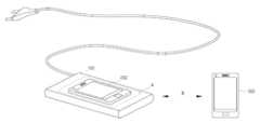
도 1은 본 발명의 일실시예인 하이브리드 무선 전력 전송 장치에서의 공명 충전과 유도 충전이 동시에 이루어지는 경우를 설명하기 위한 도면.
도 2는, 본 발명의 일실시예인 하이브리드 무선 전력 전송 장치를 포함하는 무선 전력 전송시스템의 전자적인 구성을 설명하기 위한 블록 구성도.
도 3은, 본 발명의 일실시예인 하이브리드 무선 전력 전송 장치 중 유도 전력 전송부의 전자적인 구성을 설명하기 위한 블록 구성도.
도 4는, 본 발명의 일실시예인 하이브리드 무선 전력 전송 장치 중 자기 공명 전송부의 전자적인 구성을 설명하기 위한 블록 구성도.
도 5는, 도 2의 무선 전력 전송 시스템 중 유도 전력 수신 장치의 전자적인 구성을 설명하기 위한 블록 구성도.
도 6은, 도 2의 무선 전력 전송 시스템 중 공명 전력 수신 장치의 전자적인 구성을 설명하기 위한 블록 구성도.
도 7은, 본 발명의 일실시예인 하이브리드 무선 전력 전송 장치를 포함하는 무선 전력 전송시스템에 포함되는 제 1 내지 제 4의 가변 커패시터 블록의 회로도.1 is a view for explaining a case in which resonance charging and inductive charging are simultaneously performed in a hybrid wireless power transmission device according to an embodiment of the present invention.
2 is a block diagram illustrating an electronic configuration of a wireless power transmission system including a hybrid wireless power transmission device according to an embodiment of the present invention.
3 is a block diagram illustrating an electronic configuration of an induction power transmission unit in a hybrid wireless power transmission device according to an embodiment of the present invention.
4 is a block diagram illustrating an electronic configuration of a magnetic resonance transmission unit in a hybrid wireless power transmission device according to an embodiment of the present invention.
5 is a block diagram illustrating an electronic configuration of an induction power receiving apparatus in the wireless power transmission system of FIG. 2.
6 is a block diagram illustrating an electronic configuration of an apparatus for receiving resonance power in the wireless power transmission system of FIG. 2.
7 is a circuit diagram of first to fourth variable capacitor blocks included in a wireless power transmission system including a hybrid wireless power transmission apparatus according to an embodiment of the present invention.
이하, 본 발명인 공명 전력 신호 및 유도 전력 신호를 전송할 수 있는 하이브리드 무선 전력 전송 장치 및 이를 포함하는 하이브리드 무선 전력 전송 시스템에 대하여 도면을 참조하여 보다 상세하게 설명한다.Hereinafter, a hybrid wireless power transmission apparatus capable of transmitting a resonance power signal and an induced power signal according to the present invention and a hybrid wireless power transmission system including the same will be described in more detail with reference to the drawings.
도 1은 본 발명의 일실시예인 하이브리드 무선 전력 전송 장치(100)에서의 공명 충전과 유도 충전이 동시에 이루어지는 경우를 설명하기 위한 도면이다. 도 1에 도시된 바와 같이, 본 발명의 일실시예인 하이브리드 무선 전력 전송 장치(100)는 전체적으로 직각 패널 형상을 가지며, 그 주면에는 충전 위치(A)가 형성된다. 이 충전 위치(A)에 유도 전력 수신 장치(200)가 놓이게 되면 유도 전력 신호가 발신되어서, 유도 전력 수신 장치(200)가 충전된다. 또한, 자기 공명 수신 장치(300)가 충전 거리(B) 내에 위치하게 되면 공명 전력 신호가 발신되어서 자기 공명 수신 장치(300)가 충전된다.FIG. 1 is a diagram for explaining a case in which resonance charging and inductive charging are simultaneously performed in a hybrid wireless
그런데, 이와 같이 두 개의 상이한 무선 전력 수신 장치(200,300)를 충전하게 되는 경우, 전송 안테나(121)와 전송 코일(111)간에 자기 간섭 현상이 발생하게 되고, 이에 따라 양자의 충전이 잘 이루어지지 않게 된다.However, when charging the two different
이에 본 발명에서는, 자기 간섭을 보정할 수 있도록, 임피던스 매칭을 조절하게 된다. 이하에서는 이러한 임피던스 매칭 조절에 대하여 도 2 내지 도 7을 통해 보다 상세하게 설명하도록 한다.Accordingly, in the present invention, impedance matching is adjusted so that magnetic interference can be corrected. Hereinafter, the impedance matching adjustment will be described in more detail with reference to FIGS. 2 to 7.
*도 2는, 본 발명의 일실시예인 하이브리드 무선 전력 전송 장치를 포함하는 무선 전력 전송시스템의 전자적인 구성을 설명하기 위한 블록 구성도이다. 도 2에 도시된 바와 같이, 본 발명의 일실시예인 무선 전력 전송 시스템은 하이브리드 전송 장치(100)와 무선 전력 수신 장치(200,300)를 포함할 수 있다.* FIG. 2 is a block diagram illustrating an electronic configuration of a wireless power transmission system including a hybrid wireless power transmission device according to an embodiment of the present invention. As shown in FIG. 2, a wireless power transmission system according to an embodiment of the present invention may include a
하이브리드 무선 전력 전송 장치(100)는 유도 전력 신호를 출력하는 유도 전력 전송부(110)와, 공명 전력 신호를 전송할 수 있는 자기 공명 전송부(120), 그리고, 이들을 제어하는 전송 제어부(130)를 포함할 수 있다.The hybrid wireless
유도 전력 전송부(110)와 자기 공명 전송부(120) 각각은 임피던스 매칭을 위한 제 1 가변 커패시터 블록(113) 및 제 2 가변 커패시터 블록(123)을 포함할 수 있다.Each of the induced
전송 제어부(130)는 충전 위치에 유도 전력 수신 위치(200)가 위치함과 더불어서 충전 거리(B)에 자기 공명 수신 장치(300)가 위치하는 경우, 상기 제 1 가변 커패시터 블록(113)과 상기 제 2 가변 커패시터 블록(123)을 조절하면서, 상기 유도 전력 신호 및 공명 전력 신호를 동시에 발진하도록 상기 유도 전력 전송부(120) 및 상기 자기 공명 전송부(130)를 제어할 수 있다. 이 때, 전송 제어부(130)는, 상기 제 1 및 제 2 가변 커패시터 블록(113, 123)의 커패시턴스를 랜덤하게 조절하여 임피던스 매칭을 시도할 수도 있고, 임피던스 매칭이 보다 더 중요한 상기 제 2 가변 커패시터 블록(123)의 임피던스 매칭을 우선적으로 행하고 난 뒤, 제 1 가변 커패시터 블록(113)의 임피던스 매칭을 시도할 수도 있다.When the induction
무선 전력 수신 장치의 예로는 유도 전력 신호를 수신하는 유도 전력 수신 장치와, 공명 전력 신호를 수신하는 자기 공명 수신장치가 있다. 이들의 구성에 대해서는 후술하도록 한다.Examples of the wireless power receiving device include an inductive power receiving device for receiving an inductive power signal and a magnetic resonance receiving device for receiving a resonance power signal. These configurations will be described later.
도 3은, 본 발명의 일실시예인 하이브리드 무선 전력 전송 장치 중 유도 전력 전송부의 전자적인 구성을 설명하기 위한 블록 구성도이다. 도 3에 도시된 바와 같이, 유도 전력 전송부(110)는, 전송 코일(111)과, 제 1 가변 커패시터 블록(113)을 포함할 수 있다. 전송 코일(111)을 유도 전력 신호를 전송하기 위한 구성요소이며, 제 1 가변 커패시터 블록(113)은 전송 제어부(130)의 제어에 의하여 전송 코일(111)과 무선 전력 수신 장치의 수신 코일(210)과의 임피던스 매칭을 위하여 커패시턴스 값이 변경되는 구성요소이다. 여기서 제 1 가변 커패시터 블록(113)은 비교적 큰값으로 변경되고, 수신 코일(210)에 연결되는 제 3 커패시터 블록(220)은 비교적 적은 값으로 변경됨으로써, 임피던스 매칭이 보다 용이하게 이루어질 수 있다(도 5참조).3 is a block diagram illustrating an electronic configuration of an induction power transmission unit in a hybrid wireless power transmission apparatus according to an embodiment of the present invention. As shown in FIG. 3, the induction
한편, 유도 전력 전송부(110)의 전송 코일(111)은 ASK 통신 방식으로, 유도 전력 수신 장치(200)로부터의 유도 전력 상태 정보를 수신할 수 있게 된다. 이러한 유도 전력 상태 정보는 전송 제어부에 알리게 되며, 이에 따라 전송 제어부(130)는 임피던스 매칭을 조절하여 전력 전송 효율을 극대화할 수 있게 된다.On the other hand, the
도 4는, 본 발명의 일실시예인 하이브리드 무선 전력 전송 장치 중 자기 공명 전송부의 전자적인 구성을 설명하기 위한 블록 구성도이다. 도 4에 도시된 바와 같이, 자기 공명 전송부(120)는, 전송 안테나(121)과, 제 2 가변 커패시터 블록(123)과 자기 공명 수신 장치(300)로부터의 공명 전력 상태정보를 수신하기 위한 근거리 통신부(125)를 포함할 수 있다.4 is a block diagram illustrating an electronic configuration of a magnetic resonance transmission unit in a hybrid wireless power transmission apparatus according to an embodiment of the present invention. As shown in Figure 4, the magnetic
전송 안테나(121)는 공명 전력 신호를 전송하기 위한 구성요소이며, 제 2 가변 커패시터 블록(123)은 전송 제어부(130)의 제어에 의하여 전송 안테나(121)와 자기 공명 수신 장치(300)의 수신 안테나(310)와의 임피던스 매칭을 위하여 커패시턴스 값이 변경되는 구성요소이다. 여기서 제 2 가변 커패시터 블록(123)은 비교적 큰값으로 변경되고, 수신 안테나(310)에 연결되는 제 4 커패시터 블록(320)은 비교적 적은 값으로 변경됨으로써, 임피던스 매칭이 보다 용이하게 이루어질 수 있다.The
또한 근거리 통신부(125)는, 자기 공명 수신 장치(300)의 근거리 통신모듈(350)을 통해 전송되는 공명 전력 상태 정보를 수신하여 이를 전송 제어부로 알린다. 이에 따라, 전송 제어부(130)는, 상기 공명 전력 상태 정보에 기초하여 임피던스 매칭을 조절하게 된다.In addition, the short-
도 5는 도 2의 무선 전력 전송 시스템 중 유도 전력 수신 장치의 전자적인 구성을 설명하기 위한 블록 구성도이다. 도 5에 도시된 바와 같이, 본 발명의 일실시예와 관련된 유도 전력 수신 장치(200)는, 수신 코일(210), 제 3 가변 커패시터 블록(220), 정류부(230), 부하(240) 및 유도 수신 제어부(250)를 포함할 수 있다.FIG. 5 is a block diagram illustrating an electronic configuration of an induction power receiving apparatus in the wireless power transmission system of FIG. 2. As shown in FIG. 5, the induction
여기서, 도 3에서 설명된 부분과 중복되는 구성요소에 대하여는 그 설명을 생략하도록 한다. 도 3에 도시된 바와 같이, 유도 수신 제어부(250)는, 부하(240)로부터의 충전 상태를 감지하여 유도 전력 상태 정보를 생성하고 수신 코일(210)을 통해 이를 ASK 통신 신호로 전송할 수 있다. 또한, 수신 코일(210)을 통해 수신되는 전송 장치(100)로부터의 상태 정보에 기초하여 제 3 가변 커패시터 블록(220)의 커패시턴스를 조절하게 된다. 이 때, 제 3 가변 커패시터 블록(220)의 커패시턴스는 미세 조절되게 된다.Here, a description of components that overlap with the portions described in FIG. 3 will be omitted. As shown in FIG. 3, the induction receiving
이에 따라, 공명 전력신호와 유도 전력 신호가 동시에 발진되어서 임피던스 매칭이 비틀어지는 경우, 이에 따른 임피던스 매칭이 조절되므로, 전력 전송효율을 극대화할 수 있게 된다.Accordingly, when the resonance power signal and the induced power signal are oscillated at the same time and the impedance matching is twisted, the impedance matching is adjusted accordingly, so that power transmission efficiency can be maximized.
이와 같이 구성함으로써, 제 3 가변 커패시터 블록(220)에 의해 임피던스 매칭된수신 코일(210)을 통해 수신되는 전력 신호는 정류부(230)에서 직류 전원으로 정류되어서 부하로 공급되게 되고, 이에 따라 부하가 충전되게 된다.By configuring in this way, the power signal received through the receiving
도 6은, 도 2의 무선 전력 전송 시스템 중 공명 전력 수신 장치의 전자적인 구성을 설명하기 위한 블록 구성도이다. 도 6에 도시된 바와 같이, 본 발명의 일실시예와 관련된 자기 공명 수신 장치(300)는, 수신 안테나(310), 제 4 가변 커패시터 블록(320), 정류부(330), 부하(340), 근거리 통신 모듈(350) 및 공명 수신 제어부(360)를 포함할 수 있다.6 is a block diagram illustrating an electronic configuration of an apparatus for receiving resonance power in the wireless power transmission system of FIG. 2. As shown in FIG. 6, the magnetic
여기서, 도 4에서 설명된 부분과 중복되는 구성요소에 대하여는 그 설명을 생략하도록 한다. 도 6에 도시된 바와 같이, 공명 수신 제어부(360)는, 부하(340)로부터의 충전 상태를 감지하여 공명 전력 상태 정보를 생성하고 이를 근거리 통신 모듈(350)을 통해 하이브리드 전송 장치(100)로 전송하게 된다. 또한, 근거리 통신 모듈(350)을 통해 수신되는 전송 장치(100)로부터의 상태 정보에 기초하여 제 4 가변 커패시터 블록(320)의 커패시턴스를 조절하게 된다. 이 때, 제 4 가변 커패시터 블록(320)의 커패시턴스는 미세 조절되게 된다.Here, the description of components that overlap with the portions described in FIG. 4 will be omitted. As shown in FIG. 6, the resonance
이에 따라, 공명 전력신호와 유도 전력 신호가 동시에 발진되어서 임피던스 매칭이 비틀어지는 경우, 이에 따른 임피던스 매칭이 조절되므로, 전력 전송효율을 극대화할 수 있게 된다.Accordingly, when the resonance power signal and the induced power signal are oscillated at the same time and the impedance matching is twisted, the impedance matching is adjusted accordingly, so that power transmission efficiency can be maximized.
이와 같이 구성함으로써, 제 4 가변 커패시터 블록(320)에 의해 임피던스 매칭된 수신 안테나(310)를 통해 수신되는 전력 신호는 정류부(330)에서 직류 전원으로 정류되어서 부하(340)로 공급되게 되고, 이에 따라 부하(340)가 충전되게 된다.By configuring in this way, the power signal received through the receiving
이하에서는, 가변 커패시터 블록의 회로구성에 대하여 도 7를 참조하여 설명하도록 한다. 도 7에서 설명하는 가변 커패스터 블록은 도 1 내지 6에서 설명한 제 1 내지 4 커패시터 블록에 모두 적용될 수 있는 예들이다.Hereinafter, a circuit configuration of the variable capacitor block will be described with reference to FIG. 7. The variable capacitor blocks described in FIG. 7 are examples that can be applied to all of the first to fourth capacitor blocks described in FIGS. 1 to 6.
도 7은, 본 발명의 일실시예인 하이브리드 무선 전력 전송 장치를 포함하는 무선 전력 전송시스템에 포함되는 제 1 내지 제 4의 가변 커패시터 블록의 회로도이다.7 is a circuit diagram of first to fourth variable capacitor blocks included in a wireless power transmission system including a hybrid wireless power transmission apparatus according to an embodiment of the present invention.
도 7에 도시된 바와 같이, 본 발명의 일실시예인 유도 전력 신호 및 공명 전력 신호를 송수신할 수 있는 무선 전력 전송 시스템의 가변 커패시터 블록은, 다수의 직병렬로 연결되는 커패시터(C1~C4)와, 커패시터 사이에 배치되는 스위치(S1,S2)로 구성될 수 있다. 이상과 같이 구성함으로써 보다 적은수의 커패시터로도 다양한 값의 커패시턴스를 조합할 수 있게 된다. 이에 따라 부품 점수가 적게 되어서, 제품의 경량화 및 박형화에 기여할 수 있게 된다.As shown in FIG. 7, the variable capacitor block of the wireless power transmission system capable of transmitting and receiving an inductive power signal and a resonance power signal according to an embodiment of the present invention includes a plurality of capacitors C1 to C4 connected in series and parallel. , It may be composed of a switch (S1, S2) disposed between the capacitor. By configuring as described above, it is possible to combine capacitances of various values with a smaller number of capacitors. Accordingly, the number of parts is reduced, and thus, it is possible to contribute to lighter weight and thinner product.
상술한 구성을 가지는 본 발명의 일실시예에 따르면, 하이브리드 무선 전력 전송 장치는 충전 위치에 있는 유도 전력 수신 장치와 충전 거리에 있는 자기 공명 수신 장치에 대하여 동시에 무선 전력 신호를 전송하여 충전이 동시에 이루게 할 수 있다.According to an embodiment of the present invention having the above-described configuration, the hybrid wireless power transmission device simultaneously transmits wireless power signals to the induction power receiving device in the charging position and the magnetic resonance receiving device in the charging distance so that charging is simultaneously achieved. can do.
또한, 전송 코일과 전송 안테나가 동시에 동작됨으로써 발생할 수 있는 간섭현상을 커패시턴스 변경에 의해 보정함으로써, 공명 충전 및 유도 충전의 전송 효율을 극대화할 수 있다.In addition, by correcting an interference phenomenon that may occur when the transmitting coil and the transmitting antenna are operated simultaneously by changing the capacitance, transmission efficiency of resonance charging and inductive charging can be maximized.
상기와 같이 설명된 공명 전력 신호 및 유도 전력 신호를 전송할 수 있는 하이브리드 무선 전력 전송 장치 및 이를 포함하는 하이브리드 무선 전력 전송 시스템은 상기 설명된 실시예들의 구성과 방법이 한정되게 적용될 수 있는 것이 아니라, 상기 실시예들은 다양한 변형이 이루어질 수 있도록 각 실시예들의 전부 또는 일부가 선택적으로 조합되어 구성될 수도 있다.The hybrid wireless power transmission apparatus capable of transmitting the resonance power signal and the induced power signal described above, and the hybrid wireless power transmission system including the same, are not limited to the configuration and method of the above-described embodiments, but the The embodiments may be configured by selectively combining all or part of each of the embodiments so that various modifications may be made.
A : 충전 위치
B : 충전 거리
100 : (하이브리드) 무선 전력 전송 장치
110 : 유도 전력 전송부
111 : 전송 코일
113 : 제 1 가변 커패시터 블록
120 : 자기 공명 전송부
121 : 전송 안테나
123 : 제 2 가변 커패시터 블록
125 : 근거리 통신부
200 : 유도 전력 수신 장치
210 : 수신 코일
220 : 제 3 가변 커패시터 블록
230 : 정류부
240 : 부하(배터리)
250 : 유도 수신 제어부
300 : 자기 공명 수신 장치
310 : 수신 안테나
320 : 제 4 가변 커패시터 블록
330 : 정류부
340 : 부하
350 : 근거리 통신 모듈
360 : 공명 수신 제어부A: charging position
B: charging distance
100: (hybrid) wireless power transmission device
110: induction power transmission unit
111: transmission coil
113: first variable capacitor block
120: magnetic resonance transmission unit
121: transmit antenna
123: second variable capacitor block
125: short-range communication department
200: induction power receiving device
210: receiving coil
220: third variable capacitor block
230: rectifier
240: load (battery)
250: inductive reception control unit
300: magnetic resonance receiving device
310: receiving antenna
320: fourth variable capacitor block
330: rectifier
340: load
350: short-range communication module
360: resonance reception control unit
Claims (7)
Translated fromKorean상기 유도 전력 신호를 전송하기 위해 구성된 유도 전력 전송부, 상기 유도 전력 전송부는 전송 코일과, 상기 전송 코일에 연결된 제 1 가변 커패시터 블록를 포함하고;
상기 공명 전력 신호를 전송하기 위해 구성된 자기 공명 전력 전송부, 상기 자기 공명 전력 전송부는, 전송 안테나와 상기 전송 안테나에 연결된 제 2 가변 커패시터 블록를 포함하고;
충전 위치에 유도 전력 수신 장치가 위치함과 더불어서 충전 거리에 자기 공명 수신 장치가 위치하는 경우, 상기 제 1 가변 커패시터 블록와 상기 제 2 가변 커패시터 블록를 조절하면서, 상기 유도 전력 신호 및 상기 공명 전력 신호를 동시에 발진하도록 상기 유도 전력 전송부 및 상기 자기 공명 전력 전송부를 제어하는 전송 제어부를 포함하고,
제 1 가변 커패시터 블록과 상기 제 2 가변 커패시터 블록 각각은,
직병렬로 연결되는 복수의 커패시터, 및
상기 커패시터 사이에 배치되는 스위칭부를 포함하는 것인, 공명 전력 신호 및 유도 전력 신호를 전송할 수 있는 하이브리드 무선 전력 전송 장치.
A hybrid wireless power transmission device capable of transmitting a resonant power signal and an induced power signal,
An induction power transmission unit configured to transmit the induction power signal, the induction power transmission unit including a transmission coil and a first variable capacitor block connected to the transmission coil;
A magnetic resonance power transmission unit configured to transmit the resonance power signal, the magnetic resonance power transmission unit including a transmission antenna and a second variable capacitor block connected to the transmission antenna;
When the induction power receiving device is located in the charging position and the magnetic resonance receiving device is located in the charging distance, the induction power signal and the resonance power signal are simultaneously controlled while adjusting the first variable capacitor block and the second variable capacitor block. And a transmission control unit for controlling the induction power transmission unit and the magnetic resonance power transmission unit to oscillate,
Each of the first variable capacitor block and the second variable capacitor block,
A plurality of capacitors connected in series and parallel, and
A hybrid wireless power transmission device capable of transmitting a resonance power signal and an induced power signal comprising a switching unit disposed between the capacitors.
상기 자기 공명 전송부는, 공명 수신 장치로부터의 공명 전력 상태 정보를 수신하기 위한 근거리 통신부를 더 포함하고,
상기 전송 제어부는,
상기 공명 전력 상태 정보와, 상기 전송 코일을 통해 수신되는 유도 전력 상태 정보에 기초하여, 상기 제 1 및 제 2 가변 커패시터 블록의 커패시턴스를 조절하여 임피던스 매칭을 시도하는 것인, 공명 전력 신호 및 유도 전력 신호를 전송할 수 있는 하이브리드 무선 전력 전송 장치.
The method of claim 1,
The magnetic resonance transmitting unit further includes a short-range communication unit for receiving resonance power state information from the resonance receiving device,
The transmission control unit,
Based on the resonance power state information and the induced power state information received through the transmitting coil, impedance matching is attempted by adjusting the capacitance of the first and second variable capacitor blocks, the resonance power signal and the induced power Hybrid wireless power transmission device capable of transmitting signals.
상기 전송 제어부는
상기 제 1 및 제 2 가변 커패시터 블록의 커패시턴스를 랜덤하게 조절하여 임피던스 매칭을 시도하는 것인, 공명 전력 신호 및 유도 전력 신호를 전송할 수 있는 하이브리드 무선 전력 전송 장치.
The method of claim 2,
The transmission control unit
A hybrid wireless power transmission device capable of transmitting a resonance power signal and an induced power signal to attempt impedance matching by randomly adjusting the capacitance of the first and second variable capacitor blocks.
상기 전송 제어부는,
상기 제 2 가변 커패시터 블록의 임피던스 매칭을 우선적으로 행하고 난 뒤, 제 1 가변 커패시터 블록의 임피던스 매칭을 시도하는 것인, 공명 전력 신호 및 유도 전력 신호를 전송할 수 있는 하이브리드 무선 전력 전송 장치.
The method of claim 2,
The transmission control unit,
A hybrid wireless power transmission device capable of transmitting a resonance power signal and an induced power signal, which is to attempt impedance matching of the first variable capacitor block after performing impedance matching of the second variable capacitor block first.
수신 코일과, 상기 수신 코일과 연결된 제 3 가변 커패시터 블록 및 상기 제 3 가변 커패시터 블록의 커패시턴스를 조절하는 유도 수신 제어부를 포함하는, 유도 전력 수신 장치;
수신 안테나와, 상기 수신 안테나와 연결된 제 4 가변 커패시터 블록 및 상기 제 4 가변 커패시터 블록의 커패시턴스를 조절하는 공명 수신 제어부를 포함하는, 자기 공명 수신 장치를 포함하는, 하이브리드 무선 전력 전송 시스템.
The hybrid wireless power transmission device according to any one of claims 1 to 4;
An inductive power receiving device comprising a receiving coil, a third variable capacitor block connected to the receiving coil, and an inductive receiving control unit for adjusting capacitance of the third variable capacitor block;
A hybrid wireless power transmission system comprising a receiving antenna, a fourth variable capacitor block connected to the receiving antenna, and a resonance receiving control unit configured to adjust a capacitance of the fourth variable capacitor block.
상기 유도 수신 제어부는, 상기 제 3 가변 커패시터 블록의 커패시턴스를 미세 조절하는 것인, 하이브리드 무선 전력 전송 시스템.
The method of claim 5,
The inductive reception control unit is to finely adjust the capacitance of the third variable capacitor block, hybrid wireless power transmission system.
상기 공명 수신 제어부는, 상기 제 4 가변 커패시터 블록의 커패시턴스를 미세 조절하는 것인, 하이브리드 무선 전력 전송 시스템.The method of claim 6.
The resonance receiving control unit is to finely adjust the capacitance of the fourth variable capacitor block, hybrid wireless power transmission system.
Priority Applications (4)
| Application Number | Priority Date | Filing Date | Title |
|---|---|---|---|
| KR1020200175347AKR20210004912A (en) | 2020-12-15 | 2020-12-15 | Hybrid wireless power transmission device which enables to transmit resonance power signal and induced power signal simultaneously and hybrid wireless power transmission system including the same |
| KR1020220005915AKR20220011774A (en) | 2020-12-15 | 2022-01-14 | Hybrid wireless power transmission device which enables to transmit resonance power signal and induced power signal simultaneously and hybrid wireless power transmission system including the same |
| KR1020230047024AKR20230051469A (en) | 2020-12-15 | 2023-04-10 | Hybrid wireless power transmission device which enables to transmit resonance power signal and induced power signal simultaneously and hybrid wireless power transmission system including the same |
| KR1020240122828AKR20240136921A (en) | 2020-12-15 | 2024-09-10 | Hybrid wireless power transmission device which enables to transmit resonance power signal and induced power signal simultaneously and hybrid wireless power transmission system including the same |
Applications Claiming Priority (1)
| Application Number | Priority Date | Filing Date | Title |
|---|---|---|---|
| KR1020200175347AKR20210004912A (en) | 2020-12-15 | 2020-12-15 | Hybrid wireless power transmission device which enables to transmit resonance power signal and induced power signal simultaneously and hybrid wireless power transmission system including the same |
Related Parent Applications (1)
| Application Number | Title | Priority Date | Filing Date |
|---|---|---|---|
| KR1020130138107ADivisionKR102193642B1 (en) | 2013-10-31 | 2013-11-14 | Hybrid wireless power transmission device which enables to transmit resonance power signal and induced power signal simultaneously and hybrid wireless power transmission system including the same |
Related Child Applications (1)
| Application Number | Title | Priority Date | Filing Date |
|---|---|---|---|
| KR1020220005915ADivisionKR20220011774A (en) | 2020-12-15 | 2022-01-14 | Hybrid wireless power transmission device which enables to transmit resonance power signal and induced power signal simultaneously and hybrid wireless power transmission system including the same |
Publications (1)
| Publication Number | Publication Date |
|---|---|
| KR20210004912Atrue KR20210004912A (en) | 2021-01-13 |
Family
ID=74142471
Family Applications (4)
| Application Number | Title | Priority Date | Filing Date |
|---|---|---|---|
| KR1020200175347ACeasedKR20210004912A (en) | 2020-12-15 | 2020-12-15 | Hybrid wireless power transmission device which enables to transmit resonance power signal and induced power signal simultaneously and hybrid wireless power transmission system including the same |
| KR1020220005915ACeasedKR20220011774A (en) | 2020-12-15 | 2022-01-14 | Hybrid wireless power transmission device which enables to transmit resonance power signal and induced power signal simultaneously and hybrid wireless power transmission system including the same |
| KR1020230047024ACeasedKR20230051469A (en) | 2020-12-15 | 2023-04-10 | Hybrid wireless power transmission device which enables to transmit resonance power signal and induced power signal simultaneously and hybrid wireless power transmission system including the same |
| KR1020240122828APendingKR20240136921A (en) | 2020-12-15 | 2024-09-10 | Hybrid wireless power transmission device which enables to transmit resonance power signal and induced power signal simultaneously and hybrid wireless power transmission system including the same |
Family Applications After (3)
| Application Number | Title | Priority Date | Filing Date |
|---|---|---|---|
| KR1020220005915ACeasedKR20220011774A (en) | 2020-12-15 | 2022-01-14 | Hybrid wireless power transmission device which enables to transmit resonance power signal and induced power signal simultaneously and hybrid wireless power transmission system including the same |
| KR1020230047024ACeasedKR20230051469A (en) | 2020-12-15 | 2023-04-10 | Hybrid wireless power transmission device which enables to transmit resonance power signal and induced power signal simultaneously and hybrid wireless power transmission system including the same |
| KR1020240122828APendingKR20240136921A (en) | 2020-12-15 | 2024-09-10 | Hybrid wireless power transmission device which enables to transmit resonance power signal and induced power signal simultaneously and hybrid wireless power transmission system including the same |
Country Status (1)
| Country | Link |
|---|---|
| KR (4) | KR20210004912A (en) |
Cited By (1)
| Publication number | Priority date | Publication date | Assignee | Title |
|---|---|---|---|---|
| CN119189718A (en)* | 2024-08-19 | 2024-12-27 | 智核奇点科技(深圳)有限公司 | Large-capacity automatic tracking radio frequency power supply unmanned charging system and unmanned charging method thereof |
- 2020
- 2020-12-15KRKR1020200175347Apatent/KR20210004912A/ennot_activeCeased
- 2022
- 2022-01-14KRKR1020220005915Apatent/KR20220011774A/ennot_activeCeased
- 2023
- 2023-04-10KRKR1020230047024Apatent/KR20230051469A/ennot_activeCeased
- 2024
- 2024-09-10KRKR1020240122828Apatent/KR20240136921A/enactivePending
Cited By (1)
| Publication number | Priority date | Publication date | Assignee | Title |
|---|---|---|---|---|
| CN119189718A (en)* | 2024-08-19 | 2024-12-27 | 智核奇点科技(深圳)有限公司 | Large-capacity automatic tracking radio frequency power supply unmanned charging system and unmanned charging method thereof |
Also Published As
| Publication number | Publication date |
|---|---|
| KR20240136921A (en) | 2024-09-19 |
| KR20220011774A (en) | 2022-01-28 |
| KR20230051469A (en) | 2023-04-18 |
Similar Documents
| Publication | Publication Date | Title |
|---|---|---|
| KR101184503B1 (en) | Wireless power transmission apparatus and transmission method thereof | |
| US9496731B2 (en) | Apparatus and method for transmitting wireless power by using resonant coupling and system for the same | |
| EP2720383A2 (en) | Wireless power-transmission apparatus and system | |
| KR101831993B1 (en) | Apparatus and method for controlling amount of charging current for wireless power receiver | |
| US8378524B2 (en) | Non-contact power transmission device | |
| EP2413451B1 (en) | Wireless feeding system | |
| KR101515479B1 (en) | Multi-mode wireless power receiver and wireless power receiving method thereof | |
| US20130300205A1 (en) | Method and apparatus for 3d orientation-free wireless power transfer | |
| CN105814772A (en) | Hybrid wireless power transmission system and method therefor | |
| KR20130033867A (en) | Wireless power transmission system | |
| KR102128017B1 (en) | Method for processing signal in hybrid wireless power transmission device which enables to transmit magnetic resonance wirelss power signal and induce wireless power signal, and hybrid wireless power transmission device using the same | |
| CN108599397A (en) | A kind of radio frequency reception end module suitable for long distance wireless charging | |
| KR20240136921A (en) | Hybrid wireless power transmission device which enables to transmit resonance power signal and induced power signal simultaneously and hybrid wireless power transmission system including the same | |
| CN207732518U (en) | A kind of radio frequency reception end module suitable for long distance wireless charging | |
| KR102193642B1 (en) | Hybrid wireless power transmission device which enables to transmit resonance power signal and induced power signal simultaneously and hybrid wireless power transmission system including the same | |
| KR102370577B1 (en) | Method for processing signal in hybrid wireless power transmission device which enables to transmit magnetic resonance wirelss power signal and induce wireless power signal, and hybrid wireless power transmission device using the same | |
| KR101983138B1 (en) | Apparatus and method wireless power transmission, and wireless power transmission system using the same | |
| KR102205606B1 (en) | Method for processing signal in hybrid wireless power transmission device which enables to transmit magnetic resonance wirelss power signal and induce wireless power signal, and hybrid wireless power transmission device using the same | |
| KR102376240B1 (en) | Wireless power transmission systme which enables to transmit and receive induced power signal and resonance power signal | |
| KR102150521B1 (en) | Wireless power transmission systme which enables to transmit and receive induced power signal and resonance power signal | |
| KR102297354B1 (en) | Wireless power transmission systme which enables to transmit and receive induced power signal and resonance power signal | |
| KR102257626B1 (en) | Hybrid type wireles power receiving device, method of controlling wireless power signal in hybrid type wireles power receiving device, and magnetic resonance type wireless power receiving device related to the same | |
| KR102183630B1 (en) | Hybrid type wireles power receiving device, method of controlling wireless power signal in hybrid type wireles power receiving device, and magnetic resonance type wireless power receiving device related to the same | |
| KR20220032031A (en) | Method for processing signal in hybrid wireless power transmission device which enables to transmit magnetic resonance wirelss power signal and induce wireless power signal, and hybrid wireless power transmission device using the same | |
| KR101883684B1 (en) | Apparatus and method for transmitting wireless power using resonant coupling therefor system |
Legal Events
| Date | Code | Title | Description |
|---|---|---|---|
| A107 | Divisional application of patent | ||
| PA0107 | Divisional application | Comment text:Divisional Application of Patent Patent event date:20201215 Patent event code:PA01071R01D Filing date:20131114 Application number text:1020130138107 | |
| A201 | Request for examination | ||
| PA0201 | Request for examination | Patent event code:PA02012R01D Patent event date:20210113 Comment text:Request for Examination of Application Patent event code:PA02011R04I Patent event date:20201215 Comment text:Divisional Application of Patent | |
| PG1501 | Laying open of application | ||
| E902 | Notification of reason for refusal | ||
| PE0902 | Notice of grounds for rejection | Comment text:Notification of reason for refusal Patent event date:20210310 Patent event code:PE09021S01D | |
| AMND | Amendment | ||
| E601 | Decision to refuse application | ||
| PE0601 | Decision on rejection of patent | Patent event date:20210825 Comment text:Decision to Refuse Application Patent event code:PE06012S01D Patent event date:20210310 Comment text:Notification of reason for refusal Patent event code:PE06011S01I | |
| AMND | Amendment | ||
| PX0901 | Re-examination | Patent event code:PX09011S01I Patent event date:20210825 Comment text:Decision to Refuse Application Patent event code:PX09012R01I Patent event date:20210507 Comment text:Amendment to Specification, etc. | |
| PX0601 | Decision of rejection after re-examination | Comment text:Decision to Refuse Application Patent event code:PX06014S01D Patent event date:20211125 Comment text:Amendment to Specification, etc. Patent event code:PX06012R01I Patent event date:20211021 Comment text:Decision to Refuse Application Patent event code:PX06011S01I Patent event date:20210825 Comment text:Amendment to Specification, etc. Patent event code:PX06012R01I Patent event date:20210507 Comment text:Notification of reason for refusal Patent event code:PX06013S01I Patent event date:20210310 | |
| X601 | Decision of rejection after re-examination | ||
| PA0107 | Divisional application | Comment text:Divisional Application of Patent Patent event date:20220114 Patent event code:PA01071R01D Filing date:20131114 Application number text:1020130138107 |