KR20200140485A - Display device and the method for controlling the same - Google Patents
Display device and the method for controlling the sameDownload PDFInfo
- Publication number
- KR20200140485A KR20200140485AKR1020190067104AKR20190067104AKR20200140485AKR 20200140485 AKR20200140485 AKR 20200140485AKR 1020190067104 AKR1020190067104 AKR 1020190067104AKR 20190067104 AKR20190067104 AKR 20190067104AKR 20200140485 AKR20200140485 AKR 20200140485A
- Authority
- KR
- South Korea
- Prior art keywords
- display device
- brightness
- display
- processor
- location
- Prior art date
- Legal status (The legal status is an assumption and is not a legal conclusion. Google has not performed a legal analysis and makes no representation as to the accuracy of the status listed.)
- Withdrawn
Links
Images


Classifications
- G—PHYSICS
- G09—EDUCATION; CRYPTOGRAPHY; DISPLAY; ADVERTISING; SEALS
- G09G—ARRANGEMENTS OR CIRCUITS FOR CONTROL OF INDICATING DEVICES USING STATIC MEANS TO PRESENT VARIABLE INFORMATION
- G09G3/00—Control arrangements or circuits, of interest only in connection with visual indicators other than cathode-ray tubes
- G09G3/20—Control arrangements or circuits, of interest only in connection with visual indicators other than cathode-ray tubes for presentation of an assembly of a number of characters, e.g. a page, by composing the assembly by combination of individual elements arranged in a matrix no fixed position being assigned to or needed to be assigned to the individual characters or partial characters
- G09G3/34—Control arrangements or circuits, of interest only in connection with visual indicators other than cathode-ray tubes for presentation of an assembly of a number of characters, e.g. a page, by composing the assembly by combination of individual elements arranged in a matrix no fixed position being assigned to or needed to be assigned to the individual characters or partial characters by control of light from an independent source
- G09G3/3406—Control of illumination source
- G—PHYSICS
- G01—MEASURING; TESTING
- G01D—MEASURING NOT SPECIALLY ADAPTED FOR A SPECIFIC VARIABLE; ARRANGEMENTS FOR MEASURING TWO OR MORE VARIABLES NOT COVERED IN A SINGLE OTHER SUBCLASS; TARIFF METERING APPARATUS; MEASURING OR TESTING NOT OTHERWISE PROVIDED FOR
- G01D21/00—Measuring or testing not otherwise provided for
- G01D21/02—Measuring two or more variables by means not covered by a single other subclass
- G—PHYSICS
- G01—MEASURING; TESTING
- G01J—MEASUREMENT OF INTENSITY, VELOCITY, SPECTRAL CONTENT, POLARISATION, PHASE OR PULSE CHARACTERISTICS OF INFRARED, VISIBLE OR ULTRAVIOLET LIGHT; COLORIMETRY; RADIATION PYROMETRY
- G01J1/00—Photometry, e.g. photographic exposure meter
- G01J1/02—Details
- G—PHYSICS
- G01—MEASURING; TESTING
- G01P—MEASURING LINEAR OR ANGULAR SPEED, ACCELERATION, DECELERATION, OR SHOCK; INDICATING PRESENCE, ABSENCE, OR DIRECTION, OF MOVEMENT
- G01P15/00—Measuring acceleration; Measuring deceleration; Measuring shock, i.e. sudden change of acceleration
- G—PHYSICS
- G02—OPTICS
- G02F—OPTICAL DEVICES OR ARRANGEMENTS FOR THE CONTROL OF LIGHT BY MODIFICATION OF THE OPTICAL PROPERTIES OF THE MEDIA OF THE ELEMENTS INVOLVED THEREIN; NON-LINEAR OPTICS; FREQUENCY-CHANGING OF LIGHT; OPTICAL LOGIC ELEMENTS; OPTICAL ANALOGUE/DIGITAL CONVERTERS
- G02F1/00—Devices or arrangements for the control of the intensity, colour, phase, polarisation or direction of light arriving from an independent light source, e.g. switching, gating or modulating; Non-linear optics
- G02F1/01—Devices or arrangements for the control of the intensity, colour, phase, polarisation or direction of light arriving from an independent light source, e.g. switching, gating or modulating; Non-linear optics for the control of the intensity, phase, polarisation or colour
- G02F1/13—Devices or arrangements for the control of the intensity, colour, phase, polarisation or direction of light arriving from an independent light source, e.g. switching, gating or modulating; Non-linear optics for the control of the intensity, phase, polarisation or colour based on liquid crystals, e.g. single liquid crystal display cells
- G02F1/133—Constructional arrangements; Operation of liquid crystal cells; Circuit arrangements
- G02F1/1333—Constructional arrangements; Manufacturing methods
- G02F1/1335—Structural association of cells with optical devices, e.g. polarisers or reflectors
- G02F1/1336—Illuminating devices
- G—PHYSICS
- G09—EDUCATION; CRYPTOGRAPHY; DISPLAY; ADVERTISING; SEALS
- G09F—DISPLAYING; ADVERTISING; SIGNS; LABELS OR NAME-PLATES; SEALS
- G09F21/00—Mobile visual advertising
- G09F21/04—Mobile visual advertising by land vehicles
- G—PHYSICS
- G09—EDUCATION; CRYPTOGRAPHY; DISPLAY; ADVERTISING; SEALS
- G09F—DISPLAYING; ADVERTISING; SIGNS; LABELS OR NAME-PLATES; SEALS
- G09F21/00—Mobile visual advertising
- G09F21/04—Mobile visual advertising by land vehicles
- G09F21/048—Advertisement panels on sides, front or back of vehicles
- G—PHYSICS
- G09—EDUCATION; CRYPTOGRAPHY; DISPLAY; ADVERTISING; SEALS
- G09G—ARRANGEMENTS OR CIRCUITS FOR CONTROL OF INDICATING DEVICES USING STATIC MEANS TO PRESENT VARIABLE INFORMATION
- G09G3/00—Control arrangements or circuits, of interest only in connection with visual indicators other than cathode-ray tubes
- G09G3/20—Control arrangements or circuits, of interest only in connection with visual indicators other than cathode-ray tubes for presentation of an assembly of a number of characters, e.g. a page, by composing the assembly by combination of individual elements arranged in a matrix no fixed position being assigned to or needed to be assigned to the individual characters or partial characters
- G09G3/34—Control arrangements or circuits, of interest only in connection with visual indicators other than cathode-ray tubes for presentation of an assembly of a number of characters, e.g. a page, by composing the assembly by combination of individual elements arranged in a matrix no fixed position being assigned to or needed to be assigned to the individual characters or partial characters by control of light from an independent source
- G—PHYSICS
- G09—EDUCATION; CRYPTOGRAPHY; DISPLAY; ADVERTISING; SEALS
- G09G—ARRANGEMENTS OR CIRCUITS FOR CONTROL OF INDICATING DEVICES USING STATIC MEANS TO PRESENT VARIABLE INFORMATION
- G09G5/00—Control arrangements or circuits for visual indicators common to cathode-ray tube indicators and other visual indicators
- G09G5/003—Details of a display terminal, the details relating to the control arrangement of the display terminal and to the interfaces thereto
- G—PHYSICS
- G09—EDUCATION; CRYPTOGRAPHY; DISPLAY; ADVERTISING; SEALS
- G09G—ARRANGEMENTS OR CIRCUITS FOR CONTROL OF INDICATING DEVICES USING STATIC MEANS TO PRESENT VARIABLE INFORMATION
- G09G5/00—Control arrangements or circuits for visual indicators common to cathode-ray tube indicators and other visual indicators
- G09G5/10—Intensity circuits
- H—ELECTRICITY
- H04—ELECTRIC COMMUNICATION TECHNIQUE
- H04W—WIRELESS COMMUNICATION NETWORKS
- H04W4/00—Services specially adapted for wireless communication networks; Facilities therefor
- H04W4/02—Services making use of location information
- G—PHYSICS
- G09—EDUCATION; CRYPTOGRAPHY; DISPLAY; ADVERTISING; SEALS
- G09G—ARRANGEMENTS OR CIRCUITS FOR CONTROL OF INDICATING DEVICES USING STATIC MEANS TO PRESENT VARIABLE INFORMATION
- G09G2320/00—Control of display operating conditions
- G09G2320/06—Adjustment of display parameters
- G09G2320/0626—Adjustment of display parameters for control of overall brightness
- G—PHYSICS
- G09—EDUCATION; CRYPTOGRAPHY; DISPLAY; ADVERTISING; SEALS
- G09G—ARRANGEMENTS OR CIRCUITS FOR CONTROL OF INDICATING DEVICES USING STATIC MEANS TO PRESENT VARIABLE INFORMATION
- G09G2360/00—Aspects of the architecture of display systems
- G09G2360/14—Detecting light within display terminals, e.g. using a single or a plurality of photosensors
- G09G2360/144—Detecting light within display terminals, e.g. using a single or a plurality of photosensors the light being ambient light
- G—PHYSICS
- G09—EDUCATION; CRYPTOGRAPHY; DISPLAY; ADVERTISING; SEALS
- G09G—ARRANGEMENTS OR CIRCUITS FOR CONTROL OF INDICATING DEVICES USING STATIC MEANS TO PRESENT VARIABLE INFORMATION
- G09G2370/00—Aspects of data communication
- G09G2370/02—Networking aspects
- G—PHYSICS
- G09—EDUCATION; CRYPTOGRAPHY; DISPLAY; ADVERTISING; SEALS
- G09G—ARRANGEMENTS OR CIRCUITS FOR CONTROL OF INDICATING DEVICES USING STATIC MEANS TO PRESENT VARIABLE INFORMATION
- G09G2380/00—Specific applications
- G09G2380/10—Automotive applications
Landscapes
- Physics & Mathematics (AREA)
- General Physics & Mathematics (AREA)
- Engineering & Computer Science (AREA)
- Theoretical Computer Science (AREA)
- Computer Hardware Design (AREA)
- Nonlinear Science (AREA)
- Marketing (AREA)
- Accounting & Taxation (AREA)
- Business, Economics & Management (AREA)
- Chemical & Material Sciences (AREA)
- Crystallography & Structural Chemistry (AREA)
- Spectroscopy & Molecular Physics (AREA)
- Optics & Photonics (AREA)
- Computer Networks & Wireless Communication (AREA)
- Signal Processing (AREA)
- Mathematical Physics (AREA)
- Controls And Circuits For Display Device (AREA)
Abstract
Translated fromKoreanDescription
Translated fromKorean본 발명은 주변 조도 환경에 적합하게 휘도를 제어할 수 있는 디스플레이장치 및 그의 제어방법에 관한 것이다.The present invention relates to a display device capable of controlling luminance suitable for an ambient illumination environment and a control method thereof.
디스플레이장치는 조도 센서를 통해 주변부 밝기를 인식하여, 시청자가 영상을 보기에 방해가 되지 않도록 적정한 밝기 값을 지정하고 있다. 이러한 종래의 디스플레이장치는 디지털 사이니지로 사용될 때 그 설치 위치가 고정되어 있기 때문에, 조도 센서만을 사용해 주변부 조도에 따른 변화를 감지하여 적정 밝기 값을 설정할 수 있다.The display device recognizes the brightness of the surrounding area through an illuminance sensor, and designates an appropriate brightness value so that the viewer does not interfere with viewing the image. When such a conventional display device is used as a digital signage, since its installation position is fixed, it is possible to set an appropriate brightness value by detecting a change according to the ambient illumination using only an illumination sensor.
그러나, 디지털 사이니지가 다양한 운송 수단들에 설치되어 이동한다면 문제점이 발생할 수 있다. 즉, 디스플레이장치의 조도 센서는 특정 위치에 실장되어 있기 때문에 상황에 따라 조도 값의 측정이 제한될 수 있다. 또한, 조도센서가 주변부 밝기를 감지하여 디스플레이장치에 반영하는 시점에 디스플레이장치는 이미 다른 주변부 밝기 환경으로 이동하기 때문에 정확한 주변 밝기 환경을 반영할 수 없다. 또한, 운송 수단의 진행방향에서 뒤쪽에 위치한 차량의 운전자는 밝은 지점에서 어두운 지점으로 진입하는 전방 차량의 디지털 사이니지를 보는 경우에, 아직 자신은 주변 조도가 밝은 지점에 위치하고 있기 때문에 어두운 지점으로 진입해야 하는 시점에 매우 밝은 디지털 사이니지로 인해 시야를 확보하기 어려울 수 있다. 특히, 운송수단에 장착된 디스플레이장치는 규정 이상의 휘도로 표시되면 도로 위에서 다른 차량의 운전자가 시야를 빼앗겨 사고를 유발할 수도 있다.However, if digital signage is installed and moved in various transportation means, problems may arise. That is, since the illuminance sensor of the display device is mounted at a specific location, measurement of an illuminance value may be limited depending on circumstances. In addition, when the illuminance sensor detects the brightness of the surrounding area and reflects it on the display device, the display device cannot accurately reflect the surrounding brightness environment because the display device already moves to another brightness environment of the surrounding area. In addition, when the driver of a vehicle located behind the vehicle in the direction of travel sees the digital signage of the vehicle in front that enters from a bright point to a dark point, he enters a dark point because he is still located at a point where the surrounding illumination is bright. When it should be done, it can be difficult to get a line of sight due to very bright digital signage. In particular, when a display device mounted on a vehicle is displayed with a luminance greater than the specified luminance, a driver of another vehicle on the road may lose sight of the vehicle and cause an accident.
따라서, 본 발명의 목적은, 운반수단에 장착되기 적합하고, 이동 시에도 주변의 밝기 정보를 빠르고 정확하게 반영할 수 있는 디스플레이장치 및 그의 제어방법을 제공하는 것이다.Accordingly, an object of the present invention is to provide a display device and a control method thereof, which are suitable to be mounted on a vehicle and can quickly and accurately reflect surrounding brightness information even when moving.
상술한 목적을 달성하기 위한 디스플레이장치가 제공된다. 디스플레이장치는 디스플레이와, 상기 디스플레이장치의 이동에 따라 가변되는 상기 디스플레이장치의 위치를 식별하고, 위치에 기초하여 설정된 밝기정보로부터 상기 식별된 위치의 밝기를 식별하고, 상기 식별된 밝기에 따라 상기 디스플레이의 휘도를 제어하는 프로세서를 포함한다.A display device is provided to achieve the above object. The display device identifies a display and a position of the display device that changes according to the movement of the display device, identifies the brightness of the identified position from brightness information set based on the position, and the display according to the identified brightness. It includes a processor that controls the luminance of.
상기 디스플레이장치의 위치 정보는 GPS(Global Positioning System)수신부, GIS(geographic information systems)수신부, 또는 이동통신망 중 적어도 어느 하나를 통해 수신할 수 있다.The location information of the display device may be received through at least one of a global positioning system (GPS) receiver, a geographic information systems (GIS) receiver, or a mobile communication network.
상기 디스플레이장치는 주변 밝기를 감지하는 조도센서 또는 상기 디스플레이장치의 이동 속도 또는 이동 방향을 감지하는 가속도 센서를 더 포함할 수 있다.The display device may further include an illuminance sensor for sensing ambient brightness or an acceleration sensor for sensing a moving speed or a moving direction of the display device.
디스플레이장치는 위치, 지역, 또는 도로 중 적어도 하나에 기초하여 설정된 밝기정보가 저장된 저장부를 더 포함할 수 있다.The display device may further include a storage unit storing brightness information set based on at least one of a location, an area, or a road.
상기 밝기정보는 다른 디스플레이장치들로부터 수신되어 저장될 수 있다.The brightness information may be received and stored from other display devices.
상기 디스플레이장치는 주변 밝기를 감지하는 적어도 하나의 조도센서를 더 포함하고, 상기 저장부는 상기 적어도 하나의 조도센서로부터 감지된 각 위치에 대응하는 밝기정보를 저장할 수 있다.The display device may further include at least one illuminance sensor for sensing ambient brightness, and the storage unit may store brightness information corresponding to each position detected by the at least one illuminance sensor.
상기 디스플레이는 영상을 표시하는 LCD 패널과, 상기 LCD 패널에 광을 제공하는 백라이트유닛을 포함할 수 있다.The display may include an LCD panel for displaying an image and a backlight unit for providing light to the LCD panel.
상기 프로세서는 상기 식별된 위치의 밝기에 따라 상기 백라이트유닛을 제어할 수 있다.The processor may control the backlight unit according to the brightness of the identified location.
디스플레이장치는 통신부를 더 포함하고, 상기 밝기정보는 상기 통신부를 통해 서버로부터 수신할 수 있다.The display device may further include a communication unit, and the brightness information may be received from a server through the communication unit.
디스플레이장치는 물체감지센서를 더 포함하고, 상기 프로세서는 상기 물체감지센서로부터 수신된 감지 데이터를 기초로 주변물체를 감지하고, 상기 감지된 주변물체와의 거리에 따라 상기 디스플레이의 휘도를 제어할 수 있다.The display device further includes an object detection sensor, and the processor may detect a surrounding object based on the detection data received from the object detection sensor, and control the brightness of the display according to a distance to the detected surrounding object. have.
상기 디스플레이장치는 이동속도를 측정하는 가속도센서를 더 포함하고, 상기 프로세서는 상기 측정된 디스플레이장치의 이동속도를 기초로 상기 디스플레이의 휘도를 제어할 수 있다.The display device further includes an acceleration sensor for measuring a moving speed, and the processor may control the brightness of the display based on the measured moving speed of the display device.
상기 프로세서는 상기 디스플레이장치의 이동에 따라 도로 환경이 변화하는 경우에 변화 전의 상기 디스플레이의 휘도를 소정 시간 동안 유지할 수 있다.The processor may maintain the brightness of the display before the change for a predetermined time when the road environment changes according to the movement of the display device.
상기 프로세서는 날씨 정보를 기초로 상기 디스플레이의 휘도를 가감할 수 있다.The processor may increase or decrease the luminance of the display based on weather information.
상기 프로세서는 일출시간 또는 일몰시간을 참조하여 상기 디스플레이의 휘도를 가감할 수 있다.The processor may increase or decrease the brightness of the display with reference to the sunrise time or sunset time.
본 발명의 실시예에 따른 디스플레이장치의 제어방법이 제공된다. 디스플레이장치의 제어방법은, 상기 디스플레이장치의 이동에 따라 가변되는 상기 디스플레이장치의 위치를 식별하는 단계와, 위치에 기초하여 설정된 밝기정보로부터 상기 식별된 위치의 밝기를 식별하는 단계와, 상기 밝기에 따라 디스플레이의 휘도를 제어하는 단계를 포함한다.A method of controlling a display device according to an embodiment of the present invention is provided. The method of controlling a display device includes: identifying a position of the display device that changes according to the movement of the display device; identifying a brightness of the identified position from brightness information set based on the position; and And controlling the brightness of the display accordingly.
본 발명에 의한 디스플레이장치는 운송 수단에 장착되어 다양한 도로 환경에서 주행할 때, 사전에 설정된 도로 상황과 도로 조명 표준에 적합하도록 휘도가 조절됨으로써 운송 수단 주변의 디스플레이장치의 시청자로 하여금 지나친 눈부심으로 인해 시야를 잃지 않도록 할 수 있다. 특히, 주변의 운전자는, 밝은 지점에서 어두운 지점으로 바뀌는 도로 환경에서 전방의 눈부신 디스플레이장치로 인한 사고를 피할 수 있다.When the display device according to the present invention is mounted on a transportation means and is driven in various road environments, the brightness is adjusted to suit the preset road conditions and road lighting standards, thereby causing viewers of the display apparatus around the transportation means to be excessively dazzled. You can make sure you don't lose sight. In particular, a driver around the driver can avoid an accident due to a dazzling display device in front in a road environment that changes from a bright point to a dark point.
도 1은 본 발명의 제1실시예에 따른 디스플레이장치가 장착된 차량을 도시한다.
도 2는 도 1의 디스플레이장치의 구성을 나타내는 블록도이다.
도 3은 LCD 디스플레이의 구성을 나타내는 블록도,
도 4는 본 발명의 제1실시예에 따른 위치에 대응하는 밝기 정보를 수집하는 서버의 구성을 나타내는 블록도이다.
도 5는 본 발명의 제1실시예에 따른 디스플레이장치의 제어방법을 나타내는 순서도이다.
도 6은 본 발명의 제2실시예에 따른 디스플레이장치의 제어방법을 나타내는 순서도이다.
도 7은 본 발명의 제3실시예에 따른 디스플레이장치의 제어방법을 나타내는 순서도이다.
도 8은 본 발명의 제4실시예에 따른 디스플레이장치의 제어방법을 나타내는 순서도이다.
도 9는 본 발명의 제5실시예에 따른 디스플레이장치의 제어방법을 나타내는 순서도이다.
도 10은 본 발명의 제6실시예에 따른 디스플레이장치의 제어방법을 나타내는 순서도이다.1 shows a vehicle equipped with a display device according to a first embodiment of the present invention.
2 is a block diagram showing the configuration of the display device of FIG. 1.
3 is a block diagram showing the configuration of an LCD display;
4 is a block diagram showing the configuration of a server that collects brightness information corresponding to a location according to the first embodiment of the present invention.
5 is a flowchart illustrating a method of controlling a display device according to a first embodiment of the present invention.
6 is a flowchart illustrating a method of controlling a display device according to a second embodiment of the present invention.
7 is a flowchart illustrating a method of controlling a display device according to a third embodiment of the present invention.
8 is a flowchart illustrating a method of controlling a display device according to a fourth embodiment of the present invention.
9 is a flowchart illustrating a method of controlling a display device according to a fifth embodiment of the present invention.
10 is a flowchart illustrating a method of controlling a display device according to a sixth embodiment of the present invention.
이하에서는 첨부도면을 참조하여 본 발명에 따른 실시예들에 관해 상세히 설명한다. 이하 실시예들의 설명에서는 첨부된 도면들에 기재된 사항들을 참조하는 바, 각 도면에서 제시된 동일한 참조번호 또는 부호는 실질적으로 동일한 기능을 수행하는 구성요소를 나타낸다.Hereinafter, embodiments of the present invention will be described in detail with reference to the accompanying drawings. In the following description of the embodiments, matters described in the accompanying drawings are referred to, and the same reference numerals or reference numerals in each drawing indicate components that perform substantially the same function.
도 1은 본 발명의 제1실시예에 따른 디스플레이장치(10)를 장착한 차량(1)을 도시한다. 차량(1)에 장착된 디스플레이장치(10)는 예를 들면 광고 목적의 사이니지 및 차량(1)의 상황을 경고 또는 안내하는 표시장치로서 사용될 수 있다.1 shows a
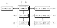
도 2는 본 발명의 제1실시예에 따른 디스플레이장치(10)의 구성을 나타내는 블록도이다.2 is a block diagram showing the configuration of the
도 2를 참조하면, 디스플레이장치(10)는 디스플레이(11), 프로세서(12), 저장부(13), 통신부(14), GPS(Global Positioning System)의 수신부(15), 물체감지센서(16), 조도센서(17), 및 가속도센서(18)를 포함할 수 있다. 디스플레이장치(10)는 도시되지 않은 영상신호 처리부, 음성신호 처리부, 스피커, 마이크로폰 등 다양한 부품들을 더 포함할 수 있다.Referring to FIG. 2, the
디스플레이(11)는 영상신호 처리부로부터 신호 처리된 영상신호에 기초하여 영상을 표시한다. 디스플레이(11)는 저장부(13)에 저장된 또는 통신부(14)를 통해 서버(20)로부터 수신한 디지털 컨텐츠를 표시할 수 있다.The
디스플레이(11)의 구현 방식은 한정되지 않는 바, 액정(liquid crystal), 플라즈마(plasma), 발광 다이오드(light-emitting diode), 유기발광 다이오드(organic light-emitting diode), 면전도 전자총(surface-conduction electron-emitter), 탄소 나노 튜브(carbon nano-tube), 나노 크리스탈(nano-crystal) 등의 다양한 디스플레이 패널로 구현될 수 있다.The implementation method of the
디스플레이(11)는 구현 방식에 따라서 부가적인 구성을 추가적으로 포함할 수 있다. 예를 들면, 도 3에 도시한 바와 같이, 디스플레이(11)는 LCD 패널(112), LCD패널(112)을 구동시키는 LCD패널구동부(114), 및 LCD 패널(112)에 광을 공급하는 백라이트 유닛(116)을 포함할 수 있다.The
프로세서(12)는 디스플레이장치(1)의 각 구성 부품을 제어할 수 있다. 프로세서(12)는, 예컨대, 사용자의 요청에 따라 디지털 컨텐츠 정보를 디스플레이(11)에 표시할 수 있다. 프로세서(12)는 이동하는 디스플레이장치의 가변되는 위치를 식별하고, 가변되는 식별 위치에 대응하는 밝기 설정을 식별하고, 식별 위치에 대응하는 밝기 설정에 따라 디스플레이(11)의 휘도를 제어할 수 있다. 예를 들면, 도3에 나타낸 바와 같이 디스플레이(11)가 LCD디스플레이인 경우, 프로세서(12)는 백라이트유닛(116)을 제어하여 휘도를 조절할 수 있다. 프로세서(12)는 위치에 따른 밝기 설정 이외에, 지도 정보, 도로 정보, 주변 운전차량과의 거리 정보, 주변 밝기 정보, 디스플레이장치(1)의 이동속도 정보, 날씨에서 흐림정도 정보, 주야간 구분 정보를 디스플레이(11)의 휘도에 반영할 수 있다.The
프로세서(12)는 제어프로그램이 설치된 비휘발성의 메모리로부터 제어프로그램의 적어도 일부를 휘발성의 메모리로 로드하고, 로드된 제어프로그램을 실행하는 적어도 하나의 범용 프로세서를 포함하며, 예를 들면 CPU(Central Processing Unit), AP(application processor), 또는 마이크로프로세서(microprocessor)로 구현될 수 있다.The
프로세서(12)는 싱글 코어, 듀얼 코어, 트리플 코어, 쿼드 코어 및 그 배수의 코어를 포함할 수 있다. 프로세서(12)는 복수 개 마련될 수 있다. 프로세서(12)는 예를 들어, 메인 프로세서(main processor) 및 슬립 모드(sleep mode, 예를 들어, 대기 전원만 공급되는 모드)에서 동작하는 서브 프로세서(sub processor)를 포함할 수 있다. 또한, 프로세서, 롬 및 램은 내부 버스(bus)를 통해 상호 연결된다.The
프로세서(12)는 디스플레이장치(10)에 내장되는 PCB 상에 실장되는 메인 SoC(Main SoC)에 포함되는 형태로서 구현 가능하다. 다른 실시예에서 메인 SoC는 영상처리부를 더 포함할 수 있다.The
제어프로그램은, BIOS, 디바이스드라이버, 운영체계, 펌웨어, 플랫폼 및 응용프로그램(어플리케이션) 중 적어도 하나의 형태로 구현되는 프로그램(들)을 포함할 수 있다. 응용프로그램은, 디스플레이장치(10)의 제조 시에 미리 설치 또는 저장되거나, 혹은 추후 사용 시에 외부로부터 응용프로그램의 데이터를 수신하여 수신된 데이터에 기초하여 설치될 수 있다. 응용 프로그램의 데이터는, 예컨대, 어플리케이션 마켓과 같은 외부 서버로부터 디스플레이장치(12)로 다운로드될 수도 있다. 이와 같은 외부 서버는, 컴퓨터프로그램제품의 일례이나, 이에 한정되는 것은 아니다.The control program may include program(s) implemented in at least one of a BIOS, a device driver, an operating system, a firmware, a platform, and an application program (application). The application program may be installed or stored in advance when the
저장부(13)는 한정되지 않은 데이터가 저장된다. 저장부(13)는 프로세서(12)에 의해 액세스 되며, 이들에 의한 데이터의 독취, 기록, 수정, 삭제, 갱신 등이 수행된다. 저장부(13)에 저장되는 데이터는, 예를 들면 위치, 지역, 지도, 도로에 대응하는 밝기가 설정된 템플릿, 및 감지되는 주변 밝기, 감지되는 속도, 날씨, 주간, 야간, 일출, 일몰에 대응하는 밝기 가감 정도가 설정된 템플릿 등을 포함한다. 물론, 저장부(13)는 운영체제, 운영체제 상에서 실행 가능한 다양한 애플리케이션, 영상데이터, 부가데이터 등을 포함한다.The
저장부(13)는 제어프로그램이 설치되는 비휘발성의 메모리, 설치된 제어프로그램의 적어도 일부가 로드되는 휘발성의 메모리를 포함한다.The
저장부(13)는 플래시 메모리 타입(flash memory type), 하드디스크 타입(hard disk type), 멀티미디어 카드 마이크로 타입(multimedia card micro type), 카드 타입의 메모리(예를 들어 SD 또는 XD 메모리 등), 램(RAM, Random Access Memory) SRAM(Static Random Access Memory), 롬(ROM, Read-Only Memory), EEPROM(Electrically Erasable Programmable Read-Only Memory), PROM(Programmable Read-Only Memory) 자기메모리, 자기 디스크, 광디스크 중 적어도 하나의 타입의 저장매체를 포함할 수 있다.The
통신부(14)는 라우터를 통해 다수의 외부장치, 예를 들면 서버(20)와 네트워크 통신을 수행할 수 있다. 통신부(14)는 라우터를 통해 서버(20)와 무선인터넷으로 통신할 수 있다.The
통신부(14)는 2G, 3G, 4G, 롱텀에볼루션(LTE), 5G와 같은 이동 통신, WLAN (Wireless LAN)(Wi-Fi), Wibro(Wireless broadband), Wimax(World Interoperability for Microwave Access), HSDPA(High Speed Downlink Packet Access) 등의 무선인터넷 모듈, 블루투스(Bluetooth), RFID(Radio Frequency Identification), 적외선 통신(IrDA, infrared Data Association), UWB(Ultra Wideband), ZigBee 등의 근거리 통신 모듈 등을 포함할 수 있다.The
GPS 수신부(15)는 복수, 예를 들면 4개 이상의 인공위성으로부터 차량(1)에 탑재되어 이동하는 디스플레이장치(10)에 대한 위치와 시간 정보를 수신할 수 있다. 이와 같이 수신된 위치 정보는 사전 설정된 위치 별 밝기에 매칭되어 디스플레이(11)의 휘도 조절에 이용될 수 있다.The
물체감지센서(16)는 카메라, 레이더, 적외선 센서, 고주파 센서 등으로 구현될 수 있다. 물체감지센서(16)는 차량(1)의 후방으로 접근하는 다른 차량을 감지하여 차량간 거리를 측정할 수 있다. 이때, 디스플레이(11)는 차량간 거리에 따라 휘도가 조절될 수 있다. 즉, 디스플레이(11)는 차량간 거리가 멀면 휘도를 높이고 가까우면 휘도를 낮출 수 있다.The
조도센서(17)는 실시간으로 디스플레이장치(10)의 주변 밝기를 측정할 수 있다. 이와 같이 측정된 주변 조도 정보는 저장부(13)에 저장될 수 있다. 이동하는 디스플레이장치(1)는 뒤따라오는 차량의 운전자가 시청자이므로, 실제 시청자의 주변 밝기에 맞게 휘도가 조절되어야 밝기 차이에 의해 발생하는 문제를 방지할 수 있다. 따라서, 이동하는 디스플레이장치(1)는 후방의 차량간 거리, 이동속도 등에 따라 실시간 밝기 정보가 아닌 이전에 얻은 밝기 정보를 참조하여 휘도를 조절할 수 있다.The
가속도센서(18)는 이동하는 차량의 속도 및 방향을 감지할 수 있다. 이와 같이 감지된 이동 속도 및 방향은 디스플레이(11)의 휘도 조절에 반영될 수 있다. 예를 들면, 이동속도가 설정된 임계값보다 낮을 경우에는 실시간 주변 밝기 정보를 반영하고, 높을 경우에는 이동속도에 연동하여 이전 감지된 주변 밝기 정보를 반영할 수 있다.The
도 4는 서버(20)의 구성을 나타내는 블록도이다. 서버(20)는 외부장치들과 통신하는 서버통신부(22), 서버(20)의 각 구성을 제어하는 서버프로세서(24) 및 데이터를 저장하는 서버저장부(26)를 포함할 수 있다.4 is a block diagram showing the configuration of the
서버통신부(22)는 라우터를 통해 디스플레이장치(10) 또는 다수의 외부디스플레이장치(30-1~30-n)와 유선 또는 무선 인터넷 통신을 수행한다.The
서버통신부(22)는 VDSL, 이더넷, 토큰링, HDMI(high definition multimedia interface), USB, 컴포넌트(component), LVDS, HEC 등의 데이터통신 모듈, 2G, 3G, 4G, 롱텀에볼루션(LTE)와 같은 이동 통신, WLAN (Wireless LAN)(Wi-Fi), Wibro(Wireless broadband), Wimax(World Interoperability for Microwave Access), HSDPA(High Speed Downlink Packet Access) 등의 무선인터넷 모듈, 블루투스(Bluetooth), RFID(Radio Frequency Identification), 적외선 통신(IrDA, infrared Data Association), UWB(Ultra Wideband), ZigBee 등의 근거리 통신 모듈 등을 포함할 수 있다.The
서버프로세서(24)는 서버(20)의 제반 구성들을 동작시키기 위한 제어를 수행한다. 서버프로세서(24)는 다수의 외부디스플레이장치(30-1~30-n)이 제공하는 위치별, 지역별, 도로별 밝기 정보를 수신하여 저장할 수 있다. 서버프로세서(24)는 중복된 위치별, 지역별, 도로별 밝기 정보들 중 소정 기간 동안의 평균값 또는 최대빈도수에 해당하는 밝기를 결정하여 위치별, 지역별, 도로별 밝기로 설정된 템플릿을 마련할 수 있다. 이와 같이, 마련된 템플릿을 디스플레이장치(10)에 제공할 수 있다.The
서버저장부(26)는 한정되지 않은 데이터가 저장된다. 서버저장부(26)는 서버프로세서(24)에 의해 액세스 되며, 이들에 의한 데이터의 독취, 기록, 수정, 삭제, 갱신 등이 수행된다. 서버저장부(26)는 기상청의 지역별 날씨정보, 및 서버통신부(22)를 통해 수신한 위치별, 지역별, 도로별 밝기 정보, 가공된 위치별, 지역별, 도로별 밝기 템플릿 등을 저장할 수 있다. 서버저장부(26)는 운영체제, 운영체제 상에서 실행 가능한 다양한 애플리케이션, 부가데이터 등을 포함한다.The
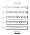
도 5는 본 발명의 제1실시예에 따른 디스플레이장치(10)의 제어방법을 설명하기 위한 순서도이다.5 is a flowchart illustrating a method of controlling the
단계 S11에서, 프로세서(12)는 GPS수신부(15), GIS(geographic information systems), 또는 이동통신망 중 적어도 어느 하나로부터 수신된 GPS정보에 의해 이동에 따라 가변되는 디스플레이장치(10)의 위치를 식별한다.In step S11, the
단계 S12에서, 프로세서(12)는 위치에 기초하여 설정된 밝기정보로부터 식별된 디스플레이장치(10)의 위치의 밝기를 식별한다.In step S12, the
단계 S13에서, 프로세서(12)는 저장부(13)에 저장된 각 도로 별로 밝기가 연결된 템플릿을 참조하여, GPS수신부로부터 수신된 디스플레이장치(10)의 위치가 속하는 도로를 매칭시킨 후, 매칭된 도로에 대응하는 밝기를 기준으로 디스플레이(11)의 휘도를 제어할 수 있다.In step S13, the
각 도로별로 밝기가 연결된 템플릿은 예를 들면 다음의 표 1 및 표 2 등을 참조하여 설정할 수 있다.A template to which brightness is connected for each road can be set by referring to Tables 1 and 2 below, for example.
아래의 표 1은 운전자에 대한 도로 조명의 휘도 기준을 나타내고 있다. 표 1에 나타나 있는 바와 같이, 도로 조명에 관한 표준과 규격 등에는 도로 및 터널의 조명 기준 그리고 빛 공해 피해를 방지 하기 위한 다양한 가이드라인이 구성되어 있다.Table 1 below shows the luminance standards of road lighting for drivers. As shown in Table 1, standards and standards related to road lighting include lighting standards for roads and tunnels, and various guidelines for preventing light pollution damage.
(최소허용치)
Lavg(sd/m2)Average road surface luminance
(Minimum allowable value)
Lavg (sd/m2 )
증분(Tl)
(최대허용치)Threshold
Increment (Tl)
(Maximum allowable value)
Lmin/LavgOverall uniformity system (Uo)
Lmin /Lavg
균제도(Ul)
Lmin/LmaxLane axle
Uniformity system (Ul)
Lmin /Lmax
평균노면휘도는 운전자 위치에서 본 마른 노면이 유지해야 할 휘도평균값의 최소허용치를 의미한다. 도로 조명의 평균노면휘도는 도로의 기하구조(도로 폭, 차로수, 중앙분리대의 유무 등) 및 도로변의 상황 등을 고려하여 설정한다.The average road surface luminance refers to the minimum allowable value of the average luminance value that the dry road surface viewed from the driver's position must be maintained. The average road surface luminance of road lighting is set in consideration of the geometry of the road (road width, number of lanes, presence or absence of a median zone, etc.) and roadside conditions.
종합 균제도(Uo)는 노면 휘도분포의 균일한 정도를 나타내는 비율로서 노면상에서의 최소휘도(Lmin)와 평균노면휘도(Lavg)의 비를 의미한다.The overall uniformity (Uo) is a ratio representing the degree of uniformity of the road surface luminance distribution, and means the ratio of the minimum luminance (Lmin ) and the average road surface luminance (Lavg ) on the road surface.
차선축 균제도(Ul)는 전방 노면의 눈에 보이는 밝기분포의 균일한 정도를 나타내는 휘도 비율로서 각 차로 중심선상에서의 최소휘도(Lmin)와 최대휘도(Lmax)의 비를 의미한다.The lane-axis uniformity (Ul) is a luminance ratio representing the uniformity of the visible brightness distribution on the road surface in front, and means the ratio of the minimum luminance (Lmin ) and the maximum luminance (Lmax ) on the center line of each lane.
임계치 증분(Tl)은 도로조명기구로부터의 불능 글레어에 의한 시력 감소를 측정하는 척도로서, 조명기구를 시야로부터 가렸을 때의 대상물의 임계휘도에 대하여 조명기구가 보여서 글레어가 있을 때 대상물의 임계휘도 증분의 백분율로 나타낸다.Threshold increment (Tl) is a measure of the decrease in visual acuity due to inability glare from road lighting equipment.The critical luminance of the object when the lighting equipment is visible and glare is relative to the critical luminance of the object when the lighting equipment is covered from the field of view. Expressed as a percentage of the increment.
아래의 표 2는 도로 및 교통의 종류에 따른 도로 조명 등급을 나타낸다.Table 2 below shows road lighting grades according to types of roads and traffic.
조명
등급road
light
rank
자동차전용도로highway
Automobile road
보조간선도로Daytime road
Auxiliary arterial road
상하행선 분리도로highway,
Up and down line separation road
국도Major city traffic routes,
National highway
지방연결도로, 주택지역 주 접근로 등Connection roads of low importance,
Local connection road, residential area main access road, etc.
교통량의 많고 적음은 연평균 일교통량 250,00대를 기준으로 할 수 있다.The high and low traffic volume can be based on the average daily traffic volume of 250,00 vehicles per year.
도로선형은 도로의 기본구조, 차량의 이동 및 시각적 환경을 의미한다. 예를 들면, 도로선형은 차선의 수, 경사면의 수, 신호등 및 표지, 진출입용 램프, 진입차량, 진출차량 등의 존재여부를 포함할 수 있다.Road linearity refers to the basic structure of the road, vehicle movement, and visual environment. For example, the road line shape may include the presence of the number of lanes, the number of slopes, traffic lights and signs, ramps for entering and exiting, vehicles entering and leaving vehicles.
상기 표 1과2에 나타낸 도로 별 조명등급과 도로 조명 휘도기준을 고려하여 위치Location in consideration of the lighting grade for each road and the road lighting luminance standards shown in Tables 1 and 2 above.
본 발명의 제1실시예에 따른 차량에 탑재되어 이동하는 디스플레이장치(10)는 도로 위에서 지나친 눈부심을 야기할 수 있게 되기 때문에, 조명등급 별로 관련 표준과 규격을 만족하도록 디스플레이(11)의 휘도를 조절할 수 있다.Since the
또한, 본 발명의 제1실시예에 따른 디스플레이장치(10)는 도로 및 교통 종류에 따른 도로 조명 등급들을 고려하여, 지도 데이터에서 각 도로 별 위치와 정체 상황 등에 따른 상황에 맞게 디스플레이(11)의 휘도를 조절할 수 있다.In addition, the
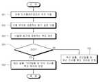
도 6은 본 발명의 제2실시예에 따른 디스플레이장치(10)의 제어방법을 나타내는 순서도이다.6 is a flow chart showing a control method of the
단계 S21에서, 프로세서(12)는 GPS수신부로부터 수신된 GPS정보에 의해 이동에 따라 가변되는 디스플레이장치(10)의 위치를 식별한다.In step S21, the
단계 S22에서, 프로세서(12)는 위치에 기초하여 설정된 밝기정보로부터 식별된 디스플레이장치(10)의 위치의 밝기를 식별한다.In step S22, the
단계 S23에서, 프로세서(12)는 식별된 밝기에 따라 디스플레이(11)의 휘도를 제어할 수 있다.In step S23, the
단계 S24에서, 프로세서(12)는 이동에 따라 가변되는 디스플레이장치(10)의 위치 변화를 기초로 도로 상황 변화, 예를 들면, 어두운 터널 내부에서 외부로 변화 또는 그 반대의 상황을 식별할 수 있다. 이러한 도로 상황 변화는 확실한 밝기의 변화가 큰 경우를 예상하여 사전에 설정될 수 있다. 차량에 탑재된 디스플레이장치(10)를 보는 시청자는 차량의 후방을 따라오는 다른 차량의 운전자이다. 이때, 디스플레이장치(10)가 탑재된 차량은 터널을 벗어나 밝은 주변환경에 맞춰 더 휘도를 높일 수 있다. 그러나, 후방차량은 아직 어두운 터널 내에 있고 밝은 외부로 나가려는 상황에 더 높인 휘도의 디스플레이장치(10)에 의해 후방차량의 운전자에게 더욱 부정적인 영향을 제공할 수 있다.In step S24, the
단계 S25에서, 프로세서(12)는 단계 S24에서 설명한 도로 상황 변화가 발생하는 경우에 소정 시간 동안 디스플레이(11)의 휘도를 높이지 이전 휘도를 유지하거나 낮출 수 있다. 또한, 프로세서(12)는 이동 속도를 고려하여 소정 시간 동안 점차적으로 디스플레이(11)의 휘도를 높일 수 있다.In step S25, the
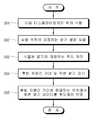
도 7은 본 발명의 제3실시예에 따른 디스플레이장치(10)의 제어방법을 나타내는 순서도이다.7 is a flow chart showing a control method of the
단계 S31에서, 프로세서(12)는 GPS수신부로부터 수신된 GPS정보에 의해 이동에 따라 가변되는 디스플레이장치(10)의 위치를 식별한다.In step S31, the
단계 S32에서, 프로세서(12)는 위치에 기초하여 설정된 밝기정보로부터 식별된 디스플레이장치(10)의 위치의 밝기를 식별한다.In step S32, the
단계 S33에서, 프로세서(12)는 식별된 밝기를 기준으로 디스플레이(11)의 휘도를 제어할 수 있다.In step S33, the
단계 S34에서, 조도센서(17)는 이동하는 디스플레이장치(10)의 주변 밝기를 감지할 수 있다. 또한, 가속도센서(18)는 이동하는 디스플레이장치(10)의 이동속도를 측정할 수 있다.In step S34, the
단계 S35에서, 프로세서(12)는 디스플레이장치(10)의 이동속도에 따라 이전에 감지되었던 주변 밝기 데이터를 반영할 수 있다. 디스플레이장치(10)를 시청하는 시청자는 후방의 차량 운전자들이므로 이동 전의 주변 밝기를 반영함으로써 후방 운전자의 상황에 맞게 휘도를 제어할 수 있다.In step S35, the
도 8은 본 발명의 제4실시예에 따른 디스플레이장치(10)의 제어방법을 나타내는 순서도이다.8 is a flow chart showing a control method of the
단계 S41에서, 프로세서(12)는 GPS수신부로부터 수신된 GPS정보에 의해 이동에 따라 가변되는 디스플레이장치(10)의 위치를 식별한다.In step S41, the
단계 S42에서, 프로세서(12)는 위치에 기초하여 설정된 밝기정보로부터 식별된 디스플레이장치(10)의 위치의 밝기를 식별한다.In step S42, the
단계 S43에서, 프로세서(12)는 식별된 밝기를 기준으로 디스플레이(11)의 휘도를 제어할 수 있다.In step S43, the
단계 S44에서, 프로세서(12)는 이동하는 디스플레이장치(10)가 위치한 지역의 날씨 정보를 파악할 수 있다. 날씨 정보는 서버(20)로부터 통신부(14)를 통해 수신하여 저장부(13)에 저장되고, 실시간 또는 설정된 시간에 업데이트될 수 있다. 날씨정보는 밝기와 관련된 흐림정도, 즉 예상되는 구름량 또는 강수확률를 포함할 수 있다.In step S44, the
단계 S45에서, 프로세서(12)는 흐림정도에 따라 디스플레이(11)의 휘도 제어를 반영할 수 있다. 시청자는 위치별 밝기 설정에 맞게 조절하더라도 지역별 날씨에 따라 시청자가 느끼는 명암이 다를 수 있다. 따라서, 디스플레이(11)의 휘도 조절은 위치별 밝기 정보뿐만 아니라 날씨 정보도 함께 고려하여 이루어질 수 있다.In step S45, the
도 9는 본 발명의 제5실시예에 따른 디스플레이장치(10)의 제어방법을 나타내는 순서도이다.9 is a flow chart showing a control method of the
단계 S51에서, 프로세서(12)는 GPS수신부로부터 수신된 GPS정보에 의해 이동에 따라 가변되는 디스플레이장치(10)의 위치를 식별한다.In step S51, the
단계 S52에서, 프로세서(12)는 위치에 기초하여 설정된 밝기정보로부터 식별된 디스플레이장치(10)의 위치의 밝기를 식별한다.In step S52, the
단계 S53에서, 프로세서(12)는 식별된 밝기를 기준으로 디스플레이(11)의 휘도를 제어할 수 있다.In step S53, the
단계 S54에서, 프로세서(12)는 현재의 시간이 주간인지 야간인지를 판단할 수 있다. 주간과 야간의 구분은 일출시간을 지나면 주간, 일몰시간을 지나면 야간으로 식별할 수 있다. 프로세서(12)는 주간이면 단계 S55를 수행하고, 야간이면 단계 S56을 수행한다.In step S54, the
단계 S55에서, 프로세서(12)는 현재 시간이 주간일출(일출 후 소정 시간)(1시간), 주간일몰(일몰 전 소정 시간)(1시간), 또는 해가 뜬 주간인지를 확인하여 디스플레이(11)의 휘도 조절에 반영할 수 있다. 즉, 프로세서(12)는 주간일출의 경우 서서히 휘도를 높이고 주간일몰의 경우 서서히 휘도를 낮추고, 주간의 경우 높게 설정된 휘도를 일정하게 반영할 수 있다.In step S55, the
단계 S56에서, 프로세서(12)는 현재 시간이 야간일출(일출 전 소정 시간)(1시간), 야간일몰(일몰 후 소정 시간)(1시간), 또는 해가 진 야간인지를 확인하여 디스플레이(11)의 휘도 조절에 반영할 수 있다. 즉, 프로세서(12)는 야간일출의 경우 서서히 휘도를 높이고 야간일몰의 경우 서서히 휘도를 낮추고, 야간의 경우 낮게 설정된 휘도를 일정하게 반영할 수 있다.In step S56, the
도 10은 본 발명의 제6실시예에 따른 디스플레이장치(10)의 제어방법을 나타내는 순서도이다.10 is a flow chart showing a control method of the
단계 S61에서, 프로세서(12)는 GPS수신부로부터 수신된 GPS정보에 의해 이동에 따라 가변되는 디스플레이장치(10)의 위치를 식별한다.In step S61, the
단계 S62에서, 프로세서(12)는 위치에 기초하여 설정된 밝기정보로부터 식별된 디스플레이장치(10)의 위치의 밝기를 식별한다.In step S62, the
단계 S63에서, 프로세서(12)는 식별된 밝기를 기준으로 디스플레이(11)의 휘도를 제어할 수 있다.In step S63, the
단계 S63에서, 프로세서(12)는 물체감지센서(16)로부터 수신한 후방 차량간의 거리 및 조도센서(17)로부터 감지된 주변 밝기를 감지할 수 있다.In step S63, the
단계 S64에서, 프로세서(12)는 후방 차량간 거리를 기초로 후방 차량의 현재 위치에 해당하는 주변 밝기 정보를 디스플레이(11)의 휘도 제어에 반영할 수 있다. 이와 같이, 이동하는 디스플레이장치(10)의 시청자는 후방 차량의 운전자이므로 후방 차량의 위치에서의 주변 밝기를 반영하여 디스플레이(11)의 휘도를 제어할 수 있다.In step S64, the
상술한 바와 같이, 프로세서(12)는 도 6 내지 10에서 설명한 다양한 정보, 예를 들면 도로 변화 정보, 이동속도 정보, 날씨 정보, 주야간 정보, 및 후방 차량간 거리 정보를 단독 또는 복합적으로 반영하여 디스플레이(11)의 휘도를 제어할 수 있다.As described above, the
이상에서는 본 발명의 바람직한 실시예에 대하여 도시하고 설명하였지만, 본 발명은 상술한 특정의 실시예에 한정되지 아니하며, 청구범위에서 청구하는 본 발명의 요지를 벗어남이 없이 당해 발명이 속하는 기술분야에서 통상의 지식을 가진 자에 의해 다양한 변형실시가 가능한 것은 물론이고, 이러한 변형 실시 예들은 본 발명의 기술적 사상이나 전망으로부터 개별적으로 이해되어서는 안 될 것이다.In the above, preferred embodiments of the present invention have been illustrated and described, but the present invention is not limited to the specific embodiments described above, and is generally used in the technical field to which the present invention belongs without departing from the gist of the present invention claimed in the claims. Various modifications can be implemented by those with knowledge of, of course, these modified embodiments should not be individually understood from the technical spirit or prospect of the present invention.
1: 차량
10: 디스플레이장치
11: 디스플레이
12: 프로세서
13: 저장부
14: 통신부
15: GPS수신부
16: 물체감지센서
17: 조도센서
18: 가속도센서
20: 서버
22: 서버통신부
24: 서버프로세서
26: 서버저장부
30-1~30-n: 외부디스플레이장치1: vehicle
10: display device
11: display
12: processor
13: storage
14: communication department
15: GPS receiver
16: object detection sensor
17: illuminance sensor
18: acceleration sensor
20: server
22: Server Communication Department
24: server processor
26: server storage
30-1~30-n: External display device
Claims (15)
Translated fromKorean디스플레이와;
상기 디스플레이장치의 이동에 따라 가변되는 상기 디스플레이장치의 위치를 식별하고,
위치에 기초하여 설정된 밝기정보로부터 상기 식별된 위치의 밝기를 식별하고,
상기 식별된 밝기에 따라 상기 디스플레이의 휘도를 제어하는
프로세서를 포함하는 디스플레이장치.In the display device,
A display;
Identifying the position of the display device that changes according to the movement of the display device,
Identify the brightness of the identified location from brightness information set based on the location,
Controlling the brightness of the display according to the identified brightness
Display device including a processor.
상기 디스플레이장치의 위치 정보는 GPS(Global Positioning System)수신부, GIS(geographic information systems)수신부, 또는 이동통신망 중 적어도 어느 하나를 통해 수신하는 디스플레이장치.The method of claim 1,
A display device that receives the location information of the display device through at least one of a Global Positioning System (GPS) receiver, a geographic information systems (GIS) receiver, or a mobile communication network.
상기 디스플레이장치의 주변 밝기를 감지하는 조도센서 또는 상기 디스플레이장치의 이동 속도 또는 이동 방향을 감지하는 가속도 센서를 더 포함하는 디스플레이장치.The method of claim 1,
A display device further comprising an illuminance sensor for sensing ambient brightness of the display device or an acceleration sensor for sensing a moving speed or direction of the display device.
위치, 지역, 또는 도로 중 적어도 하나에 대응하는 밝기정보가 저장된 저장부를 더 포함하는 디스플레이장치.The method of claim 1,
A display apparatus further comprising a storage unit storing brightness information corresponding to at least one of a location, an area, or a road.
상기 밝기정보는 다른 디스플레이장치들로부터 수신되어 저장되는 디스플레이장치.The method of claim 4,
A display device in which the brightness information is received and stored from other display devices.
상기 디스플레이장치의 주변 밝기를 감지하는 적어도 하나의 조도센서를 더 포함하며,
상기 저장부는 상기 적어도 하나의 조도센서로부터 감지된 각 위치에 대응하는 밝기정보를 저장하는 디스플레이장치.The method of claim 4,
Further comprising at least one illuminance sensor for sensing the ambient brightness of the display device,
The storage unit is a display device for storing brightness information corresponding to each position sensed by the at least one illuminance sensor.
상기 디스플레이는,
영상을 표시하는 LCD 패널과;
상기 LCD 패널에 광을 제공하는 백라이트유닛을 포함하는 디스플레이장치.The method of claim 1,
The display,
An LCD panel that displays an image;
A display device including a backlight unit providing light to the LCD panel.
상기 프로세서는 상기 식별된 위치의 밝기에 따라 상기 백라이트유닛을 제어하는 디스플레이장치.The method of claim 7,
The processor controls the backlight unit according to the brightness of the identified position.
통신부를 더 포함하며,
상기 밝기정보는 상기 통신부를 통해 서버로부터 수신되는 디스플레이장치.The method of claim 1,
Further comprising a communication unit,
The brightness information is a display device received from a server through the communication unit.
물체감지센서를 더 포함하며,
상기 프로세서는,
상기 물체감지센서로부터 수신된 감지 데이터를 기초로 주변물체를 감지하고,
상기 감지된 주변물체와의 거리에 따라 상기 디스플레이의 휘도를 제어하는 디스플레이장치.The method of claim 1,
Further comprising an object detection sensor,
The processor,
Detecting surrounding objects based on the detection data received from the object detection sensor,
A display device that controls the brightness of the display according to the sensed distance to the surrounding object.
상기 디스플레이장치의 이동속도를 측정하는 가속도센서를 더 포함하며,
상기 프로세서는 상기 측정된 디스플레이장치의 이동속도를 기초로 상기 디스플레이의 휘도를 제어하는 디스플레이장치.The method of claim 1,
Further comprising an acceleration sensor for measuring the moving speed of the display device,
The processor controls the brightness of the display based on the measured moving speed of the display device.
상기 프로세서는 상기 디스플레이장치의 이동에 따라 도로 환경이 변화하는 경우에 소정 시간 동안 변화 전의 상기 디스플레이의 휘도를 유지하는 디스플레이장치.The method of claim 1,
The processor maintains the brightness of the display before the change for a predetermined time when the road environment changes according to the movement of the display device.
상기 프로세서는 날씨 정보를 기초로 상기 디스플레이의 휘도를 가감하는 디스플레이장치.The method of claim 1,
The processor is a display device for adding or subtracting the luminance of the display based on weather information.
상기 프로세서는 일출시간 또는 일몰시간을 참조하여 상기 디스플레이의 휘도를 가감하는 디스플레이장치.The method of claim 1,
The processor is a display device that increases or decreases the luminance of the display by referring to a sunrise time or a sunset time.
상기 디스플레이장치의 이동에 따라 가변되는 상기 디스플레이장치의 위치를 식별하는 단계와;
위치에 기초하여 설정된 밝기정보로부터 상기 식별된 위치의 밝기를 식별하는 단계와;
상기 식별된 밝기에 따라 디스플레이의 휘도를 제어하는 단계를 포함하는 디스플레이장치의 제어방법.In the control method of the display device,
Identifying a position of the display device that changes according to the movement of the display device;
Identifying the brightness of the identified location from brightness information set based on the location;
And controlling the brightness of the display according to the identified brightness.
Priority Applications (2)
| Application Number | Priority Date | Filing Date | Title |
|---|---|---|---|
| KR1020190067104AKR20200140485A (en) | 2019-06-07 | 2019-06-07 | Display device and the method for controlling the same |
| PCT/KR2020/007291WO2020246827A1 (en) | 2019-06-07 | 2020-06-04 | Display device and control method therefor |
Applications Claiming Priority (1)
| Application Number | Priority Date | Filing Date | Title |
|---|---|---|---|
| KR1020190067104AKR20200140485A (en) | 2019-06-07 | 2019-06-07 | Display device and the method for controlling the same |
Publications (1)
| Publication Number | Publication Date |
|---|---|
| KR20200140485Atrue KR20200140485A (en) | 2020-12-16 |
Family
ID=73652153
Family Applications (1)
| Application Number | Title | Priority Date | Filing Date |
|---|---|---|---|
| KR1020190067104AWithdrawnKR20200140485A (en) | 2019-06-07 | 2019-06-07 | Display device and the method for controlling the same |
Country Status (2)
| Country | Link |
|---|---|
| KR (1) | KR20200140485A (en) |
| WO (1) | WO2020246827A1 (en) |
Cited By (1)
| Publication number | Priority date | Publication date | Assignee | Title |
|---|---|---|---|---|
| KR102457717B1 (en)* | 2021-05-20 | 2022-10-21 | (주)대광솔라 | Hybrid smart sign board using solar power generation |
Families Citing this family (1)
| Publication number | Priority date | Publication date | Assignee | Title |
|---|---|---|---|---|
| KR20220082531A (en)* | 2020-12-10 | 2022-06-17 | 현대자동차주식회사 | Apparatus and method for coltrolling screen of moving object, moving object system |
Family Cites Families (5)
| Publication number | Priority date | Publication date | Assignee | Title |
|---|---|---|---|---|
| JP4309707B2 (en)* | 2003-06-26 | 2009-08-05 | パナソニック株式会社 | In-vehicle display device |
| JP5784398B2 (en)* | 2011-07-19 | 2015-09-24 | 株式会社東芝 | Display control method |
| KR101992310B1 (en)* | 2013-03-25 | 2019-09-30 | 엘지디스플레이 주식회사 | Image processing method for display apparatus and image processing apparatus |
| JP2016095365A (en)* | 2014-11-13 | 2016-05-26 | シャープ株式会社 | Mobile terminal device |
| US9924583B2 (en)* | 2015-05-14 | 2018-03-20 | Mnaufacturing Resources International, Inc. | Display brightness control based on location data |
- 2019
- 2019-06-07KRKR1020190067104Apatent/KR20200140485A/ennot_activeWithdrawn
- 2020
- 2020-06-04WOPCT/KR2020/007291patent/WO2020246827A1/ennot_activeCeased
Cited By (1)
| Publication number | Priority date | Publication date | Assignee | Title |
|---|---|---|---|---|
| KR102457717B1 (en)* | 2021-05-20 | 2022-10-21 | (주)대광솔라 | Hybrid smart sign board using solar power generation |
Also Published As
| Publication number | Publication date |
|---|---|
| WO2020246827A1 (en) | 2020-12-10 |
Similar Documents
| Publication | Publication Date | Title |
|---|---|---|
| CN112837535B (en) | Traffic information processing method, device, system, equipment and storage medium | |
| US20200219325A1 (en) | Information providing method and information providing vehicle therefor | |
| US9472163B2 (en) | Adjusting content rendering for environmental conditions | |
| US9734744B1 (en) | Self-reacting message board | |
| US20210233442A1 (en) | Elevating and descending sign | |
| KR102104500B1 (en) | Method and vehicle for providing information | |
| CN111523368B (en) | Information processing device, server, and traffic management system | |
| US20190172411A1 (en) | Visual display system and method | |
| US11615551B2 (en) | Assessing visibility of a target object with autonomous vehicle fleet | |
| US20210174714A1 (en) | Controlling display of variable content sign | |
| US11748664B1 (en) | Systems for creating training data for determining vehicle following distance | |
| KR102257078B1 (en) | Fog detection device using coordinate system and method thereof | |
| US11508271B2 (en) | Display panel | |
| KR20200140485A (en) | Display device and the method for controlling the same | |
| CN119516761A (en) | An application method and system for active luminous signs based on road environment and traffic flow | |
| KR102624677B1 (en) | Smart road reflection mirror | |
| KR102282368B1 (en) | Method and vehicle for providing information | |
| RU2703887C1 (en) | Information device for traffic safety | |
| KR102524383B1 (en) | Road information display device | |
| KR102524382B1 (en) | Road-condition warning device | |
| CN115394099B (en) | Road traffic guidance method, system, equipment and traffic guidance sign | |
| WO2021061921A1 (en) | Vehicle-mounted, motion-controlled sign | |
| KR20050095282A (en) | Outdoor illuminator brightness automatic adjuster | |
| JP2013205285A (en) | Map image display system, map image display device, map image display method, and computer program |
Legal Events
| Date | Code | Title | Description |
|---|---|---|---|
| PA0109 | Patent application | Patent event code:PA01091R01D Comment text:Patent Application Patent event date:20190607 | |
| PG1501 | Laying open of application | ||
| PC1203 | Withdrawal of no request for examination |