KR20200140390A - Pressure skew system to control center-edge pressure changes - Google Patents
Pressure skew system to control center-edge pressure changesDownload PDFInfo
- Publication number
- KR20200140390A KR20200140390AKR1020207034775AKR20207034775AKR20200140390AKR 20200140390 AKR20200140390 AKR 20200140390AKR 1020207034775 AKR1020207034775 AKR 1020207034775AKR 20207034775 AKR20207034775 AKR 20207034775AKR 20200140390 AKR20200140390 AKR 20200140390A
- Authority
- KR
- South Korea
- Prior art keywords
- pumping
- zone
- chamber
- ring
- processing
- Prior art date
- Legal status (The legal status is an assumption and is not a legal conclusion. Google has not performed a legal analysis and makes no representation as to the accuracy of the status listed.)
- Withdrawn
Links
- 238000005086pumpingMethods0.000claimsabstractdescription171
- 239000007789gasSubstances0.000claimsabstractdescription60
- 238000000034methodMethods0.000claimsabstractdescription35
- 239000011261inert gasSubstances0.000claimsabstractdescription13
- NJPPVKZQTLUDBO-UHFFFAOYSA-NnovaluronChemical compoundC1=C(Cl)C(OC(F)(F)C(OC(F)(F)F)F)=CC=C1NC(=O)NC(=O)C1=C(F)C=CC=C1FNJPPVKZQTLUDBO-UHFFFAOYSA-N0.000claimsdescription25
- 125000006850spacer groupChemical group0.000claimsdescription9
- 2299100010946061 aluminium alloyInorganic materials0.000claimsdescription7
- 229910018072Al 2 O 3Inorganic materials0.000claimsdescription5
- 239000000463materialSubstances0.000claimsdescription3
- 239000000919ceramicSubstances0.000claimsdescription2
- TWNQGVIAIRXVLR-UHFFFAOYSA-Noxo(oxoalumanyloxy)alumaneChemical compoundO=[Al]O[Al]=OTWNQGVIAIRXVLR-UHFFFAOYSA-N0.000claimsdescription2
- 238000000059patterningMethods0.000abstractdescription17
- 238000000151depositionMethods0.000abstractdescription5
- 239000000758substrateSubstances0.000description29
- 238000005229chemical vapour depositionMethods0.000description10
- 238000000623plasma-assisted chemical vapour depositionMethods0.000description4
- XKRFYHLGVUSROY-UHFFFAOYSA-NArgonChemical compound[Ar]XKRFYHLGVUSROY-UHFFFAOYSA-N0.000description2
- 239000006227byproductSubstances0.000description2
- 229910052799carbonInorganic materials0.000description2
- 230000007423decreaseEffects0.000description2
- 230000008021depositionEffects0.000description2
- IJGRMHOSHXDMSA-UHFFFAOYSA-NAtomic nitrogenChemical compoundN#NIJGRMHOSHXDMSA-UHFFFAOYSA-N0.000description1
- OKTJSMMVPCPJKN-UHFFFAOYSA-NCarbonChemical compound[C]OKTJSMMVPCPJKN-UHFFFAOYSA-N0.000description1
- UFHFLCQGNIYNRP-UHFFFAOYSA-NHydrogenChemical compound[H][H]UFHFLCQGNIYNRP-UHFFFAOYSA-N0.000description1
- 229910052786argonInorganic materials0.000description1
- 229910001873dinitrogenInorganic materials0.000description1
- 230000005684electric fieldEffects0.000description1
- 238000010438heat treatmentMethods0.000description1
- 239000001307heliumSubstances0.000description1
- 229910052734heliumInorganic materials0.000description1
- SWQJXJOGLNCZEY-UHFFFAOYSA-Nhelium atomChemical compound[He]SWQJXJOGLNCZEY-UHFFFAOYSA-N0.000description1
- 239000004065semiconductorSubstances0.000description1
- 235000012431wafersNutrition0.000description1
Images


Classifications
- H—ELECTRICITY
- H01—ELECTRIC ELEMENTS
- H01L—SEMICONDUCTOR DEVICES NOT COVERED BY CLASS H10
- H01L21/00—Processes or apparatus adapted for the manufacture or treatment of semiconductor or solid state devices or of parts thereof
- H01L21/67—Apparatus specially adapted for handling semiconductor or electric solid state devices during manufacture or treatment thereof; Apparatus specially adapted for handling wafers during manufacture or treatment of semiconductor or electric solid state devices or components ; Apparatus not specifically provided for elsewhere
- H01L21/67005—Apparatus not specifically provided for elsewhere
- H01L21/67011—Apparatus for manufacture or treatment
- H01L21/67155—Apparatus for manufacturing or treating in a plurality of work-stations
- H01L21/6719—Apparatus for manufacturing or treating in a plurality of work-stations characterized by the construction of the processing chambers, e.g. modular processing chambers
- C—CHEMISTRY; METALLURGY
- C23—COATING METALLIC MATERIAL; COATING MATERIAL WITH METALLIC MATERIAL; CHEMICAL SURFACE TREATMENT; DIFFUSION TREATMENT OF METALLIC MATERIAL; COATING BY VACUUM EVAPORATION, BY SPUTTERING, BY ION IMPLANTATION OR BY CHEMICAL VAPOUR DEPOSITION, IN GENERAL; INHIBITING CORROSION OF METALLIC MATERIAL OR INCRUSTATION IN GENERAL
- C23C—COATING METALLIC MATERIAL; COATING MATERIAL WITH METALLIC MATERIAL; SURFACE TREATMENT OF METALLIC MATERIAL BY DIFFUSION INTO THE SURFACE, BY CHEMICAL CONVERSION OR SUBSTITUTION; COATING BY VACUUM EVAPORATION, BY SPUTTERING, BY ION IMPLANTATION OR BY CHEMICAL VAPOUR DEPOSITION, IN GENERAL
- C23C16/00—Chemical coating by decomposition of gaseous compounds, without leaving reaction products of surface material in the coating, i.e. chemical vapour deposition [CVD] processes
- C23C16/44—Chemical coating by decomposition of gaseous compounds, without leaving reaction products of surface material in the coating, i.e. chemical vapour deposition [CVD] processes characterised by the method of coating
- C23C16/455—Chemical coating by decomposition of gaseous compounds, without leaving reaction products of surface material in the coating, i.e. chemical vapour deposition [CVD] processes characterised by the method of coating characterised by the method used for introducing gases into reaction chamber or for modifying gas flows in reaction chamber
- C23C16/45502—Flow conditions in reaction chamber
- C—CHEMISTRY; METALLURGY
- C23—COATING METALLIC MATERIAL; COATING MATERIAL WITH METALLIC MATERIAL; CHEMICAL SURFACE TREATMENT; DIFFUSION TREATMENT OF METALLIC MATERIAL; COATING BY VACUUM EVAPORATION, BY SPUTTERING, BY ION IMPLANTATION OR BY CHEMICAL VAPOUR DEPOSITION, IN GENERAL; INHIBITING CORROSION OF METALLIC MATERIAL OR INCRUSTATION IN GENERAL
- C23C—COATING METALLIC MATERIAL; COATING MATERIAL WITH METALLIC MATERIAL; SURFACE TREATMENT OF METALLIC MATERIAL BY DIFFUSION INTO THE SURFACE, BY CHEMICAL CONVERSION OR SUBSTITUTION; COATING BY VACUUM EVAPORATION, BY SPUTTERING, BY ION IMPLANTATION OR BY CHEMICAL VAPOUR DEPOSITION, IN GENERAL
- C23C16/00—Chemical coating by decomposition of gaseous compounds, without leaving reaction products of surface material in the coating, i.e. chemical vapour deposition [CVD] processes
- C23C16/44—Chemical coating by decomposition of gaseous compounds, without leaving reaction products of surface material in the coating, i.e. chemical vapour deposition [CVD] processes characterised by the method of coating
- C23C16/4412—Details relating to the exhausts, e.g. pumps, filters, scrubbers, particle traps
- C—CHEMISTRY; METALLURGY
- C23—COATING METALLIC MATERIAL; COATING MATERIAL WITH METALLIC MATERIAL; CHEMICAL SURFACE TREATMENT; DIFFUSION TREATMENT OF METALLIC MATERIAL; COATING BY VACUUM EVAPORATION, BY SPUTTERING, BY ION IMPLANTATION OR BY CHEMICAL VAPOUR DEPOSITION, IN GENERAL; INHIBITING CORROSION OF METALLIC MATERIAL OR INCRUSTATION IN GENERAL
- C23C—COATING METALLIC MATERIAL; COATING MATERIAL WITH METALLIC MATERIAL; SURFACE TREATMENT OF METALLIC MATERIAL BY DIFFUSION INTO THE SURFACE, BY CHEMICAL CONVERSION OR SUBSTITUTION; COATING BY VACUUM EVAPORATION, BY SPUTTERING, BY ION IMPLANTATION OR BY CHEMICAL VAPOUR DEPOSITION, IN GENERAL
- C23C16/00—Chemical coating by decomposition of gaseous compounds, without leaving reaction products of surface material in the coating, i.e. chemical vapour deposition [CVD] processes
- C23C16/44—Chemical coating by decomposition of gaseous compounds, without leaving reaction products of surface material in the coating, i.e. chemical vapour deposition [CVD] processes characterised by the method of coating
- C23C16/455—Chemical coating by decomposition of gaseous compounds, without leaving reaction products of surface material in the coating, i.e. chemical vapour deposition [CVD] processes characterised by the method of coating characterised by the method used for introducing gases into reaction chamber or for modifying gas flows in reaction chamber
- C23C16/45557—Pulsed pressure or control pressure
- C—CHEMISTRY; METALLURGY
- C23—COATING METALLIC MATERIAL; COATING MATERIAL WITH METALLIC MATERIAL; CHEMICAL SURFACE TREATMENT; DIFFUSION TREATMENT OF METALLIC MATERIAL; COATING BY VACUUM EVAPORATION, BY SPUTTERING, BY ION IMPLANTATION OR BY CHEMICAL VAPOUR DEPOSITION, IN GENERAL; INHIBITING CORROSION OF METALLIC MATERIAL OR INCRUSTATION IN GENERAL
- C23C—COATING METALLIC MATERIAL; COATING MATERIAL WITH METALLIC MATERIAL; SURFACE TREATMENT OF METALLIC MATERIAL BY DIFFUSION INTO THE SURFACE, BY CHEMICAL CONVERSION OR SUBSTITUTION; COATING BY VACUUM EVAPORATION, BY SPUTTERING, BY ION IMPLANTATION OR BY CHEMICAL VAPOUR DEPOSITION, IN GENERAL
- C23C16/00—Chemical coating by decomposition of gaseous compounds, without leaving reaction products of surface material in the coating, i.e. chemical vapour deposition [CVD] processes
- C23C16/44—Chemical coating by decomposition of gaseous compounds, without leaving reaction products of surface material in the coating, i.e. chemical vapour deposition [CVD] processes characterised by the method of coating
- C23C16/455—Chemical coating by decomposition of gaseous compounds, without leaving reaction products of surface material in the coating, i.e. chemical vapour deposition [CVD] processes characterised by the method of coating characterised by the method used for introducing gases into reaction chamber or for modifying gas flows in reaction chamber
- C23C16/45587—Mechanical means for changing the gas flow
- C23C16/45591—Fixed means, e.g. wings, baffles
- C—CHEMISTRY; METALLURGY
- C23—COATING METALLIC MATERIAL; COATING MATERIAL WITH METALLIC MATERIAL; CHEMICAL SURFACE TREATMENT; DIFFUSION TREATMENT OF METALLIC MATERIAL; COATING BY VACUUM EVAPORATION, BY SPUTTERING, BY ION IMPLANTATION OR BY CHEMICAL VAPOUR DEPOSITION, IN GENERAL; INHIBITING CORROSION OF METALLIC MATERIAL OR INCRUSTATION IN GENERAL
- C23C—COATING METALLIC MATERIAL; COATING MATERIAL WITH METALLIC MATERIAL; SURFACE TREATMENT OF METALLIC MATERIAL BY DIFFUSION INTO THE SURFACE, BY CHEMICAL CONVERSION OR SUBSTITUTION; COATING BY VACUUM EVAPORATION, BY SPUTTERING, BY ION IMPLANTATION OR BY CHEMICAL VAPOUR DEPOSITION, IN GENERAL
- C23C16/00—Chemical coating by decomposition of gaseous compounds, without leaving reaction products of surface material in the coating, i.e. chemical vapour deposition [CVD] processes
- C23C16/44—Chemical coating by decomposition of gaseous compounds, without leaving reaction products of surface material in the coating, i.e. chemical vapour deposition [CVD] processes characterised by the method of coating
- C23C16/458—Chemical coating by decomposition of gaseous compounds, without leaving reaction products of surface material in the coating, i.e. chemical vapour deposition [CVD] processes characterised by the method of coating characterised by the method used for supporting substrates in the reaction chamber
- C23C16/4581—Chemical coating by decomposition of gaseous compounds, without leaving reaction products of surface material in the coating, i.e. chemical vapour deposition [CVD] processes characterised by the method of coating characterised by the method used for supporting substrates in the reaction chamber characterised by material of construction or surface finish of the means for supporting the substrate
- C—CHEMISTRY; METALLURGY
- C23—COATING METALLIC MATERIAL; COATING MATERIAL WITH METALLIC MATERIAL; CHEMICAL SURFACE TREATMENT; DIFFUSION TREATMENT OF METALLIC MATERIAL; COATING BY VACUUM EVAPORATION, BY SPUTTERING, BY ION IMPLANTATION OR BY CHEMICAL VAPOUR DEPOSITION, IN GENERAL; INHIBITING CORROSION OF METALLIC MATERIAL OR INCRUSTATION IN GENERAL
- C23C—COATING METALLIC MATERIAL; COATING MATERIAL WITH METALLIC MATERIAL; SURFACE TREATMENT OF METALLIC MATERIAL BY DIFFUSION INTO THE SURFACE, BY CHEMICAL CONVERSION OR SUBSTITUTION; COATING BY VACUUM EVAPORATION, BY SPUTTERING, BY ION IMPLANTATION OR BY CHEMICAL VAPOUR DEPOSITION, IN GENERAL
- C23C16/00—Chemical coating by decomposition of gaseous compounds, without leaving reaction products of surface material in the coating, i.e. chemical vapour deposition [CVD] processes
- C23C16/44—Chemical coating by decomposition of gaseous compounds, without leaving reaction products of surface material in the coating, i.e. chemical vapour deposition [CVD] processes characterised by the method of coating
- C23C16/458—Chemical coating by decomposition of gaseous compounds, without leaving reaction products of surface material in the coating, i.e. chemical vapour deposition [CVD] processes characterised by the method of coating characterised by the method used for supporting substrates in the reaction chamber
- C23C16/4582—Rigid and flat substrates, e.g. plates or discs
- C23C16/4583—Rigid and flat substrates, e.g. plates or discs the substrate being supported substantially horizontally
- C23C16/4585—Devices at or outside the perimeter of the substrate support, e.g. clamping rings, shrouds
- C—CHEMISTRY; METALLURGY
- C23—COATING METALLIC MATERIAL; COATING MATERIAL WITH METALLIC MATERIAL; CHEMICAL SURFACE TREATMENT; DIFFUSION TREATMENT OF METALLIC MATERIAL; COATING BY VACUUM EVAPORATION, BY SPUTTERING, BY ION IMPLANTATION OR BY CHEMICAL VAPOUR DEPOSITION, IN GENERAL; INHIBITING CORROSION OF METALLIC MATERIAL OR INCRUSTATION IN GENERAL
- C23C—COATING METALLIC MATERIAL; COATING MATERIAL WITH METALLIC MATERIAL; SURFACE TREATMENT OF METALLIC MATERIAL BY DIFFUSION INTO THE SURFACE, BY CHEMICAL CONVERSION OR SUBSTITUTION; COATING BY VACUUM EVAPORATION, BY SPUTTERING, BY ION IMPLANTATION OR BY CHEMICAL VAPOUR DEPOSITION, IN GENERAL
- C23C16/00—Chemical coating by decomposition of gaseous compounds, without leaving reaction products of surface material in the coating, i.e. chemical vapour deposition [CVD] processes
- C23C16/44—Chemical coating by decomposition of gaseous compounds, without leaving reaction products of surface material in the coating, i.e. chemical vapour deposition [CVD] processes characterised by the method of coating
- C23C16/50—Chemical coating by decomposition of gaseous compounds, without leaving reaction products of surface material in the coating, i.e. chemical vapour deposition [CVD] processes characterised by the method of coating using electric discharges
- C23C16/505—Chemical coating by decomposition of gaseous compounds, without leaving reaction products of surface material in the coating, i.e. chemical vapour deposition [CVD] processes characterised by the method of coating using electric discharges using radio frequency discharges
- C23C16/509—Chemical coating by decomposition of gaseous compounds, without leaving reaction products of surface material in the coating, i.e. chemical vapour deposition [CVD] processes characterised by the method of coating using electric discharges using radio frequency discharges using internal electrodes
- C23C16/5096—Flat-bed apparatus
- C—CHEMISTRY; METALLURGY
- C23—COATING METALLIC MATERIAL; COATING MATERIAL WITH METALLIC MATERIAL; CHEMICAL SURFACE TREATMENT; DIFFUSION TREATMENT OF METALLIC MATERIAL; COATING BY VACUUM EVAPORATION, BY SPUTTERING, BY ION IMPLANTATION OR BY CHEMICAL VAPOUR DEPOSITION, IN GENERAL; INHIBITING CORROSION OF METALLIC MATERIAL OR INCRUSTATION IN GENERAL
- C23C—COATING METALLIC MATERIAL; COATING MATERIAL WITH METALLIC MATERIAL; SURFACE TREATMENT OF METALLIC MATERIAL BY DIFFUSION INTO THE SURFACE, BY CHEMICAL CONVERSION OR SUBSTITUTION; COATING BY VACUUM EVAPORATION, BY SPUTTERING, BY ION IMPLANTATION OR BY CHEMICAL VAPOUR DEPOSITION, IN GENERAL
- C23C16/00—Chemical coating by decomposition of gaseous compounds, without leaving reaction products of surface material in the coating, i.e. chemical vapour deposition [CVD] processes
- C23C16/44—Chemical coating by decomposition of gaseous compounds, without leaving reaction products of surface material in the coating, i.e. chemical vapour deposition [CVD] processes characterised by the method of coating
- C23C16/52—Controlling or regulating the coating process
- H—ELECTRICITY
- H01—ELECTRIC ELEMENTS
- H01L—SEMICONDUCTOR DEVICES NOT COVERED BY CLASS H10
- H01L21/00—Processes or apparatus adapted for the manufacture or treatment of semiconductor or solid state devices or of parts thereof
- H01L21/67—Apparatus specially adapted for handling semiconductor or electric solid state devices during manufacture or treatment thereof; Apparatus specially adapted for handling wafers during manufacture or treatment of semiconductor or electric solid state devices or components ; Apparatus not specifically provided for elsewhere
- H01L21/67005—Apparatus not specifically provided for elsewhere
- H01L21/67011—Apparatus for manufacture or treatment
- H01L21/67017—Apparatus for fluid treatment
- H—ELECTRICITY
- H01—ELECTRIC ELEMENTS
- H01L—SEMICONDUCTOR DEVICES NOT COVERED BY CLASS H10
- H01L21/00—Processes or apparatus adapted for the manufacture or treatment of semiconductor or solid state devices or of parts thereof
- H01L21/67—Apparatus specially adapted for handling semiconductor or electric solid state devices during manufacture or treatment thereof; Apparatus specially adapted for handling wafers during manufacture or treatment of semiconductor or electric solid state devices or components ; Apparatus not specifically provided for elsewhere
- H01L21/683—Apparatus specially adapted for handling semiconductor or electric solid state devices during manufacture or treatment thereof; Apparatus specially adapted for handling wafers during manufacture or treatment of semiconductor or electric solid state devices or components ; Apparatus not specifically provided for elsewhere for supporting or gripping
- H01L21/687—Apparatus specially adapted for handling semiconductor or electric solid state devices during manufacture or treatment thereof; Apparatus specially adapted for handling wafers during manufacture or treatment of semiconductor or electric solid state devices or components ; Apparatus not specifically provided for elsewhere for supporting or gripping using mechanical means, e.g. chucks, clamps or pinches
- H01L21/68714—Apparatus specially adapted for handling semiconductor or electric solid state devices during manufacture or treatment thereof; Apparatus specially adapted for handling wafers during manufacture or treatment of semiconductor or electric solid state devices or components ; Apparatus not specifically provided for elsewhere for supporting or gripping using mechanical means, e.g. chucks, clamps or pinches the wafers being placed on a susceptor, stage or support
- H01L21/68735—Apparatus specially adapted for handling semiconductor or electric solid state devices during manufacture or treatment thereof; Apparatus specially adapted for handling wafers during manufacture or treatment of semiconductor or electric solid state devices or components ; Apparatus not specifically provided for elsewhere for supporting or gripping using mechanical means, e.g. chucks, clamps or pinches the wafers being placed on a susceptor, stage or support characterised by edge profile or support profile
- C—CHEMISTRY; METALLURGY
- C23—COATING METALLIC MATERIAL; COATING MATERIAL WITH METALLIC MATERIAL; CHEMICAL SURFACE TREATMENT; DIFFUSION TREATMENT OF METALLIC MATERIAL; COATING BY VACUUM EVAPORATION, BY SPUTTERING, BY ION IMPLANTATION OR BY CHEMICAL VAPOUR DEPOSITION, IN GENERAL; INHIBITING CORROSION OF METALLIC MATERIAL OR INCRUSTATION IN GENERAL
- C23C—COATING METALLIC MATERIAL; COATING MATERIAL WITH METALLIC MATERIAL; SURFACE TREATMENT OF METALLIC MATERIAL BY DIFFUSION INTO THE SURFACE, BY CHEMICAL CONVERSION OR SUBSTITUTION; COATING BY VACUUM EVAPORATION, BY SPUTTERING, BY ION IMPLANTATION OR BY CHEMICAL VAPOUR DEPOSITION, IN GENERAL
- C23C16/00—Chemical coating by decomposition of gaseous compounds, without leaving reaction products of surface material in the coating, i.e. chemical vapour deposition [CVD] processes
- C23C16/44—Chemical coating by decomposition of gaseous compounds, without leaving reaction products of surface material in the coating, i.e. chemical vapour deposition [CVD] processes characterised by the method of coating
- C23C16/50—Chemical coating by decomposition of gaseous compounds, without leaving reaction products of surface material in the coating, i.e. chemical vapour deposition [CVD] processes characterised by the method of coating using electric discharges
- C23C16/505—Chemical coating by decomposition of gaseous compounds, without leaving reaction products of surface material in the coating, i.e. chemical vapour deposition [CVD] processes characterised by the method of coating using electric discharges using radio frequency discharges
Landscapes
- Chemical & Material Sciences (AREA)
- Engineering & Computer Science (AREA)
- Metallurgy (AREA)
- Organic Chemistry (AREA)
- General Chemical & Material Sciences (AREA)
- Chemical Kinetics & Catalysis (AREA)
- Materials Engineering (AREA)
- Mechanical Engineering (AREA)
- Physics & Mathematics (AREA)
- Condensed Matter Physics & Semiconductors (AREA)
- General Physics & Mathematics (AREA)
- Manufacturing & Machinery (AREA)
- Computer Hardware Design (AREA)
- Microelectronics & Electronic Packaging (AREA)
- Power Engineering (AREA)
- Plasma & Fusion (AREA)
- Chemical Vapour Deposition (AREA)
Abstract
Translated fromKorean
Description
Translated fromKorean[0001]본 개시내용의 실시예들은 일반적으로, 전체적인 균일성이 개선된 고급 패터닝 필름(advanced patterning film)을 증착하기 위해 압력 스큐 시스템(pressure skew system)이 내부에 배치된 화학 기상 증착 챔버들에 관한 것이다.[0001]Embodiments of the present disclosure generally relate to chemical vapor deposition chambers in which a pressure skew system is disposed to deposit an advanced patterning film with improved overall uniformity.
[0002]CVD(chemical vapor deposition) 및 PECVD(plasma enhanced chemical vapor deposition)는 일반적으로, 반도체 웨이퍼와 같은 기판 상에 고급 패터닝 필름을 증착하는 데 이용된다. CVD 및 PECVD는 일반적으로, 기판을 포함하는 챔버 내로 프로세스 가스들을 도입함으로써 달성된다. 프로세스 가스들은 전형적으로, 챔버의 최상부 근처에 놓인 가스 확산기를 통해 하향으로 지향된다. PECVD 동안, 챔버 내의 프로세스 가스들은, 챔버에 커플링된 하나 이상의 RF(radio frequency) 소스들로부터의 RF 전력을 챔버에 인가함으로써, 플라즈마로 에너자이징된다(energized)(예컨대, 여기됨(excited)).[0002]Chemical vapor deposition (CVD) and plasma enhanced chemical vapor deposition (PECVD) are commonly used to deposit high-quality patterning films on substrates such as semiconductor wafers. CVD and PECVD are generally achieved by introducing process gases into a chamber containing a substrate. Process gases are typically directed downward through a gas diffuser placed near the top of the chamber. During PECVD, the process gases in the chamber are energized (eg, excited) into a plasma by applying RF power to the chamber from one or more radio frequency (RF) sources coupled to the chamber.
[0003]프로세스 가스들의 유동은 챔버 내의 기판의 표면에 걸쳐 반경방향으로(중심-에지(center-to-edge)) 분포한다. 프로세스 가스들의 유동의 대부분은 가스 확산기를 통해 챔버의 중심으로 유동한다. 가스 확산기를 따르는 지점들에서의 프로세스 가스들은 기판으로 하강하는 유동을 갖고, 기판의 표면과 접촉하고, 그런 다음 기판의 표면에 평행한 유동을 갖는다. 가스 확산기의 각각의 지점에서, 프로세스 가스들은 기판에 대해 수직 속도(vertical velocity)를 가지며, 그 수직 속도는 기판에 걸쳐 반경방향 바깥쪽으로 수평 속도(horizontal velocity)의 수평 유동으로 전환(transfer)된다. 가스 확산기의 각각의 지점에서, 프로세스 가스들의 수직 속도는 동일하지 않을 수 있다. 따라서, 프로세스 가스들의 수평 속도가 또한 동일하지 않아서, 기판의 표면의 부분들 위에서의 프로세스 가스들의 불균일한 체류 시간(residence time)을 야기할 수 있다. 불균일한 체류 시간은 기판에 걸쳐 불균일한 플라즈마 분포를 초래한다. 프로세스 가스들의 불균일한 체류 시간 및 결과적인 불균일한 플라즈마 분포는 고급 패터닝 필름의 불균일한 증착을 야기한다. 특히, 불균일한 체류 시간은 고급 패터닝 필름의 평면(planar) 및 잔류물(residual) 균일성에 영향을 미친다.[0003]The flow of process gases is distributed radially (center-to-edge) across the surface of the substrate in the chamber. Most of the flow of process gases flows through the gas diffuser to the center of the chamber. The process gases at points along the gas diffuser have a flow descending to the substrate, contact the surface of the substrate, and then have a flow parallel to the surface of the substrate. At each point of the gas diffuser, the process gases have a vertical velocity with respect to the substrate, which vertical velocity is transferred radially outwardly to a horizontal flow of horizontal velocity across the substrate. At each point of the gas diffuser, the vertical velocity of the process gases may not be the same. Thus, the horizontal velocity of the process gases is also not the same, which can lead to non-uniform residence time of the process gases on portions of the surface of the substrate. The non-uniform residence time results in a non-uniform plasma distribution across the substrate. The non-uniform residence time of the process gases and the resulting non-uniform plasma distribution lead to non-uniform deposition of the advanced patterning film. In particular, the non-uniform residence time affects the planar and residual uniformity of the high-grade patterning film.
[0004]따라서, 고급 패터닝 필름의 평면 및 잔류물 균일성에 영향을 미치는 프로세스 가스들의 체류 시간을 제어하기 위한 시스템이 당해 기술분야에 필요하다.[0004]Accordingly, there is a need in the art for a system to control the residence time of process gases that affect the planarity and residue uniformity of the advanced patterning film.
[0005]일 실시예에서, 시스템이 제공된다. 시스템은 챔버 덮개 및 챔버 바디를 포함한다. 챔버 바디는, 챔버 바디 내에 배치된 페디스털, 펌핑 링에 커플링된 내측 라이너, 및 외측 라이너를 갖는다. 페디스털, 내측 라이너, 펌핑 링, 및 챔버 덮개는 프로세싱 구역을 형성한다. 내측 라이너 및 외측 라이너는, 유입구 및 유출구를 갖는 펌핑 경로를 형성한다. 펌핑 링, 내측 라이너, 외측 라이너, 및 유입구는 펌핑 구역을 형성한다. 2개 이상의 벽들이 펌핑 구역에 배치된다. 펌핑 구역에 배치된 2개 이상의 벽들 중 인접한 벽들은 펌핑 구역에 펌핑 존(pumping zone)들을 형성한다. 복수의 공급 도관들이 포함된다. 각각의 공급 도관은 펌핑 존들 중 대응하는 펌핑 존 및 대응하는 유동 제어 디바이스에 유동적으로 연결된다. 각각의 유동 제어 디바이스는, 프로세싱 구역의 영역 내의 압력을 제어하고 그리고 유출구를 통한 프로세싱 구역으로부터의 프로세스 가스들의 배출을 제어하기 위해, 대응하는 펌핑 존에 제공되는 가스의 유량을 제어하도록 구성된다.[0005]In one embodiment, a system is provided. The system includes a chamber lid and a chamber body. The chamber body has a pedestal disposed within the chamber body, an inner liner coupled to the pumping ring, and an outer liner. The pedestal, inner liner, pumping ring, and chamber lid form the processing zone. The inner and outer liners form a pumping path having an inlet and an outlet. The pumping ring, inner liner, outer liner, and inlet form a pumping zone. Two or more walls are arranged in the pumping zone. Adjacent ones of the two or more walls disposed in the pumping zone form pumping zones in the pumping zone. A plurality of supply conduits are included. Each supply conduit is fluidly connected to a corresponding one of the pumping zones and a corresponding flow control device. Each flow control device is configured to control a flow rate of a gas provided to a corresponding pumping zone in order to control the pressure in the area of the processing zone and to control the discharge of process gases from the processing zone through the outlet.
[0006]다른 실시예에서, 챔버가 제공된다. 챔버는 챔버 덮개 및 챔버 바디를 포함한다. 챔버 바디는, 챔버 바디 내에 배치된 페디스털, 펌핑 링에 커플링된 내측 라이너, 및 외측 라이너를 갖는다. 페디스털, 내측 라이너, 펌핑 링, 및 챔버 덮개는 프로세싱 구역을 형성한다. 내측 라이너 및 외측 라이너는, 유입구 및 유출구를 갖는 펌핑 경로를 형성한다. 펌핑 링, 내측 라이너, 외측 라이너, 및 유입구는 펌핑 구역을 형성한다. 챔버는 압력 스큐 시스템을 포함한다. 압력 스큐 시스템은 펌핑 구역에 배치된 2개 이상의 벽들, 및 복수의 공급 도관들을 갖는다. 2개 이상의 벽들이 펌핑 구역에 배치되며, 펌핑 구역에 배치된 2개 이상의 벽들 중 인접한 벽들은 펌핑 구역에 펌핑 존들을 형성한다. 각각의 공급 도관은 인접한 벽들의 대응하는 펌핑 존, 및 대응하는 유동 제어 디바이스에 연결된다.[0006]In another embodiment, a chamber is provided. The chamber includes a chamber lid and a chamber body. The chamber body has a pedestal disposed within the chamber body, an inner liner coupled to the pumping ring, and an outer liner. The pedestal, inner liner, pumping ring, and chamber lid form the processing zone. The inner and outer liners form a pumping path having an inlet and an outlet. The pumping ring, inner liner, outer liner, and inlet form a pumping zone. The chamber contains a pressure skew system. The pressure skew system has two or more walls arranged in the pumping zone, and a plurality of supply conduits. Two or more walls are arranged in the pumping zone, and adjacent ones of the two or more walls arranged in the pumping zone form pumping zones in the pumping zone. Each supply conduit is connected to a corresponding pumping zone of adjacent walls and a corresponding flow control device.
[0007]또 다른 실시예에서, 챔버가 제공된다. 챔버는 챔버 덮개 및 챔버 바디를 포함한다. 챔버 바디는, 챔버 바디 내에 배치된 페디스털, 펌핑 링에 커플링된 내측 라이너, 및 외측 라이너를 갖는다. 페디스털, 내측 라이너, 펌핑 링, 및 챔버 덮개는 프로세싱 구역을 형성한다. 내측 라이너 및 외측 라이너는, 유입구 및 유출구를 갖는 펌핑 경로를 형성한다. 펌핑 링, 내측 라이너, 외측 라이너, 및 유입구는 펌핑 구역을 형성한다. 챔버는 압력 스큐 시스템을 포함한다. 압력 스큐 시스템은 펌핑 구역에 배치된 2개 이상의 벽들, 및 복수의 공급 도관들을 갖는다. 2개 이상의 벽들이 펌핑 구역에 배치되며, 펌핑 구역에 배치된 2개 이상의 벽들 중 인접한 벽들은 펌핑 구역에 펌핑 존들을 형성한다. 각각의 공급 도관은 인접한 벽들의 대응하는 펌핑 존, 및 대응하는 유동 제어 디바이스에 연결된다. 각각의 유동 제어 디바이스는, 프로세싱 구역의 영역 내의 압력을 제어하고 그리고 유출구를 통한 프로세싱 구역으로부터의 프로세스 가스들의 배출을 제어하기 위해, 대응하는 펌핑 존에 제공되는 가스의 유량을 제어하도록 구성된다.[0007]In yet another embodiment, a chamber is provided. The chamber includes a chamber lid and a chamber body. The chamber body has a pedestal disposed within the chamber body, an inner liner coupled to the pumping ring, and an outer liner. The pedestal, inner liner, pumping ring, and chamber lid form the processing zone. The inner and outer liners form a pumping path having an inlet and an outlet. The pumping ring, inner liner, outer liner, and inlet form a pumping zone. The chamber contains a pressure skew system. The pressure skew system has two or more walls arranged in the pumping zone, and a plurality of supply conduits. Two or more walls are arranged in the pumping zone, and adjacent ones of the two or more walls arranged in the pumping zone form pumping zones in the pumping zone. Each supply conduit is connected to a corresponding pumping zone of adjacent walls and a corresponding flow control device. Each flow control device is configured to control a flow rate of a gas provided to a corresponding pumping zone in order to control the pressure in the area of the processing zone and to control the discharge of process gases from the processing zone through the outlet.
[0008]본 개시내용의 상기 열거된 특징들이 상세히 이해될 수 있는 방식으로, 앞서 간략히 요약된 본 개시내용의 보다 구체적인 설명이 실시예들을 참조로 하여 이루어질 수 있는데, 이러한 실시예들의 일부는 첨부된 도면들에 예시되어 있다. 그러나, 첨부된 도면들은 단지 예시적인 실시예들을 도시하는 것이므로 본 개시내용의 범위를 제한하는 것으로 간주되지 않아야 하며, 다른 균등하게 유효한 실시예들을 허용할 수 있다는 것이 주목되어야 한다.
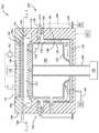
[0009]도 1a는 실시예에 따른, 압력 스큐 시스템이 내부에 배치된 화학 기상 증착 챔버의 개략적인 단면도이다.
[0010]도 1b는 실시예에 따른, 압력 스큐 시스템이 내부에 배치된 화학 기상 증착 챔버의 개략적인 단면도이다.
[0011]도 1c는 실시예에 따른, 압력 스큐 시스템이 내부에 배치된 화학 기상 증착 챔버의 개략적인 단면도이다.
[0012]도 2는 실시예에 따른 압력 스큐 시스템의 개략적인 평면도이다.
[0013]이해를 용이하게 하기 위해, 도면들에 대해 공통인 동일한 엘리먼트들을 지정하기 위해 가능한 경우 동일한 참조 번호들이 사용되었다. 일 실시예의 엘리먼트들 및 피처들이 추가의 언급없이 다른 실시예들에 유익하게 통합될 수 있음이 고려된다.[0008] In such a way that the above-listed features of the present disclosure can be understood in detail, a more specific description of the present disclosure briefly summarized above may be made with reference to embodiments, some of which are attached It is illustrated in the drawings. However, it should be noted that the appended drawings show exemplary embodiments only and should not be considered limiting of the scope of the present disclosure, and that other equally effective embodiments may be accepted.
1A is a schematic cross-sectional view of a chemical vapor deposition chamber with a pressure skew system disposed therein, according to an embodiment.
1B is a schematic cross-sectional view of a chemical vapor deposition chamber with a pressure skew system disposed therein, according to an embodiment.
1C is a schematic cross-sectional view of a chemical vapor deposition chamber in which a pressure skew system is disposed, according to an embodiment.
[0012] Figure 2 is a schematic plan view of a pressure skew system according to an embodiment.
[0013] To facilitate understanding, the same reference numbers have been used where possible to designate the same elements common to the drawings. It is contemplated that elements and features of one embodiment may be advantageously incorporated in other embodiments without further recitation.
[0014]본원에서 설명되는 실시예들은, 전체적인 균일성이 개선된 고급 패터닝 필름을 증착하기 위해 챔버 내에서의 중심-에지 압력 변화를 제어하기 위한 압력 스큐 시스템에 관한 것이다. 압력 스큐 시스템은 챔버 내에 형성되도록 구성된 펌핑 존들, 펌핑 구역 내에 배치된 벽들을 포함한다. 챔버는 프로세싱 구역, 펌핑 구역, 및 프로세스 가스들을 펌핑 구역으로부터 배출하기 위해 펌프에 연결된 펌핑 경로를 포함한다. 각각의 펌핑 존은 벽들에 의해 플랭크된(flanked) 펌핑 구역의 공간에 대응한다. 공급 도관들은 대응하는 펌핑 존 및 대응하는 질량 유량 제어 디바이스에 연결되어, 프로세싱 구역의 영역 내의 압력을 제어하기 위해, 대응하는 펌핑 존에 제공되는 불활성 가스의 유량을 제어한다.[0014]Embodiments described herein relate to a pressure skew system for controlling center-edge pressure changes within a chamber for depositing a high-quality patterning film with improved overall uniformity. The pressure skew system includes pumping zones configured to be formed within the chamber, and walls disposed within the pumping zone. The chamber includes a processing zone, a pumping zone, and a pumping path connected to the pump for evacuating process gases from the pumping zone. Each pumping zone corresponds to the space of the pumping zone flanked by walls. The supply conduits are connected to the corresponding pumping zone and the corresponding mass flow control device to control the flow rate of the inert gas provided to the corresponding pumping zone in order to control the pressure in the area of the processing zone.
[0015]도 1a는 압력 스큐 시스템(200)이 내부에 배치된 CVD(chemical vapor deposition) 챔버(100)의 개략적인 단면도이다. 챔버(100)의 일 예는 캘리포니아, 산타클라라에 소재하는 Applied Materials, Inc.에 의해 제조된 PRODUCER® 챔버 또는 XP PRECISION™ 챔버이다. 챔버(100)는 챔버 바디(102) 및 챔버 덮개(104)를 갖는다. 챔버 바디는 프로세싱 볼륨(106) 및 펌핑 볼륨(108)을 포함한다. 프로세싱 볼륨(106)은, 챔버 덮개(104), 펌핑 링(118)(외측 절연체(outer isolator)로 또한 알려짐), 내측 펌핑 라이너(120), 최하부 펌핑 플레이트(122), 및 최하부 가열기(124)에 의해 정의된 공간이다. 내측 펌핑 라이너(120)는 펌핑 링(118) 및 최하부 펌핑 플레이트(122)에 커플링된다. 최하부 펌핑 플레이트(122)는 최하부 가열기(124)에 커플링되어 프로세싱 볼륨(106)을 정의한다. 프로세싱 볼륨(106)은 챔버(100) 내에서 기판(도시되지 않음)을 지지하기 위한 페디스털(126)을 갖는다. 페디스털(126)은 전형적으로 가열 엘리먼트(도시되지 않음)를 포함한다. 페디스털(126)은, 최하부 가열기(124) 및 챔버 바디(102)를 관통해 연장되는 스템(stem)(128)에 의해 프로세싱 볼륨(106) 내에 이동가능하게 배치된다. 스템(128)은 상승된 프로세싱 포지션(도시된 바와 같음)과 본원에서 상세히 설명된 펌핑 볼륨(108) 및 챔버 바디(102)를 관통해 형성된 슬릿 밸브(132)를 통해 프로세싱 볼륨(106)으로의 그리고 프로세싱 볼륨(106)으로부터의 기판 이송을 가능하게 하는 하강된 포지션 사이에서 페디스털(126)을 이동시키는 리프트 시스템(130)에 연결된다. 상승된 프로세싱 포지션은, 챔버 덮개(104), 페디스털(126), 페디스털(126)의 에지 링(134), 내측 펌핑 라이너(120), 및 펌핑 링(118)에 의해 정의된 프로세싱 구역(110)에 대응한다.1A is a schematic cross-sectional view of a chemical vapor deposition (CVD)
[0016]펌핑 볼륨(108)은 펌핑 구역(112) 및 펌핑 경로(114)를 포함한다. 펌핑 구역(112)은, 펌핑 링(118), 스페이서 링(136), 내측 펌핑 라이너(120), 및 펌핑 경로(114)의 유입구(138)에 의해 정의된 공간이다. 펌핑 경로(114)는, 펌핑 경로(114)의 유입구(138), 챔버 바디(102)에 커플링된 외측 펌핑 라이너(140), 최하부 가열기(124), 및 최하부 가열기(124)와 챔버 바디(102)를 관통해 배치된 유출구에 의해 정의된 공간이다. 펌핑 경로(114)의 유출구(142)는 도관(146)을 통해 펌프(144)에 연결된다. 본원에서 설명된 다른 실시예들과 조합될 수 있는 일 실시예에서, 펌핑 링(118), 스페이서 링(136), 내측 펌핑 라이너(120), 외측 펌핑 라이너(140), 최하부 펌핑 플레이트(122), 및 최하부 가열기(124)는 세라믹 함유 재료들을 포함한다. 본원에서 설명된 다른 실시예들과 조합될 수 있는 다른 실시예에서, 펌핑 링(118)은 알루미늄 옥사이드(Al2O3)를 포함하고, 스페이서 링은 6061 알루미늄 합금을 포함하고, 내측 펌핑 라이너(120)는 Al2O3 및/또는 6061 알루미늄 합금을 포함하고, 외측 펌핑 라이너(140)는 6061 알루미늄 합금을 포함하고, 최하부 펌핑 플레이트(122)는 Al2O3을 포함하고, 그리고 최하부 가열기(124)는 6061 알루미늄 합금을 포함한다. 펌핑 링(118)은, 펌프(144)가 프로세싱 구역(110) 내의 압력을 제어하고 프로세싱 구역(110)으로부터 펌핑 구역(112) 및 펌핑 경로(114)를 통해 가스들 및 부산물들을 배출하는 것을 가능하게 하는 홀들(148)(도 1c 및 도 2에 도시됨)을 포함한다. 펌핑 링(118)의 홀들(148)을 도시하는, 챔버(100)의 단면도인 도 1c에 도시된 바와 같이, 홀들(148)은 펌핑 링(118)을 관통해 형성되어 프로세싱 구역(110)으로부터의 배출 가스들 및 부산물들이 펌핑 구역(112) 및 펌핑 경로(114)를 통해 유동하는 것을 가능하게 한다. 펌핑 링(118)은, 챔버(100) 내에서의 프로세싱을 촉진하는 방식으로 프로세싱 구역(110)으로부터 펌핑 볼륨(108)으로의 가스들의 유동을 가능하게 한다. 일 실시예에서, 프로세싱 구역(110) 내의 전체적인 압력은 약 3 torr 내지 약 5 torr이다. 그러나, 다른 압력들이 또한 고려된다.The pumping
[0017]챔버(100)는 또한, 프로세싱 구역(110)으로 하나 이상의 가스들의 유동을 전달하기 위해 챔버 덮개(104)에 커플링된 가스 분배 어셈블리(116)를 포함한다. 가스 분배 어셈블리(116)는, 하나 이상의 가스 소스들(152)로부터의 가스들의 유동을 수용하는, 챔버 덮개(104)에 형성된 가스 유입 통로(154)에 커플링된 가스 매니폴드(150)를 포함한다. 가스들의 유동은 가스 박스(156)에 걸쳐 분포하고, 백킹 플레이트(160)의 복수의 홀들(158)을 통해 유동하고, 백킹 플레이트(160) 및 페이스플레이트(162)에 의해 정의된 플레넘(168)에 걸쳐 추가로 분포하고, 그리고 페이스플레이트(162)의 복수의 홀들(도시되지 않음)을 통해 프로세싱 구역(110)으로 유동한다. RF(radio frequency) 소스(164)가 가스 분배 어셈블리(116)에 커플링된다. RF 소스(164)는 프로세싱 구역(110)에서 가스들로부터 플라즈마의 생성을 용이하게 하기 위해 가스 분배 어셈블리(116)에 전력을 공급한다. 페디스털(126)은 접지되거나, 페디스털(126)은 전력 공급부에 연결될 때 캐소드로서 기능하여 페이스플레이트(162)와 페디스털(126) 사이에 용량성 전기장을 생성함으로써, 기판을 향한 플라즈마 종을 가속화하여 고급 패터닝 필름을 증착할 수 있다. 제어기(101)가 챔버(100), 및 챔버(100)의 압력 스큐 시스템(200)에 커플링된다. 제어기(101)는 프로세싱 동안 챔버(100) 및 압력 스큐 시스템(200)의 양상들을 제어하도록 구성된다.[0017]The
[0018]가스들의 유동은 프로세싱 구역(110)에서 기판의 표면에 걸쳐 반경방향으로(중심-에지) 분포한다. 본원에서 설명된 다른 실시예들과 조합될 수 있는 일 실시예에서, 가스들의 유동의 대부분은 페이스플레이트(162)를 통해 프로세싱 구역(110)의 중심으로 유동한다. 페이스플레이트(162)를 따르는 지점들에서의 가스들은 기판으로 하강하는 유동을 갖고, 기판의 표면과 접촉하고, 기판의 표면에 평행한 유동을 갖는다. 페이스플레이트(162)의 각각의 지점에서, 가스들은 기판에 대해 수직 속도를 가지며, 그 수직 속도는 기판에 걸쳐 반경방향 바깥쪽으로 수평 속도의 수평 유동으로 전환된다. 펌프(144)는 펌핑 링(118), 펌핑 구역(112), 및 펌핑 경로(114)를 통해 가스들을 배출하여, 기판에 걸쳐 중심-에지 압력 변화를 초래한다. 페이스플레이트(162)의 각각의 지점에서, 가스들의 수직 속도는 동일하지 않을 수 있다. 따라서, 가스들의 수평 속도가 동일하지 않아서, 기판의 표면의 부분들 위에서의 가스들의 불균일한 체류 시간을 야기한다. 불균일한 체류 시간은 기판에 걸쳐 불균일한 플라즈마 분포를 초래한다. 가스들의 불균일한 체류 시간 및 결과적인 불균일한 플라즈마 분포는 고급 패터닝 필름의 불균일한 증착을 야기한다. 특히, 불균일한 체류 시간은 고급 패터닝 필름의 평면 및 잔류물 균일성에 영향을 미친다. 따라서, 챔버(100)는, 기판에 걸쳐 중심-에지 압력 변화를 제어하여 평면 및 잔류물 균일성을 제어하기 위한 압력 스큐 시스템(200)을 포함한다.[0018]The flow of gases is distributed radially (center-edge) across the surface of the substrate in the
[0019]도 2는 챔버(100)와 같은 프로세스 챔버에서 중심-에지 압력 변화를 제어하기 위한 압력 스큐 시스템(200)의 개략적인 평면도이다. 압력 스큐 시스템(200)은 적어도 2개의 펌핑 존들을 포함한다. 본원에서 설명된 다른 실시예들과 조합될 수 있는 일 실시예에서, 압력 스큐 시스템(200)(도시된 바와 같음)은 4개의 펌핑 존들(202a-202d)을 포함한다. 압력 스큐 시스템(200)은 고급 패터닝 필름의 평면 및 잔류물 균일성을 유발하기 위해 필요한 만큼 많은 펌핑 존들을 포함한다. 펌핑 존들(202a-202d) 중 각각의 펌핑 존은 불활성 가스 공급부(206)에 연결된 매니폴드(204)에 연결된다. 펌핑 존들(202a-202d) 중 각각의 펌핑 존은 복수의 공급 도관들(208)에 의해 매니폴드(204)에 연결된다. 각각의 공급 도관(208)은, 매니폴드(204)로부터 펌핑 존들(202a-202d)의 펌핑 존들 중 하나에 제공되는 불활성 가스, 이를테면, 질소 가스(N2), 수소 가스(H2), 아르곤(Ar), 및 헬륨(He)의 유량을 정밀하게 제어하는 유량 제어 디바이스(210), 이를테면, MFC(mass flow control) 디바이스를 갖는다. 도 1a에 도시된 바와 같이, 각각의 공급 도관(208)은 펌핑 구역(112)으로 이어지는, 스페이서 링(136)을 관통해 배치된 채널(166)에 연결된다. 펌핑 존들(202a-202d) 중 각각의 펌핑 존은 펌핑 구역(112)에 배치된 벽들(212)(도 1b에 도시됨)에 의해 플랭크되는 펌핑 구역(112)의 공간에 대응한다.FIG. 2 is a schematic plan view of a
[0020]도 1b는 압력 스큐 시스템(200)이 내부에 배치된 챔버(100)의 다른 개략적인 단면도이고, 펌핑 구역(112)에 배치된 벽들(212)이 보인다. 펌핑 구역(112)에 배치된 벽들(212)은 펌핑 구역(112)에 펌핑 존들(202a-202d) 중 각각의 펌핑 존을 정의한다. 펌핑 존들(202a-202d) 중 각각의 펌핑 존을 정의하는 벽들(212)은 각각의 펌핑 존의 압력이 독립적으로 제어되는 것을 가능하게 하는데, 왜냐하면, 가스들은 펌핑 링(118)의 홀들(148)을 통해 펌핑 구역(112)으로 유동할 수 없고 벽들(212)에 의해 차단된 펌핑 경로(114)를 통해 유동할 수 없기 때문이다. 펌핑 존들(202a-202d) 중 각각의 펌핑 존은, 기판에 걸친 가스들의 수평 속도에 영향을 미치는, 프로세싱 구역(110)의 영역의 압력 변화를 제어하여, 증착되는 고급 패터닝 필름의 평면 및 잔류물 균일성을 추가로 제어하고, 그리고 그에 따라, 증착되는 고급 패터닝 필름의 전체적인 균일성을 제어하도록, 펌핑 구역(112)에 제공되는 불활성 가스의 유량을 가질 수 있다.[0020]1B is another schematic cross-sectional view of the
[0021]도 2를 다시 참조하면, 펌핑 존들(202a-202d) 중 각각의 펌핑 존은 프로세싱 구역(110)의 영역들(214a-214d)을 제어한다. 영역들(214a-214d) 중 각각의 영역은 기판의 표면의 구역에 대응한다. 예컨대, 프로세싱 구역(110)의 영역(214a)에 걸쳐 가스들의 수평 속도를 감소시키고 기판의 표면의 구역 위에서의 가스들의 체류 시간을 증가시키기 위해, 유량 제어 디바이스(210)는 매니폴드(204)로부터 펌핑 존(202a)으로 제공되는 불활성 가스의 유량을 제어한다. 펌핑 존(202a)에 제공되는 불활성 가스의 유량은 펌핑 구역(112)의 압력을 설정하며, 이는 프로세싱 구역(110)의 영역(214a)에서 중심-에지 압력 변화를 제어한다. 본원에서 설명된 다른 실시예들과 조합될 수 있는 일 실시예에서, 프로세싱 구역(110)의 영역(214a-214d)에서 중심-에지 압력 변화는 프로세싱 구역(110) 내의 전체적인 압력보다 약 1 torr 내지 약 2 torr 더 크거나 더 작다. 본원에서 설명된 다른 실시예들과 조합될 수 있는 일 실시예에서, 불활성 가스의 유량을 증가시키는 것은 영역들(214a-214d)에 대응하는 기판의 표면의 구역 위에서의 수평 속도 감소 및 체류 시간 증가를 유발한다. 본원에서 설명된 다른 실시예들과 조합될 수 있는 다른 실시예에서, 불활성 가스의 유량을 감소시키는 것은 영역들(214a-214d)에 대응하는 기판의 표면의 구역 위에서의 수평 속도 증가 및 체류 시간 감소를 유발한다. 펌핑 존들(202a-202d) 중 각각의 펌핑 존에 제공되는 유량들은 증착되는 고급 패터닝 필름의 전체적인 균일성을 개선하기 위해 프로세싱 구역(110)의 각각의 영역(214a-214d)에서 중심-에지 압력 변화를 제어하도록 최적화된다.[0021]Referring again to FIG. 2, each of the
[0022]요약하면, 전체적인 균일성이 개선된 고급 패터닝 필름(예컨대, 탄소-함유 또는 붕소-도핑된-탄소 하드마스크)을 증착하기 위해 CVD 챔버에서 중심-에지 압력 변화를 제어하기 위한 압력 스큐 시스템이 본원에서 설명된다. 적어도 2개의 펌핑 존들을 갖는 압력 스큐 시스템이 활용되며, 여기서 각각의 펌핑 존은 MFC 디바이스를 갖는 불활성 가스 공급부에 연결된 매니폴드에 연결되며, MFC 디바이스는 각각의 펌핑 존에 제공되는 불활성 가스의 유량을 정밀하게 제어한다. 각각의 펌핑 존에 제공되는 불활성 가스의 유량은, 기판에 걸친 가스들의 수평 속도에 영향을 미치는, 프로세싱 구역의 영역의 압력 변화를 제어하며, 이는 결국, 증착되는 고급 패터닝 필름의 평면 및 잔류물 균일성을 제어하고, 그에 따라, 증착되는 고급 패터닝 필름의 전체적인 균일성을 제어한다.[0022]In summary, a pressure skew system for controlling center-edge pressure changes in a CVD chamber for depositing advanced patterning films (e.g., carbon-containing or boron-doped-carbon hardmasks) with improved overall uniformity is disclosed herein. Is explained. A pressure skew system with at least two pumping zones is utilized, where each pumping zone is connected to a manifold connected to an inert gas supply with an MFC device, and the MFC device controls the flow rate of the inert gas provided to each pumping zone. Control precisely. The flow rate of the inert gas provided to each pumping zone controls the pressure change in the area of the processing zone, which affects the horizontal velocity of the gases across the substrate, which in turn results in a flat and residual uniformity of the deposited high-quality patterning film. Control the properties and, accordingly, the overall uniformity of the deposited high-quality patterning film.
[0023]전술한 바가 본 개시내용의 예들에 관한 것이지만, 본 개시내용의 다른 그리고 추가적인 예들이, 본 개시내용의 기본적인 범위를 벗어나지 않으면서 구상될 수 있고, 본 개시내용의 범위는 다음의 청구항들에 의해 결정된다.[0023]While the foregoing relates to examples of the present disclosure, other and additional examples of the present disclosure may be envisioned without departing from the basic scope of the present disclosure, and the scope of the present disclosure is determined by the following claims. do.
Claims (15)
Translated fromKorean챔버 바디 ― 상기 챔버 바디는,
상기 챔버 바디 내에 배치된 페디스털;
펌핑 링에 커플링된 내측 라이너; 및
외측 라이너를 가지며,
상기 페디스털, 상기 내측 라이너, 상기 펌핑 링, 및 상기 챔버 덮개는 프로세싱 구역을 형성하고,
상기 내측 라이너 및 상기 외측 라이너는, 유입구 및 유출구를 갖는 펌핑 경로를 형성하고, 그리고
상기 펌핑 링, 상기 내측 라이너, 상기 외측 라이너, 및 상기 유입구는 펌핑 구역을 형성함 ―;
상기 펌핑 구역에 배치된 2개 이상의 벽들 ― 상기 펌핑 구역에 배치된 2개 이상의 벽들 중 인접한 벽들은 상기 펌핑 구역에 펌핑 존(pumping zone)들을 형성함 ―; 및
복수의 공급 도관들을 포함하며,
각각의 공급 도관은 상기 펌핑 존들 중 대응하는 펌핑 존 및 대응하는 유동 제어 디바이스에 유동적으로 연결되고, 각각의 유동 제어 디바이스는, 상기 프로세싱 구역의 영역 내의 압력을 제어하고 그리고 상기 유출구를 통한 상기 프로세싱 구역으로부터의 프로세스 가스들의 배출을 제어하기 위해, 상기 대응하는 펌핑 존에 제공되는 가스의 유량을 제어하도록 구성되는,
시스템.Chamber cover;
Chamber body-the chamber body,
A pedestal disposed in the chamber body;
An inner liner coupled to the pumping ring; And
Has an outer liner,
The pedestal, the inner liner, the pumping ring, and the chamber lid define a processing zone,
The inner liner and the outer liner form a pumping path having an inlet and an outlet, and
The pumping ring, the inner liner, the outer liner, and the inlet define a pumping zone;
Two or more walls disposed in the pumping zone, the adjacent ones of the two or more walls disposed in the pumping zone forming pumping zones in the pumping zone; And
Comprising a plurality of supply conduits,
Each supply conduit is fluidly connected to a corresponding one of the pumping zones and a corresponding flow control device, each flow control device controlling the pressure in the area of the processing zone and the processing zone through the outlet. Configured to control the flow rate of gas provided to the corresponding pumping zone, to control the discharge of process gases from
system.
상기 챔버 바디의 프로세싱 구역은 추가로, 상기 페디스털의 에지 링에 의해 정의되는,
시스템.The method of claim 1,
The processing region of the chamber body is further defined by the edge ring of the pedestal,
system.
상기 챔버 바디의 펌핑 구역은 추가로, 스페이서 링에 의해 정의되는,
시스템.The method of claim 2,
The pumping zone of the chamber body is further defined by a spacer ring,
system.
상기 펌핑 링, 상기 스페이서 링, 상기 내측 라이너, 및 상기 외측 라이너는 세라믹 함유 재료들을 포함하는,
시스템.The method of claim 3,
The pumping ring, the spacer ring, the inner liner, and the outer liner comprise ceramic containing materials,
system.
상기 펌핑 링은 알루미늄 옥사이드(Al2O3)를 포함하고, 상기 스페이서 링은 6061 알루미늄 합금을 포함하고, 상기 내측 라이너는 Al2O3 및 6061 알루미늄 합금 중 적어도 하나를 포함하고, 그리고 상기 외측 라이너는 6061 알루미늄 합금을 포함하는,
시스템.The method of claim 3,
The pumping ring includes aluminum oxide (Al2 O3 ), the spacer ring includes 6061 aluminum alloy, the inner liner includes at least one of Al2 O3 and 6061 aluminum alloy, and the outer liner Containing 6061 aluminum alloy,
system.
상기 프로세싱 구역으로부터의 프로세스 가스들이 상기 펌핑 구역 및 상기 펌핑 경로를 통해 유동하는 것을 가능하게 하기 위해 상기 펌핑 링을 관통해 홀들이 형성되는,
시스템.The method of claim 1,
Holes are formed through the pumping ring to enable process gases from the processing region to flow through the pumping region and the pumping path,
system.
상기 펌핑 존들 중 각각의 펌핑 존은 상기 프로세싱 구역의 복수의 영역들 중 하나의 영역을 제어하고, 각각의 영역은 상기 페디스털의 표면의 구역에 대응하는,
시스템.The method of claim 1,
Each of the pumping zones controls one of a plurality of areas of the processing zone, each area corresponding to an area of the surface of the pedestal,
system.
각각의 공급 도관은 상기 챔버 바디의 스페이서 링을 관통해 배치된 채널에 연결되고, 각각의 채널은 상기 펌핑 구역으로 이어지는,
시스템.The method of claim 1,
Each supply conduit is connected to a channel disposed through a spacer ring of the chamber body, each channel leading to the pumping zone,
system.
상기 프로세싱 구역의 영역 내의 압력은 상기 프로세싱 구역 내의 프로세스 가스들의 수평 속도(horizontal velocity)에 영향을 미치는,
시스템.The method of claim 1,
The pressure in the region of the processing region affects the horizontal velocity of the process gases in the processing region,
system.
챔버 바디 ― 상기 챔버 바디는,
상기 챔버 바디 내에 배치된 페디스털;
펌핑 링에 커플링된 내측 라이너; 및
외측 라이너를 가지며,
상기 페디스털, 상기 내측 라이너, 상기 펌핑 링, 및 상기 챔버 덮개는 프로세싱 구역을 형성하고,
상기 내측 라이너 및 상기 외측 라이너는, 유입구 및 유출구를 갖는 펌핑 경로를 형성하고, 그리고
상기 펌핑 링, 상기 내측 라이너, 상기 외측 라이너, 및 상기 유입구는 펌핑 구역을 형성함 ―; 및
압력 스큐 시스템(pressure skew system)을 포함하며,
상기 압력 스큐 시스템은,
상기 펌핑 구역에 배치된 2개 이상의 벽들 ― 상기 펌핑 구역에 배치된 2개 이상의 벽들 중 인접한 벽들은 상기 펌핑 구역에 펌핑 존들을 형성함 ―; 및
복수의 공급 도관들을 가지며,
각각의 공급 도관은 상기 인접한 벽들의 대응하는 펌핑 존 및 대응하는 유동 제어 디바이스에 연결되는,
챔버.Chamber cover;
Chamber body-the chamber body,
A pedestal disposed in the chamber body;
An inner liner coupled to the pumping ring; And
Has an outer liner,
The pedestal, the inner liner, the pumping ring, and the chamber lid define a processing zone,
The inner liner and the outer liner form a pumping path having an inlet and an outlet, and
The pumping ring, the inner liner, the outer liner, and the inlet define a pumping zone; And
Includes a pressure skew system,
The pressure skew system,
Two or more walls arranged in the pumping zone, the adjacent ones of the two or more walls arranged in the pumping zone forming pumping zones in the pumping zone; And
Has a plurality of supply conduits,
Each supply conduit is connected to a corresponding pumping zone and a corresponding flow control device of the adjacent walls,
chamber.
각각의 유동 제어 디바이스는, 상기 프로세싱 구역의 영역 내의 압력을 제어하고 그리고 상기 유출구를 통한 상기 프로세싱 구역으로부터의 프로세스 가스들의 배출을 제어하기 위해, 상기 대응하는 펌핑 존에 제공되는 불활성 가스의 유량을 제어하도록 구성되는,
챔버.The method of claim 10,
Each flow control device controls the flow rate of inert gas provided to the corresponding pumping zone to control the pressure in the area of the processing zone and to control the discharge of process gases from the processing zone through the outlet. Configured to,
chamber.
상기 프로세싱 구역으로부터의 프로세스 가스들이 상기 펌핑 구역 및 상기 펌핑 경로를 통해 유동하는 것을 가능하게 하기 위해 상기 펌핑 링을 관통해 홀들이 형성되는,
챔버.The method of claim 11,
Holes are formed through the pumping ring to enable process gases from the processing region to flow through the pumping region and the pumping path,
chamber.
상기 챔버의 프로세싱 구역은 추가로, 상기 페디스털의 에지 링에 의해 정의되고, 그리고 상기 챔버의 펌핑 구역은 추가로, 스페이서 링에 의해 정의되는,
챔버.The method of claim 10,
The processing zone of the chamber is further defined by an edge ring of the pedestal, and the pumping zone of the chamber is further defined by a spacer ring,
chamber.
상기 펌핑 존들 중 각각의 펌핑 존은 상기 프로세싱 구역의 복수의 영역들 중 하나의 영역을 제어하고, 각각의 영역은 상기 페디스털의 표면의 구역에 대응하는,
챔버.The method of claim 10,
Each of the pumping zones controls one of a plurality of areas of the processing zone, each area corresponding to an area of the surface of the pedestal,
chamber.
챔버 바디 ― 상기 챔버 바디는,
상기 챔버 바디 내에 배치된 페디스털;
펌핑 링에 커플링된 내측 라이너; 및
외측 라이너를 가지며,
상기 페디스털, 상기 내측 라이너, 상기 펌핑 링, 및 상기 챔버 덮개는 프로세싱 구역을 형성하고,
상기 내측 라이너 및 상기 외측 라이너는, 유입구 및 유출구를 갖는 펌핑 경로를 형성하고, 그리고
상기 펌핑 링, 상기 내측 라이너, 상기 외측 라이너, 및 상기 유입구는 펌핑 구역을 형성함 ―; 및
압력 스큐 시스템을 포함하며,
상기 압력 스큐 시스템은,
상기 펌핑 구역에 배치된 2개 이상의 벽들 ― 상기 펌핑 구역에 배치된 2개 이상의 벽들 중 인접한 벽들은 상기 펌핑 구역에 펌핑 존들을 형성함 ―; 및
복수의 공급 도관들을 가지며,
각각의 공급 도관은 상기 펌핑 존들 중 대응하는 펌핑 존 및 대응하는 유동 제어 디바이스에 유동적으로 연결되고, 각각의 유동 제어 디바이스는, 상기 프로세싱 구역의 영역 내의 압력을 제어하고 그리고 상기 유출구를 통한 상기 프로세싱 구역으로부터의 프로세스 가스들의 배출을 제어하기 위해, 상기 대응하는 펌핑 존에 제공되는 가스의 유량을 제어하도록 구성되는,
챔버.Chamber cover;
Chamber body-the chamber body,
A pedestal disposed in the chamber body;
An inner liner coupled to the pumping ring; And
Has an outer liner,
The pedestal, the inner liner, the pumping ring, and the chamber lid define a processing zone,
The inner liner and the outer liner form a pumping path having an inlet and an outlet, and
The pumping ring, the inner liner, the outer liner, and the inlet define a pumping zone; And
Includes a pressure skew system,
The pressure skew system,
Two or more walls arranged in the pumping zone, the adjacent ones of the two or more walls arranged in the pumping zone forming pumping zones in the pumping zone; And
Has a plurality of supply conduits,
Each supply conduit is fluidly connected to a corresponding one of the pumping zones and a corresponding flow control device, each flow control device controlling the pressure in the area of the processing zone and the processing zone through the outlet. Configured to control the flow rate of gas provided to the corresponding pumping zone, to control the discharge of process gases from
chamber.
Applications Claiming Priority (3)
| Application Number | Priority Date | Filing Date | Title |
|---|---|---|---|
| US201862667050P | 2018-05-04 | 2018-05-04 | |
| US62/667,050 | 2018-05-04 | ||
| PCT/US2019/025752WO2019212685A1 (en) | 2018-05-04 | 2019-04-04 | Pressure skew system for controlling center-to-edge pressure change |
Publications (1)
| Publication Number | Publication Date |
|---|---|
| KR20200140390Atrue KR20200140390A (en) | 2020-12-15 |
Family
ID=68383780
Family Applications (1)
| Application Number | Title | Priority Date | Filing Date |
|---|---|---|---|
| KR1020207034775AWithdrawnKR20200140390A (en) | 2018-05-04 | 2019-04-04 | Pressure skew system to control center-edge pressure changes |
Country Status (7)
| Country | Link |
|---|---|
| US (1) | US20190338420A1 (en) |
| JP (1) | JP2021523556A (en) |
| KR (1) | KR20200140390A (en) |
| CN (1) | CN112074624A (en) |
| SG (1) | SG11202010036PA (en) |
| TW (1) | TW201947060A (en) |
| WO (1) | WO2019212685A1 (en) |
Families Citing this family (3)
| Publication number | Priority date | Publication date | Assignee | Title |
|---|---|---|---|---|
| US12068144B2 (en) | 2020-07-19 | 2024-08-20 | Applied Materials, Inc. | Multi-stage pumping liner |
| US11427910B2 (en)* | 2020-10-20 | 2022-08-30 | Sky Tech Inc. | Atomic layer deposition equipment capable of reducing precursor deposition and atomic layer deposition process method using the same |
| TW202302907A (en)* | 2021-05-12 | 2023-01-16 | 荷蘭商Asm Ip私人控股有限公司 | Cvd apparatus and film forming method |
Family Cites Families (10)
| Publication number | Priority date | Publication date | Assignee | Title |
|---|---|---|---|---|
| JP3386651B2 (en)* | 1996-04-03 | 2003-03-17 | 株式会社東芝 | Semiconductor device manufacturing method and semiconductor manufacturing apparatus |
| US5846332A (en)* | 1996-07-12 | 1998-12-08 | Applied Materials, Inc. | Thermally floating pedestal collar in a chemical vapor deposition chamber |
| US6645884B1 (en)* | 1999-07-09 | 2003-11-11 | Applied Materials, Inc. | Method of forming a silicon nitride layer on a substrate |
| WO2003062490A2 (en)* | 2002-01-17 | 2003-07-31 | Sundew Technologies, Llc | Ald apparatus and method |
| US20040069227A1 (en)* | 2002-10-09 | 2004-04-15 | Applied Materials, Inc. | Processing chamber configured for uniform gas flow |
| US20070012402A1 (en)* | 2003-07-08 | 2007-01-18 | Sundew Technologies, Llc | Apparatus and method for downstream pressure control and sub-atmospheric reactive gas abatement |
| KR20060063188A (en)* | 2004-12-07 | 2006-06-12 | 삼성전자주식회사 | Equipment for chemical vapor deposition and method used the same |
| JP4790291B2 (en)* | 2005-03-10 | 2011-10-12 | 東京エレクトロン株式会社 | Substrate processing method, recording medium, and substrate processing apparatus |
| US20090084317A1 (en)* | 2007-09-28 | 2009-04-02 | Applied Materials, Inc. | Atomic layer deposition chamber and components |
| US9725799B2 (en)* | 2013-12-06 | 2017-08-08 | Applied Materials, Inc. | Ion beam sputtering with ion assisted deposition for coatings on chamber components |
- 2019
- 2019-04-04KRKR1020207034775Apatent/KR20200140390A/ennot_activeWithdrawn
- 2019-04-04USUS16/374,824patent/US20190338420A1/ennot_activeAbandoned
- 2019-04-04CNCN201980030059.6Apatent/CN112074624A/enactivePending
- 2019-04-04JPJP2020560989Apatent/JP2021523556A/enactivePending
- 2019-04-04WOPCT/US2019/025752patent/WO2019212685A1/ennot_activeCeased
- 2019-04-04SGSG11202010036PApatent/SG11202010036PA/enunknown
- 2019-05-02TWTW108115237Apatent/TW201947060A/enunknown
Also Published As
| Publication number | Publication date |
|---|---|
| JP2021523556A (en) | 2021-09-02 |
| CN112074624A (en) | 2020-12-11 |
| TW201947060A (en) | 2019-12-16 |
| US20190338420A1 (en) | 2019-11-07 |
| SG11202010036PA (en) | 2020-11-27 |
| WO2019212685A1 (en) | 2019-11-07 |
Similar Documents
| Publication | Publication Date | Title |
|---|---|---|
| JP7320563B2 (en) | High temperature substrate pedestal module and its components | |
| CN108070846B (en) | Gas supply unit and substrate processing apparatus including the same | |
| CN104250728B (en) | Chemical deposition chamber with gas seal | |
| CN107452590B (en) | Tunable side plenum for edge etch rate control in downstream reactors | |
| CN116970926B (en) | Film stress control for plasma enhanced chemical vapor deposition | |
| US10781516B2 (en) | Chemical deposition chamber having gas seal | |
| US10679827B2 (en) | Method and apparatus for semiconductor processing chamber isolation for reduced particles and improved uniformity | |
| KR20160137403A (en) | Deposition apparatus including edge plenum showerhead assembly | |
| CN103069560A (en) | Devices for controlling gas flow in process chambers | |
| CN113994024A (en) | Isolator apparatus and method for substrate processing chamber | |
| US11643725B2 (en) | Hardware to prevent bottom purge incursion in application volume and process gas diffusion below heater | |
| US10519545B2 (en) | Systems and methods for a plasma enhanced deposition of material on a semiconductor substrate | |
| KR20200140390A (en) | Pressure skew system to control center-edge pressure changes | |
| WO2021087002A1 (en) | Process kit for improving edge film thickness uniformity on a substrate | |
| US11017986B2 (en) | Deposition radial and edge profile tunability through independent control of TEOS flow | |
| JP7550859B2 (en) | High Density Plasma Chemical Vapor Deposition Chamber | |
| JP7564123B2 (en) | Increasing plasma density in the processing chamber | |
| JP7121446B2 (en) | High density plasma chemical vapor deposition chamber | |
| US20230215703A1 (en) | Sealing surfaces of components used in plasma etching tools using atomic layer deposition | |
| KR102770382B1 (en) | Gas distribution ceramic heater for deposition chamber | |
| TWI899112B (en) | High density plasma enhanced chemical vapor deposition chamber | |
| WO2024076479A1 (en) | Adjustable pedestal |
Legal Events
| Date | Code | Title | Description |
|---|---|---|---|
| PA0105 | International application | Patent event date:20201202 Patent event code:PA01051R01D Comment text:International Patent Application | |
| PG1501 | Laying open of application | ||
| PC1203 | Withdrawal of no request for examination |