KR20200134249A - Superparamagnetic particle imaging and its application in quantitative multi-stationary-phase diagnostic assays - Google Patents
Superparamagnetic particle imaging and its application in quantitative multi-stationary-phase diagnostic assaysDownload PDFInfo
- Publication number
- KR20200134249A KR20200134249AKR1020207028939AKR20207028939AKR20200134249AKR 20200134249 AKR20200134249 AKR 20200134249AKR 1020207028939 AKR1020207028939 AKR 1020207028939AKR 20207028939 AKR20207028939 AKR 20207028939AKR 20200134249 AKR20200134249 AKR 20200134249A
- Authority
- KR
- South Korea
- Prior art keywords
- analysis
- superparamagnetic
- magnetic
- analyte
- sample
- Prior art date
- Legal status (The legal status is an assumption and is not a legal conclusion. Google has not performed a legal analysis and makes no representation as to the accuracy of the status listed.)
- Granted
Links
Images


Classifications
- G—PHYSICS
- G01—MEASURING; TESTING
- G01R—MEASURING ELECTRIC VARIABLES; MEASURING MAGNETIC VARIABLES
- G01R33/00—Arrangements or instruments for measuring magnetic variables
- G01R33/20—Arrangements or instruments for measuring magnetic variables involving magnetic resonance
- G01R33/44—Arrangements or instruments for measuring magnetic variables involving magnetic resonance using nuclear magnetic resonance [NMR]
- G01R33/48—NMR imaging systems
- G01R33/54—Signal processing systems, e.g. using pulse sequences ; Generation or control of pulse sequences; Operator console
- G01R33/56—Image enhancement or correction, e.g. subtraction or averaging techniques, e.g. improvement of signal-to-noise ratio and resolution
- G01R33/5601—Image enhancement or correction, e.g. subtraction or averaging techniques, e.g. improvement of signal-to-noise ratio and resolution involving use of a contrast agent for contrast manipulation, e.g. a paramagnetic, super-paramagnetic, ferromagnetic or hyperpolarised contrast agent
- G—PHYSICS
- G01—MEASURING; TESTING
- G01N—INVESTIGATING OR ANALYSING MATERIALS BY DETERMINING THEIR CHEMICAL OR PHYSICAL PROPERTIES
- G01N33/00—Investigating or analysing materials by specific methods not covered by groups G01N1/00 - G01N31/00
- G01N33/48—Biological material, e.g. blood, urine; Haemocytometers
- G01N33/50—Chemical analysis of biological material, e.g. blood, urine; Testing involving biospecific ligand binding methods; Immunological testing
- G01N33/58—Chemical analysis of biological material, e.g. blood, urine; Testing involving biospecific ligand binding methods; Immunological testing involving labelled substances
- G01N33/585—Chemical analysis of biological material, e.g. blood, urine; Testing involving biospecific ligand binding methods; Immunological testing involving labelled substances with a particulate label, e.g. coloured latex
- G01N33/587—Nanoparticles
- G—PHYSICS
- G01—MEASURING; TESTING
- G01R—MEASURING ELECTRIC VARIABLES; MEASURING MAGNETIC VARIABLES
- G01R33/00—Arrangements or instruments for measuring magnetic variables
- G01R33/02—Measuring direction or magnitude of magnetic fields or magnetic flux
- G01R33/10—Plotting field distribution ; Measuring field distribution
- A—HUMAN NECESSITIES
- A61—MEDICAL OR VETERINARY SCIENCE; HYGIENE
- A61K—PREPARATIONS FOR MEDICAL, DENTAL OR TOILETRY PURPOSES
- A61K49/00—Preparations for testing in vivo
- A61K49/06—Nuclear magnetic resonance [NMR] contrast preparations; Magnetic resonance imaging [MRI] contrast preparations
- A61K49/18—Nuclear magnetic resonance [NMR] contrast preparations; Magnetic resonance imaging [MRI] contrast preparations characterised by a special physical form, e.g. emulsions, microcapsules, liposomes
- A61K49/1818—Nuclear magnetic resonance [NMR] contrast preparations; Magnetic resonance imaging [MRI] contrast preparations characterised by a special physical form, e.g. emulsions, microcapsules, liposomes particles, e.g. uncoated or non-functionalised microparticles or nanoparticles
- A61K49/1821—Nuclear magnetic resonance [NMR] contrast preparations; Magnetic resonance imaging [MRI] contrast preparations characterised by a special physical form, e.g. emulsions, microcapsules, liposomes particles, e.g. uncoated or non-functionalised microparticles or nanoparticles coated or functionalised microparticles or nanoparticles
- A61K49/1824—Nuclear magnetic resonance [NMR] contrast preparations; Magnetic resonance imaging [MRI] contrast preparations characterised by a special physical form, e.g. emulsions, microcapsules, liposomes particles, e.g. uncoated or non-functionalised microparticles or nanoparticles coated or functionalised microparticles or nanoparticles coated or functionalised nanoparticles
- A61K49/1878—Nuclear magnetic resonance [NMR] contrast preparations; Magnetic resonance imaging [MRI] contrast preparations characterised by a special physical form, e.g. emulsions, microcapsules, liposomes particles, e.g. uncoated or non-functionalised microparticles or nanoparticles coated or functionalised microparticles or nanoparticles coated or functionalised nanoparticles the nanoparticle having a magnetically inert core and a (super)(para)magnetic coating
- B—PERFORMING OPERATIONS; TRANSPORTING
- B01—PHYSICAL OR CHEMICAL PROCESSES OR APPARATUS IN GENERAL
- B01L—CHEMICAL OR PHYSICAL LABORATORY APPARATUS FOR GENERAL USE
- B01L3/00—Containers or dishes for laboratory use, e.g. laboratory glassware; Droppers
- B01L3/50—Containers for the purpose of retaining a material to be analysed, e.g. test tubes
- B01L3/502—Containers for the purpose of retaining a material to be analysed, e.g. test tubes with fluid transport, e.g. in multi-compartment structures
- B01L3/5027—Containers for the purpose of retaining a material to be analysed, e.g. test tubes with fluid transport, e.g. in multi-compartment structures by integrated microfluidic structures, i.e. dimensions of channels and chambers are such that surface tension forces are important, e.g. lab-on-a-chip
- B01L3/50273—Containers for the purpose of retaining a material to be analysed, e.g. test tubes with fluid transport, e.g. in multi-compartment structures by integrated microfluidic structures, i.e. dimensions of channels and chambers are such that surface tension forces are important, e.g. lab-on-a-chip characterised by the means or forces applied to move the fluids
- B—PERFORMING OPERATIONS; TRANSPORTING
- B01—PHYSICAL OR CHEMICAL PROCESSES OR APPARATUS IN GENERAL
- B01L—CHEMICAL OR PHYSICAL LABORATORY APPARATUS FOR GENERAL USE
- B01L3/00—Containers or dishes for laboratory use, e.g. laboratory glassware; Droppers
- B01L3/50—Containers for the purpose of retaining a material to be analysed, e.g. test tubes
- B01L3/502—Containers for the purpose of retaining a material to be analysed, e.g. test tubes with fluid transport, e.g. in multi-compartment structures
- B01L3/5027—Containers for the purpose of retaining a material to be analysed, e.g. test tubes with fluid transport, e.g. in multi-compartment structures by integrated microfluidic structures, i.e. dimensions of channels and chambers are such that surface tension forces are important, e.g. lab-on-a-chip
- B01L3/502761—Containers for the purpose of retaining a material to be analysed, e.g. test tubes with fluid transport, e.g. in multi-compartment structures by integrated microfluidic structures, i.e. dimensions of channels and chambers are such that surface tension forces are important, e.g. lab-on-a-chip specially adapted for handling suspended solids or molecules independently from the bulk fluid flow, e.g. for trapping or sorting beads, for physically stretching molecules
- G—PHYSICS
- G01—MEASURING; TESTING
- G01N—INVESTIGATING OR ANALYSING MATERIALS BY DETERMINING THEIR CHEMICAL OR PHYSICAL PROPERTIES
- G01N27/00—Investigating or analysing materials by the use of electric, electrochemical, or magnetic means
- G01N27/72—Investigating or analysing materials by the use of electric, electrochemical, or magnetic means by investigating magnetic variables
- G01N27/74—Investigating or analysing materials by the use of electric, electrochemical, or magnetic means by investigating magnetic variables of fluids
- G01N27/745—Investigating or analysing materials by the use of electric, electrochemical, or magnetic means by investigating magnetic variables of fluids for detecting magnetic beads used in biochemical assays
- G—PHYSICS
- G01—MEASURING; TESTING
- G01N—INVESTIGATING OR ANALYSING MATERIALS BY DETERMINING THEIR CHEMICAL OR PHYSICAL PROPERTIES
- G01N33/00—Investigating or analysing materials by specific methods not covered by groups G01N1/00 - G01N31/00
- G01N33/48—Biological material, e.g. blood, urine; Haemocytometers
- G01N33/50—Chemical analysis of biological material, e.g. blood, urine; Testing involving biospecific ligand binding methods; Immunological testing
- G01N33/53—Immunoassay; Biospecific binding assay; Materials therefor
- G01N33/543—Immunoassay; Biospecific binding assay; Materials therefor with an insoluble carrier for immobilising immunochemicals
- G01N33/54313—Immunoassay; Biospecific binding assay; Materials therefor with an insoluble carrier for immobilising immunochemicals the carrier being characterised by its particulate form
- G01N33/54326—Magnetic particles
- G01N33/54333—Modification of conditions of immunological binding reaction, e.g. use of more than one type of particle, use of chemical agents to improve binding, choice of incubation time or application of magnetic field during binding reaction
- G—PHYSICS
- G01—MEASURING; TESTING
- G01N—INVESTIGATING OR ANALYSING MATERIALS BY DETERMINING THEIR CHEMICAL OR PHYSICAL PROPERTIES
- G01N33/00—Investigating or analysing materials by specific methods not covered by groups G01N1/00 - G01N31/00
- G01N33/48—Biological material, e.g. blood, urine; Haemocytometers
- G01N33/50—Chemical analysis of biological material, e.g. blood, urine; Testing involving biospecific ligand binding methods; Immunological testing
- G01N33/53—Immunoassay; Biospecific binding assay; Materials therefor
- G01N33/543—Immunoassay; Biospecific binding assay; Materials therefor with an insoluble carrier for immobilising immunochemicals
- G01N33/54366—Apparatus specially adapted for solid-phase testing
- G—PHYSICS
- G01—MEASURING; TESTING
- G01R—MEASURING ELECTRIC VARIABLES; MEASURING MAGNETIC VARIABLES
- G01R33/00—Arrangements or instruments for measuring magnetic variables
- G01R33/02—Measuring direction or magnitude of magnetic fields or magnetic flux
- G01R33/06—Measuring direction or magnitude of magnetic fields or magnetic flux using galvano-magnetic devices
- G01R33/07—Hall effect devices
- G—PHYSICS
- G01—MEASURING; TESTING
- G01R—MEASURING ELECTRIC VARIABLES; MEASURING MAGNETIC VARIABLES
- G01R33/00—Arrangements or instruments for measuring magnetic variables
- G01R33/12—Measuring magnetic properties of articles or specimens of solids or fluids
- G—PHYSICS
- G01—MEASURING; TESTING
- G01R—MEASURING ELECTRIC VARIABLES; MEASURING MAGNETIC VARIABLES
- G01R33/00—Arrangements or instruments for measuring magnetic variables
- G01R33/12—Measuring magnetic properties of articles or specimens of solids or fluids
- G01R33/1253—Measuring galvano-magnetic properties
- G—PHYSICS
- G01—MEASURING; TESTING
- G01R—MEASURING ELECTRIC VARIABLES; MEASURING MAGNETIC VARIABLES
- G01R33/00—Arrangements or instruments for measuring magnetic variables
- G01R33/12—Measuring magnetic properties of articles or specimens of solids or fluids
- G01R33/1276—Measuring magnetic properties of articles or specimens of solids or fluids of magnetic particles, e.g. imaging of magnetic nanoparticles
- G—PHYSICS
- G16—INFORMATION AND COMMUNICATION TECHNOLOGY [ICT] SPECIALLY ADAPTED FOR SPECIFIC APPLICATION FIELDS
- G16H—HEALTHCARE INFORMATICS, i.e. INFORMATION AND COMMUNICATION TECHNOLOGY [ICT] SPECIALLY ADAPTED FOR THE HANDLING OR PROCESSING OF MEDICAL OR HEALTHCARE DATA
- G16H30/00—ICT specially adapted for the handling or processing of medical images
- G16H30/40—ICT specially adapted for the handling or processing of medical images for processing medical images, e.g. editing
- B—PERFORMING OPERATIONS; TRANSPORTING
- B01—PHYSICAL OR CHEMICAL PROCESSES OR APPARATUS IN GENERAL
- B01L—CHEMICAL OR PHYSICAL LABORATORY APPARATUS FOR GENERAL USE
- B01L2200/00—Solutions for specific problems relating to chemical or physical laboratory apparatus
- B01L2200/12—Specific details about manufacturing devices
- B—PERFORMING OPERATIONS; TRANSPORTING
- B01—PHYSICAL OR CHEMICAL PROCESSES OR APPARATUS IN GENERAL
- B01L—CHEMICAL OR PHYSICAL LABORATORY APPARATUS FOR GENERAL USE
- B01L2300/00—Additional constructional details
- B01L2300/08—Geometry, shape and general structure
- B01L2300/0803—Disc shape
- B—PERFORMING OPERATIONS; TRANSPORTING
- B01—PHYSICAL OR CHEMICAL PROCESSES OR APPARATUS IN GENERAL
- B01L—CHEMICAL OR PHYSICAL LABORATORY APPARATUS FOR GENERAL USE
- B01L2300/00—Additional constructional details
- B01L2300/16—Surface properties and coatings
- B01L2300/161—Control and use of surface tension forces, e.g. hydrophobic, hydrophilic
- B—PERFORMING OPERATIONS; TRANSPORTING
- B01—PHYSICAL OR CHEMICAL PROCESSES OR APPARATUS IN GENERAL
- B01L—CHEMICAL OR PHYSICAL LABORATORY APPARATUS FOR GENERAL USE
- B01L2400/00—Moving or stopping fluids
- B01L2400/04—Moving fluids with specific forces or mechanical means
- B01L2400/0403—Moving fluids with specific forces or mechanical means specific forces
- B01L2400/043—Moving fluids with specific forces or mechanical means specific forces magnetic forces
- G—PHYSICS
- G01—MEASURING; TESTING
- G01N—INVESTIGATING OR ANALYSING MATERIALS BY DETERMINING THEIR CHEMICAL OR PHYSICAL PROPERTIES
- G01N24/00—Investigating or analyzing materials by the use of nuclear magnetic resonance, electron paramagnetic resonance or other spin effects
- G01N24/08—Investigating or analyzing materials by the use of nuclear magnetic resonance, electron paramagnetic resonance or other spin effects by using nuclear magnetic resonance
- G—PHYSICS
- G01—MEASURING; TESTING
- G01N—INVESTIGATING OR ANALYSING MATERIALS BY DETERMINING THEIR CHEMICAL OR PHYSICAL PROPERTIES
- G01N33/00—Investigating or analysing materials by specific methods not covered by groups G01N1/00 - G01N31/00
- G01N33/48—Biological material, e.g. blood, urine; Haemocytometers
- G01N33/50—Chemical analysis of biological material, e.g. blood, urine; Testing involving biospecific ligand binding methods; Immunological testing
- G01N33/53—Immunoassay; Biospecific binding assay; Materials therefor
- G01N33/543—Immunoassay; Biospecific binding assay; Materials therefor with an insoluble carrier for immobilising immunochemicals
- G01N33/54313—Immunoassay; Biospecific binding assay; Materials therefor with an insoluble carrier for immobilising immunochemicals the carrier being characterised by its particulate form
- G01N33/54326—Magnetic particles
- G—PHYSICS
- G01—MEASURING; TESTING
- G01R—MEASURING ELECTRIC VARIABLES; MEASURING MAGNETIC VARIABLES
- G01R33/00—Arrangements or instruments for measuring magnetic variables
- G01R33/0023—Electronic aspects, e.g. circuits for stimulation, evaluation, control; Treating the measured signals; calibration
- G—PHYSICS
- G01—MEASURING; TESTING
- G01R—MEASURING ELECTRIC VARIABLES; MEASURING MAGNETIC VARIABLES
- G01R33/00—Arrangements or instruments for measuring magnetic variables
- G01R33/02—Measuring direction or magnitude of magnetic fields or magnetic flux
- G01R33/06—Measuring direction or magnitude of magnetic fields or magnetic flux using galvano-magnetic devices
- G01R33/09—Magnetoresistive devices
- G—PHYSICS
- G01—MEASURING; TESTING
- G01R—MEASURING ELECTRIC VARIABLES; MEASURING MAGNETIC VARIABLES
- G01R33/00—Arrangements or instruments for measuring magnetic variables
- G01R33/20—Arrangements or instruments for measuring magnetic variables involving magnetic resonance
- G01R33/28—Details of apparatus provided for in groups G01R33/44 - G01R33/64
- G01R33/30—Sample handling arrangements, e.g. sample cells, spinning mechanisms
- G01R33/302—Miniaturized sample handling arrangements for sampling small quantities, e.g. flow-through microfluidic NMR chips
Landscapes
- Health & Medical Sciences (AREA)
- Engineering & Computer Science (AREA)
- Chemical & Material Sciences (AREA)
- Life Sciences & Earth Sciences (AREA)
- Physics & Mathematics (AREA)
- Immunology (AREA)
- General Physics & Mathematics (AREA)
- Hematology (AREA)
- Molecular Biology (AREA)
- Urology & Nephrology (AREA)
- Biomedical Technology (AREA)
- General Health & Medical Sciences (AREA)
- Analytical Chemistry (AREA)
- Condensed Matter Physics & Semiconductors (AREA)
- Nanotechnology (AREA)
- Biochemistry (AREA)
- Pathology (AREA)
- Microbiology (AREA)
- Biotechnology (AREA)
- Food Science & Technology (AREA)
- Cell Biology (AREA)
- Medicinal Chemistry (AREA)
- Chemical Kinetics & Catalysis (AREA)
- Nuclear Medicine, Radiotherapy & Molecular Imaging (AREA)
- Radiology & Medical Imaging (AREA)
- High Energy & Nuclear Physics (AREA)
- Signal Processing (AREA)
- Epidemiology (AREA)
- Public Health (AREA)
- Dispersion Chemistry (AREA)
- Clinical Laboratory Science (AREA)
- Veterinary Medicine (AREA)
- Animal Behavior & Ethology (AREA)
- Medical Informatics (AREA)
- Primary Health Care (AREA)
- Fluid Mechanics (AREA)
- Electrochemistry (AREA)
- Apparatus Associated With Microorganisms And Enzymes (AREA)
- Investigating Or Analyzing Materials By The Use Of Magnetic Means (AREA)
- Measuring Or Testing Involving Enzymes Or Micro-Organisms (AREA)
Abstract
Translated fromKoreanDescription
Translated fromKorean본 출원은 2018년 4월 11일에 출원된 미국 가출원 제62/655,828호, 2018년 5월 1일에 제출한 미국 가출원 제62/664,946호, 및 2018년 4월 11일에 출원된 미국 가출원 제62/655,828 및 2018년 5월 1일에 출원된 미국 가출원 제62/664,946의 이점을 주장하는 2019년 4월 9일에 출원된 미국 정규 출원 16/379,748호의 우선권을 주장한다. 이들 출원들의 주요 사항 및 내용은 본원에 참조된다.This application is a U.S. Provisional Application No. 62/655,828 filed April 11, 2018, U.S. Provisional Application No. 62/664,946 filed May 1, 2018, and U.S. Provisional Application No. 62/655,828 and U.S. Regular Application No. 16/379,748 filed April 9, 2019 claiming the advantage of U.S. Provisional Application No. 62/664,946 filed May 1, 2018. The main points and content of these applications are incorporated herein by reference.
본 발명은 바이오 감지 기술에 관한 것이며, 특히 초상자성 입자 이미징 또는 다른 기술을 사용하여 샘플에서 다수의 분석물을 동시에 측정하는 분석 방법 및 이에 사용되는 칩 및 장비에 관한 것이다.The present invention relates to biosensing technology, and in particular, to an analytical method for simultaneously measuring a plurality of analytes in a sample using superparamagnetic particle imaging or other techniques, and to chips and equipment used therein.
바이오 센싱은 생물학적 요소를 검출하는 모든 접근방법 및 샘플의 생물학적 특성을 인식하는 관련 소프트웨어 또는 컴퓨터 기술로서 의학 진단, 환경 모니터링 및 식품 안전 보증을 위한 필수적인 요소로 되고 있다. 바이오 센싱 시스템은 전기, 전자 및 광 장치를 생물학적 재료(예컨대 조직, 효소 및 핵산) 및 화학적 분석과 결합하여 생물학적 현상을 모니터링 또는 식별하기 위한 검출 가능한 신호를 생성한다. 바이오 센싱은 생물 의학, 식품 생산 및 가공, 및 생물전 방어를 위한 세균, 바이러스 및 생물 독소를 검출하는데 그 이용이 점점 더 확산되고 있고, 완전히 새로운 과학적 패러다임 관점에서 첨단 바이오, 나노, 정보 기술들의 획기적으로 융합된 것이다.Biosensing is an essential component for medical diagnosis, environmental monitoring and food safety assurance as all approaches to detecting biological elements and related software or computer technology that recognizes the biological properties of a sample. Biosensing systems combine electrical, electronic and optical devices with biological materials (such as tissues, enzymes and nucleic acids) and chemical analysis to generate detectable signals to monitor or identify biological phenomena. Bio-sensing is increasingly being used to detect bacteria, viruses, and biotoxins for biomedical, food production and processing, and biowarfare defense, and from the perspective of a completely new scientific paradigm, the breakthrough of advanced bio, nano, and information technologies. It is fused with.
바이오 센싱 기술은 광학, 전기화학 및 자성 바이오 센싱으로 분류될 수 있다. 제1 유형의 광 변환 메커니즘을 기반으로 하는 광학 바이오 센싱은 형광, 인광, 형광 공명 에너지 전달(FRET), 화학발광, 생물발광, 양자점, 흡수율, 및 산란을 포함하는 발광 방법(luminescence methods); 및 표면 플라즈몬 공명(SPR), 표면 강화 라만 산란(SERS) 및 간섭을 포함한 표면 방법(surface methods)으로 구분된다. 일반적으로, 광학 바이오 센싱 방법은 우수한 감도를 갖고 용이하게 다중화된다(multiplexed).Biosensing technology can be classified into optical, electrochemical and magnetic biosensing. Optical biosensing based on a first type of light conversion mechanism includes luminescence methods including fluorescence, phosphorescence, fluorescence resonance energy transfer (FRET), chemiluminescence, bioluminescence, quantum dots, absorption, and scattering; And surface methods including surface plasmon resonance (SPR), surface enhanced Raman scattering (SERS) and interference. In general, optical biosensing methods have excellent sensitivity and are easily multiplexed.
두 번째, 전기화학 바이오센싱은 효소 결합 어세이(enzyme-linked assays), 전계 효과 센서, 전기 활성 태그, 나노입자에 기반한 센서 및 전기화학발광에 기반한 센서를 사용하는 방법을 포함한다. 이러한 방법 및 어세이는 본질적으로 상호작용(interfacial)하여 인식 이벤트로 인해 생성된 생물학적 인식 또는 물리적 변화가 접촉 재료의 전기적 특성을 직접 변화시킨다. 이러한 어세이는 간단하며 감도가 우수하고, 결합 이벤트가 인터페이스에서 국소화되므로 특정 분석물 및 배경 분석물에 대한 구분이 향상된다. 게다가, 이들 어세이들은 어세이 포맷(array formats)에 대한 확장 및 미세 유체 구조와의 통합하는데 적합하다.Second, electrochemical biosensing involves the use of enzyme-linked assays, field effect sensors, electroactive tags, nanoparticle-based sensors, and electrochemiluminescence-based sensors. These methods and assays are intrinsically interfacial so that the biological perception or physical changes generated by the recognition event directly change the electrical properties of the contact material. These assays are simple and have good sensitivity, and because binding events are localized at the interface, the distinction between specific analytes and background analytes is improved. In addition, these assays are suitable for extension to array formats and integration with microfluidic structures.
세 번째, 자성 바이오센싱은 일반적으로 교류 자화율 측정, 홀 효과 측정, 거대 자기 저항, 초전도 양자 간섭 장치 및 자기 인덕턴스에 기반한 방법을 포함한다.Third, magnetic biosensing generally includes an AC susceptibility measurement, a Hall effect measurement, a giant magnetoresistance, a superconducting quantum interference device, and a method based on magnetic inductance.
광학 및 자성 바이오센싱 방법과 비교하면, 자성 입자에 기반한 센싱 방법은 생체 적합성, 환경 안전성 면에서 우수하고 및 합성 면에서 비용이 낮다. 게다가, 생물학적 샘플로부터의 자기 신호가 매우 적거나 또는 전혀 존재하지 않기 때문에, 자성 입자에 기반한 센싱 방법은 더 적은 배경 소음을 제공한다. 따라서, 이들은 바이오센싱 및 진단 도구의 개발을 위해 큰 관심을 받고 있다. Issadore, D 등이 랩 칩, 14(14), 2385-2397(2014)에 발표한 "분자 분석을 위한 자성 센싱 기술"을 참조하라.Compared with the optical and magnetic biosensing methods, the magnetic particle-based sensing method is excellent in biocompatibility, environmental safety, and low cost in terms of synthesis. In addition, since the magnetic signal from the biological sample is very little or not at all, the sensing method based on magnetic particles provides less background noise. Therefore, they are receiving great interest for the development of biosensing and diagnostic tools. See "Magnetic Sensing Technology for Molecular Analysis" published by Issadore, D et al. in Lab Chip, 14(14), 2385-2397(2014).
교류 자화율 측정법은 용액에서의 자성 나노입자(MNP)의 확산 특성을 사용하는 정확한 검출 기술이다. Park, K 등이 나노 기술, 22(8), 085501(2011)에 발표한 "콤팩트형 교류 자화율계를 사용한 자성 나노입자의 브라운 이완을 기반으로 한 다중화된 센싱"을 참조하라. 이 기술은 브라운 이완 검출 방법의 원리에 기반하는데, 이 브라운 이완 검출 방법은 인가된 자기장 주파수의 함수로 집합적인 자화율(collective magnetic susceptibility)의 측정을 통해 결정된 자기적으로 태깅된 센서(magnetically tagged sensor)의 무작위 회전 운동을 사용한다. 여기 주파수가 자기적으로 레이블된 센서(magnetically labeled sensor)의 회전 운동 주파수에 근접하면, 복소 자화율(complex magnetic susceptibility)의 손실 성분이 크게 증가한다. 이 현상은 복소 자화율의 허수 성분의 피크 주파수(90° 위상차: x")로서 관찰된다. 생물학적 진단을 위한 상기 기술의 적용은 레이블된 MNP와 표적 결합시 x"의 피크 주파수의 시프트에 의존한다. 만약 표적 분자가 이후에 센서의 특정 수용체에 결합하면, 센서의 유체 역학적 크기는 효과적으로 증가하고, 유체 역학적 반경과의 입방 의존성으로 더 낮은 값으로 주파수 최대치의 시프트가 용이하게 측정된다. 교류 자화율계는 1 mg/ml의 농도 및 5 μl 용적에 대해 10 μT보다 낮은 자기장에서 높은 감도를 나타내지만, 상기 방법의 적용은 용액 매체로 제한된다.The alternating magnetic susceptibility measurement method is an accurate detection technique that uses the diffusion properties of magnetic nanoparticles (MNP) in a solution. See "Multiplexed sensing based on Brownian relaxation of magnetic nanoparticles using compact alternating current susceptibility meters" published by Park, K et al. in Nanotechnology, 22(8), 085501(2011). This technique is based on the principle of the Brownian relaxation detection method, which is a magnetically tagged sensor determined through the measurement of the collective magnetic susceptibility as a function of the applied magnetic field frequency. Uses a random rotational motion. As the excitation frequency approaches the frequency of rotational motion of a magnetically labeled sensor, the loss component of the complex magnetic susceptibility increases significantly. This phenomenon is observed as the peak frequency (90° phase difference: x") of the imaginary component of the complex susceptibility. The application of this technique for biological diagnosis depends on the shift of the peak frequency of x" upon target binding with the labeled MNP. If the target molecule subsequently binds to a specific receptor on the sensor, the hydrodynamic size of the sensor is effectively increased, and the shift of the frequency maximum to a lower value due to the cubic dependence of the hydrodynamic radius is easily measured. Alternating current susceptometers show high sensitivity at magnetic fields lower than 10 μT for a concentration of 1 mg/ml and a volume of 5 μl, but the application of this method is limited to solution media.
홀 효과 측정에 기반한 홀 센서는 포토리소그래피 및 아르곤 이온 밀에 의한 건식 에칭에 의해 약 1 μm의 암 폭(arm width) w을 갖는 십자 형상으로 한정된다. Mihajlovic, G가 응용 물리학지, 87, 112502(2005)에 발표한 "InAs 양자 웰 마이크로 홀 센서를 사용하여 생물학적 적용을 위한 단일 자기 비드 측정"; 및 Landry, G 등이 응용 물리학지, 85, 5693(2004)에 발표한 "InAs양자-우물 마이크로 홀 장치를 사용하여 단일 자성 입자 특성화"를 참조하라. 일부 십자 형상은 또한 집중 이온 빔 밀링으로 인해 500, 600 및 700 nm의 암폭을 갖도록 제한된다. 각 센서는 van der Pauw 및 홀 측정을 통해 특성화된다. 처리 후, 홀 계수 및 시트 저항값은 각각 0.031<RH<0.046 Ω/Oe 및 150<RH<600 Ω/Oe의 범위 내에 있다. 센서 칩이 주파수f0에서 변화하는 수직 교류 여기 자기장 내지 B0에 놓일 경우, 이 센서는 직류 전류I0에 의해 바이어스되고, 홀 전압은 록인 증폭기(lock-in amplifier)를 사용하여 주파수f0에서 측정한다. 비드가 초상자성이기 때문에, 자화는 Langevin 행동(Langevin behavior)에 따른다. 교류 신호는 실질적으로 Langevin 곡선의 기울기를 측정하므로, 비드의 직류 자성 상태에 의존한다. 따라서, 비드가 직류 자기장(B1)에 노출될 때, 자성 상태는 낮은 자화율 방향으로 전이되고 비드의 유도 교류 자화를 감소시킴으로써, 크로스로 감지된 비드로부터 평균 표유 자장을 감소시키며 교류 홀 전압 신호에서 드롭(drop)으로서 표현된다. 홀 센서의 선형성은 B1이 상부에 비드가 없는 빈 홀 크로스(empty Hall cross)에서 교류 홀 신호의 어떠한 변화도 일으키지 않도록 한다. 따라서, 상기 드롭은 홀 크로스에 비드가 존재함을 나타내는 확정적인 신호(definitive signal) 이다. 상기 방법의 단점은 교류 여기 자기장에 대한 직접 센서 홀 응답에 의해 생성되는 오프셋이 크다는 것인데, 이 오프셋은 통상적으로 자기 비드로부터의 작은 신호보다 큰 크기이다.The Hall sensor based on the Hall effect measurement is defined by photolithography and dry etching with an argon ion mill to a cross shape with an arm width w of about 1 μm. "Measurement of Single Magnetic Beads for Biological Applications Using InAs Quantum Well Micro Hall Sensors" published by Mihajlovic, G in the Journal of Applied Physics, 87, 112502 (2005); And “Characterization of Single Magnetic Particles Using InAs Quantum-Well Micro-Hole Devices” published by Landry, G et al. in the Journal of Applied Physics, 85, 5693 (2004). Some cruciform shapes are also limited to have dark widths of 500, 600 and 700 nm due to concentrated ion beam milling. Each sensor is characterized by van der Pauw and Hall measurements. After treatment, the Hall coefficient and sheet resistance values are in the ranges of 0.031<RH<0.046 Ω/Oe and 150<RH<600 Ω/Oe, respectively. When the sensor chip is placed in a vertical alternating current excitation magnetic field varying at frequency f0 to B0, the sensor is biased by DC current I0, and the Hall voltage is measured at frequency f0 using a lock-in amplifier. Because the bead is superparamagnetic, magnetization follows Langevin behavior. The alternating current signal actually measures the slope of the Langevin curve and therefore depends on the direct current magnetic state of the bead. Therefore, when the bead is exposed to the direct current magnetic field (B1), the magnetic state transitions in the direction of the low susceptibility and decreases the inductive alternating current magnetization of the bead, thereby reducing the average stray magnetic field from the bead detected as a cross and dropping in the alternating Hall voltage signal. Expressed as (drop). The linearity of the Hall sensor ensures that B1 does not cause any change in the AC Hall signal in an empty Hall cross with no bead on top. Thus, the drop is a definitive signal indicating the presence of a bead at the hole cross. A disadvantage of the method is that the offset produced by the direct sensor Hall response to the alternating current excitation magnetic field is large, which is typically of a larger magnitude than the small signal from the magnetic bead.
거대 자기 저항(GMR)은 강자성 및 비자성 전도층이 교대로 구성된 다층에서 관찰되는 양자 역학 자기 저항 효과이다. Hall, D 등이 바이오 센서 및 생체전자, 25(9), 2051-2057(2010)에 발표한 "GMR바이오 센서 측정-시스템 시각"; 및 Baselt, D가 바이오 센서 및 생체전자, 13, 731-739(1998)에 발표한 "자기 저항 기술에 기반한 바이오 센서"를 참조하라. 관찰된 효과는 전기 저항의 현저한 변화가 인접한 강자성 층의 자화가 평행 정렬(parallel alignment)되거나 반평행 정렬되었는지에 따른다는 것이다. 평행 정렬에 있어서는 총 저항이 상대적으로 낮고 반평행 배열에 있어서는 총 저항이 높다. 자화 방향은 예컨대 외부 자기장을 인가하여 제어할 수 있다. 그 효과는 스핀 방향에 대한 전자 산란에 의존한다. 자기 저항 재료의 개발로 고감도 마이크론 수준의 자기장 센서를 광패턴화(photopattern)할 수 있다. 자기 저항 재료는 전형적으로 박막 금속 다층 구조를 갖고, 이 구조의 저항은 자기장 응답에 따라 변화된다.Giant magneto-resistance (GMR) is a quantum mechanical magneto-resistance effect observed in multilayers composed of alternating ferromagnetic and non-magnetic conductive layers. "GMR Biosensor Measurement-System Vision" published by Hall, D et al. in Biosensors and Bioelectronics, 25(9), 2051-2057(2010); And “Biosensors based on magneto-resistance technology” published by Baselt, D in Biosensors and Bioelectronics, 13, 731-739 (1998). The observed effect is that the significant change in electrical resistance depends on whether the magnetization of the adjacent ferromagnetic layer is parallel or antiparallel. The total resistance is relatively low in the parallel arrangement and the total resistance is high in the antiparallel arrangement. The direction of magnetization can be controlled, for example, by applying an external magnetic field. Its effect depends on the electron scattering on the spin direction. With the development of magnetoresistive materials, it is possible to photopattern high-sensitivity micron-level magnetic field sensors. Magnetoresistive materials typically have a thin metal multi-layer structure, and the resistance of this structure changes according to the magnetic field response.
이방성 자기 저항 재료 및 거대 자기 저항 재료를 포함하여, 여러 근본적으로 상이한 유형의 자기 저항 재료는 이미 개시되었다. 자기 저항 센서는 자기 테이프 또는 디스크 판독용, 휴대용 자기장 센서, 위치 트랜스듀서에 상업적으로 사용된다. 자기 저항 재료를 사용하여 자기 비드 어세이용 마이크로 검출기를 제조할 수 있다. 이러한 검출기는 어세이 기판(assay substrate)에 삽입될 수 있고 자신의 바로 근처의 비드를 검출한다. 광학 또는 마이크로 기계 검출에 비해, 이 접근방법의 주요한 장점은 한 측면이 약 1 cm인 단일 칩에서 수천 개의 검출기를 제조할 수 있다는 것이다. GMR센서는 비선형 및 단층 특성을 갖는다. 이는 물체의 표면 및 자기 비드와 센서 사이의 거리에 매우 민감하다.Several fundamentally different types of magnetoresistive materials have already been disclosed, including anisotropic magnetoresistive materials and macro magnetoresistance materials. Magnetoresistive sensors are commercially used for magnetic tape or disk reading, portable magnetic field sensors, and position transducers. Magnetoresistive materials can be used to produce micro-detectors for magnetic bead assays. Such a detector can be inserted into an assay substrate and detects beads in its immediate vicinity. Compared to optical or micromechanical detection, the main advantage of this approach is the ability to fabricate thousands of detectors on a single chip about 1 cm on one side. The GMR sensor has nonlinear and single layer characteristics. It is very sensitive to the surface of the object and the distance between the magnetic bead and the sensor.
초전도 양자 간섭 장치(SQUIDs)는 조지프슨 접합(Josephson Junction)이 있는 초전도 루프를 기반으로 극히 작은 자기장을 측정하기 사용되는 고감도 자력계이다. Kotitz, R 등이 자기학 및 자성 재료 잡지 194, 62-68(1999)에 발표한 "자성 나노입자의 이완 측정에 의한 아비딘과 비오틴 사이의 결합 반응 판정"; Hathaway HJ가 유방암 연구 13, R108(2011)에 발표한 "표적 자성 나노입자 및 초감도 자기장 센서를 사용한 유방암 세포 검출"; De Haroa, L 등이 생물 의학 공정: 생물 의학 기술 60(5), 445-455(2015)에 발표한 "민감한 암 검출 및 국소화에 적용되는 자기 이완법"; 및 Perez, J 등이 자연ㆍ생물 기술 20, 816-820(2002)에 발표한 "분자 상호 작용을 감지할 수 있는 자성 이완 스위치"을 참조하라. SQUID의 감도는 며칠 동안 평균 측정으로 5 aT(5Х10-18 T)만큼 낮은 자기장을 측정하기에 충분하다. 이들의 소음 수준은 3 fTㆍHz-½만큼 낮다. 비교를 위해, 전형적인 냉장고 자석(refrigerator magnet)은 0.01테슬라(10-2 T)를 발생시키고 동물의 일부 과정은 10-9 T 및 10-6 T 사이의 매우 작은 자기장을 발생시킨다. 직류 전기(DC) 및 무선 주파수(RF)와 같은 두 가지 주요 유형의 SQUID가 있다. RF SQUID는 단지 하나의 조지프슨 접합(초전도 터널 집합)과 함께 작동할 수 있다. SQUID는 감도가 우수하지만 이들은 저온 조건과 값 비싼 장치가 필요하므로 통상적인 분석에 적합하지 않다Superconducting quantum interference devices (SQUIDs) are highly sensitive magnetometers used to measure extremely small magnetic fields based on a superconducting loop with a Josephson junction. "Determining the binding reaction between avidin and biotin by measuring the relaxation of magnetic nanoparticles" published by Kotitz, R et al. in the magazine 194, 62-68 (1999) of magnetics and magnetic materials; "Detection of Breast Cancer Cells Using Target Magnetic Nanoparticles and Super Sensitive Magnetic Field Sensors" published by Hathaway HJ in Breast Cancer Research 13, R108 (2011); De Haroa, L, et al. in Biomedical Process: Biomedical Technology 60(5), 445-455 (2015), "Self-relaxation Applied to Sensitive Cancer Detection and Localization"; And "Magnetic relaxation switch capable of detecting molecular interactions" published by Perez, J, et al. in Nature and Biological Technology 20, 816-820 (2002). The sensitivity of the SQUID is sufficient to measure magnetic fields as low as 5 aT (5Х10-18 T) on average over several days. Their noise levels are as low as 3 fT·Hz-½. For comparison, a typical refrigerator magnet generates 0.01 Tesla (10-2 T) and some processes in animals generate very small magnetic fields between 10-9 T and 10-6 T. There are two main types of SQUIDs: direct current (DC) and radio frequency (RF). RF SQUID can work with only one Josephson junction (a set of superconducting tunnels). SQUIDs have good sensitivity, but they are not suitable for routine analysis as they require low temperature conditions and expensive equipment.
자기 인덕턴스는 자성 입자가 코일을 통과할 때 자성 입자가 상대 투자율의 변화로 인해 코일의 인덕턴스를 변화시키는 현상을 지칭한다. Mδkiranta, J 등이 제28회 IEEE 생물 의학 공정 학회 국제 회의, 미국 뉴욕, Conf Proc IEEE Eng Med Biol Soc. 4598-4601(2006)에 발표한 "분자 상호 작용을 감지할 수 있는 자성 이완 스위치"을 참조하라. 인덕턴스의 변화는 코일에 진입하는 자성 입자의 양을 정량화하는데 사용할 수 있다. 상기 방법은 이미 체외 진단을 위한 다수의 장치에 적용되지만, 상기 방법은 다중화 될 수 없고 재현성이 낮다.Magnetic inductance refers to a phenomenon in which magnetic particles change the inductance of a coil due to a change in relative permeability when magnetic particles pass through a coil. Mδkiranta, J et al. at the 28th IEEE Biomedical Process Society International Conference, New York, USA, Conf Proc IEEE Eng Med Biol Soc. See "Magnetic relaxation switch capable of detecting molecular interactions" published in 4598-4601 (2006). The change in inductance can be used to quantify the amount of magnetic particles entering the coil. The method is already applied to a large number of devices for in vitro diagnosis, but the method cannot be multiplexed and has low reproducibility.
자성 입자 이미징(MPI)은 미국 특허 제7,778,681B2호에 개시된 바와 같이 새로운 비침습적이고 고감도 단층 촬영 기술이다. MPI 스캐닝 장치의 첫번째 프로토 타입은 Gleich, B가 네이쳐지 35(7046), 1214-1217(2005)의 "자성 입자 비선형 응답을 사용한 단층 영상"에 게재된다. MPI는 변화하는 외부 자기장에 대한 자성 입자의 비선형 응답을 이용하고, MPI의 기본 이론은 1908년에 Paul Langevin에 의해 처음으로 고안한 Langevin 이론(Lemons, D가 미국 물리학 잡지(Am. J. Phys), 65, 1079(1997) 에 발표한 "Paul Langevin이 1908년에 발표한 논문 '브라운 운동에 대한 이론’"이다. 이는 교번 자기장에서 자성 입자(추적자)의 자화에 의해 발생된 신호를 공간적으로 인코딩하고 추적자의 농도 및 그 위치에 정비례하는 신호를 결합하여 공간적으로 인코딩된 신호를 재구성한 후 팬텀이 성공적으로 이미지화된다. MPI의 주요 응용으로서, 체내 영상(Weizenecker, J가 의학 및 생물학의 물리학 54(5), L1-L10(2009)에 발표한 "3차원 실시간 체내 자성 입자 이미징"; Zhou, X가 의학 및 생물학의 물리학 62(9), 3510-3522(2017)에 발표한 "쥐의 폐 관류의 최초 체내 자성 입자 이미징"; 암 진단(Yu, E 등이 나노 학술지 17(3) 1648-1654(2017)에 발표한 "자성 입자 이미징: 암 검출을 위한 새로운 체내 영상 플랫폼"; 및 세포 추적(Zheng, B등이 치료 진단학(Theranostics) 6(3), 291-301(2016)에 발표한 "정량적 자성 입자 이미징으로 체내의 줄기 세포의 이식, 생물 분포 및 제거 모니터링"을 들 수 있다. MPI의 원리 및 구조의 일반적인 MPI 기기를 구성하는 방법은 Knopp 등이 스프링거 과학 및 산업 미디어(Springer Science&Business Media)(2012)에 발표한 "자성 입자 이미징-영상 원리 및 스캐너 기기의 소개"; 및 Buguz, T 등이 세계 과학 출판사(2010)에 발표한 "자성 나노입자-입자 과학, 영상 기술 및 임상 응용"에 상세하게 설명되어 왔다.Magnetic particle imaging (MPI) is a new non-invasive and sensitive tomography technique as disclosed in US Pat. No. 7,778,681B2. The first prototype of the MPI scanning device is published in Gleich, B. Nature magazine 35 (7046), 1214-1217 (2005) "Tomography Imaging Using Magnetic Particle Nonlinear Responses". MPI uses the nonlinear response of magnetic particles to a changing external magnetic field, and the basic theory of MPI is Langevin's theory (Lemons, D) first conceived by Paul Langevin in 1908 (Am. J. Phys). , 65, 1079 (1997) published in "Paul Langevin's paper'Theory of Brownian Motion'" in 1908. It spatially encodes the signal generated by the magnetization of magnetic particles (trackers) in alternating magnetic fields. The phantom is successfully imaged after reconstructing the spatially encoded signal by combining the signal that is directly proportional to the concentration of the tracer and its position. As a major application of MPI, weizenecker, J. 5), “Three-dimensional real-time magnetic particle imaging in the body” published in L1-L10 (2009); “Lung Perfusion in Rats” published by Zhou, X in Physics 62(9), 3510-3522 (2017) in Medicine and Biology First in vivo magnetic particle imaging"; Cancer Diagnosis (Yu, E et al. published in Nano Journal 17(3) 1648-1654 (2017) "magnetic particle imaging: a new in vivo imaging platform for cancer detection"; and cell tracking ( Zheng, B et al. published in Theranostics 6(3), 291-301(2016), "Monitoring the transplantation, biodistribution and removal of stem cells in the body with quantitative magnetic particle imaging." How to construct a general MPI device of principle and structure, Knopp et al. published in Springer Science & Business Media (2012) "Magnetic Particle Imaging-Introduction of Imaging Principles and Scanner Device"; and Buguz, T, et al. It has been described in detail in "Magnetic Nanoparticles-Particle Science, Imaging Technology and Clinical Applications" published in this World Science Publishing House (2010).
자성 바이오 센싱 방법 및 기술은 인체 샘플에는 자연적으로 강자성 물질이 없기 때문에 간섭 물질이 적은 것과 같은(간섭 물질이 많은 전자 및 광학 기술과 상이함) 많은 장점을 제공한다. MNP는 생물 의학 분리 기술 및 영상화에 이미 사용되었다. 현재 자성 바이오 센싱에 관한 장단점에 대한 상세한 논의는 Lee, H 등이 화학 총론 115(19), 10690-10724(2015)에 발표한 "자기 진단 시스템의 최근 발전"을 참조하라. 지금까지 광학 센싱 방법과 달리 진단에 사용되는 기존의 자기 센싱 방법의 주요한 단점은 다수의 분석물을 동시에 측정할 수 없다는 것이다. 자기 센싱 방법이 직면한 다른 하나의 과제는 이들이 일반적으로 균일한 매체 또는 단층을 처리한다는 것이다.Magnetic biosensing methods and technologies offer many advantages, such as fewer interfering substances (different from electronic and optical technologies, which have many interfering substances) because human samples are naturally ferromagnetic-free. MNP has already been used in biomedical separation techniques and imaging. For a detailed discussion of the pros and cons of magnetic biosensing at present, see "Recent Developments in Magnetic Diagnosis Systems" published by Lee, H, et al. in Chemistry General Topics 115(19) and 10690-10724(2015). Unlike the optical sensing method so far, the main disadvantage of the conventional magnetic sensing method used for diagnosis is that it cannot measure multiple analytes at the same time. Another challenge faced by magnetic sensing methods is that they generally handle uniform media or monolayers.
최근, 임상 수요가 증가함에 따라 상이한 현장 진료(point of care(POC)) 센싱 방법은 폭발적으로 증가했다. Cheng, M 등이 화학 생물학 새로운 견해 10(1), 11-19(2006)에 발표한 "생체 분자 검출 및 의학 진단에 사용되는 나노 기술"; 및 Giljohann, D 등이 네이쳐지 462(7272) 461-464(2009)에 발표한 "생물 진단 발전의 드라이버"을 참조하라. 이러한 현장 진료 방법은 일반적으로 전기 임피던스, 비색분석(colorimetric), 광학 및 자기 센싱 전략에 기반하고, 이들은 많은 도전에 직면하며 특히 세포, 분자 및 유전자 테스트에 있어서 감도 및 특이성을 더 향상시키고 테스트 복잡성을 증가시키며 복잡한 사전 정제가 필요하고(귀중한 샘플이 손실될 수 있음) 소규모 배치 테스트와 관련된 특정 문제점, 높은 교육 요구, 높은 품질 관리 비용, 규제 부담 및 비용 등을 포함한다.In recent years, as the clinical demand increases, different point of care (POC) sensing methods have exploded. "Nanotechnology Used in Biomolecular Detection and Medical Diagnosis" published by Cheng, M et al. in Chemical Biology New Views 10(1), 11-19(2006); And Giljohann, D. et al. in Nature, 462 (7272) 461-464 (2009), "Driver of Advances in Biological Diagnostics". These point-of-care methods are generally based on electrical impedance, colorimetric, optical and magnetic sensing strategies, which face many challenges, further enhancing sensitivity and specificity and increasing test complexity, especially in cell, molecular and genetic testing. It increases and requires complex pre-purification (valuable samples may be lost), and includes certain challenges associated with small batch testing, high training requirements, high quality control costs, regulatory burdens and costs.
측방 유동 면역 측정법(LFIA)은 현장 진료 장치에서 가장 널리 사용되는 형태 중 하나이다. 측방 유동 면역 측정법은 다공막, 항체(단일 클론 및/또는 다중 클론)를 사용하고 일반적으로 가시 신호 생성 시스템을 사용하여 감도가 우수하고 일회적이며 사용하기 용이한 테스트를 진행한다. 상기 기술은 임신, 생육력, 약물 남용, 전염병 및 DNA 검출을 위한 신속한 진단 테스트에 사용된다. 비처방 및 현장 진료 둘 다에 유사한 테스트가 활용된다. 이들은 사용이 용이하고 저렴하기 때문에, 이들은 현장 진료 어세이에서 가장 널리 사용되는 형태 중 하나이다. 그러나, 설계 및 구조로 인해, LFIA는 비효율적인 샘플 결합, 부분 사이의 불량한 연결, 불일치한 멤브레인, 샘플 누출, 가변적인 포획 영역 등등을 갖는다(Wang, R 등이 후마나 출판사, 2009에 발표한 "측방 유동 면역 측정법(Lateral Flow Immunoassay)". 이러한 문제점은 큰 변동 계수(CV)를 초래하고 대부분의 LFIA를 정성적인 어세이 (qualitative assay)로 한정한다. LFIA의 큰 변동 계수는 주로 각 부분 사이의 불량 연결, 포획 재료를 고정시키고 샘플을 운반하도록 사용된 멤브레인의 불일치성, 스트립(strip)의 가장자리를 통한 샘플의 누출, 분석 영역에서 스트립된 가변적인 포획 재료로 기인한다. 수동 판독은 종종 정확하지 않다.Lateral flow immunoassay (LFIA) is one of the most widely used forms of point-of-care devices. The lateral flow immunoassay method uses a porous membrane, an antibody (single clone and/or multiple clones), and generally uses a visible signal generation system to perform a test with excellent sensitivity, one-time, and easy to use. This technique is used in rapid diagnostic tests for detection of pregnancy, viability, substance abuse, infectious diseases and DNA. Similar tests are used for both over-the-counter and point-of-care. Because they are easy to use and inexpensive, they are one of the most widely used forms of point-of-care assays. However, due to design and structure, LFIA has inefficient sample bonding, poor connection between parts, inconsistent membranes, sample leakage, variable capture areas, etc. (Wang, R et al., published in Humana Publishing Co., 2009 " Lateral Flow Immunoassay". This problem results in a large coefficient of variation (CV) and limits most LFIAs to qualitative assays. The large coefficient of variation of LFIA is primarily between parts. Poor connections, mismatch of the membrane used to hold the capture material and carry the sample, leakage of the sample through the edge of the strip, and variable capture material stripped in the analysis area Manual readings are often inaccurate. .
미세 유체는 현장 진료 장치에서 널리 사용되는 다른 형태이다 . 미세유체 칩은 성형되거나 또는 조각된 마이크로채널의 패턴이다. 마이크로채널의 유체를 가이드, 혼합, 분리 또는 조작하여 다중화, 자동화 및 고처리량 시스템을 실현한다. 마이크로채널 네트워크 설계를 정확하게 구성되어 예컨대 칩 실험실, 병원체 검출, 전기 영동, DNA 분석 등과 같은 원하는 특징을 달성하여야 한다. 화학적 또는 생물학적 분석에 사용되는 미세 유체 기술은 시약 소모를 감소시키고 분석 시간이 짧으며 규모가 작고 다기능성 및 고감도를 갖는다. 지난 30년 동안 화학적 분석, 생물학적 분석, 및 임상 진단에 사용되는 미세 유체에 기반한 소형 분석 시스템 및 기술은 폭발적으로 증가하였다. 그러나, 미세유체를 화학적 및 생물학적 분석에 사용하는 것은 예컨대 샘플의 전처리 및 취급이 복잡하고 엄격하며 및 설계 및 제조가 어렵고 복잡한 등과 같은 상당히 큰 도전에 직면한다. 미세유체 칩에서 측정한 분석물은 일반적으로 용액에 존재하므로 분석물을 검출하는 방법 및 개발과 제조에 사용되는 비용 및 복잡성을 제한한다(Noh, J 등이 현대 화학 테마 304, 117-152(2011)에 게재). 복잡성으로 인해, 이는 통상적으로 상기 과정을 완료하는데 외부 구동력을 필요로 하고 더 많은 비용이 든다.Microfluidics are another form widely used in point-of-care equipment. A microfluidic chip is a pattern of molded or carved microchannels. Guide, mix, separate or manipulate fluids in microchannels to realize multiplexed, automated and high-throughput systems. The microchannel network design must be accurately configured to achieve the desired characteristics, e.g. chip laboratory, pathogen detection, electrophoresis, DNA analysis, etc. Microfluidic technology used for chemical or biological analysis reduces reagent consumption, short analysis time, small scale, versatility and high sensitivity. In the last 30 years, microfluidic microfluidic-based small analytical systems and technologies have exploded in chemical analysis, biological analysis, and clinical diagnosis. However, the use of microfluidics for chemical and biological analysis faces significant challenges, such as, for example, the pretreatment and handling of samples is complex and rigorous, and difficult and complex to design and manufacture. Analytes measured on microfluidic chips are generally present in solution, limiting the cost and complexity of methods for detecting analytes, as well as development and manufacturing (Noh, J et al., Modern Chemistry Theme 304, 117-152 (2011). ). Due to the complexity, this typically requires an external driving force and is more expensive to complete the process.
ELISA형태는 현장 진료 장치에서 비교적 적게 사용된다. 효소 결합 면역 흡착 측정(ELISA)은 플레이트 기반 어세이 기술로서 펩티드, 단백질, 항체 및 호르몬 등과 같은 물질을 검출하고 정량화하도록 설계된다. ELISA에서, 항원은 반드시 고체 표면에 고정된 후 효소에 연결된 항체와 복합되어야 한다. 측정 가능한 생성물을 생성하기 위하여 기질과 함께 부육하여 결합된 효소의 활성을 평가함으로써 검출을 완성한다. 검출 전략에서 가장 중요한 요소는 고도로 특이적인 항체-항원 상호 작용이다. ELISA형태의 한계는 다단계 작동, 어려운 시약 취급, 및 대형 장비이다. 이는 현장 진료에 적용되지 않는다. 상기 형태의 제한으로 인해, ELISA가 높은 감도 및 특이성을 갖지만 일반적으로 현장 진료 장치가 아닌 대형 임상 분석기에 사용된다.The ELISA form is relatively less used in point-of-care equipment. Enzyme-linked immunosorbent assay (ELISA) is a plate-based assay technique designed to detect and quantify substances such as peptides, proteins, antibodies and hormones. In ELISA, the antigen must be immobilized on a solid surface and then complexed with an antibody linked to the enzyme. Detection is completed by evaluating the activity of the bound enzyme by raising it with the substrate to produce a measurable product. The most important factor in the detection strategy is the highly specific antibody-antigen interaction. The limitations of the ELISA form are multi-step operation, difficult reagent handling, and large equipment. This does not apply to point-of-care. Due to the limitations of this form, ELISA has high sensitivity and specificity but is generally used in large clinical analyzers rather than point-of-care devices.
일회용 및 생분해성 어세이 포맷의 구축 및 설계는 일반적으로 분석할 샘플의 종류 및 형태에 제한된다. 이 제한은 분석 환경, 분석물, 재료, 측정을 위한 분석 방법의 물리적 조건에 의해 부여되고 대규모 생산 장치의 기술일 뿐만 아니라, 이들 제한들 모두는 시장 가격, 경쟁 및 성능에 의해 조정된다.The construction and design of disposable and biodegradable assay formats are generally limited to the type and type of sample to be analyzed. This limitation is imposed by the physical conditions of the analysis environment, analyte, material, analysis method for measurement, and is not only the technology of large-scale production equipment, but all of these limitations are governed by market price, competition and performance.
대부분의 현장 진료 장치는 모두 선형 형태이다. 예를 들어, 일반적인 플라스틱 카세트를 사용하여 임신 조기 테스트(EPT)와 같은 LFT를 유지하기 위하여 사용된다. 이들은 백킹 카드, 측방 유동막(니트로 셀룰로오스) 및 샘플 도입 패드, 필터 및 흡수막의 상이한 배치로 구성된다. 흔히 볼 수 있는 설계의 플라스틱 케이스는 모두 수용 부재로써 이들이 액체 샘플을 편리하게 인가하고 현상한 후 결과를 판독한다. 이러한 유형의 테스트를 사용할 때 가장 최근의 문제점 중 하나는 사용한 테스트 장치의 처분이다. 지난 2년 동안, 아프리카 대륙에서만 말라리아, HIV 및 뎅기열에 대해서 6억 5천만건 이상의 검사를 진행하였다. 이는 생물학적 폐기물을 처리할 능력이 제한된 개발 도상국에서 문제가 되었다. 생분해성 재료로 제조된 장치가 절실히 필요하다.Most point-of-care devices are all linear. For example, a common plastic cassette is used to maintain an LFT such as an early pregnancy test (EPT). They consist of different arrangements of backing cards, lateral flow membranes (nitrocellulose) and sample introduction pads, filters and absorbent membranes. All plastic casings of common design are housing members that conveniently apply a liquid sample, develop it, and read the result. One of the most recent problems when using this type of test is the disposal of the used test device. In the past two years, more than 650 million tests have been performed on the African continent for malaria, HIV and dengue fever. This has been a problem in developing countries with limited capacity to treat biological waste. There is an urgent need for devices made of biodegradable materials.
본 발명은 초상자성 입자 이미징 기술 및 하이브리드 현장 진료(HY-POC) 칩을 결합하여 모든 문제점에 대한 해결수단을 제공하는 동시에 자성 바이오 센싱 기술의 장점을 유지하고 확대한다. 또한, 본 발명의 하이브리드 현장 진료 칩은 기존 형태의 문제점을 해결할 뿐만 아니라 초상자성 입자 이미징 기술의 장점을 충분히 이용한다. 게다가, 본 발명은 분석 방법 및 칩과 관련하여 사용되는 분석기 장치를 제공한다.The present invention provides a solution to all problems by combining a superparamagnetic particle imaging technology and a hybrid point-of-care (HY-POC) chip, while maintaining and expanding the advantages of magnetic biosensing technology. In addition, the hybrid point-of-care chip of the present invention not only solves the problems of the existing form, but also fully utilizes the advantages of the superparamagnetic particle imaging technology. Furthermore, the present invention provides an analysis method and an analyzer device used in connection with a chip.
본 발명의 초상자성 나노입자 기반 분석 방법은 샘플 매트릭스에 적어도 하나 이상의 분석물을 포함하는 샘플을 제공하는 단계; 적어도 하나 이상의 분석 영역을 갖는 현장 진료 칩을 제공하는 단계로서, 각 분석 영역은 적어도 하나 이상의 부분을 갖는 고정상인, 제공 단계; 초상자성 나노입자로 상기 샘플의 각 분석물을 레이블링하고 상기 고정상에서 상기 레이블된 분석물을 고정시키는 단계; 체외에서 상기 초상자성 나노입자를 여기시키는 수단 및 상기 여기된 초상자성 나노입자의 응답을 감지, 수신 및 전송하는 장치를 갖는 분석 장치를 제공하는 단계; 상기 현장 진료 칩과 상기 고정상을 포함하는 상기 분석 영역을 상기 분석 장치에 배치하고 체외에서 상기 초상자성 나노입자를 여기시키는 단계; 상기 초상자성 나노입자의 상기 응답을 감지, 수신 및 전송하는 단계; 및 상기 초상자성 나노입자의 상기 응답을 분석하고 상기 분석물의 특성을 결정하는 단계를 포함하며, 상기 초상자성 나노입자의 응답은 고조파를 포함한다.The method of analyzing a superparamagnetic nanoparticle of the present invention comprises the steps of: providing a sample including at least one analyte in a sample matrix; Providing a point of care chip having at least one or more analysis areas, each analysis area being a stationary merchant having at least one or more portions; Labeling each analyte of the sample with superparamagnetic nanoparticles and immobilizing the labeled analyte on the stationary phase; Providing an analysis device having a means for exciting the superparamagnetic nanoparticles in vitro and a device for sensing, receiving, and transmitting a response of the excited superparamagnetic nanoparticles; Arranging the analysis region including the point-of-care chip and the stationary phase in the analysis device, and exciting the superparamagnetic nanoparticles in vitro; Sensing, receiving, and transmitting the response of the superparamagnetic nanoparticles; And analyzing the response of the superparamagnetic nanoparticles and determining a property of the analyte, wherein the response of the superparamagnetic nanoparticles includes harmonics.
본 발명에서, 상기 초상자성 나노입자 기반 분석 방법은 상기 분석기에 변화하는 외부 자기장과 필드 프리 존(field free zone)을 제공하는 단계로서, 상기 필드 프리 존은 상기 변화하는 외부 자기장내에서 필드 프리 포인트, 필드 프리 라인, 또는 필드 프리 공간인, 제공 단계; 및 상기 현장 진료 칩을 상기 분석기에 배치하는 단계로서, 상기 필드 프리 존은 상기 전체 분석 영역을 스캔하며 여자 코일은 상기 필드 프리 존에서 상기 고정상의 상기 초상자성 나노입자를 여기하여 상기 공간적으로 인코딩된 응답을 발생시키는, 배치 단계를 더 포함할 수 있으며, 상기 분석 영역의 상기 고정상은 두 개 이상의 부분을 포함하며, 상기 부분의 상기 초상자성 나노입자는 공간적으로 인코딩된 응답을 발생시키고, 상기 분석물의 상기 특성은 결합되지 않은 분석물의 제거 또는 재구성을 진행하거나 진행함이 없이 상기 공간적으로 인코딩된 응답으로부터 정량적으로 결정된다.In the present invention, the superparamagnetic nanoparticle-based analysis method is a step of providing a changing external magnetic field and a field free zone to the analyzer, wherein the field free zone is a field free point in the changing external magnetic field. , Field-free line, or field-free space, providing step; And arranging the point-of-care chip in the analyzer, wherein the field free zone scans the entire analysis area, and the excitation coil excites the superparamagnetic nanoparticles of the stationary phase in the field free zone and is spatially encoded. And generating a response, wherein the stationary phase of the analysis region comprises two or more portions, and the superparamagnetic nanoparticles of the portion generate a spatially encoded response, and the analyte The characteristic is quantitatively determined from the spatially encoded response with or without undergoing removal or reconstruction of the unbound analyte.
본 발명에서, 상기 고정상의 부분의 수는 1 내지 20의 범위 내에 있고 바람직하게는, 상기 고정상은 하나의 단일 부분으로 구성된다.In the present invention, the number of parts of the stationary bed is in the range of 1 to 20 and preferably, the stationary bed is composed of one single part.
본 발명에서, 각각의 상기 고정상을 사용하여 1 내지 20범위 내의 적어도 하나 이상의 상이한 초상자성 나노입자를 고정시킬 수 있다.In the present invention, each of the stationary phases can be used to immobilize at least one or more different superparamagnetic nanoparticles within the range of 1 to 20.
본 발명에서, 각각의 상기 초상자성 나노입자는 각각의 상기 레이블된 분석물에 대응될 수 있고 상기 샘플 매트릭스의 상기 레이블된 분석물에서의 다른 초상자성 나노입자와 구별될 수 있다.In the present invention, each of the superparamagnetic nanoparticles can correspond to each of the labeled analytes and can be distinguished from other superparamagnetic nanoparticles in the labeled analyte of the sample matrix.
본 발명에서, 상기 초상자성 나노입자는 1 nm 내지 1000 nm의 범위 내의 입경을 가질 수 있다. 상기 초상자성 나노입자는 Fe, CoFe, Co, Co합금, 페라이트, 질화 코발트, 산화 코발트, Co-Pd, Co-Pt, 철, 철 합금, Fe-Au, Fe-Cr, Fe-N, FeO, Fe-Pd, Fe-Pt, Fe-Zr-Nb-B, Mn-N, Nd-Fe-B, Nd-Fe-B-Nb-Cu, Ni 또는 Ni합금의 재료로 이루어 질 수 있다.In the present invention, the superparamagnetic nanoparticles may have a particle diameter in the range of 1 nm to 1000 nm. The superparamagnetic nanoparticles are Fe, CoFe, Co, Co alloy, ferrite, cobalt nitride, cobalt oxide, Co-Pd, Co-Pt, iron, iron alloy, Fe-Au, Fe-Cr, Fe-N, FeO, It may be made of a material of Fe-Pd, Fe-Pt, Fe-Zr-Nb-B, Mn-N, Nd-Fe-B, Nd-Fe-B-Nb-Cu, Ni or Ni alloy.
또한, 상기 초상자성 나노입자는 구형, 타원형, 편평형 또는 관형일 수 있고 상기 외부 자기장에 대한 상기 초상자성 나노입자의 응답을 변화시키는 재료가 코팅될 수 있다.In addition, the superparamagnetic nanoparticles may be spherical, elliptical, flat, or tubular, and a material that changes the response of the superparamagnetic nanoparticles to the external magnetic field may be coated.
본 발명에서, 상기 샘플은 샘플 매트릭스에 있고, 상기 샘플 매트릭스는 액체, 고체 추출물, 액체 또는 공기 샘플 또는 이들의 혼합물일 수 있다. 또한, 상기 샘플 매트릭스는 전혈, 혈청, 혈장, 소변, 타액, 대변, 눈물 또는 땀일 수 있다.In the present invention, the sample is in a sample matrix, and the sample matrix may be a liquid, a solid extract, a liquid or air sample, or a mixture thereof. In addition, the sample matrix may be whole blood, serum, plasma, urine, saliva, feces, tears, or sweat.
본 발명에서, 상기 분석물은 유기 분자, 생체 분자, 펩티드, 폴리머, 아미노산, 단백질, 효소, 항체, DNA, RNA, 바이러스, 세포, 세균, 병원체, 무기 분자, 약물 또는 이들의 혼합물일 수 있다.In the present invention, the analyte may be an organic molecule, a biomolecule, a peptide, a polymer, an amino acid, a protein, an enzyme, an antibody, a DNA, an RNA, a virus, a cell, a bacterium, a pathogen, an inorganic molecule, a drug, or a mixture thereof.
본 발명에서, 상기 분석 영역은 하이브리드 현장 진료, 측방 유동, 미세 유체 비드 또는 ELISA 단층인 어세이 포맷(assay format)일 수 있다.In the present invention, the analysis area may be an assay format such as hybrid point-of-care, lateral flow, microfluidic beads, or ELISA monolayer.
본 발명은 3차원 하이브리드 적어도 하나 이상의 샘플 도입 영역, 적어도 하나 이상의 분석 영역, 유체 흡수 부위, 및 선택적으로, 시약 저장고를 포함하는 3차원 하이브리드 현장 진료 칩을 더 제공한다. 상기 3차원 하이브리드 현장 진료 칩의 구조는 1 내지 10 범위 내의 다수의 레벨을 갖는 라미네이트이고, 상기 샘플 도입 영역, 상기 시약 저장고, 상기 분석 영역, 및 상기 유체 흡수 부위는 분석물을 포함하는 샘플을 분할시키고 상기 라미네이트의 상기 레벨로 향하도록 하는 마이크로채널을 통해 순차적으로 연결된다.The present invention further provides a three-dimensional hybrid point-of-care chip comprising at least one or more sample introduction regions, at least one analysis region, a fluid absorption region, and, optionally, a reagent reservoir. The structure of the 3D hybrid point-of-care chip is a laminate having a plurality of levels within the range of 1 to 10, and the sample introduction area, the reagent reservoir, the analysis area, and the fluid absorption site divide a sample containing an analyte. And connected sequentially through microchannels directed to the level of the laminate.
본 발명에서, 상기 3차원 하이브리드 현장 진료 칩은 상기 라미네이트가 두 개 이상의 레벨을 가질 경우 스위칭 컬럼을 더 포함할 수 있고, 상기 스위칭 컬럼은 상기 샘플 도입 영역과 상기 분석 영역 사이에 위치되고 상기 라미네이트의 상기 레벨을 연결하여 상기 분석물을 포함하는 상기 샘플을 분할되도록 하고 상기 라미네이트의 상이한 레벨로 향하게 한다.In the present invention, the 3D hybrid point-of-care chip may further include a switching column when the laminate has two or more levels, and the switching column is located between the sample introduction area and the analysis area, and The levels are connected so that the sample containing the analyte is split and directed to different levels of the laminate.
본 발명에서, 상기 3차원 하이브리드 현장 진료 칩은 상기 샘플 도입 영역에 연결된 다이어프램 펌프와 같은 액체 구동 메커니즘을 더 포함할 수 있다.In the present invention, the 3D hybrid point of care chip may further include a liquid driving mechanism such as a diaphragm pump connected to the sample introduction area.
본 발명에서, 상기 라미네이트의 적어도 하나 이상의 레벨은 그 내에서 분석물이 유동하는 분석물을 함유하는 샘플용 필름의 라미네이팅층이고, 상기 필름의 표면은 선택적으로 변성된다. 상기 필름은 플라스틱, 접착제, 종이, 목재, 섬유, 실리콘, 폴리디메틸실록산(PDMS), 폴리(메틸메타크릴레이트)(PMMA), 유리 섬유, 셀룰로오스, 다당류, 단백질 폴리머, 또는 캘린더링 입자(calendared particles)인 재료로 이루어진다.In the present invention, at least one level of the laminate is a laminating layer of a sample film containing an analyte through which the analyte flows, and the surface of the film is selectively modified. The film is plastic, adhesive, paper, wood, fiber, silicone, polydimethylsiloxane (PDMS), poly(methyl methacrylate) (PMMA), glass fiber, cellulose, polysaccharide, protein polymer, or calendared particles. ).
본 발명에서, 상기 샘플 도입 영역의 수는 1 내지 5의 범위 내에 있을 수 있다. 상기 샘플 도입 영역은 예컨대 Aunet에 의해 설명된 장치(Aunet, D의 US4933092, 1990)와 같은 적혈구 분리 메커니즘을 더 포함할 수 있다. 또한, 상기 샘플 도입 영역은 레이블된 분석물 인식 재료 및/또는 샘플이 마이크로채널에서 유동하도록 지원하는 시약을 포함할 수 있으며, 샘플의 pH를 조절하고 분석물과 분석 영역의 인식 재료 또는 포획 재료 사이의 반응을 향상시킬 수 있다. 일반적으로, 상기 샘플 도입 영역은 용적이 1마이크로 리터 내지 200마이크로 리터 범위 내의 상기 샘플을 수용할 수 있고, 상기 샘플은 전혈, 혈장, 혈청, 소변, 타액, 눈물, 땀, 대변 추출물, DNA/RNA추출물, 항원을 포함하는 용액, 항체, 효소, 단백질, 펩타이드, 아미노산, 호르몬, 유기 분자, 무기 분자, 바이오 마커, 산업 오염물, 병원체, 바이러스, 세포, 세포 배양 추출물, 또는 환경 샘플일 수 있다.In the present invention, the number of sample introduction regions may be in the range of 1 to 5. The sample introduction region may further comprise a red blood cell separation mechanism, such as the device described by Aunet (Aunet, D, US4933092, 1990). In addition, the sample introduction region may include a labeled analyte recognition material and/or a reagent that supports the sample to flow in the microchannel, and adjusts the pH of the sample and between the analyte and the recognition material or capture material of the analysis region. Can improve the reaction. In general, the sample introduction region can accommodate the sample in a volume ranging from 1 microliter to 200 microliters, and the sample is whole blood, plasma, serum, urine, saliva, tears, sweat, stool extract, DNA/RNA It may be an extract, a solution containing an antigen, an antibody, an enzyme, a protein, a peptide, an amino acid, a hormone, an organic molecule, an inorganic molecule, a biomarker, an industrial contaminant, a pathogen, a virus, a cell, a cell culture extract, or an environmental sample.
본 발명에서, 상기 칩의 상기 스위칭 컬럼의 수는 1 내지 5의 범위 내에 있을 수 있다.In the present invention, the number of switching columns of the chip may be in the range of 1 to 5.
본 발명에서, 상기 칩의 상기 시약 저장고의 수는 0 내지 10의 범위 내에 있을 수 있다. 상기 시약 저장고는 상기 샘플의 상기 분석물을 인식 및 고정하기 위한 하나의 시약 또는 시약들을 함유하기 위한 것일 수 있다.In the present invention, the number of reagent reservoirs of the chip may be in the range of 0 to 10. The reagent reservoir may be for containing one reagent or reagents for recognizing and fixing the analyte of the sample.
본 발명에서, 상기 칩의 상기 칩의 분석 영역의 수는 1 내지 5의 범위 내에 있을 수 있다. 상기 분석 영역은 함께 조립된 하나 이상의 부분을 포함하는 고정상이며, 상기 분석 영역의 상기 부분의 수는 1 내지 20의 범위 내에 있고, 각 부분은 입자, 기공막, 비수용성 겔, 또는 콜로이드의 형태를 갖는다. 상기 고정상의 입자는 플라스틱, 실리카, 유리, 알루미나, 유기 폴리머, 무기 폴리머, 또는 생분해성 폴리머로 이루어질 수 있다.In the present invention, the number of analysis regions of the chip of the chip may be in the range of 1 to 5. The analysis region is a fixed bed comprising one or more parts assembled together, and the number of the parts of the analysis region is in the range of 1 to 20, and each part has a shape of a particle, a pore membrane, a water-insoluble gel, or a colloid. Have. The particles of the fixed phase may be made of plastic, silica, glass, alumina, organic polymer, inorganic polymer, or biodegradable polymer.
본 발명에서, 상기 기공막은 플라스틱, 섬유, 폴리머, 다당류, 셀룰로오스, 종이, 목재, 생물학적 구조물, 생물학적 지지체, 유리 섬유, 생분해성 폴리머 또는 단백질 폴리머로 이루어질 수 있고 상기 기공막은 직조, 비직조 또는 캘린더링 입자로 이루어진다.In the present invention, the porous membrane may be made of plastic, fiber, polymer, polysaccharide, cellulose, paper, wood, biological structure, biological support, glass fiber, biodegradable polymer or protein polymer, and the porous membrane may be woven, non-woven or calendered Made of particles.
본 발명에서, 상기 고정상은 물리적 흡착 또는 상기 샘플의 상기 분석물에 대한 특정 인식 시약과의 공유 결합에 의해 기능화될 수 있다.In the present invention, the stationary phase may be functionalized by physical adsorption or covalent bonding of the sample with a specific recognition reagent for the analyte.
본 발명에서, 상기 고정상을 적합한 형상 및 크기로 사전 성형하여 상기 분석 영역에 직접 배치하거나 분배할 수 있다. 또한, 상기 분석 영역은 상기 라미네이트의 하나의 레벨 내에서 또는 여러 레벨에 걸쳐서 구성될 수 있다.In the present invention, the stationary phase may be pre-molded into a suitable shape and size, and directly placed or distributed in the analysis area. Further, the analysis area may be configured within one level or over several levels of the laminate.
본 발명에서, 상기 칩의 상기 유체 흡수 부위의 수는 1 내지 5의 범위 내에 있다. 상기 유체 흡수 부위는 유체 흡수 패드가 있는 챔버를 포함할 수 있다. 상기 유체 흡수 패드는 하이드로겔, 입자, 캘린더링 입자, 또는 기공막으로 이루어질 수 있고, 상기 기공막은 플라스틱, 섬유, 폴리머, 다당류, 셀룰로오스, 종이, 목재, 생물학적 구조물, 생물학적 지지체, 유리 섬유, 생분해성 폴리머, 또는 단백질 폴리머로 이루어 수 있다.In the present invention, the number of the fluid absorption sites of the chip is in the range of 1 to 5. The fluid absorption portion may include a chamber having a fluid absorption pad. The fluid absorption pad may be made of a hydrogel, particle, calendering particle, or a pore membrane, and the pore membrane is plastic, fiber, polymer, polysaccharide, cellulose, paper, wood, biological structure, biological support, glass fiber, biodegradable It may be made of a polymer or a protein polymer.
본 발명은 본 발명에 따른 하이브리드 현장 진료 칩을 사용하는 분석 방법을 제공하는데, 상기 분석 방법은 시약 저장고의 시약에 의해 샘플의 분석물을 인식하는 단계; 분석 영역의 상기 인식된 분석물을 고정하는 단계; 및 자성, 음향, 방사성, 형광, 화학발광 검출 방법 또는, 이들의 조합인 검출 방법에 의해 상기 분석물의 특성을 결정하는 단계를 포함한다.The present invention provides an analysis method using a hybrid point-of-care chip according to the present invention, the analysis method comprising: recognizing an analyte of a sample by a reagent in a reagent reservoir; Fixing the recognized analyte in the analysis area; And determining the properties of the analyte by a magnetic, acoustic, radioactive, fluorescence, chemiluminescent detection method, or a detection method that is a combination thereof.
상기 시약은 항체, 단백질, DNA/RNA 프로브 또는 킬레이팅제로 기능화된 자성 입자, 형광 입자, 화학발광 입자, 방사성 입자 또는 이들의 혼합물을 함유하고, 상기 샘플의 상기 분석물에 결합되어 상기 분석물을 인식하기 위하여 자성, 형광, 화학발광 또는 방사성 레이블된 항체, 단백질, DNA/RNA 프로브, 또는 킬레이팅제를 포함하며, 상기 시약은 상기 시약 저장고에 직접 배치하거나 고체 지지체에 흡수시켜 상기 시약 저장고에 배치하고, 상기 분석 영역은 인식된 분석물을 고정시키는 인식 시약으로 기능화된 고정상의 부분을 갖는다.The reagent contains magnetic particles, fluorescent particles, chemiluminescent particles, radioactive particles, or mixtures thereof functionalized with antibodies, proteins, DNA/RNA probes or chelating agents, and is bound to the analyte of the sample to obtain the analyte. Magnetic, fluorescent, chemiluminescent or radiolabeled antibodies, proteins, DNA/RNA probes, or chelating agents are included for recognition, and the reagent is placed directly in the reagent reservoir or absorbed on a solid support and placed in the reagent reservoir. And, the analysis region has a portion of the stationary phase functionalized with a recognition reagent for immobilizing the recognized analyte.
본 발명에서, 상기 하이브리드 현장 진료 칩은 원호를 따라 배치된 다수의 분석 영역을 가질 수 있다. 상기 다수의 하이브리드 현장 진료 칩은 어레이를 형성하고 동일한 샘플 도입 영역을 공유하도록 배열된다.In the present invention, the hybrid point-of-care chip may have a plurality of analysis areas arranged along an arc. The plurality of hybrid point-of-care chips are arranged to form an array and share the same sample introduction area.
본 발명에서, 하이브리드 현장 진료 칩은 모세관 작용을 통한 어떠한 외부 보조도 없이 샘플을 자동으로 작동하도록 설계된다.In the present invention, the hybrid point-of-care chip is designed to automatically operate the sample without any external assistance through capillary action.
본 발명에서, 상기 자성 검출 방법은 초상자성 영상, 자성 입자의 총 축적, 자기 인덕턴스, 교류 자화율 측정법, 상보성 금속 산화물 반도체(CMOS)교류 자화율 측정법, 홀 효과, 자기 저항, 거대 자기 저항(GMR), 초거대 자기 저항(CMR), 초전도 양자 간섭 장치(SQUID), 자기 이완법 또는 자기 공명 영상(MRI) 스핀 이완 시간을 포함할 수 있다.In the present invention, the magnetic detection method includes a superparamagnetic image, a total accumulation of magnetic particles, a magnetic inductance, an AC susceptibility measurement method, a complementary metal oxide semiconductor (CMOS) alternating susceptibility measurement method, a Hall effect, a magneto-resistance, a giant magneto-resistance (GMR), It may include a supergiant magnetoresistance (CMR), a superconducting quantum interference device (SQUID), a magnetic relaxation method, or a magnetic resonance imaging (MRI) spin relaxation time.
본 발명은 초상자성 입자 이미징 분석기를 제공하는데, 상기 초상자성 입자 이미징 분석기는 수평축을 따라 배치되고 내부 용적을 갖는 하우징; 상기 수평축을 따라 상기 하우징의 상기 내부 용적에 끼워지는 한 쌍의 영구 자석으로서, 각각의 상기 영구 자석은 서로 마주하는 정합하는 자극을 가진채 유지되어 그 사이에 필드 프리 영역을 형성하는, 한 쌍의 영구 자석; 상기 수평축을 따라 상기 한 쌍의 영구 자석 사이에 배치되는 한 쌍의 여자 코일로서, 각 여자 코일은 상기 필드 프리 영역에 근접하여 상기 필드 프리 영역에서 교류 전류를 생성하는, 한 쌍의 여자 코일; 및 상기 수평축을 따라 상기 한 쌍의 여자 코일 사이에 배치되는 한 쌍의 수신 코일로서, 각 수신 코일은 상기 필드 프리 영역에 근접하는, 한 쌍의 수신 코일을 포함한다. 분석 영역에 고정된 초상자성 나노입자로 레이블된 분석물을 갖는 샘플은 상기 하우징의 상기 내부 용적에 배치되고, 상기 초상자성 나노입자가 여기되는 상기 필드 프리 영역을 통과하고, 분석을 위해 상기 한 쌍의 수신 코일에 의해 감지되어 전송되는 초상자성 응답을 송출한다.The present invention provides a superparamagnetic particle imaging analyzer, comprising: a housing disposed along a horizontal axis and having an inner volume; A pair of permanent magnets fitted into the inner volume of the housing along the horizontal axis, each of the permanent magnets being held with mating magnetic poles facing each other to form a field-free region therebetween. Permanent magnets; A pair of excitation coils disposed between the pair of permanent magnets along the horizontal axis, each excitation coil proximate to the field-free area to generate an alternating current in the field-free area; And a pair of receiving coils disposed between the pair of excitation coils along the horizontal axis, each receiving coil being adjacent to the field-free region. A sample having an analyte labeled with superparamagnetic nanoparticles fixed to the analysis region is disposed in the inner volume of the housing, passes through the field-free region to which the superparamagnetic nanoparticles are excited, and the pair for analysis Transmits a superparamagnetic response that is sensed and transmitted by the receiving coil of.
본 발명에서, 상기 영구 자석은 NdFeB로 이루어질 수 있다.In the present invention, the permanent magnet may be made of NdFeB.
본 발명에 따른 분석기의 하나의 실시형태에서, 상기 하우징은 원통이고 상기 내부 용적은 원통형 내부 용적이며, 상기 한 쌍의 영구 자석은 원통형이고 상기 하우징의 상기 원통형 내부 용적에 끼워지며, 상기 한 쌍의 여자 코일은 상기 필드 프리 영역에서 교류 전류를 형성하여 상기 초상자성 나노입자를 여기시키는 AC 변조 자계 코일이고, 상기 샘플은 상기 원통형 하우징의 상기 원통형 내부 용적 내에서 동일한 선상에서 이동하는 하이브리드 현장 진료 칩에 배치된다.In one embodiment of the analyzer according to the present invention, the housing is cylindrical and the inner volume is a cylindrical inner volume, the pair of permanent magnets is cylindrical and fitted to the cylindrical inner volume of the housing, and the pair of The excitation coil is an AC modulated magnetic field coil that excites the superparamagnetic nanoparticles by forming an alternating current in the field-free region, and the sample is applied to a hybrid point-of-care chip moving on the same line within the cylindrical inner volume of the cylindrical housing. Is placed.
본 발명에 따른 분석기의 다른 하나의 실시형태에서, 상기 하우징은 개방형 C자형 프레임이고, 상기 한 쌍의 영구 자석은 직선형이며, 여기서 각각의 상기 영구 자석의 양극은 직선형 필드 프리 영역을 형성하도록 강제적으로 서로 마주보며, 상기 한 쌍의 여자 코일은 상기 초상자성 나노입자를 여기시키기 위한 한 쌍의 헬름홀츠 코일이고, 고정된 초상자성 나노입자로 레이블된 분석물을 함유하는 상기 샘플은 여러 방향으로부터 상기 하우징의 상기 선형 필드 프리 영역으로 이동한다.In another embodiment of the analyzer according to the invention, the housing is an open C-shaped frame, and the pair of permanent magnets are straight, wherein the anode of each permanent magnet is forced to form a straight field-free area. Facing each other, the pair of excitation coils is a pair of Helmholtz coils for exciting the superparamagnetic nanoparticles, and the sample containing an analyte labeled with fixed superparamagnetic nanoparticles is It moves to the linear field free area.
본 발명에 따른 분석기의 또 다른 하나의 실시형태에서, 상기 한 쌍의 여자 코일은 한 쌍의 E자형이고, 서로 마주보고, 절연체에 의해 분리되는 소결 철 페라이트 코어이고, 상기 E자형 코어의 각 레그(leg)는 솔레이드 코일 권선을 가져 간극을 형성하기 위하여 단락되는 E자형 코어의 2개의 정반대의 극상에서 자기장을 발생시키며, 상기 한 쌍의 영구 자석은 서로의 양극을 마주보도록 하여 상기 간극 내에서 상기 필드 프리 영역을 발생시키며, 상기 샘플은 상기 간극을 이동하여 여기 및 분석을 진행하는 영역으로 진입할 수 있다.In another embodiment of the analyzer according to the present invention, the pair of excitation coils is a pair of E-shaped, facing each other, is a sintered iron ferrite core separated by an insulator, and each leg of the E-shaped core (leg) generates a magnetic field on two opposite poles of the E-shaped core that is shorted to form a gap with a solid coil winding, and the pair of permanent magnets face each other's anodes to form a gap within the gap. The field-free region is generated, and the sample may move the gap to enter the region for excitation and analysis.
본 발명에 따른 분석기의 또 다른 하나의 실시형태에서, 상기 분석기는 영구 자석이 없는 단면 분석기이고 동심으로 배치된 두 개의 송신 코일 및 수신 코일을 포함한다. 상기 두 개의 송신 코일의 전류는 서로 대향되는 방향이고 자기장 라인을 형성하는데, 여기서 필드 프리 영역과 상기 자기장 라인은 대칭되고, 초상자성 나노입자로 레이블된 분석물을 갖는 상기 샘플은 여기를 위하여 상기 필드 프리 영역에 배치되고, 상기 초상자성 나노입자의 초상자성 응답은 상기 수신 코일에 의해 감지되고 전송된다.In yet another embodiment of the analyzer according to the present invention, the analyzer is a cross-sectional analyzer without permanent magnets and comprises two transmitting coils and a receiving coil arranged concentrically. The currents of the two transmitting coils are opposite to each other and form a magnetic field line, where the field-free region and the magnetic field line are symmetric, and the sample with an analyte labeled with superparamagnetic nanoparticles is subjected to the field for excitation. Arranged in the free region, the superparamagnetic response of the superparamagnetic nanoparticles is sensed and transmitted by the receiving coil.
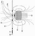
본 발명에 따른 분석기의 또 다른 하나의 실시형태에서, 상기 분석기는 자화가 불가능한 중공축, 원통형 내부를 갖고 그를 통해서 상기 자화가 불가능한 중공축에 의해 장착 및 지지되는 원통형의 영구 자석, 및 바이어스 리드와 신호가 있고 영구 자석의 원통형 내부와 자화 불가능한 중공 축에 배치되는 홀 센서를 포함하는 홀 센서 분석기이다. 본 실시형태에서, 상기 영구 자석은 자기력선을 생성하는 이론적 자기력선을 갖는데, 여기서 상기 원통형 영구 자석을 이탈한 상기 자기력선은 상기 원통의 중심 및 자기장의 중심에서 널 영역(null region)을 생성한다. 상기 영구 자석은 상기 널 영역에서의 상기 초상자성 나노입자로 레이블된 분석물을 갖는 상기 샘플에 유도를 제공한다. 상기 홀 센서는 상기 원통형 내부 중심의 상기 널 영역에 배치되어 상기 초상자성 나노입자의 상기 초상자성 응답을 감지 및 수신하고, 상기 초상자성 응답의 상기 바이어스 리드 및 신호를 송신하여 신호 처리를 진행한다.In yet another embodiment of the analyzer according to the present invention, the analyzer has a non-magnetizable hollow shaft, a cylindrical interior, through which a cylindrical permanent magnet mounted and supported by the non-magnetizable hollow shaft, and a bias lead. It is a Hall sensor analyzer that contains a Hall sensor that has a signal and is placed in a cylindrical interior of a permanent magnet and a non-magnetizable hollow shaft. In this embodiment, the permanent magnet has a theoretical line of magnetic force generating a line of magnetic force, wherein the line of magnetic force leaving the cylindrical permanent magnet creates a null region at the center of the cylinder and the center of the magnetic field. The permanent magnet provides induction to the sample with the analyte labeled with the superparamagnetic nanoparticles in the null region. The Hall sensor is disposed in the null region of the inner center of the cylinder to detect and receive the superparamagnetic response of the superparamagnetic nanoparticles, and transmit the bias lead and signal of the superparamagnetic response to perform signal processing.
또한, 상기 샘플은 샘플용 다수의 분석 영역을 포함하는 하이브리드 현장 진료 칩에 있을 수 있고, 상기 분석 영역은 상기 칩상에 원호를 다라서 배열된다. 본 발명에서, 원호를 따라 다수의 분석 영역의 배치를 갖는 하이브리드 현장 진료 칩은 본 발명의 단면 분석기 및 홀 센서 분석기에서 특히 잘 작동한다.In addition, the sample may be on a hybrid point-of-care chip including a plurality of analysis areas for samples, and the analysis areas are arranged in an arc on the chip. In the present invention, a hybrid point-of-care chip having an arrangement of multiple analysis areas along an arc works particularly well in the cross-section analyzer and Hall sensor analyzer of the present invention.
본 발명은 초상자성 입자 이미징 분석기를 사용하는 방법을 제공하는데, 상기 초상자성 입자 이미징 분석기는 초상자성 나노입자로 레이블된 분석물을 함유하는 샘플을 제공하는 단계; 상기 샘플을 분석기의 필드 프리 영역에 배치하고 상기 초상자성 나노입자의 상자성 응답으로부터 신호를 얻기 위하여 상기 필드 프리 영역에서 초상자성 나노입자를 여기시키는 단계; 신호를 감지 및 전송하는 단계, 및 상기 분석물의 특성을 얻기 위하여 상기 신호를 분석하는 단계를 제공한다.The present invention provides a method of using a superparamagnetic particle imaging analyzer, comprising the steps of: providing a sample containing an analyte labeled with superparamagnetic nanoparticles; Placing the sample in a field-free region of an analyzer and exciting the superparamagnetic nanoparticles in the field-free region to obtain a signal from the paramagnetic response of the superparamagnetic nanoparticles; It provides a step of detecting and transmitting a signal, and analyzing the signal to obtain a characteristic of the analyte.
도1은 하나의 격실을 갖는 하나의 분석 영역을 사용하고 한가지 분석물이 격실에 고정되는 본 발명에 따른 분석 방법의 제1 실시형태를 도시하는 도면.
도2는 하나의 격실을 갖는 하나의 분석 영역을 사용하고 다수의 분석물이 격실에 고정되는 본 발명에 따른 분석 방법의 제2 실시형태를 도시하는 도면.
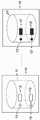
도3은 다수의 격실을 갖는 하나의 분석 영역을 사용하고 각 격실은 상이한 분석물을 고정하는 본 발명에 따른 분석 방법의 제3 및 제4 실시형태를 도시하는 도면.
도4는 다수의 격실을 갖는 하나의 분석 영역을 사용하고 각 격실은 상이한 분석물을 고정하는 본 발명에 따른 분석 방법의 제4 및 제4 실시형태를 도시하는 도면.
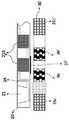
도5는 하나의 격실을 갖는 하나의 분석 영역을 사용하고 다수의 분석물이 격실에 고정되는 본 발명에 따른 분석 방법의 제5 실시형태를 도시하는 도면.
도6은 하나의 격실을 각각 갖는 다수의 분석 영역을 사용하고 각 격실에는 다수의 분석물이 고정되는 본 발명에 따른 분석 방법의 제6 실시형태를 도시하는 도면.
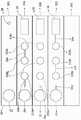
도7은 다수의 격실을 각각 갖는 다수의 분석 영역을 사용하고 각 격실에는 상이한 분석물이 고정되는 본 발명에 따른 분석 방법의 제9 및 제10 실시형태를 도시하는 도면.
도8은 다수의 격실을 각각 갖는 다수의 분석 영역을 사용하고 각 격실에는 다수의 분석물이 고정되는 본 발명에 따른 분석 방법의 제11 및 제 12 실시형태를 도시하는 도면.
도9a는 본 발명에 따른 하이브리드 현장 진료 칩의 구조에 대응하는 상부에 도시된 상면도 및 하부에 도시된 측면도; 도9b는 본 발명의 하이브리드 현장 진료 칩을 구성하는 층 및 부품의 구조 분해도, 도9c는 본 발명의 비선형 하이브리드 현장 진료 칩의 실시형태의 구조도, 및 도9d는 본 발명의 하이브리드 현장 진료 칩 어레이의 실시형태의 구조도.
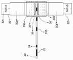
도10a는 본 발명에 따른 초상자성 입자 이미징 분석기의 제1 실시형태의 구조도로서, 상기 분석기는 동일 선형 분석기(co-linear analyzer)인, 도면, 및 도 10b는 도 10a에서 점선으로 표시된 중앙 사각형의 확대도로서, 상기 분석기에 끼워지는 위치에 일회용 부재로서 본 발명의 하이브리드 POC 칩의 구조를 도시한 도면.
도11a는 본 발명에 따른 초상자성 입자 이미징 분석기의 제2 실시형태의 구조를 도시한 정면도로서, 상기 분석기는 개방형 분석기인, 도면, 및. 도11b는 동일한 분석기의 구조를 도시하는 측면도.
도12a는 본 발명에 따른 초상자성 입자 이미징 분석기의 제3 실시형태의 "E" 코어 여기장의 구조를 도시한 도면, 및 도12b는 본 발명에 따른 하이브리드 현장 진료 칩을 도시한 부분 확대도로서, 상기 칩은 상기 분석기에 끼워지는 상기 분석기의 일회용 부재인, 도면.
도13a는 본 발명에 따른 초상자성 입자 이미징 분석기의 제4 실시형태의 구조를 도시한 상면도로서, 상기 초상자성 입자 이미징 분석기가 두 개의 동심으로 배치된 송신 코일과 별도의 수신 코일을 갖는 싱글 사이드 분석기(single sided analyzer)인, 도면, 및 도13b는 본 발명에 따른 하이브리드 현장 진료 칩의 구조를 도시한 부분 확대도로서, 상기 칩은 상기 분석기의 일회용 부품이고 분석기의 송신 코일 및 수신 코일과 관련하여 사용되는, 도면.
도14는 본 발명에 따른 초상자성 입자 이미징 분석기의 신호 체인을 도시하는 도면.
도15a는 본 발명에 따른 초상자성 입자 이미징 분석기의 제5 실시형태에서 사용되는 영구 자석의 구조를 도시한 부분 측면도로서, 상기 분석기는 홀 센서 분석기인, 도면, 도15b는 본 발명에 따른 영구 자석 및 하이브리드 현장 진료 칩을 도시한 부분 상면도로서, 상기 칩은 분석기의 일회용 부품이고 영구 자석과 관련하여 사용되는, 도면, 도15c는 본 발명에 따른 분석기의 구조를 도시한 측면도, 및 도15d는 본 발명에 따른 분석기의 구조를 도시한 상면도.
도16은 본 발명에 따른 비선형 하이브리드 현장 진료 칩과 함께 사용되는 초상자성 입자 이미징 분석기의 제6 실시형태의 구조를 도시한 도면.
도17은 홀 센서를 기반으로 한 본 발명에 따른 초상자성 입자 이미징 분석기의 신호 체인을 도시하는 도면.
도18은 실시예1에 사용되는 본 발명에 따른 하이브리드 현장 진료 칩을 도시한 도면.
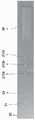
도19는 실시예1의 제1, 제2 및 제3분석 영역에 대한 수평축인 SPNP 농도(ng/ml)와 수직축인 자성 응답(Mox)의 실험 결과를 도시한 도면.
도면부호는 다음과 같다. 10- 어세이 포맷(assay format)의 분석 영역(10'또는 10a'는 직렬 배열의 다른 분석 영역을 나타냄); 11-격실(11', 11a, 11a', 11z는 직렬 배열(들)에서 다른 격실을 나타냄); 12-분석물; 13-본 발명에서 초상자성 입자, 초상자성 나노입자 레이블 또는 초상자성 입자 레이블이라고도 불리는 분석물 12를 레이블링하는데 사용되는 초상자성 나노입자; 20-하이브리드 현장 진료 칩 또는 칩 어레이(20a, 20b, 20c, 20d, 20e, 20f, 20g 및 20h는 칩 어레이의 개별 칩을 나타냄); 210-칩 20의 분석 영역(210a, 210b, 210c, 210d 및 210e는 직렬 배열의 제1, 제2, 제3, 제4, 및 제5 분석 영역을 나타냄); 21-샘플 포트; 22-시약; 23-마이크로채널(23a, 23b, 23c, 23d, 23e는 칩의 서로 다른 부분을 연결하는 서로 다른 마이크로채널을 나타냄); 24-스위칭 컬럼; 25-스위칭 컬럼 24 내부의 포장재; 26-흡수 챔버; 27-흡수 패드; 28-에어 벤트; 30-SPI 분석기; 31-하우징; 310 실린더; 311-프레임; 32-영구 자석; 33-내부 실린더 용적; 33a-영구 자석의 내부 실린더; 34-패스너; 35-여자 코일; 36-수신 코일; 37 필드 프리 포인트(FFP) 또는 필드 프리 영역(FFR); 37a-선형 필드 프리 포인트 또는 영역(FFL); 37b-널 프리 비자화 영역; 38-시야(FOV); 39-선택 필드를 나타내는 화살표; 40-신호 체인; 41-차폐; 42-AC 드라이브 필드; 43-DC 드라이브 필드; 44-신호 전치 증폭 유닛; 45-저역 통과 필터; 46-아날로그 대 디지털 변환; 47-신호 증폭기; 48 바코드 판독기; 49 중앙 처리 장치(CPU); 50-블루투쓰; 51-무선 신호 출력(WIFI); 52-디스플레이; 53-(무선) 프린터; 54-그래픽 사용자 인터페이스(GUI); 55-모바일 애플리케이션; 56-외부 12-240V 월 변압기(wall transformer); 60-홀 자기 센서; 60'-홀 소자; 61-중공 샤프트; 62-바이어스 리드 및 신호 출력; 63-생성 된 필드 라인 표현(동종 자기 양자의 팬텀); 64-지원베이스; 65-서미스터; 66-필터(오프셋 / 취소 용); 67-홀 신호 전치 증폭기 스테이지1 is a diagram showing a first embodiment of the analysis method according to the invention in which one analysis area with one compartment is used and one analyte is fixed to the compartment.
Fig. 2 shows a second embodiment of the analysis method according to the invention in which one analysis area with one compartment is used and a plurality of analytes are fixed to the compartment.
Fig. 3 is a diagram showing third and fourth embodiments of the analysis method according to the present invention in which one analysis area having a plurality of compartments is used and each compartment holds a different analyte.
Fig. 4 is a diagram showing fourth and fourth embodiments of the analysis method according to the invention in which one analysis area having a plurality of compartments is used and each compartment holds a different analyte.
Fig. 5 shows a fifth embodiment of the analysis method according to the invention in which one analysis area with one compartment is used and a plurality of analytes are fixed to the compartment.
Fig. 6 is a diagram showing a sixth embodiment of the analysis method according to the present invention in which a plurality of analysis areas each having one compartment is used, and a plurality of analytes are fixed in each compartment.
Fig. 7 is a diagram showing the ninth and tenth embodiments of the analysis method according to the present invention in which a plurality of analysis areas each having a plurality of compartments are used, and a different analyte is fixed in each compartment.
Fig. 8 is a diagram showing the eleventh and twelfth embodiments of the analysis method according to the present invention in which a plurality of analysis areas each having a plurality of compartments are used, and a plurality of analytes are fixed in each compartment.
9A is a top view and a side view shown at the top corresponding to the structure of the hybrid point-of-care chip according to the present invention; 9B is an exploded view of the structure of layers and components constituting the hybrid point-of-care chip of the present invention, FIG. 9C is a structural diagram of an embodiment of the nonlinear hybrid point-of-care chip of the present invention, and FIG. 9D is a hybrid point-of-care chip array of the present invention. Structure diagram of an embodiment of.
10A is a structural diagram of a first embodiment of a superparamagnetic particle imaging analyzer according to the present invention, wherein the analyzer is a co-linear analyzer, and FIG. 10B is a diagram of a central square indicated by a dotted line in FIG. 10A. As an enlarged view, a view showing the structure of the hybrid POC chip of the present invention as a disposable member at a position fitted to the analyzer.
Fig. 11A is a front view showing the structure of a second embodiment of a superparamagnetic particle imaging analyzer according to the present invention, wherein the analyzer is an open type analyzer. Fig. 11B is a side view showing the structure of the same analyzer.
12A is a view showing the structure of the "E" core excitation field of the third embodiment of the superparamagnetic particle imaging analyzer according to the present invention, and FIG. 12B is a partially enlarged view showing a hybrid point-of-care chip according to the present invention. The chip is a disposable member of the analyzer that is fitted to the analyzer.
13A is a top view showing the structure of a fourth embodiment of a superparamagnetic particle imaging analyzer according to the present invention, wherein the superparamagnetic particle imaging analyzer is a single side having two concentrically disposed transmitting coils and a separate receiving coil. Figure 13b, which is a single sided analyzer, is a partially enlarged view showing the structure of a hybrid point-of-care chip according to the present invention, wherein the chip is a disposable component of the analyzer and is related to the transmitting coil and the receiving coil of the analyzer. Used by, drawing.
Fig. 14 is a diagram showing a signal chain of a superparamagnetic particle imaging analyzer according to the present invention.
15A is a partial side view showing the structure of a permanent magnet used in a fifth embodiment of the superparamagnetic particle imaging analyzer according to the present invention, the analyzer being a Hall sensor analyzer, and FIG. 15B is a permanent magnet according to the present invention. And a partial top view showing a hybrid point-of-care chip, wherein the chip is a disposable part of the analyzer and is used in connection with a permanent magnet, FIG. 15C is a side view showing the structure of the analyzer according to the present invention, and FIG. 15D is A top view showing the structure of the analyzer according to the present invention.
Fig. 16 is a diagram showing the structure of a sixth embodiment of a superparamagnetic particle imaging analyzer used with a nonlinear hybrid point-of-care chip according to the present invention.
Fig. 17 is a diagram showing a signal chain of a superparamagnetic particle imaging analyzer according to the present invention based on a Hall sensor.
Fig. 18 is a diagram showing a hybrid point-of-care chip according to the present invention used in Example 1;
19 is a diagram showing experimental results of SPNP concentration (ng/ml) as a horizontal axis and magnetic response (Mox) as a vertical axis for the first, second, and third analysis regions of Example 1. FIG.
The reference numerals are as follows. 10- Analysis area in assay format (10' or 10a' represents another analysis area in a serial arrangement); 11-compartments (11', 11a, 11a', 11z denote different compartments in the series arrangement(s)); 12-analyte; 13-superparamagnetic nanoparticles used to label analyte 12, also called superparamagnetic particles, superparamagnetic nanoparticle labels or superparamagnetic particle labels in the present invention; 20-hybrid point-of-care chips or chip arrays (20a, 20b, 20c, 20d, 20e, 20f, 20g and 20h denote individual chips in the chip array); The analysis regions 210a, 210b, 210c, 210d and 210e of the 210-chip 20 represent the first, second, third, fourth, and fifth analysis regions in a serial arrangement; 21-sample port; 22-reagent; 23-microchannels (23a, 23b, 23c, 23d, 23e denote different microchannels connecting different parts of the chip); 24-switching column; Packaging material inside 25-switching column 24; 26-absorption chamber; 27-absorbent pad; 28-air vent; 30-SPI analyzer; 31-housing; 310 cylinders; 311-frame; 32-permanent magnet; 33-internal cylinder volume; 33a-inner cylinder of a permanent magnet; 34-fasteners; 35-excitation coil; 36-receiving coil; 37 Field Free Point (FFP) or Field Free Area (FFR); 37a-Linear Field Free Point or Area (FFL); 37b-null-free non-magnetic zone; 38-field of vision (FOV); 39-arrow indicating the selection field; 40-signal chain; 41-shielding; 42-AC drive field; 43-DC drive field; 44-signal preamplification unit; 45-low pass filter; 46-analog to digital conversion; 47-signal amplifier; 48 barcode reader; 49 central processing unit (CPU); 50-Bluetooth; 51-wireless signal output (WIFI); 52-display; 53-(wireless) printer; 54-graphical user interface (GUI); 55-mobile application; 56- external 12-240V wall transformer; 60-hole magnetic sensor; 60'-Hall element; 61-hollow shaft; 62-bias lead and signal output; 63-generated field line representation (phantom of homogeneous magnetism); 64-support base; 65-thermistor; 66-filter (for offset / cancel); 67-Hall signal preamplifier stage
본 발명에서, 용어 "형태” 또는 "어세이 포맷”은 분석 방법 수행에 필요한 동시에 상기 분석 방법에 사용되는 부품, 장치 및 시약의 집합을 지칭한다.In the present invention, the term "form" or "assay format" refers to a set of components, devices, and reagents used in the analytical method at the same time necessary to perform the analytical method.
본 발명의 분석 방법은 Langevin 이론에 기반한 초상자성 입자 이미징 기술을 사용하고, 변화하는 외부 자기장에 대한 초상자성 나노입자(SPNP), 주로 이의 고조파의 비선형 응답을 검출 및 분석한다. 자성 입자 이미징 기술로 용액의 자유 자성 입자(free magnetic particles)를 측정하는 것과는 달리, 고정상에 고정된 초상자성 나노입자로 레이블된 분석물의 농도를 측정한다. 결과적으로, 본 발명의 방법은 추적자(tracer)의 분포를 측정함이 없이, 단지 분석 영역의 분석물의 총 농도를 측정할 필요가 있는데, 분석 영역은 공지되었으므로 재구성 없이 농도를 측정할 수 있다.The analysis method of the present invention uses a superparamagnetic particle imaging technique based on Langevin's theory, and detects and analyzes a nonlinear response of a superparamagnetic nanoparticle (SPNP), mainly its harmonics, to a changing external magnetic field. Unlike measuring free magnetic particles in a solution with magnetic particle imaging technology, the concentration of an analyte labeled with superparamagnetic nanoparticles immobilized on a stationary phase is measured. Consequently, the method of the present invention only needs to measure the total concentration of the analyte in the analyte area, without measuring the distribution of the tracer, but since the analysis area is known, the concentration can be measured without reconstitution.
본 발명의 방법은 초상자성 입자 이미징 기술을 사용하는데, 상기 기술은 변화하는 외부 자기장에 대한 초상자성 나노입자의 공간적으로 인코딩된 비선형 응답을 이용하여 어세이 칩(assay chip)의 분석 영역에서 다수의 분석물을 동시에 정량화한다.The method of the present invention uses a superparamagnetic particle imaging technique, which uses a spatially encoded nonlinear response of a superparamagnetic nanoparticle to a varying external magnetic field. Analytes are quantified simultaneously.
본 발명에서, 초상자성 입자 이미징 기술은 체외 진단에 사용된다. 상기 초상자성 나노입자를 만들기 위하여 사용되는 재료 선택 범위는 체외 진단에 사용되는 재료보다 광범위하고, 이들 재료는 Co, Fe, CoFe, Co합금, 페라이트, 질화 코발트, 산화 코발트, Co-Pd, Co-Pt, 철, 철합금, Fe-Au, Fe-Cr, Fe-N, FeO, Fe-Pd, Fe-Pt, Fe-Zr-Nb-B, Mn-N, Nd-Fe-B, Nd-Fe-B-Nb-Cu, Ni 또는 Ni합금일 수 있다.In the present invention, the superparamagnetic particle imaging technique is used for in vitro diagnosis. The selection range of materials used to make the superparamagnetic nanoparticles is wider than those used for in vitro diagnosis, and these materials include Co, Fe, CoFe, Co alloys, ferrite, cobalt nitride, cobalt oxide, Co-Pd, Co- Pt, iron, iron alloy, Fe-Au, Fe-Cr, Fe-N, FeO, Fe-Pd, Fe-Pt, Fe-Zr-Nb-B, Mn-N, Nd-Fe-B, Nd-Fe It may be -B-Nb-Cu, Ni or Ni alloy.
본 발명에서, 상이한 형상을 갖는 입자는 상이한 고조파를 제공한다. 초상자성 나노입자는 상이한 기하학적 형상으로 제조될 수 있고 구형, 타원형 및 편평형을 포함하지만 이에 한정되지 않는다. 일부 입자에는 상이한 도료가 코딩되어 분석을 위하여 상이한 고조파를 발생시킨다.In the present invention, particles with different shapes give different harmonics. Superparamagnetic nanoparticles can be made into different geometries and include, but are not limited to, spherical, elliptical and flat. Some particles are coded with different paints to generate different harmonics for analysis.
본 발명에서, 상이한 크기를 갖는 입자가 상이한 고조파를 제공하기에 때문에, 초상자성 나노입자의 크기는 1 nm 내지 1000 nm 사이에 있다.In the present invention, since particles having different sizes provide different harmonics, the size of superparamagnetic nanoparticles is between 1 nm and 1000 nm.
본 발명에서, 고정 입자 및 자유 입자는 상이한 고조파를 제공한다. 이는 고정된 초상자성 나노입자로부터 신호를 분리하는 방법을 제공한다. 결과적으로, 분석물은 분석된 후 직접 측정되고 분석 영역을 세척하지 않고도 결합되지 않은 초상자성 나노입자를 제거할 수 있다.In the present invention, fixed particles and free particles provide different harmonics. This provides a method of separating signals from immobilized superparamagnetic nanoparticles. As a result, the analyte is measured directly after analysis and unbound superparamagnetic nanoparticles can be removed without washing the analysis area.
본 발명에서, 분석물은 초상자성 나노입자로 레이블링될 수 있고 고정상에 고정될 수 있는 임의의 물질일 수 있고, 유기 분자, 생체 분자, 펩티드, 폴리머, 아미노산, 단백질, 효소, 항체, DNAs, RNAs, 바이러스, 세균, 세포, 무기 분자, 및 약물을 포함하지만 이에 한정되지 않는다.In the present invention, the analyte may be any material that can be labeled with superparamagnetic nanoparticles and immobilized on a stationary phase, and organic molecules, biomolecules, peptides, polymers, amino acids, proteins, enzymes, antibodies, DNAs, RNAs , Viruses, bacteria, cells, inorganic molecules, and drugs.
본 발명에서, 측정될 수 있는 샘플은 전혈, 혈청, 혈장, 소변, 타액, 대변, 눈물, 땀과 같은 임의의 체액을 포함하지만 이에 한정되지 않는다. 이는 액체, 고체 및 기체 추출물일 수 있다.In the present invention, samples that can be measured include, but are not limited to, any body fluid such as whole blood, serum, plasma, urine, saliva, feces, tears, and sweat. These can be liquid, solid and gaseous extracts.
본 발명의 분석 방법은 도면과 관련하여 다음 실시 예에서 추가로 설명된다. 도1에 도시된 바와 같은 본 발명에 따른 분석 방법의 제1 실시형태에서, 분석을 진행하는 어세이 포맷은 하나의 분석 영역(10)을 포함하는데, 상기 분석 영역은 초상자성 나노입자(13)로 레이블된 분석물(12)이 고정된 하나의 격실(11)로 이루어진다.The analysis method of the present invention is further described in the following examples with reference to the drawings. In the first embodiment of the analysis method according to the present invention as shown in Fig. 1, the assay format in which the analysis is performed includes one
어세이 포맷이 본 발명의 초상자성 입자 이미징 분석기 장치에 배치될 경우 변화하는 여기장은 분석 영역(10)으로 인가되며, 분석 영역(10) 및 격실(11)의 초상자성 나노입자(13)는 응답하고, 고조파 신호는 분석기의 수신 코일에 생성한다. 생성된 고조파 신호는 격실(11)의 초상자성 나노입자의 농도와 정비례한다.When the assay format is placed in the superparamagnetic particle imaging analyzer device of the present invention, the changing excitation field is applied to the


시스템 함수를 획득하면, 수신 코일의 신호를 측정하여 형태의 분석물의 농도를 결정할 수 있다.Once the system function is obtained, the concentration of the analyte in the form can be determined by measuring the signal from the receiving coil.
도2에 도시된 바와 같이 본 발명에 따른 분석 방법의 제2 실시형태에서, 다수의 분석물을 정량화하기 위하여 변화하는 외부 자기장에 대한 초상자성 나노입자의 비선형 응답이 사용된다. 어세이 포맷은 하나의 분석 영역(10)을 포함하는데, 상기 분석 영역은 하나의 격실(11)로 구성된다. 총 개수가 Z인 분석물(제1 분석물(12) 및 제Z 분석물(12')을 도시)이 격실(11)에 고정된다. 숫자Z는 1 내지 20의 정수일 수 있다. 각 분석물은 초상자성 나노입자로 레이블된이다(각각 분석물(12 및 12')을 레이블링하는 초상자성 나노입자(13 및 13')를 도시).In the second embodiment of the analysis method according to the present invention as shown in Fig. 2, the nonlinear response of the superparamagnetic nanoparticles to a varying external magnetic field is used to quantify a plurality of analytes. The assay format includes one
어세이 포맷이 본 발명의 초상자성 입자 이미징 분석기에 배치될 경우, 변화하는 여기장은 분석 영역(10) 및 격실(11)에 인가되고, 격실(11)의 모든 초상자성 나노입자는 응답하며, 고조파 신호가 분석기의 수신 코일에 생성된다. 자성 입자의 농도는 이 고조파와 정비례한다. 격실(11)에서 측정된 n차 고조파


입자i의 n차 고조파의 진폭


입자의 모든 고조파의 비율은 농도와 무관하므로(Rauwerdink, A, 2010 참조), 이하의 식을 사용하여 격실(11)의 각 입자의 농도를 구할 수 있다.Since the ratio of all harmonics of the particle is independent of the concentration (refer to Rauwerdink, A, 2010), the concentration of each particle in the
Ax=bAx=b
여기서,here,
A =


이 식에서, 임의의 고조파를 사용하여 계산을 진행할 수 있지만 고조파의 진폭은 차수가 높아질수록 신속하게 감소되기 때문에, 고조파는 저차에서 고차까지 사용된다. 격실(11)에서 제3차 내지 제(2Z+1)차 고조파를 측정함으로써, 등식을 사용하여 모두 Z개의 분석물의 농도를 결정한다. 최대 1(분석 영역)ㆍ1(격실)ㆍZ(SPNP)분석물, 이 경우 1(분석 영역)ㆍ1(격실)Х20(SPNP)=20분석물은 동시에 분석될 수 있다.In this equation, it is possible to proceed with the calculation using arbitrary harmonics, but since the amplitude of the harmonic decreases rapidly as the order increases, the harmonics are used from low to high order. By measuring the 3rd to (2Z+1)th harmonics in the
도3에 도시된 바와 같이 본 발명에 따른 분석 방법의 제3 실시형태에서, 변화하는 외부 자기장에 대한 공간적으로 인코딩된 격실의 초상자성 나노입자의 비선형 응답이 어세이 포맷에서 다수의 분석물을 정량화하기 위하여 사용된다. 어세이 포맷은 하나의 분석 영역(10)을 포함하는데, 상기 분석 영역은 Y개의 격실로 구성된다(제1 격실(11) 및 Y번째 격실(11')을 도시). Y는 1 내지 20범위 내의 정수이다. 각 격실에는 상이한 분석물이 고정된다(격실(11)의 제1 분석물(12) 및 격실(11')의 Y번째 분석물(12')을 도시). 각 분석물은 초상자성 나노입자로 레이블된이다(격실(11)의 분석물(12)의 입자 레이블(13) 및 격실(11')의 분석물(12')의 입자 레이블(13')을 도시).In the third embodiment of the analysis method according to the present invention as shown in Fig. 3, the nonlinear response of the spatially encoded superparamagnetic nanoparticles of the compartment to the changing external magnetic field quantifies a number of analytes in the assay format. It is used to The assay format includes one
어세이 포맷이 본 발명의 초상자성 입자 이미징 분석기에 배치된 경우, 초점 자계 코일은 하나의 격실(11) 크기의 필드 프리 공간(FFS)을 생성한다. 격실의 수, 형상, 및 위치을 포함하여, 분석 영역(10)의 구조가 공지되었으므로, FFS 격실의 위치에 기반하여 한 번에 하나의 격실에 인가된다. FFS가 격실(11)에 인가될 경우, 구동 자계 코일에 의해 발생된 변화하는 여기장은 격실에 인가된다. 필드 프리 격실(11)의 초상자성 나노입자(13)는 응답하고, 고조파 신호는 분석기의 수신 코일에 발생된다. 제1 실시형태에서 설명된 방식으로 격실(11)에 고정된 분석물(12)을 분석한다. 격실(11)을 분석한 후, FFS를 다음 격실에 이동하고 다음 격실에 고정된 분석물을 분석한다. 분석 영역(10)의 모든 Y개의 격실이 분석될 때까지 동일한 과정을 반복한다. 이러한 방식으로, 모든 Y가지 분석물(단지 제1 분석물(12) 및 Y번째 분석물(12')을 도시)은 모두 정량화된다. 최대 1(분석 영역)ㆍY(격실)ㆍ1(SPNPs)분석물, 이 경우 1(분석 영역)ㆍ0(격실)Х1(SPNP)=20분석물은 동시에 분석될 수 있다.When the assay format is placed in the superparamagnetic particle imaging analyzer of the present invention, the focal magnetic field coil creates a field-free space (FFS) the size of one
본 발명에 따른 분석 방법의 제4 실시형태에서, 변화하는 외부 자기장에 대한 SPNP의 공간적으로 인코딩된 비선형 응답은 어세이 포맷에서 다수의 분석물을 동시에 정량화하는데 사용된다. 어세이 포맷은 도3에 도시된 제3 실시형태와 동일하지만, 상이한 분석 방법은 이 구성에서 사용된다.In a fourth embodiment of the analysis method according to the present invention, the spatially encoded nonlinear response of the SPNP to a changing external magnetic field is used to simultaneously quantify multiple analytes in an assay format. The assay format is the same as the third embodiment shown in Fig. 3, but a different analysis method is used in this configuration.
어세이 포맷이 본 발명의 초상자성 입자 이미징 분석기에 배치될 때, 초점 자계 코일은 필드 프리 포인트(FFP)를 발생시킨다. 격실(11, 11'...)의 수, 형상 및 위치를 포함하여, 분석 영역(10)의 구조가 공지되었으므로, FFP는 분석 영역(10) 내에서 예정된 경로로 이동한다. 변화하는 여기장이 FFP에 인가될 경우, FFP 내부의 SPNP(13, 13'...)의 자화를 유도한다. FFP는 공간적 및 시간적으로 인코딩되었으므로, FFP로부터 발생된 신호도 공간적 및 시간적으로 인코딩된다. 유도된 자화 길이는 자성 입자(13, 13'...)의 농도와 정비례한다. 자성 입자의 농도(


도4에 도시된 바와 같이 본 발명에 따른 분석 방법의 제5 실시형태에서, 변화하는 외부 자기장에 대한 공간적으로 인코딩된 격실의 초상자성 나노입자의 비선형 응답이 어세이 포맷에서 다수의 분석물을 정량화하기 위하여 사용된다. 어세이 포맷은 하나의 분석 영역(10)을 포함하는데, 상기 분석 영역은 Y개의 격실로 구성된다(제1 격실(11) 및 Y번째 격실(11')을 도시). Y는 1 내지 20범위 내의 정수이다. 각 격실에는 Z개의 분석물을 고정된다(제1 분석물(12) 및 제Z 분석물(12')을 도시). Z는 2 내지 20범위 내의 정수이다. Z개의 분석물은 Z개의 초상자성 나노입자로 레이블된이다(제1 SPNP레이블(13) 및 제Z SPNP레이블(13')을 도시).In the fifth embodiment of the analysis method according to the present invention as shown in Fig. 4, the nonlinear response of the spatially encoded superparamagnetic nanoparticles of the compartment to the changing external magnetic field quantifies a number of analytes in the assay format. It is used to The assay format includes one
어세이 포맷이 본 발명의 초상자성 입자 이미징 분석기에 배치된 경우, 초점 자계 코일은 하나의 격실(11) 크기의 필드 프리 공간(FFS)을 생성한다. Y개의 격실(11, 11',...,), 형상, 및 위치을 포함하여, 분석 영역(10)의 구조가 공지되었으므로, FFS는 격실의 위치에 기반하여 이동하고 한 번에 하나의 격실에 인가된다. FFS가 격실(11)에 인가될 경우, 구동 자계 코일에 의해 발생된 변화하는 여기장은 격실에 인가된다. 필드 프리 격실(11)의 SPNP는 응답하고 수신 고조파 신호는 코일에서 발생된다When the assay format is placed in the superparamagnetic particle imaging analyzer of the present invention, the focal magnetic field coil creates a field-free space (FFS) the size of one
제2 실시형태에서 설명된 방식으로 격실(11)에 고정된 분석물(14)을 분석한다. 제1 격실(11)의 분석물(12, 12'...)(분석물의 총 수 Z)을 정량화한다. 제1 격실(11)이 분석된 후, 분석 영역(10)의 Y번째 격실(11')을 분석할 때까지, FFS는 제2 격실로 이동하고 상기 격실을 분석 한다. 각 격실은 격실(11)과 동일한 방식으로 분석된다. 최대 1(분석 영역)ㆍY(격실)ㆍZ(SPNPs)분석물, 이 경우, 1(분석 영역)ㆍ20(격실)ㆍ20(SPNP)=400분석물은 동시에 분석될 수 있다.Analyze the
본 발명에 따른 분석 방법의 제6 실시형태에서, 변화하는 외부 자기장에 대한 SPNP의 공간적으로 인코딩된 비선형 응답은 어세이 포맷에서 다수의 분석물을 동시에 정량화하는데 사용된다. 본 실시형태는 도4에 도시된 어세이 포맷을 분석하는 또 다른 방법이다.In a sixth embodiment of the analysis method according to the present invention, the spatially encoded nonlinear response of the SPNP to a varying external magnetic field is used to simultaneously quantify multiple analytes in an assay format. This embodiment is another method of analyzing the assay format shown in FIG. 4.
어세이 포맷이 본 발명의 초상자성 입자 이미징 분석기에 배치될 때, 초점 자계 코일은 필드 프리 포인트(FFP)를 발생시킨다. 격실(11, 11'...)의 수, 형상 및 위치를 포함하여, 분석 영역(10)의 구조가 공지되었으므로, FFP는 분석 영역(10) 내에서 소정의 경로로 이동한다. 변화하는 여기장이 FFP에 인가될 경우, FFP 내부의 SPNP의 자화를 유도한다. FFP는 공간적 및 시간적으로 코딩되었으므로, FFP로부터 발생된 신호도 공간적 및 시간적으로 코딩된다. 동일한 격실로부터의 신호는 함께 처리한다.When the assay format is placed in the superparamagnetic particle imaging analyzer of the present invention, the focal magnetic field coil generates a field free point (FFP). Since the structure of the
격실에서 측정된 n차 고조파 An의 진폭은 격실의 모든 입자의 n차 고조파의 진폭

실험(An)에서 측정된 제n 진폭 및 제2 실시형태에서 설명한 방법을 이용하여 각 입자i


이상적인 경우 자성 입자i의 농도 또는 분석물i(


도5에 도시된 바와 같은 본 발명에 따른 분석 방법의 제7 실시형태에서, 변화하는 외부 자기장에 대한 SPNP의 비선형 응답은 어세이 포맷에서 다수의 분석물을 동시에 정량화하는데 사용된다. 어세이 포맷은 X개의 분석 영역(제1 분석 영역(10) 및 X번째 분석 영역(10')을 도시)을 포함하고 X는 1 내지 20 범위의 정수이다. 각 분석 영역은 하나의 격실로 구성된다(제1 분석 영역(10)의 제1 격실(11) 및 X번째 분석 영역(10')의 X번째 격실(11')을 도시). 각 격실에는 SPNP(제1 격실(11)의 제1 SPNP(13) 및 X번째 격실(11')의 X번째 SPNP(13')를 도시)로 레이블된 상이한 분석물(격실(11)의 제1 분석물(12) 및 X번째 격실(11')의 X번째 분석물(12')을 도시)이 고정된다. 분석 방법의 제7 실시형태는 분석이 X회 반복된다는 것을 제외하면 제1 실시형태와 동일하다. 최대 X(분석 영역)ㆍ1(격실)ㆍ1(SPNPs)분석물, 이 경우, 20(분석 영역ㆍ1(격실)x1(SPNP)=20분석물은 동시에 분석될 수 있다.In the seventh embodiment of the analysis method according to the present invention as shown in Fig. 5, the nonlinear response of the SPNP to the changing external magnetic field is used to simultaneously quantify multiple analytes in the assay format. The assay format includes X analysis regions (showing the
도6에 도시된 바와 같은 본 발명에 따른 분석 방법의 제8 실시형태에서, 변화하는 외부 자기장에 대한 SPNP의 비선형 응답은 어세이 포맷에서 다수의 분석물을 동시에 정량화하는데 사용된다. 어세이 포맷은 X개의 분석 영역(제1 분석 영역(10) 및 X번째 분석 영역(10')을 도시)을 포함하고 X는 1 내지 20 범위의 정수이다. 각 분석 영역은 하나의 격실로 구성된다(제1 분석 영역(10)의 제1 격실(11) 및 X번째 분석 영역(10')의 X번째 격실(11')을 도시). 각 격실에는 Z개의 분석물이 고정되고(격실(11 및 11')의 제1 분석물(12) 및 제Z 분석물(12') 둘 다를 도시), Z는 1 내지 20 범위의 정수이다. 하나의 격실의 각 분석물은 상이한 SPNP(제1 분석물용 제1 레이블 SPNP(13) 및 제Z 분석물용 제Z 레이블SPNP(13'), 각각)로 레이블된이다.In an eighth embodiment of the analysis method according to the present invention as shown in Fig. 6, the nonlinear response of the SPNP to the changing external magnetic field is used to simultaneously quantify multiple analytes in the assay format. The assay format includes X analysis regions (showing the
제8 실시형태에서 사용되는 분석 방법은 분석이 X회 반복된다는 것을 제외하면 제2 실시형태와 동일하다. 최대 X(분석 영역)ㆍ1(격실)ㆍZ(SPNP)분석물, 이 경우 20(분석 영역)ㆍ1(격실)Х1(SPNP)=20분석물은 동시에 분석될 수 있다.The analysis method used in the eighth embodiment is the same as in the second embodiment except that the analysis is repeated X times. Maximum X (analysis area)·1 (compartment)·Z(SPNP) analytes, in this case 20 (analysis area)·1 (compartment) Х1(SPNP)=20 analytes can be analyzed simultaneously.
도7에 도시된 바와 같이 본 발명에 따른 분석 방법의 제9 실시형태에서, 변화하는 외부 자기장에 대한 공간적으로 인코딩된 격실의 SPNP의 비선형 응답이 어세이 포맷에서 다수의 분석물을 정량화하기 위하여 사용된다. 어세이 포맷은 X개의 분석 영역(제1 분석 영역(10) 및 X번째 분석 영역(10')을 도시)을 포함하고 X는 1 내지 20 범위의 정수이다. 각 분석 영역은 Y개의 격실로 구성되고(제1 분석 영역(10)의 제1 격실(11)과 Y번째 격실(11') 및 X번째 분석 영역(10')의 제1 격실(11a) 및 Y번째 격실(11a')을 도시), Y는 1 내지 20 범위의 정수이다. 각 격실에는 SPNP(분석 영역(10)의 제1 격실(11)의 분석물(12)에 대한 SPNP 레이블(13), 분석 영역(10)의 Y번째 격실(11)의 분석물(12')에 대한 SPNP 레이블(13'), 분석 영역(10')의 제1 격벽(11a)의 분석물(12a)에 대한 SPNP 레이블(13a), 및 X번째 분석 영역(10')의 Y번째 격실(11a')의 분석물(12a')에 대한 SPNP 레이블(13a'))로 레이블된(분석 영역(10)의 제1 격실(11)의 제1 분석물(12) 및 Y번째 격실(11')의 Y번째 분석물(12') 및 분석 영역(10')의 Y번째 격실(11a)의 제1 분석물(12a) 및 Y번째 격실(11a')의 Y번째 분석물(12a')에 사용되는 SPNP레이블(13'), 제1 분석 영역(10')의 제1 격실(11a)의 분석물(12a)에 사용되는 SPNP레이블(13a) 및 X번째 분석 영역(10')의 Y번째 격실(11a')의 분석물(12a')에 사용되는 SPNP레이블(13a')을 도시) 상이한 분석물이 고정된다.In the ninth embodiment of the analysis method according to the present invention, as shown in Fig. 7, the nonlinear response of the SPNP of the spatially encoded compartment to a varying external magnetic field is used to quantify multiple analytes in the assay format. do. The assay format includes X analysis regions (showing the
제9 실시형태에서 사용되는 분석 방법은 분석이 X회 반복된다는 것을 제외하면 제3 실시형태와 동일하다. 최대 X(분석 영역)ㆍY(격실)ㆍ1(SPNP)분석물, 이 경우, 20(분석 영역)ㆍ20(격실)ㆍ1(SPNP)=400분석물은 동시에 분석될 수 있다.The analysis method used in the ninth embodiment is the same as in the third embodiment except that the analysis is repeated X times. A maximum of X (analysis area) ㆍY (compartment) ㆍ1 (SPNP) analyte, in this case, 20 (analysis area) ㆍ20 (compartment) ㆍ1 (SPNP) = 400 analytes can be analyzed simultaneously.
본 발명의 제10 실시형태에서, 변화하는 외부 자기장에 대한 SPNP의 공간적으로 인코딩된 비선형 응답은 어세이 포맷에서 다수의 분석물을 동시에 정량화하는데 사용된다. 측정 형태는 도7에 도시된 제9 실시형태와 동일하지만, 이는 구성을 분석하는 상이한 방법이다.In a tenth embodiment of the invention, the spatially encoded nonlinear response of the SPNP to a varying external magnetic field is used to simultaneously quantify multiple analytes in an assay format. The measurement form is the same as in the ninth embodiment shown in Fig. 7, but this is a different method of analyzing the configuration.
제10 실시형태에서 사용되는 분석 방법은 분석이 X회 반복된다는 것을 제외하면 제4 실시형태와 동일하다. 최대 X(분석 영역)ㆍY(격실)ㆍ1(SPNP)분석물, 이 경우, 20(분석 영역)ㆍ20(격실)x1(SPNP)=400분석물은 동시에 분석될 수 있다.The analysis method used in the tenth embodiment is the same as in the fourth embodiment except that the analysis is repeated X times. A maximum of X (analysis area) 占Y (compartment) 占1 (SPNP) analytes, in this case, 20 (analysis region) 占20 (compartment) x1 (SPNP) = 400 analytes can be analyzed simultaneously.
도8에 도시된 바와 같이 본 발명에 따른 분석 방법의 제11 실시형태에서, 변화하는 외부 자기장에 대한 공간적으로 인코딩된 격실의 SPNP의 비선형 응답이 어세이 포맷에서 다수의 분석물을 정량화하기 위하여 사용된다. 어세이 포맷은 X개의 분석 영역(제1 분석 영역(10) 및 X번째 분석 영역(10')을 도시)을 포함하고 X는 1 내지 20 범위의 정수이다. 각 분석 영역은 Y개의 격실로 구성되고(제1 분석 영역(10)의 제1 격실(11)과 Y번째 격실(11') 및 X번째 분석 영역(10')의 제1 격실(11a) 및 Y번째 격실(11a')을 도시), Y는 1 내지 20 범위의 정수이다. 각 격실에는 Z개의 분석물이 고정될 수 있고(제1 분석 영역(10)의 격실(11)의 제1 분석물(12) 및 제Z 분석물(12z) 및 격실(11')의 제1 분석물(12') 및 제Z 분석물(12z'); 및 X번째 분석 영역(10')의 격실(11a)의 제1 분석물(12a) 및 제Z 분석물(12b) 및 격실(11a')의 제1 분석물(12a') 및 제Z 분석물(12b')을 도시), Z는 1 내지 20 범위의 정수일 수 있다. 각각의 상기 분석물은 상이한 SPNP로 각각 레이블링되고(분석 영역(10)의 격실(11)의 각 분석물(12 및 12z)용 SPNPs(13 및 13z) 및 격실(11')의 각 분석물(12' 및 12z')용 SPNPs(13' 및 13z'); 및 분석 영역(10')의 격실(11a)의 각 분석물(12a 및 12b)용 SPNPs(13a 및 13b) 및 격실(11a')의 각 분석물(12a' 및 12b')용 SPNPs(13a' 및 13b')를 도시).In the eleventh embodiment of the analysis method according to the present invention as shown in Fig. 8, the nonlinear response of the spatially encoded compartment's SPNP to a varying external magnetic field is used to quantify multiple analytes in the assay format. do. The assay format includes X analysis regions (showing the
제11 실시형태에서 사용되는 분석 방법은 분석이 X회 반복된다는 것을 제외하면 제3 실시형태와 동일하다. 최대 X(분석 영역)ㆍY(격실)ㆍ20(SPNP)분석물, 이 경우, 20(분석 영역)ㆍ20(격실)ㆍ20(SPNP)=8,000분석물은 동시에 분석될 수 있다.The analysis method used in the eleventh embodiment is the same as in the third embodiment except that the analysis is repeated X times. A maximum of X (analysis area) · Y (compartment) · 20 (SPNP) analytes, in this case, 20 (analysis area) · 20 (compartment) · 20 (SPNP) = 8,000 analytes can be analyzed simultaneously.
본 발명에 따른 분석 방법의 제12 실시형태에서, 변화하는 외부 자기장에 대한 SPNP의 공간적으로 인코딩된 비선형 응답은 어세이 포맷에서 다수의 분석물을 동시에 정량화하는데 사용된다. 측정 형태는 도8에 도시된 제11 실시형태와 동일하지만, 이는 구성을 분석하는 상이한 방법이다. 본 실시형태에서 사용되는 분석 방법은 분석이 X회 반복된다는 점을 제외하면 제6 실시형태와 동일하다. 최대 X(분석 영역)ㆍY(격실)ㆍX(SPNP)분석물을, 이 경우, 20(분석 영역)ㆍ20(격실)ㆍ20(SPNP)=8,000분석물은 동시에 분석될 수 있다.In a twelfth embodiment of the analysis method according to the present invention, the spatially encoded nonlinear response of the SPNP to a varying external magnetic field is used to simultaneously quantify multiple analytes in an assay format. The measurement form is the same as that of the eleventh embodiment shown in Fig. 8, but this is a different method of analyzing the configuration. The analysis method used in this embodiment is the same as that of the sixth embodiment except that the analysis is repeated X times. A maximum of X (analysis area) · Y (compartment) · X (SPNP) analytes, in this case, 20 (analysis area) · 20 (compartment) · 20 (SPNP) = 8,000 analytes can be analyzed simultaneously.
이 실시형태에서 도시된 바와 같이, 본 발명의 분석 방법은 초상자성 입자 이미징 기술을 사용하여 고정상에 고정되어 있는 분석물을 정량적으로 측정한다. 상기 분석 방법은 자성 레이블의 자화로 인한 자속의 변화를 측정하여 다중화된 어세이(multiplexed assay)로 3차원 고정상에 고정된 분석 샘플의 다수의 자기적으로 레이블된 분석물의 농도를 동시에 측정한다.As shown in this embodiment, the analysis method of the present invention quantitatively measures an analyte immobilized on a stationary phase using a superparamagnetic particle imaging technique. In the above analysis method, a change in magnetic flux due to magnetization of a magnetic label is measured, and the concentration of a plurality of magnetically labeled analytes in an analysis sample fixed on a three-dimensional stationary phase is simultaneously measured by a multiplexed assay.
본 발명에서, 초상자성 입자 이미징 기술과 본 발명의 3차원 하이브리드 현장 진료 칩과 양호하게 작동하고, 측방 유동 테스트, 미세 유체 어세이, "랩 온 칩(lab on a chip)”장치 및 독립형 바이오 센서 등과 같은 다른 어세이 포맷에서도 사용될 수 있다. 화학적 및 생물학적 시약을 위한 고처리량 및 비용 효율적인 검출 플랫폼에 대한 요구는 아직 만족되지 않는다. 이러한 플랫폼은 약물 개발, 독성 연구, 현장 진료 진단 및 환경 모니터링을 위한 화학 라이브러리를 스크린닝하는 것을 포함하는 다양한 분석 및 진단 애플리케이션에 활용 될 수 있다. 통상적인 센서는 일반적으로 화학, 광학, 스펙트럼, 전기 임피던스 또는 질량 기반 검출을 사용하여 생화학적 현상을 해석한다. 초상자성 입자 이미징은 가변하는 크기, 형상 및 성분의 자성 레이블 또는 자성 나노입자를 사용한다.In the present invention, the superparamagnetic particle imaging technology and the three-dimensional hybrid point-of-care chip of the present invention work well, and the lateral flow test, microfluidic assay, "lab on a chip" device and stand-alone biosensor It can also be used in other assay formats, such as, etc. The demand for high-throughput and cost-effective detection platforms for chemical and biological reagents is not yet satisfied, such platforms for drug development, toxicity studies, point-of-care diagnostics and environmental monitoring. It can be used in a variety of analytical and diagnostic applications, including screening chemical libraries Conventional sensors typically interpret biochemical phenomena using chemical, optical, spectral, electrical impedance or mass-based detection. Particle imaging uses magnetic labels or magnetic nanoparticles of varying size, shape and composition.
초상자성 입자 이미징 기술을 사용하는 본 발명의 분석 방법은 많은 의학 진단 어세이 및 동반 약물 모니터링 테스트의 직접적이고 정확한 검출을 수행하기 위한 새로운 패러다임을 대표한다. 초상자성 입자 이미징 기술은 자성 기반 진단 어세이의 유효성 및 감도를 확장할 뿐만 아니라 다른 자성 기반 어세이의 주요한 단점을 극복하고 즉 단일 측정에서 다수의 분석물을 동시에 검출하며 광학 기반 어세이의 장점을 갖는다. 본 발명은 신속하고 감도 좋은 장치를 필요로 하지만 값 비싼 현대적인 분석 실험실 관련 비용을 요구하지 않는 분석 어세이를 개발할 수 있게 한다. DNA/RNA 분석, 환경 테스트, 화학 및 생물전 검출, 약물 남용 스크리닝, 식품 공급 품질 검출과 같은 테스트는 초상자성 입자 이미징 기술을 사용하고 생분해 가능한 일회용 어세이 칩이 있는 소형 휴대용 장치를 생산하여 개선될 수 있다.The analytical method of the present invention using superparamagnetic particle imaging technology represents a new paradigm for carrying out direct and accurate detection of many medical diagnostic assays and companion drug monitoring tests. Superparamagnetic particle imaging technology not only extends the effectiveness and sensitivity of magnetic-based diagnostic assays, but overcomes the major drawbacks of other magnetic-based assays, i.e. simultaneously detects multiple analytes in a single measurement, and takes advantage of optical-based assays. Have. The present invention makes it possible to develop analytical assays that require fast and sensitive devices but do not require expensive modern analytical laboratory related costs. Tests such as DNA/RNA analysis, environmental testing, chemical and biological detection, drug abuse screening, and food supply quality detection will be improved by using superparamagnetic particle imaging technology and producing a small, portable device with a biodegradable disposable assay chip. I can.
본 발명은 또한 본 발명의 초상자성 나노입자 기반 분석 방법과 결합하여 사용될 수 있는 하이브리드 현장 진료 칩을 제공한다.The present invention also provides a hybrid point-of-care chip that can be used in combination with the superparamagnetic nanoparticle-based analysis method of the present invention.
본 발명의 하이브리드 현장 진료 칩은 샘플이 도입되는 샘플 도입 영역; 샘플이 상이한 칩 레벨로 향하게 되는 스위칭 컬럼; 분석물이 포획, 농축 및 세정되는 분석 영역; 여분의 샘플 및 세척액이 수집되는 폐기물 챔버; 및 칩의 상이한 요소가 서로 연통되는 마이크로채널을 포함한다. 이 설계에서, 샘플 유체는 모관력(capillary force)에 의해 샘플 도입 영역에서 흡수 격실로 자동으로 흐를 수 있다. 이는 샘플 분산 채널(sample spitting channels), 시약 저장고, 혼합 포트, 및 펌프를 포함할 수 있다.The hybrid point-of-care chip of the present invention includes a sample introduction area into which a sample is introduced; A switching column in which samples are directed to different chip levels; An analysis area in which the analyte is captured, concentrated and washed; A waste chamber in which excess samples and cleaning liquids are collected; And microchannels through which different elements of the chip communicate with each other. In this design, the sample fluid can flow automatically from the sample introduction area to the absorption compartment by capillary force. This may include sample spitting channels, reagent reservoirs, mixing ports, and pumps.
본 발명의 하이브리드 현장 진료 칩의 분석 영역은 포획 재료가 적재되는 3차원 멀티 다중-격실 고정상(multi-compartment stationary phase)을 하우징한다. 샘플 유체는 3차원 경로에서 분석 영역들의 고정상으로 흐르고 이 고정상을 통과하는데, 여기서 이들 분석영역은 3차원 영역이다. 이들의 크기 및 위치는 공지되었으므로 재구성 없이 분석물의 농도를 측정할 수 있다.The analysis area of the hybrid point-of-care chip of the present invention houses a three-dimensional multi-compartment stationary phase loaded with capture material. The sample fluid flows in a three-dimensional path to and through the stationary bed of the analysis areas, where these analysis areas are three-dimensional areas. Their size and location are known so that the concentration of analytes can be determined without reconstitution.
본 발명의 하이브리드 현장 진료 포맷은 액체 샘플의 유동 경로에서 고정상으로 구성된다. 고정상은 우물(well)에 직접 분포되고 생물학적 수단에 의해 성장시키거나 유기/무기 구조 등과 같은 자체 조립 플라스틱 및 폴리머, 실리카 또는 이의 등가물로 이루어진 재료의 사전 성형품으로 구성될 수 있다. 예시는 자연계에서 생물학적으로 제조된 스트로마톨라이트, 온천에서 무기적으로 형성된 마노 또는 단백석 겔 등과 같은 콜로이드 광물, 죽순 또는 바나나 나무 줄기 및 잎의 벌집형 벽 및 격실이다. 모든 천연 구조는 생물학적 활동도의 DNA/RNA 청사진에 의해 제어되고 모두 본 발명에 사용될 수 있다.The hybrid point-of-care format of the present invention consists of a stationary bed in the flow path of a liquid sample. The stationary bed is distributed directly in a well and may be grown by biological means or may consist of preformed articles of self-assembled plastics such as organic/inorganic structures and materials made of polymers, silica or equivalents thereof. Examples are stromatolites produced biologically in nature, colloidal minerals such as agate or opal gel formed inorganically in hot springs, and honeycomb walls and compartments of bamboo shoots or banana tree trunks and leaves. All natural structures are controlled by the DNA/RNA blueprint of biological activity and all can be used in the present invention.
이러한 구조는 바람직한 라미네이트 구조에 형성된 공극에 배치되지만 벌크 또는 캐스팅 구조(bulk or cast structure)도 본 발명의 구조를 제조하는데 사용될 수 있다. 본 발명을 참조하면, 컬럼, 포획 영역, 또는 분석 영역은 액체 샘플이 기능성 "고정상”을 통해서 침투되도록 하며, 상기 기능성 "고정상”은 실제적으로 극대 표면적을 갖는 다공 재료이다. 분석 영역은 샌드위치 또는 경쟁적 면역 측정 또는 본 분야에 공지된 DNA/RNA생물 칩으로 유사한 화학 방법으로 기능화된다. 면역 측정법의 항체 또는 항원 또는 자성 나노입자로 레이블된 소형 DNA 프로브(DNA probe)를 사용하여, 이러한 영역에서 관심있는 분석물을 포획한다. 또는 경쟁적인 어세이 (competitive assay)에서, 분석물은 기능화된 고정상의 표면 구조에서 결합 부위에 대해 경쟁한다. 전체 도입된 샘플은 친수성/소수성 필름 라미네이션의 조합으로 형성된 3차원 채널로부터 직선 영역 또는 원기둥의 매 하나의 수직 경로를 통해 흐른다.These structures are placed in voids formed in the preferred laminate structure, but bulk or cast structures may also be used to make the structures of the present invention. With reference to the present invention, a column, capture region, or analysis region allows a liquid sample to penetrate through a functional “fixed phase”, which functional “fixed phase” is actually a porous material having a maximum surface area. The assay regions are functionalized by sandwich or competitive immunoassays or similar chemical methods with DNA/RNA biological chips known in the art. Immunoassay antibodies or antigens or small DNA probes labeled with magnetic nanoparticles are used to capture the analyte of interest in these regions. Or in a competitive assay, the analyte competes for the binding site in the surface structure of the functionalized stationary phase. The entire introduced sample flows through every single vertical path of a straight area or cylinder from a three-dimensional channel formed by a combination of hydrophilic/hydrophobic film lamination.
바람직한 형태에서, 컬럼 공극은 다중 라미네이트 필름에 의해 형성되는데, 상기 필름은 종이, 폴리머, 플라스틱 또는 금속화 플라스틱, 또는 금속으로 이루어질 수 있다. 이러한 필름은 Adhesive Research, 3M, DuPont Polymers, Pall, Coveme and Tesa로부터 구매될 수 있다. 이들 필름은 상이한 표면 코팅 및 특성을 갖고, 예컨대 일부의 필름은 친수성 또는 소수성인 것이다. 이들의 두께는 .001"과 .020" 사이에 있고 바람직하게는 .002"와 .015" 사이에 있으며, 가장 바람직하게는 .002"와 .009" 사이에 있다. 자성 판독 시스템의 요구에 근거하여 모든 이러한 라미네이트는 필요한 형태로 변환될 수 있다. 이 버전은 다중화된 선형 형태, 보다 급속한 원기둥 형태(more rapid circular column form), 및 분산된 샘플 도입 수단, 포획 또는 분석 영역, 궁극적으로 저장소 심지가 있는 부분 디스크입니다.In a preferred form, the column voids are formed by multiple laminate films, which film may be made of paper, polymer, plastic or metallized plastic, or metal. Such films can be purchased from Adhesive Research, 3M, DuPont Polymers, Pall, Coveme and Tesa. These films have different surface coatings and properties, for example some films are either hydrophilic or hydrophobic. Their thickness is between .001" and .020", preferably between .002" and .015", and most preferably between .002" and .009". Based on the needs of the magnetic reading system, all of these laminates can be converted into the required shape. This version is a multiplexed linear form, a more rapid circular column form, and a partial disc with a distributed sample introduction means, capture or analysis area, and ultimately a reservoir wick.
각 컬럼은 서로 액체로 연통되며, 액체는 컬럼의 저부로부터 상부로 흐른 후 인접한 컬럼의 상부로부터 저부로 흐르고 다음 인접한 컬럼의 저부로부터 상부로 흐르며, 최종적으로 심지 부재(wick member)로 흐른다(분석 영역의 수에 따른다). 각각의 또는 모든 채널 및 컬럼은 혼입된 공기를 가두어 에어포켓을 형성하여 액체의 유동을 차단한다. 갇힌 공기가 문제점이 되는 경우, 이는 각 컬럼의 상부에 작은 통기공을 배치함으로써 해결할 수 있다. 이 통기공은 갇힌 공기가 유체 채널과 컬럼을 통과하도록 허용함으로써 액체 흐름이 차단되는 것을 방지하지만, 상기 통기공은 충분히 작아 액체가 빠져나가지 않도록 한다. 이들 통기공은 그 내에 배치된 다공성 플라스틱을 가져 액체와 접촉할 때 닫히거나 또는 충분히 작게 제조되어 액체 샘플의 표면 장력이 액체가 빠져나가는 것을 방지할 수 있는데, 이는 본 분야에서 공지된 것이다. 이 크기는 0.1마이크론 내지 10마이크론의 범위 내에 있을 수 있고 바람직하게는 5마이크론 정도이다. 다른 수단은 모관력이 혼입된 공기를 유체가 유동하기 전에 충분히 이동시킬 수 있음을 확보하여 이 상황이 발생되는 것을 방지하고, 이는 채널의 재료 또는 코팅을 선택하여 실현된다.Each column is in liquid communication with each other, and the liquid flows from the bottom of the column to the top, then flows from the top of the adjacent column to the bottom, then flows from the bottom of the next adjacent column to the top, and finally flows to the wick member (analysis area Depends on the number of). Each or all of the channels and columns confine the entrained air to form air pockets to block the flow of liquid. If trapped air is a problem, this can be solved by placing a small vent at the top of each column. These vents prevent liquid flow from being blocked by allowing trapped air to pass through the fluid channels and columns, but the vents are small enough to prevent liquid from escaping. These vents have a porous plastic disposed therein to close when in contact with the liquid or be made small enough so that the surface tension of the liquid sample can prevent the liquid from escaping, which is known in the art. This size can be in the range of 0.1 microns to 10 microns and is preferably on the order of 5 microns. Another means is to ensure that the capillary force can sufficiently move the entrained air before the fluid flows to prevent this situation from occurring, which is realized by selecting the material or coating of the channel.
샘플 도입 영역과 원하는 분석 영역의 흐름 방향, 속도 및 3 차원 수준을 조절하는 연통 채널 사이에는 액체 샘플의 흐름을 유체 채널로, 원하는 제1 분석 컬럼으로 전환하는 더 작은 컬럼이 존재한다. 본 발명의 "스위칭 컬럼”은 필터, 차단제 또는 복합체(conjugates)(복합체는 자성으로 레이블된 인식 요소, 예컨대 샌드위치 어세이에서, 분석 컬럼에서 포획되고 측정될 수 있는 항체 또는 단백질)을 갖거나 갖지 않을 수 있다. 이러한 온-보드 시약(on-board reagents)은 샘플 도입 영역에 인가하기 전에 샘플과 복합체를 사전 혼합할 필요가 없도록 한다. 따라서, 유효기간 및 감도가 증가하고 어세이 변동 계수가 감소된다.Between the sample introduction area and the communication channel controlling the flow direction, velocity and three-dimensional level of the desired analysis area, there is a smaller column that converts the flow of the liquid sample into a fluid channel and into a desired first analysis column. The "switching column" of the present invention may or may not have filters, blockers or conjugates (the complex may or may not have magnetically labeled recognition elements, such as antibodies or proteins that can be captured and measured in an analytical column, in a sandwich assay). These on-board reagents eliminate the need to premix the sample and complex prior to application to the sample introduction area, thus increasing shelf life and sensitivity and reducing assay coefficient of variation. .
본 발명의 샘플 도입 수단은 적혈구 분리 메커니즘을 포함할 수 있다. 형상을 바꾸는 적혈구 세포 능력 및/또는 용혈 중에 잠재적으로 분석 부위의 포획 화학에 간섭을 일으킬 수 있는 내부 유체를 방출하는 적혈구 세포 능력 때문에, 이는 컬럼의 차단을 방지할 수 있다.The means for introducing a sample of the present invention may include a mechanism for separating red blood cells. Due to the ability of red blood cells to change shape and/or the ability of red blood cells to release internal fluid that could potentially interfere with the capture chemistry of the analyte site during hemolysis, this may prevent blockage of the column.
각각의 컬럼은 서로 액체 연통되고, 동일한 평면에 있거나 샘플 흐름을 상이한 영역으로 분할시켜 명백한 영역(distinct region)을 의도적으로 분리하여 화학 간섭을 방지하거나 또는 획득한 측정의 분석이 더 정확하도록 한다. 예를 들어, 샘플의 분석 물질이 작은 농도의 동일한 표본의 분석 물질에 비해 상대적으로 큰 농도의 분석 물질로 측정된다. 획득한 측정 결과는 작은 농도 분석물의 판독을 모호하게 하는 경향이 있다. 샘플 흐름을 상이한 3차원 레벨 샘플 흐름으로 변경하면 이 두 가지 분석물의 임의의 간섭을 최소화시킬 수 있다.Each column is in liquid communication with each other and is in the same plane or by dividing the sample flow into different regions to deliberately separate distinct regions to avoid chemical interference or to make the analysis of the obtained measurements more accurate. For example, an analyte in a sample is measured with a relatively large concentration of an analyte compared to a smaller concentration of an analyte in the same sample. The measurement results obtained tend to obscure the readings of small concentration analytes. Changing the sample flow to a different three-dimensional level sample flow can minimize any interference of these two analytes.
본 발명의 하이브리드 현장 진료 칩은 고정상 분석 영역의 3차원 다중 레벨 구조를 갖는다. 이는 필름의 층을 함께 라미네이팅하여 구성된다. 라미네이션 전에 하이브리드 현장 진료 칩의 일부 특징을 필름에 결합시킨다. 라미네이션 후 다른 특징이 생성된다. 샘플이 흐르는 층을 레벨이라고 지칭한다. 각 칩은 1개 내지 20개의 레벨, 바람직하게는1개 내지 10개의 레벨을 가진다.The hybrid point-of-care chip of the present invention has a three-dimensional multi-level structure of a stationary phase analysis area. It is constructed by laminating the layers of the film together. Some features of the hybrid point-of-care chip are bonded to the film prior to lamination. Other features are created after lamination. The layer through which the sample flows is referred to as a level. Each chip has 1 to 20 levels, preferably 1 to 10 levels.
하이브리드 현장 진료 칩은 1 내지 5개의 샘플 도입 영역, 1 내지 5개의 스위칭 컬럼, 0 내지 10개의 시약 저장고, 1 내지 20개의 분석 영역 및 1 내지 5개의 유체 흡수 부위로 구성된다. 샘플 도입 영역, 시약 저장고, 분석 영역, 및 유체 흡수 부위는 미세 유체 채널 및 비아(수직 상호 연통 채널)을 통해 연결됨으로써, 샘플을 분할하고 상이한 레벨로 흐르도록 한다. 하이브리드 현장 진료 칩은 예컨대 다이어프램 펌프와 같은 샘플 도입 영역에 연결되는 액체 구동 메커니즘을 갖거나 갖지 않을 수 있다.The hybrid point-of-care chip consists of 1 to 5 sample introduction areas, 1 to 5 switching columns, 0 to 10 reagent reservoirs, 1 to 20 analysis areas and 1 to 5 fluid absorption sites. The sample introduction area, reagent reservoir, analysis area, and fluid absorption site are connected through microfluidic channels and vias (vertical intercommunication channels), thereby dividing the sample and allowing it to flow at different levels. The hybrid point-of-care chip may or may not have a liquid drive mechanism connected to the sample introduction area such as, for example, a diaphragm pump.
상기 하이브리드 현장 진료 칩에 사용되는 필름은 플라스틱, 접착제, 종이, 목재, 섬유, 실리콘, 폴리디메틸실록산(PDMS), 폴리(메틸메타크릴레이트)(PMMA), 유리 섬유, 셀룰로오스, 다당류, 단백질 폴리머, 또는 캘린더링 입자(calendared particles)로 이루어진다. 필름 표면을 변성시켜 소수성 및 친수성을 포함하는 필요한 특성을 갖도록 할 수 있다.The film used for the hybrid point-of-care chip is plastic, adhesive, paper, wood, fiber, silicone, polydimethylsiloxane (PDMS), poly(methyl methacrylate) (PMMA), glass fiber, cellulose, polysaccharide, protein polymer, Or it consists of calendared particles. The film surface can be modified to have the necessary properties including hydrophobicity and hydrophilicity.
각 샘플 도입 영역은 적혈구 분리 장치를 구비하거나 구비하지 않을 수 있다. 이는 샘플의 관심있는 분석물을 인식하고 고정하는데 필요한 시약을 포함할 수 있다. 샘플 도입 영역은 1 내지 200마이크로 리터의 샘플을 수용할 수 있다.Each sample introduction area may or may not be equipped with a red blood cell separation device. It may contain reagents necessary to recognize and immobilize the analyte of interest in the sample. The sample introduction area can accommodate 1 to 200 microliters of sample.
샘플은 전혈, 혈장, 혈청, 소변, 타액, 눈물, 땀, 대변 추출물, DNA/RNA 추출물, 용액 함유 항원, 항체, 효소, 단백질, 펩티드, 아미노산, 호르몬, 유기분자 및 무기 분자, 바이오 마커, 산업 오염물, 병원체, 바이러스, 세포, 세포 배양 추출물, 및 환경 샘플일 수 있다.Samples include whole blood, plasma, serum, urine, saliva, tears, sweat, stool extract, DNA/RNA extract, solution-containing antigens, antibodies, enzymes, proteins, peptides, amino acids, hormones, organic and inorganic molecules, biomarkers, industrial Contaminants, pathogens, viruses, cells, cell culture extracts, and environmental samples.
시약 저장고는 자성, 형광, 화학발광 및 방사성 입자들; 항체, 단백질, DNA/RNA 프로브, 및 킬레이팅제로 기능화된 자성, 형광, 화학발광 및 방사성 입자들; 항체, 단백질, DNA/RNA 프로브, 및 킬레이팅제로 레이블된 형광, 화학발광, 및 방사성 입자를 포함하여, 관심있는 분석물을 인식하고 고정하는데 필요한 시약을 함유한다. 시약 저장고는 동일하거나 또는 상이한 샘플 경로에 있을 수 있다. 시약을 시약 저장고에 직접 배치하거나 또는 고체 지지대에 흡수될 수 있다.The reagent reservoir contains magnetic, fluorescent, chemiluminescent and radioactive particles; Magnetic, fluorescent, chemiluminescent and radioactive particles functionalized with antibodies, proteins, DNA/RNA probes, and chelating agents; It contains the reagents necessary to recognize and immobilize the analyte of interest, including antibodies, proteins, DNA/RNA probes, and fluorescent, chemiluminescent, and radioactive particles labeled with chelating agents. Reagent reservoirs can be in the same or different sample paths. Reagents can be placed directly in the reagent reservoir or can be absorbed on a solid support.
각 분석 영역은 함께 조립된 고정상의 1개 내지 20개의 부분으로 이루어진다. 분석 영역의 상이한 부분은 동일하거나 또는 상이한 고정상으로 이루어질 수 있다. 고정상은 플라스틱, 실리카, 유리, 알루미나, 유기 폴리머, 무기 폴리머 및 생분해성 폴리머로 이루어진 입자; 또는 플라스틱, 섬유, 폴리머, 다당류, 셀룰로오스, 종이, 목재, 생물학적 구조물, 생물학적 지지체, 유리 섬유, 생분해성 폴리머, 및 단백질 폴리머로 이루어진 기공막; 비수용성 겔; 콜로이드일 수 있다. 상기 기공막은 직조, 비직조 또는 캘린더링 입자일 수 있다. 고정상은 물리적 흡착 또는 관심있는 분석물에 특정한 인식 시약과의 공유 결합에 의해 기능화될 수 있다. 고정상은 분석 영역의 형상 및 크기로 사전 성형되고, 영역에 배치되거나, 또는 영역에 직접 분배할 수 있다. 분석 영역은 하나의 레벨 내 또는 다수의 레벨에 걸쳐서 구성될 수 있다.Each analysis area consists of 1 to 20 parts of a stationary bed assembled together. Different parts of the analysis area can be made of the same or different stationary phases. The stationary phase comprises particles made of plastic, silica, glass, alumina, organic polymers, inorganic polymers and biodegradable polymers; Or a porous membrane made of plastic, fiber, polymer, polysaccharide, cellulose, paper, wood, biological structure, biological support, glass fiber, biodegradable polymer, and protein polymer; Water-insoluble gel; It can be a colloid. The porous membrane may be woven, non-woven or calendering particles. The stationary phase can be functionalized by physical adsorption or covalent bonding with recognition reagents specific to the analyte of interest. The stationary phase can be preformed into the shape and size of the analysis area, placed in the area, or dispensed directly to the area. The analysis area can be organized within one level or across multiple levels.
각 흡수 부위는 유체 흡수 패드가 있는 격실로 구성된다. 패드는 플라스틱, 섬유, 폴리머, 다당류, 셀룰로오스, 종이, 목재, 생물학적 구조물, 생물학적 지지체, 유리 섬유, 생분해성 폴리머 및 단백질 폴리머로 구성된 기공막; 하이드로겔; 캘린더링 입자로 이루어진다.Each absorption site consists of a compartment with a fluid absorption pad. The pad includes a porous membrane composed of plastic, fiber, polymer, polysaccharide, cellulose, paper, wood, biological structure, biological support, glass fiber, biodegradable polymer and protein polymer; Hydrogel; It is made of calendering particles.
라미네이트의 재료는 생분해 가능하고 신속하게 분해되어 환경에 악영향을 미치지 않는 다양한 폴리머, 섬유, 셀룰로이드 및 종이로 이루어질 수 있다. 예를 들어 테스트 구조를 지지할 수 있는 기존의 플라스틱 카세트가 없으며, 라미네이트 테스트 설계에 지지대가 통합되어 자체 지지되고 있다.The material of the laminate can be made of a variety of polymers, fibers, celluloids and papers that are biodegradable and rapidly decompose and do not adversely affect the environment. For example, there is no conventional plastic cassette to support the test structure, and the support is integrated into the laminate test design and is self-supporting.
도9a 내지 도9d와 관련하여, 본 발명의 하이브리드 현장 진료 칩의 구조는 이하 실시형태에서 추가로 설명된다. 도9a에 도시된 바와 같이 본 발명의 하이브리드 현장 진료 칩의 일 실시형태에서, 본 발명의 3차원 하이브리드 현장 진료 칩(20)은 하나의 샘플 도입 영역(21) 형태의 샘플 도입 영역; 세 개의 분석 영역(210a, 210b, 및 210c); 스위칭 컬럼(24); 및 에어 벤트(28)를 갖는 흡수 격실(26) 형태의 유체 흡수 부위를 포함한다. 순서적으로, 샘플 도입 영역(21) 및 스위칭 컬럼(24)은 마이크로채널(23a)을 통해 연결되며; 스위칭 컬럼(24) 및 제1 분석 영역(210a)은 마이크로채널(23b)을 통해 연결되며; 제1 분석 영역(210a) 및 제2 분석 영역(210b)은 마이크로채널(23c)을 통해 연결되고; 제2 분석 영역(210b) 및 제3분석 영역(210c)은 마이크로채널(23d)을 통해 연결된다. 제1 분석 영역(210a)은 제1 격실(211a), 제2 격실(211b), 및 제3격실(211c)을 갖는 다중 격실 분석 영역이다. 도9a의 화살표는 칩에서의 샘플의 흐름을 도시한다.9A to 9D, the structure of the hybrid point-of-care chip of the present invention is further described in the following embodiments. In one embodiment of the hybrid point-of-care chip of the present invention as shown in Fig. 9A, the three-dimensional hybrid point-of-
칩에서 발생하는 어세이의 화학적 및 생물학적 반응에 필요한 시약(22)은 샘플 도입 영역(21)에 사전 적재된다. 분석 샘플의 양은 1마이크로 리터 내지 500마이크로 리터이고, 일반적으로 1마이크로 리터 내지 100마이크로 리터이며 바람직하게는5마이크로 리터 내지 10마이크로 리터이다. 샘플은 사전 처리하거나 또는 처리하지 않을 수 있고 혈청, 혈장, 타액, 땀, 눈물, 담액, 소변, 면봉상의 추출된 표면 와이프(surface wipes) 및 심지어 세포 배양 및 대변 추출물과 같은 반고체, 전혈(적혈구 분리 메커니즘이 전혈 분석을 위해 샘플 도입 영역(21)의 구조에 결합되었음)를 포함하지만 이에 한정되지 않는다.
샘플을 샘플 도입 영역(21)에 추가하고 시약(22)에 신속하게 용해된다. 샘플과 시약(22)과 혼합되며, 마이크로채널(23a)을 통과하고, 스위칭 컬럼(24)에 진입한다. 스위칭 컬럼(24)의 기능은 샘플을 상이한 레벨로 향하게 한다. 본 실시형태에서, 스위칭 컬럼(24)은 마이크로채널(23b)을 통해 샘플을 칩(20)의 분석 영역(210a)의 상부 레벨(만약 필요하면 샘플 흐름을 하부 레벨로 스위칭할 수도 있음)로 향하게 한다. 본 발명의 다중 레벨 설계에서, 스위칭 컬럼(24)은 원하는 대로 샘플을 임의의 레벨로 스위칭 할 수 있다. 스위칭 컬럼(24)의 충진 재료(25)는 또한 필터로 사용되어 샘플의 고체 불순물을 제거하고 깨끗한 샘플을 분석 영역으로 전달한다. 스위칭 컬럼(24)을 통과한 후, 샘플은 마이크로채널(23b)을 통과하여 제1 분석 영역(210a)에 진입한다.The sample is added to the
일반적으로, 본 발명의 하이브리드 현장 진료 칩의 분석 영역은 1개 내지 20개의 격실, 전형적으로 1개 내지 10개, 및 바람직하게는 1 개 내지 5개의 격실을 갖도록 제조될 수 있다. 본 실시형태에서, 3개의 격실(211a, 211b 및 211c)이 존재한다.In general, the analysis area of the hybrid point-of-care chip of the present invention can be made to have 1 to 20 compartments, typically 1 to 10, and preferably 1 to 5 compartments. In this embodiment, there are three
각 격실은 어세이에 따라 동일하거나 상이한 고정상을 갖도록 제조될 수 있다. 고정상은 플라스틱, 실리카, 유리, 알루미나, 유기 폴리머, 무기 폴리머 및 생분해성 폴리머로 이루어진 입자; 또는 플라스틱, 섬유, 폴리머, 다당류, 셀룰로오스, 종이, 목재, 생물학적 구조물, 생물학적 지지체, 유리 섬유, 생분해성 폴리머, 및 단백질 폴리머로 이루어진 기공막; 비수용성 겔; 콜로이드일 수 있다. 상기 기공막은 직조, 비직조 또는 캘린더링 입자일 수 있다. 고정상은 물리적 흡착 또는 관심있는 분석물에 특정한 인식 시약과의 공유 결합에 의해 기능화될 수 있다. 고정상은 분석 영역의 형상 및 크기로 사전 성형되고, 영역에 배치되거나, 또는 영역에 직접 분배할 수 있다. 분석 영역은 하나의 레벨 내 또는 다수의 레벨에 걸쳐서 구성될 수 있다. 각 격실은 상이한 분석물을 고정할 수 있다.Each compartment can be made to have the same or different stationary phases depending on the assay. The stationary phase comprises particles made of plastic, silica, glass, alumina, organic polymers, inorganic polymers and biodegradable polymers; Or a porous membrane made of plastic, fiber, polymer, polysaccharide, cellulose, paper, wood, biological structure, biological support, glass fiber, biodegradable polymer, and protein polymer; Water-insoluble gel; It can be a colloid. The porous membrane may be woven, non-woven or calendering particles. The stationary phase can be functionalized by physical adsorption or covalent bonding with recognition reagents specific to the analyte of interest. The stationary phase can be preformed into the shape and size of the analysis area, placed in the area, or dispensed directly to the area. The analysis area can be organized within one level or across multiple levels. Each compartment can hold a different analyte.
샘플이 제1 분석 영역(210a)을 통과할 경우 관심있는 분석물이 포획된다. 나머지 샘플은 제1 분석 영역(210a)을 이탈한다. 상기 과정에서, 분석물은 선택적 고정상이 있는 격실로부터 분리된다. 상기 분석물은 또한 격실에서 농축되고 통과하는 샘플 액체에 의해 세정된다. 본 발명의 다중 격실 설계로 인해 다중화가 가능하다.When the sample passes through the
마이크로채널(23c)을 통과한 후, 샘플은 이어서 제2 분석 영역(210b)으로 진입한다. 분석 영역(210b)은 격실의 수, 고정상의 재료 및 격실에 적재된 상이한 포획 재료의 수를 포함하여, 제1 분석 영역(210a)과 동일한 구조를 가질 수 있다. 제2 분석 영역(210b)을 통과한 후, 제2 분석물 세트는 분리되고 포획된다. 샘플은 계속하여 마이크로채널(23d)을 통해 이동하고 제3분석 영역(210c)으로 진입한다. 제3 분석물 세트는 제3분석 영역(210c)에서 분리된다. 나머지 샘플 유체 및 과량의 시약은 흡수 격실(26)의 유체 흡수 패드(27)에 의해 흡수된다. 흡수 패드는 플라스틱, 섬유, 폴리머, 다당류, 셀룰로오스, 종이, 목재, 생물학적 구조물, 생물학적 지지체, 유리 섬유, 생분해성 폴리머 및 단백질 폴리머로 구성된 기공막; 하이드로겔; 캘린더링 입자로 이루어진다.After passing through the
본 발명에서, 하이브리드 현장 진료 칩은 1개 내지 20개의 분석 영역, 일반적으로 1개 내지 10개의 분석 영역, 바람직하게는1개 내지 6개의 분석 영역을 갖도록 제조된다In the present invention, the hybrid point-of-care chip is manufactured to have 1 to 20 analysis areas, generally 1 to 10 analysis areas, preferably 1 to 6 analysis areas.
도9b는 본 발명의 하이브리드 현장 진료 칩의 구조를 도시한다. 본 발명의 하이브리드 현장 진료 칩(20)은 고체상 분석 영역(210a, 210b 및 210c)을 갖는 3차원 다중 레벨 구조를 갖는다. 본 실시형태에서, 칩(20)은 하부 층(201)을 포함하여, 필름의 층(하부층(201)을 포함)을 함께 라미네이팅하여 구성된다.9B shows the structure of the hybrid point-of-care chip of the present invention. The hybrid point-of-
본 발명에서, 라미네이션 전에 하이브리드 현장 진료 칩의 일부 특징을 필름에 결합시킨다. 라미네이션 후 다른 특징이 생성된다. 샘플이 흐르는 층을 레벨이라고 지칭한다. 각 칩은 1개 내지 20개의 레벨, 바람직하게는1개 내지 10개의 레벨을 가질 수 있다.In the present invention, some features of the hybrid point-of-care chip are bonded to the film prior to lamination. Other features are created after lamination. The layer through which the sample flows is referred to as a level. Each chip may have 1 to 20 levels, preferably 1 to 10 levels.
본 발명에서, 하이브리드 현장 진료 칩은 1 내지 5개의 샘플 도입 영역, 0 내지 10개의 시약 저장고, 1 내지 20개의 분석 영역 및 1 내지 5개의 유체 흡수 부위로 구성된다. 샘플 도입 영역, 시약 저장고, 분석 영역, 및 유체 흡수 부위는 미세 유체 채널 및 비아(수직 상호 연통 채널)을 통해 연결됨으로써, 샘플을 분할하고 상이한 레벨로 흐르도록 한다. 하이브리드 현장 진료 칩은 액체 구동 메커니즘을 갖거나 갖지 않을 수 있다.In the present invention, the hybrid point-of-care chip is composed of 1 to 5 sample introduction areas, 0 to 10 reagent reservoirs, 1 to 20 analysis areas, and 1 to 5 fluid absorption sites. The sample introduction area, reagent reservoir, analysis area, and fluid absorption site are connected through microfluidic channels and vias (vertical intercommunication channels), thereby dividing the sample and allowing it to flow at different levels. Hybrid point of care chips may or may not have a liquid drive mechanism.
상기 필름은 플라스틱, 접착제, 종이, 목재, 섬유, 실리콘, 폴리디메틸실록산(PDMS), 폴리(메틸메타크릴레이트)(PMMA), 유리 섬유, 셀룰로오스, 다당류, 단백질 폴리머, 또는 캘린더링 입자(calendared particles)인 재료로 이루어진다. 필름 표면을 변성시켜 소수성 및 친수성을 포함하는 필요한 특성을 갖도록 할 수 있다.The film is plastic, adhesive, paper, wood, fiber, silicone, polydimethylsiloxane (PDMS), poly(methyl methacrylate) (PMMA), glass fiber, cellulose, polysaccharide, protein polymer, or calendared particles. ). The film surface can be modified to have the necessary properties including hydrophobicity and hydrophilicity.
도9b에 도시된 바와 같은 칩(20)의 구조에서, 칩(20)은 5층의 필름, 즉, 하부층(201), 하부 채널층(202), 중간층(203), 상부 채널층(204) 및 상부층(205)으로 구성된다. 설계 요구에 기반하여 필름의 두께를 조정한다. 마이크로채널은 채널층(202 및 204)으로 형성된다. 층(201, 202 및 203)을 조립할 경우, 샘플 도입 영역(21)을 스위칭 컬럼(24)에 연결시키는 마이크로채널(23a), 제1 분석 영역(210a)을 제2 분석 영역(210b)에 연결시키는 마이크로채널(23c), 및 제3분석 영역(210c)을 흡수 챔버(26)에 연결시키는 마이크로채널(23e)을 형성한다. 층(204 및 205)을 추가한 후, 스위칭 컬럼(24)을 제1 분석 영역(210a)에 연결시키는 마이크로채널(23b), 및 제2 분석 영역(210b)을 제3분석 영역(210c)에 연결시키는 마이크로채널(23d)을 형성한다. 동시에, 스위칭 컬럼(24) 및 분석 영역을 구성한다. 상기 구조는 샘플이 마이크로채널을 통해 위치 사이에서 수평으로 통과시키고 스위칭 컬럼 및 분석 영역을 통해 레벨 사이에서 수직으로 통과시킨다. 층(204 및 205)을 추가하여 칩의 구조를 완성하기 전에 입자를 분배하거나 또는 사전 성형된 필름을 배치하여 고정상 재료를 스위칭 컬럼 및 분석 영역에 놓는다.In the structure of the
도9b에 도시된 칩(20)은 단지 설명을 위한 것이다. 더 많은 분석 영역 또는 시약 저장고와 같은 부가된 기능을 칩에 추가할 수 있다. 더 많은 필름층을 추가하여 레벨 개수를 증가시킬 수 있다.The
도9c는 본 발명의 하이브리드 현장 진료 칩의 또 다른 하나의 실시형태를 도시하는데, 이는 측방 흐름 설계와 달리, 본 발명의 하이브리드 현장 진료 칩에서 마이크로채널을 사용하여 위치 사이에서 통신을 진행하는 유연성을 이용하므로 칩의 특징은 선형 방식으로 배치될 필요가 없다. 분석 영역(210a, 210b, 210c, 210d 및 210e)은 원호를 따라 배치된다는 점이외에, 본 실시형태에서 칩(20)의 구조는 도9a 및 도9b에서 설명된 것과 동일한다. 상기 배열은 칩(20) 또는 검출기가 원주 운동으로 이동함으로써 설계 및 제조 비용을 현저하게 감소시킬 수 있다.Fig. 9c shows another embodiment of the hybrid point-of-care chip of the present invention, which, unlike the lateral flow design, provides the flexibility to communicate between locations using microchannels in the hybrid point-of-care chip of the present invention. So the features of the chip need not be arranged in a linear manner. Except that the
본 발명의 하이브리드 현장 진료 칩의 다른 하나의 실시형태는 도9d에 도시된 바와 같은 칩 어레이의 형태인데, 여기서 칩(20)은 8개의 개별 칩(20a, 20b, 20c, 20d, 20e, 20f, 20g 및 20h)을 갖는 칩 어레이의 형태이다. 필름의 각층은 다수의 세트의 칩 특징을 가지며 동일한 디스크의 모든 칩은 도9d면, 이 개인의 구성은 그림 9A 및 9B에 설명된 것과 동일하다. 본 실시형태에서, 각 개별 칩은 3개의 순차적으로 배열된 분석 영역(210a, 210b 및 210c)을 갖는다. 상기 배열은 단일한 샘플로부터 다수의 세트의 분석물을 테스트하도록 허용한다. 각 개별 칩은 칩 어레이(20)의 다른 칩과 완전히 독립된다. 따라서, 한 번의 작동으로 다수의 화학적 및/또는 생체 적합성 분석을 수행할 수 있다.Another embodiment of the hybrid point-of-care chip of the present invention is in the form of a chip array as shown in Fig. 9d, wherein the
구조를 다르게 함으로써, 본 발명의 하이브리드 현장 진료 칩은 상이한 유형의 검출 시스템과 함께 사용될 수 있다. 바람직하게는, 이러한 방법은 분석 영역의 투명도에 의존하지 않기 때문에, 하이브리드 현장 진료 칩에 사용되는 검출 방법은 자성, 음향 또는 방사성에 기반한 검출 방법이다. 이들은 표면 뿐만 아니라 전체적인 3차원 고정상체로부터의 신호를 측정할 수 있다.By varying the structure, the hybrid point-of-care chip of the present invention can be used with different types of detection systems. Preferably, since this method does not depend on the transparency of the analysis area, the detection method used in the hybrid point-of-care chip is a detection method based on magnetic, acoustic or radioactivity. They can measure signals not only from the surface but also from the entire three-dimensional stationary body.
더 바람직한 방법은 자성에 기반한 검출법이고, 초상자성 입자 이미징(SPI), 자성 입자 이미징(MPI), 자성 입자 스펙트럼법(MPS), 자성 입자의 총 축적, 자기 인덕턴스, 교류 자화율 측정법, CMOS교류 자화율 측정법, 홀 효과, 자기 저항, 거대 자기 저항(GMR), 초거대 자기 저항(CMR), 초전도 양자 간섭 장치(SQUID), 자기 이완법, 자기 공명 영상(MRI) 스핀 이완 시간을 포함한다.More preferred methods are magnetic-based detection, superparamagnetic particle imaging (SPI), magnetic particle imaging (MPI), magnetic particle spectral method (MPS), total accumulation of magnetic particles, magnetic inductance, alternating current susceptibility measurement, CMOS alternating susceptibility measurement method. , Hall effect, magneto-resistance, giant magneto-resistance (GMR), super-giant magneto-resistance (CMR), superconducting quantum interference device (SQUID), magnetic relaxation method, magnetic resonance imaging (MRI) spin relaxation time.
더 바람직한 자성 검출 방법은 초상자성 입자 이미징(SPI), 자성 입자 이미징(MPI), 자성 입자 스펙트럼법(MPS), 자성 입자의 총 축적, 자기 인덕턴스, 홀 효과이다.More preferred magnetic detection methods are superparamagnetic particle imaging (SPI), magnetic particle imaging (MPI), magnetic particle spectral method (MPS), total accumulation of magnetic particles, magnetic inductance, and Hall effect.
가장 바람직한 자성 검출 방법은 초상자성 입자 이미징 , 자성 입자 스펙트럼법(MPS), 자성 입자의 총 축적, 자기 인덕턴스이다.The most preferred magnetic detection methods are superparamagnetic particle imaging, magnetic particle spectroscopy (MPS), total accumulation of magnetic particles, and magnetic inductance.
나아가, 만약 분석 영역의 고정상이 유리, 석영, 투명 플라스틱을 포함하여, 광 투과성 재료로 이루어지면, 광학에 기반한 검출 방법은 형광, UV-Vis, 레이저, 화학 발광을 포함하여 사용할 수 있다.Further, if the stationary phase of the analysis region is made of a light-transmitting material including glass, quartz, and transparent plastic, the optical-based detection method may include fluorescence, UV-Vis, laser, and chemiluminescence.
본 발명의 하이브리드 현장 진료 칩은 미세 유체 장치의 다중 기능성 및 유연성, 측방 유동 테스트의 저비용 및 용이성, Elisa 어세이의 저 배경 잡음 및 고감도 등 장점을 가지며, 다중화할 수 있다. 하이브리드 현장 진료 칩과 고정상으로 충진된 다중 레벨 및 다중 격실의 분석 영역면에서 다른 설계들과 상이하다. 다중 격실의 구조는 상이한 포획 재료가 각각 적재된 여러 격실과 함께 적층되도록 하고 부가적으로 다양한 치수로 실현된다. 분석 영역의 고정상은 예컨대 자성 입자, 방사성 재료, 음향 활성 재료과 같은 적절한 리포터(reporter)로 레이블된 분석물을 고정한다. 표면적이 넓기 때문에, 고정상은 샘플의 분석물을 농축시키고 감도를 현저하게 향상시킨다. 이질성으로 인해 간섭 물질이 세척되고 다른 어세이 설계(assay design)보다 배경잡음이 훨씬 낮다.The hybrid point-of-care chip of the present invention has advantages such as multiple functionality and flexibility of microfluidic devices, low cost and ease of lateral flow testing, low background noise and high sensitivity of Elisa assay, and can be multiplexed. It differs from other designs in the area of analysis of a multilevel and multi-compartment filled with hybrid point-of-care chips and stationary beds. The structure of the multiple compartments allows different capture materials to be stacked together with several compartments each loaded, and additionally realized in various dimensions. The stationary phase of the analysis area holds the analyte labeled with a suitable reporter, such as magnetic particles, radioactive material, acoustically active material, for example. Because of its large surface area, the stationary phase concentrates the analyte in the sample and significantly improves the sensitivity. Due to the heterogeneity, the interfering material is washed away and the background noise is much lower than that of other assay designs.
본 발명의 하이브리드 현장 진료 칩은 측방 유동 형태와 관련된 모든 문제점을 해결한다. 미세 유체 채널로 샘플 도입 영역을 분석 영역에 연결시킴으로써, 측방 유동 형태로 존재하는 모든 교차 부분(cross sections)을 제거한다. 샘플을 분석 영역으로 직접 전달하므로 샘플 도입 영역 및 측방 유동 형태의 테트스 라인 사이의 불일치 막(insistent membrane)으로 인한 변화를 현저하게 감소시킨다. 미세 유체 채널이 닫혀 있기 때문에, 개방 가장자리로 인한 측방 유동 스트립이 누출되는 문제를 야기하지 않는다. 측방 유동 형태에서, 포획 재료가 멤브레인에 스트라이핑된다. 멤브레인, 스트라이핑 조건 및 스트라이핑 장비의 변화로 인해 분석 영역은 매우 불일치하다. 하이브리드 현장 진료 포맷에서, 분석 영역에는 고도로 조직화된 재료로 이루어진 3차원 고정상이 충진된다. 고정상 사이의 변화는 0.1%보다 작다. 측방 유동 형태의 모든 문제점을 극복하는 동시에, 하이브리드 현장 진료 포맷은 측방 유동 형태의 사용 용이성과 저렴한 비용의 장점을 유지한다.The hybrid point-of-care chip of the present invention solves all the problems associated with lateral flow patterns. By connecting the sample introduction region to the analysis region with a microfluidic channel, all cross sections present in the form of lateral flow are removed. As the sample is delivered directly to the analysis area, changes due to the insistent membrane between the sample introduction area and the test line in the form of lateral flow are significantly reduced. Since the microfluidic channel is closed, it does not cause the problem of leakage of the lateral flow strip due to the open edge. In the lateral flow form, the capture material is striped across the membrane. The analysis area is very inconsistent due to changes in the membrane, striping conditions and striping equipment. In the hybrid point-of-care format, the analysis area is filled with a three-dimensional stationary bed made of highly structured materials. The change between the stationary phases is less than 0.1%. While overcoming all the problems of the lateral flow type, the hybrid point of care format maintains the advantages of ease of use and low cost of the lateral flow type.
본 발명의 하이브리드 현장 진료 포맷은 또한 미세 유체 형태의 이러한 문제에 대한 해답을 제공한다. 마이크로채널의 경로에 침투 가능한 3차원 고정상을 배치함으로써, 분석물 이외의 다른 모든 것을 통과시키면서 분석물을 포획 및 축적시킨다. 상기 과정에서, 분석물을 농축시킴으로써 감도를 현저하게 향상시킨다. 동시에 분석물과 관련이 없는 모든 것을 제거하여 소음을 현저하게 감소시킨다. 이러한 설계로, 샘플의 전처리가 필요하지 않고 샘플의 정제 과정을 장치에 추가할 필요가 없다. 미세 유체를 이용하여 다중 격실 고정상을 설계한다. 각 격실은 상이한 분석물을 고정할 수 있다. 하이브리드 현장 진료 포맷을 초상자성 입자 이미징 기술과 결부하여 다수의 분석물을 동시에 검출할 수 있다. 하이브리드 현장 진료 포맷의 다중 레벨 설계는 화학적 및/또는 생물학적으로 호환되지 않는 분석물이 상이한 경로 및/또는 상이한 레벨로 향하도록 하고 동시에 분석되도록 한다. 하이브리드 현장 진료 포맷은 라미네이트로 제조되므로 측방 유동 형태에 비해 자동화 대규모 생산에 적합하고 생산 비용을 낮춘다.The hybrid point of care format of the present invention also provides an answer to this problem in microfluidic form. By placing a three-dimensional stationary phase that can penetrate into the path of the microchannel, the analyte is captured and accumulated while passing everything other than the analyte. In this process, the sensitivity is significantly improved by concentrating the analyte. At the same time, noise is significantly reduced by removing everything that is not related to the analyte. With this design, there is no need for sample pretreatment and no need to add sample purification steps to the device. A multi-compartment stationary bed is designed using microfluidics. Each compartment can hold a different analyte. The hybrid point-of-care format can be combined with superparamagnetic particle imaging technology to simultaneously detect multiple analytes. The multilevel design of the hybrid point-of-care format allows chemical and/or biologically incompatible analytes to be directed to different pathways and/or different levels and analyzed simultaneously. Since the hybrid point-of-care format is made of laminate, it is suitable for automated large-scale production and lower production costs compared to the lateral flow form.
또한, 사용되는 재료에 따라서 하이브리드 현장 진료 포맷의 고정상에서 발생하는 화학적 및 생물학적 과정의 표면적은 전형적인 ELISA 어세이 포맷의 300배 내지 10,000배이고, 이는 시약 취급, 조작, 장시간 대기의 문제없이 감도를 크게 향상시킨다.In addition, depending on the materials used, the surface area of chemical and biological processes occurring in the stationary phase of the hybrid point-of-care format is 300 to 10,000 times that of a typical ELISA assay format, which greatly improves sensitivity without problems of handling reagents, handling, and long waiting time Let it.
본 발명의 하이브리드 현장 진료는 새롭고 혁신적인 형태로서 소량의 생물학적, 환경적 또는 화학적 유체를 사용하여 민감하고 정량적이며 신속한 진단 어세이를 성취한다. 이는 자성을 포함하여 다양한 용액, 콜로이드 또는 현탁 입자를 사용하여 관심있는 분석물을 레이블링하거나 또는 레이블 환원을 측정하는 결합 부위와 경쟁할 수 있다. 이는 기존의 의료용 플라스틱 카세트를 사용함이 없이 생분해성 재료로 이루어진 것들을 포함하여 고정상 및 라미네이트를 사용하는 3차원 이질 설계 및 기능을 갖는다.The hybrid point-of-care of the present invention is a new and innovative form that achieves sensitive, quantitative and rapid diagnostic assays using small amounts of biological, environmental or chemical fluids. It can be used to label the analyte of interest using a variety of solutions, including magnetic, colloids or suspended particles, or compete with binding sites to measure label reduction. It has a three-dimensional heterogeneous design and function using a fixed bed and a laminate, including those made of biodegradable materials without using a conventional medical plastic cassette.
혈청, 혈장, 타액, 땀, 눈물, 담액, 소변; 면봉에서 추출된 표면 와이프, 및 나아가 세포 배양 및 대변 추출물과 같은 반고체의 전형적인 샘플량은 10마이크로 리터 또는 이하이다. 또한, 통합된 적혈구 분리 기술 및 장치를 사용하여 최소한의 용혈을 분리 및 방지할 수 있고, 하이브리드 현장 진료 포맷은 한 방울 미만의 전혈이 분석에 필요하며 어세이 시간(assay time)은 5분 미만이다.Serum, plasma, saliva, sweat, tears, liquor, urine; Typical sample volumes of semi-solids such as surface wipes extracted from swabs, and further cell cultures and fecal extracts are 10 microliters or less. In addition, the integrated red blood cell separation technology and device can be used to isolate and prevent minimal hemolysis, and the hybrid point-of-care format requires less than one drop of whole blood for analysis, and the assay time is less than 5 minutes. .
본 발명은 한 자릿수의 작동 시간을 사용하여 정량 분석의 신속한 개발을 실현하나 이와 상반되는 통상적인 측방 흐름 테스트의 작동 시간은 20분 이상이고 임의의 필요한 정규화도 필요하다. 샘플 용적 및 최소 표면 역학 및 유체 역학의 상호 작용의 감소로 인해, 작동 시간이 현저하게 감소한다.The present invention realizes rapid development of quantitative analysis using a single digit operating time, but the operating time of the conventional lateral flow test contrary to this is 20 minutes or more and any necessary normalization is also required. Due to the reduction in sample volume and the interaction of minimal surface mechanics and fluid mechanics, the operating time is significantly reduced.
본 발명의 하이브리드 현장 진료 포맷 및 칩은 통상적인 어세이의 변동 계수가 검출 한계(LOD)(전형적으로 피코그램 수준) 하의 10% 또는 이하가 되도록 한다.The hybrid point-of-care format and chip of the present invention allows the coefficient of variation of a conventional assay to be 10% or less below the limit of detection (LOD) (typically at the picogram level).
본 발명은 초상자성 입자 이미징 분석기를 더 제공하는데, 이 초상자성 입자 이미징 분석기는 초상자성 입자 이미징 기술에 기반한 설계된 기기이고 필드 프리 포인트(FFP) 및/또는 필드 프리 라인(FFL)을 생성하여 초상자성 나노입자에 의해 생성된 신호를 공간적 및 시간적으로 인코딩하며, 신호를 기록하고 신호를 하나의 단일 측정의 전체 칩의 분석물의 농도로 변환시킨다.The present invention further provides a superparamagnetic particle imaging analyzer, which is a device designed based on a superparamagnetic particle imaging technology, and generates a field free point (FFP) and/or a field free line (FFL). The signal generated by the nanoparticles is spatially and temporally encoded, the signal is recorded and the signal is converted to the concentration of the analyte of the entire chip in one single measurement.
본 발명의 하나의 측면에 따르면, 다른 하나의 초상자성 입자 이미징 분석기는 각각의 격실을 커버하는 필드 프리 공간(FFS)을 생성하며, 각 격실로부터 발생된 총 신호를 기록하고, 신호를 하나의 단일 측정에서 전체 칩의 분석물의 농도로 변환시킨다.According to one aspect of the present invention, the other superparamagnetic particle imaging analyzer creates a field-free space (FFS) covering each compartment, records the total signal generated from each compartment, and converts the signal into one single In the measurement, the concentration of the analyte in the whole chip is converted.
본 발명의 하나의 측면에 따르면, 다른 하나의 초상자성 입자 이미징 분석기는 상이한 SPNP로 레이블된 다수의 분석물을 동시에 분석하는데 사용된다.According to one aspect of the invention, another superparamagnetic particle imaging analyzer is used to simultaneously analyze multiple analytes labeled with different SPNPs.
도10a에 도시된 바와 같이 본 발명의 초상자성 입자 이미징 분석기의 제1 실시형태에서, 장치는 동일 선형 초상자성 입자 이미징 분석기이다. 분석기(30)는 하우징(31), 한 쌍의 영구 자석(32 및 32'), 한 쌍의 여자 코일(35 및 35'), 및 한 쌍의 수신 코일(36 및 36')을 포함한다.In the first embodiment of the superparamagnetic particle imaging analyzer of the present invention as shown in Fig. 10A, the device is a colinear superparamagnetic particle imaging analyzer. The
본 실시형태에서, 하우징(31)은 실린더(310)의 형상이고, 실린더(310)의 내부에서 각 영구 자석은 내부 실린더 용적(33)을 갖는 원통형이다. 영구 자석(32 및 32')은 NdFeB와 같은 희토류 합금으로 이루어지고, 고정 구 및 패스너(34)를 사용하여 매칭되는 자극이 서로 마주하도록 기계적으로 강제로 유지시키며(즉, 제1 자기체의 북극이 제2 자기체의 북극과 마주하고 제1 자기체의 남극이 제2 자기체의 남극과 마주함), 이 과정에서, 중성 자계가 존재하는 지점에 필드 프리 포인트(FFP) 또는 필드 프리 영역(FFR)(37)을 형성한다. 이론적으로, 이는 하나의 단일 지점이지만 실제적으로, 이는 경쟁하는 자기장에 의해 충돌하는 자기장 라인에 의해 형성된 영역이다(Gleich, B, 2005, Knopp, T, 2012). 이 구조 및 배열은 안정된 균일 직류(DC) 필드 프리 영역(FFR)을 형성하고 이는 또한 직류 증폭기에 의해 구동된 한 쌍의 헬름홀츠 코일에 의해 성취될 수 있다. 한 쌍의 영구 자석(32 및 32')는 덜 복잡하고 값 비싼 플랫폼의 조립을 허용하지만 임의의 조정 가능성이 부족하다.In this embodiment, the
도1B에 도시된 바와 같이, 본 발명의 하이브리드 현장 진료 칩은 단일 다중화된 장치(20)에서 샘플 처리, 수집(샘플 도입 영역(21)), 분산, 포획(분석 영역으로서, 관심 영역(ROI)(210)이라 칭함) 및 폐기물 수집(유체 흡수 부위(26))와 같은 기능 메커니즘을 포함하고, 본 발명의 초상자성 입자 이미징 분석기(30)의 일회용 부재이다.As shown in Fig. 1B, the hybrid point-of-care chip of the present invention processes samples in a single multiplexed device 20 (sample introduction area 21), dispersion, and capture (as an analysis area, a region of interest (ROI)). (Referred to as 210) and waste collection (fluid absorption site 26), and is a disposable member of the superparamagnetic
헬름홀츠 여자 코일쌍(35 및 35')을 형성하는 교류 피구동 필드를 제공하여 필드 프리 영역(37) 내의 교류(AC)를 형성한다. 일반적으로 20 KZ 내지 30 KZ까지 구동되고 본 실시형태에서는 25 KZ이다.An alternating current driven field forming the Helmholtz excitation coil pairs 35 and 35' is provided to form an alternating current (AC) in the field-
이 필드는 임의의 자성 재료는 모두 헬름홀츠 구동 주파수의 주파수로 진동하므로 변조되거나 또는 구동되기 때문에, 용어 "여기”는 "구동장" 및 "변조장” 뿐만 아니라 필드를 설명하는데 사용된다.Since this field is modulated or driven as any magnetic material all vibrates at a frequency of the Helmholtz drive frequency, the term “excitation” is used to describe the field as well as “drive field” and “modulation field”.
주변 필드의 임의의 응답을 측정하기 위하여, 평면형 또는 원형인 한 쌍의 수신 코일(36 및 36')를 간단하게 장착하여 정량화할 영향을 받는 재료에 물리적으로 최대한 접근하도록 한다. 본 실시형태에서, 상자성으로 레이블된 생체 분자에 있어서, 관심 영역(210) 또는 다수의 영역은 한 쌍의 영구 자석(32 및 32'), 한 쌍의 여자 코일(35 및 35') 및 한 쌍의 수신 코일(36 및 36')을 포함하는 실린더(310)로 이동하고 실린더(310)의 초상자성 응답 및 그 고조파를 측정한다. 필드 프리 영역(37)에서는, 초상자성 입자가 자기적으로 포화되지 않지만, 즉 자화되지 않지만, Brownian 및 Neel 이완을 진동 및 극복하고, 25 KZ의 기본 여기 주파수 뿐만 아니라 이 주파수의 고조파를 방출하는데, 이는 입자 크기 및 재료의 인식 표시이다. 이 신호는 입자 개수 및 그 공간 위치의 선형 정량화이다.In order to measure any response of the surrounding field, a pair of flat or circular receiving coils 36 and 36' are simply mounted to provide maximum physical access to the affected material to be quantified. In this embodiment, in the biomolecule labeled with paramagnetic, the region of
도11a 및 도11b에 도시된 바와 같이 본 발명의 초상자성 입자 이미징 분석기의 제2 실시형태에서, 분석기는 개방형 분석기이다.In the second embodiment of the superparamagnetic particle imaging analyzer of the present invention as shown in Figs. 11A and 11B, the analyzer is an open type analyzer.
자기 공명 영상과 유사하게, 초상자성 입자 이미징은 균일한 자기장을 필요로 한다. 자기 공명 이미징의 영상에 있어서, 검출기 또는 검출기 어레이로부터의 시야(FOV) 정보가 함께 스티치되고(stitched)(단층 촬영 기술로 공지됨) 조영제 또는 조직 자체에서 생성된 3차원 이미지로서 제공된다. 자기 공명 이미징은 이러한 필드의 질량 중심에 접근시키도록 큰 자기장 및 무선 주파수(RF) 코일을 필요로 한다. 반면, 본 발명의 초상자성 입자 이미징 분석기에서, 초상자성 레이블은 매우 상이하게 행동한다. 이는 RF 필드에 의해 간섭된 양자의 정렬을 측정하지 않고, 필드 프리 영역의 초상자성 입자의 비선형 자화를 정량화시키며, 상기 필드 프리 영역에서 브라운 및 닐 이완만이 각 입자의 필드 방향을 제어한다. 특정 주파수, 예를 들어 약 25 Kz의 여자 코일의 교류 자계는 상기 기본 속도M(t)에서 입자의 자기극을 +에서 -로 신속하게 전환한다. 여기의 기본 주파수는 유도 필드를 뿐만 아니라 입자 재료 특성 및 크기의 함수인 고조파를 발생시킨다. 고조파 스펙트럼은 각 자성 레이블의 지문 및 위치이다.(Gleich, B., 2005; Goodwill, P., et al.,이 IEEE의학 영상 잡지 30(9): 1581 -1590(2011)에 발표한 "다원화 X공간 자성 입자 이미징"; 및 Knopp, T., et al., 2012를 참조하라)Similar to magnetic resonance imaging, superparamagnetic particle imaging requires a uniform magnetic field. In images of magnetic resonance imaging, field of view (FOV) information from a detector or detector array is stitched together (known as tomography techniques) and provided as a three-dimensional image generated from the contrast medium or the tissue itself. Magnetic resonance imaging requires a large magnetic field and radio frequency (RF) coil to approach the center of mass of this field. On the other hand, in the superparamagnetic particle imaging analyzer of the present invention, the superparamagnetic label behaves very differently. This quantifies the nonlinear magnetization of superparamagnetic particles in the field-free region without measuring the alignment of the two interfered by the RF field, and only Brown and Neil relaxation in the field-free region control the field direction of each particle. The alternating magnetic field of the excitation coil at a specific frequency, for example about 25 Kz, quickly switches the magnetic pole of the particle from + to-at the fundamental velocity M(t). The fundamental frequency of excitation generates harmonics that are a function of particle material properties and size as well as inductive fields. The harmonic spectrum is the fingerprint and location of each magnetic label (Gleich, B., 2005; Goodwill, P., et al., published in IEEE Medical Imaging Magazine 30(9): 1581 -1590 (2011)). X-space magnetic particle imaging"; and Knopp, T., et al., 2012)
도11a 및 도11b에 도시된 바와 같이 본 발명의 초상자성 입자 이미징 분석기의 제2 실시형태에서, 작은 동물 및 인간을 위한 3차원 영상 장치의 전형적인 기하학적 형상(Gleich, B., 2005; Goodwill, P., 2011; Konkle J.,가 캘리포니아 대학 버클리 분교의 박사 논문(2014)에 발표한 "선진적인 단층 재구성 방법을 갖는 자성 입자 이미징"을 참조하라)을 개선하고 한가지 새로운 방법, 즉 본 발명의 하이브리드 현장 진료 칩과 결부된다. 도10a 및 도10b에 도시된 실시형태의 필드 프리 포인트 또는 영역(FFP 또는 FFR)(37)을 대체하여, 중성 필드 프리 영역의 선형 부위가 생성되는데, 이는 FFL(37')이라 칭한다. 기계적 배치, 정량화 및 이미징을 위한 원통형 중간점 확장 설계와 비교하여 제2 실시형태는 FFL(37')에 대한 액세스를 개선한다. FFL(37')은 동일 선형 실린더(co-linear cylinder)에 배치된 관심 영역 외의 기타 위치에서도 액세스할 수 있고, 이는 모든 축에서의 기계적 운동을 제한한다.In the second embodiment of the superparamagnetic particle imaging analyzer of the present invention as shown in Figs. 11A and 11B, a typical geometric shape of a three-dimensional imaging device for small animals and humans (Gleich, B., 2005; Goodwill, P. ., 2011; see "Magnetic Particle Imaging with Advanced Tomography Reconstruction Methods" published by Konkle J., in his Ph.D. dissertation at the University of California, Berkeley (2014)) and one new method, namely the hybrid of the present invention. It is associated with a point-of-care chip. By replacing the field free point or region (FFP or FFR) 37 of the embodiment shown in Figs. 10A and 10B, a linear region of the neutral field free region is created, which is referred to as FFL 37'. Compared to the cylindrical midpoint extension design for mechanical placement, quantification and imaging, the second embodiment improves access to the FFL 37'. The FFL 37' can be accessed from other locations outside the region of interest placed on the co-linear cylinder, which limits mechanical motion in all axes.
도11a에 도시된 바와 같이, 하우징(31)은 본 발명의 초상자성 입자 이미징 분석기(30)의 기계적 지지체이고, 한 상의 영구 NdFeB 자석(32 및 32')을 형성하는 선형 필드 프리 영역을 한정하는 C자형 프레임(311)으로 구성되는데, 이 선형 필드 프리 영역에선 각 자석의 양극 또는 음극이 기계적으로 강제로 서로 마주보게 된다.As shown in Fig. 11A, the
제2 실시형태에서, 이 자석은 직선형이므로, FFL(37')도 직선형이 된다. 다시 헬름홀츠 구성에서, 한 쌍의 헬름홀츠 코일(35 및 35') 및 한 쌍의 평행 수신 코일(36 및 36')은 기본 여기 영역 내의 분석 영역(210)의 초상자성 레이블로부터 유도된 자기장 및 이로 인한 고조파를 감지한다. 본 발명의 하이브리드 현장 진료 칩(20)의 분석 영역(210)은 도14에 도시된 바와 같이 유도 코일(또한 여자 코일이라고 지칭함)(35 및 35')과 밀접하게 접촉하여 전송됨으로써 측정 가능한 신호를 생성한다. 하이브리드 현장 진료 칩(20)은 스위칭 컬럼(24)에 의해 포획 분석 컬럼(210) 및 유체 흡수 부위에 분배되는 샘플 및 시약 처리 능력(샘플 도입 영역(21))을 갖는다(도9a에 도시된 바와 같음).In the second embodiment, since this magnet is straight, the FFL 37' is also straight. Again in the Helmholtz configuration, a pair of
제2 실시형태의 분석기 및 분석 방법은 측방 유동 및 미세 유체 장치의 순간 검출 설계의 제한을 초과한다. 대부분의 통상적인 어세이에 필요한 선형성은 본 발명의 분석기에서 필요하지 않음으로 본 발명의 분석기에서는 이러한 제한이 없고, 이는 도11a 및 도11b에 도시된 실시형태에 의해 성취되는데, 신속하게 이동하는 FFL 또는 FFL 공간의 관심 영역의 기계적 스캐닝으로의 액세스는 초상자성 레이블의 수, 상태(결합 또는 미결합) 및 관심 영역 내의 위치의 메트릭(metric)을 생성하도록 한다.The analyzer and analysis method of the second embodiment exceeds the limitations of the lateral flow and instantaneous detection design of the microfluidic device. The linearity required for most conventional assays is not required in the analyzer of the present invention, so there is no such limitation in the analyzer of the present invention, which is achieved by the embodiments shown in Figs. 11A and 11B, which is a fast moving FFL. Alternatively, access to the mechanical scanning of the region of interest in the FFL space allows to generate a metric of the number, states (coupled or uncoupled) of the superparamagnetic labels and the location within the region of interest.
도12a 및 도12b에 도시된 바와 같이 본 발명의 초상자성 입자 이미징 분석기의 제3 실시형태에서, 분석기(30)는 초상자성 입자 이미징 분석기에 사용되는 "E" 자기 코어 여기장을 갖는다. 도11a 및 도11b에 도시된 제2 실시형태의 여자 코일(35 및 35')을 단순화하고 매우 균일한 교류 송신 또는 변조장을 생성하기 위하여, 분석기(30)는 한 쌍의 E자형 소결 철 페라이트 자기 코어(35a 및 35a')를 사용하는데, 이 자기 코어는 서로 마주하고 세라믹 절연체(미도시)에 의해 이격된다. E자형 자기 코어의 각 레그상의 솔레노이드 코일 권선(35b 및 35b')은 단락되어 간극이 형성된 E자형 자기 코어(35a 및 35a')의 정확하게 대향되는2개의 극에서 자기장을 생성한다. 솔레노이드 권선(35b 및 35b')은 교류 주파수에서 작동하고 구동 전자 장치에 대한 피드백 루프를 갖는다(또한 도14를 참조). 도6A에 도시된 바와 같이, 이는 하이브리드 현장 진료 칩의 자성 레이블을 여기하고 진동시키는데 사용되는 변조장이다. 한 쌍의 중첩되는 영구 자석(32 및 32')은 서로의 양극을 강제적으로 마주하도록 하여 E자기 코어의 간극내에서 FFR 또는 FFP(37)를 생성시킨다. FFR(37)의 중성 영역을 제외하고 직류 자계내의 모든 재료는 자화된다. 하이브리드 현장 진료 칩(20)은 간극과 접근 가능한 영역을 통해 이동한다. 초상자성 레이블의 교류 유도는 교류 자계의 기본 주파수 및 그에 따른 고조파를 생성하며, 이들은 수신 코일(36 및 36')에 의해 측정되고 신호 체인 전자 장치로 전달된다. 본 발명의 하이브리드 현장 진료 칩과 결합하여 E 자기 코어 설계를 사용한 제3 실시형태는 교류 여기 및 수신 코일에 접근하여 우수한 SNR(신호 대 잡음비)를 제공하기 때문에 개선된 설계이다.In the third embodiment of the superparamagnetic particle imaging analyzer of the present invention as shown in Figs. 12A and 12B, the
도13a 및 도13b에 도시된 바와 같이 본 발명의 초상자성 입자 이미징 분석기의 제4 실시형태에서, 분석기는 동심으로 배치된 두 개의 송신 코일 및 분리된 수신 코일을 갖는 단면 초상자성 입자 이미징 분석기이다. 다른 실시형태와 달리, 본 실시형태에서 영구 자석을 사용하지 않는다. 본 실시형태에서, 분석기(30)는 한 쌍의 단면 헬름홀츠 코일을 가짐으로, 하이브리드 현장 진료 칩(20)의 유용성 및 형성된 1D시야(FOV)(38)와의 상호 작용을 실현한다. 원형 외부 직류 구동 자계는 교류 자계의 헬름홀츠쌍으로 둘러싸인다. 도13a의 화살표(39)는 대향 방향의 직류 전류에 의해 발생된 선택 자계를 나타낸다. 이는 대향되는 자계를 생성하고 대칭되는 FFR(37)를 형성한다. 하이브리드 현장 진료 칩(20)이 수신 코일(36)의 시야를 통과할 경우, FFR(37)의 분석 영역의 SPNP는 여기되어 신호를 생성한다. 헬름홀츠 코일을 사용하는 장점은 여자 코일 및 수신 코일의 역할을 동시에 수행한다는 것이다. 분석 영역(210)은 경사계 방식으로 센서를 통과하거나 단일 위치로 가져와 측정된다.In the fourth embodiment of the superparamagnetic particle imaging analyzer of the present invention as shown in Figs. 13A and 13B, the analyzer is a cross-sectional superparamagnetic particle imaging analyzer having two transmitting coils and separate receiving coils arranged concentrically. Unlike other embodiments, a permanent magnet is not used in this embodiment. In this embodiment, the
도14는 도10, 11 및 12에 도시된 실시형태와 같은 본 발명의 교류 코일에 기반한 초상자성 입자 이미징 분석기 및 하이브리드 현장 진료 기술의 최종 사용자와의 신호 체인 및 통신을 도시한다. 도14에 도시된 바와 같이, 차폐(41)는 교류 구동 필드(42) 및 직류 구동 필드(43)를 포함하는 자기 차폐 필드의 구동을 제공한다. 자기 공명 신호를 수신 코일(36)에서 감지되어 전송되고, 신호의 기본 주파수 또는 주파수들이 처리되고, 신호 전치 증폭 유닛(44)에서 고조파를 방출된 신호로부터 분리하고, 상기 신호 전치 증폭 유닛에서 전압이 매우 작은 고조파는 노치 필터와 잠금 증폭기를 포함하는 전치 증폭기를 사용하여 변환된다. 현재, 이러한 장치의 대부분은 별도의 칩 패키지로 구매할 수 있음으로써 별도의 회로기판을 감소시킨다. 일반적으로, 저역 통과 필터(45)를 통과하여 신호 소음 감소 및 크로스 토크 단계에서 1/f의 열 소음을 감소시키고, 전치 증폭된 전압은 아날로그-디지털 변환 회로(46)를 통해 변환되며, 신호 증폭기(47)를 통해 선형적으로 증폭되고 외부 중앙 처리 장치(CPU)(49)로 전송된다.14 shows a signal chain and communication with an end user of a hybrid point-of-care technology and a superparamagnetic particle imaging analyzer based on an alternating current coil of the present invention such as the embodiment shown in FIGS. 10, 11 and 12; As shown in Fig. 14, the
바코드 판독기(48)에 의해 판독된 2차원 바코드는 하이브리드 현장 진료의 유형, 제조 일자, 사용자를 인식하고, 중요하게는, 작업 커브는 각 제조 로트에 기반하여 하이브리드 현장 진료 어세이의 품질 및 감도를 결정한다. 이러한 정량적 결과는 블루투스(50) 또는 무선 신호 출력(51) 정보로 사용될 수 있거나 그래픽 사용자 인터페이스(GUI)(54)의 유선 신호(운영자 및 병원 정보 시스템(HIS)에서 사용됨)로 사용될 수 있다. 그래픽 사용자 인터페이스(54)는 휴대용 저장 장치 또는 데이터 베이스로의 예컨대 차량용 GPS, 어세이 성능의 시간 (time of assay performance), 기록 및 데이터 관리와 같은 입력을 처리한다.The two-dimensional barcode read by the
그래픽 사용자 인터페이스(54)는 터치 스크린 패널의 전통적인 디스플레이(52)를 제어하고, 프린터(53)로 결과 및 데이터 베이스의 하드 카피를 무선으로 프린트하고, 결과, 위치, 제안된 설명 및 데이터 이력을 제공하는 완전히 개발된 모바일 애플리케이션(55)과 추가적으로 통신한다. 상기 특징은 모바일 애플리케이션(55)의 실시간 모바일 환경에서 다수의 데이터 포인트의 그래픽 조정을 허용한다.The
본 발명의 초상자성 입자 이미징 분석기의 제5 실시형태는 도15a 내지 도15d에 도시되고, 여기서 분석기는 홀 센서를 갖는 NdFeB 영구 자석이다. 분석기(30)에서, NdFeB 원통형 영구 자석(32)를 장착한다(설명을 위해, 가상 자기장 선(63)을 구비함). 자기력선(63)은 임의의 자성 소스에 의해 둘러싸여 형성되는 균일한 양자 에너지 필드에 있고, 이들은 현저하지 않으며 중력장과 유사하고, 단지 도15a 및 도15b에 이러한 필드 및 그 분포가 설명된다.A fifth embodiment of the superparamagnetic particle imaging analyzer of the present invention is shown in Figs. 15A to 15D, where the analyzer is a NdFeB permanent magnet with a Hall sensor. In the
NdFeB 자석(32)은 자석의 남극을 떠나 영구 자석의 북극을 중심으로 접히는 자기력선(63)을 갖는다. 이러한 극은 단지 일반적인 용도로만 명명된다. 홀 프로브 센서(60)는 널 프리 영역(37b)에 배치되는데, 널 프리 영역에서 원형 자기체(32)를 이탈하는 자기력선(63)은 실린더(33a) 및 력장(force field)의 정확한 중심에서 이론적으로 널 영역에 도달한다. 홀 프로브를 실린더(33a) 내 및 자화가 불가능한 중공축(71)에 장착함으로써, 바이어스 리드 및 신호(62)는 도14와 유사하게 신호 처리 전자 장치로 재루트되도록 하지만, 구동 자계 없이도, 영구 자석은 코일 세트와 반대되는 직류 자계를 제공하여, 장치의 설계 및 제조를 크게 단순화시킨다. 상기 필드가 필드 프리 영역(37)을 형성하는 피구동 직류 자계이기 때문에 고조파를 생성하지 않는다. 널 프리 영역(37b)에서, 이론적 자기 에어리아는 매우 작거나 또는 이론적 자기 영역이 없고 좁은 프린지장(fringe fields)만 있다.The
본 발명에서, 경사계 방식으로 또는 단일 측정으로 칩(20) 및 분석 영역(210)을 센서(60)의 상방향으로 수송하고 초상자성 입자 이미징 분석기는 하이브리드 현장 진료 칩과 함께 작동되며, 분석 영역의 자기 레이블은 널 필드(37b)를 붕괴(collapsing)시키고 홀 자기 센서(60)에 유도 신호를 생성함으로써 자화된다. 이 신호는 영상을 생성하도록 정량화되고 처리될 수 있다.In the present invention, the
도15c 및 도15d는 본 발명의 하이브리드 현장 진료 칩을 갖는 초상자성 입자 이미징 분석기의 구성 이미지를 도시한다. 영구 자석(32)은 중공축(61)에 의해 지지되는 NdFeB 자석인데, 상기 중공축은 중공의 비자성 홀 센서축이고, 도15a 및 도15b의 자기력선(63)으로 설명되는 력장은 자석(32)의 실린더(33a)에서 형성된다. 초상자성 입자 이미징 분석기(30)의 기기의 외부 지지 및 차폐(41)는 중공축(61)을 하우징한다. 중공축(61)은 경로에 따라 홀 자기 센서(60)의 전압 및 출력 신호를 송신함과 동시에 영구 자석(32)의 널 필드(37b)의 프로브의 장착된다.15C and 15D show configuration images of a superparamagnetic particle imaging analyzer having a hybrid point-of-care chip of the present invention. The
도9a 내지 도9d에서 상세하게 설명된 본 발명의 하이브리드 현장 진료 칩(20)은 측면도 및 상면도로 도15c 및 도15d에 도시되고 홀 자기 센서(60)에서 전송되어 경사계 또는 공간적으로 인코딩된 신호를 생성하며, 도 14에 도시된 바와 같이 상기 경사계 또는 공간적으로 인코딩된 신호는 CPU(49)에 의해 처리되고 GUI(54)에 의해 표시된다. 도15d의 상면도는 분석 영역(210a, 210b 및 210c)이 홀 자기 센서(60)를 통과하며 또는 그 상방향에서 정적으로 측정될 때의 관계를 설명한다.The hybrid point-of-
본 발명의 비선형 하이브리드 현장 진료 칩(20)과 함께 작동하는 초상자성 입자 이미징 분석기(30)의 제6 실시형태는 도16에 도시된다. 제6 실시형태에서, 분석기(30)는 지지 베이스(64)에 지지된다. 칩(20)의 분석 영역(210a 내지 210e)은 도15a 및 도15b에 설명된 바와 같이 접근 가능한 초상자성 입자 이미징 영구 자석(32) 및 홀 자기 센서(60)에 대한 관계에서 원호의 방식으로 널 영역(37b)에 순차적으로 이동하여 진입한다. 발생된 신호는 홀 프로브 바이어스 라인 및 출력 신호(62)를 통과한다. 영구 자석(32) 및 비선형 분석 칩(20)의 형태는 총 비용을 감소시키나 분석 영역(210)은 공간 구조에 대한 사전 지식을 사용하여 다중화되고 촬상된다. 컴퓨터 단층 촬영 기술에 사용되는 재구성 기술은 홀 자기 센서(60) 또는 널 영역(37b)의 다수의 센서를 사용하여 가능한 3D 영상을 나타내는데, 각 센서는 모두 수학적 모델에 기여하는 시야(FOV)를 가진다. 분석기(30)의 지지 베이스(64)는 1차 비자성 재료이며, 상기 재료는 NdFeB 자기체(32)의 자기력선을 유도 및 분배하나 홀 프로브 바이어스 리드 및 출력 신호(62)는 지지 베이스(64)를 통과한다.A sixth embodiment of a superparamagnetic
도17에 도시된 바와 같이, 신호 체인(40)은 개요적으로 도시되고, 자기장으로부터의 센서 신호를 측정하는 하나의 예를 도시한다. 신호 체인(40)에서 120-240 교류 벽형 전원 또는 내부 배터리(57)로부터의 플러그 인 변압기(plug in transformer)(56)는 직류 바이어스 전압을 홀 소자(60')에 제공한다. 서미스터(65)는 기기의 환경 온도를 보정하고, 추가적인 홀 자기 센서(60)는 지구 자기장을 포함한 기기 근처의 임의의 자기장을 보정한다. 홀 센서가 신호 또는 전압을 생성하면, 이는 필터(66)의 오프셋 제거 집적 회로 피드백 루프에 의해 필터링되고 선형 증폭기(47)에 밀접하게 연결된 전방 증폭기(67)에 전달된다. 증폭된 신호는 게이트 드라이버(68) 및 과전류 보호(OCP)에 매칭된 저전력으로써 제어 그래픽 사용자 인터페이스(GUI)(54) 또는 사용자 입력을 제어하는 중앙 처리 장치(CPU)(49)에 입력된다. GUI(54)는 인간 인터페이스로써, 이 인간 인터페이스는 홀 소자(60')에 의해 측정된 자기 신호를 애플리케이션 또는 프로그램(55), 프린터(53), 디스플레이(52), 블루투스 장치(50) 또는 예컨대 인터넷 또는 클라우드와 같은 무선 통신(51)으로 전송된다.As shown in Fig. 17, the
실시예1. 본 발명의 HY-POC칩에서 래비트 IgG(Rabbit IgG)에 결합된 SPNP의 선량 반응(dose response):Example 1. Dose response of SPNP bound to rabbit IgG (Rabbit IgG) in the HY-POC chip of the present invention:
재료:material:
본 실시예에서, 사용된 재료는 래비트 IgG 150K(Arista Bio, AGRIG-0100, lot 091325551, 2.88 mg/ml); 고트 안티-래비트 IgG(Goat Anti-Rabbit IgG)(H&L) 항체(BioSpacific: G-301-C-ABS, lot WEB08, 6.39 mg/ml); 자기 비드(MicroMod, 09-02-132, 130 nm, 10 mg/ml);In this example, the material used was rabbit IgG 150K (Arista Bio, AGRIG-0100, lot 091325551, 2.88 mg/ml); Goat Anti-Rabbit IgG (H&L) antibody (BioSpacific: G-301-C-ABS, lot WEB08, 6.39 mg/ml); Magnetic beads (MicroMod, 09-02-132, 130 nm, 10 mg/ml);
실리카 비드(CORPUSCULAR C-SiO-10COOH, 10마이크론 볼, 10 mg/ml); 니트로셀룰로오스 막(Millipore HF180UBXSS, 로트 R6EA62198C); N-히드록시숙신이미드설포네이트나트륨염(Sulfo-NHS)(Combi-Blocks 카테고리: OR-6941; CAS번호 106627-54-7); 1-(3-디메틸아미노프로필)-3-카르보디이미드염산염(EDC)(AK Scientific 카테고리# 965299); 소혈청 알부민(BSA); 트윈20; 커플링 버퍼: 10 mM PBS pH 7.4; 저장 버퍼(10 mM PBS, 0.6 mg/ml BSA, 0.05% NaN3); 샘플 작동 버퍼(10 mM PBS, 1 mg/ml BSA, 0.1%의 트윈20).Silica beads (CORPUSCULAR C-SiO-10COOH, 10 micron balls, 10 mg/ml); Nitrocellulose membrane (Millipore HF180UBXSS, lot R6EA62198C); N-hydroxysuccinimide sulfonate sodium salt (Sulfo-NHS) (Combi-Blocks category: OR-6941; CAS number 106627-54-7); 1-(3-dimethylaminopropyl)-3-carbodiimide hydrochloride (EDC) (AK Scientific category # 965299); Bovine serum albumin (BSA);
방법론:methodology:
1.자기 비드 레이블된 래비트 IgG(R-IgG-SPNP)의 준비: 0.2 ml의 PBS커플링 버퍼에 첨가되는 것보다 앞서, 0.1 ml의 10 mg/ml 130 nm자기 비드를 1.5 ml의 튜브에 첨가되고 나서, 0.01 ml의 EDC(10 mg/ml) 및 0.01 ml의 NHS-Sulfo(10 mg/ml)를 상기 용액에 첨가된다. 연속적인 혼합 하에서 혼합물을 실온에서 20분 동안 반응시킨다. 다음, 0.57 ml의 래비트 IgG(2.88 mg/ml)를 혼합물에 첨가되고, 혼합물을 실온에서 2시간 동안 회전시킨다. 다음, 비드를 자기 분리기로 끌어 내리고 2Х0.5 ml의 PBS로 세척하며 1 ml의 저장 버퍼에 현탁하여 R-IgG-SPNP를 얻는다.1. Preparation of magnetic bead-labeled rabbit IgG (R-IgG-SPNP): 0.1 ml of 10 mg/ml 130 nm magnetic beads in a 1.5 ml tube prior to being added to 0.2 ml of PBS coupling buffer. After addition, 0.01 ml of EDC (10 mg/ml) and 0.01 ml of NHS-Sulfo (10 mg/ml) are added to the solution. The mixture is reacted at room temperature for 20 minutes under continuous mixing. Next, 0.57 ml of rabbit IgG (2.88 mg/ml) is added to the mixture and the mixture is spun at room temperature for 2 hours. Next, the beads are pulled down with a magnetic separator, washed with 2 Х0.5 ml of PBS, and suspended in 1 ml of storage buffer to obtain R-IgG-SPNP.
2.고정상의 제조: 안티-래비트 IgG(GAR) 항체에 공유 결합된 실리카 비드: 0.2 ml의 PBS커플링 버퍼보다 앞서, 0.1 ml의 10 mg/ml 10 마이크론 카르복실산 실리카 비드를 1.5 ml의 튜브에 첨가되고, 0.01 ml의 EDC(10 mg/ml) 및 0.01 ml의 NHS-Sulfo(10 mg/ml)를 상기 용액에 첨가하여 혼합물을 형성한다. 연속적인 혼합 하에서 혼합물을 실온에서 20분 동안 반응시킨다. 다음, 0.156 ml의 고트 안티-래비트-IgG(6.39 mg/ml)를 혼합물에 첨가된다. 혼합물을 실온에서 2시간 동안 회전시키고 나서, 13,000 RPM으로 3분 동안 원심 분리하고 상층액을 제거한다. 다음, 2Х0.5 ml의 PBS로 실리카 비드를 세척하고 35℃ 하에서 12시간 동안 건조시킨다.2. Preparation of stationary phase: Silica beads covalently bound to anti-rabbit IgG (GAR) antibody: 0.1 ml of 10 mg/
3.안티-래비트 IgG(GAR) 항체 흡착 실리카 비드의 제조: 0.1 ml의 10 mg/ml 10마이크론 카르복실산 실리카 비드를 1.5 ml의 튜브에 첨가되고 나서, 0.2 ml의 PBS커플링 버퍼 및 0.005 ml의 고트 안티 토끼 IgG(6.39 mg/ml)가 첨가된다. 혼합물을 실온에서 12시간 동안 회전시키고 13,000 RPM으로 3분 동안 원심 분리시킨다. 다음, 상층액이 제거되고, 2Х0.5 ml의 PBS로 실리카 비드를 세척하고 35℃ 하에서 12시간 동안 건조시킨다.3. Preparation of anti-rabbit IgG (GAR) antibody adsorption silica beads: 0.1 ml of 10 mg/
4.안티-래비트 IgG(GAR) 항체 흡착 니트로셀룰로오스 디스크 제조: 0.2 ml의 PBS를 1.5 ml의 튜브에 첨가되고 나서 0.003 ml의 고트 안티- 토끼 IgG(6.39 mg/ml) 및 사전성형된 니트로셀룰로오스 디스크에 첨가된다. 혼합물을 실온에서 2시간 동안 회전시키고 용액을 제거한다. 니트로셀룰로오스 디스크를 35℃ 하에서 12시간 동안 건조시킨다.4. Anti-rabbit IgG (GAR) antibody adsorption nitrocellulose disc preparation: 0.2 ml of PBS was added to a 1.5 ml tube, then 0.003 ml of goat anti-rabbit IgG (6.39 mg/ml) and preformed nitrocellulose Is added to the disk. The mixture is spun at room temperature for 2 hours and the solution is removed. The nitrocellulose disk is dried at 35° C. for 12 hours.
5. 래비트 IgG 하이브리드 현장 진료 칩의 구조: 도18에 도시된 바와 같이, 본 발명의 하이브리드 현장 진료 칩(20)을 조립한다. 칩(20)에서, 스위칭 컬럼(24)에는 일반적인 10마이크론 카르복실산 실리카 비드가 충진되어 있다. 제1 분석 영역(210a)에는 고정상으로서 GAR 항체에 공유 결합된 실리카 비드가 충진된다. 제2 분석 영역(210a)에는 고정상으로서 GAR 항체 흡착된 실리카 비드가 충진된다. 제3 분석 영역(210c)에는 고정상으로서 GAR 항체 흡착된 니트로셀룰로으스 디스크가 충진된다.5. Structure of rabbit IgG hybrid point-of-care chip: As shown in Fig. 18, the hybrid point-of-
이 칩의 구조는 고정상을 제조하는 두 가지 상이한 방법을 보여준다. 제1 분석 영역(210a) 및 제2 분석 영역(210b)의 입자를 분배하거나 또는 제3분석 영역(210c)의 사전 성형된 재료를 배치하는 것이다. 고정 매트릭스를 고정상에 담지하는 두 가지 상이한 방법을 보여준다. 즉 제1 분석 영역(210a)은 공유 결합이거나 또는 제2 분석 영역(210b) 및 제3분석 영역(210c)에 대한 물리적 흡착이다.The structure of this chip shows two different ways to fabricate a stationary phase. Particles of the
6.샘플 작동 용액의 제조: 샘플 작동 버퍼를 사용하여 130 nm의 자기 비드 레이블된 래비트 IgG(1 mg/ml)를 적절한 농도로 희석한다. 샘플 농도: 0, 10, 20, 30, 40, 50, 60, 70, 80, 90, 100 ng/ml.6. Preparation of sample working solution: Using the sample working buffer, dilute 130 nm magnetic bead labeled rabbit IgG (1 mg/ml) to an appropriate concentration. Sample concentration: 0, 10, 20, 30, 40, 50, 60, 70, 80, 90, 100 ng/ml.
7.어세이 실행: 0.01 ml의 샘플 실행 용액을 피펫하고 용액을 샘플 도입 영역에 첨가한다. 샘플 도입 영역이 비워질 때까지 대기한다(3분 내지 5분). 다음, 0.01 ml의 샘플 실행 버퍼이 첨가된다. 다음, 샘플 도입 영역이 비워질 때까지 대기한 후(3분 내지 5분), SPI 기기를 사용하여 칩을 판독한다.7. Assay run: Pipette 0.01 ml of sample run solution and add the solution to the sample introduction area. Wait until the sample introduction area is emptied (3 to 5 minutes). Next, 0.01 ml of sample run buffer is added. Next, after waiting until the sample introduction area is emptied (3 to 5 minutes), the chip is read using an SPI device.
8.하이브리드 현장 진료 칩 판독: SPI 분석기로 하이브리드 현장 진료 칩을 분석한다. 17초 이내에 단일 스캔으로 모든 세 개의 분석 영역(210a, 210b 및 210c)을 분석한다.8.Hybrid point-of-care chip reading: Analyze hybrid point-of-care chip with SPI analyzer. All three
실험 결과 및 토론Experiment results and discussion
실험 결과는 도19에 도시되고 본 발명의 하이브리드 현장 진료 칩에서 상이한 농도의 SPNP 레이블된 래비트 IgG 샘플(R-IgG-SPNP)을 분석한 것을 표시한다. 도19의 결과는 래비트 IgG가 모든 세 개의 분석 영역에서 모두 포획되고 자기 신호는 SPNP 농도에 비례한다는 것을 보여준다. 샘플은 어떠한 펌프없이 자동으로 하이브리드 현장 진료 칩(20)을 통해 흐른다. 어세이 시간은 10분 미만이다. 샘플량은 10마이크로 리터 미만일 수 있다.The experimental results are shown in Fig. 19 and represent the analysis of different concentrations of SPNP-labeled rabbit IgG samples (R-IgG-SPNP) in the hybrid point-of-care chip of the present invention. The results in Figure 19 show that rabbit IgG is captured in all three assay regions and the magnetic signal is proportional to the SPNP concentration. The sample flows automatically through the hybrid point-of-
상이한 재료(실리카 비드 및 니트로셀룰로오스막)를 고정상으로 하여 분석물(래비트 IgG)을 고정한다. 기능화된 고정상의 상이한 방법(공유 결합 및 물리적 흡착)은 포획 재료를 로드하도록 사용될 수 있다. 또한, 상이한 고정상 패킹 방법(현장 충진 및 사전 성형)을 사용하여 하이브리드 현장 진료 칩을 제조할 수 있다.Different materials (silica beads and nitrocellulose membrane) are used as the stationary phase to fix the analyte (rabbit IgG). Different methods of functionalized stationary bed (covalent bonding and physical adsorption) can be used to load the capture material. In addition, hybrid point-of-care chips can be made using different fixed bed packing methods (field filling and pre-molding).
Claims (22)
Translated fromKorean샘플 매트릭스에 적어도 하나 이상의 분석물을 포함하는 샘플을 제공하는 단계;
적어도 하나 이상의 분석 영역을 갖는 현장 진료 칩을 제공하되, 각 분석 영역은 적어도 하나 이상의 부분을 갖는 고정상인, 제공 단계;
초상자성 나노입자로 상기 샘플의 각 분석물을 레이블링하고 상기 고정상에서 상기 레이블된 분석물을 고정시키는 단계;
체외에서 상기 초상자성 나노입자를 여기시키는 수단 및 상기 여기된 초상자성 나노입자의 응답을 감지, 수신 및 전송하는 장치를 갖는 분석 장치를 제공하는 단계;
상기 현장 진료 칩과 상기 고정상을 포함하는 상기 분석 영역을 상기 분석 장치에 배치하고 체외에서 상기 초상자성 나노입자를 여기시키는 단계;
상기 초상자성 나노입자의 상기 응답을 감지, 수신 및 전송하는 단계; 및
상기 초상자성 나노입자의 상기 응답을 분석하고 상기 분석물의 특성을 결정하는 단계를 포함하며,
상기 초상자성 나노입자의 응답은 고조파를 포함하는, 초상자성 나노입자 기반 분석 방법.
In the superparamagnetic nanoparticle-based analysis method,
Providing a sample comprising at least one analyte in a sample matrix;
Providing a point-of-care chip having at least one analysis area, wherein each analysis area is a stationary merchant having at least one or more portions;
Labeling each analyte of the sample with superparamagnetic nanoparticles and immobilizing the labeled analyte on the stationary phase;
Providing an analysis device having a means for exciting the superparamagnetic nanoparticles in vitro and a device for sensing, receiving, and transmitting a response of the excited superparamagnetic nanoparticles;
Arranging the analysis region including the point-of-care chip and the stationary phase in the analysis device, and exciting the superparamagnetic nanoparticles in vitro;
Sensing, receiving, and transmitting the response of the superparamagnetic nanoparticles; And
Analyzing the response of the superparamagnetic nanoparticles and determining properties of the analyte,
The response of the superparamagnetic nanoparticles includes harmonics, a superparamagnetic nanoparticle-based analysis method.
상기 분석기에서 변화하는 외부 자기장 및 필드 프리 존(field free zone)을 제공하는 단계로서, 상기 필드 프리 존은 상기 변화하는 외부 자기장내에서 필드 프리 포인트, 필드 프리 라인, 또는 필드 프리 공간인, 제공 단계; 및
상기 현장 진료 칩을 상기 분석기에 배치하는 단계로서, 상기 필드 프리 존은 상기 전체 분석 영역을 스캔하며 여자 코일은 상기 필드 프리 존에서 상기 고정상의 상기 초상자성 나노입자를 여기하여 상기 공간적으로 인코딩된 응답을 발생시키는, 배치 단계를 더 포함하며,
상기 분석 영역의 고정상은 두 개 이상의 부분을 포함하며, 상기 부분의 초상자성 나노입자는 공간적으로 인코딩된 응답을 발생시키고,
상기 분석물의 상기 특성은 결합되지 않은 분석물의 제거 또는 재구성을 진행하거나 진행함이 없이 상기 공간적으로 인코딩된 응답으로부터 정량적으로 결정되는 초상자성 나노입자 기반 분석 방법.
The method of claim 1,
Providing a changing external magnetic field and a field free zone in the analyzer, wherein the field free zone is a field free point, a field free line, or a field free space within the changing external magnetic field. ; And
Arranging the point-of-care chip in the analyzer, wherein the field free zone scans the entire analysis area, and an excitation coil excites the superparamagnetic nanoparticles of the stationary phase in the field free zone, and the spatially encoded response To generate, further comprising a batch step,
The stationary phase of the analysis region includes two or more portions, and the superparamagnetic nanoparticles of the portion generate a spatially encoded response,
The characteristics of the analyte are quantitatively determined from the spatially encoded response without proceeding with or without removing or reconstitution of the unbound analyte.
상기 고정상은 하나의 단일 부분으로 구성되는 초상자성 나노입자 기반 분석 방법.
The method of claim 1,
The stationary phase is a superparamagnetic nanoparticle-based analysis method consisting of one single part.
상기 고정상은 1 내지 20 범위 내의 상이한 유형의 초상자성 나노입자를 고정시키도록 사용되는 초상자성 나노입자 기반 분석 방법.
The method of claim 1,
The stationary phase is a superparamagnetic nanoparticle-based analysis method used to immobilize different types of superparamagnetic nanoparticles within the range of 1 to 20.
각각의 상기 초상자성 나노입자는 각각의 상기 레이블된 분석물에 대응되고, 상기 샘플의 상기 레이블된 분석물에서의 다른 초상자성 나노입자와 구별되는 초상자성 나노입자 기반 분석 방법.
The method of claim 1,
Each of the superparamagnetic nanoparticles corresponds to each of the labeled analytes, and is distinguished from other superparamagnetic nanoparticles in the labeled analyte of the sample.
상기 초상자성 나노입자는 1 nm 내지 1000 nm범위의 입자 크기를 갖는 초상자성 나노입자 기반 분석 방법.
The method of claim 1,
The superparamagnetic nanoparticles have a particle size in the range of 1 nm to 1000 nm.
상기 초상자성 나노입자는 Fe, CoFe, Co, Co합금, 페라이트, 질화 코발트, 산화 코발트, Co-Pd, Co-Pt, 철, 철 합금, Fe-Au, Fe-Cr, Fe-N, FeO, Fe-Pd, Fe-Pt, Fe-Zr-Nb-B, Mn-N, Nd-Fe-B, Nd-Fe-B-Nb-Cu, Ni 또는 Ni합금의 재료로 이루어지는 초상자성 나노입자 기반 분석 방법.
The method of claim 1,
The superparamagnetic nanoparticles are Fe, CoFe, Co, Co alloy, ferrite, cobalt nitride, cobalt oxide, Co-Pd, Co-Pt, iron, iron alloy, Fe-Au, Fe-Cr, Fe-N, FeO, Analysis based on superparamagnetic nanoparticles made of Fe-Pd, Fe-Pt, Fe-Zr-Nb-B, Mn-N, Nd-Fe-B, Nd-Fe-B-Nb-Cu, Ni or Ni alloy materials Way.
상기 분석 영역은 하이브리드 현장 진료, 측방 흐름, 마이크로유체 비드, 또는 ELISA 단층인 어세이 포맷인 초상자성 나노입자 기반 분석 방법.
The method of claim 1,
The analysis area is a hybrid point-of-care, lateral flow, microfluidic beads, or an ELISA monolayer assay format based on superparamagnetic nanoparticles.
적어도 하나 이상의 샘플 도입 영역;
적어도 하나 이상의 분석 영역;
유체 흡수 부위; 및
선택적으로, 시약 저장고를 포함하며,
상기 3차원 하이브리드 현장 진료 칩의 구조는 1 내지 10 범위 내의 다수의 레벨을 갖는 라미네이트이고,
상기 샘플 도입 영역, 상기 시약 저장고, 상기 분석 영역, 및 상기 유체 흡수 부위는 분석물을 포함하는 샘플을 분할하고 상기 샘플이 상기 라미네이트의 상기 레벨로 향하도록 하는 마이크로채널에 의해 순차적으로 연결되는 3차원 하이브리드 현장 진료 칩.
In the 3D hybrid point-of-care chip,
At least one sample introduction area;
At least one analysis area;
Fluid absorption site; And
Optionally, comprising a reservoir of reagents,
The structure of the three-dimensional hybrid point-of-care chip is a laminate having a plurality of levels within the range of 1 to 10,
The sample introduction region, the reagent reservoir, the analysis region, and the fluid absorption region are sequentially connected by microchannels that divide a sample containing an analyte and direct the sample to the level of the laminate. Hybrid point-of-care chip.
스위칭 컬럼을 더 포함하며,
상기 라미네이트는 두 개 이상의 레벨을 가지고,
상기 스위칭 컬럼은 상기 샘플 도입 영역과 상기 분석 영역 사이에 위치하며, 상기 라미네이트의 상기 레벨을 연결하여 상기 분석물을 포함하는 상기 샘플이 분할되고 상기 라미네이트의 상이한 레벨로 향하도록 하는 3차원 하이브리드 현장 진료 칩.
The method of claim 9,
Further comprising a switching column,
The laminate has two or more levels,
The switching column is located between the sample introduction area and the analysis area, and connects the level of the laminate so that the sample containing the analyte is divided and directed to different levels of the laminate. chip.
상기 라미네이트는 상기 샘플이 유동하도록 하는 필름의 라미네이팅층을 포함하고, 상기 필름의 표면은 선택적으로 변성되는 3차원 하이브리드 현장 진료 칩.
The method of claim 9,
The laminate includes a laminating layer of a film to allow the sample to flow, and the surface of the film is selectively modified.
상기 필름은 플라스틱, 접착제, 종이, 목재, 섬유, 실리콘, 폴리디메틸실록산(PDMS), 폴리(메틸메타크릴레이트)(PMMA), 유리 섬유, 셀룰로오스, 다당류, 단백질 폴리머, 또는 캘린더링 입자(calendared particles)인 재료로 이루어지는 3차원 하이브리드 현장 진료 칩.
The method of claim 11,
The film is plastic, adhesive, paper, wood, fiber, silicone, polydimethylsiloxane (PDMS), poly(methyl methacrylate) (PMMA), glass fiber, cellulose, polysaccharide, protein polymer, or calendared particles. ) 3D hybrid point-of-care chip made of material.
상기 샘플 도입 영역은 상기 샘플을 1 내지 200마이크로 리터의 범위 내의 용적으로 유지하고,
상기 샘플은 전혈, 혈장, 혈청, 소변, 타액, 눈물, 땀, 대변 추출물, DNA/RNA 추출물, 용액 함유 항원, 항체, 효소, 단백질, 펩티드, 아미노산, 호르몬, 유기분자, 무기 분자, 바이오 마커, 산업 오염물, 병원체, 바이러스, 세포, 세포 배양 추출물, 및 환경 샘플인 3차원 하이브리드 현장 진료 칩.
The method of claim 9,
The sample introduction area holds the sample in a volume within the range of 1 to 200 microliters,
The sample is whole blood, plasma, serum, urine, saliva, tears, sweat, feces extract, DNA/RNA extract, solution-containing antigen, antibody, enzyme, protein, peptide, amino acid, hormone, organic molecule, inorganic molecule, biomarker, Three-dimensional hybrid point-of-care chip that is industrial contaminants, pathogens, viruses, cells, cell culture extracts, and environmental samples.
상기 분석 영역은 고정상이고 상기 고정상은 하나 이상의 함께 조립된 부분을 포함하며,
상기 분석 영역의 상기 부분의 수는 1 내지 20의 범위 내에 있고, 각 부분은 입자, 기공막, 비수용성 겔 또는 콜로이드인 3차원 하이브리드 현장 진료 칩.
The method of claim 9,
The analysis region is a stationary bed and the stationary bed comprises one or more parts assembled together,
The number of the parts in the analysis area is in the range of 1 to 20, and each part is a particle, a pore membrane, a water-insoluble gel or a colloid.
샘플 도입 영역 또는 시약 저장고 또는 이들 둘다에 있는 시약을 통해 샘플의 분석물을 인식하는 단계;
상기 분석 영역의 상기 인식된 분석물을 고정하는 단계; 및
자성, 음향, 방사성, 형광, 화학발광 검출 방법, 또는 이들의 조합인 검출 방법을 통해 상기 분석물의 특성을 결정하는 단계를 포함하며,
상기 시약은 항체, 단백질, DNA/RNA 프로브 또는 킬레이팅제로 기능화된 자성 입자, 형광 입자, 화학 발광 입자, 방사성 입자 또는 이들의 혼합물을 포함하고, 상기 샘플의 상기 분석물을 결합시키고 인식하기 위한 상기 자성, 형광, 화학발광, 또는 방사성 레이블된 항체, 단백질, DNA/RNA 프로브, 또는 킬레이팅제를 포함하며,
상기 시약은 상기 시약 저장고에 직접 배치되거나 고체 지지대로 흡수되고 상기 시약 저장고에 배치되고,
상기 분석 영역은 상기 인식된 분석물을 고정하는 인식 시약으로 기능화된 하나 이상의 부분을 갖는 고정상인 분석 방법.
In the analysis method using the hybrid point-of-care chip of claim 9,
Recognizing an analyte of the sample through reagents in the sample introduction area or reagent reservoir or both;
Fixing the recognized analyte in the analysis area; And
Magnetic, acoustic, radioactive, fluorescence, chemiluminescence detection method, or a combination thereof, comprising the step of determining the properties of the analyte,
The reagent comprises magnetic particles, fluorescent particles, chemiluminescent particles, radioactive particles or mixtures thereof functionalized with antibodies, proteins, DNA/RNA probes or chelating agents, and for binding and recognizing the analyte of the sample. Magnetic, fluorescent, chemiluminescent, or radioactively labeled antibodies, proteins, DNA/RNA probes, or chelating agents,
The reagent is placed directly in the reagent reservoir or absorbed by a solid support and placed in the reagent reservoir,
Wherein the analysis region is a fixed phase having one or more portions functionalized with a recognition reagent for immobilizing the recognized analyte.
상기 자성 검출 방법은 초상자성 이미징, 자성 입자의 총 축적, 자기 인덕턴스, 교류 자화율 측정법, CMOS교류 자화율 측정법, 홀 효과, 자기 저항, 거대 자기 저항(GMR), 초거대 자기 저항(CMR), 초전도 양자 간섭 장치(SQUIDs), 자기 이완법, 또는 자기 공명 영상(MRI) 스핀 이완 시간인 분석 방법.
The method of claim 15,
The magnetic detection method includes superparamagnetic imaging, total accumulation of magnetic particles, magnetic inductance, alternating magnetic susceptibility measurement method, CMOS alternating magnetic susceptibility measurement method, Hall effect, magneto-resistance, giant magnetoresistive (GMR), super-giant magnetoresistive (CMR), superconducting quantum Interferometric devices (SQUIDs), magnetic relaxation, or magnetic resonance imaging (MRI) spin relaxation times.
수평축을 따라 배치되고 내부 용적을 갖는 하우징;
상기 수평축을 따라 상기 하우징의 상기 내부 용적에 끼워지는 한 쌍의 영구 자석으로서, 각 하나의 상기 영구 자석은 매칭하는 자극이 서로 마주하도록 유지되어 그 사이에 필드 프리 영역을 형성하는, 한 쌍의 영구 자석;
상기 수평축을 따라 상기 한 쌍의 영구 자석 사이에 배치되는 한 쌍의 여자 코일로서, 각각의 상기 여자 코일은 필드 프리 영역에서 교류를 생성하는 필드 프리 영역에 근접하는, 한 쌍의 여자 코일; 및
상기 수평축을 따라 상기 한 쌍의 여자 코일 사이에 배치되는 한 쌍의 수신 코일로서, 각각의 상기 수신 코일은 상기 필드 프리 영역에 근접하는, 한 쌍의 수신 코일을 포함하며,
분석 영역에 고정된 초상자성 나노입자로 레이블된 분석물을 갖는 샘플은 상기 하우징의 상기 내부 용적에 배치되고, 상기 초상자성 나노입자가 여기되는 상기 필드 프리 영역을 통과하고, 분석을 위해 상기 한 쌍의 수신 코일에 의해 감지되어 전송되는 초상자성 응답을 송출하는 초상자성 입자 이미징 분석기.
In the superparamagnetic particle imaging analyzer,
A housing disposed along a horizontal axis and having an inner volume;
A pair of permanent magnets fitted into the inner volume of the housing along the horizontal axis, each of the permanent magnets being held so that matching magnetic poles face each other to form a field-free region therebetween. magnet;
A pair of excitation coils disposed between the pair of permanent magnets along the horizontal axis, each of the excitation coils being close to a field free area generating alternating current in the field free area; And
As a pair of receiving coils disposed between the pair of excitation coils along the horizontal axis, each of the receiving coils includes a pair of receiving coils that are close to the field-free area,
A sample having an analyte labeled with superparamagnetic nanoparticles fixed to the analysis region is disposed in the inner volume of the housing, passes through the field-free region to which the superparamagnetic nanoparticles are excited, and the pair for analysis A superparamagnetic particle imaging analyzer that transmits the superparamagnetic response detected and transmitted by the receiving coil of
상기 하우징은 원통이고 상기 내부 용적은 원통형 내부 용적이며,
상기 한 쌍의 영구 자석은 원통형이고 상기 하우징의 상기 원통형 내부 용적에 끼워지며,
상기 한 쌍의 여자 코일은 상기 필드 프리 영역 내부에 교류를 형성하여 상기 초상자성 나노입자를 여기시키는 교류 변조 자계 코일이고,
상기 샘플은 상기 실린더 하우징의 원통형 내부 용적 내부에서 동일 선상으로 이동하는 하이브리드 현장 진료 칩에 있는, 초상자성 입자 이미징 분석기.
The method of claim 17,
The housing is a cylinder and the inner volume is a cylindrical inner volume,
The pair of permanent magnets are cylindrical and fit into the cylindrical inner volume of the housing,
The pair of excitation coils are alternating current modulating magnetic field coils that excite the superparamagnetic nanoparticles by forming an alternating current in the field-free region,
The sample is in a hybrid point-of-care chip that moves collinearly within the cylindrical inner volume of the cylinder housing.
상기 하우징은 개방형 C자형 프레임이고,
상기 한 쌍의 영구 자석은 직선 형상인데, 각각의 상기 영구 자석의 양극은 서로 강제로 마주보아 직선형 필드 프리 영역을 생성하며,
상기 한 쌍의 여자 코일은 상기 초상자성 나노입자를 여기하는 한 쌍의 헬름홀츠 코일이고,
고정된 초상자성 나노입자로 레이블된 분석물을 함유하는 상기 샘플은 여러 방향으로부터 이동하여 상기 하우징의 상기 선형 필드 프리 영역에 진입하는 초상자성 입자 이미징 분석기.
The method of claim 17,
The housing is an open C-shaped frame,
The pair of permanent magnets have a linear shape, and the anodes of each of the permanent magnets forcibly face each other to create a linear field-free region,
The pair of excitation coils are a pair of Helmholtz coils that excite the superparamagnetic nanoparticles,
A superparamagnetic particle imaging analyzer in which the sample containing an analyte labeled with immobilized superparamagnetic nanoparticles moves from several directions to enter the linear field-free region of the housing.
상기 한 쌍의 여자 코일은 한 쌍의 E자형 소결 철 페라이트 코어이고 서로 마주하며 절연체에 의해 이격되며,
상기 E자형 자기 코어의 각 레그는 솔레노이드 코일 권선을 가져 단락되어 간극이 형성된 E자형 코어의 2개의 정확하게 대향된 극에서 자계를 생성하며,
상기 한 쌍의 영구 자석은 서로의 양극을 향하도록 강제되어 상기 간극에 상기 필드 프리 영역을 생성하고,
상기 샘플은 상기 간극 및 여기 및 분석을 위한 접근가능한 영역을 통해서 이동하는 초상자성 입자 이미징 분석기.
The method of claim 17,
The pair of excitation coils are a pair of E-shaped sintered iron ferrite cores facing each other and spaced apart by an insulator,
Each leg of the E-shaped magnetic core has a solenoid coil winding and is short-circuited to generate a magnetic field at two precisely opposite poles of the E-shaped core having a gap,
The pair of permanent magnets are forced to face each other's anode to create the field-free region in the gap,
A superparamagnetic particle imaging analyzer in which the sample moves through the gap and the accessible area for excitation and analysis.
동심으로 배치된 두 개의 송신 코일; 및
수신 코일를 포함하며,
상기 분석기는 단면 분석기이고,
상기 두 개의 송신 코일의 전류는 서로 대향되는 방향이고 자기장 라인을 형성하는데, 여기서 필드 프리 영역과 상기 자기장 라인은 대칭되고, 초상자성 나노입자로 레이블된 분석물을 갖는 상기 샘플은 여기를 위하여 상기 필드 프리 영역에 배치되고, 상기 초상자성 나노입자의 상자성 응답은 상기 수신 코일에 의해 감지되고 전송되는 초상자성 입자 이미징 분석기.
In the superparamagnetic particle imaging analyzer used in the analysis method of claim 1,
Two transmitting coils arranged concentrically; And
It includes a receiving coil,
The analyzer is a section analyzer,
The currents of the two transmitting coils are opposite to each other and form a magnetic field line, where the field-free region and the magnetic field line are symmetric, and the sample with an analyte labeled with superparamagnetic nanoparticles is subjected to the field for excitation. Arranged in the free region, the paramagnetic response of the superparamagnetic nanoparticles is detected and transmitted by the receiving coil.
자화가 불가능한 중공축;
실린더 형상이고, 원통형 내부를 갖고, 상기 자화가 불가능한 중공축에 의해 장착 및 지지되는 원통형의 영구 자석; 및
바이어스 비드 및 신호를 갖고 상기 영구 자석의 상기 원통형 내부 및 상기 자화가 불가능한 중공축에 배치되는 홀 센서를 포함하며,
상기 영구 자석은 자기력선을 생성하는 이론적 자기력선을 갖고, 상기 원통형 영구 자석을 이탈한 상기 자기력선은 상기 실린더의 중심 및 자기장의 중심에서 널 영역(null region)을 생성하며,
상기 영구 자석은 상기 널 영역에서의 상기 초상자성 나노입자로 레이블된 분석물을 갖는 상기 샘플에 유도를 제공하고,
상기 홀 센서는 상기 원통형 내부 중심의 상기 널 영역에 배치되고 상기 초상자성 나노입자의 상기 초상자성 응답을 감지 및 수신하고, 상기 초상자성 응답의 상기 바이어스 리드 및 신호를 신호 처리를 위하여 송출되는 초상자성 입자 이미징 분석기.In the superparamagnetic particle imaging analyzer used in the analysis method of claim 1,
Hollow shaft incapable of magnetization;
A cylindrical permanent magnet that has a cylindrical shape, has a cylindrical interior, and is mounted and supported by the hollow shaft in which magnetization is impossible; And
A Hall sensor having a bias bead and a signal and disposed in the cylindrical interior of the permanent magnet and on the hollow shaft in which magnetization is impossible,
The permanent magnet has a theoretical line of magnetic force that generates a line of magnetic force, and the line of magnetic force that deviates from the cylindrical permanent magnet creates a null region at the center of the cylinder and the center of the magnetic field,
The permanent magnet provides induction to the sample with the analyte labeled with the superparamagnetic nanoparticles in the null region,
The Hall sensor is disposed in the null region of the inner center of the cylinder, detects and receives the superparamagnetic response of the superparamagnetic nanoparticle, and transmits the bias lead and signal of the superparamagnetic response for signal processing. Particle Imaging Analyzer.
Applications Claiming Priority (7)
| Application Number | Priority Date | Filing Date | Title |
|---|---|---|---|
| US201862655828P | 2018-04-11 | 2018-04-11 | |
| US62/655,828 | 2018-04-11 | ||
| US201862664946P | 2018-05-01 | 2018-05-01 | |
| US62/664,946 | 2018-05-01 | ||
| US16/379,748US11585882B2 (en) | 2018-04-11 | 2019-04-09 | Superparamagnetic particle imaging and its applications in quantitative multiplex stationary phase diagnostic assays |
| US16/379,748 | 2019-04-09 | ||
| PCT/US2019/026831WO2019199999A1 (en) | 2018-04-11 | 2019-04-10 | Superparamagnetic particle imaging and its applications in quantitative multiplex stationary phase diagnostic assays |
Publications (2)
| Publication Number | Publication Date |
|---|---|
| KR20200134249Atrue KR20200134249A (en) | 2020-12-01 |
| KR102561881B1 KR102561881B1 (en) | 2023-08-02 |
Family
ID=68160806
Family Applications (1)
| Application Number | Title | Priority Date | Filing Date |
|---|---|---|---|
| KR1020207028939AActiveKR102561881B1 (en) | 2018-04-11 | 2019-04-10 | Superparamagnetic Particle Imaging and Its Applications in Quantitative Multiple Stationary Phase Diagnostic Assays |
Country Status (8)
| Country | Link |
|---|---|
| US (2) | US11585882B2 (en) |
| EP (1) | EP3775950A4 (en) |
| JP (2) | JP7386460B2 (en) |
| KR (1) | KR102561881B1 (en) |
| CN (2) | CN111954825B (en) |
| AU (2) | AU2019252255B2 (en) |
| CA (1) | CA3094099A1 (en) |
| WO (1) | WO2019199999A1 (en) |
Cited By (1)
| Publication number | Priority date | Publication date | Assignee | Title |
|---|---|---|---|---|
| WO2023042265A1 (en)* | 2021-09-14 | 2023-03-23 | 三菱電機株式会社 | Magnetic micro-particle imaging device |
Families Citing this family (50)
| Publication number | Priority date | Publication date | Assignee | Title |
|---|---|---|---|---|
| US9359554B2 (en) | 2012-08-17 | 2016-06-07 | Suncoke Technology And Development Llc | Automatic draft control system for coke plants |
| US9243186B2 (en) | 2012-08-17 | 2016-01-26 | Suncoke Technology And Development Llc. | Coke plant including exhaust gas sharing |
| US10883051B2 (en) | 2012-12-28 | 2021-01-05 | Suncoke Technology And Development Llc | Methods and systems for improved coke quenching |
| US9476547B2 (en) | 2012-12-28 | 2016-10-25 | Suncoke Technology And Development Llc | Exhaust flow modifier, duct intersection incorporating the same, and methods therefor |
| US10760002B2 (en) | 2012-12-28 | 2020-09-01 | Suncoke Technology And Development Llc | Systems and methods for maintaining a hot car in a coke plant |
| CN104902984B (en) | 2012-12-28 | 2019-05-31 | 太阳焦炭科技和发展有限责任公司 | System and method for removing the mercury in emission |
| US10047295B2 (en) | 2012-12-28 | 2018-08-14 | Suncoke Technology And Development Llc | Non-perpendicular connections between coke oven uptakes and a hot common tunnel, and associated systems and methods |
| CN104884578B (en) | 2012-12-28 | 2016-06-22 | 太阳焦炭科技和发展有限责任公司 | Vent riser cover and associated systems and methods |
| US9273250B2 (en) | 2013-03-15 | 2016-03-01 | Suncoke Technology And Development Llc. | Methods and systems for improved quench tower design |
| CN112251246B (en) | 2013-12-31 | 2022-05-17 | 太阳焦炭科技和发展有限责任公司 | Method for decarbonizing coke ovens and associated system and device |
| CA2959367C (en) | 2014-08-28 | 2018-02-20 | John Francis Quanci | Coke oven charging system |
| US10968393B2 (en) | 2014-09-15 | 2021-04-06 | Suncoke Technology And Development Llc | Coke ovens having monolith component construction |
| BR112017014186A2 (en) | 2014-12-31 | 2018-01-09 | Suncoke Tech & Development Llc | coke material multimodal beds |
| BR112017014428B1 (en) | 2015-01-02 | 2022-04-12 | Suncoke Technology And Development Llc | Method for optimizing the operation of a coke plant and coke oven |
| CN108463536B (en) | 2015-12-28 | 2021-06-01 | 太阳焦炭科技和发展有限责任公司 | Method and system for a dynamic charging coke oven |
| EP3465369A4 (en) | 2016-06-03 | 2020-01-15 | Suncoke Technology and Development LLC | METHODS AND SYSTEMS FOR AUTOMATICALLY GENERATING A REMEDIAL MEASURE IN AN INDUSTRIAL PLANT |
| CA3064430C (en) | 2017-05-23 | 2022-04-26 | Suncoke Technology And Development Llc | System and method for repairing a coke oven |
| US11585882B2 (en)* | 2018-04-11 | 2023-02-21 | Mars Sciences Limited | Superparamagnetic particle imaging and its applications in quantitative multiplex stationary phase diagnostic assays |
| BR112021012455B1 (en) | 2018-12-28 | 2023-10-24 | Suncoke Technology And Development Llc | COKE OVEN |
| US11071935B2 (en)* | 2018-12-28 | 2021-07-27 | Suncoke Technology And Development Llc | Particulate detection for industrial facilities, and associated systems and methods |
| BR112021012766B1 (en) | 2018-12-28 | 2023-10-31 | Suncoke Technology And Development Llc | DECARBONIZATION OF COKE OVENS AND ASSOCIATED SYSTEMS AND METHODS |
| BR112021012511B1 (en) | 2018-12-28 | 2023-05-02 | Suncoke Technology And Development Llc | SPRING LOADED HEAT RECOVERY FURNACE SYSTEM AND METHOD |
| CA3124563C (en) | 2018-12-28 | 2023-06-27 | Suncoke Technology And Development Llc | Coke plant tunnel repair and anchor distribution |
| CA3125279A1 (en) | 2018-12-28 | 2020-07-02 | Suncoke Technology And Development Llc | Improved oven uptakes |
| CA3125589A1 (en) | 2018-12-31 | 2020-07-09 | Suncoke Technology And Development Llc | Methods and systems for providing corrosion resistant surfaces in contaminant treatment systems |
| BR112021012412A2 (en) | 2018-12-31 | 2021-09-08 | Suncoke Technology And Development Llc | IMPROVED SYSTEMS AND METHODS TO USE COMBUSTION GAS |
| DE102019106665A1 (en)* | 2019-03-15 | 2020-09-17 | Rheinisch-Westfälische Technische Hochschule (Rwth) Aachen | Method and signal transmission arrangement for carrying out magnetic particle imaging signal detection |
| US11112468B2 (en)* | 2019-04-12 | 2021-09-07 | Western Digital Technologies, Inc. | Magnetoresistive sensor array for molecule detection and related detection schemes |
| US11561270B2 (en)* | 2019-08-30 | 2023-01-24 | Electronics And Telecommunications Research Institute | Apparatus and method for nano magnetic particle imaging |
| US12227699B2 (en) | 2019-12-26 | 2025-02-18 | Suncoke Technology And Development Llc | Oven health optimization systems and methods |
| WO2021219519A1 (en)* | 2020-05-01 | 2021-11-04 | Asml Netherlands B.V. | Enhanced architecture for high-performance detection device |
| MX2022013769A (en) | 2020-05-03 | 2023-01-04 | Suncoke Tech & Development Llc | High-quality coke products. |
| US20230304909A1 (en)* | 2020-08-19 | 2023-09-28 | Aalto University Foundation Sr | Method of characterizing the properties of a surface |
| CN112634121B (en)* | 2020-11-26 | 2024-01-30 | 钢研纳克检测技术股份有限公司 | Rapid processing method for big data in oversized metal in-situ analyzer |
| CN112652402B (en)* | 2020-12-11 | 2021-10-15 | 华中科技大学 | A virus detection method and system based on the harmonic response of magnetic nanoparticles |
| US12269484B2 (en) | 2021-02-26 | 2025-04-08 | NearField Atomics Inc. | Systems and methods to keep drivers, pilots, or others alert or focused by electromagnetic delivery of signals |
| US11614501B2 (en) | 2021-03-11 | 2023-03-28 | Trustees Of Boston University | Single point gradiomeier |
| US11633619B2 (en) | 2021-03-22 | 2023-04-25 | NearField Atomics Inc. | Systems and methods for measuring magnetic fields from solvated target molecules using a magnetoresistive sensor |
| CN118339566A (en) | 2021-06-11 | 2024-07-12 | 西克公司 | System and method for flux biasing of superconducting quantum circuits |
| CN113791372B (en)* | 2021-08-17 | 2023-05-09 | 北京航空航天大学 | A device and method for spatial positioning of magnetic nanoparticles |
| WO2023062810A1 (en)* | 2021-10-15 | 2023-04-20 | 三菱電機株式会社 | Magnetic particle imaging device, magnetic particle imaging method, and magnetic particle imaging program |
| US11946108B2 (en) | 2021-11-04 | 2024-04-02 | Suncoke Technology And Development Llc | Foundry coke products and associated processing methods via cupolas |
| AU2022381759B2 (en) | 2021-11-04 | 2024-05-23 | Suncoke Technology And Development Llc | Foundry coke products, and associated systems, devices, and methods |
| CN114965993B (en)* | 2022-05-17 | 2025-04-11 | 西安交通大学 | A biological magnetic bead detection device and method based on magnetoelectric composite material sensor |
| FR3137175B1 (en)* | 2022-06-24 | 2025-09-05 | Commissariat Energie Atomique | METHOD FOR MAGNETIC DETECTION OF MICROSCOPIC BIOLOGICAL OBJECTS AND ASSOCIATED DEVICES |
| EP4612261A1 (en) | 2022-11-04 | 2025-09-10 | Suncoke Technology and Development LLC | Coal blends, foundry coke products, and associated systems, devices, and methods |
| KR102705081B1 (en)* | 2023-04-10 | 2024-09-11 | 한국전자기술연구원 | Microplastic detection sensor and microplastic detection system using the same |
| CN116983485B (en)* | 2023-09-19 | 2024-01-23 | 中国科学院自动化研究所 | Mouse esophageal stent for quantitative monitoring of coating release and preparation method thereof |
| KR102840019B1 (en)* | 2023-09-26 | 2025-07-29 | 이화여자대학교 산학협력단 | Lateral flow assays system based on magnetic coil and operating method thereof |
| WO2025111437A1 (en) | 2023-11-21 | 2025-05-30 | Suncoke Technology And Development Llc | Flat push hot car for foundry coke and associated systems and methods |
Citations (4)
| Publication number | Priority date | Publication date | Assignee | Title |
|---|---|---|---|---|
| US20040248318A1 (en)* | 2003-01-30 | 2004-12-09 | Ciphergen Biosystems, Inc. | Apparatus for microfluidic processing and reading of biochip arrays |
| US20050130292A1 (en)* | 2003-09-26 | 2005-06-16 | The University Of Cincinnati | Smart disposable plastic lab-on-a-chip for point-of-care testing |
| US20130022969A1 (en)* | 2011-07-22 | 2013-01-24 | Access Bio, Inc. | Single-pad strip for an improved lateral flow assay and a test device using the same |
| US20140097829A1 (en)* | 2010-11-15 | 2014-04-10 | Regents Of The University Of Minnesota | Search coil |
Family Cites Families (29)
| Publication number | Priority date | Publication date | Assignee | Title |
|---|---|---|---|---|
| US4933092A (en) | 1989-04-07 | 1990-06-12 | Abbott Laboratories | Methods and devices for the separation of plasma or serum from whole blood |
| RU2166751C1 (en) | 2000-03-09 | 2001-05-10 | Никитин Петр Иванович | Process of analysis of mixture of biologic and/or chemical components with use of magnetic particles and device for its implementation |
| US20040043479A1 (en) | 2000-12-11 | 2004-03-04 | Briscoe Cynthia G. | Multilayerd microfluidic devices for analyte reactions |
| DE10151778A1 (en) | 2001-10-19 | 2003-05-08 | Philips Corp Intellectual Pty | Method for determining the spatial distribution of magnetic particles |
| FR2832507B1 (en)* | 2001-11-20 | 2004-02-20 | Stago Diagnostica | METHOD OF DETECTING ANALYTE (S) USING COLLOIDAL MAGNETIC PARTICLES |
| US20040130314A1 (en)* | 2003-01-08 | 2004-07-08 | Siemens Vdo Automotive Corporation | Sensor adjusting magnetic field |
| CA2537796C (en) | 2003-09-03 | 2013-12-03 | Life Patch International, Inc. | Personal diagnostic devices and related methods |
| US7906345B2 (en) | 2003-11-12 | 2011-03-15 | The Board Of Trustees Of The Leland Stanford Junior University | Magnetic nanoparticles, magnetic detector arrays, and methods for their use in detecting biological molecules |
| EP1802974B1 (en)* | 2004-09-30 | 2009-01-07 | Quidel Corporation | Analytical devices with primary and secondary flow paths |
| US20060263818A1 (en)* | 2005-05-23 | 2006-11-23 | Axel Scherer | High throughput multi-antigen microfluidic fluorescence immunoassays |
| WO2008001261A2 (en) | 2006-06-28 | 2008-01-03 | Koninklijke Philips Electronics N. V. | A magnetic sensor device for and a method of sensing magnetic particles |
| US20100259250A1 (en)* | 2006-08-09 | 2010-10-14 | Koninklijke Philips Electronics N.V. | Magnetic sensor device on a microchip |
| US8954131B2 (en) | 2007-06-19 | 2015-02-10 | The Trustees Of Dartmouth College | Magnetic particle imaging (MPI) system and method for use of iron-based nanoparticles in imaging and diagnosis |
| KR100885074B1 (en) | 2007-07-26 | 2009-02-25 | 주식회사 아이센스 | Microfluidic Sensor Complex Structure |
| FR2920875B1 (en) | 2007-09-07 | 2009-12-04 | Magnisense Tech Limited | METHOD AND DEVICE FOR ANALYZING MAGNETIC MATERIAL, APPARATUS INCLUDING THE DEVICE |
| US8884617B2 (en)* | 2008-06-23 | 2014-11-11 | The Regents Of The University Of California | Magnetic particle imaging devices and methods |
| WO2010008478A2 (en) | 2008-06-23 | 2010-01-21 | The Regents Of The University Of California, Berkeley | Improved techniques for magnetic particle imaging |
| CN101726535B (en) | 2008-10-24 | 2012-03-07 | 北京朔望科技有限公司 | Time-resolved remanence relaxation detector and application thereof in detection of superparamagnetic nanomaterial |
| DE102010009161A1 (en) | 2010-02-24 | 2011-08-25 | Technische Hochschule Mittelhessen, 35390 | Improvement of the detection limit of magnetically labeled samples |
| DE102010013900B4 (en)* | 2010-04-01 | 2013-01-03 | Hochschule Für Angewandte Wissenschaften Fachhochschule Würzburg-Schweinfurt | Magnetic microparticle imaging method and apparatus therefor |
| DE102010020785A1 (en) | 2010-05-18 | 2011-11-24 | Siemens Aktiengesellschaft | Device and method for detecting magnetically marked micro-objects |
| WO2011161499A1 (en)* | 2010-06-22 | 2011-12-29 | Koninklijke Philips Electronics N.V. | Detection of magnetic particles and their clustering |
| US8815610B2 (en) | 2010-10-15 | 2014-08-26 | International Business Machines Corporation | Magnetic nanoparticle detection across a membrane |
| WO2013088413A1 (en) | 2011-12-15 | 2013-06-20 | Koninklijke Philips Electronics N.V. | Removal of background in mpi |
| JP2015222177A (en) | 2012-09-19 | 2015-12-10 | シャープ株式会社 | Chip, analyzer and analysis system |
| US9248448B2 (en) | 2013-04-24 | 2016-02-02 | William Marsh Rice University | Multisample bionanochip platform |
| KR102161826B1 (en)* | 2013-11-13 | 2020-10-06 | 삼성전자주식회사 | Voltage Converter, wireless power receiver and wireless power transmission system |
| EP3406192A1 (en) | 2015-11-12 | 2018-11-28 | Matrix Cell Research Institute Inc. | Magnetic fluid detection device |
| US11585882B2 (en)* | 2018-04-11 | 2023-02-21 | Mars Sciences Limited | Superparamagnetic particle imaging and its applications in quantitative multiplex stationary phase diagnostic assays |
- 2019
- 2019-04-09USUS16/379,748patent/US11585882B2/enactiveActive
- 2019-04-10EPEP19784759.3Apatent/EP3775950A4/enactivePending
- 2019-04-10KRKR1020207028939Apatent/KR102561881B1/enactiveActive
- 2019-04-10AUAU2019252255Apatent/AU2019252255B2/enactiveActive
- 2019-04-10CNCN201980025053.XApatent/CN111954825B/enactiveActive
- 2019-04-10WOPCT/US2019/026831patent/WO2019199999A1/ennot_activeCeased
- 2019-04-10CACA3094099Apatent/CA3094099A1/enactivePending
- 2019-04-10CNCN202310658196.2Apatent/CN117110957A/enactivePending
- 2019-04-10JPJP2021505616Apatent/JP7386460B2/enactiveActive
- 2023
- 2023-01-20USUS18/157,807patent/US20230160985A1/enactivePending
- 2023-10-05AUAU2023241336Apatent/AU2023241336B2/enactiveActive
- 2023-11-02JPJP2023188635Apatent/JP7709777B2/enactiveActive
Patent Citations (4)
| Publication number | Priority date | Publication date | Assignee | Title |
|---|---|---|---|---|
| US20040248318A1 (en)* | 2003-01-30 | 2004-12-09 | Ciphergen Biosystems, Inc. | Apparatus for microfluidic processing and reading of biochip arrays |
| US20050130292A1 (en)* | 2003-09-26 | 2005-06-16 | The University Of Cincinnati | Smart disposable plastic lab-on-a-chip for point-of-care testing |
| US20140097829A1 (en)* | 2010-11-15 | 2014-04-10 | Regents Of The University Of Minnesota | Search coil |
| US20130022969A1 (en)* | 2011-07-22 | 2013-01-24 | Access Bio, Inc. | Single-pad strip for an improved lateral flow assay and a test device using the same |
Cited By (1)
| Publication number | Priority date | Publication date | Assignee | Title |
|---|---|---|---|---|
| WO2023042265A1 (en)* | 2021-09-14 | 2023-03-23 | 三菱電機株式会社 | Magnetic micro-particle imaging device |
Also Published As
| Publication number | Publication date |
|---|---|
| KR102561881B1 (en) | 2023-08-02 |
| WO2019199999A1 (en) | 2019-10-17 |
| AU2019252255B2 (en) | 2023-07-06 |
| JP7709777B2 (en) | 2025-07-17 |
| US11585882B2 (en) | 2023-02-21 |
| CN117110957A (en) | 2023-11-24 |
| US20190317167A1 (en) | 2019-10-17 |
| CN111954825B (en) | 2023-08-01 |
| EP3775950A4 (en) | 2022-11-09 |
| CN111954825A (en) | 2020-11-17 |
| JP2021523382A (en) | 2021-09-02 |
| EP3775950A1 (en) | 2021-02-17 |
| JP2024009013A (en) | 2024-01-19 |
| CA3094099A1 (en) | 2019-10-17 |
| AU2023241336B2 (en) | 2025-06-05 |
| AU2019252255A1 (en) | 2020-10-29 |
| US20230160985A1 (en) | 2023-05-25 |
| AU2023241336A1 (en) | 2023-10-26 |
| JP7386460B2 (en) | 2023-11-27 |
Similar Documents
| Publication | Publication Date | Title |
|---|---|---|
| KR102561881B1 (en) | Superparamagnetic Particle Imaging and Its Applications in Quantitative Multiple Stationary Phase Diagnostic Assays | |
| Xianyu et al. | Magnetic particles-enabled biosensors for point-of-care testing | |
| Lin et al. | Magnetic sensing platform technologies for biomedical applications | |
| US9506919B2 (en) | Methods and devices for detecting the presence of an analyte in a sample | |
| JP4657552B2 (en) | Method and apparatus for measuring accumulation of magnetic particles | |
| JP5628784B2 (en) | Cartridge for assay with magnetic particles | |
| Huang et al. | Magnetoresistive biosensors for direct detection of magnetic nanoparticle conjugated biomarkers on a chip | |
| US10520444B2 (en) | Device for spectroscopic detection and monitoring of biologically relevant molecules | |
| CN101111769A (en) | Rapid and sensitive biosensing | |
| US20070224604A1 (en) | Method of Determining the Presence and/or Concentration of Substances of Interest in Fluids | |
| Slimani et al. | Magnetic nanosensors and their potential applications | |
| US20190346435A1 (en) | Detection of target analytes at picomolar concentrations | |
| Wang et al. | Simulation and improvements of a magnetic flux sensor for application in immunomagnetic biosensing platforms | |
| Zhao et al. | Magnetic nanoprobe-enabled lateral flow assays: recent advances | |
| Wang et al. | Highly sensitive and quantitative magnetic nanoparticle-based lateral flow immunoassay with an atomic magnetometer | |
| CN101627297B (en) | Measuring agglutination parameters | |
| Sharma et al. | Magnetic point-of-care biosensors for infectious disease diagnosis | |
| Frade-González et al. | Magnetic point-of-care systems for medical diagnosis | |
| US11366050B1 (en) | Ultra-sensitive volumetric magnetic particle detector | |
| Rabehi | Electromagnetic microsystem for the detection of magnetic nanoparticles in a microfluidic structure for immunoassays | |
| Gambini et al. | 5 Technologies for Low-Cost, Hall Effect–Based Magnetic Immunosensors | |
| Gani | Portable Giant Magnetoresistive Sensor System for Quantitative Point-Of-Care Health Diagnostics | |
| KR20120085503A (en) | Diagnostic Kit and Diagnostic Method using magnetic particles | |
| Hawkins et al. | 9 Magnetic Nanoparticles |
Legal Events
| Date | Code | Title | Description |
|---|---|---|---|
| PA0105 | International application | St.27 status event code:A-0-1-A10-A15-nap-PA0105 | |
| A201 | Request for examination | ||
| PA0201 | Request for examination | St.27 status event code:A-1-2-D10-D11-exm-PA0201 | |
| P11-X000 | Amendment of application requested | St.27 status event code:A-2-2-P10-P11-nap-X000 | |
| P13-X000 | Application amended | St.27 status event code:A-2-2-P10-P13-nap-X000 | |
| R15-X000 | Change to inventor requested | St.27 status event code:A-3-3-R10-R15-oth-X000 | |
| R16-X000 | Change to inventor recorded | St.27 status event code:A-3-3-R10-R16-oth-X000 | |
| PG1501 | Laying open of application | St.27 status event code:A-1-1-Q10-Q12-nap-PG1501 | |
| E902 | Notification of reason for refusal | ||
| PE0902 | Notice of grounds for rejection | St.27 status event code:A-1-2-D10-D21-exm-PE0902 | |
| P11-X000 | Amendment of application requested | St.27 status event code:A-2-2-P10-P11-nap-X000 | |
| P13-X000 | Application amended | St.27 status event code:A-2-2-P10-P13-nap-X000 | |
| E701 | Decision to grant or registration of patent right | ||
| PE0701 | Decision of registration | St.27 status event code:A-1-2-D10-D22-exm-PE0701 | |
| PR0701 | Registration of establishment | St.27 status event code:A-2-4-F10-F11-exm-PR0701 | |
| PR1002 | Payment of registration fee | St.27 status event code:A-2-2-U10-U12-oth-PR1002 Fee payment year number:1 | |
| PG1601 | Publication of registration | St.27 status event code:A-4-4-Q10-Q13-nap-PG1601 |