KR20200133832A - Smartphone, system and method comprising a radar system - Google Patents
Smartphone, system and method comprising a radar systemDownload PDFInfo
- Publication number
- KR20200133832A KR20200133832AKR1020207033558AKR20207033558AKR20200133832AKR 20200133832 AKR20200133832 AKR 20200133832AKR 1020207033558 AKR1020207033558 AKR 1020207033558AKR 20207033558 AKR20207033558 AKR 20207033558AKR 20200133832 AKR20200133832 AKR 20200133832A
- Authority
- KR
- South Korea
- Prior art keywords
- radar
- gesture
- electronic device
- user
- text
- Prior art date
- Legal status (The legal status is an assumption and is not a legal conclusion. Google has not performed a legal analysis and makes no representation as to the accuracy of the status listed.)
- Granted
Links
Images


Classifications
- G—PHYSICS
- G06—COMPUTING OR CALCULATING; COUNTING
- G06F—ELECTRIC DIGITAL DATA PROCESSING
- G06F3/00—Input arrangements for transferring data to be processed into a form capable of being handled by the computer; Output arrangements for transferring data from processing unit to output unit, e.g. interface arrangements
- G06F3/01—Input arrangements or combined input and output arrangements for interaction between user and computer
- G06F3/011—Arrangements for interaction with the human body, e.g. for user immersion in virtual reality
- G—PHYSICS
- G06—COMPUTING OR CALCULATING; COUNTING
- G06F—ELECTRIC DIGITAL DATA PROCESSING
- G06F3/00—Input arrangements for transferring data to be processed into a form capable of being handled by the computer; Output arrangements for transferring data from processing unit to output unit, e.g. interface arrangements
- G06F3/01—Input arrangements or combined input and output arrangements for interaction between user and computer
- G06F3/017—Gesture based interaction, e.g. based on a set of recognized hand gestures
- G—PHYSICS
- G01—MEASURING; TESTING
- G01S—RADIO DIRECTION-FINDING; RADIO NAVIGATION; DETERMINING DISTANCE OR VELOCITY BY USE OF RADIO WAVES; LOCATING OR PRESENCE-DETECTING BY USE OF THE REFLECTION OR RERADIATION OF RADIO WAVES; ANALOGOUS ARRANGEMENTS USING OTHER WAVES
- G01S13/00—Systems using the reflection or reradiation of radio waves, e.g. radar systems; Analogous systems using reflection or reradiation of waves whose nature or wavelength is irrelevant or unspecified
- G01S13/02—Systems using reflection of radio waves, e.g. primary radar systems; Analogous systems
- G01S13/06—Systems determining position data of a target
- G01S13/42—Simultaneous measurement of distance and other co-ordinates
- G—PHYSICS
- G01—MEASURING; TESTING
- G01S—RADIO DIRECTION-FINDING; RADIO NAVIGATION; DETERMINING DISTANCE OR VELOCITY BY USE OF RADIO WAVES; LOCATING OR PRESENCE-DETECTING BY USE OF THE REFLECTION OR RERADIATION OF RADIO WAVES; ANALOGOUS ARRANGEMENTS USING OTHER WAVES
- G01S13/00—Systems using the reflection or reradiation of radio waves, e.g. radar systems; Analogous systems using reflection or reradiation of waves whose nature or wavelength is irrelevant or unspecified
- G01S13/86—Combinations of radar systems with non-radar systems, e.g. sonar, direction finder
- G—PHYSICS
- G01—MEASURING; TESTING
- G01S—RADIO DIRECTION-FINDING; RADIO NAVIGATION; DETERMINING DISTANCE OR VELOCITY BY USE OF RADIO WAVES; LOCATING OR PRESENCE-DETECTING BY USE OF THE REFLECTION OR RERADIATION OF RADIO WAVES; ANALOGOUS ARRANGEMENTS USING OTHER WAVES
- G01S13/00—Systems using the reflection or reradiation of radio waves, e.g. radar systems; Analogous systems using reflection or reradiation of waves whose nature or wavelength is irrelevant or unspecified
- G01S13/88—Radar or analogous systems specially adapted for specific applications
- G—PHYSICS
- G01—MEASURING; TESTING
- G01S—RADIO DIRECTION-FINDING; RADIO NAVIGATION; DETERMINING DISTANCE OR VELOCITY BY USE OF RADIO WAVES; LOCATING OR PRESENCE-DETECTING BY USE OF THE REFLECTION OR RERADIATION OF RADIO WAVES; ANALOGOUS ARRANGEMENTS USING OTHER WAVES
- G01S7/00—Details of systems according to groups G01S13/00, G01S15/00, G01S17/00
- G01S7/02—Details of systems according to groups G01S13/00, G01S15/00, G01S17/00 of systems according to group G01S13/00
- G01S7/41—Details of systems according to groups G01S13/00, G01S15/00, G01S17/00 of systems according to group G01S13/00 using analysis of echo signal for target characterisation; Target signature; Target cross-section
- G01S7/415—Identification of targets based on measurements of movement associated with the target
- G—PHYSICS
- G06—COMPUTING OR CALCULATING; COUNTING
- G06F—ELECTRIC DIGITAL DATA PROCESSING
- G06F3/00—Input arrangements for transferring data to be processed into a form capable of being handled by the computer; Output arrangements for transferring data from processing unit to output unit, e.g. interface arrangements
- G06F3/01—Input arrangements or combined input and output arrangements for interaction between user and computer
- G06F3/03—Arrangements for converting the position or the displacement of a member into a coded form
- G06F3/041—Digitisers, e.g. for touch screens or touch pads, characterised by the transducing means
- G06F3/0416—Control or interface arrangements specially adapted for digitisers
- G—PHYSICS
- G06—COMPUTING OR CALCULATING; COUNTING
- G06F—ELECTRIC DIGITAL DATA PROCESSING
- G06F3/00—Input arrangements for transferring data to be processed into a form capable of being handled by the computer; Output arrangements for transferring data from processing unit to output unit, e.g. interface arrangements
- G06F3/01—Input arrangements or combined input and output arrangements for interaction between user and computer
- G06F3/048—Interaction techniques based on graphical user interfaces [GUI]
- G06F3/0487—Interaction techniques based on graphical user interfaces [GUI] using specific features provided by the input device, e.g. functions controlled by the rotation of a mouse with dual sensing arrangements, or of the nature of the input device, e.g. tap gestures based on pressure sensed by a digitiser
- G06F3/0488—Interaction techniques based on graphical user interfaces [GUI] using specific features provided by the input device, e.g. functions controlled by the rotation of a mouse with dual sensing arrangements, or of the nature of the input device, e.g. tap gestures based on pressure sensed by a digitiser using a touch-screen or digitiser, e.g. input of commands through traced gestures
- G06F3/04883—Interaction techniques based on graphical user interfaces [GUI] using specific features provided by the input device, e.g. functions controlled by the rotation of a mouse with dual sensing arrangements, or of the nature of the input device, e.g. tap gestures based on pressure sensed by a digitiser using a touch-screen or digitiser, e.g. input of commands through traced gestures for inputting data by handwriting, e.g. gesture or text
- G—PHYSICS
- G06—COMPUTING OR CALCULATING; COUNTING
- G06T—IMAGE DATA PROCESSING OR GENERATION, IN GENERAL
- G06T19/00—Manipulating 3D models or images for computer graphics
- G06T19/006—Mixed reality
- G—PHYSICS
- G06—COMPUTING OR CALCULATING; COUNTING
- G06V—IMAGE OR VIDEO RECOGNITION OR UNDERSTANDING
- G06V20/00—Scenes; Scene-specific elements
- G06V20/20—Scenes; Scene-specific elements in augmented reality scenes
- H—ELECTRICITY
- H04—ELECTRIC COMMUNICATION TECHNIQUE
- H04M—TELEPHONIC COMMUNICATION
- H04M1/00—Substation equipment, e.g. for use by subscribers
- H04M1/72—Mobile telephones; Cordless telephones, i.e. devices for establishing wireless links to base stations without route selection
- H04M1/724—User interfaces specially adapted for cordless or mobile telephones
- H04M1/72519—
- G—PHYSICS
- G01—MEASURING; TESTING
- G01S—RADIO DIRECTION-FINDING; RADIO NAVIGATION; DETERMINING DISTANCE OR VELOCITY BY USE OF RADIO WAVES; LOCATING OR PRESENCE-DETECTING BY USE OF THE REFLECTION OR RERADIATION OF RADIO WAVES; ANALOGOUS ARRANGEMENTS USING OTHER WAVES
- G01S13/00—Systems using the reflection or reradiation of radio waves, e.g. radar systems; Analogous systems using reflection or reradiation of waves whose nature or wavelength is irrelevant or unspecified
- G01S13/02—Systems using reflection of radio waves, e.g. primary radar systems; Analogous systems
- G01S13/06—Systems determining position data of a target
- G01S13/08—Systems for measuring distance only
- G01S13/32—Systems for measuring distance only using transmission of continuous waves, whether amplitude-, frequency-, or phase-modulated, or unmodulated
- G01S13/34—Systems for measuring distance only using transmission of continuous waves, whether amplitude-, frequency-, or phase-modulated, or unmodulated using transmission of continuous, frequency-modulated waves while heterodyning the received signal, or a signal derived therefrom, with a locally-generated signal related to the contemporaneously transmitted signal
- G01S13/343—Systems for measuring distance only using transmission of continuous waves, whether amplitude-, frequency-, or phase-modulated, or unmodulated using transmission of continuous, frequency-modulated waves while heterodyning the received signal, or a signal derived therefrom, with a locally-generated signal related to the contemporaneously transmitted signal using sawtooth modulation
- G—PHYSICS
- G01—MEASURING; TESTING
- G01S—RADIO DIRECTION-FINDING; RADIO NAVIGATION; DETERMINING DISTANCE OR VELOCITY BY USE OF RADIO WAVES; LOCATING OR PRESENCE-DETECTING BY USE OF THE REFLECTION OR RERADIATION OF RADIO WAVES; ANALOGOUS ARRANGEMENTS USING OTHER WAVES
- G01S13/00—Systems using the reflection or reradiation of radio waves, e.g. radar systems; Analogous systems using reflection or reradiation of waves whose nature or wavelength is irrelevant or unspecified
- G01S13/02—Systems using reflection of radio waves, e.g. primary radar systems; Analogous systems
- G01S13/06—Systems determining position data of a target
- G01S13/08—Systems for measuring distance only
- G01S13/32—Systems for measuring distance only using transmission of continuous waves, whether amplitude-, frequency-, or phase-modulated, or unmodulated
- G01S13/34—Systems for measuring distance only using transmission of continuous waves, whether amplitude-, frequency-, or phase-modulated, or unmodulated using transmission of continuous, frequency-modulated waves while heterodyning the received signal, or a signal derived therefrom, with a locally-generated signal related to the contemporaneously transmitted signal
- G01S13/345—Systems for measuring distance only using transmission of continuous waves, whether amplitude-, frequency-, or phase-modulated, or unmodulated using transmission of continuous, frequency-modulated waves while heterodyning the received signal, or a signal derived therefrom, with a locally-generated signal related to the contemporaneously transmitted signal using triangular modulation
- G—PHYSICS
- G01—MEASURING; TESTING
- G01S—RADIO DIRECTION-FINDING; RADIO NAVIGATION; DETERMINING DISTANCE OR VELOCITY BY USE OF RADIO WAVES; LOCATING OR PRESENCE-DETECTING BY USE OF THE REFLECTION OR RERADIATION OF RADIO WAVES; ANALOGOUS ARRANGEMENTS USING OTHER WAVES
- G01S13/00—Systems using the reflection or reradiation of radio waves, e.g. radar systems; Analogous systems using reflection or reradiation of waves whose nature or wavelength is irrelevant or unspecified
- G01S13/02—Systems using reflection of radio waves, e.g. primary radar systems; Analogous systems
- G01S13/06—Systems determining position data of a target
- G01S13/42—Simultaneous measurement of distance and other co-ordinates
- G01S13/424—Stacked beam radar
- G—PHYSICS
- G01—MEASURING; TESTING
- G01S—RADIO DIRECTION-FINDING; RADIO NAVIGATION; DETERMINING DISTANCE OR VELOCITY BY USE OF RADIO WAVES; LOCATING OR PRESENCE-DETECTING BY USE OF THE REFLECTION OR RERADIATION OF RADIO WAVES; ANALOGOUS ARRANGEMENTS USING OTHER WAVES
- G01S13/00—Systems using the reflection or reradiation of radio waves, e.g. radar systems; Analogous systems using reflection or reradiation of waves whose nature or wavelength is irrelevant or unspecified
- G01S13/02—Systems using reflection of radio waves, e.g. primary radar systems; Analogous systems
- G01S13/06—Systems determining position data of a target
- G01S13/42—Simultaneous measurement of distance and other co-ordinates
- G01S13/426—Scanning radar, e.g. 3D radar
- G—PHYSICS
- G01—MEASURING; TESTING
- G01S—RADIO DIRECTION-FINDING; RADIO NAVIGATION; DETERMINING DISTANCE OR VELOCITY BY USE OF RADIO WAVES; LOCATING OR PRESENCE-DETECTING BY USE OF THE REFLECTION OR RERADIATION OF RADIO WAVES; ANALOGOUS ARRANGEMENTS USING OTHER WAVES
- G01S7/00—Details of systems according to groups G01S13/00, G01S15/00, G01S17/00
- G01S7/02—Details of systems according to groups G01S13/00, G01S15/00, G01S17/00 of systems according to group G01S13/00
- G01S7/28—Details of pulse systems
- G01S7/285—Receivers
- G01S7/288—Coherent receivers
- G01S7/2883—Coherent receivers using FFT processing
- G—PHYSICS
- G01—MEASURING; TESTING
- G01S—RADIO DIRECTION-FINDING; RADIO NAVIGATION; DETERMINING DISTANCE OR VELOCITY BY USE OF RADIO WAVES; LOCATING OR PRESENCE-DETECTING BY USE OF THE REFLECTION OR RERADIATION OF RADIO WAVES; ANALOGOUS ARRANGEMENTS USING OTHER WAVES
- G01S7/00—Details of systems according to groups G01S13/00, G01S15/00, G01S17/00
- G01S7/02—Details of systems according to groups G01S13/00, G01S15/00, G01S17/00 of systems according to group G01S13/00
- G01S7/35—Details of non-pulse systems
- G01S7/352—Receivers
- G01S7/356—Receivers involving particularities of FFT processing
- G—PHYSICS
- G06—COMPUTING OR CALCULATING; COUNTING
- G06F—ELECTRIC DIGITAL DATA PROCESSING
- G06F2203/00—Indexing scheme relating to G06F3/00 - G06F3/048
- G06F2203/041—Indexing scheme relating to G06F3/041 - G06F3/045
- G06F2203/04101—2.5D-digitiser, i.e. digitiser detecting the X/Y position of the input means, finger or stylus, also when it does not touch, but is proximate to the digitiser's interaction surface and also measures the distance of the input means within a short range in the Z direction, possibly with a separate measurement setup
- G—PHYSICS
- G06—COMPUTING OR CALCULATING; COUNTING
- G06F—ELECTRIC DIGITAL DATA PROCESSING
- G06F2203/00—Indexing scheme relating to G06F3/00 - G06F3/048
- G06F2203/048—Indexing scheme relating to G06F3/048
- G06F2203/04806—Zoom, i.e. interaction techniques or interactors for controlling the zooming operation
- G—PHYSICS
- G06—COMPUTING OR CALCULATING; COUNTING
- G06F—ELECTRIC DIGITAL DATA PROCESSING
- G06F3/00—Input arrangements for transferring data to be processed into a form capable of being handled by the computer; Output arrangements for transferring data from processing unit to output unit, e.g. interface arrangements
- G06F3/01—Input arrangements or combined input and output arrangements for interaction between user and computer
- G06F3/048—Interaction techniques based on graphical user interfaces [GUI]
- G06F3/0484—Interaction techniques based on graphical user interfaces [GUI] for the control of specific functions or operations, e.g. selecting or manipulating an object, an image or a displayed text element, setting a parameter value or selecting a range
- G06F3/04845—Interaction techniques based on graphical user interfaces [GUI] for the control of specific functions or operations, e.g. selecting or manipulating an object, an image or a displayed text element, setting a parameter value or selecting a range for image manipulation, e.g. dragging, rotation, expansion or change of colour
- H—ELECTRICITY
- H04—ELECTRIC COMMUNICATION TECHNIQUE
- H04M—TELEPHONIC COMMUNICATION
- H04M2250/00—Details of telephonic subscriber devices
- H04M2250/12—Details of telephonic subscriber devices including a sensor for measuring a physical value, e.g. temperature or motion
Landscapes
- Engineering & Computer Science (AREA)
- Theoretical Computer Science (AREA)
- Physics & Mathematics (AREA)
- General Engineering & Computer Science (AREA)
- General Physics & Mathematics (AREA)
- Radar, Positioning & Navigation (AREA)
- Remote Sensing (AREA)
- Human Computer Interaction (AREA)
- Computer Networks & Wireless Communication (AREA)
- Software Systems (AREA)
- Computer Graphics (AREA)
- Computer Hardware Design (AREA)
- Electromagnetism (AREA)
- Signal Processing (AREA)
- Multimedia (AREA)
- User Interface Of Digital Computer (AREA)
- Radar Systems Or Details Thereof (AREA)
- Telephone Function (AREA)
- Position Input By Displaying (AREA)
Abstract
Translated fromKoreanDescription
Translated fromKorean스마트 폰과 같은 전자 디바이스는 통신, 내비게이션, 쇼핑, 게임 플레이, 증강 현실(AR) 상호 작용 및 많은 다른 기능에 사용된다. 사용자는 일반적으로 터치 입력으로 그의 전자 디바이스상의 애플리케이션과 상호 작용한다. 이러한 애플리케이션이 제공할 수 있는 다양한 범위의 기능때문에, 사용자가 다단계 또는 복잡한 입력을 제공해야 하는 필요성이 점차 일반화되고 있다. 제스처 인식 기술은 제스처가 터치 스크린 및 터치 패드와 같은 디바이스 표면을 통해 이루어질 때 전자 디바이스와 덜 복잡한 제스처 상호 작용을 가능하게 한다. 그러나 터치 입력 인터페이스로 보다 복잡한 입력을 제공하기 위해 전자 디바이스와 상호 작용하는 것은 번거롭고 비효율적이며 불편할 수 있다.Electronic devices such as smart phones are used for communication, navigation, shopping, gameplay, augmented reality (AR) interaction, and many other functions. The user typically interacts with an application on his electronic device by means of a touch input. Because of the wide range of functions that these applications can provide, the need for users to provide multiple or complex inputs is becoming increasingly common. Gesture recognition technology enables less complex gesture interactions with electronic devices when gestures are made through device surfaces such as touch screens and touch pads. However, interacting with an electronic device to provide more complex inputs with a touch input interface can be cumbersome, inefficient, and inconvenient.
특히 AR 환경은 사용자에게 과제(challenges)를 제기할 수 있다. 2차원(2D) 터치 스크린을 사용하여 3차원(3D) 객체를 조작하는 것은 어려울 수 있다. 예를 들어 특정 실제 객체와 관련된 3D AR 객체를 조작하려면, 사용자는 한 손으로 전자 디바이스를 안정적으로 유지하고(AR 객체는 디스플레이내에 프레임되어 유지됨) 다른 손으로 2D 터치 스크린을 통해 AR 객체와 상호 작용해야 한다. 이는 욕구 불만, 불편함, 부정확하거나 불완전한 입력을 유발할 수 있다. 따라서, 사용자는 터치 입력 방법의 한계로 인해 전자 디바이스의 잠재력을 충분히 발휘하지 못할 수 있다.In particular, the AR environment can pose challenges to users. Manipulating three-dimensional (3D) objects using a two-dimensional (2D) touch screen can be difficult. For example, to manipulate a 3D AR object related to a specific real object, the user holds the electronic device stably with one hand (the AR object remains framed within the display) and the other hand interacts with the AR object via a 2D touch screen. Should be. This can lead to frustration, discomfort, inaccurate or incomplete input. Therefore, the user may not fully exhibit the potential of the electronic device due to the limitation of the touch input method.
본 문서는 레이더 시스템을 포함하는 스마트 폰, 시스템 및 방법을 가능하게 하는 기술 및 시스템을 기술한다. 이 기술 및 시스템은 스마트 폰과 같은 전자 디바이스의 디스플레이 상에 제시되는 증강 현실(AR) 객체와 상호 작용하는데 사용될 수 있는 3차원(3D) 제스처를 정확하게 결정하기 위해 레이더 필드를 사용한다. 이러한 기술을 통해 사용자는 거리에서 3D 제스처를 수행할 수 있다. 이들 기술은 사용자가 스크린을 터치하는 동안 전자 디바이스를 안정적으로 유지할 필요가 없으며 제스처로 인해 디스플레이에 제시된 AR 객체에 대한 사용자의 시야를 방해하지 않는, 거리에서 사용자가 3D 제스처를 행할 수 있도록 한다.This document describes the technologies and systems that enable smart phones, systems and methods, including radar systems. This technology and system uses a radar field to accurately determine three-dimensional (3D) gestures that can be used to interact with an augmented reality (AR) object presented on the display of an electronic device such as a smart phone. This technology allows users to perform 3D gestures on the street. These technologies allow the user to make 3D gestures from a distance, without the need to stably hold the electronic device while the user touches the screen and the gesture does not interfere with the user's view of the AR object presented on the display.
이하에 설명되는 양태는 디스플레이, 레이더 시스템, 하나 이상의 컴퓨터 프로세서 및 하나 이상의 컴퓨터 판독 가능 매체를 포함하는 스마트 폰을 포함한다. 레이더 시스템은 적어도 부분적으로 하드웨어로 구현되고 레이더 필드를 제공한다. 레이더 시스템은 또한 레이더 필드에 있는 객체로부터의 반사를 감지하고 레이더 필드에 있는 객체로부터의 반사를 분석한다. 레이더 시스템은 반사의 분석에 기초하여 레이더 데이터를 추가로 제공한다. 하나 이상의 컴퓨터 판독 가능 매체는 레이더-기반 애플리케이션을 구현하기 위해 하나 이상의 컴퓨터 프로세서에 의해 실행될 수 있는 저장된 명령을 포함한다. 레이더-기반 애플리케이션은 스마트 폰의 디스플레이를 통해 증강 현실(AR) 엘리먼트를 제시한다. AR 엘리먼트는 터치 입력 컨트롤을 포함하며 실제 객체와 관련이 있다. 실제 객체의 이미지는 스마트 폰의 디스플레이에 표시된다. 레이더 데이터에 기초하여, 레이더 필드 내의 객체가 디스플레이를 향해 이동하고 있다는 결정에 응답하여, 레이더-기반 애플리케이션은 터치 입력 컨트롤을 디스플레이의 고정(된) 위치에 유지한다.Aspects described below include a smart phone comprising a display, a radar system, one or more computer processors, and one or more computer-readable media. The radar system is implemented at least in part in hardware and provides a radar field. The radar system also detects reflections from objects in the radar field and analyzes reflections from objects in the radar field. The radar system further provides radar data based on the analysis of the reflection. One or more computer readable media contain stored instructions that can be executed by one or more computer processors to implement radar-based applications. Radar-based applications present an augmented reality (AR) element through the display of a smart phone. AR elements contain touch input controls and are related to real objects. The image of the actual object is displayed on the display of the smartphone. Based on the radar data, in response to determining that an object in the radar field is moving towards the display, the radar-based application maintains the touch input control in a fixed (fixed) position on the display.
이하에서 설명되는 양태들은 또한 디스플레이, 레이더 시스템, 하나 이상의 컴퓨터 프로세서, 및 하나 이상의 컴퓨터 판독 가능 매체를 포함하는 전자 디바이스를 포함하는 시스템을 포함한다. 레이더 시스템은 적어도 부분적으로 하드웨어로 구현되고 레이더 필드를 제공한다. 레이더 시스템은 처음에 레이더 필드의 객체로부터의 반사를 감지한다. 레이더 시스템은 또한 레이더 필드의 객체로부터의 반사를 분석하고 그 반사의 분석에 기초하여 레이더 데이터를 제공한다. 하나 이상의 컴퓨터 판독 가능 매체는 레이더-기반 애플리케이션을 구현하기 위해 하나 이상의 컴퓨터 프로세서에 의해 실행될 수 있는 저장된 명령을 포함한다. 레이더-기반 애플리케이션은 전자 디바이스의 디스플레이를 통해 증강 현실(AR) 엘리먼트를 제시한다. 레이더-기반 애플리케이션은 또한 제1 시간보다 늦은 제2 시간에, AR 엘리먼트를 선택하는 입력을 수신한다. 또한, 레이더-기반 애플리케이션은 레이더 데이터에 기초하여, 레이더 필드 내의 객체에 의한 제스처를 결정하고 선택된 AR 엘리먼트와 관련된 동작을 수행한다. 수행된 동작은 결정된 제스처에 대응한다.Aspects described below also include a system including a display, a radar system, one or more computer processors, and an electronic device including one or more computer-readable media. The radar system is implemented at least in part in hardware and provides a radar field. The radar system initially detects reflections from objects in the radar field. The radar system also analyzes reflections from objects in the radar field and provides radar data based on the analysis of those reflections. One or more computer readable media contain stored instructions that can be executed by one or more computer processors to implement radar-based applications. Radar-based applications present an augmented reality (AR) element through the display of an electronic device. The radar-based application also receives an input selecting the AR element at a second time later than the first time. In addition, the radar-based application determines a gesture by an object in the radar field based on the radar data and performs an operation related to the selected AR element. The performed action corresponds to the determined gesture.
이하에서 설명되는 양태들은 또한 디스플레이, 레이더 시스템, 및 레이더-기반 애플리케이션을 포함하는 전자 디바이스에서 구현되는 방법을 포함한다. 이 방법은 레이더 시스템에 의해, 레이더 필드를 제공하는 단계 및 레이더 시스템에 의해, 레이더 필드내의 객체로부터의 반사를 감지하는 단계를 포함한다. 이 방법은 또한 레이더 필드 내의 객체로부터의 반사를 분석하는 단계 및 레이터 시스템에 의해, 반사의 분석에 기초하여 레이더 데이터를 제공하는 단계를 포함한다. 이 방법은 또한 레이더-기반 애플리케이션에 의해, 전자 디바이스의 디스플레이를 통해 증강 현실(AR) 엘리먼트를 제시하는 단계를 포함한다. AR 엘리먼트는 터치 입력 컨트롤을 포함하고 이미지가 디스플레이 상에 제시되는 실제 객체와 관련된다. 레이더 데이터에 기초하여, 레이더 필드 내의 객체가 디스플레이를 향해 이동하고 있다는 결정에 응답하여, 터치 입력 컨트롤은 디스플레이상의 고정 위치에 유지된다.Aspects described below also include a display, a radar system, and a method implemented in an electronic device including a radar-based application. The method includes providing, by a radar system, a radar field, and detecting, by a radar system, reflections from objects within the radar field. The method also includes analyzing reflections from objects in the radar field and providing, by the radar system, radar data based on the analysis of the reflections. The method also includes presenting, by a radar-based application, an augmented reality (AR) element via the display of the electronic device. The AR element contains touch input controls and is associated with the actual object on which the image is presented on the display. Based on the radar data, in response to determining that an object in the radar field is moving towards the display, the touch input control is held in a fixed position on the display.
아래에 설명되는 양태들은 또한 전자 디바이스를 포함하는 시스템과 레이더 필드를 제공하고 레이더 필드 내의 객체가 전자 디바이스를 향해 이동하고 있는지 결정하기 위한 수단을 포함한다. 시스템은 전자 디바이스의 디스플레이를 통해 증강 현실(AR) 엘리먼트를 제시한다. AR 엘리먼트는 터치 입력 컨트롤을 포함하고, 이미지가 전자 디바이스의 디스플레이 상에 제시되는 실제 객체와 관련된다. 시스템은 레이더 필드 내의 객체가 디스플레이를 향해 이동하고 있다는 결정에 응답하여 전자 디바이스의 디스플레이상의 고정 위치에 터치 입력 컨트롤을 유지하기 위한 수단을 더 포함한다.Aspects described below also include a system including an electronic device and a means for providing a radar field and determining whether an object within the radar field is moving towards the electronic device. The system presents an augmented reality (AR) element through the display of the electronic device. The AR element includes a touch input control, and an image is associated with the actual object presented on the display of the electronic device. The system further includes means for maintaining the touch input control at a fixed location on the display of the electronic device in response to determining that an object in the radar field is moving towards the display.
이 요약은 레이더 시스템을 포함하는 스마트 폰, 시스템 및 방법에 관한 단순화된 개념을 소개하기 위해 제공되며, 이는 아래의 상세한 설명 및 도면에서 추가로 설명된다. 이 요약은 청구된 주제의 필수 특징을 식별하기 위한 것이 아니며 청구된 주제의 범위를 결정하는데 사용하기 위한 것이 아니다.This summary is provided to introduce a simplified concept of smart phones, systems and methods including radar systems, which are further described in the detailed description and drawings below. This summary is not intended to identify essential features of the claimed subject matter and is not intended to be used in determining the scope of the claimed subject matter.
레이더 시스템을 포함하는 스마트 폰, 시스템 및 방법의 하나 이상의 양태의 세부 사항은 다음 도면을 참조하여 본 명세서에 기술되어 있다. 도면 전체에서 동일한 피쳐 및 구성 요소를 참조하기 위해 동일한 번호가 사용된다.
도 1은 레이더 시스템을 포함하는 스마트 폰, 시스템 및 방법을 가능하게 하는 기술이 구현될 수 있는 예시적인 환경을 도시한다.
도 2는 레이더 시스템을 포함하고 그 레이더 시스템을 포함하는 스마트 폰, 시스템 및 방법을 구현할 수 있는 도 1의 스마트 폰의 예시적인 구현을 도시한다.
도 3은 도 2의 레이더 시스템의 예시적인 구현을 도시한다.
도 4는 도 3의 레이더 시스템을 위한 수신 안테나 엘리먼트의 예시적인 배열을 도시한다.
도 5는 도 2의 레이더 시스템의 예시적인 구현의 추가 세부 사항을 도시한다.
도 6은 도 2의 레이더 시스템에 의해 구현될 수 있는 예시적인 방식을 도시한다.
도 7은 레이더 시스템을 포함하는 스마트 폰, 시스템 및 방법을 가능하게 하는 기술이 구현될 수 있는 다른 예시적인 환경을 도시한다.
도 8은 레이더 시스템을 포함하는 스마트 폰, 시스템 및 방법을 가능하게 하기 위해 3차원(3D) 제스처를 사용하는 레이더 시스템의 기능에 관한 추가 세부 사항을 기술하는 도 7의 레이더 시스템의 예시적인 구현을 도시한다.
도 9는 레이더 시스템을 포함하는 스마트 폰, 시스템 및 방법을 가능하게 하기 위해 3D 제스처를 사용하는 레이더 시스템의 기능에 관한 보다 상세한 세부 사항을 기술하는 도 7의 레이더 시스템의 다른 예시적인 구현을 도시한다.
도 10 및 11은 레이더 시스템을 포함하는 스마트 폰, 시스템 및 방법을 가능하게 하는 예시적인 방법을 도시한다.
도 12는 도 10 및 11의 방법의 추가 세부 사항을 도시한다.
도 13은 레이더 시스템을 포함하는 스마트 폰, 시스템 및 방법을 구현할 수 있거나 가슨하게 하는 기술이 구현될 수 있는 예시적인 컴퓨팅 시스템을 도시한다.Details of one or more aspects of smart phones, systems, and methods including radar systems are described herein with reference to the following figures. The same numbers are used throughout the drawings to refer to the same features and components.
1 depicts an exemplary environment in which the technology that enables smart phones, systems and methods including radar systems may be implemented.
FIG. 2 shows an exemplary implementation of the smart phone of FIG. 1 that includes a radar system and can implement a smart phone, system and method comprising the radar system.
3 shows an exemplary implementation of the radar system of FIG. 2.
4 shows an exemplary arrangement of receive antenna elements for the radar system of FIG. 3.
5 shows further details of an exemplary implementation of the radar system of FIG. 2.
6 shows an exemplary scheme that may be implemented by the radar system of FIG. 2.
7 shows another example environment in which the technology enabling a smart phone, system and method including a radar system may be implemented.
FIG. 8 depicts an exemplary implementation of the radar system of FIG. 7 describing additional details regarding the functionality of the radar system using three-dimensional (3D) gestures to enable smart phones, systems and methods including radar systems. Shows.
FIG. 9 shows another exemplary implementation of the radar system of FIG. 7 describing more detailed details of the functionality of the radar system using 3D gestures to enable a smart phone, system and method including a radar system. .
10 and 11 illustrate exemplary methods enabling smart phones, systems and methods including radar systems.
12 shows further details of the method of FIGS. 10 and 11.
13 illustrates an exemplary computing system in which a smart phone including a radar system, a system and a method may be implemented, or a technique may be implemented.
개요summary
본 문서는 레이더 시스템을 포함하는 스마트 폰, 시스템 및 방법을 가능하게 하는 기술 및 시스템을 기술한다. 언급한 바와 같이, 터치 입력 인터페이스를 사용하여 증강 현실(AR) 애플리케이션을 위한 복잡한 입력을 하는 것은 2차원(2D) 터치 스크린을 사용하여 3차원(3D) 객체를 조작하기가 어렵기 때문에 과제일 수 있다. 따라서 사용자는 터치 입력 방법의 한계로 인해 AR 애플리케이션의 잠재력을 충분히 발휘하지 못할 수 있다. 이 기술 및 시스템은 3차원(3D) 제스처(예를 들어, 레이더 필드에 의해 조명되는 3D 공간 내에서 임의의 방향으로 하나 이상의 이동을 포함하는 제스처)를 정확하게 결정하기 위해 레이더 필드(radar field)를 사용한다. 3D 제스처는 증강 현실(AR) 객체와 상호 작용하는데 사용될 수 있다. 특정 상황에서 다르게 명시하지 않는 한, 정확도 증가(향상)는 개선도 증가, 사실(truth) 부합성의 증가, 또는 개선도 증가와 사실 부합성 증가 모두를 의미한다. 기술 및 시스템은 레이더 필드를 사용하여 전자 디바이스가 전자 디바이스 주위의 3D 공간에서 행해진 제스처들을 인식할 수 있게 하기 때문에, 사용자는 스크린을 터치하거나 디스플레이에 제시된 객체들의 뷰를 방해할 필요가 없다.This document describes the technologies and systems that enable smart phones, systems and methods, including radar systems. As mentioned, making complex inputs for augmented reality (AR) applications using a touch input interface can be a challenge because it is difficult to manipulate three-dimensional (3D) objects using a two-dimensional (2D) touch screen. have. Therefore, users may not be able to realize the full potential of AR applications due to the limitations of touch input methods. The technology and system is a radar field to accurately determine three-dimensional (3D) gestures (e.g., gestures involving one or more movements in any direction within a 3D space illuminated by the radar field). use. 3D gestures can be used to interact with augmented reality (AR) objects. Unless otherwise stated in a particular situation, an increase in accuracy (improvement) means an increase in improvement, an increase in truth conformance, or both an increase in improvement and an increase in fact conformance. Since technology and systems use a radar field to enable the electronic device to recognize gestures made in the 3D space around the electronic device, the user does not need to touch the screen or obstruct the view of objects presented on the display.
기술 및 시스템은 전자 디바이스가 AR 환경에서 3D 제스처 및 2차원(2D) 터치 입력 모두를 인식할 수 있게 한다. 종종 AR 컨텐츠는 실제 객체와 관련이 있다. 따라서, 사용자가 AR이 가능한 실제 객체를 보기 위해 디바이스를 움직일 때, 실제 객체가 디스플레이내에 프레임되는 동안 AR 콘텐츠는 2D 터치 입력 컨트롤로서 디스플레이에 제시될 수 있다. 예를 들어, 가구 매장의 장식용 식물에 대한 AR 컨텐츠에는 제품 정보 및 구매 옵션이 포함될 수 있다. 설명된 기술과 함께 레이더 필드를 사용하여, 전자 디바이스는 사용자가 디스플레이상의 2D 터치 입력 컨트롤쪽으로 도달하고 있다고 판단하고 특정 위치에 터치 입력 컨트롤을 2D 터치 스크린에 고정하거나 록킹한다. 이를 통해 사용자가 전자 디바이스를 움직여서 실제 객체가 더 이상 디스플레이에 프레임되지 않더라도 사용자는 컨트롤과 상호 작용할 수 있다. 또한, 기술 및 시스템은 디바이스가 3차원에서 AR 객체를 조작하는데 사용될 수 있는 3D 제스처를 결정할 수 있게 한다. 따라서 이 기술은 사용자의 뷰를 방해하지 않고 3D 객체와 상호 작용하기 위한 편리하고 자연스러운 3D 제스처를 가능하게 함으로써 AR 애플리케이션을 사용할 때 사용자의 효율성, 작업 흐름 및 즐거움을 향상시킨다.Technologies and systems enable electronic devices to recognize both 3D gestures and two-dimensional (2D) touch inputs in an AR environment. Often, AR content is related to real objects. Thus, when a user moves the device to view an AR-enabled real object, AR content can be presented on the display as a 2D touch input control while the real object is framed in the display. For example, AR contents for decorative plants in a furniture store may include product information and purchase options. Using the radar field in conjunction with the described technique, the electronic device determines that the user is reaching towards the 2D touch input control on the display and locks or locks the touch input control to the 2D touch screen at a specific location. This allows the user to interact with the controls even if the user moves the electronic device and the actual object is no longer framed on the display. In addition, technology and systems enable devices to determine 3D gestures that can be used to manipulate AR objects in three dimensions. Therefore, this technology enables convenient and natural 3D gestures to interact with 3D objects without interfering with the user's view, thereby improving the user's efficiency, workflow and enjoyment when using AR applications.
예를 들어, 쇼핑할 때 추가 기능을 제공하는 AR 인터페이스를 갖는 레이더-기반 애플리케이션을 포함하는 전자 디바이스를 고려한다. 예를 들어, 레이더-기반 애플리케이션은 사용자가 상점에서 실제 객체를 보고, 가상 가격 태그 또는 사용자가 실제 객체를 가상 쇼핑 카트에 추가할 수 있게 하는 링크와 같은 실제 객체와 관련된 AR 객체를 디스플레이할 수 있게 한다. 이 예에서, 전자 디바이스는 AR 인터페이스를 가능하게 하는 다수의 카메라를 포함할 수 있다. 기존 AR 인터페이스는 주로 (예를 들어, 사용 가능한 AR 컨텐츠를 디스플레이하기 위해 실제 환경주위를 이동하는) "검색(discovery)"을 위해 구성된다. 따라서, 사용자는 실제 환경에서 주변 디바이스를 움직일 수 있고, 스크린에 디스플레이된 실제 객체와 관련된 터치-작동 AR 컨텐츠가 상기 디스플레이된 실제 객체 근처의 스크린상에 디스플레이될 수 있다(예를 들어, "장바구니에 추가" 버튼). 그러나, 종래의 AR 인터페이스는 일반적으로 터치 스크린상의 터치 상호 작용에 편리하지 않다. 예를 들어, AR 컨텐츠와 상호 작용하기 위해, 사용자는 한 손으로 디바이스를 안정되게 잡고 다른 손으로 디바이스를 향해 도달해야 한다. 이로 인해 디스플레이에 대한 사용자의 뷰가 방해를 받거나 또는 사용자가 디바이스를 움직여 실제 객체가 더 이상 디스플레이되지 않게 되어 레이더-기반 애플리케이션이 AR 콘텐츠 디스플레이를 중지할 수 있다. AR 인터페이스와의 지속적으로 어렵거나 불편한 상호 작용은 사용자의 효율성, 제스처의 효과 및 디바이스와 애플리케이션에 대한 사용자 경험의 품질을 떨어뜨릴 수 있다.For example, consider an electronic device that includes a radar-based application with an AR interface that provides additional functionality when shopping. For example, radar-based applications allow users to view real objects in a store and display AR objects associated with real objects, such as virtual price tags or links that allow users to add real objects to a virtual shopping cart. do. In this example, the electronic device may include multiple cameras that enable an AR interface. The existing AR interface is mainly configured for "discovery" (eg, moving around the real environment to display usable AR content). Thus, the user can move the peripheral device in the real environment, and the touch-operated AR content related to the real object displayed on the screen can be displayed on the screen near the displayed real object (for example, "In the cart Add" button). However, conventional AR interfaces are generally not convenient for touch interaction on a touch screen. For example, to interact with AR content, the user must hold the device stably with one hand and reach towards the device with the other hand. This may interfere with the user's view of the display, or the user moves the device so that the actual object is no longer displayed, and the radar-based application may stop displaying AR content. Continuously difficult or uncomfortable interactions with the AR interface can degrade the user's efficiency, the effect of gestures, and the quality of the user experience for devices and applications.
이러한 종래 기술을 본 명세서에 기술된 시스템 및 기술과 대조하면 여러 영역에서 효율성과 유용성을 향상시킬 수 있다. 예를 들어 위의 예에서, 사용자는 첫 번째 손으로 실제 환경 내에서 디바이스를 움직이고 있고, 실제 객체와 관련된 터치-작동 AR 컨텐츠(예를 들어, "장바구니에 추가" 버튼)는 디스플레이된 실제 객체 근처의 스크린 상에 제시된다. 이러한 상황에서, 전자 디바이스는 디바이스 주변 영역(예를 들어, 디바이스 주변 반경이 5 또는 8 피트이며, 사용자의 다른 손을 포함하는 "카메라 뒤" 공간을 포함하여 가장 빈번한 영역)으로 연장되는 레이더 필드를 제공할 수 있는 레이더 시스템을 포함할 수 있다. 레이더 센서들은 레이더 필드에 진입하는 객체들에서 반사된 레이더 신호를 사용하여 사용자의 다른 손이 전자 디바이스를 향해 도달하는 것을 검출할 수 있다. 이러한 도달을 검출하면, 전자 디바이스는 사용자가 디바이스를 계속 움직이더라도 AR 콘텐츠가 움직이거나 사라지지 않도록 AR 콘텐츠가 특정 위치에 고정시킬 수 있다.Contrasting this prior art with the systems and techniques described herein can improve efficiency and usability in several areas. For example, in the example above, the user is moving the device within the real environment with the first hand, and the touch-operated AR content associated with the real object (e.g. the "Add to Cart" button) is near the displayed real object. Is presented on the screen. In such a situation, the electronic device may have a radar field that extends into the area around the device (for example, the most frequent area including the space "behind the camera" containing the user's other hand, with a radius of 5 or 8 feet around the device). It may include a radar system that can provide. Radar sensors may use radar signals reflected from objects entering the radar field to detect the arrival of the user's other hand towards the electronic device. Upon detecting such arrival, the electronic device may fix the AR content at a specific location so that the AR content does not move or disappear even if the user continues to move the device.
이러한 방식으로, 설명된 기술 및 시스템은 터치-기반 AR 컨텐츠 및 애플리케이션과 쉽고 편리하게 상호 작용할 수 있게 한다. 사용자는 AR 애플리케이션의 검색 기능을 즐기면서도 터치-기반 AR 컨텐츠와 쉽게 상호 작용할 수 있다. 이를 통해 효율성을 향상시키고 AR 컨텐츠에 액세스하기 위해 객체들을 재프레임해야 하는 등의 사용자 불만을 줄일 수 있어 사용자 경험의 품질을 향상시킨다. 또한, 레이더 시스템의 전력 소비는 AR 인터페이스를 제공하고 사용자가 전자 디바이스를 향해 도달하고 있는지를 결정하기 위해 다수의 카메라를 사용할 수 있는 일부 종래 기술보다 실질적으로 적을 수 있다.In this way, the described techniques and systems make it possible to easily and conveniently interact with touch-based AR content and applications. Users can easily interact with touch-based AR content while enjoying the AR application's search function. This improves efficiency and reduces user dissatisfaction such as having to reframe objects to access AR content, thereby improving the quality of the user experience. Further, the power consumption of the radar system may be substantially less than some prior art techniques that provide an AR interface and can use multiple cameras to determine if the user is reaching towards an electronic device.
이것들은 본 명세서에 설명된 기술 및 디바이스가 사용자들이 3D 및 2D 제스처 둘 다를 사용하여 AR 애플리케이션 및 객체들과 상호 작용할 수 있게 하는 방법의 몇 가지 예일 뿐이다. 본 문서 전체에 다른 예와 구현이 설명되어 있다. 본 문서는 이제 예시적인 환경으로 돌아가서 예시적인 시스템, 디바이스, 방법 및 구성 요소를 설명한다.These are just a few examples of how the technology and device described herein allows users to interact with AR applications and objects using both 3D and 2D gestures. Other examples and implementations are described throughout this document. This document now returns to an exemplary environment and describes exemplary systems, devices, methods and components.
동작 환경Operating environment
도 1은 레이더 시스템을 포함하는 스마트 폰, 시스템 및 방법을 가능하게 하는 기술이 구현될 수 있는 예시적인 환경(100)을 도시한다. 예시적인 환경(100)은 레이더 시스템(104), 레이더-기반 애플리케이션(106) 및 디스플레이(108)를 포함하거나 이와 관련된 스마트 폰(102)을 포함한다. 레이더 시스템(104)의 일부 실시예는 저전력에 대한 요구, 처리 효율에 대한 요구, 안테나 엘리먼트들의 간격 및 레이아웃의 제한과 같은 이슈 및 기타 이슈가 수렴되는 스마트 폰(102)과 같은 스마트 폰들의 상황에서 적용될 때 특히 유리하고, 미세한 손 제스처의 레이더 검출이 요구되는 스마트 폰의 특정 상황에서 더욱 유리하다. 실시예들은 레이더 검출된 미세한 손 제스처가 요구되는 스마트 폰의 기술된 상황에서 특히 유리하지만, 본 발명의 특징 및 장점의 적용 가능성이 반드시 그렇게 제한되는 것은 아니며, 다른 유형의 전자 디바이스를 포함하는 다른 실시예도 본 교시의 범위 내에 있을 수 있음을 이해해야 한다.1 depicts an
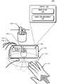
예시적인 환경(100)에서, 레이더 시스템(104)은 도 3 내지 도 6을 참조하여 후술되는 바와 같이 하나 이상의 레이더 신호 또는 파형을 전송함으로써 레이더 필드(110)를 제공한다. 레이더 필드(110)는 레이더 시스템(104)이 레이더 신호 및 파형의 반사(예를 들어, 공간 체적에서 객체들로부터 반사된 레이더 신호 및 파형)를 검출할 수 있는 공간 체적이다. 레이더 시스템(104)은 또한 스마트 폰(102)이 레이더 필드(110) 내의 객체(112)로부터의 반사를 감지하고 분석할 수 있게 한다. 객체(112)는 레이더 시스템(104)이 목재, 플라스틱, 금속, 직물 또는 인체 부분(예를 들어, 스마트 폰(102) 사용자의 손)과 같은 것으로부터의 반사를 감지하고 분석할 수 있는 다양한 객체 중 임의의 것일 수 있다. 반사의 분석에 기초하여, 레이더 시스템(104)은 도 3 내지 도 6을 참조하여 후술되는 바와 같이, 레이더 필드(110)와 관련된 다양한 유형의 정보 및 객체(112)로부터의 반사를 포함하는 레이더 데이터를 제공할 수 있다(예를 들어, 레이더 시스템(104)은 레이더 데이터를 레이더-기반 애플리케이션(106)과 같은 다른 엔티티들로 전달할 수 있다). 또한, 레이더 데이터에 기초하여, 레이더 시스템(104), 레이더-기반 애플리케이션(106) 또는 다른 엔티티는 레이더 필드(110) 내의 객체(112)가 (회색 화살표(114)로 도시된 바와 같이) 디스플레이(108)를 향해 이동하고 있다고 결정할 수 있다.In the
레이더 데이터는 레이더 필드(110)내의 객체(112)로부터의 감지 및 분석된 반사에 기초하여 시간에 따라 연속적으로 또는 주기적으로 제공될 수 있음에 유의해야 한다. 객체(112)의 위치는 시간에 따라 변할 수 있고(예를 들어, 객체(112)는 레이더 필드(110) 내에서 이동할 수 있음), 따라서 레이더 데이터는 변경된 위치, 반사 및 분석에 대응하여 시간에 따라 변할 수 있다. 레이더 데이터는 시간이 지남에 따라 변할 수 있기 때문에, 레이더 시스템(104)은 상이한 시간 주기에 대응하는 레이더 데이터의 하나 이상의 서브 세트를 포함하는 레이더 데이터를 제공할 수 있다. 예를 들어, 레이더 시스템(104)은 제1 시간주기에 대응하는 레이더 데이터의 제1 서브 세트, 제2 시간주기에 대응하는 레이더 데이터의 제2 서브 세트 등을 제공할 수 있다.It should be noted that the radar data may be provided continuously or periodically over time based on detected and analyzed reflections from
레이더-기반 애플리케이션(106)은 또한 디스플레이(108)를 통해 증강 현실(AR) 엘리먼트(116)를 제공할 수 있다. AR 엘리먼트(116)는 터치 입력 컨트롤(118)를 포함하고 디스플레이(108)를 통해 가시적일 수 있는 실제 객체(120-1)와 관련된다. 터치될 때, 터치 입력 컨트롤(118)은 실제 객체(120-1)에 관한 추가 세부 사항(예를 들어, 치수, 무게 또는 기술 사양), 실제 객체(120-1)를 구매하기 위한 링크, 또는 실제 객체(120-1)와 관련된 아이템들의 목록을 제공할 수 있다. 도 1에 도시된 바와 같이, AR 엘리먼트(116)는 터치 입력 컨트롤(118)를 포함하는 가상 가격 태그이다. 이러한 방식으로, 사용자는 AR 엘리먼트(116)를 터치할 수 있고, 터치 입력 컨트롤(118)는 추가적인 AR 컨텐츠를 제시한다.The radar-based
일부 구현에서, 레이더-기반 애플리케이션(106)은 실제 객체(120-1)의 이미지 및 실제 객체(120-1)와 관련된 AR 엘리먼트(116) 모두를 디스플레이(108) 상에 제시할 수 있는 AR 애플리케이션일 수 있다. 예를 들어, 도 1에 도시된 바와 같이, 실제 객체(120-1)는 실제 환경에서 그리고 디스플레이(108) 상에 이미지(120-2)(이미지(120-2)는 점선 화살표로 표시됨)로서 도시된 장식용 식물이다. 일부 구현에서, 레이더-기반 애플리케이션(106)은 실시간(또는 거의 실시간)으로 실제 객체(120-1)의 이미지(1202)를 제시한다. 실시간 또는 거의 실시간 제시는, 예를 들어, 스마트 폰(102)에 포함되거나 이와 분리되어 통신과 같은 하나 이상의 이미지 캡처 디바이스를 통해 달성될 수 있다.In some implementations, the radar-based
레이더 필드(110)내의 객체(112)가 디스플레이(108)를 향해 움직이고 있다는 결정에 응답하여, 레이더-기반 애플리케이션(106)은 스마트 폰(102)의 터치 스크린상의 고정(된) 위치에 터치 입력 컨트롤(118)를 제공할 수 있다. 일부 구현에서, 레이더-기반 애플리케이션(106)은 실제 객체(120-1)의 이미지(120-2) 자체가 더 이상 디스플레이(108)에서 보이지 않을 때에도 터치 입력 컨트롤(118)의 고정 위치를 유지할 수 있다. 또한, 레이더-기반 애플리케이션(106)은 레이더 필드(110) 내의 객체(112)가 디스플레이(108)를 향해 이동하고 있다는 결정의 임계 시간 내에 상기 고정 위치에 있는 터치 입력 컨트롤(118)이 터치되지 않는 것에 응답하여, 고정 위치에 터치 입력 컨트롤을 제공하는 것을 중단할 수 있다. 예를 들어, 터치 입력 컨트롤(118)이 임계 시간 내에 터치되지 않는 것에 기초하여, 레이더-기반 애플리케이션(106)이 디폴트 모드로 복귀할 수 있고, 레이더-기반 애플리케이션(106)이 터치 입력 컨트롤(118)의 제시를 중단할 수 있고(예를 들어, 터치 입력 컨트롤이 사라짐), 또는 레이더-기반 애플리케이션(106)이 고정 위치가 아니라 디스플레이(108)에 제시되는 컨텐츠에 적합한 임의의 위치에 터치 입력 컨트롤(118)을 계속 제시할 수 있다. 임계 시간은 1.5초, 2초 또는 3초와 같은 임의의 적절한 시간일 수 있다. 또 다른 구현에서, 레이더-기반 애플리케이션(106)은 레이더 필드(110) 내의 객체(112)가 임계 속도(예를 들어, 0.25 피트/초(fps), 0.5fps 또는 0.75fps)를 초과하는 속도로 디스플레이(108)를 향해 이동하는 것으로 결정되면 고정 위치에 터치 입력 컨트롤을 제공할 수 있다. 따라서, 스마트 폰(102)은 레이더 시스템(104) 및 레이더-기반 애플리케이션(106)과 함께 AR 애플리케이션의 사용자가 AR 환경에서 터치 입력을 효율적이고 편리하게 사용할 수 있도록 함께 작동한다.In response to determining that the
예를 들어, 스마트 폰(102)은 AR 특징 및 기능을 포함하는 애플리케이션을 포함한다고 가정한다. AR 기능 중 적어도 일부에 액세스하려면, 사용자는 다양한 터치 입력 컨트롤을 활성화하기 위해 디스플레이(108)에 도달하여 터치하면서 스마트 폰(102)의 디스플레이(108)에 프레임된(표시된) 실제 객체를 유지해야 한다. 이는 디스플레이(108)를 향해 도달하는 것이 디스플레이(108)에 대한 사용자의 시야를 방해하여 상기 컨트롤과의 상호 작용을 어렵게 만들 수 있기 때문에, 사용자에게 몇 가지 과제를 제시할 수 있다. 일부 사용자는 일부 디바이스, 특히 크거나 무거운 디바이스를 안정적으로 유지하는데 어려움이 있을 수 있다. 또한, 사용자가 스마트 폰(102)을 이동하여 실제 객체가 더 이상 프레임되지 않도록 하면, AR 컨트롤들이 더 이상 디스플레이되지 않을 수 있다. 반면에, 레이더 필드(110)를 제공하고, 레이더 시스템(104)(또는 레이더-기반 애플리케이션(106)과 같은 다른 엔티티)이 사용자가 디스플레이를 향에 도달하는 시점을 자동으로 결정한 다음 디스플에이 상의 컨트롤들을 자동으로 동결시키거나 고정시킬 수 있는 레이더 시스템(104)를 고려한다. 쉽게 알 수 있는 바와같이, 레이더 시스템(104)은 AR 인터페이스를 사용하기가 훨씬 쉽고 편리하게 만들 수 있으며, 종래의 AR 인터페이스를 사용하는 디바이스에 비해 향상된 경험을 제공할 수 있다.For example, assume that the
보다 상세하게, (레이더 시스템(104), 레이더-기반 애플리케이션(106) 및 디스플레이(108)를 포함하는) 스마트 폰(102)의 예시적인 구현(200)을 도시하는 도 2를 고려한다. 도 2의 스마트 폰(102)은 모바일 폰(102-1), 태블릿(102-2), 랩탑(102-3), 데스크탑 컴퓨터(102-4), 컴퓨팅 워치(102-5), 컴퓨팅 안경(102-6), 게임 시스템(102-7), 마이크로웨이브(102-8) 및 차량(102-9)을 포함하여, 레이더 시스템을 포함하는 스마트 폰, 시스템 및 방법을 구현할 수 있는 다른 비-제한하는 예시적인 디바이스를 포함하는 것으로 도시되어 있다. 다른 전자 디바이스는 또한 텔레비전, 엔터테인먼트 시스템, 오디오 시스템, 드론, 트랙 패드, 드로잉 패드, 넷북, 전자책 리더, 홈 자동화 및 제어 시스템, 홈 보안 시스템 및 기타 가전 제품을 포함할 수 있다. 설명된 기술들을 구현할 수 있는 전자 디바이스들은 착용 가능하거나, 착용 가능하지 않지만 이동 가능(mobile)하거나 또는 상대적으로 이동 가능하지 않을 수 있다는(예를 들어, 데스크탑 및 기기) 점에 유의한다.In more detail, consider FIG. 2, which shows an
스마트 폰(102)의 예시적인 전체 측면 치수는 예를 들어 대략 8 센티미터 × 대략 15 센티미터일 수 있다. 레이더 시스템(104)의 예시적인 풋 프린트는 안테나가 포함된 대략 4 밀리미터 × 6 밀리미터와 같이 더욱 제한될 수 있다. 레이더 시스템(104)의 예시적인 전력 소비는 수 밀리 와트(mW) 내지 수 mW(예를 들어, 대략 2 mW 내지 20 mW) 정도일 수 있다. 전력 및 처리 제한과 결합된 공간-제한된 패키지(예를 들어, 카메라, 지문 센서, 디스플레이(108) 등)에서 스마트 폰(102)의 많은 다른 바람직한 특징을 수용하기 위해 필요한 레이더 시스템(104)에 대한 이러한 제한된 풋 프린트의 요구 사항은 레이더 제스처 검출의 정확성과 효율성을 떨어뜨릴 수 있으며, 이들 중 적어도 일부는 본 명세서의 교시의 관점에서 극복될 수 있다.An exemplary overall side dimension of
스마트 폰(102)은 또한 하나 이상의 컴퓨터 프로세서(202), 및 메모리 매체 및 저장 매체를 포함하는 하나 이상의 컴퓨터 판독 가능 매체(204)를 포함한다. 컴퓨터 판독 가능 매체(204) 상에 컴퓨터 판독 가능 명령으로서 구현된 애플리케이션 및/또는 운영 체제(미도시)는 본 명세서에 기술된 기능들 중 일부를 제공하기 위해 컴퓨터 프로세서(202)에 의해 실행될 수 있다. 스마트 폰(102)은 또한 네트워크 인터페이스를 포함할 수 있다. 스마트 폰(102)은 유선, 무선 또는 광 네트워크를 통해 데이터를 통신하기 위해 네트워크 인터페이스(206)를 사용할 수 있다. 예로서 제한없이, 네트워크 인터페이스(206)는 근거리 통신망(LAN), 무선 근거리 통신망(WLAN),개인 영역 네트워크(PAN), 광역 통신망(WAN), 인트라넷, 인터넷, 피어 투 피어 네트워크, 포인트 투 포인트 네트워크 또는 메시 네트워크를 통해 데이터를 통신할 수 있다.The
레이더 시스템(104)의 다양한 구현은 SoC(System-on-Chip), 하나 이상의 집적 회로(IC), 프로세서 명령이 내장되거나 메모리에 저장된 프로세서 명령에 액세스하도록 구성된 프로세서, 펌웨어가 내장된 하드웨어, 다양한 하드웨어 구성 요소가 있는 인쇄 회로 기판 또는 이들의 임의의 조합을 포함할 수 있다. 레이더 시스템(104)은 자신의 레이더 신호를 송수신함으로써 단일 정적 레이더로서 동작한다. 일부 구현에서, 레이더 시스템(104)은 또한 외부 환경 내에 있는 다른 레이더 시스템(104)과 협력하여 바이스태틱(bistatic) 레이더, 멀티스태틱 레이더 또는 네트워크 레이더를 구현할 수 있다. 언급한 바와 같이, 스마트 폰(102)의 제약 또는 제한은 레이더 시스템(104)의 설계에 영향을 줄 수 있다. 예를 들어, 스마트 폰(102)은 레이더를 작동하는데 이용 가능한 제한된 전력, 제한된 계산 능력, 크기 제약, 레이아웃 제한, 레이더 신호를 감쇠 또는 왜곡시키는 외부 하우징 등을 가질 수 있다. 레이더 시스템(104)은 도 3과 관련하여 아래에 더 설명되는 바와 같이, 이러한 제약 조건의 존재하에서 고급 레이더 기능 및 고성능이 실현될 수 있게 하는 여러 특징을 포함한다. 도 2에서, 레이더 시스템(104)은 스마트 폰(102)의 일부로서 도시되어 있다. 다른 구현에서, 레이더 시스템(104)은 스마트 폰(102)으로부터 분리되거나 원격일 수 있다.Various implementations of the
이들 및 다른 기능 및 구성뿐만 아니라 도 1의 엔티티들이 작용하고 상호 작용하는 방식이 아래에 더 상세히 설명된다. 이들 엔티티는 추가로 분할되거나 결합될 수 있다. 도 1의 환경(100) 및 도 2 내지 도 12의 상세한 예시는 설명된 기술을 이용할 수 있는 많은 가능한 환경 및 디바이스들 중 일부를 도시한다. 도 3 내지 도 6은 레이더 시스템(104)의 추가 세부 사항 및 특징을 기술한다. 도 3 내지 도 6에서, 레이더 시스템(104)은 스마트 폰(102)의 맥락에서 기술되지만, 위에서 언급된 바와 같이, 기술된 시스템 및 기술의 특징 및 장점의 적용 가능성이 반드시 그렇게 제한되는 것은 아니며, 다른 유형의 전자 디바이스를 포함하는 다른 실시예도 본 교시의 범위 내에 있을 수 있다.These and other functions and configurations as well as the manner in which the entities of FIG. 1 interact and interact are described in more detail below. These entities can be further divided or combined. The
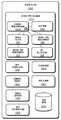
도 3은 레이더 시스템을 포함하는 스마트 폰, 시스템 및 방법을 가능하게 하는데 사용될 수 있는 레이더 시스템(104)의 예시적인 구현(300)을 도시한다. 예(300)에서, 레이더 시스템(104)은 다음의 각각의 구성 요소 즉, 통신 인터페이스(302), 안테나 어레이(304), 송수신기(306), 프로세서(308) 및 시스템 매체(310)(예를 들어, 하나 이상의 컴퓨터 판독 가능 저장 매체) 중 적어도 하나를 포함한다. 프로세서(308)는 디지털 신호 프로세서, 컨트롤러, 애플리케이션 프로세서, 다른 프로세서(예를 들어, 스마트 폰(102)의 컴퓨터 프로세서(202)) 또는 이들의 일부 조합으로 구현될 수 있다. 스마트 폰(102)의 컴퓨터 판독 가능 매체(204) 내에 포함되거나 이로부터 분리될 수 있는 시스템 매체(310)는 다음의 모듈, 즉 감쇠 완화기(314), 디지털 빔포머(316), 각 추정기(318) 또는 전력 관리자(320) 중 하나 이상을 포함한다. 이들 모듈은 스마트 폰(102) 내에 레이더 시스템(104)을 통합하는 것을 보상하거나 스마트 폰(102) 내에 레이더 시스템(104)을 통합하는 효과를 완화시킬 수 있고, 이로써 레이더 시스템(104)이 작거나 복잡한 제스처를 인식하고, 사용자의 상이한 방향을 구별하고, 외부 환경을 지속적으로 모니터링하거나, 또는 타겟 오경보 율을 실현할 수 있게 한다. 이들 특징에 의해, 레이더 시스템(104)은 도 2에 도시된 디바이스와 같은 다양한 다른 디바이스 내에서 구현될 수 있다.3 shows an exemplary implementation 300 of a
통신 인터페이스(302)를 사용하여, 레이더 시스템(104)은 레이더 데이터를 레이더-기반 애플리케이션(106)에 제공할 수 있다. 통신 인터페이스(302)는 스마트 폰(102)과 별도로 구현되거나 스마트 폰(102) 내에 통합되는 레이더 시스템(104)에 기초하여 무선 또는 유선 인터페이스 일 수 있다. 애플리케이션에 따라, 레이더 데이터는 원시 또는 최소 처리된 데이터, 동 위상 및 직교(I/Q) 데이터, 범위-도플러 데이터, 타겟 위치 정보(예를 들어, 범위, 방위각, 고도), 클러터 맵 데이터 등을 포함하는 처리된 데이터를 포함할 수 있다. 일반적으로, 레이더 데이터는 레이더 시스템을 포함하는 스마트 폰, 시스템 및 방법을 구현하기 위한 레이더-기반 애플리케이션(106)에 의해 사용 가능한 정보를 포함한다.Using the
안테나 어레이(304)는 적어도 하나의 송신 안테나 엘리먼트(미도시) 및 적어도 2개의 수신 안테나 엘리먼트(도 4에 도시됨)를 포함한다. 일부 경우에, 안테나 어레이(304)는 한 번에 다수의 별개의 파형(예를 들어, 송신 안테나 엘리먼트마다 다른 파형)을 송신할 수 있는 다중 입력 다중 출력(MIMO) 레이더를 구현하기 위해 다수의 송신 안테나 엘리먼트를 포함할 수 있다. 다중 파형의 사용은 레이더 시스템(104)의 측정 정확도를 증가시킬 수 있다. 수신 안테나 엘리먼트는 3개 이상의 수신 안테나 엘리먼트를 포함하는 구현을 위해 1차원 형상(예를 들어, 라인) 또는 2차원 형상으로 위치될 수 있다. 1차원 형상은 레이더 시스템(104)이 하나의 각도 치수(예를 들어, 방위각 또는 고도)를 측정할 수 있게 하는 한편, 2차원 형상은 2개의 각도 치수(예를 들어, 방위각 및 고도 모두)가 측정될 수 있게 한다. 수신 안테나 엘리먼트의 예시적인 2 차원 배열이 도 4와 관련하여 더 설명된다.The
도 4는 수신 안테나 엘리먼트(402)의 예시적인 디바이스(400)를 도시한다. 안테나 어레이(304)가 예를 들어 적어도 4개의 수신 안테나 엘리먼트(402)를 포함하는 경우, 수신 안테나 엘리먼트(402)는 도 4의 중앙에 도시된 바와 같이 직사각형 배열(404-1)로 배열될 수 있다. 대안적으로, 안테나 어레이(304)가 적어도 3개의 수신 안테나 엘리먼트(402)를 포함하는 경우, 삼각형 배열(404-2) 또는 L자 배열(404-3)이 사용될 수 있다.4 shows an
스마트 폰(102)의 크기 또는 레이아웃 제약으로 인해, 수신 안테나 엘리먼트들(402) 사이의 엘리먼트 간격 또는 수신 안테나 엘리먼트(402)의 수량은 레이더 시스템(104)이 모니터링할 각도에 이상적이지 않을 수 있다. 특히, 엘리먼트 간격은 각도 모호성을 제공하여 종래의 레이더가 타겟의 각도 위치를 추정하는 것을 어렵게 할 수 있다. 따라서, 종래의 레이더는 각도 모호성을 갖는 모호한 구역을 피하기 위해 시야(예를 들어, 모니터링될 각도)를 제한하여 오탐지를 감소시킬 수 있다. 예를 들어, 종래의 레이더는 5mm의 파장 및 3.5mm의 엘리먼트 간격(예를 들어, 엘리먼트 간격은 파장의 70%)을 사용하여 발생하는 각도 모호성을 피하기 위해 약 -45도 내지 45도 사이의 각도로 시야를 제한할 수 있다. 결과적으로, 종래의 레이더는 시야의 45도 제한을 초과하는 표적을 검출하지 못할 수 있다. 반면에, 레이더 시스템(104)은 각도 모호성을 해결하고 레이더 시스템(104)이 대략 -90도 내지 90도 사이의 각도 또는 최대 -180도에서 180도까지의 각도와 같은 45도 제한을 초과하는 각도를 모니터링할 수 있게 하는 디지털 빔포머(316) 및 각 추정기(318)를 포함한다. 이러한 각도 범위는 하나 이상의 방향(예를 들어, 방위각 및/또는 고도)에 걸쳐 적용될 수 있다. 따라서, 레이더 시스템(104)은 레이더 신호의 중심 파장의 절반보다 작거나 크거나 같은 엘리먼트 간격을 포함하여 다양한 상이한 안테나 어레이 설계에 대해 낮은 오경보 율을 실현할 수 있다.Due to the size or layout constraints of the
안테나 어레이(304)를 사용하여, 레이더 시스템(104)은 조향되거나 미조향된, 넓거나 좁은, 또는 형상화된(예를 들어, 반구, 큐브, 팬, 원뿔 또는 원통 모양) 빔을 형성할 수 있다. 예로서, 하나 이상의 송신 안테나 엘리먼트(미도시)는 미조향된 전 방향성 방사 패턴을 갖거나 넓은 송신 빔(406)과 같은 넓은 빔을 생성할 수 있다. 이들 기술 중 어느 하나는 레이더 시스템(104)이 공간의 많은 체적을 조명할 수 있게 한다. 그러나, 타겟 각도 정확도와 각도 해상도를 달성하기 위해, 수신 안테나 엘리먼트(402) 및 디지털 빔포머(316)는 좁은 수신 빔(408)과 같은 수천 개의 좁고 조향된 빔(예를 들어, 2000 빔, 4000 빔 또는 6000 빔)을 생성하는데 사용될 수 있다. 이러한 방식으로, 레이더 시스템(104)은 외부 환경을 효율적으로 모니터링하고 외부 환경 내에서 반사의 도달각을 정확하게 결정할 수 있다.Using the
도 3으로 돌아가면, 송수신기(306)는 안테나 어레이(304)를 통해 레이더 신호를 송신 및 수신하기 위한 회로 및 로직을 포함한다. 송수신기(306)의 구성 요소는 레이더 신호를 조절(conditioning)하기 위한 증폭기, 믹서, 스위치, 아날로그-디지털 변환기, 필터 등을 포함할 수 있다. 송수신기(306)는 또한 변조 또는 복조와 같은 동위상/직교위상(I/Q) 동작을 수행하기 위한 로직을 포함할 수 있다. 송수신기(306)는 연속파 레이더 동작 또는 펄스 레이더 동작을 위해 구성될 수 있다. 선형 주파수 변조, 삼각 주파수 변조, 계단형 주파수 변조 또는 위상 변조를 포함하여 다양한 변조가 레이더 신호를 생성하는데 사용될 수 있다.Returning to FIG. 3, the
송수신기(306)는 1 기가 헤르츠(GHz) 내지 400 GHz, 4 GHz 내지 100 GHz, 또는 57 GHz 내지 63 GHz와 같은 주파수 범위(예를 들어, 주파수 스펙트럼) 내에서 레이더 신호를 생성할 수 있다. 주파수 스펙트럼은 유사한 대역폭 또는 상이한 대역폭을 갖는 다중 서브-스펙트럼으로 나누어질 수 있다. 대역폭은 500MHz, 1GHz, 2GHz 등의 정도일 수 있다. 예로서, 상이한 주파수 서브-스펙트럼은 대략 57 GHz 내지 59 GHz, 59 GHz 내지 61 GHz, 또는 61 GHz 내지 63 GHz의 주파수를 포함할 수 있다. 동일한 대역폭을 갖고 연속적이거나 비연속적일 수 있는 다중 주파수 서브-스펙트럼이 또한 일관성(coherence)을 위해 선택될 수 있다. 다중 주파수 서브-스펙트럼은 단일 레이더 신호 또는 다중 레이더 신호를 사용하여 동시에 전송되거나 시간적으로 분리될 수 있다. 인접한 주파수 서브-스펙트럼은 레이더 신호가 더 넓은 대역폭을 갖도록 하는 반면, 비-인접 주파수 서브-스펙트럼은 각 추정기(318)가 각도 모호성을 해결할 수 있게 하는 진폭 및 위상 차이를 더 강조할 수 있다. 감쇠 완화기(314) 또는 각 추정기(318)는 도 5 및 6과 관련하여 더 설명된 바와 같이, 송수신기(306)가 하나 이상의 주파수 서브-스펙트럼을 이용하여 레이더 시스템(104)의 성능을 향상시키도록 할 수 있다.The
전력 관리자(320)는 레이더 시스템(104)이 스마트 폰(102) 내부적으로 또는 외부적으로 전력을 절약할 수 있게 한다. 내부적으로, 예를 들어, 전력 관리자(320)는 레이더 시스템(104)이 기 정의된 전력 모드 또는 특정 듀티 사이클을 이용하여 데이터를 수집하게 할 수 있다. 저전력 모드 또는 고전력 모드에서 동작하는 대신에, 전력 관리자(320)는 응답 지연 및 전력 소비가 환경 내의 활동에 기초하여 함께 관리되도록 상이한 전력 모드 사이에서 동적으로 전환한다. 일반적으로, 전력 관리자(320)는 전력이 절약될 수 있는 시점 및 방법을 결정하고, 레이더 시스템(104)이 스마트 폰(102)의 전력 제한 내에서 동작할 수 있도록 전력 소비를 점진적으로 조정한다. 일부 경우, 전력 관리자(320)는 잔여 가용 전력량을 모니터링하고 이에 따라 레이더 시스템(104)의 동작을 조정할 수 있다. 예를 들어, 잔여 전력량이 적은 경우, 전력 관리기(320)는 고전력 모드로 전환하는 대신 저전력 모드에서 계속 동작할 수 있다.The
저전력 모드는 예를 들어, 수 헤르츠(예를 들어, 대략 1Hz 또는 5Hz 미만) 정도의 저 듀티 사이클을 사용할 수 있는데, 이는 전력 소비를 수 밀리 와트(mW)(예를 들어, 대략 2mW 및 5mW)로 감소시킨다. 반면에, 고전력 모드는 수십 헤르츠(Hz)(예를 들어, 대략 20Hz 또는 10Hz 이상) 정도의 높은 듀티 사이클을 사용할 수 있는데, 이는 레이더 시스템(104)이 수 밀리 와트(예를 들어, 대략 8mW 내지 20mW) 정도의 전력을 소비하게 한다. 저전력 모드는 외부 환경을 모니터링하거나 접근하는 사용자를 검출하는데 사용될 수 있지만, 전력 관리자(320)는 레이더 시스템(104)이 사용자가 제스처를 수행하기 시작한다고 결정하는 경우 고전력 모드로 전환할 수 있다. 상이한 트리거는 전력 관리자(320)가 상이한 전력 모드 사이를 전환하게 할 수 있다. 예시적인 트리거는 모션 또는 모션의 결여, 사용자의 출현 또는 소멸, 사용자가 지정된 영역(예를 들어, 범위, 방위각 또는 고도로 정의된 영역)으로 들어오거나 나가는 것, 사용자와 관련된 모션의 속도 변화, 또는 반사된 신호 강도의 변화(예를 들어, 레이더 단면의 변화로 인한)를 포함한다. 일반적으로, 사용자가 스마트 폰(102)과 상호 작용할 가능성이 낮거나 응답 지연이 더 긴 데이터를 선호하는 것을 나타내는 트리거들은 전력을 절약하기 위해 저전력 모드가 활성화되게 할 수 있다.Low power modes can use low duty cycles, e.g., on the order of a few hertz (e.g., less than about 1 Hz or 5 Hz), which can reduce power consumption by several milliwatts (mW) (e.g., approximately 2 mW and 5 mW). Decrease to On the other hand, the high power mode can use a duty cycle as high as tens of hertz (Hz) (e.g., approximately 20 Hz or more than 10 Hz), which means that the
전력 관리자(320)는 또한, 비활성 시간 기간 동안 송수신기(306) 내의 하나 이상의 구성 요소(예를 들어, 전압 제어 발진기, 멀티플렉서, 아날로그-디지털 변환기, 위상 잠금 루프 또는 수정 발진기)를 턴오프함으로써 전력을 절약할 수 있다. 이러한 비활성 시간 기간은 레이더 시스템(104)이 레이더 신호를 능동적으로 송신 또는 수신하지 않는 경우에 발생하며, 이는 마이크로 초(μs), 밀리 초(ms) 또는 초(s) 정도일 수 있다. 또한, 전력 관리자(320)는 전력을 절약하기 위해 레이더 시스템(104) 내의 상이한 하드웨어 구성 요소들의 사용을 제어할 수 있다. 만약 프로세서(308)가 저전력 프로세서 및 고전력 프로세서(예를 들어, 상이한 양의 메모리 및 계산 능력을 갖는 프로세서)를 포함하는 경우, 예를 들어, 전력 관리자(320)는 저-수준 분석(예를 들어, 모션 검출, 사용자의 위치 결정 또는 환경 모니터링)을 위한 저전력 프로세와 고-충실도 또는 정확한 레이더 데이터가 레이더-기반 애플리케이션(106)에 의해 요청되는 상황(예를 들어, 제스처 인식 또는 사용자 배향)을 위한 고전력 프로세서의 사용을 전환할 수 있다.
전술한 내부 절전 기술에 추가하여, 전력 관리자(320)는 또한 스마트 폰(102) 내에 있는 다른 외부 구성 요소 또는 센서들을 활성화 또는 비활성화함으로써 스마트 폰(102) 내의 전력을 절약할 수 있다. 이들 외부 구성 요소들은 스피커, 카메라 센서, 글로벌 위치 측정 시스템, 무선 통신 송수신기, 디스플레이, 자이로 스코프 또는 가속도계를 포함할 수 있다. 레이더 시스템(104)은 적은 양의 전력을 사용하여 환경을 모니터링할 수 있기 때문에, 전력 관리자(320)는 사용자의 위치 또는 사용자의 활동에 기초하여 이들 외부 구성 요소를 적절하게 온 또는 오프할 수 있다. 이러한 방식으로, 스마트 폰(102)은 자동 차단 타이머의 사용 없이 또는 사용자가 스마트 폰(102)을 물리적으로 터치하거나 구두로 제어하지 않고 사용자에게 원활하게 응답하고 전력을 절약할 수 있다.In addition to the above-described internal power saving techniques,
도 5는 스마트 폰(102) 내의 레이더 시스템(104)의 예시적인 구현(500)의 추가 세부 사항을 도시한다. 예(500)에서, 안테나 어레이(304)는 유리 커버 또는 외부 케이스와 같은 스마트 폰(102)의 외부 하우징 아래에 위치된다. 그의 재료 특성에 따라, 외부 하우징은 레이더 시스템(104)에 의해 전송 및 수신되는 레이더 신호를 감쇠 또는 왜곡시키는 감쇠기(502)로서 작용할 수 있다. 감쇠기(502)는 상이한 유형의 유리 또는 플라스틱을 포함할 수 있으며, 이들 중 일부는 디스플레이 스크린, 외부 하우징 또는 스마트 폰(102)의 다른 구성 요소 내에서 발견될 수 있고 대략 4 내지 10 사이의 유전 상수(예를 들어, 비유전율)를 갖는다. 따라서, 감쇠기(502)는 레이더 신호(506)에 대해 불투명하거나 반투명하며, 송신 또는 수신된 레이더 신호(506)의 일부가 (반사된 부분(504)에 의해 도시된 바와 같이) 반사되게 할 수 있다. 종래의 레이더의 경우, 감쇠기(502)는 모니터링될 수 있는 유효 범위를 감소시키거나, 작은 표적이 검출되는 것을 방지하거나, 전체 정확도를 감소시킬 수 있다.5 shows additional details of an
레이더 시스템(104)의 전송 전력이 제한되고 외부 하우징을 재 설계하는 것이 바람직하지 않다고 가정하면, 레이더 신호(506)의 하나 이상의 감쇠-의존적 특성(예를 들어, 주파수 서브 스펙트럼(508) 또는 조향각(510)) 또는 감쇠기(502)의 감쇠-의존적 특성(예를 들어, 감쇠기(502)와 레이더 시스템(104) 사이의 거리(512) 104 또는 감쇠기(502)의 두께(514))은 감쇠기(502)의 효과를 완화시키도록 조정된다. 이들 특성 중 일부는 제조 중에 설정되거나 레이더 시스템(104)의 작동 중에 감쇠 완화기(314)에 의해 조정될 수 있다. 감쇠 완화기(314)는, 예를 들어, 송수신기(306)가 선택된 주파수 서브-스펙트럼(508) 또는 조향각(510)을 사용하여 레이더 신호(506)를 송신하게 하고, 플랫폼이 거리(512)를 변경하기 위해 레이더 시스템(104)을 감쇠기(502)로 더 가깝게 또는 그로부터 더 멀게 이동시키게 하거나, 사용자에게 감쇠기(502)의 두께(514)를 증가시키기 위해 다른 감쇠기를 적용하도록 프롬프트한다.Assuming that the transmit power of the
적절한 조정은 감쇠기(502)의 사전 결정된 특성(예를 들어, 스마트 폰(102)의 컴퓨터 판독 가능 매체(204) 또는 시스템 매체(310) 내에 저장된 특성)에 기초하거나 또는 감쇠기(502)의 하나 이상의 특성을 측정하기 위해 레이더 신호(506)의 리턴을 처리함으로써 감쇠 완화기(314)에 의해 이루어질 수 있다. 감쇠-의존적 특성 중 일부가 고정되거나 제한되더라도, 감쇠 완화기(314)는 이러한 제한 사항을 고려하여 각 파라미터의 균형을 맞추고 타겟 레이더 성능을 달성할 수 있다. 결과적으로, 감쇠 완화기(314)는 레이더 시스템(104)이 감쇠기(502)의 반대편에 위치한 사용자를 검출하고 추적하기 위해 향상된 정확도 및 더 큰 유효 범위를 실현할 수 있게 한다. 이들 기술은 레이더 시스템(104)의 전력 소비를 증가시키는 전송 전력 증가 또는 일단 디바이스가 생상되면 어렵고 비쌀 수 있는 감쇠기(502)의 재료 특성 변경에 대한 대안을 제공한다. .The appropriate adjustment may be based on a predetermined characteristic of the attenuator 502 (e.g., a characteristic stored in the computer
도 6은 레이더 시스템(104)으로 구현된 예시적인 방식(scheme)(600)을 도시한다. 이 방식(600)의 일부는 프로세서(308), 컴퓨터 프로세서(202) 또는 다른 하드웨어 회로에 의해 수행될 수 있다. 방식(600)은 상이한 유형의 전자 디바이스 및 레이더-기반 애플리케이션(106)을 지원하도록 커스터마이징될 수 있고, 또한 레이더 시스템(104)이 설계 제약에도 불구하고 타겟 각도 정확도를 달성할 수 있게 한다.6 shows an
송수신기(306)는 수신된 레이더 신호에 대한 수신 안테나 엘리먼트(402)의 개별 응답에 기초하여 미가공 데이터(602)를 생성한다. 수신된 레이더 신호는 각도 모호성 해상도를 용이하게 하기 위해 각 추정기(318)에 의해 선택된 하나 이상의 주파수 서브-스펙트럼(604)과 연관될 수 있다. 주파수 서브-스펙트럼(604)은 예를 들어, 사이드 로브의 양을 감소시키거나 사이드 로브의 진폭을 감소(예를 들어, 진폭을 0.5dB, 1dB 이상 감소)시키도록 선택될 수 있다. 주파수 서브-스펙트럼의 양은 레이더 시스템(104)의 타겟 각도 정확도 또는 계산 한계에 기초하여 결정될 수 있다.
미가공 데이터(602)는 수신 안테나 엘리먼트(402)와 각각 관련된 시간 기간, 상이한 파수(wavenumbers) 및 다수의 채널에 대한 디지털 정보(예를 들어, 동 위상 및 직교 데이터)를 포함한다. 고속 푸리에 변환(FFT)(606)은 원시 데이터(602)에 대해 수행되어 전처리된 데이터(608)를 생성한다. 전처리된 데이터(608)는 상이한 범위(예를 들어, 레인지 빈)에 대해, 시간 기간에 걸쳐 그리고 다수의 채널에 대한 디지털 정보를 포함한다. 레인지(range)-도플러 데이터(612)를 생성하기 위해 전처리된 데이터(608)에 대해 도플러 필터링 프로세스(610)가 수행된다. 도플러 필터링 프로세스(610)는 다수의 레인지 빈, 다수의 도플러 주파수 및 다수의 채널에 대한 진폭 및 위상 정보를 생성하는 다른 FFT를 포함할 수 있다. 디지털 빔포머(316)는 레인지-도플러 데이터(612)에 기초하여 빔포밍 데이터(614)를 생성한다. 빔포밍 데이터(614)는 방위각 및/또는 고도 세트에 대한 디지털 정보를 포함하는데, 이는 상이한 조향각 또는 빔들이 디지털 빔포머(316)에 의해 형성되는 시야를 나타낸다. 도시되지는 않았지만, 디지털 빔포머(316)는 대안적으로 전처리된 데이터(608)에 기초하여 빔포밍 데이터(614)를 생성할 수 있고, 도플러 필터링 프로세스(610)는 빔포밍 데이터(614)에 기초하여 레인지-도플러 데이터(612)를 생성할 수 있다. 계산량을 감소시키기 위해, 디지털 빔포머(316)는 관심 범위, 시간 또는 도플러 주파수 간격에 기초하여 레인지-도플러 데이터(612) 또는 전처리된 데이터(608)의 일부를 처리할 수 있다.
디지털 빔포머(316)는 싱글-룩(single-look) 빔포머(616), 멀티-룩 간섭계(618) 또는 멀티-룩 빔포머(620)를 사용하여 구현될 수 있다. 일반적으로, 싱글-룩 빔포머(616)는 결정성 객체(예를 들어, 단일 위상 중심을 갖는 포인트-소스 타겟)에 사용될 수 있다. 비-결정성 타겟(예를 들어, 다중 위상 중심을 갖는 타겟)에 대해, 멀티-룩 간섭계(618) 또는 멀티-룩 빔포머(620)는 단일-룩 빔포머(616)에 비해 정확도를 향상시키기 위해 사용된다. 인간은 비-결정성 타겟의 예이고, 624-1 및 624-2에 도시된 바와 같이 상이한 종횡각에 기초하여 변화할 수 다수의 위상 중심(622)을 갖는다. 다수의 위상 중심(622)에 의해 생성된 구조적 또는 파괴적 간섭의 변화는 종래의 레이더가 각도 위치를 정확하게 결정하는 것을 어렵게 할 수 있다. 그러나, 멀티-룩 간섭계(618) 또는 멀티-룩 빔포머(620)는 빔포밍 데이터(614)의 정확도를 증가시키기 위해 일관된 평균화(coherent averaging)를 수행한다. 멀티-룩 간섭계(618)는 2개의 채널을 일관성 있게 평균화하여 각도 정보를 정확하게 결정하는데 사용될 수 있는 위상 정보를 생성한다. 한편, 멀티-룩 빔포머(620)는 푸리에, 캡온(Capon), 다중 신호 분류(MUSIC), 또는 최소 분산 왜곡 감소 응답 (MVDR)과 같은 선형 또는 비선형 빔포머를 사용하여 2개 이상의 채널을 일관성 있게 평균화할 수 있다. 멀티-룩 빔포머(620) 또는 멀티-룩 간섭계(618)를 통해 제공된 증가된 정확도는 레이더 시스템(104)이 작은 제스처를 인식하거나 사용자의 다수의 부분을 구별할 수 있게 한다.The
각 추정기(318)는 빔포밍 데이터(614)를 분석하여 하나 이상의 각도 위치를 추정한다. 각 추정기(318)는 신호 처리 기술, 패턴 매칭 기술 또는 기계 학습을 이용할 수 있다. 각 추정기(318)는 또한 레이더 시스템(104)의 설계 또는 레이더 시스템(104)이 모니터링하는 시야에서 발생할 수 있는 각 모호성을 해소한다. 예시적인 각 모호성은 진폭 플롯(626)(예를 들어, 진폭 응답) 내에 도시되어 있다.Each
진폭 플롯(626)은 타겟의 상이한 각 위치 및 상이한 조향각(510)에 대해 발생할 수 있는 진폭 차이를 나타낸다. 제1 진폭 응답(628-1)(실선으로 도시됨)은 제1 각 위치(630-1)에 위치된 타겟에 대해 도시되어 있다. 마찬가지로, 제2 진폭 응답(628-2)(점선으로 도시됨)은 제2 각 위치(630-2)에 위치된 타겟에 대해 도시되어 있다. 이 예에서, 차이는 -180도에서 180도 사이의 각도에서 고려된다.
진폭 플롯(626)에 도시된 바와 같이, 2개의 각 위치(630-1 및 630-2)에 대해 모호한 구역(zone)이 존재한다. 제1 진폭 응답(628-1)은 제1 각 위치(630-1)에서 최고 피크를 갖고 제2 각 위치(630-2)에서 더 작은 피크를 갖는다. 최고 피크는 타겟의 실제 위치에 해당하지만, 더 적은 피크는 제1 각 위치(630-1)가 모호해지게 하는데, 이는 종래의 레이더가 상기 표적이 제1 각 위치(630-1)에 있는지 또는 제2 각 위치(630-2)에 있는지를 자신있게 결정할 수 없는 일부 임계치 내에 있기 때문이다. 대조적으로, 제2 진폭 응답(628-2)은 제2 각 위치(630-2)에서 더 작은 피크를 갖고 제1 각 위치(630-1)에서 더 높은 피크를 갖는다. 이 경우, 더 작은 피크가 타겟의 위치에 해당한다.As shown in
종래의 레이더는 각 위치들을 결정하기 위해 최고 피크 진폭을 사용하는 것으로 제한될 수 있지만, 각 추정기(318)는 대신 진폭 응답들(628-1 및 628-2)의 형상(shapes)의 미묘한 차이를 분석한다. 형상의 특성은 예를 들어 롤-오프, 피크 또는 널 폭, 피크 또는 널의 각 위치, 피크 및 널의 높이 또는 깊이, 사이드로브의 모양, 진폭 응답(628-1 또는 628-2)내의 대칭, 또는 진폭 응답(628-1 또는 628-2)내의 대칭 부재를 포함할 수 있다. 위상 응답에서 유사한 형상 특성이 분석될 수 있는데, 이는 각 모호성을 해소하기 위한 추가 정보를 제공할 수 있다. 따라서 각 추정기(318)는 고유각 서명 또는 패턴을 각 위치에 매핑한다.Conventional radar may be limited to using the highest peak amplitude to determine the respective positions, but each
각 추정기(318)는 전자 디바이스의 유형(예를 들어, 계산 능력 또는 전력 제약) 또는 레이더-기반 애플리케이션(106)에 대한 타겟 각 해상도에 따라 선택될 수 있는 일련의 알고리즘 또는 툴을 포함할 수 있다. 일부 구현에서, 각 추정기(318)는 신경망(632), 컨볼루션 신경망(CNN)(634), 또는 장단기 메모리(LSTM) 네트워크(636)를 포함할 수 있다. 신경망(632)은 다양한 깊이 또는 양의 히든 계층(예를 들어, 3개의 히든 계층, 5개의 히든 계층 또는 10개의 히든 계층)을 가질 수 있고, 또한 상이한 양의 연결을 포함할 수 있다(예를 들어, 신경망(632)은 완전-연결된 신경망 또는 부분-연결된 신경망을 포함할 수 있음). 일부 경우, CNN(634)은 각 추정기(318)의 계산 속도를 증가시키기 위해 사용될 수 있다. LSTM 네트워크(636)는 각 추정기(318)가 타겟을 추적할 수 있게 하는데 사용될 수 있다. 기계 학습 기술을 사용하여, 각 추정기(318)는 비선형 함수를 사용하여 진폭 응답(628-1 또는 628-2)의 형상을 분석하고 각 확률 데이터(638)를 생성하는데, 이는 사용자 또는 사용자의 일부가 각도 빈 내에 있을 가능성을 나타낸다. 각 추정기(318)는 스마트 폰(102)의 좌측 또는 우측에 있는 타겟의 확률 또는 수천의 각 빈들에 대한 확률을 제공하기 위해(예를 들어, 연속적인 각 측정을 위한 각 확률 데이터(638)를 제공하기 위해) 2개의 각도 빈과 같은 몇몇 각도 빈들에 대한 각 확률 데이터(638)를 제공할 수 있다.Each
각 확률 데이터(638)에 기초하여, 추적기 모듈(640)은 타겟의 각 위치를 식별하는 각 위치 데이터(642)를 생성한다. 추적기 모듈(640)은 각 확률 데이터(638)에서 최고 확률을 갖는 각도 빈에 기초하거나 예측 정보(예를 들어, 이전에 측정된 각 위치 정보)에 기초하여 타겟의 각 위치를 결정할 수 있다. 추적기 모듈(640)은 또한 레이더 시스템(104)이 타겟을 확실하게 구별하거나 식별할 수 있도록 하나 이상의 이동 타겟을 추적할 수 있다. 범위, 도플러, 속도 또는 가속도를 포함하여 각 위치를 결정하는데 다른 데이터를 사용할 수도 있다. 일부 경우에, 추적기 모듈(640)은 알파-베타 추적기, 칼만 필터, 다중 가설 추적기(MHT) 등을 포함할 수 있다.Based on each
양자화기 모듈(644)은 각 위치 데이터(642)를 획득하고 그 데이터를 양자화하여 양자화된 각 위치 데이터(646)를 생성한다. 양자화는 레이더-기반 애플리케이션(106)에 대한 타겟 각 해상도에 기초하여 수행될 수 있다. 일부 상황에서, 양자화된 각 위치 데이터(646)가 타겟이 스마트 폰(102)의 우측에 있는지 또는 좌측에 있는지를 나타내거나 또는 타겟이 위치하는 90도 사분면을 식별하도록 더 적은 양자화 레벨이 사용될 수 있다. 이것은 사용자 근접 검출과 같은 일부 레이더-기반 애플리케이션(106)에 충분할 수 있다. 다른 상황에서, 양자화된 각 위치 데이터(646)가 1 도, 1 도, 5 도 등의 일부 정도의 정확도 내에서 타겟의 각 위치를 나타내도록 더 많은 수의 양자화 레벨이 사용될 수 있다. 이 해상도는 제스처 인식과 같은 고해상도 레이더-기반 애플리케이션(106)에 사용될 수 있다. 일부 구현에서, 디지털 빔포머(316), 각 추정기(318), 추적기 모듈(640) 및 양자화기 모듈(644)은 단일 기계 학습 모듈에서 함께 구현된다.The
이들 및 다른 능력 및 구성뿐만 아니라 도 1 내지 도 6의 엔티티들이 작용하고 상호 작용하는 방식이 아래에 기술된다. 기술된 엔티티들은 다른 센서 또는 구성 요소 등과 함께 추가로 분할, 결합, 사용될 수 있다. 이러한 방식으로, 레이더 시스템(104) 및 비-레이더 센서의 상이한 구성을 갖는 전자 디바이스(예를 들어, 스마트 폰(102))의 상이한 구현은 레이더 시스템을 포함하는 스마트 폰, 시스템 및 방법을 구현하는데 사용될 수 있다. 도 1의 예시적인 동작 환경(100) 및 도 2 내지 도 6의 상세한 예시는 설명된 기술을 이용할 수 있는 많은 가능한 환경 및 디바이스 중 일부를 도시한다.These and other capabilities and configurations as well as the manner in which the entities of FIGS. 1-6 interact and interact are described below. The described entities may be further divided, combined, and used with other sensors or components. In this way, different implementations of electronic devices (e.g., smart phones 102) with different configurations of
예시적인 시스템Exemplary system
전술한 바와 같이, 본 명세서에 기술된 기술 및 시스템은 또한 디바이스가 증강 현실(AR) 객체들을 조작하는데 사용될 수 있는 3차원(3D) 제스처를 결정할 수 있게 할 수 있다.As noted above, the techniques and systems described herein may also enable a device to determine three-dimensional (3D) gestures that can be used to manipulate augmented reality (AR) objects.
도 7은 레이더 시스템을 포함하는 스마트 폰, 시스템 및 방법을 가능하게 하는 기술이 구현될 수 있는 다른 예시적인 환경(700)을 도시한다. 예시적인 동작 환경(700)은 레이더 시스템(104), 디스플레이(108) 및 레이더-기반 애플리케이션(702)을 포함하거나 이와 관련되는 스마트 폰(102)을 포함한다. 예시적인 동작 환경(700)이 스마트 폰(102)의 맥락에서 예시되어 있지만, 도 1 및 도 2를 참조하여 전술한 바와 같이 다른 전자 디바이스가 또한 도 7 내지 도 9를 참조하여 설명된 특징 및 기술을 구현하는데 사용될 수 있다. 예시적인 환경(700)에서, 레이더 시스템(104)은 도 1 내지 도 6을 참조하여 전술한 바와 같이 레이더 필드(110)를 제공한다. 레이더 시스템(104)은 또한 스마트 폰(102)이 레이더 필드(110) 내의 객체(704)로부터의 반사를 감지하고 분석할 수 있게 한다. 도 7에 도시된 바와같이, 객체(704)는 인간의 손이지만, 객체(704)는 레이더 시스템(104)이 목재, 플라스틱, 금속, 직물 또는 유기 물질(예를 들어, 사용자의 신체의 일부)과 같은 것으로부터의 반사를 감지하고 분석할 수 있는 임의의 다양한 객체일 수 있다. 반사의 분석에 기초하여, 레이더 시스템(104)은 도 1 내지 도 6을 참조하여 전술한 바와 같은 레이더 데이터를 제공할 수 있다. 예를 들어, 레이더 시스템(104)은 레이더 데이터를 레이더-기반 애플리케이션(702)과 같은 다른 엔티티로 전달할 수 있다.7 shows another
레이더-기반 애플리케이션(702)은 디스플레이(108)를 통해 AR 엘리먼트(706)를 제시하고 그 AR 엘리먼트(706)를 선택하는 입력을 수신할 수 있는 다양한 AR 가능 애플리케이션(예를 들어, 레이더-기반 애플리케이션(106))들 중 임의의 것일 수 있다. AR 엘리먼트(706)를 선택하기 위해 수신된 입력은 음성 입력 또는 스마트 폰(102)의 터치 스크린을 통해 수신된 터치 입력일 수 있다. 더욱이, 레이더-기반 애플리케이션(702)은 레이더 데이터에 기초하여, 레이더 필드(110)내의 객체(704)에 의해 만들어진 제스처(예를 들어, 사용자의 손 또는 다른 신체 부분)를 결정하고 그 결정된 제스처에 대응하는 상기 선택된 AR 엘리먼트(706)와 관련된 동작을 수행할 수 있다. 제스처를 결정하는데 사용되는 레이더 데이터는 AR 엘리먼트(706)를 선택하는 입력이 레이더-기반 애플리케이션(702)에 의해 수신된 후에 수신된 반사의 분석에 기초한 레이더 데이터이다. 일부 구현에서, 결정된 제스처는 3D 제스처(예를 들어, 레이더 필드(110)에 의해 조명되는 3D 공간 내에서 임의의 방향으로 하나 이상의 움직임을 포함하는 제스처)일 수 있다.The radar-based application 702 presents the
3D 제스처는 수평 방향으로(예를 들어, 스마트 폰(102)의 좌측에서 스마트 폰(102)의 우측으로) 손을 스마트 폰(102) 위로 이동시킴으로써 행해지는 스크롤링 제스처, 팔꿈치를 중심으로 회전하는 사용자의 팔에 의해 행해지는 위빙(waving) 제스처, 수직 방향으로(예를 들어, 스마트 폰(102)의 하부측에서 스마트 폰(102)의 상부측으로) 사용자의 손을 스마트 폰(102) 위로 이동시킴으로써 행해지는 푸싱 제스처를 포함하여 다양한 제스처들 중 하나일 수 있다. 사용자의 손을 스마트 폰(102)을 향해 이동시킴으로써 행해지는 도달(reaching) 제스처, 가상의 문 손잡이를 돌리는 동작을 모방하도록 가상의 문 손잡이를 잡기 위해 사용자의 손의 손가락을 말아서 시계 방향 또는 시계 반대 방향으로 회전시킴으로써 행해지는 손잡이-회전 제스처, 및 엄지와 적어도 하나의 다른 손가락을 함께 문지르는 스핀들-비틀림 제스처와 같은 다른 유형의 3D 제스처 또는 모션이 또한 행해질 수 있다. 이들 예시적인 제스처 유형 각각은 레이더 시스템(104)에 의해 검출될 수 있다. 이들 제스처 각각을 검출하면, 스마트 폰(102)은 새로운 콘텐츠를 표시하거나, 커서를 이동 시키거나, 하나 이상의 센서를 활성화시키거나, 애플리케이션을 열거나, AR 엘리먼트를 조작하는 것과 같은 동작을 수행할 수 있다. 이러한 방식으로, 레이더 시스템(104)은 스마트 폰(102)의 터치-프리 컨트롤을 제공한다. 예시적인 3D 제스처 및 대응하는 동작은 도 8 및 9를 참조하여 아래에 설명된다.The 3D gesture is a scrolling gesture performed by moving a hand over the
레이더-기반 애플리케이션(702)은 또한 레이더 데이터에 기초하여 3D 제스처를 결정하는 것과 관련된 정보 및 3D 제스처에 대응하는 동작과 관련된 정보를 저장할 수 있는 3D 제스처 모듈(708)을 포함할 수 있다. 이러한 방식으로, 설명된 디바이스 및 기술은 AR 애플리케이션의 사용자가 AR 환경에서 터치 입력 및 3D 제스처 모두를 원활하고 편리하게 사용할 수 있게 한다.The radar-based application 702 may also include a
추가의 예로서, 도 1 및 2를 고려한다. 예시적인 구현(800 및 900)을 각각 도시하는 도 8 및 9를 고려한다. 예시적인 구현(800 및 900)은 레이더 시스템을 포함하는 스마트 폰, 시스템 및 방법을 가능하게 하기 위해 3D 제스처를 사용하는 레이더 시스템(104)의 기능에 관한 추가 세부 사항을 기술한다.As a further example, consider FIGS. 1 and 2. Consider FIGS. 8 and 9, which illustrate
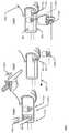
도 8의 상세 뷰(800-1)에서, 예시적인 환경(800)은 레이더 필드(110)(미도시)를 제공하는 레이더 시스템(104)을 포함하는 스마트 폰(102)을 도시한다. 상세 뷰(800-1)에서, 사용자가 예를 들어 터치 입력을 통해 AR 엘리먼트(802)를 선택함으로써 AR 엘리먼트(802)를 이미 선택했다고 가정한다. 사용자의 신체 부분(804)(이 경우 사용자의 손(804))이 레이더 필드(110)내에 있고, 레이더 시스템(104)은 사용자의 손(804)에 의해 행해진 3D 제스처를 결정할 수 있다.In the detailed view 800-1 of FIG. 8, the
상세 뷰(800-2)에서, 사용자는 사용자의 손(804)과 레이더 시스템(104) 사이의 거리를 변경함으로써 제스처(예를 들어, 도달 제스처)를 만들었다. 상세 뷰뷰(8002)에서, 이 거리는 화살표(806)로 도시된 바와 같이, 사용자의 손(804)과 레이더 시스템(104) 사이의 거리를 증가시키기 위해 사용자의 손(804)을 이동시킴으로써 변경된다. 이 제스처에 해당하는 동작은 선택된 AR 엘리먼트(802)의 증가된 크기로 상세 뷰(800-2)에 도시된, 선택된 AR 엘리먼트(802)가 사용자에게 더 가까워지는 움직임이다. 유사하게, 도 8에 도시되지 않았지만, 사용자는 사용자의 손(804)과 레이더 시스템(104) 사이의 거리를 감소시키기 위해 사용자의 손(804)을 이동시킴으로써 제스처를 만들 수 있다. 이러한 경우, 이 제스처에 해당하는 동작은 선택된 AR 엘리먼트(802)가 사용자로부터 멀어지는 움직임이다.In detailed view 800-2, the user made a gesture (eg, a reach gesture) by changing the distance between the user's
일부 구현에서, 사용자에게 더욱 가까워진 선택된 AR 엘리먼트(802)의 이동은 사용자의 손(804)과 레이더 시스템(104) 사이의 증가된 거리에 비례한다. 유사하게, 사용자로부터 멀어지는 선택된 AR 엘리먼트(802)의 이동은 사용자의 손(804)과 레이더 시스템(104) 사이의 감소된 거리에 비례한다. 다른 구현에서, 선택된 AR 엘리먼트(802)의 이동은 속도 또는 각도와 같은 레이더 데이터로부터 결정될 수 있는 제스처의 다른 양태에 비례하거나 또는 제스처의 다양한 양태의 조합에 비례할 수 있다.In some implementations, movement of the selected
도 9의 상세 뷰(900-1)에서, 예시적인 환경(900)은 레이더 필드(110)(미도시)를 제공하는 레이더 시스템(104)을 포함하는 스마트 폰(102)을 도시한다. 상세 뷰(900-1)에서, 사용자가 예를 들어 터치 입력을 통해 AR 엘리먼트(902)를 선택함으로써 AR 엘리먼트(902)를 이미 선택했다고 가정한다. 사용자의 신체 부분(904)(이 경우 사용자의 손(904))은 레이더 필드(110)내에 있고, 레이더 시스템(104)은 사용자의 손(904)에 의해 행해진 3D 제스처를 결정할 수 있다.In detailed view 900-1 of FIG. 9,
상세 뷰(900-2)에서, 사용자는 사용자의 손(904)과 디스플레이(108)의 평면과 같은 기준(예를 들어, 스크롤링 제스처) 사이의 실질적으로 유사한 거리를 유지하면서 레이더 시스템(104)에 대해 사용자의 손(904)의 위치를 변경함으로써 제스처를 수행하였다. 상세 뷰(9002)에서, 사용자의 손(904)의 변경된 위치는 화살표(906)로 도시된 바와 같이 우측에서 좌측으로의 움직임이다. 이 제스처에 해당하는 동작은 화살표(908)로 도시된 바와 같이 선택된 AR 엘리먼트(902)의 축을 중심으로 한 방향으로 상기 선택된 AR 엘리먼트(902)의 회전이며, 대략 90도 회전하는 AR 엘리먼트(902)의 마킹 표면("X"로 표시됨)의 예시이다. 유사하게, 도 9에는 도시되지 않았지만, 사용자는 사용자의 손(904)을 좌측에서 우측으로 이동시킴으로써 제스처를 수행할 수 있다. 그러한 경우에, 이 제스처에 대응하는 동작은 선택된 AR 엘리먼트(902)가 축을 중심으로 반대 방향으로 회전하는 것이다.In detailed view 900-2, the user is directed to
일부 구현에서, 축 주위의 상기 선택된 AR 엘리먼트(902)의 회전 속도 및 양은 각각 사용자 손(904)의 좌우 운동의 속도 또는 거리에 비례한다. 다른 구현에서, AR 엘리먼트(902)의 회전은 사용자 손(904)의 형상 또는 표면 영역과 같은 레이더 데이터로부터 결정될 수 있는 제스처의 다른 양태에 비례하거나 제스처의 다양한 양태의 조합에 비례할 수 있다.In some implementations, the rotational speed and amount of the selected
예시적인 구현(800 및 900)은 레이더 시스템을 포함하는 스마트 폰, 시스템 및 방법을 가능하게 하는 설명된 기술, 시스템 및 디바이스를 사용하여 가능한 많은 가능한 제스처들 중 단지 2개의 예시임에 유의해야 한다. 예를 들어, 사용자는 터치 입력을 사용하여 AR 환경에서 3D 객체를 선택한 다음 3D 핀치 제스처를 사용하여 3D 객체를 더 작게 만들거나 삭제할 수도 있다. 유사하게, 사용자는 AR 환경에서 플리킹 모션을 사용하여 선택된 3D 객체를 던질 수 있다.It should be noted that the
또한, 설명된 기술은 다른 유형의 애플리케이션(예를 들어, 비-AR) 또는 AR 애플리케이션의 비-AR 피처들과 함께 사용될 수 있다. 예를 들어, 사용자는 혼합 제어(예를 들어, 3D 제스처와 조합된 터치 또는 음성 입력)를 사용하여 도면 기반 또는 텍스트 기반 애플리케이션 및 피처와 상호 작용할 수 있다. 일 예에서, 사용자는 디바이스의 터치 스크린에 손가락을 터치한 다음 터치 스크린을 따라 손가락을 슬라이딩함으로써 애플리케이션에서 선을 그릴 수 있다. 그런 다음 사용자는 터치 스크린에서 손가락을 떼고 가상 다이얼 돌리기와 같은 3D 제스처를 사용하여 선의 두께나 다른 속성을 변경할 수 있다. 다른 예에서, 사용자는 터치 스크린상에서 텍스트를 선택, 복사 및 붙여넣기할 수 있다. 예를 들어, 사용자는 터치 스크린상에서 터치-앤-핀치 제스처를 수행하여 디스플레이된 텍스트의 일부를 선택할 수 있다. 그런 다음 사용자는 3D 핀치 제스처를 수행하여 텍스트를 복사하고 터치 입력으로 다시 전환하여 커서를 터치 스크린에 배치할 수 있다. 다른 3D 핀치 제스처는 선택한 텍스트를 새로 위치에 붙여 넣는다. 이러한 방식으로, 레이더 시스템을 포함하는 스마트 폰, 시스템 및 방법은 터치 및 3D 제스처의 원활한 통합을 가능하게 하여 AR 및 비-AR 애플리케이션의 기능 및 사용자 즐거움을 향상시킨다.In addition, the described technique can be used with other types of applications (eg, non-AR) or with non-AR features of an AR application. For example, a user may use blended controls (eg, touch or voice input combined with 3D gestures) to interact with drawing-based or text-based applications and features. In one example, the user can draw a line in the application by touching a finger on the touch screen of the device and then sliding the finger along the touch screen. The user can then change the thickness of the line or other properties using 3D gestures such as lifting a finger from the touch screen and turning a virtual dial. In another example, the user can select, copy and paste text on the touch screen. For example, the user may select a portion of the displayed text by performing a touch-and-pinch gesture on the touch screen. The user can then perform a 3D pinch gesture to copy the text and switch back to touch input to place the cursor on the touch screen. Another 3D pinch gesture pastes the selected text into a new location. In this way, smart phones, systems and methods, including radar systems, enable seamless integration of touch and 3D gestures to enhance the functionality and user enjoyment of AR and non-AR applications.
예시적인 방법Exemplary method
도 10 및 11은 레이더 시스템을 포함하는 스마트 폰, 시스템 및 방법을 가능하게 하는 예시적인 방법(1000)을 도시한다. 방법(1000)은 레이더 시스템을 사용하여 레이더 필드를 제공하는 전자 디바이스로 수행될 수 있다. 레이더 필드는 레이더 필드 내의 객체가 레이더 시스템을 향해 이동하고 있는지 결정하는데 사용되고, 객체가 레이더 시스템을 향해 이동하고 있다는 결정에 응답하여 다양한 터치 입력 컨트롤의 위치를 특정 위치에 고정할 수 있다. 방법(1000)은 수행된 동작을 특정하는 블록 세트로 도시되어 있지만, 각각의 블록에 의해 동작을 수행하기 위해 도시된 순서 또는 조합으로 반드시 제한되는 것은 아니다. 또한, 하나 이상의 동작 중 임의의 것이 반복, 조합, 재구성 또는 링크되어 다양한 추가 및/또는 대체 방법을 제공할 수 있다. 다음의 논의의 일부에서, 도 1의 예시적인 동작 환경(100) 또는 도 2 내지 도 9에 상세히 기술된 엔티티 또는 프로세스가 참조될 수 있으며, 참조는 단지 예일 뿐이다. 이 기술은 하나의 엔티티 또는 하나의 디바이스에서 작동하는 여러 엔티티에 의한 성능으로 제한되지 않는다.10 and 11 illustrate an
단계(1002)에서, 레이더 필드가 제공된다. 이 레이더 필드는 디스플레이(예를 들어, 디스플레이(108)), 레이더 시스템(예를 들어, 레이더 시스템(104)) 및 레이더-기반 애플리케이션(예를 들어, 레이더-기반 애플리케이션(106 또는 702))을 포함하는 다양한 전자 디바이스(예를 들어, 전술한 스마트 폰(102)) 중 임의의 것에 의해 제공될 수 있다. 또한, 레이더 필드는 전술한 레이더 필드(110)와 같은 다양한 유형의 레이더 필드 중 임의의 것일 수 있다.In step 1002, a radar field is provided. This radar field includes a display (e.g., display 108), a radar system (e.g., radar system 104) and a radar-based application (e.g., radar-based
단계(1004)에서, 레이더 필드 내의 객체로부터의 반사는 레이더 시스템에 의해 감지된다. 객체는 목재, 플라스틱, 금속, 직물 또는 유기 물질과 같은 다양한 객체일 수 있다. 예를 들어, 객체는 전술한 바와 같이 객체(112, 704, 804 또는 904) 중 하나와 같은 인체 부분(예를 들어, 손)일 수 있다.In
단계(1006)에서, 레이더 필드 내의 객체로부터의 반사가 분석된다. 분석은 임의의 다양한 엔티티(예를 들어, 레이더 시스템(104) 또는 본 명세서에 기술된 임의의 레이더-기반 애플리케이션)에 의해 수행될 수 있으며, 도 3 내지 도 6을 참조하여 기술된 것과 같은 다양한 동작 또는 결정을 포함할 수 있다.In
단계(1008)에서, 반사의 분석에 기초하여, 도 3 내지 도 6을 참조하여 전술한 레이더 데이터와 같은 레이더 데이터가 제공된다. 레이더 데이터는 레이더 시스템(104)과 같은 임의의 다양한 엔티티 또는 본 명세서에 기술된 임의의 레이더-기반 애플리케이션에 의해 제공될 수 있다. 일부 구현에서, 레이더 시스템은 레이더 데이터를 제공하고 다른 엔티티(예를 들어, 기술된 임의의 레이더-기반 애플리케이션들)에 레이더 데이터를 전달할 수 있다. 방법(1000)의 설명은 도 11의 블록(1008) 이전 문자 "A"에 대응하는 도 10의 블록(1008) 이후 문자 "A"로 표시된 바와같이 도 11에서 계속된다.In
단계(1010)에서, 레이더-기반 애플리케이션은 디스플레이(예를 들어, 디스플레이(108))를 통해 증강 현실(AR) 엘리먼트를 제시한다. AR 엘리먼트는 전술한 AR 엘리먼트(116)와 같은 다양한 유형의 AR 엘리먼트 중 임의의 것일 수 있다. AR 엘리먼트는 전술한 터치 입력 컨트롤(118)와 같은 터치 입력 컨트롤을 포함하고, 이미지가 디스플레이 상에 제시되는 실제 객체(예를 들어, 전술한 실제 객체(120-1))와 관련된다.In
단계(1012)에서, 레이더 필드 내의 객체가 레이더 시스템을 향해 이동하고 있다는 결정에 응답하여, 터치 입력 컨트롤이 전자 디바이스의 터치 스크린상의 고정 위치에 제공되고 유지된다. 고정 위치는 터치 입력 컨트롤이 초기에 디스플레이되는 위치 또는 디스플레이상의 다른 위치일 수 있다. 레이더 필드 내의 객체가 레이더 시스템을 향해 이동하고 있다는 결정은 레이더 시스템 또는 레이더-기반 애플리케이션과 같은 다양한 엔티티들 중 임의의 것에 의해 이루어질 수 있다.In step 1012, in response to determining that an object in the radar field is moving towards the radar system, touch input controls are provided and maintained at a fixed location on the touch screen of the electronic device. The fixed position may be a position at which the touch input control is initially displayed or another position on the display. The determination that an object in a radar field is moving towards a radar system can be made by any of a variety of entities, such as a radar system or a radar-based application.
일부 구현에서, 터치 입력 컨트롤은 실제 객체의 이미지가 더 이상 디스플레이 상에 제시되지 않을 때 고정 위치에 유지된다. 예를 들어, 터치 입력 컨트롤이 디스플레이의 특정 코너에 있는 AR 엘리먼트로 제공되는 반면 관련된 실제 객체는 전자 디바이스의 디스플레이에서 보여지고 사용자는 디스플레이를 향해 도달한다고 가정한다. 어떤 이유로 실제 객체의 이미지가 디스플레이상에 제시되지 않으면(예를 들어, 사용자가 터치 입력 컨트롤에 도달하는 동안 프레임된 실제 객체를 유지하지 않았기 때문에), 터치 입력 컨트롤은 디스플레이의 특정 코너에서(또는 다른 위치에서) 계속 유지될 수 있어서, 사용자는 터치 입력 컨트롤과 상호 작용할 수 있다.In some implementations, the touch input control remains in a fixed position when an image of the actual object is no longer presented on the display. For example, assume that the touch input control is provided as an AR element in a specific corner of the display, while the actual object involved is seen on the display of the electronic device and the user reaches towards the display. If for some reason the image of the real object is not presented on the display (for example, because the user did not hold the framed real object while reaching the touch input control), the touch input control will be Location), allowing the user to interact with the touch input control.
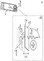
예를 들어, 방법(1000)의 추가 세부 사항을 기술하는 예시적인 환경(1200)을 도시하는 도 12를 고려한다. 도 12의 상세 뷰(1200-1)에서, 예시적인 환경(1200)은 레이더 필드(110)(미도시)를 제공하는 레이더 시스템(104)을 포함하는 전자 디바이스(이 경우 스마트 폰(102))를 도시한다. 상세 뷰(1200-1)는 스마트 폰을 한 손(예를 들어, 왼손(1202))으로 잡고 있는 사용자가 스마트 폰(1021)상에서 실행되는 레이더-기반 애플리케이션(106)의 AR 인터페이스에서 실제 객체(120-1)를 프레임화한 것을 도시한다. 도시된 바와 같이, 레이더-기반 애플리케이션(106)은 디스플레이(108) 상에 실제 객체(1201)의 이미지(예를 들어, 이미지(120-2))를 제시하고 있다(이미지(120-2)는 점선 화살표로 도시됨). 레이더-기반 애플리케이션(106)은 또한 디스플레이(108)의 코너 근처의 위치에 터치 입력 컨트롤(118)을 포함하는 AR 엘리먼트(116)를 제시하고 있다.For example, consider FIG. 12, which illustrates an
상세 뷰(1200-2)에서, 사용자는 음영 화살표(1206)로 도시된 바와 같이 다른 손(예를 들어, 오른손(1204))으로 터치 입력 컨트롤부(118)를 향해 도달하기 시작했다. 사용자가 스마트 폰(102)을 향해 도달하고 있다고 판단되었다고 가정한다(예를 들어, 레이더-기반 애플리케이션(106) 또는 다른 엔티티는 레이더 데이터를 사용하여 오른손(1204)이 스마트 폰(102)을 향해 도달하고 있음을 결정한다). 오른손(1204)으로 터치 입력 컨트롤(118)에 도달하는 동안, 사용자는 또한 실제 객체(120-1)의 이미지(120-2)가 디스플레이(108)를 통해 더 이상 보이지 않도록 스마트 폰(102)을 이동시켰다. 이 이동은 점선 화살표(1208)로 도시되어 있다. 설명된 기술을 사용하여, 레이더-기반 애플리케이션(106)은 여전히 디스플레이(108)의 코너 근처의 거의 동일한 위치에서 AR 엘리먼트(116) 및 터치 입력 컨트롤(118)을 유지하고 있다.In detailed view 1200-2, the user begins to reach toward the touch
상세 뷰(1200-3)에서, 사용자가 (예를 들어, 오른손(1204)으로 터치 입력을 통해) 터치 입력 컨트롤(118)을 활성화했다고 가정한다. 응답으로, 레이더-기반 애플리케이션(106)은 실제 객체(120-1)에 관한 정보를 사용자에게 제공할 수 있는 추가 터치 입력 컨트롤들(1212)과 함께 실제 객체(120-1)(미도시)의 다른 이미지(120-2)를 도시하는 2D 인터페이스(1210)를 제시하고 있다.In detailed view 1200-3, assume that the user has activated the touch input control 118 (eg, via touch input with the right hand 1204). In response, the radar-based
일부 구현에서, 고정 위치에 제공되고 있는 터치 입력 컨트롤(118)이 레이더 필드 내의 객체가 디스플레이(108)를 향해 이동하고 있다는 결정으로부터 임계 시간 내에 터치되지 않으면, 터치 입력 컨트롤은 고정 위치에서 제공되는 것이 중단될 수 있다. 임계 시간은 1.5초, 2초 또는 3초와 같은 다양한 시간일 수 있으며, 미리 설정되거나 사용자가 선택 가능할 수 있다. 또 다른 구현에서, 레이더-기반 애플리케이션(106)은 사용자의 손이 임계 속도를 초과하는 속도로 디스플레이(108)를 향해 이동하고 있다고 판단되는 경우에만 고정 위치에 터치 입력 컨트롤을 제공할 수 있다. 임계 속도는 0.25 피트/초(fps), 0.5fps 또는 0.75fps와 같은 임의의 적절한 속도일 수 있다.In some implementations, if the
예시적인 컴퓨팅 시스템Exemplary computing system
도 13은 레이더 시스템을 포함하는 스마트 폰, 시스템 및 방법을 구현하기 위해 이전의 도 1 내지 도 12를 참조하여 설명된 바와 같이 임의의 유형의 클라이언트, 서버 및/또는 전자 디바이스로서 구현될 수 있는 예시적인 컴퓨팅 시스템(1300)의 다양한 구성 요소를 도시한다.13 is an example that can be implemented as any type of client, server and/or electronic device as previously described with reference to FIGS. 1-12 to implement a smart phone, system and method including a radar system. Various components of a
컴퓨팅 시스템(1300)은 디바이스 데이터(1304)(예를 들어, 레이더 데이터, 3D 제스처 데이터, 인증 데이터, 기준 데이터, 수신된 데이터, 수신중인 데이터, 브로드캐스트를 위해 스케줄링된 데이터, 데이터의 데이터 패킷)의 유선 및/또는 무선 통신을 가능하게 하는 통신 디바이스(1302)를 포함한다. 디바이스 데이터(1304) 또는 다른 디바이스 컨텐츠는 디바이스의 구성 설정, 디바이스에 저장된 미디어 컨텐츠 및/또는 디바이스의 사용자와 관련된 정보(예를 들어, 레이더 필드 내의 사람의 신원)를 포함할 수 있다. 컴퓨팅 시스템(1300)에 저장된 미디어 컨텐츠는 임의의 유형의 레이더, 생체, 오디오, 비디오 및/또는 이미지 데이터를 포함할 수 있다. 컴퓨팅 시스템(1300)은 인간 발언(utterance), 레이더 필드와의 상호 작용, 터치 입력, 사용자 선택 가능 입력(명시적 또는 암시적), 메시지, 음악, 텔레비전 미디어 컨텐츠, 녹화된 비디오 컨텐츠, 및 임의의 컨텐츠 및/또는 데이터 소스로부터 수신된 임의의 다른 유형의 오디오, 비디오 및/또는 이미지 데이터와 같은, 임의의 유형의 데이터, 미디어 컨텐츠 및/또는 입력이 수신될 수 있는 하나 이상의 데이터 입력(1306)을 포함한다.The
컴퓨팅 시스템 1300)은 또한 하나 이상의 직렬 및/또는 병렬 인터페이스, 무선 인터페이스, 임의의 유형의 네트워크 인터페이스, 모뎀 및 임의의 다른 유형의 통신 인터페이스로서 구현될 수 있는 통신 인터페이스(1308)를 포함한다. 통신 인터페이스(1308)는 컴퓨팅 시스템(1300)과 다른 전자, 컴퓨팅 및 통신 디바이스가 컴퓨팅 시스템(1300)과 데이터를 통신하는 통신 네트워크 사이의 연결 및/또는 통신 링크를 제공한다.The
컴퓨팅 시스템(1300)은 컴퓨팅 시스템(1300)의 동작을 제어하고 레이더 시스템을 포함하는 스마트 폰, 시스템 및 방법에 대한 기술을 가능하게 하거나 또는 구현할 수 있는 다양한 컴퓨터 실행 가능 명령을 처리할 수 있는 하나 이상의 프로세서(1310)(예를 들어, 임의의 마이크로 프로세서, 제어기 또는 다른 제어기)를 포함한다. 대안적으로 또는 추가적으로, 컴퓨팅 시스템(1300)은 1312에서 일반적으로 식별되는 프로세싱 및 제어 회로와 관련하여 구현되는 하드웨어, 펌웨어 또는 고정 논리 회로의 임의의 하나 또는 조합으로 구현될 수 있다. 도시되지는 않았지만, 컴퓨팅 시스템(1300)은 디바이스 내의 다양한 구성 요소를 연결하는 시스템 버스 또는 데이터 전송 시스템을 포함할 수 있다. 시스템 버스는 메모리 버스 또는 메모리 제어기, 주변 디바이스 버스, 범용 직렬 버스 및/또는 다양한 버스 아키텍처 중 하나를 사용하는 프로세서 또는 로컬 버스와 같은 상이한 버스 구조 중 하나 또는 그 조합을 포함할 수 있다.The
컴퓨팅 시스템(1300)은 또한 예를 들어, 랜덤 액세스 메모리(RAM), 비 휘발성 메모리(예를 들어, 임의의 하나 이상의 판독 전용 메모리(ROM), 플래시 메모리, EPROM, EEPROM 등) 및 디스크 저장 디바이스를 포함하는 영구 및/또는 비-일시적 데이터 저장(즉, 단순한 신호 전송과 대조되는)을 가능하게 하는 하나 이상의 메모리 디바이스와 같은 컴퓨터 판독 가능 매체(1314)를 포함한다. 디스크 저장 디바이스는 하드 디스크 드라이브, 기록 가능 및/또는 재기록 가능 컴팩트 디스크(CD), 임의의 유형의 디지털 다목적 디스크(DVD) 등과 같은 임의의 유형의 자기 또는 광 저장 디바이스로서 구현될 수 있다. 컴퓨팅 시스템(1300)은 또한 대용량 저장 매체 디바이스(저장 매체)(1316)를 포함할 수 있다.
컴퓨터 판독 가능 매체(1314)는 디바이스 데이터(1304)뿐만 아니라 다양한 디바이스 애플리케이션(1318) 및 컴퓨팅 시스템(1300)의 동작 양태와 관련된 임의의 다른 유형의 정보 및/또는 데이터를 저장하기 위한 데이터 저장 메커니즘을 제공한다. 예를 들어, 운영 체제(1320)는 컴퓨터 판독 가능 매체(1314)를 갖는 컴퓨터 애플리케이션으로서 유지될 수 있고 프로세서(1310)상에서 실행될 수 있다. 디바이스 애플리케이션(1318)은 임의의 형태의 제어 애플리케이션, 소프트웨어 애플리케이션, 신호 처리 및 제어 모듈, 특정 디바이스 고유의 코드, 추상화 모듈, 제스처 인식 모듈 및 기타 모듈과 같은 디바이스 관리자를 포함할 수 있다. 디바이스 애플리케이션(1318)은 또한 레이더 시스템(104), 레이더-기반 애플리케이션(106) 또는 (3D 제스처 모듈(708)을 포함하는) 레이더-기반 애플리케이션(702)와 같은 레이더 시스템을 포함하는 스마트 폰, 시스템 및 방법을 구현하기 위한 시스템 구성 요소, 엔진 또는 관리자를 포함할 수 있다. 컴퓨팅 시스템(1300)은 또한 하나 이상의 기계 학습 시스템을 포함하거나 이에 액세스할 수 있다.Computer-
이하에서는 일부 예시가 설명된다.Some examples are described below.
예시 1 : 스마트 폰은 디스플레이와; 적어도 부분적으로 하드웨어로 구현되어, 레이더 필드(radar field)를 제공하고; 레이더 필드내의 객체로부터의 반사를 감지하고; 레이더 필드내의 객체로부터의 반사를 분석하고; 그리고 반사의 분석에 기초하여, 레이더 데이터를 제공하도록 구성된 레이더 시스템과; 하나 이상의 컴퓨터 프로세서와; 그리고 하나 이상의 컴퓨터 프로세서에 의한 실행에 응답하여, 레이더-기반 애플리케이션을 구현하는 명령들이 저장된 하나 이상의 컴퓨터 판독 가능 매체를 포함하고, 상기 레이더-기반 애플리케이션은 스마트 폰의 디스플레이를 통해 증강 현실(AR) 엘리먼트를 제시하고, 상기 AR 엘리먼트는 터치 입력 컨트롤을 포함하고 이미지가 디스플레이에 제시되는 실제 객체와 관련되며; 그리고 레이더 데이터에 기초하여, 레이더 필드 내의 객체가 디스플레이를 향해 이동하고 있다는 결정에 응답하여, 터치 입력 컨트롤을 디스플레이의 고정 위치에 유지한다.Example 1: Smartphone with a display; Implemented at least partially in hardware, providing a radar field; Sensing reflections from objects within the radar field; Analyze reflections from objects in the radar field; And a radar system configured to provide radar data based on the analysis of the reflection; One or more computer processors; And in response to execution by the one or more computer processors, at least one computer-readable medium storing instructions for implementing the radar-based application, wherein the radar-based application is an augmented reality (AR) element through the display of the smart phone. And the AR element includes a touch input control and is associated with an actual object on which an image is presented on the display; And, based on the radar data, in response to a determination that an object in the radar field is moving towards the display, it holds the touch input control in a fixed position on the display.
예시 2 : 예시 1에 있어서, 상기 레이더 필드 내의 객체는 사용자이고, 이에 의해 터치 입력 컨트롤과의 사용자 상호 작용의 용이성 및 정확성은 실제 객체의 이미지가 디스플레이상에서 비정상적으로 이동하더라도 터치 입력 컨트롤을 고정 위치에 유지함으로써 촉진되도록 한다.Example 2: In Example 1, the object in the radar field is a user, and thus, the ease and accuracy of user interaction with the touch input control is determined by moving the touch input control to a fixed position even if the image of the actual object moves abnormally on the display. It is promoted by maintaining.
예시 3 : 예시 1 또는 예시 2에 있어서, 상기 레이더-기반 애플리케이션은 사용자가 제1 손으로 스마트 폰을 잡고 있는 동안 터치 입력 컨트롤을 포함하는 증강 현실(AR) 엘리먼트를 제시하도록 더 구성된다.Example 3: In Example 1 or Example 2, the radar-based application is further configured to present an augmented reality (AR) element including a touch input control while the user is holding the smart phone with the first hand.
예시 4 : 선행하는 예시 중 적어도 하나에 있어서, 상기 레이더 필드 내의 객체가 디스플레이를 향해 이동하고 있다는 결정은 사용자가 제2 손으로 스마트 폰을 향해 도달하고 있다고 결정하는 것을 포함하고; 상기 스마트 폰은 실제 객체의 이미지가 더 이상 디스플레이 상에 제시되지 않도록 위치되고; 그리고 상기 레이더-기반 애플리케이션은 실제 객체의 이미지가 더 이상 디스플레이 상에 제시되지 않도록 사용자가 스마트 폰을 이동시키기 전에 제시된 것과 거의 동일한 디스플레이 상의 위치에 AR 엘리먼트 및 터치 입력 컨트롤을 유지하도록 더 구성된다.Example 4: In at least one of the preceding examples, determining that the object in the radar field is moving towards the display comprises determining that the user is reaching towards the smart phone with a second hand; The smart phone is positioned so that the image of the real object is no longer presented on the display; And the radar-based application is further configured to keep the AR element and touch input control at a position on the display approximately the same as that presented before the user moves the smart phone so that the image of the real object is no longer presented on the display.
예시 5 : 선행하는 예시 중 적어도 하나에 있어서, 상기 터치 입력 컨트롤은 제2 손에 의한 이전 터치 입력을 통해 활성화되고; 상기 레이더-기반 애플리케이션은 터치 입력 컨트롤의 활성화에 응답하여, 실제 객체의 다른 이미지; 및 실제 객체에 관한 정보를 사용자에게 제공하는 다른 터치 입력 컨트롤을 포함하는 2차원(2D) 인터페이스를 디스플레이상에 제시하도록 더 구성된다.Example 5: In at least one of the preceding examples, the touch input control is activated through a previous touch input by a second hand; The radar-based application, in response to activation of a touch input control, may include another image of an actual object; And a two-dimensional (2D) interface including other touch input controls that provide information about an actual object to a user.
예시 6 : 선행하는 예시 중 적어도 하나에 있어서, 상기 레이더-기반 애플리케이션은 실제 객체의 이미지가 더 이상 디스플레이상에 제시되지 않을 때 터치 입력 컨트롤의 고정 위치를 유지하도록 더 구성된다.Example 6: In at least one of the preceding examples, the radar-based application is further configured to maintain a fixed position of the touch input control when the image of the actual object is no longer presented on the display.
예시 7 : 선행하는 예시 중 적어도 하나에 있어서, 상기 레이더-기반 애플리케이션은 고정 위치의 터치 입력 컨트롤이 임계 시간 내에 터치되지 않은 것에 응답하여, 터치 입력 컨트롤을 고정 위치에 제공하는 것을 중지하도록 더 구성된다.Example 7: In at least one of the preceding examples, the radar-based application is further configured to stop providing the touch input control to the fixed position in response to the fixed position touch input control not being touched within the threshold time. .
예시 8 : 선행하는 예시 중 적어도 하나에 있어서, 상기 레이더-기반 애플리케이션은 레이더 필드 내의 객체가 임계 속도를 초과하는 속도로 디스플레이를 향해 이동하는 경우 고정 위치에 터치 입력 컨트롤을 제공하도록 더 구성된다.Example 8: In at least one of the preceding examples, the radar-based application is further configured to provide touch input control at a fixed position when an object in the radar field moves toward the display at a speed exceeding a threshold speed.
예시 9 : 선행하는 예시 중 적어도 하나에 있어서, 상기 스마트 폰은 이미지 캡처 디바이스를 포함하고, 상기 레이더-기반 애플리케이션은 이미지 캡처 디바이스를 통해 실시간 또는 거의 실시간으로 실제 객체의 이미지를 제시한다.Example 9: In at least one of the preceding examples, the smart phone includes an image capture device, and the radar-based application presents an image of a real object in real time or near real time via the image capture device.
예시 10 : 선행하는 예시 중 적어도 하나에 있어서, 상기 레이더 시스템은 레이더 데이터에 기초하여, 레이더 필드 내의 객체가 디스플레이를 향해 이동하고 있는지 결정하도록 더 구성된다.Example 10: In at least one of the preceding examples, the radar system is further configured to determine, based on radar data, whether an object in the radar field is moving towards the display.
예시 11 : 선행하는 예시 중 적어도 하나에 있어서, 상기 레이더-기반 애플리케이션은 레이더 데이터에 기초하여, 레이더 필드 내의 객체가 디스플레이를 향해 이동하고 있는지 결정하도록 더 구성된다.Example 11: In at least one of the preceding examples, the radar-based application is further configured to determine, based on radar data, whether an object in the radar field is moving towards the display.
예시 12 : 선행하는 예시 중 적어도 하나에 있어서, 상기 레이더 필드 내의 객체는 사용자의 신체 부분이다.Example 12: In at least one of the preceding examples, the object in the radar field is a body part of the user.
예시 13 : 시스템은 디스플레이를 포함하는 전자 디바이스와; 적어도 부분적으로 하드웨어로 구현되어, 레이더 필드를 제공하고; 제1 시간에, 레이더 필드내의 객체로부터의 반사를 감지하고; 레이더 필드내의 객체로부터의 반사를 분석하고; 반사의 분석에 기초하여 레이더 데이터를 제공하도록 구성된 레이더 시스템과; 하나 이상의 컴퓨터 프로세서과; 그리고 하나 이상의 컴퓨터 프로세서에 의한 실행에 응답하여, 레이더-기반 애플리케이션을 구현하는 명령들이 저장된 하나 이상의 컴퓨터 판독 가능 매체를 포함하고, 상기 레이더-기반 애플리케이션은 전자 디바이스의 디스플레이를 통해 증강 현실(AR) 엘리먼트를 제시하고; 제1시간보다 늦은 제2 시간에, AR 엘리먼트를 선택하는 입력을 수신하고; 레이더 데이터에 기초하여, 레이더 필드내의 객체에 의한 제스처를 결정하고; 결정된 제스처에 대응하는 상기 선택된 AR 엘리먼트와 관련된 동작을 수행하도록 구성된다.Example 13: The system includes an electronic device including a display; Implemented at least partially in hardware, providing a radar field; At a first time, detecting a reflection from an object in the radar field; Analyze reflections from objects in the radar field; A radar system configured to provide radar data based on the analysis of the reflection; One or more computer processors; And in response to execution by the one or more computer processors, at least one computer-readable medium storing instructions for implementing the radar-based application, wherein the radar-based application is an augmented reality (AR) element through a display of the electronic device. To present; At a second time later than the first time, receiving an input for selecting an AR element; Based on the radar data, determine a gesture by the object in the radar field; Configured to perform an operation related to the selected AR element corresponding to the determined gesture.
예시 14 : 예시 13에 있어서, 상기 AR 엘리먼트를 선택하는 입력은 터치 입력이다.Example 14: In Example 13, the input for selecting the AR element is a touch input.
예시 15 : 예시 13 또는 14에 있어서, 상기 결정된 제스처는 3차원(3D) 제스처이다.Example 15: In Example 13 or 14, the determined gesture is a three-dimensional (3D) gesture.
예시 16 : 예시 13 내지 15 중 적어도 하나에 있어서, 상기 객체는 사용자의 신체 부분이다.Example 16: In at least one of Examples 13 to 15, the object is a body part of the user.
예시 17 : 예시 13 내지 16 중 적어도 하나에 있어서, 상기 결정된 제스처는 객체와 레이더 시스템 사이의 거리를 변경시키는 것을 포함한다.Example 17: In at least one of Examples 13 to 16, the determined gesture includes changing the distance between the object and the radar system.
예시 18 : 예시 17에 있어서, 상기 객체와 레이더 시스템 사이의 증가된 거리인 상기 변경된 거리에 대응하는 동작은 사용자에게 더 근접하는 선택된 AR 엘리먼트의 이동이고; 그리고 상기 객체와 레이더 시스템 사이의 감소된 거리인 상기 변경된 거리에 대응하는 동작은 사용자로부터 멀어지는 선택된 AR 엘리먼트의 이동이다.Example 18: In Example 17, the action corresponding to the changed distance, which is the increased distance between the object and the radar system, is the movement of the selected AR element closer to the user; And the operation corresponding to the changed distance, which is the reduced distance between the object and the radar system, is the movement of the selected AR element away from the user.
예시 19 : 예시 18에 있어서, 상기 사용자에게 더 근접하는 선택된 AR 엘리먼트의 이동은 증가된 거리에 비례하고; 그리고 상기 사용자로부터 멀어지는 선택된 AR 엘리먼트의 이동은 감소된 거리에 비례한다.Example 19: In Example 18, the movement of the selected AR element closer to the user is proportional to the increased distance; And the movement of the selected AR element away from the user is proportional to the reduced distance.
예시 20 : 예시 13 내지 19 중 적어도 하나에 있어서, 상기 결정된 제스처는 신체 부분과 전자 디바이스의 디스플레이 평면 사이에서 실질적으로 유사한 거리를 유지하면서 레이더 시스템에 대한 객체의 위치를 변경하는 것을 포함한다.Example 20: The determined gesture of at least one of Examples 13-19, including changing the position of the object with respect to the radar system while maintaining a substantially similar distance between the body part and the display plane of the electronic device.
예시 21 : 예시 20에 있어서, 제1 방향으로 위치를 변경하는 것에 대응하는 동작은 선택된 AR 엘리먼트의 축을 중심으로 제1 회전 방향으로 선택된 AR 엘리먼트의 회전이고; 그리고 제2 방향으로 위치를 변경하는 것에 대응하는 동작은 상기 축을 중심으로 제2 회전 방향으로 선택된 AR 엘리먼트의 회전이다.Example 21: In Example 20, the operation corresponding to changing the position in the first direction is rotation of the selected AR element in the first rotation direction about the axis of the selected AR element; And the operation corresponding to changing the position in the second direction is the rotation of the AR element selected in the second rotation direction about the axis.
예시 22 : 예시 13 내지 21 중 적어도 하나에 있어서, 상기 레이더 시스템은 디지털 빔포머 및 각 추정기를 더 포함하고, 상기 레이더 시스템은 대략 -90도 내지 대략 90도 사이의 시야에서 각도를 모니터링하도록 구성된다.Example 22: The radar system of at least one of Examples 13 to 21, wherein the radar system further comprises a digital beamformer and an angle estimator, and the radar system is configured to monitor an angle in a field of view between approximately -90 degrees and approximately 90 degrees. .
예시 23 : 디스플레이, 레이더 시스템, 및 레이더-기반 애플리케이션을 포함하는 전자 디바이스에서 구현되는 방법으로서, 상기 방법은 레이더 시스템에 의해, 레이더 필드를 제공하는 단계; 레이더 시스템에 의해, 레이더 필드내의 객체로부터의 반사를 감지하는 단계; 레이더 필드내의 객체로부터의 반사를 분석하는 단계; 반사의 분석에 기초하여, 레이더 데이터를 제공하는 단계; 레이더-기반 애플리케이션에 의해, 전자 디바이스의 디스플레이를 통해 증강 현실(AR) 엘리먼트를 제시하는 단계, 상기 AR 엘리먼트는 터치 입력 컨트롤을 포함하고 이미지가 디스플레이상에 제시되는 실제 객체와 관련되고; 및 레이더 데이터에 기초하여, 레이더 필드내의 객체가 디스플레이를 향해 이동하고 있다는 결정에 응답하여, 터치 입력 컨트롤을 디스플레이의 고정 위치에 유지하는 단계를 포함한다.Example 23: A method implemented in an electronic device comprising a display, a radar system, and a radar-based application, the method comprising, by a radar system, providing a radar field; Sensing, by the radar system, reflections from objects within the radar field; Analyzing reflections from objects within the radar field; Based on the analysis of the reflection, providing radar data; Presenting, by a radar-based application, an augmented reality (AR) element via a display of an electronic device, the AR element comprising a touch input control and an image being associated with a real object presented on the display; And in response to determining, based on the radar data, that the object in the radar field is moving toward the display, maintaining the touch input control in a fixed position of the display.
예시 24 : 예시 23에 있어서, 상기 레이더 데이터에 기초하여, 레이더 필드내의 객체가 디스플레이를 향해 이동하고 있다는 결정은 레이더 시스템 또는 레이더-기반 애플리케이션에 의해 수행된다.Example 24: In Example 23, based on the radar data, the determination that an object in the radar field is moving towards the display is performed by a radar system or radar-based application.
예시 25 : 예시 23 또는 24에 있어서, 상기 전자 디바이스는 핸드 헬드 디바이스이고, 상기 레이더 필드내의 객체는 사용자이고, 상기 방법은 터치 입력 컨트롤과의 사용자의 상호 작용의 용이성과 정확성이 촉진되도록 실제 객체의 이미지가 디스플레이상에서 비정상적으로 이동하더라도 터치 입력 컨트롤을 고정 위치에 유지하는 단계를 더 포함한다.Example 25: In Example 23 or 24, the electronic device is a handheld device, the object in the radar field is a user, and the method is to facilitate the ease and accuracy of user interaction with the touch input control. The step of maintaining the touch input control in a fixed position even if the image moves abnormally on the display.
예시 26 : 예시 23 내지 25 중 적어도 하나에 있어서, 레이더-기반 애플리케이션에 의해, 사용자가 제1 손으로 전자 디바이스를 잡고 있는 동안 터치 입력 컨트롤을 포함하는 증강 현실(AR) 엘리먼트를 제시하는 단계를 더 포함한다.Example 26: The method of at least one of Examples 23-25, further comprising, by a radar-based application, presenting an augmented reality (AR) element comprising a touch input control while the user is holding the electronic device with the first hand. Include.
예시 27 : 예시 23 내지 26 중 적어도 하나에 있어서, 상기 레이더 필드 내의 객체가 디스플레이를 향해 이동하고 있다는 결정은 사용자가 제2 손으로 전자 디바이스를 향해 도달하고 있다고 결정하는 것을 포함하고; 상기 전자 디바이스는 실제 객체의 이미지가 더 이상 디스플레이 상에 제시되지 않도록 위치되고; 그리고 상기 방법은 레이더-기반 애플리케이션에 의해, 실제 객체의 이미지가 더 이상 디스플레이상에 제시되지 않도록 사용자가 전자 디바이스를 이동시키기 전에 제시된 것과 거의 동일한 디스플레이상의 위치에 AR 엘리먼트 및 터치 입력 컨트롤을 유지하는 단계를 더 포함한다.Example 27: The method of at least one of Examples 23-26, wherein determining that the object in the radar field is moving towards the display comprises determining that the user is reaching towards the electronic device with a second hand; The electronic device is positioned such that an image of an actual object is no longer presented on the display; And the method comprises, by a radar-based application, maintaining the AR element and the touch input control at a position on the display approximately identical to that presented before the user moves the electronic device so that the image of the actual object is no longer presented on the display. It includes more.
예시 28 : 예시 23 내지 27 중 적어도 하나에 있어서, 상기 터치 입력 컨트롤은 제2 손에 의한 이전 터치 입력을 통해 활성화되고, 상기 방법은 레이더-기반 애플리케이션에 의해, 터치 입력 컨트롤의 활성화에 응답하여, 2차원(2D) 사용자 인터페이스를 디스플레이상에 제시하는 단계를 더 포함하고, 상기 2D 사용자 인터페이스는, 실제 객체의 다른 이미지; 및 실제 객체에 관한 정보를 사용자에게 제공하는 다른 터치 입력 컨트롤을 포함한다.Example 28: In at least one of Examples 23 to 27, the touch input control is activated through a previous touch input by a second hand, and the method is by a radar-based application, in response to activation of the touch input control, And presenting a two-dimensional (2D) user interface on the display, the 2D user interface comprising: another image of an actual object; And another touch input control that provides information on an actual object to a user.
결론conclusion
레이더 시스템을 포함하는 스마트 폰, 시스템 및 방법을 위한 기술 및 이를 가능하게 하는 장치가 특징 및/또는 방법에 대해 특정한 언어로 기술되었지만, 첨부된 청구항의 주제는 기술된 특정 특징이나 방법으로 반드시 제한되는 것은 아니라는 것을 이해해야 한다. 오히려, 특정 특징 및 방법은 레이더 시스템을 포함하는 스마트 폰, 시스템 및 방법을 가능하게 하는 예시적인 구현으로서 개시되어 있다.Although the technology for smart phones, systems and methods including radar systems, and devices that enable them have been described in a specific language for features and/or methods, the subject of the appended claims is necessarily limited to the specific features or methods described. It should be understood that it is not. Rather, certain features and methods are disclosed as example implementations that enable smart phones, systems, and methods including radar systems.
Claims (20)
Translated fromKorean디스플레이;
적어도 부분적으로 하드웨어에 구현되어,
레이더(radar) 필드를 제공하고;
레이더 필드내의 객체로부터의 반사를 감지하고;
레이더 필드내의 객체로부터의 반사를 분석하고; 그리고
반사의 분석에 기초하여, 레이더 데이터를 제공하도록 구성된 레이더 시스템;
하나 이상의 컴퓨터 프로세서; 및
하나 이상의 컴퓨터 프로세서에 의한 실행에 응답하여:
사용자 입력을 수신하고, 상기 사용자 입력은 전자 디바이스의 디스플레이의 사용자 인터페이스를 통해 수신된 터치 입력 및 전자 디바이스의 마이크로폰을 통해 수신된 음성 입력 중 하나이고;
사용자 입력에 대응하는 제1 액션을 수행하고, 상기 제1 액션은 결과를 발생하고;
레이더 데이터에 기초하여, 레이더 필드내의 객체에 의한 제스처를 결정하고; 그리고
결정된 제스처에 대응하는 제2 액션을 수행하도록 구성된, 명령들이 저장된 하나 이상의 컴퓨터 판독 가능 매체를 포함하고, 상기 제2 액션은 사용자 입력에 대응하는 제1 액션의 결과와 연관되는 것을 특징으로 하는 전자 디바이스.As an electronic device,
display;
At least partially implemented in hardware,
Provide a radar field;
Detects reflections from objects within the radar field;
Analyze reflections from objects in the radar field; And
A radar system configured to provide radar data based on the analysis of the reflection;
One or more computer processors; And
In response to execution by one or more computer processors:
Receiving a user input, the user input being one of a touch input received through a user interface of a display of the electronic device and a voice input received through a microphone of the electronic device;
Performing a first action corresponding to a user input, the first action generating a result;
Based on the radar data, determine a gesture by the object in the radar field; And
An electronic device comprising at least one computer-readable medium in which instructions are stored, configured to perform a second action corresponding to the determined gesture, the second action being associated with a result of the first action corresponding to a user input. .
상기 레이더 필드내의 객체는 사용자인 것을 특징으로 하는 전자 디바이스.The method of claim 1,
The electronic device, wherein the object in the radar field is a user.
상기 사용자 입력이 터치 입력인 경우, 터치 입력에 대응하는 제1 액션은 드로잉 기반 애플리케이션에 의한 액션을 포함하고; 그리고
상기 결정된 제스처에 대응하는 제2 액션은 드로잉 기반 애플리케이션과 관련되는 것을 특징으로 하는 전자 디바이스.The method of claim 2,
When the user input is a touch input, the first action corresponding to the touch input includes an action by a drawing-based application; And
The electronic device, wherein the second action corresponding to the determined gesture is related to a drawing-based application.
상기 드로잉 기반 애플리케이션은,
그래픽 디자인 애플리게이션;
스케치 애플리케이션; 또는
컴퓨터 지원 제도 프로그램 중 하나인 것을 특징으로 하는 전자 디바이스.The method of claim 3,
The drawing-based application,
Graphic design applications;
Sketch application; or
Electronic device, characterized in that one of computer support system programs.
상기 결정된 제스처에 대응하고 드로잉 기반 애플리케이션과 관련되는 제2 액션은,
드로잉 기반 애플리케이션으로 생성된 드로잉의 새로운 엘리먼트 생성:
드로잉 기반 애플리케이션으로 생성된 드로잉의 기존 엘리먼트 변경;
드로잉 기반 애플리케이션으로 생성된 드로잉을 나타내는 데이터 파일에 대해 수행되는 동작; 또는
드로잉 기반 애플리케이션의 메뉴와의 상호 작용 중 하나 이상을 포함하는 것을 특징으로 하는 전자 디바이스.The method of claim 3,
The second action corresponding to the determined gesture and related to the drawing-based application,
Creating a new element of a drawing created with a drawing-based application:
Change existing elements of drawings created with drawing-based applications;
An operation performed on a data file representing a drawing created by a drawing-based application; or
An electronic device comprising at least one of interaction with a menu of a drawing-based application.
상기 터치 입력은 사용자 인터페이스를 따라 손가락의 터치 및 슬라이드를 포함하고;
상기 터치 입력에 대응하는 제1 액션의 결과는 디스플레이상에 슬라이드의 형태에 대응하는 형태를 갖는 라인을 디스플레이하는 것이고; 그리고
상기 결정된 제스처에 대응하는 제2 액션은 라인에 대한 변경을 포함하고,
상기 변경은,
선의 두께 증가 또는 감소;
선의 색상 변경;
선의 길이 증가 또는 감소; 또는
선의 패턴 변경 중 적어도 하나를 포함하는 것을 특징으로 하는 전자 디바이스.The method of claim 2,
The touch input includes a touch and a slide of a finger along a user interface;
The result of the first action corresponding to the touch input is to display a line having a shape corresponding to the shape of the slide on the display; And
The second action corresponding to the determined gesture includes a change to the line,
The above changes are:
Increasing or decreasing the thickness of the line;
Change the color of the line;
Increase or decrease the length of the line; or
Electronic device comprising at least one of changing a pattern of a line.
상기 결정된 제스처는,
다이얼 돌리기(dial-turning) 제스처; 또는
스핀들 트위스팅(spindle-twisting) 제스처를 포함하는 3차원(3D) 제스처인 것을 특징으로 하는 전자 디바이스.The method of claim 2,
The determined gesture,
Dial-turning gesture; or
Electronic device, characterized in that it is a three-dimensional (3D) gesture including a spindle-twisting gesture.
상기 터치 입력에 대응하는 제1 액션은 텍스트 기반 애플리케이션에 의한 액션을 포함하고; 그리고
상기 결정된 제스처에 대응하는 제2 액션은 텍스트 기반 애플리케이션과 관련되는 것을 특징으로 하는 전자 디바이스.The method of claim 2,
The first action corresponding to the touch input includes an action by a text-based application; And
The electronic device, wherein the second action corresponding to the determined gesture is related to a text-based application.
상기 텍스트 기반 애플리케이션은,
워드 프로세싱 애플리케이션;
이메일 애플리케이션; 또는
스프레드시트(spreadsheet) 애플리케이션 중 하나인 것을 특징으로 하는 전자 디바이스.The method of claim 8,
The text-based application,
Word processing applications;
Email application; or
Electronic device, characterized in that one of the spreadsheet (spreadsheet) application.
상기 결정된 제스처에 대응하는 제2 액션은,
텍스트 기반 애플리케이션에서 기존 텍스트 변경;
텍스트 기반 애플리케이션에서 새로운 텍스트 생성;
텍스트 기반 애플리케이션에서 텍스트를 나타내는 데이터 파일에 대해 수행되는 동작; 또는
텍스트 기반 애플리케이션의 메뉴와의 상호 작용 중 하나 이상을 포함하는 것을 특징으로 하는 전자 디바이스.The method of claim 8,
The second action corresponding to the determined gesture,
Change existing text in text-based applications;
Creating new text in text-based applications;
An operation performed on a data file representing text in a text-based application; or
An electronic device comprising at least one of interaction with a menu of a text-based application.
상기 터치 입력은 디스플레이된 텍스트의 일부 근처의 사용자 인터페이스에 대한 사용자의 2개 이상의 손가락의 터치 및 그런 다음 사용자 인터페이스에 대한 터치를 유지하면서 손가락을 펴는데 효과적인 하나 이상의 손가락의 슬라이드를 포함하고;
상기 터치 입력에 대응하는 제1 액션의 결과는 터치 입력이 수행되는 디스플레이된 텍스트의 일부를 선택하는 것이고; 그리고
상기 결정된 제스처는 선택된 텍스트에 대해 동작을 수행하는 3차원(3D) 제스처인 것을 특징으로 하는 전자 디바이스.The method of claim 2,
The touch input comprises a touch of the user's two or more fingers to a user interface near a portion of the displayed text and then a slide of one or more fingers effective to open a finger while maintaining the touch to the user interface;
The result of the first action corresponding to the touch input is to select a portion of the displayed text on which the touch input is performed; And
The electronic device, wherein the determined gesture is a three-dimensional (3D) gesture for performing an operation on the selected text.
상기 3D 제스처는 제1 핀치(pinch) 제스처를 포함하고;
상기 선택된 텍스트에 대해 수행된 동작은 선택된 텍스트를 복사하는 것이고; 그리고
상기 명령들은:
사용자 인터페이스를 통해 다른 터치 입력을 수신하고, 상기 다른 터치 입력은 다른 터치 입력에 대응하는 위치에 있는 사용자 인터페이스상에 커서를 위치시키는데 효과적이고;
레이더 데이터에 기초하여, 사용자에 의한 다른 제스처를 결정하고, 상기 다른 제스처는 제2 핀치 제스처를 포함하고; 그리고
제2 핀치 제스처를 결정하는 것에 응답하여, 상기 선택된 텍스트에 대해 다른 동작을 수행하도록 더 구성되고, 상기 다른 동작은 상기 선택된 텍스트를 다른 터치 입력에 대응하는 위치에 붙여 넣는 것을 포함하는 것을 특징으로 하는 전자 디바이스.The method of claim 11,
The 3D gesture includes a first pinch gesture;
The operation performed on the selected text is to copy the selected text; And
The above commands are:
Receiving another touch input through a user interface, the other touch input being effective in placing a cursor on the user interface at a position corresponding to the other touch input;
Based on the radar data, determine another gesture by the user, the other gesture including a second pinch gesture; And
In response to determining a second pinch gesture, further configured to perform another operation on the selected text, wherein the other operation comprises pasting the selected text to a location corresponding to another touch input. Electronic device.
상기 사용자 입력이 음성 입력인 경우, 음성 입력에 대응하는 제1 액션은 드로잉 기반 애플리케이션에 의한 액션을 포함하고; 그리고
상기 결정된 제스처에 대응하는 제2 액션은 드로잉 기반 애플리케이션과 관련되는 것을 특징으로 하는 전자 디바이스.The method of claim 2,
When the user input is a voice input, the first action corresponding to the voice input includes an action by a drawing-based application; And
The electronic device, wherein the second action corresponding to the determined gesture is related to a drawing-based application.
상기 음성 입력은 사용자 인터페이스에 표시될 선(line)을 기술하는 명령들을 포함하는 제1 음성 명령을 포함하고;
상기 음성 입력에 대응하는 제1 액션의 결과는 디스플레이상에 제1 음성 명령에 의해 기술된 형태에 대응하는 형태를 갖는 라인을 디스플레이하는 것이고; 그리고
상기 결정된 제스처에 대응하는 제2 액션은 선에 대한 변경을 포함하고, 상기 변경은,
선의 두께 증가 또는 감소;
선의 색상 변경;
선의 길이 증가 또는 감소; 또는
선의 패턴 변경 중 적어도 하나를 포함하는 것을 특징으로 하는 전자 디바이스.The method of claim 13,
The voice input comprises a first voice command comprising commands describing a line to be displayed on the user interface;
The result of the first action corresponding to the voice input is to display a line having a shape corresponding to the shape described by the first voice command on the display; And
The second action corresponding to the determined gesture includes a change to the line, and the change,
Increasing or decreasing the thickness of the line;
Change the color of the line;
Increase or decrease the length of the line; or
Electronic device comprising at least one of changing a pattern of a line.
상기 음성 입력에 대응하는 제1 액션은 텍스트 기반 애플리케이션에 의한 액션을 포함하고; 그리고
상기 결정된 제스처에 대응하는 제2 액션은 텍스트 기반 애플리케이션과 관련되는 것을 특징으로 하는 전자 디바이스.The method of claim 13,
The first action corresponding to the voice input includes an action by a text-based application; And
The electronic device, wherein the second action corresponding to the determined gesture is related to a text-based application.
상기 음성 입력은 사용자 인터페이스에 디스플레이된 텍스트의 일부를 기술하는 명령들을 포함하는 제2 음성 입력을 포함하고;
상기 음성 입력에 대응하는 제1 액션의 결과는 제2 음성 입력에 의해 기술되는 디스플레이된 텍스트의 일부를 선택하는 것이고; 그리고
상기 결정된 제스처는 선택된 텍스트에 대해 동작을 수행하는 3차원(3D) 제스처인 것을 특징으로 하는 전자 디바이스.The method of claim 13,
The voice input comprises a second voice input comprising instructions for describing a portion of text displayed on the user interface;
The result of the first action corresponding to the voice input is to select a portion of the displayed text described by the second voice input; And
The electronic device, wherein the determined gesture is a three-dimensional (3D) gesture for performing an operation on the selected text.
상기 3D 제스처는 상기 선택된 텍스트를 복사하는데 효과적인 제1 핀치 제스처를 포함하고; 그리고
상기 명령들은:
사용자 인터페이스를 통해 다른 음성 입력을 수신하고, 상기 다른 음성 입력은 인터페이스상에 커서를 위치시킬 위치를 기술하는 제3 음성 명령을 포함하고;
레이더 데이터에 기초하여, 사용자에 의한 다른 제스처를 결정하고, 상기 다른 제스처는 제2 핀치 제스처를 포함하고; 그리고
제2 핀치 제스처를 결정하는 것에 응답하여, 상기 선택된 텍스트에 대해 다른 동작을 수행하도록 더 구성되고, 상기 다른 동작은 상기 선택된 텍스트를 제3 음성 명령에 기술된 위치에 붙여 넣는 것을 포함하는 것을 특징으로 하는 전자 디바이스.The method of claim 16,
The 3D gesture comprises a first pinch gesture effective to copy the selected text; And
The above commands are:
Receiving another voice input through a user interface, the other voice input including a third voice command describing a location to place the cursor on the interface;
Based on the radar data, determine another gesture by the user, the other gesture including a second pinch gesture; And
In response to determining a second pinch gesture, further configured to perform another action on the selected text, wherein the other action comprises pasting the selected text at the location described in the third voice command. Electronic device.
상기 레이더 시스템은 디지털 빔 포머 및 각도 추정기를 더 포함하고, 상기 레이더 시스템은 -90도 내지 90도 사이의 시야각을 모니터링하도록 구성되는 것을 특징으로 하는 전자 디바이스.The method of claim 1,
Wherein the radar system further comprises a digital beam former and an angle estimator, wherein the radar system is configured to monitor a viewing angle between -90 degrees and 90 degrees.
레이더 필드를 제공하는 단계;
레이더 필드내의 객체로부터의 반사를 감지하는 단계;
레이더 필드내의 객체로부터의 반사를 분석하는 단계;
반사의 분석에 기초하여, 레이더 데이터를 제공하는 단계;
사용자 입력을 수신하는 단계, 상기 사용자 입력은 전자 디바이스의 디스플레이의 사용자 인터페이스를 통해 수신된 터치 입력 및 전자 디바이스의 마이크로폰을 통해 수신된 음성 입력 중 하나이고;
사용자 입력에 대응하는 제1 액션을 수행하는 단계, 상기 제1 액션은 결과를 발생하고;
레이더 데이터에 기초하여, 레이더 필드내의 객체에 의한 제스처를 결정하는 단계; 및
결정된 제스처에 대응하는 제2 액션을 수행하는 단계를 포함하고, 상기 제2 액션은 사용자 입력에 대응하는 제1 액션의 결과와 연관되는 것을 특징으로 하는 전자 디바이스에서 구현되는 방법.A method implemented in an electronic device comprising a display, a radar system and a radar-based application, comprising:
Providing a radar field;
Sensing reflections from objects within the radar field;
Analyzing reflections from objects within the radar field;
Based on the analysis of the reflection, providing radar data;
Receiving a user input, the user input being one of a touch input received through a user interface of a display of the electronic device and a voice input received through a microphone of the electronic device;
Performing a first action corresponding to a user input, the first action generating a result;
Determining a gesture by an object in the radar field based on the radar data; And
And performing a second action corresponding to the determined gesture, wherein the second action is associated with a result of the first action corresponding to a user input.
상기 레이더 필드내의 객체는 사용자인 것을 특징으로 하는 전자 디바이스에서 구현되는 방법.The method of claim 19,
The method implemented in an electronic device, characterized in that the object in the radar field is a user.
Applications Claiming Priority (4)
| Application Number | Priority Date | Filing Date | Title |
|---|---|---|---|
| US16/112,130 | 2018-08-24 | ||
| US16/112,130US10698603B2 (en) | 2018-08-24 | 2018-08-24 | Smartphone-based radar system facilitating ease and accuracy of user interactions with displayed objects in an augmented-reality interface |
| KR1020207008514AKR102184107B1 (en) | 2018-08-24 | 2019-08-05 | Smartphone, system and method including radar system |
| PCT/US2019/045128WO2020040966A1 (en) | 2018-08-24 | 2019-08-05 | Smartphone, system and method comprising a radar system |
Related Parent Applications (1)
| Application Number | Title | Priority Date | Filing Date |
|---|---|---|---|
| KR1020207008514ADivisionKR102184107B1 (en) | 2018-08-24 | 2019-08-05 | Smartphone, system and method including radar system |
Publications (2)
| Publication Number | Publication Date |
|---|---|
| KR20200133832Atrue KR20200133832A (en) | 2020-11-30 |
| KR102318343B1 KR102318343B1 (en) | 2021-10-27 |
Family
ID=67660474
Family Applications (3)
| Application Number | Title | Priority Date | Filing Date |
|---|---|---|---|
| KR1020207008514AActiveKR102184107B1 (en) | 2018-08-24 | 2019-08-05 | Smartphone, system and method including radar system |
| KR1020207033558AActiveKR102318343B1 (en) | 2018-08-24 | 2019-08-05 | Smartphone, system and method comprising a radar system |
| KR1020207013505AActiveKR102318342B1 (en) | 2018-08-24 | 2019-08-05 | Smartphone, system and method comprising a radar system |
Family Applications Before (1)
| Application Number | Title | Priority Date | Filing Date |
|---|---|---|---|
| KR1020207008514AActiveKR102184107B1 (en) | 2018-08-24 | 2019-08-05 | Smartphone, system and method including radar system |
Family Applications After (1)
| Application Number | Title | Priority Date | Filing Date |
|---|---|---|---|
| KR1020207013505AActiveKR102318342B1 (en) | 2018-08-24 | 2019-08-05 | Smartphone, system and method comprising a radar system |
Country Status (7)
| Country | Link |
|---|---|
| US (3) | US10698603B2 (en) |
| EP (2) | EP3673346B1 (en) |
| JP (4) | JP6851547B2 (en) |
| KR (3) | KR102184107B1 (en) |
| CN (3) | CN111149079B (en) |
| TW (1) | TWI738022B (en) |
| WO (1) | WO2020040966A1 (en) |
Cited By (2)
| Publication number | Priority date | Publication date | Assignee | Title |
|---|---|---|---|---|
| WO2022124659A1 (en)* | 2020-12-07 | 2022-06-16 | 삼성전자 주식회사 | Electronic device and method for processing user input |
| US11928263B2 (en) | 2020-12-07 | 2024-03-12 | Samsung Electronics Co., Ltd. | Electronic device for processing user input and method thereof |
Families Citing this family (41)
| Publication number | Priority date | Publication date | Assignee | Title |
|---|---|---|---|---|
| DE102017131114A1 (en)* | 2017-12-22 | 2019-06-27 | S.M.S, Smart Microwave Sensors Gmbh | Method and device for determining at least one parameter of an object |
| US10890653B2 (en) | 2018-08-22 | 2021-01-12 | Google Llc | Radar-based gesture enhancement for voice interfaces |
| US10770035B2 (en) | 2018-08-22 | 2020-09-08 | Google Llc | Smartphone-based radar system for facilitating awareness of user presence and orientation |
| US10698603B2 (en) | 2018-08-24 | 2020-06-30 | Google Llc | Smartphone-based radar system facilitating ease and accuracy of user interactions with displayed objects in an augmented-reality interface |
| US10788880B2 (en) | 2018-10-22 | 2020-09-29 | Google Llc | Smartphone-based radar system for determining user intention in a lower-power mode |
| US11494051B1 (en)* | 2018-11-01 | 2022-11-08 | Intuit, Inc. | Image template-based AR form experiences |
| US10761611B2 (en) | 2018-11-13 | 2020-09-01 | Google Llc | Radar-image shaper for radar-based applications |
| US11288733B2 (en)* | 2018-11-14 | 2022-03-29 | Mastercard International Incorporated | Interactive 3D image projection systems and methods |
| US11082535B2 (en)* | 2018-12-20 | 2021-08-03 | Here Global B.V. | Location enabled augmented reality (AR) system and method for interoperability of AR applications |
| US11555915B2 (en)* | 2019-03-01 | 2023-01-17 | Samsung Electronics Co., Ltd. | Determining relevant signals using multi-dimensional radar signals |
| US11442550B2 (en)* | 2019-05-06 | 2022-09-13 | Samsung Electronics Co., Ltd. | Methods for gesture recognition and control |
| FR3102623A1 (en)* | 2019-10-24 | 2021-04-30 | Orange | Process for validating a transaction during radio communication |
| WO2021175439A1 (en)* | 2020-03-06 | 2021-09-10 | Sandvik Ltd | Computer enhanced maintenance system |
| JP7644574B2 (en)* | 2020-06-19 | 2025-03-12 | ブラザー工業株式会社 | Programs and Electronic Devices |
| US12405367B2 (en)* | 2020-06-25 | 2025-09-02 | Lassen Peak, Inc. | Systems and methods for noninvasive detection of impermissible objects |
| JP7618776B2 (en) | 2020-07-10 | 2025-01-21 | テレフオンアクチーボラゲット エルエム エリクソン(パブル) | Visual Feedback from User Device |
| KR20220009207A (en) | 2020-07-15 | 2022-01-24 | 삼성전기주식회사 | Radio frequency module and electronic device including the same |
| EP3944107A1 (en) | 2020-07-22 | 2022-01-26 | Nokia Technologies Oy | Apparatus, method and computer program for authenticating images |
| TWI760808B (en)* | 2020-08-04 | 2022-04-11 | 何忠誠 | Radar distance detection device and method |
| US11441805B2 (en)* | 2020-08-28 | 2022-09-13 | Google Llc | Thermostat control using touch sensor gesture based input |
| KR102322817B1 (en)* | 2020-09-10 | 2021-11-08 | 한국항공대학교산학협력단 | Convolutional neural network based human machine interface system using doppler radar and voice sensor, device for processing sensor data of the human machine interface system, method for operating the sames |
| US12099360B2 (en) | 2020-12-16 | 2024-09-24 | Lassen Peak, Inc. | Systems and methods for noninvasive aerial detection of impermissible objects |
| CN112904999A (en)* | 2020-12-30 | 2021-06-04 | 江苏奥格视特信息科技有限公司 | Augmented reality somatosensory interaction method and system based on laser radar |
| US11982734B2 (en) | 2021-01-06 | 2024-05-14 | Lassen Peak, Inc. | Systems and methods for multi-unit collaboration for noninvasive detection of concealed impermissible objects |
| US12000924B2 (en) | 2021-01-06 | 2024-06-04 | Lassen Peak, Inc. | Systems and methods for noninvasive detection of impermissible objects |
| CN113033311A (en)* | 2021-02-25 | 2021-06-25 | 福建氢启健康科技有限公司 | Equipment control method based on video stream |
| US11474232B2 (en) | 2021-03-19 | 2022-10-18 | KaiKuTek Inc. | Range doppler angle detection method and range doppler angle detection device |
| US12130377B2 (en)* | 2021-04-29 | 2024-10-29 | Qualcomm Incorporated | Phase based search procedure for radar detection |
| TWI756122B (en)* | 2021-04-30 | 2022-02-21 | 開酷科技股份有限公司 | Distance Doppler Radar Angle Sensing Method and Device |
| US12211358B2 (en)* | 2021-09-29 | 2025-01-28 | The Adt Security Corporation | Gesture based interface for a premises security system |
| CN113918015B (en)* | 2021-10-08 | 2024-04-19 | 三星电子(中国)研发中心 | A method and device for interactive augmented reality |
| TWI804072B (en)* | 2021-11-26 | 2023-06-01 | 國立陽明交通大學 | Real-time object motion state recognition method using millimeter wave radar |
| EP4445165A1 (en)* | 2021-12-09 | 2024-10-16 | Telefonaktiebolaget LM Ericsson (publ) | Radar- based detection of hand gestures via a communication device |
| JP7580679B2 (en)* | 2022-09-13 | 2024-11-11 | 三菱電機株式会社 | Operation panel device equipped with machine learning-based position estimation unit |
| US12366920B2 (en) | 2022-09-26 | 2025-07-22 | Pison Technology, Inc. | Systems and methods for gesture inference using transformations |
| US12340627B2 (en) | 2022-09-26 | 2025-06-24 | Pison Technology, Inc. | System and methods for gesture inference using computer vision |
| US12366923B2 (en) | 2022-09-26 | 2025-07-22 | Pison Technology, Inc. | Systems and methods for gesture inference using ML model selection |
| US12430856B2 (en) | 2022-12-16 | 2025-09-30 | Lowe's Companies, Inc. | Compact augmented reality view experience |
| US12399571B2 (en) | 2022-12-19 | 2025-08-26 | T-Mobile Usa, Inc. | Hand-movement based interaction with augmented reality objects |
| JP2025508289A (en)* | 2023-01-17 | 2025-03-26 | グーグル エルエルシー | Ultra-wideband radar device for controlling cloud-based gaming |
| EP4474775A1 (en)* | 2023-06-06 | 2024-12-11 | Cumulocity GmbH | Method for providing energy management for at least one sensor |
Citations (3)
| Publication number | Priority date | Publication date | Assignee | Title |
|---|---|---|---|---|
| US20100017722A1 (en)* | 2005-08-29 | 2010-01-21 | Ronald Cohen | Interactivity with a Mixed Reality |
| JP2014197317A (en)* | 2013-03-29 | 2014-10-16 | ソニー株式会社 | Information processing apparatus, information processing method, and recording medium |
| KR20160128318A (en)* | 2014-03-28 | 2016-11-07 | 인텔 코포레이션 | Radar-based gesture recognition |
Family Cites Families (131)
| Publication number | Priority date | Publication date | Assignee | Title |
|---|---|---|---|---|
| US8228305B2 (en) | 1995-06-29 | 2012-07-24 | Apple Inc. | Method for providing human input to a computer |
| JPH11338120A (en)* | 1998-05-27 | 1999-12-10 | Dainippon Screen Mfg Co Ltd | Layout device |
| US7511630B2 (en) | 1999-05-04 | 2009-03-31 | Intellimat, Inc. | Dynamic electronic display system with brightness control |
| US6971072B1 (en) | 1999-05-13 | 2005-11-29 | International Business Machines Corporation | Reactive user interface control based on environmental sensing |
| JP3518431B2 (en) | 1999-07-21 | 2004-04-12 | トヨタ自動車株式会社 | Object detection device and system |
| US7085253B2 (en) | 2001-11-02 | 2006-08-01 | Samsung Electronics Co., Ltd. | System and method for notifying a user of the status of other mobile terminals |
| US20070015559A1 (en) | 2002-07-27 | 2007-01-18 | Sony Computer Entertainment America Inc. | Method and apparatus for use in determining lack of user activity in relation to a system |
| US7434169B2 (en) | 2002-11-25 | 2008-10-07 | Aol Llc, A Delaware Limited Liability Company | Facilitating communications between computer users across a network |
| IL156629A0 (en) | 2003-06-25 | 2004-01-04 | A method and a system for control over unauthorized persons | |
| US7199749B2 (en) | 2003-12-12 | 2007-04-03 | Georgia Tech Research Corporation | Radar detection device employing a scanning antenna system |
| US7301494B2 (en) | 2004-05-03 | 2007-11-27 | Jeffrey Waters | Combination cellular telephone and radar detector |
| JP2006013819A (en) | 2004-06-24 | 2006-01-12 | Fujitsu Ltd | Radar reflector |
| WO2007050885A2 (en) | 2005-10-26 | 2007-05-03 | Sony Computer Entertainment America Inc. | System and method for interfacing with a computer program |
| TW200731743A (en) | 2006-02-15 | 2007-08-16 | Asustek Comp Inc | Mobile device capable of adjusting volume dynamically and related method |
| US20080029316A1 (en) | 2006-08-07 | 2008-02-07 | Denny Jaeger | Method for detecting position of input devices on a screen using infrared light emission |
| US9772689B2 (en)* | 2008-03-04 | 2017-09-26 | Qualcomm Incorporated | Enhanced gesture-based image manipulation |
| KR100984230B1 (en) | 2008-03-20 | 2010-09-28 | 엘지전자 주식회사 | A mobile terminal having a proximity touch sensing function and a screen control method using the same |
| US8723811B2 (en)* | 2008-03-21 | 2014-05-13 | Lg Electronics Inc. | Mobile terminal and screen displaying method thereof |
| JP5134409B2 (en) | 2008-03-27 | 2013-01-30 | 日本写真印刷株式会社 | Presentation system |
| US20090322690A1 (en) | 2008-06-30 | 2009-12-31 | Nokia Corporation | Screen display |
| JP2010038607A (en) | 2008-08-01 | 2010-02-18 | Hitachi Ltd | Detection apparatus and railway vehicle |
| TWI384850B (en) | 2008-12-25 | 2013-02-01 | Inventec Appliances Corp | Mobile phone and method for automatically switching the telephoning alert of mobile phone |
| US8243724B2 (en) | 2009-02-18 | 2012-08-14 | MBTE Holdings Sweden AB | Enhanced calling features |
| US7924212B2 (en) | 2009-08-10 | 2011-04-12 | Robert Bosch Gmbh | Method for human only activity detection based on radar signals |
| US20110181510A1 (en) | 2010-01-26 | 2011-07-28 | Nokia Corporation | Gesture Control |
| US9335825B2 (en)* | 2010-01-26 | 2016-05-10 | Nokia Technologies Oy | Gesture control |
| WO2011106797A1 (en)* | 2010-02-28 | 2011-09-01 | Osterhout Group, Inc. | Projection triggering through an external marker in an augmented reality eyepiece |
| KR20110101585A (en) | 2010-03-09 | 2011-09-16 | 삼성전자주식회사 | Screen switching device and method of a portable terminal |
| US20110237274A1 (en) | 2010-03-25 | 2011-09-29 | Palm, Inc. | Mobile computing device having relative positioning circuit |
| US8860672B2 (en)* | 2010-05-26 | 2014-10-14 | T-Mobile Usa, Inc. | User interface with z-axis interaction |
| US8296151B2 (en) | 2010-06-18 | 2012-10-23 | Microsoft Corporation | Compound gesture-speech commands |
| KR101330811B1 (en)* | 2010-08-25 | 2013-11-18 | 주식회사 팬택 | Apparatus and Method for augmented reality using instant marker |
| US9569003B2 (en) | 2010-09-30 | 2017-02-14 | Broadcom Corporation | Portable computing device including a three-dimensional touch screen |
| US8723986B1 (en) | 2010-11-04 | 2014-05-13 | MCube Inc. | Methods and apparatus for initiating image capture on a hand-held device |
| TW201228332A (en) | 2010-12-20 | 2012-07-01 | Hui-Chuan Chien | Mobile electronic device |
| US20120280900A1 (en) | 2011-05-06 | 2012-11-08 | Nokia Corporation | Gesture recognition using plural sensors |
| US8803697B2 (en) | 2011-05-13 | 2014-08-12 | Nokia Corporation | Detecting movement for determining characteristics of user notification |
| KR101853277B1 (en) | 2011-07-18 | 2018-04-30 | 삼성전자 주식회사 | Method for executing application during call and mobile terminal supporting the same |
| EP2560145A3 (en)* | 2011-08-18 | 2017-03-15 | Layar B.V. | Methods and systems for enabling the creation of augmented reality content |
| US20130053007A1 (en) | 2011-08-24 | 2013-02-28 | Microsoft Corporation | Gesture-based input mode selection for mobile devices |
| US20130057571A1 (en) | 2011-09-02 | 2013-03-07 | Nokia Siemens Networks Oy | Display Orientation Control |
| KR20140069124A (en)* | 2011-09-19 | 2014-06-09 | 아이사이트 모빌 테크놀로지 엘티디 | Touch free interface for augmented reality systems |
| EP2575006B1 (en) | 2011-09-27 | 2018-06-13 | Elo Touch Solutions, Inc. | Touch and non touch based interaction of a user with a device |
| US20180032997A1 (en) | 2012-10-09 | 2018-02-01 | George A. Gordon | System, method, and computer program product for determining whether to prompt an action by a platform in connection with a mobile device |
| CA3044757C (en) | 2011-10-21 | 2021-11-09 | Google Llc | User-friendly, network connected learning thermostat and related systems and methods |
| US20130120458A1 (en) | 2011-11-16 | 2013-05-16 | Microsoft Corporation | Detecting screen orientation by using one or more proximity sensors |
| JP2013125328A (en)* | 2011-12-13 | 2013-06-24 | Stella Green Corp | Augmented reality display method |
| KR101371547B1 (en) | 2012-03-08 | 2014-03-07 | 삼성전자주식회사 | Apparatas and method of measuring face gradient spins a screen in a electronic device |
| CN103383607B (en)* | 2012-05-02 | 2017-03-01 | 国际商业机器公司 | For the method and system that the displayed content in touch panel device is drilled through |
| US9494973B2 (en) | 2012-05-09 | 2016-11-15 | Blackberry Limited | Display system with image sensor based display orientation |
| JP5477424B2 (en) | 2012-07-02 | 2014-04-23 | 沖電気工業株式会社 | Object detection apparatus, object detection method, and program |
| US20140046922A1 (en)* | 2012-08-08 | 2014-02-13 | Microsoft Corporation | Search user interface using outward physical expressions |
| US9317972B2 (en)* | 2012-12-18 | 2016-04-19 | Qualcomm Incorporated | User interface for augmented reality enabled devices |
| EP4006700A1 (en) | 2013-01-08 | 2022-06-01 | BlackBerry Limited | On-demand user control |
| WO2014125482A1 (en)* | 2013-02-12 | 2014-08-21 | Inuitive Ltd. | System and method for combining touch and gesture in a three dimensional user interface |
| US20140267130A1 (en) | 2013-03-13 | 2014-09-18 | Microsoft Corporation | Hover gestures for touch-enabled devices |
| KR102091028B1 (en)* | 2013-03-14 | 2020-04-14 | 삼성전자 주식회사 | Method for providing user's interaction using multi hovering gesture |
| US20140315531A1 (en) | 2013-04-17 | 2014-10-23 | Donald Joong | System & method for enabling or restricting features based on an attention challenge |
| US9075435B1 (en) | 2013-04-22 | 2015-07-07 | Amazon Technologies, Inc. | Context-aware notifications |
| WO2014181326A1 (en) | 2013-05-08 | 2014-11-13 | Geva Ran | Motion-based message display |
| US9245388B2 (en)* | 2013-05-13 | 2016-01-26 | Microsoft Technology Licensing, Llc | Interactions of virtual objects with surfaces |
| US20140347188A1 (en) | 2013-05-22 | 2014-11-27 | Motorola Mobility Llc | Auto-adjust of indication characteristics based on user proximity |
| TWI547626B (en) | 2013-05-31 | 2016-09-01 | 原相科技股份有限公司 | Apparatus having the gesture sensor |
| KR102160767B1 (en) | 2013-06-20 | 2020-09-29 | 삼성전자주식회사 | Mobile terminal and method for detecting a gesture to control functions |
| US9589565B2 (en) | 2013-06-21 | 2017-03-07 | Microsoft Technology Licensing, Llc | Environmentally aware dialog policies and response generation |
| US20140380249A1 (en) | 2013-06-25 | 2014-12-25 | Apple Inc. | Visual recognition of gestures |
| US9058738B1 (en) | 2013-07-26 | 2015-06-16 | SkyBell Technologies, Inc. | Doorbell communication systems and methods |
| US20150036999A1 (en) | 2013-07-30 | 2015-02-05 | Texas Instruments Incorporated | Viewer Attention Controlled Video Playback |
| EP2887092A1 (en) | 2013-12-18 | 2015-06-24 | BAE SYSTEMS plc | Computing radar cross section |
| US20150187137A1 (en) | 2013-12-31 | 2015-07-02 | Daqri, Llc | Physical object discovery |
| JP5899251B2 (en)* | 2014-01-29 | 2016-04-06 | 本田技研工業株式会社 | Vehicle input device |
| US20160118036A1 (en) | 2014-10-23 | 2016-04-28 | Elwha Llc | Systems and methods for positioning a user of a hands-free intercommunication system |
| US10338800B2 (en) | 2014-02-21 | 2019-07-02 | FLIR Belgium BVBA | Enhanced pilot display systems and methods |
| JP6417104B2 (en) | 2014-04-16 | 2018-10-31 | 株式会社日立システムズ | Text editing apparatus, text editing method, and program |
| US9575560B2 (en)* | 2014-06-03 | 2017-02-21 | Google Inc. | Radar-based gesture-recognition through a wearable device |
| US10367950B2 (en) | 2014-06-11 | 2019-07-30 | Lenovo (Singapore) Pte. Ltd. | Device notification adjustment dependent on user proximity |
| US20150370472A1 (en)* | 2014-06-19 | 2015-12-24 | Xerox Corporation | 3-d motion control for document discovery and retrieval |
| US9497592B2 (en) | 2014-07-03 | 2016-11-15 | Qualcomm Incorporated | Techniques for determining movements based on sensor measurements from a plurality of mobile devices co-located with a person |
| US9600177B2 (en) | 2014-07-17 | 2017-03-21 | Google Technology Holdings LLC | Electronic device with gesture display control and corresponding methods |
| KR20160012410A (en) | 2014-07-24 | 2016-02-03 | 삼성전자주식회사 | Electronic device and method for controlling output thereof |
| WO2016017978A1 (en)* | 2014-07-31 | 2016-02-04 | Samsung Electronics Co., Ltd. | Device and method for performing functions |
| JP2016035625A (en) | 2014-08-01 | 2016-03-17 | ソニー株式会社 | Information processing apparatus, information processing method, and program |
| US9811164B2 (en) | 2014-08-07 | 2017-11-07 | Google Inc. | Radar-based gesture sensing and data transmission |
| US9921660B2 (en) | 2014-08-07 | 2018-03-20 | Google Llc | Radar-based gesture recognition |
| US9778749B2 (en) | 2014-08-22 | 2017-10-03 | Google Inc. | Occluded gesture recognition |
| WO2016032806A1 (en) | 2014-08-26 | 2016-03-03 | Apple Inc. | User interface for limiting notifications and alerts |
| CN204145834U (en) | 2014-09-26 | 2015-02-04 | 生迪光电科技股份有限公司 | Intelligent lightening device and illuminator |
| US9600080B2 (en) | 2014-10-02 | 2017-03-21 | Google Inc. | Non-line-of-sight radar-based gesture recognition |
| US20160103655A1 (en)* | 2014-10-08 | 2016-04-14 | Microsoft Corporation | Co-Verbal Interactions With Speech Reference Point |
| US9911235B2 (en)* | 2014-11-14 | 2018-03-06 | Qualcomm Incorporated | Spatial interaction in augmented reality |
| CN104793731A (en)* | 2015-01-04 | 2015-07-22 | 北京君正集成电路股份有限公司 | Information input method for wearable device and wearable device |
| KR102256676B1 (en) | 2015-02-06 | 2021-05-26 | 삼성전자주식회사 | Multi-purpose device including mobile terminal and sensing device using radio-wave based sensor |
| US9817109B2 (en) | 2015-02-27 | 2017-11-14 | Texas Instruments Incorporated | Gesture recognition using frequency modulated continuous wave (FMCW) radar with low angle resolution |
| US10481696B2 (en) | 2015-03-03 | 2019-11-19 | Nvidia Corporation | Radar based user interface |
| JP2016205907A (en) | 2015-04-20 | 2016-12-08 | 株式会社Ihiエアロスペース | Corner reflector and decoy system having corner reflector |
| EP3289434A1 (en)* | 2015-04-30 | 2018-03-07 | Google LLC | Wide-field radar-based gesture recognition |
| KR102236958B1 (en)* | 2015-04-30 | 2021-04-05 | 구글 엘엘씨 | Rf-based micro-motion tracking for gesture tracking and recognition |
| US10134368B2 (en) | 2015-06-04 | 2018-11-20 | Paypal, Inc. | Movement based graphical user interface |
| WO2017018388A1 (en) | 2015-07-29 | 2017-02-02 | 京セラ株式会社 | Wearable device, control method, and control program |
| US9691361B2 (en) | 2015-08-03 | 2017-06-27 | International Business Machines Corporation | Adjusting presentation of content on a display |
| US10817065B1 (en) | 2015-10-06 | 2020-10-27 | Google Llc | Gesture recognition using multiple antenna |
| US11106273B2 (en) | 2015-10-30 | 2021-08-31 | Ostendo Technologies, Inc. | System and methods for on-body gestural interfaces and projection displays |
| JP6515028B2 (en)* | 2015-12-18 | 2019-05-15 | 本田技研工業株式会社 | Vehicle control device |
| US20170289766A1 (en) | 2016-03-29 | 2017-10-05 | Microsoft Technology Licensing, Llc | Digital Assistant Experience based on Presence Detection |
| US11558848B2 (en) | 2016-03-30 | 2023-01-17 | Lenovo (Singapore) Pte. Ltd. | Intelligent notification delivery |
| US10687184B2 (en) | 2016-05-13 | 2020-06-16 | Google Llc | Systems, methods, and devices for utilizing radar-based touch interfaces |
| US10613213B2 (en) | 2016-05-13 | 2020-04-07 | Google Llc | Systems, methods, and devices for utilizing radar with smart devices |
| WO2017200571A1 (en) | 2016-05-16 | 2017-11-23 | Google Llc | Gesture-based control of a user interface |
| US20170349184A1 (en) | 2016-06-06 | 2017-12-07 | GM Global Technology Operations LLC | Speech-based group interactions in autonomous vehicles |
| US10353478B2 (en)* | 2016-06-29 | 2019-07-16 | Google Llc | Hover touch input compensation in augmented and/or virtual reality |
| US20180018965A1 (en) | 2016-07-12 | 2018-01-18 | Bose Corporation | Combining Gesture and Voice User Interfaces |
| US20180052520A1 (en) | 2016-08-19 | 2018-02-22 | Otis Elevator Company | System and method for distant gesture-based control using a network of sensors across the building |
| US10299290B2 (en) | 2016-09-30 | 2019-05-21 | Intel IP Corporation | Apparatus, system and method of radar detection |
| CN106980362A (en)* | 2016-10-09 | 2017-07-25 | 阿里巴巴集团控股有限公司 | Input method and device based on virtual reality scenario |
| KR101847295B1 (en)* | 2016-10-31 | 2018-05-28 | 재단법인 다차원 스마트 아이티 융합시스템 연구단 | User interface apparatus using transmitting and receiving supersound signal |
| US10726835B2 (en) | 2016-12-23 | 2020-07-28 | Amazon Technologies, Inc. | Voice activated modular controller |
| JP2018116653A (en) | 2017-01-20 | 2018-07-26 | 株式会社デンソーテン | Identification apparatus, identification system and identification method |
| US11243293B2 (en) | 2017-02-07 | 2022-02-08 | Samsung Electronics Company, Ltd. | Radar-based system for sensing touch and in-the-air interactions |
| US10845477B2 (en) | 2017-05-10 | 2020-11-24 | Google Llc | Power management using a low-power radar |
| US10719870B2 (en)* | 2017-06-27 | 2020-07-21 | Microsoft Technology Licensing, Llc | Mixed reality world integration of holographic buttons in a mixed reality device |
| CN109997348B (en)* | 2017-09-25 | 2021-10-15 | 华为技术有限公司 | A terminal interface display method and terminal |
| US10217488B1 (en) | 2017-12-15 | 2019-02-26 | Snap Inc. | Spherical video editing |
| CN108334199A (en) | 2018-02-12 | 2018-07-27 | 华南理工大学 | The multi-modal exchange method of movable type based on augmented reality and device |
| US10796157B2 (en)* | 2018-03-13 | 2020-10-06 | Mediatek Inc. | Hierarchical object detection and selection |
| US10579154B1 (en) | 2018-08-20 | 2020-03-03 | Google Llc | Smartphone-based radar system detecting user gestures using coherent multi-look radar processing |
| US10794997B2 (en) | 2018-08-21 | 2020-10-06 | Google Llc | Smartphone-based power-efficient radar processing and memory provisioning for detecting gestures |
| US10890653B2 (en) | 2018-08-22 | 2021-01-12 | Google Llc | Radar-based gesture enhancement for voice interfaces |
| US10770035B2 (en) | 2018-08-22 | 2020-09-08 | Google Llc | Smartphone-based radar system for facilitating awareness of user presence and orientation |
| US10698603B2 (en) | 2018-08-24 | 2020-06-30 | Google Llc | Smartphone-based radar system facilitating ease and accuracy of user interactions with displayed objects in an augmented-reality interface |
| US10788880B2 (en) | 2018-10-22 | 2020-09-29 | Google Llc | Smartphone-based radar system for determining user intention in a lower-power mode |
| US10761611B2 (en) | 2018-11-13 | 2020-09-01 | Google Llc | Radar-image shaper for radar-based applications |
- 2018
- 2018-08-24USUS16/112,130patent/US10698603B2/enactiveActive
- 2019
- 2019-07-05TWTW108123712Apatent/TWI738022B/enactive
- 2019-08-05CNCN201980004742.2Apatent/CN111149079B/enactiveActive
- 2019-08-05EPEP19755482.7Apatent/EP3673346B1/enactiveActive
- 2019-08-05EPEP20172743.5Apatent/EP3722928A1/ennot_activeWithdrawn
- 2019-08-05JPJP2020517425Apatent/JP6851547B2/enactiveActive
- 2019-08-05KRKR1020207008514Apatent/KR102184107B1/enactiveActive
- 2019-08-05WOPCT/US2019/045128patent/WO2020040966A1/ennot_activeCeased
- 2019-08-05KRKR1020207033558Apatent/KR102318343B1/enactiveActive
- 2019-08-05CNCN202110307190.1Apatent/CN113220115B/enactiveActive
- 2019-08-05KRKR1020207013505Apatent/KR102318342B1/enactiveActive
- 2019-08-05CNCN202010434459.8Apatent/CN111766943B/enactiveActive
- 2020
- 2020-05-25JPJP2020090667Apatent/JP6861311B2/enactiveActive
- 2020-05-27USUS16/884,943patent/US10936185B2/enactiveActive
- 2021
- 2021-01-13USUS17/148,414patent/US11204694B2/enactiveActive
- 2021-03-09JPJP2021037423Apatent/JP7296415B2/enactiveActive
- 2022
- 2022-06-06JPJP2022091665Apatent/JP7340656B2/enactiveActive
Patent Citations (3)
| Publication number | Priority date | Publication date | Assignee | Title |
|---|---|---|---|---|
| US20100017722A1 (en)* | 2005-08-29 | 2010-01-21 | Ronald Cohen | Interactivity with a Mixed Reality |
| JP2014197317A (en)* | 2013-03-29 | 2014-10-16 | ソニー株式会社 | Information processing apparatus, information processing method, and recording medium |
| KR20160128318A (en)* | 2014-03-28 | 2016-11-07 | 인텔 코포레이션 | Radar-based gesture recognition |
Cited By (2)
| Publication number | Priority date | Publication date | Assignee | Title |
|---|---|---|---|---|
| WO2022124659A1 (en)* | 2020-12-07 | 2022-06-16 | 삼성전자 주식회사 | Electronic device and method for processing user input |
| US11928263B2 (en) | 2020-12-07 | 2024-03-12 | Samsung Electronics Co., Ltd. | Electronic device for processing user input and method thereof |
Also Published As
| Publication number | Publication date |
|---|---|
| KR102184107B1 (en) | 2020-11-27 |
| KR20200036944A (en) | 2020-04-07 |
| CN111149079B (en) | 2021-04-02 |
| EP3673346A1 (en) | 2020-07-01 |
| CN111766943A (en) | 2020-10-13 |
| JP6851547B2 (en) | 2021-03-31 |
| JP2022119986A (en) | 2022-08-17 |
| EP3673346B1 (en) | 2021-10-06 |
| US10698603B2 (en) | 2020-06-30 |
| CN111149079A (en) | 2020-05-12 |
| JP7340656B2 (en) | 2023-09-07 |
| US20200285383A1 (en) | 2020-09-10 |
| US11204694B2 (en) | 2021-12-21 |
| US20210132788A1 (en) | 2021-05-06 |
| KR102318342B1 (en) | 2021-10-27 |
| CN111766943B (en) | 2024-07-16 |
| KR20200055157A (en) | 2020-05-20 |
| JP2020173817A (en) | 2020-10-22 |
| EP3722928A1 (en) | 2020-10-14 |
| KR102318343B1 (en) | 2021-10-27 |
| CN113220115B (en) | 2024-07-16 |
| CN113220115A (en) | 2021-08-06 |
| WO2020040966A1 (en) | 2020-02-27 |
| TWI738022B (en) | 2021-09-01 |
| JP6861311B2 (en) | 2021-04-21 |
| JP2021504771A (en) | 2021-02-15 |
| US10936185B2 (en) | 2021-03-02 |
| JP2021099857A (en) | 2021-07-01 |
| TW202009650A (en) | 2020-03-01 |
| JP7296415B2 (en) | 2023-06-22 |
| US20200064996A1 (en) | 2020-02-27 |
Similar Documents
| Publication | Publication Date | Title |
|---|---|---|
| KR102184107B1 (en) | Smartphone, system and method including radar system | |
| US11435468B2 (en) | Radar-based gesture enhancement for voice interfaces | |
| EP4216037B1 (en) | Smartphone-based radar system for determining user intention in a lower-power mode | |
| KR102828469B1 (en) | Input methods for mobile devices | |
| CN113874812B (en) | Input mode notification for multiple input modes | |
| KR102457186B1 (en) | Radar Image Shaper for Radar-Based Applications | |
| WO2021040749A1 (en) | Detecting and processing unsuccessfully recognized or unsuccessfully utilized non-contact gestures for a computing system |
Legal Events
| Date | Code | Title | Description |
|---|---|---|---|
| A107 | Divisional application of patent | ||
| PA0104 | Divisional application for international application | St.27 status event code:A-0-1-A10-A18-div-PA0104 St.27 status event code:A-0-1-A10-A16-div-PA0104 | |
| PA0201 | Request for examination | St.27 status event code:A-1-2-D10-D11-exm-PA0201 | |
| PG1501 | Laying open of application | St.27 status event code:A-1-1-Q10-Q12-nap-PG1501 | |
| P22-X000 | Classification modified | St.27 status event code:A-2-2-P10-P22-nap-X000 | |
| E902 | Notification of reason for refusal | ||
| PE0902 | Notice of grounds for rejection | St.27 status event code:A-1-2-D10-D21-exm-PE0902 | |
| P11-X000 | Amendment of application requested | St.27 status event code:A-2-2-P10-P11-nap-X000 | |
| P13-X000 | Application amended | St.27 status event code:A-2-2-P10-P13-nap-X000 | |
| E701 | Decision to grant or registration of patent right | ||
| PE0701 | Decision of registration | St.27 status event code:A-1-2-D10-D22-exm-PE0701 | |
| GRNT | Written decision to grant | ||
| PR0701 | Registration of establishment | St.27 status event code:A-2-4-F10-F11-exm-PR0701 | |
| PR1002 | Payment of registration fee | St.27 status event code:A-2-2-U10-U12-oth-PR1002 Fee payment year number:1 | |
| PG1601 | Publication of registration | St.27 status event code:A-4-4-Q10-Q13-nap-PG1601 | |
| PR1001 | Payment of annual fee | St.27 status event code:A-4-4-U10-U11-oth-PR1001 Fee payment year number:4 | |
| PR1001 | Payment of annual fee | St.27 status event code:A-4-4-U10-U11-oth-PR1001 Fee payment year number:5 |