KR20200126409A - Surgical stapler with electric handle - Google Patents
Surgical stapler with electric handleDownload PDFInfo
- Publication number
- KR20200126409A KR20200126409AKR1020207028047AKR20207028047AKR20200126409AKR 20200126409 AKR20200126409 AKR 20200126409AKR 1020207028047 AKR1020207028047 AKR 1020207028047AKR 20207028047 AKR20207028047 AKR 20207028047AKR 20200126409 AKR20200126409 AKR 20200126409A
- Authority
- KR
- South Korea
- Prior art keywords
- lockout
- handle
- motor
- shaft
- control system
- Prior art date
- Legal status (The legal status is an assumption and is not a legal conclusion. Google has not performed a legal analysis and makes no representation as to the accuracy of the status listed.)
- Granted
Links
Images


Classifications
- A—HUMAN NECESSITIES
- A61—MEDICAL OR VETERINARY SCIENCE; HYGIENE
- A61B—DIAGNOSIS; SURGERY; IDENTIFICATION
- A61B17/00—Surgical instruments, devices or methods
- A61B17/068—Surgical staplers, e.g. containing multiple staples or clamps
- A61B17/072—Surgical staplers, e.g. containing multiple staples or clamps for applying a row of staples in a single action, e.g. the staples being applied simultaneously
- A61B17/07207—Surgical staplers, e.g. containing multiple staples or clamps for applying a row of staples in a single action, e.g. the staples being applied simultaneously the staples being applied sequentially
- A—HUMAN NECESSITIES
- A61—MEDICAL OR VETERINARY SCIENCE; HYGIENE
- A61B—DIAGNOSIS; SURGERY; IDENTIFICATION
- A61B17/00—Surgical instruments, devices or methods
- A61B2017/00017—Electrical control of surgical instruments
- A—HUMAN NECESSITIES
- A61—MEDICAL OR VETERINARY SCIENCE; HYGIENE
- A61B—DIAGNOSIS; SURGERY; IDENTIFICATION
- A61B17/00—Surgical instruments, devices or methods
- A61B2017/00017—Electrical control of surgical instruments
- A61B2017/00115—Electrical control of surgical instruments with audible or visual output
- A—HUMAN NECESSITIES
- A61—MEDICAL OR VETERINARY SCIENCE; HYGIENE
- A61B—DIAGNOSIS; SURGERY; IDENTIFICATION
- A61B17/00—Surgical instruments, devices or methods
- A61B2017/00017—Electrical control of surgical instruments
- A61B2017/00137—Details of operation mode
- A61B2017/00154—Details of operation mode pulsed
- A61B2017/00181—Means for setting or varying the pulse energy
- A61B2017/0019—Means for setting or varying the pulse width
- A—HUMAN NECESSITIES
- A61—MEDICAL OR VETERINARY SCIENCE; HYGIENE
- A61B—DIAGNOSIS; SURGERY; IDENTIFICATION
- A61B17/00—Surgical instruments, devices or methods
- A61B2017/0023—Surgical instruments, devices or methods disposable
- A—HUMAN NECESSITIES
- A61—MEDICAL OR VETERINARY SCIENCE; HYGIENE
- A61B—DIAGNOSIS; SURGERY; IDENTIFICATION
- A61B17/00—Surgical instruments, devices or methods
- A61B2017/00367—Details of actuation of instruments, e.g. relations between pushing buttons, or the like, and activation of the tool, working tip, or the like
- A61B2017/00398—Details of actuation of instruments, e.g. relations between pushing buttons, or the like, and activation of the tool, working tip, or the like using powered actuators, e.g. stepper motors, solenoids
- A—HUMAN NECESSITIES
- A61—MEDICAL OR VETERINARY SCIENCE; HYGIENE
- A61B—DIAGNOSIS; SURGERY; IDENTIFICATION
- A61B17/00—Surgical instruments, devices or methods
- A61B2017/00367—Details of actuation of instruments, e.g. relations between pushing buttons, or the like, and activation of the tool, working tip, or the like
- A61B2017/00407—Ratchet means
- A—HUMAN NECESSITIES
- A61—MEDICAL OR VETERINARY SCIENCE; HYGIENE
- A61B—DIAGNOSIS; SURGERY; IDENTIFICATION
- A61B17/00—Surgical instruments, devices or methods
- A61B2017/0042—Surgical instruments, devices or methods with special provisions for gripping
- A—HUMAN NECESSITIES
- A61—MEDICAL OR VETERINARY SCIENCE; HYGIENE
- A61B—DIAGNOSIS; SURGERY; IDENTIFICATION
- A61B17/00—Surgical instruments, devices or methods
- A61B2017/0046—Surgical instruments, devices or methods with a releasable handle; with handle and operating part separable
- A—HUMAN NECESSITIES
- A61—MEDICAL OR VETERINARY SCIENCE; HYGIENE
- A61B—DIAGNOSIS; SURGERY; IDENTIFICATION
- A61B17/00—Surgical instruments, devices or methods
- A61B2017/00681—Aspects not otherwise provided for
- A61B2017/00734—Aspects not otherwise provided for battery operated
- A—HUMAN NECESSITIES
- A61—MEDICAL OR VETERINARY SCIENCE; HYGIENE
- A61B—DIAGNOSIS; SURGERY; IDENTIFICATION
- A61B17/00—Surgical instruments, devices or methods
- A61B17/068—Surgical staplers, e.g. containing multiple staples or clamps
- A61B17/072—Surgical staplers, e.g. containing multiple staples or clamps for applying a row of staples in a single action, e.g. the staples being applied simultaneously
- A61B2017/07214—Stapler heads
- A61B2017/07271—Stapler heads characterised by its cartridge
- A—HUMAN NECESSITIES
- A61—MEDICAL OR VETERINARY SCIENCE; HYGIENE
- A61B—DIAGNOSIS; SURGERY; IDENTIFICATION
- A61B17/00—Surgical instruments, devices or methods
- A61B17/068—Surgical staplers, e.g. containing multiple staples or clamps
- A61B17/072—Surgical staplers, e.g. containing multiple staples or clamps for applying a row of staples in a single action, e.g. the staples being applied simultaneously
- A61B2017/07214—Stapler heads
- A61B2017/07285—Stapler heads characterised by its cutter
- A—HUMAN NECESSITIES
- A61—MEDICAL OR VETERINARY SCIENCE; HYGIENE
- A61B—DIAGNOSIS; SURGERY; IDENTIFICATION
- A61B17/00—Surgical instruments, devices or methods
- A61B17/28—Surgical forceps
- A61B17/29—Forceps for use in minimally invasive surgery
- A61B17/2909—Handles
- A61B2017/2912—Handles transmission of forces to actuating rod or piston
- A61B2017/2923—Toothed members, e.g. rack and pinion
- A—HUMAN NECESSITIES
- A61—MEDICAL OR VETERINARY SCIENCE; HYGIENE
- A61B—DIAGNOSIS; SURGERY; IDENTIFICATION
- A61B17/00—Surgical instruments, devices or methods
- A61B17/28—Surgical forceps
- A61B17/29—Forceps for use in minimally invasive surgery
- A61B17/2909—Handles
- A61B2017/2925—Pistol grips
- A—HUMAN NECESSITIES
- A61—MEDICAL OR VETERINARY SCIENCE; HYGIENE
- A61B—DIAGNOSIS; SURGERY; IDENTIFICATION
- A61B17/00—Surgical instruments, devices or methods
- A61B17/28—Surgical forceps
- A61B17/29—Forceps for use in minimally invasive surgery
- A61B2017/2926—Details of heads or jaws
- A61B2017/2927—Details of heads or jaws the angular position of the head being adjustable with respect to the shaft
- A—HUMAN NECESSITIES
- A61—MEDICAL OR VETERINARY SCIENCE; HYGIENE
- A61B—DIAGNOSIS; SURGERY; IDENTIFICATION
- A61B17/00—Surgical instruments, devices or methods
- A61B17/28—Surgical forceps
- A61B17/29—Forceps for use in minimally invasive surgery
- A61B2017/2946—Locking means
- A—HUMAN NECESSITIES
- A61—MEDICAL OR VETERINARY SCIENCE; HYGIENE
- A61B—DIAGNOSIS; SURGERY; IDENTIFICATION
- A61B18/00—Surgical instruments, devices or methods for transferring non-mechanical forms of energy to or from the body
- A61B2018/00053—Mechanical features of the instrument of device
- A61B2018/00297—Means for providing haptic feedback
- A—HUMAN NECESSITIES
- A61—MEDICAL OR VETERINARY SCIENCE; HYGIENE
- A61B—DIAGNOSIS; SURGERY; IDENTIFICATION
- A61B90/00—Instruments, implements or accessories specially adapted for surgery or diagnosis and not covered by any of the groups A61B1/00 - A61B50/00, e.g. for luxation treatment or for protecting wound edges
- A61B90/06—Measuring instruments not otherwise provided for
- A61B2090/064—Measuring instruments not otherwise provided for for measuring force, pressure or mechanical tension
- A—HUMAN NECESSITIES
- A61—MEDICAL OR VETERINARY SCIENCE; HYGIENE
- A61B—DIAGNOSIS; SURGERY; IDENTIFICATION
- A61B90/00—Instruments, implements or accessories specially adapted for surgery or diagnosis and not covered by any of the groups A61B1/00 - A61B50/00, e.g. for luxation treatment or for protecting wound edges
- A61B90/08—Accessories or related features not otherwise provided for
- A61B2090/0807—Indication means
- A61B2090/0811—Indication means for the position of a particular part of an instrument with respect to the rest of the instrument, e.g. position of the anvil of a stapling instrument
- A—HUMAN NECESSITIES
- A61—MEDICAL OR VETERINARY SCIENCE; HYGIENE
- A61B—DIAGNOSIS; SURGERY; IDENTIFICATION
- A61B90/00—Instruments, implements or accessories specially adapted for surgery or diagnosis and not covered by any of the groups A61B1/00 - A61B50/00, e.g. for luxation treatment or for protecting wound edges
- A61B90/08—Accessories or related features not otherwise provided for
- A61B2090/0814—Preventing re-use
Landscapes
- Health & Medical Sciences (AREA)
- Life Sciences & Earth Sciences (AREA)
- Surgery (AREA)
- Heart & Thoracic Surgery (AREA)
- Engineering & Computer Science (AREA)
- Biomedical Technology (AREA)
- Nuclear Medicine, Radiotherapy & Molecular Imaging (AREA)
- Medical Informatics (AREA)
- Molecular Biology (AREA)
- Animal Behavior & Ethology (AREA)
- General Health & Medical Sciences (AREA)
- Public Health (AREA)
- Veterinary Medicine (AREA)
- Surgical Instruments (AREA)
- Ophthalmology & Optometry (AREA)
Abstract
Translated fromKorean
Description
Translated fromKorean관련 출원들에 대한 상호 참조Cross-reference to related applications
본 출원은 "Surgical Stapler Having a Powered Handle"이라는 명칭으로 2018년 02월 27일자로 출원된 미국 가특허 출원 일련번호 제62/636,070호 및 "Surgical Stapler Having a Powered Handle"이라는 명칭으로 2018년 09월 20일자로 출원된 미국 가특허 출원 일련번호 제62/734,154호의 이익을 주장한다. 이로써 이러한 출원들의 각각은 그 전체가 본원에 참조로서 통합된다.This application was filed on February 27, 2018 under the name "Surgical Stapler Having a Powered Handle", US Provisional Patent Application Serial No. 62/636,070, and September 2018 under the name "Surgical Stapler Having a Powered Handle". Claims the benefit of US Provisional Patent Application Serial No. 62/734,154, filed on the 20th. Each of these applications is hereby incorporated by reference in its entirety herein.
기술분야Technical field
본 출원은 전반적으로 수술용 폐색 기구들에 관한 것으로서, 더 구체적으로는, 전동(powered) 수술용 스테이플러들에 관한 것이다.The present application relates generally to surgical obturator instruments, and more specifically, to powered surgical staplers.
수술용 스테이플러들은 조직을 클램핑(clamp)하거나 또는 접근시키기 위하여 그리고 클램핑된 조직을 함께 스테이플하기 위하여 사용된다. 이와 같이, 수술용 스테이플러들은 조직을 클램핑하기 위한 그리고 조직을 관통해 스테이플(staple)들을 드라이브(drive)하기 위한 메커니즘들을 갖는다. 결과적으로, 이는, 예를 들어, 클램핑된 조직의 적절한 스테이플링을 제공하기 위한 복잡한 메커니즘들과 함께 복수의 트리거(trigger)들 및 핸들(handle)들을 초래하였다. 이러한 복잡한 메커니즘들을 이용하면, 수술용 스테이플러들은 디바이스 고장 및 사용자에 대한 혼란에 대한 잠재적인 소스들뿐만 아니라 증가된 제조 부담을 가질 수 있다. 따라서, 복잡한 메커니즘들 없이 클램핑된 조직의 신뢰할 수 있는 스테이플링이 희망된다.Surgical staplers are used to clamp or access tissue and to staple the clamped tissue together. As such, surgical staplers have mechanisms for clamping tissue and for driving staples through the tissue. As a result, this has resulted in a plurality of triggers and handles, for example, with complex mechanisms to provide adequate stapling of the clamped tissue. Using these complex mechanisms, surgical staplers can have an increased manufacturing burden as well as potential sources of device failure and confusion for the user. Thus, reliable stapling of the clamped tissue without complicated mechanisms is desired.
특정 실시예들에 있어서, 수술용 스테이플링 시스템에 대한 전동 핸들이 본원에서 제공된다. 전동 핸들은 작동 어댑터를 선택적으로 작동시키기 위하여 전원 공급장치에 의해 전력이 공급되는 드라이브(drive) 시스템을 포함할 수 있다. 전동 핸들은 관절(articulation) 어댑터를 선택적으로 작동시키기 위한 수동 관절 메커니즘을 포함할 수 있다. 전동 핸들은 관절 어댑터 및 작동 어댑터를 동시에 재장전물(reload) 샤프트 내의 관절 부재 및 드라이브 부재에 결합하기 위한 베이오넷(bayonet) 결합부를 갖는 커플러(coupler)를 더 포함할 수 있다.In certain embodiments, a powered handle for a surgical stapling system is provided herein. The powered handle may comprise a drive system powered by a power supply to selectively operate the actuation adapter. The powered handle may include a manual articulation mechanism for selectively actuating the articulation adapter. The powered handle may further comprise a coupler having a bayonet coupling for coupling the joint adapter and the actuation adapter to the joint member and the drive member in the reload shaft at the same time.
특정 실시예들에 있어서, 수술용 스테이플링 시스템의 전동 핸들은 전동 핸들 상의 이동식 트리거 및 발사/복귀 버튼으로부터의 사용자 입력에 응답하여 드라이브 시스템을 작동시키기 위한 제어 시스템을 포함한다. 제어 시스템은 추가로, 드라이브 시스템 동작 토크, 작동 어댑터의 길이 방향(longitudinal) 위치, 및 조(jaw) 어셈블리 길이 또는 구성의 신원(identification)을 포함하는 다양한 동작 파라미터들에 응답하여 드라이브 시스템의 작동 프로파일을 변화시킬 수 있다.In certain embodiments, the powered handle of the surgical stapling system includes a control system for operating the drive system in response to user input from a movable trigger on the powered handle and a trigger/return button. The control system further comprises the operating profile of the drive system in response to various operating parameters including the drive system operating torque, the longitudinal position of the operating adapter, and the jaw assembly length or identification of the configuration. Can change.
특정 실시예들에 있어서, 수술용 스테이플링 시스템의 전동 핸들은 볼 스크루(ball screw) 메커니즘을 포함하는 수동 관절 시스템을 포함한다. 볼 스크루 메커니즘은, 미리 결정된 관절 범위 내에서 스테이플링 시스템의 조 어셈블리의 연속적인 관절화(articulation)를 허용할 수 있다. 볼 스크루 메커니즘은 길이 방향으로 중심 위치(centered position)로 편향될 수 있으며, 릴리즈(release) 메커니즘의 사용을 통해 빠르게 중심에 위치될 수 있다.In certain embodiments, the powered handle of the surgical stapling system comprises a manual articulation system including a ball screw mechanism. The ball screw mechanism may allow continuous articulation of the jaw assembly of the stapling system within a predetermined joint range. The ball screw mechanism can be deflected to a centered position in the longitudinal direction and can be quickly centered through the use of a release mechanism.
특정 실시예들에 있어서, 수술용 스테이플러에 대한 핸들 어셈블리가 제공된다. 핸들 어셈블리는 핸들 몸체, 전기 모터, 작동 샤프트 및 기계적 복귀 메커니즘을 포함한다. 핸들 몸체는 고정식 핸들 및 핸들 몸체에 피봇이 가능하게 결합된 트리거를 포함한다. 전기 모터는 핸들 몸체 내에 배치된다. 작동 샤프트는 길이 방향 축을 따라 핸들 몸체 내에서 슬라이드할 수 있으며, 길이 방향 축에 대하여 핸들 몸체 내에서 회전할 수 있다. 작동 샤프트는 그 위에 형성된 랙(rack)을 포함한다. 작동 샤프트는, 작동 샤프트를 길이 방향으로 슬라이드시키기 위하여 랙이 전기 모터와 동작이 가능하게 맞물리는 제 1 위치로부터 랙이 전기 모터로부터 분리되고 수동 복귀 메커니즘과 맞물리는 제 2 위치로 회전할 수 있다. 수동 복귀 메커니즘은 핸들 몸체 내에서 슬라이드가능한 복귀 잠금 메커니즘, 샤프트 회전 메커니즘 및 샤프트 견인 메커니즘을 포함한다.In certain embodiments, a handle assembly for a surgical stapler is provided. The handle assembly includes a handle body, an electric motor, an actuation shaft and a mechanical return mechanism. The handle body includes a fixed handle and a trigger pivotally coupled to the handle body. The electric motor is disposed within the handle body. The actuating shaft can slide within the handle body along a longitudinal axis and can rotate within the handle body about a longitudinal axis. The working shaft comprises a rack formed thereon. The actuating shaft can rotate from a first position in which the rack is operatively engaged with the electric motor to slide the actuating shaft longitudinally to a second position where the rack is disengaged from the electric motor and engaged with a manual return mechanism. The manual return mechanism includes a return locking mechanism slidable within the handle body, a shaft rotation mechanism and a shaft traction mechanism.
특정 실시예들에 있어서, 수술용 스테이플러에 대한 핸들 어셈블리가 제공된다. 핸들 어셈블리는 핸들 몸체, 전기 모터, 작동 샤프트, 모터 기어, 보조 기어를 포함한다. 핸들 몸체는 고정식 핸들 및 핸들 몸체에 피봇이 가능하게 결합된 트리거를 포함한다. 전기 모터는 핸들 몸체 내에 배치된다. 모터는 출력 샤프트를 포함한다. 작동 샤프트는 길이 방향 축을 따라 핸들 몸체 내에서 슬라이드할 수 있다. 모터 기어는 모터의 출력 샤프트에 결합된다. 보조 기어는 모터 기어와 드라이브 맞물림(driven engagement)된다. 보조 기어는 랙과 동작이 가능하게 맞물린다. 보조 기어는 제 2 기어 세그먼트에 회전적으로 결합된 제 1 기어 세그먼트 및 제 1 기어 세그먼트와 제 2 기어 세그먼트 사이에서 연장하는 중심 영역을 포함한다. 제 1 기어 세그먼트는 모터 기어와 드라이브 맞물림되며, 제 2 기어 세그먼트는 랙과 동작이 가능하게 맞물린다.In certain embodiments, a handle assembly for a surgical stapler is provided. The handle assembly includes a handle body, an electric motor, an operating shaft, a motor gear, and an auxiliary gear. The handle body includes a fixed handle and a trigger pivotally coupled to the handle body. The electric motor is disposed within the handle body. The motor includes an output shaft. The working shaft can slide within the handle body along the longitudinal axis. The motor gear is coupled to the output shaft of the motor. The auxiliary gear is in driven engagement with the motor gear. The auxiliary gear is movably engaged with the rack. The auxiliary gear includes a first gear segment rotationally coupled to the second gear segment and a central region extending between the first and second gear segments. The first gear segment is drive-engaged with the motor gear, and the second gear segment is movably engaged with the rack.
특정 실시예들에 있어서, 제거가능하게 결합된 기구 샤프트를 갖는 수술용 스테이플러에 대한 핸들 어셈블리가 제공된다. 핸들 어셈블리는 핸들 몸체, 전력 시스템, 작동 샤프트, 관절 메커니즘, 및 관절 락아웃(lockout) 메커니즘을 포함한다. 핸들 몸체는 고정식 핸들 및 핸들 몸체에 피봇이 가능하게 결합된 트리거를 포함한다. 전력 시스템은 핸들 몸체 내에 존재한다. 작동 샤프트는 전력 시스템에 동작이 가능하게 결합된다. 작동 샤프트는 길이 방향 축을 따라 핸들 몸체 내에서 슬라이드할 수 있다. 관절 메커니즘은 수동 작동형 관절 손잡이 및 관절 어댑터를 포함한다. 수동 작동형 관절 손잡이는 핸들 몸체의 근위 단부에 위치되며, 길이 방향 축에 대하여 회전할 수 있다. 관절 어댑터는 핸들 몸체의 원위 단부에 위치된다. 관절 어댑터는, 길이 방향 축에 대한 관절 손잡이의 회전이 관절 어댑터를 길이 방향으로 슬라이드시키도록 관절 손잡이에 동작이 가능하게 결합된다. 관절 락아웃 메커니즘은, 어떠한 기구 샤프트도 수술용 스테이플러에 결합되지 않을 때 관절 어댑터로부터 관절 손잡이를 분리한다.In certain embodiments, a handle assembly for a surgical stapler having an instrument shaft that is removably coupled is provided. The handle assembly includes a handle body, a power system, an actuation shaft, a joint mechanism, and a joint lockout mechanism. The handle body includes a fixed handle and a trigger pivotally coupled to the handle body. The power system resides within the handle body. The actuating shaft is operatively coupled to the power system. The working shaft can slide within the handle body along the longitudinal axis. The joint mechanism includes a manually actuated joint handle and joint adapter. The manually actuated articulating handle is located at the proximal end of the handle body and can rotate about a longitudinal axis. The articulation adapter is located at the distal end of the handle body. The joint adapter is movably coupled to the joint handle such that rotation of the joint handle relative to the longitudinal axis slides the joint adapter longitudinally. The joint lockout mechanism separates the joint handle from the joint adapter when no instrument shaft is coupled to the surgical stapler.
특정 실시예들에 있어서, 수술용 스테이플러에 대한 핸들 어셈블리가 제공된다. 핸들 어셈블리는 핸들 몸체, 전력 시스템, 작동 샤프트, 위치 센서, 및 제어 시스템을 포함한다. 핸들 몸체는 고정식 핸들 및 핸들 몸체에 이동이 가능하게 결합된 트리거를 포함한다. 전력 시스템은 핸들 몸체 내에 존재한다. 전력 시스템은 핸들 몸체 내에 위치될 수 있는 모터 및 전원을 포함한다. 작동 샤프트는 전력 시스템에 동작이 가능하게 결합된다. 작동 샤프트는 핸들 몸체 내에서 길이 방향으로 슬라이드할 수 있다. 위치 센서는 작동 샤프트의 길이 방향 위치를 결정하도록 구성된다. 제어 시스템은 전력 시스템, 트리거, 및 위치 센서에 전기적으로 결합된다. 제어 시스템은, 그래스퍼 구역, 락아웃 구역, 및 발사 구역에 대응하는 작동 샤프트의 위치에서 모터에 대한 적어도 하나의 동작 파라미터를 정의하기 위한 모터 드라이브 로직 프로파일을 정의하도록 구성된다.In certain embodiments, a handle assembly for a surgical stapler is provided. The handle assembly includes a handle body, a power system, an actuation shaft, a position sensor, and a control system. The handle body includes a fixed handle and a trigger movably coupled to the handle body. The power system resides within the handle body. The power system includes a motor and power source that can be located within the handle body. The actuating shaft is operatively coupled to the power system. The actuating shaft can slide longitudinally within the handle body. The position sensor is configured to determine a longitudinal position of the actuation shaft. The control system is electrically coupled to the power system, trigger, and position sensor. The control system is configured to define a motor drive logic profile for defining at least one operating parameter for the motor at the position of the actuating shaft corresponding to the grasper zone, lockout zone, and firing zone.
특정 실시예들에 있어서, 락아웃 메커니즘을 갖는 제거가능하게 결합된 기구 샤프트를 갖는 수술용 스테이플러에 대한 핸들 어셈블리가 제공된다. 핸들 어셈블리는 핸들 몸체, 전력 시스템, 작동 샤프트, 위치 센서, 및 제어 시스템을 포함한다. 핸들 몸체는 고정식 핸들 및 핸들 몸체에 피봇이 가능하게 결합된 트리거를 포함한다. 전력 시스템은 핸들 몸체 내에 존재한다. 전력 시스템은 핸들 몸체 내에 위치될 수 있는 모터 및 전원을 포함한다. 작동 샤프트는 전력 시스템에 동작이 가능하게 결합된다. 작동 샤프트는 핸들 몸체 내에서 길이 방향으로 슬라이드할 수 있다. 위치 센서는 작동 샤프트의 길이 방향 위치를 결정하도록 구성된다. 제어 시스템은 전력 시스템, 트리거, 및 위치 센서에 전기적으로 결합된다. 제어 시스템은, 작동 샤프트의 길이 방향 위치 및 모터의 전류 드로우(draw)를 모니터링하고, 모터의 전류 드로우 프로파일의 경사도를 계산하며, 모니터링되는 경사도를 사용하여 락아웃 메커니즘의 맞물림을 검출하도록 구성된 락아웃 모듈을 포함한다. 락아웃 모듈은 락아웃 메커니즘의 맞물림의 검출 시에 모터의 전원 차단(depower) 동작을 하도록 구성된다.In certain embodiments, a handle assembly for a surgical stapler having a removably coupled instrument shaft with a lockout mechanism is provided. The handle assembly includes a handle body, a power system, an actuation shaft, a position sensor, and a control system. The handle body includes a fixed handle and a trigger pivotally coupled to the handle body. The power system resides within the handle body. The power system includes a motor and power source that can be located within the handle body. The actuating shaft is operatively coupled to the power system. The actuating shaft can slide longitudinally within the handle body. The position sensor is configured to determine a longitudinal position of the actuation shaft. The control system is electrically coupled to the power system, trigger, and position sensor. The control system monitors the longitudinal position of the working shaft and the current draw of the motor, calculates the slope of the current draw profile of the motor, and uses the monitored slope to detect the engagement of the lockout mechanism. Includes modules. The lockout module is configured to depower the motor upon detection of engagement of the lockout mechanism.
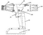
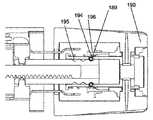
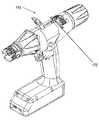
도 1은 전동 핸들의 일 실시예를 갖는 수술용 스테이플링 시스템의 일 실시예의 사시도이다.
도 2는 도 1의 수술용 스테이플링 시스템의 전동 핸들의 측면도이다.
도 3은 그것의 드라이브 시스템을 예시하기 위하여 컴포넌트들이 제거된 상태의 도 2의 전동 핸들의 부분 절개 사시도이다.
도 4는 도 2의 전동 핸들에 대한 드라이브 시스템의 일 실시예의 사시도이다.
도 5는 도 4의 드라이브 시스템의 사시도이다.
도 6은 도 4의 드라이브 시스템의 분해 사시도이다.
도 7은 도 4의 드라이브 시스템의 사시도이다.
도 8은 도 2의 전동 핸들에 대한 전원 공급장치의 일 실시예의 사시도이다.
도 9는 도 8의 전원 공급장치의 일 실시예의 단면 사시도이다.
도 10은 도 2의 전동 핸들의 절개 상면도이다.
도 11은 도 2의 전동 핸들의 관절 메커니즘의 일 실시예의 절개 상면도이다.
도 12는 관절화 위치(articulated position)의 도 10의 관절 메커니즘의 절개 상면도이다.
도 13은 다른 관절화 위치의 도 10의 관절 메커니즘의 절개 상면도이다.
도 14는, 릴리즈 버튼이 작동된 상태에서 중심화된 위치의 도 10의 관절 메커니즘의 절개 상면도이다.
도 15는 릴리즈 버튼이 작동된 상태에서 중심화된 위치의 도 10의 관절 메커니즘의 절개 상면도이다.
도 16은, 관절 메커니즘이 락 아웃된 구성에 있는 상태의 도 2의 전동 핸들의 절개 상면도이다.
도 17은, 관절 메커니즘이 잠금 해제된 구성에 있는 상태의 도 2의 전동 핸들의 절개 상면도이다.
도 18은 도 2의 전동 핸들의 관절 메커니즘 및 드라이브 시스템의 사시도이다.
도 19는, 도 2의 전동 핸들의 관절 메커니즘의 관절 링크들 및 락아웃 링크들의 사시도이다.
도 20은, 오버라이드(override) 복귀 메커니즘이 분리된 구성에 있는 상태의 도 2의 전동 핸들의 사시도이다.
도 21은, 오버라이드 복귀 메커니즘이 복귀 구성으로의 움직임을 위하여 잠금 해제된 상태의 도 2의 전동 핸들의 사시도이다.
도 22은, 오버라이드 복귀 메커니즘이 복귀 구성으로의 움직임을 위해 잠금 해제된 상태의 도 2의 전동 핸들의 부분 절개 사시도이다.
도 23은, 오버라이드 복귀 메커니즘이 분리된 구성에 있는 상태의 도 2의 전동 핸들의 부분 절개 측면도이다.
도 24는, 오버라이드 복귀 메커니즘이 복귀 구성으로의 움직임을 위하여 잠금 해제된 상태의 도 2의 전동 핸들의 부분 절개 측면도이다.
도 25는, 오버라이드 복귀 메커니즘이 복귀 구성에 있는 상태의 도 2의 전동 핸들의 사시도이다.
도 26은, 오버라이드 복귀 메커니즘이 복귀 구성에 있는 상태의 도 2의 전동 핸들의 부분 절개 사시도이다.
도 27은, 오버라이드 복귀 메커니즘이 복귀 구성에 있으며 수동 복귀 사이클이 개시된 상태의 도 2의 전동 핸들의 부분 절개 사시도이다.
도 27a는 도 2의 전동 핸들의 오버라이드 복귀 메커니즘의 복귀 폴(pawl)의 사시도이다.
도 27b는 도 2의 전동 핸들의 오버라이드 복귀 메커니즘의 측면도이다.
도 27c는 도 2의 전동 핸들의 오버라이드 복귀 메커니즘의 측면도이다.
도 28은 수술용 스테이플러에 대한 오버라이드 복귀 메커니즘의 다른 실시예의 측면도이다.
도 29는 도 28의 오버라이드 복귀 메커니즘의 사시도이다.
도 30은 도 28의 오버라이드 복귀 메커니즘의 사시도이다.
도 31은 도 28의 오버라이드 복귀 메커니즘의 측면도이다.
도 32는 수술용 스테이플링 디바이스의 특정 실시예들에서 사용하기 위한 재장전물 카트리지의 사시도이다.
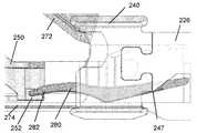
도 33은 수술용 스테이플링 디바이스의 세장형 샤프트 어셈블리의 특정 실시예들에서 사용하기 위한 발사 빔 및 발사 부재의 사시도이다.
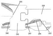
도 34는 수술용 스테이플링 디바이스의 세장형 샤프트 어셈블리의 특정 실시예들의 조 어셈블리의 근위 단부의 부분 분해 사시도이다.
도 35는 수술용 스테이플링 디바이스의 세장형 샤프트 어셈블리의 특정 실시예들의 조 어셈블리의 근위 단부의 절개 측면도이다.
도 36은, 발사되지 않은 재장전물이 부분적으로 삽입된 상태의 도 35의 조 어셈블리의 근위 단부의 절개 측면도이다.
도 37은, 발사되지 않은 재장전물이 부분적으로 삽입된 상태의 도 35의 조 어셈블리의 근위 단부의 절개 측면도이다.
도 38은, 발사되지 않은 재장전물이 부분적으로 삽입된 상태의 도 35의 조 어셈블리의 근위 단부의 절개 측면도이다.
도 39는, 발사되지 않은 재장전물이 삽입된 상태의 도 35의 조 어셈블리의 근위 단부의 절개 측면도이다.
도 40은, 적어도 부분적으로 발사된 재장전물이 부분적으로 삽입된 상태의 도 35의 조 어셈블리의 근위 단부의 절개 측면도이다.
도 41은, 재장전물이 삽입되지 않은 상태의 도 35의 조 어셈블리의 근위 단부의 절개 측면도이다.
도 42는 전기적으로 결합된 광 링(light ring) 사용자 디스플레이를 갖는 도 2의 전동 핸들의 부분 절개 측면도이다.
도 43는 도 2의 전동 핸들의 광 링 사용자 디스플레이의 측면도이다.
도 44는 도 2의 전동 핸들의 광 링 사용자 디스플레이의 사시도이다.
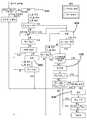
도 45는 도 2의 전동 핸들에 대한 제어 시스템의 일 실시예에 대한 정보 및 전력 흐름의 블록도이다.
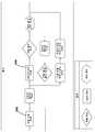
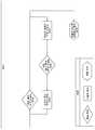
도 46은 도 2의 전동 핸들의 예시적인 동작 시퀀스에 대한 동작 시퀀스 흐름도이다.
도 47은 도 2의 전동 핸들의 제어 유닛에 의해 구현될 수 있는 모터 제어 로직 프로파일의 일 실시예의 개략도이다.
도 48은 도 2의 전동 핸들과 같은 전동 핸들에 대한 하나의 예시적인 조 어셈블리 그래스핑 및 발사-전 락아웃에 대한 모터 부하 대 작동 랙 위치의 플롯(plot)이다.
도 49는 도 2의 전동 핸들과 같은 전동 핸들에 대한 완전 발사를 통한 하나의 예시적인 조 어셈블리 그래스핑에 대한 모터 부하 대 작동 랙 위치의 플롯이다.
도 50은 전원이 켜지고 조직 그래스핑 구성들로 동작하는 도 2의 전동 핸들의 제어 유닛에 의해 구현될 수 있는 모터 제어 로직 프로파일의 일 실시예의 개략도이다.
도 51은 발사 구성으로 동작하는 도 50의 모터 제어 로직 프로파일의 실시예의 개략도이다.
도 52는 역전 구성으로 동작하는 도 50의 모터 제어 로직 프로파일의 실시예의 개략도이다.
도 53은 전원이 켜지고 조직 그래스핑 구성들로 동작하는 도 2의 전동 핸들의 제어 유닛에 의해 구현될 수 있는 모터 제어 로직 프로파일의 다른 실시예의 개략도이다.
도 54는 발사 구성으로 동작하는 도 53의 모터 제어 로직 프로파일의 실시예의 개략도이다.
도 55는 역전 구성으로 동작하는 도 53의 모터 제어 로직 프로파일의 실시예의 개략도이다.
도 56은 촉각 피드백 모듈의 모터 드라이브 프로파일의 일 실시예의 개략도이다.
도 57은 촉각 피드백 모듈의 모터 드라이브 프로파일의 다른 실시예의 개략도이다.
도 58은 전동 핸들 어셈블리의 일 실시예에 대한 특정 동작 조건들에 걸친 측정된 전류 드로우 대 작동 샤프트 위치의 예시적인 플롯이다.
도 59는 전동 핸들 어셈블리의 일 실시예에 대한 제 1 락아웃 맞물림 조건들에 걸친 측정된 전류 드로우 대 작동 위치의 예시적인 플롯이다.
도 60은 전동 핸들 어셈블리의 일 실시예에 대한 제 2 락아웃 맞물림 조건들에 걸친 측정된 전류 드로우 대 작동 위치의 예시적인 플롯이다.
도 61은 전동 핸들 어셈블리의 일 실시예에 대한 예시적인 락아웃 메커니즘 제어 로직 프로파일이다.
도 62는 전동 핸들 어셈블리의 일 실시예에 대한 모터 극성 검증 로직 구조이다.
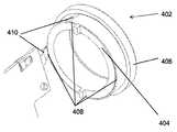
도 63은 전동 핸들 어셈블리에 대한 제거가능 메모리 모듈의 일 실시예의 사시도이다.
도 64a는 도 63의 제거가능 메모리 모듈의 제거의 측면도이다.
도 64b는 도 63의 제거가능 메모리 모듈의 제거의 측면도이다.
도 65는 전동 핸들 어셈블리의 특정 실시예들에 대한 제거가능 메모리 모듈의 다른 실시예의 사시도이다.
도 66은 전동 핸들 어셈블리의 특정 실시예들에 대한 제거가능 메모리 모듈의 다른 실시예의 사시도이다.1 is a perspective view of an embodiment of a surgical stapling system having an embodiment of an electric handle.
2 is a side view of an electric handle of the surgical stapling system of FIG. 1.
Fig. 3 is a partially cut-away perspective view of the powered handle of Fig. 2 with components removed to illustrate its drive system.
4 is a perspective view of an embodiment of a drive system for the power handle of FIG. 2;
5 is a perspective view of the drive system of FIG. 4;
6 is an exploded perspective view of the drive system of FIG. 4.
7 is a perspective view of the drive system of FIG. 4.
8 is a perspective view of an embodiment of a power supply device for the electric handle of FIG. 2.
9 is a cross-sectional perspective view of an embodiment of the power supply device of FIG. 8.
10 is a cutaway top view of the electric handle of FIG. 2.
11 is a cut-away top view of an embodiment of the joint mechanism of the power handle of FIG. 2.
Fig. 12 is a top cutaway view of the articulating mechanism of Fig. 10 in an articulated position.
13 is a cutaway top view of the joint mechanism of FIG. 10 in another articulating position.
14 is a cutaway top view of the joint mechanism of FIG. 10 in a centered position with the release button activated.
Fig. 15 is a cutaway top view of the joint mechanism of Fig. 10 in a centered position with the release button activated.
Fig. 16 is a cut-away top view of the electric handle of Fig. 2 with the joint mechanism in a locked-out configuration.
Fig. 17 is a cutaway top view of the powered handle of Fig. 2 with the joint mechanism in an unlocked configuration.
18 is a perspective view of the joint mechanism and drive system of the electric handle of FIG. 2;
19 is a perspective view of the articulation links and lockout links of the articulation mechanism of the power handle of FIG. 2;
Fig. 20 is a perspective view of the powered handle of Fig. 2 with the override return mechanism in a separate configuration.
Fig. 21 is a perspective view of the powered handle of Fig. 2 with the override return mechanism unlocked for movement to the return configuration.
Fig. 22 is a partially cut-away perspective view of the electric handle of Fig. 2 with the override return mechanism unlocked for movement to the return configuration.
Fig. 23 is a partially cutaway side view of the electric handle of Fig. 2 with the override return mechanism in a separate configuration.
Fig. 24 is a partially cut-away side view of the powered handle of Fig. 2 with the override return mechanism unlocked for movement to the return configuration.
Fig. 25 is a perspective view of the powered handle of Fig. 2 with the override return mechanism in the return configuration.
Fig. 26 is a partially cut-away perspective view of the electric handle of Fig. 2 with the override return mechanism in the return configuration.
Fig. 27 is a partially cut-away perspective view of the electric handle of Fig. 2 with the override return mechanism in a return configuration and a manual return cycle being initiated.
27A is a perspective view of a return pawl of the override return mechanism of the power handle of FIG. 2;
Fig. 27B is a side view of an override return mechanism of the electric handle of Fig. 2;
Fig. 27C is a side view of an override return mechanism of the electric handle of Fig. 2;
28 is a side view of another embodiment of an override return mechanism for a surgical stapler.
29 is a perspective view of the override return mechanism of FIG. 28;
Fig. 30 is a perspective view of the override return mechanism of Fig. 28;
Fig. 31 is a side view of the override return mechanism of Fig. 28;
32 is a perspective view of a reload cartridge for use in certain embodiments of a surgical stapling device.
33 is a perspective view of a firing beam and firing member for use in certain embodiments of an elongate shaft assembly of a surgical stapling device.
34 is a partially exploded perspective view of the proximal end of the jaw assembly of certain embodiments of an elongate shaft assembly of a surgical stapling device.
35 is a cutaway side view of the proximal end of the jaw assembly of certain embodiments of the elongate shaft assembly of a surgical stapling device.
FIG. 36 is a cutaway side view of the proximal end of the jaw assembly of FIG. 35 with a partially inserted reload that has not been fired.
37 is a cut-away side view of the proximal end of the jaw assembly of FIG. 35 with a partially inserted reload that has not been fired.
FIG. 38 is a cutaway side view of the proximal end of the jaw assembly of FIG. 35 with a partially inserted reload that has not been fired.
FIG. 39 is a cut-away side view of the proximal end of the jaw assembly of FIG. 35 with an unfired reload inserted.
FIG. 40 is a cutaway side view of the proximal end of the jaw assembly of FIG. 35 with a partially inserted at least partially fired reload.
Fig. 41 is a cut-away side view of the proximal end of the jaw assembly of Fig. 35 with no reloading material inserted.
FIG. 42 is a partially cutaway side view of the powered handle of FIG. 2 with an electrically coupled light ring user display.
43 is a side view of the optical ring user display of the electric handle of FIG. 2;
44 is a perspective view of an optical ring user display of the electric handle of FIG. 2;
45 is a block diagram of information and power flow for an embodiment of the control system for the electric handle of FIG. 2.
46 is an operation sequence flow diagram for an exemplary operation sequence of the power steering wheel of FIG. 2;
47 is a schematic diagram of one embodiment of a motor control logic profile that may be implemented by the control unit of the electric handle of FIG. 2;
FIG. 48 is a plot of motor load versus actuation rack position for one exemplary jaw assembly grasping and pre-fire lockout for a powered handle, such as the powered handle of FIG. 2;
FIG. 49 is a plot of motor load versus actuation rack position for one exemplary jaw assembly grasping through full firing for a powered handle, such as that of FIG. 2;
50 is a schematic diagram of one embodiment of a motor control logic profile that may be implemented by the control unit of the powered handle of FIG. 2 powered on and operating in tissue grasping configurations.
51 is a schematic diagram of an embodiment of the motor control logic profile of FIG. 50 operating in a firing configuration.
52 is a schematic diagram of an embodiment of the motor control logic profile of FIG. 50 operating in a reverse configuration.
FIG. 53 is a schematic diagram of another embodiment of a motor control logic profile that may be implemented by the control unit of the powered handle of FIG. 2, powered on and operating in tissue grasping configurations.
FIG. 54 is a schematic diagram of an embodiment of the motor control logic profile of FIG. 53 operating in a firing configuration.
55 is a schematic diagram of an embodiment of the motor control logic profile of FIG. 53 operating in a reverse configuration.
56 is a schematic diagram of one embodiment of a motor drive profile of a tactile feedback module.
57 is a schematic diagram of another embodiment of a motor drive profile of a tactile feedback module.
58 is an exemplary plot of measured current draw versus actuation shaft position over specific operating conditions for one embodiment of a power handle assembly.
59 is an exemplary plot of measured current draw versus actuation position over first lockout engagement conditions for one embodiment of a power handle assembly.
60 is an exemplary plot of measured current draw versus actuation position over second lockout engagement conditions for one embodiment of a power handle assembly.
61 is an exemplary lockout mechanism control logic profile for one embodiment of a powered handle assembly.
62 is a motor polarity verification logic structure for an embodiment of an electric handle assembly.
63 is a perspective view of one embodiment of a removable memory module for a power handle assembly.
64A is a side view of the removal of the removable memory module of FIG. 63;
64B is a side view of the removal of the removable memory module of FIG. 63;
65 is a perspective view of another embodiment of a removable memory module for certain embodiments of a power handle assembly.
66 is a perspective view of another embodiment of a removable memory module for certain embodiments of a power handle assembly.
도 1 내지 도 2를 참조하면, 수술용 스테이플링 시스템의 일 실시예가 예시된다. 수술용 스테이플러(10)의 예시된 실시예는 세장형 샤프트(20), 조 어셈블리(30), 및 핸들 어셈블리(40)를 포함한다. 도 1은, 전동 핸들의 일 실시예가 전동 스테이플 발사 및 수동 조 어셈블리 관절을 갖는 상태의 개방 구성의 조 어셈블리(30)를 갖는 수술용 스테이플러(10)를 예시한다. 도 2는 세장형 샤프트가 제거된 상태의 수술용 스테이플러 시스템(10)의 전동 핸들(40)을 예시한다. 도 2의 전동 핸들(40)은 전동 스테이플 발사 및 수동 조 어셈블리 관절을 갖는다. 예시된 실시예들에 있어서, 샤프트(20) 및 조 어셈블리(30)는 핸들(40) 상의 회전 손잡이의 회전에 의해서 샤프트(20)에 의해 획정(define)된 길이 방향 축에 대하여 자유롭게 회전될 수 있다. 다른 실시예들에 있어서, 스테이플링 시스템은 미리 정의된 범위 또는 회전적으로 고정된 조 어셈블리 내에서 길이 방향 축에 대한 조 어셈블리의 회전을 허용하도록 구성될 수 있다.1 to 2, an embodiment of a stapling system for surgery is illustrated. The illustrated embodiment of the
계속해서 도 1을 참조하면, 수술용 스테이플러(10)의 예시된 실시예는 복강경 수술 절차들에서 사용하기 위하여 크기가 결정되고 구성될 수 있다. 예를 들어, 세장형 샤프트(20) 및 조 어셈블리(30)는 액세스 포트 또는 투관침 캐뉼라(trocar cannula)를 통해 수술 필드 내로 도입될 수 있도록 크기가 결정되고 구성될 수 있다. 일부 실시예들에 있어, 세장형 샤프트(20) 및 조 어셈블리(30)는, 상대적으로 작은 작업 채널 직경, 예를 들어, 8 mm 미만의 직경을 갖는 투관침 캐뉼라를 통해 삽입될 수 있도록 크기가 결정되고 구성될 수 있다. 다른 실시예들에 있어, 세장형 샤프트(20) 및 조 어셈블리(30)는 더 큰 작업 채널 직경, 예를 들어, 10 mm, 11 mm, 12 mm, 또는 15 mm와 같은 직경을 갖는 투관침 캐뉼라를 통해 삽입될 수 있도록 크기가 결정되고 구성될 수 있다. 다른 실시예들에 있어, 본원에서 설명되는 수술용 스테이플러들의 특정 측면들이 개복 수술 절차들에서의 사용을 위한 수술용 스테이플링 디바이스 내에 통합될 수 있다는 것이 고려된다.With continued reference to FIG. 1, the illustrated embodiment of the
계속해서 도 1을 참조하면, 예시된 바와 같이, 세장형 샤프트(20)는 전반적으로 튜브형 부재를 포함한다. 세장형 샤프트(20)는 근위 단부로부터 원위 단부로 연장한다. 세장형 샤프트(20)는, 근위 단부(22)와 원위 단부(24) 사이에서 연장하는, 수술용 스테이플러(10)의 중심 길이 방향 축 L을 획정한다.With continued reference to FIG. 1, as illustrated, the
계속해서 도 1을 참조하면, 예시된 실시예에 있어서, 조 어셈블리(30)는 세장형 샤프트(20)의 원위 단부에서 세장형 샤프트(20)에 결합된다. 조 어셈블리(30)는 제 1 조(32) 및 제 1 조(32)에 피봇이 가능하게 결합된 제 2 조(34)를 포함한다. 예시된 실시예에 있어, 제 1 조가 중심 길이 방향 축 L을 따라 원위로 연장하고 그리고 핸들(40) 내의 관절 메커니즘에 응답하여 세장형 샤프트(20)에 대해 관절화될 수 있도록, 제 1 조(32)가 세장형 샤프트(20)의 원위 단부(24)에 고정된다. 초기 구성에서, 제 1 조(32)는 재장전물(reload)(50) 내부에 배치된 복수의 스테이플들(36)을 포함한다. 다른 실시예들에 있어서, 재장전물(50)은, 장전된 스테이플들을 갖는 전체 샤프트 어셈블리(20) 및 조 어셈블리(30)가 단일 재장전물 어셈블리를 획정하도록 조 어셈블리(30)와 통합될 수 있다. 일부 실시예들에 있어, 스테이플들은 초기에 제 2 조(34) 내에 위치될 수도 있다.With continued reference to FIG. 1, in the illustrated embodiment,
계속해서 도 1을 참조하면, 예시된 실시예에 있어서, 조 어셈블리(30)는 세장형 샤프트 내에서 길이 방향으로 슬라이드할 수 있는 드라이브 부재 또는 빔에 의해 개방 구성(도 1)으로부터 폐쇄 구성으로 그리고 스테이플링 구성으로 작동될 수 있다. 초기 위치에서, 빔은 세장형 샤프트(20)의 원위 단부(24)에 위치될 수 있다. 빔이 초기 위치에 있는 상태에서, 제 2 조(34)는 조 어셈블리(30)가 개방 구성이 되도록 제 1 조(32)로부터 멀어지도록 피봇된다. 작동 부재 또는 빔이 길이 방향 축 L을 따라 원위로 이동하면 작동 빔이 제 2 조(34)와 맞물린다. 작동 빔이 초기 위치로부터 원위로 제 1 거리를 병진 이동하는 것이 조 어셈블리를 개방 구성으로부터 폐쇄 구성으로 작동시킬 수 있다. 조 어셈블리(30)가 폐쇄 구성에 있는 상태에서, 작동 빔이 조 어셈블리(30)를 개방 구성으로 복귀시키기 위하여 제 1 거리만큼 근위로 복귀될 수 있다. 작동 빔의 원위 단부가 제 1 조(32)로부터 스테이플들을 전개(deploy)하도록 구성된 스테이플 슬라이더를 전진시킬 수 있으며, 그 결과 제 1 거리를 넘는 원위로의 작동 빔의 추가적인 병진 이동이 제 1 조(32) 내의 재장전물(50)로부터 복수의 스테이플들(36)을 전개한다.With continued reference to FIG. 1, in the illustrated embodiment, the
계속해서 도 1을 참조하면, 예시된 실시예에 있어서, 핸들 어셈블리는 세장형 샤트프(20)의 근위 단부에서 세장형 샤트프(20)에 결합되도록 구성된다. 예시된 바와 같이, 핸들 어셈블리(40)는 고정식 핸들(42)을 획정하는 하우징을 갖는 피스톨 그립(pistol grip) 구성 및 고정식 핸들(42)에 피봇 가능하게 결합된 이동가능 핸들(44) 또는 트리거를 갖는다. 다른 실시예들에서, 본원에서 설명되는 측면들을 포함하는 수술용 스테이플러가 다른 구성들, 예를 들어, 가위-그립 구성들, 또는 인-라인(in-line) 구성들과 같은 다른 구성들을 갖는 핸들 어셈블리들을 가질 수 있다는 것이 고려된다. 이하에서 더 상세하게 추가적으로 설명되는 바와 같이, 핸들 어셈블리(40)는 이동가능 핸들(44)의 움직임에 응답하여 구동 샤프트를 선택적으로 전진시키도록 구성된 전동 작동 메커니즘을 하우징한다.With continued reference to FIG. 1, in the illustrated embodiment, the handle assembly is configured to be coupled to the
예시된 실시예들에 있어서, 수술용 스테이플러(10)는 일회용 카트리지 재장전물(50) 내에 위치된 복수의 스테이플들(36)을 포함할 수 있으며, 반면 조 어셈블리(30)는 단일 절차에서 복수의 스테이플 카트리지 재장전물들(50)과 함께 재사용되도록 구성된다. 일부 실시예들에 있어, 세장형 샤프트(20) 및 조 어셈블리(30)가 제거가능하게 핸들 어셈블리(40)에 결합될 수 있는 일회용 재장전물 샤프트를 규정한다. 따라서, 예시된 실시예에 있어, 핸들 어셈블리(40)는 그 원위 단부에 커플러(coupler)(46)를 포함한다. 커플러(46)는 수술용 스테이플러(10)의 세장형 샤프트(20)와 맞물리도록 적응된다. 커플러(46)는, 핸들 어셈블리(42)를 세장형 샤프트(20)에 제거가능하게 연결할 수 있는 외부 커넥터, 핸들 어셈블리(42)의 작동 샤프트를 세장형 샤프트(20)의 드라이브 부재에 제거가능하게 연결할 수 있는 제 1 내부 커넥터, 및 핸들 어셈블리(42)의 작동 커플러를 세장형 샤프트(20)의 관절 링크에 제거가능하게 연결할 수 있는 제 2 내부 커넥터를 갖는 베이오넷 연결부(bayonet connection)를 가질 수 있다. 세장형 샤프트(20)가 핸들 어셈블리(42)에 결합될 때 이러한 3개의 제거가능 결합들이 동시에 발생한다. 따라서, 수술용 스테이플러(10)는, 핸들 어셈블리(40)가 수술 절차 동안 다수의 재장전물 샤프트들(20)과 함께 재사용될 수 있도록 구성될 수 있다. 다른 실시예들에 있어, 핸들 어셈블리 및 가늘고 긴 샤프트의 어떤 부분이 재사용이 가능할 수 있으며, 반면 조 어셈블리 내의 가늘고 긴 샤프트의 나머지가 일회용 카트리지를 규정하는 것으로 고려된다. 특정한 다른 실시예들에 있어, 핸들 어셈블리 및 세장형 샤프트가 재사용이 가능할 수 있으며, 반면 조 어셈블리가 일회용 카트리지를 획정한다. 또 다른 실시예들에 있어, 복수의 스테이플들을 하우징하는 조 삽입부(jaw insert)가 일회용 카트리지를 획정할 수 있으며, 반면 수술용 스테이플러의 나머지 부분이 재사용가능하다.In the illustrated embodiments, the
도 2을 참조하면, 수술용 스테이플링 시스템에 대한 전동 핸들의 일 실시예가 예시된다. 전동 핸들은, 샤프트 구성, 조 어셈블리 구성, 및 스테이플 구성이 특정 절차를 위하여 선택될 수 있도록 다양한 샤프트 재장전물들 및 카트리지들과 함께 사용될 수 있다. 핸들의 예시된 실시예는 전동(모터-구동형) 클램핑 및 조들의 개방과 스테이플 라인의 발사를 제공한다. 조 어셈블리의 관절은 수술자가 회전시키는 관절 손잡이에 의해 수동으로 제어될 수 있다. 모터는, 상이한 사용 단계 동안 핸들의 기능을 지시하는 내장형 제어 시스템에 의해 제어된다.2, an embodiment of an electric handle for a surgical stapling system is illustrated. The powered handle can be used with a variety of shaft reloads and cartridges so that the shaft configuration, jaw assembly configuration, and staple configuration can be selected for a particular procedure. The illustrated embodiment of the handle provides electric (motor-driven) clamping and opening of jaws and firing of staple lines. The joints of the jaw assembly can be manually controlled by a joint handle rotated by the operator. The motor is controlled by a built-in control system that directs the function of the handle during different stages of use.
계속해서 도 2를 참조하면, 전동 핸들(40)은 고정식 핸들(42) 및 거기에 피봇이 가능하게 결합된 이동식 핸들(44) 또는 트리거를 갖는 피스톨-그립 구성을 포함한다. 전원 공급장치(130) 또는 배터리는 고정식 핸들의 하부 표면 상에 위치될 수 있다. 전동 핸들(40)은 사용자가 스테이플링 시퀀스를 선택적으로 제어하는 것을 가능하게 하기 위한 발사 또는 발사/역전 버튼(150)과 같은 사용자 제어부를 더 포함할 수 있다. 전동 핸들(40)은, 전동 시스템 고장, 제어 시스템 고장, 전원 공급장치 고장, "조잠김(lockjaw)" 또는 다른 기계적인 묶임(binding)의 경우에 사용자가 수동으로 스테이플링 시스템을 개방 구성으로 복귀시키는 것을 가능하게 하기 위한 여분의 수동 복귀 시스템(170)을 더 포함할 수 있다. 전동 핸들은 회전가능 관절 손잡이(190)를 포함하는 수동 관절 메커니즘을 더 포함할 수 있다. 예시된 실시예에 있어서, 관절 손잡이(190)는 전동 핸들의 근위 단부 상에 위치되며, 전반적으로 스테이플링 시스템의 길이 방향 축에 대응하는 축에 대하여 회전할 수 있다. 일부 실시예들에 있어서, 전동 핸들은 사용자에게 희망되는 상태 표시를 디스플레이하기 위한 환형 광 링과 같은 조명형 사용자 디스플레이를 더 포함할 수 있다.With continued reference to Fig. 2, the
전동 핸들 어셈블리들 및 연관된 작동 메커니즘들의 다양한 실시예들은 "Reload Shaft Assembly for Surgical Stapler"라는 명칭으로 2017년 04월 12일자로 출원된 미국 특허 출원 일련번호 제15/486,227호 및 "Surgical Stapler Having a Powered Handle"이라는 명칭으로 2017년 04월 12일자로 출원된 미국 특허 출원 일련번호 제15/486,008호에 개시되며, 이러한 출원들 둘 모두는 그 전체가 본원에 참조로서 통합된다.Various embodiments of power handle assemblies and associated actuation mechanisms are described in U.S. Patent Application Serial No. 15/486,227 filed April 12, 2017 under the designation "Reload Shaft Assembly for Surgical Stapler" and "Surgical Stapler Having a Powered". US Patent Application Serial No. 15/486,008, filed April 12, 2017 under the name "Handle", both of which are incorporated herein by reference in their entirety.
전동 드라이브 시스템Electric drive system
도 3을 참조하면, 전동 핸들의 부분 절개도가 예시된다. 예시된 절개도에서, 전동 핸들의 몇몇 컴포넌트들은 전동 핸들의 드라이브 시스템을 명확하게 도시하기 위하여 제거되었다. 예시된 실시예에 있어서, 드라이브 시스템은 고정식 핸들(42) 내에 위치된 모터(112), 모터(112)의 출력 샤프트 상에 위치된 모터 기어(114), 및 모터 기어(114)와 드라이브 맞물림되는 보조 기어(116)를 포함한다. 일부 실시예들에 있어서, 모터(112)는 브러시형(brushed) DC 기어모터이다. 유익하게는, 보조 기어(116)를 통해 전력을 전달하는 것은 핸들 밸런스 및 사용자 인체공학을 향상시키기 위하여 모터(112)가 고정식 핸들 내에서 측방으로 중심에 위치되는 것을 가능하게 할 수 있다. 추가로, 일부 실시예들에 있어서, 모터 기어(114) 및 보조 기어(116)는 랙(122)에서 희망되는 동작 토크를 제공하도록 구성될 수 있다. 일부 실시예들에 있어서, 모터(112)는 희망되는 동작 토크를 제공하기 위하여 보조 기어(116)에 결합된 모터 기어(114)와 모터(112) 사이에 동작이 가능하게 결합되는 다중기어 트랜스미션(multigear transmission)을 포함할 수 있다. 모터(112)는 제어 시스템을 통해 전원 공급장치(130)에 전기적으로 결합될 수 있다. 핸들 내의 제어 시스템은 작동 샤프트(120)의 위치 및 그에 따른 조 어셈블리의 작동을 측정하기 위하여 드라이브 시스템과 인터페이스한다.3, a partial cutaway view of the electric handle is illustrated. In the illustrated cut-away view, several components of the power handle have been removed to clearly show the drive system of the power handle. In the illustrated embodiment, the drive system is in drive engagement with the
드라이브 시스템은, 핸들 내의 마이크로제어기를 포함하는 제어 시스템에 정보를 제공하는 하드웨어에 탑재된다. 이러한 내장형 시스템은 모터의 속력 및 토크를 제어할 수 있다. 이는 또한 사용자 입력들(트리거의 움직임 및 발사/역전 버튼의 눌림)에 기초하여 디바이스의 기능 및 드라이브 시스템의 위치를 제어할 수 있다. 제어 시스템은 또한 스테이플들을 계속해서 발사하기에 부하들이 너무 큰지 여부 또는 재장전물 카트리지 락아웃(lockout)이 활성화되었는지 여부를 결정하기 위하여 모터로부터의 피드백을 측정할 수 있다. 이는 또한 배터리 수명을 측정할 수 있으며, 디바이스의 발사 횟수를 제한할 수 있다. 드라이브 시스템이 주로 전동 동작들을 위하여 구성되지만, 특정 실시예들에 있어서, 본원에서 추가로 설명되는 바와 같이 오버라이드 전동 동작에 수동 복귀 메커니즘을 제공하는 것이 바람직할 수 있다.The drive system is mounted on hardware that provides information to the control system including the microcontroller in the handle. This built-in system can control the speed and torque of the motor. It can also control the function of the device and the position of the drive system based on user inputs (trigger movement and trigger/reverse button press). The control system can also measure feedback from the motor to determine whether the loads are too high to continue firing staples or whether a reload cartridge lockout has been activated. It can also measure battery life and limit the number of launches of the device. Although the drive system is primarily configured for electric power operations, in certain embodiments, it may be desirable to provide a manual return mechanism for the override electric operation as further described herein.
도 4 내지 도 6을 참조하면, 전동 핸들의 드라이브 시스템의 세부 도면들이 예시된다. 예시된 실시예에 있어서, 드라이브 시스템은, 지지 플레이트(121)에 의해 그것의 종점들 사이에서 지지되는 두갈래(bifurcated) 보조 기어(116)를 포함한다. 유익하게는, 보조 기어(116)에 대한 이러한 지지형 배열은, 강한 부하 조건들에서 모터 기어(114)가 보조 기어(116)로부터 분리되는 경향을 상당히 감소시킬 수 있는 견고한 메커니즘을 제공한다.4 to 6, detailed drawings of the drive system of the electric handle are illustrated. In the illustrated embodiment, the drive system includes a bifurcated
도 5 내지 도 6을 참조하면, 두갈래 보조 기어(116)는 제 2 기어 세그먼트(115)에 회전적으로 결합된 제 1 기어 세그먼트(113)를 포함한다. 제 1 기어 세그먼트(113)는 제 1 맞물림 표면을 포함할 수 있으며, 제 2 기어 세그먼트(115)는 제 2 맞물림 표면을 포함할 수 있으며, 그 결과 제 1 맞물림 표면 및 제 2 맞물림 표면은 제 1 기어 세그먼트(113)를 제 2 기어 세그먼트(115)에 회전적으로 결합하도록 결합될 수 있다. 예시된 실시예에 있어서, 제 1 기어 세그먼트(113)는 제 1 맞물림 표면을 획정(define)하는 축 방향으로 연장하는 돌기를 포함하며, 제 2 기어 세그먼트(115)는 제 2 맞물림 표면을 획정하는 축 방향으로 연장하는 돌기를 포함한다. 제 1 기어 세그먼트 및 제 2 기어 세그먼트의 축 방향으로 연장하는 돌기(boss)들 각각은, 제 1 기어 세그먼트(113) 및 제 2 기어 세그먼트(115)의 회전 결합을 가능하게 하는 사각 톱니형(square toothed) 또는 '캐슬(castle)" 프로파일을 포함한다. 일부 실시예들에 있어서, 제 1 및 제 2 기어 세그먼트들(113, 115)은 회전적으로 결합되며, 축 방향으로 연장하는 돌기들은, 제 1 기어 세그먼트(113) 및 제 2 기어 세그먼트(115) 중 하나의 외부 직경보다 더 작은 외부 직경을 갖는 중심 영역을 형성하도록 맞물린다.5 to 6, the bifurcated
도 6을 참조하면, 두갈래 보조 기어(116)를 갖는 드라이브 시스템의 분해도가 예시된다. 예시된 바와 같이, 드라이브 시스템은 보조 기어(116)의 제 1 단부와 제 2 단부 사이에 위치되는 지지 플레이트(121)를 더 포함한다. 지지 플레이트(121)는 그 안에 형성된 모터 기어 보어(bore)(125) 및 보조 기어 보어(123)를 갖는 강성 플레이트일 수 있다. 일부 실시예들에 있어서, 지지 플레이트(121)는 금속성 재료를 포함할 수 있다. 드라이브 시스템은 보조 기어 보어(123) 내에 위치된 보조 기어 부싱(bushing)(117) 및 모터 기어 보어(125) 내에 위치된 모터 기어 부싱(119)을 더 포함할 수 있다. 부싱들(117, 119)은 DELRIN® 재료와 같은 상대적으로 낮은 마찰 계수를 갖는 재료를 포함할 수 있다. 작동 샤프트 브래킷(bracket) 또는 가이드 부재(127)는 보조 기어(116)의 제 2 기어 세그먼트(115)와 작동 샤프트(120)의 랙(122)의 맞물림을 용이하게 할 수 있다.6, an exploded view of a drive system having a bifurcated
도 5 내지 도 6을 참조하면, 보조 기어(116)의 제 1 기어 세그먼트(113) 및 보조 기어의 제 2 기어 세그먼트(115)는, 보조 기어(116)의 중심 영역이 보조 기어 보어(123) 및 보조 기어 부싱(117)을 통해 연장하고 보조 기어(116)가 제 1 단부와 제 2 단부 사이에서 지지되도록 지지 플레이트(121) 주위에 조립될 수 있다. 예시된 실시예에 있어서, 보조 기어(116)의 제 1 기어 세그먼트(113)는 모터 기어(114)와 기어 맞물림(gear engagement)된다. 보조 기어(116)의 제 2 기어 세그먼트(115)는 작동 샤프트(120)의 랙 표면(122)과 기어 맞물림된다. 지지 플레이트(121)는 드라이브 시스템에 대한 지지를 제공하기 위하여 그 위에 형성된 돌기들 및 핸들 어셈블리 하우징의 벽들에 의해 봉지된다.5 to 6, in the
도 7을 참조하면, 전동 동작 동안, 보조 기어(116)는 핸들 몸체 내에서 길이 방향으로 연장하는 작동 샤프트(120) 상의 랙(122)과 메시 맞물림(mesh engagement)된다. 예시된 실시예에 있어서, 보조 기어는, 이를 통해 작동 샤프트(120)가 슬라이드하는 가이드 부재 내에 지지된다. 가이드 부재(127)는 보조 기어(116)와 랙(122) 사이의 메시 접촉을 유지하는데 도움을 준다. 작동 샤프트(120)의 원위 단부는, 전동 핸들의 원위 단부에서 커플러(46)(도 1) 내로 길이 방향으로 연장하는 작동 어댑터(124)에 자유롭게 회전하도록 결합된다.Referring to FIG. 7, during the transmission operation, the
샤프트(20)가 전동 핸들(40)의 커플러(46)에 결합되면, 작동 어댑터(124)는 베이오넷 연결을 통해 샤프트(20) 내의 드라이브 부재에 연결된다. 따라서, 샤프트(20)가 핸들(40)에 부착될 때, 모터(112) 및 랙(122)은 조 어셈블리에 결합되며 기구 샤프트(20) 내에서 연장하는 드라이브 부재를 드라이브할 것이다. 따라서, 핸들 내의 드라이브 시스템은 "랙과 피니언(rack and pinion)" 설계를 포함한다. 사용자의 입력에 응답하는 모터(112)의 동작은 스테이플러를 폐쇄, 발사, 또는 개방 동작들로 선택적으로 작동시키기 위하여 작동 샤프트(120)를 길이 방향으로 전방으로 및 후방으로 드라이브할 것이다.When the
도 8 및 도 9를 참조하면, 전동 핸들(40)에 대한 전원 공급장치(130)의 일 실시예가 예시된다. 전원 공급장치(130)는 전동 핸들 모터 및 제어 시스템에 직류를 전달하도록 구성될 수 있다. 예시된 실시예에 있어, 스테이플러는 12V에서 동작할 수 있다. 예시된 전원 공급장치는 12V 전원 공급을 생성하기 위하여 직렬로 연결된 4개의 3V 리튬-이온 배터리들(132)을 포함할 수 있다. 예시된 바와 같이, 배터리들(132)은 배터리 팩을 형성하기 위하여 플라스틱 하우징(134) 내에 4 x 1 구성으로 쌓인다. 다른 실시예들에 있어서, 개별적인 배터리 셀들의 다른 수들 및 구성들이 배터리 팩을 형성하기 위하여 사용될 수 있다. 예를 들어, 특정 실시예들에 있어서, 배터리 팩은 AA, AAA, 또는 다른 표준 또는 특정 목적을 위해 만들어진 단일 사용 또는 충전가능 화학 배터리로 구성될 수 있다. 전동 핸들(40)의 예시된 실시예에 있어서, 배터리 팩은 고정식 핸들의 하단에 위치된다. 바람직하게는, 이러한 위치결정은 평평한 표면 상에 핸들(40)을 고정하기 위한 안정적인 표면을 제공한다. 다른 실시예들에 있어서, 전원 공급장치는 핸들 내의 임의의 장소, 예컨대 핸들의 근위 단부에 위치될 수 있다는 것이 고려된다. 전원 공급장치(130)는 메인 파워 스위치 및 표시기 조명, 예컨대 발광 다이오드를 포함할 수 있다. 조명 컬러들, 플래싱(flashing) 시퀀스들, 또는 고체 조명의 사용을 통해서, 표시기 조명은, 전원 공급장치의 전원 온/오프 상태, 저 전력 상태, 또는 다른 전원 공급장치 상태 정보, 예컨대 충전 상태를 디스플레이하도록 구성될 수 있다.8 and 9, an embodiment of the
계속해서 도 8 및 도 9를 참조하면, 일부 실시예들에 있어서, 전원 공급장치(130)는 핸들(40)과 함께 패키징될 수 있지만 사용 전에는 설치되지 않을 것이다. 사용 시점에, 사용자는 전원 공급장치(130)를 핸들(40)의 하단과 맞물리게 함으로써 배터리 팩을 설치할 수 있다. 유익하게는, 설치되지 않은 배터리 팩을 운송하는 것이 사용 이전에 우연한 배터리 방전의 발생을 감소시킬 수 있다. 또한, 제거가능 배터리 팩은, 새로운 배터리 기술품을 입수할 수 있게 되었을 때 스테이플러 시스템이 새로운 배터리로 용이하게 업그레이드되는 것을 가능하게 할 수 있다. 다른 실시예들에 있어서, 전원 공급장치는, 배터리 팩의 전기적 연결을 차단하는 제거가능 스트립을 가진 상태로 핸들 내에 설치된 채로 패키징될 수 있다. 또 다른 실시예들에 있어서, 핸들에는 벽 소켓, USB 커넥터, 또는 다른 표준 전기 연결과 같은 AC 또는 DC 전원 내로 플러그되도록 구성된 전원 케이블이 구비될 수 있다.With continued reference to FIGS. 8 and 9, in some embodiments, the
일부 실시예들에 있어서, 전원은, 스테이플러의 사용의 디지털 기록을 저장할 수 있는 비-휘발성 메모리와 같은 메모리 모듈을 더 포함한다. 예를 들어, 메모리 모듈은, 발사 동안의 배터리 전압 및 모터 전류의 주기적인 샘플링, 소프트웨어 상태 머신의 상태들의 시퀀스, 발생했을 수 있는 예상되지 않은 임의의 이벤트들, 사용된 샤프트 유형들, 발사들의 횟수, 발사들 사이의 간격들, 및 스테이플러 핸들의 모델 및 일련 번호를 포함하는 스테이플러의 각각의 발사의 세부사항들을 기록하도록 구성될 수 있다. 메모리 모듈은 또한 사용자들이 배터리 팩을 재사용할 수 없도록 배터리 팩 자체가 사용되었는지 여부를 기록할 수 있다. 다른 실시예들에 있어서, 메모리 모듈은, 예컨대, 예를 들어, 회로 보드(144)(도 4) 상에 위치되거나 또는 이에 전기적으로 결합되거나, 또는 핸들 어셈블리의 전기 포트로부터 용이하게 제거가능하도록 위치되는, 전원으로부터 분리된 핸들 어셈블리 내에 배치될 수 있으며, 그 결과 메모리 모듈은 전원과 통합되지 않는다.In some embodiments, the power supply further includes a memory module, such as a non-volatile memory, capable of storing a digital record of the stapler's use. For example, the memory module may include periodic sampling of battery voltage and motor current during launch, a sequence of states in the software state machine, any unexpected events that may have occurred, shaft types used, number of launches. , Intervals between shots, and details of each shot of the stapler including the model and serial number of the stapler handle. The memory module can also record whether the battery pack itself has been used so that users cannot reuse the battery pack. In other embodiments, the memory module is, for example, located on or electrically coupled to the circuit board 144 (FIG. 4), or positioned to be easily removable from the electrical port of the handle assembly. It can be placed in a handle assembly separate from the power source, so the memory module is not integrated with the power source.
일부 실시예들에 있어서, 전동 핸들(40) 및 연관된 전원 공급장치(130)는 단일 절차에서 사용되고 절차 이후에 폐기되도록 구성될 수 있다. 전원 공급장치(130)는 재사용에 대한 기회를 감소시키기 위한 전력 드레인(power drain)을 포함할 수 있다. 수술 절차에서의 사용 다음에, 사용자는 핸들(40)로부터 배터리 팩을 제거할 수 있다. 핸들(40)로부터 배터리 팩을 제거하는 것은 배터리들을 고갈시키는 것을 개시할 수 있다. 예를 들어, 배터리 팩이 한번 사용된 이후에, 단자들을 낮은 값의 저항기들 또는 전기적 특징부에 연결함으로써 배터리를 단락시킬 수 있는 기계적인 특징부가 회로와 동일한 임무를 달성할 수 있다. 추가적으로, 수술 절차가 완료된 이후에 배터리 팩이 핸들(40) 내에 남겨진 경우, 일부 실시예들에 있어서, 핸들의 제어 시스템은 최소 시간 제한 이후에 기능을 불능화하고 배터리 팩을 고갈시키도록 프로그래밍된다. 예를 들어, 메모리 모듈을 포함하는 전원의 실시예들에 있어서, 마이크로제어기는, 미리 결정된 수의 발사 스트로크(stroke)들 이후에 메모리 모듈 상의 발사 카운트 메모리 위치와 같은 메모리 위치를 수정할 수 있는 발사 관리 모듈을 포함할 수 있다. 마이크로제어기는 기동(startup) 동작 시퀀스에서 발사 카운트 메모리 위치를 평가하도록 구성될 수 있다. 이러한 메모리 위치가 배터리가 사용되었음을 나타내는 경우, 일부 실시예들에 있어서, 마이크로제어기는 스테이플러를 디세이블(disable)하고 전원 내의 방전회로를 활성화하도록 구성될 수 있다. 마이크로제어기는 또한, 다른 미리 결정된 동작 조건들에서, 예컨대, 핸들 어셈블리가 미리 결정된 기간 동안, 예컨대, 일 실시예에 있어서, 12 시간보다 더 길게 전원이 켜졌거나, 미리 결정된 횟수, 예컨대, 일 실시예에 있어서, 12번보다 더 많이 발사되었거나, 수동 오버라이드 복귀 메커니즘을 전개하였거나, 또는 복구불능 고장을 경험했을 때 방전 회로를 활성화하도록 구성될 수 있다.In some embodiments, the
도 4 및 도 10을 참조하면, 전동 핸들 내에서 사용하기 위한 위치 센서 메커니즘의 일 실시예가 예시된다. 동작 시에, 모터 기어(114)의 회전은 핸들(40) 내에 장착된 크라운 기어(142)를 대응적으로 회전시킨다. 크라운 기어(142)는, 모터 기어(114)의 위치 및 그에 따라 작동 랙의 실제 위치가 전위차계에서의 저항의 변화들을 측정하는 것에 기초하여 결정될 수 있도록 전위차계에 결합된다. 일부 실시예들에 있어서, 전위차계는, 그 위에 제어 시스템에 위치될 수 있는 회로 보드(144) 상에 장착될 수 있다. 예시된 실시예가 전위차계-기반 위치 센서 메커니즘을 포함하지만, 다른 실시예들에 있어서, 예를 들어, 홀 효과 센서들을 갖는 자기 인코더의 사용, 작동 샤프트가 미리 결정된 거리를 이동했을 때 활성화되는 제한 스위치들의 사용, 작동 샤프트를 따른 패턴의 이동을 측정하기 위한 포토다이오드들, 모터의 샤프트 상에 위치된 광학적 인코더과 같은 광학적 시스템들의 사용, 또는 다른 위치 센싱 시스템들을 포함하는 다른 위치 센싱 메커니즘들이 사용될 수 있다는 것이 고려된다.4 and 10, one embodiment of a position sensor mechanism for use within a powered handle is illustrated. In operation, rotation of the
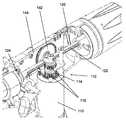
관절 메커니즘Joint mechanism
도 11 내지 도 17을 참조하면, 전동 핸들(40)에 대한 관절 메커니즘의 일 실시예가 예시된다. 예시된 실시예에 있어서, 핸들은 길이 방향 중심 위치에 대하여 어느 하나의 방향으로 완전히 관절화된 위치에서 최대 45°까지 샤프트의 원위 단부에서 조 어셈블리를 관절화할 수 있다. 일부 실시예들에 있어서, 전동 핸들은, 핸들의 근위 단부에서의 수동 작동형 관절 손잡이(190)에 결합된 일련의 컴포넌트들을 포함하는 수동 관절 메커니즘을 사용한다. 다른 실시예들에 있어서, 관절 메커니즘의 수동 작동형 관절 손잡이 및 특정한 연관된 엘리먼트들은 핸들의 다른 장소들에, 예컨대 핸들의 원위 단부에 인접하게 위치될 수 있다.Referring to Figures 11-17, one embodiment of an articulating mechanism for the
도 11 및 도 12를 참조하면, 관절 메커니즘은, 재장전물 샤프트가 핸들에 결합될 때 재장전물 샤프트 내에서 길이 방향으로 연장하는 관절 부재에 결합된다. 관절 메커니즘의 작동은 샤프트의 원위 단부에서 조 어셈블리를 관절화하기 위하여 관절 부재를 샤프트에 대하여 근위로 또는 원위로 길이 방향으로 병진 이동시킨다.11 and 12, the joint mechanism is coupled to an articulating member extending longitudinally within the reload shaft when the reload shaft is coupled to the handle. The actuation of the articulation mechanism translates the articulation member longitudinally proximally or distal to the shaft to articulate the jaw assembly at the distal end of the shaft.
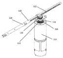
도 11을 참조하면, 관절 메커니즘은, 하나 이상의 볼 베어링(194)이 그 안에서 라이딩(ride)할 수 있는 적어도 하나의 나선형 홈 또는 스레드(thread)(195)를 갖는 볼 스크루(192)를 포함한다. 예시된 실시예에 있어서, 관절 메커니즘은 2개의 스레드들(195)과 맞물릴 수 있는 2개의 볼 베어링들(194)을 포함한다. 볼 베어링(194)은 볼 스크루(192)의 방사상으로 바깥쪽에 위치된 볼 슬리브(sleeve)(191) 내의 볼 베어링 개구들(189) 내에 위치된다. 볼 베어링들(194)은, 볼 베어링들(194)의 방사상으로 바깥쪽에 위치된 릴리즈 슬리브(196)에 의해 스레드들(195) 내에 유지된다. 예컨대 연결 핀들(193)에 의해 볼 슬리브(191)에 결합된 관절 손잡이(190)의 회전은 볼 슬리브(191)를 회전 축에 대하여 회전시키며, 이는 볼 베어링들(194)이 스레드들(195) 내에서 이동하고 그에 대응하여 볼 스크루(192)를 길이 방향으로 병진 이동시키게끔 한다. 조 어셈블리의 관절화는, 그들의 길이 방향 위치가 회전 축을 따라 고정되어 있는 동안 볼 슬리브(191) 및 볼 베어링들(194)을 회전 축에 대하여 대응적으로 회전시키기 위하여 관절 손잡이(190)를 회전시킴으로써 달성된다. 그러면, 볼 스크루(192)의 스레드들(195) 내에 맞물린 볼 베어링들(194)은 볼 스크루(192)를 회전 축을 따라 전방으로 및 후방으로 병진 이동시킬 것이다. 예시된 실시예에 있어서, 볼 슬리브(191)는 그 안에 형성된 공동을 갖는 전반적으로 튜브형이며, 볼 스크루(192)의 일 부분은 공동 내에 위치되고 공동 내에서 길이 방향으로 병진 이동한다. 관절 메커니즘의 예시된 실시예가 볼 스크루 내의 스레드들과 맞물릴 수 있는 2개의 볼 베어링들을 포함하지만, 다른 실시예들에 있어서, 관절 메커니즘이, 예를 들어, 단일 나선형 스크루 내에 위치된 단일 볼 베어링 또는 대응하는 수의 나선형 스레드들 내의 3개 이상의 볼 베어링들과 같이 2개보다 더 많거나 또는 더 적은 볼 베어링들을 가질 수 있다는 것이 고려된다.Referring to FIG. 11, the articulating mechanism includes a
도 11 및 도 12를 참조하면, 볼 스크루(192)는 관절 링크들(202)의 쌍에 결합된 원위 단부(200)까지 연장한다. 관절 링크들(202)은 서로 이격되며, 이는 바람직하게는 이들이 핸들 내의 드라이브 시스템 및 관절 샤프트의 방사상으로 바깥쪽에 위치되는 것을 가능하게 한다. 관절 링크들(202)의 원위 단부들은, 핸들의 원위 단부에서 관절 어댑터의 동축으로 방사상으로 바깥쪽에 위치될 수 있는 관절 어댑터(204)에 회전이 가능하게 결합될 수 있다. 이러한 회전 결합은 상대적으로 낮은 마찰 속성들을 갖는 관절 베어링(205)을 포함할 수 있다. 이러한 관절 베어링(205)은, 관절 메커니즘의 동작 동안 핸들 어셈블리에 대한 결합된 재장전물 샤프트의 회전 및 관절 어댑터(204)의 길이 방향 움직임을 가능하게 할 수 있다. 관절 메커니즘의 예시된 실시예가 핸들 내에서 관절 메커니즘으로부터 측방으로 오프셋된 2개의 관절 링크들을 포함하지만, 다른 실시예들에 있어서, 관절 메커니즘은, 예를 들어, 하나의 관절 링크 또는 3개 이상의 관절 링크들과 같이 2개보다 더 많거나 또는 더 적은 관절 링크들을 가질 수 있다는 것이 고려된다.11 and 12, the
계속해서 도 11 내지 도 13을 참조하면, 관절 어댑터(204)는, 샤프트가 핸들에 결합될 때 베이오넷 연결에 의해 샤프트 내의 관절 부재에 결합될 수 있다. 스레드들(195)은, 볼 스크루를 근위로 움직이는 것이 길이 방향 중심 위치에 대하여 핸들로부터 바라볼 때 조 어셈블리를 좌측으로 관절화하고 볼 스크루(192)를 원위로 움직이는 것이 중심 위치에 대하여 핸들로부터 바라볼 때 조 어셈블리를 우측으로 관절화하도록 구성될 수 있다. 도 12 및 도 13은 동작 범위의 말단들을 정의하는 완전화 관절화된 구성들로 위치된 관절 메커니즘을 예시한다.With continued reference to FIGS. 11 to 13, the
유익하게는, 볼 스크루(192)의 나선형 스레드들(195)이 연속적이기 때문에, 관절 메커니즘은 조 어셈블리가 희망되는 동작 범위 사이에서 실질적으로 유한한 각도 위치들로 관절화되는 것을 가능하게 할 수 있다. 일부 실시예들에 있어서, 관절 메커니즘은, 샤프트의 길이 방향 축에 의해 획정되는 길이 방향 중심 위치에 대하여 조 어셈블리의 -45° 내지 +45°의 관절화 동작 범위를 제공하도록 구성될 수 있다. 다른 실시예들에 있어서, 관절 메커니즘은 +/-45° 이상의 관절화를 제공하는 범위들 또는 +/-45° 미만의 관절화를 제공하는 범위들을 포함하는 다른 동작 관절화 범위들을 제공하도록 구성될 수 있다. 일부 실시예들에 있어서, 관절 메커니즘은 길이 방향 중심 위치에 대하여 단일 방향으로 관절화를 제공하도록 구성될 수 있다.Advantageously, since the
일부 실시예들에 있어서, 볼 스크루(192) 상의 스레드들(195)의 피치(pitch)는 가변적이다. 예를 들어, 스레드들(195)은 유익하게는, 조 어셈블리가 관절화를 위하여 더 많은 힘을 필요로 할 때 더 큰 기계적 이점을 제공하기 위하여 스레드들의 단부를 향한 상대적으로 낮은 피치를 포함할 수 있다. 스레드들(195)은, 조 어셈블리가 관절화를 위하여 더 낮은 힘을 필요로 할 때 상대적으로 더 낮은 기계적 이점을 가지고 빠른 움직임을 가능하게 하기 위하여 스레드들의 중심을 향한 상대적으로 더 높은 피치를 포함할 수 있다. 다른 실시예들에 있어서, 스레드들(195)은, 관절 손잡이의 회전이 스테이플러 조 어셈블리의 비례적인 양의 관절화를 야기하도록 관절 메커니즘의 관절화 범위에 걸쳐 변화하지 않는 일정한 피치를 포함한다. 바람직하게는, 이러한 일정한 피치의 스레드 볼 스크루는 작동 메커니즘의 동작 동안 용이하게 예측할 수 있는 응답을 야기할 수 있다.In some embodiments, the pitch of the
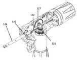
도 14 내지 도 15를 참조하면, 관절 메커니즘은, 관절 메커니즘이 유익하게는 임의의 관절화 위치로부터 길이 방향 중심 위치로 리셋되는 것을 가능하게 하는 릴리즈 메커니즘을 포함할 수 있다. 릴리즈 메커니즘은 사용자가 릴리즈 버튼(198)을 누름으로써 동작된다. 예시된 실시예에 있어서, 릴리즈 버튼(198)은 관절 손잡이(190) 내에 방사상으로 포개져 위치된다.With reference to FIGS. 14-15, the joint mechanism may comprise a release mechanism that advantageously allows the joint mechanism to be reset from any articulating position to a longitudinal center position. The release mechanism is operated by the user pressing the
도 14를 참조하면, 릴리즈 버튼(198)의 동작은 릴리즈 슬리브(196)를 원위로 전진시킬 것이다. 릴리즈 슬리브(196)의 방사상으로 내부 표면은 상대적으로 작은 내부 직경을 갖는 맞물림 표면(186) 및 맞물림 표면과 릴리즈 표면 사이에서 매끈한 램프(ramp)를 갖는 상대적으로 큰 내부 직경을 갖는 릴리즈 표면(188)을 포함하도록 단차가 있다. 동작 시에, 릴리즈 슬리브의 맞물림 표면은 볼 베어링들(194)을 볼 스크루(192)의 스레드들(195) 내에 유지한다. 일단 릴리즈 버튼(198)이 눌리면, 맞물림 표면은 원위로 전진되며, 이는 볼 베어링들(194)이 스레드들(195)로부터 분리되어 릴리즈 표면에 대한 볼 슬리브 내의 볼 베어링 개구들(189)을 통해 방사상으로 바깥쪽으로 전진하는 것을 가능하게 한다.Referring to FIG. 14, operation of the
계속해서 도 14를 참조하면, 볼 베어링들(194)이 스레드들(195)로부터 분리되면, 관절 메커니즘은 중심 위치로 편향될 수 있다. 일부 실시예들에 있어서, 볼 스크루(192)는 샤프트로부터의 스프링 힘 및 2개의 스프링들과 같은 편향 부재에 의해 중심 위치로 편향된다. 스레드들(195)을 따라 중심 위치에 위치된 볼 베어링들(194)은 조 어셈블리의 길이 방향 중심 위치에 대응한다.With continued reference to FIG. 14, when the
도 15를 참조하면, 일단 릴리즈 버튼(198)이 방해받지 않는 구성으로 복귀하도록 허용되면, 릴리즈 슬리브(196)는 스프링에 의해 근위로 견인된다. 릴리즈 슬리브(196)의 근위 움직임은 볼 베어링들(194)이 볼 스크루의 스레드들(195)과 맞물리도록 강제한다. 따라서, 그런 다음 관절 메커니즘이 길이 방향 중심 위치로부터 조 어셈블리를 관절화하기 위하여 사용될 수 있거나, 또는 스테이플러가 길이 방향 중심 위치에서 조 어셈블리와 함께 사용될 수 있다.Referring to FIG. 15, once
도 16 내지 도 17을 참조하면, 관절 메커니즘의 특정 실시예들의 샤프트 인식 및 관절 락아웃 메커니즘(300)이 예시된다. 관절 메커니즘은, 어떠한 기구 샤프트도 핸들 어셈블리에 결합되지 않는 경우 관절 메커니즘을 중심 위치에 유지하는 관절 락아웃 메커니즘을 포함할 수 있다. 따라서, 이상에서 이전에 논의된 기구 샤프트 및 핸들 어셈블리의 베이오넷 결합을 용이하게 하기 위하여 관절 어댑터(204)의 중심 위치가 유지된다. 심지어 어떠한 기구 샤프트도 핸들 어셈블리에 결합되지 않을 때에도 관절 메커니즘이 맞물린 구성으로 유지되는 경우, 기구 샤프트를 핸들 어셈블리와 결합하려고 하는 시도에서 기구 샤프트 내의 관절 부재를 관절 어댑터(204)와 정렬시키는 것이 어려울 수 있다. 핸들 어셈블리의 예시된 실시예에 있어서, 관절 락아웃 메커니즘은 샤프트 인식 메커니즘과 결합될 수 있다.16-17, the shaft recognition and
계속해서 도 16 내지 도 17을 참조하면, 샤프트 인식 및 관절 락아웃 메커니즘은 핸들 어셈블리의 원위 단부에서 락아웃 슬리브(302) 및 락아웃 슬리브에 결합된 적어도 하나의 락아웃 암(arm)(304)을 포함한다. 예시된 실시예에 있어서, 락아웃 슬리브(302)는 관절 어댑터(204)의 방사상으로 바깥쪽에 위치될 수 있다. 예시된 바와 같이, 관절 락아웃 메커니즘은 릴리즈 슬리브(196)에 결합된 근위 단부로부터 락아웃 슬리브(302)에 결합된 원위 단부까지 핸들 어셈블리 내에서 길이 방향으로 연장하는 2개의 락아웃 암들(304)을 포함한다. 락아웃 암들은 관절 링크들(202) 및 관절 샤프트(120) 및 다른 드라이브 메커니즘 컴포넌트들의 측방으로 바깥쪽에 위치될 수 있다. 다른 실시예들에 있어서, 하나 또는 2개 이상의 락아웃 암들(304)이 락아웃 슬리브(302)를 릴리즈 슬리브(196)에 결합할 수 있으며, 락아웃 암들(304)은 예시된 실시예와는 상이한 측방 위치에 배치될 수 있다.With continued reference to FIGS. 16-17, the shaft recognition and joint lockout mechanism includes a
동작 시에, 기구 샤프트가 핸들 어셈블리에 결합될 때, 락아웃 슬리브(302)는 기구 샤프트의 근위 단부에서의 돌기, 탭, 칼라(collar), 또는 다른 엘리먼트와 접촉한다. 이러한 접촉은, 베이오넷 결합이 맞물림에 따라 락아웃 슬리브를 미리 결정된 양만큼 근위로 병진 이동시킨다. 어떠한 기구 샤프트도 핸들 어셈블리에 연결되지 않으면(도 16), 관절 락아웃 메커니즘 및 릴리즈 슬리브(196)는, 볼 베어링들이 그것의 릴리즈 표면에 기대어 있는 상태로 릴리스 슬리브(196)가 위치되도록 구성된다. 따라서, 관절 메커니즘은 락 아웃된 구성에 있다. 따라서, 어떠한 기구 샤프트도 핸들 어셈블리에 결합되지 않으면, 볼 베어링들이 볼 스크루의 스레드들로부터 분리되기 때문에 관절 메커니즘을 작동시키지 않고 관절 손잡이가 회전될 수 있다.In operation, when the instrument shaft is coupled to the handle assembly, the
도 17을 참조하면, 일단 기구 샤프트가 핸들 어셈블리에 결합되면, 관절 락아웃 메커니즘은 맞물림 구성으로 이동된다. 락아웃 슬리브와 기구 샤프트의 맞물림은 락아웃 슬리브(302) 및 그것에 결합된 락아웃 암들(304)을 근위로 병진 이동시킨다. 락아웃 암들(304)의 근위 단부들은, 락아웃 암들(304)의 근위 움직임이 릴리즈 슬리브(196)를 근위로 전진시켜서 볼 베어링들을 볼 스크루의 스레드들과 맞물리게 하도록 관절 메커니즘의 릴리스 슬리브(196)에 결합된다. 따라서, 기구 샤프트가 부착되면, 관절 손잡이의 회전은 기구 샤프트에 결합된 엔드 이펙터(end effector)를 관절화하기 위한 관절 어댑터의 병진 이동을 야기한다.Referring to Fig. 17, once the instrument shaft is coupled to the handle assembly, the articulated lockout mechanism is moved into an engaged configuration. The engagement of the lockout sleeve and the instrument shaft translates the
도 18 및 도 19를 참조하면, 관절 메커니즘 및 샤프트 인식/관절 락아웃 메커니즘은 각기 개별적인 메커니즘의 위치를 식별하기 위하여 센서(306, 308)를 포함할 수 있다. 예시된 실시예에 있어서, 관절 메커니즘의 센서는 하나의 관절 링크(202) 상에 형성된 톱니형 랙과 기어 맞물림된 전위차계를 포함하며, 샤프트 인식/관절 락아웃 메커니즘의 센서는 하나의 락아웃 암(304)과 기어 맞물림된 전위차계를 포함할 수 있다. 일부 실시예들에 있어서, 관절 메커니즘 및 샤프트 인식/관절 래치(latch) 메커니즘의 센서들은 각기, 그 위에 제어 시스템에 위치될 수 있는 회로 보드(144) 상에 장착될 수 있다. 따라서, 관절 위치 및 샤프트 인식 위치 데이터 중 하나 또는 둘 모두는, 전동 핸들의 개방/폐쇄, 발사, 및 복귀 동작 동안 모터 드라이브 프로파일을 수정하기 위해 제어 시스템에 의해 통합될 수 있다. 예를 들어, 관절 위치는, 모터의 특정 동작 상태들이 주어진 측정된 관절을 고려하여 작동기의 교정된 위치에 기초하여 제어될 수 있도록 측정된 작동기 랙 및 작동기 위치에 교정 값을 적용하기 위해 제어 시스템에 의해 통합될 수 있다. 예시된 실시예가 전위차계-기반 위치 센서 메커니즘을 포함하지만, 다른 실시예들에 있어서, 다른 위치 센싱 메커니즘이 사용될 수 있음이 고려된다.18 and 19, the joint mechanism and shaft recognition/joint lockout mechanism may each include
수동 오버라이드 복귀 시스템Manual override return system
도 20 내지 도 27을 참조하면, 전동 핸들에 대한 수동 복귀 메커니즘의 일 실시예가 예시된다. 수동 복귀 메커니즘은 유익하게는, 전원 공급장치 고장, 다른 전동 컴포넌트 고장, 또는 기계적 고장 또는 묶임의 경우에 여분의 복귀 메커니즘을 제공할 수 있다.20-27, an embodiment of a manual return mechanism for an electric handle is illustrated. The manual return mechanism can advantageously provide a redundant return mechanism in case of power supply failure, other electric component failure, or mechanical failure or bundling.
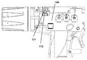
도 20 내지 도 25를 참조하면, 수동 복귀 메커니즘은, 작동 샤프트(120)를 조 어셈블리의 개방 구성에 대응하는 핸들 내의 최-근위 위치로 복귀시키기 위한 시퀀스에서 동작되는 3개의 별개의 독립적으로 동작할 수 있는 서브어셈블리들을 포함한다. 예시된 바와 같이, 수동 복귀 메커니즘(170)은 복귀 잠금 메커니즘, 샤프트 회전 메커니즘 및 샤프트 견인 메커니즘을 포함한다. 도 20은, 복귀 잠금 메커니즘이 잠긴 구성에 있는 상태의 전동 동작 모드의 전동 핸들을 예시한다. 동작 시에, 수동으로 스테이플러를 개방 구성으로 복귀시키는 것이 바람직할 때, 복귀 잠금 메커니즘은 처음에 수동 복귀 메커니즘을 잠금 해제하도록 작동된다.20-25, the manual return mechanism is operated in a sequence to return the
도 21 내지 도 22에 예시된 바와 같이, 복귀 잠금 메커니즘을 작동시키기 위하여, 복귀 잠금부(171)는 처음에 핸들 어셈블리의 하우징에 대하여 근위로 슬라이드된다. 복귀 잠금부(171)의 이러한 움직임은 샤프트 회전 메커니즘 및 샤프트 견인 메커니즘을 잠금 해제한다. 예시된 실시예에 있어서, 복귀 잠금부(171)는, 이것이 샤프트 회전 메커니즘의 움직임을 간섭하는 위치에서 벗어나도록 이동되며, 이는 사용을 위하여 샤프트 회전 메커니즘을 노출시킨다. 동시에, 복귀 잠금부(171)는 샤프트 견인 메커니즘 상의 잠금 돌출부들(173) 또는 탭들로부터 분리되며, 이는 샤프트 메커니즘이 핸들 어셈블리로부터 멀어지도록 피봇하는 것을 가능하게 한다. 샤프트 견인 메커니즘의 레버는 핸들 어셈블리로부터 멀어지도록 편향될 수 있으며, 이는 이것이 복귀 잠금부가 근위로 슬라이드될 때 핸들 어셈블리로부터 멀어지도록 피봇하게끔 한다.21-22, in order to activate the return locking mechanism, the
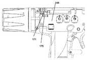
도 23 및 도 24를 참조하면, 복귀 잠금부가 복귀 메커니즘을 잠금 해제하기 위해 근위로 슬라이드될 때, 복귀 잠금부(171)는 핸들 어셈블리의 전원을 차단하기 위해 핸들 어셈블리의 제어 유닛에 전기적으로 결합될 수 있다. 따라서, 일단 복귀 잠금 메커니즘이 동작되면, 핸들은, 심지어 사용자가 반복 사용을 위해 수동 복귀 메커니즘 및 드라이브 시스템을 수동으로 재위치시키려고 시도하는 경우에도 추가적인 사용으로부터 디세이블될 수 있다. 예시된 실시예에 있어서, 핸들 어셈블리가 전동 동작을 위해 구성될 때(도 23), 복귀 잠금부는 제어 유닛을 갖는 회로 보드(144)로부터 전기적으로 분리된다. 복귀 잠금부가 복귀 메커니즘을 잠금 해제하기 위해 근위로 슬라이드될 때, 복귀 잠금부는, 핸들 어셈블리의 전원을 차단하기 위해 회로 보드(144) 상의 회로에 전기적으로 맞물리는 압인된 스프링 컴포넌트(175)를 근위로 움직인다. 스프링 컴포넌트(175)는 근위 움직임만을 위해 구성되며, 심지어 복귀 잠금부가 그것의 초기 위치로 원위로 복귀되는 경우에도 원위로 복귀하지 않는다. 따라서, 복귀 잠금부(171)를 슬라이드함으로써 복귀 메커니즘을 잠금 해제하는 것은 핸들 어셈블리의 전동 기능을 영구적으로 디세이블한다.23 and 24, when the return lock portion slides proximally to unlock the return mechanism, the
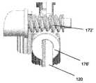
도 25 및 도 26을 참조하면, 수동 복귀 메커니즘(170)의 샤프트 회전 메커니즘을 동작시키기 위하여, 사용자는, 이제 복귀 잠금부의 움직임에 의해 차단이 해제된, 핸들의 외부 표면으로 연장하도록 회전 레버(172)를 회전시킨다. 회전 레버(172)는 작동 샤프트에 회전적으로 결합된 샤프트 회전 칼라에 결합된다. 예시된 실시예에 있어서, 작동 샤프트(120)는 샤프트 회전 칼라(176)를 통해 연장하며, 이를 통해 슬라이드할 수 있다. 따라서, 샤프트 회전 칼라(collar)(176)를 회전시키는 것이 작동 샤프트(120)를 그것의 길이 방향 축에 대하여 약 90도 회전시킨다. 이러한 회전은 작동 샤프트의 랙(122)을 드라이브 시스템의 보조 기어(116)와의 맞물림으로부터 벗어나도록 위치시킨다. 이러한 회전은 작동 어댑터에 영향을 주지 않고 달성될 수 있으며, 이는 작동 샤프트(120)가 작동 어댑터에 회전가능하게 결합되기 때문이다(도 5).Referring to Figures 25 and 26, in order to operate the shaft rotation mechanism of the
예시된 실시예가 사용자에 의해 회전되는 회전 레버(172)를 갖는 샤프트 회전 메커니즘을 포함하지만, 다른 실시예들에 있어서, 샤프트 회전 메커니즘은 복귀 잠금부의 근위 움직임 시에 자체-전개(self-deploy)하도록 구성될 수 있다. 예를 들어, 샤프트 회전 메커니즘을 자체-전개하는 것은 비틀림 편향을 갖는 샤프트 회전 칼라를 포함할 수 있다. 특정 실시예들에 있어서, 샤프트 회전 칼라는 비틀림 스프링에 의해 핸들 어셈블리에 결합된다. 복귀 잠금부가 근위로 슬라이드될 때, 샤프트 회전의 비틀림 편향은 작동 랙을 보조 기어로부터 분리하고 작동 랙을 샤프트 견인 메커니즘과 맞물리게 하기 위하여 작동 랙을 회전시키는 경향이 있다.While the illustrated embodiment includes a shaft rotation mechanism having a
도 26 및 도 27을 참조하면, 일단 샤프트 회전 메커니즘이 동작되었으면, 샤프트 견인 메커니즘이 작동 샤프트를 핸들 내에서 근위로 복귀시키기 위하여 동작될 수 있다. 복귀 잠금부를 핸들 어셈블리 내에서 슬라이드시키는 것은 전동 핸들 상의 복귀 레버(180)를 잠금 해제한다. 복귀 레버(180)는 피봇 조인트(184)에서 복귀 폴(182)에 피봇이 가능하게 결합된다. 작동 샤프트(120)의 랙(122)이 드라이브 시스템과의 맞물림을 벗어나도록 회전되었을 때, 이는 샤프트 견인 메커니즘과 맞물리도록 회전된다. 복귀 레버(180)는, 복귀 폴(182)을 작동 샤프트(120) 상의 랙(122)과 맞물리게 하고 작동 샤프트(120)를 래칫-형(ratchet-type) 동작으로 핸들 내에서 근위로 견인하기 위하여 하나의 또는 일련의 복귀 사이클들(도 26, 도 27)을 통해 회전될 수 있다.Referring to Figures 26 and 27, once the shaft rotation mechanism has been operated, the shaft traction mechanism can be operated to return the actuating shaft proximally within the handle. Sliding the return lock within the handle assembly unlocks the
도 27a 내지 도 27c를 참조하면, 복귀 폴(182)은 작동 샤프트 견인을 용이하게 하도록 구성될 수 있다. 예시된 실시예에 있어서, 복귀 폴(182)은, 복귀 사이클의 일 부분 동안 모터 마운트의 가이드 부재(127)와 상호작용하도록 위치된 돌출 돌기 또는 제 2 폴 톱니(183)를 포함한다. 제 2 폴 톱니(183)가 가이드 부재(127)와 접촉할 때, 복귀 폴(182)은 작동 샤프트(120)의 랙(122)과 맞물리는 것이 제한된다(도 27b). 바람직하게는, 제 2 폴 톱니(183)는, 사용자가 그렇지 않았다면 상대적으로 낮은 기계적 장점을 가졌을, 복귀 사이클의 일 부분 동안 랙(122)과의 복귀 폴(182)의 맞물림을 제한하도록 위치될 수 있다. 예시된 바와 같이, 제 2 폴 톱니(183)는, 복귀 레버(180)가 희망되는 기계적 장점을 제공하기 위해 작동 샤프트(120)의 길이 방향 축에 대하여 미리 결정된 각도로 위치될 때까지(도 27c), 복귀 폴(182)이 랙(122)과 맞물리는 것을 방지한다.27A-27C, the
도 28 내지 도 31을 참조하면, 전동 핸들에 대한 수동 복귀 메커니즘의 다른 실시예가 예시된다. 수동 복귀 메커니즘(170')의 컴포넌트들 및 동작은 도 20 내지 도 27의 수동 복귀 메커니즘(170)에 대하여 이상에서 설명된 것과 유사하다. 그러나, 수동 복귀 메커니즘(170')의 사용 시에, 복귀 잠금 및 샤프트 회전 메커니즘 기능은 웜 기어-구동형(worm gear-driven) 샤프트 회전 칼라(176')에 의해 제공될 수 있다. 따라서, 사용자는 처음에, 예를 들어, 6각형 키를 가지고 웜 기어 드라이브를 회전시킴으로써 전동 드라이브 시스템으로부터 멀어지도록 작동 샤프트(120)를 회전시킬 수 있다. 웜 기어의 회전을 통해, 샤프트 회전 메커니즘은 샤프트 견인 메커니즘을 릴리즈하고, 작동 랙을 전동 드라이브로부터 분리하며, 작동 랙을 샤프트 견인 메커니즘과 맞물리도록 위치시킨다(도 31). 수동 복귀 메커니즘(170')의 샤프트 견인 메커니즘은 수동 복귀 메커니즘(170)과 관련하여 이상에서 논의된 것과 유사한 복귀 폴(182')에 피봇가능하게 결합된 복귀 레버(180')를 갖는 래칫-형 동작을 포함한다.Referring to Figures 28-31, another embodiment of a manual return mechanism for an electric handle is illustrated. The components and operation of the manual return mechanism 170' are similar to those described above for the
2-위치 락아웃 메커니즘2-position lockout mechanism
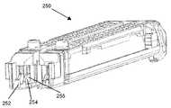
도 32를 참조하면, 발사된 재장전물 락아웃 메커니즘 및 별개의 빈 조 어셈블리를 갖는 수술용 스테이플러 디바이스의 세장형 샤프트와 함께 사용하기 위한 재장전물 카트리지(250)가 예시된다. 이하에서 추가로 설명되는 바와 같이, 조 어셈블리 내에 어떠한 재장전물 카트리지(250)도 존재하지 않으며 사용자가 개방-폐쇄 스트로크에서 조 어셈블리를 그래스핑하려고 시도하는 경우, 2-위치 락아웃 레버는 먼저 잠긴 위치로 이동할 것이다. 예시된 바와 같이, 재장전물 카트리지는, 재장전물이 조 어셈블리의 재장전물 지지부 내에 위치될 때, 빈 조 어셈블리 락아웃 메커니즘을 극복(defeat)하기 위하여 2-위치 락아웃 레버를 제 2 위치에 위치시키도록 크기가 결정되고 위치되는 제 1 락아웃 작동기를 포함한다. 제 1 락아웃 작동기는 카트리지의 몸체의 측벽으로부터 측방으로 안쪽으로 연장하는 램프형 돌기(ramped boss)(252)를 포함할 수 있다.Referring to FIG. 32, a reload
계속해서 도 32를 참조하면, 예시된 실시예에 있어서, 재장전물 카트리지(250)는, 발사되지 않은 재장전물이 조 어셈블리 내에 위치될 때 발사된 재장전물 락아웃 메커니즘을 극복하기 위하여 2-위치 락아웃 레버를 잠금 해제된 위치에 위치시키도록 크기가 결정되고 구성된 제 2 락아웃 작동기를 포함한다. 따라서, 2개의 락아웃 위치들에 더하여, 2-위치 락아웃 레버가 잠금해제된 위치로 피봇이 가능하다. 특정 실시예들에 있어서, 제 2 락아웃 작동기는 재장전물 카트리지(250)의 슬라이더(255)로부터 근위로 연장하는 테일(tail)(254)을 포함한다. 재장전물 카트리지(250)가 발사되지 않은 상태에 있을 때, 슬라이더(255)는, 슬라이더 테일(254)이 락아웃 레버와 맞물리도록 근위로 연장하도록 근위 위치에 존재한다. 발사 부재가 발사 스트로크에서 원위로 전진됨에 따라, 이는 재장전물 카트리지 내의 슬라이더와 접하며, 슬라이더를 원위로 전진시킨다. 따라서, 일단 재장전물 카트리지(250)가 부분적으로 발사된(또는 완전히 발사된) 상태에 있게 되면, 근위로-연장하는 슬라이더 테일(254)은 발사된 재장전물 락아웃 메커니즘을 극복하기 위한 제 위치에 존재하지 않는다.With continued reference to FIG. 32, in the illustrated embodiment, the
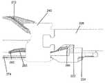
도 33을 참조하면, 발사된 재장전물 락아웃 메커니즘 및 별개의 빈 조 어셈블리를 갖는 수술용 스테이플러 디바이스의 세장형 샤프트와 함께 사용하기 위한 발사 빔(226)이 예시된다. 발사 빔(226)은 근위 단부로부터 원위 단부(230)로 연장한다. 전반적으로 I-빔 구성을 갖는 발사 부재(240)는 발사 빔(226)의 원위 단부(230)에 배치된다. I-빔 발사 부재(240)의 상부 및 하부 수평 플랜지(flange)들(242, 244)은 조들에 접근하기 위해 조 어셈블리의 제 1 및 제 2 조들 내의 채널들에 라이딩하며, 그런 다음 스테이플 발사 동안 조들의 간격을 유지한다. 커팅 블레이드(245)는 스테이플들의 로우들 사이에서 조직을 가로로 절개하기 위해 I-빔 프로파일의 수직 부분 상에 위치된다. I-빔 발사 부재(240)는, 인터락 핏(interlock fit), 용접, 다른 연결 기술, 또는 이들의 일부 조합에 의해 발사 빔(226)의 원위 단부에 부착될 수 있다. I-빔 발사 부재(240)의 근위 에지는, 발사 빔(226)이 개방 조 어셈블리에 대응하는 완전히 견인된 위치에 있는 상태에서 락아웃 레버의 근위 부분 상에 놓일 수 있는 근위로-연장하는 돌출부 또는 테일(247)을 가질 수 있다.Referring to FIG. 33, a
계속해서 도 33을 참조하면, 발사 빔은 빈 조 어셈블리 락아웃 메커니즘과 함께 사용하기 위한 제 1 락아웃 노치(notch)(222) 및 발사된 재장전물 락아웃 메커니즘과 함께 사용하기 위한 제 2 락아웃 노치(224)를 포함할 수 있다. 예시된 실시예에 있어서, 제 1 락아웃 노치(222)는 발사 빔(226)의 인접한 하부 에지(220)로부터 제 1 높이로 연장한다. 이하에서 추가로 설명되는 바와 같이, 제 1 높이는, 재장전물 카트리지가 존재하지 않는 상태에서 조 어셈블리에 접근하려고 하는 시도에 의해 빈 조 어셈블리 락아웃이 작동되었을 때 락아웃 레버의 근위 단부의 높이에 대응하도록 선택된다.With continued reference to FIG. 33, the firing beam is a
계속해서 도 33을 참조하면, 예시된 실시예에 있어서, 제 2 락아웃 노치(224)는 제 1 락아웃 노치(222)의 근위에서 발사 빔 상에 위치된다. 제 2 락아웃 노치(224)는 발사 빔(226)의 인접한 하부 에지(220)로부터 제 2 높이로 연장한다. 이하에서 추가로 설명되는 바와 같이, 제 2 높이는, 이전에 발사된 또는 부분적으로 발사된 재장전물을 발사하려는 시도에 의해 발사된 재장전물 락아웃 메커니즘이 작동되었을 때 락아웃 레버의 근위 단부의 높이에 대응하도록 선택된다.With continued reference to FIG. 33, in the illustrated embodiment, the
발사 빔(226)의 예시된 실시예는, 발사 빔의 인접한 하부 에지(220)가 제 1 락아웃 노치(222) 및 제 2 락아웃 노치(224)에 대응하는 길이 방향 스팬(span)에 걸쳐 두드러지도록(relieved) 실질적으로 연속한 제 1 락아웃 노치(222) 및 제 2 락아웃 노치(224)를 갖는다. 다른 실시예들에 있어서, 제 1 락아웃 노치 및 제 2 락아웃 노치는 발사 빔의 하부 에지의 두드러지지 않은 세그먼트에 의해 서로 이격될 수 있다. 본원에서 추가로 설명되는 바와 같이, 제 1 락아웃 노치 및 제 2 락아웃 노치의 높이들 및 길이 방향 위치들은 스테이플러 핸들 어셈블리의 희망되는 동작 특성들을 달성하도록 구성될 수 있다.The illustrated embodiment of the
도 34 및 도 35를 참조하면, 조 어셈블리(270)의 일 부분이 부분적인 분해도(도 34)로 그리고 절개 측면도(도 35)로 예시되며, 여기에서 다양한 컴포넌트들은 빈 조 어셈블리 락아웃 메커니즘 및 발사된 재장전물 락아웃 메커니즘의 예시를 위해 감춰진다. 특정 실시예들에 있어서, 락아웃 메커니즘들은 2-위치 락아웃 레버(280), 편향 스프링(290), 제 1 락아웃 노치(222), 및 제 2 락아웃 노치(224)를 포함한다. 3 위치 락아웃 레버(280)는 재장전물 카트리지 상의 제 1 락아웃 작동기 및 제 2 락아웃 작동기와 맞물리도록 구성된 원위 단부(282), 원위 단부의 근위의 피봇(284), 및 제 1 락아웃 노치, 제 2 락아웃 노치 중 하나와 맞물리거나 또는 이들 중 아무것 과도 맞물리지 않도록 구성된 근위 단부(286)를 갖는다. 편향 스프링(290)은, 피봇(284) 원위의 락아웃 레버(280)의 단부를 제 2 조(274)의 재장전물 지지부를 향해 아래쪽 방향으로 편향시키는 적어도 하나의 하부 스프링 암(292)을 갖는다. 예시된 실시예에 있어서, 편향 스프링은 그 사이에 간극을 갖는 2개의 스프링 암들(292)을 가지며, 이는 발사 부재(240) 및 발사 빔(226)의 통과를 허용한다. 편향 스프링(290)은, 제 1 조(272)를 개방 구성을 향해 편향시키는 적어도 하나의 상부 스프링 암(294)을 가질 수 있다. 편향 스프링(290)은 발사 빔(226)을 걸터앉도록 구성될 수 있으며, 이로부터 적어도 하나의 하부 스프링 암(292) 및 적어도 하나의 상부 스프링 암(294)이 연장하는 중심 새들(saddle) 부재를 가질 수 있다.34 and 35, a portion of the
도 36 내지 도 41을 참조하면, 2개의 락아웃 메커니즘들의 동작이 예시된다. 이러한 조 어셈블리의 특정 실시예들의 근위 단부의 부분 절개 측면도들에서, (편향 스프링과 같은) 조 어셈블리의 특정 엘리먼트들은 예시되지 않으며, 락아웃 메커니즘들의 동작의 가시성을 향상시키기 위하여 투명 엘리먼트들로서 (발사 부재(240)와 같은) 특정 컴포넌트들이 예시된다. 도 36 내지 도 39는, 완전한 발사되지 않은 스테이플 재장전물(250) 카트리지가 제 2 조(274)의 재장전물 지지부 내에 위치됨에 따른 락아웃 메커니즘들의 기능을 예시한다. 도 40은 발사된 재장전물 락아웃 메커니즘의 동작을 예시한다. 도 41은 빈 조 어셈블리 락아웃 메커니즘의 동작을 예시한다.36-41, the operation of two lockout mechanisms is illustrated. In the partial cutaway side views of the proximal end of certain embodiments of these jaw assemblies, specific elements of the jaw assembly (such as a deflection spring) are not illustrated, and as transparent elements (such as the firing member) to improve visibility of the operation of the lockout mechanisms Certain components (such as 240) are illustrated. 36-39 illustrate the function of the lockout mechanisms as the fully unfired staple reload 250 cartridge is positioned within the reload support of
도 36은, 조 어셈블리의 근위 단부의 절개 측면도가 예시된다. 조 어셈블리는, 제 1 조(272)가 제 2 조(274)에 대하여 개방 위치로 편향되도록 개방 구성에 있다. 발사 부재(240) 및 발사 빔(226)은, 락아웃 레버(280)의 근위 표면이 발사 부재(240)의 근위로 연장하는 테일(247) 상에 놓이도록 완전히 근위로 견인된 위치에 있다. 따라서, 락아웃 레버(280)의 원위 단부(282)는, 락아웃 작동기가 재장전물 지지부와 락아웃 레버(280) 사이에 위치될 수 있도록 재장전물 지지부로부터 멀어지도록 약간 융기된다.36 illustrates a cutaway side view of the proximal end of the jaw assembly. The jaw assembly is in an open configuration such that the
계속해서 도 36을 참조하면, 락아웃 레버(280)의 원위 단부(282)의 약간의 융기는 재장전물 카트리지 몸체 상에 형성된 램프형 돌기(252) 또는 제 1 락아웃 작동기의 램프형 근위 표면을 수용할 수 있다. 락아웃 레버(280)의 원위 단부(282)는, 조 어셈블리의 재장전물 지지부로의 삽입 시에 재장전물 카트리지(250)가 근위로 슬라이드됨에 따라 제 1 락아웃 작동기와 맞물리도록 위치된 측방 연장부(283)(도 34) 및 제 2 락아웃 작동기와 맞물리도록 위치된 내측 표면(medial surface)(281)(도 34)을 갖는다.With continued reference to FIG. 36, a slight elevation of the
도 37을 참조하면, 재장전물(250)이 부분적으로 삽입된 상태의 조 어셈블리의 근위 단부의 절개 측면도가 예시된다. 예시된 바와 같이, 락아웃 레버(280)의 원위 단부(282)의 측방 연장부(283)는 램프형 돌기(252)의 램프형 근위 표면(283)과 맞물렸다. 재장전물(250) 카트리지가 추가로 근위로 슬라이드됨에 따라, 측방 연장부(283)는 램프형 표면 위에서 재장전물 지지부에 대하여 제 1 높이까지 이동하며, 이는 락아웃 레버(280)를 제 2 위치로 피봇하고 빈 조 어셈블리 락아웃 메커니즘을 극복한다. 빈 조 어셈블리 락아웃 메커니즘의 동작이 도 41을 참조하여 추가로 설명된다. 예시된 실시예에 있어서, 발사되지 않은 재장전물(250) 카트리지의 제 2 락아웃 작동기 또는 슬라이더 테일(254)은, 일단 락아웃 레버(280)의 원위 단부(282)가 제 1 락아웃 작동기에 의해 재장전물 지지부로부터 제 1 높이까지 융기되면, 락아웃 레버(280)의 원위 단부(282)의 내측 표면(281)과 맞물리도록 위치된 높이에서의 제 1 락아웃 작동기의 바로 원위에 위치된다. 따라서, 절개 측면도에서 보일 때, 도 37에 예시된 바와 같이, 제 1 락아웃 작동기 및 제 2 락아웃 작동기는, 재장전물(250) 카트리지가 재장전물 지지부 내로 삽입됨에 따라 락아웃 레버(280)의 원위 단부(282)를 2개의 미리 정의된 위치들까지 상승시키도록 배열된 점진적인 램프형 프로파일을 정의한다.Referring to FIG. 37, a cutaway side view of the proximal end of the jaw assembly in a state in which the reloading
도 38을 참조하면, 재장전물(250) 카트리지가 거의 완전히 삽입된 상태의 조 어셈블리의 근위 단부의 절개도가 예시된다. 예시된 바와 같이, 락아웃 레버(280)의 원위 단부(282) 상의 내측 표면(281)은 제 2 락아웃 작동기 또는 슬라이더 테일(254)의 램프형 근위 표면과 맞물렸다. 예시된 실시예에 있어서, 재장전물(250)의 슬라이더의 근위로 연장하는 테일(254)은, 발사되지 않은 상태의 재장전물 카트리지를 가지고, 락아웃 레버(280)의 원위 단부(282)와 맞물리는 리드-인(lead-in) 램프형 표면을 갖는다. 특정 실시예들에 있어서, 락아웃 레버(280) 및 슬라이더 테일(254)은, 카트리지의 삽입 동안 매끄럽고 상대적으로 낮은 마찰의 재장전물 삽입을 제공하며 슬라이드의 바인딩(binding) 또는 의도하지 않은 전진의 가능성을 감소시키도록 구성될 수 있다. 예를 들어, 특정 실시예들에 있어서, 락아웃 레버(280)의 원위 단부(282)의 내측 표면(281)은, 재장전물(250) 카트리지와 재장전물 지지부 사이의 잠재적인 약간의 각도적 불일치들에도 불구하고 슬라이더 테일과의 상호작용에 의해 락아웃 레버(280)가 피봇될 수 있도록 반경형(radiused) 원위 팁을 가질 수 있다. 또한, 특정 실시예들에 있어서, 슬라이더 테일(254)의 램프형 근위 표면은, 재장전물 지지부에 대하여 제 1 락아웃 작동기의 높이보다 더 작은, 근위 단부에서의 재장전물 지지부에 대하여 제 1 높이로부터 연장할 수 있다. 따라서, 발사되지 않은 재장전물(250) 카트리지가 재장전물 지지부 내에 위치됨에 따라, 락아웃 레버(280)의 원위 단부(282)는 재장전물 카트리지 및 재장전물 지지부 사이의 넓은 범위의 각도적 정렬들로 제 1 락아웃 작동기로부터 제 2 락아웃 작동기로 매끄럽게 전환될 수 있다.Referring to FIG. 38, a cutaway view of the proximal end of the jaw assembly in a state in which the
도 39를 참조하면, 재장전물(250) 카트리지가 완전히 삽입된 상태의 조 어셈블리의 근위 단부의 절개도가 예시된다. 예시된 바와 같이, 락아웃 레버(280)의 원위 단부(282) 상의 내측 표면(281)은 제 2 락아웃 작동기의 램프형 근위 표면을 따라 그리고 제 2 락아웃 작동기 또는 슬라이더 테일(254) 상으로 전진되었다. 슬라이더 테일(254)의 램프형 표면을 따른 이러한 전진은, 락아웃 레버(280)의 원위 단부(282)가 재장전물 지지부에 대하여 제 2 높이에 있도록 락아웃 레버(280)를 피봇(284)에 대하여 피봇한다. 락아웃 레버(280)의 원위 단부가 제 2 높이에 있으면, 락아웃 레버는 빈 조 어셈블리 락아웃 메커니즘의 잠금해제된 상태 및 발사된 재장전물 락아웃 메커니즘의 잠금해제된 상태에 대응하는 잠금해제된 위치에 존재한다.Referring to FIG. 39, a cutaway view of the proximal end of the jaw assembly in a state in which the
계속해서 도 39를 참조하면, 락아웃 레버(280)가 잠금해제된 위치에 있으면, 락아웃 레버(280)의 근위 단부(286)는 발사 빔의 하부 에지 아래의 높이에 위치된다. 따라서, 발사 부재(240) 및 발사 빔(226)은, 동작가능하게 결합된 기계적 또는 전동 핸들 어셈블리(도 1 내지 도 5)로부터의 사용자 입력에 반응하는 개방-폐쇄 스트로크 및 발사 스트로크를 통해 원위로 전진될 수 있다. 따라서, 발사되지 않은 재장전물 카트리지가 조 어셈블리의 재장전물 지지부에 삽입될 때, 사용자가 조 어셈블리를 가지고 조직을 그래스핑하고 조 어셈블리 내에서 발사 빔 및 발사 부재의 원위 병진이동에 의해 조 어셈블리로부터 스테이플들을 발사하기 위해 사용자가 스테이플러 핸들 어셈블리를 동작시키는 것을 가능하게 하기 위하여 빈 조 어셈블리 락아웃 메커니즘 및 발사된 재장전물 락아웃 메커니즘 둘 모두가 극복된다.Continuing with reference to FIG. 39, when the
도 40을 참조하면, 일단 재장전물(250) 카트리지가 적어도 부분적으로 발사되면, 재장전물(250) 내의 슬라이더는 근위의 발사되지 않은 위치로부터 원위로 전진된다. 발사 스트로크의 완료 시에, 슬라이더는 재장전물 카트리지 내의 원위 위치에 남아 있으며, 반면 발사 빔(226) 및 발사 부재(240)는 복귀 또는 견인 스트로크에서의 핸들 어셈블리의 동작에 반응하여 근위로 견인될 수 있다. 따라서, 일단 재장전물(250) 카트리지가 부분적으로 또는 완전히 발사되면, 제 2 락아웃 작동기 또는 슬라이더 테일은 락아웃 레버(280)의 원위 단부(282)와 맞물리기 위한 제 위치에 있지 않는다. 특정 실시예들에 있어서, 제 1 락아웃 작동기 또는 램프형 돌기(252)는 그러나 카트리지의 몸체에 대하여 고정식이다. 따라서, 부분적으로 또는 완전히 발사된 재장전물(250)이 재장전물 지지부 내에 위치되면, 락아웃 레버(280)의 원위 단부(282)는 재장전물 지지부에 대하여 제 1 높이에 락아웃 레버(280)의 원위 단부(282)를 위치시키기 위하여 제 1 락아웃 작동기에 의해 맞물린다. 락아웃 레버의 제 2 위치에 대응하는 제 1 높이에서의 락아웃 레버(280)의 원위 단부(282)를 가지면, 빈 조 어셈블리 락아웃 메커니즘이 극복되지만 발사된 재장전물 락아웃 메커니즘이 잠긴다.Referring to Figure 40, once the reload 250 cartridge is at least partially fired, the slider in the reload 250 is advanced distally from the proximal unfired position. Upon completion of the firing stroke, the slider remains in a distal position within the reload cartridge, while the
계속해서 도 40을 참조하면, 락아웃 레버(280)가 제 2 위치에 있으면, 락아웃 레버(280)의 근위 단부(286)는 발사 빔(226) 상의 제 2 락아웃 노치(224)에 대응하는 높이에 존재한다. 또한, 특정 실시예들에 있어서, 편향 스프링(290)(도 34)은 락아웃 레버(280)의 원위 단부(282)의 상부 표면 상에 힘을 가하며, 이는 발사 빔(226) 상의 제 2 락아웃 노치(224)에 대응하는 높이에 락아웃 레버(280)의 근위 단부(286)를 유지하는 경향을 갖는다. 따라서, 사용자가 조 어셈블리 내에 존재하는 발사된 재장전물 카트리지를 갖는 조 어셈블리를 작동시키려고 시도하는 경우, 락아웃 레버(280)의 근위 단부(286)가 발사 빔(226)의 제 2 락아웃 노치(224) 내에 안착할 때까지 발사 빔(226)이 원위로 전진될 수 있으며, 이는 발사된 재장전물 락아웃 메커니즘의 맞물림을 나타내고 발사 빔 및 발사 부재의 추가적인 원위 모션을 방지한다.Continuing with reference to FIG. 40, when the
계속해서 도 40을 참조하면, 특정 실시예들에 있어서, 발사된 재장전물 락아웃 메커니즘은 적어도 개방-폐쇄 스트로크의 일 부분에서 스테이플링 디바이스의 조 어셈블리의 동작을 허용하도록 구성될 수 있다. 예를 들어, 특정 실시예들에 있어서, 제 2 락아웃 노치(224)의 위치 및 락아웃 레버(280)의 길이는, 조 어셈블리의 완전히 폐쇄된 또는 거의 완전히 폐쇄된 구성에 대응하는 위치에서 발사된 재장전물 메커니즘의 맞물림 시에 발사 빔(226)이 정지되도록 구성되고 크기가 결정될 수 있다. 조 어셈블리가 이러한 구성에 있으면, 발사 부재(240)는, 제 1 조 및 제 2 조를 접근시키지만 커팅 에지(245)를 상당히 리세스된 위치에 유지하는 원위 위치로 전진된다. 유익하게는, 발사된 재장전물 락아웃이 개방-폐쇄 스트로크를 허용하도록 구성되면, 재장전물 카트리지로부터의 스테이플들을 발사한 이후에, 사용자는 잠재적인 제 2 재장전물의 적용을 위하여 다양한 위치들에서 조직 두께들 및 일관성(consistency)을 평가하기 위하여 하나 이상의 개방-폐쇄 스트로크들로 조 어셈블리를 동작시킬 수 있다. 마찬가지로, 투관침과 같은 수술용 액세스 포트를 통한 스테이플링 디바이스의 삽입이 전형적으로 조 어셈블리가 폐쇄 구성에 있을 것을 요구할 수 있기 때문에, 사용자는 수술 지점 내의 다양한 위치들에서 조직 두께 및 일관성을 평가하기 위하여 사용자는 하나 이상의 수술용 액세스 포트들을 통해 조 어셈블리를 인출하고 재삽입할 수 있다.With continued reference to FIG. 40, in certain embodiments, the fired reload lockout mechanism may be configured to allow operation of the jaw assembly of the stapling device in at least a portion of the open-closed stroke. For example, in certain embodiments, the position of the
계속해서 도 40을 참조하면, 특정 실시예들에 있어서, 발사된 재장전물 락아웃 메커니즘은 추가로 발사 스트로크에서 스테이플링 디바이스의 동작을 방지하도록 구성될 수 있다. 도 1 내지 도 5와 관련하여 이상에서 논의된 것들과 같은, 본원에서 설명되는 바와 같은 세장형 샤프트 및 조 어셈블리와 함께 사용하기 위해 구성된 기계적 및 전동 스테이플러 핸들 어셈블리들은 전형적으로, 일단 조 어셈블리가 폐쇄 구성에 위치되었을 때에만 사용자가 조 어셈블리의 발사 스트로크의 동작을 긍정적으로 선택하는 것을 가능하게 하기 위한 발사 모드 선택기 메커니즘들 또는 발사 안전 스위치들을 포함한다. 따라서, 특정 실시예들에 있어서, 제 2 락아웃 노치(224)의 위치 및 락아웃 레버(280)의 길이는, 조 어셈블리의 완전히 폐쇄된 구성의 근위의 위치에 대응하는 위치에서 발사된 재장전물 메커니즘의 맞물림 시에 발사 빔이 정지되도록 구성되고 크기가 결정될 수 있다. 따라서, 이러한 실시예들에 있어서, 일단 발사된 재장전물 락아웃 메커니즘이 맞물리면, 사용자는 핸들 어셈블리 상에서 발사 스트로크의 동작을 선택하는 것이 불가능할 것이다. 유익하게는, 핸들 어셈블리 상의 발사 스트로크의 선택을 방지하기 위한 발사된 재장전물 락아웃 메커니즘의 동작은 사용자에 대하여 락아웃이 맞물렸다는 표시로서 역할할 것이다.With continued reference to FIG. 40, in certain embodiments, the fired reload lockout mechanism may be further configured to prevent operation of the stapling device in the firing stroke. Mechanical and electric stapler handle assemblies configured for use with an elongated shaft and jaw assembly as described herein, such as those discussed above in connection with FIGS. 1-5, are typically configured once the jaw assembly is closed. Fire mode selector mechanisms or fire safety switches to enable a user to positively select the action of the firing stroke of the jaw assembly only when positioned at. Thus, in certain embodiments, the position of the
도 41을 참조하면, 어떠한 재장전물 카트리지도 삽입되지 않고 발사 부재 및 발사 빔이 길이 방향으로 약간 전진된 상태의 조 어셈블리의 근위 단부의 절개도가 예시된다. 어떠한 재장전물도 존재하지 않으면, 일단 발사 부재(240)의 테일(247)이 락아웃 레버(280)의 근위 단부(286)를 벗어나 전진하면, 편향 스프링(290)(도 34)은 재장전물 지지부를 향해 락아웃 레버(280)의 원위 단부(282)의 상부 표면 상에 힘을 가한다. 따라서, 사용자가 개방-폐쇄 스트로크에서 조 어셈블리를 전진시키기 위해 핸들 어셈블리를 작동시키는 것에 반응하는 발사 빔(226)의 초기 전진 시에, 락아웃 레버(280)는 빈 조 어셈블리 락아웃 메커니즘의 잠긴 구성에 대응하는 제 1 위치로 피봇된다. 발사 빔(226)이 원위로 전진됨에 따라, 락아웃 레버(280)의 근위 단부(286)는 발사 빔(226) 상의 제 1 락아웃 노치(222) 내에 안착하고 빈 조 어셈블리 락아웃 메커니즘과 맞물리며, 이는 발사 빔(226) 및 발사 부재(240)의 추가적인 원위 병진 이동을 방지한다.Referring to FIG. 41, a cutaway view of the proximal end of the jaw assembly with no reload cartridge inserted and the firing member and the firing beam slightly advanced in the longitudinal direction is illustrated. If no reload is present, once the
계속해서 도 41을 참조하면, 특정 실시예들에 있어서, 빈 조 어셈블리 락아웃 메커니즘은 조 어셈블리의 실질적인 개방 구성에 대응하는 위치에서 발사 빔의 모션을 정지시키도록 구성될 수 있다. 예를 들어, 발사 빔(226) 상의 제 1 락아웃 노치(222)의 위치, 락아웃 레버(280)의 길이, 및 발사 부재(240)의 테일(247)의 길이는, 빈 재장전물 락아웃 메커니즘이 조 어셈블리의 개방-폐쇄 스트로크에서 조기에 잠기도록 구성되고 크기가 결정될 수 있다. 유익하게는, 빈 조 어셈블리 락아웃 메커니즘이 개방-폐쇄 스트로크의 초기 부분 동안 잠기도록 구성되면, 어떠한 재장전물 카트리지도 조 어셈블리 내에 존재하지 않는 경우에 사용자는 수술용 액세스 포트를 통해 삽입되기에 충분히 조 어셈블리를 폐쇄하기 위해 핸들 어셈블리를 작동시키는 것이 불가능할 것이다. 따라서, 빈 조 어셈블리 락아웃 메커니즘이 그렇게 구성되면, 사용자는, 빈 조 어셈블리를 우연히 수술 지점에 도입하기 이전에 어떠한 재장전물 카트리지도 조 어셈블리 내에 존재하지 않는다는 촉각적 표시를 가질 것이다. 또한, 이러한 빈 조 어셈블리 락아웃은 바람직하게는 발사 부재(240)의 커팅 에지(245)를 조 어셈블리 내에 어떠한 재장전물도 존재하지 않는 조 어셈블리에 비하여 상당히 견인되고 차폐된 위치에 유지한다.With continued reference to FIG. 41, in certain embodiments, the empty jaw assembly lockout mechanism may be configured to stop motion of the firing beam at a position corresponding to the substantially open configuration of the jaw assembly. For example, the position of the
광 링 사용자 디스플레이Optical ring user display
특정 실시예들에 있어서, 핸들 어셈블리는, 발사의 난이도에 대한 정보, 테스트 시간에 대한 정보, 및 디바이스 상태를 포함하는 동작 데이터를 프로세싱하고 일부 경우들에 있어서 이들을 메모리 모듈에 저장하거나 또는 세이브하는 제어 유닛을 포함할 수 있다. 따라서, 스테이플러는, 그 또는 그녀가 수행하려고 하는 발사에 대한 지능적인 결정을 내릴 수 있도록 외과의에게 특정 정보를 전달하기 위한 사용자 디스플레이를 포함하는 것이 바람직할 수 있다. 예를 들어, 일부 경우들에 있어서, 클램핑 시간 및 클램핑된 조직이 스테이플러의 엔드 이펙터 내의 스테이플 재장전물 카트리지의 동작 파라미터 내에서 스테이플하기에 적절한 두께를 갖는지 여부에 관한 특정 정보를 사용자에게 제공하는 것이 바람직할 수 있다.In certain embodiments, the handle assembly is a control that processes motion data, including information about difficulty of firing, information about test time, and device state, and in some cases stores or saves them to a memory module May contain units. Thus, the stapler may preferably include a user display for conveying specific information to the surgeon so that he or she can make intelligent decisions about the firing he or she is about to perform. For example, in some cases, it is desirable to provide the user with specific information regarding the clamping time and whether the clamped tissue has a suitable thickness to staple within the operating parameters of the staple reload cartridge in the stapler's end effector. It may be desirable.
도 42를 참조하면, 특정 실시예들에 있어서, 핸들 어셈블리는, 사용자 디스플레이로서 환형 조명형 "광 링" 사용자 디스플레이(402)와 같은 다기능 조명형 디스플레이를 포함할 수 있다. 유익하게는, 광 링 서브어셈블리의 환형 구성은, 핸들 어셈블리가 수술 절차 동안 다양한 각도 배향들로 재위치되고 조작될 때 임의의 디바이스 배향으로부터 수술자에게 높은 가시성의 사용자 디스플레이를 제공한다.Referring to FIG. 42, in certain embodiments, the handle assembly may include a multifunctional illuminated display such as an annular illuminated “light ring”
도 43 내지 도 44를 참조하면, 예시된 실시예에 있어서, 광 링 사용자 디스플레이(402)는 환형 광 반사기(404), 환형 광 링(406), 및 복수의 광원들(408)을 포함한다. 환형 광 반사기(404)는, 방사상으로 안쪽으로 비치는 광원들(408)로부터의 조명이 환형 광 반사기에 반사되어 환형 광 링을 통해 투과되도록 환형 광 링(406)의 방사상으로 안쪽에 위치된다. 광 링(406)의 재료는, 사용자에게 보일 수 있는 외부의 밝은 스팟들을 회피하기 위하여 광 분산을 제어하면서 높은 정도의 광 투과율을 가능하게 하도록 선택될 수 있다. 예시된 바와 같이, 사용자 디스플레이(402)는, 광 링 사용자 디스플레이(402)에 대하여 대략적으로 동등하게 이격된 4개의 광원들(408)을 포함한다. 특정 실시예들에 있어서, 광원들은 각기 매우 광범위한 컬러들 및 밝기들로 조명할 수 있는 RGB 발광 다이오드를 포함할 수 있다. 광 링 사용자 디스플레이(402)는 리지드 플렉스 인쇄 회로 보드(Rigid Flex printed circuit board)와 같은 가요성 인쇄 회로 보드 위의 회로 보드와 같은 핸들 어셈블리의 제어 유닛에 전기적으로 결합될 수 있다. 예시된 바와 같이, 가요성 인쇄 회로 보드(410)는 환형 구성으로 형성되고 환형 광 링(406)과 환형 광 반사기(404) 사이에 위치될 수 있다. 광원들(408)은, 환형 광 반사기(404)를 향해 방사상으로 안쪽으로 광을 방출하기 위하여 가요성 전기 케이블(410)의 내부 표면에 장착될 수 있다. 바람직하게는, 하우징 반사기 및 가요성 인쇄 회로 보드의 형상은, 반사되는 광을 최대화하고 밝은 스팟들을 최소화하기 위하여 광원들이 임의의 각도로 홀딩되는 것을 용이하게 가능하게 할 수 있다.43-44, in the illustrated embodiment, the optical
광 링 사용자 디스플레이(402)의 일 실시예가 이상에서 예시되고 논의되었지만, 광 링 사용자 디스플레이의 다른 실시예들은 다른 측면들을 포함할 수 있음이 고려된다. 예를 들어, 특정 실시예들에 있어서, 4개보다 더 많거나 또는 더 적은 광원들(408)이 광 링 사용자 디스플레이 내에서 사용될 수 있으며, 상이하거나 또는 추가적인 조명 기술들이 사용될 수 있다. 일부 실시예들에 있어서, 광원들은, 광 링 사용자 디스플레이 내에 어떠한 환형 광 반사기도 존재하지 않는 상태로 환형 광 링(406)을 통해 직접적으로 방출하기 위하여 가요성 전기 케이블(410)의 외부 표면 상에 위치될 수 있다. 다른 실시예들에 있어서, 핸들 어셈블리의 하우징의 절반부들 중 하나 또는 둘 모두 상에 형성된 표면은 별개의 환형 광 링의 사용 없이 광원들로부터 광을 방출하기 위해 사용될 수 있다.While one embodiment of the optical
도 42를 참조하면, 광 링 사용자 디스플레이(402)가 제어 유닛에 전기적으로 결합될 수 있으며 사용자에게 다양한 상태 메시지들을 디스플레이하도록 구성될 수 있음이 고려된다. 예를 들어, 컬러, 밝기, 플래싱 시퀀스, 또는 안정 온/오프 조명이 희망되는 정보를 사용자에게 전달하기 위해 제어될 수 있다. 추가적으로, 일부 실시예들에 있어서, 특정 컬러 전환, 또는 밝기 전화의 발생 및/또는 속력이 사용자에게 정보를 전달하기 위해 사용될 수 있다. 일부 디스플레이 제어 프로파일들에 있어서, 제 1 컬러는 발사 작동의 가능성이 없이 핸들이 개방-클램핑(open-to-clamp) 기능에 있다는 것을 나타내기 위해 사용되며, 반면 제 2 컬러는 스테이플러가 스테이플들을 발사하도록 구성된 발사 모드에 있다는 것을 나타내기 위해 사용될 수 있다. 추가적인 컬러들 또는 다른 표지들이 다음과 같은 스테이플러의 동작 상태들 또는 다른 이벤트들을 나타내기 위해 사용될 수 있다: 발사가 완료되고 발사 메커니즘이 역전된 것; 및 발사 오류가 발생한 것.Referring to FIG. 42, it is contemplated that the optical
제어 유닛Control unit
예시된 핸들 어셈블리의 특정 특징들에 대하여 이상에서 논의된 바와 같이, 핸들 어셈블리는 제어 유닛을 더 포함할 수 있다. 예시된 바와 같이, 제어 유닛은, 다양한 추가적인 센서, 전원 공급장치, 및 사용자 디스플레이 컴포넌트들이 전기적으로 결합되는 회로 보드에 전기적으로 결합된 마이크로제어기를 포함할 수 있다. 제어 유닛은, 스테이플러 조 어셈블리에서의 스테이플 발사 기능이 후속되는 개방-클램핑 기능을 제공하기 위해 모터를 드라이브하도록 구성될 수 있다. 제어 유닛은 추가적으로 다음 중 하나 이상으로부터의 센서 데이터에 기초하여 모터의 동작 파라미터들을 수정하도록 구성될 수 있다: 모터 부하 센서, 작동 랙 위치 센서, 샤프트 인식 센서, 및 관절 위치 센서.As discussed above with respect to certain features of the illustrated handle assembly, the handle assembly may further include a control unit. As illustrated, the control unit may include a microcontroller electrically coupled to a circuit board to which various additional sensors, power supplies, and user display components are electrically coupled. The control unit may be configured to drive the motor to provide an open-clamping function followed by a staple firing function in the stapler jaw assembly. The control unit may further be configured to modify the operating parameters of the motor based on sensor data from one or more of the following: motor load sensor, operating rack position sensor, shaft recognition sensor, and joint position sensor.
도 45에 대하여, 전동 핸들에 대한 예시적인 제어 시스템에 대한 데이터 및 전력 흐름을 나타내는 개략적인 흐름도가 예시된다. 예시된 흐름도에 있어서, 제어 시스템은 예시된 마이크로제어기(502)를 포함한다. 다양한 실시예들에 있어서, 마이크로제어기는 애플리케이션 특정 집적 회로 또는 범용 마이크로제어기 구동 애플리케이션 특정 펌웨어 및/또는 소프트웨어를 포함할 수 있다. 예시된 바와 같이, 마이크로제어기는 전원 공급장치 내의 배터리들(504)로부터 배터리 상태에 관한 데이터 및 전력을 수신한다. 마이크로제어기는, 모터 드라이버(506) 및 전류 모니터(508), 작동 랙 위치 센싱 메커니즘(510), 및 샤프트 연결 및 유형 모니터(512)와 같은 스테이플러의 다양한 기계적인 하드웨어로부터 데이터를 더 수신한다. 관절 메커니즘과 관련하여 이상에서 논의된 바와 같이, 마이크로제어기(502)는 추가적으로 관절 위치 센싱 메커니즘(514)으로부터 관절 위치 정보를 수신할 수 있다. 마이크로제어기는 트리거 위치 센서(516), 및 푸시버튼 스위치들을 통해 사용자로부터 데이터를 더 수신할 수 있다. 제어 시스템은 모터 드라이버(506)를 통해 전동 핸들의 드라이브 시스템을 작동시키기 위한 제어 신호를 출력할 수 있다. 제어 시스템은 또한, 특정 실시예들에 있어서, 제거가능 모듈을 포함할 수 있는 메모리 모듈(520)로 특정 동작 파라미터 정보를 출력할 수 있으며, 이는 본원에서 논의되는 광 링 사용자 디스플레이와 같은 핸들 상의 LED 광들(522)을 통해 사용자가 보기 위한 특정 데이터를 출력할 수 있다. 일부 실시예들에 있어서, 제어 시스템은, 예컨대, 도 56 내지 도 57을 참조하여 본원에서 추가로 설명되는 바와 같이, 전방 방향 및 역 방향으로 하나 이상의 작은 변위들로 모터의 회전을 지시할 수 있는 촉각 생성 모터 드라이브 프로파일의 작동에 의해 또는 별개의 촉각 모듈의 작동에 의해 촉각 피드백을 제공하도록 구성될 수 있으며, 그 결과 사용자는 피드백 감각을 느낄 것이지만 작동 랙의 위치는 크게 영향을 받지는 않을 것이다. 일부 실시예들에 있어서, 마이크로제어기는, 예컨대, 예를 들어, 블루투스, WiFi, 또는 다른 무선 프로토콜을 통해 무선으로 정보를 송신하고 수신하도록 구성될 수 있다.With respect to FIG. 45, a schematic flow diagram showing data and power flow for an exemplary control system for an electric handle is illustrated. In the illustrated flowchart, the control system includes the illustrated
특정 실시예들에 있어서, 제어 시스템은 또한 전동 핸들의 동작 파라미터들을 추가로 정의하도록 구성된다. 예를 들어, 전원 공급장치 상의 또는 제어 시스템 자체 상의 메모리 모듈을 질의함으로써, 제어 시스템은 전동 핸들이 단일 절차보다 더 많은 절차에 대하여 사용되었는지 여부를 검출할 수 있다. 일부 실시예들에 있어서, 스테이플링 시스템은 단일 절차에서의 사용을 위하여 설계되며, 재살균(resterilization)을 위하여 설계되지 않는다. 추가적으로, 제어 시스템은 또한 추가적인 발사를 완료하기 위한 충분한 배터리 전력이 남아 있는지 여부를 평가하기 위하여 스테이플의 횟수를 검출하기 위해 전원 공급장치 또는 제어 시스템 상의 메모리 모듈들을 질의할 수 있다.In certain embodiments, the control system is also configured to further define operating parameters of the powered handle. For example, by querying a memory module on the power supply or on the control system itself, the control system can detect whether the power handle has been used for more than a single procedure. In some embodiments, the stapling system is designed for use in a single procedure and is not designed for resterilization. Additionally, the control system can also query memory modules on the power supply or control system to detect the number of staples to evaluate whether there is enough battery power remaining to complete the additional firing.
특정 실시예들에 있어서, 제어 시스템은 스테이플 발사를 방해할 수 있는 조직 특성을 검출하도록 구성된다. 일부 실시예들에 있어서, 제어 시스템은 드라이브 시스템 내의 모터의 위치, 속력, 및 공급되는 토크를 모니터링할 수 있다. 제어 시스템은, 조 어셈블리를 폐쇄하기 위하여 과도한 토크가 요구되는지 여부, 조 어셈블리를 폐쇄하기 위하여 초과 시간이 요구되는지 여부, 또는 조들이 저속으로 폐쇄되고 있는지 여부를 검출할 수 있다. 이러한 상태들은, 조 어셈블리 내의 조직이 스테이플러가 효력이 있기에는 너무 두껍거나 또는 너무 조밀하다는 것을 나타낼 수 있다. 특정 실시예들에 있어서, 제어 시스템은 시간에 대한 작동 샤프트의 위치를 모니터링하고, 두께 및 밀도와 같은 조직 특성을 평가하기 위하여 기준선 '0 부하(zero load)' 시간 기준 위치 및 시간에 대하여 이러한 모니터링된 위치 및 시간을 평가할 수 있다. 드라이브 시스템이 미리 결정된 동작 파라미터들을 초과하는 경우에, 제어 시스템은 오류 상태를 표시하고 발사 동작을 중단할 수 있다.In certain embodiments, the control system is configured to detect tissue characteristics that may interfere with staple firing. In some embodiments, the control system can monitor the position, speed, and torque supplied of the motor within the drive system. The control system can detect whether excessive torque is required to close the jaw assembly, whether excess time is required to close the jaw assembly, or whether the jaws are closing at low speed. These conditions may indicate that the tissue in the jaw assembly is too thick or too dense for the stapler to work. In certain embodiments, the control system monitors the position of the working shaft against time, and this monitoring against a baseline'zero load' time reference position and time to evaluate tissue properties such as thickness and density Can evaluate the location and time In case the drive system exceeds the predetermined operating parameters, the control system may indicate an error condition and stop firing operation.
도 46을 참조하면, 제어 시스템의 예시적인 발사 시퀀스에 대한 동작 흐름도의 블록도가 예시된다. 예시된 바와 같이, 제어 시스템은 조 어셈블리를 완전히 개방된 상태(530)로부터 완전히 폐쇄된 상태(532)로 그리고 발사 시퀀스(534)로 전진시키기 위하여 그리고 그런 다음 완전히 개방된 상태(530)로 되돌리기 위하여 트리거 및 발사 버튼으로부터의 사용자 입력들뿐만 아니라 다양한 센서들 및 모니터들로부터의 하드웨어 입력들을 통합한다.Referring to FIG. 46, a block diagram of an operation flow diagram for an exemplary firing sequence of a control system is illustrated. As illustrated, the control system is to advance the jaw assembly from the fully
발사 동작 동안, 제어 유닛은 희망되는 모터 드라이브 프로파일을 제공하기 위하여 작동 샤프트의 위치를 모니터링할 수 있다. 특정 실시예들에 있어서, 마이크로제어기는 작동 랙 위치의 다양한 동작 구역들을 식별하는 모터 드라이브 로직 프로파일을 사용하여 동작할 수 있으며, 예를 들어, 이러한 구역들의 각각에 대하여 그리고 이러한 구역들 내의 다양한 작동 랙 위치들에 대하여 모터 속력 및 모터 부하 모니터링과 같은 미리 결정된 모터 드라이브 파라미터들을 적용할 수 있다. 특정 실시예들에 있어서, 모터 드라이브 로직 프로파일은, 제어 유닛에 전기적으로 결합되거나 또는 컴퓨터 판독가능 매체와 같은 메모리 모듈 내에 저장되는 소프트웨어 또는 펌웨어 기반 컴퓨팅 프로그램일 수 있다. 특정 실시예들에 있어서, 모터 드라이브 로직 프로파일은 다음 중 하나 이상을 통한 동작 시퀀스 및 이에 대한 동작 파라미터들을 정의할 수 있다: 그래스퍼 구역, 락아웃 구역, 발사 구역, 완전 발사된 구역, 복귀 구역, 및 개방 구역. 특정 실시예들에 있어서, 모터 드라이브 로직 프로파일은, 관절 위치 센서, 샤프트 인식 센서, 모터 부하 모니터, 또는 다른 센서 입력 중 하나 이상으로부터 수신되는 센서 입력에 응답하여 그 사이의 연관된 구역들 및 특정 위치들을 조정하도록 구성될 수 있다.During the firing operation, the control unit can monitor the position of the actuation shaft in order to provide the desired motor drive profile. In certain embodiments, the microcontroller can operate using a motor drive logic profile that identifies the various operating zones of the operating rack location, for example, for each of these zones and within the various operating racks within these zones. For positions it is possible to apply predetermined motor drive parameters such as motor speed and motor load monitoring. In certain embodiments, the motor drive logic profile may be a software or firmware based computing program that is electrically coupled to the control unit or stored in a memory module such as a computer readable medium. In certain embodiments, the motor drive logic profile may define an operating sequence and operating parameters for it through one or more of the following: a grasper zone, a lockout zone, a firing zone, a fully fired zone, a return zone, And open areas. In certain embodiments, the motor drive logic profile identifies associated regions and specific locations therebetween in response to sensor input received from one or more of a joint position sensor, shaft recognition sensor, motor load monitor, or other sensor input. Can be configured to adjust.
그래스퍼 구역은 기구 샤프트 상의 부착된 엔드 이펙터의 조 개방 위치와 조 클램핑 위치 사이의 작동 랙의 움직임의 구역에 대응한다. 이러한 영역에서, 마이크로제어기는, 사용자에 의해 입력되며 트리거 전위차계와 같은 트리거 위치 센서에 의해 마이크로제어기로 송신되는 트리거 움직임의 정도에 비례하여 조 어셈블리를 드라이브하도록 구성될 수 있다. 트리거가 완전히 눌리는 경우, 디바이스는 엔드 이펙터의 조들을 완전히 폐쇄된 위치에 위치시키기 위하여 작동 샤프트를 전진시킬 것이다. 트리거가 완전히 릴리즈되는 경우, 디바이스들 조들을 개방 상태로 복귀시킬 것이다. 발사 버튼을 누르면서 동시에 트리거를 완전히 당기는 것은 작동 샤프트를 락아웃 구역으로 전진시킬 것이다. 다른 실시예들에 있어서, 그래스퍼 구역에서, 마이크로제어기는 트리거 변위의 각도에 비례하는 레이트(rate)로 모터를 드라이브하도록 구성될 수 있으며, 그 결과, 트리거 움직임에 의해 정의되는 조 폐쇄의 양이 아니라 그래스퍼 구역에서의 조 폐쇄의 속력이 트리거 움직임에 의해 정의될 것이다.The grasper zone corresponds to the zone of movement of the working rack between the jaw opening position and the jaw clamping position of the attached end effector on the instrument shaft. In this area, the microcontroller may be configured to drive the jaw assembly in proportion to the degree of trigger movement that is input by the user and transmitted to the microcontroller by a trigger position sensor, such as a trigger potentiometer. When the trigger is fully depressed, the device will advance the actuation shaft to place the jaws of the end effector in the fully closed position. When the trigger is fully released, it will return the devices jaws to the open state. Fully pulling the trigger while simultaneously pressing the trigger button will advance the actuation shaft into the lockout area. In other embodiments, in the grasper zone, the microcontroller may be configured to drive the motor at a rate proportional to the angle of the trigger displacement, so that the amount of jaw closure defined by the trigger motion is Rather, the speed of jaw closing in the grasper area will be defined by the trigger movement.
특정 실시예들에 있어서, 모터 속력은 특정 구역에 대한 희망되는 이동 속력까지 펄스 폭 변조를 통해 변화될 수 있다. 특정 실시예들에 있어서, 모터는 그래스퍼 구역에 대하여 100%보다 더 작은 듀티 사이클로 펄스 폭 변조될 수 있다. 특정 실시예들에 있어서, 그래스퍼 구역에서 약 50% 내지 90% 사이의 듀티 사이클로 모터를 드라이브하는 것이 바람직할 수 있다. 특정 실시예들에 있어서, 모터 드라이브 로직 프로파일은, 모터가 그래스퍼 구역에서 70% 듀티 사이클로 펄스 폭 변조되도록 구성될 수 있다.In certain embodiments, the motor speed can be varied through pulse width modulation up to the desired speed of movement for a particular area. In certain embodiments, the motor may be pulse width modulated with a duty cycle of less than 100% for the grasper region. In certain embodiments, it may be desirable to drive the motor with a duty cycle between about 50% and 90% in the grasper zone. In certain embodiments, the motor drive logic profile may be configured such that the motor is pulse width modulated with a 70% duty cycle in the grasper region.
그래스퍼 구역 내의 폐쇄된 위치의 조들로부터, 사용자가 핸들 상의 발사 버튼을 누르는 경우, 제어 유닛은 모터 드라이브 로직 프로파일의 락아웃 구역으로 전진할 것이다. 락아웃 구역은, 발사된 스테이플러 재장전물 카트리지가 존재하거나 또는 어떠한 스테이플러 재장전물 카트리지도 존재하지 않는 경우, 스테이플러의 발사 작동을 방지하기 위한 발사 락아웃을 포함하는 기구 샤프트 및 조 어셈블리에 대한 모터 제어 프로파일을 제공하도록 구성될 수 있다. 이러한 유형의 락아웃의 동작은, 기구 샤프트 또는 조 어셈블리 내의 발사 메커니즘의 일 부분이 작동기의 미리 결정된 작동 위치에서 추가로 전진하는 것이 방지됨에 따라 모터의 상당히 증가된 부하를 야기할 수 있다. 따라서, 락아웃 구역 동안, 제어 유닛은 모터 부하에서의 예상된 스파이크에 대하여 작동기 랙 위치 센서 및 모터 부하 센서로부터의 센서 정보를 모니터링할 수 있다.From the jaws in the closed position within the grasper area, when the user presses the trigger button on the steering wheel, the control unit will advance to the lockout area of the motor drive logic profile. The lockout zone comprises a firing lockout to prevent firing operation of the stapler when a fired stapler reload cartridge is present or no stapler reload cartridge is present, the motor to the instrument shaft and jaw assembly It can be configured to provide a control profile. The operation of this type of lockout can result in a significantly increased load on the motor as the instrument shaft or part of the firing mechanism in the jaw assembly is prevented from further advancing at a predetermined operating position of the actuator. Thus, during the lockout zone, the control unit can monitor sensor information from the actuator rack position sensor and motor load sensor for expected spikes in the motor load.
본원에서 예시되는 핸들 어셈블리 및 제어 유닛의 실시예들이 트리거 및 발사 버튼을 포함하지만, 다른 실시예들에 있어서, 핸들 어셈블리 및 제어 유닛은 단일 제어부, 예컨대 발사 버튼이 없는 단일 트리거 또는 트리거가 없는 단일 버튼을 가지고 구성될 수 있다는 것이 고려된다. 이러한 단일-제어부 실시예들에 있어서, 제어 유닛은 초기 트리거 압박 또는 버튼 푸시 시에 그래스핑 구역에서 동작하고 그런 다음 릴리즈 및 제 2 트리거 압박 또는 버튼 푸시 시에 락아웃 구역으로 전진하도록 구성될 수 있다. 또한, 또 다른 실시예들에 있어서, 핸들 어셈블리 및 제어 유닛은, 예를 들어, 원위 또는 전방 방향으로 발사 시퀀스를 통해 모터 및 작동기를 전진시키기 위한 제어 유닛을 가지고 구성된 발사 버튼 및 근위 또는 역 방향으로 모터 및 작동기를 동작시키도록 구성된 역전 버튼과 같은 듀얼-입력 트리거를 가지고 동작하도록 구성될 수 있다.While embodiments of the handle assembly and control unit illustrated herein include a trigger and trigger button, in other embodiments, the handle assembly and control unit have a single control, such as a single trigger without a trigger button or a single button without trigger. It is contemplated that it can be configured with In such single-control embodiments, the control unit may be configured to operate in the grasping zone upon initial trigger press or button push and then advance to the lockout zone upon release and second trigger press or button push. . Further, in yet other embodiments, the handle assembly and control unit is configured with a trigger button and a trigger button configured with a control unit for advancing the motor and actuator through a firing sequence, for example in a distal or forward direction, and in a proximal or reverse direction. It may be configured to operate with a dual-input trigger, such as a reversing button configured to operate a motor and actuator.
락아웃 구역의 개시에서의 초기 정지 위치로부터, 제어 유닛은, 락아웃 구역 모터 속력을 달성하기 위하여 펄스 폭 변조된 듀티 사이클을 증가시키는 모터 드라이브 프로파일을 적용할 것이다. 특정 실시예들에 있어서, 락아웃 구역 듀티 사이클은 그래스퍼 구역 듀티 사이클보다 더 작다. 예를 들어, 일부 실시예들에 있어서, 락아웃 구역 듀티 사이클은 약 30% 내지 약 60% 사이에 있는 것이 바람직할 수 있다. 다른 실시예들에 있어서, 락아웃 구역 듀티 사이클은 약 45% 내지 55% 사이이다. 특정 실시예들에 있어서, 락아웃 구역 듀티 사이클은 락아웃 구역 전체에 걸쳐 약 50%일 수 있다. 락아웃 구역 내에서, 제어 유닛은 특정한 미리 정의된 위치들을 참조하여 작동 랙 위치를 모니터링하고 모터 부하를 평가할 것이다. 조 폐쇄 위치로부터, 초기에, 제어 유닛은 부하 스파이크에 대하여 모터 부하를 능동적으로 모니터링하지 않는다. 작동기 듀티 사이클이 상대적으로 더 낮은 동작 부하로 안정되는 락아웃 구역 듀티 사이클까지 증가됨에 따라 상대적으로 높은 부하가 존재할 수 있다. 작동 랙 위치가 미리 결정된 락아웃 하부(low) 위치에 도달할 때, 제어 유닛은 잠재적인 모터 부하 스파이크에 대하여 모니터링할 것이다. 제어 유닛은, 작동 랙이 락아웃 상부(high) 위치로서 정의된 위치로 병진 이동될 때까지 계속해서 모터 부하를 모니터링할 것이다.From the initial stop position at the start of the lockout zone, the control unit will apply a motor drive profile that increases the pulse width modulated duty cycle to achieve the lockout zone motor speed. In certain embodiments, the lockout zone duty cycle is less than the grasper zone duty cycle. For example, in some embodiments, it may be desirable for a lockout zone duty cycle to be between about 30% and about 60%. In other embodiments, the lockout zone duty cycle is between about 45% and 55%. In certain embodiments, the lockout zone duty cycle may be about 50% across the lockout zone. Within the lockout area, the control unit will monitor the operating rack position and evaluate the motor load with reference to certain predefined positions. From the jaw closed position, initially, the control unit does not actively monitor the motor load for load spikes. Relatively high loads may exist as the actuator duty cycle is increased up to the lockout zone duty cycle which stabilizes with a relatively lower operating load. When the operating rack position reaches the predetermined lockout low position, the control unit will monitor for potential motor load spikes. The control unit will continue to monitor the motor load until the operating rack is translated into a position defined as the lockout high position.
락아웃 하부 및 락아웃 하부 위치는 락아웃 공칭 위치 주위의 미리 결정된 버퍼를 정의한다. 락아웃 공칭 위치는 락아웃 메커니즘의 동작에 기인하는 모터 부하 스파이크의 예상되는 위치에 대응한다. 그러나, 조직 두께 및 조 관절과 관련된 다양한 인자들이 실제 모터 부하 스파이크의 위치를 예상된 락아웃 공칭 위치로부터 시프트할 수 있으며, 따라서, 락아웃 구역은 락아웃 공칭 위치의 각 측면 상의 범퍼 구역에서 연장하는 범위 내에서 모터 부하 스파이크를 검출하도록 구성된다.The lockout lower and lockout lower positions define a predetermined buffer around the lockout nominal position. The lockout nominal position corresponds to the expected position of the motor load spike due to operation of the lockout mechanism. However, various factors related to tissue thickness and jaw joint may shift the position of the actual motor load spike from the expected lockout nominal position, so that the lockout zone extends from the bumper zone on each side of the lockout nominal position. It is configured to detect motor load spikes within range.
특정 실시예들에 있어서, 제어 유닛은 모터에 의해 드로우되는 전류를 추적함으로써 모터 부하를 모니터링한다. 특정 실시예들에 있어서, 락아웃 전류 스파이크는, 미리 결정된 전류 임계를 초과하는 임의의 값으로서 정의된다. 이하에서 추가로 논의되는 바와 같이, 제어 시스템의 다른 실시예들에 있어서, 제어 유닛은, 그래스퍼 구역 내에 맞물리는 락아웃 메커니즘의 다른 실시예들의 맞물림을 검출하기 위한 락아웃 모듈을 포함할 수 있다. 특정 실시예들에 있어서, 임계는, 락아웃 하부 위치와 같은 미리 결정된 위치에서 샘플링된 전류 값 더하기 부하의 스파이크를 나타낼 수 있는 추가적인 양으로서 정의될 수 있다. 특정 실시예들에 있어서, 임계는 락아웃 하부 전류 값 더하기 추가적인 적어도 20mA일 수 있다. 다른 실시예들에 있어서, 임계는 락아웃 하부 전류 값 더하기 추가적인 적어도 50 mA일 수 있다. 또 다른 실시예들에 있어서, 임계는 락아웃 하부 위치에서 샘플링된 전류 값 더하기 30 mA로서 정의될 수 있다. 다른 실시예들에 있어서, 다른 모터 파라미터들이 모니터링될 수 있으며, 다른 임계 값들이 부하 스파이크를 정의하기 위해 사용될 수 있다. 제어 유닛이 락아웃 하부 위치와 락아웃 상부 위치 사이에서 모터 부하 스파이크를 검출하는 경우, 전형적으로 이러한 조건은, 상실(missing) 또는 사용된 재장전물에 기인하여 발사 락아웃이 트리거되었음을 나타낸다. 제어 유닛이 발사 락아웃을 검출하는 경우, 모터 드라이브 프로파일은 조 어셈블리를 조 개방 상태로 복귀시키기 위하여 즉시 작동 샤프트를 복귀시키도록 구성된다. 제어 유닛이 락아웃 구역 내의 발사 락아웃에 대응하는 모터 부하 스파이크를 검출하지 않는 경우, 제어 유닛은 발사 구역으로 전진할 것이다.In certain embodiments, the control unit monitors the motor load by tracking the current drawn by the motor. In certain embodiments, the lockout current spike is defined as any value that exceeds a predetermined current threshold. As discussed further below, in other embodiments of the control system, the control unit may include a lockout module for detecting engagement of other embodiments of the lockout mechanism that engages within the grasper zone. . In certain embodiments, the threshold may be defined as a current value sampled at a predetermined location, such as a lockout lower location, plus an additional amount that may represent a spike in the load. In certain embodiments, the threshold may be a lockout lower current value plus an additional at least 20 mA. In other embodiments, the threshold may be a lockout lower current value plus an additional at least 50 mA. In still other embodiments, the threshold may be defined as the value of the current sampled at the lockout lower position plus 30 mA. In other embodiments, different motor parameters may be monitored, and different threshold values may be used to define the load spike. When the control unit detects a motor load spike between the lockout lower position and the lockout upper position, typically this condition indicates that the firing lockout has been triggered due to a missing or used reload. When the control unit detects firing lockout, the motor drive profile is configured to immediately return the actuation shaft to return the jaw assembly to the jaw open state. If the control unit does not detect a motor load spike corresponding to a firing lockout in the lockout zone, the control unit will advance to the firing zone.
발사 구역은 락아웃 구역의 말단에서의 락아웃 상부와 완전 발사된 구역의 개시에서의 완전 발사 시작 사이에 발생한다. 제어 유닛은, 모터 드라이브 듀티 사이클을 락아웃 구역 듀티 사이클로부터 상대적으로 높은 듀티 사이클로 상승(ramp up)시키는 모터 드라이브 프로파일을 가지며, 이러한 구역의 지속기간 동안 이러한 속력으로 이동한다. 예를 들어, 일부 실시예들에 있어서, 발사 구역 듀티 사이클은 70% 내지 100% 사이일 수 있다. 특정 실시예들에 있어서, 발사 구역 듀티 사이클은 사이클의 지속기간 동안 약 100%일 수 있다.The firing zone occurs between the top of the lockout at the end of the lockout zone and the start of full fire at the beginning of the fully fired zone. The control unit has a motor drive profile that ramps up the motor drive duty cycle from the lockout zone duty cycle to a relatively high duty cycle and travels at this speed for the duration of this zone. For example, in some embodiments, the firing zone duty cycle may be between 70% and 100%. In certain embodiments, the firing zone duty cycle may be about 100% for the duration of the cycle.
완전 발사된 구역은, 작동 랙의 병진 이동이 미리 정의된 완전 발사 시작 위치에 도달할 때 시작한다. 일단 작동 랙이 완전 발사 시작 위치로 병진 이동되면, 제어 유닛은 모터 듀티 사이클을 완전 발사 구역 듀티 사이클로 감소시키는 모터 드라이브 프로파일을 적용한다. 일부 실시예들에 있어서, 완전 발사 구역 듀티 사이클은 약 30% 내지 80% 사이일 수 있으며, 바람직하게는 약 40% 내지 60% 사이일 수 있다. 특정 실시예들에 있어서, 완전 발사 구역 듀티 사이클은 약 50%일 수 있다. 제어 유닛은 또한 전류 스파이크의 검출을 개시하기 위하여 모터 부하를 모니터링한다. 완전 발사된 구역에서의 전류 스파이크는, 조 어셈블리 내의 발사 메커니즘 및 재장전물이 그것의 이동의 원위 단부에 도달하였다는 것을 나타낸다. 일부 실시예들에 있어서, I-빔 조 폐쇄 및 발사 빔은 완전히 연장되었으며, 조 어셈블리의 원위 단부에 히트(hit)하였다. 일부 실시예들에 있어서, 모터 하중은, 완전 발사 시작 위치에서 샘플링된 전류를 초과하는 임의의 값으로서 정의된 전류 스파이크를 검출하기 위하여 완전 발사된 구역 동안 모니터링될 수 있다.The fully fired zone begins when the translational movement of the operating rack reaches a predefined full fire start position. Once the working rack is translated to the full firing start position, the control unit applies a motor drive profile that reduces the motor duty cycle to a full firing zone duty cycle. In some embodiments, the full firing zone duty cycle may be between about 30% and 80%, and preferably between about 40% and 60%. In certain embodiments, the full firing zone duty cycle may be about 50%. The control unit also monitors the motor load to initiate detection of current spikes. The current spike in the fully fired area indicates that the firing mechanism and reload in the jaw assembly has reached the distal end of its movement. In some embodiments, the I-beam jaw closure and firing beam were fully extended and hit the distal end of the jaw assembly. In some embodiments, the motor load may be monitored during the fully fired area to detect a current spike defined as any value that exceeds the sampled current at the full fire start position.
제어 유닛은, 핸들 어셈블리에 결합된 조 어셈블리의 길이에 기초하여 완전 발사된 구역을 개시하는 완전 발사 시작 위치에 대하여 상이한 값들을 할당하기 위하여 이상에서 설명된 샤프트 인식 센서로부터의 센서 데이터를 통합할 수 있다. 예를 들어, 완전 발사 시작 위치는 45mm 조들을 갖는 조 어셈블리에 비하여 30mm 조들을 갖는 조 어셈블리에 대하여 상대적으로 낮을 것이다. 마찬가지로, 완전 발사 시작 위치는 60mm 조들을 갖는 조 어셈블리에 비하여 45mm 조들을 갖는 조 어셈블리에 대하여 상대적으로 낮을 것이다. 특정 실시예들에 있어서, 샤프트 인식 센서 및 제어 유닛은 몇몇 샤프트 길이들을 인식하고 이러한 인식된 샤프트 길이들에 대응하는 완전 발사 구역 위치들을 정의하도록 구성될 수 있다. 예를 들어, 일 실시예에 있어서, 샤프트 인식 센서 및 제어 유닛은 30 mm, 45 mm, 및 60 mm 중 하나 이상의 조 어셈블리들을 포함하는 샤프트들에 대하여 별개의 완전 발사 구역 위치들을 정의하도록 구성될 수 있다. 추가적으로, 샤프트 인식 센서 및 제어 유닛은 어떠한 샤프트도 핸들 어셈블리에 결합되지 않는 때를 인식하고 이러한 조건이 인식될 때 작동 구역 중 일부 또는 전부를 통한 모터의 작동을 방지하도록 구성될 수 있다.The control unit may incorporate sensor data from the shaft recognition sensor described above to assign different values for a full firing start position that initiates a full fired area based on the length of the jaw assembly coupled to the handle assembly. have. For example, the full firing start position will be relatively low for a jaw assembly with 30 mm jaws compared to a jaw assembly with 45 mm jaws. Likewise, the full firing start position will be relatively low for a jaw assembly with 45 mm jaws compared to a jaw assembly with 60 mm jaws. In certain embodiments, the shaft recognition sensor and control unit may be configured to recognize several shaft lengths and define complete firing zone positions corresponding to these recognized shaft lengths. For example, in one embodiment, the shaft recognition sensor and control unit may be configured to define separate complete firing zone positions for shafts comprising one or more jaw assemblies of 30 mm, 45 mm, and 60 mm. have. Additionally, the shaft recognition sensor and control unit may be configured to recognize when no shaft is coupled to the handle assembly and to prevent activation of the motor through some or all of the operating zones when this condition is recognized.
완전 발사 구역은 완전 발사 위치에서 종료한다. 완전 발사 위치는, 제어 유닛이 완전 발사 전류 스파이크를 검출해야만 하는 계산된 위치에 대응한다. 그러나, 일부 실시예들에 있어서, 제어 유닛은 오로지 전류 스파이크가 검출되는 경우에만 복귀 구역으로 전진하며, 이는 조직 두께 및 관절을 포함하는 다양한 인자들에 기인하여 이러한 위치 앞에 또는 뒤에 발생할 수 있다. 완전 발사 시작 위치와 유사하게, 제어 유닛은, 핸들 어셈블리에 결합된 조 어셈블리의 길이에 기초하여 완전 발사 위치에 대하여 상이한 값들을 할당하기 위해 샤프트 인식 센서로부터의 센서 데이터를 통합할 수 있다. 추가로, 일부 실시예들에 있어서, 제어 유닛은 완전 발사 시작 위치 및 완전 발사 위치의 조정된 위치들을 정의하기 위하여 도 19를 참조하여 이상에서 설명된 관절 센서로부터의 센서 데이터를 통합할 수 있다.The full firing zone ends at the full firing position. The full firing position corresponds to the calculated position at which the control unit should detect the full firing current spike. However, in some embodiments, the control unit advances to the return zone only when a current spike is detected, which may occur before or after this location due to various factors including tissue thickness and joints. Similar to the full firing start position, the control unit can incorporate sensor data from the shaft recognition sensor to assign different values for the full firing position based on the length of the jaw assembly coupled to the handle assembly. Additionally, in some embodiments, the control unit may incorporate sensor data from the joint sensor described above with reference to FIG. 19 to define the full firing start position and the adjusted positions of the full firing position.
일단 디바이스가 완전히 발사되면, 제어 유닛은 복귀 구역으로 전진한다. 복귀 구역에서, 제어 유닛은 상대적으로 높은 속력으로 모터를 드라이브하도록 구성된다. 예를 들어, 일부 실시예들에 있어서, 제어 유닛은 복귀 구역에서 70% 내지 100% 사이의 듀티 사이클로 모터를 드라이브할 수 있다. 다른 실시예들에 있어서, 제어 유닛은 복귀 구역에서 85% 내지 100% 사이의 듀티 사이클로 모터를 드라이브할 수 있다. 또 다른 실시예들에 있어서, 제어 유닛은, 작동 샤프트가 조 어셈블리의 조 폐쇄 위치에 대응하는 위치에 위치될 때까지 약 100% 듀티 사이클로 모터를 드라이브할 수 있다. 그런 다음, 사용자는, 조 어셈블리의 조 개방 위치에 대응하는 관절 랙 위치로 100% 듀티 사이클로 모터를 드라이브하기 위하여 트리거를 당김으로써 제어 유닛을 개방 구역으로 전진시킬 수 있다.Once the device is fully fired, the control unit advances to the return zone. In the return zone, the control unit is configured to drive the motor at a relatively high speed. For example, in some embodiments, the control unit may drive the motor with a duty cycle between 70% and 100% in the return zone. In other embodiments, the control unit can drive the motor with a duty cycle between 85% and 100% in the return zone. In still other embodiments, the control unit can drive the motor with about 100% duty cycle until the actuation shaft is positioned in a position corresponding to the jaw closed position of the jaw assembly. The user can then advance the control unit into the open area by pulling the trigger to drive the motor with a 100% duty cycle to the joint rack position corresponding to the jaw open position of the jaw assembly.
도 47 내지 도 49는 이상에서 논의된 모터 드라이브 로직 프로파일의 일 예를 사용하여 핸들 어셈블리의 예시적인 동작의 측면들을 예시한다. 도 47은 모터 드라이브 로직 프로파일의 특정 측면들을 포함하는 전동 핸들 어셈블리의 완전 발사 및 복귀 동작 사이클의 개략도를 예시한다. 중심 화살표(540)는 결합된 조 어셈블리의 조 개방 위치에 대응하는 교정된 '0'으로부터 시작하여 본원에서 설명되는 작동 랙 전위차계와 같은 작동 랙 센서를 모니터링함으로써 정의되는 '카운트들'의 표시된 수에 의해 라벨링되는 바와 같이 증가하는 작동 랙의 위치를 나타낸다. 이상에서 논의된 다양한 구역들은 중심 화살표 양쪽에 라벨링되며 특정 위치들은 다음으로 넘버링된다: 조 개방 위치에 대응하는 제 1 위치 1; 조 폐쇄 위치에 대응하는 제 2 위치 2; 락아웃 하부 위치에 대응하는 제 3 위치 4; 락아웃 공칭 위치에 대응하는 제 4 위치 4; 락아웃 상부 위치에 대응하는 제 5 위치 5; 완전 발사 시작 위치에 대응하는 제 6 위치 6; 및 완전 발사 위치에 대응하는 제 7 위치 7. 완전 발사 시작 위치(6) 및 완전 발사 위치(7)는 샤프트 인식 센서에 의해 인식되는 상이한 샤프트 기하구조들과 연관된 상이한 위치 값들을 나타내기 위해 반복된다. 이상의 논의는 특정 모터 동작 속력들, 위치들, 및 조 크기들을 포함하지만, 다른 실시예들에 있어서, 본 핸들 어셈블리의 제어 유닛은 상이한 속력들, 위치들, 및 조 크기들을 포함하는 모터 드라이브 로직 프로파일 또는 다른 센서들로부터의 센서 데이터를 통합하는 모터 드라이브 로직 프로파일을 통합할 수 있다는 것이 고려된다.47-49 illustrate aspects of exemplary operation of a handle assembly using an example of a motor drive logic profile discussed above. 47 illustrates a schematic diagram of a full launch and return operation cycle of a powered handle assembly including certain aspects of a motor drive logic profile. The
도 47을 참조하면, 모터 제어 로직 프로파일은, 조 개방 위치(1)와 조 폐쇄 위치(2) 사이에서 연장하는 그래스퍼 구역(542), 조 폐쇄 위치(2)와 락아웃 상부 위치(5) 사이에서 연장하는 락아웃 구역(544), 락아웃 상부 위치(5)와 완전 발사 시작 위치(6) 사이에서 연장하는 발사 구역(546), 완전 발사 시작 위치(6)와 완전 발사 위치(7) 사이에서 연장하는 완전 발사 구역(548), 완전 발사 위치(7)로부터 조 폐쇄 위치(2)로 연장하는 복귀 구역(550), 및 조 폐쇄 위치(2)로부터 조 개방 위치(1)로 연장하는 개방 구역(552)을 포함할 수 있다. 모터 제어 로직 프로파일의 예시된 실시예는 도 32 내지 도 41의 락아웃 메커니즘들에 대하여 추가로 논의되는 바와 같이 그래스퍼 구역(542) 외부의 락아웃 구역(544)을 포함하지만, 제어 시스템이 도 58 내지 도 61을 참조하여 논의되는 바와 같이 락아웃 모듈을 포함할 수 있도록 락아웃 구역이 그래스퍼 구역과 중첩할 수 있다.Referring to Figure 47, the motor control logic profile includes a
도 48 및 도 49는, 본원에서 논의되는 모터 제어 로직 프로파일의 일 실시예를 가지고 동작하는 핸들 어셈블리의 예시적인 발사 스트로크에서 모터 부하(밀리암페어 단위) 대 작동 랙 위치(카운트 단위)의 플롯들을 예시한다. 도 48은 폐쇄 및 락아웃 구역들을 통한 모터 부하의 일 예를 예시하며, 여기에서 락아웃 모터 부하 스파이크는, 작동 랙의 락아웃 하부 위치(3)와 락아웃 공칭 위치(4) 사이의 락아웃 구역 동안 조우되었다. 이상에서 논의된 바와 같이, 이러한 모터 부하 스파이크를 조우(encounter)하는 것은, 제어 유닛이 작동 랙을 엔드 이펙터의 조 개방 위치에 대응하는 위치로 복귀시키는 것을 야기할 것이다. 예시된 바와 같이, 모터 부하는 또한 조 폐쇄 위치(2) 주위에서 급등한다. 이러한 부하 스파이크는, 제어 유닛이 그래스퍼 구역으로부터 락아웃 구역으로 전진함에 따라 상이한 속력에서의 모터 정지 및 재시작에 대응할 수 있다. 이러한 초기 움직임 부하 스파이크는 안정되기 위해 작동 랙의 작은 병진이동, 예를 들어, 15 카운트들을 소요할 수 있다. 따라서, 락아웃 구역에서, 제어 유닛은, 락아웃 구역의 시작에서 일시적인 부하 스파이크 너머에 존재하는 락아웃 하부 위치(3)까지 락아웃 조건에 대응하는 부하 스파이크들에 대하여 모니터링하지 않는다.48 and 49 illustrate plots of motor load (in milliamps) versus actuation rack position (in counts) at an exemplary firing stroke of a handle assembly operating with an embodiment of the motor control logic profile discussed herein. do. 48 illustrates an example of a motor load through the closing and lockout zones, wherein the lockout motor load spike is the lockout between the lockout lower position (3) and the lockout nominal position (4) of the operating rack Encountered during the zone. As discussed above, encountering this motor load spike will cause the control unit to return the operating rack to a position corresponding to the jaw open position of the end effector. As illustrated, the motor load also surges around the
도 49는 완전 개방 위치(7)를 통한 조 개방으로부터의 작동 랙 위치(1) 대 모터 부하의 일 예를 예시한다. 예시된 바와 같이, 모터 부하는 락아웃 상부 위치(5)에서의 발사 구역의 시작 및 조 폐쇄 위치(2)에서의 락아웃 구역의 시작에 대응하는 작동 랙 위치들에서 일시적으로 급등할 수 있다. 이러한 위치들에서, 제어 유닛은, 모니터링되는 모터 부하를 일시적으로 증가시키는 모터 속력 변화들을 지시할 수 있다.49 illustrates an example of the motor load versus the
도 45 내지 도 46을 참조하여 이상에서 논의된 바와 같이, 마이크로제어기는, 본원에서 설명되는 전동 핸들의 그래스핑, 발사, 및 복귀 시퀀스들에서 사용자 입력들 및 시스템 하드웨어 입력들을 통합하기 위한 제어 시스템을 가지고 구성될 수 있다. 제어 시스템은 마이크로제어기 상에서 동작하는 소프트웨어 또는 펌웨어 소프트웨어로 구현될 수 있다. 일부 실시예들에 있어서, 마이크로제어기는 전동 핸들의 동작 시퀀스를 정의하는 단일 제어 시스템을 가지고 구성될 수 있다. 다른 실시예들에 있어서, 마이크로제어기는, 사용자가 희망되는 스테이플링 동작 특성을 위하여 희망되는 동작 시퀀스를 선택할 수 있도록 2개 이상의 제어 시스템을 가지고 구성될 수 있다. 2개의 예시적인 제어 시스템들의 특정 측면들이 도 50 내지 도 52 및 도 53 내지 도 55의 개략도들에 대하여 논의된다. 일반적으로, 도 50 내지 도 52의 제어 시스템은, 핸들이 동작을 개시하기 이전에 트리거 또는 발사 버튼의 작동 형태로 사용자로부터의 수동 입력으로 필요로 하도록 구성된다. 바람직하게는, 이러한 제어 시스템은 스테이플링 동작에 대한 높은 정도의 사용자 제어 및 예측성을 제공할 수 있다. 도 53 내지 도 55의 제어 시스템은, 이들이 추가적인 사용자 입력 없이 진행할 수 있도록 스테이플링 동작의 특정 부분들을 자동화하도록 구성된다. 바람직하게는, 이러한 제어 시스템은 더 효율적인 스테이플링 시퀀스들을 가능하게 하고 사용자 피로에 대한 가능성을 감소시킬 수 있다. 다른 실시예들에 있어서, 제어 시스템은, 도 50 내지 도 52의 것과 같은 더 수동으로 제어되는 시스템 내에 도 53 내지 도 55에 예시된 시스템의 자동화된 특징들의 전부는 아니지만 일부를 포함할 수 있다는 것이 고려된다. 제어 시스템의 또 다른 실시예들에 있어서, 추가적인 자동화된 동작 시퀀스들이 도 53 내지 도 55의 시스템에 추가될 수 있다는 것이 고려된다.As discussed above with reference to FIGS. 45-46, the microcontroller provides a control system for integrating user inputs and system hardware inputs in the grasping, firing, and return sequences of the powered handle described herein. Can be configured with. The control system can be implemented with software or firmware software running on the microcontroller. In some embodiments, the microcontroller may be configured with a single control system that defines the operating sequence of the powered handle. In other embodiments, the microcontroller may be configured with two or more control systems so that a user can select a desired sequence of operations for a desired stapling operation characteristic. Certain aspects of two exemplary control systems are discussed with respect to the schematic diagrams of FIGS. 50-52 and 53-55. In general, the control system of FIGS. 50-52 is configured to require manual input from the user in the form of an actuation of a trigger or trigger button before the handle begins to operate. Advantageously, such a control system can provide a high degree of user control and predictability for the stapling operation. The control system of FIGS. 53-55 is configured to automate certain parts of the stapling operation so that they can proceed without additional user input. Advantageously, such a control system can enable more efficient stapling sequences and reduce the likelihood for user fatigue. In other embodiments, it is noted that the control system may include some, but not all, of the automated features of the system illustrated in FIGS. 53-55 within a more manually controlled system such as that of FIGS. 50-52. Is considered. In still other embodiments of the control system, it is contemplated that additional automated operation sequences may be added to the system of FIGS. 53-55.
도 50 내지 도 52를 참조하면, 예시적인 그래스핑(도 50), 발사(도 51), 및 복귀(도 52) 시퀀스들에 대한 동작 순서도를 개략적으로 예시하는 블록도들이 예시된다. 예시된 바와 같이, 제어 시스템은, 다양한 센서들로부터 보고되는 (세장형 6각형 블록들에서 '핸들 위치들'로서 예시된) 핸들 위치 정보뿐만 아니라 (일반적으로 직사각형 블록들에서 '사용자 액션들'로서 예시된) 트리거 및 발사 버튼으로부터의 사용자 입력들, 및 핸들 어셈블리가 조 어셈블리를 완전 개방 상태로부터 완전 폐쇄 상태로 그리고 발사 시퀀스로, 그런 다음 다시 완전 개방 상태로 전진시키도록 동작함에 따른 (다이아몬드형 블록들에서 '핸들 액션들'로서 예시된) 대응하는 핸들 액션들을 통합한다.Referring to FIGS. 50-52, block diagrams schematically illustrating an operational flowchart for exemplary grasping (FIG. 50 ), firing (FIG. 51 ), and returning (FIG. 52) sequences are illustrated. As illustrated, the control system provides handle position information (illustrated as'handle positions' in elongate hexagonal blocks) reported from various sensors, as well as'user actions' (generally in rectangular blocks). As illustrated) user inputs from the trigger and trigger buttons, and the handle assembly act to advance the jaw assembly from a fully open state to a fully closed state and into a firing sequence, then back to a fully open state Exemplified as'handle actions' in the field).
도 50을 참조하면, 제어 시스템의 전원 온 및 그래스핑 동작들의 특정 측면들이 개략적으로 예시된다. 범례에 예시되고 이상에서 설명된 바와 같은 제어 시스템의 특정 측면들을 개략적으로 예시하는 다양한 형상들에 더하여, 핸들의 동작 상태를 사용자에게 나타내기 위한 선택된 컬러, 플래싱 빈도, 및 듀티 사이클 중 일 예를 갖는, 예를 들어, 도 42 내지 도 44에 대하여 설명된 광 링과 같은 멀티컬러 LED에 표현될 수 있는 사용자 피드백 표시의 일 예는 따옴표로 설명된다. 다른 실시예들에 있어서, 다른 사용자 피드백 표시들이 도 50 내지 도 52의 제어 시스템과 관련하여 제시될 수 있음이 고려된다.Referring to FIG. 50, certain aspects of the power-on and grasping operations of the control system are schematically illustrated. In addition to various shapes that schematically illustrate certain aspects of the control system as illustrated in the legend and described above, the selected color for indicating the operating state of the handle to the user, flashing frequency, and duty cycle. , For example, an example of a user feedback display that can be expressed on a multicolor LED such as the optical ring described with respect to FIGS. 42 to 44 is described with quotation marks. It is contemplated that in other embodiments, other user feedback indications may be presented in connection with the control system of FIGS. 50-52.
계속해서 도 50을 참조하면, 백색 컬러의 매끄러운 펄스를 가지고 초기 전원 온 동작이 표시된다. 초기 위치에서, 조 어셈블리는 개방되며, 스테이플러는 조들은 트리거(560)의 움직임에 응답하여 개방되고 폐쇄될 수 있는 그래스핑 구성에 있는 상태이다. 발사되지 않은 재장전물 카트리지가 조 어셈블리 내에 존재하는 경우, 핸들 어셈블리는, 개방 및 폐쇄 위치 사이에서의 조 어셈블리의 움직임이 전반적으로 핸들로부터 이격된 초기 위치로부터 핸들과 접근된 압박된 위치로의 트리거의 움직임에 대응할 수 있도록 동작하게 구성된다. 유익하게는, 트리거 및 조 어셈블리의 이러한 일반적으로 비례적인 동작은 사용자가 수술 필드 내에서 희망되는 스테이플링 위치 및 조직 배치를 정확하게 찾기 위하여 조들을 반복적으로 개방 및 폐쇄하는 것을 가능하게 한다.Continuing with reference to FIG. 50, the initial power-on operation is displayed with a white color smooth pulse. In the initial position, the jaws assembly is open and the stapler is in a grasping configuration in which the jaws can be opened and closed in response to movement of the
계속해서 도 50을 참조하면, 예시된 제어 시스템에 있어서, 사용자가 트리거를 핸들에 대하여 완전히 접근시키는 경우, 조들의 폐쇄되며, 사용자 피드백 표시부는 청색 조명을 가지고 이러한 폐쇄 구성(562)을 나타낸다. 조들이 이러한 폐쇄된 상태에 있으며, 예시된 제어 시스템은 추가적인 사용자 입력이 없는 한 핸들을 그래스핑 구성으로 유지할 것이다. 따라서, 사용자가 트리거를 완전히 접근된 위치로부터 릴리즈하는 경우, 조들은 (트리거 릴리즈의 양에 대응하는 위치로) 개방될 것이다. 발사 구성에 진입하도록 핸들 어셈블리에 지시하게끔 제어 시스템을 구성하기 위해 추가적인 사용자 입력이 요구된다.With continued reference to FIG. 50, in the illustrated control system, when the user fully approaches the trigger to the handle, the jaws are closed, and the user feedback indicator shows this
계속해서 도 50을 참조하면, 조 어셈블리 내에 재장전물이 존재하지 않는 경우, 또는 조 어셈블리 내에 사용되거나 또는 부분적으로 사용된 재장전물이 존재하는 경우, 조들은 완전히 폐쇄되지 않을 것이다. 예시된 제어 시스템에 있어서, 사용자 피드백 표시부는 황색 광(564)을 디스플레이하며, 이는 사용자에게 조들이 개방 구성으로 복귀하는 것을 허용하기 위하여 트리거를 릴리즈하도록 유도한다.With continued reference to FIG. 50, if there is no reloading material in the jaw assembly, or if there is a used or partially used reloading material in the jaw assembly, the jaws will not be completely closed. In the illustrated control system, the user feedback indicator displays a
도 50 및 도 51을 참조하면, 전동 핸들의 제어 시스템의 그래스핑 및 발사 구성들의 동작이 개략적으로 예시된다. 예시된 제어 시스템에 있어서, (완전한(solid) 청색 광이 켜진 사용자 피드백 표시부에 의해 표시되는 바와 같이) 트리거가 완전히 접근된 위치에 홀딩되고 조들이 완전히 폐쇄되면, 제어 시스템이 핸들로 하여금 발사 구성(도 51)에 진입하도록 핸들에 지시하기 위하여 사용자는 반드시 발사 버튼(566)을 눌러야만 한다. 일단 발사 구성에 진입하면, 사용자 피드백 표시부는 완전한 녹색 광을 디스플레이한다. 트리거가 완전히 접근된 위치에 유지되면, 버튼의 제 2 누름은, 제어 시스템으로 하여금 핸들이 그래스핑 구성으로 복귀하도록 핸들에 지시하게끔 하고 사용자 피드백 표시부가 청색 광을 디스플레이하게끔 한다. 핸들 어셈블리가 발사 구성이고 사용자 피드백 표시부가 발사를 개시하기 위한 녹색 광을 디스플레이하면, 사용자는 먼저 트리거를 릴리즈하고, 그런 다음 트리거(568)를 접근시키며, 모터에 전력을 공급하고 조 어셈블리 내의 발사 부재를 모든 스테이플들이 스테이플러로부터 전개된 완전 발사된 위치를 향해 전진시키도록 핸들에 지시하기 위하여 이를 완전히 접근된 위치에 홀딩한다. 사용자가 스테이플 발사를 일시 정지하기를 희망하는 경우, 트리거를 릴리즈하는 것이 제어 시스템으로 하여금 모터가 정지하도록 모터에 지시하게끔 할 것이다. 사용자가 일시 정지된 상태로부터 발사 동작으로 복귀하는 것을 희망하는 경우, 사용자는 발사 동작에 재진입하기 위하여 트리거를 재접근시킬 수 있다. 대안적으로, 이러한 일시 정지된 상태로부터, 트리거가 릴리즈되면, 사용자가 스테이플링을 중단하기를 희망하는 경우에, 사용자는 버튼을 누를 수 있으며, 이는, 제어 시스템으로 하여금, 핸들이 완전히 발사된 위치를 바이패스(bypass)하고 복귀 구성에 진입하도록 핸들에 지시하게끔 하고, 이는 이러한 복귀 구성을 반영하기 위하여 사용자 피드백 표시부의 뚜렷한 펄싱을 야기한다.50 and 51, the operation of the grasping and firing configurations of the control system of the electric steering wheel is schematically illustrated. In the illustrated control system, when the trigger is held in the fully approached position (as indicated by the user feedback indicator illuminated with solid blue light) and the jaws are fully closed, the control system causes the handle to trigger the firing configuration ( 51), the user must press the
도 51 및 도 52를 참조하면, 전동 스테이플러 핸들에 대한 제어 시스템의 발사 및 복귀 동작들의 특정 측면들이 개략적으로 예시한다. 발사 동작을 완전히 수행함으로써 또는 트리거를 릴리즈하여 발사 동작을 일시 정지시키고 그런 다음 중지하고 이어서 발사 버튼을 누름으로써, 사용자가, 제어 시스템으로 하여금 핸들이 역전 구성에 진입하도록 핸들에 지시하게끔 한 경우, 트리거를 접근된 상태로 유지하는 것은, 제어 시스템으로 하여금, 조 어셈블리 내에서 발사 부재를 길이 방향으로 견인하기 위하여 핸들이 역방향으로 동작하도록 핸들에 지시하게끔 한다. 사용자가 복귀 동작을 일시 정지시키는 것을 희망하는 경우, 사용자는 트리거를 릴리즈할 수 있다. 그런 다음, 사용자는 핸들에 대하여 트리거를 재접근시킴으로써 복귀 동작을 재개할 수 있다. 유익하게는, 복귀 동작의 이러한 수동 제어는, 이것이 희망되어야만 하는 경우, 발사 부재를 완전히 견인하지 않고 스테이플 형성 및 조직 압박을 조사하는 옵션을 사용자에게 제공할 수 있다. 복귀 동작이 완료되며, 여기에서 조 어셈블리는 폐쇄 위치에 있으며 트리거는 계속해서 핸들 몸체에 접근되어 있다.51 and 52, certain aspects of firing and returning operations of the control system for an electric stapler handle are schematically illustrated. Trigger if the user causes the control system to instruct the handle to enter the reversing configuration, either by fully performing the firing motion or by releasing the trigger to pause the firing motion and then stop and then press the fire button Keeping the in an approached state causes the control system to instruct the handle to act in the reverse direction to pull the firing member longitudinally within the jaw assembly. If the user wishes to pause the return operation, the user can release the trigger. The user can then resume the return operation by re-approaching the trigger to the handle. Advantageously, this manual control of the return operation can provide the user with the option of examining staple formation and tissue compression without fully towing the firing member, if this should be desired. The return motion is complete, where the jaw assembly is in the closed position and the trigger continues to approach the handle body.
도 50 및 도 52를 참조하면, 복귀 동작의 완료 시에, 제어 시스템은, 핸들 어셈블리가 그래스핑 구성으로 복귀하도록 핸들 어셈블리에 지시한다. 그런 다음, 사용자가 조 어셈블리를 개방 구성으로 복귀시키기 위하여 트리거를 릴리즈할 수 있다. 유익하게는, 발사 및 복귀 동작들 다음의 조 개방의 이러한 수동 제어는, 스테이플링된 조직으로부터 조 어셈블리를 완전히 릴리즈하기 이전에 사용자가 조직 압박을 모니터링하고 조직 압박을 위하여 추가적인 시간을 허용하는 것을 가능하게 한다.50 and 52, upon completion of the return operation, the control system instructs the handle assembly to return to the grasping configuration. The user can then release the trigger to return the jaw assembly to the open configuration. Advantageously, this manual control of jaw opening following firing and return operations enables the user to monitor tissue compression and allow additional time for tissue compression prior to fully releasing the jaw assembly from the stapled tissue. Let's do it.
도 53을 참조하면, 도 53 내지 도 55의 제어 시스템의 전원 온 및 그래스핑 동작들의 특정 측면들이 개략적으로 예시된다. 도 53 내지 도 55의 제어 시스템의 개략적이 예시에 있어서, 블록 형상들 및 사용자 피드백 표시부는 도 50 내지 도 52의 제어 시스템에 대하여 제시된 규칙에 대응한다.Referring to FIG. 53, specific aspects of power-on and grasping operations of the control system of FIGS. 53 to 55 are schematically illustrated. In a schematic illustration of the control system of FIGS. 53 to 55, the block shapes and the user feedback display unit correspond to rules presented for the control system of FIGS.
계속해서 도 53을 참조하면, 백색 컬러의 매끄러운 펄스를 가지고 초기 전원 온 동작이 표시된다. 초기 위치에서, 조 어셈블리는 개방되며, 제어 시스템이 핸들이 그래스핑 구성으로 남아 있도록 핸들에 지시하고, 여기에서 조들은 트리거(570)의 움직임에 응답하여 개방되고 폐쇄될 수 있다. 발사되지 않은 재장전물 카트리지가 조 어셈블리 내에 존재하는 경우, 핸들 어셈블리는, 개방 및 폐쇄 위치 사이에서의 조 어셈블리의 움직임이 전반적으로 핸들로부터 이격된 초기 위치로부터 핸들과 접근된 압박된 위치로의 트리거의 움직임에 대응할 수 있도록 동작하게 구성된다. 유익하게는, 트리거 및 조 어셈블리의 이러한 일반적으로 비례적인 동작은 사용자가 수술 필드 내에서 희망되는 스테이플링 위치 및 조직 배치를 정확하게 찾기 위하여 조들을 반복적으로 개방 및 폐쇄하는 것을 가능하게 한다.Subsequently, referring to FIG. 53, the initial power-on operation is displayed with a smooth pulse of white color. In the initial position, the jaw assembly is open and the control system instructs the handle to remain in a grasping configuration, where the jaws can be opened and closed in response to movement of the
계속해서 도 53을 참조하면, 예시된 제어 시스템에 있어서, 사용자가 트리거를 핸들에 대하여 완전히 접근시키는 경우, 조들의 폐쇄되며, 사용자 피드백 표시부는 청색 조명을 가지고 이러한 폐쇄 구성(572)을 나타낸다. 제어 시스템은, 트리거가 그 후에 릴리즈될 때에도 핸들이 이러한 폐쇄 구성을 자동으로 유지하도록 핸들에 지시한다. 조들이 이러한 래치(latch)된 폐쇄된 상태에 있으며, 예시된 제어 시스템은 핸들을 그래스핑 구성으로 유지할 것이며, 여기에서 조들은 추가적인 사용자 입력이 없는 한 완전히 폐쇄된다. 유익하게는, 이러한 래치된 폐쇄된 위치는, 사용자가 수술 지점에서의 가시성을 획득하기 위하여 핸들을 조작하면서 트리거를 릴리즈하고 조직 압박을 유지하는 것을 허용한다. 사용자가 래치된 폐쇄된 구성으로부터 조 어셈블리를 언래치(unlatch)하는 것을 희망하는 경우, 사용자는 트리거를 재접근시킬 수 있으며, 이는 제어 시스템으로 하여금, 핸들이 조들을 언래치된 폐쇄된 구성("오프" 사용자 피드백 표시부를 가짐)으로 위치시키도록 핸들에 지시하게끔 한다. 그 후에 트리거를 릴리즈하는 것은 제어 시스템으로 하여금, 핸들이 조들을 개방 위치로 움직이도록 핸들에 지시하게끔 한다.With continued reference to FIG. 53, in the illustrated control system, when the user fully approaches the trigger to the handle, the jaws are closed, and the user feedback indicator shows this
계속해서 도 53을 참조하면, 조 어셈블리 내에 재장전물이 존재하지 않는 경우, 또는 조 어셈블리 내에 사용되거나 또는 부분적으로 사용된 재장전물이 존재하는 경우, 조들은 완전히 폐쇄되지 않을 것이다. 예시된 제어 시스템에 있어서, 사용자 피드백 표시부는 황색 광(574)을 디스플레이하며, 이는 사용자에게 조들이 개방 구성으로 복귀하는 것을 허용하기 위하여 트리거를 릴리즈하도록 유도한다.With continued reference to FIG. 53, the jaws will not be completely closed if no reloading material is present in the jaw assembly, or if there is a reloaded material used or partially used in the jaw assembly. In the illustrated control system, the user feedback indicator displays a
도 53 및 도 54를 참조하면, 전동 핸들의 제어 시스템의 그래스핑 및 발사 구성들의 동작이 개략적으로 예시된다. 예시된 제어 시스템에 있어서, (완전한 청색 광이 켜진 사용자 피드백 표시부에 의해 표시되는 바와 같이) 트리거가 릴리즈되고 조들이 완전히 폐쇄되고 래치된 구성에 있으면, 제어 시스템이 핸들로 하여금 발사 구성(도 54)에 진입하도록 핸들에 지시하기 위하여 사용자는 반드시 발사 버튼을 눌러야만 한다. 일단 발사 구성에 진입하면, 사용자 피드백 표시부는 플래싱 녹색 광을 디스플레이한다. 트리거가 완전히 릴리즈된 위치에 유지되면, 버튼(576)의 제 2 누름은, 제어 시스템으로 하여금 핸들이 그래스핑 구성으로 복귀하도록 핸들에 지시하게끔 하고 사용자 피드백 표시부가 청색 광을 디스플레이하게끔 한다. 핸들 어셈블리가 발사 구성이고 사용자 피드백 표시부가 발사를 개시하기 위한 플래싱 녹색 광을 디스플레이하면, 사용자는 트리거(578)를 접근시키며, 제어 시스템으로 하여금, 핸들이 모터에 전력을 공급하고 조 어셈블리 내의 발사 부재를 모든 스테이플들이 스테이플러로부터 전개된 완전 발사된 위치를 향해 전진시키도록 핸들에 지시하게끔 하기 위하여 이를 완전히 접근된 위치에 홀딩한다. 일단 트리거가 이러한 발사 동작에서 접근되었으면, 사용자 피드백 표시부는 완전한 녹색 조명을 디스플레이한다. 일단 완전 발사된 위치에 도달되면, 제어 시스템은 모터의 이동을 중단하도록 핸들에 지시하고, 핸들이 복귀 구성에 진입했음을 나타내는 별개의 패턴을 나타내도록 사용자 디스플레이 표시부에 지시한다. 사용자가 발사 동작 동안 스테이플 발사를 일시 정지하기를 희망하는 경우, 트리거(580)를 릴리즈하는 것이 제어 시스템으로 하여금 모터가 정지하도록 모터에 지시하게끔 할 것이다. 사용자가 일시 정지된 상태로부터 발사 동작으로 복귀하는 것을 희망하는 경우, 사용자는 발사 동작에 재진입하기 위하여 트리거(578)를 재접근시킬 수 있다. 대안적으로, 이러한 일시 정지된 상태로부터, 트리거가 릴리즈되면, 사용자가 스테이플링을 중단하기를 희망하는 경우에, 사용자는 버튼(582)을 누를 수 있으며, 이는, 제어 시스템으로 하여금, 핸들이 완전히 발사된 위치를 바이패스하고 복귀 구성에 진입하도록 핸들에 지시하게끔 하고, 이는 이러한 복귀 구성을 반영하기 위하여 사용자 피드백 표시부의 뚜렷한 펄싱을 야기한다.53 and 54, the operation of the grasping and firing configurations of the control system of the electric steering wheel is schematically illustrated. In the illustrated control system, if the trigger is released (as indicated by the fully blue lighted user feedback indicator) and the jaws are fully closed and in a latched configuration, the control system causes the handle to trigger the firing configuration (Figure 54). The user must press the fire button to instruct the steering wheel to enter. Once entering the firing configuration, the user feedback indicator displays a flashing green light. When the trigger is held in the fully released position, a second press of
도 54 및 도 55를 참조하면, 전동 스테이플러 핸들에 대한 제어 시스템의 발사 및 복귀 동작들의 특정 측면들이 개략적으로 예시한다. 발사 동작을 완전히 수행함으로써 또는 트리거를 릴리즈하여 발사 동작을 일시 정지시키고 그런 다음 중지하고 이어서 발사 버튼을 누름으로써, 사용자가, 제어 시스템으로 하여금 핸들이 역전 구성에 진입하도록 핸들에 지시하게끔 한 경우, 트리거를 접근된 상태로 복귀시키고 그런 다음 트리거(584)를 릴리즈하는 것은, 제어 시스템으로 하여금, 조 어셈블리 내에서 발사 부재를 길이 방향으로 견인하기 위하여 핸들이 역방향으로 동작하도록 핸들에 지시하게끔 한다. 이러한 복귀 동작은, 사용자가 복귀 동작 동안 트리거를 릴리즈할 수 있도록 발사 부재가 조들 내의 조 폐쇄 위치로 견인될 때까지 자동으로 진행된다. 그런 다음, 사용자는 핸들에 대하여 트리거를 재접근시킴으로써 복귀 동작을 재개할 수 있다. 바람직하게는, 복귀 동작의 이러한 자동화된 제어는, 일단 스테이플 발사가 완료되면 사용자 상호작용에 대한 필요성을 감소시킴으로써 사용자 편의성을 향상시킬 수 있다. 복귀 동작이 완료되며, 여기에서 조 어셈블리는 폐쇄 위치에 있다.Referring to Figures 54 and 55, certain aspects of firing and returning operations of the control system for an electric stapler handle are schematically illustrated. Trigger if the user causes the control system to instruct the handle to enter the reversing configuration, either by fully performing the firing motion or by releasing the trigger to pause the firing motion and then stop and then press the fire button. Returning to the approached state and then releasing
도 53 및 도 55를 참조하면, 복귀 동작의 완료 시에, 제어 시스템은, 핸들 어셈블리가 그래스핑 구성으로 복귀하도록 핸들 어셈블리에 지시하며, 여기에서 조들은 래치된 폐쇄된 구성에 있으며 사용자 피드백 표시부는 청색으로 조명된다. 그런 다음 사용자는, 폐쇄된 조 어셈블리를 언래치하고 조 어셈블리를 개방 구성으로 복귀시키기 위하여 트리거를 재접근시킨 후 트리거를 릴리즈할 수 있다. 유익하게는, 발사 및 복귀 동작들 다음의 조 개방의 이러한 수동 제어는, 스테이플링된 조직으로부터 조 어셈블리를 완전히 릴리즈하기 이전에 사용자가 조직 압박을 모니터링하고 조직 압박을 위하여 추가적인 시간을 허용하는 것을 가능하게 한다.53 and 55, upon completion of the return operation, the control system instructs the handle assembly to return to the grasping configuration, wherein the jaws are in a latched closed configuration and the user feedback indicator Illuminated in blue. The user can then release the trigger after re-approaching the trigger to unlatch the closed jaw assembly and return the jaw assembly to the open configuration. Advantageously, this manual control of jaw opening following firing and return operations enables the user to monitor tissue compression and allow additional time for tissue compression prior to fully releasing the jaw assembly from the stapled tissue. Let's do it.
촉각 피드백 모듈Tactile feedback module
도 42 내지 도 44를 참조하여 논의된 광 링 사용자 디스플레이에 더하여, 핸들 어셈블리의 특정 동작 상태들을 나타내기 위해 특정 패턴들로 윙윙거리거나 또는 진동하는 핸들과 같은 촉각 피드백의 사용을 통해 추가적인 사용자 피드백이 제공될 수 있다. 특정 실시예들에 있어서, 진동 피드백 모터와 같은 전용 촉각 피드백 생성기가 핸들 어셈블리 내에 위치될 수 있으며, 특정 상태들로 사용자에게 피드백을 제공하도록 구성될 수 있다. 그러나, 특정 실시예들에 있어서, 촉각 피드백은 바람직하게는 추가적인 컴포넌트들의 사용 없이 제공될 수 있다. 핸들 어셈블리가 조직을 횡단하고 접근시키기 위한 선형 작동력을 제공하기 위하여 DC 모터 및 감소 드라이브를 포함할 수 있기 때문에, 이러한 모터 및 드라이브 시스템은 컴포넌트들 사이의 기계적 간격들로부터 기인하는 백래시(backlash)를 포함할 수 있다. 이러한 백래시에 기인하여, 스테이플링 시스템의 조 어셈블리 및 작동기의 움직임을 야기하지 않는 DC 모터 출력 샤프트의 초기 작동의 기간이 존재한다. 따라서, 일부 실시예들에 있어서, DC 모터는 빠르게 연속적으로 시계 방향으로 그리고 반시계 방향으로 드라이브될 수 있으며, 이는 작동기의 상당한 병진이동 없이 사용자에 대한 핸들 어셈블리의 주목할 만한 진동을 야기한다. DC 모터의 이러한 촉각 피드백 모드를 달성하기 위하여, 제어 시스템은 촉각 피드백 모듈을 포함할 수 있으며, 이는 시계 방향 회전(592) 및 반시계 방향 회전(594)의 피크들 사이에서 교번하는 실질적으로 사각파 모터 드라이브 파형 프로파일(590)로 모터를 드라이브하도록 작동될 수 있으며, 각각의 피크는 모터 및 드라이브 시스템의 백래시에 기인하는 작동 샤프트의 움직임을 생성하지 않는 미리 결정된 시간의 지속기간을 갖는다. 도 56은 핸들 어셈블리 내에 핸들 윙윙거림 또는 진동 느낌을 갖는 촉각 피드백을 생성하기 위한 예시적인 모터 드라이브 프로파일(590)을 예시한다. 추가적으로, 사각 파형 및 결과적인 모터 진동은, 예를 들어, 파형의 인접한 피크들 사이에 전원 차단되는 일시 정지 또는 지연을 도입함으로써 변경될 수 있다. 도 57은 촉각 피드백을 갖는 펄싱 느낌을 생성하기 위하여 시계 방향 회전(592) 및 반시계 방향 회전(594)의 교번하는 피크들 중에 전원 차단되는 시간 지연(596)을 통합하는 예시적인 모터 드라이브 파형 프로파일(590')을 예시한다. 따라서, 촉각 피드백 모듈은, 핸들 어셈블리의 상이한 동작 상태들에 대응할 수 있는 상이한 패턴화된 또는 진동하는 윙윙거리거나 또는 진동하는 패턴들을 생성하도록 구성될 수 있다. 예시적인 모터 드라이브 파형 프로파일들(590, 590')이 이상화된 사각파들을 예시하지만, 다른 실시예들에 있어서, 촉각 모듈은 작동 샤프트의 상당한 움직임 없이 모터의 움직임을 생성하도록 구성된 다른 파형 프로파일들을 포함할 수 있다는 것이 고려된다.In addition to the optical ring user display discussed with reference to FIGS. 42-44, additional user feedback is provided through the use of tactile feedback, such as a handle that buzzes or vibrates in specific patterns to indicate specific operating states of the handle assembly. Can be provided. In certain embodiments, a dedicated tactile feedback generator, such as a vibration feedback motor, may be located within the handle assembly and may be configured to provide feedback to the user in specific states. However, in certain embodiments, tactile feedback may preferably be provided without the use of additional components. Because the handle assembly can include a DC motor and a reduction drive to provide a linear actuation force for traversing and approaching tissue, this motor and drive system includes backlash resulting from mechanical gaps between components. can do. Due to this backlash, there is a period of initial operation of the DC motor output shaft that does not cause movement of the actuator and jaw assembly of the stapling system. Thus, in some embodiments, the DC motor can be driven clockwise and counterclockwise in rapid succession, which causes noticeable vibration of the handle assembly for the user without significant translation of the actuator. To achieve this tactile feedback mode of the DC motor, the control system may include a tactile feedback module, which is a substantially square wave alternating between the peaks of
락아웃 제어 모듈들Lockout control modules
도 47 내지 도 49를 참조하여 이상에서 논의된 바와 같이, 특정 실시예들에 있어서, 제어 시스템은 작동기 위치의 정의된 '락아웃 구역' 내의 전류를 모니터링하도록 구성될 수 있다. 이러한 실시예들에 있어서, 제어 시스템은 락아웃 메커니즘 맞물림의 존재를 결정하기 위하여 오로지 전류 임계에 의존할 수 있다. 특정 실시예들에 있어서, 전류 임계는 락아웃 구역의 시작에서의 샘플 더하기 상수 300mA에 기초하여 결정되었으며, 이는 재장전물 락아웃이 극복되지 않았으며 작동기의 이동이 정지되었음을 나타낸다. 그러나, 제어 시스템의 이러한 1 인자 락아웃 센싱 모듈은, 작동기가 조 어셈블리의 발사 스트로크에 진입하고 있음에 따라 그래스핑 영역 외부에서 가장 효율적이다. 그래스핑 영역 외부에서, 제어 시스템은 모터의 일정한 pwm 동작을 지시한다. 그러나, 작동기가 그래스핑 영역을 넘어 원위로 전진될 때, 조직 클램핑이 이미 발생했으며, 따라서 조직 두께 및 일관성 변동들로부터 기인하는 임의의 잠재적인 전류 변동이 최소화될 것이다. 그러나, 도 32 내지 도 41을 참조하여 이상에서 설명된 2-위치 락아웃 메커니즘들은, 락아웃 메커니즘들이 그래스퍼 구역 내에서 맞물릴 수 있을 때 이들이 특정 동작 장점들을 제공함에 따라, 제어 시스템의 락아웃 검출 모듈들의 추가적인 세분화를 요구할 수 있다.As discussed above with reference to FIGS. 47-49, in certain embodiments, the control system may be configured to monitor current within a defined'lockout zone' of the actuator position. In such embodiments, the control system may rely solely on the current threshold to determine the presence of the lockout mechanism engagement. In certain embodiments, the current threshold was determined based on a sample plus a constant 300 mA at the beginning of the lockout zone, indicating that the reload lockout was not overcome and movement of the actuator was stopped. However, this one factor lockout sensing module of the control system is most efficient outside the grasping area as the actuator is entering the firing stroke of the jaw assembly. Outside the grasping area, the control system directs the constant PWM operation of the motor. However, when the actuator is advanced distally beyond the grasping area, tissue clamping has already occurred, so any potential current fluctuations resulting from tissue thickness and consistency fluctuations will be minimized. However, the two-position lockout mechanisms described above with reference to FIGS. 32-41 are the lockout of the control system, as they provide certain operational advantages when the lockout mechanisms can be engaged within the grasper zone. Additional subdivision of detection modules may be required.
도 32 내지 도 41을 참조하여 이상에서 설명된 바와 같이, 2-위치 락아웃 메커니즘들은 바람직하게는 빈 조 어셈블리 및 적어도 부분적으로 발사된 재장전물에 대응하는 2개의 별개의 작동기 위치들에서 맞물릴 수 있다. 일부 실시예들에 있어서, 이러한 락아웃된 작동기 위치들은, 발사 빔 내에 형성된 락아웃 노치들이 실질적으로 인접할 수 있음에 따라 상대적으로 서로 가깝다. 또한, 특정 실시예들에 있어서, 이러한 작동기 위치들의 각각은 제어 시스템 동작의 그래스핑 구역 또는 영역 내에 속할 수 있다. 그래스핑 영역에서, 제어 시스템은 발사 상태에 진입하기 이전에 조 어셈블리의 조들의 개방 및 폐쇄에 걸쳐 사용자 완전 제어를 제공하도록 구성될 수 있다. 사용자는 제한 없이 조들을 부분적으로 폐쇄하고, 재-개방하고, 재-폐쇄할 수 있다. 특정 실시예들에 있어서, 그래스핑 영역에서, 트리거는 비례적인 조 폐쇄에 매핑되며, 이는 트리거를 25% 당기는 것이 25%의 조 폐쇄를 야기함을 의미한다. 그러나, 사용자가 조들을 일시 정지하거나, 개방하거나 또는 폐쇄할 때마다, 모터가 정지하고 재시작한다. 이는 모터가 관성을 극복하고 최대 속력까지 상승하기 위해 추가적인 전력을 필요로 하며, 이는 큰 순간적인 전류 스파이크를 야기한다. 또한, 조 어셈블리가 전형적으로 그래스핑 영역에서의 조 폐쇄 동안 조직들을 압박함에 따라, 더 두껍거나 또는 더 조밀한 조직이 조들 사이에 위치되는 것에 응답하여 모터 상의 부하가 상승될 수 있다. 따라서, 일부 경우들에 있어서, 전류 검출만에 기초하는 제어 시스템 내의 락아웃 모듈은 거짓 양성 표시들을 초래할 수 있으며, 여기에서 하나 이상의 락아웃 메커니즘들은 일시적인 사용자 입력 및 조직 압박 상태들에 기인하여 그래스퍼 영역 내의 작동기 위치에서 맞물릴 수 있다.As described above with reference to FIGS. 32-41, the two-position lockout mechanisms are preferably engaged in two separate actuator positions corresponding to the empty jaw assembly and at least partially fired reload. I can. In some embodiments, these locked out actuator positions are relatively close to each other as lockout notches formed in the firing beam can be substantially adjacent. Further, in certain embodiments, each of these actuator positions may fall within a grasping zone or area of control system operation. In the grasping area, the control system can be configured to provide user complete control over the opening and closing of the jaws of the jaw assembly prior to entering the firing state. The user can partially close, re-open, and re-close the jaws without restriction. In certain embodiments, in the grasping area, the trigger maps to a proportional jaw closure, meaning that pulling the trigger by 25% causes a jaw closure of 25%. However, whenever the user pauses, opens or closes the jaws, the motor stops and restarts. This requires additional power for the motor to overcome inertia and rise to maximum speed, which causes a large momentary current spike. Also, as the jaw assembly typically presses the tissues during jaw closure in the grasping area, the load on the motor may be raised in response to the thicker or denser tissue being placed between the jaws. Thus, in some cases, a lockout module in a control system based only on current detection may result in false positive indications, where one or more lockout mechanisms may be grasper due to transient user input and tissue compression conditions. It can be engaged at the actuator position within the area.
도 58을 참조하면, 전동 스테이플러의 다양한 동작 상태들에 대한 25개의 예시적인 전류 프로파일들(600)의 중첩 플롯이 예시된다. 플롯은, 전위차계와 같은 위치 검출 디바이스의 '카운트'로서 측정되는 작동 샤프트 또는 작동기의 작동된 위치들에 걸쳐 추적된 모터 부하 또는 전류 드로우(밀리암페어로 측정됨)를 예시한다. 경험되는 부하들 및 검출되는 위치는 모터, 배터리, 및 기어의 규격들에 더하여 세장형 샤프트, 조 어셈블리, 및 락아웃 메커니즘의 크기 및 구성에 기초하여 변화할 수 있다. 따라서, 플롯은 단지 전동 스테이플러의 특정 실시예들의 성능의 예시이다. 플롯은, 도 41에 대하여 이상에서 논의된 바와 같은 빈 조 어셈블리 락아웃 메커니즘을 트리거하기 위해 어떠한 재장전물도 없이 동작하는(602), 도 40에 대하여 이상에서 논의된 바와 같은 발사된 재장전물 락아웃 메커니즘을 트리거하기 위한 발사된 재장전물을 가지고 동작하는(604), 및 어떠한 락아웃 메커니즘 맞물림도 갖지 않고 그래스핑 동작을 완료하기 위하여 발사되지 않은 재장전물을 가지고 동작하는(606) 전동 핸들 어셈블리에 대한 전류 대 위치를 예시한다. 플롯은, 전류 드로우에 대한 조직 압박의 충격의 비교를 위하여 조 어셈블리 내에 위치된 약한(608) 및 강한(610) 시뮬레이션된 조직 부하들 둘 모두를 갖는 발사되지 않은 재장전물을 갖는 핸들 어셈블리의 동작으로부터의 데이터를 예시한다. 상이한 락아웃 위치들 및 공칭 전류 드로우들에도 불구하고, 락아웃 상태가 맞물릴 때 전류 프로파일의 경사도는 모든 테스트들 사이에서 일관되게 나타난다.Referring to FIG. 58, an overlap plot of 25 exemplary
제어 시스템에 의해 모니터링될 수 있는 락아웃 상태들과 관련하여, 시간 및 위치는 신뢰하지 못할 수 있으며, 그들의 변화의 레이트는 작동기 이동의 그래스핑 영역에서 생성될 수 있는 상이한 부하들 사이에서 일관되지 않을 수 있다. 전류 임계 단독은 정상 그래스퍼 사용에서 생성되는 전류 드로우 상태들에 의해 잘못 트리거될 수 있으며, 배터리들이 소모됨에 따라 전압이 변화한다. 그러나, 하나의 일관된 락아웃 조건은 도 58에 예시된 바와 같은 작동기 위치에 대한 전류 프로파일의 경사도이며, 이는 락아웃 조건이 존재할 때 뚜렷한 허용 범위 내에 속한다. 공칭 전류 드로우는 더 낮은 경사도를 나타내며, 반면 그래스퍼 사용을 훨씬 더 가파른 경사도를 갖는다. 아주 드물게 발생하는 경우를 제외하면, 락아웃 맞물림은 다른 경우들 사이에 속하는 고유한 전류 대 시간 플롯을 갖는다. 세장형 샤프트의 특정 구성에 대한 락아웃 경사도 허용 범위는 큰 샘플 크기로부터 락아웃 경사도들을 조사함으로써 계산될 수 있다. 특정 실시예들에 있어서, 제어 시스템은, 락아웃 메커니즘이 맞물렸음을 나타내는, 전류 프로파일 경사도가 락아웃 허용 범위 내에 속하는지 여부를 검출하기 위하여 작동 샤프트 위치에 대하여 전류 드로우의 경사도를 모니터링하는 락아웃 모듈을 포함할 수 있다. 제어 시스템의 락아웃 모듈은 모터를 분리하고, 락아웃 메커니즘(564, 574)의 맞물림의 표시 시에 도 50 내지 도 55의 모터 드라이브 프로파일들에 대하여 논의된 추가적인 액션을 취하도록 제어 시스템을 구성하도록 구성될 수 있다. 도 59는, 도 41의 빈 조 어셈블리 락아웃 메커니즘이 맞물리도록 재장전물을 갖지 않는 예시적인 작동 시퀀스들에 대한 플롯팅된 모터 전류 드로우 데이터 대 작동기 위치(602)를 예시한다. 플롯팅된 데이터는 초기 전류 스파이크(610), 공칭 전로 드로우 영역(612), 및 상대적으로 일관된 전류 프로파일 경사도를 갖는 락아웃 맞물림 영역(614)을 반영한다. 도 60은, 도 40의 발사된 재장전물 락아웃 메커니즘이 맞물린, 이전에-발사된 재장전물을 갖는 예시적인 작동 시퀀스들에 대한 플롯팅된 모터 전류 드로우 데이터 대 작동기 위치(604)를 예시한다. 플롯팅된 데이터는 초기 전류 스파이크(620), 공칭 전로 드로우 영역(622), 및 상대적으로 일관된 전류 프로파일 경사도를 갖는 락아웃 맞물림 영역(624)을 반영한다. 플롯팅된 데이터는, 조 어셈블리 내의 조직 부하와 무관하게 락아웃 맞물림 영역(624) 내의 전류 프로파일의 경사도의 일관성을 예시하기 위하여 조 어셈블리에 의한 강한(heavy) 조직 압박을 갖는 예시적인 작동 시퀀스들(628) 및 조 어셈블리에 의한 약한(light) 조직 압박을 갖는 예시적인 작동 시퀀스들(626)을 포함한다.With regard to lockout conditions that can be monitored by the control system, time and location may be unreliable, and their rate of change may be inconsistent among different loads that may be created in the grasping region of actuator movement. I can. The current threshold alone can be erroneously triggered by current draw conditions that result from normal grasper use, and the voltage changes as the batteries are consumed. However, one consistent lockout condition is the slope of the current profile with respect to the actuator position as illustrated in FIG. 58, which falls within a distinct tolerance when the lockout condition exists. The nominal current draw has a lower slope, while the grasper use has a much steeper slope. Except in rare cases, lockout engagement has a unique current versus time plot that falls between the other cases. The lockout slope tolerance for a particular configuration of an elongated shaft can be calculated by examining the lockout slopes from a large sample size. In certain embodiments, the control system monitors the slope of the current draw relative to the actuation shaft position to detect whether the current profile slope falls within the lockout tolerance, indicating that the lockout mechanism is engaged. May contain modules. The lockout module of the control system separates the motor and configures the control system to take the additional action discussed with respect to the motor drive profiles of FIGS. 50-55 upon indication of engagement of the
특정 실시예들에 있어서, 제어 시스템의 락아웃 모듈은, 심지어 그렇지 않았다면 락아웃 메커니즘의 맞물림에 대응하는 경사도를 나타냈을 모터 드로우 대 위치 모니터링에서의 일시적인 불일치의 경우에도 더 일관적인 락아웃 맞물림 검출을 제공하도록 추가로 개선될 수 있다. 특정 경우들에 있어서, 전류 프로파일은 변화하는 조직 밀도, 구동계 컴포넌트 마모, 또는 지연된 데이터 수집에 기인하여 일시적인 불일치가 발생하기 쉽다. 기어들 중 하나가 흠집 또는 버(burr)를 갖거나 또는 조직의 비정상적으로 두꺼운 포켓이 압박되는 경우 전류는 예상된 경사도로부터 일시적으로 벗어날 수 있다. 이러한 변동들과 싸우기 위하여, 제어 시스템 내의 락아웃 모듈의 특정 실시예들에 있어서, 전류 (경사도)에서의 변화는 안정적이고 신뢰할 수 있는 추세를 디스플레이하기 위하여 복수의 데이터 엔트리들에 걸쳐 평균화될 수 있다. 일부 실시예들에 있어서, 전류 프로파일의 경사도가 5개의 데이터 엔트리들에 걸쳐 평균화될 수 있다. 이러한 평균화는 락아웃의 검출을 약간 지연시킬 수 있지만, 오검출 레이트에 대한 이득은 이러한 지연 기간 동안 컴포넌트들이 견딜 수 있는 사소한 추가적인 힘들의 결점을 충분히 보충할 수 있다.In certain embodiments, the lockout module of the control system provides more consistent lockout engagement detection even in the case of a temporary mismatch in motor draw vs. position monitoring that would otherwise have exhibited a slope corresponding to the engagement of the lockout mechanism. It can be further refined to provide. In certain cases, the current profile is prone to transient inconsistencies due to varying tissue density, driveline component wear, or delayed data collection. The current may temporarily deviate from the expected slope if one of the gears has scratches or burrs, or if an abnormally thick pocket of tissue is squeezed. To combat these fluctuations, in certain embodiments of the lockout module in the control system, the change in current (gradient) can be averaged over multiple data entries to display a stable and reliable trend. . In some embodiments, the slope of the current profile may be averaged over five data entries. This averaging may slightly delay the detection of the lockout, but the gain on the false detection rate can sufficiently compensate for the deficiencies of the minor additional forces the components can withstand during this delay period.
이상에서 언급된 바와 같이, 경사도가 우연히 허용 윈도우 내에 속할 수 있는 드문 경우들이 존재한다. 이러한 하나의 경우는 트리거 관절 주위의 일시적인 부하 상태들에 기인할 수 있다. 트리거 움직임 다음에, 전류 프로파일은 대응하는 전류 스파이크를 나타낸다. 이러한 스파이크의 피크에서, 전류는 다시 공칭으로 감소하기 이전에 일시적으로 안정된다. 이러한 적은 카운트의 안정화 동안, 전류에서의 변화는 때때로 락아웃 허용 범위 내에 속한다.As mentioned above, there are rare cases in which the gradient may accidentally fall within the allowable window. One such case may be due to transient load conditions around the trigger joint. Following the trigger movement, the current profile represents the corresponding current spike. At the peak of this spike, the current stabilizes temporarily before declining back to nominal. During the stabilization of these small counts, the change in current sometimes falls within the lockout tolerance.
오로지 전류 경사도 또는 프로파일에만 기초하여 락아웃 맞물림을 검출하는 락아웃 모듈의 실시예들에 있어서, 이러한 데이터 포인트들은 락아웃 메커니즘들의 맞물림을 잘못 나타낼 것이다. 따라서, 특정 실시예들에 있어서, 락아웃 모듈은 오로지, 전류 경사도의 복수의 연속적인 평균들의 최소값이 미리 결정된 허용 범위 내에 속하는 경우에만 락아웃 메커니즘 맞물림을 검출하도록 구성될 수 있다. 예를 들어, 락아웃 모듈은, 오로지 전류 경사도의 3개의 연속적인 평균들이 허용 범위 내에 속하는 경우에만 락아웃 메커니즘 맞물림을 검출하도록 구성될 수 있다. (이전의 복수의 전류 경사도 프로파일들의) 평균이 락아웃 허용 범위 내에 있는 경우, 제어 시스템은 이러한 평균을 저장하며, (일부 실시예들에 있어서, 10ms 이후의) 제어 시스템에 의한 다음 데이터 획득 시에, 락아웃 모듈은 새로운 데이터 포인트를 사용하여 이전의 복수의 전류 프로파일들의 평균을 다시 계산하고(여기에서 초기의 복수의 전류 프로파일들로부터의 가장 오래된 전류 프로파일 값은 더 이상 계산에서 존재하지 않음) 이러한 새로운 평균을 락아웃 허용 범위와 비교할 것이다. 3개의 연속적인 값들이 락아웃 허용 범위 내에 속하는 경우, 락아웃 모듈은 락아웃 메커니즘이 맞물렸음을 나타낼 수 있다. 제 2 또는 제 3 평균이 허용 윈도우 내에 속하지 않는 경우, 제어 시스템은 임의의 저장된 평균들을 소거하고 미리 결정된 락아웃 범위 내의 3개의 연속적인 전류 프로파일 평균들에 대한 모니터링을 계속할 수 있다.In embodiments of the lockout module that detect lockout engagement based solely on the current gradient or profile, these data points will erroneously indicate the engagement of the lockout mechanisms. Thus, in certain embodiments, the lockout module may be configured to detect lockout mechanism engagement only if the minimum value of a plurality of successive averages of the current gradient falls within a predetermined tolerance. For example, the lockout module may be configured to detect lockout mechanism engagement only if three successive averages of the current gradient fall within an acceptable range. If the average (of the previous plurality of current gradient profiles) is within the lockout tolerance, the control system stores this average and at the next data acquisition by the control system (after 10 ms in some embodiments). In this case, the lockout module recalculates the average of the previous plurality of current profiles using the new data point (where the oldest current profile value from the initial plurality of current profiles is no longer present in the calculation). The new average will be compared to the lockout tolerance. If three consecutive values fall within the lockout tolerance range, the lockout module may indicate that the lockout mechanism is engaged. If the second or third average does not fall within the tolerance window, the control system may cancel any stored averages and continue monitoring for three consecutive current profile averages within the predetermined lockout range.
특정 실시예들에 있어서, 락아웃 모듈은, 락아웃 맞물림의 잘못된 표시들을 제공할 수 있는 일시적인 상태들을 제거하도록 추가로 개선될 수 있다. 그래스핑 영역 내의 특정 모터 부하 프로파이들에 있어서, 전류 스파이크들의 존재하며, 이는 경험적으로 락아웃 맞물림 영역 내에 있는 것으로 결정되는 전류 프로파일의 경사도에 대응하는 미리 결정된 허용 범위 내의 복수의 연속적인 전류 프로파일 평균들을 생성할 수 있다. 특정 실시예들에 있어서, 허용 범위는 mA로 측정된 전류 드로우를 갖는 전류 프로파일 및 전위차계 기반 위치 센싱 메커니즘에서 카운트들로 측정된 작동기 위치로부터 계산되는 12 내지 40 사이일 수 있다. 다른 실시예들에 있어서, 허용 범위는 상이한 계산 단위들 또는 상이한 핸들 어셈블리, 샤프트 어셈블리, 또는 락아웃 메커니즘 구성들에 기초하여 상이한 범위를 가질 수 있다. 따라서, 특정 실시예들에 있어서, 복수의 연속적인 평균들이 미리 결정된 락아웃 허용 범위 내에 속하는 경우의 락아웃 맞물림에 대해 모니터링하는 것에 더하여, 락아웃 모듈은 복수의 연속적인 허용가능 평균들의 마지막 값을 복수의 연속적인 허용가능 평균들의 첫 번째 값과 비교할 수 있다. 그런 다음, 락아웃 모듈은, 마지막 평균이 첫 번째 평균보다 더 큰 경우 락아웃 메커니즘이 맞물렸음을 나타낼 수 있다. 도 56을 참조하면, 락아웃 메커니즘의 맞물림 동안, 경사도는 일관된 범위 내에 속하지만 여전히 시간에 걸쳐 점진적으로 증가한다. 그러나, 전류 스파이크 다음의 전류 경사도 평균은 전형적으로 시간에 걸쳐 감소한다. 따라서, 락아웃 모듈은, 복수의 전류 경사도 평균들이 일시적인 전류 스파이크를 나타낼 가능성이 있는지 여부를 평가함으로써 락아웃 메커니즘 맞물림의 검출에서의 오류를 추가로 감소시키도록 구성될 수 있다.In certain embodiments, the lockout module may be further refined to eliminate temporary conditions that may provide false indications of lockout engagement. For certain motor load profiles within the grasping region, the presence of current spikes, which empirically averages a plurality of successive current profiles within a predetermined tolerance corresponding to the slope of the current profile determined to be within the lockout engagement region. Can be created. In certain embodiments, the acceptable range may be between 12 and 40 calculated from the actuator position measured in counts in a potentiometer based position sensing mechanism and a current profile with a current draw measured in mA. In other embodiments, the tolerance may have a different range based on different computational units or different handle assembly, shaft assembly, or lockout mechanism configurations. Thus, in certain embodiments, in addition to monitoring for lockout engagement when a plurality of successive averages fall within a predetermined lockout tolerance, the lockout module calculates the last value of a plurality of successive allowable averages. It can be compared to the first value of a plurality of successive acceptable averages. Then, the lockout module may indicate that the lockout mechanism is engaged if the last average is greater than the first average. Referring to Fig. 56, during engagement of the lockout mechanism, the inclination falls within a consistent range but still increases gradually over time. However, the average of the current slope following the current spike typically decreases over time. Thus, the lockout module can be configured to further reduce errors in detection of lockout mechanism engagement by evaluating whether a plurality of current gradient averages are likely to exhibit a temporary current spike.
그래스핑 영역 내의 락아웃 메커니즘 맞물림을 검출하는 특정 측면들의 이상의 논의를 고려하여, 일부 실시예들에 있어서, 제어 시스템은, 그래스핑 구역 내의 모터 상의 다른 일시적인 부하 상태들로부터 락아웃 메커니즘의 맞물림을 지속적으로 구별하도록 구성된 락아웃 모듈을 포함할 수 있다. 특정 실시예들에 있어서, 제어 시스템은 모터 전류, 작동기 위치, 및 경과 시간을 주기적으로 모니터링할 수 있으며, 락아웃 모듈은 전류 경사도 프로파일이 락아웃 메커니즘 맞물림을 나타내는지 여부를 계산하기 위하여 소프트웨어 또는 펌웨어로 구현된 일련의 컴퓨터 프로세서 구현가능 명령어들을 포함할 수 있다. 일 실시예에 있어서, 락아웃 모듈은 다음의 기준에 기초하여 락아웃이 맞물렸음을 나타내도록 구조화될 수 있다:In view of the above discussion of certain aspects of detecting lockout mechanism engagement within the grasping area, in some embodiments, the control system continues to engage the lockout mechanism from other transient load conditions on the motor within the grasping area. It may include a lockout module configured to be distinguished by. In certain embodiments, the control system may periodically monitor motor current, actuator position, and elapsed time, and the lockout module may be configured with software or firmware to calculate whether the current gradient profile indicates lockout mechanism engagement. It may include a series of computer processor-implementable instructions implemented as. In one embodiment, the lockout module may be structured to indicate that the lockout has been engaged based on the following criteria:
●만약: pwm = 최대 pwm이면●If: PWM = maximum PWM
●yn = 모터 전류●yn = motor current
●Δyn = 경사도 = 전류의 변화 = ( yn - yn-1 )●Δyn = slope = change in current = (yn-yn-1)
●Xn = 이전의 5개의 Δy의 평균 = [ (Δyn + Δyn-1 + Δyn-2 + Δyn-3 + Δyn-4) / 5 ]●Xn = mean of previous 5 Δy = [(Δyn + Δyn-1 + Δyn-2 + Δyn-3 + Δyn-4) / 5]
●12 - 40 = 허용 범위 = 12 ≤ Xn < 40●12-40 = permissible range = 12 ≤ Xn <40
●요구되는 3개의 연속적인 값들 = 12 ≤ Xn, Xn-1, Xn-2 < 40●3 consecutive values required = 12 ≤ Xn, Xn-1, Xn-2 <40
●마지막 연속적인 값은 첫 번째 연속적인 값보다 커야만 한다 = Xn > Xn-2●The last consecutive value must be greater than the first consecutive value = Xn> Xn-2
●이상이 참이면 = 락아웃 맞물림●If the above is true = lockout engagement
락아웃 맞물림들 중 대다수가 이상의 로직 구조를 적용하는 락아웃 모듈에 의해 검출되지만, 특정 실시예들에 있어서, 제어 시스템은 특정 동작 상태들 하에서 락아웃 맞물림 검출을 추가로 향상시키기 위한 락아웃 모듈들에 대한 개선들을 더 포함할 수 있다. 이상에서 표시된 바와 같이, 락아웃 모듈에 대한 동작 상태들 중 하나는, 모터의 모니터링되는 pwm이 pwm 최대인 것, 즉, 트리거가 완전히 눌릴 때 락아웃 모듈이 사용되며 제어 시스템은 전속력으로 동작하도록 핸들 내의 모터에 명령하는 것이다.Although the majority of lockout engagements are detected by the lockout module applying the above logic structure, in certain embodiments, the control system includes lockout modules to further enhance the lockout engagement detection under certain operating conditions. It may further include improvements to. As indicated above, one of the operating states for the lockout module is that the monitored PWM of the motor is at the maximum PWM, that is, when the trigger is fully pressed, the lockout module is used and the control system handles the operation at full speed. I am commanding my motor.
그러나, 그래스핑 맞물림 동안 PLLC의 트리거가 눌리거나 또는 릴리즈되면, 모터는 고정 상태로부터 전속력으로 전환되어야만 한다. 모터가 즉시 전속력으로 회전하도록 명령을 받은 경우, 결과적인 전류 스파이크는 속력에서의 점프에 기인하여 클 것이다. 그 대신에, 전류 스파이크는 상승 사이클을 통해 모터의 속력을 제어함으로써 최소화될 수 있다. 이러한 제어는 pwm, 또는 펄스-폭 변조를 사용한다. pwm은 모터가 수신하는 전력의 퍼센트를 통제한다. pwm = 100인 경우, 모터는 전속력으로 동작할 것이다. pwm = 50인 경우, 모터는 그것의 최대 속력의 50%로 동작할 것이다. 트리거 움직임 다음에 설정된 간격으로 pwm을 상승시킴으로써, 모터는 전속력까지 더 느리게 전환되며, 임의의 결과적인 전류 스파이크가 여전히 존재하기는 하지만 크게 감소된다. 특정 실시예들에 있어서, 그래스핑 영역에서의 pwm 상승의 상승 프로파일은 완료까지 100ms 미만의 시간을 소요하며, 따라서, (특정 실시예들에 있어서, 약 1.5 초 내에 전환될 수 있는) 락아웃 영역의 대부분에 대하여, 이상에서 설명된 락아웃 모듈이 실행 중이다. However, if the trigger of the PLLC is depressed or released during the grasping engagement, the motor has to switch from a fixed state to full speed. If the motor is commanded to turn at full speed immediately, the resulting current spike will be large due to the jump in speed. Instead, the current spike can be minimized by controlling the speed of the motor through the rising cycle. This control uses pwm, or pulse-width modulation. PWM controls the percentage of power the motor receives. If pwm = 100, the motor will run at full speed. If pwm = 50, the motor will run at 50% of its maximum speed. By raising the pwm at a set interval following the trigger movement, the motor switches more slowly to full speed, and any resulting current spikes are still present, but greatly reduced. In certain embodiments, the rising profile of the pwm rise in the grasping region takes less than 100 ms to complete, and thus the lockout region (which in certain embodiments can be switched within about 1.5 seconds). For most of these, the lockout module described above is running.
그러나, pwm이 최대 pwm이 아닐 때, 락아웃 모듈에 의한 락아웃 검출은, 가능성이 낮지만 가능한 사용 시나리오들을 고려하기 위하여 특정 교정 서브-모듈들의 적용에 의해 개선될 수 있다. 예를 들어, 사용자가 락아웃 메커니즘의 몇몇 위치 카운트들 내에서 작동기를 움직일 수 있는 만큼만 트리거를 당기고 그런 다음 정지한 경우. 트리거의 재맞물림 시에, 사용자는 pwm이 상승하게끔 할 것이며, 샤프트 및 조 어셈블리는 동시에 물리적으로 락아웃 메커니즘과 맞물릴 것이다. 이러한 불안정한 영역 동안 이상에서 설명된 락아웃 모듈에 의존하는 것은 락아웃 메커니즘 검출을 바람직하게 않게 지연시킬 것이다. 그 대신에, 특정 실시예들에 있어서, 락아웃 모듈은 이상의 사용 시나리오에서 락아웃 메커니즘의 맞물림을 더 빠르게 검출하기 위한 락아웃 상승 서브모듈을 더 포함할 수 있다.However, when the pwm is not the maximum pwm, the lockout detection by the lockout module can be improved by the application of certain calibration sub-modules to account for possible use scenarios, although unlikely. For example, if the user pulls the trigger only enough to move the actuator within several position counts of the lockout mechanism and then stops. Upon re-engagement of the trigger, the user will cause the PWM to rise and the shaft and jaw assembly will physically engage the lockout mechanism at the same time. Relying on the lockout module described above during these unstable areas will undesirably delay the detection of the lockout mechanism. Instead, in certain embodiments, the lockout module may further include a lockout raising submodule for faster detection of engagement of the lockout mechanism in the above usage scenario.
락아웃 상승 서브모듈은 락아웃 모듈에 대한 종료 조건으로서 구조화될 수 있다. 락아웃 메커니즘이 맞물렸다는 락아웃 모듈에 의한 표시 다음에, 락아웃 상승 서브모듈은 pwm이 전류 상승 상태에 있는지 여부를 결정하기 위하여 실행될 수 있으며, 이는 위치 인덱스 카운트들에 걸쳐 증가하는 모니터링된 전류에 의해 식별될 수 있다. 그런 경우, 락아웃 상승 서브모듈은, 락아웃 모듈이 락아웃 메커니즘이 맞물렸음을 나타낼 수 있기 이전에 추가적인 평가를 적용할 수 있다. 바람직하게는, 이러한 락아웃 상승 서브모듈은 일시적인 사용자 트리거 입력들에 기인하는 잘못된 락아웃 메커니즘 검출의 위험을 감소시킬 수 있다. 예를 들어, 이상에서 설명된 사용 시나리오에 더하여, 사용자가 트리거를 약간씩 신중하고 반복적으로 누르고 릴리즈하는 경우, 트리거가 진동하고 전류가 그에 따른다. 사용자가 계속해서 이러한 방식으로 트리거를 흔드는 경우, 락아웃 메커니즘이 맞물렸음을 나타내기 위하여 락아웃 모듈에 대하여 요구되는 연속적인 평균들 내를 포함하여, 전류는 궁극적으로는 락아웃 허용 범위와 일치할 수 있다. 이러한 트리거 진동 사용 시나리오는 정상적인 손 떨림을 넘는 신중한 액션을 필요로 하지만, 상승 서브모듈은, 특정한 모니터링되는 전류 프로파일이 락아웃 메커니즘의 맞물림 또는 트리거 진동에 기인하는지 여부를 식별하도록 구성될 수 있다.The lockout raising submodule can be structured as an end condition for the lockout module. Following the indication by the lockout module that the lockout mechanism has been engaged, the lockout rising submodule can be executed to determine whether the PWM is in a rising current state, which is dependent on the monitored current increasing over the position index counts. Can be identified by If so, the lockout raising submodule may apply additional evaluation before the lockout module can indicate that the lockout mechanism has been engaged. Advantageously, such a lockout raising submodule can reduce the risk of detecting an erroneous lockout mechanism due to temporary user trigger inputs. For example, in addition to the usage scenario described above, if the user carefully and repeatedly presses and releases the trigger slightly, the trigger vibrates and the current follows. If the user continues to shake the trigger in this way, the current will ultimately match the lockout tolerance, including within the continuous averages required for the lockout module to indicate that the lockout mechanism is engaged. I can. These trigger vibration usage scenarios require careful action beyond normal hand shake, but the rising submodule can be configured to identify whether a particular monitored current profile is due to engagement of the lockout mechanism or trigger vibration.
(락아웃 모듈이 락아웃 메커니즘이 존재한다는 것을 나타내고 pwm이 상승 상태에 있다고 평가된 이후에) 락아웃 상승 서브모듈이 개시된 경우, 락아웃 상승 서브모듈은 모니터링된 전류를 계산된 임계 값과 비교한다. 이러한 전류 임계는 전류가 공칭 이상임을 보장하며, 그에 따라서 모터가 락아웃 메커니즘의 맞물림에 의해 부하를 받고 있음을 나타낸다. 극복해야 할 전류 임계를 계산하기 위하여, 서브모듈은 지금까지 pwm = 최대 pwm의 제 1 인스턴스(instance)를 평가한다. 이러한 전류 값은 전류 기준선으로서 제어 시스템에 의해 저장될 수 있으며, 트리거가 완전히 릴리즈되고 조가 그들의 개방 위치로 복귀할 때마다 재설정된다. 트리거가 점진적으로 눌리는 경우, 오로지 pwm = 최대 pwm의 제 1 인스턴스만을 전류 기준선으로서 저장된다. 이러한 기준선은 핸들 내의 주어진 모터, 구동계 컴포넌트들, 및 배터리들을 고려하여 그 포인트에서의 예상된 전류 값에 대한 기준을 제공한다. 이러한 초기 값은, 구동계 이동이 지금까지 최소화되었고 락아웃 메커니즘이 여전히 상대적으로 멀리에 있음에 따라 이전에 락아웃이 발생할 위험이 없이 때문에 전류 기준선으로서 저장될 수 있다.When the lockout rising submodule is initiated (after the lockout module indicates that a lockout mechanism exists and the PWM is evaluated to be in a rising state), the lockout rising submodule compares the monitored current to the calculated threshold. . This current threshold ensures that the current is above nominal, thus indicating that the motor is being loaded by the engagement of the lockout mechanism. In order to calculate the current threshold to be overcome, the submodule evaluates the first instance of pwm = maximum pwm so far. This current value can be stored by the control system as a current reference line and is reset each time the trigger is fully released and the jaws return to their open position. When the trigger is pressed progressively, only the first instance of pwm = maximum pwm is stored as the current reference line. This baseline provides a reference for the expected current value at that point, taking into account a given motor, drivetrain components, and batteries in the handle. This initial value can be stored as a current baseline because there is no risk of previous lockout occurring as the drivetrain movement has so far been minimized and the lockout mechanism is still relatively far away.
위치-종속 전류 교정 값이 전류 임계를 수립하기 위하여 전류 기준선에 추가된다. 이러한 전류 교정 값은 그래스핑 영역 내에서 이후에 발생하는 클램핑 및 조직 압박에 기인하는 위치에 따른 공칭 전류의 증가를 고려한다. 위치 기반 전류 교정 값들은, 이상적인 락아웃 위치들에서 최대 공칭 전류 값들을 플롯팅하고 이들을 연결하는 선형 방정식을 계산함으로써 주어진 세장형 샤프트 및 락아웃 메커니즘 어셈블리에 대하여 경험적으로 결정될 수 있다. 그런 다음, 이러한 미리 결정된 전류 교정 값들은 락아웃 메커니즘 맞물림의 존재를 평가하는데 있어서 락아웃 상승 서브모듈에 의한 사용을 위해 저장될 수 있다.A position-dependent current calibration value is added to the current baseline to establish the current threshold. This current correction value takes into account the increase in nominal current with position due to clamping and tissue compression occurring later within the grasping region. Position based current correction values can be determined empirically for a given elongated shaft and lockout mechanism assembly by plotting the maximum nominal current values at ideal lockout positions and calculating a linear equation connecting them. These predetermined current calibration values can then be stored for use by the lockout raising submodule in assessing the presence of lockout mechanism engagement.
락아웃 상승 서브모듈의 동작 시에, 일단 전류 임계가 수립되면, 모니터링된 전류가 비교되고, 이것이 임계를 초과하는 경우, 락아웃 상승 서브모듈은 락아웃 메커니즘이 맞물렸음을 나타낸다. 특정 실시예들에 있어서, 락아웃 상승 서브모듈은 다음의 논리적 구조에 따라 동작하는 소프트웨어 또는 펌웨어 프로그램으로 구현될 수 있다:Upon operation of the lockout rising submodule, once a current threshold is established, the monitored current is compared, and if this exceeds the threshold, the lockout rising submodule indicates that the lockout mechanism is engaged. In certain embodiments, the lockout raising submodule may be implemented as a software or firmware program that operates according to the following logical structure:
●만약: 락아웃 모듈 = 참이면●If: lockout module = true
●만약: pwm ≠ 최대 pwm(상승)이면●If: pwm ≠ maximum pwm (rising)
●yn = 모터 전류●yn = motor current
●yb = 전류 기준선 = 최대 pwm의 제 1 인스턴스에서의 y●yb = current baseline = y at the first instance of maximum pwm
●yths = 전류 임계 = 전류 기준선 + [ (5*position) - 200]●yths = current threshold = current baseline + [(5*position)-200]
●전류는 전류 임계를 초과해야만 한다 = yn > yths●Current must exceed current threshold = yn> yths
●이상이 참이면 = 락아웃 맞물림●If the above is true = lockout engagement
특정 실시예들에 있어서, 제어 시스템의 락아웃 모듈은 락아웃 모듈에 의한 락아웃 메커니즘 검출을 추가로 개선하기 위한 락아웃 전환 서브모듈을 포함할 수 있다. 락아웃 전환 서브모듈은 pwm 상승의 피크에서 활성화될 수 있다. 모터가 트리거 움직임 및 전류 스파이크 다음에 최종적으로 최대 속력에 도달할 때(pwm = 최대 pwm), 전류가 안정되고 안정화되며, 종종 약간의 하락(dip)을 경험할 수 있다. 스테이플러 사용 시나리오 동안, 전류가 최대 속력에 도달한 것으로부터 안정됨에 따라 락아웃 메커니즘이 맞물리는 경우에, 락아웃 모듈은 락아웃 메커니즘이 맞물렸음을 표시하는데 실패할 수 있다. 이러한 시나리오에 있어서, 마지막 전류 평균은 첫 번째 전류 평균보다 더 낮다. 이러한 거짓 음성(false negative)을 방지하기 위하여, 특정 실시예들에 있어서, 락아웃 전환 서브모듈이 각각의 상승에 대하여 pwm = 최대 pwm의 제 1 인스턴스 동안 실행된다.In certain embodiments, the lockout module of the control system may include a lockout switching submodule to further improve detection of the lockout mechanism by the lockout module. The lockout conversion submodule can be activated at the peak of the PWM rise. When the motor finally reaches maximum speed (pwm = maximum pwm) following the trigger movement and current spike, the current stabilizes and stabilizes, and can often experience a slight dip. During a stapler usage scenario, if the lockout mechanism engages as the current stabilizes from reaching its maximum speed, the lockout module may fail to indicate that the lockout mechanism is engaged. In this scenario, the last current average is lower than the first current average. To prevent this false negative, in certain embodiments, the lockout transition submodule is executed for the first instance of pwm = maximum pwm for each rise.
락아웃 전환 서브모듈은 추가적인 평균을 취함으로써 전류 하락의 경우에 락아웃 메커니즘 검출을 추가로 향상시킬 수 있다. 락아웃 전환 서브모듈은 상승으로부터 최대 pwm까지의 전환 동안 활성화될 수 있다. 동작 시에, 락아웃 전환 서브모듈은 더 안정적인 데이터 포인트를 생성하기 위하여 (각각의 평균이 전류에서의 이전의 5개의 변화들을 나타내는) 이전의 3개의 평균들의 평균을 낸다. 초기 평균들을 허용 범위와 비교하는 대신에, 락아웃 전환 서브모듈은 두 번째로 획득된 평균을 별개의 허용 윈도우와 비교한다. 이러한 서브모듈이 각각의 상승에 대하여 한번만 활성화됨에 따라, 이것은 연속적인 값들을 기다릴 수 없으며, 따라서, 오로지 단일의 두 번째 평균 값만이 분석될 것이다. 두 번째 평균이 (특정 스테이플러 구성에 대하여 경험적으로 결정된) 허용 범위 내에 속하는 경우, 다음 단계는 락아웃 상승 서브모듈에서와 동일한 전류 임계 계산을 사용하여 전류 임계를 계산하는 것이다. 일단 전류 임계가 수립되면, 모니터링된 전류가 전류 임계와 비교되고, 이것이 임계를 초과하는 경우, 락아웃 전환 서브모듈은 락아웃 메커니즘이 맞물렸음을 나타낸다.The lockout switching submodule can further improve the detection of the lockout mechanism in case of current drop by taking an additional average. The lockout transition submodule can be activated during transition from rising to maximum PWM. In operation, the lockout transition submodule averages the previous three averages (each average represents the previous five changes in current) to produce a more stable data point. Instead of comparing the initial averages to the tolerance range, the lockout transition submodule compares the second acquired average to a separate tolerance window. As this submodule is activated only once for each ascent, it cannot wait for successive values, and thus only a single second average value will be analyzed. If the second average falls within the tolerance (determined empirically for a particular stapler configuration), the next step is to calculate the current threshold using the same current threshold calculation as in the lockout rising submodule. Once the current threshold is established, the monitored current is compared to the current threshold, and if this exceeds the threshold, the lockout switching submodule indicates that the lockout mechanism is engaged.
특정 실시예들에 있어서, 락아웃 전환 서브모듈은 다음의 논리적 구조에 따라 동작하는 소프트웨어 또는 펌웨어 프로그램으로 구현될 수 있다:In certain embodiments, the lockout conversion submodule may be implemented as a software or firmware program that operates according to the following logical structure:
●만약: 락아웃 모듈 = 거짓이면●If: lockout module = false
●만약: pwm = 최대 pwm(상승 마다의 제 1 인스턴스)이면●If: pwm = maximum pwm (first instance per rise)
●yn = 모터 전류●yn = motor current
●Δyn = 경사도 = 전류의 변화 = ( yn - yn-1 )●Δyn = slope = change in current = (yn-yn-1)
●Xn = 이전의 5개의 Δy의 평균 = [ (Δyn + Δyn-1 + Δyn-2 + Δyn-3 + Δyn-4) / 5 ]●Xn = mean of previous 5 Δy = [(Δyn + Δyn-1 + Δyn-2 + Δyn-3 + Δyn-4) / 5]
●Zn = 이전의 3개의 X의 평균 = (Xn + Xn-1 + Xn-2) / 3●Zn = mean of the previous three Xs = (Xn + Xn-1 + Xn-2) / 3
●15 - 40 = 허용 범위 = 15 < Zn < 40●15-40 = permissible range = 15 <Zn <40
●yb = 전류 기준선 = 최대 pwm의 제 1 인스턴스에서의 y●yb = current baseline = y at the first instance of maximum pwm
●yths = 전류 임계 = 전류 기준선 + [ (5*position) - 225]●yths = current threshold = current baseline + [(5*position)-225]
●전류는 전류 임계를 초과해야만 한다 = yn > yths●Current must exceed current threshold = yn> yths
●이상이 참이면 = 락아웃 맞물림●If the above is true = lockout engagement
특정 실시예들에 있어서, 락아웃 모듈은, 락아웃 전환 서브모듈 다음에 미리 결정된 작동 샤프트 움직임 범위에 대하여 활성화되는 락아웃 전환 후 서브모듈을 더 포함할 수 있다. 일 실시예에 있어서, 락아웃 전환 후 서브모듈은 락아웃 전환 서브모듈 다음에 10 카운트 내에 활성화된다. 일단 전류가 전환으로부터 pwm 최대로 안정화되면, 이는 진동할 수 있으며 빠르게 연속적으로 약간의 하락 및 이득을 경험할 수 있다. 그러나, 락아웃 메커니즘이 맞물리는 경우, 전류는 이러한 전환 후 또는 10 카운트 윈도우 전체에 걸쳐 안정적으로 증가할 것이다. 전환-후 기간 동안 이러한 일시적이고 진동하는 전류 드로우 상태들을 가지면, 락아웃 모듈은, 계산된 평균들에 영향을 주기 위한 몇몇 카운트들의 추세에 대한 필요성에 기인하여 맞물린 락아웃 메커니즘의 존재를 나타내기 위해 몇몇 카운트를 소요할 수 있다. 따라서, 락아웃 모듈의 성능은, 락아웃 전환 서브모듈 다음의 락아웃 전환-후 서브모듈의 활성화를 통해 향상될 수 있고 디바이스에 대한 마모가 감소될 수 있다. 락아웃 전환 후 서브모듈은 락아웃 전환 모듈 다음에 미리 결정된 변위에 대하여 활성화되며, 미리 결정된 측정 기간 동안 상향 추세가 존재하는지 여부를 확인하기 위하여 전류에서의 이전의 인덱스의 변화들에 대하여 모니터링된 전류에서의 변화를 비교한다. 특정 실시예들에 있어서, 전류에서의 변화가 3개의 연속적인 시간들에서 증가하고 있는 경우, 락아웃 전환 후 서브모듈은 락아웃 메커니즘이 맞물렸음을 나타낸다.In certain embodiments, the lockout module may further include a submodule after lockout transition that is activated for a predetermined range of motion shaft motion following the lockout transition submodule. In one embodiment, after a lockout transition, the submodule is activated within 10 counts after the lockout transition submodule. Once the current has stabilized from the transition to the PWM maximum, it can oscillate and experience slight drops and gains in rapid succession. However, if the lockout mechanism engages, the current will steadily increase after this transition or over the entire 10 count window. Having these transient and oscillating current draw states during the post-transition period, the lockout module is to indicate the presence of an interlocked lockout mechanism due to the need for a trend of several counts to affect the calculated averages. It may take several counts. Accordingly, the performance of the lockout module can be improved through the activation of the submodule after the lockout conversion submodule after the lockout conversion submodule and wear to the device can be reduced. After the lockout changeover, the submodule is activated for a predetermined displacement following the lockout changeover module, and the current monitored for changes in the previous index in the current to see if an upward trend exists during the predetermined measurement period. Compare the changes in In certain embodiments, if the change in current is increasing at three consecutive times, the submodule after the lockout transition indicates that the lockout mechanism is engaged.
특정 실시예들에 있어서, 락아웃 전환 후 서브모듈은 다음의 논리적 구조에 따라 동작하는 소프트웨어 또는 펌웨어 프로그램으로 구현될 수 있다:In certain embodiments, the submodule after lockout conversion may be implemented as a software or firmware program that operates according to the following logical structure:
●만약: 락아웃 모듈 = 거짓이면●If: lockout module = false
●만약: 전환 서브모듈 = 거짓이면●If: Transition submodule = false
●만약: 최대 pwm 전환 다음에 10 카운트 이내에●IF: Within 10 counts following maximum PWM switching
●yn = 모터 전류●yn = motor current
●Δyn = 경사도 = 전류의 변화 = ( yn - yn-1 )●Δyn = slope = change in current = (yn-yn-1)
●전류에서의 변화가 증가 = Δyn > Δyn-1●Increase in current = Δyn> Δyn-1
●요구되는 3개의 연속적인 값들 = Δyn > Δyn-1 > Δyn-2 > Δyn-3●3 consecutive values required = Δyn> Δyn-1> Δyn-2> Δyn-3
●이상이 참이면 = 락아웃 맞물림●If the above is true = lockout engagement
락아웃 모듈은 제어 시스템으로부터 모터 드라이브의 pwm 감소(ramp down) 동안 락아웃 메커니즘 검출을 개선하기 위한 락아웃 감소 서브모듈을 더 포함할 수 있다. 특정 실시예들에 있어서, 락아웃 감소 서브모듈은 pwm 감소 동안 활성화되며, 이는, 제어 시스템에 모터에 감속 또는 정지를 지시하는 임의의 시간에 발생한다. 제어 시스템이 전류 스파이크를 회피하기 위하여 pwm 상승을 통해 모터에 지시하는 것처럼, 트리거가 릴리즈되거나 또는 작동기가 그래스핑 영역 내의 트리거 위치에 비례하는 위치에 도달할 때 pwm이 감소된다. pwm이 감소함에 따라, 줄어든 전력 요건들에 기인하여 전류가 유사하게 감소할 것으로 예상된다. 락아웃 감소 서브모듈은, pwm 감소 이벤트 동안 전류가 예상된 바와 같이 감소한다는 것을 검증한다. 락아웃 감소 서브모듈은 전류에서의 변화를 0 상태와 비교할 수 있다. 전류에서의 변화가 몇몇 연속적인 측정들에 걸쳐 0보다 더 큰 경우, 락아웃 감소 서브모듈은 락아웃 메커니즘이 맞물렸음을 나타낸다. 특정 실시예들에 있어서, 락아웃 감소 서브모듈은 3개의 측정 기간들에 걸쳐 전류에서의 변화를 0 상태와 비교한다.The lockout module may further comprise a lockout reduction submodule to improve the lockout mechanism detection during PWM ramp down of the motor drive from the control system. In certain embodiments, the lockout reduction submodule is activated during PWM reduction, which occurs at any time instructing the control system to decelerate or stop the motor. As the control system instructs the motor via pwm rise to avoid current spikes, the pwm is reduced when the trigger is released or when the actuator reaches a position proportional to the trigger position within the grasping area. As pwm decreases, the current is expected to similarly decrease due to the reduced power requirements. The lockout reduction submodule verifies that the current decreases as expected during the PWM reduction event. The lockout reduction submodule can compare the change in current to the zero state. If the change in current is greater than zero over several successive measurements, the lockout reduction submodule indicates that the lockout mechanism is engaged. In certain embodiments, the lockout reduction submodule compares the change in current to a zero state over three measurement periods.
특정 실시예들에 있어서, 락아웃 감소 서브모듈은 다음의 논리적 구조에 따라 동작하는 소프트웨어 또는 펌웨어 프로그램으로 구현될 수 있다:In certain embodiments, the lockout reduction submodule may be implemented as a software or firmware program that operates according to the following logical structure:
●만약: 락아웃 모듈 = 거짓이면●If: lockout module = false
●만약: 전환 서브모듈 = 거짓이면●If: Transition submodule = false
●만약: 전환-후 서브모듈 = 거짓이면●If: Submodule after conversion = false
●만약: pwm ≠ 최대 pwm(감소)이면●If: pwm ≠ maximum pwm (decrease)
●yn = 모터 전류●yn = motor current
●Δyn = 경사도 = 전류의 변화 = ( yn - yn-1 )●Δyn = slope = change in current = (yn-yn-1)
●전류에서의 변화가 증가 = Δyn > 0●Increase in current = Δyn> 0
●요구되는 3개의 연속적인 값들 = Δyn , Δyn-1 , Δyn-2 > 0●3 consecutive values required = Δyn, Δyn-1, Δyn-2> 0
●이상이 참이면 = 락아웃 맞물림●If the above is true = lockout engagement
도 61을 참조하면, 다양한 서브모듈들을 포함하는 락아웃 모듈에 대한 예시적인 순서도가 예시된다. 예시된 실시예에 있어서, 제어 시스템이 (특정 실시예들에 있어서, 10ms마다) 전류 및 위치 모니터링을 리프레시함에 따라, 핸들은 이것이 여전히 락아웃 영역 내에 있는지 여부를 결정하기 위해 작동 샤프트 위치 전위차계를 판독한다. 작동기가 락아웃 영역 내에 있는 경우, 핸들 어셈블리의 제어 시스템은 락아웃 모듈(630)을 수행한다. 락아웃 모듈이 락아웃 메커니즘이 맞물렸음을 나타내는 경우, 제어 시스템은 락아웃 상승 서브모듈(632)이 적용가능한지 여부를 결정하고, 그러한 경우, 이를 수행한다. 상승 서브모듈(632)이 적용가능하지 않은 경우, 제어 시스템은 락아웃 메커니즘이 맞물렸음을 나타내고 모터의 전원을 차단한다. 상승 서브모듈(632)이 적용가능하며 락아웃 메커니즘이 맞물렸음을 나타내는 경우, 제어 시스템은 락아웃 메커니즘이 맞물렸음을 나타내고 모터의 전원을 차단한다. 상승 서브모듈(632)이 적용가능하며 맞물린 락아웃 메커니즘을 찾는데 실패하는 경우, 락아웃 모듈(630)이 종료되며 재시작을 위해 10ms를 기다린다. 락아웃 모듈(630)이 맞물린 락아웃 메커니즘을 찾는데 실패한 경우, 제어 시스템은 전환 서브모듈(634), 그런 다음 전환-후 서브모듈(636), 그리고 마지막으로 감소 서브모듈(638)을 평가한다.Referring to FIG. 61, an exemplary flow chart for a lockout module including various submodules is illustrated. In the illustrated embodiment, as the control system refreshes the current and position monitoring (every 10 ms in certain embodiments), the handle reads the working shaft position potentiometer to determine if it is still in the lockout area. do. When the actuator is within the lockout area, the control system of the handle assembly performs the
특정 실시예들에 있어서, 락아웃 모듈 및 제어 시스템의 다양한 서브모듈들이 락아웃 메커니즘 맞물림의 존재를 나타내는데 실패한 경우, 제어 시스템은 락아웃 모듈에서 사용된 임의의 저장된 X 및 Z 변수들(평균들)을 소거할 수 있다. 아직 3개의 연속적인 패스(pass)들이 존재하지 않고 (그렇지만 현재 시도가 패스했기) 때문에 제어 시스템이 락아웃 모듈을 리셋한 경우, 핸들은 변수 값들을 유지한다. 핸들이 조 개방 위치로 완전히 리셋할 때까지 현재 기준선이 또한 유지된다.In certain embodiments, if the lockout module and the various submodules of the control system fail to indicate the presence of the lockout mechanism engagement, the control system will perform any stored X and Z variables (averages) used in the lockout module. Can be erased. If the control system resets the lockout module because there are no three consecutive passes yet (but the current attempt has passed), the handle retains the variable values. The current baseline is also maintained until the handle is fully reset to the jaw open position.
모터 극성 검증 모듈Motor polarity verification module
일부 실시예들에 있어서, 제어 시스템은 DC 모터의 이동 방향을 평가하고 교정하기 위한 극성 검증 모듈을 포함할 수 있다. 스테이플러 핸들 어셈블리 제조 동안, DC 모터가 역-극성 배향으로 설치되는 것이 가능하다. 특정 핸들 어셈블리 및 테스트 절차들은 역전된 모터 극성의 발생을 상당히 감소시키도록 구현될 수 있다. 그러나, 이러한 절차들은 시간 집중적일 수 있으며 생산 비용을 추가할 수 있다. 모터가 우연히 역-극성 배향으로 설치된 경우, 스테이플러는 사용자 입력에 반응하여 의도된 바와 같이 기능하지 않을 것이다. 역-극성 모터 설치의 충격을 감소시키기 위하여, 특정 실시예들에 있어서, 제어 시스템은 DC 모터에 대한 전력의 인가 시에 작동기 위치를 모니터링하도록 구성된 모터 극성 검증 모듈을 포함할 수 있다. 따라서, 유익하게는, 모터 극성 검증 모듈은, 극성 검증 절차가 핸들 어셈블리 생산으로부터 제거될 수 있음에 따라, 핸들 어셈블리 생산 효율을 증가시키고 비용들을 감소시킬 수 있다. 극성 검증 모듈은, 특정 모터 극성이 작동의 특정 방향을 야기할 것이라는 디폴트 극성 추정을 포함할 수 있다. 그러면, 극성 검증 모듈은 알려진 극성을 갖는 모터에 전력을 인가하고, 작동기의 위치에서의 변화를 모니터링할 수 있다.In some embodiments, the control system may include a polarity verification module for evaluating and calibrating the direction of movement of the DC motor. During manufacture of the stapler handle assembly, it is possible for the DC motor to be installed in a reverse-polar orientation. Certain handle assembly and test procedures can be implemented to significantly reduce the occurrence of reversed motor polarity. However, these procedures can be time intensive and add to the cost of production. If the motor is accidentally installed in a reverse-polar orientation, the stapler will not function as intended in response to user input. To reduce the impact of an inverse-polar motor installation, in certain embodiments, the control system may include a motor polarity verification module configured to monitor the actuator position upon application of power to the DC motor. Thus, advantageously, the motor polarity verification module can increase handle assembly production efficiency and reduce costs, as the polarity verification procedure can be eliminated from handle assembly production. The polarity verification module may include a default polarity estimation that a specific motor polarity will result in a specific direction of operation. Then, the polarity verification module can apply power to a motor having a known polarity and monitor a change in the position of the actuator.
도 62는, 핸들 어셈블리의 제어 시스템 내로 통합될 수 있는 모터 극성 검증 모듈(640)의 예시적인 논리적 흐름 구조를 예시한다. 모터에 대한 전력의 인가(642) 이후에, 작동기 위치가 디폴트 극성 추정과 일치하게 변화된 경우, 제어 시스템의 모터 드라이브 로직은 변경되지 않은 채로 남아 있는다(644). 모터에 대한 전력의 인가(642) 이후에, 작동기 위치가 디폴트 극성 추정과 반대 방향으로 변화된 위치를 갖는 경우, 제어 시스템의 모터 드라이브 로직은 그래스핑, 스테이플링, 및 복귀 동작들에서 인가될 전력의 극성을 역전시키도록 수정된다(646). 특정 실시예들에 있어서, 극성의 역전 다음에 극성 검증 모듈에 의해 극성이 역전되는 경우, 극성 검증 모듈은, 역전된 극성에서 모터에 전력을 인가하고(648) 및 작동 샤프트의 이동 방향이 전방임을 검증함으로써 이동 방향을 리셋하도록 구성될 수 있다.62 illustrates an exemplary logical flow structure of a motor
제거가능 데이터 로그Removable data log
이해될 수 있는 바와 같이, 수술용 스테이플러의 하나 이상의 그래스핑, 발사 및 견인 동작들에서 제어 시스템의 동작을 가지면, 모터 전류 드로우, 모터 속력, 전력, 토크, 락아웃 작동, 발사된 재장전물 카트리지들의 수, 배터리 수명, 및 유사한 것에 관한 다양한 데이터가 핸들 어셈블리 내에 위치된 고체 상태 메모리 모듈과 같은 메모리 디바이스 상에 저장될 수 있다. 이러한 데이터를 검색하고 분석하는 것이 바람직할 수 있다. 일부 실시예들에 있어서, 데이터는 유선 또는 무선 통신 프로토콜을 통해 핸들 어셈블리에 전기적으로 결합함으로써 검색될 수 있다. 그러나, 핸들 어셈블리가 수술용 디바이스이기 때문에, 데이터를 검색하기 위하여 이전에-사용된 핸들 어셈블리를 액세스하는 것과 연관된 병참(logistical) 문제들이 존재할 수 있다. 따라서, 특정 실시예들에 있어서, 수술용 스테이플러 핸들 어셈블리는, 수술 절차의 완료 시에 핸들 어셈블리로부터 제거될 수 있는 제거가능 메모리 모듈을 포함할 수 있다.As can be appreciated, having the operation of the control system in one or more grasping, firing and traction motions of the surgical stapler, motor current draw, motor speed, power, torque, lockout actuation, fired reload cartridge Various data regarding the number, battery life, and the like may be stored on a memory device such as a solid state memory module located within the handle assembly. It may be desirable to retrieve and analyze such data. In some embodiments, the data may be retrieved by electrically coupling to the handle assembly via a wired or wireless communication protocol. However, since the handle assembly is a surgical device, there may be logistical issues associated with accessing a previously-used handle assembly to retrieve data. Thus, in certain embodiments, the surgical stapler handle assembly may include a removable memory module that can be removed from the handle assembly upon completion of the surgical procedure.
도 63 및 도 64a 내지 도 64b를 참조하면, 특정 실시예들에 있어서, 전원 또는 배터리 팩(650)이 제거가능 메모리 모듈(652)을 포함할 수 있다. 예시된 실시예에 있어서, 배터리 팩은 메모리 모듈(652)을 포함하는 전기적으로 결합된 인쇄 회로 보드 어셈블리(printed circuit board assembly; PCBA)를 포함한다. PCBA는 메모리 모듈(652)과의 핸들 어셈블리의 동작 파라미터들의 판독 기입 액세스를 위하여 마이크로프로세서와 통신 인터페이스를 통해 연결될 수 있다. PCBA는 그 위에 배치된 전기적 접촉 패드들과 같은 데이터 인터페이스 표면을 더 포함할 수 있다. 사용 시, 수술 절차의 완료 시에, 사용자는 핸들 어셈블리로부터 배터리 팩(650)을 제거할 수 있으며, 배터리 팩(650)으로부터 메모리 모듈(652)을 포함하는 PCBA를 제거할 수 있다. 일부 실시예들에 있어서, PCBA는 메모리 모듈(652)의 빠른 분리를 용이하게 하기 위하여 제거가능 풀-탭(pull-tab)에 의해 배터리 팩(650)에 결합될 수 있다. 다른 실시예들에 있어서, 메모리 모듈(652)은 전용 제거 툴 또는 다른 핸드 툴의 사용을 통해 배터리 팩으로부터 제거가능할 수 있다. 메모리 모듈(652)의 제거 시에, 스테이플러 및 배터리 팩은 의료용 폐기물로서 적절하게 프로세싱될 수 있다.63 and 64A to 64B, in certain embodiments, the power or
계속해서 도 63 및 도 64a 내지 도 64b를 참조하면, 특정 실시예들에 있어서, 배터리 팩(650)은 메모리 모듈(652) 및 하나 이상의 배터리 셀들(656)에 전기적으로 결합된 배터리 방전 회로(654)를 더 포함할 수 있다. 예시된 바와 같이, 배터리 팩으로부터의 메모리 모듈의 제거 시에, 배터리 팩(650) 내에 하우징된 방전 회로(654)는 폐기 다음의 배터리 단자들의 잠재적인 단락에 의해 제공되는 화재 위험들 또는 전기적 위험들을 감소시키기 위해 배터리를 드레인(drain)한다. 특정 실시예들에 있어서, 배터리 방전 회로(654)는 메모리 모듈의 제거 시에 배터리를 드레인하도록 구성된 방전 저항기를 포함할 수 있다.With continued reference to FIGS. 63 and 64A-64B, in certain embodiments, the
도 65를 참조하면, 특정 실시예들에 있어서, 제거가능 메모리 모듈(660)은 PCB의 제거가능 섹션 상에 위치될 수 있다. 예시된 바와 같이, PCB의 제거가능 섹션은, 사용자가 PCV(662)로부터 메모리 모듈(660)을 빠르게 분리할 수 있도록 절단 또는 천공형 섹션(664)에 의해 PCB에 결합될 수 있다. PCB의 제거가능 섹션은 메모리 모듈(660)에 전기적으로 결합된 복수의 접촉 패드들과 같은 전자적 인터페이스 표면(668)을 더 포함할 수 있다.Referring to FIG. 65, in certain embodiments,
도 66을 참조하면, 특정 실시예들에 있어서, 제거가능 메모리 모듈(670)은, 가위 또는 다른 용이하게 이용가능한 기구들을 가지고 용이하게 커팅되도록 선택될 수 있는 커넥터에 의해 핸들 어셈블리 내의 메인 인쇄 회로 보드(662)(PCB)에 결합될 수 있다. 예시된 실시예에 있어서, 메모리 모듈은, 가요성 PCB(674)에 의해 메인 PCV(662)에 전자적으로 결합된 메모리 PCB(672) 상에 위치된다. 핸들 어셈블리의 사용 이후에, 사용자는 가요성 PCB(674)를 커팅하고 메모리 모듈(670) 및 메모리 PCB(672)를 제거할 수 있다. 메모리 PCB(672)는 메모리 모듈(670)에 전기적으로 결합된 복수의 접촉 패드들과 같은 전자 인터페이스 표면(678)을 더 포함할 수 있다.Referring to Figure 66, in certain embodiments, the removable memory module 670 is a main printed circuit board in the handle assembly by a connector that can be easily cut with scissors or other readily available instruments. 662 (PCB). In the illustrated embodiment, the memory module is located on a
본원에서 설명되는 메모리 모듈들은 핸들 어셈블리의 동작 동안 메모리 모듈에 대한 의도하지 않은 액세스를 방지하지만 핸들 어셈블리의 완료 시에 메모리 모듈에 대한 액세스를 제공하도록 핸들 어셈블리 내에 위치될 수 있다. 예를 들어, 도 63 및 도 64a 내지 도 64b를 참조하여 설명된 바와 같이, 특정 실시예들에 있어서, 메모리 모듈은, 이것이 배터리의 제거 시에 제거될 수 있도록 핸들 어셈블리의 배터리 구획 또는 배터리 팩 내에 하우징될 수 있다. 다른 실시예들에 있어서, 메모리 모듈은 핸들 어셈블리의 전용 액세스 패널 뒤에 위치될 수 있다. 특정 실시예들에 있어서, 전용 액세스 패널은 개방하기 위한 전용 툴 또는 키를 요구할 수 있다. 다른 실시예들에 있어서, 메모리 모듈은, 도 21 내지 도 31을 참조하여 설명된 것과 같은 수동 오버라이드 복귀 시스템의 동작 시에 액세스가능할 수 있다.The memory modules described herein may be positioned within the handle assembly to prevent unintentional access to the memory module during operation of the handle assembly, but to provide access to the memory module upon completion of the handle assembly. For example, as described with reference to FIGS. 63 and 64A-64B, in certain embodiments, the memory module is within the battery compartment or battery pack of the handle assembly so that it can be removed upon removal of the battery. Can be housed. In other embodiments, the memory module may be located behind a dedicated access panel of the handle assembly. In certain embodiments, a dedicated access panel may require a dedicated tool or key to open. In other embodiments, the memory module may be accessible during operation of a manual override return system such as that described with reference to FIGS. 21-31.
본 출원이 특정한 선호되는 실시예들 및 예들을 개시하지만, 본 발명이 특별히 개시된 실시예들을 넘어 다른 대안적인 실시예들 및/또는 본 발명의 용례들 및 자명한 수정예들 및 그 등가물들로 연장한다는 것이 당업자들에 의해 이해될 것이다. 또한, 이러한 발명들의 다양한 특징들이 홀로, 또는 이하에서 명확히 기재되는 것과는 다른 이러한 발명들의 다른 특징들과 함께 사용될 수 있다. 따라서, 본원에서 본 발명들의 범위는 이상에서 설명된 개시된 특정 실시예들에 제한되지 않아야 하며, 오로지 이하의 청구항들의 적절한 해석에 의해 결정되도록 의도된다.While this application discloses certain preferred embodiments and examples, the present invention extends beyond the specifically disclosed embodiments to other alternative embodiments and/or applications of the invention and obvious modifications and equivalents thereof. It will be understood by those skilled in the art. In addition, various features of these inventions may be used alone or in combination with other features of these inventions other than those explicitly described below. Accordingly, the scope of the inventions herein should not be limited to the specific disclosed embodiments described above, but is only intended to be determined by proper interpretation of the following claims.
Claims (40)
Translated fromKorean고정식 핸들 및 핸들 몸체에 피봇이 가능하게 결합된 트리거를 포함하는 핸들 몸체;
상기 핸들 몸체 내에 배치되는 전기 모터;
길이 방향 축을 따라 상기 핸들 몸체 내에서 슬라이드할 수 있으며 상기 길이 방향 축에 대하여 상기 핸들 몸체 내에서 회전할 수 있는 작동 샤프트로서, 상기 작동 샤프트는 그 위에 형성된 랙(rack)을 포함하는, 상기 작동 샤프트; 및
상기 핸들 몸체 내에서 슬라이드할 수 있는 복귀 잠금 메커니즘, 샤프트 회전 메커니즘 및 샤프트 견인 메커니즘을 포함하는 기계적 복귀 메커니즘을 포함하며,
상기 작동 샤프트는, 상기 작동 샤프트를 길이 방향으로 슬라이드시키기 위하여 상기 랙이 상기 전기 모터와 동작이 가능하게 맞물리는 제 1 위치로부터 상기 랙이 상기 전기 모터로부터 분리되고 상기 수동 복귀 메커니즘과 맞물리는 제 2 위치로 회전할 수 있는, 핸들 어셈블리.
As a handle assembly for a surgical stapler,
A handle body including a fixed handle and a trigger pivotally coupled to the handle body;
An electric motor disposed within the handle body;
An actuating shaft capable of sliding within the handle body along a longitudinal axis and rotatable in the handle body with respect to the longitudinal axis, the actuating shaft comprising a rack formed thereon ; And
And a mechanical return mechanism including a return locking mechanism, a shaft rotation mechanism, and a shaft traction mechanism slidable within the handle body,
The actuating shaft includes a second rack in which the rack is separated from the electric motor and engaged with the manual return mechanism from a first position in which the rack is operatively engaged with the electric motor to slide the actuating shaft longitudinally Handle assembly, which can be rotated into position.
상기 복귀 잠금 메커니즘은 잠긴 위치로부터 잠금 해제된 위치로 상기 핸들 몸체에 대하여 길이 방향으로 슬라이드할 수 있는 복귀 잠금부를 포함하는, 핸들 어셈블리.
The method according to claim 1,
Wherein the return locking mechanism includes a return lock capable of sliding longitudinally relative to the handle body from a locked position to an unlocked position.
상기 샤프트 견인 메커니즘은 이로부터 연장하는 돌출부들을 포함하며, 상기 복귀 잠금부는 상기 잠긴 위치에서 상기 돌출부들과 맞물리고 상기 잠금 해제된 위치에서 상기 돌출부들로부터 분리되는, 핸들 어셈블리.
The method according to claim 2,
The shaft pulling mechanism includes protrusions extending therefrom, the return lock engaging the protrusions in the locked position and disengaging from the protrusions in the unlocked position.
상기 핸들 어셈블리는 상기 전기 모터에 전기적으로 결합된 제어 유닛을 더 포함하며, 상기 복귀 잠금 메커니즘은 상기 제어 유닛에 전기적으로 결합되는, 핸들 어셈블리.
The method according to claim 1,
The handle assembly further comprises a control unit electrically coupled to the electric motor, the return locking mechanism electrically coupled to the control unit.
상기 복귀 잠금 메커니즘의 작동은 상기 제어 유닛을 디세이블(disable)하는, 핸들 어셈블리.
The method of claim 4,
And actuation of the return locking mechanism disables the control unit.
상기 복귀 잠금 메커니즘은, 상기 제어 유닛을 디세이블하기 위하여 상기 복귀 잠금 메커니즘에 의해 상기 제어 유닛과 전기적으로 맞물리도록 길이 방향으로 슬라이드할 수 있는 스프링을 포함하는, 핸들 어셈블리.
The method of claim 5,
Wherein the return locking mechanism includes a spring slidable longitudinally to electrically engage the control unit by the return locking mechanism to disable the control unit.
고정식 핸들 및 핸들 몸체에 피봇이 가능하게 결합된 트리거를 포함하는 핸들 몸체;
상기 핸들 몸체 내에 배치되며, 출력 샤프트를 포함하는 전기 모터;
길이 방향 축을 따라 상기 핸들 몸체 내에서 슬라이드할 수 있는 작동 샤프트로서, 상기 작동 샤프트는 그 위에 형성된 랙을 포함하는, 상기 작동 샤프트;
상기 모터의 상기 출력 샤프트에 결합되는 모터 기어; 및
상기 모터 기어와 드라이브 맞물림(drive engagement)되며 상기 랙과 동작이 가능하게 맞물리는 보조 기어로서, 상기 보조 기어는 제 2 기어 세그먼트에 회전적으로 결합된 제 1 기어 세그먼트 및 상기 제 1 기어 세그먼트와 상기 제 2 기어 세그먼트 사이에서 연장하는 중심 영역을 포함하는, 상기 보조 기어를 포함하며,
상기 제 1 기어 세그먼트는 상기 모터 기어와 드라이브 맞물림되며, 상기 제 2 기어 세그먼트는 상기 랙과 동작이 가능하게 맞물리는, 핸들 어셈블리.
As a handle assembly for a surgical stapler,
A handle body including a fixed handle and a trigger pivotally coupled to the handle body;
An electric motor disposed within the handle body and including an output shaft;
An actuating shaft slidable within the handle body along a longitudinal axis, the actuating shaft comprising a rack formed thereon;
A motor gear coupled to the output shaft of the motor; And
An auxiliary gear in drive engagement with the motor gear and operatively engaged with the rack, wherein the auxiliary gear includes a first gear segment rotatably coupled to a second gear segment, and the first gear segment and the first gear segment. The auxiliary gear comprising a central region extending between the two gear segments,
Wherein the first gear segment is drively engaged with the motor gear, and the second gear segment is operatively engaged with the rack.
상기 핸들 어셈블리는 상기 중심 영역에서 상기 보조 기어를 지지하는 지지 플레이트를 더 포함하는, 핸들 어셈블리.
The method of claim 7,
The handle assembly further comprises a support plate supporting the auxiliary gear in the central region.
상기 지지 플레이트는 이를 통해 연장하는 보조 기어 보어(bore) 및 이를 통해 연장하는 모터 기어 보어를 포함하는, 핸들 어셈블리.
The method of claim 8,
Wherein the support plate comprises an auxiliary gear bore extending therethrough and a motor gear bore extending therethrough.
상기 지지 플레이트는 금속성 재료를 포함하는, 핸들 어셈블리.
The method of claim 8,
Wherein the support plate comprises a metallic material.
상기 제 1 기어 세그먼트는 제 1 맞물림 표면을 포함하며, 상기 제 2 기어 세그먼트는 제 2 맞물림 표면을 포함하고, 상기 제 1 맞물림 표면 및 상기 제 2 맞물림 표면은 상기 제 1 기어 세그먼트 및 상기 제 2 기어 세그먼트를 회전적으로 결합하도록 결합되는, 핸들 어셈블리.
The method of claim 7,
The first gear segment comprises a first engagement surface, the second gear segment comprises a second engagement surface, and the first engagement surface and the second engagement surface are the first gear segment and the second gear A handle assembly that is joined to rotationally engage the segments.
상기 제 1 맞물림 표면은 사각 톱니형(square toothed) 프로파일을 획정(define)하는 축 방향으로 연장하는 돌기(boss)에 의해 획정되며, 상기 제 2 맞물림 표면은 사각 톱니형 프로파일을 획정하는 축 방향으로 연장하는 돌기에 의해 획정되는, 핸들 어셈블리.
The method of claim 11,
The first engagement surface is defined by a boss extending in an axial direction defining a square toothed profile, and the second engagement surface is in an axial direction defining a square toothed profile. Handle assembly defined by an extending protrusion.
상기 중심 영역은, 상기 제 1 기어 세그먼트 및 상기 제 2 기어 세그먼트의 외부 직경보다 더 작은 외부 직경을 갖는, 핸들 어셈블리.
The method of claim 7,
Wherein the central region has an outer diameter that is smaller than the outer diameters of the first gear segment and the second gear segment.
고정식 핸들 및 핸들 몸체에 피봇이 가능하게 결합된 트리거를 포함하는 핸들 몸체;
상기 핸들 몸체 내의 전력 시스템;
상기 전력 시스템에 동작이 가능하게 결합된 작동 샤프트;
수동 작동형 관절 손잡이 및 관절 어댑터를 포함하는 관절 메커니즘; 및
관절 락아웃(lockout) 메커니즘을 포함하며,
상기 수동 작동형 관절 손잡이는 상기 핸들 몸체의 근위 단부에 위치되고 상기 길이 방향 축에 대하여 회전이 가능하며, 상기 관절 어댑터는 상기 핸들 몸체의 상기 원위 단부에 위치되고,
상기 관절 어댑터는, 상기 길이 방향 축에 대한 상기 관절 손잡이의 회전이 상기 관절 어댑터를 길이 방향으로 슬라이드시키도록 상기 관절 손잡이에 동작이 가능하게 결합되며,
상기 관절 락아웃 메커니즘은, 어떠한 기구 샤프트도 상기 수술용 스테이플러에 결합되지 않을 때 상기 관절 어댑터로부터 상기 관절 손잡이를 분리하는, 핸들 어셈블리.
A handle assembly for a surgical stapler having an instrument shaft removably coupled, comprising:
A handle body including a fixed handle and a trigger pivotally coupled to the handle body;
A power system within the handle body;
An operation shaft operatively coupled to the power system;
A joint mechanism including a manually actuated joint handle and joint adapter; And
It includes a joint lockout mechanism,
The manually actuated articulation handle is located at the proximal end of the handle body and is rotatable about the longitudinal axis, the articulation adapter is located at the distal end of the handle body,
The joint adapter is movably coupled to the joint handle so that rotation of the joint handle with respect to the longitudinal axis slides the joint adapter in the longitudinal direction,
Wherein the joint lockout mechanism separates the joint handle from the joint adapter when no instrument shaft is coupled to the surgical stapler.
상기 관절 락아웃 메커니즘은, 어떠한 기구 샤프트도 상기 수술용 스테이플러에 결합되지 않은 때 상기 관절 메커니즘을 중심 위치에 유지하는, 핸들 어셈블리.
The method of claim 14,
Wherein the joint lockout mechanism holds the joint mechanism in a central position when no instrument shaft is coupled to the surgical stapler.
상기 관절 락아웃 메커니즘은 상기 핸들 어셈블리의 상기 원위 단부에서 락아웃 슬리브(sleeve) 및 상기 락아웃 슬리브에 결합된 적어도 하나의 락아웃 암(arm)을 포함하는, 핸들 어셈블리.
The method of claim 14,
The joint lockout mechanism comprising a lockout sleeve at the distal end of the handle assembly and at least one lockout arm coupled to the lockout sleeve.
상기 적어도 하나의 락아웃 암은 2개의 락아웃 암들을 포함하는, 핸들 어셈블리.
The method of claim 16,
Wherein the at least one lockout arm comprises two lockout arms.
상기 핸들 어셈블리는 상기 관절 메커니즘의 위치를 식별하도록 구성된 관절 메커니즘 위치 센서를 더 포함하는, 핸들 어셈블리.
The method of claim 14,
The handle assembly further comprising a joint mechanism position sensor configured to identify a position of the joint mechanism.
상기 핸들 어셈블리는 상기 관절 락아웃 메커니즘의 위치를 식별하도록 구성된 관절 락아웃 메커니즘 위치 센서를 더 포함하는, 핸들 어셈블리.
The method of claim 14,
The handle assembly further comprising a joint lockout mechanism position sensor configured to identify a position of the joint lockout mechanism.
고정식 핸들 및 핸들 몸체에 이동이 가능하게 결합된 트리거를 포함하는 핸들 몸체;
상기 핸들 몸체 내의 전력 시스템으로서, 상기 전력 시스템은 상기 핸들 몸체 내에 위치될 수 있는 모터 및 전원을 포함하는, 상기 전력 시스템;
상기 전력 시스템에 동작이 가능하게 결합되며, 상기 핸들 몸체 내에서 길이 방향으로 슬라이드할 수 있는 작동 샤프트;
상기 작동 샤프트의 길이 방향 위치를 결정하도록 구성된 위치 센서; 및
상기 전력 시스템, 상기 트리거, 및 상기 위치 센서에 전기적으로 결합된 제어 시스템으로서, 상기 제어 시스템은 그래스퍼(grasper) 구역, 락아웃 구역, 및 발사 구역에 대응하는 상기 작동 샤프트의 위치에서 상기 모터에 대한 적어도 하나의 동작 파라미터를 정의하기 위한 모터 드라이브 로직 프로파일을 정의하도록 구성되는, 상기 제어 시스템을 포함하는, 핸들 어셈블리.
As a handle assembly for a surgical stapler,
A handle body including a fixed handle and a trigger movably coupled to the handle body;
A power system within the handle body, the power system comprising a motor and a power source that may be located within the handle body;
An actuating shaft operatively coupled to the power system and slidable longitudinally within the handle body;
A position sensor configured to determine a longitudinal position of the actuation shaft; And
A control system electrically coupled to the power system, the trigger, and the position sensor, the control system being adapted to the motor at a position of the actuation shaft corresponding to a grasper zone, a lockout zone, and a firing zone. And the control system configured to define a motor drive logic profile for defining at least one operating parameter for.
상기 핸들 어셈블리는 사용자 디스플레이를 더 포함하는, 핸들 어셈블리.
The method of claim 20,
The handle assembly further comprising a user display.
상기 사용자 디스플레이는 멀티컬러 LED 광 링을 포함하는, 핸들 어셈블리.
The method of claim 21,
Wherein the user display comprises a multicolor LED light ring.
상기 적어도 하나의 동작 파라미터는 펄스 폭 변조 듀티 사이클을 포함하는, 핸들 어셈블리.
The method of claim 20,
And the at least one operating parameter comprises a pulse width modulation duty cycle.
상기 제어 시스템은 상기 모터의 전류 부하를 모니터링하도록 구성되는, 핸들 어셈블리.
The method of claim 20,
The control system is configured to monitor the current load of the motor.
상기 제어 시스템은 촉각 피드백 모듈을 더 포함하는, 핸들 어셈블리.
The method of claim 20,
Wherein the control system further comprises a tactile feedback module.
상기 촉각 피드백 모듈은, 상기 작동 샤프트의 움직임 없이 상기 핸들 어셈블리의 진동을 생성하기 위하여 방향들을 빠르게 교번시키는 실질적으로 사각파 프로파일로 상기 모터를 드라이브하는, 핸들 어셈블리.
The method of claim 25,
The tactile feedback module drives the motor with a substantially square wave profile that rapidly alters directions to generate vibration of the handle assembly without movement of the actuation shaft.
상기 실질적으로 사각파 프로파일은 지연 세그먼트들을 더 포함하는, 핸들 어셈블리.
The method of claim 26,
The substantially square wave profile further comprising delay segments.
상기 제어 시스템은 모터 극성 검증 모듈을 더 포함하는, 핸들 어셈블리.
The method of claim 20,
Wherein the control system further comprises a motor polarity verification module.
상기 핸들 어셈블리는 상기 제어 시스템에 전기적으로 결합된 제거가능 메모리 모듈을 더 포함하는, 핸들 어셈블리.
The method of claim 20,
The handle assembly further comprising a removable memory module electrically coupled to the control system.
상기 메모리 모듈은 상기 전원에 전기적으로 결합되는, 핸들 어셈블리.
The method of claim 29,
The memory module is electrically coupled to the power source.
상기 전원은 배터리 팩을 포함하는, 핸들 어셈블리.
The method of claim 30,
Wherein the power source includes a battery pack.
상기 배터리 팩은, 상기 메모리 모듈의 제거가 상기 배터리 팩을 드레인(drain)하기 위하여 상기 배터리 팩을 방전 저항기에 전기적으로 결합하도록 상기 배터리 팩 및 상기 메모리 모듈에 전기적으로 결합된 상기 방전 저항기를 더 포함하는, 핸들 어셈블리.
The method of claim 31,
The battery pack further includes the battery pack and the discharge resistor electrically coupled to the memory module so that the removal of the memory module electrically couples the battery pack to a discharge resistor to drain the battery pack. That, the handle assembly.
고정식 핸들 및 핸들 몸체에 피봇이 가능하게 결합된 트리거를 포함하는 핸들 몸체;
상기 핸들 몸체 내의 전력 시스템으로서, 상기 전력 시스템은 상기 핸들 몸체 내에 위치될 수 있는 모터 및 전원을 포함하는, 상기 전력 시스템;
상기 전력 시스템에 동작이 가능하게 결합되며, 상기 핸들 몸체 내에서 길이 방향으로 슬라이드할 수 있는 작동 샤프트;
상기 작동 샤프트의 길이 방향 위치를 결정하도록 구성된 위치 센서; 및
상기 전력 시스템, 상기 트리거, 및 상기 위치 센서에 전기적으로 결합된 제어 시스템을 포함하며, 상기 제어 시스템은, 상기 모터의 전류 드로우(draw) 및 상기 작동 샤프트의 길이 방향 위치를 모니터링하고 상기 모터의 전류 드로우 프로파일의 경사도를 계산하며 상기 모니터링된 경사도를 사용하여 상기 락아웃 메커니즘의 맞물림을 검출하도록 구성되고, 상기 락아웃 모듈은 상기 락아웃 메커니즘의 맞물림의 검출 시에 상기 모터의 전원 차단 동작을 하도록 구성되는, 핸들 어셈블리.
A handle assembly for a surgical stapler having a removably coupled instrument shaft with a lockout mechanism, comprising:
A handle body including a fixed handle and a trigger pivotally coupled to the handle body;
A power system within the handle body, the power system comprising a motor and a power source that may be located within the handle body;
An actuating shaft operatively coupled to the power system and slidable longitudinally within the handle body;
A position sensor configured to determine a longitudinal position of the actuation shaft; And
A control system electrically coupled to the power system, the trigger, and the position sensor, the control system monitoring a current draw of the motor and a longitudinal position of the actuating shaft and monitoring the current of the motor It is configured to calculate the slope of the draw profile and detect engagement of the lockout mechanism using the monitored slope, and the lockout module is configured to perform a power-off operation of the motor upon detection of engagement of the lockout mechanism. Being, the handle assembly.
상기 락아웃 모듈은, 상기 전류 드로우 프로파일의 연속적인 복수의 평균들이 미리 결정된 락아웃 허용 범위 내에 속할 때 상기 락아웃 메커니즘의 맞물림을 검출하도록 구성되는, 핸들 어셈블리.
The method of claim 33,
Wherein the lockout module is configured to detect engagement of the lockout mechanism when a successive plurality of averages of the current draw profile fall within a predetermined lockout tolerance.
상기 락아웃 모듈은, 상기 제어 시스템이 듀티 사이클 상승(ramp up)으로 상기 모터를 드라이브할 때 상기 락아웃 메커니즘의 맞물림을 검출하도록 구성된 락아웃 상승 서브모듈을 포함하는, 핸들 어셈블리.
The method of claim 34,
Wherein the lockout module comprises a lockout lift submodule configured to detect engagement of the lockout mechanism when the control system drives the motor with a duty cycle ramp up.
상기 락아웃 상승 서브모듈은, 상기 모터의 상기 전류 드로우가 전류 임계를 초과하는 경우에 듀티 사이클 상승의 상기 모터와 상기 락아웃 메커니즘의 맞물림을 검출하는, 핸들 어셈블리.
The method of claim 35,
Wherein the lockout raise submodule detects engagement of the motor and the lockout mechanism of duty cycle increase when the current draw of the motor exceeds a current threshold.
상기 락아웃 모듈은, 상기 제어 시스템이 듀티 사이클 상승 다음에 전환(transition) 기간에서 상기 모터를 드라이브할 때 상기 락아웃 메커니즘의 맞물림을 검출하도록 구성된 락아웃 전환 서브모듈을 포함하는, 핸들 어셈블리.
The method of claim 33,
Wherein the lockout module includes a lockout transition submodule configured to detect engagement of the lockout mechanism when the control system drives the motor in a transition period following a duty cycle increase.
상기 락아웃 모듈은, 상기 제어 시스템이 듀티 사이클 상승 다음의 상기 전환 기간 다음에 작동 샤프트 위치의 미리 결정된 범위에 걸쳐 상기 모터를 드라이브할 때 상기 락아웃 메커니즘의 맞물림을 검출하도록 구성된 락아웃 전환 후 서브모듈을 포함하는, 핸들 어셈블리.
The method of claim 37,
The lockout module is configured to detect engagement of the lockout mechanism when the control system drives the motor over a predetermined range of actuating shaft positions following the switching period following a duty cycle increase Handle assembly, including modules.
상기 락아웃 모듈은, 상기 제어 시스템이 듀티 사이클 감소(ramp down)로 상기 모터를 드라이브할 때 상기 락아웃 메커니즘의 맞물림을 검출하도록 구성된 락아웃 전환 서브모듈을 포함하는, 핸들 어셈블리.
The method of claim 33,
Wherein the lockout module includes a lockout transition submodule configured to detect engagement of the lockout mechanism when the control system drives the motor with a duty cycle ramp down.
상기 락아웃 감소 서브모듈은, 상기 모터의 상기 전류 드로우가 복수의 연속적인 모니터링된 이벤트들에 걸쳐 감소하지 않을 때 듀티 사이클 감소의 상기 모터와 상기 락아웃 메커니즘의 맞물림을 검출하는, 핸들 어셈블리.The method of claim 39,
Wherein the lockout reduction submodule detects engagement of the motor with the lockout mechanism of reduced duty cycle when the current draw of the motor does not decrease over a plurality of successive monitored events.
Priority Applications (1)
| Application Number | Priority Date | Filing Date | Title |
|---|---|---|---|
| KR1020247021410AKR102782167B1 (en) | 2018-02-27 | 2019-02-27 | Surgical stapler having a powered handle |
Applications Claiming Priority (5)
| Application Number | Priority Date | Filing Date | Title |
|---|---|---|---|
| US201862636070P | 2018-02-27 | 2018-02-27 | |
| US62/636,070 | 2018-02-27 | ||
| US201862734154P | 2018-09-20 | 2018-09-20 | |
| US62/734,154 | 2018-09-20 | ||
| PCT/US2019/019867WO2019169010A1 (en) | 2018-02-27 | 2019-02-27 | Surgical stapler having a powered handle |
Related Child Applications (1)
| Application Number | Title | Priority Date | Filing Date |
|---|---|---|---|
| KR1020247021410ADivisionKR102782167B1 (en) | 2018-02-27 | 2019-02-27 | Surgical stapler having a powered handle |
Publications (2)
| Publication Number | Publication Date |
|---|---|
| KR20200126409Atrue KR20200126409A (en) | 2020-11-06 |
| KR102680497B1 KR102680497B1 (en) | 2024-07-04 |
Family
ID=65763840
Family Applications (3)
| Application Number | Title | Priority Date | Filing Date |
|---|---|---|---|
| KR1020257007908APendingKR20250038836A (en) | 2018-02-27 | 2019-02-27 | Surgical stapler having a powered handle |
| KR1020207028047AActiveKR102680497B1 (en) | 2018-02-27 | 2019-02-27 | Surgical stapler with electric handle |
| KR1020247021410AActiveKR102782167B1 (en) | 2018-02-27 | 2019-02-27 | Surgical stapler having a powered handle |
Family Applications Before (1)
| Application Number | Title | Priority Date | Filing Date |
|---|---|---|---|
| KR1020257007908APendingKR20250038836A (en) | 2018-02-27 | 2019-02-27 | Surgical stapler having a powered handle |
Family Applications After (1)
| Application Number | Title | Priority Date | Filing Date |
|---|---|---|---|
| KR1020247021410AActiveKR102782167B1 (en) | 2018-02-27 | 2019-02-27 | Surgical stapler having a powered handle |
Country Status (7)
| Country | Link |
|---|---|
| US (3) | US11064999B2 (en) |
| EP (1) | EP3758620A1 (en) |
| JP (2) | JP7423538B2 (en) |
| KR (3) | KR20250038836A (en) |
| AU (2) | AU2019228507B2 (en) |
| CA (1) | CA3092330A1 (en) |
| WO (1) | WO2019169010A1 (en) |
Cited By (3)
| Publication number | Priority date | Publication date | Assignee | Title |
|---|---|---|---|---|
| KR20220080616A (en) | 2020-12-07 | 2022-06-14 | 주식회사 메디튤립 | Staple apparatus for surgical |
| KR20220080614A (en) | 2020-12-07 | 2022-06-14 | 주식회사 메디튤립 | Staple apparatus for surgical |
| KR20220080615A (en) | 2020-12-07 | 2022-06-14 | 주식회사 메디튤립 | Staple apparatus for surgical |
Families Citing this family (534)
| Publication number | Priority date | Publication date | Assignee | Title |
|---|---|---|---|---|
| US9060770B2 (en) | 2003-05-20 | 2015-06-23 | Ethicon Endo-Surgery, Inc. | Robotically-driven surgical instrument with E-beam driver |
| US20070084897A1 (en) | 2003-05-20 | 2007-04-19 | Shelton Frederick E Iv | Articulating surgical stapling instrument incorporating a two-piece e-beam firing mechanism |
| US11998198B2 (en) | 2004-07-28 | 2024-06-04 | Cilag Gmbh International | Surgical stapling instrument incorporating a two-piece E-beam firing mechanism |
| US9072535B2 (en) | 2011-05-27 | 2015-07-07 | Ethicon Endo-Surgery, Inc. | Surgical stapling instruments with rotatable staple deployment arrangements |
| US11890012B2 (en) | 2004-07-28 | 2024-02-06 | Cilag Gmbh International | Staple cartridge comprising cartridge body and attached support |
| US8215531B2 (en) | 2004-07-28 | 2012-07-10 | Ethicon Endo-Surgery, Inc. | Surgical stapling instrument having a medical substance dispenser |
| US11246590B2 (en) | 2005-08-31 | 2022-02-15 | Cilag Gmbh International | Staple cartridge including staple drivers having different unfired heights |
| US7669746B2 (en) | 2005-08-31 | 2010-03-02 | Ethicon Endo-Surgery, Inc. | Staple cartridges for forming staples having differing formed staple heights |
| US7934630B2 (en) | 2005-08-31 | 2011-05-03 | Ethicon Endo-Surgery, Inc. | Staple cartridges for forming staples having differing formed staple heights |
| US10159482B2 (en) | 2005-08-31 | 2018-12-25 | Ethicon Llc | Fastener cartridge assembly comprising a fixed anvil and different staple heights |
| US9237891B2 (en) | 2005-08-31 | 2016-01-19 | Ethicon Endo-Surgery, Inc. | Robotically-controlled surgical stapling devices that produce formed staples having different lengths |
| US11484312B2 (en) | 2005-08-31 | 2022-11-01 | Cilag Gmbh International | Staple cartridge comprising a staple driver arrangement |
| US20070106317A1 (en) | 2005-11-09 | 2007-05-10 | Shelton Frederick E Iv | Hydraulically and electrically actuated articulation joints for surgical instruments |
| US20120292367A1 (en) | 2006-01-31 | 2012-11-22 | Ethicon Endo-Surgery, Inc. | Robotically-controlled end effector |
| US11278279B2 (en) | 2006-01-31 | 2022-03-22 | Cilag Gmbh International | Surgical instrument assembly |
| US20110024477A1 (en) | 2009-02-06 | 2011-02-03 | Hall Steven G | Driven Surgical Stapler Improvements |
| US8820603B2 (en) | 2006-01-31 | 2014-09-02 | Ethicon Endo-Surgery, Inc. | Accessing data stored in a memory of a surgical instrument |
| US8708213B2 (en) | 2006-01-31 | 2014-04-29 | Ethicon Endo-Surgery, Inc. | Surgical instrument having a feedback system |
| US7753904B2 (en) | 2006-01-31 | 2010-07-13 | Ethicon Endo-Surgery, Inc. | Endoscopic surgical instrument with a handle that can articulate with respect to the shaft |
| US8186555B2 (en) | 2006-01-31 | 2012-05-29 | Ethicon Endo-Surgery, Inc. | Motor-driven surgical cutting and fastening instrument with mechanical closure system |
| US11224427B2 (en) | 2006-01-31 | 2022-01-18 | Cilag Gmbh International | Surgical stapling system including a console and retraction assembly |
| US7845537B2 (en) | 2006-01-31 | 2010-12-07 | Ethicon Endo-Surgery, Inc. | Surgical instrument having recording capabilities |
| US11793518B2 (en) | 2006-01-31 | 2023-10-24 | Cilag Gmbh International | Powered surgical instruments with firing system lockout arrangements |
| US20110295295A1 (en) | 2006-01-31 | 2011-12-01 | Ethicon Endo-Surgery, Inc. | Robotically-controlled surgical instrument having recording capabilities |
| US8992422B2 (en) | 2006-03-23 | 2015-03-31 | Ethicon Endo-Surgery, Inc. | Robotically-controlled endoscopic accessory channel |
| US8322455B2 (en) | 2006-06-27 | 2012-12-04 | Ethicon Endo-Surgery, Inc. | Manually driven surgical cutting and fastening instrument |
| US10568652B2 (en) | 2006-09-29 | 2020-02-25 | Ethicon Llc | Surgical staples having attached drivers of different heights and stapling instruments for deploying the same |
| US11980366B2 (en) | 2006-10-03 | 2024-05-14 | Cilag Gmbh International | Surgical instrument |
| US8632535B2 (en) | 2007-01-10 | 2014-01-21 | Ethicon Endo-Surgery, Inc. | Interlock and surgical instrument including same |
| US8684253B2 (en) | 2007-01-10 | 2014-04-01 | Ethicon Endo-Surgery, Inc. | Surgical instrument with wireless communication between a control unit of a robotic system and remote sensor |
| US11291441B2 (en) | 2007-01-10 | 2022-04-05 | Cilag Gmbh International | Surgical instrument with wireless communication between control unit and remote sensor |
| US11039836B2 (en) | 2007-01-11 | 2021-06-22 | Cilag Gmbh International | Staple cartridge for use with a surgical stapling instrument |
| US20080169333A1 (en) | 2007-01-11 | 2008-07-17 | Shelton Frederick E | Surgical stapler end effector with tapered distal end |
| US7673782B2 (en) | 2007-03-15 | 2010-03-09 | Ethicon Endo-Surgery, Inc. | Surgical stapling instrument having a releasable buttress material |
| US11564682B2 (en) | 2007-06-04 | 2023-01-31 | Cilag Gmbh International | Surgical stapler device |
| US8931682B2 (en) | 2007-06-04 | 2015-01-13 | Ethicon Endo-Surgery, Inc. | Robotically-controlled shaft based rotary drive systems for surgical instruments |
| US7753245B2 (en) | 2007-06-22 | 2010-07-13 | Ethicon Endo-Surgery, Inc. | Surgical stapling instruments |
| US11849941B2 (en) | 2007-06-29 | 2023-12-26 | Cilag Gmbh International | Staple cartridge having staple cavities extending at a transverse angle relative to a longitudinal cartridge axis |
| US11986183B2 (en) | 2008-02-14 | 2024-05-21 | Cilag Gmbh International | Surgical cutting and fastening instrument comprising a plurality of sensors to measure an electrical parameter |
| US9179912B2 (en) | 2008-02-14 | 2015-11-10 | Ethicon Endo-Surgery, Inc. | Robotically-controlled motorized surgical cutting and fastening instrument |
| US7819298B2 (en) | 2008-02-14 | 2010-10-26 | Ethicon Endo-Surgery, Inc. | Surgical stapling apparatus with control features operable with one hand |
| JP5410110B2 (en) | 2008-02-14 | 2014-02-05 | エシコン・エンド−サージェリィ・インコーポレイテッド | Surgical cutting / fixing instrument with RF electrode |
| US7866527B2 (en) | 2008-02-14 | 2011-01-11 | Ethicon Endo-Surgery, Inc. | Surgical stapling apparatus with interlockable firing system |
| US8636736B2 (en) | 2008-02-14 | 2014-01-28 | Ethicon Endo-Surgery, Inc. | Motorized surgical cutting and fastening instrument |
| US8758391B2 (en) | 2008-02-14 | 2014-06-24 | Ethicon Endo-Surgery, Inc. | Interchangeable tools for surgical instruments |
| US8573465B2 (en) | 2008-02-14 | 2013-11-05 | Ethicon Endo-Surgery, Inc. | Robotically-controlled surgical end effector system with rotary actuated closure systems |
| US9585657B2 (en) | 2008-02-15 | 2017-03-07 | Ethicon Endo-Surgery, Llc | Actuator for releasing a layer of material from a surgical end effector |
| US9005230B2 (en) | 2008-09-23 | 2015-04-14 | Ethicon Endo-Surgery, Inc. | Motorized surgical instrument |
| US11648005B2 (en) | 2008-09-23 | 2023-05-16 | Cilag Gmbh International | Robotically-controlled motorized surgical instrument with an end effector |
| US8210411B2 (en) | 2008-09-23 | 2012-07-03 | Ethicon Endo-Surgery, Inc. | Motor-driven surgical cutting instrument |
| US9386983B2 (en) | 2008-09-23 | 2016-07-12 | Ethicon Endo-Surgery, Llc | Robotically-controlled motorized surgical instrument |
| US8608045B2 (en) | 2008-10-10 | 2013-12-17 | Ethicon Endo-Sugery, Inc. | Powered surgical cutting and stapling apparatus with manually retractable firing system |
| US8517239B2 (en) | 2009-02-05 | 2013-08-27 | Ethicon Endo-Surgery, Inc. | Surgical stapling instrument comprising a magnetic element driver |
| RU2525225C2 (en) | 2009-02-06 | 2014-08-10 | Этикон Эндо-Серджери, Инк. | Improvement of drive surgical suturing instrument |
| US8220688B2 (en) | 2009-12-24 | 2012-07-17 | Ethicon Endo-Surgery, Inc. | Motor-driven surgical cutting instrument with electric actuator directional control assembly |
| US8851354B2 (en) | 2009-12-24 | 2014-10-07 | Ethicon Endo-Surgery, Inc. | Surgical cutting instrument that analyzes tissue thickness |
| US8783543B2 (en) | 2010-07-30 | 2014-07-22 | Ethicon Endo-Surgery, Inc. | Tissue acquisition arrangements and methods for surgical stapling devices |
| US12213666B2 (en) | 2010-09-30 | 2025-02-04 | Cilag Gmbh International | Tissue thickness compensator comprising layers |
| US11925354B2 (en) | 2010-09-30 | 2024-03-12 | Cilag Gmbh International | Staple cartridge comprising staples positioned within a compressible portion thereof |
| US10945731B2 (en) | 2010-09-30 | 2021-03-16 | Ethicon Llc | Tissue thickness compensator comprising controlled release and expansion |
| US9351730B2 (en) | 2011-04-29 | 2016-05-31 | Ethicon Endo-Surgery, Llc | Tissue thickness compensator comprising channels |
| US9629814B2 (en) | 2010-09-30 | 2017-04-25 | Ethicon Endo-Surgery, Llc | Tissue thickness compensator configured to redistribute compressive forces |
| US11812965B2 (en) | 2010-09-30 | 2023-11-14 | Cilag Gmbh International | Layer of material for a surgical end effector |
| US11298125B2 (en) | 2010-09-30 | 2022-04-12 | Cilag Gmbh International | Tissue stapler having a thickness compensator |
| US9016542B2 (en) | 2010-09-30 | 2015-04-28 | Ethicon Endo-Surgery, Inc. | Staple cartridge comprising compressible distortion resistant components |
| US9386988B2 (en) | 2010-09-30 | 2016-07-12 | Ethicon End-Surgery, LLC | Retainer assembly including a tissue thickness compensator |
| US9788834B2 (en) | 2010-09-30 | 2017-10-17 | Ethicon Llc | Layer comprising deployable attachment members |
| US8695866B2 (en) | 2010-10-01 | 2014-04-15 | Ethicon Endo-Surgery, Inc. | Surgical instrument having a power control circuit |
| AU2012250197B2 (en) | 2011-04-29 | 2017-08-10 | Ethicon Endo-Surgery, Inc. | Staple cartridge comprising staples positioned within a compressible portion thereof |
| US11207064B2 (en) | 2011-05-27 | 2021-12-28 | Cilag Gmbh International | Automated end effector component reloading system for use with a robotic system |
| BR112014024098B1 (en) | 2012-03-28 | 2021-05-25 | Ethicon Endo-Surgery, Inc. | staple cartridge |
| MX358135B (en) | 2012-03-28 | 2018-08-06 | Ethicon Endo Surgery Inc | Tissue thickness compensator comprising a plurality of layers. |
| JP6224070B2 (en) | 2012-03-28 | 2017-11-01 | エシコン・エンド−サージェリィ・インコーポレイテッドEthicon Endo−Surgery,Inc. | Retainer assembly including tissue thickness compensator |
| US11871901B2 (en) | 2012-05-20 | 2024-01-16 | Cilag Gmbh International | Method for situational awareness for surgical network or surgical network connected device capable of adjusting function based on a sensed situation or usage |
| US9101358B2 (en) | 2012-06-15 | 2015-08-11 | Ethicon Endo-Surgery, Inc. | Articulatable surgical instrument comprising a firing drive |
| BR112014032776B1 (en) | 2012-06-28 | 2021-09-08 | Ethicon Endo-Surgery, Inc | SURGICAL INSTRUMENT SYSTEM AND SURGICAL KIT FOR USE WITH A SURGICAL INSTRUMENT SYSTEM |
| US12383267B2 (en) | 2012-06-28 | 2025-08-12 | Cilag Gmbh International | Robotically powered surgical device with manually-actuatable reversing system |
| US11278284B2 (en) | 2012-06-28 | 2022-03-22 | Cilag Gmbh International | Rotary drive arrangements for surgical instruments |
| US9289256B2 (en) | 2012-06-28 | 2016-03-22 | Ethicon Endo-Surgery, Llc | Surgical end effectors having angled tissue-contacting surfaces |
| US9408606B2 (en) | 2012-06-28 | 2016-08-09 | Ethicon Endo-Surgery, Llc | Robotically powered surgical device with manually-actuatable reversing system |
| JP6290201B2 (en) | 2012-06-28 | 2018-03-07 | エシコン・エンド−サージェリィ・インコーポレイテッドEthicon Endo−Surgery,Inc. | Lockout for empty clip cartridge |
| US20140001231A1 (en) | 2012-06-28 | 2014-01-02 | Ethicon Endo-Surgery, Inc. | Firing system lockout arrangements for surgical instruments |
| US9282974B2 (en) | 2012-06-28 | 2016-03-15 | Ethicon Endo-Surgery, Llc | Empty clip cartridge lockout |
| RU2672520C2 (en) | 2013-03-01 | 2018-11-15 | Этикон Эндо-Серджери, Инк. | Hingedly turnable surgical instruments with conducting ways for signal transfer |
| BR112015021082B1 (en) | 2013-03-01 | 2022-05-10 | Ethicon Endo-Surgery, Inc | surgical instrument |
| EP2967564B1 (en) | 2013-03-14 | 2018-09-12 | Applied Medical Resources Corporation | Surgical stapler with partial pockets |
| US9629629B2 (en) | 2013-03-14 | 2017-04-25 | Ethicon Endo-Surgey, LLC | Control systems for surgical instruments |
| US9808244B2 (en) | 2013-03-14 | 2017-11-07 | Ethicon Llc | Sensor arrangements for absolute positioning system for surgical instruments |
| US9820742B2 (en) | 2013-03-15 | 2017-11-21 | Applied Medical Resources Corporation | Surgical stapler with expandable jaw |
| KR102526549B1 (en) | 2013-03-15 | 2023-04-27 | 어플라이드 메디컬 리소시스 코포레이션 | Surgical stapler having actuation mechanism with rotatable shaft |
| US9826976B2 (en) | 2013-04-16 | 2017-11-28 | Ethicon Llc | Motor driven surgical instruments with lockable dual drive shafts |
| BR112015026109B1 (en) | 2013-04-16 | 2022-02-22 | Ethicon Endo-Surgery, Inc | surgical instrument |
| MX369362B (en) | 2013-08-23 | 2019-11-06 | Ethicon Endo Surgery Llc | Firing member retraction devices for powered surgical instruments. |
| US9775609B2 (en) | 2013-08-23 | 2017-10-03 | Ethicon Llc | Tamper proof circuit for surgical instrument battery pack |
| US9962161B2 (en) | 2014-02-12 | 2018-05-08 | Ethicon Llc | Deliverable surgical instrument |
| US10004497B2 (en) | 2014-03-26 | 2018-06-26 | Ethicon Llc | Interface systems for use with surgical instruments |
| BR112016021943B1 (en) | 2014-03-26 | 2022-06-14 | Ethicon Endo-Surgery, Llc | SURGICAL INSTRUMENT FOR USE BY AN OPERATOR IN A SURGICAL PROCEDURE |
| US12232723B2 (en) | 2014-03-26 | 2025-02-25 | Cilag Gmbh International | Systems and methods for controlling a segmented circuit |
| US20150272580A1 (en) | 2014-03-26 | 2015-10-01 | Ethicon Endo-Surgery, Inc. | Verification of number of battery exchanges/procedure count |
| US10013049B2 (en) | 2014-03-26 | 2018-07-03 | Ethicon Llc | Power management through sleep options of segmented circuit and wake up control |
| BR112016023825B1 (en) | 2014-04-16 | 2022-08-02 | Ethicon Endo-Surgery, Llc | STAPLE CARTRIDGE FOR USE WITH A SURGICAL STAPLER AND STAPLE CARTRIDGE FOR USE WITH A SURGICAL INSTRUMENT |
| US20150297225A1 (en) | 2014-04-16 | 2015-10-22 | Ethicon Endo-Surgery, Inc. | Fastener cartridges including extensions having different configurations |
| US10470768B2 (en) | 2014-04-16 | 2019-11-12 | Ethicon Llc | Fastener cartridge including a layer attached thereto |
| CN106456176B (en) | 2014-04-16 | 2019-06-28 | 伊西康内外科有限责任公司 | Fastener Cartridge Including Extensions With Different Configurations |
| CN106456159B (en) | 2014-04-16 | 2019-03-08 | 伊西康内外科有限责任公司 | Fastener Cartridge Assembly and Nail Retainer Cover Arrangement |
| US10327764B2 (en) | 2014-09-26 | 2019-06-25 | Ethicon Llc | Method for creating a flexible staple line |
| ES2861258T3 (en) | 2014-06-11 | 2021-10-06 | Applied Med Resources | Circumferential Shot Surgical Stapler |
| US11311294B2 (en) | 2014-09-05 | 2022-04-26 | Cilag Gmbh International | Powered medical device including measurement of closure state of jaws |
| US10135242B2 (en) | 2014-09-05 | 2018-11-20 | Ethicon Llc | Smart cartridge wake up operation and data retention |
| BR112017004361B1 (en) | 2014-09-05 | 2023-04-11 | Ethicon Llc | ELECTRONIC SYSTEM FOR A SURGICAL INSTRUMENT |
| KR102773368B1 (en) | 2014-09-15 | 2025-02-27 | 어플라이드 메디컬 리소시스 코포레이션 | Surgical stapler with self-adjusting staple height |
| US10105142B2 (en) | 2014-09-18 | 2018-10-23 | Ethicon Llc | Surgical stapler with plurality of cutting elements |
| US11523821B2 (en) | 2014-09-26 | 2022-12-13 | Cilag Gmbh International | Method for creating a flexible staple line |
| CN107427300B (en) | 2014-09-26 | 2020-12-04 | 伊西康有限责任公司 | Surgical suture buttresses and auxiliary materials |
| US9924944B2 (en) | 2014-10-16 | 2018-03-27 | Ethicon Llc | Staple cartridge comprising an adjunct material |
| US11141153B2 (en) | 2014-10-29 | 2021-10-12 | Cilag Gmbh International | Staple cartridges comprising driver arrangements |
| US10517594B2 (en) | 2014-10-29 | 2019-12-31 | Ethicon Llc | Cartridge assemblies for surgical staplers |
| US11504192B2 (en) | 2014-10-30 | 2022-11-22 | Cilag Gmbh International | Method of hub communication with surgical instrument systems |
| US9844376B2 (en) | 2014-11-06 | 2017-12-19 | Ethicon Llc | Staple cartridge comprising a releasable adjunct material |
| US10736636B2 (en) | 2014-12-10 | 2020-08-11 | Ethicon Llc | Articulatable surgical instrument system |
| MX389118B (en) | 2014-12-18 | 2025-03-20 | Ethicon Llc | SURGICAL INSTRUMENT WITH AN ANVIL THAT CAN BE SELECTIVELY MOVED ON A DISCRETE, NON-MOBILE AXIS RELATIVE TO A STAPLE CARTRIDGE. |
| US9943309B2 (en) | 2014-12-18 | 2018-04-17 | Ethicon Llc | Surgical instruments with articulatable end effectors and movable firing beam support arrangements |
| US10085748B2 (en) | 2014-12-18 | 2018-10-02 | Ethicon Llc | Locking arrangements for detachable shaft assemblies with articulatable surgical end effectors |
| US9844374B2 (en) | 2014-12-18 | 2017-12-19 | Ethicon Llc | Surgical instrument systems comprising an articulatable end effector and means for adjusting the firing stroke of a firing member |
| US9987000B2 (en) | 2014-12-18 | 2018-06-05 | Ethicon Llc | Surgical instrument assembly comprising a flexible articulation system |
| US9844375B2 (en) | 2014-12-18 | 2017-12-19 | Ethicon Llc | Drive arrangements for articulatable surgical instruments |
| US11154301B2 (en) | 2015-02-27 | 2021-10-26 | Cilag Gmbh International | Modular stapling assembly |
| US10245033B2 (en) | 2015-03-06 | 2019-04-02 | Ethicon Llc | Surgical instrument comprising a lockable battery housing |
| JP2020121162A (en) | 2015-03-06 | 2020-08-13 | エシコン エルエルシーEthicon LLC | Time dependent evaluation of sensor data to determine stability element, creep element and viscoelastic element of measurement |
| US10548504B2 (en) | 2015-03-06 | 2020-02-04 | Ethicon Llc | Overlaid multi sensor radio frequency (RF) electrode system to measure tissue compression |
| US9901342B2 (en) | 2015-03-06 | 2018-02-27 | Ethicon Endo-Surgery, Llc | Signal and power communication system positioned on a rotatable shaft |
| US9993248B2 (en) | 2015-03-06 | 2018-06-12 | Ethicon Endo-Surgery, Llc | Smart sensors with local signal processing |
| US9808246B2 (en)* | 2015-03-06 | 2017-11-07 | Ethicon Endo-Surgery, Llc | Method of operating a powered surgical instrument |
| US10441279B2 (en) | 2015-03-06 | 2019-10-15 | Ethicon Llc | Multiple level thresholds to modify operation of powered surgical instruments |
| US10433844B2 (en) | 2015-03-31 | 2019-10-08 | Ethicon Llc | Surgical instrument with selectively disengageable threaded drive systems |
| US10835249B2 (en) | 2015-08-17 | 2020-11-17 | Ethicon Llc | Implantable layers for a surgical instrument |
| US10238386B2 (en) | 2015-09-23 | 2019-03-26 | Ethicon Llc | Surgical stapler having motor control based on an electrical parameter related to a motor current |
| US10105139B2 (en) | 2015-09-23 | 2018-10-23 | Ethicon Llc | Surgical stapler having downstream current-based motor control |
| US10299878B2 (en) | 2015-09-25 | 2019-05-28 | Ethicon Llc | Implantable adjunct systems for determining adjunct skew |
| US10980539B2 (en) | 2015-09-30 | 2021-04-20 | Ethicon Llc | Implantable adjunct comprising bonded layers |
| US11890015B2 (en) | 2015-09-30 | 2024-02-06 | Cilag Gmbh International | Compressible adjunct with crossing spacer fibers |
| US10433846B2 (en) | 2015-09-30 | 2019-10-08 | Ethicon Llc | Compressible adjunct with crossing spacer fibers |
| US10478188B2 (en) | 2015-09-30 | 2019-11-19 | Ethicon Llc | Implantable layer comprising a constricted configuration |
| US10368865B2 (en) | 2015-12-30 | 2019-08-06 | Ethicon Llc | Mechanisms for compensating for drivetrain failure in powered surgical instruments |
| US10265068B2 (en) | 2015-12-30 | 2019-04-23 | Ethicon Llc | Surgical instruments with separable motors and motor control circuits |
| US10292704B2 (en) | 2015-12-30 | 2019-05-21 | Ethicon Llc | Mechanisms for compensating for battery pack failure in powered surgical instruments |
| BR112018016098B1 (en) | 2016-02-09 | 2023-02-23 | Ethicon Llc | SURGICAL INSTRUMENT |
| US11213293B2 (en) | 2016-02-09 | 2022-01-04 | Cilag Gmbh International | Articulatable surgical instruments with single articulation link arrangements |
| US11224426B2 (en) | 2016-02-12 | 2022-01-18 | Cilag Gmbh International | Mechanisms for compensating for drivetrain failure in powered surgical instruments |
| US10448948B2 (en) | 2016-02-12 | 2019-10-22 | Ethicon Llc | Mechanisms for compensating for drivetrain failure in powered surgical instruments |
| WO2017180706A1 (en) | 2016-04-12 | 2017-10-19 | Applied Medical Resources Corporation | Surgical stapler having articulation mechanism |
| AU2017250206B2 (en) | 2016-04-12 | 2022-03-24 | Applied Medical Resources Corporation | Surgical stapler having a powered handle |
| KR102388183B1 (en) | 2016-04-12 | 2022-04-19 | 어플라이드 메디컬 리소시스 코포레이션 | Reload Shaft Assembly for Surgical Stapler |
| US10426467B2 (en) | 2016-04-15 | 2019-10-01 | Ethicon Llc | Surgical instrument with detection sensors |
| US10456137B2 (en) | 2016-04-15 | 2019-10-29 | Ethicon Llc | Staple formation detection mechanisms |
| US10357247B2 (en) | 2016-04-15 | 2019-07-23 | Ethicon Llc | Surgical instrument with multiple program responses during a firing motion |
| US11179150B2 (en) | 2016-04-15 | 2021-11-23 | Cilag Gmbh International | Systems and methods for controlling a surgical stapling and cutting instrument |
| US10828028B2 (en) | 2016-04-15 | 2020-11-10 | Ethicon Llc | Surgical instrument with multiple program responses during a firing motion |
| US11607239B2 (en) | 2016-04-15 | 2023-03-21 | Cilag Gmbh International | Systems and methods for controlling a surgical stapling and cutting instrument |
| US10335145B2 (en) | 2016-04-15 | 2019-07-02 | Ethicon Llc | Modular surgical instrument with configurable operating mode |
| US10492783B2 (en) | 2016-04-15 | 2019-12-03 | Ethicon, Llc | Surgical instrument with improved stop/start control during a firing motion |
| US20170296173A1 (en) | 2016-04-18 | 2017-10-19 | Ethicon Endo-Surgery, Llc | Method for operating a surgical instrument |
| US10363037B2 (en) | 2016-04-18 | 2019-07-30 | Ethicon Llc | Surgical instrument system comprising a magnetic lockout |
| US11317917B2 (en) | 2016-04-18 | 2022-05-03 | Cilag Gmbh International | Surgical stapling system comprising a lockable firing assembly |
| US10500000B2 (en) | 2016-08-16 | 2019-12-10 | Ethicon Llc | Surgical tool with manual control of end effector jaws |
| US20180168615A1 (en) | 2016-12-21 | 2018-06-21 | Ethicon Endo-Surgery, Llc | Method of deforming staples from two different types of staple cartridges with the same surgical stapling instrument |
| US10813638B2 (en) | 2016-12-21 | 2020-10-27 | Ethicon Llc | Surgical end effectors with expandable tissue stop arrangements |
| CN110087565A (en) | 2016-12-21 | 2019-08-02 | 爱惜康有限责任公司 | Surgical stapling system |
| JP2020501815A (en) | 2016-12-21 | 2020-01-23 | エシコン エルエルシーEthicon LLC | Surgical stapling system |
| MX2019007295A (en) | 2016-12-21 | 2019-10-15 | Ethicon Llc | Surgical instrument system comprising an end effector lockout and a firing assembly lockout. |
| US11419606B2 (en) | 2016-12-21 | 2022-08-23 | Cilag Gmbh International | Shaft assembly comprising a clutch configured to adapt the output of a rotary firing member to two different systems |
| US20180168625A1 (en) | 2016-12-21 | 2018-06-21 | Ethicon Endo-Surgery, Llc | Surgical stapling instruments with smart staple cartridges |
| US10973516B2 (en) | 2016-12-21 | 2021-04-13 | Ethicon Llc | Surgical end effectors and adaptable firing members therefor |
| JP6983893B2 (en) | 2016-12-21 | 2021-12-17 | エシコン エルエルシーEthicon LLC | Lockout configuration for surgical end effectors and replaceable tool assemblies |
| JP7010957B2 (en) | 2016-12-21 | 2022-01-26 | エシコン エルエルシー | Shaft assembly with lockout |
| US10582928B2 (en) | 2016-12-21 | 2020-03-10 | Ethicon Llc | Articulation lock arrangements for locking an end effector in an articulated position in response to actuation of a jaw closure system |
| US10898186B2 (en) | 2016-12-21 | 2021-01-26 | Ethicon Llc | Staple forming pocket arrangements comprising primary sidewalls and pocket sidewalls |
| US10485543B2 (en) | 2016-12-21 | 2019-11-26 | Ethicon Llc | Anvil having a knife slot width |
| JP7010956B2 (en) | 2016-12-21 | 2022-01-26 | エシコン エルエルシー | How to staple tissue |
| US10542982B2 (en) | 2016-12-21 | 2020-01-28 | Ethicon Llc | Shaft assembly comprising first and second articulation lockouts |
| US10568625B2 (en) | 2016-12-21 | 2020-02-25 | Ethicon Llc | Staple cartridges and arrangements of staples and staple cavities therein |
| US10980536B2 (en) | 2016-12-21 | 2021-04-20 | Ethicon Llc | No-cartridge and spent cartridge lockout arrangements for surgical staplers |
| US11090048B2 (en) | 2016-12-21 | 2021-08-17 | Cilag Gmbh International | Method for resetting a fuse of a surgical instrument shaft |
| US11134942B2 (en) | 2016-12-21 | 2021-10-05 | Cilag Gmbh International | Surgical stapling instruments and staple-forming anvils |
| EP3338959A1 (en)* | 2016-12-23 | 2018-06-27 | HILTI Aktiengesellschaft | Tool device |
| US10433842B2 (en) | 2017-04-07 | 2019-10-08 | Lexington Medical, Inc. | Surgical handle assembly |
| USD879809S1 (en) | 2017-06-20 | 2020-03-31 | Ethicon Llc | Display panel with changeable graphical user interface |
| US10881399B2 (en) | 2017-06-20 | 2021-01-05 | Ethicon Llc | Techniques for adaptive control of motor velocity of a surgical stapling and cutting instrument |
| US10888321B2 (en) | 2017-06-20 | 2021-01-12 | Ethicon Llc | Systems and methods for controlling velocity of a displacement member of a surgical stapling and cutting instrument |
| US10980537B2 (en) | 2017-06-20 | 2021-04-20 | Ethicon Llc | Closed loop feedback control of motor velocity of a surgical stapling and cutting instrument based on measured time over a specified number of shaft rotations |
| US11090046B2 (en) | 2017-06-20 | 2021-08-17 | Cilag Gmbh International | Systems and methods for controlling displacement member motion of a surgical stapling and cutting instrument |
| US11517325B2 (en) | 2017-06-20 | 2022-12-06 | Cilag Gmbh International | Closed loop feedback control of motor velocity of a surgical stapling and cutting instrument based on measured displacement distance traveled over a specified time interval |
| US10779820B2 (en) | 2017-06-20 | 2020-09-22 | Ethicon Llc | Systems and methods for controlling motor speed according to user input for a surgical instrument |
| US11071554B2 (en) | 2017-06-20 | 2021-07-27 | Cilag Gmbh International | Closed loop feedback control of motor velocity of a surgical stapling and cutting instrument based on magnitude of velocity error measurements |
| US11382638B2 (en) | 2017-06-20 | 2022-07-12 | Cilag Gmbh International | Closed loop feedback control of motor velocity of a surgical stapling and cutting instrument based on measured time over a specified displacement distance |
| US11653914B2 (en) | 2017-06-20 | 2023-05-23 | Cilag Gmbh International | Systems and methods for controlling motor velocity of a surgical stapling and cutting instrument according to articulation angle of end effector |
| US10307170B2 (en) | 2017-06-20 | 2019-06-04 | Ethicon Llc | Method for closed loop control of motor velocity of a surgical stapling and cutting instrument |
| US11266405B2 (en) | 2017-06-27 | 2022-03-08 | Cilag Gmbh International | Surgical anvil manufacturing methods |
| US10993716B2 (en) | 2017-06-27 | 2021-05-04 | Ethicon Llc | Surgical anvil arrangements |
| US11324503B2 (en) | 2017-06-27 | 2022-05-10 | Cilag Gmbh International | Surgical firing member arrangements |
| US11090049B2 (en) | 2017-06-27 | 2021-08-17 | Cilag Gmbh International | Staple forming pocket arrangements |
| US11484310B2 (en) | 2017-06-28 | 2022-11-01 | Cilag Gmbh International | Surgical instrument comprising a shaft including a closure tube profile |
| US11246592B2 (en) | 2017-06-28 | 2022-02-15 | Cilag Gmbh International | Surgical instrument comprising an articulation system lockable to a frame |
| US11259805B2 (en) | 2017-06-28 | 2022-03-01 | Cilag Gmbh International | Surgical instrument comprising firing member supports |
| USD906355S1 (en) | 2017-06-28 | 2020-12-29 | Ethicon Llc | Display screen or portion thereof with a graphical user interface for a surgical instrument |
| US11564686B2 (en) | 2017-06-28 | 2023-01-31 | Cilag Gmbh International | Surgical shaft assemblies with flexible interfaces |
| EP3420947B1 (en) | 2017-06-28 | 2022-05-25 | Cilag GmbH International | Surgical instrument comprising selectively actuatable rotatable couplers |
| US10903685B2 (en) | 2017-06-28 | 2021-01-26 | Ethicon Llc | Surgical shaft assemblies with slip ring assemblies forming capacitive channels |
| US10765427B2 (en) | 2017-06-28 | 2020-09-08 | Ethicon Llc | Method for articulating a surgical instrument |
| US10758232B2 (en) | 2017-06-28 | 2020-09-01 | Ethicon Llc | Surgical instrument with positive jaw opening features |
| US10932772B2 (en) | 2017-06-29 | 2021-03-02 | Ethicon Llc | Methods for closed loop velocity control for robotic surgical instrument |
| US11974742B2 (en) | 2017-08-03 | 2024-05-07 | Cilag Gmbh International | Surgical system comprising an articulation bailout |
| US11304695B2 (en) | 2017-08-03 | 2022-04-19 | Cilag Gmbh International | Surgical system shaft interconnection |
| US11471155B2 (en) | 2017-08-03 | 2022-10-18 | Cilag Gmbh International | Surgical system bailout |
| US11944300B2 (en) | 2017-08-03 | 2024-04-02 | Cilag Gmbh International | Method for operating a surgical system bailout |
| USD907647S1 (en) | 2017-09-29 | 2021-01-12 | Ethicon Llc | Display screen or portion thereof with animated graphical user interface |
| USD917500S1 (en) | 2017-09-29 | 2021-04-27 | Ethicon Llc | Display screen or portion thereof with graphical user interface |
| USD907648S1 (en) | 2017-09-29 | 2021-01-12 | Ethicon Llc | Display screen or portion thereof with animated graphical user interface |
| US10743872B2 (en) | 2017-09-29 | 2020-08-18 | Ethicon Llc | System and methods for controlling a display of a surgical instrument |
| US11399829B2 (en) | 2017-09-29 | 2022-08-02 | Cilag Gmbh International | Systems and methods of initiating a power shutdown mode for a surgical instrument |
| US11291510B2 (en) | 2017-10-30 | 2022-04-05 | Cilag Gmbh International | Method of hub communication with surgical instrument systems |
| US11229436B2 (en) | 2017-10-30 | 2022-01-25 | Cilag Gmbh International | Surgical system comprising a surgical tool and a surgical hub |
| US11510741B2 (en) | 2017-10-30 | 2022-11-29 | Cilag Gmbh International | Method for producing a surgical instrument comprising a smart electrical system |
| US10736616B2 (en) | 2017-10-30 | 2020-08-11 | Ethicon Llc | Surgical instrument with remote release |
| US11564756B2 (en) | 2017-10-30 | 2023-01-31 | Cilag Gmbh International | Method of hub communication with surgical instrument systems |
| US11925373B2 (en) | 2017-10-30 | 2024-03-12 | Cilag Gmbh International | Surgical suturing instrument comprising a non-circular needle |
| US11129634B2 (en) | 2017-10-30 | 2021-09-28 | Cilag Gmbh International | Surgical instrument with rotary drive selectively actuating multiple end effector functions |
| US11090075B2 (en) | 2017-10-30 | 2021-08-17 | Cilag Gmbh International | Articulation features for surgical end effector |
| US11311342B2 (en) | 2017-10-30 | 2022-04-26 | Cilag Gmbh International | Method for communicating with surgical instrument systems |
| US11801098B2 (en) | 2017-10-30 | 2023-10-31 | Cilag Gmbh International | Method of hub communication with surgical instrument systems |
| US11134944B2 (en) | 2017-10-30 | 2021-10-05 | Cilag Gmbh International | Surgical stapler knife motion controls |
| US11026687B2 (en) | 2017-10-30 | 2021-06-08 | Cilag Gmbh International | Clip applier comprising clip advancing systems |
| US10932804B2 (en) | 2017-10-30 | 2021-03-02 | Ethicon Llc | Surgical instrument with sensor and/or control systems |
| US11317919B2 (en) | 2017-10-30 | 2022-05-03 | Cilag Gmbh International | Clip applier comprising a clip crimping system |
| US11911045B2 (en) | 2017-10-30 | 2024-02-27 | Cllag GmbH International | Method for operating a powered articulating multi-clip applier |
| US10842490B2 (en) | 2017-10-31 | 2020-11-24 | Ethicon Llc | Cartridge body design with force reduction based on firing completion |
| US10779825B2 (en) | 2017-12-15 | 2020-09-22 | Ethicon Llc | Adapters with end effector position sensing and control arrangements for use in connection with electromechanical surgical instruments |
| US11197670B2 (en) | 2017-12-15 | 2021-12-14 | Cilag Gmbh International | Surgical end effectors with pivotal jaws configured to touch at their respective distal ends when fully closed |
| US10966718B2 (en) | 2017-12-15 | 2021-04-06 | Ethicon Llc | Dynamic clamping assemblies with improved wear characteristics for use in connection with electromechanical surgical instruments |
| US11033267B2 (en) | 2017-12-15 | 2021-06-15 | Ethicon Llc | Systems and methods of controlling a clamping member firing rate of a surgical instrument |
| US10779826B2 (en) | 2017-12-15 | 2020-09-22 | Ethicon Llc | Methods of operating surgical end effectors |
| US10828033B2 (en) | 2017-12-15 | 2020-11-10 | Ethicon Llc | Handheld electromechanical surgical instruments with improved motor control arrangements for positioning components of an adapter coupled thereto |
| US10743875B2 (en) | 2017-12-15 | 2020-08-18 | Ethicon Llc | Surgical end effectors with jaw stiffener arrangements configured to permit monitoring of firing member |
| US10869666B2 (en) | 2017-12-15 | 2020-12-22 | Ethicon Llc | Adapters with control systems for controlling multiple motors of an electromechanical surgical instrument |
| US11071543B2 (en) | 2017-12-15 | 2021-07-27 | Cilag Gmbh International | Surgical end effectors with clamping assemblies configured to increase jaw aperture ranges |
| USD910847S1 (en) | 2017-12-19 | 2021-02-16 | Ethicon Llc | Surgical instrument assembly |
| US10835330B2 (en) | 2017-12-19 | 2020-11-17 | Ethicon Llc | Method for determining the position of a rotatable jaw of a surgical instrument attachment assembly |
| US11020112B2 (en) | 2017-12-19 | 2021-06-01 | Ethicon Llc | Surgical tools configured for interchangeable use with different controller interfaces |
| US10729509B2 (en) | 2017-12-19 | 2020-08-04 | Ethicon Llc | Surgical instrument comprising closure and firing locking mechanism |
| US11311290B2 (en) | 2017-12-21 | 2022-04-26 | Cilag Gmbh International | Surgical instrument comprising an end effector dampener |
| US11179151B2 (en) | 2017-12-21 | 2021-11-23 | Cilag Gmbh International | Surgical instrument comprising a display |
| US11129680B2 (en) | 2017-12-21 | 2021-09-28 | Cilag Gmbh International | Surgical instrument comprising a projector |
| US12336705B2 (en) | 2017-12-21 | 2025-06-24 | Cilag Gmbh International | Continuous use self-propelled stapling instrument |
| US11076853B2 (en) | 2017-12-21 | 2021-08-03 | Cilag Gmbh International | Systems and methods of displaying a knife position during transection for a surgical instrument |
| US11257589B2 (en) | 2017-12-28 | 2022-02-22 | Cilag Gmbh International | Real-time analysis of comprehensive cost of all instrumentation used in surgery utilizing data fluidity to track instruments through stocking and in-house processes |
| US11969142B2 (en) | 2017-12-28 | 2024-04-30 | Cilag Gmbh International | Method of compressing tissue within a stapling device and simultaneously displaying the location of the tissue within the jaws |
| US11744604B2 (en) | 2017-12-28 | 2023-09-05 | Cilag Gmbh International | Surgical instrument with a hardware-only control circuit |
| US11540855B2 (en) | 2017-12-28 | 2023-01-03 | Cilag Gmbh International | Controlling activation of an ultrasonic surgical instrument according to the presence of tissue |
| US11864728B2 (en) | 2017-12-28 | 2024-01-09 | Cilag Gmbh International | Characterization of tissue irregularities through the use of mono-chromatic light refractivity |
| US11832899B2 (en) | 2017-12-28 | 2023-12-05 | Cilag Gmbh International | Surgical systems with autonomously adjustable control programs |
| US11389164B2 (en) | 2017-12-28 | 2022-07-19 | Cilag Gmbh International | Method of using reinforced flexible circuits with multiple sensors to optimize performance of radio frequency devices |
| US11304763B2 (en) | 2017-12-28 | 2022-04-19 | Cilag Gmbh International | Image capturing of the areas outside the abdomen to improve placement and control of a surgical device in use |
| US12396806B2 (en) | 2017-12-28 | 2025-08-26 | Cilag Gmbh International | Adjustment of a surgical device function based on situational awareness |
| US11602393B2 (en) | 2017-12-28 | 2023-03-14 | Cilag Gmbh International | Surgical evacuation sensing and generator control |
| US11786245B2 (en) | 2017-12-28 | 2023-10-17 | Cilag Gmbh International | Surgical systems with prioritized data transmission capabilities |
| US20190201142A1 (en) | 2017-12-28 | 2019-07-04 | Ethicon Llc | Automatic tool adjustments for robot-assisted surgical platforms |
| US11832840B2 (en) | 2017-12-28 | 2023-12-05 | Cilag Gmbh International | Surgical instrument having a flexible circuit |
| US11559308B2 (en) | 2017-12-28 | 2023-01-24 | Cilag Gmbh International | Method for smart energy device infrastructure |
| US20190201112A1 (en) | 2017-12-28 | 2019-07-04 | Ethicon Llc | Computer implemented interactive surgical systems |
| US11026751B2 (en) | 2017-12-28 | 2021-06-08 | Cilag Gmbh International | Display of alignment of staple cartridge to prior linear staple line |
| US10892995B2 (en) | 2017-12-28 | 2021-01-12 | Ethicon Llc | Surgical network determination of prioritization of communication, interaction, or processing based on system or device needs |
| US11529187B2 (en) | 2017-12-28 | 2022-12-20 | Cilag Gmbh International | Surgical evacuation sensor arrangements |
| US12127729B2 (en) | 2017-12-28 | 2024-10-29 | Cilag Gmbh International | Method for smoke evacuation for surgical hub |
| US11304745B2 (en) | 2017-12-28 | 2022-04-19 | Cilag Gmbh International | Surgical evacuation sensing and display |
| US11666331B2 (en) | 2017-12-28 | 2023-06-06 | Cilag Gmbh International | Systems for detecting proximity of surgical end effector to cancerous tissue |
| US11013563B2 (en) | 2017-12-28 | 2021-05-25 | Ethicon Llc | Drive arrangements for robot-assisted surgical platforms |
| US10758310B2 (en) | 2017-12-28 | 2020-09-01 | Ethicon Llc | Wireless pairing of a surgical device with another device within a sterile surgical field based on the usage and situational awareness of devices |
| US12376855B2 (en) | 2017-12-28 | 2025-08-05 | Cilag Gmbh International | Safety systems for smart powered surgical stapling |
| US11903601B2 (en) | 2017-12-28 | 2024-02-20 | Cilag Gmbh International | Surgical instrument comprising a plurality of drive systems |
| US11308075B2 (en) | 2017-12-28 | 2022-04-19 | Cilag Gmbh International | Surgical network, instrument, and cloud responses based on validation of received dataset and authentication of its source and integrity |
| US10918310B2 (en) | 2018-01-03 | 2021-02-16 | Biosense Webster (Israel) Ltd. | Fast anatomical mapping (FAM) using volume filling |
| US20190206569A1 (en) | 2017-12-28 | 2019-07-04 | Ethicon Llc | Method of cloud based data analytics for use with the hub |
| US11896322B2 (en) | 2017-12-28 | 2024-02-13 | Cilag Gmbh International | Sensing the patient position and contact utilizing the mono-polar return pad electrode to provide situational awareness to the hub |
| US11464559B2 (en) | 2017-12-28 | 2022-10-11 | Cilag Gmbh International | Estimating state of ultrasonic end effector and control system therefor |
| US11132462B2 (en) | 2017-12-28 | 2021-09-28 | Cilag Gmbh International | Data stripping method to interrogate patient records and create anonymized record |
| US11273001B2 (en) | 2017-12-28 | 2022-03-15 | Cilag Gmbh International | Surgical hub and modular device response adjustment based on situational awareness |
| US12062442B2 (en) | 2017-12-28 | 2024-08-13 | Cilag Gmbh International | Method for operating surgical instrument systems |
| US11284936B2 (en) | 2017-12-28 | 2022-03-29 | Cilag Gmbh International | Surgical instrument having a flexible electrode |
| US11633237B2 (en) | 2017-12-28 | 2023-04-25 | Cilag Gmbh International | Usage and technique analysis of surgeon / staff performance against a baseline to optimize device utilization and performance for both current and future procedures |
| US11179208B2 (en) | 2017-12-28 | 2021-11-23 | Cilag Gmbh International | Cloud-based medical analytics for security and authentication trends and reactive measures |
| US11179175B2 (en) | 2017-12-28 | 2021-11-23 | Cilag Gmbh International | Controlling an ultrasonic surgical instrument according to tissue location |
| US11419630B2 (en) | 2017-12-28 | 2022-08-23 | Cilag Gmbh International | Surgical system distributed processing |
| US11410259B2 (en) | 2017-12-28 | 2022-08-09 | Cilag Gmbh International | Adaptive control program updates for surgical devices |
| US11311306B2 (en) | 2017-12-28 | 2022-04-26 | Cilag Gmbh International | Surgical systems for detecting end effector tissue distribution irregularities |
| US11266468B2 (en) | 2017-12-28 | 2022-03-08 | Cilag Gmbh International | Cooperative utilization of data derived from secondary sources by intelligent surgical hubs |
| US11786251B2 (en) | 2017-12-28 | 2023-10-17 | Cilag Gmbh International | Method for adaptive control schemes for surgical network control and interaction |
| US11291495B2 (en) | 2017-12-28 | 2022-04-05 | Cilag Gmbh International | Interruption of energy due to inadvertent capacitive coupling |
| US11376002B2 (en) | 2017-12-28 | 2022-07-05 | Cilag Gmbh International | Surgical instrument cartridge sensor assemblies |
| US11432885B2 (en) | 2017-12-28 | 2022-09-06 | Cilag Gmbh International | Sensing arrangements for robot-assisted surgical platforms |
| US11576677B2 (en) | 2017-12-28 | 2023-02-14 | Cilag Gmbh International | Method of hub communication, processing, display, and cloud analytics |
| US11109866B2 (en) | 2017-12-28 | 2021-09-07 | Cilag Gmbh International | Method for circular stapler control algorithm adjustment based on situational awareness |
| US11304720B2 (en) | 2017-12-28 | 2022-04-19 | Cilag Gmbh International | Activation of energy devices |
| US11696760B2 (en) | 2017-12-28 | 2023-07-11 | Cilag Gmbh International | Safety systems for smart powered surgical stapling |
| US12096916B2 (en) | 2017-12-28 | 2024-09-24 | Cilag Gmbh International | Method of sensing particulate from smoke evacuated from a patient, adjusting the pump speed based on the sensed information, and communicating the functional parameters of the system to the hub |
| US11424027B2 (en) | 2017-12-28 | 2022-08-23 | Cilag Gmbh International | Method for operating surgical instrument systems |
| US11937769B2 (en) | 2017-12-28 | 2024-03-26 | Cilag Gmbh International | Method of hub communication, processing, storage and display |
| US11446052B2 (en) | 2017-12-28 | 2022-09-20 | Cilag Gmbh International | Variation of radio frequency and ultrasonic power level in cooperation with varying clamp arm pressure to achieve predefined heat flux or power applied to tissue |
| US20190201090A1 (en) | 2017-12-28 | 2019-07-04 | Ethicon Llc | Capacitive coupled return path pad with separable array elements |
| US11419667B2 (en) | 2017-12-28 | 2022-08-23 | Cilag Gmbh International | Ultrasonic energy device which varies pressure applied by clamp arm to provide threshold control pressure at a cut progression location |
| US11857152B2 (en) | 2017-12-28 | 2024-01-02 | Cilag Gmbh International | Surgical hub spatial awareness to determine devices in operating theater |
| US11612444B2 (en) | 2017-12-28 | 2023-03-28 | Cilag Gmbh International | Adjustment of a surgical device function based on situational awareness |
| US11278281B2 (en) | 2017-12-28 | 2022-03-22 | Cilag Gmbh International | Interactive surgical system |
| US11571234B2 (en) | 2017-12-28 | 2023-02-07 | Cilag Gmbh International | Temperature control of ultrasonic end effector and control system therefor |
| US11317937B2 (en) | 2018-03-08 | 2022-05-03 | Cilag Gmbh International | Determining the state of an ultrasonic end effector |
| US11998193B2 (en) | 2017-12-28 | 2024-06-04 | Cilag Gmbh International | Method for usage of the shroud as an aspect of sensing or controlling a powered surgical device, and a control algorithm to adjust its default operation |
| US11202570B2 (en) | 2017-12-28 | 2021-12-21 | Cilag Gmbh International | Communication hub and storage device for storing parameters and status of a surgical device to be shared with cloud based analytics systems |
| US11096693B2 (en) | 2017-12-28 | 2021-08-24 | Cilag Gmbh International | Adjustment of staple height of at least one row of staples based on the sensed tissue thickness or force in closing |
| US11100631B2 (en) | 2017-12-28 | 2021-08-24 | Cilag Gmbh International | Use of laser light and red-green-blue coloration to determine properties of back scattered light |
| US11253315B2 (en) | 2017-12-28 | 2022-02-22 | Cilag Gmbh International | Increasing radio frequency to create pad-less monopolar loop |
| US11818052B2 (en) | 2017-12-28 | 2023-11-14 | Cilag Gmbh International | Surgical network determination of prioritization of communication, interaction, or processing based on system or device needs |
| US20190201039A1 (en) | 2017-12-28 | 2019-07-04 | Ethicon Llc | Situational awareness of electrosurgical systems |
| US11304699B2 (en) | 2017-12-28 | 2022-04-19 | Cilag Gmbh International | Method for adaptive control schemes for surgical network control and interaction |
| US11166772B2 (en) | 2017-12-28 | 2021-11-09 | Cilag Gmbh International | Surgical hub coordination of control and communication of operating room devices |
| US11160605B2 (en) | 2017-12-28 | 2021-11-02 | Cilag Gmbh International | Surgical evacuation sensing and motor control |
| US11364075B2 (en) | 2017-12-28 | 2022-06-21 | Cilag Gmbh International | Radio frequency energy device for delivering combined electrical signals |
| US11464535B2 (en) | 2017-12-28 | 2022-10-11 | Cilag Gmbh International | Detection of end effector emersion in liquid |
| US11559307B2 (en) | 2017-12-28 | 2023-01-24 | Cilag Gmbh International | Method of robotic hub communication, detection, and control |
| US11147607B2 (en) | 2017-12-28 | 2021-10-19 | Cilag Gmbh International | Bipolar combination device that automatically adjusts pressure based on energy modality |
| US11678881B2 (en) | 2017-12-28 | 2023-06-20 | Cilag Gmbh International | Spatial awareness of surgical hubs in operating rooms |
| WO2019133144A1 (en) | 2017-12-28 | 2019-07-04 | Ethicon Llc | Detection and escalation of security responses of surgical instruments to increasing severity threats |
| US11659023B2 (en) | 2017-12-28 | 2023-05-23 | Cilag Gmbh International | Method of hub communication |
| US11589888B2 (en) | 2017-12-28 | 2023-02-28 | Cilag Gmbh International | Method for controlling smart energy devices |
| US11423007B2 (en) | 2017-12-28 | 2022-08-23 | Cilag Gmbh International | Adjustment of device control programs based on stratified contextual data in addition to the data |
| US11234756B2 (en) | 2017-12-28 | 2022-02-01 | Cilag Gmbh International | Powered surgical tool with predefined adjustable control algorithm for controlling end effector parameter |
| US11969216B2 (en) | 2017-12-28 | 2024-04-30 | Cilag Gmbh International | Surgical network recommendations from real time analysis of procedure variables against a baseline highlighting differences from the optimal solution |
| US11076921B2 (en) | 2017-12-28 | 2021-08-03 | Cilag Gmbh International | Adaptive control program updates for surgical hubs |
| US11896443B2 (en) | 2017-12-28 | 2024-02-13 | Cilag Gmbh International | Control of a surgical system through a surgical barrier |
| US11324557B2 (en) | 2017-12-28 | 2022-05-10 | Cilag Gmbh International | Surgical instrument with a sensing array |
| KR20250038836A (en) | 2018-02-27 | 2025-03-19 | 어플라이드 메디컬 리소시스 코포레이션 | Surgical stapler having a powered handle |
| US11534196B2 (en) | 2018-03-08 | 2022-12-27 | Cilag Gmbh International | Using spectroscopy to determine device use state in combo instrument |
| US11986233B2 (en) | 2018-03-08 | 2024-05-21 | Cilag Gmbh International | Adjustment of complex impedance to compensate for lost power in an articulating ultrasonic device |
| US12303159B2 (en) | 2018-03-08 | 2025-05-20 | Cilag Gmbh International | Methods for estimating and controlling state of ultrasonic end effector |
| US11259830B2 (en) | 2018-03-08 | 2022-03-01 | Cilag Gmbh International | Methods for controlling temperature in ultrasonic device |
| US11219453B2 (en) | 2018-03-28 | 2022-01-11 | Cilag Gmbh International | Surgical stapling devices with cartridge compatible closure and firing lockout arrangements |
| US11278280B2 (en) | 2018-03-28 | 2022-03-22 | Cilag Gmbh International | Surgical instrument comprising a jaw closure lockout |
| US11213294B2 (en) | 2018-03-28 | 2022-01-04 | Cilag Gmbh International | Surgical instrument comprising co-operating lockout features |
| US11589865B2 (en) | 2018-03-28 | 2023-02-28 | Cilag Gmbh International | Methods for controlling a powered surgical stapler that has separate rotary closure and firing systems |
| US11207067B2 (en) | 2018-03-28 | 2021-12-28 | Cilag Gmbh International | Surgical stapling device with separate rotary driven closure and firing systems and firing member that engages both jaws while firing |
| US11471156B2 (en) | 2018-03-28 | 2022-10-18 | Cilag Gmbh International | Surgical stapling devices with improved rotary driven closure systems |
| US11090047B2 (en) | 2018-03-28 | 2021-08-17 | Cilag Gmbh International | Surgical instrument comprising an adaptive control system |
| US11497490B2 (en)* | 2018-07-09 | 2022-11-15 | Covidien Lp | Powered surgical devices including predictive motor control |
| US11272948B2 (en)* | 2018-07-10 | 2022-03-15 | Covidien Lp | Hand-held surgical instruments |
| US11291440B2 (en) | 2018-08-20 | 2022-04-05 | Cilag Gmbh International | Method for operating a powered articulatable surgical instrument |
| USD914878S1 (en) | 2018-08-20 | 2021-03-30 | Ethicon Llc | Surgical instrument anvil |
| US20200054321A1 (en) | 2018-08-20 | 2020-02-20 | Ethicon Llc | Surgical instruments with progressive jaw closure arrangements |
| US11083458B2 (en) | 2018-08-20 | 2021-08-10 | Cilag Gmbh International | Powered surgical instruments with clutching arrangements to convert linear drive motions to rotary drive motions |
| US11045192B2 (en) | 2018-08-20 | 2021-06-29 | Cilag Gmbh International | Fabricating techniques for surgical stapler anvils |
| US11039834B2 (en) | 2018-08-20 | 2021-06-22 | Cilag Gmbh International | Surgical stapler anvils with staple directing protrusions and tissue stability features |
| US11207065B2 (en) | 2018-08-20 | 2021-12-28 | Cilag Gmbh International | Method for fabricating surgical stapler anvils |
| US10912559B2 (en) | 2018-08-20 | 2021-02-09 | Ethicon Llc | Reinforced deformable anvil tip for surgical stapler anvil |
| US10856870B2 (en) | 2018-08-20 | 2020-12-08 | Ethicon Llc | Switching arrangements for motor powered articulatable surgical instruments |
| US11253256B2 (en) | 2018-08-20 | 2022-02-22 | Cilag Gmbh International | Articulatable motor powered surgical instruments with dedicated articulation motor arrangements |
| US11324501B2 (en) | 2018-08-20 | 2022-05-10 | Cilag Gmbh International | Surgical stapling devices with improved closure members |
| US11871924B2 (en) | 2018-09-21 | 2024-01-16 | Covidien Lp | Hand-held surgical instruments |
| US11395655B2 (en) | 2019-12-06 | 2022-07-26 | Covidien Lp | Hand-held surgical instruments |
| US10646104B1 (en) | 2018-10-29 | 2020-05-12 | G.I. View Ltd. | Disposable endoscope |
| US10856871B2 (en) | 2019-01-16 | 2020-12-08 | Lexington Medical, Inc. | Advancing a toothed rack of a surgical handle assembly |
| US11369377B2 (en) | 2019-02-19 | 2022-06-28 | Cilag Gmbh International | Surgical stapling assembly with cartridge based retainer configured to unlock a firing lockout |
| US11317915B2 (en) | 2019-02-19 | 2022-05-03 | Cilag Gmbh International | Universal cartridge based key feature that unlocks multiple lockout arrangements in different surgical staplers |
| US11331100B2 (en) | 2019-02-19 | 2022-05-17 | Cilag Gmbh International | Staple cartridge retainer system with authentication keys |
| US11357503B2 (en) | 2019-02-19 | 2022-06-14 | Cilag Gmbh International | Staple cartridge retainers with frangible retention features and methods of using same |
| US11464511B2 (en)* | 2019-02-19 | 2022-10-11 | Cilag Gmbh International | Surgical staple cartridges with movable authentication key arrangements |
| CN109730735B (en)* | 2019-02-21 | 2024-04-12 | 上海逸思医疗科技股份有限公司 | Reduction mechanism, stapler and medical device |
| EP3930588B1 (en) | 2019-02-27 | 2025-09-03 | Applied Medical Resources Corporation | Surgical stapling instrument having a two-position lockout mechanism |
| US11147553B2 (en) | 2019-03-25 | 2021-10-19 | Cilag Gmbh International | Firing drive arrangements for surgical systems |
| US11696761B2 (en) | 2019-03-25 | 2023-07-11 | Cilag Gmbh International | Firing drive arrangements for surgical systems |
| US11147551B2 (en) | 2019-03-25 | 2021-10-19 | Cilag Gmbh International | Firing drive arrangements for surgical systems |
| US11172929B2 (en) | 2019-03-25 | 2021-11-16 | Cilag Gmbh International | Articulation drive arrangements for surgical systems |
| KR20210145248A (en) | 2019-03-29 | 2021-12-01 | 어플라이드 메디컬 리소시스 코포레이션 | Reload cover for surgical stapling system |
| US11452528B2 (en) | 2019-04-30 | 2022-09-27 | Cilag Gmbh International | Articulation actuators for a surgical instrument |
| US11471157B2 (en) | 2019-04-30 | 2022-10-18 | Cilag Gmbh International | Articulation control mapping for a surgical instrument |
| US11648009B2 (en) | 2019-04-30 | 2023-05-16 | Cilag Gmbh International | Rotatable jaw tip for a surgical instrument |
| US11426251B2 (en) | 2019-04-30 | 2022-08-30 | Cilag Gmbh International | Articulation directional lights on a surgical instrument |
| US11432816B2 (en) | 2019-04-30 | 2022-09-06 | Cilag Gmbh International | Articulation pin for a surgical instrument |
| US11253254B2 (en) | 2019-04-30 | 2022-02-22 | Cilag Gmbh International | Shaft rotation actuator on a surgical instrument |
| US11903581B2 (en)* | 2019-04-30 | 2024-02-20 | Cilag Gmbh International | Methods for stapling tissue using a surgical instrument |
| USD964564S1 (en) | 2019-06-25 | 2022-09-20 | Cilag Gmbh International | Surgical staple cartridge retainer with a closure system authentication key |
| USD950728S1 (en) | 2019-06-25 | 2022-05-03 | Cilag Gmbh International | Surgical staple cartridge |
| USD952144S1 (en) | 2019-06-25 | 2022-05-17 | Cilag Gmbh International | Surgical staple cartridge retainer with firing system authentication key |
| US12004740B2 (en) | 2019-06-28 | 2024-06-11 | Cilag Gmbh International | Surgical stapling system having an information decryption protocol |
| US11241235B2 (en) | 2019-06-28 | 2022-02-08 | Cilag Gmbh International | Method of using multiple RFID chips with a surgical assembly |
| US11660163B2 (en) | 2019-06-28 | 2023-05-30 | Cilag Gmbh International | Surgical system with RFID tags for updating motor assembly parameters |
| US11298127B2 (en) | 2019-06-28 | 2022-04-12 | Cilag GmbH Interational | Surgical stapling system having a lockout mechanism for an incompatible cartridge |
| US11771419B2 (en) | 2019-06-28 | 2023-10-03 | Cilag Gmbh International | Packaging for a replaceable component of a surgical stapling system |
| US11224497B2 (en) | 2019-06-28 | 2022-01-18 | Cilag Gmbh International | Surgical systems with multiple RFID tags |
| US11684434B2 (en) | 2019-06-28 | 2023-06-27 | Cilag Gmbh International | Surgical RFID assemblies for instrument operational setting control |
| US11464601B2 (en) | 2019-06-28 | 2022-10-11 | Cilag Gmbh International | Surgical instrument comprising an RFID system for tracking a movable component |
| US11638587B2 (en) | 2019-06-28 | 2023-05-02 | Cilag Gmbh International | RFID identification systems for surgical instruments |
| US11219455B2 (en) | 2019-06-28 | 2022-01-11 | Cilag Gmbh International | Surgical instrument including a lockout key |
| US11478241B2 (en) | 2019-06-28 | 2022-10-25 | Cilag Gmbh International | Staple cartridge including projections |
| US11291451B2 (en) | 2019-06-28 | 2022-04-05 | Cilag Gmbh International | Surgical instrument with battery compatibility verification functionality |
| US11259803B2 (en) | 2019-06-28 | 2022-03-01 | Cilag Gmbh International | Surgical stapling system having an information encryption protocol |
| US11298132B2 (en) | 2019-06-28 | 2022-04-12 | Cilag GmbH Inlernational | Staple cartridge including a honeycomb extension |
| US11051807B2 (en) | 2019-06-28 | 2021-07-06 | Cilag Gmbh International | Packaging assembly including a particulate trap |
| US11523822B2 (en) | 2019-06-28 | 2022-12-13 | Cilag Gmbh International | Battery pack including a circuit interrupter |
| US11627959B2 (en) | 2019-06-28 | 2023-04-18 | Cilag Gmbh International | Surgical instruments including manual and powered system lockouts |
| US11553971B2 (en) | 2019-06-28 | 2023-01-17 | Cilag Gmbh International | Surgical RFID assemblies for display and communication |
| US11426167B2 (en) | 2019-06-28 | 2022-08-30 | Cilag Gmbh International | Mechanisms for proper anvil attachment surgical stapling head assembly |
| US11399837B2 (en) | 2019-06-28 | 2022-08-02 | Cilag Gmbh International | Mechanisms for motor control adjustments of a motorized surgical instrument |
| US11246678B2 (en) | 2019-06-28 | 2022-02-15 | Cilag Gmbh International | Surgical stapling system having a frangible RFID tag |
| US11497492B2 (en) | 2019-06-28 | 2022-11-15 | Cilag Gmbh International | Surgical instrument including an articulation lock |
| US11376098B2 (en) | 2019-06-28 | 2022-07-05 | Cilag Gmbh International | Surgical instrument system comprising an RFID system |
| US12035913B2 (en) | 2019-12-19 | 2024-07-16 | Cilag Gmbh International | Staple cartridge comprising a deployable knife |
| US11576672B2 (en) | 2019-12-19 | 2023-02-14 | Cilag Gmbh International | Surgical instrument comprising a closure system including a closure member and an opening member driven by a drive screw |
| US11931033B2 (en) | 2019-12-19 | 2024-03-19 | Cilag Gmbh International | Staple cartridge comprising a latch lockout |
| US11304696B2 (en) | 2019-12-19 | 2022-04-19 | Cilag Gmbh International | Surgical instrument comprising a powered articulation system |
| US11234698B2 (en) | 2019-12-19 | 2022-02-01 | Cilag Gmbh International | Stapling system comprising a clamp lockout and a firing lockout |
| US11844520B2 (en) | 2019-12-19 | 2023-12-19 | Cilag Gmbh International | Staple cartridge comprising driver retention members |
| US11504122B2 (en) | 2019-12-19 | 2022-11-22 | Cilag Gmbh International | Surgical instrument comprising a nested firing member |
| US11701111B2 (en) | 2019-12-19 | 2023-07-18 | Cilag Gmbh International | Method for operating a surgical stapling instrument |
| US11446029B2 (en) | 2019-12-19 | 2022-09-20 | Cilag Gmbh International | Staple cartridge comprising projections extending from a curved deck surface |
| US11291447B2 (en) | 2019-12-19 | 2022-04-05 | Cilag Gmbh International | Stapling instrument comprising independent jaw closing and staple firing systems |
| US11607219B2 (en) | 2019-12-19 | 2023-03-21 | Cilag Gmbh International | Staple cartridge comprising a detachable tissue cutting knife |
| US11529139B2 (en) | 2019-12-19 | 2022-12-20 | Cilag Gmbh International | Motor driven surgical instrument |
| US11911032B2 (en) | 2019-12-19 | 2024-02-27 | Cilag Gmbh International | Staple cartridge comprising a seating cam |
| US11464512B2 (en) | 2019-12-19 | 2022-10-11 | Cilag Gmbh International | Staple cartridge comprising a curved deck surface |
| US11559304B2 (en) | 2019-12-19 | 2023-01-24 | Cilag Gmbh International | Surgical instrument comprising a rapid closure mechanism |
| US11529137B2 (en) | 2019-12-19 | 2022-12-20 | Cilag Gmbh International | Staple cartridge comprising driver retention members |
| US11963711B2 (en) | 2019-12-31 | 2024-04-23 | Applied Medical Resources Corporation | Electrosurgical system with tissue and maximum current identification |
| CN111557739B (en)* | 2020-01-14 | 2023-05-02 | 杭州法博激光科技有限公司 | Computer storage medium suitable for soft mirror auxiliary device |
| CN111565379B (en)* | 2020-01-14 | 2023-09-01 | 杭州法博激光科技有限公司 | Soft mirror auxiliary system based on wireless communication network |
| US12156651B2 (en) | 2020-02-03 | 2024-12-03 | Covidien Lp | Surgical stapling device |
| CN115103642A (en) | 2020-02-14 | 2022-09-23 | 柯惠有限合伙公司 | surgical stapler |
| JP2023523507A (en) | 2020-02-14 | 2023-06-06 | コヴィディエン リミテッド パートナーシップ | A cartridge holder for surgical staples and having ridges on the peripheral wall for gripping tissue |
| US12108953B2 (en) | 2020-03-24 | 2024-10-08 | Covidien Lp | Surgical stapling device with replaceable staple cartridge |
| DE102020109069A1 (en)* | 2020-04-01 | 2021-10-07 | Aesculap Ag | Smart drill with data monitoring / smart medical electric drive instrument with data monitoring |
| USD975851S1 (en) | 2020-06-02 | 2023-01-17 | Cilag Gmbh International | Staple cartridge |
| USD975850S1 (en) | 2020-06-02 | 2023-01-17 | Cilag Gmbh International | Staple cartridge |
| USD976401S1 (en) | 2020-06-02 | 2023-01-24 | Cilag Gmbh International | Staple cartridge |
| USD966512S1 (en) | 2020-06-02 | 2022-10-11 | Cilag Gmbh International | Staple cartridge |
| USD975278S1 (en) | 2020-06-02 | 2023-01-10 | Cilag Gmbh International | Staple cartridge |
| USD967421S1 (en) | 2020-06-02 | 2022-10-18 | Cilag Gmbh International | Staple cartridge |
| USD974560S1 (en) | 2020-06-02 | 2023-01-03 | Cilag Gmbh International | Staple cartridge |
| US12349902B2 (en) | 2020-07-09 | 2025-07-08 | Covidien Lp | Powered handle assembly for surgical devices |
| EP4185215A4 (en) | 2020-07-21 | 2024-04-03 | Covidien LP | Shipping cover for staple cartridge |
| US11871925B2 (en) | 2020-07-28 | 2024-01-16 | Cilag Gmbh International | Surgical instruments with dual spherical articulation joint arrangements |
| US20220047261A1 (en)* | 2020-08-17 | 2022-02-17 | Covidien Lp | Surgical stapling device with reload assembly having a lockout |
| US11779330B2 (en) | 2020-10-29 | 2023-10-10 | Cilag Gmbh International | Surgical instrument comprising a jaw alignment system |
| US11517390B2 (en) | 2020-10-29 | 2022-12-06 | Cilag Gmbh International | Surgical instrument comprising a limited travel switch |
| US11931025B2 (en) | 2020-10-29 | 2024-03-19 | Cilag Gmbh International | Surgical instrument comprising a releasable closure drive lock |
| US11844518B2 (en) | 2020-10-29 | 2023-12-19 | Cilag Gmbh International | Method for operating a surgical instrument |
| US11730475B2 (en)* | 2020-10-29 | 2023-08-22 | Applied Medical Resources Corporation | Surgical stapler having a powered handle |
| US12053175B2 (en) | 2020-10-29 | 2024-08-06 | Cilag Gmbh International | Surgical instrument comprising a stowed closure actuator stop |
| US11896217B2 (en) | 2020-10-29 | 2024-02-13 | Cilag Gmbh International | Surgical instrument comprising an articulation lock |
| EP4236819A1 (en) | 2020-10-29 | 2023-09-06 | Applied Medical Resources Corporation | Material combinations and processing methods for a surgical instrument |
| KR20230096077A (en)* | 2020-10-29 | 2023-06-29 | 어플라이드 메디컬 리소시스 코포레이션 | Working Shaft Retaining Mechanism for Surgical Stapler |
| US11717289B2 (en) | 2020-10-29 | 2023-08-08 | Cilag Gmbh International | Surgical instrument comprising an indicator which indicates that an articulation drive is actuatable |
| USD1013170S1 (en) | 2020-10-29 | 2024-01-30 | Cilag Gmbh International | Surgical instrument assembly |
| US11534259B2 (en) | 2020-10-29 | 2022-12-27 | Cilag Gmbh International | Surgical instrument comprising an articulation indicator |
| US11452526B2 (en) | 2020-10-29 | 2022-09-27 | Cilag Gmbh International | Surgical instrument comprising a staged voltage regulation start-up system |
| US11617577B2 (en) | 2020-10-29 | 2023-04-04 | Cilag Gmbh International | Surgical instrument comprising a sensor configured to sense whether an articulation drive of the surgical instrument is actuatable |
| USD980425S1 (en) | 2020-10-29 | 2023-03-07 | Cilag Gmbh International | Surgical instrument assembly |
| US11737751B2 (en) | 2020-12-02 | 2023-08-29 | Cilag Gmbh International | Devices and methods of managing energy dissipated within sterile barriers of surgical instrument housings |
| US11890010B2 (en) | 2020-12-02 | 2024-02-06 | Cllag GmbH International | Dual-sided reinforced reload for surgical instruments |
| US11653915B2 (en) | 2020-12-02 | 2023-05-23 | Cilag Gmbh International | Surgical instruments with sled location detection and adjustment features |
| US11627960B2 (en) | 2020-12-02 | 2023-04-18 | Cilag Gmbh International | Powered surgical instruments with smart reload with separately attachable exteriorly mounted wiring connections |
| US11944296B2 (en) | 2020-12-02 | 2024-04-02 | Cilag Gmbh International | Powered surgical instruments with external connectors |
| US11653920B2 (en) | 2020-12-02 | 2023-05-23 | Cilag Gmbh International | Powered surgical instruments with communication interfaces through sterile barrier |
| US11678882B2 (en) | 2020-12-02 | 2023-06-20 | Cilag Gmbh International | Surgical instruments with interactive features to remedy incidental sled movements |
| US11744581B2 (en) | 2020-12-02 | 2023-09-05 | Cilag Gmbh International | Powered surgical instruments with multi-phase tissue treatment |
| US11849943B2 (en) | 2020-12-02 | 2023-12-26 | Cilag Gmbh International | Surgical instrument with cartridge release mechanisms |
| CN112426191A (en)* | 2020-12-04 | 2021-03-02 | 武汉工程大学 | Automatic advancing and retracting mechanism and method of electric endoscope anastomat |
| WO2022140080A1 (en) | 2020-12-23 | 2022-06-30 | Covidien Lp | Surgical instrument including a decoupling mechanism |
| US12279767B2 (en)* | 2021-01-14 | 2025-04-22 | Applied Medical Resources Corporation | Surgical stapler having shaft recognition mechanism |
| CN112998767A (en)* | 2021-02-03 | 2021-06-22 | 上海市肺科医院 | Multifunctional biopsy sampling equipment |
| US11749877B2 (en) | 2021-02-26 | 2023-09-05 | Cilag Gmbh International | Stapling instrument comprising a signal antenna |
| US11701113B2 (en) | 2021-02-26 | 2023-07-18 | Cilag Gmbh International | Stapling instrument comprising a separate power antenna and a data transfer antenna |
| US11696757B2 (en) | 2021-02-26 | 2023-07-11 | Cilag Gmbh International | Monitoring of internal systems to detect and track cartridge motion status |
| US12108951B2 (en) | 2021-02-26 | 2024-10-08 | Cilag Gmbh International | Staple cartridge comprising a sensing array and a temperature control system |
| US12324580B2 (en) | 2021-02-26 | 2025-06-10 | Cilag Gmbh International | Method of powering and communicating with a staple cartridge |
| US11980362B2 (en) | 2021-02-26 | 2024-05-14 | Cilag Gmbh International | Surgical instrument system comprising a power transfer coil |
| US11723657B2 (en) | 2021-02-26 | 2023-08-15 | Cilag Gmbh International | Adjustable communication based on available bandwidth and power capacity |
| US11950779B2 (en) | 2021-02-26 | 2024-04-09 | Cilag Gmbh International | Method of powering and communicating with a staple cartridge |
| US11793514B2 (en) | 2021-02-26 | 2023-10-24 | Cilag Gmbh International | Staple cartridge comprising sensor array which may be embedded in cartridge body |
| US11730473B2 (en) | 2021-02-26 | 2023-08-22 | Cilag Gmbh International | Monitoring of manufacturing life-cycle |
| US11812964B2 (en) | 2021-02-26 | 2023-11-14 | Cilag Gmbh International | Staple cartridge comprising a power management circuit |
| US11751869B2 (en) | 2021-02-26 | 2023-09-12 | Cilag Gmbh International | Monitoring of multiple sensors over time to detect moving characteristics of tissue |
| US11744583B2 (en) | 2021-02-26 | 2023-09-05 | Cilag Gmbh International | Distal communication array to tune frequency of RF systems |
| US11925349B2 (en) | 2021-02-26 | 2024-03-12 | Cilag Gmbh International | Adjustment to transfer parameters to improve available power |
| US11950777B2 (en) | 2021-02-26 | 2024-04-09 | Cilag Gmbh International | Staple cartridge comprising an information access control system |
| US11723658B2 (en)* | 2021-03-22 | 2023-08-15 | Cilag Gmbh International | Staple cartridge comprising a firing lockout |
| US11826012B2 (en) | 2021-03-22 | 2023-11-28 | Cilag Gmbh International | Stapling instrument comprising a pulsed motor-driven firing rack |
| US11717291B2 (en) | 2021-03-22 | 2023-08-08 | Cilag Gmbh International | Staple cartridge comprising staples configured to apply different tissue compression |
| US11759202B2 (en) | 2021-03-22 | 2023-09-19 | Cilag Gmbh International | Staple cartridge comprising an implantable layer |
| US11806011B2 (en) | 2021-03-22 | 2023-11-07 | Cilag Gmbh International | Stapling instrument comprising tissue compression systems |
| US11737749B2 (en) | 2021-03-22 | 2023-08-29 | Cilag Gmbh International | Surgical stapling instrument comprising a retraction system |
| US11826042B2 (en) | 2021-03-22 | 2023-11-28 | Cilag Gmbh International | Surgical instrument comprising a firing drive including a selectable leverage mechanism |
| US11903582B2 (en) | 2021-03-24 | 2024-02-20 | Cilag Gmbh International | Leveraging surfaces for cartridge installation |
| US11744603B2 (en) | 2021-03-24 | 2023-09-05 | Cilag Gmbh International | Multi-axis pivot joints for surgical instruments and methods for manufacturing same |
| US11857183B2 (en) | 2021-03-24 | 2024-01-02 | Cilag Gmbh International | Stapling assembly components having metal substrates and plastic bodies |
| US12102323B2 (en) | 2021-03-24 | 2024-10-01 | Cilag Gmbh International | Rotary-driven surgical stapling assembly comprising a floatable component |
| US11793516B2 (en) | 2021-03-24 | 2023-10-24 | Cilag Gmbh International | Surgical staple cartridge comprising longitudinal support beam |
| US11832816B2 (en) | 2021-03-24 | 2023-12-05 | Cilag Gmbh International | Surgical stapling assembly comprising nonplanar staples and planar staples |
| US11849945B2 (en) | 2021-03-24 | 2023-12-26 | Cilag Gmbh International | Rotary-driven surgical stapling assembly comprising eccentrically driven firing member |
| US11896218B2 (en) | 2021-03-24 | 2024-02-13 | Cilag Gmbh International | Method of using a powered stapling device |
| US11896219B2 (en) | 2021-03-24 | 2024-02-13 | Cilag Gmbh International | Mating features between drivers and underside of a cartridge deck |
| US11944336B2 (en) | 2021-03-24 | 2024-04-02 | Cilag Gmbh International | Joint arrangements for multi-planar alignment and support of operational drive shafts in articulatable surgical instruments |
| US11849944B2 (en) | 2021-03-24 | 2023-12-26 | Cilag Gmbh International | Drivers for fastener cartridge assemblies having rotary drive screws |
| US11786243B2 (en) | 2021-03-24 | 2023-10-17 | Cilag Gmbh International | Firing members having flexible portions for adapting to a load during a surgical firing stroke |
| US11786239B2 (en) | 2021-03-24 | 2023-10-17 | Cilag Gmbh International | Surgical instrument articulation joint arrangements comprising multiple moving linkage features |
| US11622764B2 (en)* | 2021-04-27 | 2023-04-11 | Lexington Medical, Inc. | Surgical handle assembly |
| WO2022233036A1 (en)* | 2021-05-07 | 2022-11-10 | Covidien Lp | Auxiliary devices for stapling apparatus |
| CN117337154A (en) | 2021-05-21 | 2024-01-02 | 柯惠有限合伙公司 | Articulated assemblies for surgical devices |
| US11701119B2 (en)* | 2021-05-26 | 2023-07-18 | Covidien Lp | Powered stapling device with rack release |
| US11826047B2 (en) | 2021-05-28 | 2023-11-28 | Cilag Gmbh International | Stapling instrument comprising jaw mounts |
| US12343009B2 (en) | 2021-06-07 | 2025-07-01 | Lexington Medical, Inc. | Motorized surgical handle assembly |
| US12011164B2 (en)* | 2021-08-16 | 2024-06-18 | Cilag Gmbh International | Cartridge-based firing lockout mechanism for surgical stapler |
| US11779334B2 (en)* | 2021-08-19 | 2023-10-10 | Covidien Lp | Surgical stapling device including a manual retraction assembly |
| US11864761B2 (en) | 2021-09-14 | 2024-01-09 | Covidien Lp | Surgical instrument with illumination mechanism |
| US11980363B2 (en) | 2021-10-18 | 2024-05-14 | Cilag Gmbh International | Row-to-row staple array variations |
| US11957337B2 (en) | 2021-10-18 | 2024-04-16 | Cilag Gmbh International | Surgical stapling assembly with offset ramped drive surfaces |
| US12239317B2 (en) | 2021-10-18 | 2025-03-04 | Cilag Gmbh International | Anvil comprising an arrangement of forming pockets proximal to tissue stop |
| US11877745B2 (en) | 2021-10-18 | 2024-01-23 | Cilag Gmbh International | Surgical stapling assembly having longitudinally-repeating staple leg clusters |
| CN113842184B (en)* | 2021-10-20 | 2022-12-27 | 常州威克医疗器械有限公司 | Triggering safety device for electric endoscope anastomat |
| US11937816B2 (en) | 2021-10-28 | 2024-03-26 | Cilag Gmbh International | Electrical lead arrangements for surgical instruments |
| US12089841B2 (en) | 2021-10-28 | 2024-09-17 | Cilag CmbH International | Staple cartridge identification systems |
| US12432790B2 (en) | 2021-10-28 | 2025-09-30 | Cilag Gmbh International | Method and device for transmitting UART communications over a security short range wireless communication |
| US12268389B2 (en) | 2021-11-12 | 2025-04-08 | Covidien Lp | Surgical stapling device with firing lockout |
| CN113855131B (en)* | 2021-11-18 | 2023-08-11 | 重庆迈科唯医疗科技有限公司 | Electric anastomat with manual reset mechanism |
| CN114767192B (en)* | 2022-04-01 | 2025-02-14 | 常州安康医疗器械有限公司 | An adjustable cutting stroke manually closed electric laparoscopic stapler |
| CN114767193B (en)* | 2022-04-01 | 2025-09-19 | 常州安康医疗器械有限公司 | Manual closed electric endoscope anastomat with manual reset mechanism |
| WO2023214250A1 (en)* | 2022-05-03 | 2023-11-09 | Covidien Lp | Powered stapling device with manual retraction |
| US12137905B2 (en) | 2022-05-16 | 2024-11-12 | Covidien Lp | Gas-powered continuous feed surgical fastening device |
| US12193666B2 (en) | 2022-05-27 | 2025-01-14 | Covidien Lp | Replaceable staple cartridge with retractable knife |
Citations (5)
| Publication number | Priority date | Publication date | Assignee | Title |
|---|---|---|---|---|
| JP2009090113A (en)* | 2007-10-05 | 2009-04-30 | Tyco Healthcare Group Lp | Powered surgical stapling device |
| KR20090090113A (en) | 2008-02-20 | 2009-08-25 | 주식회사 아모센스 | Semiconductor package with MR and Hall sensors |
| US20110017801A1 (en) | 2007-10-05 | 2011-01-27 | Tyco Healthcare Group Lp | Internal backbone structural chassis for a surgical device |
| EP3064152A1 (en)* | 2015-03-06 | 2016-09-07 | Ethicon Endo-Surgery, LLC | Multiple level thresholds to modify operation of powered surgical instruments |
| US20170290583A1 (en) | 2016-04-12 | 2017-10-12 | Applied Medical Resources Corporation | Surgical stapler having a powered handle |
Family Cites Families (541)
| Publication number | Priority date | Publication date | Assignee | Title |
|---|---|---|---|---|
| US2351608A (en) | 1944-06-20 | Staple and method of making the | ||
| US2073960A (en) | 1935-03-07 | 1937-03-16 | Parrot Speed Fastener Corp | Anvil for stapling machines |
| US2140593A (en) | 1935-09-05 | 1938-12-20 | William G Pankonin | Staple |
| US2487565A (en) | 1946-11-27 | 1949-11-08 | Cons Wire Products Co | Stapling apparatus |
| US2641154A (en) | 1950-08-31 | 1953-06-09 | Harold S Heller | Staple having deflecting points |
| US3077812A (en) | 1958-01-27 | 1963-02-19 | Josef Kihlberg | Staple |
| US3076373A (en) | 1958-11-14 | 1963-02-05 | Plastic Clad Metal Products In | Fastener with a linearly oriented thermoplastic covering |
| US3080564A (en) | 1959-09-10 | 1963-03-12 | Strekopitov Alexey Alexeevich | Instrument for stitching hollow organs |
| US3273562A (en) | 1960-02-24 | 1966-09-20 | Rene G Le Vaux | Skin and surgical clips |
| US3252643A (en) | 1962-12-24 | 1966-05-24 | Strekopytov Alexey Alexcevich | Instrument for suturing living tissue |
| US3203220A (en) | 1963-07-24 | 1965-08-31 | Ethicon Inc | Surgical staple applicator |
| US3373646A (en) | 1966-03-24 | 1968-03-19 | George H. Ehlert | Staple |
| US3494533A (en) | 1966-10-10 | 1970-02-10 | United States Surgical Corp | Surgical stapler for stitching body organs |
| US3459187A (en) | 1967-03-09 | 1969-08-05 | Weck & Co Inc Edward | Surgical instrument and method of manufacture |
| US3662939A (en) | 1970-02-26 | 1972-05-16 | United States Surgical Corp | Surgical stapler for skin and fascia |
| US3675688A (en) | 1970-04-27 | 1972-07-11 | United States Surgical Corp | Instrument for ligating, suturing and dividing organic tubular structures |
| BE758685A (en) | 1970-10-14 | 1971-05-10 | Vnii Khirurgicheskoi Apparatur | SURGICAL APPARATUS FOR TISSUE SUTURE WITH STAPLES |
| US4304236A (en) | 1977-05-26 | 1981-12-08 | United States Surgical Corporation | Stapling instrument having an anvil-carrying part of particular geometric shape |
| US4261244A (en) | 1979-05-14 | 1981-04-14 | Senco Products, Inc. | Surgical staple |
| US4281785A (en) | 1979-12-21 | 1981-08-04 | Dayco Corporation | Stapling apparatus and method and thermoplastic stables used therewith |
| US4317451A (en) | 1980-02-19 | 1982-03-02 | Ethicon, Inc. | Plastic surgical staple |
| US4312363A (en) | 1980-02-26 | 1982-01-26 | Senco Products, Inc. | Surgical tissue thickness measuring instrument |
| CA1170536A (en) | 1980-08-25 | 1984-07-10 | United States Surgical Corporation | Surgical staples |
| SU982676A1 (en) | 1981-04-07 | 1982-12-23 | Всесоюзный научно-исследовательский и испытательный институт медицинской техники | Surgical cramp |
| US4442964A (en) | 1981-12-07 | 1984-04-17 | Senco Products, Inc. | Pressure sensitive and working-gap controlled surgical stapling instrument |
| CA1188183A (en) | 1981-12-22 | 1985-06-04 | Hans L. Freund | Surgical stapling instrument |
| US4454875A (en) | 1982-04-15 | 1984-06-19 | Techmedica, Inc. | Osteal medical staple |
| US4522327A (en) | 1983-05-18 | 1985-06-11 | United States Surgical Corporation | Surgical fastener applying apparatus |
| US4527724A (en) | 1983-06-10 | 1985-07-09 | Senmed, Inc. | Disposable linear surgical stapling instrument |
| US4610383A (en) | 1983-10-14 | 1986-09-09 | Senmed, Inc. | Disposable linear surgical stapler |
| US4606344A (en) | 1984-07-16 | 1986-08-19 | Ethicon, Inc. | Surgical instrument for applying fasteners having improved gap indicating means (Case V) |
| US4591085A (en) | 1984-07-16 | 1986-05-27 | Ethicon, Inc. | Surgical instrument for applying fasteners, said instrument having an improved trigger interlocking mechanism (Case VI) |
| US4589582A (en) | 1984-08-23 | 1986-05-20 | Senmed, Inc. | Cartridge and driver assembly for a surgical stapling instrument |
| US4608981A (en) | 1984-10-19 | 1986-09-02 | Senmed, Inc. | Surgical stapling instrument with staple height adjusting mechanism |
| US4728020A (en) | 1985-08-30 | 1988-03-01 | United States Surgical Corporation | Articulated surgical fastener applying apparatus |
| EP0251444A1 (en) | 1986-04-30 | 1988-01-07 | Minnesota Mining And Manufacturing Company | Anvil assembly |
| US4941623A (en) | 1987-05-12 | 1990-07-17 | United States Surgical Corporation | Stapling process and device for use on the mesentery of the abdomen |
| GB8718392D0 (en) | 1987-08-04 | 1987-09-09 | System Stecko Ltd | Laminated cotter pin/locking staple |
| US4805823A (en) | 1988-03-18 | 1989-02-21 | Ethicon, Inc. | Pocket configuration for internal organ staplers |
| US5071052A (en) | 1988-09-22 | 1991-12-10 | United States Surgical Corporation | Surgical fastening apparatus with activation lockout |
| US4892244A (en) | 1988-11-07 | 1990-01-09 | Ethicon, Inc. | Surgical stapler cartridge lockout device |
| US5106008A (en) | 1989-05-26 | 1992-04-21 | United States Surgical Corporation | Locking mechanism for a surgical fastening apparatus |
| US4955959A (en) | 1989-05-26 | 1990-09-11 | United States Surgical Corporation | Locking mechanism for a surgical fastening apparatus |
| US4978049A (en) | 1989-05-26 | 1990-12-18 | United States Surgical Corporation | Three staple drive member |
| US5031814A (en) | 1989-05-26 | 1991-07-16 | United States Surgical Corporation | Locking mechanism for surgical fastening apparatus |
| US5116349A (en) | 1990-05-23 | 1992-05-26 | United States Surgical Corporation | Surgical fastener apparatus |
| US5129570A (en) | 1990-11-30 | 1992-07-14 | Ethicon, Inc. | Surgical stapler |
| CA2055943C (en) | 1990-12-06 | 2003-09-23 | Daniel P. Rodak | Surgical fastening apparatus with locking mechanism |
| US5470009A (en) | 1990-12-06 | 1995-11-28 | United States Surgical Corporation | Surgical fastening apparatus with locking mechanism |
| BR9107241A (en) | 1990-12-18 | 1994-02-16 | Minnesota Mining & Mfg | CLAMP CARTRIDGE SET ADAPTED FOR USE IN A SURGICAL STAPLER |
| CA2055985A1 (en) | 1990-12-20 | 1992-06-21 | Daniel Shichman | Fascia clip |
| US5571285A (en) | 1991-02-19 | 1996-11-05 | Ethicon, Inc. | Surgical staple for insertion into tissue |
| US5065929A (en) | 1991-04-01 | 1991-11-19 | Ethicon, Inc. | Surgical stapler with locking means |
| US5246156A (en) | 1991-09-12 | 1993-09-21 | Ethicon, Inc. | Multiple fire endoscopic stapling mechanism |
| EP0596543B1 (en) | 1991-05-14 | 1999-08-11 | United States Surgical Corporation | Surgical stapler with spent cartridge sensing and lockout means |
| AU671685B2 (en) | 1991-05-14 | 1996-09-05 | United States Surgical Corporation | Surgical stapler with spent cartridge sensing and lockout means |
| US5413267A (en) | 1991-05-14 | 1995-05-09 | United States Surgical Corporation | Surgical stapler with spent cartridge sensing and lockout means |
| US5221036A (en) | 1991-06-11 | 1993-06-22 | Haruo Takase | Surgical stapler |
| USD347474S (en) | 1991-10-11 | 1994-05-31 | Ethicon, Inc. | Endoscopic stapler |
| US5201746A (en) | 1991-10-16 | 1993-04-13 | United States Surgical Corporation | Surgical hemostatic clip |
| AU660712B2 (en) | 1991-10-18 | 1995-07-06 | United States Surgical Corporation | Apparatus for applying surgical fasteners |
| CA2078794C (en) | 1991-10-18 | 1998-10-06 | Frank J. Viola | Locking device for an apparatus for applying surgical fasteners |
| US5497933A (en) | 1991-10-18 | 1996-03-12 | United States Surgical Corporation | Apparatus and method for applying surgical staples to attach an object to body tissue |
| US5307976A (en) | 1991-10-18 | 1994-05-03 | Ethicon, Inc. | Linear stapling mechanism with cutting means |
| US5397046A (en) | 1991-10-18 | 1995-03-14 | United States Surgical Corporation | Lockout mechanism for surgical apparatus |
| US5308576A (en) | 1991-10-18 | 1994-05-03 | United States Surgical Corporation | Injection molded anvils |
| US5579978A (en) | 1991-10-18 | 1996-12-03 | United States Surgical Corporation | Apparatus for applying surgical fasteners |
| US5289963A (en) | 1991-10-18 | 1994-03-01 | United States Surgical Corporation | Apparatus and method for applying surgical staples to attach an object to body tissue |
| US6250532B1 (en) | 1991-10-18 | 2001-06-26 | United States Surgical Corporation | Surgical stapling apparatus |
| US5326013A (en) | 1991-10-18 | 1994-07-05 | United States Surgical Corporation | Self contained gas powered surgical apparatus |
| CA2079756A1 (en) | 1991-10-18 | 1993-04-19 | David T. Green | Apparatus for applying surgical fasteners |
| US5350400A (en) | 1991-10-30 | 1994-09-27 | American Cyanamid Company | Malleable, bioabsorbable, plastic staple; and method and apparatus for deforming such staple |
| US5240163A (en) | 1991-10-30 | 1993-08-31 | American Cyanamid Company | Linear surgical stapling instrument |
| US5395034A (en) | 1991-11-07 | 1995-03-07 | American Cyanamid Co. | Linear surgical stapling instrument |
| US5180092A (en) | 1992-02-05 | 1993-01-19 | Lawrence Crainich | Linear surgical stapling instrument |
| US5571115A (en) | 1992-02-12 | 1996-11-05 | United States Surgical Corporation | Manipulator apparatus |
| US5236440A (en) | 1992-04-14 | 1993-08-17 | American Cyanamid Company | Surgical fastener |
| US5344059A (en) | 1992-05-19 | 1994-09-06 | United States Surgical Corporation | Surgical apparatus and anvil delivery system therefor |
| US5389098A (en) | 1992-05-19 | 1995-02-14 | Olympus Optical Co., Ltd. | Surgical device for stapling and/or fastening body tissues |
| US5485952A (en) | 1992-09-23 | 1996-01-23 | United States Surgical Corporation | Apparatus for applying surgical fasteners |
| US5662662A (en) | 1992-10-09 | 1997-09-02 | Ethicon Endo-Surgery, Inc. | Surgical instrument and method |
| US5381943A (en) | 1992-10-09 | 1995-01-17 | Ethicon, Inc. | Endoscopic surgical stapling instrument with pivotable and rotatable staple cartridge |
| US5626587A (en) | 1992-10-09 | 1997-05-06 | Ethicon Endo-Surgery, Inc. | Method for operating a surgical instrument |
| US5601224A (en) | 1992-10-09 | 1997-02-11 | Ethicon, Inc. | Surgical instrument |
| US5431323A (en) | 1992-10-09 | 1995-07-11 | Ethicon, Inc. | Endoscopic surgical instrument with pivotable and rotatable staple cartridge |
| US5360305A (en) | 1993-03-19 | 1994-11-01 | Duo-Fast Corporation | Clinch staples and method of manufacturing and applying clinch staples |
| CA2120828C (en) | 1993-04-16 | 1999-11-02 | Paul J. Phillips | Surgical hemostatic clip |
| ES2122282T3 (en) | 1993-04-30 | 1998-12-16 | United States Surgical Corp | SURGICAL INSTRUMENT THAT HAS AN ARTICULATED JAW STRUCTURE. |
| US5447265A (en) | 1993-04-30 | 1995-09-05 | Minnesota Mining And Manufacturing Company | Laparoscopic surgical instrument with a mechanism for preventing its entry into the abdominal cavity once it is depleted and removed from the abdominal cavity |
| US5415334A (en) | 1993-05-05 | 1995-05-16 | Ethicon Endo-Surgery | Surgical stapler and staple cartridge |
| ATE209875T1 (en)* | 1993-07-21 | 2001-12-15 | Charles H Klieman | SURGICAL INSTRUMENT FOR ENDOSCOPIC AND GENERAL OPERATIONS |
| US5792165A (en)* | 1993-07-21 | 1998-08-11 | Charles H. Klieman | Endoscopic instrument with detachable end effector |
| US5503320A (en) | 1993-08-19 | 1996-04-02 | United States Surgical Corporation | Surgical apparatus with indicator |
| CA2132503C (en) | 1993-10-07 | 2005-05-10 | Donald F. Wilson | Curved knife for linear staplers |
| US5439155A (en) | 1993-10-07 | 1995-08-08 | United States Surgical Corporation | Cartridge for surgical fastener applying apparatus |
| US5487499A (en) | 1993-10-08 | 1996-01-30 | United States Surgical Corporation | Surgical apparatus for applying surgical fasteners including a counter |
| US5465894A (en) | 1993-12-06 | 1995-11-14 | Ethicon, Inc. | Surgical stapling instrument with articulated stapling head assembly on rotatable and flexible support shaft |
| US5470008A (en) | 1993-12-20 | 1995-11-28 | United States Surgical Corporation | Apparatus for applying surgical fasteners |
| US5782397A (en) | 1994-01-04 | 1998-07-21 | Alpha Surgical Technologies, Inc. | Stapling device |
| US5597107A (en) | 1994-02-03 | 1997-01-28 | Ethicon Endo-Surgery, Inc. | Surgical stapler instrument |
| US5465895A (en) | 1994-02-03 | 1995-11-14 | Ethicon Endo-Surgery, Inc. | Surgical stapler instrument |
| US5487500A (en) | 1994-02-03 | 1996-01-30 | Ethicon Endo-Surgery, Inc. | Surgical stapler instrument |
| US5452836A (en) | 1994-02-07 | 1995-09-26 | Ethicon Endo-Surgery, Inc. | Surgical stapling instrument with improved jaw closure and staple firing actuator mechanism |
| US5507773A (en) | 1994-02-18 | 1996-04-16 | Ethicon Endo-Surgery | Cable-actuated jaw assembly for surgical instruments |
| WO1995023557A1 (en) | 1994-03-01 | 1995-09-08 | United States Surgical Corporation | Surgical stapler with anvil sensor and lockout |
| CA2145723A1 (en) | 1994-03-30 | 1995-10-01 | Steven W. Hamblin | Surgical stapling instrument with remotely articulated stapling head assembly on rotatable support shaft |
| US5415335A (en) | 1994-04-07 | 1995-05-16 | Ethicon Endo-Surgery | Surgical stapler cartridge containing lockout mechanism |
| RU2063710C1 (en) | 1994-04-19 | 1996-07-20 | Сергей Владимирович Колядин | Surgical suture appliance for endoscopic operations and agraffe |
| US5529235A (en) | 1994-04-28 | 1996-06-25 | Ethicon Endo-Surgery, Inc. | Identification device for surgical instrument |
| US5489058A (en) | 1994-05-02 | 1996-02-06 | Minnesota Mining And Manufacturing Company | Surgical stapler with mechanisms for reducing the firing force |
| US5470007A (en) | 1994-05-02 | 1995-11-28 | Minnesota Mining And Manufacturing Company | Laparoscopic stapler with overload sensor and interlock |
| EP0699418A1 (en) | 1994-08-05 | 1996-03-06 | United States Surgical Corporation | Self-contained powered surgical apparatus |
| US5779130A (en) | 1994-08-05 | 1998-07-14 | United States Surgical Corporation | Self-contained powered surgical apparatus |
| US5507426A (en) | 1994-08-05 | 1996-04-16 | United States Surgical Corporation | Apparatus for applying surgical fasteners |
| US5480089A (en) | 1994-08-19 | 1996-01-02 | United States Surgical Corporation | Surgical stapler apparatus with improved staple pockets |
| US5571116A (en) | 1994-10-02 | 1996-11-05 | United States Surgical Corporation | Non-invasive treatment of gastroesophageal reflux disease |
| US5797538A (en) | 1994-10-05 | 1998-08-25 | United States Surgical Corporation | Articulating apparatus for applying surgical fasteners to body tissue |
| US5901895A (en) | 1994-10-05 | 1999-05-11 | United States Surgical Corporation | Articulating apparatus for applying surgical fasteners to body tissue |
| US5636779A (en) | 1994-12-13 | 1997-06-10 | United States Surgical Corporation | Apparatus for applying surgical fasteners |
| US5988479A (en) | 1994-12-13 | 1999-11-23 | United States Surgical Corporation | Apparatus for applying surgical fasteners |
| US5713505A (en) | 1996-05-13 | 1998-02-03 | Ethicon Endo-Surgery, Inc. | Articulation transmission mechanism for surgical instruments |
| US5632432A (en) | 1994-12-19 | 1997-05-27 | Ethicon Endo-Surgery, Inc. | Surgical instrument |
| US5704534A (en) | 1994-12-19 | 1998-01-06 | Ethicon Endo-Surgery, Inc. | Articulation assembly for surgical instruments |
| US5735445A (en) | 1995-03-07 | 1998-04-07 | United States Surgical Corporation | Surgical stapler |
| US5553765A (en) | 1995-04-28 | 1996-09-10 | Ethicon Endo-Surgery, Inc. | Surgical stapler with improved operating lever mounting arrangement |
| US5678748A (en) | 1995-05-24 | 1997-10-21 | Vir Engineering | Surgical stapler with improved safety mechanism |
| US5706998A (en) | 1995-07-17 | 1998-01-13 | United States Surgical Corporation | Surgical stapler with alignment pin locking mechanism |
| US5718359A (en) | 1995-08-14 | 1998-02-17 | United States Of America Surgical Corporation | Surgical stapler with lockout mechanism |
| US5715988A (en) | 1995-08-14 | 1998-02-10 | United States Surgical Corporation | Surgical stapler with lockout mechanism |
| US5762256A (en) | 1995-08-28 | 1998-06-09 | United States Surgical Corporation | Surgical stapler |
| US5782396A (en) | 1995-08-28 | 1998-07-21 | United States Surgical Corporation | Surgical stapler |
| US6032849A (en) | 1995-08-28 | 2000-03-07 | United States Surgical | Surgical stapler |
| US5814055A (en) | 1995-09-19 | 1998-09-29 | Ethicon Endo-Surgery, Inc. | Surgical clamping mechanism |
| US5662667A (en) | 1995-09-19 | 1997-09-02 | Ethicon Endo-Surgery, Inc. | Surgical clamping mechanism |
| US5860995A (en) | 1995-09-22 | 1999-01-19 | Misener Medical Co. Inc. | Laparoscopic endoscopic surgical instrument |
| US5697542A (en) | 1995-10-19 | 1997-12-16 | Ethicon Endo-Surgery, Inc. | Endoscopic surgical stapler with compact profile |
| US5704898A (en) | 1995-11-17 | 1998-01-06 | Circon Corporation | Articulation mechanism for an endoscope |
| US5797537A (en) | 1996-02-20 | 1998-08-25 | Richard-Allan Medical Industries, Inc. | Articulated surgical instrument with improved firing mechanism |
| US5820009A (en) | 1996-02-20 | 1998-10-13 | Richard-Allan Medical Industries, Inc. | Articulated surgical instrument with improved jaw closure mechanism |
| US5762255A (en) | 1996-02-20 | 1998-06-09 | Richard-Allan Medical Industries, Inc. | Surgical instrument with improvement safety lockout mechanisms |
| US5673842A (en) | 1996-03-05 | 1997-10-07 | Ethicon Endo-Surgery | Surgical stapler with locking mechanism |
| US5605272A (en) | 1996-03-12 | 1997-02-25 | Ethicon Endo-Surgery, Inc. | Trigger mechanism for surgical instruments |
| US5697543A (en) | 1996-03-12 | 1997-12-16 | Ethicon Endo-Surgery, Inc. | Linear stapler with improved firing stroke |
| US5810240A (en) | 1996-03-15 | 1998-09-22 | United States Surgical Corporation | Surgical fastener applying device |
| USD416089S (en) | 1996-04-08 | 1999-11-02 | Richard-Allan Medical Industries, Inc. | Endoscopic linear stapling and dividing surgical instrument |
| US5785232A (en) | 1996-04-17 | 1998-07-28 | Vir Engineering | Surgical stapler |
| US6109500A (en) | 1996-10-04 | 2000-08-29 | United States Surgical Corporation | Lockout mechanism for a surgical stapler |
| US5931847A (en) | 1997-01-09 | 1999-08-03 | Ethicon Endo-Surgery, Inc. | Surgical cutting instrument with improved cutting edge |
| US5878938A (en) | 1997-08-11 | 1999-03-09 | Ethicon Endo-Surgery, Inc. | Surgical stapler with improved locking mechanism |
| US5865361A (en) | 1997-09-23 | 1999-02-02 | United States Surgical Corporation | Surgical stapling apparatus |
| JP2000193893A (en) | 1998-12-28 | 2000-07-14 | Suzuki Motor Corp | Bending device of insertion tube for inspection |
| US6264087B1 (en) | 1999-07-12 | 2001-07-24 | Powermed, Inc. | Expanding parallel jaw device for use with an electromechanical driver device |
| US6716233B1 (en) | 1999-06-02 | 2004-04-06 | Power Medical Interventions, Inc. | Electromechanical driver and remote surgical instrument attachment having computer assisted control capabilities |
| US8241322B2 (en) | 2005-07-27 | 2012-08-14 | Tyco Healthcare Group Lp | Surgical device |
| US6488196B1 (en) | 1999-06-30 | 2002-12-03 | Axya Medical, Inc. | Surgical stapler and method of applying plastic staples to body tissue |
| US6325810B1 (en) | 1999-06-30 | 2001-12-04 | Ethicon, Inc. | Foam buttress for stapling apparatus |
| JP2001087272A (en) | 1999-09-24 | 2001-04-03 | Motoko Iwabuchi | Automatic suturing unit for excising living body tissue |
| US6569171B2 (en) | 2001-02-28 | 2003-05-27 | Microline, Inc. | Safety locking mechanism for a medical clip device |
| US8016855B2 (en) | 2002-01-08 | 2011-09-13 | Tyco Healthcare Group Lp | Surgical device |
| US6511277B1 (en) | 2000-07-10 | 2003-01-28 | Affymetrix, Inc. | Cartridge loader and methods |
| AU2001288462A1 (en) | 2000-08-30 | 2002-03-13 | Cerebral Vascular Applications Inc. | Medical instrument |
| IL138320A (en) | 2000-09-07 | 2005-11-20 | Niti Alloys Tech Ltd | Staples for bone fixation |
| US6817508B1 (en) | 2000-10-13 | 2004-11-16 | Tyco Healthcare Group, Lp | Surgical stapling device |
| US7055730B2 (en) | 2000-10-13 | 2006-06-06 | Tyco Healthcare Group Lp | Surgical fastener applying apparatus |
| USD441865S1 (en) | 2000-10-13 | 2001-05-08 | Tyco Healthcare Group Lp | Surgical stapling device |
| US7334717B2 (en) | 2001-10-05 | 2008-02-26 | Tyco Healthcare Group Lp | Surgical fastener applying apparatus |
| US20040267310A1 (en) | 2000-10-20 | 2004-12-30 | Racenet David C | Directionally biased staple and anvil assembly for forming the staple |
| US6821282B2 (en) | 2000-11-27 | 2004-11-23 | Scimed Life Systems, Inc. | Full thickness resection device control handle |
| JP2002200575A (en) | 2000-12-28 | 2002-07-16 | Nisca Corp | Staple cartridge and stapler provided with the same |
| US6835199B2 (en) | 2001-01-31 | 2004-12-28 | Rex Medical, L.P. | Apparatus and method for resectioning gastro-esophageal tissue |
| US20020025243A1 (en) | 2001-02-02 | 2002-02-28 | Heck Christopher Francis | Surgical stapling instrument and method thereof |
| US7083629B2 (en) | 2001-05-30 | 2006-08-01 | Satiety, Inc. | Overtube apparatus for insertion into a body |
| US6616659B1 (en) | 2001-07-27 | 2003-09-09 | Starion Instruments Corporation | Polypectomy device and method |
| US6550757B2 (en) | 2001-08-07 | 2003-04-22 | Hewlett-Packard Company | Stapler having selectable staple size |
| EP1432358B1 (en) | 2001-10-05 | 2015-08-12 | Covidien LP | Surgical stapling device |
| US7464847B2 (en) | 2005-06-03 | 2008-12-16 | Tyco Healthcare Group Lp | Surgical stapler with timer and feedback display |
| US7070083B2 (en) | 2002-04-11 | 2006-07-04 | Tyco Healthcare Group Lp | Surgical stapling apparatus including an anvil and cartridge each having cooperating mating surfaces |
| AU2003234551A1 (en) | 2002-05-13 | 2003-11-11 | Tyco Healthcare Group, Lp | Surgical stapler and disposable loading unit having different size staples |
| US6923360B2 (en) | 2002-07-31 | 2005-08-02 | Hewlett-Packard Development Company, L.P. | Adjustable stapler and methods associated therewith |
| AU2003279854B2 (en) | 2002-10-04 | 2008-12-18 | Covidien Lp | Tool assembly for a surgical stapling device |
| JP4422027B2 (en) | 2002-10-04 | 2010-02-24 | タイコ ヘルスケア グループ エルピー | Surgical stapling device |
| ES2730694T3 (en) | 2002-10-04 | 2019-11-12 | Covidien Lp | Surgical stapler with universal joint and prior tissue support |
| ES2289334T3 (en) | 2002-10-04 | 2008-02-01 | Tyco Healthcare Group Lp | TOOL ASSEMBLY FOR SURGICAL STAPLING DEVICE. |
| US7399310B2 (en) | 2002-12-16 | 2008-07-15 | Edrich Vascular Devices, Inc. | Endovascular stapler |
| US8627992B2 (en) | 2002-12-16 | 2014-01-14 | Edrich Health Technologies, Inc. | Endovascular stapler |
| US20040138705A1 (en) | 2003-01-09 | 2004-07-15 | Harri Heino | Surgical staple for tissue treatment |
| US20070084897A1 (en) | 2003-05-20 | 2007-04-19 | Shelton Frederick E Iv | Articulating surgical stapling instrument incorporating a two-piece e-beam firing mechanism |
| US7380695B2 (en) | 2003-05-20 | 2008-06-03 | Ethicon Endo-Surgery, Inc. | Surgical stapling instrument having a single lockout mechanism for prevention of firing |
| US7380696B2 (en) | 2003-05-20 | 2008-06-03 | Ethicon Endo-Surgery, Inc. | Articulating surgical stapling instrument incorporating a two-piece E-beam firing mechanism |
| US7044352B2 (en) | 2003-05-20 | 2006-05-16 | Ethicon Endo-Surgery, Inc. | Surgical stapling instrument having a single lockout mechanism for prevention of firing |
| US6988649B2 (en) | 2003-05-20 | 2006-01-24 | Ethicon Endo-Surgery, Inc. | Surgical stapling instrument having a spent cartridge lockout |
| US7143923B2 (en) | 2003-05-20 | 2006-12-05 | Ethicon Endo-Surgery, Inc. | Surgical stapling instrument having a firing lockout for an unclosed anvil |
| US9060770B2 (en) | 2003-05-20 | 2015-06-23 | Ethicon Endo-Surgery, Inc. | Robotically-driven surgical instrument with E-beam driver |
| US7140528B2 (en) | 2003-05-20 | 2006-11-28 | Ethicon Endo-Surgery, Inc. | Surgical stapling instrument having an electroactive polymer actuated single lockout mechanism for prevention of firing |
| US6978921B2 (en) | 2003-05-20 | 2005-12-27 | Ethicon Endo-Surgery, Inc. | Surgical stapling instrument incorporating an E-beam firing mechanism |
| EP2474272B1 (en) | 2003-06-17 | 2020-11-04 | Covidien LP | Surgical stapling device |
| US9002518B2 (en)* | 2003-06-30 | 2015-04-07 | Intuitive Surgical Operations, Inc. | Maximum torque driving of robotic surgical tools in robotic surgical systems |
| US6786382B1 (en) | 2003-07-09 | 2004-09-07 | Ethicon Endo-Surgery, Inc. | Surgical stapling instrument incorporating an articulation joint for a firing bar track |
| US7213736B2 (en) | 2003-07-09 | 2007-05-08 | Ethicon Endo-Surgery, Inc. | Surgical stapling instrument incorporating an electroactive polymer actuated firing bar track through an articulation joint |
| US6964363B2 (en) | 2003-07-09 | 2005-11-15 | Ethicon Endo-Surgery, Inc. | Surgical stapling instrument having articulation joint support plates for supporting a firing bar |
| US7434715B2 (en) | 2003-09-29 | 2008-10-14 | Ethicon Endo-Surgery, Inc. | Surgical stapling instrument having multistroke firing with opening lockout |
| US7303108B2 (en) | 2003-09-29 | 2007-12-04 | Ethicon Endo-Surgery, Inc. | Surgical stapling instrument incorporating a multi-stroke firing mechanism with a flexible rack |
| US7914543B2 (en) | 2003-10-14 | 2011-03-29 | Satiety, Inc. | Single fold device for tissue fixation |
| US7097650B2 (en) | 2003-10-14 | 2006-08-29 | Satiety, Inc. | System for tissue approximation and fixation |
| US10105140B2 (en) | 2009-11-20 | 2018-10-23 | Covidien Lp | Surgical console and hand-held surgical device |
| US8968276B2 (en) | 2007-09-21 | 2015-03-03 | Covidien Lp | Hand held surgical handle assembly, surgical adapters for use between surgical handle assembly and surgical end effectors, and methods of use |
| US8806973B2 (en) | 2009-12-02 | 2014-08-19 | Covidien Lp | Adapters for use between surgical handle assembly and surgical end effector |
| US9055943B2 (en) | 2007-09-21 | 2015-06-16 | Covidien Lp | Hand held surgical handle assembly, surgical adapters for use between surgical handle assembly and surgical end effectors, and methods of use |
| US10588629B2 (en) | 2009-11-20 | 2020-03-17 | Covidien Lp | Surgical console and hand-held surgical device |
| US8770459B2 (en) | 2003-10-17 | 2014-07-08 | Covidien Lp | Surgical stapling device with independent tip rotation |
| EP1680028B1 (en) | 2003-10-17 | 2012-01-25 | Tyco Healthcare Group LP | Surgical stapling device |
| US7530484B1 (en) | 2003-10-30 | 2009-05-12 | Ayaz Mahmud Durrani | Single cartridge surgical stapler |
| US7549563B2 (en) | 2003-12-30 | 2009-06-23 | Ethicon Endo-Surgery, Inc. | Rotating curved cutter stapler |
| US7147139B2 (en) | 2003-12-30 | 2006-12-12 | Ethicon Endo-Surgery, Inc | Closure plate lockout for a curved cutter stapler |
| US7097089B2 (en) | 2004-02-17 | 2006-08-29 | Tyco Healthcare Group Lp | Surgical stapling apparatus with locking mechanism |
| ES2285587T3 (en) | 2004-02-17 | 2007-11-16 | Tyco Healthcare Group Lp | SURGICAL ENGRAVING DEVICE WITH LOCKING MECHANISM. |
| US6953138B1 (en) | 2004-02-18 | 2005-10-11 | Frank W. Dworak | Surgical stapler anvil with nested staple forming pockets |
| US7621926B2 (en) | 2004-04-16 | 2009-11-24 | Applied Medical Resources Corporation | Multi-fire surgical clip applier |
| US7513408B2 (en) | 2004-07-28 | 2009-04-07 | Ethicon Endo-Surgery, Inc. | Multiple firing stroke surgical instrument incorporating electroactive polymer anti-backup mechanism |
| US7506790B2 (en) | 2004-07-28 | 2009-03-24 | Ethicon Endo-Surgery, Inc. | Surgical instrument incorporating an electrically actuated articulation mechanism |
| US7487899B2 (en) | 2004-07-28 | 2009-02-10 | Ethicon Endo-Surgery, Inc. | Surgical instrument incorporating EAP complete firing system lockout mechanism |
| US7559450B2 (en) | 2005-02-18 | 2009-07-14 | Ethicon Endo-Surgery, Inc. | Surgical instrument incorporating a fluid transfer controlled articulation mechanism |
| US7780054B2 (en) | 2005-02-18 | 2010-08-24 | Ethicon Endo-Surgery, Inc. | Surgical instrument with laterally moved shaft actuator coupled to pivoting articulation joint |
| US7654431B2 (en) | 2005-02-18 | 2010-02-02 | Ethicon Endo-Surgery, Inc. | Surgical instrument with guided laterally moving articulation member |
| US20060289602A1 (en) | 2005-06-23 | 2006-12-28 | Ethicon Endo-Surgery, Inc. | Surgical instrument with articulating shaft with double pivot closure and single pivot frame ground |
| US7784662B2 (en) | 2005-02-18 | 2010-08-31 | Ethicon Endo-Surgery, Inc. | Surgical instrument with articulating shaft with single pivot closure and double pivot frame ground |
| CA2598771C (en) | 2005-02-23 | 2012-11-27 | Worktools, Inc. | Stapler safety device to limit motion of striker |
| US7784663B2 (en) | 2005-03-17 | 2010-08-31 | Ethicon Endo-Surgery, Inc. | Surgical stapling instrument having load sensing control circuitry |
| US7780055B2 (en) | 2005-04-06 | 2010-08-24 | Tyco Healthcare Group Lp | Loading unit having drive assembly locking mechanism |
| US7740641B2 (en) | 2005-04-14 | 2010-06-22 | Ethicon Endo-Surgery, Inc. | Clip applier with migrational resistance features |
| CA2609970C (en) | 2005-06-03 | 2014-08-12 | Tyco Healthcare Group Lp | Battery powered surgical instrument |
| US7717312B2 (en) | 2005-06-03 | 2010-05-18 | Tyco Healthcare Group Lp | Surgical instruments employing sensors |
| US7416788B2 (en) | 2005-06-30 | 2008-08-26 | Honeywell International Inc. | Thermal barrier coating resistant to penetration by environmental contaminants |
| WO2007013906A2 (en) | 2005-07-15 | 2007-02-01 | Incisive Surgical, Inc. | Mechanical method and apparatus for sequential tissue fastening |
| US9662116B2 (en) | 2006-05-19 | 2017-05-30 | Ethicon, Llc | Electrically self-powered surgical instrument with cryptographic identification of interchangeable part |
| US8627993B2 (en) | 2007-02-12 | 2014-01-14 | Ethicon Endo-Surgery, Inc. | Active braking electrical surgical instrument and method for braking such an instrument |
| US7959050B2 (en) | 2005-07-26 | 2011-06-14 | Ethicon Endo-Surgery, Inc | Electrically self-powered surgical instrument with manual release |
| US8573462B2 (en) | 2006-05-19 | 2013-11-05 | Ethicon Endo-Surgery, Inc. | Electrical surgical instrument with optimized power supply and drive |
| US9554803B2 (en) | 2005-07-26 | 2017-01-31 | Ethicon Endo-Surgery, Llc | Electrically self-powered surgical instrument with manual release |
| US8627995B2 (en) | 2006-05-19 | 2014-01-14 | Ethicon Endo-Sugery, Inc. | Electrically self-powered surgical instrument with cryptographic identification of interchangeable part |
| US8579176B2 (en) | 2005-07-26 | 2013-11-12 | Ethicon Endo-Surgery, Inc. | Surgical stapling and cutting device and method for using the device |
| CA2617120C (en) | 2005-07-27 | 2014-10-07 | Power Medical Interventions, Inc. | System and method for forming staple pockets of a surgical stapler |
| WO2007014354A2 (en) | 2005-07-27 | 2007-02-01 | Power Medical Interventions, Inc. | Staple pocket arrangement for surgical stapler |
| US7243832B2 (en) | 2005-07-30 | 2007-07-17 | Peigen Jiang | Spring-powered stapler |
| US7398908B2 (en) | 2005-08-15 | 2008-07-15 | Tyco Healthcare Group Lp | Surgical stapling instruments including a cartridge having multiple staple sizes |
| US7401721B2 (en) | 2005-08-15 | 2008-07-22 | Tyco Healthcare Group Lp | Surgical stapling instruments including a cartridge having multiple staple sizes |
| US8579178B2 (en) | 2005-08-15 | 2013-11-12 | Covidien Lp | Surgical stapling instruments including a cartridge having multiple staples sizes |
| US7407075B2 (en) | 2005-08-15 | 2008-08-05 | Tyco Healthcare Group Lp | Staple cartridge having multiple staple sizes for a surgical stapling instrument |
| US10159482B2 (en) | 2005-08-31 | 2018-12-25 | Ethicon Llc | Fastener cartridge assembly comprising a fixed anvil and different staple heights |
| US7669746B2 (en) | 2005-08-31 | 2010-03-02 | Ethicon Endo-Surgery, Inc. | Staple cartridges for forming staples having differing formed staple heights |
| US7934630B2 (en) | 2005-08-31 | 2011-05-03 | Ethicon Endo-Surgery, Inc. | Staple cartridges for forming staples having differing formed staple heights |
| US9237891B2 (en) | 2005-08-31 | 2016-01-19 | Ethicon Endo-Surgery, Inc. | Robotically-controlled surgical stapling devices that produce formed staples having different lengths |
| US7673781B2 (en) | 2005-08-31 | 2010-03-09 | Ethicon Endo-Surgery, Inc. | Surgical stapling device with staple driver that supports multiple wire diameter staples |
| US7407078B2 (en) | 2005-09-21 | 2008-08-05 | Ehthicon Endo-Surgery, Inc. | Surgical stapling instrument having force controlled spacing end effector |
| US7467740B2 (en) | 2005-09-21 | 2008-12-23 | Ethicon Endo-Surgery, Inc. | Surgical stapling instruments having flexible channel and anvil features for adjustable staple heights |
| US7357287B2 (en) | 2005-09-29 | 2008-04-15 | Ethicon Endo-Surgery, Inc. | Surgical stapling instrument having preloaded firing assistance mechanism |
| US7635074B2 (en) | 2005-10-04 | 2009-12-22 | Tyco Healthcare Group Lp | Staple drive assembly |
| US7641091B2 (en) | 2005-10-04 | 2010-01-05 | Tyco Healthcare Group Lp | Staple drive assembly |
| CA2563147C (en) | 2005-10-14 | 2014-09-23 | Tyco Healthcare Group Lp | Surgical stapling device |
| US20070102472A1 (en) | 2005-11-04 | 2007-05-10 | Ethicon Endo-Surgery, Inc. | Electrosurgical stapling instrument with disposable severing / stapling unit |
| US7328828B2 (en) | 2005-11-04 | 2008-02-12 | Ethicon Endo-Surgery, Inc, | Lockout mechanisms and surgical instruments including same |
| US20070106317A1 (en) | 2005-11-09 | 2007-05-10 | Shelton Frederick E Iv | Hydraulically and electrically actuated articulation joints for surgical instruments |
| US7651017B2 (en) | 2005-11-23 | 2010-01-26 | Ethicon Endo-Surgery, Inc. | Surgical stapler with a bendable end effector |
| US7670334B2 (en) | 2006-01-10 | 2010-03-02 | Ethicon Endo-Surgery, Inc. | Surgical instrument having an articulating end effector |
| US7644848B2 (en) | 2006-01-31 | 2010-01-12 | Ethicon Endo-Surgery, Inc. | Electronic lockouts and surgical instrument including same |
| US20070175951A1 (en) | 2006-01-31 | 2007-08-02 | Shelton Frederick E Iv | Gearing selector for a powered surgical cutting and fastening instrument |
| US8186555B2 (en) | 2006-01-31 | 2012-05-29 | Ethicon Endo-Surgery, Inc. | Motor-driven surgical cutting and fastening instrument with mechanical closure system |
| US7891531B1 (en) | 2006-01-31 | 2011-02-22 | Ward Gary L | Sub-miniature surgical staple cartridge |
| US7416101B2 (en) | 2006-01-31 | 2008-08-26 | Ethicon Endo-Surgery, Inc. | Motor-driven surgical cutting and fastening instrument with loading force feedback |
| US7766210B2 (en) | 2006-01-31 | 2010-08-03 | Ethicon Endo-Surgery, Inc. | Motor-driven surgical cutting and fastening instrument with user feedback system |
| US20070175950A1 (en) | 2006-01-31 | 2007-08-02 | Shelton Frederick E Iv | Disposable staple cartridge having an anvil with tissue locator for use with a surgical cutting and fastening instrument and modular end effector system therefor |
| US8708213B2 (en) | 2006-01-31 | 2014-04-29 | Ethicon Endo-Surgery, Inc. | Surgical instrument having a feedback system |
| US8820603B2 (en) | 2006-01-31 | 2014-09-02 | Ethicon Endo-Surgery, Inc. | Accessing data stored in a memory of a surgical instrument |
| US7464849B2 (en) | 2006-01-31 | 2008-12-16 | Ethicon Endo-Surgery, Inc. | Electro-mechanical surgical instrument with closure system and anvil alignment components |
| US8763879B2 (en) | 2006-01-31 | 2014-07-01 | Ethicon Endo-Surgery, Inc. | Accessing data stored in a memory of surgical instrument |
| US7422139B2 (en) | 2006-01-31 | 2008-09-09 | Ethicon Endo-Surgery, Inc. | Motor-driven surgical cutting fastening instrument with tactile position feedback |
| US7845537B2 (en) | 2006-01-31 | 2010-12-07 | Ethicon Endo-Surgery, Inc. | Surgical instrument having recording capabilities |
| US9861359B2 (en) | 2006-01-31 | 2018-01-09 | Ethicon Llc | Powered surgical instruments with firing system lockout arrangements |
| US7464846B2 (en) | 2006-01-31 | 2008-12-16 | Ethicon Endo-Surgery, Inc. | Surgical instrument having a removable battery |
| US8236010B2 (en) | 2006-03-23 | 2012-08-07 | Ethicon Endo-Surgery, Inc. | Surgical fastener and cutter with mimicking end effector |
| US8833631B2 (en) | 2011-05-16 | 2014-09-16 | John J. Munro, III | Delivery applicator for radioactive staples for brachytherapy medical treatment |
| EP2018248B1 (en) | 2006-05-19 | 2015-11-04 | Applied Medical Resources Corporation | Surgical stapler |
| US8322455B2 (en) | 2006-06-27 | 2012-12-04 | Ethicon Endo-Surgery, Inc. | Manually driven surgical cutting and fastening instrument |
| DE602006017990D1 (en) | 2006-07-07 | 2010-12-16 | Ethicon Endo Surgery Inc | Surgical stapling applicator and stapling cartridge and staple for such a device |
| US20080029574A1 (en) | 2006-08-02 | 2008-02-07 | Shelton Frederick E | Pneumatically powered surgical cutting and fastening instrument with actuator at distal end |
| US7431189B2 (en) | 2006-08-02 | 2008-10-07 | Ethicon Endo-Surgery, Inc. | Pneumatically powered surgical cutting and fastening instrument with mechanical linkage coupling end effector and trigger motion |
| US7506791B2 (en) | 2006-09-29 | 2009-03-24 | Ethicon Endo-Surgery, Inc. | Surgical stapling instrument with mechanical mechanism for limiting maximum tissue compression |
| US10130359B2 (en) | 2006-09-29 | 2018-11-20 | Ethicon Llc | Method for forming a staple |
| US20110087276A1 (en) | 2009-10-09 | 2011-04-14 | Ethicon Endo-Surgery, Inc. | Method for forming a staple |
| US8584921B2 (en) | 2006-10-06 | 2013-11-19 | Covidien Lp | Surgical instrument with articulating tool assembly |
| US8733614B2 (en) | 2006-10-06 | 2014-05-27 | Covidien Lp | End effector identification by mechanical features |
| US7481348B2 (en) | 2006-10-06 | 2009-01-27 | Tyco Healthcare Group Lp | Surgical instrument with articulating tool assembly |
| US7866525B2 (en) | 2006-10-06 | 2011-01-11 | Tyco Healthcare Group Lp | Surgical instrument having a plastic surface |
| US8807414B2 (en) | 2006-10-06 | 2014-08-19 | Covidien Lp | System and method for non-contact electronic articulation sensing |
| US7434716B2 (en) | 2006-12-21 | 2008-10-14 | Tyco Healthcare Group Lp | Staple driver for articulating surgical stapler |
| US8684253B2 (en) | 2007-01-10 | 2014-04-01 | Ethicon Endo-Surgery, Inc. | Surgical instrument with wireless communication between a control unit of a robotic system and remote sensor |
| US7721936B2 (en) | 2007-01-10 | 2010-05-25 | Ethicon Endo-Surgery, Inc. | Interlock and surgical instrument including same |
| US8632535B2 (en) | 2007-01-10 | 2014-01-21 | Ethicon Endo-Surgery, Inc. | Interlock and surgical instrument including same |
| US8459520B2 (en) | 2007-01-10 | 2013-06-11 | Ethicon Endo-Surgery, Inc. | Surgical instrument with wireless communication between control unit and remote sensor |
| US7721931B2 (en) | 2007-01-10 | 2010-05-25 | Ethicon Endo-Surgery, Inc. | Prevention of cartridge reuse in a surgical instrument |
| US20080169333A1 (en) | 2007-01-11 | 2008-07-17 | Shelton Frederick E | Surgical stapler end effector with tapered distal end |
| US7753246B2 (en) | 2007-01-31 | 2010-07-13 | Tyco Healthcare Group Lp | Surgical instrument with replaceable loading unit |
| US7682367B2 (en) | 2007-02-28 | 2010-03-23 | Tyco Healthcare Group Lp | Surgical stapling apparatus |
| US8011550B2 (en) | 2009-03-31 | 2011-09-06 | Tyco Healthcare Group Lp | Surgical stapling apparatus |
| US7422136B1 (en) | 2007-03-15 | 2008-09-09 | Tyco Healthcare Group Lp | Powered surgical stapling device |
| US7673782B2 (en) | 2007-03-15 | 2010-03-09 | Ethicon Endo-Surgery, Inc. | Surgical stapling instrument having a releasable buttress material |
| US7431188B1 (en) | 2007-03-15 | 2008-10-07 | Tyco Healthcare Group Lp | Surgical stapling apparatus with powered articulation |
| CA2681186C (en) | 2007-03-22 | 2015-07-21 | Tyco Healthcare Group Lp | Apparatus for forming variable height surgical fasteners |
| US7490749B2 (en) | 2007-03-28 | 2009-02-17 | Ethicon Endo-Surgery, Inc. | Surgical stapling and cutting instrument with manually retractable firing member |
| US8006885B2 (en) | 2007-04-09 | 2011-08-30 | Tyco Healthcare Group Lp | Surgical stapling apparatus with powered retraction |
| US8800837B2 (en) | 2007-04-13 | 2014-08-12 | Covidien Lp | Powered surgical instrument |
| US7950560B2 (en) | 2007-04-13 | 2011-05-31 | Tyco Healthcare Group Lp | Powered surgical instrument |
| US7823760B2 (en) | 2007-05-01 | 2010-11-02 | Tyco Healthcare Group Lp | Powered surgical stapling device platform |
| US7549564B2 (en) | 2007-06-22 | 2009-06-23 | Ethicon Endo-Surgery, Inc. | Surgical stapling instrument with an articulating end effector |
| US7810693B2 (en) | 2007-05-30 | 2010-10-12 | Ethicon Endo-Surgery, Inc. | Surgical stapling and cutting instrument with articulatable end effector |
| US7798386B2 (en) | 2007-05-30 | 2010-09-21 | Ethicon Endo-Surgery, Inc. | Surgical instrument articulation joint cover |
| US8157145B2 (en) | 2007-05-31 | 2012-04-17 | Ethicon Endo-Surgery, Inc. | Pneumatically powered surgical cutting and fastening instrument with electrical feedback |
| US7731072B2 (en) | 2007-06-18 | 2010-06-08 | Ethicon Endo-Surgery, Inc. | Surgical stapling and cutting instrument with improved anvil opening features |
| US7658311B2 (en) | 2007-06-22 | 2010-02-09 | Ethicon Endo-Surgery, Inc. | Surgical stapling instrument with a geared return mechanism |
| US7753245B2 (en) | 2007-06-22 | 2010-07-13 | Ethicon Endo-Surgery, Inc. | Surgical stapling instruments |
| US8062330B2 (en) | 2007-06-27 | 2011-11-22 | Tyco Healthcare Group Lp | Buttress and surgical stapling apparatus |
| US20090048589A1 (en) | 2007-08-14 | 2009-02-19 | Tomoyuki Takashino | Treatment device and treatment method for living tissue |
| US7624902B2 (en) | 2007-08-31 | 2009-12-01 | Tyco Healthcare Group Lp | Surgical stapling apparatus |
| US8061576B2 (en) | 2007-08-31 | 2011-11-22 | Tyco Healthcare Group Lp | Surgical instrument |
| US8070036B1 (en) | 2007-09-06 | 2011-12-06 | Cardica, Inc | True multi-fire surgical stapler configured to fire staples of different sizes |
| US8556151B2 (en) | 2007-09-11 | 2013-10-15 | Covidien Lp | Articulating joint for surgical instruments |
| CN102793571B (en) | 2007-09-21 | 2014-12-17 | 柯惠Lp公司 | Surgical device |
| US9023014B2 (en) | 2007-09-21 | 2015-05-05 | Covidien Lp | Quick connect assembly for use between surgical handle assembly and surgical accessories |
| AU2008302043B2 (en) | 2007-09-21 | 2013-06-27 | Covidien Lp | Surgical device |
| US7703653B2 (en) | 2007-09-28 | 2010-04-27 | Tyco Healthcare Group Lp | Articulation mechanism for surgical instrument |
| US9707003B2 (en) | 2007-10-02 | 2017-07-18 | Covidien Lp | Articulating surgical instrument |
| EP2044888B1 (en) | 2007-10-05 | 2016-12-07 | Covidien LP | Articulation mechanism for a surgical instrument |
| US8967443B2 (en)* | 2007-10-05 | 2015-03-03 | Covidien Lp | Method and apparatus for determining parameters of linear motion in a surgical instrument |
| US20130214025A1 (en) | 2007-10-05 | 2013-08-22 | Covidien Lp | Powered surgical stapling device |
| US8012170B2 (en) | 2009-04-27 | 2011-09-06 | Tyco Healthcare Group Lp | Device and method for controlling compression of tissue |
| US7922063B2 (en) | 2007-10-31 | 2011-04-12 | Tyco Healthcare Group, Lp | Powered surgical instrument |
| US7954685B2 (en) | 2007-11-06 | 2011-06-07 | Tyco Healthcare Group Lp | Articulation and firing force mechanisms |
| US10010339B2 (en) | 2007-11-30 | 2018-07-03 | Ethicon Llc | Ultrasonic surgical blades |
| US8727199B2 (en) | 2008-01-03 | 2014-05-20 | Covidien Lp | Surgical stapler |
| US20090198272A1 (en) | 2008-02-06 | 2009-08-06 | Lawrence Kerver | Method and apparatus for articulating the wrist of a laparoscopic grasping instrument |
| US8540133B2 (en) | 2008-09-19 | 2013-09-24 | Ethicon Endo-Surgery, Inc. | Staple cartridge |
| US8622274B2 (en) | 2008-02-14 | 2014-01-07 | Ethicon Endo-Surgery, Inc. | Motorized cutting and fastening instrument having control circuit for optimizing battery usage |
| US7913891B2 (en) | 2008-02-14 | 2011-03-29 | Ethicon Endo-Surgery, Inc. | Disposable loading unit with user feedback features and surgical instrument for use therewith |
| US20090206133A1 (en) | 2008-02-14 | 2009-08-20 | Ethicon Endo-Surgery, Inc. | Articulatable loading units for surgical stapling and cutting instruments |
| US8573465B2 (en) | 2008-02-14 | 2013-11-05 | Ethicon Endo-Surgery, Inc. | Robotically-controlled surgical end effector system with rotary actuated closure systems |
| US8657174B2 (en) | 2008-02-14 | 2014-02-25 | Ethicon Endo-Surgery, Inc. | Motorized surgical cutting and fastening instrument having handle based power source |
| US7866527B2 (en) | 2008-02-14 | 2011-01-11 | Ethicon Endo-Surgery, Inc. | Surgical stapling apparatus with interlockable firing system |
| US8636736B2 (en) | 2008-02-14 | 2014-01-28 | Ethicon Endo-Surgery, Inc. | Motorized surgical cutting and fastening instrument |
| US7819298B2 (en) | 2008-02-14 | 2010-10-26 | Ethicon Endo-Surgery, Inc. | Surgical stapling apparatus with control features operable with one hand |
| US7861906B2 (en) | 2008-02-14 | 2011-01-04 | Ethicon Endo-Surgery, Inc. | Surgical stapling apparatus with articulatable components |
| US7793812B2 (en) | 2008-02-14 | 2010-09-14 | Ethicon Endo-Surgery, Inc. | Disposable motor-driven loading unit for use with a surgical cutting and stapling apparatus |
| US7857185B2 (en) | 2008-02-14 | 2010-12-28 | Ethicon Endo-Surgery, Inc. | Disposable loading unit for surgical stapling apparatus |
| US8584919B2 (en) | 2008-02-14 | 2013-11-19 | Ethicon Endo-Sugery, Inc. | Surgical stapling apparatus with load-sensitive firing mechanism |
| US9585657B2 (en) | 2008-02-15 | 2017-03-07 | Ethicon Endo-Surgery, Llc | Actuator for releasing a layer of material from a surgical end effector |
| US8608044B2 (en) | 2008-02-15 | 2013-12-17 | Ethicon Endo-Surgery, Inc. | Feedback and lockout mechanism for surgical instrument |
| US20090206137A1 (en) | 2008-02-15 | 2009-08-20 | Ethicon Endo-Surgery, Inc. | Disposable loading units for a surgical cutting and stapling instrument |
| US20090206131A1 (en) | 2008-02-15 | 2009-08-20 | Ethicon Endo-Surgery, Inc. | End effector coupling arrangements for a surgical cutting and stapling instrument |
| US8231040B2 (en) | 2008-04-14 | 2012-07-31 | Tyco Healthcare Group Lp | Variable compression surgical fastener cartridge |
| US8231041B2 (en) | 2008-04-14 | 2012-07-31 | Tyco Healthcare Group Lp | Variable compression surgical fastener cartridge |
| US8028884B2 (en) | 2008-04-22 | 2011-10-04 | Tyco Healthcare Group Lp | Cartridge for applying varying amounts of tissue compression |
| US8464922B2 (en) | 2008-05-09 | 2013-06-18 | Covidien Lp | Variable compression surgical fastener cartridge |
| US9016541B2 (en) | 2008-05-09 | 2015-04-28 | Covidien Lp | Varying tissue compression with an anvil configuration |
| US8186556B2 (en) | 2008-05-09 | 2012-05-29 | Tyco Healthcare Group Lp | Variable compression surgical fastener apparatus |
| US8967446B2 (en) | 2008-05-09 | 2015-03-03 | Covidien Lp | Variable compression surgical fastener cartridge |
| US8007513B2 (en) | 2008-06-12 | 2011-08-30 | Ethicon Endo-Surgery, Inc. | Partially reusable surgical stapler |
| US7543730B1 (en) | 2008-06-24 | 2009-06-09 | Tyco Healthcare Group Lp | Segmented drive member for surgical instruments |
| US8011551B2 (en) | 2008-07-01 | 2011-09-06 | Tyco Healthcare Group Lp | Retraction mechanism with clutch-less drive for use with a surgical apparatus |
| US20100069942A1 (en) | 2008-09-18 | 2010-03-18 | Ethicon Endo-Surgery, Inc. | Surgical instrument with apparatus for measuring elapsed time between actions |
| US7954686B2 (en) | 2008-09-19 | 2011-06-07 | Ethicon Endo-Surgery, Inc. | Surgical stapler with apparatus for adjusting staple height |
| US8210411B2 (en) | 2008-09-23 | 2012-07-03 | Ethicon Endo-Surgery, Inc. | Motor-driven surgical cutting instrument |
| US7988028B2 (en) | 2008-09-23 | 2011-08-02 | Tyco Healthcare Group Lp | Surgical instrument having an asymmetric dynamic clamping member |
| US8608045B2 (en) | 2008-10-10 | 2013-12-17 | Ethicon Endo-Sugery, Inc. | Powered surgical cutting and stapling apparatus with manually retractable firing system |
| US8020743B2 (en) | 2008-10-15 | 2011-09-20 | Ethicon Endo-Surgery, Inc. | Powered articulatable surgical cutting and fastening instrument with flexible drive member |
| US7918377B2 (en) | 2008-10-16 | 2011-04-05 | Ethicon Endo-Surgery, Inc. | Surgical stapling instrument with apparatus for providing anvil position feedback |
| US8469251B2 (en) | 2008-11-26 | 2013-06-25 | Crain Cutter Company, Inc. | Stapling tool for hardwood plank staples |
| US8469252B2 (en) | 2009-01-26 | 2013-06-25 | Ethicon Endo-Surgery, Inc. | Surgical stapler fastening device with adjustable anvil |
| US20100193566A1 (en) | 2009-02-05 | 2010-08-05 | Ethicon Endo-Surgery, Inc. | Surgical stapling instrument |
| US8517239B2 (en) | 2009-02-05 | 2013-08-27 | Ethicon Endo-Surgery, Inc. | Surgical stapling instrument comprising a magnetic element driver |
| US8414577B2 (en) | 2009-02-05 | 2013-04-09 | Ethicon Endo-Surgery, Inc. | Surgical instruments and components for use in sterile environments |
| US8453907B2 (en) | 2009-02-06 | 2013-06-04 | Ethicon Endo-Surgery, Inc. | Motor driven surgical fastener device with cutting member reversing mechanism |
| US8453913B2 (en) | 2009-02-06 | 2013-06-04 | Covidien Lp | Anvil for surgical stapler |
| US8444036B2 (en) | 2009-02-06 | 2013-05-21 | Ethicon Endo-Surgery, Inc. | Motor driven surgical fastener device with mechanisms for adjusting a tissue gap within the end effector |
| US8245899B2 (en) | 2009-02-06 | 2012-08-21 | Ethicon Endo-Surgery, Inc. | Driven surgical stapler improvements |
| US8708211B2 (en) | 2009-02-12 | 2014-04-29 | Covidien Lp | Powered surgical instrument with secondary circuit board |
| US7918376B1 (en) | 2009-03-09 | 2011-04-05 | Cardica, Inc. | Articulated surgical instrument |
| US8397973B1 (en) | 2009-03-09 | 2013-03-19 | Cardica, Inc. | Wide handle for true multi-fire surgical stapler |
| US8016178B2 (en) | 2009-03-31 | 2011-09-13 | Tyco Healthcare Group Lp | Surgical stapling apparatus |
| US9486215B2 (en) | 2009-03-31 | 2016-11-08 | Covidien Lp | Surgical stapling apparatus |
| US8127976B2 (en) | 2009-05-08 | 2012-03-06 | Tyco Healthcare Group Lp | Stapler cartridge and channel interlock |
| US8308043B2 (en) | 2009-05-19 | 2012-11-13 | Covidien Lp | Recognition of interchangeable component of a device |
| US8070034B1 (en) | 2009-05-29 | 2011-12-06 | Cardica, Inc. | Surgical stapler with angled staple bays |
| US8056789B1 (en) | 2009-06-03 | 2011-11-15 | Cardica, Inc. | Staple and feeder belt configurations for surgical stapler |
| US8827134B2 (en) | 2009-06-19 | 2014-09-09 | Covidien Lp | Flexible surgical stapler with motor in the head |
| US10080482B2 (en) | 2009-06-30 | 2018-09-25 | Intuitive Surgical Operations, Inc. | Compliant surgical device |
| US8360299B2 (en) | 2009-08-11 | 2013-01-29 | Covidien Lp | Surgical stapling apparatus |
| US8276801B2 (en) | 2011-02-01 | 2012-10-02 | Tyco Healthcare Group Lp | Surgical stapling apparatus |
| US8342378B2 (en) | 2009-08-17 | 2013-01-01 | Covidien Lp | One handed stapler |
| US8152041B2 (en) | 2009-10-14 | 2012-04-10 | Tyco Healthcare Group Lp | Varying tissue compression aided by elastic members |
| US8225979B2 (en) | 2009-10-30 | 2012-07-24 | Tyco Healthcare Group Lp | Locking shipping wedge |
| US8418907B2 (en) | 2009-11-05 | 2013-04-16 | Covidien Lp | Surgical stapler having cartridge with adjustable cam mechanism |
| US8136712B2 (en) | 2009-12-10 | 2012-03-20 | Ethicon Endo-Surgery, Inc. | Surgical stapler with discrete staple height adjustment and tactile feedback |
| US8851354B2 (en) | 2009-12-24 | 2014-10-07 | Ethicon Endo-Surgery, Inc. | Surgical cutting instrument that analyzes tissue thickness |
| US8220688B2 (en) | 2009-12-24 | 2012-07-17 | Ethicon Endo-Surgery, Inc. | Motor-driven surgical cutting instrument with electric actuator directional control assembly |
| US8561871B2 (en) | 2009-12-31 | 2013-10-22 | Covidien Lp | Indicators for surgical staplers |
| KR101642149B1 (en)* | 2010-01-05 | 2016-07-25 | 삼성전자주식회사 | Method and apparatus for controlling haptic feedback in portable terminal having touch-screen |
| US8261958B1 (en) | 2010-01-06 | 2012-09-11 | Cardica, Inc. | Stapler cartridge with staples frangibly affixed thereto |
| US8403945B2 (en) | 2010-02-25 | 2013-03-26 | Covidien Lp | Articulating endoscopic surgical clip applier |
| US8672209B2 (en) | 2010-02-25 | 2014-03-18 | Design Standards Corporation | Laproscopic stapler |
| US8696665B2 (en) | 2010-03-26 | 2014-04-15 | Ethicon Endo-Surgery, Inc. | Surgical cutting and sealing instrument with reduced firing force |
| US8074859B2 (en) | 2010-03-31 | 2011-12-13 | Tyco Healthcare Group Lp | Surgical instrument |
| US8439246B1 (en) | 2010-07-20 | 2013-05-14 | Cardica, Inc. | Surgical stapler with cartridge-adjustable clamp gap |
| US8632525B2 (en) | 2010-09-17 | 2014-01-21 | Ethicon Endo-Surgery, Inc. | Power control arrangements for surgical instruments and batteries |
| US20120078244A1 (en) | 2010-09-24 | 2012-03-29 | Worrell Barry C | Control features for articulating surgical device |
| US9089327B2 (en)* | 2010-09-24 | 2015-07-28 | Ethicon Endo-Surgery, Inc. | Surgical instrument with multi-phase trigger bias |
| US8733613B2 (en) | 2010-09-29 | 2014-05-27 | Ethicon Endo-Surgery, Inc. | Staple cartridge |
| CN102440813B (en) | 2010-09-30 | 2013-05-08 | 上海创亿医疗器械技术有限公司 | Endoscopic surgical cutting anastomat with chain joints |
| US9016542B2 (en) | 2010-09-30 | 2015-04-28 | Ethicon Endo-Surgery, Inc. | Staple cartridge comprising compressible distortion resistant components |
| US9332974B2 (en) | 2010-09-30 | 2016-05-10 | Ethicon Endo-Surgery, Llc | Layered tissue thickness compensator |
| US9314246B2 (en) | 2010-09-30 | 2016-04-19 | Ethicon Endo-Surgery, Llc | Tissue stapler having a thickness compensator incorporating an anti-inflammatory agent |
| US9113862B2 (en) | 2010-09-30 | 2015-08-25 | Ethicon Endo-Surgery, Inc. | Surgical stapling instrument with a variable staple forming system |
| US9055941B2 (en) | 2011-09-23 | 2015-06-16 | Ethicon Endo-Surgery, Inc. | Staple cartridge including collapsible deck |
| US9788834B2 (en) | 2010-09-30 | 2017-10-17 | Ethicon Llc | Layer comprising deployable attachment members |
| US9629814B2 (en) | 2010-09-30 | 2017-04-25 | Ethicon Endo-Surgery, Llc | Tissue thickness compensator configured to redistribute compressive forces |
| US8695866B2 (en) | 2010-10-01 | 2014-04-15 | Ethicon Endo-Surgery, Inc. | Surgical instrument having a power control circuit |
| GB201017968D0 (en) | 2010-10-23 | 2010-12-08 | Sra Dev Ltd | Ergonomic handpiece for laparoscopic and open surgery |
| US20120109186A1 (en) | 2010-10-29 | 2012-05-03 | Parrott David A | Articulating laparoscopic surgical instruments |
| US9526921B2 (en) | 2010-11-05 | 2016-12-27 | Ethicon Endo-Surgery, Llc | User feedback through end effector of surgical instrument |
| US8308041B2 (en) | 2010-11-10 | 2012-11-13 | Tyco Healthcare Group Lp | Staple formed over the wire wound closure procedure |
| US8523043B2 (en) | 2010-12-07 | 2013-09-03 | Immersion Corporation | Surgical stapler having haptic feedback |
| US8714352B2 (en) | 2010-12-10 | 2014-05-06 | Covidien Lp | Cartridge shipping aid |
| US8336754B2 (en) | 2011-02-04 | 2012-12-25 | Covidien Lp | Locking articulation mechanism for surgical stapler |
| US20120211542A1 (en) | 2011-02-23 | 2012-08-23 | Tyco Healthcare Group I.P | Controlled tissue compression systems and methods |
| US8800841B2 (en) | 2011-03-15 | 2014-08-12 | Ethicon Endo-Surgery, Inc. | Surgical staple cartridges |
| US8926598B2 (en) | 2011-03-15 | 2015-01-06 | Ethicon Endo-Surgery, Inc. | Surgical instruments with articulatable and rotatable end effector |
| US8397972B2 (en) | 2011-03-18 | 2013-03-19 | Covidien Lp | Shipping wedge with lockout |
| CN103153161B (en) | 2011-03-29 | 2015-12-02 | 奥林巴斯株式会社 | Endoscope |
| US8573463B2 (en) | 2011-03-31 | 2013-11-05 | Covidien Lp | Locking articulation mechanism |
| US8636189B1 (en) | 2011-04-19 | 2014-01-28 | Cardica, Inc. | Active wedge for surgical stapler |
| US9038880B1 (en) | 2011-04-25 | 2015-05-26 | Cardica, Inc. | Articulated surgical instrument |
| US8631990B1 (en) | 2011-04-25 | 2014-01-21 | Cardica, Inc. | Staple trap for surgical stapler |
| US8573464B2 (en) | 2011-05-19 | 2013-11-05 | Ethicon Endo-Surgery, Inc. | Circular stapling instrument having a breakaway washer attachment member |
| US8763876B2 (en) | 2011-06-30 | 2014-07-01 | Covidien Lp | Surgical instrument and cartridge for use therewith |
| US20130012958A1 (en) | 2011-07-08 | 2013-01-10 | Stanislaw Marczyk | Surgical Device with Articulation and Wrist Rotation |
| US9724095B2 (en) | 2011-08-08 | 2017-08-08 | Covidien Lp | Surgical fastener applying apparatus |
| US8833632B2 (en) | 2011-09-06 | 2014-09-16 | Ethicon Endo-Surgery, Inc. | Firing member displacement system for a stapling instrument |
| TWM423874U (en) | 2011-09-26 | 2012-03-01 | Power Quotient Int Co Ltd | Card reader with communication function |
| US8931679B2 (en) | 2011-10-17 | 2015-01-13 | Covidien Lp | Surgical stapling apparatus |
| US8899462B2 (en) | 2011-10-25 | 2014-12-02 | Covidien Lp | Apparatus for endoscopic procedures |
| US8672206B2 (en) | 2011-10-25 | 2014-03-18 | Covidien Lp | Apparatus for endoscopic procedures |
| US9016539B2 (en) | 2011-10-25 | 2015-04-28 | Covidien Lp | Multi-use loading unit |
| US8657177B2 (en) | 2011-10-25 | 2014-02-25 | Covidien Lp | Surgical apparatus and method for endoscopic surgery |
| US8418908B1 (en) | 2011-10-26 | 2013-04-16 | Covidien Lp | Staple feeding and forming apparatus |
| US9675351B2 (en) | 2011-10-26 | 2017-06-13 | Covidien Lp | Buttress release from surgical stapler by knife pushing |
| KR102019754B1 (en) | 2011-10-26 | 2019-09-10 | 인튜어티브 서지컬 오퍼레이션즈 인코포레이티드 | Surgical instrument with integral knife blade |
| US8584920B2 (en) | 2011-11-04 | 2013-11-19 | Covidien Lp | Surgical stapling apparatus including releasable buttress |
| EP2781195B1 (en) | 2011-11-16 | 2016-10-26 | Olympus Corporation | Medical instrument |
| US8740036B2 (en) | 2011-12-01 | 2014-06-03 | Covidien Lp | Surgical instrument with actuator spring arm |
| US8967447B2 (en) | 2011-12-14 | 2015-03-03 | Covidien Lp | Surgical instrument including firing indicator |
| US9022274B2 (en) | 2012-02-15 | 2015-05-05 | Covidien Lp | Circular stapler with increased lumen diameter |
| US8979827B2 (en) | 2012-03-14 | 2015-03-17 | Covidien Lp | Surgical instrument with articulation mechanism |
| US20130334280A1 (en) | 2012-06-14 | 2013-12-19 | Covidien Lp | Sliding Anvil/Retracting Cartridge Reload |
| US9101358B2 (en) | 2012-06-15 | 2015-08-11 | Ethicon Endo-Surgery, Inc. | Articulatable surgical instrument comprising a firing drive |
| US9364220B2 (en) | 2012-06-19 | 2016-06-14 | Covidien Lp | Apparatus for endoscopic procedures |
| US9554796B2 (en) | 2012-07-18 | 2017-01-31 | Covidien Lp | Multi-fire surgical stapling apparatus including safety lockout and visual indicator |
| US9161813B2 (en) | 2012-07-20 | 2015-10-20 | Stryker Corporation | RF energy console including method for vessel sealing |
| US9402604B2 (en) | 2012-07-20 | 2016-08-02 | Covidien Lp | Apparatus for endoscopic procedures |
| US9386985B2 (en) | 2012-10-15 | 2016-07-12 | Ethicon Endo-Surgery, Llc | Surgical cutting instrument |
| US9364217B2 (en) | 2012-10-16 | 2016-06-14 | Covidien Lp | In-situ loaded stapler |
| US9265585B2 (en) | 2012-10-23 | 2016-02-23 | Covidien Lp | Surgical instrument with rapid post event detection |
| US9445816B2 (en) | 2012-12-17 | 2016-09-20 | Ethicon Endo-Surgery, Llc | Circular stapler with selectable motorized and manual control |
| US9566065B2 (en) | 2012-12-21 | 2017-02-14 | Cardica, Inc. | Apparatus and methods for surgical stapler clamping and deployment |
| US8517240B1 (en) | 2013-01-03 | 2013-08-27 | Just Right Surgical, Llc | Medical device and method of use |
| US9345480B2 (en) | 2013-01-18 | 2016-05-24 | Covidien Lp | Surgical instrument and cartridge members for use therewith |
| US9386984B2 (en) | 2013-02-08 | 2016-07-12 | Ethicon Endo-Surgery, Llc | Staple cartridge comprising a releasable cover |
| US9216013B2 (en) | 2013-02-18 | 2015-12-22 | Covidien Lp | Apparatus for endoscopic procedures |
| US9717497B2 (en) | 2013-02-28 | 2017-08-01 | Ethicon Llc | Lockout feature for movable cutting member of surgical instrument |
| US9808248B2 (en) | 2013-02-28 | 2017-11-07 | Ethicon Llc | Installation features for surgical instrument end effector cartridge |
| US9795379B2 (en) | 2013-02-28 | 2017-10-24 | Ethicon Llc | Surgical instrument with multi-diameter shaft |
| US9867615B2 (en) | 2013-02-28 | 2018-01-16 | Ethicon Llc | Surgical instrument with articulation lock having a detenting binary spring |
| US9468438B2 (en) | 2013-03-01 | 2016-10-18 | Eticon Endo-Surgery, LLC | Sensor straightened end effector during removal through trocar |
| US9936951B2 (en) | 2013-03-12 | 2018-04-10 | Covidien Lp | Interchangeable tip reload |
| JP6187807B2 (en) | 2013-03-12 | 2017-08-30 | 株式会社ジェイテクト | Ball screw device |
| US9629628B2 (en) | 2013-03-13 | 2017-04-25 | Covidien Lp | Surgical stapling apparatus |
| US9668729B2 (en) | 2013-03-13 | 2017-06-06 | Covidien Lp | Surgical stapling apparatus |
| US9717498B2 (en) | 2013-03-13 | 2017-08-01 | Covidien Lp | Surgical stapling apparatus |
| EP3135225B1 (en) | 2013-03-13 | 2019-08-14 | Covidien LP | Surgical stapling apparatus |
| US9814463B2 (en) | 2013-03-13 | 2017-11-14 | Covidien Lp | Surgical stapling apparatus |
| US9808244B2 (en) | 2013-03-14 | 2017-11-07 | Ethicon Llc | Sensor arrangements for absolute positioning system for surgical instruments |
| US9629629B2 (en) | 2013-03-14 | 2017-04-25 | Ethicon Endo-Surgey, LLC | Control systems for surgical instruments |
| EP2967564B1 (en) | 2013-03-14 | 2018-09-12 | Applied Medical Resources Corporation | Surgical stapler with partial pockets |
| KR102526549B1 (en) | 2013-03-15 | 2023-04-27 | 어플라이드 메디컬 리소시스 코포레이션 | Surgical stapler having actuation mechanism with rotatable shaft |
| CN104042288A (en) | 2013-03-15 | 2014-09-17 | 柯惠Lp公司 | Operation anastomosis device |
| US9510827B2 (en) | 2013-03-25 | 2016-12-06 | Covidien Lp | Micro surgical instrument and loading unit for use therewith |
| US9826976B2 (en) | 2013-04-16 | 2017-11-28 | Ethicon Llc | Motor driven surgical instruments with lockable dual drive shafts |
| WO2014203673A1 (en) | 2013-06-20 | 2014-12-24 | オリンパスメディカルシステムズ株式会社 | Introduction device |
| US9797486B2 (en) | 2013-06-20 | 2017-10-24 | Covidien Lp | Adapter direct drive with manual retraction, lockout and connection mechanisms |
| US9775609B2 (en) | 2013-08-23 | 2017-10-03 | Ethicon Llc | Tamper proof circuit for surgical instrument battery pack |
| US9539006B2 (en) | 2013-08-27 | 2017-01-10 | Covidien Lp | Hand held electromechanical surgical handle assembly for use with surgical end effectors, and methods of use |
| US9662108B2 (en) | 2013-08-30 | 2017-05-30 | Covidien Lp | Surgical stapling apparatus |
| US20140014704A1 (en) | 2013-09-16 | 2014-01-16 | Ethicon Endo-Surgery, Inc. | Medical Device Having An Improved Coating |
| US20140014707A1 (en) | 2013-09-16 | 2014-01-16 | Ethicon Endo-Surgery, Inc. | Surgical Stapling Instrument Having An Improved Coating |
| US9955966B2 (en) | 2013-09-17 | 2018-05-01 | Covidien Lp | Adapter direct drive with manual retraction, lockout, and connection mechanisms for improper use prevention |
| US9962157B2 (en) | 2013-09-18 | 2018-05-08 | Covidien Lp | Apparatus and method for differentiating between tissue and mechanical obstruction in a surgical instrument |
| US10478189B2 (en) | 2015-06-26 | 2019-11-19 | Ethicon Llc | Method of applying an annular array of staples to tissue |
| US10463365B2 (en) | 2013-10-17 | 2019-11-05 | Covidien Lp | Chip assembly for surgical instruments |
| US9936950B2 (en) | 2013-11-08 | 2018-04-10 | Ethicon Llc | Hybrid adjunct materials for use in surgical stapling |
| US10456129B2 (en) | 2013-11-08 | 2019-10-29 | Ethicon Llc | Positively charged implantable materials and method of forming the same |
| US9700311B2 (en) | 2013-11-08 | 2017-07-11 | Ethicon Llc | Tissue ingrowth materials and method of using the same |
| US20150134076A1 (en) | 2013-11-08 | 2015-05-14 | Ethicon Endo-Surgery, Inc. | Hybrid adjunct materials for use in surgical stapling |
| US9724092B2 (en) | 2013-12-23 | 2017-08-08 | Ethicon Llc | Modular surgical instruments |
| US9579099B2 (en) | 2014-01-07 | 2017-02-28 | Covidien Lp | Shipping member for loading unit |
| US9913642B2 (en)* | 2014-03-26 | 2018-03-13 | Ethicon Llc | Surgical instrument comprising a sensor system |
| US20150272580A1 (en)* | 2014-03-26 | 2015-10-01 | Ethicon Endo-Surgery, Inc. | Verification of number of battery exchanges/procedure count |
| US9757126B2 (en) | 2014-03-31 | 2017-09-12 | Covidien Lp | Surgical stapling apparatus with firing lockout mechanism |
| US10470768B2 (en) | 2014-04-16 | 2019-11-12 | Ethicon Llc | Fastener cartridge including a layer attached thereto |
| US20150324317A1 (en) | 2014-05-07 | 2015-11-12 | Covidien Lp | Authentication and information system for reusable surgical instruments |
| US10194972B2 (en) | 2014-08-26 | 2019-02-05 | Ethicon Llc | Managing tissue treatment |
| US9943312B2 (en) | 2014-09-02 | 2018-04-17 | Ethicon Llc | Methods and devices for locking a surgical device based on loading of a fastener cartridge in the surgical device |
| US10687806B2 (en) | 2015-03-06 | 2020-06-23 | Ethicon Llc | Adaptive tissue compression techniques to adjust closure rates for multiple tissue types |
| US9808246B2 (en)* | 2015-03-06 | 2017-11-07 | Ethicon Endo-Surgery, Llc | Method of operating a powered surgical instrument |
| US10617463B2 (en) | 2015-04-23 | 2020-04-14 | Covidien Lp | Systems and methods for controlling power in an electrosurgical generator |
| US10265068B2 (en)* | 2015-12-30 | 2019-04-23 | Ethicon Llc | Surgical instruments with separable motors and motor control circuits |
| US11051840B2 (en)* | 2016-01-15 | 2021-07-06 | Ethicon Llc | Modular battery powered handheld surgical instrument with reusable asymmetric handle housing |
| US10420559B2 (en) | 2016-02-11 | 2019-09-24 | Covidien Lp | Surgical stapler with small diameter endoscopic portion |
| US10531874B2 (en) | 2016-04-01 | 2020-01-14 | Ethicon Llc | Surgical cutting and stapling end effector with anvil concentric drive member |
| US10420552B2 (en)* | 2016-04-01 | 2019-09-24 | Ethicon Llc | Surgical stapling system configured to provide selective cutting of tissue |
| KR102388183B1 (en) | 2016-04-12 | 2022-04-19 | 어플라이드 메디컬 리소시스 코포레이션 | Reload Shaft Assembly for Surgical Stapler |
| US11607239B2 (en)* | 2016-04-15 | 2023-03-21 | Cilag Gmbh International | Systems and methods for controlling a surgical stapling and cutting instrument |
| US10363037B2 (en) | 2016-04-18 | 2019-07-30 | Ethicon Llc | Surgical instrument system comprising a magnetic lockout |
| US10624667B2 (en)* | 2016-05-20 | 2020-04-21 | Ethicon Llc | System and method to track usage of surgical instrument |
| US10426471B2 (en) | 2016-12-21 | 2019-10-01 | Ethicon Llc | Surgical instrument with multiple failure response modes |
| US10973516B2 (en) | 2016-12-21 | 2021-04-13 | Ethicon Llc | Surgical end effectors and adaptable firing members therefor |
| US20180168648A1 (en) | 2016-12-21 | 2018-06-21 | Ethicon Endo-Surgery, Llc | Durability features for end effectors and firing assemblies of surgical stapling instruments |
| US10980537B2 (en)* | 2017-06-20 | 2021-04-20 | Ethicon Llc | Closed loop feedback control of motor velocity of a surgical stapling and cutting instrument based on measured time over a specified number of shaft rotations |
| US10307170B2 (en)* | 2017-06-20 | 2019-06-04 | Ethicon Llc | Method for closed loop control of motor velocity of a surgical stapling and cutting instrument |
| US11424027B2 (en)* | 2017-12-28 | 2022-08-23 | Cilag Gmbh International | Method for operating surgical instrument systems |
| KR20250038836A (en) | 2018-02-27 | 2025-03-19 | 어플라이드 메디컬 리소시스 코포레이션 | Surgical stapler having a powered handle |
| EP4552604A2 (en) | 2018-10-16 | 2025-05-14 | Covidien LP | Surgical stapling device with powered handle assembly |
| EP3930588B1 (en) | 2019-02-27 | 2025-09-03 | Applied Medical Resources Corporation | Surgical stapling instrument having a two-position lockout mechanism |
| US11730473B2 (en)* | 2021-02-26 | 2023-08-22 | Cilag Gmbh International | Monitoring of manufacturing life-cycle |
| US11950779B2 (en)* | 2021-02-26 | 2024-04-09 | Cilag Gmbh International | Method of powering and communicating with a staple cartridge |
- 2019
- 2019-02-27KRKR1020257007908Apatent/KR20250038836A/enactivePending
- 2019-02-27USUS16/287,748patent/US11064999B2/enactiveActive
- 2019-02-27KRKR1020207028047Apatent/KR102680497B1/enactiveActive
- 2019-02-27AUAU2019228507Apatent/AU2019228507B2/enactiveActive
- 2019-02-27KRKR1020247021410Apatent/KR102782167B1/enactiveActive
- 2019-02-27EPEP19710908.5Apatent/EP3758620A1/enactivePending
- 2019-02-27CACA3092330Apatent/CA3092330A1/enactivePending
- 2019-02-27JPJP2020544651Apatent/JP7423538B2/enactiveActive
- 2019-02-27WOPCT/US2019/019867patent/WO2019169010A1/ennot_activeCeased
- 2021
- 2021-06-03USUS17/337,672patent/US11937815B2/enactiveActive
- 2023
- 2023-11-22JPJP2023198039Apatent/JP2024028734A/enactivePending
- 2024
- 2024-03-20USUS18/611,503patent/US20240285276A1/enactivePending
- 2025
- 2025-03-26AUAU2025202168Apatent/AU2025202168A1/enactivePending
Patent Citations (5)
| Publication number | Priority date | Publication date | Assignee | Title |
|---|---|---|---|---|
| JP2009090113A (en)* | 2007-10-05 | 2009-04-30 | Tyco Healthcare Group Lp | Powered surgical stapling device |
| US20110017801A1 (en) | 2007-10-05 | 2011-01-27 | Tyco Healthcare Group Lp | Internal backbone structural chassis for a surgical device |
| KR20090090113A (en) | 2008-02-20 | 2009-08-25 | 주식회사 아모센스 | Semiconductor package with MR and Hall sensors |
| EP3064152A1 (en)* | 2015-03-06 | 2016-09-07 | Ethicon Endo-Surgery, LLC | Multiple level thresholds to modify operation of powered surgical instruments |
| US20170290583A1 (en) | 2016-04-12 | 2017-10-12 | Applied Medical Resources Corporation | Surgical stapler having a powered handle |
Cited By (3)
| Publication number | Priority date | Publication date | Assignee | Title |
|---|---|---|---|---|
| KR20220080616A (en) | 2020-12-07 | 2022-06-14 | 주식회사 메디튤립 | Staple apparatus for surgical |
| KR20220080614A (en) | 2020-12-07 | 2022-06-14 | 주식회사 메디튤립 | Staple apparatus for surgical |
| KR20220080615A (en) | 2020-12-07 | 2022-06-14 | 주식회사 메디튤립 | Staple apparatus for surgical |
Also Published As
| Publication number | Publication date |
|---|---|
| EP3758620A1 (en) | 2021-01-06 |
| KR20250038836A (en) | 2025-03-19 |
| US11064999B2 (en) | 2021-07-20 |
| CA3092330A1 (en) | 2019-09-06 |
| US20190261984A1 (en) | 2019-08-29 |
| KR20240108551A (en) | 2024-07-09 |
| US20210290234A1 (en) | 2021-09-23 |
| AU2019228507B2 (en) | 2025-01-02 |
| US20240285276A1 (en) | 2024-08-29 |
| US11937815B2 (en) | 2024-03-26 |
| KR102680497B1 (en) | 2024-07-04 |
| JP7423538B2 (en) | 2024-01-29 |
| JP2021513906A (en) | 2021-06-03 |
| KR102782167B1 (en) | 2025-03-17 |
| WO2019169010A1 (en) | 2019-09-06 |
| AU2025202168A1 (en) | 2025-04-10 |
| AU2019228507A1 (en) | 2020-08-13 |
| JP2024028734A (en) | 2024-03-05 |
Similar Documents
| Publication | Publication Date | Title |
|---|---|---|
| KR102782167B1 (en) | Surgical stapler having a powered handle | |
| US11730475B2 (en) | Surgical stapler having a powered handle | |
| US10838372B2 (en) | Surgical instrument with rapid post event detection | |
| EP4144304B1 (en) | Surgical stapler having a powered handle |
Legal Events
| Date | Code | Title | Description |
|---|---|---|---|
| PA0105 | International application | St.27 status event code:A-0-1-A10-A15-nap-PA0105 | |
| PG1501 | Laying open of application | St.27 status event code:A-1-1-Q10-Q12-nap-PG1501 | |
| A201 | Request for examination | ||
| E13-X000 | Pre-grant limitation requested | St.27 status event code:A-2-3-E10-E13-lim-X000 | |
| P11-X000 | Amendment of application requested | St.27 status event code:A-2-2-P10-P11-nap-X000 | |
| P13-X000 | Application amended | St.27 status event code:A-2-2-P10-P13-nap-X000 | |
| PA0201 | Request for examination | St.27 status event code:A-1-2-D10-D11-exm-PA0201 | |
| D13-X000 | Search requested | St.27 status event code:A-1-2-D10-D13-srh-X000 | |
| D14-X000 | Search report completed | St.27 status event code:A-1-2-D10-D14-srh-X000 | |
| E902 | Notification of reason for refusal | ||
| PE0902 | Notice of grounds for rejection | St.27 status event code:A-1-2-D10-D21-exm-PE0902 | |
| E13-X000 | Pre-grant limitation requested | St.27 status event code:A-2-3-E10-E13-lim-X000 | |
| P11-X000 | Amendment of application requested | St.27 status event code:A-2-2-P10-P11-nap-X000 | |
| P13-X000 | Application amended | St.27 status event code:A-2-2-P10-P13-nap-X000 | |
| E701 | Decision to grant or registration of patent right | ||
| PE0701 | Decision of registration | St.27 status event code:A-1-2-D10-D22-exm-PE0701 | |
| PA0104 | Divisional application for international application | St.27 status event code:A-0-1-A10-A18-div-PA0104 St.27 status event code:A-0-1-A10-A16-div-PA0104 | |
| PR0701 | Registration of establishment | St.27 status event code:A-2-4-F10-F11-exm-PR0701 | |
| PR1002 | Payment of registration fee | St.27 status event code:A-2-2-U10-U12-oth-PR1002 Fee payment year number:1 | |
| PG1601 | Publication of registration | St.27 status event code:A-4-4-Q10-Q13-nap-PG1601 |