KR20200121390A - Systems and methods relating to a thermoelectric heat exchange system - Google Patents
Systems and methods relating to a thermoelectric heat exchange systemDownload PDFInfo
- Publication number
- KR20200121390A KR20200121390AKR1020207029730AKR20207029730AKR20200121390AKR 20200121390 AKR20200121390 AKR 20200121390AKR 1020207029730 AKR1020207029730 AKR 1020207029730AKR 20207029730 AKR20207029730 AKR 20207029730AKR 20200121390 AKR20200121390 AKR 20200121390A
- Authority
- KR
- South Korea
- Prior art keywords
- heat
- cooling chamber
- tec
- temperature
- heat exchanger
- Prior art date
- Legal status (The legal status is an assumption and is not a legal conclusion. Google has not performed a legal analysis and makes no representation as to the accuracy of the status listed.)
- Granted
Links
- 238000000034methodMethods0.000titleclaimsdescription40
- 238000001816coolingMethods0.000claimsdescription271
- 238000005057refrigerationMethods0.000claimsdescription110
- 239000011810insulating materialSubstances0.000claimsdescription5
- 238000009413insulationMethods0.000claimsdescription4
- 239000012774insulation materialSubstances0.000claims4
- 238000012546transferMethods0.000description52
- 239000012530fluidSubstances0.000description39
- 239000002826coolantSubstances0.000description33
- 238000011084recoveryMethods0.000description24
- 230000000694effectsEffects0.000description16
- 230000008569processEffects0.000description14
- 238000010586diagramMethods0.000description13
- 230000007423decreaseEffects0.000description12
- 230000004907fluxEffects0.000description12
- 230000006870functionEffects0.000description9
- 230000005484gravityEffects0.000description9
- 230000006835compressionEffects0.000description8
- 238000007906compressionMethods0.000description8
- 238000007599dischargingMethods0.000description8
- 239000000284extractSubstances0.000description7
- 238000000605extractionMethods0.000description7
- 239000011159matrix materialSubstances0.000description7
- 230000007246mechanismEffects0.000description6
- 230000004913activationEffects0.000description5
- 230000009849deactivationEffects0.000description5
- 239000004033plasticSubstances0.000description5
- 229920003023plasticPolymers0.000description5
- 239000000463materialSubstances0.000description4
- 230000004044responseEffects0.000description4
- 239000010409thin filmSubstances0.000description4
- 230000009471actionEffects0.000description3
- 230000003213activating effectEffects0.000description3
- 238000004891communicationMethods0.000description3
- 230000008878couplingEffects0.000description3
- 238000010168coupling processMethods0.000description3
- 238000005859coupling reactionMethods0.000description3
- 230000003247decreasing effectEffects0.000description3
- 230000017525heat dissipationEffects0.000description3
- 239000013529heat transfer fluidSubstances0.000description3
- RYGMFSIKBFXOCR-UHFFFAOYSA-NCopperChemical compound[Cu]RYGMFSIKBFXOCR-UHFFFAOYSA-N0.000description2
- XAGFODPZIPBFFR-UHFFFAOYSA-NaluminiumChemical compound[Al]XAGFODPZIPBFFR-UHFFFAOYSA-N0.000description2
- 229910052782aluminiumInorganic materials0.000description2
- 230000008901benefitEffects0.000description2
- 230000015572biosynthetic processEffects0.000description2
- 230000001413cellular effectEffects0.000description2
- 230000008859changeEffects0.000description2
- 229910052802copperInorganic materials0.000description2
- 239000010949copperSubstances0.000description2
- 238000005538encapsulationMethods0.000description2
- 230000006872improvementEffects0.000description2
- 238000004519manufacturing processMethods0.000description2
- 238000012986modificationMethods0.000description2
- 230000004048modificationEffects0.000description2
- 238000010248power generationMethods0.000description2
- 230000005855radiationEffects0.000description2
- 229910001220stainless steelInorganic materials0.000description2
- 239000010935stainless steelSubstances0.000description2
- 230000004308accommodationEffects0.000description1
- 238000003491arrayMethods0.000description1
- 230000004888barrier functionEffects0.000description1
- 230000000903blocking effectEffects0.000description1
- 239000000919ceramicSubstances0.000description1
- 239000004020conductorSubstances0.000description1
- 238000013461designMethods0.000description1
- 238000005265energy consumptionMethods0.000description1
- 238000001704evaporationMethods0.000description1
- 230000008020evaporationEffects0.000description1
- 239000006260foamSubstances0.000description1
- 238000002955isolationMethods0.000description1
- 239000007788liquidSubstances0.000description1
- 238000012544monitoring processMethods0.000description1
- 230000003647oxidationEffects0.000description1
- 238000007254oxidation reactionMethods0.000description1
- 230000003071parasitic effectEffects0.000description1
- 238000009428plumbingMethods0.000description1
- 230000002028prematureEffects0.000description1
- 238000005086pumpingMethods0.000description1
- 230000031070response to heatEffects0.000description1
- 230000002441reversible effectEffects0.000description1
- 238000007789sealingMethods0.000description1
- 239000003566sealing materialSubstances0.000description1
- 125000006850spacer groupChemical group0.000description1
- 238000013517stratificationMethods0.000description1
- 230000001052transient effectEffects0.000description1
- 238000004078waterproofingMethods0.000description1
Images


Classifications
- F—MECHANICAL ENGINEERING; LIGHTING; HEATING; WEAPONS; BLASTING
- F25—REFRIGERATION OR COOLING; COMBINED HEATING AND REFRIGERATION SYSTEMS; HEAT PUMP SYSTEMS; MANUFACTURE OR STORAGE OF ICE; LIQUEFACTION SOLIDIFICATION OF GASES
- F25B—REFRIGERATION MACHINES, PLANTS OR SYSTEMS; COMBINED HEATING AND REFRIGERATION SYSTEMS; HEAT PUMP SYSTEMS
- F25B21/00—Machines, plants or systems, using electric or magnetic effects
- F25B21/02—Machines, plants or systems, using electric or magnetic effects using Peltier effect; using Nernst-Ettinghausen effect
- F25B21/04—Machines, plants or systems, using electric or magnetic effects using Peltier effect; using Nernst-Ettinghausen effect reversible
- F—MECHANICAL ENGINEERING; LIGHTING; HEATING; WEAPONS; BLASTING
- F25—REFRIGERATION OR COOLING; COMBINED HEATING AND REFRIGERATION SYSTEMS; HEAT PUMP SYSTEMS; MANUFACTURE OR STORAGE OF ICE; LIQUEFACTION SOLIDIFICATION OF GASES
- F25B—REFRIGERATION MACHINES, PLANTS OR SYSTEMS; COMBINED HEATING AND REFRIGERATION SYSTEMS; HEAT PUMP SYSTEMS
- F25B21/00—Machines, plants or systems, using electric or magnetic effects
- F25B21/02—Machines, plants or systems, using electric or magnetic effects using Peltier effect; using Nernst-Ettinghausen effect
- F—MECHANICAL ENGINEERING; LIGHTING; HEATING; WEAPONS; BLASTING
- F25—REFRIGERATION OR COOLING; COMBINED HEATING AND REFRIGERATION SYSTEMS; HEAT PUMP SYSTEMS; MANUFACTURE OR STORAGE OF ICE; LIQUEFACTION SOLIDIFICATION OF GASES
- F25B—REFRIGERATION MACHINES, PLANTS OR SYSTEMS; COMBINED HEATING AND REFRIGERATION SYSTEMS; HEAT PUMP SYSTEMS
- F25B49/00—Arrangement or mounting of control or safety devices
- F—MECHANICAL ENGINEERING; LIGHTING; HEATING; WEAPONS; BLASTING
- F25—REFRIGERATION OR COOLING; COMBINED HEATING AND REFRIGERATION SYSTEMS; HEAT PUMP SYSTEMS; MANUFACTURE OR STORAGE OF ICE; LIQUEFACTION SOLIDIFICATION OF GASES
- F25B—REFRIGERATION MACHINES, PLANTS OR SYSTEMS; COMBINED HEATING AND REFRIGERATION SYSTEMS; HEAT PUMP SYSTEMS
- F25B23/00—Machines, plants or systems, with a single mode of operation not covered by groups F25B1/00 - F25B21/00, e.g. using selective radiation effect
- F25B23/006—Machines, plants or systems, with a single mode of operation not covered by groups F25B1/00 - F25B21/00, e.g. using selective radiation effect boiling cooling systems
- F—MECHANICAL ENGINEERING; LIGHTING; HEATING; WEAPONS; BLASTING
- F25—REFRIGERATION OR COOLING; COMBINED HEATING AND REFRIGERATION SYSTEMS; HEAT PUMP SYSTEMS; MANUFACTURE OR STORAGE OF ICE; LIQUEFACTION SOLIDIFICATION OF GASES
- F25B—REFRIGERATION MACHINES, PLANTS OR SYSTEMS; COMBINED HEATING AND REFRIGERATION SYSTEMS; HEAT PUMP SYSTEMS
- F25B2321/00—Details of machines, plants or systems, using electric or magnetic effects
- F25B2321/003—Details of machines, plants or systems, using electric or magnetic effects by using thermionic electron cooling effects
- F—MECHANICAL ENGINEERING; LIGHTING; HEATING; WEAPONS; BLASTING
- F25—REFRIGERATION OR COOLING; COMBINED HEATING AND REFRIGERATION SYSTEMS; HEAT PUMP SYSTEMS; MANUFACTURE OR STORAGE OF ICE; LIQUEFACTION SOLIDIFICATION OF GASES
- F25B—REFRIGERATION MACHINES, PLANTS OR SYSTEMS; COMBINED HEATING AND REFRIGERATION SYSTEMS; HEAT PUMP SYSTEMS
- F25B2321/00—Details of machines, plants or systems, using electric or magnetic effects
- F25B2321/02—Details of machines, plants or systems, using electric or magnetic effects using Peltier effects; using Nernst-Ettinghausen effects
- F25B2321/021—Control thereof
- F25B2321/0212—Control thereof of electric power, current or voltage
- F—MECHANICAL ENGINEERING; LIGHTING; HEATING; WEAPONS; BLASTING
- F25—REFRIGERATION OR COOLING; COMBINED HEATING AND REFRIGERATION SYSTEMS; HEAT PUMP SYSTEMS; MANUFACTURE OR STORAGE OF ICE; LIQUEFACTION SOLIDIFICATION OF GASES
- F25B—REFRIGERATION MACHINES, PLANTS OR SYSTEMS; COMBINED HEATING AND REFRIGERATION SYSTEMS; HEAT PUMP SYSTEMS
- F25B2321/00—Details of machines, plants or systems, using electric or magnetic effects
- F25B2321/02—Details of machines, plants or systems, using electric or magnetic effects using Peltier effects; using Nernst-Ettinghausen effects
- F25B2321/023—Mounting details thereof
- F—MECHANICAL ENGINEERING; LIGHTING; HEATING; WEAPONS; BLASTING
- F25—REFRIGERATION OR COOLING; COMBINED HEATING AND REFRIGERATION SYSTEMS; HEAT PUMP SYSTEMS; MANUFACTURE OR STORAGE OF ICE; LIQUEFACTION SOLIDIFICATION OF GASES
- F25B—REFRIGERATION MACHINES, PLANTS OR SYSTEMS; COMBINED HEATING AND REFRIGERATION SYSTEMS; HEAT PUMP SYSTEMS
- F25B2321/00—Details of machines, plants or systems, using electric or magnetic effects
- F25B2321/02—Details of machines, plants or systems, using electric or magnetic effects using Peltier effects; using Nernst-Ettinghausen effects
- F25B2321/025—Removal of heat
- F25B2321/0252—Removal of heat by liquids or two-phase fluids
- F—MECHANICAL ENGINEERING; LIGHTING; HEATING; WEAPONS; BLASTING
- F25—REFRIGERATION OR COOLING; COMBINED HEATING AND REFRIGERATION SYSTEMS; HEAT PUMP SYSTEMS; MANUFACTURE OR STORAGE OF ICE; LIQUEFACTION SOLIDIFICATION OF GASES
- F25B—REFRIGERATION MACHINES, PLANTS OR SYSTEMS; COMBINED HEATING AND REFRIGERATION SYSTEMS; HEAT PUMP SYSTEMS
- F25B2700/00—Sensing or detecting of parameters; Sensors therefor
- F25B2700/21—Temperatures
- F25B2700/2104—Temperatures of an indoor room or compartment
- Y—GENERAL TAGGING OF NEW TECHNOLOGICAL DEVELOPMENTS; GENERAL TAGGING OF CROSS-SECTIONAL TECHNOLOGIES SPANNING OVER SEVERAL SECTIONS OF THE IPC; TECHNICAL SUBJECTS COVERED BY FORMER USPC CROSS-REFERENCE ART COLLECTIONS [XRACs] AND DIGESTS
- Y02—TECHNOLOGIES OR APPLICATIONS FOR MITIGATION OR ADAPTATION AGAINST CLIMATE CHANGE
- Y02B—CLIMATE CHANGE MITIGATION TECHNOLOGIES RELATED TO BUILDINGS, e.g. HOUSING, HOUSE APPLIANCES OR RELATED END-USER APPLICATIONS
- Y02B30/00—Energy efficient heating, ventilation or air conditioning [HVAC]
Landscapes
- Engineering & Computer Science (AREA)
- Physics & Mathematics (AREA)
- Mechanical Engineering (AREA)
- Thermal Sciences (AREA)
- General Engineering & Computer Science (AREA)
- Devices That Are Associated With Refrigeration Equipment (AREA)
- Cooling Or The Like Of Electrical Apparatus (AREA)
- Cooling Or The Like Of Semiconductors Or Solid State Devices (AREA)
- Control Of Temperature (AREA)
- Measuring Temperature Or Quantity Of Heat (AREA)
- Lining Or Joining Of Plastics Or The Like (AREA)
- Organic Low-Molecular-Weight Compounds And Preparation Thereof (AREA)
Abstract
Translated fromKoreanDescription
Translated fromKorean관련 출원Related application
본 출원은,This application,


의 유이을 청구하며, 이들 문헌은 그 전체 내용이 본 명세서에 병합되어 있다.It claims to be, and the entire contents of these documents are incorporated herein by reference.
기술 분야Technical field
본 발명은 열전 시스템(thermoelectric system)에 2상 열전 열 교환기(two-phase thermoelectric heat exchanger)를 장착하는 것에 관한 것이다.The present invention relates to mounting a two-phase thermoelectric heat exchanger in a thermoelectric system.
오늘날, 많은 냉동 시스템(refrigeration system)이 증기 압축에 기반하고, 자동 온도 조절 장치로 조절되는 듀티 사이클(duty cycle) 제어를 사용한다. 그러나, 일반적인 증기 압축 기반 냉동 시스템은, 예를 들어, 풀 다운(pull down) 또는 회수(recovery) 동안 정상 상태(steady state) 및 과도 수요(transient demand)를 모두 충족시킬 만큼 충분히 동적이지 않다. 따라서, 증기 압축 기반 냉동 시스템은 정상 상태 동작 동안 요구되는 열 추출 수요를 훨씬 초과하는 초과 냉각 능력을 구비하는 경향이 있다. 초과 냉각 능력이 제공하는 초과 용량은 풀 다운 성능을 개선시키지만, 스타트업 동안 큰 전류 서지(current surge)가 발생하는 것으로 인해 더 높은 용량이 요구되고 부하를 처리하는데 더 비싼 컴포넌트가 요구된다. 더욱이, 듀티 사이클을 제어하는 것에 의해 초래되는 큰 전류 서지 및 부하는 컴포넌트를 과도하게 마모시켜, 잠재적으로 조기 고장을 야기한다. 나아가, 그 제어 특성, 열역학적 제한 및 제품 성능 수요에 의해, 증기 압축 기반 냉동 시스템은 최적 미만의 효율을 구비한다.Today, many refrigeration systems are based on vapor compression and use thermostatically controlled duty cycle control. However, typical vapor compression based refrigeration systems are not dynamic enough to meet both steady state and transient demands, for example during pull down or recovery. Thus, vapor compression based refrigeration systems tend to have excess cooling capabilities that far exceed the heat extraction demands required during steady state operation. The excess capacity provided by the excess cooling capability improves the pull-down performance, but higher capacity is required due to the large current surge occurring during startup and more expensive components are required to handle the load. Moreover, the large current surges and loads caused by controlling the duty cycle cause excessive wear of the component, potentially leading to premature failure. Furthermore, due to its control characteristics, thermodynamic limitations and product performance demands, vapor compression based refrigeration systems have less than optimal efficiency.
증기 압축 기반 냉동 시스템의 효율이 최적 미만이라는 단점은 냉각 챔버 내 온도를 정밀하게 제어하는 것과 관련된다. 일반적으로, 냉각 챔버 내 온도가 특정 값을 초과할 때, 증기 압축 기반 냉동 시스템은 활성화되고, 냉각 챔버 내 온도가 특정 값 아래에 있을 때까지 계속 동작한다. 냉각 챔버가 특정 값 아래 온도에 도달하면, 증기 압축 기반 냉동 시스템은 정지된다. 그럼에도 불구하고, 전술한 바와 같이 과도한 마모에 더하여, 이러한 유형의 제어 스킴(control scheme)은 일반적으로 상대적으로 큰 제어 대역 및 상대적으로 큰 내부 온도 성층화를 구비하여, 에너지 소비를 최소화하고 변화된 주위 조건에서도 동작을 허용할 수 있다. 이러한 체제는 대부분 가끔 사용되는데 그 이유는 억압(throttling) 또는 용량 변동이 증기 압축 사이클에 구현하는 것이 곤란하고 값 비싸고 체적 효율이 떨어질 때 제한된 효력을 제공하기 때문이다.The disadvantage that the efficiency of vapor compression based refrigeration systems is less than optimal is related to the precise control of the temperature in the cooling chamber. In general, when the temperature in the cooling chamber exceeds a certain value, the vapor compression based refrigeration system is activated and continues to operate until the temperature in the cooling chamber is below a certain value. When the cooling chamber reaches a temperature below a certain value, the vapor compression based refrigeration system is shut down. Nevertheless, in addition to excessive wear as described above, this type of control scheme generally has a relatively large control band and a relatively large internal temperature stratification, minimizing energy consumption and even under varied ambient conditions. Can allow operation. These regimes are mostly used occasionally because throttling or capacity fluctuations are difficult to implement in the vapor compression cycle, are expensive and provide limited effectiveness when volumetric efficiency is low.
따라서, 냉각 챔버로부터 열을 추출하는데 사용되는 컴포넌트의 효율을 최대화하는 냉각 챔버 내 온도를 정밀하게 제어하는 시스템 및 방법이 요구된다. 나아가, 냉각 챔버의 냉각 수요에 기초하여 냉동 시스템 내 컴포넌트 및 용량을 개별적으로 선택할 수 있는 시스템 및 방법이 요구된다.Accordingly, there is a need for a system and method for precisely controlling the temperature in a cooling chamber that maximizes the efficiency of components used to extract heat from the cooling chamber. Further, there is a need for a system and method capable of individually selecting components and capacities in a refrigeration system based on the cooling demand of the cooling chamber.
본 발명은 열전 시스템에 2상 열 교환기를 장착하는 것에 관한 것이다. 일반적으로, 2상 열 교환기는 수직으로부터 오프셋된 각도로 장착된다. 일 실시예에서, 이 각도는 수직으로부터 2도 내지 88도의 범위이다. 다른 실시예에서, 이 각도는 수직으로부터 6도 내지 84도의 범위이다. 또 다른 실시예에서, 이 각도는 수직으로부터 12도 내지 78도의 범위이다. 하나의 바람직한 실시예에서, 이 각도는 작동 유체가 2상 열 교환기 내 최고 열 플럭스 구역(heat flux region)에 직접 도달하도록 선택된다. 이런 방식으로, 2상 열 교환기의 효율이 개선된다.The present invention relates to mounting a two-phase heat exchanger in a thermoelectric system. Typically, two phase heat exchangers are mounted at an angle offset from the vertical. In one embodiment, this angle ranges from 2 degrees to 88 degrees from vertical. In another embodiment, this angle ranges from 6 degrees to 84 degrees from vertical. In another embodiment, this angle ranges from 12 degrees to 78 degrees from vertical. In one preferred embodiment, this angle is selected so that the working fluid directly reaches the highest heat flux region in the two-phase heat exchanger. In this way, the efficiency of the two-phase heat exchanger is improved.
이 기술 분야에 통상의 지식을 가진 자라면 본 발명의 범위를 이해하고, 첨부 도면을 참조하여 바람직한 실시예의 이하 상세한 설명을 판독하면 추가적인 측면을 구현할 수 있을 것이다.Those of ordinary skill in the art will understand the scope of the present invention, and read the following detailed description of preferred embodiments with reference to the accompanying drawings to implement additional aspects.
본 명세서에 포함되고 본 명세서의 일부를 형성하는 첨부 도면은 본 발명의 여러 측면을 예시하고, 그 상세한 설명과 함께 본 발명의 원리를 설명하는 역할을 한다.
도 1은 본 발명의 일 실시예에 따라 냉각 챔버, 저온측 히트 싱크(cold side heat sink)와 고온측 히트 싱크(hot side heat sink) 사이에 배치된 다수의 열전 쿨러(thermoelectric Cooler: TEC)를 포함하는 카트리지를 포함하는 열 교환기, 및 이 TEC를 제어하여 냉각 챔버의 설정점(set point)의 온도를 유지하는 제어기를 구비하는 열전 냉동 시스템을 도시한 도면;
도 2는 TEC의 입력 전류에 대한 TEC의 냉각 용량 및 냉각 효율을 도시하는 그래프;
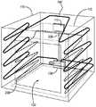
도 3은 본 발명의 일 실시예에 따라 TEC 어레이에서 TEC의 다수의 상이한 서브셋(subset)을 선택적으로 제어할 수 있는 상호 연결 보드(interconnect board)에 배치된 TEC를 포함하는 도 1의 카트리지의 상세도;
도 4는 본 발명의 다른 실시예에 따라 TEC 어레이에서 TEC의 다수의 상이한 서브셋을 선택적으로 제어할 수 있는 상호 연결 보드에 배치된 TEC를 포함하는 도 1의 카트리지의 상세도;
도 5는 본 발명의 다른 실시예에 따라 TEC의 다수의 상이한 서브셋을 선택적으로 제어할 수 있는 상호 연결 보드에 배치된 TEC를 포함하는 도 1의 카트리지의 상세도;
도 6은 본 발명의 또 다른 실시예에 따라 상호 연결 보드에 배치된 단일 TEC를 포함하는 도 1의 카트리지의 상세도;
도 7은 본 발명의 또 다른 실시예에 따라 상호 연결 보드에 배치된 4개의 TEC를 포함하는 도 1의 카트리지의 상세도;
도 8은 본 발명의 또 다른 실시예에 따라 상호 연결 보드에 배치된 6개의 TEC를 포함하는 도 1의 카트리지의 상세도;
도 9는 본 발명의 일 실시예에 따라 TEC 없는 도 3의 상호 연결 보드를 도시한 도면;
도 10은 본 발명의 다른 실시예에 따라 TEC 없는 도 4의 상호 연결 보드를 도시한 도면;
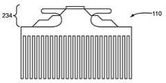
도 11은 본 발명의 또 다른 실시예에 따라 TEC 없는 도 5의 상호 연결 보드를 도시한 도면;
도 12는 본 발명의 또 다른 실시예에 따라 TEC 없는 도 6의 상호 연결 보드를 도시한 도면;
도 13은 본 발명의 또 다른 실시예에 따라 TEC 없는 도 7의 상호 연결 보드를 도시한 도면;
도 14는 본 발명의 또 다른 실시예에 따라 TEC 없는 도 8의 상호 연결 보드를 도시한 도면;
도 15는 본 발명의 일 실시예에 따라 도 1의 제어기의 여러 동작 상태, 입력 및 출력을 상술하는 하나의 시스템 컴포넌트 레이아웃의 출력을 도시한 도면;
도 16은 본 발명의 일 실시예에 따라 도 15의 여러 동작 상태에서 동작할 때 도 1의 제어기의 동작을 도시하는 상세도;
도 17은 본 발명의 일 실시예에 따라 냉각 챔버의 온도를 설정점 온도에 유지하기 위해 도 1의 제어기를 동작시키는 방법을 도시한 도면;
도 18은 본 발명의 다른 실시예에 따라 냉각 챔버의 온도를 설정점 온도에 유지하기 위해 도 1의 제어기를 동작시키는 방법을 도시한 도면;
도 19는 본 발명의 일 실시예에 따라 도 1의 열 교환기의 하나 이상의 컴포넌트의 온도를 모니터링하며 초과 온도(over-temperature) 상태를 검출하고, 이에 응답하여, 열 교환기의 하나 이상의 컴포넌트의 온도를 낮추는 액션을 취하는 도 1의 제어기를 동작시키는 방법을 도시한 도면;
도 20a 내지 도 20c는 본 발명의 다른 실시예에 따라 다수의 병렬 열 교환기를 구비하는 열전 냉동 시스템을 도시한 도면;
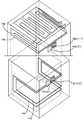
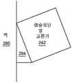
도 21은 본 발명의 다른 실시예에 따라 별개의 열적으로 결합된 히트 싱크를 각각 구비하는 2개의 냉각 챔버를 포함하는 열전 냉동 시스템을 도시한 도면;
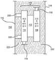
도 22는 본 발명의 일 실시예에 따라 도 1의 열 교환기를 도시하는 상세도;
도 23 및 도 24는 본 발명의 일 실시예에 따라 도 22의 열 교환기에 결합된 수용 루프(accept loop) 및 방출 루프(reject loop)의 열 다이오드(heat diode)의 효과를 그래프로 도시한 도면;
도 25는 본 발명의 일 실시예에 따라 하이브리드 열 교환기의 열 다이오드의 효과를 도시한 도면;
도 26 내지 도 29는 본 발명의 일 실시예에 따라 도 1 및 도 21의 열 교환기의 저온측 히트 싱크의 구성을 도시하는 개략도;
도 30은 본 발명의 일 실시예에 따라 열 도관을 통해 열적으로 결합된, 물리적으로 분리된 고온측 히트 싱크와 저온측 히트 싱크를 구비하는 열 교환기를 도시한 도면;
도 31은 본 발명의 일 실시예에 따라 도 30의 열 교환기에서 열 흐름을 도시하는 개략도;
도 32 및 도 33은 도 30의 열 교환기를 사용하는 열전 냉동 시스템의 실시예를 도시한 도면;
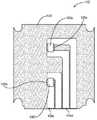
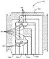
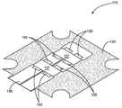
도 34는 본 발명의 일 실시예에 따라 수직으로부터 오프셋된 각도로 2상 열 교환기를 장착하는 것을 도시한 도면;
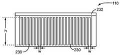
도 35는 2상 열 교환기가 2상 열 교환기의 특정 실시예에 최적화된 특정 각도로 장착된 도 34의 하나의 특정 예를 도시한 도면;
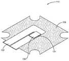
도 36a 및 도 36b는 본 발명의 일 실시예에 따라 도 34의 2상 열 교환기를 캡슐화한 것을 도시한 도면;
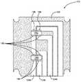
도 37a 및 도 37b는 본 발명 일 실시예에 따라 2상 열 교환기의 각도를 유지하기 위해 도 34, 도 36a 및 도 36b의 2상 열 교환기를 열전 시스템의 벽(예를 들어, 열전 냉동 시스템의 내부벽)에 장착하는 것을 도시한 도면 ; 및
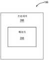
도 38은 본 발명의 일 실시예에 따라 도 1의 제어기에 대한 블록도.BRIEF DESCRIPTION OF THE DRAWINGS The accompanying drawings, which are incorporated herein and form a part of this specification, illustrate various aspects of the invention and, together with the detailed description, serve to explain the principles of the invention.
1 illustrates a cooling chamber, a plurality of thermoelectric coolers (TECs) disposed between a cold side heat sink and a hot side heat sink according to an embodiment of the present invention. A diagram showing a thermoelectric refrigeration system comprising a heat exchanger including a containing cartridge, and a controller controlling the TEC to maintain a temperature of a set point of the cooling chamber;
2 is a graph showing the cooling capacity and cooling efficiency of the TEC versus the input current of the TEC;
FIG. 3 is a detail of the cartridge of FIG. 1 including a TEC disposed on an interconnect board capable of selectively controlling a number of different subsets of TECs in a TEC array in accordance with an embodiment of the present invention. Degree;
Figure 4 is a detailed view of the cartridge of Figure 1 including a TEC disposed on an interconnect board capable of selectively controlling a number of different subsets of TECs in a TEC array in accordance with another embodiment of the present invention;
5 is a detailed view of the cartridge of FIG. 1 including a TEC disposed on an interconnect board capable of selectively controlling a number of different subsets of the TEC in accordance with another embodiment of the present invention;
6 is a detailed view of the cartridge of FIG. 1 including a single TEC disposed on an interconnection board in accordance with another embodiment of the present invention;
Fig. 7 is a detailed view of the cartridge of Fig. 1 including four TECs disposed on an interconnection board in accordance with another embodiment of the present invention;
Fig. 8 is a detailed view of the cartridge of Fig. 1 including six TECs disposed on an interconnect board according to another embodiment of the present invention;
Figure 9 shows the interconnection board of Figure 3 without a TEC in accordance with an embodiment of the present invention;
Fig. 10 shows the interconnection board of Fig. 4 without a TEC in accordance with another embodiment of the present invention;
Fig. 11 shows the interconnection board of Fig. 5 without a TEC according to another embodiment of the present invention;
Figure 12 shows the interconnection board of Figure 6 without a TEC in accordance with another embodiment of the present invention;
Figure 13 shows the interconnection board of Figure 7 without a TEC according to another embodiment of the present invention;
Figure 14 shows the interconnection board of Figure 8 without a TEC in accordance with another embodiment of the present invention;
FIG. 15 is a diagram showing the output of one system component layout detailing the various operating states, inputs and outputs of the controller of FIG. 1 in accordance with an embodiment of the present invention;
Figure 16 is a detailed view showing the operation of the controller of Figure 1 when operating in the various operating states of Figure 15 in accordance with an embodiment of the present invention;
FIG. 17 illustrates a method of operating the controller of FIG. 1 to maintain the temperature of a cooling chamber at a set point temperature in accordance with an embodiment of the present invention;
Figure 18 illustrates a method of operating the controller of Figure 1 to maintain the temperature of a cooling chamber at a set point temperature in accordance with another embodiment of the present invention;
FIG. 19 monitors the temperature of one or more components of the heat exchanger of FIG. 1 and detects an over-temperature condition in accordance with an embodiment of the present invention, and in response, measures the temperature of one or more components of the heat exchanger. A diagram illustrating a method of operating the controller of FIG. 1 taking a lowering action;
20A to 20C are diagrams illustrating a thermoelectric refrigeration system having a plurality of parallel heat exchangers according to another embodiment of the present invention;
21 is a diagram illustrating a thermoelectric refrigeration system comprising two cooling chambers each having a separate thermally coupled heat sink in accordance with another embodiment of the present invention;
22 is a detailed view showing the heat exchanger of FIG. 1 in accordance with an embodiment of the present invention;
23 and 24 are graphs showing the effect of a heat diode of an accept loop and a reject loop coupled to the heat exchanger of FIG. 22 according to an embodiment of the present invention. ;
25 is a diagram showing the effect of a thermal diode of a hybrid heat exchanger according to an embodiment of the present invention;
26 to 29 are schematic diagrams showing the configuration of a low temperature side heat sink of the heat exchanger of FIGS. 1 and 21 according to an embodiment of the present invention;
FIG. 30 is a view showing a heat exchanger having a physically separated high-temperature heat sink and a low-temperature heat sink thermally coupled through a heat conduit according to an embodiment of the present invention;
31 is a schematic diagram showing heat flow in the heat exchanger of FIG. 30 in accordance with an embodiment of the present invention;
32 and 33 are diagrams illustrating an embodiment of a thermoelectric refrigeration system using the heat exchanger of FIG. 30;
Fig. 34 shows mounting a two-phase heat exchanger at an angle offset from the vertical according to an embodiment of the present invention;
FIG. 35 shows one specific example of FIG. 34 in which a two-phase heat exchanger is mounted at a specific angle optimized for a specific embodiment of a two-phase heat exchanger;
36A and 36B illustrate an encapsulation of the two-phase heat exchanger of FIG. 34 according to an embodiment of the present invention;
37A and 37B show the two-phase heat exchanger of Figs. 34, 36A, and 36B to maintain the angle of the two-phase heat exchanger according to an embodiment of the present invention. Figure showing mounting on the inner wall); And
Figure 38 is a block diagram of the controller of Figure 1 in accordance with an embodiment of the present invention.
아래에 제시된 실시예는 이 기술 분야에 통상의 지식을 가진 자가 본 실시예를 실시할 수 있게 하고 이 실시예를 실시하는 최상의 모드를 예시하는데 필요한 정보를 제시한다. 첨부 도면을 고려하여 이하의 상세한 설명을 읽으면, 이 기술 분야에 통상의 지식을 가진 자라면 본 발명의 개념을 이해하고 본 명세서에서에서 구체적으로 언급되지 못한 개념의 응용을 인식할 수 있을 것이다. 이들 개념 및 응용은 본 발명의 범위 및 첨부된 특허청구범위 내에 있는 것으로 이해되어야 한다.The embodiments presented below enable a person skilled in the art to practice this embodiment and present the information necessary to illustrate the best mode of practicing this embodiment. If you read the following detailed description in consideration of the accompanying drawings, those of ordinary skill in the art will understand the concept of the present invention and recognize the application of the concept not specifically mentioned in the present specification. These concepts and applications are to be understood as being within the scope of the present invention and the appended claims.
본 명세서에서 제1, 제2, 등의 용어를 사용하여 여러 요소를 기술할 수 있으나, 이들 요소는 이들 용어로 제한되는 것이 아닌 것으로 이해된다. 이들 용어는 하나의 요소를 다른 요소와 단지 구별하기 위해서 사용된 것이다. 예를 들어, 본 발명의 범위를 벗어남이 없이 제1 요소는 제2 요소라고 언급될 수 있고, 마찬가지로, 제2 요소는 제1 요소로 언급될 수 있다. 본 명세서에서 사용된 바와 같이, "및/또는" 이라는 용어는 연관된 나열된 항목에서 하나 이상의 항목의 임의의 및 모든 조합을 포함한다.In this specification, terms such as first, second, and the like may be used to describe various elements, but it is understood that these elements are not limited to these terms. These terms are only used to distinguish one element from another. For example, a first element may be referred to as a second element, and likewise a second element may be referred to as a first element without departing from the scope of the present invention. As used herein, the term “and/or” includes any and all combinations of one or more items in the associated listed item.
"아래" 또는 "위에" 또는 "상부" 또는 "하부" 또는 "수평" 또는 "수직"과 같은 상대적인 용어는 도면에 도시된 바와 같이 본 명세서에서 하나의 요소, 층 또는 구역과 다른 요소, 층 또는 구역의 관계를 기술하는데 사용될 수 있다. 이들 용어와 및 전술한 용어는 도면에 도시된 배향에 더하여 디바이스의 상이한 배향을 포함하도록 의도된 것으로 이해된다. Relative terms such as "below" or "above" or "top" or "bottom" or "horizontal" or "vertical" are used herein as shown in the figures to refer to elements, layers, or It can be used to describe the relationship of zones. It is understood that these terms and the foregoing terms are intended to encompass different orientations of the device in addition to the orientations shown in the figures.
본 명세서에서 사용된 용어는 특정 실시예를 단지 설명하기 위한 것일 뿐, 본 발명을 제한하려고 의도된 것이 전혀 아니다. 본 명세서에서 사용된 바와 같이, 단수 형태 "하나", "일" 및 "상기"라는 용어는 문맥이 달리 언급하지 않는 한, 복수의 형태를 포함하는 것으로 의도된다. 나아가 "포함한다", "포함하는", "구비한다" 및/또는 "구비하는"라는 용어는 본 명세서에서 사용될 때 언급된 특징, 숫자, 단계, 동작, 요소 및/또는 컴포넌트의 존재를 나타내지만, 하나 이상의 다른 특징, 숫자, 단계, 동작, 요소, 컴포넌트 및/또는 이들의 그룹이 존재하는 것이나 추가하는 것을 배제하지 않는 것으로 이해된다.The terms used in this specification are only for describing specific embodiments, and are not intended to limit the present invention. As used herein, the terms “one”, “one” and “above” in the singular form are intended to include the plural form unless the context dictates otherwise. Furthermore, the terms "comprising", "comprising", "having" and/or "having" as used herein denote the presence of the mentioned features, numbers, steps, actions, elements and/or components, , It is to be understood that the presence or addition of one or more other features, numbers, steps, actions, elements, components and/or groups thereof is not excluded.
달리 정의되지 않는 한, 본 명세서에서 사용된 모든 용어(기술적 용어와 과학적 용어를 포함하여)는 본 발명이 속하는 이 기술 분야에 통상의 지식을 가진 자라면 일반적으로 이해되는 바와 동일한 의미를 구비한다. 나아가 본 명세서에서 사용된 용어는 본 명세서 및 관련 기술 분야의 분맥에서의 의미와 동일한 의미를 가지는 것으로 해석되어야 하고, 본 명세서에서에서 명시적으로 정의되지 않는 한, 이상화되거나 과도하게 형식적인 의미로 해석되어서는 아니되는 것으로 이해된다.Unless otherwise defined, all terms (including technical and scientific terms) used herein have the same meaning as commonly understood by those of ordinary skill in the art to which the present invention belongs. Furthermore, the terms used in this specification should be interpreted as having the same meaning as the meaning in the branch of the present specification and related technical fields, and unless explicitly defined in the present specification, it is interpreted as an idealized or excessively formal meaning. It is understood that it should not be.
도 1은 본 발명의 일 실시예에 따른 열전 냉동 시스템(100)을 도시한다. 예시된 바와 같이, 열전 냉동 시스템(100)은 냉각 챔버(102), 열 교환기(104), 및 이 냉각 챔버(102)의 냉각을 제어하는 제어기(106)를 포함한다. 열 교환기(104)는 고온측 히트 싱크(108), 저온측 히트 싱크(110) 및 다수의 열전 쿨러(TEC)를 구비하는 카트리지(112)를 포함하고, 여기서 각 TEC는 저온측 히트 싱크(110)와 열적으로 결합된 저온측, 및 고온측 히트 싱크(108)와 열적으로 결합된 고온측을 구비한다. TEC는 바람직하게는 박막 디바이스이다. 하나 이상의 TEC가 제어기(106)에 의해 활성화될 때, 활성화된 TEC(들)는 고온측 히트 싱크(108)를 가열하고, 저온측 히트 싱크(110)를 냉각시켜 열 전달을 촉진하여 냉각 챔버(102)로부터 열을 추출하도록 동작한다. 보다 구체적으로, 하나 이상의 TEC가 활성화될 때, 고온측 히트 싱크(108)가 가열되어 증발기를 형성하고, 저온측 히트 싱크(110)가 냉각되어 응축기를 형성한다.1 shows a
응축기로 동작할 때, 저온측 히트 싱크(110)는 저온측 히트 싱크(110)와 결합된 수용 루프(114)를 통해 냉각 챔버(102)로부터 열을 추출한다. 수용 루프(114)는 열전 냉동 시스템(100)의 내부 벽(115)에 열적으로 결합된다. 내부 벽(115)은 냉각 챔버(102)를 한정한다. 일 실시예에서, 수용 루프(114)는 내부 벽(115)에 통합되거나 또는 내부 벽(115)의 표면에 직접 통합된다. 수용 루프(114)는 임의의 유형의 배관(plumbing)에 의해 형성되어 냉각 매체(예를 들어, 2상 냉각제)가 수용 루프(114)를 흐르거나 통과할 수 있게 한다. 수용 루프(114)와 내부 벽(115)이 열적으로 결합된 것으로 인해, 냉각 매체가 수용 루프(114)를 통과할 때 냉각 매체는 냉각 챔버(102)로부터 열을 추출한다. 수용 루프(114)는, 예를 들어, 구리 배관(tubing), 플라스틱 배관, 스테인리스 스틸 배관, 알루미늄 배관 등으로 형성될 수 있다.When operating as a condenser, the low-
저온측 히트 싱크(110)와 수용 루프(114)에 의해 형성된 응축기는 임의의 적절한 열 교환 기술에 따라 동작한다. 하나의 바람직한 실시예에서, 수용 루프(114)는 열 사이펀 원리(thermosiphon principle)에 따라 동작하여 (즉, 열 사이펀으로 작용하여) 냉각 매체가 저온측 히트 싱크(110)로부터 수용 루프(114)를 통해 저온측 히트 싱크(110)로 진행하여 2상 수동 열 수송(two-phase, passive heat transport)을 사용하여 냉각 챔버(102)를 냉각시킨다. 구체적으로, 수동 열 교환은 수용 루프(114) 내 냉각 매체와 냉각 챔버(102) 사이에 자연 대류를 통해 일어난다. 일 실시예에서, 냉각 매체가 냉각 챔버(102)와 열 접촉할 때 냉각 매체는 액체 형태이다. 구체적으로, 냉각 챔버(102) 내 환경과 수용 루프(114) 내 냉각 매체 사이에 수동 열 교환이 일어나서 냉각 챔버(102)의 온도가 감소하고 냉각 매체의 온도가 증가하거나 및/또는 상 변화가 일어난다. 냉각 매체의 온도가 증가할 때, 예를 들어 증발을 통해 냉각 매체의 밀도가 감소한다. 그 결과, 냉각 매체는 수용 루프(114)에서 부력에 의해 위쪽 방향 열 교환기(104) 쪽으로 및 구체적으로 저온측 히트 싱크(110) 쪽으로 이동한다. 냉각 매체는 저온측 히트 싱크(110)와 열 접촉을 하는데, 여기서 냉각 매체와 저온측 히트 싱크(110) 사이에 열 교환이 일어난다. 냉각 매체와 저온측 히트 싱크(110) 사이에 열 교환이 일어나면, 냉각 매체는 응축하고 다시 수용 루프(114)를 통해 중력에 의해 흐르며 냉각 챔버(102)로부터 추가적인 열을 추출한다. 따라서, 일부 실시예에서, 수용 루프(114)는 냉각 챔버(102)를 냉각시킬 때 증발기로 기능한다.The condenser formed by the cold
전술한 바와 같이, 열 교환기(104)는 고온측 히트 싱크(108)와 저온측 히트 싱크(110) 사이에 배치된 카트리지(112)를 포함한다. 카트리지(112) 내 TEC는 고온측 히트 싱크(108)와 열적으로 결합된 고온측(즉, TEC의 동작 동안 가열되는 측), 및 저온측 히트 싱크(110)와 열적으로 결합된 저온측(즉, TEC의 동작 동안 냉각되는 측)을 구비한다. 카트리지(112) 내 TEC는 저온측 히트 싱크(110)와 고온측 히트 싱크(108) 사이에 열 전달을 효과적으로 제공한다. 보다 구체적으로, 수용 루프(114) 내 냉각 매체와 저온측 히트 싱크(110) 사이에 열 전달이 일어나면, 활성 TEC는 저온측 히트 싱크(110)와 고온측 히트 싱크(108) 사이에 열을 전달한다..As described above, the
증발기로 작용할 때, 고온측 히트 싱크(108)는 고온측 히트 싱크(108)에 결합된 방출 루프(116)를 통해 냉각 챔버(102)의 외부 환경으로 열 방출을 제공한다. 방출 루프(116)는 열전 냉동 시스템(100)의 외부 벽(118) 또는 외부 스킨(skin)에 열적으로 결합된다. 외부 벽(118)은 냉각 챔버(102)의 외부 환경과 직접 열 접촉한다. 나아가, 외부 벽(118)은, 예를 들어, 적절한 단열재(insulation)에 의해 수용 루프(114) 및 내부 벽(115)(및 냉각 챔버(102))와 열적으로 차단된다. 일 실시예에서, 방출 루프(116)는 외부 벽(118)에 통합되거나 또는 외부 벽(118)의 표면에 통합된다. 방출 루프(116)는 열 전달 매체(예를 들어, 2상 냉각제)가 방출 루프(116)를 흐르거나 통과할 수 있는 임의의 유형의 배관으로 형성된다. 방출 루프(116)와 외부 환경이 열적으로 결합된 것으로 인해, 열 전달 매체가 방출 루프(116)를 통해 흐를 때 열 전달 매체는 외부 환경으로 열을 방출한다. 방출 루프(116)는, 예를 들어, 구리 배관, 플라스틱 배관, 스테인리스 스틸 배관, 알루미늄 배관 등으로 형성될 수 있다.When acting as an evaporator, the hot
고온측 히트 싱크(108)와 방출 루프(116)에 의해 형성된 증발기는 임의의 적절한 열 교환 기술에 따라 동작한다. 하나의 바람직한 실시예에서, 방출 루프(116)는 열 사이펀 원리에 따라 동작하여 (즉, 열 사이펀으로 작용하여) 열 전달 매체는 고온측 히트 싱크(108)로부터 방출 루프(116)를 통해 고온측 히트 싱크(108)으로 진행하여 2상 수동 열 수송을 사용하여 열을 방출한다. 구체적으로, 고온측 히트 싱크(108)는 저온측 히트 싱크(110)로부터 수신된 열을 방출 루프(116) 내 열 전달 매체로 전달한다. 열이 열 전달 매체로 전달되면, 열 전달 매체는 상 변화가 일어나고 방출 루프(116)를 통해 진행하여 외부 벽(118)과 열 접촉을 하여 냉각 챔버(102)의 외부 환경으로 열이 방출된다. 방출 루프(116) 내 열 전달 매체가 외부 벽(118)과 직접 열 접촉하면, 방출 루프(116) 내 열 전달 매체와 외부 환경 사이에 수동 열 교환이 일어난다. 잘 알려진 바와 같이, 수동 열 교환은 방출 루프(116) 내 열 전달 매체를 응축시켜, 열 전달 매체는 중력에 의해 열 교환기(104)로 다시 진행한다. 따라서, 방출 루프(116)는 냉각 챔버(102)의 외부 환경으로 열을 방출할 때 응축기로 기능한다.The evaporator formed by the hot
보다 상세히 후술된 바와 같이, 하나의 바람직한 실시예에서, 열 교환기(104)는 냉각 챔버(102)와 직접 열 접촉하지 않고 냉각 챔버(102)로부터 열적으로 차단된다. 마찬가지로, 열 교환기(104)는 외부 벽(118)과 직접 열 접촉하지 않고 외부 벽(118)과 열적으로 차단된다. 따라서, 아래에 상술된 바와 같이, 열 교환기(104)는 열전 냉동 시스템(100)의 냉각 챔버(102) 및 외부 벽(118)으로부터 열적으로 차단된다. 중요한 것은, 이것이 TEC가 비활성화될 때 열이 냉각 챔버(102)로 누설되는 것을 방지하는 열 다이오드 효과를 제공한다는 것이다.As described in more detail below, in one preferred embodiment, the
제어기(106)는 카트리지(112) 내 TEC를 제어하여 냉각 챔버(102)의 원하는 설정점 온도를 유지하도록 동작한다. 일반적으로, 제어기(106)는 TEC를 선택적으로 활성화/비활성화하고, TEC의 입력 전류를 선택적으로 제어하고, 및/또는 TEC의 듀티 사이클을 선택적으로 제어하여 원하는 설정점 온도를 유지하도록 동작한다. 나아가, 바람직한 실시예에서, 제어기(106)는 TEC의 하나 이상의 서브셋, 및 일부 실시예에서, 2개 이상의 서브셋을 별개로 또는 독립적으로 제어하도록 인에이블되고, 여기서 각 서브셋은 하나 이상의 상이한 TEC를 포함한다. 따라서, 일례로서, 카트리지(112)에 4개의 TEC가 있는 경우, 제어기(106)는 제1 개별 TEC, 제2 개별 TEC 및 2개의 TEC의 그룹(즉, 제1 및 제2 개별 TEC 및 2개의 TEC의 그룹)을 별개로 제어하도록 인에이블될 수 있다. 이 방법에 의해, 제어기(106)는, 예를 들어, 요구될 때 최대화된 효율로 1개, 2개, 3개 또는 4개의 TEC를 독립적으로 선택적으로 활성화할 수 있다.The
이 예를 계속 들면, 제어기(106)는 (1) 제1 개별 TEC의 활성화/비활성화, 제1 개별 TEC의 입력 전류 및/또는 제1 개별 TEC의 듀티 사이클; (2) 제2 개별 TEC의 활성화/비활성화, 제2 개별 TEC의 입력 전류 및/또는 제2 개별 TEC의 듀티 사이클; 및 (3) 2개의 TEC의 그룹의 활성화/비활성화, 2개의 TEC의 그룹의 입력 전류 및/또는 2개의 TEC의 그룹의 듀티 사이클을 별개로 및 선택적으로 제어하도록 인에이블될 수 있다. TEC의 상이한 서브셋을 이렇게 별개로 선택적으로 제어하면, 제어기(106)는 바람직하게는 열전 냉동 시스템(100)의 효율을 개선시키도록 TEC를 제어할 수 있다. 예를 들어, 제어기(106)는 예를 들어 냉각 챔버(102)가 설정점 온도에 있거나 또는 미리 한정된 정상 상태 온도 범위 내에 있을 때 정상 상태 모드에서 동작할 때 효율을 최대화하도록 TEC를 제어할 수 있다. 그러나, 풀 다운 또는 회수 동안, 제어기(106)는, 예를 들어, 냉각 챔버(102)로부터 열 추출을 최대화하는 것, 풀 다운/회수 시간과 효율 사이에 트레이드오프(tradeoff)를 제공하는 것 등과 같은 원하는 성능을 달성하도록 TEC를 제어할 수 있다.Continuing this example, the
더 진행하기 전에, TEC의 냉각 용량 대 입력 전류 특성 및 효율 대 입력 전류 특성을 간략히 설명하는 것이 유리하다. 이런 점에서, 도 2는 TEC의 냉각 용량(Q) 및 냉각 효율(COP) 대 TEC의 입력 전류를 도시하는 그래프이다. 냉각 효율은 보다 구체적으로 성능 계수(Coefficient of Performance: COP)로 표시된다. 도 2에 도시된 바와 같이, TEC의 입력 전류(I)가 증가할 때, TEC의 냉각 용량이 또한 증가한다. TEC에 의해 최대 열의 양이 제거되는 곳을 나타내는 냉각 용량(Q) 곡선 상의 점은 Qmax으로 표시된다. 따라서, TEC가 Qmax에서 동작하고 있을 때, TEC는 가능한 최대의 열량을 제거한다. TEC는 대응하는 최대 전류(Imax)가 TEC에 제공될 때 Qmax에서 동작한다. 도 2는 또한 전류의 함수로서 TEC의 COP를 도시한다. 냉각 응용을 위해, TEC의 COP는 열을 제거하기 위해 TEC의 일 입력(work input)의 양에 대해 제거된 열의 비율이다. TEC의 COP가 최대화되는 열 또는 용량(Q)의 양은 QCOPmax로 표시된다. TEC는 전류(ICOPmax)가 TEC에 제공될 때 QCOPmax에서 동작한다. 따라서, TEC의 효율 또는 COP는 전류(ICOPmax)가 TEC에 제공되어 TEC가 QCOPmax에서 동작할 때 최대화된다.Before proceeding further, it is advantageous to briefly describe the TEC's cooling capacity versus input current characteristics and efficiency versus input current characteristics. In this regard, Figure 2 is a graph showing the cooling capacity (Q) and cooling efficiency (COP) of the TEC versus the input current of the TEC. The cooling efficiency is more specifically expressed as a coefficient of performance (COP). As shown in Fig. 2, when the input current I of the TEC increases, the cooling capacity of the TEC also increases. The point on the cooling capacity (Q) curve indicating where the maximum amount of heat is removed by the TEC is denoted by Qmax . Thus, when the TEC is operating at Qmax , the TEC removes the greatest possible amount of heat. The TEC operates at Qmax when the corresponding maximum current (Imax ) is provided to the TEC. 2 also shows the COP of the TEC as a function of current. For cooling applications, a TEC's COP is the ratio of heat removed to the amount of TEC's work input to remove heat. The amount of heat or capacity (Q) at which the COP of the TEC is maximized is expressed as QCOPmax . The TEC operates at QCOPmax when current (ICOPmax ) is provided to the TEC. Thus, the efficiency or COP of the TEC is maximized when a current (ICOPmax ) is provided to the TEC so that the TEC operates at QCOPmax .
보다 상세히 후술된 바와 같이, 바람직한 실시예에서, 제어기(106)는 정상 상태 동작 동안, 하나 이상의 TEC가 활성화되고 QCOPmax에서 동작하며 나머지 TEC는 비활성화되어 효율을 최대화하도록 카트리지(112) 내 TEC를 제어한다. 활성화된 TEC의 개수 및 역으로 비활성화된 TEC의 개수는 수요에 따라 지시된다. 역으로, 풀 다운 또는 회수 동안, 카트리지(112) 내 하나 이상 및 가능하게는 모두가 활성화되고 원하는 성능 프로파일에 따라 동작된다. 원하는 성능 프로파일의 일례는 모든 TEC가 활성화되고 Qmax에서 동작되어 풀 다운 또는 회수 시간을 최소화하는 것이다. 그러나, 원하는 성능 프로파일은 대안적으로 풀 다운 또는 회수 시간과 효율 사이에 트레이드오프를 제공할 수 있고, 예를 들어, 모든 TEC가 활성화되고 QCOPmax와 Qmax 사이의 점에서 동작된다. 후술하는 바와 같이, TEC의 제어는 이들 예로 제한되지 않는다는 것이 주목된다.As described in more detail below, in a preferred embodiment, the
전술한 바와 같이, 도 2는 단일 TEC의 냉각 용량 및 냉각 효율을 도시한다. TEC의 개수를 선형적으로 증가시키면 TEC를 사용하는 열전 냉동 시스템(100)의 동작 COP에 영향을 미침이 없이 열 제거 용량을 선형으로 증가시킬 수 있다. 따라서, 열전 냉동 시스템(100)이 4개의 TEC를 포함하면, 열전 냉동 시스템(100)의 열 제거 용량이 단일 TEC를 포함하는 열전 냉동 시스템(100)의 일 실시예에 비해 4배 증가되면서, 전체 시스템이 일부 바람직한 실시예에서, 오프, QCOPmax 및 Qmax 사이에서 동작할 수 있게 된다.As described above, Fig. 2 shows the cooling capacity and cooling efficiency of a single TEC. Increasing the number of TECs linearly can increase the heat removal capacity linearly without affecting the operating COP of the
TEC에 전기 전류를 인가하는 것을 도 2를 참조하여 냉각의 문맥에서 설명하지만, 동일한 원리는 TEC를 사용하여 열에 응답하여 전력이나 전류를 생성하는 열 회수/발전의 문맥에 적용하는 경우에도 적용된다는 것이 주목된다.The application of electric current to the TEC is described in the context of cooling with reference to Fig. 2, but the same principle is also applied in the context of heat recovery/generation where the TEC is used to generate power or current in response to heat. Noted.
TEC 카트리지TEC cartridge
TEC를 별개로 및 선택적으로 제어하는 제어기(106)의 동작 상세를 설명하기 전에, TEC를 별개로 및 선택적으로 제어할 수 있는 도 1의 카트리지(112)의 실시예를 설명하는 것이 유리하다. 카트리지(112)의 이후 설명은 도 1의 열전 냉동 시스템(100)에 대한 것이지만, 이 카트리지(112)는 도 1의 열전 냉동 시스템(100)에 사용하는 것으로 제한되지도 않고 일반적으로 열전 냉동으로도 제한되지 않는다는 것이 주목된다. 예를 들어, 이 카트리지(112)는 열 회수 또는 발전 응용에 적용하는데 사용될 수 있다.Before describing the details of the operation of the
전술한 바와 같이, 카트리지(112) 내 TEC를 사용하여 냉각 챔버(102)의 온도를 조절한다. 많은 냉동 응용에 맞는 원하는 냉각 용량을 충족하기 위하여, 열전 냉동 시스템(100)은 다수의 TEC를 사용한다. 다수의 TEC를 사용하면 다수의 TEC가 별개로 제어되어 가변 조건 하에서 원하는 성능을 제공할 수 있으므로 하나의 큰 TEC를 사용하는 것에 비해 유리하다. 이와 대조적으로, 풀 다운 또는 회수를 위해 최대로 원하는 용량을 제공하도록 설계된 하나의 오버 사이즈(over-sized)의 TEC는 이러한 융통성을 제공하지 않는다. 예를 들어, 정상 상태 동안, 하나의 오버 사이즈의 TEC는 일반적으로 낮은 COP 값에 대응하는 낮은 용량점에서 동작할 수 있다. 다시 말해, 오버 사이즈의 TEC는 비효율적으로 동작할 수 있다. 이와 대조적으로, 제어기(106)는 정상 상태 동안 효율을 최대화하기 위해 카트리지(112) 내 TEC의 서브셋을 별개로 제어하도록 인에이블된다. As described above, the TEC in the
도 3 내지 도 5는 제어기(106)가 원하는 제어 스킴에 따라 TEC의 상이한 서브셋을 별개로 및 선택적으로 제어할 수 있는 카트리지(112)의 실시예를 도시한다. 그러나, 도 3 내지 도 5의 실시예는 단지 예시를 위한 것임이 주목된다. 카트리지(112)는 임의의 개수의 TEC를 보유하고 임의의 개수의 TEC의 서브셋이 별개로 제어될 수 있도록 구성될 수 있다. 각 서브셋은 일반적으로 하나 이상의 TEC를 포함한다. 나아가, 상이한 서브셋은 동일한 개수 또는 상이한 개수의 TEC를 포함할 수 있다.3-5 illustrate embodiments of a
도 3의 실시예에서, 카트리지(112)는 상호 연결 보드(122) 상에 배치된 TEC(120a 내지 120f)(보다 일반적으로 본 명세서에서 집합적으로 TEC(120) 및 개별적으로 TEC(120)로 지칭됨)를 포함한다. TEC(120)는 박막 디바이스이다. 박막 TEC의 일부 비제한적인 예는 미국 특허 번호 8,216,871(발명의 명칭: "METHOD FOR THIN FILM THERMOELECTRIC MODULE FABRICATION")에 개시되어 있고, 이 문헌은 그 전체 내용이 본 명세서에서 병합되어 있다. 상호 연결 보드(122)는 TEC(120a 내지 120f)의 4개의 서브셋을 한정하는 전기적으로 전도성 트레이스(124a 내지 124d)(보다 일반적으로 본 명세서에서 집합적으로 트레이스 124 및 개별적으로 트레이스 124로 지칭됨)를 포함한다. 구체적으로, TEC(120a)와 TEC(120b)는 트레이스(124a)를 통해 서로 전기적으로 직렬로 연결되고, 그리하여, TEC(120)의 제1 서브셋을 형성한다. 마찬가지로, TEC(120c)와 TEC(120d)는 트레이스(124b)를 통해 서로 전기적으로 직렬로 연결되고, 그리하여, TEC(120)의 제2 서브셋을 형성한다. TEC(120e)는 트레이스(124d)에 연결되고, 그리하여, TEC(120)의 제3 서브셋을 형성하고, TEC(120f)는 트레이스(124c)에 연결되고, 그리하여, TEC(120)의 제4 서브셋을 형성한다. 제어기(106)(도 1)는, 임의의 순서로, 트레이스(124a)에 인가되는 전류를 제어하는 것에 의해 TEC(120)의 제1 서브셋(즉, TEC(120a 및 120b))을 선택적으로 제어하고, 트레이스(124b)에 인가되는 전류를 제어하는 것에 의해 TEC(120)의 제2 서브셋(즉, TEC(120c 및 120d))을 선택적으로 제어하고, 트레이스(124d)에 인가된 전류를 제어하는 것에 의해 TEC(120)의 제3 서브셋(즉, TEC(120e))을 선택적으로 제어하고, 트레이스(124c)에 인가된 전류를 제어하는 것에 의해 TEC(120)의 제4 서브셋(즉, TEC(120f)을 선택적으로 제어할 수 있다. 따라서, 일례로서 TEC(120a 및 120b)를 사용하면, 제어기(106)는 트레이스(124a)로부터 전류를 제거(비활성화)하거나 또는 트레이스(124a)에 전류를 인가(활성화)하는 것에 의해 TEC(120a 및 120b)를 선택적으로 활성화/비활성화할 수 있고, TEC(120a 및 120b)가 활성화되는 동안 트레이스(124a)에 인가된 전류를 선택적으로 증가시키거나 감소시킬 수 있고, 및/또는 TEC(120a 및 120b)가 활성화되는 동안 TEC(120a 및 120b)의 듀티 사이클(예를 들어, 전류의 펄스 폭 변조)을 제어하는 방식으로 트레이스(124a)에 인가된 전류를 제어할 수 있다.In the embodiment of Figure 3, the
상호 연결 보드(122)는 TEC(120a 내지 120f)의 바닥 표면(bottom surface)을 노출시키는 개구부(126a 및 126b)(보다 일반적으로 본 명세서에서 집합적으로 개구부(126) 및 개별적으로 개구부(126)로 지칭됨)를 포함한다. 고온측 히트 싱크(108)(도 1)와 저온측 히트 싱크(110)(도 1) 사이에 배치될 때, 개구부(126a 및 126b)를 통해 TEC(120a 내지 120f)의 바닥 표면은 적절한 히트 싱크(108 또는 110)에 열적으로 결합될 수 있다.The
본 발명의 실시예에 따라, 동작 동안, 제어기(106)는 대응하는 트레이스(124a 내지 124d)로부터 전류를 인가하거나 제거하는 것에 의해 TEC(120)의 서브셋의 임의의 조합을 선택적으로 활성화 또는 비활성화할 수 있다. 나아가, 제어기(106)는 대응하는 트레이스(124a 내지 124d)에 제공되는 전류의 양을 제어하는 것에 의해 활성 TEC(120)의 동작점을 제어할 수 있다. 예를 들어, TEC(120)의 제1 서브셋만이 활성화되고 정상 상태 동작 동안 QCOPmax에서 동작되어야 하는 경우, 제어기(106)는 전류(ICOPmax)를 트레이스(124a)에 제공하여 TEC(120a 및 120b)를 활성화시켜 QCOPmax에서 TEC(120a 및 120b)를 동작시킬 수 있고, 다른 트레이스(124b 내지 124d)로부터 전류를 제거하여 다른 TEC(120c 내지 120f)를 비활성화시킬 수 있다.In accordance with an embodiment of the present invention, during operation,
도 3과 관련하여 도시된 실시예에서, 카트리지(112)는 TEC(120a 내지 120f)를 포함한다. 본 발명의 실시예에 따라, 카트리지(112)는 임의의 개수의 TEC(120)를 포함할 수 있다. 예를 들어, 도 4와 관련하여 도시된 실시예에서, 카트리지(112)는 단 2개의 TEC(120), 즉 TEC(120e 및 120f)만을 구비하는 상호 연결 보드(122)를 포함한다. 이 실시예에서, 제어기(106)(도 1)는 대응하는 트레이스(124d 및 124c)에 제공되는 전류를 각각 제어하는 것에 의해 TEC(120e 및 120f)를 개별적으로 제어할 수 있다. 다른 예로서, 카트리지(112)는 도 5와 관련하여 도시된 바와 같이 TEC(120c 내지 120f)와 같은 단 4개의 TEC(120)만을 포함할 수 있다. 이 실시예에서, 상호 연결 보드(122)는 TEC(120c 내지 120f)에 전류를 각각 제공하는 트레이스(124b 내지 124d)를 포함한다. 더욱이, TEC(120)의 대응하는 서브셋은 적절한 전류를 트레이스(124b 내지 124d)에 제공하는 것에 의해 제어기(106)에 의해 제어될 수 있다.In the embodiment shown in connection with Fig. 3, the
도 3 내지 도 5는 카트리지(112)에서 상이한 TEC를 선택적으로 제어할 수 있는 카트리지(112)의 실시예를 도시하는 반면, 도 6 내지 도 8은 선택적인 제어가 요구되지 않는 경우 사용될 수 있는 카트리지(112)의 실시예를 도시한다. 이들 실시예에서, TEC의 입력 전류 및/또는 TEC의 듀티 사이클은 원하는 용량, 원하는 효율, 또는 용량과 효율 사이의 일정 트레이드오프를 제공하도록 변경될 수 있다. 구체적으로, 도 6은 상호 연결 보드(128) 및 이 상호 연결 보드(128) 상에 배치된 하나의 TEC(130)를 포함하는 카트리지(112)의 일 실시예를 도시한다. 상호 연결 보드(128) 내 개구부(131)는 TEC(130)의 바닥 표면을 노출시킨다. 제어기(106)(도 1)는 상호 연결 보드(128) 상의 전기 전도성 트레이스(132)를 통해 TEC(130)에 전류 입력을 제어하는 것에 의해 TEC(130)의 용량 및 효율을 제어할 수 있다.3 to 5 show embodiments of a
도 7은 도 6의 것과 유사하지만 카트리지(112)가 4개의 TEC를 포함하는 것인 카트리지(112)의 일 실시예를 도시한다. 보다 구체적으로, 카트리지(112)는 상호 연결 보드(134) 및 이 상호 연결 보드(134) 상에 배치된 4개의 TEC(136)를 포함한다. 상호 연결 보드(134)에는 TEC(136)의 바닥 표면을 노출시키는 개구부(137)가 있다. 다시, 제어기(112)는 상호 연결 보드(134) 상의 전기 전도성 트레이스(138)를 통해 TEC(136)의 듀티 사이클 및/또는 TEC(136)에의 전류 입력을 제어하는 것에 의해 TEC(136)의 용량과 효율을 제어할 수 있다.FIG. 7 shows an embodiment of a
도 8은 도 6 및 도 7의 것과 유사하지만 카트리지(112)가 6개의 TEC를 포함하는 것인 카트리지(112)의 다른 예를 도시한다. 보다 구체적으로, 카트리지(112)는 상호 연결 보드(140) 및 이 상호 연결 보드(140) 상에 배치된 6개의 TEC(142)를 포함한다. 상호 연결 보드(140)에는 TEC(142)의 바닥 표면을 노출시키는 개구부(143)가 있다. 다시, 제어기(112)는 상호 연결 보드(140) 상의 전기 전도성 트레이스(144)를 통해 TEC(142)의 듀티 사이클 및/또는 TEC(142)에의 전류 입력을 제어하는 것에 의해 TEC(142)의 용량 및 효율을 제어할 수 있다. 도 6 내지 도 8의 실시예는 단지 예시를 위한 것이라는 것이 주목된다. 카트리지(112)는 직렬 또는 병렬 구성으로 임의의 개수의 TEC 또는 전도성 트레이스를 포함하도록 구성될 수 있다.8 shows another example of a
도 9 내지 도 14는, 상호 연결 보드에 부착된 TEC 없는, 도 3 내지 도 8의 상호 연결 보드(122, 128, 134 및 140)를 각각 도시한다. 도 9 내지 도 14는 TEC의 바닥 표면을 노출시키거나, 또는 다시 말해, TEC의 바닥 표면과 적절한 히트 싱크(108 또는 110) 사이를 열적으로 결합시키는 개구부(126, 131, 137 및 143)가 상호 연결 보드에 있다는 것을 보다 명확히 도시한다. 도 9 내지 도 14는 상호 연결 보드(122, 128, 134 및 140)와 이에 대응하는 TEC 사이를 전기적으로 및 기계적으로 연결할 수 있는 접촉점(146, 148, 150 및 152)을 도시한다.9-14 show the
TEC의 선택적 제어Optional control of TEC
이하는 도 1의 제어기(106)의 동작 실시예를 상세히 설명한 것이다. 이 설명에서, 카트리지(112)는 TEC(120)의 다수의 상이한 서브셋을 선택적으로 제어할 수 있는 도 3의 카트리지(112)인 것으로 가정된다. 그러나, 도 3의 카트리지(112)는 단지 예시를 위해 사용된 것이라는 것이 주목된다.The following is a detailed description of an operating embodiment of the
도 15는 본 발명의 일 실시예에 따른 제어기(106)의 동작을 도시한다. 도시된 바와 같이, 제어기(106)는 온도 입력(154 및 156)으로부터 온도 데이터를 수신한다. 온도 입력(154 및 156)은 임의의 유형의 온도 센서일 수 있다. 온도 데이터는 냉각 챔버(102)의 온도(TCH) 및 열 교환기(104)의 방출측 또는 고온측의 온도(TR)를 포함한다. 열 교환기(104)의 방출 측은 열 교환기(104)의 고온측이다. 따라서, 예를 들어, 온도(TR)는 고온측 히트 싱크(108)의 온도일 수 있다. 온도 데이터에 기초하여, 제어기(106)는 열전 냉동 시스템(100)의 전류 동작 모드를 결정한다. 이 실시예에서, 전류 동작 모드는 풀 다운 모드(158), 정상 상태 모드(160), 초과 온도(over temperature) 모드(162) 및 회수 모드(163) 중 하나이다. 풀 다운 모드(158)는 일반적으로 열전 냉동 시스템(100)이 제일 먼저 전력 온(power on)될 때 일어난다. 정상 상태 모드(160)는 냉각 챔버(102)의 온도가 원하는 설정점 온도에 있거나 그 부근에 있을 때 일어난다. 구체적으로, 냉각 챔버(102)의 온도는 냉각 챔버(102)의 온도가 설정점 온도를 포함하는 미리 한정된 정상 상태 범위(예를 들어, 냉각 챔버(102)의 설정점 온도 ± 2도) 내에 있을 때 원하는 설정점 온도에 있거나 그 부근에 있다. 초과 온도 모드(162)는 열 교환기(104)의 방출측의 온도가 미리 한정된 최대 허용가능한 온도를 초과할 때이다. 초과 온도 모드(162)는 열 교환기(104)의 방출측의 온도와 TEC(120)의 고온측의 온도가 감소하여 TEC(120)의 손상을 방지하는 안전 모드이다. 마지막으로, 회수 모드(163)는, 예를 들어, 냉각 챔버(102)로 열이 누설되는 것, 냉각 챔버(102)의 도어가 개방되는 것 등으로 인해 냉각 챔버(102)의 온도가 정상 상태 범위 밖으로 증가할 때이다.15 shows the operation of the
본 발명의 일 실시예에서 상이한 모드(158, 160, 162 및 163)에서 제어기(106)를 동작시키는 것이 도 16에 도시되어 있다. 도 16에 도시된 바와 같이, 풀 다운 모드(158)에서 동작할 때, 제어기(106)는 모든 TEC(120)가 원하는 성능 프로파일이 지시하는 바대로 QCOPmax와 Qmax 사이의 전력 레벨에서 동작하도록 모든 TEC(120)에 대한 전류를 제어한다. 다시 말해, 제어기(106)는 ICOPmax와 Imax 사이의 전류를 모든 TEC(120)에 제공하게 한다. 제어기(106)는 열전 냉동 시스템(100)이 예를 들어, 초기에 전력 온 된 것에 기초하여 풀 다운 모드(158)에 있을 때, 예를 들어 열전 냉동 시스템(100)이 처음 구매될 때 또는 열전 냉동 시스템(100)이 전원로부터 분리된 후 전력 온 된 후를 결정한다. 제어기(106)는 164로 도시된 바와 같이 냉각 챔버(102)의 온도가 설정점 온도로 풀 다운되거나 또는 설정점 온도의 수용가능한 범위 내에 있을 때까지, QCOPmax와 Qmax 사이의 전력 레벨로 모든 TEC(120)를 유지한다. 냉각 챔버(102)가 설정점 온도로 풀 다운되면, 제어기(106)는 전류(ICOPmax)를 모든 TEC(120)에 제공하는 것에 의해 모든 TEC(120)가 QCOPmax에서 동작하도록 TEC(120)의 동작을 제어한다. 더욱이, 제어기(106)는 냉각 챔버(102)가 설정점 온도로 풀 다운되면 활성화되는 TEC(120)의 개수를 감소시킬 수 있다.Operating the
전술한 바와 같이, 온도 데이터에 기초하여, 제어기(106)는 또한 열전 냉동 시스템(100)이 정상 상태 모드(160)에 있을 때를 결정한다. 열전 냉동 시스템(100)은 냉각 챔버(102)의 온도가 설정점 온도와 같거나 또는 설정점 온도의 미리 결정된 범위 내에 있는 경우 정상 상태 모드(160)에 있다. 정상 상태 모드(160)에 있을 때, 제어기(106)는 TEC(120)의 요구되는 개수를 수요에 의해 요구되는 대로 QCOPmax로 설정한다. 이 예에서, 모든 TEC(120)는 정상 상태 모드(160)에서 QCOPmax에서 동작한다. 정상 상태 모드(160) 동안, 166으로 도시된 바와 같이 QCOPmax > Q누설인 경우, 냉각 챔버(102)의 온도는 계속 감소한다. 이 경우에, 제어기(106)는 168로 도시된 바와 같이 활성화된 TEC(120)의 듀티 사이클을 감소시킨다. 역으로, 170으로 도시된 바와 같이 QCOPmax < Q누설인 경우, 냉각 챔버(102)의 온도는 증가한다. 이 경우에, 제어기(106)는 이용가능한 활성 TEC(120)의 개수를 증가시키고 나서, 활성 TEC(120)에 제공되는 전류를 172로 도시된 바와 같이 ICOPmax와 Imax사이의 값으로 증가시킨다. 특히, Q누설는 냉각 챔버(102)로 누설되는 열의 양, 예를 들어, 냉각 챔버(102)의 도어의 밀봉부를 통해 전달되는 열의 양, 냉각 챔버(102)를 통한 자연적인 열 전도 등을 말한다.As described above, based on the temperature data, the
전술한 바와 같이, 또한 제어기(106)는 냉각 챔버(102)가 온도 입력(156)으로부터 온도 데이터에 기초하여 초과 온도 모드(162)에 있는지를 결정한다. 열전 냉동 시스템(100)의 동작 동안, 열 교환기(104)의 방출측의 온도를 모니터링하여 열 교환기(104)의 방출측의 온도가 미리 결정된 최대 허용가능한 온도를 초과하지 않는 것을 보장한다. 열 교환기(104)의 방출측의 온도는, 예를 들어, 냉각 챔버(102)가 냉각되지 않을 때, 예를 들어, 냉각 챔버(102)로 가는 도어가 적절히 닫혀 있지 않는 경우 등에서 미리 결정된 최대 허용가능한 온도를 초과할 수 있다. As described above, the
제어기(106)가 열 교환기(104)의 방출측의 온도가 미리 결정된 최대 허용가능한 온도를 초과하는 것으로 결정하면, 동작(174)에서, 제어기(106)는 냉각을 촉진하는 TEC(120)의 일부 또는 전부를 비활성화하는 것에 의해 또는 TEC(120)에 제공되는 전류를 감소시키는 것에 의해 열 교환기(104)의 방출측의 온도를 감소시킨다. 예를 들어, 모든 TEC(120)가 QCOPmax또는 Qmax에서 동작하고 있는 경우, 제어기(106)는 하나 이상의 TEC(120) 또는 바람직하게는 모든 TEC(120)를 비활성화할 수 있다. 다른 예에서, TEC(120a, 120b, 120e 및 120f)가 Qmax에서 동작하고 있는 경우, 제어기(106)는 TEC(120a 및 120b)만이 Qmax에서 동작하며 냉각 챔버(102)로부터 열을 추출할 수 있도록 TEC(120e 및 120f)를 비활성화할 수 있다. 또 다른 예에서, TEC(120a 내지 120d)가 QCOPmax에서 동작하고 있는 경우, 제어기(106)는 TEC(120c 및 120d)를 비활성화하고 나서 TEC(120e)를 활성화하여 카트리지(112)를 손상시킴이 없이 냉각 챔버(102)의 온도를 가능한 한 설정점 온도에 근접하게 유지할 수 있다. 제어기(106)는 열 교환기(104)의 온도가 최대 허용가능한 온도를 초과하는 것으로 결정된 것에 응답하여 임의의 개수의 활성 TEC(120)를 비활성화하고 임의의 개수의 비활성 TEC(120)를 활성화할 수 있다는 것이 주목된다.If
전술한 바와 같이, 제어기(106)가 열 교환기(104)의 온도가 미리 결정된 최대 허용가능한 온도를 초과하는 것으로 결정한 경우, 제어기(106)는 TEC(120)의 일부나 전부를 비활성화한 것에 더하여 또는 이의 대안으로서 TEC(120)에 제공되는 전류를 감소시킬 수 있다. 이 기능을 더 예시하기 위해, 모든 TEC(120)가 QCOPmax 또는 Qmax에서 동작하고 있는 경우, 제어기(106)는 각 TEC(120)에 제공되는 전류의 양을 감소시킬 수 있다. 예를 들어, 모든 TEC(120)가 Qmax에서 동작하고 있는 경우, 제어기(106)는 Imax로부터 ICOPmax와 Imax 사이의 값으로 전류를 감소시킬 수 있다. 게다가, 모든 TEC(120)가 QCOPmax 또는 Qmax에서 동작하고 있는 경우, 제어기(106)는 TEC(120)의 일부에 제공되는 전류만을 감소시켜 열 교환기(104)의 온도를 감소시킬 수 있다. 추가적인 실시예에서, 제어기(106)는 TEC(120)의 일부를 비활성화할 수 있고, 이때 열 교환기(104)의 온도가 미리 결정된 최대 허용가능한 온도를 초과하는 경우 여전히 활성화되어 있는 TEC(120)의 일부나 전부에 대한 전류를 동시에 감소시킬 수 있다.As described above, if the
회수 모드(163)에 있을 때, 제어기(106)는 동작(175)에 도시된 바와 같이 QCOPmax에서 동작하는 것으로부터 Qmax에서 동작하는 것으로 활성 TEC(120)를 스위칭한다. 정상 상태 동작 동안, 제어기(106)가 냉각 챔버(102) 내 온도가 짧은 시간 기간 내에 설정점 온도를 넘어 상당히 증가하였다는 것을 나타내는 온도 데이터를 온도 입력(154)으로부터 수신하는 경우 회수 모드(163)가 발생한다. 구체적으로, 열전 냉동 시스템(100)은 냉각 챔버(102) 내 온도가 온도의 정상 상태 범위의 상한 임계값을 넘어 증가하는 경우(예를 들어, 원하는 정상 상태 범위의 상한 임계값을 한정하는 일부 미리 한정된 값에서 설정점 온도를 더한 것을 넘어 증가하는 경우) 회수 모드(163)에 들어갈 수 있다.When in
상이한 모드(158, 160, 162 및 163)에 대해 도 16에 도시된 제어(164, 166, 168, 170, 172, 174 및 175)는 단지 예시를 위한 것임이 주목된다. 제어기(106)가 각 모드(158, 160, 162 및 163) 내 TEC(120)를 제어하는 방식은 특정 구현예에 따라 변할 수 있다. 일반적으로, 전술한 바와 같이, 제어기(106)는 풀 다운 모드(158) 또는 회수 모드(163)에 있을 때 냉각 챔버(102)의 온도를 감소시키도록 TEC(120)를 제어한다. 이것이 수행되는 정확한 방식은 변할 수 있다. 예를 들어, 성능 프로파일이 최소 풀 다운 또는 회수 시간이 요구되는 것인 경우, 제어기(106)는 100% 듀티 사이클(항상 온)에서 Qmax에서 모든 TEC(120)를 활성화할 수 있다. 역으로, 풀 다운 또는 회수 시간과 효율 사이에 트레이드오프가 요구되는 경우, 제어기(106)는, 예를 들어, 100% 듀티 사이클(항상 온)에서 QCOPmax에서 또는 QCOPmax와 Qmax 사이 어디엔가에서 모든 TEC(120)를 활성화할 수 있다. 정상 상태 모드(160)에 있을 때, 제어기(106)는 일반적으로 효율적인 방식으로 설정점 온도를 유지하도록 동작한다. 예를 들어, 제어기(106)는 부하에 기초하여 QCOPmax에서 요구되는 개수의 TEC(120)(예를 들어, 모든 TEC(120) 또는 모두가 아닌 TEC(120))를 동작시킬 수 있다. TEC(120)의 이 미리 결정된 개수는 QCOPmax에서 또는 그 부근에서 동작하는 것에 의해 설정점 온도를 유지하도록 요구되는 TEC(120)의 개수이다. 모든 TEC(120)가 정상 상태 모드(160) 동안 요구되는 것이 아닌 경우, 요구되지 않는 TEC(120)는 비활성화된다. 제어기(106)는 예를 들어, 활성화된 TEC(120)가 QCOPmax를 약간 넘어 동작하도록 활성화된 TEC(120)의 입력 전류를 약간 증가시키거나 감소시키는 것에 의해 또는 Q누설를 보상하기 위해 활성화된 TEC(120)의 듀티 사이클을 증가시키거나 감소시키는 것에 의해 활성화된 TEC(120)의 동작을 정밀 튜닝하여 설정점 온도를 정밀 유지할 수 있다.It is noted that the
도 15를 다시 참조하면, 열전 냉동 시스템(100)은 유저 인터페이스(user interface: UI)(176), 전원(178), 부속 장치(accessory)(180) 및 전력 전자 부품(182)을 더 포함한다. 유저 인터페이스(176)를 통해 유저는 열전 냉동 시스템(100)과 연관된 여러 제어 파라미터를 입력할 수 있다. 이들 제어 파라미터는 냉각 챔버(102)의 설정점 온도를 포함한다. 일부 실시예에서, 제어 파라미터는 온도의 정상 상태 범위에 대한 값을 추가적으로 포함할 수 있다. 일부 실시예에서, 유저 인터페이스(176)를 통해 추가적으로 열전 냉동 시스템(100)의 유저 또는 제조사는 열 교환기(104)의 방출측의 최대 허용가능한 온도, ICOPmax 및 Imax와 연관된 전류값 및/또는 등을 한정할 수 있다는 것이 주목된다. 그러나, 제어 파라미터의 일부나 전부는 제어기(106)에 프로그래밍되거나 하드-코딩(hard-coded)될 수 있는 것으로 이해된다.Referring back to FIG. 15, the
전원(178)는 제어기(106), 부속 장치(180) 및 전력 전자 부품(182)에 전력을 제공한다. 부속 장치(180)는 챔버 조명(light) 또는 능력 확장을 위한 통신 모듈일 수 있다. 부속 장치(180)가 통신 모듈인 일 실시예에서, 부속 장치(180)는 셀룰러 전화, 원격 위치된 컴퓨팅 디바이스 또는 심지어 다른 기기 및 열전 냉동 시스템을 포함하나 이들로 제한되지 않는 원격 디바이스와 통신할 수 있다. 부속 장치(180)가 셀룰러 전화 또는 원격 위치된 컴퓨팅 디바이스와 통신하는 일 실시예에서, 부속 장치(180)는 냉각 챔버(102)와 열전 냉동 시스템(100)의 동작 파라미터(예를 들어, 온도 데이터)를 원격 디바이스 또는 개체에 제공할 수 있다. 부속 장치(acc)(180)가 다른 열전 냉동 시스템과 통신하는 일 실시예에서, 부속 장치(180)는 설정점 온도, 설정점 온도의 상한 및 하한 임계값, 냉각 챔버(102)의 최대 허용가능한 온도, 열 교환기(104)의 방출측의 최대 허용가능한 온도 등과 같은 열전 냉동 시스템(100)의 동작 파라미터를 다른 열전 냉동 시스템에 전달할 수 있다.A power source 178 provides power to the
전력 전자 부품(182)은 일반적으로 제어기(106)로부터의 제어 입력에 응답하여 TEC(120)에 전류를 제공하도록 동작한다. 보다 구체적으로, 전력 전자 부품(182)은 TEC(120)의 각 서브셋에 전류를 독립적으로 제공한다. 일 실시예에서, TEC(120)의 상이한 서브셋의 듀티 사이클이 또한 제어된다. 이 경우에, 전력 전자 부품(182)은 TEC(120)의 상이한 서브셋의 듀티 사이클을 제어하는 펄스 폭 변조 기능을 제공할 수 있다.
도 17을 참조하면, 냉각 챔버(102)를 설정점 온도에 유지시키는 제어기(106)의 동작 방법이 본 발명의 일 실시예에 따라 도시된다. 초기에, 냉각 챔버(102)의 온도 및 열 교환기(104)의 방출측의 온도에 대응하는 온도 데이터가 수신된다(단계 1000). 예를 들어, 열전쌍 또는 임의의 다른 유형의 온도 센서를 사용하여 냉각 챔버(102)의 온도를 결정하고 단계(1000)에서 이 온도를 온도 데이터로서 온도 입력(154)을 통해 제어기(106)에 제공할 수 있다. 나아가, 열전쌍 또는 임의의 다른 유형의 온도 센서를 사용하여 열 교환기(104)의 방출측의 온도를 결정하고, 단계(1000)에서 이 온도를 온도 데이터로서 온도 입력(156)을 통해 제어기(106)에 제공할 수 있다.Referring to Figure 17, a method of operating the
온도 데이터를 수신한 것에 응답하여, 제어기(106)는 온도 데이터에 기초하여 TEC를 선택적으로 제어한다(단계 1002). 일반적으로, 제어기(106)는 온도 데이터 및 냉각 챔버(102)의 설정점 온도에 기초하여 TEC의 하나 이상의 서브셋, 및 일부 바람직한 실시예에서, 2개 이상의 상이한 서브셋을 선택적으로 제어한다. 일례로서, 도 3의 카트리지(112)에 TEC(120)를 사용하여, 제어기(106)는 TEC(120)의 상이한 서브셋을 선택적으로 또는 별개로 제어한다. 보다 구체적으로, 전술한 바와 같이, 제어기(106)는 온도 데이터 및 냉각 챔버(102)의 설정점 온도에 기초하여 열전 냉동 시스템(100)이 풀 다운 모드(158), 정상 상태 모드(160) 또는 회수 모드(163)에 있는지 여부를 결정한다. 제어기(106)가 열전 냉동 시스템(100)이 풀 다운 모드(158) 또는 회수 모드(163)에 있는 것으로 결정하면, 제어기(106)는 현재 비활성화된 TEC(120)를 활성화하거나, 활성화된 TEC(120)에 제공되는 전류를 증가시키거나 및/또는 활성화된 TEC(120)의 듀티 사이클을 증가시키는 것에 의해 냉각 챔버(102)의 온도를 감소시키도록 TEC(120)를 제어한다. 제어기(106)가 열전 냉동 시스템(100)이 정상 상태 모드(160)에 있는 것으로 결정하면, 제어기(106)는 설정점 온도를 유지하도록 TEC(120)를 제어한다. 정상 상태 모드(160)에서, 제어기(106)는 설정점 온도를 유지하기 위해 필요에 따라, 예를 들어, TEC(120)의 상이한 서브셋을 활성화 또는 비활성화하거나, 활성화된 TEC(120)의 상이한 서브셋에 제공되는 전류를 증가 또는 감소시키거나, 및/또는 활성화된 TEC(120)의 상이한 서브셋의 듀티 사이클을 증가 또는 감소시킬 수 있다.In response to receiving the temperature data, the
일례로서, 온도 데이터가 열전 냉동 시스템(100)이 회수 모드(163)에 있는 동안 TEC(120a, 120b 및 120e)는 정상 상태 동작 동안 QCOPmax에서 동작하는 것을 나타내면, 제어기(106)는 비활성 TEC(120c, 120d 및 120f)의 추가적인 서브셋을 활성화하고 QCOPmax에서 새로이 활성화된 TEC(120)를 동작시킬 수 있다. 추가적인 냉각 용량이 요구되는 경우, 제어기(106)는 활성 TEC(120a, 120b, 120c, 120d, 120e 및 120f)에 제공되는 전류를 최대 Imax로 증가시켜 냉각 챔버(102)의 온도를 가능한 빨리 설정점 온도로 풀 다운시킬 수 있다. 제어기(106)가 Qmax에서 동작하도록 선택적으로 TEC(120)를 제어한 후, 방법은 단계(1000)로 리턴하고 제어기(106)는 온도 데이터를 다시 한번 수신한다. 이 예를 다시 참조하면, 단계(1000)에서 수신된 온도 데이터가 냉각 챔버(102)가 설정점 온도로 냉각된 것을 나타내면, 제어기(106)는 TEC(120a, 120b 및 120e)에 제공되는 전류를 Imax로부터 ICOPmax로 감소시켜 TEC(120a, 120b 및 120e)가 단계(1002)에서 정상 상태 모드(160)에서 QCOPmax에서 동작하게 한다. 게다가, 제어기(120)는 이 예에서 정상 상태 모드(160)에서 사용되지 않는 TEC(120c, 120d 및 120f)를 비활성화한다. 제어기(106)는 연속적으로 이 공정을 반복하여 냉각 챔버(102)의 설정점 온도를 유지한다.As an example, if the temperature data indicates that theTECs 120a, 120b and 120e are operating at QCOPmax during steady state operation while the
다시 말해, 일 실시예에서, 제어기(106)는 다수의 제어 스킴에 따라 TEC(120)를 제어하도록 구성되거나 인에이블된다. 제어 스킴은 TEC(120)의 상이한 서브셋의 활성화 및 비활성화를 독립적으로 제어하는 것, TEC(120)의 각 서브셋에 제공되는 전류를 독립적으로 제어하는 것, 및/또는 TEC(120)의 각 서브셋의 듀티 사이클을 독립적으로 제어하는 것을 포함한다. 동작시, 제어기(106)는 냉각 챔버(102)의 온도, 및 일부 실시예에서, 열 교환기(104)의 방출측의 온도 및 원하는 성능 프로파일에 기초하여 하나 이상의 제어 스킴을 선택한다. 원하는 성능 프로파일은 제어기(106)에 프로그래밍되거나 하드-코딩될 수 있다. 원하는 성능 프로파일은 TEC(120)가 상이한 동작 모드에 대해 (예를 들어, 최대 효율, 최대 용량 또는 이 최대 효율과 최대 용량 사이 어디엔가로) 제어되는 양을 지시한다. 제어 스킴(들)이 선택되면, 제어기(106)는 선택된 제어 스킴(들)에 따라 TEC(120)의 상이한 서브셋을 제어한다. 따라서, 제어기(106)는 각 동작 모드에 대해 활성화/비활성화, 전류 및 듀티 사이클의 임의의 조합을 제어할 수 있다.In other words, in one embodiment, the
예를 들어, 정상 상태 모드(160)에서, 제어기(106)는 정상 상태 모드(160) 동안 냉각 챔버(102)의 온도 및 효율을 최대화하는 원하는 성능 프로파일에 기초하여 TEC(120)의 활성화/비활성화의 제어 스킴을 선택할 수 있다. 이 경우에, 제어기(106)는 TEC(120)의 하나 이상의 서브셋을 활성화하고, 일부 실시예에서, TEC(120)의 하나 이상의 다른 서브셋을 비활성화한다. 게다가, 제어기(106)는 정상 상태 모드(160) 동안 활성화된 TEC(120)의 전류 및/또는 듀티 사이클을 제어하도록 선택할 수 있고, 이 경우에 제어기(106)는 TEC(120)의 각 활성화된 서브셋에 제공되는 전류 및/또는 TEC(120)의 각 활성화된 서브셋의 듀티 사이클을 독립적으로 제어할 수 있다. 이 예를 계속 들면, 회수 모드(163) 또는 풀 다운 모드(158)에서, 제어기(106)는 냉각 챔버(102)의 온도 및 원하는 성능 프로파일(예를 들어, 풀 다운 또는 회수 시간을 최소화하는 것)에 기초하여 TEC(120)의 활성화/비활성화의 제어 스킴을 선택할 수 있다. 이 경우에, 제어기(106)는 정상 상태 모드(160) 동안 활성화되지 않은 TEC(120)의 추가적인 서브셋을 활성화한다. 게다가, 제어기(106)는 풀 다운 모드(158) 또는 회수 모드(163)에서 TEC(120)의 활성화된 서브셋의 듀티 사이클 및/또는 전류을 제어하도록 선택할 수 있고, 이 경우에 제어기(106)는 TEC(120)의 각 활성화된 서브셋의 전류 및/또는 TEC(120)의 각 활성화된 서브셋의 듀티 사이클을 독립적으로 제어할 수 있다. For example, in
도 18은 본 발명의 다른 실시예에 따른 설정점 온도에 냉각 챔버(102)를 유지하는 제어기(106)의 동작 방법을 예시하는 흐름도이다. 초기에, 냉각 챔버(102) 및 열 교환기(104)의 방출측의 온도 데이터가 수신된다(단계 1100). 온도 데이터가 수신된 후, 제어기(106)는 냉각 챔버(102)의 온도가 냉각 챔버(102)의 온도의 정상 상태 범위의 상한 임계값을 초과하는지 여부를 결정한다(단계 1102). 정상 상태 범위는 설정점 온도를 포함하는 냉각 챔버(102)의 수용가능한 온도 범위이다. 일례로서, 정상 상태 범위는 설정점 온도에 미리 한정된 오프셋(예를 들어, 2도)을 더하거나 뺀 것일 수 있다. 냉각 챔버(102)의 온도가 정상 상태 범위의 상한 임계값 이하이면, 제어기(106)는 냉각 챔버(102)의 온도가 정상 상태 범위의 하한 임계값을 초과하는지 여부를 결정한다(단계 1104). 18 is a flow chart illustrating a method of operating the
냉각 챔버(102)의 온도가 정상 상태 범위의 하한 임계값 이하이면, 공정은 단계(1100)로 리턴한다. 그러나, 냉각 챔버(102)의 온도가 정상 상태 범위의 하한 임계값 미만이면, 제어기(106)는 냉각 챔버(102)의 온도를 증가시키도록 TEC(120)를 제어한다(단계 1106). 특정 실시예에 따라, 제어기(106)는 하나 이상의 TEC를 비활성화시키거나, 하나 이상의 TEC(120)에 입력되는 전류를 감소시키거나, 및/또는 하나 이상의 TEC(120)의 듀티 사이클을 감소시키는 것에 의해 냉각 챔버(102)의 온도를 증가시킨다. 제어기(106)는 TEC(120)의 상이한 서브셋을 선택적으로 제어할 수 있으므로, 제어기(106)는 냉각 챔버(102)의 온도가 증가되는 양에 상당한 융통성을 제공한다. TEC(120)를 제어하여 냉각 챔버(102)의 온도를 증가시킨 후, 공정은 단계(1100)로 리턴하고 반복된다.If the temperature of the
단계(1102)를 다시 참조하면, 냉각 챔버(102)의 온도가 정상 상태 범위의 상한 임계값을 초과하면, 제어기(106)는 냉각 챔버(102)의 온도가 냉각 챔버(102)의 미리 결정된 최대 허용가능한 온도를 초과하는지 여부를 결정한다(단계 1108). 만약 그렇다면, 공정은 단계(1112)로 진행한다. 만약 그렇지 않다면, 제어기(106)는 냉각 챔버(102)의 온도를 감소시키도록 TEC(120)를 제어한다(단계 1110). 제어기(106)는 하나 이상의 이전에 비활성화된 TEC(120)를 활성화시키거나, 하나 이상의 활성화된 TEC(120)에 입력되는 전류를 ICOPmax로부터 ICOPmax를 초과하는 값(예를 들어, Imax)으로 증가시키거나, 및/또는 하나 이상의 활성화된 TEC(120)의 듀티 사이클을 증가시키는 것에 의해 냉각 챔버(102)의 온도를 감소시키도록 TEC(120)를 제어한다. 일례로서 도 3의 카트리지(112)의 실시예에서 TEC(120)를 사용하면, 제어기(106)는 TEC(120)의 상이한 서브셋을 독립적으로 제어한다. 그래서, 예를 들어, 단계(1110)로 가기 전에 TEC의 제1 서브셋(즉, TEC(120a 및 120b))이 QCOPmax에서 활성화되고 동작하지만 나머지 TEC(120)는 비활성화되면, 제어기(106)는 TEC(120)의 제1 서브셋에 입력되는 전류를 ICOPmax로부터 ICOPmax를 초과하는 값(예를 들어, Imax)으로 증가시키거나, TEC(120)의 제1 서브셋의 듀티 사이클을 증가시키거나, QCOPmax에서 동작하거나 또는 원하는 듀티 사이클(예를 들어, 항상 온)에서 QCOPmax를 초과하는 용량에서 동작하도록 TEC(120)의 제2 서브셋을 활성화시키거나, QCOPmax에서 동작하거나 또는 원하는 듀티 사이클(예를 들어, 항상 온)에서 QCOPmax를 초과하는 용량에서 동작하도록 TEC(120)의 제3 서브셋을 활성화시키거나, 및/또는 QCOPmax에서 동작하거나 또는 원하는 듀티 사이클(예를 들어, 항상 온)에서 QCOPmax를 초과하는 용량에서 동작하도록 TEC(120)의 제4 서브셋을 활성화시키는 것에 의해 냉각 챔버(102)의 온도를 감소시킬 수 있다.Referring back to
다음으로, 단계(1108) 또는 단계(1110)의 "예" 분기로부터 진행하는지 여부에 상관없이, 제어기(106)는 열 교환기(104)의 방출측의 온도가 열 교환기(104)의 방출측의 미리 결정된 최대 허용가능한 온도를 초과하는지 여부를 결정한다(단계 1112). 만약 그렇다면, 제어기(106)는 열 교환기 컴포넌트의 온도를 저하시키도록 TEC(120)를 제어한다(단계 1114). 구체적으로, 제어기(106)는 방출 측에 있는 열 교환기(104)의 컴포넌트(예를 들어, 고온측 히트 싱크(108))의 온도를 저하시키도록 TEC(120)를 제어한다. 열 교환기(104)의 컴포넌트의 온도를 저하시키는 것은 TEC(120)의 일부나 전부를 비활성화하거나, TEC(120)의 일부나 전부에 제공되는 전류를 감소시키거나 또는 이들의 조합에 의해 달성될 수 있다. 공정은 이후 단계(1100)로 리턴하고 반복된다.Next, regardless of whether proceeding from
그러나, 열 교환기(104)의 방출측의 온도가 미리 결정된 최대 허용가능한 온도 이하이면, 제어기(106)는 냉각 챔버(102)의 온도를 감소시키도록 TEC를 제어한다(단계 1116). 전술한 바와 같이, 제어기(106)는 하나 이상의 이전에 비활성화된 TEC(120)를 활성화시키거나, 하나 이상의 활성화된 TEC(120)에 입력되는 전류를 ICOPmax로부터 ICOPmax를 초과하는 값(예를 들어, Imax)으로 증가시키거나, 및/또는 하나 이상의 활성화된 TEC(120)의 듀티 사이클을 증가시키는 것에 의해 냉각 챔버(102)의 온도를 감소시키도록 TEC(120)를 제어한다. 예를 들어, 단계(1116) 이전에 TEC의 제1 서브셋(즉, TEC(120a 및 120b))이 QCOPmax에서 활성화되고 동작하지만 나머지 TEC(120)는 비활성화된 경우, 제어기(106)는 TEC(120)의 제1 서브셋에 입력되는 전류를 ICOPmax로부터 ICOPmax를 초과하는 값(예를 들어, Imax)으로 증가시키거나, TEC(120)의 제1 서브셋의 듀티 사이클을 증가시키거나, QCOPmax에서 동작하거나 또는 원하는 듀티 사이클(예를 들어, 항상 온)에서 QCOPmax를 초과하는 용량에서 동작하도록 TEC(120)의 제2 서브셋을 활성화시키거나, QCOPmax에서 동작하거나 또는 원하는 듀티 사이클(예를 들어, 항상 온)에서 QCOPmax을 초과하는 용량에서 동작하도록 TEC(120)의 제3 서브셋을 활성화시키거나, 및/또는 QCOPmax에서 동작하거나 또는 원하는 듀티 사이클(예를 들어, 항상 온)에서 QCOPmax을 초과하는 용량에서 동작하도록 TEC(120)의 제4 서브셋을 활성화시키는 것에 의해 냉각 챔버(102)의 온도를 감소시킬 수 있다. 단계(1116)에서 냉각 챔버(102)의 온도를 감소시킨 후, 공정은 단계(1100)로 리턴하고 반복된다.However, if the temperature on the discharge side of the
일례로서, 온도 데이터가 냉각 챔버(102)가 0.9℃에 있고 열 교환기(104)의 방출측이 19℃에 있는 것을 나타낸다고 가정하자. 게다가, 이 예에서, 냉각 챔버(102)의 설정점 온도는 2.2℃이고, 정상 상태 범위의 상한 임계값은 5.0℃이며, 정상 상태 범위의 하한 임계값은 1.0℃이고, 냉각 챔버(102)에서 최대 허용가능한 온도는 15℃이며, 열 교환기(104)의 방출측에서 최대 허용가능한 온도는 20℃이다. 이 예를 사용하면, 제어기(106)는 냉각 챔버(102)의 온도(0.9℃)가 정상 상태 범위의 상한 임계값(5.0℃) 이하인지를 먼저 결정한다. 따라서, 제어기(106)는 단계(1104)를 수행하고 여기서 제어기(106)는 냉각 챔버(102)의 온도(0.9℃)가 정상 상태 범위의 하한 임계값(1.0℃) 미만인지를 결정한다. 그리하여, 제어기(106)는 단계(1106)를 수행하여 냉각 챔버(102)의 온도를 증가시킨다. 단계(1106)를 수행한 후, 제어기(106)는 단계(1100)로 리턴하여 업데이트된 온도 데이터를 수신하고 공정을 계속 수행한다.As an example, assume that the temperature data indicates that the
다른 예로서, 온도 데이터가 냉각 챔버(102)의 온도가 14℃이고 열 교환기(104)의 방출측의 온도가 18℃인 것을 나타내는 것으로 가정하자. 게다가, 이 예에서, 냉각 챔버(102)의 설정점 온도가 2.2℃이고, 정상 상태 범위의 상한 임계값은 5.0℃이며, 정상 상태 범위의 하한 임계값은 1.0℃이고, 냉각 챔버(102)에서 최대 허용가능한 온도는 15℃이며, 열 교환기(104)의 방출측의 최대 허용가능한 온도는 20℃이다. 이 예를 사용하면, 제어기(106)는 냉각 챔버(102)의 온도(14℃)가 정상 상태 범위의 상한 임계값(5.0℃)을 초과하는지를 결정한다. 그리하여, 제어기(106)는 단계(1108)를 수행하고, 여기서 제어기(106)는 냉각 챔버(102)의 온도(14℃)가 냉각 챔버(102)의 최대 허용가능한 온도(15℃) 미만인지를 결정한다. 따라서, 제어기(106)는 단계(1110)를 수행하여 냉각 챔버(102)의 온도를 감소시킨다.As another example, assume that the temperature data indicates that the temperature of the
제3 예에서, 온도 데이터는 냉각 챔버(102)의 온도가 17℃이고 열 교환기(104)의 온도가 22℃인 것을 나타낸다. 게다가, 이 예에서, 냉각 챔버(102)의 설정점 온도는 2.2℃이고, 정상 상태 범위의 상한 임계값은 5.0℃이며, 정상 상태 범위의 하한 임계값은 1.0℃이고, 냉각 챔버(102)의 최대 허용가능한 온도는 15℃이며, 열 교환기(104)의 방출측의 최대 허용가능한 온도는 20℃이다. 단계(1102)에서, 제어기(106)는 냉각 챔버(102)의 온도가 정상 상태 범위의 상한 임계값을 초과하는지를 결정한다. 그리하여, 제어기(106)는 단계(1108)를 수행하고, 여기서 제어기(106)는 냉각 챔버(102)의 온도(17℃)가 냉각 챔버(102)의 최대 허용가능한 온도(15℃)를 초과하는지를 결정한다. 따라서, 제어기(106)는 단계(1112)를 수행하고, 여기서 제어기(106)는 열 교환기(104)의 방출측의 온도가 열 교환기(104)의 방출측의 최대 허용가능한 온도를 초과하는지를 결정한다. 본 발명의 일 실시예에 따라, 열 교환기(104)의 방출측의 최대 허용가능한 온도는 열 교환기(104)의 컴포넌트들이 과열되어 손상될 수 있는 온도이다. 열 교환기(104)의 방출측의 온도가 열 교환기(104)의 방출측의 최대 허용가능한 온도를 초과하는 경우의 일례는 냉각 챔버(102)를 통해 상당한 양의 열이 누설될 때, 예를 들어 냉각 챔버(102)의 도어가 열려 있을 때이다. 냉각 챔버(102)의 도어가 열려 있는 시나리오에서, 열전 냉동 시스템(100)은 냉각 챔버(102)의 온도를 설정점 온도로 풀 다운하려고 한다. 여기서, 상당한 양의 열이 누설되므로, 열 교환기(104)의 컴포넌트들은 냉각 챔버(102)의 온도를 풀 다운할 수 없어서 초과 동작하게 되어, (즉, 열 교환기(104)의 방출측의 최대 허용가능한 온도를 초과하여) 과열될 수 있다. 열 교환기(104)의 방출측의 온도가 열 교환기(104)의 방출측의 최대 허용가능한 온도를 초과하는 다른 예는 수용 루프(114)와 냉각 챔버(102) 사이에 적절한 열 전달이 일어나지 않을 때, 예를 들어, 수용 루프(114)가 막힌 경우, 수용 루프(114) 내 냉각 매체에 문제가 있는 경우 등이다. 제3 예에서, 열 교환기(104)의 방출측의 온도(22℃)는 열 교환기(104)의 방출측의 최대 허용가능한 온도(20℃)를 초과한다. 따라서, 제어기(106)는 단계(1114)를 수행하고, 여기서 제어기(106)는 열 교환기(104)의 컴포넌트의 온도를 냉각시킨다.In the third example, the temperature data indicates that the temperature of the
도 19는 본 발명의 일 실시예에 따른 열 교환기(104)의 방출측의 온도를 모니터링하는 제어기(106)의 동작 방법을 예시하는 흐름도이다. 초기에, 제어기(106)는 온도 데이터를 수신한다(단계 1200). 일 실시예에서, 온도 데이터는 열 교환기(104)의 방출측의 온도에 대응한다. 온도 데이터를 수신한 후, 제어기(106)는 도 18의 단계(1112)와 관련하여 전술한 바와 같이 열 교환기(104)의 방출측의 온도가 열 교환기(104)의 방출측의 최대 허용가능한 온도를 초과하는지를 결정한다(단계 1202). 열 교환기(104)의 방출측의 온도가 최대 허용가능한 온도를 초과하지 않는 경우, 공정은 단계(1200)로 리턴하고 반복된다. 그러나, 열 교환기(104)의 방출측의 온도가 열 교환기(104)의 방출측의 최대 허용가능한 온도를 초과하는 경우, 제어기(106)는 열 교환기(104)의 방출측의 온도를 감소시키도록 TEC(120)를 제어한다(단계 1204).19 is a flowchart illustrating a method of operating the
다중 병렬 열 교환 시스템Multiple parallel heat exchange system
전술한 실시예에서, 열전 냉동 시스템(100)은 단일 열 교환 시스템(즉, 단일 열 교환기(104), 단일 수용 루프(114) 및 단일 방출 루프(116))을 포함한다. 도 20a 내지 도 20c는 2개의 병렬 열 교환 시스템을 포함하는 열전 냉동 시스템(100)의 다른 실시예를 도시한다. 2개의 병렬 열 교환 시스템이 도 20a 내지 도 20c의 실시예에 도시되어 있으나, 2개 이상 중 임의의 개수의 병렬 열 교환 시스템이 사용될 수 있다는 것이 주목된다. 도 20a에 도시된 바와 같이, 2개의 병렬 열 교환 시스템은 도 1의 열 교환 시스템과 동일한 것이다. 구체적으로, 제1 열 교환 시스템은 고온측 히트 싱크(108a), 저온측 히트 싱크(110a), 이 고온측과 저온측 히트 싱크(108a 및 110a) 사이에 배치된 카트리지(112a), 이 저온측 히트 싱크(110a)에 결합된 수용 루프(114a), 및 고온측 히트 싱크(108a)에 결합된 방출 루프(116a)를 포함하는 열 교환기(104a)를 포함한다. 카트리지(112a)는 제어기(106)에 의해 선택적으로 제어되는 하나 이상의 TEC 및 바람직하게는 다수의 TEC를 포함한다. 일부 바람직한 실시예에서, TEC는 도 1의 카트리지(112)에 대하여 전술한 방식으로 TEC의 하나 이상의 서브셋 및 바람직하게는 2개 이상의 서브셋을 선택적으로 및 독립적으로 제어할 수 있는 상호 연결 보드 상에 배치된다. 마찬가지로, 제2 열 교환 시스템은 고온측 히트 싱크(108b), 저온측 히트 싱크(110b), 이 고온측과 저온측 히트 싱크(108b 및 110b) 사이에 배치된 카트리지(112b), 이 저온측 히트 싱크(110b)에 결합된 수용 루프(114b), 및 고온측 히트 싱크(108b)에 결합된 방출 루프(116b)를 포함하는 열 교환기(104b)를 포함한다. 카트리지(112b)는 제어기(106)에 의해 선택적으로 제어되는 하나 이상의 TEC 및 바람직하게는 다수의 TEC를 포함한다. 일부 바람직한 실시예에서, TEC는 도 1의 카트리지(112)와 관련하여 전술한 방식으로 TEC의 하나 이상의 서브셋 및 바람직하게는 2개 이상의 서브셋을 선택적으로 및 독립적으로 제어할 수 있는 상호 연결 보드 상에 배치된다. 도 20a의 2개의 병렬 열 교환 시스템의 동작 및 카트리지(112a 및 112b) 내 TEC의 제어는 도 1의 대응하는 열 교환 시스템 및 카트리지(112)와 관련하여 전술한 것과 동일하다. 그리하여, 그 상세는 반복하지 않는다.In the embodiment described above, the
병렬 열 교환 시스템은 카트리지(112a 및 112b)에 있는 TEC를 제어할 때 제어기(106)에 추가적인 자유도를 제공한다. 보다 구체적으로, 카트리지(112a)에 있는 TEC의 하나 이상의 서브셋 및 바람직하게는 2개 이상의 서브셋을 선택적으로 및 독립적으로 제어하는 것에 더하여, 제어기(106)는 카트리지(112a)에 있는 TEC의 서브셋(들)으로부터 독립적으로 카트리지(112b) 내 TEC의 하나 이상의 서브셋 및 바람직하게는 2개 이상의 서브셋을 선택적으로 및 독립적으로 제어하도록 인에이블된다. 일례로서, 정상 상태 동작 동안, 제어기(106)는 도 20b에 도시된 바와 같이 바람직하게는 QCOPmax에 또는 그 부근(예를 들어, 약간 위 또는 잠재적으로 아래)에 있는 카트리지(112a) 내 TEC의 일부나 잠재적으로 전부를 활성화시키고, 카트리지(112b) 내 TEC의 전부를 비활성화할 수 있다. 역으로, 풀 다운 또는 회수 동안, 제어기(106)는 도 20c에 도시된 바와 같이 카트리지(112a) 내 임의의 이전에 비활성화된 TEC를 활성화시키고, 카트리지(112b) 내 TEC의 일부나 잠재적으로 전부를 활성화시킬 수 있다. 풀 다운 또는 회수 동안, 활성화된 TEC는 바람직하게는 QCOPmax, Qmax, 또는 이 QCOPmax와 Qmax 사이의 어느 값에서 동작된다.The parallel heat exchange system provides an additional degree of freedom to the
병렬 열 교환기(104a 및 104b)의 하나의 비제한적인 장점은 활성 TEC와 동일한 열 교환기(104a, 104b)에 위치된 비활성화된 TEC와 연관된 기생 손실이 없이 큰 회수 용량을 제공함과 동시에 많은 수의 TEC 서브셋을 완전히 차단할 수 있는 능력이 있다는 것이다. 병렬 열 교환기(104a 및 104b)의 다른 비제한적인 장점은 관련 열 교환기 볼륨/발산 영역에 상이한 제어 체제를 더 잘 균형 맞추는 것에 의해 효율을 최대화하는 것과 관련된다.One non-limiting advantage of
케스케이드된(Cascaded) 히트 싱크Cascaded heat sink
본 발명의 추가적인 실시예에서, TEC의 어레이는 상이한 냉각 챔버를 상이한 설정점 온도에 유지하기 위해 케스케이드된될 수 있다. 일 실시예에서, 단일 열전 냉동 시스템은 상이한 설정점 온도를 각각 구비하는 제1 냉각 챔버 및 제2 냉각 챔버를 구비할 수 있다. 일 실시예에서, TEC의 제1 세트(예를 들어, 제1 카트리지 내 TEC)는 제1 냉각 챔버를 위한 냉각을 제공한다. 게다가, TEC의 제2 세트(예를 들어, 제2 카트리지 내 TEC)는 제2 냉각 챔버를 위한 냉각을 제공하고, 여기서 제2 냉각 챔버의 설정점 온도는 제1 냉각 챔버의 설정점 온도보다 낮다. 이 실시예에서, TEC의 제1 및 제2 세트는 케스케이드된 히트 싱크를 통해 서로 열적으로 결합된다. 이 실시예에서, 제1 냉각 챔버의 냉각 동안, TEC의 제1 세트는 제1 냉각 챔버로부터 열을 추출하고 추출된 열을 제1 냉각 챔버의 외부 환경으로 방출하도록 동작한다. 이 실시예에서, 제2 냉각 챔버의 냉각 동안, TEC의 제2 세트는 제2 냉각 챔버로부터 열을 추출하고 나서 추출된 열을 TEC의 제1 세트로 방출하도록 동작한다. 여기서, TEC의 제1 세트는 제2 냉각 챔버로부터 추출된 열을 제1 및 제2 냉각 챔버의 외부 환경으로 방출하도록 동작한다. 이 실시예에서, TEC의 제1 세트는 TEC의 제2 세트와 독립적으로 동작할 수 있다. 구체적으로, 제1 설정점 온도는 제2 설정점 온도와 상이할 수 있다. 나아가, 각 냉각 챔버는 상이한 동작 모드에 있을 수 있다(예를 들어, 제1 냉각 챔버는 풀 다운일 수 있는 반면, 제2 냉각 챔버는 제1 냉각 챔버의 도어의 개구부로 인해 정상 상태에 있을 수 있다).In a further embodiment of the invention, arrays of TECs may be cascaded to maintain different cooling chambers at different set point temperatures. In one embodiment, a single thermoelectric refrigeration system may have a first cooling chamber and a second cooling chamber each having a different set point temperature. In one embodiment, a first set of TECs (eg, TECs in a first cartridge) provides cooling for the first cooling chamber. In addition, a second set of TECs (e.g., TECs in the second cartridge) provides cooling for the second cooling chamber, where the set point temperature of the second cooling chamber is lower than the set point temperature of the first cooling chamber. . In this embodiment, the first and second sets of TECs are thermally coupled to each other through a cascaded heat sink. In this embodiment, during cooling of the first cooling chamber, the first set of TECs are operated to extract heat from the first cooling chamber and dissipate the extracted heat to the external environment of the first cooling chamber. In this embodiment, during cooling of the second cooling chamber, the second set of TECs is operated to extract heat from the second cooling chamber and then release the extracted heat to the first set of TECs. Here, the first set of TECs are operative to dissipate heat extracted from the second cooling chamber to the external environment of the first and second cooling chambers. In this embodiment, the first set of TECs can operate independently of the second set of TECs. Specifically, the first set point temperature may be different from the second set point temperature. Furthermore, each cooling chamber may be in a different mode of operation (e.g., the first cooling chamber may be pulled down, while the second cooling chamber may be in a normal state due to the opening of the door of the first cooling chamber. have).
이런 점에서, 도 21은 본 발명의 일 실시예에 따라 냉각 챔버(186 및 188)를 구비하는 열전 냉동 시스템(184)을 도시한다. 이 실시예에서, 냉각 챔버(186 및 188)는 상이한 설정점 온도를 구비한다. 예를 들어, 열전 냉동 시스템(184)이 가정용 냉장고인 경우, 냉각 챔버(186)는 냉동실(freezer)에 대응할 수 있고 냉각 챔버(188)는 냉장실(refrigerator)에 대응할 수 있다. 열전 냉동 시스템(184)은 본 발명의 다른 실시예에 따라 열 교환기(190)를 더 포함한다. 여기서, 열 교환기(190)는 고온측 히트 싱크(192) 및 2개의 저온측 히트 싱크, 즉, 저온측 히트 싱크(194) 및 저온측 히트 싱크(196)를 포함한다. 고온측 히트 싱크(192)는 방출 루프(198)와 열적으로 결합되고, 도 1의 냉각 챔버(102), 고온측 히트 싱크(108) 및 방출 루프(116)와 관련하여 전술한 바와 유사한 방식으로 냉각 챔버(186 및 188)로부터 열을 방출하도록 동작한다. 이 예에서, 열 교환기(190)는 냉각 챔버(188)를 한정하는 내부 벽(200)과 열전 냉동 시스템(184)의 외부 벽(202) 사이에 있다.In this respect, FIG. 21 shows a
열 교환기(190)는 카트리지(204 및 206)를 더 포함한다. 카트리지(204)는 저온측 히트 싱크(194) 및 저온측 히트 싱크(196) 모두와 열적으로 결합한다. 카트리지(204)는 도 1의 카트리지(112)와 관련하여 전술한 TEC를 포함하고, 여기서 TEC의 저온측은 저온측 히트 싱크(194)에 열적으로 결합되고 TEC의 고온측은 저온측 히트 싱크(196)에 열적으로 결합된다. 더욱이, 카트리지(204) 내에 배치된 TEC는 도 3 내지 도 8과 관련하여 전술한 바와 같이 임의의 개수의 TEC를 구비할 수 있다. 카트리지(204) 내 TEC는 저온측 히트 싱크(194)와 저온측 히트 싱크(196) 사이에 열 전달을 촉진한다. 저온측 히트 싱크(194)와 저온측 히트 싱크(196) 사이에 전달되는 열은 수용 루프(208)를 통해 냉각 챔버(186)로부터 추출된 열이다.
카트리지(206)는 고온측 히트 싱크(192)와 저온측 히트 싱크(196) 사이에 배치된다. 이 카트리지(206)는 도 1의 카트리지(112)와 관련하여 전술한 TEC를 포함하고, 여기서 TEC의 저온측은 저온측 히트 싱크(196)에 열적으로 결합되고 TEC의 고온측은 고온측 히트 싱크(192)에 열적으로 결합된다. 카트리지(206) 내 TEC는 저온측 히트 싱크(196)와 고온측 히트 싱크(192) 사이에 열 전달을 촉진한다. 더욱이, 카트리지(206) 내에 배치된 TEC는 도 3 내지 도 8과 관련하여 전술한 바와 같이 임의의 개수의 TEC를 구비할 수 있다. 이 실시예에서, 저온측 히트 싱크(196)와 고온측 히트 싱크(192) 사이에 전달되는 열은 수용 루프(210)를 통해 냉각 챔버(188)로부터 추출된 열이고, 카트리지(204) 내 TEC가 활성화되면, 수용 루프(208)를 통해 냉각 챔버(186)로부터 추출된 열이다.The
각 수용 루프(208 및 210)는 도 1의 수용 루프(114)와 관련하여 전술한 바와 유사한 방식으로 동작한다. 구체적으로, 수용 루프(114)와 관련하여 전술한 바와 같이, 각 수용 루프(208 및 210)는 냉각된 챔버(즉, 각각 냉각 챔버(186 또는 188))로부터 열 추출을 촉진한다. 카트리지(204 및 206) 내 TEC는 별개로 제어가능하다. 따라서, 다시 말해, 각 카트리지(204 및 206)에서 TEC의 서브셋은 별개로 제어가능하여 냉각 챔버(186 및 188)의 설정점 온도를 유지할 수 있다.Each of the receiving
전술한 바와 같이, 각 카트리지(204 및 206)는 전술한 기능을 구비하는 TEC를 포함한다. 본 발명의 일 실시예에서, 카트리지(206)는 카트리지(204)보다 더 많은 개수의 TEC를 구비하여 카트리지(206)가 수용 루프(208 및 210) 모두로부터 열 전달을 촉진할 수 있다. 예를 들어, 카트리지(204) 내 TEC의 하나 이상의 서브셋이 활성화되면, 카트리지(206) 내 TEC는 수용 루프(208)에 의해 추출된 열 및 수용 루프(210)에 의해 추출된 임의의 열을 전달할 만큼 충분한 용량을 구비하도록 제어되어야 한다. 예를 들어, 카트리지(204)에서 4개의 TEC가 QCOPmax에서 동작하고 있는 경우, 카트리지(206)에서 4개를 초과하는 TEC가 QCOPmax에서 동작하여야 카트리지(204)에서 활성화된 TEC에 의해 전달된 열을 전달하는데 충분한 용량을 제공할 수 있다. 게다가, 열이 수용 루프(210)에 의해 추출되는 경우, 카트리지(206)에서 TEC는 수용 루프(210)를 통해 원하는 양의 열을 추출하기 위해 추가적인 용량을 제공하도록 더 제어된다.As described above, each
열전 냉동 시스템(184)의 동작 동안, 제어기(212)는 냉각 챔버(186 및 188)에 원하는 설정점 온도를 유지하도록 카트리지(204 및 206) 내에 배치된 TEC를 제어한다. 구체적으로, 냉각 챔버(186)에 원하는 설정점 온도를 유지하기 위하여, 제어기(212)는 냉각 챔버(186)의 온도, 및 일부 실시예에서, 도 15 내지 도 19와 관련하여 전술한 열 교환기(190)의 방출측의 온도에 기초하여 카트리지(204 및 206) 내에 배치된 TEC를 제어한다. 그리하여, 일 실시예에서, 제어기(212)는 냉각 챔버(186) 및 열 교환기(190)의 방출측 모두에 대한 온도 데이터를 수신하고, 카트리지(204 및 206) 내에 배치된 TEC를 선택적으로 제어하여 냉각 챔버(186)에 원하는 설정점 온도를 유지한다. 일반적으로, 제어기(212)는 동작 모드(즉, 정상 상태, 회수, 풀 다운 등)를 검출하고 나서 카트리지(204 및 206)에 있는 TEC를 활성화/비활성화시키거나, 카트리지(204 및 206)에 있는 TEC의 듀티 사이클을 증가 또는 감소시키거나, 및/또는 동작 모드에 따라 카트리지(204 및 206)에 있는 TEC에 제공된 전류를 증가 또는 감소시킨다.During operation of the
예를 들어, 냉각 챔버(186)가 설정점 온도에 있는 경우, 제어기(212)는 냉각 챔버(186)의 정상 상태 동작에 필요한 미리 결정된 개수의 TEC가 QCOPmax에서 동작하도록 카트리지(204) 내 TEC를 제어한다. 이 예에서, 카트리지(204)는 4개의 TEC를 구비하고 4개의 TEC 중 3개가 QCOPmax에서 동작하고 있다. 게다가, 냉각 챔버(186)의 정상 상태 동작 동안, 제어기(212)는 카트리지(206) 내 3개 이상의 TEC를 제어하여 카트리지(206) 내 활성 TEC가 QCOPmax에서 동작하는 카트리지(204) 내에 있는 3개의 TEC와 함께 및 이들 TEC를 지원하며 QCOPmax에서 동작하게 한다. 이 예에서, 제어기(212)가 후속해서 냉각 챔버(186)가 회수 모드에 있는 것을 검출하면, 제어기(212)는 카트리지(204) 내 TEC를 선택적으로 제어하여 냉각 챔버(186)의 온도를 설정점 온도로 풀 다운시킨다. 예를 들어, 제어기(212)는 카트리지(204) 내 모두 4개의 TEC를 활성화시켜 카트리지(204) 내 모든 TEC가 Qmax에서 동작하게 할 수 있다. 더욱이, 제어기(212)가 Qmax에서 카트리지(204) 내 모두 4개의 TEC를 활성화하면, 제어기(212)는 카트리지(206)에서 더 많은 TEC를 활성화시켜 카트리지(204)에서 새로이 활성화된 TEC에 의해 제공되는 추가적인 용량을 지원하게 한다.For example, if the
전술한 바와 같이, 열전 냉동 시스템(184)은 수용 루프(210)가 도 1의 수용 루프(114)와 관련하여 전술한 바와 같이 냉각 챔버(188)로부터 열의 추출을 촉진하는 냉각 챔버(188)를 더 포함한다. 수용 루프(210)는 저온측 히트 싱크(196)에 열적으로 결합하여 저온측 히트 싱크(196)는 냉각 챔버(188)로부터 추출된 열을 카트리지(206) 및 내부에 배치된 TEC를 통해 방출 루프(198)로 전달한다. 따라서, 방출 루프(198)는 냉각 챔버(186) 및 냉각 챔버(188)로부터 추출된 열을 방출하도록 동작한다. 전술한 바와 같이, 카트리지(206)는 카트리지(204) 내에 배치된 TEC와 함께 작동하는 TEC를 포함한다. 여기서, 카트리지(206)는 냉각 챔버(188)로부터 추출된 열을 고온측 히트 싱크(192)로 전달을 촉진하는 추가적인 TEC를 포함한다. As described above, the
카트리지(206) 내에 배치된 TEC를 제어하여 카트리지(204) 내에 배치된 활성화된 TEC에 의한 열 전달을 지원하는 것에 더하여, 제어기(212)는 카트리지(206) 내에 배치된 TEC를 선택적으로 제어하여 전술한 도 15 내지 도 19의 방법에 따라 냉각 챔버(188)에 원하는 설정점 온도를 유지시킨다. 따라서, 제어기(212)는 냉각 챔버(188)의 온도 데이터를 수신하고 이에 따라 카트리지(206) 내에 배치된 TEC를 선택적으로 제어한다. 예를 들어, 정상 상태 동작 동안, 제어기(212)는 냉각 챔버(186)와 연관된 열 전달을 촉진하지 않는 카트리지(206) 내 TEC를 선택하여 선택된 TEC가 QCOPmax에 동작하게 한다. 이 예를 계속 들면, 제어기(212)는 냉각 챔버(188)가 회수 모드에 있는 것을 검출하면, 일 실시예에서, 제어기(212)는 선택된 TEC를 제어하여 선택된 TEC가 Qmax에서 동작하게 한다. 게다가, 제어기(212)는 활성화되지 않은 추가적인 TEC를 선택하여 추가적인 TEC가 Qmax에서 동작하거나 또는 QCOPmax와 Qmax 사이의 어느 점에서 동작하게 한다. 이 시나리오에서, 카트리지(206)가 10개의 TEC를 포함하고 이들 TEC 중 4개는 냉각 챔버(188)의 정상 상태 동작 동안 나머지 6개의 TEC의 냉각 챔버(186)와 연관된 열 전달을 촉진하는 경우, 제어기(212)는 나머지 TEC 중 3개를 선택하여 QCOPmax에서 동작하게 할 수 있다. 그러나, 냉각 챔버(188)가 회수 모드에 있고 제어기(212)가 냉각 챔버(188)의 온도를 설정점 온도로 풀 다운할 필요가 있을 때, 제어기(212)는 QCOPmax에서 동작하는 3개의 TEC를 제어하여 이들 TEC가 Qmax에서 동작시키고 나서, 활성화되지 않은 나머지 3개의 TEC 중에서, 제어기(212)는 하나 이상의 추가적인 TEC를 더 활성화시켜 Qmax에서 동작하게 할 수 있다.In addition to controlling the TEC placed in the
상기 시나리오에서는, 카트리지(206)에서 활성화된 TEC 중에서 4개의 TEC가 냉각 챔버(186)로부터 열 전달을 촉진하기 위하여 QCOPmax에서 동작하고 있었다. 상기 시나리오에서 냉각 챔버(188)가 회수 모드에 있을 때, 본 발명의 실시예에 따라, 제어기(212)는 냉각 챔버(186)로부터 추출된 열의 열 전달을 통해 지원하고 있는 4개의 TEC를 제어하여 이들 4개의 TEC가 Qmax에서 동작할 수 있는 것이 주목된다. 여기서, 4개의 TEC는 냉각 챔버(188)의 온도를 설정점 온도로 풀 다운하는 것을 지원하는 것(도 2와 관련하여 도시된 바와 같이 QCOPmax 및 Qmax와 연관된 점 사이에서 추출될 수 있는 추가적인 열)과 동시에 (TEC는 QCOPmax에서만 동작할 필요가 있으므로) 냉각 챔버(186)를 설정점 온도에 유지하도록 여전히 작동할 수 있다. 냉각 챔버(186) 및 냉각 챔버(188)가 회수 모드에 있을 때 카트리지(206)에서 모든 TEC는 Qmax에서 동작하도록 제어될 수 있는 것으로 이해된다.In the above scenario, four of theTECs activated in the
열 다이오드 효과 및 열 교환 시스템의 열 차단Thermal diode effect and heat blocking of heat exchange system
본 발명의 일부 바람직한 실시예에서, 본 명세서에 개시된 열 교환 시스템(들)은 냉각 챔버(들) 및 외부 환경으로부터 열 다이오드 효과 및 열 교환기의 열 차단을 더 제공한다. 이것은 열 다이오드 효과 및 열 교환기(들)의 열 차단이 외부 환경으로부터, 열 교환기(들)를 통해, 냉각 챔버(들)로 열이 누설되는 것을 방지하거나 적어도 최소화하기 때문에 유리하다. 이런 점에서, 도 22는 도 1의 열 교환기(104)의 일 실시예를 도시하며, 여기서 열 교환기(104)는 열전 냉동 시스템(100)의 냉각 챔버(102) 및 외부 벽(118)과 열적으로 차단되어 열 교환기(104)가 냉각 챔버(102)로부터 열 추출을 능동적으로 촉진하지 않을 때에 (즉, 모든 TEC가 비활성일 때) 열 교환기(104)로부터 냉각 챔버(102)로 열이 누설되는 것이 발생하지 않는다.In some preferred embodiments of the present invention, the heat exchange system(s) disclosed herein further provide a thermal diode effect and thermal isolation of the heat exchanger from the cooling chamber(s) and the external environment. This is advantageous because the thermal diode effect and heat shielding of the heat exchanger(s) prevent or at least minimize heat leakage from the external environment, through the heat exchanger(s), into the cooling chamber(s). In this respect, FIG. 22 shows an embodiment of the
도 1과 관련하여 전술한 바와 같이, 열 교환기(104)는 저온측 히트 싱크(110) 및 고온측 히트 싱크(108)를 포함하며 여기서 카트리지(112)는 저온측 히트 싱크(110)와 고온측 히트 싱크(108) 사이에 배치된다. 도 22에 도시된 바와 같이, 열 교환기(104)의 열 차단을 제공하기 위하여, 열 교환기(104)는 스탠드오프(standoff)(220)를 통해 내부 벽(115)과 물리적으로 분리되어 이 내부벽에 물리적으로 부착된다. 구체적으로, 스탠드오프(220)는 저온측 히트 싱크(110) 및 내부 벽(115)에 결합되어 스탠드오프(220)는 열전 냉동 시스템(100) 내 열 교환기(104)를 장착함과 동시에 내부 벽(115)으로부터 열 교환기(104)를 물리적으로 및 열적으로 차단하게 한다. 본 발명의 일 실시예에 따라, 스탠드오프(220)는 세라믹, 플라스틱 등을 포함하는 임의의 낮은 열 전도성 물질과 같은 열 전도율을 최소화하는 임의의 유형의 물질로 형성될 수 있다. 더욱이, 도 22와 관련하여 볼 수 있는 바와 같이, 열 교환기(104)는 내부 벽(115)과 외부 벽(118)(및 냉각 챔버(102)) 사이에 배치되고, 여기서 열 교환기(104)는 단열재(222)에 의하여 내부 벽(115) 및 외부 벽(118)과 열적으로 차단된다.1, the
열 교환기(104)의 열 차단이 수용 루프와 방출 루프(114 및 116)에 의해 제공된 열 다이오드 효과와 조합되면, 카트리지(112) 내에 배치된 TEC가 듀티 사이클의 제어 동안 모두 비활성화되거나 또는 "오프" 상태에 있을 때 열은 외부 환경 및 열 교환기(104)로부터 냉각 챔버(102)로 누설된다. 일 실시예에서, 수용 루프와 방출 루프(114 및 116)는 열 사이펀 원리(즉, 열 사이펀)에 따라 동작하여, 열 다이오드 효과를 제공한다. 이 열 다이오드 효과는 도 23 및 도 24와 관련하여 도시된다. 도 23은 열 교환기(104) 내 하나 이상의 TEC가 활성화되거나 또는 듀티 사이클의 제어 동안 "온" 상태에 있을 때 열 교환 시스템을 통한 열 전달을 도시한다. 도시된 바와 같이, 하나 이상의 TEC가 온일 때, 수용 루프(114) 내 냉각 매체는 열 교환기(104)의 저온측 히트 싱크(110)에 의해 응축되어 응축된 냉각 매체는 중력에 의해 수용 루프(114)를 흐른다. 수용 루프(114)를 흐를 때, 냉각 매체는 냉각 챔버(102)로부터 열을 추출한다. 추출된 열은 냉각 매체를 증발시킨다. 증발된 냉각 매체는 부력에 의해 열 교환기(104)의 저온측 히트 싱크(110)로 리턴한다. 이 공정은 냉각 챔버(102)로부터 열 추출을 계속 촉진시킨다. 역으로, 방출 측에서, 방출 루프(116) 내 열 교환 매체는 열 교환기(104)의 고온측 히트 싱크(108)에 의해 증발된다. 증발된 열 교환 매체는 부력에 의해 방출 루프(116)를 흘러서 열은 외부 환경으로 방출된다. 이 열 방출로 인해, 열 교환 매체는 응축되고, 응축된 열 교환 매체는 중력에 의해 고온측 히트 싱크(108)로 리턴한다. 공정은 외부 환경으로 열을 계속 방출한다.When the thermal shutdown of the
열 교환기(104) 내 TEC가 듀티 사이클 제어 동안 모두 비활성화되거나 또는 "오프" 상태에 있는 경우, 수용 루프와 방출 루프(114 및 116)는 도 24에 도시된 바와 같이 수용 루프와 방출 루프(114 및 116)를 통해 열이 냉각 챔버(102) 쪽으로 전달되는 것을 방지한다. 보다 구체적으로, 모든 TEC가 듀티 사이클의 제어 동안 비활성화되거나 또는 "오프" 상태에 있는 경우, 열 교환기(104)의 저온측 히트 싱크(110)는 수용 루프(114) 내 냉각 매체를 응축시킬 만큼 더 이상 충분히 차갑지 않다. 그리하여, 수용 루프(114) 내 냉각 매체는 증발하고 저온측 히트 싱크(110)에서 수집되어, 수용 루프(114)를 통해 추가적인 열 전달이 방지된다. 그리하여, 수용 루프(114)가 냉각 챔버(102)로부터 밖으로 열 전달을 제공(즉, 열 추출)하지만 냉각 챔버(102) 쪽으로 열 전달은 방지(즉, 열은 냉각 챔버(102)로 다시 누설된다)하는 것을 볼 수 있다. 이런 방식으로, 수용 루프(114)는 열 다이오드 효과를 제공한다. 유사한 방식으로, 고온측 히트 싱크(108)는 방출 루프(116) 내 열 교환 매체를 증발시킬 만큼 더 이상 충분히 고온이지 않다. 그리하여, 방출 루프(116) 내 열 교환 매체는 응축하고 고온측 히트 싱크(108)에서 수집되어, 방출 루프(116)를 통해 추가적인 열 전달을 방지한다. 그리하여, 방출 루프(116)가 열 교환기(104)로부터 밖으로 열 전달을 제공(즉, 열 방출)하지만 열 교환기(104) 쪽으로 열 전달은 방지(즉, 열은 외부 환경으로부터 열 교환기(104)로 누설된다)하는 것을 볼 수 있다. 이런 방식으로, 방출 루프(116)는 열 다이오드 효과를 제공한다. 중요한 것은, 열 교환기(104)의 단열재 및 수용 루프와 방출 루프(114 및 116)의 열 다이오드 효과가 (1) 냉각 챔버(102)로 열 누설이 없이 또는 열 누설이 최소화되어 열 교환기(104) 내 모든 TEC를 비활성화할 수 있고, 및 (2) 냉각 챔버(102)로 열 누설이 없이 또는 열 누설이 최소화되어 열 교환기(104) 내 TEC의 듀티 사이클을 제어할 수 있다는 것이다.When the TECs in the
특히, 도 1의 열 교환 시스템은 수용 루프와 방출 루프(114 및 116)를 모두 포함하지만, 본 발명은 이것으로 제한되지 않는다. 열 교환 시스템은 대안적으로 열 교환기(104)의 수용 측에 수용 루프(114)를 포함하고 열 교환기(104)의 방출측에 대안적인 열 교환 메커니즘(예를 들어, 핀 및 팬)을 포함하는 하이브리드 시스템일 수 있다. 이 대안적인 실시예에서, 수용 루프(114)는 열 교환기(104) 내 모든 TEC가 도 25에 도시된 바와 같이 듀티 사이클의 제어 동안 비활성화되거나 "오프" 상태에 있을 때 냉각 챔버(102)로 열이 누설되는 것을 방지하는 열 다이오드 효과를 여전히 제공한다. 다른 대안으로서, 열 교환 시스템은 열 교환기(104)의 방출측에 방출 루프(116)를 포함하고 열 교환기(104)의 수용측에 대안적인 열 교환 메커니즘(예를 들어, 핀 및 팬)을 포함하는 하이브리드 시스템일 수 있다. 이 대안적인 실시예에서, 방출 루프(116)는 외부 환경으로부터 열 교환기(104)로 열이 누설되는 것을 방지하는 열 다이오드 효과를 제공한다.In particular, the heat exchange system of FIG. 1 includes both receiving and discharging
도 26은 본 발명의 일 실시예에 따라 도 21의 열 교환기(190)의 열 차단을 도시한다. 여기서, 열 교환기(190)는 스탠드오프(220)를 통해 냉각 챔버(188)를 한정하는 내부 벽(200)과 인터페이싱한다. 구체적으로, 스탠드오프(220)는 저온측 히트 싱크(194) 및 내부 벽(200)에 결합하여 스탠드오프(220)가 열전 냉동 시스템(184)에 열 교환기(190)를 장착함과 동시에 냉각 챔버(188)로부터 열 교환기(190)를 물리적으로 및 열적으로 차단하게 한다. 열 교환기(190) 주위 단열재(222)는 냉각 챔버(188) 및 외부 벽(202)으로부터 열 교환기(190)를 열적으로 차단한다. 나아가, 전술한 바와 유사한 방식으로, 방출 루프(198) 및 수용 루프(208 및 210)는 각각 열 다이오드 효과를 제공한다. 특히, 이 실시예에서, 대응하는 냉각 챔버(186 및 188)로 열이 누설하는 것을 방지하는 열 다이오드 효과를 각각 제공하는 2개의 수용 루프, 즉 수용 루프(208 및 210)가 있다. 따라서, 열 교환기(190)가 냉각 챔버(186 또는 188)로부터 열을 능동적으로 추출하지 않는 경우, 열 교환기(190)를 통해 냉각 챔버(186 및 188)로 열이 누설하는 일이 일어나지 않는다.FIG. 26 shows the heat shield of the
히트 싱크 구성Heat sink configuration
도 1과 관련하여 전술한 바와 같이, 수용 루프(114)는 냉각 챔버(102)로부터 추출된 열을 저온측 히트 싱크(110)로 전달하고 고온측 히트 싱크(108)는 추출된 열을 방출 루프(116)로 전달한다. 도 27은 본 발명의 일 실시예에 따라 저온측 히트 싱크(110)의 구성을 도시하는 개략도이다. 본 설명은 저온측 히트 싱크(110)에 초점을 두고 있지만, 본 설명은 저온측 히트 싱크(194 및 196) 및 고온측 히트 싱크(108 및 192)에 동일하게 적용될 수 있다는 것이 주목된다. 저온측 히트 싱크(110)는 2개의 입구/출구 포트(226/228)를 포함하며, 이들 포트를 통해 냉각 매체는 저온측 히트 싱크(110)에 들어가고 나서, 카트리지(112) 내 TEC(120)의 어레이의 활성화된 TEC 중 하나 및/또는 냉각 챔버(102)와 열 전달 후 이 저온측 히트 싱크를 빠져나간다. 구체적으로, 냉각 매체가 입구/출구 포트(226/228)에 들어갈 때, 냉각 매체는 냉각 챔버(102)로부터 추출된 열을 포함한다. 냉각 챔버(102)로부터 추출된 열은 열 대류, 전도 및 복사를 통해 냉각 매체로 전달되고 나서, 냉각 매체와 저온측 히트 싱크(110) 사이에 열 대류, 전도 및 복사를 통해 저온측 히트 싱크(110)로 전달된다. 추출된 열은 저온측 히트 싱크(110) 상에 배치된 핀(230)을 통해 TEC(120)의 어레이로 전달되고 TEC(120)의 어레이에 열적으로 결합된 도 28과 관련하여 도시된 판(232)으로 전달된다.As described above with respect to FIG. 1, the receiving
도 27과 관련하여 도시된 바와 같이, 각 핀(230)은 세장형 형상을 구비하고, 각각 길이(L1 내지 L4)에 이른다. 더욱이, 도 28과 관련하여 볼 수 있는 바와 같이, 핀(230)은 높이(h)만큼 연장되고 서로 폭(w)만큼 이격되어 있다. 따라서, 각 핀(230)은 길이(L1 내지 L4) 및 높이(h)의 함수인 열을 전달하는 유효 표면적을 구비한다. 저온측 히트 싱크(110)가 전술한 구성 및 크기를 가지는 핀(230)을 구비하는 것으로 설명되어 있으나, 저온측 히트 싱크(110)는 임의의 구성을 가지는 핀을 구비할 수 있고 열 부하 및 공간 제약에 따라 임의의 크기를 구비할 수 있는 것이 주목된다. 일부 실시예에서, 핀(230)의 구성 및 크기는 수용 루프(114)에 사용되는 냉각 매체의 유형, 및 냉각 챔버(102), 열 교환기(104)와 주위 온도 사이에 온도 차이의 함수일 수 있다. 더욱이, 핀(230)의 크기 및 구성은 또한 수용 루프(114) 및 방출 루프(116) 내 유체의 압력 및 열전 냉동 시스템(100) 내 임의의 열 누설의 함수일 수 있다.As shown in connection with FIG. 27, each
도 29는 히트 싱크(234)를 포함하는 저온측 히트 싱크(110)의 다른 실시예를 도시한다. 일 실시예에서, 열전 냉동 시스템(100)은 방출 루프(116)를 포함하지 않고 히트 싱크(234)를 포함하는데 여기서 열전 냉동 시스템(100)은 히트 싱크(234)에 의해 흡수된 열을 열전 냉동 시스템(100)의 외부 환경으로 배기하는 팬(미도시)을 포함한다. 더욱이, 본 발명의 추가적인 실시예에서, 열전 냉동 시스템(100)은 히트 싱크(234) 및 방출 루프(116)를 모두 포함하여, 히트 싱크(234) 및 방출 루프(116)가 냉각 챔버(102)로부터 추출된 열을 열전 냉동 시스템(100)의 외부 환경으로 방출하도록 동작하는 하이브리드 구성을 형성할 수 있다.29 shows another embodiment of a low temperature
분리된 열 교환기Separated heat exchanger
본 발명의 일부 실시예는 수용 루프와 방출 루프를 통해 각각 열을 전달하는데 사용가능한 냉각 챔버의 내부 벽의 이용가능한 표면적 및/또는 외부 벽의 이용가능한 표면적을 증가시키는 것에 의해 열전 냉동 시스템의 열 추출 능력을 최대화하거나 또는 적어도 증가한다. 일반적으로, 이들 실시예는 열 도관에 의해 열적으로 결합되고, 물리적으로 분리된 고온측 및 저온측 히트 싱크를 구비하는 열 교환기를 제공한다. 일 실시예에서, TEC를 포함하는 카트리지는 저온측 히트 싱크에 물리적으로 부착되는데, 여기서 열 도관은 TEC의 고온측을 고온측 히트 싱크에 열적으로 결합시킨다. 다른 실시예에서, TEC를 포함하는 카트리지는 고온측 히트 싱크에 물리적으로 부착되는데, 여기서 열 도관은 TEC의 저온측을 저온측 히트 싱크에 열적으로 결합시킨다.Some embodiments of the present invention provide heat extraction of a thermoelectric refrigeration system by increasing the available surface area of the inner wall of the cooling chamber and/or the available surface area of the outer wall available to transfer heat through the receiving loop and the discharging loop, respectively. Maximize or at least increase ability. In general, these embodiments provide a heat exchanger having hot and cold side heat sinks that are thermally coupled by a heat conduit and physically separated. In one embodiment, a cartridge containing a TEC is physically attached to a cold side heat sink, wherein the heat conduit thermally couples the hot side of the TEC to the hot side heat sink. In another embodiment, a cartridge comprising a TEC is physically attached to a hot side heat sink, wherein the heat conduit thermally couples the cold side of the TEC to the cold side heat sink.
이런 점에서, 도 30은 고온측 히트 싱크(108)로부터 저온측 히트 싱크(110)를 물리적으로 분리할 수 있는 열 도관(236)을 포함하는 열 교환기의 일 실시예를 도시한다. 본 발명의 실시예에 따라, 열 도관(236)은 저온측 히트 싱크(110)와 고온측 히트 싱크(108) 사이에 열을 전도하는데 적절한 임의의 디바이스일 수 있다. 열 도관(236)에 사용될 수 있는 디바이스의 예로는 저온측 히트 싱크(110)로부터 고온측 히트 싱크(108)로 하향 방향으로 열을 수동으로 이동시킬 수 있는 전통적인 히트 파이프를 포함할 수 있다.In this regard, FIG. 30 shows an embodiment of a heat exchanger that includes a
대안적인 실시예에서, 열 도관(236)은 저온측 히트 싱크(110)와 고온측 히트 싱크(108) 사이에 열 전달을 촉진하기 위해 공간과 함께 작용하는 대류 결합을 포함할 수 있다. 더욱이, 다른 실시예에서, 열 도관(236)은 열 전달 유체를 구비하는 유체 루프를 포함할 수 있고 여기서 펌프는 저온측 히트 싱크(110)와 고온측 히트 싱크(108) 사이에 열 전달 유체를 펌핑한다. 열 도관(236)이 유체 루프를 포함하는 일 실시예에서, 열 전달 유체는 저온측 히트 싱크(110)로부터 열을 고온측 히트 싱크(108)로 운반한다. 추가적으로, 열 도관(236)은 직접 전도를 통해 열을 전달할 수 있는데, 여기서 열 도관(236)은 저온측 히트 싱크(110)로부터 열을 고온측 히트 싱크(108)로 전도성으로 전달한다.In an alternative embodiment, the
열 도관(236)은 확산기 판과 같은 임의의 잘 알려진 기술을 사용하여 카트리지(112)에 물리적으로 및 열적으로 결합되는데, 여기서 확산기 판은 카트리지(112) 내에 배치된 TEC(120)와 인터페이싱한다. 전술한 바와 같이, 냉각 챔버(102)를 냉각시키는 동안, 냉각 챔버(102)로부터 열은 수용 루프(114)로 열적으로 전달된다. 수용 루프(114)로부터 열은 전술한 바와 같이 카트리지(112) 내에 배치된 TEC(120)로 열적으로 전달된다. 열은 TEC(120)로부터 열 도관(236)으로 전달되고, 열 도관(236)은 열을 고온측 히트 싱크(108)로 전달한다. 더욱이, 열 도관(236)은 기계적 조립체(237)와 같은 임의의 잘 알려진 기술을 사용하여 고온측 히트 싱크(108)와 물리적으로 및 열적으로 결합되고, 여기서 열 도관(236)은 고온측 히트 싱크(108)에 직접 결합된다. 대안적인 실시예에서, 열 도관(236)은 고온측 히트 싱크(108)에 직접 결합되어 기계적 조립체(237)가 필요치 않을 수 있다는 것이 주목된다. 카트리지(112)가 저온측 히트 싱크(110)에 열적으로 결합되어 열 도관(236)이 카트리지(112) 및 고온측 싱크(108)에 열적으로 결합된 것으로 도시되어 있으나, 카트리지(112)는 고온측 히트 싱크(108)와 열적으로 결합되어 카트리지(112)가 고온측 히트 싱크(108)와 결합될 때 열 도관(236)이 저온측 히트 싱크(110) 및 카트리지(112)에 직접 열적으로 결합될 수 있다는 것이 주목된다. 저온측 히트 싱크(110) 및 고온측 히트 싱크(108)가 서로 열적으로 결합된 상태에서 고온측 히트 싱크(108)로부터 저온측 히트 싱크(110)를 분리하는데 임의의 방법이 사용될 수 있는 것으로 이해된다. 예를 들어, 저온측 히트 싱크(110) 및 고온측 히트 싱크(108)는 전도성으로 및 대류적으로 서로 결합될 수 있다. 더욱이, 저온측 히트 싱크(110) 및 고온측 히트 싱크(108)는 펌핑된 루프를 사용하여 열적으로 결합되거나 또는 서로 복사선으로 결합될 수 있다.The
도 31은 본 발명의 일 실시예에 따라 도 30의 열 교환기(104)를 위한 열 흐름을 도시하는 개략도이다. 보다 구체적으로, 열은 Q수용입력으로 표시된 냉각 챔버(102)로부터 추출되고 나서 Q수용출력으로 표시된 열 도관(236)으로 전달된다. 열 도관(236)은 열을 Q방출입력으로 표시된 방출 루프(116)로 전달하는데, 여기서 열은 Q방출출력으로 도시된 냉각 챔버(102)의 외부 환경으로 최종적으로 방출된다.FIG. 31 is a schematic diagram illustrating heat flow for
열 도관(236)이 고온측 히트 싱크(108)로부터 저온측 히트 싱크(110)를 분리하는 실시예에서, 저온측 히트 싱크(110)는 고온측 히트 싱크(108)로부터 이격되어 있는데, 일 실시예에서, 도 32 및 도 33을 참조하여 도시된 바와 같이, 저온측 히트 싱크(110)는 열전 냉동 시스템(100)의 상단 부분에 있고 고온측 히트 싱크(108)는 열전 냉동 시스템(100)의 하부 부분에 있다. 저온측 히트 싱크(110)가 열전 냉동 시스템(100)의 상단 부분에 배치된 실시예에서, 수용 루프(238)는 냉각 챔버(102)의 더 큰 표면적을 나타내어서, 냉각 챔버(102)와 수용 루프(238) 사이에 표면적이 더 큰 것에 의해 수용 루프(238) 내 냉각 매체와 냉각 챔버(102) 사이에 더 많은 양의 열 전달이 일어날 수 있다. 보다 구체적으로, 수용 루프(238)가 냉각 챔버(102)의 더 큰 부분과 열적으로 연통하므로, 수용 루프(238)는 더 많은 양의 열을 추출할 수 있어서, 수용 루프(238)를 구현하는 디바이스의 전체 열 효율을 증가시킬 수 있다.In an embodiment in which the
게다가, 고온측 히트 싱크(108)가 열전 냉동 시스템(100)의 바닥 부분에 배치된 실시예에서, 방출 루프(240)는 도 32 및 도 33에 도시된 바와 같이 열전 냉동 시스템(100)의 바닥 부분으로부터 열전 냉동 시스템(100)의 상단(top) 부분으로 연장하여, 방출 루프(240)는 냉각 챔버(102)의 외부 환경에 더 큰 표면적이 노출될 수 있다. 여기서, 다시, 냉각 챔버(102)의 외부 환경과 방출 루프(240) 사이에 표면적이 더 큰 것에 의해 냉각 챔버(102)의 외부 환경과 방출 루프(240) 사이에 더 많은 양의 열 전달이 일어날 수 있다. 도 32 및 도 33은 열전 냉동 시스템(100)의 상단 부분에 배치된 저온측 히트 싱크(110)를 도시하고 열전 냉동 시스템(100)의 바닥 부분에 배치된 고온측 히트 싱크(108)를 도시하고 있으나, 열 도관(236)을 포함하는 실시예에서, 저온측 히트 싱크(110)는 열전 냉동 시스템(100)의 임의의 위치에 배치될 수 있고 고온측 히트 싱크(108)는 열전 냉동 시스템(100)의 임의의 위치에 배치될 수 있으며, 여기서 저온측 히트 싱크(110) 및 고온측 히트 싱크(108) 사이의 거리는 본 발명의 실시예를 구현하는 디바이스의 물리적 크기에 대해 최대화되어 있는 것으로 이해된다. 열 도관(236)에 대하여, 열 도관(236)은 열전 냉동 시스템(100)에 대해 도시되고 설명되어 있으나, 열 도관(236)은 열전 냉동 시스템(184)과 함께 사용될 수 있고, 여기서 열 도관(236)은 저온측 히트 싱크(196)와 고온측 히트 싱크(192) 사이를 열적으로 결합시켜 저온측 히트 싱크(194 및 196)는 열전 냉동 시스템(184)의 제1 측에 (즉, 열전 냉동 시스템(184)의 상단 부분 부근에) 배치되고, 고온측 히트 싱크(192)는 제1 측과는 반대쪽 열전 냉동 시스템(184)의 제2 측에 (즉, 열전 냉동 시스템(184)의 바닥 부근에) 배치된다.In addition, in the embodiment in which the hot
2상 열 교환기의 장착Mounting of two-phase heat exchanger
전통적으로, 열 교환기는 중력을 사용하는 2상 열 교환 시스템에 최대 유체 속도를 제공하도록 수직으로 장착된다. 그러나, 수직 구성은 열 펌핑 방출 또는 수용 표면과 열 교환기의 가장 멀리 있는 현존 표면 사이에 수평 열 구배를 생성한다. 본 발명자는 수직으로부터 각도 있게 열 교환기를 장착하는 것에 의해, 이 구배가 최소화될 수 있고, 이에 의해 주어진 표면적과 시스템 설계에 대한 효율을 최대화할 수 있다는 것을 발견하였다.Traditionally, heat exchangers are mounted vertically to provide maximum fluid velocity for a two-phase heat exchange system using gravity. However, the vertical configuration creates a horizontal thermal gradient between the heat pumped discharge or receiving surface and the farthest existing surface of the heat exchanger. The inventors have found that by mounting the heat exchanger at an angle from vertical, this gradient can be minimized, thereby maximizing the efficiency for a given surface area and system design.
도 34 내지 도 37b는 본 발명의 실시예에 따라 열전 시스템에 2상 열 교환기(242)를 장착하는 것에 관한 것이다. 2상 열 교환기(242)가 장착된 열전 시스템은 전술한 것이거나 또는 일부 다른 유형의 열전 시스템(예를 들어, 열전 발전기)과 같거나 유사한 열전 냉동 시스템일 수 있다. 도 34에 도시된 바와 같이, 2상 열 교환기(242)는 고온측 히트 싱크(244), 저온측 히트 싱크(246), 및 이들 사이에 배치된 하나 이상의 TEC(248)를 포함한다. 보다 구체적으로, TEC(248)는 TEC(248)의 고온측이 열 확산기(250)에 물리적으로 및 열적으로 결합되도록 배열되는데, 여기서 열 확산기(250)는 고온측 히트 싱크(244)의 일부이거나 또는 고온측 히트 싱크(244)에 물리적으로 및 열적으로 결합된다. 유사한 방식으로, TEC(248)의 저온측은 열 확산기(252)에 물리적으로 및 열적으로 결합되는데, 여기서 열 확산기(252)는 저온측 히트 싱크(246)의 일부이거나 또는 저온측 히트 싱크(246)에 물리적으로 및 열적으로 결합된다.34 to 37B relate to mounting a two-
고온측 히트 싱크(244)는 입구 포트(256)를 구비하는 챔버(254)를 포함한다. 이 실시예에서, 입구 파이프(258)는 입구 포트(256)에 연결된다. 입구 파이프(258)는 임의의 적절한 열 교환 메커니즘에 결합될 수 있다. 일 실시예에서, 입구 파이프(258)는, 예를 들어, 전술한 방출 루프의 실시예와 같은 열 사이펀 원리에 따라 동작하는 방출 루프에 결합된다. 이 챔버(254)는 작동 유체(260)로 채워진다. 동작 시, TEC(248)가 활성일 때, TEC(248)의 고온측은 작동 유체(260)를 증발시키고 증발된 작동 유체는 입구 포트(256)를 통해 부력에 의해 입구 파이프(258)로 전달된다. 입구 파이프(258)를 통과한 후, 증발된 작동 유체는 응축되고 응축된 작동 유체는 중력에 의해 입구 파이프(258) 및 입구 포트(256)를 통해 고온측 히트 싱크(244)의 챔버(254)로 리턴한다.The hot
유사한 방식으로, 저온측 히트 싱크(246)는 입구 포트(264)를 구비하는 챔버(262)를 포함한다. 이 실시예에서, 입구 파이프(266)는 입구 포트(264)에 연결된다. 입구 파이프(266)는 임의의 적절한 열 교환 메커니즘에 결합될 수 있다. 일 실시예에서, 입구 파이프(266)는, 예를 들어, 전술한 수용 루프의 실시예와 같은 열 사이펀 원리에 따라 동작하는 수용 루프에 결합된다. 동작시, TEC(248)가 활성일 때, TEC(248)의 저온측은 챔버(262) 내 작동 유체를 응축시킨다. 응축된 작동 유체는 챔버(262)로부터 입구 포트(264)를 통해 중력에 의해 입구 파이프(266)로 흐른다. 입구 파이프(266)를 통과한 후, 응축된 작동 유체는 증발되고 최종 증발된 작동 유체는 부력에 의해 입구 파이프(266) 및 입구 포트(264)를 통해 저온측 히트 싱크(246)의 챔버(262)로 리턴된다.In a similar manner, the cold
예시된 바와 같이, 2상 열 교환기(242)는 수직으로부터 각도(α)로 장착된다. 먼저, 이 각도(α)는 고온측 히트 싱크(244)의 챔버(254) 내 작동 유체(260)가 TEC(248)의 고온측과 열 확산기(250)에 인접한 챔버(254)의 벽에 최대 열 플럭스 구역(268)에 직접 도달하도록 선택된다. 보다 구체적으로, 이 각도(α)는 TEC(248)가 활성일 때, 챔버(254) 내 작동 유체 레벨(270)(즉, 챔버(254) 내 작동 유체(260)의 레벨)이 최대 열 플럭스 구역(268)의 상단에 있거나 이보다 약간 높도록 선택된다. 이렇게 함으로써, 작동 유체(260)는 최대 열 플럭스 구역(268)의 전체에 직접 도달하게 되고, 이는 2상 열 교환기(242)의 효율을 개선시킨다. 다시 말해, 작동 유체 레벨(270)이 최대 열 플럭스 구역(268)의 상단에 있거나 이보다 더 높도록 각도(α)를 선택하는 것에 의해, 작동 유체(260)와 열 접촉하는 최대 열 플럭스 구역(268)의 표면적이 증가하고, 이는 TEC(248)의 고온측으로부터 작동 유체(260)로 열 전달 효율을 보다 좋게 할 수 있게 한다. 그에 비해, 2상 열 교환기(242)가 수직으로 장착된 경우, 동일한 양의 작동 유체에 대해 챔버(254) 내 작동 유체 레벨(270)은 최대 열 플럭스 구역(268)의 상단 아래에 있는데, 이는 작동 유체(260)와 접촉하는 최대 열 플럭스 구역(268)의 표면적을 감소시켜 TEC(248)의 고온측으로부터 작동 유체(260)로의 열 전달 효율을 감소시킨다.As illustrated, the two-
작동 유체 레벨(270)이 최대 열 플럭스 구역(268)의 상단에 있거나 이 위에 있도록 각도(α)를 선택하면 증발된 작동 유체의 흐름으로부터 응축된 작동 유체의 흐름을 분리시킬 수 있다. 보다 구체적으로, 예시된 바와 같이, 응축된 작동 유체의 액적은 입구 포트(256)를 통해 고온측 히트 싱크(244)의 챔버(254)에 들어간다. 2상 열 교환기(242)가 장착된 각도(α)로 인해, 응축된 작동 유체의 액적은 중력에 의해 당겨져서 입구 포트(256)의 하부 절반을 통해 들어가고 나서, 열 확산기(250) 및 TEC(248)에 인접한 챔버(254)의 벽 아래로 흐르게 된다. 이에 반해, 증발된 작동 유체는 부력에 의해 위쪽으로 및 입구 포트(256)의 상단 절반을 통해 흐른다. 이런 방식으로, 응축된 작동 유체 및 증발된 작동 유체의 흐름이 분리된다.Selecting the angle α such that the working
게다가, 이 각도(α)는 저온측 히트 싱크(246)의 챔버(262) 내 증발된 작동 유체가 TEC(248)의 저온측과 열 확산기(252)에 인접한 챔버(262)의 벽에 최대 열 플럭스 구역(272)에 직접 도달하도록 선택된다. 보다 구체적으로, 각도(α)로 인해, 중력에 의해 응축된 작동 유체의 액적이 열 확산기(252) 및 TEC(248)에 인접한 챔버(262)의 벽의 표면으로부터 챔버(262)의 반대쪽 벽으로 떨어진다. 액적은 입구 포트(264)의 하부 절반을 통해 입구 파이프(266)로 흐른다. 역으로, 증발된 작동 유체는 입구 포트(264)의 상단 절반을 통해 챔버(262)에 들어가서 위쪽으로 최대 열 플럭스 구역(272)으로 흐른다. 응축된 작동 유체의 액적은 챔버(262)의 벽의 표면으로부터 떨어지므로, 증발된 작동 유체는 최대 열 플럭스 구역(272)에 직접 도달하도록 인에이블되고, 이는 TEC(248)의 저온측으로부터 증발된 작동 유체로 열 전달 효율을 개선시킨다.In addition, this angle α is the maximum heat that the evaporated working fluid in the
각도(α)의 최적 값은 2상 열 교환기(242)의 기하학적 형상(예를 들어, 2상 열 교환기(242)의 높이 대 폭의 비), 2상 열 교환기(242) 내 TEC(248)의 위치, 열 확산기(250 및 252)의 구조, 입구 포트(258 및 264) 및 입구 파이프(258 및 266)의 위치와 배향, 및 2상 열 교환기(242)에 존재하는 임의의 연장된 표면적 특징의 기하학적 형상을 포함하는 여러 파라미터에 의존한다. 2상 열 교환기(242)의 각 특정 구현은 각도(α)의 자체 최적 값을 구비할 수 있다. 일 실시예에서, 이 각도(α)는 2도 내지 88도의 범위이다. 또 다른 실시예에서, 이 각도(α)는 6도 내지 84도의 범위이다. 더 다른 실시예에서, 이 각도(α)는 12도 내지 78도의 범위이다.The optimum value of the angle α is the geometry of the two-phase heat exchanger 242 (e.g., the ratio of the height to the width of the two-phase heat exchanger 242), the
도 35는 도 34의 2상 열 교환기(242)의 하나의 특정 예를 도시한다. 이 예에서, 2상 열 교환기(242)의 높이는 75밀리미터(mm)이고 고온측 히트 싱크(244)와 저온측 히트 싱크(246) 사이의 공간은 10mm이다. 이 예에서, 각도(α)의 최적값은 29도이다. 이 예는 나사산 형성된 포트(274 및 276) 및 스페이서(275)를 도시하며, 이 스페이서를 통해 볼트(278)가 고온측 히트 싱크(244) 및 저온측 히트 싱크(246)에 물리적으로 부착하도록 나사산으로 결합될 수 있다는 것이 주목된다. 또한, 후술하는 바와 같이, 볼트(278)는 수직에 대해 원하는 각도(α)를 유지하는 방식으로 2상 열 교환기(242)를 열전 시스템에 장착하는데 사용될 수 있다.FIG. 35 shows one specific example of the two-
TEC(248)와 같은 TEC는 모듈 조립체의 전도성 레그(leg)에 증기 응축물이 형성되는 것에 의해 성능이 저하하고 손상될 수 있다. 이로 인해, TEC(들)는 종종 TEC(들)의 주변(perimeter)이 밀봉 물질로 팟팅(poting)된다. 이 팟팅은 TEC(들)의 열 단락 회로를 야기하여, TEC(들)의 성능과 효율을 감소시킨다. 도 36a는 TEC(들)(248)에 증기 응축물이 형성되는 것을 차단하고 방지하는 2상 열 교환기(242)의 일 실시예를 도시하는데, 이는 제조를 간단하게 하고 비용을 감소시키면서 2상 열 교환기(242)의 성능, 열 펌핑 용량 및 효율을 개선시킨다. 도 36a의 개념은 2상 열 교환기(242)와 함께 사용하는 것으로 제한되는 것은 아닌 것으로 이해된다. 오히려, 도 36a의 개념은 임의의 열전 열 교환기에 적용가능하다.A TEC, such as
도 36a에 도시된 바와 같이, 2상 열 교환기(242)는, 예를 들어, 발포된 폼 단열 매트릭스(expanded foam insulating matrix)와 같은 적절한 방수 매트릭스(280)에 캡슐화된다. 이 실시예에서, 2상 열 교환기(242)는 방수 매트릭스(280) 내에서 각도(α)로 유지되도록 2상 열 교환기(242)가 캡슐화된다. 나아가, 이 실시예에서, 공기 또는 유사한 저전도성 가스 또는 배기된 공간의 작은 포켓(282)이 TEC(들)(248) 주위에 형성된다. 방수 매트릭스(280)는 증기 응축물이 산화되고 손상되는 것을 최소화하도록 TEC(들)(248)를 팟팅할 필요성을 제거한다. 구체적으로, 방수 매트릭스(280)에 의해 제공된 차단물은 TEC(들)(248)에 증기 응축물이 형성되는 것을 제거하여, TEC(들)(248)가 팟팅될 필요성을 제거하고 최소 열 누설로 최대 성능을 허용한다.As shown in Fig. 36A, the two-
도 36b는, 캡슐화된 구조에 대해, 2상 열 교환기(242)가 수직이도록 2상 열 교환기(242)가 방수 매트릭스(280)에 캡슐화된 일 실시예를 도시한다. 이 실시예에서, 2상 열 교환기(242)는 수직에 대해 원하는 각도(α)를 제공하는 대응하는 부착 구조물(284)을 사용하여 장착된다. 이 부착 구조물(284)은 바람직하게는 단열성이다(예를 들어, 단열 플라스틱 물질로 만들어진다).36B shows an embodiment in which the two-
도 37a는 본 발명의 일 실시예에 따라 열전 시스템의 벽(285)(예를 들어, 열전 냉동 시스템의 내부벽)에 장착된 도 36a의 캡슐화된 2상 열 교환기(242)를 도시한다. 캡슐화된 2상 열 교환기(242)는 임의의 적절한 메커니즘을 사용하여 벽(285)에 장착될 수 있다. 예를 들어, 볼트(278)는 캡슐화된 2상 열 교환기(242)로부터 벽(285) 또는 벽(285)의 부착 판으로 연장될 수 있다. 그러나, 다시, 캡슐화된 2상 열 교환기(242)를 벽(285)에 부착하는 임의의 적절한 메커니즘이 사용될 수 있다.FIG. 37A shows the encapsulated two-
도 37b는 수직에 대해 각도(α)를 유지하는 방식으로 캡슐화된 2상 열 교환기(242)가 열전 시스템의 벽(285)(예를 들어, 열전 냉동 시스템의 내부벽)에 장착된 도 36b의 캡슐화된 2상 열 교환기(242)의 일 실시예를 도시한다. 예시된 바와 같이, 캡슐화된 2상 열 교환기(242)는 캡슐화된 2상 열 교환기(242)의 상대적인 배향을 유지하는 부착 구조물(284)을 통해 열전 시스템에 장착된다(즉, 부착 구조물(284)은 수직에 대해 각도(α)를 유지한다). 일 실시예에서, 이 부착 구조물(284)은, 예를 들어, 단열성 플라스틱 물질과 같은 적절한 물질로 형성된 단열 부착 구조물(284)이다. 부착 구조물(284)은 캡슐화된 2상 열 교환기(242)로부터 분리되거나 이에 통합될 수 있다. 예를 들어, 일 실시예에서, 캡슐화된 2상 열 교환기(242)는 부착 구조물(284)에 볼트 결합되고, 여기서 부착 구조물(284)은 열전 시스템의 적절한 벽에 부착되거나 이에 통합된다. 다른 예로서, 부착 구조물(284)은 캡슐화된 2상 열 교환기(242)에 부착되고 방수 매트릭스(280)에 의해 적어도 부분적으로 캡슐화될 수 있다. 부착 구조물(284)은 수직에 대해 원하는 각도(α)를 유지하는 방식으로 열전 시스템의 벽(285)에 볼트 결합되거나 이에 부착된다.Figure 37b is the encapsulation of Figure 36b in which a two-
도 38은 본 발명의 일 실시예에 따른 제어기(106)의 블록도이다. 본 설명은 제어기(212)에도 동일하게 적용가능하다. 이 실시예에서, 제어기(106)는 하드웨어 프로세서(286) 및 이 하드웨어 프로세서(286)와 연관된 메모리(288)를 포함한다. 일 실시예에서, 메모리(288)는 하드웨어 프로세서(286)로 하여금 본 발명의 여러 실시예에 따라 전술한 동작을 수행하게 하는 명령을 저장한다.38 is a block diagram of a
열전 냉동 시스템(100 및 184)이 냉각 챔버(102 및 196)를 냉각하는 것에 대해 설명되었으나, 열전 냉동 시스템(100 및 184)은 열 회수/발전을 하는데 사용될 수도 있고 이 경우 TEC(120)의 동작은 역전되어 수용 루프(114, 202 및 204) 내 냉각 매체로부터 열을 취하는 대신, TEC(120)에 열을 제공하여 TEC(120)를 통해 전류를 생성할 수 있는 것이 주목된다. 보다 구체적으로, 열전 냉동 시스템(100 및 184)에 대해 설명된 TEC 시스템은 펠티에(Peltier) 및 제벡(Seebeck) 공정에 의해 정의된 완전히 가역적인 열역학 공정이므로, 전술한 열전 냉동 시스템(100 및 184)은 열 회수/발전 응용에 사용될 수 있다. 더욱이, 전술한 공정은 열전 냉동 시스템(100)에 대하여 설명되었으나, 이들 공정은 열전 냉동 시스템(184)에 사용될 수도 있는 것으로 이해된다. 따라서, 도 17 내지 도 19에 대해 전술한 방법은 열전 냉동 시스템(184)에 사용될 수 있다.Although the
이 기술 분야에 통상의 지식을 가진 자라면 본 발명의 바람직한 실시예에 여러 개선과 변형이 이루어질 수 있다는 것을 인식할 수 있을 것이다. 모든 이러한 개선과 변형은 본 명세서 및 이하 특허청구범위에 개시된 개념의 범위 내에 있는 것으로 고려된다. Those of ordinary skill in the art will recognize that various improvements and modifications can be made to the preferred embodiments of the present invention. All such improvements and modifications are considered to be within the scope of the concepts disclosed in this specification and in the claims below.
Claims (15)
Translated fromKorean냉각 챔버;
상기 냉각 챔버의 벽 내의 열 교환기 - 상기 냉각 챔버의 벽 내의 열 교환기는,
저온측 히트 싱크;
고온측 히트 싱크; 및
카트리지를 포함하고,
상기 카트리지는,
제1 전도성 트레이스 및 하나 이상의 추가 전도성 트레이스를 포함하는 복수의 전도성 트레이스를 갖되, 상기 제1 전도성 트레이스 및 상기 하나 이상의 추가 전도성 트레이스는 상기 제1 전도성 트레이스 및 상기 하나 이상의 추가 전도성 트레이스를 통하는 전류가 개별적으로 제어될 수 있도록 하는, 상호 연결 보드;
상기 복수의 전도성 트레이스 각각을 통해 상기 상호 연결 보드의 제1 표면으로부터 상기 상호 연결 보드의 제2 표면으로의 적어도 하나의 개구부를 포함하는, 상기 상호 연결 보드의 상기 제1 표면으로부터 상기 상호 연결 보드의 상기 제2 표면으로의 복수의 개구부; 및
상기 저온측 히트 싱크 및 상기 고온측 히트 싱크 사이에 배치되고, 상기 상호 연결 보드 상에 상기 복수의 전도성 트레이스를 통하는 상기 복수의 개구부 중 대응하는 하나 위에 장착되는 복수의 열전 쿨러
를 포함함 -;
열 사이펀 원리에 따라 상기 냉각 챔버로부터 상기 저온측 히트 싱크로 열의 일방 수송(one-way transport)을 제공하도록 동작하는 열 수용 루프(heat accept loop);
열 사이펀 원리에 따라 상기 고온측 히트싱크로부터 상기 열전 냉동 시스템의 외부 환경으로 열의 일방 수송을 제공하도록 동작하는 열 방출 루프(heat reject loop); 및
상기 열전 냉동 시스템의 상기 냉각 챔버 및 상기 열전 냉동 시스템의 상기 외부 환경으로 구성된 그룹 중 적어도 하나로부터 상기 열 교환기를 단열하는 단열재
를 포함하는 열전 냉동 시스템.As a thermoelectric refrigeration system,
Cooling chamber;
A heat exchanger in the wall of the cooling chamber-a heat exchanger in the wall of the cooling chamber,
Low temperature side heat sink;
High temperature side heat sink; And
Including a cartridge,
The cartridge,
And a plurality of conductive traces including a first conductive trace and one or more additional conductive traces, wherein the first conductive trace and the one or more additional conductive traces are individually current through the first conductive trace and the one or more additional conductive traces. An interconnection board that can be controlled with
Of the interconnect board from the first surface of the interconnect board, comprising at least one opening through each of the plurality of conductive traces from a first surface of the interconnect board to a second surface of the interconnect board. A plurality of openings into the second surface; And
A plurality of thermoelectric coolers disposed between the low temperature heat sink and the high temperature heat sink and mounted on a corresponding one of the plurality of openings on the interconnection board through the plurality of conductive traces
Includes -;
A heat accept loop operative to provide one-way transport of heat from the cooling chamber to the low temperature heat sink according to a heat siphon principle;
A heat reject loop operative to provide one-way transport of heat from the hot side heat sink to the external environment of the thermoelectric refrigeration system according to a heat siphon principle; And
Insulation material for insulating the heat exchanger from at least one of the group consisting of the cooling chamber of the thermoelectric refrigeration system and the external environment of the thermoelectric refrigeration system
Thermoelectric refrigeration system comprising a.
상기 복수의 열전 쿨러의 듀티 사이클(duty cycle) 제어를 제공하도록 구성되는 제어기를 더 포함하고,
상기 듀티 사이클 제어의 오프 사이클 동안 상기 복수의 열전 쿨러 중 하나 이상의 열전 쿨러가 비활성화될 때 상기 열 수용 루프 및 상기 열 방출 루프는 열 다이오드로서 동작하여, 상기 듀티 사이클 제어의 상기 오프 사이클 동안 상기 하나 이상의 열전 쿨러가 비활성화될 때 상기 단열재와 결합된 상기 열 다이오드가 상기 냉각 챔버로의 열 누설을 방지하도록 하는, 열전 냉동 시스템.The method of claim 1,
Further comprising a controller configured to provide duty cycle control of the plurality of thermoelectric coolers,
When at least one thermoelectric cooler among the plurality of thermoelectric coolers is deactivated during the off cycle of the duty cycle control, the heat receiving loop and the heat dissipating loop operate as thermal diodes, so that the at least one Wherein when the thermoelectric cooler is deactivated, the thermal diode coupled with the insulating material prevents heat leakage into the cooling chamber.
상기 복수의 열전 쿨러의 듀티 사이클(duty cycle) 제어를 제공하도록 구성되는 제어기를 더 포함하고,
상기 듀티 사이클 제어의 오프 사이클 동안 상기 복수의 열전 쿨러 중 하나 이상의 열전 쿨러가 비활성화될 때 상기 열 수용 루프 및 상기 열 방출 루프는 열 다이오드들로서 동작하여, 상기 듀티 사이클 제어의 상기 오프 사이클 동안 상기 하나 이상의 열전 쿨러가 비활성화될 때 상기 단열재와 결합된 상기 열 다이오드들이 상기 냉각 챔버로의 열 누설을 방지하도록 하는, 열전 냉동 시스템.The method of claim 6,
Further comprising a controller configured to provide duty cycle control of the plurality of thermoelectric coolers,
When at least one thermoelectric cooler among the plurality of thermoelectric coolers is deactivated during the off cycle of the duty cycle control, the heat receiving loop and the heat dissipating loop operate as thermal diodes, so that the one or more during the off cycle of the duty cycle control The thermoelectric refrigeration system, wherein the thermal diodes coupled with the insulation prevent heat leakage into the cooling chamber when the thermoelectric cooler is deactivated.
상기 냉각 챔버의 온도를 나타내는 온도 데이터를 수신하고;
상기 냉각 챔버의 온도가 설정점 온도를 포함하는 미리 정의된 정상 상태 범위 내에 있을 때, 성능 계수가 최대화되는 지점에 대응하는 진폭을 갖는 전류 또는 전압을 제공함으로써 상기 성능 계수가 최대화되는 지점 또는 그 부근에서 상기 복수의 열전 쿨러 중 열전 쿨러의 제1 서브셋 내의 각각의 열전 쿨러를 동작하도록 구성되는, 열전 냉동 시스템.The method of claim 1, further comprising a controller, wherein the controller
Receiving temperature data representing the temperature of the cooling chamber;
When the temperature of the cooling chamber is within a predefined steady state range including the set point temperature, at or near the point at which the coefficient of performance is maximized by providing a current or voltage with an amplitude corresponding to the point at which the coefficient of performance is maximized. Wherein the thermoelectric refrigeration system is configured to operate each thermoelectric cooler in the first subset of thermoelectric coolers among the plurality of thermoelectric coolers.
Applications Claiming Priority (34)
| Application Number | Priority Date | Filing Date | Title |
|---|---|---|---|
| US201261643640P | 2012-05-07 | 2012-05-07 | |
| US201261643644P | 2012-05-07 | 2012-05-07 | |
| US201261643649P | 2012-05-07 | 2012-05-07 | |
| US201261643628P | 2012-05-07 | 2012-05-07 | |
| US201261643631P | 2012-05-07 | 2012-05-07 | |
| US201261643646P | 2012-05-07 | 2012-05-07 | |
| US201261643635P | 2012-05-07 | 2012-05-07 | |
| US201261643622P | 2012-05-07 | 2012-05-07 | |
| US201261643625P | 2012-05-07 | 2012-05-07 | |
| US61/643,649 | 2012-05-07 | ||
| US61/643,646 | 2012-05-07 | ||
| US61/643,625 | 2012-05-07 | ||
| US61/643,644 | 2012-05-07 | ||
| US61/643,631 | 2012-05-07 | ||
| US61/643,628 | 2012-05-07 | ||
| US61/643,622 | 2012-05-07 | ||
| US61/643,640 | 2012-05-07 | ||
| US61/643,635 | 2012-05-07 | ||
| US201261716882P | 2012-10-22 | 2012-10-22 | |
| US201261716885P | 2012-10-22 | 2012-10-22 | |
| US61/716,885 | 2012-10-22 | ||
| US61/716,882 | 2012-10-22 | ||
| US201261739239P | 2012-12-19 | 2012-12-19 | |
| US61/739,239 | 2012-12-19 | ||
| US13/836,525US20130291555A1 (en) | 2012-05-07 | 2013-03-15 | Thermoelectric refrigeration system control scheme for high efficiency performance |
| US13/836,525 | 2013-03-15 | ||
| US13/867,519US9310111B2 (en) | 2012-05-07 | 2013-04-22 | Systems and methods to mitigate heat leak back in a thermoelectric refrigeration system |
| US13/867,567US20130291560A1 (en) | 2012-05-07 | 2013-04-22 | Cartridge for multiple thermoelectric modules |
| US13/867,519 | 2013-04-22 | ||
| US13/867,567 | 2013-04-22 | ||
| US13/867,589US8991194B2 (en) | 2012-05-07 | 2013-04-22 | Parallel thermoelectric heat exchange systems |
| US13/867,589 | 2013-04-22 | ||
| PCT/US2013/039943WO2013169772A1 (en) | 2012-05-07 | 2013-05-07 | Systems and methods relating to a thermoelectric heat exchange system |
| KR1020147034298AKR102303082B1 (en) | 2012-05-07 | 2013-05-07 | Systems and methods relating to a thermoelectric heat exchange system |
Related Parent Applications (1)
| Application Number | Title | Priority Date | Filing Date |
|---|---|---|---|
| KR1020147034298ADivisionKR102303082B1 (en) | 2012-05-07 | 2013-05-07 | Systems and methods relating to a thermoelectric heat exchange system |
Publications (2)
| Publication Number | Publication Date |
|---|---|
| KR20200121390Atrue KR20200121390A (en) | 2020-10-23 |
| KR102313264B1 KR102313264B1 (en) | 2021-10-14 |
Family
ID=49511510
Family Applications (2)
| Application Number | Title | Priority Date | Filing Date |
|---|---|---|---|
| KR1020207029730AActiveKR102313264B1 (en) | 2012-05-07 | 2013-05-07 | Systems and methods relating to a thermoelectric heat exchange system |
| KR1020147034298AActiveKR102303082B1 (en) | 2012-05-07 | 2013-05-07 | Systems and methods relating to a thermoelectric heat exchange system |
Family Applications After (1)
| Application Number | Title | Priority Date | Filing Date |
|---|---|---|---|
| KR1020147034298AActiveKR102303082B1 (en) | 2012-05-07 | 2013-05-07 | Systems and methods relating to a thermoelectric heat exchange system |
Country Status (17)
| Country | Link |
|---|---|
| US (8) | US20130291555A1 (en) |
| EP (1) | EP2847524B1 (en) |
| JP (3) | JP2015521272A (en) |
| KR (2) | KR102313264B1 (en) |
| CN (6) | CN104854414B (en) |
| CY (1) | CY1118481T1 (en) |
| DK (1) | DK2847524T3 (en) |
| ES (1) | ES2611963T3 (en) |
| HR (1) | HRP20161732T1 (en) |
| HU (1) | HUE031683T2 (en) |
| LT (1) | LT2847524T (en) |
| PL (1) | PL2847524T3 (en) |
| PT (1) | PT2847524T (en) |
| RS (1) | RS55575B1 (en) |
| SI (1) | SI2847524T1 (en) |
| SM (2) | SMT201700089T1 (en) |
| WO (1) | WO2013169772A1 (en) |
Families Citing this family (77)
| Publication number | Priority date | Publication date | Assignee | Title |
|---|---|---|---|---|
| WO2009038552A1 (en) | 2007-09-18 | 2009-03-26 | Carrier Corporation | Methods and systems for controlling integrated air conditioning systems |
| CN101909789B (en)* | 2007-12-14 | 2013-03-27 | 阿吾尔技术股份公司 | Hot isostatic pressing arrangement |
| US9814331B2 (en) | 2010-11-02 | 2017-11-14 | Ember Technologies, Inc. | Heated or cooled dishware and drinkware |
| US10010213B2 (en) | 2010-11-02 | 2018-07-03 | Ember Technologies, Inc. | Heated or cooled dishware and drinkware and food containers |
| US11950726B2 (en) | 2010-11-02 | 2024-04-09 | Ember Technologies, Inc. | Drinkware container with active temperature control |
| US20130291555A1 (en) | 2012-05-07 | 2013-11-07 | Phononic Devices, Inc. | Thermoelectric refrigeration system control scheme for high efficiency performance |
| JP6403664B2 (en) | 2012-05-07 | 2018-10-10 | フォノニック デバイセズ、インク | Thermoelectric heat exchanger components including protective heat spreading lid and optimal thermal interface resistance |
| US11680734B2 (en) | 2013-03-13 | 2023-06-20 | Gwyn-Mohr Pierce Tully | Portable insulated thermo-electric cooler and dispenser |
| RS56149B1 (en) | 2013-09-16 | 2017-11-30 | Phononic Devices Inc | Enhanced heat transport systems for cooling chambers and surfaces |
| PT3063798T (en) | 2013-10-28 | 2017-08-01 | Phononic Devices Inc | THERMOELECTRIC HEAT PUMP WITH A STRUCTURE OF PERIPHERY AND REMOVAL (SAS) |
| EP3099986B1 (en) | 2014-01-28 | 2019-11-13 | Phononic Devices, Inc. | Mechanism for mitigating high heat-flux conditions in a thermosiphon evaporator or condenser |
| US9746247B2 (en) | 2014-01-28 | 2017-08-29 | Phononic Devices, Inc. | Mechanism for mitigating high heat-flux conditions in a thermosiphon evaporator or condenser |
| CN106416038B (en)* | 2014-06-06 | 2019-12-31 | 弗诺尼克设备公司 | High-efficiency power conversion architecture for driving thermoelectric coolers in energy-conscious applications |
| EP3172503A1 (en)* | 2014-07-21 | 2017-05-31 | Phononic Devices, Inc. | Systems and methods for mitigating heat rejection limitations of a thermoelectric module |
| US20160018139A1 (en)* | 2014-07-21 | 2016-01-21 | Phononic Devices, Inc. | Integration of thermosiphon tubing into accept heat exchanger |
| US10458683B2 (en) | 2014-07-21 | 2019-10-29 | Phononic, Inc. | Systems and methods for mitigating heat rejection limitations of a thermoelectric module |
| US9593871B2 (en)* | 2014-07-21 | 2017-03-14 | Phononic Devices, Inc. | Systems and methods for operating a thermoelectric module to increase efficiency |
| WO2016014541A1 (en)* | 2014-07-21 | 2016-01-28 | Phononic Devices, Inc. | Integration of thermosiphon tubing into accept heat exchanger |
| CN105716319B (en)* | 2014-12-01 | 2019-03-05 | 青岛海尔特种电冰柜有限公司 | Radiator and semiconductor refrigerating equipment |
| CN105716339A (en)* | 2014-12-01 | 2016-06-29 | 青岛海尔特种电冰柜有限公司 | Refrigerant filling method for heat pipe heat dissipation type heat exchange device |
| CN105716318B (en)* | 2014-12-01 | 2019-05-31 | 青岛海尔特种电冰柜有限公司 | Heat-exchange device and semiconductor refrigerating equipment |
| CN105650933B (en)* | 2014-12-01 | 2018-10-09 | 青岛海尔特种电冰柜有限公司 | The refrigerating method of semiconductor refrigerating equipment |
| CN105716321B (en)* | 2014-12-01 | 2019-03-05 | 青岛海尔特种电冰柜有限公司 | Semiconductor refrigerating equipment |
| CN105716363B (en)* | 2014-12-01 | 2018-10-09 | 青岛海尔特种电冰柜有限公司 | Semiconductor refrigerating equipment and its power supply and method for controlling power supply |
| CN105716365B (en)* | 2014-12-01 | 2018-09-07 | 青岛海尔特种电冰柜有限公司 | semiconductor wine cabinet |
| CN105627645B (en)* | 2014-12-01 | 2018-10-09 | 青岛海尔特种电冰柜有限公司 | Multi-temperature zone semiconductor refrigerating equipment and its temprature control method |
| CN105716315B (en)* | 2014-12-01 | 2018-09-07 | 青岛海尔特种电冰柜有限公司 | Semiconductor refrigerating equipment |
| CN105716322B (en)* | 2014-12-01 | 2018-10-09 | 青岛海尔特种电冰柜有限公司 | Multi-temperature zone semiconductor refrigerating equipment and its temprature control method |
| CN105627677B (en)* | 2014-12-01 | 2019-03-05 | 青岛海尔特种电冰柜有限公司 | Refrigeration equipment cabinet and semiconductor refrigerating equipment |
| WO2016090243A1 (en)* | 2014-12-05 | 2016-06-09 | Phononic Devices, Inc. | Hybrid heat transfer system |
| CN104534781B (en)* | 2014-12-15 | 2016-11-23 | 青岛海尔股份有限公司 | Cold end heat-exchanger rig and semiconductor freezer |
| CN104613804B (en)* | 2014-12-15 | 2017-03-01 | 青岛海尔股份有限公司 | Bending pipe fitting and the semiconductor freezer with this bending pipe fitting |
| CN104567175B (en)* | 2014-12-15 | 2016-11-23 | 青岛海尔股份有限公司 | Semiconductor freezer |
| AT516611B1 (en)* | 2015-06-23 | 2016-07-15 | Avl List Gmbh | Temperature control unit for a gaseous or liquid medium |
| EP3394525B1 (en)* | 2015-12-21 | 2022-04-06 | Carrier Corporation | Electrocaloric heat transfer system with electrically conductive liquid |
| DE102017000355A1 (en)* | 2016-06-13 | 2017-12-14 | Gentherm Gmbh | Method for controlling a thermoelectric device |
| US11839062B2 (en) | 2016-08-02 | 2023-12-05 | Munters Corporation | Active/passive cooling system |
| US11255611B2 (en) | 2016-08-02 | 2022-02-22 | Munters Corporation | Active/passive cooling system |
| KR101747048B1 (en)* | 2016-11-11 | 2017-06-14 | 강희천 | Refrigerator using thermoelectric element |
| CN106679230A (en)* | 2016-12-08 | 2017-05-17 | 青岛海尔股份有限公司 | Semiconductor refrigeration device |
| DE102017200775A1 (en)* | 2017-01-19 | 2018-07-19 | Carl Zeiss Smt Gmbh | Component for a projection exposure system |
| KR20190120380A (en)* | 2017-03-10 | 2019-10-23 | 포노닉, 인크. | Thermoelectric pump cascade using multiple printed circuit boards with thermoelectric modules |
| JP2020510807A (en)* | 2017-03-10 | 2020-04-09 | フォノニック インコーポレイテッド | Solid-state switch architecture for multi-mode operation of thermoelectric devices |
| WO2018187276A1 (en) | 2017-04-03 | 2018-10-11 | Ecodyst, Inc. | Large scale standalone chillers, all-in-one rotary evaporators and related methods |
| US11536506B2 (en)* | 2018-09-12 | 2022-12-27 | Omnicell, Inc. | Temperature controlled dispense drawer |
| AU2018368950B2 (en)* | 2017-11-17 | 2024-08-01 | Omnicell, Inc. | Temperature controlled dispense drawer |
| US10663218B2 (en) | 2017-11-17 | 2020-05-26 | Omnicell, Inc. | Dispensing system with temperature controlled drawers |
| USD903727S1 (en) | 2018-02-19 | 2020-12-01 | Ecodyst, Inc. | Large scale chiller |
| EP3781884A1 (en) | 2018-04-19 | 2021-02-24 | Ember Technologies, Inc. | Portable cooler with active temperature control |
| US11169583B2 (en)* | 2018-08-07 | 2021-11-09 | Western Digital Technologies, Inc. | Methods and apparatus for mitigating temperature increases in a solid state device (SSD) |
| US10962298B2 (en)* | 2018-09-28 | 2021-03-30 | Microsoft Technology Licensing, Llc | Two-phase thermodynamic system having a porous microstructure sheet to increase an aggregate thin-film evaporation area of a working fluid |
| US10935325B2 (en) | 2018-09-28 | 2021-03-02 | Microsoft Technology Licensing, Llc | Two-phase thermodynamic system having a porous microstructure sheet with varying surface energy to optimize utilization of a working fluid |
| CA3125017A1 (en) | 2019-01-11 | 2020-07-16 | Ember Technologies, Inc. | Portable cooler with active temperature control |
| US11152557B2 (en) | 2019-02-20 | 2021-10-19 | Gentherm Incorporated | Thermoelectric module with integrated printed circuit board |
| US10534388B1 (en) | 2019-03-22 | 2020-01-14 | Stmicroelectronics S.R.L. | Temperature limited current driver |
| US11668508B2 (en) | 2019-06-25 | 2023-06-06 | Ember Technologies, Inc. | Portable cooler |
| EP4621318A2 (en) | 2019-06-25 | 2025-09-24 | YETI Coolers, LLC | Portable cooler |
| US11162716B2 (en) | 2019-06-25 | 2021-11-02 | Ember Technologies, Inc. | Portable cooler |
| DE102019212434A1 (en)* | 2019-08-20 | 2021-02-25 | Robert Bosch Gmbh | Thermoactive element |
| US20220221917A1 (en)* | 2019-09-19 | 2022-07-14 | Hewlett-Packard Development Company, L.P. | Chassis components |
| US11313625B2 (en)* | 2019-12-16 | 2022-04-26 | Yuan-Hsin Sun | Intensified cassette-type heat dissipation module |
| JP2023508480A (en) | 2019-12-26 | 2023-03-02 | フォノニック インコーポレイテッド | Storage and transport coolers for thermoelectric refrigeration/refrigeration products |
| KR20220129087A (en) | 2020-02-04 | 2022-09-22 | 포노닉, 인크. | Systems and methods for actively conditioned and hydrodynamic isolation of return airflow in an unconstrained environment |
| US11906209B2 (en)* | 2020-02-19 | 2024-02-20 | Hill Phoenix, Inc. | Thermoelectric cooling system |
| IL272829A (en)* | 2020-02-20 | 2021-08-31 | Cool Wear Therapeutics Ltd | Cooling apparatus |
| JP2023521040A (en) | 2020-04-03 | 2023-05-23 | エンバー ライフサイエンシズ, インコーポレイテッド | Portable cooler with active temperature control |
| US11204206B2 (en) | 2020-05-18 | 2021-12-21 | Envertic Thermal Systems, Llc | Thermal switch |
| CN112629064B (en)* | 2020-12-11 | 2022-06-10 | 杭州大和热磁电子有限公司 | Heat exchanger for liquid refrigeration of polyhedral spiral channel |
| KR20240032869A (en) | 2021-07-09 | 2024-03-12 | 포노닉, 인크. | Beverage cooler control scheme optimized for beverage quality and fast pull-down times |
| CN117751268A (en) | 2021-07-09 | 2024-03-22 | 弗诺尼克公司 | High-reliability microchannel heat pipe array to increase efficiency, simplify charge/drain, and reduce manufacturing costs |
| KR20240065254A (en) | 2021-09-15 | 2024-05-14 | 포노닉, 인크. | How to Use the Intelligent Active Cooling Tote |
| CN216532339U (en)* | 2021-11-12 | 2022-05-13 | 深圳市英维克科技股份有限公司 | Combined heat radiator |
| WO2023114542A1 (en) | 2021-12-17 | 2023-06-22 | Phononic, Inc. | Countertop freezer |
| US11827075B1 (en) | 2022-07-26 | 2023-11-28 | Artyc PBC | Temperature-controlled shipping container |
| KR20250040716A (en) | 2022-09-16 | 2025-03-24 | 레이던 컴퍼니 | Phase change material (PCM)-based conductive thermal actuator switches and related stacking and array systems |
| WO2024119110A1 (en)* | 2022-12-01 | 2024-06-06 | Phononic, Inc. | High efficiency architecture and control scheme for solid-state hvac applications |
| US20250214011A1 (en)* | 2024-01-03 | 2025-07-03 | Halliburton Energy Services, Inc. | Impinging Gas Sample Water Condenser |
Citations (3)
| Publication number | Priority date | Publication date | Assignee | Title |
|---|---|---|---|---|
| KR19990051576A (en)* | 1997-12-19 | 1999-07-05 | 윤종용 | Cooling Method of Refrigerator Using Thermoelectric Semiconductor Element |
| KR200396494Y1 (en)* | 2005-06-27 | 2005-09-23 | 이옥섭 | Electronic cooling unit using thermoelectric element and refrigerator having the same |
| KR20090112368A (en)* | 2008-04-24 | 2009-10-28 | 주식회사 자이벡 | Temperature controller for enclosure |
Family Cites Families (404)
| Publication number | Priority date | Publication date | Assignee | Title |
|---|---|---|---|---|
| US2027057A (en) | 1933-01-05 | 1936-01-07 | Servel Inc | Refrigeration |
| US2497150A (en)* | 1946-08-23 | 1950-02-14 | Standard Oil Dev Co | Process for the control of foaming |
| US2947150A (en)* | 1958-02-21 | 1960-08-02 | Whirlpool Co | Refrigerating apparatus having improved heat transferring means |
| US2938357A (en) | 1959-05-08 | 1960-05-31 | Carrier Corp | Method and apparatus for mounting thermoelectric element |
| US3100969A (en) | 1960-08-03 | 1963-08-20 | Thore M Elfving | Thermoelectric refrigeration |
| FR1310228A (en)* | 1961-01-06 | 1963-03-06 | ||
| US3196620A (en)* | 1964-02-10 | 1965-07-27 | Thore M Elfving | Thermoelectric cooling system |
| US3393127A (en) | 1966-01-06 | 1968-07-16 | Braun & Co C F | Thermosiphon deep pool reactor |
| US3532159A (en) | 1968-07-24 | 1970-10-06 | Trw Inc | High performance heat pipe |
| US3621906A (en) | 1969-09-02 | 1971-11-23 | Gen Motors Corp | Control system for heat pipes |
| US3821881A (en) | 1972-07-14 | 1974-07-02 | Mobile Metal Prod Inc | Refrigerator box with door mounted refrigeration unit |
| US4011104A (en)* | 1973-10-05 | 1977-03-08 | Hughes Aircraft Company | Thermoelectric system |
| US5333677A (en) | 1974-04-02 | 1994-08-02 | Stephen Molivadas | Evacuated two-phase head-transfer systems |
| JPS5916192B2 (en) | 1977-09-24 | 1984-04-13 | シャープ株式会社 | Cooling device for pillows, etc. |
| DE2830852C3 (en) | 1978-07-13 | 1981-04-02 | Siemens AG, 1000 Berlin und 8000 München | Cooling device for the rotor of an electrical machine |
| US4213448A (en) | 1978-08-24 | 1980-07-22 | Hebert Raymond T | Thermosiphon solar space heating system with phase change materials |
| JPS5612997A (en) | 1979-07-11 | 1981-02-07 | Hitachi Ltd | Heat exchanger |
| US4306613A (en) | 1980-03-10 | 1981-12-22 | Christopher Nicholas S | Passive cooling system |
| US4357932A (en) | 1980-05-29 | 1982-11-09 | Creare Incorporated | Self pumped solar energy collection system |
| US4335578A (en) | 1980-05-30 | 1982-06-22 | Ford Aerospace & Communications Corporation | Solar power converter with pool boiling receiver and integral heat exchanger |
| JPS5928839B2 (en) | 1980-09-01 | 1984-07-16 | 工業技術院長 | Thermosiphon type heat pipe with heat storage function |
| US6866092B1 (en) | 1981-02-19 | 2005-03-15 | Stephen Molivadas | Two-phase heat-transfer systems |
| US4393663A (en) | 1981-04-13 | 1983-07-19 | Gas Research Institute | Two-phase thermosyphon heater |
| US4366857A (en) | 1981-04-28 | 1983-01-04 | The United States Of America As Represented By The Secretary Of The Air Force | Magnetic two-phase thermosiphon |
| JPS57196089A (en) | 1981-05-29 | 1982-12-01 | Hitachi Ltd | Heat pipe |
| JPS57202494A (en) | 1981-06-05 | 1982-12-11 | Sanyo Electric Co Ltd | Heat accumulating equipment for air-conditioning utilizing solar heat |
| US4476922A (en) | 1981-10-26 | 1984-10-16 | Heilig Jr Glenn M | Forced bilateral thermosiphon loop |
| US4383414A (en) | 1981-10-30 | 1983-05-17 | Bipol Ltd. | Peltier refrigeration construction |
| US4513732A (en) | 1981-11-10 | 1985-04-30 | Feldman Jr Karl T | Passive integral solar heat collector system |
| JPS58123091A (en) | 1982-01-18 | 1983-07-22 | Furukawa Electric Co Ltd:The | Cooling apparatus |
| JPS58174109A (en) | 1982-04-07 | 1983-10-13 | Hitachi Ltd | Power generation plant using low boiling point media |
| JPS58178191A (en) | 1982-04-09 | 1983-10-19 | Matsushita Electric Ind Co Ltd | Heat storage device |
| JPS58198648A (en) | 1982-05-13 | 1983-11-18 | Matsushita Electric Ind Co Ltd | Loop type heat pipe system solar heat water heater |
| US4474228A (en) | 1982-08-24 | 1984-10-02 | The United States Of America As Represented By The Secretary Of The Navy | Closed cycle vaporization cooling system for underwater vehicle inner-to-outer hull heat transfer |
| DE3335178C2 (en) | 1982-09-29 | 1986-07-03 | Hitachi, Ltd., Tokio/Tokyo | Power generator in thermosiphon design |
| US4498306A (en) | 1982-11-09 | 1985-02-12 | Lewis Tyree Jr | Refrigerated transport |
| US4545364A (en) | 1982-12-20 | 1985-10-08 | One Design, Inc. | Solar heating module |
| US4449377A (en) | 1983-03-14 | 1984-05-22 | Westinghouse Electric Corp. | Thermosyphon coil arrangement for heat pump outdoor unit |
| US4505261A (en) | 1983-12-19 | 1985-03-19 | Hunter Billy D | Modular passive solar heating system |
| US4627242A (en)* | 1984-04-19 | 1986-12-09 | Vapor Corporation | Thermoelectric cooler |
| US4607498A (en) | 1984-05-25 | 1986-08-26 | Dinh Company, Inc. | High efficiency air-conditioner/dehumidifier |
| JPS60253791A (en) | 1984-05-30 | 1985-12-14 | Hitachi Zosen Corp | Thermal energy recovery method |
| JPS61142635A (en) | 1984-12-17 | 1986-06-30 | Toshiba Corp | Boiling cooling accelerator |
| JPS61228292A (en) | 1985-03-30 | 1986-10-11 | Agency Of Ind Science & Technol | Heat transfer tube with heat pipe built-in fins |
| JPS6241531A (en) | 1985-08-16 | 1987-02-23 | Nippon Alum Mfg Co Ltd:The | Ceiling air conditioning device |
| US4833567A (en) | 1986-05-30 | 1989-05-23 | Digital Equipment Corporation | Integral heat pipe module |
| JPS62284147A (en) | 1986-06-03 | 1987-12-10 | Matsushita Electric Ind Co Ltd | Hot water supplier of heat pump type |
| US4687048A (en) | 1986-06-18 | 1987-08-18 | The United States Of America As Represented By The Administrator Of The National Aeronautics And Space Administration | Monogroove cold plate |
| JPS63118546A (en) | 1986-11-05 | 1988-05-23 | Takenaka Komuten Co Ltd | Air conditioning system for building |
| US4700771A (en) | 1987-01-13 | 1987-10-20 | Air Products And Chemicals, Inc. | Multi-zone boiling process and apparatus |
| JPS62294897A (en) | 1987-01-22 | 1987-12-22 | Fujikura Ltd | Heat accumulation type heat exchanger |
| CN87213525U (en)* | 1987-09-17 | 1988-04-13 | 郑万烈 | Semiconductor refrigerator for adopting separative hot tube |
| US4848445A (en) | 1987-10-28 | 1989-07-18 | Allied-Signal Inc. | Heat transfer apparatus and method |
| US4810460A (en) | 1988-02-22 | 1989-03-07 | General Electric Company | Nuclear boiling water reactor upper plenum with lateral throughpipes |
| JPH01222825A (en) | 1988-03-03 | 1989-09-06 | Fanuc Ltd | Manufacture of heat exchanger |
| CN2040618U (en)* | 1988-12-20 | 1989-07-05 | 刘泰云 | Semiconductor galvanic pile cooling vacuum insulating refrigerator |
| US4842050A (en) | 1988-12-22 | 1989-06-27 | Allied-Signal Inc. | Heat transfer apparatus and method |
| US5598721A (en) | 1989-03-08 | 1997-02-04 | Rocky Research | Heating and air conditioning systems incorporating solid-vapor sorption reactors capable of high reaction rates |
| US5477706A (en) | 1991-11-19 | 1995-12-26 | Rocky Research | Heat transfer apparatus and methods for solid-vapor sorption systems |
| US5628205A (en) | 1989-03-08 | 1997-05-13 | Rocky Research | Refrigerators/freezers incorporating solid-vapor sorption reactors capable of high reaction rates |
| JP2751337B2 (en) | 1989-03-09 | 1998-05-18 | アイシン精機株式会社 | Internal combustion engine cooling system |
| US5069274A (en) | 1989-12-22 | 1991-12-03 | Grumman Aerospace Corporation | Spacecraft radiator system |
| US5000252A (en) | 1990-02-22 | 1991-03-19 | Wright State University | Thermal energy storage system |
| JP2789788B2 (en)* | 1990-06-04 | 1998-08-20 | 株式会社デンソー | Electronic refrigerator |
| JPH04126973A (en)* | 1990-09-18 | 1992-04-27 | Toshiba Corp | Electronic refrigerator |
| EP0484034A1 (en) | 1990-10-31 | 1992-05-06 | Hewlett-Packard Company | Thermal ink jet print device having phase change cooling |
| JPH04174269A (en) | 1990-11-05 | 1992-06-22 | Toshiba Corp | Electronic refrigerator |
| US5195575A (en) | 1991-04-09 | 1993-03-23 | Roger Wylie | Passive three-phase heat tube for the protection of apparatus from exceeding maximum or minimum safe working temperatures |
| JPH0510644A (en)* | 1991-07-04 | 1993-01-19 | Toshiba Corp | Electronic refrigerator |
| US5161090A (en) | 1991-12-13 | 1992-11-03 | Hewlett-Packard Company | Heat pipe-electrical interconnect integration for chip modules |
| US5190098A (en) | 1992-04-03 | 1993-03-02 | Long Erwin L | Thermosyphon with evaporator having rising and falling sections |
| JP3020728B2 (en)* | 1992-05-08 | 2000-03-15 | 株式会社東芝 | Electronic refrigerator |
| JP3451107B2 (en) | 1992-10-05 | 2003-09-29 | 株式会社エコ・トゥエンティーワン | Electronic cooling device |
| JP3323568B2 (en) | 1993-01-11 | 2002-09-09 | 株式会社神戸製鋼所 | Multi-stage thermosiphon with built-in plate fin heat exchanger |
| US5384051A (en) | 1993-02-05 | 1995-01-24 | Mcginness; Thomas G. | Supercritical oxidation reactor |
| FR2702831B1 (en) | 1993-03-17 | 1995-05-24 | Faudat | Method and device for cooling the enclosure of a heat exchanger. |
| ES2137365T3 (en) | 1993-05-11 | 1999-12-16 | Rocky Research | PERFECTED THERMOTRANSFER APPARATUS AND PROCEDURES FOR SOLID / VAPOR SORBTION SYSTEMS. |
| US5355678A (en) | 1993-05-19 | 1994-10-18 | Shlomo Beitner | Thermoelectric element mounting apparatus |
| US5408847A (en) | 1993-05-26 | 1995-04-25 | Erickson; Donald C. | Rotary solid sorption heat pump with embedded thermosyphons |
| US5309725A (en) | 1993-07-06 | 1994-05-10 | Cayce James L | System and method for high-efficiency air cooling and dehumidification |
| US5596981A (en) | 1993-07-19 | 1997-01-28 | Soucy; Paul B. | Solar device and method for assembly |
| JP3273669B2 (en) | 1993-07-23 | 2002-04-08 | 株式会社ワコム | Position detection device |
| US5458189A (en) | 1993-09-10 | 1995-10-17 | Aavid Laboratories | Two-phase component cooler |
| US5704416A (en) | 1993-09-10 | 1998-01-06 | Aavid Laboratories, Inc. | Two phase component cooler |
| US5406805A (en) | 1993-11-12 | 1995-04-18 | University Of Maryland | Tandem refrigeration system |
| US5386701A (en) | 1994-02-03 | 1995-02-07 | Cao; Yiding | Human body cooling suit with heat pipe transfer |
| US5456081A (en) | 1994-04-01 | 1995-10-10 | International Business Machines Corporation | Thermoelectric cooling assembly with optimized fin structure for improved thermal performance and manufacturability |
| US5411077A (en) | 1994-04-11 | 1995-05-02 | Minnesota Mining And Manufacturing Company | Flexible thermal transfer apparatus for cooling electronic components |
| CN1114037A (en)* | 1994-05-04 | 1995-12-27 | 俄罗斯冰箱有限责任公司 | Method for cooling object with series connecting temperature different battery group |
| US5647429A (en) | 1994-06-16 | 1997-07-15 | Oktay; Sevgin | Coupled, flux transformer heat pipes |
| US5864466A (en) | 1994-07-19 | 1999-01-26 | Remsburg; Ralph | Thermosyphon-powered jet-impingement cooling device |
| US5551244A (en) | 1994-11-18 | 1996-09-03 | Martin Marietta Corporation | Hybrid thermoelectric/Joule-Thomson cryostat for cooling detectors |
| JP3191609B2 (en)* | 1995-04-26 | 2001-07-23 | 松下電器産業株式会社 | pot |
| JPH08303919A (en)* | 1995-05-08 | 1996-11-22 | Hitachi Ltd | Electronic refrigerator |
| DE19521344C5 (en) | 1995-06-12 | 2006-03-16 | Fraunhofer-Gesellschaft zur Förderung der angewandten Forschung e.V. | Use of plasma polymer-hard material layer sequences as functional layers in mass transport or heat exchanger systems |
| US5548971A (en) | 1995-06-14 | 1996-08-27 | Rocky Research | Method for use of liquid/vapor ammonia absorption systems in unitary HVAC systems |
| US5770903A (en) | 1995-06-20 | 1998-06-23 | Sundstrand Corporation | Reflux-cooled electro-mechanical device |
| US5587880A (en) | 1995-06-28 | 1996-12-24 | Aavid Laboratories, Inc. | Computer cooling system operable under the force of gravity in first orientation and against the force of gravity in second orientation |
| EP0753713B1 (en) | 1995-07-14 | 2001-10-17 | Actronics Kabushiki Kaisha | Method of manufacturing tunnel-plate type heat pipes |
| US5622057A (en) | 1995-08-30 | 1997-04-22 | Carrier Corporation | High latent refrigerant control circuit for air conditioning system |
| US5655598A (en) | 1995-09-19 | 1997-08-12 | Garriss; John Ellsworth | Apparatus and method for natural heat transfer between mediums having different temperatures |
| US6014968A (en) | 1995-09-26 | 2000-01-18 | Alam Hassan | Tubular heating-pipe solar water-heating-system with integral tank |
| US6006998A (en) | 1995-10-13 | 1999-12-28 | Societe Generfeu | Apparatus for heating a building using a heat pipe |
| US5737923A (en) | 1995-10-17 | 1998-04-14 | Marlow Industries, Inc. | Thermoelectric device with evaporating/condensing heat exchanger |
| US5579830A (en) | 1995-11-28 | 1996-12-03 | Hudson Products Corporation | Passive cooling of enclosures using heat pipes |
| JP2778561B2 (en) | 1995-12-15 | 1998-07-23 | 日本電気株式会社 | Air filter with freeze prevention function |
| JP3130787B2 (en) | 1996-02-02 | 2001-01-31 | シーケーディ株式会社 | Liquid supply device |
| JP2741364B2 (en) | 1996-02-14 | 1998-04-15 | 川崎重工業株式会社 | Heat pipe radiator in two-phase fluid loop thermal control system |
| JPH09273877A (en) | 1996-04-03 | 1997-10-21 | Fujikura Ltd | Heat pipe type air cooling device |
| EP0813032A3 (en) | 1996-06-10 | 2001-05-23 | Thermovonics Co., Ltd | Air-conditioning ventilator |
| JP3241270B2 (en) | 1996-06-25 | 2001-12-25 | 日本政策投資銀行 | Thermoelectric converter |
| US6058712A (en) | 1996-07-12 | 2000-05-09 | Thermotek, Inc. | Hybrid air conditioning system and a method therefor |
| US6167948B1 (en) | 1996-11-18 | 2001-01-02 | Novel Concepts, Inc. | Thin, planar heat spreader |
| US6064572A (en) | 1996-11-27 | 2000-05-16 | Remsburg; Ralph | Thermosyphon-powered jet-impingement cooling device |
| JP3423172B2 (en)* | 1996-12-27 | 2003-07-07 | 株式会社エコ・トゥエンティーワン | Electric refrigerator |
| JP3054098B2 (en) | 1997-02-25 | 2000-06-19 | スガツネ工業株式会社 | Hinge |
| JP3918279B2 (en) | 1997-02-28 | 2007-05-23 | アイシン精機株式会社 | Multistage electronic cooling device and manufacturing method thereof |
| WO1998045173A1 (en) | 1997-04-10 | 1998-10-15 | The International Telecommunications Satellite Organization | Apparatus and method for operating a heat pipe panel assembly |
| JPH10300307A (en)* | 1997-04-23 | 1998-11-13 | Matsushita Refrig Co Ltd | Thermoelectric module type electric refrigerator |
| JPH1163862A (en) | 1997-08-22 | 1999-03-05 | Furukawa Electric Co Ltd:The | Plate type heat pipe and cooling structure using it |
| AU8751098A (en)* | 1997-08-25 | 1999-03-16 | Citizen Watch Co. Ltd. | Thermoelectric device |
| JPH1163774A (en)* | 1997-08-28 | 1999-03-05 | Sanden Corp | Showcase |
| JP3547295B2 (en)* | 1997-10-03 | 2004-07-28 | ジーエーシー株式会社 | Refrigeration apparatus and refrigeration method |
| US5931156A (en) | 1997-11-18 | 1999-08-03 | Industrial Technology Research Institute | Integral heat-pipe type solar collector |
| US5867990A (en)* | 1997-12-10 | 1999-02-09 | International Business Machines Corporation | Thermoelectric cooling with plural dynamic switching to isolate heat transport mechanisms |
| US6109044A (en) | 1998-01-26 | 2000-08-29 | International Environmental Corp. | Conditioned air fan coil unit |
| US5970719A (en) | 1998-03-02 | 1999-10-26 | Merritt; Thomas | Heating and cooling device |
| US6055157A (en) | 1998-04-06 | 2000-04-25 | Cray Research, Inc. | Large area, multi-device heat pipe for stacked MCM-based systems |
| ES2159218B1 (en)* | 1998-05-14 | 2002-04-01 | Consejo Superior Investigacion | DOMESTIC REFRIGERATOR WITH PELTIER EFFECT, THERMAL ACCUMULATORS AND EVAPORATIVE THERMOSIFONS. |
| US6019165A (en) | 1998-05-18 | 2000-02-01 | Batchelder; John Samuel | Heat exchange apparatus |
| US6021844A (en) | 1998-06-03 | 2000-02-08 | Batchelder; John Samuel | Heat exchange apparatus |
| US6097597A (en) | 1998-06-30 | 2000-08-01 | Mitsubishi Denki Kabushiki Kaisha | Thermo-siphon and manufacturing method of thermo-siphon and information processing apparatus |
| EP1003006A1 (en) | 1998-11-19 | 2000-05-24 | Franz Isella S.p.A. | Hybrid system of passive cooling using heat pipes |
| US6073888A (en) | 1998-12-02 | 2000-06-13 | Loral Space & Communications, Ltd. | Sequenced heat rejection for body stabilized geosynchronous satellites |
| US6161388A (en) | 1998-12-28 | 2000-12-19 | International Business Machines Corporation | Enhanced duty cycle design for micro thermoelectromechanical coolers |
| US6173576B1 (en)* | 1999-03-25 | 2001-01-16 | Intel Corporation | Cooling unit for an integrated circuit package |
| US6148905A (en) | 1999-04-30 | 2000-11-21 | Motorola, Inc. | Two-phase thermosyphon including air feed through slots |
| US6237682B1 (en) | 1999-04-30 | 2001-05-29 | Motorola, Inc. | Cooling module including a pressure relief mechanism |
| US6234242B1 (en) | 1999-04-30 | 2001-05-22 | Motorola, Inc. | Two-phase thermosyphon including a porous structural material having slots disposed therein |
| US6237223B1 (en) | 1999-05-06 | 2001-05-29 | Chip Coolers, Inc. | Method of forming a phase change heat sink |
| US6499777B1 (en) | 1999-05-11 | 2002-12-31 | Matrix Integrated Systems, Inc. | End-effector with integrated cooling mechanism |
| JP4223628B2 (en) | 1999-05-20 | 2009-02-12 | ティーエス ヒートロニクス 株式会社 | Electronic equipment cooling device |
| KR100294317B1 (en) | 1999-06-04 | 2001-06-15 | 이정현 | Micro-cooling system |
| US7069975B1 (en) | 1999-09-16 | 2006-07-04 | Raytheon Company | Method and apparatus for cooling with a phase change material and heat pipes |
| US6347521B1 (en) | 1999-10-13 | 2002-02-19 | Komatsu Ltd | Temperature control device and method for manufacturing the same |
| KR200189302Y1 (en)* | 1999-10-21 | 2000-07-15 | 강순조 | Coldness and warmth pannel using peltier's effect |
| US6410982B1 (en) | 1999-11-12 | 2002-06-25 | Intel Corporation | Heatpipesink having integrated heat pipe and heat sink |
| US7310971B2 (en) | 2004-10-25 | 2007-12-25 | Conocophillips Company | LNG system employing optimized heat exchangers to provide liquid reflux stream |
| US20010023762A1 (en) | 2000-01-11 | 2001-09-27 | Sagal E. Mikhail | Heat pipe spreader construction |
| US6585039B2 (en) | 2000-02-01 | 2003-07-01 | Cool Options, Inc. | Composite overmolded heat pipe construction |
| US6672370B2 (en) | 2000-03-14 | 2004-01-06 | Intel Corporation | Apparatus and method for passive phase change thermal management |
| CA2305647C (en)* | 2000-04-20 | 2006-07-11 | Jacques Laliberte | Modular thermoelectric unit and cooling system using same |
| US6382309B1 (en) | 2000-05-16 | 2002-05-07 | Swales Aerospace | Loop heat pipe incorporating an evaporator having a wick that is liquid superheat tolerant and is resistant to back-conduction |
| JP2001330339A (en) | 2000-05-19 | 2001-11-30 | Gac Corp | Peltier cooling unit and device |
| JP2002013885A (en) | 2000-06-28 | 2002-01-18 | Twinbird Corp | Thermo-siphon for refrigerator |
| US8047268B1 (en) | 2002-10-02 | 2011-11-01 | Alliant Techsystems Inc. | Two-phase heat transfer system and evaporators and condensers for use in heat transfer systems |
| US7549461B2 (en) | 2000-06-30 | 2009-06-23 | Alliant Techsystems Inc. | Thermal management system |
| US7004240B1 (en) | 2002-06-24 | 2006-02-28 | Swales & Associates, Inc. | Heat transport system |
| US7251889B2 (en) | 2000-06-30 | 2007-08-07 | Swales & Associates, Inc. | Manufacture of a heat transfer system |
| US7708053B2 (en) | 2000-06-30 | 2010-05-04 | Alliant Techsystems Inc. | Heat transfer system |
| US8136580B2 (en) | 2000-06-30 | 2012-03-20 | Alliant Techsystems Inc. | Evaporator for a heat transfer system |
| US8109325B2 (en) | 2000-06-30 | 2012-02-07 | Alliant Techsystems Inc. | Heat transfer system |
| US6889754B2 (en) | 2000-06-30 | 2005-05-10 | Swales & Associates, Inc. | Phase control in the capillary evaporators |
| US6294853B1 (en) | 2000-08-02 | 2001-09-25 | The United States Of America As Represented By The Secretary Of The Air Force | Cooling of electromechanical actuator with phase change material and thermosyphons containing working fluid |
| US6345507B1 (en) | 2000-09-29 | 2002-02-12 | Electrografics International Corporation | Compact thermoelectric cooling system |
| US6679316B1 (en) | 2000-10-02 | 2004-01-20 | The United States Of America As Represented By The Secretary Of The Air Force | Passive thermal spreader and method |
| WO2002028583A1 (en) | 2000-10-03 | 2002-04-11 | Visteon Global Technologies, Inc. | System and method for mounting electronic components onto flexible substrates |
| US6631624B1 (en) | 2000-11-10 | 2003-10-14 | Rocky Research | Phase-change heat transfer coupling for aqua-ammonia absorption systems |
| JP2002168547A (en) | 2000-11-20 | 2002-06-14 | Global Cooling Bv | Cpu cooling device using siphon |
| KR100419318B1 (en) | 2000-12-07 | 2004-02-19 | 한국전력공사 | Decay heat removal apparatus using the thermosyphon in the liquid metal reactor |
| DE20105487U1 (en) | 2001-01-31 | 2001-10-18 | Digger Research and Management Corp., Wilmington, Del. | Cooling device with multiple working modes to optimize effectiveness. |
| US7231772B2 (en)* | 2001-02-09 | 2007-06-19 | Bsst Llc. | Compact, high-efficiency thermoelectric systems |
| US7556086B2 (en) | 2001-04-06 | 2009-07-07 | University Of Maryland, College Park | Orientation-independent thermosyphon heat spreader |
| US6657121B2 (en) | 2001-06-27 | 2003-12-02 | Thermal Corp. | Thermal management system and method for electronics system |
| US6536510B2 (en) | 2001-07-10 | 2003-03-25 | Thermal Corp. | Thermal bus for cabinets housing high power electronics equipment |
| US6388882B1 (en) | 2001-07-19 | 2002-05-14 | Thermal Corp. | Integrated thermal architecture for thermal management of high power electronics |
| WO2003012357A2 (en) | 2001-07-20 | 2003-02-13 | Alma Technology Co., Ltd. | Heat exchanger assembly and heat exchange manifold |
| US6672373B2 (en) | 2001-08-27 | 2004-01-06 | Idalex Technologies, Inc. | Method of action of the pulsating heat pipe, its construction and the devices on its base |
| US6533029B1 (en) | 2001-09-04 | 2003-03-18 | Thermal Corp. | Non-inverted meniscus loop heat pipe/capillary pumped loop evaporator |
| US6828675B2 (en) | 2001-09-26 | 2004-12-07 | Modine Manufacturing Company | Modular cooling system and thermal bus for high power electronics cabinets |
| US6808011B2 (en) | 2001-09-26 | 2004-10-26 | Thermal.Corp. | Heat pipe system for cooling flywheel energy storage systems |
| US6942018B2 (en) | 2001-09-28 | 2005-09-13 | The Board Of Trustees Of The Leland Stanford Junior University | Electroosmotic microchannel cooling system |
| JP2002184918A (en) | 2001-10-01 | 2002-06-28 | Nec Corp | Temperature control unit |
| JP3382231B2 (en) | 2001-10-05 | 2003-03-04 | 株式会社東芝 | Still image information management system |
| US20030075306A1 (en) | 2001-10-19 | 2003-04-24 | Jon Zuo | Thermal control layer in miniature LHP/CPL wicks |
| CN2504569Y (en)* | 2001-11-07 | 2002-08-07 | 王彬 | Splitting thermoelectric cooling module |
| US6568857B1 (en) | 2001-11-08 | 2003-05-27 | The Torrington Company | Thrust bearing assembly |
| US6739138B2 (en) | 2001-11-26 | 2004-05-25 | Innovations Inc. | Thermoelectric modules and a heating and cooling apparatus incorporating same |
| US6642485B2 (en) | 2001-12-03 | 2003-11-04 | Visteon Global Technologies, Inc. | System and method for mounting electronic components onto flexible substrates |
| US6712258B2 (en)* | 2001-12-13 | 2004-03-30 | International Business Machines Corporation | Integrated quantum cold point coolers |
| US6889753B2 (en) | 2001-12-19 | 2005-05-10 | Ts Heatronics Co., Ltd. | Capillary tube heat pipe and temperature controlling apparatus |
| US20030121515A1 (en) | 2001-12-28 | 2003-07-03 | Industrial Technology Research Institute | Counter - thermosyphon loop heat pipe solar collector |
| JP4015435B2 (en)* | 2002-01-08 | 2007-11-28 | 雅一 林 | Heating and cooling devices using thermoelectric elements |
| CN1195196C (en) | 2002-01-10 | 2005-03-30 | 杨洪武 | Integzated type heat pipe and heat exchange method |
| CN1330922C (en) | 2002-01-22 | 2007-08-08 | 汉尼·迪那 | Heat pipe loop with pump assist |
| FR2835090B1 (en) | 2002-01-23 | 2005-08-05 | Commissariat Energie Atomique | INSTALLATION OF VERY LONG-TERM STORAGE OF PRODUCTS EMITTING A HIGH THERMAL FLOW |
| CA2473792C (en) | 2002-01-29 | 2010-11-30 | Telefonaktiebolaget L M Ericsson (Publ) | A method and system of cooling a cabinet using dynamically controlled ciculating cooling fluid |
| JP2003244968A (en) | 2002-02-15 | 2003-08-29 | Toshiba Corp | Vehicle power converter |
| US20030159806A1 (en) | 2002-02-28 | 2003-08-28 | Sehmbey Maninder Singh | Flat-plate heat-pipe with lanced-offset fin wick |
| US6557354B1 (en) | 2002-04-04 | 2003-05-06 | International Business Machines Corporation | Thermoelectric-enhanced heat exchanger |
| JP4033699B2 (en) | 2002-04-08 | 2008-01-16 | シャープ株式会社 | Loop thermosyphon and Stirling refrigerator |
| WO2003099374A2 (en) | 2002-05-21 | 2003-12-04 | Duke University | Batch target and method for producing radionuclide |
| JP2003343985A (en) | 2002-05-27 | 2003-12-03 | Komatsu Electronics Inc | Plate type heat exchanger |
| FR2840394B1 (en) | 2002-05-30 | 2004-08-27 | Cit Alcatel | HEAT TRANSFER DEVICE FOR SATELLITE COMPRISING AN EVAPORATOR |
| WO2004005433A1 (en) | 2002-07-03 | 2004-01-15 | Exxonmobil Chemical Patents Inc. | Process for steam cracking heavy hydrocarbon feedstocks |
| US6631755B1 (en) | 2002-07-17 | 2003-10-14 | Compal Electronics, Inc. | Thermal module with temporary heat storage |
| FR2843446B1 (en) | 2002-08-07 | 2005-02-25 | Peugeot Citroen Automobiles Sa | AIR CONDITIONING SYSTEM, IN PARTICULAR FOR A MOTOR VEHICLE |
| US6804117B2 (en) | 2002-08-14 | 2004-10-12 | Thermal Corp. | Thermal bus for electronics systems |
| DE10244428A1 (en) | 2002-09-24 | 2004-06-17 | Siemens Ag | Electrical machine with a cooling device |
| FR2845351B1 (en) | 2002-10-03 | 2005-07-22 | Cit Alcatel | MODULAR ARCHITECTURE FOR THE THERMAL CONTROL OF A SPATIAL VEHICLE |
| JP2004140429A (en) | 2002-10-15 | 2004-05-13 | Okano Electric Wire Co Ltd | Cooled electronic camera |
| US6994151B2 (en) | 2002-10-22 | 2006-02-07 | Cooligy, Inc. | Vapor escape microchannel heat exchanger |
| FR2846195B1 (en) | 2002-10-23 | 2005-01-21 | Gen Biscuit | PROCESS FOR MANUFACTURING A FOOD PRODUCT BASED ON CEREALS, COOKED IN A MOLD |
| US6771498B2 (en) | 2002-10-25 | 2004-08-03 | Thermal Corp. | Cooling system for hinged portable computing device |
| KR100505554B1 (en) | 2003-01-24 | 2005-08-03 | 아이큐리랩 홀딩스 리미티드 | Cooling device of hybrid-type |
| US6804965B2 (en)* | 2003-02-12 | 2004-10-19 | Applied Integrated Systems, Inc. | Heat exchanger for high purity and corrosive fluids |
| US6658857B1 (en) | 2003-02-20 | 2003-12-09 | Hatho M. George | Portable thermoelectric cooling and heating appliance device and method of using |
| JP4029748B2 (en) | 2003-03-18 | 2008-01-09 | 富士電機リテイルシステムズ株式会社 | Cooling transfer device for Stirling refrigerator |
| SE0301381D0 (en) | 2003-05-12 | 2003-05-12 | Sapa Ab | Extruded heat sink with integrated thermosyphon |
| US7215541B2 (en) | 2003-07-11 | 2007-05-08 | Intel Corporation | Multi-stage low noise integrated object and system cooling solution |
| US6951114B2 (en) | 2003-07-15 | 2005-10-04 | Weatherford/Lamb, Inc. | Reliable outdoor instrument cooling system |
| WO2005008160A1 (en) | 2003-07-23 | 2005-01-27 | Sharp Kabushiki Kaisha | Loop type thermo syphone, heat radiation system, heat exchange system, and stirling cooling chamber |
| JP4488778B2 (en) | 2003-07-25 | 2010-06-23 | 株式会社東芝 | Thermoelectric converter |
| US7013955B2 (en) | 2003-07-28 | 2006-03-21 | Thermal Corp. | Flexible loop thermosyphon |
| KR20050017631A (en) | 2003-08-08 | 2005-02-22 | 이충구 | Two-phase Loop Thermosyphon using Nano Fluid as working fluid |
| KR20050017738A (en) | 2003-08-08 | 2005-02-23 | 이세용 | Two-phase vertical bar Thermosyphon using Nano Fluid as working fluid |
| US6789610B1 (en) | 2003-08-28 | 2004-09-14 | Hewlett-Packard Development Company, L.P. | High performance cooling device with vapor chamber |
| EP1669710A1 (en) | 2003-09-02 | 2006-06-14 | Sharp Kabushiki Kaisha | Loop type thermo siphon, stirling cooling chamber, and cooling apparatus |
| US7013956B2 (en) | 2003-09-02 | 2006-03-21 | Thermal Corp. | Heat pipe evaporator with porous valve |
| EP1680634B1 (en) | 2003-10-15 | 2007-10-10 | Ice Energy, Inc. | High efficiency refrigerant based energy storage and cooling system |
| EP1682832B1 (en) | 2003-10-15 | 2009-06-17 | Ice Energy, Inc. | Refrigeration apparatus |
| US7854129B2 (en) | 2003-10-15 | 2010-12-21 | Ice Energy, Inc. | Refrigeration apparatus |
| US6880345B1 (en)* | 2003-11-04 | 2005-04-19 | Intel Corporation | Cooling system for an electronic component |
| EP1531384A3 (en) | 2003-11-14 | 2006-12-06 | LG Electronics Inc. | Cooling apparatus for portable computer |
| US7261151B2 (en) | 2003-11-20 | 2007-08-28 | Modine Manufacturing Company | Suction line heat exchanger for CO2 cooling system |
| JP2005172329A (en) | 2003-12-10 | 2005-06-30 | Sharp Corp | Refrigerator |
| US7032389B2 (en) | 2003-12-12 | 2006-04-25 | Thermoelectric Design, Llc | Thermoelectric heat pump with direct cold sink support |
| US7448222B2 (en) | 2003-12-15 | 2008-11-11 | Bormann Ronald M | Thermoelectric refrigeration system |
| JP2005195226A (en) | 2004-01-06 | 2005-07-21 | Mitsubishi Electric Corp | Pumpless water cooling system |
| US20050257532A1 (en) | 2004-03-11 | 2005-11-24 | Masami Ikeda | Module for cooling semiconductor device |
| JP4039380B2 (en) | 2004-03-24 | 2008-01-30 | トヨタ自動車株式会社 | Air-fuel ratio control device for internal combustion engine |
| US7958935B2 (en) | 2004-03-31 | 2011-06-14 | Belits Computer Systems, Inc. | Low-profile thermosyphon-based cooling system for computers and other electronic devices |
| CA2561769C (en) | 2004-03-31 | 2009-12-22 | Belits Computer Systems, Inc. | Low-profile thermosyphon-based cooling system for computers and other electronic devices |
| JP2005315462A (en) | 2004-04-27 | 2005-11-10 | Sanki Eng Co Ltd | Heat storage type radiation air conditioning panel |
| US7509995B2 (en) | 2004-05-06 | 2009-03-31 | Delphi Technologies, Inc. | Heat dissipation element for cooling electronic devices |
| CN2708195Y (en)* | 2004-05-19 | 2005-07-06 | 广东科龙电器股份有限公司 | A semiconductor refrigerating system |
| KR20050112427A (en) | 2004-05-25 | 2005-11-30 | 엘지전자 주식회사 | A cooling device for portable computer |
| GB2430084B8 (en) | 2004-06-14 | 2008-09-17 | Cray Inc | Apparatuses and methods for ooling electronic devices in computer systems |
| KR20050121128A (en) | 2004-06-21 | 2005-12-26 | 엘지전자 주식회사 | A heat pipe |
| KR100634997B1 (en) | 2004-07-14 | 2006-10-17 | 한국에너지기술연구원 | Non-powered two-phase flow mobile communication repeater cooling system |
| JP2006073628A (en)* | 2004-08-31 | 2006-03-16 | Denso Corp | PMW driving method and PMW driving device of Peltier element, on-vehicle temperature control device and car seat temperature control device, PWM driving characteristic chart of Peltier element, drawing method and using method thereof, PWM driving characteristic test method of Peltier element |
| JP2006090633A (en)* | 2004-09-24 | 2006-04-06 | Matsushita Electric Ind Co Ltd | Electronic cold storage |
| WO2006037178A1 (en)* | 2004-10-01 | 2006-04-13 | Hydrocool Pty Limited | Reverse peltier defrost systems |
| KR100605484B1 (en) | 2004-10-14 | 2006-07-28 | 주식회사 리우스 | Loop type heat pipe having TID-PCM storage module with condensation unit and cooling device using same |
| US7266976B2 (en) | 2004-10-25 | 2007-09-11 | Conocophillips Company | Vertical heat exchanger configuration for LNG facility |
| US7212403B2 (en) | 2004-10-25 | 2007-05-01 | Rocky Research | Apparatus and method for cooling electronics and computer components with managed and prioritized directional air flow heat rejection |
| US20060088746A1 (en) | 2004-10-25 | 2006-04-27 | 3M Innovative Properties Company | Passive dual-phase cooling for fuel cell assemblies |
| US7204298B2 (en) | 2004-11-24 | 2007-04-17 | Lucent Technologies Inc. | Techniques for microchannel cooling |
| US7642644B2 (en) | 2004-12-03 | 2010-01-05 | Mayo Foundation For Medical Education And Research | Packaging for high power integrated circuits |
| US20060118969A1 (en) | 2004-12-03 | 2006-06-08 | Taiwan Semiconductor Manufacturing Co., Ltd. | Flip chip ball grid array package assemblies and electronic devices with heat dissipation capability |
| US7227749B2 (en) | 2004-12-07 | 2007-06-05 | Rocky Research | Thermal bus load control management for electronic systems |
| US7285802B2 (en) | 2004-12-21 | 2007-10-23 | 3M Innovative Properties Company | Illumination assembly and method of making same |
| US7266969B2 (en) | 2005-01-06 | 2007-09-11 | Ut-Batelle, Llc | Refrigerant directly cooled capacitors |
| CN1808018A (en)* | 2005-01-20 | 2006-07-26 | 文生 | Semiconductor refrigerator |
| US7506682B2 (en) | 2005-01-21 | 2009-03-24 | Delphi Technologies, Inc. | Liquid cooled thermosiphon for electronic components |
| US20060162903A1 (en) | 2005-01-21 | 2006-07-27 | Bhatti Mohinder S | Liquid cooled thermosiphon with flexible partition |
| US7077189B1 (en) | 2005-01-21 | 2006-07-18 | Delphi Technologies, Inc. | Liquid cooled thermosiphon with flexible coolant tubes |
| WO2006105638A1 (en) | 2005-04-05 | 2006-10-12 | Tir Systems Ltd. | Electronic device package with an integrated evaporator |
| US7604040B2 (en) | 2005-06-15 | 2009-10-20 | Coolit Systems Inc. | Integrated liquid cooled heat sink for electronic components |
| US8513577B2 (en) | 2005-06-24 | 2013-08-20 | Carrier Corporation | Device for controlling a thermo-electric system |
| US20100043463A1 (en) | 2005-06-27 | 2010-02-25 | Fleming Mark A | Refrigerator or freezer with enhanced efficiency |
| CN2816705Y (en)* | 2005-06-28 | 2006-09-13 | 吕小询 | Light cold-storage case |
| CA2511034C (en) | 2005-06-29 | 2009-01-06 | Grit Industries Inc. | Heat exchange apparatus |
| CN100556216C (en) | 2005-07-02 | 2009-10-28 | 富准精密工业(深圳)有限公司 | The heat conduction module |
| WO2007018524A2 (en) | 2005-07-28 | 2007-02-15 | Carrier Corporation | Closed-loop dehumidification circuit for refrigerant system |
| JP4901350B2 (en) | 2005-08-02 | 2012-03-21 | 株式会社東芝 | Thermoelectric conversion device and manufacturing method thereof |
| CN101515628B (en) | 2005-08-02 | 2011-03-09 | 株式会社东芝 | Thermoelectric device and method for manufacturing same |
| JP2007093112A (en) | 2005-08-31 | 2007-04-12 | Sanyo Electric Co Ltd | Cooling storage |
| CN2830990Y (en)* | 2005-09-10 | 2006-10-25 | 海尔集团公司 | Refrigerator |
| JP2007113805A (en)* | 2005-10-19 | 2007-05-10 | Iom Kk | Hot/cold insulation device for drink in container |
| US7212409B1 (en) | 2005-12-05 | 2007-05-01 | Hewlett-Packard Development Company, L.P. | Cam actuated cold plate |
| US20070227703A1 (en) | 2006-03-31 | 2007-10-04 | Bhatti Mohinder S | Evaporatively cooled thermosiphon |
| US7556089B2 (en) | 2006-03-31 | 2009-07-07 | Coolit Systems, Inc. | Liquid cooled thermosiphon with condenser coil running in and out of liquid refrigerant |
| US20070227701A1 (en) | 2006-03-31 | 2007-10-04 | Bhatti Mohinder S | Thermosiphon with flexible boiler plate |
| KR20070102889A (en) | 2006-04-17 | 2007-10-22 | (주)뉴보테카 | Heat pipe cooling device, its manufacturing method |
| US7424906B2 (en) | 2006-04-19 | 2008-09-16 | Delphi Technologies, Inc. | High performance thermosiphon with internally enhanced condensation |
| US20070246195A1 (en) | 2006-04-19 | 2007-10-25 | Bhatti Mohinder S | Orientation insensitive thermosiphon with squirrel cage configuration |
| US20070246193A1 (en) | 2006-04-20 | 2007-10-25 | Bhatti Mohinder S | Orientation insensitive thermosiphon of v-configuration |
| US7406999B2 (en) | 2006-04-27 | 2008-08-05 | Delphi Technologies, Inc. | Capillary-assisted compact thermosiphon |
| US7520317B2 (en) | 2006-05-16 | 2009-04-21 | Delphi Technologies, Inc | Orientation insensitive compact thermosiphon with a remote auxiliary condenser |
| US8720530B2 (en) | 2006-05-17 | 2014-05-13 | The Boeing Company | Multi-layer wick in loop heat pipe |
| US7644753B2 (en) | 2006-05-23 | 2010-01-12 | Delphi Technologies, Inc. | Domed heat exchanger (porcupine) |
| US7665511B2 (en) | 2006-05-25 | 2010-02-23 | Delphi Technologies, Inc. | Orientation insensitive thermosiphon capable of operation in upside down position |
| JP2008034792A (en) | 2006-06-28 | 2008-02-14 | Denso Corp | Thermoelectric conversion device and manufacturing method thereof |
| US20080012436A1 (en) | 2006-07-13 | 2008-01-17 | Encap Technologies Inc. | Electromagnetic device with encapsulated heat transfer fluid confinement member |
| US20080013283A1 (en) | 2006-07-17 | 2008-01-17 | Gilbert Gary L | Mechanism for cooling electronic components |
| US7629716B2 (en) | 2006-07-19 | 2009-12-08 | Encap Technologies Inc. | Electromagnetic device with closed heat transfer system |
| US7928348B2 (en) | 2006-07-19 | 2011-04-19 | Encap Technologies Inc. | Electromagnetic device with integrated fluid flow path |
| US7566999B2 (en) | 2006-07-19 | 2009-07-28 | Encap Technologies Inc. | Electromagnetic device with composite structure heat transfer flow path |
| US7683509B2 (en) | 2006-07-19 | 2010-03-23 | Encap Technologies Inc. | Electromagnetic device with open, non-linear heat transfer system |
| WO2008012286A1 (en) | 2006-07-25 | 2008-01-31 | Shell Internationale Research Maatschappij B.V. | Method and apparatus for vaporizing a liquid stream |
| US7861538B2 (en)* | 2006-07-26 | 2011-01-04 | The Aerospace Corporation | Thermoelectric-based refrigerator apparatuses |
| TWI301937B (en) | 2006-07-31 | 2008-10-11 | Compal Electronics Inc | Thermal conducting medium protector |
| US7477516B2 (en) | 2006-08-17 | 2009-01-13 | Delphi Technologies, Inc. | Air cooled computer chip |
| US9091490B2 (en) | 2006-08-23 | 2015-07-28 | The United States Of America As Represented By The Administrator Of The National Aeronautics And Space Administration | Open loop heat pipe radiator having a free-piston for wiping condensed working fluid |
| ATE510337T1 (en) | 2006-08-25 | 2011-06-15 | Abb Research Ltd | COOLING DEVICE FOR ELECTRICAL EQUIPMENT |
| DE102006046688B3 (en) | 2006-09-29 | 2008-01-24 | Siemens Ag | Cooling system, e.g. for super conductive magnets, gives a non-mechanical separation between the parts to be cooled and the heat sink |
| CN101155497A (en) | 2006-09-29 | 2008-04-02 | 诺亚公司 | Phase-change heat radiating device and method |
| US7532467B2 (en) | 2006-10-11 | 2009-05-12 | Georgia Tech Research Corporation | Thermal management devices, systems, and methods |
| KR100820448B1 (en) | 2006-10-17 | 2008-04-10 | 현대자동차주식회사 | Capillary force-driven thermocycler for polymer electrolyte fuel cells |
| US20080098750A1 (en)* | 2006-10-27 | 2008-05-01 | Busier Mark J | Thermoelectric cooling/heating device |
| US7426910B2 (en) | 2006-10-30 | 2008-09-23 | Ford Global Technologies, Llc | Engine system having improved efficiency |
| US7475718B2 (en) | 2006-11-15 | 2009-01-13 | Delphi Technologies, Inc. | Orientation insensitive multi chamber thermosiphon |
| ATE519360T1 (en) | 2006-12-23 | 2011-08-15 | Abb Research Ltd | FLEXIBLE HEATING CABLE DEVICE |
| TW200829852A (en) | 2007-01-09 | 2008-07-16 | Univ Tamkang | Loop heat pipe with a flat plate evaporator structure |
| US20080209919A1 (en) | 2007-03-01 | 2008-09-04 | Philips Medical Systems Mr, Inc. | System including a heat exchanger with different cryogenic fluids therein and method of using the same |
| EP1967808A1 (en) | 2007-03-06 | 2008-09-10 | Coolit Systems Inc. | Cooling device for electronic components |
| CN201034395Y (en)* | 2007-03-06 | 2008-03-12 | 卢振涛 | Semiconductor refrigerating heat exchanger |
| JP4702315B2 (en)* | 2007-03-29 | 2011-06-15 | ヤマハ株式会社 | Semiconductor laser module |
| US8209989B2 (en)* | 2007-03-30 | 2012-07-03 | Intel Corporation | Microarchitecture control for thermoelectric cooling |
| US7556088B2 (en) | 2007-03-30 | 2009-07-07 | Coolit Systems, Inc. | Thermosiphon for laptop computer |
| US7650928B2 (en) | 2007-03-30 | 2010-01-26 | Coolit Systems Inc. | High performance compact thermosiphon with integrated boiler plate |
| US7497249B2 (en) | 2007-03-30 | 2009-03-03 | Delphi Technologies, Inc. | Thermosiphon for laptop computer |
| US8422218B2 (en) | 2007-04-16 | 2013-04-16 | Stephen Samuel Fried | Liquid cooled condensers for loop heat pipe like enclosure cooling |
| KR100870985B1 (en) | 2007-05-03 | 2008-12-01 | 이상직 | Heat pipe and heat exchange system using same |
| CN104990301B (en)* | 2007-05-25 | 2019-04-16 | 詹思姆公司 | Distribution formula thermoelectricity heating and cooling system and method |
| DE102007027355A1 (en) | 2007-06-11 | 2008-12-18 | Trithor Gmbh | Heat pipe and cooling device for cryogenics |
| JP4953075B2 (en) | 2007-06-14 | 2012-06-13 | 国立大学法人茨城大学 | heatsink |
| ES2330493B1 (en)* | 2007-06-29 | 2010-09-16 | Bsh Electrodomesticos España, S.A | REFRIGERATORY APPARATUS AND PROCESS FOR THE CONSTANT MAINTENANCE OF A PRE-DEFINED TEMPERATURE IN A REFRIGERATOR CHAMBER OF THE REFRIGERATORY APPLIANCE. |
| EP2031332B1 (en) | 2007-08-27 | 2010-09-15 | ABB Research LTD | Heat exchanger for power-electronics components |
| WO2009036077A1 (en) | 2007-09-10 | 2009-03-19 | Amerigon, Inc. | Operational control schemes for ventilated seat or bed assemblies |
| JP2009076650A (en) | 2007-09-20 | 2009-04-09 | Sony Corp | Phase change type heat spreader, passage structure, electronic device, and method of manufacturing phase transformation type heat spreader |
| US7770632B2 (en) | 2007-09-26 | 2010-08-10 | Coolit Systems, Inc. | Thermosiphon for laptop computers comprising a boiling chamber with a square wave partition |
| US20100305918A1 (en) | 2007-11-07 | 2010-12-02 | University Of Utah Research Foundation | Ground-Coupled Heat Exchange for Heating and Air Conditioning Applications |
| JP2009115396A (en) | 2007-11-07 | 2009-05-28 | Fujitsu Ltd | Loop type heat pipe |
| US8262263B2 (en) | 2007-11-16 | 2012-09-11 | Khanh Dinh | High reliability cooling system for LED lamps using dual mode heat transfer loops |
| US20090139263A1 (en) | 2007-12-04 | 2009-06-04 | Air Products And Chemicals, Inc. | Thermosyphon reboiler for the denitrogenation of liquid natural gas |
| US9157687B2 (en) | 2007-12-28 | 2015-10-13 | Qcip Holdings, Llc | Heat pipes incorporating microchannel heat exchangers |
| US20100186820A1 (en) | 2008-11-10 | 2010-07-29 | Schon Steven G | Solar electricity generation with improved efficiency |
| US9115919B2 (en) | 2009-01-28 | 2015-08-25 | Micro Q Technologies | Thermo-electric heat pump systems |
| US8677767B2 (en)* | 2008-01-28 | 2014-03-25 | Tayfun Ilercil | Thermo-electric heat pump systems |
| WO2010088433A1 (en) | 2009-01-28 | 2010-08-05 | Micro Q Llc | Thermo-electric heat pump systems |
| JP5134395B2 (en) | 2008-02-26 | 2013-01-30 | アイシン精機株式会社 | Thermoelectric module, thermoelectric device using thermoelectric module, and method of manufacturing thermoelectric module |
| CN103398494B (en) | 2008-03-05 | 2017-03-01 | 史泰克公司 | Cooling system and the method for operation thermoelectric cooling system |
| US7954331B2 (en) | 2008-04-08 | 2011-06-07 | The Boeing Company | Thermally-balanced solid state cooling |
| WO2009129517A1 (en) | 2008-04-18 | 2009-10-22 | Jarrell Wenger | Evaporative cooling tower enhancement through cooling recovery |
| US20090308571A1 (en) | 2008-05-09 | 2009-12-17 | Thermal Centric Corporation | Heat transfer assembly and methods therefor |
| JP2009295612A (en) | 2008-06-02 | 2009-12-17 | Olympus Corp | Fixing structure of peltier element, cooling device and analyzing device |
| WO2009151434A1 (en) | 2008-06-09 | 2009-12-17 | Otis Elevator Company | Elevator machine motor and drive and cooling thereof |
| US20090314472A1 (en) | 2008-06-18 | 2009-12-24 | Chul Ju Kim | Evaporator For Loop Heat Pipe System |
| US8033017B2 (en) | 2008-06-23 | 2011-10-11 | Zalman Tech Co., Ltd. | Method for manufacturing evaporator for loop heat pipe system |
| JP5067287B2 (en) | 2008-07-03 | 2012-11-07 | 横浜ゴム株式会社 | Vehicle operating state monitoring method and apparatus |
| US20100006265A1 (en) | 2008-07-14 | 2010-01-14 | Johnson Controls Technology Company | Cooling system |
| US20100031991A1 (en) | 2008-08-07 | 2010-02-11 | Fujikura Ltd. | Concentrating photovoltaic generation system |
| KR101519601B1 (en) | 2008-09-09 | 2015-05-13 | 삼성전자주식회사 | A Semiconductor Module And An Electronic System Including The Same |
| US8859882B2 (en) | 2008-09-30 | 2014-10-14 | Aerojet Rocketdyne Of De, Inc. | Solid state heat pipe heat rejection system for space power systems |
| CN201503164U (en)* | 2008-10-08 | 2010-06-09 | 河南鸿昌电子有限公司 | Multilevel refrigerating and heating machine |
| US11022380B2 (en) | 2008-11-03 | 2021-06-01 | Guangwei Hetong Energy Techology (Beijing) Co., Ltd | Heat pipe with micro-pore tube array and heat exchange system employing the heat pipe |
| US20110308709A1 (en) | 2008-12-12 | 2011-12-22 | Joseph Ouellette | Mandrel with integral heat pipe |
| US20100154109A1 (en) | 2008-12-18 | 2010-06-24 | Christopher Mathew Roseberry | Pool Heating System |
| US8238988B2 (en) | 2009-03-31 | 2012-08-07 | General Electric Company | Apparatus and method for cooling a superconducting magnetic assembly |
| BRPI0901418B1 (en) | 2009-04-01 | 2019-10-01 | Embraco Indústria De Compressores E Soluções Em Refrigeração Ltda. | COMPACT EQUIPMENT REFRIGERATION SYSTEM |
| FR2945337B1 (en) | 2009-05-06 | 2012-05-25 | Commissariat Energie Atomique | THERMAL EXCHANGE DEVICE WITH INCREASED THERMAL EXCHANGE COEFFICIENT AND METHOD OF MAKING SAME |
| CN102440086B (en) | 2009-05-18 | 2015-03-25 | 华为技术有限公司 | Heat spreading device and method therefore |
| US20100300654A1 (en) | 2009-05-29 | 2010-12-02 | Darvin Renne Edwards | Modified heat pipe for phase change cooling of electronic devices |
| CN102317732A (en) | 2009-06-17 | 2012-01-11 | 华为技术有限公司 | Heat sink and radio frequency module with heat sink |
| US20100326627A1 (en) | 2009-06-30 | 2010-12-30 | Schon Steven G | Microelectronics cooling system |
| EP2276046B1 (en) | 2009-07-15 | 2014-09-24 | ABB Technology AG | Switching device with thermal balancing equipment |
| ATE554643T1 (en) | 2009-08-05 | 2012-05-15 | Abb Research Ltd | EVAPORATOR AND COOLING CIRCUIT |
| US8378559B2 (en) | 2009-08-20 | 2013-02-19 | Progressive Cooling Solutions, Inc. | LED bulb for high intensity discharge bulb replacement |
| CN201697409U (en)* | 2009-08-21 | 2011-01-05 | 张延红 | Multi-temperature region refrigerator with energy saving and environmental protection |
| JP5210997B2 (en) | 2009-08-28 | 2013-06-12 | 株式会社日立製作所 | COOLING SYSTEM AND ELECTRONIC DEVICE USING THE SAME |
| US9671171B2 (en) | 2009-09-17 | 2017-06-06 | Bluelagoon Technologies Ltd. | Systems and methods of thermal transfer and/or storage |
| WO2011035213A2 (en) | 2009-09-17 | 2011-03-24 | Xiaodong Xiang | Systems and methods of thermal transfer and/or storage |
| KR101054092B1 (en) | 2009-09-25 | 2011-08-03 | 잘만테크 주식회사 | Evaporator for Loop Heat Pipe System |
| US8763408B2 (en) | 2009-10-01 | 2014-07-01 | The Curators Of The University Of Missouri | Hybrid thermoelectric-ejector cooling system |
| US8216871B2 (en) | 2009-10-05 | 2012-07-10 | The Board Of Regents Of The University Of Oklahoma | Method for thin film thermoelectric module fabrication |
| CA2682442C (en) | 2009-10-14 | 2017-09-12 | Claude Pinet | High efficiency thermoelectric cooling system and method of operation |
| US8213471B2 (en) | 2010-01-22 | 2012-07-03 | Integral Laser Solutions, Llc | Thin disk laser operations with unique thermal management |
| US8785024B2 (en) | 2010-02-23 | 2014-07-22 | GM Global Technology Operations LLC | Combination of heat pipe and louvered fins for air-cooling of Li-Ion battery cell and pack |
| JP2011187669A (en) | 2010-03-08 | 2011-09-22 | Techno Sansho:Kk | Heat transfer structure of power generation unit |
| ATE557255T1 (en) | 2010-03-26 | 2012-05-15 | Abb Oy | OUTER CASE FOR ELECTRONIC EQUIPMENT AND METHOD FOR PROVIDING AN OUTER CASE FOR ELECTRONIC EQUIPMENT |
| JP6096656B2 (en) | 2010-03-30 | 2017-03-15 | マーレ ベア ゲゼルシャフト ミット ベシュレンクテル ハフツング ウント コンパニー コマンディートゲゼルシャフトMAHLE Behr GmbH & Co.KG | Temperature adjustment element and temperature adjustment device for vehicle |
| WO2011127416A2 (en) | 2010-04-09 | 2011-10-13 | Arnold Anthony P | Improved mechanical support for a thin-film thermoelectric cooling device |
| US20110259041A1 (en) | 2010-04-21 | 2011-10-27 | Whirlpool Corporation | High efficiency condenser |
| US20110284189A1 (en) | 2010-05-24 | 2011-11-24 | Sumontro Sinha | Reusable high temperature thermal protection system |
| US20110289953A1 (en) | 2010-05-27 | 2011-12-01 | Gerald Allen Alston | Thermally Enhanced Cascade Cooling System |
| JP2011253945A (en) | 2010-06-02 | 2011-12-15 | Okano Electric Wire Co Ltd | Peltier module arrangement device and inside of housing cooling device using the same |
| US20120047917A1 (en) | 2010-08-27 | 2012-03-01 | Alexander Rafalovich | MODULAR REFRIGERATOR and ICEMAKER |
| US8516832B2 (en) | 2010-08-30 | 2013-08-27 | B/E Aerospace, Inc. | Control system for a food and beverage compartment thermoelectric cooling system |
| US8217557B2 (en) | 2010-08-31 | 2012-07-10 | Micron Technology, Inc. | Solid state lights with thermosiphon liquid cooling structures and methods |
| WO2012033476A1 (en) | 2010-09-10 | 2012-03-15 | Sheetak Inc. | Distributed thermoelectric coolers |
| WO2012050906A1 (en) | 2010-09-29 | 2012-04-19 | The Neothermal Energy Company | Method and apparatus for generating electricity by thermally cycling an electrically polarizable material using heat from various sources and a vehicle comprising the apparatus |
| CN201876001U (en)* | 2010-11-30 | 2011-06-22 | 河北鸿久人生电子科技有限公司 | Split multi-stage thermoelectric refrigerator |
| US8644020B2 (en) | 2010-12-01 | 2014-02-04 | Google Inc. | Cooling heat-generating electronics |
| EP2463870A1 (en) | 2010-12-10 | 2012-06-13 | ABB Research Ltd. | Dry transformer with heat pipe inside the high voltage winding |
| KR20120080022A (en) | 2011-01-06 | 2012-07-16 | 삼성엘이디 주식회사 | Illuminating device |
| EP2663824A1 (en) | 2011-01-13 | 2013-11-20 | Sheetak, Inc. | Thermoelectric cooling systems |
| DE102011004610A1 (en) | 2011-02-23 | 2014-08-21 | Behr Gmbh & Co. Kg | Method and device for setting an electric current for an electrothermal converter for controlling the temperature of an energy store |
| EP2807432A1 (en) | 2011-11-17 | 2014-12-03 | Sheetak, Inc. | Method and apparatus for thermoelectric cooling of fluids |
| US20130291555A1 (en) | 2012-05-07 | 2013-11-07 | Phononic Devices, Inc. | Thermoelectric refrigeration system control scheme for high efficiency performance |
| JP6403664B2 (en)* | 2012-05-07 | 2018-10-10 | フォノニック デバイセズ、インク | Thermoelectric heat exchanger components including protective heat spreading lid and optimal thermal interface resistance |
| WO2013169874A1 (en) | 2012-05-08 | 2013-11-14 | Sheetak, Inc. | Thermoelectric heat pump |
| PT3063798T (en)* | 2013-10-28 | 2017-08-01 | Phononic Devices Inc | THERMOELECTRIC HEAT PUMP WITH A STRUCTURE OF PERIPHERY AND REMOVAL (SAS) |
- 2013
- 2013-03-15USUS13/836,525patent/US20130291555A1/ennot_activeAbandoned
- 2013-04-22USUS13/867,589patent/US8991194B2/enactiveActive
- 2013-04-22USUS13/867,567patent/US20130291560A1/ennot_activeAbandoned
- 2013-04-22USUS13/867,519patent/US9310111B2/enactiveActive
- 2013-05-07RSRS20170044Apatent/RS55575B1/enunknown
- 2013-05-07CNCN201380036256.1Apatent/CN104854414B/enactiveActive
- 2013-05-07SISI201330465Apatent/SI2847524T1/enunknown
- 2013-05-07CNCN201710352342.3Apatent/CN107504714B/enactiveActive
- 2013-05-07PLPL13724982Tpatent/PL2847524T3/enunknown
- 2013-05-07CNCN201710352021.3Apatent/CN107504713B/enactiveActive
- 2013-05-07USUS13/888,820patent/US9103572B2/enactiveActive
- 2013-05-07EPEP13724982.7Apatent/EP2847524B1/enactiveActive
- 2013-05-07KRKR1020207029730Apatent/KR102313264B1/enactiveActive
- 2013-05-07DKDK13724982.7Tpatent/DK2847524T3/enactive
- 2013-05-07USUS13/888,799patent/US9341394B2/enactiveActive
- 2013-05-07ESES13724982.7Tpatent/ES2611963T3/enactiveActive
- 2013-05-07CNCN201710352773.XApatent/CN107504716A/enactivePending
- 2013-05-07HRHRP20161732TTpatent/HRP20161732T1/enunknown
- 2013-05-07CNCN201710352771.0Apatent/CN107504715B/enactiveActive
- 2013-05-07JPJP2015511623Apatent/JP2015521272A/enactivePending
- 2013-05-07KRKR1020147034298Apatent/KR102303082B1/enactiveActive
- 2013-05-07USUS13/888,833patent/US9234682B2/enactiveActive
- 2013-05-07USUS13/888,791patent/US10012417B2/enactiveActive
- 2013-05-07SMSM20170089Tpatent/SMT201700089T1/enunknown
- 2013-05-07CNCN201710352369.2Apatent/CN107529608B/enactiveActive
- 2013-05-07LTLTEP13724982.7Tpatent/LT2847524T/enunknown
- 2013-05-07WOPCT/US2013/039943patent/WO2013169772A1/enactiveApplication Filing
- 2013-05-07HUHUE13724982Apatent/HUE031683T2/enunknown
- 2013-05-07PTPT137249827Tpatent/PT2847524T/enunknown
- 2017
- 2017-01-24CYCY20171100102Tpatent/CY1118481T1/enunknown
- 2017-02-08SMSM201700089Tpatent/SMT201700089B/enunknown
- 2018
- 2018-04-19JPJP2018080683Apatent/JP6378464B1/enactiveActive
- 2018-04-19JPJP2018080682Apatent/JP6431634B2/enactiveActive
Patent Citations (3)
| Publication number | Priority date | Publication date | Assignee | Title |
|---|---|---|---|---|
| KR19990051576A (en)* | 1997-12-19 | 1999-07-05 | 윤종용 | Cooling Method of Refrigerator Using Thermoelectric Semiconductor Element |
| KR200396494Y1 (en)* | 2005-06-27 | 2005-09-23 | 이옥섭 | Electronic cooling unit using thermoelectric element and refrigerator having the same |
| KR20090112368A (en)* | 2008-04-24 | 2009-10-28 | 주식회사 자이벡 | Temperature controller for enclosure |
Also Published As
Similar Documents
| Publication | Publication Date | Title |
|---|---|---|
| KR102313264B1 (en) | Systems and methods relating to a thermoelectric heat exchange system | |
| EP3047219B1 (en) | Enhanced heat transport systems for cooling chambers and surfaces | |
| JP2015521272A5 (en) |
Legal Events
| Date | Code | Title | Description |
|---|---|---|---|
| A107 | Divisional application of patent | ||
| A302 | Request for accelerated examination | ||
| PA0104 | Divisional application for international application | Comment text:Divisional Application for International Patent Patent event code:PA01041R01D Patent event date:20201015 Application number text:1020147034298 Filing date:20141205 | |
| PA0201 | Request for examination | ||
| PA0302 | Request for accelerated examination | Patent event date:20201015 Patent event code:PA03022R01D Comment text:Request for Accelerated Examination | |
| PG1501 | Laying open of application | ||
| E902 | Notification of reason for refusal | ||
| PE0902 | Notice of grounds for rejection | Comment text:Notification of reason for refusal Patent event date:20210106 Patent event code:PE09021S01D | |
| E902 | Notification of reason for refusal | ||
| PE0902 | Notice of grounds for rejection | Comment text:Notification of reason for refusal Patent event date:20210405 Patent event code:PE09021S01D | |
| E701 | Decision to grant or registration of patent right | ||
| PE0701 | Decision of registration | Patent event code:PE07011S01D Comment text:Decision to Grant Registration Patent event date:20210708 | |
| GRNT | Written decision to grant | ||
| PR0701 | Registration of establishment | Comment text:Registration of Establishment Patent event date:20211008 Patent event code:PR07011E01D | |
| PR1002 | Payment of registration fee | Payment date:20211008 End annual number:3 Start annual number:1 | |
| PG1601 | Publication of registration | ||
| PR1001 | Payment of annual fee | Payment date:20241008 Start annual number:4 End annual number:4 |