KR20200119905A - Active suspension with on-demand energy - Google Patents
Active suspension with on-demand energyDownload PDFInfo
- Publication number
- KR20200119905A KR20200119905AKR1020207029064AKR20207029064AKR20200119905AKR 20200119905 AKR20200119905 AKR 20200119905AKR 1020207029064 AKR1020207029064 AKR 1020207029064AKR 20207029064 AKR20207029064 AKR 20207029064AKR 20200119905 AKR20200119905 AKR 20200119905A
- Authority
- KR
- South Korea
- Prior art keywords
- hydraulic
- actuator
- motor
- pump
- suspension
- Prior art date
- Legal status (The legal status is an assumption and is not a legal conclusion. Google has not performed a legal analysis and makes no representation as to the accuracy of the status listed.)
- Granted
Links
Images


Classifications
- B—PERFORMING OPERATIONS; TRANSPORTING
- B60—VEHICLES IN GENERAL
- B60G—VEHICLE SUSPENSION ARRANGEMENTS
- B60G17/00—Resilient suspensions having means for adjusting the spring or vibration-damper characteristics, for regulating the distance between a supporting surface and a sprung part of vehicle or for locking suspension during use to meet varying vehicular or surface conditions, e.g. due to speed or load
- B60G17/015—Resilient suspensions having means for adjusting the spring or vibration-damper characteristics, for regulating the distance between a supporting surface and a sprung part of vehicle or for locking suspension during use to meet varying vehicular or surface conditions, e.g. due to speed or load the regulating means comprising electric or electronic elements
- B60G17/016—Resilient suspensions having means for adjusting the spring or vibration-damper characteristics, for regulating the distance between a supporting surface and a sprung part of vehicle or for locking suspension during use to meet varying vehicular or surface conditions, e.g. due to speed or load the regulating means comprising electric or electronic elements characterised by their responsiveness, when the vehicle is travelling, to specific motion, a specific condition, or driver input
- B—PERFORMING OPERATIONS; TRANSPORTING
- B60—VEHICLES IN GENERAL
- B60G—VEHICLE SUSPENSION ARRANGEMENTS
- B60G17/00—Resilient suspensions having means for adjusting the spring or vibration-damper characteristics, for regulating the distance between a supporting surface and a sprung part of vehicle or for locking suspension during use to meet varying vehicular or surface conditions, e.g. due to speed or load
- B60G17/015—Resilient suspensions having means for adjusting the spring or vibration-damper characteristics, for regulating the distance between a supporting surface and a sprung part of vehicle or for locking suspension during use to meet varying vehicular or surface conditions, e.g. due to speed or load the regulating means comprising electric or electronic elements
- B60G17/0152—Resilient suspensions having means for adjusting the spring or vibration-damper characteristics, for regulating the distance between a supporting surface and a sprung part of vehicle or for locking suspension during use to meet varying vehicular or surface conditions, e.g. due to speed or load the regulating means comprising electric or electronic elements characterised by the action on a particular type of suspension unit
- B60G17/0157—Resilient suspensions having means for adjusting the spring or vibration-damper characteristics, for regulating the distance between a supporting surface and a sprung part of vehicle or for locking suspension during use to meet varying vehicular or surface conditions, e.g. due to speed or load the regulating means comprising electric or electronic elements characterised by the action on a particular type of suspension unit non-fluid unit, e.g. electric motor
- F—MECHANICAL ENGINEERING; LIGHTING; HEATING; WEAPONS; BLASTING
- F15—FLUID-PRESSURE ACTUATORS; HYDRAULICS OR PNEUMATICS IN GENERAL
- F15B—SYSTEMS ACTING BY MEANS OF FLUIDS IN GENERAL; FLUID-PRESSURE ACTUATORS, e.g. SERVOMOTORS; DETAILS OF FLUID-PRESSURE SYSTEMS, NOT OTHERWISE PROVIDED FOR
- F15B13/00—Details of servomotor systems ; Valves for servomotor systems
- F15B13/02—Fluid distribution or supply devices characterised by their adaptation to the control of servomotors
- F15B13/04—Fluid distribution or supply devices characterised by their adaptation to the control of servomotors for use with a single servomotor
- F15B13/044—Fluid distribution or supply devices characterised by their adaptation to the control of servomotors for use with a single servomotor operated by electrically-controlled means, e.g. solenoids, torque-motors
- F15B13/0444—Fluid distribution or supply devices characterised by their adaptation to the control of servomotors for use with a single servomotor operated by electrically-controlled means, e.g. solenoids, torque-motors with rotary electric motor
- F—MECHANICAL ENGINEERING; LIGHTING; HEATING; WEAPONS; BLASTING
- F16—ENGINEERING ELEMENTS AND UNITS; GENERAL MEASURES FOR PRODUCING AND MAINTAINING EFFECTIVE FUNCTIONING OF MACHINES OR INSTALLATIONS; THERMAL INSULATION IN GENERAL
- F16K—VALVES; TAPS; COCKS; ACTUATING-FLOATS; DEVICES FOR VENTING OR AERATING
- F16K11/00—Multiple-way valves, e.g. mixing valves; Pipe fittings incorporating such valves
- F16K11/02—Multiple-way valves, e.g. mixing valves; Pipe fittings incorporating such valves with all movable sealing faces moving as one unit
- F16K11/06—Multiple-way valves, e.g. mixing valves; Pipe fittings incorporating such valves with all movable sealing faces moving as one unit comprising only sliding valves, i.e. sliding closure elements
- F16K11/065—Multiple-way valves, e.g. mixing valves; Pipe fittings incorporating such valves with all movable sealing faces moving as one unit comprising only sliding valves, i.e. sliding closure elements with linearly sliding closure members
- F—MECHANICAL ENGINEERING; LIGHTING; HEATING; WEAPONS; BLASTING
- F16—ENGINEERING ELEMENTS AND UNITS; GENERAL MEASURES FOR PRODUCING AND MAINTAINING EFFECTIVE FUNCTIONING OF MACHINES OR INSTALLATIONS; THERMAL INSULATION IN GENERAL
- F16K—VALVES; TAPS; COCKS; ACTUATING-FLOATS; DEVICES FOR VENTING OR AERATING
- F16K31/00—Actuating devices; Operating means; Releasing devices
- F16K31/12—Actuating devices; Operating means; Releasing devices actuated by fluid
- B—PERFORMING OPERATIONS; TRANSPORTING
- B60—VEHICLES IN GENERAL
- B60G—VEHICLE SUSPENSION ARRANGEMENTS
- B60G15/00—Resilient suspensions characterised by arrangement, location or type of combined spring and vibration damper, e.g. telescopic type
- B60G15/08—Resilient suspensions characterised by arrangement, location or type of combined spring and vibration damper, e.g. telescopic type having fluid spring
- B60G15/10—Resilient suspensions characterised by arrangement, location or type of combined spring and vibration damper, e.g. telescopic type having fluid spring and mechanical damper or dynamic damper
- B—PERFORMING OPERATIONS; TRANSPORTING
- B60—VEHICLES IN GENERAL
- B60G—VEHICLE SUSPENSION ARRANGEMENTS
- B60G2202/00—Indexing codes relating to the type of spring, damper or actuator
- B60G2202/40—Type of actuator
- B60G2202/41—Fluid actuator
- B60G2202/413—Hydraulic actuator
- B—PERFORMING OPERATIONS; TRANSPORTING
- B60—VEHICLES IN GENERAL
- B60G—VEHICLE SUSPENSION ARRANGEMENTS
- B60G2204/00—Indexing codes related to suspensions per se or to auxiliary parts
- B60G2204/10—Mounting of suspension elements
- B60G2204/11—Mounting of sensors thereon
- B—PERFORMING OPERATIONS; TRANSPORTING
- B60—VEHICLES IN GENERAL
- B60G—VEHICLE SUSPENSION ARRANGEMENTS
- B60G2400/00—Indexing codes relating to detected, measured or calculated conditions or factors
- B60G2400/05—Attitude
- B60G2400/051—Angle
- B60G2400/0511—Roll angle
- B—PERFORMING OPERATIONS; TRANSPORTING
- B60—VEHICLES IN GENERAL
- B60G—VEHICLE SUSPENSION ARRANGEMENTS
- B60G2400/00—Indexing codes relating to detected, measured or calculated conditions or factors
- B60G2400/05—Attitude
- B60G2400/052—Angular rate
- B60G2400/0521—Roll rate
- B—PERFORMING OPERATIONS; TRANSPORTING
- B60—VEHICLES IN GENERAL
- B60G—VEHICLE SUSPENSION ARRANGEMENTS
- B60G2400/00—Indexing codes relating to detected, measured or calculated conditions or factors
- B60G2400/60—Load
- B—PERFORMING OPERATIONS; TRANSPORTING
- B60—VEHICLES IN GENERAL
- B60G—VEHICLE SUSPENSION ARRANGEMENTS
- B60G2800/00—Indexing codes relating to the type of movement or to the condition of the vehicle and to the end result to be achieved by the control action
- B60G2800/70—Estimating or calculating vehicle parameters or state variables
- F—MECHANICAL ENGINEERING; LIGHTING; HEATING; WEAPONS; BLASTING
- F04—POSITIVE - DISPLACEMENT MACHINES FOR LIQUIDS; PUMPS FOR LIQUIDS OR ELASTIC FLUIDS
- F04B—POSITIVE-DISPLACEMENT MACHINES FOR LIQUIDS; PUMPS
- F04B49/00—Control, e.g. of pump delivery, or pump pressure of, or safety measures for, machines, pumps, or pumping installations, not otherwise provided for, or of interest apart from, groups F04B1/00 - F04B47/00
- F04B49/20—Control, e.g. of pump delivery, or pump pressure of, or safety measures for, machines, pumps, or pumping installations, not otherwise provided for, or of interest apart from, groups F04B1/00 - F04B47/00 by changing the driving speed
- H—ELECTRICITY
- H02—GENERATION; CONVERSION OR DISTRIBUTION OF ELECTRIC POWER
- H02P—CONTROL OR REGULATION OF ELECTRIC MOTORS, ELECTRIC GENERATORS OR DYNAMO-ELECTRIC CONVERTERS; CONTROLLING TRANSFORMERS, REACTORS OR CHOKE COILS
- H02P23/00—Arrangements or methods for the control of AC motors characterised by a control method other than vector control
- H02P23/06—Controlling the motor in four quadrants
Landscapes
- Engineering & Computer Science (AREA)
- Mechanical Engineering (AREA)
- General Engineering & Computer Science (AREA)
- Physics & Mathematics (AREA)
- Fluid Mechanics (AREA)
- Vehicle Body Suspensions (AREA)
- Multiple-Way Valves (AREA)
- Fluid-Damping Devices (AREA)
Abstract
Translated fromKoreanDescription
Translated fromKorean관련 출원 상호참조Cross-reference of related applications
본 출원은 발명의 명칭이 "유압 작동 시스템 및 제어"인 2014년 3월 14일자로 출원된 미국 출원 번호 제14/212,521호, 발명의 명칭이 "유압 작동 시스템 및 제어"인 2014년 3월 14일자로 출원된 미국 출원 제14/212,443호 및 발명의 명칭이 "유압 작동 시스템 및 제어"인 2014년 3월 14일자로 출원된 미국 출원 제14/212,359호에 대한 우선권을 35 U.S.C.§120하에 주장하며, 14/212,521, 14/212,443 및 14/212,359 출원 각각은 발명의 명칭이 2013년 3월 15일자로 출원된 발명의 명칭이 "액티브 현가장치의 개선"인 미국 가출원 제61/789,600호, 2013년 4월 23일자로 출원된 발명의 명칭이 "액티브 현가장치"인 미국 가출원 제61/815,251호 및 2013년 8월 14일자로 출원된 발명의 명칭이 "다중 경로 유체 다이버터 밸브"인 미국 가출원 제61/865,970호에 대한 우선권을 35 U.S.C.§119(e)하에 주장하며, 상술한 출원들 각각은 본 명세서에 그 전문이 참조로 통합되어 있다.This application is filed on March 14, 2014, entitled "Hydraulic Operating Systems and Controls", US Application No. 14/212,521, entitled "Hydraulic Operating Systems and Controls" on March 14, 2014. U.S. Application No. 14/212,443 filed dated and U.S. Application No. 14/212,359 filed March 14, 2014 entitled "Hydraulic Actuated Systems and Controls" under 35 USC§120 In addition, each of the 14/212,521, 14/212,443 and 14/212,359 applications filed on March 15, 2013 in the US Provisional Application No. 61/789,600, 2013, entitled "Improvement of Active Suspension System" US Provisional Application No. 61/815,251 entitled "Active Suspension", filed April 23, 2013, and United States Provisional Application, entitled "Multi-Path Fluid Diverter Valve", filed August 14, 2013 Priority to 61/865,970 is claimed under 35 USC§119(e), each of which is incorporated herein by reference in its entirety.
기술 분야Technical field
개시된 실시예는 유압 작동 시스템 및 제어에 관한 것이다.The disclosed embodiments relate to hydraulic actuation systems and controls.
유압 작동기는 예로서, 휠 및/또는 관련 차체에 인가된 다양한 부하에 응답하여 액티브 현가장치에 에너지를 인가하는 액티브 현가 시스템을 포함하는 운동 제어를 위해 장기간 사용되어 왔다. 원하는 레벨의 성능을 달성하기 위해, 액티브 현가 시스템은 이미 존재하거나 적절한 시기에 제공될 수 있는 에너지를 가질 필요가 있다. 유압 시스템의 경우에, 필요한 에너지는 필수적 유압 압력 및 유동에 상응한다. 적시적 방식으로 에너지가 인가되는 것을 보증하기 위해 유압 작동 시스템 및 유압 작동 현가 시스템에 사용되는 한 가지 일반적 접근법은 원하는 유압 압력과 유동을 제공하기 위해 연속 작동 펌프를 사용하는 것이다. 이들 유형의 시스템은 펌프의 용적의 제어 및/또는 하나 이상의 전기 제어식 밸브를 사용함으로써 연속 작동 펌프에 의해 제공되는 유체 유동 및 압력을 제어하여, 펌프로부터 작동기로의 유체 유동 및 압력을 제어한다. 일부 시스템, 특히, 고정 용적 펌프를 포함하는 시스템은 작동기를 우회하기 위해 밸브를 사용한다. 그러나, 일부 유압 시스템에서, 펌프의 속도는 유압 유동 체적 및/또는 압력을 증가 또는 감소시키기 위해 조정될 수 있다는 것을 유의하여야 한다.Hydraulic actuators have long been used for motion control, including, for example, active suspension systems that energize the active suspension in response to various loads applied to the wheels and/or associated vehicle bodies. In order to achieve the desired level of performance, the active suspension system needs to already exist or have energy that can be provided at the right time. In the case of a hydraulic system, the energy required corresponds to the necessary hydraulic pressure and flow. One common approach used in hydraulically actuated systems and hydraulically actuated suspension systems to ensure that energy is applied in a timely manner is to use a continuously operated pump to provide the desired hydraulic pressure and flow. These types of systems control the fluid flow and pressure provided by the continuously operated pump by controlling the volume of the pump and/or by using one or more electrically controlled valves, thereby controlling the fluid flow and pressure from the pump to the actuator. Some systems, particularly those that include fixed displacement pumps, use valves to bypass the actuator. However, it should be noted that in some hydraulic systems, the speed of the pump can be adjusted to increase or decrease the hydraulic flow volume and/or pressure.
유압 작동기 시스템 및 유압 현가 시스템은 통상적으로 유압 호스 또는 튜브의 배열을 통해 작동기로 그리고 작동기로부터 유압 유체를 전달하기 위해 사용되는 원격 유압 파워 소스와 연계하여 유압 작동기를 사용하여 파워공급된다. 유압 파워 소스는 예로서 전기 모터 및 펌프 조립체와 유체 저장부를 포함하는 다양한 구성요소를 포함할 수 있다.Hydraulic actuator systems and hydraulic suspension systems are typically powered using hydraulic actuators through an arrangement of hydraulic hoses or tubes in connection with a remote hydraulic power source used to deliver hydraulic fluid to and from the actuator. The hydraulic power source may include various components including, for example, an electric motor and pump assembly and a fluid reservoir.
일 실시예에서, 액티브 현가 시스템은 신장 체적과 압축 체적을 포함하는 유압 작동기를 포함한다. 유압 작동기는 차량 휠 또는 현가 부재에 결합되도록 구성 및 배열된다. 유압 모터는 유압 작동기의 신장 체적 및 압축 체적과 유체 연통함으로써 유압 작동기의 신장 및 압축을 제어한다. 전기 모터는 또한 유압 모터에 작동식으로 결합된다. 제어기는 전기 모터에 전기적으로 결합되며, 제어기는 유압 작동기의 힘 속도 도메인의 4분면 중 적어도 세개에서 유압 작동기를 동작시키도록 전기 모터의 모터 입력을 제어한다.In one embodiment, the active suspension system includes a hydraulic actuator comprising a stretch volume and a compression volume. The hydraulic actuator is constructed and arranged to be coupled to a vehicle wheel or suspension member. The hydraulic motor controls the extension and compression of the hydraulic actuator by in fluid communication with the extension and compression volumes of the hydraulic actuator. The electric motor is also operatively coupled to the hydraulic motor. The controller is electrically coupled to the electric motor, the controller controlling the motor input of the electric motor to operate the hydraulic actuator in at least three of the quadrants of the hydraulic actuator's force velocity domain.
다른 실시예에서, 액티브 현가 시스템을 제어하기 위한 방법은 유압 작동기의 힘 속도 도메인의 4분면 중 적어도 세개에서 유압 작동기를 동작시키도록 전기 모터의 모터 입력을 제어하는 단계를 포함하며, 유압 작동기는 차량 휠 또는 현가 부재에 결합되도록 구성 및 배열되며, 전기 모터는 유압 작동기의 신장 체적 및 압축 체적과 유체 연통하여 유압 모터에 작동식으로 결합됨으로써 유압 작동기의 신장 및 압축을 제어한다.In another embodiment, a method for controlling an active suspension system comprises controlling a motor input of an electric motor to operate a hydraulic actuator in at least three of the quadrants of a force velocity domain of the hydraulic actuator, wherein the hydraulic actuator Constructed and arranged to be coupled to a wheel or suspension member, the electric motor controls the extension and compression of the hydraulic actuator by being operatively coupled to the hydraulic motor in fluid communication with the extension and compression volumes of the hydraulic actuator.
또 다른 실시예에서, 액티브 현가 시스템은 신장 체적과 압축 체적을 포함하는 유압 작동기를 포함한다. 유압 작동기는 차량 휠 또는 현가 부재에 결합되도록 구성 및 배열된다. 유압 모터-펌프는 유압 작동기의 신장 체적 및 압축 체적과 유체 연통함으로써 유압 작동기의 신장 및 압축을 제어한다. 전기 모터는 또한 유압 작동기에 작동식으로 결합되고, 센서는 휠 이벤트 및/또는 본체 이벤트를 감지하도록 구성 및 배열된다. 제어기는 전기 모터 및 센서에 전기식으로 결합된다. 추가적으로, 감지된 휠 이벤트 및/또는 감지된 본체 이벤트에 응답하여, 제어기는 유압 작동기를 제어하도록 전기 모터에 모터 입력을 인가한다.In yet another embodiment, the active suspension system includes a hydraulic actuator comprising an elongated volume and a compression volume. The hydraulic actuator is constructed and arranged to be coupled to a vehicle wheel or suspension member. The hydraulic motor-pump controls the expansion and compression of the hydraulic actuator by fluid communication with the expansion and compression volumes of the hydraulic actuator. The electric motor is also operatively coupled to the hydraulic actuator, and the sensors are configured and arranged to detect wheel events and/or body events. The controller is electrically coupled to the electric motor and sensor. Additionally, in response to a sensed wheel event and/or a sensed body event, the controller applies a motor input to the electric motor to control the hydraulic actuator.
다른 실시예에서, 액티브 현가 시스템을 제어하는 방법은 휠 이벤트 및/또는 본체 이벤트를 감지하는 단계 및 감지된 휠 이벤트 및/또는 본체 이벤트에 응답하여 전기 모터에 모터 입력을 인가하는 단계를 포함하며, 전기 모터는 유압 작동기의 신장 체적 및 압축 체적과 유체 연통하여 유압 모터-펌프에 작동식으로 결합된다.In another embodiment, a method of controlling an active suspension system comprises detecting a wheel event and/or body event and applying a motor input to the electric motor in response to the sensed wheel event and/or body event, The electric motor is operatively coupled to the hydraulic motor-pump in fluid communication with the expansion and compression volumes of the hydraulic actuator.
또 다른 실시예에서, 작동 시스템은 신장 체적과 압축 체적을 포함하는 유압 작동기를 포함한다. 유압 모터는 유압 모터의 신장 체적 및 압축 체적과 유체 연통함으로써 유압 작동기의 신장 및 압축을 제어한다. 또한, 전기 모터는 유압 모터에 작동식으로 결합된다. 작동 시스템은 반사 시스템 관성과 시스템 컴플라이언스를 가지고, 시스템 컴플라이언스와 반사 시스템 관성의 곱의 적은 약 0.0063 s-2이하이다.In yet another embodiment, the actuation system includes a hydraulic actuator comprising an elongated volume and a compression volume. The hydraulic motor controls the extension and compression of the hydraulic actuator by fluid communication with the extension and compression volumes of the hydraulic motor. In addition, the electric motor is operatively coupled to the hydraulic motor. The operating system has reflection system inertia and system compliance, and the product of the product of system compliance and reflection system inertia is less than about 0.0063 s-2 .
다른 실시예에서, 장치는 제1 포트 및 제2 포트를 포함하는 하우징을 포함한다. 유압 모터-펌프는 하우징 내에 배치되고, 유압 모터-펌프는 제1 포트와 제2 포트 사이의 유체의 유동을 제어한다. 전기 모터는 하우징 내에 배치되고 유압 모터에 작동식으로 결합된다. 추가적으로, 전기 모터에 전기적으로 결합되고 하우징 내에 배치된 제어기는 전기 모터의 모터 입력을 제어한다.In another embodiment, the device includes a housing comprising a first port and a second port. The hydraulic motor-pump is disposed in the housing, and the hydraulic motor-pump controls the flow of fluid between the first port and the second port. The electric motor is disposed within the housing and is operatively coupled to the hydraulic motor. Additionally, a controller electrically coupled to the electric motor and disposed within the housing controls the motor input of the electric motor.
또 다른 실시예에서, 액티브 현가 시스템은 액티브 현가 하우징과 액티브 현가 하우징 내에 배치된 유압 모터-펌프를 포함한다. 유압 모터는 액티브 현가 하우징을 통한 유체 유동을 제어한다. 전기 모터는 유압 모터에 작동식으로 결합되고 액티브 현가 하우징 내에 배치된다. 또한, 제어기는 전기 모터에 전기적으로 결합되며 액티브 현가 하우징 내에 배치된다. 제어기는 전기 모터의 모터 입력을 제어한다.In yet another embodiment, an active suspension system includes an active suspension housing and a hydraulic motor-pump disposed within the active suspension housing. The hydraulic motor controls the fluid flow through the active suspension housing. The electric motor is operatively coupled to the hydraulic motor and disposed within the active suspension housing. In addition, the controller is electrically coupled to the electric motor and disposed within the active suspension housing. The controller controls the motor input of the electric motor.
다른 실시예에서, 차량은 하나 이상의 액티브 현가 작동기를 포함하고, 각 액티브 현가 작동기가 신장 체적과 압축 체적을 포함하는 유압 작동기를 포함한다. 유압 모터-펌프는 유압 작동기의 신장 체적과 유체 연통함으로써 유압 작동기의 신장 및 압축을 제어한다. 전기 모터는 유압 모터-펌프에 작동식으로 결합되고, 제어기는 전기 모터에 전기적으로 결합된다. 제어기는 유압 작동기를 제어하기 위해 전기 모터의 모터 입력을 제어한다. In another embodiment, the vehicle comprises one or more active suspension actuators, each active suspension actuator comprising a hydraulic actuator comprising an extension volume and a compression volume. The hydraulic motor-pump controls the expansion and compression of the hydraulic actuator by fluid communication with the expansion volume of the hydraulic actuator. The electric motor is operatively coupled to the hydraulic motor-pump, and the controller is electrically coupled to the electric motor. The controller controls the motor input of the electric motor to control the hydraulic actuator.
다른 실시예에서, 장치는 하우징과 하우징의 제1 부분과 하우징의 제2 부분 사이에 배치된 하우징에 위치된 압력 밀봉 배리어를 포함한다. 제1 부분은 제2 부분에 대한 가변적 압력에 노출되는 유체로 충전되도록 구성 및 배열된다. 추가적으로, 하우징의 제1 부분으로부터 하우징의 제2 부분으로 압력 밀봉 배리어를 통해 전기적 피드스루가 통과한다. 전기적 피드스루에 순응성 연결부가 전기적으로 연결되고, 또한, 하우징 상에 또는 하우징 내에 배치된 제어기에 전기적으로 연결된다.In another embodiment, the device includes a housing and a pressure sealing barrier located in the housing disposed between the first portion of the housing and the second portion of the housing. The first portion is constructed and arranged to be filled with a fluid exposed to a variable pressure on the second portion. Additionally, an electrical feedthrough passes through the pressure seal barrier from the first portion of the housing to the second portion of the housing. The compliant connection is electrically connected to the electrical feedthrough and is also electrically connected to a controller disposed on or within the housing.
상술한 개념 및 후술된 추가적 개념은 본 내용은 이러한 관점에 한정되는 것이 아니기 때문에 임의의 적절한 조합으로 배열될 수 있다는 것을 이해하여야 한다. 또한, 본 내용의 다른 장점 및 신규한 특징은 첨부 도면과 연계하여 고려할 때 다양한 비제한적 실시예에 대한 이하의 상세한 설명으로 명백히 알 수 있을 것이다.It should be understood that the above-described concepts and additional concepts described below may be arranged in any suitable combination since the present content is not limited to this point of view. In addition, other advantages and novel features of the present disclosure will be apparent from the following detailed description of various non-limiting embodiments when considered in connection with the accompanying drawings.
본 명세서와 참조로 통합된 문헌이 상충 및/또는 불일치한 내용을 포함하는 경우, 본 명세서가 기준이다. 참조로 통합된 둘 이상의 문헌이 서로에 관하여 상충 및/또는 불일치하는 내용을 포함하는 경우, 이때, 더 최근의 유효 일자를 갖는 문헌이 기준이다.In the event that this specification and the documents incorporated by reference contain conflicting and/or inconsistent content, the present specification is the basis. If two or more documents incorporated by reference contain conflicting and/or inconsistent content with respect to each other, then the document with a more recent effective date is the criterion.
첨부 도면은 실척대로 그려진 것은 아니다. 도면에서, 다양한 도면에 예시되어 있는 각각의 동일 또는 거의 동일한 구성요소는 유사 번호로 표시될 수 있다. 명료성을 위해, 모든 구성요소가 모든 도면에 참조번호가 부여되어 있는 것은 아니다.
도 1은 종래의 반-액티브 현가 힘/속도 범위의 예시적 그래프이다.
도 2는 4개 사분면을 사용한 액티브 현가장치의 예시적 그래프이다.
도 3은 액티브 현가 시스템의 다양한 입력 및 모터 제어를 위한 주파수-도메인의 예시적 그래프이다.
도 4는 유압 작동기의 개략도이다.
도 5는 차량 현가장치에 통합된 유압 작동기의 개략도이다.
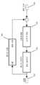
도 6은 액티브 현가 시스템의 예시적 블록도이다.
도 7은 액티브 현가 시스템의 에너지 유동의 예시적 그래프이다.
도 8은 이벤트당 기반으로 액티브 현가 제어를 예시하는 본체 가속 및 모터 토크의 그래프이다.
도 9는 본체 가속에 상관된 토크 명령의 크기 대 주파수의 보드(Bode) 다이어그램이다.
도 10은 액티브 현가 시스템의 피드백 루프의 예시적 블록도이다.
도 11은 응답 시간, 오버샷 및 후속 힘 진동을 예시하는 계산된 힘 응답이다.
도 12는 계산된 보드 다이어그램이다.
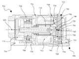
도 13은 유압 작동기와 스마트 밸브를 포함하는 액티브 현가 작동기의 단면도이다.
도 14는 스마트 밸브의 단면도이다.
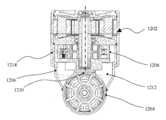
도 15는 유압 작동기와 스마트 밸브를 포함하는 액티브 현가 작동기의 단면도이다.
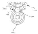
도 16은 도 15의 스마트 밸브의 확대 단면도이다.
도 17은 제어기 밸브 통합체의 개략도이다.
도 18은 포괄적 전기-유압 밸브 아키텍처의 개략도이다.
도 19a 내지 도 19f는 작동기 본체에 스마트 밸브를 연결하기 위한 다양한 부착 방법을 도시한다.
도 20은 차량의 일 코너에서 휠 웰(wheel well) 내에 배치된 스마트 밸브와 연결된 유압 작동기의 단면도이다.
도 21은 가요성 케이블 연결 시스템을 채용하는 차량의 일 코너에서 휠 웰 내에 배치된 스마트 밸브와 연결된 유압 작동기의 개략도이다.
도 22는 차량의 일 코너에서 휠 웰 내에 배치된 상단 장착된 스마트 밸브와 연결된 유압 작동기의 단면도이다.
도 23은 수요 공급식 에너지 유동을 갖는 액티브 현가장치의 예시적 블록도이다.
도 24는 수요 공급식 에너지를 제공하도록 구성된 액티브 현가장치의 개략도이다.
도 25는 수요 공급식 에너지를 제공하도록 구성된 직렬 스프링 및 병렬 댐퍼를 갖는 액티브 현가장치의 개략도이다.
도 26a 내지 도 26d는 수요 공급식 에너지를 제공하도록 구성된 밸브 및 댐퍼를 포함하는 액티브 현가장치의 개략도이다.
도 27은 수요 공급식 에너지를 제공하도록 구성된 단일 작동 작동기를 포함하는 액티브 현가장치의 개략도이다.
도 28은 액티브 현가 시스템을 위한 4개 작동 사분면 힘 속도 도메인의 그래프이다.The accompanying drawings are not drawn to scale. In the drawings, each of the same or almost identical components illustrated in various drawings may be indicated by like numbers. For the sake of clarity, not all components are given reference numerals in all drawings.
1 is an exemplary graph of a conventional semi-active suspension force/speed range.
2 is an exemplary graph of an active suspension using four quadrants.
3 is an exemplary graph of a frequency-domain for motor control and various inputs of an active suspension system.
4 is a schematic diagram of a hydraulic actuator.
5 is a schematic diagram of a hydraulic actuator integrated into a vehicle suspension.
6 is an exemplary block diagram of an active suspension system.
7 is an exemplary graph of the energy flow of an active suspension system.
8 is a graph of body acceleration and motor torque illustrating active suspension control on a per-event basis.
9 is a Bode diagram of magnitude versus frequency of torque command correlated to body acceleration.
10 is an exemplary block diagram of a feedback loop of an active suspension system.
11 is a calculated force response illustrating response time, overshot and subsequent force oscillations.
12 is a calculated board diagram.
13 is a cross-sectional view of an active suspension actuator including a hydraulic actuator and a smart valve.
14 is a cross-sectional view of a smart valve.
15 is a cross-sectional view of an active suspension actuator including a hydraulic actuator and a smart valve.
16 is an enlarged cross-sectional view of the smart valve of FIG. 15.
17 is a schematic diagram of the controller valve assembly.
18 is a schematic diagram of a comprehensive electro-hydraulic valve architecture.
19A-19F illustrate various attachment methods for connecting the smart valve to the actuator body.
20 is a cross-sectional view of a hydraulic actuator connected to a smart valve disposed in a wheel well at a corner of the vehicle.
21 is a schematic diagram of a hydraulic actuator connected with a smart valve disposed in a wheel well at a corner of a vehicle employing a flexible cable connection system.
22 is a cross-sectional view of a hydraulic actuator connected to a top mounted smart valve disposed within a wheel well at a corner of the vehicle.
23 is an exemplary block diagram of an active suspension with demand and supply energy flow.
24 is a schematic diagram of an active suspension configured to provide on-demand energy.
25 is a schematic diagram of an active suspension with series springs and parallel dampers configured to provide on-demand energy.
26A-26D are schematic diagrams of an active suspension comprising a valve and a damper configured to provide on-demand energy.
27 is a schematic diagram of an active suspension comprising a single actuating actuator configured to provide on-demand energy.
28 is a graph of the four operating quadrant force velocity domains for an active suspension system.
본 발명자는 전형적 유압 작동기 시스템 및 유압 현가 시스템과 연계된 다수의 단점을 인식하였다. 더 구체적으로, 전형적 유압 작동기 및 유압 현가 시스템과 함께 사용되는 유압 파워 시스템과 연계된 비용은 다수의 용례에 대하여 사용불가하게 고가이다. 또한, 원격 위치된 유압 파워 시스템과 연계된 패키징은 설치 과제 및 신뢰성 문제를 제공할 수 있는 비교적 긴 길이에 걸친 다수의 유압 호스 및/또는 배관의 사용을 필요로 한다. 추가적으로, 상술한 바와 같이 에너지가 일정하게 가용할 필요가 있는 용례는 연속 구동 펌프의 사용을 필요로 한다. 그러나, 본 발명자는 펌프가 연속적으로 동작할 필요가 있다는 것은 어떠한 유압 에너지도 실제 필요로하지 않을 때에도 에너지가 펌프에 인가되는 것을 필요로 함으로써 시스템 효율을 감소시킨다는 것을 인식하였다. 일부 시스템이 시스템 효율을 증가시키기 위해 가변 용적 펌프를 사용하지만, 이 시스템은 고정 용적 펌프를 사용하는 대응 시스템보다 더 고가이고 덜 신뢰적인 경향이 있어서 다수의 용례를 위한 그 사용을 제한할 수 있다. 추가적으로, 펌프의 속도를 조절하는 시스템은 또한 예로서, 시동 마찰, 회전 관성 및 그 전기적 제어 시스템에 대한 제한을 포함하는 그 용도를 제한하는 다수의 기술적 과제에 직면하고 있다.The inventors have recognized a number of drawbacks associated with typical hydraulic actuator systems and hydraulic suspension systems. More specifically, the costs associated with hydraulic power systems used with typical hydraulic actuators and hydraulic suspension systems are unusable and expensive for many applications. In addition, packaging associated with remotely located hydraulic power systems requires the use of multiple hydraulic hoses and/or piping over relatively long lengths that can present installation challenges and reliability issues. Additionally, applications where the energy needs to be constantly available as described above require the use of a continuous drive pump. However, the inventors have recognized that the need for the pump to operate continuously reduces system efficiency by requiring that energy be applied to the pump even when no hydraulic energy is actually needed. While some systems use variable volume pumps to increase system efficiency, these systems tend to be more expensive and less reliable than counterparts using fixed volume pumps, which can limit their use for many applications. Additionally, systems for regulating the speed of the pump also face a number of technical challenges that limit their use, including, for example, limitations on starting friction, rotational inertia and their electrical control systems.
상술한 바 및 다른 고려사항의 견지에서, 본 발명자는 자립식 또는 부분 자립식 유압 작동 시스템을 제공하기 위해 유압 시스템을 탈중앙화하는 것과 연계된 이득을 인식하였다. 예로서, 그리고, 더 상세히 후술된 바와 같이, 원격 위치된 유압 파워 시스템을 포함하는 대신, 유압 파워 시스템 또는 유압 파워 시스템의 일부 부분은 유압 작동기와 일체화되거나 유압 작동기에 부착될 수 있다. 특정 구성에 따라서, 이는 유압 파워 시스템과 유압 작동기 사이의 외부적 유압 연결에 대한 필요성을 감소 또는 제거시킬 수 있다. 이는 증가된 신뢰성 및 감소된 설치 비용과 전체 유압 시스템과 연계된 복잡성 양자 모두를 제공할 수 있다.In view of the foregoing and other considerations, the inventors have recognized the benefits associated with decentralizing a hydraulic system to provide a self-contained or partially self-contained hydraulic operating system. By way of example, and as described in more detail below, instead of including a remotely located hydraulic power system, the hydraulic power system or some portion of the hydraulic power system may be integrated with or attached to the hydraulic actuator. Depending on the particular configuration, this can reduce or eliminate the need for an external hydraulic connection between the hydraulic power system and the hydraulic actuator. This can provide both increased reliability and reduced installation costs and the complexity associated with the entire hydraulic system.
또한, 본 발명자는 연속 동작 펌프를 필요로 하지 않기 때문에 에너지 소비를 감소시킬 수 있는 수요 공급식 파워를 제공할 수 있는 유압 작동기 및/또는 액티브 현가 시스템을 제공하는 것과 연계된 이득을 인식하였다. 수요 공급식 파워를 제공할 수 있는 유압 시스템은 유압 작동기 본체, 유압 모터-펌프, 유압 모터-펌프에 작동식으로 결합된 연계된 전기 모터 및 제어기를 포함할 수 있다. 추가적으로, 유압 모터-펌프는 전기 모터로의 에너지 전달이 신속하고 부수적 전자 제어식 밸브에 대한 필요성 없이 유압 작동기에 인가된 압력 및 이에 따른 그 응답을 직접적으로 제어하도록 유압 작동기와 로크스텝(lockstep)식으로 동작될 수 있다. 수요시 공급 파워를 제공할 수 있는 유압 시스템은 또한 원하는 성능 레벨을 제공하면서 시스템의 복잡성을 감소시킬 수 있다.In addition, the inventors have recognized the benefits associated with providing hydraulic actuators and/or active suspension systems capable of providing on-demand power capable of reducing energy consumption since they do not require a continuous action pump. A hydraulic system capable of providing on-demand power may include a hydraulic actuator body, a hydraulic motor-pump, an associated electric motor and a controller operatively coupled to the hydraulic motor-pump. In addition, the hydraulic motor-pump is a hydraulic actuator and lockstep method to directly control the pressure applied to the hydraulic actuator and hence its response without the need for a quick energy transfer to the electric motor and the need for an additional electronically controlled valve. It can be operated. Hydraulic systems that can provide supply power on demand can also reduce the complexity of the system while providing the desired level of performance.
상술한 바에 추가로, 본 발명자는 시간에 걸친 평균 거동에 기초한 시스템의 제어에 대해 비교할 때, 시스템이 개별 이벤트에 응답할 수 있게 하도록 충분히 신속한 속도로 제어될 수 있는 유압 작동기 및/또는 현가 시스템을 제공하는 것과 연계된 이득을 인식하였다. 이는 개선된 차량 성능 및 쾌적성을 가능하게 할 수 있는 개별 휠 및/또는 본체 이벤트에 응답하는 차량 현가 시스템을 위한 용도에 특히 유익할 수 있다. 추가적으로, 특정 용례에 따라서, 유압 시스템은 또한 더 상세히 후술된 바와 같이 힘 속도 도메인의 셋 이상의 사분면 내에서 제어를 제공할 수 있다. 그러나, 개시 내용이 제한적이지 않기 때문에 유압 시스템은 또한 하나, 둘 또는 임의의 적절한 수의 힘 속도 도메인의 사분면에서 동작할 수도 있다.In addition to the foregoing, the present inventors propose a hydraulic actuator and/or suspension system that can be controlled at a sufficiently fast speed to enable the system to respond to individual events when compared to the control of the system based on average behavior over time. Recognize the benefits associated with providing. This may be particularly beneficial for applications for vehicle suspension systems responsive to individual wheel and/or body events that may enable improved vehicle performance and comfort. Additionally, depending on the particular application, the hydraulic system may also provide control within three or more quadrants of the force velocity domain, as described in more detail below. However, since the disclosure is not limiting, the hydraulic system may also operate in one, two or any suitable number of the quadrants of the force velocity domains.
개시된 유압 작동기 및 현가 시스템을 구현하는 실시예에서, 본 발명자는 유압 시스템에 의해 원하는 힘 및/또는 변위를 공급하기 위해 응답 시간이 시스템의 다양한 구성요소의 컴플라이언스 및 관성과 연계된 고유한 지연에 기인하여 제한될 수 있다는 것을 인식하였다. 결과적으로, 특정 응답 시간을 갖는 것이 바람직한 실시예에서, 본 발명자는 더 상세히 후술된 바와 같이 원하는 성능 레벨을 가능하게 하도록 유압 시스템의 컴플라이언스 및 관성을 설계하는 것이 바람직할 수 있다는 것을 인식하였다.In embodiments implementing the disclosed hydraulic actuator and suspension system, the inventors have found that the response time is due to the inherent delay associated with the compliance and inertia of the various components of the system to supply the desired force and/or displacement by the hydraulic system. It was recognized that it could be limited. Consequently, in embodiments where it is desirable to have a specific response time, the inventors have recognized that it may be desirable to design the compliance and inertia of the hydraulic system to enable the desired level of performance, as described in more detail below.
전형적 유압 작동기 및 현가 시스템 및 다양한 실시예와 연계된 다수의 가능한 이득에 관한 문제가 인지되어 왔지만, 본 명세서에 설명된 실시예는 상술한 제한을 다루는 것에만 한정되지 않아야 하며, 또한, 본 내용이나 청구범위 중 어느 쪽도 이러한 형태에 한정되지 않으며 다른 이득을 제공할 수도 있다.While problems with typical hydraulic actuators and suspension systems and a number of possible benefits associated with the various embodiments have been recognized, the embodiments described herein should not be limited to addressing the limitations described above, but also Neither of the claims is limited to this form and may provide other benefits.
본 출원의 목적상, 용어 유압 모터-펌프는 유압 모터나 유압 펌프 중 어느 한쪽을 지칭할 수 있다.For the purposes of this application, the term hydraulic motor-pump may refer to either a hydraulic motor or a hydraulic pump.
일 실시예에서, 유압 시스템은 유압 작동기, 유압 모터-펌프, 전기 모터 및 관련 제어기를 포함한다. 유압 작동기는 유압 작동기의 하우징 내에 위치된 신장 체적과 압축 체적을 포함한다. 신장 체적 및 압축 체적은 작동기의 신장 행정 및 압축 행정을 통해 이동하도록 구성 및 배열된 피스톤의 각 측부 상에 위치된다. 유압 작동기 하우징은 예로서, 하나 이상의 동심 튜브에 의해 형성되는 다수의 채널을 포함하는 유압 작동기 하우징을 포함한 임의의 적절한 구조에 대응할 수 있다. 유압 작동기는 유압 작동기의 작동을 제어하기 위해 유압 작동기의 신장 체적 및 압축 체적과 유체 연통하는 유압 모터-펌프와 연계된다. 더 구체적으로, 유압 모터-펌프가 제1 방향으로 동작될 때, 유체는 신장 체적으로부터 압축 체적으로 유동하고, 유압 작동기는 신장 행정을 받는다. 대응적으로, 유압 모터-펌프가 제2 방향으로 동작될 때, 유체는 압축 체적으로부터 신장 체적으로 유동하고, 유압 작동기는 압축 행정을 받는다. 추가적으로, 적어도 일부 실시예에서, 유압 모터-펌프는 유압 작동기의 신장 및 압축 양자 모두를 제어하도록 유압 작동기와 로크스텝식으로 동작할 수 있다. 본 내용이 임의의 특정 장치에 한정되지 않으므로, 고정 용적, 가변 용적, 고정 속도 및/또는 가변 속도를 제공할 수 있는 장치를 포함하는 임의의 적절한 유압 모터-펌프가 사용될 수 있다는 것을 이해하여야 한다. 예로서, 일 실시예에서, 유압 모터-펌프는 제로터에 대응할 수 있다.In one embodiment, the hydraulic system includes a hydraulic actuator, a hydraulic motor-pump, an electric motor and an associated controller. The hydraulic actuator includes an elongated volume and a compression volume located within a housing of the hydraulic actuator. The extension and compression volumes are located on each side of the piston configured and arranged to move through the extension and compression strokes of the actuator. The hydraulic actuator housing may correspond to any suitable structure, including, for example, a hydraulic actuator housing comprising a plurality of channels formed by one or more concentric tubes. The hydraulic actuator is associated with a hydraulic motor-pump in fluid communication with the expansion and compression volumes of the hydraulic actuator to control the operation of the hydraulic actuator. More specifically, when the hydraulic motor-pump is operated in the first direction, the fluid flows from the stretching volume to the compression volume, and the hydraulic actuator is subjected to a stretching stroke. Correspondingly, when the hydraulic motor-pump is operated in the second direction, the fluid flows from the compression volume to the extension volume, and the hydraulic actuator is subjected to a compression stroke. Additionally, in at least some embodiments, the hydraulic motor-pump may operate in a lockstep with the hydraulic actuator to control both elongation and compression of the hydraulic actuator. As the disclosure is not limited to any particular device, it should be understood that any suitable hydraulic motor-pump may be used, including devices capable of providing a fixed volume, a variable volume, a fixed speed and/or a variable speed. As an example, in one embodiment, a hydraulic motor-pump may correspond to a gerotor.
상술한 바와 같이, 유압 시스템은 또한 유압 모터-펌프에 작동식으로 결합될 수 있는 전기 모터를 포함한다. 전기 모터는 본 내용이 이에 한정되지 않으므로 유압 모터-펌프에 간접적으로 또는 직접적으로 결합될 수 있다. 각 경우에, 전기 모터는 유압 모터-펌프에 적용되는 힘을 제어한다. 또한, 전기 모터가 제어되는 방식에 따라서, 유압 모터-펌프는 유압 작동기를 능동적으로 구동할 수 있거나, 미래의 사용을 위해 보관되거나 소산될 수 있는 에너지를 또한 생성하면서 유압 작동기에 댐핑을 제공하기 위한 발전기로서 작용할 수 있다. 전기 모터가 발전기로서 역방향 구동되는 예에서, 유압 모터-펌프는 인가된 힘에 응답하여 유압 작동기의 신장 체적과 압축 체적 사이에서 유동하는 유체에 의해 특정 방향으로 구동된다. 순차적으로, 유압 모터-펌프는 전기 에너지를 생성하기 위해 전기 모터를 구동한다. 발전 동안 전기 모터에 인가되는 임피던스 또는 다른 적절한 입력을 제어함으로써 유압 작동기에 인가된 댐핑 힘은 소정 범위의 힘을 제공하도록 전기적으로 제어될 수 있다. 일부 실시예에서, 유압 모터-펌프는 유압 작동기와 로크스텝식으로 동작한다.As mentioned above, the hydraulic system also includes an electric motor that can be operatively coupled to a hydraulic motor-pump. The electric motor may be indirectly or directly coupled to the hydraulic motor-pump as the present disclosure is not limited thereto. In each case, the electric motor controls the force applied to the hydraulic motor-pump. In addition, depending on how the electric motor is controlled, the hydraulic motor-pump can be used to actively drive the hydraulic actuator, or to provide damping to the hydraulic actuator while also generating energy that can be stored or dissipated for future use. Can act as a generator. In the example in which the electric motor is driven in the reverse direction as a generator, the hydraulic motor-pump is driven in a specific direction by the fluid flowing between the compression volume and the elongation volume of the hydraulic actuator in response to an applied force. Sequentially, the hydraulic motor-pump drives the electric motor to generate electrical energy. By controlling the impedance or other suitable input applied to the electric motor during power generation, the damping force applied to the hydraulic actuator can be electrically controlled to provide a range of forces. In some embodiments, the hydraulic motor-pump operates in a lockstep manner with a hydraulic actuator.
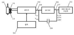
상술한 제어기는 전기 모터에 전기적으로 결합되며, 특정 동작 모드와 유압 작동기에 인가되는 힘을 제어하기 위해 전기 모터의 모터 입력을 제어한다. 모터 입력은 예로서, 전기 모터의 위치, 전압, 토크, 임피던스, 주파수 및/또는 모터 속도를 포함하는 임의의 적절한 파라미터에 대응할 수 있다. 전기 모터는 예로서, 외부적 파워 공급부, 차량의 배터리 및 다른 적절한 소스 같은 외부 에너지 소스 및 배터리, 슈퍼 커패시터, 유압 축압기, 플라이휠 및 다른 적절한 장치 같은 유압 작동기 및/또는 제어기와 통합될 수 있는 내부적 소스를 포함하는 임의의 적절한 에너지 소스에 의해 파워공급될 수 있다. 상술한 견지에서, 유압 작동기에 공급된 압력은 별개로 제어되는 밸브를 필요로 하지 않고 유압 모터-펌프에 연결된 전기 모터에 의해 제어될 수 있다.The above-described controller is electrically coupled to the electric motor and controls a motor input of the electric motor to control a specific mode of operation and a force applied to the hydraulic actuator. The motor input may correspond to any suitable parameter including, for example, position, voltage, torque, impedance, frequency, and/or motor speed of the electric motor. Electric motors are, for example, external power supplies, external energy sources such as the vehicle's battery and other suitable sources, and internally that can be integrated with hydraulic actuators and/or controllers such as batteries, super capacitors, hydraulic accumulators, flywheels and other suitable devices. It can be powered by any suitable energy source including a source. In view of the above, the pressure supplied to the hydraulic actuator can be controlled by an electric motor connected to the hydraulic motor-pump without requiring a separately controlled valve.
또한, 유압 모터-펌프가 단일 방향으로만 동작되는 실시예도 적절한 밸브의 사용을 통해 가능하지만, 유압 모터-펌프는 양방향적 방식으로 동작될 수 있다. 이런 실시예에서, 유압 작동기의 위치는 전기 모터의 위치에 의해 결정될 수 있다. 결과적으로, 전기 모터가 제어되는 방식에 따라서, 연계된 유압 작동기는 여전히, 능동적으로 신장 또는 능동적으로 압축되어 유지될 수 있다. 대안적으로, 유압 작동기에는 역시 압축 댐핑 또는 신장 댐핑 중 어느 하나가 적용될 수 있다. 상술된 바와 같이 구성 및 동작되는 유압 시스템은 복잡한 밸브 장치의 사용 없이 각 방향으로 유압 작동기를 제어하기 위해 사용될 수 있으며, 파워는 연속 동작 펌프에 비해 필요시에만 시스템에 인가된다. 예로서, 일 특정 실시예에서, 유압 모터-펌프에 의해 펌핑되는 유체의 절반을 초과한 양이 하나 이상의 밸브를 통해 작동기를 우회하는 대신 유압 작동기를 작동시키기 위해 사용될 수 있다.Further, an embodiment in which the hydraulic motor-pump is operated only in a single direction is also possible through the use of an appropriate valve, but the hydraulic motor-pump can be operated in a bidirectional manner. In this embodiment, the position of the hydraulic actuator can be determined by the position of the electric motor. Consequently, depending on how the electric motor is controlled, the associated hydraulic actuator can still be actively stretched or actively compressed and held. Alternatively, either compression damping or extension damping can also be applied to the hydraulic actuator. The hydraulic system constructed and operated as described above can be used to control the hydraulic actuator in each direction without the use of a complex valve device, and power is applied to the system only when necessary compared to a continuous operation pump. By way of example, in one particular embodiment, more than half of the fluid pumped by the hydraulic motor-pump may be used to operate the hydraulic actuator instead of bypassing the actuator through one or more valves.
예로서, 오프-하이웨이(off highway) 리프팅 용례, 포크리프트, 리프트 붐 또는 로봇 용례 같은 부하 유지 용례에 유압 작동기가 사용되는 예에서, 작동기가 이동하도록 명령될 때까지 제 위치에 작동기를 유압식으로 로크하기 위해 부하 유지 밸브를 통합하는 것이 바람직할 수 있다. 또한, 부하 유지 장치는 안전성 및/또는 페일세이프 이유로 바람직할 수 있다. 일 실시예에서, 부하 유지 장치는 하나 이상의 부하 유지 밸브이다. 이들 하나 이상의 부하 유지 밸브는 본질적으로 패시브식, 예를 들어, 파일롯 작동식 체크 밸브일 수 있거나 이들은 이들이 제어 입력, 예를 들어, 솔레노이드 작동식 밸브를 필요로 하도록 액티브식일 수 있다. 다른 실시예에서, 부하 유지 장치는 유압 작동기를 제 위치에 로크하도록 구성 및 배열되는 기계적 장치이다. 예로서, 부하 유지 장치는 피스톤 로드를 파지하도록 구성 및 배열된 기계적 브레이크일 수 있다. 이런 실시예에서, 기계적 장치는 유압 작동기를 이동시키는 것이 소망될 때 유압식, 기계식 및/또는 전기식으로 비활성화될 수 있다. 다수의 가능한 부하 유지 장치가 상술되었지만, 유압 작동기의 작동을 제한 및/또는 방지할 수 있는 임의의 적절한 장치가 사용될 수 있다는 것을 이해하여야 한다.For example, in an example where a hydraulic actuator is used in a load holding application such as an off highway lifting application, forklift, lift boom, or robotic application, hydraulically locking the actuator in place until the actuator is commanded to move It may be desirable to incorporate a load holding valve in order to do so. Additionally, load holding devices may be desirable for safety and/or failsafe reasons. In one embodiment, the load holding device is one or more load holding valves. These one or more load holding valves may be passive in nature, eg pilot operated check valves or they may be active such that they require control inputs, eg solenoid operated valves. In another embodiment, the load holding device is a mechanical device constructed and arranged to lock the hydraulic actuator in place. As an example, the load holding device may be a mechanical brake constructed and arranged to grip a piston rod. In this embodiment, the mechanical device can be deactivated hydraulically, mechanically and/or electrically when it is desired to move the hydraulic actuator. While a number of possible load holding devices have been described above, it should be understood that any suitable device capable of limiting and/or preventing operation of the hydraulic actuator may be used.
특정 실시예가 상술되었지만, 본 내용은 이에 한정되지 않으므로, 연속 동작 펌프 및/또는 다양한 유형의 밸브를 통합하는 실시예가 또한 가능하다는 것을 이해하여야 한다.While specific embodiments have been described above, it should be understood that embodiments incorporating a continuous action pump and/or various types of valves are also possible as the present disclosure is not limited thereto.
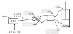
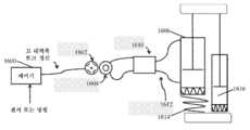
일 실시예에서, 유압 작동 시스템 및/또는 현가 시스템은 전기 모터, 유압 모터-펌프(HSU로 일반적으로 지칭되는 정수역학적 유닛일 수 있음), 유압 작동기 및 모터 제어기를 포함한다. 실시예에 따라서, 상술한 구성요소 중 다양한 구성요소가 단일 하우징 내에 배치되거나 그와 통합될 수 있다. 추가적으로, 전기 모터 및 유압 모터-펌프는 서로 긴밀하게 결합될 수 있다. 전기 모터 및 유압 모터-펌프가 공통 샤프트에 긴밀하게 결합되는 전기 모터, 유압 모터-펌프 및 모터 제어기를 축약적, 자립식 유닛으로 조합하는 기능은 크기, 성능, 신뢰성 및 내구성에 관하여 다수의 장점을 제공할 수 있다. 일부 실시예에서, 모터 제어기는 양방향적 파워 유동을 위한 기능을 가지며, 모터 전압, 전류, 저항 중 어느 하나, 상술한 바의 조합 또는 다른 적절한 모터 입력을 제어함으로써 정확하게 모터를 제어하는 기능을 가진다. 이는 모터 제어기가 센서 입력에 기초하여, 원하는 모터 속도, 위치 및/또는 토크를 정확하게 달성할 수 있게 한다(내부 센서, 외부 센서 또는 양자의 조합으로부터). 유닛이 양방향적 방식으로 유압 유동 및/또는 압력을 정확하게 제어할 수 있으므로 요소의 상술한 조합은 "스마트 밸브"라 명명될 수 있다. 추가적으로 이러한 제어는 별도의 수동적 또는 능동적 제어식 밸브에 대한 필요성 없이 달성될 수 있다. 추가적 밸브가 스마트 밸브와 함게 사용될 수 있는 실시예도 고려된다.In one embodiment, the hydraulic actuation system and/or suspension system comprises an electric motor, a hydraulic motor-pump (which may be a hydrodynamic unit commonly referred to as an HSU), a hydraulic actuator and a motor controller. Depending on the embodiment, various components among the above-described components may be disposed within or integrated with a single housing. Additionally, the electric motor and hydraulic motor-pump can be tightly coupled to each other. The ability to combine electric motor, hydraulic motor-pump, and motor controller into a compact, self-contained unit in which electric motor and hydraulic motor-pump are tightly coupled to a common shaft offers a number of advantages in terms of size, performance, reliability and durability Can provide. In some embodiments, the motor controller has a function for bidirectional power flow, and has the function of accurately controlling the motor by controlling any one of motor voltage, current, resistance, a combination of the above or other suitable motor input. This enables the motor controller to accurately achieve the desired motor speed, position and/or torque based on the sensor input (from an internal sensor, an external sensor or a combination of both). The above-described combination of elements may be termed a "smart valve" since the unit can accurately control hydraulic flow and/or pressure in a bidirectional manner. Additionally, this control can be achieved without the need for a separate passive or actively controlled valve. Embodiments are also contemplated in which additional valves may be used with smart valves.
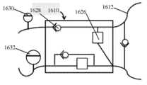
상술한 바와 같이, 스마트 밸브 내의 유압 모터-펌프 및 전기 모터는 공통 샤프트에 긴밀하게 결합될 수 있다. 추가적으로, 이들 구성요소는 공통 유체 충전된 하우징에 배치될 수 있으며, 그에 의해, 밀봉부를 갖는 샤프트에 대한 필요성을 제거한다. 이는 밸브의 내구성 및 성능을 증가시킬 수 있다. 추가적으로, 일부 실시예의 스마트 밸브는 또한 통합된 전자 제어기를 포함하며, 이는 파워 및 로직 기능 양자 모두를 조합할 수 있고 또한 회전 위치 센서, 가속계 또는 온도 센서 등 같은 센서를 포함할 수 있다. 스마트 밸브 내로 전자 제어기를 통합하는 것은 제어기 파워 보드와 전기 모터 권선 사이의 거리를 최소화하며, 그에 의해, 통합된 전자 제어기의 파워 보드 섹션과 전기 모터 사이의 파워 연결의 길이를 감소시킨다. 이는 차량 내부로부터의 전자기 간섭(EMI) 교란 및 접속의 파워 손실 양자 모두를 감소시킬 수 있다.As described above, the hydraulic motor-pump and electric motor in the smart valve can be tightly coupled to a common shaft. Additionally, these components can be placed in a common fluid filled housing, thereby eliminating the need for a shaft with a seal. This can increase the durability and performance of the valve. Additionally, the smart valves of some embodiments also include an integrated electronic controller, which may combine both power and logic functions and may also include sensors such as rotational position sensors, accelerometers or temperature sensors, and the like. Integrating the electronic controller into the smart valve minimizes the distance between the controller power board and the electric motor windings, thereby reducing the length of the power connection between the electric motor and the power board section of the integrated electronic controller. This can reduce both electromagnetic interference (EMI) disturbances from inside the vehicle and the power loss of the connection.
단일 본체 유닛으로의 스마트 밸브와 유압 작동기의 조합은 다수의 이득을 제공하는 매끈하고 축약적인 디자인을 제공할 수 있다. 예로서, 이런 실시예는 긴 유압 호스를 연장할 필요성을 제거함으로써 통합 복잡성을 감소시키고, 시스템을 완전히 밀봉함으로써 내구성을 향상시기고, 제조 비용을 감소시키고, 시스템 강성도를 증가시킴으로써 응답 시간을 개선시키며, 구성요소 사이의 더 짧은 거리로부터 전기적 및 유압적 양자 모두의 손실을 감소시킨다. 이런 시스템은 또한 모노튜브, McPherson 스트러트 또는 공기 스프링 시스템 같은 다수의 현가 아키텍쳐와의 손쉬운 통합을 가능하게 한다. 차량으로의 통합의 용이성을 위해, 통합된 액티브 현가 스마트 밸브 및 유압 작동기를 전형적 패시브 댐퍼 기반 현가 시스템의 크기 및/또는 형상의 제약 내에 맞추는 것이 바람직하다. 따라서, 일부 실시예에서, 스마트 밸브는 특히 스마트 밸브 기반 작동기가 이들 플랫폼의 현저한 재설계를 필요로 하지 않고 기존 차량 플랫폼 내에 설치될 수 있게 할 수 있는 전형적 패시브 댐퍼 기반 현가 시스템의 크기, 형태 및 형상 인자 제약에 부합되도록 크기설정 및 성형된다.The combination of a smart valve and hydraulic actuator into a single body unit can provide a sleek and compact design that provides multiple benefits. As an example, this embodiment reduces integration complexity by eliminating the need to extend long hydraulic hoses, improves durability by completely sealing the system, reduces manufacturing costs, and improves response times by increasing system stiffness. , Reducing both electrical and hydraulic losses from shorter distances between components. These systems also allow easy integration with multiple suspension architectures such as monotubes, McPherson struts or air spring systems. For ease of integration into a vehicle, it is desirable to fit the integrated active suspension smart valve and hydraulic actuator within the constraints of the size and/or shape of a typical passive damper based suspension system. Thus, in some embodiments, smart valves are the size, shape, and shape of a typical passive damper-based suspension system that specifically allows smart valve-based actuators to be installed within existing vehicle platforms without requiring significant redesign of these platforms. It is sized and molded to meet factor constraints.
일 양태에 따라서, 스마트 밸브는 단일 유닛으로 구성된, 전자 제어 유닛 또는 제어기, 유압 모터-펌프에 작동식으로 결합된 전기 모터 및 하나 이상의 센서를 포함할 수 있다. 유압 모터-펌프는 제1 포트와 제2 포트를 포함한다. 제1 포트는 유압 작동기의 신장 체적과 유체 연통하고, 제2 포트는 유압 작동기의 압축 체적과 유체 연통한다. 이런 실시예에서, 스마트 밸브는 차량 현가 힘 속도 도메인의 다수의(예를 들어, 통상적으로 셋 또는 넷의) 사분면에서 제어된 힘을 생성하도록 제어될 수 있으며, 그에 의해, 유압 작동기의 힘 속도 도메인의 4개 사분면은 압축 댐핑, 신장 댐핑, 액티브 신장 및 액티브 압축에 대응한다. 스마트 밸브의 다양한 실시예가 가능하며, 선택적으로 유압 작동기 내에 배치된 피스톤을 포함하는 상술한 아이템을 포함할 수 있다. 피스톤은 작동기 내의 제1 챔버와 제2 챔버 사이에서 이동가능하게 위치된다. 제1 챔버는 신장 체적일 수 있고, 제2 챔버는 압축 체적일 수 있다.According to one aspect, a smart valve may comprise an electronic control unit or controller, configured as a single unit, an electric motor operatively coupled to a hydraulic motor-pump, and one or more sensors. The hydraulic motor-pump includes a first port and a second port. The first port is in fluid communication with the elongated volume of the hydraulic actuator, and the second port is in fluid communication with the compression volume of the hydraulic actuator. In such an embodiment, the smart valve can be controlled to generate a controlled force in multiple (e.g., typically three or four) quadrants of the vehicle suspension force velocity domain, whereby the force velocity domain of the hydraulic actuator. The four quadrants of correspond to compression damping, stretching damping, active stretching and active compression. Various embodiments of the smart valve are possible, and may optionally include the above-described item including a piston disposed in a hydraulic actuator. The piston is located movably between the first chamber and the second chamber in the actuator. The first chamber can be an elongated volume and the second chamber can be a compressed volume.
다른 양태에 따라서, 스마트 밸브는 역시 제어기, 전기 모터, 유압 모터-펌프 및 하나 이상의 센서를 포함할 수 있다. 스마트 밸브는 모터 권선을 통한 전압 또는 전류 같은 전기 모터의 모터 입력을 제어함으로써 전기 모터에 원하는 속도 또는 토크 같은 모터 출력을 제공하도록 전자 제어기에 의해 작동될 수 있다. 이는 모터의 회전을 저지하는 토크를 생성할 수 있다.According to another aspect, the smart valve may also comprise a controller, an electric motor, a hydraulic motor-pump and one or more sensors. The smart valve can be actuated by an electronic controller to provide a motor output such as a desired speed or torque to the electric motor by controlling the motor input of the electric motor, such as voltage or current through the motor windings. This can create a torque that impedes the rotation of the motor.
다른 양태에 따라서, 제어기는 위치, 전압, 토크, 임피던스 또는 주파수 중 적어도 하나의 모터 입력에 의해 전기 모터를 제어할 수 있다. 추가적으로, 스마트 밸브의 다양한 구성요소는 단일 하우징 또는 본체 내에 배치될 수 있거나 그와 통합될 수 있다. 대안적으로, 제어기, 전기 모터 및 센서는 하우징 내에 수납될 수 있고, 이는 액티브 현가 시스템 구성요소 사이의 통신을 촉진하도록 유압 모터-펌프를 위한 하우징에 조립될 수 있다.According to another aspect, the controller may control the electric motor by motor input of at least one of position, voltage, torque, impedance, or frequency. Additionally, various components of the smart valve may be disposed within a single housing or body or may be integrated therewith. Alternatively, the controller, electric motor and sensor can be housed within a housing, which can be assembled into a housing for a hydraulic motor-pump to facilitate communication between the active suspension system components.
다른 실시예에서, 스마트 밸브는 전기 모터, 전기 모터 제어기 및 유압 펌프를 하우징 내에 포함할 수 있다. 실시예에 따라서, 하우징은 유체 충전된다. 스마트 밸브의 대안적 구성은 유압 펌프, 유압 펌프의 동작을 제어하는 전기 모터, 전기 모터 제어기 및 단일 본체 하우징 내의 하나 이상의 센서를 포함할 수 있다. 스마트 밸브의 또 다른 구성에서, 스마트 밸브는 전기 모터, 유압 모터-펌프 및 유압 모터-펌프와 유체 연통하는 피스톤이 장비된 유압 작동기를 포함할 수 있다.In another embodiment, the smart valve may include an electric motor, an electric motor controller and a hydraulic pump within a housing. According to an embodiment, the housing is fluid filled. Alternative configurations of the smart valve may include a hydraulic pump, an electric motor that controls the operation of the hydraulic pump, an electric motor controller and one or more sensors within a single body housing. In yet another configuration of the smart valve, the smart valve may comprise a hydraulic actuator equipped with an electric motor, a hydraulic motor-pump and a piston in fluid communication with the hydraulic motor-pump.
다른 양태에 따라서, 스마트 밸브는 차량 휠 웰에 맞도록 크기설정 및 성형될 수 있다. 이런 실시예에서, 스마트 밸브는 작동기 본체에 배치된 피스톤 로드, 유압 모터, 전기 모터 및 전기 모터를 제어하기 위한 전기 제어기를 포함할 수 있다. 스마트 밸브는 또한 작동기 본체에 배치된 하나 이상의 패시브 밸브를 포함할 수 있다. 패시브 밸브는 유압 모터와 직렬이거나 그와 병렬로 동작될 수 있다.According to another aspect, the smart valve can be sized and shaped to fit a vehicle wheel well. In this embodiment, the smart valve may comprise a piston rod disposed in the actuator body, a hydraulic motor, an electric motor and an electric controller for controlling the electric motor. The smart valve may also include one or more passive valves disposed in the actuator body. The passive valve can be operated in series with or in parallel with the hydraulic motor.
다른 양태에 따라서, 액티브 현가 시스템에 통합된 스마트 밸브는 전기 모터를 제어하는 전자 제어기가 스마트 밸브 및/또는 전기 모터와 긴밀하게 통합되도록 구성될 수 있다. 이는 전기 모터에 대한 제어 전자장치로부터 높은 전류 경로의 길이를 유익하게 최소화할 수 있다.According to another aspect, the smart valve integrated in the active suspension system may be configured such that the electronic controller controlling the electric motor is tightly integrated with the smart valve and/or the electric motor. This can advantageously minimize the length of the high current path from the control electronics for the electric motor.
다른 양태에 따라서, 하나 이상의 스마트 밸브 및/또는 유압 작동기를 차량의 모든 휠을 제어하는 차량 액티브 현가 시스템과 통합하는 것이 바람직할 수 있다. 이런 시스템은 복수의 스마트 밸브를 포함할 수 있으며, 이들 각각은 각 스마트 밸브가 관련 휠을 제어하기 위한 압력 및/또는 휠 특정 가변 유동을 생성할 수 있도록 차량 휠에 인접하게 배치된다. 이는 스마트 밸브를 통한 유체의 유동을 제어함으로써 달성될 수 있다. 상술한 바와 유사하게, 개별 스마트 밸브를 통한 유체의 유동은 각 스마트 밸브의 유압 모터-펌프와 연계된 전기 모터를 사용하여 제어될 수 있다. 특정 실시예에 따라서, 전기 모터가 유압 모터-펌프와 함께 동축으로 배치되는 것이 바람직할 수 있다.According to another aspect, it may be desirable to integrate one or more smart valves and/or hydraulic actuators with a vehicle active suspension system that controls all wheels of the vehicle. Such a system may include a plurality of smart valves, each of which is placed adjacent to the vehicle wheel such that each smart valve can create a pressure and/or wheel specific variable flow to control the associated wheel. This can be achieved by controlling the flow of fluid through the smart valve. Similar to the above, the flow of fluid through individual smart valves can be controlled using an electric motor associated with the hydraulic motor-pump of each smart valve. Depending on the particular embodiment, it may be desirable for the electric motor to be arranged coaxially with the hydraulic motor-pump.
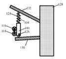
스마트 밸브의 다수의 가능한 실시예가 본 명세서에 설명되어 있지만, 스마트 밸브는 다양한 다른 방식으로 구성될 수 있는 것으로 이해되어야 한다. 일부 예시적 방식은 몇몇을 들자면 모터 제어기에 모터 전류를 전달하는 어떠한 노출된 또는 가요성 배선도 존재하지 않도록 모터 하우징과 통합된 전자식 모터 제어기; 작동기 본체 또는 하우징에 연결되거나 그와 완전히 통합된 스마트 밸브의 구성요소; 유압 충격 흡수기 본체에 연결되거나 그와 통합된 스마트 밸브의 구성요소; 스마트 밸브의 전자장치는 작동기에 장착되고; 스마트 밸브의 전기 모터 및 유압 펌프는 동일 샤프트 상에 배치되고; 어떠한 유압 호스도 필요로 하지 않는 스마트 밸브; 작동기의 피스톤 로드와 대략 축방향으로 정렬되는 유압 모터; 피스톤 로드 이동 방향에 대략 수직인 유압 모터 및 차량 휠 조립체의 하부 제어 아암과 스트러트의 상단부 사이에 장착되는 스마트 밸브를 포함한다.While a number of possible embodiments of a smart valve are described herein, it is to be understood that the smart valve may be configured in a variety of different ways. Some exemplary approaches include an electronic motor controller integrated with the motor housing such that there is no exposed or flexible wiring to carry motor current to the motor controller, to name a few; Components of a smart valve connected to or fully integrated with the actuator body or housing; A component of a smart valve connected to or integrated with the hydraulic shock absorber body; The electronics of the smart valve are mounted on the actuator; The electric motor and hydraulic pump of the smart valve are arranged on the same shaft; Smart valves that do not require any hydraulic hoses; A hydraulic motor substantially axially aligned with the piston rod of the actuator; A hydraulic motor approximately perpendicular to the direction of movement of the piston rod and a smart valve mounted between the lower control arm of the vehicle wheel assembly and the upper end of the strut.
다른 양태에 따라서, 특정 용례에서, 스마트 밸브는 특정 크기, 형상 및/또는 배향 제한을 필요로 할 수 있다. 다양한 용례를 위한 예시적 스마트 밸브 실시예가 이제 설명된다. 일 실시예에서, 스마트 밸브는 현가장치와 통합되고, 작동기 상단 및 저부 장착부 사이에서 그리고 차량 휠 웰 내에 끼워질 수 있는 체적 및 형상을 점유한다. 다른 실시예에서, 스마트 밸브는 현가장치와 통합되고 현가 시스템의 연계된 작동기의 관절작동 및 전체 범위의 운동 동안 적절한 유극이 스마트 밸브와 모든 주변 구성요소 사이에서 유지되도록 체적과 형상을 점유한다. 또 다른 실시예에서, 현가 작동기는 작동기 본체와 동축으로 스마트 밸브를 지지하며 작동기 상단 장착부에 연결된다. 다른 실시예에서, 현가장치는 작동기 본체와 동축으로 스마트 밸브를 지지하고, 자동차 댐퍼 상단 장착부 및 스프링 퍼치(perch)의 것과 실질적으로 유사한 직경을 점유한다. 모터-펌프의 액티브 현가 제어부는 8 in 미만 직경, 8 in 깊이가 되도록 구성될 수 있으며, 일부 경우에는 그 점유면적보다 실질적으로 작다.According to another aspect, in certain applications, smart valves may require certain size, shape and/or orientation restrictions. Exemplary smart valve embodiments for various applications are now described. In one embodiment, the smart valve is integrated with the suspension and occupies a volume and shape that can fit between the actuator top and bottom mounts and within the vehicle wheel well. In another embodiment, the smart valve is integrated with the suspension and occupies a volume and shape such that adequate play is maintained between the smart valve and all surrounding components during articulation and full range of motion of the associated actuator of the suspension system. In another embodiment, the suspension actuator supports the smart valve coaxially with the actuator body and is connected to the actuator top mount. In another embodiment, the suspension supports the smart valve coaxially with the actuator body and occupies a diameter substantially similar to that of the automotive damper top mount and spring perch. The motor-pump's active suspension control can be configured to be less than 8 inches in diameter, 8 inches deep, and in some cases substantially smaller than its occupied area.
다른 양태에 따라서, 스마트 밸브는 자립식일 수 있으며, 외부적으로 발생된 지식, 센서 입력 또는 차량으로부터의 다른 데이터를 필요로하지 않을 수 있다. 통합된 프로세서 기반 제어기를 갖는 스마트 밸브는 다른 시스템에 독립적으로 기능할 수 있다. 이는 차량의 다른 휠 상에 동작하는 다른 스마트 밸브(예를 들어, 코너 제어기)가 존재하는지 여부에 무관하게 자체 캘리브레이션 같은 기능을 포함할 수 있다. 스마트 밸브는 광범위한 현가 성능을 전달할 수 있으며, 이는 패시브 댐퍼, 반-액티브 현가장치/재생성 작동기, 가변 현가장치로서 및/또는 완전 액티브 현가장치 등으로서의 동작을 포함할 수 있다. 자립식이고 요구되는 파워 모두와, 로직 제어 및 모든 유압 연결이 작동기 조립체 내에 수용되기 때문에 이러한 기능이 용이해진다. 자립식 스마트 밸브는 잠재적으로 더 많은 값 및/또는 개선된 성능을 전달하기 위한 광범위한 진보된 차량 기능과 조합될 수 있다. 스마트 밸브를 예측 제어, GPS 가능화 도로 조건 정보, 레이더, 전방 관찰 센서 등과 조합하는 것은 CAN 버스 같은 차량 통신 버스의 사용을 통해 쉽게 달성될 수 있다. 스마트 밸브의 알고리즘은 현가 동작, 성능 등을 조절하기 위해 이러한 추가적 정보를 포함할 수 있다. 일 예에서, 후방 휠 스마트 밸브가 전방 휠 스마트 밸브 및 차량 속도에 대한 일부 지식에 의해 취해지는 작동에 대한 지식을 갖는 경우, 후방 휠의 현가 시스템은 휠이 이벤트를 경험하기 이전에 휠 이벤트에 응답하도록 준비될 수 있다.According to another aspect, the smart valve may be self-contained and may not require externally generated knowledge, sensor input or other data from the vehicle. Smart valves with an integrated processor-based controller can function independently of other systems. This may include functions such as self-calibration regardless of whether there are other smart valves (eg, corner controllers) operating on different wheels of the vehicle. Smart valves can deliver a wide range of suspension capabilities, which may include operation as passive dampers, semi-active suspension/regeneration actuators, variable suspensions and/or fully active suspensions, and the like. This function is facilitated because it is self-contained and all the required power, logic control and all hydraulic connections are housed within the actuator assembly. Self-contained smart valves can potentially be combined with a wide range of advanced vehicle functions to deliver more value and/or improved performance. Combining the smart valve with predictive control, GPS-enabled road condition information, radar, and forward-looking sensors can be easily achieved through the use of a vehicle communication bus such as a CAN bus. The smart valve's algorithm can include this additional information to control suspension behavior, performance, etc. In one example, if the rear wheel smart valve has knowledge of the operation taken by the front wheel smart valve and some knowledge of the vehicle speed, the suspension system of the rear wheel responds to the wheel event before the wheel experiences the event. Can be prepared to do.
다른 양태에 따라서, 다른 압력 밀봉된 배리어와 조합된 가요성 멤브레인 또는 순응성 전기 연결부는 유압 가압식 하우징 내에 위치된 제어기로부터 배리어 또는 멤브레인의 운동을 기계적으로 분리시키기 위해 사용될 수 있다. 유압 가압식 하우징은 별개의 가압 유체 충전 부분 및 공기 충전 부분을 포함할 수 있다. 제어기로부터 이동을 분리시키는 것은 제어기의 인쇄 회로 보드에 접속된 멤브레인 또는 압력 밀봉 배리어를 통해 통과한 모터 연결부 사이의 땜납 조인트의 브레이킹을 방지하는 것을 도울 수 있다. 다른 양태에 따라서, 유압 가압식 하우징 내에 제어기 전자장치들을 동시위치시키는 것은 또한 복잡한 기계적 피드스루에 대한 필요성을 제거하고, 더욱 예측가능한 열적 환경을 제공한다.According to another aspect, a flexible membrane or compliant electrical connection in combination with another pressure sealed barrier can be used to mechanically separate the motion of the barrier or membrane from a controller located within a hydraulically pressurized housing. The hydraulic pressurized housing can include separate pressurized fluid filling portions and air filling portions. Separating the movement from the controller can help prevent braking of the solder joints between the motor connections passed through a membrane or pressure seal barrier connected to the controller's printed circuit board. According to another aspect, co-locating the controller electronics within a hydraulically pressurized housing also eliminates the need for complex mechanical feedthroughs and provides a more predictable thermal environment.
다른 양태에 따라서, 유압 모터-펌프로부터의 유압 압력 리플은 포트 타이밍 축압기 버퍼를 사용함으로써 및/또는 유압 리플 소거 알고리즘을 위한 신호를 공급하기 위해 회전 위치 센서를 사용함으로써 감소된다.According to another aspect, hydraulic pressure ripple from the hydraulic motor-pump is reduced by using a port timing accumulator buffer and/or by using a rotational position sensor to supply a signal for the hydraulic ripple cancellation algorithm.
상술한 유압 작동 시스템은 임의의 수의 용례에 사용될 수 있다. 예로서, 유압 시스템은 몇몇을 들자면 굴착기 아암, 항공기(예를 들어, 플랩, 에일러론, 엘리베이터, 러더 등)의 제어 표면, 포크리프트, 리프트 붐 및 액티브 현가 시스템에 결합되도록 구성 및 배열될 수 있다. 따라서, 제어 시스템의 특정 실시예가 더 상세히 후술된 바와 같이 액티브 현가 시스템에 관련하지만, 언급된 제어 방법 및 후술된 시스템은 임의의 적절한 시스템에 통합될 수 있고, 액티브 현가 시스템에만 한정되는 것은 아니라는 것을 이해하여야 한다.The hydraulic actuation system described above can be used for any number of applications. By way of example, the hydraulic system may be configured and arranged to couple to an excavator arm, a control surface of an aircraft (e.g., flaps, ailerons, elevators, rudders, etc.), forklifts, lift booms and active suspension systems, to name a few. Thus, while certain embodiments of the control system relate to an active suspension system as described in more detail below, it is understood that the mentioned control method and the system described below may be incorporated into any suitable system and are not limited to the active suspension system only. shall.
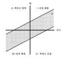
도 1 및 도 2는 힘 속도 도메인 내에서 현가 시스템에 통합된 유압 작동기를 제어하기 위한 다양한 방식의 플롯을 제공한다. 도면에 예시된 바와 같이, 힘 속도 도메인은 유압 작동기의 신장에 상쇄작용하기 위해 유압 작동기에 의해 힘이 인가되는 신장 댐핑에 대응하는 제1 사분면 I을 포함한다. 유사하게, 사분면 III은 압축력에 의한 유압 작동기의 압축을 상쇄작용하기 위해 유압 작동기에 의해 힘이 인가되는 압축 댐핑에 대응한다. 대조적으로, 사분면 II 및 IV는 원하는 위치로 구동되는 유압 작동기의 액티브 압축 및 액티브 신장에 대응한다.1 and 2 provide plots of various ways for controlling hydraulic actuators integrated into a suspension system within a force velocity domain. As illustrated in the figure, the force velocity domain includes a first quadrant I corresponding to the elongation damping in which force is applied by the hydraulic actuator to counteract the elongation of the hydraulic actuator. Similarly, quadrant III corresponds to compression damping in which force is applied by the hydraulic actuator to counteract the compression of the hydraulic actuator by the compression force. In contrast, quadrants II and IV correspond to the active compression and active extension of the hydraulic actuator driven to the desired position.
도 1은 전형적 반-액티브 현가장치에 통합된 작동기의 명령 기구(2)의 플롯이다. 도면에 예시된 바와 같이, 반-액티브 현가장치의 명령 기구(2)는 신장 및 압축 댐핑에 대응하는 사분면 I 및 III 내에 위치된다. 따라서, 이런 시스템은 단지 이동을 상쇄하도록 힘(즉, 반응력)을 인가한다. 통상적으로, 반-액티브 현가장치의 성능은 시스템을 통한 유체 유동을 조정하도록 간단한 전자 제어식 밸브의 개방 및 폐쇄를 통해 전체 연성(4) 및 전체 강성(6)에 대응하는 댐핑 특성 곡선 사이에서 변화될 수 있다. 전자 제어식 밸브를 통합하는 시스템은 통상적으로 동작을 위해 에너지를 소비하며, 유압 작동기의 댐핑과 연계된 에너지는 열로서 소산된다. 또한, 반-액티브 시스템의 동작 범위는 높은 힘에서의 누설에 기인하여 제한되며, 더 낮은 힘에서 유체 손실 및 마찰 효과를 겪는다.1 is a plot of the
본 명세서에 설명된 바와 같은 유압 작동기는 도 1에 도시된 바와 같이 반-액티브 시스템의 성능을 에뮬레이팅하도록 동작될 수 있다. 그러나, 이런 시스템은 에너지를 소비하는 대신 에너지를 재생한다. 예로서, 유압 모터-펌프에 작동식으로 결합된 전기 모터의 단자가 개회로 상태로 남아있는 경우(예를 들어, 비교적 높은 임피던스 상태), 전체 연성(4) 곡선과 유사한 댐핑 곡선이 달성될 수 있다. 대신 전기 모터의 단자가 낮은 임피던스에 연결되는 경우, 전체 강성(6) 곡선과 유사한 댐핑 곡선이 달성될 수 있다. 이들 경계 사이의 댐핑 곡선에 대하여, 본 명세서에 설명된 것들 같은 유압 작동기는 휠 이동으로부터 에너지를 발생할 수 있다. 고 및 저 임피던스 상태의 설명은 기능적 설명이며, 일부 실시예에서, 이는 H-브리지 모터 제어기 같은 스위칭 파워 컨버터에 의해 달성될 수 있고, 여기서, 스위치는 원하는 토크 특성을 달성하도록 제어된다. 그러나, 인가된 임피던스 또는 다른 적절한 모터 입력을 제어할 수 있는 임의의 적절한 메커니즘이 사용될 수 있는 것을 이해하여야 한다. 각 경우에, 반-액티브 모드에서도 출력 토크는 단지 필요할 때 힘을 생성하기 위해 휠 이벤트에 직접적으로 응답하여 제어될 수 있으며, 연속 동작 펌프로부터 시스템에 에너지를 지속적으로 제공하는 것은 필요하지 않다.A hydraulic actuator as described herein can be operated to emulate the performance of a semi-active system as shown in FIG. 1. However, these systems regenerate energy instead of consuming it. As an example, if the terminals of the electric motor operatively coupled to the hydraulic motor-pump remain open circuit (e.g., in a relatively high impedance state), a damping curve similar to the overall ductility (4) curve can be achieved. have. Instead, if the terminals of the electric motor are connected to a low impedance, a damping curve similar to the
반-액티브 현가 시스템의 성능을 에뮬레이팅할 수 있지만, 일부 실시예에서, 전체 액티브 모드에서 유압 작동기를 동작시키는 것이 바람직하다. 이런 실시예에서, 전기 모터와 연계된 제어기는 더 상세히 후술된 바와 같이 힘 속도 도메인의 적어도 세 사분면에서 유압 작동기를 사용하여 제어된 힘을 제공하기 위해 전기 모터의 입력을 제어한다. 그러나, 적어도 하나의 실시예에서, 유압 작동기는 본 내용이 이에 제한되지 않으므로, 모든 4개 사분면에서 제어된 힘을 생성하도록 동작될 수 있다.While it is possible to emulate the performance of a semi-active suspension system, in some embodiments, it is desirable to operate the hydraulic actuator in full active mode. In this embodiment, a controller associated with the electric motor controls the input of the electric motor to provide a controlled force using a hydraulic actuator in at least three quadrants of the force velocity domain, as described in more detail below. However, in at least one embodiment, the hydraulic actuator may be operated to generate a controlled force in all four quadrants, as the present disclosure is not limited thereto.
도 2는 전체 액티브 현가 시스템에 통합된 유압 작동기의 명령 기구(8)의 대표적 플롯이다. 제1 사분면 I에서, 시스템은 차량 휠의 반동에 대한 반응력에 대응할 수 있는 신장 댐핑을 제공할 수 있다. 제3 사분면 III에서, 시스템은 차량 휠의 압축에 대한 반응력에 대응할 수 있는 압축 댐핑을 제공할 수 있다. 이전에 설명된 바와 같이, 유압 시스템은 이 에너지가 소산되는 실시예도 가능하지만 사분면 I 및 III의 적어도 일부에서 에너지를 발생하도록 구성될 수 있다. 그러나, 상술한 반-액티브 시스템과는 달리, 시스템은 또한 휠을 아래로 추진하기 위해 힘을 인가하는 것에 대응할 수 있는 액티브 신장 IV 및/또는 자동차 휠을 위로 견인하는 것에 대응할 수 있는 액티브 압축 II에 대응하는 두 개의 잔여 사분면 중 적어도 하나에서 힘을 생성할 수 있다. 이들 사분면에서, 시스템은 원하는 힘을 인가하도록 에너지를 소비할 수 있다. 이 에너지는 예로서, 커패시터나 배터리 같은 에너지 저장 장치 또는 차량으로부터의 전기 에너지; 축압기 또는 유사한 장치 같은 장치로부터의 유압 에너지 저장량; 및/또는 플라이휠 같은 기계적 에너지 저장 수단을 포함하는 임의의 적절한 소스로부터 유입될 수 있다.2 is a representative plot of the
상술한 설명의 견지에서, 일부 실시예에서, 힘 속도 도메인의 4개 사분면 중 적어도 셋에서 동작되는 전체 액티브 시스템은 양방향적 에너지 유동을 제공한다. 더 구체적으로, 사분면 I 및 III 에너지는 압축 댐핑 및 신장 댐핑 동안 구동되는 전기 모터에 의해 재생되며, 사분면 II 및 IV 에너지는 전기 모터에 인가되고 전기 모터에 의해 소비됨으로써 유압 작동기를 능동적으로 연장 또는 압축한다. 이런 유압 작동 시스템은 현가 시스템과 통합된 기존의 유압 작동 시스템에 비해 특히 유익할 수 있으며, 그 이유는, 유압 작동기 본체의 다양한 부분으로 그리고 그로부터 유체의 유동을 제어하기 위해 별개의 액티브 제어식 밸브의 사용을 필요로하지 않기 때문이다.In view of the above description, in some embodiments, the entire active system operating in at least three of the four quadrants of the force velocity domain provides a bidirectional energy flow. More specifically, the energy in the quadrants I and III is regenerated by the electric motor driven during compression damping and extension damping, and the energy in the quadrants II and IV is applied to the electric motor and consumed by the electric motor, thereby actively extending or compressing the hydraulic actuator. do. Such hydraulically actuated systems can be particularly beneficial compared to conventional hydraulically actuated systems integrated with suspension systems, since the use of separate active controlled valves to control the flow of fluid to and from various parts of the hydraulic actuator body. Because it doesn't need.
본 명세서에 설명된 바와 같은 유압 작동기의 실시예가 상술한 바와 같이 힘 속도 도메인의 모든 4개 사분면에서 동작할 수 있지만, 유압 작동기에 전달된 에너지는 전기 모터 및 유압 모터-펌프의 동작의 힘, 속도 및 방향에 의해 제어된다. 더구체적으로, 전기 모터 및 유압 모터-펌프와 마찬가지로, 그리고, 다른 연계된 구성요소는 지속적으로 동작 방향을 반전시키고, 하나의 동작 속도로부터 다른 속도로 가속하고, 정지상태로부터 유압 작동기 동작 전반에 걸친 원하는 동작 속도로 진행한다. 결과적으로, 유압 작동기의 응답 시간은 일 동작 상태와 다음 동작 상태 사이의 신속한 전이를 위한 이들 다양한 구성요소의 기능과 연계된 지연을 포함한다. 이는 연계된 유압 작동기를 제어하기 위한 압력 및/또는 유체의 일정한 유동을 포함하는 유압 라인과 연계된 밸브를 간단하게 개방 및 폐쇄하는 시스템에 대한 비교이다. 따라서, 일부 실시예에서, 마찬가지로 다른 장치와 연계된 응답 지연을 고려하면서 원하는 시스템 성능을 달성하기 위해 원하는 응답 시간을 제공하도록 시스템을 설계하는 것이 바람직하다. 다수의 유형의 이벤트가 상술되었지만, 전기 모터 및 유압 모터-펌프의 동작과 연계된 다른 유형의 거동도 가능하다.Although embodiments of the hydraulic actuator as described herein can operate in all four quadrants of the force velocity domain as described above, the energy delivered to the hydraulic actuator is the force, speed of the operation of the electric motor and hydraulic motor-pump. And controlled by the direction. More specifically, as with electric motors and hydraulic motor-pumps, and other associated components continuously reverse the direction of motion, accelerate from one operating speed to another, and from standstill to the entire hydraulic actuator motion. Proceed at the desired operating speed. Consequently, the response time of the hydraulic actuator includes a delay associated with the functioning of these various components for rapid transition between one operating state and the next. This is a comparison to a system that simply opens and closes a valve associated with a hydraulic line containing a constant flow of pressure and/or fluid to control an associated hydraulic actuator. Thus, in some embodiments, it is desirable to design the system to provide the desired response time to achieve the desired system performance while also taking into account the response delay associated with other devices. Although a number of types of events have been described above, other types of behavior are possible, associated with the operation of electric motors and hydraulic motor-pumps.
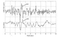
신속 응답 시간이 임의의 수의 용례에서 바람직하지만, 더 상세히 후술된 바와 같이, 일 실시예에서, 연계된 유압 작동기, 전기 모터 및 유압 모터-펌프를 포함하는 시스템은 액티브 현가 시스템에서 기능하기 위해 충분히 신속한 응답 시간을 갖도록 설게된다. 이런 실시예에서, 응답 시간은 액티브 현가 시스템이 개별 이벤트에 응답할 수 있도록 선택될 수 있다. 이들 이벤트는 임의의 적절한 제어 입력에 대응할 수 있지만, 일부 실시예에서, 이들 이벤트는 개별 본체 이벤트 및/또는 휠 이벤트이다. 한가지 이런 실시예에서, 센서는 차량의 본체 이벤트 및/또는 휠 이벤트를 감지하도록 구성 및 배열된다. 센서는 현가 시스템에 통합된 유압 작동기의 제어기에 전기적으로 결합된다. 휠 이벤트 및/또는 본체 이벤트의 감지시, 제어기는 유압 모터-펌프에 결합된 전기 모터에 모터 입력을 인가한다. 이는 순차적으로 유압 모터-펌프가 유압 작동기에 힘을 인가함에 따라 유압 작동기 내의 유체의 유동을 직접적으로 제어한다. 따라서, 유압 작동기는 휠 또는 본체 이동 중 어느 하나에서 초래되는 개별 감지된 휠 이벤트 및/또는 본체 이벤트에 응답하여 제어될 수 있다. 더 상세히 후술된 바와 같이, 개별 본체 이벤트 및/또는 휠 이벤트는 통상적으로 0.5 Hz, 2 Hz, 8 Hz 또는 임의의 다른 적절한 주파수보다 큰 주파수에서 동작한다. 개별 본체 이벤트 및/또는 휠 이벤트는 또한 통상적으로 약 20 Hz 마만의 주파수에서 발생한다. 따라서, 일 실시예에서, 현가 시스템에 통합된 유압 작동 시스템은 경계를 포함하여 약 0.5 Hz 내지 20 Hz 사이의 주파수에서 발생하는 개별 본체 이벤트 및/또는 휠 이벤트에 응답하도록 가공된다.While rapid response time is desirable in any number of applications, as described in more detail below, in one embodiment, a system comprising an associated hydraulic actuator, electric motor and hydraulic motor-pump is sufficient to function in an active suspension system. It is designed to have a quick response time. In such an embodiment, the response time may be selected so that the active suspension system can respond to individual events. These events may correspond to any suitable control input, but in some embodiments, these events are individual body events and/or wheel events. In one such embodiment, the sensors are configured and arranged to detect vehicle body events and/or wheel events. The sensor is electrically coupled to the controller of the hydraulic actuator integrated into the suspension system. Upon detection of a wheel event and/or body event, the controller applies a motor input to the electric motor coupled to the hydraulic motor-pump. This in turn directly controls the flow of fluid in the hydraulic actuator as the hydraulic motor-pump applies force to the hydraulic actuator. Thus, the hydraulic actuator can be controlled in response to individual sensed wheel events and/or body events resulting from either wheel or body movement. As discussed in more detail below, individual body events and/or wheel events typically operate at frequencies greater than 0.5 Hz, 2 Hz, 8 Hz or any other suitable frequency. Individual body events and/or wheel events also typically occur at a frequency of about 20 Hz Maman. Thus, in one embodiment, the hydraulic actuation system integrated into the suspension system is engineered to respond to individual body events and/or wheel events occurring at frequencies between about 0.5 Hz and 20 Hz including the boundary.
개별 본체 이벤트 및/또는 휠 이벤트가 발생하는 속도의 견지에서, 일부 실시예에서, 유압 시스템의 응답 시간이 이들 이벤트에 시간적으로 적어도 대등한 것이 바람직하다. 일부 실시예에서, 응답 시간이 개별 이벤트에 응답할 때 고려될 수 있는 시스템에 존재하는 다른 지연에 기인하여 개별 이벤트가 발생하는 속도보다 신속한 것이 바람직할 수 있다. 상술한 견지에서, 일부 실시예에서, 유압 시스템의 응답 시간은 약 150 ms, 100 ms, 50 ms 또는 임의의 다른 적절한 시간 주기 미만일 수 있다. 응답 시간은 또한 약 1 ms, 10 ms, 20 ms, 50 ms 또는 임의의 다른 적절한 시간 주기보다 클 수 있다. 예로서, 유압 시스템의 응답 시간은 약 1 ms와 150 ms 사이, 10 ms와 150 ms 사이, 10 ms와 100 ms 사이, 또는 10 ms와 50 ms 사이일 수 있다. 상술한 것들보다 크거나 그보다 작은 응답 시간이 또한 가능하다는 것을 이해하여야 한다. 추가적으로, 상술한 것들 같은 신속한 응답 시간을 나타내는 유압 작동기는 본 내용이 임의의 특정 용례에 한정되지 않으므로 현가 시스템 이외의 용례에 사용될 수 있다는 것을 이해하여야 한다.In terms of the speed at which individual body events and/or wheel events occur, in some embodiments, it is desirable that the response time of the hydraulic system is at least equivalent in time to these events. In some embodiments, it may be desirable for the response time to be faster than the rate at which individual events occur due to other delays present in the system that may be considered when responding to individual events. In view of the above, in some embodiments, the response time of the hydraulic system may be less than about 150 ms, 100 ms, 50 ms, or any other suitable time period. The response time may also be greater than about 1 ms, 10 ms, 20 ms, 50 ms or any other suitable time period. As an example, the response time of the hydraulic system may be between about 1 ms and 150 ms, between 10 ms and 150 ms, between 10 ms and 100 ms, or between 10 ms and 50 ms. It should be understood that response times greater than or less than those described above are also possible. Additionally, it should be understood that hydraulic actuators exhibiting rapid response times, such as those described above, may be used in applications other than suspension systems as the disclosure is not limited to any particular application.
본 예에서 더 상세히 설명된 바와 같이, 그리고, 이론에 구속되지 않고, 유압 작동 시스템의 응답 시간은 유압 작동 시스템의 고유 주파수에 비례한다. 따라서, 원하는 응답 시간을 제공하기 위해, 유압 작동 시스템의 고유 주파수는 약 2 Hz, 5 Hz, 10 Hz, 20 Hz 또는 임의의 다른 적절한 주파수보다 클 수 있다. 추가적으로, 고유 주파수는 약 100 Hz, 50 Hz, 40 Hz보다 작을 수 있다. 예로서, 일 실시예에서, 유압 작동 시스템의 고유 주파수는 경계를 포함하여 약 2 Hz와 100 Hz 사이이다.As explained in more detail in this example, and without being bound by theory, the response time of the hydraulic actuated system is proportional to the natural frequency of the hydraulic actuated system. Thus, in order to provide the desired response time, the natural frequency of the hydraulic actuation system may be greater than about 2 Hz, 5 Hz, 10 Hz, 20 Hz or any other suitable frequency. Additionally, the natural frequency may be less than about 100 Hz, 50 Hz, 40 Hz. As an example, in one embodiment, the natural frequency of the hydraulic actuation system is between about 2 Hz and 100 Hz including the boundary.
이론에 얽매이기를 바라지 않고, 유압 작동 시스템의 고유 주파수에 영향을 주는 설계 고려사항은 유압 작동 시스템의 컴플라이언스 및 반사 관성을 포함한다. 본 예에서 언급한 바와 같이, 유압 작동 시스템의 고유 주파수는 이하의 공식을 사용하여 규정될 수 있다:Without wishing to be bound by theory, design considerations that affect the natural frequency of a hydraulically actuated system include compliance and reflected inertia of the hydraulically actuated system. As mentioned in this example, the natural frequency of the hydraulic operating system can be defined using the following formula:

여기서, f는 유압 작동 시스템의 고유 주파수이고,
유압 작동 시스템의 반사 관성(Jn2)은 전기 모터의 회전을 작동기의 선형 운동으로 변환하는 운동 비율(n)의 제곱으로 승산된 작동기의 운동과 로크스텝식으로 회전하는 모든 구성요소의 관성(J)의 회전 모멘트를 포함한다. 예로서, 반사 관성은 로터; 전기 모터와 유압 모터-펌프 사이의 결합 샤프트; 로터, 샤프트 및/또는 펌프와 결합되는 임의의 베어링; 유압 모터-펌프; 및 다른 적절한 구성요소의 관성 모멘트를 포함할 수 있다. 일 실시예에서, 본 명세서에 설명된 바와 같은 유압 작동 시스템의 운동 비율(n)은 회전 당 유압 모터-펌프의 용적 체적으로 나누어진, 유압 피스톤의 피스톤 로드 둘레의 피스톤의 환형 영역에 의해 특징지어진다. 그러나, 본 기술 분야에 알려진 바와 같이 운동 비율(n)을 형성하는 다른 방식도 고려된다. 선형 운동이 일반적인 또는 유압 모터-펌프의 작동에 응답하여 선형적으로 이동하는 전달 구성요소가 현저한 질량을 갖는 시스템에서, 전체 반사 관성은 또한 선형 이동 구성요소의 질량을 포함할 수 있다.The reflected inertia (Jn2 ) of the hydraulic operating system is the motion of the actuator multiplied by the square of the ratio of motion (n) that converts the rotation of the electric motor into the linear motion of the actuator, and the inertia of all components rotating in a lockstep manner (J ) Of rotational moment. By way of example, the reflective inertia is a rotor; Coupling shaft between electric motor and hydraulic motor-pump; Any bearings associated with the rotor, shaft and/or pump; Hydraulic motor-pump; And moments of inertia of other suitable components. In one embodiment, the rate of motion (n) of a hydraulically actuated system as described herein is characterized by the annular area of the piston around the piston rod of the hydraulic piston divided by the volumetric volume of the hydraulic motor-pump per revolution. Lose. However, other ways of forming the motion ratio n as known in the art are also contemplated. In systems in which linear motion is common or in which the transmission component moves linearly in response to actuation of the hydraulic motor-pump has a significant mass, the total reflection inertia may also include the mass of the linear moving component.
전체 양(Jn2)은 또한 그 자체의 회전 관성 모멘트 및 그 자체의 전달 비율(n)을 각각 갖는 피스톤의 운동과 로크스텝식으로 이동하는 다수의 구성요소로 구성될 수 있다. 예로서, 모터 샤프트의 평면내 운동을 구속하는 베어링 시스템은 모터 샤프트의 것과는 다른 각속도로 회전하는 구성요소를 갖는다. 반사 시스템 관성에 대한 그 전체 기여도에 의존하여, 그 각각의 관성 모멘트 및 전달 비율을 사용하여 시스템의 디자인을 위해 사용되는 반사 시스템 관성에서의 이들 기여도를 포함하는 것이 바람직할 수 있다. 예로서, 그리고, 이론에 얽매이는 것을 원하지 않고, 베어링 시스템이 롤러 형 베어링인 경우, 이때, 롤러는 샤프트와 로크스텝식으로, 그러나, 샤프트 자체의 것의 절반과 근접한 각속도로 이동한다. 동시에, 여전히 샤프트와 로크스텝 상태에 있는 동안 개별 롤러는 매우 더 신속한 각속도로 이동한다. 따라서, 이들 구성요소 각각은 그 소유의 관성 모멘트 및 그 소유의 운동 비율을 사용하여 고려될 수 있다.The total amount Jn2 may also consist of a number of components moving in a lockstep manner and the movement of the piston, each having its own moment of rotational inertia and its own transmission ratio n. As an example, a bearing system that constrains the in-plane motion of a motor shaft has a component that rotates at an angular velocity different from that of the motor shaft. Depending on its overall contribution to the reflection system inertia, it may be desirable to include these contributions in the reflection system inertia used for the design of the system using its respective moment of inertia and transmission ratio. As an example, and not wishing to be bound by theory, if the bearing system is a roller-type bearing, then the roller moves in a lockstep with the shaft, but at an angular velocity close to half that of the shaft itself. At the same time, the individual rollers move at a much faster angular velocity while still in the shaft and lockstep state. Thus, each of these components can be considered using its own moment of inertia and its own rate of motion.
선형 운동이 일반적인, 그리고, 모터 힘과 작동력 사이의 전달장치가 선형 레버를 사용하는 시스템에서, 모터의 이동 구성요소의 선형 질량은 또한 작동기 단부에서의 운동을 레버의 모터 단부에서의 운동으로 변환하는 그 선형 운동 비율(n)을 통해 고려될 수도 있다. 이러한 개념에서, 수식 (Jn2)는 더 일반적으로 작동기에서의 선형 또는 회전 운동을 특정 이동 요소의 선형 또는 회전 운동으로 변환하는 운동 비율의 제곱으로 각각 승산된 모든 이동 질량과 모든 회전 관성 모멘트의 합으로서 의도된다.In systems where linear motion is common, and the transmission between motor force and actuation force uses a linear lever, the linear mass of the moving component of the motor also converts motion at the actuator end into motion at the motor end of the lever. It may be considered through its linear motion ratio n. In this concept, the equation (Jn2 ) is more generally the sum of all moving masses and all rotational moments of inertia, each multiplied by the square of the rate of motion that converts linear or rotational motion in the actuator to linear or rotational motion of a specific moving element. It is intended as.
유압 작동 시스템 컴플라이언스(1/K)는 유압 작동기의 힘 출력 지점(예를 들어, 작동기의 이동 샤프트)과 전기 모터 사이에 위치된, 그리고, 전기 모터와 직렬인 모든 요소의 컴플라이언스이다. 유압 작동 시스템 컴플라이언스에 대한 다양한 기여도는 유압 작동기의 피스톤과 유압 모터-펌프 사이의 유체 컬럼의 전체 압축성; 호스, 튜브 또는 유압 모터-펌프를 유압 작동기에 연결하는 구조의 유연성; 힘 인가 지점에 대한 유압 작동기의 장착 표면의 유연성; 및 유압 작동 시스템의 전체 컴플라이언스에 기여할 수 있는 다른 적절한 고려사항을 포함할 수 있다. 유압 작동 시스템 컴플라이언스의 역수는 유압 작동 시스템 강성도(K)라는 것을 인지하여야 한다.Hydraulic actuated system compliance (1/K) is the compliance of all elements located between the force output point of the hydraulic actuator (eg, the actuator's moving shaft) and the electric motor and in series with the electric motor. The various contributions to hydraulic actuation system compliance include the overall compressibility of the fluid column between the hydraulic actuator's piston and the hydraulic motor-pump; Flexibility in the construction of connecting hoses, tubes or hydraulic motor-pumps to hydraulic actuators; Flexibility of the mounting surface of the hydraulic actuator to the point of force application; And other suitable considerations that may contribute to the overall compliance of the hydraulic operating system. It should be noted that the reciprocal of hydraulic-operated system compliance is hydraulic-operated system stiffness (K).
상술한 견지에서, 원하는 고유 주파수 및 이에 따른 응답 시간을 제공하기 위해, 유압 작동 시스템은 컴플라이언스와 반사 관성 사이의 상호작용을 사용하여 설계될 수 있다. 더 구체적으로, 유압 작동 시스템의 강성도에 대한 반사 관성의 비율로서 보여질수도 있는 반사 관성과 유압 작동 시스템의 컴플라이언스의 곱(Jn2/K)은 이하의 디자인 범위에 따라 설계될 수 있다. 일부 실시예에서, 반사 관성과 유압 작동 시스템의 컴플라이언스의 곱은 6.3x10⁻³ s2, 1.0x10⁻³ s2, 2.5x10⁻⁴ s2, 6.3x10⁻⁵ s2, 2.8x10⁻⁵ s2, 1.6x10⁻⁵ s2 또는 임의의 다른 적절한 값보다 작을 수 있다. 추가적으로, 반사 관성과 유압 작동 시스템의 컴플라이언스의 곱은 1.6x10⁻⁵ s2, 1.0x10⁻⁵ s2, 2.5x10⁻⁶ s2 또는 임의의 다른 적절한 값보다 클 수 있다. 예로서, 일 실시예에서, 반사 관성과 유압 작동 시스템의 컴플라이언스 사이의 곱은 경계를 포함하여 약 2.5x10⁻⁶ s2과 6.3x10⁻³ s2 사이이다. 그러나, 상술한 것들보다 큰 및 그보다 작은 양자 모두의 값으로 설계된 유압 작동 시스템이 또한 고려될 수 있다는 것을 이해하여야 한다. 상술한 설계 기준을 사용하여, 설계자는 원하는 응답 시간을 제공하도록 시스템의 컴플라이언스와 전달 비율 및 시스템의 다양한 구성요소의 관성을 사용할 수 있다. 임의의 파라미터가 원하는 응답을 획득하도록 변경될 수 있지만, 설계 파라미터는 변환 인자의 자승에 대한 의존성 및 유압 작동 시스템의 컴플라이언스와 구성요소의 관성에 대한 선형 의존성을 갖는다는 것을 언급할 필요가 있다. 결과적으로, 변환 인자의 변화는 시스템의 전체 응답의 대응적 더 큰 변화를 제공할 수 있다. 유압 작동 시스템을 설계하는 이들 파라미터의 상호작용의 예는 본 예에서 더 상세히 제공된다.In view of the above, in order to provide the desired natural frequency and thus the response time, the hydraulic actuation system can be designed using the interaction between compliance and reflective inertia. More specifically, the product (Jn2 /K) of the compliance of the hydraulic operating system and the reflected inertia, which may be viewed as a ratio of the reflected inertia to the stiffness of the hydraulic operating system, can be designed according to the following design range. In some embodiments, the product of the reflective inertia and the compliance of the hydraulically operated system is 6.3x10⁻³ s2 , 1.0x10⁻³ s2 , 2.5x10⁻⁴ s2 , 6.3x10⁻⁵ s2 , 2.8x10⁻⁵ s2 , May be less than 1.6x10⁻⁵ s2 or any other suitable value. Additionally, the product of the reflective inertia and the compliance of the hydraulic actuation system may be greater than 1.6x10⁻⁵ s2 , 1.0x10⁻⁵ s2 , 2.5x10⁻⁶ s2 or any other suitable value. As an example, in one embodiment, the product between the reflective inertia and the compliance of the hydraulically actuated system is between about 2.5x10⁻⁶ s2 and 6.3x10⁻³ s2 including the boundary. However, it should be understood that hydraulically actuated systems designed for both values greater than and less than those described above may also be considered. Using the design criteria described above, the designer can use the compliance and delivery ratio of the system and the inertia of the various components of the system to provide the desired response time. While any parameter can be changed to obtain the desired response, it is worth mentioning that the design parameters have a dependence on the square of the conversion factor and a linear dependence on the compliance of the hydraulic operating system and the inertia of the components. As a result, a change in the conversion factor can provide a correspondingly larger change in the overall response of the system. An example of the interaction of these parameters in designing a hydraulic operating system is provided in more detail in this example.
유압 작동 시스템의 적절한 응답 시간을 제공하는 것에 추가하여, 일부 실시예에서, 본체 및/또는 휠 이벤트 같은 제어 이벤트의 주파수보다 크거나 그와 유사한 주파수로 유압 작동 시스템을 제어하는 것이 바람직하다. 도 3은 차량의 휠 이동(12) 및 본체 이동(10)의 전형적 주파수와 연계된 본체 제어 및 휠 제어 주파수 대역과 모터 토크 갱신(14)과 관련시키는 주파수 플롯을 도시한다. 통상적 승용차에 대하여, 비록 이 대역을 초과한 더 높은 주파수의 본체 이동이 양호할 수 있지만, 본체 이동(10)은 0 Hz와 4 Hz 사이에서 발생한다. 휠 이동은 종종 8 Hz와 20 Hz 사이에서 발생하며, 대략 약 10 Hz 주변에 중심설정된다. 그러나, 본체 및 휠 이동 주파수는 차량간에, 그리고, 도로 조건에 기초하여 다르다는 것을 이해하여야 한다. 휠 이벤트 및/또는 본체 이벤트는 휠 및/또는 본체 이동을 유발하는 휠 또는 본체로의 임의의 입력으로서 규정될 수 있다(조향 입력의 결과 포함). 주파수 관점으로부터, 휠 이벤트 및 본체 이벤트는 종종 대략 0.5 Hz 이상에서 발생하고(16 참조), 1000 Hz를 초과한 주파수에서도 발생할 수 있다. 결과적으로, 모터 입력 갱신 주파수는 0.5 Hz 만큼 낮은 주파수로부터 심지어 가능하게는 1,000 Hz보다 더 큰 주파수까지 변할 수 있다(14 참조). 기능적 견지에서, 휠 이벤트 및/또는 본체 이벤트(하나 이상의 센서에 의해 측정된 바와 같이)에 응답하여 모터 토크 같은 명령된 모터 입력의 임의의 변화는 휠 이벤트 및/또는 본체 이벤트에 대한 응답으로서 고려될 수 있다.In addition to providing an adequate response time of the hydraulic actuated system, in some embodiments, it is desirable to control the hydraulic actuated system at a frequency greater than or similar to the frequency of control events such as body and/or wheel events. FIG. 3 shows a body control and wheel control frequency band associated with typical frequencies of
상술한 견지에서, 일부 실시예에서, 개별 본체 이벤트 및/또는 휠 이벤트가 발생하는 주파수와 유사하거나 더 큰 주파수에서 유압 작동기가 제어되는 것이 바람직하다. 따라서, 적어도 하나의 실시예에서, 제어기는 유압 작동기를 동작시키기 위해 사용되는 전기 모터에 전기적으로 결합되고, 제어기는 개별 본체 이벤트 및/또는 휠 이벤트보다 신속한 속도로 전기 모터의 모터 입력을 갱신한다. 모터 입력은 약 0.5 Hz, 2 Hz, 8 Hz, 20 Hz 또는 제어기 및 연계된 전기 모터가 동작할 수 있는 임의의 적절한 주파수보다 큰 주파수로 갱신될 수 있다. 일부 실시예에서, 모터 입력은 약 1 kHz보다 작은 주파수로 갱신될 수 있지만, 다른 주파수도 가능하다. 따라서, 일 예시적 실시예에서, 모터 입력은 경계를 포함하여 약 0.5 Hz와 1 kHz 사이의 주파수로 제어된다.In view of the above, in some embodiments, it is desirable for the hydraulic actuator to be controlled at a frequency similar to or greater than the frequency at which individual body events and/or wheel events occur. Thus, in at least one embodiment, the controller is electrically coupled to the electric motor used to operate the hydraulic actuator, the controller updating the motor input of the electric motor at a faster rate than the individual body event and/or wheel event. The motor input can be updated to a frequency greater than about 0.5 Hz, 2 Hz, 8 Hz, 20 Hz or any suitable frequency at which the controller and associated electric motor can operate. In some embodiments, the motor input may be updated to a frequency less than about 1 kHz, but other frequencies are possible. Thus, in one exemplary embodiment, the motor input is controlled to a frequency between about 0.5 Hz and 1 kHz including the boundary.
일 예시적 실시예에서, 제어 시스템은 비록 다른 주파수가 가능하지만, 모터 토크 같은 모터 입력을 10 Hz로 갱신되도록 명령한다. 각 갱신시, 명령된 모터 입력은 작동기가 본체 속도에 대향한 힘을 생성하도록 스케일링 인자(k)로 승산된 현재 수직 본체 속도(소프트웨어 적분기를 통해 입력된 본체 가속)가 되도록 설정된다. 이런 실시예는 차량의 본체 제어를 개선시킬 수 있다. 휠 제어에 관한 다른 실시예에서, 모터 토크 같은 명령된 모터 입력은 현재 작동기 속도(휠과 본체 사이의 차등 이동)가 되고 이동을 상쇄하기 위해 인자(k)로 승산되도록 설정된다. 여기서, 시스템은 댐퍼와 매우 유사하게 응답한다. 상술한 실시예는 전체 차량 제어를 제공하기 위해 휠 제어 및 본체 제어 양자 모두를 제공하도록 함께 사용될 수 있다는 것을 이해하여야 한다. 다른 실시예에서, 명령된 모터 입력은 0.5 Hz 같은 더 느린 속도 또는 1 kHz 같은 더 빠른 속도로 갱신된다. 더 복잡한 제어 시스템도 전술한 바와 같이 본체 가속 대신 또는 그에 추가로 다른 센서 데이터를 사용할 수 있으며, 본 내용이 이에 한정되지 않으므로, 비례적, 적분, 미분 또는 더 복잡한 피드백 제어 체계를 포함할 수 있다.In one exemplary embodiment, the control system commands the motor input, such as motor torque, to be updated to 10 Hz, although other frequencies are possible. At each update, the commanded motor input is set to be the current vertical body speed (body acceleration entered through the software integrator) multiplied by a scaling factor k to cause the actuator to generate a force against the body speed. This embodiment can improve the control of the body of the vehicle. In another embodiment regarding wheel control, the commanded motor input, such as motor torque, is set to be the current actuator speed (differential movement between wheel and body) and multiplied by a factor k to offset the movement. Here, the system responds very similarly to a damper. It should be understood that the above-described embodiments can be used together to provide both wheel control and body control to provide overall vehicle control. In another embodiment, the commanded motor input is updated at a slower speed such as 0.5 Hz or a faster speed such as 1 kHz. A more complex control system may also use other sensor data instead of or in addition to the body acceleration as described above, and since the present disclosure is not limited thereto, a proportional, integral, differential or more complex feedback control system may be included.
도 4는 전체 액티브 작동기로서 힘 속도 도메인의 모든 4개 사분면에서 동작될 수 있는 유압 작동기(100)의 일 실시예를 도시한다. 피스톤 로드(104)와 피스톤 헤드(106)를 포함하는 피스톤은 유체 충전된 하우징(102) 내에 배치된다. 피스톤의 이동시, 하나 이상의 동심 유체 유동 튜브(122) 또는 다른 적절한 연결을 통해, 피스톤 헤드(106)는 유체를 피스톤 헤드의 일 측부에 배치된 신장 체적(110)과 피스톤 헤드의 대향 측부 상에 위치된 압축 체적(108)의 내외로 유체를 추진한다. 유체 유동 튜브(122) 또는 다른 적절한 연결 또는 포트 배열은 유압 모터-펌프(114)에 연결된다. 따라서, 유압 모터-펌프(114)는 도면에 화살표로 표시된 바와 같이 유압 작동기의 압축 체적(108) 및 신장 체적(110)과 유체 연통한다. 유압 모터-펌프(114)는 적절한 커플링(118)을 거쳐 전기 모터(116)에 작동식으로 결합된다.4 shows an embodiment of a
특정 실시예에 따라서, 전기 모터(116) 및/또는 유압 모터-펌프(114)는 본 내용이 이에 한정되지 않기 때문에 유압 작동기(100) 상에 배치되거나, 그와 통합되거나 그로부터 원격 배치될 수 있다. 대안적으로, 본 명세서의 임의의 위치에서 설명된 바와 같이, 유압 모터-펌프(114), 전기 모터(116) 및 커플링(118)은 개별적으로 동작되는 밸브를 필요로하지 않고 유압 작동기의 압축 체적과 신장 체적 사이의 유체 유동을 제어할 수 있는 단일 스마트 밸브에 통합될 수 있다. 그러나, 별개의 밸브를 포함하는 실시예가 고려된다. 본 내용이 이에 한정되지 않으므로, 예로서, 유압 모터-펌프의 포트 또는 출구와 유압 작동기의 신장 체적 및 압축 체적 사이의 유체 연결은 임의의 밸브 없이 직접 연결될 수 있거나, 하나 이상의 밸브가 모터-펌프로부터 작동기로의 유동 경로 사이에 위치될 수 있다. 추가적으로, 더 상세히 후술된 바와 같이, 하나 이상의 밸브가 또한 유압 작동기의 압축 체적과 신장 체적 사이에 위치될 수 있다.Depending on the specific embodiment, the
임의의 유압 모터-펌프, 전기 모터 및 커플링이 사용될 수 있다는 것을 이해하여야 한다. 예로서, 유압 모터-펌프는 예로서, 제로터, 베인 펌프, 내부 또는 외부 기어 펌프, 게롤러(gerolor), 고 토크/저속 제로터 모터, 터빈 펌프, 원심 펌프, 축류 피스톤 펌프 또는 굴곡 축 펌프를 포함하는 유압 펌프 또는 유압 모터로서 기능할 수 있는 임의의 장치일 수 있다. 유압 모터-펌프가 제로터인 실시예에서, 조립체는 내부 및 외부 제로터 요소 사이의 누설 및/또는 백래시를 감소시키도록 루트 및/또는 팁 유극이 쉽게 조정될 수 있도록 구성될 수 있다. 그러나, 제로터가 조정가능한 루트 및/또는 팁 유극을 포함하지 않는 실시예도 고려된다.It should be understood that any hydraulic motor-pump, electric motor and coupling can be used. As an example, a hydraulic motor-pump may be, for example, a gerotor, a vane pump, an internal or external gear pump, a gerolor, a high torque/low speed gerotor motor, a turbine pump, a centrifugal pump, an axial piston pump or a curved shaft pump. It may be any device capable of functioning as a hydraulic pump or a hydraulic motor including a. In embodiments where the hydraulic motor-pump is a gerotor, the assembly may be configured such that the root and/or tip play can be easily adjusted to reduce leakage and/or backlash between the inner and outer gerotor elements. However, embodiments are also contemplated in which the gerotor does not include an adjustable route and/or tip clearance.
상술한 바에 추가로, 전기 모터(116)는 3상 영구 자석 동기 모터 같은 브러시리스 DC 모터, 브러시 DC 모터, 유도 모터, 다이나모 또는 전기를 회전 운동으로 및/또는 그 반대로 변환할 수 있는 임의의 다른 유형의 장치를 포함하는 임의의 적절한 장치일 수 있다. 그러나, 일부 실시예에서, 전기 모터는 엔진 구동식 유압 모터-펌프에 의해 대체될 수 있다. 이런 실시예에서, 높은 액티브 작동기 힘이 필요하지 않으면서 엔지 부하를 감소시키기 위해 전자 제어식 클러치 또는 압력 바이패스를 제공하는 것이 바람직할 수 있다. 전기 모터의 모터 입력을 급속 제어하는 것과 유사하게(예를 들어, 전기 모터의 급속 토크 변화), 유압 모터 구동부(전자 클러치, 전자 제어식 유압 바이패스 밸브 등 중 어느 하나를 통해)는 시스템의 에너지 사용량을 조정하기 위해 휠 이벤트 당 기반으로 급속 제어될 수 있다.In addition to the foregoing, the
유압 모터-펌프 및 전기 모터의 다양한 유형에 추가로, 전기 모터와 유압 펌프-모터 사이의 커플링(118)은 임의의 적절한 커플링일 수 있다. 예로서, 단순한 샤프트가 사용될 수 있거나, 시스템의 동역학적 전달 특성을 변경하기 위한 클러치(속도, 전자식, 방향적 또는 다른 방식으로 제어됨), 스프링 핀 같은 충격 흡수 장치, 완충/댐핑 장치, 상술한 바의 조합 또는 유압 모터-펌프에 전기 모터를 결합할 수 있는 임의의 다른 적절한 배열 같은 하나 이상의 장치를 포함할 수 있다. 일부 실시예에서, 응답 시간을 감소시키기 위해, 전기 모터와 유압 모터-펌프 사이에 비교적 강성적인 커플링(118)을 제공하는 것이 바람직할 수 있다. 한 가지 이런 실시예에서, 짧은, 긴밀하게 결합된 샤프트는 전기 모터를 유압 모터-펌프에 연결하기 위해 사용된다. 특정 실시예에 따라서, 샤프트에 대한 유압 모터-펌프의 결합은 또한 이들 사이의 백래시를 감소시키도록 스프링 핀 및/또는 구동 키이 특징부를 포함할 수 있다.In addition to the various types of hydraulic motor-pump and electric motors, the coupling 118 between the electric motor and the hydraulic pump-motor may be any suitable coupling. As an example, a simple shaft could be used, or a clutch (controlled in speed, electronically, directional or otherwise) to change the dynamic transmission characteristics of the system, shock absorbers such as spring pins, shock absorbers/damping devices, as described above. It may include one or more devices, such as a combination of bars or any other suitable arrangement capable of coupling the electric motor to a hydraulic motor-pump. In some embodiments, to reduce the response time, it may be desirable to provide a relatively rigid coupling 118 between the electric motor and the hydraulic motor-pump. In one such embodiment, a short, tightly coupled shaft is used to connect the electric motor to the hydraulic motor-pump. Depending on the particular embodiment, the coupling of the hydraulic motor-pump to the shaft may also include spring pin and/or drive key features to reduce backlash between them.
에너지가 전기 모터(116)의 단자에 인가될 때, 커플링(118)은 유압 모터-펌프(114)에 출력 운동을 전달한다. 일부 실시예에서, 유압 모터-펌프(114)와 전기 모터(116)는 또한 역구동될 수도 있다. 따라서, 연계된 유압 작동기로부터 인가된 압력에 기인한 유압 모터-펌프의 회전은 전기 모터(116)의 출력 샤프트를 회전시키도록 커플링(118)을 거쳐 전달될 수 있다. 이런 실시예에서, 전기 모터는 에너지를 재생하기 위해 유압 모터-펌프에 의한 전기 모터의 회전이 사용될 수 있는 경우 발전기로서 사용될 수 있다. 이런 실시예에서, 전기 모터의 유효 임피던스는 예로서, 제공된 댐핑 힘과 회수된 에너지의 양을 제어하기 위해 다수의 서로 다른 부하 중에서 펄스 폭 변조를 포함하는 임의의 적절한 방법을 사용하여 제어될 수 있다.When energy is applied to the terminals of the
상술한 견지에서, 전기 모터(116) 및/또는 유압 모터-펌프(114)의 동작은 다양한 동작 모드 동안 피스톤 로드(104)의 이동을 초래하는 유압 모터-펌프를 통한 신장 체적 및 압축 체적 사이의 유체의 이동을 초래한다. 더 구체적으로, 제1 모드에서, 제1 방향으로의 유압 모터 펌프(114)의 회전은 신장 체적(110)으로부터의 유체를 하나 이상의 유체 유동 튜브(122) 및 유압 모터-펌프(114)를 통해 압축 체적(108)으로 밀어 넣는다. 유체의 이러한 유동은 피스톤 헤드(106)의 제1 측부에 인가된 압축 체적의 압력을 증가시키고 피스톤 헤드(106)의 제2 측부에 인가된 신장 체적의 압력을 저하시킨다. 이러한 압력차는 작동기를 연장시키기 위해 피스톤 로드(104) 상에 힘을 인가한다. 제2 모드에서, 유체가 압축 체적(108)으로부터 신장 체적(110)으로 유체가 이동되도록 제2 방향으로 유압 모터(114)가 회전한다. 상술한 바와 유사하게, 유체의 이러한 유동은 피스톤 헤드(106)의 제2 측부에 인가된 신장 체적(110)의 압력을 증가시키고, 피스톤 헤드(106)의 제1 측부에 인가된 압축 체적(108)의 압력을 저하시킨다. 이 압력차는 작동기를 압축 또는 수축시키도록 피스톤 로드(104)에 힘을 인가한다. 또 다른 동작 모드에서, 유압 모터(114)는 피스톤 로드(104)에 댐핑 힘을 제공하도록 신장 체적(110)과 압축 체적(108) 사이의 유체 이동에 맞선다.In view of the above, the operation of the
상술한 견지에서, 유압 모터-펌프에 의해 제공되는 압력에 의해 생성된 힘(유압 모터-펌프 상에 작용하는 전기 모터로부터의 토크에 의해 유발됨)이 피스톤 로드(104)에 인가된 힘을 극복하기에 충분할 때, 유압 작동기는 능동적으로 구동된다. 대조적으로, 유압 모터-펌프에 의해 제공되는 압력에 의해 생성되는 힘이 피스톤 로드(104) 상에 작용하는 힘 미만일 때, 유압 작동기는 역구동되고 댐핑력을 받게 될 수 있다. 따라서, 일부 실시예에서, 유압 모터-펌프는 역구동되도록 구성 및 배열된 포지티브 용적 유압 모터이다. 역구동될 수 있는 전기 모터와 유압 모터-펌프를 포함하는 일 실시예가 상술되어 있지만, 유압 작동 시스템이 역구동가능하지 않은 실시예도 고려된다. 추가로, 일부 실시예에서, 보조 패시브 또는 전자 밸브가 유압 작동 시스템에 포함되며, 이 유압 작동 시스템은 특정 모드에서 전기 모터 이동으로부터 피스톤 이동을 분리시킨다(즉, 피스톤 헤드의 이동은 전기 모터의 즉시적이고 상관된 이동을 생성하지 못할 수 있다).In view of the above, the force generated by the pressure provided by the hydraulic motor-pump (caused by the torque from the electric motor acting on the hydraulic motor-pump) overcomes the force applied to the
유체 충전된 하우징(102)의 유체 체적이 피스톤(104)이 하우징에 진입 및 진출함에 따라 변하기 때문에, 도 3의 실시예는 피스톤 로드 체적을 수용하기 위해 축압기(112)를 포함한다. 일 실시예에서, 축압기(122)는 유압 유체로부터 밀봉된, 하우징을 이동시킬 수 있는 부유 피스톤을 갖는 질소 충전된 챔버이다. 내부 축압기가 도시되어 있지만, 본 내용이 이에 한정되지 않으므로 외부적으로 위치된 축압기를 포함하는 하우징(102) 내에 존재하는 유체 체적의 변화를 수용할 수 있는 임의의 적절한 구조, 장치 또는 압축가능한 매체가 사용될 수 있다.As the fluid volume of the fluid-filled
도 4에 도시된 실시예는 다수의 다양한 유체 유동 경로를 수용하도록 구성될 수 있으며, 유압 모터-펌프와 하우징의 다양한 부분 사이에 유체 유동을 제공하는 임의의 특정 배열 또는 방법에 한정되지 않는다. 예로서, 일 실시예에서, 유체 유동 튜브(122)는 파이프 또는 유압 호스일 수 있다. 다른 실시예에서, 유체 유동 튜브(122)는 트리플 튜브 댐퍼의 세 개의 튜브 각각 사이의 동심 영역 또는 트윈 튜브 댐퍼의 내부 튜브와 외부 튜브 사이의 동심 영역일 수 있다. 상술한 실시예에서, 유체는 유압 모터-펌프를 통해 양방향으로 유동할 수 있다. 모노튜브 댐퍼 구조가 사용되는 실시예에서, 예로서, 35 bar를 초과하는 고도의 가스 예비 충전이 사용되어 유압 유체 강성도를 증가시키고 따라서 랙 및 지연을 감소시킬 수 있다. 다른 실시예에서, 25 bar 정도 또는 임의의 다른 적절한 압력의 가스 예비 충전이 사용될 수 있다. 유압 작동기는 또한 McPherson 스트러트 구성 및 댐퍼 본체; 진동 댐퍼 내부에 전용 공기 수집 영역을 필요로 하지 않는 충전 등 동안에 도입될 수 있는 공기를 제거하기 위한 탈기 장치; 댐퍼 피스톤 로드 및/또는 피스톤 헤드를 위한 고압 밀봉부; 저가 저 관성 부유 피스톤 튜브(예를 들어, 모노튜브) 등을 포함하지만 그에 한정되지 않는 다양한 댐퍼 튜브 기술과 유익하게 조합될 수도 있다.The embodiment shown in FIG. 4 may be configured to accommodate a number of different fluid flow paths and is not limited to any particular arrangement or method of providing fluid flow between the hydraulic motor-pump and the various portions of the housing. As an example, in one embodiment,
도 5는 액티브 현가 시스템일 수 있는 현가 시스템 내에 통합된, 유압 작동기(100), 유압 모터-펌프(114) 및 전기 모터(116)를 포함하는 현가 시스템 내에 통합된 유압 작동 시스템의 일 실시예를 제공한다. 현가 시스템은 휠(128)에 연결되며 차량의 휠 웰 내에 위치된다. 도면에 도시된 바와 같이, 작동 시스템은 댐퍼가 통상적으로 배치되는 위치에 위치되며, 하부(130) 및 상부(132) 현가 부재 사이에서 현가 시스템에 결합되도록 구성 및 배열된다. 다른 구성이 가능하지만, 상부 및 하부 현가 부재는 현가 시스템의 상부 상단 장착부 및 하부 제어 아암일 수 있다. 도면에 도시된 바와 같이, 유압 작동기 하우징(102)은 피스톤과 유압 작동기의 일 측부 상의 하부 현가 부재(130)에 연결되고, 피스톤 로드(104)는 유압 작동기의 대향 측부 상에서 상부 현가 부재(132)에 연결된다. 그러나, 유압 작동기는 마찬가지로 대향 방향으로 배향될 수 있다는 것을 이해하여야 한다. 추가적으로, 유압 작동기와 현가 부재 사이의 연결은 예로서 부싱을 포함하는 임의의 적절한 연결에 대응할 수 있다. 일부 실시예에서, 작동기 이동과 연계된 노이즈 및 공진 진동을 감소시키도록 구성된 부싱이 사용될 수 있다. 상술한 바와 유사하게, 유압 작동기(100)는 또한 전기 모터(116) 및 유압 모터-펌프(114)에 작동식으로 연결된다. 도면에 도시된 바와 같이, 유압 모터-펌프 및 전기 모터는 유압 작동기에 연결되거나 그와 통합될 수 있다. 도시된 실시예에서, 유압 모터-펌프(114) 및 전기 모터(116)는 현가 부재(130, 132) 사이에 위치된다. 그러나, 유압 모터-펌프(114) 및/또는 전기 모터가 유압 작동기(100)로부터 원격 배치되는 실시예도 고려된다.5 shows an embodiment of a hydraulic actuation system integrated within a suspension system including a
도면에 예시된 바와 같이, 일부 실시예에서, 스프링(124)은 피스톤 로드(104) 둘레에 동축으로 배치되고, 유압 작동기 본체(102)와 상부 현가 부재(132) 사이에서 연장한다. 따라서, 스프링은 압축의 양에 따른 힘을 상부 현가 부재(132)에 인가한다. 이런 구성에서, 스프링(124)은 유압 작동기에 병렬로 위치된다. 그러나, 스프링이 유압 작동기와 직렬로 위치되는 실시예가 또한 고려된다. 예로서, 스프링은 피스톤 로드(104)와 상부 현가 부재(132) 사이에 또는 유압 작동기 하우징(102)과 하부 현가 부재(130) 사이에 위치될 수 있다. 스프링이 유압 작동기와 직렬로 위치될 때, 별개의 작동기 및/또는 댐퍼가 유압 작동기와 직렬로, 그리고, 스프링과 병렬로 배치될 수 있다.As illustrated in the figures, in some embodiments, the
실시예에 따라서, 유압 작동기는 유압 작동기 하우징(102)과 통합된 하나 이상의 패시브 및/또는 전자 제어식 밸브(126)를 포함할 수 있다(도 5 참조). 유압 작동기와 연계될 수 있는 유형의 밸브는 프로그래시브 밸브, 다단 밸브, 가요성 디스크, 디스크 스택, 진폭 의존 댐핑 밸브, 체적 가변 챔버 밸브, 유압 펌프와 직렬 또는 병렬로 배치된 비례 솔레노이드 밸브, 피스톤 로컬 챔버와 보상 챔버 사이에서 유압 유체를 소통하기 위한 전자기 조절 밸브 및 조절가능한 제한 밸브를 갖는 압력 제어부 중 적어 하나를 포함하지만 이에 한정되지 않는다. 추가적으로, 유체 유동에 관련한 노이즈를 감소시키기 위한 무음화 덕트를 형성하기 위한 배플 판이 사용될 수 있다. 유압 모터-펌프를 지나친 신장 체적과 압축 체적 사이의 유체 유동의 일부를 전향시키도록 구성 및 배열된 다이버터 밸브는 또한 유압 모터-펌프에 인가된 압력, 유동 및/또는 에너지의 양 중 어느 하나를 한정하기 위해 사용될 수도 있다. 실시예에 따라서, 유압 작동기 힘은 하나 이상의 밸브(126)에 의해 적어도 부분적으로 제어될 수 있다. 추가적으로, 하나 이상의 밸브(126)는 압력 작동, 관성 작동, 가속 작동 및/또는 전자 제어될 수 있다.Depending on the embodiment, the hydraulic actuator may include one or more passive and/or electronically controlled
상술한 액티브 현가 시스템은 또한 임의의 수의 다른 연계된 구성요소 및/또는 변경을 통합할 수 있다. 예로서, 일 실시예에서, 액티브 현가 시스템은 반전된 작동기, 텔레스코핑 작동기, 공기 스프링, 자가 펌핑 탑승 높이 조정 장치 및/또는 다른 적절한 장치 중 적어도 하나와 통합된다. 추가적으로, 유압 작동 시스템은 작동기 본체와 제어/전자장치 사이의 열적 격리; 전자장치의 기류 냉각; 및 다른 적절한 열적 관리 장치 및/또는 방법 같은 다양한 유형의 열적 관리를 포함할 수 있다. 다른 실시예에서, 유압 작동 시스템은 유압 모터-펌프 및 전기 모터를 포함하는 스마트 밸브 또는 별개의 유압 모터-펌프와 전기 모터 조합에 대한 연결을 위한 적절한 연결을 포함한다. 임의의 적절한 연결이 사용될 수 있지만, 일 실시예에서, 연결은 차량 배선 하네스, 외부 장착식 파워 스위치 및 다른 적절한 파워 및/또는 제어 소스에 대한 연결을 위한 직접 배선, 가요성 케이블 및/또는 하나 이상의 모듈식 커넥터에 대응한다.The active suspension system described above may also incorporate any number of other associated components and/or modifications. By way of example, in one embodiment, the active suspension system is integrated with at least one of an inverted actuator, a telescoping actuator, an air spring, a self pumping ride height adjustment device and/or other suitable device. Additionally, the hydraulic actuation system may include thermal isolation between the actuator body and the control/electronics; Airflow cooling of electronics; And various types of thermal management, such as other suitable thermal management devices and/or methods. In another embodiment, the hydraulic actuation system comprises a suitable connection for connection to a separate hydraulic motor-pump and electric motor combination or a smart valve comprising a hydraulic motor-pump and an electric motor. Although any suitable connection may be used, in one embodiment, the connection may be direct wiring, flexible cables and/or one or more of the vehicle wiring harnesses, externally mounted power switches and other suitable power and/or control sources for connection. Corresponds to a modular connector.
상술한 바와 같이, 일부 실시예에서, 유압 작동 시스템은 휠 당 및/또는 본체 이벤트 기반으로 응답할 수 있다. 따라서, 유압 작동을 제어하는 전기 모터에 대한 모터 입력은 이벤트가 발생하는 주파수 이상의 갱신 속도로 변하거나 감지된 이벤트에 직접적으로 응답하여 발생하는 것이 바람직하다. 도 6은 이런 유압 작동 시스템을 제어하기 위한 포괄적 제어 구조를 예시한다. 특정 실시예에 따라서, 본 내용이 이에 한정되지 않으므로, 다양한 구성요소는 별개로 제공될 수 있거나 이들 중 하나 이상이 함께 통합 또는 부착될 수 있다. 도시된 실시예에서, 유압 작동 시스템은 전자 제어기(200)를 포함한다. 일부 실시예에서, 제어기는 단일 휠과 연계된 액티브 현가 시스템을 제어하도록 구성된 코너 제어기이다. 도면에 도시된 바와 같이, 제어기는 전기 모터(116)에 전기적으로 결합되며, 전기 모터는 현재 실시예에서 인코더를 갖는 3상 전기 모터이다. 이런 실시예의 한 가지 가능한 전기적 토폴로지는 3상 브리지를 포함하며, 각 모터 페이즈가 두 개의 직렬 MOSFET 사이의 접합부에 연결되는 6개 MOSFET 트랜지스터를 갖는다. 이런 실시예에서, 고위측 MOSFET는 전압 레일에 연결되고, 저위측 MOSFET는 접지에 연결되며, 제어기는 116을 위한 모터를 구동하기 위해 각 MOSFET의 게이트로의 제어 신호를 급속 펄스폭 변조한다. 그러나, 인코더 대신 예로서 센서리스 제어를 포함하는 다른 유형의 전기 모터 및 제어 방법이 또한 사용될 수 있다.As noted above, in some embodiments, the hydraulic actuation system may respond on a per wheel and/or body event basis. Therefore, it is preferable that the motor input to the electric motor that controls the hydraulic operation changes at an update rate above the frequency at which the event occurs or occurs in direct response to a sensed event. 6 illustrates a comprehensive control structure for controlling such a hydraulic operating system. Depending on the specific embodiment, since the present disclosure is not limited thereto, various components may be provided separately or one or more of them may be integrated or attached together. In the illustrated embodiment, the hydraulic actuation system includes an
제어기(200)는 전기 모터(200)의 모터 입력, 그리고, 이에 따른 유압 작동기의 모터 입력을 제어하는 방식을 결정하기 위해 다양한 서로 다른 정보 소스에 대응하는 하나 이상의 입력(202)으로부터 신호를 수용하도록 구성된다. 이들 센서는 개별 휠 이벤트, 본체 이벤트 및/또는 다른 관련 정보를 감지하는 것에 관련된 정보를 제공할 수 있다. 제어기(200)는 유압 작동기와 통합되거나 유압 작동기 상에 배치된 센서로부터 또는 유압 작동기에 대해 외부에 있는 센서로부터 입력을 수신할 수 있다. 유압 작동기에 대해 외부에 위치된 센서는 유압 작동기에 지정된 센서일 수 있거나 본 내용이 이에 한정되지 않으므로 이들은 차량 본체와 통합된 센서일 수 있다. 상술한 센서는 이하의 센서 구조 중 하나 이상에 대응한다: 휠 가속 감지; 본체 가속 감지, 유체 압력 감지; 위치 감지; 스마트 밸브 위치 감지; 모터 위치 감지; 다중센서 전체 차량 감지; 중앙화된 관성 측정 유닛 센서 구조; 차량 CAN 버스, 휠과 연계된 하나 이상의 센서(예를 들어, 가속계) 및 굴대와 연계된 하나 이상의 센서(예를 들어, 가속계). 다른 실시예에서, 제어기(200)에 의해 수신된 입력은 하나 이상의 다른 제어기 및 유압 작동기와 연계된 중앙 제어기로부터 신호이고, 다른 본체 이벤트, 휠 이벤트 또는 중앙 제어기에 입력되거나 다른 제어기에 의해 감지된 다른 관련 정보에 관련한 정보를 제공할 수 있다.The
일 특정 실시예에서, 제어기(200)에 의해 수신된 입력은 전기 모터의 속도 및/또는 위치를 감지하는 로터 위치 센서로부터의 정보를 포함한다. 이 센서는 직접적으로 또는 간접적으로 전기 모터에 작동식으로 결합될 수 있다. 예로서, 모터 위치는 자기 또는 광학 인코더를 사용하여 접촉 없이 감지될 수 있다. 다른 실시예에서, 로터 위치는 유압 펌프 위치를 측정함으로써 측정될 수 있고, 이 유압 펌프 위치는 전기 모터 위치에 관하여 상대적으로 고정될 수 있다. 이 로터 위치 또는 속도 정보는 전기 모터에 연결된 제어기에 의해 사용될 수 있다. 위치 정보는 모터 정류(예를 들어, 브러시리스 DC 모터에서); 작동기 속도 추산(실질적으로 포지티브 용적 펌프를 갖는 시스템에 대해 로터 속도의 함수일 수 있음); 압력 동요 및 리플의 전자 소거; 및 작동기 위치 추산(실질적 포지티브 용적 펌프를 갖는 시스템에 대해 로터 속도의 함수일 수 있음) 같은 다양한 목적을 위해 사용될 수 있다. 이론에 구속되지 않고, 그에 결합된 회전 위치 센서와 전기 모터 및/또는 유압 펌프를 포함하는 액티브 현가장치를 결합시키는 것에 의해, 시스템은 더욱 정확하게, 그리고, 효율적으로 제어될 수 있다.In one particular embodiment, the input received by the
입력(202)의 다른 가능한 실시예는 글로벌 위치확인 시스템(GPS) 데이터, 자가 구동 파라미터, 차량 모드 설정(즉, 쾌적/스포츠/에코), 드라이버 거동(예를 들어, 스로틀 및 조향 입력이 얼마나 공격적인지), 본체 센서(가속계, 관성 측정 유닛, 차량 상의 다른 장치로부터의 자이로스코프), 안전 시스템 상태(예를 들어, ABS 제동 결부, 전자 안정화 프로그램 상태, 토크 벡터링, 에어백 전개) 및 다른 적절한 입력 같은 정보를 포함한다. 예로서, 일 실시예에서, 현가 시스템은 GPS 온보드 차량과 인터페이싱할 수 있으며, 차량은 도로 조건과 GPS 위치를 상관시키는 맵을 포함할 수 있다(국지적으로 또는 네트워크 접속을 통해). 이러한 실시예에서, 액티브 현가장치는 차량의 위치에 응답하여 현가장치를 조절하기 위해 예측적 형태로 반응하도록 현가장치 내에서 유압 작동 시스템을 제어할 수 있다. 예로서, 속도 범프의 위치가 알려진 경우, 작동기는 충격 직전에 휠을 들어올리기 시작할 수 있다. 유사하게, 언덕 같은 지세적 특징부가 더 양호하게 인식될 수 있고, 시스템은 이에 따라 응답할 수 있다. 민간 GPS가 그 해상도 및 정확도가 제한적이기 때문에, GPS 데이터는 더 정확한 위치 추산 및/또는 임의의 다른 적절한 장치를 제공하기 위해 Kalman 필터 같은 필터를 사용하여 관성 측정 유닛(또는 가속계) 같은 다른 차량 센서와 조합될 수 있다.Other possible embodiments of
차량의 다른 센서 및 시스템과 액티브 현가장치를 통합함으로써, 탑승 동역학은 다수의 소스로부터의 예측적이고 반응적인 센서 데이터를 사용함으로써 개선될 수 있다(전체 시스템에 대한 더 큰 정확도를 제공하기 위해 조합 및 사용될 수 있는 중복적 소스를 포함한다). 추가적으로, 액티브 현가장치는 그 성능을 개선시키기 위해 안전 시스템 같은 다른 시스템에 명령을 전송할 수 있다. CAN(제어기 지역 네트워크) 및 FlexRay 같은 서브시스템 사이에서 이 데이터를 통신하기 위해 몇몇 데이터 네트워크가 존재한다.By integrating the active suspension with other sensors and systems in the vehicle, ride dynamics can be improved by using predictive and responsive sensor data from multiple sources (combined and used to provide greater accuracy for the entire system. Include possible redundant sources) Additionally, the active suspension can send commands to other systems, such as safety systems, to improve its performance. Several data networks exist to communicate this data between subsystems such as CAN (controller area network) and FlexRay.
다수 유형의 센서 및 제어 배열이 상술되었지만, 본 내용이 이에 한정되지 않으므로, 다른 적절한 유형의 입력, 센서 및 제어 체계도 고려되는 것으로 이해되어야 한다. 도 6에 표시된 입력(202)은 또한 몇몇을 들자면 예로서, 전기 모터 속도를 측정함으로써 작동기 속도를 계산하는 것 및 전기 모터 전류를 측정함으로써 작동기 힘을 계산하는 것을 포함하는 전기 모터로부터 유도된 정보를 포함할 수 있다. 다른 실시예에서, 입력(202)은 이벤트 발생 이전에 유압 작동기의 제어를 조절하기 위해 전방 휠로부터 정보를 수신하는 차량의 후방 차축 상의 작동기와 연계된 제어기 같은 룩-어헤드 센서로부터의 정보를 포함한다.While many types of sensors and control arrangements have been described above, it should be understood that other suitable types of inputs, sensors and control schemes are also contemplated, as the subject matter is not limited thereto. The
도 6의 시스템 레벨 실시예에서, 에너지는 현가 전기 버스(204) 상의 제어기의 내외로 유동한다. 교류 전류를 사용하는 실시예가 또한 고려되지만 현가 전기 버스(204)는 직류 전류일 수 있다. 도 6에 도시되어 있지 않지만, 일 실시예에서, 다수 작동기(100) 및 제어기(200)는 공통 현가 전기 버스(204)를 공유한다. 이 방식에서, 작동기 및/또는 제어기 쌍이 재생 에너지인 경우, 다른 쌍은 이 재생된 에너지를 소비할 수 있다. 일부 실시예에서, 현가 전기 버스(204)의 전압은 48 볼트, 380 볼트 또는 임의의 다른 적절한 전압 같은 차량의 전기 시스템의 것보다 높은 전압(Vhigh)에서 유지된다. 이론에 구속되지 않고, 이런 실시예는 잠재적 비용, 중량 및 통합 장점을 제공하는 더 낮은 전류를 갖는 더 작은 배선의 사용을 가능하게 할 수 있다. 다른 실시예에서, 이 전압은 DC-DC 컨버터(206)에 대한 필요성을 제거 또는 감소시킬 수 있는 차량의 전기적 시스템 전압(12, 24 또는 48 볼트)과 실질적으로 유사하다. 그러나, 일부 실시예에서, 슈퍼 커패시터에 대한 필요성을 감소시키기 위해 차량의 전기적 시스템보다 낮은 전압(Vlow)을 사용하는 것이 바람직할 수 있다.In the system level embodiment of FIG. 6, energy flows in and out of the controller on the suspended
도 6의 실시예에서, 현가 전기 버스(204)는 양방향 DC-DC 컨버터(206)를 통해 차량의 전기적 시스템(210) 및 차량의 에너지 저장부(212), 예로서 주 배터리 또는 다른 적절한 에너지 저장부와 인터페이싱한다. 적절한 양방향 컨버터는 갈바닉 격리 및 비갈바닉 격리 컨버터 양자 모두를 포함한다. 그러나, 차량의 전기 시스템(210)과 현가 전기 버스(204) 사이에서 전기 신호를 변환할 수 있는 다른 장치가 사용될 수 있다. 소수의 가능한 기술은 동기식 벅 컨버터(프리휠링 다이오드가 트랜지스터로 대체됨), 각 측부 상에 급속 스위칭 DC/AC 컨버터를 갖는 변압기 및 공진 컨버터와 다른 적절한 장치를 포함한다.In the embodiment of Figure 6, the suspension
현대의 차량은 통상적으로 온보드 장치로부터 재생성 전기 에너지를 수용하도록 그리고 온보드 장치에 다량의 에너지를 전달하도록 그 용량이 제한된다. 이론에 구속되지 않고, 전자에서, 재생된 에너지는 차량의 전기적 시스템 전압이 허용가능한 것보다 높게 상승하게 할 수 있고, 후자에서, 큰 파워 흡인이 차량에 대한 부족전압 상태 또는 전압 블로우아웃을 유발할 수 있다. 액티브 현가장치에 충분한 파워를 전달하기 위해, 또는 최대량의 재생된 에너지를 포착하기 위해, 현가 시스템 자체와 연계된 에너지 저장부의 형태가 사용될 수 있다. 에너지 저장부는 충전 제어기, 울트라 커패시터 또는 다른 형태의 전기적 에너지 저장부를 갖는 리튬 이온 배터리 같은 배터리의 형태일 수 있다. 도 6의 실시예에서, 하나 이상의 울트라 커패시터(208)의 음 단자는 차량 전기 시스템(212)의 양 단자에 접속되고, 양 단자는 차량 전기 시스템 전압보다 높은 전압에서 운용되는 현가 전기 버스(204)에 접속된다. 이런 실시예에서, 부분 버스 상에 위치된 울트라 커패시터 또는 다른 적절한 저장 장치는 휠 모멘트를 효과적으로 제어하고 댐핑 동안 에너지를 재생하기 위해(양방향 에너지 유동) 그리고 전체 차량 전기 시스템에 대한 이런 현가 시스템의 영향을 제한하기 위해 재생성 및/또는 예상된 소비 스파이크를 수용하도록 크기설정될 수 있다. 그러나, 상술한 바와 같이, 예로서, 에너지 저장부가 직접적으로 현가 전기 버스 또는 차량 전기 시스템 상에 배치될 수 있는 것을 포함하는 다른 실시예도 가능하다.Modern vehicles are typically limited in their capacity to receive renewable electrical energy from onboard devices and to deliver large amounts of energy to onboard devices. Without wishing to be bound by theory, in the former, the regenerated energy can cause the vehicle's electrical system voltage to rise above acceptable, and in the latter, a large power suction can cause an undervoltage condition or voltage blowout for the vehicle. have. In order to deliver sufficient power to the active suspension, or to capture the maximum amount of regenerated energy, a form of energy storage associated with the suspension system itself can be used. The energy storage unit may be in the form of a battery such as a charge controller, an ultra capacitor, or a lithium ion battery having another type of electrical energy storage unit. In the embodiment of Figure 6, the negative terminal of one or
슈퍼 커패시터(208) 또는 다른 적절한 장치 및 차량 에너지 저장 장치(212) 상에 국지적으로 재생된 에너지를 저장하기 위한 기능에 기인하여, 상술한 실시예는 재생된 에너지에 의해 자체 파워공급되거나 적어도 부분적으로 자체 파워공급될 수 있다. 몇몇 장점은 자체 파워공급 구조와 액티브 현가장치를 조합함으로써 달성될 수 있다. 액티브 현가장치는 파워 버스 고장의 고장 내성일 수 있으며, 시스템은 버스 고장에 의한 제어된 댐핑의 경우에도 여전히 댐핑을 제공할 수 있다. 다른 장점은 차량 상의 설치된 OEM 또는 사후시장일 수 있으며 어떠한 배선 또는 파워 접속도 필요로하지 않는 개장가능한 반-액티브 또는 완전 액티브 현가장치에 대한 가능성이다. 이런 시스템은 차량 CAN 같은 유선 연결을 통해서 또는 무선적으로 각 작동기 장치와 통신할 수 있다. 시스템에 파워공급하기 위한 에너지는 댐핑으로부터 회수 소산 에너지를 통해 얻어질 수 있다. 이는 용이한 설치 및 더 낮은 비용의 장점을 갖는다. 다른 장점은 이런 시스템이 에너지 효율적 액티브 현가장치로서 기능할 수 있다는 것이다. 더 구체적으로, 액티브 현가장치에서의 재생된 에너지를 사용함으로써, DC/DC 컨버터 손실은 최소화될 수 있으며, 그래서, 회수된 에너지는 차량으로 다시 전달되지 않고, 오히려, 저장되며 그후 추후 시기에 현가장치에서 직접적으로 사용된다. 상술된 바와 같이, 에너지가 차량으로 다시 전달되는 실시예도 고려된다.Due to the ability to store locally regenerated energy on the
일부 실시예에서, 현가 시스템에 통합된 유압 작동 시스템은 다른 실시예에서 순수 에너지 소비자 또는 생성자일 수 있지만, 에너지 효율적 현가 시스템을 제공하기 위해 사용 동안 실질적으로 에너지 중립적인 유압 작동 시스템을 제공하는 것이 바람직할 수 있다. 이런 실시예에서, 유압 작동 시스템과 연계된 제어기는 도로 상태, 휠 이벤트 및/또는 본체 이벤트에 응답하여 전기 모터와 연계된 모터 입력을 제어하며, 그래서, 재생 사이클 동안(예를 들어, 댐핑 동안) 수확된 에너지 및 현가 시스템의 액티브 사이클 동안 관련된 에너지(수요 공급식 에너지 전달)는 원하는 시간 기간에 걸쳐 실질적으로 균등하다. 전술한 바와 같이, 후속 사용을 위해 의도된 재생된 에너지는 개별 유압 작동기와 연계된 국지적 에너지 저장부를 포함하는 임의의 적절한 방식으로 저장될 수 있거나 에너지는 차량 레벨에서 저장될 수 있다. 적절한 유형의 에너지 저장부는 슈퍼 커패시터, 배터리, 플라이휠, 유압 축압기 또는 재포획된 운동학적 에너지를 저장하고 이를 원하는 시기에 원하는 양의 운동 에너지로 재변환하기 위해 시스템에 의해 사용되도록 추후 제공할 수 있는 임의의 다른 적절한 기구를 포함하지만 이에 한정되지 않는다.In some embodiments, the hydraulic actuated system integrated into the suspension system may be a pure energy consumer or generator in other embodiments, but it is desirable to provide a hydraulically actuated system that is substantially energy neutral during use to provide an energy efficient suspension system. can do. In this embodiment, the controller associated with the hydraulic actuation system controls the motor input associated with the electric motor in response to road conditions, wheel events and/or body events, so that during the regeneration cycle (e.g., during damping) The energy harvested and the energy involved during the active cycle of the suspension system (demand-supplied energy transfer) are substantially equal over the desired time period. As mentioned above, the regenerated energy intended for subsequent use may be stored in any suitable manner, including local energy storage associated with individual hydraulic actuators, or energy may be stored at the vehicle level. An appropriate type of energy storage unit may be provided later for use by the system to store the supercapacitor, battery, flywheel, hydraulic accumulator, or recaptured kinetic energy and convert it back to the desired amount of kinetic energy at the desired time Including, but not limited to, any other suitable apparatus.
도 6의 실시예를 참조하면, 중립 에너지 제어를 사용하는 일부 실시예에서, 제어기(200)는 저진폭 및/또는 저주파수 휠 및/또는 본체 이벤트로부터 재생을 통해 포획된 에너지가 슈퍼 커패시터(208)에 저장되도록 에너지 유동을 제어할 수 있다. 슈퍼 커패시터가 완전히 충전되고 나면, 추가적 재생된 에너지는 차량 에너지 저장 장치(212)를 충전하기 위해 차량 전기 버스(210)에 전달, 차량 전기 버스(210)에 연결된 부하에 의해 소비 및/또는 소산 저항기 상에서 열로 소산된다. 감지된 이벤트에 응답하여 휠의 이동을 조장하기 위한 또는 휠의 이동을 저지하기 위한 것 같이 현가 제어 시스템이 에너지가 필요할 때, 에너지는 슈퍼 커패시터(208)로부터 및/또는 차량 전기 버스(210)로부터 양방향 파워 컨버터(206)를 통해 인출된다. 다양한 감지된 이벤트를 관리하기 위해 소비되는 에너지는 상술한 바와 같은 후속 재생 이벤트 동안 대체된다. 상대적 양의 재생 및 액티브 작동이 적절히 제어될 때, 제어기는 원하는 시간 기간에 걸쳐 실질적 에너지 중립 현가 제어를 제공한다. 다른 실시예에서, 제어기는 원하는 시간 기간에 걸쳐 상대적 양의 재생을 제어함으로써 75 와트, 50 와트 또는 임의의 다른 원하는 평균 파워 이하인 크기를 갖는 평균 파워를 제공한다. 이 평균 파워는 에너지 소비에 대한 포지티브 대응 및/또는 에너지 재생에 네거티브 대응일 수 있다. 이런 제어 시스템은 재생 및 실제 제어를 포함하는 완전 액티브 시스템에 한정되지 않는다. 대신, 시스템의 평균 파워를 제한하는 것은 또한 유압 작동 시스템 및/또는 반-액티브 현가 시스템에서 볼 수 있는 것 같은 순수 액티브 시스템 및 순수 재생성 시스템에 적용될 수 있다.Referring to the embodiment of FIG. 6, in some embodiments using neutral energy control, the
도 7은 현가 시스템의 에너지 중립 제어의 예시적 구현을 예시한다. 도면은 시간에 걸친 파워 유동(300)을 도시한다. 양의 y-축 값(302)은 댐핑 동안 재생된 에너지에 대응하고, 음의 y-축 값(304)은 액티브 작동 동안 소비된 에너지에 대응한다. 도시된 실시예에서, 제어기는 전체 액티브 현가장치의 힘 및 결과적 파워 유동 곡선(300)을 조절하여, 평균 파워가 예로서 연장된 시간 기간에 걸친 재생 및/또는 소비의 75 W 또는 50 W 같이 0에 실질적으로 가까운 윈도우(306) 내에 있게 한다. 이런 제어 시스템은 에너지 중립 제어 시스템으로 고려될 수 있다.7 illustrates an example implementation of energy neutral control of a suspension system. The figure shows the
도 4에 도시된 것 같은 액티브 현가 시스템의 제어 시스템은 휠 및 본체 가속, 조향 입력, 제동 입력, 관찰 카메라 같은 룩-어헤드 센서, 평면 레이저 스캐너 등 같은 다양한 파라미터를 수반할 수 있다. 파워가 점화로부터 추적되는 실시예도 사용될 수 있지만, 에너지 중립 제어 시스템의 일 실시예에서, 제어기는 파워의 가동 평균을 계산한다(소비 또는 재생). 일 실시예에서, 원하는 시간 기간에 걸쳐 파워 유동 곡선(300)의 적분과 같은 전체 파워를 취하고 이를 시간 기간으로 나눔으로써 평균 파워가 계산된다. 제어기는 그후 중립 대역(306) 내에서 또한 액티브 제어 수요 임계치라 지칭될 수 있는 평균 파워를 유지하기 위해 잉여 파워 소비가 발생한 경우 재생 영역을 향해 또는 잉여 파워 재생이 발생한 경우 액티브 작동 영역을 향해 더 많이 현가 시스템의 제어를 편향시키도록 제어 알고리즘에서 이득 파라미터를 변경할 수 있다. 예로서, 연장된 높은 측방향 가속의 회전 동안, 제어 알고리즘은 차량이 느리게 구르게 할 수 있으며, 따라서, 순간적 파워 소비를 감소시킬 수 있고, 시간에 걸쳐, 소비된 에너지를 감소시킨다(더 낮은 평균 파워). 에너지 중립 시스템에서 전기 시스템에 관하여 상술하였지만, 기계적 시스템으로 액티브 제어 수요 임계치를 구현하는 제어 시스템의 실시예도 고려된다. 예로서, 유압 에너지는 유압 축압기를 사용하여 포획 및/또는 적절한 요소를 사용하여 소산될 수 있다. 상술한 바와 같은 방식으로 제어될 수 있는 한 가지 이런 실시예는 두 개의 전자 제어식 밸브 및 3개 체크 밸브를 사용하는 것을 수반한다.The control system of the active suspension system as shown in FIG. 4 may involve various parameters such as wheel and body acceleration, steering input, braking input, look-ahead sensors such as observation cameras, flat laser scanners, and the like. An embodiment in which power is tracked from ignition may also be used, but in one embodiment of an energy neutral control system, the controller calculates the running average of the power (consumption or regeneration). In one embodiment, the average power is calculated by taking the total power equal to the integral of the
상술된 실시예가 에너지 중립적인 단일 유압 작동기의 평균 파워 유동을 제공하는 것에 관련하지만, 본 내용은 이에 한정되지 않는다. 대신, 일부 실시예에서, 평균 파워 유동은 차량 또는 다른 시스템 내에 위치된 모든 유압 작동기의 합으로서 취해질 수 있다. 추가적으로, 평균 파워 유동은 차량 또는 시스템 내에 위치된 유압 작동기의 부분집합을 위해 결정될 수 있다. 또한, 평균은 상시, 차량 점화 시동 사이, 작은 시간 윈도우에 걸쳐 또는 임의의 다른 적절한 시간 주기에 걸쳐 이루어질 수 있다.While the above-described embodiment relates to providing an average power flow of a single hydraulic actuator that is energy neutral, the present disclosure is not so limited. Instead, in some embodiments, the average power flow may be taken as the sum of all hydraulic actuators located within the vehicle or other system. Additionally, the average power flow can be determined for a subset of hydraulic actuators located within the vehicle or system. Also, the averaging can be made at all times, between vehicle ignition starts, over a small window of time, or over any other suitable time period.
일부 상황에서, 상술한 에너지 중립 제한을 무효화하는 것이 바람직할 수 있다. 예로서, 회피, 제동, 급속 조향 및/또는 다른 안전성이 중요한 조작 같은 감지 이벤트와 연계된 안전 모드 동안, 에너지 중립 시스템과 연계된 파워 제한이 무효화된다. 안전 조작 검출 알고리즘의 일 실시예는 브레이크 위치가 특정 임계치를 초과하여 눌러지고 위치 도함수(즉, 브레이크 누름 속도)도 임계치를 초과하는 경우 트리거이다. 안전 조작 검출 알고리즘의 다른 실시예는 종방향 가속 임계치, 조향 임계치 및/또는 다른 적절한 입력의 사용을 포함한다. 일 특정 실시예에서, 급속 제어 루프는 임계치 응급 조향 임계치를 차량의 현재 속도에 의해 인덱싱된 참조표로부터의 값과 조향율을 승산함으로써 유도된 인자에 비교한다. 참조표는 각 차량 속도에서 최대 정규 구동 조향율을 관련시키는 스칼라 값을 포함할 수 있다. 예로서, 주차장에서, 급속 회전은 종래의 조작이다. 그러나, 고속도로 속도에서, 동일한 급속 회전 입력은 안정화된 차량을 유지하기 위해 현가장치가 에너지 한계를 무시하여야 하는 안전 조작일 가능성이 높다. 다른 예시적 실시예에서, 임박한 롤오버 조건이 검출되는 경우 현가 역학을 변경하도록 측방향 가속 같은 다수의 센서를 포함하는 SUV의 차량 롤오버 모델이 사용될 수 있다. 다수의 실제 용례에서, 다수의 이들 자습(heuristic)(제동, 조향, 레인-이탈/트래픽 검출 센서, 감속, 측방향 가속 등)은 현가 시스템을 제어하기 위해 원하는 제어 결정을 도출하도록 함께 융합될 수 있다(퍼지 로직을 사용하는 것에 의한 것 같은). 실시예에 따라서, 제어 결정은 이진적이 아닐 수 있으며, 대신, 파워 한계에 대한 스케일링 인자일 수 있다.In some situations, it may be desirable to override the energy neutral limit described above. For example, during a safe mode associated with a sensing event such as avoidance, braking, rapid steering and/or other safety critical manipulation, the power limit associated with the energy neutral system is invalidated. One embodiment of the safe manipulation detection algorithm is a trigger when the brake position is pressed beyond a certain threshold and the position derivative (ie, brake pressing speed) also exceeds the threshold. Other embodiments of the safe maneuver detection algorithm include the use of a longitudinal acceleration threshold, a steering threshold and/or other suitable input. In one particular embodiment, the rapid control loop compares the threshold emergency steering threshold to a factor derived by multiplying the steering rate by a value from a lookup table indexed by the vehicle's current speed. The reference table may contain a scalar value relating the maximum normal drive steering rate at each vehicle speed. As an example, in a parking lot, rapid rotation is a conventional operation. However, at highway speeds, the same rapid turn input is likely a safe operation in which the suspension must ignore energy limits to maintain a stabilized vehicle. In another exemplary embodiment, a vehicle rollover model of an SUV comprising multiple sensors, such as lateral acceleration, may be used to change the suspension dynamics when an impending rollover condition is detected. In many practical applications, a number of these heuristics (braking, steering, lane departure/traffic detection sensors, deceleration, lateral acceleration, etc.) can be fused together to derive the desired control decisions to control the suspension system. Yes (like by using fuzzy logic). Depending on the embodiment, the control decision may not be binary, but instead may be a scaling factor for the power limit.
다른 실시예에서, 현가 시스템의 제어기는 유압 작동 시스템 내에 존재하는 슈퍼 커패시터 같은 에너지 저장부 내에서의 에너지 반전의 가용성에 기초하는 감지된 휠 및/또는 본체 이벤트에 응답하는 방식을 조절한다. 더 구체적으로, 에너지 반전이 최소화되기 시작할 때, 소정 휠 이벤트에 대한 응답은 에너지 소비로부터 작동기 이동으로부터의 에너지 수확으로 전이할 수 있다. 자가 파워공급 적응성 현가 제어의 일 예에서, 작은 진폭 및/또는 저 주파수 휠 이벤트로부터의 재생을 통해 포획된 에너지는 도 6의 슈퍼 커패시터에 저장될 수 있다. 현가 제어 시스템이 0 속도에 실질적으로 근접한 매우 낮은 속도에서의 휠의 이동에 저항하거나 휠 이벤트에 응답하여 휠을 능동적으로 이동시키기 위한 것 같은 에너지를 필요로 할 때, 에너지는 슈퍼 커패시터로부터 인출될 수 있다. 슈퍼 커패시터 또는 다른 적절한 장치에서의 에너지 반전이 최소화될 때, 제어기는 에너지 반전이 "정상적" 액티브 현가 동작을 재개하기에 충분히 보급될 때까지 재생 및 에너지 보전을 향해 시스템 응답을 편향시킨다.In another embodiment, the controller of the suspension system adjusts the way it responds to sensed wheel and/or body events based on the availability of energy reversal within an energy store such as a super capacitor present in the hydraulic actuation system. More specifically, when energy reversal begins to be minimized, a response to a given wheel event may transition from energy consumption to energy harvesting from actuator movement. In one example of self-powered adaptive suspension control, energy captured through regeneration from small amplitude and/or low frequency wheel events may be stored in the super capacitor of FIG. 6. When the suspension control system resists movement of the wheel at very low speeds substantially close to zero speed, or requires energy, such as to actively move the wheel in response to a wheel event, energy can be withdrawn from the super capacitor. have. When energy reversal in a super capacitor or other suitable device is minimized, the controller deflects the system response towards regeneration and energy conservation until the energy reversal is sufficiently replenished to resume “normal” active suspension operation.
에너지 최적화 알고리즘 및/또는 에너지 중립 알고리즘을 사용하여 시간에 걸쳐 그 파워 소비를 조절할 수 있는 현가장치를 조합하는 것은 현가 효율을 향상시킬 수 있다. 추가적으로, 이는 교류기의 현재 용량을 훼손시키지 않고 차량 내에 액티브 현가장치가 통합될 수 있게 한다. 예로서, 현가장치는 안티 로크 제동 시스템(ABS 브레이크), 전기 파워 조향, 동적 안정성 제어 및 엔진 제어 유닛(ECU) 같은 다른 하위시스템을 위한 충분한 차량 에너지를 제공하기 위해 소비되는 그 순간적 에너지를 감소시키도록 조절할 수 있다.Combining a suspension that can adjust its power consumption over time using an energy optimization algorithm and/or an energy neutral algorithm can improve suspension efficiency. Additionally, this allows an active suspension to be integrated in the vehicle without compromising the current capacity of the alternator. As an example, the suspension can reduce its instantaneous energy consumed to provide sufficient vehicle energy for other subsystems such as anti-lock braking systems (ABS brakes), electric power steering, dynamic stability control and engine control units (ECUs). Can be adjusted to
다른 예시적 실시예에서, 본 명세서에 설명된 바와 같은 현가 시스템은 현가 시스템의 파워 스로틀링을 제어하도록 구성된 액티브 새시 파워 관리 시스템과 연계될 수 있다. 더 구체적으로, 액티브 현가장치를 명령하는 것을 담당하는 제어기는 액티브 롤 안정화, 전기적 파워 조향, 다른 적절한 장치 같은 차량 상의 다른 장치의 에너지 수요 및/또는 교류발전기 상태, 배터리 전압 및/또는 엔진 RPM 같은 에너지 가용성 정보에 응답한다. 또한, 필요시, 제어기는 다른 장치에 의해 파워가 요구될 때 및/또는 교류발전기 상태, 배터리, 전압 및/또는 엔진 RPM에 의해 나타내어진 바와 같은 낮은 시스템 에너지가 존재할 때 현가 시스템의 파워 소비를 감소시킬 수 있다. 예로서, 일 실시예에서, 현가장치의 제어기는 이하의 이벤트 중 하나, 즉, 차량 배터리 전압이 소정 임계치 미만으로 강하; 교류발전기 전류 출력이 낮고, 엔진 RPM이 낮고, 배터리 전압이 사전설정된 임계치를 초과하는 율로 강하; 차량 상의 제어기(예를 들어, 엔진 제어 유닛)이 비교적 높은 파워에서의 파워 소비 장치(전기 파워 조향 같은)를 명령하는 것(예로서, 저속에서의 급선회 같은); 액티브 현가장치를 위한 경제성 모드 설정이 활성화 및/또는 감소된 파워 소비가 바람직한 다른 적절한 조건의 발생 중 하나가 발생하는 경우 그 순간적 및/또는 시간 평균 파워 소비를 감소시킨다.In another exemplary embodiment, a suspension system as described herein may be associated with an active chassis power management system configured to control power throttling of the suspension system. More specifically, the controller responsible for commanding the active suspension is the active roll stabilization, electrical power steering, energy demand of other devices on the vehicle such as other suitable devices and/or energy such as alternator status, battery voltage and/or engine RPM. Respond to availability information. Also, if necessary, the controller reduces the power consumption of the suspension system when power is requested by other devices and/or when low system energy as indicated by alternator status, battery, voltage and/or engine RPM is present. I can make it. As an example, in one embodiment, the controller of the suspension may perform one of the following events: the vehicle battery voltage drops below a predetermined threshold; The alternator current output is low, the engine RPM is low, and the battery voltage drops at a rate exceeding a preset threshold; A controller on the vehicle (eg, an engine control unit) commanding a power consuming device (such as electric power steering) at a relatively high power (eg, such as a sharp turn at low speed); Setting the economy mode for an active suspension reduces its instantaneous and/or time average power consumption when one of the occurrences of activation and/or other suitable conditions where reduced power consumption is desirable.
중립 에너지 제어에 추가로, 도 7은 또한 액티브 현가 시스템을 위한 수요 공급식 에너지 전달의 일 예를 제공한다. 수요 공급식 에너지 전달 가능 액티브 현가 시스템이 포지티브 에너지 유동(302)을 초과할 때(그래프가 중심선 위에 있을 때), 발전기로서 작용할 수 있는, 전기 모터 또는 다른 적절한 연계된 장치가 이 에너지를 전기를 생성하기 위해 사용할 수 있다. 이는 휠 반동 작용 또는 압축에 기인하여 도 4의 유압 모터(114)를 지나쳐 유체가 유동할 때 발생할 수 있다. 유체의 이러한 유동은 에너지 발전기를 회전시키기 위해 사용됨으로써 수요 공급식 소비를 위해 저장될 수 있는 전기를 생성하거나 유압 작동기를 포함하는 차량 또는 다른 현가 시스템 내의 다른 관련 장치에 의해 순간적으로 소비될 수 있다. 재생에 대비하여, 수요 공급식 에너지 전달 가능 현가 시스템이 네거티브 에너지 유동(304)을 겪을 때(그래프가 중심선 아래에 있을 때), 에너지는 필요에 따라 소비된다(즉, 수요 공급식). 소비된 에너지는 원하는 방향으로 유압 작동기를 능동적으로 작동시키기 위해 사용될 수 있거나, 발전기에 상반 작용 전류로서 인가되어 유압 모터의 회전을 저지하도록 사용될 수 있으며, 이는 순차적으로 작동기의 압력을 증가시켜 수요를 구동하는 휠 이동이 완화되게 한다. 소비된 파워는 이전 재생 사이클 동안 수확된 에너지에 대응할 수 있다. 대안적으로, 에너지는 예로서, 현가 시스템과 연계된 에너지 저장 장치, 차량의 12V 또는 48V 전기 시스템 및/또는 현가 시스템으로 또는 현가 시스템으로부터 원하는 파워 유동을 전달할 수 있는 임의의 다른 적용가능한 에너지 저장 시스템을 포함하는 다양한 서로 다른 소스로부터 소비될 수 있다.In addition to neutral energy control, FIG. 7 also provides an example of on-demand energy transfer for an active suspension system. When an active suspension system capable of delivering on-demand energy exceeds the positive energy flow 302 (when the graph is above the center line), an electric motor or other suitable associated device that can act as a generator generates this energy. Can be used to This may occur when a fluid flows past the
수요 공급식 에너지를 제공하기 위해 제어되는, 현가 시스템의 일예에서, 차량이 속도 범프와 조우하게 될 때 같은 휠 이벤트 전반에 걸쳐 에너지 소비가 요구될 수 있다. 과속 방지턱 위로 진행할 때 휠을 상승시키기 위해(즉, 휠과 차량 사이의 거리를 감소시킴), 그리고, 그후, 과속 방지턱을 벗어날 때 차량을 전반에 걸쳐 더 평준하게 유지하기 위해 휠을 아래로 누르기 위해 에너지가 필요할 수 있다. 그러나, 과속 방지턱을 벗어날 때 도로 표면 위로 돌아오는 휠 같은 반동 작용은 에너지를 재생하기 위해 신장 댐핑을 사용하여 스프링 내에 위치 에너지를 하네싱(harnessing)함으로써 포지티브 에너지 유동 사이클에 들어갈 수 있다.In one example of a suspension system, controlled to provide on-demand energy, energy consumption may be required throughout the same wheel event when the vehicle encounters a speed bump. To raise the wheel when traveling over the speed bump (i.e. to reduce the distance between the wheel and the vehicle), and then press the wheel down to keep the vehicle more even throughout the vehicle when it leaves the speed bump. You may need energy. However, a wheel-like recoil action that returns over the road surface when leaving the speed bump can enter a positive energy flow cycle by harnessing potential energy within the spring using stretch damping to regenerate energy.
재생 및 액티브 작동 양자 모두가 가능한 현가 시스템에 관한 실시예가 상술되었지만, 파워를 재생하지 않고 및/또는 재생된 파워를 소산시키는 현가 시스템의 실시예가 또한 고려된다.While embodiments of a suspension system capable of both regenerative and active operation have been described above, embodiments of suspension systems that do not regenerate power and/or dissipate regenerated power are also contemplated.
도 13은 스마트 밸브를 포함하는 현가 작동기의 일 실시예를 도시한다. 액티브 현가 작동기(602)는 작동기 본체(하우징)(604) 및 스마트 밸브(606)를 포함한다. 스마트 밸브(606)는 스마트 밸브와 유체 본체 사이의 긴밀한 통합 및 짧은 유체 연통이 존재하도록 작동기 본체(604)에 긴밀하게 결합되고, 통합된 액티브 현가 스마트 밸브 조립체가 단일 본체(또는 하우징) 액티브 현가 작동기가 되도록 밀봉된다. 도 13에 도시된 실시예에서, 스마트 밸브(606)는 스마트 밸브의 축(630)(즉, 통합된 유압 모터-펌프와 전기 모터의 회전축)이 작동기 본체(632)의 축과 평행하도록 작동기 본체(604)에 결합된다. 작동기 본체와의 긴밀하게 결합된 연결이 도시되어 있지만, 호스 또는 다른 유사한 기구의 사용을 통해 작동기에 연결되는, 작동기 본체와 동일한 하우징에 스마트 밸브가 통합되는 실시예 및 다른 연결 배열도 고려된다.13 shows an embodiment of a suspension actuator comprising a smart valve. The
통합된 스마트 밸브(606)는 전자 제어기(608), 유압 모터(예를 들어, HSU)(612)에 긴밀하게 결합된 전기 모터(610)를 포함한다. 유압 모터-펌프는 작동기 본체(604)의 제2 챔버(620)와 유체 연통하는 제2 포트(618) 및 작동기 본체(604) 내의 제1 챔버(616)와 유체 연통하는 제1 포트(614)를 갖는다. 제1 포트 및 제2 포트는 작동기와 유체 연통하여 스마트 밸브를 배치하도록 구성 및 배열된 유압 연결을 포함한다. 일 실시예에서, 유압 연결은 제2 튜브 내측의 제1 튜브를 포함한다. 제1 포트는 제1 튜브에 대응하고, 제2 포트는 제1 튜브와 제2 튜브 사이의 환형 영역에 대응한다. 대안 실시예에서, 유압 연결은 단순히 두 개의 인접한 포트에 대응할 수 있다. 유압 밀봉부는 제1 및 제2 유압 연결부 내에 유체를 수용하기 위해, 그리고, 유체가 작동기 내에 밀봉되는 것을 보증하기 위해 사용될 수 있다. 유압 연결 배열의 다수의 다른 순열이 구성될 수 있고, 본 내용은 단지 본 명세서에 설명된 연결 배열에만 한정되는 것은 아니라는 것을 이해하여야 한다.The integrated
도 13에 개시된 실시예에서, 제1 챔버는 신장 체적이고, 제2 챔버는 압축 체적이지만, 이들 챔버 및 체적은 뒤바뀔 수 있으며, 본 내용은 이에 관하여 한정되지 않는다. 유압 모터-펌프(612)는 피스톤 로드(624)에 연결된 피스톤(622)의 대향 측부들 상에 위치된 제1 및 제2 챔버와 유압 연통한다. 따라서, 피스톤 및 피스톤 로드가 제1 방향으로 이동할 때(즉, 신장 행정), 유압 모터-펌프는 제1 방향으로 회전하고, 피스톤 및 피스톤 로드가 제2 방향으로 이동할 때(즉, 압축 행정), 유압 모터는 제2 회전으로 회전한다. 작동기의 신장 및 압축 챔버와의 제1 및 제2 포트를 통한 유압 모터-펌프의 긴밀한 결합은 작동기의 응답성을 바람직하게 향상시킬 수 있는 매우 강성적인 유압 시스템을 가능하게 할 수 있다. 전술한 바와 같이, 작동기 시스템을 위한 신속한 응답 시간은 특히, 20 Hz 이상에서 작용하는 휠 이벤트에 응답할 필요가 있는 경우의 액티브 현가 시스템에 대하여 매우 바람직하다. 전술한 바와 같이, 제2 오더 시스템의 응답 시간은 그 고유 주파수에 직접적으로 비례하며, 도 13에 도시된 시스템은 약 30 Hz의 고유 주파수를 갖는다(10 ms 미만의 응답 시간을 초래). 상술한 견지에서, 다른 주파수도 가능하지만 유사한 시스템은 약 2 Hz 내지 100 Hz의 범위 내의 임의의 위치의 고유 주파수를 쉽게 제공할 수 있어야 한다.In the embodiment disclosed in FIG. 13, the first chamber is an elongated volume and the second chamber is a compression volume, but these chambers and volumes can be reversed, and the present disclosure is not limited in this regard. The hydraulic motor-
액티브 현가 작동기(602)는 피스톤(622)과 피스톤 로드(624)의 선형 속도로부터 긴밀하게 결합된 유압 모터-펌프 및 전기 모터의 회전 속도까지의 높은 운동 비율을 가질 수 있다. 따라서, 고속 현가 이벤트 동안, 극도로 높은 회전 속도가 긴밀하게 결합된 유압 모터-펌프와 전기 모터에 의해 달성될 수 있다. 이는 유압 모터-펌프 및 전기 모터에 대한 손상을 유발할 수 있다. 이 문제를 극복하고 작동기가 고속 현가 환경에서 존속할 수 있게 하도록, 일부 실시예에서, 수동 밸브가 유압 모터-펌프와 병렬, 직렬 또는 양자의 조합으로 유압식으로 작용하도록 통합될 수 있다. 이런 패시브 밸브는 다이버터 밸브(들)(626)를 포함할 수 있다. 다이버터 밸브(들)(626)은 사전설정된 유체 유동율(즉, 유체 전용 임계치)에서 작동하도록 구성되고, 유체 전용 임계치를 초과하는 율로 유동하는 유압 유체에 응답하여 유압 모터-펌프(612)로부터 멀어지는 방향으로 유압 유체를 전용한다. 유체 전용 임계치는 매우 높은 속도의 현가 이벤트에서도 유압 모터-펌프와 모터의 최대 안전 동작 속도가 절대 초과되지 않도록 선택될 수 있다. 다이버터가 작동하고 전향 유동 모드에 진입하여 유압 모터-펌프로의 유체 유동을 규제할 때, 제어된 분할 유동 경로는 유체 유동이 제어된 방식으로 유압 펌프를 우회하도록 생성되며, 그에 의해, 다이버터 밸브가 전향 유동 모드에 있을 때 휠 댐핑이 달성되도록 작동기 상에 댐핑력을 생성한다. 다이버터 밸브는 압축 및 신장 행정 방향 중 적어도 하나에 통합될 수 있다. 다이버터 밸브(들)는 본 내용이 이에 관하여 제한되지 않으므로 작동기 본체(604)와 유압 모터-펌프(612) 사이의 유압 연결부의 임의의 위치 또는 도 13의 실시예에 도시된 바와 같은 신장 체적 및 압축 체적 내에 위치될 수 있다. 패시브 밸브의 다른 형태는 또한 유압 모터-펌프와 병렬, 직렬 또는 양자의 조합으로 유압식으로 작용하도록 통합될 수 있다. 예로서, 블로우오프 밸브(들)(628)가 사용될 수 있다. 블로우오프 밸브(들)는 이들이 피스톤(622)에 걸친 특정 압력 강하가 달성될 때 동작됨으로써 시스템 내의 최대 압력을 제한하도록 구성될 수 있다. 블로우 오프 밸브(들)(628)은 유압 모터-펌프(612)와 작동기 본체(604) 사이의 유압 연결부의 임의의 위치 또는 도 13의 실시예에 도시된 바와 같이 피스톤 내에 위치될 수 있다.The
액티브 현가 작동기(602)와 함께 사용되는 패시브 밸브는 점진적 작동을 제공하도록 구성됨으로써 그 동작에 의해 유도되는 임의의 진동 및 심각성(NVH)를 최소화할 수 있다. 액티브 현가 작동기에 통합될 수 있는 패시브 밸브는 프로그래시브 밸브, 다단 밸브, 가요성 디스크, 디스크 스택, 진폭 의존 댐핑 밸브, 체적 가변 챔버 밸브 및 유체 유동에 관련된 노이즈를 감소시키기 위한 무음 덕트를 형성하기 위한 배플 판 중 적어도 하나를 포함할 수 있다. 제어된 밸브의 다른 형태가 또한 유압 모터-펌프와 직렬 또는 병렬로 배치된 비례 솔레노이드 밸브, 피스톤-로컬 챔버와 보상 챔버 사이에서 유압 유체를 소통시키기 위한 전자기적으로 조절가능한 밸브 및 조절가능한 제한 밸브를 갖는 압력 제어 같은 액티브 현가 작동기에 통합될 수 있다. 패시브 및 제어식 밸브의 특정 배열 및 구성이 상술되어 있지만, 다른 배열 및 구성도 고려된다.Passive valves used with
피스톤(624)이 작동기에 진입 및 진출할 때 작동기 본체(604) 내의 유체 체적이 변하기 때문에, 도 13의 실시예는 피스톤 로드 체적을 수용하도록 축압기(634)를 포함한다. 일 실시예에서, 축압기는 밀봉부(638)로 유압 유체로부터 밀봉되고 작동기 본체 내에서 이동할 수 있는 부유 피스톤(636)을 갖는 질소 충전 챔버이다. 도시된 실시예에서, 축압기는 압축 챔버(616)와 유체 연통된다. 축압기 내의 질소는 사전충전 압력에 있고, 그 값은 압축 챔버 내의 최대 작동 압력보다 높은 값에 있도록 결정된다. 부유 피스톤(636)은 작동기 본체(604)에 강성적으로 연결된 축압기 본체(640)의 보어 내에 탑재된다. 압축 챔버와 유체 연통하는 작동기 본체(604)와 축압기 본체(640)의 외측 사이에 작은 환형 간극(642)이 존재하며, 따라서, 축압기와 동일한 압력(또는 거의 동일한 압력)에 있으며, 그에 의해, 축압기 본체의 내측과 외측 사이의 압력 강하를 무효화 또는 감소시킨다. 이 배열은 예비 충전된 질소로부터의 압력 하에서의 본체 팽창 없이 얇은 벽 축압기 본체의 사용을 가능하게 한다.As the fluid volume in the
내부 축압기가 도시되어 있지만, 외부적으로 위치된 축압기를 포함하는 작동기(604) 내에 존재하는 유체 체적의 변화를 수용할 수 있는 임의의 적절한 구조, 장치 또는 압축가능한 매체가 사용될 수 있으며, 축압기가 압축 챔버와 유체 연통하는 것으로 도시되어 있지만, 본 내용이 이에 한정되지 않으므로, 축압기는 신장 챔버와 유체 연통될 수 있다.While an internal accumulator is shown, any suitable structure, device or compressible medium may be used that is capable of accommodating changes in the volume of fluid present in
도 13의 실시예의 통합된 스마트 밸브 및 액티브 현가 작동기의 소형 특성 및 크기는 차량 현가 댐퍼 휠 웰 유극과 호환적인 체적 및 형상을 점유한다. 이는 차량 휠 웰 내로의 용이한 통합을 가능하게 한다. 스마트 밸브는 액티브 현가 작동기의 운동 및 관절작동의 전체 범위 동안, 사전결정되 최소 유극이 스마트 밸브와 종래의 차량 휠 웰의 모든 주변 구성요소 사이에 유지될 수 있게 하도록 적절한 체적 및 형상을 점유한다. 도 13에 개시된 바와 같은 스마트 밸브의 크기는 직경이 8"(203 mm) 미만이고, 길이가 8"(203 mm) 미만이다. 그러나, 다른 크기, 치수 및 배향도 가능하다.The compact nature and size of the integrated smart valve and active suspension actuator of the embodiment of FIG. 13 occupy a volume and shape compatible with vehicle suspension damper wheel well play. This allows easy integration into vehicle wheel wells. The smart valve occupies a suitable volume and shape such that during the full range of motion and articulation of the active suspension actuator, a predetermined minimum clearance can be maintained between the smart valve and all surrounding components of the conventional vehicle wheel well. The dimensions of the smart valve as disclosed in FIG. 13 are less than 8" (203 mm) in diameter and less than 8" (203 mm) in length. However, other sizes, dimensions and orientations are possible.
도 14는 스마트 밸브(702)의 일 실시예를 도시한다. 도 13의 실시예에 개시된 바와 같이, 유체 충전 하우징(704)은 제어 하우징(706)과 결합된다. 제어 하우징은 스마트 밸브(702)와 통합된다. 스마트 밸브 조립체는 전기 모터/발전기의 로터(710)에 근접하게 결합되고 작동식으로 연결된 유압 모터-펌프 조립체(HSU)(708)를 포함한다. 전기 모터/발전기의 스테이터(712)는 전자 유압 밸브 조립체(702)의 본체에 강성적으로 위치된다. 유압 모터-펌프는 작동기의 제2 챔버와 유체 연통하는 제2 포트(716) 및 작동기의 제1 챔버와 유체 연통하는 제1 포트(714)를 포함한다. 제2 포트(716)는 또한 하우징(704)의 체적 내에 수용된 유체(718)와 유체 연통한다. 유압 모터-펌프와 전기 모터/발전기 조립체는 유체 충전된 하우징(704) 내에 수용된 유체(718) 내에 수용되고 그 내부에서 동작한다.14 shows an embodiment of a
신뢰성 및 내구성의 이유로, 전기 모터/발전기는 브러시리스 DC 모터이고, 오일 충전 환경에서 신뢰성있게 유지될 수 없는 정류를 위한 기계적 수단(예로서 브러시 같은)을 사용하는 것과는 반대로 전기 정류는 전자 제어기 및 제어 프로토콜을 통해 수행된다. 그러나, 브러시 모터 및 다른 유형의 모터를 사용하는 실시예도 고려된다. 유체(718)가 유압 모터-펌프(708)의 제2 포트(716)와 유체 연통하기 때문에, 유압 모터-펌프의 제2 포트에 존재하는 임의의 압력이 유체(718)에도 존재할 것이다. 제2 포트에서의 유체 압력은 유압 모터-펌프를 가로질러(그리고, 이에 따라, 도 13의 실시예의 작동기의 피스톤을 가로질러) 존재하는 압력 강하에 의해 생성될 수 있으며, 피스톤을 가로지른 압력 강하(및 이에 따른 힘)에 따라서 변할 수 있다. 제2 포트에서의 압력은 또한 가압된 저장부에 기인하여 존재할 수 있는 사전충전 압력에 기인하여 존재할 수 있다(이는 예로서, 피스톤 및 피스톤 로드 행정으로서 작동기의 작동 체적에 도입되거나 그로부터 제거되는 로드 체적에 기인하여 존재할 수 있다). 이 사전충전 압력은 행정 위치, 온도 또는 양자의 조합에 의해 변동될 수 있다. 제2 포트에서의 압력은 또한 유압 모터-펌프 및 사전 충전 압력을 가로지른 압력 강하의 조합으로서 생성될 수 있다.For reliability and durability reasons, electric motors/generators are brushless DC motors, and as opposed to using mechanical means (such as brushes) for commutation that cannot be reliably maintained in an oil-filled environment, electrical commutation is an electronic controller and It is done through the protocol. However, embodiments using brush motors and other types of motors are also contemplated. Because the fluid 718 is in fluid communication with the
제어 하우징(706)은 스마트 밸브 본체(702)와 통합되고, 제어기 공동(720)을 수용한다. 제어기 공동(720)은 벌크헤드(722) 또는 다른 압력 밀봉 배리어에 의해 하우징(704) 내에 수용된 유압 유체(718)로부터 분리된다. 제어기 공동(720) 내의 압력은 대기압(또는 근사 대기압)이다. 벌크헤드(722)는 유체 충전 하우징과 제어 공동 사이의 압력 배리어로서 작용하는 밀봉부(들)(724)에 의해 유체 충전된 하우징(704) 내에서 유체(718)를 수용한다. 제어 하우징(706)은 다른 구성요소들 중에서 로직 보드(728), 파워 보드(730) 및 커패시터(732)를 포함하는 전자 제어기 조립체일 수 있는 제어기 조립체(726)를 수용한다. 일부 실시예에서, 제어기 조립체는 제어 하우징(706)에 강성적으로 연결된다. 전기 모터/발전기 스테이터(712)는 전기 커넥터(738)와 전기 소통하는 가요성 전기 연결부(736)(예로서 가요성 PCB 같은)에 전기적으로 연결된 권선 전기 단자(734)를 포함한다. 밀봉된 패스쓰루(740)의 사용을 통해 하우징의 유체 충전된 부분으로부터 제어기 공동을 여전히 격리시키면서 전기 커넥터(738)는 벌크헤드(722)를 통과한다The
벌크헤드(722)가 유체 충전된 하우징(704) 내에 유체(718)를 수용하기 때문에, 벌크헤드는 유압 모터-펌프의 제2 포트(716)로부터의 압력에 기인하여 유체(718)의 압력 변동을 받는다. 벌크헤드의 대향 측부 상에서, 벌크헤드는 대기압(또는 근사 대기압)에 노출된다. 이는 벌크헤드가 편향될 수 있게 하는 벌크헤드를 가로지른 압력차를 생성할 수 있다. 벌크헤드가 강하고 강성적인 재료로 구성되는 경우에도(예로서, 강철 같은), 유체(718)와 제어기 공동(720) 사이의 압력차의 임의의 변화는 벌크헤드의 편향의 변화를 유발할 수 있다. 밀봉된 패스쓰루(740)가 벌크헤드를 통과하기 때문에, 벌크헤드의 편향의 임의의 변화는 밀봉된 패스쓰루에 운동을 부여할 수 있으며, 이는 순차적으로 밀봉된 패스쓰루 내에 수용된 전기 커넥터(738)에 운동을 부여할 수 있다. 가요성 전기 연결부(736)는 권선 전기 단자(734)와 전기 커넥터(738) 사이의 운동을 흡수 또는 다른 방식으로 수용할 수 있도록 구성된다. 따라서, 권선 전기 단자(734)와 가요성 전기 연결부(736) 사이, 그리고, 가요성 전기 연결부(736)와 전기 커넥터(738) 사이의 연결부는 고장을 초래할 수 있는 피로로부터 보호될 수 있다.Because the
전기 커넥터(738)는 다른 순응성 전기 부재(미도시)를 통해 파워 보드(730)와 전기 소통할 수 있다. 순응성 전기적 부재는 파워 보드(730)와 순응성 전기적 부재 사이 및 순응성 전기적 부재(742)와 전기 커넥터(738) 사이의 연결부가 마찬가지로 이들 연결부가 고장나게 할 수 있는 경시적 피로를 받지 않도록 전기 커넥터(738)와 파워 보드(730) 사이에 존재할 수 있는 임의의 운동을 흡수할 수 있도록 구성된다.The
제어 하우징(706)은 로직 보드, 파워 보드, 커패시터 및 FET 또는 IGBT 같은 다른 전자 구성요소를 포함할 수 있는 제어 조립체(726)를 수용한다. 제어 조립체(726)의 열 소산을 위한 효과적 수단을 제공하기 위해, 제어 하우징(706)은 히트 싱크로서 작용할 수 있고, 양호한 열 전도성 및 질량을 제공하는 재료(예로서, 알루미늄이나 열 소산 플라스틱 같은)로부터 구성될 수 있다. 효율적 열 소산 기능이 제어 하우징(706)에 의해 달성되는 것을 보증하기 위해, 제어 조립체(726)의 파워 구성요소(FET 또는 IGBT 같은)는 평탄하게 장착되고, 히트 싱크로서 이 표면을 사용할 수 있도록 제어 하우징(706)의 표면 내측과 긴밀하게 접촉할 수 있다. 제어 하우징(706)의 구조는 다양한 재료로 하우징을 구성하고, 하우징(704)과 접촉하는 열적 비전도성 플라스틱으로 히트 싱크 표면 재료를 오버몰딩하는 것 같은 방법을 사용함으로써 유체 충전된 하우징(704)으로부터 열적으로 격리될 수 있도록 이루어질 수 있다. 대안적으로, 제어 하우징(706)은 유체 충전된 하우징(704)에 열적으로 히트 싱크 표면이 연결되도록 구성될 수 있다. 스마트 밸브가 차량의 휠 웰 내에 배치될 수 있기 때문에, 제어 하우징(706)의 히트 싱크 특징부는 히트 싱크의 열 질량을 냉각시키도록 휠 웰 내에 존재하는 임의의 주변 공기 유동을 사용하도록 구성 및 최적화될 수 있다.The
일부 실시예에서, 전기 모터/발전기 로터(710)에 구동식으로 연결되는 소스 자석(744)의 회전 위치를 측정하는 회전 위치 센서(742)는 로직 보드(728)에 직접적으로 장착된다. 회전 위치 센서는 홀(Hall) 효과 유형 또는 다른 유형으로 이루어질 수 있다. 비자기 센서 차폐부(746)가 벌크헤드 내에 위치되고, 회전 위치 센서(742)와 소스 자석(744) 사이에 배치된다. 결과적으로, 로터(710)의 각도 위치를 검출하기 위해 회전 위치 센서(742)에 의해 검출될 수 있도록 소스 자석(744)의 자속이 방해받지 않고 통과할 수 있게 하면서 유체 충전된 하우징 내에 있는 유체(718)를 센서 차폐부가 수용한다.In some embodiments, a
회전 위치 센서(742)로부터의 신호는 BLDC 모터의 정류를 위해, 그리고, 유압 리플 소거 알고리즘(또는 프로토콜)에 사용하기 위한 것 같은 다른 기능을 위해 전기 제어기에 의해 사용될 수 있다. 이론에 구속되지는 것을 바라지 않고, 모든 포지티브 변위 유압 펌프 및 모터(예를 들어, HSU)는 그 회전 위치에 관련한 압력 맥동을 생성한다. 이러한 압력 맥동은 유압 모터-펌프가 회전당 균등한 유동을 공급하지 않기 때문에 생성된다. 대신, 유압 모터-펌프는 회전당 유동 맥동을 생성하며, 그에 의해, 특정 위치에서, 유압 모터-펌프는 회전당 그 공칭 이론적 유동보다 많은 유동(즉, 추가적 유동)을 전달하고, 다른 위치에서, 유압 모터-펌프는 회전당 그 공칭 이론적 유동보다 더 적은 유동(즉, 네거티브 유동)을 전달한다. 유동 맥동(또는 리플)의 프로파일은 유압 모터-펌프의 회전 위치에 관하여 알려져 있다. 이 유동 리플은 그후 순차적으로 유체의 질량 및 회전 구성요소의 관성 등에 기인한 시스템의 압력 리플을 생성하며, 이 압력 맥동은 하류 작동기 등의 원치않는 노이즈 및 힘 맥동을 생성할 수 있다. 압력 맥동의 프로파일이 소스 자석 위치를 사용하여 로터 위치로부터 측정될 수 있는 펌프 위치에 대하여 결정될 수 있기 때문에, 제어기가 모터 전류, 그리고, 이에 따른 모터 토크를 로터 위치 신호에 기초하여 변화시키는 프로토콜을 사용하여 이들 압력 맥동을 상쇄시키는 것이 가능하다. 이는 압력 맥동을 완화 또는 감소시키고 따라서 유압 노이즈를 감소시키며 시스템 성능을 개선하는 것을 도울 수 있다. 유압 모터-펌프로부터의 유압 리플을 감소시키는 다른 방법은 포트 타이밍식 축압기 버퍼의 사용일 수 있다. 이런 배열에서, 유압 모터-펌프는 유압 모터-펌프 리플 신호에 따라서 타이밍조정되는 포트를 포함함으로써 유압 모터-펌프가 그 공칭값보다 많은 유동(즉, 추가적 유동)을 전달할 때의 위치에서 포트가 유압 모터-펌프 제1 포트로부터 압축가능한 매체를 수용하는 챔버로 개방되어 이 추가적 유동을 수용하도록 유압 모터-펌프로부터 챔버로의 유체 유동이 존재하게 하고, 유압 모터-펌프가 그 공칭값보다 적은 유동(즉, 네거티브 유동)을 전달할 때의 위치에서, 포트가 유압 모터-펌프 제1 포트로부터 압축가능한 매체를 수용하는 저장부로 개방되어 유체가 저장부로부터 유압 모터-펌프 제1 포트로 유동하여 네거티브 유동을 구성할 수 있게 한다. 압축가능한 매체를 갖는 챔버는 그에 의해 유체 맥동을 버퍼링 제거하고, 따라서, 유압 모터-펌프로부터의 압력 맥동을 버퍼링 제거한다. 유압 모터-펌프의 노이즈 신호 및 압력 리플을 추가로 감소시킴으로써 스마트 밸브의 성능을 추가로 개선시키기 위해 상술한 포트 타이밍식 축압기 버퍼와 함께 전술한 유압 리플 소거 알고리즘을 사용하는 것이 가능하다.The signal from the
도 15는 작동기 본체(하우징)(804)와 스마트 밸브(806)를 포함하는 현가 시스템(802)의 일 실시예를 도시한다. 스마트 밸브(806)는 작동기 본체(804)에 긴밀하게 결합됨으로써 스마트 밸브와 유체 본체 사이의 긴밀한 통합과 짧은 유체 소통이 존재하고, 통합된 액티브 현가 스마트 밸브 조립체가 단일 본체(또는 하우징) 현가 시스템이거나 그로서 기능할 수 있도록 밀봉된다. 통합된 스마트 밸브(806)는 유압 모터-펌프(예를 들어, HSU)(812)에 긴밀하게 결합된 전기 모터(810)와 전자 제어기(808)를 포함한다. 유압 모터-펌프는 작동기 본체(804) 내의 제1 챔버(816)와 유체 연통하는 제1 포트(814) 및 작동기 본체(804) 내의 제2 챔버(820)와 유체 연통하는 제2 포트(818)를 갖는다. 제1 포트 및 제2 포트는 작동기에 유압 연결된다. 유압 연결부는 제2 튜브 내측의 제1 튜브를 포함하며, 그래서, 제1 포트는 제1 튜브이고, 제2 포트는 제1 튜브와 제2 튜브 사이의 환형 영역이다. 대안적 실시예에서, 유압 연결부는 두 개의 인접한 포트를 포함할 수 있다. 그러나, 연결부의 다른 유형 및 배열도 사용될 수 있다.FIG. 15 shows an embodiment of a
도 15의 실시예는 도 13의 실시예의 것과 유사하고, 스마트 밸브의 축(630)(즉, 통합된 유압 모터-펌프 및 전기 모터의 회전축)이 작동기(632)의 축에 평행한 것과 반대로 작동기 본체(632)의 축과 수직 또는 거의 수직이도록 작동기 본체(804)에 스마트 밸브(806)가 결합되는 것이 차이점이다. 물론, 작동기 본체 축(632)의 것에 평행한 것과 수직인 것 사이의 임의의 각도에서 그 축(630)을 갖는 상태로 스마트 밸브를 장착하는 것이 가능하다. 따라서, 유압 모터-펌프는 임의의 적절한 배향 및 임의의 적절한 위치에서 작동기 본체에 결합될 수 있다는 것을 이해하여야 한다.The embodiment of FIG. 15 is similar to that of the embodiment of FIG. 13, and the actuator is as opposed to the
도 16은 도 15에 개시된 것과 유사한 스마트 밸브(902)의 일 실시예를 도시한다. 이 실시예는 제어기 모듈(906)과 결합된 하우징(904)을 포함하는 스마트 밸브(902)를 도시한다. 제어기 모듈은 스마트 밸브(902)의 상단에 배치된다. 스마트 밸브 조립체는 전기 모터/발전기의 로터(910)에 긴밀하게 결합된 유압 모터-펌프 조립체(예를 들어, HSU)(908)를 포함한다. 전기 모터/발전기의 스테이터(912)는 전자 유압 밸브 조립체(902)의 하우징(904)에 강성적으로 연결된다. 유압 모터-펌프는 작동기의 제1 챔버와 유체 연통하는 제1 포트(914) 및 작동기의 제2 챔버와 유체 연통하는 제2 포트(916)를 포함한다. 제2 포트(916)는 또한, 하우징(904)의 체적 내에 수용되는 유체(918)와 유체 연통한다. 유압 모터-펌프와 전기 모터/발전기 조립체는 유체 충전된 하우징(904) 내에 수용된 유체(918) 내에 수용 및 동작된다.FIG. 16 shows an embodiment of a
제어기 모듈(906)은 전기 접속부(920)를 통해 전기 모터/발전기에 연결되고, 벌크헤드(922) 또는 다른 적절한 압력 밀봉된 배리어로부터 유압 유체로부터 분리된다. 전기 접속부(920)는 패스쓰루(924)를 통해 유압 유체로부터 격리된다. 제어기 공동 내에는 로직 서브조립체(932), 파워 팩(934) 및 커패시터(936)가 있다. 다른 실시예에서, 파워 팩(934)은 유압 밸브 조립체(902)로부터 열적으로 분리된 전용 히트 싱크에 장착될 수 있다. 파워 저장 유닛은 유압 밸브 조립체(902)의 측부에 장착되거나 파워 팩(934)과 통합될 수 있다. 또 다른 실시예에서, 파워 팩(934)은 세 개의 서브 유닛으로 분할되고, 각 서브유닛은 파워 팩의 단일 다리부(하프 브리지)를 수용한다. 그러나, 다른 배열도 가능하다. 열적 부하 및 체적을 최소화할 목적으로, 로직 서브조립체는 로직 파워 모듈, 센서 인터페이스 모듈 및 프로세서 모듈로 세분될 수 있다. 일 실시예에서, 로직 서브조립체(932)는 위치 센서(938)를 사용한다. 위치 센서는 FET(IGBT)를 수용하기 위해 사용되는 동일한 인쇄 회로 보드(PCB)를 공유할 수 있거나, 가요성 케이블 상에 장착될 수 있다. 다른 실시예에서, 로직 서브조립체(932)는 완전하게 비센서식일 수 있다. 또한, 세분된 제어기를 상술하였지만, 제어기 모듈(906)의 모든 구성요소는 단일 조립체에 통합되고 단일 PCB 상에 생성될 수 있다는 것을 이해하여야 한다.The
일 실시예에서, 전기 모터/발전기 로터(910)에 구동식으로 연결되는 소스 자석(940)의 회전 위치를 측정하는 회전 홀 효과 위치 센서(938)가 로직 보드(932)에 직접적으로 장착된다. 홀 효과 위치 센서는 또한 센서 차폐부(942)에 의해 전자 유압 밸브 조립체(902)의 작동 유압 유체로부터 보호될 수 있다.In one embodiment, a rotational Hall
도 17은 개략적 형태로 제어기 밸브 통합의 일 실시예를 도시한다. 압력 배리어(1002)는 대기압에 노출되는 공기 충전된 제어기 격실(1006)로부터 유체 충전된 가압된 저장부(1004)를 분리시킨다. 모터(1010)와 제어기 보드(1012)가 고정 상태로 있는 동안 압력 배리어(1002)는 체적(1004) 내의 가변적 압력의 영향 하에 경계부(1008) 내에서 편향된다. 피드쓰루(1014)와 모터 연결부(1016)는 가요성 인쇄 회로 보드(1018)의 대향 단부들에 전기적으로 연결된다. 압력 배리어(1002)가 가변 압력의 영향 하에 굴곡될 때, 이는 피드쓰루(1014)를 이와 함께 당기며, 이는 모터 연결부(1016)에 힘을 전달하지 않고 이 이동을 수용하도록 굴곡되는 가요성 인쇄 회로 보드(1018)에 힘을 인가할 수 있다. 이는 대응 납땜 결합부의 신뢰성 있는 동작을 보증하는 것을 도울 수 있다. 제어기 보드(1012)는 밸브 하우징(1020)에 강성적으로 부착될 수 있으며, 피드쓰루(1014)가 압력 배리어(1002)(예를 들어, 멤브레인 또는 다른 구성)의 운동과 결합 이동하는 동안 운동이 규제된다. 가요성 엽상부(1022)는 용접(1024)되거나 다른 방식으로 피드쓰루 핀(1026)에 전기적으로 연결된다. 가요성 엽상부(1022)는 피드쓰루(1014)의 운동을 수용하며 제어기 보드(1012)로의 왕복력의 전달을 방지한다. 반경방향으로 자화된 자석(1033)은 자속 투과성 윈도우(1032)를 통해 트랜스듀서 모듈 장치(1030)에 로터(1028)의 각도 위치를 전달할 수 있다.17 shows an embodiment of the controller valve integration in schematic form. The
일부 실시예에서, 가요성 엽상부(1022)는 저온 땜납 조인트(1024)를 사용하여 피드쓰루 핀(1026)와 납땜 결합될 수 있다. 이는 가요성 고전류 연결부의 자가 치유 거동을 가능하게 할 수 있다. 구체적으로, 1024가 미소 균열을 발생시킬 때, 대응 납땜 조인트의 저항이 증가하여 국지적 온도 상승 및 저온 땜납의 재용융을 유발한다. 이는 지정된 납땜 영역으로부터 멀어지는 방향으로의 용융된 땜납의 리플로우를 방지하도록 납땜 조인트의 외측의 주변 납땜 및 연결 패드에 인가된 비습윤성 도금과 조합될 수 있다.In some embodiments,
도 18은 스마트 밸브 아키텍쳐의 일 실시예의 개략도이다. 로터 샤프트(1102)는 양방향적 및 역구동 양자 모두가 가능할 수 있는 유압 모터-펌프(1104)의 샤프트에 작동식으로 결합된다. 그러나, 유압 모터-펌프가 단방향성이고 및/또는 펌핑 전용인 실시예도 고려된다. 모터(1106)에 유압 펌프(1104)를 강성적으로 연결하는 로터 샤프트(1102)의 각도 위치는 다른 위치에서 설명된 바와 같이 모터 제어 루프에서 사용될 수 있다. 상술한 위치 측정은 유체 충전된 저장부(1110) 내에 작동식으로 위치된 로터 샤프트(1102)에 강성적으로 부착된 반경방향으로 자화된 영구 자석 유도자(1108)로부터 유도된다. 축방향으로 회전하는 자석(1108)에 의해 유도된 자기장 자속은 멤브레인(1114) 내에 구축되는 자기적으로 투과성인 윈도우(1112)를 통해 침투한다. 멤브레인은 유체 충전된 저장부(1110)를 대기압에 노출되는 전자 수납체(1116)로부터 분리시킨다. 멤브레인(1114)은 유체 충전된 수납체와 공기 노출 수납체 사이의 가변적 차압에 노출됨으로써 가변적 멤브레인 편향을 초래한다는 것을 유의하여야 한다. 자속(1118)은 측정된 자속(1118)의 강도를 로터 샤프트(1102)의 각도 위치로 변환하는 자기장 감응 트랜스듀서(1120)와 상호작용한다.18 is a schematic diagram of one embodiment of a smart valve architecture. The
일 실시예에서, 제어기 모듈(1130)은 프로세서 모듈(1133), 저장 커패시터(1134), 3상 정류자(1131) 및 3상 파워 브리지(1132)를 포함한다. 3상 정류기(1131) 및 3상 파워 브리지(1132)는 양방향 3상 피드(1135)를 통해 모터(1106)에 작동식으로 연결된다. 제어기(1130)는 파워 피드(1141)를 통해 직류 전압 파워 소스에 의해 급전되고, 정류 버스(1140)를 통해 적어도 하나의 다른 유사 제어기 또는 중앙 차량 현가 제어기와 통신할 수 있다. 무선 정류를 포함하는 다른 유형도 사용될 수 있다. 상술한 아키텍쳐, 알고리즘 및 대응 구현예의 세부사항이 임의의 장소에서 설명된다. 수직 휠 운동과 연계된 재생 이벤트 또는 유압 작동기의 다른 적절한 운동 동안, 유체는 유압 모터-펌프(1104)를 통해 밀어내어짐으로써 전기 모터(1106)의 회전 운동을 생성하고, 이 회전 운동은 전기 모터의 단자 상에 역방향 전동력(BEMF)의 생성을 초래한다. "소진되는" DC 파워 피드(1141)에서 확인될 수 있는 파워 버스 고장의 경우에, BEMF는 1131에서 정류되고, 파워 소스의 양 단자와 음 단자 사이에 연결되는 커패시터(1134)에 그 에너지가 저장된다. 따라서, 커패시터(1134)의 충전은 커패시터(1134)의 양 및 음 단자 사이에 또한 연결되는 제어기(1130)의 파워 로직에 충분한 전압을 발생시킨다. 프로세서(1133) 상에 이행된 제어 알고리즘은 브리지(1132)의 모든 스위치를 폐쇄함으로써 또는 브리지의 듀티 사이클을 변조하여 모터(1106)의 권선을 통한 원하는 전류를 유지하고 안전 댐핑 힘을 초래하는 최소 페일세이프 토크를 생성함으로써 파괴에 대응한다. 유사하게, 통신 버스(1140)의 고장의 경우에, 제어기는 패시브 댐핑 모드로 되돌아가고 현가 시스템의 원하는 패시브 댐핑 특성을 유지한다. 또한, 제어기(1130)의 파국적 파괴의 경우에, 모터-펌프 조립체(1106, 1102, 1104)는 허용불가한 현가장치 고장을 나타내는 DC 버스에 대한 전압 상승을 초래하는 제어를 스핀 아웃할 수 있다: 임의의 위치에 설명된 바와 같은 DC 버스를 가로질러 연결된 션트 릴레이는 "안전 전압 레벨 초과" 조건을 검출하고 회로를 닫아서 DC 버스를 단락시키고, 안전 현가 댐핑을 효과적으로 보증한다.In one embodiment, the
제어기 모듈(1130)의 프로세서 모듈(1133)은 복수의 내재적, 외래적 및 차량 관련 정보를 수신한다. 내재적 정보는 스마트 밸브 하우징(1153) 및/또는 완전한 스마트 밸브(1155)를 형성하는 제어기 하우징(1154) 내부로부터 발생할 수 있다.The
내재적 센서 슈트는 적어도 두 개의 모터 전류 센서(1117), 버스 전압(1119) 및 전류(1118) 센서, 차압 센서(1111), 작동기 본체 가속계(1145), 분위기(1142), 유체(1144) 및 FET 온도 센서(1143)를 포함하지만 이에 한정되지 않는다. 외재적 센서 슈트(1150)는 또한 예로서 현가 위치 센서(1151) 및 본체 가속 센서(1152)를 포함할 수 있으며, 여기서, 현가 위치 센서(1151)는 차량 본체에 관한 휠의 종방향 위치를 통신하고, 본체 가속계(1152)는 본체 병진 및/또는 회전 운동을 포함할 수 있는 관성 기준 시스템을 기준으로 차량 본체 운동을 통신한다.The intrinsic sensor suite includes at least two motor
양호한 실시예에서, 차량 관련 정보는 조향, 스로틀, 제동 입력, 요 레이트, 종방향 가속, 측방향 가속, 드라이버 선호도 및 계산된 순시적 힘 속도 요건 같은 복수의 입력을 포함하지만 이에 한정되지 않을 수 있다. 이들 입력은 통신 버스(1140)를 통해 제어기에 통신될 수 있다. 구현예의 특정사항이 본 명세서의 임의의 위치에 설명되었다. 그러나, 상기 신호는 파워 라인 프로토콜에 대한 데이터를 사용하여 또는 개별 신호의 직접 라우팅을 포함하는 임의의 다른 적절한 수단을 사용하여 제어기(1130)에 통신될 수 있다는 것을 이해하여야 한다.In a preferred embodiment, vehicle-related information may include, but is not limited to, a plurality of inputs such as steering, throttle, braking input, yaw rate, longitudinal acceleration, lateral acceleration, driver preference and calculated instantaneous force speed requirements. . These inputs may be communicated to the controller via a
또한, 현가 작동기는 사실상 복수의 작동기 운동에 의해 총체적으로 영향을 받는 차량 본체 및 독립적으로 이동하는 휠 사이의 링크이다. 따라서, 그리고, 이론에 구속되지 않고, 임의의 휠 작동기 조립체의 동적 이벤트의 개시는 차량의 본체와 그 대응 휠 사이에 연결된 모든 작동기의 거동에 영향을 준다. 결과적으로, 제어 예측으로부터 모든 작동기 제어기(1130)에 임의의 현가 이벤트를 예측적으로 신호하는 것이 유익할 수 있다. 따라서, 차량 내의 작동기 제어기는 원하는 정보를 통신할 수 있게 하도록 제어기에 연결되는 것이 바람직할 수 있다. 네트워킹은 중앙 제어기에 압력 리플 같은 시간 민감성 정보를 포함하지만 이에 한정되지 않는 모든 정보를 각 작동기가 업로드할 때 중앙화된 형태로 달성될 수 있으며, 이 중앙 제어기는 순차적으로 이 정보를 하류로 네트워크의 모든 작동기 제어기로 분배한다. 대안적으로, 이는 CAN 버스, 토큰 링 버스 또는 데이터 오버 파워 버스 인터페이스를 포함하지만 이에 한정되지 않는 임의의 적절한 접속을 사용하여 차량 내의 모든 제어기를 균질적으로 연결함으로써 탈중앙화된 방식으로 달성될 수 있다.Further, the suspension actuator is in fact a link between the vehicle body and independently moving wheels that are collectively affected by a plurality of actuator motions. Thus, and without being bound by theory, the initiation of a dynamic event of any wheel actuator assembly affects the behavior of all actuators connected between the vehicle's body and its corresponding wheel. Consequently, it may be beneficial to predictively signal any suspension event to all
이론에 구속되지 않고, 임의의 주어진 시간적 순간에 전자-유압 작동기의 성능은 주로 유압 모터-펌프 및 전기 모터 성능 특성과, 파워 버스 제한, 주변 온도, 전자 구성요소 및 유압 유체 온도에 의존한다. 회복가능한 열적 의존성 및 유체 조성물의 기계적 마모 및 화학적 변화에 기인한 회복불가한 연령 관련 퇴화는 제어 알고리즘 또는 프로토콜에 의해 고려될 수 있다. 구체적으로, 단기 시간 스케일에서 전류-대-토크 변환 곡선은 온도 변동에 기인한 유체 점도 변화 및 시스템에 저장된 가용 에너지의 양과 전자 구성요소의 상승하는 온도에 기인한 전자장치의 파워 취급 기능에 기초하여 조절될 수 있다. 장기 시간 스케일에서, 적응성 제어 알고리즘은 유압 유체의 장기 점도 변화(화학적 열화에 기인) 및/또는 유압 펌프(1104) 구성요소의 기계적 마모에 기인한 증가된 누설을 고려할 수 있다. 차압 센서(1111), 온도 센서(1144, 1142, 1143) 및 외재적 센서로부터 수신된 명령된 및 실제적 힘-속도 응답을 포함하지만 이에 한정되지 않는 상술한 동일한 센서 슈트가 실제 모델의 단기 및 장기 파라미터 양자 모두를 조절하기 위해 사용될 수 있다. 장기 파라미터 조절은 FLASH 메모리 유닛(1137)에 저장될 수 있다.Without wishing to be bound by theory, the performance of an electro-hydraulic actuator at any given time instant depends primarily on hydraulic motor-pump and electric motor performance characteristics, power bus limits, ambient temperature, electronic components and hydraulic fluid temperature. Recoverable thermal dependence and irreversible age-related deterioration due to mechanical wear and chemical changes of the fluid composition can be considered by control algorithms or protocols. Specifically, the current-to-torque conversion curve on the short time scale is based on the fluid viscosity change due to temperature fluctuations and the amount of available energy stored in the system and the power handling capabilities of the electronics due to the rising temperature of the electronic component. Can be adjusted. On a long time scale, the adaptive control algorithm may take into account long-term viscosity changes (due to chemical degradation) of the hydraulic fluid and/or increased leakage due to mechanical wear of the
도시된 실시예에서, 차압 센서(1111)의 제1 입력은 펌프(1104)의 제1 포트에 연결되고, 센서(1111)의 제2 입력은 펌프(1104)의 제2 포트에 작동식으로 연결된다. 차압 센서(1111)의 파워 및 출력 리드는 유체 충전된 저장부(1110)로부터 기밀 밀봉된 경로를 통해 제어기 구획(1116)으로 침투하고, 펌프(1104)를 가로지른 차압을 나타내는 전압을 프로세서 모듈(1133)에 전달한다. 차압값은 단기 및 장기 시스템 드리프트를 나타내는 새로운 시스템을 계산하기 위해 플랜트의(즉, 제어 대상) 힘-속도와, 유체 온도에 상관되고, 장기 모델은 FLASH 메모리(1137)에 저장될 수 있다.In the illustrated embodiment, the first input of the
상술한 바에 추가로, 차압 변동은 플랜트의 운동 방향으로의 펜딩 반전(pending reversal)을 나타내도록 초기 전진관찰(forward looking) 신호로서 사용될 수 있다. 후자는 일반적으로 전기 모터/유압 모터 펌프 조립체가 제로 RPM 지점을 교차할 때 발생하며 회전 속도는 로터 위치 감지 단독에 기초하여서는 계산될 수 없다. 추가적으로, 플랜트에 인가된 힘의 직접적 지표인, 차압은 순간적 압력 변동에 응답하여 급속 제어 루프에 수반되는 명확한 입력을 제어기(1130)에 제공한다.In addition to the above, differential pressure fluctuations can be used as an initial forward looking signal to indicate a pending reversal in the direction of movement of the plant. The latter generally occurs when the electric motor/hydraulic motor pump assembly crosses the zero RPM point and the rotational speed cannot be calculated based on rotor position sensing alone. Additionally, differential pressure, a direct indicator of the force applied to the plant, provides a clear input to the
도 19a, 19b, 19c, 19d, 19e 및 19f는 액티브 현가 작동기 본체와 스마트 밸브를 상호작용시키기 위한 연결 방법의 다양한 실시예를 도시한다. 도 19a의 실시예에서, 작동기(1204)와 스마트 밸브(1202)를 통한 단면이 도시되어 있으며, 여기서, 작동기 본체는 작동기 본체로부터 외향 연장하는 돌출부(1206)를 갖는다. 돌출부(1206)는 작동기 본체의 제1 챔버와 유압 모터-펌프의 제1 포트 사이의 유압 연결부가 튜브(1210)를 통해 형성되도록 유압 모터-펌프(1208)의 본체를 수용 및 위치설정할 수 있도록 형성된다. 돌출부(1206)는 돌출부가 작동기 본체와 일체로 형성되도록(예를 들어, 예로서 캐스팅 또는 시트 금속 성형 공정을 사용함으로써) 작동기 본체를 구성함으로써 또는 작동기 본체에 별개의 부재를 고정(예로서 용접에 의해)하는 것 같은 다양한 수단에 의해 구성될 수 있다. 돌출부(1206)에 의해 생성된 개방 공동(1212)은 그에 연결될 때 작동기 본체의 제2 챔버와 유압 모터-펌프의 제2 포트와 유체 연통되며, 둘 사이의 유압 연결부를 형성하도록 기능한다. 외부 부재(1214)는 스마트 밸브 조립체(1202)를 수납하고, 작동기 본체에 스마트 밸브 조립체를 견고히 고정하도록, 그리고, 내부에 유체를 수용하도록 기능한다. 외부 부재(1214)는 적절한 금속 성형 공정(예로서, 롤링 또는 크림핑 같은)에 의해 또는 예로서 체결구에 의해 고정되는 것 같은 다른 수단에 의해 작동기 본체에 스마트 밸브 조립체가 연결된 이후 조립 및 고정될 수 있다.19A, 19B, 19C, 19D, 19E and 19F illustrate various embodiments of a connection method for interacting an active suspension actuator body with a smart valve. In the embodiment of FIG. 19A, a cross section through
도 19b는 작동기 본체(1204)에 스마트 밸브(1202)를 연결하는 대안 실시예를 도시한다. 도시된 실시예에서, 작동기 본체는 작동기 본체로부터 외부로 연장하는 돌출부(1206)를 가지며, 이는 작동기 본체의 제1 챔버와 유압 모터-펌프의 제1 포트 사이의 유압 연결부가 캡슐화된 커넥터 튜브(1214)를 통해 형성되도록 유압 모터-펌프(1216)의 유체 충전된 하우징을 수용 및 위치설정하도록 구성된다. 돌출부(1206)는 작동기 본체에 별개의 부재를 고정(예로서 용접에 의해)하는 것 같은 다양한 수단에 의해 또는 돌출부가 작동기 본체와 일체로 형성되도록 작동기 본체를 구성함으로써(예로서, 캐스팅 또는 시트 금속 성형 공정을 사용함으로써) 구성될 수 있다. 제2 공동(1218)(도 19c에 도시됨)은 돌출부(1206)에 생성되며, 유압 모터-펌프의 제2 포트 및 작동기 본체의 제2 챔버와 유체 연통하며, 둘 사이에 유압 연결을 형성하도록 기능한다. 돌출부(1206)는 예로서, 압연 공정이나 크림핑 같은 적절한 금속 성형 공정에 의해 작동기 본체에 스마트 밸브 조립체가 연결된 이후 고정될 수 있다. 돌출부(1206)의 비성형 상태는 도 19b에 도시되어 있고, 도 19c에 고정 및 성형된 상태로 도시되어 있다. 도 19b 및 도 19c의 실시예에서, 돌출부(1206)는 유체 충전된 하우징(1216) 내로 형성된 탭(1218) 위에 형성된다. 도 19d에서, 작동기 본체(1204)는 작동기 본체의 개구(1220, 1222)가 보여질 수 있도록 스마트밸브 없이, 그리고, 비성형 상태의 돌출부(1206)를 도시하도록 도시되어 있다. 작동기 본체(1204)의 개구(1220)는 커넥터 튜브(1214)를 둘러싸고, 개구(1222)는 유체 충전된 하우징(1216)을 통해 유압 모터-펌프 내의 제2 포트에 연결된다. 개구(1220)는 또한 작동기의 제2 챔버와 유체 연통된다. 밀봉부 또는 개스킷(미도시)은 개구(1220, 1222)로부터 내부적으로 유압 유체를 밀봉하도록, 그리고, 외부적으로 누설될 수 없도록 유체를 수용하도록 스마트 밸브와 작동기 본체 사이에 배치될 수 있다. 돌출부(1206)의 대안적 고정 형상이 도 19e 및 도 19f에 도시되어 있다. 도시된 실시예에서, 돌출부(1206)는 유체 충전된 하우징(1218) 내로 형성된 홈(1226) 내로 형성된다. 돌출부(1206)는 도 19e에 비성형 상태로 도시되어 있고, 도 19f에 고정된 성형된 상태로 도시되어 있다. 필요시 스마트 밸브와 작동기 본체 사이에 열적 절연 부재를 통합하는 것이 가능하다.19B shows an alternative embodiment of connecting the
작동기 본체에 스마트 밸브를 고정하기 위한 특정 방법 및 배열이 상술되어 있지만, 작동기 본체에 스마트 밸브를 고정하는 다른 방법이 또한 고려된다는 것을 이해하여야 한다.While specific methods and arrangements for fixing the smart valve to the actuator body have been described above, it should be understood that other methods of fixing the smart valve to the actuator body are also contemplated.
도 20은 차량의 일 코너에서 휠 웰 내의 액티브 현가 작동기(1304)의 현가 설비(1302)의 일 실시예를 도시한다. 현가 시스템(1302)은 휠(1310)과 새시(1308) 사이에 결합된 스마트 밸브(1306)와 통합된 액티브 현가 작동기(1304)를 포함한다. 일반적으로, 새시는 통상적으로 스프링 위 질량이라 지칭되고, 휠 및 장착 조립체는 통상적으로 스프링 아래 질량이라 지칭된다. 예시된 바와 같이, 휠(1310)은 상부 제어 아암(1312), 하부 제어 아암(1314) 및 장착 부재(1316)(통상적으로 너클(knuckle)이라 지칭됨)에 의해 작동기(1302) 및 새시에 결합된다. 상부 제어 아암(1312) 및 하부 제어 아암(1314)은 연결점(1318)에서 새시에 결합되고, 작동기는 하부 장착 부재(1320)를 통해 하부 제어 아암(1314)에, 그리고, 상부 장착 부재(1322)에서 새시에 결합된다. 장착 부재(1320, 1322)는 예로서 차량 NVH 특성을 개선시키기 위해 또는 차량에 전달되는 액티브 현가 작동기의 동작과 연계될 수 있는 노이즈 또는 공진을 감소시키기 위해 구성될 수 있는 하이드라마운트 또는 액티브 현가 부싱 같은, 엘라스토머 부싱 또는 다른 유형의 현가 장착부 형태일 수 있다. 도면에 도시된 바와 같이, 위치 센서(1324)는 새시에 대한 휠 위치가 감시되고 액티브 현가 작동기의 제어를 위해 사용될 수 있도록 현가 장착 조립체와 새시 사이에 위치될 수 있다. 가속계(1326)는 휠 가속을 감시하도록 스프링 아래 질량 상에 장착될 수 있고, 가속계(들)(1328)는 새시 가속을 감시하도록 스프링 위 질량 상에 장착될 수 있다. 가속계, 회전 위치 센서 및/또는 압력 센서는 액티브 현가 하우징 내에 수용될 수 있고, 휠 및/또는 본체 이벤트를 감지하도록 차량 센서와 조합 및 구성될 수 있다. 이들 신호는 액티브 현가 작동기의 제어를 위해 사용될 수 있다. 차량 및 작동기 기반 센서의 다수의 조합은 휠 및/또는 본체 이벤트를 감지하도록 구성 및 배열될 수 있고, 액티브 현가 작동기의 제어를 위해 사용될 수 있다. 예로서, 적절한 센서 입력이 휠 가속 감지, 압력 감지, 위치 감지, 스마트 밸브 로컬 감지, 회전 모터 위치 감지, 다중 센서 전체 차량 감지, 중앙화된 IMU 센서 구조, 휠과 차축 마다의 센서의 조합 사용 및 다른 적절한 유형의 센서에 관련될 수 있다.20 shows an embodiment of a
도시된 스마트 밸브는 연결부(1330)를 통해 차량 전기 파워, 제어 및 센서 시스템에 전기적으로 연결된다. 소형의 통합된 액티브 현가 작동기(1304)는 전형적 패시브 및 반 액티브 댐퍼와 유사한 체적을 점유하며, 이는 차량 휠 웰 내로의 통합된 시스템의 설치를 돕는다. 도 20에 도시된 실시예에서, 스마트 밸브(1306)는 그 축(630)이 작동기 본체(632)의 축에 평행한 상태로 위치된다. 그러나, 다른 차량 위치 및 다른 가능한 용례에서의 설치를 돕기 위해 스마트 밸브의 다른 위치 및 배향도 고려된다.The illustrated smart valve is electrically connected to the vehicle electrical power, control and sensor system through a
도 21은 새시 장착식 파워 및 신호 배선 연결부를 갖는 통합된 스마트 밸브(1404)를 구비한 액티브 현가 작동기(1402)의 일 실시예의 개략적 구현예를 도시한다. 도면에 도시된 바와 같이, 작동기 및 스마트 밸브는 차량 휠 웰(1406) 내에 배치되어 있다. 본 실시예에서, 통합된 스마트 밸브(1402, 1404)를 갖는 액티브 현가 작동기가 휠(1410)을 차량 새시(1412)에 연결하는 현가장치(1408)의 스프링 아래 부분에 부착되고 그래서, 동작 동안 차량(1412)의 새시와 스마트 밸브(1404) 사이에 상대 운동이 존재한다. 스마트 밸브의 제어기는 커넥터(1418)의 정합 쌍(들)과 하나 이상의 가요성 케이블 피그테일(1416)을 거쳐 새시 장착식 배선 하네스(1414)에 연결된다. 피그테일은 변형 경감 및 환경적 밀봉을 제공하는 하나 이상의 리드아웃 글랜드(1420)를 통해 제어기 하우징을 벗어난다. 커넥터의 정합된 쌍의 양 측부는 새시 장착식 브래킷(1422)에 부착되고, 그 케이블은 충격, 진동 또는 케이블 굴곡 중 어느 것에 기인하든 연결부를 가로지른 임의의 운동을 최소화하도록 동일 브래킷에 연결된 변형 경감부를 포함한다. 마찬가지로 작동기 장착 스마트 밸브 제어기에 국지적 센서 및 다른 구성요소를 결선하기 위해 동일한 접근법이 사용될 수 있다.21 shows a schematic implementation of one embodiment of an
도 22는 작동기 본체 상의 스마트 밸브의 대안적 위치를 도시한다. 도 13 도 15 및 도 20의 실시예에서, 스마트 밸브는 작동기 본체의 측부 상에 위치된다. 그러나, 스마트 밸브는 마찬가지로 액티브 현가 작동기 상의 다른 위치에 장착될 수 있다. 한 가지 이런 위치는 새시 부재에 고정되는 피스톤 로드의 외부 단부에 있을 수 있다. 도 22의 실시예는 차량의 일 코너에서 휠 웰 내에서의 액티브 현가 작동기(1504)의 현가 설비(1502)를 도시한다. 현가 시스템(1502)은 휠(1510)과 새시(1508) 사이에 결합된 스마트 밸브(1506)와 통합된 액티브 현가 작동기(1504)를 포함한다. 도 22에 도시된 실시예에서, 스마트 밸브(1506)는 피스톤 로드(1512)의 외부 단부에 위치된다. 유압 모터-펌프(630)의 축은 작동기(632)의 축과 동축일 수 있으며, 새시(1508)에 연결되는 현가 장착부(1514)에 고정될 수 있다. 이러한 배열에서, 스마트 밸브 내에 수용된 유압 모터-펌프의 제1 포트 및 제2 포트는 피스톤 로드(1512)에 형성된 유압 유동 통로를 통한 작동기의 제1 챔버 및 제2 챔버와 유체 연통한다. 스마트 밸브는 차량 전기 파워, 제어 및 센서 시스템에 연결부(1516)를 통해 전기적으로 연결된다.22 shows an alternative location of a smart valve on the actuator body. 13 In the embodiment of FIGS. 15 and 20, the smart valve is located on the side of the actuator body. However, the smart valve can likewise be mounted in other locations on the active suspension actuator. One such location could be at the outer end of the piston rod that is secured to the chassis member. The embodiment of FIG. 22 shows a
도 22에 도시된 배열은 스마트 밸브가 이제 상단 현가 장착부가 통상적으로 세시에 연결되는 현가장치의 상단에서 공간을 점유하고, 이런 다수의 차량 새시 구성은 이 영역에서 적절한 유극을 가질 때 바람직할 수 있다. 다른 장점은 스마트 밸브가 새시에 연결되지 않으면서 휠과 함께 이동하지 않으며 그에 의해, 현가장치의 스프링 아래 질량을 감소시키고 가요성 케이블에 대한 가능한 필요성을 완화시킨다는 점이다. 실시예에서 스마트 밸브가 유압 작동기와 동축으로, 그 상단 현가 장착부에 인접하게 위치되지만, 스마트 밸브가 유압 작동기의 저부 장착부에 위치되거나 그에 인접한 실시예도 고려된다.The arrangement shown in FIG. 22 would be desirable when the smart valve now occupies space at the top of the suspension where the top suspension mount is typically connected to the cemetery, and such multiple vehicle chassis configurations have adequate play in this area. . Another advantage is that the smart valve does not move with the wheel without being connected to the chassis, thereby reducing the mass under the spring of the suspension and alleviating the possible need for flexible cables. Although in embodiments the smart valve is located coaxially with the hydraulic actuator and adjacent to its upper suspension mount, embodiments are contemplated where the smart valve is located on or adjacent to the bottom mount of the hydraulic actuator.
도 20 및 도 15에 도시된 실시예는 상부 및 하부 현가 부재가 새시에 대해 휠 조립체를 위치시키기 위해 사용되는 현가 배열을 도시한다. 그러나, 대안 실시예에서, 통합된 스마트 밸브를 갖는 액티브 현가 작동기는 도시되지 않은 McPherson 스트러트 배열로 구성될 수 있다. 이런 배열에서, 작동기 본체 및 피스톤 로드는 휠 조립체의 위치설정 부재가 될 수 있다. 또한, 본 내용은 이에 한정되지 않으므로, 일체형 공기 스프링, 코일 스프링, 비틀림 스프링, 판/비임 스프링, 반전된 작동기, 텔레스코핑 작동기, 자가 펌핑 탑승 높이 조절 장치 같은 배열을 통합하기 위해 또는 모노튜브, 트윈 튜브 및/또는 트리플 튜브 구성 같은 대안적 작동기 배열을 통합하도록 액티브 현가 작동기를 구성하는 것이 가능할 수 있다.The embodiments shown in Figures 20 and 15 illustrate a suspension arrangement in which upper and lower suspension members are used to position the wheel assembly relative to the chassis. However, in an alternative embodiment, an active suspension actuator with an integrated smart valve may be configured with a McPherson strut arrangement, not shown. In this arrangement, the actuator body and piston rod can be the positioning members of the wheel assembly. In addition, the present disclosure is not limited thereto, so to incorporate arrangements such as integral air springs, coil springs, torsion springs, plate/beam springs, inverted actuators, telescoping actuators, self-pumping ride height adjustment devices, or monotubes, twins It may be possible to configure the active suspension actuator to incorporate alternative actuator arrangements such as tube and/or triple tube configurations.
도 23은 수요 공급식 에너지를 제공하도록 구성된 현가 시스템의 일 실시예의 개략도이다. 도면에 예시된 바와 같이, 수요 공급식 에너지 제어기(1600)는 전기 모터의 모터 입력을 제어하도록 전기 모터(1602)에 작동식으로 결합된다. 전기 모터(1602)는 유압 작동기(1606)에 결합된 유압 모터 펌프(1604)에 작동식으로 결합된다. 유압 모터-펌프(1604)의 작동은 작동기의 작동력을 생성하도록 작동기(1606)의 다양한 부분의 내외로 유체 유동을 제어한다. 또한, 시스템은 수요 공급식 에너지 제어기(1600)와 전기적으로 소통하는 적어도 하나의 센서(1608)를 포함한다. 센서는 하나 이상의 시스템 상태를 검출하도록 그리고, 수요 공급식 에너지 제어기에 해당 정보를 제공하도록 구성되며, 그래서, 제어기는 해당 센서 입력에 응답하도록 전체 현가 시스템을 제어할 수 있다. 이러한 시스템이 수요 공급식 에너지 현가 시스템에 관하여 설명되었지만, 임의의 유압 작동기는 또한 본 명세서의 임의의 위치에서 설명된 바와 같이 수요 공급식 에너지 제어 시스템을 구현할 수 있다는 것을 이해하여야 한다.23 is a schematic diagram of one embodiment of a suspension system configured to provide on-demand energy. As illustrated in the figure, the demand-
도 24 및 도 25는 제어기(1600), 전기 모터(1602), 유압 모터-펌프(1604) 및 유압 작동기(1606)를 역시 포함하는 현가 시스템의 실시예에 관련한다. 그러나, 도면에 도시된 바와 같이, 이들이 직접적으로 연결되거나 서로 긴밀하게 결합되는 이전 실시예와는 달리, 유압 모터-펌프(1604)와 유압 작동기(1606) 사이의 유체 연결부는 하나 이상의 밸브(1610) 및 유압 튜브 또는 호스(1612)를 포함할 수 있다. 특정 실시예에 따라서, 유압 모터-펌프(1604)는 여전히 유압 작동기(1606) 부근에 위치되거나 그에 부착되며, 유압 작동기(1606) 내에 또는 그에 인접하게 밸브(1610)를 포함한다. 그러나, 유압 모터-펌프는 유압 작동기(1606)로부터 원격 위치된 실시예가 또한 고려된다. 하나 이상의 밸브(1610) 및 유압 튜브 또는 호스(1612)의 사용에 무관하게, 전기 모터(1602)는 시스템을 동적으로 제어하고 수요 공급식 에너지를 제공하기 위해 및/또는 힘 속도 도메인의 셋 이상의 사분면에서의 제어를 위해 전술한 방식으로 여전히 제어될 수 있다.24 and 25 relate to an embodiment of a suspension system that also includes a
상술한 바에 추가로, 도 25는 또한 유압 작동기(1606)와 병렬로 위치된 댐퍼(1616) 및 유압 작동기(1606)와 직렬로 위치된 순응성 메커니즘(1614)을 포함한다. 순응성 메커니즘은 스프링(예를 들어, 코일 스프링, 공기 스프링 또는 다른 적절한 스프링) 또는 엘라스토머 부싱(예를 들어, 현가 상단 장착부 또는 저부 장착부) 또는 스프링 처럼 기능할 수 있는 임의의 다른 적절한 메커니즘일 수 있다. 추가적으로, 유압 작동기(1606) 및 순응성 메커니즘(1614) 양자 모두와 병렬로 위치된 댐퍼(1616)는 본 내용이 이에 한정되지 않으므로 반 액티브 댐퍼 또는 패시브 댐퍼 중 어느 하나일 수 있다. 역시, 전기 모터(1602)는 시스템을 동적으로 제어하고 수요 공급식 에너지를 제공하기 위해 및/또는 힘 속도 도메인의 셋 이상의 사분면 내에서의 제어를 위해 전술된 바와 같은 방식으로 여전히 제어될 수 있다. 일 실시예에서, 제어기는 본체 및/또는 휠 제어에 영향을 주도록 일체로 동작하도록 이들이 조화되도록 댐퍼(1616) 내의 하나 이상의 반 액티브 밸브 및 모터(1602)를 제어할 수 있다. 일부 실시예에서, 전기적으로 제어되고 및/또는 제어기에 의해 조화되는 하나 이상의 밸브(1610)가 포함된다. 추가적으로, 특정 실시예에서, 도시되지 않은 피스톤 헤드 상에 존재할 수 있는 압축 및 반동 블로우오프 밸브 같은 추가적 패시브 밸브가 또한 포함될 수 있다.In addition to the above, FIG. 25 also includes a
일부 실시예에서, 도 24 및 도 25에 도시되고 상술된 하나 이상의 밸브(1610)는 더 상세히 후술된 바와 같이, 그리고, 도 26a 내지 도 26d에 도시된 특정 밸브 배열에 대응할 수 있다.In some embodiments, one or more of the
도 26a는 유압 튜브 또는 호스(1612)가 직접 연결되고 하나 이상의 밸브(1610)가 사용되지 않는 실시예를 도시한다.26A shows an embodiment in which the hydraulic tube or
도 26b는 하나 이상의 밸브(1610)가 블로우오프 밸브(1618)를 포함하는 실시예를 도시한다(이는 별개의 반동 및 압축 디그레시브(digressive) 밸브를 포함할 수 있으며, 압축 동안 사용을 위해 저부 다이버터 밸브(1622)와 반동 동안 사용을 위한 상단 다이버터 밸브(1620) 및 제1 압력 임계치 미만의 실질적 비 누설을 더 특징으로 할 수 있다). 다이버터 밸브는 유체 속도가 임계치 미만일 때 작동기 체적과 유압 모터-펌프(1604) 사이의 유체 연통을 제공하고, 유체 유동 속도 임계치가 초과될 때 바이패스 채널과 유압 모터-펌프 양자 사이의 이중적 소통을 제공한다. 바이패스 채널은 댐핑을 제공하도록 조율된 조정 밸브를 더 포함할 수 있다.26B shows an embodiment in which one or
도 26c는 하나 이상의 밸브(1610)가 유압 호스 또는 튜브(1612)를 통한 유체 유동을 제어하는 제어된 H 브리지 정류기(1624)에 대응하는 실시예를 도시한다. H 브리지 정류기(1624)는 솔레노이드 밸브 또는 다른 적절한 밸브 같은 전자 제어식 밸브를 포함한다. 추가적으로, 체크 밸브는 도시되지 않은 각 전자 제어식 밸브에 평행하게 위치될 수 있으며, 그래서, 유압 작동기(1606) 내로의 외부적 이동은 유체가 작동기 본체로부터 체크 밸브를 통해 유압 모터-펌프를 향해 이동할 수 있게 한다. 이들 역전 체크 밸브는 작동기에 대한 외부적 입력이 유압 모터-펌프(1604)의 회전을 생성하도록 재생 동작을 제공한다.26C shows an embodiment in which one or
도 26d는 하나의 유압 튜브나 호스(1612) 상에 위치된 전기 제어식 밸브(1626)와 유압 튜브 또는 호스(1612) 양자 사이의 유체 유동을 제어하는 다른 전기 제어식 밸브(1626)를 포함하는 하나 이상의 밸브(1610)의 일 실시예를 도시한다. 또한, 실시예는 작동된 압력 행정에서, 수요 공급식 유체 압력이 환형 영역(피스톤 영역에서 피스톤 로드를 제외한 영역) 상에 작용하도록, 그리고, 작동된 신장 행정에서, 수요 공급식 유체 압력이 피스톤 로드 영역 상에 작용하도록 두 개의 유압 호스 또는 튜브(1612)와 전기 제어식 밸브(1626)에 대한 유체를 제어하기 위해 다수의 패시브 체크 밸브(1628)를 포함한다. 수요 공급식 에너지 제어에 추가로 이런 밸브의 존재는 시스템의 관성 응답을 향상시키고, 단방향적 유동을 제공하고, 일부 실시예의 심각성 특성을 개선시킨다. 이런 실시예에서, 작동기 상의 힘은 유압 모터-펌프에 의해 생성된 압력으로부터 적어도 부분적으로 분리되는 작동기(1606) 내의 압력에 의해 생성될 수 있다. 유압 모터-펌프는 높은 대역폭에서(휠 당 또는 본체 이벤트 기반 같은) 동작될 수 있으며, 전자 제어식 밸브 또한 적어도 이러한 주파수로 동작할 수 있다. 특정 밸브 배열이 상술되었지만, 다른 유형의 밸브 배열을 사용한 및/또는 스마트 밸브에 의해 제공되는 것 이외의 어떠한 별개의 밸브도 사용하지 않는 실시예도 고려된다는 것을 이해하여야 한다.26D shows one or more electrically controlled
도 27은 제어기(1600), 전기 모터(1602), 유압 모터-펌프(1604) 및 유압 작동기(1606)를 역시 포함하는 현가 시스템의 일 실시예를 도시한다. 또한, 이 실시예는 유압 모터-펌프(1604)의 제1 포트와 유체 연결되는 저압 저장부 또는 축압기(1630)를 포함한다. 유압 작동기(1606)와 유압 모터-펌프(1604)의 제2 포트 사이의 유체 연결부는 하나 이상의 밸브(1610)와 유압 튜브 또는 호스(1612)를 포함할 수 있다. 특정 실시예에 따라서, 유압 모터-펌프(1604)는 여전히 유압 작동기(1606) 부근에 위치되고 그에 부착된다. 그러나, 유압 모터-펌프가 유압 작동기(1606)로부터 원격 위치되는 실시예가 또한 고려된다. 하나 이상의 밸브(1610) 및 유압 튜브 또는 호스(1612)의 사용에 무관하게, 전기 모터(1602)는 여전히 시스템을 동적으로 제어하고 수요 공급식 에너지를 제공하기 위해 및/또는 힘 속도 도메인의 셋 이상의 사분면 내에서의 제어를 위해 전술한 방식으로 제어될 수 있다. 도시된 실시예에서, 작동기는 단일 작동 작동기이며, 여기서, 하나 이상의 밸브는 단일 작동 작동기로부터 유압 모터-펌프로의 유체의 유동에 대해 점검하는 체크 밸브를 포함할 수 있다. 체크 밸브는 단일 작동 작동기로부터 유압 모터-펌프로의 유체 유동을 제어하는 전기 제어식 밸브에 병렬적일 수 있다. 다른 실시예에서, 단일 전기 제어식 밸브는 단일 작동 작동기 및 유압 모터-펌프 내외로 유체의 유동을 제어할 수 있다. 단일 작동 작동기의 비제어 측부는 대기압으로 개방될 수 있거나 저압 가스를 수용할 수 있다. 유압 연결부(1612)는 작동기의 압축 측부에 또는 단일 작동 작동기의 신장 측부에 연결될 수 있다.27 shows one embodiment of a suspension system that also includes a
일부 실시예에서, 도 27에 도시된 시스템은 다음과 같이, 즉, 액티브 신장력을 생성하도록 제어될 수 있으며, 제어기(1600)는 전기 모터(1602)에 토크를 생성하고, 이는 유압 모터-펌프(1604)에 토크를 부여함으로써 압력을 생성한다. 펌프는 순방향으로 동작할 수 있으며, 여기서, 유압 모터-펌프로부터의 압력은 유체를 유압 모터-펌프로부터 밸브(1610)를 통해(체크 밸브가 없는 유동 경로 같은), 그리고, 작동기의 제어된 측부로 제1 방향으로 유체를 이동시킴으로써 신장 힘을 생성한다. 신장 힘은 후술된 순응성 메커니즘(1614) 상에 동작한다. 작동기가 실질적으로 낮은 힘을 제공하게 되는 압축 컴플라이언스를 생성하기 위해, 밸브(1610)는 개방되도록(전자 제어식 솔레노이드 또는 서보 밸브 같은) 제어기(1600)에 의해 제어됨으로써 유체가 작동기의 제어된 측부로부터 유압 모터-펌프(1604)로, 그리고, 저장부(1630) 내로 유체가 유동할 수 있게 한다. 이 경우에, 전기 모터는 재생 동작 모드에서 모터로부터 제어기로 유동할 수 있도록 역구동된다. 일 제어 모드에서, 전기 모터는 작동기의 제어된 측부로부터 저장부(1630)로 능동적으로 유체를 펌핑하도록 유압 모터-펌프를 제어할 수 있다. 모터 내의 토크를 동적으로(일부 실시예에서는 1610에서 밸브와 연계하여) 제어함으로써, 순간적 힘이 현가장치에 제공될 수 있다.In some embodiments, the system shown in FIG. 27 may be controlled as follows, i.e., to generate an active stretch force, and the
다른 실시예에서, 도 27의 시스템은 보유력이 전기 모터(1602)를 직접적으로 제어함으로써 달성되도록 어떠한 밸브(1610)도 없이 달성될 수 있다. 그러나, 밸브를 사용하느 한가지 가능한 이득은 저 에너지 보유력 동작을 제공하는 것이다.In another embodiment, the system of FIG. 27 may be achieved without any
상술한 바에 추가로, 도 27은 또한 유압 작동기(1606)와 직렬로 위치된 순응성 메커니즘(1614)과 유압 작동기(1606)와 병렬로 위치된 댐퍼(1616)를 포함한다. 순응성 메커니즘은 스프링(예를 들어, 코일 스프링, 공기 스프링 또는 다른 적절한 스프링) 또는 엘라스토머 부싱(예를 들어, 현가 상단 장착부 또는 저부 장착부) 또는 스프링 처럼 기능할 수 있는 임의의 다른 적절한 메커니즘일 수 있다. 추가적으로, 유압 작동기(1606) 및 순응성 메커니즘(1614) 양자 모두와 병렬로 위치되는 댐퍼(1616)는 본 내용이 이에 제한되지 않으므로 반 액티브 댐퍼 또는 패시브 댐퍼 중 어느 하나일 수 있다. 역시, 전기 모터(1602)는 여전히 시스템을 동적으로 제어하고 수요 공급식 에너지를 제공하기 위해, 및/또는 힘 속도 도메인의 셋 이상의 사분면 내의 제어를 위해 전술된 방식으로 제어될 수 있다.In addition to the above, FIG. 27 also includes a
도 28은 본 명세서에 설명된 바와 같은 수요 공급식 에너지 유동을 제공할 수 있는 액티브 현가 시스템의 일 실시예를 위한 제어 및 조율 체계를 도시하는 그래프이다. 힘 속도 도메인의 4개 사분면 내에서 동작하는 것에 추가하여, 그래프는 또한 롤 유지력, 압력 블로우오프(압축 및 반동 각각을 위한 개별 밸브일 수 있음), 고속 밸브(본 명세서의 임의의 위치에 설명된 다이버터 밸브 같은) 및 소프트웨어 파워 한계(모터 제어기의 최대 전류 또는 최대 전류 시간 속도를 제어하는 것 같은)에 대응하는 영역을 나타낸다. 이들 다양한 개념은 임의의 위치에서 더 상세히 설명된다.28 is a graph illustrating a control and tuning scheme for an embodiment of an active suspension system capable of providing on-demand energy flow as described herein. In addition to operating within the four quadrants of the force velocity domain, the graph also shows roll holding force, pressure blowoff (which can be separate valves for each of compression and recoil), high speed valves (as described in any position herein. Represents an area corresponding to a diverter valve) and software power limit (such as controlling the maximum current or maximum current time rate of a motor controller). These various concepts are described in more detail elsewhere.
일부 실시예에서, 유압 작동기 및/또는 현가 시스템은 단일 액티브 현가 시스템 조건을 위해 사용될 수 있는 전압 레벨을 갖는 에너지 버스를 사용하는 전자장치 구조와 연계된다. 예로서, 수요 공급식 에너지 전달을 갖는 액티브 현가장치는 약 40과 50 볼트 사이에서 동요하는 느슨하게 조정된 DC 버스에 의해 파워공급될 수 있다. 버스가 하부 임계치, 예로서, 42 볼트 미만일 때, 각 작동기를 위한 액티브 현가 제어기는 더 효율적 상태에서 동작함으로써 그 에너지 소비를 감소시켜 그것이 명령하는 힘의 양을 감소시키고 및/또는 그것이 얼마나 길게 힘을 명령하는지를 감소시킬 수 있다(예를 들어, 롤 이벤트 동안, 제어기는 에너지를 절약하기 위해 안티-롤 이동을 완화시킴으로써 차량이 점증적으로 기울어지게 할 수 있다). 추가적으로, 더 낮은 전압은 작동기가 에너지 회수가 가능한 경우 재생 모드를 향해 바이어스하도록 액티브 현가 작동기를 신호할 수 있다. 유사하게, 고전압이 검출될 때, 작동기는 에너지 회복을 감소시킬 수 있거나 과전압 상태를 방지하기 위해 모터의 권선에서 댐핑 에너지를 소산시킬 수 있다. 본 실시예가 임계치를 사용하여 설명되었지만, 또한, 액티브 현가장치가 그 파워 버스의 전압의 일부 함수로서 단순하게 제어되는 연속적 방식으로 구현될 수도 있다. 이런 시스템은 다수의 단점을 가질 수 있다. 예로서, 전압이 동요할 수 있게 하는 것은 버스 상의 슈퍼 커패시터 같은 특정 에너지 저장 메커니즘의 사용가능한 용량을 증가시킨다. 또한, 시스템에서의 데이터 연결의 수를 감소시키거나 CAN 같은 데이터 접속을 거쳐 전송될 필요가 있는 데이터의 양을 감소시킬 수 있다. 일부 실시예에서, 파워 버스는 힘 명령 및 센서 값 같은 데이터를 전송하기 위해서 파워 라인 변조 체계의 다양한 통신을 통해서 데이터를 전송하기 위해서도 사용될 수 있다.In some embodiments, the hydraulic actuator and/or suspension system is associated with an electronics structure that uses an energy bus with a voltage level that can be used for a single active suspension system condition. As an example, an active suspension with on-demand energy transfer can be powered by a loosely regulated DC bus that fluctuates between about 40 and 50 volts. When the bus is below a lower threshold, e.g. 42 volts, the active suspension controller for each actuator operates in a more efficient state, thereby reducing its energy consumption, reducing the amount of force it commands and/or how long it is. Commanding can be reduced (eg, during a roll event, the controller can incrementally tilt the vehicle by mitigating anti-roll movement to save energy). Additionally, a lower voltage may signal the active suspension actuator to bias the actuator towards regenerative mode if energy recovery is possible. Similarly, when a high voltage is detected, the actuator may reduce energy recovery or dissipate damping energy in the motor's windings to prevent overvoltage conditions. Although this embodiment has been described using a threshold, it may also be implemented in a continuous manner in which the active suspension is simply controlled as a function of the voltage of its power bus. Such a system can have a number of drawbacks. For example, allowing the voltage to fluctuate increases the usable capacity of certain energy storage mechanisms, such as super capacitors on the bus. It can also reduce the number of data connections in the system or reduce the amount of data that needs to be transmitted over a data connection such as CAN. In some embodiments, the power bus may also be used to transmit data through various communications in a power line modulation scheme to transmit data such as force commands and sensor values.
다른 실시예에서, 상술한 바와 같은 액티브 현가장치는 차량의 주 전기 시스템으로부터 다른(예를 들어, 그보다 높은) 전압에서 동작하는 차량 고 파워 전기 시스템과 연계된다. 예로서, 다수의 액티브 현가 파워 유닛은 고 파워 버스와 차량의 전기 시스템 사이의 DC/DC 컨버터를 갖는 48 볼트 같은 전압에서 동작하는 공통 고 파워 전기 버스로부터 에너지공급될 수 있다. 액티브 현가장치에 추가로 다수의 장치가 예로서, 전기 파워 조향(EPS) 같은 이 버스로부터 파워공급될 수 있다. 이런 실시예에서, 고 파워 버스는 두 개의 버스 사이의 변압기-기반 DC/DC 컨버터를 사용하여 차량의 주 전기 시스템으로부터 갈바닉적으로 격리된다. 일부 실시예에서, 고 파워 전기 시스템은 일부 범위 내에서의 전압 스윙을 가능하게 하는 장치에 의해 느슨하게 조정될 수 있다. 일부 실시예에서, 고 파워 전기 시스템은 커패시터 및/또는 재충전가능한 배터리 같은 에너지 저장부의 적절한 형태에 작동식으로 연결될 수 있다. 이들 에너지 저장 장치는 버스에 직접적으로 연결되고 접지에 레퍼런스될 수 있거나; 차량 전기 시스템과 고 파워 전기 시스템 사이에 연결되거나; 또는 보조 DC/DC 컨버터를 통해 연결될 수 있다. 예로서, 차량 전기 시스템, 하이 파워 버스 및 에너지 저장부에 연결되는 스플릿 DC/DC 컨버터를 포함하는 특정 다른 연결부가 또한 존재할 수 있다.In another embodiment, an active suspension as described above is associated with a vehicle high power electrical system operating at a different (eg, higher) voltage from the vehicle's main electrical system. As an example, multiple active suspension power units may be energized from a common high power electric bus operating at a voltage such as 48 volts with a DC/DC converter between the high power bus and the vehicle's electrical system. In addition to the active suspension, a number of devices can be powered from this bus, for example electric power steering (EPS). In this embodiment, the high power bus is galvanically isolated from the vehicle's main electrical system using a transformer-based DC/DC converter between the two buses. In some embodiments, the high power electrical system may be loosely regulated by a device that allows voltage swings within some range. In some embodiments, the high power electrical system may be operatively connected to an appropriate form of energy storage such as a capacitor and/or rechargeable battery. These energy storage devices can be connected directly to the bus and referenced to ground; Connected between the vehicle electrical system and the high power electrical system; Alternatively, it can be connected through an auxiliary DC/DC converter. Certain other connections may also exist, including, for example, a vehicle electrical system, a high power bus and a split DC/DC converter connected to the energy storage.
이론에 구속되지 않고, 차량의 전기 시스템에 독립적인 파워 버스와 액티브 현가장치를 조합하는 것은 다수의 장점을 제공할 수 있다. 먼저, 차량의 전기 시스템은 현가 작동기 같은 고 파워 소비장치로부터의 전기 노이즈 및 전압 스파이크로부터 격리될 수 있다. DC/DC 컨버터는 또한 너무 많은 부하가 차량 전기 시스템에 과부담을 주지 않도록 동적 에너지 제한기를 사용하도록 구성될 수 있다. 차량의 전기 시스템보다 높은 전압에서 하이 파워 버스를 운용함으로써, 이 시스템은 또한 모터 권선과 파워 케이블 내의 전류 유동을 감소시킴으로써 더욱 효율적으로 동작할 수 있다. 또한, 액티브 현가 작동기는 주어진 모터 권선을 위한 더 높은 속도에서 동작할 수 있다.Without being bound by theory, combining an active suspension with a power bus that is independent of the vehicle's electrical system can provide a number of advantages. First, the vehicle's electrical system can be isolated from voltage spikes and electrical noise from high power consumption devices such as suspension actuators. The DC/DC converter can also be configured to use a dynamic energy limiter so that too many loads do not overload the vehicle electrical system. By operating the high power bus at a higher voltage than the vehicle's electrical system, the system can also operate more efficiently by reducing the current flow in the motor windings and power cables. Additionally, active suspension actuators can operate at higher speeds for a given motor winding.
일부 실시예에서, 상술한 현가 시스템은 충돌 또는 위험 차량 상황 동안 차량의 안전을 향상시키기 위해 현가 시스템을 제어하도록 구성된 액티브 안전 시스템과 연계된다. 일 예시적 실시예에서, 현가 시스템은 차량의 운전자와 승객에 대한 부정적 충격을 최소화하거나 구겨진 구역을 최대화하도록 장애물(예로서, 정지된 SUV 전방)과 차량의 범퍼가 충돌하는 것을 보증하기 위해 임박한 충돌이 검출될 때 차량 높이 조정을 전달하도록 제어된다. 이런 실시예에서, 현가장치는 임의의 종류의 충돌 전 또는 충돌 후 시나리오 동안 성능을 최적화하도록 설정된 탑승 높이로 조절할 수 있다. 다른 실시예에서, 현가 시스템은 ABS 제동 이벤트 또는 전자 안정성 프로그램(ESP) 이벤트 동안 트랙션을 향상시키기 위해 도로 동역학에 타이어와 휠 힘을 조절할 수 있다. 예로서, 휠은 접촉력을 일시적으로 증가시키도록(차량의 수직 관성을 활용함으로써) 지면을 향해 추진될 수 있다. 본 개시 내용이 이에 한정되지 않으므로, 이는 사전결정된 기간 동안 지속되거나 다수의 더 짧은 기간에 걸쳐 맥동할 수 있다.In some embodiments, the above-described suspension system is associated with an active safety system configured to control the suspension system to improve the safety of the vehicle during a crash or hazardous vehicle situation. In one exemplary embodiment, the suspension system is an impending collision to ensure that the bumper of the vehicle collides with an obstacle (e.g., in front of a stationary SUV) to minimize negative impact on the vehicle's driver and passengers or maximize a crumpled area. It is controlled to transmit the vehicle height adjustment when it is detected. In this embodiment, the suspension can be adjusted to a set ride height to optimize performance during pre-impact or post-impact scenarios of any kind. In another embodiment, the suspension system may adjust tire and wheel force to road dynamics to improve traction during ABS braking events or Electronic Stability Program (ESP) events. As an example, the wheel can be propelled toward the ground to temporarily increase the contact force (by utilizing the vehicle's vertical inertia). As the present disclosure is not so limited, it may last for a predetermined period of time or may pulsate over a number of shorter periods.
상술한 실시예에서, 본 명세서에 설명된 바와 같은 현가 시스템은 임박한 안정성 위협에 대응하기 위해 이벤트당 기반으로 현가장치에 의해 전달되는 성능 및 에너지를 급속히 변경시키기 위해 사용될 수 있다. 약 100 ms 이하에서 보정 작용이 종종 발생하는 경우 액티브 시스템과 조합하여 이들 현가 시스템의 급속 응답 시간 특성을 활용함으로써, 높이, 휠 위치 및 휠 트랙션 같은 차량 동역학은 신속히 조정될 수 있고 차량 안정성을 증가시키도록 차량 상에서 다른 안전 시스템 및 제어기와 일체로 동작할 수 있다.In the above-described embodiments, a suspension system as described herein can be used to rapidly change the performance and energy delivered by the suspension on a per-event basis to counter impending stability threats. If corrections often occur below about 100 ms, by utilizing the rapid response time characteristics of these suspension systems in combination with the active system, vehicle dynamics such as height, wheel position and wheel traction can be adjusted quickly and to increase vehicle stability. It can operate integrally with other safety systems and controllers on the vehicle.
일 특정 실시예에서, 본 명세서에 설명된 바와 같은 현가장치는 다른 장점들 중에서 쾌적성을 증가시키기 위해 액티브 트럭 캡 안정화 시스템으로서 사용된다. 유럽 디자인 트럭을 향해 준비된 일 실시예에서, 4개 유압 작용 시스템은 캐빈과 중량 트럭의 새시 사이에 배치된다. 도 5에 도시된 스프링 및 작동기와 유사하게 스프링은 각 작동기(즉, 코일 스프링, 공기 스프링 또는 판 스프링 등)와 병렬로 배치되고, 각 조립체는 캐빈의 코너에 대략적으로 배치된다. 캐빈 및/또는 새시 감지 이동부 상의 센서 및 액티브 현가장치를 제어하는 제어 루프는 캐빈을 대략 평준하게 유지하도록 작동기에 명령한다. 북미 디자인 트럭의 실시예에서, 2개 작동기는 캐빈의 후방에서 사용되며, 캐빈의 전방은 새시에 힌지결합되어 있다. 일부 실시예에서, 이런 현가장치는 요, 피치 및/또는 롤의 더 큰 컴플라이언스를 가능하게 하도록 변형된 힌지 및 부싱을 포함할 수 있다. 관련 실시예에서, 이러한 유형의 유압 작동기를 포함하는 현가 시스템은 예로서, 트럭 부하에 전달되는 진동을 감소시키도록 격리된 트럭 베드 또는 트레일러 상에 같은 다른 적절한 용례에 적용될 수 있다. 여기서, 시스템은 캡을 안정화하기 위해 두 개의 액티브 작동기를 사용할 수 있다. 시스템은 캡 이동을 감지 또는 예측하기 위해 복수의 센서(예를 들어, 가속계) 및/또는 차량 데이터(예를 들어, 조형 각도)를 사용하고, 제어 시스템은 캡을 안정화하기 위해 작동기에 명령을 전송한다. 이런 캡 안정화는 쾌적성의 현저한 개선을 제공하고, 트럭의 정비 요건을 감소시킬 수 있다.In one specific embodiment, a suspension as described herein is used as an active truck cab stabilization system to increase comfort, among other advantages. In one embodiment prepared for a European design truck, four hydraulic action systems are placed between the cabin and the chassis of the heavy truck. Similar to the springs and actuators shown in Fig. 5, the springs are arranged in parallel with each actuator (ie, coil spring, air spring or leaf spring, etc.), and each assembly is arranged approximately at a corner of the cabin. The control loop that controls the active suspension and sensors on the cabin and/or chassis sensing movement instructs the actuator to keep the cabin approximately flat. In the embodiment of the North American design truck, two actuators are used at the rear of the cabin and the front of the cabin is hinged to the chassis. In some embodiments, such suspensions may include hinges and bushings modified to enable greater compliance of yaw, pitch and/or roll. In a related embodiment, a suspension system comprising a hydraulic actuator of this type may be applied in other suitable applications, such as on an isolated truck bed or trailer to reduce vibrations transmitted to the truck load, for example. Here, the system can use two active actuators to stabilize the cab. The system uses multiple sensors (e.g. accelerometer) and/or vehicle data (e.g. sculpting angle) to detect or predict cab movement, and the control system sends commands to the actuator to stabilize the cab. do. Such cab stabilization provides a significant improvement in comfort and can reduce the maintenance requirements of the truck.
다른 관련 실시예에서, 단일 유압 작동기는 예로서, 트럭 시트 같은 현가된 시트에 결합될 수 있다. 본 실시예에서, 시트는 공기 스프링 같은 순응성 장치 상에 올려지고, 작동기는 이러한 순응성 장치에 병렬로 연결된다. 센서는 가속을 측정하고, 시트 상에 앉은 개인에 대한 히브 입력을 감소시키도록 동적으로 시트 높이를 제어한다. 일부 경우에, 작동기는 서로 다른 방향의 운동에 영향을 주기 위해 수직 축을 벗어나 배치될 수 있다. 기계적 안내부를 사용함으로써, 이 운동은 선형 운동에 제한되지 않을 수 있다. 추가로, 다수의 작동기는 시트의 이동을 제어하기 위한 하나보다 많은 자유도를 제공하도록 사용될 수 있다.In another related embodiment, a single hydraulic actuator may be coupled to a suspended seat such as a truck seat, for example. In this embodiment, the seat is mounted on a compliant device, such as an air spring, and the actuator is connected in parallel to this compliant device. The sensor measures acceleration and dynamically controls the seat height to reduce the heave input for the individual sitting on the seat. In some cases, the actuator may be positioned off the vertical axis to affect motion in different directions. By using a mechanical guide, this motion may not be limited to linear motion. Additionally, multiple actuators can be used to provide more than one degree of freedom for controlling the movement of the seat.
액티브 현가장치를 포함하는 장거리 수송 트럭은 운전자 쾌적성을 향상시키고 운전자 피로를 감소시킴으로써 특히 유익할 수 있다. 수요 공급식 에너지 전달을 갖는 액티브 현가장치를 사용함으로써, 시스템은 더 작고, 통합이 더 용이하고, 응답 시간이 더 신속하며, 더 에너지 효율적일 수 있다.Long haul trucks with active suspension can be particularly beneficial by improving operator comfort and reducing operator fatigue. By using an active suspension with on-demand energy transfer, the system can be smaller, easier to integrate, faster response time, and more energy efficient.
다른 실시예에서, 본 명세서에 설명된 바와 같은 현가 시스템은 정적인 탑승 높이가 압축 공기를 포함하는 챔버에 의해 공칭적으로 제공되는 공기 스프링 현가장치와 연계된다. 이런 일 실시예에서, 현가 시스템의 유압 작동기는 표준 유압 트리플 튜브 댐퍼에 통합되며, 상술된 바와 같은 하우징과 통합되거나 통합되지 않을 수 있는 측부 장착식 유압 모터-펌프 및 전기 모터를 갖는다. 유압 모터-펌프 및 전기 모터는 절첩되는 벨로우즈를 갖는 에어백이 하우징의 상부 부분 상에서 작동기 둘레에 설치될 수 있도록 작동기 본체의 베이스를 향해 변위될 수 있다. 이런 실시예에서, 표준 공기 현가 에어백은 유닛의 상단을 향해 작동기 본체 주변에 배치될 수 있다. 다른 실시예에서, 현가 시스템은 저부 부근에서 유압 작동기 하우징을 벗어나고 유압 모터-펌프와 전기 모터를 포함하는 외부 파워 팩을 향해 이어지는 호스를 포함한다. 이 때문에, 공기 스프링과 액티브 현가 작동기의 물리적 구조는 역시 하우징의 상단에 결합될 수 있다.In another embodiment, a suspension system as described herein is associated with an air spring suspension whose static ride height is nominally provided by a chamber containing compressed air. In one such embodiment, the hydraulic actuator of the suspension system is integrated into a standard hydraulic triple tube damper and has a side-mounted hydraulic motor-pump and electric motor that may or may not be integrated with a housing as described above. The hydraulic motor-pump and electric motor can be displaced towards the base of the actuator body so that an airbag with a folded bellows can be installed around the actuator on the upper part of the housing. In this embodiment, a standard air suspension airbag may be placed around the actuator body towards the top of the unit. In another embodiment, the suspension system includes a hose that exits the hydraulic actuator housing near the bottom and runs towards an external power pack containing a hydraulic motor-pump and an electric motor. Because of this, the physical structure of the air spring and the active suspension actuator can also be coupled to the top of the housing.
관련 실시예에서, 공기 현가 시스템과 현가 시스템을 위한 제어 시스템은 서로 전기적으로 소통되거나 함께 통합될 수 있다. 이런 실시예에서, 공기 현가장치의 공기 압력은 현가 시스템의 유압 작동기의 명령된 힘과 결합적으로 제어될 수 있다. 이런 조합된 제어는 전체 공기 스프링 시스템을 위한 것일 수 있거나, 스프링 당(휠 당) 기반으로 구현될 수 있다. 이러한 제어의 주파수는 일반적 도로 조건에 기초 및/또는 이벤트 당 기반일 수 있다. 일반적으로, 액티브 현가 작동기의 응답 시간은 공기 스프링의 것보다 신속하지만, 공기 스프링은 주어진 탑승 높이 또는 롤 힘의 유지시 에너지 소비에 관하여 더 효율적일 수 있다. 이 때문에, 제어기는 수요 공급식 에너지 시스템에서 순간적으로 에너지를 증가시킴으로써 급속한 이벤트를 위한 액티브 현가장치를 제어할 수 있으며, 동시에, 그 공기 스프링의 압력을 증가 또는 감소시켜서 저 주파수에서이기는 하지만 공기 스프링이 효율적으로 수요 공급식 에너지 전달 장치가 되게 한다. 스프링 힘을 동적으로 변경하기 위해 제어될 수 있는 공기 스프링과 수요 공급식 에너지를 사용하는 액티브 현가장치의 제어된 양태를 조합함으로써 현가장치에서 더 큰 힘이 달성될 수 있고, 조정이 더 효율적으로 이루어질 수 있고, 전체 탑승 경험이 개선될 수 있다.In a related embodiment, the air suspension system and the control system for the suspension system may be in electrical communication with each other or integrated together. In this embodiment, the air pressure of the air suspension can be controlled in combination with the commanded force of the hydraulic actuator of the suspension system. This combined control can be for the entire air spring system, or can be implemented on a per spring (per wheel) basis. The frequency of these controls may be based on general road conditions and/or on a per event basis. In general, the response time of an active suspension actuator is faster than that of an air spring, but an air spring can be more efficient with respect to energy consumption in maintaining a given ride height or roll force. Because of this, the controller can control the active suspension for rapid events by instantaneously increasing energy in the demand-supplied energy system, while at the same time increasing or decreasing the pressure of the air spring, the air spring, albeit at low frequencies, is It makes it an efficient supply-demand energy delivery device. By combining a controlled aspect of an active suspension that uses on-demand energy and a pneumatic spring that can be controlled to dynamically change the spring force, a greater force can be achieved in the suspension, and the adjustment can be made more efficient. And the overall ride experience can be improved.
일부 실시예에서, 본 명세서에 설명된 바와 같은 현가 시스템은 차량 내의 하나 이상의 안티-롤 바아와 결합된다. 일 특정 실시예에서, 표준 기계적 안티-롤 바아가 두 개의 전방 휠 사이에 부착되고 두 개의 후방 휠 사이에 두 번째가 부착된다. 다른 실시예에서, 교차 결합된 유압 롤 바아(또는 작동기)는 전방 좌측과 후방 우측 휠 사이에 부착되며, 그후, 전방 우측과 후방 좌측 휠 사이에 나머지가 부착된다. 액티브 현가장치는 종종 휠 이벤트 동안 롤 바아에 상쇄작용하기 때문에, 효율 및 성능 이유로 롤 바아를 완전히 제거하거나(수요 공급식 에너지를 갖는 에너지 현가장치가 유일한 차량 롤 바아로서 작용함) 신규한 롤 바아 디자인을 부착하는 것이 바람직할 수 있다. 일 실시예에서, 크기축소된 안티 롤 바아가 휠 사이에 배치되며, 그래서, 바아에 더 큰 양의 스플링 컴플라이언스가 존재한다. 다른 실시예에서, 히스테리시스를 갖는 안티 롤 바아는 두 개의 전방 및/또는 두 개의 후방 휠 사이에 배치된다. 이런 시스템은 롤 바아의 중심에 회전점을 갖는 표준 롤 바아에서 달성될 수 있으며, 두 한계 사이에서, 바아의 두 단부는 자유롭게 비틀릴 수 있다. 비틀림이 소정 각도에 도달할 때, 한계가 도달되고, 비틀림은 강성화될 수 있다. 이 때문에, 레벨로부터 일부 음의 비틀림 및 일부 양의 비틀림 사이의 특정 각도에 대하여, 바아는 자유롭게 이동할 수 있다. 각 측부 상의 임계치가 도달되고 나면, 비틀림은 더욱 곤란해지게 된다. 이런 시스템은 한계의 결합이 점진적이도록(예로서, 한계 각도에 도달하기 이전에, 스프링이 결합되고 비틀림 저항력이 증가함) 및/또는 댐핑되도록(예를 들어, 동적 기계적 마찰 또는 유체 메커니즘을 사용) 스프링 또는 회전 유체 댐퍼를 사용함으로써 추가로 개선될 수 있다.In some embodiments, a suspension system as described herein is coupled with one or more anti-roll bars in a vehicle. In one specific embodiment, a standard mechanical anti-roll bar is attached between the two front wheels and a second between the two rear wheels. In another embodiment, a cross-linked hydraulic roll bar (or actuator) is attached between the front left and rear right wheels, and then the rest is attached between the front right and rear left wheels. Active suspension often counteracts the roll bar during wheel events, so either completely remove the roll bar for efficiency and performance reasons (energy suspension with demand-supplied energy acts as the only vehicle roll bar) or a new roll bar design. It may be desirable to attach. In one embodiment, a downsized anti-roll bar is placed between the wheels, so there is a greater amount of spling compliance in the bar. In another embodiment, an anti-roll bar with hysteresis is disposed between two front and/or two rear wheels. Such a system can be achieved on a standard roll bar with a point of rotation at the center of the roll bar, and between the two limits, the two ends of the bar can be freely twisted. When the torsion reaches a certain angle, the limit is reached, and the torsion can be stiffened. Because of this, for a specific angle between some negative and some positive twists from the level, the bar can move freely. Once the threshold on each side has been reached, the torsion becomes more difficult. Such a system is such that the coupling of the limit is gradual (e.g., before the limit angle is reached, the spring engages and the torsional resistance increases) and/or is damped (e.g., using dynamic mechanical friction or fluid mechanisms). It can be further improved by using springs or rotating fluid dampers.
다른 실시예에서, 현가 시스템은 액티브 롤 안정화 시스템과 결합될 수 있다. 액티브 롤 안정화 시스템은 유압식, 전자기계식 또는 임의의 다른 적절한 구조 중 어느 하나일 수 있다.In another embodiment, the suspension system may be combined with an active roll stabilization system. The active roll stabilization system can be either hydraulic, electromechanical, or any other suitable structure.
본 명세서에서 설명된 바와 같은 현가 시스템, 그리고, 특히, 액티브 현가장치와 연계하여 안티 롤 바아 기술 및/또는 액티브 롤 안정화기 시스템을 사용하는 것은 롤 힘이 가장 크고 현가 작동기의 최대 힘 기능을 초과할 수 있는 높은 측방향 가속을 차량이 받을 때 특히 유익할 수 있다. 따라서, 현가 시스템에 비해 더 높은 가속, 롤 힘 레벨 및/또는 롤 각도에서 주로 동작하는 액티브 롤 안정화기 시스템 및/또는 안티 롤 바아 기술을 구현함으로써, 롤 성능이 개선될 수 있다. 차량 롤을 완화시키는 것을 돕기 위해 다수의 기술이 개시되어 있지만, 현가장치를 보완하기 위해 안티 롤 힘을 제공하는 다수의 적절한 장치 및 방법이 존재하기 때문에 본 개시 내용은 이에 한정되지 않는다.The use of a suspension system as described herein, and, in particular, an anti-roll bar technology and/or an active roll stabilizer system in conjunction with an active suspension, has the greatest roll force and will exceed the maximum force function of the suspension actuator. It can be particularly beneficial when the vehicle is subjected to a high lateral acceleration that can be. Thus, by implementing an active roll stabilizer system and/or anti-roll bar technology that operates primarily at higher accelerations, roll force levels and/or roll angles compared to suspension systems, roll performance can be improved. While a number of techniques have been disclosed to help relieve vehicle roll, the present disclosure is not limited thereto as there are a number of suitable devices and methods that provide anti-roll force to supplement the suspension.
상술한 바와 같이, 유압 작동 시스템 및/또는 현가 시스템 중 어느 하나를 위한 급속 응답 시간을 제공하는 것이 바람직하다. 그러나, 이론에 구속되지 않고, 작동 시스템 자체 및 그와 관련된 구성요소의 관성은 시스템의 응답을 제한하는 관성력에 기인하여 신속하게 응답하는 기능에 영향을 줄 수 있다. 결과적으로, 일부 실시예에서, 시스템의 응답에 대한 시스템 관성의 영향을 완화시키는 것이 바람직하다. 더 상세히 후술된 바와 같이, 이는 다양한 방식으로 달성될 수 있다.As mentioned above, it is desirable to provide a rapid response time for either a hydraulic actuation system and/or a suspension system. However, without being bound by theory, the inertia of the operating system itself and its associated components may affect the ability to respond quickly due to inertial forces that limit the response of the system. Consequently, in some embodiments, it is desirable to mitigate the effect of system inertia on the response of the system. As described in more detail below, this can be accomplished in a variety of ways.
일부 실시예에서, 유압 작동 시스템 및/또는 현가 시스템은 이들 요소를 가속시키고, 따라서, 시스템 응답 시간을 증가시키기 위해 필요한 에너지의 양을 감소시키기 위해 저 관성 재료로 이루어진 회전 요소를 포함한다. 예로서, 유압 펌프 및/또는 모터 샤프트는 회전 관성을 감소시키기 위해 낮은 질량을 갖는 가공된 플라스틱으로 제조될 수 있다. 이는 또한 작동기로의 고 주파수 입력의 전달능을 감소시킴으로서(즉, 휠 상의 고속 입력으로 등급화된 도로) 포지티브 용적 펌프를 포함하는 시스템에 대해 추가적 이득을 가질 수 있다. 다른 예시적 실시예에서, 시스템은 제로터 같은 저 관성 유압 모터-펌프를 포함할 수 있다. 또한, 유압 펌프에 결합된 전기 모터는 또한 모터의 세장형의 그러나 좁은 직경 로터를 사용하는 것에 의한 것 같은 낮은 관성을 가질 수 있다. 한 가지 이런 실시예에서, 로터의 직경은 로터의 높이보다 작다. 추가적으로, 시스템은 회전 조립체의 시동 마찰을 감소시키기 위해 베어링, 저 시동 토크 유압 모터-펌프 또는 유체역학적 베어링 같은 특징을 사용할 수 있다.In some embodiments, the hydraulic actuation system and/or suspension system includes a rotating element made of a low inertia material to reduce the amount of energy required to accelerate these elements and thus increase the system response time. As an example, hydraulic pumps and/or motor shafts can be made of a low mass processed plastic to reduce rotational inertia. It can also have additional benefits for systems including positive displacement pumps by reducing the ability to transmit high frequency inputs to the actuator (ie roads graded with high speed inputs on the wheel). In another exemplary embodiment, the system may include a low inertia hydraulic motor-pump such as a gerotor. In addition, the electric motor coupled to the hydraulic pump may also have a low inertia, such as by using the motor's elongated but narrow diameter rotor. In one such embodiment, the diameter of the rotor is less than the height of the rotor. Additionally, the system may use features such as bearings, low starting torque hydraulic motor-pumps or hydrodynamic bearings to reduce the starting friction of the rotating assembly.
다른 실시예에서, 유압 작동 시스템 또는 현가 시스템은 관성 영향을 완화시키는 것을 돕도록 직렬로 위치된 관성 버퍼를 포함한다. 관성 버퍼는 유압 작동기 외부에 위치되거나 본 내용은 이에 한정되지 않으므로 유압 모터에 통합될 수 있다. 관성 버퍼는 다수의 다른 방식으로 구현될 수 있다. 예로서, 관성 버퍼는 유압 모터-펌프, 유압 모터-펌프와 병렬로 배열된 적절하게 크기설정된 오리피스, 유압 모터-펌프와 전기 모터 사이의 탄성 커플링, 피스톤 헤드와 작동기 본체 사이에 위치된 댐퍼와 스프링 조합, 액티브 부싱 및/또는 전기 모터, 유압 모터-펌프 및/또는 유압 작동기의 이동을 서로 적어도 부분적으로 분리시킬 수 있는 임의의 다른 적절한 장치 또는 구성 주변의 유체 누설로서 구현될 수 있다.In another embodiment, the hydraulic actuation system or suspension system includes inertial buffers positioned in series to help mitigate inertial effects. The inertial buffer may be located outside the hydraulic actuator or may be integrated into the hydraulic motor as the present disclosure is not limited thereto. Inertial buffers can be implemented in a number of different ways. By way of example, the inertial buffer may include a hydraulic motor-pump, a properly sized orifice arranged in parallel with the hydraulic motor-pump, an elastic coupling between the hydraulic motor-pump and the electric motor, a damper located between the piston head and the actuator body. It may be implemented as a fluid leak around the spring combination, active bushing and/or electric motor, hydraulic motor-pump and/or any other suitable device or configuration capable of at least partially separating the movement of the hydraulic actuator from each other.
또 다른 실시예에서, 유압 작동 시스템 및/또는 현가 시스템은 시스템의 관성의 예측 및 보상 양자 모두를 위한 알고리즘을 사용하여 제어된다. 이런 실시예에서, 알고리즘은 전기 모터 및/또는 유압 모터-펌프의 관성을 예측하고, 시스템의 등답에 대한 관성의 영향을 적어도 부분적으로 감소시키도록 전기 모터의 모터 입력, 예를 들어, 모터 토크를 제어한다. 예로서, 전기 모터에 작동식으로 결합된 유압 모터-펌프를 포함하는 유압 액티브 현가장치에 대하여, 휠에 대한 급속한 포트홀 타격은 유압 유체 압력의 쇄도를 생성하고, 유압 모터-펌프와 전기 모터를 가속한다. 그러나, 본 경우에 유압 모터-펌프와 전기 모터인 회전 요소의 관성은 이러한 가속을 저지하여 작동기에 힘을 생성한다. 이러한 힘은 휠의 컴플라이언스를 상쇄한다. 이는 차량의 탑승의 심각성을 생성하고, 불안정할 수 있다. 대조적으로, 예측 분석 알고리즘을 채용하는 시스템은 다양한 회전 요소의 관성을 액티브 현가 제어에 인자화하고, 가속 이벤트 동안 바람직한 토크보다 낮은 모터 토크를 명령하고, 감속 이벤트 동안 원하는 토크보다 높은 토크를 명령할 수 있다. 원하는 토크(차량 동적 알고리즘으로부터 출력된 제어 같은)와 모터의 명령 토크 사이의 델타는 로터 또는 작동기 가속의 함수이다. 추가적으로, 로터의 질량 및 물리적 특성은 알고리즘에 통합될 수 있다. 일부 실시예에서, 가속은 현가장치 상의 하나 또는 두 개의 서로 차동 가속계에 의해 또는 회전 속도 센서(도함수를 취함으로써)로부터 계산된다. 일부 경우에, 관성 완화 알고리즘을 채용하는 제어기는 능동적으로 질량을 가속할 수 있다.In another embodiment, the hydraulic actuation system and/or suspension system is controlled using an algorithm for both prediction and compensation of the system's inertia. In this embodiment, the algorithm predicts the inertia of the electric motor and/or hydraulic motor-pump and calculates the motor input of the electric motor, e.g., motor torque, to at least partially reduce the effect of the inertia on the system's equivalence. Control. For example, for a hydraulic active suspension comprising a hydraulic motor-pump operatively coupled to an electric motor, a rapid pothole hitting the wheel creates a rush of hydraulic fluid pressure, accelerating the hydraulic motor-pump and the electric motor. do. However, in this case the inertia of the rotating element, which is the hydraulic motor-pump and the electric motor, prevents this acceleration and creates a force in the actuator. This force offsets the wheel's compliance. This creates the severity of the vehicle's ride and can be unstable. In contrast, systems employing predictive analysis algorithms can factor the inertia of the various rotating elements into active suspension control, command a motor torque lower than the desired torque during an acceleration event, and command a torque higher than the desired torque during a deceleration event. have. The delta between the desired torque (such as the control output from the vehicle dynamic algorithm) and the command torque of the motor is a function of the rotor or actuator acceleration. Additionally, the mass and physical properties of the rotor can be incorporated into the algorithm. In some embodiments, acceleration is calculated by one or two mutually differential accelerometers on the suspension or from a rotational speed sensor (by taking a derivative). In some cases, a controller employing an inertial relaxation algorithm can actively accelerate the mass.
이론에 구속되지 않고, 제로터 같은 특정 유압 모터 펌프는 동작 동안 압력 리플을 생성한다. 동작 주파수에 따라서, 이 압력 리플은 가청적으로 또는 물리적으로 인지할 수 있는 진동을 초래할 수 있다. 결론적으로, 일부 실시예에서, 유압 작동 시스템 및/또는 현가 시스템은 적절한 리플 소거 방법 및/또는 장치를 포함할 수 있다. 예로서, 전기 모터의 모터 입력은 압력 리플과 유사하지만 위상으로부터 180도 벗어난 프로파일을 갖는 가변적 압력을 생성하도록 제어될 수 있다. 다른 예시적 실시예에서, 압축 매체를 포함하는 챔버와 소통하는 위치 타이밍조정 포트는 압력 리플을 감소시키기 위해 사용된다. 본 개시내용이 여기에 한정되지 않으므로 압력 리플을 감소시키는 다른 방법이 또한 사용될 수 있다.Without being bound by theory, certain hydraulic motor pumps such as Gerotor create pressure ripple during operation. Depending on the operating frequency, this pressure ripple can lead to audible or physically perceptible vibrations. Consequently, in some embodiments, the hydraulic actuation system and/or suspension system may comprise a suitable ripple cancellation method and/or apparatus. As an example, the motor input of an electric motor can be controlled to produce a variable pressure with a profile similar to pressure ripple but 180 degrees out of phase. In another exemplary embodiment, a position timing port in communication with the chamber containing the compressed medium is used to reduce pressure ripple. Other methods of reducing pressure ripple may also be used as the present disclosure is not limited thereto.
예 : 휠 이벤트에 응답한 액티브 현가 시스템 제어Example: controlling an active suspension system in response to a wheel event
도 8은 감지된 본체 가속(400)으로부터 결정된 휠 이벤트에 응답하여 갱신되는 액티브 현가 모터 토크(402) 제어 시스템을 예시한다. 차트에서 볼 수 있는 바와 같이, 명령된 모터 토크(402)에 대한 변화는 회전, 제동 등 같은 운전자 입력과 범프, 언덕 및 포트홀 같은 휠 이벤트에 의해 유발되는 본체 가속(400)에 대해 제공된 시간 기간에 걸쳐 유사한 주파수로 발생한다.8 illustrates an active
도 9는 시간 대신 주파수에 관하여 동일한 데이터를 도시한다. 주파수에 관한 모터 토크(408) 크기 명령의 형상은 주파수에 관한 본체 가속(406) 크기의 형상을 대략 추종한다. 제어 알고리즘의 이러한 트레이스는 적어도 휠 이벤트가 발생하는 것 만큼 높은 주파수로 갱신되는 명령된 모터 토크 뿐만 아니라, 모터 토크 크기와 본체 가속 크기 사이의 높은 상관관계도 존재한다는 것을 예시한다.9 shows the same data with respect to frequency instead of time. The shape of the
예 : 시스템 고유 주파수 편차Example: System natural frequency deviation
일부 실시예에서 상술한 바와 같이, 폐루프 제어 시스템에서 동작하도록 시스템의 기능에 직접적으로 영향을 주기 때문에 명령에 신속히 응답하는 것이 유압 작동 시스템 및/또는 현가 시스템에 대해 바람직하다.As described above in some embodiments, it is desirable for hydraulically actuated systems and/or suspension systems to respond quickly to commands as they directly affect the ability of the system to operate in a closed loop control system.
도 10을 참조하면, 피드백 루프에서, 외부 명령(500)을 수신하고, 원하는 출력(502)을 명령하는 시간 및 504에서 순차적으로 응답하는 물리적 시스템은 전체 시스템이 제어될 수 있는 최대 주파수에 영향을 준다(그 대역폭). 이는 응답 시간에 추가로, 이는 후속 감지와 연계되고, 폐루프 명령 구조를 사용하여 원하는 출력을 508에서 획득하도록 506에서 명령한다. 따라서, 그리고, 이론에 구속되지 않고, 고 주파수 입력에 응답하기 위한 폐루프 시스템의 기능(이들을 배제하거나 이들에 후속하여)은 작동기의 응답 시간에 의해 부분적으로 제한된다.10, in the feedback loop, the time to receive the
시스템 응답 시간은 다수의 다양한 방식으로 특징지어질 수 있지만 결과적 작동기 출력이 해당 명령에 도달할 때의 시간과 명령 변화 사이의 시간으로서 가장 빈번하게 설명된다.System response time can be characterized in a number of different ways, but is most often described as the time between command change and the time when the resulting actuator output reaches that command.
도 11에 예시된 바와 같이, 물리적 시스템의 응답 시간은 출력이 해당 명령 변화의 결과로서 그 안정적 상태 값의 90%에 도달하는 시간(t90)과 명령 변화 사이의 시간(t0)으로서 일반적으로 특징지어진다.As illustrated in Fig. 11, the response time of the physical system is generally characterized as the time between the command change (t0) and the time (t90) for the output to reach 90% of its stable state value as a result of the corresponding command change. Lose.
다수의 일반적 유형의 작동기는 적어도 2차 시스템으로서 특징지어질 수 있으며, 명령된 입력에 의해 나누어진 작동기의 힘 또는 토크 출력은 이하의 수학식에 의해 주파수의 함수로서 특징지어질 수 있다.Many general types of actuators can be characterized as at least secondary systems, and the actuator's force or torque output divided by the commanded input can be characterized as a function of frequency by the following equation.

여기서, s는 복소 주파수 변수이고,
예시적 보드 다이어그램이 도 12에 제공되어 있으며, 단순한 2차 시스템을 위한 예측된 주파수 응답을 예시한다.An exemplary board diagram is provided in FIG. 12, illustrating the predicted frequency response for a simple secondary system.
예로서, 역구동가능한 유압 모터-펌프에 작동식으로 결합되고 유압 피스톤에 결합되는 전기 모터를 포함하는 전기유압 액티브 현가 작동기에서, 시스템은 그 반사 관성, 그 시스템 컴플라이언스 및 고유 시스템 댐핑을 통해 특징지어질 수 있다.As an example, in an electrohydraulic active suspension actuator comprising an electric motor operatively coupled to a hydraulic piston and coupled to a hydraulic piston, the system is characterized through its reflective inertia, its system compliance and inherent system damping. I can lose.
이 시스템의 전달 함수는 이제 다음과 같아진다.The system's transfer function now becomes

여기서, s는 역시 복소 주파수 벡터이고, B는 고유 시스템 댐핑이고, 1/K는 전체 컴플라이언스(즉, 시스템 강성도 K의 역수)이고, J는 전체 시스템 관성이며, n은 운동 비율이다. 통상적으로 다음과 같은 비율이다.Here, s is also a complex frequency vector, B is the intrinsic system damping, 1/K is the overall compliance (that is, the reciprocal of the system stiffness K), J is the overall system inertia, and n is the motion ratio. It is usually the following ratio.

이론에 구속되지 않고, 이 비율은 통상적으로 2πf와 같은 것으로서 규정되며, 여기서, f는 고유 주파수이다. 이 비율은 또한 시스템의 전체 포텐셜 에너지와 전체 운동 에너지가 크기가 동일해지는 주파수로서 규정되며, 따라서, 입력 또는 교란에 대한 시스템의 응답 동안의 절충될 수 있다. 추가적으로, 2차 시스템의 응답 시간은 고유 주파수에 직접적으로 비례하고, 응답 시간은 오버샷이 감소하는 동안 시스템 댐핑 함께 증가한다는 것을 볼 수 있다. 현용의 액티브 현가 시스템 디자인에서, 약 30 Hz의 고유 주파수는 약 10 ms 미만의 응답 시간을 제공한다.Without wishing to be bound by theory, this ratio is usually defined as equal to 2πf, where f is the natural frequency. This ratio is also defined as the frequency at which the total potential energy of the system and the total kinetic energy are equal in magnitude, and thus can be compromised during the system's response to inputs or disturbances. Additionally, it can be seen that the response time of the secondary system is directly proportional to the natural frequency, and the response time increases with system damping while the overshot decreases. In current active suspension system designs, a natural frequency of about 30 Hz provides a response time of less than about 10 ms.
상술한 바와 같이, 일부 실시예에서, 액티브 현가 시스템 및/또는 유압 작동 시스템을 위한 응답 시간은 원하는 성능을 제공하기 위해 약 150 ms 미만일 수 있고, 이는 약 2 Hz보다 큰 시스템 고유 주파수 또는 시스템 컴플라이언스와 반사 시스템 관성의 곱의 적 또는 대안적으로 약 0.0063 미만의 시스템 강성도에 대한 반사 시스템 관성의 비율을 의미한다.As noted above, in some embodiments, the response time for an active suspension system and/or hydraulically actuated system may be less than about 150 ms to provide the desired performance, which may result in a system natural frequency or system compliance greater than about 2 Hz. The product of the product of the reflection system inertia, or alternatively the ratio of the reflection system inertia to the system stiffness less than about 0.0063.
예 : 고유 주파수 디자인 변동Example: Natural frequency design variation
표 I 내지 III은 약 2 Hz 내지 100 Hz 사이의 범위의 고유 주파수를 위한 시스템 강성도에 대한 반사 시스템 관성의 비율을 나타낸다. 추가적으로, 이 표들은 주어진 특정 반사 시스템 관성, 강성도 및/또는 운동 비율에서 원하는 고유 주파수를 위한 서로 다른 디자인 변동을 제공한다. 구체적으로, 표 I은 다양한 고유 주파수를 위한 20 kg의 주어진 반사 시스템 관성을 위한 시스템 강성도의 변동을 나타낸다. 표 II는 5x10⁵ N/m의 시스템 강성도와 600 rad/m의 주어진 운동 비율을 위한 시스템 관성의 변동을 나타낸다. 표 III는 5x10⁵ N/m의 주어진 시스템 강성도와, 5x10⁻⁵ kg m2의 시스템 관성을 위한 운동 비율의 변동을 나타낸다. 이들 디자인 기준의 특정 예시적 조합이 후술되어 있지만, 본 내용은 이들 파라미터에만 한정되지 않으며, 후술된 것들보다 크고 작은 양자 모두의 시스템 관성, 운동 비율 및 강성도를 포함하는 시스템이 또한 고려된다는 것을 이해하여야 한다.Tables I-III show the ratio of reflection system inertia to system stiffness for natural frequencies ranging between about 2 Hz and 100 Hz. Additionally, these tables provide different design variations for the desired natural frequency given a particular reflection system inertia, stiffness and/or rate of motion. Specifically, Table I shows the variation in system stiffness for a given reflection system inertia of 20 kg for various natural frequencies. Table II shows the system stiffness of 5x10⁵ N/m and the variation of system inertia for a given rate of motion of 600 rad/m. Table III shows the variation of the rate of motion for a given system stiffness of 5x10⁵ N/m and system inertia of 5x10⁻⁵ kg m2 . While certain exemplary combinations of these design criteria are described below, it should be understood that the present disclosure is not limited to these parameters, and systems including both system inertia, rate of motion, and stiffness of both larger and smaller than those described below are also contemplated. do.
본 교시가 다양한 실시예 및 예와 연계하여 설명되어 있지만, 본 교지는 이런 실시예 또는 예에 한정되는 것을 의도하지 않는다. 대조적으로, 본 교시는 본 기술 분야의 숙련자들이 알 수 있는 바와 같이 다양한 대안, 변경 및 균등물을 포함한다. 따라서, 이하의 설명 및 도면은 단지 예이다.While the present teaching has been described in connection with various embodiments and examples, the present teachings are not intended to be limited to these embodiments or examples. In contrast, this teaching includes various alternatives, modifications and equivalents, as will be appreciated by those skilled in the art. Accordingly, the following description and drawings are only examples.
Claims (1)
Translated fromKorean제1 포트 및 제2 포트를 포함하는 하우징,
하우징 내에 배치된 유압 모터-펌프로서, 제1 포트와 제2 포트 사이에서 유체의 유동을 제어하는 유압 모터-펌프,
하우징 내에 배치되고 유압 모터에 작동식으로 결합되는 전기 모터, 및
전기 모터에 전기적으로 결합되고 하우징 내에 배치되는 제어기를 포함하고,
제어기는 전기 모터의 모터 입력을 제어하는 장치.Device,
A housing including a first port and a second port,
A hydraulic motor-pump disposed in a housing, comprising: a hydraulic motor-pump for controlling a flow of fluid between a first port and a second port,
An electric motor disposed within the housing and operatively coupled to the hydraulic motor, and
A controller electrically coupled to the electric motor and disposed within the housing,
The controller is a device that controls the motor input of the electric motor.
Priority Applications (1)
| Application Number | Priority Date | Filing Date | Title |
|---|---|---|---|
| KR1020217016509AKR102319736B1 (en) | 2013-03-15 | 2014-03-15 | Active suspension with on-demand energy |
Applications Claiming Priority (14)
| Application Number | Priority Date | Filing Date | Title |
|---|---|---|---|
| US201361789600P | 2013-03-15 | 2013-03-15 | |
| US61/789,600 | 2013-03-15 | ||
| US201361815251P | 2013-04-23 | 2013-04-23 | |
| US61/815,251 | 2013-04-23 | ||
| US201361865970P | 2013-08-14 | 2013-08-14 | |
| US61/865,970 | 2013-08-14 | ||
| US14/212,521 | 2014-03-14 | ||
| US14/212,521US9550404B2 (en) | 2013-03-15 | 2014-03-14 | Active suspension with on-demand energy flow |
| US14/212,443US10029534B2 (en) | 2013-03-15 | 2014-03-14 | Hydraulic actuator with on-demand energy flow |
| US14/212,359US9676244B2 (en) | 2013-03-15 | 2014-03-14 | Integrated active suspension smart valve |
| US14/212,443 | 2014-03-14 | ||
| US14/212,359 | 2014-03-14 | ||
| KR1020157029596AKR102166434B1 (en) | 2013-03-15 | 2014-03-15 | Active suspension with on-demand energy |
| PCT/US2014/029937WO2014145215A2 (en) | 2013-03-15 | 2014-03-15 | Active suspension with on-demand energy |
Related Parent Applications (1)
| Application Number | Title | Priority Date | Filing Date |
|---|---|---|---|
| KR1020157029596ADivisionKR102166434B1 (en) | 2013-03-15 | 2014-03-15 | Active suspension with on-demand energy |
Related Child Applications (1)
| Application Number | Title | Priority Date | Filing Date |
|---|---|---|---|
| KR1020217016509ADivisionKR102319736B1 (en) | 2013-03-15 | 2014-03-15 | Active suspension with on-demand energy |
Publications (2)
| Publication Number | Publication Date |
|---|---|
| KR20200119905Atrue KR20200119905A (en) | 2020-10-20 |
| KR102260642B1 KR102260642B1 (en) | 2021-06-07 |
Family
ID=51521044
Family Applications (4)
| Application Number | Title | Priority Date | Filing Date |
|---|---|---|---|
| KR1020157029596AActiveKR102166434B1 (en) | 2013-03-15 | 2014-03-15 | Active suspension with on-demand energy |
| KR1020217016509AActiveKR102319736B1 (en) | 2013-03-15 | 2014-03-15 | Active suspension with on-demand energy |
| KR1020207029064AActiveKR102260642B1 (en) | 2013-03-15 | 2014-03-15 | Active suspension with on-demand energy |
| KR1020217034695AActiveKR102450051B1 (en) | 2013-03-15 | 2014-03-15 | Active suspension with on-demand energy |
Family Applications Before (2)
| Application Number | Title | Priority Date | Filing Date |
|---|---|---|---|
| KR1020157029596AActiveKR102166434B1 (en) | 2013-03-15 | 2014-03-15 | Active suspension with on-demand energy |
| KR1020217016509AActiveKR102319736B1 (en) | 2013-03-15 | 2014-03-15 | Active suspension with on-demand energy |
Family Applications After (1)
| Application Number | Title | Priority Date | Filing Date |
|---|---|---|---|
| KR1020217034695AActiveKR102450051B1 (en) | 2013-03-15 | 2014-03-15 | Active suspension with on-demand energy |
Country Status (5)
| Country | Link |
|---|---|
| US (7) | US8840118B1 (en) |
| EP (1) | EP2969608B1 (en) |
| JP (1) | JP6396414B2 (en) |
| KR (4) | KR102166434B1 (en) |
| WO (2) | WO2014152482A2 (en) |
Families Citing this family (240)
| Publication number | Priority date | Publication date | Assignee | Title |
|---|---|---|---|---|
| US8839920B2 (en) | 2008-04-17 | 2014-09-23 | Levant Power Corporation | Hydraulic energy transfer |
| US10279641B2 (en) | 2008-04-17 | 2019-05-07 | ClearMotion, Inc. | Distributed active suspension with an electrically driven pump and valve controlled hydraulic pump bypass flow path |
| US8616351B2 (en) | 2009-10-06 | 2013-12-31 | Tenneco Automotive Operating Company Inc. | Damper with digital valve |
| EP2582976B1 (en) | 2010-06-16 | 2019-08-21 | ClearMotion, Inc. | Integrated energy generating damper |
| WO2013052540A2 (en)* | 2011-10-04 | 2013-04-11 | Parker-Hannifin Corporation | Method and system for controlling electric actuators |
| KR101416362B1 (en)* | 2012-11-15 | 2014-08-07 | 현대자동차 주식회사 | Energy regeneration device of suspension system for vehicle |
| US9884533B2 (en) | 2013-02-28 | 2018-02-06 | Tenneco Automotive Operating Company Inc. | Autonomous control damper |
| US9217483B2 (en) | 2013-02-28 | 2015-12-22 | Tenneco Automotive Operating Company Inc. | Valve switching controls for adjustable damper |
| JP6346908B2 (en) | 2013-02-28 | 2018-06-20 | テネコ オートモティブ オペレーティング カンパニー インコーポレイテッドTenneco Automotive Operating Company Inc. | Damper with integrated electronic circuit |
| US9174508B2 (en) | 2013-03-15 | 2015-11-03 | Levant Power Corporation | Active vehicle suspension |
| US20140265560A1 (en)* | 2013-03-15 | 2014-09-18 | Levant Power Corporation | System and method for using voltage bus levels to signal system conditions |
| US9879748B2 (en) | 2013-03-15 | 2018-01-30 | Tenneco Automotive Operating Company Inc. | Two position valve with face seal and pressure relief port |
| WO2014152482A2 (en) | 2013-03-15 | 2014-09-25 | Levant Power Corporation | Multi-path fluid diverter valve |
| EP3626485B1 (en) | 2013-03-15 | 2024-05-29 | ClearMotion, Inc. | Active vehicle suspension improvements |
| US9879746B2 (en) | 2013-03-15 | 2018-01-30 | Tenneco Automotive Operating Company Inc. | Rod guide system and method with multiple solenoid valve cartridges and multiple pressure regulated valve assemblies |
| US9702349B2 (en)* | 2013-03-15 | 2017-07-11 | ClearMotion, Inc. | Active vehicle suspension system |
| US9855814B2 (en) | 2013-04-23 | 2018-01-02 | ClearMotion, Inc. | Active suspension with structural actuator |
| CN105722735B (en) | 2013-06-03 | 2018-01-30 | E-Aam 传动系统公司 | Method for determining vehicle speed parameters |
| US10465925B2 (en)* | 2013-12-17 | 2019-11-05 | Belimo Holding Ag | Systems and methods for fault detection using smart valves |
| KR101534985B1 (en)* | 2013-12-27 | 2015-07-07 | 현대자동차주식회사 | A friction adjustment method of MDPS[Moter driven power steering] and the apparatus thereof |
| DE102014201960B4 (en)* | 2014-02-04 | 2025-01-02 | Zf Friedrichshafen Ag | Vibration damper with a generator connection |
| DE102014201958A1 (en)* | 2014-02-04 | 2015-08-06 | Zf Friedrichshafen Ag | Vibration damper with a generator connection |
| JP7145585B2 (en) | 2014-02-28 | 2022-10-03 | プロジェクト・フェニックス・エルエルシー | Pump and method of moving fluid from first port to second port of pump |
| US10315900B2 (en) | 2014-04-01 | 2019-06-11 | The Raymond Corporation | Caster wheel with constant force mechanism |
| EP4491421A3 (en) | 2014-04-02 | 2025-04-02 | ClearMotion, Inc. | Active safety suspension system |
| DE102015205369B4 (en)* | 2014-04-04 | 2019-08-22 | Ford Global Technologies, Llc | Method for operating a suspension system |
| WO2015164453A2 (en) | 2014-04-22 | 2015-10-29 | Afshari Thomas | Fluid delivery system with a shaft having a through-passage |
| US10160281B2 (en)* | 2014-05-02 | 2018-12-25 | Ford Global Technologies, Llc | Road roughness preview with drive history |
| EP3149343B1 (en) | 2014-06-02 | 2020-06-17 | Project Phoenix LLC | Linear actuator assembly and system |
| EP3149362B1 (en) | 2014-06-02 | 2019-04-10 | Project Phoenix LLC | Hydrostatic transmission assembly and system |
| KR101971549B1 (en)* | 2014-06-11 | 2019-04-23 | 주식회사 만도 | Active suspension apparatus for vehicle |
| KR101989061B1 (en)* | 2014-06-11 | 2019-06-13 | 주식회사 만도 | Active suspension apparatus for vehicle |
| DE102014008675B4 (en) | 2014-06-13 | 2017-09-21 | Audi Ag | Method for operating a suspension system |
| US11635075B1 (en) | 2014-06-25 | 2023-04-25 | ClearMotion, Inc. | Gerotor pump with bearing |
| JP6349182B2 (en)* | 2014-07-22 | 2018-06-27 | Kyb株式会社 | Damper control device |
| CA2955017C (en) | 2014-07-22 | 2023-05-09 | Project Phoenix, LLC | External gear pump integrated with two independently driven prime movers |
| US10851816B1 (en) | 2014-08-19 | 2020-12-01 | ClearMotion, Inc. | Apparatus and method for active vehicle suspension |
| WO2016033685A1 (en) | 2014-09-05 | 2016-03-10 | I.B.B. Rhéologie Inc. | System and method for determining a status of a valve |
| US9751374B2 (en)* | 2014-09-22 | 2017-09-05 | GM Global Technology Operations LLC | Vehicle and a height adjustment system for the vehicle |
| US10072676B2 (en) | 2014-09-23 | 2018-09-11 | Project Phoenix, LLC | System to pump fluid and control thereof |
| US9702424B2 (en) | 2014-10-06 | 2017-07-11 | ClearMotion, Inc. | Hydraulic damper, hydraulic bump-stop and diverter valve |
| US10677352B2 (en) | 2014-10-20 | 2020-06-09 | Project Phoenix, LLC | Hydrostatic transmission assembly and system |
| KR102032450B1 (en)* | 2014-10-22 | 2019-10-21 | 주식회사 만도 | Active suspension apparatus for vehicle |
| US9321441B1 (en)* | 2014-11-19 | 2016-04-26 | Robert Bosch Gmbh | GPS based learned control event prediction |
| DE102014225929A1 (en) | 2014-12-15 | 2016-06-16 | Zf Friedrichshafen Ag | Method for operating a motor vehicle, method for roll compensation of a motor vehicle and motor vehicle |
| DE102014225930A1 (en) | 2014-12-15 | 2016-06-16 | Zf Friedrichshafen Ag | Vibration damper and motor vehicle |
| DE102014225928A1 (en) | 2014-12-15 | 2016-06-30 | Zf Friedrichshafen Ag | Method for operating a motor vehicle and motor vehicle |
| DE102014225926A1 (en) | 2014-12-15 | 2016-06-16 | Zf Friedrichshafen Ag | Vibration damper and motor vehicle |
| DE102014225931B4 (en)* | 2014-12-15 | 2022-09-08 | Zf Friedrichshafen Ag | Method for operating a motor vehicle |
| US10279482B1 (en) | 2014-12-18 | 2019-05-07 | Boston Dynamics, Inc. | Braking and regeneration control in a legged robot |
| US10875375B2 (en)* | 2015-01-23 | 2020-12-29 | ClearMotion, Inc. | Method and apparatus for controlling an actuator |
| DE102015201411A1 (en)* | 2015-01-28 | 2016-07-28 | Robert Bosch Gmbh | Motor-pump unit for a brake system |
| US10300760B1 (en) | 2015-03-18 | 2019-05-28 | Apple Inc. | Fully-actuated suspension system |
| KR20160117894A (en)* | 2015-04-01 | 2016-10-11 | 현대자동차주식회사 | Device and method for controlling air suspension system |
| US9399380B1 (en)* | 2015-04-17 | 2016-07-26 | Ping Fan | Vibration-type electric generator applied to automobile suspension system |
| DE102015208787B4 (en)* | 2015-05-12 | 2018-10-04 | Zf Friedrichshafen Ag | Adjustable spring carrier |
| KR102737455B1 (en) | 2015-06-03 | 2024-12-04 | 클리어모션, 아이엔씨. | Methods and systems for controlling vehicle body motion and occupant experience |
| JP6316776B2 (en)* | 2015-06-09 | 2018-04-25 | 日立建機株式会社 | Hydraulic drive system for work machines |
| EP3112698B1 (en) | 2015-06-30 | 2019-09-04 | Goodrich Actuation Systems SAS | Electro hydrostatic actuators |
| CN105090143B (en)* | 2015-07-22 | 2017-06-20 | 南京梅山冶金发展有限公司 | A kind of control method of the control system of stacker-reclaimer pitching oil cylinder |
| DE102015214651A1 (en) | 2015-07-31 | 2017-02-02 | Zf Friedrichshafen Ag | Vibration damper and motor vehicle |
| US20170058895A1 (en)* | 2015-08-26 | 2017-03-02 | GM Global Technology Operations LLC | Dual pump system for automatic transmission augmentation, extended stop and start, and sailing |
| TWI704286B (en) | 2015-09-02 | 2020-09-11 | 美商鳳凰計劃股份有限公司 | System to pump fluid and control thereof |
| TWI712744B (en) | 2015-09-02 | 2020-12-11 | 美商鳳凰計劃股份有限公司 | System to pump fluid and control thereof |
| DE102015011517B3 (en)* | 2015-09-03 | 2016-09-08 | Audi Ag | Method for determining a current level position of a vehicle |
| DE102015217477A1 (en) | 2015-09-14 | 2017-03-16 | Zf Friedrichshafen Ag | Method for operating a motor vehicle, control device and motor vehicle |
| US10293653B2 (en)* | 2015-09-29 | 2019-05-21 | Ford Global Technologies, Llc | Obstacle avoidance system with active suspensions |
| DE102015013802B4 (en)* | 2015-10-23 | 2019-12-24 | Audi Ag | Situation detection with active running gear |
| US10315481B2 (en)* | 2015-11-05 | 2019-06-11 | Ford Global Technologies, Llc | Systems and methods for vehicle dynamics assignment |
| US10486645B2 (en)* | 2015-11-20 | 2019-11-26 | Ford Global Technologies, Llc | Lock for vehicle active front steering system |
| DE102015224529A1 (en) | 2015-12-08 | 2017-06-08 | Bayerische Motoren Werke Aktiengesellschaft | Damper system for a suspension of a vehicle and vehicle with a suspension with a damper system |
| US9855816B2 (en)* | 2015-12-22 | 2018-01-02 | Uber Technologies, Inc. | Thermal reduction system for an automated vehicle |
| CN117207734A (en) | 2015-12-24 | 2023-12-12 | 动态清晰公司 | Integrated multi-actuator electro-hydraulic unit |
| CN105840894B (en)* | 2016-04-18 | 2018-02-23 | 中国海洋石油总公司 | A kind of flow control valve of viscosity sensitive |
| EP3445978B1 (en) | 2016-04-19 | 2021-03-10 | Clearmotion, Inc. | Active hydraulec ripple cancellation methods and systems |
| DE102016206887A1 (en)* | 2016-04-22 | 2017-10-26 | Zf Friedrichshafen Ag | Suspension arrangement and motor vehicle |
| WO2017184950A1 (en)* | 2016-04-22 | 2017-10-26 | ClearMotion, Inc. | Method and apparatus for on-center steering and a fast response vehicle |
| US10214071B1 (en) | 2016-05-28 | 2019-02-26 | PAL Suspension LLC | Vehicle suspension system with multi-stage hydraulic cylinder assemblies and external spring packs |
| EP3464967A4 (en) | 2016-06-01 | 2020-01-29 | BE Aerospace, Inc. | Valve assembly and method of operating same |
| US11480199B2 (en) | 2016-06-02 | 2022-10-25 | ClearMotion, Inc. | Systems and methods for managing noise in compact high speed and high force hydraulic actuators |
| RU2750106C2 (en) | 2016-06-07 | 2021-06-22 | Флюид Хэндлинг ЭлЭлСи | Direct numerical three-dimensional sensorless transducer for pump flow and pressure |
| DE102016212822A1 (en) | 2016-07-13 | 2018-01-18 | Bayerische Motoren Werke Aktiengesellschaft | Active hydraulic vibration damper in the wheel suspension of a vehicle |
| CN106160610B (en)* | 2016-07-14 | 2018-06-26 | 江苏大学 | A kind of building method of Active suspension electromagnetic actuator intelligent controller |
| KR102515669B1 (en) | 2016-08-30 | 2023-03-29 | 에이치엘만도 주식회사 | Suspension system |
| JP6879695B2 (en)* | 2016-08-30 | 2021-06-02 | Kyb株式会社 | Semi-active damper |
| CN109715495B (en)* | 2016-09-15 | 2022-04-08 | 住友精密工业株式会社 | Steering control device for aircraft |
| KR102532579B1 (en) | 2016-10-06 | 2023-05-15 | 에이치엘만도 주식회사 | Active suspension system |
| US10507825B2 (en)* | 2016-11-08 | 2019-12-17 | Ford Global Technologies, Llc | Vehicle pitch control during a stop |
| DE102017201702A1 (en) | 2017-02-02 | 2018-08-02 | Continental Automotive Gmbh | Actuator control unit for a motor vehicle for controlling actuators |
| EP3580075A4 (en)* | 2017-02-12 | 2021-01-20 | Clearmotion, Inc. | HYDRAULIC ACTUATOR WITH A FREQUENCY DEPENDENT RELATIVE PRESSURE RATIO |
| DE102017002061A1 (en)* | 2017-03-03 | 2018-09-06 | Wabco Gmbh | Control unit for a vehicle and vehicle with such a control unit |
| US10655695B2 (en)* | 2017-03-21 | 2020-05-19 | Allison Transmission, Inc. | Deceleration based brake coolant system and method thereof |
| JP6273059B1 (en)* | 2017-03-24 | 2018-01-31 | 株式会社ショーワ | Vehicle control device and vehicle |
| JP6285591B1 (en)* | 2017-03-24 | 2018-02-28 | 株式会社ショーワ | Suspension control device and suspension device |
| US10279644B2 (en) | 2017-03-30 | 2019-05-07 | Cnh Industrial America Llc | Task-specific ride-height control of an agricultural product applicator with air strut suspension |
| EP3606772A4 (en)* | 2017-04-05 | 2021-05-19 | ClearMotion, Inc. | Active force cancellation at structural interfaces |
| EP3606802A4 (en) | 2017-04-06 | 2020-11-25 | Kongsberg Inc. | POWER STEERING SYSTEM AND METHOD OF OPERATING IT |
| JP6426785B2 (en)* | 2017-04-17 | 2018-11-21 | 本田技研工業株式会社 | Electromagnetic suspension device |
| US10814690B1 (en)* | 2017-04-18 | 2020-10-27 | Apple Inc. | Active suspension system with energy storage device |
| JP2020518514A (en) | 2017-05-08 | 2020-06-25 | アップル インコーポレイテッドApple Inc. | Active suspension system |
| US10710588B2 (en) | 2017-05-23 | 2020-07-14 | Toyota Motor Engineering & Manufacturing North America, Inc. | Merging and lane change acceleration prediction energy management |
| US10774571B2 (en) | 2017-05-30 | 2020-09-15 | Magna Closures Inc. | Integrated controller with sensors for electromechanical biasing member |
| US12117024B2 (en) | 2017-05-31 | 2024-10-15 | ClearMotion, Inc. | Pilot operated blow-off valves for hydraulic actuators |
| US10479160B2 (en) | 2017-06-06 | 2019-11-19 | Tenneco Automotive Operating Company Inc. | Damper with printed circuit board carrier |
| US10588233B2 (en) | 2017-06-06 | 2020-03-10 | Tenneco Automotive Operating Company Inc. | Damper with printed circuit board carrier |
| CN109087338B (en)* | 2017-06-13 | 2021-08-24 | 北京图森未来科技有限公司 | A method and device for extracting sparse optical flow from images |
| DE102017210426B4 (en) | 2017-06-21 | 2024-06-27 | Vitesco Technologies Germany Gmbh | Pump, especially transmission oil pump |
| US10899340B1 (en) | 2017-06-21 | 2021-01-26 | Apple Inc. | Vehicle with automated subsystems |
| KR102496250B1 (en)* | 2017-06-30 | 2023-02-08 | 현대자동차주식회사 | Sopiler system of vehicle which controls airplow to environmental factor |
| US10668959B2 (en)* | 2017-07-06 | 2020-06-02 | Hall Labs Llc | Big air control apparatus |
| DE102017212373A1 (en)* | 2017-07-19 | 2019-01-24 | Volkswagen Aktiengesellschaft | Method for determining a trajectory for an autonomously driving motor vehicle, control device and motor vehicle |
| CN107599778B (en)* | 2017-07-31 | 2020-09-25 | 江苏大学 | Control method of electromagnetic hybrid suspension |
| US20200173802A1 (en)* | 2017-08-11 | 2020-06-04 | Cummins Inc. | Route parameter manager system |
| US11085502B2 (en) | 2017-08-28 | 2021-08-10 | Qa1 Precision Products, Inc. | Bleed needle for a hydraulic system |
| US11105390B2 (en) | 2017-08-28 | 2021-08-31 | Qa1 Precision Products, Inc. | Shock absorber with dry valving |
| USD866408S1 (en) | 2017-08-28 | 2019-11-12 | Qa1 Precision Products, Inc. | Shock absorber |
| USD872837S1 (en) | 2017-08-28 | 2020-01-14 | Qa1 Precision Products, Inc. | Bleed needle |
| USD869259S1 (en)* | 2017-08-28 | 2019-12-10 | Qa1 Precision Products, Inc. | Valve component |
| US11173766B1 (en) | 2017-09-07 | 2021-11-16 | Apple Inc. | Suspension system with locking structure |
| US11430331B2 (en) | 2017-09-08 | 2022-08-30 | Uatc, Llc | Power and thermal management systems and methods for autonomous vehicles |
| US10906370B1 (en) | 2017-09-15 | 2021-02-02 | Apple Inc. | Active suspension system |
| US11124035B1 (en) | 2017-09-25 | 2021-09-21 | Apple Inc. | Multi-stage active suspension actuator |
| US10960723B1 (en) | 2017-09-26 | 2021-03-30 | Apple Inc. | Wheel-mounted suspension actuators |
| WO2019065289A1 (en)* | 2017-09-27 | 2019-04-04 | 日立オートモティブシステムズ株式会社 | Vehicle control device |
| KR102254147B1 (en)* | 2017-10-16 | 2021-05-18 | 현대모비스 주식회사 | Suspension for vehicle |
| CN107738549B (en)* | 2017-10-20 | 2019-10-08 | 东风汽车集团有限公司 | The energy output controlling method of linear motor type electromagnetic active suspension |
| WO2019105573A1 (en)* | 2017-12-01 | 2019-06-06 | Volvo Truck Corporation | A method for maintenance of a vehicle |
| US10729068B2 (en) | 2017-12-04 | 2020-08-04 | Cnh Industrial America Llc | Method and system for automatically controlling a position of a ground engaging tool of an agricultural implement relative to a ground surface |
| US10647329B2 (en)* | 2017-12-12 | 2020-05-12 | Uatc, Llc | Disengaging autonomous control of vehicle |
| CN107939893B (en)* | 2017-12-29 | 2024-03-15 | 深圳职业技术学院 | Active suspension system, shock absorber and shock absorbing component |
| WO2019168858A2 (en) | 2018-02-27 | 2019-09-06 | ClearMotion, Inc. | Through tube active suspension actuator |
| DE102018203329A1 (en)* | 2018-03-06 | 2019-09-12 | Zf Friedrichshafen Ag | spring support |
| DE112019002298T5 (en)* | 2018-05-04 | 2021-02-18 | Hendrickson Usa, L.L.C. | Axle suspension system for heavy-duty vehicles with optimized damping |
| EP3807108A4 (en) | 2018-06-14 | 2022-08-03 | Clearmotion, Inc. | ACCUMULATORS FOR A DISTRIBUTED ACTIVE SUSPENSION SYSTEM |
| US11354406B2 (en) | 2018-06-28 | 2022-06-07 | Intel Corporation | Physics-based approach for attack detection and localization in closed-loop controls for autonomous vehicles |
| US10828955B1 (en)* | 2018-06-29 | 2020-11-10 | Zoox, Inc. | Vehicle suspension system with remote actuation |
| IT201800008039A1 (en)* | 2018-08-10 | 2020-02-10 | Sistemi Sospensioni Spa | Recognition of degraded performance in a vehicle suspension system. |
| US11221078B2 (en) | 2018-08-14 | 2022-01-11 | Automatic Switch Company | Pinch valve guard |
| US11131398B2 (en) | 2018-08-14 | 2021-09-28 | Automatic Switch Company | Smart pinch valve |
| CN109066871A (en)* | 2018-08-30 | 2018-12-21 | 苏州宏奇锐自动化有限公司 | A kind of charging protection device for electric vehicle monitoring pressure |
| US11285773B1 (en) | 2018-09-12 | 2022-03-29 | Apple Inc. | Control system |
| US11634167B1 (en) | 2018-09-14 | 2023-04-25 | Apple Inc. | Transmitting axial and rotational movement to a hub |
| CN109398020B (en)* | 2018-09-19 | 2021-11-23 | 江苏大学 | Nonlinear model-based prediction control method for vehicle hydro-electric coupling type ISD suspension |
| CN109334379B (en)* | 2018-09-19 | 2021-11-23 | 江苏大学 | Method for identifying nonlinear inertia force of hydro-electric inertial container for heavy-duty vehicle |
| EP3626489A1 (en) | 2018-09-19 | 2020-03-25 | Thermo King Corporation | Methods and systems for energy management of a transport climate control system |
| EP3626490A1 (en) | 2018-09-19 | 2020-03-25 | Thermo King Corporation | Methods and systems for power and load management of a transport climate control system |
| US11034213B2 (en) | 2018-09-29 | 2021-06-15 | Thermo King Corporation | Methods and systems for monitoring and displaying energy use and energy cost of a transport vehicle climate control system or a fleet of transport vehicle climate control systems |
| US11273684B2 (en) | 2018-09-29 | 2022-03-15 | Thermo King Corporation | Methods and systems for autonomous climate control optimization of a transport vehicle |
| US11440366B1 (en) | 2018-10-03 | 2022-09-13 | ClearMotion, Inc. | Frequency dependent pressure and/or flow fluctuation mitigation in hydraulic systems |
| DE102018126442A1 (en)* | 2018-10-24 | 2020-04-30 | Thomas Magnete Gmbh | Electro-hydraulic motor pump unit |
| US11059352B2 (en) | 2018-10-31 | 2021-07-13 | Thermo King Corporation | Methods and systems for augmenting a vehicle powered transport climate control system |
| US10875497B2 (en) | 2018-10-31 | 2020-12-29 | Thermo King Corporation | Drive off protection system and method for preventing drive off |
| US10926610B2 (en) | 2018-10-31 | 2021-02-23 | Thermo King Corporation | Methods and systems for controlling a mild hybrid system that powers a transport climate control system |
| US11022451B2 (en) | 2018-11-01 | 2021-06-01 | Thermo King Corporation | Methods and systems for generation and utilization of supplemental stored energy for use in transport climate control |
| CA3119048A1 (en) | 2018-11-09 | 2020-05-14 | Flowserve Management Company | Fluid exchange devices and related systems, and methods |
| US11027786B2 (en) | 2018-11-20 | 2021-06-08 | Harley-Davidson Motor Company Group, LLC | Gyroscopic rider assist device |
| EP3891422A1 (en) | 2018-12-06 | 2021-10-13 | Bray International, Inc. | Smart valve adaptor with integrated electronics |
| CN109683480B (en)* | 2018-12-27 | 2021-04-02 | 西北工业大学 | Nonlinear mechanical system fixed time control method considering actuator faults |
| US11554638B2 (en) | 2018-12-28 | 2023-01-17 | Thermo King Llc | Methods and systems for preserving autonomous operation of a transport climate control system |
| US11072321B2 (en) | 2018-12-31 | 2021-07-27 | Thermo King Corporation | Systems and methods for smart load shedding of a transport vehicle while in transit |
| WO2020142061A1 (en) | 2018-12-31 | 2020-07-09 | Thermo King Corporation | Methods and systems for notifying and mitigating a suboptimal event occurring in a transport climate control system |
| US12097751B2 (en) | 2018-12-31 | 2024-09-24 | Thermo King Llc | Methods and systems for providing predictive energy consumption feedback for powering a transport climate control system |
| WO2020142066A1 (en) | 2018-12-31 | 2020-07-09 | Thermo King Corporation | Methods and systems for providing predictive energy consumption feedback for powering a transport climate control system using external data |
| US11993131B2 (en) | 2018-12-31 | 2024-05-28 | Thermo King Llc | Methods and systems for providing feedback for a transport climate control system |
| WO2020142668A1 (en) | 2019-01-03 | 2020-07-09 | ClearMotion, Inc. | Slip control via active suspension for optimization of braking and accelerating of a vehicle |
| WO2020160063A1 (en)* | 2019-01-29 | 2020-08-06 | Itt Manufacturing Enterprises Llc | Stackable, configurable monitoring system for shock absorbers |
| US12253137B2 (en)* | 2019-02-01 | 2025-03-18 | Stabilus Gmbh | Damping apparatus and method of using same |
| US11170639B2 (en)* | 2019-03-05 | 2021-11-09 | University Of Massachusetts | Transportation threat detection system |
| DE102019105566B4 (en)* | 2019-03-05 | 2023-01-05 | Benteler Automobiltechnik Gmbh | Chassis arrangement for a motor vehicle and method for operating a motor vehicle |
| WO2020195113A1 (en)* | 2019-03-27 | 2020-10-01 | 日立オートモティブシステムズ株式会社 | Suspension control device |
| CN110096969B (en)* | 2019-04-11 | 2022-09-02 | 南京师范大学 | Plain irrigation area pump gate position and type identification method thereof based on high-grade-two and Lidar data |
| US11624447B2 (en)* | 2019-05-13 | 2023-04-11 | Boston Dynamics, Inc. | Rotary valve assembly |
| US11345209B1 (en) | 2019-06-03 | 2022-05-31 | Apple Inc. | Suspension systems |
| RU196177U1 (en)* | 2019-08-29 | 2020-02-19 | Общество с ограниченной ответственностью "МОБИТРАК" | Hydraulic suspension |
| US11135894B2 (en) | 2019-09-09 | 2021-10-05 | Thermo King Corporation | System and method for managing power and efficiently sourcing a variable voltage for a transport climate control system |
| US11214118B2 (en) | 2019-09-09 | 2022-01-04 | Thermo King Corporation | Demand-side power distribution management for a plurality of transport climate control systems |
| US11376922B2 (en) | 2019-09-09 | 2022-07-05 | Thermo King Corporation | Transport climate control system with a self-configuring matrix power converter |
| US10985511B2 (en) | 2019-09-09 | 2021-04-20 | Thermo King Corporation | Optimized power cord for transferring power to a transport climate control system |
| US11794551B2 (en) | 2019-09-09 | 2023-10-24 | Thermo King Llc | Optimized power distribution to transport climate control systems amongst one or more electric supply equipment stations |
| US11420495B2 (en) | 2019-09-09 | 2022-08-23 | Thermo King Corporation | Interface system for connecting a vehicle and a transport climate control system |
| US11458802B2 (en) | 2019-09-09 | 2022-10-04 | Thermo King Corporation | Optimized power management for a transport climate control energy source |
| EP3789221B1 (en) | 2019-09-09 | 2024-06-26 | Thermo King LLC | Prioritized power delivery for facilitating transport climate control |
| US11203262B2 (en) | 2019-09-09 | 2021-12-21 | Thermo King Corporation | Transport climate control system with an accessory power distribution unit for managing transport climate control loads |
| US11179991B1 (en) | 2019-09-23 | 2021-11-23 | Apple Inc. | Suspension systems |
| US11938922B1 (en) | 2019-09-23 | 2024-03-26 | Apple Inc. | Motion control system |
| US20200026289A1 (en)* | 2019-09-28 | 2020-01-23 | Ignacio J. Alvarez | Distributed traffic safety consensus |
| US11207937B2 (en) | 2019-11-20 | 2021-12-28 | DRiV Automotive Inc. | Suspension system for a vehicle |
| US10737545B1 (en) | 2019-12-19 | 2020-08-11 | PAL Suspension LLC | Vehicle suspension system with multi-stage hydraulic cylinder assemblies and external spring packs |
| US11489431B2 (en) | 2019-12-30 | 2022-11-01 | Thermo King Corporation | Transport climate control system power architecture |
| CA3163447A1 (en) | 2020-01-03 | 2021-07-08 | Bray International, Inc. | Valve with load cell |
| US11126165B2 (en) | 2020-02-11 | 2021-09-21 | Uatc, Llc | Vehicle computing system cooling systems |
| RU198034U1 (en)* | 2020-02-17 | 2020-06-16 | Общество с ограниченной ответственностью "МОБИТРАК" | Vehicle suspension |
| CN111439087B (en)* | 2020-03-27 | 2022-08-23 | 江苏大学 | Vehicle ISD suspension active control method based on model reference adaptive control |
| US11707961B1 (en) | 2020-04-28 | 2023-07-25 | Apple Inc. | Actuator with reinforcing structure for torsion resistance |
| DE102020114570A1 (en)* | 2020-05-29 | 2021-12-02 | Bayerische Motoren Werke Aktiengesellschaft | Device and method for operating a roll stabilization system |
| JP7290137B2 (en)* | 2020-06-10 | 2023-06-13 | トヨタ自動車株式会社 | Vehicle damping control device and damping control method |
| US11828339B1 (en) | 2020-07-07 | 2023-11-28 | Apple Inc. | Vibration control system |
| GB2597454B (en)* | 2020-07-21 | 2023-01-25 | Jaguar Land Rover Ltd | Active suspension system |
| JP7251538B2 (en)* | 2020-10-19 | 2023-04-04 | トヨタ自動車株式会社 | VEHICLE CONTROL METHOD AND CONTROL DEVICE |
| CN112421745A (en)* | 2020-10-27 | 2021-02-26 | 武汉大学 | A kind of energy management method of electric vehicle composite power system |
| GB2601349B (en)* | 2020-11-27 | 2023-05-24 | Jaguar Land Rover Ltd | Wheel-to-surface contact patch force variation |
| US11814042B1 (en)* | 2020-12-09 | 2023-11-14 | Zoox, Inc. | Reducing hydraulic fluid pressure based on predicted collision |
| US11211896B1 (en) | 2021-01-14 | 2021-12-28 | FTC Solar, Inc. | Systems for damping a solar photovoltaic array tracker |
| CN113124086B (en)* | 2021-02-26 | 2022-08-05 | 江苏开沃汽车有限公司 | Multi-cavity shock absorber for energy recovery and working method |
| JP7263421B2 (en)* | 2021-03-25 | 2023-04-24 | 本田技研工業株式会社 | vehicle |
| US12017498B2 (en) | 2021-06-07 | 2024-06-25 | Apple Inc. | Mass damper system |
| IT202100015182A1 (en) | 2021-06-10 | 2022-12-10 | Ferrari Spa | METHOD OF CONTROLLING THE ACTIVE SHOCK ABSORBERS OF A ROAD VEHICLE INVOLVING ADJUSTMENT OF THE ROLL ANGLE AND THE PITCH ANGLE |
| IT202100015170A1 (en) | 2021-06-10 | 2022-12-10 | Ferrari Spa | METHOD OF CHECKING THE ACTIVE SHOCK ABSORBERS OF A ROAD VEHICLE INVOLVING THE LOWERING OF THE CENTER OF GRAVITY |
| US11945278B2 (en)* | 2021-06-24 | 2024-04-02 | Ford Global Technologies, Llc | Enhanced vehicle suspension |
| WO2023285932A1 (en)* | 2021-07-14 | 2023-01-19 | Agco Corporation | Height-adjustable agricultural vehicles and methods of transferring loads therein |
| US20230024676A1 (en) | 2021-07-22 | 2023-01-26 | Gonzalo Fuentes Iriarte | Systems and methods for electric vehicle energy recovery |
| US11695370B2 (en) | 2021-07-27 | 2023-07-04 | FTC Solar, Inc. | Locking assembly for a solar photovoltaic array tracker |
| KR102514695B1 (en) | 2021-08-25 | 2023-03-29 | 주식회사 에어밴 | Stabilizer and vehicle include the same |
| US12059937B2 (en)* | 2021-10-12 | 2024-08-13 | DRiV Automotive Inc. | Suspension system with roll and pitch stiffness deactivation based on road profile information |
| US11865889B2 (en) | 2021-10-12 | 2024-01-09 | DRiV Automotive Inc. | Suspension system with comfort valves between cross-over hydraulic circuits |
| US11919355B2 (en)* | 2021-10-12 | 2024-03-05 | DRiV Automotive Inc. | Valve diagnostic systems and methods |
| US11904841B2 (en) | 2021-10-12 | 2024-02-20 | DRiV Automotive Inc. | Suspension system integration with advanced driver assistance system |
| US12168378B2 (en) | 2021-10-12 | 2024-12-17 | DRiV Automotive Inc. | Accumulator check systems and methods |
| US12097739B2 (en) | 2021-10-12 | 2024-09-24 | DRiV Automotive Inc. | Pump rinsing systems and methods |
| US11865887B2 (en) | 2021-10-12 | 2024-01-09 | DRiV Automotive Inc. | Suspension system with incremental roll and pitch stiffness control |
| US11938772B2 (en) | 2021-10-12 | 2024-03-26 | DRiV Automotive Inc. | System for grading filling of a hydraulic suspension system |
| US20230150331A1 (en)* | 2021-11-15 | 2023-05-18 | Sony Group Corporation | Vehicle with suspension-controlled motion resistance members |
| US11719349B2 (en) | 2021-11-16 | 2023-08-08 | Mueller Refrigeration, LLC | Axial three-way modulating valve |
| US12162478B2 (en)* | 2021-12-10 | 2024-12-10 | Ford Global Technologies, Llc | Obstacle maneuver assistance systems and methods for vehicles |
| DE102022108181B3 (en) | 2022-04-05 | 2023-05-11 | Liebherr-Aerospace Lindenberg Gmbh | Control electronics, electromechanical actuator, aircraft and method for damping movement of an electromechanical actuator |
| DE102022108679A1 (en)* | 2022-04-11 | 2023-10-12 | Dr. Ing. H.C. F. Porsche Aktiengesellschaft | Method for reducing vibration of a vehicle body of an electric vehicle by means of its electric motor |
| IT202200007496A1 (en) | 2022-04-14 | 2023-10-14 | Ferrari Spa | METHOD OF CONTROL OF AN ACTIVE SHOCK ABSORBER OF A ROAD VEHICLE |
| JP2023159788A (en)* | 2022-04-20 | 2023-11-01 | Thk株式会社 | Suspension control device and suspension control method |
| IT202200008252A1 (en)* | 2022-04-27 | 2023-10-27 | Ferrari Spa | ACTIVE DAMPER DEVICE FOR MOTOR VEHICLE WITH INTEGRATED CONTROL UNIT |
| US12251973B2 (en) | 2022-06-10 | 2025-03-18 | Apple Inc. | Vibration absorber |
| KR102696060B1 (en)* | 2022-06-30 | 2024-08-19 | 현대모비스 주식회사 | Vehicle height adjusting device |
| CN120187593A (en)* | 2022-09-12 | 2025-06-20 | 动态清晰公司 | Force arbitration in active suspension systems |
| EP4382324A3 (en)* | 2022-11-21 | 2024-08-14 | BeijingWest Industries Co. Ltd. | Independent corner lift system for vehicles |
| CN115949698B (en)* | 2022-12-06 | 2024-07-12 | 广东博智林机器人有限公司 | Damping device and sensor system |
| US20240198751A1 (en)* | 2022-12-20 | 2024-06-20 | Guident Ltd. | System, apparatus, and method for a regenerative device |
| US12168375B1 (en) | 2023-01-26 | 2024-12-17 | Apple Inc. | Motion control system |
| DE102023105815B3 (en) | 2023-03-09 | 2024-06-06 | Dr. Ing. H.C. F. Porsche Aktiengesellschaft | Damping system for a wheel of a motor vehicle and motor vehicle |
| DE102023108631A1 (en)* | 2023-04-04 | 2024-10-10 | Dr. Ing. H.C. F. Porsche Aktiengesellschaft | Damping arrangement for an axle of a motor vehicle and motor vehicle |
| DE102023122138B4 (en)* | 2023-08-18 | 2025-06-12 | Dr. Ing. H.C. F. Porsche Aktiengesellschaft | Motor-pump unit for use in a motor vehicle |
| DE102023127440A1 (en)* | 2023-10-09 | 2025-04-10 | Audi Aktiengesellschaft | Vehicle axle and media transfer station |
Citations (4)
| Publication number | Priority date | Publication date | Assignee | Title |
|---|---|---|---|---|
| JP2007253904A (en)* | 2006-03-27 | 2007-10-04 | Fujitsu Ten Ltd | Vehicle control device and method therefor |
| JP2008199860A (en)* | 2007-02-15 | 2008-08-28 | Auto Network Gijutsu Kenkyusho:Kk | Target charge amount calculation method, target charge amount calculation device, and charge amount control device |
| JP2008289303A (en)* | 2007-05-18 | 2008-11-27 | Toyota Motor Corp | Power control device |
| JP2012157209A (en)* | 2011-01-28 | 2012-08-16 | Mitsubishi Electric Corp | Power supply control device |
Family Cites Families (274)
| Publication number | Priority date | Publication date | Assignee | Title |
|---|---|---|---|---|
| US998128A (en) | 1910-02-03 | 1911-07-18 | Thomas C Neal | Combined air pump and cushion. |
| US1116293A (en) | 1914-02-02 | 1914-11-03 | Joseph G Waters | Apparatus for transforming energy. |
| US1290293A (en) | 1918-04-15 | 1919-01-07 | American Motor Spring Patents Company | Shock-absorber and suspension for vehicles. |
| US2194530A (en) | 1938-01-05 | 1940-03-26 | Servel Inc | Vehicle refrigeration |
| GB652732A (en) | 1943-04-16 | 1951-05-02 | British Thomson Houston Co Ltd | Improvements relating to regulators for dynamo electric machines |
| FR1089112A (en) | 1952-12-08 | 1955-03-15 | Siegener Eisenbahnbedarf Ag | Vehicle suspension |
| US2958292A (en) | 1956-10-22 | 1960-11-01 | Allis Chalmers Mfg Co | Canned motor |
| US2942581A (en)* | 1958-03-12 | 1960-06-28 | Fisher Governor Co | Hydraulic operator |
| GB1070783A (en) | 1963-06-17 | 1967-06-01 | Ass Elect Ind | Improvements relating to power transfer circuit arrangements |
| US3507580A (en) | 1967-05-12 | 1970-04-21 | Landon H Howard | Energy generator |
| US3515889A (en) | 1967-08-14 | 1970-06-02 | Lamphere Jean K | Power generation apparatus |
| US3559027A (en) | 1967-09-27 | 1971-01-26 | Harold B Arsem | Electric shock absorber |
| US3688859A (en) | 1970-10-08 | 1972-09-05 | Fma Inc | Vehicular air compression system |
| US3805833A (en) | 1971-10-20 | 1974-04-23 | G Teed | Back-suction diverter valve |
| DE2217536C2 (en) | 1972-04-12 | 1974-05-09 | Carl Schenck Maschinenfabrik Gmbh, 6100 Darmstadt | Arrangement for regulating a dynamic test system, in particular for a hydraulically driven one |
| US3800202A (en) | 1972-04-24 | 1974-03-26 | J Oswald | Cemf dependent regenerative braking for dc motor |
| FR2152111A6 (en) | 1972-09-05 | 1973-04-20 | Ferrara Guy | |
| US3921746A (en) | 1972-12-28 | 1975-11-25 | Alexander J Lewus | Auxiliary power system for automotive vehicle |
| US4295538A (en) | 1974-03-21 | 1981-10-20 | Lewus Alexander J | Auxiliary power system for automotive vehicle |
| US3947004A (en) | 1974-12-23 | 1976-03-30 | Tayco Developments, Inc. | Liquid spring, vehicle suspension system and method for producing a low variance in natural frequency over a predetermined load range |
| US4032829A (en) | 1975-08-22 | 1977-06-28 | Schenavar Harold E | Road shock energy converter for charging vehicle batteries |
| US4008732A (en)* | 1975-09-23 | 1977-02-22 | American Standard, Inc. | Diverter valve |
| FR2346176A1 (en) | 1975-10-31 | 1977-10-28 | Milleret Michel | ENERGY RECOVERY MOTOR |
| US4033580A (en) | 1976-01-15 | 1977-07-05 | Paris Irwin S | Elastic type exercising |
| FR2380664A1 (en) | 1977-02-11 | 1978-09-08 | Cableform Ltd | PULSE MOTOR CONTROL DEVICE |
| JPS586364B2 (en) | 1977-08-10 | 1983-02-04 | 株式会社日立製作所 | Braking control system for chopper electric cars |
| US5794439A (en) | 1981-11-05 | 1998-08-18 | Lisniansky; Robert Moshe | Regenerative adaptive fluid control |
| US4480709A (en) | 1982-05-12 | 1984-11-06 | Commanda Ephrem E | Fluid powered generator |
| WO1984002886A1 (en) | 1983-01-21 | 1984-08-02 | Lotus Car | Vehicle suspension system |
| JPS59187124A (en) | 1983-04-06 | 1984-10-24 | Chiyoda Chem Eng & Constr Co Ltd | Vibration damping device |
| IT1164365B (en) | 1983-08-04 | 1987-04-08 | Alfa Romeo Auto Spa | OSCILLATION SHOCK ABSORBER DEVICE FOR A VEHICLE |
| US4770438A (en) | 1984-01-20 | 1988-09-13 | Nissan Motor Co., Ltd. | Automotive suspension control system with road-condition-dependent damping characteristics |
| US4500827A (en) | 1984-06-11 | 1985-02-19 | Merritt Thomas D | Linear reciprocating electrical generator |
| US4729459A (en) | 1984-10-01 | 1988-03-08 | Nippon Soken, Inc. | Adjustable damping force type shock absorber |
| DE3524862A1 (en) | 1985-04-12 | 1986-10-30 | Robert Bosch Gmbh, 7000 Stuttgart | DEVICE FOR DAMPING MOTION PROCESSES |
| JPS61287808A (en) | 1985-06-14 | 1986-12-18 | Nissan Motor Co Ltd | Suspension control device for vehicle |
| US4740711A (en) | 1985-11-29 | 1988-04-26 | Fuji Electric Co., Ltd. | Pipeline built-in electric power generating set |
| US5657840A (en)* | 1986-06-05 | 1997-08-19 | Lizell; Magnus B. | Method and apparatus for absorbing mechanical shock |
| JP2575379B2 (en) | 1987-03-24 | 1997-01-22 | 日産自動車株式会社 | Active suspension device |
| JPS6430816A (en) | 1987-07-24 | 1989-02-01 | Toyota Motor Corp | Active suspension for vehicle |
| US4815575A (en) | 1988-04-04 | 1989-03-28 | General Motors Corporation | Electric, variable damping vehicle suspension |
| US4857755A (en) | 1988-09-27 | 1989-08-15 | Comstock W Kenneth | Constant power system and method |
| CA1336616C (en) | 1988-10-05 | 1995-08-08 | I. Davis Roy | Electrically powered active suspension for a vehicle |
| US5060959A (en) | 1988-10-05 | 1991-10-29 | Ford Motor Company | Electrically powered active suspension for a vehicle |
| US4908553A (en) | 1988-12-20 | 1990-03-13 | Eaton Corporation | Magnetic regenerative braking system |
| JP2575485B2 (en)* | 1989-02-07 | 1997-01-22 | 日産自動車株式会社 | Active suspension |
| US4887699A (en) | 1989-02-10 | 1989-12-19 | Lord Corporation | Vibration attenuating method utilizing continuously variable semiactive damper |
| JPH07102768B2 (en)* | 1989-04-14 | 1995-11-08 | トヨタ自動車株式会社 | Fluid pressure active suspension |
| US4921080A (en) | 1989-05-08 | 1990-05-01 | Lin Chien H | Hydraulic shock absorber |
| US4981309A (en) | 1989-08-31 | 1991-01-01 | Bose Corporation | Electromechanical transducing along a path |
| DE69031794T2 (en) | 1989-09-11 | 1998-04-23 | Denso Corp | Suspension control system |
| DE3937987A1 (en) | 1989-11-15 | 1991-05-16 | Bosch Gmbh Robert | VEHICLE SUSPENSION I |
| US5028073A (en) | 1990-01-08 | 1991-07-02 | General Electric Company | Dynamic vehicle suspension system including electronically commutated motor |
| US5046309A (en) | 1990-01-22 | 1991-09-10 | Shin Caterpillar Mitsubishi Ltd. | Energy regenerative circuit in a hydraulic apparatus |
| JPH03123981U (en) | 1990-03-30 | 1991-12-17 | ||
| DE4014466A1 (en) | 1990-05-07 | 1991-11-14 | Bosch Gmbh Robert | VEHICLE SUSPENSION |
| KR100201267B1 (en) | 1990-05-16 | 1999-06-15 | 가와모토 노부히코 | Regenerative Braking System for Electric Vehicles |
| NL9001394A (en) | 1990-06-19 | 1992-01-16 | P G Van De Veen Consultancy B | CONTROLLED SILENCER. |
| US5091679A (en) | 1990-06-20 | 1992-02-25 | General Motors Corporation | Active vehicle suspension with brushless dynamoelectric actuator |
| JPH04126623A (en)* | 1990-09-18 | 1992-04-27 | Nissan Motor Co Ltd | Active type suspension |
| US5203199A (en) | 1990-10-12 | 1993-04-20 | Teledyne Industries, Inc. | Controlled acceleration platform |
| US5145206A (en) | 1991-03-07 | 1992-09-08 | Trw Inc. | Semi-active suspension system with energy saving actuator |
| US5102161A (en) | 1991-03-07 | 1992-04-07 | Trw Inc. | Semi-active suspension system with energy saving valve |
| US5098119A (en) | 1991-03-22 | 1992-03-24 | Trw Inc. | Semi-active suspension system with energy saving |
| US5497324A (en) | 1991-05-20 | 1996-03-05 | General Motors Corporation | Vehicle suspension system with gain scheduling |
| US5572425A (en) | 1991-06-18 | 1996-11-05 | Ford Motor Company | Powered active suspension system responsive to anticipated power demand |
| US5232242A (en) | 1991-06-18 | 1993-08-03 | Ford Motor Company | Power consumption limiting means for an active suspension system |
| US5276622A (en) | 1991-10-25 | 1994-01-04 | Lord Corporation | System for reducing suspension end-stop collisions |
| US5360445A (en) | 1991-11-06 | 1994-11-01 | International Business Machines Corporation | Blood pump actuator |
| JP3049136B2 (en) | 1991-12-09 | 2000-06-05 | マツダ株式会社 | Vehicle suspension device |
| JPH0550195U (en) | 1991-12-09 | 1993-07-02 | 株式会社昭和製作所 | Hydraulic shock absorber with power generation function |
| US5337560A (en) | 1992-04-02 | 1994-08-16 | Abdelmalek Fawzy T | Shock absorber and a hermetically sealed scroll gas expander for a vehicular gas compression and expansion power system |
| US5425436A (en) | 1992-08-26 | 1995-06-20 | Nippondenso Co., Ltd. | Automotive suspension control system utilizing variable damping force shock absorber |
| JPH0672126A (en)* | 1992-08-28 | 1994-03-15 | Toyota Motor Corp | Active suspension unit |
| US5291960A (en) | 1992-11-30 | 1994-03-08 | Ford Motor Company | Hybrid electric vehicle regenerative braking energy recovery system |
| US5329767A (en) | 1993-01-21 | 1994-07-19 | The University Of British Columbia | Hydraulic circuit flow control |
| US5295563A (en) | 1993-03-01 | 1994-03-22 | General Motors Corporation | Active suspension actuator with control flow through the piston rod |
| US5570286A (en) | 1993-12-23 | 1996-10-29 | Lord Corporation | Regenerative system including an energy transformer which requires no external power source to drive same |
| US5529152A (en) | 1994-07-08 | 1996-06-25 | Aimrite Systems International, Inc. | Variable constant force hydraulic components and systems |
| JP2738819B2 (en) | 1994-08-22 | 1998-04-08 | 本田技研工業株式会社 | Power generation control device for hybrid vehicle |
| JPH0865809A (en) | 1994-08-25 | 1996-03-08 | Yamaha Motor Co Ltd | Motor controller for motor driven vehicle |
| JP3125603B2 (en) | 1994-10-07 | 2001-01-22 | トヨタ自動車株式会社 | Suspension control device |
| EP0706906A3 (en) | 1994-10-12 | 1997-07-02 | Unisia Jecs Corp | Apparatus and method for controlling damping force characteristic of vehicular suspension system |
| JP3089958B2 (en) | 1994-12-06 | 2000-09-18 | 三菱自動車工業株式会社 | Electric vehicle braking control device |
| JPH08226377A (en) | 1994-12-09 | 1996-09-03 | Fuotsukusu Hetsudo:Kk | Surge generator |
| US5590734A (en) | 1994-12-22 | 1997-01-07 | Caires; Richard | Vehicle and method of driving the same |
| US5480186A (en) | 1994-12-23 | 1996-01-02 | Ford Motor Company | Dynamic roll control system for a motor vehicle |
| JP3387287B2 (en) | 1995-09-19 | 2003-03-17 | 日産自動車株式会社 | Regenerative charging control device |
| DE19535752A1 (en) | 1995-09-26 | 1997-03-27 | Peter Dipl Ing Mumm | Control of independent power generation system |
| JP3454036B2 (en) | 1995-11-13 | 2003-10-06 | トヨタ自動車株式会社 | Hybrid drive |
| US5659205A (en) | 1996-01-11 | 1997-08-19 | Ebara International Corporation | Hydraulic turbine power generator incorporating axial thrust equalization means |
| IT1289322B1 (en) | 1996-01-19 | 1998-10-02 | Carlo Alberto Zenobi | DEVICE FOR OBTAINING ELECTRICITY FROM THE DYNAMIC ACTIONS ARISING FROM THE RELATIVE MOTION BETWEEN VEHICLES AND THE GROUND |
| US5682980A (en) | 1996-02-06 | 1997-11-04 | Monroe Auto Equipment Company | Active suspension system |
| WO1997030858A2 (en) | 1996-02-26 | 1997-08-28 | Board Of Regents, The University Of Texas System | Constant force suspension, near constant force suspension, and associated control algorithms |
| US5717303A (en) | 1996-03-04 | 1998-02-10 | Tenergy, L.L.C. | DC motor drive assembly including integrated charger/controller/regenerator circuit |
| JP3118414B2 (en) | 1996-05-22 | 2000-12-18 | 株式会社豊田中央研究所 | Vehicle sprung unsprung relative speed calculation device |
| JP3689829B2 (en) | 1996-10-04 | 2005-08-31 | 株式会社日立製作所 | Suspension control device |
| US5892293A (en) | 1997-01-15 | 1999-04-06 | Macrosonix Corporation | RMS energy conversion |
| US6025665A (en) | 1997-02-21 | 2000-02-15 | Emerson Electric Co. | Rotating machine for use in a pressurized fluid system |
| EP0878333B1 (en) | 1997-05-16 | 2003-08-27 | Conception et Développement Michelin | Suspension device with spring correction unit |
| US6092618A (en) | 1997-10-31 | 2000-07-25 | General Motors Corporation | Electro-hydraulic power steering control with fluid temperature and motor speed compensation of power steering load signal |
| US5941328A (en) | 1997-11-21 | 1999-08-24 | Lockheed Martin Corporation | Electric vehicle with variable efficiency regenerative braking depending upon battery charge state |
| JPH11166474A (en) | 1997-12-01 | 1999-06-22 | Kotou Unyu Kk | Generator using reciprocating motion |
| KR19990031628U (en)* | 1997-12-31 | 1999-07-26 | 정몽규 | Vehicle Active Suspension |
| US6049746A (en) | 1998-04-01 | 2000-04-11 | Lord Corporation | End stop control method |
| DE29809485U1 (en) | 1998-05-28 | 1998-09-10 | Tiromat Krämer + Grebe GmbH & Co. KG, 35216 Biedenkopf | Wolf for chopping frozen and fresh meat |
| US6349543B1 (en) | 1998-06-30 | 2002-02-26 | Robert Moshe Lisniansky | Regenerative adaptive fluid motor control |
| JP3787038B2 (en)* | 1998-09-10 | 2006-06-21 | トヨタ自動車株式会社 | Elastic support device, vehicle elastic support device, and control device for vehicle suspension device |
| US6502837B1 (en) | 1998-11-11 | 2003-01-07 | Kenmar Company Trust | Enhanced computer optimized adaptive suspension system and method |
| US6282453B1 (en) | 1998-12-02 | 2001-08-28 | Caterpillar Inc. | Method for controlling a work implement to prevent interference with a work machine |
| US6575264B2 (en) | 1999-01-29 | 2003-06-10 | Dana Corporation | Precision electro-hydraulic actuator positioning system |
| US6519517B1 (en) | 1999-04-12 | 2003-02-11 | Kinetic Pty. Ltd. | Active ride control for a vehicle suspension system |
| DE19920109A1 (en) | 1999-05-03 | 2000-11-09 | Zahnradfabrik Friedrichshafen | Actuator |
| US6190319B1 (en) | 1999-06-21 | 2001-02-20 | International Business Machines Corporation | Self calibrating linear position sensor |
| CA2279435A1 (en) | 1999-07-30 | 2001-01-30 | Michael Alexander Duff | Linear actuator |
| US6227817B1 (en) | 1999-09-03 | 2001-05-08 | Magnetic Moments, Llc | Magnetically-suspended centrifugal blood pump |
| US7195250B2 (en) | 2000-03-27 | 2007-03-27 | Bose Corporation | Surface vehicle vertical trajectory planning |
| DE10019532C2 (en) | 2000-04-20 | 2002-06-27 | Zf Sachs Ag | Suspension system for motor vehicles |
| JP2001311452A (en) | 2000-04-28 | 2001-11-09 | Tokico Ltd | Electromagnetic suspension control device |
| US6876100B2 (en) | 2000-05-17 | 2005-04-05 | Kabushiki Kaisha Sankyo Seiki Seisakusho | Small power generating device and water faucet device |
| US6394238B1 (en) | 2000-05-25 | 2002-05-28 | Husco International, Inc. | Regenerative suspension for an off-road vehicle |
| EP1188587B1 (en) | 2000-05-25 | 2008-04-16 | Husco International, Inc. | Regenerative suspension for an off-road vehicle |
| US6731019B2 (en) | 2000-08-07 | 2004-05-04 | Ocean Power Technologies, Inc. | Apparatus and method for optimizing the power transfer produced by a wave energy converter (WEC) |
| CN100341227C (en) | 2000-09-06 | 2007-10-03 | 日本电产三协株式会社 | Small-sized hydroelectric power generating apparatus |
| WO2002022969A1 (en) | 2000-09-12 | 2002-03-21 | Yanmar Co., Ltd. | Hydraulic circuit of excavating and slewing working vehicle |
| US6397134B1 (en) | 2000-09-13 | 2002-05-28 | Delphi Technologies, Inc. | Vehicle suspension control with enhanced body control in steering crossover |
| US6834737B2 (en) | 2000-10-02 | 2004-12-28 | Steven R. Bloxham | Hybrid vehicle and energy storage system and method |
| JP3582479B2 (en) | 2000-11-21 | 2004-10-27 | 日産自動車株式会社 | Vehicle battery charge control device |
| US6441508B1 (en) | 2000-12-12 | 2002-08-27 | Ebara International Corporation | Dual type multiple stage, hydraulic turbine power generator including reaction type turbine with adjustable blades |
| US6573675B2 (en) | 2000-12-27 | 2003-06-03 | Transportation Techniques Llc | Method and apparatus for adaptive energy control of hybrid electric vehicle propulsion |
| DE10104851A1 (en) | 2001-02-03 | 2002-08-22 | Zf Lenksysteme Gmbh | Pump system with a hydraulic pump, in particular for a steering system |
| US6973880B2 (en) | 2001-03-27 | 2005-12-13 | General Electric Company | Hybrid energy off highway vehicle electric power storage system and method |
| US7571683B2 (en) | 2001-03-27 | 2009-08-11 | General Electric Company | Electrical energy capture system with circuitry for blocking flow of undesirable electrical currents therein |
| CA2343489C (en) | 2001-04-05 | 2007-05-22 | Electrofuel, Inc. | Energy storage device for loads having variable power rates |
| US6952060B2 (en) | 2001-05-07 | 2005-10-04 | Trustees Of Tufts College | Electromagnetic linear generator and shock absorber |
| DE10126933B4 (en) | 2001-06-01 | 2004-08-26 | Continental Aktiengesellschaft | Method for regulating or controlling the damper force of adjustable dampers on vehicles |
| US6575484B2 (en) | 2001-07-20 | 2003-06-10 | Husco International, Inc. | Dual mode regenerative suspension for an off-road vehicle |
| JP2003035254A (en) | 2001-07-24 | 2003-02-07 | Sony Corp | Power source device |
| US6679504B2 (en) | 2001-10-23 | 2004-01-20 | Liquidspring Technologies, Inc. | Seamless control of spring stiffness in a liquid spring system |
| FR2831226B1 (en) | 2001-10-24 | 2005-09-23 | Snecma Moteurs | AUTONOMOUS ELECTROHYDRAULIC ACTUATOR |
| US6631960B2 (en) | 2001-11-28 | 2003-10-14 | Ballard Power Systems Corporation | Series regenerative braking torque control systems and methods |
| US6452535B1 (en) | 2002-01-29 | 2002-09-17 | Ford Global Technologies, Inc. | Method and apparatus for impact crash mitigation |
| CN1370926A (en) | 2002-02-01 | 2002-09-25 | 张玉森 | Electrically driven vehicle device to collecting vibration-reducing energy and converting inti electric energy and its method |
| EP1472434A2 (en) | 2002-02-05 | 2004-11-03 | The Texas A & M University System | Gerotor apparatus for a quasi-isothermal brayton cycle engine |
| KR100427364B1 (en) | 2002-03-06 | 2004-04-14 | 현대자동차주식회사 | Battery system current measuring system of electric vehicle |
| JP3749232B2 (en)* | 2002-04-01 | 2006-02-22 | 三洋電機株式会社 | Step elevation method, cart and wheelchair |
| DE20209120U1 (en) | 2002-06-12 | 2003-10-16 | Hemscheidt Fahrwerktechnik GmbH & Co., 42781 Haan | Suspension device for motor vehicles |
| US7156406B2 (en) | 2002-10-25 | 2007-01-02 | Ina- Schaeffler Kg | Anti-roll bar for the chassis of a motor vehicle |
| US6886650B2 (en) | 2002-11-13 | 2005-05-03 | Deere & Company | Active seat suspension control system |
| GB0226843D0 (en) | 2002-11-16 | 2002-12-24 | Cnh Uk Ltd | cab support system for an agricultural vehicle |
| JP2004190845A (en) | 2002-12-13 | 2004-07-08 | Shin Caterpillar Mitsubishi Ltd | Drive device for working machine |
| US6841970B2 (en) | 2002-12-20 | 2005-01-11 | Mark Zabramny | Dual-use generator and shock absorber assistant system |
| CN100444495C (en) | 2003-01-24 | 2008-12-17 | 三菱电机株式会社 | Power circuit for battery |
| WO2004071814A1 (en) | 2003-02-17 | 2004-08-26 | Denso Corporation | Vehicle-use supply system |
| JP4131395B2 (en) | 2003-02-21 | 2008-08-13 | 株式会社デンソー | Regenerative braking device for vehicle |
| US7087342B2 (en) | 2003-04-15 | 2006-08-08 | Visteon Global Technologies, Inc. | Regenerative passive and semi-active suspension |
| US6920951B2 (en) | 2003-04-17 | 2005-07-26 | Visteon Global Technologies, Inc. | Regenerative damping method and apparatus |
| US20040212273A1 (en) | 2003-04-24 | 2004-10-28 | Gould Len Charles | Heat engine and generator set incorporating multiple generators for synchronizing and balancing |
| US20040211631A1 (en) | 2003-04-24 | 2004-10-28 | Hsu William W. | Hydraulic damper |
| US6765389B1 (en) | 2003-06-12 | 2004-07-20 | Delphi Technologies, Inc. | Method of computing AC impedance of an energy system |
| US20050017462A1 (en) | 2003-07-23 | 2005-01-27 | Kroppe William J. | Suspension system |
| WO2005015384A1 (en) | 2003-08-12 | 2005-02-17 | Robertson Graeme K | Shock absorber assembly |
| DE10337620B4 (en) | 2003-08-16 | 2017-09-28 | Daimler Ag | Motor vehicle with a pre-safe system |
| US6964325B2 (en) | 2003-09-15 | 2005-11-15 | Tenneco Automotive Operating Company Inc. | Integrated tagging system for an electronic shock absorber |
| US20060090462A1 (en) | 2003-11-14 | 2006-05-04 | Kazunori Yoshino | Energy regeneration system for working machinery |
| JP4386826B2 (en) | 2003-11-25 | 2009-12-16 | 日立機材株式会社 | Hydraulic damper |
| US7438164B2 (en) | 2003-12-08 | 2008-10-21 | Tenneco Automotive Operating Company Inc. | Solenoid actuated continuously variable servo valve for adjusting damping in shock absorbers and struts |
| US7333882B2 (en) | 2004-02-12 | 2008-02-19 | Hitachi, Ltd. | Suspension control apparatus |
| JP2005253126A (en) | 2004-03-01 | 2005-09-15 | Nissan Motor Co Ltd | Hybrid vehicle braking force control device and vehicle equipped with the control device |
| US8380416B2 (en) | 2004-03-18 | 2013-02-19 | Ford Global Technologies | Method and apparatus for controlling brake-steer in an automotive vehicle in reverse |
| CN2707546Y (en) | 2004-04-16 | 2005-07-06 | 江苏大学 | Energy feeding back type semi-active suspension |
| US7335999B2 (en) | 2004-06-15 | 2008-02-26 | Honeywell International, Inc. | Fluid actuated rotating device including a low power generator |
| US7202577B2 (en) | 2004-06-17 | 2007-04-10 | Bose Corporation | Self-cooling actuator |
| US7421954B2 (en) | 2004-06-18 | 2008-09-09 | Bose Corporation | Active suspension controller |
| US7427072B2 (en) | 2004-06-18 | 2008-09-23 | Bose Corporation | Active vehicle suspension |
| JP4134964B2 (en) | 2004-08-02 | 2008-08-20 | 株式会社デンソー | Power generation control device |
| US6944544B1 (en) | 2004-09-10 | 2005-09-13 | Ford Global Technologies, Llc | Adaptive vehicle safety system for collision compatibility |
| US7051526B2 (en) | 2004-10-01 | 2006-05-30 | Moog Inc. | Closed-system electrohydraulic actuator |
| US7740256B2 (en) | 2004-10-25 | 2010-06-22 | Horstman, Inc. | Compressible fluid independent active suspension |
| US7983813B2 (en) | 2004-10-29 | 2011-07-19 | Bose Corporation | Active suspending |
| US20060108860A1 (en) | 2004-11-23 | 2006-05-25 | Delaware Capital Formation | Brake energy recovery system |
| DE102004056610A1 (en) | 2004-11-24 | 2006-06-01 | Zf Friedrichshafen Ag | Method for controlling and regulating an active suspension system |
| WO2006060638A2 (en) | 2004-12-01 | 2006-06-08 | Haldex Hydraulics Corporation | Hydraulic drive system |
| US7702440B2 (en) | 2005-02-08 | 2010-04-20 | Ford Global Technologies | Method and apparatus for detecting rollover of an automotive vehicle based on a lateral kinetic energy rate threshold |
| GB2425160B (en) | 2005-04-12 | 2010-11-17 | Perpetuum Ltd | An Electromechanical Generator for, and method of, Converting Mechanical Vibrational Energy into Electrical Energy |
| JP4525918B2 (en) | 2005-04-15 | 2010-08-18 | トヨタ自動車株式会社 | Damping force generating system and vehicle suspension system including the same |
| JP4114679B2 (en) | 2005-05-24 | 2008-07-09 | トヨタ自動車株式会社 | Vehicle damping force control device |
| TWI279970B (en) | 2005-07-20 | 2007-04-21 | Delta Electronics Inc | Configuration and controlling method of boost circuit having pulse-width modulation limiting controller |
| JP4852919B2 (en) | 2005-07-25 | 2012-01-11 | アイシン・エィ・ダブリュ株式会社 | Vehicle ride control system and vehicle ride control method |
| US7286919B2 (en) | 2005-10-17 | 2007-10-23 | Gm Global Technology Operations, Inc. | Method and apparatus for controlling damping of a vehicle suspension |
| US7261171B2 (en) | 2005-10-24 | 2007-08-28 | Towertech Research Group | Apparatus and method for converting movements of a vehicle wheel to electricity for charging a battery of the vehicle |
| US20070089924A1 (en) | 2005-10-24 | 2007-04-26 | Towertech Research Group | Apparatus and method for hydraulically converting movement of a vehicle wheel to electricity for charging a vehicle battery |
| US7823891B2 (en) | 2005-11-29 | 2010-11-02 | Bose Corporation | Active vehicle suspension system |
| DE102005059117B4 (en) | 2005-12-10 | 2014-11-13 | Zf Friedrichshafen Ag | Actuator for an active chassis of a motor vehicle |
| DE102006010508A1 (en) | 2005-12-20 | 2007-08-09 | Robert Bosch Gmbh | Vehicle with a drive motor for driving a traction drive and a working hydraulics |
| US8269360B2 (en) | 2006-01-17 | 2012-09-18 | Uusi, Llc | Electronic control for a hydraulically driven auxiliary power source |
| US8269359B2 (en) | 2006-01-17 | 2012-09-18 | Uusi, Llc | Electronic control for a hydraulically driven generator |
| DE102006002983B4 (en) | 2006-01-21 | 2016-09-15 | Bayerische Motoren Werke Aktiengesellschaft | Active chassis system of a vehicle |
| AU2007223733B2 (en) | 2006-03-09 | 2013-01-10 | The Regents Of The University Of California | Power generating leg |
| TWM299089U (en) | 2006-04-28 | 2006-10-11 | Shui-Chuan Chiao | Wireless adjustment controller for damping of shock absorber on a vehicle |
| US7887033B2 (en) | 2006-06-06 | 2011-02-15 | Deere & Company | Suspension system having active compensation for vibration |
| ES2315965T3 (en) | 2006-06-23 | 2009-04-01 | Fondazione Torino Wireless | SUSPENSION TILT MODULE FOR WHEELED VEHICLES AND A WHEEL VEHICLE EQUIPPED WITH SUCH SUSPENSION Tilt MODULE. |
| JP4828325B2 (en) | 2006-07-03 | 2011-11-30 | カヤバ工業株式会社 | Shock absorber controller |
| EP1878598A1 (en) | 2006-07-13 | 2008-01-16 | Fondazione Torino Wireless | Regenerative suspension for a vehicle |
| CN201002520Y (en) | 2006-11-09 | 2008-01-09 | 宋杨 | Hydraulic energy-feeding type vibration damping suspension for vehicle |
| US8067863B2 (en) | 2007-01-18 | 2011-11-29 | Bose Corporation | Detent force correcting |
| US8448432B2 (en) | 2007-02-13 | 2013-05-28 | The Board Of Regents Of The University Of Texas System | Actuators |
| JP5129493B2 (en) | 2007-03-12 | 2013-01-30 | 日立建機株式会社 | Travel control device for work vehicle |
| JP5046690B2 (en) | 2007-03-12 | 2012-10-10 | 日立建機株式会社 | Control device for work vehicle |
| US8285447B2 (en) | 2007-03-20 | 2012-10-09 | Enpulz, L.L.C. | Look ahead vehicle suspension system |
| EP1974965A1 (en) | 2007-03-26 | 2008-10-01 | C.R.F. Società Consortile per Azioni | System for controlling damping and roll and pitch body movements of a motor vehicle, having adjustable hydraulic actuators |
| US8032281B2 (en) | 2007-03-29 | 2011-10-04 | Ford Global Technologies | Vehicle control system with advanced tire monitoring |
| US7948224B2 (en) | 2007-03-30 | 2011-05-24 | Hong Kong Applied Science And Technology Research Institute Co. Ltd. | Feedback controller having multiple feedback paths |
| US7656055B2 (en) | 2007-04-12 | 2010-02-02 | Rosalia Torres | Hydro-wind power generating turbine system and retrofitting method |
| BRPI0704656A2 (en) | 2007-04-19 | 2008-12-02 | Seahorse Wave Energy | Hybrid plant for the generation of electricity by sea waves |
| DE102007021498A1 (en)* | 2007-05-04 | 2008-11-06 | Deere & Company, Moline | Active movement system of an agricultural or industrial commercial vehicle |
| CN101687455B (en) | 2007-07-02 | 2012-04-25 | 爱考斯研究株式会社 | camber control device |
| US8022674B2 (en) | 2007-07-10 | 2011-09-20 | Toyota Motor Engineering & Manufacturing North America, Inc. | State of charge control method and systems for vehicles |
| JP2009115301A (en) | 2007-11-09 | 2009-05-28 | Toyota Motor Corp | Shock absorber control device |
| EP2065295A1 (en) | 2007-11-27 | 2009-06-03 | TNO Bedrijven B.V. | Suspension assembly for suspending a cabin of a truck or the like vehicle |
| US20090192674A1 (en) | 2008-01-24 | 2009-07-30 | Gerald Frank Simons | Hydraulically propelled - gryoscopically stabilized motor vehicle |
| US7847444B2 (en) | 2008-02-26 | 2010-12-07 | Gm Global Technology Operations, Inc. | Electric motor assembly with stator mounted in vehicle powertrain housing and method |
| US7938217B2 (en) | 2008-03-11 | 2011-05-10 | Physics Lab Of Lake Havasu, Llc | Regenerative suspension with accumulator systems and methods |
| US8839920B2 (en) | 2008-04-17 | 2014-09-23 | Levant Power Corporation | Hydraulic energy transfer |
| US8392030B2 (en) | 2008-04-17 | 2013-03-05 | Levant Power Corporation | System and method for control for regenerative energy generators |
| US8376100B2 (en) | 2008-04-17 | 2013-02-19 | Levant Power Corporation | Regenerative shock absorber |
| DE102009002849A1 (en) | 2008-07-11 | 2010-01-14 | Deere & Company, Moline | Drive system for a feed conveyor of a harvester |
| US8080888B1 (en) | 2008-08-12 | 2011-12-20 | Sauer-Danfoss Inc. | Hydraulic generator drive system |
| EP2156970A1 (en) | 2008-08-12 | 2010-02-24 | Nederlandse Organisatie voor toegepast- natuurwetenschappelijk onderzoek TNO | Multi-point hydraulic suspension system for a land vehicle |
| US7963529B2 (en) | 2008-09-08 | 2011-06-21 | Bose Corporation | Counter-rotating motors with linear output |
| US8453441B2 (en) | 2008-11-06 | 2013-06-04 | Purdue Research Foundation | System and method for pump-controlled cylinder cushioning |
| DE102009022328A1 (en) | 2008-12-10 | 2010-06-17 | Daimler Ag | damper device |
| DE102009027939A1 (en) | 2009-02-03 | 2010-08-05 | Robert Bosch Gmbh | Method for suspension control of a motor vehicle, and device for implementation |
| US8063498B2 (en) | 2009-02-27 | 2011-11-22 | GM Global Technology Operations LLC | Harvesting energy from vehicular vibrations |
| US8344526B2 (en) | 2009-03-25 | 2013-01-01 | Bhat Nikhil | Energy generating supports |
| WO2010113329A1 (en)* | 2009-03-31 | 2010-10-07 | トヨタ自動車株式会社 | Damping force controller |
| DE112009004633B4 (en) | 2009-04-06 | 2016-02-25 | Toyota Jidosha Kabushiki Kaisha | Stabilization device for a vehicle |
| US9222538B2 (en) | 2009-04-16 | 2015-12-29 | Oneiric Systems, Inc. | Shock absorber having unidirectional fluid flow |
| MX2011010753A (en) | 2009-04-16 | 2012-01-12 | Oneiric Systems Inc | Shock absorber having unidirectional fluid flow. |
| US20100308589A1 (en) | 2009-05-27 | 2010-12-09 | Rohrer Technologies, Inc. | Heaving ocean wave energy converter |
| JP5463263B2 (en) | 2009-11-30 | 2014-04-09 | 日立オートモティブシステムズ株式会社 | Suspension control device for vehicle |
| JP5306974B2 (en) | 2009-12-02 | 2013-10-02 | 日立オートモティブシステムズ株式会社 | Electric oil pump |
| CN101749353B (en) | 2010-01-27 | 2011-10-19 | 武汉理工大学 | Electrohydraulic energy-regenerative type shock absorber |
| US8744681B2 (en)* | 2010-02-17 | 2014-06-03 | Toyota Jidosha Kabushiki Kaisha | Damping force control device for vehicle |
| JP2011174494A (en) | 2010-02-23 | 2011-09-08 | Takeuchi Seisakusho:Kk | Hydraulic control device |
| US8844392B2 (en) | 2010-06-09 | 2014-09-30 | Gm Global Technology Operations, Llc | Electro-hydraulic and electro-mechanical control system for a dual clutch transmission |
| DE102010023434A1 (en) | 2010-06-11 | 2011-12-15 | Daimler Ag | Gas spring damper device |
| EP2582976B1 (en) | 2010-06-16 | 2019-08-21 | ClearMotion, Inc. | Integrated energy generating damper |
| WO2012006294A1 (en)* | 2010-07-05 | 2012-01-12 | Fluid Ride Ltd. | Suspension strut for a vehicle |
| JP5571519B2 (en) | 2010-09-27 | 2014-08-13 | 日立オートモティブシステムズ株式会社 | Body posture control device |
| JP5927766B2 (en) | 2011-03-11 | 2016-06-01 | 株式会社ジェイテクト | Electric pump unit |
| US20120233991A1 (en) | 2011-03-16 | 2012-09-20 | Purdue Research Foundtion | Multi-function machines, hydraulic systems therefor, and methods for their operation |
| JP5789131B2 (en) | 2011-05-31 | 2015-10-07 | 日立オートモティブシステムズ株式会社 | Shock absorber and suspension device |
| EP3340434B1 (en) | 2011-06-10 | 2021-12-22 | Axiflux Holdings Pty Ltd | Electric motor/generator |
| US8616563B2 (en) | 2011-08-25 | 2013-12-31 | Stealth Innovative Systems, Llc | Device for adjusting the height of a vehicle |
| US20130081382A1 (en) | 2011-09-30 | 2013-04-04 | Bryan E. Nelson | Regeneration configuration for closed-loop hydraulic systems |
| US8966889B2 (en) | 2011-11-01 | 2015-03-03 | Tenneco Automotive Operating Company Inc. | Energy harvesting passive and active suspension |
| US8641053B2 (en) | 2012-02-27 | 2014-02-04 | Bose Corporation | Actuator assembly |
| US8938333B2 (en) | 2012-06-27 | 2015-01-20 | Bose Corporation | Active wheel damping |
| US20140012468A1 (en) | 2012-07-09 | 2014-01-09 | Ford Global Technologies, Llc | Real-Time Center-of-Gravity Height Estimation |
| DE102012013462A1 (en) | 2012-07-09 | 2014-01-09 | Zf Friedrichshafen Ag | Energy recuperating fluid vibration damper |
| US20140095022A1 (en) | 2012-10-03 | 2014-04-03 | Thomas J. Cashman | Active Suspension System |
| US8820064B2 (en) | 2012-10-25 | 2014-09-02 | Tenneco Automotive Operating Company Inc. | Recuperating passive and active suspension |
| US8892304B2 (en) | 2013-01-08 | 2014-11-18 | Ford Global Technologies, Llc | Adaptive crash height adjustment using active suspensions |
| US9702349B2 (en) | 2013-03-15 | 2017-07-11 | ClearMotion, Inc. | Active vehicle suspension system |
| WO2014152482A2 (en) | 2013-03-15 | 2014-09-25 | Levant Power Corporation | Multi-path fluid diverter valve |
| US9174508B2 (en) | 2013-03-15 | 2015-11-03 | Levant Power Corporation | Active vehicle suspension |
| US9145905B2 (en) | 2013-03-15 | 2015-09-29 | Oshkosh Corporation | Independent load sensing for a vehicle hydraulic system |
| EP3626485B1 (en) | 2013-03-15 | 2024-05-29 | ClearMotion, Inc. | Active vehicle suspension improvements |
| US9855814B2 (en) | 2013-04-23 | 2018-01-02 | ClearMotion, Inc. | Active suspension with structural actuator |
| US9199563B2 (en) | 2013-06-04 | 2015-12-01 | Bose Corporation | Active suspension of a motor vehicle passenger seat |
| US9108484B2 (en) | 2013-07-25 | 2015-08-18 | Tenneco Automotive Operating Company Inc. | Recuperating passive and active suspension |
| US20150059325A1 (en) | 2013-09-03 | 2015-03-05 | Caterpillar Inc. | Hybrid Apparatus and Method for Hydraulic Systems |
| US9702424B2 (en) | 2014-10-06 | 2017-07-11 | ClearMotion, Inc. | Hydraulic damper, hydraulic bump-stop and diverter valve |
- 2014
- 2014-03-14WOPCT/US2014/027389patent/WO2014152482A2/enactiveApplication Filing
- 2014-03-14JPJP2016502418Apatent/JP6396414B2/ennot_activeExpired - Fee Related
- 2014-03-14USUS14/212,238patent/US8840118B1/enactiveActive
- 2014-03-14EPEP14770308.6Apatent/EP2969608B1/enactiveActive
- 2014-03-14USUS14/777,068patent/US9809078B2/enactiveActive
- 2014-03-14USUS14/212,521patent/US9550404B2/enactiveActive
- 2014-03-14USUS14/212,443patent/US10029534B2/enactiveActive
- 2014-03-14USUS14/212,359patent/US9676244B2/enactiveActive
- 2014-03-15KRKR1020157029596Apatent/KR102166434B1/enactiveActive
- 2014-03-15KRKR1020217016509Apatent/KR102319736B1/enactiveActive
- 2014-03-15WOPCT/US2014/029937patent/WO2014145215A2/enactiveApplication Filing
- 2014-03-15KRKR1020207029064Apatent/KR102260642B1/enactiveActive
- 2014-03-15KRKR1020217034695Apatent/KR102450051B1/enactiveActive
- 2014-04-01USUS14/242,715patent/US9440507B2/enactiveActive
- 2018
- 2018-06-25USUS16/017,980patent/US10814688B2/enactiveActive
Patent Citations (4)
| Publication number | Priority date | Publication date | Assignee | Title |
|---|---|---|---|---|
| JP2007253904A (en)* | 2006-03-27 | 2007-10-04 | Fujitsu Ten Ltd | Vehicle control device and method therefor |
| JP2008199860A (en)* | 2007-02-15 | 2008-08-28 | Auto Network Gijutsu Kenkyusho:Kk | Target charge amount calculation method, target charge amount calculation device, and charge amount control device |
| JP2008289303A (en)* | 2007-05-18 | 2008-11-27 | Toyota Motor Corp | Power control device |
| JP2012157209A (en)* | 2011-01-28 | 2012-08-16 | Mitsubishi Electric Corp | Power supply control device |
Also Published As
| Publication number | Publication date |
|---|---|
| US9440507B2 (en) | 2016-09-13 |
| WO2014152482A2 (en) | 2014-09-25 |
| KR20210068598A (en) | 2021-06-09 |
| US20140265169A1 (en) | 2014-09-18 |
| EP2969608A2 (en) | 2016-01-20 |
| KR102166434B1 (en) | 2020-10-15 |
| WO2014145215A2 (en) | 2014-09-18 |
| US9550404B2 (en) | 2017-01-24 |
| KR20210134067A (en) | 2021-11-08 |
| JP2016522360A (en) | 2016-07-28 |
| KR102450051B1 (en) | 2022-10-04 |
| WO2014145215A3 (en) | 2014-12-31 |
| EP2969608A4 (en) | 2017-10-11 |
| KR102319736B1 (en) | 2021-11-01 |
| US10029534B2 (en) | 2018-07-24 |
| US10814688B2 (en) | 2020-10-27 |
| EP2969608B1 (en) | 2021-11-17 |
| US20140265168A1 (en) | 2014-09-18 |
| US9809078B2 (en) | 2017-11-07 |
| US20180297432A1 (en) | 2018-10-18 |
| US20140265170A1 (en) | 2014-09-18 |
| US20140260233A1 (en) | 2014-09-18 |
| KR20160026837A (en) | 2016-03-09 |
| US8840118B1 (en) | 2014-09-23 |
| WO2014152482A3 (en) | 2014-12-04 |
| US20140297119A1 (en) | 2014-10-02 |
| KR102260642B1 (en) | 2021-06-07 |
| US20160031285A1 (en) | 2016-02-04 |
| US9676244B2 (en) | 2017-06-13 |
| JP6396414B2 (en) | 2018-09-26 |
Similar Documents
| Publication | Publication Date | Title |
|---|---|---|
| KR102166434B1 (en) | Active suspension with on-demand energy | |
| US12179539B2 (en) | Active vehicle suspension system | |
| US11850905B2 (en) | Active vehicle suspension system | |
| US11745558B2 (en) | Active vehicle suspension | |
| JP4775250B2 (en) | Vehicle suspension system |
Legal Events
| Date | Code | Title | Description |
|---|---|---|---|
| A107 | Divisional application of patent | ||
| PA0104 | Divisional application for international application | Comment text:Divisional Application for International Patent Patent event code:PA01041R01D Patent event date:20201008 Application number text:1020157029596 Filing date:20151015 | |
| PG1501 | Laying open of application | ||
| PA0201 | Request for examination | Patent event code:PA02012R01D Patent event date:20201105 Comment text:Request for Examination of Application | |
| E902 | Notification of reason for refusal | ||
| PE0902 | Notice of grounds for rejection | Comment text:Notification of reason for refusal Patent event date:20201229 Patent event code:PE09021S01D | |
| E701 | Decision to grant or registration of patent right | ||
| PE0701 | Decision of registration | Patent event code:PE07011S01D Comment text:Decision to Grant Registration Patent event date:20210310 | |
| A107 | Divisional application of patent | ||
| GRNT | Written decision to grant | ||
| PA0104 | Divisional application for international application | Comment text:Divisional Application for International Patent Patent event code:PA01041R01D Patent event date:20210531 Application number text:1020157029596 Filing date:20151015 | |
| PR0701 | Registration of establishment | Comment text:Registration of Establishment Patent event date:20210531 Patent event code:PR07011E01D | |
| PR1002 | Payment of registration fee | Payment date:20210601 End annual number:3 Start annual number:1 | |
| PG1601 | Publication of registration |