KR20200119121A - Connector for high tibia osteotomy - Google Patents
Connector for high tibia osteotomyDownload PDFInfo
- Publication number
- KR20200119121A KR20200119121AKR1020190041553AKR20190041553AKR20200119121AKR 20200119121 AKR20200119121 AKR 20200119121AKR 1020190041553 AKR1020190041553 AKR 1020190041553AKR 20190041553 AKR20190041553 AKR 20190041553AKR 20200119121 AKR20200119121 AKR 20200119121A
- Authority
- KR
- South Korea
- Prior art keywords
- plate
- tibia
- block
- fastening hole
- osteotomy
- Prior art date
- Legal status (The legal status is an assumption and is not a legal conclusion. Google has not performed a legal analysis and makes no representation as to the accuracy of the status listed.)
- Abandoned
Links
- 210000002303tibiaAnatomy0.000titleclaimsabstractdescription104
- 210000000988bone and boneAnatomy0.000claimsdescription16
- 238000000034methodMethods0.000claimsdescription10
- 230000002093peripheral effectEffects0.000claimsdescription4
- 230000000149penetrating effectEffects0.000claims1
- 239000002184metalSubstances0.000description4
- 230000008901benefitEffects0.000description3
- 230000014509gene expressionEffects0.000description2
- 238000003780insertionMethods0.000description2
- 230000037431insertionEffects0.000description2
- 210000000629knee jointAnatomy0.000description2
- 230000007246mechanismEffects0.000description2
- 238000012986modificationMethods0.000description2
- 230000004048modificationEffects0.000description2
- 210000001519tissueAnatomy0.000description2
- 241000469816VarusSpecies0.000description1
- 206010003246arthritisDiseases0.000description1
- 210000000245forearmAnatomy0.000description1
- 210000002414legAnatomy0.000description1
- 201000008482osteoarthritisDiseases0.000description1
- 230000008569processEffects0.000description1
- 238000003786synthesis reactionMethods0.000description1
Images


Classifications
- A—HUMAN NECESSITIES
- A61—MEDICAL OR VETERINARY SCIENCE; HYGIENE
- A61B—DIAGNOSIS; SURGERY; IDENTIFICATION
- A61B17/00—Surgical instruments, devices or methods
- A61B17/56—Surgical instruments or methods for treatment of bones or joints; Devices specially adapted therefor
- A61B17/58—Surgical instruments or methods for treatment of bones or joints; Devices specially adapted therefor for osteosynthesis, e.g. bone plates, screws or setting implements
- A61B17/68—Internal fixation devices, including fasteners and spinal fixators, even if a part thereof projects from the skin
- A61B17/80—Cortical plates, i.e. bone plates; Instruments for holding or positioning cortical plates, or for compressing bones attached to cortical plates
- A61B17/8095—Wedge osteotomy devices
- A—HUMAN NECESSITIES
- A61—MEDICAL OR VETERINARY SCIENCE; HYGIENE
- A61B—DIAGNOSIS; SURGERY; IDENTIFICATION
- A61B17/00—Surgical instruments, devices or methods
- A61B17/56—Surgical instruments or methods for treatment of bones or joints; Devices specially adapted therefor
- A61B17/58—Surgical instruments or methods for treatment of bones or joints; Devices specially adapted therefor for osteosynthesis, e.g. bone plates, screws or setting implements
- A61B17/68—Internal fixation devices, including fasteners and spinal fixators, even if a part thereof projects from the skin
- A61B17/80—Cortical plates, i.e. bone plates; Instruments for holding or positioning cortical plates, or for compressing bones attached to cortical plates
- A61B17/808—Instruments for holding or positioning bone plates, or for adjusting screw-to-plate locking mechanisms
- A—HUMAN NECESSITIES
- A61—MEDICAL OR VETERINARY SCIENCE; HYGIENE
- A61B—DIAGNOSIS; SURGERY; IDENTIFICATION
- A61B17/00—Surgical instruments, devices or methods
- A61B17/56—Surgical instruments or methods for treatment of bones or joints; Devices specially adapted therefor
- A61B17/58—Surgical instruments or methods for treatment of bones or joints; Devices specially adapted therefor for osteosynthesis, e.g. bone plates, screws or setting implements
- A61B17/68—Internal fixation devices, including fasteners and spinal fixators, even if a part thereof projects from the skin
- A61B17/80—Cortical plates, i.e. bone plates; Instruments for holding or positioning cortical plates, or for compressing bones attached to cortical plates
- A61B17/809—Cortical plates, i.e. bone plates; Instruments for holding or positioning cortical plates, or for compressing bones attached to cortical plates with bone-penetrating elements, e.g. blades or prongs
- A—HUMAN NECESSITIES
- A61—MEDICAL OR VETERINARY SCIENCE; HYGIENE
- A61B—DIAGNOSIS; SURGERY; IDENTIFICATION
- A61B17/00—Surgical instruments, devices or methods
- A61B17/56—Surgical instruments or methods for treatment of bones or joints; Devices specially adapted therefor
- A61B17/58—Surgical instruments or methods for treatment of bones or joints; Devices specially adapted therefor for osteosynthesis, e.g. bone plates, screws or setting implements
- A61B17/68—Internal fixation devices, including fasteners and spinal fixators, even if a part thereof projects from the skin
- A61B17/84—Fasteners therefor or fasteners being internal fixation devices
- A61B17/86—Pins or screws or threaded wires; nuts therefor
Landscapes
- Health & Medical Sciences (AREA)
- Orthopedic Medicine & Surgery (AREA)
- Surgery (AREA)
- Life Sciences & Earth Sciences (AREA)
- Heart & Thoracic Surgery (AREA)
- Nuclear Medicine, Radiotherapy & Molecular Imaging (AREA)
- Engineering & Computer Science (AREA)
- Biomedical Technology (AREA)
- Neurology (AREA)
- Medical Informatics (AREA)
- Molecular Biology (AREA)
- Animal Behavior & Ethology (AREA)
- General Health & Medical Sciences (AREA)
- Public Health (AREA)
- Veterinary Medicine (AREA)
- Surgical Instruments (AREA)
Abstract
Translated fromKoreanDescription
Translated fromKorean본 발명은 경골 근위부 절골술에 사용되는 결속구에 관한 것으로서, 더욱 상세하게는 경골 근위부 절골술에서 벌어진 경골을 고정하는 결속구에 관한 것이다.The present invention relates to a binding tool used for proximal tibial osteotomy, and more particularly, to a binding tool for fixing the tibia wide open in the proximal tibia osteotomy.
일반적으로 경골 근위부 절골술은 퇴행성 관절염으로 다리가 휘어진 O형 다리 환자들에게 절골술을 통하여 휜다리를 바르게 교정하고 관절염이 있는 슬관절의 내측에 집중된 체중의 부하를 외측으로 분산시켜 통증을 감소시키기 위해 시행하는 수술법으로 내반슬 정도가 심하고 슬관절에 통증을 느끼는 젊은 휜다리 환자의 교정을 위해서도 시행하는 수술법이다.In general, proximal tibial osteotomy is a surgical method performed in patients with degenerative arthritis and O-shaped legs to reduce pain by correcting the forearm through osteotomy and distributing the load of weight concentrated on the medial side of the knee joint with arthritis to the outside. As a result, it is a surgical method that is also performed for the correction of a young patient with severe varus and a pain in the knee joint.
통상적으로 경골 근위부 절골술에서는 절골된 경골을 고정하기 위해 금속 결속구를 사용한다.Typically, in proximal tibia osteotomy, a metal binding tool is used to fix the dissected tibia.
경골 근위부 절골술에 이용되는 대표적인 기구로는 토모픽스('TomoFix', synthes사의 상표명, 스위스)가 있으며, 상기 토모픽스는 경골 근위부의 골을 절골하여 절골부를 형성하고, 내측 골의 표면에 금속판을 인접되게 접촉한 다음 복수개의 체결나사를 이용하여 고정할 수 있게 되어 있다.A representative instrument used for proximal tibial osteotomy is TomoFix ('TomoFix', trade name of synthes, Switzerland), and the TomoFix cuts a bone in the proximal tibia to form an osteotomy, and a metal plate is adjacent to the surface of the medial bone. After contacting it, it can be fixed using a plurality of fastening screws.
그런데 상기 일반적인 토모픽스의 경우 금속판이 평판형이기 때문에 경골의 외면에 밀착되기 어려우며, 벌어져 있는 절골부의 간격을 효과적으로 유지시키지 못하는 문제가 있다.However, in the case of the general tomofix, since the metal plate is flat, it is difficult to adhere to the outer surface of the tibia, and there is a problem in that the spacing of the open cutting portion is not effectively maintained.
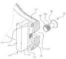
따라서 대한민국 등록특허 제10-1632652호에는 도 1에 도시된 것처럼 절골부에에 간격유지를 위한 블럭을 장착할 수 있는 고정기구가 제안되었다.Accordingly, Korean Patent Registration No. 10-1632652 has proposed a fixing mechanism capable of mounting a block for maintaining a gap in the cutting portion as shown in FIG. 1.
상기 선행문헌에는 절골부로 삽입되는 블럭이 플레이트에 고정되며, 플레이트의 길이방향을 따라 연장되어 있는 장공에 체결됨으로써 플레이트의 길이방향을 따라 소정거리 이동 가능하게 형성되는 기술이 기재되어 있다.The prior literature describes a technique in which a block inserted into a cutting portion is fixed to a plate and is fastened to a long hole extending along the length direction of the plate, thereby forming a predetermined distance movement along the length direction of the plate.
그러나 종래의 선행기술의 경우 플레이트의 폭방향으로 블럭이 이동하거나 소정각도 회전하는 것이 불가능하여 환자의 상태와 절골부의 크기 및 방향에 따라 유연하게 고정기구를 장착하기 어려운 문제가 있었다.However, in the case of the prior art, since it is impossible to move the block in the width direction of the plate or rotate it at a predetermined angle, it is difficult to flexibly mount the fixing mechanism according to the condition of the patient and the size and direction of the cutting part.
본 발명은 상기 문제점을 해결하기 위해 창출된 것으로, 절골부로 삽입되는 블럭이 플레이트의 폭방향을 따라 움직일 수 있고, 절골부의 상태에 따라 소정각도 회전이 가능한 경골 근위부 절골술용 결속구를 제공하는데 그 목적이 있다.The present invention has been created to solve the above problem, and provides a binding tool for proximal tibia osteotomy capable of moving a block inserted into an osteotomy along the width direction of the plate and capable of rotating a predetermined angle according to the state of the osteotomy. There is this.
본 발명은 경골 근위부 절골술에 사용되어 벌어진 경골을 고정하는 경골 근위부 절골술용 결속구에 있어서, 상기 경골에 형성되는 절골부에 삽입되는 지지블럭과, 상기 절골부를 가로질러 연장되도록 상기 경골에 결합되는 플레이트와, 상기 플레이트가 경골과 결합하도록 상기 플레이트에 형성된 체결공을 통해 경골에 삽입되는 복수개의 고정나사와, 상기 플레이트에 형성된 제1 블럭체결홀을 관통해 상기 지지블럭과 체결되는 블럭체결부재를 포함하되, 상기 지지블럭이 상기 플레이트의 길이방향 및 폭방향으로 이동이 가능하도록 상기 제1 블럭체결홀은 상기 플레이트의 길이방향을 따라 연장되는 장공으로 형성되고, 상기 지지블럭에는 상기 블럭체결부재가 체결되는 장공 형상의 제2 블럭체결홀이 형성된 것이다.The present invention is a binding tool for proximal tibial osteotomy to fix an open tibia by being used for proximal tibia osteotomy, a support block inserted into an osteotomy formed in the tibia, and a plate coupled to the tibia so as to extend across the osteotomy And, a plurality of fixing screws inserted into the tibia through a fastening hole formed in the plate so that the plate is coupled to the tibia, and a block fastening member through the first block fastening hole formed in the plate and fastened to the support block. However, the first block fastening hole is formed as a long hole extending along the length direction of the plate so that the support block can move in the length direction and the width direction of the plate, and the block fastening member is fastened to the support block. The long hole-shaped second block fastening hole is formed.
상기 플레이트의 후면은 상기 플레이트가 장착되는 경골의 외면 형상에 대응하도록 곡면 형상을 가지며, 상기 지지블럭은 상기 플레이트의 후면과 접촉하는 전면부가 상기 플레이트의 내주면 형상에 대응하도록 만곡지게 형성되는 것이 바람직하다.It is preferable that the rear surface of the plate has a curved shape to correspond to the shape of the outer surface of the tibia on which the plate is mounted, and the support block is formed to be curved so that the front portion contacting the rear surface of the plate corresponds to the shape of the inner circumferential surface of the plate. .
상기 지지블럭은 상기 제2 블럭체결홀이 소정길이를 갖는 장공형상으로 형성되며, 상기 제2 블럭체결홀의 연장 구간 중 일측에는 상기 제2 블럭체결홀의 폭보다 상대적으로 큰 직경을 갖는 나사홀이 형성되되, 상기 나사홀의 내주면에는 나사산이 형성되어 있고, 상기 블럭체결부재는 상기 제1 블럭체결홀을 관통할 수 없는 크기의 헤드부와, 상기 헤드부로부터 연장되며 상기 제1 블럭체결홀을 관통할 수 있고, 상기 제2 블럭체결홀을 통과할 수 있는 직경의 연장부와, 상기 연장부의 하단에 형성되며, 상기 제1 블럭체결홀은 통과할 수 있지만 상기 나사홀에 나사결합될 수 있도록 나사산이 형성된 스크류부를 포함하고, 상기 연장부의 높이는 상기 나사홀이 형성되어 있는 지지블럭의 나사홀 깊이보다 상대적으로 크거나 같도록 형성되는 것이 바람직하다.In the support block, the second block fastening hole is formed in a long hole shape having a predetermined length, and a screw hole having a diameter relatively larger than the width of the second block fastening hole is formed at one side of the extension section of the second block fastening hole. Wherein, a thread is formed on the inner circumferential surface of the screw hole, and the block fastening member has a head having a size that cannot penetrate the first block fastening hole, and extends from the head and penetrates the first block fastening hole. And an extension having a diameter capable of passing through the second block fastening hole, and formed at a lower end of the extension, and the first block fastening hole can pass, but the thread is screwed into the screw hole. It includes a formed screw portion, and the height of the extension portion is preferably formed to be relatively larger than or equal to the depth of the screw hole of the support block in which the screw hole is formed.
상기 지지블럭은 상기 플레이트의 후면과 접촉하며, 상기 제2 블럭체결홀이 형성되어 있는 전면판과, 상기 전면판의 상부 및 하부 가장자리로부터 후방으로 소정길이 연장되는 측면판과, 상기 측면판의 후단부에 형성되며, 절골부에 삽입된 상태에서 상기 경골의 치밀골의 내측에 위치하며 상기 측면판의 외주면보다 외측으로 소정길이 돌출되는 걸림턱을 형성하는 베이스부를 포함하는 것이 바람직하다.The support block is in contact with the rear surface of the plate, a front plate having the second block fastening hole formed therein, a side plate extending a predetermined length rearward from the upper and lower edges of the front plate, and a rear side of the side plate It is preferable to include a base portion formed at an end portion and forming a locking jaw protruding a predetermined length outward from the outer circumferential surface of the side plate and positioned on the inner side of the compact bone of the tibia in a state inserted into the cutting portion.
상기 전면판은 일측 단부에서 타측으로 연장될수록 폭이 점점 커지도록 형성될 수 있다.The front plate may be formed to increase in width as it extends from one end to the other.
상기 플레이트는 경골의 외주면과 밀착도를 높일 수 있도록 길이방향을 따라 연장되는 축을 기준으로 소정각도 트위스트되도록 형성될 수 있다.The plate may be formed to be twisted at a predetermined angle with respect to an axis extending along the longitudinal direction so as to increase adhesion to the outer circumferential surface of the tibia.
상기 플레이트는 상기 제1 블럭체결홀을 중심으로 상부에 형성되고, 상기 경골의 절골부 상측에 결합되는 상부플레이트와, 상기 제1 블럭체결홀의 하부에 형성되며, 상기 경골의 절골부 하측에 결합되는 하부플레이트를 포함하되, 상기 하부플레이트는 상기 절골부의 하부측 경골의 형상에 따라 측방향으로 소정각도 경사지게 연장되도록 형성될 수 있다.The plate is formed at an upper portion centering on the first block fastening hole, an upper plate coupled to an upper side of the tibia, and a lower portion of the first block fastening hole, and coupled to a lower side of the tibia Including a lower plate, the lower plate may be formed to extend inclined at a predetermined angle in the lateral direction according to the shape of the lower tibia of the cutting unit.
본 발명에 따른 경골 근위부 절골술용 결속구는 경골의 절골부로 삽입되는 지지블럭이 플레이트의 길이방향 뿐 아니라 폭방향으로도 소정거리 이동할 수 있어 절골부의 지지를 더욱 견고하게 실시할 수 있는 이점이 있다.The binding tool for proximal tibia osteotomy according to the present invention has the advantage that the support block inserted into the osteotomy of the tibia can move a predetermined distance not only in the length direction of the plate but also in the width direction, so that the support of the osteotomy can be performed more firmly.
아울러 본 발명의 경골 근위부 절골술용 결속구는 지지블럭에 치밀골의 내측에서 해면골에 삽입되어 지지블럭이 경골의 절골부로부터 외측으로 인출되는 것을 방지할 수 있는 걸림턱 형태의 베이스부가 마련되므로 지지블럭의 결합상태를 용이하게 유지할 수 있는 이점이 있다.In addition, the binding tool for proximal tibial osteotomy of the present invention is inserted into the cancellous bone from the inner side of the dense bone in the support block to prevent the support block from being pulled out from the tibial cutting part, so that the support block is combined. There is an advantage of being able to easily maintain the state.
도 1은 종래기술의 경골 근위부 절골술용 결속구를 도시한 사시도,
도 2는 본 발명에 따른 경골 근위부 절골술용 결속구의 제1 실시예의 사시도,
도 3은 도 2의 경골 근위부 절골술용 결속구의 분리사시도,
도 4는 도 2의 경골 근위부 절골술용 결속구의 지지블럭과 블럭체결부재를 발췌 도시한 부분절단 사시도,
도 5는 지지블럭이 플레이트 상에서 이동되는 상태를 표시한 평면도,
도 6은 지지블럭이 경골의 절골부로 삽입되어 체결된 상태를 개념적으로 도시한 단면도,
도 7은 경골 근위부 절골술용 결속구의 플레이트의 다른 실시예의 사시도,
도 8은 경골 근위부 절골술용 결속구의 제2 실시예의 사시도이다.1 is a perspective view showing a binding tool for proximal tibia osteotomy in the prior art,
Figure 2 is a perspective view of the first embodiment of the binding tool for proximal tibia osteotomy according to the present invention,
Figure 3 is an exploded perspective view of the binding tool for the proximal tibia osteotomy of Figure 2,
Figure 4 is a partial cut-away perspective view showing an extract of the support block and the block fastening member of the binding tool for the proximal tibia osteotomy of Figure 2;
5 is a plan view showing a state in which a support block is moved on a plate;
6 is a cross-sectional view conceptually showing a state in which the support block is inserted into the cutting portion of the tibia and fastened;
7 is a perspective view of another embodiment of a plate of a binding tool for proximal tibia osteotomy,
8 is a perspective view of a second embodiment of a binding tool for proximal tibia osteotomy.
이하, 첨부한 도면을 참조하여 본 발명의 실시예에 따른 경골 근위부 절골술용 결속구에 대해 상세히 설명한다. 본 발명은 다양한 변경을 가할 수 있고 여러 가지 형태를 가질 수 있는 바, 특정 실시 예들을 도면에 예시하고 본문에 상세하게 설명하고자 한다. 그러나 이는 본 발명을 특정한 개시 형태에 대해 한정하려는 것이 아니며, 본 발명의 사상 및 기술 범위에 포함되는 모든 변경, 균등물 내지 대체물을 포함하는 것으로 이해되어야 한다. 각 도면을 설명하면서 유사한 참조부호를 유사한 구성요소에 대해 사용하였다. 첨부된 도면에 있어서, 구조물들의 치수는 본 발명의 명확성을 기하기 위하여 실제보다 확대하여 도시한 것이다.Hereinafter, a binding tool for proximal tibia osteotomy according to an embodiment of the present invention will be described in detail with reference to the accompanying drawings. In the present invention, various modifications may be made and various forms may be applied, and specific embodiments will be illustrated in the drawings and described in detail in the text. However, this is not intended to limit the present invention to a specific form of disclosure, it is to be understood as including all changes, equivalents, or substitutes included in the spirit and scope of the present invention. In describing each drawing, similar reference numerals have been used for similar elements. In the accompanying drawings, the dimensions of the structures are shown to be enlarged compared to the actual size for clarity of the present invention.
제1, 제2 등의 용어는 다양한 구성요소들을 설명하는데 사용될 수 있지만, 상기 구성요소들은 상기 용어들에 의해 한정되어서는 안 된다. 상기 용어들은 하나의 구성요소를 다른 구성요소로부터 구별하는 목적으로만 사용된다. 예를 들어, 본 발명의 권리 범위를 벗어나지 않으면서 제1 구성요소는 제2 구성요소로 명명될 수 있고, 유사하게 제2 구성요소도 제1 구성요소로 명명될 수 있다.Terms such as first and second may be used to describe various components, but the components should not be limited by the terms. These terms are used only for the purpose of distinguishing one component from another component. For example, without departing from the scope of the present invention, a first element may be referred to as a second element, and similarly, a second element may be referred to as a first element.
본 출원에서 사용한 용어는 단지 특정한 실시 예를 설명하기 위해 사용된 것으로, 본 발명을 한정하려는 의도가 아니다. 단수의 표현은 문맥상 명백하게 다르게 뜻하지 않는 한, 복수의 표현을 포함한다. 본 출원에서, "포함하다" 또는 "가지다" 등의 용어는 명세서 상에 기재된 특징, 숫자, 단계, 동작, 구성요소, 부분품 또는 이들을 조합한 것이 존재함을 지정하려는 것이지, 하나 또는 그 이상의 다른 특징들이나 숫자, 단계, 동작, 구성요소, 부분품 또는 이들을 조합한 것들의 존재 또는 부가 가능성을 미리 배제하지 않는 것으로 이해되어야 한다.The terms used in the present application are used only to describe specific embodiments, and are not intended to limit the present invention. Singular expressions include plural expressions unless the context clearly indicates otherwise. In the present application, terms such as "comprise" or "have" are intended to designate the presence of features, numbers, steps, actions, components, parts, or combinations thereof described in the specification, but one or more other features. It is to be understood that the presence or addition of elements or numbers, steps, actions, components, parts, or combinations thereof, does not preclude in advance the possibility of being added.
다르게 정의되지 않는 한, 기술적이거나 과학적인 용어를 포함해서 여기서 사용되는 모든 용어들은 본 발명이 속하는 기술 분야에서 통상의 지식을 가진 자에 의해 일반적으로 이해되는 것과 동일한 의미를 가지고 있다. 일반적으로 사용되는 사전에 정의되어 있는 것과 같은 용어들은 관련 기술의 문맥 상 가지는 의미와 일치하는 의미를 가지는 것으로 해석되어야 하며, 본 출원에서 명백하게 정의하지 않는 한, 이상적이거나 과도하게 형식적인 의미로 해석되지 않는다.Unless otherwise defined, all terms used herein, including technical or scientific terms, have the same meaning as commonly understood by one of ordinary skill in the art to which the present invention belongs. Terms as defined in a commonly used dictionary should be interpreted as having a meaning consistent with the meaning in the context of the related technology, and should not be interpreted as an ideal or excessively formal meaning unless explicitly defined in this application. Does not.
도 2 내지 도 6에는 본 발명에 따른 경골 근위부 절골술용 결속구(100)의 제1 실시예가 도시되어 있다.2 to 6 shows a first embodiment of the
본 실시예의 경골 근위부 절골술용 결속구(100)는 경골(10)의 절골부(13)로 삽입되는 지지블럭(130)과, 경골(10)에 형성된 절골부(13)를 유지하기 위해 경골(10)에 체결되는 플레이트(110)와, 플레이트(110)를 경골(10)에 고정하는 고정나사(120)들 및 상기 플레이트(110)에 상기 지지블럭(130)을 체결하기 위한 블럭체결부재(140)를 포함한다.In order to maintain the
상기 플레이트(110)는 상술한 것처럼 절골부(13)를 가로질러 연장되도록 경골(10)에 결합되어 경골(10)의 절골부(13)를 지지하는 역할을 하는 것이다.As described above, the
상기 플레이트(110)는 절골부(13)를 기준으로 절골부(13)의 상부측 경골(10)에 결합되는 상부플레이트(111)와, 상부플레이트(111)의 하단에서 하방으로 연장되는 하부플레이트(112)를 포함한다. 상기 하부플레이트(112)가 절골부(13)를 통과해 하방으로 연장되는 형상이 된다.The
플레이트(110)에는 다수의 체결공(113)들이 형성되어 있으며, 이 체결공(113)을 통과해 고정나사(120)가 경골(10)에 삽입됨으로써 플레이트(110)가 경골(10)에 결합된다. 상기 체결공(113)은 고정나사(120)가 삽입되는 삽입방향을 가이드할 수 있도록 체결공(113)이 관통방향이 고정나사(120)의 삽입방향에 대응하도록 형성될 수 있다.A plurality of
플레이트(110)의 내주면은 경골(10)과의 밀착이 용이하도록 외측으로 만곡지게 형성되어 있다. 상기 플레이트(110)의 내주면의 곡률은 플레이트(110)가 부착되는 경골(10)의 곡면 형상에 대응하도록 형성되는 것이 바람직하다.The inner circumferential surface of the
아울러 상기 하부플레이트(112)에는 길이방향을 따라 연장되어 있는 소정 길이의 장공 형태의 제1 블럭체결홀(114)이 형성되어 있다. 상기 제1 블럭체결홀(114)은 후술하는 지지블럭(130)과 플레이트(110)를 체결하기 위한 블럭체결부재(140)가 통과하는 구멍이다.In addition, the
상기 제1 블럭체결홀(114)이 플레이트(110)의 길이방향을 따라 연장되는 장공 형태로 형성되어 있기 때문에 지지블럭(130)이 체결되는 체결위치를 제1 블럭체결홀(114)의 길이방향 상에서 용이하게 조절할 수 있다.Since the first
본 실시예의 경우 상부플레이트(111)는 역삼각형 형태이고, 하부플레이트(112)는 상부플레이트(111)의 하단에서 소정의 폭을 갖는 스트립 형상으로 형성되어 있으나, 상기 플레이트(110)의 형상은 필요에 따라 다양하게 형성될 수 있다.In this embodiment, the
도시되지는 않았으나, 상기 하부플레이트(112)는 필요에 따라 좌측 또는 우측으로 소정각도 경사지게 연장되도록 형성될 수 있다.Although not shown, the
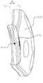
상기 지지블럭(130)은 블럭체결부재(140)를 통해 플레이트(110)와 결합되며, 절골부(13)로 삽입되어 절골부(13)를 기준으로 상부측 경골(10)과 하부측 경골(10)이 유합될 때까지 경골(10)에 인가되는 하중을 지지한다.The
도 2 내지 도 4를 참조하면, 상기 지지블럭(130)은 상기 플레이트(110)의 후면과 접촉하며, 상기 제2 블럭체결홀(132)이 형성되어 있는 전면판(131)과, 상기 전면판(131)의 상부 및 하부 가장자리로부터 후방으로 소정길이 연장되는 측면판(134)과, 상기 측면판(134)의 후단부에 형성되며, 상기 측면판(134)의 외주면보다 외측으로 소정길이 돌출되는 걸림턱을 형성하는 베이스부(135)를 포함한다.2 to 4, the
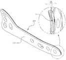
상기 전면판(131)에는 플레이트(110)와 지지블럭(130)을 체결하기 위한 블럭체결부재(140)가 통과할 수 있는 제2 블럭체결홀(132)이 형성되어 있는데, 상기 제2 블럭체결홀(132) 역시 소정 길이를 갖는 장공 형태로 형성되어 있다.The
상기 제2 블럭체결홀(132)은 소정 직경의 장공 형태이며, 제2 블럭체결홀(132)의 일측에, 본 실시예의 경우에는 장공의 중간 부분에 제2 블럭체결홀(132)의 폭보다 상대적으로 큰 직경을 갖는 나사홀(133)이 형성되어 있고, 이 나사홀(133)의 내주면에는 나사산이 형성되어 있다.The second
상기 제2 블럭체결홀(132)과 나사홀(133)은 블럭체결부재(140)와의 체결을 위해 형성된 것인데, 블럭체결부재(140)는 헤드부(141)와, 헤드부(141)로부터 연장되는 연장부(142)와, 연장부(142)의 하단에 형성되는 스크류부(143)를 포함한다.The second
상기 연장부(142)와 스크류부(143)는 제1 블럭체결홀(114)의 폭보다 직경이 작기 때문에 제1 블럭체결홀(114)을 통과할 수 있지만, 상기 헤드부(141)는 제1 블럭체결홀(114)의 폭보다 상대적으로 직경이 크기 때문에 제1 블럭체결홀(114)을 통과할 수 없는 크기를 갖는다. 따라서 플레이트(110)의 전방으로부터 블럭체결부를 삽입하면, 스크류부(143)와 연장부(142)는 제1 블럭체결홀(114)을 통과하지만 헤드부(141)가 플레이트(110)에 걸리게 된다.Since the
상기 연장부(142)와 스크류부(143)의 직경은 상호 상이하다. 즉, 연장부(142)는 상기 제2 블럭체결홀(132)의 폭에 대응하는 직경을 갖도록 형성되어 있으며, 스크류부(143)의 직경은 상기 나사홀(133)의 직경에 대응한다. 특히 스크류부(143)는 나사홀(133)의 내주면에 형성되어 있는 나사산에 대응하는 나사산을 갖기 때문에 상기 스크류부(143)가 나사홀(133)의 나사산을 따라 회전하면서 전면판(131)을 통과해 내측으로 진입할 수 있다. 그리고 스크류부(143)가 나사홀(133)을 통과한 후에는 연장부(142)가 나사홀(133) 및 제2 블럭체결홀(132)에 대응하는 위치에 있는데, 상술한 것처럼 연장부(142)의 직경은 제2 블럭체결홀(132)의 폭에 대응하기 때문에 지지블럭(130)은 연장부(142)가 제2 블럭체결홀(132)을 관통하고 있는 상태에서는 좌우로 소정길이 이동하거나 블럭체결부재(140)를 중심으로 소정각도 회전하는 것도 가능하다.The diameters of the
상기 전면판(131)의 전면은 플레이트(110)의 내주면과 접촉하므로 상기 플레이트(110) 내주면의 곡률에 대응하도록 표면이 만곡지게 형성되는 것이 바람직하다.Since the front surface of the
상기 측면판(134)은 전면판(131)의 양측 가장자리에서 후방으로 소정길이 연장되며, 상기 베이스부(135)는 측면판(134)의 후단부에 형성된다.The
상기 베이스부(135)는 측면판(134)의 후단부에서 외측방향으로 돌출되도록 형성되어 있다. 상기 베이스부(135)는 지지블럭(130)이 절골부(13)에 삽입될 때, 경골(10)의 치밀골(11) 내측에 위치하도록 형성된다.The
경골(10)은 겉부분에 상대적으로 단단하고 치밀한 조직의 치밀골(11)이 형성되어 있고, 치밀골(11)의 내측에 스펀지와 같은 조직의 해면골(12)이 형성되어 있는데, 절골부(13)를 형성하게 되면 상기 해면골(12)이 노출된다.The
도 6에 도시된 것처럼, 상기 지지블럭(130)을 절골부(13)에 삽입할 때, 상기 베이스부(135)가 해면골(12)에 위치하면 베이스부(135)의 돌출된 부분이 해면골(12)을 가압하면서 내부로 소정깊이 인입되며, 지지블럭(130)이 경골(10)에서 인출되는 방향으로 힘을 받을 때, 인입된 베이스부(135)가 치밀골(11)의 내측에 걸려 지지블럭(130)의 인출이 방지된다.As shown in Fig. 6, when inserting the
아울러 도시된 바와 같이 상기 전면판(131)은 일측 단부에서 타측으로 연장될수록 폭이 점점 커지도록 형성되어 있고, 측면판(134)도 이렇게 경사진 전면판(131)의 가장자리를 따라 연장되어 있기 때문에 두 측면판(134) 사이의 폭 역시 일측에서 타측으로 연장될수록 점점 커진다. 이는 절골부(13)의 형상 때문인데, 경골(10)근위 절골술을 시행하기 위해 경골(10)에 절골부(13)를 형성할 때, 경골(10)의 외측에서 내부를 향해 인입될수록 벌어진 폭이 점점 작아지기 때문에 지지블럭(130)도 전면판(131)과 전면판(131)에 연결되는 측면판(134)이 이러한 절골부(13)의 형상에 대응하도록 형성된다.In addition, as shown, the
도 7에는 플레이트(110)의 다른 실시예가 도시되어 있다.In Figure 7 another embodiment of the
본 실시예의 경우 플레이트(110), 특히 하부플레이트(112)가 경골(10)과의 밀착도를 높이기 위해 트위스트 되어 있다. 즉, 상기 플레이트(110)의 길이방향을 따라 연장되는 축(S)을 중심으로 하부플레이트(112)가 소정각도 회전되어 있다.In this embodiment, the
도면에 도시된 것처럼 축(S)을 지나가는 기준선(L1)에 대하여 트위스트된 하부플레이트(112) 단부의 연장선(L2)이 소정각도(α)만큼 벌어져 있다.As shown in the drawing, the extension line L2 of the end of the
이렇게 하부플레이트를 소정각도 트위스트시킴으로써 플레이트(110)와 경골(10) 사이의 밀착이 더욱 견고하게 이루어질 수 있다.By twisting the lower plate at a predetermined angle, close contact between the
도 8에는 경골 근위부 절골술용 결속구(200)의 제2 실시예가 도시되어 있다.FIG. 8 shows a second embodiment of a
본 실시예의 경우 플레이트(210)에 제1 블럭체결홀이 형성되어 있지 않고, 절골부(13)로 삽입되는 지지블럭도 구비되어 있지 않다.In the present embodiment, the first block fastening hole is not formed in the
본 실시예의 플레이트(210)는 절골부(13)를 기준으로 경골(10)의 상부와 하측에 고정나사(120)들을 통해 결합될 수 있도록 형성되어 있으며, 지지블럭이 삽입되지 않고도 경골(10)의 절골부(13)가 유착되는 과정에서 경골(10)에 가해지는 외력을 플레이트(210) 만으로도 충분히 지지할 수 있는 경우 지지블럭(130)을 생략한다.The
본 실시예의 플레이트(210)도 도 7에 도시된 플레이트의 다른 실시예에서와 마찬가지로 경골(10)의 외주면과의 밀착도를 높일 수 있도록 플레이트(210)가 길이방향을 따라 연장되는 축(S)을 기준으로 소정각도 트위스트 되어 있어 경골(10)과의 밀착도를 높이도록 형성될 수 있다.The
이상에서 설명한 본 발명에 따른 경골 근위부 절골술용 결속구(100)는 절골부(13)로 삽입되는 지지블럭(130)이 플레이트(110)의 길이방향 뿐 아니라 길이방향과 교차하는 방향으로도 소정길이 이동할 수 있고, 절골부(13)의 위치나 형상에 따라 블럭체결부재(140)를 중심으로 소정각도 회전할 수도 있어 경골(10)에 형성되는 절골부(13)의 지지가 더욱 견고하게 이루어질 수 있는 이점이 있다.In the
제시된 실시예들에 대한 설명은 임의의 본 발명의 기술분야에서 통상의 지식을 가진 자가 본 발명을 이용하거나 또는 실시할 수 있도록 제공된다. 이러한 실시예들에 대한 다양한 변형들은 본 발명의 기술 분야에서 통상의 지식을 가진자에게 명백할 것이며, 여기에 정의된 일반적인 원리들은 본 발명의 범위를 벗어남이 없이 다른 실시예들에 적용될 수 있다. 그리하여, 본 발명은 여기에 제시된 실시예들로 한정되는 것이 아니라, 여기에 제시된 원리들 및 신규한 특징들과 일관되는 최광의의 범위에서 해석되어야 할 것이다.Description of the presented embodiments is provided to enable any person skilled in the art to use or practice the present invention. Various modifications to these embodiments will be apparent to those of ordinary skill in the art, and the general principles defined herein can be applied to other embodiments without departing from the scope of the present invention. Thus, the present invention is not to be limited to the embodiments presented herein, but is to be construed in the widest scope consistent with the principles and novel features presented herein.
10: 경골11: 치밀골
12: 해면골13: 절골부
100: 경골 근위부 절골술용 결속구
110: 플레이트111: 상부플레이트
112: 하부플레이트113: 체결공
114: 제1 블럭체결홀120: 고정나사
130: 지지블럭131: 전면판
132: 제2 블럭체결홀133: 나사홀
134: 측면판135: 베이스부
140: 블럭체결부재141: 헤드부
142: 연장부143: 스크류부
200: 경골 근위부 절골술용 결속구
210: 플레이트211: 체결공10: tibia 11: compact bone
12: cancellous bone 13: osteotomy
100: Binding tool for proximal tibia osteotomy
110: plate 111: upper plate
112: lower plate 113: fastening hole
114: first block fastening hole 120: fixing screw
130: support block 131: front plate
132: second block fastening hole 133: screw hole
134: side plate 135: base portion
140: block fastening member 141: head
142: extension part 143: screw part
200: Binding tool for proximal tibia osteotomy
210: plate 211: fastening hole
Claims (8)
Translated fromKorean상기 경골에 형성되는 절골부에 삽입되는 지지블럭과;
상기 절골부를 가로질러 연장되도록 상기 경골에 결합되는 플레이트와;
상기 플레이트가 경골과 결합하도록 상기 플레이트에 형성된 체결공을 통해 경골에 삽입되는 복수개의 고정나사와;
상기 플레이트에 형성된 제1 블럭체결홀을 관통해 상기 지지블럭과 체결되는 블럭체결부재를 포함하되,
상기 지지블럭이 상기 플레이트의 길이방향 및 폭방향으로 이동이 가능하도록 상기 제1 블럭체결홀은 상기 플레이트의 길이방향을 따라 연장되는 장공으로 형성되고,
상기 지지블럭에는 상기 블럭체결부재가 체결되는 장공 형상의 제2 블럭체결홀이 형성된 것을 특징으로 하는
경골 근위부 절골술용 결속구.
In the proximal tibia osteotomy binding tool used for proximal tibia osteotomy to fix the open tibia,
A support block inserted into the cutting part formed in the tibia;
A plate coupled to the tibia so as to extend across the cutting part;
A plurality of fixing screws inserted into the tibia through a fastening hole formed in the plate so that the plate is coupled to the tibia;
Including a block fastening member through the first block fastening hole formed in the plate and fastened to the support block,
The first block fastening hole is formed as a long hole extending along the length direction of the plate so that the support block can move in the length direction and the width direction of the plate,
In the support block, characterized in that a second block fastening hole having a long hole shape to which the block fastening member is fastened is formed.
Binding tool for proximal tibia osteotomy.
상기 플레이트의 후면은 상기 플레이트가 장착되는 경골의 외면 형상에 대응하도록 곡면 형상을 가지며,
상기 지지블럭은 상기 플레이트의 후면과 접촉하는 전면부가 상기 플레이트의 내주면 형상에 대응하도록 만곡지게 형성된 것을 특징으로 하는
경골 근위부 절골술용 결속구.
The method of claim 1,
The rear surface of the plate has a curved shape to correspond to the external shape of the tibia on which the plate is mounted,
The support block is characterized in that the front portion in contact with the rear surface of the plate is formed to be curved to correspond to the shape of the inner peripheral surface of the plate.
Binding tool for proximal tibia osteotomy.
상기 지지블럭은 상기 제2 블럭체결홀이 소정길이를 갖는 장공형상으로 형성되며,
상기 제2 블럭체결홀의 연장 구간 중 일측에는 상기 제2 블럭체결홀의 폭보다 상대적으로 큰 직경을 갖는 나사홀이 형성되되, 상기 나사홀의 내주면에는 나사산이 형성되어 있고,
상기 블럭체결부재는 상기 제1 블럭체결홀을 관통할 수 없는 크기의 헤드부와,
상기 헤드부로부터 연장되며 상기 제1 블럭체결홀을 관통할 수 있고, 상기 제2 블럭체결홀을 통과할 수 있는 직경의 연장부와,
상기 연장부의 하단에 형성되며, 상기 제1 블럭체결홀은 통과할 수 있지만 상기 나사홀에 나사결합될 수 있도록 나사산이 형성된 스크류부를 포함하고,
상기 연장부의 높이는 상기 나사홀이 형성되어 있는 지지블럭의 나사홀 깊이보다 상대적으로 크거나 같도록 형성된 것을 특징으로 하는
경골 근위부 절골술용 결속구.
The method of claim 1,
The support block is formed in a long hole shape with the second block fastening hole having a predetermined length,
A screw hole having a diameter relatively larger than the width of the second block fastening hole is formed at one side of the extension section of the second block fastening hole, and a thread is formed on the inner circumferential surface of the screw hole,
The block fastening member includes a head having a size that cannot penetrate the first block fastening hole,
An extension part extending from the head part and having a diameter capable of penetrating the first block fastening hole and passing through the second block fastening hole,
It is formed at the lower end of the extension, the first block fastening hole may pass, but includes a screw thread formed to be screwed into the screw hole,
The height of the extension part is formed to be relatively greater than or equal to the depth of the screw hole of the support block in which the screw hole is formed.
Binding tool for proximal tibia osteotomy.
상기 지지블럭은 상기 플레이트의 후면과 접촉하며, 상기 제2 블럭체결홀이 형성되어 있는 전면판과,
상기 전면판의 상부 및 하부 가장자리로부터 후방으로 소정길이 연장되는 측면판과,
상기 측면판의 후단부에 형성되며, 절골부에 삽입된 상태에서 상기 경골의 치밀골의 내측에 위치하며 상기 측면판의 외주면보다 외측으로 소정길이 돌출되는 걸림턱을 형성하는 베이스부를 포함하는 것을 특징으로 하는
경골 근위부 절골술용 결속구.
The method of claim 1,
The support block is in contact with the rear surface of the plate, the front plate in which the second block fastening hole is formed,
A side plate extending a predetermined length rearward from the upper and lower edges of the front plate,
It is formed at the rear end of the side plate, and is located inside the compact bone of the tibia in a state inserted in the cutting portion, and comprises a base portion forming a locking jaw protruding a predetermined length outward from the outer peripheral surface of the side plate. doing
Binding tool for proximal tibia osteotomy.
상기 전면판은 일측 단부에서 타측으로 연장될수록 폭이 점점 커지도록 형성된 것을 특징으로 하는
경골 근위부 절골술용 결속구.
The method of claim 4,
The front plate is characterized in that the width is formed to gradually increase as it extends from one end to the other
Binding tool for proximal tibia osteotomy.
상기 플레이트는 경골의 외주면과 밀착도를 높일 수 있도록 길이방향을 따라 연장되는 축을 기준으로 소정각도 트위스트된 것을 특징으로 하는
경골 근위부 절골술용 결속구.
The method of claim 1,
The plate is characterized in that it is twisted at a predetermined angle with respect to an axis extending along the longitudinal direction so as to increase adhesion with the outer circumferential surface of the tibia.
Binding tool for proximal tibia osteotomy.
상기 플레이트는 상기 제1 블럭체결홀을 중심으로 상부에 형성되고, 상기 경골의 절골부 상측에 결합되는 상부플레이트와,
상기 제1 블럭체결홀의 하부에 형성되며, 상기 경골의 절골부 하측에 결합되는 하부플레이트를 포함하되,
상기 하부플레이트는 상기 절골부의 하부측 경골의 형상에 따라 측방향으로 소정각도 경사지게 연장되어 있는 것을 특징으로 하는
경골 근위부 절골술용 결속구.
The method according to any one of claims 1 to 6,
The plate is formed on the upper side of the first block fastening hole, the upper plate coupled to the upper side of the cutting portion of the tibia,
And a lower plate formed under the first block fastening hole and coupled to a lower side of the tibia's cutting portion,
The lower plate is characterized in that it extends obliquely at a predetermined angle in the lateral direction according to the shape of the tibia at the lower side of the cutting unit.
Binding tool for proximal tibia osteotomy.
상기 절골부를 가로질러 연장되도록 상기 경골에 결합되는 플레이트와;
상기 플레이트가 경골과 결합하도록 상기 플레이트에 형성된 체결공을 통해 경골에 삽입되는 복수개의 고정나사를 포함하고,
상기 플레이트는 경골의 외주면과 밀착도를 높일 수 있도록 길이방향을 따라 연장되는 축을 기준으로 소정각도 트위스트된 것을 특징으로 하는
경골 근위부 절골술용 결속구.
In the proximal tibia osteotomy binding tool used for proximal tibia osteotomy to fix the open tibia,
A plate coupled to the tibia so as to extend across the cutting part;
Includes a plurality of fixing screws inserted into the tibia through a fastening hole formed in the plate so that the plate is coupled to the tibia,
The plate is characterized in that it is twisted at a predetermined angle with respect to an axis extending along the longitudinal direction so as to increase adhesion with the outer circumferential surface of the tibia.
Binding tool for proximal tibia osteotomy.
Priority Applications (1)
| Application Number | Priority Date | Filing Date | Title |
|---|---|---|---|
| KR1020190041553AKR20200119121A (en) | 2019-04-09 | 2019-04-09 | Connector for high tibia osteotomy |
Applications Claiming Priority (1)
| Application Number | Priority Date | Filing Date | Title |
|---|---|---|---|
| KR1020190041553AKR20200119121A (en) | 2019-04-09 | 2019-04-09 | Connector for high tibia osteotomy |
Publications (1)
| Publication Number | Publication Date |
|---|---|
| KR20200119121Atrue KR20200119121A (en) | 2020-10-19 |
Family
ID=73042821
Family Applications (1)
| Application Number | Title | Priority Date | Filing Date |
|---|---|---|---|
| KR1020190041553AAbandonedKR20200119121A (en) | 2019-04-09 | 2019-04-09 | Connector for high tibia osteotomy |
Country Status (1)
| Country | Link |
|---|---|
| KR (1) | KR20200119121A (en) |
Cited By (1)
| Publication number | Priority date | Publication date | Assignee | Title |
|---|---|---|---|---|
| KR20250068269A (en) | 2023-11-09 | 2025-05-16 | 주식회사 바이원 | Fixture for High Tibial Osteotomy |
Citations (2)
| Publication number | Priority date | Publication date | Assignee | Title |
|---|---|---|---|---|
| KR100641312B1 (en) | 2006-05-18 | 2006-11-01 | 송은규 | Metal Locks for Proximal Open Tibial Osteotomy |
| KR101632652B1 (en) | 2014-04-18 | 2016-07-01 | 백혜선 | A fixation tool for opening wedge high tibial osteotomy |
- 2019
- 2019-04-09KRKR1020190041553Apatent/KR20200119121A/ennot_activeAbandoned
Patent Citations (2)
| Publication number | Priority date | Publication date | Assignee | Title |
|---|---|---|---|---|
| KR100641312B1 (en) | 2006-05-18 | 2006-11-01 | 송은규 | Metal Locks for Proximal Open Tibial Osteotomy |
| KR101632652B1 (en) | 2014-04-18 | 2016-07-01 | 백혜선 | A fixation tool for opening wedge high tibial osteotomy |
Cited By (1)
| Publication number | Priority date | Publication date | Assignee | Title |
|---|---|---|---|---|
| KR20250068269A (en) | 2023-11-09 | 2025-05-16 | 주식회사 바이원 | Fixture for High Tibial Osteotomy |
Similar Documents
| Publication | Publication Date | Title |
|---|---|---|
| KR101632652B1 (en) | A fixation tool for opening wedge high tibial osteotomy | |
| US7963966B2 (en) | Bone fixation system and method of use | |
| US20210121213A1 (en) | Orthopedic Implant In The Form Of A Plate To Be Fixed Between Two Bone Parts | |
| KR101740905B1 (en) | A fixation tool for opening wedge high tibial osteotomy | |
| JP5014549B2 (en) | Palm-side fixing device | |
| US9023052B2 (en) | Ulna osteotomy system | |
| EP2938279B1 (en) | Alignment guide system | |
| DE69716230T2 (en) | Orthopedic device, in particular for the surgical correction of knock deformations | |
| US8740902B2 (en) | Joint fusion apparatus for the ankle-type joint and arthrodetic pin for use in said apparatus | |
| KR20020033649A (en) | Vertebral osteosynthesis plate and osteosynthesis system | |
| JP2003529414A5 (en) | ||
| JP2006521160A (en) | Fracture fixation system with subchondral joint surface support | |
| TW201601677A (en) | Locking first metacarpal plate | |
| MX2011002560A (en) | Orthopaedic device to be associated with the outside of a bone. | |
| JPWO2017195307A1 (en) | Bone plate and bone plate system | |
| JP7326381B2 (en) | phalanx head plate | |
| JP2016538942A (en) | Guide system and method for bone fusion | |
| US9155576B2 (en) | Bone anchor, orthopaedic device and orthopaedic system | |
| WO2010122034A1 (en) | Foot positioning system and method | |
| KR102030140B1 (en) | Pin clamp of an external fixator for fracture cure | |
| KR20200119121A (en) | Connector for high tibia osteotomy | |
| KR20220041571A (en) | Hybrid Type Fracture Fixation Device for Fracture Treatment | |
| KR101913846B1 (en) | Bone fixation device | |
| JP7309911B2 (en) | bone surgery instrument | |
| KR102422928B1 (en) | Osteosynthesis plate |
Legal Events
| Date | Code | Title | Description |
|---|---|---|---|
| PA0109 | Patent application | Patent event code:PA01091R01D Comment text:Patent Application Patent event date:20190409 | |
| PA0201 | Request for examination | ||
| PG1501 | Laying open of application | ||
| E902 | Notification of reason for refusal | ||
| PE0902 | Notice of grounds for rejection | Comment text:Notification of reason for refusal Patent event date:20201113 Patent event code:PE09021S01D | |
| E701 | Decision to grant or registration of patent right | ||
| PE0701 | Decision of registration | Patent event code:PE07011S01D Comment text:Decision to Grant Registration Patent event date:20210311 | |
| PC1904 | Unpaid initial registration fee |