KR20200104727A - Plug connector - Google Patents
Plug connectorDownload PDFInfo
- Publication number
- KR20200104727A KR20200104727AKR1020190023449AKR20190023449AKR20200104727AKR 20200104727 AKR20200104727 AKR 20200104727AKR 1020190023449 AKR1020190023449 AKR 1020190023449AKR 20190023449 AKR20190023449 AKR 20190023449AKR 20200104727 AKR20200104727 AKR 20200104727A
- Authority
- KR
- South Korea
- Prior art keywords
- extension
- wall
- plug
- terminal
- plug connector
- Prior art date
- Legal status (The legal status is an assumption and is not a legal conclusion. Google has not performed a legal analysis and makes no representation as to the accuracy of the status listed.)
- Granted
Links
- 238000000034methodMethods0.000claimsdescription19
- 238000000465mouldingMethods0.000claimsdescription16
- 239000002184metalSubstances0.000description14
- 229910052751metalInorganic materials0.000description14
- 239000000758substrateSubstances0.000description12
- 238000005452bendingMethods0.000description8
- 238000005476solderingMethods0.000description7
- 229910000679solderInorganic materials0.000description6
- 230000008901benefitEffects0.000description5
- 230000000694effectsEffects0.000description5
- 230000008569processEffects0.000description5
- 230000008878couplingEffects0.000description4
- 238000010168coupling processMethods0.000description4
- 238000005859coupling reactionMethods0.000description4
- 238000010586diagramMethods0.000description4
- 239000007788liquidSubstances0.000description4
- RYGMFSIKBFXOCR-UHFFFAOYSA-NCopperChemical compound[Cu]RYGMFSIKBFXOCR-UHFFFAOYSA-N0.000description3
- 239000004593EpoxySubstances0.000description3
- 239000004020conductorSubstances0.000description3
- 229910052802copperInorganic materials0.000description3
- 239000010949copperSubstances0.000description3
- 239000012212insulatorSubstances0.000description3
- 239000007769metal materialSubstances0.000description3
- 239000011347resinSubstances0.000description3
- 229920005989resinPolymers0.000description3
- 229920000106Liquid crystal polymerPolymers0.000description2
- 239000004977Liquid-crystal polymers (LCPs)Substances0.000description2
- PXHVJJICTQNCMI-UHFFFAOYSA-NNickelChemical compound[Ni]PXHVJJICTQNCMI-UHFFFAOYSA-N0.000description2
- 230000003204osmotic effectEffects0.000description2
- 230000000630rising effectEffects0.000description2
- 229910000881Cu alloyInorganic materials0.000description1
- 238000005299abrasionMethods0.000description1
- 238000007792additionMethods0.000description1
- 239000003086colorantSubstances0.000description1
- 238000005336crackingMethods0.000description1
- PCHJSUWPFVWCPO-UHFFFAOYSA-NgoldChemical compound[Au]PCHJSUWPFVWCPO-UHFFFAOYSA-N0.000description1
- 239000010931goldSubstances0.000description1
- 229910052737goldInorganic materials0.000description1
- 239000000463materialSubstances0.000description1
- 230000013011matingEffects0.000description1
- 229910052759nickelInorganic materials0.000description1
- 238000007747platingMethods0.000description1
- 230000002265preventionEffects0.000description1
- 230000009467reductionEffects0.000description1
- 230000003014reinforcing effectEffects0.000description1
- 238000005728strengtheningMethods0.000description1
Images


Classifications
- H—ELECTRICITY
- H01—ELECTRIC ELEMENTS
- H01R—ELECTRICALLY-CONDUCTIVE CONNECTIONS; STRUCTURAL ASSOCIATIONS OF A PLURALITY OF MUTUALLY-INSULATED ELECTRICAL CONNECTING ELEMENTS; COUPLING DEVICES; CURRENT COLLECTORS
- H01R13/00—Details of coupling devices of the kinds covered by groups H01R12/70 or H01R24/00 - H01R33/00
- H01R13/64—Means for preventing incorrect coupling
- H—ELECTRICITY
- H01—ELECTRIC ELEMENTS
- H01R—ELECTRICALLY-CONDUCTIVE CONNECTIONS; STRUCTURAL ASSOCIATIONS OF A PLURALITY OF MUTUALLY-INSULATED ELECTRICAL CONNECTING ELEMENTS; COUPLING DEVICES; CURRENT COLLECTORS
- H01R13/00—Details of coupling devices of the kinds covered by groups H01R12/70 or H01R24/00 - H01R33/00
- H01R13/62—Means for facilitating engagement or disengagement of coupling parts or for holding them in engagement
- H01R13/629—Additional means for facilitating engagement or disengagement of coupling parts, e.g. aligning or guiding means, levers, gas pressure electrical locking indicators, manufacturing tolerances
Landscapes
- Connector Housings Or Holding Contact Members (AREA)
- Coupling Device And Connection With Printed Circuit (AREA)
- Manufacturing Of Electrical Connectors (AREA)
Abstract
Translated fromKoreanDescription
Translated fromKorean본 발명은 플러그 커넥터에 관한 것이다. 보다 구체적으로, 본 발명은 전원 단자를 포함하는 플러그 커넥터에 관한 것이다.The present invention relates to a plug connector. More specifically, the present invention relates to a plug connector comprising a power terminal.
일반적으로, 기판들이 상호 연결되는 경우, 솔더링과 같은 방법에 의하여 각각의 기판과 연결되는 두 개의 커넥터가 사용되고, 상기 두 개의 커넥터는 서로 연결될 수 있다. 여기서, 두 개의 커넥터 중 하나는 플러그 커넥터이며, 나머지 하나는 소켓 커넥터이다. 소켓 커넥터는 리셉터클(receptacle) 커넥터라고도 불리운다. 이러한 플러그 커넥터와 소켓 커넥터는 몰드부에 단자를 배치하여 형성될 수 있다. 플러그 커넥터와 소켓 커넥터는 서로 체결되어 전기 커넥터 조립체를 형성할 수 있다.In general, when the substrates are interconnected, two connectors that are connected to each substrate by a method such as soldering are used, and the two connectors may be connected to each other. Here, one of the two connectors is a plug connector and the other is a socket connector. The socket connector is also called a receptacle connector. These plug connectors and socket connectors may be formed by disposing terminals on a mold part. The plug connector and the socket connector may be coupled to each other to form an electrical connector assembly.
전자 기기의 소형화 추세에 따라 커넥터의 소형화 및 저배화(低背化)도 요구되는 실정이다. 그러나, 커넥터가 소형화 및 저배화됨에 따라, 커넥터의 몰드부가 쉽게 파손되어 뭉개짐 등이 발생하거나, 원치 않는 납오름(solder wick)이 발생하거나, 원하는 정도의 단자 지지력이 발휘되지 않는 등의 문제가 있다.According to the trend of miniaturization of electronic devices, miniaturization and reduction in size of connectors are also required. However, as the connector becomes smaller and smaller, the molded part of the connector is easily damaged, resulting in crushing, unwanted solder wicking, or inability to exhibit a desired level of terminal support. have.
본 발명이 해결하고자 하는 기술적 과제는 강도 및 실장성이 개선되고, 실장시에 틈새를 통한 납오름(solder wick)이 최소화되고, 몰드부의 파손이 최소화되는 플러그 커넥터를 제공하는 것이다.The technical problem to be solved by the present invention is to provide a plug connector that improves strength and mountability, minimizes solder wick through gaps during mounting, and minimizes damage to the mold part.
또한, 플러그 커넥터와 소켓 커넥터를 결합할 때에 몰드부의 뭉개짐, 부스러기 발생 등의 문제를 해결하는 것이다.In addition, when the plug connector and the socket connector are combined, problems such as crushing of the mold part and generation of debris are solved.
본 발명의 기술적 과제들은 이상에서 언급한 기술적 과제로 제한되지 않으며, 언급되지 않은 또 다른 기술적 과제들은 아래의 기재로부터 통상의 기술자에게 명확하게 이해될 수 있을 것이다.The technical problems of the present invention are not limited to the technical problems mentioned above, and other technical problems that are not mentioned will be clearly understood by those skilled in the art from the following description.
본 발명에 의하면, 소켓 커넥터에 결합되는 플러그 커넥터로서, 기저부와, 상기 기저부의 상면으로부터 돌출되는 제1 벽부, 상기 기저부의 상면으로부터 돌출되고 상기 제1 벽부와 교차하는 제2 벽부, 상기 기저부의 상면으로부터 돌출되고 상기 제2 벽부와 교차하며 상기 제1 벽부와 대향하는 제3 벽부, 상기 기저부의 상면으로부터 돌출되고 상기 제1 및 제3 벽부와 교차하며 상기 제2 벽부와 대향하는 제4 벽부를 포함하는 몰드부; 및 제1 아암부를 포함하는 제1 플러그 단자를 포함하고, 상기 제1 아암부는, 상기 제1 벽부의 상부의 적어도 일부를 덮으면서 연장되는 제1 연장부와, 상기 제1 연장부의 일단으로부터 연장되어 상기 기저부의 하면으로부터 돌출되는 제2 연장부를 포함하고, 상기 몰드부는 상기 제1 플러그 단자에 대하여 인서트 몰딩으로 형성되어, 상기 제1 연장부의 하면과 상기 몰드부 사이에 간극이 없으며, 상기 제1 연장부는 상기 제1 벽부의 인접한 상면과 적어도 일부 구간에서 단차를 가지며, 상기 단차는 상기 제1 연장부가 더 돌출되어 있도록 형성되는 플러그 커넥터가 제공된다.According to the present invention, a plug connector coupled to the socket connector, comprising: a base portion, a first wall portion protruding from an upper surface of the base portion, a second wall portion protruding from an upper surface of the base portion and intersecting the first wall portion, and an upper surface of the base portion A third wall part protruding from and intersecting the second wall part and facing the first wall part, a fourth wall part protruding from an upper surface of the base part, intersecting the first and third wall parts, and facing the second wall part A mold part; And a first plug terminal including a first arm portion, wherein the first arm portion includes a first extension portion extending while covering at least a portion of an upper portion of the first wall portion, and extending from one end of the first extension portion A second extension portion protruding from a lower surface of the base portion, and the mold portion is formed by insert molding with respect to the first plug terminal, so that there is no gap between the lower surface of the first extension portion and the mold portion, and the first extension A plug connector is provided in which the portion has a step difference between an upper surface adjacent to the first wall portion and at least a partial section, and the step difference is formed such that the first extension portion further protrudes.
바람직하게는, 상기 제1 연장부는 상기 제1 벽부에 매립되어 있지 않고, 상기 제2 연장부의 적어도 일부는 상기 제1 벽부에 매립되어 있으며, 상기 단차가 존재하는 구간은 상기 제1 연장부의 정점(頂點)에서부터 상기 제1 연장부와 상기 제2 연장부가 만나는 지점까지이다.Preferably, the first extension portion is not buried in the first wall portion, at least a part of the second extension portion is buried in the first wall portion, and a section in which the step exists is a peak of the first extension portion ( It is from 頂點) to the point where the first extension part and the second extension part meet.
바람직하게는, 상기 제1 아암부는, 상기 제1 연장부의 타단으로부터 상기 제1 벽부의 외측면을 따라 연장되는 제3 연장부를 더 포함하며, 상기 단차가 존재하는 구간은, 상기 제1 연장부의 정점(頂點)에서부터 상기 제1 연장부와 상기 제3 연장부가 만나는 지점까지를 더 포함한다.Preferably, the first arm portion further includes a third extension portion extending along an outer surface of the first wall portion from the other end of the first extension portion, and the section in which the step exists is a peak of the first extension portion It further includes from (頂點) to the point where the first extension and the third extension meet.
바람직하게는, 상기 단차가 존재하는 구간은, 상기 제1 연장부와 상기 제3 연장부가 만나는 지점인 상기 제3 연장부의 일단에서부터 상기 제3 연장부의 타단까지를 더 포함한다.Preferably, the section in which the step is present further includes from one end of the third extension part to the other end of the third extension part, which is a point where the first extension part and the third extension part meet.
바람직하게는, 상기 플러그 커넥터를 상면에서 보았을 때, 상기 제1 연장부와 상기 제1 벽부의 상면이 인접하는 개소의 종단면에서, 상기 제1 연장부의 단면은 원의 일부이면서 상기 제1 벽부의 상면보다 돌출되어 있다.Preferably, when the plug connector is viewed from an upper surface, in a longitudinal section of a location where the upper surface of the first extension part and the first wall part are adjacent, the cross section of the first extension part is part of a circle and the upper surface of the first wall part It is more protruding.
바람직하게는, 상기 플러그 커넥터를 상면에서 보았을 때, 상기 제1 연장부와 상기 제1 벽부의 상면이 인접하는 개소의 종단면에서, 상기 제1 연장부의 단면은 하방이 뚫린 ㄷ자 형상이면서 상기 제1 벽부의 상면보다 돌출되어 있다.Preferably, when the plug connector is viewed from an upper surface, in a longitudinal section of a location where the upper surface of the first extension part and the first wall part are adjacent, the cross section of the first extension part has a U-shape through which the bottom is drilled and the first wall It protrudes from the upper surface of the negative.
바람직하게는, 상기 제2 연장부는, 상기 기저부의 하면에 평행하게 상기 플러그 커넥터의 외측으로 돌출되는 제1 실장부를 더 포함한다.Preferably, the second extension portion further includes a first mounting portion protruding outward of the plug connector parallel to a lower surface of the base portion.
바람직하게는, 상기 제2 벽부와 상기 제4 벽부의 어느 일방 또는 양방 상에, 상기 제1 플러그 단자와 전기적으로 절연되는 복수의 제2 플러그 단자를 더 포함하며, 상기 복수의 제2 플러그 단자는 상기 제2 벽부의 인접한 상면과 단차를 갖지 않도록 형성된다.Preferably, a plurality of second plug terminals electrically insulated from the first plug terminal are further included on one or both of the second wall portion and the fourth wall portion, and the plurality of second plug terminals It is formed so as not to have a step with an adjacent upper surface of the second wall part.
바람직하게는, 상기 제1 플러그 단자는, 상기 제1 벽부와 상기 제2 벽부에 걸쳐 배치되는 제2 아암부를 더 포함하고, 상기 제2 아암부는, 상기 기저부의 하면을 따라 연장되는 제2 실장부를 포함한다.Preferably, the first plug terminal further includes a second arm portion disposed across the first wall portion and the second wall portion, and the second arm portion includes a second mounting portion extending along a lower surface of the base portion. Include.
바람직하게는, 상기 제1 플러그 단자는, 상기 제1 벽부와 상기 제4 벽부에 걸쳐 배치되는 제3 아암부를 더 포함하고, 상기 제3 아암부는, 상기 기저부의 하면을 따라 연장되는 제3 실장부를 포함한다.Preferably, the first plug terminal further includes a third arm portion disposed across the first wall portion and the fourth wall portion, and the third arm portion includes a third mounting portion extending along a lower surface of the base portion. Include.
바람직하게는, 상기 제3 연장부의 하단부에는 절결부가 형성되어 있으며, 상기 플러그 커넥터를 상면에서 보았을 때, 상기 제3 연장부는 제1 절곡부를 통해 상기 제1 아암부와 연결되어 있고, 상기 제3 연장부는 제2 절곡부를 통해 상기 제2 아암부와 연결되어 있다.Preferably, a cutout is formed at a lower end of the third extension, and when the plug connector is viewed from an upper surface, the third extension is connected to the first arm through a first bent, and the third The extension part is connected to the second arm part through a second bent part.
본 발명의 기술적 사상의 실시예들에 의하면 적어도 다음과 같은 효과가 있다.According to embodiments of the inventive concept, there are at least the following effects.
또한, 제1 몰드부(100)를 인서트 몰딩에 의해 형성함으로써, 몰드와 단자 사이의 틈을 없애고, 그와 함께, 단차 구조를 활용함으로써 전원 단자 부근에서 몰드면이 전원 단자에 닿을 확률 및 횟수가 줄어들며 그에 따른 몰드의 쓸림, 뭉개짐(burr 등)이 줄어든다.In addition, by forming the
일실시예에 따른 플러그 커넥터에서 단자 지지력이 강화된다. 단자 지지력이 높다 함은 실장 후에 몰드부로부터 플러그 단자가 잘 분리되지 않음을 의미한다. 플러그 커넥터와 소켓 커넥터가 기판에 실장되고 서로 결합된 후에, 하나의 커넥터를 발거(즉, 커넥터끼리 분리)하는 경우에 전원 단자가 이탈되는 문제 또한, 이러한 몰드와 단자의 지지력/부착력의 강화에 의해 완화될 수 있다.In the plug connector according to an embodiment, the terminal support is strengthened. The high terminal support means that the plug terminal is not well separated from the mold after mounting. After the plug connector and the socket connector are mounted on the board and coupled to each other, the power terminal is removed when one connector is removed (i.e., the connectors are separated from each other). In addition, by strengthening the holding power/adhesion of the mold and the terminal. It can be alleviated.
또한, 납오름(solder wick)이 방지된다. 실장부는 기판에 납땜(soldering)에 의해 부착됨으로써 실장되는데, 이러한 납땜 과정에서 좁은 틈으로 액체가 침투하는 현상, 즉, 삼투압에 의해 액체 상태의 땜남이 실장부를 타고 올라갈 우려가 있다. 그러나 본 발명의 구조에서는 예컨대, 제3 연장부(240)가 몰드부 내에 매립되어 있으며 노출되어 있지는 않은 구조이므로, 노출되어 있는 경우에 비하여 납오름의 가능성은 작아진다.In addition, solder wick is prevented. The mounting portion is mounted by being attached to the substrate by soldering. In this soldering process, liquid penetrates into a narrow gap, that is, there is a concern that the liquid solder rises on the mounting portion due to osmotic pressure. However, in the structure of the present invention, since, for example, the
또한, 제1 몰드부(100)를 인서트 몰딩에 의해 형성함으로써, 몰드와 단자 사이의 틈을 없애고 그에 의해서도 납오름의 가능성은 한층 더 감소될 수 있다.In addition, by forming the
한편, 본 발명의 구조에 의하면 전원 단자 부근에서 몰드면이 전원 단자에 닿을 확률 및 횟수가 줄어들며 그에 따른 몰드의 쓸림, 뭉개짐(burr 등)이 줄어든다.On the other hand, according to the structure of the present invention, the probability and the number of times that the mold surface touches the power terminal in the vicinity of the power terminal is reduced, and accordingly, friction and burr of the mold are reduced.
본 발명에 따른 효과는 이상에서 예시된 내용에 의해 제한되지 않으며, 더욱 다양한 효과들이 본 명세서 내에 포함되어 있다.The effects according to the present invention are not limited by the contents exemplified above, and more various effects are included in the present specification.
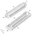
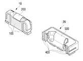
도 1은 본 발명에 따른 플러그 커넥터(10) 및 소켓 커넥터(20)를 나타내는 도면이다.
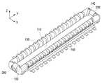
도 2a, 도 2b 및 도 2c는 본 발명의 기술적 사상의 일실시예에 따른 플러그 커넥터(10)를 설명하기 위한 사시도이다.
도 3은 도 2a의 사시도에서 제1 몰드부(100)를 제외한 경우에 단자(200, 300)의 배치를 나타내는 도면이다.
도 4a는 도 2a의 좌측 하단(제1 벽부(120) 부근)을 확대한 도면이며, 도 4b는 도 4a에서 제1 몰드부(100)를 제외한 것을 나타내는 도면이다.
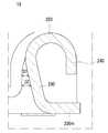
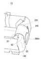
도 5a는 플러그 커넥터(10)의 제3 벽부(140) 부근을 나타낸 도면이며, 도 5b는 도 5a의 A-A' 단면을 나타내는 도면이다.
도 6a 및 도 6b는 제3 벽부(140) 부근에서의 플러그 커넥터(10) 및 소켓 커넥터(20)의 일부 단면도이다.
도 7a 및 도 7b는 제3 벽부(140) 근방에서 (제1 아암부(210)의) 제1 연장부(220) 및 제2 연장부(230) 등과 (제1 몰드부(100)의) 제3 벽부(140) 사이의 단차를 나타내는 도면이다.
도 8은 도 5b의 단면과 관련하여 플러그 커넥터(10)과 소켓 커넥터(20)가 결합하는 경우를 나타내는 도면이다.1 is a view showing a
2A, 2B, and 2C are perspective views illustrating a
FIG. 3 is a diagram illustrating the arrangement of
FIG. 4A is an enlarged view of the lower left side (near the first wall portion 120) of FIG. 2A, and FIG. 4B is a view showing that the
5A is a view showing the vicinity of the
6A and 6B are partial cross-sectional views of the
7A and 7B show the
8 is a diagram illustrating a case in which the
본 발명의 이점 및 특징, 그리고 그것들을 달성하는 방법은 첨부되는 도면과 함께 상세하게 후술되어 있는 실시예들을 참조하면 명확해질 것이다. 그러나 본 발명은 이하에서 개시되는 실시예들에 한정되는 것이 아니라 서로 다른 다양한 형태로 구현될 것이며, 단지 본 실시예들은 본 발명의 개시가 완전하도록 하며, 본 발명이 속하는 기술분야에서 통상의 지식을 가진 자에게 발명의 범주를 완전하게 알려주기 위해 제공되는 것이며, 본 발명은 청구항의 범주에 의해 정의될 뿐이다. 명세서 전체에 걸쳐 동일 참조 부호는 동일 구성 요소를 지칭한다.Advantages and features of the present invention, and a method of achieving them will become apparent with reference to the embodiments described below in detail together with the accompanying drawings. However, the present invention is not limited to the embodiments disclosed below, but will be implemented in a variety of different forms, and only these embodiments make the disclosure of the present invention complete, and common knowledge in the technical field to which the present invention pertains. It is provided to completely inform the scope of the invention to those who have it, and the invention is only defined by the scope of the claims. The same reference numerals refer to the same components throughout the specification.
하나의 구성 요소가 다른 구성 요소와 "연결된(connected to)" 또는 "커플링된(coupled to)" 이라고 지칭되는 것은, 다른 구성 요소와 직접 연결 또는 커플링된 경우 또는 중간에 다른 구성 요소를 개재한 경우를 모두 포함한다. 반면, 하나의 구성 요소가 다른 구성 요소와 "직접 연결된(directly connected to)" 또는 "직접 커플링된(directly coupled to)"으로 지칭되는 것은 중간에 다른 구성 요소를 개재하지 않은 것을 나타낸다. "및/또는"은 언급된 아이템들의 각각 및 하나 이상의 모든 조합을 포함한다.When one component is referred to as "connected to" or "coupled to" with another component, it is possible to directly connect or couple with another component, or to intervene another component. Includes all cases. On the other hand, when one component is referred to as "directly connected to" or "directly coupled to" with another component, it indicates that no other component is intervened. "And/or" includes each and every combination of one or more of the recited items.
구성 요소가 다른 구성 요소의 "위(on)" 또는 "상(on)"으로 지칭되는 것은 다른 구성 요소의 바로 위뿐만 아니라 중간에 다른 구성 요소를 개재한 경우를 모두 포함한다. 반면, 구성 요소가 다른 구성 요소의 "직접 위(directly on)" 또는 "바로 위"로 지칭되는 것은 중간에 다른 구성 요소를 개재하지 않은 것을 나타낸다. 공간적으로 상대적인 용어인 "아래(below)", "아래(beneath)", "하부(lower)", "위(above)", "상부(upper)" 등은 도면에 도시되어 있는 바와 같이 하나의 구성 요소들과 다른 구성 요소들과의 상관관계를 용이하게 기술하기 위해 사용될 수 있다. 공간적으로 상대적인 용어는 도면에 도시되어 있는 방향에 더하여 사용시 또는 동작시 소자의 서로 다른 방향을 포함하는 용어로 이해되어야 한다.That a component is referred to as "on" or "on" of another component includes both the case where the other component is interposed not only above the other component but also in the middle. On the other hand, when a component is referred to as "directly on" or "directly on" of another component, it indicates that no other component is intervened. Spatially relative terms "below", "beneath", "lower", "above", "upper", etc., as shown in the figure It can be used to easily describe the correlation between components and other components. Spatially relative terms should be understood as terms including different directions of the device during use or operation in addition to the directions shown in the drawings.
예를 들면, 도면에 도시되어 있는 소자를 뒤집을 경우, 다른 소자의 "아래(below)" 또는 "아래(beneath)"로 기술된 구성 요소는 다른 구성 요소의 "위(above)"에 놓여질 수 있다. 따라서, 예시적인 용어인 "아래"는 아래와 위의 방향을 모두 포함할 수 있다. 구성 요소는 다른 방향으로도 배향될 수 있고, 이에 따라 공간적으로 상대적인 용어들은 배향에 따라 해석될 수 있다.For example, when an element shown in the figure is turned over, a component described as "below" or "beneath" of another element may be placed "above" another element. . Accordingly, the exemplary term “below” may include both directions below and above. Components may be oriented in other directions, and thus spatially relative terms may be interpreted according to the orientation.
본 명세서에서 사용된 용어는 실시예들을 설명하기 위한 것이며 본 발명을 제한하고자 하는 것은 아니다. 본 명세서에서, 단수형은 문구에서 특별히 언급하지 않는 한 복수형도 포함한다. 명세서에서 사용되는 "포함한다(comprises)" 및/또는 "포함하는(comprising)"은 언급된 구성 요소, 단계, 동작 및/또는 소자는 하나 이상의 다른 구성 요소, 단계, 동작 및/또는 소자의 존재 또는 추가를 배제하지 않는다.The terms used in the present specification are for describing exemplary embodiments and are not intended to limit the present invention. In this specification, the singular form also includes the plural form unless specifically stated in the phrase. As used in the specification, "comprises" and/or "comprising" refers to the presence of one or more other components, steps, actions and/or elements in the referenced components, steps, actions and/or elements. Or does not exclude additions.
비록 제1, 제2 등이 다양한 구성 요소들을 서술하기 위해서 사용되나, 이들 구성 요소들은 이들 용어에 의해 제한되지 않음은 물론이다. 이들 용어들은 단지 하나의 구성 요소를 다른 구성 요소와 구별하기 위하여 사용하는 것이다. 따라서, 이하에서 언급되는 제1 구성 요소는 본 발명의 기술적 사상 내에서 제2 구성 요소일 수도 있음은 물론이다.Although the first, second, and the like are used to describe various components, it goes without saying that these components are not limited by these terms. These terms are only used to distinguish one component from another component. Therefore, it goes without saying that the first component mentioned below may be the second component within the technical idea of the present invention.
다른 정의가 없다면, 본 명세서에서 사용되는 모든 용어(기술 및 과학적 용어를 포함)는 본 발명이 속하는 기술 분야에서 통상의 지식을 가진 자에게 공통적으로 이해될 수 있는 의미로 사용될 수 있을 것이다. 또 일반적으로 사용되는 사전에 정의되어 있는 용어들은 명백하게 특별히 정의되어 있지 않는 한 이상적으로 또는 과도하게 해석되지 않는다.Unless otherwise defined, all terms (including technical and scientific terms) used in the present specification may be used as meanings that can be commonly understood by those of ordinary skill in the art to which the present invention belongs. In addition, terms defined in a commonly used dictionary are not interpreted ideally or excessively unless explicitly defined specifically.
도 1은 본 발명에 따른 플러그 커넥터(10) 및 소켓 커넥터(20)를 나타내는 도면이다.1 is a view showing a
도 1의 상부에는 플러그 커넥터(10)가 도시되어 있으며, 도 1의 하부에는 소켓 커넥터(20)가 도시되어 있다.A
플러그 커넥터(10)는 제1 몰드부(100), 제1 플러그 단자(200), 제2 플러그 단자(300) 등을 포함한다.The
도 1에 나타난 플러그 커넥터(10)에서는 구조 확인의 편의상 제1 플러그 단자(200) 및 제2 플러그 단자(300)가 상방을 향하고 있으나, 실제 결합시에는 도 1에 도시된 플러그 커넥터(10)를 (도 2c와 같이) 상하 반전하여 제1 플러그 단자(200) 및 제2 플러그 단자(300)가 하방을 향하도록 한 후에, 도 1의 하단에 도시된 소켓 커넥터(20)에 결합한다.In the
이러한 결합을 위한 소켓 커넥터(20)에 대해 설명하면 다음과 같다.A description of the
소켓 커넥터(20)는 예를 들어, 제2 몰드부(400), 제1 소켓 단자(500) 및 제2 소켓 단자(600)를 포함할 수 있다.The
제2 몰드부(400)는 제1 몰드부(100)를 수용하는 형상을 가질 수 있다. 예를 들어, 제1 몰드부(100)는 제2 몰드부(400)에 의해 정의되는 공간에 삽입되는 형상을 가질 수 있다.The
제2 몰드부(400)는 수지 및 에폭시 등을 포함하는 절연체로 형성될 수 있으나, 이에 제한되는 것은 아니다.The
제1 소켓 단자(500) 및 제2 소켓 단자(600)는 제2 몰드부(400)의 벽부 상에 배치될 수 있다. 또한, 복수의 제1 소켓 단자(500) 및 복수의 제2 소켓 단자(600)가 제2 몰드부(400)의 벽부 상에 배치될 수 있다.The
제1 소켓 단자(500) 및 제2 소켓 단자(600)는 도전성 물질을 포함할 수 있다.The
예를 들어, 제1 소켓 단자(500) 및 제2 소켓 단자(600)는 구리 등을 포함하는 금속 물질로 형성될 수 있으나, 이에 제한되는 것은 아니다.For example, the
이에 따라, 플러그 커넥터(10)가 소켓 커넥터(20)에 체결될 때, 제1 플러그 단자(200) 및 제2 플러그 단자(300)는 제1 소켓 단자(500) 및 제2 소켓 단자(600)와 전기적으로 연결될 수 있다.Accordingly, when the
예를 들어, 제1 플러그 단자(200)는 제1 소켓 단자(500)와 전기적으로 연결될 수 있고, 제2 플러그 단자(300)는 제2 소켓 단자(600)와 전기적으로 연결될 수 있다. 예를 들어, 제1 플러그 단자(200)가 전원 단자인 경우에, 제1 소켓 단자(500)는 전원 전기 신호를 입출력할 수 있다. 예를 들어, 제2 플러그 단자(300)가 신호 단자인 경우에, 제2 소켓 단자(600)는 데이터 전기 신호를 입출력할 수 있다.For example, the
소켓 커넥터(20)는 일실시예에 따른 플러그 커넥터(10)가 체결되는 예시적인 소켓 커넥터일 수 있다. 소켓 커넥터(20)는 예를 들어, 제2 몰드부(400), 제1 소켓 단자(500) 및 제2 소켓 단자(600)를 포함할 수 있다.The
제2 몰드부(400)는 제1 몰드부(100)를 수용하는 형상을 가질 수 있다. 예를 들어, 제1 몰드부(100)는 제2 몰드부(400)에 의해 정의되는 공간에 삽입되는 형상을 가질 수 있다.The
제2 몰드부(400)는 수지 및 에폭시 등을 포함하는 절연체로 형성될 수 있으나, 이에 제한되는 것은 아니다.The
제1 소켓 단자(500) 및 제2 소켓 단자(600)는 제2 몰드부(400)의 벽부 상에 배치될 수 있다. 또한, 복수의 제1 소켓 단자(500) 및 복수의 제2 소켓 단자(600)가 제2 몰드부(400)의 벽부 상에 배치될 수 있다.The
도 1의 소켓 커넥터(20)에서 양단의 각각의 제1 소켓 단자(500)는 플라스틱 하우징(제2 몰드부(400))을 덮고 있다. 즉, 플라스틱 하우징이 제1 소켓 단자(500)를 덮고 있는 부분은 없고 제1 소켓 단자(500)가 플라스틱 하우징을 덮으며 제1 소켓 단자(500)는 노출되어 있다. 종래예로서 제1 소켓 단자(500)의 일부(예컨대, 소켓 커넥터(20)의 모서리 부분에 해당하는 부분)가 플라스틱 하우징으로 덮여있는 경우가 있는데, 본 발명은 그에 비해 제1 소켓 단자(500)의 금속이 전체적으로 커버하고 있으므로 하우징 크랙을 방지하고 더 용이한 결합 동작을 가능하게 한다.In the
한편, 일예로, 제2 플러그 단자(300) 및 제2 소켓 단자(600)로서 신호 단자는 0.3A의 전류를 허용하는 32개의 PIN으로 구성될 수도 있고, 제1 플러그 단자(200) 및 제1 소켓 단자(500)로서 전원 단자는 5A의 전류를 허용할 수 있다. 플러그 커넥터(10)의 제1 몰드부(100) 및/또는 소켓 커넥터(20)의 제2 몰드부(400)는 플라스틱 재질인 것이 바람직하며, 예를 들어 LCP(Liquid Crystal Polymer)일 수 있다. 플러그 커넥터(10)의 제1 플러그 단자(200) 및 제2 플러그 단자(300) 및/또는 소켓 커넥터(20)의 제1 소켓 단자(500) 및 제2 소켓 단자(600)는 금속 재질인 것이 바람직하며, 예를 들어 구리 합금에 금도금(니켈 언더 레이어)을 한 것일 수 있다.Meanwhile, as an example, the signal terminals as the
도 2a, 도 2b 및 도 2c는 본 발명의 기술적 사상의 일실시예에 따른 플러그 커넥터(10)를 설명하기 위한 사시도이다.2A, 2B, and 2C are perspective views illustrating a
도 2a에서, 플러그 커넥터(10)는 제1 몰드부(100), 제1 플러그 단자(200) 및 제2 플러그 단자(300)를 포함한다.In FIG. 2A, the
제1 몰드부(100)는 기저부(110) 및 제1 내지 제4 벽부(120, 130, 140, 150)를 포함할 수 있다. 제1 내지 제4 벽부(120, 130, 140, 150)는 기저부(110)의 상면으로부터 각각 돌출되는 모양을 가질 수 있다.The
구체적으로, 제1 벽부(120)는 기저부(110) 상에서 제1 방향(X)으로 연장될 수 있다. 제2 벽부(130)는 기저부(110) 상에서 제1 방향(X)과 교차하는 제2 방향(Y)으로 연장될 수 있다. 제3 벽부(140)는 기저부(110) 상에서 제1 벽부(120)와 대향될 수 있다. 제4 벽부(150)는 기저부(110) 상에서 제2 벽부(130)와 대향될 수 있다. 이 때, 제2 벽부(130)는 제1 벽부(120)의 일측 및 제3 벽부(140)의 일측과 연결될 수 있다. 또한, 제4 벽부(150)는 제1 벽부(120)의 타측 및 제3 벽부(140)의 타측과 연결될 수 있다. 이에 따라, 기저부(110) 및 제1 내지 제4 벽부(120, 130, 140, 150)는 서로 연결되어 제1 몰드부(100)를 형성할 수 있다.Specifically, the
제1 내지 제4 벽부(120, 130, 140, 150)는, 플러그 커넥터(10)가 소켓 커넥터(도 1의 20)에 체결되는 공간을 정의할 수 있다. 예를 들어, 제1 내지 제4 벽부(120, 130, 140, 150)는 기저부(110)의 상면의 가장자리를 따라 형성될 수 있다. 이에 따라, 기저부(110)의 상면의 중앙부 상에 공간이 형성될 수 있고, 이 공간에 소켓 커넥터(도 1의 20)의 일부가 삽입되어, 플러그 커넥터(10)와 소켓 커넥터(도 1의 20)가 체결될 수 있다.The first to
제1 몰드부(100)는 수지 및 에폭시 등을 포함하는 절연체로 형성될 수 있으나, 이에 제한되는 것은 아니다.The
제1 플러그 단자(200)는 제1 몰드부(100)의 제1 벽부(120) 및/또는 제3 벽부(140) 상에 배치될 수 있다. 설명의 편의를 위해, 이하에서는 제1 벽부(120) 상에 배치되는 제1 플러그 단자(200)를 중심으로 설명한다. 단, 제3 벽부(140) 상에 배치되는 다른 제2 플러그 단자(200)도 방향만 대칭일 뿐 동일한 구조일 수도 있다.The
도 2b는 도 2a와 동일하나, 부품간의 명확한 구별 및 시인성을 고려하여 음영 및 컬러를 표시하여 나타낸 도면이다.FIG. 2B is the same as FIG. 2A, but is a view showing shades and colors in consideration of clear distinction and visibility between parts.
도 2c는 도 2a에 나타난 플러그 커넥터(10)를 상하 반전하여 나타낸 도면이다.2C is a view showing the
도면 좌측 하단에는 제1 플러그 단자(200)가 기판에 3개소에서 실장되어 있는 것이 도시되어 있고, 도면 우측 상단에는 다른 제1 플러그 단자(200)가 기판에 3개소에서 실장되어 있는 것이 도시되어 있다. 예시적인 종래예에 비해 실장부의 개소가 많은 점도 본 발명의 일특징이다. 이는 PCB 기판과의 부착력을 강화하는 데에 도움을 준다.The lower left of the drawing shows that the
도 3은 도 2a의 사시도에서 제1 몰드부(100)를 제외한 경우에 단자(200, 300)의 배치를 나타내는 도면이다.FIG. 3 is a diagram illustrating the arrangement of
도 3에서 보는 바와 같이, 양단에 각각 1개씩의 제1 플러그 단자(200)가 배치되어 있으며, 그 사이에 복수(예컨대 32개)의 제2 플러그 단자(300)가 배치되어 있다.As shown in FIG. 3, one
제1 플러그 단자(200)는 일예로 전원 단자일 수 있으며, 제2 플러그 단자(300)는 일예로 신호 단자일 수 있다.The
도 4a는 도 2a의 좌측 하단(제1 벽부(120) 부근)을 확대한 도면이며, 도 4b는 도 4a에서 제1 몰드부(100)를 제외한 것을 나타내는 도면이다.FIG. 4A is an enlarged view of the lower left side (near the first wall portion 120) of FIG. 2A, and FIG. 4B is a view showing that the
도 4a에는 제1 몰드부(100) 중, 제1 벽부(120)가 나타나 있으며, 기저부(110)의 일부, 제2 벽부(130)의 일부, 제4 벽부(150)의 일부가 나타나 있다.In FIG. 4A, among the
도 2a, 도 2c, 도 3에 대한 설명에서는 간략히 제1 플러그 단자(200)라 표시하였으나, 도 4a, 도 4b와 같이, 세부적으로 제1 플러그 단자(200)는 서로 연결된 제1 아암부(210), 제2 아암부(250), 제3 아암부(260)를 포함할 수 있다. 일예로, 하나의 금속판이 절단 및 절곡되어 제1 아암부(210), 제2 아암부(250), 제3 아암부(260)가 서로 연결된 채로 형성된 제1 플러그 단자(200)를 얻을 수 있다. 단, 이는 일예이고, 복수의 아암부(210, 250, 260)끼리는 하나로 연결되어 있지 않은 실시예도 필요에 따라서는 가능할 것이다.In the description of FIGS. 2A, 2C, and 3, the
제1 플러그 단자(200)의 제1 아암부(210)는 제1 몰드부(100)의 제1 벽부(120) 상에 배치될 수 있다. 제1 아암부(210)는 제1 연장부(220), 제2 연장부(230) 및 제3 연장부(240)를 포함할 수 있다.The
제1 아암부(210)의 제1 연장부(220)는 제1 벽부(120)의 상면을 따라 연장될 수 있다. 예를 들어, 제1 연장부(220)는 제1 벽부(120)의 상면 상에서 제2 방향(Y)으로 연장될 수 있다. 이에 따라, 제1 연장부(220)는 제1 벽부(120)의 상면의 일부를 덮을 수 있다.The
제1 아암부(210)의 제2 연장부(230)는, 제1 연장부(220)의 일단으로부터 연장되어 기저부(110)의 하면으로부터 돌출될 수 있다. 예를 들어, 제2 연장부(230)의 일단(예컨대, 도 5b의 상측)은 제1 연장부(220)의 일단(예컨대, 도 5b의 좌측)으로부터 연장되며, 제2 연장부(230)의 타단(예컨대, 도 5b의 하측)은 기저부(110)의 하면으로부터 돌출된 것일 수 있다. 또한, 제2 연장부(230)의 일부는 제1 벽부(120)의 내부로 인입될 수 있다. 플러그 커넥터(10)의 제1 아암부(210)의 제2 연장부(230)와 제1 연장부(220)는 커넥터 결합한 최종 상태에서 소켓 커넥터(20)의 제1 소켓 단자(500)의 하단 상면(도 1, 도 8 참조)에 접촉하여도 좋고, 또는 약간의 공차를 두어 접촉하지 않아도 좋다,The
도 4a, 도 4b에서는 제1 벽부(120) 부근만을 도시하였으나, 도 1에서와 같이 제3 벽부(140) 부근도 대칭적으로 형성되어 있을 수 있다.In FIGS. 4A and 4B, only the vicinity of the
도 4a 및 도 4b에서, 제1 플러그 단자(200)의 제2 아암부(250)는 제1 몰드부(100)의 제1 벽부(120) 및 제2 벽부(130)에 걸쳐 배치될 수 있다. 예를 들어, 도 4a 및 도 4b에 도시된 것처럼, 제2 아암부(250)는 제2 벽부(130)의 상부를 감싸는 모양을 가질 수 있다.4A and 4B, the
제1 아암부(210)의 제2 연장부(230)는 하방에서 제1 실장부(230m)와 만난다. 이는 일체 형성되어 굴곡(벤딩)되는 것이 바람직하다. 제1 실장부(230m) 아래에 도시된 부재는 기판에 실장되는 경우를 상정하여 기판의 일부를 도시해 둔 것이다.The
일실시예에서, 제2 아암부(250)는 제2 실장부(250m)를 포함할 수 있다.In one embodiment, the
제2 실장부(250m)는 기저부(110)의 하면을 따라 연장될 수 있다. 제2 실장부(250m)는 납땜과 같은 방법으로 플러그 커넥터(10)를 기판(미도시) 등에 실장할 수 있다.The
제1 플러그 단자(200)의 제3 아암부(260)는 제1 몰드부(100)의 제1 벽부(120) 및 제4 벽부(150)에 걸쳐 배치될 수 있다. 예를 들어, 도 4a 및 도 4b에 도시된 것처럼, 제3 아암부(260)는 제4 벽부(150)의 상부를 감싸는 모양을 가질 수 있다.The
일실시예에서, 제3 아암부(260)는 제3 실장부(260m)를 포함할 수 있다.In one embodiment, the
제3 실장부(260m)는 기저부(110)의 하면을 따라 연장될 수 있다. 제3 실장부(260m)는 납땜과 같은 방법으로 플러그 커넥터(10)를 기판 등에 실장할 수 있다.The
제2 실장부(250m), 제3 실장부(260m)의 아래에 도시된 부재는 기판에 실장되는 경우를 상정하여 기판의 일부를 도시해 둔 것이다. 제2 플러그 단자의 실장부 아래에 도시된 부재도 마찬가지로 기판의 일부를 도시해 둔 것이다.The members shown below the second mounting
일실시예에 따른 제1 플러그 단자(200)는, 3개의 실장부를 구비하여 플러그 커넥터(10)가 기판 등과 쉽게 분리되는 것을 방지할 수 있다. 예를 들어, 도 4a, 4b에 도시된 것처럼, 제1 내지 제3 실장부(230m, 250m, 260m)가 기저부(110)의 하면으로부터 노출될 수 있다. 3개의 실장부를 포함하는 제1 플러그 단자(200)는, 플러그 커넥터가 기판 등과 실장되는 부분의 면적을 확장하여, 플러그 커넥터가 기판 등과 쉽게 분리되는 것을 용이하게 방지할 수 있다.The
제1 플러그 단자(200)는 도전성 물질을 포함할 수 있다. 예를 들어, 제1 플러그 단자(200)는 구리 등을 포함하는 금속 물질로 형성될 수 있으나, 이에 제한되는 것은 아니다.The
일실시예에서, 제1 플러그 단자(200)는 전원 단자일 수 있다. 즉, 제1 플러그 단자(200)는 전원 전기 신호를 입출력하여, 플러그 커넥터(10)가 실장되는 기판 등에 전원을 공급할 수 있다. 그러나, 본 발명의 기술적 사상이 이에 제한되는 것은 아니고, 제1 플러그 단자(200)는 전원 전기 신호를 입출력하지 않을 수도 있다.In one embodiment, the
제2 플러그 단자(300)는 제1 몰드부(100)의 제2 벽부(130) 및/또는 제4 벽부(150) 상에 배치될 수 있다. 그러나, 제2 플러그 단자(300)는 제1 플러그 단자(200)와 전기적으로 절연될 수 있다.The
제2 플러그 단자(300)는 제2 벽부(130) 및/또는 제4 벽부(150) 상에 복수 개로 배치될 수 있다. 예를 들어, 도 1 등에 도시된 것처럼, 복수의 제2 플러그 단자(300)는 제2 벽부(130) 및 제4 벽부(150)에 걸쳐 배치될 수 있다.A plurality of
제2 플러그 단자(300)는 도전성 물질을 포함할 수 있다. 예를 들어, 제2 플러그 단자(300)는 구리 등을 포함하는 금속 물질로 형성될 수 있으나, 이에 제한되는 것은 아니다.The
일실시예에서, 제2 플러그 단자(300)는 신호 단자일 수 있다. 즉, 제2 플러그 단자(300)는 데이터 전기 신호를 입출력하여, 플러그 커넥터(10)가 실장되는 기판의 전기 소자 등에 데이터를 전달할 수 있다. 그러나, 복수의 제2 플러그 단자(300)가 모두 동일한 데이터 전기 신호를 입출력하는 것은 아니고, 필요에 따라 복수의 제2 플러그 단자(300)는 서로 다른 종류의 데이터 전기 신호를 입출력할 수 있다.In one embodiment, the
한편, 도 4b에서, 제3 연장부(240)의 하단부에는 절결부(240g)가 형성되어 있다. 일예로 당해 절결부(240g)는 상방이 좁고 하방이 넓은 평행사변형이다. 그리고, 플러그 커넥터(10)를 상면에서 보았을 때, 제1 아암부(210)의 제3 연장부(240)는 제2 아암부(250)와 제1 절곡부(벤딩부)를 통해 연결되어 있고, 제3 연장부(240)는 제3 아암부와 제2 절곡부(벤딩부)를 통해 연결되어 있다. 도 4b의 예에서는 하나의 금속편을 절곡하여 제1 절곡부 및 제2 절곡부를 형성함으로써 상면에서 보아 ㄷ자 형상(도 3 참조)의 제1 플러그 단자(200)(즉, 제1 아암부(210), 제2 아암부(250), 제3 아암부(260))를 얻을 수 있다. 이때, 제3 연장부(240)의 하단부에 형성된 절결부(240g)는 도구(코어)를 넣어서 벤딩(절곡) 작업을 하는 데에 사용된다. 즉, 이 절결부(240g)가 없으면 제1 절곡부, 제2 절곡부 등을 형성하는 것이 곤란할 수 있다. 이러한 옆 방향으로의 벤딩 뿐만 아니라 아래쪽으로 벤딩을 하는 데에도 이 절결부(240g)가 사용될 수 있다.Meanwhile, in FIG. 4B, a
도 5a는 플러그 커넥터(10)의 제3 벽부(140) 부근을 나타낸 도면이며, 도 5b는 도 5a의 A-A' 단면을 나타내는 도면이다.FIG. 5A is a view showing the vicinity of the
전술한 바와 같이 제1 아암부(210)는 제1 연장부(220), 제2 연장부(230), 제3 연장부(240)를 포함할 수 있다.As described above, the
도 5b에 나타난 바와 같이, 제1 플러그 단자(200)의 제1 아암부(210)의 A-A' 단면을 보면, 대략적으로 반원 형상의 제1 연장부(220)가 있고, 제1 연장부(220)의 일단에서 그 하방으로 제3 연장부(240)가 연장되어 있으며, 제1 연장부(220)의 타단에서 그 하방으로 제2 연장부(230)가 연장되어 있으며, 제2 연장부(230)는 저면 근방에서 절곡되어 실장부(230m)가 형성되어 있다.As shown in FIG. 5B, when looking at the cross section AA′ of the
도 5b에 나타난 제1 플러그 단자(200)의 제1 아암부(210)의 단면에서 제1 아암부(210)는 제3 벽부(140)과 결합되어 있으며, 일부는 제3 벽부(140)에 가려져 있고 일부는 노출되어 있다. 예컨대, 도 5b에서 대략 반원 형상의 제1 연장부(220)는 그 외측이 노출되어 있고, 그 내측에는 제1 몰드부(100)의 일부인 제3 벽부(140)로 채워져 있다. 또한, 도 5b에서 제3 연장부(240)의 외측은 노출되어 있고, 그 내측은 제1 몰드부(100)의 일부인 제3 벽부(140)로 채워져 있다. 한편, 제2 연장부(230)는 외부에 노출되어 시인되는 부분이 없거나 거의 없음을 알 수 있다.In the cross section of the
도 5a 및 도 5b를 참조하면, 부분적으로 노출되어 있는 제1 아암부(210)는 제2 연장부(230)의 상단(제1 연장부(220)와 제2 연장부(230)가 만나는 부분)에서부터 제2 연장부(230)의 하단(제2 연장부(230)가 저면에서 절곡되는 부분)에 이르기까지 제3 벽부(140) 내에 파묻혀 있다. 도 5b에서, 제3 벽부(140)의 내벽 표면과 제2 연장부(230) 사이의 거리는 아래로 내려갈수록 멀어지는 구조이며, 상부의 어느 지점에서는 D1 만큼 떨어져 있고, 그보다 하부의 다른 어느 지점에서는 D2 만큼 떨어져 있음이 도시되어 있다(단, D2>D1).5A and 5B, the partially exposed
즉, 도 5b에 나타난 일예에서, 제1 플러그 단자(200)의 제1 아암부(210)의 제2 연장부(230)는 사선 방향으로 제1 몰드부(100)의 제3 벽부(140) 안으로 매립되는 구조이다. D1, D2의 두께에 따른 강도 및 충분한 실장부(230m) 길이 확보 등을 고려하여, 이 사선의 각도는 대략 5~40도, 바람직하게는 10~30도, 더 바람직하게는 15~20 정도일 수 있다.That is, in the example shown in FIG. 5B, the
도 5a, 도 5b는 제3 벽부(140) 부근에서의 제1 플러그 단자(200)를 도시한 것이지만, 제1 벽부(120) 부근에서의 다른 제1 플러그 단자(200)에 대해서도 동일하게 적용할 수 있음은 물론이다.5A and 5B show the
이러한 구조에 따른 이점의 일예로는, 단자 지지력이 강화된다는 점을 들 수 있다. 단자 지지력이 높다 함은 실장 후에 제1 몰드부(100)로부터 제1 플러그 단자(200)가 잘 분리되지 않음을 의미한다. 플러그 커넥터(10) 및/또는 소켓 커넥터(20)가 기판에 실장되고 커넥터(10, 20)끼리 결합된 후에, 커넥터(10, 20)를 발거하는 경우에 전원 단자(예컨대, 제1 플러그 단자(200))가 이탈되는 문제 또한, 이러한 몰드와 단자의 지지력/부착력의 강화에 의해 완화될 수 있다.An example of the advantages of this structure is that the terminal support is strengthened. The high terminal support means that the
또한, 이러한 구조에 따른 이점의 다른 예로는, 납오름(solder wick)이 방지된다는 점을 들 수 있다. 도 5b에서 실장부(230m)는 기판에 납땜(soldering)에 의해 부착됨으로써 실장되는데, 이러한 납땜 과정에서 좁은 틈으로 액체가 침투하는 현상, 즉, 삼투압에 의해 액체 상태의 땜남이 실장부를 타고 올라갈 우려가 있다. 그러나 도 5b의 구조에서는 제1 아암부(210) 중 실장부(230m)로부터 연장되어 위로 올라가는 부분(예컨대, 제2 연장부(230))이 제1 몰드부(100)의 제3 벽부(140) 내에 매립되어 있으며 노출되어 있지는 않은 구조이므로, 노출되어 있는 경우에 비하여 납오름의 가능성은 작아진다. 그리고, 후술하겠으나 이러한 구조에 부가하여, 제3 벽부(140)(더 나아가서는 제1 몰드부(100))를 인서트 몰딩에 의해 형성함으로써, 상기 제3 벽부(140)와 제1 아암부(210) 사이의 틈을 없애고 그에 의해서도 납오름의 가능성은 한층 더 감소될 수 있다.In addition, another example of the advantages of this structure is that solder wick is prevented. In FIG. 5B, the mounting
한편, 도 5b에서 제1 연장부(220)의 종단면은 아래가 뚫린 대략의 반원이지만, 다른 형상도 가능하며, 예컨대 제1 연장부(220)의 종단면은 아래가 뚫린 'ㄷ'자 형상일 수도 있다.On the other hand, in FIG. 5B, the longitudinal section of the
도 6a 및 도 6b는 제3 벽부(140) 부근에서의 플러그 커넥터(10) 및 소켓 커넥터(20)의 일부 단면도이다.6A and 6B are partial cross-sectional views of the
도 6a는 제2 플러그 단자(300)(예컨대, 신호 단자) 근방에서의 단면 및 제2 소켓 단자(600)(예컨대, 신호 단자) 근방에서의 단면을 나타낸다.6A shows a cross section in the vicinity of the second plug terminal 300 (eg, a signal terminal) and a cross section in the vicinity of the second socket terminal 600 (eg, a signal terminal).
도 6b는 제1 플러그 단자(200)(예컨대, 전원 단자) 근방에서의 단면 및 제1 소켓 단자(500)(예컨대, 신호 단자) 근방에서의 단면을 나타낸다.6B shows a cross section in the vicinity of the first plug terminal 200 (eg, a power terminal) and a cross section in the vicinity of the first socket terminal 500 (eg, a signal terminal).
도 6a 및 도 6b의 단면에서 볼 수 있는 바와 같이, 제1 몰드부(100)는 제1 플러그 단자(200) 및 제2 플러그 단자(300)의 적어도 일부를 감싸고 있으며, 제2 몰드부(400)는 제1 소켓 단자(500) 및 제2 소켓 단자(600)의 적어도 일부를 감싸고 있다. 이때 제1 몰드부(100) 및/또는 제2 몰드부(400)는 인서트 몰딩(인서트 성형)에 의해 형성된 것일 수 있다. 인서트 몰딩으로 형성하는 경우의 이점은 여러 가지가 있으나, 예컨대, 납오름이 방지되는 것을 들 수 있으며, 특히 도 5b와 관련하여 전술한 제2 연장부(230)의 사선 하강 구조(즉, 점진적으로 D2>D1인 구조)에 의하면 이러한 납오름은 더욱 확실히 방지될 수 있다. 물론, 사선 하강 구조의 장점은 단지 납오름 방지에 국한되는 것은 아니며, 제품(커넥터) 발거시 전원 단자가 이탈하는 것을 방지하고 지지력을 강화하기 위한 것 등도 포함될 수 있다.As can be seen from the cross-sections of FIGS. 6A and 6B, the
도 7a 및 도 7b는 제3 벽부(140) 근방에서 (제1 아암부(210)의) 제1 연장부(220) 및 제2 연장부(230) 등과 (제1 몰드부(100)의) 제3 벽부(140) 사이의 단차를 나타내는 도면이다.7A and 7B show the
도 7b는 도 7a의 플러그 커넥터(10)에서 사각형으로 표시한 부분(제3 벽부(140) 부근)을 확대해서 나타낸 도면이다.FIG. 7B is an enlarged view of a portion (near the third wall 140) of the
도 7b에 나타난 바와 같이, 제1 아암부(210)와 제3 벽부(140)의 노출부가 접하는 부분이 있다. 제1 아암부(210)는 예로 금속 재질이고, 제3 벽부(140)는 일예로 플라스틱 재질이다. 도 7b에 나타난 바와 같이, 제1 아암부(210)가 노출된 부분 중 특히 제1 연장부(220)에 있어서, 제1 연장부(220)의 상방면은 인접한 제3 벽부(140)의 상방면에 비하여 더 높게 위치하여 있다. 도 7b에는 제1 아암부(210) 중 예시적으로 선정된 3개소가 E1, E2, E3로 표시되어 있는데, E1 지점은 제1 연장부(220)에 해당하는 부분이며, E2 지점은 대략적으로 제1 연장부(220)와 제3 연장부(240)가 만나는 부분이며, E3 지점은 대략적으로 제3 연장부(240)에 해당하는 부분이다. E1, E2, E3 지점에서, 제3 벽부(140)의 노출면에 비해 제1 아암부(210)의 노출면(즉, 제1 연장부(220)의 노출면)이 더 외부로 돌출되어 있는 것이 바람직하다. 설사 E1, E2, E3 지점 중에서 일부는 제3 벽부(140)의 노출면과 제1 아암부(210)의 노출면(즉, 제1 연장부(220)의 노출면)이 같은 높이에서 연속되는 면을 형성하더라도 E1, E2, E3 지점 중에 적어도 하나 이상에서는 제3 벽부(140)의 노출면에 비해 제1 아암부(210)의 노출면(즉, 제1 연장부(220)의 노출면)이 더 외부로 돌출되어 있는 것이 바람직하다. 예컨대, 적어도 제1 연장부(220)는 전부 또는 일부는 인접하는 제3 벽부(140)의 면에 비해 외부로 돌출되어 있는 것이 바람직하다. 일예로 도 7b에서 E1은 인접한 제3 벽부(140)에 비해 돌출되어 있고, E2은 인접한 제3 벽부(140)에 비해 돌출되어 있으나 그 돌출량이 E1 보다는 적고, E3는 인접한 제3 벽부(140)와 거의 동일한 면이거나 또는 미세하게 안쪽으로 들어가 있다.As shown in FIG. 7B, there is a portion in which the exposed portions of the
이러한 구조에 의하면 상대물(즉, 소켓 커넥터(20))과 체결되는 경우에 있어서 특히 E1, E2로 표시된 부분에서 금속부끼리 선(先)접촉하는 것이 가능하다.According to this structure, in the case of being fastened with the counterpart (ie, the socket connector 20), it is possible to make line contact between the metal parts, particularly at the portions indicated by E1 and E2.
만약 본 발명과 같은 구조가 아니라 E1 지점에서 제3 벽부(140)의 노출면과 E1 지점의 노출면이 실질적으로 동일한 높이라고 가정해 보면, 소켓 커넥터(20)의 제1 소켓 단자(500)는 플러그 커넥터(10)의 (제1 플러그 단자(200)가 아니라) 제1 플러그 단자(200)에 인접한 제3 벽부(140)(즉, 제1 몰드부(100))에 먼저 접촉할 수도 있다. 이 경우, 부재 사이의 강도 차이에 기인하여 마모의 문제가 발생한다(후술의 도 8 참조).If it is not the same structure as in the present invention but assuming that the exposed surface of the
그러나, 본 발명의 구조에 의하면 E1 지점에서 제3 벽부(140)의 노출면이 E1 지점의 노출면보다 더 외부로 돌출해 있으므로, 몰드면(즉, 제3 벽부(140)의 노출면)이 금속(즉, 소켓 커넥터(20)의 제1 소켓 단자(500))에 닿을 확률 및 횟수가 줄어들며 그에 따른 몰드의 쓸림, 뭉개짐(burr 등)이 줄어든다.However, according to the structure of the present invention, since the exposed surface of the
이러한 본 발명의 단차를 형성하기 위해서는, 도 6a 및 도 6b에 나타난 바와 같이 제1 몰드부(100) 및/또는 제2 몰드부(400)를 형성할 때, 인서트 몰딩 방식에 의해 형성하는 것이 바람직하다. PG 성형으로는 이러한 단차 형성 및 제3 벽부(140)와 제1 아암부(120)를 밀착시키는 것이 용이하지 않다. 방전 성형도 고려해 볼 수 있겠으나 가공의 정밀도가 떨어져서 적용이 용이하지 않다.In order to form the step difference of the present invention, when forming the
부언하자면, 이러한 E1, E2, E3는 도 4a에서도 그 대응 개소를 확인할 수 있을 것이다. 제1 몰드부(100)(특히, 제1 벽부(120) 또는 제3 벽부(140) 등)는 제1 플러그 단자(200)에 대하여 인서트 몰딩을 행하여 형성되어 있다. 제1 플러그 단자(200)에 대한 인서트 몰딩(인서트 성형) 방법을 사용하지 않는다면, 본 발명의 커넥터의 크기가 작은 점을 고려할 때에 적절한 치수의 단차를 형성하는 것이 곤란할 수도 있다.Incidentally, these E1, E2, and E3 will be able to confirm their corresponding points in Fig. 4A as well. The first mold part 100 (especially, the
제1 연장부(220)는 제1 벽부(120)(또는 제3 벽부(140))의 인접한 상면과 적어도 일부 구간에서 단차를 가지며, 단차는 제1 연장부(220)가 더 돌출되어 있도록 형성된다. 단차부는 예컨대, 도 7b의 E1, E2, E3 지점이다.The
E1 및 그 근방 개소와 관련하여, 단차가 존재하는 구간은 제1 연장부(220)의 정점(頂點)에서부터 제1 연장부(220)와 제2 연장부(230)가 만나는 지점까지일 수 있다.In relation to E1 and its vicinity, the section in which the step exists may be from the apex of the
E2 및 그 근방 개소와 관련하여, 단차가 존재하는 구간은 제1 연장부(220)의 정점(頂點)에서부터 제1 연장부(220)와 제3 연장부(240)가 만나는 지점까지를 더 포함할 수 있다.In relation to E2 and its vicinity, the section where the step exists further includes from the apex of the
E3 및 그 근방 개소와 관련하여, 단차가 존재하는 구간은 제1 연장부(220)와 제3 연장부(240)가 만나는 지점인 제3 연장부(240)의 일단에서부터 제3 연장부(240)의 타단(즉, 제3 연장부(240)의 최하부)까지를 더 포함할 수도 있다.In relation to E3 and its vicinity, the section where the step exists is from one end of the
E3의 단차의 필요성보다는 E1, E2에서 단차의 필요성이 더 클 것이다. 또한, 결합할 때에 부딪힐 가능성을 감안하면 E1의 단차가 E2의 단차보다 더 큰 것이 바람직할 수도 있다.The need for a step in E1 and E2 will be greater than the need for a step in E3. In addition, it may be desirable that the level difference of E1 is larger than the level difference of E2 in consideration of the possibility of colliding when engaging.
이와 같은 구성에 의해, 몰드면(즉, 제1 몰드부(100)의 제1 벽부(120) 또는 제3 벽부(140)의 노출면)이 금속(즉, 소켓 커넥터(20)의 제1 소켓 단자(500))에 닿을 확률 및 횟수가 줄어들며 그에 따른 몰드의 쓸림, 뭉개짐(burr 등)이 줄어든다.With this configuration, the mold surface (that is, the exposed surface of the
압입 성형에서 본 발명과 같은 단차의 외형을 갖고 있다고 해도 본 발명과 같은 효과는 발휘되지 않는다. 그 이유는, 압입 구조는 몰드에 단자를 끼우는 것인데 이때 불가피하게 단자와 몰드 사이에 이격(간극)이 존재하기 때문이다. 그렇다면 외형상으로는 본 발명의 단차처럼 금속부의 단자가 더 돌출한 것처럼 보이더라도 실제로 플러그 커넥터와 소켓 커넥터를 결합하는 과정에서 압력을 받으면 이격만큼 눌리므로 결합시에는 실제로 금속부가 몰드부에 비해 더 돌출해 있지 않을 가능성이 매우 크다. 따라서, 본 발명에서의 단차는 적어도 제1 플러그 단자에 대해 인서트 성형임을 전제로 할 때에 그 효과(결합하는 과정에서 원치 않게 몰드와 금속이 접촉하여 몰드 부스러기가 생기는 것을 방지)가 발휘된다.Even if the press-fitting molding has the same stepped appearance as in the present invention, the same effects as in the present invention are not exhibited. The reason for this is that in the press-fitting structure, a terminal is inserted into a mold, and at this time, a gap (gap) exists between the terminal and the mold inevitably. Then, even if the terminal of the metal part appears to protrude more like the step of the present invention, the metal part actually protrudes more than the mold part when it is combined because it is pressed by a distance when pressure is applied in the process of actually combining the plug connector and the socket connector. It is very likely not. Accordingly, the step difference in the present invention has an effect (prevention of undesired contact between the mold and metal during the bonding process, resulting in mold debris) when at least the first plug terminal is subjected to insert molding.
참고로, 제2 플러그 단자(300)가 신호 단자인 경우에는 제2 플러그 단자(300)는 전술한 단차를 갖지 않아도 무방하다. 신호 단자로서의 제2 플러그 단자(200)와 제2 소켓 단자(500)는 주로 잠금(lock)의 역할을 하므로, 결합시의 마모 등의 문제에 있어서도 제1 플러그 단자(200)의 경우와는 다소 다를 수 있다.For reference, when the
도 8은 도 5b의 단면과 관련하여 플러그 커넥터(10)과 소켓 커넥터(20)가 결합하는 경우를 나타내는 도면이다.8 is a diagram illustrating a case in which the
도 5b에서는 제1 연장부(220)가 상방에 있고 실장부(230m)가 하방에 있었으나, 도 8에서는 도 5b의 부재를 상하 반전시켜 제1 연장부(220)가 하방을 향하고 실장부(230m)가 상방을 향한 채로 소켓 커넥터(20)에 결합되고 있다.In FIG. 5B, the
본 발명의 커넥터(10, 20)의 사이즈가 매우 작은 것을 고려하면, 플러그 커넥터(10)과 소켓 커넥터(20)가 처음부터 정위치에서 결합 시작하기보다는 도 8과 같이 약간 어긋난 위치에서 결합하기 시작하는 경우가 많을 것이다. 이 경우에 본 발명의 플러그 커넥터(10)는 제2 플러그 단자(200)의 금속 부분과 제3 벽부(140)의 플라스틱 부분에 단차가 존재하고 금속 부분이 더 돌출해 있으므로, 도 8과 같은 경우라도 제3 벽부(140)의 플라스틱 부분이 먼저 소켓 커넥터(20)에 접촉하는 것이 아니라 제2 플러그 단자(200)의 금속 부분(예컨대, 제1 연장부(220)의 노출부)이 먼저 소켓 커넥터(20)에 접촉한다. 따라서, 몰드의 쓸림, 뭉개짐(burr 등)의 발생이 저감되며, 자기 정렬(self alignment)도 어느 정도 가능해진다.Considering that the sizes of the
도 8의 과정을 거친 후에 플러그 커넥터(10)와 소켓 커넥터(20)가 결합 완료된 상태를 상정해 보면, 일예로, 제1 연장부(220)만 소켓 커넥터(20)의 제1 소켓 단자(500)의 하단에 접촉하고 제2 연장부(230) 및 제3 연장부(240)는 제1 소켓 단자(500)의 좌우측에 접촉하지 않을 수 있다. 물론 이는 일예이며, 결합 완료된 상태에서, 제1 연장부(220)와 소켓 커넥터(20)의 제1 소켓 단자(500)의 하단 사이에 미세한 공차를 둠으로써 접촉하지 않게 함으로써, 결합 완료된 상태에서 제1 연장부(220), 제2 연장부(230) 및 제3 연장부(240)가 제1 소켓 단자(500)에 접촉하지 않는 실시예도 가능하다,Assuming a state in which the
이상 첨부된 도면을 참조하여 본 발명의 실시예들을 설명하였으나, 본 발명은 상기 실시예들에 한정되는 것이 아니라 서로 다른 다양한 형태로 제조될 수 있으며, 본 발명이 속하는 기술분야에서 통상의 지식을 가진 자는 본 발명의 기술적 사상이나 필수적인 특징을 변경하지 않고서 다른 구체적인 형태로 실시될 수 있다는 것을 이해할 수 있을 것이다. 그러므로 이상에서 기술한 실시예들은 모든 면에서 예시적인 것이며 한정적이 아닌 것으로 이해해야만 한다.Although the embodiments of the present invention have been described with reference to the accompanying drawings, the present invention is not limited to the above embodiments, but may be manufactured in various different forms, and those having ordinary knowledge in the technical field to which the present invention pertains. It will be understood that the present invention can be implemented in other specific forms without changing the technical spirit or essential features of the present invention. Therefore, it should be understood that the embodiments described above are illustrative in all respects and not limiting.
10: 플러그 커넥터
20: 소켓 커넥터
100: 제1 몰드부
110: 기저부
120, 130, 140, 150: 벽부
200: 제1 플러그 단자
210, 250, 260: 아암부
220, 230, 240: 연장부
230m: 제1 실장부
300: 제2 플러그 단자
E1, E2, E3: 단차
400: 제2 몰드부
500: 제1 소켓 단자
600: 제2 소켓 단자10: plug connector
20: socket connector
100: first mold part
110: base
120, 130, 140, 150: wall
200: first plug terminal
210, 250, 260: arm part
220, 230, 240: extension
230m: 1st mounting part
300: second plug terminal
E1, E2, E3: Step
400: second mold part
500: first socket terminal
600: second socket terminal
Claims (11)
Translated fromKorean기저부와, 상기 기저부의 상면으로부터 돌출되는 제1 벽부, 상기 기저부의 상면으로부터 돌출되고 상기 제1 벽부와 교차하는 제2 벽부, 상기 기저부의 상면으로부터 돌출되고 상기 제2 벽부와 교차하며 상기 제1 벽부와 대향하는 제3 벽부, 상기 기저부의 상면으로부터 돌출되고 상기 제1 및 제3 벽부와 교차하며 상기 제2 벽부와 대향하는 제4 벽부를 포함하는 몰드부; 및
제1 아암부를 포함하는 제1 플러그 단자
를 포함하고,
상기 제1 아암부는, 상기 제1 벽부의 상부의 적어도 일부를 덮으면서 연장되는 제1 연장부와, 상기 제1 연장부의 일단으로부터 연장되어 상기 기저부의 하면으로부터 돌출되는 제2 연장부를 포함하고,
를 포함하고,
상기 몰드부는 상기 제1 플러그 단자에 대하여 인서트 몰딩으로 형성되어, 상기 제1 연장부의 하면과 상기 몰드부 사이에 간극이 없으며,
상기 제1 연장부는 상기 제1 벽부의 인접한 상면과 적어도 일부 구간에서 단차를 가지며, 상기 단차는 상기 제1 연장부가 더 돌출되어 있도록 형성되는 플러그 커넥터.As a plug connector mated to the socket connector,
A base portion, a first wall portion protruding from an upper surface of the base portion, a second wall portion protruding from an upper surface of the base portion and intersecting the first wall portion, and the first wall portion protruding from an upper surface of the base portion and intersecting the second wall portion A mold portion including a third wall portion facing the and a fourth wall portion protruding from an upper surface of the base portion, crossing the first and third wall portions, and facing the second wall portion; And
First plug terminal including a first arm portion
Including,
The first arm portion includes a first extension portion extending while covering at least a portion of an upper portion of the first wall portion, and a second extension portion extending from one end of the first extension portion and protruding from a lower surface of the base portion,
Including,
The mold part is formed by insert molding with respect to the first plug terminal, so that there is no gap between the lower surface of the first extension part and the mold part,
The first extension part has a step in at least a partial section with an upper surface adjacent to the first wall part, and the step is formed such that the first extension part further protrudes.
상기 제1 연장부는 상기 제1 벽부에 매립되어 있지 않고,
상기 제2 연장부의 적어도 일부는 상기 제1 벽부에 매립되어 있으며,
상기 단차가 존재하는 구간은 상기 제1 연장부의 정점(頂點)에서부터 상기 제1 연장부와 상기 제2 연장부가 만나는 지점까지인 플러그 커넥터.The method of claim 1,
The first extension part is not embedded in the first wall,
At least a part of the second extension is embedded in the first wall,
The section in which the step is present is from an apex of the first extension to a point where the first extension and the second extension meet.
상기 제1 아암부는, 상기 제1 연장부의 타단으로부터 상기 제1 벽부의 외측면을 따라 연장되는 제3 연장부를 더 포함하며,
상기 단차가 존재하는 구간은, 상기 제1 연장부의 정점(頂點)에서부터 상기 제1 연장부와 상기 제3 연장부가 만나는 지점까지를 더 포함하는 플러그 커넥터.The method of claim 2,
The first arm portion further includes a third extension portion extending along an outer surface of the first wall portion from the other end of the first extension portion,
The section in which the step is present further includes from an apex of the first extension to a point where the first extension and the third extension meet.
상기 단차가 존재하는 구간은, 상기 제1 연장부와 상기 제3 연장부가 만나는 지점인 상기 제3 연장부의 일단에서부터 상기 제3 연장부의 타단까지를 더 포함하는 플러그 커넥터.The method of claim 3,
The section in which the step is present further includes from one end of the third extension part to the other end of the third extension part, which is a point where the first extension part and the third extension part meet.
상기 플러그 커넥터를 상면에서 보았을 때, 상기 제1 연장부와 상기 제1 벽부의 상면이 인접하는 개소의 종단면에서, 상기 제1 연장부의 단면은 원의 일부이면서 상기 제1 벽부의 상면보다 돌출되어 있는 플러그 커넥터.The method of claim 2,
When the plug connector is viewed from the top, in a longitudinal section of a location where the top surface of the first extension part and the first wall part are adjacent, the cross section of the first extension part is part of a circle and protrudes from the top surface of the first wall part. Plug connector.
상기 플러그 커넥터를 상면에서 보았을 때, 상기 제1 연장부와 상기 제1 벽부의 상면이 인접하는 개소의 종단면에서, 상기 제1 연장부의 단면은 하방이 뚫린 ㄷ자 형상이면서 상기 제1 벽부의 상면보다 돌출되어 있는 플러그 커넥터.The method of claim 2,
When the plug connector is viewed from the upper surface, in a longitudinal section of a location where the upper surface of the first extension part and the first wall part are adjacent, the cross section of the first extension part has a U shape with a hole in the lower part and protrudes from the upper surface of the first wall part. Plug connector.
상기 제2 연장부는, 상기 기저부의 하면에 평행하게 상기 플러그 커넥터의 외측으로 돌출되는 제1 실장부를 더 포함하는 플러그 커넥터.The method of claim 2,
The second extension portion, a plug connector further comprising a first mounting portion protruding to the outside of the plug connector parallel to the lower surface of the base portion.
상기 제2 벽부와 상기 제4 벽부의 어느 일방 또는 양방 상에, 상기 제1 플러그 단자와 전기적으로 절연되는 복수의 제2 플러그 단자를 더 포함하며,
상기 복수의 제2 플러그 단자는 상기 제2 벽부의 인접한 상면과 단차를 갖지 않도록 형성되는 플러그 커넥터.The method of claim 1,
Further comprising a plurality of second plug terminals electrically insulated from the first plug terminal on either or both of the second wall portion and the fourth wall portion,
The plurality of second plug terminals are plug connectors formed so as not to have a step with an adjacent upper surface of the second wall.
상기 제1 플러그 단자는, 상기 제1 벽부와 상기 제2 벽부에 걸쳐 배치되는 제2 아암부를 더 포함하고,
상기 제2 아암부는, 상기 기저부의 하면을 따라 연장되는 제2 실장부를 포함하는 플러그 커넥터.The method of claim 1,
The first plug terminal further includes a second arm portion disposed over the first wall portion and the second wall portion,
The second arm portion, a plug connector including a second mounting portion extending along a lower surface of the base portion.
상기 제1 플러그 단자는, 상기 제1 벽부와 상기 제4 벽부에 걸쳐 배치되는 제3 아암부를 더 포함하고,
상기 제3 아암부는, 상기 기저부의 하면을 따라 연장되는 제3 실장부를 포함하는 플러그 커넥터.The method of claim 9,
The first plug terminal further includes a third arm portion disposed over the first wall portion and the fourth wall portion,
The third arm portion, a plug connector including a third mounting portion extending along a lower surface of the base portion.
상기 제3 연장부의 하단부에는 절결부가 형성되어 있으며,
상기 플러그 커넥터를 상면에서 보았을 때, 상기 제3 연장부는 제1 절곡부를 통해 상기 제1 아암부와 연결되어 있고, 상기 제3 연장부는 제2 절곡부를 통해 상기 제2 아암부와 연결되어 있는 플러그 커넥터.The method of claim 9,
A cutout is formed at the lower end of the third extension,
When the plug connector is viewed from the top, the third extension portion is connected to the first arm portion through a first bent portion, and the third extension portion is connected to the second arm portion through a second bent portion. .
Priority Applications (3)
| Application Number | Priority Date | Filing Date | Title |
|---|---|---|---|
| KR1020190023449AKR102553861B1 (en) | 2019-02-27 | 2019-02-27 | Plug connector |
| JP2020026941AJP7507567B2 (en) | 2019-02-27 | 2020-02-20 | Plug Connector |
| CN202020205939.2UCN211605466U (en) | 2019-02-27 | 2020-02-25 | Plug connector |
Applications Claiming Priority (1)
| Application Number | Priority Date | Filing Date | Title |
|---|---|---|---|
| KR1020190023449AKR102553861B1 (en) | 2019-02-27 | 2019-02-27 | Plug connector |
Publications (2)
| Publication Number | Publication Date |
|---|---|
| KR20200104727Atrue KR20200104727A (en) | 2020-09-04 |
| KR102553861B1 KR102553861B1 (en) | 2023-07-10 |
Family
ID=72280615
Family Applications (1)
| Application Number | Title | Priority Date | Filing Date |
|---|---|---|---|
| KR1020190023449AActiveKR102553861B1 (en) | 2019-02-27 | 2019-02-27 | Plug connector |
Country Status (3)
| Country | Link |
|---|---|
| JP (1) | JP7507567B2 (en) |
| KR (1) | KR102553861B1 (en) |
| CN (1) | CN211605466U (en) |
Cited By (2)
| Publication number | Priority date | Publication date | Assignee | Title |
|---|---|---|---|---|
| KR20220112524A (en)* | 2021-02-04 | 2022-08-11 | 히로세코리아 주식회사 | Electric connector |
| KR20230090764A (en)* | 2021-12-15 | 2023-06-22 | 에이치알에스코리아 주식회사 | Electric connector |
Families Citing this family (2)
| Publication number | Priority date | Publication date | Assignee | Title |
|---|---|---|---|---|
| US12191590B2 (en) | 2021-04-02 | 2025-01-07 | Molex, Llc | Plug connector for board-to-board connector and connector assembly including the same |
| JP7456454B2 (en)* | 2022-01-31 | 2024-03-27 | 株式会社村田製作所 | connector |
Citations (4)
| Publication number | Priority date | Publication date | Assignee | Title |
|---|---|---|---|---|
| KR20150075029A (en)* | 2013-12-24 | 2015-07-02 | 히로세덴끼 가부시끼가이샤 | Electrical connector |
| KR20160118141A (en)* | 2015-04-01 | 2016-10-11 | 히로세덴끼 가부시끼가이샤 | Electric connector for circuit board |
| KR20160118140A (en)* | 2015-04-01 | 2016-10-11 | 히로세덴끼 가부시끼가이샤 | Electric connector for circuit board |
| KR20170128079A (en)* | 2016-05-13 | 2017-11-22 | 몰렉스 엘엘씨 | Connector |
Family Cites Families (4)
| Publication number | Priority date | Publication date | Assignee | Title |
|---|---|---|---|---|
| CN202855994U (en) | 2012-09-29 | 2013-04-03 | 富士康(昆山)电脑接插件有限公司 | Electric connector |
| JP6199666B2 (en) | 2013-09-04 | 2017-09-20 | モレックス エルエルシー | Board to board connector |
| JP6034339B2 (en) | 2014-07-29 | 2016-11-30 | ヒロセ電機株式会社 | Circuit board electrical connector |
| JP6681951B2 (en) | 2018-08-08 | 2020-04-15 | ヒロセ電機株式会社 | Electrical connector for circuit board |
- 2019
- 2019-02-27KRKR1020190023449Apatent/KR102553861B1/enactiveActive
- 2020
- 2020-02-20JPJP2020026941Apatent/JP7507567B2/enactiveActive
- 2020-02-25CNCN202020205939.2Upatent/CN211605466U/enactiveActive
Patent Citations (4)
| Publication number | Priority date | Publication date | Assignee | Title |
|---|---|---|---|---|
| KR20150075029A (en)* | 2013-12-24 | 2015-07-02 | 히로세덴끼 가부시끼가이샤 | Electrical connector |
| KR20160118141A (en)* | 2015-04-01 | 2016-10-11 | 히로세덴끼 가부시끼가이샤 | Electric connector for circuit board |
| KR20160118140A (en)* | 2015-04-01 | 2016-10-11 | 히로세덴끼 가부시끼가이샤 | Electric connector for circuit board |
| KR20170128079A (en)* | 2016-05-13 | 2017-11-22 | 몰렉스 엘엘씨 | Connector |
Cited By (2)
| Publication number | Priority date | Publication date | Assignee | Title |
|---|---|---|---|---|
| KR20220112524A (en)* | 2021-02-04 | 2022-08-11 | 히로세코리아 주식회사 | Electric connector |
| KR20230090764A (en)* | 2021-12-15 | 2023-06-22 | 에이치알에스코리아 주식회사 | Electric connector |
Also Published As
| Publication number | Publication date |
|---|---|
| CN211605466U (en) | 2020-09-29 |
| JP7507567B2 (en) | 2024-06-28 |
| JP2020140959A (en) | 2020-09-03 |
| KR102553861B1 (en) | 2023-07-10 |
Similar Documents
| Publication | Publication Date | Title |
|---|---|---|
| US9496664B2 (en) | Flippable electrical connector | |
| US10170870B2 (en) | Flippable electrical connector | |
| KR20200104727A (en) | Plug connector | |
| US20070054556A1 (en) | Electrical connector | |
| KR102047677B1 (en) | Plug connector | |
| KR20220048770A (en) | Socket connector | |
| JP5203029B2 (en) | Electrical connector | |
| US10498085B2 (en) | Molded interconnect substrate for a cable assembly | |
| KR20200104726A (en) | Plug connector | |
| KR20070014950A (en) | Connector and Handheld Terminal | |
| CN114175409B (en) | Connectors | |
| KR100622968B1 (en) | Board Connectors | |
| KR100700239B1 (en) | A housing having a method of connecting a printed circuit board and a cable and a cable connected to the printed circuit board according to the method | |
| CN117156736A (en) | Electronic component | |
| KR102165739B1 (en) | Hold down of connector and connector including the same | |
| CN222802140U (en) | Electrical connector | |
| CN222088880U (en) | Electrical connector | |
| US20250239793A1 (en) | Electric connector | |
| JP2007234491A (en) | Connector | |
| US20240072491A1 (en) | Electric connector | |
| KR102728096B1 (en) | Electric connector | |
| US20240106168A1 (en) | Electric connector | |
| KR102800864B1 (en) | Floating connector | |
| KR102706995B1 (en) | Electric connector | |
| CN222422457U (en) | Electric connector |
Legal Events
| Date | Code | Title | Description |
|---|---|---|---|
| PA0109 | Patent application | Patent event code:PA01091R01D Comment text:Patent Application Patent event date:20190227 | |
| PG1501 | Laying open of application | ||
| A201 | Request for examination | ||
| PA0201 | Request for examination | Patent event code:PA02012R01D Patent event date:20210914 Comment text:Request for Examination of Application Patent event code:PA02011R01I Patent event date:20190227 Comment text:Patent Application | |
| E902 | Notification of reason for refusal | ||
| PE0902 | Notice of grounds for rejection | Comment text:Notification of reason for refusal Patent event date:20230414 Patent event code:PE09021S01D | |
| E701 | Decision to grant or registration of patent right | ||
| PE0701 | Decision of registration | Patent event code:PE07011S01D Comment text:Decision to Grant Registration Patent event date:20230620 | |
| GRNT | Written decision to grant | ||
| PR0701 | Registration of establishment | Comment text:Registration of Establishment Patent event date:20230705 Patent event code:PR07011E01D | |
| PR1002 | Payment of registration fee | Payment date:20230705 End annual number:3 Start annual number:1 | |
| PG1601 | Publication of registration |