KR20200103023A - Diagnostic skin patch - Google Patents
Diagnostic skin patchDownload PDFInfo
- Publication number
- KR20200103023A KR20200103023AKR1020207019600AKR20207019600AKR20200103023AKR 20200103023 AKR20200103023 AKR 20200103023AKR 1020207019600 AKR1020207019600 AKR 1020207019600AKR 20207019600 AKR20207019600 AKR 20207019600AKR 20200103023 AKR20200103023 AKR 20200103023A
- Authority
- KR
- South Korea
- Prior art keywords
- layer
- evaporation layer
- evaporation
- fluid
- microneedle
- Prior art date
- Legal status (The legal status is an assumption and is not a legal conclusion. Google has not performed a legal analysis and makes no representation as to the accuracy of the status listed.)
- Withdrawn
Links
- 239000007933dermal patchSubstances0.000titledescription2
- 238000001704evaporationMethods0.000claimsabstractdescription157
- 230000008020evaporationEffects0.000claimsabstractdescription156
- 238000004458analytical methodMethods0.000claimsabstractdescription55
- 239000012530fluidSubstances0.000claimsabstractdescription55
- 210000001124body fluidAnatomy0.000claimsabstractdescription30
- 238000000034methodMethods0.000claimsdescription20
- 239000010839body fluidSubstances0.000claimsdescription14
- 238000010438heat treatmentMethods0.000claimsdescription8
- 230000001965increasing effectEffects0.000claimsdescription7
- 230000000844anti-bacterial effectEffects0.000claimsdescription4
- 239000010410layerSubstances0.000description193
- 238000004891communicationMethods0.000description20
- 238000003860storageMethods0.000description16
- WQZGKKKJIJFFOK-GASJEMHNSA-NGlucoseNatural productsOC[C@H]1OC(O)[C@H](O)[C@@H](O)[C@@H]1OWQZGKKKJIJFFOK-GASJEMHNSA-N0.000description15
- 239000008103glucoseSubstances0.000description15
- 239000000463materialSubstances0.000description15
- 229910052751metalInorganic materials0.000description15
- 239000002184metalSubstances0.000description14
- 239000008280bloodSubstances0.000description13
- 210000004369bloodAnatomy0.000description13
- 239000000853adhesiveSubstances0.000description12
- 230000001070adhesive effectEffects0.000description12
- 239000002250absorbentSubstances0.000description11
- 230000002745absorbentEffects0.000description11
- 230000003115biocidal effectEffects0.000description11
- 229920001971elastomerPolymers0.000description10
- XLYOFNOQVPJJNP-UHFFFAOYSA-NwaterSubstancesOXLYOFNOQVPJJNP-UHFFFAOYSA-N0.000description10
- 238000010521absorption reactionMethods0.000description8
- 239000003242anti bacterial agentSubstances0.000description8
- 239000000806elastomerSubstances0.000description8
- 210000003722extracellular fluidAnatomy0.000description8
- 239000012491analyteSubstances0.000description7
- 230000005540biological transmissionEffects0.000description7
- 238000005070samplingMethods0.000description7
- 230000008901benefitEffects0.000description6
- 230000009471actionEffects0.000description5
- 150000001875compoundsChemical class0.000description5
- 238000005259measurementMethods0.000description5
- 229920000642polymerPolymers0.000description5
- 239000000047productSubstances0.000description5
- 239000000126substanceSubstances0.000description5
- 230000007246mechanismEffects0.000description4
- 239000002861polymer materialSubstances0.000description4
- 108090000623proteins and genesProteins0.000description4
- 102000004169proteins and genesHuman genes0.000description4
- QTBSBXVTEAMEQO-UHFFFAOYSA-NAcetic acidChemical compoundCC(O)=OQTBSBXVTEAMEQO-UHFFFAOYSA-N0.000description3
- LFQSCWFLJHTTHZ-UHFFFAOYSA-NEthanolChemical compoundCCOLFQSCWFLJHTTHZ-UHFFFAOYSA-N0.000description3
- 108010015776Glucose oxidaseProteins0.000description3
- 239000004599antimicrobialSubstances0.000description3
- KRKNYBCHXYNGOX-UHFFFAOYSA-Ncitric acidChemical compoundOC(=O)CC(O)(C(O)=O)CC(O)=OKRKNYBCHXYNGOX-UHFFFAOYSA-N0.000description3
- 230000012010growthEffects0.000description3
- 238000004519manufacturing processMethods0.000description3
- 239000011148porous materialSubstances0.000description3
- 150000003839saltsChemical class0.000description3
- 239000003053toxinSubstances0.000description3
- 231100000765toxinToxicity0.000description3
- 108700012359toxinsProteins0.000description3
- 230000032258transportEffects0.000description3
- 238000011282treatmentMethods0.000description3
- 230000001960triggered effectEffects0.000description3
- 108010001478BacitracinProteins0.000description2
- 241000894006BacteriaSpecies0.000description2
- 229920003043Cellulose fiberPolymers0.000description2
- 108090000790EnzymesProteins0.000description2
- 102000004190EnzymesHuman genes0.000description2
- 239000004366Glucose oxidaseSubstances0.000description2
- XEEYBQQBJWHFJM-UHFFFAOYSA-NIronChemical compound[Fe]XEEYBQQBJWHFJM-UHFFFAOYSA-N0.000description2
- PXHVJJICTQNCMI-UHFFFAOYSA-NNickelChemical compound[Ni]PXHVJJICTQNCMI-UHFFFAOYSA-N0.000description2
- KAESVJOAVNADME-UHFFFAOYSA-NPyrroleChemical compoundC=1C=CNC=1KAESVJOAVNADME-UHFFFAOYSA-N0.000description2
- 238000004026adhesive bondingMethods0.000description2
- 239000012080ambient airSubstances0.000description2
- 239000003429antifungal agentSubstances0.000description2
- 229940121375antifungal agentDrugs0.000description2
- 238000003491arrayMethods0.000description2
- 230000001580bacterial effectEffects0.000description2
- 239000000090biomarkerSubstances0.000description2
- 230000008859changeEffects0.000description2
- HVYWMOMLDIMFJA-DPAQBDIFSA-NcholesterolChemical compoundC1C=C2C[C@@H](O)CC[C@]2(C)[C@@H]2[C@@H]1[C@@H]1CC[C@H]([C@H](C)CCCC(C)C)[C@@]1(C)CC2HVYWMOMLDIMFJA-DPAQBDIFSA-N0.000description2
- 238000000576coating methodMethods0.000description2
- 229940088598enzymeDrugs0.000description2
- 239000011888foilSubstances0.000description2
- IECPWNUMDGFDKC-MZJAQBGESA-Nfusidic acidChemical compoundO[C@@H]([C@@H]12)C[C@H]3\C(=C(/CCC=C(C)C)C(O)=O)[C@@H](OC(C)=O)C[C@]3(C)[C@@]2(C)CC[C@@H]2[C@]1(C)CC[C@@H](O)[C@H]2CIECPWNUMDGFDKC-MZJAQBGESA-N0.000description2
- 229940116332glucose oxidaseDrugs0.000description2
- 235000019420glucose oxidaseNutrition0.000description2
- PCHJSUWPFVWCPO-UHFFFAOYSA-NgoldChemical compound[Au]PCHJSUWPFVWCPO-UHFFFAOYSA-N0.000description2
- 229910052737goldInorganic materials0.000description2
- 239000010931goldSubstances0.000description2
- 229940088597hormoneDrugs0.000description2
- 239000005556hormoneSubstances0.000description2
- JYGXADMDTFJGBT-VWUMJDOOSA-NhydrocortisoneChemical compoundO=C1CC[C@]2(C)[C@H]3[C@@H](O)C[C@](C)([C@@](CC4)(O)C(=O)CO)[C@@H]4[C@@H]3CCC2=C1JYGXADMDTFJGBT-VWUMJDOOSA-N0.000description2
- JVTAAEKCZFNVCJ-UHFFFAOYSA-Nlactic acidChemical compoundCC(O)C(O)=OJVTAAEKCZFNVCJ-UHFFFAOYSA-N0.000description2
- 239000007788liquidSubstances0.000description2
- 230000014759maintenance of locationEffects0.000description2
- 150000002739metalsChemical class0.000description2
- 244000005700microbiomeSpecies0.000description2
- 238000012544monitoring processMethods0.000description2
- 244000052769pathogenSpecies0.000description2
- BASFCYQUMIYNBI-UHFFFAOYSA-NplatinumChemical compound[Pt]BASFCYQUMIYNBI-UHFFFAOYSA-N0.000description2
- 229920000058polyacrylatePolymers0.000description2
- 239000004814polyurethaneSubstances0.000description2
- 108090000765processed proteins & peptidesProteins0.000description2
- 239000005060rubberSubstances0.000description2
- 230000011664signalingEffects0.000description2
- 229910052709silverInorganic materials0.000description2
- 239000004332silverSubstances0.000description2
- NDVLTYZPCACLMA-UHFFFAOYSA-Nsilver oxideChemical compound[O-2].[Ag+].[Ag+]NDVLTYZPCACLMA-UHFFFAOYSA-N0.000description2
- 239000007787solidSubstances0.000description2
- 229920000247superabsorbent polymerPolymers0.000description2
- 239000004583superabsorbent polymers (SAPs)Substances0.000description2
- 238000004381surface treatmentMethods0.000description2
- 238000012360testing methodMethods0.000description2
- 238000012546transferMethods0.000description2
- 230000003612virological effectEffects0.000description2
- XMAYWYJOQHXEEK-OZXSUGGESA-N(2R,4S)-ketoconazoleChemical compoundC1CN(C(=O)C)CCN1C(C=C1)=CC=C1OC[C@@H]1O[C@@](CN2C=NC=C2)(C=2C(=CC(Cl)=CC=2)Cl)OC1XMAYWYJOQHXEEK-OZXSUGGESA-N0.000description1
- DQJCDTNMLBYVAY-ZXXIYAEKSA-N(2S,5R,10R,13R)-16-{[(2R,3S,4R,5R)-3-{[(2S,3R,4R,5S,6R)-3-acetamido-4,5-dihydroxy-6-(hydroxymethyl)oxan-2-yl]oxy}-5-(ethylamino)-6-hydroxy-2-(hydroxymethyl)oxan-4-yl]oxy}-5-(4-aminobutyl)-10-carbamoyl-2,13-dimethyl-4,7,12,15-tetraoxo-3,6,11,14-tetraazaheptadecan-1-oic acidChemical compoundNCCCC[C@H](C(=O)N[C@@H](C)C(O)=O)NC(=O)CC[C@H](C(N)=O)NC(=O)[C@@H](C)NC(=O)C(C)O[C@@H]1[C@@H](NCC)C(O)O[C@H](CO)[C@H]1O[C@H]1[C@H](NC(C)=O)[C@@H](O)[C@H](O)[C@@H](CO)O1DQJCDTNMLBYVAY-ZXXIYAEKSA-N0.000description1
- WJFKNYWRSNBZNX-UHFFFAOYSA-N10H-phenothiazineChemical compoundC1=CC=C2NC3=CC=CC=C3SC2=C1WJFKNYWRSNBZNX-UHFFFAOYSA-N0.000description1
- ZCYVEMRRCGMTRW-UHFFFAOYSA-N7553-56-2Chemical compound[I]ZCYVEMRRCGMTRW-UHFFFAOYSA-N0.000description1
- NIXOWILDQLNWCW-UHFFFAOYSA-MAcrylateChemical compound[O-]C(=O)C=CNIXOWILDQLNWCW-UHFFFAOYSA-M0.000description1
- 229940123208BiguanideDrugs0.000description1
- 108010074051C-Reactive ProteinProteins0.000description1
- 102100032752C-reactive proteinHuman genes0.000description1
- 229920002134Carboxymethyl cellulosePolymers0.000description1
- GHXZTYHSJHQHIJ-UHFFFAOYSA-NChlorhexidineChemical compoundC=1C=C(Cl)C=CC=1NC(N)=NC(N)=NCCCCCCN=C(N)N=C(N)NC1=CC=C(Cl)C=C1GHXZTYHSJHQHIJ-UHFFFAOYSA-N0.000description1
- 229920001634CopolyesterPolymers0.000description1
- RYGMFSIKBFXOCR-UHFFFAOYSA-NCopperChemical compound[Cu]RYGMFSIKBFXOCR-UHFFFAOYSA-N0.000description1
- 229920002943EPDM rubberPolymers0.000description1
- 239000004593EpoxySubstances0.000description1
- 229920000181Ethylene propylene rubberPolymers0.000description1
- IECPWNUMDGFDKC-UHFFFAOYSA-NFusicsaeureNatural productsC12C(O)CC3C(=C(CCC=C(C)C)C(O)=O)C(OC(C)=O)CC3(C)C1(C)CCC1C2(C)CCC(O)C1CIECPWNUMDGFDKC-UHFFFAOYSA-N0.000description1
- 102000002068GlycopeptidesHuman genes0.000description1
- 108010015899GlycopeptidesProteins0.000description1
- 229920000544Gore-TexPolymers0.000description1
- 244000043261Hevea brasiliensisSpecies0.000description1
- 108010020056HydrogenaseProteins0.000description1
- DGAQECJNVWCQMB-PUAWFVPOSA-MIlexoside XXIXChemical compoundC[C@@H]1CC[C@@]2(CC[C@@]3(C(=CC[C@H]4[C@]3(CC[C@@H]5[C@@]4(CC[C@@H](C5(C)C)OS(=O)(=O)[O-])C)C)[C@@H]2[C@]1(C)O)C)C(=O)O[C@H]6[C@@H]([C@H]([C@@H]([C@H](O6)CO)O)O)O.[Na+]DGAQECJNVWCQMB-PUAWFVPOSA-M0.000description1
- 108060003951ImmunoglobulinProteins0.000description1
- WHUUTDBJXJRKMK-VKHMYHEASA-NL-glutamic acidChemical compoundOC(=O)[C@@H](N)CCC(O)=OWHUUTDBJXJRKMK-VKHMYHEASA-N0.000description1
- JVTAAEKCZFNVCJ-UHFFFAOYSA-MLactateChemical compoundCC(O)C([O-])=OJVTAAEKCZFNVCJ-UHFFFAOYSA-M0.000description1
- 229920000079Memory foamPolymers0.000description1
- CERQOIWHTDAKMF-UHFFFAOYSA-MMethacrylateChemical compoundCC(=C)C([O-])=OCERQOIWHTDAKMF-UHFFFAOYSA-M0.000description1
- BYBLEWFAAKGYCD-UHFFFAOYSA-NMiconazoleChemical compoundClC1=CC(Cl)=CC=C1COC(C=1C(=CC(Cl)=CC=1)Cl)CN1C=NC=C1BYBLEWFAAKGYCD-UHFFFAOYSA-N0.000description1
- 229930193140NeomycinNatural products0.000description1
- 229920000459Nitrile rubberPolymers0.000description1
- 239000004100OxytetracyclineSubstances0.000description1
- 102000007079Peptide FragmentsHuman genes0.000description1
- 108010033276Peptide FragmentsProteins0.000description1
- 239000005062PolybutadieneSubstances0.000description1
- 108010040201PolymyxinsProteins0.000description1
- 239000004372Polyvinyl alcoholSubstances0.000description1
- 239000004820Pressure-sensitive adhesiveSubstances0.000description1
- BQCADISMDOOEFD-UHFFFAOYSA-NSilverChemical compound[Ag]BQCADISMDOOEFD-UHFFFAOYSA-N0.000description1
- 239000004098TetracyclineSubstances0.000description1
- RTAQQCXQSZGOHL-UHFFFAOYSA-NTitaniumChemical compound[Ti]RTAQQCXQSZGOHL-UHFFFAOYSA-N0.000description1
- 230000001133accelerationEffects0.000description1
- 229960000583acetic acidDrugs0.000description1
- 229920000122acrylonitrile butadiene styrenePolymers0.000description1
- 239000012790adhesive layerSubstances0.000description1
- 150000001298alcoholsChemical class0.000description1
- 239000000956alloySubstances0.000description1
- 229910045601alloyInorganic materials0.000description1
- 229940126575aminoglycosideDrugs0.000description1
- PYKYMHQGRFAEBM-UHFFFAOYSA-NanthraquinoneNatural productsCCC(=O)c1c(O)c2C(=O)C3C(C=CC=C3O)C(=O)c2cc1CC(=O)OCPYKYMHQGRFAEBM-UHFFFAOYSA-N0.000description1
- 150000004056anthraquinonesChemical class0.000description1
- 230000000843anti-fungal effectEffects0.000description1
- 230000000845anti-microbial effectEffects0.000description1
- 239000003443antiviral agentSubstances0.000description1
- 238000013459approachMethods0.000description1
- 238000000149argon plasma sinteringMethods0.000description1
- QVGXLLKOCUKJST-UHFFFAOYSA-Natomic oxygenChemical compound[O]QVGXLLKOCUKJST-UHFFFAOYSA-N0.000description1
- 229960003071bacitracinDrugs0.000description1
- 229930184125bacitracinNatural products0.000description1
- CLKOFPXJLQSYAH-ABRJDSQDSA-Nbacitracin AChemical compoundC1SC([C@@H](N)[C@@H](C)CC)=N[C@@H]1C(=O)N[C@@H](CC(C)C)C(=O)N[C@H](CCC(O)=O)C(=O)N[C@@H]([C@@H](C)CC)C(=O)N[C@@H]1C(=O)N[C@H](CCCN)C(=O)N[C@@H]([C@@H](C)CC)C(=O)N[C@H](CC=2C=CC=CC=2)C(=O)N[C@@H](CC=2N=CNC=2)C(=O)N[C@H](CC(O)=O)C(=O)N[C@@H](CC(N)=O)C(=O)NCCCC1CLKOFPXJLQSYAH-ABRJDSQDSA-N0.000description1
- 229960005364bacitracin zincDrugs0.000description1
- 239000003782beta lactam antibiotic agentSubstances0.000description1
- 150000004283biguanidesChemical class0.000description1
- 239000002551biofuelSubstances0.000description1
- 230000015572biosynthetic processEffects0.000description1
- 150000004287bisbiguanidesChemical class0.000description1
- 238000010241blood samplingMethods0.000description1
- 230000036760body temperatureEffects0.000description1
- 229920005549butyl rubberPolymers0.000description1
- 239000006227byproductSubstances0.000description1
- 239000001768carboxy methyl celluloseSubstances0.000description1
- 235000010948carboxy methyl celluloseNutrition0.000description1
- 239000008112carboxymethyl-celluloseSubstances0.000description1
- 125000002091cationic groupChemical group0.000description1
- 210000004027cellAnatomy0.000description1
- 210000000170cell membraneAnatomy0.000description1
- 239000001913celluloseSubstances0.000description1
- 229920002678cellulosePolymers0.000description1
- 239000000919ceramicSubstances0.000description1
- 238000006243chemical reactionMethods0.000description1
- 239000003153chemical reaction reagentSubstances0.000description1
- 239000003795chemical substances by applicationSubstances0.000description1
- 229960003260chlorhexidineDrugs0.000description1
- 229960002152chlorhexidine acetateDrugs0.000description1
- YZIYKJHYYHPJIB-UUPCJSQJSA-Nchlorhexidine gluconateChemical compoundOC[C@@H](O)[C@@H](O)[C@H](O)[C@@H](O)C(O)=O.OC[C@@H](O)[C@@H](O)[C@H](O)[C@@H](O)C(O)=O.C1=CC(Cl)=CC=C1NC(=N)NC(=N)NCCCCCCNC(=N)NC(=N)NC1=CC=C(Cl)C=C1YZIYKJHYYHPJIB-UUPCJSQJSA-N0.000description1
- 229960003333chlorhexidine gluconateDrugs0.000description1
- NEHMKBQYUWJMIP-UHFFFAOYSA-NchloromethaneChemical compoundClCNEHMKBQYUWJMIP-UHFFFAOYSA-N0.000description1
- 235000012000cholesterolNutrition0.000description1
- OEYIOHPDSNJKLS-UHFFFAOYSA-NcholineChemical compoundC[N+](C)(C)CCOOEYIOHPDSNJKLS-UHFFFAOYSA-N0.000description1
- 229960001231cholineDrugs0.000description1
- SCKYRAXSEDYPSA-UHFFFAOYSA-NciclopiroxChemical compoundON1C(=O)C=C(C)C=C1C1CCCCC1SCKYRAXSEDYPSA-UHFFFAOYSA-N0.000description1
- 229960004106citric acidDrugs0.000description1
- 229960004022clotrimazoleDrugs0.000description1
- VNFPBHJOKIVQEB-UHFFFAOYSA-NclotrimazoleChemical compoundClC1=CC=CC=C1C(N1C=NC=C1)(C=1C=CC=CC=1)C1=CC=CC=C1VNFPBHJOKIVQEB-UHFFFAOYSA-N0.000description1
- 239000011248coating agentSubstances0.000description1
- 238000011109contaminationMethods0.000description1
- 229920001577copolymerPolymers0.000description1
- 229910052802copperInorganic materials0.000description1
- 239000010949copperSubstances0.000description1
- 238000007405data analysisMethods0.000description1
- 238000013500data storageMethods0.000description1
- 239000007857degradation productSubstances0.000description1
- 238000013461designMethods0.000description1
- 125000004386diacrylate groupChemical group0.000description1
- 238000010586diagramMethods0.000description1
- 150000001991dicarboxylic acidsChemical class0.000description1
- 238000002845discolorationMethods0.000description1
- 238000009826distributionMethods0.000description1
- 239000003814drugSubstances0.000description1
- 239000013536elastomeric materialSubstances0.000description1
- 239000003792electrolyteSubstances0.000description1
- 238000005516engineering processMethods0.000description1
- 230000002708enhancing effectEffects0.000description1
- 230000002255enzymatic effectEffects0.000description1
- 229960004756ethanolDrugs0.000description1
- KTWOOEGAPBSYNW-UHFFFAOYSA-NferroceneChemical class[Fe+2].C=1C=C[CH-]C=1.C=1C=C[CH-]C=1KTWOOEGAPBSYNW-UHFFFAOYSA-N0.000description1
- 239000006260foamSubstances0.000description1
- 239000003574free electronSubstances0.000description1
- 230000006870functionEffects0.000description1
- 229960004675fusidic acidDrugs0.000description1
- 229930195712glutamateNatural products0.000description1
- 229940049906glutamateDrugs0.000description1
- 230000005484gravityEffects0.000description1
- 229960000890hydrocortisoneDrugs0.000description1
- 229920002681hypalonPolymers0.000description1
- 238000003018immunoassayMethods0.000description1
- 102000018358immunoglobulinHuman genes0.000description1
- 229940072221immunoglobulinsDrugs0.000description1
- 230000006698inductionEffects0.000description1
- 208000015181infectious diseaseDiseases0.000description1
- 239000011630iodineSubstances0.000description1
- 229910052740iodineInorganic materials0.000description1
- 229910052742ironInorganic materials0.000description1
- 229960000318kanamycinDrugs0.000description1
- SBUJHOSQTJFQJX-NOAMYHISSA-NkanamycinChemical compoundO[C@@H]1[C@@H](O)[C@H](O)[C@@H](CN)O[C@@H]1O[C@H]1[C@H](O)[C@@H](O[C@@H]2[C@@H]([C@@H](N)[C@H](O)[C@@H](CO)O2)O)[C@H](N)C[C@@H]1NSBUJHOSQTJFQJX-NOAMYHISSA-N0.000description1
- 229930027917kanamycinNatural products0.000description1
- 229930182823kanamycin ANatural products0.000description1
- 229960004125ketoconazoleDrugs0.000description1
- 229940001447lactateDrugs0.000description1
- 239000004310lactic acidSubstances0.000description1
- 235000014655lactic acidNutrition0.000description1
- 229960000448lactic acidDrugs0.000description1
- 150000002632lipidsChemical class0.000description1
- 210000004185liverAnatomy0.000description1
- 230000033001locomotionEffects0.000description1
- 239000003120macrolide antibiotic agentSubstances0.000description1
- FPYJFEHAWHCUMM-UHFFFAOYSA-Nmaleic anhydrideChemical compoundO=C1OC(=O)C=C1FPYJFEHAWHCUMM-UHFFFAOYSA-N0.000description1
- 230000007257malfunctionEffects0.000description1
- 239000011159matrix materialSubstances0.000description1
- 239000008210memory foamSubstances0.000description1
- 230000004060metabolic processEffects0.000description1
- 239000007769metal materialSubstances0.000description1
- 229960002509miconazoleDrugs0.000description1
- 239000000203mixtureSubstances0.000description1
- 229920003052natural elastomerPolymers0.000description1
- 229920001194natural rubberPolymers0.000description1
- 229960004927neomycinDrugs0.000description1
- 229910052759nickelInorganic materials0.000description1
- 239000002777nucleosideSubstances0.000description1
- 150000003833nucleoside derivativesChemical class0.000description1
- 239000007800oxidant agentSubstances0.000description1
- 229910052760oxygenInorganic materials0.000description1
- 239000001301oxygenSubstances0.000description1
- IWVCMVBTMGNXQD-PXOLEDIWSA-NoxytetracyclineChemical compoundC1=CC=C2[C@](O)(C)[C@H]3[C@H](O)[C@H]4[C@H](N(C)C)C(O)=C(C(N)=O)C(=O)[C@@]4(O)C(O)=C3C(=O)C2=C1OIWVCMVBTMGNXQD-PXOLEDIWSA-N0.000description1
- 229960000625oxytetracyclineDrugs0.000description1
- 235000019366oxytetracyclineNutrition0.000description1
- 230000003071parasitic effectEffects0.000description1
- 230000001717pathogenic effectEffects0.000description1
- 230000035515penetrationEffects0.000description1
- 229950000688phenothiazineDrugs0.000description1
- 125000001644phenoxazinyl groupChemical classC1(=CC=CC=2OC3=CC=CC=C3NC12)*0.000description1
- 229910052697platinumInorganic materials0.000description1
- 229920001084poly(chloroprene)Polymers0.000description1
- 229920002857polybutadienePolymers0.000description1
- 229920000515polycarbonatePolymers0.000description1
- 239000004417polycarbonateSubstances0.000description1
- 150000004291polyenesChemical class0.000description1
- 229920000728polyesterPolymers0.000description1
- 229920000570polyetherPolymers0.000description1
- 229920000139polyethylene terephthalatePolymers0.000description1
- 229920005644polyethylene terephthalate glycol copolymerPolymers0.000description1
- 229920001195polyisoprenePolymers0.000description1
- 229920001296polysiloxanePolymers0.000description1
- 229920001021polysulfidePolymers0.000description1
- 239000005077polysulfideSubstances0.000description1
- 150000008117polysulfidesPolymers0.000description1
- 229920002635polyurethanePolymers0.000description1
- 229920002451polyvinyl alcoholPolymers0.000description1
- 229920000915polyvinyl chloridePolymers0.000description1
- 239000004800polyvinyl chlorideSubstances0.000description1
- 238000003825pressingMethods0.000description1
- 102000004196processed proteins & peptidesHuman genes0.000description1
- MCSINKKTEDDPNK-UHFFFAOYSA-Npropyl propionateChemical compoundCCCOC(=O)CCMCSINKKTEDDPNK-UHFFFAOYSA-N0.000description1
- 238000005086pumpingMethods0.000description1
- 150000003856quaternary ammonium compoundsChemical class0.000description1
- 150000007660quinolonesChemical class0.000description1
- 150000004053quinonesChemical class0.000description1
- 229910052710siliconInorganic materials0.000description1
- 239000002210silicon-based materialSubstances0.000description1
- 229910001923silver oxideInorganic materials0.000description1
- 239000011734sodiumSubstances0.000description1
- 229910052708sodiumInorganic materials0.000description1
- 238000004611spectroscopical analysisMethods0.000description1
- 239000010935stainless steelSubstances0.000description1
- 229910001220stainless steelInorganic materials0.000description1
- 150000003431steroidsChemical class0.000description1
- 238000005728strengtheningMethods0.000description1
- 229920003048styrene butadiene rubberPolymers0.000description1
- 229940124530sulfonamideDrugs0.000description1
- 150000003456sulfonamidesChemical class0.000description1
- 238000002198surface plasmon resonance spectroscopyMethods0.000description1
- 239000004094surface-active agentSubstances0.000description1
- 230000009182swimmingEffects0.000description1
- DOMXUEMWDBAQBQ-WEVVVXLNSA-NterbinafineChemical compoundC1=CC=C2C(CN(C\C=C\C#CC(C)(C)C)C)=CC=CC2=C1DOMXUEMWDBAQBQ-WEVVVXLNSA-N0.000description1
- 229960002722terbinafineDrugs0.000description1
- IWVCMVBTMGNXQD-UHFFFAOYSA-Nterramycin dehydrateNatural productsC1=CC=C2C(O)(C)C3C(O)C4C(N(C)C)C(O)=C(C(N)=O)C(=O)C4(O)C(O)=C3C(=O)C2=C1OIWVCMVBTMGNXQD-UHFFFAOYSA-N0.000description1
- 235000019364tetracyclineNutrition0.000description1
- 150000003522tetracyclinesChemical class0.000description1
- 229940040944tetracyclinesDrugs0.000description1
- 239000010936titaniumSubstances0.000description1
- 229910052719titaniumInorganic materials0.000description1
- 230000000699topical effectEffects0.000description1
- 102000035160transmembrane proteinsHuman genes0.000description1
- 108091005703transmembrane proteinsProteins0.000description1
- 210000000689upper legAnatomy0.000description1
- 125000000391vinyl groupChemical group[H]C([*])=C([H])[H]0.000description1
- 229920002554vinyl polymerPolymers0.000description1
- UCRLQOPRDMGYOA-DFTDUNEMSA-Lzinc;(4r)-4-[[(2s)-2-[[(4r)-2-[(1s,2s)-1-amino-2-methylbutyl]-4,5-dihydro-1,3-thiazole-4-carbonyl]amino]-4-methylpentanoyl]amino]-5-[[(2s,3s)-1-[[(3s,6r,9s,12r,15s,18r,21s)-3-(2-amino-2-oxoethyl)-18-(3-aminopropyl)-12-benzyl-15-[(2s)-butan-2-yl]-6-(carboxChemical compound[Zn+2].C1SC([C@@H](N)[C@@H](C)CC)=N[C@@H]1C(=O)N[C@@H](CC(C)C)C(=O)N[C@H](CCC([O-])=O)C(=O)N[C@@H]([C@@H](C)CC)C(=O)N[C@@H]1C(=O)N[C@H](CCCN)C(=O)N[C@@H]([C@@H](C)CC)C(=O)N[C@H](CC=2C=CC=CC=2)C(=O)N[C@@H](CC=2NC=NC=2)C(=O)N[C@H](CC([O-])=O)C(=O)N[C@@H](CC(N)=O)C(=O)NCCCC1UCRLQOPRDMGYOA-DFTDUNEMSA-L0.000description1
- 239000002132β-lactam antibioticSubstances0.000description1
- 229940124586β-lactam antibioticsDrugs0.000description1
Images


Classifications
- A—HUMAN NECESSITIES
- A61—MEDICAL OR VETERINARY SCIENCE; HYGIENE
- A61B—DIAGNOSIS; SURGERY; IDENTIFICATION
- A61B5/00—Measuring for diagnostic purposes; Identification of persons
- A61B5/145—Measuring characteristics of blood in vivo, e.g. gas concentration or pH-value ; Measuring characteristics of body fluids or tissues, e.g. interstitial fluid or cerebral tissue
- A61B5/14507—Measuring characteristics of blood in vivo, e.g. gas concentration or pH-value ; Measuring characteristics of body fluids or tissues, e.g. interstitial fluid or cerebral tissue specially adapted for measuring characteristics of body fluids other than blood
- A61B5/1451—Measuring characteristics of blood in vivo, e.g. gas concentration or pH-value ; Measuring characteristics of body fluids or tissues, e.g. interstitial fluid or cerebral tissue specially adapted for measuring characteristics of body fluids other than blood for interstitial fluid
- A61B5/14514—Measuring characteristics of blood in vivo, e.g. gas concentration or pH-value ; Measuring characteristics of body fluids or tissues, e.g. interstitial fluid or cerebral tissue specially adapted for measuring characteristics of body fluids other than blood for interstitial fluid using means for aiding extraction of interstitial fluid, e.g. microneedles or suction
- A—HUMAN NECESSITIES
- A61—MEDICAL OR VETERINARY SCIENCE; HYGIENE
- A61B—DIAGNOSIS; SURGERY; IDENTIFICATION
- A61B10/00—Instruments for taking body samples for diagnostic purposes; Other methods or instruments for diagnosis, e.g. for vaccination diagnosis, sex determination or ovulation-period determination; Throat striking implements
- A61B10/0045—Devices for taking samples of body liquids
- A—HUMAN NECESSITIES
- A61—MEDICAL OR VETERINARY SCIENCE; HYGIENE
- A61B—DIAGNOSIS; SURGERY; IDENTIFICATION
- A61B5/00—Measuring for diagnostic purposes; Identification of persons
- A61B5/145—Measuring characteristics of blood in vivo, e.g. gas concentration or pH-value ; Measuring characteristics of body fluids or tissues, e.g. interstitial fluid or cerebral tissue
- A61B5/14507—Measuring characteristics of blood in vivo, e.g. gas concentration or pH-value ; Measuring characteristics of body fluids or tissues, e.g. interstitial fluid or cerebral tissue specially adapted for measuring characteristics of body fluids other than blood
- A61B5/1451—Measuring characteristics of blood in vivo, e.g. gas concentration or pH-value ; Measuring characteristics of body fluids or tissues, e.g. interstitial fluid or cerebral tissue specially adapted for measuring characteristics of body fluids other than blood for interstitial fluid
- A—HUMAN NECESSITIES
- A61—MEDICAL OR VETERINARY SCIENCE; HYGIENE
- A61B—DIAGNOSIS; SURGERY; IDENTIFICATION
- A61B5/00—Measuring for diagnostic purposes; Identification of persons
- A61B5/145—Measuring characteristics of blood in vivo, e.g. gas concentration or pH-value ; Measuring characteristics of body fluids or tissues, e.g. interstitial fluid or cerebral tissue
- A61B5/14532—Measuring characteristics of blood in vivo, e.g. gas concentration or pH-value ; Measuring characteristics of body fluids or tissues, e.g. interstitial fluid or cerebral tissue for measuring glucose, e.g. by tissue impedance measurement
- A—HUMAN NECESSITIES
- A61—MEDICAL OR VETERINARY SCIENCE; HYGIENE
- A61B—DIAGNOSIS; SURGERY; IDENTIFICATION
- A61B5/00—Measuring for diagnostic purposes; Identification of persons
- A61B5/145—Measuring characteristics of blood in vivo, e.g. gas concentration or pH-value ; Measuring characteristics of body fluids or tissues, e.g. interstitial fluid or cerebral tissue
- A61B5/1491—Heated applicators
- A—HUMAN NECESSITIES
- A61—MEDICAL OR VETERINARY SCIENCE; HYGIENE
- A61B—DIAGNOSIS; SURGERY; IDENTIFICATION
- A61B5/00—Measuring for diagnostic purposes; Identification of persons
- A61B5/15—Devices for taking samples of blood
- A61B5/157—Devices characterised by integrated means for measuring characteristics of blood
- A—HUMAN NECESSITIES
- A61—MEDICAL OR VETERINARY SCIENCE; HYGIENE
- A61B—DIAGNOSIS; SURGERY; IDENTIFICATION
- A61B5/00—Measuring for diagnostic purposes; Identification of persons
- A61B5/68—Arrangements of detecting, measuring or recording means, e.g. sensors, in relation to patient
- A61B5/6846—Arrangements of detecting, measuring or recording means, e.g. sensors, in relation to patient specially adapted to be brought in contact with an internal body part, i.e. invasive
- A61B5/6847—Arrangements of detecting, measuring or recording means, e.g. sensors, in relation to patient specially adapted to be brought in contact with an internal body part, i.e. invasive mounted on an invasive device
- A61B5/685—Microneedles
- A—HUMAN NECESSITIES
- A61—MEDICAL OR VETERINARY SCIENCE; HYGIENE
- A61B—DIAGNOSIS; SURGERY; IDENTIFICATION
- A61B5/00—Measuring for diagnostic purposes; Identification of persons
- A61B5/68—Arrangements of detecting, measuring or recording means, e.g. sensors, in relation to patient
- A61B5/6846—Arrangements of detecting, measuring or recording means, e.g. sensors, in relation to patient specially adapted to be brought in contact with an internal body part, i.e. invasive
- A61B5/6879—Means for maintaining contact with the body
- A61B5/688—Means for maintaining contact with the body using adhesives
- A—HUMAN NECESSITIES
- A61—MEDICAL OR VETERINARY SCIENCE; HYGIENE
- A61M—DEVICES FOR INTRODUCING MEDIA INTO, OR ONTO, THE BODY; DEVICES FOR TRANSDUCING BODY MEDIA OR FOR TAKING MEDIA FROM THE BODY; DEVICES FOR PRODUCING OR ENDING SLEEP OR STUPOR
- A61M5/00—Devices for bringing media into the body in a subcutaneous, intra-vascular or intramuscular way; Accessories therefor, e.g. filling or cleaning devices, arm-rests
- A61M5/002—Packages specially adapted therefor, e.g. for syringes or needles, kits for diabetics
- A61M5/003—Kits for diabetics
- A—HUMAN NECESSITIES
- A61—MEDICAL OR VETERINARY SCIENCE; HYGIENE
- A61B—DIAGNOSIS; SURGERY; IDENTIFICATION
- A61B2560/00—Constructional details of operational features of apparatus; Accessories for medical measuring apparatus
- A61B2560/04—Constructional details of apparatus
Landscapes
- Health & Medical Sciences (AREA)
- Life Sciences & Earth Sciences (AREA)
- Physics & Mathematics (AREA)
- Animal Behavior & Ethology (AREA)
- Veterinary Medicine (AREA)
- Public Health (AREA)
- Engineering & Computer Science (AREA)
- Biomedical Technology (AREA)
- Heart & Thoracic Surgery (AREA)
- General Health & Medical Sciences (AREA)
- Pathology (AREA)
- Surgery (AREA)
- Molecular Biology (AREA)
- Medical Informatics (AREA)
- Biophysics (AREA)
- Optics & Photonics (AREA)
- Hematology (AREA)
- Emergency Medicine (AREA)
- Diabetes (AREA)
- Vascular Medicine (AREA)
- Anesthesiology (AREA)
- Measurement Of The Respiration, Hearing Ability, Form, And Blood Characteristics Of Living Organisms (AREA)
- Measuring And Recording Apparatus For Diagnosis (AREA)
Abstract
Translated fromKoreanDescription
Translated fromKorean본 발명은 피부에 부착하기 위한 의료 기구에 관한 것이며, 이 기구는 유체, 예를 들면, 간질액 중의 분석물, 예를 들면, 포도당을 측정하기 위한 적어도 하나의 중공 마이크로니들(microneedle)을 포함한다.The present invention relates to a medical device for attachment to the skin, the device comprising at least one hollow microneedle for measuring an analyte in a fluid, for example interstitial fluid, for example glucose. .
당뇨병 환자는 정기적으로 때로는 하루에 여러 번 혈액 중의 포도당 농도를 측정해야 한다. 현재, 이는 통상적으로 환자가 자신의 피부를 찔러서 한 방울의 혈액을 생성한 다음 이것을 분석함으로써 수행된다. 혈액의 방울은 포도당 측정 스틱에 의해 수집되고, 이 스틱은 휴대용 포도당 측정 기구 내에 삽입된다. 이러한 절차는 혈당을 측정할 때마다 실행된다. 이것은 환자가 기구와 테스트 스틱을 가지고 다녀야 하고, 테스트를 수행하는 것을 기억해야 하고, 혈당을 측정할 때마다 자신의 피부에 구멍을 내야 하므로 다소 번거롭다. 이것은 일부의 환자가 필요한 만큼 자신의 혈당을 측정하는 것에 꺼리게 되는 것에 영향을 준다. 이는 환자에게 매우 위험할 수 있다.Diabetics need to measure their blood glucose levels regularly, sometimes several times a day. Currently, this is typically done by a patient pricking his skin to produce a drop of blood and then analyzing it. Drops of blood are collected by a glucose measuring stick, which is inserted into a portable glucose measuring instrument. This procedure is carried out each time blood glucose is measured. This is a bit cumbersome as the patient has to carry instruments and test sticks, remember to perform tests, and puncture their skin every time they measure blood sugar. This affects some patients' reluctance to measure their blood sugar as needed. This can be very dangerous for the patient.
Abbot FreeStyle Libre는 피부 내에 삽입되어 연속적으로 혈당을 측정하는 니들을 구비한 피부 패치를 제공하므로 이 문제에 대한 하나의 해결책을 제공한다. FreeStyle Libre 패치는 혈당을 분석하고, 측정치를 무선으로 휴대용 기구에 전송할 수 있다. 그러나, 이 제품은 약 5 mm의 길이인 니들의 길이로 인해 약간의 불편을 유발한다.Abbot FreeStyle Libre offers a solution to this problem as it provides a skin patch with a needle inserted into the skin to continuously measure blood sugar. The FreeStyle Libre patch can analyze blood sugar and transmit measurements wirelessly to a portable instrument. However, this product causes some discomfort due to the length of the needle, which is about 5 mm long.
혈당 외에도, 예를 들면, 호르몬 또는 기타 신호전달 분자, 독소, 감염의 지표 등과 같이 지속적인 측정으로부터 이익을 얻을 수 있는 많은 다양한 분석물이 있다.In addition to blood sugar, there are many different analytes that can benefit from continuous measurements, such as hormones or other signaling molecules, toxins, indicators of infection, etc.
WO90333898는 사용자로부터 유체를 수집하기 위한 기구를 개시하고 있으며, 여기서 유체는 제한된 공간을 갖는 폐쇄된 체임버 내에 수집되므로 이 기구는 다량의 유체를 수집하기에 부적합하다.WO90333898 discloses a device for collecting fluid from a user, wherein the device is unsuitable for collecting a large amount of fluid since the fluid is collected in a closed chamber having a limited space.
Ventrelli 등(Adv Helthcare Mater. 2015, DOI: 10.1002/adhm.201500450)은 마이크로니들 내부에서 분석이 이루어지는 다양한 마이크로니들의 어레이를 기술하고 있다. 이것은 분석 전극을 소형화해야 하므로 제조가 어려워지는 단점이 있다.Ventrelli et al. (Adv Helthcare Mater. 2015, DOI: 10.1002/adhm. 201500450) describe arrays of various microneedles that are analyzed inside the microneedle. This has a disadvantage in that it is difficult to manufacture because the analysis electrode must be miniaturized.
따라서, 환자의 신체로부터 분석물을 측정하기 위한 보다 편안하고 장기간 동안 사용될 수 있는 기구가 필요하다.Therefore, there is a need for an instrument that is more comfortable and can be used for long periods of time for measuring analytes from the patient's body.
본 발명의 제 1 양태에서, 피부 부착면, 바람직하게는 증발층인 흡수층, 및 피부 부착면으로부터 연장되는 적어도 하나의 중공 마이크로니들을 포함하는 의료 기구가 제공되며, 이 기구는 유동 채널, 체액을 분석하기 위한 분석 유닛, 및 증발층을 더 포함하고, 유동 채널이 증발층에 유체를 방출시킬 수 있도록 유동 채널은 마이크로니들로부터 분석 유닛으로 그리고 분석 유닛으로부터 증발층으로 유체를 수송하도록 배치된다.In a first aspect of the invention, there is provided a medical device comprising a skin adhesion surface, an absorbent layer, preferably an evaporation layer, and at least one hollow microneedle extending from the skin adhesion surface, the device comprising a flow channel, a body fluid. An analysis unit for analysis, and an evaporation layer, further comprising an evaporation layer, wherein the flow channel is arranged to transport fluid from the microneedle to the analysis unit and from the analysis unit to the evaporation bed so that the flow channel can discharge fluid to the evaporation bed.
이 기구의 장점 중 하나는 증발층으로 인해 기구가 다량의 유체를 취급할 수 있다는 것이다. 따라서, 이 기구는 장시간에 걸쳐 사용될 수 있다. 또한, 분석 유닛을 크게 소형화할 필요가 없다.One of the advantages of this device is that the evaporation layer allows the device to handle large amounts of fluid. Therefore, this device can be used over a long period of time. In addition, there is no need to greatly downsize the analysis unit.
이 기구는 마이크로니들로부터 증발층으로 유체를 수송하는 펌프 유닛을 포함할 수 있다. 펌프는 마이크로니들로부터 증발층으로의 흐름을 생성하는 것을 돕는다.This mechanism may include a pump unit that transports fluid from the microneedle to the evaporation bed. The pump helps to create a flow from the microneedle to the evaporation bed.
다른 실시형태에서, 의료 기구를 통한 유체의 수송은 증발층에 의해 구동된다. 흐름은 일회용 펌프에 의해 개시될 수 있다.In another embodiment, the transport of fluid through the medical device is driven by the evaporation layer. Flow can be initiated by a disposable pump.
이 기구는 바람직하게는 본체를 포함하고, 분석 유닛은 본체에 포함된다. 적어도 하나의 마이크로니들이 본체로부터 연장된다. 따라서, 분석 유닛은 마이크로니들에 포함되지 않는다. 이는 중공 마이크로니들 내에 분석 유닛의 일부를 가지는 것이 아니라 분석 유닛을 위해 본체 내의 공간을 사용하는 장점이 있다.This instrument preferably comprises a body, and the analysis unit is contained in the body. At least one microneedle extends from the body. Therefore, the analysis unit is not included in the microneedle. This has the advantage of using the space in the body for the analysis unit rather than having a part of the analysis unit in the hollow microneedle.
특히 기구 내의 흐름이 증발에 의해 유발되는 경우에 증발층으로부터의 증발 속도는 유동 채널 내에서의 유동 속도와 동일하거나 그보다 빠를 수 있다.The rate of evaporation from the evaporation bed may be equal to or higher than the rate of flow in the flow channel, especially if the flow in the apparatus is caused by evaporation.
이 의료 기구는 적어도 하나의 발열 전자 유닛을 포함할 수 있고, 증발층은 이 적어도 하나의 발열 전자 유닛과 접촉하여 배치된다. 이는 증발층으로부터 증발을 증가시키는 장점이 있다. 이 기구는 부착면과 증발층 사이에 배치되는 열전도 요소를 포함할 수 있다. 이는 사용자의 신체로부터 열을 전도하여 증발층으로부터의 증발을 증가시키는 장점이 있다. 이 열전도 요소는 증발층과 발열 전자 유닛 사이에 배치될 수 있다.The medical device may include at least one heating electronic unit, and the evaporation layer is disposed in contact with the at least one heating electronic unit. This has the advantage of increasing evaporation from the evaporation layer. The device may comprise a heat conducting element disposed between the adhesion surface and the evaporation layer. This has the advantage of increasing evaporation from the evaporation layer by conducting heat from the user's body. This heat-conducting element may be disposed between the evaporation layer and the heating electronic unit.
발열 전자 유닛 또는 열전도 요소에는 적어도 하나의 핀(fin)과 같은 적어도 하나의 표면적 증가 요소가 제공될 수 있다.At least one surface area increasing element, such as at least one fin, may be provided on the heating electronic unit or the heat conducting element.
증발층은, 예를 들면, 박테리아의 증식을 방지하기 위한 항균 작용을 갖는다. 증발층의 유체 취급은 증발이 그렇게 중요한 역할을 하지 않는 유체의 흡수 및 보유에 기초할 수 있다.The evaporation layer has, for example, an antibacterial action for preventing the growth of bacteria. Fluid handling in the evaporation layer can be based on the absorption and retention of fluids where evaporation does not play such an important role.
선택된 실시형태에서, 증발층은 이 의료 기구로부터 제거되고 다른 증발층으로 대체될 수 있다. 일 실시형태에서, 이 기구는 부착층을 포함하는 피부 부착층을 포함하고, 이 피부 부착층은 기구로부터 제거될 수 있고 다른 피부 부착층으로 대체될 수 있다. 피부 부착층은 적어도 하나의 마이크로니들을 포함할 수 있다. 따라서, 일 실시형태에서, 피부 부착층 및 적어도 하나의 마이크로니들은 하나의 유닛으로서 의료 기구로부터 제거될 수 있고 다른 부착층으로 대체될 수 있다. 이는 이 기구의 고가의 부품의 재사용을 가능하게 한다. 따라서, 증발층 및/또는 피부 부착층은 교체될 수 있다.In selected embodiments, the evaporation layer can be removed from this medical device and replaced with another evaporation layer. In one embodiment, the device includes a skin adhesion layer comprising an adhesion layer, which skin adhesion layer may be removed from the device and replaced with another skin adhesion layer. The skin adhesion layer may include at least one microneedle. Thus, in one embodiment, the skin adhesion layer and at least one microneedle may be removed from the medical device as one unit and replaced with another adhesion layer. This makes it possible to reuse expensive parts of this device. Thus, the evaporation layer and/or the skin adhesion layer can be replaced.
본 발명의 제 2 양태에서, 바람직하게는 제거가능한 증발층을 갖는 의료 기구에 부착하기 위한 증발층인 흡수층이 제공된다.In a second aspect of the present invention, an absorbent layer is provided, which is an evaporation layer, preferably for attachment to a medical instrument having a removable evaporation layer.
본 발명의 제 3 양태에서, 제거가능한 피부 부착층을 갖는 의료 기구에 부착하기 위한 피부 부착층이 제공된다. 피부 부착층은 적어도 하나의 마이크로니들을 포함할 수 있다.In a third aspect of the present invention, a skin adhesion layer for attaching to a medical device having a removable skin adhesion layer is provided. The skin adhesion layer may include at least one microneedle.
본 발명의 제 4 양태에서, 사용자의 피부에 전술한 기구를 부착하는 단계, 적어도 하나의 마이크로니들을 사용하여 사용자로부터 체액을 수집하는 단계, 분석 유닛을 사용하여 체액을 분석하는 단계, 체액의 적어도 일부가 증발층에 의해 흡수되도록 허용하는 단계, 및 체액의 적어도 일부가 증발층으로부터 증발되도록 허용하는 단계를 포함하는 체액 분석 방법이 제공된다.In a fourth aspect of the invention, the steps of attaching the above-described instrument to the user's skin, collecting bodily fluids from the user using at least one microneedle, analyzing bodily fluids using an analysis unit, at least A method for analyzing body fluids is provided comprising allowing a portion to be absorbed by the evaporation layer, and allowing at least a portion of the body fluid to evaporate from the evaporation layer.
첨부 도면은 명세서의 일부를 형성하고, 본 발명의 바람직한 실시형태를 개략적으로 도시하며, 본 발명의 원리를 설명하는 역할을 한다.The accompanying drawings form part of the specification, schematically depict preferred embodiments of the present invention, and serve to explain the principles of the present invention.
도 1은 사용자의 피부에 부착된 의료 기구의 개략 측단면도이다.
도 2는 중공 마이크로니들의 어레이의 개략 측단면도이다.
도 3은 의료 기구 내의 다양한 전자 유닛의 개략도이다.
도 4는 의료 기구의 개략 측단면도이다.
도 5는 의료 기구의 개략 측단면도이다.
도 6의 의료 기구의 개략 사시도이다.
도 7은 도 6의 의료 기구의 개략 측단면도이다.
도 8은 엘라스토머를 포함하는 의료 기구의 개략 측단면도이다.
도 9 내지 도 12, 도 13a 및 도 14는 의료 기구의 개략 측면도이다.
도 13b는 착탈가능한 증발층의 개략 측단면도이다.
도 13c는 재사용가능한 부품의 개략 측단면도이다.
도 13d는 착탈가능한 부착층의 개략 측단면도이다.
도 14는 환자의 피부에 부착된 의료 기구를 도시한다.1 is a schematic side cross-sectional view of a medical device attached to a user's skin.
2 is a schematic cross-sectional side view of an array of hollow microneedles.
3 is a schematic diagram of various electronic units within a medical instrument.
4 is a schematic cross-sectional side view of a medical instrument.
5 is a schematic cross-sectional side view of a medical instrument.
6 is a schematic perspective view of the medical instrument.
7 is a schematic cross-sectional side view of the medical instrument of FIG. 6.
8 is a schematic side cross-sectional view of a medical device comprising an elastomer.
9-12, 13A and 14 are schematic side views of a medical device.
13B is a schematic cross-sectional side view of a detachable evaporation layer.
13C is a schematic cross-sectional side view of a reusable component.
13D is a schematic cross-sectional side view of a detachable adhesive layer.
14 shows a medical device attached to a patient's skin.
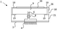
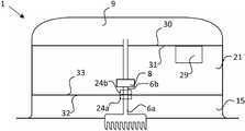
도 1을 참조하면, 의료 기구(1)는 피부(2)에 부착하여 체액을 분석하기 위한 것이다. 체액은, 예를 들면, 혈액 또는 간질액일 수 있으며, 여기서 간질액이 바람직하다. 이 기구(1)를 부착하기 위한 적절한 위치는 팔, 예를 들면, 상완 또는 허벅지를 포함할 수 있다.Referring to FIG. 1, the
이 의료 기구(1)는 바람직하게는 패치 또는 납작한 하우징의 형상을 갖는다. 이 기구는 이 기구를 사용자의 피부(2)에 부착하기 위한 부착면(3)인 적어도 하나의 평평한 표면을 갖는다. 적어도 하나의 마이크로니들(4)이 이 부착면(3)으로부터 돌출한다. 이 기구(1)는 적어도 하나의 마이크로니들(4)이 사용자의 신체 내에 삽입되도록 피부(2)에 부착되기 위한 것이다. 이에 의해 마이크로니들(4)은 피부(2)의 외면을 관통한다.This
체액은 적어도 하나의 중공 마이크로니들(4)을 사용하여 신체로부터 추출된다. 바람직하게는 복수의 마이크로니들(4)을 포함하는 어레이(5)가 존재한다. 어레이(5)가 존재하는 경우, 마이크로니들(4)은 바람직하게는 거의 동일한 방향으로 배치된다. 마이크로니들(4)의 방향은 피부 부착면(3)에 약 90°(수직)일 수 있고, 또는 피부 부착면(3)에 대해 약간 경사를 이룰 수 있다. 복수의 마이크로니들(4)의 어레이(5)를 보여주는 도 2를 참조하면, 적어도 하나의 마이크로니들(4)은 중공형이고, 선단부(25) 근처에 또는 선단부(25)에 체액을 받아들이기 위한 적어도 하나의 개구(24)를 갖는다. 마이크로니들(4)의 길이는 사용자의 불편(예를 들면, 통증)을 최소화하기 위해 가능한 짧은 것이 바람직하지만 신뢰할 수 있는 방식으로 대상의 체액을 샘플링하기에 충분한 길이이어야 한다. 혈액의 샘플링에는 더 긴 마이크로니들(4)이 요구될 수 있으므로 간질액의 샘플링이 바람직할 수 있다. 마이크로니들의 길이는 50 μm 내지 3000 μm, 바람직하게는 100 μm 내지 2000 μm, 더 바람직하게는 200 μm 내지 1500 μm일 수 있다. 중공 마이크로니들의 내경은, 예를 들면, 15 μm 내지 300 μm의 범위일 수 있다.. 마이크로니들(4)은 바람직하게는 금속, 실리콘(silicon), 또는 폴리머 재료, 또는 세라믹으로 제작된다. 유용한 재료는 백금, 타이타늄, 철, 금, 니켈, 구리, 금, 또는 이들 금속의 합금을 포함한다. 스테인리스강도 유용한 재료이다. US9033898 및 그 안의 참조문헌, 그리고 Ventrell 등(Adv Helthcare Mater. 2015, DOI: 10.1002/adhm.201500450)은 적합한 마이크로니들, 어레이 및 이것의 제조에 관한 정보를 제공한다.The body fluid is extracted from the body using at least one
이 어레이(5)는 임의의 적절한 수의 마이크로니들(4)을 가질 수 있다. 예를 들면, 1, 2, 3 또는 그 이상, 예를 들면, 10 또는 그 이상, 예를 들면, 100 또는 그 이상, 예를 들면, 최대 500 개의 마이크로니들(4). 복수의 마이크로니들(4)이 있을 때, 이들은 선을 따라 또는 매트릭스로서, 예를 들면, 정사각형으로 또는 원으로 배치될 수 있다.This
피부(2)의 탄성으로 인해 피부 내에 최소의 마이크로니들(4) 또는 복수의 마이크로니들(4)을 삽입하기 위해 어플리케이터(applicator)가 사용되어야 할 수 있다. 1 m/s 내지 20 m/s의 부착 속도가 유용할 수 있다. 어플리케이터는 4 m/s2 내지 100 000 m/s2의 가속도를 발생시킬 수 있다.Due to the elasticity of the
도 1로 돌아가서, 마이크로니들(4) 또는 마이크로니들(4)들은 마이크로니들(4) 내에 수집된 유체가 유동 채널(6) 내로 유입될 수 있도록 유동 채널(6)에 접속된다. 이 기구(1)의 마이크로니들(4)의 어레이 또는 모든 마이크로니들(4)은 브랜치(branch; 7) 시스템을 이용하여 동일한 유동 채널(6)에 접속될 수 있다.Returning to FIG. 1, the
체액은 사용자의 신체로부터 적어도 하나의 마이크로니들(4)의 개구(24) 내로 그리고 마이크로니들(4)로부터 유동 채널(6)로 흐른다. 다음이 이 체액은 분석 유닛(8)을 통과하고, 여기서 적어도 일부의 체액이 분석된다. 유동 채널(6)은 분석 유닛(8)의 타측 상으로 계속된다. 다음에 체액은 바람직하게는 증발층(9)인 저장층 내로 유출되고, 이 체액의 물 성분은 흡수되어 증발된다. 대안적으로, 흡수층은 저장층일 수 있다(하기 참조). 분석 유닛(8)은 유동 채널(6)의 일부 내에 통합될 수 있다. 예를 들면, 분석 유닛(8)은 저장 층 내에 배치되는 전극일 수 있다.The bodily fluid flows from the user's body into the
기구(1)를 통한 흐름은 적어도 부분적으로 흡수층(이것은 증발층(9)일 수 있음)으로부터의 증발에 의해, 또는 흡수층(이것은 증발층(9)일 수 있음)에 의한 체액의 흡수에 의해, 또는 펌프(10)(도 10)에 의해, 또는 이들의 조합에 의해 달성될 수 있다. 흐름은 펌프(10)의 도움없이 흡수층(이것은 증발층(9)일 수 있음)의 모세관 작용 및/또는 위킹 작용(wicking action) 및/또는 증발에 의해 유발될 수 있다. 따라서, 일부의 실시형태에서, 기구 내의 유동 채널을 통한 흐름은 펌프(10)의 도움없이 발생할 수 있다. 일부의 실시형태에서, 펌프(10)는 기구(1)를 통한 흐름을 개시하고 작동을 중단시키는데 사용된다.The flow through the
이 유동 채널(6)은 채널(6) 내의 일부의 유체(예를 들면, 물)와 함께 전달되어 증발을 개시하고, 유동 채널(6)을 통해 흐르도록 사전 습윤 상태가 될 수 있다. 그러나, 모세관 작용은 초기 흐름을 제공하기에 충분할 수 있다. 모세관 작용은 비교적 가느다란 유동 채널에서 최상으로 달성된다.This
펌프(10)는 마이크로니들(4)로부터 흡수층으로의 흐름을 개시하는 데에만 사용되도록 되어 있으므로 흡수층은 유동 채널(6)이 채워지면 흐름을 구동할 수 있다. 모세관 흐름이 흐름을 개시시키기에 충분하지 않은 경우에 이것이 유용할 수 있다. 그러면 펌프(10)는 바람직하게는 일회용 펌프, 예를 들면, 사전 포장된 진공 체임버, 또는, 예를 들면, 전자기력 또는 전류의 도움으로 그 형상을 변화시키는 체임버일 수 있다. 일회용 펌프(10)의 역할은 마이크로니들(4)로부터 증발층(9)까지의 흐름 체임버(6)를 체액으로 채우는 것이다. 펌프(10)는 기구(1)를 통한 흐름이 확립되면 작동을 중단하도록 하는 것일 수 있다. 일회용 펌프는 피부(2)에 이 기구(1)를 부착함으로써 활성화될 수 있다. 예를 들면, 일회용 펌프는 체온에 의해 활성화될 수 있다. 대안적으로, 부착면(3)은 사용자가 피부에 기구를 부착할 때 변위되는 벌지(bulge) 또는 버튼을 가질 수 있고, 버튼은 유동 채널(6) 내에서 흡인을 유발할 수 있다. 제 3 선택지로서, 펌핑 작용은 사용자가 버튼을 누름으로써 유발될 수 있다.Since the
유동 채널(6)은 바람직하게는 마이크로유체 채널이다. 유동 채널(6)의 지름은 전형적으로 1 mm 미만, 더 바람직하게는 500 마이크론 미만, 일부의 실시형태에서는, 50 마이크론 미만, 일부의 실시형태에서는, 1 마이크론 미만이다.The
유동 채널(6)은 하우징(18)의 일부 또는 내부 하우징(28)에 의해 구성될 수 있거나 별도의 배관에 의해 구성될 수 있다. 유동 채널(6)의 배관의 재료는, 예를 들면, 폴리머 재료일 수 있으나, 예를 들면, 금속도 사용될 수 있다.The
기구(1)의 유동 속도는 기구(1) 특히 마이크로니들(4)을 가능한 소형으로 유지하면서 신뢰할 수 있는 분석, 전형적으로는 분석물 농도 측정이 얻어지도록 선택될 수 있다. 흐름 및 분석을 위한 임의의 유용한 스케쥴이 사용될 수 있다. 1 nl/시 내지 300 μl/시의 기구(1)를 통한 유동 속도가 사용될 수 있으며, 여기서 100 nl 내지 30 μl/시가 바람직하다. 더 높은 유동 속도를 얻기 위해 펌프(10)를 사용해야 할 수도 있다. 흐름은 다소 일정하거나 시간에 따라 변화할 수 있다. 예를 들면, 흐름은 특정의 시점에서 증가될 수 있고, 또는 다른 시점에서는 중단되거나 거의 중단될 수 있다. 유동 채널(6) 내에서 흐름은 펌프(10) 또는 밸브를 사용하여 제어될 수 있다. 밸브 및 펌프(10)는 프로세서(11)에 의해 제어될 수 있다.The flow rate of the
임의선택적 펌프(10)는 흡인 또는 압력을 생성하는 임의의 유형의 메커니즘일 수 있다. 일 실시형태에서, 펌프(10)는 전기로 구동된다. 펌프(10)는, 예를 들면, 압전 기구 또는 전기기계 기구일 수 있다. 펌프(10)는 대안적으로는 사전 포장된 진공 체임버, 또는, 예를 들면, 메모리 폼(memory foam)의 도움으로 진공을 생성하는 다른 기구, 또는 시간에 따라 그 형상을 변화함으로써 흡인 또는 압력을 생성하는 체임버일 수 있다. 펌프(10)는 마이크로니들(4)과 분석 유닛(8) 사이 또는 분석 유닛(8)과 증발층(9) 사이에 배치될 수 있다.The
분석 유닛(8)은 체액의 적어도 하나의 특성을 검출할 수 있다. 이 특성은 분석물의 부재 또는 존재 또는 농도일 수 있다. 임의의 유용한 분석물은 분석 유닛(8)에 의해 분석될 수 있다. 분석물의 예는 포도당, pH, 전해질, 간 효소 값, 바이오마커(biomarker), c-반응성 단백질, 면역글로블린, 의약품 또는 이들의 분해 생성물, 호르몬 또는 기타 신호전달 분자, 펩타이드 또는 펩타이드 단편, 독소, 대사 산물, 세균성 또는 바이러스성 독소 또는 단백질과 같은 병원체로부터의 물질, 콜레스테롤과 같은 지질을 포함한다. 바이오마커는 내인성 단백질 또는 병원체 단백질, 예를 들면, 바이러스, 세균성 단백질 또는 기생충 단백질일 수 있다.The
임의의 유용한 화학물질이나 방법이 분석물을 분석하는데 사용될 수 있다. 예를 들면, 기구(1) 특히 기구(1)의 본체(26) 내에 장착되는 정도로 소형화될 있는 한(이하 참조), 전위, 분광학, 형광, 면역측정법, 광 산란, 표면 플라즈몬 공명, 항체와 같은 특정 시약의 결합, 또는 효소 활성, 또는 이들의 조합이 사용될 수 있다.Any useful chemical or method can be used to analyze the analyte. For example, as long as the
포도당이 바람직한 분석물이다. 따라서, 기구(1)는 바람직한 실시형태에서 사용자의 간질액 또는 혈액 중의 포도당의 농도를 분석하도록 구성된다. 포도당의 농도를 검출하는 방법은 잘 알려져 있다. 포도당 농도의 연속 측정은 전극을 사용하는 전통적인 포도당 산화효소 화학을 사용하여 적절하게 측정된다. 전형적으로, 작용 전극, 상대 전극 및 기준 전극의 3 개의 전극이 사용된다. 전형적으로, 작용 전극에서 H2O2의 생성을 촉매하기 위해 효소 포도당 산화효소가 사용된다. 포도당 산화효소는, 예를 들면, 전극 상의 층 내에서 포획될 수 있다. 작용 전극에서 이 반응이 발생하기 위해서는 과잉의 O2가 필요하고, O2의 필요성을 감소시키기 위해 H2O2로부터 자유 전자를 생성하기 위해 매개 화합물이 사용될 수 있다. 유용한 매개물질은 페로센 유도체, 페리사이아나이드, 전도성 유기염(특히 테트라티아풀발렌-테트라시아노퀴노디메탄, TTF-TCNQ), 페노티아진 및 페녹사진 화합물, 또는 퀴논 화합물을 포함한다. 대안적으로, 글루코스 히드로게나제가 효소로서 사용될 수도 있다. Ventrelli 등(Adv Helthcare Mater. 2015, DOI: 10.1002/adhm.201500450)은 유용한 포도당 센서에 대한 정보를 제공한다.Glucose is the preferred analyte. Thus, the
간질액 분석에 의한 사용자, 특히 당뇨병 환자의 포도당 농도의 분석은 바람직한 실시형태이다. 간질액의 포도당 농도는 혈액 중의 포도당 농도를 밀접하게 반영하지만 약간의 시간 지체가 있다.Analysis of the glucose concentration of users, particularly diabetics by interstitial fluid analysis, is a preferred embodiment. The glucose concentration in the interstitial fluid closely reflects the glucose concentration in the blood, but there is a slight delay.
전극으로 측정될 수 있는 다른 유형의 분석물은 글루타메이트, 에탄올, 콜린, 코르티솔 또는 락테이트를 포함한다. 예를 들면, Pinnacle Technology(소재지: Kansas, USA)에 의해 판매되는 유형의 전극이 사용될 수 있다. 바람직하게는 분석 유닛(8)은 분석물의 존재 또는 농도를 측정하기 위한 적어도 하나의 전극(8)을 포함한다.Other types of analytes that can be measured with electrodes include glutamate, ethanol, choline, cortisol or lactate. For example, electrodes of the type sold by Pinnacle Technology (Location: Kansas, USA) can be used. Preferably the
도 3을 참조하면, 기구(1)는 바람직하게는 분석 유닛(8)으로부터 신호를 수집하기 위한 프로세서(11) 및 측정값 및 소프트웨어를 저장하기 위한 메모리(12), 및무선 통신 유닛(13)을 포함한다. 무선 통신 유닛(13)은, 바람직하게는 제 2 기구(36), 예를 들면, 스마트폰 또는 기타 유형의 무선 장치, 또는 기타 유형의 장치에 정보를 전송할 수 있다. 바람직하게는 샘플 데이터는 분석 또는 샘플링을 위한 시점과 함께 전송된다. 제 2 기구(36)가 의료 기구(1)의 범위 내에 있을 때에 데이터 전송이 자동으로 발생할 수 있다. 무선 통신은 근거리 무선 통신(NFC)형, 예를 들면, 블루투스®일 수 있다.Referring to FIG. 3, the
기구(1)는 바람직하게는 다양한 전자 컴포넌트들 사이의 통신을 허용하기 위한 통신 인터페이스(14)를 포함한다. 분석 유닛(8), 펌프(10), 프로세서(11), 메모리(12), 무선 통신 유닛(13) 및 통신 인터페이스(14) 및 센서(23), 예를 들면, 유량 센서 또는 압력 센서 중 하나 이상에 급전하기 위한 배선 및 배터리와 같은 전원이 있을 수 있다. 배터리는 유도 코일 또는 포트를 사용하여 충전되거나 사용 후 버릴 수 있는 것일 수 있다. 배터리의 대안으로서 기구는 셀프 파워식 바이오연료 전지(self-powered biofuel cell; BFC)를 가질 수 있다. 여기서 분석 유닛(8), 펌프(10), 프로세서(11), 메모리(12), 무선 통신 유닛(13), 통신 인터페이스(14), 배터리 및 센서(23)는 모두 "전자 유닛"(29)으로 지칭된다. 기구(1)는 센서, 알람, 발광 유닛, 충전 코일, 밸브, 등과 같은 기타 전자 유닛을 포함할 수 있으나, 이들에 한정되지 않는다. 이들도 또한 "전자 유닛"(29)으로 지칭된다. 기구(1)는 적어도 하나의 전자 유닛(29), 특히 작동시의 부산물로서 약간을 열을 생성하는 전자 유닛(29)을 가질 수 있다. 예를 들면, 무선 통신 유닛(13)은 송신 동안에 적어도 약간의 열을 생성하며, 프로세서(11)는 이것이 작동하고 있을 때 적어도 약간의 열을 생성한다.The
메모리(12) 내에 저장된 프로세서(11) 및 소프트웨어는 기구(1)의 다양한 전자 유닛(29)으로부터 데이터를 제어하거나 수신한다. 프로세서(11) 및 소프트웨어는 펌프(10) 또는 밸브를 제어함으로써 기구(1)를 통한 유체의 흐름을 제어할 수 있다. 샘플링 또는 분석은 임의의 적절한 간격으로 수행될 수 있으며, 프로세서(11)에 의해 제어될 수 있다. 샘플링 또는 분석은 적어도 소정의 타이머 간격마다, 예를 들면, 적어도 24 시간 마다, 더 바람직하게는 적어도 12 시간 마다, 적어도 6 시간 마다, 적어도 3 시간 마다, 적어도 2 시간 마다, 적어도 60 분 마다, 적어도 30 분 마다, 적어도 15 분 마다, 적어도 10 분 마다, 적어도 5 분 마다, 적어도 1 분 마다, 적어도 10 초 마다 또는 적어도 1 초 마다 실행될 수 있다. 펌프(10) 및 밸브는 샘플 빈도와 연동하여 작동할 수 있다. 분석 유닛(8)으로부터의 데이터는 샘플링을 위한 시간 및 날짜와 같은 관련된 시점과 함께 메모리(12) 내에 저장될 수 있다. 분석이 센서, 예를 들면, 전극을 다소 연속적으로 통과하는 유체에서 수행되는 경우, 분석을 위한 시점은 보다 관련성이 높을 수 있다. 일부의 실시형태에서, 유체는 분석 전에 분리될 수 있고, 이 경우 샘플링을 위한 시점이 관련성이 더 높을 수 있다.
제 2 기구(36)로의 데이터의 전송은 적어도 하루에 1 회일 수 있는 소정의 스케쥴에 따라 자동적으로 수행되거나 사용자의 편의에 따라 수행될 수 있다. 데이터의 전송은 사용자에 의해, 예를 들면, 데이터 전송을 트리거하는 제 2 기구(36)를 사용함으로써 개시될 수 있다. 프로세서(11)는 무선 통신 유닛(13)을 사용하여 샘플링, 분석 및 제 2 기구(36)로의 데이터의 전송을 제어할 수 있다. 예를 들면, 이 기구(1) 및 제 2 기구(36)는 제 2 기구(36)로의 데이터의 전송 전에 핸드셰이크(handshake)를 수행할 수 있다. 제 2 기구(36)는 데이터를 저장할 수 있다. 제 2 기구(36)는 또한 디스플레이 상에 데이터를 표시할 수도 있다. 제 2 기구(36)는 또한 저장, 분석 및 향후 참조를 위해 클라우드 솔루션에 데이터를 전송할 수도 있다.The transmission of data to the
프로세서(11) 및 소프트웨어는 다음 중 하나 이상을 수행하도록 구성될 수 있다: 기구(1)를 통한 유동 속도의 모니터링, 유동 속도의 제어, 펌프(10) 및 밸브의 제어, 기구(1)의 올바른 기능의 모니터링, 오작동 또는 교체가 필요한 경우에 알람 발생, 배터리 상태의 확인, 유량이 낮은 경우에 알람 발생, 기구의 시동 및 정지, 기구의 리세팅, 제 2 기구(36)와의 무선 통신, 데이터 분석, 데이터 저장 및 전송, 데이터 암호화, 기구(1) 및 제 2 기구(36)의 ID의 저장.
바람직하게는 기구(1)는 몇 일 또는 몇 주 동안, 예를 들면, 3 일 이상, 더 바람직하게는 5 일 이상, 더 바람직하게는 10 일 이상, 가장 바람직하게는 20 일 이상 사용되도록 구성된다. 따라서, 이 기구(1)는 이러한 시간 동안에 체액을 인출하여 분석할 수 있다.Preferably the
증발층Evaporation layer
이 기구는 흡수층을 갖는다. 흡수층은 증발층(9) 또는 대안적으로 저장층일 수 있다. 저장층의 유체 처리 능력은 완전히 또는 거의 완전히 유체의 흡수에 기초하며, 여기서 증발은 무시될 수 있다. 증발층을 구비하는 본 발명의 모든 실시형태는 가능한 경우에는 언제나 증발층(9) 대신 저장층과 함께 사용될 수 있다. 저장층을 사용하는 것의 장점은 흡수성 재료가 캡슐화될 수 있으므로 사용자는 수중에서, 예를 들면, 수영하면서 이 기구(1)를 사용할 수 있다는 점이다. 엘라스토머 층(27)을 갖는 실시형태가 이를 위해 특히 유용할 수 있다(도 8 참조). 그러나, 바람직한 실시형태에서, 기구는 증발층(9)을 가지며, 유체 취급은 적어도 부분적으로 증발에 기초한다. 따라서, 증발층(9)은 유체의 증발을 도울 수 있다.This device has an absorbent layer. The absorbing layer may be an
기구(1)의 유체 처리 능력은 유체가 기구 내의 유동 속도와 동일한 속도로 처리되는 정도일 수 있다.The fluid handling capability of the
도 1로 돌아가서, 유동 채널(6)은 개구(37)를 통해 증발층(9) 내로 유체를 토출한다. 유동 채널(6)은 2 개 이상의 분기(22)(도 9 및 도 10 참조)로 분기될 수 있고, 이 분기는 개구(37)을 통해 증발층(9) 내로 접속된다. 따라서, 2 개 이상의 개구(37)가 있을 수 있다. 분기(22)의 목적은 증발층(9) 내에 유체를 분산시키는 것이다. 증발층(9)은 유동 채널(6)로부터 유체를 받아들이기에 적합하다. 유체는 바람직하게는 간질액 또는 혈액과 같은 물을 기반으로 하는 유체이다. 증발층(9)의 목적은 다음 중 적어도 하나이다: a) 마이크로니들(4)에 의해 유체를 흡수함으로써 수집된 유체를 증발시키도록 처리하는 것(여기서 모든 유체가 반드시 증발되는 것은 아님) 및 b) 유체의 흡수에 의해 또는 증발에 의해 기구(1)를 통한 흐름을 향상시키거나 흐름을 유발하는 것. 바람직하게는 a) 및 b)의 둘 모두가 달성된다.Returning to FIG. 1, the
증발층(9)은 유체를 흡수할 수 있고 및/또는 유체를 증발시킬 수 있다. 적절한 증발층(9)은 높은 유체 처리 능력을 갖는다. 본원에서 사용되는 "유체 처리 능력"은 수분을 흡수하는 능력과 이것을 환경(주위 공기) 내로 증발시키는 능력의 조합된 능력을 의미한다. 증발층의 유체 처리 능력은, 균일한 두께의 층의 경우에, 약 1 g/m2/24h 이상, 더 바람직하게는 10 g/m2/24h 이상, 더 바람직하게는 500g/m2/24h 이상, 더 바람직하게는 1000 g/m2/24h 이상, 더 바람직하게는 2500 g/m2/24 시 이상, 또는 약 3500 g/m2/24 시 이상일 수 있다.The
증발층(9)의 유체 처리 능력은 증발이 그다지 중요한 역할을 하지 않는 경우에는 유체의 흡수 및 보유(저장)에 주로 기초할 수 있고, 대부분의 유체가 증발되는 경우에는 주로 증발에 기초할 수 있다. 시간이 지남에 따라, 증발층(9)의 사용의 초기 단계에서는 저장이 더 중요한 성분일 수 있고, 증발층이 포화에 도달함에 따라 증발이 더 중요한 부분일 수 있다. 정상 상태에서, 모든 유체 처리 능력은 증발에 의해 제공될 수 있다. 일 실시형태에서, 그 사용 시간 동안에 증발층의 총 유체 처리 능력의 50 % 이상, 더 바람직하게는 60%, 보다 더 바람직하게는 70%, 보다 더 바람직하게는 80%, 보다 더 바람직하게는 90%, 보다 더 바람직하게는 95%, 가장 바람직하게는 99% 이상이 증발에 의해 제공된다.The fluid handling capacity of the
수증기 투과율(MVTR)은 수증기가 물질을 통과하는 측정값이다. 일 실시형태에서, 증발층(9)은 높은 MVTR을 갖는다. 기구(1)의 MVTR은 증발층(9)에 도달하는 모든 유체가 시간이 지남에 따라 증발하도록 유체가 기구(1) 내에서의 유체의 유동 속도와 동일하거나 더 빠르게 증발하는 정도이다. 증발층(9)은 균일한 두께를 갖는 경우에 1 g/m2/24 시 이상, 더 바람직하게는 300 g/m2/24 시, 더 바람직하게는 500 g/m2/24 시 이상, 더 바람직하게는 1000 g/m2/24 시 이상, 가장 바람직하게는 1200 g/m2/24 시 이상의 MVTR를 가질 수 있다. 높은 MVTR는 항균성 성장을 방지하고 수분의 형성을 방지하여 사용자에게 더 큰 편안함을 제공하므로 유용하다. 유체 처리 및 MVTR을 결정하는 방법은 WO2013071007에 기재되어 있다.Water vapor transmission rate (MVTR) is a measure of water vapor passing through a material. In one embodiment, the
증발층(9)은 적어도 부분적으로 증발을 촉진하는 주위 공기에 노출될 수 있다.The
증발층(9)은 플러프 층(fluff layer), 발포체 층, 다공질 층 또는 스펀지형 층과 같은 큰 표면적을 갖는 재료를 포함할 수 있다.The
증발층(9)은 셀룰로오스 플러프(플러프 펄프)와 같은 셀룰로오스 섬유를 포함할 수 있다. 유용한 재료의 예는 BASF Luquafleece®, Texsus Absorflex® 및 유사한 제품을 포함한다. 흡수성 재료의 예는 또한 WO9620667 및 WO200115649에도 제공되어 있다.The
증발층(9)은 하이드로겔 형성 흡수성 폴리머를 포함하거나 이것으로 구성될 수 있다. 초 흡수성 폴리머는 가교 아크릴레이트 폴리머, 비닐 알코올-아크릴레이트 코폴리머의 가교 생성물, 말레산 무수물 및 카르복시메틸셀룰로오스로 그라프팅된 폴리비닐 알코올의 가교 생성물을 포함한다. 폴리아크릴레이트의 Medi Gel® 및 Artic Gel® 브랜드를 포함하는 BASF 초흡수성 폴리머가 유용하다.The
증발층(9)은 하이드로겔 형성 흡수성 폴리머와 조합된 셀룰로오스 섬유를 포함할 수 있다.The
흡수층이 저장층인 경우, 이것은 증발층과 동일한 유형의 재료를 포함하고, 이 재료로 구성될 수 있다. 특히, 하이드로겔 형성 흡수제 형성 폴리머가 저장층에 사용될 수 있다.When the absorbing layer is a storage layer, it includes, and may be composed of, the same type of material as the evaporation layer. In particular, a hydrogel-forming absorbent-forming polymer may be used in the storage layer.
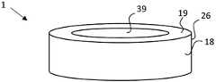
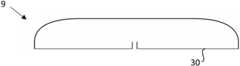
증발층(9)의 형상은 바람직하게는 큰 표면적을 가지도록 선택될 수 있다. 예를 들면, 이것은 다소 평탄한 구성을 가질 수 있다. 바람직하게는 증발층(9)의 두께는 증발층(9)의 너비 및 길이의 둘 모두보다 얇다. 증발층(9)의 최대 두께는 기구(1)의 최대 너비의 50% 이하, 더 바람직하게는 30% 이하인 것이 바람직하다. 기구(1)가 퍽(puck)의 형상(도 6 및 도 7)인 경우, 너비는 기구(1)의 지름이다.The shape of the
이 기구는 외층(39)을 가질 수 있고, 이 외층은 통기성 외층(39), 가장 바람직하게는 증발층(9)의 외부의 얇은 통기성 층(도 6 및 도 7)일 수 있다. 외층(39)은 물의 비산, 오염 또는 기계적 마모로부터 보호하기 위한 목적을 위한 것이다. 외층(39)은 바람직하게는 부직 재료 또는 필름 재료를 포함할 수 있다. 이 재료는 수증기 투과성일 수 있다. 외층(39)은, 예를 들면, 통기성을 증가시키기 위해 작은 구멍 또는 기공을 가질 수 있다. 외층(39)은, 예를 들면, 폴리우레탄, 엘라스토머 폴리에스테르 또는 폴리비닐 클로라이드를 포함하거나, 이들로 구성될 수 있다. 외층은 Gore-Tex 유형, 즉 물의 침투를 방지하지만 여전히 통기성인 재료일 수 있다.The device may have an
도 4를 참조하면, 이 기구(1)는 바람직하게는 부착면(3)을 포함하는 접착제 피부 부착층(15)을 포함할 수 있다. 접착제 부착층(15)은 기구(1)가 수직의 체표면에 부착된 경우에도 이동 중에 피부(2)의 외면에 접착되게 하는 접착제 화합물 또는 조성물을 포함한다. 접착제 부착층(15)의 접착제는 메타크릴레이트 및 에폭시 디아크릴레이트를 포함하는 아크릴레이트일 수 있다. 접착제는 감압 접착제일 수 있다. Henkel Duro-Tak®가 유용한 접착제이다. 접착제 부착층(15)은 또한 엘라스토머 화합물을 포함할 수 있다. 접착제 부착층은 또한 기구(1)의 나머지로부터 착탈가능한 별개의 하우징 내에 포함될 수 있다.Referring to FIG. 4, the
접착제 부착층(15)은 피부 접촉면 상에 박리 라이너(release liner; 16)를 가질 수 있다. 박리 라이너(16)는 이 기구(1)를 사용자의 피부(2)에 적용하기 직전에 제거된다.The
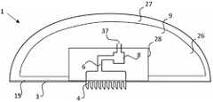
도 1, 도 4, 도 5 내지 도 13 및 도 15를 참조하면, 이 의료 기구(1)는 임의의 적절한 형상을 가질 수 있다. 의료 기구는 바람직하게는 부착면(3)을 포함하는 본체(26)를 가지며, 여기서 적어도 하나의 마이크로니들(4)이 본체(26)로부터 돌출해 있다. 본체는 증발층(9), 부착면(3), 유동 채널(6)의 주요 부분, 분석 유닛(8), 부착층(15) 및 임의의 전자 유닛(29)을 포함한다. 본체(26)는 마이크로니들(4)이 본체(26)에 통합된 베이스로부터 돌출하도록 마이크로니들(4)의 베이스를 포함할 수도 있다. 바람직하게는 기구(1)는 본체(26) 및 적어도 하나의 마이크로니들(4)로 구성된다.1, 4, 5 to 13, and 15, this
바람직하게는 본체(26)는 퍽 형상과 같은 둥근 형상을 가지거나 패치로서 형성된다. 패치는 소프트 패치일 수 있다. 바람직하게는 분석 유닛(8)은 의료 기구(1)의 본체(26) 내에 포함된다. 예를 들면, 하우징(18)의 내부에 또는 아래에서 설명하는 바와 같이 엘라스토머(27) 내에 매립된다. 따라서, 바람직하게는, 분석 유닛(8)의 어느 부분(예를 들면, 전극)도 마이크로니들(4)의 내부에 있지 않다.Preferably, the
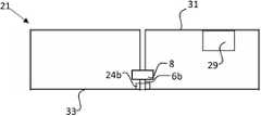
분석 유닛(8) 및 기타 컴포넌트, 예를 들면, 기타 전자 컴포넌트(29)는 증발층(9)과 접착제 부착층(15) 사이에 위치하는 기구(1)의 본체(26)의 재사용가능한 부품(21)(도 5, 도 7, 도 9 및 도 13) 내에 배치될 수 있다.The
기구(1)는, 도 5, 도 6, 및 도 7에 도시된 바와 같이, 외부 하우징(18)을 가지며, 이 외부 하우징(18)의 상면 또는 상부 구획에는 증발층(9)이 있다. 하우징(18)은, 예를 들면, ABS, PET, PETG 또는 폴리카보네이트와 같은 강성 폴리머 재료로 제작될 수 있다. 증발층(9)은 하우징(18)의 상면이나 하우징(18) 내의 개구 내에 위치하며, 플랜지에 의해 정위치에 유지될 수 있다(도 7).The
기구(1)는 엘라스토머(고무형) 재료를 포함할 수 있다. 그러면 기구의 본체(26)는 소프트 패치(soft patch)일 수 있다. 예를 들면, 유동 채널(6) 및 마이크로니들(4)의 어레이(5)의 베이스 및 적어도 하나의 전자 유닛(29), 바람직하게는 분석 유닛(8), 또는 모든 전자 유닛(29)은 엘라스토머 층(27) 내에 수용될 수 있다. 도 8을 참조하면, 엘라스토머 층(27)은 증발층(9), 특히 하이드로겔 형성 폴리머와 같은 다량의 유체를 흡수하는 증발층(9)을 포함하거나 둘러쌀 수 있다. 이 실시형태는 특히 증발층(9) 대신 저장층이 사용되는 경우에 유용할 수 있다. 바람직하게는 엘라스토머 층(27)은 액상의 물에 대해 불투과성이므로 저장층 또는 증발층(9)은 사용자가 수영을 하거나 샤워를 할 때 젖지 않는다. 바람직하게는 도 8에 도시된 실시형태에서 저장층으로서 하이드로겔 형성 화합물이 사용된다. 유동 채널(6) 및 분석 유닛(8)은 엘라스토머 층(27) 및 증발층(9) 내에 매립된 내부 하우징(28)에 수용될 수 있다. 내부 하우징(28)은 또한 다른 전자 유닛(29)을 포함할 수 있다. 내부 하우징(28)은 또한 어레이(5)를 위한 베이스를 포함할 수 있다. 유동 채널(6) 및 내부 하우징(28)을 위한 배관은 단품의 폴리머 재료로 몰딩될 수 있다.The
엘라스토머 층(27)은 수증기를 통과시키기 위해 통기성일 수 있다. 예를 들면, 엘라스토머 층(27)은 기공을 가질 수 있다. 그러나, 유체 처리는 엘라스토머 층(27) 내부의 증발층(9)에서의 흡수에 거의 완전하게 기초할 수 있다. 그러면 엘라스토머 층은 외부로부터의 수분으로부터 층(9)을 보호하기 위해 낮은 MVTR(낮은 통기성)을 가질 수 있다.The
유용한 엘라스토머의 예는 천연 고무, 폴리이소프렌, 스티렌 부타디엔 고무, 클로로프렌 고무, 폴리부타디엔, 니트릴 고무, 부틸 고무, 에틸렌 프로필렌 고무, 에틸렌 프로필렌 디엔 단량체, 클로로설폰화 폴리에틸렌, 폴리설파이드 고무, 폴리우레탄(PU), EVA 필름, 코폴리에스테르, 및 실리콘(silicone)을 포함할 수 있지만, 이들에 한정되지 않는다.Examples of useful elastomers are natural rubber, polyisoprene, styrene butadiene rubber, chloroprene rubber, polybutadiene, nitrile rubber, butyl rubber, ethylene propylene rubber, ethylene propylene diene monomer, chlorosulfonated polyethylene, polysulfide rubber, polyurethane (PU). , EVA films, copolyesters, and silicones, but are not limited thereto.
증발의 강화Strengthening of evaporation
증발층(9)으로부터 유체의 증발은 사용자의 체열에 의해 강화될 수 있다. 체열은 사용자로부터 부착층(15)을 통해 증발층(9)으로 전도 또는 방열될 수 있다. 사용자의 신체에 의한 증발층(9)의 가열은 기구(1)의 두께가 얇아서 증발층(9)이 신체에 근접하는 경우에 촉진된다. 기구(1)의 최대 두께(부착면(3)으로부터 증발층(9) 또는 외층(39)의 상면까지 측정된 두께)는 바람직하게는 20 mm 미만, 보다 더 바람직하게는 10 mm 미만, 가장 바람직하게는 5 mm 미만이다.Evaporation of the fluid from the
증발층(9)으로부터 유체의 증발은 적어도 하나의 전자 유닛(29)으로부터의 열에 의해서도 향상될 수 있다. 적어도 하나의 전자 유닛(29)은 이것이 적어도 부분적으로 증발층(9)과 접촉하여 배치되도록 배치될 수 있다(도 9). 전자 유닛(29)은, 예를 들면, 분석 유닛(8), 펌프(10), 프로세서(11), 메모리(12), 무선 통신 유닛(13), 통신 인터페이스(14), 센서(23), 및 배터리로 구성된 그룹으로부터 선택될 수 있다.Evaporation of the fluid from the
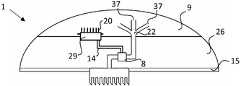
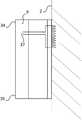
기구(1)는 열전도 요소(17)를 포함할 수 있다. 열전도 요소(17)는 사용자의 신체로부터 그리고 기구(1)의 임의의 전자 유닛(29)으로부터 증발층(9)으로의 열의 전도 및 분산을 돕는다. 열전도 요소(17)는, 예를 들면, 열전도층, 예를 들면, 도 10에 도시된 바와 같은 금속 필름 또는 포일일 수 있다.The
열전도 요소(17)는 부착층(15)과 증발층(9) 사이에 배치될 수 있다. 열전도 요소(17)의 적어도 일부는 바람직하게는 증발층(9)과 접촉한다. 열전도 요소(17)는, 도 10에 도시된 바와 같이, 전자 유닛(29)의 위에 그러나 증발층(9)의 아래에 배치될 수 있고, 이로 인해 전자 유닛(29)으로부터 증발층(9)으로 열을 전달하여 증발을 향상시킬 수 있다. 따라서, 열전도 요소(17)는 분석 유닛(8), 펌프(10), 프로세서(11), 메모리(12), 무선 통신 유닛(13), 통신 인터페이스(14), 센서(23) 및 배터리로부터 선택되는 하나의 컴포넌트와 증발층(9) 사이에 배치될 수 있다. 열전도 요소(17)는, 도 10에 도시된 바와 같이, 피부 부착면(3)에 대략 평행한 층일 수 있다. 그러나, 열전도 요소(17)는 사용자의 신체로부터 증발층(도 11)으로 열을 전도하는 수직 금속 스터드 또는 금속 막 또는 금속 시트로서 배치될 수도 있다. 열전도 요소(17)는 바람직하게는 부착면의 근접부로부터 증발층(9)을 향해 신장된다. 열전도 요소(17)의 일부는 기구(1)가 피부(2)에 부착될 때 피부(2)의 외면에 접촉할 수도 있다. 예를 들면, 도의 스터드는 피부(2)의 표면과 접촉할 수 있다. 일반적으로, 열전도 요소(17)는 부착면(3)에 수직한 그리고 증발층(9)을 향한 방향으로 열을 전도하도록 배치될 수 있다.The thermally
열전도 요소(17) 또는 전자 유닛(29)은 증발층(9)에 열을 전도하기 위한 표면적을 증가시키는 열전도 핀(20) 또는 유사 구성과 같은 열전도 표면적 증가 요소를 포함할 수 있다. 핀(20)은 바람직하게는 금속과 같은 높은 열전도성을 갖는 재료로 제작된다. 핀(20)과 같은 표면적 증가 요소의 일부는 증발층(9) 내에 매립될 수 있다. 전자 유닛(29)은 그 외면에 부착된 금속 핀(20)을 가질 수 있으며, 이 금속 핀(20)은 증발층(9)에 근접하거나 증발층(9) 내에 매립된다(도 9). 예를 들면, 프로세서(11), 분석 유닛(8) 또는 무선 통신 유닛(13)은 증발층(9)에 근접하여 배치될 수 있고, 이 증발층(9)에 매립된 핀(20)을 가질 수 있다. 핀(20)의 대안으로서, 금속 나사산, 금속 와이어, 금속 메시(mesh), 또는 유사물이 사용될 수 있다. 추가의 실시예로서 열전도 요소(17)는 그 일면이 증발층(9) 내에 매립된 파형 금속 포일일 수 있다(도 12).The
도 9 및 도 10은 또한 기구(1)의 통신 인터페이스(14)를 도시하고 있다.9 and 10 also show the
항균제Antibacterial
이 기구(1), 특히 증발층(9)은 항균제, 특히 항세균제, 항진균제 또는 항바이러스제를 포함할 수 있다. 항균제를 포함할 수 있는 다른 부분은 적어도 하나의 마이크로니들(4) 및 유동 채널(6)의 내면, 및 분석 유닛(8)이다.The
하나 이상 실시형태에서, 항생제는 베타-락탐 항생제, 아미노글리코시드, 안사형 항생제, 안트라퀴논, 항생물질 아졸, 항생물질 글리코펩타이드, 마크로라이드, 항생물질 뉴클레오사이드, 항생물질 펩타이드, 항생물질 폴리엔, 알코올, 항생물질 폴리에테르, 퀴놀론, 항생물질 스테로이드, 설폰아미드, 테트라사이클린, 디카르복실산, 항생물질 금속, 산화제, 자유 라디칼 및/또는 활성 산소를 방출하는 물질, 양이온성 항균제, 4차 암모늄 화합물, 비구아나이드, 트리구아나이드, 비스비구아나이드 및 그 유사체 및 그 폴리머, 자연 발생 항생물질 화합물로 구성된 클래스로부터 선택된다.In one or more embodiments, the antibiotic is a beta-lactam antibiotic, an aminoglycoside, an ansatype antibiotic, an anthraquinone, an antibiotic azole, an antibiotic glycopeptide, a macrolide, an antibiotic nucleoside, an antibiotic peptide, an antibiotic polyene. , Alcohols, antibiotic polyethers, quinolones, antibiotic steroids, sulfonamides, tetracyclines, dicarboxylic acids, antibiotic metals, oxidizing agents, substances that release free radicals and/or active oxygen, cationic antibacterial agents, quaternary ammonium Compounds, biguanides, triguanides, bisbiguanides and their analogs and their polymers, are selected from the class consisting of naturally occurring antibiotic compounds.
특히 유용한 항균제의 예는 파라클로로메탁실레놀; 클로르헥시딘, 및 그 염(예를 들면, 클로르헥시딘 아세테이트 및 클로르헥시딘 글루코네이트; 요오드; 요오도퍼; 폴리-N-비닐피롤리돈-요오도퍼; 은 산화물, 및 은 및 그 염, 퓨시드산, 소듐 퓨시데이트, 레타파뮬린, 무피로신, 옥시테트라사이클린, 폴리믹신(B), 카나마이신, 바시트라신, 바시트라신 아연, 네오마이신, 락트산, 시트르산, 및 아세트산일 수 있다.Examples of particularly useful antimicrobial agents include parachloromethoxylenol; Chlorhexidine, and salts thereof (e.g., chlorhexidine acetate and chlorhexidine gluconate; iodine; iodophor; poly-N-vinylpyrrolidone-iodoper; silver oxide, and silver and salts thereof, fusidic acid, sodium Fucidate, retapamuline, mupirosine, oxytetracycline, polymyxin (B), kanamycin, bacitracin, bacitracin zinc, neomycin, lactic acid, citric acid, and acetic acid.
본 발명에서 사용될 수 있고, 국소 용도가 알려져 있는 항진균제의 예는 아모로핀, 클로트리마졸, 미코나졸, 케토코나졸, 시클로피록스, 또는 테르비나핀이다.Examples of antifungal agents that can be used in the present invention and whose topical use is known are amorphine, clotrimazole, miconazole, ketoconazole, cyclopirox, or terbinafine.
항균제는 실온에서 고체인 것이 바람직하고, 35℃ 이하의 온도에서 고체인 것이 바람직하다. 이 온도는 증발층(9)으로부터 체액의 증발을 최대화하기 위해 바람직할 수 있다.The antimicrobial agent is preferably solid at room temperature, and preferably solid at a temperature of 35°C or less. This temperature may be desirable to maximize the evaporation of body fluids from the
적어도 하나의 마이크로니들(4) 또는 유동 채널(6)의 내면 또는 증발층(9)과 같은 기구(1)의 부품은 또한 미생물의 증식을 억제하는 표면 처리 또는 코팅을 포함할 수 있다. 이러한 코팅 또는 표면 처리의 예는 박테리아의 부착을 억제하는 구성, 예를 들면, 표면활성제 또는 막 관통 단백질과 같은 미생물의 세포막을 파괴하는 작용제, 및 은 이용의 사용이다.The at least one
교체가능한 부품Replaceable parts
도 13a 내지 도 13d를 참조한 특정 실시형태(이것은 다른 실시형태와 조합될 수 있음)에서, 의료 기구(1)의 증발층(9) 및 접착제 부착층(15)(마이크로니들(4)을 포함함) 중 적어도 하나는 대체될 수 있다. 따라서, 증발층(9)은 기구(1)의 나머지의 상면(31)에 제거가능하게 부착된 하면(30)을 가질 수 있다. 부착면(3)을 포함하는 부착층(15)은 의료 기구(1)의 나머지, 예를 들면, 하우징(18) 또는 엘라스토머 층(27)의 하면(33)에 제거가능하게 부착된 상면(32)을 가질 수 있다.In a particular embodiment with reference to FIGS. 13A to 13D (which can be combined with other embodiments), the
바람직한 실시형태에서, 증발층(9) 및 부착면(3)은 대체될 수 있는 반면에 적어도 하나의 전자 유닛(29), 특히 분석 유닛(8)을 포함하는 재사용가능한 부품(21)은 재사용될 수 있다. 재사용가능한 부품(21)은 펌프(10), 프로세서(11), 메모리(12), 무선 통신 유닛(13)과 같은 고가여서 재사용될 수 있는 기타 전자 유닛(29)을 포함하는 것이 바람직하다.In a preferred embodiment, the
일 실시형태에서, 배터리는 교체 부품(9 또는 15) 중 하나에 제공된다. 이러한 방식으로, 배터리는 증발층(9) 또는 부착층(15)를 변경할 때 교체된다. 그러면 배터리와 전자 유닛(19) 사이의 전기 공급 케이블은 채널(6)과 거의 동일한 방식으로 물리적 커넥터를 가질 수 있다(도 13a를 참조하는 아래의 설명 참조).In one embodiment, the battery is provided in one of the
따라서 증발층(9)(도 13b) 또는 부착층(15)(도 13d) 또는 둘 모두는 기구(1)의 나머지, 예를 들면, 재사용가능한 부품(21)(도 13b)에, 예를 들면, 접착제를 이용하여 가역적으로 부착될 수 있다. 접착제는 재사용가능한 부품(21)을 파손시키지 않고 탈부착을 가능하게 하는 유형의 것이 바람직하다. 부착은, 예를 들면, 마이크로 벨크로(micro Velcro) 또는 유사 수단에 의해 달성될 수도 있다.Thus, the evaporation layer 9 (Fig. 13b) or the adhesion layer 15 (Fig. 13d) or both are applied to the rest of the
재사용가능한 부품(21)은 임의의 적절한 설계를 가질 수 있다. 예를 들면, 재사용가능한 부품(21)은 외부 하우징(18)을 포함할 수 있다. 이 기구가 도 8의 실시형태를 갖는 경우, 재사용가능한 부품은 내부 하우징(28)을 포함할 수 있다.The
도 13a 및 도 13d의 착탈가능한 부착층(15)은 (하우징(18)과 별개의) 하우징을 포함할 수 있거나, 엘라스토머 재료의 본체를 포함할 수 있다.The
바람직하게는 교체가능한 부착층(15)은 마이크로니들(4), 예를 들면, 마이크로니들(4)의 어레이(5)를 포함한다. 마이크로니들(4) 또는 유동 채널(6a)의 하부는 커넥터(24a , 24b; 도 13a, 도 13c, 도 13d)에 의해 유동 채널(6b)의 나머지에 접속될 수 있다. 바람직하게는 커넥터(24a와 24b) 사이의 접속은, 예를 들면, 개스킷 또는 프레스 끼워맞춤 또는 둘 모두를 이용하여 누출 방지된다. 커넥터(24a, 24b)는 퀵록(quick lock)을 가질 수 있고, 예를 들면, 커넥터(24a, 24b)는 서로 스냅결합될 수 있다.Preferably the
유동 채널(6)은 증발층이 재사용가능한 부품(21)에 부착될 때 유동 채널(6)이 증발층(9) 내로 접속되도록 재사용가능한 부품(21)의 상면(31)에서 끝날 수 있다. 대안적으로, 교체가능한 증발층은 커넥터(24a, 24b)와 유사한 커넥터를 이용하여 유동 채널(6b)에 접속되는 유동 채널(도 13b)의 연속부를 가질 수 있다. 이것은 특히 유동 채널이 증발층(9) 내로 분기를 갖는 경우에 유용할 수 있다(도 9 및 도 10).The
피부 부착층 또는 증발층의 교체는 상이한 이벤트(event)에 의해, 예를 들면, 특정 시점에서 트리거될 수 있다. 예를 들면, 증발층 또는 피부 부착층은, 예를 들면, 7 일 또는 14 일일 수 있는 소정의 시간 제한 내에 대체될 수 있다. 바람직하게는 교체는 사용자 자신에 의해 수행될 수 있다. 기구(1)는 사용자에게 교체를 상기시키는 알람 또는 화학적 컬러 인디케이터(colour indicator)를 가질 수 있다. 예를 들면, 프로세서(11)는 소정의 시점 이후에 음향 알람을 트리거할 수 있다. 증발층(9)은 특정 시간 동안 습윤된 후에 변색되는 화학적 변색 인디케이터를 구비할 수 있다.The replacement of the skin adhesion layer or the evaporation layer can be triggered by different events, for example at a specific point in time. For example, the evaporation layer or the skin adhesion layer can be replaced within a predetermined time limit, which can be, for example, 7 or 14 days. Preferably, the replacement can be performed by the user himself. The
추가의 고려사항Additional considerations
도 14에 도시된 바와 같이, 기구(1)는 상단부(34) 및 하단부(35)를 가질 수 있고, 유동 채널(6)은 하단부(35)보다는 상단부(34)에 더 가까운 증발층(9) 내로 접속된다. 기구(1)가 상완의 측면과 같은 종종 수직이거나 거의 수직인 표면인 피부(2)의 일부 상에 배치된 경우(적어도 사용자가 누워 있지 않은 경우), 중력에 의해 유체는 유동 채널(6)의 개구(37)로부터 증발층(9) 내로 하방으로 흐르는 경향이 있으므로 이러한 구성은 증발층(9) 내의 액체의 분포를 개선시킬 것이다. 유동 채널은 복수의 개구(37)를 제공하는 분기(22)를 가질 수 있다.As shown in Fig. 14, the
일반적으로, 기구(1)의 본체(26)는 임의 적절한 형상을 가질 수 있다. 도 15는 환자의 팔의 피부에 부착된 패치 형상의 의료 기구(1)를 도시하고 있다. 도 15의 기구(1)는 연부가 둥근 정사각형 형상을 갖는 패치 형상의 본체(26)를 갖는다. 패치의 형상은 원형 또는 타원형이고, 또는 임의의 적절한 형상을 가질 수 있다. 바람직하게는 본체(26)는 가능한 납작할 수 있다. 바람직하게는 본체(26)의 연부는 옷 등에 걸리지 않도록 도 15 및 기타 도면에 도시된 바와 같이 둥글다.In general, the
기구(1) 및 부착층(15)의 형상 및 크기는 사용자가 이 기구(1)를 착용하여 지참할 수 있도록 선택되어야 한다. 바람직하게는 사용자는 이 기구(1)를 착용한 상태에서 작업, 운동 등을 포함하는 자신의 정상적인 라이프 스타일을 유지할 수 있어야 한다.The shape and size of the
또한 기구(1)를 사용자의 피부에 부착하는 단계, 사용자로부터 체액을 분석하는 단계, 및 체액의 적어도 일부가 증발층(9)에 의해 흡수되도록 허용하는 단계, 및 흡수된 체액의 적어도 일부가 증발층(9)으로부터 증발하도록 허용하는 단계를 포함하는 체액을 분석하는 방법이 제공된다. 이 방법은 교체가능한 부착층(15) 또는 교체가능한 증발층(9)을 교체하는 단계를 포함할 수 있다.In addition, attaching the
당업자는 본 발명의 다양한 실시형태들이 가능한 경우에는 언제든지 조합될 수 있다는 것을 이해한다. 본 발명은 특정의 예시적인 실시형태를 참조하여 설명되었으나, 이 설명은 일반적으로 발명의 개념을 설명하기 위한 것일 뿐이며, 본 발명의 범위를 제한하는 것으로 간주되어서는 안된다. 본 발명은 전체로서 청구범위에 의해 정의된다.Those skilled in the art understand that various embodiments of the invention may be combined whenever possible. While the present invention has been described with reference to specific exemplary embodiments, this description is for general purposes only, and should not be regarded as limiting the scope of the invention. The invention as a whole is defined by the claims.
Claims (16)
Translated fromKorean상기 기구(1)는 유동 채널(6), 체액을 분석하기 위한 분석 유닛(8), 및 증발층(9)을 더 포함하고, 상기 유동 채널(6)이 상기 증발층(9)에 유체를 방출시킬 수 있도록 상기 유동 채널(6)은 상기 마이크로니들(4)로부터 상기 분석 유닛(8)으로 그리고 상기 분석 유닛(8)으로부터 상기 증발층(9)으로 유체를 수송하도록 배치된, 의료 기구.A medical device (1) comprising an attachment surface (3), an evaporation layer (9) and at least one hollow microneedle (4) extending from the attachment surface (3),
The instrument (1) further comprises a flow channel (6), an analysis unit (8) for analyzing bodily fluids, and an evaporation layer (9), wherein the flow channel (6) supplies a fluid to the evaporation layer (9). The flow channel (6) is arranged to transport fluid from the microneedle (4) to the analysis unit (8) and from the analysis unit (8) to the evaporation layer (9) so as to be able to discharge.
상기 기구는 본체를 포함하고, 상기 적어도 하나의 마이크로니들은 상기 본체로부터 연장되고, 상기 분석 유닛은 상기 본체 내에 포함된, 의료 기구.The method of claim 1,
The device comprises a body, the at least one microneedle extends from the body, and the analysis unit is contained within the body.
상기 의료 기구를 통한 유체의 수송은 상기 증발층에 의해 구동될 수 있는, 의료 기구.The method according to claim 1 or 2,
The transport of fluid through the medical device can be driven by the evaporation layer.
상기 유동은 일회용 펌프에 의해 개시되는, 의료 기구.The method of claim 3,
The flow is initiated by a disposable pump.
상기 기구는 적어도 하나의 발열 전자 유닛을 포함하고, 상기 증발층은 상기 적어도 하나의 발열 전자 유닛과 접촉하여 배치되는, 의료 기구.The method according to any one of claims 1 to 4,
The device includes at least one heating electronic unit, and the evaporation layer is disposed in contact with the at least one heating electronic unit.
상기 기구는 상기 부착면과 상기 증발층 사이에 배치되는 열전도 요소를 포함하는, 의료 기구.The method according to any one of claims 1 to 5,
The device includes a heat conduction element disposed between the attachment surface and the evaporation layer.
상기 열전도 요소는 상기 증발층과 발열 전자 유닛 사이에 배치되는, 의료 기구.The method of claim 6,
The thermally conductive element is disposed between the evaporation layer and the exothermic electronic unit.
상기 발열 전자 유닛 또는 상기 열전도 요소에는 적어도 하나의 표면적 증가 요소가 제공되는, 의료 기구.The method according to any one of claims 5 to 7,
The medical device, wherein the heating electronic unit or the thermally conductive element is provided with at least one surface area increasing element.
상기 증발층은 항균 작용을 갖는, 의료 기구.The method according to any one of claims 1 to 8,
The evaporation layer has an antibacterial action, medical device.
상기 증발층은 상기 의료 기구로부터 제거될 수 있고, 다른 증발층으로 대체될 수 있는, 의료 기구.The method according to any one of claims 1 to 9,
The evaporation layer may be removed from the medical instrument and may be replaced with another evaporation layer.
상기 의료 기구는 상기 부착면을 포함하는 피부 부착층을 포함하고, 상기 피부 부착층은 상기 기구로부터 제거될 수 있고, 다른 피부 부착층으로 대체될 수 있는, 의료 기구.The method according to any one of claims 1 to 10,
Wherein the medical device comprises a skin adhesion layer comprising the adhesion surface, the skin adhesion layer being removable from the device and replaceable with another skin adhesion layer.
상기 피부 부착층은 상기 적어도 하나의 마이크로니들을 포함하는, 의료 기구.The method according to any one of claims 1 to 11,
The skin adhesion layer comprises the at least one microneedle.
상기 부착층은 적어도 하나의 마이크로니들을 포함하는, 피부 부착층.The method of claim 14,
The adhesion layer comprises at least one microneedle, skin adhesion layer.
사용자의 피부에 제 1 항 내지 제 12 항에 따른 기구를 부착하는 단계, 적어도 하나의 마이크로니들을 사용하여 사용자로부터 체액을 수집하는 단계, 분석 유닛을 사용하여 상기 체액을 분석하는 단계, 상기 체액의 적어도 일부가 상기 증발층에 의해 흡수되도록 허용하는 단계, 및 상기 체액의 적어도 일부가 상기 증발층으로부터 증발되도록 허용하는 단계를 포함하는, 체액 분석 방법.As a method of analyzing body fluids,
Attaching the instrument according to claim 1 to the user's skin, collecting bodily fluid from the user using at least one microneedle, analyzing the bodily fluid using an analysis unit, Allowing at least a portion to be absorbed by the evaporation layer, and allowing at least a portion of the body fluid to evaporate from the evaporation layer.
Applications Claiming Priority (3)
| Application Number | Priority Date | Filing Date | Title |
|---|---|---|---|
| SE1751628-7 | 2017-12-22 | ||
| SE1751628ASE541788C2 (en) | 2017-12-22 | 2017-12-22 | Skin patch for diagnosis comprising an evaporation layer |
| PCT/EP2018/084763WO2019121324A1 (en) | 2017-12-22 | 2018-12-13 | Skin patch for diagnosis |
Publications (1)
| Publication Number | Publication Date |
|---|---|
| KR20200103023Atrue KR20200103023A (en) | 2020-09-01 |
Family
ID=65009683
Family Applications (1)
| Application Number | Title | Priority Date | Filing Date |
|---|---|---|---|
| KR1020207019600AWithdrawnKR20200103023A (en) | 2017-12-22 | 2018-12-13 | Diagnostic skin patch |
Country Status (10)
| Country | Link |
|---|---|
| US (1) | US20200330008A1 (en) |
| EP (1) | EP3727151A1 (en) |
| JP (1) | JP2021506391A (en) |
| KR (1) | KR20200103023A (en) |
| CN (1) | CN111526791A (en) |
| BR (1) | BR112020012606A2 (en) |
| MX (1) | MX2020006264A (en) |
| SE (1) | SE541788C2 (en) |
| SG (1) | SG11202005726PA (en) |
| WO (1) | WO2019121324A1 (en) |
Families Citing this family (15)
| Publication number | Priority date | Publication date | Assignee | Title |
|---|---|---|---|---|
| CA3114763A1 (en) | 2018-10-02 | 2020-04-09 | WearOptimo Pty Ltd | System for performing measurements on a biological subject |
| FR3108837B1 (en)* | 2020-04-06 | 2022-03-11 | Pkvitality | ANALYTE MEASURING DEVICE INCLUDING ADHESIVE PATCH |
| FR3120779B1 (en)* | 2021-03-19 | 2024-02-09 | Pkvitality | SENSOR FOR BODY MONITORING DEVICE LIMITING IRRITATION |
| US12048543B2 (en) | 2021-11-08 | 2024-07-30 | Satio, Inc. | Dermal patch for collecting a physiological sample with removable vial |
| US12214346B2 (en) | 2021-10-13 | 2025-02-04 | Satio, Inc. | Dermal patch with a diagnostic test strip |
| US12023156B2 (en) | 2021-10-13 | 2024-07-02 | Satio, Inc. | Dermal patch for collecting a physiological sample |
| US11964121B2 (en) | 2021-10-13 | 2024-04-23 | Satio, Inc. | Mono dose dermal patch for pharmaceutical delivery |
| US11877848B2 (en) | 2021-11-08 | 2024-01-23 | Satio, Inc. | Dermal patch for collecting a physiological sample |
| US12053284B2 (en) | 2021-11-08 | 2024-08-06 | Satio, Inc. | Dermal patch for collecting a physiological sample |
| US12029562B2 (en) | 2021-04-14 | 2024-07-09 | Satio, Inc. | Dermal patch system |
| US12178979B2 (en) | 2021-10-13 | 2024-12-31 | Satio, Inc. | Dermal patch for delivering a pharmaceutical |
| CA3219530A1 (en)* | 2021-05-19 | 2022-11-24 | Namal NAWANA | Self-contained dermal patch for blood analysis |
| JPWO2023048214A1 (en)* | 2021-09-24 | 2023-03-30 | ||
| WO2024197126A1 (en)* | 2023-03-21 | 2024-09-26 | Trustees Of Tufts College | Grooved microneedles for passive and active sampling of interstitial fluids |
| WO2025070573A1 (en)* | 2023-09-26 | 2025-04-03 | Toppanホールディングス株式会社 | Inspection device and inspection method |
Family Cites Families (19)
| Publication number | Priority date | Publication date | Assignee | Title |
|---|---|---|---|---|
| US5582184A (en)* | 1993-10-13 | 1996-12-10 | Integ Incorporated | Interstitial fluid collection and constituent measurement |
| SE508626C2 (en) | 1994-12-30 | 1998-10-19 | Sca Hygiene Prod Ab | A material with high absorption capacity as well as an absorbent structure and an absorbent article comprising the material in question |
| ATE318103T1 (en)* | 1998-07-21 | 2006-03-15 | Spectrx Inc | DEVICE FOR CONTINUOUS EXTRACTION AND ANALYSIS OF LIQUIDS |
| US7037277B1 (en)* | 1998-07-21 | 2006-05-02 | Spectrx, Inc. | System and method for fluid management in a continuous fluid collection and sensor device |
| SE515689C2 (en) | 1999-08-30 | 2001-09-24 | Sca Hygiene Prod Ab | Absorbent porous structure, method of preparation of the structure and absorbent articles containing the structure. |
| GB0030929D0 (en)* | 2000-12-19 | 2001-01-31 | Inverness Medical Ltd | Analyte measurement |
| US7883464B2 (en)* | 2005-09-30 | 2011-02-08 | Abbott Diabetes Care Inc. | Integrated transmitter unit and sensor introducer mechanism and methods of use |
| US20070004989A1 (en)* | 2005-06-29 | 2007-01-04 | Parvinder Dhillon | Device for transdermal sampling |
| US20090131778A1 (en)* | 2006-03-28 | 2009-05-21 | Jina Arvind N | Devices, systems, methods and tools for continuous glucose monitoring |
| US20080234562A1 (en)* | 2007-03-19 | 2008-09-25 | Jina Arvind N | Continuous analyte monitor with multi-point self-calibration |
| US8116841B2 (en)* | 2007-09-14 | 2012-02-14 | Corventis, Inc. | Adherent device with multiple physiological sensors |
| JP2011504129A (en)* | 2007-11-21 | 2011-02-03 | メディンゴ・リミテッド | Analyte monitoring and fluid dispensing system |
| US8965498B2 (en)* | 2010-04-05 | 2015-02-24 | Corventis, Inc. | Method and apparatus for personalized physiologic parameters |
| WO2011163347A2 (en) | 2010-06-23 | 2011-12-29 | Seventh Sense Biosystems, Inc. | Sampling devices and methods involving relatively little pain |
| US20180126031A9 (en) | 2010-09-02 | 2018-05-10 | Avery Dennison Corporation | Fluid Absorbent Adhesive Articles |
| EP2713879B1 (en)* | 2011-12-11 | 2017-07-26 | Abbott Diabetes Care, Inc. | Analyte sensor devices, connections, and methods |
| US9138191B1 (en)* | 2014-07-09 | 2015-09-22 | Qualcomm Incorporated | Integrated circuit module with lead frame micro-needles |
| US11219413B2 (en)* | 2014-08-26 | 2022-01-11 | Dexcom, Inc. | Systems and methods for securing a continuous analyte sensor to a host |
| WO2016153313A1 (en)* | 2015-03-25 | 2016-09-29 | Samsung Electronics Co., Ltd. | Wearable electronic device |
- 2017
- 2017-12-22SESE1751628Apatent/SE541788C2/ennot_activeIP Right Cessation
- 2018
- 2018-12-13KRKR1020207019600Apatent/KR20200103023A/ennot_activeWithdrawn
- 2018-12-13JPJP2020532650Apatent/JP2021506391A/enactivePending
- 2018-12-13EPEP18830757.3Apatent/EP3727151A1/ennot_activeWithdrawn
- 2018-12-13SGSG11202005726PApatent/SG11202005726PA/enunknown
- 2018-12-13MXMX2020006264Apatent/MX2020006264A/enunknown
- 2018-12-13BRBR112020012606-3Apatent/BR112020012606A2/ennot_activeIP Right Cessation
- 2018-12-13CNCN201880082039.9Apatent/CN111526791A/enactivePending
- 2018-12-13WOPCT/EP2018/084763patent/WO2019121324A1/ennot_activeCeased
- 2018-12-13USUS16/956,728patent/US20200330008A1/ennot_activeAbandoned
Also Published As
| Publication number | Publication date |
|---|---|
| MX2020006264A (en) | 2020-12-03 |
| JP2021506391A (en) | 2021-02-22 |
| BR112020012606A2 (en) | 2020-11-24 |
| CN111526791A (en) | 2020-08-11 |
| EP3727151A1 (en) | 2020-10-28 |
| SE1751628A1 (en) | 2019-06-23 |
| SG11202005726PA (en) | 2020-07-29 |
| US20200330008A1 (en) | 2020-10-22 |
| WO2019121324A1 (en) | 2019-06-27 |
| SE541788C2 (en) | 2019-12-17 |
Similar Documents
| Publication | Publication Date | Title |
|---|---|---|
| KR20200103023A (en) | Diagnostic skin patch | |
| US9357960B2 (en) | Monitoring device and monitoring method | |
| US7384396B2 (en) | System and method for continuous analyte monitoring | |
| EP1098594B1 (en) | System and method for continuous analyte monitoring | |
| CN103561649B (en) | The method and apparatus activated for lancet | |
| CN103607950B (en) | Tissue penetration device | |
| US20080312518A1 (en) | On-demand analyte monitor and method of use | |
| US20090312622A1 (en) | Device And Method For Determining A Value Of A Physiological Parameter Of A Body Fluid | |
| US20100049021A1 (en) | Devices, systems, methods and tools for continuous analyte monitoring | |
| US20080234562A1 (en) | Continuous analyte monitor with multi-point self-calibration | |
| JP2004510453A5 (en) | ||
| JP2006527020A (en) | A system for extracting body fluid and monitoring analytes in the body fluid | |
| JP2012509138A (en) | Devices, systems, methods, and tools for continuous analyte monitoring | |
| EP2124726A1 (en) | Fluid delivery with in vivo electrochemical analyte sensing | |
| JP2012026910A (en) | Biosensor unit and biosensor system | |
| CN108348156B (en) | Mechanically co-located sweat stimulation and sensing | |
| JP2009136526A (en) | Analysis chip | |
| JP5406646B2 (en) | Tissue fluid collection kit and tissue fluid collection sheet used for tissue fluid collection method | |
| JP3844987B2 (en) | Biological information measuring sensor and manufacturing method thereof | |
| WO2018100176A1 (en) | Cartridge for biochemical sensor | |
| HK1125019B (en) | Analytical contrivance with sterile protection for the lancet and test chamber |
Legal Events
| Date | Code | Title | Description |
|---|---|---|---|
| PA0105 | International application | Patent event date:20200707 Patent event code:PA01051R01D Comment text:International Patent Application | |
| PG1501 | Laying open of application | ||
| PC1203 | Withdrawal of no request for examination |