KR20200097349A - How to combine NVM class and SRAM class MRAM elements on the same chip - Google Patents
How to combine NVM class and SRAM class MRAM elements on the same chipDownload PDFInfo
- Publication number
- KR20200097349A KR20200097349AKR1020207022170AKR20207022170AKR20200097349AKR 20200097349 AKR20200097349 AKR 20200097349AKR 1020207022170 AKR1020207022170 AKR 1020207022170AKR 20207022170 AKR20207022170 AKR 20207022170AKR 20200097349 AKR20200097349 AKR 20200097349A
- Authority
- KR
- South Korea
- Prior art keywords
- magnetic
- mask
- type material
- magnetic memory
- performance characteristics
- Prior art date
- Legal status (The legal status is an assumption and is not a legal conclusion. Google has not performed a legal analysis and makes no representation as to the accuracy of the status listed.)
- Granted
Links
- 230000005291magnetic effectEffects0.000claimsabstractdescription120
- 238000004519manufacturing processMethods0.000claimsabstractdescription14
- 239000000463materialSubstances0.000claimsdescription97
- 238000000034methodMethods0.000claimsdescription51
- 239000000758substrateSubstances0.000claimsdescription28
- 229920002120photoresistant polymerPolymers0.000claimsdescription15
- 238000000151depositionMethods0.000claimsdescription12
- 230000003068static effectEffects0.000claimsdescription8
- 238000000137annealingMethods0.000claimsdescription5
- 238000001020plasma etchingMethods0.000claimsdescription5
- 238000000992sputter etchingMethods0.000claims8
- 239000010410layerSubstances0.000description133
- 230000005415magnetizationEffects0.000description42
- 210000004027cellAnatomy0.000description7
- 230000004888barrier functionEffects0.000description6
- 230000010287polarizationEffects0.000description5
- 230000008021depositionEffects0.000description4
- 238000005530etchingMethods0.000description4
- 239000004065semiconductorSubstances0.000description4
- 239000000126substanceSubstances0.000description4
- 238000010884ion-beam techniqueMethods0.000description3
- 238000000059patterningMethods0.000description3
- 239000002356single layerSubstances0.000description3
- 238000000231atomic layer depositionMethods0.000description2
- 230000015572biosynthetic processEffects0.000description2
- 239000004020conductorSubstances0.000description2
- 230000008878couplingEffects0.000description2
- 238000010168coupling processMethods0.000description2
- 238000005859coupling reactionMethods0.000description2
- 230000014759maintenance of locationEffects0.000description2
- 238000005498polishingMethods0.000description2
- OKTJSMMVPCPJKN-UHFFFAOYSA-NCarbonChemical compound[C]OKTJSMMVPCPJKN-UHFFFAOYSA-N0.000description1
- 229910019092Mg-OInorganic materials0.000description1
- 229910019395Mg—OInorganic materials0.000description1
- 238000009825accumulationMethods0.000description1
- PNEYBMLMFCGWSK-UHFFFAOYSA-Naluminium oxideInorganic materials[O-2].[O-2].[O-2].[Al+3].[Al+3]PNEYBMLMFCGWSK-UHFFFAOYSA-N0.000description1
- 238000003491arrayMethods0.000description1
- 229910052799carbonInorganic materials0.000description1
- 150000001875compoundsChemical class0.000description1
- 239000013078crystalSubstances0.000description1
- 238000002425crystallisationMethods0.000description1
- 230000008025crystallizationEffects0.000description1
- 238000013500data storageMethods0.000description1
- 238000005137deposition processMethods0.000description1
- 238000005516engineering processMethods0.000description1
- 230000005294ferromagnetic effectEffects0.000description1
- 238000010438heat treatmentMethods0.000description1
- 230000010354integrationEffects0.000description1
- 238000004321preservationMethods0.000description1
- 239000007787solidSubstances0.000description1
- 238000009987spinningMethods0.000description1
- 210000000352storage cellAnatomy0.000description1
Images


Classifications
- H01L43/02—
- H—ELECTRICITY
- H10—SEMICONDUCTOR DEVICES; ELECTRIC SOLID-STATE DEVICES NOT OTHERWISE PROVIDED FOR
- H10N—ELECTRIC SOLID-STATE DEVICES NOT OTHERWISE PROVIDED FOR
- H10N50/00—Galvanomagnetic devices
- H10N50/80—Constructional details
- G—PHYSICS
- G11—INFORMATION STORAGE
- G11C—STATIC STORES
- G11C11/00—Digital stores characterised by the use of particular electric or magnetic storage elements; Storage elements therefor
- G11C11/02—Digital stores characterised by the use of particular electric or magnetic storage elements; Storage elements therefor using magnetic elements
- G11C11/16—Digital stores characterised by the use of particular electric or magnetic storage elements; Storage elements therefor using magnetic elements using elements in which the storage effect is based on magnetic spin effect
- G11C11/161—Digital stores characterised by the use of particular electric or magnetic storage elements; Storage elements therefor using magnetic elements using elements in which the storage effect is based on magnetic spin effect details concerning the memory cell structure, e.g. the layers of the ferromagnetic memory cell
- G—PHYSICS
- G11—INFORMATION STORAGE
- G11C—STATIC STORES
- G11C11/00—Digital stores characterised by the use of particular electric or magnetic storage elements; Storage elements therefor
- G11C11/21—Digital stores characterised by the use of particular electric or magnetic storage elements; Storage elements therefor using electric elements
- G11C11/34—Digital stores characterised by the use of particular electric or magnetic storage elements; Storage elements therefor using electric elements using semiconductor devices
- G11C11/40—Digital stores characterised by the use of particular electric or magnetic storage elements; Storage elements therefor using electric elements using semiconductor devices using transistors
- G11C11/41—Digital stores characterised by the use of particular electric or magnetic storage elements; Storage elements therefor using electric elements using semiconductor devices using transistors forming static cells with positive feedback, i.e. cells not needing refreshing or charge regeneration, e.g. bistable multivibrator or Schmitt trigger
- G11C11/412—Digital stores characterised by the use of particular electric or magnetic storage elements; Storage elements therefor using electric elements using semiconductor devices using transistors forming static cells with positive feedback, i.e. cells not needing refreshing or charge regeneration, e.g. bistable multivibrator or Schmitt trigger using field-effect transistors only
- H—ELECTRICITY
- H01—ELECTRIC ELEMENTS
- H01F—MAGNETS; INDUCTANCES; TRANSFORMERS; SELECTION OF MATERIALS FOR THEIR MAGNETIC PROPERTIES
- H01F10/00—Thin magnetic films, e.g. of one-domain structure
- H01F10/32—Spin-exchange-coupled multilayers, e.g. nanostructured superlattices
- H01F10/324—Exchange coupling of magnetic film pairs via a very thin non-magnetic spacer, e.g. by exchange with conduction electrons of the spacer
- H01F10/3286—Spin-exchange coupled multilayers having at least one layer with perpendicular magnetic anisotropy
- H—ELECTRICITY
- H01—ELECTRIC ELEMENTS
- H01F—MAGNETS; INDUCTANCES; TRANSFORMERS; SELECTION OF MATERIALS FOR THEIR MAGNETIC PROPERTIES
- H01F41/00—Apparatus or processes specially adapted for manufacturing or assembling magnets, inductances or transformers; Apparatus or processes specially adapted for manufacturing materials characterised by their magnetic properties
- H01F41/14—Apparatus or processes specially adapted for manufacturing or assembling magnets, inductances or transformers; Apparatus or processes specially adapted for manufacturing materials characterised by their magnetic properties for applying magnetic films to substrates
- H01F41/30—Apparatus or processes specially adapted for manufacturing or assembling magnets, inductances or transformers; Apparatus or processes specially adapted for manufacturing materials characterised by their magnetic properties for applying magnetic films to substrates for applying nanostructures, e.g. by molecular beam epitaxy [MBE]
- H01F41/302—Apparatus or processes specially adapted for manufacturing or assembling magnets, inductances or transformers; Apparatus or processes specially adapted for manufacturing materials characterised by their magnetic properties for applying magnetic films to substrates for applying nanostructures, e.g. by molecular beam epitaxy [MBE] for applying spin-exchange-coupled multilayers, e.g. nanostructured superlattices
- H01F41/308—Apparatus or processes specially adapted for manufacturing or assembling magnets, inductances or transformers; Apparatus or processes specially adapted for manufacturing materials characterised by their magnetic properties for applying magnetic films to substrates for applying nanostructures, e.g. by molecular beam epitaxy [MBE] for applying spin-exchange-coupled multilayers, e.g. nanostructured superlattices lift-off processes, e.g. ion milling, for trimming or patterning
- H01L27/11—
- H01L27/222—
- H01L29/66984—
- H01L43/08—
- H01L43/12—
- H—ELECTRICITY
- H10—SEMICONDUCTOR DEVICES; ELECTRIC SOLID-STATE DEVICES NOT OTHERWISE PROVIDED FOR
- H10B—ELECTRONIC MEMORY DEVICES
- H10B10/00—Static random access memory [SRAM] devices
- H—ELECTRICITY
- H10—SEMICONDUCTOR DEVICES; ELECTRIC SOLID-STATE DEVICES NOT OTHERWISE PROVIDED FOR
- H10B—ELECTRONIC MEMORY DEVICES
- H10B61/00—Magnetic memory devices, e.g. magnetoresistive RAM [MRAM] devices
- H—ELECTRICITY
- H10—SEMICONDUCTOR DEVICES; ELECTRIC SOLID-STATE DEVICES NOT OTHERWISE PROVIDED FOR
- H10D—INORGANIC ELECTRIC SEMICONDUCTOR DEVICES
- H10D48/00—Individual devices not covered by groups H10D1/00 - H10D44/00
- H10D48/385—Devices using spin-polarised carriers
- H—ELECTRICITY
- H10—SEMICONDUCTOR DEVICES; ELECTRIC SOLID-STATE DEVICES NOT OTHERWISE PROVIDED FOR
- H10N—ELECTRIC SOLID-STATE DEVICES NOT OTHERWISE PROVIDED FOR
- H10N50/00—Galvanomagnetic devices
- H10N50/01—Manufacture or treatment
- H—ELECTRICITY
- H10—SEMICONDUCTOR DEVICES; ELECTRIC SOLID-STATE DEVICES NOT OTHERWISE PROVIDED FOR
- H10N—ELECTRIC SOLID-STATE DEVICES NOT OTHERWISE PROVIDED FOR
- H10N50/00—Galvanomagnetic devices
- H10N50/10—Magnetoresistive devices
- G—PHYSICS
- G11—INFORMATION STORAGE
- G11C—STATIC STORES
- G11C11/00—Digital stores characterised by the use of particular electric or magnetic storage elements; Storage elements therefor
- G11C11/21—Digital stores characterised by the use of particular electric or magnetic storage elements; Storage elements therefor using electric elements
- G11C11/34—Digital stores characterised by the use of particular electric or magnetic storage elements; Storage elements therefor using electric elements using semiconductor devices
- G11C11/40—Digital stores characterised by the use of particular electric or magnetic storage elements; Storage elements therefor using electric elements using semiconductor devices using transistors
- G11C11/41—Digital stores characterised by the use of particular electric or magnetic storage elements; Storage elements therefor using electric elements using semiconductor devices using transistors forming static cells with positive feedback, i.e. cells not needing refreshing or charge regeneration, e.g. bistable multivibrator or Schmitt trigger
Landscapes
- Engineering & Computer Science (AREA)
- Power Engineering (AREA)
- Chemical & Material Sciences (AREA)
- Crystallography & Structural Chemistry (AREA)
- Nanotechnology (AREA)
- Manufacturing & Machinery (AREA)
- Computer Hardware Design (AREA)
- Spectroscopy & Molecular Physics (AREA)
- Physics & Mathematics (AREA)
- Microelectronics & Electronic Packaging (AREA)
- Mram Or Spin Memory Techniques (AREA)
- Hall/Mr Elements (AREA)
- Semiconductor Memories (AREA)
Abstract
Translated fromKoreanDescription
Translated fromKorean본 발명은 자기 랜덤 액세스 메모리 제작에 관한 것으로, 특히 동일 메모리 칩 상에 비휘발성 메모리 클래스 요소 및 정적 랜덤 액세스 메모리 요소를 모두 제작하는 방법에 관한 것이다.The present invention relates to fabrication of a magnetic random access memory, and more particularly, to a method of fabricating both a nonvolatile memory class element and a static random access memory element on the same memory chip.
자기 랜덤 액세스 메모리(MRAM)는 자기 저항 터널 접합(MTJ) 셀과 같은 자기 저항 셀을 사용하여 데이터를 저장하는 비휘발성 데이터 메모리 기술이다. 이들의 가장 기본적인 레벨에서, 이러한 MTJ 요소는 Mg-O와 같은 재료로 구성될 수 있는 터널 장벽층과 같은 얇은 비-자기층에 의해 분리된 제1 및 제2 자기층을 포함한다. 기준층이라 지칭될 수 있는 제1 자기층은 층의 평면에 수직인 방향으로 고정된 자화를 갖는다. 자기 자유층이라 지칭될 수 있는 제2 자기층은 자기 자유층의 평면에 모두 거의 수직인 2개의 방향 중 어느 하나의 방위로 있을 수 있도록 자유롭게 이동할 수 있는 자화를 갖는다. 따라서, 자유층의 자화는 기준층의 자화와 평행하거나 기준층의 방향에 반평행(즉, 기준층의 방향과 반대)일 수 있다.Magnetic random access memory (MRAM) is a non-volatile data memory technology that stores data using magnetoresistive cells such as magnetoresistive tunnel junction (MTJ) cells. At their most basic level, these MTJ elements comprise first and second magnetic layers separated by a thin non-magnetic layer, such as a tunnel barrier layer, which may be made of a material such as Mg-O. The first magnetic layer, which may be referred to as a reference layer, has a magnetization fixed in a direction perpendicular to the plane of the layer. The second magnetic layer, which may be referred to as the magnetic free layer, has a magnetization that can move freely so that it can be in either of two directions that are all substantially perpendicular to the plane of the magnetic free layer. Accordingly, the magnetization of the free layer may be parallel to the magnetization of the reference layer or antiparallel to the direction of the reference layer (ie, opposite to the direction of the reference layer).
층의 평면에 수직인 방향으로 MTJ 요소를 통한 전기 저항은 자기 기준층 및 자기 자유층의 자화의 상대적 방위에 따라 변한다. 자기 자유층의 자화가 자기 기준층의 자화와 동일한 방향의 방위로 있을 때, MTJ 요소를 통한 전기 저항은 가장 낮은 전기 저항 상태에 있다. 반대로, 자기 자유층의 자화가 자기 기준층의 방향과 반대 방향일 때, MTJ 요소에 걸친 전기 저항은 가장 높은 전기 저항 상태에 있다.The electrical resistance through the MTJ element in the direction perpendicular to the plane of the layer varies depending on the relative orientation of the magnetization of the magnetic reference layer and the magnetic free layer. When the magnetization of the magnetic free layer is in the same direction as the magnetization of the magnetic reference layer, the electrical resistance through the MTJ element is at the lowest electrical resistance state. Conversely, when the magnetization of the magnetic free layer is in a direction opposite to that of the magnetic reference layer, the electrical resistance across the MTJ element is in the highest electrical resistance state.
고 저항 상태와 저 저항 상태 간에 MTJ 요소의 스위칭은 전자 스핀 전달에 기인한다. 전자는 스핀 방위를 갖는다. 일반적으로, 도전성 재료를 통해 흐르는 전자는 순 스핀 방위가 없이 랜덤한 스핀 방위를 갖는다. 그러나, 전자가 자화된 층을 통해 흐를 때, 전자의 스핀 방위는 자기층을 통해 흐르는 전자의 순 정렬된 방위가 존재하도록 정렬되고, 이 정렬의 방위는 자신들이 통과하는 자기층의 자화 방위에 의존한다. 자유 및 기준층의 자화의 방위가 동일한 방향의 방위로 있을 때, 자유층 내 전자의 스핀은 일반적으로 기준층 내 전자의 스핀의 방위와 동일한 방향에 있다. 이들 전자 스핀은 일반적으로 동일한 방향이므로, 전자는 터널 장벽층을 비교적 쉽게 통과할 수 있다. 그러나, 자유층과 기준층의 자화의 방위가 서로 반대이면, 자유층 내 전자 스핀은 일반적으로 기준층 내 전자 스핀과 반대일 것이다. 이 경우, 전자는 장벽층을 쉽게 통과할 수 없어, MTJ 스택을 통해 더 높은 전기 저항을 야기한다.The switching of the MTJ element between the high and low resistance states is due to electron spin transfer. Electrons have a spin orientation. Generally, electrons flowing through a conductive material have a random spin orientation without a forward spin orientation. However, when electrons flow through the magnetized layer, the spin orientation of the electrons is aligned such that there is an ordered orientation of electrons flowing through the magnetic layer, and the orientation of this alignment depends on the magnetization orientation of the magnetic layer through which they pass. do. When the orientations of the magnetization of the free and reference layers are in the same direction, the spins of electrons in the free layer are generally in the same direction as the spins of electrons in the reference layer. Since these electron spins are generally in the same direction, electrons can pass relatively easily through the tunnel barrier layer. However, if the orientations of the magnetization of the free layer and the reference layer are opposite to each other, the electron spin in the free layer will generally be opposite to the electron spin in the reference layer. In this case, electrons cannot easily pass through the barrier layer, resulting in higher electrical resistance through the MTJ stack.
MTJ 요소는 저 전기 저항 상태와 고 전기 저항 상태 간에 스위칭될 수 있기 때문에, 한 비트의 데이터를 저장하는 메모리 요소로서 사용될 수 있다. 예를 들어, 저 저항 상태는 온 또는 "1"로 판독될 수 있는 반면, 고 저항 상태는 "0"으로서 판독될 수 있다. 또한, 요소에 어떠한 전기 파워도 없이도 자기 자유층의 자기 방위는 이의 스위칭된 방위로 유지되기 때문에, 강고한 비휘발성 데이터 메모리 비트를 제공한다.Since the MTJ element can be switched between a low electrical resistance state and a high electrical resistance state, it can be used as a memory element to store one bit of data. For example, a low resistance state can be read as on or "1", while a high resistance state can be read as "0". In addition, since the magnetic orientation of the magnetic free layer remains in its switched orientation without any electrical power to the element, it provides a robust non-volatile data memory bit.
MTJ 셀에 데이터 비트를 기입하기 위해, 자기 자유층의 자기 방위는 제1 방향에서 제1 방향으로부터 180도인 제2 방향으로 스위칭될 수 있다. 이것은 예를 들어 MTJ 요소의 층의 평면에 직교하는 방향으로 MTJ 요소를 통해 전류를 인가함으로써 달성될 수 있다. 한 방향으로 인가된 전류는 자유층의 자화를 제1 방위로 스위칭하는 반면, 제2 방향으로 인가된 전류는 자유층의 자기를 반대의 제2 방위로 스위칭할 것이다. 일단 자유층의 자화가 전류에 의해 스위칭되었으면, MTJ 요소의 상태는 MTJ 요소에 걸친 전압을 판독함으로써 판독될 수 있고, 그에 따라 MTJ 요소가 "1" 또는 "0"비트 상태인지를 결정한다. 유리하게는, 일단 스위칭 전류가 제거되면, 자유층의 자기 상태는 MTJ 요소를 다시 스위칭하기 위해 또 다른 전류가 인가될 때까지 스위칭된 방위로 유지될 것이다. 따라서, 기록된 데이트 비트는 임의의 전기 파워가 없을 땐 그대로 유지된다는 점에서 비휘발성이다.To write data bits to the MTJ cell, the magnetic orientation of the magnetic free layer can be switched from the first direction to the second direction, which is 180 degrees from the first direction. This can be achieved, for example, by applying a current through the MTJ element in a direction orthogonal to the plane of the layer of the MTJ element. A current applied in one direction will switch the magnetization of the free layer to the first orientation, while a current applied in the second direction will switch the magnetization of the free layer to the opposite second orientation. Once the magnetization of the free layer has been switched by current, the state of the MTJ element can be read by reading the voltage across the MTJ element, thereby determining whether the MTJ element is in a "1" or "0" bit state. Advantageously, once the switching current is removed, the magnetic state of the free layer will remain in the switched orientation until another current is applied to switch the MTJ element again. Thus, the recorded data bits are non-volatile in that they remain unchanged in the absence of any electrical power.
본 발명은 상이한 성능 특징을 갖는 자기 랜덤 액세스 메모리 요소를 갖는 자기 데이터 칩을 제조하는 방법을 제공한다. 자기 메모리 칩은 기판의 제1 영역 상에 형성된 제1 복수의 자기 랜덤 액세스 메모리 칩을 갖는 기판을 포함한다. 제2 복수의 자기 랜덤 액세스 메모리 칩은 기판의 제2 영역 상에 형성된다. 제2 복수의 자기 랜덤 액세스 메모리 칩은 제1 복수의 자기 랜덤 액세스 메모리 칩의 성능 특징과는 상이한 성능 특징을 갖는다.The present invention provides a method of manufacturing a magnetic data chip having magnetic random access memory elements having different performance characteristics. The magnetic memory chip includes a substrate having a first plurality of magnetic random access memory chips formed on a first region of the substrate. The second plurality of magnetic random access memory chips are formed on the second region of the substrate. The second plurality of magnetic random access memory chips have performance characteristics different from those of the first plurality of magnetic random access memory chips.
예를 들어, 제1 복수의 자기 랜덤 액세스 메모리 요소는 비휘발성 메모리 구조의 성능 특징을 충족시키거나 초과하는 성능 특징을 가질 수 있다. 제2 복수의 자기 랜덤 액세스 메모리 요소는 정적 랜덤 액세스 메모리 구조의 성능 특징을 충족시키거나 초과하는 성능 특징을 가질 수 있다.For example, the first plurality of magnetic random access memory elements may have performance characteristics that meet or exceed the performance characteristics of the nonvolatile memory structure. The second plurality of magnetic random access memory elements may have performance characteristics that meet or exceed performance characteristics of the static random access memory structure.
이러한 방식으로, 자기 랜덤 액세스 메모리는 고체 상태 비휘발성 메모리 및 또한 정적 랜덤 액세스 메모리와 같은 다른 유형의 메모리의 대체로서 유리하게 사용될 수 있으며, 이들 각각은 상이하고 고유한 성능 요건 및 특징을 갖는다.In this way, magnetic random access memory can be advantageously used as a replacement for solid state nonvolatile memory and also other types of memory such as static random access memory, each of which has different and unique performance requirements and characteristics.
상이한 성능 특징을 갖는 자기 랜덤 액세스 메모리 요소는 기판 상의 상이한 영역에 2개의 상이한 유형의 자기 메모리 재료를 피착하고 이들을 공통의 프로세스에서 상이한 재료로 패터닝 및 에칭하는 것을 포함하는 신규한 프로세스에 의해 동일 메모리 칩 상에 형성될 수 있다. 제1 자기 메모리 재료는 제1 영역에 피착될 수 있고, 제2 자기 메모리 재료는 기판 상의 제2 영역에 피착될 수 있다.Magnetic random access memory elements with different performance characteristics are the same memory chip by a novel process that includes depositing two different types of magnetic memory materials in different areas on a substrate and patterning and etching them with different materials in a common process. It can be formed on. The first magnetic memory material may be deposited on the first region, and the second magnetic memory material may be deposited on the second region on the substrate.
이것은, 예를 들어, 기판 위에 제1 자기 랜덤 액세스 메모리 재료 풀 필름을 피착함으로써 수행될 수 있다. 이어서, 제1 자기 요소 영역을 커버하는 제1 마스크가 형성될 수 있고, 이어서 제1 마스크에 의해 보호되지 않는 제1 자기 랜덤 액세스 재료의 부분을 제거하기 위해 재료 제거 프로세스가 수행될 수 있다. 이어서, 제2 자기 랜덤 액세스 메모리 재료가 피착되고 마스크가 제거되어, 제1 자기 랜덤 액세스 재료의 영역에 인접한 제2 자기 랜덤 액세스 재료의 영역을 남긴다.This can be done, for example, by depositing a first magnetic random access memory material full film over the substrate. Then, a first mask covering the first magnetic element region may be formed, and then a material removal process may be performed to remove a portion of the first magnetic random access material that is not protected by the first mask. Subsequently, a second magnetic random access memory material is deposited and the mask is removed, leaving an area of the second magnetic random access material adjacent to the area of the first magnetic random access material.
이어서, 제1 센서 요소 영역 및 제2 센서 요소 영역 모두에서 자기 요소 필라를 정의하는 제2 마스크가 형성될 수 있다. 제2 마스크 구조에 의해 보호되지 않는 제1 및 제2 자기 랜덤 액세스 재료 둘 다의 부분들을 제거하기 위해 재료 제거 프로세스가 수행될 수 있으며, 이에 의해 제1 요소 영역 및 제2 요소 영역 모두에 정의된 자기 요소 필라를 남긴다.Subsequently, a second mask defining magnetic element pillars may be formed in both the first sensor element region and the second sensor element region. A material removal process may be performed to remove portions of both the first and second magnetic random access material that are not protected by the second mask structure, whereby defined in both the first element region and the second element region. Leave the magnetic element pillar.
제1 자기 랜덤 액세스 메모리 재료를 구성하는 재료는 제2 자기 랜덤 액세스 재료를 구성하는 재료와 매우 유사하기 때문에, 제1 및 제2 영역 각각에서 필라의 형성은 유리하게는 공통의 마스크 패터닝 및 재료 제거 단계에서 수행될 수 있다. 재료 제거 레이트와 특징은 두 영역에서 본질적으로 동일할 것이다.Since the material constituting the first magnetic random access memory material is very similar to the material constituting the second magnetic random access material, the formation of pillars in each of the first and second regions is advantageously common mask patterning and material removal. Can be done in steps. The material removal rate and characteristics will be essentially the same in both areas.
본 발명의 이들 및 다른 특징 및 장점은 동일한 참조번호가 전체에 걸쳐 동일한 요소를 나타내는 도면과 관련하여 취해진 실시예의 다음의 상세한 설명을 읽을 때 명백해질 것이다.These and other features and advantages of the present invention will become apparent upon reading the following detailed description of the embodiments taken in connection with the drawings in which the same reference numerals represent the same elements throughout.
바람직한 사용 양태 뿐만 아니라 본 발명의 본질 및 장점에 대한 완전한 이해를 위해, 축척대로 되어 있지는 않은 첨부 도면과 함께 독해되는 다음의 상세한 설명을 참조한다.
도 1은 본 발명의 실시예에서 사용될 수도 있을 수직 자기 터널 접합(pTMR) 요소의 개략적인 단면도이다.
도 2는 기판 상에 형성된 메모리 요소의 측단면도이다.
도 3은 상이한 클래스의 자기 메모리 요소를 갖는 2개의 영역을 포함하는 칩의 평면도이다.
도 4-도 13은 상이한 클래스의 자기 메모리 요소를 갖는 칩을 제조하는 방법을 도시하는 다양한 중간 제조 단계들에서의 웨이퍼를 도시한 것이다.
도 14-도 20은 상이한 클래스의 자기 메모리 요소를 갖는 칩을 제조하기 위한 대안적 방법을 도시하는 다양한 중간 제조 단계들에서의 웨이퍼를 도시한 것이다.For a complete understanding of the nature and advantages of the present invention, as well as preferred embodiments of use, reference is made to the following detailed description, which is read together with the accompanying drawings, which are not to scale.
1 is a schematic cross-sectional view of a perpendicular magnetic tunnel junction (pTMR) element that may be used in an embodiment of the present invention.
2 is a cross-sectional side view of a memory element formed on a substrate.
3 is a plan view of a chip including two regions with different classes of magnetic memory elements.
4-13 illustrate a wafer at various intermediate manufacturing steps illustrating a method of manufacturing a chip having different classes of magnetic memory elements.
14-20 illustrate a wafer at various intermediate manufacturing steps showing an alternative method for manufacturing a chip with different classes of magnetic memory elements.
다음의 설명은 본 발명을 수행하기 위해 현재 고찰되는 최상의 실시예에 관한 것이다. 이 설명은 본 발명의 일반적인 원리를 설명하기 위한 것이며, 여기에 청구된 본 발명의 개념을 제한하려는 것이 아니다.The following description relates to the best embodiments currently contemplated for carrying out the invention. This description is intended to illustrate the general principles of the invention and is not intended to limit the inventive concept as claimed herein.
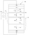
이제 도 1을 참조하면, 자기 메모리 요소(100)는 수직 자기 터널 접합(pMTJ) 메모리 요소의 형태일 수 있다. 자기 메모리 요소는 자기 기준층(102), 자기 자유층(104), 및 자기 기준층(102)과 자기 자유층(104) 사이에 위치된 얇은 비-자기 전기 절연 자기 장벽층(106)을 포함할 수 있는 MTJ 접합(101)을 포함할 수 있다. 자기 기준층은 화살표(108)로 표시된 바와 같이 층의 평면에 바람직하게 수직인 방향으로 고정된 자화(108)를 갖는다. 자기 자유층은 층(104)의 평면에 수직인 2개의 방향 중 어느 하나일 수 있는 자화(110)를 갖는다. 자유층의 자화(110)는 정지(quiescent) 상태에서 층(104)의 평면에 직교하는 2개의 방향 중 하나로 유지되지만, 이것은 이하 여기에서 더 상세히 설명되는 바와 같이 이들 2개의 방향 사이에서 이동될 수 있다. 자기 자유층(104)의 자화(110)가 기준층(102)의 자화(108)와 동일한 방향에 있을 때, 층(102, 106, 104)에 걸친 전기 저항은 저 저항 상태에 있다. 반대로, 자유층(104)의 자화(110)가 기준층(102)의 자화(108)와 반대일 때, 층(102, 106, 104)에 걸친 전기 저항은 고 저항 상태에 있다.Referring now to FIG. 1, the
자기 기준층(102)은 자기 키퍼(keeper) 층(114), 및 키퍼층(114)과 기준층(102) 사이에 위치된 비-자기 반평행 결합층(116)을 포함할 수 있는 반평행 자기 피닝(pinning) 구조(112)의 일부일 수 있다. 반평행 결합층(116)은 Ru와 같은 재료일 수 있고, 층(114, 102)을 강자기 반평행 결합시키도록 하는 두께를 갖도록 구성될 수 있다. 층(114, 102) 사이의 반평행 결합은 기준층(102)의 자화(108)를 키퍼층(114)의 자화 방향(118)에 반대되는 방향으로 피닝한다.The
시드(seed) 층(120)은 위에 피착된 층들에서 원하는 결정 구조를 시작하기 위해 메모리 요소(100)의 하부 근처에 제공될 수 있다. 캡핑(capping) 층(122)은 고온 어닐링과 같은 제조 동안 하지의 층을 보호하기 위해 메모리 요소(100)의 상부 근처에 제공될 수 있다. 또한, 전극(124, 126)은 메모리 요소(100)의 상부 및 하부에 제공될 수 있다. 전극(124, 126)은 Cu와 같은 비-자기 전기 도전성 재료로 구성될 수 있고, 전류원을 포함하고 메모리 요소(100)에 걸친 전기 저항을 판독하기 위한 회로를 더 포함할 수 있는 회로(128)와의 전기적 연결을 제공할 수 있다.A
자기 자유층(104)은 자유층(104)의 자화(110)가 자유층(104)의 평면에 수직 인 2개의 방향 중 하나의 방향으로 안정적으로 유지되게 하는 자기 이방성을 갖는다. 기입 모드에서, 자유층(104)의 자화(110)의 방위는 회로(128)로부터 메모리 요소(100)를 통해 전류를 인가함으로써 이들 2개의 방향 사이에서 스위칭될 수 있다. 한 방향으로의 전류는 메모리 요소가 제1 방위로 반전되게 하고 반대 방향의 전류는 자화를 반대되는 제2 방향으로 반전되게 할 것이다. 예를 들어, 도 1에서 자화(110)가 처음에 하향 방향의 방위로 있다면, 요소(100)를 통해 하향 방향으로 전류를 인가하는 것은 전자가 요소(100)를 통해 반대 방향으로 위로 흐르게 할 것이다. 기준층(102)을 통해 이동하는 전자는 기준층(102)의 자화(108)의 결과로서 스핀 분극될 것이다. 이들 스핀 분극된 전자는 자유층(104)의 자화(110)에 스핀 토크를 유발하여, 자화가 방향을 반전되게 한다.The magnetic
한편, 자유층(104)의 자화(110)가 초기에 도 1에서 상향 방향에 있다면, 요소(100)를 통해 상향 방향으로 전류를 인가하는 것은 전자가 반대 방향으로 요소(100)를 통해 하향으로 흐르게 할 것이다. 그러나, 자유층(104)의 자화(110)가 기준층(102)의 자화(108)와 반대이기 때문에, 반대 스핀을 갖는 전자는 장벽층(106)을 통해 기준층(102)으로 통과할 수 없을 것이다. 결과적으로, 반대 스핀을 갖는 전자는 자유층(104)과 장벽층(106) 사이의 접합에 축적될 것이다. 스핀 분극된 전자의 이러한 축적은 자유층(104)의 자화(110)를 하향 방향에서 상향 방향으로 반전되게 하는 스핀 토크를 야기한다.On the other hand, if the
자유층(104)의 자화(110)의 스위칭을 보조하기 위해, 메모리 요소(100)는 자유층(104) 위에 형성된 스핀 분극층(130)을 포함할 수 있다. 스핀 분극층은 교환 결합층(132)에 의해 자유층(104)으로부터 분리될 수 있다. 스핀 분극층(130)은 평면 방향의 방위로 있는(예를 들어, 자유층 및 기준층(104, 102)의 자화(110, 108)에 수직) 일차 성분을 갖는 자화(134)를 갖도록 하는 자기 이방성을 갖는다. 스핀 분극층(130)의 자화(134)는 도 100에 도시된 바와 같이 고정되거나 세차 방식으로 움직일 수 있다. 스핀 분극층(130)의 자화(134)는 자유층(104)의 평면에 수직인 정지 상태로부터 자화를 멀어지게 이동시키는 것을 보조하는 스핀 토크를 자유층(104)에 유발한다. 이것은 메모리 요소(100)에 기입 전류를 인가할 때 보다 적은 에너지를 사용하여 보다 쉽게 자유층(104)의 자화(110)가 반전할 수 있게 한다.To assist in switching the
도 2는 메모리 칩의 일부의 측단면도를 도시한다. 하나 이상의 MRAM 메모리 요소(202)는 CMOS 반도체 회로 요소(204)와 같은 회로의 상부에 형성될 수 있다. MRAM 메모리 요소(202)는 반도체 회로 요소(204)의 필라 구조로서 형성될 수 있고, 다수의 MRAM 요소/회로 요소 조합(202/204)은 반도체 기판(206) 위에 단일 메모리 칩(200) 상에 포함될 수 있다.2 shows a cross-sectional side view of a portion of a memory chip. One or more
자기 랜덤 액세스 메모리(MRAM)는 다른 유형의 데이터 메모리로는 이용할 수없는 고유한 성능 및 내구성 속성을 제공한다. 따라서 MRAM은 다른 유형의 데이터 메모리를 대체하거나 확장할 수 있다. 예를 들어, MRAM 데이터 스토리지는 NVM(Non-Volatile Memory) 플래시 및/또는 SRAM(Static Random Access Memory)과 같은 기존의 상이한 유형의 메모리 구조를 대체하는 데 사용할 수 있다. 그러나, 이러한 상이한 유형의 메모리는 상이한 성능 메트릭을 갖는다. 예를 들어, 명칭이 제시하는 바와 같이 NVM 메모리 셀은 데이터가 장기간(즉, 125℃에서 10년) 기록된 채로 유지할 것을 요구하는 것과 같은 높은 보존을 요구할 수 있다. 그러나, 이 높은 보존은 메모리 셀이 이의 수명중에 스위칭될 수 있는 횟수로 측정되는 바와 같은 더 낮은 내구성과 더 낮은 기록 속도를 갖는 것의 트레이드오프가 수반될 수 있다. 반면에 SRAM 메모리는 훨씬 더 빠른 속도 및 여러번 기록 및 스위칭할 수 있는 능력(즉, 높은 내구성)에 대한 필요성을 갖지만 전기 파워를 인가하지 않고 몇분에서 며칠 동안만 데이터를 보존하는 것과 같이 낮은 보존을 가질 수 있다.Magnetic random access memory (MRAM) offers unique performance and endurance properties not available with other types of data memory. Thus, MRAM can replace or expand other types of data memory. For example, MRAM data storage can be used to replace existing different types of memory structures such as Non-Volatile Memory (NVM) Flash and/or Static Random Access Memory (SRAM). However, these different types of memory have different performance metrics. For example, as the name suggests, NVM memory cells may require high preservation, such as requiring data to remain recorded for long periods (ie, 10 years at 125°C). However, this high retention may be accompanied by a tradeoff between having a lower endurance and a lower write speed as measured by the number of times a memory cell can be switched during its lifetime. SRAM memory, on the other hand, has a need for much higher speeds and the ability to write and switch multiple times (i.e., high endurance), but low retention, such as retaining data only for minutes to days without applying electrical power. I can.
NVM 및 SRAM 응용과 같은 기존의 데이터 유형을 효과적으로 대체하기 위해, 이용된 MRAM 스토리지 셀은 이들 상이한 성능 메트릭을 충족시키거나 초과하도록 구성될 것이 바람직하다. MRAM 셀의 구조는 어느 하나의 성능 요구사항을 충족시키도록 수정 및 구성될 수 있으며, 많은 응용에서 단일 메모리 칩 상에 이들 상이한 성능 특징을 제공하는 MRAM 셀을 갖는 것이 바람직할 수 있다.In order to effectively replace existing data types such as NVM and SRAM applications, it is desirable that the used MRAM storage cells be configured to meet or exceed these different performance metrics. The structure of an MRAM cell can be modified and configured to meet any one performance requirement, and in many applications it may be desirable to have an MRAM cell that provides these different performance characteristics on a single memory chip.
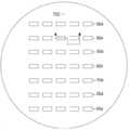
도 3은 예시적인 자기 메모리 칩(300)의 평면도를 도시한다. 메모리 칩(300)은 각각 상이한 메모리 요소 특징을 갖는 제1 및 제2 메모리 어레이(302, 304)를 포함한다. 예를 들어, 제1 영역(302)은 비휘발성 메모리(NVM)를 에뮬레이트하는 성능 특징을 갖는 복수의 제1 MRAM 메모리 요소(306)를 포함할 수 있다. 영역(304)은 정적 랜덤 액세스 메모리(SRAM)의 것들을 에뮬레이트하는 성능 특징을 갖는 제2 복수의 MRAM 메모리 요소(308)를 포함할 수 있다. 메모리 요소(306, 308) 각각은 CMOS 회로(도 3에는 도시되지 않음)와 같은 하지의 회로 상에 형성되고 이에 전기적으로 연결될 수 있다. 메모리 요소(306, 308)는 칩 기판(310) 상에 형성될 수 있다.3 is a plan view of an exemplary
단일 메모리 칩 상에 상이한 물리적 및 성능 특징을 갖는 MRAM 메모리 요소의 통합은 기판상의 동일 구축 레벨에서 상이한 메모리 요소가 공통 기판 상에 형성되어야 하기 때문에 제조 과제를 제시한다. 이러한 과제는 상이한 물리적 및 성능 특징을 갖는 메모리 요소를 갖는 메모리 칩을 제조하는 방법을 도시하는 도 4-도 13을 참조하여 해결된다.The integration of MRAM memory elements with different physical and performance characteristics on a single memory chip presents a manufacturing challenge because different memory elements must be formed on a common substrate at the same build level on the substrate. This problem is solved with reference to FIGS. 4-13, which illustrate a method of manufacturing a memory chip with memory elements having different physical and performance characteristics.
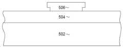
도 4는 제조의 중간 단계에서의 웨이퍼의 평면도를 도시하고, 도 5는 도 4의 선 5-5에서 본 확대된 단면도이다. 도 5에서 더 명백히 보이는 바와 같이, 제1 MRAM 요소 유형을 구성하는 재료층(504)은 CMOS 회로(도 5에 도시되지 않음)와 같은 회로를 포함할 수 있는 반도체 기판과 같은 기판(502) 위에 피착된다. 층(504)이 단일층으로서 도 5에 도시되어 있지만, 이는 간략화 및 명확성을 위한 것이며, 층(504)은 도 1을 참조하여 설명된 것과 같은 MRAM 요소를 구성하게 될 것들과 같은 다수의 층을 포함할 수 있음을 이해해야 한다.FIG. 4 is a plan view of the wafer in an intermediate stage of manufacturing, and FIG. 5 is an enlarged cross-sectional view taken along line 5-5 of FIG. 4. As more clearly seen in FIG. 5, the
제1 메모리 요소층(504)이 피착된 후에, 마스크 구조(506)는 층(504) 위에 형성된다. 마스크 구조는 바람직하게는 도시된 바와 같이 돌출한 에지를 갖는 이중층 리프트 오프 마스크인데, 이는 아래에서 더 명확해지는 바와 같이 이후의 마스크의 리프트오프를 용이하게 할 것이다. 마스크(506)는 포토리소그래피 패터닝되고 원하는 형상을 갖도록 현상될 수 있는 하나 이상의 포토레지스트층으로 구성될 수 있다. 평면도를 도시하는 도 4에서, 마스크 구조(506)가 제1 MRAM 유형 어레이를 정의할 영역을 커버하도록 형성됨을 알 수 있다. 이것은 NVM 또는 SRAM 성능 메트릭을 충족하는 센서 영역일 수도 있을 것이다.After the first
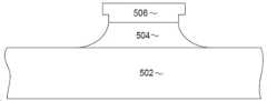
이어서, 마스크(506)에 의해 보호되지 않는 제1 MRAM 요소 재료(504)의 일부를 제거하기 위해 이온 빔 에칭 또는 반응성 이온 에칭과 같은 재료 제거 프로세스가 수행되어, 도 6에 도시된 것과 같은 구조를 남긴다. 남은 재료(504)의 외부 에지는 도시된 바와 같이 불완전한 접합 형상을 가질 수 있다. 그러나 이 부분은 나중에 볼 수 있듯이 제거될 것이다.Subsequently, a material removal process such as ion beam etching or reactive ion etching is performed to remove a portion of the first
도 7을 참조하면, 제2 MRAM 요소 재료층(702)이 풀 필름으로 피착된다. 다시, 층(702)은 단일층으로서 도시되어 있지만, 실제로는 도 1을 참조하여 전술한 것과 같은 MRAM 센서를 형성하는데 필요한 다양한 층을 포함할 수 있다. 제2 MRAM층(702)을 피착한 후, 마스크(506)는 리프트 오프될 수 있어, 도 8에 도시된 것과 같은 구조를 남긴다. 마스크(506)는 이중층 마스크로서 구성되기 때문에, 제2 MRAM층(702)의 피착은 도 7에 도시된 바와 같이, 마스크를 마스크(506)의 외부 에지에서 노출시키기 위한 개구를 남길 것이다. 이는 예를 들어 화학적 리프트오프 프로세스에 의해 수행될 수 있는 마스크(506)의 제거를 용이하게 한다.Referring to Fig. 7, a second MRAM
도 9는 도 8의 선 9-9에서 본 평면도를 도시하지만, 전체 웨이퍼를 도시하도록 확대되었다. 도 9에서, 이전에 수행된 피착 및 마스크 리프트오프 프로세스는 제2 MRAM 재료(702)의 영역으로 둘러싸인 제1 MRAM 재료(504)의 정의된 영역을 남겨둔다는 것을 알 수 있다. 제2 MRAM 재료는 본질적으로 제1 MRAM 재료(504)로 커버되지 않은 모든 영역을 커버하여, 제2 MRAM 재료(702)가 제1 MRAM 재료(504)의 영역을 둘러싸도록 한다. 이 시점에서, 도 1을 참조하여 전술한 키퍼 및 기준층(102, 114)의 자화를 설정하기 위해 필요에 따라 하나 이상의 어닐링 프로세스가 수행될 수 있다. 어닐링 프로세스는 10분 내지 60분 동안 300 내지 400 ℃와 같은 층(102, 114)의 재료의 최적 결정화 온도 또는 그 이상의 온도로 웨이퍼를 가열하는 것을 포함할 수 있다.Fig. 9 shows a plan view as seen from line 9-9 of Fig. 8, but is enlarged to show the entire wafer. In FIG. 9, it can be seen that the deposition and mask liftoff process performed previously leaves a defined area of the
따라서, 이 시점에서 웨이퍼는 웨이퍼 상의 다른 곳의 제1 MRAM 재료(504) 및 제2 MRAM 재료(702)의 정의된 영역을 포함한다. 두 영역에서, 제1 및 제2 MRAM층(504, 702)은 매우 유사한 두께 및 재료를 갖는다. 따라서, MRAM 필라를 정의하기 위한 표준 프로세스는 두 유형의 MRAM 재료 모두에 대해 양호한 결과를 갖고 두 영역 모두에서 동시에 수행될 수 있다.Thus, at this point the wafer includes a defined area of
도 10은 도 9의 선 10-10으로부터 취한 단면도를 도시한다. 도 9로부터, 도 10에 도시된 단면은 제1 및 제2 MRAM 디바이스 영역을 모두 보이기 위해 곧바른 단면이 아니라 엇갈려 있는 것을 알 수 있다. 도 10을 참조하면, 다이아몬드 유사 탄소 DLC(1002)와 같은 하드 마스크 재료층이 제1 및 제2 MRAM 재료(502, 702) 위에 피착된다. 포토레지스트 마스크(1004)는 하드 마스크(1002) 위에 형성된다. 포토레지스트 마스크(1004)는 Si를 포함하는 포토레지스트와 같은 유리형 포토레지스트층상에서 스피닝함으로써 형성될 수 있다. 이어 이 포토레지스트 재료(1004)는 보여지는 바와 같이 MRAM 필라를 정의할 개별 필라를 갖는 마스크 형상을 정의하기 위해 포토리소그래피에 의해 패터닝되고 현상된다. 포토레지스트 마스크는 제1 MRAM 유형 영역이 될 영역(1006) 및 제2 MRAM 유형 영역이 될 영역(1008)에서 이러한 필라를 정의한다는 것을 알 수 있다. 포토레지스트의 패터닝은 임의의 원하는 형상으로 행해질 수 있고 각각의 MRAM 영역(1006, 1008)에서 상이한 필라 형상 및 크기를 정의할 수 있다.10 shows a cross-sectional view taken from line 10-10 in FIG. 9; From FIG. 9, it can be seen that the cross-sections shown in FIG. 10 are not straight cross-sections to show both the first and second MRAM device regions, but are staggered. Referring to FIG. 10, a layer of a hard mask material such as a diamond-
이제 도 11을 참조하면, 포토레지스트 마스크(1004)의 패턴은 하지의 하드 마스크(1002)로 전사될 수 있다. 이것은 예를 들어 우선적으로 하드 마스크 재료층(1002)을 제거할 화합물에서 반응성 이온 에칭(RIE)을 수행함으로써 수행될 수 있다.Referring now to FIG. 11, the pattern of the
일단 포토레지스트 마스크 패턴(1004)이 하드 마스크층(1002)으로 전사되면, 재료 제거 프로세스는 하드 마스크(1002)에 의해 보호되지 않는 제1 및 제2 MRAM 재료(504, 702)의 일부를 제거하기 위해 수행될 수 있어 도 12에 도시된 것과 같은 구조를 남긴다. 이 프로세스는 이온 빔 에칭을 사용하여 수행될 수 있다. 포토레지스트 마스크(1004)의 일부 또는 전부가 이 프로세스에 의해 제거될 수 있지만, 하드 마스크(1002)는 그대로 유지되어 MRAM 재료(504, 702)의 필라를 정밀하게 정의할 것이다. 다시, 제1 및 제2 MRAM층(504, 702)은 유사한 두께를 갖는 유사한 재료로 구성되기 때문에, 재료 제거 프로세스(예를 들어, 이온 빔 에칭)은 본질적으로 동일한 결과 및 재료 제거 레이트로 재료(504, 702) 모두에서 동시에 수행될 수 있다.Once the
재료의 필라(504, 702)가 정의된 후에, 알루미나(1302)와 같은 절연성 충전층은 원자층 피착(ALD)과 같은 컨포멀 피착 프로세스에 의해 피착될 수 있고, 화학 기계식 폴리싱(CMP)와 같은 평탄화 프로세스가 수행되 수 있어, 도 13에 도시된 것과 같은 구조를 남긴다. 절연성 충전 재료(1302)의 컨포멀 피착은 영역(1006, 1008) 사이의 공간을 충전할 뿐만 아니라 영역(1006, 1008) 각각에서 개별 필라(504, 702) 사이의 영역을 채우도록 수행될 수 있다. 평탄화 프로세스(즉, 화학적 기계식 폴리싱)은 개별 필라(504, 702))의 상부와 전기적 접촉이 될 수 있도록 필라(504, 702)의 상부를 노출시키기에 충분히 수행될 수 있다.After the
도 14-도 20은 상이한 성능 특징을 갖는 MRAM 요소의 영역을 형성하기 위한 대안적 방법을 도시한다. 이 대안적 방법은 마스크 리프트오프 프로세스를 이용한다. 도 14를 참조하면, 기판(1402)이 웨이퍼 상에 형성된다. 전술한 바와 같이, 이 기판은 CMOS 요소(도시되지 않음)와 같은 회로를 포함할 수 있다. 포토레지스트 마스크 재료층(1404)은 기판(1402) 위에 피착된다. 마스크층은 이중층 리프트-오프 구조(도시되지 않음)일 수 있고, 다른 재료층도 포함할 수도 있을 것이다.14-20 illustrate an alternative method for forming regions of MRAM elements with different performance characteristics. This alternative method uses a mask liftoff process. 14, a
도 15를 참조하면, 포토레지스트 마스크 재료는 제1 MRAM 영역을 정의할 영역에 개구를 남기게 마스크 재료를 제거하기 위해 포토리소그래피로 패터닝되고 현상된다. 이어, 도 16을 참조하면, 제1 MRAM 재료의 층이 웨이퍼 위에 풀 필름으로 피착된다. 전술한 바와 같이, 단일층으로서 도시되어 있지만, 제1 MRAM 재료(1602)는 제1 세트의 성능 특징을 갖는 하나 이상의 MRAM 요소를 구성하기 위해 사용되는 다양한 재료층을 포함한다. 재료(1602)는 마스크(1404)의 상부 위 뿐만 아니라 마스크(1404)의 개구에 피착될 것이다.Referring to FIG. 15, a photoresist mask material is photolithographically patterned and developed to remove the mask material to leave an opening in an area to define a first MRAM area. Next, referring to FIG. 16, a layer of the first MRAM material is deposited as a full film on the wafer. As described above, although shown as a single layer,
이어서, 마스크(1404)는 리프트오프되어, 마스크(1404) 위에 형성된 재료를 제거하고, 제1 마스크(1404) 내 개구에 의해 정의된 영역에만 제1 MRAM 재료(1602)를 갖는 도 17에 도시된 바와 같은 구조를 남길 수 있다. 이어, 도 18을 참조하면, 남은 재료(1602)의 영역 위에 제2 리프트오프 마스크(1802)가 형성된다. 마스크(1802)에 의해 정의된 외부 에지에서의 영역이 필라 정의 동안 제거될 것이기 때문에, 이 마스크(1802)의 완벽한 정렬은 중요하지 않다. 제2 마스크(1802)는 추가 재료층 피착후 리프트오프를 용이하게 하기 위해 이중층 포토레지스트 마스크일 수 있다.The
마스크(1802)를 형성한 후, 도 19에 도시된 바와 같이, 제2 MRAM 재료층(1902)이 풀 필름으로 피착된다. 다시, 이 층(1902)은 제2 세트의 성능 특징을 갖는 원하는 MRAM 요소를 형성하기 위해 필요한 다양한 재료층을 포함할 수 있다. 재료(1902)의 피착 후에, 마스크(1802)는 화학적 리프트오프와 같은 프로세스에 의해 리프트 오프될 수 있어, 도 20에 도시된 바와 같은 구조를 남긴다. 도 20에서, 2 개의 층(1602, 1902)의 접합에서의 영역(괄호(2002)로 도시됨)은 MRAM 필라 형성을 정의하기 위해 추가 처리 동안 이들 영역이 제거될 것이기 때문에 엄밀하게 위치되거나 완벽하게 매끄러울 필요가 없다.After forming the
도 20에 도시된 바와 같이 2개의 MRAM 재료층(1602, 1902)을 형성한 후, 원하는 MRAM 필라를 정의하기 위해 추가 처리가 수행될 수 있다. 이들 필라 정의 프로세스는 도 9-도 13을 참조하여 전술한 것과 유사할 수 있다.After forming the two
전술한 프로세스는 메모리 칩의 상이한 영역 상에 상이한 성능 특징을 갖는 센서를 형성하기 위한 효율적이고 비용 효과적인 수단을 제공한다. 이들 프로세스는 MRAM 요소를 사용하여 비휘발성 메모리(NVM) 및 정적 랜덤 액세스 메모리(SRAM) 대체를 형성하기 위한 방법으로서 설명되었지만, 이는 예시적인 실시예에 의한 것이다. 상이한 특징을 갖는 다른 유형의 자기 메모리 요소도 이러한 방식으로 제조될 수 있을 것이다. 또한, 위의 프로세스는 단지 2개의 상이한 유형의 MRAM 요소를 제조하는 방법으로서 설명되었지만, 더 많은 수의 상이한 유형의 MRAM 요소가 전술한 프로세스에 의해 구성될 수도 있을 것이다.The process described above provides an efficient and cost effective means for forming sensors with different performance characteristics on different areas of a memory chip. These processes have been described as methods for forming nonvolatile memory (NVM) and static random access memory (SRAM) replacements using MRAM elements, but by way of example embodiments. Other types of magnetic memory elements with different characteristics could also be manufactured in this way. Also, although the above process has been described as a method of manufacturing only two different types of MRAM elements, a greater number of different types of MRAM elements may be configured by the above-described process.
다양한 실시예가 위에서 설명되었지만, 이들은 단지 예로서 제시된 것이며 제한적이지 않은 것으로 이해되어야 한다. 본 발명의 범위 내에 속하는 다른 실시예도 당업자에게 명백할 수 있다. 따라서, 본 발명의 폭 및 범위는 전술한 예시적인 실시예들 중 어느 것에 의해서도 제한되지 않아야 하고, 다음의 청구 범위 및 그 등가물에 따라서만 정의되어야 한다.While various embodiments have been described above, it is to be understood that these have been presented by way of example only and not limiting. Other embodiments that fall within the scope of the present invention may be apparent to those skilled in the art. Accordingly, the breadth and scope of the present invention should not be limited by any of the above-described exemplary embodiments, but should be defined only in accordance with the following claims and their equivalents.
Claims (20)
Translated fromKorean기판을 제공하는 단계;
제1 자기 메모리 요소 유형 재료를 피착하는 단계;
상기 제1 자기 메모리 요소 유형 재료 위에 마스크를 형성하는 단계 - 상기 마스크는 제1 자기 요소 유형 영역을 정의함 -;
상기 마스크에 의해 보호되지 않는 상기 제1 자기 요소 유형 재료의 부분들을 제거하기 위해 재료 제거 프로세스를 수행하는 단계;
제2 자기 요소 유형 재료를 피착하는 단계; 및
상기 마스크를 제거하는 단계를 포함하는, 방법.As a method of forming a data memory chip,
Providing a substrate;
Depositing a first magnetic memory element type material;
Forming a mask over the first magnetic memory element type material, the mask defining a first magnetic element type region;
Performing a material removal process to remove portions of the first magnetic element type material that are not protected by the mask;
Depositing a second magnetic element type material; And
And removing the mask.
하드 마스크를 피착하는 단계;
어닐링을 수행하는 단계;
상기 제1 자기 요소 유형 영역에 및 또한 제2 자기 요소 유형 영역에 자기 요소들을 정의하도록 구성된 자기 요소 정의 마스크를 형성하는 단계; 및
상기 자기 요소 정의 마스크에 의해 보호되지 않는 상기 제1 자기 요소 유형 재료 및 상기 제2 자기 요소 유형 재료의 부분들을 제거하기 위해 제2 재료 제거 프로세스를 수행하는 단계를 더 포함하는, 방법.The method of claim 1, after removing the mask:
Applying a hard mask;
Performing annealing;
Forming a magnetic element defining mask configured to define magnetic elements in the first magnetic element type region and also in the second magnetic element type region; And
Further comprising performing a second material removal process to remove portions of the first magnetic element type material and the second magnetic element type material that are not protected by the magnetic element definition mask.
기판을 제공하는 단계;
상기 기판 위에 제1 마스크 구조를 형성하는 단계 - 상기 마스크 구조는 제1 자기 메모리 유형 영역을 정의하도록 구성된 개구를 가짐 -;
제1 자기 메모리 유형 재료를 피착하는 단계;
상기 마스크를 제거하여, 제1 메모리 유형 영역에 제1 자기 메모리 유형 재료를 남기는 단계;
제2 마스크를 형성하는 단계 - 상기 제2 마스크의 적어도 일부는 상기 제1 메모리 유형 영역에 상기 제1 자기 메모리 유형 재료 위에 형성됨 -;
제2 자기 메모리 유형 재료를 피착하는 단계; 및
상기 제2 마스크를 제거하는 단계를 포함하는, 방법.As a method of manufacturing a data memory chip,
Providing a substrate;
Forming a first mask structure over the substrate, the mask structure having an opening configured to define a first magnetic memory type region;
Depositing a first magnetic memory type material;
Removing the mask, leaving a first magnetic memory type material in a first memory type region;
Forming a second mask, wherein at least a portion of the second mask is formed over the first magnetic memory type material in the first memory type region;
Depositing a second magnetic memory type material; And
And removing the second mask.
하드 마스크를 피착하는 단계;
어닐링을 수행하는 단계;
상기 제1 자기 메모리 유형 영역에 및 제2 자기 메모리 유형 영역에 자기 필라들을 정의하도록 구성된 제3 마스크 구조를 형성하는 단계; 및
상기 제3 마스크에 의해 보호되지 않는 상기 제1 및 제2 자기 메모리 유형 재료를 모두 제거하기 위해 재료 제거 프로세스를 수행하는 단계를 더 포함하는, 방법.The method of claim 8, after removing the second mask:
Applying a hard mask;
Performing annealing;
Forming a third mask structure configured to define magnetic pillars in the first magnetic memory type region and in the second magnetic memory type region; And
And performing a material removal process to remove both the first and second magnetic memory type material not protected by the third mask.
Applications Claiming Priority (3)
| Application Number | Priority Date | Filing Date | Title |
|---|---|---|---|
| US15/859,451 | 2017-12-30 | ||
| US15/859,451US10211395B1 (en) | 2017-12-30 | 2017-12-30 | Method for combining NVM class and SRAM class MRAM elements on the same chip |
| PCT/US2018/067084WO2019133479A1 (en) | 2017-12-30 | 2018-12-21 | Method for combining nvm class and sram class mram elements on the same chip |
Publications (2)
| Publication Number | Publication Date |
|---|---|
| KR20200097349Atrue KR20200097349A (en) | 2020-08-18 |
| KR102198742B1 KR102198742B1 (en) | 2021-01-07 |
Family
ID=65322787
Family Applications (1)
| Application Number | Title | Priority Date | Filing Date |
|---|---|---|---|
| KR1020207022170AActiveKR102198742B1 (en) | 2017-12-30 | 2018-12-21 | How to combine NVM class and SRAM class MRAM elements on the same chip |
Country Status (6)
| Country | Link |
|---|---|
| US (1) | US10211395B1 (en) |
| JP (1) | JP6860748B2 (en) |
| KR (1) | KR102198742B1 (en) |
| CN (1) | CN111480242B (en) |
| SG (1) | SG11202003131RA (en) |
| WO (1) | WO2019133479A1 (en) |
Families Citing this family (2)
| Publication number | Priority date | Publication date | Assignee | Title |
|---|---|---|---|---|
| US10903002B2 (en)* | 2019-04-29 | 2021-01-26 | Spin Memory, Inc. | Method for manufacturing a magnetic memory element using Ru and diamond like carbon hard masks |
| US10916696B2 (en)* | 2019-05-01 | 2021-02-09 | Spin Memory, Inc. | Method for manufacturing magnetic memory element with post pillar formation annealing |
Citations (9)
| Publication number | Priority date | Publication date | Assignee | Title |
|---|---|---|---|---|
| US20020006674A1 (en)* | 1999-12-22 | 2002-01-17 | Shawming Ma | Hydrogen-free contact etch for ferroelectric capacitor formation |
| US20090197208A1 (en)* | 2008-01-31 | 2009-08-06 | Vladimir Nikitin | Method for manufacturing a perpendicular magnetic write pole using an electrical lapping guide for tight write pole flare point control |
| US20090244789A1 (en)* | 2008-04-01 | 2009-10-01 | Westem Digital (Fremont), Llc | Method and system for providing a hard bias capping layer |
| US8747680B1 (en)* | 2012-08-14 | 2014-06-10 | Everspin Technologies, Inc. | Method of manufacturing a magnetoresistive-based device |
| US20150287911A1 (en)* | 2014-04-03 | 2015-10-08 | Kyoung-Sun Kim | Methods of manufacturing a magnetoresistive random access memory device |
| US20160351792A1 (en)* | 2015-05-26 | 2016-12-01 | Globalfoundries Singapore Pte. Ltd. | Magnetic shielding for mtj device or bit |
| US20170256708A1 (en)* | 2016-03-07 | 2017-09-07 | Samsung Electronics Co., Ltd. | Method and system for providing a magnetic junction usable in spin transfer torque applications using multiple stack depositions |
| US20170279037A1 (en)* | 2016-03-22 | 2017-09-28 | Kabushiki Kaisha Toshiba | Magnetic memory device and nonvolatile memory apparatus |
| US20170324025A1 (en)* | 2016-05-03 | 2017-11-09 | Kilho Lee | Data storage devices and methods for manufacturing the same |
Family Cites Families (7)
| Publication number | Priority date | Publication date | Assignee | Title |
|---|---|---|---|---|
| KR100399436B1 (en)* | 2001-03-28 | 2003-09-29 | 주식회사 하이닉스반도체 | A Magnetic random access memory and a method for manufacturing the same |
| US7368299B2 (en)* | 2004-07-14 | 2008-05-06 | Infineon Technologies Ag | MTJ patterning using free layer wet etching and lift off techniques |
| CN101459218B (en)* | 2007-12-13 | 2011-01-12 | 中芯国际集成电路制造(上海)有限公司 | Annular semiconductor device and producing method thereof |
| FR3027450B1 (en)* | 2014-10-20 | 2016-11-04 | Commissariat Energie Atomique | HYBRID NON-VOLATILE MEMORY DEVICE AND METHOD FOR MANUFACTURING SUCH A DEVICE |
| US9614003B1 (en)* | 2015-10-21 | 2017-04-04 | Globalfoundries Inc. | Method of forming a memory device structure and memory device structure |
| US9653295B1 (en)* | 2016-01-07 | 2017-05-16 | Taiwan Semiconductor Manufacturing Co., Ltd. | Method of manufacturing a static random access memory |
| US10038137B2 (en)* | 2016-09-30 | 2018-07-31 | Taiwan Semiconductor Manufacturing Co., Ltd. | MRAM device and method for fabricating the same |
- 2017
- 2017-12-30USUS15/859,451patent/US10211395B1/enactiveActive
- 2018
- 2018-12-21SGSG11202003131RApatent/SG11202003131RA/enunknown
- 2018-12-21CNCN201880081072.XApatent/CN111480242B/enactiveActive
- 2018-12-21WOPCT/US2018/067084patent/WO2019133479A1/ennot_activeCeased
- 2018-12-21JPJP2020536182Apatent/JP6860748B2/enactiveActive
- 2018-12-21KRKR1020207022170Apatent/KR102198742B1/enactiveActive
Patent Citations (9)
| Publication number | Priority date | Publication date | Assignee | Title |
|---|---|---|---|---|
| US20020006674A1 (en)* | 1999-12-22 | 2002-01-17 | Shawming Ma | Hydrogen-free contact etch for ferroelectric capacitor formation |
| US20090197208A1 (en)* | 2008-01-31 | 2009-08-06 | Vladimir Nikitin | Method for manufacturing a perpendicular magnetic write pole using an electrical lapping guide for tight write pole flare point control |
| US20090244789A1 (en)* | 2008-04-01 | 2009-10-01 | Westem Digital (Fremont), Llc | Method and system for providing a hard bias capping layer |
| US8747680B1 (en)* | 2012-08-14 | 2014-06-10 | Everspin Technologies, Inc. | Method of manufacturing a magnetoresistive-based device |
| US20150287911A1 (en)* | 2014-04-03 | 2015-10-08 | Kyoung-Sun Kim | Methods of manufacturing a magnetoresistive random access memory device |
| US20160351792A1 (en)* | 2015-05-26 | 2016-12-01 | Globalfoundries Singapore Pte. Ltd. | Magnetic shielding for mtj device or bit |
| US20170256708A1 (en)* | 2016-03-07 | 2017-09-07 | Samsung Electronics Co., Ltd. | Method and system for providing a magnetic junction usable in spin transfer torque applications using multiple stack depositions |
| US20170279037A1 (en)* | 2016-03-22 | 2017-09-28 | Kabushiki Kaisha Toshiba | Magnetic memory device and nonvolatile memory apparatus |
| US20170324025A1 (en)* | 2016-05-03 | 2017-11-09 | Kilho Lee | Data storage devices and methods for manufacturing the same |
Also Published As
| Publication number | Publication date |
|---|---|
| SG11202003131RA (en) | 2020-05-28 |
| CN111480242B (en) | 2022-01-28 |
| JP2021507543A (en) | 2021-02-22 |
| KR102198742B1 (en) | 2021-01-07 |
| CN111480242A (en) | 2020-07-31 |
| US10211395B1 (en) | 2019-02-19 |
| JP6860748B2 (en) | 2021-04-21 |
| WO2019133479A1 (en) | 2019-07-04 |
Similar Documents
| Publication | Publication Date | Title |
|---|---|---|
| JP6933683B2 (en) | How to manufacture magnetoresistive random access memory | |
| US9721990B2 (en) | Magnetic tunnel junction and 3-D magnetic tunnel junction array | |
| KR101459511B1 (en) | Magnetic stack design | |
| US11257862B2 (en) | MRAM having spin hall effect writing and method of making the same | |
| US20160149124A1 (en) | Mram having spin hall effect writing and method of making the same | |
| US9461243B2 (en) | STT-MRAM and method of manufacturing the same | |
| US9755141B2 (en) | Method for fabricating MRAM bits on a tight pitch | |
| US9087983B2 (en) | Self-aligned process for fabricating voltage-gated MRAM | |
| JP7700239B2 (en) | High-density spin-orbit magnetic random access memory | |
| US9412935B1 (en) | Method for fabricating magnetic tunnel junction and 3-D magnetic tunnel junction array | |
| KR102337388B1 (en) | Magnetic cell, magnetic memory and method for their manufacture | |
| KR102350684B1 (en) | Method for fabricating magnetic junction, and magnetic memory | |
| KR102198742B1 (en) | How to combine NVM class and SRAM class MRAM elements on the same chip | |
| US20060228853A1 (en) | Memory devices including spacers on sidewalls of memory storage elements and related methods | |
| US10388860B2 (en) | Method for manufacturing high density magnetic random access memory devices using diamond like carbon hard mask | |
| US11329099B2 (en) | Magnetic memory chip having nvm class and SRAM class MRAM elements on the same chip | |
| CN113826216B (en) | Method for manufacturing magnetic memory element using Ru and diamond-like carbon hard mask | |
| US20190207107A1 (en) | Method for manufacturing reduced pitch magnetic random access memory pillar | |
| US10608047B1 (en) | Magnetic memory element with voltage controlled magnetic anistropy | |
| US10607902B2 (en) | Method for measuring proximity effect on high density magnetic tunnel junction devices in a magnetic random access memory device | |
| US7394683B2 (en) | Solid state magnetic memory system and method | |
| CN111373475B (en) | Initialization process for fabricating Magnetic Random Access Memory (MRAM) | |
| US10374153B2 (en) | Method for manufacturing a magnetic memory device by pre-patterning a bottom electrode prior to patterning a magnetic material | |
| US20200043537A1 (en) | Patterning of high density small feature size pillar structures | |
| CN113767482A (en) | Vertical selector STT-MRAM architecture |
Legal Events
| Date | Code | Title | Description |
|---|---|---|---|
| A201 | Request for examination | ||
| A302 | Request for accelerated examination | ||
| PA0105 | International application | Patent event date:20200730 Patent event code:PA01051R01D Comment text:International Patent Application | |
| PA0201 | Request for examination | Patent event code:PA02012R01D Patent event date:20200730 Comment text:Request for Examination of Application | |
| PA0302 | Request for accelerated examination | Patent event date:20200730 Patent event code:PA03022R01D Comment text:Request for Accelerated Examination | |
| PG1501 | Laying open of application | ||
| E701 | Decision to grant or registration of patent right | ||
| PE0701 | Decision of registration | Patent event code:PE07011S01D Comment text:Decision to Grant Registration Patent event date:20201027 | |
| GRNT | Written decision to grant | ||
| PR0701 | Registration of establishment | Comment text:Registration of Establishment Patent event date:20201229 Patent event code:PR07011E01D | |
| PR1002 | Payment of registration fee | Payment date:20201229 End annual number:3 Start annual number:1 | |
| PG1601 | Publication of registration | ||
| PR1001 | Payment of annual fee | Payment date:20241120 Start annual number:5 End annual number:5 |