KR20200096572A - Apparatus and method for analyzing substances - Google Patents
Apparatus and method for analyzing substancesDownload PDFInfo
- Publication number
- KR20200096572A KR20200096572AKR1020207019041AKR20207019041AKR20200096572AKR 20200096572 AKR20200096572 AKR 20200096572AKR 1020207019041 AKR1020207019041 AKR 1020207019041AKR 20207019041 AKR20207019041 AKR 20207019041AKR 20200096572 AKR20200096572 AKR 20200096572A
- Authority
- KR
- South Korea
- Prior art keywords
- measuring
- measurement
- excitation
- excitation beam
- electrodes
- Prior art date
- Legal status (The legal status is an assumption and is not a legal conclusion. Google has not performed a legal analysis and makes no representation as to the accuracy of the status listed.)
- Granted
Links
Images


Classifications
- A—HUMAN NECESSITIES
- A61—MEDICAL OR VETERINARY SCIENCE; HYGIENE
- A61B—DIAGNOSIS; SURGERY; IDENTIFICATION
- A61B5/00—Measuring for diagnostic purposes; Identification of persons
- A61B5/145—Measuring characteristics of blood in vivo, e.g. gas concentration or pH-value ; Measuring characteristics of body fluids or tissues, e.g. interstitial fluid or cerebral tissue
- A61B5/14532—Measuring characteristics of blood in vivo, e.g. gas concentration or pH-value ; Measuring characteristics of body fluids or tissues, e.g. interstitial fluid or cerebral tissue for measuring glucose, e.g. by tissue impedance measurement
- G—PHYSICS
- G01—MEASURING; TESTING
- G01N—INVESTIGATING OR ANALYSING MATERIALS BY DETERMINING THEIR CHEMICAL OR PHYSICAL PROPERTIES
- G01N25/00—Investigating or analyzing materials by the use of thermal means
- G01N25/18—Investigating or analyzing materials by the use of thermal means by investigating thermal conductivity
- A—HUMAN NECESSITIES
- A61—MEDICAL OR VETERINARY SCIENCE; HYGIENE
- A61B—DIAGNOSIS; SURGERY; IDENTIFICATION
- A61B5/00—Measuring for diagnostic purposes; Identification of persons
- A61B5/0059—Measuring for diagnostic purposes; Identification of persons using light, e.g. diagnosis by transillumination, diascopy, fluorescence
- A—HUMAN NECESSITIES
- A61—MEDICAL OR VETERINARY SCIENCE; HYGIENE
- A61B—DIAGNOSIS; SURGERY; IDENTIFICATION
- A61B5/00—Measuring for diagnostic purposes; Identification of persons
- A61B5/0093—Detecting, measuring or recording by applying one single type of energy and measuring its conversion into another type of energy
- A61B5/0095—Detecting, measuring or recording by applying one single type of energy and measuring its conversion into another type of energy by applying light and detecting acoustic waves, i.e. photoacoustic measurements
- A—HUMAN NECESSITIES
- A61—MEDICAL OR VETERINARY SCIENCE; HYGIENE
- A61B—DIAGNOSIS; SURGERY; IDENTIFICATION
- A61B5/00—Measuring for diagnostic purposes; Identification of persons
- A61B5/68—Arrangements of detecting, measuring or recording means, e.g. sensors, in relation to patient
- A61B5/6801—Arrangements of detecting, measuring or recording means, e.g. sensors, in relation to patient specially adapted to be attached to or worn on the body surface
- A61B5/6813—Specially adapted to be attached to a specific body part
- A61B5/6825—Hand
- A61B5/6826—Finger
- A—HUMAN NECESSITIES
- A61—MEDICAL OR VETERINARY SCIENCE; HYGIENE
- A61B—DIAGNOSIS; SURGERY; IDENTIFICATION
- A61B5/00—Measuring for diagnostic purposes; Identification of persons
- A61B5/68—Arrangements of detecting, measuring or recording means, e.g. sensors, in relation to patient
- A61B5/6801—Arrangements of detecting, measuring or recording means, e.g. sensors, in relation to patient specially adapted to be attached to or worn on the body surface
- A61B5/6844—Monitoring or controlling distance between sensor and tissue
- G—PHYSICS
- G01—MEASURING; TESTING
- G01N—INVESTIGATING OR ANALYSING MATERIALS BY DETERMINING THEIR CHEMICAL OR PHYSICAL PROPERTIES
- G01N21/00—Investigating or analysing materials by the use of optical means, i.e. using sub-millimetre waves, infrared, visible or ultraviolet light
- G01N21/17—Systems in which incident light is modified in accordance with the properties of the material investigated
- G01N21/171—Systems in which incident light is modified in accordance with the properties of the material investigated with calorimetric detection, e.g. with thermal lens detection
- G—PHYSICS
- G01—MEASURING; TESTING
- G01N—INVESTIGATING OR ANALYSING MATERIALS BY DETERMINING THEIR CHEMICAL OR PHYSICAL PROPERTIES
- G01N29/00—Investigating or analysing materials by the use of ultrasonic, sonic or infrasonic waves; Visualisation of the interior of objects by transmitting ultrasonic or sonic waves through the object
- G01N29/22—Details, e.g. general constructional or apparatus details
- G01N29/24—Probes
- G01N29/2418—Probes using optoacoustic interaction with the material, e.g. laser radiation, photoacoustics
- G—PHYSICS
- G01—MEASURING; TESTING
- G01N—INVESTIGATING OR ANALYSING MATERIALS BY DETERMINING THEIR CHEMICAL OR PHYSICAL PROPERTIES
- G01N33/00—Investigating or analysing materials by specific methods not covered by groups G01N1/00 - G01N31/00
- G01N33/48—Biological material, e.g. blood, urine; Haemocytometers
- G01N33/483—Physical analysis of biological material
- G01N33/487—Physical analysis of biological material of liquid biological material
- G01N33/49—Blood
- G—PHYSICS
- G01—MEASURING; TESTING
- G01N—INVESTIGATING OR ANALYSING MATERIALS BY DETERMINING THEIR CHEMICAL OR PHYSICAL PROPERTIES
- G01N21/00—Investigating or analysing materials by the use of optical means, i.e. using sub-millimetre waves, infrared, visible or ultraviolet light
- G01N21/17—Systems in which incident light is modified in accordance with the properties of the material investigated
- G01N21/25—Colour; Spectral properties, i.e. comparison of effect of material on the light at two or more different wavelengths or wavelength bands
- G01N21/31—Investigating relative effect of material at wavelengths characteristic of specific elements or molecules, e.g. atomic absorption spectrometry
- G01N21/39—Investigating relative effect of material at wavelengths characteristic of specific elements or molecules, e.g. atomic absorption spectrometry using tunable lasers
- G01N2021/396—Type of laser source
- G01N2021/399—Diode laser
- G—PHYSICS
- G01—MEASURING; TESTING
- G01N—INVESTIGATING OR ANALYSING MATERIALS BY DETERMINING THEIR CHEMICAL OR PHYSICAL PROPERTIES
- G01N2201/00—Features of devices classified in G01N21/00
- G01N2201/02—Mechanical
- G01N2201/023—Controlling conditions in casing
- G01N2201/0231—Thermostating
- G—PHYSICS
- G01—MEASURING; TESTING
- G01N—INVESTIGATING OR ANALYSING MATERIALS BY DETERMINING THEIR CHEMICAL OR PHYSICAL PROPERTIES
- G01N2201/00—Features of devices classified in G01N21/00
- G01N2201/06—Illumination; Optics
- G01N2201/069—Supply of sources
- G01N2201/0691—Modulated (not pulsed supply)
Landscapes
- Health & Medical Sciences (AREA)
- Life Sciences & Earth Sciences (AREA)
- Physics & Mathematics (AREA)
- General Health & Medical Sciences (AREA)
- Pathology (AREA)
- Engineering & Computer Science (AREA)
- Biomedical Technology (AREA)
- Biophysics (AREA)
- Molecular Biology (AREA)
- Animal Behavior & Ethology (AREA)
- Veterinary Medicine (AREA)
- Public Health (AREA)
- Surgery (AREA)
- Medical Informatics (AREA)
- Heart & Thoracic Surgery (AREA)
- Chemical & Material Sciences (AREA)
- Analytical Chemistry (AREA)
- Biochemistry (AREA)
- General Physics & Mathematics (AREA)
- Immunology (AREA)
- Optics & Photonics (AREA)
- Hematology (AREA)
- Emergency Medicine (AREA)
- Acoustics & Sound (AREA)
- Urology & Nephrology (AREA)
- Ecology (AREA)
- Medicinal Chemistry (AREA)
- Food Science & Technology (AREA)
- Investigating Or Analysing Materials By Optical Means (AREA)
- Investigating, Analyzing Materials By Fluorescence Or Luminescence (AREA)
- Investigating Or Analyzing Materials By The Use Of Ultrasonic Waves (AREA)
- Measuring Fluid Pressure (AREA)
- Measuring Temperature Or Quantity Of Heat (AREA)
Abstract
Translated fromKorean
Description
Translated fromKorean본 특허 출원은, 배제되지 않는 경우에, 특히 피에조-효과(piezo-effect)를 이용할 수 있게 하는 검출 방법을 고려하는, 물질을 분석하기 위한 장치 및 방법에 관한 것이다. 여기에서 설명된 장치 및 여기에서 설명된 방법은 예를 들어, 동물 또는 인간 조직, 체액의 분석을 위해서 그리고 일 실시예에서 글루코스 또는 혈당의 측정을 위해서 이용될 수 있다.The present patent application relates to an apparatus and method for analyzing substances, which, if not excluded, in particular take into account a detection method that makes it possible to utilize the piezo-effect. The devices described herein and the methods described herein can be used, for example, for analysis of animal or human tissues, body fluids, and in one embodiment for measurement of glucose or blood sugar.
물질을 분석하기 위한, 특히 혈당의 측정을 위한 공지된 방법이 예를 들어 이하의 문헌에서 설명되어 있다:Known methods for analyzing substances, in particular for measuring blood glucose, are described, for example, in the following literature:
- Guo et al.: "Noninvasive glucose detection in human skin using wavelength modulated differential laser photothermal radiometry", Biomedical Optics Express, Vol. 3, 2012, No. 11,-Guo et al.: "Noninvasive glucose detection in human skin using wavelength modulated differential laser photothermal radiometry", Biomedical Optics Express, Vol. 3, 2012, No. 11,
- Uemura et al.: "Non-invasive blood glucose measurement by Fourier transform infrared spectroscopic analysis through the mucous membrane of the lip: application of a chalcogenide optical fiber System", Front Med Biol Eng. 1999; 9(2): 137-153,-Uemura et al.: "Non-invasive blood glucose measurement by Fourier transform infrared spectroscopic analysis through the mucous membrane of the lip: application of a chalcogenide optical fiber System", Front Med Biol Eng. 1999; 9(2): 137-153,
- Farahi et al.: "Pump probe photothermal spectroscopy using quantum cascade lasers", J. Phys. D. Appl. Phys. 45 (2012) und-Farahi et al.: "Pump probe photothermal spectroscopy using quantum cascade lasers", J. Phys. D. Appl. Phys. 45 (2012) und
- M. Fujinami et al.: "Highly sensitive detection of molecules at the liquid/liquid interface using total internal reflection-optical beam deflection based on photothermal spectroscopy", Rev. Sci. Instrum., Vol. 74, Number 1 (2003).-M. Fujinami et al.: "Highly sensitive detection of molecules at the liquid/liquid interface using total internal reflection-optical beam deflection based on photothermal spectroscopy", Rev. Sci. Instrum., Vol. 74, Number 1 (2003).
- (1) von Lilienfeld-Toal, H. Weidenmueller, M. Xhelaj, A. Maentele, W. A Novel Approach to Non-Invasive Glucose Measurement by Mid-Infrared Spectroscopy: The Combination of Quantum Cascade Lasers (QCL) and Photoacoustic Detection Vibrational Spectroscopy, 38:209-215, 2005.-(1) von Lilienfeld-Toal, H. Weidenmueller, M. Xhelaj, A. Maentele, W. A Novel Approach to Non-Invasive Glucose Measurement by Mid-Infrared Spectroscopy: The Combination of Quantum Cascade Lasers (QCL) and Photoacoustic Detection Vibrational Spectroscopy, 38:209-215, 2005.
- (2) Pleitez, M. von Lilienfeld-Toal, H. Maentele W. Infrared spectroscopic analysis of human interstitial fluid in vitro and in vivo using FT-IR spectroscopy and pulsed quantum Cascade lasers (QCL): Establishing a new approach to non-invasive glucose measurement Spectrochimica Acta. Part A, Molecular and Biomolecular spectroscopy, 85:61-65, 2012-(2) Pleitez, M. von Lilienfeld-Toal, H. Maentele W. Infrared spectroscopic analysis of human interstitial fluid in vitro and in vivo using FT-IR spectroscopy and pulsed quantum Cascade lasers (QCL): Establishing a new approach to non -invasive glucose measurement Spectrochimica Acta. Part A, Molecular and Biomolecular spectroscopy, 85:61-65, 2012
- (3) Pleitez, M. et al. In Vivo noninvasive Monitoring of glucose concentration in Human Epidermis by Mid-Infrared Pulsed Photoacoustic Spectroscopy Analytical Chemistry, 85:1013-1020, 2013.-(3) Pleitez, M. et al. In Vivo noninvasive Monitoring of glucose concentration in Human Epidermis by Mid-Infrared Pulsed Photoacoustic Spectroscopy Analytical Chemistry, 85:1013-1020, 2013.
- (4) Pleitez, M. Lieblein, T. Bauer, A. Hertzberg, O. of Lilienfeld-Toal, H. Maentele, W. Windowless ultrasound photocoutic cell for in vivo mid-IR spectroscopy of human epidermis: Low interference by changes of air pressure, temperature, and humidity caused by skin contact opens the possibility for non-invasive monitoring of glucose in the interstitial fluid Review of Scientific instruments 84, 2013-(4) Pleitez, M. Lieblein, T. Bauer, A. Hertzberg, O. of Lilienfeld-Toal, H. Maentele, W. Windowless ultrasound photocoutic cell for in vivo mid-IR spectroscopy of human epidermis: Low interference by changes of air pressure, temperature, and humidity caused by skin contact opens the possibility for non-invasive monitoring of glucose in the interstitial fluid Review of Scientific instruments 84, 2013
- (5) M. A. Pleitez Rafael, O. Hertzberg, A. Bauer, M. Seeger, T.. Lieblein, H. von Lilienfeld-Toal, and W. Maentele. Photothermal deflectometry enhanced by total internal reflection enables non-invasive glucose monitoring in human epidermis. The Analyst, November 2014.-(5) M. A. Pleitez Rafael, O. Hertzberg, A. Bauer, M. Seeger, T.. Lieblein, H. von Lilienfeld-Toal, and W. Maentele. Photothermal deflectometry enhanced by total internal reflection enables non-invasive glucose monitoring in human epidermis. The Analyst, November 2014.
본 발명의 목적은, 물질, 특히 동물이나 사람의 조직 또는 조직의 구성요소 또는 성분을 특히 단순하고 비용-효과적인 방식으로 분석하기 위해서 이용될 수 있는 장치 및 방법을 특정하는 것이다. 본 발명의 하나의 양태는 또한 작은 크기의 장치의 성취를 포함한다.It is an object of the present invention to specify devices and methods that can be used to analyze substances, in particular tissues of animals or humans or components or components of tissues in a particularly simple and cost-effective manner. One aspect of the invention also includes the achievement of a small sized device.
이러한 목적은, 특히, 제1항에 따른 특징을 갖는 장치에 의해서 달성된다. 장치의 실시예가 종속항에서 특정된다. 또한, 본 발명은 독립적인 방법에 따른 방법에 관한 것이고, 그러한 방법에는 종속항(들)에 따른 상응 실시예가 종속된다.This object is achieved, in particular, by a device having the features according to
독일 특허 DE 10 2014 108 424 B3을 참조하며, 그러한 특허의 내용이 여기에서 구체적으로 참조되며, 본원의 내용은 그러한 특허를 기초로 하고; 독일 특허 명세서 DE 10 2014 108 424 B3의 전체 내용은, 그에 따라, 본원의 개시 내용의 일부로서 또한 간주된다(그러한 개시 내용의 모든 상세 내용의 "참조에 의한 포함"). 특히, 이러한 참조는 허여된 특허 청구항에서 언급된 특징 모두와 관련된다. 게다가, 참조는 또한, 예를 들어, 언급된 펄스 주파수 및 파장(파장 범위)의 수치 값에 대해서 그리고 또한 간질 유체(interstitial fluid) 내의 글루코스 함량의 측정과 관련된 상세 내용에 대해서 언급된, 여기 광 빔(excitation light beam)에 관한 상세 내용에 특히 관련된다.Reference is made to German patent DE 10 2014 108 424 B3, the contents of which are specifically referenced herein, the content of which is based on such patents; The entire contents of the German
출원시에 명백하게 언급된 청구항의 청구 대상 예시적인 실시예에 더하여, 본 특허 출원은 또한 본 설명의 말미에 나열된 다른 양태와 관련된다. 이러한 양태들은, 개별적으로 또는 그룹으로, 출원시에 기재된 청구항의 특징과 각각 조합될 수 있다. 이러한 양태는 또한, 서로 구분적이든 또는 본원의 청구된 청구 대상과 조합되든 간에, 독립적인 발명을 구성한다. 출원인은 이러한 발명을 추후에 청구항의 대상으로 만들 권리를 보유한다. 이는 본원의 일부로서 또는 후속 하위-출원, 계속 출원(U.S.), 부분-계속 출원(U.S.), 또는 본원의 우선권을 주장하는 추후의 출원 내에서 이루어질 수 있다.In addition to the claimed exemplary embodiments of the claims expressly stated at the time of filing, this patent application also relates to other aspects listed at the end of the description. These aspects, individually or as a group, may each be combined with the features of the claims set forth at the time of filing. These aspects also constitute an independent invention, whether distinct from each other or in combination with the claimed subject matter herein. Applicant reserves the right to make such an invention the subject of later claims. This may be made as part of this application or within a subsequent sub-application, a continuation application (U.S.), a partial continuation application (U.S.), or a later application claiming the priority of this application.
이하의 진술과 관련하여, "광" 또는 "레이저 광"이라는 용어는 가시광선 범위, 근적외선, 중간 적외선 및 원적외선 범위 내의 그리고 UV 범위 내의 전자기파 또는 전자기 복사선을 의미한다.With respect to the following statements, the term "light" or "laser light" means electromagnetic waves or electromagnetic radiation in the visible range, near infrared, mid infrared and far infrared range and within the UV range.
본원에서 제공된 방법의 하나의 가능한 양태는, 재료 표면 아래의(재료 표면과 간격을 두고 이격된) 선택된 깊이 범위 상에서의 응답 신호의 측정의 포커싱이다. 매개변수(d)는 방법을 이용하여 측정되는 깊이 범위에 가장 큰 영향을 미친다. 이는 d = √(D/(π*f))로서 정의되고, 여기에서 D는 샘플(예를 들어, 여기에서, 피부)의 열 확산도이고 f는 여기 빔의 변조 주파수이다. 피부의 열 확산도에 관한 문헌:One possible aspect of the method provided herein is the focusing of the measurement of the response signal over a selected depth range below the material surface (spaced apart from the material surface). The parameter (d) has the greatest influence on the depth range measured using the method. It is defined as d = √(D/(π*f)), where D is the thermal diffusivity of the sample (eg, here, skin) and f is the modulation frequency of the excitation beam. Literature on the degree of thermal diffusivity of the skin:
- U. Werner, K. Giese, B. Sennheiser, K. Plamann, and K. Koelmel, "Measurement of the thermal diffusivity of human epidermis by studying thermal wave propagation," Phys. Med. Biol. 37(1), 21-35 (1992).-U. Werner, K. Giese, B. Sennheiser, K. Plamann, and K. Koelmel, "Measurement of the thermal diffusivity of human epidermis by studying thermal wave propagation," Phys. Med. Biol. 37(1), 21-35 (1992).
- A. M. Stoll, heat Transfer in Biotechnology, Vol 4 of advances in heat Transfer, J. P. Hartnett and T. Irvin, eds. (New York, Academic, 1967), p 117.-A. M. Stoll, heat Transfer in Biotechnology,
측정의 품질을 개선하기 위해서 물질의 최상단 층으로부터의 응답 신호를 제거하기 위해, 일 실시예에서는, 최상단 층에서의 측정이 다른 더 깊은 층에 비교하여 더 작은 범위로 또는 더 느리게 변화되는 경우, 이전 측정에 비교된 측정 값의 변화가 이용될 수 있다. 이는, 인간 피부에 대한 측정의 실시예의 경우일 수 있고, 여기에서 피부의 최상단 층은 하부 층과 함께 실질적으로 교환하지 않으며, 그에 따라 생리적인 매개변수가 상당히 크게 변화되지 않는다. 측정된 값의 시간 유도값이 또한 응답 신호를 위해서 사용되어, 피부의 최상단 층으로부터의 신호를 배제할 수 있다. 이러한 방식으로, 측정 또는 적어도 평가가 피부 내의 간질 유체로 제한되거나 그에 포커스된다.In order to remove the response signal from the top layer of material to improve the quality of the measurement, in one embodiment, if the measurement in the top layer changes to a smaller range or slower compared to other deeper layers, the previous A change in the measured value compared to the measurement can be used. This may be the case of an embodiment of measurement on human skin, where the top layer of skin does not substantially exchange with the lower layer, and thus physiological parameters do not change significantly. The time-derived value of the measured value can also be used for the response signal to exclude the signal from the top layer of the skin. In this way, the measurement or at least the evaluation is limited to or focused on the interstitial fluid within the skin.
이를 위해서, 측정은, 여기 광원의 상이한 변조 주파수들로 여러 차례 획득된 스펙트럼에 대한 응답 신호를 획득하는 것, 예를 들어 동일 파장 및 상이한 변조 시퀀스에 대한 응답 신호의 측정 값의 몫을 구별하거나 형성함으로써 상이한 변조 주파수에 대한 결과들을 조합하는 것을 포함할 수 있다. 그러한 측정을 실시하기 위해서, 여기 빔을 위한 적절한 제어 장치 및 응답 신호의 스펙트럼에 대한 평가 장치를 갖는 장치가 또한 제공되어야 한다.To this end, the measurement is to obtain a response signal for a spectrum acquired several times at different modulation frequencies of the excitation light source, for example to distinguish or form the quotient of the measured value of the response signal for the same wavelength and different modulation sequences. This may involve combining the results for different modulation frequencies. In order to carry out such measurements, a device with an appropriate control device for the excitation beam and an evaluation device for the spectrum of the response signal must also be provided.
이하의 내용은 먼저 출원 시에 나열된 청구항의 청구 대상을 설명한다.The following content first describes the subject of claims listed at the time of filing.
본 발명의 목적은 물질 분석을 위한 장치에 의해서 특허 청구항 제1항에 따른 발명의 특징으로 달성되고, 그러한 장치는:The object of the invention is achieved by the features of the invention according to
- 측정을 위한 물질과 적어도 부분적으로 접촉되는 측정 표면을 갖는 측정 본체,-A measuring body having a measuring surface at least partially in contact with the substance for measuring,
- 측정 표면을 통과하는 것에 의해서 물질로 지향되는, 바람직하게 적외선 스펙트럼 범위 내의, 상이한 파장들의 하나 이상의 여기 빔을 생성하기 위한, 여기 빔원, 특히 레이저 장치, 보다 특히 퀀텀 캐스케이드 레이저(quantum cascade laser)(QCL), 튜닝 가능 QCL, 및/또는 레이저 어레이, 바람직하게 QCL의 어레이를 갖는 여기 빔원, 및-Excitation beam sources, in particular laser devices, more particularly quantum cascade lasers, for generating one or more excitation beams of different wavelengths, preferably in the range of the infrared spectral, directed to the material by passing through the measuring surface ( QCL), an excitation beam source with a tunable QCL, and/or a laser array, preferably an array of QCL, and
- 검출 장치를 갖고, 그러한 검출 장치는:-Have a detection device, such a detection device:
· 측정 본체의 일부이고 특히 측정 표면에 인접하여 또는 직접적으로 인접하여 배열되는 검출 영역으로서, 그 재료가, 압력 또는 온도의 변화에 따라 달라지는 전기 특성을 갖는, 검출 영역, 및A detection area which is part of the measurement body and is in particular arranged adjacent to or directly adjacent to the measurement surface, the material of which has an electrical property that varies with changes in pressure or temperature, and
· 특정된 전기 특성을 나타내는 전기 신호를 검출하기 위해서 사용될 수 있는 전극을 포함한다.· Includes electrodes that can be used to detect electrical signals exhibiting specified electrical properties.
이러한 경우에, 영역의 특정된 특성은, 특히, 영역의 재료의 특성일 수 있다.In this case, the specified property of the area may, in particular, be a property of the material of the area.
바람직한 접근방식은 물질을 분석하기 위해서 그러한 장치를 이용하는 것으로서, 그러한 장치에서, 압력 또는 온도에 따라 변화되는 전기 특성은,A preferred approach is to use such a device to analyze the material, in which the electrical properties that vary with pressure or temperature are:
· 압력 변화 및/또는 온도 변화에 따라, 전극에서 압전 신호를 초래하거나,Depending on pressure change and/or temperature change, resulting in a piezoelectric signal at the electrode,
· 온도에 따라 달라지는 전기 비저항(specific electrical resistance)에 의해서 형성되고,It is formed by specific electrical resistance that varies with temperature,
장치는 또한, 전기 저항 및/또는 압전 신호를 검출하기 위해서 측정 본체의 검출 영역에 전기 전도적으로 연결되는, 전극을 포함하는 전기 접촉 장치를 포함한다.The device also includes an electrical contact device comprising an electrode, which is electrically conductively connected to the detection area of the measurement body to detect electrical resistance and/or piezoelectric signals.
압전 신호의 검출의 경우에, 압력 또는 온도에 따라 달라지는 전기 특성이 "분극(polarization)"으로 지칭될 수 있다. 압력 및/또는 온도에 따라 달라지고 본 발명의 목적을 위해서 이용될 수 있는, 유전 상수와 같은, 다른 전기 특성이 마찬가지로 가능하다.In the case of detection of a piezoelectric signal, electrical properties that vary depending on pressure or temperature may be referred to as "polarization". Other electrical properties, such as dielectric constant, that depend on pressure and/or temperature and can be used for the purposes of the present invention are likewise possible.
이러한 맥락에서, 여기 빔은 광 빔, 레이저 빔, 또는 심지어 여기 빔원, 특히 레이저 장치 또는 여기 빔원, 특히 레이저 장치의 개별적인 레이저 요소에 의해서 피분석 물질로 순차적으로 또는 동시에 방출되는 다수의 실질적으로 평행한 레이저 빔들을 의미하는 것으로 이해하여야 한다. 여기 빔의 가간섭성(coherence)은 요구되지 않으며, 그에 따라 심지어 비-간섭적인 또는 단지 부분적으로 간섭적인 복사선이 또한 이용될 수 있다. 이와 관련하여, 레이저 장치에 더하여, 파장 또는 파장 범위를 선택할 수 있게 하는, 다른 광원, 예를 들어 LED/반도체 다이오드 또는 기타가 또한 빔원으로서 이용될 수 있다. 여기 빔을 위해서 더 광대역인 광원을 이용할 때, 상이한 파장들 또는 파장 범위들을 위한 여기 빔을 선택적으로 생성하기 위해서, 파장 필터, 예를 들어 튜닝 가능 필터가 또한 이용될 수 있다.In this context, the excitation beam is a light beam, a laser beam, or even an excitation beam source, in particular a laser device or an excitation beam source, in particular a number of substantially parallel, sequentially or concurrently emitted material to the analyte by individual laser elements of the laser device It should be understood to mean laser beams. The coherence of the excitation beam is not required, so even non-coherent or only partially coherent radiation can also be used. In this regard, in addition to the laser device, other light sources, such as LED/semiconductor diodes or others, which allow selection of the wavelength or wavelength range, can also be used as the beam source. When using a broader light source for the excitation beam, a wavelength filter, for example a tunable filter, may also be used to selectively generate the excitation beam for different wavelengths or wavelength ranges.
상이한 적용예들을 위해서, 중간-적외선 범위의 여기 빔을 선택하는 것이 유용할 수 있다. 예를 들어, OPA(광학적 매개변수 증폭(optical parametric amplification)) 또는 NOPA(비-동일선상의 광학적 매개변수 증폭) 또는 OPG (광학적 매개변수 생성) 방법을 이용하여 동작되고 그러한 방법을 이용하여 상이한 파장들을 생성할 수 있게 하는 레이저를 광원으로 또한 선택할 수 있다.For different applications, it may be useful to select an excitation beam in the mid-infrared range. For example, it is operated using OPA (optical parametric amplification) or NOPA (non-collinear optical parameter amplification) or OPG (optical parameter generation) methods and uses such methods to achieve different wavelengths. It is also possible to choose a laser as the light source, which makes it possible to generate the light.
또한, 광학적으로 비선형적인 결정(crystal), 예를 들어 베타-바륨 붕산염을 갖는 광학적 공진기에서 소위 광학적 매개변수 발진기(OPO)를 이용할 수 있다. 비-선형적 3-파동 상호작용으로 인해서, 결정은, 특히, 주입된 펌프 파동으로부터, 변형된 파장의 복사선을 생성한다. 이러한 방식으로, 전술한 OPA/NOPA 방법 또는 배열체(arrangement)에서와 같이, 예를 들어 근적외선 파장 범위 내의 복사선으로부터, 중간-적외선 범위 내의 복사선을 획득할 수 있고, 이는 본원에서 설명되는 분광적 과정을 위해서 이용될 수 있다.It is also possible to use a so-called optical parameter oscillator (OPO) in an optical resonator with optically nonlinear crystals, for example beta-barium borate. Due to the non-linear three-wave interaction, the crystal produces radiation of modified wavelength, especially from the injected pump wave. In this way, it is possible to obtain radiation in the mid-infrared range, for example from radiation in the near infrared wavelength range, as in the above-described OPA/NOPA method or arrangement, which is a spectroscopic process described herein. Can be used for
측정 본체의 검출 영역은, 온도- 또는 압력-의존적 전기 비저항을 갖는 것에 의해서 및/또는 압력 또는 온도 변화의 적용 하에서 전기적인, 특히 압전적인, 전압 신호를 생성하는 것에 의해서, 전술한 특성을 나타내는 측정 본체의 공간적인 영역 또는 섹션을 지칭한다. 이는, 재료 선택에 의해서 그리고 선택적으로 또한 검출 영역을 구성하는 재료의 추가적인 구성, 예를 들어 프로세싱에 의해서 달성된다.The detection area of the measuring body is a measurement that exhibits the above-described characteristics by having a temperature- or pressure-dependent electrical resistivity and/or by generating an electrical, in particular piezoelectric, voltage signal under the application of a pressure or temperature change. Refers to the spatial area or section of the body. This is achieved by material selection and optionally also by further construction, for example processing, of the material constituting the detection area.
이는, 검출 영역에 인접한 측정 본체의 영역이 이러한 측면에서, 특히 구성 재료와 관련하여, 검출 영역의 재료와 상이한 경우일 수 있다. 그러나, 검출 영역에 인접한 측정 본체의 영역뿐만 아니라 검출 영역 자체가 온도- 또는 압력-의존적인 전기 비저항을 갖는 것 및/또는 압력 또는 온도 변화의 경우에 전기적인, 특히 압전적인 전압 신호를 생성하는 것이 제공될 수 있다. 검출 영역은 전극 및/또는 분리 영역에 의해서 측정 본체의 다른 영역으로부터 분리될 수 있고, 분리 영역은, 분리 영역의 재료가 검출 영역의 재료보다 압력 또는 온도 증가를 덜 전도하도록, 검출 영역의 재료보다 상당히 더 연성인, 더 탄성적인 또는 더 가요적인 재료로 제조될 수 있다.This may be the case where the area of the measuring body adjacent to the detection area is different from the material of the detection area in this respect, especially with respect to the constituent material. However, not only the region of the measuring body adjacent to the detection region, but also the detection region itself has a temperature- or pressure-dependent electrical resistivity and/or in the case of a pressure or temperature change it is desirable to generate an electrical, especially piezoelectric voltage signal. Can be provided. The detection area can be separated from other areas of the measurement body by electrodes and/or separation areas, and the separation area is less than the material of the detection area so that the material of the separation area conducts less pressure or temperature increase than the material of the detection area. It can be made of a material that is significantly softer, more resilient or more flexible.
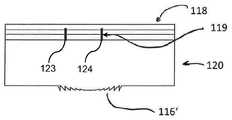
특히, 측정 본체는 또한 측정 본체의 제1 부분 및 센서 층으로서 구현된 측정 본체의 제2 부분에 의해서 형성될 수 있고, 센서 층은 측정 본체의 제1 부분과 상이한 조성을 가질 수 있고, 특히, 적어도 부분적으로 압전 재료로 구성될 수 있다. 센서 층은 측정 표면의 영역 내에서 측정 본체의 제1 부분에 도포, 특히 접착식으로 결합될 수 있다. 센서 층은 또한, 측정 본체의 제1 부분보다 더 큰, 압력 또는 온도에 대한 굴절률 의존성을 갖는 재료로 제조될 수 있다. 측정 본체의 제1 부분은 여기 빔/여기 빔들에 대해서 투명할 수 있고, 예를 들어 규소로 구성될 수 있다. 여기 빔(들)을 위한 센서 층이 투명하지 않거나 측정 본체의 제1 부분보다 덜 투명한 경우에, 센서 층은 여기 빔(들)의 통과를 허용하기 위한 슬롯을 가질 수 있다. 여기 빔(들)을 피분석 물질 내의 지점 상으로 포커스하기 위해서, 예를 들어, 렌즈가 또한 슬롯 내에 제공될 수 있다.In particular, the measuring body can also be formed by a first part of the measuring body and a second part of the measuring body embodied as a sensor layer, the sensor layer can have a composition different from the first part of the measuring body, in particular at least It may be partially composed of a piezoelectric material. The sensor layer can be applied, in particular adhesively bonded, to a first part of the measuring body within the area of the measuring surface. The sensor layer may also be made of a material having a greater dependence of the refractive index on pressure or temperature than the first part of the measurement body. The first part of the measurement body may be transparent to the excitation/excitation beams, and may consist of silicon, for example. In case the sensor layer for the excitation beam(s) is not transparent or less transparent than the first part of the measurement body, the sensor layer may have a slot to allow passage of the excitation beam(s). In order to focus the excitation beam(s) onto a point in the analyte, for example, a lens may also be provided in the slot.
측정 표면 내에서, 상에서 또는 그 전방에서 종료되는 광학적 도파관이 또한 측정 본체 내측에 제공되어 여기 빔(들)을 안내할 수 있다. 광학적 도파관은 측정 본체의 기재 내로 통합될 수 있고, SOI 기술로 제조될 수 있다. 광학적 도파관은 검출 영역을 통과할 수 있거나, 또한 검출 영역을 지나서 안내될 수 있다. 여기 빔에 미치는 압전 압력 생성의 영향을 최소화하기 위해서, 광학적 도파관은, 기계적 압력에 대한 굴절률 의존성이 없는 또는 단지 최소인 재료로 구성될 수 있다. 광학적 도파관 재료는 또한 검출 영역 내에 제공된 압전 재료로부터 기계적으로 이격될 수 있거나, 가요적인, 특히 탄성적인 재료 층 또는 가스 층에 의해서 그로부터 기계적으로 디커플링될 수 있다.An optical waveguide terminating within, on or in front of the measurement surface can also be provided inside the measurement body to guide the excitation beam(s). The optical waveguide can be integrated into the substrate of the measurement body and can be manufactured with SOI technology. The optical waveguide may pass through the detection area, or may also be guided past the detection area. In order to minimize the effect of piezoelectric pressure generation on the excitation beam, the optical waveguide may be constructed of a material that has no or only minimal refractive index dependence on mechanical pressure. The optical waveguide material may also be mechanically spaced from the piezoelectric material provided in the detection area, or may be mechanically decoupled therefrom by a flexible, in particular elastic material layer or gas layer.
본 발명의 목적은 대안적으로 물질 분석을 위한 장치에 의해서 특허 청구항 제2항에 따른 발명의 특징으로 달성되고, 그러한 장치는:The object of the invention is alternatively achieved with the features of the invention according to
- 측정을 위한 물질과 적어도 부분적으로 접촉되는 측정 표면을 갖는 측정 본체,-A measuring body having a measuring surface at least partially in contact with the substance for measuring,
- 측정 표면을 통과하는 동안 재료로 지향되는, 바람직하게 적외선 스펙트럼 범위 내에서, 상이한 선택 가능 파장들의 여기 빔을 생성하기 위한, 여기 빔원, 특히 레이저 장치, 보다 특히 퀀텀 캐스케이드 레이저(QCL), 튜닝 가능 QCL, 및/또는 레이저 어레이, 바람직하게 QCL의 어레이를 갖는 여기 빔원, 및-An excitation beam source, in particular a laser device, more particularly a quantum cascade laser (QCL), tunable, for generating an excitation beam of different selectable wavelengths, which is directed to the material while passing through the measuring surface, preferably within the range of the infrared spectrum An excitation beam source having a QCL, and/or a laser array, preferably an array of QCL, and
- 측정 표면에 인접하여 및/또는 직접적으로 접하여 배열되는 적어도 하나의 검출 장치로서, 검출 장치는 압전 신호를 검출하기 위한 적어도 2개의 전극을 갖는 접촉 장치를 갖고, 전극은 검출 영역의 상이한 측면들 상에서 서로 대향되게 위치되는, 적어도 하나의 검출장치를 포함한다. 검출 영역에서, 특히 압전 효과로 인해서, 온도 및/또는 압력 변화에 따라 전기 저항이 변화되는 또는 전기 신호를 생성하는 재료가 배열된다.-At least one detection device arranged adjacent and/or in direct contact with the measuring surface, the detection device having a contact device with at least two electrodes for detecting the piezoelectric signal, the electrodes being on different sides of the detection area And at least one detection device positioned opposite to each other. In the detection area, in particular due to the piezoelectric effect, a material is arranged whose electrical resistance changes with temperature and/or pressure changes or generates an electrical signal.
여기원 특히, 레이저 장치는 여기 빔을 피분석 물질 내로 전송하고, 그러한 여기 빔은, 예를 들어, 특정 파동수/파장을 통해서 스위핑(sweep)하거나, 순차적으로 또는 동시에, 특정된 고정 파동수를 갖는 다수의 여기 빔을 방출하고, 이들 모두는 제1항의 청구 대상의 경우 및 제2항의 청구 대상의 경우이다. 이러한 경우에, 파장 선택은 또한 여기 빔원 뒤쪽의 광 경로 내의 필터에 의해서 추후에 실행될 수 있다.An excitation source, in particular, a laser device transmits an excitation beam into an analyte, and such an excitation beam, for example, sweeps through a specific wave number/wavelength, or sequentially or simultaneously, a specified fixed wave number. And emits a plurality of excitation beams, all of which are the case of the claim of
어레이를 이용할 때, 레이저 어레이는 단순한 고정 파장 레이저를 가질 수 있다. 특정 파장에서, 빔은 피분석 물질의 재료에 따라 흡수되고, 그에 따라 에너지가 방출되며, 그러한 에너지는 적어도 부분적으로 열 파동 형태로 재료의 표면에 그리고 이어서 측정 본체 내로 그리고 그곳에서 또한 검출 영역으로 전달된다. 여기 빔은 유리하게 세기-변조되고, 상이한, 심지어 복수의 변조 시퀀스를 이용할 수 있다. 또한, 푸리에-변환 도메인 내의 다수의 변조 주파수를 포함하는 레이저 펄스를 형성할 수 있다. 검출 영역 내의 재료의 펄스화된 가열은 저항 및/또는 전기 전압 신호의 변화가 생성되게 하고 및/또는 다른 매개변수 변화, 예를 들어 굴절률의 변화가 생성되게 한다. 접촉 장치의 전극 및 그 공급 케이블에 의해서, 언급된 처음의 2개의 전기적인 현상이, 전압 및/또는 전기 저항을 측정하는 측정 장치에 연결될 수 있고, 그러한 장치는 이러한 변화를 평가하고 이들을 물질 내의 온도 증가 및/또는 여기 빔의 흡수 세기로 할당한다. 그에 따라, 흡수 세기는, 횡단되는 여기 빔의 파동수/주파수에 따른 흡수 스펙트럼으로서 측정될 수 있다.When using an array, the laser array can have a simple fixed wavelength laser. At a certain wavelength, the beam is absorbed according to the material of the analyte, and thus energy is emitted, which energy is transmitted at least partially to the surface of the material in the form of thermal waves and then into and from the measuring body and also to the detection area. do. The excitation beam is advantageously intensity-modulated, and different, even multiple modulation sequences can be used. It is also possible to form a laser pulse comprising multiple modulation frequencies within the Fourier-transform domain. Pulsed heating of the material in the detection area causes a change in resistance and/or electrical voltage signal to be produced and/or another parameter change, for example a change in refractive index. By means of the electrode of the contact device and its supply cable, the first two electrical phenomena mentioned can be connected to a measuring device that measures voltage and/or electrical resistance, which device evaluates these changes and converts them to the temperature in the material. Increase and/or allocate to the absorption intensity of the excitation beam. Accordingly, the absorption intensity can be measured as an absorption spectrum according to the wave number/frequency of the excitation beam traversed.
검출 영역은 유리하게 측정 표면에 인접하여 위치되고, 다시 말해서 검출 영역은 측정 표면에 직접 인접하여 또는 그로부터 거리를 두고 배열되고, 이러한 거리는 작아야(예를 들어, 각각의 경우에 검출 영역과 측정 표면 사이의 가장 짧은 거리에서 측정된, 10 미크론 미만 또는 100 미크론 미만) 한다. 예를 들어, 검출 장치는 또한, 측정 본체의 일부로서 측정 본체의 다른 부분과 함께 결합되는 판 또는 본체, 또는 측정 표면의 영역 내의 측정 본체의 일부의 코팅을 포함할 수 있다.The detection area is advantageously located adjacent to the measurement surface, ie the detection area is arranged directly adjacent to or at a distance from the measurement surface, and this distance should be small (e.g. between the detection area and the measurement surface in each case) Measured at the shortest distance, less than 10 microns or less than 100 microns). For example, the detection device may also include a plate or body that is joined together with other portions of the measurement body as part of the measurement body, or a coating of a portion of the measurement body in an area of the measurement surface.
특히, 압력 변화가 검출되는 경우에, 예를 들어 피에조-감응형 재료/피에조-센서를 이용할 때, 검출 장치는 또한, 피분석 물질 내의 여기 빔의 흡수에 의해서 생성되고 알려진 속력(인간 조직 내에서, 약 1500 m/s)으로 측정 표면 및 검출 영역으로 이동되는, 음파 형태의 응답 신호를 검출하기 위해서 이용될 수 있다. 여기 빔에 대한 변조 장치에 연결된 평가 장치에 의해서, 응답 신호의 측정의 양호한 시간적 해상도로 인해서, 여기 빔의 변조와 응답 신호 사이의 위상 변이가 측정될 수 있고, 그에 의해서 흡수가 발생되는 조직 내의 깊이를 결정할 수 있다. 신호가 종종 상이한 조직 층들로부터의 상이한 응답 신호들의 중첩이기 때문에, 상이한 측정들이 상이한 변조 주파수들에서 실시될 수 있고, 상이한 변조 주파수들에서의 응답 신호들이 상호 연관되어, 특히, 상부 조직 층으로부터의 신호를 상쇄 및 제거할 수 있는데, 이는 상부 조직 층으로부터의 신호가 분진 및 죽은 피부 세포에 의한 오염으로 인해서 오류에 특히 민감하기 때문이다.In particular, when a pressure change is detected, for example when using a piezo-sensitive material/piezo-sensor, the detection device is also generated by absorption of the excitation beam in the analyte and has a known speed (in human tissue). , About 1500 m/s), which is moved to the measurement surface and the detection area, can be used to detect a response signal in the form of a sound wave. Due to the good temporal resolution of the measurement of the response signal, by means of the evaluation device connected to the modulation device for the excitation beam, the phase shift between the modulation of the excitation beam and the response signal can be measured, whereby the depth in the tissue where absorption occurs. Can be determined. Since the signal is often an overlap of different response signals from different tissue layers, different measurements can be made at different modulation frequencies, and the response signals at different modulation frequencies are correlated, in particular the signal from the upper tissue layer. Can be canceled out and eliminated, since the signal from the upper tissue layer is particularly susceptible to errors due to contamination by dust and dead skin cells.
본 개시 내용에서, "응답 신호"라는 동일한 용어가 몇 가지 방식으로 사용된다는 것을 주목하여야 한다. 한편으로, 그러한 용어는 여기 빔에 의한 여기에 대한 물리적 응답, 즉 예를 들어 음파, 온도 증가 또는 기타를 설명할 수 있다. 다른 한편으로, 그러한 용어는 또한, 이러한 물리적 응답을 나타내는 (전형적으로 전기적인) 신호, 즉 예를 들어 전극에 의해서 측정되는 전압 또는 전류 흐름을 지칭할 수 있다. 단순함 및 제시 내용과의 일관성을 위해서, "응답 신호"라는 동일한 용어가 전체적으로 사용되고, 추가적인 설명이 없이도, 문맥으로부터, 그러한 용어가 물리적 응답(예를 들어, 압력 파동), 그러한 물리적 응답의 물리적 결과(예를 들어, 압전 재료의 압축), 또는 연관된 측정 신호(예를 들어, 압전 재료에 의해서 생성되는 전압)를 지칭하는지의 여부를 명확하게 알 수 있다.It should be noted that in this disclosure, the same term "response signal" is used in several ways. On the one hand, such terms can describe the physical response to excitation by an excitation beam, i.e., for example a sound wave, an increase in temperature or the like. On the other hand, such terms may also refer to a (typically electrical) signal representing this physical response, ie a voltage or current flow measured by an electrode, for example. For the sake of simplicity and consistency with the presentation, the same term "response signal" is used throughout, and without further explanation, from context, such term is referred to as a physical response (e.g., pressure wave), the physical result of such a physical response ( It can be clearly seen whether it refers to, for example, compression of a piezoelectric material, or an associated measurement signal (eg, a voltage generated by the piezoelectric material).
상이한 변조 주파수들 대신, 급격히 상승되는 신호(이상적으로 소위 디랙 펄스(Dirac pulse))가 또한 형성될 수 있고, 이는 많은 변조 주파수들의 혼합을 나타내고, 푸리에 분석에 의한 상이한 변조 주파수들의 분석을 가능하게 한다.Instead of different modulation frequencies, a rapidly rising signal (ideally a so-called Dirac pulse) can also be formed, which indicates a mixture of many modulation frequencies and allows the analysis of different modulation frequencies by Fourier analysis. .
장치의 구현예가, 특히 측정 표면의 표면 법선을 따라 적어도 2개의 전극이 측정 표면으로부터 상이한 거리들에서 서로 앞뒤로 위치되는 것, 또는 표면 법선에 수직인 방향으로 검출 영역의 상이한 측면들에서 서로 이격되는 것을 제공할 수 있다.The embodiment of the device is, in particular, that at least two electrodes are positioned back and forth from each other at different distances from the measurement surface along the surface normal of the measurement surface, or are spaced apart from each other on different sides of the detection area in a direction perpendicular to the surface normal. Can provide.
측정 표면은 편평하거나 곡선형일 수 있다. 곡선형의 경우에, 표면 법선은 하나의 지점에서의, 특히 여기 빔이 측정 표면을 통과하는 위치에서의 측정 표면에 대한 법선을 의미하는 것으로 이해된다.The measuring surface can be flat or curved. In the case of a curved shape, the surface normal is understood to mean the normal to the measurement surface at one point, in particular at the location where the excitation beam passes through the measurement surface.
적어도 2개의 전극이 검출 영역을 완전히 또는 부분적으로 둘러싸도록, 또는 검출 영역이 완전히 또는 부분적으로 2개의 전극 사이에 위치되도록, 적어도 2개의 전극이 배열되어야 한다. 전극들은 검출 영역의 상이한 측면들 상의 상이한 기하형태적 위치들에서 분포될 수 있고, 특히 검출 영역 주위에 분포될 수 있다.At least two electrodes should be arranged such that at least two electrodes completely or partially surround the detection area, or so that the detection area is completely or partially positioned between the two electrodes. The electrodes may be distributed at different geometric locations on different sides of the detection area, and in particular may be distributed around the detection area.
장치의 추가적인 구현예는, 여기 빔이 측정 본체, 특히 검출 영역을 통과하는 것을 제공할 수 있고, 여기에서 광학적 도파관이, 특히 여기 빔을 안내하기 위해서, 측정 본체 내에 또는 위에 배열되고, 또한 특히 광학적 도파관이 측정 본체 내로 통합된다.A further embodiment of the device may provide for the excitation beam to pass through the measurement body, in particular the detection area, wherein an optical waveguide is arranged in or on the measurement body, in particular for guiding the excitation beam, and in particular optical The waveguide is integrated into the measurement body.
그에 따라, 여기 빔은 측정 본체를 통해서, 예를 들어 측정 본체의 재료를 직접적으로 통해서 또는 그 내부에 배열된 광학적 도파관을 통해서, 그리고 검출 영역을 통해서 또는 검출 영역을 지나서 피분석 물질의 지점까지 이동되고, 피분석 물질은 여기 복사선을 흡수하고 열 복사선을 방출한다.Accordingly, the excitation beam travels through the measurement body, for example directly through the material of the measurement body or through an optical waveguide arranged therein, and through or through the detection region to the point of the analyte. And the analyte absorbs excitation radiation and emits thermal radiation.
측정 본체의 재료 내로 및/또는 검출 영역의 재료 내로 통합된 광학적 도파관은 여기 빔을 안내하기 위한 광학적 도파관으로서 이용될 수 있다. 그러한 광학적 도파관은, 예를 들어, 에피택셜 방법에 의해서 또는 웨이퍼 내로의 또는 상으로의 웨이퍼 재료의 선택적인 도핑에 의해서 도포될 수 있다. 그러나, 광섬유 케이블이 측정 본체 내로 삽입될 수 있거나, 외측에서 측정 본체에 적어도 부분적으로 도포될 수 있다.An optical waveguide integrated into the material of the measurement body and/or into the material of the detection area can be used as an optical waveguide to guide the excitation beam. Such an optical waveguide may be applied, for example, by an epitaxial method or by selective doping of the wafer material into or onto the wafer. However, the optical fiber cable can be inserted into the measuring body, or it can be applied at least partially to the measuring body from the outside.
여기 빔이, 검출 영역에 직접적으로 인접하는 및/또는 접하는 영역 내에서 측정 표면을 통과하는 것이 또한 제공될 수 있다.It may also be provided for the excitation beam to pass through the measurement surface in an area directly adjacent and/or abutting the detection area.
장치의 추가적인 구현예가, 여기 빔의 세기를 변조하기 위한 변조 장치를 제공할 수 있다. 이러한 경우에, 기계적인 초퍼(chopper)를 이용한 그리고 제어 가능한 셔터 또는 편향 거울 장치, 또는 전달을 제어할 수 있는 본체/층을 이용한, 상이한 변조 유형들이 가능하다. 게다가, 변조는 또한 여기 광원/레이저 광원의 활성화에 의해서 직접적으로 달성될 수 있다. 이어서, 측정이, 하나 이상의 변조 주파수에서의 스펙트럼의 획득을 포함할 수 있고, 상이한 변조 주파수들에서의 측정들이 서로 상호 연관되어, 깊이 정보를 획득할 수 있고 및/또는 피분석 샘플/물질의 특정 깊이 범위로부터의 측정 데이터를 제거할 수 있다. 특히, 물질의 표면으로부터 기원하는 측정 데이터가 그에 따라 제거될 수 있다. 이들은, 물질의 표면에서의 여기 광 빔의 흡수로부터 초래되고 피분석 물질의 표면 상의 불순물 또는 비정상부에 의해서 유발될 수 있는, 측정 데이터 및 열 파동이다. 이러한 것의 하나의 예는, 환자 피부의 분석에서, 정보 가치가 없는 조성을 갖는 및/또는 잘못된 정보를 제공하는, 부분적으로 죽은 세포로 이루어진 최상부 층이다. 이는, 특히 생물학적 활성 물질, 활성 대사 또는 대사 생성물 또는 유사물이 피부에서 검출되는 경우에 특히 그러하다.A further implementation of the device may provide a modulation device for modulating the intensity of the excitation beam. In this case, different modulation types are possible, using a mechanical chopper and using a controllable shutter or deflection mirror device, or a body/layer capable of controlling the transmission. In addition, modulation can also be achieved directly by activation of an excitation light source/laser light source. Subsequently, the measurement may include acquisition of a spectrum at one or more modulation frequencies, and measurements at different modulation frequencies may be correlated with each other to obtain depth information and/or specificity of the sample/material under analysis. Measurement data from the depth range can be removed. In particular, measurement data originating from the surface of the material can be removed accordingly. These are measurement data and thermal waves, which result from absorption of the excitation light beam at the surface of the material and may be caused by impurities or abnormalities on the surface of the analyte. One example of this is the top layer of partially dead cells, which, in the analysis of patient skin, have a composition with no informational value and/or give false information. This is particularly the case when biologically active substances, active metabolites or metabolic products or the like are detected in the skin.
이하에서, 다양한 기하형태적 전극 구성이 제공되고 그 장점이 설명된다.In the following, various geometric electrode configurations are provided and their advantages are described.
이를 위해서, 예를 들어, 적어도 2개, 특히 적어도 3개 또는 4개, 보다 특히 적어도 6개, 보다 특히 적어도 8개의 전극이 측정 표면으로부터 상이한 거리들에서 서로 앞뒤로 배열되거나, 측정 표면의 표면 법선에 수직인 방향으로 서로 이격되는 것이 제공될 수 있다.For this purpose, for example, at least 2, in particular at least 3 or 4, more particularly at least 6, more particularly at least 8 electrodes are arranged back and forth from each other at different distances from the measurement surface, or in the surface normal of the measurement surface. It may be provided that they are spaced apart from each other in a vertical direction.
전극 중 적어도 하나 이상이 검출 영역의 각각의 측면에 배열된다. 이는, 전기 저항 또는 전압을 측정하기 위해서 이용될 수 있는 상이한 전극의 쌍들의 이용이 가능하다는 것을 의미한다.At least one or more of the electrodes are arranged on each side of the detection area. This means that the use of different pairs of electrodes that can be used to measure electrical resistance or voltage is possible.
공급 케이블을 통해서 복수의 또는 모든 전극에 연결되는, 전자 장치가 이러한 목적을 위해서 제공된다. 전자 장치는, 상이한 선택 가능한 전극들 사이의 전기 저항 또는 전압의 순차적인 또는 동시적인 획득 및 평가를 유발하는, 제어 장치 그리고 특히 평가 장치를 갖는다.An electronic device is provided for this purpose, which is connected to a plurality or all of the electrodes via a supply cable. The electronic device has a control device and in particular an evaluation device, which causes the sequential or simultaneous acquisition and evaluation of the electrical resistance or voltage between different selectable electrodes.
이를 위해서, 상이한 전극의 쌍들 또는 모든 전극의 쌍들이 임의적으로 선택될 수 있다. 임의적인 측정을 위해서 전극 쌍 중에서 선택된 전극들은 그 사이에서 검출 영역의 적어도 일부를 각각 가져야 한다. 개별적인 전극 쌍으로부터의 측정들 서로 비교될 수 있고 평가될 수 있다. 평가 매개변수는, 예를 들어, 신호 강도 또는 신호 변화의 크기, 또는 신호-대-잡음비 또는 다른 매개변수일 수 있다. 전극을 측정 본체에 통합하는 것에 더하여, 복수의 전극이 접착제에 의해서 측정 본체의 표면/측정 표면 위에 엇갈린 패턴으로 도포되는, 또는 그 위에서 통합되거나 증발되는 다른 경우가 또한 포함되어야 한다.For this purpose, different pairs of electrodes or all pairs of electrodes can be selected arbitrarily. For arbitrary measurements, the electrodes selected among the electrode pairs should each have at least a portion of the detection area between them. Measurements from individual electrode pairs can be compared to each other and evaluated. The evaluation parameter may be, for example, a signal strength or magnitude of a change in signal, or a signal-to-noise ratio or other parameter. In addition to incorporating the electrodes into the measurement body, other cases in which a plurality of electrodes are applied in a staggered pattern on the surface/measurement surface of the measurement body by means of an adhesive, or integrated or evaporated thereon should also be included.
적어도 2개, 특히 적어도 3개 또는 4개, 특히 적어도 6개, 특히 적어도 8개의 전극이 측정 표면의 표면 법선의 방향으로, 또는 그에 수직으로, 또는 표면 법선의 0 내지 90도의 방향으로 검출 영역으로부터 상이한 거리들에서, 특히 검출 영역의 중심으로부터 상이한 거리들에서 서로 앞뒤로 배열되는 것이 또한 제공될 수 있다. 이러한 경우에 검출 영역은, 예를 들어, 특정 재료로 이루어진 측정 본체의 공간적 영역에 의해서 형성될 수 있다. 검출 영역은 또한 전체적인 배열에 의해서 피분석 재료 내로의 여기 빔의 진입 지점 위에 위치되는 측정 본체의 영역으로서 규정될 수 있다.At least 2, in particular at least 3 or 4, in particular at least 6, in particular at least 8 electrodes from the detection area in the direction of, or perpendicular to, the surface normal of the measurement surface or in the direction of 0 to 90 degrees of the surface normal It can also be provided that they are arranged back and forth from each other at different distances, in particular at different distances from the center of the detection area. In this case, the detection area can be formed, for example, by a spatial area of the measuring body made of a specific material. The detection area can also be defined by the overall arrangement as the area of the measurement body positioned above the point of entry of the excitation beam into the material to be analyzed.
게다가, 검출 영역은 또한, 전기 신호가 이용 가능 전극에 의해서 잠재적으로 검출될 수 있는 공간적 지점들의 합에 의해서 규정될 수 있다.In addition, the detection area can also be defined by the sum of spatial points at which an electrical signal can potentially be detected by an available electrode.
추가적인 구현예가, 적어도 2개, 특히 적어도 3개 또는 4개, 보다 특히 적어도 6개, 보다 특히 적어도 8개의 전극이 검출 영역 주위의 환형 또는 구형 쉘-형상의(shell-shaped) 영역 내에 그리고 검출 영역의 상이한 측면들 상에서 적어도 부분적으로 서로 대향되게 배열되는 것을 제공할 수 있고, 상이한 전극들은 검출 영역의 중심으로부터 본질적으로 동일한 거리 또는 검출 영역의 중심으로부터 상이한 거리들을 갖는다. 이는 또한 전극들이 측정 본체의 표면 위에 분포된 경우를 포함하도록 의도된다.A further embodiment is that at least two, in particular at least 3 or 4, more particularly at least 6, more particularly at least 8 electrodes are in an annular or spherical shell-shaped area around the detection area and in the detection area It can be provided that they are arranged at least partially opposite to each other on different sides of the detection area, the different electrodes having essentially the same distance from the center of the detection area or different distances from the center of the detection area. It is also intended to include the case where the electrodes are distributed over the surface of the measuring body.
전술한 전극 분포 그리고 예를 들어 다수의 전극 쌍에서의 측정에 의해서, 측정에 가장 적합한 전극 쌍(들)이 선택되고 사용될 수 있다.By means of the electrode distribution described above and, for example, measurements on multiple electrode pairs, the electrode pair(s) most suitable for the measurement can be selected and used.
전극 쌍을 선택할 때 측정 품질에 관한 적절한 기준으로서, 예를 들어 신호 강도 또는 신호 동적 범위 또는 잡음 레벨 또는 신호/잡음비를 이용할 수 있다.When selecting an electrode pair, it is possible to use, for example, signal strength or signal dynamic range or noise level or signal/noise ratio as an appropriate criterion for measurement quality.
또한, 접촉 장치의 전극의 하나 이상 또는 전부가 디스크-형상 또는 판-형상, 환형, 환형 디스크-형상, 개구부를 갖는 직사각형 또는 다각형 프레임의 형태, 캡-형상 또는 막대-형상이 되도록 설계된다.In addition, one or more or all of the electrodes of the contact device are designed to be disk-shaped or plate-shaped, annular, annular disk-shaped, in the form of a rectangular or polygonal frame with openings, cap-shaped or rod-shaped.
장치의 구현예는, 접촉 장치의 전극의 하나 이상 또는 전부가 측정 본체 또는 검출기 장치의 하나의 표면 상에 배열되는 것, 그리고 특히 접합 방법에 의해서, 특히 접착제 결합 또는 용접에 의해서 부착되는 것을 제공할 수 있다. 전극은 또한 증착 또는 코팅에 의해서 도포될 수 있다. 측정 본체는 하나의 균질한 재료로 제조될 수 있거나, 검출 영역에서 측정 본체는, 측정 본체의 다른 영역의 재료와 상이한 특별한 재료로 이루어질 수 있다.Embodiments of the device provide that one or more or all of the electrodes of the contact device are arranged on one surface of the measuring body or detector device, and are attached in particular by a bonding method, in particular by adhesive bonding or welding. I can. Electrodes can also be applied by vapor deposition or coating. The measuring body can be made of one homogeneous material, or the measuring body in the detection area can be made of a special material different from the material of other areas of the measuring body.
전극은 일반적으로 모든 실시예에서 금속으로 제조되고, 모든 경우에 양호한 전기 전도도를 갖는 재료로 제조된다. 전극은 또한 전기 전도성 플라스틱 또는 전도적으로 충진된 재료로 제조될 수 있다.The electrodes are generally made of metal in all embodiments, and in all cases made of a material with good electrical conductivity. The electrode can also be made of an electrically conductive plastic or a conductively filled material.
장치의 추가적인 구현예는, 접촉 장치의 전극의 하나 이상 또는 전부가, 측정 본체의 하나 이상의 슬롯 내에서, 예를 들어 보어 가공된 홀, 함몰부 또는 홈 내에서 측정 본체의 내부 측면 또는 외부 측면 상에 배열되는 것, 특히 사출 몰딩에 의해서 또는 적층 제조 방법(3D 프린팅)에 의해서 삽입되고, 내부로 주조되고, 통합되는 것을 제공할 수 있다. 이러한 변형예는 기술적으로 단순한 방식으로 측정 본체 내로 전극을 삽입할 수 있게 한다.A further embodiment of the device is that one or more or all of the electrodes of the contact device are on the inner side or outer side of the measuring body in one or more slots of the measuring body, for example in boreholes, depressions or grooves. Arranged in, in particular by injection molding or by additive manufacturing methods (3D printing) it is possible to provide for being inserted, cast inside and integrated. This variant makes it possible to insert the electrode into the measuring body in a technically simple manner.
전극은 또한, 조사(irradiation)에 의해서 또는 입자의 충격에 의해서 측정 본체의 재료의 영역을 전기 전도적이 되게 하는 것에 의해서 측정 본체 내에서 생성될 수 있다. 이는, 예를 들어, 플라스틱에서 이루어질 수 있고, 고-에너지 복사선이 탄소 분자를 부분적으로 파괴하고 전도적인 탄소 축적물을 형성한다.Electrodes can also be created within the measuring body by irradiation or by making an area of the material of the measuring body electrically conductive by the impact of particles. This can be done, for example, in plastics, where high-energy radiation partially destroys carbon molecules and forms conductive carbon deposits.
또한, 측정 본체가 편평한 본체로서, 특히 판 형태의 평면-평행 본체로서 형성되는 것이 제공될 수 있고, 여기에서 특히 측정 표면에 수직인 두께는 측정 표면 내에서 연장되는 방향을 따른 측정 본체의 가장 짧은 연장 길이의 50% 미만, 특히 25% 미만, 보다 특히 10% 미만이다.It may also be provided that the measuring body is formed as a flat body, in particular a planar-parallel body in the form of a plate, wherein the thickness in particular perpendicular to the measuring surface is the shortest of the measuring body along the direction extending within the measuring surface. Less than 50%, in particular less than 25% and more particularly less than 10% of the extension length.
측정 본체의 이러한 설계 변형예는 열적 응답 신호의 다른 검출 방법을 위해서 이용될 수 있고, 원칙적으로 피에조-효과를 기초로 하는 검출 방법으로 제한되지 않는다. 이는 또한, 측정 표면에서 반사된 측정 빔 및 그 편향을 검출하기 위한 검출기를 이용하는 측정 방법에서 사용될 수 있고, 측정 표면에 수직인 방향을 따른 측정 본체 치수의 상당한 감소를 가능하게 한다. 측정 방법과 관계없이, 예를 들어 피에조-효과를 이용하는 것 또는 반사된 빔의 편향을 측정하는 것에 의해서, 편평한 본체로서 형성된 측정 본체는 측정 표면의 영역 내에서 층을 가질 수 있고, 그러한 층은, 피에조-측정 방법의 경우에, 압전 재료로 구성될 수 있고, 반사된 측정 빔의 편향을 측정하는 것에 의한 검출의 경우에, 측정 본체의 다른 영역의 재료에서보다 굴절률이 온도에 따라 더 크게 변하는 재료로 구성될 수 있다.This design variant of the measurement body can be used for other detection methods of the thermal response signal, and in principle is not limited to detection methods based on piezo-effects. It can also be used in a measuring method using a measuring beam reflected from the measuring surface and a detector for detecting its deflection, and allows a significant reduction of the measuring body dimension along a direction perpendicular to the measuring surface. Regardless of the measuring method, for example by using the piezo-effect or measuring the deflection of the reflected beam, a measuring body formed as a flat body can have a layer within the area of the measuring surface, such a layer, In the case of the piezo-measurement method, a material which may be composed of a piezoelectric material, and in the case of detection by measuring the deflection of the reflected measuring beam, the refractive index changes more with temperature than in the material of other areas of the measuring body It can be composed of.
장치의 추가적인 구현예는, 측정 본체가 여기 빔원, 특히 레이저 장치에 의해서 조사되는 여기 빔을 반사하기 위한 거울 장치를 갖는 것, 또는 그러한 거울 장치를 수반하는 것을 제공할 수 있다.A further embodiment of the device may provide that the measuring body has an excitation beam source, in particular a mirror device for reflecting the excitation beam irradiated by the laser device, or is accompanied by such a mirror device.
매우 편평한 측정 본체의 경우에, 여기 빔은 측정 본체의 편평한 측면으로부터 조사될 수 있다. 이어서, 여기 빔은 여기 빔원으로부터, 초기에 본질적으로 측정 본체 내의 측정 표면에 평행하게 또는 측정 본체의 경계 표면에 평행하게 전파되고, 이어서 측정 표면을 향해서 편향된다.In the case of a very flat measuring body, the excitation beam can be irradiated from the flat side of the measuring body. The excitation beam then propagates from the excitation beam source, initially essentially parallel to the measurement surface in the measurement body or parallel to the boundary surface of the measurement body, and then deflects towards the measurement surface.
여기 빔을 반사시키는 것 대신, 여기 빔은 또한 측정 본체의 적절한 재료 설계에 의해서 측정 표면을 향해서 편향될 수 있다. 편평한 본체는 또한 여기 빔을 위한 광학 포커싱 요소를 가질 수 있거나, 그러한 요소, 예를 들어 하나 이상의 렌즈에 연결될 수 있다.Instead of reflecting the excitation beam, the excitation beam can also be deflected towards the measurement surface by a suitable material design of the measurement body. The flat body may also have an optical focusing element for the excitation beam, or may be connected to such an element, for example one or more lenses.
또한, 여기 빔이 측정 표면에 평행하게 또는 측정 표면에 대해서 30도 미만, 특히 20도 미만, 보다 특히 10도 미만 또는 5도 미만의 각도로 측정 본체 내로 조사되는 것, 그리고 여기 빔이 측정 표면을 향해서 전환되거나 편향되고 측정 표면을 통과하는 것이 제공될 수 있다.In addition, the excitation beam is irradiated into the measurement body at an angle of less than 30 degrees, in particular less than 20 degrees, more particularly less than 10 degrees or less than 5 degrees, parallel to or relative to the measurement surface, and the excitation beam hits the measurement surface. It may be provided to be diverted or deflected towards and through the measuring surface.
특히 편평한 본체가 사용될 때, 측정 본체 내로 통합되거나 직접적으로 연결되는, 예를 들어 회절 요소/렌즈 형태의, 포커싱 장치가 제공될 수 있고, 포커싱 장치는 여기 빔을 측정 표면 및 피분석 물질의 물질 표면 상으로 포커스한다.In particular, when a flat body is used, a focusing device may be provided, which is integrated or directly connected into the measuring body, for example in the form of a diffractive element/lens, which focuses the excitation beam to the measuring surface and the material surface of the analyte. Focus on the prize.
또한, 여기 빔이 측정 본체의 재료를 통과하는 것이 제공될 수 있다.It can also be provided for the excitation beam to pass through the material of the measuring body.
또한, 측정 본체가, 여기 빔이 침투하는, 적어도 하나의 슬롯, 특히 보어 가공된 홀을 갖는 것이 제공될 수 있고, 그러한 슬롯 및/또는 보어 가공된 홀은, 특히, 측정 표면으로부터 측정 본체 내로 연장되거나, 함몰부 또는 슬롯 및/또는 보어 가공된 홀이, 측정 본체의 측정 표면에 대향되는 경계 표면으로부터 전체 측정 본체를 통과하여 측정 표면에 도달한다. 함몰부는 채널 또는 보어 가공될 홀로서 연장될 수 있고, 그러한 채널 또는 홀의 길이방향 축은 또한 적어도 부분적으로 측정 표면에 평행한 여기 빔의 방향을 따른다. 센서 층이 제공되는 경우에, 센서 층 자체에 슬롯이 침투하지 않도록, 슬롯, 함몰부 및/또는 보어 가공된 홀이 측정 표면에 대향되는 센서 층의 경계 표면으로부터 측정 본체 내로 연장될 수 있다.It can also be provided that the measuring body has at least one slot, in particular boreed hole, through which the excitation beam penetrates, such a slotted and/or boreed hole extending, in particular, from the measuring surface into the measuring body. Alternatively, a recess or a slot and/or a bore-machined hole passes through the entire measurement body from the boundary surface opposite to the measurement surface of the measurement body to reach the measurement surface. The depression may extend as a channel or hole to be bore, the longitudinal axis of such a channel or hole also at least partially along the direction of the excitation beam parallel to the measuring surface. In the case where a sensor layer is provided, slots, depressions and/or bore holes may extend into the measurement body from the boundary surface of the sensor layer opposite the measurement surface so that the slot does not penetrate the sensor layer itself.
이러한 경우에, 측정 본체는 여기 빔을 위한 중공형 채널/보어 가공된 홀/함몰부를 가질 수 있고, 그에 따라, 여기 빔이 측정 본체 및 측정 표면을 통해서 피분석 물질까지 전달되는 경우에도, 여기 빔은 측정 본체의 재료를 침투하지 않는다.In this case, the measurement body may have a hollow channel/bore machined hole/depression for the excitation beam, so that even when the excitation beam is transmitted through the measurement body and the measurement surface to the analyte, the excitation beam Does not penetrate the material of the measuring body.
또한, 측정 본체가, 여기 빔을 위한 연속적인 채널을 갖는 제1 부분을 갖는 것, 그리고 측정 본체가, 제1 부분 상의 그 하부측에서, 센서 층을 갖는 것이 제공될 수 있고, 센서 층은 함몰부가 없이 연속적이거나 제1 부분의 함몰부의 연속이다. 센서 층이 200 미크론 미만으로, 특히 100 미크론 미만으로 얇은 경우에, 여기 빔은 - 적외선 빔이 아닌 경우에도 - 너무 많이 흡수되지 않고 이를 통과할 수 있고, 센서 층 내의 함몰부, 보어 가공된 홀 또는 채널은 필요치 않다. 측정 본체의 센서 층은, 압전 특성을 갖고 본 발명에 따른 검출 영역을 형성하는 재료로 구성될 수 있다. 센서 층은, 온도 및/또는 압력의 변화가 굴절률의 변화를 유발하는 재료로 구성될 수 있고, 그에 따라 이러한 변화는 또한, 예를 들어 센서 층에서 반사된 검출 빔의 반사 각도를 검출하는 것에 의해서, 응답 신호로서 검출될 수 있다. 예를 들어, 그에 따라 측정 본체의 제1 부분은, 가시광선 범위에서 그리고 검출 빔에 대해서 투과적이나 적외선 스펙트럼 범위 내에서는 덜 투과적이거나 불투명한, 석영 또는 사파이어와 같은 재료로 구성될 수 있다.It may also be provided that the measuring body has a first part with a continuous channel for the excitation beam, and that the measuring body has a sensor layer, on its lower side on the first part, the sensor layer being recessed. It is continuous without addition or is a continuation of the depression of the first part. If the sensor layer is thin, less than 200 microns, especially less than 100 microns, the excitation beam-even if it is not an infrared beam-can pass through it without being absorbed too much, and can pass through the sensor layer with depressions, boreholes or No channel is required. The sensor layer of the measurement body can be made of a material that has piezoelectric properties and forms the detection region according to the present invention. The sensor layer may be composed of a material in which a change in temperature and/or pressure causes a change in the refractive index, and thus this change can also be made, for example, by detecting the reflection angle of the detection beam reflected from the sensor layer. , Can be detected as a response signal. For example, the first part of the measurement body can thus be made of a material such as quartz or sapphire, which is less transmissive or opaque in the visible range and in the range of the infrared spectral but transmissive to the detection beam.
장치의 추가적인 구현예는, 측정 본체 내의 또는 상의, 특히 검출 장치 내의, 또는 그에 직접 인접하고 열적으로 접촉되는, 적어도 하나의 히트 싱크(heat sink)가 본체의 형태로 배열되고, 그 비열용량(specific thermal capacity) 및/또는 비열전도도가, 측정 본체를 구성하는 또는 펠티에 요소(Peltier element)로서 설계되는 재료의 비열용량 및/또는 비열전도도보다 큰 것을 제공할 수 있다.A further embodiment of the device is that at least one heat sink is arranged in the form of the body in or on the measuring body, in particular in the detection device or directly adjacent and in thermal contact therewith, and its specific heat capacity thermal capacity) and/or specific thermal conductivity may be greater than the specific heat capacity and/or specific thermal conductivity of the material constituting the measurement body or designed as a Peltier element.
비열용량 및/또는 열전도도가 측정 본체 제조 재료의 비열용량 및/또는 비열전도도보다 큰, 본체 형태의 히트 싱크 대신, 온도 구배를 조정하기 위한 능동형 또는 피동형 냉각 요소, 특히 펠티에 냉각 요소가 또한 제공될 수 있다. 온도 구배 또는 절대 온도는 또한 폐쇄-루프 제어 장치를 이용하여 펠티에 요소에 의해서 제어될 수 있다.In lieu of a heat sink in the form of a body, in which the specific heat capacity and/or thermal conductivity is greater than the specific heat capacity and/or specific thermal conductivity of the measuring body manufacturing material, an active or passive cooling element for adjusting the temperature gradient, in particular a Peltier cooling element, may also be provided. I can. The temperature gradient or absolute temperature can also be controlled by the Peltier element using a closed-loop control device.
예를 들어 금속 또는 결정 본체 또는 능동적으로 동작되는 펠티에 요소 형태의 이러한 종류의 히트 싱크로, 열 확산도와 관련된 측정 본체의 적절한 열적 특성이 달성될 수 있고, 그러한 열적 특성은, 변조 주파수로 온도 변화가 검출 영역 내에서 충분히 축적되는 것 그리고 열이 충분히 신속하게 멀리 이송되는 것 모두를 보장하는데 있어서 필요하다. 물론, 이는, 측정 본체/검출 장치의 재료에 주로 의존하나, 이는 하나 이상의 히트 싱크의 적절한 부가에 의해서 영향을 받을 수 있다. 예를 들어, 이들은 적어도 부분적으로 검출 영역 주위에 배열될 수 있거나, 검출 영역의 하나의 측면 상에 제공될 수 있다.With this kind of heat sink, for example in the form of a metal or crystalline body or an actively operated Peltier element, the appropriate thermal properties of the measuring body related to the thermal diffusivity can be achieved, and such thermal properties can be detected by temperature changes with the modulation frequency. It is necessary to ensure both sufficient accumulation in the area and that heat is transferred far enough quickly. Of course, this depends primarily on the material of the measuring body/detection device, but this can be affected by the appropriate addition of one or more heat sinks. For example, they may be at least partially arranged around the detection area or may be provided on one side of the detection area.
장치의 추가적인 구현예는, 측정 본체 내의 또는 상의, 특히 검출 장치 내의, 또는 그에 직접 인접하고 열적으로 접촉되는, 적어도 하나의 열적 장벽이 본체의 형태로 배열되고, 그 비열용량 및/또는 비열전도도가, 측정 본체 제조 재료의 비열용량 및/또는 비열전도도보다 작은 것을 제공할 수 있다.A further embodiment of the device is that at least one thermal barrier is arranged in the form of a body in or on the measuring body, in particular in the detection device or directly adjacent and in thermal contact therewith, and its specific heat capacity and/or specific thermal conductivity is , It is possible to provide something smaller than the specific heat capacity and/or specific thermal conductivity of the material for manufacturing the measuring body.
단독적인 또는 히트 싱크와 또한 조합된, 이러한 종류의 열적 장벽으로, 열 확산도와 관련된 측정 본체의 적절한 열적 특성이 달성될 수 있고, 그러한 열적 특성은, 변조 주파수로 온도 변화가 검출 영역 내에서 충분히 축적되는 것 그리고 또한 열이 변조 주파수에 상응하게 충분히 신속하게 멀리 이송되는 것 모두를 보장하는데 있어서 필요하다. 이는 하나 이상의 열적 장벽의 적절한 부가에 의해서 영향을 받을 수 있다. 예를 들어, 이들은 적어도 부분적으로 검출 영역 주위에 배열될 수 있거나, 검출 영역의 하나의 측면 상에 제공될 수 있다. 열적 장벽은, 예를 들어, 단열 플라스틱 요소에 의해서 구현될 수 있다. 예를 들어, 하나 이상의 히트 싱크가 검출 영역의 제1 측면 상에 그리고 하나 이상의 열적 장벽이 제1 측면에 대향되는 검출 영역의 제2 측면 상에 제공될 수 있고, 그에 따라 온도 구배를 생성할 수 있고 열 전달 방향을 제어할 수 있다.With this kind of thermal barrier, either alone or in combination with a heat sink, the appropriate thermal properties of the measuring body in relation to the thermal diffusivity can be achieved, and such thermal properties can be sufficiently accumulated within the detection area by the temperature change with the modulation frequency. It is necessary both to ensure that heat is transferred far enough and quickly enough corresponding to the modulation frequency. This can be affected by the appropriate addition of one or more thermal barriers. For example, they may be at least partially arranged around the detection area or may be provided on one side of the detection area. The thermal barrier can be implemented, for example, by an insulating plastic element. For example, one or more heat sinks may be provided on a first side of the detection area and one or more thermal barriers may be provided on a second side of the detection area opposite the first side, thereby creating a temperature gradient. And can control the heat transfer direction.
검출 장치 및/또는 측정 본체가 적어도 부분적으로 압전 재료로, 특히 압전 세라믹, 특히 PZT 세라믹, 보다 특히 소결 세라믹, 또는 단-결정 압전 재료, 특히 석영, 토르말린, 리튬 니오베이트, 갈륨 오르토포스페이트, 베르리나이트, 세이넷트 염, 강유전체, 예를 들어 바륨 티타네이트(BTO) 또는 납 지르코네이트 티타네이트, 갈륨 포스페이트 또는 납-마그네슘 니오베이트, 또는 얇은-층 침착물로서의 아연 산화물(ZnO) 또는 알루미늄 질화물 또는 양극화된 폴리비닐 플루오라이드로 구성되는 것이 제공될 수 있다.The detection device and/or the measuring body is at least partially made of a piezoelectric material, in particular a piezoelectric ceramic, in particular a PZT ceramic, more particularly a sintered ceramic, or a single-crystal piezoelectric material, in particular quartz, tourmaline, lithium niobate, gallium orthophosphate, Berley. Knights, sainet salts, ferroelectrics such as barium titanate (BTO) or lead zirconate titanate, gallium phosphate or lead-magnesium niobate, or zinc oxide (ZnO) or aluminum nitride as a thin-layer deposit or Those consisting of anodized polyvinyl fluoride may be provided.
각각의 재료는 적외선 주파수 범위 내에서, 유리하게 중간-적외선 주파수 범위 내에서 가능한 한 투명하여야 한다.Each material should be as transparent as possible within the infrared frequency range, advantageously within the mid-infrared frequency range.
전술한 압전 재료는 측정 본체 상의 얇은 층으로서 제공될 수 있고 측정 표면을 형성할 수 있다. 층 두께는 0.5 mm 미만, 특히 300 미크론 미만이어야 하고, 및/또는 여기 빔을 위한 보어 가공된 홀 또는 채널과 같은, 함몰부 또는 슬롯을 가져야 한다. 이어서, 측정 본체의 나머지 부분은 여기 빔에 대해서 압전적 및 투명하지 않을 수 있고, 및/또는 여기 빔을 위한 함몰부를 갖지 않을 수 있다. 측정 본체의 이러한 나머지 부분은 압전 재료를 갖는 코팅을 위한 히트 싱크로서 작용할 수 있고, 이는 나머지 부분이 압전 층보다 큰 비열용량 및/또는 열전도도를 가질 수 있다는 것을 의미한다.The above-described piezoelectric material can be provided as a thin layer on the measurement body and can form a measurement surface. The layer thickness should be less than 0.5 mm, in particular less than 300 microns, and/or should have depressions or slots, such as bore holes or channels for excitation beams. The rest of the measurement body may then be piezoelectric and non-transparent with respect to the excitation beam, and/or may not have depressions for the excitation beam. This remaining part of the measuring body can act as a heat sink for a coating with a piezoelectric material, which means that the remaining part can have a greater specific heat capacity and/or thermal conductivity than the piezoelectric layer.
장치의 추가적인 구현예는, 측정 본체의 압전 요소 또는 압전 영역이 작동기로서 전압원에 연결될 수 있는 것 그리고, 제어 가능한 입력 전압에 따라, 여기 빔에 대한 차단부를 형성하는 것을 제공할 수 있다.A further embodiment of the device may provide that the piezoelectric element or piezoelectric region of the measuring body can be connected to a voltage source as an actuator, and, depending on the controllable input voltage, form a block for the excitation beam.
이러한 방식으로, 측정 본체의 재료는 또한, 유전 상수 변경에 의해서, 여기 빔에 대한 광학적 초퍼로서 이용될 수 있다.In this way, the material of the measuring body can also be used as an optical chopper for the excitation beam, by changing the dielectric constant.
본 발명에 따른 장치의 동작 방법은, 변조된 여기 빔이, 특히 측정 본체를 통해서, 피분석 물질 상으로 지향되는 것, 그리고 접촉 장치의 상이한 전극 쌍들로부터의 신호가 동시에 또는 순차적으로 획득되고 분석되는 것, 이러한 것이 먼저 전극의 쌍 중 하나 이상이 추가적인 프로세싱에 적합한 신호를 전달하는 기준을 기초로 결정되는 것, 그리고 하나 이상의 선택된 전극 쌍으로부터의 신호가 이어서 측정 및 평가를 위해서 사용되는 것, 그리고, 특히, 선택된 전극 쌍 또는 쌍들의 신호가 획득되고 평가되는 후속 측정이 실시되는 것을 제공할 수 있다.The method of operation of the device according to the invention is that the modulated excitation beam is directed, in particular through the measuring body, onto the analyte, and signals from different electrode pairs of the contact device are acquired and analyzed simultaneously or sequentially. Which is first determined based on criteria by which one or more of the pairs of electrodes conveys a signal suitable for further processing, and that the signals from one or more selected electrode pairs are then used for measurement and evaluation, and In particular, it can be provided that a subsequent measurement in which the signal of the selected electrode pair or pairs is obtained and evaluated is performed.
예를 들어, 신호의 강도, 신호/잡음비 또는 신호가 여기 빔의 변조를 따르는 기울기(steepness)를 기초로, 적합한 신호가 선택될 수 있다. 적합한 전극의 선택으로, 해당되는 경우, 예를 들어 열적 파동이 측정 영역의 중심에 도달하지 않는 경우에, 측정 장치에 대한 피분석 물질의 임의의 오정렬을 검출 및 보정할 수 있다. 이러한 경우에, 전류 측정을 위해서, 상이하게 분포된 전극들이 선택된다.For example, a suitable signal may be selected based on the strength of the signal, the signal/noise ratio, or the slope that the signal follows the modulation of the excitation beam. With the selection of a suitable electrode, it is possible to detect and correct any misalignment of the analyte with respect to the measurement device, if applicable, for example when the thermal wave does not reach the center of the measurement area. In this case, for current measurement, differently distributed electrodes are selected.
측정 중에, 여기 빔이 파동수/파장/주파수와 관련하여 연속적으로 또는 단계적으로 변경되거나, 특징적인 파장 범위가 스캐닝된다. 어레이를 이용할 때, 여기 빔은 또한, 상이한 파장들 또는 상이한 파장 범위들에서, 어레이의 상이한 요소들을 통해서 동시에 또는 순차적으로 방출될 수 있다.During the measurement, the excitation beam is continuously or stepwise changed in relation to the wave number/wavelength/frequency, or a characteristic wavelength range is scanned. When using an array, the excitation beam can also be emitted simultaneously or sequentially through different elements of the array, at different wavelengths or different wavelength ranges.
방법의 일 구현예에서, 초기 테스트 측정 후에, 검출된 신호에 따라서, 피분석 물질에 대한 장치의 오정렬이 결정되고 표시되는 것, 그리고 특히, 재-정렬의 실시를 사용자에게 요청하는 것이 또한 제공될 수 있다.In one embodiment of the method, it will also be provided that after the initial test measurement, according to the detected signal, the misalignment of the device to the analyte is determined and indicated, and in particular, requesting the user to perform re-alignment. I can.
이러한 방법이 심지어 다른 검출 방법과, 예를 들어 반사된 검출 빔과 병렬로 이용되어, 측정이 실시되는 손가락의 오정렬만을 검출하고 신호할 수 있다.This method can even be used in parallel with other detection methods, for example a reflected detection beam, to detect and signal only the misalignment of the finger on which the measurement is being made.
오정렬은, 예를 들어, 프로파일/벡터 형태의 초기 측정에서의 상이한 전극 쌍들의 신호 강도를 결정하는 것 그리고 이러한 프로파일/벡터를 이전의 측정으로부터의 상응 값 또는 특정된 기준 값과 비교하는 것에 의해서 검출될 수 있다. 특정 프로파일은 또한 신호 강도에 대해서 정규화될(normalized) 수 있다. 기준 프로파일에 대한 차이가 프로파일의 또는 비대칭성과 관련된 특정 요소에 대한 특정 문턱값을 초과하는 경우에, 오정렬이 추정될 수 있다.Misalignment is detected, for example, by determining the signal strength of different electrode pairs in the initial measurement of the profile/vector form and comparing this profile/vector with a corresponding value from a previous measurement or a specified reference value. Can be. Certain profiles can also be normalized for signal strength. If the difference to the reference profile exceeds a specific threshold for a specific factor related to the asymmetry or of the profile, a misalignment can be estimated.
방법의 추가적인 구현예에서,In a further embodiment of the method,
- 여기 전달 장치로, 적어도 하나의 여기 파장을 갖는 적어도 하나의 세기-변조된 전자기 여기 빔이 생성되고, 여기 전달 장치는 적어도 하나의 전자기 여기 빔을, 물질의 표면 아래에 위치되는 물질의 부피 내로 조사하는 것이 제공될 수 있고,-With an excitation delivery device, at least one intensity-modulated electromagnetic excitation beam having at least one excitation wavelength is generated, and the excitation delivery device directs the at least one electromagnetic excitation beam into a volume of material located below the surface of the material. Research can be provided,
- 검출 장치로, 응답 신호가 검출되는 것이 제공될 수 있고, 그리고-As a detection device, it may be provided that a response signal is detected, and
- 검출된 응답 신호를 기초로 물질을 분석하는 것이 제공될 수 있고, 여기에서-Analyzing a substance based on the detected response signal may be provided, where
- 여기 전달 장치의 상이한 변조 주파수를 이용하여, 응답 신호, 특히 여기 빔의 상이한 파장들에 대한 시간적 응답 신호 파형이 연속적으로 결정되고, 그리고-Using different modulation frequencies of the excitation delivery device, the response signal, in particular the temporal response signal waveform for different wavelengths of the excitation beam is continuously determined, and
- 상이한 변조 주파수들에서의 복수의 응답 신호 파형들이 서로 상호 연관되고, 그리고 여기에서-A plurality of response signal waveforms at different modulation frequencies are correlated with each other, and where
- 물질의 표면 아래의 깊이 범위에 특정된 정보가 이들로부터 얻어진다.-Information specific to the depth range below the surface of the material is obtained from them.
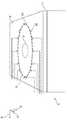
도 1 내지 도 17은, 일부 경우에 상이한 실시예들 내의, 장치의 다른 요소 및 그 요소의 개략도를 도시한다.
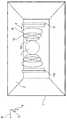
도 18은 제1 통합 렌즈를 갖는 측정 본체 및 측정 표면 상의 손가락의 횡단면이다.
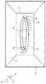
도 19는 제2 통합 렌즈를 갖는 측정 본체의 횡단면이다.
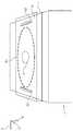
도 20은 제3 통합 렌즈를 갖는 측정 본체의 횡단면이다.
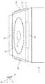
도 21은 제1 통합 렌즈를 갖는 측정 본체 및 여기 빔의 횡단면이다.
도 22는 제2 통합 렌즈를 갖는 측정 본체 및 여기 빔의 횡단면이다.
도 23은 제3 통합 렌즈를 갖는 측정 본체 및 여기 빔의 횡단면이다.
도 24, 도 25, 도 26은 측정 본체, 및 레이저 광원 또는 여기 광원, 특히 레이저 장치 형태의 여기 광원을 갖는 몇몇 배열체이고, 여기 광 빔은, 측정 본체의 기재 내로 통합된 광학적 도파관에 의해서, 측정 장치를 통해서 측정 표면으로 안내된다.1-17 show other elements of the device and schematic diagrams of the elements, in different embodiments in some cases.
18 is a cross section of a measurement body with a first integrated lens and a finger on the measurement surface.
19 is a cross-sectional view of a measurement body with a second integrated lens.
20 is a cross-sectional view of a measurement body having a third integrated lens.
21 is a cross-sectional view of an excitation beam and a measurement body with a first integrated lens.
22 is a cross-sectional view of an excitation beam and a measurement body with a second integrated lens.
23 is a cross-sectional view of an excitation beam and a measurement body with a third integrated lens.
24, 25 and 26 are some arrangements with a measurement body and an excitation light source in the form of a laser light source or an excitation light source, in particular a laser device, the excitation light beam by means of an optical waveguide integrated into the substrate of the measurement body, It is guided through the measuring device to the measuring surface.
도 1은 물질을 분석하기 위한 장치의 예시적인 실시예를 도시한다. 물질(5)은 바람직하게 측정 본체(1) 상에 직접 위치되거나 그 반대로 위치되고, 그 모두의 경우에, 물질, 및 본 개시 내용에서 "광학적 매체"로도 지칭되는 측정 본체(1)의 측정 표면(2)이 측정 동작을 위해서 직접적으로 물리적으로 접촉된다. 측정 본체(1)는 광에 투명한 또는 적어도 적외선 범위에서 투명한 중실형 본체(solid body), 특히 결정 또는 유리 본체 또는 플라스틱 본체, 특히 중합체 본체로서 구현되고, 그러한 본체는, 예를 들어 장치가 액체 내의, 일 실시예에서와 같이, 예를 들어 혈액 내의 글루코스 또는 혈당 함량을 측정하도록 설계될 때, 특히 중간-적외선 범위에서 투명하다. 이어서, 장치를 이용하여 글루코스 또는 혈당 레벨 지표를 생성할 수 있다.1 shows an exemplary embodiment of a device for analyzing a substance. The
장치는, 바람직하게 하나 이상의 여기 파장을 갖는 여기 광 빔 형태의 하나 이상의 전자기 여기 빔을 물질의 표면의 제1 영역 아래의 물질(5) 내에 위치되는 부피(5a) 내로 방출하기 위한, 여기 빔원 형태의 여기 전달 장치(3), 특히 레이저 장치를 포함한다. 여기 전달 장치(3)는 또한 이하에서 레이저 장치로 간략히 지칭된다. 레이저 장치는, 파장과 관련하여 튜닝될 수 있는 레이저, 특히 튜닝 가능 퀀텀 캐스케이드 레이저일 수 있고; 이하에서 더 설명되는 바와 같이, 동시에 또는 순차적으로 적절한 필터와 조합되는 그리고 특정 파장 또는 파장 범위를 격리시키기 위해서 직렬로 연결되는 광원의 이용 가능성을 포함하여, 규정된 좁은 파장 범위 내의 특정된 개별적인 파장 또는 광을 각각 방출하는, 레이저 형태의 적어도 2개의 단일 방출기, 특히 고정 파장을 갖는 반도체 레이저 또는 발광 반도체 다이오드를 갖는 광원 스트립 또는 광원 어레이를 이용하는 것이 바람직하다. 복수의 개별적인 방출기들이 조합되는 경우에, 개별적인 여기 광 빔은 다중화기에 의해서 함께 광 경로 내로, 예를 들어 광섬유 케이블 또는 격리된 채널 또는 광학적 매체 내의 다른 광 경로 내로 주입될 수 있다. 시준기가 또한 제공되어, 동시에 방출되는 다수의 광의 빔의 경우 그리고 순차적으로 방출되는 다수의 광의 빔의 경우 모두에서, 상이한 방출기들에 의해서 방출된 광 빔들을 서로 평행하게 가능한 한 근접하여 정렬시킬 수 있고 이들을 가능한 한 최대로 하나의 빔으로 조합할 수 있다.The device is in the form of an excitation beam source for emitting at least one electromagnetic excitation beam, preferably in the form of an excitation light beam having at least one excitation wavelength, into a
여기 광의 경로에서, 여기 광을 포커스하기 위한 광학적 요소가 또한 제공될 수 있다. 이는, 예를 들어, 측정 표면과 동일한 높이로 또는 측정 표면과 검출 장치 사이에서, 레이저 장치와 측정 본체 사이에, 또는 여기 빔이 진입하는 측정 본체 자체 상에, 또는 또한 여기 빔이 측정 본체를 떠나는 영역 내의, 예를 들어 측정 표면의 영역 내의 측정 본체 상에, 측정 표면 상에 제공될 수 있다.In the path of the excitation light, an optical element for focusing the excitation light may also be provided. This is, for example, at the same height as the measurement surface or between the measurement surface and the detection device, between the laser device and the measurement body, or on the measurement body itself into which the excitation beam enters, or also the excitation beam leaves the measurement body. It can be provided on the measuring surface, on the measuring body in the region, for example in the region of the measuring surface.
예를 들어, 광학적 요소가 볼록 렌즈로서 측정 본체의 재료로부터 가공될 수 있거나, 또한 측정 본체의 재료와 상이한 재료로 구성될 수 있다.For example, the optical element may be processed from the material of the measuring body as a convex lens, or it may also be composed of a material different from the material of the measuring body.
또한, 여기 빔(들)/여기 광 빔(들)의 세기 변조를 위한 장치(9)가 제공되고, 그러한 장치는 바람직하게 여기 빔원을 위한, 특히 레이저 장치를 위한, 특히 그 활성화를 위한, 변조 장치, 및/또는 빔 경로 내에 배열되는 적어도 하나의 제어되는 거울 및/또는 투명도와 관련하여 제어될 수 있고 빔 경로 내에 배열되는 층에 의해서 형성된다.In addition, a
물질의 영역(5a) 내의 여기 빔의 흡수 후에 방출된 열적 파동이 측정 본체에 진입하고, 측정 본체에서 열적 파동은 검출 장치에 의해서 검출 영역(4)에서 검출될 수 있다. 이는, 흡수 뒤에 시간적으로 매우 빨리 발생되는 국소적인 온도 증가 또는 온도 변화를 검출하는 것에 의해서 실행된다. 또한, 흡수 위상의 종료 후(여기 빔의 세기가 여기 빔의 변조의 일부로서 감소될 때)의 온도 변화의 반전(온도의 감소)은, 여기 빔이 물질에서 흡수되는 깊이에 따라 달라지는 특정 위상 오프셋을 갖고, 흡수 세기의 세기 곡선을 매우 신속하게 따른다.Thermal waves emitted after absorption of the excitation beam in the
본원에서, 응답 신호의 진폭은 여기 빔의 파장, 샘플의 흡수 특성, 및 샘플의 그리고 측정 본체/광학적 매체(1)의 열적 특성, 특히 열적 확산도 및 열적 전도도에 따라 달라진다. 또한, 샘플로부터의 열적 신호를 측정 본체 내로 커플링시키는 것이 또한 역할을 한다.Here, the amplitude of the response signal depends on the wavelength of the excitation beam, the absorption properties of the sample, and the thermal properties of the sample and of the measuring body/
도시된 예시적인 실시예에서, 검출 장치(4, 6)는 측정 본체(1)의 영역(4)으로서 형성되고, 이는 적어도 부분적으로 또는 일부 섹션에서 압전 재료로 구성되고, 검출 장치(4, 6)는 또한, 검출 영역(4)의 각각의 대향 측면들 상에 배열되는, 전극(6a, 6b, 6c 및 6d)을 갖는다. 전극(6a 내지 6d)은 검출 영역(4)의 재료와 전기적으로 접촉되고, 이하에서 "접촉 장치"(6)로서 함께 지칭된다. 이러한 방식으로, 전극들 사이에서 발생된 피에조-전압에 의해서 또는 전기 저항 또는 저항의 변화에 의해서, 압전 재료의 재료 선택에 따라서, 온도 또는 온도 변화가 검출될 수 있다.In the illustrated exemplary embodiment, the
도 1의 예에서, 2개의 직사각형, 층상형 또는 판-형상의, 평면 전극(6c 및 6d)이, 측정 표면(2)으로부터 상이한 거리들에서 측정 표면(2)의 표면 법선(7)을 따라 서로 팽행하게 배열된다. 또한 평면형이고 판-형상인 2개의 전극(6a 및 6b)이, 표면 법선(7)의 방향에 수직이고 측정 표면(2)에 평행한, 화살표(B)의 방향으로 서로 이격되고 평행하게 배열된다. 화살표(A)가 측정 표면(2)의 표면 법선(7)에 평행하고 화살표(B 및 C)는 그에 수직인, 화살표(A, B 및 C)에 의해서 형성된 좌표계가 또한, 도 1에 도시된 바와 같이, 방향성을 위해서 도 2 내지 도 15에 도시되어 있다.In the example of FIG. 1, two rectangular, layered or plate-shaped,
전자 장치, 특히 디지털 프로세싱 장치, 예를 들어 마이크로제어기 또는 프로세서로서 또는 컴퓨터로서 설계된, 물질을 분석하기 위한 평가 장치(16)가 전기 케이블(17, 18)을 통해서 접촉 장치(6)의 전극(6a, 6b, 6c 및 6d)과 전기적으로 접촉되고, 검출된 응답 신호를 평가하고, 일 실시예에서 글루코스 또는 혈액 혈당 레벨 지표(BSI)를 생성한다.An electronic device, in particular a digital processing device, for example designed as a microcontroller or processor or as a computer, an
여기 빔의 주파수/파장 그리고 특히 변조의 주파수 및/또는 위상에 관한 정보가 평가 유닛(16)에서 이용될 수 있도록 그리고 평가에서 고려될 수 있도록, 평가 장치(16)가 또한 변조 장치(9)에 전기적으로 연결된다. 이러한 방식으로, 예를 들어, 여기 빔의 변조 기능에 대한 응답 신호의 위상 변이를 평가하여, 응답 신호가 생성된, 물질 내의 깊이, 다시 말해서 또한 측정 표면(2) 또는 검출 영역(4)으로부터의 거리에 관한 정보를 획득할 수 있다. 이는, 물질(5) 내의, 글루코스와 같은 피검출 물질의 분포에 관한 깊이 프로파일링에 대한 정보가 얻어질 수 있게 한다.The
여기 빔의 변조에 관한 정보가 변조 장치(9)로부터 평가 장치(16)로 전송될 수 있으나, 제어 장치(16)가 변조를 직접 제어하는 것이 또한 제공될 수 있다. 평가 장치(16)는 또한, 특히 변조 주파수에서 신호를 평가하는, 평가를 위한 록-인 증폭기(lock-in amplifier)를 또한 가질 수 있다.Information about the modulation of the excitation beam can be transmitted from the
도시된 전극 쌍(6a/6b, 6c/6d)의 배열체는 단지 예이다. 전극의 하나의 쌍으로 또한 충분할 수 있으나, 검출 영역(4)의 적어도 일부가 2개의 전극 사이에 위치되어야 한다는 것이 중요하다. 또한, 최적의 기능을 위해서, 테스트 대상인 손가락과 같은 피분석 물질이 측정 표면(2) 상의 지정 지점에 반드시 배치되어야 한다. 손가락/물질의 임의의 측방향 변위는, 열 펄스가 전극들 사이에서 그 영향을 정확하게 미치지 않게 할 수 있고 측정 판독값이 최적이 아니게 하거나 정확해지지 않게 할 수 있다.The arrangement of the illustrated electrode pairs 6a/6b, 6c/6d is only an example. One pair of electrodes may also suffice, but it is important that at least a part of the
전극(6a, 6b, 6c, 6d)은, 부가적인 방법(3D-프린팅)에 의해서, 몰딩, 증발, 도핑, 측정 본체의 원료의 표적화된 변경(예를 들어, 입자 복사선 또는 감마 복사선 또는 레이저 복사선에 의한, 탄화수소의 전기 전도 탄소로의 변환), 접착 또는 이전에 도입된 함몰부 또는 슬롯 내로의 삽입에 의해서, 측정 본체(1) 내로 삽입되거나 그에 부착될 수 있다.
도 1에 따른 장치의 동작 및, 이러한 맥락의, 물질(5)을 분석하기 위한 방법을, 피분석 물질(5)이 인간 또는 동물 조직인 경우에 대해서 더 구체적으로 설명할 것이고, 여기에서 물질의 분석의 일부로서, 글루코스 또는 혈당 레벨 지표가 결정된다.The operation of the device according to FIG. 1 and, in this context, a method for analyzing the
하나 이상의 여기 빔(8), 바람직하게 적외선 빔이 레이저 광원(3)으로 순차적으로 또는 동시에 생성된다. 적외선 빔 또는 빔들의 파장은 바람직하게 3 ㎛ 내지 20 ㎛ 범위이고, 특히 바람직하게 8 ㎛ 내지 11 ㎛ 범위이다.One or
여기 빔(8)은 세기 변조 장치(9)에 의해서 세기-변조 또는 진폭-변조된다. 일 실시예에서, 세기 변조 장치(9)는 바람직하게 1 kHz 내지 1 MHz의 펄스 주파수를 갖는 짧은 광 펄스, 또는 바람직하게 1 kHz 내지 10 kHz의 엔벨로프 주파수(envelope frequency)를 갖는 펄스 패킷(pulse packet)(이중 또는 다중 변조)를 생성한다.The
변조된 여기 빔(8)은 광학적 매체/측정 본체(1) 내로, 특히 측정 본체의 재료 내로 직접적으로 커플링되고, 측정 표면(2)을 통과한 후에, 이들은 조직(5) 내의 부피(5a)에 진입한다.The modulated
본 발명은, 여기 빔(8)이 측정 표면(2)의 하부측의 피분석 물질(5)에 진입하는 것이 보장되기만 한다면, 측정 본체(1)의 통과 또는 측정 본체 제조 재료 내로의 진입으로 인해서 여기가 이루어지게 하는 기능을 할 수 있으나, 이는 필수적인 것이 아니다. 이러한 것은, 함몰부/슬롯(13)이 도 1에서 잠재적인 함몰부로서 제공된다는 사실에 의해서 설명되고, 그러한 잠재적인 함몰부는, 측정 본체(1)의 하부측의 측정 표면(2) 내로 병합되는 좁은 채널, 예를 들어 보어 가공된 홀을 형성하고, 이를 통해서 여기 빔(8)은 측정 표면(2)의 하부측에 도달할 수 있고 물질(5)에 진입할 수 있다. 이러한 넓은 의미에서, 전술한 특징부에 의해서 초기 빔이 "측정 표면(2)"을 통과한다는 것이 이해될 것이다. 일반적으로, 여기 빔(8)이 측정 본체(1)의 재료를 용이하게 통과할 수 있기만 하다면, 그러한 함몰부(13)가 없는 구조물이 제공될 수 있다. 그러한 함몰부(13)는 또한 측정 본체를 부분적으로만 침투할 수 있다. 함몰부(13) 대신, 통합된 광학적 도파관이 동일한 영역 내에 제공될 수 있고, 그러한 영역은 여기 빔이 주입될 수 있는 영역이다. 이는, 측정 표면 또는 센서 층 내에서 또는 상에서 종료될 수 있다. 광학적 도파관은, 표준 제조 방법을 이용하여, 측정 본체의 기재 내로 통합될 수 있다. 예를 들어, 측정 본체가 전체적으로 또는 부분적으로 규소로 구성되는 경우에, 광학적 도파관 케이블이 실리콘 온 인슐레이터(SOI) 광학적 도파관으로서 통합될 수 있다. 그러한 광학적 도파관은 직선형 또는 곡선형의 프로파일을 가질 수 있다. 이는, 여기 빔을 생성하는 여기 빔원, 특히 레이저 장치가 측정 본체에 대해서 자유롭게 배치될 수 있게 한다.The present invention, as long as it is ensured that the
여기에서 설명된 혈당 측정의 예의 경우에 - 여기 빔(8)이 글루코스 또는 혈당에 의해서 상당히 흡수되는 방식으로, 여기 빔(8)의 파장이 바람직하게 선택된다. 이하의 글루코스-관련 적외선 파장(진공 파장)이 글루코스 또는 혈당의 측정에 특히 적합하고, 응답 신호를 측정하기 위한 고정 파장; 8.1 ㎛, 8.3 ㎛, 8.5 ㎛, 8.8 ㎛, 9.2 ㎛, 9.4 ㎛ 및 9.7 ㎛로서 동시에 또는 연속적으로 개별적으로 또는 그룹으로 설정될 수 있다. 또한, 존재하는 다른 물질을 식별하기 위해서 그리고 측정에서 그 영향을 배제하기 위해서, 글루코스에 의해서 흡수되지 않는 글루코스-내성(tolerant) 파장이 이용될 수 있다.In the case of the example of blood glucose measurement described here-in such a way that the
측정을 위해서, 여기원, 특히 레이저 장치(3)를 스캐닝하는 것에 의해서 스펙트럼 영역이 연속적으로 스캐닝될 수 있거나, 스펙트럼이 적합한 특정 고정 파장에 의해서 지지 지점들에서 불연속적으로 커버될 수 있다.For measurement, the spectral region can be continuously scanned by scanning the excitation source, in particular the
글루코스 이외의 물질을 검출하고자 하는 경우에, 이러한 물질을 위한 흡수 파장을 특징으로 하는 상응 파장이 여기 빔을 위해서 선택된다.If it is desired to detect substances other than glucose, a corresponding wavelength characterizing the absorption wavelength for this substance is selected for the excitation beam.
조직(5) 내의 여기 빔(8)의 흡수는 부피(5a)의 영역 내의 국소적인 온도 증가를 유발하고, 이는, 조직(5)의 표면 및 그와 접촉되는 측정 표면(2)을 향하는 열 전달 그리고 그에 따라 연관된 압력 파동 및 열적 펄스의 전달을 트리거링한다(trigger). 측정 표면(2)에서 그리고 측정 본체(1) 내에서 이에 인접하여 발생되는 온도 및 압력 요동으로 인해서, 측정 표면(2)에 근접한 검출 영역(4) 내의 밀도, 굴절률 또는 변형, 미세구조 및 반사 거동이 변조되고, 결과적으로, 압전-재료의 경우에, 응답 신호로서 전기 저항이 영향을 받거나 압전-전압이 생성되거나 변화/변조된다.Absorption of the
측정된 값/응답 신호의 세기 변조의 크기/진폭은 (조직 내의 필연적인 흡수로 인해서) 여기 빔의 파장에 따라 그리고 (조직의 내부로부터 측정 표면(2)을 향하는 열 전달 및 압력 파동으로 인해서) 여기 빔의 펄스 주파수/변조 주파수에 따라, 그리고 샘플 및 측정 본체(1)의 열적 특성에 따라 달라진다.The magnitude/amplitude of the intensity modulation of the measured value/response signal depends on the wavelength of the excitation beam (due to the inevitable absorption within the tissue) and (due to the heat transfer and pressure waves from the inside of the tissue towards the measurement surface 2). It depends on the pulse frequency/modulation frequency of the excitation beam and on the thermal characteristics of the sample and
측정은 복수의 상이한 변조 주파수에 대해서 실시될 수 있고, 예를 들어 스펙트럼 형태의 측정 결과들이 서로 상호 연관될 수 있다. 개별적인 스펙트럼은, 여기 빔의 파장에 따라 달라지는, 응답 신호, 예를 들어 압전-전압 또는 가변적인 압전-전압의 진폭을 나타낸다. 샘플의(또는 물질(5)의) 표면으로부터의 측정 값들이 상쇄/제거될 수 있게 하는 또는 특정 정보가 특정 깊이 범위로부터 얻어질 수 있게 하는 방식으로, 상이한 스펙트럼들이 상호 연관될 수 있다.Measurements can be carried out for a plurality of different modulation frequencies, for example measurement results in spectral form can be correlated with each other. The individual spectra represent the amplitude of the response signal, for example piezo-voltage or variable piezo-voltage, depending on the wavelength of the excitation beam. Different spectra can be correlated in such a way that measurements from the surface of the sample (or of the material 5) can be canceled/removed or specific information can be obtained from a specific depth range.
주어진 변조 주파수에서 스펙트럼의 각각이, 상이한 깊이들의, 피분석 물질(5)로부터의 응답 신호들의 중첩으로 인해서 발생되는데, 이는 여기 빔(8)이 샘플을 통과할 때 상이한 깊이의 층들에서 부분적으로 흡수되기 때문이다.Each of the spectra at a given modulation frequency occurs due to the overlap of the response signals from the
그에 따라, 응답 신호는 상이한 깊이들로부터의 신호들의 혼합을 나타낸다.Accordingly, the response signal represents a mixture of signals from different depths.
상이한 깊이들로부터의 신호들의 혼합비는 여기 빔(8)의 변조 주파수에 따라 달라진다.The mixing ratio of signals from different depths depends on the modulation frequency of the
상이한 변조 주파수들에서의 상이한 스펙트럼들을 상호 연관시키는 것, 예를 들어, 각각의 경우에 개별적인 스펙트럼의 가중치를 달리하면서, 더 높은 변조 주파수에서의 스펙트럼과 더 낮은 변조 주파수에서의 스펙트럼 사이의 차이를 계산하는 것 또는 더 높은 변조 주파수에서의 스펙트럼을 더 낮은 변조 주파수에서의 스펙트럼으로 나누는 것에 의해서, 물질의 상부 층의 영향이 제거되거나 적어도 감소될 수 있다.Correlating different spectra at different modulation frequencies, e.g. calculating the difference between a spectrum at a higher modulation frequency and a spectrum at a lower modulation frequency, varying the weight of the individual spectrum in each case By doing or dividing the spectrum at a higher modulation frequency by a spectrum at a lower modulation frequency, the influence of the upper layer of material can be eliminated or at least reduced.
일 실시예에서 비교표 또는 비교 곡선의 형태로 평가 장치(16)의 메모리 내에 저장된, 이전에 실시된 교정(calibration) 또는 비교 측정치와의 비교, 또는 기준 데이터 세트와의 비교를 기초로, 조직 내의 또는 부피(5a) 내의 글루코스 또는 혈당의 현재 농도에 관한 정보를 제공할 수 있고 상응하는 글루코스 또는 혈당 레벨 지표를 생성할 수 있다. 예를 들어, 비교표 또는 비교 곡선은, 환자 신체의 외부에서 분석된 혈액 샘플로부터 얻어진 글루코스 또는 혈당 값을 기초로 생성된 것일 수 있다.In one embodiment, based on a comparison with a previously performed calibration or comparative measurement, stored in the memory of the
도시된 예시적인 실시예에서 여기 광 빔 또는 빔들(8)을 방출하는 레이저 장치(3)에 의해서 형성된 여기 빔원이 어레이로서 구현될 수 있다. 어레이는, 피분석 물질의 흡수 스펙트럼 내의 상이한, 고정 파장들의 단색 광을 위한 적어도 5개, 유리하게는 적어도 10개, 더 유리하게 적어도 15개 또는 적어도 50개 또는 100개의 개별적으로 제어 가능한 방출기(100a)를 갖는다. 개별적인 방출기는 레이저 방출기일 수 있으나, 이들은 또한, 특정 파장 범위 내의 복사선을 선택적으로 방출하는, 다른 유형의 방출기, 예를 들어 적합한 발광 다이오드 또는 다른 반도체 구성요소일 수 있다.In the illustrated exemplary embodiment, an excitation light beam or an excitation beam source formed by a
어레이는 바람직하게 이하의 파장(진공 파장) 중 하나 이상, 특히 바람직하게 전부를 갖는 단색 광의 빔을 생성한다: 8.1 ㎛, 8.3 ㎛, 8.5 ㎛, 8.8 ㎛, 9.2 ㎛, 9.4 ㎛ 및 9.7 ㎛ 그리고, 희망하는 경우에, 또한 글루코스-내성 파장.The array preferably produces a beam of monochromatic light having one or more, particularly preferably all, of the following wavelengths (vacuum wavelengths): 8.1 μm, 8.3 μm, 8.5 μm, 8.8 μm, 9.2 μm, 9.4 μm and 9.7 μm and, If desired, also a glucose-tolerant wavelength.
여기 전달 장치/여기 광원(3)이 직접적으로 또는 조정 장치에 의해서 광학적 매체/측정 본체(1)에 영구적으로 그리고 기계적으로 연결되는 것이 제공될 수 있다. 조정 장치는 바람직하게 측정 본체(1)로부터의 여기 광원(3)의 거리의 조정, 또는 빔의 길이방향을 따른 조정 및/또는 그에 수직인 평면 내의 조정을 가능하게 한다.It may be provided that the excitation delivery device/
여기 전달 장치(3), 및 검출 장치(4, 6)를 갖는 측정 본체(1)가 직접적으로 서로 또는 공통 캐리어(미도시)에 부착되는 것이 또한 제공될 수 있다. 캐리어는, 하우징 내에 장착된 플라스틱 부분, 인쇄회로기판 또는 금속 시트에 의해서 형성될 수 있다.It can also be provided that the
캐리어는 또한 하우징 자체에 의해서 또는 하우징의 일부에 의해서 형성될 수 있다.The carrier can also be formed by the housing itself or by a part of the housing.
물질을 분석하기 위한 장치가 내부에 배열되는 하우징(미도시)을 갖는, 물질을 분석하기 위한 장치는 신체, 예를 들어 사람의 몸통에 부착될 수 있고, 하나 이상의 여기 광 빔(8)을 방출하기 위한 여기 전달 장치(3) 및 시간-의존적 응답 신호를 검출하기 위한 검출 장치(4, 6)는, 장치의 측정에 적합한 측면 및 측정 표면(2)이 신체/몸통에 대향되는 장치의 측면 상에 위치되고, 그에 따라 피분석 물질이, 예를 들어 측정 표면(2) 상에 손가락을 배치한 사람에 의해서, 신체/몸통으로부터 멀어지는 쪽으로 대면되는 하우징의 측면 상에서 측정되도록 하는 방식으로, 배열되고 구성된다. 이를 위해서, 예를 들어, 하우징은 본체의 일부를 형성하는 스트랩에 의해서 사람의 신체에 부착되고, 실시예에서 손목 밴드 형태로 손목에 부착된다. 손목의 대향 측면 상에서, 이어서 하우징은 여기 광 빔(8)이 투과할 수 있는 창을 갖거나, 외측-대면 측정 표면(2)을 갖는 측정 본체(1)가 신체로부터 멀리 외측으로 대면되는 하우징의 측면 내로 직접적으로 피팅되고, 예를 들어, 측정 표면(2)과 함께, 하우징 자체의 표면의 일부 섹션을 형성한다.The device for analyzing the material, having a housing (not shown) in which the device for analyzing the material is arranged, can be attached to the body, for example the torso of a person, and emits one or more
이러한 설계에서, 손가락 패드가 이어서 측정 본체(1) 상에 배치될 수 있고 모니터링될 수 있다.In this design, a finger pad can then be placed on the measuring
측정 본체(1)는, 캐리어와 동일한 방식으로, 하우징의 내측에 또는 하우징 상에 직접 장착될 수 있다. 측정 본체(1)는 또한 캐리어에 직접적으로 연결될 수 있고, 광학적 매체/측정 본체(1)에 대한 캐리어의 배치를 위해서 조정 장치가 제공되어야 한다.The measuring
또한, 여기 광원(3)을 측정 본체 상에 직접 장착할 수 있다.Further, the
하우징 내의 광학 창을 통해서 및/또는 측정 본체(1)를 통해서, 물질 표면 또는 도포된 손가락 패드의 다른 매개변수가 모니터링될 수 있고, 일 실시예에서 지문이 모니터링될 수 있다. 이를 위해서, 카메라 형태의 광학적 검출기가 또한 예를 들어 캐리어에 부착될 수 있고, 그러한 카메라는 측정 본체를 통해서 물질(5)의 표면에 관한 또는 측정 본체 이후에 통과되는 물질의 표면에 관한 화상을 디지털적으로 획득한다. 이러한 화상 및 검출 장치(4, 6)로부터의 측정 정보가 프로세싱 장치 내에서 프로세스되고, 그러한 프로세싱 장치는 검출 장치(4, 6)에 그리고 또한 여기 전달 장치(3)에 직접적으로 연결될 수 있다. 프로세싱 장치는 또한 측정을 위한 제어 과제를 실시할 수 있다. 프로세싱 장치는 또한, 장치의 다른 부분으로부터 적어도 부분적으로 분리되고 이격될 수 있고 무선 링크를 통해서 이들과 통신할 수 있다.Through the optical window in the housing and/or through the measuring
그에 따라, 카메라로부터의 화상 데이터는 하우징 내에서, 또는 하우징 외부의 무선 연결을 또한 통해서 더 프로세스될 수 있고, 식별된 사람에 관한 교정 데이터를 검색하기 위해서 개인 신원 데이터베이스와 비교될 수 있고, 이러한 데이터를 측정을 위한 기초로 이용할 수 있다.Accordingly, image data from the camera can be further processed within the housing, or also via a wireless connection outside the housing, and can be compared to a personal identity database to retrieve calibration data regarding the identified person, and such data Can be used as a basis for measurement.
그러한 교정 데이터는 또한 원격 검색을 위해서 데이터베이스 내에, 일 실시예에서 클라우드 내에 저장될 수 있다. 검출 장치의 측정 데이터가 또한 하우징의 내부 및 외부 모두에서 더 프로세스될 수 있다.Such calibration data may also be stored in a database for remote retrieval, in one embodiment in the cloud. The measurement data of the detection device can also be further processed both inside and outside the housing.
데이터가 하우징의 외부에서 프로세스되는 경우에, 결과적인 데이터는 바람직하게, 하우징 내의 장치에서 디스플레이되도록, 무선에 의해서 하우징 내의 장치로 다시 전송되어야 한다.If the data is processed outside of the housing, the resulting data should preferably be transmitted back to the device in the housing by radio, so that it is displayed on the device in the housing.
어느 경우에도, 유리하게 광학 창을 통해서 그리고 일 실시예에서 또한 부분적으로 측정 본체를 통해서 또는 측정 본체(1) 상에서 판독될 수 있는 디스플레이(미도시)가 하우징에 제공될 수 있다. 디스플레이는 또한 광학 창을 통해서 디스플레이 표면 상으로 표시자 광(indicator light)을 투사할 수 있고, 이를 위해서, 투사 장치를 포함할 수 있다. 일 실시예에서, 디스플레이는 측정 또는 분석 결과, 특히 글루코스 농도가 디스플레이될 수 있게 한다. 출력은 일 실시예에서 기호 코드 또는 컬러 코드를 이용하여 구현될 수 있다. 일 실시예에서, 디스플레이 또는 그와 병렬인 신호전달 장치를 통해서, 다른 환자 매개변수(예를 들어, 인슐린 보정 계수)에 따라, 인슐린 투여를 위한 제안이 출력될 수 있거나, 신호가 인슐린 펌프 형태의 투여 장치에 자동적으로 전달될 수 있다.In either case, a display (not shown) can advantageously be provided in the housing which can be read through an optical window and in one embodiment also partly through or on the measuring
대안적으로, 특정 양의 특정 식품의 소비를 위한 권장이 이루어질 수 있다. 이는, 예를 들어, 데이터베이스로부터 검색될 수 있고 특히 전자 형태로 전달될 수 있는, 준비를 위한 제안에 연계될 수 있다. 이러한 준비 지시는 또한 자동 식품 준비 장치로 전송될 수 있다.Alternatively, recommendations can be made for the consumption of certain foods in certain amounts. This can be linked to proposals for preparation, which can be retrieved, for example, from databases and delivered in particular in electronic form. These preparation instructions can also be transmitted to an automatic food preparation device.
외부 데이터 프로세싱 장치로의 그리고 그로부터의 장치의 연결은, 광섬유, 케이블, 무선(예를 들어, 블루투스, 와이파이), 또는 심지어 초음파 또는 적외선 신호와 같은, 모든 일반적인 표준을 이용하여 구현될 수 있다.The connection of the device to and from an external data processing device can be implemented using all common standards, such as optical fiber, cable, wireless (eg Bluetooth, Wi-Fi), or even ultrasonic or infrared signals.
도 2 내지 도 16은, 다른 것들 중에서, 다양한 방식으로 분포되는 전극을 갖는 접촉 장치(6)의 특정 설계를 도시한다.2 to 16 show a specific design of a
도 17은 측정 광 빔의 반사를 검출하는 검출 장치를 갖는 본 발명의 설계를 도시한다.Fig. 17 shows a design of the present invention with a detection device for detecting reflection of a measuring light beam.
도 2는 측정 표면(2) 및 검출 영역(4)을 갖는 측정 본체(1), 및 접촉 장치(6)를 다시 개략적으로 도시한다. 도 2는 또한, 접촉 장치(6)가 검출 영역(4)의 각각의 측면 상에서 복수의 전극을 또한 가질 수 있다는 것을 보여준다. 도시된 예에서, 전극(6e, 6f)은 검출 영역(4)의 제1 측면 상에 도시되어 있고, 전극(6g, 6h)은 검출 영역(4)의 대향 측면 상에 도시되어 있다. 도시된 예에서, 개별적인 전극이 직사각형 판-유사 방식으로 설계된다. 측정을 위해서, 장치(16)가 2개의 전극들(6e, 6f, 6g, 6h) 사이의 (압전 전압 또는 변경된 저항 형태의) 피에조-신호를 평가할 수 있고, 결과들이 비교될 수 있다. 이어서, 측정의 추가적인 평가를 위해서 또는 후속 측정을 위해서, 전극의 쌍이 선택될 수 있다. 그러한 선택은, 어떠한 전극의 쌍이 가장 큰 신호 또는 간섭에 가장 덜 민감한 신호를 제공하는지를 고려할 수 있다. 인접 전극의 쌍, 예를 들어 전극(6f 및 6g) 또는 전극(6e 및 6f 또는 6g 및 6h)이 바람직하게 선택될 수 있다. 그러나, 측정을 위해서 전극 쌍(6e, 6h)을 이용할 수 있고 이러한 전극들 사이에 존재하는 신호를 평가할 수 있다. 그렇게 하는데 있어서, 측정을 위해서 현재 사용되지 않는 전극들이 다른 전극에 대한 유전적 차폐를 제공할 수 있다는 것을 주목하여야 한다. 예를 들어, 미사용 전극은 플로팅 전위에서 유지될 수 있거나, 특정 경우에 접지 전위에 연결될 수 있다.2 schematically shows again the measuring
도 3은, 검출 영역(4)의 각각의 측면 상에서 3개의 환형 전극(6i, 6j, 6k)을 갖는 접촉 장치(6)의 배열을 도시한다. 이러한 전극은 또한 측정을 위한 쌍에서 이용될 수 있다. 도시된 경우에, 환형 전극의 직경은 검출 영역(4)으로부터 외측으로 증가되고, 그에 따라 전극(6i)은 전극(6j)보다 큰 직경을 갖고, 전극은 전극(6k)보다 큰 직경을 갖는다.3 shows an arrangement of a
또한, 예를 들어 편평한, 판-형상의 전극(6l, 6m)의 쌍이 전극(6i, 6j, 6k) 뒤쪽의 외측에 제공될 수 있다.Further, for example, a pair of flat, plate-shaped
이러한 전극의 환형 설계는, 외측으로 증가되는 크기와 함께, 내부 전극에 의해서 덜 차폐되는 외부 전극 및 서로 독립적으로 사용될 수 있는 상이한 전극 쌍을 초래할 수 있다.The annular design of these electrodes, along with an outwardly increasing size, can result in external electrodes less shielded by internal electrodes and different electrode pairs that can be used independently of each other.
도 4는 측정 표면(2)에 평행한 수평 방향 - 즉 방향(B) - 으로 검출 영역의 각각의 측면 상의 서로 앞뒤의 3개의 환형 전극(6n, 6o, 6p)을 갖는 접촉 장치(6)를 갖는 배열을 도시하고, 환형 전극들의 직경은 검출 영역(4)으로부터의 거리가 증가됨에 따라 감소된다.4 shows a
검출 영역의 각각의 측면 상에서, 전극 외측 측방향으로, 측정 본체 내로 통합될 수 있거나 그 외측에 부착될 수 있는 히트 싱크(14, 14a)가 도시되어 있다. 예를 들어, 이러한 히트 싱크는, 열 용량 및/또는 열 전도도가 측정 본체(1)를 구성하는 재료(들)의 열 용량 및/또는 열 전도도보다 큰, 금속 또는 다른 재료로 구성될 수 있다.On each side of the detection area, there are shown
환형 본체와 같은 단일 본체가 또한, 검출 영역(4) 또는 전체 측정 본체(1)를 둘러싸는 히트 싱크로서 제공될 수 있다. 히트 싱크는 또한 펠티에 요소에 의해서 구현될 수 있다. 히트 싱크는, 검출 영역 내의 열적 파동/열 펄스의 도달에 의해서 유발되는 온도 증가가 냉각에 의해서 가능한 한 신속하게 보상될 수 있도록, 그에 따라 검출 영역(4) 내의 측정 본체(1)의 재료가 후속 열 펄스에 가능한 한 신속하게 반응할 수 있도록 보장한다.A single body, such as an annular body, can also be provided as a heat sink surrounding the
열 펄스들은 여기 빔의 변조 주파수를 갖고 서로를 뒤따른다. 검출 영역 위에, 판-형상의 열적 장벽(15)이 제공되고, 열적 장벽은 여기 빔(8)의 통과를 위한 개구부를 갖는다. 이는, 측정 본체(1)의 재료의 열 전도도가 너무 큰 경우에, 열 펄스가 검출 영역에 도달할 때 열 펄스가 너무 빨리 소산되지 않게 보장하고, 그에 따라 예를 들어 히트 싱크를 통한 열 소산 전에 온도 증가가 검출 영역(4) 내에서 짧게 축적될 수 있게 보장한다.The heat pulses follow each other with the modulation frequency of the excitation beam. Above the detection area, a plate-shaped
하나 이상의 히트 싱크 및/또는 하나 이상의 열적 장벽이 측정 본체 내로 통합되거나 그 외측에 장착되어, 열 전달을 적절히 지향시킬 수 있다. 이는 편평한 측정 본체에서, 또는 얇은 피에조-재료의 코팅을 갖고 다른 곳은 피에조-효과를 갖지 않는 재료로 구성되는 측정 본체에서 특히 실용적일 수 있다.One or more heat sinks and/or one or more thermal barriers may be incorporated into or mounted outside the measurement body to properly direct heat transfer. This may be particularly practical in a flat measuring body, or in a measuring body composed of a material that has a thin coating of piezo-material and does not have a piezo-effect elsewhere.
도 5는 검출 영역(4)의 각각의 측면 상에서 2개의 프레임-형상의 전극(6q, 6r)을 갖는 접촉 장치(6)를 도시하고, 프레임-형상의 전극은 직사각형 프레임으로서 구현되고 검출 영역(4)으로부터 동일한 거리에 또는 검출 영역(4)으로부터 상이한 거리들에 배열될 수 있다. 그에 따라, 전극(6q, 6r)은, 예를 들어, 검출 영역(4)의 각각의 측면 상에서 서로 공통 평면적으로 그리고 동심적으로 배열될 수 있거나, 검출 영역(4)으로부터의 거리와 관련하여 엇갈릴 수 있다.5 shows a
도 6은 검출 영역(4)의 위 및 아래 모두에서 3개의 환형 전극을 갖는, 다시 말해서 전극들이, 방향(A)을 따라 표면 법선과 관련하여 측정 표면(2)으로부터 상이한 거리들에서 서로 앞뒤로, 검출 영역(4)의 양 측면 상에 배열되는 접촉 장치(6)를 도시한다.6 shows three annular electrodes both above and below the
도 7은 접촉 장치(6)의 전극의 이용에 관한 예를 도시한다. 검출 영역(4)의 각각의 측면 상에서, 2개의 프레임-형상의 전극(6q, 6r)이 검출 영역(4)으로부터 상이한 거리들에서 제공된다. 일반적으로, 피분석 물질이 물질의 영역(5)에 의해서 도 7에 표시된 바와 같이 측정 표면(2) 아래의 중심에 위치되는 경우에, 검출 영역(4)의 양 측면 상의 2개의 전극의 선택이 측정을 위해서 최적일 수 있다. 그러나, 예를 들어 대상의 손가락이 최적의 위치와 관련하여 측방향으로 이동되는 것에 의해서, 샘플이 잘못된 장소에서 측정 표면(2) 상에 배치되는 경우에, 피분석 재료는 도시된 위치(5')의 방향으로 이동될 것이고, 최적의 검출 영역은, 4'로서 표시된, 측정 본체(1)의 영역 내에 놓일 것이다. 이러한 경우에, 2개의 다른 전극, 도시된 경우, 전극(6q, 6r)을 측정을 위해서 선택하는 것, 그리고 그 사이에서 발생된 전기 신호를 평가하는 것이 실용적일 수 있다. 이러한 경우에, 상이한 전극의 쌍들이 또한 테스트로서 사용될 수 있고, 상응 신호가 평가될 수 있고 서로에 대해서 비교될 수 있고, 그에 따라 피분석 물질(5)이 측정 표면(2) 상에 위치되는 정확한 지점을 그리고 어떠한 전극 쌍이 최적의 결과를 생성하는지를 결정할 수 있다.7 shows an example of the use of the electrodes of the
도 8은 검출 영역(4)의 양 측면 상에서 표면 법선(A)의 방향으로 서로 앞뒤로 위치된 6개의 환형 전극을 도시한다. 검출 영역의 각각의 측면은 서로 동축적으로 배열된 3개의 환형 전극을 갖고, 각각의 전극의 직경은 검출 영역(4)으로부터 거리가 멀어질수록 증가된다. 여기에서 다시, 검출 영역(4)과 관련하여 대칭적으로 또는 비대칭적으로 서로 대향되어 배치되는 상이한 전극 쌍들이 측정을 위해서 선택될 수 있다. 이러한 구성에서, 다른 도면 중 일부에서와 같이, 여기 빔 및 레이저 장치의 예시로서, 명료함을 위해서 평가 유닛을 생략하였다.8 shows six annular electrodes positioned back and forth from each other in the direction of the surface normal A on both sides of the
도 9는 검출 영역(4)을 갖는 측정 본체(1)를 도시하고, 접촉 장치(6)는, 검출 영역(4) 주위의 환형 영역(10) 내에 분포된 복수의 전극(6s, 6t, 6u)을 갖는다. 전극(6s, 6t, 6u)의 이러한 분포에서, 측정을 위해서 2개의 대각선 방향으로 대향된 전극(6s, 6u) 사이의 신호를 선택하는 것이 적절하고, 상이한 전극 쌍들은 시험적인 선택을 위해서 동작될 수 있다.9 shows a
이러한 맥락에서, 검출 영역(4)은, 도면에서, 요구되는 재료 선택에 상응하는 그에 따라 압전-효과를 디스플레이하는 그리고 동시에 피분석 물질(5)로부터의 응답 신호가 열 펄스의 형태로 도달하는 측정 본체(1)의 영역 내에 위치되는, 측정 본체의 영역으로서 식별된다는 것을 주목하여야 한다. 가능한 검출 영역(4)은 또한 측정을 위해서 선택된 전극(6)에 따라 달라지고, 이러한 영역(4) 내의 측정 본체(1)가 필요 재료로 구성되거나 압전-효과를 나타낼 때, 측정을 위해서 선택된 전극들(6) 사이에 일반적으로 위치된다. 그에 따라, 검출 영역(4)은 반드시 측정 본체 내에서 특정될 필요가 없고, 사실상, 물질(5)이 측정 표면(2) 아래에 적절히 배치될 때 이용되는 물리적 영향에 의해서, 선택된 접촉 전극(6)에 의해서 피분석 물질로부터의 응답 신호가 검출될 수 있는 영역으로서 획득된다.In this context, the
도 9에 도시된 전극(6s, 6t, 6u)은 직사각형 또는 둥근형 또는 계란형 및 편평하거나 부분적으로 원통형인 형상, 즉 하나의 축에서 곡선화된 것일 수 있다.The
도 10은, 예에서, 전극들이 검출 영역 주위에 배치된 환형 영역(10)이 측정 표면에 평행한 원형 링의 형태로 배열될 필요가 없고, 상이한 각도 위치에서 측정 본체(1)의 공간 내에 원형 링으로서 제공될 수 있다는 것을 보여준다.FIG. 10 shows, in an example, that the
도 11은, 접촉 장치(6)가 측정 본체(1) 내에서 또는 측정 본체(1) 상에서 측정 표면(2)의 영역 내에 직접적으로 제공되는 배열을 도시한다. 개별적인 전극(6v, 6w)이 환형 영역(10) 내에서 검출 영역(4) 주위에 분포된 측정 표면(2) 상에 직접적으로 배열된다.11 shows an arrangement in which the contacting
도 12는 도 11에 도시된 구조의 특정 실시예를 도시한다. 도 12에서, 측정 본체(1)는 하부로부터, 즉 외측으로부터 측정 표면(2)을 바라보는 것으로 도시되어 있고, 전극을 수용하기 위한 함몰부는 측정 본체(1)의 하부 층(1') 내의 환형 영역(10) 주위에 제공된다. 함몰부는(17, 18, 19, 20, 21)로 표시되어 있다. 전극 본체(6x, 6y)가 함몰부 내에 배치될 수 있고, 형상-피팅 또는 재료 결합 방식으로 그 곳에서 유지될 수 있다. 예를 들어, 전극(6x, 6y)은 함몰부(21, 20) 내에 래칭될(latched) 수 있다. 함몰부(17, 18, 19, 20, 21)는 예를 들어, 측정 표면(2) 상의 전도체 트랙(32)에 연결되는 접촉부를 갖는다. 전도체 트랙(32)은, 도시되지 않은 평가 장치에 전기적으로 연결된다. 전극(6x, 6y)을 함몰부 내로 삽입할 때, 전극은 전도체 트랙(32)에 그리고 그에 따라 평가 장치에 전기적으로 연결된다.12 shows a specific embodiment of the structure shown in FIG. 11. In Fig. 12, the measuring
전술한 바와 같이 측정을 위해서 전극이 선택될 수 있다.Electrodes can be selected for measurement as described above.
예를 들어, 측정 본체(1)의 층(1')이 압전 재료로 구성되는 한편, 측정 본체(1)의 나머지는, 또한 압전적으로 감응적인 또는 비-압전적인, 다른 재료로 구성되는 것이 제공될 수 있다.For example, it is provided that the
도 13은, 측정 본체(1)의 층(1')이, 예를 들어 접착 결합 또는 증착에 의해서 층(1')(센서 층)에 외부 도포되는 전극(22, 23)을 수반하는, 설계 변형을 도시한다. 압전 재료로 제조되는 센서 층(1')의 층 두께는 0 내지 1 mm, 특히 0 내지 500 미크론, 특히 100 미크론 미만일 수 있다. 그러한 층은 측정 본체(1)의 제1 부분/나머지 섹션에 접착 결합될 수 있거나, 다른 접합 기술에 의해서 그에 접합될 수 있다. 여기 빔은 이러한 층(1')을 통과할 수 있다. 여기 빔을 위한 채널-형상의 함몰부가 측정 본체(1)의 나머지 섹션 내에(소위 측정 본체(1)의 제1 부분 내에) 제공될 수 있다. 이어서, 측정 본체(1)의 이러한 나머지 섹션의 재료는, 석영 또는 사파이어와 같은 적외선에 대해서 불투과적인 재료로 구성될 수 있다. 이러한 전극은 층(1') 내의 검출 영역(4) 내의 압전 효과의 측정을 가능하게 한다. 동일한 유형의 다른 전극이, 검출 영역(4) 주위의 환형 영역(10) 내에서, 측정 표면(2) 아래에 또는 측정 표면(2) 내의 함몰부 내에 제공될 수 있다.Figure 13 is a design in which the layer 1'of the measuring
도 14는 측정 본체(1)의 압전 층(1')을 갖는 실시예를 도시하고, 여기에서 2개의 전극(24, 25)이 층(1')의 측면에 부착된다. 이러한 전극(24, 25)은 또한, 예를 들어, 접착식으로 결합되거나 증착될 수 있거나, 다른 방식으로 층(1')의 표면에 도포될 수 있고, 또는 전극이 층(1) 내의 함몰부 내로 도입될 수 있다. 층(1')의 나머지 측면 표면이 또한 전극(26, 27)을 가질 수 있고, 모든 전극은 광 케이블 또는 전도체 트랙을 통해서 평가 장치에 연결된다.14 shows an embodiment with a piezoelectric layer 1'of the measuring
도 15는, 검출 영역(4) 주위의 환형 영역(10) 내에서, 측정 본체의 압전 층의 하부측에, 즉 측정 표면(2)에 배열된 복수의 전극(28, 29)을 도시한다. 여기에서 다시, 상이한 전극의 쌍들이 측정을 위해서 대안적으로 이용될 수 있고, 쌍의 2개의 전극은 검출 영역(4)의 상이한 측면들 상에서 서로 대면되어 배치되도록 설계된다. 이러한 전극은 또한, 예를 들어, 접착식으로 결합되거나 증착될 수 있거나, 다른 방식으로 층(1')의 표면에 도포될 수 있고, 또는 층 내의 함몰부 내로 도입될 수 있다. 실험에 의해서, 측정 표면(2) 아래의 물질(5)의 위치에 따라, 즉 최적 검출 영역(4)의 위치에 따라 최적의 전극 쌍을 선택하도록, 상이한 전극의 쌍들이 측정을 위해서 조립 및 동작될 수 있다.FIG. 15 shows a plurality of
도 16은, 편평한 본체로서 설계되고 예를 들어 도 14, 도 15에 도시된 측정 본체(1)의 층(1')과 유사하게 설계될 수 있고 전극을 구비할 수 있는, 측정 본체(11)를 도시한다. 그러나, 이러한 경우에, 전체 측정 본체(1)가 편평한 본체(11)에 의해서 형성될 수 있다. 편평한 본체(11)의 하부측에, 측정 표면(2)이 제공되고, 측정 표면(2)의 표면 법선(7)의 방향을 따른 편평한 본체(11)의 연장 길이는 측정 표면(2)에 평행한 방향을 따른 연장 길이에 비해서 짧다. 장치의 설치를 위해서 표면 법선(7)을 따라 최소 공간을 차지하도록, 레이저 장치(3)를 측정 표면의 편평한 측면 중 하나 상의 측정 표면의 가상 연장 길이에 걸쳐 편평한 본체의 측면에 대해서 배열하는 것, 그리고 여기 빔(8)을 측정 표면(2)에 평행하게 또는 실질적으로 평행하게 측정 본체/편평한 본체(11) 내로 조사하는 것이 제공될 수 있다. 여기 빔(8)을 위해서, 도 1에서 참조 부호 13으로 도시된 것과 유사하게, 채널-형상 함몰부가 이어서 편평한 본체 내에 제공될 수 있다. 예를 들어, 거울 장치(12)가 이어서 편평한 본체 내측에 제공되고, 거울 장치는 측정 빔(8)을 측정 표면(2)을 향해서 그리고 이어서 측정 표면(2)을 통해서 물질(5) 내로 반사한다.Figure 16 is a measuring
편평한 본체는 또한 전체적으로 압전 재료로 구성될 수 있거나, 측정 표면의 영역 내에서 압전 층을 가질 수 있다.The flat body may also be entirely composed of a piezoelectric material, or may have a piezoelectric layer within the region of the measurement surface.
대안적으로, 여기 빔(8)이 편평한 본체에 평행하게 편평한 본체(11)의 상단부에 배열된 거울 장치(12)로 복사되도록 그리고 그곳에서 측정 표면(2)에 수직으로 편평한 본체(11) 내로 반사되도록, 레이저 장치(3)가 편평한 본체(11)의 약간 위에 배치되는 것이 또한 제공될 수 있다. 양 경우에, 표면 법선(7)의 방향을 따른 장치의 연장 길이는 도 1에 도시된 실시예에 비해서 크게 감소된다. 측정 본체(11) 및 레이저 장치(3)가 그에 따라 함께, 가능하게는 평가 장치(16)와 함께, 편평한 하우징 내에 수용될 수 있다.Alternatively, the
전극(22, 23)은, 검출 영역(4) 상의 측정을 위해서 이용되는, 편평한 본체(11)의 내측에, 아래에 또는 그 측면에 제공될 수 있다. 이러한 설계에서, 전술한 둘 이상의 전극의 임의의 배열이 또한 이용될 수 있다.The
또한, 편평한 본체(11)로서 형성된 그러한 측정 본체는 제1 부분 및 이러한 부분에 접합/접착된, 센서 층, 예를 들어 압전 층으로부터 형성될 수 있고, 이어서 압전 층은 측정 표면을 형성하고 전극을 구비한다. 이러한 경우에 또한, 함몰부가 측정 본체(11)의 제1 부분 내에서 여기 빔을 위해서 제공될 수 있고, 그러한 측정 본체는 이어서 선택적으로, 석영 또는 사파이어와 같이, 적외선에 대해서 불투과적인 또는 매우 투과성이 좋지 못한 재료로 구성될 수 있다.Further, such a measurement body formed as a
도 16의 하부 부분에서, 여기 빔(8)의 반사 경로가 명확해지도록, 사시도로 앞서서 도시되었던 배열을 측면도로서 도시하였다.In the lower part of Fig. 16, the arrangement previously shown in perspective is shown as a side view so that the reflection path of the
전술한 편평한 본체가, 편평한 본체 내의 또는 위의 측정 표면에 실질적으로 평행하게, 파장이 변경되는 세기-변조된 여기 빔을 방출하는 방식으로 편평한 본체의 측면에 배치되고 정렬되는 레이저 장치와 함께 이용되고, 여기 빔이 측정 표면으로 전환되는 경우에, 측정 본체 내로 주입되고 측정 표면의 영역 내에서 반사되는, 빔원에 의해서 별개로 생성되는 측정 빔이 검출을 위해서 사용될 수 있고, 측정 표면의 영역 내의 측정 본체 내의 측정 빔의 편향(편향 각도)은 피분석 물질로부터의 응답 신호에 의해서 영향을 받는다. 편향 각도가 측정될 수 있고, 응답 신호의 세기를 결정하기 위해서 사용될 수 있으며, 이는 물질(5) 내의 여기 빔의 흡수 세기 및 물질 내의 흡수 물질/피검출 물질의 밀도/농도에 상응한다.The flat body described above is used in conjunction with a laser device arranged and aligned on the side of the flat body in a manner that emits an intensity-modulated excitation beam of varying wavelength, substantially parallel to the measurement surface in or above the flat body, In the case where the excitation beam is converted to the measurement surface, a measurement beam separately generated by the beam source, which is injected into the measurement body and reflected within the area of the measurement surface, can be used for detection, and the measurement body within the area of the measurement surface The deflection (deflection angle) of the measuring beam within is affected by the response signal from the analyte. The deflection angle can be measured and used to determine the intensity of the response signal, which corresponds to the absorption intensity of the excitation beam in the
그러한 적용예에서도, 편평한 본체는 굴절률이 온도에 따라 달라지는 재료로 균질하게 구성될 수 있거나, 편평한 본체는 굴절률이 온도에 따라 달라지는 재료로 이루어진, 측정 표면의 영역 내의 층을 가질 수 있다.Even in such applications, the flat body may be constructed homogeneously from a material whose refractive index varies with temperature, or the flat body may have a layer in the region of the measurement surface, which is made of a material whose refractive index varies with temperature.
도 18은, 도 19 내지 도 23과 마찬가지로, 기재(120)의 횡단면도를 도시하고, 그러한 기재 내로, 2개의 개략적으로 도시된 평행한 판 전극들(123 및 124)을 갖는 제1 전극 배열체(119)가 압전 검출 장치의 일부로서 내재된다. 명료함을 위해서 절취 부분에 빗금을 표시하지 않았다. 측정 표면(118)은 각각의 도면에서, 전체적으로 또는 부분적으로 규소로 구성될 수 있는, 기재(120)의 상부 부분 내에 위치된다. 예시로서, 도 18 및 도 20에서, 인간 손가락(117)이 예시적인 측정 물체로서 도시되어 있고, 그 물질이 분석된다. 손가락은 분석을 위해서 측정 표면(118) 상에 배치된다.FIG. 18 shows a cross-sectional view of a
도 18 내지 도 23에서, 기재(120)는 측정 본체의 영역에서 각각 도시되고, 기재의 재료는 적외선 범위, 중간 적외선 범위 또는 일반적으로 여기 빔(121)의 파장 범위 내의 여기 빔(121)에 대해서 투과적이다. 예를 들어, 이는 중간-적외선 범위를 위한 규소 기재(120)에 적용된다. 기재(120)에 더하여, 측정 본체는 다른 본체 및 층, 예를 들어 압전 영역/검출 영역, 및 측정 표면(118)에 인접하여 도 18 내지 도 23에 개략적으로 도시된, 측정 표면(118)의 기계적 보호를 위한 및/또는 임피던스 매칭을 위한 하나 이상의 커버링 층을 포함할 수 있다. 기재(120)가 여기 빔의 파장 범위에 대해서 투명한 경우에, 여기 빔(121)은 기재 재료를 통해서 측정 표면(118) 상으로 그리고 측정 표면을 통해서 피측정 물질(예를 들어, 손가락(117)) 내로 지향될 수 있다. 그러한 경우에, 여기 빔(121)을 위해서 기재(120) 내에 개구부를 제공할 필요가 없다. 여기 빔(121)은 전극 장치(119)를 지나서 또는 통해서 조향될 수 있다.18 to 23, the
측정 표면(118)에 대향되는 측정 본체 또는 기재(120)의 측면에서, 렌즈(116, 116', 116")가 기재(120) 내로 통합될 수 있고, 특히 예를 들어 연마 방법에 의해서, 특히 에칭 또는 스퍼터링에 의해서, 기재(120)의 재료에 의해서 형성될 수 있고 기재의 재료로부터 만들어질 수 있다.On the side of the measuring body or
가능한 렌즈 형상에 관한 3개의 예가 도 18 내지 도 23에 도시되어 있고, 제1 렌즈는 도 18 및 도 21에 도시되어 있고, 제2 렌즈는 도 19 및 도 22에 도시되어 있으며, 제3 렌즈는 도 20 및 도 23에 도시되어 있다.Three examples of possible lens shapes are shown in Figs. 18 to 23, the first lens is shown in Figs. 18 and 21, the second lens is shown in Figs. 19 and 22, and the third lens is 20 and 23.
제1 렌즈(116)는 정상적으로 굴절시키는 굴절형 볼록 수렴 렌즈에 상응하고, 제2 렌즈(116')는 프레넬(Fresnel) 형태(Kinoform 렌즈)로 연마된 (굴절형) 수렴 렌즈에 상응하고, 제3 렌즈(116")는, 동심적인 격자 구조에서 회절에 의해서 여기 빔(10)을 포커스하는, 회절 렌즈에 상응한다. 렌즈(116 내지 116")의 광학 축은 측정 표면(118) 상에서 수직으로 각각 배치되고, 그에 따라 여기 광원이 직접적으로 기재(120)를 통해서 직선으로 통과할 수 있다. 그러나, 기재에 대해서 각도를 이루는 여기 광원의 잠재적인 공간-절감 배치를 가능하게 하기 위해서, 광학 축이 또한 측정 표면(118)에 대한 수직에 대해서 경사질 수 있다.The
도 21, 도 22 및 도 23은, 여기 빔(121) 및 피분석 물질에 포커스된 포커스 빔(122)과 함께 기재(120) 상의 렌즈 형상(116, 116', 116")을 각각 도시한다.21, 22, and 23 show the lens shapes 116, 116', 116" on the
도 24는 센서 층(1')을 갖는 측정 본체(1)를 횡단면으로 도시하고, 여기 빔(8)은 레이저 배열체(3)의 외부로 광학적 도파관(126) 내로 지향되고, 이는 측정 본체(1)를 통해서 층(1')에 전달된다. 광학적 도파관(126)은 또한 측정 표면(2)까지 층(1')을 통해서 연장될 수 있으나, 층(1')이 여기 빔(8)을 위한 슬롯을 갖는 것 또는 여기 빔(8)이 층의 재료를 통해서 복사되는 것이 또한 제공될 수 있다. 측정 표면(2)의 영역에서, 예를 들어 측정 표면(2)에 직접적으로 접하여 및/또는 층(1') 내에서, 렌즈(140)가 제공되어 여기 빔(8)을 피검사 물질 내의 지점 상으로 포커스할 수 있다. 광학적 도파관(126)은 레이저 장치(3)로부터 측정 표면(2)까지 직선으로 연장되고, 검출 장치 및/또는 전극들(123, 124) 사이의 영역을 통과한다. 압전 효과와 광학적 도파관 상의 검출 영역의 재료의 결과적인 힘 작용 사이의 간섭을 피하기 위해서, 그러한 재료는, 굴절률이 외부 힘 또는 압력에 의해서 달라지지 않거나 최소로 달라지는 재료로 구성될 수 있다. 예를 들어, 레이저 장치가 측정 본체의 측면에 배치되는 경우에(도 26 참조), 광학적 도파관은 또한 측정 본체의 표면을 따라서 부분적으로 또는 완전히 연장될 수 있다. 도 24에서, 광학적 도파관(127)은, 광학적 도파관(126)과 같이, 먼저 측정 본체의 표면에서의 또는 그 위의 그 길이의 제1 부분 상에서 레이저 장치(3')로부터 연장되고, 이어서 그 길이의 제2 부분에 걸쳐 측정 본체를 계속 통과한다. 여기 빔(8)은 광학적 도파관의 방향 변화 영역 내의, 예를 들어 거울에서 반사될 수 있거나, 광학적 도파관이 그 곳에서 굽혀질 수 있다. 그러한 광학적 도파관(126, 127)은 제조 기술(예를 들어, SOI - 실리콘 온 인슐레이터 기술)에 의해서 측정 본체의 재료 내로 통합될 수 있거나, 예를 들어 접착 결합에 의해서 광섬유 도파관으로서 그에 연결될 수 있거나, 광학적 도파관이 그 길이의 하나의 부분에 걸쳐 통합되고 그 길이의 다른 부분에 걸쳐 광섬유 케이블로서 구현될 수 있다.24 shows the measuring
도 24는 또한, 전극(123, 124)이 일반적으로 측정 본체 내의 함몰부 또는 슬롯 내에 제공되는 것을 보여준다. 이러한 경우에 주조에 의해서 중합체로 밀봉되는 이러한 함몰부 또는 홈(128, 129)을 이용하여, 검출 영역 그리고 그에 따라 검출 영역을 형성하는 압전 본체를 분리하고, 그러한 압전 본체는 열적 및/또는 압력 파동의 결과로서 팽창 및 수축할 수 있고, 그에 의해서 압전적인 측정 가능 영향을 나타낸다. 그러한 영향은 이어서 전극에 의해서 검출된다.Fig. 24 also shows that
상응 함몰부 또는 홈(128, 129)이 여러 측정 본체 내의 본 명세서에서 예시된 모든 전극 상에 제공될 수 있고, 중합체와 같은 비-압전 재료로 주조될 수 있다.Corresponding depressions or
재료 함몰부(128, 129)는, 예를 들어, 측정 본체(1)의 생산 중에 제공될 수 있거나, 에칭 또는 스퍼터링에 의해서 또는 톱질 또는 레이저 컷팅에 의해서 추후에 도입될 수 있다.The
그러나, 도 25로부터 확인될 수 있는 바와 같이, 광학적 도파관 설계의 2개의 상이한 변형예에서, 곡선형 광학적 도파관(133, 134)이 또한 제공될 수 있고, 이는 여기 빔을, 레이저 장치(3')가 위에 제공되는 측정 본체(1) 상의 위치로부터 측정 표면(2)까지 안내한다. 광학적 도파관(133, 134)의 경로가 비교적 자유롭게 성형될 수 있다는 사실은, 여기 빔(8)이 침투하는 영역과 검출 영역 사이에서 최소 거리가 유지될 수 있게 한다. 여기 빔(8)은 또한 측정 표면(2)의 표면 법선에 대해서 0도 내지 60도, 특히 0 내지 45도의 각도로 측정 표면(2)을 타격하고 통과할 수 있다.However, as can be seen from FIG. 25, in two different variants of the optical waveguide design, curved
피분석 물질 내로의 얕은 침투 깊이로 인해서, 여기 빔(8)이 상호작용하는 물질의 영역은, 비스듬한 조사 방향에도 불구하고, 검출 장치 및 전극(123, 124) 바로 아래에 놓인다. 예를 들어, 곡선형 광학적 도파관(133, 134)이 측정 본체(1)의 보어 가공된 홀 또는 유사한 함몰부 내의 광섬유 케이블로서 적어도 섹션으로 제공될 수 있고, 그러한 보어 가공된 홀 또는 유사 함몰부에서 광섬유 케이블이 제 위치에 접착되거나 주조된다.Due to the shallow depth of penetration into the analyte, the region of the substance with which the
도 26으로부터 확인될 수 있는 바와 같이, 광학적 도파관(135, 136, 137, 138)이 또한 여기 빔(8)을 안내하기 위해서 제공될 수 있고, 그러한 여기 빔은, 예를 들어, 측정 본체(1)의 1개의 또는 2개의 또는 3개의 상이한, 상호 인접한 표면 상에서 다수의 방향으로 및/또는 2 또는 3개의 상호 수직인 방향들로 안내된다. 예를 들어, 그러한 광학적 도파관(135, 136, 137, 138)은, 도 24 및 도 25에 도시된 광학적 도파관과 같이, 각각의 측정 본체(1) 내로 통합될 수 있다. 측정 본체의 표면 상에서, 이러한 것을 SOI 기술에서 구현하는 것 또는, 측정 본체의 재료에 따라, 관련된 솔리드-스테이트 제조 기술에서 구현하는 것이 특히 단순하다. 규소 기재에서, 광학적 도파관이 이러한 목적을 위해서 통합될 수 있고, 광학적 도파관은 규소 산화물 층 또는 다른 층에 의해서 덮이고 기재로부터 분리된다. 이를 위해, 추후에 커버링 및 광학적 도파관의 재료를 적절히 침착하기 위해서, 적합한 함몰부가 먼저 기재 내로 에칭 또는 스퍼터링될 수 있다. 이러한 경우에, 예를 들어, 광학적 도파관의 커버링은 측정 본체의 표면과 같은 높이일 수 있고, 그에 따라 광학적 도파관(135, 136, 137, 138)은 측정 본체(1)를 넘어서 돌출되지 않는다. 측정 본체(1)의 표면을 따른 광학적 도파관(135, 136, 137, 138)의 경로는, 여기 빔(8)이 검출 장치 및 압전 재료의 영향과 상호작용하는 것을 완전히 방지한다. 마지막 광학적 도파관(138)은 이어서, 여기 빔(8)이 피분석 물질에 진입하여야 하는 영역에서 종료된다. 광학적 도파관(138)의 단부에서, 여기 빔(8)을 물질 내로 지향시키는 요소, 예를 들어 거울이 제공될 수 있다.As can be seen from FIG. 26,
도 26의 하부 우측 모서리의 원(142) 내에 도시된 상세 부분은, 광학적 도파관(138)이 또한, 측정 표면(2) 상으로 대각선 방향으로 이어지는, 측정 본체(1)의 (점선으로 도시된) 함몰부 또는 홈 내에 배열될 수 있고, 그에 따라 광학적 도파관의 길이방향 축이 측정 표면(2)을 통해서 홈의 하단부(141)에 평행하게 피분석 물질 상으로 지향되는 것을 보여준다.The detail shown in the
(이미 언급한 바와 같은) 본 특허 출원은, 청구범위의 청구 대상 및 전술한 예시적인 실시예에 더하여, 이하의 양태와 또한 관련된다. 이러한 양태, 또는 그 개별적인 특징은, 개별적으로 또는 그룹으로, 청구항의 특징과 조합될 수 있다. 양태는 또한, 서로 구분적이든 또는 서로 조합되거나 본원의 청구된 청구 대상과 조합되든 간에, 독립적인 발명을 구성한다. 출원인은 이러한 발명을 추후에 청구항의 대상으로 만들 권리를 보유한다. 이러한 것은, 본원의 범위 내에서 또는, 본원의 우선권을 주장하는, 후속되는 부분 출원 또는 후속 출원에서 이루어질 수 있다.This patent application (as already mentioned), in addition to the subject matter of the claims and the above-described exemplary embodiments, is also related to the following aspects. These aspects, or individual features thereof, may be combined, individually or in groups, with the features of the claims. Aspects, whether distinct from each other, in combination with each other, or with the claimed subject matter herein, constitute an independent invention. Applicant reserves the right to make such an invention the subject of later claims. This may be done within the scope of this application or in a subsequent partial or subsequent application claiming the priority of this application.
양태:mode:
1)신체 내의 물질을 분석하기 위한 방법이며:One)It is a method for analyzing substances in the body:
- 신체의 표면의 제1 영역을 통해서 하나 이상의 특정 여기 파장을 갖는 여기 광 빔(여기 빔)을 방출하는 단계,-Emitting an excitation light beam (excitation beam) having at least one specific excitation wavelength through a first region of the surface of the body,
- 기계적, 전기적 또는 광학적 초퍼에 의해서, 특히 여기 광원의 전자적 활성화, 여기 광원으로서 작용하는 여기 레이저의 공진기를 위한 조정 장치 또는 이동 가능 거울 장치, 제어 가능한 회절 장치, 스텝퍼 모터와 같은 모터 또는 MEMS에 커플링된 셔터 또는 거울 장치, 또는 전달 또는 반사와 관련하여 제어될 수 있는 빔 경로 내의 층에 의해서, 특히 순차적으로, 하나 이상의 주파수로 여기 광 빔을 세기 변조하는 단계,-By mechanical, electrical or optical choppers, in particular electronic activation of the excitation light source, coupling to a motor or MEMS such as a movable mirror device, a controllable diffraction device, a stepper motor, or a resonator of the excitation laser acting as an excitation light source Intensity modulating the excitation light beam at one or more frequencies, particularly sequentially, by a ringed shutter or mirror device, or a layer in the beam path that can be controlled with respect to transmission or reflection,
- 신체 외측에 배열된 검출기에 의해서 신체 내의 여기 광 빔의 파장-의존적 흡수의 효과로 인한 응답 신호를 시간-분해 검출하는 단계를 포함한다.-Time-resolved detection of a response signal due to the effect of wavelength-dependent absorption of the excitation light beam in the body by means of a detector arranged outside the body.
검출기는, 예를 들어, 특히 측정 표면(= 피분석 물질과 접촉되는 측정 본체의 경계 표면)에 인접한 또는 바로 인접한, 그리고 압력- 또는 온도-의존적 특정 전기 저항을 갖고 및/또는 압력 또는 온도 변화의 경우에 전기적, 특히 압전적, 전압 신호를 생성하는 검출 영역을 갖는, 그리고 전기 저항 및/또는 전기 신호를 검출하기 위해서 광학적 매체/측정 본체의 검출 영역에 전기 전도적으로 연결되는 전극을 갖춘 전기 접촉 장치를 갖는, 검출 영역을 갖춘 광학적 매체/측정 본체에 의해서 형성될 수 있고, 검출 장치는 접촉 장치 및 검출 영역으로 형성된다.The detector, for example, in particular adjacent or immediately adjacent to the measurement surface (= the boundary surface of the measurement body in contact with the analyte) and has a pressure- or temperature-dependent specific electrical resistance and/or of a pressure or temperature change. Electrical contact, in case electrical, in particular piezoelectric, with an electrode having a detection zone for generating a voltage signal and electrically conductively connected to the detection zone of the optical medium/measurement body for detecting electrical resistance and/or electrical signals It can be formed by an optical medium/measurement body having a device and having a detection area, the detection device being formed of a contact device and a detection area.
예를 들어, 검출기/검출 장치는 압전 재료 또는 양의 또는 음의 온도 계수(서미스터)를 갖는 온도-의존적 저항 또는 열전쌍을 포함할 수 있다.For example, the detector/detection device may comprise a piezoelectric material or a temperature-dependent resistor or thermocouple having a positive or negative temperature coefficient (thermistor).
변조는, 일 실시예에서, 간섭에 의해서 또는, 특히 여기 전달 장치가 레이저 광 장치를 포함하는 경우에, 여기 전달 장치의 복사선의 위상 또는 분극을 조작하는 것에 의해서 실시될 수 있다. 변조는 또한, 측정 본체의 일부/요소이고 그 전달 또는 반사 특성/반사도가 피에조 요소에 대한 전압 제어기에 의해서 제어될 수 있는, 능동 동작 피에저 요소를 제어하는 것에 의해서 실시될 수 있다. 응답 신호는, 예를 들어, 반사된 측정 빔의 세기 또는 편향 각도 또는 압전 효과로 동작되는 검출기의 전압 신호일 수 있다.The modulation can, in one embodiment, be effected by interference or by manipulating the phase or polarization of the radiation of the excitation delivery device, especially if the excitation delivery device comprises a laser light device. The modulation can also be effected by controlling an active operating piezoelectric element, which is part/element of the measuring body and whose transmission or reflection characteristics/reflectivity can be controlled by a voltage controller for the piezo element. The response signal may be, for example, an intensity or deflection angle of a reflected measurement beam, or a voltage signal of a detector operated by a piezoelectric effect.
2)양태 1에 따른 방법에 있어서, 여기 광 빔/여기 빔은, 상이한 파장의 광을 동시에 또는 순차적으로 또는 펄스 패턴으로, 또는 또한 교번적으로 방출하는, 특히 레이저 어레이 형태의, 복수의 방출기 또는 다중-방출기에 의해서 발생되는 것을 특징으로 한다.2)In the method according to
3)양태 1 또는 양태 2에 따른 방법에 있어서, 신체의 표면의 제1 영역에서, 음향 응답 신호가 음향 센서에 의해서 검출되는 것을 특징으로 한다.3)A method according to
4)양태 1 내지 양태 3 중 어느 한 양태에 따른 방법에 있어서, 신체의 표면의 제1 영역에서, 응답 신호가, 적외선 센서, 특히 열전쌍, 볼로미터(bolometer) 또는 반도체 검출기, 예를 들어 퀀텀 캐스케이드 검출기, 또는 피에조-검출기에 의해서 검출되는 것을 특징으로 한다. 피에조-검출기는, 예를 들어 측정 본체/광학적 매체 내에 또는 상에 형성될 수 있다.4)In the method according to any one of
5)양태 1 내지 양태 4 중 어느 한 양태에 따른 방법에 있어서,5)In the method according to any one of
- 광학적 매체/측정 본체(예를 들어, 측정 표면)의 표면의 적어도 하나의 영역이 신체의 표면의 제1 영역과 접촉되도록, 광학적 매체/측정 본체와 신체의 물질 표면을 접촉시키는 단계;-Contacting the optical medium/measurement body and the material surface of the body such that at least one region of the surface of the optical medium/measurement body (eg, the measurement surface) is in contact with the first region of the surface of the body;
- 특히 물질 표면의 제1 영역과 접촉되는 광학적 매체의 표면의 영역을 통해서, 표면의 제1 영역 아래의 물질 내에 위치된 부피 내로 여기 파장을 갖는 여기 광 빔을 방출하는 단계,-Emitting an excitation light beam with an excitation wavelength into a volume located in the material below the first area of the surface, in particular through an area of the surface of the optical medium in contact with the first area of the surface of the material,
- 고온 측정 또는 광열적 방법에 의해서 광학적 매체 표면의 제1 영역 내의 온도 또는 온도 변화 및/또는 압력 변화를 측정하는 단계;-Measuring temperature or temperature change and/or pressure change in the first region of the surface of the optical medium by high temperature measurement or photothermal method;
- 여기 광 빔의 파장에 따라, 검출된 온도 증가를 기초로 물질을 분석하는 단계를 포함한다. 이러한 프로세스는 상이한 변조 주파수들에 대한 하나의 측정 중에 실시될 수 있고, 상이한 변조 주파수들에 대한 결과들이 조합될 수 있다.-Analyzing the material based on the detected temperature increase according to the wavelength of the excitation light beam. This process can be carried out during one measurement for different modulation frequencies, and results for different modulation frequencies can be combined.
6)양태 5에 따른 방법에 있어서,6)In the method according to
측정 광 빔 및 여기 광 빔이, 측정 광 빔이 반사되는, 광학적 매체/측정 본체와 물질 표면의 인터페이스에서 서로 직접적으로 인접되는 또는 중첩되는 방식으로, 광학적 매체/측정 본체를 통해서, 물질 표면과 직접 접촉되는 광학적 매체의 표면의 영역 상으로 측정 광 빔을 방출하는 단계;The measuring light beam and the excitation light beam are directly adjacent to or overlapping each other at the interface of the optical medium/measurement body and the material surface on which the measuring light beam is reflected, through the optical medium/measurement body, directly with the material surface. Emitting a measuring light beam onto an area of the surface of the optical medium in contact;
여기 광 빔의 파장에 따라, 반사된 측정 광 빔의 편향을 직접적으로 또는 간접적으로 검출하는 단계; 및Directly or indirectly detecting a deflection of the reflected measurement light beam according to the wavelength of the excitation light beam; And
여기 광 빔의 파장에 따라, 측정 광 빔의 검출된 편향을 기초로 물질을 분석하는 단계를 특징으로 한다. 이러한 프로세스는 상이한 변조 주파수들에 대한 하나의 측정 중에 실시될 수 있고, 상이한 변조 주파수들에 대한 결과들이 조합될 수 있다.According to the wavelength of the excitation light beam, analyzing the material based on the detected deflection of the measurement light beam. This process can be carried out during one measurement for different modulation frequencies, and results for different modulation frequencies can be combined.
이러한 방법은 또한, 예를 들어, 편평한 측정 본체 및 (실질적으로 측정 표면에 평행한) 여기 빔의 측방향 조사와 함께, 그리고 측정 표면으로 그리고 피분석 물질로 반사되는 여기 빔과 함께 이용될 수 있다.This method can also be used, for example, with a flat measurement body and lateral irradiation of the excitation beam (substantially parallel to the measurement surface), and with an excitation beam that is reflected to the measurement surface and to the analyte. .
7)양태 5 또는 양태 6 중 한 양태에 따른 방법에 있어서, 측정 광 빔이, 여기 광 빔을 생성하는 것과 동일한 광원에 의해서 생성되는 것을 특징으로 한다.7)A method according to one of
8)양태 5 내지 양태 7 중 어느 한 양태에 따른 방법에 있어서, 측정 빔이, 편향 이후에 그리고 검출 이전에, 광학적 매체 내에서, 광학적 매체의 외부에서, 또는 부분적으로 광학적 매체의 내측 및 부분적으로 광학적 매체의 외측에서 한 차례 이상 반사되는 것을 특징으로 한다.8)The method according to any one of
9)양태 1에 따른 또는 다른 선행하는 또는 후술되는 양태 중 어느 한 양태에 따른 방법에 있어서, 여기 광 빔은, 특히 적외선 스펙트럼 범위 내의, 세기-변조된, 특히 펄스화된 여기 광 빔이고, 변조율은 특히 1 Hz 내지 10 kHz, 바람직하게 10Hz 내지 3000Hz인 것을 특징으로 한다.9)In a method according to
10)양태 1에 따른 또는 다른 선행하는 또는 후술되는 양태 중 어느 한 양태에 따른 방법에 있어서, 여기 광 빔(들)의 광이, 복수의 개별적인 레이저, 특히 레이저 어레이를 갖는 통합된 배열체에 의해서, 동시에 또는 순차적으로 또는 부분적으로 동시적으로 그리고 부분적으로 순차적으로 생성되는 것을 특징으로 한다.10)In the method according to
11)양태 1에 따른 또는 다른 선행하는 또는 후술되는 양태 중 어느 한 양태에 따른 방법에 있어서, 응답 신호의 세기 분포가, 응답 신호가 생성되는 표면 아래의 깊이에 따라, 여기 광 빔의 상이한 변조 주파수들에서 획득된 응답 신호들로부터 결정되는 것을 특징으로 한다.11)In the method according to
12)양태 1에 따른 또는 다른 선행하는 또는 후술되는 양태 중 어느 한 양태에 따른 방법에 있어서, 응답 신호의 세기 분포가, 응답 신호가 생성되는 표면 아래의 깊이에 따라, 여기 광 빔의 하나 하나의 또는 상이한 변조 주파수의 변조된 여기 광 빔과 관련된 응답 신호의 위상 오프셋으로부터 결정되는 것을 특징으로 한다.12)In the method according to
13)양태 11 또는 양태 12에 따른 방법에 있어서, 표면 아래의 깊이에 따라 응답 신호의 세기 분포를 결정하기 위해서, 상이한 변조 주파수들에서의 측정 결과가 가중되고 서로 상호 연관되는 것을 특징으로 한다.13)A method according to
14)양태 11 내지 양태 13 중 어느 한 양태에 따른 방법에 있어서, 특정 깊이에서 또는 깊이 범위 내에서 특정 파장 범위 내의 여기 광 빔을 흡수하는 물질의 재료 밀도가, 신체의 표면 아래의 깊이에 걸쳐 세기 분포로부터 결정되는 것을 특징으로 한다.14)The method according to any one of
15)양태 1에 따른 또는 다른 선행하는 또는 후술되는 양태 중 어느 한 양태에 따른 방법에 있어서, 응답 신호/신호들의 검출 바로 전 또는 후 또는 도중에, 적어도 하나의 생체 측정, 특히 지문의 측정이, 물질 분석이 실시되는 또는 그에 바로 인접한 표면의 제1 영역 내에서 실행되고, 신체, 특히 사람이 식별되며, 그리고 특히 기준 값(교정 값)이 사람의 식별에 의해서 응답 신호의 검출에 할당되는 것을 특징으로 한다.15)In the method according to
생체 측정은 또한, 여기 광 빔의 스펙트럼에 걸쳐 스캐닝할 때, 응답 신호의 스펙트럼의 측정을 포함할 수 있다. 스펙트럼의 평가에 의해서, 신체 내에 존재하는 물질의 프로파일 그 양 또는 밀도비가 결정될 수 있고, 이는 사람을 식별할 수 있게 한다.Biometrics may also include measurement of the spectrum of the response signal when scanning across the spectrum of the excitation light beam. By evaluating the spectrum, the profile of the substance present in the body, its amount or density ratio can be determined, which makes it possible to identify a person.
16)물질 분석을 위한 장치이며,16)It is a device for material analysis,
복사선 공급원의 변조 장치, 특히 그 제어기, 간섭 장치, 위상 또는 분극화 변조 장치 및/또는 빔 경로 내에 배열된 적어도 하나의 제어되는 거울, 및/또는 투명도와 관련하여 제어될 수 있고 빔 경로 내에 배열되는 층을 갖는, 하나의 여기 파장을 각각 갖는 하나 이상의 여기 광 빔을 물질 표면의 제1 영역 아래에서 물질 내에 위치되는 부피 내로 방출하기 위한 장치, 및 여기 광의 파장 및 여기 광의 세기 변조에 따라 시간-의존적 응답 신호를 검출하기 위한 장치, 및 검출된 응답 신호를 이용하여 물질을 분석하기 장치를 갖는다.Modulating device of the radiation source, in particular its controller, interfering device, phase or polarization modulating device and/or at least one controlled mirror arranged in the beam path, and/or a layer which can be controlled in terms of transparency and is arranged in the beam path A device for emitting one or more beams of excitation light each having one excitation wavelength, each having one excitation wavelength, into a volume located in the material below a first region of the material surface, and a time-dependent response depending on the wavelength of the excitation light and the intensity of the excitation light. And an apparatus for detecting a signal, and an apparatus for analyzing a substance using the detected response signal.
17)양태 16에 따른 장치에 있어서, 상이한 세기 변조 주파수에 따라 별개로 응답 신호를 결정하기 위한 장치 및/또는 여기 광 빔의 변조의 위상에 대한 각각의 응답 신호의 위상 오프셋에 따라, 특히 여기 광 빔의 변조 주파수에 따라, 응답 신호를 결정하기 위한 장치를 갖는다.17)In the apparatus according to
18)양태 16 또는 양태 17에서 규정된 바와 같은 물질을 분석하기 위한 장치에 있어서, 광학적 매체의 표면(예를 들어, 소위 측정 표면)과 물질 표면의 제1 영역을 접촉시키기 위한 광학적 매체/측정 본체를 갖고, 그리고18)An apparatus for analyzing a substance as defined in
특히 물질의 표면과 접촉되는 광학적 매체의 표면(측정 표면)의 영역을 통해서, 표면의 제1 영역 아래의 물질 내에 위치된 부피 내로 하나 이상의 여기 파장을 갖는 여기 광 빔을 방출하기 위한 장치를 갖고, 그리고With a device for emitting an excitation light beam having at least one excitation wavelength into a volume located in the material below the first area of the surface, in particular through an area of the surface of the optical medium (measurement surface) in contact with the surface of the material, And
측정 광 빔을 이용하는 광학적 절차에 의해서 또는 압전-효과를 이용하는 전술한 방법에 의해서, 재료 표면의 제1 영역과 접촉되는, 측정 표면(소위 검출 영역)에 바로 근접하는 측정 본체 내의 영역 내의 온도 및/또는 압력 변화 형태의 응답 신호를 측정하기 위한 장치를 갖고, 여기 광 빔의 파장 및 여기 광 빔의 세기 변조, 특히 여기 광 빔의 변조 주파수에 따라, 온도 변화/압력 변화 형태의 검출된 응답 신호를 이용하여 물질을 분석하기 위한 장치를 갖는다.Temperature in the region in the measuring body in immediate proximity to the measuring surface (so-called detection region), which is in contact with the first region of the material surface, by an optical procedure using a measuring light beam or by the aforementioned method using a piezoelectric effect, and/ Or a device for measuring a response signal in the form of a pressure change, and modulates the wavelength of the excitation light beam and the intensity of the excitation light beam, in particular, according to the modulation frequency of the excitation light beam, the detected response signal in the form of a temperature change/pressure change. It has a device for analyzing the material using.
이러한 양태 및 이와 관련된 후속 양태에서, 측정 본체가 여기 빔을 위한 연속적인 채널 형태의 함몰부/슬롯을 갖는 제1 부분을 갖는 것이 또한 제공될 수 있고, 측정 본체는 그 하부측에서 제1 부분 상의 센서 층을 갖고, 이는 여기 빔을 위한 함몰부/슬롯이 없이 연속적이거나 제1 부분의 함몰부의 연속부를 구비한다. 센서 층이 예를 들어 200 미크론 미만으로, 특히 100 미크론 미만으로 충분히 얇은 경우에, 층의 선택된 재료에 따라, 여기 빔은, 적외선 빔인 경우에도, 너무 많이 흡수되지 않고 이를 또한 통과할 수 있고, 센서 층 내의 함몰부/슬롯은 필요치 않다. 측정 본체의 센서 층은 측정 본체의 제1 부분/나머지에 접착 결합될 수 있거나 다른 접합 기술에 의해서 그에 접합될 수 있고, 압전 특성을 갖고 본 발명에 따른 검출 영역을 형성하는 재료로 구성될 수 있다. 센서 층은, 온도 및/또는 압력의 변화가 굴절률의 변화를 유발하는 재료로 구성될 수 있고, 그에 따라 이러한 변화는 또한, 예를 들어 센서 층 내에서 또는 상에서 반사된 검출 빔의 반사 각도를 검출하는 것에 의해서, 응답 신호로서 검출될 수 있다. 예를 들어, 이어서 측정 본체의 제1 부분/나머지는, 가시광선 범위에서 그리고 검출 빔에 대해서 투과적이나 적외선 스펙트럼 범위 내에서는 덜 투과적이거나 불투명한, 석영 또는 사파이어 또는 플라스틱, 예를 들어 중합체와 같은 재료로 구성될 수 있다.In this and subsequent aspects related thereto, it may also be provided that the measuring body has a first portion with a recess/slot in the form of a continuous channel for the excitation beam, the measuring body being on the first portion at its lower side. It has a sensor layer, which is continuous with no depressions/slots for the excitation beam or has a continuation of depressions in the first part. If the sensor layer is thin enough, for example less than 200 microns, especially less than 100 microns, depending on the selected material of the layer, the excitation beam, even if it is an infrared beam, is not absorbed too much and can also pass through it, and the sensor No depressions/slots in the layer are required. The sensor layer of the measurement body may be adhesively bonded to the first part/remaining of the measurement body or may be bonded thereto by other bonding techniques, and may be composed of a material having piezoelectric properties and forming the detection region according to the present invention. . The sensor layer may be composed of a material in which a change in temperature and/or pressure causes a change in the refractive index, and thus this change also detects the reflection angle of the detection beam reflected in or on the sensor layer, for example. By doing so, it can be detected as a response signal. For example, then the first part/remaining of the measurement body is transparent or opaque in the visible range and in the range of the detection beam but less transparent in the range of the infrared spectrum, such as quartz or sapphire or plastic, for example a polymer. It can be composed of materials.
19)양태 18에 따른 장치에 있어서, 여기 광원이 광학적 매체/측정 본체에 직접적이고 영구적으로 그리고 기계적으로 연결되는 것을 특징으로 한다.19)Device according to
20)양태 18에 따른 장치에 있어서, 물질의 표면의 제1 영역과 접촉되는 광학적 매체/측정 본체의 영역 내로 측정 광 빔을 전달하기 위한 장치가 제공되고, 측정 광 빔을 검출하기 위한 이러한 장치/또는 검출 장치가 광학적 매체/측정 본체에 영구적으로 그리고 직접적으로 기계적으로 연결되고, 그 내부로 통합되고, 또는 광학적 도파관에 의해서 그에 커플링되는 것을 특징으로 한다.20)A device according to
21)양태 18 내지 양태 20 중 어느 한 양태에 따른 장치에 있어서, 광학적 매체/측정 본체가 영상화 광학기기를 직접적으로 지지하고, 및/또는 영상화 광학기기가 광학적 매체/측정 본체 내로 통합되는 것을 특징으로 한다.21)An apparatus according to any one of aspects 18-20, characterized in that the optical medium/measurement body directly supports the imaging optics, and/or the imaging optics are incorporated into the optical medium/measurement body.
22)양태 18에 따른 또는 다른 선행하는 또는 후술되는 양태 중 어느 한 양태에 따른 장치에 있어서, 광학적 매체/측정 본체의 표면이 서로를 향해서 경사진 복수의 부분적인 면을 갖고, 그러한 면에서 측정 광 빔이 다수 횟수로 반사되는 것을 특징으로 한다.22)In an apparatus according to
23)양태 18에 따른 또는 다른 선행하는 또는 후술되는 양태 중 어느 한 양태에 따른 장치에 있어서, 측정 광 빔의 반사를 위해서, 광학적 매체/측정 본체 내에 또는 상에, 하나 이상의 거울 표면이 제공되는 것을 특징으로 한다.23)Device according to
24)측정 빔의 다수의 반사로 인해서, 빔의 경로가 연장되고, 그에 따라 각도 편차가 보다 양호하게 검출될 수 있다(또한 도 17 참조).24)Due to the large number of reflections of the measuring beam, the path of the beam is extended, so that the angular deviation can be better detected (see also Fig. 17).
25)양태 16 또는 양태 17에 따른 장치에 있어서, 시간-의존적 응답 신호를 검출하기 위한 검출 장치는, 특히 공진기, 보다 특히 헬름홀츠(Helmholtz) 공진기를 갖는, 재료 표면 상의 음향 파동을 검출하기 위한 음향 검출기를 갖는 것을 특징으로 한다.25)In the apparatus according to
이와 독립적으로, 바람직하게 지정된 공진기와 동일한 공진 주파수를 갖는 석영 튜닝 포크(quartz tuning fork)가 검출기로서 이용될 수 있다. 공진기는 또한 개방되거나 폐쇄될 수 있다. 석영 포크는 바람직하게 공진기의 목부(neck) 내에 또는 그 위에(오프-빔) 또는 공진기의 내측/ 외측에(인-빔(in-beam)) 위치된다.Independently of this, a quartz tuning fork having a resonant frequency that is preferably the same as that of the designated resonator can be used as the detector. The resonator can also be open or closed. The quartz fork is preferably located in or on the neck of the resonator (off-beam) or inside/outside the resonator (in-beam).
26)양태 16 내지 양태 18 중 어느 한 양태에 따른 장치에 있어서, 시간-의존적 응답 신호를 검출하기 위한 검출 장치는, 물질의 표면에서 열 복사선을 검출하기 위한 열 복사선 검출기, 특히 적외선 검출기, 보다 특히 열전쌍, 볼로미터, 또는 반도체 검출기 또는 피에조 요소를 갖는 것을 특징으로 한다.26)The device according to any one of
27)양태 16 내지 양태 25 중 어느 한 양태에 따른 장치에 있어서, 여기 광원 및 검출 장치가 서로 직접적으로 또는 공통 캐리어에 부착되고, 공통 캐리어는 특히 장치의 하우징 또는 하우징 부분에 의해서 형성되는 것을 특징으로 한다.27)Device according to any one of
28)양태 16 내지 양태 26 중 어느 한 양태에 따른 장치에 있어서, 장치가, 사람의 신체에 부착될 수 있는 휴대용 하우징을 갖고, 하나 이상의 여기 광 빔을 방출하기 위한 장치 및 시간-의존적 응답 신호를 검출하기 위한 검출 장치는 동작 시에, 장치가 신체에 착용되는 경우에, 피분석 물질이 신체로부터 먼 쪽으로 대면되는 하우징의 측면 상에서 측정되는, 특히 측정 본체의 측정 표면이 신체로부터 먼 쪽으로 대면되는 측면 상에 위치되는 방식으로, 배열되고 구성되는 것을 특징으로 한다.28)A device according to any one of
29)양태 16 내지 양태 26 중 어느 한 양태에 따른 장치에 있어서, 장치는, 사람의 신체에 부착될 수 있는 휴대용 하우징을 갖고, 장치의 하우징은, 의도된 착용 위치에서 신체로부터 먼 쪽으로 대면되는 그 측면 상에서 여기 빔에 대해서 투과적인 창을 갖는 것을 특징으로 한다.29)A device according to any one of
그러한 창은 측정 본체의 전방에 직접적으로 위치될 수 있거나, 측정 본체의 측정 표면에 의해서 형성될 수 있다.Such a window can be positioned directly in front of the measuring body, or it can be formed by the measuring surface of the measuring body.
29a) 물질을 분석하기 위한 장치가, 적어도 하나의 여기 파장을 갖는, 적어도 하나의 전자기 여기 빔, 특히 여기 광 빔을 생성하기 위한 여기 전달 장치, 응답 신호를 검출하기 위한 검출 장치, 및 검출된 응답 신호를 이용하여 물질을 분석하기 위한 장치를 갖는다.29a) a device for analyzing a substance, having at least one excitation wavelength, an excitation delivery device for generating at least one electromagnetic excitation beam, in particular an excitation light beam, a detection device for detecting a response signal, and a detected response It has a device for analyzing substances using signals.
30)양태 16 내지 양태 29a 중 어느 한 양태에 따른 장치에 있어서, 검출 장치가, 가시광선 범위의 스펙트럼에서 투명한 결정 또는 다른 재료의 변형을 측정하도록 구성되는 것을 특징으로 한다.30)A device according to any one of
변형은, 샘플 표면에 대한 측정 빔의 더 가파른(더 큰) 입사 각도의 선택에 의해서, 광열 '바운싱 방법'과 유사하게, 보다 효과적으로 측정될 수 있고, 신기루 효과에 의해서 유발된 측정 빔의 편향이 최소화될 수 있다.Deformation can be measured more effectively, similar to the photothermal'bouncing method', by choosing a steeper (larger) angle of incidence of the measuring beam with respect to the sample surface, and the deflection of the measuring beam caused by the mirage effect is Can be minimized.
문헌:literature:
M. Bertolotti, G.L. Liakhou, R. Li Voti, S. Paolino, and C. Sibilia. Analysis of the photothermal deflection technique in the surface refection theme: Theory and Experiment. Journal of Applied Physics 83, 966 (1998)M. Bertolotti, G.L. Liakhou, R. Li Voti, S. Paolino, and C. Sibilia. Analysis of the photothermal deflection technique in the surface refection theme: Theory and Experiment. Journal of Applied Physics 83, 966 (1998)
외팔보(cantilever)가 샘플 상에 또는 충분히 얇은 광학적 매체 상에 직접 배치될 수 있고, 그러한 샘플 또는 광학적 매체 상에서, 샘플이 일 측면 상에 배치되고 외팔보가 대향 측면 상에 배치된다. 샘플 또는 광학적 요소의 열 팽창은, 변조된 펌프 빔/여기 빔의 흡수에 의해서 유발되는 열 팽창의 결과로서, 외팔보가 진동하게 한다. 측정 빔은 외팔보의 측정 표면에서 반사되고, 조사되는 파장 및 샘플의 열적 특성뿐만 아니라 변조 주파수에 따라, 진동에 의해서 편향된다. 이러한 편향이 검출된다.A cantilever can be placed directly on the sample or on a sufficiently thin optical medium, and on such a sample or optical medium, the sample is placed on one side and the cantilever is placed on the opposite side. The thermal expansion of the sample or optical element causes the cantilever to vibrate, as a result of thermal expansion caused by absorption of the modulated pump beam/excitation beam. The measuring beam is reflected from the measuring surface of the cantilever and deflected by vibration, depending on the wavelength to be irradiated and the thermal characteristics of the sample as well as the modulation frequency. This deflection is detected.
31)양태 16 내지 양태 30 중 어느 한 양태에 따른 장치에 있어서, 여기 전달 장치는 탐침 레이저 또는 LED, 예를 들어 NIR(근적외선) LED를 포함하는 것을 특징으로 한다.31)The device according to any one of aspects 16-30, wherein the excitation delivery device comprises a probe laser or LED, for example a NIR (near infrared) LED.
32)양태 16 내지 양태 31 중 어느 한 양태에 따른 장치에 있어서, 여기 전달 장치는, 부가적인 펌프 레이저(= 여기 빔을 생성하기 위한 레이저)보다 작은 직경을 갖는 탐침 레이저를 갖는 것을 특징으로 한다.32)In an apparatus according to any one of
33)양태 16 내지 양태 32 중 어느 한 양태에 따른 장치에 있어서, 보다 바람직한 신호-대-잡음비를 성취하기 위해서, 열이 보다 양호하게 소산되도록, 특히 방출기 상에서, 특별한 코팅, 예를 들어 IRE(예를 들어, "열 전도 페이스트")가 제공되는 것을 특징으로 한다.33)In the device according to any one of
광학 요소는, 광학적 매체 내로의 열 신호의 개선된 전달이 이루어질 수 있게 하는 방식으로, 접촉 표면 상에 코팅될 수 있다. 또한, 코팅은 긁힘에 대한 보호부로서 또한 이용될 수 있고, 숙련된 재료 선택이 또한 측정 빔에 대한 반사 표면을 제공할 수 있다. 이러한 경우에, 여기 광을 위한 투명도를 유지하는 것이 필수적이다.The optical element can be coated on the contact surface in such a way that an improved transmission of the heat signal into the optical medium can be achieved. In addition, the coating can also be used as a protection against scratches, and skilled material selection can also provide a reflective surface for the measuring beam. In this case, it is essential to maintain transparency for the excitation light.
34)양태 16 내지 양태 33 중 어느 한 양태에 따른 장치에 있어서, 장치가,34)In the device according to any one of
i. 펄스 트레인(pulse train)/이중 변조i. Pulse train/double modulation
ii. 발진 거울(oscillating mirror)ii. Oscillating mirror
iii. MEMS 간섭계를 위한 시스템 갖는 것을 특징으로 한다.iii. It is characterized by having a system for a MEMS interferometer.
35)양태 16 내지 양태 34 중 어느 한 양태에 따른 장치에 있어서, 장치는, 일 실시예에서, 하우징에 연결된 보유 장치, 예를 들어 벨트, 스트랩 또는 체인 또는 걸쇠에 의해서, 신체 상에서 사람이 영구적으로 차용할 수 있도록 설계되고, 및/또는 검출 장치는, 측정, 하루 중의 시간 및/또는 문자 정보와 같은 정보를 위한 디스플레이 표면으로서의 역할을 또한 할 수 있는 검출 표면을 갖는 것을 특징으로 한다.35)The device according to any one of
검출 표면은 측정 표면과 동일할 수 있거나, 그 연장부/연속부를 형성할 수 있다.The detection surface may be the same as the measurement surface, or may form an extension/continuation thereof.
36)양태 35에 따른 장치에 있어서, 장치는, 물질의 표면의 전처리를 위한 그리고 청정 표면을 보장하기 위한, 및/또는 글루코스 측정의 경우에 일 실시예에서, 특히 피부 세정을 위해서, 검출 표면/측정 표면의 영역 내에서, 바람직하게 검출 표면/측정 표면 옆에서, 벗겨-제거하는 필름을 갖는 것을 특징으로 한다.36)In the device according to aspect 35, the device comprises a detection surface/measurement surface for pretreatment of the surface of the substance and for ensuring a clean surface, and/or in one embodiment in the case of glucose measurement, in particular for cleaning the skin. Characterized by having a peel-off film within the region of, preferably next to the detection surface/measurement surface.
37)양태 16 내지 양태 36 중 어느 한 양태에 따른 장치에 있어서, 검출 장치가, 사람의 특정 값/교정을 검색하기 위해서 지문을 판독하고 인지하도록 구성되고, 및/또는 검출 장치가 손가락의 위치를 검출하기 위한, 바람직하게 측정 중에 원치 않는 이동을 검출하고 결정하기 위한 장치를 갖는 것을 특징으로 한다.37)An apparatus according to any one of
38)양태 16 내지 양태 37 중 어느 한 양태에 따른 장치에 있어서, 검출 장치가, 음향적으로, 오류 표시(예를 들어: "100 mg/dl 플러스/마이너스 5 mg/dl")를 포함하는 일 실시예에서, 아날로그 디스플레이로서, 바람직하게 컬러 코딩으로 구현되는 및/또는 (예를 들어, 다중-컬러 신호등 디스플레이를 이용하는) 장치가 허용하는 측정 정확도보다 더 많은 단계의 측정 값의 결과적인 디스플레이로 구현되는, 결과 디스플레이를 갖는 것을 특징으로 한다. 이는, 사용자가, 불확실성을 유도할 수 있는 작은 요동에 관해서는 통지 받지 않는다는 것을 의미한다.38)An embodiment according to any one of
39)양태 16 내지 양태 38 중 어느 한 양태에 따른 장치에 있어서, 장치가39)A device according to any one of
측정된 데이터를 교환하기 위한 그리고 교정 또는 식별 데이터 또는 다른 데이터를 다른 장치 또는 클라우드 시스템으로부터 검색하기 위한 데이터 인터페이스, 예를 들어 유선 또는 무선 인터페이스(적외선, 광 또는 무선 인터페이스)를 갖고,Having a data interface, for example a wired or wireless interface (infrared, optical or wireless interface) for exchanging measured data and for retrieving calibration or identification data or other data from other devices or cloud systems,
장치는 바람직하게, 데이터 전송이 암호화될 수 있게, 특히 조작자의 지문 또는 다른 생체 데이터에 의해서 암호화될 수 있게 보장하도록 구성되는 것을 특징으로 한다.The device is preferably characterized in that it is configured to ensure that the data transmission can be encrypted, in particular by means of an operator's fingerprint or other biometric data.
40)양태 16 내지 양태 39 중 어느 한 양태에 따른 장치에 있어서, 인슐린 투여 또는 물질/식품에 관한 제안이 사람에게 주어지도록 그리고 소비되는 양이 장치(예를 들어, 인슐린 보정 계수)에 의해서 결정될 수 있도록, 및/또는 체중, 체지방이 측정될 수 있고 및/또는 수동적으로 입력될 수 있거나 동시에 다른 장치로부터 그러한 장치로 전송될 수 있도록, 장치가 구성되는 것을 특징으로 한다.40)A device according to any one of
41)양태 16 내지 양태 40 중 어느 한 양태에 따른 장치에 있어서, 측정 정확도를 높이기 위해서, 장치는, 광의 분광화(손가락 표면 상의 물/땀 제외)를 측정하기 위해서, 일 실시예에서 피부의 피부 온도, 확산도, 전도도/수분 레벨을 결정하기 위한 센서에 의해서, 추가적인 매개변수를 결정하도록 구성되는 것을 특징으로 한다.41)In the device according to any one of
글루코스 측정에 영향을 미칠 수 있는 사람의 피부 표면 상의 물 및 땀은, 1640 cm-1(6.1 ㎛) 및 690 cm-1(15 ㎛)의 물-특정 밴드를 갖는 여기 전달 장치에 의한 여기 복사선을 이용한 테스트 여기에 의해서 검출될 수 있다. 만약 흡수가 특정 값을 초과한다면, 측정 장소/물질 표면/피부 표면이 너무 젖어서 신뢰 가능한 측정을 할 수 없다. 대안적으로, 수분 레벨을 결정하기 위해서, 물질의 전도도가 측정 장소에서 직접적으로 또는 그 부근에서 측정될 수 있다. 이어서, 오류 메시지 및 건조 지시가 생성될 수 있다.Water and sweat on the surface of human skin, which can affect glucose measurements, exhibit excitation radiation by excitation delivery devices with water-specific bands of 1640 cm-1 (6.1 μm) and 690 cm-1 (15 μm). It can be detected by using test excitation. If the absorption exceeds a certain value, the measurement site/material surface/skin surface is too wet to make reliable measurements. Alternatively, to determine the moisture level, the conductivity of the material can be measured directly or near the measurement site. Subsequently, error messages and drying instructions can be generated.
42)양태 16 내지 양태 41 중 어느 한 양태에 따른 장치에 있어서, 장치가, 펌프 및/또는 측정 빔 레이저의 빔 경로 내에 커버를 갖는 것을 특징으로 한다. 이는, 필수적인 인간의 눈의 안전을 보장할 수 있다.42)An apparatus according to any one of
43)양태 16 내지 양태 42 중 어느 한 양태에 따른 장치에 있어서, 장치는 교환 가능 검출 표면/측정 표면을 갖는 것을 특징으로 한다.43)A device according to any one of
44)양태 16 내지 양태 43 중 어느 한 양태에 따른 장치에 있어서, 광학적 매체/측정 본체로서의 장치가, 샘플(예를 들어, 손가락)이 보다 양호하게 교정될 수 있게 하는, 부분적으로 홈이 형성된 또는 조질화된 결정을 측정 본체로서 갖는 것을 특징으로 한다. 피분석 물질의 표면이 놓이는 측정 지점은 바람직하게 홈을 갖지 않고 매끄럽게 설계된다.44)The device according to any one of
45)양태 16 내지 양태 44 중 어느 한 양태에 따른 장치에 있어서, 측정 빔을 위해서, 원통형 TEMpl TEM00 모드가 이용될 수 있고, 또는, 원통형 TEMpl TEM00 모드 대신에 TEM01(Doughnut), TEM02 또는 TEM03의 다른 모드가 이용될 수 있는 것을 특징으로 한다. 특히 후자의 모드는, 특히, 그들의 세기가, 편향된 측정 빔을 위한 검출기를 형성하는, 쿼드런트 다이오드(quadrant diode)의 감도 프로파일에 매칭될 수 있다는 장점을 갖는다. 또한, TEM30 또는 TEM03 또는 그 이상과 같은, 직사각형 모드 TEMmn 모드가 이용될 수 있다. 이는, 수평 또는 수직 방향으로 간섭에 덜 민감한 스캐닝/측정 빔이 이용될 수 있게 한다.45) In the device according to any one of
46)양태 16 내지 양태 45 중 어느 한 양태에 따른 장치에 있어서, 장치는 하나의 점에서뿐만 아니라 그리드(grid)로 측정하는 것을 특징으로 한다. 이는, 펌프 또는 탐침 레이저 또는 검출 유닛을 대상의 피부 표면에 대해서 변위시키는 것에 의해서 실행될 수 있다. 변위 대신, 어레이에 걸쳐 공간적으로 분포된 하나 이상의 펌프 또는 탐침 레이저의 어레이를 이용하는 것을 또한 생각할 수 있다.46)A device according to any one of
또한, 본 발명의 이하의 양태가 또한 언급되어야 한다.In addition, the following aspects of the present invention should also be mentioned.
47)특히 또한 제16항 내지 제46항 중 어느 한 항에 따른, 물질을 분석하기 위한 장치(10)이며,47)In particular also a device (10) for analyzing substances according to any one of
적어도 하나의 여기 파장을 갖는 적어도 하나의 전자기 여기 빔, 특히 여기 광 빔을 생성하기 위한 여기 전달 장치/레이저 장치,An excitation delivery device/laser device for generating at least one electromagnetic excitation beam, in particular an excitation light beam, having at least one excitation wavelength,
응답 신호를 검출하기 위한 검출 장치, 및A detection device for detecting a response signal, and
검출된 응답 신호를 이용하여 물질을 분석하기 위한 장치를 갖는다.It has a device for analyzing a substance using the detected response signal.
시간-의존적 응답 신호는 측정 본체 내의 온도 또는 압력 증가뿐만 아니라 그러한 것을 검출하는 임의의 측정된 변수, 예를 들어 측정 빔의 편향 또는 측정 본체 내에 또는 상에 위치된 압전 요소의 전기 신호의 형태를 가질 수 있다.The time-dependent response signal may take the form of an increase in temperature or pressure within the measurement body, as well as any measured variable that detects such, e.g., deflection of the measurement beam or an electrical signal of a piezoelectric element located within or on the measurement body. I can.
48)(참조 부호가 도 17을 참조하는) 양태 47에 따른 장치에 있어서,48)In the device according to aspect 47 (reference numeral refers to Fig. 17),
여기 전달 장치는 복사선 공급원(3)이고, 일 실시예에서, 단색성, 특히 분극된 복사선 공급원, 보다 특히 레이저 광원이고,The excitation delivery device is a
장치는, 물질(5)과, 특히 물질의 표면의 제1 영역(5a)과 직접 접촉되는 광학적 매체/측정 본체(1, 1')를 갖고(측정 본체는 전체적으로 균질할 수 있고, 굴절률이 온도에 따라 변화되는, 재료로 구성되거나, 적어도 측정 표면의 영역 내에서, 측정 본체는 그러한 재료로 이루어진 층(1'), 또는 굴절률이 측정 본체의 다른 영역에서보다 온도에 따라 더 크게 변화되는 층을 가질 수 있고),The device has an optical medium/
방출된 여기 빔(8)이 광학적 매체/측정 본체(1, 1')를 통과하도록(측정 본체의 재료를 반드시 통과하는 것은 아니다) 그리고 다시 광학적 매체/측정 본체의 표면에서 측정 본체의 한계를 떠나도록, 여기 전달 장치가 바람직하게 배열되고, 그리고So that the emitted
장치는 측정 빔, 특히 측정 광 빔(112)을 방출하기 위한 장치(105)를 포함하고, 그러한 장치는 방출된 측정 빔이 광학적 매체에 침투하는 방식으로 배열되며, 동작 중에, 측정 빔 및 여기 빔은 바람직하게 광학적 매체의 인터페이스/측정 표면(2) 및 측정 빔(112)이 반사되는 물질의 표면(이러한 영역은 측정 표면과 동일하거나 부분적으로 동일할 수 있다)에서 중첩되며, 그리고The device comprises a
검출 장치는, 응답 신호를 형성하는 반사된 측정 빔(112)을 수신하기 위한, 및/또는 반사된 측정 빔의 편향을 직접적으로 또는 간접적으로 검출하기 위한 장치(106)이다.The detection device is a
- 또한, 여기 전달 장치(3)가 레이저 형태의, 특히 1-, 2- 또는 다-차원적인 전달 요소 어레이 형태의 2개 초과의 전달 요소를 포함하는 것, 그리고 2개 이상의 전달 요소의 전자기 여기 빔의 고정 파장들이 상이한 것이 제공될 수 있고, 그리고-Furthermore, the
- 변조 장치가 여기 빔의 세기 변조를 위해서 제공되고, 그리고-A modulator is provided for modulating the intensity of the excitation beam, and
- 응답 신호를 검출하기 위한 검출 장치가 제공되고, 그리고-A detection device for detecting a response signal is provided, and
- 장치(107, 109)는 검출된 응답 신호를 기초로 물질을 분석하고,-The
- 측정 본체는 측정 빔에 투명한 재료, 특히 유리, 결정, 또는 투명 플라스틱으로 구성되고, 검출 장치는, 측정 본체 내에서 한 차례 이상 반사된(도 17에 따라, 층(1')을 제외하고, 또한 빔 경로를 연장시키기 위한 2개의 다른 반사 요소(114, 115)), 응답 신호를 형성하는 측정 빔을 수신하기 위한, 및/또는 반사된 측정 빔의 편향을 직접적으로 또는 간접적으로 검출하기 위한 장치(106)이고, 측정 빔을 방출하기 위한 장치 및 검출 장치는, 빔이 광학적 매체/측정 본체의 측정 표면의 영역 내에서 적어도 1차례 반사된 후에, 검출 장치가 시간-의존적 응답 신호로서 측정 빔을 검출하는 방식으로, 서로에 대해서 정렬된다. 검출 장치(106)는, 측정 표면 상에 위치된 반사 지점 뒤쪽에서 측정 광 빔의 빔 경로 내에 위치되고 측정 빔의 위치를 검출하는, 위치-감응형 광전기 검출 요소, 예를 들어 쿼드런트 다이오드를 가질 수 있다.-The measuring body is made of a material transparent to the measuring beam, in particular glass, crystal, or transparent plastic, and the detecting device is reflected one or more times in the measuring body (according to Fig. 17, except for the layer 1'), Also two different reflective elements (114, 115) for extending the beam path), a device for receiving a measuring beam forming a response signal, and/or for directly or indirectly detecting the deflection of the reflected measuring beam (106), wherein the device for emitting the measuring beam and the detection device, after the beam has been reflected at least once within the region of the measuring surface of the optical medium/measurement body, causes the detection device to generate the measuring beam as a time-dependent response signal. In a way of detecting, they are aligned with each other. The
검출 장치는, 그에 따라, 여기 광의 파장 및/또는 여기 광의 세기 변조에 따라 시간-의존적 응답 신호를 검출하는데 있어서 적합하다. 이를 위해서, 평가 유닛(109)이 또한 여기 빔을 위한 변조 장치(9)에 연결된다. 또한, 장치는 검출된 응답 신호를 기초로 물질을 분석하기에 적합하고, 여기 전달 장치의 상이한 변조 주파수들을 이용하여, 응답 신호들, 특히 여기 빔의 상이한 파장들에 대한 시간적 응답 신호 파형들이 연속적으로 결정되고, 상이한 변조 주파수들에서의 복수의 응답 신호 파형들이 평가 장치(109)에 의해서 상호 연관되고, 이로부터, 물질 표면 아래의 깊이 범위에 특정된 정보가 획득된다.The detection device is, accordingly, suitable for detecting a time-dependent response signal in accordance with the wavelength of the excitation light and/or the intensity modulation of the excitation light. To this end, the
양태 47 또는 양태 48에 따른 실시예에서, 측정 본체를 편평한 본체로서 설계하는 것을 생각할 수 있고, 그러한 편평한 본체는, 측정 표면에 평행한 측정 본체의 가장 작은 치수의 50% 미만, 특히 20% 미만, 보다 특히 10% 미만일 수 있는, 측정 표면에 수직인 두께/치수를 갖는다. 이어서, 여기 빔을 생성하기 위한 여기 전달 장치/레이저 장치는, 측정 표면에 실질적으로 평행하게(또는 이러한 방향으로부터 20도 미만의 각도 편차를 갖고) 측정 본체 내로 여기 빔을 방출하는 방식으로, 측정 본체의 측면에 대해서 배치되고 정렬될 수 있다. (이는, 여기 빔이 여기 전달 장치의 외부로 그리고 광학적 도파관 내로 그리고 그로부터 측정 본체 내로 커플링되는 것을 필요로 할 수 있다. 그러나, 거울 장치가 또한, 여기 전달 장치/레이저 장치와 측정 본체 사이에 제공될 수 있고, 그에 따라 여기 전달 장치로부터 나오는 여기 빔은 측정 표면의 측방향, 가상 연장선의 방향으로 제1 거울에 의해서 초기에 반사되고 이어서 측정 표면에 평행한 방향으로 전환된다). 이어서, 여기 빔은 측정 표면으로 재지향될 수 있고 그로부터 피분석 물질에 진입할 수 있다.In an embodiment according to aspect 47 or aspect 48, it is conceivable to design the measuring body as a flat body, such a flat body being less than 50%, in particular less than 20%, of the smallest dimension of the measuring body parallel to the measuring surface, More particularly it has a thickness/dimension perpendicular to the measurement surface, which may be less than 10%. The excitation delivery device/laser device for generating the excitation beam is then, in a manner that emits the excitation beam into the measurement body substantially parallel to the measurement surface (or with an angular deviation of less than 20 degrees from this direction), the measurement body Can be placed and aligned with respect to the sides of the (This may require the excitation beam to be coupled to the outside of the excitation delivery device and into and from the optical waveguide into the measurement body. However, a mirror device is also provided between the excitation delivery device/laser device and the measurement body. And thus the excitation beam coming from the excitation delivery device is initially reflected by the first mirror in the lateral direction of the measurement surface, in the direction of an imaginary extension line, and then diverted in a direction parallel to the measurement surface). The excitation beam can then be redirected to the measurement surface and enter the analyte therefrom.
49)양태 47 또는 양태 48에 따른 장치에 있어서,49)In the device according to aspect 47 or aspect 48,
장치는 물질과, 특히 물질의 표면의 제1 영역과 직접 접촉되는 광학적 매체/측정 본체를 갖고, 응답 신호의 검출을 위해서, 검출 장치는, 응답 신호의 결과로서, 특히 제1 영역에 인접한 영역 내의 광학적 매체/측정 본체의 매개변수의 변화, 특히 광학적 매체의 변형 및/또는 밀도 변화 또는 굴절률의 변화를 검출하는 것을 특징으로 한다.The device has an optical medium/measurement body in direct contact with the material, in particular with a first area of the surface of the material, and for detection of the response signal, the detection device, as a result of the response signal, in particular in an area adjacent to the first area It is characterized by detecting changes in parameters of the optical medium/measurement body, in particular deformation and/or density changes or changes in refractive index of the optical medium.
전술한 유형의 장치에서, 특히 양태 47, 양태 48, 또는 양태 49에 따른 장치에서, 측정 본체가, 측정 본체의 나머지보다 온도 또는 압력에 따라 굴절률이 더 크게 변화되는 재료로 측정 표면의 영역 내에서 코팅되는 것이 제공되고, 그러한 코팅은 유리하게 1 mm보다 얇고, 보다 유리하게 0.5 mm보다 얇고, 특히 0.2 mm보다 얇고, 또는 0.1 mm보다 얇다. 코팅은 또한 접착 결합된 센서 층으로서 또는 측정 본체의 나머지/제1 부분에 부착되는 것으로서 형성될 수 있다.In a device of the type described above, in particular in a device according to aspect 47, aspect 48, or aspect 49, the measurement body is made of a material whose refractive index changes more with temperature or pressure than the rest of the measurement body within the region of the measurement surface. It is provided to be coated, which coating is advantageously thinner than 1 mm, more advantageously thinner than 0.5 mm, in particular thinner than 0.2 mm, or thinner than 0.1 mm. The coating can also be formed as an adhesively bonded sensor layer or as affixed to the remaining/first part of the measurement body.
코팅 또는 센서 층에 연결되는, 측정 본체의 나머지 부분에서, 함몰부(13)(도 17 참조)는, 측정 본체의 이러한 영역 내의 여기 빔이 적어도 측정 본체의 제1 부분의 재료와 닿지 않거나 통과하지 않는 방식으로, 도입될 수 있다. 측정 본체의 나머지 영역은 측정 빔이 투과할 수 있어야 하고, 즉 스펙트럼의 가시광선 범위 내에서 투과될 수 있어야 하고, 그에 따라 이러한 측정 빔은 코팅/센서 층에 도달할 수 있고 그 위에서 또는 내부에서 반사될 수 있다.In the remainder of the measuring body, which is connected to the coating or sensor layer, the depression 13 (see Fig. 17) means that the excitation beam in this area of the measuring body does not touch or pass through at least the material of the first part of the measuring body. In a way that doesn't, it can be introduced. The rest of the measuring body must be transmissible, i.e. in the visible range of the spectrum, so that these measuring beams can reach the coating/sensor layer and are reflected on or inside it. Can be.
코팅/센서 층(1')(또한 도 17 참조)에 연결되는 측정 본체의 재료는, 코팅(1')의 재료보다 큰 비열용량 또는 열전도도를 가질 수 있고, 그에 따라 코팅에 연결되는 측정 본체의 나머지 부분이 코팅을 위한 히트 싱크로서 작용할 수 있다. 대안적으로 또는 부가적으로, 부가적인 히트 싱크 또는 펠티에 요소(110)가 측정 본체 상에 제공될 수 있고, 그에 의해서 측정 본체의 온도가 제어 장치를 이용하여 제어될 수 있다.The material of the measuring body connected to the coating/sensor layer 1'(see also Fig. 17) may have a greater specific heat capacity or thermal conductivity than the material of the coating 1', and thus the measuring body connected to the coating. The remainder of the can act as a heat sink for the coating. Alternatively or additionally, an additional heat sink or
이러한 경우에, 측정 빔의 반사 각도는 검출되는 응답 신호를 나타낸다.In this case, the reflection angle of the measuring beam represents the detected response signal.
50)양태 47 내지 양태 49 중 어느 한 양태에 따른 방법에 있어서,50)The method according to any one of aspects 47 to 49, wherein
검출 장치가, 변형 및/또는 온도 또는 밀도 변화를 검출하기 위한 검출기로서, 광학적 매체에 연결되거나 그에 통합되는 피에조-요소를 갖는 것을 특징으로 한다.The detection device is characterized in that it has a piezo-element connected to or incorporated into an optical medium as a detector for detecting deformation and/or changes in temperature or density.
51)양태 47 또는 이하 중 임의의 하나에 따른 장치에 있어서,51)A device according to aspect 47 or any one of the following,
검출 장치가 응답 신호를 검출하기 위한 검출기로서 온도 센서를 갖는 것을 특징으로 한다.The detection device is characterized in that it has a temperature sensor as a detector for detecting a response signal.
52)양태 47 또는 이하 중 임의의 하나에 따른 장치에 있어서,52)A device according to aspect 47 or any one of the following,
장치가 여기 광 빔의 세기 변조를 위한 장치를 갖고, 그리고The device has a device for modulating the intensity of the excitation light beam, and
검출 장치는 여기 광의 파장 및/또는 여기 광의 세기 변조에 따라 시간-의존적 응답 신호를 검출하는데 있어서 적합하다.The detection device is suitable for detecting a time-dependent response signal according to the wavelength of the excitation light and/or the intensity of the excitation light.
53)양태 47 또는 이하 중 임의의 하나에 따른 장치에 있어서,53)A device according to aspect 47 or any one of the following,
여기 빔을 생성하기 위해서, 여기 전달 장치/레이저 광원이 적어도 하나의 전자기 여기 빔을, 물질의 표면의 제1 영역 아래에 놓인 물질의 부피 내로 방출하는 것을 특징으로 한다.In order to generate an excitation beam, the excitation delivery device/laser light source is characterized in that it emits at least one electromagnetic excitation beam into the volume of material lying below the first area of the surface of the material.
54)양태 47 또는 이하 중 임의의 하나에 따른 장치에 있어서,54)A device according to aspect 47 or any one of the following,
여기 빔을 생성하기 위한 여기 전달 장치/레이저 광원은, 특히 1-, 2-, 다-차원적 전달 요소 어레이 형태의, 2개 이상의 전달 요소를 포함하는 것을 특징으로 한다.The excitation delivery device/laser light source for generating the excitation beam is characterized in that it comprises at least two transmission elements, in particular in the form of an array of 1-, 2-, multi-dimensional transmission elements.
개별적인 전달 요소는, 예를 들어 고정 파장을 갖는 QC 레이저 또는 솔리드-스테이트 층일 수 있다.The individual transmission elements can be, for example, a QC laser with a fixed wavelength or a solid-state layer.
55)양태 47 또는 이하 중 임의의 하나에 따른 장치에 있어서,55)A device according to aspect 47 or any one of the following,
둘 이상의 전달 요소의 각각이 분리된 전자기 여기 빔을 생성하고, 그러한 빔을 제1 영역 아래의 부피 내로 복사하는 것을 특징으로 한다.It is characterized in that each of the two or more transmitting elements produces a separate electromagnetic excitation beam and radiates such beam into the volume below the first area.
56)양태 47 또는 이하 중 임의의 하나에 따른 장치에 있어서,56)A device according to aspect 47 or any one of the following,
둘 이상의 전달 요소의 전자기 여기 빔들의 파장들이 상이한 것을 특징으로 한다.It is characterized in that the wavelengths of the electromagnetic excitation beams of the two or more transmitting elements are different.
57)양태 47 또는 이하 중 임의의 하나에 따른 장치에 있어서,57)A device according to aspect 47 or any one of the following,
여기 빔을 생성하기 위한 여기 전달 장치/레이저 광원은, 특히 1-, 2-, 또는 다-차원적 레이저 어레이 형태의 둘 이상의 레이저, 및/또는, 특히 1-, 2-, 또는 다-차원적 다이오드 어레이 형태의 둘 이상의 LED를 포함하는 것을 특징으로 한다.The excitation delivery device/laser light source for generating the excitation beam is, in particular, two or more lasers in the form of a 1-, 2-, or multi-dimensional laser array, and/or, in particular 1-, 2-, or multi-dimensional It characterized in that it comprises two or more LEDs in the form of a diode array.
58)양태 47 또는 이하 중 임의의 하나에 따른 장치에 있어서,58)A device according to aspect 47 or any one of the following,
여기 전달 장치는, 물질에, 특히 물질 분석을 위한 측정이 실시되는 물질의 표면의 제1 영역에 영구적으로 기계적으로 연결되는, 광학적 매체/측정 본체에 직접적으로 - 또는 교정 장치에 의해서 간접적으로 - 연결되는 것을 특징으로 한다.The excitation delivery device is connected directly-or indirectly by means of a calibration device-to the material, in particular to the optical medium/measurement body, which is permanently mechanically connected to the first area of the surface of the material on which the measurement for analysis of the material is carried out. It is characterized by being.
59)양태 47 또는 이하 중 임의의 하나에 따른 장치에 있어서,59)A device according to aspect 47 or any one of the following,
세기 변조 장치는, 여기 빔을 생성하기 위해서 여기 전달 장치/레이저 광원에 전기적으로 연결되고 전기적으로 제어하는 전기 변조 장치를 포함하거나 그에 의해서 형성되는 것을 특징으로 한다.The intensity modulating device is characterized in that it comprises or is formed by an electrical modulator that is electrically connected and electrically controlled to an excitation delivery device/laser light source to generate an excitation beam.
60)양태 47 또는 이하 중 임의의 하나에 따른 장치에 있어서,60)A device according to aspect 47 or any one of the following,
세기 변조 장치가, 빔 경로 내에 배열된 적어도 하나의 제어되는 거울을 포함하는 것을 특징으로 한다.The intensity modulation device is characterized in that it comprises at least one controlled mirror arranged in the beam path.
61)양태 47 또는 이하 중 임의의 하나에 따른 장치에 있어서,61)A device according to aspect 47 or any one of the following,
세기 변조 장치가, 빔 경로 내에 배열된, 그 투명도와 관련하여 제어될 수 있는, 적어도 하나의 층을 포함하거나 그에 의해서 형성되는 것을 특징으로 한다.The intensity modulating device is characterized in that it comprises or is formed by at least one layer arranged in the beam path, which can be controlled with respect to its transparency.
62)양태 47 또는 이하 중 임의의 하나에 따른 장치에 있어서,62)A device according to aspect 47 or any one of the following,
측정 빔, 특히 측정 광 빔을, 재료 분석이 실시되는 물질의 표면과 접촉되는 광학적 매체/측정 본체의 영역 내로 방출하기 위한 장치(105)가 제공되는 것을 특징으로 한다. 측정 본체의 상응 표면이 또한 측정 표면으로 지칭된다.It is characterized in that a
63)양태 47 또는 이하 중 임의의 하나에 따른 장치에 있어서,63)A device according to aspect 47 or any one of the following,
측정 빔을 방출하기 위한 장치 및 검출 장치는, 측정 빔이, 물질과 특히 물질의 표면의 제1 영역과 접촉되는 광학적 매체(= 측정 표면)의 인터페이스에서 적어도 한차례 반사된 후에, 검출 장치가 시간-의존적 응답 신호로서 측정 빔을 검출하는 방식으로, 서로 정렬되는 것을 특징으로 한다.A device for emitting a measuring beam and a detecting device, after the measuring beam is reflected at least once at the interface of the material and in particular an optical medium (= measuring surface) in contact with a first area of the surface of the material, the detection device is time- It is characterized in that they are aligned with each other in a manner of detecting the measuring beams as dependent response signals.
측정 표면은, 측정 본체의 일부를 형성하고 특히 접착 결합에 의해서 측정 본체의 나머지에 연결되는, 센서 층의 외부 표면일 수 있다.The measuring surface may be an outer surface of the sensor layer, which forms part of the measuring body and is in particular connected to the rest of the measuring body by adhesive bonding.
64)양태 47 또는 이하 중 임의의 하나에 따른 장치에 있어서,64)A device according to aspect 47 or any one of the following,
측정 빔을 방출하기 위한 장치 및/또는 검출 장치 및/또는 여기 전달 장치가 광학적 매체/측정 본체에 기계적으로 영구적으로 연결되고 및/또는 광학적 도파관에 의해서 그에 커플링되는 것을 특징으로 한다.It is characterized in that a device for emitting a measuring beam and/or a detection device and/or an excitation delivery device is mechanically permanently connected to the optical medium/measurement body and/or is coupled thereto by an optical waveguide.
65)양태 47 또는 이하 중 임의의 하나에 따른 장치에 있어서,65)A device according to aspect 47 or any one of the following,
광학적 매체/측정 본체가 영상화 광학기기를 직접적으로 지지하는 및/또는 영상화 광학기기가 광학적 매체 내로 통합되는 것을 특징으로 한다. 예를 들어, 영상화 광학기기는, 측정 본체 내로 몰딩된 하나 이상의 렌즈 또는 반사 표면을 포함할 수 있다. 예를 들어, 측정 본체의 표면은 이러한 목적을 위한 렌즈로서 성형될 수 있다.It is characterized in that the optical medium/measurement body directly supports the imaging optics and/or the imaging optics is incorporated into the optical medium. For example, the imaging optical device may include one or more lenses or reflective surfaces molded into the measurement body. For example, the surface of the measuring body can be molded as a lens for this purpose.
66)양태 47 또는 이하 중 임의의 하나에 따른 장치에 있어서,66)A device according to aspect 47 or any one of the following,
측정 빔, 특히 측정 광 빔이 다수의 횟수로 반사되는, 서로를 향해서 경사진 복수의 부분적인 면을 광학적 매체의 표면이 갖는 것을 특징으로 한다.It is characterized in that the surface of the optical medium has a plurality of partial planes inclined toward each other on which the measuring beam, in particular the measuring light beam, is reflected a plurality of times.
67)양태 47 또는 이하 중 임의의 하나에 따른 장치에 있어서,67)A device according to aspect 47 or any one of the following,
광학적 매체/측정 본체 내에 또는 상에, 여기 빔 또는 측정 빔, 특히 측정 광 빔의 반사를 위한 하나 이상의 거울 표면이 제공되는 것을 특징으로 한다.It is characterized in that, in or on the optical medium/measurement body, at least one mirror surface is provided for the reflection of the excitation or measurement beam, in particular the measurement light beam.
68)양태 47 또는 이하 중 임의의 하나에 따른 장치에 있어서,68)A device according to aspect 47 or any one of the following,
여기 전달 장치(및/또는 측정 빔의 방출을 위한 장치 및/또는 검출 장치)가 직접적으로 서로 부착되거나 공동 캐리어에 부착되는 것을 특징으로 한다. 이러한 캐리어는 측정 본체에 대해서 유닛으로서 제어된 방식으로 이동될 수 있고, 교정 장치에 의해서 그에 대해서 조정될 수 있다.It is characterized in that the excitation delivery device (and/or the device and/or the detection device for the emission of the measuring beam) are directly attached to each other or to a common carrier. Such a carrier can be moved in a controlled manner as a unit with respect to the measuring body and can be adjusted for it by means of a calibration device.
69)양태 47 또는 이하 중 임의의 하나에 따른 장치에 있어서,69)A device according to aspect 47 or any one of the following,
캐리어는 인쇄회로기판, 금속 판 또는 플라스틱 판, 또는 장치의 하우징 또는 하우징 부분에 의해서 형성되는 것을 특징으로 한다.The carrier is characterized in that it is formed by a printed circuit board, a metal plate or a plastic plate, or a housing or housing portion of the device.
70)양태 47 또는 이하 중 임의의 하나에 따른 장치에 있어서,70)A device according to aspect 47 or any one of the following,
여기 전달 장치가, 하나 이상의 레이저 요소 및 적어도 하나의 마이크로-광학 구성요소 그리고 바람직하게 부가적인 변조 요소를 갖는, 집적된 반도체 장치를 포함하는 것을 특징으로 한다.The excitation delivery device is characterized in that it comprises an integrated semiconductor device, with at least one laser element and at least one micro-optical component and preferably an additional modulation element.
71)양태 47 또는 이하 중 임의의 하나에 따른 장치에 있어서,71)A device according to aspect 47 or any one of the following,
변조 요소는, 반도체 구성요소의 나머지에 대해서 이동 가능하고 그 위치와 관련하여 제어될 수 있는, 적어도 하나의 요소, 특히 거울을 갖는 것을 특징으로 한다.The modulating element is characterized as having at least one element, in particular a mirror, which is movable relative to the rest of the semiconductor component and can be controlled in relation to its position.
72)양태 47 또는 이하 중 임의의 하나에 따른 장치에 있어서,72)A device according to aspect 47 or any one of the following,
변조 요소가, 그 복사 투과도와 관련하여 제어될 수 있는 층을 갖는 것을 특징으로 한다.It is characterized in that the modulating element has a layer which can be controlled with respect to its radiant transmission.
73)양태 47 또는 이하 중 임의의 하나에 따른 장치에 있어서,73)A device according to aspect 47 or any one of the following,
변조 요소가 하나 이상의 레이저 요소의 변조를 위한 전자 제어 회로를 갖는 것을 특징으로 한다.It is characterized in that the modulating element has an electronic control circuit for the modulation of one or more laser elements.
74)이전의 양태 중 임의의 양태에 따른 장치에 있어서, 측정 본체 또는 광학적 매체가 편평한 본체로서, 특히 판 형태의 평면-평행 본체로서 형성되고, 특히 측정 표면(다시 말해서, 피분석 물질이 배치되는 광학적 매체의 경계 표면)에 수직인 두께가 측정 표면에 평행한 방향을 따른 측정 본체의 가장 짧은 연장 길이의 50% 미만, 특히 25% 미만, 보다 특히 10% 미만 또는 5% 미만 또는 1% 미만인 것을 특징으로 한다.74)In the device according to any of the previous embodiments, the measurement body or optical medium is formed as a flat body, in particular as a plate-shaped planar-parallel body, in particular the measurement surface (i.e., the optical medium on which the analyte is placed) And a thickness perpendicular to the boundary surface of) is less than 50%, in particular less than 25%, more particularly less than 10% or less than 5% or less than 1% of the shortest extension length of the measuring body along a direction parallel to the measuring surface. do.
영상화 광학기기가 측정 표면에 인접하는 또는 그에 대향되는 표면 상에, 또는 측정 표면 자체 상에 장착될 수 있거나, 영상화 광학기기가 이러한 표면 내로 통합될 수 있다. 영상화 광학기기는 적어도 하나의 렌즈를 포함할 수 있다.The imaging optics may be mounted on a surface adjacent to or opposite to the measurement surface, or on the measurement surface itself, or the imaging optics may be integrated into such a surface. The imaging optical device may include at least one lens.
75)이전의 양태 중 임의의 양태에 따른 장치에 있어서, 측정 본체/광학적 매체는, 레이저 장치에 의해서 방출되는 여기 빔을 측정 표면으로(또는 피분석 물질이 배치되는 광학적 매체의 인터페이스로) 반사시키기 위한 거울 장치를 갖거나 수반하는 것을 특징으로 한다.75)In a device according to any of the preceding aspects, the measurement body/optical medium is a mirror for reflecting the excitation beam emitted by the laser device to the measurement surface (or to the interface of the optical medium on which the analyte is disposed). It is characterized by having or accompanying a device.
76)제1항 또는 이하 중 임의의 하나에 따른 물질을 분석하기 위한 장치에 있어서, 여기 빔은, 측정 표면(또는 피분석 물질이 배치되는 광학적 매체의 경계 표면)에 평행하게 또는 측정 표면(또는 피분석 물질이 배치되는 광학적 매체의 경계 표면)에 대해서 30도 미만, 특히 20도 미만, 보다 특히 10도 미만 또는 5도 미만의 각도로 측정 본체 내로 조사되며, 여기 빔은 측정 표면(또는 피분석 물질이 배치되는 광학적 매체의 인터페이스)을 향해서 전환 또는 편향되고 이를 통과하는 것을 특징으로 한다.76)In an apparatus for analyzing a substance according to any one of
측정 본체는, 길이방향이 측정 표면에 평행하게 연장되는, 여기 빔을 위한 채널-유사 함몰부를 가질 수 있고, 그에 따라 여기 빔이 측정 표면을 통해서 빠져 나갈 때까지 여기 빔이 측정 본체의 재료 내에서 이동하는 거리가 감소되고, 특히 0으로 감소된다. 센서 층이 측정 본체 내로 통합되는 경우에, 측정 본체 내의 함몰부/슬롯이 이러한 것까지 도달할 수 있다.The measurement body may have a channel-like depression for the excitation beam, extending longitudinally parallel to the measurement surface, so that the excitation beam is in the material of the measurement body until it exits through the measurement surface. The distance traveled is reduced, in particular to zero. In case the sensor layer is integrated into the measuring body, the depressions/slots in the measuring body can reach this far.
77)물질을 분석하기 위한 방법에서,77)In a method for analyzing a substance,
여기 전달 장치를 이용하여, 레이저 광원의 복수의 레이저 방출기의 적어도 부분적으로 동시적인 또는 연속적인 동작에 의해서, 하나 이상의 여기 파장을 갖는 적어도 하나의 전자기 여기 빔이 생성되고 물질 내로 전달되고,At least one electromagnetic excitation beam having one or more excitation wavelengths is generated and delivered into the material by means of at least partially simultaneous or continuous operation of a plurality of laser emitters of a laser light source using an excitation delivery device,
검출 장치로 응답 신호가 검출되고, 그리고A response signal is detected by the detection device, and
검출된 응답 신호를 기초로 물질이 분석된다.The material is analyzed based on the detected response signal.
78)양태 77에 따른 방법에 있어서, 여기 전달 장치의 상이한 변조 주파수들을 이용하여, 응답 신호들, 특히 시간적 응답 신호 파형들이 연속적으로 결정되고, 상이한 변조 주파수들에서의 복수의 응답 신호 파형들이 서로 상호 연관되고, 이로부터, 물질의 표면 아래의 깊이 범위에 대해서 특정된 정보가 얻어지는 것을 특징으로 한다.78)In the method according to aspect 77, using different modulation frequencies of the excitation delivery device, the response signals, in particular the temporal response signal waveforms are successively determined, and a plurality of response signal waveforms at different modulation frequencies are correlated with each other and , Characterized in that, from this, specific information is obtained about the depth range below the surface of the material.
79)제78 양태에 따른 방법에 있어서,79)In the method according to aspect 78,
상이한 변조 주파수에서의 응답 신호 파형이 여기 빔의 상이한 파장들에 대해서 결정되고, 특히, 이로부터, 물질의 표면 아래의 깊이 범위에 대해서 특정된 정보가 얻어지는 것을 특징으로 한다.It is characterized in that the response signal waveforms at different modulation frequencies are determined for different wavelengths of the excitation beam, from which specific information is obtained, in particular, about the depth range below the surface of the material.
80)제79 양태에 따른 방법에 있어서,80)In the method according to aspect 79,
여기 빔의 복수의 변조 주파수들이 동시에 이용될 때, 검출된 응답 신호가 분석 방법, 바람직하게 푸리에 변환에 의해서 그 주파수들에 따라서 분리되고, 그리고When multiple modulation frequencies of the excitation beam are used simultaneously, the detected response signal is separated according to those frequencies by an analysis method, preferably a Fourier transform, and
한 번에, 프로세스되는 주파수에 상응하는 하나의 부분적 신호만이 필터링되고, 측정되고, 분석되는 것을 특징으로 한다.It is characterized in that at a time, only one partial signal corresponding to the frequency being processed is filtered, measured and analyzed.
이러한 방식으로, 상이한 변조 주파수들에서의 복수의 신호가 연속적으로 분석될 수 있고, 상이한 변조 주파수들의 결과들이 서로 상호 연관되어 신호에 관한 깊이 정보를 획득할 수 있거나 물질의 표면으로부터의 신호를 제거할 수 있다.In this way, a plurality of signals at different modulation frequencies can be sequentially analyzed, and the results of different modulation frequencies can be correlated with each other to obtain depth information about the signal or to remove the signal from the surface of the material. I can.
81)선행 양태 77 내지 양태 80 중 어느 한 양태에 따른 방법에 있어서,81)In the method according to any one of the preceding aspects 77 to 80,
광학적 매체/측정 본체가 물질과 직접적으로, 특히 물질의 표면의 제1 영역과 직접적으로 접촉되고,The optical medium/measurement body is in direct contact with the material, in particular with a first area of the surface of the material,
여기 전달 장치를 이용하여, 방출 여기 빔이 생성되고, 특히, 방출 여기 빔이 광학적 매체를 침투하고 광학적 매체의 표면 상의 미리 결정된 지점에서, 특히 측정 표면에서 그러한 광학적 매체를 빠져나가는 방식으로, 복사되며,Using an excitation delivery device, an emission excitation beam is generated and is radiated, in particular in such a way that the emission excitation beam penetrates the optical medium and exits such optical medium at a predetermined point on the surface of the optical medium, in particular at the measurement surface. ,
측정 빔이 광학적 매체/측정 본체 내로 침투하는 그리고, 특히, 동작 중에 측정 빔 및 여기 빔이, 광학적 매체의 인터페이스 및 측정 빔이 반사되는 재료의 표면, 특히 측정 표면에서, 중첩되는 방식으로, 측정 빔, 특히 측정 광 빔이 측정 빔을 방출하기 위한 장치에 의해서 생성되고, 그리고The measuring beam in such a way that the measuring beam penetrates into the optical medium/measurement body and, in particular during operation, the measuring beam and the excitation beam overlap, at the interface of the optical medium and on the surface of the material from which the measuring beam is reflected, in particular at the measuring surface. , In particular a measuring light beam is generated by a device for emitting a measuring beam, and
응답 신호를 형성하는 반사된 측정 빔이 검출 장치로 측정되고,The reflected measuring beam forming the response signal is measured with a detection device,
및/또는 반사된 빔의 편향이 직접적 또는 간접적으로 검출되는 것을 특징으로 한다.And/or deflection of the reflected beam is detected directly or indirectly.
반사된 측정 빔은, 예를 들어, 공간적으로 분해하는 광-감응형 반도체 장치, 특히 쿼드런트 다이오드로 그 세기를 검출하는 것에 의해서 측정될 수 있다.The reflected measuring beam can be measured, for example, by detecting its intensity with a spatially decomposing light-sensitive semiconductor device, in particular a quadrant diode.
82)선행 양태 77 내지 양태 81 중 어느 한 양태에 따른 방법에 있어서,82)In the method according to any one of the preceding aspects 77 to 81,
물질 내에서 결정된 물질의 농도에 따라, 투여 장치가 활성화되어 다른 물질을 상기 물질 내로, 특히 환자의 신체 내로 방출하고, 및/또는 음향 및/또는 광학적 신호가 방출되고 및/또는 신호가 무선 링크를 통해서 프로세싱 장치로 전달되고, 및/또는 하나 이상의 식품 또는 식품 조합이 데이터베이스에 의해서 측정된 물질 농도에 할당되고 영양 정보, 특히 영양 권장사항으로서 출력되는 것을 특징으로 한다.Depending on the determined concentration of the substance in the substance, the dosing device is activated to release other substances into the substance, in particular into the body of the patient, and/or an acoustic and/or optical signal is emitted and/or the signal connects to the radio link. And/or one or more food products or food combinations are assigned to the substance concentrations measured by the database and output as nutritional information, in particular nutritional recommendations.
그러한 권장사항에 더하여 또는 그와 조합되어, 양의 표시가 또한 식품 또는 식품 조합에 대해서 주어질 수 있다. 식품 조합은 또한 준비된 식품 부분을 의미하기 위한 것이다.In addition to or in combination with such recommendations, an indication of quantity may also be given for food or food combinations. Food combination is also meant to mean the prepared food portion.
임의의 주어진 측정 방법과 관련된, 특히 측정 광 빔 및 그 편향의 검출과 관련된 양태에서 언급된, 여기 빔, 그 광학적 안내 및 변조에 관한 모든 특징 및 측정뿐만 아니라 기계적인 구조 및 조정 가능성에 관한 특징, 하우징 및 외부 장치, 데이터베이스 및 연결된 장치와의 통신에 관한 특징이 또한, 본원의 특허 청구항에서 청구된 바와 같은 검출 방법에 적용될 수 있고, 다시 말해서 물질로부터 측정 본체 내로 방출된 열적 파동을 응답 신호로서 검출하기 위해서 압전 효과를 이용하는 것에 적용될 수 있다.All features and measurements relating to the excitation beam, its optical guidance and modulation, as well as features relating to the mechanical structure and adjustability, referred to in the aspects relating to any given measuring method, in particular relating to the detection of the measuring light beam and its deflection, Features relating to communication with the housing and external devices, databases and connected devices can also be applied to the detection method as claimed in the patent claims of the present application, i.e. the thermal wave emitted from the material into the measuring body is detected as a response signal. It can be applied to using the piezoelectric effect to do so.
여기 빔의 방출 이후에 응답 신호를 검출하기 위한 다른 검출 방법이:Another detection method for detecting the response signal after the emission of the excitation beam is:
- 광-음향 검출 - 튜닝 포크 또는 다른 진동 요소에 의한 광음향 검출 또는: 개방형 QePAS 셀(석영-강화 광음향 분광(Quartz-enhanced PhotoAcoustic Spectroscopy))을 갖는 약간 변형된 광음향을 포함할 수 있다. 이러한 방법은 물질의 표면 상에서의 압력 요동/진동을 검출하기 위해서 그리고 측정된 빔 편향을 위해서 전술한 방식으로 이들을 평가하기 위해서 이용될 수 있다.-Photo-acoustic detection-Photoacoustic detection by a tuning fork or other vibrating element OR: May contain slightly modified photoacoustics with open QePAS cells (Quartz-enhanced PhotoAcoustic Spectroscopy). This method can be used to detect pressure fluctuations/vibrations on the surface of the material and to evaluate them in the manner described above for measured beam deflection.
원칙적으로, 여기 빔의 주기적 변조에 응답하여 깊이 프로파일링을 위해서 결정된 응답 신호의 위상 변이의 값이 이용될 수 있다. (물질 표면의 가열/냉각 위상이 그 특성과 관련하여 더 정밀하게 평가되어야 한다).In principle, the value of the phase shift of the response signal determined for depth profiling in response to periodic modulation of the excitation beam may be used. (The heating/cooling phase of the material surface should be evaluated more precisely with respect to its properties).
설명된 장치는, 인간 신체 상에서의 최대로 가능한 무-간섭 측정을 가능하게 하기 위해서, 죽은 피부 층을 제거하기 위한 접착 스트립뿐만 아니라, 규칙적으로 광학적 매체에 도포될 수 있는 열 전도 페이스트를 갖는 패치의 공급을 포함할 수 있다. 나머지 부분의 적절한 장착 및 교정이 주어지기만 한다면, 광학적 매체가 상호 교환될 수 있다.The device described is of a patch with an adhesive strip for removing dead skin layers, as well as a thermally conductive paste that can be regularly applied to an optical medium, in order to enable the maximum possible interference-free measurement on the human body. May include supply. Optical media can be interchanged as long as the proper mounting and calibration of the remaining parts is given.
장치는, 사람의 손가락에서뿐만 아니라 입술 또는 귓불에서의 측정을 위해서 설계되고 구성될 수 있다.The device can be designed and configured for measurements on a person's fingers as well as on the lips or earlobe.
측정은, 그 정확도 및 신뢰성과 관련하여, 오류에 대한 유사한 민감도를 갖는 설명되고 기술된 많은 수의 측정 시스템의 조합에 의해서 개선될 수 있다.Measurements can be improved by a combination of a large number of measurement systems described and described with similar sensitivity to errors, with respect to their accuracy and reliability.
평가에서 DAQ 및 록-인 증폭기가 하나의 장치 내에 조합될 수 있고, 전체 평가 프로세스가 디지털화될 수 있다.In evaluation, DAQ and lock-in amplifiers can be combined in one device, and the entire evaluation process can be digitized.
측정은 또한, 장치를 이용하여, 장치에 대해서 이동하는 물질 표면에서, 그에 따라 그리드 측정의 과정에서 실행될 수 있고: 그리드 측정에서: 여기 광원 및/또는 측정 광원은 그리드 패턴으로 피부를 가로질러 이동하여, 피부 불규칙부가 보상되거나 평균화되어 제거될 수 있게 한다.Measurements can also be carried out using the device, on the surface of the material moving relative to the device, and thus in the course of a grid measurement: In a grid measurement: the excitation light source and/or the measurement light source travels across the skin in a grid pattern , Skin irregularities can be compensated or averaged and removed.
검출 장치/편향 유닛의 감도는, 샘플 빔/측정 광원의 파장의 조정/변경에 의해서, 최적화될 수 있다. 이를 위해서, 측정 광원은 파장과 관련하여 변경될 수 있거나, 선택 및 조합을 위한 상이한 파장들의 복수의 레이저 광원을 포함할 수 있다.The sensitivity of the detection device/deflection unit can be optimized by adjusting/changing the wavelength of the sample beam/measurement light source. To this end, the measuring light source can be varied in relation to the wavelength, or it can include a plurality of laser light sources of different wavelengths for selection and combination.
최적의 횡단 모드(TEM)가 펌프/탐침 레이저의 편향을 위해서 선택될 수 있다.The optimal transverse mode (TEM) can be selected for deflection of the pump/probe laser.
여기 전달 장치, 측정 광원 및 검출기가 공통 어레이로서 조립될 수 있고, 빔은, 모든 빔의 전달 및 수용을 하나의 장소에 집중하기에 적합한 방식으로, 광학적 매체 내에서 편향될 수 있다.The excitation delivery device, measurement light source and detector can be assembled as a common array, and the beam can be deflected within the optical medium in a manner suitable to focus the transmission and reception of all beams in one place.
광학적 매체의 결정 상의 또는 그 내부의 렌즈는, 응답 신호에 따라 측정 광 빔을 더 크게 편향시키기 위해서 이용될 수 있다.A lens on or within the crystal of the optical medium can be used to deflect the measurement light beam larger depending on the response signal.
또한, 검출을 위해서 무-간극 포토다이오드를 이용하는 것을 생각할 수 있고, 그러한 경우에 렌즈는, 그 방출 이후에, 측정 광 빔을 포커스할 수 있고, 그에 따라 더 정확한 측정을 가능하게 할 수 있다.It is also conceivable to use a gap-free photodiode for detection, in which case the lens can, after its emission, focus the measuring light beam, thereby enabling more accurate measurements.
특허 청구항에 따른 본 발명의 부가적인 구성을 이하의 개념으로 설명한다. 또한, 이러한 개념은, 단독으로 취해지든지 또는 전술한 양태 또는 청구범위의 청구 대상과 조합하여 취해지든지 간에, 적어도 하나의 발명을 자체적으로 구성한다. 출원인은 이러한 발명 또는 발명들을 추후에 청구항의 대상으로 만들 권리를 보유한다. 이러한 것은, 본원의 범위 내에서 또는, 본원의 우선권을 주장하는, 후속되는 부분 출원 또는 후속 출원에서 이루어질 수 있다.An additional configuration of the present invention according to the patent claims will be described with the following concept. Further, this concept, whether taken alone or in combination with the foregoing aspects or claims, constitutes at least one invention by itself. Applicant reserves the right to make any such invention or inventions later subject to claims. This may be done within the scope of this application or in a subsequent partial or subsequent application claiming the priority of this application.
퀀텀 캐스케이드 레이저에 의한 자극에 의해서 피부 내의 글루코스를 결정하는 것 그리고 복사 열로 인한 열적 파동을 측정하는 것에 의한 비침습적 혈당 측정을 위한 이하의 개념은 또한 본 발명에 포함되어야 하고, 청구항의 대상으로 조합될 수 있거나 분할 출원에서 독립적으로 계속될 수 있다.The following concepts for determining glucose in the skin by stimulation by quantum cascade lasers and for non-invasive blood glucose measurement by measuring thermal waves due to radiant heat should also be included in the present invention and be combined as the subject of the claims. May or may continue independently in a divisional application.
피부 내의 간질 유체(ISF) 내의 글루코스 또는 다른 물질의 농도가 결정될 수 있게 하는 방법이 설명된다. ISF 내의 글루코스는 혈액 글루코스를 나타내고, 변화가 발생될 때 이를 신속하게 따른다. 방법은 이하의 단계의 또는 전체 시퀀스로부터의 적어도 개별적인 단계 또는 그룹으로 이루어진다:A method by which the concentration of glucose or other substances in the interstitial fluid (ISF) in the skin can be determined is described. Glucose in ISF represents blood glucose and follows quickly when changes occur. The method consists of at least individual steps or groups of the following steps or from the entire sequence:
1.피부 상의 지점(이러한 경우에, 물질 표면의 제1 영역)이, 또한 거울 또는 오목 거울에서 반사될 수 있는 그리고, 글루코스가 특정적으로 흡수하는 특정 적외선 범위에 걸쳐 간헐적으로 또는 연속적으로 튜닝되는, 퀀텀 캐스케이드 레이저의 포커스된 빔으로 조사된다. 퀀텀 캐스케이드 레이저 대신, 단일 파장을 복사하는 복수의 레이저를 갖는 레이저 어레이가 또한 이용될 수 있다. 스펙트럼 범위(또는 개별적인 파장, 전형적으로 5개 이상의 파장)는, 글루코스가 흡수 지문(fingerprint)을 갖는, 즉 전형적이고 대표적인 흡수 라인을 갖는, 특히 약 900 내지 약 1300 cm-1일 수 있다.1.A point on the skin (in this case, the first area of the material surface) is tuned intermittently or continuously over a specific infrared range that can also be reflected in a mirror or concave mirror and that glucose specifically absorbs. , Irradiated with a focused beam of a quantum cascade laser. Instead of a quantum cascade laser, a laser array having a plurality of lasers radiating a single wavelength can also be used. The spectral range (or individual wavelengths, typically 5 or more wavelengths) can be in particular from about 900 to about 1300 cm−1 , in particular, where glucose has an absorbing fingerprint, ie a typical and representative absorption line.
2.여기 빔은 연속 모드(CW 레이저)로 또는 큰 펄스 반복율로 펄스화된 또는 변조되어 사용된다. 또한, 여기 빔은 저주파에서, 특히 10 내지 1000 Hz의 주파수 범위 내에서 변조된다. 저주파 변조는 상이한 주기적 함수들로, 다른 실시예에서, 정현파, 구형파 또는 톱니파로 실시될 수 있다.2.The excitation beam is used pulsed or modulated in continuous mode (CW laser) or at a large pulse repetition rate. Further, the excitation beam is modulated at low frequencies, especially within the frequency range of 10 to 1000 Hz. Low frequency modulation may be implemented with different periodic functions and, in other embodiments, with a sinusoidal, square or sawtooth wave.
3.피부의 조사에 의해서, IR 복사선이 약 50 내지 100 ㎛의 깊이까지 피부에 침투하고 - 파장에 따라 - 글루코스 분자 내에서 특정 진동을 여기한다. 그러한 진동 레벨(v0 내지 v1)의 이러한 여기는 매우 짧은 시간 내에 기본 상태로 복귀되고; 이러한 단계 중에 열이 방출된다.3.By irradiation of the skin, IR radiation penetrates the skin to a depth of about 50 to 100 μm and-depending on the wavelength-excites certain vibrations within the glucose molecule. This excitation of such vibration levels (v0 to v1) returns to the basic state within a very short time; Heat is released during this step.
4.(3)에 따라 발생된 열의 결과로서, 흡수 장소로부터 등방적으로 전파되는 열적 파동이 발생된다. (2)에서 설명된 저주파 변조에 의해서 결정되는, 열 확산 길이에 따라, 열 파동은 변조 주파수에서 주기적으로 피부의 표면에 도달한다.4.As a result of the heat generated according to (3), a thermal wave propagating isotropically from the absorption site is generated. According to the heat diffusion length, determined by the low frequency modulation described in (2), the heat wave periodically reaches the surface of the skin at the modulation frequency.
5.표면에서의 열 파동의 주기적인 출현은 피부(샘플 물질의 표면)의 열 복사 특성의 주기적인 변조에 상응한다. 피부는 여기에서, 스테판-볼츠만 법칙에 의한 전체 방출이 표면 온도의 4제곱(fourth power)에 비례하는, 대략적으로 흑체 복사체로서 설명될 수 있다.5.The periodic appearance of heat waves on the surface corresponds to the periodic modulation of the thermal radiation properties of the skin (the surface of the sample material). The skin can be described here as a roughly blackbody radiator, where the total emission according to the Stefan-Boltzmann law is proportional to the fourth power of the surface temperature.
6.피부의 조사 지점에 지향된, 열 복사선 검출기 즉, 적외선 검출기, 즉 열전쌍, 볼로미터, 반도체 검출기, 피에조-검출기 또는 유사 장치는 (5)에서 설명된 주기적인 온도 증가를 기록한다. 이는 (1) 및 (2)에서 설명된 적외선 광의 조사에, 그리고 (3)에서 설명된 흡수에 따라 달라지고, 그에 따라 글루코스의 농도에 따라 달라진다.6.A thermal radiation detector, ie an infrared detector, ie thermocouple, bolometer, semiconductor detector, piezo-detector or similar device, directed at the irradiation point of the skin, records the periodic temperature increase described in (5). It depends on the irradiation of infrared light described in (1) and (2), and on the absorption described in (3), and accordingly depends on the concentration of glucose.
열 복사선(이러한 경우에, 응답 신호)이, 예를 들어, 광학적 요소에 의해서, 일 실시예에서 적외선 렌즈 또는 거울, 특히 오목한 포물선형 거울에 의해서 수집되고, 일 실시예에서, 볼록 거울을 통해서 검출기 상으로 지향된다. 이를 위해서, 일 실시예에서 사용되는 수집 거울은 개구부를 가질 수 있고, 수집된 빔은 그러한 개구부를 통해서 지향된다. 또한, 필터가 빔 경로 내에 제공될 수 있고, 그러한 필터는 특정 파장 범위의 적외선만을 전달한다.Thermal radiation (in this case, the response signal) is collected, for example by an optical element, in one embodiment by an infrared lens or mirror, in particular a concave parabolic mirror, and in one embodiment, through a convex mirror. It is oriented towards the prize. To this end, the collecting mirror used in one embodiment may have an opening, and the collected beam is directed through such opening. Also, a filter may be provided in the beam path, such a filter transmitting only infrared rays in a specific wavelength range.
다른 예시적인 실시예에서, 열 복사선은, 압전 효과에 의해서, 특허 청구항에서 청구된 바와 같은 측정 본체에 의해서 검출된다.In another exemplary embodiment, thermal radiation is detected by the measuring body as claimed in the patent claims, by means of a piezoelectric effect.
7.응답 신호 프로세싱에서, 변조 주파수가 특히 고려될 수 있고, 이를 위해서, 응답 신호가 록-인 증폭기에서 프로세스될 수 있다. 제어 및 프로세싱 장치에 의한 여기 신호와 열 복사 신호(응답 신호) 사이의 위상 오프셋을 분석하는 것에 의해서, 응답 신호가 대부분 얻어지는 물질의 표면 아래의 깊이를 통해서 깊이 정보가 획득될 수 있다.7.In response signal processing, the modulation frequency can be considered in particular, and for this purpose, the response signal can be processed in a lock-in amplifier. By analyzing the phase offset between the excitation signal and the heat radiation signal (response signal) by the control and processing device, depth information can be obtained through the depth below the surface of the material from which the response signal is mostly obtained.
8.깊이 정보는 또한, (2)에서 설명된 바와 같이 여기 빔에 대한 상이한 저주파 변조 주파수들을 선택 및 분석하는 것 그리고 상이한 변조 주파수에 대한 결과들을 상호 연관시키는 것(상이한 변조 주파수들에 대한 결과가 또한 상이하게 가중될 수 있다)에 의해서 얻어질 수 있다. 미분법, (예를 들어, 단일 파장에 대한 그리고 이어서 측정된 스펙트럼을 통한 파장의 통과에 대한) 각각의 경우에 적어도 2개의 응답 신호로부터의 몫 형성 또는 다른 결정 방법을 이용하여 상부 피부 층의 흡수에 대한 보상을 할 수 있다.8.Depth information also includes selecting and analyzing different low-frequency modulation frequencies for the excitation beam as described in (2) and correlating the results for different modulation frequencies (the results for different modulation frequencies are also different. Can be weighted). Differential method, in each case (for a single wavelength and then for the passage of a wavelength through the measured spectrum) in each case the formation of a quotient from at least two response signals, or the absorption of the upper skin layer using other determination methods. You can compensate for it.
9.가능한 한 민감하게 (6)에 따라 열 복사선을 검출할 수 있게 하기 위해서, 이는 해당되는 전체 적외선 범위를 위한 광대역 스펙트럼으로서 이용된다. 가능한 한 프랭크 복사 곡선의 많은 영역들이 이용되어야 한다. 검출이 집중적인 여기 복사선에 둔감해지게 하기 위해서, 열 복사선의 검출이 이러한 여기 파장에 대한 차단 필터(노치 필터)를 구비한다.9.In order to be able to detect thermal radiation according to (6) as sensitively as possible, it is used as a broadband spectrum for the entire infrared range in question. As much as possible of the Frank radiation curve should be used. In order to make the detection insensitive to intensive excitation radiation, the detection of thermal radiation is provided with a cut-off filter (notch filter) for this excitation wavelength.
10.여기 파장에 따라 달라지는, (6) 내지 (9)에 따라 측정된 열 신호로부터, 일 실시예에서, 글루코스가 검출되는 경우에, 그에 따라 배경이 먼저 여기 빔의 비-글루코스-관련 (또는 글루코스-관련을 배제하는) 파장에서 결정되고, 이어서, 글루코스-관련 파장(또는 포함)에서 배경 신호에 대한 차이가 결정된다. 이는, (7)에 따른 선택된 위상 오프셋 또는 (8)에 따른 상이한 변조 주파수들 또는 그 상호 연관에 의해서 결정되는, 피부 층 또는 피부 층들 내의 글루코스 농도를 초래한다.10.From the heat signal measured according to (6) to (9), which varies depending on the excitation wavelength, in one embodiment, when glucose is detected, the background is first non-glucose-related (or glucose-related) of the excitation beam. Is determined at the wavelength excluding association) and then the difference to the background signal at the glucose-related wavelength (or including) is determined. This results in the concentration of glucose in the skin layer or skin layers, which is determined by the selected phase offset according to (7) or by different modulation frequencies according to (8) or their correlation.
본 발명이 바람직한 예시적 실시예에 의해서 더 구체적으로 설명되고 예시되었지만, 본 발명은 개시된 예에 의해서 제한되지 않으며, 본 발명의 보호 범위로부터 벗어나지 않고도, 다른 변경이 당업자에 의해서 그로부터 안출될 수 있을 것이다.Although the present invention has been described and illustrated in more detail by the preferred exemplary embodiments, the present invention is not limited by the disclosed examples, and other changes may be made therefrom by those skilled in the art without departing from the protection scope of the present invention. .
1측정 본체
1'층
2측정 표면
3레이저 장치
4검출 영역
4'검출 영역
5영역, 물질
5'위치
6접촉 장치
6e 내지 6y전극
7표면 법선
8여기 빔
9변조 장치
10영역
11편평한 본체
12거울 장치
13함몰부
14, 14a히트 싱크
15열적 장벽
16평가 장치
17 내지 21함몰부
22 내지 29전극
32전도체 트랙
A방향, 표면 법선
B방향1 measurement body
First floor
2 measuring surface
3 laser device
4 detection area
4'detection area
5 areas, matter
5'position
6 contact device
6e to 6y electrodes
7 surface normal
8 excitation beam
9 modulation device
10 areas
11 flat body
12 mirror device
13 depression
14, 14a heat sink
15 thermal barrier
16 evaluation device
17 to 21 depressions
22 to 29 electrodes
32 conductor track
A direction, surface normal
B direction
Claims (25)
Translated fromKorean- 측정을 위한 물질(5)과 적어도 부분적으로 접촉되는 측정 표면(2)을 갖는 측정 본체(1, 1', 11),
- 측정 표면을 통과하는 동안 물질로 지향되는, 바람직하게는 적외선 스펙트럼 범위 내의, 상이한 파장들을 갖는 하나 이상의 여기 빔(8)을 생성하기 위한 여기 빔원, 특히 레이저 장치(3), 보다 특히 퀀텀 캐스케이드 레이저(QCL), 튜닝 가능 QCL, 및/또는 레이저 어레이, 바람직하게는 QCL의 어레이를 갖는 여기 빔원, 및
- 검출 장치(4, 6)를 갖고, 상기 검출 장치는:
· 측정 본체(1, 1', 11)의 일부이고 특히 측정 표면(2)에 인접하여 또는 직접적으로 인접하여 배열되고, 압력 또는 온도의 변화에 따라 달라지는 전기 특성을 갖는, 검출 영역(4, 4'), 및
· 전술한 전기 특성을 나타내는 전기 신호를 검출하기 위해서 사용될 수 있는 전극(6a 내지 6y, 22, 23, 24, 25, 26, 27, 28, 29, 123, 124, 130, 131)을 포함하는, 물질 분석용 장치.The device for analysis of the substance (5):
-A measuring body (1, 1', 11) having a measuring surface (2) in at least partly contact with the substance (5) for measuring,
-An excitation beam source, in particular a laser device 3, more particularly a quantum cascade laser, for generating one or more excitation beams 8 of different wavelengths, which are directed to the material while passing through the measuring surface, preferably in the range of the infrared spectral range. (QCL), an excitation beam source having a tunable QCL, and/or a laser array, preferably an array of QCL, and
-Having a detection device (4, 6), said detection device:
Part of the measuring body 1, 1', 11 and arranged in particular adjacent to or directly adjacent to the measuring surface 2, and having electrical properties that vary with changes in pressure or temperature, detection zones 4, 4 '), and
Including electrodes 6a to 6y, 22, 23, 24, 25, 26, 27, 28, 29, 123, 124, 130, 131, which can be used to detect electrical signals representing the aforementioned electrical characteristics, Device for material analysis.
압력 또는 온도에 따라 달라지는 전기 특성은
· 압력 변화 및/또는 온도 변화에 따라 전극(6a 내지 6y, 22, 23, 24, 25, 26, 27, 28, 29, 123, 124, 130, 13i)에서 압전 신호를 생성하거나,
· 온도에 따라 달라지는 전기 비저항에 의해서 형성되고,
장치는, 전기 저항 및/또는 압전 신호를 검출하기 위해서 측정 본체의 검출 영역에 전기 전도적으로 연결되는, 전극(6a 내지 6y, 22, 23, 24, 25, 26, 27, 28, 29, 123, 124, 130, 131)을 포함하는, 전기 접촉 장치(6)를 더 포함하는, 물질 분석용 장치.The method of claim 1,
Electrical properties that depend on pressure or temperature are
Generate a piezoelectric signal at the electrodes (6a to 6y, 22, 23, 24, 25, 26, 27, 28, 29, 123, 124, 130, 13i) according to pressure change and/or temperature change,
It is formed by electrical resistivity that varies depending on temperature,
The device comprises electrodes 6a to 6y, 22, 23, 24, 25, 26, 27, 28, 29, 123, which are electrically conductively connected to the detection area of the measuring body to detect electrical resistance and/or piezoelectric signals. , 124, 130, 131), further comprising an electrical contact device (6).
- 측정을 위한 물질(5)과 적어도 부분적으로 접촉되는 측정 표면(2)을 갖는 측정 본체(1, 1', 11),
- 측정 표면(2)을 통과하는 동안 물질로 지향되는, 상이한 선택 가능 파장들을 갖는 여기 빔(8)을 생성하기 위한 여기 빔원, 특히 레이저 장치(3), 보다 특히 QCL 및/또는 레이저 어레이를 갖는 여기 빔원, 및
- 측정 표면에 인접하여 및/또는 직접적으로 접하여 배열되는 적어도 하나의 검출 장치(4, 4', 6)로서, 검출 장치(4, 4', 6)는 압전 신호를 검출하기 위한 적어도 2개의 전극(6a 내지 6y, 22, 23, 24, 25, 26, 27, 28, 29, 123, 124, 130, 131)을 갖는 접촉 장치(6)를 갖고, 전극은 검출 영역(4, 4')의 상이한 측면들 상에서 서로 대향되게 위치되는, 적어도 하나의 검출장치를 포함하는, 물질 분석용 장치.A device for material analysis:
-A measuring body (1, 1', 11) having a measuring surface (2) in at least partly contact with the substance (5) for measuring,
-With an excitation beam source, in particular a laser device 3, more particularly a QCL and/or a laser array, for generating an excitation beam 8 with different selectable wavelengths, which is directed to the material while passing through the measuring surface 2 Excitation beam source, and
-At least one detection device (4, 4', 6) arranged adjacent to and/or in direct contact with the measuring surface, the detection device (4, 4', 6) at least two electrodes for detecting the piezoelectric signal (6a to 6y, 22, 23, 24, 25, 26, 27, 28, 29, 123, 124, 130, 131) has a contact device 6, the electrode is the detection region (4, 4') An apparatus for analyzing a substance, comprising at least one detection device, positioned opposite each other on different sides.
적어도 2개의 전극(6c, 6d)이, 특히 측정 표면(2)의 표면 법선(7)을 따라, 측정 표면(2)으로부터 상이한 거리들에서 서로 앞뒤로, 또는 검출 영역(4)의 상이한 측면들 상에서 표면 법선(7)에 수직인 방향으로 서로 이격되어, 배열되는 것을 특징으로 하는, 물질 분석용 장치.The method according to any one of claims 1 to 3,
At least two electrodes 6c, 6d, in particular along the surface normal 7 of the measuring surface 2, before and after each other at different distances from the measuring surface 2, or on different sides of the detection area 4 Device for material analysis, characterized in that they are arranged to be spaced apart from each other in a direction perpendicular to the surface normal (7).
여기 빔(8)이 측정 본체(1), 특히 측정 본체의 검출 영역(4, 4')을 통과하고, 광학적 도파관(126, 133, 134, 135, 136, 137)이 특히 측정 본체(1) 내에 또는 상에 배열되어 여기 빔을 안내하고, 보다 특히, 광학적 도파관이 측정 본체 내로 통합되는 것을 특징으로 하는, 물질 분석용 장치.The method according to any one of claims 1 to 4,
The excitation beam 8 passes through the measurement body 1, in particular the detection areas 4, 4'of the measurement body, and the optical waveguides 126, 133, 134, 135, 136, 137 are in particular the measurement body 1 Apparatus for material analysis, characterized in that it is arranged in or on to guide the excitation beam and, more particularly, an optical waveguide integrated into the measuring body.
여기 빔이, 검출 영역(4, 4')에 직접적으로 인접하는 및/또는 접하는 영역 내에서 측정 표면(2)을 통과하는 것을 특징으로 하는, 물질 분석용 장치.The method according to any one of claims 1 to 3,
Device for material analysis, characterized in that the excitation beam passes through the measuring surface (2) in a region directly adjacent and/or in contact with the detection regions (4, 4').
변조 장치(9)가 여기 빔(8)의 세기 변조를 위해서 제공되는 것을 특징으로 하는, 물질 분석용 장치.The method according to any one of claims 1 to 6,
Device for analysis of substances, characterized in that a modulation device (9) is provided for modulating the intensity of the excitation beam (8).
적어도 2개, 특히 적어도 3개 또는 4개, 보다 특히 적어도 6개, 보다 특히 적어도 8개의 전극이 측정 표면(3)으로부터 상이한 거리들에서 서로 앞뒤로 배열되거나, 측정 표면의 표면 법선(7)에 수직인 방향으로 서로 이격되는 것을 특징으로 하는, 물질 분석용 장치.The method according to any one of claims 1 to 7,
At least two, in particular at least 3 or 4, more particularly at least 6 and more particularly at least 8 electrodes are arranged back and forth from each other at different distances from the measuring surface 3 or perpendicular to the surface normal 7 of the measuring surface Device for material analysis, characterized in that spaced apart from each other in the direction of.
적어도 2개, 특히 적어도 3개 또는 4개, 보다 특히 적어도 6개, 보다 특히 적어도 8개의 전극(6a 내지 6y, 22, 23, 24, 25, 26, 27, 28, 29, 123, 124, 130, 131)이 측정 표면(2)의 표면 법선(7)의 방향으로, 또는 그에 수직으로, 또는 표면 법선(7)의 0 내지 90도의 방향으로 검출 영역(4, 4')으로부터 상이한 거리들에서, 특히 검출 영역의 중심으로부터 상이한 거리들에서 서로 앞뒤로 배열되는 것을 특징으로 하는, 물질 분석용 장치.The method according to any one of claims 1 to 8,
At least 2, especially at least 3 or 4, more particularly at least 6, more particularly at least 8 electrodes 6a to 6y, 22, 23, 24, 25, 26, 27, 28, 29, 123, 124, 130 , 131 at different distances from the detection area 4, 4'in the direction of the surface normal 7 of the measuring surface 2, or perpendicular to it, or in the direction of 0 to 90 degrees of the surface normal 7 , In particular arranged back and forth from each other at different distances from the center of the detection area.
적어도 2개, 특히 적어도 3개 또는 4개, 보다 특히 적어도 6개, 보다 특히 적어도 8개의 전극(6a 내지 6y, 22, 23, 24, 25, 26, 27, 28, 29, 123, 124, 130, 131)이 검출 영역(4, 4') 주위의 환형 영역(10) 또는 구형 쉘-형상의 영역 내에 그리고 검출 영역의 상이한 측면들 상에서 적어도 부분적으로 서로 대향되게 배열되고, 상이한 전극들의 각각은 검출 영역의 중심으로부터 실질적으로 동일한 거리 또는 검출 영역의 중심으로부터 상이한 거리들에 위치되는 것을 특징으로 하는, 물질 분석용 장치.The method according to any one of claims 1 to 9,
At least 2, especially at least 3 or 4, more particularly at least 6, more particularly at least 8 electrodes 6a to 6y, 22, 23, 24, 25, 26, 27, 28, 29, 123, 124, 130 , 131 are arranged opposite to each other at least partially within the annular region 10 or spherical shell-shaped region around the detection region 4, 4'and on different sides of the detection region, each of the different electrodes being detected. Apparatus for material analysis, characterized in that it is located at substantially the same distance from the center of the area or at different distances from the center of the detection area.
접촉 장치(6)의 전극(6a 내지 6y, 22, 23, 24, 25, 26, 27, 28, 29, 123, 124, 130, 131)의 하나 이상 또는 전부가 디스크-형상 또는 판-형상, 환형, 환형 디스크-형상, 개구부를 갖는 직사각형 또는 다각형 프레임의 형태, 캡-형상 또는 막대-형상인 것을 특징으로 하는, 물질 분석용 장치.The method according to any one of claims 1 to 10,
At least one or all of the electrodes 6a to 6y, 22, 23, 24, 25, 26, 27, 28, 29, 123, 124, 130, 131 of the contact device 6 are disk-shaped or plate-shaped, Apparatus for material analysis, characterized in that it is in the form of an annular, annular disk-shaped, rectangular or polygonal frame with openings, cap-shaped or rod-shaped.
접촉 장치(6)의 전극(6a 내지 6y, 22, 23, 24, 25, 26, 27, 28, 29, 123, 124, 130, 131)의 하나 이상 또는 전부가 측정 본체(1, 1', 11) 또는 검출 장치(4, 4', 6)의 표면 상에 배열되고, 특히 접합 방법에 의해서, 보다 특히 접착 결합 또는 용접에 의해서 부착되는 것을 특징으로 하는, 물질 분석용 장치.The method according to any one of claims 1 to 11,
One or more or all of the electrodes 6a to 6y, 22, 23, 24, 25, 26, 27, 28, 29, 123, 124, 130, 131 of the contact device 6 are the measuring body 1, 1', 11) Or a device for material analysis, characterized in that it is arranged on the surface of the detection device (4, 4', 6) and is attached, in particular by a bonding method, more particularly by adhesive bonding or welding.
접촉 장치(6)의 전극(6a 내지 6y, 22, 23, 24, 25, 26, 27, 28, 29, 123, 124, 130, 131)의 하나 이상 또는 전부가, 측정 본체의 하나 이상의 함몰부(17, 18, 19, 20, 21) 내에서, 측정 본체(1, 1', 11)의 내측에 또는 그 외부 측면에 배열되고, 전극은, 특히, 주조에 의해서, 사출 몰딩에 의해서 또는 적층 제조 방법(3D 프린팅)에 의해서 삽입되고, 도입되는 것을 특징으로 하는, 물질 분석용 장치.The method according to any one of claims 1 to 12,
One or more or all of the electrodes 6a to 6y, 22, 23, 24, 25, 26, 27, 28, 29, 123, 124, 130, 131 of the contact device 6 are at least one depression of the measuring body (17, 18, 19, 20, 21), arranged inside or on the outer side of the measuring body 1, 1', 11, and the electrodes are, in particular, by casting, by injection molding or laminating Device for material analysis, characterized in that it is inserted and introduced by a manufacturing method (3D printing).
측정 본체(1, 1', 11)가 편평한 본체(11)로서, 특히 판 형태의 평면-평행 본체로서 형성되고, 특히 측정 표면(2)에 수직인 방향을 따른 측정 본체(1)의 두께는 측정 표면 내에서 연장되는 방향을 따른 측정 본체의 가장 짧은 연장 길이의 50% 미만, 특히 25% 미만, 보다 특히 10% 미만인 것을 특징으로 하는, 물질 분석용 장치.The method according to any one of claims 1 to 13,
The measuring body 1, 1', 11 is formed as a flat body 11, in particular as a plate-shaped plane-parallel body, in particular the thickness of the measuring body 1 along the direction perpendicular to the measuring surface 2 Device for analysis of substances, characterized in that it is less than 50%, in particular less than 25%, more particularly less than 10% of the shortest extension length of the measuring body along the direction extending within the measuring surface.
측정 본체(1, 1', 11)는, 여기 빔원, 특히 레이저 장치(3)에 의해서 측정 표면(2) 상으로 조사된 여기 빔(8)을 반사시키기 위한 거울 장치(12)를 갖거나 수반하는 것을 특징으로 하는, 물질 분석용 장치.The method of claim 14,
The measuring body 1, 1', 11 has or is accompanied by an excitation beam source, in particular a mirror device 12 for reflecting the excitation beam 8 irradiated onto the measurement surface 2 by the laser device 3 It characterized in that, the material analysis device.
여기 빔(8)이 측정 표면(2)에 평행하게 또는 측정 표면에 대해서 30도 미만, 특히 20도 미만, 보다 특히 10도 미만 또는 5도 미만의 각도로 측정 본체(1, 1', 11) 내로 조사되고, 여기 빔이 측정 표면(2)의 방향으로 전환되거나 편향되고 측정 표면을 통과하는 것을 특징으로 하는, 물질 분석용 장치.The method according to any one of claims 1 to 15,
The excitation beam 8 is parallel to or relative to the measuring surface 2 at an angle of less than 30 degrees, in particular less than 20 degrees, more particularly less than 10 degrees or less than 5 degrees, the measuring body 1, 1', 11 Device for material analysis, characterized in that it is irradiated into and the excitation beam is diverted or deflected in the direction of the measurement surface (2) and passes through the measurement surface.
여기 빔(8)이 측정 본체(1)의 재료를 통과하는 것을 특징으로 하는, 물질 분석용 장치.The method according to any one of claims 1 to 16,
Device for material analysis, characterized in that the excitation beam (8) passes through the material of the measuring body (1).
측정 본체(1, 1', 11)가 적어도 하나의 함몰부 또는 슬롯(13), 특히 보어 가공된 홀을 갖고, 이를 통해서 여기 빔(8)이 통과하고, 함몰부 또는 슬롯 및/또는 보어 가공된 홀은, 특히 측정 표면(2)으로부터 또는 측정 표면에 의해서 경계 지어진 측정 본체의 센서 층으로부터 측정 본체 내로 연장되거나, 함몰부 또는 슬롯(13) 및/또는 보어 가공된 홀은 측정 표면(2)에 대향되는 측정 본체의 경계 표면으로부터 측정 표면(2)까지 멀리 전체 측정 본체를 침투하는 것을 특징으로 하는, 물질 분석용 장치.The method according to any one of claims 1 to 17,
The measuring body 1, 1', 11 has at least one depression or slot 13, in particular a boreed hole, through which the excitation beam 8 passes, and the depression or slot and/or bore The formed hole extends into the measuring body, in particular from the measuring surface 2 or from the sensor layer of the measuring body bounded by the measuring surface, or the recessed or slotted 13 and/or bore hole is the measuring surface 2 Apparatus for material analysis, characterized in that it penetrates the entire measuring body far from the boundary surface of the measuring body opposite to the measuring surface (2).
측정 본체(1, 1', 11) 내에, 특히 검출 장치(4, 4', 6) 내에 또는 그에 직접 인접하고 그와 열적으로 접촉되어, 적어도 하나의 히트 싱크(14)가 본체의 형태로 배열되고, 그 비열용량 및/또는 비열전도도는, 측정 본체를 구성하는 또는 펠티에 요소로서 설계되는 재료 또는 재료들의 비열용량 및/또는 비열전도도보다 큰 것을 특징으로 하는, 물질 분석용 장치.The method according to any one of claims 1 to 18,
In the measuring body 1, 1', 11, in particular in or directly adjacent to and in thermal contact with the detection device 4, 4', 6, at least one heat sink 14 is arranged in the form of a body And the specific heat capacity and/or specific thermal conductivity is greater than the specific heat capacity and/or specific thermal conductivity of the material or materials constituting the measurement body or designed as a Peltier element.
측정 본체(1, 1', 11) 내에, 특히 검출 장치(4, 4', 6) 내에 또는 그에 직접 인접하고 그와 열적으로 접촉되어, 적어도 하나의 열적 장벽(15)이 본체의 형태로 배열되고, 그 비열용량 및/또는 비열전도도는, 측정 본체(1)를 구성하는 재료의 비열용량 및/또는 비열전도도보다 큰 것을 특징으로 하는, 물질 분석용 장치.The method according to any one of claims 1 to 19,
In the measuring body 1, 1 ′, 11, in particular in or directly adjacent to and in thermal contact with the detection device 4, 4 ′, 6, at least one thermal barrier 15 is arranged in the form of a body And the specific heat capacity and/or specific thermal conductivity is greater than the specific heat capacity and/or specific thermal conductivity of the material constituting the measuring body 1.
검출 장치(4, 4', 6) 및/또는 측정 본체(1, 1', 11) 및/또는 측정 본체의 센서 층(1')이 적어도 부분적으로 압전 재료로, 특히 압전 세라믹, 특히 PZT 세라믹, 보다 특히 소결 세라믹, 또는 단-결정 압전 재료, 특히 석영, 토르말린, 리튬 니오베이트, 갈륨 오르토포스페이트, 베르리나이트, 세이넷트 염, 강유전체, 예를 들어 바륨 티타네이트(BTO) 또는 납 지르코네이트-티타네이트, 갈륨 포스페이트 또는 납-마그네슘 니오베이트, 또는 얇은-층 침착물로서의 아연 산화물(ZnO) 또는 알루미늄 질화물 또는 양극화된 폴리비닐 플루오라이드로 제조되는 것을 특징으로 하는, 물질 분석용 장치.The method according to any one of claims 1 to 20,
The detection devices 4, 4', 6 and/or the measuring body 1, 1', 11 and/or the sensor layer 1'of the measuring body are at least partially made of a piezoelectric material, in particular piezoelectric ceramics, in particular PZT ceramics. , More particularly sintered ceramics, or single-crystal piezoelectric materials, in particular quartz, tourmaline, lithium niobate, gallium orthophosphate, berlinite, sainet salt, ferroelectric, for example barium titanate (BTO) or lead zirconate. Device for material analysis, characterized in that it is made of titanate, gallium phosphate or lead-magnesium niobate, or zinc oxide (ZnO) or aluminum nitride or anodized polyvinyl fluoride as a thin-layer deposit.
측정 본체(1, 1', 11)의 압전 요소 또는 압전 영역이 작동기로서 전압원에 연결될 수 있고, 입력 전압에 따라, 여기 빔에 대한 차단부를 나타내는 것을 특징으로 하는, 물질 분석용 장치.The method according to any one of claims 1 to 21,
Apparatus for material analysis, characterized in that the piezoelectric element or piezoelectric region of the measuring body (1, 1', 11) can be connected to a voltage source as an actuator and, according to the input voltage, represents a cutoff for the excitation beam.
변조된 여기 빔(8)이, 특히 측정 본체(1, 1', 11)를 통해서, 피분석 물질(5)로 지향되고, 접촉 장치(6)의 상이한 전극 쌍들로부터의 신호가 동시에 또는 순차적으로 획득되고 분석되며, 이러한 것이 먼저 전극의 쌍 중 하나 이상이 추가적인 프로세싱에 적합한 신호를 전달하는 기준을 기초로 결정되고, 하나 이상의 선택된 전극 쌍으로부터의 신호가 이어서 측정 및 평가를 위해서 사용되며, 특히, 선택된 전극 쌍 또는 쌍들의 신호가 획득되고 평가되는 후속 측정이 실시되는 것을 특징으로 하는 방법.A method of operating the device according to any one of claims 1 to 22,
The modulated excitation beam 8 is directed, in particular through the measuring body 1, 1 ′, 11, to the analyte 5, and signals from different electrode pairs of the contact device 6 are simultaneously or sequentially Acquired and analyzed, which is first determined on the basis of the criteria by which at least one of the pairs of electrodes conveys a signal suitable for further processing, and signals from at least one selected electrode pair are then used for measurement and evaluation, in particular A method, characterized in that a subsequent measurement is carried out in which the signal of the selected electrode pair or pairs is obtained and evaluated.
초기 측정 테스트 후에, 검출된 신호에 따라서, 피분석 물질(5)에 대한 장치의 오정렬이 결정되고 표시되며, 그리고 특히, 재-정렬의 실시가 사용자에게 통지되는 것을 특징으로 하는 방법.The method of claim 23,
Method characterized in that after the initial measurement test, in accordance with the detected signal, the misalignment of the device with respect to the analyte 5 is determined and indicated, and in particular, the execution of the re-alignment is notified to the user.
- 여기 전달 장치(3)로, 적어도 하나의 여기 파장을 갖는 적어도 하나의 세기-변조된 전자기 여기 빔(8)이 생성되고, 여기 전달 장치(3)는 적어도 하나의 전자기 여기 빔(8)을, 물질(5)의 표면 아래에 위치되는 물질(5)의 부피 내로 조사하고,
- 응답 신호가 검출 장치(16, 106, 107, 109)를 이용하여 검출되고, 그리고
- 검출된 응답 신호를 기초로 물질이 분석되며, 특히
- 여기 전달 장치의 상이한 변조 주파수를 이용하여, 응답 신호, 특히 여기 빔의 상이한 파장들에 대한 시간적 응답 신호 파형이 연속적으로 결정되고, 그리고
- 상이한 변조 주파수들에서의 복수의 응답 신호 파형들이 서로 상호 연관되고, 그리고 여기에서
- 물질의 표면 아래의 깊이 범위에 대해서 특정된 정보가 이들로부터 얻어지는, 방법.A method for analyzing substances (5), in particular using the device according to any one of claims 1 to 22,
-With the excitation delivery device 3, at least one intensity-modulated electromagnetic excitation beam 8 having at least one excitation wavelength is generated, the excitation delivery device 3 receiving at least one electromagnetic excitation beam 8 , Irradiating into the volume of the material 5 located below the surface of the material 5,
-The response signal is detected using the detection device (16, 106, 107, 109), and
-The substance is analyzed based on the detected response signal, especially
-Using different modulation frequencies of the excitation delivery device, the response signal, in particular the temporal response signal waveform for different wavelengths of the excitation beam is continuously determined, and
-A plurality of response signal waveforms at different modulation frequencies are correlated with each other, and where
-A method in which information specified about the depth range below the surface of the material is obtained from them.
Applications Claiming Priority (3)
| Application Number | Priority Date | Filing Date | Title |
|---|---|---|---|
| PCT/EP2017/081398WO2019110084A1 (en) | 2017-12-04 | 2017-12-04 | Device and method for analysing a substance |
| EPPCT/EP2017/081398 | 2017-12-04 | ||
| PCT/EP2018/083509WO2019110597A2 (en) | 2017-12-04 | 2018-12-04 | Device and method for analyzing a substance |
Publications (2)
| Publication Number | Publication Date |
|---|---|
| KR20200096572Atrue KR20200096572A (en) | 2020-08-12 |
| KR102715544B1 KR102715544B1 (en) | 2024-10-08 |
Family
ID=60765610
Family Applications (1)
| Application Number | Title | Priority Date | Filing Date |
|---|---|---|---|
| KR1020207019041AActiveKR102715544B1 (en) | 2017-12-04 | 2018-12-04 | Apparatus and method for analyzing substances |
Country Status (6)
| Country | Link |
|---|---|
| US (1) | US11946887B2 (en) |
| EP (1) | EP3721225B1 (en) |
| JP (1) | JP7254080B2 (en) |
| KR (1) | KR102715544B1 (en) |
| CN (1) | CN111788482B (en) |
| WO (2) | WO2019110084A1 (en) |
Families Citing this family (16)
| Publication number | Priority date | Publication date | Assignee | Title |
|---|---|---|---|---|
| WO2014152048A2 (en)* | 2013-03-14 | 2014-09-25 | Cytonome/St, Llc | Assemblies and methods for reducing optical crosstalk in particle processing systems |
| US12298264B2 (en)* | 2019-09-30 | 2025-05-13 | United States Of America As Represented By The Secretary Of The Army | Measuring deflection to determine a characteristic of a layered-material strip |
| CA3159183A1 (en)* | 2019-11-22 | 2021-05-27 | Tailor Dilip | Fiber optics sensor for hydrocarbon and chemical detection |
| KR20210075648A (en)* | 2019-12-13 | 2021-06-23 | 삼성전자주식회사 | Compact raman sensor, and apparatus for estimating bio-component using the same |
| DE112020006830T5 (en)* | 2020-03-04 | 2022-12-15 | Mitsubishi Electric Corporation | MEASURING DEVICE FOR BIOLOGICAL COMPONENTS |
| CN111220649A (en)* | 2020-03-10 | 2020-06-02 | 大连理工大学 | A test device for measuring thermal insulation properties |
| FR3108725B1 (en) | 2020-03-24 | 2022-03-25 | Commissariat Energie Atomique | Device for detecting an analyte by photoacoustic detection |
| KR20230002696A (en)* | 2020-04-13 | 2023-01-05 | 온투 이노베이션 아이엔씨. | Characterization of Patterned Structures Using Acoustic Metrology |
| WO2021233560A1 (en) | 2020-05-20 | 2021-11-25 | Diamontech Ag | Method and apparatus for analyte measurement including real-time quality assessment and improvement |
| WO2021233559A1 (en) | 2020-05-20 | 2021-11-25 | Diamontech Ag | Method and apparatus for analyte measurement including material status analysis |
| WO2021239263A1 (en) | 2020-05-27 | 2021-12-02 | Diamontech Ag | Apparatus and method for analyte measurement with improved detection of the deflection of a detection light beam |
| WO2021239262A1 (en) | 2020-05-27 | 2021-12-02 | Diamontech Ag | Apparatus and method for analyte measurement with improved coupling of excitation radiation into material including said analyte |
| US12044615B2 (en)* | 2021-03-23 | 2024-07-23 | Mitsubishi Electric Corporation | Biological component measurement device and biological component measurement method |
| US12292400B2 (en)* | 2022-02-17 | 2025-05-06 | Mitsubishi Electric Corporation | Non-invasive substance analysis apparatus |
| EP4230131A1 (en) | 2022-02-22 | 2023-08-23 | DiaMonTech AG | Wearable device and method for detecting an analyte in tissue of a human or animal subject |
| EP4505940A1 (en) | 2023-08-10 | 2025-02-12 | DiaMonTech AG | Device and method for detecting an analyte in tissue using an adjustable irradiation position |
Citations (6)
| Publication number | Priority date | Publication date | Assignee | Title |
|---|---|---|---|---|
| US5676673A (en)* | 1994-09-15 | 1997-10-14 | Visualization Technology, Inc. | Position tracking and imaging system with error detection for use in medical applications |
| JP2001025465A (en)* | 1999-04-30 | 2001-01-30 | Lilienfeld-Toal Hermann V | Apparatus and method for detecting substances |
| US20070015978A1 (en)* | 2002-10-31 | 2007-01-18 | Shoichi Kanayama | Method and apparatus for non-invasive measurement of living body characteristics by photoacoustics |
| JP2011143259A (en)* | 2011-02-28 | 2011-07-28 | Toshiba Corp | Biological information measuring device |
| US20170146455A1 (en)* | 2014-06-16 | 2017-05-25 | Diamontech Gmbh | Non-Invasive Substance Analysis |
| WO2017097824A1 (en)* | 2015-12-09 | 2017-06-15 | Diamontech Gmbh | Device and method for analysing a material |
Family Cites Families (5)
| Publication number | Priority date | Publication date | Assignee | Title |
|---|---|---|---|---|
| US5348002A (en)* | 1992-04-23 | 1994-09-20 | Sirraya, Inc. | Method and apparatus for material analysis |
| JPH09133655A (en)* | 1995-11-10 | 1997-05-20 | Hitachi Ltd | Photoacoustic spectrum analyzer and photoacoustic spectrum analysis method |
| EP1744662B1 (en)* | 2004-05-06 | 2011-08-24 | Koninklijke Philips Electronics N.V. | Protection mechanism for spectroscopic analysis of biological tissue |
| US8843186B2 (en)* | 2012-11-21 | 2014-09-23 | Folim G. Halaka | Non-invasive reagentless glucose determination |
| WO2016117520A1 (en)* | 2015-01-21 | 2016-07-28 | 国立研究開発法人日本原子力研究開発機構 | Device for measuring concentration of substance in blood, and method for measuring concentration of substance in blood |
- 2017
- 2017-12-04WOPCT/EP2017/081398patent/WO2019110084A1/ennot_activeCeased
- 2018
- 2018-12-04CNCN201880078241.4Apatent/CN111788482B/enactiveActive
- 2018-12-04JPJP2020530510Apatent/JP7254080B2/enactiveActive
- 2018-12-04WOPCT/EP2018/083509patent/WO2019110597A2/ennot_activeCeased
- 2018-12-04KRKR1020207019041Apatent/KR102715544B1/enactiveActive
- 2018-12-04USUS16/769,530patent/US11946887B2/enactiveActive
- 2018-12-04EPEP18815162.5Apatent/EP3721225B1/enactiveActive
Patent Citations (6)
| Publication number | Priority date | Publication date | Assignee | Title |
|---|---|---|---|---|
| US5676673A (en)* | 1994-09-15 | 1997-10-14 | Visualization Technology, Inc. | Position tracking and imaging system with error detection for use in medical applications |
| JP2001025465A (en)* | 1999-04-30 | 2001-01-30 | Lilienfeld-Toal Hermann V | Apparatus and method for detecting substances |
| US20070015978A1 (en)* | 2002-10-31 | 2007-01-18 | Shoichi Kanayama | Method and apparatus for non-invasive measurement of living body characteristics by photoacoustics |
| JP2011143259A (en)* | 2011-02-28 | 2011-07-28 | Toshiba Corp | Biological information measuring device |
| US20170146455A1 (en)* | 2014-06-16 | 2017-05-25 | Diamontech Gmbh | Non-Invasive Substance Analysis |
| WO2017097824A1 (en)* | 2015-12-09 | 2017-06-15 | Diamontech Gmbh | Device and method for analysing a material |
Non-Patent Citations (1)
| Title |
|---|
| Jonas Kottmann, "Mid-Infrared Fiber-Coupled Photoacoustic Sensor for Biomedical Applications", Sensors (Basel), 2013, 13(1): pp.535~549* |
Also Published As
| Publication number | Publication date |
|---|---|
| US20210164928A1 (en) | 2021-06-03 |
| US11946887B2 (en) | 2024-04-02 |
| WO2019110597A3 (en) | 2019-10-10 |
| CN111788482B (en) | 2024-04-26 |
| EP3721225B1 (en) | 2025-10-01 |
| WO2019110597A2 (en) | 2019-06-13 |
| CN111788482A (en) | 2020-10-16 |
| KR102715544B1 (en) | 2024-10-08 |
| WO2019110084A1 (en) | 2019-06-13 |
| JP2021505871A (en) | 2021-02-18 |
| EP3721225A2 (en) | 2020-10-14 |
| JP7254080B2 (en) | 2023-04-07 |
Similar Documents
| Publication | Publication Date | Title |
|---|---|---|
| KR102715544B1 (en) | Apparatus and method for analyzing substances | |
| CN112955075B (en) | Device and method for analyzing a substance | |
| US12066378B2 (en) | Device and method for analyzing a material | |
| KR102634764B1 (en) | Apparatus and method for materials analysis | |
| JP2021051078A (en) | Device and method for analyzing substance | |
| RU2813964C2 (en) | Device and method of analyzing substance | |
| HK1253844B (en) | Device and method for analysing a material | |
| HK1253846B (en) | Apparatus and method for analyzing a material | |
| HK1253844A1 (en) | Device and method for analysing a material | |
| HK40008568B (en) | Apparatus and method for analyzing a material | |
| HK1253846A1 (en) | Apparatus and method for analyzing a material |
Legal Events
| Date | Code | Title | Description |
|---|---|---|---|
| PA0105 | International application | Patent event date:20200701 Patent event code:PA01051R01D Comment text:International Patent Application | |
| PG1501 | Laying open of application | ||
| PA0201 | Request for examination | Patent event code:PA02012R01D Patent event date:20210909 Comment text:Request for Examination of Application | |
| E902 | Notification of reason for refusal | ||
| PE0902 | Notice of grounds for rejection | Comment text:Notification of reason for refusal Patent event date:20230704 Patent event code:PE09021S01D | |
| E902 | Notification of reason for refusal | ||
| PE0902 | Notice of grounds for rejection | Comment text:Notification of reason for refusal Patent event date:20240121 Patent event code:PE09021S01D | |
| E701 | Decision to grant or registration of patent right | ||
| PE0701 | Decision of registration | Patent event code:PE07011S01D Comment text:Decision to Grant Registration Patent event date:20240921 | |
| GRNT | Written decision to grant | ||
| PR0701 | Registration of establishment | Comment text:Registration of Establishment Patent event date:20241004 Patent event code:PR07011E01D | |
| PR1002 | Payment of registration fee | Payment date:20241004 End annual number:3 Start annual number:1 | |
| PG1601 | Publication of registration |