KR20200088063A - Wireless power transfer appratus - Google Patents
Wireless power transfer appratusDownload PDFInfo
- Publication number
- KR20200088063A KR20200088063AKR1020190004589AKR20190004589AKR20200088063AKR 20200088063 AKR20200088063 AKR 20200088063AKR 1020190004589 AKR1020190004589 AKR 1020190004589AKR 20190004589 AKR20190004589 AKR 20190004589AKR 20200088063 AKR20200088063 AKR 20200088063A
- Authority
- KR
- South Korea
- Prior art keywords
- wireless power
- coil
- transmission
- fan
- coils
- Prior art date
- Legal status (The legal status is an assumption and is not a legal conclusion. Google has not performed a legal analysis and makes no representation as to the accuracy of the status listed.)
- Granted
Links
- 238000012546transferMethods0.000titledescription5
- 230000005540biological transmissionEffects0.000claimsabstractdescription275
- 238000001514detection methodMethods0.000claimsabstractdescription46
- 230000004044responseEffects0.000claimsabstractdescription34
- 238000004891communicationMethods0.000claimsdescription97
- 238000000034methodMethods0.000claimsdescription63
- 238000001816coolingMethods0.000abstractdescription5
- 239000000463materialSubstances0.000description25
- 230000008859changeEffects0.000description14
- 230000007704transitionEffects0.000description9
- 239000003990capacitorSubstances0.000description8
- 238000010586diagramMethods0.000description6
- 230000007423decreaseEffects0.000description4
- 230000020169heat generationEffects0.000description4
- 230000008569processEffects0.000description4
- 238000012545processingMethods0.000description4
- 238000000926separation methodMethods0.000description4
- PXHVJJICTQNCMI-UHFFFAOYSA-NNickelChemical compound[Ni]PXHVJJICTQNCMI-UHFFFAOYSA-N0.000description3
- 238000012937correctionMethods0.000description3
- 238000004880explosionMethods0.000description3
- 238000004364calculation methodMethods0.000description2
- 238000012986modificationMethods0.000description2
- 230000004048modificationEffects0.000description2
- 239000000126substanceSubstances0.000description2
- ZOXJGFHDIHLPTG-UHFFFAOYSA-NBoronChemical compound[B]ZOXJGFHDIHLPTG-UHFFFAOYSA-N0.000description1
- XEEYBQQBJWHFJM-UHFFFAOYSA-NIronChemical compound[Fe]XEEYBQQBJWHFJM-UHFFFAOYSA-N0.000description1
- 208000006930Pseudomyxoma PeritoneiDiseases0.000description1
- XUIMIQQOPSSXEZ-UHFFFAOYSA-NSiliconChemical compound[Si]XUIMIQQOPSSXEZ-UHFFFAOYSA-N0.000description1
- 230000003044adaptive effectEffects0.000description1
- 229910052796boronInorganic materials0.000description1
- 238000006243chemical reactionMethods0.000description1
- 239000010941cobaltSubstances0.000description1
- 229910017052cobaltInorganic materials0.000description1
- GUTLYIVDDKVIGB-UHFFFAOYSA-Ncobalt atomChemical compound[Co]GUTLYIVDDKVIGB-UHFFFAOYSA-N0.000description1
- 230000008878couplingEffects0.000description1
- 238000010168coupling processMethods0.000description1
- 238000005859coupling reactionMethods0.000description1
- 238000013500data storageMethods0.000description1
- 230000003111delayed effectEffects0.000description1
- 238000013461designMethods0.000description1
- 230000000694effectsEffects0.000description1
- 230000005674electromagnetic inductionEffects0.000description1
- 230000005284excitationEffects0.000description1
- 238000002474experimental methodMethods0.000description1
- 230000006698inductionEffects0.000description1
- 229910052759nickelInorganic materials0.000description1
- 230000003287optical effectEffects0.000description1
- 229920000306polymethylpentenePolymers0.000description1
- 230000009467reductionEffects0.000description1
- 238000011160researchMethods0.000description1
- 230000035939shockEffects0.000description1
- 230000011664signalingEffects0.000description1
- 229910052710siliconInorganic materials0.000description1
- 239000010703siliconSubstances0.000description1
- 230000000087stabilizing effectEffects0.000description1
- 239000010409thin filmSubstances0.000description1
- 229910000859α-FeInorganic materials0.000description1
Images


Classifications
- H—ELECTRICITY
- H02—GENERATION; CONVERSION OR DISTRIBUTION OF ELECTRIC POWER
- H02J—CIRCUIT ARRANGEMENTS OR SYSTEMS FOR SUPPLYING OR DISTRIBUTING ELECTRIC POWER; SYSTEMS FOR STORING ELECTRIC ENERGY
- H02J7/00—Circuit arrangements for charging or depolarising batteries or for supplying loads from batteries
- H02J7/0029—Circuit arrangements for charging or depolarising batteries or for supplying loads from batteries with safety or protection devices or circuits
- H02J7/00309—Overheat or overtemperature protection
- H—ELECTRICITY
- H02—GENERATION; CONVERSION OR DISTRIBUTION OF ELECTRIC POWER
- H02J—CIRCUIT ARRANGEMENTS OR SYSTEMS FOR SUPPLYING OR DISTRIBUTING ELECTRIC POWER; SYSTEMS FOR STORING ELECTRIC ENERGY
- H02J50/00—Circuit arrangements or systems for wireless supply or distribution of electric power
- H02J50/80—Circuit arrangements or systems for wireless supply or distribution of electric power involving the exchange of data, concerning supply or distribution of electric power, between transmitting devices and receiving devices
- H—ELECTRICITY
- H01—ELECTRIC ELEMENTS
- H01F—MAGNETS; INDUCTANCES; TRANSFORMERS; SELECTION OF MATERIALS FOR THEIR MAGNETIC PROPERTIES
- H01F27/00—Details of transformers or inductances, in general
- H01F27/08—Cooling; Ventilating
- H01F27/085—Cooling by ambient air
- H—ELECTRICITY
- H01—ELECTRIC ELEMENTS
- H01F—MAGNETS; INDUCTANCES; TRANSFORMERS; SELECTION OF MATERIALS FOR THEIR MAGNETIC PROPERTIES
- H01F38/00—Adaptations of transformers or inductances for specific applications or functions
- H01F38/14—Inductive couplings
- H—ELECTRICITY
- H02—GENERATION; CONVERSION OR DISTRIBUTION OF ELECTRIC POWER
- H02J—CIRCUIT ARRANGEMENTS OR SYSTEMS FOR SUPPLYING OR DISTRIBUTING ELECTRIC POWER; SYSTEMS FOR STORING ELECTRIC ENERGY
- H02J50/00—Circuit arrangements or systems for wireless supply or distribution of electric power
- H—ELECTRICITY
- H02—GENERATION; CONVERSION OR DISTRIBUTION OF ELECTRIC POWER
- H02J—CIRCUIT ARRANGEMENTS OR SYSTEMS FOR SUPPLYING OR DISTRIBUTING ELECTRIC POWER; SYSTEMS FOR STORING ELECTRIC ENERGY
- H02J50/00—Circuit arrangements or systems for wireless supply or distribution of electric power
- H02J50/10—Circuit arrangements or systems for wireless supply or distribution of electric power using inductive coupling
- H02J50/12—Circuit arrangements or systems for wireless supply or distribution of electric power using inductive coupling of the resonant type
- H—ELECTRICITY
- H02—GENERATION; CONVERSION OR DISTRIBUTION OF ELECTRIC POWER
- H02J—CIRCUIT ARRANGEMENTS OR SYSTEMS FOR SUPPLYING OR DISTRIBUTING ELECTRIC POWER; SYSTEMS FOR STORING ELECTRIC ENERGY
- H02J50/00—Circuit arrangements or systems for wireless supply or distribution of electric power
- H02J50/40—Circuit arrangements or systems for wireless supply or distribution of electric power using two or more transmitting or receiving devices
- H02J50/402—Circuit arrangements or systems for wireless supply or distribution of electric power using two or more transmitting or receiving devices the two or more transmitting or the two or more receiving devices being integrated in the same unit, e.g. power mats with several coils or antennas with several sub-antennas
- H—ELECTRICITY
- H02—GENERATION; CONVERSION OR DISTRIBUTION OF ELECTRIC POWER
- H02J—CIRCUIT ARRANGEMENTS OR SYSTEMS FOR SUPPLYING OR DISTRIBUTING ELECTRIC POWER; SYSTEMS FOR STORING ELECTRIC ENERGY
- H02J7/00—Circuit arrangements for charging or depolarising batteries or for supplying loads from batteries
- H02J7/00032—Circuit arrangements for charging or depolarising batteries or for supplying loads from batteries characterised by data exchange
- H02J7/00034—Charger exchanging data with an electronic device, i.e. telephone, whose internal battery is under charge
- H—ELECTRICITY
- H02—GENERATION; CONVERSION OR DISTRIBUTION OF ELECTRIC POWER
- H02J—CIRCUIT ARRANGEMENTS OR SYSTEMS FOR SUPPLYING OR DISTRIBUTING ELECTRIC POWER; SYSTEMS FOR STORING ELECTRIC ENERGY
- H02J7/00—Circuit arrangements for charging or depolarising batteries or for supplying loads from batteries
- H02J7/0013—Circuit arrangements for charging or depolarising batteries or for supplying loads from batteries acting upon several batteries simultaneously or sequentially
- H02J7/0024—Parallel/serial switching of connection of batteries to charge or load circuit
- H—ELECTRICITY
- H02—GENERATION; CONVERSION OR DISTRIBUTION OF ELECTRIC POWER
- H02J—CIRCUIT ARRANGEMENTS OR SYSTEMS FOR SUPPLYING OR DISTRIBUTING ELECTRIC POWER; SYSTEMS FOR STORING ELECTRIC ENERGY
- H02J50/00—Circuit arrangements or systems for wireless supply or distribution of electric power
- H02J50/10—Circuit arrangements or systems for wireless supply or distribution of electric power using inductive coupling
Landscapes
- Engineering & Computer Science (AREA)
- Power Engineering (AREA)
- Computer Networks & Wireless Communication (AREA)
- Charge And Discharge Circuits For Batteries Or The Like (AREA)
Abstract
Description
Translated fromKorean본 발명은, 무선 전력 전송 장치에 관한 것으로서, 보다 상세하게는, 무선 전력 전송시, 전송 코일에서 발생되는 열을 보다 효율적으로 저감시킬 수 있는 무선 전력 전송 장치에 관한 것이다.The present invention relates to a wireless power transmission device, and more particularly, to a wireless power transmission device capable of more efficiently reducing heat generated in the transmission coil during wireless power transmission.
전자기기에 전력을 공급하기 위한 방법으로써, 상용전원과 전자기기에 물리적인 케이블 또는 전선을 연결하는 단자공급방식이 있다. 이러한, 단자 공급방식은, 케이블 또는 전선들이 상당한 공간을 차지하고, 정리가 용이하지 않으며, 단선의 위험이 있다.As a method for supplying power to electronic devices, there is a terminal supply method for connecting a physical cable or electric wire to commercial power and electronic devices. In the terminal supply method, cables or wires occupy a considerable space, are not easy to organize, and there is a risk of disconnection.
최근에는 이러한 문제점을 해결하기 위하여, 무선 전력 전송 방식에 대한 연구가 논의되고 있다.Recently, to solve this problem, research on a wireless power transmission method is being discussed.
무선 전력 전송 시스템은, 단일 코일 또는 멀티 코일을 통해 전력을 공급하는 무선 전력 전송 장치와, 무선 전력 전송 장치로부터 무선으로 공급되는 전력을 수신하여 이를 사용하는 무선 전력 수신 장치로 구성될 수 있다.The wireless power transmission system may include a wireless power transmission device that supplies power through a single coil or multiple coils, and a wireless power reception device that receives and uses power supplied wirelessly from the wireless power transmission device.
그러나, 전송 전력이 증가함에 따라, 전송 코일의 온도가 상승하게 되고, 특히, 대용량의 무선 전력 수신 장치의 충전 시에는, 발열로 인한 과부하, 제품 소손, 폭발 등으로부터, 사용자를 보호할 필요성이 있다.However, as the transmission power increases, the temperature of the transmission coil increases, and in particular, when charging a large-capacity wireless power receiving device, it is necessary to protect the user from overload due to heat generation, product burnout, explosion, and the like. .
한편, KR10-2019-0001161에 개시된, '무선 충전 장치'는, 무선 충전 코일을 통하여, 휴대폰, 노트북과 같은 휴대용 단말을 충전하는 방안을 제시한다.Meanwhile, disclosed in KR10-2019-0001161, the'wireless charging device' proposes a method of charging a portable terminal such as a mobile phone or a laptop through a wireless charging coil.
그러나, 상기의 '무선 충전 장치'는, 노트북과 같은 대용량 단말의 충전시 발생하는 열을 저감하기 위한 대책에 대해 전혀 언급하지 않고 있다.However, the'wireless charging device' does not mention any countermeasures to reduce the heat generated when charging a large capacity terminal such as a laptop.
한편, KR10-2014-0060798에 개시된 '무선 충전 장치'는, 무선 충전 장치가 충전되는 기기의 온도 변화를 감지하는 온도 센서를 포함하는 구성을 개시한다.Meanwhile, the'wireless charging device' disclosed in KR10-2014-0060798 discloses a configuration including a temperature sensor that detects a temperature change of a device in which the wireless charging device is charged.
그러나, 온도 센서를 이용하여, 기기의 온도를 측정하는 방식은, 제품 단가를 상승시키고, 제품 설계를 변경하여야 한다는 문제점이 있다.However, the method of measuring the temperature of the device by using the temperature sensor, there is a problem that the product cost is increased, and the product design must be changed.
본 발명의 목적은, 부분적으로 중첩되는 멀티 코일에 있어서, 전송 코일의 발열을 효율적으로 저감할 수 있는 무선 전력 전송 장치를 제공함에 있다.An object of the present invention is to provide a wireless power transmission device capable of efficiently reducing heat generation of a transmission coil in a partially overlapping multi-coil.
본 발명의 다른 목적은, 무선 전력 수신 장치의 전력량에 따라, 통신 방법을 효율적으로 가변할 수 있는 무선 전력 전송 장치를 제공함에 있다.Another object of the present invention is to provide a wireless power transmission device capable of efficiently varying a communication method according to the amount of power of the wireless power receiving device.
상기 목적을 달성하기 위한, 본 발명의 실시예에 따른 무선 전력 전송 장치는, 부분적으로 중첩되는 복수의 전송 코일을 구비하는 전송 코일부와, 상기 전송 코일부에서 발생된 열을 냉각시키는 팬과, 상기 전송 코일부를 통해 감지 신호를 송출하고, 상기 감지 신호에 대한 응답 신호의 세기를 기초로, 동작 코일의 개수를 연산하며, 연산된 상기 동작 코일의 개수를 기초로, 상기 팬을 제어하는 제어부를 포함한다.In order to achieve the above object, a wireless power transmission apparatus according to an embodiment of the present invention includes a transmission coil unit including a plurality of transmission coils partially overlapping, a fan cooling the heat generated in the transmission coil unit, A control unit for transmitting a detection signal through the transmission coil unit, calculating the number of operation coils based on the intensity of a response signal to the detection signal, and controlling the fan based on the calculated number of operation coils It includes.
상기 목적을 달성하기 위한, 본 발명의 다른 실시예에 따른 무선 전력 전송 장치는, 부분적으로 중첩되는 복수의 전송 코일을 구비하는 전송 코일부와, 상기 전송 코일부에서 발생된 열을 냉각시키는 팬과, 상기 전송 코일부를 통해 수신한, 무선 전력 수신 장치의 고유 정보를 기초로, 상기 무선 전력 수신 장치의 전력을 연산하고, 연산된 상기 전력을 기초로, 상기 무선 전력 수신 장치와의 통신 방법을 변경하고, 상기 통신 방법의 변경 여부를 기초로, 상기 팬을 제어하는 제어부를 포함한다.In order to achieve the above object, a wireless power transmission apparatus according to another embodiment of the present invention includes a transmission coil unit including a plurality of transmission coils partially overlapping, a fan cooling the heat generated in the transmission coil unit, , Based on the unique information of the wireless power receiving device received through the transmission coil unit, calculates the power of the wireless power receiving device, and based on the calculated power, a communication method with the wireless power receiving device And a control unit that controls the fan based on whether the communication method is changed.
본 발명의 실시예에 따른, 무선 전력 전송 장치는, 동작되어야할 동작 코일의 개수를 연산하며, 연산된 동작 코일의 개수를 기초로, 팬을 효율적으로 제어할 수 있다.The wireless power transmission apparatus according to an embodiment of the present invention calculates the number of operation coils to be operated, and can efficiently control the fan based on the calculated number of operation coils.
또한, 무선 전력 전송 장치는, 팬을 연속하여 동작시키는 것이 아닌, 동작되어야할 동작 코인의 개수가 기준 개수 미만인 경우, 팬을 구동하지 않으므로, 팬 구동으로 인한 소음 및 소비 전력이 저감되는 효과가 있다.In addition, the wireless power transmission apparatus does not continuously operate the fan, and when the number of operating coins to be operated is less than the reference number, the fan is not driven, so that noise and power consumption due to the fan driving are reduced. .
또한, 무선 전력 전송 장치는, 무선 전력 수신 장치의 전력에 따라, 동작 코일의 개수를 가변시키므로, 무선 전력 수신 장치를 보다 효율적으로 충전시킬 수 있다.In addition, the wireless power transmitting apparatus can charge the wireless power receiving apparatus more efficiently because the number of operating coils varies according to the power of the wireless power receiving apparatus.
또한, 무선 전력 전송 장치는, 무선 전력 수신 장치의 전력에 따라, 동작 코일의 개수를 가변시키므로, 다양한 전력의 무선 전력 수신 장치에 호환성을 갖는다.In addition, since the wireless power transmission device varies the number of operating coils according to the power of the wireless power receiving device, it is compatible with wireless power receiving devices of various powers.
본 발명의 다른 실시예에 따른, 무선 전력 전송 장치는, 대용량의 무선 전력 수신 장치를 충전시키는 경우, 아웃오브밴드 통신으로 통신 방법을 변경하므로, 인밴드 통신에서 대용량의 데이터 패킷을 변조하는 경우, 발생되는 고주파 소음 문제를 해결할 수 있다.According to another embodiment of the present invention, when a wireless power transmission device charges a large capacity wireless power receiving device, a communication method is changed to out-of-band communication, and thus, when in-band communication modulates a large data packet, It can solve the high frequency noise problem.
또한, 무선 전력 전송 장치는, 대용량의 무선 전력 수신 장치를 충전시키는 경우, 아웃오브밴드 통신으로 통신 방법을 변경하므로, 대용량의 데이터 패킷을 전송하는 경우에도 전송 속도가 지연되지 않으며, 통신 신뢰성이 향상될 수 있다.In addition, the wireless power transmission device, when charging a large-capacity wireless power receiving device, changes the communication method by out-of-band communication, so that even when transmitting large data packets, the transmission speed is not delayed and communication reliability is improved. Can be.
또한, 무선 전력 전송 장치는, 수신 코일에 흐르는 전류 또는 수신 코일의 양단 전압에 대응하여, 적응적으로 팬의 회전 속도를 제어하므로, 에너지 절감 효과가 있다.In addition, since the wireless power transmission device adaptively controls the rotation speed of the fan in response to the current flowing through the receiving coil or the voltage across the receiving coil, there is an energy saving effect.
도 1은, 본 발명의 실시예에 따른 무선 전력 시스템의 내부 블록도의 일예이다.
도 2는, 도 1의 무선 전력 시스템 내의 무선 전력 전송 장치의 내부 블록도이다.
도 3은, 도 1의 무선 전력 시스템 내의 무선 전력 수신 장치의 내부 블록도이다.
도 4는, 도 2의 코일부의 구조를 설명하기 위한 도면이다.
도 5는, 도 4의 코일부의 계층 구조를 나타내는 사시도이다.
도 6은, 본 발명의 실시예에 따른, 무선 전력 전송 방법을 설명하기 위한 순서도이다.
도 7은, 본 발명의 실시예에 따른, 무선 전력 전송 장치 내의 팬 구동 방법을 설명하기 위한 순서도이다.
도 8은, 본 발명의 다른 실시예에 따른, 무선 전력 전송 장치 내의 팬 구동 방법을 설명하기 위한 순서도이다.
도 9는, 본 발명의 다른 실시예에 따른, 무선 전력 전송 장치 내의 팬 구동 방법을 설명하기 위한 순서도이다.1 is an example of an internal block diagram of a wireless power system according to an embodiment of the present invention.
FIG. 2 is an internal block diagram of a wireless power transmission device in the wireless power system of FIG. 1.
3 is an internal block diagram of a wireless power receiving apparatus in the wireless power system of FIG. 1.
4 is a view for explaining the structure of the coil portion of FIG. 2.
5 is a perspective view showing the hierarchical structure of the coil portion of FIG. 4.
6 is a flowchart illustrating a wireless power transmission method according to an embodiment of the present invention.
7 is a flowchart illustrating a fan driving method in a wireless power transmission apparatus according to an embodiment of the present invention.
8 is a flowchart illustrating a fan driving method in a wireless power transmission apparatus according to another embodiment of the present invention.
9 is a flowchart illustrating a fan driving method in a wireless power transmission apparatus according to another embodiment of the present invention.
이하에서는 도면을 참조하여 본 발명을 보다 상세하게 설명한다.Hereinafter, the present invention will be described in more detail with reference to the drawings.
이하의 설명에서 사용되는 구성요소에 대한 접미사 "모듈" 및 "부"는 단순히 본 명세서 작성의 용이함만이 고려되어 부여되는 것으로서, 그 자체로 특별히 중요한 의미 또는 역할을 부여하는 것은 아니다. 따라서, 상기 "모듈" 및 "부"는 서로 혼용되어 사용될 수도 있다.The suffixes "modules" and "parts" for components used in the following description are given simply by considering the ease of writing the present specification, and do not give meanings or roles that are particularly important in themselves. Therefore, the "module" and the "unit" may be used interchangeably.
제1, 제2 등과 같이 서수를 포함하는 용어는 다양한 구성요소들을 설명하는데 사용될 수 있지만, 상기 구성요소들은 상기 용어들에 의해 한정되지는 않는다. 상기 용어들은 하나의 구성요소를 다른 구성요소로부터 구별하는 목적으로만 사용된다.Terms including ordinal numbers such as first and second may be used to describe various components, but the components are not limited by the terms. The terms are used only for the purpose of distinguishing one component from other components.
본 출원에서, "포함한다" 또는 "가지다" 등의 용어는 명세서상에 기재된 특징, 숫자, 단계, 동작, 구성요소, 부품 또는 이들을 조합한 것이 존재함을 지정하려는 것이지, 하나 또는 그 이상의 다른 특징들이나, 숫자, 단계, 동작, 구성요소, 부품, 또는 이들을 조합한 것들의 존재, 또는 부가 가능성을 미리 배제하지 않는 것으로 이해되어야 한다.In this application, terms such as “comprises” or “have” are intended to indicate that a feature, number, step, operation, component, part, or combination thereof described in the specification exists, and that one or more other features are present. It should be understood that it does not preclude the presence, or the likelihood of adding, or adding, numbers, steps, actions, components, parts, or combinations thereof.
도 1은, 본 발명의 실시예에 따른 무선 전력 시스템의 내부 블록도의 일예이다.1 is an example of an internal block diagram of a wireless power system according to an embodiment of the present invention.
도면을 참조하여 설명하면, 무선 전력 시스템(10)은, 무선으로 전력을 전송하는 무선 전력 전송 장치(100) 및 무선 전송된 전력을 수신 받는 무선 전력 수신 장치(200)를 포함할 수 있다.Referring to the drawings, the
무선 전력 전송 장치(100)는, 코일(181)의 자기장을 변화시켜, 수신 코일(281)에 전류가 유도되는 자기 유도 현상을 이용하여, 무선 전력 수신 장치(200)에 전력을 전달할 수 있다. 이때, 무선 전력 전송 장치(100) 및 무선 전력 수신 장치(200)는 WPC(Wireless Power Consortium) 또는 PMA(Power Matters Alliance)에서 정의된 전자기 유도 방식의 무선 충전방식을 이용할 수 있다. 또는, 무선 전력 전송 장치(100) 및 무선 전력 수신 장치(200)는, A4WP(Alliance for Wireless Power)에서 정의된 자기공명 방식의 무선 충전방식을 이용할 수 있다.The wireless
무선 전력 전송 장치(100)는, 무선으로 전력을 전송하여, 무선 전력 수신 장치(200)를 충전시킬 수 있다.The wireless
실시예에 따라, 하나의 무선 전력 전송 장치(100)가, 복수의 무선 전력 수신 장치(200)를 충전할 수도 있다. 이때, 무선 전력 전송 장치(100)는, 시분할 방식으로 복수의 무선 전력 수신 장치(200)에 전력을 분배하여 전송할 수 있으나, 이에 한정되지는 않으며, 다른 일 예로, 무선 전력 전송 장치(100)는, 무선 전력 수신 장치(200) 별 할당된 상이한 주파수 대역을 이용하여 복수의 무선 전력 수신 장치(200)에 전력을 분배하여 전송할 수 있다. 하나의 무선 전력 전송 장치(100)에 연결 가능한 무선 전력 수신 장치(200)의 개수는, 무선 전력 수신 장치(200) 별 요구 전력량, 무선 전력 전송 장치(100)의 가용 전력량 등을 고려하여 적응적으로 결정될 수 있다.According to an embodiment, one wireless
또 다른 실시예에서, 복수의 무선 전력 전송 장치(100)가, 적어도 어느 하나의 무선 전력 수신 장치(200)를 충전하는 것도 가능하다. 이 경우, 적어도 어느 하나의 무선 전력 수신 장치(200)는, 복수의 무선 전력 전송 장치(100)와 동시에 연결될 수 있으며, 연결된 무선 전력 전송 장치(100)로부터 동시에 전력을 수신하여 충전을 수행할 수 있다. 이때, 무선 전력 전송 장치(100)의 개수는, 무선 전력 수신 장치(200) 별 요구 전력량, 무선 전력 전송 장치(100)의 가용 전력량 등을 고려하여 적응적으로 결정될 수 있다.In another embodiment, it is also possible for the plurality of
무선 전력 수신 장치(200)는, 무선 전력 전송 장치(100)로부터 전송된 전력을 수신 받을 수 있다.The wireless
예를 들어, 무선 전력 수신 장치(200)는, 모바일 폰(mobile phone), 노트북 컴퓨터(laptop computer), 스마트 워치(Smart watch)와 같은, 웨어러블 디바이스, PDA(Personal Digital Assistants), PMP(Portable Multimedia Player), 네비게이션, MP3 player, 전동 칫솔, 조명 장치, 리모콘일 수 있으나, 본 발명은 이에 한정되지 아니하며, 배터리 충전이 가능한 전자기기라면 족하다.For example, the wireless
무선 전력 전송 장치(100) 및 무선 전력 수신 장치(200)는 양방향 통신할 수 있다. 실시예에 따라, 무선 전력 전송 장치(100) 및 무선 전력 수신 장치(200)가, 단방향 통신 또는 반이중 통신하는 것도 가능하다.The wireless
이 때, 통신 방식은, 동일한 주파수 대역을 사용하는, 인밴드(in-band) 통신 방식 및/또는, 서로 상이한 주파수 대역을 사용하는, 아웃오브밴드(out-of-band) 통신 방식일 수 있다.In this case, the communication method may be an in-band communication method using the same frequency band and/or an out-of-band communication method using different frequency bands. .
일 예로, 무선 전력 전송 장치(100)와 무선 전력 수신 장치(200) 사이에 교환되는 정보는, 서로의 상태 정보, 전력 사용량 정보, 배터리 충전 정보, 배터리 출력 전압/전류 정보, 제어 정보 등을 포함할 수 있다.For example, information exchanged between the wireless
도 2는, 도 1의 무선 전력 시스템 내의 무선 전력 전송 장치의 내부 블록도이다.FIG. 2 is an internal block diagram of a wireless power transmission device in the wireless power system of FIG. 1.
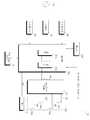
도면을 참조하여 설명하면, 무선 전력 전송 장치(100)는, 상용 교류 전원(405)을 직류 전원으로 변환하는 컨버터(110)와, 직류 전원을 교류 전원으로 변환하는 무선 전력 구동부(170)와, 변환된 교류 전원을 이용하여 무선으로 전력을 전송하는 전송 코일부(180)와, 전송 코일부(180)에서 발생된 열을 냉각시키는 팬(131)을 구비할 수 있다.Referring to the drawings, the wireless
또한, 무선 전력 전송 장치(100)는, 전력 전달 및 통신을 위해, 무선 전력 전송 장치(100) 내의 내부 구성을 제어하는 제어부(160)와, 복수의 코일(제181 내지 184) 중 적어도 하나의 코일이 포함되도록 코일 조합을 생성하는 코일 조합 생성부(161)와, 소정의 통신 방식에 의해, 무선 전력 수신 장치(200)와 통신하는 제1 통신부(140) 및 제2 통신부와, 무선 전력 전송 장치(100)의 구동을 위한 제어 프로그램 등을 저장하는 메모리(120)를 더 포함할 수 있다.In addition, the wireless
무선 전력 전송 장치(100)는, 직류 전원에 의해 동작하며, 이 직류 전원은 상용 교류 전원을 직류 전원으로 변환하는 컨버터(110)에 의해 공급될 수 있다.The wireless
컨버터(110)는, 상용 교류 전원(405)을 직류 전원으로 변환하여 출력할 수 있다. 도면에서는, 상용 교류 전원(405)을 단상 교류 전원으로 도시하고 있으나, 삼상 교류 전원일 수도 있다. 상용 교류 전원(405)의 종류에 따라 컨버터(110)의 내부 구조도 달라질 수 있다.The
한편, 컨버터(110)는, 스위칭 소자 없이 다이오드 등으로 이루어져, 별도의 스위칭 동작 없이 정류 동작을 수행할 수도 있다.Meanwhile, the
예를 들어, 단상 교류 전원인 경우, 4개의 다이오드가 브릿지 형태로 사용될 수 있으며, 삼상 교류 전원인 경우, 6개의 다이오드가 브릿지 형태로 사용될 수 있다.For example, in the case of a single-phase AC power supply, four diodes may be used in the form of a bridge, and in the case of a three-phase AC power supply, six diodes may be used in the form of a bridge.
한편, 컨버터(110)는, 예를 들어, 2개의 스위칭 소자 및 4개의 다이오드가 연결된 하프 브릿지형의 컨버터가 사용될 수 있으며, 삼상 교류 전원의 경우, 6개의 스위칭 소자 및 6개의 다이오드가 사용될 수도 있다.Meanwhile, as the
제어부(160)는, 무선 전력 전송시, 컨버터(110)로부터의 직류 전원이 무선 전력 구동부(170)로 공급되는 경우, 전력 구동부(170)를 제어하여, 무선 전력 수신 장치(200)에 무선으로 전력을 전송할 수 있다. 이때, 무선 전력 구동부(170)는 직류 전원을 무선 전력 전송을 위한 교류 전원으로 변환할 수 있다.When the wireless power is transmitted, when the DC power from the
구체적으로, 제어부(160)는, PWM 신호를 발생하는 PWM 발생부(160a), PWM 신호에 기초하여, 구동 신호(Sic)를 생성하여 출력하는 드라이버(160b)를 구비할 수 있다.Specifically, the
제어부(160)는, 전력 전송량, 무선 전력 구동부(170)에 흐르는 전류 값 등에 기초하여, PWM 신호의 듀티를 결정할 수 있다. PWM 발생부(160a)는, PWM 신호의 듀티를 기초로, PWM 신호를 발생시킬 수 있다. 드라이버(160b)는, PWM 신호를 기초로, 무선 전력 구동부(170)의 구동을 위한 구동 신호(Sic)를 출력할 수 있다.The
무선 전력 구동부(170)는, 직류 전원을 교류 전원으로 변환하기 위한 적어도 하나의 스위칭 소자(미도시)를 구비할 수 있다. 예를 들어, 스위칭 소자가 IBGT인 경우, 드라이버(160b)에서 게이트 구동 신호가 출력되어, 스위칭 소자의 게이트 단자에 입력될 수 있다. 또한, 게이트 구동 신호에 따라, 스위칭 소자가 스위칭 동작을 수행할 수 있다. 스위칭 소자의 스위칭 동작에 의해 직류 전원이 교류 전원으로 변환되어, 전송 코일부(180)에 출력될 수 있다.The
한편, 실시예에 따라, 무선 전력 구동부(170)가 제어부(160) 내의 구성으로 포함되는 것도 가능하다.Meanwhile, according to an embodiment, it is also possible that the
전송 코일부(180)는, 복수의 코일(181 내지 184, 이하 구분의 필요가 없는 경우, 181이라 함)을 포함할 수 있다. 복수의 코일(181 내지 184)은, 부분적으로 중첩될 수 있다.The
전송 코일부(180)는, 복수의 코일(181 내지 184)에서 선택된 어느 하나의 코일 조합을 통해, 무선 전력 수신 장치(200)에 무선으로 전력을 전송할 수 있다.The
복수의 코일(181 내지 184)은, 도 3의 수신 코일(281)과의 구분을 위해, 복수의 전송 코일(181 내지 184)이라고 명명할 수도 있다.The plurality of
한편, 복수의 전송 코일(181 내지 184)은, 수신 코일(281)과 이격되어 있어, 누설 인덕턴스가 높고, 결합 계수(coupling factor)가 낮으므로 전송 효율이 낮을 수 있다.On the other hand, the plurality of transmission coils 181 to 184 are spaced apart from the
따라서, 본 발명의 무선 전력 전송 장치(100)는, 전송 효율을 향상시키기 위해서, 복수의 전송 코일(181 내지 184) 각각에 커패시터를 연결하여, 수신 코일(281)과 공진 회로를 형성하도록 할 수 있다.Therefore, in order to improve the transmission efficiency, the wireless
전송 코일부(180)는, 복수의 전송 코일(181 내지 184)과 복수의 코일(181 내지 184)에 각각 접속되는 복수의 커패시터 소자(185 내지 188)를 포함할 수 있다.The
복수의 커패시터 소자(185 내지188)는, 복수의 전송 코일(181 내지 184) 각각에 직렬 접속되어 공진 회로를 형성할 수 있다.The plurality of
실시예에 따라, 도 2와 달리, 복수의 커패시터 소자(185 내지 188)는, 복수의 전송 코일(181 내지 184) 각각에 병렬 접속되어 공진 회로를 형성할 수도 있다.According to an embodiment, unlike in FIG. 2, the plurality of
복수의 전송 코일(181 내지 184) 및 복수의 커패시터 소자(185 내지 188)는, 전력 전송의 공진 주파수를 결정할 수 있다.The plurality of transmission coils 181 to 184 and the plurality of
한편, 전송 코일부(180) 내의 커패시터 소자와, 전송 코일이 공진 회로를 형성하므로, 전송 코일부(180)는, 공진 회로부라고 명명할 수도 있다. 또는, 전송 코일부(180)는, 코일부라고 명명할 수도 있다.Meanwhile, since the capacitor element in the
전송 코일부(180)는, 복수의 전송 코일(181 내지 184)의 일측에 배치되어, 누설되는 자기장을 차폐하는 차폐재(도 4의 190)를 더 포함할 수 있다.The
한편, 제어부(160)는, 전송 코일부(180) 내의 복수의 전송 코일(181 내지 184)을 통해, 감지 신호(도 3의 Sd)를 송출하고, 감지 신호(Sd)에 대한 응답 신호(Sr)을 수신할 수 있다.Meanwhile, the
감지 신호(Sd)는, 충전면의 물체가 무선 충전 가능한 수신기인지 식별하기 위한, 디지털 핑(Digital Ping: DP) 신호일 수 있다.The detection signal Sd may be a digital ping (DP) signal for identifying whether an object on the charging surface is a wirelessly chargeable receiver.
응답 신호(Sr)는, 무선 전력 수신 장치(200)에 수신된 전력의 세기를 나타내는 신호일 수 있다.The response signal Sr may be a signal indicating the strength of the power received by the wireless
예를 들어, 응답 신호(Sr)의 세기가 클수록, 무선 전력 수신 장치(200)에 수신되는, 전력이 클 수 있다. 반대로, 응답 신호(Sr)의 세기가 작을수록, 무선 전력 수신 장치(200)에 수신되는 전력이 작을 수 있다.For example, the greater the intensity of the response signal Sr, the greater the power received by the wireless
제어부(160)는, 감지 신호(Sd)를 복수의 전송 코일(181 내지 184)를 통해 동시에 또는 순차적으로 전송할 수 있다.The
한편, 제어부(160)는, 전송 코일부(180) 내의 복수의 전송 코일(181 내지 184)을 통해, 무선 전력 수신 장치(200)의 고유 정보(RXID)를 수신 받을 수 있다. 제어부(160)는, 고유 정보(RXID)를 기초로, 무선 전력 수신 장치(200)의 전력을 연산할 수 있다.Meanwhile, the
또한, 제어부(160)는, 전송 코일부(180) 내의 복수의 전송 코일(181 내지 184)을 통해 맥 어드레스(MAC)를 수신 받을 수 있다. 제어부(160)는, 맥 어드레스(MAC)를 기초로, 무선 전력 전송 장치(200)와 페어링을 수행할 수 있다.Also, the
또한, 제어부(160)는, 전송 코일부(180) 내의 복수의 전송 코일(181 내지 184)을 통해 센싱 데이터(Sd)를 소정 주기로 수신 받을 수 있다. 이때, 센싱 데이터(Sd)는, 수신 코일(281)에 흐르는 전류(ir) 및/또는, 수신 코일(281)의 양단 전압(Vr)일 수 있다.In addition, the
한편, 무선 전력 전송 장치(100)에서 전송되는, 전력량이 증가할수록, 전송 코일부(180)에서 발생되는 열도 증가될 수 있다.Meanwhile, as the amount of power transmitted from the wireless
본 발명은, 전송 코일부(180)에서 발생된 열을 냉각시키는 팬(131)을 포함할 수 있다.The present invention may include a
제어부(160)는, 팬(131)의 구동을 제어할 수 있다. 구체적으로 제어부(160)는, 팬(131)의 구동을 위한 제어 신호(Sic)를 팬(131)에 출력할 수 있다. 팬(131)은, 제어 신호(Sic)를 기초로 구동될 수 있다.The
제어부(160)는, 팬(131)을 구동 또는 정지시킬 수 있다. 보다 상세하게는, 제어부(160)는, 동작 코일이 기설정된 개수 이상인 경우, 팬(131)이 구동하도록 제어할 수 있다.The
또한, 제어부(160)는, 동작 코일이 기준 개수 미만인 경우라도, 적어도 하나의 코일이, 고속 충전 모드인 경우, 팬(131)이 구동하도록 제어할 수 있다.Also, the
또는, 제어부(160)는, 무선 전력 수신 장치(200)와 아웃오브밴드(Out Of Band:OOB) 통신하는 경우, 팬(131)이 구동하도록 제어할 수 있다.Alternatively, the
또한, 제어부(160)는, 수신 코일(281)에 흐르는 전류 또는 수신 코일(281) 양단 전압이, 기준 값 이상인 경우, 팬(131)의 구동이 유지되도록 제어하고, 수신 코일(281)에 흐르는 전류 또는 수신 코일(281) 양단 전압이, 기준 값 미만인 경우, 수신 코일(281)에 흐르는 전류 또는 수신 코일(281) 양단 전압에 대응하여 팬(131)의 회전 속도를 제어할 수 있다.In addition, when the current flowing through the receiving
한편, 본 발명은 팬을 구동시키는 팬 구동부(미도시)를 더 포함할 수 있고, 제어부(160)는, 팬(131) 구동을 위한 제어 신호(Sic)를 팬 구동부(미도시)에 전송할 수 있다. 팬 구동부(미도시)는, 제어 신호(Sic)를 기초로 팬의 회전 속도를 제어할 수 있다.Meanwhile, the present invention may further include a fan driving unit (not shown) for driving the fan, and the
코일 조합 생성부(161)는, 복수의 전송 코일(181 내지 184) 중, 적어도 하나의 코일이 포함되도록 코일 조합을 생성할 수 있다.The
제1 통신부(140)는, 무선 전력 수신 장치(200)와 제1 통신 방법으로 통신할 수 있다. 제1 통신부(140)는, 무선 전력 전송 장치(200)의 상태 정보, 전력 제어 정보 등을 소정 신호 처리하여 무선 전력 수신 장치(200)에 전송하고, 무선 전력 수신 장치(200)의 상태 정보, 전력 사용량 정보, 충전 효율 정보 등을 수신하여, 소정 신호 처리한 후, 제어부(160)에 전송할 수 있다.The
제2 통신부(150)는, 무선 전력 수신 장치(200)와 제1 통신 방법과는 상이한 제2 통신 방법으로 통신할 수 있다. 제2 통신부(140)도, 무선 전력 전송 장치(200)의 상태 정보, 전력 제어 정보 등을 소정 신호 처리하여 무선 전력 수신 장치(200)에 전송하고, 무선 전력 수신 장치(200)의 상태 정보, 전력 사용량 정보, 충전 효율 정보 등을 수신하여, 소정 신호 처리한 후, 제어부(160)에 전송할 수 있다.The
제1 통신부(140) 및 제2 통신부(150)는, 무선 전력 전송 장치(100)에서 송출되는 데이터 신호 및 무선 전력 수신 장치(200)로부터 수신되는 데이터 신호를 변복조(modulation/demodulation)하기 위한, 변복조부(미도시)를 더 포함할 수 있다.The
또한, 제1 통신부(140) 및 제2 통신부(150)는, 무선 전력 수신 장치(200)로부터의 데이터 신호를 필터링하는 필터부(미도시)를 더 포함할 수 있다. 이때, 필터부(미도시)는, 대역통과필터(Band Pass Filter:BPF)를 구비할 수 있다.In addition, the
한편, 제1 통신 방법은, 무선 전력 수신 장치(200)와 동일한 주파수 대역을 사용하는 인밴드(in-band) 통신 방법일 수 있고, 제2 통신 방법은, 무선 전력 수신 장치(200)와 상이한 주파수 대역을 사용하는 아웃오브밴드(out-of-band) 통신 방법일 수 있다.Meanwhile, the first communication method may be an in-band communication method using the same frequency band as the wireless
무선 전력 전송 장치(100)는, 무선 전력 수신 장치(200)의 전력 정보를 기초로, 통신 방법을 변경할 수 있다.The wireless
메모리(120)는, 전력 전송 장치(100)의 동작을 위한 프로그램을 저장할 수 있다.The
또한, 메모리(120)는, 충전면의 물체를 감지하기 위해, 복수의 코일에서 송출되는 각각의 물체 감지 신호의 송출 세기를 저장할 수 있다.In addition, the
또한, 메모리(120)는, 복수의 코일에서 송출되는 각각의 코일 선택 신호의 송출 세기를 저장할 수 있다.In addition, the
이때, 물체 감지 신호의 송출 세기 및 코일 선택 신호의 송출 세기는, 공장 교정(factory calibration)된 신호 일 수 있다.In this case, the transmission intensity of the object detection signal and the transmission intensity of the coil selection signal may be a factory calibrated signal.
구체적으로, 본 발명의 복수의 전송 코일(181 내지 184)은 도 4와 같이, 부분적으로 겹쳐져 층을 형성하므로, 각각의 코일에서, 동일한 송출 세기로 물체 감지 신호 및 코일 선택 신호를 송출하는 경우, 무선 전력 수신 장치(200)가 배치되는 충전면에서의 각각의 물체 감지 신호 및 코일 선택 신호의 세기는 상이할 수 있다.Specifically, since the plurality of transmission coils 181 to 184 of the present invention are partially overlapped to form a layer, as shown in FIG. 4, when each object transmits an object detection signal and a coil selection signal at the same transmission intensity, The intensity of each object detection signal and the coil selection signal on the charging surface where the wireless
이러한, 충전면에서의 물체 감지 신호 및 코일 선택 신호의 세기 차이는, 물체(object) 감지 및 동작 코일 조합에 있어서 오류를 일으킬 수 있다.The difference in intensity between the object detection signal and the coil selection signal on the charging surface may cause an error in the object detection and operation coil combination.
본 발명은 이러한 문제점을 해결하기 위하여, 물체 감지 신호의 송출 세기 및 코일 선택 신호의 송출 세기를 각각의 코일과, 무선 전력 수신 장치(200)가 배치되는 충전면 사이의 거리를 보상하여 설정할 수 있다.In order to solve this problem, the present invention can set the transmission strength of the object detection signal and the transmission strength of the coil selection signal by compensating the distance between each coil and the charging surface on which the wireless
예를 들어, 충전면과 코일 사이의 거리가 멀수록 물체 감지 신호의 송출 세기 및 코일 선택 신호의 송출 세기가 크도록 설정될 수 있다.For example, the distance between the charging surface and the coil may be set such that the transmission intensity of the object detection signal and the transmission intensity of the coil selection signal are greater.
예를 들어, 충전면과 코일 사이의 거리가 멀수록 물체 감지 신호의 송출 세기 및 코일 선택 신호의 송출 세기가 크도록 설정될 수 있다.For example, the distance between the charging surface and the coil may be set such that the transmission intensity of the object detection signal and the transmission intensity of the coil selection signal are greater.
이에 따라, 무선 전력 수신 장치(200)가 배치되는 충전면에서의 각각의 물체 감지 신호의 세기는 모두 동일할 수 있다. 또한, 충전면에서의 각각의 코일 선택 신호의 세기는 모두 동일할 수 있다.한편, 보상된 물체 감지 신호의 송출 세기 및 코일 선택 신호의 송출 세기는, 공장 교정(factory calibration)된 값으로써, 메모리(120)에 저장될 수 있다.Accordingly, the intensity of each object detection signal on the charging surface on which the wireless
특히, 메모리(120)는, 감지 신호에 대한 응답 신호의 기준 세기를 저장할 수 있다.In particular, the
예를 들어, 메모리(120)는, 전력 전송을 수행할, 동작 코일의 개수 연산에 사용되는, 응답 신호의 제1 기준 세기를 저장할 수 있다. 또한, 메모리(120)는, 동작 코일이 고속 충전 모드인지 여부를 연산하기 위한, 응답 신호의 제2 기준 세기를 저장할 수 있다.For example, the
또는, 메모리(120)는, 통신 방법 변경에 기준이 되는 기준 전력을 저장할 수 있다.Alternatively, the
또한, 메모리(120)는, 팬(131)의 회전 속도 제어에 사용되는, 수신 코일(281)에 흐르는 전류 또는 수신 코일(281)의 양단 전압의 기준 값을 저장할 수 있다.Also, the
제어부(160)는, 무선 전력 전송 장치(100)의 전반적인 동작을 제어할 수 있다.The
제어부(160)는, 코일 조합 생성부(161)에 의해 생성된 코일 조합에서, 무선 전력 전송에 사용할 동작 코일 조합을 선택하고, 선택된 동작 코일 조합을 통해 무선 전력 수신 장치(200)를 충전시킬 수 있다.The
구체적으로, 제어부(160)는 코일 조합에 포함된 코일을 통해, 코일 선택 신호를 송출하고, 코일 선택에 대한 코일 선택 응답 신호를 수신할 수 있다.Specifically, the
또한, 제어부(160)는, 코일 선택 응답 신호의 세기 및 무선 전력 수신 장치(200)의 충전 효율을 기초로 코일 조합 중, 무선 전력에 사용될 동작 코일 조합을 선택할 수 있다.In addition, the
제어부(160)는, 동작 코일 조합을 통해, 무선 전력 수신 장치(200)에 무선으로 전력을 전송할 수 있다.The
한편, 코일 조합 생성부(161)는, 복수의 전송 코일(181 내지 184)을 통해 물체 감지 신호를 송출하고, 물체 감지 신호에 대한 전류 변화량을 기초로, 무효 코일을 연산할 수 있다.Meanwhile, the coil
또한, 코일 조합 생성부(161)는, 복수의 전송 코일(181 내지 184) 중, 무효 코일을 제외하고, 유효 코일 조합을 생성할 수 있다.In addition, the coil
이때, 제어부(160)는, 유효 코일 조합에서, 무선 전력에 사용될 동작 코일 조합을 선택할 수 있다.At this time, the
한편, 코일 조합 생성부(161)는, 전송 코일부(180)를 통해 수신 받은, 무선 전력 수신 장치(200)의 고유 정보를 기초로, 무선 전력 수신 장치(200)의 전력을 연산하고, 연산된 무선 전력 수신 장치(200)의 전력을 기초로, 동작 코일 개수를 연산할 수도 있다.Meanwhile, the coil
또한, 코일 조합 생성부(161)는, 동작 코일 개수에 따라, 코일 조합을 생성할 수 있다.Further, the coil
한편, 코일 조합 생성부(161)는, 도 2와 달리 제어부(160)에 포함되는 구성일 수 있다. 즉, 코일 조합 생성부(161)는, 제어부(160)의 일부 구성으로 구현될 수 있다.Meanwhile, unlike the FIG. 2, the coil
도 3은, 도 1의 무선 전력 시스템 내의 무선 전력 수신 장치의 내부 블록도이다.3 is an internal block diagram of a wireless power receiving apparatus in the wireless power system of FIG. 1.
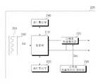
도면을 참조하여 설명하면, 무선 전력 수신 장치(200)는, 무선 전력 전송 장치(100)로부터 무선 전력을 수신하는 전력 수신부(280)와, 수신된 무선 전력을 정류하는 정류부(210)와, 정류된 무선 전력을 안정화하는 스위칭 레귤레이터(220)와, 스위칭 레귤레이터(220)를 제어하여, 부하에 동작 전원을 출력하는 스위칭 레귤레이터 제어부(230)를 포함할 수 있다.Referring to the drawings, the wireless
또한, 무선 전력 수신 장치(200)는, 무선 전력 전송 장치(100)와 통신하기 위한, 제1 통신부(240) 및 제2 통신부(150)를 더 포함할 수 있다.In addition, the wireless
전력 수신부(280)는, 전송 코일부(180)로부터 전송된 무선 전력을 수신 받을 수 있다. 이를 위해, 전력 수신부(280)는, 수신 코일(281)을 구비할 수 있다.The
수신 코일(281)은, 복수의 전송 코일(181 내지 184) 중 어느 하나의 코일에서 발생된 자기장에 의해, 유도 기전력이 발생될 수 있다. 유도 기전력에 의한 무선 전력이, 후술하는 정류부(210), 스위칭 레귤레이터(220)를 지나, 무선 전력을 사용하는 부하에 직접 공급되거나, 부하가 배터리인 경우, 전력은, 배터리를 충전하기 위해 이용될 수 있다.The receiving
수신 코일(281)은, 인쇄회로 기판(PCB)에 박막 형태의 도전성 패턴으로 형성될 수 있다. 수신 코일(281)은, 폐루프 형상으로, 수신 패드(미도시)에 인쇄될 수 있다. 수신 코일(281)의 극성은, 동일한 방향으로 극성을 갖도록 권회하는 형상일 수 있다.The receiving
한편, 무선 전력 수신 장치(200)는, 무선 전력 전송 장치(100) 내의 전송 코일부(180)와 공진 회로를 형성하기 위한, 커패시터 소자(미도시)를 더 포함할 수 있다. 이때, 커패시터 소자(미도시)는, 수신 코일(281)에 직렬 또는 병렬 접속될 수 있다.Meanwhile, the wireless
한편, 무선 전력 수신 장치(200)는, 수신 코일(281)을 통해, 무선 전력 전송 장치(100)가 전송한, 감지 신호(Sd)를 수신할 수 있다.Meanwhile, the wireless
또한, 무선 전력 수신 장치(200)는, 수신 코일(281)을 통해, 감지 신호(Sd)에 대한 응답 신호(Sr)를 송출할 수 있다.In addition, the wireless
정류부(210)는, 무선 전력 전송 장치(100)로부터의 무선 전력 수신 시, 수신 코일(281)을 통해 수신되는 무선 전력을 정류할 수 있다. 정류부(210)는, 적어도 하나의 다이오드 소자(미도시)를 포함할 수 있다.The
스위칭 레귤레이터(220)는, 스위칭 레귤레이터 제어부(230)의 제어에 의해, 정류된 무선 전력을, 배터리에 공급되는 충전 전원(v)으로 출력할 수 있다.The
스위칭 레귤레이터 제어부(230)는, 스위칭 레귤레이터로 레귤레이터 제어 신호(Src)를 인가하여, 충전 전원(v)이 출력되도록 제어할 수 있다.The switching
한편, 스위칭 레귤레이터(220)는, 스위칭 레귤레이터 제어부(230)의 레귤레이터 제어 신호(Src)에 따라, DC-DC 컨버팅을 수행하여, 출력 전압을 조절할 수 있다. 스위칭 레귤레이터(220)는, 레귤레이터 제어 신호(Src)를 기초로, 출력 전압을 제어하여 지정된 크기의 전압을 갖는 충전 전원(v)을 출력할 수 있다.Meanwhile, the
한편, 무선 전력 수신 장치(200)에는, 별도의 마이크로프로세서가 포함되지 않고, 정류된 충전 전원(v)이 스위칭 레귤레이터에 의해 소정 크기의 전압으로 출력되는 때에, 스위칭 레귤레이터 제어부(230)에 의해 스위칭 레귤레이터가 제어될 수 있다. 무선 전력 수신 장치(200)가 마이크로프로세서를 구비하지 않는 경우, 하드웨어 구성이 단순화되고, 소비 전력이 감소하는 효과가 있다.On the other hand, the wireless
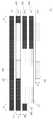
도 4는, 도 2의 코일부의 구조를 설명하기 위한 도면이고, 도 5는, 도 4의 코일부의 계층 구조를 나타내는 사시도이다.FIG. 4 is a view for explaining the structure of the coil part in FIG. 2, and FIG. 5 is a perspective view showing the hierarchical structure of the coil part in FIG. 4.
도면을 참조하여 설명하면, 본 발명의 실시예에 따른 전송 코일부(180)는, 제1 내지 제4 코일(181 내지 184)을 포함할 수 있다.Referring to the drawings, the
전송 코일부(180)가 단일의 대형 코일이 아닌, 제1 내지 제4 코일(181 내지 184)을 구비함에 따라, 충전면의 자유도를 향상시키는 것은 물론, 대형 코일의 표류 자계(stray magnetic fields)로 인한 전력 효율 저감을 방지할 수 있게 된다.As the
제1 내지 제4 코일(181 내지 184)은, 서로 일부 영역이 중첩되어 배치될 수 있다. 구체적으로, 도 4에서와 같이, 제1 코일(181)은 제2 코일(182)과 서로 일부 영역이 중첩되고, 제2 코일(182)은, 제3 코일(183)과 서로 일부 영역이 중첩되고, 제3 코일(183)은, 제4 코일(184)과 일부 영역이 중첩될 수 있다.The first to
제1 내지 제4 코일(181 내지 184)의 중첩 영역은, 충전 불가능한 영역인 데드존(dead zone)이 최소가 되도록 설정될 수 있다. 구체적으로, 제1 내지 제4 코일(181 내지 184)의 중첩 영역은, 충전 영역 중심부의 데드존이 최소가 되도록 설정될 수 있다.The overlapping regions of the first to
제1 내지 제4 코일(181 내지 184)은, 기설정된 외측 길이(ho), 내측 길이(hi), 외측 너비(wo), 내측 너비(wi), 두께 및 권선수로 제조될 수 있다. 또한, 제1 내지 제4 코일(181 내지 184)의 외측 길이(ho), 내측 길이(hi), 외측 너비(wo), 내측 너비(wi)는, 동일할 수 있다.The first to
한편, 제4 코일(184)은, 무선 전력 수신 장치(200)에 가장 근접하게 배치되므로, 제4 코일(184)의 인덕턴스는, 제1 내지 제3 코일(181 내지 183)의 인덕턴스 보다 작게 설정될 수 있다. 이는, 전송 코일부(180) 표면의 전력 전송량 또는 전력 효율을 일정하게 하기 위함이다.On the other hand, since the
제1 내지 제4 코일(181 내지 184)은 차폐재(190) 위에 배치될 수 있다. 차폐재(190)는 코발트(Co), 철(Fe), 니켈(Ni), 붕소(B), 규소(Si) 등으로 이루어진 군에서 선택되는 1종 또는 2종 이상의 원소의 조합으로 이루어진 페라이트를 포함할 수 있다. 차폐재(190)는, 코일의 일측에 배치되어, 누설되는 자기장을 차폐하고, 자기장의 방향성을 극대화할 수 있다.The first to
차폐재(190)는, 제1 내지 제4 코일(181 내지 184)이 배치된 면적보다 큰 면적으로 형성될 수 있다. 예를 들어, 도 4 내지 도 5에서와 같이, 차폐재(190)는, 제1 내지 제4 코일(181 내지 184)의 가로 외측에서 a1 간격으로 연장되어 형성될 수 있다. 또한, 차폐재(190)는, 제1 내지 제4 코일(181 내지 184)의 세로 외측에서 a1 간격으로 연장되어 형성될 수 있다.The shielding
차폐재(190)가 제1 내지 제4 코일(181 내지 184)의 외측 길이보다 크게 형성됨으로써, 누설 자기장이 저감되고, 자기장의 방향성이 극대화될 수 있다.Since the shielding
한편, 제1 내지 제4 코일(181 내지 184)은 서로 일부 영역이 중첩되어 배치되므로, 중첩되지 않은 영역에 들뜸 현상이 발생될 수 있다. 예를 들어, 도 5에서, 제1 코일(181)과 제2 코일(182)은 서로 일부 영역만 중첩되므로, 중첩되지 않은 영역에 d1의 이격 거리가 발생될 수 있다.Meanwhile, since the first to
이러한 이격 거리에 의해, 제2 코일(182)의 누설 자기장이 차폐되지 못하여, 무선 전력 전송 장치(100)의 전송 효율이 저감되는 것은 물론, 자기장의 방향이 분산될 수 있다. 또한, 이러한 이격 거리로 인하여, 무선 전력 전송 장치(100)가 외부 충격에 의해 쉽게 파손될 수 있다.Due to the separation distance, the leakage magnetic field of the
본 발명은 이러한 문제를 해결하기 위하여, 제1 내지 제4 코일(181 내지 184)과 차폐재(190)가 층을 이루어 형성될 수 있다.In order to solve this problem, the present invention, the first to
보다 상세하게는, 전송 코일부(180)의 제1 층(ly1)에는, 기초(base) 차폐재(191)가 배치될 수 있다.More specifically, a
기초 차폐재(191)의 상측인 제2 층(ly2)에는, 제1 코일(181)과, 제1 차폐재(192)가 배치될 수 있다.The
제1 코일(181)의 상측인 제3 층(ly3)에는, 제1 코일(181)과 부분적으로 겹쳐지는, 제2 코일(182)이 배치될 수 있다. 이때, 제2 층(ly2)에 배치되는 제1 차폐재(192)가, 제1 코일(181) 및 제2 코일(182)의 중첩 구조로 인해 발생되는 들뜸 현상을 방지하게 된다.The
동일한 이치로, 전송 코일부(180)의 제3 층(ly3)에는, 제2 코일(182) 뿐만 아니라, 제2 차폐재(193)도 배치될 수 있다.In the same manner, the
제2 코일(182)의 상측인 제4 층(ly4)에는, 제2 코일(182)과 부분적으로 겹쳐지는, 제3 코일(183)이 배치될 수 있다. 이때, 제3 층(ly3)에 배치되는 제2 차폐재(193)가, 제2 코일(182)과 제3 코일(183)의 중첩 구조로 인해 발생되는 들뜸 현상을 방지하게 된다.A
또한, 전송 코일부(180)의 제4 층(ly4)에는, 제3 코일(183) 뿐만 아니라, 제3 차폐재(194)도 배치될 수 있고, 제3 차폐재(194)는, 제3 코일(183)과 제4 코일(184)의 중첩 구조로 인한 들뜸 현상을 방지할 수 있다.In addition, in the fourth layer ly4 of the
또한, 제1 내지 제4 코일(181 내지 184)은 들뜸 현상 없이, 차폐재(190)(기초 차폐재(191) 및 제1 차폐재 내지 제3 차폐재(192 내지 194)를 포함한다.)에 접착되어야 하므로, 차폐재의 두께(tkf)는, 제1 내지 제4 코일(181 내지 184)의 두께(tkc)와 동일한 것이 바람직하다.In addition, the first to
한편, 도 5에서는 전송 코일부(180)의 각 층(layer)이 이격된 것으로 도시하나, 이는 설명의 편의를 위한 것이며, 전송 코일부(180)의 각 층은 서로 밀착될 수 있다.Meanwhile, in FIG. 5, each layer of the
전송 코일부(180)가 도 5에서와 같이, 배치됨에 따라, 부분적으로 겹쳐지는, 제1 내지 제4 코일(181 내지 184)의 들뜸 현상이 방지되고, 외부 충격으로부터 제1 내지 제4 코일(181 내지 184)의 이탈을 방지할 수 있다.As shown in FIG. 5, as the
또한, 각각의 코일 일측에 차폐재(190)가 배치되므로, 누설 자기장이 차폐되고, 자기장의 방향을 보다 집중시켜, 전송 효율이 상승될 수 있다.In addition, since the shielding
또한, 각각의 코일 사이에 차폐재(190)가 배치됨에 따라, 멀티 코일에서 발생되는 열을 보다 쉽게 저감 시킬 수 있다.In addition, as the shielding
한편, 제1 내지 제4 코일(181 내지 184)은, 설명의 편의를 위해 도시하지 않은 케이스에 수용될 수 있다. 케이스의 일측면에는, 무선 전력 수신 장치(200)가 놓여질 수 있다. 무선 전력 수신 장치(200)가 케이스의 일측면에 놓여지는 경우, 전송 코일부(180)가 무선으로 전력을 전송하여, 무선 전력 수신 장치(200)를 충전시키므로, 무선 전력 수신 장치(200)가 놓여지는 케이스의 일측면을 충전면이라 명명할 수 있다. 또한, 충전면과 인터페이스 표면은 혼용하여 사용될 수 있다.Meanwhile, the first to
도 6은, 본 발명의 실시예에 따른, 무선 전력 전송 방법을 설명하기 위한 순서도이다.6 is a flowchart illustrating a wireless power transmission method according to an embodiment of the present invention.
도면을 참조하여 설명하면, 무선 전력 전송은 선택 단계(selection phase, S610), 핑 단계(ping phase, S620), 식별 및 구성 단계(identification and configuration phase, S630), 핸드오버 단계(handover phase, S640), 협상 단계(negotiation phase, S650), 보정 단계(calibration phase, S660), 전력 전송 단계(power transfer phase, S670) 및 재협상 단계(re-negotiation phase, S680)를 포함할 수 있다.Referring to the drawings, wireless power transmission is a selection phase (selection phase, S610), a ping phase (ping phase, S620), identification and configuration phase (identification and configuration phase, S630), handover phase (handover phase, S640) ), a negotiation phase (negotiation phase, S650), a calibration phase (calibration phase, S660), a power transfer phase (power transfer phase, S670) and a renegotiation phase (re-negotiation phase, S680).
먼저, 선택 단계(S610)에서, 무선 전력 전송 장치(100)는, 감지 영역 내에 물체(object)들이 존재하는지 여부를 감지할 수 있다.First, in the selection step (S610 ), the wireless
무선 전력 전송 장치(100)는, 감지 영역 내에 물체(object)들이 존재하는지 여부를 감지하기 위하여, 물체 감지 신호에 대한 전력 변화(예를 들어, 코일의 전류 변화)에 기초하여, 충전 영역에 물체(object)가 존재하는지 여부를 감지할 수 있다. 이때, 물체 감지 신호는, 매우 짧은 펄스의 아날로그 핑(Analog Ping: AP) 신호일 수 있다. 무선 전력 전송 장치(100)는 충전면에 물체(object)가 감지될 때까지 소정 주기로 아날로그 핑(AP) 신호를 송출할 수 있다.The wireless
무선 전력 전송 장치(100)가 복수의 전송 코일(181 내지 184)을 구비하는 경우, 무선 전력 전송 장치(100)는, 물체 감지 신호를 복수의 전송 코일(181 내지 184)을 통해, 소정 순서로 송출하고, 각각의 물체 감지 신호에 대한 코일의 전류 변화량을 기초로, 충전 영역에 물체(object)가 존재하는지 여부를 감지할 수 있다.When the wireless
구체적으로, 무선 전력 전송 장치(100)는, 전류 변화량이 기설정된 전류 변화량 이상인 경우, 해당 코일에 대응되는 충전 영역에 물체(object)가 존재한다고 연산할 수 있다. 이때, 해당 코일을 후술하는 유효 코일 조합에 사용되는 유효 코일이라고 명명할 수 있다.Specifically, when the current change amount is equal to or greater than a preset current change amount, the wireless
무선 전력 전송 장치(100)는, 선택 단계(S610)에서, 충전 영역에 이물질이 존재하는지 여부를 연산할 수 있다. 이물질은, 동전, 키 등을 포함하는 금속성 물체일 수 있고, 이러한 이물질은, FO(Foreign Object)라 명명할 수 있다.The wireless
선택 단계(S610)에서, 무선 전력 전송 장치(100)는, 감지 영역 내의 물체(object)의 배치 또는 제거를 지속적으로 감지할 수 있다. 또한, 선택 단계(S610)에서, 무선 전력 전송 장치(100)가, 감지 영역 내의 물체(object)를 감지한 경우, 핑 단계(S620)로 천이할 수 있다.In the selection step (S610), the wireless
무선 전력 전송 장치(100)가 물체(object)를 감지한 경우, 무선 전력 전송 장치(100)는, 핑 단계(S620)에서, 무선 전력 수신 장치(200)를 활성화(awake) 시키고, 감지된 물체(object)가 무선 전력 수신 장치(200)인지를 식별하기 위한 수신 장치 감지 신호(Sd)를 전송할 수 있다. 이때, 수신 장치 감지 신호는, 디지털 핑(Digital Ping: DP) 신호일 수 있다.When the wireless
디지털 핑(DP) 신호는 무선 전력 수신 장치(200)와의 통신 설정을 시도하기 위하여, 아날로그 핑(AP) 신호에 비해 듀티가 크게 설정될 수 있다.The digital ping (DP) signal may have a larger duty than an analog ping (AP) signal in order to attempt to establish communication with the wireless
무선 전력 수신 장치(200)는, 디지털 핑(DP) 신호를 변조하고, 변조된 디지털 핑(DP) 신호를 무선 전력 전송 장치(100)로 전송할 수 있다. 이때, 변조된 디지털 핑(DP) 신호를, 응답 신호(Sr)라고 할 수 있다. 응답 신호(Sr)는, 무선 전력 수신 장치(200)에 수신 장치(200)에 수신된 전력의 세기를 나타내는 신호일 수 있다.The wireless
무선 전력 전송 장치(100)는, 변조된 디지털 핑(DP) 신호를 복조하고, 복조된 디지털 핑(DP) 신호로부터, 수신 장치 감지 신호에 대한 응답에 해당하는 디지털 형태의 감지 데이터를 획득할 수 있다.The wireless
무선 전력 전송 장치(100)는, 디지털 형태의 감지 데이터로부터, 전력 전송의 대상이 되는 무선 전력 수신 장치(200)를 인지할 수 있다.The wireless
무선 전력 전송 장치(100)는, 핑 단계(S620)에서, 무선 전력 수신 장치(200)를 식별한 경우, 식별 및 구성 단계(S630)로 천이할 수 있다.When the wireless
또는, 무선 전력 전송 장치(100)는, 핑 단계(S620)에서, 디지털 형태의 감지 데이터를 수신 받지 못한 경우, 다시 선택 단계(S610)로 천이할 수 있다.Alternatively, the wireless
식별 및 구성 단계(S630)에서, 무선 전력 전송 장치(100)는, 무선 전력 수신 장치(200)가 전송하는 식별 정보, 전력 정보 등을 수신하여, 전력 전달이 효율적으로 이루어지도록 제어할 수 있다.In the identification and configuration step (S630 ), the wireless
먼저, 식별 및 구성 단계(S630)에서, 무선 전력 수신 장치(200)는, 식별 데이터를 전송할 수 있다.First, in the identification and configuration step (S630), the wireless
식별 데이터에는, 무선 전력 전송 규약의 버전 정보, 무선 전력 수신 장치(200)의 제조 업체 정보, 기본 장치 식별자 정보, 확장 장치 식별자의 유무를 나타내는 정보 등이 포함될 수 있다.The identification data may include version information of the wireless power transmission protocol, manufacturer information of the wireless
또한, 식별 및 구성 단계(S630)에서, 무선 전력 수신 장치(200)는, 전력 데이터를 전송할 수 있다.In addition, in the identification and configuration step (S630), the wireless
전력 데이터에는, 무선 전력 수신 장치(200)의 최대 전력에 대한 정보, 잔여 전력에 대한 정보, 전력 클래스 정보 등이 포함될 수 있다.The power data may include information about the maximum power of the wireless
무선 전력 전송 장치(100)는, 식별 데이터 및 전력 데이터를 기초로, 무선 전력 수신 장치(200)를 식별하고, 무선 전력 수신 장치(200)의 전력 정보를 획득할 수 있다.The wireless
무선 전력 전송 장치(100)는, 무선 전력 수신 장치(200)를 식별하고, 무선 전력 수신 장치(200)의 전력 정보를 획득한 경우, 핸드 오버 단계(S630)로 천이할 수 있다.When the wireless
또는, 무선 전력 전송 장치(100)는, 식별 및 구성 단계(S630)에서, 식별 데이터 및/또는 전력 데이터를 수신 받지 못한 경우, 선택 단계(S610)로 천이할 수 있다.Alternatively, the wireless
무선 전력 전송 장치(100)는, 핸드 오버 단계(S640)에서, 무선 전력 수신 장치(200)와의 통신 방법 변경 여부를 연산할 수 있다.The wireless
구체적으로, 무선 전력 전송 장치(100)는, 무선 전력 수신 장치(200)와 인밴드(in-band) 통신 방법으로 통신하는 상태에서, 선택 단계(S610), 핑 단계(S620) 또는 식별 및 구성 단계(S630) 중, 적어도 어느 하나의 단계에서 획득한 무선 전력 수신 장치(200)의 전력 정보를 기초로, 인밴드(in-band) 통신을 유지할 것인지 또는 아웃오브밴드(out-of-band) 통신 방법으로 변경할 것인지 여부를 연산할 수 있다.Specifically, the wireless
한편, 무선 전력 전송 장치(100)는, 식별 및 구성 단계(S630) 또는 핸드 오버 단계(S640)에서 수신된 협상 필드(negotiation field) 값에 기초하여, 협상 단계(S650)로의 진입이 필요한지 여부를 연산할 수 있다.On the other hand, the wireless
무선 전력 전송 장치(100)는, 연산 결과, 협상이 필요한 경우, 협상 단계(S650)로 천이하여, 이물질 검출(Foreign Object Detection: FOD) 절차를 수행할 수 있다.The wireless
또한, 무선 전력 전송 장치(100)는, 연산 결과, 협상이 불필요한 경우, 곧바로 전력 전송 단계(S670)로 천이할 수도 있다.In addition, the wireless
무선 전력 전송 장치(100)는, 선택 단계(S610) 또는 협상 단계(S650)에서, 연산된 충전면의 이물질 존재 여부를 기초로, 보정 단계(S660) 진입 여부를 결정할 수 있다.The wireless
무선 전력 전송 장치(100)는, 이물질이 검출되지 않은 경우, 보정 단계(S660)를 거쳐, 전력 전송 단계(S670)로 천이할 수 있다.The wireless
또는, 무선 전력 전송 장치(100)는, 이물질이 검출된 경우, 전력 전송을 수행하지 않고, 선택 단계(S610)로 천이할 수도 있다.Alternatively, the wireless
보정 단계(S660)에서, 무선 전력 전송 장치(100)는, 무선 전력 전송 장치(100)의 송신 전력과, 무선 전력 수신 장치(200)의 수신 전력 차이를 기초로, 전력 손실을 연산할 수 있다.In the correction step (S660), the wireless
전력 전송 단계(S670)에서, 무선 전력 전송 장치(100)는, 무선 전력 수신 장치(200)로 전력을 전송할 수 있다.In the power transmission step (S670 ), the wireless
전력 전송 단계(S670)에서, 무선 전력 전송 장치(100)는, 전력을 전송하는 도중에, 무선 전력 수신 장치(200)로부터 전력 제어 정보를 수신하고, 수신한 전력 제어 정보에 대응하여, 코일에 인가되는 전력의 특성을 조절할 수 있다.In the power transmission step (S670 ), the wireless
전력 전송 단계(S670)에서, 무선 전력 전송 장치(100)는, 원하지 않은 데이터를 수신 받거나(unexpected data), 기 설정된 시간 동안, 원하는 데이터, 예를 들어, 전력 제어 정보를 수신 받지 못하거나(time out), 기 설정된 전력 전송 계약에 대한 위반이 발생되거나(power transfer contract violation), 충전이 완료된 경우, 선택 단계(S610)로 천이할 수 있다.In the power transmission step (S670), the wireless
또한, 전력 전송 단계(S670)에서, 무선 전력 전송 장치(100)는, 무선 전력 전송 장치(100) 또는, 무선 전력 수신 장치(200)의 상태 변화 등에 따라 전력 전송 협상을 재구성할 필요가 있는 경우, 재협상 단계(S680)로 천이할 수 있다. 이때, 무선 전력 전송 장치(100)는, 재협상이 정상적으로 완료되면, 전력 전송 단계(S670)로 회귀할 수 있다.In addition, in the power transmission step (S670), the wireless
도 7은, 본 발명의 실시예에 따른, 무선 전력 전송 장치 내의 팬 구동 방법을 설명하기 위한 순서도이다.7 is a flowchart illustrating a fan driving method in a wireless power transmission apparatus according to an embodiment of the present invention.
도면을 참조하여 설명하면, 도 7에서, 제어부(160)는, 전송 코일부(180)를 통해 감지 신호(Sd)를 송출할 수 있다(S710).Referring to the drawings, in FIG. 7, the
제어부(160)는, 도 6의 핑 단계(S620)에서, 감지 신호(Sd)를 송출할 수 있다.The
감지 신호(Sd)는, 충전면에 물체가 무선 충전 가능한 수신기인지 식별하기 위한 디지털 핑(DP) 신호일 수 있다.The detection signal Sd may be a digital ping (DP) signal for identifying whether an object on the charging surface is a wirelessly chargeable receiver.
제어부(160)는, 전송 코일부(180)를 통해 감지 신호(Sd)에 대한 응답 신호(Sr)를 수신할 수 있다(S720).The
제어부(160)는, 감지 신호(Sd)에 대한 응답 신호(Sr)의 세기를 기초로, 동작 코일의 개수를 연산할 수 있다.The
먼저, 제어부(160)는, 감지 신호(Sd)에 대한 응답 신호(Sr)의 세기를 연산할 수 있다(S730).First, the
응답 신호(Sr)는, 무선 전력 수신 장치(200)에 수신된 전력의 세기를 나타내는 신호일 수 있다.The response signal Sr may be a signal indicating the strength of the power received by the wireless
예를 들어, 응답 신호(Sr)의 세기가 클수록, 무선 전력 수신 장치(200)에 수신되는, 전력이 클 수 있다. 반대로, 응답 신호(Sr)의 세기가 작을수록, 무선 전력 수신 장치(200)에 수신되는 전력이 작을 수 있다.For example, the greater the intensity of the response signal Sr, the greater the power received by the wireless
한편, 본 발명은, 복수의 전송 코일(181 내지 184)을 포함하므로, 무선 전력 수신 장치(200)와의 정렬(align) 여부에 따라, 무선 전력 전송에 사용되는, 동작 코일을 선택할 필요가 있다.Meanwhile, since the present invention includes a plurality of transmission coils 181 to 184, it is necessary to select an operation coil used for wireless power transmission, depending on whether or not it is aligned with the wireless
본 발명의 제어부(160)는, 응답 신호(Sr)의 세기를 기초로, 무선 전력 전송에 사용되는 동작 코일을 연산할 수 있다.The
제어부(160)는, 복수의 전송 코일(181 내지 184) 중, 제1 기준 세기 이상의 응답 신호를 수신한 전송 코일을 동작 코일로 연산할 수 있다.The
제1 기준 세기는, 전송 코일과 수신 코일(281)의 정렬(align)시, 전송 코일이 수신 받은, 응답 신호(Sr)의 세기를 기초로 적절하게 설정될 수 있다.The first reference intensity may be appropriately set based on the intensity of the response signal Sr received by the transmission coil when the transmission coil and the
다음, 제어부(160)는, 동작 코일을 카운트하여, 무선 전력 전송에 사용될 동작 코일의 총 개수를 연산할 수 있다(S740).Next, the
한편, 무선 전력 수신 장치(200)의 전력이 커질수록, 즉, 전력 전송량이 커질수록, 동작 코일의 개수가 증가하고, 이에 따라, 전송 코일부(180)의 온도도 증가될 수 있다.Meanwhile, as the power of the wireless
이때, 전송 코일부(180)에 대한, 적절한 온도 제어를 수행하지 않는 경우, 발열로 인한, 폭발, 화재 위험이 존재한다.At this time, for the
이에 따라, 본 발명의 제어부(160)는, 연산된 동작 코일의 개수를 기초로 팬(131)을 제어할 수 있다.Accordingly, the
구체적으로, 제어부(160)는, 동작 코일의 개수가 기준 개수 이상인지 여부를 연산할 수 있다(S750).Specifically, the
기준 개수는, 무선으로 전송되는 전력량을 기초로 적절하게 설정될 수 있다. 예를 들어, 전송 코일부(180)가 제1 내지 제4 전송 코일(181 내지 184)을 구비하는 경우, 기준 개수는 2개일 수 있다. 이때, 전송되는 전력량은, 30W일 수 있다.The reference number may be appropriately set based on the amount of power transmitted wirelessly. For example, when the
제어부(160)는, 복수의 전송 코일(181 내지 184) 중, 동작 코일이, 기설정된 기준 개수 이상인 경우, 팬(131)이 구동하도록 제어할 수 있다(S780).The
예를 들어, 전송 코일부(180)가 제1 내지 제4 전송 코일(181 내지 184)을 구비하고, 동작 코일이 2개 이상인 경우, 팬(131)이 구동하도록 제어할 수 있다.For example, when the
한편, 동작 코일이 기설된 개수 미만인 경우라도, 무선 전력 전송 장치(100)가 고속으로 무선 전력 수신 장치(200)를 충전하는 경우, 전송 코일부(180)의 온도가 급격하게 상승될 수 있다.On the other hand, even when the number of operation coils is less than a predetermined number, when the wireless
예를 들어, 무선 전력 전송 장치(100) 및 무선 전력 수신 장치(200)가 WPC에 따른, EPP(Extended Power Profile) 인증을 받은 상태에서, 무선 전력 전송 장치(100)가 고속으로 무선 전력 수신 장치(200)를 충전하는 경우, 전송 코일부(180)의 온도가 급격하게 상승될 수 있다.For example, in a state in which the wireless
따라서, 무선 전력 수신 장치(200)의 고속 충전 시에도, 전송 코일부(180)의 온도를 하강시킬 필요가 있다.Therefore, even when the wireless
제어부(160)는, 동작 코일이 기준 개수 미만인 상태에서, 팬 구동이 필요한지 여부를 연산할 수 있다(S760).The
제어부(160)는, 동작 코일이 기준 개수 미만인 상태에서 적어도 어느 하나의 전송 코일이 제1 기준 세기 보다 큰 제2 기준 세기 이상인 경우, 팬(131)이 구동하도록 제어할 수 있다(S780).The
고속 충전에서는, 수신된 전력의 세기도 커지므로, 무선 전력 전송 장치(100)가 수신한 응답 신호(Sr)의 세기도 클 수 있다. 따라서, 제어부(160)는, 응답 신호(Sr)의 세기가 제1 기준 세기 보다 큰 제2 기준 세기인 경우, 무선 전력 수신 장치(200)가 고속 충전을 지원하는 것으로 연산할 수 있다.In the fast charging, since the intensity of the received power also increases, the intensity of the response signal Sr received by the wireless
제어부(160)는, 무선 전력 수신 장치(200)를 고속으로 충전하는 경우, 동작 코일의 개수가 기준 개수 미만인 경우라도, 팬(131)을 구동시킬 수 있다.When charging the
예를 들어, 전송 코일부(180)가 제1 내지 제4 전송 코일(181 내지 184)을 구비하고, 동작 코일이 1개인 경우에도, 전송 코일부(180)가 고속으로, 무선 전력 수신 장치(200)를 충전한다면, 제어부(160)는, 팬(131)을 구동시킬 수 있다. 한편, 기본 충전 모드에서, 각각의 전송 코일에서 전송되는 전력량이 15W인 경우, 고속 충전 모드에서, 각각의 전송 코일에서 전송되는 전력량은, 24W일 수 있다.For example, even if the
한편, 제어부(160)는, 동작 코일이 기준 개수 미만인 상태에서 모든 전송 코일이, 제2 기준 세기 미만인 경우, 팬(131)이 정지하도록 제어할 수 있다(S770).Meanwhile, the
상기와 같이, 본 발명은, 온도 센서 없이도, 동작 코일의 개수 및 충전 모드에 따라, 팬(131)을 제어하여, 전송 코일부(180)의 발열로 인한 화재, 폭발 위험을 제거할 수 있다.As described above, the present invention, without a temperature sensor, by controlling the
도 8 내지 도 9는, 본 발명의 다른 실시예에 따른, 무선 전력 전송 장치 내의 팬 구동 방법을 설명하기 위한 순서도이다.8 to 9 are flowcharts for describing a fan driving method in a wireless power transmission apparatus according to another embodiment of the present invention.
도면을 참조하여 설명하면 무선 전력 전송 장치(100)는, 무선 전력 수신 장치(200)와 인밴드(in-band) 통신 방법으로 통신할 수 있다.Referring to the drawings, the wireless
무선 전력 전송 장치(100)는, 인밴드(in-band) 통신 시, 각종 제어 정보가 포함된 제1 전송 대상 패킷을 FSK(Frequency Shift Keying) 통신 방식에 의해 변조하여, 무선 전력 전송 장치(100)에 전송할 수 있다.In the in-band communication, the wireless
또한, 무선 전력 수신 장치(100)는, 인밴드(in-band) 통신 시, 제2 전송 대상 패킷을 ASK(Amplitude-Shift Keying) 통신 방식에 의해 변조하여, 무선 전력 수신 장치(200)에 전송할 수 있다.In addition, the wireless
제2 전송 대상 패킷에는, 수신 코일(281)에 인가되는 전류 세기 정보, 부하의 요구 전력 정보, 수신 전력 세기 정보, 상태 정보 등이 포함될 수 있다.The second transmission target packet may include current intensity information applied to the receiving
제2 전송 대상 패킷에는, 무선 전력 수신 장치(200)의 고유 정보(RXID)가 포함될 수 있다.The second transmission target packet may include unique information (RXID) of the wireless
한편, FSK 통신 방식은, 수 바이트(byte)의 전송 대상 패킷을 전송하기에 유리할 뿐, 전송 대상 패킷의 용량이 커질수록 전송 속도가 감소된다는 문제가 있다.On the other hand, the FSK communication method is advantageous in transmitting a packet to be transmitted with a few bytes, and there is a problem in that the transmission speed decreases as the capacity of the packet to be transmitted increases.
특히, 무선 전력 수신 장치(200)의 전력이 커질수록, 무선 전력 수신 장치(200)의 인증 또는 제어를 위해 전송되어야 할 데이터 용량도 증가하므로, 대용량의 무선 전력 수신 장치(200)의 경우, 통신 시간이 증가될 수 있다. 이러한 통신 시간의 증가는, 결국 충전 시간의 증가를 가져올 수 있다.In particular, as the power of the wireless
이러한 문제를 해결하기 위해, 제어부(160)는, 무선 전력 수신 장치(200)의 충전 전력에 따라, 통신 방법을 가변할 수 있다.To solve this problem, the
먼저, 전송 코일부(180)는, 무선 전력 수신 장치(200)로부터 고유 정보(RXID)를 수신 받을 수 있다(S810).First, the
무선 전력 수신 장치(200)는, 무선 전력 전송 장치(100)의 요청 또는 주기적으로, 인밴드 통신 방법을 통해, 무선 전력 수신 장치(200)의 고유 정보(RXID)를 전송할 수 있다. 고유 정보(RXID)에는, 무선 전력 수신 장치(200)의 제품 정보, 특히, 충전 전력 정보 등이 포함될 수 있다.The wireless
예를 들어, 무선 전력 수신 장치(200)가, 이동 단말기인 경우, 무선 전력 수신 장치(200)의 충전 전력은, 15W일 수 있다. 또는, 이동 단말기가 고속 충전을 지원하는 경우, 충전 전력은, 24W일 수 있다.For example, when the wireless
무선 전력 전송 장치(100)는, 도 6의 선택 단계(S610), 핑 단계(S620) 또는 식별 및 구성 단계(S630) 중 적어도 하나의 단계에서 고유 정보(RXID)를 수신 받을 수 있다.The wireless
제어부(160)는, 전송 코일부(180)를 통해, 수신한, 무선 전력 수신 장치(200)의 고유 정보(RXID)를 기초로, 무선 전력 수신 장치(200)의 전력을 연산할 수 있다(S820). 이때, 전력은, 무선 전력 수신 장치(200)의 충전 전력을 의미할 수 있다.The
제어부(160)는, 연산된 전력을 기초로, 무선 전력 수신 장치(200)와의 통신 방법을 변경할 수 있다.The
구체적으로, 제어부(160)는, 연산된 전력이 기준 전력에 포함되는지 여부를 연산할 수 있다(S830).Specifically, the
기준 전력은, 무선 전력 수신 장치(200)의 충전 전력 증가에 따른 통신 부하를 고려하여 적절하게 설정될 수 있다. 예를 들어, 기준 전력은, 30W일 수 있다.The reference power may be appropriately set in consideration of a communication load according to an increase in charging power of the wireless
제어부(160)는, 통신 방법의 변경 여부를 기초로, 팬(131)을 제어할 수 있다.The
제어부(160)는, 연산된 전력이, 기준 전력 미만인 경우, 인밴드(in band) 통신을 유지할 수 있다(S840).When the calculated power is less than the reference power, the
예를 들어, 제어부(160)는, 연산된 전력이 30W 미만인 경우, 인밴드 통신을 유지할 수 있다.For example, the
이때, 제어부(160)는, 제1 통신부(140)를 통해, 인밴드 통신으로 무선 전력 수신 장치(200)와 통신할 수 있다.In this case, the
제1 통신부(140)는, 무선 전력 전송 장치(200)의 상태 정보, 전력 제어 정보 등을 소정 신호 처리하여, 무선 전력 수신 장치(200)에 인밴드 통신으로 전송하고, 무선 전력 수신 장치(200)의 상태 정보, 전력 사용량 정보, 충전 효율 정보 등을 인밴드 통신으로 수신하여, 소정 신호 처리한 후, 제어부(160)에 전송할 수 있다.The
실시예에 따라, 제1 통신부(140)는, 제어부(160)의 일부 구성으로 포함될 수도 있다.According to an embodiment, the
제어부(160)는, 무선 전력 수신 장치(200)와 인밴드 통신하는 경우, 팬(131)이 정지하도록 제어할 수 있다.The
한편, 제어부(160)는, 인밴드 통신으로 무선 전력 수신 장치(200)와 통신하는 상태에서, 무선 전력 수신 장치(200)의 충전 전력이 기준 전력 이상인 경우, 통신 방법을 변경하여, 무선 전력 수신 장치(200)와 아웃오브밴드(out-of-band) 통신할 수 있다(S860).Meanwhile, when the charging power of the wireless
예를 들어, 제어부(160)는, 연산된 전력이 30W 이상인 경우, 통신 방법을 변경하여, 무선 전력 수신 장치(200)와 아웃오브밴드 통신할 수 있다.For example, when the calculated power is 30 W or more, the
제어부(160)는, 제2 통신부(150)를 통해, 아웃오브밴드(out-of-band) 통신으로 무선 전력 수신 장치(200)와 통신할 수 있다.The
제2 통신부(140)는, 무선 전력 전송 장치(200)의 상태 정보, 전력 제어 정보 등을 소정 신호 처리하여 무선 전력 수신 장치(200)에 아웃오브밴드(out-of-band) 통신으로 전송하고, 무선 전력 수신 장치(200)의 상태 정보, 전력 사용량 정보, 충전 효율 정보 등을 아웃오브밴드(out-of-band) 통신으로 수신하여, 소정 신호 처리한 후, 제어부(160)에 전송할 수 있다.The
아웃오브밴드(out-of-band) 통신은 블루투스 통신, 또는 BLE (Bluetooth Low Energy) 통신, NFC(Near Field Communication), RFID(Radio Frequency Identification) 통신, 지그비(Zigbee) 통신 중 어느 하나일 수 있다.The out-of-band communication may be any of Bluetooth communication, Bluetooth Low Energy (BLE) communication, Near Field Communication (NFC), Radio Frequency Identification (RFID) communication, and Zigbee communication. .
제2 통신부(150)는, 모듈형태로, 무선 전력 전송 장치(100)에 구비될 수 있다.The
예를 들어, BLE 통신 모듈이, 무선 전력 전송 장치(100) 내에서, 제어부(160)와 전기적으로 연결될 수 있다. 이때, 제어부(160)는, 인밴드(in-band) 통신으로, 무선 전력 수신 장치(200)의 디바이스 주소를 수신 받고, 디바이스 주소를 기초로, 상기 무선 전력 수신 장치와 페어링을 수행할 수 있다. 디바이스 주소는, S810 단계에서 수신된 무선 전력 수신 장치(200)의 고유 정보(RXID)에 포함될 수 있다.For example, the BLE communication module may be electrically connected to the
또한, 제어부(160)는, 무선 전력 수신 장치(200)와 페어링된 경우, 통신 방법을 변경하여, 무선 전력 수신 장치(200)와 BLE 통신할 수 있다.In addition, when paired with the wireless
제어부(160)는, 무선 전력 수신 장치(200)와의 통신 방법을 변경한 경우, 팬(131)이 구동하도록 제어할 수 있다(S870).When the communication method with the wireless
제어부(160)는, 무선 전력 수신 장치(200)와 아웃오브밴드 통신하는 경우, 팬(131)이 구동하도록 제어할 수 있다.The
한편, 팬(131)이 구동된 상태에서, 무선 전력 수신 장치(200)의 충전이 진행됨에 따라, 수신 코일(281)에 흐르는 전류 및/또는, 수신 코일(281)의 양단 전압이 점차 감소될 수 있다. 이에 따라, 전송 코일부(180)의 온도도 감소될 수 있다.On the other hand, in the state in which the
수신 코일(281)에 흐르는 전류 및/또는, 수신 코일(281)의 양단 전압이 점차 감소됨에도, 제어부(161)가 팬(131)을 최대의 속도로 구동시키는 경우, 소비 전력은 물론, 소음이 증가된다는 문제점이 있다.When the current flowing in the receiving
이에 따라, 본 발명은, 수신 코일(281)에 흐르는 전류 및/또는, 수신 코일(281)의 양단 전압에 대응하여, 팬(131)의 회전 속도를 제어할 수 있다.Accordingly, the present invention can control the rotational speed of the
구체적으로, 무선 전력 수신 장치(200)는, 수신 코일(281)에 흐르는 전류 및/또는, 수신 코일(281)의 양단 전압을 감지할 수 있다.Specifically, the wireless
무선 전력 수신 장치(200)는, 수신 코일(281)에 흐르는 전류 및/또는, 수신 코일(281)이 양단 전압을 센싱 데이터로써, 무선 전력 전송 장치(100)에 전송할 수 있다.The wireless
무선 전력 수신 장치(200)는, 아웃오브밴드 통신을, 센싱 데이터를 무선 전력 전송 장치(100)에 전송할 수 있다.The wireless
전송 코일부(180)는, 팬(131)이 구동된 상태에서, 무선 전력 수신 장치(200)의 센싱 데이터를 소정 주기로 수신 받을 수 있다(S910).The
전송 코일부(180)는, 무선 전력 수신 장치(200)와의 아웃오브밴드 통신을 통해, 센싱 데이터를, 소정 주기로 수신 받을 수 있다.The
제어부(160)는, 센싱 데이터가 기준 값 이상인지 여부를 연산할 수 있다(S930).The
이때, 기준 값은, 전송 코일부(180)의 온도에 따라 적절하게 설정될 수 있다. 기준 값은, 실험에 의해 도출되는 것으로써, 메모리(120)에 저장될 수 있다.At this time, the reference value may be appropriately set according to the temperature of the
제어부(160)는, 센싱 데이터가 기설정된 기준 값 이상인 경우, 팬(131)의 구동이 유지되도록 제어할 수 있다.If the sensing data is greater than or equal to a preset reference value, the
제어부(160)는, 센싱 데이터가 기준 값 미만인 경우, 센싱 데이터에 대응하여, 팬(131)의 회전 속도를 제어할 수 있다(S950).When the sensing data is less than the reference value, the
예를 들어, 제어부(160)는, 센싱 데이터(전압 및/또는 전류)가 작아질수록, 팬(131)이 저속으로 구동되도록 제어할 수 있다.For example, the
한편, 본 발명의 제어부(160)는, 전력 전송 장치(100)에 구비된 프로세서가 읽을 수 있는 기록매체에 프로세서가 읽을 수 있는 코드로서 구현하는 것이 가능하다. 프로세서가 읽을 수 있는 기록매체는 프로세서에 의해 읽혀질 수 있는 데이터가 저장되는 모든 종류의 기록장치를 포함한다. 프로세서가 읽을 수 있는 기록매체의 예로는 ROM, RAM, CD-ROM, 자기 테이프, 플로피디스크, 광 데이터 저장장치 등이 있으며, 또한, 인터넷을 통한 전송 등과 같은 캐리어 웨이브의 형태로 구현되는 것도 포함한다. 또한, 프로세서가 읽을 수 있는 기록매체는 네트워크로 연결된 컴퓨터 시스템에 분산되어, 분산방식으로 프로세서가 읽을 수 있는 코드가 저장되고 실행될 수 있다.Meanwhile, the
또한, 이상에서는 본 발명의 바람직한 실시예에 대하여 도시하고 설명하였지만, 본 발명은 상술한 특정의 실시예에 한정되지 아니하며, 청구범위에서 청구하는 본 발명의 요지를 벗어남이 없이 당해 발명이 속하는 기술분야에서 통상의 지식을 가진자에 의해 다양한 변형실시가 가능한 것은 물론이고, 이러한 변형실시들은 본 발명의 기술적 사상이나 전망으로부터 개별적으로 이해되어져서는 안될 것이다.In addition, although the preferred embodiments of the present invention have been illustrated and described above, the present invention is not limited to the specific embodiments described above, and the technical field to which the present invention pertains without departing from the gist of the present invention claimed in the claims. In addition, various modifications can be made by those skilled in the art, and these modifications should not be individually understood from the technical idea or prospect of the present invention.
10: 무선 전력 시스템
100: 무선 전력 전송 장치
140: 제1 통신부
150: 제2 통신부
160: 제어부
180: 전송 코일부
200: 무선 전력 수신 장치10: wireless power system
100: wireless power transmission device
140: first communication unit
150: second communication unit
160: control unit
180: transmission coil unit
200: wireless power receiver
Claims (11)
Translated fromKorean상기 전송 코일부에서 발생된 열을 냉각시키는 팬; 및
상기 전송 코일부를 통해 감지 신호를 송출하고,
상기 감지 신호에 대한 응답 신호의 세기를 기초로, 동작 코일의 개수를 연산하며,
연산된 상기 동작 코일의 개수를 기초로, 상기 팬을 제어하는 제어부;를 포함하는 것을 특징으로 하는 무선 전력 전송 장치.A transmission coil unit having a plurality of transmission coils partially overlapped;
A fan that cools heat generated in the transmission coil unit; And
A detection signal is transmitted through the transmission coil unit,
Based on the intensity of the response signal to the detection signal, the number of operation coils is calculated,
And a control unit controlling the fan based on the calculated number of operation coils.
상기 제어부는,
상기 복수의 전송 코일 중, 제1 기준 세기 이상의 응답 신호를 수신한 전송 코일을 상기 동작 코일로 연산하는 것을 특징으로 하는 무선 전력 전송 장치.According to claim 1,
The control unit,
A wireless power transmission apparatus, characterized in that, among the plurality of transmission coils, a transmission coil receiving a response signal having a first reference strength or higher is calculated as the operation coil.
상기 제어부는,
상기 복수의 전송 코일 중, 상기 동작 코일이, 기설정된 기준 개수 이상인 경우, 상기 팬이 구동하도록 제어하는 것을 특징으로 하는 무선 전력 전송 장치.According to claim 2,
The control unit,
A wireless power transmission apparatus, characterized in that, when the operation coil is greater than or equal to a preset reference number among the plurality of transmission coils, the fan is controlled to drive.
상기 제어부는,
상기 동작 코일이, 상기 기준 개수 미만인 상태에서, 적어도 어느 하나의 전송 코일이, 상기 제1 기준 세기 보다 큰 제2 기준 세기 이상인 경우, 상기 팬이 구동하도록 제어하는 것을 특징으로 하는 무선 전력 전송 장치.According to claim 3,
The control unit,
When the operation coil is less than the reference number, at least one transmission coil, the second reference strength greater than the first reference strength, characterized in that the control to operate the fan, the wireless power transmission device.
상기 전송 코일부에서 발생된 열을 냉각시키는 팬; 및
상기 전송 코일부를 통해 수신한, 무선 전력 수신 장치의 고유 정보를 기초로, 상기 무선 전력 수신 장치의 전력을 연산하고,
연산된 상기 전력을 기초로, 상기 무선 전력 수신 장치와의 통신 방법을 변경하고,
상기 통신 방법의 변경 여부를 기초로, 상기 팬을 제어하는 제어부;를 포함하는 것을 특징으로 하는 무선 전력 전송 장치.A transmission coil unit having a plurality of transmission coils partially overlapped;
A fan that cools heat generated in the transmission coil unit; And
Based on the unique information of the wireless power receiving device received through the transmission coil unit, calculates the power of the wireless power receiving device,
Based on the calculated power, a communication method with the wireless power receiving device is changed,
And a control unit controlling the fan based on whether the communication method is changed.
상기 제어부는,
인밴드 통신으로 상기 무선 전력 수신 장치와 통신하는 상태에서, 연산된 상기 전력이 기설정된 기준 전력 이상인 경우, 통신 방법을 변경하여, 아웃오브밴드 통신으로 상기 무선 전력 수신 장치와 통신하는 것을 특징으로 하는 무선 전력 전송 장치.The method of claim 5,
The control unit,
In the state of communicating with the wireless power receiving device in the in-band communication, if the calculated power is greater than or equal to a preset reference power, the communication method is changed to communicate with the wireless power receiving device through out-of-band communication. Wireless power transmission device.
상기 제어부는,
상기 무선 전력 수신 장치와의 통신 방법을 변경한 경우, 상기 팬이 구동하도록 제어하는 것을 특징으로 하는 무선 전력 전송 장치.The method of claim 5,
The control unit,
When the communication method with the wireless power receiving device is changed, the wireless power transmitting device, characterized in that to control the fan to drive.
상기 전송 코일부는,
상기 팬이 구동된 상태에서, 상기 무선 전력 수신 장치의 센싱 데이터를 소정 주기로 수신 받는 것을 특징으로 하는 무선 전력 전송 장치.The method of claim 7,
The transmission coil unit,
In the state in which the fan is driven, the wireless power transmission device, characterized in that receiving the sensing data of the wireless power receiving device at a predetermined cycle.
상기 제어부는,
상기 센싱 데이터가 기설정된 기준 값 이상인 경우, 상기 팬의 구동이 유지되도록 제어하는 것을 특징으로 하는 무선 전력 전송 장치.The method of claim 8,
The control unit,
When the sensing data is more than a predetermined reference value, the wireless power transmission device characterized in that the control to maintain the operation of the fan.
상기 제어부는,
상기 센싱 데이터가 상기 기준 값 미만인 경우, 상기 센싱 데이터에 대응하여, 상기 팬의 회전 속도를 제어하는 것을 특징으로 하는 무선 전력 전송 장치.The method of claim 9,
The control unit,
When the sensing data is less than the reference value, in response to the sensing data, the wireless power transmission device, characterized in that for controlling the rotational speed of the fan.
상기 센싱 데이터는,
상기 무선 전력 수신 장치에 구비된, 수신 코일에 흐르는 전류 또는, 상기 수신 코일의 양단 전압인 것을 특징으로 하는 무선 전력 전송 장치.The method of claim 8,
The sensing data,
A wireless power transmission device provided in the wireless power receiving device, characterized in that the current flowing in the receiving coil or the voltage across the receiving coil.
Priority Applications (3)
| Application Number | Priority Date | Filing Date | Title |
|---|---|---|---|
| KR1020190004589AKR102709256B1 (en) | 2019-01-14 | 2019-01-14 | Wireless power transfer appratus |
| JP2020002613AJP6848099B2 (en) | 2019-01-14 | 2020-01-10 | Wireless power transmitter |
| US16/742,374US11349320B2 (en) | 2019-01-14 | 2020-01-14 | Wireless power transmitting device |
Applications Claiming Priority (1)
| Application Number | Priority Date | Filing Date | Title |
|---|---|---|---|
| KR1020190004589AKR102709256B1 (en) | 2019-01-14 | 2019-01-14 | Wireless power transfer appratus |
Publications (2)
| Publication Number | Publication Date |
|---|---|
| KR20200088063Atrue KR20200088063A (en) | 2020-07-22 |
| KR102709256B1 KR102709256B1 (en) | 2024-09-23 |
Family
ID=71517852
Family Applications (1)
| Application Number | Title | Priority Date | Filing Date |
|---|---|---|---|
| KR1020190004589AActiveKR102709256B1 (en) | 2019-01-14 | 2019-01-14 | Wireless power transfer appratus |
Country Status (3)
| Country | Link |
|---|---|
| US (1) | US11349320B2 (en) |
| JP (1) | JP6848099B2 (en) |
| KR (1) | KR102709256B1 (en) |
Families Citing this family (6)
| Publication number | Priority date | Publication date | Assignee | Title |
|---|---|---|---|---|
| CN111095950B (en)* | 2017-09-15 | 2022-04-29 | 大北欧听力公司 | Method for inductive charging of a rechargeable hearing device |
| US11075548B2 (en)* | 2019-01-16 | 2021-07-27 | Integrated Device Technology, Inc. | Reconfigurable power in a wireless power transfer system |
| US11837882B2 (en)* | 2020-01-06 | 2023-12-05 | Aira, Inc. | Amplitude shift key modulation for multi-device wireless chargers |
| CN112331464A (en)* | 2020-09-30 | 2021-02-05 | 国网上海市电力公司 | A temperature detection device and method for a dry-type air-core reactor |
| EP4220895A4 (en)* | 2021-01-29 | 2024-06-05 | Samsung Electronics Co., Ltd. | Electronic apparatus for transmitting wireless power and wireless charging method using same |
| CN113063461B (en)* | 2021-03-17 | 2021-11-30 | 中旭京坤(北京)科技有限公司 | Detection method based on intelligent sensor |
Citations (2)
| Publication number | Priority date | Publication date | Assignee | Title |
|---|---|---|---|---|
| KR20170043764A (en)* | 2015-10-14 | 2017-04-24 | 엘지이노텍 주식회사 | Multi-coil wireless charging method and apparatus and system therefor |
| KR20180074372A (en)* | 2016-12-23 | 2018-07-03 | 삼성전자주식회사 | Wireless Charging Device |
Family Cites Families (10)
| Publication number | Priority date | Publication date | Assignee | Title |
|---|---|---|---|---|
| EP2765681B1 (en)* | 2011-10-07 | 2019-03-13 | Toyota Jidosha Kabushiki Kaisha | Power reception device, vehicle provided with same, and power transmission system |
| JP5664544B2 (en)* | 2011-12-27 | 2015-02-04 | トヨタ自動車株式会社 | Non-contact power receiving device and non-contact charging system |
| KR20140060798A (en) | 2012-11-12 | 2014-05-21 | 삼성전기주식회사 | Cordless charging apparatus and manufacturing method thereof |
| US20160181849A1 (en)* | 2014-12-22 | 2016-06-23 | Qualcomm Incorporated | System and method for thermal management in wireless charging devices |
| US20160190850A1 (en)* | 2014-12-24 | 2016-06-30 | Intel Corporation | Enhanced wireless charging through active cooling |
| KR102241991B1 (en)* | 2015-08-13 | 2021-04-19 | 삼성전자주식회사 | Wireless charging method and apparatus thereof |
| KR20190001161A (en) | 2017-06-26 | 2019-01-04 | 엘지이노텍 주식회사 | Wireless charger having wireless communication coil |
| KR20190045465A (en)* | 2017-10-24 | 2019-05-03 | 엘지이노텍 주식회사 | Wireless Charging Method and Apparatus therefor |
| KR20190061617A (en)* | 2017-11-28 | 2019-06-05 | 엘지이노텍 주식회사 | Wireless charger having wireless communication coil |
| CN110880803B (en)* | 2019-12-17 | 2022-02-15 | 台达电子企业管理(上海)有限公司 | Wireless charging device |
- 2019
- 2019-01-14KRKR1020190004589Apatent/KR102709256B1/enactiveActive
- 2020
- 2020-01-10JPJP2020002613Apatent/JP6848099B2/enactiveActive
- 2020-01-14USUS16/742,374patent/US11349320B2/enactiveActive
Patent Citations (2)
| Publication number | Priority date | Publication date | Assignee | Title |
|---|---|---|---|---|
| KR20170043764A (en)* | 2015-10-14 | 2017-04-24 | 엘지이노텍 주식회사 | Multi-coil wireless charging method and apparatus and system therefor |
| KR20180074372A (en)* | 2016-12-23 | 2018-07-03 | 삼성전자주식회사 | Wireless Charging Device |
Also Published As
| Publication number | Publication date |
|---|---|
| KR102709256B1 (en) | 2024-09-23 |
| JP2020114168A (en) | 2020-07-27 |
| US11349320B2 (en) | 2022-05-31 |
| JP6848099B2 (en) | 2021-03-24 |
| US20200227932A1 (en) | 2020-07-16 |
Similar Documents
| Publication | Publication Date | Title |
|---|---|---|
| KR102709256B1 (en) | Wireless power transfer appratus | |
| CN111509870B (en) | Wireless power transfer apparatus and method | |
| KR102549724B1 (en) | A coil apparatus and wireless power charging apparatus having the same | |
| KR102205164B1 (en) | Wireless power transfer appratus and method thereof | |
| KR102313298B1 (en) | Wireless power transfer apparatus and system including the same | |
| KR102421069B1 (en) | Wireless Power Transmitter for Wireless Charging | |
| EP3131178A1 (en) | Wireless power transmission system having wireless power transmission device | |
| EP3654491B1 (en) | Wireless power transmission apparatus | |
| EP3863148A1 (en) | Wireless power transmitter | |
| KR102569215B1 (en) | Wireless power transfer appratus | |
| JP2015231329A (en) | Wireless power transmission device | |
| KR102598645B1 (en) | Wireless power transfer appratus | |
| KR102590344B1 (en) | Wireless power transfer appratus | |
| KR102206468B1 (en) | Wireless power transfer apparatus and method thereof | |
| KR102198183B1 (en) | Wireless power transfer apparatus and method thereof | |
| KR102287514B1 (en) | Wireless power transfer apparatus and system including the same | |
| KR20190076345A (en) | Wireless charger having wireless communication coil | |
| KR20190047343A (en) | Wireless charging coil and wireless charging apparatus having the same |
Legal Events
| Date | Code | Title | Description |
|---|---|---|---|
| PA0109 | Patent application | Patent event code:PA01091R01D Comment text:Patent Application Patent event date:20190114 | |
| PG1501 | Laying open of application | ||
| A201 | Request for examination | ||
| PA0201 | Request for examination | Patent event code:PA02012R01D Patent event date:20220104 Comment text:Request for Examination of Application Patent event code:PA02011R01I Patent event date:20190114 Comment text:Patent Application | |
| E902 | Notification of reason for refusal | ||
| PE0902 | Notice of grounds for rejection | Comment text:Notification of reason for refusal Patent event date:20240111 Patent event code:PE09021S01D | |
| PE0701 | Decision of registration | Patent event code:PE07011S01D Comment text:Decision to Grant Registration Patent event date:20240627 | |
| GRNT | Written decision to grant | ||
| PR0701 | Registration of establishment | Comment text:Registration of Establishment Patent event date:20240919 Patent event code:PR07011E01D | |
| PR1002 | Payment of registration fee | Payment date:20240919 End annual number:3 Start annual number:1 | |
| PG1601 | Publication of registration |