KR20200087797A - Smart home system with a kind of standard track - Google Patents
Smart home system with a kind of standard trackDownload PDFInfo
- Publication number
- KR20200087797A KR20200087797AKR1020207016756AKR20207016756AKR20200087797AKR 20200087797 AKR20200087797 AKR 20200087797AKR 1020207016756 AKR1020207016756 AKR 1020207016756AKR 20207016756 AKR20207016756 AKR 20207016756AKR 20200087797 AKR20200087797 AKR 20200087797A
- Authority
- KR
- South Korea
- Prior art keywords
- facility
- expansion
- smart home
- power supply
- home system
- Prior art date
- Legal status (The legal status is an assumption and is not a legal conclusion. Google has not performed a legal analysis and makes no representation as to the accuracy of the status listed.)
- Ceased
Links
- 238000000034methodMethods0.000claimsdescription8
- 230000007613environmental effectEffects0.000claimsdescription5
- WABPQHHGFIMREM-UHFFFAOYSA-Nlead(0)Chemical compound[Pb]WABPQHHGFIMREM-UHFFFAOYSA-N0.000claimsdescription2
- 238000005516engineering processMethods0.000description5
- 238000004891communicationMethods0.000description3
- 238000003491arrayMethods0.000description2
- 238000010586diagramMethods0.000description2
- 238000010438heat treatmentMethods0.000description2
- 238000009434installationMethods0.000description2
- 238000012423maintenanceMethods0.000description2
- 238000012360testing methodMethods0.000description2
- 241000282414Homo sapiensSpecies0.000description1
- 238000004378air conditioningMethods0.000description1
- 238000004887air purificationMethods0.000description1
- 230000004397blinkingEffects0.000description1
- 239000003086colorantSubstances0.000description1
- 238000003745diagnosisMethods0.000description1
- 238000012986modificationMethods0.000description1
- 230000004048modificationEffects0.000description1
- 230000002265preventionEffects0.000description1
- 238000011160researchMethods0.000description1
Images
Classifications
- G—PHYSICS
- G05—CONTROLLING; REGULATING
- G05B—CONTROL OR REGULATING SYSTEMS IN GENERAL; FUNCTIONAL ELEMENTS OF SUCH SYSTEMS; MONITORING OR TESTING ARRANGEMENTS FOR SUCH SYSTEMS OR ELEMENTS
- G05B19/00—Programme-control systems
- G05B19/02—Programme-control systems electric
- G05B19/04—Programme control other than numerical control, i.e. in sequence controllers or logic controllers
- G05B19/042—Programme control other than numerical control, i.e. in sequence controllers or logic controllers using digital processors
- H—ELECTRICITY
- H05—ELECTRIC TECHNIQUES NOT OTHERWISE PROVIDED FOR
- H05K—PRINTED CIRCUITS; CASINGS OR CONSTRUCTIONAL DETAILS OF ELECTRIC APPARATUS; MANUFACTURE OF ASSEMBLAGES OF ELECTRICAL COMPONENTS
- H05K7/00—Constructional details common to different types of electric apparatus
- H05K7/14—Mounting supporting structure in casing or on frame or rack
- H05K7/1462—Mounting supporting structure in casing or on frame or rack for programmable logic controllers [PLC] for automation or industrial process control
- H05K7/1474—Mounting of modules, e.g. on a base or rail or wall
- G—PHYSICS
- G05—CONTROLLING; REGULATING
- G05B—CONTROL OR REGULATING SYSTEMS IN GENERAL; FUNCTIONAL ELEMENTS OF SUCH SYSTEMS; MONITORING OR TESTING ARRANGEMENTS FOR SUCH SYSTEMS OR ELEMENTS
- G05B19/00—Programme-control systems
- G05B19/02—Programme-control systems electric
- G05B19/418—Total factory control, i.e. centrally controlling a plurality of machines, e.g. direct or distributed numerical control [DNC], flexible manufacturing systems [FMS], integrated manufacturing systems [IMS] or computer integrated manufacturing [CIM]
- H—ELECTRICITY
- H04—ELECTRIC COMMUNICATION TECHNIQUE
- H04L—TRANSMISSION OF DIGITAL INFORMATION, e.g. TELEGRAPHIC COMMUNICATION
- H04L12/00—Data switching networks
- H04L12/28—Data switching networks characterised by path configuration, e.g. LAN [Local Area Networks] or WAN [Wide Area Networks]
- H04L12/2803—Home automation networks
- H04L12/283—Processing of data at an internetworking point of a home automation network
- H04L12/2832—Interconnection of the control functionalities between home networks
- H—ELECTRICITY
- H04—ELECTRIC COMMUNICATION TECHNIQUE
- H04L—TRANSMISSION OF DIGITAL INFORMATION, e.g. TELEGRAPHIC COMMUNICATION
- H04L12/00—Data switching networks
- H04L12/28—Data switching networks characterised by path configuration, e.g. LAN [Local Area Networks] or WAN [Wide Area Networks]
- H04L12/2803—Home automation networks
- H04L12/283—Processing of data at an internetworking point of a home automation network
- H04L12/2834—Switching of information between an external network and a home network
- G—PHYSICS
- G05—CONTROLLING; REGULATING
- G05B—CONTROL OR REGULATING SYSTEMS IN GENERAL; FUNCTIONAL ELEMENTS OF SUCH SYSTEMS; MONITORING OR TESTING ARRANGEMENTS FOR SUCH SYSTEMS OR ELEMENTS
- G05B15/00—Systems controlled by a computer
- G05B15/02—Systems controlled by a computer electric
- G—PHYSICS
- G05—CONTROLLING; REGULATING
- G05B—CONTROL OR REGULATING SYSTEMS IN GENERAL; FUNCTIONAL ELEMENTS OF SUCH SYSTEMS; MONITORING OR TESTING ARRANGEMENTS FOR SUCH SYSTEMS OR ELEMENTS
- G05B19/00—Programme-control systems
- G05B19/02—Programme-control systems electric
- G05B19/04—Programme control other than numerical control, i.e. in sequence controllers or logic controllers
- G05B19/05—Programmable logic controllers, e.g. simulating logic interconnections of signals according to ladder diagrams or function charts
- G—PHYSICS
- G05—CONTROLLING; REGULATING
- G05B—CONTROL OR REGULATING SYSTEMS IN GENERAL; FUNCTIONAL ELEMENTS OF SUCH SYSTEMS; MONITORING OR TESTING ARRANGEMENTS FOR SUCH SYSTEMS OR ELEMENTS
- G05B2219/00—Program-control systems
- G05B2219/20—Pc systems
- G05B2219/26—Pc applications
- G05B2219/2642—Domotique, domestic, home control, automation, smart house
- H—ELECTRICITY
- H04—ELECTRIC COMMUNICATION TECHNIQUE
- H04L—TRANSMISSION OF DIGITAL INFORMATION, e.g. TELEGRAPHIC COMMUNICATION
- H04L12/00—Data switching networks
- H04L12/54—Store-and-forward switching systems
- H04L12/56—Packet switching systems
- H04L12/5601—Transfer mode dependent, e.g. ATM
- H04L2012/5614—User Network Interface
- H04L2012/5618—Bridges, gateways [GW] or interworking units [IWU]
Landscapes
- Engineering & Computer Science (AREA)
- Automation & Control Theory (AREA)
- Physics & Mathematics (AREA)
- General Physics & Mathematics (AREA)
- Signal Processing (AREA)
- Computer Networks & Wireless Communication (AREA)
- General Engineering & Computer Science (AREA)
- Computing Systems (AREA)
- Quality & Reliability (AREA)
- Manufacturing & Machinery (AREA)
- Microelectronics & Electronic Packaging (AREA)
- Selective Calling Equipment (AREA)
- Remote Monitoring And Control Of Power-Distribution Networks (AREA)
- Emergency Protection Circuit Devices (AREA)
Abstract
Translated fromKoreanDescription
Translated fromKorean본 발명은 일종의 스마트 홈 시스템 기술영역에 관련 되는 내용으로 특히 일종의 표준궤도의 스마트 홈 시스템에 관련된다.The present invention relates to a kind of smart home system technology area, and particularly to a smart home system of a kind of standard orbit.
스마트 홈은 선진적인 컴퓨터 기술과 인터넷 통신 기술, 종합 배선기술, 의료전자 기술을 이용하여 인체공학 원리에 따라 개성적인 수요를 융합하였으며 홈 리빙에 관련된 보안 시스템, 조명 컨트롤, 가스 밸브 컨트롤, 정보 가전, 정경 연동, 바닥 난방, 건강 보건, 위생 방역 등 각종 시스템을 유기적으로 결합시키고 인터넷으로 스마트 컨트롤과 관리를 종합시켜 인간을 근본으로 하는 신형 홈 리빙 체험을 실현 하였다.Smart home uses advanced computer technology, Internet communication technology, comprehensive wiring technology, and medical electronics technology to converge individual demands according to ergonomic principles. Security systems related to home living, lighting control, gas valve control, information appliances, Various systems such as canon linkage, floor heating, health and health, and sanitation prevention are organically combined, and smart control and management are integrated through the Internet to realize a new home living experience based on human beings.
스마트 홈 시스템의 두드러진 특징은 전체 시스템이 사용하는 모듈이 많을수록 설치가 분산되며 더 복잡해 지고 가격도 더 비싸지게 되며 고장 발생의 가능성과 유지보수 비용도 더불어 높아지게 된다. 예를 들면 인터넷을 통하여 원격으로 시스템의 성능을 시험하거나 유지 보수를 진행 할 경우 사용자의 스마트 홈 시스템의 컨트롤 기능을 실현함과 동시에 공정인원이 원격으로 시스템의 작업 상태를 검사하여 시스템의 고장에 대한 진단을 할 수 있는 환경도 만들어야 하기 때문에 설치, 성능 시험과 유지보수의 작업량이 방대하며 대량의 인력과 물력을 투입하여야 한다. 이와 동시에 사용자의 수요에 따라 어떻게 시스템을 확장하고 정합 할 것인지는 스마트 홈 시스템의 연구 과제이기도 하다.The prominent feature of the smart home system is that the more modules the entire system uses, the more distributed the installation becomes, the more complicated the price becomes, and the higher the possibility of failure and maintenance cost. For example, in the case of remotely testing or maintaining the performance of the system through the Internet, realizing the control function of the user's smart home system and process personnel remotely inspecting the system's working status for system failure. Since the environment for diagnosis can also be made, the amount of installation, performance testing, and maintenance work is enormous, and a large amount of manpower and power must be applied. At the same time, how to expand and match the system according to the user's demand is also a research task of the smart home system.
상기 기술 문제에 의거, 본 발명은 일종의 표준 궤도의 스마트 홈 시스템을 개시 하였으며,Based on the above technical problem, the present invention discloses a kind of standard track smart home system,
전력 공급 전원선과 전력 공급 접지선을 각자 연결하는 게이트웨이 설비의 전원 인터페이스, 원격 연결이 가능한 적어도 한개 이상의 사용자 단말을 포함하며 다수의 제 1 확장설비에 연결할 수 있는 게이트웨이 설비;A gateway facility that includes at least one user terminal capable of remote connection, and a gateway facility capable of connecting to a plurality of first expansion facilities;
게이트웨이 설비 및 다수의 제 1 확장설비를 배열하여 설치 할 수 있으며 다수의 접선 단자와 서로 연결되는 표준 궤도;A standard track that can be installed by arranging a gateway facility and a plurality of first expansion facilities and connected to a plurality of tangential terminals;
매개 제 1 확장설비의 인출선 인터페이스에 각자 연결되어 있는 한개 혹은 다수의 스마트 홈 설비를 포함할 수 있다.It may include one or a plurality of smart home facilities that are respectively connected to the lead-out interface of each first expansion facility.
바람직하게는 상기 표준 궤도 위에는 누전 보호장치가 설치되어 있어야 하며 상기 누전 보호장치에는 전원 인터페이스와 인출선 인터페이스 및 스위치가 배치 되는것을 포함할 수 있다.Preferably, an earth leakage protection device should be installed on the standard track, and the earth leakage protection device may include a power interface, a leader line interface, and a switch.
상기 전원 인터페이스는 상기 전력 공급 전원선과 상기 전력 공급 접지선에 각자 연결되며 상기 인출선 인터페이스는 상기 전력 공급 전원선과 상기 전력 공급 접지선을 각자 연결하여 출력시키며 이와 동시에 상기 게이트웨이 설비의 전원 인터페이스와 각자 연결되며 상기 스위치는 누전 보호장치에 사용되며 이와 동시에 상기 전력 공급 전원선과 상기 전력 공급 접지선의 전력 공급과 차단을 컨트롤 하는 것을 특징으로 한다.The power interface is respectively connected to the power supply power line and the power supply ground line, and the lead line interface connects and outputs the power supply power line and the power supply ground line respectively, and at the same time, is respectively connected to the power interface of the gateway facility. The switch is used in the earth leakage protection device, and at the same time, it is characterized in that it controls the power supply and disconnection of the power supply power line and the power supply ground line.
바람직하게는 상기 표준궤도 위에 설치되어 다수의 제 2 확장설비의 연결에 사용되는 전력 공급 설비를 포함할 수 있으며 상기 전력 공급 설비는 모든 상기 제 2 확장설비에 전력을 공급한다.Preferably, it is installed on the standard track and may include a power supply facility used to connect a plurality of second expansion facilities, and the power supply facility supplies power to all of the second expansion facilities.
바람직하게는 상기 표준궤도 위에 설치되어 다수 배열의 상기 제 1 확장설비에 사용되는 커넥터를 포함할 수 있다.Preferably, it is installed on the standard track and may include a connector used in the first expansion facility in a plurality of arrangements.
바람직하게는 상기 게이트웨이 설비는 네트워크 인터페이스와 무선 네트워크 모듈을 포함할 수 있다.Preferably, the gateway facility may include a network interface and a wireless network module.
상기 게이트웨이 설비는 상기 네트워크 인터페이스가 제공하는 유선 네트워크 연결 방식으로 상기 사용자 단말에 연결되거나 상기 게이트웨이 설비는 상기 무선 네트워크 모듈이 제공하는 무선 네트워크 연결 방식으로 상기 사용자 단말에 연결된다.The gateway facility is connected to the user terminal by a wired network connection method provided by the network interface, or the gateway facility is connected to the user terminal by a wireless network connection method provided by the wireless network module.
바람직하게는 상기 제 1 확장설비는 단상의 스마트 에어 스위치 혹은 삼상의 스마트 에어 스위치 일 수 있다.Preferably, the first expansion facility may be a single-phase smart air switch or a three-phase smart air switch.
바람직하게는 상기 제 2 확장설비는 환경 센서 혹은 클라우드 컨트롤러 혹은 무선 접수장치 혹은 원격 컨트롤러일 수 있다.Preferably, the second expansion facility may be an environmental sensor or a cloud controller, a wireless reception device, or a remote controller.
바람직하게는 상기 게이트웨이 설비에는 제 1 표시등을 포함 할 수 있으며 상기 제 1 표시등은 상기 게이트웨이 설비의 작업 상태를 표시하는데 사용 될 수 있다.Preferably, the gateway facility may include a first indicator light, and the first indicator light may be used to indicate a working state of the gateway facility.
바람직하게는 상기 제 1 확장설비에는 제 2 표시등을 포함 할 수 있으며 상기 제 2 표시등은 상기 제 1 확장설비와 상기 게이트웨이 설비의 연결 상태를 표시하는데 사용 될 수 있다.Preferably, the first expansion facility may include a second indicator light, and the second indicator light may be used to indicate a connection state between the first expansion facility and the gateway facility.
본 발명에 개시된 일종의 표준궤도의 스마트 홈 시스템으로 전력 공급 회로에 의거하여 사용자가 필요한 확장 설비를 선택하여 추가 할 수 있으며 분산된 스마트 홈 컨트롤 모듈을 체계적으로 표준궤도에 정합시켜 사용자의 조작과 관리에 편리하도록 하여 지능적으로 스마트 가전 설비를 컨트롤 할 수 있도록 하였다.As a smart home system of a standard orbit disclosed in the present invention, a user can select and add an extension facility based on a power supply circuit, and systematically match a distributed smart home control module to a standard orbit for user manipulation and management. By making it convenient, it is possible to intelligently control smart home appliance facilities.
첨부도면을 참조하여 보다 충분히 본 발명의 실시예를 설명 하나 첨부도면은 본 발명의 설명의 일부에 불과하며 본 발명의 범위를 제한하지 않는다.
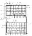
도 1은 본 발명의 실시예에서 단상 표준궤도의 스마트 홈 시스템의 전체 구조에 관한 설명도이다;
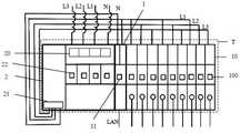
도 2는 본 발명의 실시예에서 삼상 표준궤도의 스마트 홈 시스템의 전체 구조에 관한 설명도이다.The embodiments of the present invention will be described more fully with reference to the accompanying drawings, but the attached drawings are only a part of the description of the present invention and do not limit the scope of the present invention.
1 is an explanatory diagram of the overall structure of a smart home system in a single-phase standard orbit in an embodiment of the present invention;
2 is an explanatory diagram of the overall structure of a three-phase standard orbit smart home system in an embodiment of the present invention.
이하 첨부도면과 구체적인 실시예를 결부하여 본 발명의 실시예에서의 기술방안에 대한 상세한 설명을 진행한다. 이하 설명은 본 발명의 부분적인 실시예로 전부 실시예로 제한하지 않으며 본 영역의 기술인원이 창조성 노동을 전제로 획득하지 않은 모든 기타 실시예는 본 발명의 의도와 범위내에 소속된 사항으로 간주할 수 있다.Hereinafter, a detailed description of the technical solutions in the embodiments of the present invention will be made in conjunction with the accompanying drawings and specific embodiments. The following description is only a partial embodiment of the present invention and is not limited to all embodiments, and all other embodiments that are not acquired by creative personnel in this area on the premise of creative labor will be regarded as belonging to the intention and scope of the present invention. Can.
특별히 설명할 것은 서로 충돌되지 않는 상황에서 본 발명의 실시예 및 실시예에서의 특징은 상호 결합 할 수 있다.What is specifically described, in the situation that does not conflict with each other, the features of the embodiments and examples of the present invention can be combined with each other.
본 발명은 일종의 표준궤도의 스마트 홈 시스템으로,The present invention is a kind of standard track smart home system,
전력 공급 전원선(L)과 전력 공급 접지선(N)을 각자 연결하는 게이트웨이 설비의 전원 인터페이스, 원격 연결이 가능한 적어도 한개 이상의 사용자 단말을 포함하며 다수의 제 1 확장설비(10)에 연결할 수 있는 게이트웨이 설비(1);A power supply interface of a gateway facility that connects the power supply power line (L) and the power supply ground line (N) respectively, and includes at least one user terminal capable of remote connection, and can be connected to a plurality of first expansion facilities (10)
게이트웨이 설비(1) 및 다수의 제 1 확장설비(10)를 배열하여 설치 할 수 있으며 다수의 접선 단자(도면에 표시되지 않음)와 서로 연결되는 표준궤도(T);A standard orbit (T) that can be installed by arranging the gateway facility (1) and a plurality of first expansion facilities (10) and connected to a plurality of tangential terminals (not shown in the figure);
매개 제 1 확장설비(10)의 인출선 인터페이스에 각자 연결되어 있는 한개 혹은 다수의 스마트 홈 설비를 포함할 수 있다.It may include one or a plurality of smart home facilities that are each connected to the leader line interface of each first expansion facility (10).
상기 표준궤도 스마트 홈 시스템의 기술 방안에 의거 도 1에서 제시한 바와 같이 게이트웨이 설비(1)와 다수의 제 1 확장설비(10)는 표준궤도(T)에 배열하여 설치하며 다수의 접선 단자(도면에 표시되지 않음)와 서로 연결되며 바람직하게는 접선 단자(도면에 표시되지 않음)는 팔침 단자로 게이트웨이 설비(1)와 다수의 제 1 확장단자(10)의 전기 접속 부분으로 다수의 제 1 확장설비(10)에 전력을 공급하며 게이트웨이 설비(1)는 다수의 제 1 확장설비(10)를 연결하는데 사용되고 매개 제 1 확장설비(10)는 사용자 단말 혹은 로컬 조작을 통하여 대응되는 스마트 홈 설비를 컨트롤 한다. 구체적으로 스마트 홈 설비는 조명설비, 난방설비, 공조 시스템, 공기정화 시스템, 커튼 등 설비일 수 있다.Based on the technical scheme of the standard orbit smart home system, as shown in FIG. 1, the
더 나아가서 공전 회로에 의거 사용자는 수요에 따라 필요한 제 1 확장설비(10)를 선택 할 수 있어 분산된 스마트 홈 컨트롤 모듈을 계통적으로 표준궤도(T) 위에 정합 하여 사용자의 조작과 관리에 편리 하도록 하여 지능적으로 스마트 홈 설비를 컨트롤 할수 있도록 한다.Furthermore, based on the revolution circuit, the user can select the required first expansion facility (10) according to the demand, so that the distributed smart home control module is systematically matched on the standard track (T) to facilitate user operation and management. It enables intelligent control of smart home equipment.
특별히 설명해야 할 부분은 본 발명중의 확장설비는 제 1 확장설비(10)의 스마트 에어 스위치가 단상 혹은 삼상 인 것에 제한되지 않으며 사용자의 수요에 의거 제 1 확장설비(10)를 교체 할 수 있고 표준궤도 스마트 홈 시스템에 의거 계통적으로 표준궤도(T)에 정합 할 수 있기에 여기서 구체적으로 언급 하지 않는다.Particularly, the expansion facility in the present invention is not limited to a single-phase or three-phase smart air switch of the
일종의 비교적 우수한 실시 예로 누전 보호장치(2)가 포함되어야 하며 누전 보호장치(2)는 표준궤도(T) 위에 설치되어 있어야 하고 누전 보호장치(2)에는 전원 인터페이스(20)와 인출선 인터페이스(21) 및 스위치(22)가 배치되어 있어야 한다.As a kind of relatively good embodiment, the earth
전원 인터페이스(20)는 전력 공급 전원선(L)과 전력 공급 접지선(N)에 각자 연결되며 인출선 인터페이스(21)는 전력 공급 전원선(L)과 전력 공급 접지선(N)을 각자 연결하여 출력시키며 이와 동시에 게이트웨이 설비(1)의 전원 인터페이스와 각자 연결되며 스위치(22)는 누전 보호에 사용되며 이와 동시에 전력 공급 전원선(L)과 전력 공급 접지선(N)의 전력 공급과 차단을 컨트롤 한다.The
구체적으로 누전 보호장치(2)는 표준궤도(T)위에 설치 되며 누전 보호장치(2)는 단상 혹은 삼상의 표준궤도 스마트 홈 시스템의 누전 보호 기능을 갖고 있는 에어 스위치 이다.Specifically, the earth
일종의 비교적 우수한 실시 예로 도 1에서 제시한 바와 같이 전력 공급 설비(3)를 포함하며 전력 공급 설비(3)는 표준궤도(T) 위에 설치 되며 전력 공급 설비(3)는 다수의 제 2 확장설비(30)의 연결에 사용되어 모든 제 2 확장설비(30)에 전력을 공급한다. 전력 공급 설비(3)는 외부의 다종 기능 유형의 확장 설비에 사용되며 다수의 제 2 확장설비(30)를 포함 하며 제 2 확장설비(30)는 환경 센서 혹은 무선 접수 장치 혹은 원격 컨트롤러 일 수 있다.As a kind of comparatively good embodiment, as shown in FIG. 1, the power supply facility 3 is included, and the power supply facility 3 is installed on a standard track T, and the power supply facility 3 includes a plurality of second expansion facilities ( It is used to connect 30) to supply power to all of the
일종의 비교적 우수한 실시 예로 도 1에서 제시한 바와 같이 커넥터(4)를 포함하며 커넥터(4)는 표준궤도(T) 위에 설치 되며 커넥터(4)는 다수의 제 1 확장설비(10)의 배열을 연결하는데 사용된다. 사용자의 수요에 따라 표준궤도(T)위에 설치된 커넥터(4)는 다수의 제 1 확장설비(10)의 배열을 연결할 수 있는 통신 커넥터 일 수 있다.As a kind of relatively excellent embodiment, as shown in FIG. 1, the
일종의 비교적 우수한 실시 예로 게이트웨이 설비(1)는 네트워크 인터페이스(LAN)와 무선 네트워크 모듈(도면에 표시되지 않음)을 포함하며 게이트웨이 설비(1)는 네트워크 인터페이스(LAN)가 제공하는 유선 네트워크 연결 방식으로 사용자 단말에 연결되거나 무선 네트워크 모듈(도면에 표시되지 않음)이 제공하는 무선 네트워크 연결 방식으로 사용자 단말에 연결된다. 무선 네트워크 모듈(도면에 표시되지 않음)은 게이트웨이 설비(1)의 내부에 있는 무선 네트워크 연결 기능을 이용하며 WIFI 네트워크 연결 기능도 포함한다.As a kind of relatively good embodiment, the
특별히 설명해야 할 부분은 사용자 단말은 이동식 혹은 비 이동식 단말에 제한되지 않으며 성공적으로 클라우드 컨트롤 설비에 연결되면 사용할 수 있기에 여기서 구체적으로 언급 하지 않는다.Particularly, the user terminal is not limited to a mobile or non-mobile terminal, and is not specifically described here because it can be used when it is successfully connected to a cloud control facility.
일종의 비교적 우수한 실시 예로 제 1 확장설비(10)는 단상의 스마트 에어 스위치 혹은 삼상의 스마트 에어 스위치이다. 여기서 제 1 확장설비(10)는 단상의 스마트 에어 스위치 혹은 삼상의 스마트 에어 스위치에 제한 되지 않으며 사용자는 전력 공급 회로와 수요에 따라 선택한 제 1 확장설비(10)에 의거하여 게이트웨이 설비(1)와 누전 보호장치(2)를 표준궤도(T)위에 함께 설치하며 게이트웨이 설비(1)의 사용자 단말 컨트롤러 혹은 제 1 확장설비(10)에 의거 대응되는 스마트 홈 설비를 로컬에서 컨트롤 할 수 있기에 표준궤도 스마트 시스템이 분산된 스마트 홈 설비를 계통적으로 표준궤도(T)위에 정합할 수 있어 사용자의 조작과 관리에 편리하게 한다.As a kind of relatively good embodiment, the
일종의 비교적 우수한 실시 예로 제 2 확장설비(30)는 환경 센서 혹은 클라우드 컨트롤러 혹은 무선 접수장치 혹은 원격 컨트롤러 일 수 있다As a kind of relatively good embodiment, the
특별히 설명해야 할 부분은 제 2 확장설비(30)는 환경 센서 혹은 클라우드 컨트롤러 혹은 무선 접수 장치 혹은 원격 컨트롤러에 제한 되지 않으며 사용자의 수요에 따라 제 2 확장설비(30)를 교체할 수 있으며 표준궤도 스마트 홈 시스템에 의거 계통적으로 표준궤도(T)에 정합 할 수 있기에 여기서 구체적으로 언급 하지 않는다.Particularly, the
일종의 비교적 우수한 실시 예로 게이트웨이 설비(1)는 제 1 표시등(11)을 포함하며 제 1 표시등(11)은 게이트웨이 설비의 작업 상태를 표시하는데 사용된다.As a kind of relatively good embodiment, the
더 나아가서 제 1 표시등(11)은 게이트웨이 설비의 작업 상태를 표시하는데 사용되며; 제 1 표시등(11)의 녹색등이 반짝이는 상태 일 때 게이트웨이 설비(1)에 성공적으로 전력이 공급된 것을 표시하고; 제 1 표시등(11)의 녹색등이 점멸 된 상태 일 때 게이트웨이 설비(1)에 전력 공급이 실패 된것을 표시하며; 제 1 표시등(11)의 녹색등이 느리게 반짝이는 상태 일 때 게이트웨이 설비(1)의 유선 네트워크 연결이 성공된 것을 표시하고; 제 1 표시등(11)의 녹색등이 빠르게 반짝이는 상태 일 때 게이트웨이 설비(1)의 유선 네트워크 연결이 실패 하였거나 연결중 인 것을 표시하며; 제 1 표시등(11)의 홍색등이 상시 점등되며 녹색등이 간헐적으로 반짝이는 상태 일 때 게이트웨이 설비(1)는 무선 배치 상태 인 것을 표시하며; 제 1 표시등(11)의 홍색등이 상시 점등되며 녹색등이 느리게 반짝이는 상태 일 때 게이트웨이 설비(1)의 무선 네트워크 연결이 성공된 것을 표시하고; 제 1 표시등(11)의 홍색등이 상시 점등되며 녹색등이 빠르게 반짝이는 상태 일 때 게이트웨이 설비(1)의 무선 네트워크 연결이 실패 하였거나 연결중 인 것을 표시한다.Furthermore, the
일종의 비교적 우수한 실시 예로 제 1 확장설비(10)에는 제 2 표시등(100)이 포함되며 제 2 표시등(100)은 제 1 확장설비(10)와 게이트웨이 설비(1)의 연결 상태를 표시하는데 사용된다.As a kind of relatively good embodiment, the
더 나아가서 제 2 표시등(100)은 제 1 확장설비(10)와 게이트웨이 설비(1)의 연결 상태를 표시하는데 사용되며; 게이트웨이 설비(1)에 전력 공급 후 제 2 표시등(100)의 홍색등이 반짝이는 상태 일 때 제 1 확장설비(10)에 성공적으로 전력이 공급된 것을 표시하고; 게이트웨이 설비(1)에 전력 공급 후 제 2 표시등(100)의 홍색등이 점멸된 상태 일 때 제 1 확장설비(10)에 전력 공급이 실패 된 것을 표시하며; 제 2 표시등(100)의 홍색등이 빠르게 반짝이는 상태로부터 점멸 상태로 바뀔 때 제 1 확장설비(10)와 게이트웨이 설비(1)의 연결이 성공되었음을 표시하며; 제 2 표시등(100)의 홍색등이 빠르게 반짝이는 상태일 때 제 1 확장설비(10)와 게이트웨이 설비(1)의 연결이 실패하였거나 연결중 인 것을 표시하며; 제 2 표시등(100)의 녹색등이 상시 점등된 상태 일 때 제 1 확장설비(10)의 온/통전 상태를 표시하고; 제 2 표시등(100)의 녹색등이 점멸된 상태 일 때 제 1 확장설비(10)의 오프/단전 상태를 표시하며; 제 1 확장설비(10)의 잠금상태 혹은 비 잠금상태 일 때 제 2 표시등(100)의 표시 색상은 상반되며 제 1 확장설비(10)의 정점부분에 있는 버튼을 길게 누르면 잠금상태로 전환 할수 있고 잠금상태에서 표준궤도 스마트 홈 시스템은 로컬 조작만 가능하다.Furthermore, the second indicator light 100 is used to indicate the connection status between the first expansion facility 10 and the gateway facility 1; When the red light of the second indicator light 100 is flashing after the power is supplied to the gateway facility 1, it indicates that power has been successfully supplied to the first expansion facility 10; After power is supplied to the gateway facility 1, when the red light of the second indicator light 100 is flashing, it indicates that power supply to the first expansion facility 10 has failed; When the red light of the second indicator light 100 is rapidly changed from a flashing state to a blinking state, it indicates that the connection between the first expansion facility 10 and the gateway facility 1 is successful; When the red light of the second indicator 100 is rapidly flashing, it indicates that the connection between the first expansion facility 10 and the gateway facility 1 has failed or is being connected; When the green light of the second indicator light 100 is always lit, the on/off state of the first expansion facility 10 is displayed; When the green light of the second indicator light 100 is flashing, it displays an off/power failure state of the first expansion facility 10; When the first expansion facility 10 is in a locked or non-locked state, the display colors of the second indicator 100 are incompatible, and a long press of the button at the apex of the first expansion facility 10 can switch to the locked state. In the locked state, the standard track smart home system can only be operated locally.
일종의 비교적 우수한 실시 예로 도 1에서 제시한 바와 같이 단상 표준궤도 스마트 홈 시스템에는 누전 보호장치(2), 전력 공급 유닛(3) 및 다수의 제 1 확장설비(10)가 표준궤도(T)위에 병렬로 설치되어 있으며 다수의 제 1 확장설비(10)는 다수의 접선 단자(도면에 표시되지 않음)로 상호 연결되어 있으며 접선 단자(도면에 표시되지 않음)는 팔침 단자로 다수의 제 1 확장설비(10)사이의 전력 연결을 실현하며 전력 공급 설비(3)는 외부의 각종 기능 유형의 확장 설비를 연결 하는데 사용되며 제 2 확장설비(30)를 포함한다.As a relatively good embodiment of the present invention, as shown in FIG. 1, the single-phase standard orbit smart home system includes a short circuit protection device (2), a power supply unit (3), and a plurality of first expansion facilities (10) parallel to the standard orbit (T). It is installed as a plurality of
더 나아가서 다른 표준궤도(T)위에 병렬로 연결된 다수의 제 1 확장설비(10)와 게이트웨이 설비(1)는 다수의 접선 단자(도면에 표시되지 않음)로 상호 연결되어 있으며 접선 단자(도면에 표시되지 않음)는 팔침 단자로 게이트웨이 설비(1)와 다수의 제 1 확장설비(10) 사이의 전력 연결을 실현하며 두개의 배열 사이의 제 1 확장설비(10)는 커넥터(4)를 통하여 연결되어 두개의 배열 사이의 다수의 제 1 확장설비(10)의 통신 연결을 실현하여 분산된 스마트 컨트롤 모듈을 표준궤도(T)위에 정합하여 사용자의 조작과 관리에 편리하게 한다.Furthermore, a plurality of
일종의 비교적 우수한 실시 예로 도 2에서 제시한 바와 같이 삼상 궤도의 스마트 홈 시스템은 표준궤도(T)위에서 병열로 게이트웨이 설비(1), 누전 보호장치(2) 및 다수의 제 1 확장설비 조합을 연결하며 매개 제 1 확장설비 조합에는 3개의 제 1 확장설비(10)를 포함하고 매개 제 1 확장설비(10)의 전원 인터페이스는 각각 하나의 전력 공급 전원선(L)을 연결하여 제 1 확장설비(10)에 전력을 공급하며 매개 제 1 확장설비(10)의 인출선 인터페이스는 하나 혹은 다수의 스마트 홈 설비와 연결되고 매개 제 1 확장설비(10)는 사용자 단말 혹은 로컬에서 단독으로 대응 연결되는 스마트 홈 설비를 컨트롤 하며 매개 단상 제 1 확장설비(10)는 하나의 삼상 제 1 확장설비 조합을 구성 할 수 있으며 사용자는 커넥터(4)를 통하여 사용자가 필요한 삼상의 확장 설비를 연결 할 수 있다.As a relatively good embodiment of the present invention, as shown in FIG. 2, a three-phase orbit smart home system connects a gateway facility (1), an earth leakage protection device (2), and a plurality of first expansion facility combinations in parallel on a standard track (T). Each first expansion facility combination includes three
상기 실시 예는 본 발명의 비교적 우수한 실시 예로 본 발명의 실시 방법과 보호범위에 제한 되지 않는다. 본 영역의 기술인원은 본 발명의 진실된 의도와 범위의 전체 변화와 수정을 포함한 내용으로 간주 할 수 있으며 본 발명이 명세서와 도면의 내용이 응용되는 모든 등가의 범위와 내용은 모두 본 발명의 의도와 범위내에 소속된 사항으로 간주할 수 있다.The above embodiments are not limited to the implementation method and the protection scope of the present invention as a relatively excellent embodiment of the present invention. The technical personnel in this area can be regarded as contents including all changes and modifications of the true intention and scope of the present invention, and all equivalent ranges and contents of the present invention to which the contents of the specification and drawings are applied are all the intention of the present invention. It can be regarded as belonging to the range within and.
Claims (9)
Translated fromKorean전력 공급 전원선과 전력 공급 접지선을 각자 연결하는 게이트웨이 설비의 전원 인터페이스, 원격 연결이 가능한 적어도 한개 이상의 사용자 단말을 포함하며 다수의 제 1 확장설비에 연결할 수 있는 게이트웨이 설비;
게이트웨이 설비 및 다수의 제 1 확장설비를 배열하여 설치 할 수 있으며 다수의 접선 단자와 서로 연결되는 표준 궤도;
매개 제 1 확장설비의 인출선 인터페이스에 각자 연결되어 있는 한개 혹은 다수의 스마트 홈 설비를 포함할 수 있다.
바람직하게는 상기 표준 궤도 위에는 누전 보호장치가 설치되어 있어야 하며 상기 누전 보호장치에는 전원 인터페이스와 인출선 인터페이스 및 스위치가 배치 되는것을 포함하는 것을 특징으로 한다.The present invention discloses a smart home system of a kind of standard orbit,
A gateway facility that includes at least one user terminal capable of remote connection, and a gateway facility capable of connecting to a plurality of first expansion facilities;
A standard track that can be installed by arranging a gateway facility and a plurality of first expansion devices and connected to a plurality of tangential terminals;
It may include one or a plurality of smart home facilities that are respectively connected to the leader line interface of each first expansion facility.
Preferably, an earth leakage protection device should be installed on the standard track, and the earth leakage protection device may include a power interface, a lead line interface, and a switch.
상기 전원 인터페이스는 상기 전력 공급 전원선과 상기 전력 공급 접지선에 각자 연결되며 상기 인출선 인터페이스는 상기 전력 공급 전원선과 상기 전력 공급 접지선을 각자 연결하여 출력시키며 이와 동시에 상기 케이트웨이 설비의 전원 인터페이스와 각자 연결되며 상기 스위치는 누전 보호장치에 사용되며 이와 동시에 상기 전력 공급 전원선과 상기 전력 공급 접지선의 전력 공급과 차단을 컨트롤 하는것을 특징으로 한다.According to claim 1, the smart home system of the standard track is characterized in that a short circuit protection device is installed on the standard track, and the short circuit protection device includes a power interface, a lead wire interface, and a switch.
The power interface is respectively connected to the power supply power line and the power supply ground line, and the lead line interface connects and outputs the power supply power line and the power supply ground line respectively, and at the same time, is respectively connected to the power interface of the cableway facility. The switch is used in an earth leakage protection device, and at the same time, it is characterized in that it controls the power supply and disconnection of the power supply power line and the power supply ground line.
상기 게이트웨이 설비는 상기 네트워크 인터페이스가 제공하는 유선 네트워크 연결 방식으로 상기 사용자 단말에 연결되거나 상기 게이트웨이 설비는 상기 무선 네트워크 모듈이 제공하는 무선 네트워크 연결 방식으로 상기 사용자 단말에 연결된다.According to claim 1, the smart home system of the standard track is characterized in that the gateway facility includes a network interface and a wireless network module.
The gateway facility is connected to the user terminal by a wired network connection method provided by the network interface, or the gateway facility is connected to the user terminal by a wireless network connection method provided by the wireless network module.
Applications Claiming Priority (3)
| Application Number | Priority Date | Filing Date | Title |
|---|---|---|---|
| CN201711342895.7ACN107942699A (en) | 2017-12-14 | 2017-12-14 | A kind of standard trajectory intelligent domestic system |
| CN201711342895.7 | 2017-12-14 | ||
| PCT/CN2018/118364WO2019114561A1 (en) | 2017-12-14 | 2018-11-30 | Standard track smart home system |
Publications (1)
| Publication Number | Publication Date |
|---|---|
| KR20200087797Atrue KR20200087797A (en) | 2020-07-21 |
Family
ID=61943283
Family Applications (1)
| Application Number | Title | Priority Date | Filing Date |
|---|---|---|---|
| KR1020207016756ACeasedKR20200087797A (en) | 2017-12-14 | 2018-11-30 | Smart home system with a kind of standard track |
Country Status (6)
| Country | Link |
|---|---|
| US (1) | US11199825B2 (en) |
| EP (1) | EP3726302A4 (en) |
| JP (1) | JP7036926B2 (en) |
| KR (1) | KR20200087797A (en) |
| CN (1) | CN107942699A (en) |
| WO (1) | WO2019114561A1 (en) |
Families Citing this family (1)
| Publication number | Priority date | Publication date | Assignee | Title |
|---|---|---|---|---|
| CN107942699A (en)* | 2017-12-14 | 2018-04-20 | 宁波智轩物联网科技有限公司 | A kind of standard trajectory intelligent domestic system |
Family Cites Families (24)
| Publication number | Priority date | Publication date | Assignee | Title |
|---|---|---|---|---|
| US20030038849A1 (en)* | 2001-07-10 | 2003-02-27 | Nortel Networks Limited | System and method for remotely interfacing with a plurality of electronic devices |
| JP4458277B2 (en)* | 2005-08-31 | 2010-04-28 | オムロン株式会社 | Programmable controller remote terminal device |
| JP4821495B2 (en)* | 2006-08-10 | 2011-11-24 | パナソニック電工株式会社 | Power distribution system |
| US8869296B2 (en)* | 2009-11-06 | 2014-10-21 | Verizon Patent And Licensing Inc. | Access to user information |
| GB2464629B (en)* | 2009-12-21 | 2011-01-12 | Paul Richard Jewell | Electricity supply and control apparatus |
| CN201623724U (en)* | 2010-02-09 | 2010-11-03 | 上海天朗电子技术有限公司 | DIN standard guide rail type mounted EIB-AMX gateway |
| TW201143595A (en)* | 2010-05-27 | 2011-12-01 | Hon Hai Prec Ind Co Ltd | High voltage defend device |
| US8384249B2 (en)* | 2011-04-14 | 2013-02-26 | Elbex Video Ltd. | Method and apparatus for combining AC power relay and current sensors with AC wiring devices |
| JP5994973B2 (en)* | 2012-04-27 | 2016-09-21 | 東芝ライテック株式会社 | Distribution board |
| CN102694870B (en)* | 2012-06-08 | 2015-12-16 | 汕头市易普联科技有限公司 | The online upgrading method of the gateway of dynamically allocate address |
| CN203054539U (en)* | 2012-06-19 | 2013-07-10 | 广州市晶控电子科技有限公司 | Intelligent household security and protection system based on ZigBee and webOS |
| CN102882751B (en)* | 2012-09-21 | 2016-01-27 | 鸿富锦精密工业(深圳)有限公司 | Intelligent domestic network system and chromacoder thereof |
| IL228749A (en)* | 2013-10-06 | 2014-09-30 | Adir Tubi | Method and device for wifi controlled electrical switch |
| CN204613659U (en)* | 2015-04-15 | 2015-09-02 | 杜春辉 | Internet of Things Domestic distributing box |
| CN105137783A (en)* | 2015-07-31 | 2015-12-09 | 陈泽 | Intelligent socket and smart home system |
| CN106549862B (en)* | 2015-09-23 | 2023-05-16 | 北京北信源软件股份有限公司 | Personification intelligent home gateway and access method |
| EP3375146B1 (en)* | 2015-11-11 | 2020-09-16 | Telefonaktiebolaget LM Ericsson (publ) | Systems and methods relating to a smart home manager |
| CN206364824U (en)* | 2016-08-31 | 2017-07-28 | 深圳市欧瑞博电子有限公司 | Built-in intelligent gateway and intelligent domestic system |
| CN206349651U (en)* | 2016-12-20 | 2017-07-21 | 上海全筑建筑装饰集团股份有限公司 | A kind of family expenses strong and weak electricity integrated box |
| CN106597868B (en)* | 2016-12-30 | 2020-04-10 | 中科同德(北京)生态科技有限公司 | Intelligent household control system |
| CN206452097U (en)* | 2016-12-30 | 2017-08-29 | 深圳市欧瑞博电子有限公司 | Intelligent tripper and distribution box |
| WO2018164616A1 (en)* | 2017-03-09 | 2018-09-13 | Telefonaktiebolaget Lm Ericsson (Publ) | Methods and apparatus for packet communication over a local network using a local packet replication procedure |
| CN107942699A (en)* | 2017-12-14 | 2018-04-20 | 宁波智轩物联网科技有限公司 | A kind of standard trajectory intelligent domestic system |
| CN207851525U (en)* | 2017-12-14 | 2018-09-11 | 宁波智轩物联网科技有限公司 | A kind of standard trajectory intelligent domestic system |
- 2017
- 2017-12-14CNCN201711342895.7Apatent/CN107942699A/enactivePending
- 2018
- 2018-11-30KRKR1020207016756Apatent/KR20200087797A/ennot_activeCeased
- 2018-11-30WOPCT/CN2018/118364patent/WO2019114561A1/ennot_activeCeased
- 2018-11-30EPEP18887517.3Apatent/EP3726302A4/ennot_activeWithdrawn
- 2018-11-30JPJP2020533075Apatent/JP7036926B2/enactiveActive
- 2018-11-30USUS16/768,775patent/US11199825B2/enactiveActive
Also Published As
| Publication number | Publication date |
|---|---|
| US20200371486A1 (en) | 2020-11-26 |
| JP7036926B2 (en) | 2022-03-15 |
| EP3726302A1 (en) | 2020-10-21 |
| WO2019114561A1 (en) | 2019-06-20 |
| CN107942699A (en) | 2018-04-20 |
| US11199825B2 (en) | 2021-12-14 |
| EP3726302A4 (en) | 2021-08-11 |
| JP2021507603A (en) | 2021-02-22 |
Similar Documents
| Publication | Publication Date | Title |
|---|---|---|
| US20210391803A1 (en) | Modular in-wall ac-dc power supply | |
| US20090143917A1 (en) | Residential Environmental Management Control System Interlink | |
| CN102164065B (en) | Electric link bus system | |
| CN112114554B (en) | Wireless control system and method for power supply on-off of power equipment | |
| CN104269710B (en) | A kind of integrated intelligent socket and electric power networks control system | |
| US8086357B2 (en) | Offline configuration using USB download in an integrated power distribution system | |
| WO2008039277A2 (en) | System controller for integrated lighting control panels | |
| CN103257600A (en) | Device and method of household appliance intelligent control | |
| CN102291284A (en) | Intelligent terminal device of wireless network digital home | |
| CN107078479B (en) | Electrical connection points installed in walls of dwellings and electrical installations comprising at least one such connection point | |
| CN206461637U (en) | A kind of intelligent domestic system | |
| KR20200087797A (en) | Smart home system with a kind of standard track | |
| CN112099428B (en) | Wired control system and method for power supply on-off of power equipment | |
| CN203084467U (en) | Household electric appliance intelligent control device | |
| CN213244435U (en) | Intelligent lighting control system | |
| CN104821075A (en) | Intelligent control system for home networks | |
| KR102077464B1 (en) | System for automatic controlling building by integration dde of air conditioning, air-conditioner, lighting and power | |
| CN213094227U (en) | Edge intelligent gateway for power supply safety management | |
| CN207851525U (en) | A kind of standard trajectory intelligent domestic system | |
| WO2018129578A1 (en) | Intelligent power distribution system | |
| CN112947109A (en) | Wired and wireless combined intelligent home system | |
| CN206283516U (en) | The detection platform of intelligent MANET data terminal communication base station | |
| KR20090108813A (en) | G-Wave Smart Mesh Network Light Control and Light Switch | |
| CN204538486U (en) | The wire structures of distribution box and circuit | |
| KR102870267B1 (en) | Lighting apparatus with easy application customization |
Legal Events
| Date | Code | Title | Description |
|---|---|---|---|
| PA0105 | International application | Patent event date:20200611 Patent event code:PA01051R01D Comment text:International Patent Application | |
| PA0201 | Request for examination | ||
| PG1501 | Laying open of application | ||
| E902 | Notification of reason for refusal | ||
| PE0902 | Notice of grounds for rejection | Comment text:Notification of reason for refusal Patent event date:20210218 Patent event code:PE09021S01D | |
| E601 | Decision to refuse application | ||
| PE0601 | Decision on rejection of patent | Patent event date:20210817 Comment text:Decision to Refuse Application Patent event code:PE06012S01D Patent event date:20210218 Comment text:Notification of reason for refusal Patent event code:PE06011S01I | |
| E601 | Decision to refuse application | ||
| E801 | Decision on dismissal of amendment | ||
| PE0601 | Decision on rejection of patent | Patent event date:20211105 Comment text:Decision to Refuse Application Patent event code:PE06012S01D Patent event date:20210218 Comment text:Notification of reason for refusal Patent event code:PE06011S01I | |
| PE0801 | Dismissal of amendment | Patent event code:PE08012E01D Comment text:Decision on Dismissal of Amendment Patent event date:20211105 Patent event code:PE08011R01I Comment text:Amendment to Specification, etc. Patent event date:20211018 Patent event code:PE08011R01I Comment text:Amendment to Specification, etc. Patent event date:20210419 |