KR20200085859A - Windshield wiper connector and assembly - Google Patents
Windshield wiper connector and assemblyDownload PDFInfo
- Publication number
- KR20200085859A KR20200085859AKR1020207016992AKR20207016992AKR20200085859AKR 20200085859 AKR20200085859 AKR 20200085859AKR 1020207016992 AKR1020207016992 AKR 1020207016992AKR 20207016992 AKR20207016992 AKR 20207016992AKR 20200085859 AKR20200085859 AKR 20200085859A
- Authority
- KR
- South Korea
- Prior art keywords
- connector
- frame
- wiper blade
- tertiary
- cover
- Prior art date
- Legal status (The legal status is an assumption and is not a legal conclusion. Google has not performed a legal analysis and makes no representation as to the accuracy of the status listed.)
- Ceased
Links
- 239000011324beadSubstances0.000description26
- 230000002787reinforcementEffects0.000description14
- 239000004033plasticSubstances0.000description11
- 229920003023plasticPolymers0.000description11
- 238000003780insertionMethods0.000description10
- 230000037431insertionEffects0.000description10
- 239000000463materialSubstances0.000description10
- 210000000078clawAnatomy0.000description9
- 238000000034methodMethods0.000description8
- 210000002105tongueAnatomy0.000description8
- 229910052751metalInorganic materials0.000description7
- 239000002184metalSubstances0.000description7
- 238000013461designMethods0.000description5
- 150000002739metalsChemical class0.000description5
- 230000001154acute effectEffects0.000description4
- 230000000712assemblyEffects0.000description3
- 238000000429assemblyMethods0.000description3
- 229910000831SteelInorganic materials0.000description2
- 238000009826distributionMethods0.000description2
- 238000004519manufacturing processMethods0.000description2
- 238000012986modificationMethods0.000description2
- 230000004048modificationEffects0.000description2
- 230000003014reinforcing effectEffects0.000description2
- 239000010959steelSubstances0.000description2
- 239000000853adhesiveSubstances0.000description1
- 230000001070adhesive effectEffects0.000description1
- 229910052782aluminiumInorganic materials0.000description1
- XAGFODPZIPBFFR-UHFFFAOYSA-NaluminiumChemical compound[Al]XAGFODPZIPBFFR-UHFFFAOYSA-N0.000description1
- 238000004873anchoringMethods0.000description1
- 238000013459approachMethods0.000description1
- 230000000295complement effectEffects0.000description1
- 239000002131composite materialSubstances0.000description1
- 238000002788crimpingMethods0.000description1
- 239000006185dispersionSubstances0.000description1
- 239000013013elastic materialSubstances0.000description1
- 229920001971elastomerPolymers0.000description1
- 230000007613environmental effectEffects0.000description1
- 238000009434installationMethods0.000description1
- 230000002452interceptive effectEffects0.000description1
- 229920001296polysiloxanePolymers0.000description1
- 238000003825pressingMethods0.000description1
- 230000000452restraining effectEffects0.000description1
- 239000005060rubberSubstances0.000description1
- 238000000926separation methodMethods0.000description1
- 238000004513sizingMethods0.000description1
- 238000005728strengtheningMethods0.000description1
- 238000003466weldingMethods0.000description1
Images


Classifications
- B—PERFORMING OPERATIONS; TRANSPORTING
- B60—VEHICLES IN GENERAL
- B60S—SERVICING, CLEANING, REPAIRING, SUPPORTING, LIFTING, OR MANOEUVRING OF VEHICLES, NOT OTHERWISE PROVIDED FOR
- B60S1/00—Cleaning of vehicles
- B60S1/02—Cleaning windscreens, windows or optical devices
- B60S1/04—Wipers or the like, e.g. scrapers
- B60S1/32—Wipers or the like, e.g. scrapers characterised by constructional features of wiper blade arms or blades
- B60S1/38—Wiper blades
- B—PERFORMING OPERATIONS; TRANSPORTING
- B60—VEHICLES IN GENERAL
- B60S—SERVICING, CLEANING, REPAIRING, SUPPORTING, LIFTING, OR MANOEUVRING OF VEHICLES, NOT OTHERWISE PROVIDED FOR
- B60S1/00—Cleaning of vehicles
- B60S1/02—Cleaning windscreens, windows or optical devices
- B60S1/04—Wipers or the like, e.g. scrapers
- B60S1/32—Wipers or the like, e.g. scrapers characterised by constructional features of wiper blade arms or blades
- B60S1/40—Connections between blades and arms
- B60S1/4006—Connections between blades and arms for arms provided with a hook-shaped end
- B60S1/4009—Connections between blades and arms for arms provided with a hook-shaped end comprising a detachable intermediate element mounted on the hook-shaped end
- B—PERFORMING OPERATIONS; TRANSPORTING
- B60—VEHICLES IN GENERAL
- B60S—SERVICING, CLEANING, REPAIRING, SUPPORTING, LIFTING, OR MANOEUVRING OF VEHICLES, NOT OTHERWISE PROVIDED FOR
- B60S1/00—Cleaning of vehicles
- B60S1/02—Cleaning windscreens, windows or optical devices
- B60S1/04—Wipers or the like, e.g. scrapers
- B60S1/32—Wipers or the like, e.g. scrapers characterised by constructional features of wiper blade arms or blades
- B60S1/38—Wiper blades
- B60S1/3801—Wiper blades characterised by a blade support harness consisting of several articulated elements
- B—PERFORMING OPERATIONS; TRANSPORTING
- B60—VEHICLES IN GENERAL
- B60S—SERVICING, CLEANING, REPAIRING, SUPPORTING, LIFTING, OR MANOEUVRING OF VEHICLES, NOT OTHERWISE PROVIDED FOR
- B60S1/00—Cleaning of vehicles
- B60S1/02—Cleaning windscreens, windows or optical devices
- B60S1/04—Wipers or the like, e.g. scrapers
- B60S1/32—Wipers or the like, e.g. scrapers characterised by constructional features of wiper blade arms or blades
- B60S1/40—Connections between blades and arms
- B60S1/4003—Multi-purpose connections for two or more kinds of arm ends
- B—PERFORMING OPERATIONS; TRANSPORTING
- B60—VEHICLES IN GENERAL
- B60S—SERVICING, CLEANING, REPAIRING, SUPPORTING, LIFTING, OR MANOEUVRING OF VEHICLES, NOT OTHERWISE PROVIDED FOR
- B60S1/00—Cleaning of vehicles
- B60S1/02—Cleaning windscreens, windows or optical devices
- B60S1/04—Wipers or the like, e.g. scrapers
- B60S1/32—Wipers or the like, e.g. scrapers characterised by constructional features of wiper blade arms or blades
- B60S1/40—Connections between blades and arms
- B60S1/4038—Connections between blades and arms for arms provided with a channel-shaped end
- B60S1/4045—Connections between blades and arms for arms provided with a channel-shaped end comprising a detachable intermediate element mounted on the channel-shaped end
- B60S1/4048—Connections between blades and arms for arms provided with a channel-shaped end comprising a detachable intermediate element mounted on the channel-shaped end the element being provided with retention means co-operating with the channel-shaped end of the arm
- B—PERFORMING OPERATIONS; TRANSPORTING
- B60—VEHICLES IN GENERAL
- B60S—SERVICING, CLEANING, REPAIRING, SUPPORTING, LIFTING, OR MANOEUVRING OF VEHICLES, NOT OTHERWISE PROVIDED FOR
- B60S1/00—Cleaning of vehicles
- B60S1/02—Cleaning windscreens, windows or optical devices
- B60S1/04—Wipers or the like, e.g. scrapers
- B60S1/32—Wipers or the like, e.g. scrapers characterised by constructional features of wiper blade arms or blades
- B60S1/40—Connections between blades and arms
- B60S1/4083—Connections between blades and arms for arms provided with a flat end
- F—MECHANICAL ENGINEERING; LIGHTING; HEATING; WEAPONS; BLASTING
- F16—ENGINEERING ELEMENTS AND UNITS; GENERAL MEASURES FOR PRODUCING AND MAINTAINING EFFECTIVE FUNCTIONING OF MACHINES OR INSTALLATIONS; THERMAL INSULATION IN GENERAL
- F16B—DEVICES FOR FASTENING OR SECURING CONSTRUCTIONAL ELEMENTS OR MACHINE PARTS TOGETHER, e.g. NAILS, BOLTS, CIRCLIPS, CLAMPS, CLIPS OR WEDGES; JOINTS OR JOINTING
- F16B45/00—Hooks; Eyes
- F—MECHANICAL ENGINEERING; LIGHTING; HEATING; WEAPONS; BLASTING
- F16—ENGINEERING ELEMENTS AND UNITS; GENERAL MEASURES FOR PRODUCING AND MAINTAINING EFFECTIVE FUNCTIONING OF MACHINES OR INSTALLATIONS; THERMAL INSULATION IN GENERAL
- F16B—DEVICES FOR FASTENING OR SECURING CONSTRUCTIONAL ELEMENTS OR MACHINE PARTS TOGETHER, e.g. NAILS, BOLTS, CIRCLIPS, CLAMPS, CLIPS OR WEDGES; JOINTS OR JOINTING
- F16B5/00—Joining sheets or plates, e.g. panels, to one another or to strips or bars parallel to them
- F16B5/12—Fastening strips or bars to sheets or plates, e.g. rubber strips, decorative strips for motor vehicles, by means of clips
- F16B5/123—Auxiliary fasteners specially designed for this purpose
- B—PERFORMING OPERATIONS; TRANSPORTING
- B60—VEHICLES IN GENERAL
- B60S—SERVICING, CLEANING, REPAIRING, SUPPORTING, LIFTING, OR MANOEUVRING OF VEHICLES, NOT OTHERWISE PROVIDED FOR
- B60S1/00—Cleaning of vehicles
- B60S1/02—Cleaning windscreens, windows or optical devices
- B60S1/04—Wipers or the like, e.g. scrapers
- B60S1/0491—Additional elements being fixed on wipers or parts of wipers not otherwise provided for, e.g. covers, antennae or lights
- B—PERFORMING OPERATIONS; TRANSPORTING
- B60—VEHICLES IN GENERAL
- B60S—SERVICING, CLEANING, REPAIRING, SUPPORTING, LIFTING, OR MANOEUVRING OF VEHICLES, NOT OTHERWISE PROVIDED FOR
- B60S1/00—Cleaning of vehicles
- B60S1/02—Cleaning windscreens, windows or optical devices
- B60S1/04—Wipers or the like, e.g. scrapers
- B60S1/32—Wipers or the like, e.g. scrapers characterised by constructional features of wiper blade arms or blades
- B60S1/38—Wiper blades
- B60S1/3806—Means, or measures taken, for influencing the aerodynamic quality of the wiper blades
- B—PERFORMING OPERATIONS; TRANSPORTING
- B60—VEHICLES IN GENERAL
- B60S—SERVICING, CLEANING, REPAIRING, SUPPORTING, LIFTING, OR MANOEUVRING OF VEHICLES, NOT OTHERWISE PROVIDED FOR
- B60S1/00—Cleaning of vehicles
- B60S1/02—Cleaning windscreens, windows or optical devices
- B60S1/04—Wipers or the like, e.g. scrapers
- B60S1/32—Wipers or the like, e.g. scrapers characterised by constructional features of wiper blade arms or blades
- B60S1/38—Wiper blades
- B60S2001/3812—Means of supporting or holding the squeegee or blade rubber
- B60S2001/3813—Means of supporting or holding the squeegee or blade rubber chacterised by a support harness consisting of several articulated elements
- B60S2001/3815—Means of supporting or holding the squeegee or blade rubber chacterised by a support harness consisting of several articulated elements chacterised by the joint between elements
- B—PERFORMING OPERATIONS; TRANSPORTING
- B60—VEHICLES IN GENERAL
- B60S—SERVICING, CLEANING, REPAIRING, SUPPORTING, LIFTING, OR MANOEUVRING OF VEHICLES, NOT OTHERWISE PROVIDED FOR
- B60S1/00—Cleaning of vehicles
- B60S1/02—Cleaning windscreens, windows or optical devices
- B60S1/04—Wipers or the like, e.g. scrapers
- B60S1/32—Wipers or the like, e.g. scrapers characterised by constructional features of wiper blade arms or blades
- B60S1/38—Wiper blades
- B60S2001/3843—Wiper blades equipped with removable cover or protective elements
- B—PERFORMING OPERATIONS; TRANSPORTING
- B60—VEHICLES IN GENERAL
- B60S—SERVICING, CLEANING, REPAIRING, SUPPORTING, LIFTING, OR MANOEUVRING OF VEHICLES, NOT OTHERWISE PROVIDED FOR
- B60S1/00—Cleaning of vehicles
- B60S1/02—Cleaning windscreens, windows or optical devices
- B60S1/04—Wipers or the like, e.g. scrapers
- B60S1/32—Wipers or the like, e.g. scrapers characterised by constructional features of wiper blade arms or blades
- B60S1/40—Connections between blades and arms
- B60S1/4006—Connections between blades and arms for arms provided with a hook-shaped end
- B60S1/4009—Connections between blades and arms for arms provided with a hook-shaped end comprising a detachable intermediate element mounted on the hook-shaped end
- B60S2001/4012—Connections between blades and arms for arms provided with a hook-shaped end comprising a detachable intermediate element mounted on the hook-shaped end the element being provided with bearing surfaces on its side walls
- B—PERFORMING OPERATIONS; TRANSPORTING
- B60—VEHICLES IN GENERAL
- B60S—SERVICING, CLEANING, REPAIRING, SUPPORTING, LIFTING, OR MANOEUVRING OF VEHICLES, NOT OTHERWISE PROVIDED FOR
- B60S1/00—Cleaning of vehicles
- B60S1/02—Cleaning windscreens, windows or optical devices
- B60S1/04—Wipers or the like, e.g. scrapers
- B60S1/32—Wipers or the like, e.g. scrapers characterised by constructional features of wiper blade arms or blades
- B60S1/40—Connections between blades and arms
- B60S1/4006—Connections between blades and arms for arms provided with a hook-shaped end
- B60S1/4009—Connections between blades and arms for arms provided with a hook-shaped end comprising a detachable intermediate element mounted on the hook-shaped end
- B60S1/4016—Connections between blades and arms for arms provided with a hook-shaped end comprising a detachable intermediate element mounted on the hook-shaped end the element being provided with retention means co-operating with the hook-shaped end of the arm
- B60S2001/4022—Connections between blades and arms for arms provided with a hook-shaped end comprising a detachable intermediate element mounted on the hook-shaped end the element being provided with retention means co-operating with the hook-shaped end of the arm the element being provided with a locking element movable thereon
- B—PERFORMING OPERATIONS; TRANSPORTING
- B60—VEHICLES IN GENERAL
- B60S—SERVICING, CLEANING, REPAIRING, SUPPORTING, LIFTING, OR MANOEUVRING OF VEHICLES, NOT OTHERWISE PROVIDED FOR
- B60S1/00—Cleaning of vehicles
- B60S1/02—Cleaning windscreens, windows or optical devices
- B60S1/04—Wipers or the like, e.g. scrapers
- B60S1/32—Wipers or the like, e.g. scrapers characterised by constructional features of wiper blade arms or blades
- B60S1/40—Connections between blades and arms
- B60S1/4006—Connections between blades and arms for arms provided with a hook-shaped end
- B60S2001/4035—Connections between blades and arms for arms provided with a hook-shaped end the connection being covered by a removable cover mounted on the blade
- B—PERFORMING OPERATIONS; TRANSPORTING
- B60—VEHICLES IN GENERAL
- B60S—SERVICING, CLEANING, REPAIRING, SUPPORTING, LIFTING, OR MANOEUVRING OF VEHICLES, NOT OTHERWISE PROVIDED FOR
- B60S1/00—Cleaning of vehicles
- B60S1/02—Cleaning windscreens, windows or optical devices
- B60S1/04—Wipers or the like, e.g. scrapers
- B60S1/32—Wipers or the like, e.g. scrapers characterised by constructional features of wiper blade arms or blades
- B60S1/40—Connections between blades and arms
- B60S1/4038—Connections between blades and arms for arms provided with a channel-shaped end
- B60S1/4045—Connections between blades and arms for arms provided with a channel-shaped end comprising a detachable intermediate element mounted on the channel-shaped end
- B60S1/4048—Connections between blades and arms for arms provided with a channel-shaped end comprising a detachable intermediate element mounted on the channel-shaped end the element being provided with retention means co-operating with the channel-shaped end of the arm
- B60S2001/4054—Connections between blades and arms for arms provided with a channel-shaped end comprising a detachable intermediate element mounted on the channel-shaped end the element being provided with retention means co-operating with the channel-shaped end of the arm the intermediate element engaging the back part of the arm
- B—PERFORMING OPERATIONS; TRANSPORTING
- B60—VEHICLES IN GENERAL
- B60S—SERVICING, CLEANING, REPAIRING, SUPPORTING, LIFTING, OR MANOEUVRING OF VEHICLES, NOT OTHERWISE PROVIDED FOR
- B60S1/00—Cleaning of vehicles
- B60S1/02—Cleaning windscreens, windows or optical devices
- B60S1/04—Wipers or the like, e.g. scrapers
- B60S1/32—Wipers or the like, e.g. scrapers characterised by constructional features of wiper blade arms or blades
- B60S1/40—Connections between blades and arms
- B60S1/4038—Connections between blades and arms for arms provided with a channel-shaped end
- B60S2001/4058—Connections between blades and arms for arms provided with a channel-shaped end comprising a separate locking element, e.g. in addition to an intermediate element
- F—MECHANICAL ENGINEERING; LIGHTING; HEATING; WEAPONS; BLASTING
- F16—ENGINEERING ELEMENTS AND UNITS; GENERAL MEASURES FOR PRODUCING AND MAINTAINING EFFECTIVE FUNCTIONING OF MACHINES OR INSTALLATIONS; THERMAL INSULATION IN GENERAL
- F16B—DEVICES FOR FASTENING OR SECURING CONSTRUCTIONAL ELEMENTS OR MACHINE PARTS TOGETHER, e.g. NAILS, BOLTS, CIRCLIPS, CLAMPS, CLIPS OR WEDGES; JOINTS OR JOINTING
- F16B2/00—Friction-grip releasable fastenings
- F16B2/20—Clips, i.e. with gripping action effected solely by the inherent resistance to deformation of the material of the fastening
- F16B2/22—Clips, i.e. with gripping action effected solely by the inherent resistance to deformation of the material of the fastening of resilient material, e.g. rubbery material
- F—MECHANICAL ENGINEERING; LIGHTING; HEATING; WEAPONS; BLASTING
- F16—ENGINEERING ELEMENTS AND UNITS; GENERAL MEASURES FOR PRODUCING AND MAINTAINING EFFECTIVE FUNCTIONING OF MACHINES OR INSTALLATIONS; THERMAL INSULATION IN GENERAL
- F16B—DEVICES FOR FASTENING OR SECURING CONSTRUCTIONAL ELEMENTS OR MACHINE PARTS TOGETHER, e.g. NAILS, BOLTS, CIRCLIPS, CLAMPS, CLIPS OR WEDGES; JOINTS OR JOINTING
- F16B21/00—Means for preventing relative axial movement of a pin, spigot, shaft or the like and a member surrounding it; Stud-and-socket releasable fastenings
- F16B21/02—Releasable fastening devices locking by rotation
- F—MECHANICAL ENGINEERING; LIGHTING; HEATING; WEAPONS; BLASTING
- F16—ENGINEERING ELEMENTS AND UNITS; GENERAL MEASURES FOR PRODUCING AND MAINTAINING EFFECTIVE FUNCTIONING OF MACHINES OR INSTALLATIONS; THERMAL INSULATION IN GENERAL
- F16B—DEVICES FOR FASTENING OR SECURING CONSTRUCTIONAL ELEMENTS OR MACHINE PARTS TOGETHER, e.g. NAILS, BOLTS, CIRCLIPS, CLAMPS, CLIPS OR WEDGES; JOINTS OR JOINTING
- F16B5/00—Joining sheets or plates, e.g. panels, to one another or to strips or bars parallel to them
- F16B5/12—Fastening strips or bars to sheets or plates, e.g. rubber strips, decorative strips for motor vehicles, by means of clips
- F16B5/121—Fastening strips or bars to sheets or plates, e.g. rubber strips, decorative strips for motor vehicles, by means of clips fastened over the edge(s) of the sheet(s) or plate(s)
- F—MECHANICAL ENGINEERING; LIGHTING; HEATING; WEAPONS; BLASTING
- F16—ENGINEERING ELEMENTS AND UNITS; GENERAL MEASURES FOR PRODUCING AND MAINTAINING EFFECTIVE FUNCTIONING OF MACHINES OR INSTALLATIONS; THERMAL INSULATION IN GENERAL
- F16B—DEVICES FOR FASTENING OR SECURING CONSTRUCTIONAL ELEMENTS OR MACHINE PARTS TOGETHER, e.g. NAILS, BOLTS, CIRCLIPS, CLAMPS, CLIPS OR WEDGES; JOINTS OR JOINTING
- F16B5/00—Joining sheets or plates, e.g. panels, to one another or to strips or bars parallel to them
- F16B5/12—Fastening strips or bars to sheets or plates, e.g. rubber strips, decorative strips for motor vehicles, by means of clips
- F16B5/126—Fastening strips or bars to sheets or plates, e.g. rubber strips, decorative strips for motor vehicles, by means of clips at least one of the sheets, plates, bars or strips having integrally formed or integrally connected snap-in-features
- F—MECHANICAL ENGINEERING; LIGHTING; HEATING; WEAPONS; BLASTING
- F16—ENGINEERING ELEMENTS AND UNITS; GENERAL MEASURES FOR PRODUCING AND MAINTAINING EFFECTIVE FUNCTIONING OF MACHINES OR INSTALLATIONS; THERMAL INSULATION IN GENERAL
- F16B—DEVICES FOR FASTENING OR SECURING CONSTRUCTIONAL ELEMENTS OR MACHINE PARTS TOGETHER, e.g. NAILS, BOLTS, CIRCLIPS, CLAMPS, CLIPS OR WEDGES; JOINTS OR JOINTING
- F16B5/00—Joining sheets or plates, e.g. panels, to one another or to strips or bars parallel to them
- F16B5/12—Fastening strips or bars to sheets or plates, e.g. rubber strips, decorative strips for motor vehicles, by means of clips
- F16B5/128—Fastening strips or bars to sheets or plates, e.g. rubber strips, decorative strips for motor vehicles, by means of clips a strip with a C-or U-shaped cross section being fastened to a plate such that the fastening means remain invisible, e.g. the fastening being completely enclosed by the strip
Landscapes
- Engineering & Computer Science (AREA)
- Mechanical Engineering (AREA)
- General Engineering & Computer Science (AREA)
- Connector Housings Or Holding Contact Members (AREA)
Abstract
Translated fromKoreanDescription
Translated fromKorean관련 출원의 상호 참조Cross reference of related applications
본 출원은, 각각의 전체 내용이 참조로 본 명세서에 통합되는, 2018년 7월 30일 출원된 미국 특허출원번호 제16/049,540호, 2017년 11월 16일 출원된 미국 가출원번호 제62/587,111호, 2018년 2월 1일 출원된 미국 가출원번호 제62/625,335호, 2018년 3월 22일 출원된 미국 가출원번호 제62/646,498호, 2018년 4월 2일 출원된 미국 가출원번호 제62/651,435호, 및 2018년 5월 15일 출원된 미국 가출원번호 제62/671,539호에 대한 우선권을 주장한다.This application is filed on July 30, 2018, U.S. Patent Application No. 16/049,540, and on November 16, 2017, U.S. Provisional Application No. 62/587,111, the entire contents of each of which are incorporated herein by reference. U.S. Provisional Application No. 62/625,335 filed on February 1, 2018, U.S. Provisional Application No. 62/646,498 filed on March 22, 2018, U.S. Provisional Application No. 62/ filed on April 2, 2018 Claims priority to 651,435, and U.S. Provisional Application No. 62/671,539 filed May 15, 2018.
기술 분야Technical field
본 개시는 개괄적으로, 와이퍼 블레이드들, 커넥터들, 및 와이퍼 블레이드를 차량의 와이퍼 아암과 연결하기 위한 조립체들에 관한 것이다.The present disclosure generally relates to wiper blades, connectors, and assemblies for connecting a wiper blade to a wiper arm of a vehicle.
전통적인 브라켓형 와이퍼 블레이드에 관하여 개선하고자 하는 노력으로, 더 낮은 윤곽을 유지하며 그리고 일반적으로 대부분의 브라켓형 와이퍼 블레이드들보다 더욱 균일한 분산을 제공하는, 빔 블레이드(또는 평면형 블레이드)가, 개발되었다. 에드헤(Edhe)에게 허여된 미국 특허 제8,397,341호는, 종래 기술에 공지된 예시의 빔 블레이드를 개시한다. 그러나, 빔 블레이드들은, 브라켓형 블레이드들의 횡방향 안정성을 갖지 못하며, 그리고 그들의 곡률이 윈드쉴드에 대해 너무 날카로울 때 랩핑(wrapping)(즉, 와이퍼 블레이드의 외측 에지들과 윈드쉴드 사이의 접촉을 유지하는 것)을 동반하는 문제점을 가질 수 있다. 따라서, 빔 블레이드들은, 본래의 장비(즉, 자동차들 상에 제조업체들에 의해 설치된, 그러한 자동차를 위해 특수하게 설계된, 와이퍼 블레이드들)를 위해 양호하게 역할을 할 수 있지만, 부품 시장용 와이퍼 블레이드들(즉, 어떤 차량 상에 블레이드가 사용될 것인지 제조업체가 알지 못하는 경우인, 다양한 상이한 윈드쉴드들 상에서 사용되도록 설계되는 교체 블레이드들)로서 설계되는 경우에, 어떤 차량들 상에서 문제점들을 경험할 수 있다.In an effort to improve with respect to traditional bracketed wiper blades, beam blades (or planar blades) have been developed, which maintain a lower contour and generally provide more uniform dispersion than most bracketed wiper blades. U.S. Patent No. 8,397,341 to Edhe discloses an exemplary beam blade known in the prior art. However, the beam blades do not have the lateral stability of the bracketed blades, and when their curvature is too sharp for the windshield, they wrap (i.e., maintain contact between the outer edges of the wiper blade and the windshield). To do). Thus, the beam blades can serve well for the original equipment (ie wiper blades specially designed for such vehicles, installed by manufacturers on the automobiles), but wiper blades for the aftermarket When designed as (ie replacement blades designed to be used on a variety of different windshields, where the manufacturer does not know which vehicle to use the blade), it can experience problems on which vehicles.
더불어, 와이퍼 블레이드 아암들은, 차량마다 균일하지 않으며, 그리고 부품 시장용 와이퍼 블레이드 제조업체들은 종종, 본 명세서의 도 153에 도시된 것과 같은, 부품 시장용 와이퍼 블레이드들을 다양한 와이퍼 아암 유형들과 연결하기 위한, 범용 와이퍼 블레이드 커넥터들을 필요로 한다.In addition, wiper blade arms are not vehicle-specific, and aftermarket wiper blade manufacturers often connect the aftermarket wiper blades with various wiper arm types, such as shown in FIG. 153 herein. Requires universal wiper blade connectors.
개발된 제1 세대의 하이브리드 와이퍼 블레이드들은, 이러한 환경에서 빔 블레이드 성능에 관해 개선되었다. 이러한 블레이드들은, 밴딩(banding)을 동반하는 문제점을 생성하지 않는 가운데, 빔-유사 특성을 갖는 브라켓들의 사용과 조합된다. 전통적인 브라켓들과 빔들 또는 평면형 브라켓들의 조합을 사용하는, 이러한 하이브리드 와이퍼 블레이드에 대한 하나의 그러한 개선예가, 그의 전체 내용이 참조로 본 명세서에 통합되는, 미국 특허출원 제13/776,376호에서 앞서 개시되었다. 본 개시는, 범용 커넥터들 및 커넥터 조립체들 뿐만 아니라, 하이브리드 와이퍼 블레이드에 대한 추가적인 개선들을 제공한다.The first generation hybrid wiper blades developed have improved in terms of beam blade performance in this environment. These blades are combined with the use of brackets with beam-like properties, without creating problems with banding. One such improvement over this hybrid wiper blade, using a combination of traditional brackets and beams or planar brackets, was previously disclosed in U.S. Patent Application Serial No. 13/776,376, the entire contents of which are incorporated herein by reference. . The present disclosure provides general connector and connector assemblies, as well as further improvements to the hybrid wiper blade.
뒤따르는 것은, 본 발명의 일부 양태에 대한 기본적 이해를 제공하기 위한 본 개시의 단순화된 개요를 제시한다. 이러한 개요는, 본 명세서에 개시되는 모든 실시예에 대한 광범위한 개관이 아니다. 이러한 개요는, 다양한 실시예들에 대한 핵심 또는 중요 요소들을 확인하고자 하는 것도 아니고, 본 개시의 범위를 기술하고자 하는 것도 아니다. 이러한 개요의 단 하나의 목적은, 이후에 제시되는 더욱 상세한 설명에 대한 도입부로서, 본 명세서에 개시되는 다양한 실시예들에 따른, 본 개시의 일부 개념을 단순화된 형태로 제시하는 것이다.What follows is a simplified overview of the present disclosure to provide a basic understanding of some aspects of the invention. This summary is not an extensive overview of all the embodiments disclosed herein. This summary is not intended to identify key or critical elements to the various embodiments, nor is it intended to describe the scope of the disclosure. The sole purpose of this overview is to present some concepts of the disclosure in a simplified form, in accordance with various embodiments disclosed herein, as an introduction to the more detailed description that is presented later.
본 개시의 하나의 실시예에서, 와이퍼 블레이드 지지 구조물이, 제1 종방향 단부 및 제2 종방향 단부를 구비하는, 일차적 프레임으로서, 제1 측방 부분이 제1 종방향 단부 근처에 한정될 수 있고, 제2 측방 부분이 제2 종방향 단부 근처에 한정될 수 있으며, 그리고 중심 부분이 제1 종방향 단부와 제2 종방향 단부 사이에 한정될 수 있는 것인, 일차적 프레임을 포함할 수 있을 것이다. 와이퍼 블레이드 지지 구조물은, 일차적 프레임의 제2 측방 부분과 연결되는 이차적 프레임으로서, 이차적 프레임은 제1 종방향 단부 및 제2 종방향 단부를 구비하고, 제1 측방 부분이 제1 종방향 단부 근처에 한정될 수 있고, 제2 측방 부분이 제2 종방향 단부 근처에 한정될 수 있으며, 그리고 중심 부분이 제1 종방향 단부와 제2 종방향 단부 사이에 한정될 수 있는 것인, 이차적 프레임을 더 포함할 수 있을 것이다.In one embodiment of the present disclosure, the wiper blade support structure, as a primary frame, having a first longitudinal end and a second longitudinal end, the first lateral portion can be defined near the first longitudinal end and , Which may include a primary frame, wherein the second lateral portion may be defined near the second longitudinal end, and the central portion may be defined between the first longitudinal end and the second longitudinal end. . The wiper blade support structure is a secondary frame that is connected to the second lateral portion of the primary frame, the secondary frame having a first longitudinal end and a second longitudinal end, the first lateral portion being near the first longitudinal end. Further a secondary frame, wherein a second lateral portion can be defined near the second longitudinal end, and a central portion can be defined between the first longitudinal end and the second longitudinal end. It may contain.
본 개시의 하나의 실시예에서, 와이퍼 블레이드가, 와이퍼 스트립과, 와이퍼 스트립을 고정하는 와이퍼 블레이드 지지 구조물을 포함할 수 있을 것이다. 와이퍼 블레이드 지지 구조물이, 제1 종방향 단부 및 제2 종방향 단부를 구비하는, 일차적 프레임으로서, 제1 측방 부분이 제1 종방향 단부 근처에 한정될 수 있고, 제2 측방 부분이 제2 종방향 단부 근처에 한정될 수 있으며, 그리고 중심 부분이 제1 종방향 단부와 제2 종방향 단부 사이에 한정될 수 있는 것인, 일차적 프레임을 포함할 수 있을 것이다. 와이퍼 블레이드 지지 구조물은, 일차적 프레임의 제2 측방 부분과 연결되는 이차적 프레임으로서, 이차적 프레임은 제1 종방향 단부 및 제2 종방향 단부를 구비하고, 제1 측방 부분이 제1 종방향 단부 근처에 한정될 수 있고, 제2 측방 부분이 제2 종방향 단부 근처에 한정될 수 있으며, 그리고 중심 부분이 제1 종방향 단부와 제2 종방향 단부 사이에 한정될 수 있는 것인, 이차적 프레임을 더 포함할 수 있을 것이다.In one embodiment of the present disclosure, the wiper blade may include a wiper strip and a wiper blade support structure that secures the wiper strip. As a primary frame, wherein the wiper blade support structure has a first longitudinal end and a second longitudinal end, the first lateral portion can be defined near the first longitudinal end, and the second lateral portion is the second type It may include a primary frame, which may be defined near the directional end, and the central portion may be defined between the first longitudinal end and the second longitudinal end. The wiper blade support structure is a secondary frame that is connected to the second lateral portion of the primary frame, the secondary frame having a first longitudinal end and a second longitudinal end, the first lateral portion being near the first longitudinal end. Further a secondary frame, wherein a second lateral portion can be defined near the second longitudinal end, and a central portion can be defined between the first longitudinal end and the second longitudinal end. It may contain.
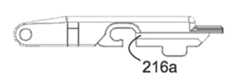
특정 실시예에서, 와이퍼 블레이드가, 연결 장치, 와이퍼 스트립 및 L-자 형상 리벳을 포함하는, 지지 구조물을 포함할 수 있을 것이다.In certain embodiments, the wiper blade may include a support structure, including a connecting device, a wiper strip, and L-shaped rivets.
특정 실시예에서, 와이퍼 블레이드가, 연결 장치, 커넥터, 및 와이퍼 스트립을 포함하는, 지지 구조물을 포함할 수 있을 것이다. 연결 장치는, 제1 정지부를 구비할 수 있을 것이다.In certain embodiments, the wiper blade may include a support structure, including a connecting device, a connector, and a wiper strip. The connecting device may be provided with a first stop.
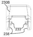
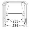
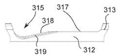
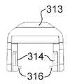
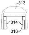
특정 실시예에서, 와이퍼 블레이드가, 일차적 프레임, 이차적 프레임, 및 삼차적 프레임, 그리고 와이퍼 스트립을 포함할 수 있는, 와이퍼 블레이드 지지 구조물을 포함할 수 있을 것이다. 삼차적 프레임은, 와이퍼 스트립을 고정 및 유지할 수 있을 것이다. 이차적 프레임은, 삼차적 프레임 커넥터에 의해 삼차적 프레임에 연결될 수 있을 것이다. 삼차적 프레임 커넥터는, 캡, 캡으로부터 하방으로 돌출하는 하측면 돌출부, 및 하측 부분을 갖도록 제공될 수 있을 것이다. 하측면 돌출부들은, 하측 부분에 대해 수직으로 배향될 수 있을 것이다.In certain embodiments, the wiper blade may include a wiper blade support structure, which may include a primary frame, a secondary frame, and a tertiary frame, and a wiper strip. The tertiary frame will be able to hold and hold the wiper strip. The secondary frame may be connected to the tertiary frame by a tertiary frame connector. The tertiary frame connector may be provided with a cap, a lower side protrusion projecting downward from the cap, and a lower portion. The lower side protrusions may be oriented perpendicular to the lower portion.
뒤따르는 설명 및 첨부 도면들은, 본 개시의 실시예들에 대한 특정의 예시적인 양태들을 제시한다. 이러한 양태들은, 그러나, 본 개시의 원리들이 사용될 수 있는 다양한 방식들 중의 일부만을 나타내며, 그리고 다양한 실시예들은, 모든 그러한 양태들 및 그들의 균등물들을 포함하는 것으로 의도된다. 다른 이점들 및 신규의 특징들이, 도면들과 함께 고려될 때, 뒤따르는 설명으로부터 명백해질 것이다.The following description and the annexed drawings set forth certain illustrative aspects of the embodiments of the present disclosure. These aspects, however, represent only some of the various ways in which the principles of the present disclosure can be used, and various embodiments are intended to include all such aspects and their equivalents. Other advantages and novel features will become apparent from the description that follows when considered in conjunction with the drawings.
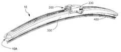
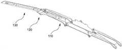
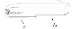
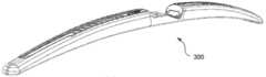
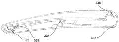
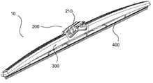
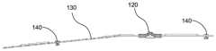
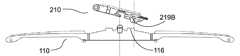
도 1은 와이퍼 블레이드 조립체의 실시예에 대한 상부 사시도를 도시한다.
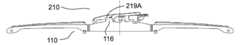
도 2는, 와이퍼 블레이드 커넥터 커버를 갖지 않는, 도 1의 와이퍼 블레이드 조립체의 상부 사시도를 도시한다.
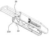
도 3은, 와이퍼 블레이드 커버 측방 섹션들을 갖지 않는, 도 2의 와이퍼 블레이드 조립체의 상부 사시도를 도시한다.
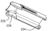
도 4는, 와이퍼 스트립을 갖지 않는, 도 3의 와이퍼 블레이드 조립체의 상부 사시도를 도시한다.
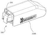
도 5는, 와이퍼 블레이드 커넥터를 갖지 않는, 도 4의 와이퍼 블레이드 조립체의 상부 사시도를 도시한다.
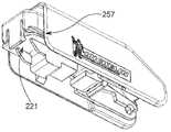
도 6은, 커버 중심 섹션을 갖지 않는 그리고 일차적 리벳을 갖지 않는, 도 5의 와이퍼 블레이드 조립체의 상부 사시도를 도시한다.
도 7은 일차적 프레임의 실시예에 대한 상부 사시도를 도시한다.
도 8은 도 7의 일차적 프레임의 하부 사시도를 도시한다.
도 9는 도 7의 일차적 프레임의 정면도를 도시한다.
도 10은 도 7의 일차적 프레임의 배면도를 도시한다.
도 11은 도 7의 일차적 프레임의 측면도를 도시한다.
도 12는 도 7의 일차적 프레임의 반대편 측면도를 도시한다.
도 13은 도 7의 일차적 프레임의 평면도를 도시한다.
도 14는 도 7의 일차적 프레임의 저면도를 도시한다.
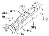
도 15는 이차적 프레임과 커플링되는 일차적 프레임의 실시예에 대한 상부 사시도를 도시한다.
도 16은 도 15의 이차적 프레임과 커플링되는 일차적 프레임의 하부 사시도를 도시한다.
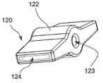
도 17은 이차적 프레임 커넥터의 상부 사시도를 도시한다.
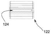
도 18은 이차적 프레임 커넥터 절반에 대한 상부 사시도를 도시한다.
도 19는 도 17의 이차적 프레임 커넥터의 정면도를 도시한다.
도 20은 도 17의 이차적 프레임 커넥터의 배면도를 도시한다.
도 21은 도 17의 이차적 프레임 커넥터의 측면도를 도시한다.
도 22는 도 17의 이차적 프레임 커넥터의 반대편 측면도를 도시한다.
도 23은 도 17의 이차적 프레임 커넥터의 평면도를 도시한다.
도 24는 도 17의 이차적 프레임 커넥터의 저면도를 도시한다.
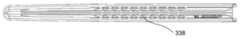
도 25는 이차적 프레임의 실시예에 대한 상부 사시도를 도시한다.
도 26은 도 25의 이차적 프레임의 하부 사시도를 도시한다.
도 27은 도 25의 이차적 프레임의 정면도를 도시한다.
도 28은 도 25의 이차적 프레임의 배면도를 도시한다.
도 29는 도 25의 이차적 프레임의 측면도를 도시한다.
도 30은 도 25의 이차적 프레임의 반대편 측면도를 도시한다.
도 31은 도 25의 이차적 프레임의 평면도를 도시한다.
도 32는 도 25의 이차적 프레임의 저면도를 도시한다.
도 33은 도 25의 이차적 프레임 및 도 17의 이차적 프레임 커넥터의 종방향 단면에 대한 정면도를 도시한다.
도 34는 2-피스형 이차적 프레임 커넥터의 상부 사시도를 도시한다.
도 35는 도 34의 2-피스형 이차적 프레임 커넥터의 제1 피스의 종방향 단면에 대한 정면도를 도시한다.
도 36은 도 34의 2-피스형 이차적 프레임 커넥터의 제2 피스의 종방향 단면에 대한 정면도를 도시한다.
도 37은 도 24의 이차적 프레임 및 도 34의 이차적 프레임 커넥터의 종방향 단면에 대한 정면도를 도시한다.
도 38은, 한 쌍의 삼차적 프레임과 연결되는, 이차적 프레임의 실시예에 대한 상부 사시도를 도시한다.
도 39는 삼차적 프레임 커넥터의 실시예에 대한 상부 사시도를 도시한다.
도 40은 도 39의 삼차적 프레임 커넥터의 하부 사시도를 도시한다.
도 41은 도 39의 삼차적 프레임 커넥터의 정면도를 도시한다.
도 42는 도 39의 삼차적 프레임 커넥터의 배면도를 도시한다.
도 43은 도 39의 삼차적 프레임 커넥터의 측면도를 도시한다.
도 44는 도 39의 삼차적 프레임 커넥터의 반대편 측면도를 도시한다.
도 45는 도 39의 삼차적 프레임 커넥터의 평면도를 도시한다.
도 46은 도 39의 삼차적 프레임 커넥터의 저면도를 도시한다.
도 47은 삼차적 프레임의 실시예에 대한 상부 사시도를 도시한다.
도 48은 도 47의 삼차적 프레임의 하부 사시도를 도시한다.
도 49는 도 47의 삼차적 프레임의 정면도를 도시한다.
도 50은 도 47의 삼차적 프레임의 배면도를 도시한다.
도 51은 도 47의 삼차적 프레임의 측면도를 도시한다.
도 52는 도 47의 삼차적 프레임의 반대편 측면도를 도시한다.
도 53은 도 47의 삼차적 프레임의 평면도를 도시한다.
도 54는 도 47의 삼차적 프레임의 저면도를 도시한다.
도 55는 삼차적 프레임 커넥터의 실시예에 대한 상부 사시도를 도시한다.
도 56은, 이차적 프레임 및 삼차적 프레임에 연결되는, 도 55의 삼차적 프레임 커넥터의 상부 사시도를 도시한다.
도 57은 삼차적 프레임 커넥터의 실시예에 대한 하부 사시도를 도시한다.
도 58은, 이차적 프레임 및 삼차적 프레임에 연결되는, 도 57의 삼차적 프레임 커넥터의 상부 사시도를 도시한다.
도 59는 삼차적 프레임 커넥터의 실시예에 대한 하부 사시도를 도시한다.
도 60은, 이차적 프레임에 연결되는, 삼차적 프레임 커넥터의 상부 사시도를 도시한다.
도 61은, 와이퍼 블레이드 커넥터 커버 및 와이퍼 블레이드 커넥터를 포함하는, 와이퍼 블레이드 커넥터 조립체의 실시예에 대한 상부 사시도를 도시한다.
도 62는 도 61의 와이퍼 블레이드 커넥터 조립체의 분해된 상부 사시도를 도시한다.
도 63은 도 61의 와이퍼 블레이드 커넥터 조립체의 하부 사시도를 도시한다.
도 64는 도 61의 와이퍼 블레이드 커넥터 조립체의 측면도를 도시한다.
도 65는 도 61의 와이퍼 블레이드 커넥터 조립체의 반대편 측면도를 도시한다.
도 66은 도 61의 와이퍼 블레이드 커넥터 커버의 상부 사시도를 도시한다.
도 67은 도 61의 와이퍼 블레이드 커넥터 커버의 하부 사시도를 도시한다.
도 68은 도 67의 와이퍼 블레이드 커넥터 커버의 정면도를 도시한다.
도 69는 도 67의 와이퍼 블레이드 커넥터 커버의 배면도를 도시한다.
도 70은 도 67의 와이퍼 블레이드 커넥터 커버의 측면도를 도시한다.
도 71은 도 67의 와이퍼 블레이드 커넥터 커버의 반대편 측면도를 도시한다.
도 72는 도 67의 와이퍼 블레이드 커넥터 커버의 평면도를 도시한다.
도 73은 도 67의 와이퍼 블레이드 커넥터 커버의 저면도를 도시한다.
도 74는 도 61의 와이퍼 블레이드 커넥터의 상부 사시도를 도시한다.
도 75는 도 74의 와이퍼 블레이드 커넥터의 하부 사시도를 도시한다.
도 76은 도 74의 와이퍼 블레이드 커넥터의 정면도를 도시한다.
도 77은 도 74의 와이퍼 블레이드 커넥터의 배면도를 도시한다.
도 78은 도 74의 와이퍼 블레이드 커넥터의 측면도를 도시한다.
도 79는 도 74의 와이퍼 블레이드 커넥터의 반대편 측면도를 도시한다.
도 80은 도 74의 와이퍼 블레이드 커넥터의 평면도를 도시한다.
도 81은 도 74의 와이퍼 블레이드 커넥터의 저면도를 도시한다.
도 82는 도 74의 와이퍼 커넥터의 종방향 단면에 대한 정면도를 도시한다.
도 83은 도 61의 와이퍼 블레이드 커넥터 조립체와 연결되는 와이퍼 아암의 상부 사시도를 도시한다.
도 84는, 와이퍼 블레이드 커넥터 커버가 제거된, 도 83의 와이퍼 블레이드 조립체와 연결되는 와이퍼 아암의 상부 사시도를 도시한다.
도 85는 도 84의 와이퍼 블레이드 커넥터와 연결되는 와이퍼 아암의 평면도를 도시한다.
도 86은 도 84의 와이퍼 블레이드 커넥터와 연결되는 와이퍼 아암의 종방향 단면에 대한 정면도를 도시한다.
도 87은 도 83의 와이퍼 블레이드 커넥터 조립체와 연결되는 와이퍼 아암 그리고 일차적 프레임 및 일차적 프레임 리벳의 실시예에 대한 하부 사시도를 도시한다.
도 88은 도 61의 와이퍼 블레이드 커넥터 조립체와 연결되는 와이퍼 아암의 실시예에 대한 상부 사시도를 도시한다.
도 89는 도 88의 와이퍼 블레이드 커넥터 조립체와 연결되는 와이퍼 아암의 하부 사시도를 도시한다.
도 90은, 와이퍼 블레이드 커넥터 커버 및 와이퍼 블레이드 커넥터를 포함하는, 와이퍼 블레이드 커넥터 조립체의 실시예에 대한 상부 사시도를 도시한다.
도 91은 도 90의 와이퍼 블레이드 커넥터 조립체의 하부 사시도를 도시한다.
도 92는 도 90의 와이퍼 블레이드 커넥터 조립체의 커넥터 커버의 하부 사시도를 도시한다.
도 93은 도 90의 와이퍼 블레이드 커넥터 조립체와 연결되는 와이퍼 아암의 하부 사시도를 도시한다.
도 94는 도 90의 와이퍼 블레이드 커넥터 조립체와 연결되는 와이퍼 아암의 종방향 단면에 대한 상부 사시도를 도시한다.
도 95는 도 90의 와이퍼 블레이드 조립체와 연결되는 와이퍼 아암의 하부 사시도를 도시한다.
도 96은 도 92의 커넥터 커버의 상부 사시도를 도시한다.
도 97은 도 92의 커넥터 커버의 하부 사시도를 도시한다.
도 98은 도 92의 커넥터 커버의 정면도를 도시한다.
도 99는 도 92의 커넥터 커버의 배면도를 도시한다.
도 100은 도 92의 커넥터 커버의 평면도를 도시한다.
도 101은 도 92의 커넥터 커버의 저면도를 도시한다.
도 102는 도 92의 커넥터 커버의 측면도를 도시한다.
도 103은 도 92의 커넥터 커버의 반대편 측면도를 도시한다.
도 104는, 커넥터 커버, 커넥터 및 어댑터를 포함하는, 와이퍼 블레이드 커넥터 조립체의 상부 사시도를 도시한다.
도 105는, 커넥터 커버가 제거된, 도 104의 와이퍼 블레이드 커넥터 조립체의 상부 사시도를 도시한다.
도 106은 도 104의 와이퍼 블레이드 커넥터 조립체의 하부 사시도를 도시한다.
도 107은, 커넥터 커버가 제거된, 도 104의 와이퍼 블레이드 커넥터 조립체의 하부 사시도를 도시한다.
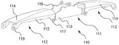
도 108은 도 104의 와이퍼 블레이드 커넥터 조립체의 어댑터의 상부 사시도를 도시한다.
도 109는 도 108의 어댑터의 하부 사시도를 도시한다.
도 110은 도 108의 어댑터의 정면도를 도시한다.
도 111은 도 108의 어댑터의 배면도를 도시한다.
도 112는 도 108의 어댑터의 측면도를 도시한다.
도 113은 도 108의 어댑터의 반대편 측면도를 도시한다.
도 114는 도 108의 어댑터의 평면도를 도시한다.
도 115는 도 108의 어댑터의 저면도를 도시한다.
도 116은 도 104의 커넥터 커버의 상부 사시도를 도시한다.
도 117은 도 116의 커넥터 커버의 하부 사시도를 도시한다.
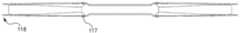
도 118은 도 116의 커넥터 커버의 정면도를 도시한다.
도 119는 도 116의 커넥터 커버의 배면도를 도시한다.
도 120은 도 116의 커넥터 커버의 평면도를 도시한다.
도 121은 도 116의 커넥터 커버의 저면도를 도시한다.
도 122는 도 116의 커넥터 커버의 측면도를 도시한다.
도 123은 도 116의 커넥터 커버의 반대편 측면도를 도시한다.
도 124는 도 104의 와이퍼 커넥터 조립체와 연결되는 와이퍼 아암의 상부 사시도를 도시한다.
도 125는 도 124의 와이퍼 커넥터 조립체와 연결되는 와이퍼 아암의 하부 사시도를 도시한다.
도 126은 와이퍼 블레이드 커넥터 조립체의 실시예에 대한 상부 사시도를 도시한다.
도 127은 도 126의 와이퍼 블레이드 커넥터 조립체의 분해된 상부 사시도를 도시한다.
도 128은 도 126의 와이퍼 블레이드 커넥터 조립체의 분해된 하부 사시도를 도시한다.
도 129는 도 126의 와이퍼 블레이드 커넥터 조립체의 와이퍼 블레이드 커넥터의 종방향 단면에 대한 상부 사시도를 도시한다.
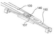
도 130은 도 126의 와이퍼 블레이드 커넥터 조립체의 종방향 단면에 대한 상부 사시도를 도시한다.
도 131은, 일차적 프레임, 장착 베이스 및 리벳을 포함하는, 일차적 프레임 조립체의 실시예에 대한 상부 사시도를 도시한다.
도 132는 도 131의 일차적 프레임 조립체의 분해된 상부 사시도를 도시한다.
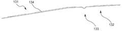
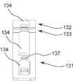
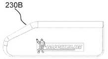
도 133은 와이퍼 블레이드 커버의 실시예에 대한 상부 사시도를 도시한다.
도 134는, 와이퍼 블레이드 커버의 제1 측방 섹션, 중심 섹션, 및 제2 측방 섹션의 사시도를 도시하는, 도 133의 와이퍼 블레이드 커버의 분해된 상부 사시도를 도시한다.
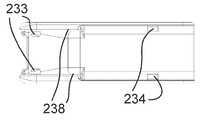
도 135는 도 133의 와이퍼 블레이드 커버의 하부 사시도를 도시한다.
도 136은 도 133의 와이퍼 블레이드 커버의 평면도를 도시한다.
도 137은 도 133의 와이퍼 블레이드 커버의 저면도를 도시한다.
도 138은 도 134의 와이퍼 블레이드 커버의 커버 측방 섹션의 정면도를 도시한다.
도 139는 도 138의 커버 측방 섹션의 배면도를 도시한다.
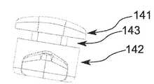
도 140은 도 138의 커버 측방 섹션의 측면도를 도시한다.
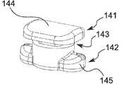
도 141은 도 138의 커버 측방 섹션의 반대편 측면도를 도시한다.
도 142는 도 138의 커버 측방 섹션의 평면도를 도시한다.
도 143은 도 138의 커버 측방 섹션의 저면도를 도시한다.
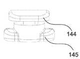
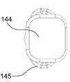
도 144는 도 138의 커버 측방 섹션의 하부 사시도를 도시한다.
도 145는 도 134의 커버 중심 섹션의 상부 사시도를 도시한다.
도 146은 도 145의 커버 중심 섹션의 하부 사시도를 도시한다.
도 147은 도 145의 커버 중심 섹션의 정면도를 도시한다.
도 148은 도 145의 커버 중심 섹션의 배면도를 도시한다.
도 149는 도 145의 커버 중심 섹션의 평면도를 도시한다.
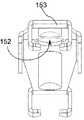
도 150은 도 145의 커버 중심 섹션의 저면도를 도시한다.
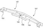
도 151은 도 145의 커버 중심 섹션의 측면도를 도시한다.
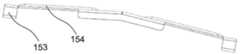
도 152는 도 145의 커버 중심 섹션의 반대편 측면도를 도시한다.
도 153은, 와이퍼 블레이드 커넥터 조립체의 실시예와 맞물릴 수 있는, 다양한 유형의 와이퍼 아암들의 실시예들을 도시한다.
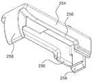
도 154는 와이퍼 블레이드 커넥터의 실시예에 대한 상부 사시도를 도시한다.
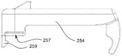
도 155는 도 154의 와이퍼 블레이드 커넥터의 하부 사시도를 도시한다.
도 156은 도 154의 와이퍼 블레이드 커넥터의 정면도를 도시한다.
도 157은 도 154의 와이퍼 블레이드 커넥터의 배면도를 도시한다.
도 158은 도 154의 와이퍼 블레이드 커넥터의 평면도를 도시한다.
도 159는 도 154의 와이퍼 블레이드 커넥터의 저면도를 도시한다.
도 160은 도 154의 와이퍼 블레이드 커넥터의 측면도를 도시한다.
도 161은 도 154의 와이퍼 블레이드 커넥터의 반대편 측면도를 도시한다.
도 162는 와이퍼 블레이드 커넥터 커버의 실시예에 대한 상부 사시도를 도시한다.
도 163은 도 162의 와이퍼 블레이드 커넥터 커버의 하부 사시도를 도시한다.
도 164는 도 162의 와이퍼 블레이드 커넥터 커버의 정면도를 도시한다.
도 165는 도 162의 와이퍼 블레이드 커넥터 커버의 배면도를 도시한다.
도 166은 도 162의 와이퍼 블레이드 커넥터 커버의 평면도를 도시한다.
도 167은 도 162의 와이퍼 블레이드 커넥터 커버의 저면도를 도시한다.
도 168은 도 162의 와이퍼 블레이드 커넥터 커버의 측면도를 도시한다.
도 169는 도 162의 와이퍼 블레이드 커넥터 커버의 반대편 측면도를 도시한다.
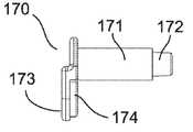
도 170은 와이퍼 블레이드 어댑터의 실시예에 대한 상부 사시도를 도시한다.
도 171은 도 170의 와이퍼 블레이드 어댑터의 하부 사시도를 도시한다.
도 172는 와이퍼 블레이드 커넥터의 실시예에 대한 상부 사시도를 도시한다.
도 173은 와이퍼 블레이드 커넥터 커버의 실시예에 대한 하부 사시도를 도시한다.
도 174는, 폐쇄 위치에서, 도 173의 와이퍼 블레이드 커넥터 커버 및 와이퍼 블레이드 커넥터의 실시예를 포함하는 와이퍼 블레이드 커넥터 조립체에 의해, 와이퍼 블레이드 지지 구조물과 연결되는 와이퍼 아암의 측면도를 도시한다.
도 175는, 도 174의 폐쇄 위치에서의, 와이퍼 아암, 와이퍼 블레이드 지지 구조물 및 와이퍼 블레이드 커넥터 조립체의 측단면도를 도시한다.
도 176은, 도 174의 개방 위치에서의, 와이퍼 아암, 와이퍼 블레이드 지지 구조물 및 와이퍼 블레이드 커넥터 조립체의 측단면도를 도시한다.
도 177은, 와이퍼 블레이드 지지 구조물 및 커버를 구비하는, 와이퍼 블레이드 조립체의 실시예에 대한 상부 사시도를 도시한다.
도 178은 도 177의 와이퍼 블레이드의 분해된 정면도를 도시한다.
도 179는, 이차적 프레임, 이차적 프레임 커넥터 및 2개의 삼차적 프레임 커넥터를 포함하는, 도 177의 이차적 프레임 조립체의 상부 사시도를 도시한다.
도 180은 도 179의 이차적 프레임 조립체의 정면도를 도시한다.
도 181은 도 179의 이차적 프레임 조립체의 분해된 정면도를 도시한다.
도 182는 이차적 프레임 커넥터의 상부 전방측 사시도를 도시한다.
도 183은 도 182의 이차적 프레임 커넥터의 하부 후방측 사시도를 도시한다.
도 184는 도 182의 이차적 프레임 커넥터의 정면도를 도시한다.
도 185는 도 182의 이차적 프레임 커넥터의 배면도를 도시한다.
도 186은 도 182의 이차적 프레임 커넥터의 우측면도를 도시한다.
도 187은 도 182의 이차적 프레임 커넥터의 좌측면도를 도시한다.
도 188은 도 182의 이차적 프레임 커넥터의 평면도를 도시한다.
도 189는 도 182의 이차적 프레임 커넥터의 저면도를 도시한다.
도 190은 도 177의 와이퍼 블레이드 지지 구조물의 상부 사시도를 도시한다.
도 191은 도 190의 와이퍼 블레이드 지지 구조물의 일차적 프레임의 상부 사시도를 도시한다.
도 192는 도 190의 와이퍼 블레이드 지지 구조물의 L-자 형상 일차적 프레임 리벳의 상부 사시도를 도시한다.
도 193은 도 190의 와이퍼 블레이드 지지 구조물의 L-자 형상 일차적 프레임 리벳의 하부 사시도를 도시한다.
도 194는 도 190의 와이퍼 블레이드 지지 구조물의 L-자 형상 일차적 프레임 리벳의 우측면도를 도시한다.
도 195는, 리벳이 압착(crimp)되거나 또는 압축된 이후의, 도 190의 와이퍼 블레이드 지지 구조물의 일차적 프레임 리벳의 좌측면도를 도시한다.
도 196은 도 190의 와이퍼 블레이드 지지 구조물의 일차적 프레임 리벳의 정면도를 도시한다.
도 197은 도 190의 와이퍼 블레이드 지지 구조물의 L-자 형상 일차적 프레임 리벳의 배면도를 도시한다.
도 198은 도 190의 와이퍼 블레이드 지지 구조물의 L-자 형상 일차적 프레임 리벳의 평면도를 도시한다.
도 199는 도 190의 와이퍼 블레이드 지지 구조물의 L-자 형상 일차적 프레임 리벳의 저면도를 도시한다.
도 200은 도 177의 와이퍼 블레이드 조립체의 와이퍼 블레이드 커버의 중심 섹션의 평면도를 도시한다.
도 201은 도 177의 와이퍼 블레이드 조립체의 와이퍼 블레이드 커넥터의 상부 사시도를 도시한다.
도 202는 도 201의 커넥터의 평면도를 도시한다.
도 203은, 일차적 프레임의 L-자 형상 일차적 리벳의 메인 회전축이 리벳 클립에 대한 핀 통과/진입 지점의 상측 단부와 정렬되는, 도 177의 커넥터 및 일차적 프레임의 분해된 정면도를 도시한다.
도 204는, 일차적 프레임의 L-자 형상 일차적 리벳의 메인 회전축이 리벳 클립의 회전축과 정렬되는, 도 177의 커넥터 및 일차적 프레임의 분해된 정면도를 도시한다.
도 205는, 일차적 프레임의 L-자 형상 일차적 리벳의 메인 회전축이 리벳 클립의 회전축과 정렬되는, 도 177의 커넥터 및 일차적 프레임의 분해된 정면측 단면도를 도시한다.
도 206은, 도 177의 커넥터 및 일차적 프레임의 정면측 단면도를 도시한다.
도 207은, 부채꼴형 제1 단부(scalloped first end) 및 손가락 파지부들을 구비하는, 커넥터 커버의 상부 사시도를 도시한다.
도 208은 도 207의 커넥터 커버의 하부 사시도를 도시한다.
도 209는 도 207의 커넥터 커버의 평면도를 도시한다.
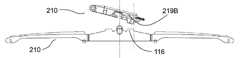
도 210은, 중앙 간극을 구비하는 제1 클립을 갖는, 커넥터 어댑터의 상부 사시도를 도시한다.
도 211은, 부채꼴형 제1 단부 및 제2 단부 내의 절개부를 구비하는, 커넥터 커버의 상부 사시도를 도시한다.
도 212는 도 211의 커넥터 커버의 평면도를 도시한다.1 shows a top perspective view of an embodiment of a wiper blade assembly.
FIG. 2 shows a top perspective view of the wiper blade assembly of FIG. 1 without a wiper blade connector cover.
3 shows a top perspective view of the wiper blade assembly of FIG. 2 without wiper blade cover lateral sections.
FIG. 4 shows a top perspective view of the wiper blade assembly of FIG. 3 without a wiper strip.
FIG. 5 shows a top perspective view of the wiper blade assembly of FIG. 4 without a wiper blade connector.
FIG. 6 shows a top perspective view of the wiper blade assembly of FIG. 5 without cover center section and without primary rivets.
7 shows a top perspective view of an embodiment of a primary frame.
8 shows a bottom perspective view of the primary frame of FIG. 7.
FIG. 9 shows a front view of the primary frame of FIG. 7.
FIG. 10 shows a rear view of the primary frame of FIG. 7.
11 shows a side view of the primary frame of FIG. 7.
FIG. 12 shows an opposite side view of the primary frame of FIG. 7.
FIG. 13 shows a top view of the primary frame of FIG. 7.
FIG. 14 shows a bottom view of the primary frame of FIG. 7.
15 shows a top perspective view of an embodiment of a primary frame coupled with a secondary frame.
FIG. 16 shows a bottom perspective view of the primary frame coupled with the secondary frame of FIG. 15.
17 shows a top perspective view of a secondary frame connector.
18 shows a top perspective view of the secondary frame connector half.
19 shows a front view of the secondary frame connector of FIG. 17.
FIG. 20 shows a rear view of the secondary frame connector of FIG. 17.
FIG. 21 shows a side view of the secondary frame connector of FIG. 17.
22 shows an opposite side view of the secondary frame connector of FIG. 17.
FIG. 23 shows a top view of the secondary frame connector of FIG. 17.
FIG. 24 shows a bottom view of the secondary frame connector of FIG. 17.
25 shows a top perspective view of an embodiment of a secondary frame.
FIG. 26 shows a bottom perspective view of the secondary frame of FIG. 25.
FIG. 27 shows a front view of the secondary frame of FIG. 25.
FIG. 28 shows a rear view of the secondary frame of FIG. 25.
FIG. 29 shows a side view of the secondary frame of FIG. 25.
FIG. 30 shows an opposite side view of the secondary frame of FIG. 25.
FIG. 31 shows a top view of the secondary frame of FIG. 25.
FIG. 32 shows a bottom view of the secondary frame of FIG. 25.
FIG. 33 shows a front view of the longitudinal section of the secondary frame connector of FIG. 25 and of the secondary frame of FIG. 17.
34 shows a top perspective view of a two piece secondary frame connector.
FIG. 35 shows a front view in longitudinal section of the first piece of the two-piece type secondary frame connector of FIG. 34;
FIG. 36 shows a front view in longitudinal section of the second piece of the two-piece type secondary frame connector of FIG. 34;
FIG. 37 shows a front view of the longitudinal cross section of the secondary frame connector of FIG. 24 and the secondary frame connector of FIG. 34.
38 shows a top perspective view of an embodiment of a secondary frame, connected to a pair of tertiary frames.
39 shows a top perspective view of an embodiment of a tertiary frame connector.
FIG. 40 shows a bottom perspective view of the tertiary frame connector of FIG. 39.
FIG. 41 shows a front view of the tertiary frame connector of FIG. 39.
FIG. 42 shows a rear view of the tertiary frame connector of FIG. 39.
43 shows a side view of the tertiary frame connector of FIG. 39;
FIG. 44 shows an opposite side view of the tertiary frame connector of FIG. 39.
FIG. 45 shows a top view of the tertiary frame connector of FIG. 39.
46 shows a bottom view of the tertiary frame connector of FIG. 39;
47 shows a top perspective view of an embodiment of a tertiary frame.
FIG. 48 shows a bottom perspective view of the tertiary frame of FIG. 47.
49 shows a front view of the tertiary frame of FIG. 47;
FIG. 50 shows a rear view of the tertiary frame of FIG. 47.
51 shows a side view of the tertiary frame of FIG. 47;
FIG. 52 shows an opposite side view of the tertiary frame of FIG. 47.
53 shows a top view of the tertiary frame of FIG. 47;
FIG. 54 shows a bottom view of the tertiary frame of FIG. 47;
55 shows a top perspective view of an embodiment of a tertiary frame connector.
FIG. 56 shows a top perspective view of the tertiary frame connector of FIG. 55, connected to the secondary frame and the tertiary frame.
57 shows a bottom perspective view of an embodiment of a tertiary frame connector.
FIG. 58 shows a top perspective view of the tertiary frame connector of FIG. 57, connected to the secondary frame and the tertiary frame.
59 shows a bottom perspective view of an embodiment of a tertiary frame connector.
60 shows a top perspective view of a tertiary frame connector, connected to a secondary frame.
61 shows a top perspective view of an embodiment of a wiper blade connector assembly, including a wiper blade connector cover and a wiper blade connector.
FIG. 62 shows an exploded top perspective view of the wiper blade connector assembly of FIG. 61.
FIG. 63 shows a bottom perspective view of the wiper blade connector assembly of FIG. 61.
64 shows a side view of the wiper blade connector assembly of FIG. 61.
FIG. 65 shows an opposite side view of the wiper blade connector assembly of FIG. 61.
FIG. 66 shows a top perspective view of the wiper blade connector cover of FIG. 61.
FIG. 67 shows a bottom perspective view of the wiper blade connector cover of FIG. 61;
FIG. 68 shows a front view of the wiper blade connector cover of FIG. 67;
FIG. 69 shows a rear view of the wiper blade connector cover of FIG. 67;
FIG. 70 shows a side view of the wiper blade connector cover of FIG. 67;
FIG. 71 shows an opposite side view of the wiper blade connector cover of FIG. 67;
FIG. 72 shows a top view of the wiper blade connector cover of FIG. 67;
73 shows a bottom view of the wiper blade connector cover of FIG. 67;
FIG. 74 shows a top perspective view of the wiper blade connector of FIG. 61.
FIG. 75 shows a bottom perspective view of the wiper blade connector of FIG. 74;
76 shows a front view of the wiper blade connector of FIG. 74;
FIG. 77 shows a rear view of the wiper blade connector of FIG. 74.
FIG. 78 shows a side view of the wiper blade connector of FIG. 74.
FIG. 79 shows an opposite side view of the wiper blade connector of FIG. 74;
FIG. 80 shows a top view of the wiper blade connector of FIG. 74.
FIG. 81 shows a bottom view of the wiper blade connector of FIG. 74.
FIG. 82 shows a front view of the wiper connector of FIG. 74 in the longitudinal section.
FIG. 83 shows a top perspective view of the wiper arm connected to the wiper blade connector assembly of FIG. 61.
FIG. 84 shows a top perspective view of the wiper arm connected to the wiper blade assembly of FIG. 83 with the wiper blade connector cover removed.
FIG. 85 shows a top view of the wiper arm connected to the wiper blade connector of FIG. 84.
FIG. 86 shows a front view of the longitudinal section of the wiper arm connected to the wiper blade connector of FIG. 84;
FIG. 87 shows a bottom perspective view of an embodiment of the wiper arm and primary frame and primary frame rivets connected to the wiper blade connector assembly of FIG. 83.
88 shows a top perspective view of an embodiment of the wiper arm connected to the wiper blade connector assembly of FIG. 61.
FIG. 89 shows a bottom perspective view of the wiper arm connected to the wiper blade connector assembly of FIG. 88.
90 shows a top perspective view of an embodiment of a wiper blade connector assembly, including a wiper blade connector cover and a wiper blade connector.
FIG. 91 shows a bottom perspective view of the wiper blade connector assembly of FIG. 90.
FIG. 92 shows a bottom perspective view of the connector cover of the wiper blade connector assembly of FIG. 90.
FIG. 93 shows a bottom perspective view of the wiper arm connected to the wiper blade connector assembly of FIG. 90.
FIG. 94 shows a top perspective view of the longitudinal section of the wiper arm connected to the wiper blade connector assembly of FIG. 90.
FIG. 95 shows a bottom perspective view of the wiper arm connected to the wiper blade assembly of FIG. 90.
FIG. 96 shows a top perspective view of the connector cover of FIG. 92.
FIG. 97 shows a bottom perspective view of the connector cover of FIG. 92.
98 shows a front view of the connector cover of FIG. 92;
FIG. 99 shows a rear view of the connector cover of FIG. 92.
FIG. 100 shows a top view of the connector cover of FIG. 92.
FIG. 101 shows a bottom view of the connector cover of FIG. 92.
FIG. 102 shows a side view of the connector cover of FIG. 92;
FIG. 103 shows an opposite side view of the connector cover of FIG. 92;
104 shows a top perspective view of a wiper blade connector assembly, including a connector cover, a connector and an adapter.
FIG. 105 shows a top perspective view of the wiper blade connector assembly of FIG. 104 with the connector cover removed.
FIG. 106 shows a bottom perspective view of the wiper blade connector assembly of FIG. 104.
FIG. 107 shows a bottom perspective view of the wiper blade connector assembly of FIG. 104 with the connector cover removed.
FIG. 108 shows a top perspective view of the adapter of the wiper blade connector assembly of FIG. 104.
109 shows a bottom perspective view of the adapter of FIG. 108.
FIG. 110 shows a front view of the adapter of FIG. 108.
FIG. 111 shows a rear view of the adapter of FIG. 108;
FIG. 112 shows a side view of the adapter of FIG. 108.
FIG. 113 shows the opposite side view of the adapter of FIG. 108.
FIG. 114 shows a top view of the adapter of FIG. 108.
FIG. 115 shows a bottom view of the adapter of FIG. 108.
FIG. 116 shows a top perspective view of the connector cover of FIG. 104.
117 shows a bottom perspective view of the connector cover of FIG. 116;
118 shows a front view of the connector cover of FIG. 116;
FIG. 119 shows a rear view of the connector cover of FIG. 116;
FIG. 120 shows a top view of the connector cover of FIG. 116.
FIG. 121 shows a bottom view of the connector cover of FIG. 116;
FIG. 122 shows a side view of the connector cover of FIG. 116;
123 shows an opposite side view of the connector cover of FIG. 116;
FIG. 124 shows a top perspective view of the wiper arm connected to the wiper connector assembly of FIG. 104.
FIG. 125 shows a bottom perspective view of the wiper arm connected to the wiper connector assembly of FIG. 124.
126 shows a top perspective view of an embodiment of a wiper blade connector assembly.
127 shows an exploded top perspective view of the wiper blade connector assembly of FIG. 126.
FIG. 128 shows an exploded bottom perspective view of the wiper blade connector assembly of FIG. 126.
129 shows a top perspective view of the longitudinal section of the wiper blade connector of the wiper blade connector assembly of FIG. 126.
FIG. 130 shows a top perspective view of the longitudinal section of the wiper blade connector assembly of FIG. 126.
131 shows a top perspective view of an embodiment of a primary frame assembly, including a primary frame, mounting base and rivets.
132 shows an exploded top perspective view of the primary frame assembly of FIG. 131.
133 shows a top perspective view of an embodiment of a wiper blade cover.
134 shows an exploded top perspective view of the wiper blade cover of FIG. 133, showing perspective views of the first lateral section, the central section, and the second lateral section of the wiper blade cover.
FIG. 135 shows a bottom perspective view of the wiper blade cover of FIG. 133.
FIG. 136 shows a top view of the wiper blade cover of FIG. 133.
137 shows a bottom view of the wiper blade cover of FIG. 133;
FIG. 138 shows a front view of the cover side section of the wiper blade cover of FIG. 134;
FIG. 139 shows a rear view of the cover lateral section of FIG. 138;
FIG. 140 shows a side view of the cover lateral section of FIG. 138.
141 shows an opposite side view of the cover lateral section of FIG. 138.
142 shows a top view of the cover side section of FIG. 138.
FIG. 143 shows a bottom view of the cover lateral section of FIG. 138;
144 shows a bottom perspective view of the cover lateral section of FIG. 138.
145 shows a top perspective view of the cover center section of FIG. 134.
146 shows a bottom perspective view of the cover center section of FIG. 145.
147 shows a front view of the cover center section of FIG. 145.
148 shows a rear view of the cover center section of FIG. 145.
149 shows a top view of the cover center section of FIG. 145;
FIG. 150 shows a bottom view of the cover center section of FIG. 145.
151 shows a side view of the cover center section of FIG. 145.
152 shows an opposite side view of the cover center section of FIG. 145.
153 shows embodiments of various types of wiper arms that may engage an embodiment of a wiper blade connector assembly.
154 shows a top perspective view of an embodiment of a wiper blade connector.
155 shows a bottom perspective view of the wiper blade connector of FIG. 154.
156 shows a front view of the wiper blade connector of FIG. 154.
157 shows a rear view of the wiper blade connector of FIG. 154.
158 shows a top view of the wiper blade connector of FIG. 154.
159 shows a bottom view of the wiper blade connector of FIG. 154.
FIG. 160 shows a side view of the wiper blade connector of FIG. 154.
161 shows an opposite side view of the wiper blade connector of FIG. 154.
162 shows a top perspective view of an embodiment of a wiper blade connector cover.
163 shows a bottom perspective view of the wiper blade connector cover of FIG. 162.
FIG. 164 shows a front view of the wiper blade connector cover of FIG. 162.
165 shows a rear view of the wiper blade connector cover of FIG. 162.
166 shows a top view of the wiper blade connector cover of FIG. 162.
167 shows a bottom view of the wiper blade connector cover of FIG. 162.
168 shows a side view of the wiper blade connector cover of FIG. 162.
169 shows an opposite side view of the wiper blade connector cover of FIG. 162;
170 shows a top perspective view of an embodiment of a wiper blade adapter.
FIG. 171 shows a bottom perspective view of the wiper blade adapter of FIG. 170.
172 shows a top perspective view of an embodiment of a wiper blade connector.
173 shows a bottom perspective view of an embodiment of a wiper blade connector cover.
FIG. 174 shows a side view of the wiper arm connected to the wiper blade support structure by a wiper blade connector assembly comprising the wiper blade connector cover of FIG. 173 and an embodiment of the wiper blade connector in a closed position.
175 shows a side cross-sectional view of the wiper arm, wiper blade support structure and wiper blade connector assembly, in the closed position of FIG. 174.
176 shows a side cross-sectional view of the wiper arm, wiper blade support structure and wiper blade connector assembly, in the open position of FIG. 174.
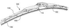
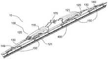
177 shows a top perspective view of an embodiment of a wiper blade assembly, having a wiper blade support structure and a cover.
178 shows an exploded front view of the wiper blade of FIG. 177.
FIG. 179 shows a top perspective view of the secondary frame assembly of FIG. 177, including the secondary frame, secondary frame connector and two tertiary frame connectors.
FIG. 180 shows a front view of the secondary frame assembly of FIG. 179.
181 shows an exploded front view of the secondary frame assembly of FIG. 179.
182 shows a top front side perspective view of the secondary frame connector.
183 shows a bottom rear perspective view of the secondary frame connector of FIG. 182.
184 shows a front view of the secondary frame connector of FIG. 182.
185 shows a rear view of the secondary frame connector of FIG. 182.
186 shows a right side view of the secondary frame connector of FIG. 182.
187 shows a left side view of the secondary frame connector of FIG. 182.
188 shows a top view of the secondary frame connector of FIG. 182.
189 shows a bottom view of the secondary frame connector of FIG. 182.
FIG. 190 shows a top perspective view of the wiper blade support structure of FIG. 177.
191 shows a top perspective view of the primary frame of the wiper blade support structure of FIG. 190.
192 shows a top perspective view of the L-shaped primary frame rivet of the wiper blade support structure of FIG. 190;
193 shows a bottom perspective view of the L-shaped primary frame rivet of the wiper blade support structure of FIG. 190.
FIG. 194 shows a right side view of the L-shaped primary frame rivet of the wiper blade support structure of FIG. 190.
195 shows a left side view of the primary frame rivet of the wiper blade support structure of FIG. 190 after the rivet has been crimped or compressed.
196 shows a front view of the primary frame rivet of the wiper blade support structure of FIG. 190.
197 shows a rear view of the L-shaped primary frame rivet of the wiper blade support structure of FIG. 190.
198 shows a top view of the L-shaped primary frame rivet of the wiper blade support structure of FIG. 190.
199 shows a bottom view of the L-shaped primary frame rivet of the wiper blade support structure of FIG. 190.
FIG. 200 shows a top view of the central section of the wiper blade cover of the wiper blade assembly of FIG. 177.
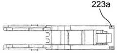
201 shows a top perspective view of the wiper blade connector of the wiper blade assembly of FIG. 177.
202 shows a top view of the connector of FIG. 201.
FIG. 203 shows an exploded front view of the connector and primary frame of FIG. 177 with the main axis of rotation of the L-shaped primary rivet of the primary frame aligned with the upper end of the pin pass/entry point for the rivet clip.
204 shows an exploded front view of the connector and primary frame of FIG. 177 with the main axis of rotation of the L-shaped primary rivet of the primary frame aligned with the axis of rotation of the rivet clip.
205 shows an exploded front side sectional view of the connector and primary frame of FIG. 177, with the main axis of rotation of the L-shaped primary rivet of the primary frame aligned with the axis of rotation of the rivet clip.
206 shows a front side sectional view of the connector and primary frame of FIG. 177.
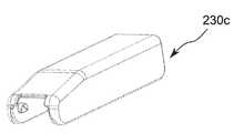
207 shows a top perspective view of a connector cover, having a scalloped first end and finger grips.
208 shows a bottom perspective view of the connector cover of FIG. 207.
209 shows a top view of the connector cover of FIG. 207.
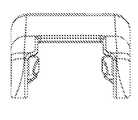
210 shows a top perspective view of the connector adapter, with a first clip having a central gap.
FIG. 211 shows a top perspective view of the connector cover, having a fan-shaped first end and a cut in the second end.
212 shows a top view of the connector cover of FIG. 211.
뒤따르는 상세한 설명 및 첨부 도면들은, 관련 분야의 당업자가 이러한 실시예들을 이루고 사용하는 것을 가능하게 할 목적으로, 본 개시의 일부 실시예들을 설명하고 도시한다. 그에 따라, 이러한 실시예들에 대한 상세한 설명 및 도시는, 순수하게 본질적으로 예시이며 그리고, 어떤 식으로도, 본 개시의 범위를 임의의 방식으로 제한하고자 하는 것이 아니다. 도면들은 반드시 축적에 맞는 것은 아니며 그리고 어떤 경우에, 제작 및 조립에 대한 세부사항과 같은 실시예들에 대한 이해를 위해 필요하지 않은, 세부사항이 생략되었을 수 있다는 것을, 또한 이해해야만 할 것이다. 첨부 도면들에서, 동일한 참조 부호들은 동일한 구성요소들을 지시한다.DETAILED DESCRIPTION The accompanying description and accompanying drawings describe and illustrate some embodiments of the present disclosure for the purpose of enabling those skilled in the art to make and use these embodiments. Accordingly, the detailed description and illustration of these embodiments are purely illustrative in nature and are not intended to limit the scope of the present disclosure in any way in any way. It should also be understood that the drawings are not necessarily to scale and, in some cases, details may be omitted, which are not necessary for understanding embodiments such as details for fabrication and assembly. In the accompanying drawings, the same reference numbers indicate the same components.
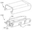
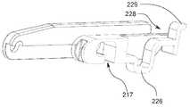
와이퍼 블레이드 커넥터 조립체의 실시예가, 차량의 와이퍼 아암을 와이퍼 블레이드와 연결하기 위해 제공될 수 있으며, 그리고 와이퍼 블레이드 커넥터 조립체는, 와이퍼 블레이드 커넥터 및 와이퍼 블레이드 커넥터 커버를 포함할 수 있을 것이다. 와이퍼 블레이드 커넥터는, 제1 측방 부분, 제2 측방 부분, 및 제1 측방 부분과 제2 측방 부분 사이에 한정되는 중심 부분을 구비할 수 있을 것이다. 와이퍼 블레이드 커넥터는, 한 쌍의 측벽을 포함할 수 있고, 각 측벽은, 제1 측방 부분 및 중심 부분의 에지를 따라 제공되며 그리고 각 측벽은, 상측 표면 및 하측 표면을 갖는다. 와이퍼 블레이드 커넥터는 또한, 한 쌍의 커넥터 커버 구멍을 구비할 수 있고, 각 커넥터 커버 구멍은, 제1 측방 부분에서 대향하는 측벽 상에 제공된다. 와이퍼 블레이드 커넥터 커버는, 제1 부분 및 제2 부분을 구비할 수 있고, 와이퍼 블레이드 커버는, 한 쌍의 커넥터 구멍 로드(connector hole rod)를 구비하며, 각 커넥터 구멍 로드는, 제1 부분 내의 대향하는 내측 표면으로부터 돌출한다. 커넥터 커버 축이, 커넥터 커버 구멍 쌍을 통해 양호하게 한정될 수 있을 것이다. 각 커넥터 구멍 로드는, 커넥터 커버 구멍들 중의 하나와 연결 가능할 수 있으며, 그리고 와이퍼 블레이드 커넥터 커버는, 개방 위치와 폐쇄 위치 사이에서 커넥터 커버 축을 중심으로 선회 가능하다.An embodiment of the wiper blade connector assembly may be provided for connecting the wiper arm of the vehicle to the wiper blade, and the wiper blade connector assembly may include a wiper blade connector and a wiper blade connector cover. The wiper blade connector may have a first lateral portion, a second lateral portion, and a central portion defined between the first lateral portion and the second lateral portion. The wiper blade connector can include a pair of side walls, each side wall being provided along the edges of the first lateral portion and the central portion, and each side wall has an upper surface and a lower surface. The wiper blade connector can also have a pair of connector cover holes, each connector cover hole being provided on the side wall opposite in the first lateral portion. The wiper blade connector cover may have a first portion and a second portion, and the wiper blade cover includes a pair of connector hole rods, and each connector hole rod is opposed in the first portion. To protrude from the inner surface. The connector cover shaft may be well defined through a pair of connector cover holes. Each connector hole rod can be connectable with one of the connector cover holes, and the wiper blade connector cover is pivotable about the connector cover axis between an open position and a closed position.
추가적 실시예에서, 와이퍼 블레이드 커넥터는, 제2 측방 부분 상의 선반(shelf)을 더 포함하고, 선반은, 한 쌍의 날개 및 날개들 사이에 한정되는 중심 섹션을 포함한다. 커넥터 채널이, 선반의 중심 섹션 위에 그리고 측벽 쌍 사이에 한정될 수 있으며, 그리고 커넥터는, 커넥터 채널을 따라 와이퍼 아암을 수용할 수 있을 것이다. 커넥터 커버는, 각각 커넥터 커버의 제2 부분 상에 제공되는, 한 쌍의 커넥터 커버 탭을 구비할 수 있으며, 그리고 적어도 하나의 커넥터 커버 탭은, 커넥터 커버가 폐쇄 위치에 놓일 때, 날개의 하측면과 맞물릴 수 있을 것이다. 날개 쌍 중의 하나는, 다른 날개보다 종방향으로 더 연장될 수 있을 것이다. 커넥터 커버는, 커넥터 커버의 제1 부분 상에 제공되는, 적어도 하나의 부가적 커넥터 탭을 구비할 수 있을 것이다. 측벽들의 하측 표면은, 제2 측방 부분에서의 높은 위치보다 제1 측방 부분에서 낮은 위치에 배치될 수 있으며, 그리고 측벽들의 하측 표면의 높은 위치는, 날개들의 하측면과 동일 평면상에 놓인다. 리벳 절개부가, 측벽들의 하측 표면의 높은 위치와 낮은 위치 사이에서, 중심 부분 내에 제공될 수 있을 것이다. 외향 돌출부가, 리벳 절개부와 제1 측방 부분 사이에서, 각 측벽의 중심 부분 상에 제공될 수 있을 것이다. 제1 측방 부분에서의 적어도 하나의 측벽의 상측 표면은, 중심 부분에서의 적어도 하나의 측벽으로부터의 상측 표면으로부터 하방으로 경사질 수 있을 것이다. 커넥터의 적어도 하나의 측벽은, 제1 측방 부분에 내측 렛지(inner ledge)를 구비할 수 있을 것이다. 내측 렛지는, 절개부를 구비할 수 있을 것이다. 커넥터 커버는, 상측 표면 및 외팔보(cantilever)에 의해 상측 표면에 연결되는 탄력적 버튼을 구비할 수 있을 것이다. 커넥터 커버는, 커넥터 커버의 제2 부분 상에 제공되는, 적어도 하나의 커넥터 커버 탭을 구비할 수 있을 것이다. 선반의 중심 섹션은, 외팔보로서 형성될 수 있을 것이다. 중심 섹션은, 립부(lip)를 구비하는 기둥(pillar)을 더 포함하며, 그리고 중심 섹션 기둥은, 커넥터가 후크를 구비하는 제1 와이퍼 아암과 맞물리게 되는 경우, 아래로 눌리게 될 수 있으며, 그리고 기둥의 립부는, 제2 와이퍼 아암의 후방 탭과 맞물릴 수 있을 것이다.In a further embodiment, the wiper blade connector further comprises a shelf on the second lateral portion, the shelf comprising a pair of wings and a central section defined between the wings. A connector channel can be defined over the center section of the shelf and between the pair of sidewalls, and the connector will be able to receive the wiper arm along the connector channel. The connector cover may be provided with a pair of connector cover tabs, each provided on a second portion of the connector cover, and the at least one connector cover tab, when the connector cover is placed in the closed position, the lower side of the wing Will be able to interlock with. One of the pair of wings may extend more longitudinally than the other. The connector cover may have at least one additional connector tab provided on the first portion of the connector cover. The lower surface of the side walls can be arranged at a lower position in the first lateral portion than the higher position in the second lateral portion, and the higher position of the lower surface of the side walls is coplanar with the lower surface of the wings. Rivet cuts may be provided in the central portion between the high and low positions of the lower surface of the side walls. An outward protrusion may be provided on the central portion of each side wall, between the rivet cutout and the first lateral portion. The upper surface of the at least one side wall in the first lateral portion may be inclined downward from the upper surface from the at least one side wall in the central portion. At least one side wall of the connector may be provided with an inner ledge in the first lateral portion. The inner ledge may be provided with an incision. The connector cover may have an elastic button connected to the upper surface by an upper surface and a cantilever. The connector cover may be provided with at least one connector cover tab, provided on the second part of the connector cover. The central section of the shelf may be formed as a cantilever beam. The central section further includes a pillar with a lip, and the central section pillar can be pressed down when the connector engages a first wiper arm with a hook, and The lip of the column may engage the rear tab of the second wiper arm.
와이퍼 블레이드 커넥터 조립체의 실시예가, 차량의 와이퍼 아암을 와이퍼 블레이드와 연결하기 위해 제공될 수 있으며, 그리고 와이퍼 블레이드 커넥터 조립체는, 와이퍼 블레이드 커넥터, 와이퍼 블레이드 커넥터 커버, 및 와이퍼 블레이드 커넥터 어댑터를 포함할 수 있을 것이다. 와이퍼 블레이드 커넥터는, 제1 측방 부분, 제2 측방 부분, 및 제1 측방 부분과 제2 측방 부분 사이에 한정되는 중심 부분을 구비할 수 있을 것이다. 와이퍼 블레이드 커넥터는, 한 쌍의 측벽으로서, 각 측벽은 제1 측방 부분 및 중심 부분의 에지를 따라 제공되며 그리고 각 측벽은 상측 표면 및 하측 표면을 갖는 것인, 한 쌍의 측벽; 한 쌍의 커넥터 커버 구멍으로서, 각 커넥터 커버 구멍은 제1 측방 부분에서의 대향하는 측벽 상에 제공되는 것인, 한 쌍의 커넥터 커버 구멍; 및 제2 측방 부분 상에 제공되는 선반을 구비할 수 있을 것이다. 와이퍼 블레이드 커넥터 커버는, 제1 부분 및 제2 부분을 구비할 수 있을 것이다. 와이퍼 블레이드 커넥터 커버는, 한 쌍의 커넥터 구멍 로드를 구비하며, 각 커넥터 구멍 로드는, 제1 부분 내의 대향하는 내측 표면으로부터 돌출한다. 와이퍼 블레이드 커넥터 어댑터는, 제1 부분 및 제2 부분을 구비할 수 있을 것이다. 와이퍼 블레이드 커넥터 어댑터는, 제1 부분에 제공되는 제1 클립 및, 제2 부분에 제공되며 그리고 선반의 하측면과 맞물릴 수 있는, 제2 클립을 구비할 수 있을 것이다. 커넥터 커버 축이, 커넥터 커버 구멍 쌍을 통해 한정될 수 있을 것이다. 각 커넥터 구멍 로드는, 커넥터 커버 구멍들 중의 하나와 연결 가능할 수 있으며, 그리고 와이퍼 블레이드 커넥터 커버는, 개방 위치와 폐쇄 위치 사이에서 커넥터 커버 축을 중심으로 선회 가능할 수 있을 것이다. 와이퍼 블레이드 커넥터 어댑터는, 와이퍼 블레이드 커넥터와 연결 가능할 수 있으며 그리고, 와이퍼 블레이드 커넥터와 연결될 때, 와이퍼 블레이드 커버가 폐쇄 위치에 놓임에 따라 와이퍼 블레이드 커버와 와이퍼 블레이드 커넥터 사이에 배치될 수 있을 것이다.An embodiment of a wiper blade connector assembly can be provided for connecting a wiper arm of a vehicle to a wiper blade, and the wiper blade connector assembly can include a wiper blade connector, a wiper blade connector cover, and a wiper blade connector adapter will be. The wiper blade connector may have a first lateral portion, a second lateral portion, and a central portion defined between the first lateral portion and the second lateral portion. A wiper blade connector includes a pair of sidewalls, each sidewall provided along the edges of the first lateral portion and the central portion, and each sidewall having an upper surface and a lower surface; A pair of connector cover holes, each connector cover hole being provided on opposing side walls in the first lateral portion; And a shelf provided on the second lateral portion. The wiper blade connector cover may have a first portion and a second portion. The wiper blade connector cover includes a pair of connector hole rods, and each connector hole rod protrudes from the opposite inner surface in the first portion. The wiper blade connector adapter may have a first portion and a second portion. The wiper blade connector adapter may be provided with a first clip provided in the first portion and a second clip provided in the second portion and engageable with the underside of the shelf. The connector cover shaft may be defined through a pair of connector cover holes. Each connector hole rod may be connectable with one of the connector cover holes, and the wiper blade connector cover may be pivotable about the connector cover axis between an open position and a closed position. The wiper blade connector adapter may be connectable with a wiper blade connector, and when connected to the wiper blade connector, may be disposed between the wiper blade cover and the wiper blade connector as the wiper blade cover is placed in the closed position.
와이퍼 블레이드 커넥터 조립체의 추가적 실시예에서, 와이퍼 블레이드 커넥터 어댑터는, 상측 표면 및, 외팔보에 의해 상측 표면에 연결되는 탄력적 버튼을 구비할 수 있을 것이다. 와이퍼 블레이드 커넥터 어댑터는, 낮은 위치 및 높은 위치를 갖는 하측 표면을 구비할 수 있으며, 어댑터가 커넥터와 연결될 때, 낮은 위치는 선반에 인접하게 놓이며 높은 위치는 커넥터의 측벽들의 상측 표면에 인접하게 놓인다.In a further embodiment of the wiper blade connector assembly, the wiper blade connector adapter may have an upper surface and an elastic button connected to the upper surface by a cantilever beam. The wiper blade connector adapter may have a lower surface having a low position and a high position, and when the adapter is connected to the connector, the low position is placed adjacent to the shelf and the high position is placed adjacent to the upper surface of the side walls of the connector. .
본 개시의 하나의 실시예에서, 와이퍼 블레이드 커넥터 조립체가, 와이퍼 블레이드 지지 구조물을 와이퍼 아암과 연결하기 위해 제공될 수 있을 것이다. 와이퍼 블레이드 조립체는, 제1 부분, 제1 부분에 대해 종방향으로 반대편에 놓이는 제2 부분, 및 제1 부분과 제2 부분 사이에 한정되는 중심 부분을 구비하는, 와이퍼 블레이드 커넥터를 포함할 수 있을 것이다. 와이퍼 블레이드 커넥터는, 제1 부분, 제2 부분 및 중심 부분 중의 적어도 일부를 따라 연장되는 한 쌍의 측벽을 포함할 수 있고, 각 측벽은, 상측 표면 및 하측 표면을 갖는다. 와이퍼 블레이드 커넥터는 또한, 와이퍼 블레이드 커넥터의 제2 부분 상의 측벽 쌍 사이에 한정되는 커넥터 채널을 구비할 수 있으며, 그리고 커넥터 채널은, 와이퍼 아암의 적어도 일부를 수용하도록 치수결정될 수 있을 것이다. 와이퍼 블레이드 커넥터는, 하측 표면 근처에 제공되며 그리고 와이퍼 블레이드 지지 구조물 상의 리벳을 수용하도록 치수결정되는, 리벳 절개부를 더 구비할 수 있을 것이다. 와이퍼 블레이드 커넥터는 부가적으로, 하측 표면 근처에 제공되며 그리고 리벳 절개부로부터 이격되는, 후크 단부 정지부를 구비할 수 있으며, 후크 단부 정지부는, 후크-스타일 와이퍼 아암의 단부에 접경하도록 배치된다.In one embodiment of the present disclosure, a wiper blade connector assembly may be provided for connecting the wiper blade support structure to the wiper arm. The wiper blade assembly may include a wiper blade connector having a first portion, a second portion lying opposite the longitudinal direction relative to the first portion, and a central portion defined between the first portion and the second portion. will be. The wiper blade connector can include a pair of sidewalls extending along at least a portion of the first portion, the second portion, and the central portion, each sidewall having an upper surface and a lower surface. The wiper blade connector may also have a connector channel defined between a pair of sidewalls on the second portion of the wiper blade connector, and the connector channel may be dimensioned to accommodate at least a portion of the wiper arm. The wiper blade connector may further include a rivet incision provided near the lower surface and dimensioned to receive the rivet on the wiper blade support structure. The wiper blade connector can additionally have a hook end stop provided near the lower surface and spaced from the rivet incision, the hook end stop being arranged to abut the end of the hook-style wiper arm.
와이퍼 블레이드 커넥터 조립체의 추가적 실시예에서, 제1 부분에서의 측벽들의 상측 표면은, 중심 부분에서의 측벽들의 상측 표면에 대해 하방으로 경사질 수 있으며, 그리고 중심 부분에서의 측벽들의 상측 표면은, 제2 부분에서의 측벽들의 상측 부분과 동일 평면 상에 놓일 수 있을 것이다. 제1 부분에서의 적어도 하나의 측벽의 내측 표면은, 내측 렛지를 구비할 수 있으며, 그리고 내측 렛지는, 일차적 프레임 절개부를 구비할 수 있을 것이다. 제1 부분에서의 측벽들의 하측 표면은, 중심 부분에서의 측벽들의 하측 표면과 동일 평면 상에 놓일 수 있을 것이다. 중심 부분에서의 측벽들의 하측 표면은, 제2 부분에서의 측벽들의 하측 표면과 상이한 높이에 놓일 수 있을 것이다. 리벳 절개부는, 중심 부분 및 제2 부분 근처에 제공될 수 있으며, 그리고 후크 단부 정지부는, 제2 부분 상에 제공될 수 있을 것이다. 상측 립부가, 상측 채널 내로 연장될 수 있으며 그리고 외팔보에 의해 후크 단부 정지부와 연결될 수 있을 것이다. 리벳 절개부는, "L"자-형상을 형성하는 리벳 통로 및 리벳 클립을 구비할 수 있을 것이다.In a further embodiment of the wiper blade connector assembly, the upper surface of the side walls in the first portion can be inclined downward with respect to the upper surface of the side walls in the central portion, and the upper surface of the side walls in the central portion is: It may lie on the same plane as the upper part of the side walls in the two parts. The inner surface of the at least one side wall in the first portion may have an inner ledge, and the inner ledge may have a primary frame incision. The lower surface of the side walls in the first portion may be coplanar with the lower surface of the side walls in the central portion. The lower surface of the side walls in the central portion may be at a different height from the lower surface of the side walls in the second portion. The rivet incision may be provided near the center portion and the second portion, and the hook end stop may be provided on the second portion. The upper lip may extend into the upper channel and be connected to the hook end stop by a cantilever beam. The rivet incision may be provided with rivet passages and rivet clips forming an “L” shaped.
와이퍼 블레이드 커넥터 조립체의 일 실시예가, 와이퍼 블레이드 지지 구조물을 와이퍼 아암과 연결하기 위해 제공될 수 있을 것이다. 와이퍼 블레이드 조립체는, 와이퍼 블레이드 커넥터의 실시예를 포함할 수 있을 것이다. 와이퍼 블레이드 커넥터 조립체는, 제1 부분 및 제1 부분의 종방향 반대편에 놓이는 제2 부분을 구비하는 와이퍼 블레이드 커넥터 커버로서, 와이퍼 블레이드 커넥터 커버의 제1 부분은, 와이퍼 블레이드 커넥터의 개별적인 제1 부분에 대해 선회 가능하며, 그리고 와이퍼 블레이드 커넥터 커버의 제2 부분은, 와이퍼 블레이드 커넥터에 고정 가능한 것인, 와이퍼 블레이드 커넥터 커버를 더 구비할 수 있을 것이다.One embodiment of the wiper blade connector assembly may be provided for connecting the wiper blade support structure to the wiper arm. The wiper blade assembly may include an embodiment of a wiper blade connector. The wiper blade connector assembly is a wiper blade connector cover having a first portion and a second portion lying opposite the longitudinal direction of the first portion, wherein the first portion of the wiper blade connector cover is provided on a separate first portion of the wiper blade connector. The second part of the wiper blade connector cover is pivotable and may be further provided with a wiper blade connector cover, which is fixed to the wiper blade connector.
와이퍼 블레이드 커넥터 조립체의 추가적 실시예에서, 와이퍼 블레이드 커넥터는, 와이퍼 블레이드 커넥터의 제2 부분 상에 제공되는 선반을 구비할 수 있고, 선반은, 커넥터 채널과 정렬되는 중심 섹션을 구비할 수 있으며, 그리고 적어도 하나의 날개가, 측벽들 중의 하나에 인접하게 제공될 수 있을 것이다. 와이퍼 블레이드 커넥터 커버는, 와이퍼 블레이드 커넥터 커버의 제2 부분 상에 제공되는 적어도 하나의 커넥터 커버 탭을 구비할 수 있으며, 그리고 적어도 하나의 커넥터 커버 탭은, 폐쇄 위치에 와이퍼 블레이드 커넥터 커버를 고정하기 위해 적어도 하나의 날개와 맞물릴 수 있을 것이다. 와이퍼 블레이드 커넥터의 제1 부분에서의 측벽들의 상측 표면은, 와이퍼 블레이드 커넥터의 중심 부분에서의 측벽들의 상측 표면에 대해 하방으로 경사질 수 있으며, 그리고 와이퍼 블레이드 커넥터의 중심 부분에서의 측벽들의 상측 표면은, 와이퍼 블레이드 커넥터의 제2 부분에서의 측벽들의 상측 부분과 동일 평면 상에 놓일 수 있을 것이다. 커넥터 커버의 제1 부분에서의 측벽들의 하측 표면은, 커넥터 커버의 중심 부분에서의 측벽들의 하측 표면과 동일 평면 상에 놓일 수 있으며, 그리고 와이퍼 블레이드 커넥터 커버의 중심 부분에서의 측벽들의 하측 표면은, 와이퍼 블레이드 커넥터의 제2 부분에서의 측벽들의 상측 부분과 상이한 높이에 놓일 수 있을 것이다. 적어도 하나의 날개의 하측면이, 와이퍼 블레이드 커넥터의 제2 부분에서의 측벽들의 하측 표면과 동일 평면 상에 놓일 수 있을 것이다. 와이퍼 블레이드 커넥터 커버는, 와이퍼 블레이드 커넥터 커버의 제1 부분 상에 제공되는 적어도 하나의 후방 커버 탭을 구비할 수 있으며, 그리고 와이퍼 블레이드 커넥터는, 커넥터 측벽들 중의 하나의 외측 표면으로부터 연장되는 외향 돌출부를 구비할 수 있을 것이다. 적어도 하나의 후방 커버 탭은, 커버가 폐쇄 위치에 놓일 때, 돌출부의 바닥 측면과 맞물릴 수 있을 것이다. 와이퍼 블레이드 커넥터의 제1 부분은, 한 쌍의 커넥터 커버 수용 구멍을 구비할 수 있으며, 그리고 와이퍼 블레이드 커넥터 커버의 제1 부분은, 내향으로 돌출하며 그리고 커넥터 커버 수용 구멍들과 맞물릴 수 있는, 한 쌍의 커넥터 구멍 로드를 구비할 수 있을 것이다. 와이퍼 블레이드 커넥터 커버의 하측면이, 후크 정지부를 구비할 수 있을 것이다. 와이퍼 블레이드 커넥터 커버는, 와이퍼 블레이드 커넥터 커버의 제1 부분에서의 제1 높이에 그리고 와이퍼 블레이드 커넥터 커버의 제2 부분에서의 제2 높이에, 하측 표면을 구비할 수 있을 것이다. 와이퍼 블레이드 커넥터 커버는, 와이퍼 블레이드 커넥터 커버의 상측 표면에 외팔보형으로 연결되는 버튼을 구비할 수 있으며, 그리고 버튼의 원위 에지가, 와이퍼 블레이드 커넥터 커버의 상측 표면으로부터 상방으로 돌출하며 그리고 모깎기된 표면을 구비한다.In a further embodiment of the wiper blade connector assembly, the wiper blade connector can have a shelf provided on a second portion of the wiper blade connector, and the shelf can have a central section aligned with the connector channel, and At least one wing may be provided adjacent one of the side walls. The wiper blade connector cover can have at least one connector cover tab provided on the second portion of the wiper blade connector cover, and the at least one connector cover tab is for securing the wiper blade connector cover in a closed position. You will be able to engage at least one wing. The upper surface of the side walls in the first portion of the wiper blade connector can be inclined downward relative to the upper surface of the side walls in the central portion of the wiper blade connector, and the upper surface of the side walls in the central portion of the wiper blade connector is , May be coplanar with the upper portion of the side walls in the second portion of the wiper blade connector. The lower surface of the side walls in the first portion of the connector cover can be coplanar with the lower surface of the side walls in the central portion of the connector cover, and the lower surface of the side walls in the central portion of the wiper blade connector cover is: It may be placed at a different height than the upper portion of the side walls in the second portion of the wiper blade connector. The underside of the at least one wing may lie flush with the underside surface of the side walls in the second portion of the wiper blade connector. The wiper blade connector cover can have at least one rear cover tab provided on the first portion of the wiper blade connector cover, and the wiper blade connector includes an outward protrusion extending from the outer surface of one of the connector sidewalls. It may be equipped. The at least one rear cover tab may engage the bottom side of the protrusion when the cover is in the closed position. The first portion of the wiper blade connector can have a pair of connector cover receiving holes, and the first portion of the wiper blade connector cover protrudes inwardly and is capable of engaging the connector cover receiving holes, A pair of connector hole rods may be provided. The lower side of the wiper blade connector cover may be provided with a hook stop. The wiper blade connector cover may have a lower surface at a first height at a first portion of the wiper blade connector cover and at a second height at a second portion of the wiper blade connector cover. The wiper blade connector cover may have a button that is cantilevered to the upper surface of the wiper blade connector cover, and the distal edge of the button protrudes upward from the upper surface of the wiper blade connector cover and filleted surface It is provided.
와이퍼 블레이드 커넥터 조립체의 실시예들은, 제1 부분 및 제1 부분의 종방향 반대편에 놓이는 제2 부분을 구비하는 와이퍼 블레이드 커넥터 어댑터를 더 구비할 수 있으며, 그리고 와이퍼 블레이드 커넥터 어댑터는, 와이퍼 블레이드 커넥터와 와이퍼 블레이드 커넥터 커버 사이에 고정 가능할 수 있을 것이다. 와이퍼 블레이드 커넥터는, 와이퍼 블레이드 커넥터의 제2 부분 상에 제공되는 선반을 구비할 수 있고, 선반은, 커넥터 채널과 정렬되는 중심 섹션 및 측벽들 중의 하나에 인접하게 제공되는 적어도 하나의 날개를 구비할 수 있을 것이다. 와이퍼 블레이드 커넥터 어댑터는, 와이퍼 블레이드 커넥터 어댑터의 제1 부분 상에 제공되는 제1 클립 및 와이퍼 블레이드 커넥터 어댑터의 제2 부분 상에 제공되는 제2 클립을 구비할 수 있을 것이다. 제1 클립은, 커넥터 채널을 통해 삽입 가능할 수 있으며, 그리고 제2 클립의 원위 에지가, 선반의 중심 섹션의 하측면과 맞물릴 수 있을 것이다. 와이퍼 블레이드 커넥터 커버는, 와이퍼 블레이드 커넥터 커버의 제2 부분 상에 제공되는 적어도 하나의 커넥터 커버 탭을 구비할 수 있으며, 그리고 적어도 하나의 커넥터 커버 탭은, 폐쇄 위치에 와이퍼 블레이드 커넥터 커버를 고정하기 위해 적어도 하나의 날개와 맞물릴 수 있을 것이다. 와이퍼 블레이드 커넥터 어댑터는, 와이퍼 블레이드 커넥터의 제2 부분의 적어도 일부에 대해 커넥터 측벽들의 상측 표면을 접촉시키는, 하부 에지를 구비하는 어댑터 측벽들을 구비할 수 있을 것이다.Embodiments of the wiper blade connector assembly may further include a wiper blade connector adapter having a first portion and a second portion lying opposite the longitudinal direction of the first portion, and the wiper blade connector adapter comprises: a wiper blade connector and It may be lockable between the wiper blade connector cover. The wiper blade connector can have a shelf provided on a second portion of the wiper blade connector, the shelf having at least one wing provided adjacent to one of the side walls and a central section aligned with the connector channel. Will be able to. The wiper blade connector adapter may have a first clip provided on the first portion of the wiper blade connector adapter and a second clip provided on the second portion of the wiper blade connector adapter. The first clip may be insertable through the connector channel, and the distal edge of the second clip may engage the underside of the central section of the shelf. The wiper blade connector cover can have at least one connector cover tab provided on the second portion of the wiper blade connector cover, and the at least one connector cover tab is for securing the wiper blade connector cover in a closed position. You will be able to engage at least one wing. The wiper blade connector adapter may be provided with adapter sidewalls with a lower edge, contacting the upper surface of the connector sidewalls with respect to at least a portion of the second portion of the wiper blade connector.
와이퍼 블레이드 조립체의 실시예가, 와이퍼 스트립, 지지 구조물, 지지 구조물과 연결 가능한 와이퍼 블레이드 커넥터 조립체, 지지 구조물과 연결 가능한 와이퍼 스트립, 및 지지 구조물과 연결 가능한 와이퍼 블레이드 커버를 포함할 수 있을 것이다. 와이퍼 블레이드 커넥터 조립체는, 와이퍼 블레이드 커넥터 조립체가 와이퍼 블레이드 커넥터 및 개방 위치와 폐쇄 위치 사이에서 와이퍼 블레이드 커넥터에 대해 선회 가능한 와이퍼 블레이드 커버를 포함할 수 있는 실시예를 포함하는, 본 명세서에 개시되는 임의의 실시예의 와이퍼 블레이드 지지 구조물을 포함할 수 있을 것이다.An embodiment of a wiper blade assembly may include a wiper strip, a support structure, a wiper blade connector assembly connectable with a support structure, a wiper strip connectable with a support structure, and a wiper blade cover connectable with a support structure. The wiper blade connector assembly is any of those disclosed herein, including an embodiment in which the wiper blade connector assembly can include a wiper blade connector and a wiper blade cover pivotable to the wiper blade connector between open and closed positions. It may include the wiper blade support structure of the embodiment.
와이퍼 블레이드 조립체를 위한 지지 구조물의 실시예가, 일차적 프레임, 이차적 프레임, 및 삼차적 프레임을 포함할 수 있을 것이다. 일차적 프레임은, 제1 종방향 단부 및 제2 종방향 단부, 제1 종방향 단부 근처에 한정되는 제1 측방 부분, 제2 종방향 단부 근처에 한정되는 제2 측방 부분, 그리고 제1 측방 부분과 제2 측방 부분 사이에 한정되는 중심 부분을 구비할 수 있을 것이다. 이차적 프레임은, 일차적 프레임의 제2 측방 부분과 연결될 수 있을 것이다. 이차적 프레임은, 제1 종방향 단부 및 제2 종방향 단부, 제1 종방향 단부 근처에 한정되는 제1 측방 부분, 제2 종방향 단부 근처에 한정되는 제2 측방 부분, 그리고 제1 측방 부분과 제2 측방 부분 사이에 한정되는 중심 부분을 구비할 수 있을 것이다. 삼차적 프레임은, 이차적 프레임의 제1 측방 부분에서, 이차적 프레임과 연결될 수 있을 것이다.Embodiments of the support structure for the wiper blade assembly may include a primary frame, a secondary frame, and a tertiary frame. The primary frame includes a first longitudinal end and a second longitudinal end, a first lateral portion defined near the first longitudinal end, a second lateral portion defined near the second longitudinal end, and a first lateral portion. A central portion defined between the second lateral portions may be provided. The secondary frame may be connected to the second lateral portion of the primary frame. The secondary frame includes a first longitudinal end and a second longitudinal end, a first lateral portion defined near the first longitudinal end, a second lateral portion defined near the second longitudinal end, and a first lateral portion. A central portion defined between the second lateral portions may be provided. The tertiary frame may be connected to the secondary frame in the first lateral portion of the secondary frame.
지지 구조물의 다른 실시예에서, 일차적 프레임은 각 부분에 측벽들을 구비할 수 있고, 중심 부분에서의 측벽들은, 측방 부분들에서의 측벽들보다 더욱 횡방향 내향으로 배치될 수 있을 것이다. 일차적 프레임은, 복수의 커버 맞물림 돌출부를 더 구비할 수 있고, 각 커버 맞물림 돌출부는, 측방 부분들 중의 하나에서의 측벽들 중의 하나 상에 제공될 수 있으며 그리고 중심 부분 근처에 배치될 수 있을 것이다. 일차적 프레임의 제2 측방 부분은, 측벽들 사이에 상측 표면을 구비할 수 있을 것이다. 일차적 프레임의 중심 부분에서의 각 측벽은, 제2 측방 부분의 상측 표면 위에 배치되는, 일차적 구멍을 구비할 수 있을 것이다. 일차적 프레임의 중심 부분에서의 각 측벽은, 한 쌍의 정지부를 구비할 수 있으며, 하나의 정지부가 일차적 구멍의 각 측부에 제공된다.In another embodiment of the support structure, the primary frame may have sidewalls in each part, and the sidewalls in the central part may be disposed more transversely inward than the sidewalls in the lateral parts. The primary frame may further include a plurality of cover engagement protrusions, and each cover engagement protrusion may be provided on one of the sidewalls in one of the lateral portions and may be disposed near the central portion. The second lateral portion of the primary frame may have an upper surface between the side walls. Each side wall in the central portion of the primary frame may have a primary hole, which is disposed over the upper surface of the second lateral portion. Each side wall in the central portion of the primary frame may have a pair of stops, one stop being provided on each side of the primary hole.
지지 구조물의 또 다른 실시예에서, 이차적 프레임은, 이차적 프레임의 중심 부분에서 일차적 프레임과 연결될 수 있을 것이다. 지지 구조물은, 이차적 프레임 커넥터를 더 포함할 수 있을 것이다. 이차적 프레임 커넥터는, 이차적 프레임 커넥터 리벳 및, 이차적 프레임 커넥터 리벳의 삽입을 허용하도록 치수결정되는 내부 통로 및 이차적 프레임의 중심 부분의 삽입을 허용하도록 치수결정되는 한 쌍의 측방 개구를 구비할 수 있는, 이차적 커넥터 구조물을 포함할 수 있을 것이다. 일차적 프레임은, 제2 측방 부분에 한 쌍의 이차적 프레임 커넥터 구멍을 구비할 수 있을 것이다. 이차적 프레임 커넥터 리벳은, 이차적 커넥터 축을 따라 이차적 프레임 커넥터 구멍들 및 내부 통로를 통해 상호 삽입 가능할 수 있을 것이다. 이차적 프레임은, 이차적 커넥터 축을 중심으로 일차적 프레임에 대해 선회 가능할 수 있을 것이다. 이차적 프레임의 중심 부분은, 계곡부(valley)를 구비할 수 있을 것이다. 이차적 프레임은, 한 쌍의 중앙 구멍을 구비할 수 있고, 하나의 중앙 구멍이, 계곡부의 각 측부 상에 제공되며, 그리고 이차적 커넥터 구조물은, 각각 중앙 구멍들 중의 하나와 맞물릴 수 있는, 한 쌍의 내부 돌출부를 구비할 수 있을 것이다. 이차적 커넥터 구조물은, 2개의 연결 가능한 절반부로 구성될 수 있을 것이다. 이차적 프레임의 제1 측방 부분은, 이차적 프레임의 중심 부분으로부터 둔각으로 경사질 수 있을 것이다. 이차적 프레임은, 제1 측방 부분 및 중심 부분을 따라 이차적 프레임의 상측 표면 위에서 연장되는, 강화 비드(strengthening bead)를 구비할 수 있을 것이다. 이차적 프레임은, 이차적 프레임의 제1 측방 부분을 따르는 이차적 프레임의 상측 표면 상의 제1 강화 비드, 이차적 프레임의 제1 측방 부분 및 중심 부분을 따르는 이차적 프레임의 상측 표면 상의 제2 강화 비드, 제2 측방 부분을 따르는 이차적 프레임의 상측 표면 상의 제3 강화 비드를 구비할 수 있을 것이다. 삼차적 프레임은, 제1 강화 비드와 제2 강화 비드 사이에서 이차적 프레임과 연결될 수 있을 것이다. 일차적 프레임은, 제2 강화 비드와 제3 강화 비드 사이에서 이차적 프레임과 연결될 수 있을 것이다. 이차적 프레임의 중심 부분은, 계곡부 및, 제2 강화 비드와 제3 강화 비드 사이에 제공되는, 한 쌍의 중앙 구멍을 구비할 수 있을 것이다. 지지 구조물은, 이차적 프레임의 제2 측방 부분에서, 이차적 프레임과 연결되는, 부가적인 삼차적 프레임을 구비할 수 있을 것이다.In another embodiment of the support structure, the secondary frame may be connected to the primary frame at the central portion of the secondary frame. The support structure may further include a secondary frame connector. The secondary frame connector may include a secondary frame connector rivet and an inner passage dimensioned to allow insertion of the secondary frame connector rivet and a pair of lateral openings dimensioned to allow insertion of the central portion of the secondary frame, It may include secondary connector structures. The primary frame may be provided with a pair of secondary frame connector holes in the second lateral portion. The secondary frame connector rivets may be interleaved through secondary frame connector holes and internal passages along the secondary connector axis. The secondary frame may be pivotable relative to the primary frame around the secondary connector axis. The central portion of the secondary frame may have a valley. The secondary frame can have a pair of central holes, one central hole is provided on each side of the valley, and the secondary connector structure is a pair, each of which can engage one of the central holes It may be provided with an internal projection of the. The secondary connector structure may consist of two connectable halves. The first lateral portion of the secondary frame may be inclined at an obtuse angle from the central portion of the secondary frame. The secondary frame may have a strengthening bead that extends over the upper surface of the secondary frame along the first lateral portion and the central portion. The secondary frame includes a first reinforcement bead on the upper surface of the secondary frame along the first lateral portion of the secondary frame, a second reinforcement bead on the upper side surface of the secondary frame along the first lateral portion and the central portion of the secondary frame, and a second lateral side. A third reinforcement bead on the upper surface of the secondary frame along the portion may be provided. The tertiary frame may be connected to the secondary frame between the first reinforcement bead and the second reinforcement bead. The primary frame may be connected to the secondary frame between the second reinforcement bead and the third reinforcement bead. The central portion of the secondary frame may have a valley portion and a pair of central holes provided between the second reinforcement bead and the third reinforcement bead. The support structure may be provided with an additional tertiary frame, which, in the second lateral part of the secondary frame, is connected to the secondary frame.
지지 구조물의 또 다른 실시예에서, 지지 구조물은, 상측 부분, 하측 부분, 및 상측 부분과 하측 부분 사이에 한정되는 목 부분을 구비하는, 삼차적 프레임 커넥터를 포함할 수 있을 것이다. 이차적 프레임은, 삼차적 커넥터 구멍을 구비할 수 있고, 삼차적 프레임은, 중앙 커넥터 구멍을 구비할 수 있으며, 그리고 목 부분은, 삼차적 커넥터 구멍 및 중앙 커넥터 구멍 양자 모두를 통해 상호 수용 가능할 수 있을 것이다. 상측 부분은, 이차적 프레임 근처에 배치될 수 있으며 그리고 하측 부분은, 삼차적 프레임 근처에 배치된다. 삼차적 프레임 커넥터는, 이차적 프레임의 상측 표면 위에 배치되는 상측 부분에서의 캡 및 삼차적 프레임의 하측면 아래에 배치되는 하측 부분에서의 한 쌍의 날개를 구비할 수 있을 것이다. 날개들의 상측 표면이, 라운드형일 수 있을 것이다. 캡은, 캡의 하측면 상에 제공되는 한 쌍의 하측면 돌출부를 구비할 수 있고, 하측면 돌출부들은, 날개들과 수직으로 배향된다. 목 부분은, 한 쌍의 측벽 사이에 한정되는 중앙 간극을 구비할 수 있고, 중앙 간극은, 하측 부분 내로 연장된다. 목 부분은, 한 쌍의 측벽 사이에 한정되는 중앙 간극을 구비할 수 있고, 중앙 간극은, 상측 부분 내로 연장된다. 삼차적 프레임은, 한 쌍의 측방 부분 및 측방 부분들을 결합하는 곳에 제공되는 중앙 커넥터 구멍을 구비할 수 있을 것이다. 삼차적 프레임은, 각각 중앙 커넥터 구멍 근처의 삼차적 프레임의 횡방향 에지 상에 제공되는, 한 쌍의 측벽을 구비할 수 있을 것이다. 각 측방 부분은, 강화 비드를 구비할 수 있을 것이다.In another embodiment of the support structure, the support structure may include a tertiary frame connector having an upper portion, a lower portion, and a neck portion defined between the upper portion and the lower portion. The secondary frame may have a tertiary connector hole, the tertiary frame may have a central connector hole, and the neck portion may be mutually acceptable through both the tertiary connector hole and the central connector hole. will be. The upper part can be arranged near the secondary frame and the lower part is located near the tertiary frame. The tertiary frame connector may have a cap in the upper portion disposed above the upper surface of the secondary frame and a pair of wings in the lower portion disposed below the lower surface of the tertiary frame. The upper surface of the wings may be round. The cap can have a pair of lower face protrusions provided on the lower face of the cap, the lower face protrusions being oriented perpendicular to the wings. The neck portion may have a central gap defined between a pair of side walls, and the central gap extends into the lower portion. The neck portion may have a central gap defined between the pair of side walls, and the central gap extends into the upper portion. The tertiary frame may have a central connector hole provided where a pair of lateral portions and lateral portions are joined. The tertiary frame may each have a pair of sidewalls, which are provided on the transverse edge of the tertiary frame near the central connector hole. Each lateral part may be provided with a reinforcement bead.
와이퍼 블레이드를 위한 지지 구조물의 실시예가, 일차적 프레임, 이차적 프레임, 이차적 프레임 커넥터, 제1 삼차적 프레임, 제1 삼차적 프레임 커넥터, 제2 삼차적 프레임, 및 제2 삼차적 프레임 커넥터를 포함할 수 있을 것이다. 일차적 프레임은, 제1 종방향 단부 및 제2 종방향 단부, 제1 종방향 단부 근처에 한정되는 제1 측방 부분, 및 제2 종방향 단부 근처에 한정되는 제2 측방 부분을 구비할 수 있을 것이다. 이차적 프레임은, 제1 종방향 단부 및 제2 종방향 단부, 제1 종방향 단부 근처에 한정되는 제1 측방 부분, 제2 종방향 단부 근처에 한정되는 제2 측방 부분, 그리고 제1 측방 부분과 제2 측방 부분 사이에 한정되는 중심 부분을 구비할 수 있을 것이다. 이차적 프레임은, 이차적 프레임의 중심 부분에서 일차적 프레임의 제2 측방 부분과 연결될 수 있으며, 그리고 이차적 프레임의 각 측방 부분은, 삼차적 커넥터 구멍을 구비할 수 있을 것이다. 이차적 프레임 커넥터가, 이차적 프레임 커넥터 리벳 및, 이차적 프레임 커넥터 리벳의 삽입을 허용하도록 치수결정되는 내부 통로 및 이차적 프레임의 중심 부분의 삽입을 허용하도록 치수결정되는 한 쌍의 측방 개구를 구비할 수 있는, 이차적 커넥터 구조물을 포함할 수 있을 것이다. 제1 삼차적 프레임은, 이차적 프레임의 제1 측방 부분과 연결될 수 있으며, 그리고 삼차적 프레임은, 중앙 커넥터 구멍을 구비할 수 있을 것이다. 제1 삼차적 프레임 커넥터는, 상측 부분, 하측 부분, 및 상측 부분과 하측 부분 사이에 한정되는 목 부분을 구비할 수 있으며, 그리고 목 부분은, 이차적 프레임의 중앙 커넥터 구멍들 중의 하나 그리고 제1 삼차적 프레임의 삼차적 커넥터 구멍 양자 모두를 통해 상호 수용 가능할 수 있을 것이다. 제2 삼차적 프레임은, 이차적 프레임의 제2 측방 부분과 연결될 수 있을 것이다. 제2 삼차적 프레임 커넥터는, 상측 부분, 하측 부분, 및 상측 부분과 하측 부분 사이에 한정되는 목 부분을 구비할 수 있으며, 그리고 목 부분은, 이차적 프레임의 중앙 커넥터 구멍들 중의 하나 그리고 제2 삼차적 프레임의 삼차적 커넥터 구멍 양자 모두를 통해 상호 수용 가능할 수 있을 것이다.Embodiments of the support structure for the wiper blade may include a primary frame, a secondary frame, a secondary frame connector, a first tertiary frame, a first tertiary frame connector, a second tertiary frame, and a second tertiary frame connector There will be. The primary frame may have a first longitudinal end and a second longitudinal end, a first lateral portion defined near the first longitudinal end, and a second lateral portion defined near the second longitudinal end. . The secondary frame includes a first longitudinal end and a second longitudinal end, a first lateral portion defined near the first longitudinal end, a second lateral portion defined near the second longitudinal end, and a first lateral portion. A central portion defined between the second lateral portions may be provided. The secondary frame may be connected to the second lateral portion of the primary frame at the central portion of the secondary frame, and each lateral portion of the secondary frame may be provided with tertiary connector holes. The secondary frame connector may have a secondary frame connector rivet and an inner passage dimensioned to allow insertion of the secondary frame connector rivet and a pair of lateral openings dimensioned to allow insertion of the central portion of the secondary frame, It may include secondary connector structures. The first tertiary frame may be connected to the first lateral portion of the secondary frame, and the tertiary frame may be provided with a central connector hole. The first tertiary frame connector can have an upper portion, a lower portion, and a neck portion defined between the upper portion and the lower portion, and the neck portion is one of the central connector holes of the secondary frame and the first tertiary It may be mutually acceptable through both the tertiary connector holes of the enemy frame. The second tertiary frame may be connected to the second lateral portion of the secondary frame. The second tertiary frame connector can have an upper portion, a lower portion, and a neck portion defined between the upper portion and the lower portion, and the neck portion is one of the central connector holes of the secondary frame and the second tertiary It may be mutually acceptable through both the tertiary connector holes of the enemy frame.
와이퍼 블레이드의 실시예가, 지지 구조물 및 와이퍼 블레이드 커버를 포함할 수 있을 것이다. 지지 구조물은, 일차적 프레임, 제1 이차적 프레임, 및 제2 이차적 프레임을 포함할 수 있을 것이다. 일차적 프레임은, 제1 종방향 단부 및 제2 종방향 단부, 제1 종방향 단부 근처에 한정되는 제1 측방 부분, 제2 종방향 단부 근처에 한정되는 제2 측방 부분, 그리고 제1 측방 부분과 제2 측방 부분 사이에 한정되는 중심 부분을 구비할 수 있을 것이다. 제1 이차적 프레임은, 일차적 프레임의 제1 측방 부분과 연결될 수 있으며, 그리고 이차적 프레임은, 제1 종방향 단부 및 제2 종방향 단부를 구비할 수 있을 것이다. 제2 이차적 프레임은, 일차적 프레임의 제2 측방 부분과 연결될 수 있으며, 그리고 이차적 프레임은, 제1 종방향 단부 및 제2 종방향 단부를 구비할 수 있을 것이다. 와이퍼 블레이드 커버는, 제1 측방 섹션 및 제2 측방 섹션 그리고 제1 측방 섹션과 제2 측방 섹션 사이의 중심 섹션을 구비할 수 있으며, 그리고 와이퍼 블레이드 커버는, 일차적 프레임 및 이차적 프레임 위에 부착 가능할 수 있을 것이다.Embodiments of wiper blades may include a support structure and a wiper blade cover. The support structure may include a primary frame, a first secondary frame, and a second secondary frame. The primary frame includes a first longitudinal end and a second longitudinal end, a first lateral portion defined near the first longitudinal end, a second lateral portion defined near the second longitudinal end, and a first lateral portion. A central portion defined between the second lateral portions may be provided. The first secondary frame may be connected to the first lateral portion of the primary frame, and the secondary frame may have a first longitudinal end and a second longitudinal end. The second secondary frame may be connected to a second lateral portion of the primary frame, and the secondary frame may have a first longitudinal end and a second longitudinal end. The wiper blade cover may have a first lateral section and a second lateral section and a central section between the first lateral section and the second lateral section, and the wiper blade cover may be attachable over the primary frame and the secondary frame. will be.
와이퍼 블레이드의 추가적 실시예에서, 일차적 프레임은, 각 부분에서의 측벽들로서, 중심 부분에서의 측벽들이 측방 부분들에서의 측벽들보다 더 횡방향 내향으로 배치될 수 있는 것인, 측벽들, 및 복수의 커버 맞물림 돌출부로서, 각 커버 맞물림 돌출부는 측방 부분들 중의 하나에서의 측벽들 중의 하나 상에 제공될 수 있으며 그리고 중심 부분 근처에 배치될 수 있는 것인, 복수의 커버 맞물림 돌출부를 구비할 수 있을 것이다. 와이퍼 블레이드 커버의 각 측방 섹션은, 각각 커버 맞물림 돌출부들 중의 하나와 맞물릴 수 있는, 복수의 구멍을 구비할 수 있을 것이다. 와이퍼 블레이드 커버의 각 측방 섹션은, 이차적 프레임들 중의 하나의 종방향 단부들 중의 하나와 맞물리도록 하기 위한 원위 홈(distal groove)을 구비할 수 있을 것이다. 각 원위 홈은, 렛지(ledge)에 의해 한정될 수 있을 것이다. 와이퍼 블레이드 커버의 중심 섹션은, 일차적 프레임의 중심 부분에서의 측벽들의 하측면과 맞물리도록 하기 위한, 복수의 파지부를 구비할 수 있을 것이다. 와이퍼 블레이드 커버의 중심 섹션은, 2개의 랩 오버 부분을 구비할 수 있고, 각 랩 오버 부분은, 중심 섹션의 종방향 단부에 제공될 수 있으며, 각 랩 오버 부분은, 일차적 프레임 위로 연장된다. 와이퍼 블레이드 커버의 중심 섹션은, 랩 오버 부분들 중의 하나 근처에 만입된 영역(recessed area)을 구비할 수 있을 것이다.In a further embodiment of the wiper blade, the primary frame is sidewalls in each part, wherein the sidewalls in the central part can be disposed more transversely inward than the sidewalls in the lateral parts, and a plurality of As cover engagement protrusions of, each cover engagement protrusion may be provided on one of the sidewalls in one of the lateral portions and may have a plurality of cover engagement protrusions, which may be disposed near the central portion. will be. Each lateral section of the wiper blade cover may be provided with a plurality of holes, each capable of engaging one of the cover engagement protrusions. Each lateral section of the wiper blade cover may be provided with a distal groove to engage one of the longitudinal ends of one of the secondary frames. Each distal groove may be defined by a ledge. The central section of the wiper blade cover may be provided with a plurality of grips for engaging the lower side of the side walls in the central portion of the primary frame. The center section of the wiper blade cover can have two wrap over sections, each wrap over section can be provided at the longitudinal end of the center section, and each wrap over section extends over the primary frame. The central section of the wiper blade cover may have a recessed area near one of the wrap over parts.
본 개시의 하나의 실시예에서, 와이퍼 블레이드 지지 구조물이, 제1 종방향 단부 및 제2 종방향 단부를 구비하는, 일차적 프레임으로서, 제1 측방 부분이 제1 종방향 단부 근처에 한정될 수 있고, 제2 측방 부분이 제2 종방향 단부 근처에 한정될 수 있으며, 그리고 중심 부분이 제1 종방향 단부와 제2 종방향 단부 사이에 한정될 수 있는 것인, 일차적 프레임을 포함할 수 있을 것이다. 와이퍼 블레이드 지지 구조물은, 일차적 프레임의 제2 측방 부분과 연결되는 이차적 프레임으로서, 이차적 프레임은 제1 종방향 단부 및 제2 종방향 단부를 구비하고, 제1 측방 부분이 제1 종방향 단부 근처에 한정될 수 있고, 제2 측방 부분이 제2 종방향 단부 근처에 한정될 수 있으며, 그리고 중심 부분이 제1 종방향 단부와 제2 종방향 단부 사이에 한정될 수 있는 것인, 이차적 프레임을 더 포함할 수 있을 것이다.In one embodiment of the present disclosure, the wiper blade support structure, as a primary frame, having a first longitudinal end and a second longitudinal end, the first lateral portion can be defined near the first longitudinal end and , Which may include a primary frame, wherein the second lateral portion may be defined near the second longitudinal end, and the central portion may be defined between the first longitudinal end and the second longitudinal end. . The wiper blade support structure is a secondary frame that is connected to the second lateral portion of the primary frame, the secondary frame having a first longitudinal end and a second longitudinal end, the first lateral portion being near the first longitudinal end. Further a secondary frame, wherein a second lateral portion can be defined near the second longitudinal end, and a central portion can be defined between the first longitudinal end and the second longitudinal end. It may contain.
본 개시의 하나의 실시예에서, 와이퍼 블레이드가, 와이퍼 스트립과, 와이퍼 스트립을 고정하는 와이퍼 블레이드 지지 구조물을 포함할 수 있을 것이다. 와이퍼 블레이드 지지 구조물이, 제1 종방향 단부 및 제2 종방향 단부를 구비하는, 일차적 프레임으로서, 제1 측방 부분이 제1 종방향 단부 근처에 한정될 수 있고, 제2 측방 부분이 제2 종방향 단부 근처에 한정될 수 있으며, 그리고 중심 부분이 제1 종방향 단부와 제2 종방향 단부 사이에 한정될 수 있는 것인, 일차적 프레임을 포함할 수 있을 것이다. 와이퍼 블레이드 지지 구조물은, 일차적 프레임의 제2 측방 부분과 연결되는 이차적 프레임으로서, 이차적 프레임은 제1 종방향 단부 및 제2 종방향 단부를 구비하고, 제1 측방 부분이 제1 종방향 단부 근처에 한정될 수 있고, 제2 측방 부분이 제2 종방향 단부 근처에 한정될 수 있으며, 그리고 중심 부분이 제1 종방향 단부와 제2 종방향 단부 사이에 한정될 수 있는 것인, 이차적 프레임을 더 포함할 수 있을 것이다.In one embodiment of the present disclosure, the wiper blade may include a wiper strip and a wiper blade support structure that secures the wiper strip. As a primary frame, wherein the wiper blade support structure has a first longitudinal end and a second longitudinal end, the first lateral portion can be defined near the first longitudinal end, and the second lateral portion is the second type It may include a primary frame, which may be defined near the directional end, and the central portion may be defined between the first longitudinal end and the second longitudinal end. The wiper blade support structure is a secondary frame that is connected to the second lateral portion of the primary frame, the secondary frame having a first longitudinal end and a second longitudinal end, the first lateral portion being near the first longitudinal end. Further a secondary frame, wherein a second lateral portion can be defined near the second longitudinal end, and a central portion can be defined between the first longitudinal end and the second longitudinal end. It may contain.
특정 실시예에서, 와이퍼 블레이드 지지 구조물의 일차적 프레임은, 각 부분에서의 측벽들을 더 구비할 수 있으며, 일차적 프레임의 중심 부분에서의 일차적 프레임 측벽들은, 일차적 프레임의 측방 부분들에서의 일차적 프레임 측벽보다 더 횡방향 내향으로 배치될 수 있을 것이다. 특정 실시예에서, 일차적 프레임은, 일차적 프레임의 중심 부분 근처의 일차적 프레임의 측방 부분들 중의 하나에서 일차적 프레임 측벽들 중의 하나 상에 제공되는, 복수의 커버 맞물림 돌출부를 더 구비할 수 있을 것이다. 특정 실시예에서, 일차적 프레임의 제2 측방 부분은, 측벽들 사이에 상측 표면을 구비할 수 있으며, 그리고 중심 부분에서의 적어도 하나의 측벽은, 상측 표면 위에 배치되는 일차적 프레임 구멍을 구비할 수 있을 것이다. 특정 실시예에서, 와이퍼 블레이드 지지 구조물은, "L"자 형상 리벳을 더 포함할 수 있을 것이다. 특정 실시예에서, "L"자 형상 리벳은, 만입된 표면 및 리벳 측벽을 구비할 수 있고, 만입된 표면은 일차적 프레임 구멍 내로 삽입 가능하며 그리고 "L"자 형상 리벳은, 리벳 측벽이 일차적 프레임과 접촉할 수 있거나 접촉하지 않도록, 일차적 프레임 구멍 내부에서 회전 가능할 수 있을 것이다.In certain embodiments, the primary frame of the wiper blade support structure may further include sidewalls in each portion, and the primary frame sidewalls in the central portion of the primary frame, than the primary frame sidewalls in lateral portions of the primary frame. It may be arranged more transversely inward. In certain embodiments, the primary frame may further include a plurality of cover engagement protrusions provided on one of the primary frame sidewalls in one of the lateral portions of the primary frame near the central portion of the primary frame. In certain embodiments, the second lateral portion of the primary frame may have an upper surface between the side walls, and the at least one side wall in the central portion may have a primary frame hole disposed over the upper surface. will be. In certain embodiments, the wiper blade support structure may further include “L” shaped rivets. In certain embodiments, the "L" shaped rivets can have an indented surface and rivet sidewalls, the indented surface can be inserted into a primary frame hole, and the "L" shaped rivet has a rivet sidewall primary frame It may be rotatable inside the primary frame hole, such that it may or may not be in contact with.
특정 실시예에서, 와이퍼 블레이드 지지 구조물은, 이차적 프레임 커넥터를 포함할 수 있고, 일차적 프레임은, 이차적 프레임 커넥터에 의해 이차적 프레임의 중심 부분에 연결될 수 있을 것이다. 특정 실시예에서, 이차적 프레임 커넥터는, 이차적 프레임 리벳 및 이차적 커넥터 구조물을 더 포함할 수 있을 것이다. 일차적 프레임은, 일차적 프레임의 제2 측방 부분에 한 쌍의 이차적 프레임 커넥터 구멍을 구비할 수 있으며, 그리고 이차적 커넥터 구조물은, 이차적 프레임 리벳의 삽입을 허용하도록 치수결정되는 내부 통로를 구비할 수 있을 것이다. 내부 통로는, 이차적 프레임 커넥터 구멍들 및 내부 통로 양자 모두를 통한 이차적 프레임 리벳의 삽입을 상호 허용하도록 하기 위해, 이차적 프레임 커넥터 구멍들과 정렬될 수 있을 것이다. 이차적 프레임 커넥터 구조물은, 이차적 프레임의 중심 부분의 중심 삽입을 허용하도록 치수결정되는, 한 쌍의 측방 개구를 더 구비할 수 있을 것이다. 이차적 프레임의 중심 부분은, 계곡부(valley)를 구비한다. 이차적 프레임의 중심 부분은, 중심 부분 상부에서 연장되는 홈을 구비할 수 있을 것이다.In certain embodiments, the wiper blade support structure may include a secondary frame connector, and the primary frame may be connected to the central portion of the secondary frame by the secondary frame connector. In certain embodiments, the secondary frame connector may further include secondary frame rivets and secondary connector structures. The primary frame may have a pair of secondary frame connector holes in the second lateral portion of the primary frame, and the secondary connector structure may have internal passages dimensioned to allow insertion of secondary frame rivets. . The inner passage may be aligned with the secondary frame connector holes to allow mutual insertion of secondary frame rivets through both the secondary frame connector holes and the inner passage. The secondary frame connector structure may further include a pair of lateral openings, dimensioned to allow central insertion of the central portion of the secondary frame. The central portion of the secondary frame has a valley. The central portion of the secondary frame may have a groove extending above the central portion.
이차적 커넥터 구조물은, 2개의 연결 가능한 절반부로 형성될 수 있을 것이다. 내부 통로는, 이차적 커넥터 구조물의 하나의 횡방향 단부에서 개방되며, 그리고 이차적 커넥터 구조물의 반대편 횡방향 단부에서 폐쇄된다. 와이퍼 블레이드 지지 구조물은, 삼차적 프레임 커넥터에 의해 이차적 프레임의 제2 단부와 연결되는, 삼차적 프레임을 더 포함할 수 있을 것이다. 이차적 프레임은, 삼차적 커넥터 구멍을 구비할 수 있고, 삼차적 프레임은, 중앙 커넥터 구멍을 구비할 수 있으며, 그리고 삼차적 프레임 커넥터는, 삼차적 커넥터 구멍 및 중앙 커넥터 구멍을 통해 상호 삽입될 수 있을 것이다. 삼차적 커넥터는, 상측 부분, 하측 부분, 및 상측 부분과 하측 부분 사이의 목 부분을 구비할 수 있으며, 그리고 목 부분은, 삼차적 커넥터 구멍 및 중앙 커넥터 구멍을 통해 삽입되고, 상측 부분은, 이차적 프레임 근처에 배치되며, 그리고 하측 부분은, 삼차적 프레임 근처에 배치된다. 삼차적 커넥터는, 이차적 프레임의 상측 표면 위에 배치되는 상측 부분에서의 캡 및 삼차적 프레임의 하측면 아래에 배치되는 하측 부분에서의 한 쌍의 날개를 구비할 수 있을 것이다. 목 부분은, 하측 부분 내로 연장되는 중앙 간극을 구비할 수 있으며, 그리고 중앙 간극은, 한 쌍의 삼차적 커넥터 측벽 사이에 한정된다.The secondary connector structure may be formed of two connectable halves. The inner passageway opens at one transverse end of the secondary connector structure, and is closed at the opposite transverse end of the secondary connector structure. The wiper blade support structure may further include a tertiary frame, which is connected to the second end of the secondary frame by a tertiary frame connector. The secondary frame can have a tertiary connector hole, the tertiary frame can have a central connector hole, and the tertiary frame connector can be interleaved through the tertiary connector hole and the central connector hole. will be. The tertiary connector can have an upper portion, a lower portion, and a neck portion between the upper portion and the lower portion, and the neck portion is inserted through the tertiary connector hole and the central connector hole, and the upper portion is secondary. It is arranged near the frame, and the lower part is arranged near the tertiary frame. The tertiary connector may have a cap in the upper portion disposed above the upper surface of the secondary frame and a pair of wings in the lower portion disposed below the lower surface of the tertiary frame. The neck portion may have a central gap extending into the lower portion, and the central gap is defined between a pair of tertiary connector sidewalls.
와이퍼 블레이드 조립체가, 이상에 개시되는 와이퍼 블레이드 지지 구조물들 중의 임의의 것; 및 와이퍼 블레이드 커버; 그리고 와이퍼 블레이드 지지 구조물을 차량의 와이퍼 아암과 연결하기 위한 와이퍼 블레이드 커넥터 조립체를 포함할 수 있을 것이다.The wiper blade assembly is any of the wiper blade support structures disclosed above; And a wiper blade cover. And it may include a wiper blade connector assembly for connecting the wiper blade support structure to the wiper arm of the vehicle.
특정 실시예에서, 와이퍼 블레이드가, 연결 장치, 와이퍼 스트립 및 L-자 형상 리벳을 포함하는, 지지 구조물을 포함할 수 있을 것이다. 특정 실시예에서, L-자 형상 리벳은, 측벽 및 베어링 표면을 구비할 수 있으며, 베어링 표면은, 측벽으로부터 연장된다. 특정 실시예에서, L-자 형상 리벳은, L-자 형상 리벳의 측벽으로부터 돌출하는 오프셋 돌출부(offset protrusion)를 구비할 수 있을 것이다.In certain embodiments, the wiper blade may include a support structure, including a connecting device, a wiper strip, and L-shaped rivets. In certain embodiments, the L-shaped rivet may have sidewalls and bearing surfaces, the bearing surfaces extending from the sidewalls. In certain embodiments, the L-shaped rivet may be provided with an offset protrusion projecting from the sidewall of the L-shaped rivet.
특정 실시예에서, 와이퍼 블레이드가, 연결 장치, 커넥터, 및 와이퍼 스트립을 포함하는, 지지 구조물을 포함할 수 있을 것이다. 특정 실시예에서, 연결 장치는, 제1 정지부를 구비할 수 있을 것이다. 특정 실시예에서, 연결 장치는, 제2 정지부를 구비할 수 있을 것이다. 커넥터는, 제1 정지 절개부를 구비할 수 있을 것이다. 커넥터는, 제2 정지 절개부를 구비할 수 있을 것이다. 특정 실시예에서, 제2 정지 절개부는, 제1 정지 절개부보다 더 클 수 있으며, 그리고 둔각을 형성하는 상측 표면을 구비할 수 있을 것이다. 특정 실시예에서, 제2 정지 절개부는, 커넥터가 연결 장치와 맞물릴 때, 제2 정지부가 제2 정지 절개부를 따라 슬라이딩 가능하게 이동하는 것을 허용할 수 있을 것이다. 특정 실시예에서, 제1 정지부 및 제1 정지 절개부는, 커넥터가 연결 장치에 연결되거나 분리될 수 있도록 하기 위해 제1 정지부가 제1 정지 절개부로부터 제거되도록 하는, 제1 방향으로 커넥터가 회전되어야만 하도록, 크기결정되고 성형될 수 있을 것이다. 특정 실시예에서, 커넥터는, 근위 단부를 구비할 수 있으며, 그리고 제1 방향은, 근위 단부가 하향 방향으로 회전되도록 커넥터가 회전되는 방향일 수 있을 것이다. 특정 실시예에서, 커넥터는, 와이퍼 아암에 연결된 동안에, 제1 방향으로 배치될 수 없다.In certain embodiments, the wiper blade may include a support structure, including a connecting device, a connector, and a wiper strip. In certain embodiments, the connecting device may have a first stop. In certain embodiments, the connecting device may have a second stop. The connector may be provided with a first stop incision. The connector may be provided with a second stop incision. In certain embodiments, the second stop incision may be larger than the first stop incision, and may have an upper surface defining an obtuse angle. In certain embodiments, the second stop incision may allow the second stop to slidably move along the second stop incision when the connector engages the connection device. In certain embodiments, the first stop and the first stop incision rotate the connector in a first direction such that the first stop is removed from the first stop incision to enable the connector to be connected to or disconnected from the connection device It should be sized and molded so that it should. In certain embodiments, the connector may have a proximal end, and the first direction may be a direction in which the connector is rotated such that the proximal end is rotated downward. In certain embodiments, the connector cannot be disposed in the first direction while connected to the wiper arm.
특정 실시예에서, 와이퍼 블레이드가, 일차적 프레임, 이차적 프레임, 및 삼차적 프레임, 그리고 와이퍼 스트립을 포함할 수 있는, 와이퍼 블레이드 지지 구조물을 포함할 수 있을 것이다. 삼차적 프레임은, 와이퍼 스트립을 고정 및 유지할 수 있을 것이다. 이차적 프레임은, 삼차적 프레임 커넥터에 의해 삼차적 프레임에 연결될 수 있을 것이다. 삼차적 프레임 커넥터는, 캡, 캡으로부터 하방으로 돌출하는 하측면 돌출부, 및 하측 부분을 갖도록 제공될 수 있을 것이다. 하측면 돌출부들은, 하측 부분에 대해 수직으로 배향될 수 있을 것이다. 특정 실시예에서, 삼차적 프레임 커넥터는, 하측면 돌출부가 이차적 프레임 내의 삼차적 커넥터 구멍과 정렬되며 그리고 삼차적 프레임을 삼차적 프레임 커넥터에 연결하기 위해 이차적 프레임에 대해 잠금고정되도록, 배향되어야만 한다.In certain embodiments, the wiper blade may include a wiper blade support structure, which may include a primary frame, a secondary frame, and a tertiary frame, and a wiper strip. The tertiary frame will be able to hold and hold the wiper strip. The secondary frame may be connected to the tertiary frame by a tertiary frame connector. The tertiary frame connector may be provided with a cap, a lower side protrusion projecting downward from the cap, and a lower portion. The lower side protrusions may be oriented perpendicular to the lower portion. In certain embodiments, the tertiary frame connector must be oriented such that the lower side protrusions are aligned with the tertiary connector holes in the secondary frame and locked to the secondary frame to connect the tertiary frame to the tertiary frame connector.
와이퍼 블레이드 조립체(10) 및 연결 시스템의 다양한 실시예들이, 본 명세서에 개시된다. 와이퍼 블레이드 조립체의 실시예들은, 차량들 상에서 발견되는 하나 이상의 와이퍼 아암 유형(20)과 연결 가능할 수 있을 것이다. 와이퍼 아암 유형들(20)의 많은 실시예들 중의 일부가, 도 153에 도시된다. 와이퍼 아암 유형들은, 하나 이상의 텅부, 핀, 후크, 또는 이들의 조합을 포함할 수 있을 것이다.Various embodiments of the
도 1 내지 도 6을 참조하면, 와이퍼 블레이드 조립체(10)가, 지지 구조물(100), 와이퍼 블레이드 커넥터 조립체(200), 와이퍼 블레이드 커버(300), 및 와이퍼 블레이드 스트립(400)을 포함할 수 있을 것이다. 일반적으로 말하면, 그리고 본 명세서에서 더욱 상세하게 논의되는 바와 같이, 전통적인 프레임 지지 구조물, 빔 지지 구조물, 전통적인 프레임들 및 빔들 또는 빔-유사 프레임들을 구비하는 하이브리드 지지 구조물을 포함하는, 개시된 개념들을 갖는, 임의의 지지 구조물(100)이, 사용될 수 있을 것이다. 도 3 내지 도 6에 도시된 바와 같이, 지지 구조물(100)은, 일차적 프레임(110), 일차적 프레임(110)에 연결되는 하나 이상의 이차적 프레임(130), 및 각각 이차적 프레임(130)에 연결되는 하나 이상의 삼차적 프레임(150)을 포함할 수 있을 것이다. 도시된 실시예에서, 일차적 프레임(110)이, 이차적 프레임 커넥터(120)를 사용하여 서로 반대편에 놓이는 종방향 단부들(10A, 10B)에서 이차적 프레임(130)과 연결되며, 그리고 2개의 삼차적 프레임(150)이, 삼차적 프레임 커넥터(140)를 사용하여 서로 반대편에 놓이는 종방향 단부들(10A, 10B)에서 각각의 이차적 프레임(130)과 연결된다. 각 삼차적 프레임(150)은, 와이퍼 스트립(400)을 유지하거나 지지할 수 있을 것이다. 당업자는, 이차적 프레임들이, 개시된 개념들에 따라, 하나의 단부 또는 양자 모두의 단부 상에서 직접적으로, 와이퍼 스트립을 유지하거나 지지하도록 수정될 수 있다는 것을, 인식할 것이다. 와이퍼 블레이드 커버(300)가, 지지 구조물(100)의 대부분을 기상 조건으로부터 커버하거나 차폐하기 위해 제공될 수 있을 것이다. 와이퍼 블레이드 커버는, 단일 부품이거나 또는, 예시된 실시예에서 도시된 바와 같이, 복수 섹션형일 수 있을 것이다. 와이퍼 블레이드 커넥터 조립체(200)가, 한편으로 지지 구조물(100) 그리고 다른 한편으로 와이퍼 아암(20)과 상호 연결될 수 있을 것이다. 와이퍼 블레이드 커넥터 조립체는, 와이퍼 블레이드 커넥터(210) 및 와이퍼 블레이드 커넥터 커버(230)를 포함할 수 있을 것이다. 본 명세서의 아래에서 예시되는 바와 같이, 와이퍼 블레이드 커넥터 조립체는, 여러 상이한 유형의 아암들에 연결하도록 구성될 수 있으며 그리고, 하나 이상의 커넥터 커버를 포함하며 그리고 어댑터를 포함할 수 있는, 연결 시스템의 일부를 형성할 수 있을 것이다. 당업자는, 개시된 개념들이, 종래 기술에 공지된 또는 개발될, 임의의 커넥터, 어댑터 또는 연결 시스템과 함께, 실행될 수 있다는 것을, 인식할 것이다.1 to 6, the
종방향에 대한 본 개시에서의 기준은, 종방향 단부들(10A, 10B)과 일치하는 방향을 지칭하는 것으로 의도된다. 횡방향에 대한 기준은, 본 명세서에서 설명되는 다양한 구성요소들의 폭에 상응하여, 종방향에 직교한다. 상측 표면들 또는 단부들이, 예를 들어, 커넥터 조립체(200)에 더 가까운, 방향 또는 측부에 대응하는 가운데, 하측 표면들 또는 단부들이, 예를 들어, 와이퍼 스트립(400)에 더 가까운, 방향 또는 측부에 대응한다. 근위 단부들 또는 측부들이, 차량에 연결되는 와이퍼 아암의 부분에 가장 가까운 방향에 대응한다. 원위 단부들 또는 측부들이, 차량에 연결되는 와이퍼 아암의 부분으로부터 가장 먼 방향 또는 측부에 대응한다. 내측 단부들 또는 측부들이, 커넥터, 일차적 리벳 또는 와이퍼 블레이드의 중심에 가장 가까운 방향 또는 측부에 대응한다. 외측 단부들 또는 측부들이, 커넥터, 일차적 리벳 또는 와이퍼 블레이드의 중심으로부터 가장 먼 방향 또는 측부에 대응한다.The reference in the present disclosure for the longitudinal direction is intended to refer to the direction coinciding with the longitudinal ends 10A, 10B. The criteria for the transverse direction are orthogonal to the longitudinal direction, corresponding to the widths of the various components described herein. The upper surfaces or ends correspond, for example, closer to the
지금부터 도 7 내지 도 14를 참조하면, 지지 구조물(100)은, 지지 구조물(100) 내부의 중앙에 제공될 수 있는, 일차적 프레임(110)을 포함할 수 있을 것이다. 일차적 프레임(110)은, 강성일 수 있을 것이다. 일차적 프레임(110)은, 중앙 부분(111) 및, 중앙 부분(111)으로부터 종방향으로 연장되는, 한 쌍의 측방 부분(112)을 포함할 수 있을 것이다. 중앙 부분(111)은, 서로에 대해 평행하며 그리고 와이퍼 블레이드의 종방향과 직교할 수 있는, 한 쌍의 측벽(113)을 구비할 수 있을 것이다. 측방 부분들(112)은 각각, 한 쌍의 측벽(113) 및 상측 표면(114)을 구비할 수 있을 것이다. 중심 부분(111)의 측벽들(113)은, 측방 부분들(112)의 측벽들(113)보다 더 횡방향 내향으로 배치될 수 있을 것이다. 중심 부분(111)의 측벽들(113) 사이의 더 좁은 거리가, 일차적 프레임(110)과 연결될 때, 와이퍼 블레이드 커넥터 조립체의 회전 또는 요동(rocking)을 가능하게 할 수 있을 것이다. 일부 실시예에서, 측방 부분들(112)의 측벽들(113) 사이의 폭 또는 거리는, 커넥터 커버(230)의 폭 및/또는 와이퍼 블레이드 커버(300)의 중심 섹션의 폭과 실질적으로 유사할 수 있을 것이다. 일부 실시예에서, 중심 부분(111)의 측벽들(113)은, 도 131 및 도 132에 도시된 대안적인 실시예와 같이, 측방 부분들(112)의 측벽들(113)과 동일한 폭일 수 있을 것이다. 일차적 프레임은, 이에 국한되는 것은 아니지만, 스틸 또는 알루미늄과 같은 금속들, 플라스틱, 및 다른 합성 또는 복합 재료들을 포함하는, 임의의 적절한 재료로 제작될 수 있을 것이다.Referring now to FIGS. 7 to 14, the
일차적 프레임 구멍들(115)이, 리벳과 맞물리도록 하기 위해 중심 부분의 측벽들(113)의 상측부 상에 제공될 수 있을 것이다. 당업자는, 개시된 개념들이, 제한 없이, 리벳 대신에 내향 돌출부들 또는 외향 돌출부들을 사용하는, 구멍들, 클립들 또는 리세스들이, 커넥터 등에 배치되는 리벳 또는 돌출부들을 수용하는, 와이퍼 아암들에 대한 직접적인 연결들을 포함하는, 종래 기술에 공지된 또는 개발될 와이퍼 아암에 와이퍼 블레이드를 연결하기 위한 임의의 방법 또는 구조물과 함께, 실행될 수 있다는 것을, 인식할 것이다.Primary frame holes 115 may be provided on the upper side of the
연결된 커넥터 조립체(200)의 선회 또는 요동을 방지하거나 또는 그렇지 않으면 선회 또는 요동의 정도를 제어할 수 있는, 정지부들(116)이, 일차적 프레임 구멍들에 인접한 중심 부분의 측벽들(113)의 상측부 상에 제공될 수 있을 것이다. 측벽들은, 측벽들의 베이스를 향해 일차적 프레임 구멍들(115)로부터 경사질 수 있을 것이다. 대안적으로, 직사각형 측벽들, 또는 임의의 다른 요구되는 형상의 측벽들이, 개시된 개념들에 따라 사용될 수 있을 것이다. 일차적 프레임 구멍(115)은, 측방 부분들(112)의 상측 표면(114) 위에 배치될 수 있을 것이다. 대안적으로, 일차적 구멍(115)은, 측방 부분들(112)의 상측 표면(114)과 일직선 상에, 또는 그 보다 아래에 배치될 수 있을 것이다. 예시된 실시예에서, 일차적 프레임 구멍들(115)의 각 측부에 하나의 정지부씩, 각 측벽(113) 상에 2개씩, 총 4개의 정지부(116)가, 제공된다. 커버 맞물림 돌출부들(117)과 같은, 하나 이상의 일차적 프레임 커버 맞물림 구조물이, 또한, 일차적 프레임(110)의 와이퍼 블레이드 커버(300)와의 맞물림을 가능하게 하기 위해 제공될 수 있을 것이다. 일차적 프레임 커버 맞물림 돌출부들(117)은, 중심 부분(111) 근처의 또는 그에 가까운 측방 부분들(112) 상의 측벽들(113)의 하단부를 향해 제공될 수 있을 것이다. 일차적 프레임 커버 맞물림 돌출부들(117)은, 커버(300)의 일부분과 맞물릴 수 있으며 그리고, 본 명세서에서 추가로 논의될 것으로서, 특히 복수-섹션형 커버의 중심 부분과 맞물릴 수 있을 것이다. 당업자는, 제한 없이, 클로들(claws) 또는 파지부들(grips), 또는 다른 형상-맞춤 구조물들을 사용하는, 커버 부분들로부터의 맞물림 돌출부들을 수용하는, 일차적 프레임 상의 구멍들 또는 리세스들을 구비하는 것을 포함하는, 종래 기술에 공지된 또는 개발될 커버의 일부분과 맞물리는 임의의 형태가, 개시된 개념들에 따라 사용될 수 있다는 것을, 인식할 것이다. 선회 연장 벽들(118)이, 측방 부분들(112)의 종방향 단부들 상에 제공될 수 있을 것이다. 이러한 선회 연장 벽들(118)은 각각, 이차적 프레임 커넥터의 맞물림을 가능하게 하기 위한 일차적-대-이차적 구멍(119)을 구비할 수 있으며, 그리고 구멍들(119)은, 이차적 프레임 커넥터의 일부로서, 리벳, 로드, 또는 다른 원통형 구성요소를 상호 수용하도록, 정렬될 수 있을 것이다. 당업자는, 개시된 개념들이, 제한 없이, 리벳 대신에 내향 돌출부들 또는 외향 돌출부들을 사용하는, 구멍들, 클립들 또는 리세스들이, 이차적 프레임 등에 배치되는 리벳 또는 돌출부들을 수용하는, 이차적 프레임과 일차적 프레임 사이의 직접적인 연결들을 포함하는, 종래 기술에 공지된 또는 개발될 이차적 프레임에 일차적 프레임을 연결하기 위한 임의의 방법 또는 구조물과 함께, 실행될 수 있다는 것을, 인식할 것이다.The
도 15 및 도 16일 참조하면, 일차적 프레임(110)은, 이차적 프레임 커넥터(120)에 의해 이차적 프레임(130)과 연결될 수 있을 것이다. 이차적 프레임 커넥터 리벳(121)이, 횡방향으로 한정된 이차적 커넥터 축을 따라, 일차적 프레임(110)의 구멍들(119) 및 이차적 커넥터 구조물(122)의 리벳 통로(123) 서로를 통해 제공될 수 있을 것이다. 이상에 논의된 바와 같이, 당업자는, 개시된 개념들이, 종래 기술에 공지된 또는 개발될 이차적 프레임에 일차적 프레임을 연결하기 위한 임의의 방법 또는 구조물과 함께 실행될 수 있다는 것을, 인식할 것이다.15 and 16, the
이차적 프레임 커넥터(120)는, 그를 통한 이차적 프레임(130)의 일부분의 통과를 허용할 수 있는, 하나 이상의 측방 개구(124)를 구비하는, 베이스 이차적 커넥터 구조물(122)을 구비할 수 있을 것이다. 도시된 그리고 본 명세서에 더욱 상세하게 설명된 바와 같이, 이차적 커넥터 구조물(122) 내부에 배치될 수 있는 이차적 프레임(130)의 부분은, 이차적 프레임 커넥터 리벳(121)과 합치하도록 성형되는 그리고 일단 연결되면 이차적 프레임(130)으로부터의 이차적 커넥터 구조물(122)의 분리를 추가로 방지하기 위한, 홈 또는 계곡부(136)를 구비할 수 있을 것이다. 이차적 커넥터 구조물(122)은, 이차적 커넥터 축에 대해 대칭일 수 있으며, 그리고 리벳(121) 및 이차적 프레임(130)의 삽입된 부분을 수용하기 위해 중심을 향해 더 두꺼울 수 있을 것이다. 일차적 프레임(110)과 이차적 프레임(130)이 연결되는 동안에, 이차적 프레임 커넥터(120)의 상기 구조물은, 이차적 커넥터 축을 중심으로 일차적 프레임(110)에 대한 이차적 프레임(130)의 선회 또는 요동을 허용할 수 있을 것이다. 연장 벽들(118)은, 이러한 요동 또는 선회를 허용하기 위한, 예를 들어 상측 표면(114)을 포함하는 일차적 프레임(110)의 나머지로부터의, 이차적 커넥터 구조물(122)의 틈새를 제공하도록 치수결정되고 성형될 수 있을 것이다.The
이차적 프레임 커넥터는, 플라스틱, 또는 금속, 또는 종래 기술에 공지된 또는 개발될 임의의 다른 적절한 재료로 제작될 수 있을 것이다. 이차적 프레임 커넥터(120)는, 이차적 프레임(130) 둘레에 성형될 수 있는, 일체형 구조물일 수 있을 것이다. 대안적으로, 이차적 프레임 커넥터는, 복수 부품으로 조립될 수 있을 것이다. 예를 들어, 도 18에 도시된 바와 같이, 이차적 프레임 커넥터(120)는, 수직의 종방향 평면을 따라 이차적 프레임 커넥터를 분할함에 의해, 2개의 이차적 커넥터 절반부(120a)로 형성될 수 있을 것이다. 측방 개구들(124)은, 이차적 커넥터 절반부 구조물(122a)과 이차적 커넥터 절반부 실린더(128) 사이에 형성되는, 이차적 프레임의 계곡부(136)를 고정하도록 돕는, 통로로 연결될 수 있을 것이다. 이차적 프레임 커넥터 절반부는, 이차적 프레임의 중앙 구멍들(138)과 맞물릴 수 있는, 하나 이상의 돌출부(125)를 더 구비할 수 있을 것이다. 부가적인 돌출부들 및 리세스들이, 2개의 이차적 커넥터 절반부(120a)를 서로 추가로 고정하기 위해, 각 이차적 커넥터 절반부(120a)에 구비될 수 있을 것이다. 2개의 이차적 커넥터 절반부(120a)는, 리벳(121)에 의해, 및/또는, 이에 국한되는 것은 아니지만, 접착제들, 일차적 프레임(110)의 연장 벽들(118) 내부에 리벳에 의해 함께 유지되는 것, 리세스들과 맞물리는 돌출부들, 및 다른 형상-맞춤 연결들을 포함하는, 종래 기술에 공지된 또는 개발될, 2개의 이차적 커넥터 절반부를 고정하는 임의의 다른 방법에 의해, 함께 유지될 수 있을 것이다. 도 33 내지 도 37에 대해 이하에 논의되는 바와 같이, 이차적 프레임 커넥터들을 형성하는 다른 방법들이, 개시된 개념들의 범위 이내에서 실행될 수 있을 것이다.The secondary frame connector may be made of plastic, or metal, or any other suitable material known or developed in the prior art. The
지금부터 도 25 내지 도 32를 참조하면, 이차적 프레임(130)이, 제1 측방 부분(131), 제2 측방 부분(132), 및 중심 부분(133)을 포함할 수 있을 것이다. 하나 이상의 측방 부분(131, 132)이, 중심 부분(133)에 대해 경사질 수 있으며, 그리고 예시된 실시예에서, 제1 측방 부분(131)은, 중심 부분(133)으로부터 하방으로 예각으로 경사질 수 있고, 그로 인해 중심 부분과 둔각을 형성하는 가운데, 제2 측방 부분(132)은, 경사지지 않을 수 있을 것이다. 하나 이상의 측방 부분(131, 132)이, 하나 이상의 강화 비드(134)를 더 구비할 수 있을 것이다. 강화 비드(134)는, 이차적 프레임(130)을 따라 종방향으로 제공된다. 3개의 강화 비드(134)가, 예시된 실시예에서 제공되는데: 종방향 단부(10A/10B) 근처의 제1 부분(131) 상에 제공되는 제1 비드(134A); 제1 부분(131) 뿐만 아니라 중심 부분(133) 상에 제공되며 그리고 제1 비드(134A)로부터 이격되는, 제2 비드(134B); 및 제2 부분(132) 상의 제3 비드(134C)가, 제공된다. 비드들(134)은, 이차적 프레임(130)의 상측 표면으로부터 상방을 향해 돌출하거나 또는 호(arc)를 이룰 수 있을 것이다. 하측면 상에서, 비드들(134)은, 균일한 두께가 이차적 프레임(130)을 가로질러 유지되도록, 중공형이거나 또는 만입될 수 있을 것이다. 비드들(134)을 구비함으로써, 이차적 프레임은, 와이퍼 블레이드의 작동 도중에 이차적 프레임(130)에 의해 경험되는 힘으로부터의 파손에 저항하기 위한, 증가된 강도를 얻을 수 있을 것이다. 하나 이상의 비드 구멍(135)이, 강화 비드(134) 내에 제공될 수 있을 것이다. 중심 부분(133)은, 이차적 프레임 커넥터 리벳(121)과 합치하는 형상을 갖는 계곡부(136) 내로 부분적으로 만곡될 수 있을 것이다. 하나 이상의 중앙 구멍(138)이, 계곡부(136)의 양측부에 배치될 수 있을 것이다. 측방 부분들(131, 132)은 또한, 삼차적 커넥터 구멍(137)을 구비할 수 있을 것이다. 삼차적 커넥터 구멍(137)은, 본 명세서에서 추가로 설명되는 바와 같은 삼차적 프레임 커넥터와 맞물리도록 치수결정되고 성형되는, 정사각형, 직사각형, 계란형, 또는 임의의 다른 적당한 형상일 수 있을 것이다. 측방 부분들(131, 132)은, 동일한 길이일 수 있으며 또는, 측방 부분(131)이 측방 부분(132)보다 더 긴 예시된 실시예에서 도시된 바와 같이, 상이한 길이를 가질 수 있을 것이다. 제1 측방 부분(131)의 외측 단부는, 본 명세서에서 추가로 설명되는 바와 같은 와이퍼 커버(300)와 맞물릴 수 있으며, 그리고 그에 따라, 측방 부분(131)의 길이를 연장시키는 것이, 더 긴 와이퍼 블레이드들 및 와이퍼 블레이드 커버들을 허용할 수 있을 것이다. 이러한 도면들에 예시된 바와 같이, 빔들은 아니지만, 이차적 프레임들은, 빔-유사형일 수 있으며, 그리고 스프링-탄성 스틸 또는 다른 금속들과 갖은 탄력적 스프링-탄성 재료, 또는 플라스틱으로 제작될 수 있을 것이다. 대안적으로, 이차적 프레임은, 강성일 수 있으며, 그리고 금속들 및 플라스틱들을 포함하는 임의의 적절한 재료로 제작될 수 있을 것이다. 당업자는, 이에 국한되는 것은 아니지만, 강성의 전통적 프레임들, 다른 빔-유사 프레임들을 포함하는, 또는 이차적 프레임들이 빔들에 의해 교체되는 실시예들에, 이차적 프레임들의 상이한 형상들과 설계들 또는 다른 이차적 힘 분산 구조물들이, 개시된 개념들에 따라, 실행될 수 있다는 것을, 인식할 것이다.Referring now to FIGS. 25 to 32, the
도 33 내지 도 37을 참조하면, 도 33은, 이차적 프레임 커넥터에 커플링되는, 이차적 프레임의 단면도를 도시한다. 도 34 내지 도 37은, 이차적 프레임 커넥터(120)가 수평 종방향 평면을 따라 절반부 구조물들(122a, 122b)로 분할되는, 이차적 커넥터 절반부들의 대안적인 실시예를 도시한다. 각 커넥터 절반부(122a, 122b)의 내부 돌출부들(125)은, 다른 절반부의 2개의 리세스(126) 및 이차적 프레임의 중앙 구멍들(138)과 맞물릴 수 있을 것이다. 부가적으로, 내측 돌출부들(127)이, 이차적 커넥터 절반부 구조물(122b)에 대해 계곡부(136)를 고정하는 것을 돕기 위해, 이차적 커넥터 절반부 구조물(122a)에 제공될 수 있을 것이다. 다시, 당업자는, 개시된 개념들이, 종래 기술에 현재 공지된 또는 개발될, 임의의 적절한 설계의 이차적 프레임 커넥터와 함께, 실행될 수 있다는 것을, 인식할 것이다.33-37, FIG. 33 shows a cross-sectional view of the secondary frame, coupled to the secondary frame connector. 34-37 show alternative embodiments of secondary connector halves, where the
지금부터 도 38 내지 도 46을 참조하면, 하나 이상의 삼차적 프레임(150)이, 삼차적 프레임 커넥터(140)에 의해 이차적 프레임(130)과 각각 연결될 수 있을 것이다. 예시된 실시예에서, 2개의 삼차적 프레임(150)이, 각 측방 부분(131, 132)에 하나씩, 이차적 프레임(130)과 연결된다. 본 개시는 추가로, 양 측방 부분(131, 132)에 연결되는 단지 하나의 삼차적 프레임(150)을 예상한다.Referring now to FIGS. 38 to 46, one or more
삼차적 프레임 커넥터(140)는, 상측 부분(141), 하측 부분(142), 및 상측 부분과 하측 부분 사이에 한정되는 목 부분(143)을 구비할 수 있을 것이다. 목 부분(143)은, 상측 부분 또는 하측 부분보다 더 좁을 수 있으며, 그리고 목 부분(143)은, 삼차적 커넥터 구멍(137) 내부에 끼워지도록 치수결정될 수 있을 것이다. 목 부분(143)은, 삼차적 커넥터 구멍(137)을 통해 한정되는 삼차적 선회축을 중심으로 하는 이차적 프레임(130)에 대한 삼차적 프레임(150)의 선회 또는 요동을 가능하게 하기 위한, 라운드형 외측 표면을 구비할 수 있을 것이다. 상측 부분(141)은, 캡(144)을 구비할 수 있고, 캡은, 이차적 프레임(130)의 상측 표면과 접촉할 수 있는, 캡의 하측면 상에 제공되는 실질적으로 평면형 표면을 구비할 수 있을 것이다. 캡(144)은, 이차적 프레임(130) 내의 삼차적 커넥터 구멍(137)을 통해 삽입될 수 있도록, 크기결정되고 성형될 수 있을 것이다. 캡은 추가로, 캡이 이차적 프레임에 대해 90도 회전될 때, 캡의 개별적인 횡방향 측면들이, 삼차적 커넥터 구멍(137)의 횡방향 측면들보다 더 크도록, 그리고 그에 따라 캡(144)이, 이차적 프레임(130)을 삼차적 프레임(150)에 고정하는 것을 돕도록, 크기결정되고 성형될 수 있을 것이다. 하측 부분(142)은, 날개들(145)을 구비할 수 있고, 날개들은, 삼차적 프레임(150)의 하측면과 접촉할 수 있는, 그들의 상측 표면들 상에서 라운드형으로 또는 곡면형으로 형성될 수 있을 것이다. 날개들(145)을 포함하는, 하측 부분(142)은, 이들이 삼차적 프레임 내의 중앙 삼차적 커넥터 구멍(152) 내로 삽입될 수 있도록, 크기결정되고 성형될 수 있을 것이다. 날개들(145)을 포함하는, 하측 부분(142)은, 삼차적 커넥터(140)가 90도 회전될 때, 날개들(145)의 단부들 사이의 거리가, 날개들이 삼차적 프레임(150)을 이차적 프레임(130)에 고정하는 것을 돕도록 하기 위해, 중앙 구멍(152)의 횡방향 측면들 사이의 거리보다 더 크도록, 크기결정되고 성형될 수 있을 것이다. 이에 국한되는 것은 아니지만, 도 55 내지 도 60에 대해 이하에 설명되는 삼차적 프레임 커넥터들, 및 종래 기술에 공지된 또는 개발될 모든 다른 삼차적 프레임 커넥터들을 포함하는, 이차적 프레임을 삼차적 프레임에 연결할 수 있는 임의의 적절한 프레임 커넥터가, 개시된 개념들의 범위 이내에서 사용될 수 있을 것이다. 삼차적 프레임 커넥터들은, 이에 국한되는 것은 아니지만 플라스틱들 및 금속들을 포함하는, 종래 기술에 공지된 또는 개발될 임의의 적절한 재료로 제작될 수 있을 것이다.The
도 47 내지 도 54를 참조하면, 삼차적 프레임(150)은, 삼차적 측방 부분들(151) 및, 중앙 삼차적 커넥터 구멍(152)으로부터 돌출하는, 중심부를 구비할 수 있을 것이다. 이상에서 논의된 바와 같이, 중앙 삼차적 커넥터 구멍(152)은, 삼차적 프레임 커넥터(140)의 하측 부분(142)이 하나의 배향으로 관통하는 것을 허용하도록, 그리고 삼차적 프레임 커넥터(140)가 90도 회전될 때 자체를 고정하도록, 성형될 수 있을 것이다. 중앙 삼차적 커넥터 구멍은, 삼차적 프레임 커넥터의 크기 및 형상과 상보적인, 임의의 적절한 크기 및 형상을 가질 수 있을 것이다. 측방 부분들(151)은, 중앙 구멍(152)으로부터 하방으로 예각으로 경사질 수 있으며, 그로 인해 반대편 삼차적 측방 부분과 둔각을 형성한다. 개별적인 측방 부분들(151)은, 길이 및 하강 각도 양자 모두에 대해, 대칭일 수 있고, 또는 비대칭일 수 있을 것이다. 각 측방 부분(151)의 종방향 단부에 또는 그 근처에, 와이퍼 스트립(400)을 파지하도록 치수결정되는 클로(153)가 존재할 수 있을 것이다. 하나 이상의 비드(154)가 또한, 이차적 프레임(130) 상에 제공되는 비드들(134)과 유사하게, 하나 이상의 측방 부분(151) 상에 제공될 수 있을 것이다. 측벽(155)이 또한, 삼차적 커넥터(140)의 하측 부분(142)을 보호하기 위해, 특히 중앙 구멍(152) 근처에서, 삼차적 프레임(150)의 하측면을 차단 또는 차폐하도록, 삼차적 프레임(150)의 횡방향 단부들 상에 제공될 수 있을 것이다. 측벽들(155)은 또한, 삼차적 프레임(150)의 강성을 증가시킬 수 있을 것이다. 개시된 개념들은, 이에 국한되는 것은 아니지만, 강성 및/또는 탄성 금속들 및 플라스틱들을 포함하는, 종래 기술에 공지된 또는 개발될 임의의 적절한 재료로 제작될 수 있는, 삼차적 프레임들과 함께 실행될 수 있을 것이다.47 to 54, the
도 55 내지 도 60은, 삼차적 커넥터들 및/또는 이를 수용하기 위한 구멍들(137, 152)의 대안적인 실시예들을 도시한다. 도 55 내지 도 58을 참조하면, 삼차적 프레임 커넥터(140)의 실시예가, (예를 들어 도 55 및 도 56에 도시된 바와 같은) 하측 부분이나 (예를 들어 도 57 및 도 58에 도시된 바와 같은) 상측 부분 내로 연장될 수 있는, 목 부분(143)을 통한 중앙 간극(147)을 구비할 수 있을 것이다. 중앙 간극(147)의 에지들은, 내향으로 탄성적으로 편향 가능할 수 있는, 삼차적 프레임 커넥터 측벽들(146)에 의해 한정될 수 있을 것이다. 도 55에 도시된 바와 같이, 날개들(145)이, 측벽들(146)로부터, 또는 도 57에 도시된 바와 같이, 베이스로부터, 외향으로 돌출할 수 있을 것이다. 날개들(145)은, (예를 들어 도 55에 도시된 바와 같이) 예각이거나 또는 (예를 들어 도 57에 도시된 바와 같이) 실질적으로 수직일 수 있은, 각도로 돌출할 수 있을 것이다. 날개들(145)은, 이들이 삼차적 프레임(150)을 이차적 프레임(130)에 대해 유지하도록 크기결정되고 성형되어, 삼차적 프레임(150)이 이차적 프레임(130)과 연결될 때, 이차적 프레임(130)의 하측 표면에 인접하게 배치될 수 있을 것이다. 간극(147)이 상측 부분(141)으로부터 연장되는 실시예에서, 캡(144)은, 각각 이차적 프레임의 상측 표면과 합치하도록 조립되는 실질적으로 평면형 하측 표면을 구비하는, 측벽들(146)로부터 외향으로 돌출하는 별개의 부분들로 분할될 수 있을 것이다. 간극(147)이 하측 부분(142)으로부터 연장되는 실시예에서, 캡(144)은, 이차적 프레임(130)의 상측면과 합치하도록 조립하기 위한 실질적으로 평면형 하측 표면을 구비한다. 실시예들은, 하나 또는 2개의 날개(145)를 구비할 수 있을 것이다. 당업자는, 도 55 내지 도 58에 도시된 것과 같은 삼차적 프레임 커넥터들(140)이, 날개들(145) 및/또는 캡(144)이 구멍을 통과할 때까지 측벽들이 내향으로 편향되도록 그리고 일단 날개들(145) 또는 캡(144)이 구멍들(137, 152)을 통과하면 측벽들이 제자리에 스냅 고정되도록, 구멍들(137, 152) 내로 삽입될 수 있다는 것을, 인식할 것이다. 대안적으로, 도 57에 도시된 바와 같은 그리고 이상에 논의된 바와 같은, 캡/날개들은, 구멍들(137, 152) 내로 삽입될 수 있으며 그리고 고정 위치로 회전될 수 있을 것이다. 대안적으로, 도 58에 도시된 바와 같이, 구멍들(137, 152)은, 대체로 "T"자형으로 성형될 수 있으며, 그리고 T자의 상측 바(top bar)와 T자의 하측 부분 사이에 더 좁은 목부를 더 구비할 수 있을 것이다. 따라서, 날개들(145) 및/또는 캡(144)은, "T"자의 상측 바 내로 삽입될 수 있으며, 그리고 이어서 제자리로 슬라이딩될 수 있고, 그로 인해 측벽들(146)은, 삼차적 커넥터가 "T"자의 하측 부분 내로 더 좁은 목부를 통과하는 것을 허용하기에 충분할 정도로, 편향된다. 당업자는, 본 명세서에서 논의된 형상들 및 구조들의 임의의 적절한 조합이, 일차적, 이차적 또는 삼차적이든지 간에, 프레임을 프레임에 확고하게 연결하기 위해, 개시된 개념들의 범위 이내에서, 조합되고 사용될 수 있다는 것을, 인식할 것이다.55-60 show alternative embodiments of tertiary connectors and/or
도 59 및 도 60을 참조하면, 삼차적 프레임 커넥터(140)의 실시예가, 하나 이상의 하측면 돌출부(144a)를 갖는 캡(144)을 구비할 수 있을 것이다. 하측면 돌출부들(144a)은, 이차적 프레임(130) 내의 삼차적 커넥터 구멍(137) 내부에 삼차적 프레임 커넥터(140)를 고정할 수 있을 것이다. 예시된 실시예에서 도시된 바와 같이, 한 쌍의 캡 하측면 돌출부(144a)가, 목 부분(143)의 서로 반대편에 놓이는 측부들 상에 제공될 수 있으며, 그리고 캡 돌출부들(144a)은, 삼차적 커넥터 구멍 내에 삽입될 때, 삼차적 커넥터 구멍(137) 내부에서 종방향으로 배향될 수 있을 것이다. 하측면 돌출부들(144a)은, 하측 부분에 대해 수직으로 배향될 수 있을 것이다. 삼차적 커넥터 구멍(137)은, 날개들(145)을 포함하는 삼차적 프레임 커넥터(140)의 하측 부분(142)이, 하나의 배향에서 관통하는 것을 허용하도록, 크기결정되고 성형될 수 있을 것이다. 삼차적 커넥터는 이때, 삼차적 커넥터 구멍(137) 내부에 하측면 돌출부들(144a)을 끼우도록 회전될 수 있으며, 그리고 캡(144)은, 캡이 삼차적 커넥터 구멍(137)을 통해 끼워지지 않도록, 크기결정될 수 있을 것이다.59 and 60, an embodiment of the
지금부터 도 61 내지 도 89를 참조하면, 와이퍼 블레이드 커넥터 조립체(200)가, 복수 유형의 와이퍼 아암(20)과, 지지 구조물(100)을 연결하기 위해, 더욱 구체적으로 일차적 프레임(110)의 와이퍼 커넥터 리벳(102)을 연결하기 위해, 제공될 수 있을 것이다. 와이퍼 블레이드 커넥터 조립체는, 와이퍼 블레이드 커넥터(210) 및 와이퍼 블레이드 커넥터 커버(230)를 포함할 수 있을 것이다. 와이퍼 블레이드 커넥터 커버(230)는, (도 68 내지 도 72에 더욱 구체적으로 도시되는) 커넥터 커버(230)와 와이퍼 블레이드 커넥터(210) 사이에 삽입되는 와이퍼 아암(20)을 고정하는 것을 지원하기 위해 또는 가능하게 하기 위해, 와이퍼 블레이드 커넥터(210)에 부착될 수 있을 것이다. 본 명세서에 개시되는 커넥터들(210), 어댑터들(250) 및 커넥터 커버들(230)을 포함하는, 커넥터 조립체(200)의 부품들은, 플라스틱, 또는 종래기술에서 당업자에게 공지된 또는 개발될 임의의 다른 적절한 재료 또는 재료들로 제작될 수 있을 것이다. 부가적으로, 당업자는, 이러한 커넥터 조립체들이 예시적이라는 것을, 그리고 개시된 개념들이, 다른 커넥터들, 어댑터들 및 커넥터 커버들을 포함하는, 임의의 적절한 커넥터 조립체와 함께 실행될 수 있다는 것을, 인식할 것이다.Referring now to FIGS. 61 to 89, the wiper
와이퍼 블레이드 커넥터(210)는, 제1 측방 부분(211), 제2 측방 부분(212), 및 중심 부분(213)을 포함할 수 있을 것이다. 제1 측방 부분은, 커넥터의 원위 단부에 위치하게 될 수 있는 가운데, 제2 측방 부분은, 커넥터의 근위 단부에 위치하게 될 수 있을 것이다. 측벽(214)이, 각 부분(211, 212, 213) 중의 하나 이상에 걸쳐 와이퍼 블레이드 커넥터(210)의 각 횡방향 에지 상에 제공될 수 있으며, 그리고 내측 부분들 뿐만 아니라 외측 부분들을 구비할 수 있을 것이다. 예시된 실시예에서, 한 쌍의 측벽(214)이, 제1 측방 부분(211)과 중심 부분(213)을 따라 제공된다. 제1 측방 부분(211)에서의 측벽들(214)의 상측 표면(215)은, 중심 부분(213)에서의 측벽들(214)의 상측 표면(215)에 대해, 하방으로 그리고 예각으로 경사질 수 있을 것이다. 측벽들(214)의 하측 표면(216)은, 측벽들(214)의 부분에 의존하여 상이한 높이를 가질 수 있을 것이다. 예를 들어, 예시된 실시예에서, 하측 표면(216)은, 제1 측방 부분(211) 및 제1 측방 부분 근처의 중심 부분(213)에서 제1 높이에 배치되는 가운데, 외측 측벽의 하측 표면(216)은, 제2 측방 부분(212) 근처의 중심 부분(213)에서 더 높은 제2 높이에 배치된다. 유사하게, 내측 측벽의 하측 부분은, 후크 단부 정지부(226) 근처에서 더 낮은 높이에 위치하게 된다. 하측 표면(216)의 제1 높이와 제2 높이 사이에, 삽입된 와이퍼 커넥터 리벳(102)을 수용하기 위한 리벳 절개부(217)가, 존재할 수 있을 것이다. 리벳 절개부(217)는, 리벳 클립에 인접한 측벽들(214)과 커넥터의 중심 부분(213)의 바닥에 배치되는 리벳 통로 사이에서, 횡방향으로 연결될 수 있을 것이다. 리벳 클립 및 리벳 통로는, "L"자-형상을 형성할 수 있으며, 그리고 리벳(102)은, 그 내부에 스냅 결합(snap fit)으로 삽입 가능할 수 있을 것이다. 제1 측방 부분(211)에서, 측벽(214)의 내측 표면은, 일차적 프레임 정지 절개부(219)를 포함하는 내측 렛지(218)를 포함할 수 있을 것이다. 도 87에 더욱 구체적으로 도시된 바와 같이, 일차적 프레임(110) 상의 정지부들(116)이, 제2 측방 부분(212)에서 하측 표면(216)과 접촉 가능할 수 있는 가운데, 제1 측방 부분(211)에 인접한 정지부들(116)이, 커넥터(210)의 요동을 방지하기 위해 정지 절개부들(219)과 접촉 가능할 수 있을 것이다. 일부 실시예에서, 정지 절개부들(219)이, 제2 측방 부분에 제공될 수 있을 것이다.The
제1 측방 부분(211) 상에, 커넥터 커버 수용 구멍들(220) 또는 리세스들과 같은, 커넥터 커버 수용 구조물들이, 각 측벽(214) 상에 제공될 수 있을 것이다. 각 커넥터 커버 구멍(220)은, 커넥터 커버(230)의 내측 표면 상에 제공되는 커넥터 구멍 로드(233)와 맞물릴 수 있을 것이다. 당업자는, 로드들 또는 돌출부들이 커넥터(210) 상에 존재하는 가운데 리세스들 또는 구멍들이 커넥터 커버(230) 상에 존재하도록, 이러한 관계가 반전될 수 있다는 것을, 그리고 종래 기술에 공지된 또는 개발될 임의의 다른 적절한 연결 구조가 개시된 개념들에 따라 사용될 수 있다는 것을, 인식할 것이다. 제2 측방 부분(212) 상에, 중심 섹션(222) 및 횡방향 날개들(223)을 구비하는, 선반(221)이, 제공될 수 있을 것이다. 보강 리브들이, 선반(221)의 상측 표면을 따라 중심 섹션과 횡방향 날개들 사이에 위치하게 될 수 있을 것이다. 유사하게, 내부 측벽들(214)은, 선반(221)의 하측 표면 아래에서 보강 리브들을 형성할 수 있을 것이다. 선반(221)의 중심 섹션(222)은, 도 61 내지 도 82에 도시된 바와 같이, 횡방향 날개들(223)과 통합될 수 있으며, 또는 중심 섹션은, 도 126 내지 도 130에 도시되며 그리고 이하에 논의되는 바와 같이, 외팔보형으로 연결될 수 있으며 그리고 횡방향 날개들(223)에 대해 이동 가능할 수 있을 것이다. 커넥터 커버 탭들(234)이, 커넥터 커버(230)의 내측 표면 상에 제공될 수 있으며, 그리고 커넥터 커버 탭들(234)은, 도 61에 도시된 바와 같이, 횡방향 날개들(223)과 스냅 결합에 의해 맞물릴 수 있을 것이다. 대안적으로, 이러한 관계는, 개시된 개념들의 범위 이내에서, 커넥터 커버 상의 구멍들, 리세스들, 또는 선반들과 맞물리는, 커넥터(210) 상의 클로들 또는 돌출부들로, 서로 바뀔 수 있을 것이다. 커넥터 커버(230)는, 커넥터 커버 수용 구멍들(220)을 통해 횡방향으로 연장되는, 커넥터 커버 축을 중심으로 회전할 수 있을 것이다. 개방 위치에서, 커넥터 커버(230)는, 커넥터(210) 내로의 와이퍼 아암(20)의 삽입을 수용할 수 있으며, 그리고 이어서, 커넥터 커버(230)가 탭들(234)의 날개들(223)과의 맞물림에 의해 폐쇄 위치에 잠금고정되는 가운데, 삽입된 와이퍼 아암(20)을 고정하기 위해, 폐쇄 위치로 하방으로 회전될 수 있다. 하나 이상의 측벽이 또한, 제1 측방 부분(211) 근처의 중심 부분(213) 상에 배치되는 외향 돌출부(224)를 구비할 수 있을 것이다.On the first
커넥터 커버(230)는, 종방향으로 서로 반대편에 놓이는 단부들에 한정되는, 제1 부분(231) 및 제2 부분(232)을 구비할 수 있을 것이다. 제1 부분은, 커넥터의 원위 단부에 위치하게 될 수 있는 가운데, 제2 부분은, 커넥터의 근위 단부에 위치하게 될 수 있을 것이다. 한 쌍의 상기한 커넥터 구멍 로드(233)가, 제1 부분(231)의 대향하는 내측 표면들 상에 제공될 수 있는 가운데, 각 로드(233)는 구멍(220)과 맞물리도록 내향으로 돌출한다. 앞서 논의된 바와 같이, 이러한 관계는, 서로 바뀔 수 있고, 또는 종래기술에 공지된 임의의 다른 적당한 연결 방법이, 사용될 수 있을 것이다. 한 쌍의 상기한 커넥터 커버 탭(234)이, 제2 부분(232) 상에 제공될 수 있을 것이다. 앞서 논의된 바와 같이, 이러한 관계는, 서로 바뀔 수 있고, 또는 종래기술에 공지된 임의의 다른 적당한 연결 방법이, 사용될 수 있을 것이다. 커넥터 커버(230)는 또한, 하부 에지(235)를 구비할 수 있을 것이다. 하부 에지(235)는, 커넥터 커버(230)의 제1 부분(231)에서 제1 낮은 높이를 그리고 제2 부분(232)에서 제2 높은 높이를 가질 수 있을 것이다. 높이 변경은, 와이퍼 아암(20)의 클로들(23)을 위한 정지부로서 작용하도록, 90도 각도로 이루어질 수 있을 것이다.The
커넥터 커버(230)의 실시예들은, 잠금고정된 또는 고정된 위치에서 커넥터(210)의 실시예들의 길이를 실질적으로 커버하는 것으로, 본 명세서에서 대체로 도시되고 설명된다. 그러나, 커넥터 커버(230)가 단지 커넥터(210)의 상당히 더 적은 부분만을 커버하는 실시예들이, 본 개시 내에서 예상된다. 예를 들어, 커넥터 커버 탭들(234)은, 대체로 도시되고 설명된 바와 같이 제2 부분(212) 대신에, 커넥터(210)의 제1 부분(211)과 맞물릴 수 있을 것이다. 이러한 더 짧은 커넥터 커버 실시예의 예가, 그의 내용이 참조로 본 명세서에 통합되는, 미국 가특허출원 제62/538,368호의 도 13에 도시된다.Embodiments of
도 83 내지 도 87에 도시된 바와 같이, 후크들(21)들을 구비하는 와이퍼 아암들(20)들은, 개방 위치에 커넥터 커버(230)를 배치함에 의해, 와이퍼 아암(20)의 후크 단부를 커넥터(210) 내로 삽입함에 의해, 와이퍼 아암이 커넥터 채널(225) 내로 꼭 맞게 끼워질 때까지 그리고 후크의 단부가 커넥터(210)의 바닥 측면 상의 후크 단부 정지부(226)와 접촉하도록 와이퍼 아암(20)을 당김에 의해, 그리고 커넥터 커버(230)를 그의 폐쇄 위치로 회전시킴에 의해, 와이퍼 블레이드 커넥터 조립체(200)와 연결될 수 있을 것이다. 커넥터 커버(230)의 하측 표면 상에, 커넥터 커버(230)가 폐쇄 위치에 놓일 때 후크 타입의 만곡된 단부를 안정적으로 추가로 고정하기 위한, 후크 정지부(236)가, 존재할 수 있을 것이다.83 to 87, the
도 88 및 도 89에 도시된 바와 같이, 커넥터 조립체(200)는 또한, 개구들(22) 및/또는 하측면 렛지들(23)을 구비하는 와이퍼 아암들(20)과 연결될 수 있을 것이다. 탄력적 버튼(237)이, 커넥터 커버(230)의 상측 표면 상에 제공될 수 있을 것이다. 버튼(237)은, 상방으로 돌출할 수 있으며 그리고 커넥터 커버(230)의 상측 표면 상의 외팔보 상에 제공될 수 있을 것이다. 와이퍼 아암(20)이, 개구(22) 내로 삽입되는 버튼(237)에 의해 커넥터 커버(230)와 맞물릴 수 있는 가운데, 하측면 렛지들(23)이, 제2 부분(232) 상에서 높은 높이를 갖는 하측 표면(235)의 일부분일 수 있는, 하측 표면(235) 아래에 끼워진다. 버튼(237)은, 개구(22)와의 맞물림을 가능하게 하기 위해 모깎기된 상측 표면을 구비할 수 있을 것이다.As shown in FIGS. 88 and 89, the
지금부터 도 90 내지 도 103을 참조하면, 커넥터 조립체(200)의 실시예가, 커넥터(210)와 연결 가능한 커넥터 커버(230A)의 실시예를 포함할 수 있을 것이다. 커넥터 커버(230A)는, 커넥터 커버(230)보다 더 길 수 있을 것이다. 그에 따라, 커넥터(210)는, 선반(221)의 일부로서 2개의 상이한 유형의 날개(223)를 구비할 수 있을 것이다. 날개들은, 제1 거리만큼 종방향으로 돌출하는 제1 날개(223A)를 포함할 수 있는 가운데, 제2 날개(223B)는, 제1 날개보다 더 긴 제2 거리만큼 종방향으로 돌출할 수 있을 것이다. 부가적으로, 제1 날개(223A)가 라운드형 모서리를 구비할 수 있는 가운데, 제2 날개(223B)가 더욱 직각의 모서리를 구비할 수 있을 것이다. 2개의 상이하게 치수결정된 날개(223A, 223B)를 구비하는 것은, 상이하게 크기결정되고 및/또는 배치되는 탭들(234)을 구비하는 복수 크기의 커넥터 커버들(230)이 동일한 커넥터(210)와 함께 사용되는 것을 허용할 수 있으며, 그리고 추가로, 도 153에 도시된 바와 같은, 오프셋된 맞물림 부분을 구비하는 아암들 및 선형 맞물림 부분을 구비하는 아암들에, 커넥터(210)를 연결하는 것을 허용할 수 있을 것이다. 커넥터 커버(230A)는 또한, 커넥터 커버 측벽들의 두께를 증가시키는, 제1 부분(231)에서 또는 제1 부분(231) 근처에서의 커넥터 커버(230A)의 내측 표면 상에 제공되는, 하나 이상의 내측 플랫폼(238)을 구비할 수 있을 것이다. 로드들(233)이, 플랫폼들(238)로부터 돌출할 수 있을 것이다.Referring now to FIGS. 90 to 103, embodiments of the
도 93 내지 도 96은, 와이퍼 블레이드 커넥터(210) 및 와이퍼 블레이드 커넥터 커버(230A)를 포함하는, 와이퍼 블레이드 커넥터 조립체(200)와 연결되는 다양한 유형의 와이퍼 아암들(20)을 도시한다. 도 94 및 도 95는, 날개 부재들(24) 및 전방 텅부(25)를 구비하는 와이퍼 아암(20)을 도시한다. 커넥터 커버 탭들(234)이, 날개 부재들(24)을 고정하는데 순응하도록 치수결정될 수 있는 가운데, 전방 텅부(25)는 커버(230A)와 커넥터(210) 사이에 배치 가능할 수 있을 것이다. 와이퍼 아암은, 커넥터(210) 위에 그리고 커넥터 측벽들(214)과 커버(230A) 사이에 조립될 수 있으며, 그리고 와이퍼 아암(20)은, 플랫폼(238)의 에지에 대해 압박할 수 있을 것이다. 도 95는, 어떻게 후방 텅부(25)를 구비하는 와이퍼 아암(20)이, 후방 텅부(25)가 채널(225) 내부에 삽입 가능하도록, 수용될 수 있는지를 도시한다.93-96 show various types of
도 104 내지 도 123을 참조하면, 와이퍼 블레이드 커넥터 조립체가, 와이퍼 블레이드 커넥터(210), 와이퍼 블레이드 커넥터 커버(230B), 그리고 커넥터(210)와 커넥터 커버(230B) 사이에 연결되는 와이퍼 블레이드 커넥터 어댑터(250)를 포함할 수 있을 것이다. 커넥터 커버(230B)는, 커넥터 커버(230A)보다 더 높을 수 있을 것이다. 어댑터(250)는, 제1 부분(251)과 제2 부분(252), 상측 표면(253), 및 한 쌍의 측벽(254)을 구비할 수 있을 것이다. 제1 부분(251)은, 어댑터(250)의 원위 단부에 위치하게 될 수 있는 가운데, 제2 부분(252)은, 어댑터(250)의 근위 단부에 위치하게 될 수 있을 것이다. 어댑터 버튼(255)이, 외팔보로부터 돌출할 수 있으며 또는 외팔보에 의해 상측 표면(253)과 연결될 수 있을 것이다. 어댑터 측벽들(254)은, 엇갈리는 또는 상이한 높이들을 가질 수 있는, 하부 에지(256)를 구비할 수 있을 것이다. 예시된 실시예에서, 하부 에지(256)는, 제2 부분(252)에서보다 제1 부분(251)에서 높은 높이를 갖는다. 더불어, 낮은 높이의 하부 에지(256)는, 본 명세서에 추가로 도시된 바와 같은 와이퍼 아암(20)으로부터의 돌출부를 수용하기 위한, 절개부(257)를 구비할 수 있을 것이다. 하부 에지(256)의 높은 높이는, 커넥터(210)의 상측 에지(215)와 접촉할 수 있는 가운데, 하부 에지(256)의 낮은 높이는, 선반(221)의 상측면과, 그리고 더욱 구체적으로 날개들(223)의 상측면과, 접촉할 수 있을 것이다. 도 114에 도시된 바와 같이, 어댑터(250)의 근위 단부의 상측 표면의 일측은, 더욱 만곡될 수 있는 가운데, 다른 단부는 더욱 직각일 수 있을 것이다. 이는, 도 124에 도시되는 와이퍼 아암(20)과 같이 오프셋된 맞물림 부분을 구비하는, 아암들과의 연결을 가능하게 할 수 있을 것이다.104 to 123, a wiper blade connector assembly, a
제1 클립(258)이, 어댑터(250)의 제1 부분(251)에 제공될 수 있으며, 그리고 제2 클립(259)이, 제2 부분(252)에 제공될 수 있을 것이다. 제1 클립(258)은, 하방으로 돌출할 수 있으며 그리고, 리벳 절개부(217) 근처의 커넥터(210)의, 와이퍼 아암 후크(21)가 앞서 도시된 바와 같이 끼워질 수 있는 곳인, 만곡된 영역에 대해 스냅 끼워맞춤될 수 있을 것이다. 제2 클립(259) 또한, 하방으로 돌출할 수 있으며 그리고 중심 섹션(222)에서 선반(221)의 하측면을 클립고정한다. 제1 클립(258) 및 제2 클립(259) 중의 하나 또는 양자 모두는, 커넥터(210)에 대한 어댑터(250)의 연결을 가능하게 하기 위해 탄성적으로 편향 가능할 수 있을 것이다.The
도 124 및 도 125는, 개구(22)를 구비하는 와이퍼 아암(20)과 연결되는, 어댑터(250) 및 커넥터 커버(230B)를 구비하는 와이퍼 블레이드 커넥터 조립체(200)의 실시예를 도시한다. 커버 탭들(234)이, 폐쇄 위치에서 아암(20)의 에지를 파지할 수 있으며, 그리고 버튼(255)이, 와이퍼 아암 내의 개구(22)와 맞물릴 수 있을 것이다. 따라서, 와이퍼 어댑터(250)는, 커넥터 조립체(200)가, 더 크거나 더 두꺼운 것들을 포함하는, 상이하게 치수결정된 와이퍼 아암들(20)을 수용하는 것을 허용할 수 있을 것이다. 어댑터(250)의 사용은, 적어도 더 긴 측벽들을 구비하는 상이하게 치수결정된 커버(350B)를 요구할 수 있을 것이다.124 and 125 show an embodiment of a wiper
지금부터 도 126 내지 130을 참조하면, 커넥터 조립체(200)의 실시예가, 날개들(223) 사이에서 선반(221)으로부터 상방으로 돌출할 수 있는, 기둥(227)을 구비하는 커넥터(210A)를 포함할 수 있을 것이다. 기둥(227)은, 본 명세서에서 추가로 설명되는 바와 같은, 와이퍼 아암(20) 상의 텅부와 탄력적으로 맞물릴 수 있는, 상측 립부(229)까지 외팔보(228)에 의해 연장된다. 립부(229)는, 와이퍼 아암의 후방 텅부(25)와 맞물리도록, 크기결정되고 성형될 수 있을 것이다. 기둥(227)은, 총체적으로 리벳 절개부(217) 근처에서 커넥터(210A)의 중심으로부터 연장되는 굽혀진 외팔보일 수 있는, 후크 단부 정지부(226)의 연장부일 수 있을 것이다. 더불어, 커넥터(210A)는, 리벳 윈도우(217A)가 리벳 절개부(217) 대신에 사용될 수 있다는 것을 보여준다. 이 점에 있어서, 리벳 윈도우(217A)는, 리벳 통로 및 리벳 클립에 인접하게 제공될 수 있으며, 그리고 리벳 윈도우는, 하측 에지(216)를 통해 연장될 수 있을 것이다. 커버(230A)는 또한, 잠재적으로 돌출부(224)에서, 측벽(214)의 하측 에지(216)와 압입 연결하기 위한, 후방 탭들(234A)을 갖도록 제공될 수 있을 것이다.Referring now to FIGS. 126 to 130, an embodiment of the
앞서 논의된 바와 같이, 커넥터 조립체(200)는, 지지 구조물(100)에 연결될 수 있으며 그리고, 더욱 구체적으로, 일차적 프레임 구멍들(115) 상에 고정되는 커넥터 리벳(102)에 연결될 수 있을 것이다. 도 131 및 도 132는, 장착 베이스(111A)가 일차적 프레임(110)의 나머지와 별개의 부품인, 일차적 프레임(110)의 다른 실시예를 도시한다. 장착 베이스(111A)는, 용접, 크림핑(crimping), 또는 당업자에게 공지된 임의의 다른 방법을 통해, 일차적 프레임(110)에 확고하게 부착될 수 있을 것이다. 장착 베이스(111A)는, 낮은 윤곽을 가질 수 있으며 그리고 인접한 측방 부분들(112A)과 그의 종방향 에지들에서 맞물릴 수 있고, 그리고 측방 부분들(112A)은, 제거 가능한 장착 베이스(111A)가 그들 사이에 안착되는, 이웃하는 측벽들(113A)을 구비할 수 있을 것이다.As discussed above, the
지금부터 도 133 내지 도 152를 참조하면, 와이퍼 블레이드 커버(300)가, 환경 조건으로부터, 와이퍼 블레이드의 다양한 구성요소들을, 특히 지지 구조물(100)을, 커버하기 위해 제공될 수 있을 것이다. 와이퍼 블레이드 커버(300)는, 중심 섹션(310) 및 2개의 측방 섹션(330)을 포함할 수 있을 것이다. 중심 섹션은, 중심 섹션(310)의 종방향 에지들에서 일차적 프레임(110)의 중앙 부분(111) 위로 연장되는, 2개의 랩 오버 부분(313) 사이의 측벽들(312)을 구비할 수 있을 것이다. 커버 중심 섹션은 바람직하게, 강성 또는 경질 플라스틱으로 이루어지질 수 있는 가운데, 커버 측방 섹션들은 바람직하게, 강성의 경질 플라스틱 또는 탄성의 연질 플라스틱으로 이루어질 수 있을 것이다. 당업자는, 개시된 개념들이, 이에 국한되는 것은 아니지만 플라스틱들, 고무들, 및 실리콘을 포함하는, 종래 기술에 공지된 또는 개발될 임의의 적절한 재료 또는 재료들로 이루어지는 커버들을 포함할 수 있다는 것을, 인식할 것이다. 하나 이상의 리브(314)가, 중심 섹션(310)의 내측 표면 상에 제공될 수 있을 것이다. 하나 이상의 파지부(316)가, 일차적 프레임에 대한 중심 섹션(310)의 고정을 가능하게 하도록 일차적 프레임(110)의 측벽들(113)의 하측면과 맞물리도록 하기 위해, 측벽들(312)의 하부 에지를 따라 제공될 수 있을 것이다. 파지부들(316)은, 측벽들(312)의 내측면 상의 리브들(314)의 단부에 제공될 수 있을 것이다. 당업자는, 본 명세서에 설명된 파지부들(316)이 예시적인 것이며 그리고 커버 중심 섹션(310)을 일차적 프레임(110)에 연결 및 고정하기 위한 임의의 구조물이 사용될 수 있다는 것을, 인식할 것이다. 중심 섹션 측벽들(312)은 또한, 연결된 커넥터 조립체(200)의 선회 또는 요동과 간섭하지 않도록 하기 위한, 만입된 영역(315)을 구비할 수 있을 것이다. 내측 렛지(317)가, 만입된 영역(315)에 인접한, 예각으로 하강하는 하방으로 경사진 섹션(318)을 구비할 수 있을 것이다. 하방으로 경사진 섹션(318)은, 좁은 부분(319)에서의 측벽들(312)의 외측 표면들 사이의 거리가, 커버 중심 섹션(310)의 다른 부분들에서의 측벽들(312)의 외측 표면들 사이의 거리보다 작도록 하는, 좁은 부분(319)을 더 구비할 수 있을 것이다.Referring now to FIGS. 133 to 152, a
측방 섹션들(330)은, 이차적 프레임(130)의 외측 단부를 수용하도록 치수결정되는 외측 단부 홈(332)을 구비할 수 있을 것이다. 외측 홈(332)은, 커버 측방 섹션(330)의 바닥 측면 상에 제공되는 렛지에 의해 한정될 수 있고, 더불어 렛지는 원위 단부 전체에 걸쳐 내향으로 돌출한다. 이차적 프레임(130)의 외측 에지는, 이때, 그러한 렛지 상에 끼워질 수 있을 것이다. 내측 돌출부들(339)이, 비드 구멍(135)과 같은, 이차적 프레임의 외측 단부의 구멍들과 맞물리도록 하기 위해 제공될 수 있을 것이다. 하나 이상의 중간 중간 버팀대(334)가 또한, 횡방향 지지를 제공하기 위해 그리고 일차적 프레임(110)과 같은 지지 구조물(100)을 고정하기 위해, 측방 섹션(330) 내부에 제공될 수 있을 것이다. 하향 돌출부(336)가, 일차적 프레임 측방 부분들(112)의 내측 에지와 맞물리도록 하기 위해 그리고, 와이퍼 블레이드가 이동하며 그리고 섹션들(310, 330)이 떨어지도록 힘을 받을 수 있을 때, 와이퍼 블레이드 커버 섹션들(310, 330) 사이의 간극들을 감소시키기 위해, 중심 섹션(310) 근처의 측방 섹션(330)의 하측면 상에 제공될 수 있을 것이다. 중심 섹션(310)에 또는 중심 섹션 근처에, 일차적 프레임(110) 상의 커버 맞물림 돌출부들(117)을 수용하기 위한, 하나 이상의 구멍(337)이 존재할 수 있을 것이다. 커버 측방 섹션(330)의 측벽의 내측 표면은, 커버 맞물림 돌출부들(117)의 삽입을 가능하게 하기 위해, 구멍들(337) 근처에서 만입될 수 있을 것이다. 장식 목적 뿐만 아니라 와이퍼 블레이드가 이동할 때 공기 역학적 목적으로, 이중으로 역할을 할 수 있는, 타이어 접지면형 요소(Tire treading)(338)가 또한, 측방 섹션들의 상측 표면 상에 제공될 수 있을 것이다. 대안적으로, 커버는, 스포일러 또는, 개시된 개념들의 범위 이내에서, 종래 기술에 공지된 또는 개발될, 임의의 다른 기능적 또는 심미적 특징부들을 갖도록, 제공될 수 있을 것이다. 당업자는, 이러한 도면들에 도시된 커버 디자인이 예시이며 그리고 개시된 개념들이 종래 기술에 공지된 또는 개발될 임의의 적절한 커버와 함께 실행될 수 있다는 것을, 인식할 것이다.
지금부터 도 154 내지 도 171을 참조하여, 커넥터(210b), 커넥터 커버(230c), 및 어댑터(250a)를 포함하는, 커넥터 조립체(200)의 추가적 실시예가, 도시되고 설명된다. 도 154 내지 도 161은, 선반(221)의 중심 섹션(222) 상에 제공되는 선반 개구 또는 윈도우(222a)를 구비하는, 커넥터(210b)의 실시예를 도시한다. 하나 이상의 노치(223a)가, 선반(221) 상에, 더욱 구체적으로 날개들(223) 상에, 제공될 수 있을 것이다. 도시된 바와 같이, 하나 이상의 노치(223a)는, 실질적으로 삼각형 단면을 가질 수 있을 것이다. 노치들(223a)의 위치설정 및 치수결정은, 대체로 삼각형 또는 굽혀진 형상을 갖는 돌출부들 또는 클로들의 단부들을 수용할 수 있으며, 그리고 특정 실시예의 와이퍼 아암(20) 상의 대응하는 래치들(latches)과 함께 고정 인터페이스를 개선할 수 있을 것이다. 하부 에지 슬롯(216a)이 또한, 특정 실시예의 와이퍼 아암(20)을 수용하기 위해, 그리고 더욱 고정하기 위해, 제공될 수 있을 것이다. 도 155 및 도 156에 도시된 바와 같이, 일차적 프레임 정지 절개부(219)가 추가로, 더 내향으로, 즉 선회 지점에 더 가깝게, 배치될 수 있으며, 그리고 대응하는 조절이, 정지부들(116)의 위치설정에 대해 이루어질 수 있을 것이다.Referring now to FIGS. 154-171, additional embodiments of a
도 162 내지 도 169는, 커넥터 커버(230c)의 실시예를 도시한다. 커넥터 커버 탭들(234b)이, 대체로 삼각형 또는 굽혀진 형상을 갖는 와이퍼 아암 클로들 또는 돌출부들을 수용하기 위한, 절개부들(239)을 구비할 수 있을 것이다. 커넥터 커버(230c)는, 지지를 향상시키기 위한 그리고 와이퍼 아암에 대해 커버를 고정하는 것을 가능하게 하기 위한, 탭들(234b)의 하측면 상의 삼각형 형상 지지대들을 더 구비할 수 있을 것이다. 하측벽이 또한, 커넥터 또는 어댑터의 접경 부분들에 제공될 수 있을 것이다.162 to 169 show an embodiment of the
도 170 및 도 171은, 어댑터(250a)의 실시예를 도시한다. 어댑터(250, 250a)의 실시예들은, 이전의 실시예들에서 예시된 바와 같이 내향으로 지향되거나, 또는 제2 클립(259)이 어댑터(250a) 내에 도시된 바와 같이 외향으로 지향될 수 있는, 클립들(258, 259)을 구비할 수 있을 것이다. 예를 들어, 외향 지향 제2 클립(259)이, 커넥터(210b)의 선반 윈도우(222a)와 맞물릴 수 있을 것이다. 끝단 정지부(260)가 또한, 제1 부분(251) 또는 제2 부분(252) 중의 어느 단부에 제공될 수 있을 것이다. 도시된 바와 같이, 끝단 정지부(260)는, 제1 클립(258) 근처의 제1 부분(251)에 제공된다. 끝단 정지부(260)는, 제1 클립(258)을 지나도록 종방향으로 돌출할 수 있고, 상측 표면(253)을 향해 만곡될 수 있으며, 그리고 제1 부분(251)의 단부 근처에서 상측 표면(253)으로부터 멀어지게 돌출하는 상벽(261)을 구비할 수 있을 것이다. 상벽(261)은, 커버(230b) 상의 하측벽에 대해 압박 또는 접경할 수 있으며 그리고, 와이퍼 아암(20)의 단부를 수용하거나, 와이퍼 아암(20)의 단부와 접경하거나, 또는 그렇지 않으면 와이퍼 아암(20)의 단부에 대한 정지부로서 작용할 수 있을 것이다. 부가적으로, 어댑터(250a)는, 또한 와이퍼 아암의 단부를 수용하거나, 와이퍼 아암의 단부와 접경하거나, 또는 그렇지 않으면 와이퍼 아암의 단부에 대한 정지부로서 작용할 수 있는, 정지 벽(262)을 갖도록 제공될 수 있을 것이다. 어댑터(250a) 내의 절개부들(257)은 추가로, 와이퍼 아암(20)의 돌출부들 또는 클로들을 수용하거나, 와이퍼 아암(20)의 돌출부들 또는 클로들과 접경하거나, 또는 그렇지 않으면 와이퍼 아암(20)의 돌출부들 또는 클로들에 대한 정지부로서 작용하는, 정지부들(263)을 갖도록 제공될 수 있을 것이다.170 and 171 show an embodiment of the
도 172를 참조하면, 일차적 프레임 정지 절개부(219)는, 내측 렛지 대신에 측벽들(214)의 하측 표면에 제공될 수 있을 것이다. 더불어, 날개들(223)은, 선반(221)으로부터 대신에 측벽들(214a)로부터의 종방향 돌출부로부터 연장될 수 있을 것이다. 날개들(223)은 또한, 와이퍼 아암(20)의 측벽들 상의 하측 에지들(26)의 일부분과 접촉할 수 있을 것이다.Referring to Figure 172, the primary
도 173 내지 도 176을 참조하면, 커넥터 커버(230)가 커넥터(210)의 상당히 더 적은 부분을 커버할 수 있는 실시예들이, 본 개시 내에서 예상된다. 예를 들어, 커넥터 커버 탭들(234)은, 대체로 도시되고 설명된 바와 같이 제2 부분(212) 대신에, 커넥터(210)의 제1 부분(211)과 맞물릴 수 있을 것이다. 상측 탭(236a)이, 하측면으로부터 돌출할 수 있으며, 그리고 와이퍼 아암의 전방 텅부(24)와 맞물릴 수 있을 것이다.173-176, embodiments within which the
지금부터 도 177 내지 도 212를 참조하면, 도 177 및 도 178은, 지지 구조물(100), 연결 시스템(200), 커버(300), 및 와이퍼 스트립을 구비하는, 개시된 개념들에 대한 다른 와이퍼 블레이드 실시예를 도시한다. 지지 구조물은, 이차적 프레임 커넥터에 의해 한 쌍의 이차적 프레임(130)에 연결되는, 일차적 프레임(110)을 포함할 수 있을 것이다. 각 이차적 프레임(130)은, 삼차적 프레임 커넥터(140)에 의해 한 쌍의 삼차적 프레임(150)에 연결될 수 있을 것이다. 삼차적 프레임들(150)은, 와이퍼 스트립(400)을 유지 및 고정할 수 있을 것이다.Referring now to FIGS. 177 to 212, FIGS. 177 and 178 are other wiper blades for the disclosed concepts, including a
도 179 내지 도 181은, 이차적 프레임(130), 이차적 프레임 커넥터(120), 및 2개의 삼차적 프레임 커넥터(140)를 포함하는, 이차적 프레임 조립체를 도시한다. 도 180 및 도 181에 도시된 바와 같이, 이차적 프레임(130)의 연결 부분의 홈(136)은, 연결 부분으로부터 상방으로 돌출할 수 있을 것이다. 이는, 이차적 리벳들(121)이 홈 아래의 리벳 통로 내에 배치됨에 따라, 그리고 그에 따라 이차적 프레임이, 심지어 이차적 프레임 커넥터(120)가 파손되는 상황에서도, 리벳(121)에 의해 일차적-이차적 프레임 연결 구조물 내부에 구속될 수 있음에 따라, 일차적 프레임에 대한 이차적 프레임을 위한 부가적인 안정성 제공할 수 있을 것이다. 이차적 커넥터는 추가로, 커버 측방 섹션들의 단부들에 연결하는 것을 가능하게 하기 위한, T-자 형상 제1 측방 부분(131)을 갖도록 제공될 수 있을 것이다.179-181 show a secondary frame assembly, including a
도 179 내지 도 181에 도시된 바와 같이, 그리고 도 182 내지 도 191에 대해 이하에서 상세히 논의될 것으로, 이차적 프레임 커넥터(120)는, 전방면 또는 후방면 상에서 개방되는, 조개 형상 트러니언(clam-shaped trunnion)일 수 있으며, 그리고 제자리에 고정될 때까지 이차적 프레임 위에서 슬라이딩 이동될 수 있다. 도 179 내지 도 182에 도시된 바와 같이, 삼차적 프레임 커넥터들(140)은, 하측면 돌출부들(144a)을 구비하는, 도 59 및 도 60에 도시된 유형의 것일 수 있을 것이다. 따라서, 그러한 삼차적 프레임 커넥터(140)를 이차적 프레임에 설치하기 위해, 삼차적 프레임 커넥터(140)의 하측 부분(142)은, 이차적 프레임(130) 내에 삽입될 이차적 프레임(130)의 삼차적 커넥터 구멍(137)과 정렬되어야만 한다. 일단 삼차적 프레임 커넥터(140)의 하측 부분(142)이 삼차적 커넥터 구멍(137)을 통과하면, 삼차적 프레임 커넥터는, 하측면 돌출부들(144a)이 삼차적 커넥터 구멍과 정렬되도록, 90도 또는 임의의 다른 적절한 양만큼, 회전될 수 있을 것이다. 일단 적절하게 정렬되면, 삼차적 프레임 커넥터(140)는, 하측면 돌출부들(144a)이 삼차적 커넥터 구멍과 맞물리도록 그리고 이차적 프레임(130)에 대해 회전할 수 없게 삼차적 프레임 커넥터(140)를 잠금고정하도록, 이차적 프레임 내로 밀릴 수 있을 것이다. 삼차적 프레임 커넥터(140)는, 삼차적 프레임 커넥터(140)가 적절하게 정렬되고 이차적 프레임(130) 내에 잠금고정될 때까지, 삼차적 프레임(150)이 삼차적 프레임 커넥터(140)에 연결될 수 없도록, 크기결정될 수 있을 것이다. 이는, 이차적 프레임(130)과 삼차적 프레임들(150) 사이의 힘의 분배의 효율성을 증가시킬 수 있을 것이다. 이상에 논의된 바와 같이, 임의의 적절한 이차적 프레임 커넥터(120) 및 삼차적 프레임 커넥터들(140)이, 개별적으로 일차적 프레임 및 삼차적 프레임에 이차적 프레임들을 연결하기 위해, 개시된 개념에 따라 사용될 수 있을 것이다.179 to 181, and will be discussed in detail below with respect to FIGS. 182 to 191, the
지금부터 도 182 내지 도 189를 참조하면, 이차적 프레임 커넥터(120)는, 도 18에 대해 이상에 논의된 이차적 커넥터 절반부들(120a)과 유사한 형상을 갖는, 조개 형상 트러니언일 수 있을 것이다. 그러한 이차적 프레임 커넥터들(120)은, 이차적 프레임 커넥터(120)의 전방측 및 후방측에서 개방될 수 있는, 측방 개구(124)를 구비할 수 있을 것이다. 하나 이상의 이차적 프레임 커넥터 윈도우(129)가 또한, 이차적 프레임 커넥터(120)의 상측면 및 바닥 측면 상에 제공될 수 있으며, 그리고 더욱 구체적으로, 윈도우들(129)은, 커넥터(120)의 설치를 가능하게 하도록 도울 수 있는, 이차적 커넥터 구조물(122) 상에 제공될 수 있을 것이다. 내부 돌출부들(125)이 또한, 이차적 프레임(130) 내의 중앙 구멍들(138)과 맞물림에 의해, 이차적 프레임 커넥터(120)의 이차적 프레임과의 맞물림을 개선하기 위해 제공될 수 있을 것이다. 상측면 돌출부(125A)가 또한, 이차적 프레임 커넥터(120)의 상측면 상에 제공될 수 있을 것이다. 상측면 돌출부(125A)는, 중심 부분으로부터 그리고 더욱 구체적으로 중심 부분의 아치형 범프 또는 피크의 측으로부터, 돌출하도록 배치될 수 있을 것이다. 상측면 돌출부(125A)는, 일차적 프레임(110)이 이차적 프레임(130)과 연결될 때, 과도한 요동 또는 선회를 방지하기 위해, 일차적 프레임(110)과 상호작용할 수 있을 것이다. 이 점에 있어서, 상측면 돌출부(125A)는, 이차적 프레임(130)이 일 방향으로 선회하여, 그로 인해 상측면 돌출부(125A)가 일차적 프레임(110) 내로 선회하도록 야기함에 따라, 일차적 프레임(110)과 접촉할 수 있지만, 상측면 돌출부(125A)가 일차적 프레임(110)으로부터 멀어지게 선회할, 반대 방향으로는 접촉할 수 없을 것이다.Referring now to FIGS. 182-189, the
도 190은, 도 177에 도시된 와이퍼 블레이드의 지지 구조물(100) 및 와이퍼 스트립(400)을 도시한다. 지지 구조물(100)은, 일차적 프레임(110), 각각 이상에 논의된 조개 형상 트러니언 유형의 것일 수 있는 이차적 프레임 커넥터(120)에 의해 일차적 프레임에 연결되는, 2개의 이차적 프레임(130), 및 이차적 리벳(121)을 포함할 수 있을 것이다. 각각의 이차적 프레임은 추가로, 삼차적 프레임 커넥터들(140)에 의해 하나 또는 2개의 삼차적 프레임(150)에 연결될 수 있을 것이다. 일차적 프레임(110)은, 이하에 더욱 상세하게 논의되는 바와 같은, L-자 형상 리벳(170)을 갖도록 제공될 수 있을 것이다.FIG. 190 shows the
도 190 내지 도 199에 도시된 바와 같이, 일차적 프레임은, 2개의 동축 일차적 프레임 구멍(115) 또는 리벳 클립(115A)을 관통하며 그리고 그에 고정되는, 일반적 리벳(102)을 구비하는 대신, 제1 일차적 프레임 구멍(115) 또는 리벳 클립(115A) 및, 제1 일차적 프레임 구멍(115) 또는 리벳 클립(115A)과 동축 상에 놓이지 않는, 오프셋된 제2 일차적 프레임 구멍(115) 또는 리벳 클립(115A)을 관통하는, L-자 형상 리벳(170)을 갖도록 제공된다는 점을 제외하고, 도 7 내지 도 16 그리고 131 및 도 132에 관해 이상에 논의된 일차적 프레임들과 유사할 수 있을 것이다. 이는, 2개의 동축 리벳 구멍(115) 또는 리벳 클립(115A)을 갖는 높이가 배제되는 설계에서, 일차적 프레임 구멍의 금속 스탬핑을 허용하는데 유리할 수 있을 것이다. 도 192 내지 도 199에 상세하게 도시된 바와 같이, L-자 형상 리벳은, 본 명세서에 설명되는 바와 같은 또는 달리 종래기술에서 공지된 바와 같은 또는 개발될 하나 이상의 커넥터(210)에 연결되는, 측벽(173)으로부터 연장되는 베어링 표면(171)을 갖도록 제공될 수 있을 것이다. L-자 형상 리벳은 추가로, 리벳을 일차적 리벳 구멍(115) 또는 리벳 클립(115A)에 고정하는, 도 195에 도시된 바와 같은, 구속 구조물(175)을 형성하기 위해, 부가적인 부재에 대해 압착, 압축, 그렇지 않으면 변형, 또는 연결될 수 있는 곳인, 일차적 리벳 구멍(115) 또는 리벳 클립(115A)을 통과할 수 있는, 만입된 원통형 표면(172)을 갖도록 제공될 수 있을 것이다. L-자 형상 리벳(170)은 추가로, 오프셋된 일차적 리벳 클립(115A) 또는 일차적 리벳 구멍(115)과 맞물리며 그리고 그 내부에 상주하는, 오프셋된 돌출부(174)를 갖도록 제공될 수 있을 것이다. 오프셋된 돌출부는, 오프셋된 리벳 클립(115A) 또는 리벳 구멍(115)과 확고하게 맞물리거나, 또는 그와 슬라이딩 가능하게 맞물릴 수 있을 것이다. 따라서, 탄성적으로 변형 가능한 일차적 프레임 측벽들(113)을 구비하는 실시예에서, L-자 형상 리벳 클립의 오프셋된 돌출부(174)는, 오프셋된 리벳 클립(115A) 또는 리벳 구멍과 맞물리거나 그로부터 분리될 수 있을 것이다. 커넥터(210)는, 커넥터가 일차적 프레임(110)의 측벽들(113) 내부에서 L-자 형상 리벳(170)의 베어링 표면(171)에 연결될 때, 오프셋된 리벳 클립(115A) 또는 리벳 구멍(115)으로부터의 오프셋된 돌출부(174)의 충분한 이동을 방지하도록 크기결정될 수 있을 것이다. 도 192 내지 도 199에 도시된 바와 같이, 오프셋된 돌출부(174)는 또한, 만입된 표면(172)이 베어링 표면(171)의 단부로부터 연장될 수 있는 가운데, 측벽(173)으로부터 연장될 수 있을 것이다. 일부 대안적인 실시예에서, 만입된 표면(172) 또는 단순히 고정 원통이, 측벽(173)의 양측으로부터 연장될 수 있으며, 그리고 오프셋된 리벳 클립(115A) 또는 리벳 구멍(115)에 대해 압축, 압착 또는 달리 고정될 수 있는, 관계가, 교환될 수 있을 것이다. 베어링 표면은, 돌출부(174)를 구비할 수 있거나, 또는, 단순히 일차적 리벳 구멍(115) 또는 리벳 클립(115A)과 슬라이딩 가능하게 또는 확고하게 맞물리는, 일관적인 또는 만입된 형상을 가질 수 있을 것이다.As shown in FIGS. 190-199, the primary frame, instead of having a
도 200은 커버 중심 섹션(310)의 대안적인 실시예를 도시한다. 도 200 및 도 174 내지 도 176에 도시된 바와 같이, 커버 중심 섹션은, 리벳(102, 170)의 양측부 상에 2개의 하방으로 경사진 섹션을 갖는, 내측 렛지(317)를 구비할 수 있을 것이다. 커버 중심 섹션(310)은 추가로, L-자 형상 리벳(170)의 측벽(173)의 하측 부분을 수용하기 위한 리벳 절개부(317A)를 갖도록 제공될 수 있을 것이다.200 shows an alternative embodiment of the
지금부터 도 201 내지 도 206을 참조하면, 커넥터(210)는, 중심 부분(213)에 대해 와이퍼 아암의 후크를 고정하는 것을 돕기 위해, 제1 측방 부분(211) 내의 내부 돌출부들(211A)을 갖도록 제공될 수 있을 것이다. 커넥터(210)는 또한, 커넥터(210)의 제1 측방 부분(211) 내의 제1 일차적 정지 절개부들(219A) 그리고, 제2 측방 부분(212) 내의 또는 중심 부분(213)과 제2 측방 부분(212) 사이에서 연장되는, 제2 일차적 정지 절개부들(219B)을 갖도록 제공될 수 있을 것이다. 제2 일차적 정지 절개부들(219B)의 상측 표면은, 둔각을 갖도록 제공될 수 있으며, 그리고 제1 일차적 정지 절개부들(219A)보다 더 클 수 있을 것이다. 이러한 방식으로, 일차적 리벳(102) 또는 L-자 형상 리벳(170)은, 도 203에 도시된 바와 같이, 리벳 클립에 대한 진입부에서 리벳 통로 내부에 배치될 수 있을 것이다. 커넥터(210)는, 커넥터를 기울임에 의해, 리벳 클립 내로의 리벳(102) 또는 L-자 형상 리벳(170)의 삽입을 위해 정렬될 수 있으며, 따라서 제2 측방 부분(212)이, 정지부들(116)이 제2 일차적 정지 절개부들(219B)의 근위 단부에 인접할 때까지, 하방으로 회전한다. 커넥터(210)는 이어서, 도 204에 도시된 바와 같이, L-자 형상 리벳(170)의 베어링 표면(171) 또는 리벳(102)이 커넥터(210)의 리벳 클립과 맞물릴 때까지, 원위 방향으로 밀리게 될 수 있을 것이다.Referring now to FIGS. 201 to 206, the
도 205에 도시된 바와 같이, 커넥터를 리벳 클립으로부터 제거하기 위해, 커넥터는 도 204에 도시된 동일한 위치로 회전될 수 있을 것이다. 도 205에 도시된 바와 같이, 커넥터가, L-자 형상 리벳(170)의 베어링 표면(171) 또는 리벳(102)이 리벳 클립 내에 맞물린 가운데, 하방으로 회전된 제2 측방 부분(212)(즉, 근위 단부)을 동반하는, 이러한 위치에 놓일 때, 일차적 프레임(110)의 정지부(116)는, 리벳(102, 170)이 리벳 클립에서 나올 때까지 L-자 형상 리벳(170)의 베어링 표면(171) 또는 리벳(102)이 제2 측방 부분(212)을 향해 밀리는 것을 허용하도록, 제1 일차적 정지 절개부(219A) 아래에 배치될 것이다. 도 206에 도시된 바와 같이, 다른 방향에서, 일차적 프레임(110)의 정지부들(116)은, 회전을 허용하지만 횡방향 이동(즉, 제1 측방 부분(211) 또는 제2 측방 부분을 향한, 또는 커넥터의 근위 방향 또는 원위 방향의, 이동)을 허용하지 않도록 크기결정될 수 있는, 제1 일차적 정지 절개부들(219A) 내부에 상주할 수 있을 것이다. 이는, 와이퍼 아암이 커넥터(210)에 연결될 때, 커넥터가 일차적 프레임(110)의 일차적 리벳(102, 170)으로부터 커넥터(210)를 분리하기 위해 필요한 정렬을 달성할 수 없도록, 커넥터 및 일차적 프레임을 설계하는데 유리할 수 있을 것이다.As shown in Figure 205, to remove the connector from the rivet clip, the connector may be rotated to the same position shown in Figure 204. As shown in FIG. 205, the connector is rotated downward while the bearing
도 207 내지 도 209는, 부채꼴형 제1 단부(231A) 및 손가락 파지부들(232A)을 구비하는, 커넥터 커버(230A)를 도시한다. 부채꼴형 제1 단부(231A)는, 제조 도중에 뒤틀림(warping)을 감소시키기 위해, 커넥터 전체에 걸쳐 더욱 균일한 벽 폭을 제공하는데 유리할 수 있을 것이다. 손가락 파지부들(232A)은, 제2 단부(232) 상에 제공될 수 있으며, 그리고 와이퍼 아암 및/또는 커넥터(210)로부터의 커넥터 커버(230A)의 제거를 용이하게 할 수 있을 것이다.207 to 209 show the
도 210은, 뒤틀림의 기회를 감소시킬 뿐만 아니라, 어댑터의 재료의 양(및 비용)을 감소시키도록 도울 수 있는, 중앙 간극(258A)을 구비하는 제1 클립(258)을 갖도록 제공되는 어댑터(250)를 도시한다.210 is an adapter provided to have a
도 211 및 도 212는, 부채꼴형 제1 단부(231A) 및 자체의 제2 단부 상의 절개부(232B)를 구비하는, 더 큰 커넥터 커버(230B)를 도시한다. 절개부는, 커넥터 커버가 어댑터 버튼을 누르는 것을 방지하도록 그리고, 커넥터 커버가 커넥터(210)에 부착되는 동안에, 어댑터 버튼(255)의 위치설정 및 작동을 용이하게 하도록, 간극 및 어댑터 버튼(255)에 대한 접근 양자 모두를 허용할 수 있을 것이다.211 and 212 show a
이상에 기술된 설명은, 예시적인 것으로 그리고 제한하지 않는 것으로 의미하게 된다. 본 명세서에 설명된 것에 부가되는, 실시예들에 대한 다양한 수정들이, 상기한 설명으로부터 당업자에게 명백해질 것이다. 그러한 수정들은 또한, 본 명세서에 설명되는 개념의 범위 이내에 속하는 것으로 의도된다. 본 문헌에서 인용되거나 설명되는 각각의 특허, 특허 출원, 및 공개문헌은, 그들 전체로, 참조로 본 명세서에 통합된다.The descriptions described above are meant to be illustrative and not limiting. Various modifications to the embodiments, in addition to those described herein, will become apparent to those skilled in the art from the foregoing description. Such modifications are also intended to fall within the scope of the concepts described herein. Each patent, patent application, and publication cited or described in this document is incorporated herein by reference in its entirety.
본 개시와 일치하는 가능한 구현예들에 대한 상기한 설명은, 설명된 모든 그러한 구현예들 또는 구현예들의 모든 변형예들의 포괄적인 목록을 나타내는 것은 아니다. 일부 구현예에 대한 설명은, 다른 구현예를 배제할 의도로서 해석되지 않아야 한다. 예를 들어, 숙련자들은, 본 개시의 범위로부터 벗어나지 않는 균등예들 및 대안예들을 사용하여, 어떻게 실시예들을 많은 다른 방식으로 구현하는지를 이해할 것이다. 더불어, 앞선 설명에서 반대로 지시되지 않는 한, 구현예들에서 설명된 구성요소들 중 어느 것도 개시된 실시예들에 필수적인 것은 아니다. 따라서, 본 개시의 진정한 범위 및 사상이 뒤따르는 청구항들에 의해 지시되는 가운데, 실시예들은 예시로서 간주되는 것으로, 의도된다.The foregoing description of possible implementations consistent with the present disclosure does not represent a comprehensive list of all such implementations or all variations of implementations described. Descriptions of some embodiments should not be construed as intending to exclude other embodiments. For example, those skilled in the art will understand how to implement embodiments in many different ways, using equivalents and alternatives that do not depart from the scope of the present disclosure. In addition, none of the components described in the embodiments are essential to the disclosed embodiments, unless indicated to the contrary in the preceding description. Accordingly, the embodiments are intended to be regarded as illustrative, while the true scope and spirit of the disclosure is indicated by the claims that follow.
Claims (15)
Translated fromKorean제1 종방향 단부 및 제2 종방향 단부, 제1 종방향 단부 근처에 한정되는 제1 측방 부분, 제2 종방향 단부 근처에 한정되는 제2 측방 부분, 그리고 제1 종방향 단부와 제2 종방향 단부 사이에 한정되는 중심 부분을 구비하는, 일차적 프레임;
상기 일차적 프레임의 제2 측방 부분과 연결되는 이차적 프레임으로서, 제1 종방향 단부 및 제2 종방향 단부, 제1 종방향 단부 근처에 한정되는 제1 측방 부분, 제2 종방향 단부 근처에 한정되는 제2 측방 부분, 그리고 제1 종방향 단부와 제2 종방향 단부 사이에 한정되는 중심 부분을 구비하는 것인, 이차적 프레임
을 포함하는 것인, 와이퍼 블레이드 지지 구조물.As a wiper blade support structure:
The first longitudinal end and the second longitudinal end, the first lateral portion defined near the first longitudinal end, the second lateral portion defined near the second longitudinal end, and the first longitudinal end and the second species A primary frame having a central portion defined between directional ends;
A secondary frame connected to a second lateral portion of the primary frame, the first longitudinal end and the second longitudinal end, the first lateral portion being defined near the first longitudinal end, the second longitudinal end being defined near the second longitudinal end And a second lateral portion and a central portion defined between the first longitudinal end and the second longitudinal end.
It comprises, a wiper blade support structure.
상기 일차적 프레임은, 각 부분에서의 측벽들을 더 구비하며, 그리고 상기 일차적 프레임의 중심 부분에서의 일차적 프레임 측벽들은, 상기 일차적 프레임의 측방 부분들에서의 일차적 프레임 측벽들보다 더 횡방향 내향으로 배치되는 것인, 와이퍼 블레이드 지지 구조물.According to claim 1,
The primary frame further includes sidewalls in each portion, and primary frame sidewalls in the central portion of the primary frame are disposed more transversely inward than primary frame sidewalls in lateral portions of the primary frame. The wiper blade support structure.
상기 일차적 프레임은, 상기 일차적 프레임의 중심 부분 근처의 상기 일차적 프레임의 측방 부분들 중의 하나에서 상기 일차적 프레임 측벽들 중의 하나 상에 제공되는, 복수의 커버 맞물림 돌출부를 더 구비하는 것인, 와이퍼 블레이드 지지 구조물.According to claim 2,
The primary frame further includes a plurality of cover engagement protrusions provided on one of the primary frame sidewalls in one of the lateral portions of the primary frame near the central portion of the primary frame. structure.
상기 일차적 프레임의 제2 측방 부분은, 측벽들 사이에 상측 표면을 더 구비하며, 그리고
중심 부분에서의 적어도 하나의 측벽은, 상기 상측 표면 위에 배치되는 일차적 프레임 구멍을 구비하는 것인, 와이퍼 블레이드 지지 구조물.According to claim 2,
The second lateral portion of the primary frame further has an upper surface between the side walls, and
A wiper blade support structure, wherein at least one side wall in the central portion has a primary frame hole disposed over the upper surface.
만입된 표면 및 리벳 측벽을 구비하는 "L"자 형상 리벳으로서, 상기 만입된 표면은 상기 일차적 프레임 구멍 내로 삽입 가능하며 그리고 "L"자 형상 리벳은, 상기 리벳 측벽이 상기 일차적 프레임과 접촉할 수 있거나 접촉하지 않도록, 상기 일차적 프레임 구멍 내부에서 회전 가능한 것인, "L"자 형상 리벳을 더 포함하는 것인, 와이퍼 블레이드 지지 구조물.According to claim 4,
An “L” shaped rivet having an indented surface and a rivet sidewall, wherein the indented surface is insertable into the primary frame hole, and the “L” shaped rivet allows the rivet sidewall to contact the primary frame. A wiper blade support structure further comprising an “L” shaped rivet, which is rotatable inside the primary frame hole, such that it does not or does not contact.
이차적 프레임 커넥터를 더 포함하며, 그리고 상기 일차적 프레임은, 상기 이차적 프레임 커넥터에 의해, 상기 이차적 프레임의 중심 부분에 연결되는 것인, 와이퍼 블레이드 지지 구조물.According to claim 1,
And a secondary frame connector, wherein the primary frame is connected to the central portion of the secondary frame by the secondary frame connector.
상기 이차적 프레임 커넥터는, 이차적 프레임 리벳 및 이차적 커넥터 구조물을 더 포함하고,
상기 일차적 프레임은, 상기 일차적 프레임의 제2 측방 부분에 한 쌍의 이차적 프레임 커넥터 구멍을 구비하며, 그리고
상기 이차적 커넥터 구조물은,
상기 이차적 프레임 리벳의 삽입을 허용하도록 치수결정되는 내부 통로로서, 상기 이차적 프레임 커넥터 구멍들 및 내부 통로 양자 모두를 통한 상기 이차적 프레임 리벳의 삽입을 상호 허용하도록 하기 위해, 상기 이차적 프레임 커넥터 구멍들과 정렬되는 것인, 내부 통로, 및
상기 이차적 프레임의 중심 부분의 중심 삽입을 허용하도록 치수결정되는, 한 쌍의 측방 개구를 구비하는 것인, 와이퍼 블레이드 지지 구조물.The method of claim 6,
The secondary frame connector further includes a secondary frame rivet and a secondary connector structure,
The primary frame has a pair of secondary frame connector holes in a second lateral portion of the primary frame, and
The secondary connector structure,
Aligned with the secondary frame connector holes to allow mutual insertion of the secondary frame rivet through both the secondary frame connector holes and internal passages, as an internal passage dimensioned to allow insertion of the secondary frame rivets The inner passage, and
A wiper blade support structure, having a pair of lateral openings, dimensioned to allow center insertion of the central portion of the secondary frame.
상기 이차적 프레임의 중심 부분은, 계곡부(valley)를 구비하는 것인, 와이퍼 블레이드 지지 구조물.The method of claim 7,
The central portion of the secondary frame is to have a valley (valley), the wiper blade support structure.
상기 이차적 커넥터 구조물은, 2개의 연결 가능한 절반부로 형성되는 것인, 와이퍼 블레이드 지지 구조물.The method of claim 7,
The secondary connector structure is formed of two connectable halves, a wiper blade support structure.
상기 내부 통로는, 상기 이차적 커넥터 구조물의 하나의 횡방향 단부에서 개방되며, 그리고 상기 이차적 커넥터 구조물의 반대편 횡방향 단부에서 폐쇄되는 것인, 와이퍼 블레이드 지지 구조물.The method of claim 7,
The inner passageway is open at one transverse end of the secondary connector structure, and is closed at an opposite transverse end of the secondary connector structure.
삼차적 프레임 커넥터에 의해 상기 이차적 프레임의 제2 단부와 연결되는, 삼차적 프레임을 더 포함하고,
상기 이차적 프레임은, 삼차적 커넥터 구멍을 구비하고, 상기 삼차적 프레임은, 중앙 커넥터 구멍을 구비하며, 그리고 상기 삼차적 프레임 커넥터는, 상기 삼차적 커넥터 구멍 및 상기 중앙 커넥터 구멍을 통해 상호 삽입되는 것인, 와이퍼 블레이드 지지 구조물.According to claim 1,
Further comprising a tertiary frame, which is connected to the second end of the secondary frame by a tertiary frame connector,
The secondary frame is provided with a tertiary connector hole, the tertiary frame is provided with a central connector hole, and the tertiary frame connector is mutually inserted through the tertiary connector hole and the central connector hole Phosphor, wiper blade support structure.
상기 삼차적 커넥터는, 상측 부분, 하측 부분, 및 상측 부분과 하측 부분 사이의 목 부분을 구비하며, 그리고
상기 목 부분은, 상기 삼차적 커넥터 구멍 및 상기 중앙 커넥터 구멍을 통해 삽입되고, 상기 상측 부분은, 상기 이차적 프레임 근처에 배치되며, 그리고 상기 하측 부분은, 상기 삼차적 프레임 근처에 배치되는 것인, 와이퍼 블레이드 지지 구조물.The method of claim 11,
The tertiary connector has an upper portion, a lower portion, and a neck portion between the upper portion and the lower portion, and
The neck portion is inserted through the tertiary connector hole and the central connector hole, the upper portion is disposed near the secondary frame, and the lower portion is disposed near the tertiary frame, Wiper blade support structure.
상기 삼차적 커넥터는, 상기 이차적 프레임의 상측 표면 위에 배치되는 상기 상측 부분에서의 캡 및 상기 삼차적 프레임의 하측면 아래에 배치되는 상기 하측 부분에서의 한 쌍의 날개를 구비하는 것인, 와이퍼 블레이드 지지 구조물.The method of claim 12,
Wherein the tertiary connector has a cap at the upper portion disposed above the upper surface of the secondary frame and a pair of wings at the lower portion disposed below the lower surface of the tertiary frame, a wiper blade Supporting structures.
상기 목 부분은, 상기 하측 부분 내로 연장되는 중앙 간극을 구비하며, 그리고 상기 중앙 간극은, 한 쌍의 삼차적 커넥터 측벽 사이에 한정되는 것인, 와이퍼 블레이드 지지 구조물.The method of claim 12,
The neck portion has a central gap extending into the lower portion, and the central gap is defined between a pair of tertiary connector sidewalls.
제1항 내지 제14항 중 어느 한 항에 따른 와이퍼 블레이드 지지 구조물;
와이퍼 블레이드 커버; 및
상기 와이퍼 블레이드 지지 구조물을 와이퍼 아암과 연결하기 위한, 와이퍼 블레이드 커넥터 조립체
를 포함하는 것인, 와이퍼 블레이드 조립체.As a wiper blade assembly:
15. A wiper blade support structure according to any one of claims 1 to 14;
Wiper blade cover; And
Wiper blade connector assembly for connecting the wiper blade support structure with a wiper arm
It includes, wiper blade assembly.
Applications Claiming Priority (13)
| Application Number | Priority Date | Filing Date | Title |
|---|---|---|---|
| US201762587111P | 2017-11-16 | 2017-11-16 | |
| US62/587,111 | 2017-11-16 | ||
| US201862625335P | 2018-02-01 | 2018-02-01 | |
| US62/625,335 | 2018-02-01 | ||
| US201862646498P | 2018-03-22 | 2018-03-22 | |
| US62/646,498 | 2018-03-22 | ||
| US201862651435P | 2018-04-02 | 2018-04-02 | |
| US62/651,435 | 2018-04-02 | ||
| US201862671539P | 2018-05-15 | 2018-05-15 | |
| US62/671,539 | 2018-05-15 | ||
| US16/049,540 | 2018-07-30 | ||
| US16/049,540US11370394B2 (en) | 2017-07-28 | 2018-07-30 | Windshield wiper connector and assembly |
| PCT/US2018/061698WO2019099956A1 (en) | 2017-11-16 | 2018-11-16 | Windshield wiper connector and assembly |
Publications (1)
| Publication Number | Publication Date |
|---|---|
| KR20200085859Atrue KR20200085859A (en) | 2020-07-15 |
Family
ID=66540418
Family Applications (1)
| Application Number | Title | Priority Date | Filing Date |
|---|---|---|---|
| KR1020207016992ACeasedKR20200085859A (en) | 2017-11-16 | 2018-11-16 | Windshield wiper connector and assembly |
Country Status (9)
| Country | Link |
|---|---|
| US (1) | US11433857B2 (en) |
| EP (1) | EP3710316A4 (en) |
| JP (1) | JP2021503408A (en) |
| KR (1) | KR20200085859A (en) |
| CN (2) | CN111971208B (en) |
| AU (1) | AU2018370158A1 (en) |
| CA (1) | CA3082275A1 (en) |
| MX (1) | MX2020005150A (en) |
| WO (1) | WO2019099956A1 (en) |
Families Citing this family (2)
| Publication number | Priority date | Publication date | Assignee | Title |
|---|---|---|---|---|
| WO2022036135A1 (en) | 2020-08-12 | 2022-02-17 | Pylon Manufacturing Corp. | Windshield wiper connector |
| EP4215422B1 (en)* | 2022-01-19 | 2024-09-18 | Danyang UPC Auto Parts Co., Ltd. | Wiper structure |
Family Cites Families (26)
| Publication number | Priority date | Publication date | Assignee | Title |
|---|---|---|---|---|
| US4137598A (en)* | 1977-07-18 | 1979-02-06 | Parker-Hannifin Corporation | Windshield wiper blade holder having articulated molded yokes |
| JPS63215451A (en)* | 1987-03-03 | 1988-09-07 | Nippon Waipabureede Kk | Wiper blade |
| DE29513220U1 (en)* | 1995-08-17 | 1995-12-21 | Wolters, Hans, 29643 Neuenkirchen | Double wipers |
| US5546627A (en)* | 1995-12-20 | 1996-08-20 | Chen; Liang-Yuan | Adjustable length windshield wiper |
| US5920950A (en)* | 1997-12-09 | 1999-07-13 | Trico Products Corporation | Wiper blade attachment adapter |
| US6161249A (en)* | 1999-01-27 | 2000-12-19 | Rally Manufacturing, Inc. | Windshield wiper frame and connector assembly |
| JP2000238616A (en)* | 1999-02-22 | 2000-09-05 | Maruenu Kk | Wiper |
| DE19941499B4 (en)* | 1999-08-31 | 2018-08-16 | Robert Bosch Gmbh | Connector for connecting a wiper blade to a wiper arm |
| JP2001163188A (en)* | 1999-09-30 | 2001-06-19 | Ngk Spark Plug Co Ltd | Wiper blade coupler |
| JP3898186B2 (en) | 2003-02-14 | 2007-03-28 | ケーシーダブリュー コーポレーション | Wiper blade assembly for vehicle |
| US7802341B2 (en)* | 2006-10-24 | 2010-09-28 | Trico Products Corporation | Wiper system having a pin-style wiper arm and wiper assembly |
| DE102008049273A1 (en)* | 2008-09-26 | 2010-04-01 | Valeo Systèmes d'Essuyage | Wiper blade and wiper blade / Wischarmverbindung |
| DE102008049269B4 (en)* | 2008-09-26 | 2020-08-27 | Valeo Systèmes d'Essuyage | Wiper arm / wiper blade connection and wiper blade |
| CN101722933B (en)* | 2008-10-27 | 2012-07-04 | 市光工业株式会社 | Windscreen wiper |
| US8341799B2 (en) | 2009-07-10 | 2013-01-01 | Federal-Mogul Corporation | Multifunction wiper blade connector and assembly |
| US20130227809A1 (en)* | 2012-02-24 | 2013-09-05 | Pylon Manufacturing Corp. | Wiper blade |
| US8397341B2 (en) | 2010-05-13 | 2013-03-19 | Trico Products Corporation | Beam blade windshield wiper assembly |
| DE102010030880A1 (en)* | 2010-07-02 | 2012-01-05 | Robert Bosch Gmbh | Connecting device for the articulated connection of a wiper arm with a wiper blade |
| CN202193059U (en)* | 2011-06-09 | 2012-04-18 | 杨志铭 | Average pressure wiper structure |
| MX345011B (en)* | 2011-07-28 | 2017-01-11 | Pylon Mfg Corp | Windshield wiper adapter, connector and assembly. |
| CA2843637C (en)* | 2011-07-29 | 2018-12-11 | Pylon Manufacturing Corp. | Windshield wiper connector |
| US9009909B2 (en) | 2011-11-15 | 2015-04-21 | Dongguan Hongyi Wiper Co., Ltd. | Windshield wiper |
| US20130219649A1 (en)* | 2012-02-24 | 2013-08-29 | Pylon Manufacturing Corp. | Wiper blade |
| KR101335312B1 (en)* | 2012-10-26 | 2013-12-05 | 케이씨더블류 주식회사 | wiper blade |
| DE102014110064A1 (en)* | 2014-07-17 | 2016-01-21 | Valeo Systèmes d'Essuyage | Wiper device for cleaning a vehicle window and wiper blade for a wiper device |
| WO2017201458A1 (en)* | 2016-05-19 | 2017-11-23 | Pylon Manufacturing Corp. | Windshield wiper connector |
- 2018
- 2018-11-16KRKR1020207016992Apatent/KR20200085859A/ennot_activeCeased
- 2018-11-16CNCN201880086517.3Apatent/CN111971208B/enactiveActive
- 2018-11-16JPJP2020526973Apatent/JP2021503408A/enactivePending
- 2018-11-16WOPCT/US2018/061698patent/WO2019099956A1/ennot_activeCeased
- 2018-11-16MXMX2020005150Apatent/MX2020005150A/enunknown
- 2018-11-16AUAU2018370158Apatent/AU2018370158A1/ennot_activeAbandoned
- 2018-11-16CACA3082275Apatent/CA3082275A1/enactivePending
- 2018-11-16CNCN202410547257.2Apatent/CN118514648A/enactivePending
- 2018-11-16EPEP18878616.4Apatent/EP3710316A4/enactivePending
- 2018-11-16USUS16/344,310patent/US11433857B2/enactiveActive
Also Published As
| Publication number | Publication date |
|---|---|
| EP3710316A4 (en) | 2021-12-08 |
| CA3082275A1 (en) | 2019-05-23 |
| JP2021503408A (en) | 2021-02-12 |
| US20210001815A1 (en) | 2021-01-07 |
| CN118514648A (en) | 2024-08-20 |
| WO2019099956A1 (en) | 2019-05-23 |
| CN111971208B (en) | 2024-05-24 |
| CN111971208A (en) | 2020-11-20 |
| US11433857B2 (en) | 2022-09-06 |
| MX2020005150A (en) | 2020-11-24 |
| AU2018370158A1 (en) | 2020-06-04 |
| EP3710316A1 (en) | 2020-09-23 |
Similar Documents
| Publication | Publication Date | Title |
|---|---|---|
| AU2024216465A1 (en) | Windshield wiper connector and assembly | |
| EP4242475B1 (en) | Dual component u-base fastener | |
| US20090007364A1 (en) | Connector Connecting a Windscreen-Wiper Blade to a Drive Arm | |
| KR20130038817A (en) | Adapter for the articulated connection of a connecting element at the end of a wiper arm to a connector element of a wiper blade | |
| KR20200085859A (en) | Windshield wiper connector and assembly | |
| US11760312B2 (en) | Windshield wiper blade | |
| US20210131527A1 (en) | Separator for an energy chain | |
| CN114555901B (en) | Coupling system | |
| US20190031150A1 (en) | Windshield Wiper Blade Assembly | |
| US20200207311A1 (en) | Connecting device for connecting a wiper blade to a drive arm of a wiper system for a motor vehicle | |
| JP7377872B2 (en) | windshield wiper blade adapter | |
| KR20160010372A (en) | Streamlined flat windscreen wiper | |
| KR20160010376A (en) | Streamlined flat windscreen wiper | |
| WO2022035883A1 (en) | Windshield wiper connector |
Legal Events
| Date | Code | Title | Description |
|---|---|---|---|
| PA0105 | International application | Patent event date:20200612 Patent event code:PA01051R01D Comment text:International Patent Application | |
| PG1501 | Laying open of application | ||
| A201 | Request for examination | ||
| PA0201 | Request for examination | Patent event code:PA02012R01D Patent event date:20211110 Comment text:Request for Examination of Application | |
| PE0902 | Notice of grounds for rejection | Comment text:Notification of reason for refusal Patent event date:20230228 Patent event code:PE09021S01D | |
| E601 | Decision to refuse application | ||
| PE0601 | Decision on rejection of patent | Patent event date:20230511 Comment text:Decision to Refuse Application Patent event code:PE06012S01D Patent event date:20230228 Comment text:Notification of reason for refusal Patent event code:PE06011S01I |