KR20200084474A - Clamping device - Google Patents
Clamping deviceDownload PDFInfo
- Publication number
- KR20200084474A KR20200084474AKR1020190000118AKR20190000118AKR20200084474AKR 20200084474 AKR20200084474 AKR 20200084474AKR 1020190000118 AKR1020190000118 AKR 1020190000118AKR 20190000118 AKR20190000118 AKR 20190000118AKR 20200084474 AKR20200084474 AKR 20200084474A
- Authority
- KR
- South Korea
- Prior art keywords
- sliding block
- handle
- support sheet
- lock rod
- sheet
- Prior art date
- Legal status (The legal status is an assumption and is not a legal conclusion. Google has not performed a legal analysis and makes no representation as to the accuracy of the status listed.)
- Granted
Links
- 230000007246mechanismEffects0.000claimsabstractdescription34
- 230000002265preventionEffects0.000claimsdescription24
- 238000000034methodMethods0.000claimsdescription4
- XLYOFNOQVPJJNP-UHFFFAOYSA-NwaterSubstancesOXLYOFNOQVPJJNP-UHFFFAOYSA-N0.000description5
- 238000003795desorptionMethods0.000description3
- 230000007257malfunctionEffects0.000description2
- 230000000149penetrating effectEffects0.000description2
- 230000006835compressionEffects0.000description1
- 238000007906compressionMethods0.000description1
- 230000008878couplingEffects0.000description1
- 238000010168coupling processMethods0.000description1
- 238000005859coupling reactionMethods0.000description1
- 239000013078crystalSubstances0.000description1
- 230000000694effectsEffects0.000description1
- 230000002708enhancing effectEffects0.000description1
- 230000002093peripheral effectEffects0.000description1
- 230000003449preventive effectEffects0.000description1
- 230000002787reinforcementEffects0.000description1
- 238000001356surgical procedureMethods0.000description1
Images


Classifications
- A—HUMAN NECESSITIES
- A61—MEDICAL OR VETERINARY SCIENCE; HYGIENE
- A61G—TRANSPORT, PERSONAL CONVEYANCES, OR ACCOMMODATION SPECIALLY ADAPTED FOR PATIENTS OR DISABLED PERSONS; OPERATING TABLES OR CHAIRS; CHAIRS FOR DENTISTRY; FUNERAL DEVICES
- A61G13/00—Operating tables; Auxiliary appliances therefor
- A61G13/10—Parts, details or accessories
- A—HUMAN NECESSITIES
- A61—MEDICAL OR VETERINARY SCIENCE; HYGIENE
- A61B—DIAGNOSIS; SURGERY; IDENTIFICATION
- A61B90/00—Instruments, implements or accessories specially adapted for surgery or diagnosis and not covered by any of the groups A61B1/00 - A61B50/00, e.g. for luxation treatment or for protecting wound edges
- A61B90/50—Supports for surgical instruments, e.g. articulated arms
- A61B90/57—Accessory clamps
- A61B2090/571—Accessory clamps for clamping a support arm to a bed or other supports
Landscapes
- Health & Medical Sciences (AREA)
- Life Sciences & Earth Sciences (AREA)
- General Health & Medical Sciences (AREA)
- Animal Behavior & Ethology (AREA)
- Surgery (AREA)
- Veterinary Medicine (AREA)
- Engineering & Computer Science (AREA)
- Biomedical Technology (AREA)
- Public Health (AREA)
- Medical Informatics (AREA)
- Molecular Biology (AREA)
- Pathology (AREA)
- Nuclear Medicine, Radiotherapy & Molecular Imaging (AREA)
- Heart & Thoracic Surgery (AREA)
- Oral & Maxillofacial Surgery (AREA)
- Accommodation For Nursing Or Treatment Tables (AREA)
Abstract
Translated fromKoreanDescription
Translated fromKorean본 발명은 클램핑 기구에 관한 것으로서, 특히 위치결정이 신속하고 탈착이 간편한 클램핑 기구에 관한 것이다.The present invention relates to a clamping mechanism, and more particularly, to a clamping mechanism for quick positioning and easy removal.
외과수술을 시행하기 전, 일반적으로 고정구를 이용하여 보조기계(예를 들어 로봇 암)를 수술대의 측변에 가설하여, 외과의사가 전술한 보조기계의 도움하에 더욱 효율적인 방식으로 수술을 집행할 수 있도록 하고 있다.Before performing surgery, an auxiliary machine (e.g., a robot arm) is generally placed on the side of the operating table using a fixture, so that the surgeon can perform the operation in a more efficient manner with the aid of the aforementioned auxiliary machine. Doing.
고정구와 관련한 선행기술로서, 회전 노브를 통해 고정구를 수술대의 측변에 체결하는 방식이 있으나, 탈착에 매우 시간이 걸리고 힘이 들며, 또한, 예를 들어 미국 공고 제7,003,827호 특허는 조작이 쉽지 않고 조립이 불편한 문제 이외에도, 설계상 안전 메커니즘이 결여되어 있어, 잘못 만지면 뜻하지 않게 탈락하는 상황이 발생하기가 매우 쉽다.As a prior art related to a fastener, there is a method of fastening the fastener to the side of the operating table through a rotary knob, but it is very time-consuming and difficult to remove and, for example, US Patent No. 7,003,827 is not easy to operate and assembles. In addition to this inconvenient problem, the safety mechanism is lacking by design, and it is very easy to accidentally drop out if touched incorrectly.
본 발명의 주요 목적은 위치결정이 신속하고 탈착이 간편하며, 양호한 사용 안전성을 지닌 클램핑 기구를 제공하는 것이다.The main object of the present invention is to provide a clamping mechanism with quick positioning, easy desorption, and good safety of use.
상기 주요 목적을 달성하기 위하여, 본 발명의 클램핑 기구는 지지시트, 핸들, 클램핑 유닛, 및 잠금 제동 유닛을 포함한다. 상기 핸들은 상기 지지시트의 일단에 피봇 설치되고; 상기 클램핑 유닛은 상부 클램프시트, 슬라이딩 블록과 하부 클램프시트를 구비하며, 상기 상부 클램프시트는 상기 지지시트의 상면에 고정 설치되고, 상기 슬라이딩 블록은 상기 지지시트에 설치되어 상기 핸들에 의해 밀려 움직이며 상기 지지시트에 대해 수평으로 이동 가능하며, 상기 하부 클램프시트는 상기 지지시트에 상하 이동 가능하게 설치되고, 그 중 상기 슬라이딩 블록의 상단은 경사면을 구비하고, 상기 하부 클램프시트의 하단은 경사면을 구비하여, 상기 슬라이딩 블록의 경사면이 상기 하부 클램프시트의 경사면에 접촉됨으로써, 상기 슬라이딩 블록이 상기 핸들에 의해 밀려 움직일 때 상기 하부 클램프시트를 함께 석방위치로부터 클램핑 위치로 상승시키고, 하부 클램프시트가 상기 클램핑 위치에 위치 시, 상기 상부 클램프시트와 협동하여 수술대의 측면 레일을 중간에 협지하며; 상기 잠금제동 유닛은 슬라이딩방지 블록, 복귀스프링과 잠금로드를 구비하고, 상기 슬라이딩방지 블록은 상기 지지시트에 상하로 이동 가능하게 설치되며 또한 제2 위치결정부를 구비하여, 상기 슬라이딩방지 블록의 제2 위치결정부가 상기 슬라이딩 블록의 제1 위치결정부와 서로 정합되며, 상기 복귀스프링은 상기 슬라이딩방지 블록을 상기 슬라이딩 블록 방향으로 밀어올리도록 상기 슬라이딩 방지 블록에 작용하고, 상기 잠금로드는 상기 지지시트에 수평 이동 가능하게 설치되며 또한 상기 핸들에 의해 잠금 위치와 잠금해제 위치 사이에서 상기 슬라이딩방지 블록에 대해 작동 가능하여, 상기 잠금로드가 상기 잠금 위치에 위치 시, 상기 잠금로드의 잠금제동부가 상기 슬라이딩방지 블록을 밀어올림으로써, 상기 슬라이딩방지 블록이 상기 슬라이딩 블록을 위치결정시키며, 이때 상기 하부 클램프시트가 즉시 상기 클램핑 위치에 유지될 수 있으며, 상기 잠금로드가 상기 잠금해제 위치에 위치 시, 상기 잠금로드의 잠금제동부가 상기 슬라이딩방지 블록을 석방하여, 상기 슬라이딩방지 블록이 상기 슬라이딩 블록을 수평 이동하도록 허용하며, 이때 사용자는 본 발명을 상향 이동시킬 수 있어, 상기 측면 레일과 상기 상부 클램프시트 및 상기 하부 클램프시트의 접촉을 통해, 상기 측면 레일이 상기 하부 클램프시트에 힘을 인가함으로써, 상기 슬라이딩 블록을 좌측으로 밀어 움직이며, 상기 하부 클램프시트가 상기 석방위치로 하강 후, 즉시 상기 측면 레일을 석방할 수 있다.In order to achieve the above main object, the clamping mechanism of the present invention includes a support seat, a handle, a clamping unit, and a locking brake unit. The handle is pivotally installed at one end of the support sheet; The clamping unit is provided with an upper clamp sheet, a sliding block and a lower clamp sheet, the upper clamp sheet is fixedly installed on the upper surface of the support sheet, and the sliding block is installed on the support sheet to be pushed and moved by the handle. It is movable horizontally with respect to the support sheet, the lower clamp sheet is installed to be movable up and down on the support sheet, of which the upper end of the sliding block has an inclined surface, and the lower end of the lower clamp sheet has an inclined surface. Thus, when the inclined surface of the sliding block is in contact with the inclined surface of the lower clamp sheet, when the sliding block is pushed and moved by the handle, the lower clamp sheet is raised from a release position to a clamping position, and the lower clamp sheet is clamped. When in position, in cooperation with the upper clamp seat, the side rails of the operating table are held in the middle; The locking braking unit is provided with a sliding prevention block, a return spring and a locking rod, and the sliding prevention block is movably installed up and down on the support sheet and is further provided with a second positioning portion, so that the second of the sliding prevention block is provided. The positioning portion is matched with the first positioning portion of the sliding block, and the return spring acts on the sliding prevention block to push the sliding prevention block in the direction of the sliding block, and the lock rod is attached to the support sheet. It is installed to be horizontally movable and is operable for the anti-sliding block between the locked position and the unlocked position by the handle, so that when the lock rod is in the locked position, the locking brake part of the lock rod is the sliding By pushing the preventive block, the anti-sliding block positions the sliding block, wherein the lower clamp seat can be immediately held in the clamping position, and when the lock rod is in the unlocked position, the lock The locking brake of the rod releases the anti-sliding block, allowing the anti-sliding block to horizontally move the sliding block, wherein the user can move the present invention upwards, the side rail and the upper clamp sheet and Through the contact of the lower clamp sheet, the side rail moves the sliding block to the left by applying a force to the lower clamp sheet, and immediately after the lower clamp sheet descends to the release position, the side rail Can be released.
상기 내용으로 알 수 있듯이, 본 발명의 클램핑 기구는 한 손을 이용하여 장착과 분리를 완수할 수 있고, 안전 메커니즘을 구비하여, 타인이 잘못 접촉하여 뜻하지 않게 탈락하는 상황의 발생을 방지하고, 나아가 위치결정이 신속하고, 탈착이 간편하며 사용 안전성을 강화시키는 목적을 달성할 수 있다.As can be seen from the above, the clamping mechanism of the present invention can complete the mounting and detachment using one hand, and has a safety mechanism to prevent the occurrence of a situation in which other people accidentally drop out due to incorrect contact, and furthermore Positioning is quick, desorption is easy, and the purpose of enhancing the safety of use can be achieved.
바람직하게는, 상기 측면 레일은 외측면을 구비하고, 상기 핸들은 피봇축을 통해 상기 지지시트에 피봇 설치되며, 상기 피봇축의 축방향과 상기 측면 레일의 외측면의 연장방향이 서로 수직을 이룸으로써, 상기 핸들의 조작방향이 주변의 사람 또는 물체와 간섭이 발생하는 것을 피할 수 있으며, 나아가 조작의 편리성이 증가된다.Preferably, the side rail has an outer surface, the handle is pivotally installed on the support sheet through a pivot axis, and the axial direction of the pivot axis and the extending direction of the outer surface of the side rail are perpendicular to each other, The operation direction of the handle can be avoided to interfere with people or objects around, further increasing the convenience of operation.
바람직하게는, 상기 핸들은 이젝팅 원호면을 구비하고, 상기 슬라이딩 블록은 수압(受壓) 평면을 구비한다. 이를 통해, 상기 핸들을 아래로 눌렀을 때, 상기 핸들의 이젝팅 원호면이 상기 슬라이딩 블록의 수압 평면을 밀어올림으로써, 상기 핸들이 안정적이고 원활한 방식으로 상기 슬라이딩 블록을 밀어 움직이게 할 수 있다.Preferably, the handle has an ejecting arc surface, and the sliding block has a water pressure plane. Through this, when the handle is pressed down, the ejecting arc surface of the handle pushes up the water pressure plane of the sliding block, so that the handle can slide and move the sliding block in a stable and smooth manner.
바람직하게는, 상기 핸들은 제1 횡방향 돌출부와 제2 횡방향 돌출부를 구비하고, 상기 제1, 제2 횡방향 돌출부는 상기 핸들의 동측에 위치하며, 상기 제1 횡방향 돌출부의 길이는 상기 제2 횡방향 돌출부의 길이보다 짧고, 또한 상기 제1 횡방향 돌출부의 위치는 상기 제2 횡방향 돌출부의 위치보다 낮으며, 상기 잠금로드의 일단은 상기 잠금제동부를 구비하고, 상기 잠금로드의 타단은 직립부 및 이젝팅부를 구비한다. 이를 통해, 상기 잠금로드의 이젝팅부가 상기 핸들의 제1 횡방향 돌출부에 의해 밀려 움직일 때, 상기 잠금로드가 상기 잠금 위치로부터 상기 잠금해제 위치로 이동하고, 상기 잠금로드의 직립부가 상기 핸들의 제2 횡방향 돌출부에 의해 밀려 움직일 때, 상기 잠금로드가 상기 잠금해제 위치로부터 상기 잠금 위치로 이동할 수 있다.Preferably, the handle has a first transverse protrusion and a second transverse protrusion, the first and second transverse protrusions are located on the same side of the handle, and the length of the first transverse protrusion is the The length of the second transverse protrusion is shorter, and the position of the first transverse protrusion is lower than the position of the second transverse protrusion, and one end of the locking rod is provided with the locking brake, and the locking rod The other end has an upright part and an ejecting part. Through this, when the ejecting portion of the lock rod is pushed and moved by the first transverse protrusion of the handle, the lock rod moves from the locked position to the unlocked position, and the upright portion of the lock rod is the first part of the handle. 2 When pushed by the transverse protrusion, the lock rod can move from the unlocked position to the locked position.
바람직하게는, 상기 지지시트는 장공을 구비하고, 상기 잠금로드의 일단은 상기 직립부와 수직인 조작부를 구비하며, 조작자가 한 손으로 잠금해제 동작을 수행하기에 유리하도록, 상기 잠금로드의 조작부가 상기 지지시트의 장공에 수평 이동 가능하게 관통 설치되어 상기 지지시트의 상기 측면 레일과 등지는 측면에 돌출된다.Preferably, the support sheet is provided with a long hole, one end of the lock rod is provided with an operation portion perpendicular to the upright portion, so that the operator is advantageous to perform the unlocking operation with one hand, the operation portion of the lock rod Is installed to be horizontally movable in the long hole of the support sheet, the side rail and the back of the support sheet protrude on the side.
바람직하게는, 상기 지지시트는 개구를 더 구비하고, 상기 슬라이딩방지 블록은 연장부를 구비하여, 상기 슬라이딩방지 블록의 연장부가 상기 지지시트의 개구에 감입 체결되며, 상기 잠금제동 유닛은 연동로드를 더 구비하여, 상기 연동로드는 상기 지지시트의 상기 측면 레일과 등지는 측면에 맞닿고, 상기 연동로드의 일단은 상기 슬라이딩방지 블록의 연장부에 고정되며, 상기 연동로드의 타단은 돌출부를 구비한다. 이를 통해, 상기 잠금로드가 상기 잠금 위치에 위치 시, 제2 안전 메커니즘으로써, 상기 잠금로드의 조작부가 상기 연동로드의 돌출부를 밀어올리고, 상기 잠금로드가 상기 잠금해제 위치에 위치 시, 상기 잠금로드의 조작부가 상기 연동로드의 돌출부를 석방하여, 상기 슬라이딩방지 블록이 상기 슬라이딩 블록의 이동을 허용한다.Preferably, the support sheet further includes an opening, and the anti-sliding block has an extension, so that the extension of the anti-sliding block is fitted into the opening of the support sheet, and the locking brake unit further comprises an interlocking rod. With the interlocking rod, the side rail and the back of the support sheet abut against the side, one end of the interlocking rod is fixed to the extension of the sliding prevention block, and the other end of the interlocking rod has a protrusion. Through this, when the lock rod is in the locked position, as a second safety mechanism, the operation portion of the lock rod pushes up the protrusion of the interlocking rod, and when the lock rod is in the unlocked position, the lock rod The operation portion of the release of the protrusion of the interlocking rod, the anti-sliding block allows the movement of the sliding block.
바람직하게는, 상기 지지시트 내에 자석이 설치되고, 상기 핸들에 노치가 구비되며, 상기 핸들의 상기 노치가 상기 자석에 감입 체결 시, 상기 핸들이 상기 자석에 의해 흡착되어 위치결정됨으로써, 상기 핸들에 오동작이 발생하는 것을 방지한다.Preferably, a magnet is installed in the support sheet, a notch is provided in the handle, and when the notch of the handle is fastened to the magnet, the handle is adsorbed and positioned by the magnet, thereby positioning the handle. Prevents malfunction.
본 발명이 제공하는 클램핑 기구에 대한 상세한 구조, 특징, 조립 또는 사용방식에 관하여, 후속되는 실시방식에서 상세히 설명할 것이다. 그러나 본 발명분야에서 통상적인 지식을 갖춘 자라면, 상기 상세 설명 및 본 발명에 열거된 특정 실시예의 실시가 단지 본 발명을 설명하기 위한 것일 뿐, 본 발명의 특허출원 범위를 제한하기 위한 것이 아님을 이해할 수 있을 것이다.The detailed structure, features, assembly or use of the clamping mechanism provided by the present invention will be described in detail in the following embodiments. However, those of ordinary skill in the art, the above detailed description and the practice of the specific embodiments listed in the present invention are merely intended to illustrate the present invention and not to limit the scope of the patent application of the present invention. You will understand.
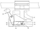
도 1은 본 발명의 클램핑 기구를 측변 레일에 고정시킨 외관 입체도이다.
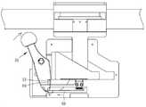
도 2는 본 발명의 클램핑 기구의 입체 분해도이다.
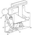
도 3은 본 발명의 클램핑 기구의 평면도이다.
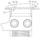
도 4는 본 발명의 클램핑 기구에서, 핸들의 제1 횡방향 돌출부와 잠금로드의 이젝팅부 사이의 상대 위치를 위주로 나타낸 국부 입체도이다.
도 5는 본 발명의 클램핑 기구에서, 핸들의 제1 횡방향 돌출부와 잠금로드의 이젝팅부 사이의 상대 위치를 위주로 나타낸 국부 측면도이다.
도 6a~6g는 도 3과 유사하며, 본 발명의 클램핑 기구의 조작 과정을 위주로 나타낸 도면이다.
도 7은 본 발명의 클램핑 기구에서, 핸들의 제1 횡방향 돌출부와 잠금로드의 직립부 사이의 상대 위치를 위주로 나타낸 국부 입체도이다.
도 8은 본 발명의 클램핑 기구에서, 핸들의 제1 횡방향 돌출부와 잠금로드의 직립부 사이의 상대 위치를 위주로 나타낸 국부 측면도이다.
도 9는 본 발명의 클램핑 기구에서, 슬라이딩 블록의 제1 위치결정부와 슬라이딩방지 블록의 제2 위치결정부의 구조 관계를 위주로 나타낸 국부 확대도이다.
도 10은 도 9와 유사하며, 슬라이딩 블록의 제1 위치결정부와 슬라이딩방지 블록의 제2 위치결정부의 또 다른 실시 양태를 위주로 나타낸 도면이다.1 is a three-dimensional appearance of the clamping mechanism of the present invention fixed to the side rail.
2 is a three-dimensional exploded view of the clamping mechanism of the present invention.
3 is a plan view of the clamping mechanism of the present invention.
FIG. 4 is a local three-dimensional view mainly showing a relative position between the first transverse protrusion of the handle and the ejecting portion of the locking rod in the clamping mechanism of the present invention.
Fig. 5 is a local side view mainly showing the relative position between the first transverse protrusion of the handle and the ejecting portion of the locking rod in the clamping mechanism of the present invention.
6A to 6G are similar to FIG. 3 and mainly show the operation of the clamping mechanism of the present invention.
7 is a local three-dimensional view mainly showing a relative position between the first transverse protrusion of the handle and the upright portion of the locking rod in the clamping mechanism of the present invention.
Fig. 8 is a local side view mainly showing the relative position between the first transverse protrusion of the handle and the upright portion of the locking rod in the clamping mechanism of the present invention.
9 is an enlarged view of a local part mainly showing the structural relationship between the first positioning portion of the sliding block and the second positioning portion of the sliding prevention block in the clamping mechanism of the present invention.
FIG. 10 is a view similar to FIG. 9 and mainly showing another embodiment of the first positioning portion of the sliding block and the second positioning portion of the sliding prevention block.
출원인은 먼저 여기서, 전체 명세서 중, 아래에 소개하는 실시예 및 특허출원 범위의 청구항을 포함하여, '상(上)', '하', '좌', '우', '상(頂)', '저(底)', '내', '외' 등 방향성과 관련된 명사는 모두 도면 중의 방향을 기준으로 함을 밝혀둔다. 그 다음, 이하 소개하려는 실시예 및 도면에서, 동일한 부재의 부호는 동일하거나 유사한 부재 또는 그 구조 특징을 대표한다.Applicants first, here, among the entire specification, including the embodiments and patent claims to be introduced below,'upper','lower','left','right','upper (상)' It is revealed that nouns related to directionality such as'low','my', and'other' are based on the directions in the drawing. Next, in the examples and drawings to be introduced below, the same member numbers represent the same or similar members or structural features thereof.
도 1 내지 도 5를 참조하면, 본 발명의 클램핑 기구(10)는 지지시트(20), 핸들(30), 클램핑 유닛(40) 및 잠금제동 유닛(60)을 포함한다.1 to 5, the
지지시트(20)는 전방 가림판(21)과 후방 가림판(23)으로 구성된다. 전방 가림판(21)의 내측면에 위치제한홈(22)이 구비되고, 후방 가림판(23)의 일단에 내, 외 양측면을 관통하는 장공(24)이 구비되며, 후방 가림판(23)의 중앙에 내, 외 양측면을 관통하는 개구(25)가 구비된다.The
핸들(30)은 피봇축(35)을 통해 지지시트(20)의 일단에 피봇 설치된다. 핸들(30)의 전방 가림판(21)을 향하는 측면에 노치(31)가 구비되고, 핸들(30)의 후방 가림판(23)을 향하는 측면에 제1 횡방향 돌출부(32)와 제2 횡방향 돌출부(33)가 구비되며, 제1 횡방향 돌출부(32)의 길이는 제2 횡방향 돌출부(33)의 길이보다 짧고, 또한 제1 횡방향 돌출부(32)의 위치는 제2 횡방향 돌출부(33)의 위치보다 낮다. 또한 핸들(30)은 제2 횡방향 돌출부(33)에 인접한 이젝팅 원호면(34)을 더 구비한다.The
클램핑 유닛(40)은 상부 클램프시트(41), 슬라이딩 블록(44), 및 하부 클램프시트(48)를 포함하며, 그 중에서, 상부 클램프시트(41)는 나사류의 고정부재를 이용하여 후방 가림판(23)의 상단에 체결되며, 상부 클램프시트(41)의 일단에 한 쌍의 상부 클램핑부(42)가 구비되고, 상부 클램프시트(41)의 타단에 마운팅시트(43)가 일체형으로 연결되며, 마운팅시트(43)는 수술 보조기계(예를 들어 로봇 암, 미도시)가 장착되기 위한 것이다.The
슬라이딩 블록(44)은 지지시트(20) 내에 설치되고 또한 수압(受壓) 평면(45)을 구비하며, 슬라이딩 블록(44)의 수압 평면(45)이 핸들(30)의 이젝팅 원호면(34)에 의해 밀려 움직일 때, 슬라이딩 블록(44)에 지지시트(20)에 대한 수평 이동이 발생하며, 또한, 슬라이딩 블록(44)의 상면에 경사면(46)이 형성되고, 슬라이딩 블록(44)의 저면에 제1 위치결정부(47)가 구비된다. 본 실시예에서, 도 9에 도시된 바와 같이, 제1 위치결정부(47)는 등간격으로 배열되는 다수의 오목홈(472)으로 구성되며, 각각의 오목홈(472)의 홈벽은 제1 평면(474) 및 제1 평면(474)에 대한 제1 경사면(476)을 구비한다.The sliding
하부 클램프시트(48)는 축부(49)를 구비하고, 축부(49)는 지지시트(20)에 상하로 이동 가능하게 관통 설치되며, 축부(49)의 상단은 지지시트(20)의 외측에 위치하는 하부 클램핑부(50)에 일체형으로 연결되고, 축부(49)의 저단은 경사면(51)을 구비하여, 하부 클램프시트(48)의 경사면(51)이 슬라이딩 블록(44)의 경사면(46)에 접촉됨으로써(도 6a 참조), 슬라이딩 블록(44)에 수평 이동이 발생 시 하부 클램프시트(48)가 위로 밀려올라간다.The
잠금제동 유닛(60)은 슬라이딩방지 블록(61), 복귀스프링(64), 잠금로드(66) 및 연동로드(71)를 구비하며, 그 중에서, 슬라이딩방지 블록(61)은 지지시트(20)에 상하로 이동 가능하게 설치되고, 슬라이딩방지 블록(61)의 상면은 제2 위치결정부(62)를 구비한다. 본 실시예에서, 도 9에 도시된 바와 같이, 제2 위치결정부(62)는 등간격으로 배열되는 다수의 돌기(622)로 구성되고, 돌기(622)는 일대일 방식으로 오목홈(472)에 감입 체결되며, 또한 돌출블록(622)은 제2 평면(624) 및 제2 평면(624)에 대한 제2 경사면(626)을 구비하고, 돌출블록(622)의 제2 평면(624)과 제2 경사면(626)은 각각 오목홈(472)의 제1 평면(474)과 제1 경사면(476)에 각각 접촉됨으로써, 슬라이딩방지 블록(61)의 제2 위치결정부(62)와 슬라이딩 블록(44)의 제1 위치결정부(47) 사이가 서로 정합된다. 또한, 슬라이딩방지 블록(61)의 일단은 연장부(63)를 구비하여, 슬라이딩방지 블록(61)의 연장부(63)가 후방 가림판(23)의 개구(25)에 감입 설치되며, 또한, 슬라이딩방지 블록(61)의 연장부(63)의 크기는 슬라이딩방지 블록(61)이 상하로 이동 시 간섭이 발생하지 않도록 후방 가림판(23)의 개구(25)의 크기보다 작다.The
복귀스프링(64)(여기서는 압축스프링)의 상, 하 양단은 슬라이딩방지 블록(61)의 저면 및 받침판(65)의 상면에 각각 접촉되고, 받침판(65)은 나사류의 고정부재를 이용하여 전방 가림판(21)에 체결되며, 복귀스프링(64)이 탄력을 제공함으로써, 슬라이딩방지 블록(61)을 슬라이딩 블록(44) 방향으로 밀어올린다.The upper and lower ends of the return spring 64 (here, the compression spring) are respectively in contact with the bottom surface of the
잠금로드(66)는 지지시트(20)에 수평 이동 가능하게 설치되고, 잠금로드(66)의 중앙에 위치제한부(67)가 구비되어, 잠금로드(66)의 위치제한부(67)가 전방 가림판(21)의 위치제한홈(22)에 감입 설치되며, 잠금로드(66)의 일단에 잠금제동부(68)가 구비되고, 잠금로드(66)의 잠금제동부(68)는 슬라이딩방지블록(61)의 연장부(63) 하방에 위치하며, 잠금로드(66)의 타단은 직립부(69), 직립부(69)와 수직인 조작부(70) 및 이젝팅부(81)를 구비하며(도 4 및 도 5 참조), 잠금로드(66)의 조작부(70)는 후방 가림판(23)의 장공(24)에 관통 설치되어 후방 가림판(23)의 외측면(다시 말해 지지시트(20)의 측면 레일(12)과 등지는 측면, 도 1 참조)에 돌출된다.The
연동로드(71)는 후방 가림판(23)의 외측면(다시 말해 지지시트(20)의 측면 레일(12)과 등지는 측면, 도 1 참조)에 맞닿고, 연동로드(71)의 일단은 고정부(74)를 구비하며, 연동로드(71)가 슬라이딩방지 블록(61)과 동기적으로 작동하도록, 연동로드(71)의 고정부(74)가 나사류의 고정부재를 이용하여 슬라이딩방지 블록(61)의 연장부(63)에 체결되고, 연동로드(71)의 타단은 돌출부(72)를 구비하며, 제2의 안전 메커니즘으로써, 연동로드(71)의 돌출부(72)가 잠금로드(66)의 조작부(70)에 접촉된다.The interlocking
실제 가설 시, 먼저 핸들(30)을 돌려 핸들(30)의 제1 횡방향 돌출부(32)가 잠금로드(66)의 이젝팅부(81)를 밀어올리면 잠금로드(66)가 우측으로 이동하기 시작하며, 핸들(30)이 피복축(35)을 따라 요동하기 때문에, 이후 제1 횡방향 돌출부(32)가 이젝팅부(81)와 분리될 수 있다. 이어서, 도 6a 및 도 6b에 도시된 바와 같이(설명의 편의를 위해, 도 6b에서는 연동로드(71)를 생략하였다), 잠금로드(66)의 잠금제동부(68)가 슬라이딩방지 블록(61)의 연장부(63)를 벗어날 때, 잠금로드(66)가 잠금해제 위치(P3)에 도달하게 되며, 이때의 슬라이딩방지 블록(61)은 즉시 상하로 작동 가능하게 된다. 이어서 지속적으로 핸들(30)을 좌측으로 밀면, 이때는 핸들(30)의 제1 횡방향 돌출부(32)가 길이면에서 비교적 짧기 때문에, 도 7 및 도 8에 도시된 바와 같이, 핸들(30)이 지속적으로 피봇 회전하는 과정에서, 핸들(30)의 제1 횡방향 돌출부(32)가 잠금로드(66)의 직립부(69)에 닿지 않아 상호간의 간섭을 피할 수 있다. 이후 핸들(30)의 이젝팅 원호면(34)이 슬라이딩 블록(44)의 수압 평면(45)을 밀어올리기 시작하며, 이때 슬라이딩방지 블록(61)이 상하로 작동 가능한 상태에 놓여 있기 때문에, 슬라이딩 블록(44)이 우측으로 이동하기 시작할 수 있다. 도 6c 및 도 6d에 도시된 바와 같이, 슬라이딩 블록(44)의 이동 과정에서, 한편으로는 제1 위치결정부(47)의 제1 평면(474)이 슬라이딩방지 블록(61)의 제2 위치결정부(62)의 제2 평면(624)을 밀어, 슬라이딩방지 블록(61)이 슬라이딩 블록(44)과 복귀스프링(64)의 이중 작용하에 반복적으로 상하로 작동하게 되고, 다른 한편으로는 경사면(46)이 하부 클램프시트(48)의 경사면(51)을 밀어올려, 하부 지지시트(48)가 석방 위치(P1)(도 6a 참조)로부터 위를 향해 클램핑 위치(P2)까지 상승하며(도 6d 참조), 하부 클램프시트(48)가 클램핑 위치(P2)에 도달 시, 상부 클램프시트(41)와 협동하여 수술대의 측면 레일(12)을 중간에 협지할 수 있게 된다. 이후 다시 핸들(30)을 우측으로 밀어, 핸들(30)의 제2 횡방향 돌출부(33)가 잠금로드(66)의 직립부(69)를 밀면, 도 6e에 도시된 바와 같이, 이때는 핸들(30)의 제2 횡방향 돌출부(33)가 길이면에서 상대적으로 길기 때문에, 핸들(30)이 역방향으로 피봇 회전하는 과정에서, 핸들(30)의 제2 횡방향 돌출부(33)가 잠금로드(66)의 직립부(69)에 지속적으로 접촉하여, 잠금로드(66)를 지속적으로 좌측으로 이동시키며, 잠금로드(66)의 잠금제동부(68)와 잠금로드(66)의 조작부(70)가 슬라이딩방지 블록(61)의 연장부(63)와 연동로드(71)의 돌출부(72)에 각각 접촉 시, 도 6f에 도시된 바와 같이, 잠금로드(66)가 잠금 위치(P4)에 도달하여, 슬라이딩방지 블록(61)이 상하로 작동할 수 없으며, 이때 슬라이딩 블록(44)은 슬라이딩방지 블록(61)의 위치결정에 의해 이동할 수 없게 되어, 이와 같은 방식으로 가설이 완료된다.In the actual hypothesis, when the first
그리고 핸들(30)에 오작동이 발생하는 것을 방지하기 위하여, 전방 가림판(21)의 내측면에 자석(73)이 설치되며(도 2 참조), 핸들(30)이 도 6a에 도시된 바와 같이 초기 상태에 위치 시, 핸들(30)의 노치(31)에 자석(73)이 감입 체결되어, 핸들(30)이 자석(73)에 의해 흡착되도록 함으로써 위치결정이 이루어질 수 있다. 이밖에, 가설이 완료된 후, 피봇축(35)의 축방향(A)을 측면 레일(12)의 외측면(14)의 연장방향과 서로 수직이 되도록 함으로써, 핸들(30)의 조작방향이 주변의 사람 또는 물체와 간섭이 발생하는 것을 방지할 수 있다.In addition, in order to prevent a malfunction from occurring in the
또한, 분리하고자 할 때, 한 손으로 잠금로드(66)의 조작부(70)를 우측으로 움직이면, 도 6g에 도시된 바와 같이, 한편으로는 잠금로드(66)의 조작부(70)가 연동로드(71)의 돌출부(72)로부터 이탈되고, 다른 한편으로는 잠금로드(66)의 잠금제동부(68)가 슬라이딩방지 블록(61)의 연장부(63)로부터 이탈되며, 다시 말해 잠금로드(66)가 잠금해제 위치(P3)로 이동하며, 이어서 한 손으로 연동로드(71)의 고정부(74)를 누르면, 연동로드(71)의 고정부(74)가 슬라이딩방지 블록(61)의 연장부(63)와 함께 고정되어 있기 때문에, 슬라이딩방지 블록(61)이 동기적으로 하향 이동하게 됨으로써, 슬라이딩방지 블록(61)이 한편으로는 복귀스프링(64)을 압축시키고, 다른 한편으로는 슬라이딩 블록(44)에 대한 위치결정이 해제된다. 이어서 사용자가 마운팅시트(43)를 쥐고 위를 향해 힘을 인가하면, 측면 레일(12)이 상부 클램프시트(41) 및 하부 클램프시트(48)와 접촉되어, 측면 레일(12)이 하부 클램프시트(48)에 힘을 인가함으로써, 슬라이딩 블록(44)을 좌측으로 밀어 움직이며, 하부 클램프시트(48)가 도 6a에 도시된 석방 위치(P1)까지 하강하면 즉시 측면 레일(12)을 석방하게 되어 분리가 간편하다.In addition, when you want to remove, if you move the
보충 설명해야 할 점으로, 슬라이딩 블록(44)의 오목홈(472)과 슬라이딩방지 블록(61)의 돌기(622) 사이는 상이한 구조 변화가 있을 수 있으며, 도 10에 도시된 바와 같이, 슬라이딩 블록(44)의 오목홈(472)은 제1 평면(474) 및 제1 평면(474)에 대한 제1 원호면(478)을 구비하고, 슬라이딩방지 블록(61)의 돌기(622)는 제2 평면(624) 및 제2 평면(624)에 대한 제2 원호면(628)을 구비하여, 슬라이딩 블록(44)의 오목홈(472)의 제1 평면(474)과 슬라이딩방지 블록(61)의 돌기(622)의 제2 평면(624)이 서로 접촉되고, 슬라이딩 블록(44)의 오목홈(472)의 제1 원호면(478)과 슬라이딩방지 블록(61)의 돌기(622)의 제2 원호면(628)이 서로 접촉됨으로써, 슬라이딩 블록(44)의 제1 위치결정부(47)와 슬라이딩방지 블록(61)의 제2 위치결정부(62) 역시 상호 간의 결합을 통해 위치결정 효과를 발생시킬 수 있다.As a supplementary point, there may be different structural changes between the
결론적으로, 본 발명의 클램핑 기구(10)는 한 손을 이용하여 장착과 분리를 즉시 완수할 수 있으며, 안전 메커니즘을 구비하여, 타인이 잘못 접촉하여 뜻하지 않게 탈락되는 상황을 방지할 수 있으며, 나아가 신속한 위치결정, 간편한 탈착 및 사용 안전성의 강화 목적을 달성할 수 있다.In conclusion, the
10: 클램핑 기구12: 측면 레일
14: 외측면20: 지지시트
21: 전방 가림판22: 위치제한홈
23: 후방 가림판24: 장공
25: 개구30: 핸들
31: 노치32: 제1 횡방향 돌출부
33: 제2 횡방향 돌출부34: 이젝팅 원호면
35: 피봇축40: 클램핑 유닛
41: 상부 클램프시트42: 상부 클램핑부
43: 마운팅시트44: 슬라이딩 블록
45: 수압 평면46: 경사면
47: 제1 위치결정부48: 하부 클램프시트
49: 축부50: 하부 클램핑부
51: 경사면60: 잠금 제동 유닛
61: 슬라이딩방지 블록62: 제2 위치결정부
63: 연장부64: 복귀 스프링
65: 받침판66: 잠금로드
67: 위치제한부68: 잠금 제동부
69: 직립부70: 조작부
71: 연동로드72: 돌출부
73: 자석74: 고정부
81: 이젝팅부472: 오목홈
474: 제1 평면476: 제1 경사면
478: 제1 원호면622: 돌기
624: 제2 평면626: 제2 경사면
628: 제2 원호면P1: 석방위치
P2: 클램핑 위치P3: 잠금해제 위치
P4: 잠금위치A: 축방향10: clamping mechanism 12: side rail
14: outer surface 20: support sheet
21: Front blanking plate 22: Position limit groove
23: rear blanking plate 24: long hole
25: opening 30: handle
31: notch 32: first transverse projection
33: second transverse projection 34: ejecting arc surface
35: pivot axis 40: clamping unit
41: upper clamp sheet 42: upper clamping part
43: mounting seat 44: sliding block
45: water pressure plane 46: slope
47: first positioning portion 48: lower clamp seat
49: shaft portion 50: lower clamping portion
51: Slope 60: Locking brake unit
61: anti-sliding block 62: second positioning unit
63: extension 64: return spring
65: base plate 66: locking rod
67: Position limit 68: Locking brake
69: upright portion 70: operation portion
71: interlocking rod 72: protrusion
73: magnet 74: fixing part
81: ejecting portion 472: concave groove
474: first plane 476: first slope
478: first arc surface 622: projection
624: second plane 626: second slope
628: Second arc surface P1: Release position
P2: Clamping position P3: Unlocked position
P4: Locking position A: Axial
Claims (10)
Translated fromKorean상기 클램핑 기구는
지지시트;
상기 지지시트의 일단에 피봇 설치되는 핸들;
상부 클램프시트, 슬라이딩 블록과 하부 클램프시트를 구비하며, 상기 상부 클램프시트는 상기 지지시트의 상면에 고정 설치되고, 상기 슬라이딩 블록은 상기 지지시트에 설치되어 상기 핸들에 의해 상기 지지시트에 대해 수평 이동 가능하고, 또한 상기 슬라이딩 블록은 제1 위치결정부와 경사면을 구비하며, 상기 하부 클램프시트는 상기 지지시트에 상하로 이동 가능하게 설치되고 또한 경사면을 구비하여, 상기 하부 클램프시트의 경사면이 상기 슬라이딩 블록의 경사면에 접촉됨으로써, 상기 하부 클램프시트가 상기 슬라이딩 블록에 의해 석방 위치로부터 클램핑 위치로 상승 가능하며, 상기 하부 클램프시트가 상기 클램핑 위치에 위치 시, 상기 측면 레일이 상기 상, 하 클램프시트의 중간에 협지되는 클램핑 유닛; 및
슬라이딩방지 블록, 복귀스프링과 잠금로드를 구비하며, 상기 슬라이딩방지 블록은 상기 지지시트에 상하로 이동 가능하게 설치되고 또한 제2 위치결정부를 구비하여, 상기 슬라이딩방지 블록의 제2 위치결정부와 상기 슬라이딩 블록의 제1 위치결정부 사이가 서로 정합되며, 상기 복귀스프링은 상기 슬라이딩방지 블록을 상기 슬라이딩 블록 방향으로 밀어올리도록 상기 슬라이딩방지 블록에 작용하고, 상기 잠금로드는 상기 지지시트에 수평 이동 가능하게 설치되며 또한 상기 핸들에 의해 잠금 위치와 잠금해제 위치 사이에서 상기 슬라이딩방지 블록에 대해 작동 가능하여, 상기 잠금로드가 상기 잠금 위치에 위치 시, 상기 잠금로드의 잠금제동부가 상기 슬라이딩방지 블록을 밀어올림으로써, 상기 슬라이딩방지 블록이 상기 슬라이딩 블록을 위치결정시키고, 상기 잠금로드가 상기 잠금해제 위치에 위치 시, 상기 잠금로드의 잠금제동부가 상기 슬라이딩방지 블록을 석방하여, 상기 슬라이딩방지 블록이 상기 슬라이딩 블록을 수평 이동하도록 허용하는 잠금제동 유닛을 포함하는
클램핑 기구.In the clamping mechanism for securing the surgical aid to the side rail of the operating table,
The clamping mechanism
Support sheet;
A handle pivoted on one end of the support sheet;
It has an upper clamp sheet, a sliding block and a lower clamp sheet, and the upper clamp sheet is fixedly installed on the upper surface of the support sheet, and the sliding block is installed on the support sheet and horizontally moved with respect to the support sheet by the handle. It is possible, and the sliding block has a first positioning portion and an inclined surface, and the lower clamp sheet is installed to be movable up and down on the support sheet, and also has an inclined surface, so that the inclined surface of the lower clamp sheet is the sliding By being in contact with the inclined surface of the block, the lower clamp sheet can be raised from the release position to the clamping position by the sliding block, and when the lower clamp sheet is located in the clamping position, the side rails are the upper and lower clamp sheets. A clamping unit interposed in the middle; And
It is provided with a sliding prevention block, a return spring and a lock rod, and the sliding prevention block is movably installed up and down on the support sheet, and further includes a second positioning portion, so that the second positioning portion and the The first positioning portions of the sliding blocks are aligned with each other, and the return spring acts on the anti-sliding block to push the anti-sliding block in the direction of the sliding block, and the lock rod can be horizontally moved on the support sheet. It is also installed and is operable to the anti-skid block between the locked position and the unlocked position by the handle, so that when the lock rod is in the locked position, the locking brake of the lock rod blocks the anti-skid block. By pushing up, the anti-sliding block positions the sliding block, and when the lock rod is in the unlocked position, the locking brake portion of the lock rod releases the anti-skid block, so that the anti-skid block And a locking brake unit allowing the sliding block to move horizontally
Clamping mechanism.
상기 측면 레일은 외측면을 구비하고, 상기 핸들은 피봇축을 통해 상기 지지시트에 피봇 설치되며, 상기 피봇축의 축방향과 상기 측면 레일의 외측면의 연장방향이 서로 수직을 이루는, 클램핑 기구.According to claim 1,
The side rail has an outer surface, and the handle is pivotally installed on the support sheet through a pivot axis, and an axial direction of the pivot axis and an extension direction of the outer surface of the side rail are perpendicular to each other.
상기 핸들은 이젝팅 원호면을 구비하고, 상기 슬라이딩 블록은 수압(受壓) 평면을 구비하며, 상기 핸들의 이젝팅 원호면이 상기 슬라이딩 블록의 수압 평면을 밀어올림으로써, 상기 슬라이딩 블록이 상기 하부 클램프시트를 상기 석방 위치로부터 상기 클램핑 위치로 상승시키는, 클램핑 기구.According to claim 1,
The handle has an ejecting arc surface, the sliding block has a hydraulic pressure plane, and the ejecting arc surface of the handle pushes up the hydraulic plane of the sliding block, so that the sliding block is the lower portion. A clamping mechanism that raises a clamp sheet from the released position to the clamping position.
상기 핸들은 제1 횡방향 돌출부와 제2 횡방향 돌출부를 구비하고, 상기 제1, 제2 횡방향 돌출부는 상기 핸들의 동측에 위치하며, 상기 제1 횡방향 돌출부의 길이는 상기 제2 횡방향 돌출부의 길이보다 짧고, 또한 상기 제1 횡방향 돌출부의 위치는 상기 제2 횡방향 돌출부의 위치보다 낮으며, 상기 잠금로드의 일단은 상기 잠금제동부를 구비하고, 상기 잠금로드의 타단은 직립부 및 이젝팅부를 구비하며, 상기 잠금로드의 이젝팅부가 상기 핸들의 제1 횡방향 돌출부에 의해 밀려 움직일 때, 상기 잠금로드가 상기 잠금 위치로부터 상기 잠금해제 위치로 이동하고, 상기 잠금로드의 직립부가 상기 핸들의 제2 횡방향 돌출부에 의해 밀려 움직일 때, 상기 잠금로드가 상기 잠금해제 위치로부터 상기 잠금 위치로 이동하는, 클램핑 기구.According to claim 1,
The handle has a first transverse protrusion and a second transverse protrusion, the first and second transverse protrusions are located on the same side of the handle, and the length of the first transverse protrusion is the second transverse Shorter than the length of the protrusion, and the position of the first transverse protrusion is lower than the position of the second transverse protrusion, one end of the locking rod is provided with the locking brake, and the other end of the locking rod is an upright portion. And an ejecting portion, when the ejecting portion of the lock rod is pushed and moved by the first transverse protrusion of the handle, the lock rod moves from the locked position to the unlocked position, and an upright portion of the lock rod A clamping mechanism, when pushed by a second transverse projection of the handle, moves the lock rod from the unlocked position to the locked position.
상기 지지시트는 위치제한홈을 구비하고, 상기 잠금로드는 위치제한부를 구비하며, 상기 잠금로드의 위치제한부가 상기 지지시트의 위치제한홈에 수평 이동 가능하게 감입 설치되는, 클램핑 기구.According to claim 1,
The support seat has a position limiting groove, the lock rod has a position limiting part, and the clamping mechanism is installed so that the position limiting part of the locking rod is horizontally movable into the position limiting groove of the support sheet.
상기 지지시트는 장공을 구비하고, 상기 잠금로드의 일단은 직립부와 수직인 조작부를 구비하며, 상기 잠금로드의 조작부가 상기 지지시트의 장공에 수평 이동 가능하게 관통 설치되어 상기 지지시트의 상기 측면 레일과 등지는 측면에 돌출되는, 클램핑 기구.According to claim 1,
The support sheet has a long hole, one end of the lock rod is provided with an operation portion perpendicular to the upright portion, the operation portion of the lock rod is installed through the long hole of the support sheet to be horizontally movable through the side of the support sheet Rails and backs are clamping mechanisms protruding from the sides.
상기 지지시트는 개구를 더 구비하고, 상기 슬라이딩방지 블록은 연장부를 구비하여, 상기 슬라이딩방지 블록의 연장부가 상기 지지시트의 개구에 감입 체결되고 또한 상기 잠금로드의 잠금제동부에 지지되며, 상기 잠금제동 유닛은 연동로드를 더 구비하여, 상기 연동로드는 상기 지지시트의 상기 측면 레일과 등지는 측면에 맞닿고, 상기 연동로드의 일단은 상기 슬라이딩방지 블록의 연장부에 고정되며, 상기 연동로드의 타단은 돌출부를 구비하여, 상기 잠금로드가 상기 잠금 위치에 위치 시, 상기 잠금로드의 조작부가 상기 연동로드의 돌출부를 밀어올리고, 상기 잠금로드가 상기 잠금해제 위치에 위치 시, 상기 잠금로드의 조작부가 상기 연동로드의 돌출부를 석방하는, 클램핑 기구.The method of claim 6,
The support sheet further includes an opening, and the anti-sliding block has an extension, so that the extension of the anti-sliding block is fitted into the opening of the support sheet and supported by the locking brake of the lock rod, The braking unit further includes an interlocking rod, the interlocking rod abuts the side rail and the back side of the support sheet, and one end of the interlocking rod is fixed to the extension portion of the sliding prevention block, The other end is provided with a protrusion, and when the lock rod is in the locked position, when the operation portion of the lock rod pushes up the protrusion of the interlocking rod, and when the lock rod is in the unlocked position, the operation portion of the lock rod A clamping mechanism that releases the protrusion of the interlocking rod.
상기 지지시트 내에 자석이 설치되고, 상기 핸들에 노치가 구비되며, 상기 핸들의 상기 노치가 상기 자석에 감입 체결 시, 상기 핸들이 상기 자석에 의해 흡착되어 위치결정되는, 클램핑 기구.According to claim 1,
A magnet is installed in the support sheet, a notch is provided in the handle, and when the notch of the handle is fitted into the magnet, the handle is adsorbed and positioned by the magnet, thereby clamping mechanism.
상기 클램핑 유닛은 마운팅시트를 더 구비하며, 상기 마운팅시트가 상기 수술 보조 기계를 장착하기 위해 상기 상부 클램프시트에 연결되는, 클램핑 기구.According to claim 1,
The clamping unit further comprises a mounting sheet, wherein the mounting sheet is connected to the upper clamp sheet for mounting the surgical aid machine.
상기 슬라이딩 블록의 제1 위치결정부는 등간격으로 배열되는 다수의 오목홈으로 구성되고, 상기 슬라이딩방지 블록의 제2 위치결정부는 등간격으로 배열되는 다수의 돌기이며, 상기 오목홈과 상기 돌기 사이가 일대일로 서로 감입 체결되는, 클램핑 기구.According to claim 1,
The first positioning portion of the sliding block is composed of a plurality of concave grooves arranged at equal intervals, the second positioning portion of the sliding prevention block is a plurality of projections arranged at equal intervals, the gap between the concave groove and the projection A clamping mechanism that engages and engages one-to-one.
Priority Applications (1)
| Application Number | Priority Date | Filing Date | Title |
|---|---|---|---|
| KR1020190000118AKR102177120B1 (en) | 2019-01-02 | 2019-01-02 | Clamping device |
Applications Claiming Priority (1)
| Application Number | Priority Date | Filing Date | Title |
|---|---|---|---|
| KR1020190000118AKR102177120B1 (en) | 2019-01-02 | 2019-01-02 | Clamping device |
Publications (2)
| Publication Number | Publication Date |
|---|---|
| KR20200084474Atrue KR20200084474A (en) | 2020-07-13 |
| KR102177120B1 KR102177120B1 (en) | 2020-11-11 |
Family
ID=71570778
Family Applications (1)
| Application Number | Title | Priority Date | Filing Date |
|---|---|---|---|
| KR1020190000118AActiveKR102177120B1 (en) | 2019-01-02 | 2019-01-02 | Clamping device |
Country Status (1)
| Country | Link |
|---|---|
| KR (1) | KR102177120B1 (en) |
Cited By (3)
| Publication number | Priority date | Publication date | Assignee | Title |
|---|---|---|---|---|
| CN114572687A (en)* | 2022-03-08 | 2022-06-03 | 黄结恩 | Separation placing device for goggle processing |
| CN116475648A (en)* | 2023-06-26 | 2023-07-25 | 玉田县信德诚印刷机械有限公司 | Automatic welding equipment for steel cores of printing rollers |
| CN118080925A (en)* | 2024-04-26 | 2024-05-28 | 常州纺兴精密机械有限公司 | Clamping type manipulator for processing ultra-high molecular weight polyethylene fiber spinneret plate |
Citations (6)
| Publication number | Priority date | Publication date | Assignee | Title |
|---|---|---|---|---|
| US20100299890A1 (en)* | 2008-09-12 | 2010-12-02 | Mark Doyle | Bedrail clamp |
| US8561234B1 (en)* | 2008-08-12 | 2013-10-22 | Bob Kring | Surgical bed clamp apparatus |
| US9022334B1 (en)* | 2013-04-01 | 2015-05-05 | Innovative Medical Products, Inc. | Operating table quick release clamp |
| EP3085349A1 (en)* | 2015-03-24 | 2016-10-26 | Stryker Corporation | Rotatable seat clamps for rail clamp |
| US20160361219A1 (en)* | 2015-06-11 | 2016-12-15 | Acist Medical Systems, Inc. | Variable rate bedrail clamp |
| KR20170083576A (en)* | 2014-11-06 | 2017-07-18 | 마쿠에트 게엠베하 | Gripping claw for mounting on a slide rail of an operating table |
- 2019
- 2019-01-02KRKR1020190000118Apatent/KR102177120B1/enactiveActive
Patent Citations (6)
| Publication number | Priority date | Publication date | Assignee | Title |
|---|---|---|---|---|
| US8561234B1 (en)* | 2008-08-12 | 2013-10-22 | Bob Kring | Surgical bed clamp apparatus |
| US20100299890A1 (en)* | 2008-09-12 | 2010-12-02 | Mark Doyle | Bedrail clamp |
| US9022334B1 (en)* | 2013-04-01 | 2015-05-05 | Innovative Medical Products, Inc. | Operating table quick release clamp |
| KR20170083576A (en)* | 2014-11-06 | 2017-07-18 | 마쿠에트 게엠베하 | Gripping claw for mounting on a slide rail of an operating table |
| EP3085349A1 (en)* | 2015-03-24 | 2016-10-26 | Stryker Corporation | Rotatable seat clamps for rail clamp |
| US20160361219A1 (en)* | 2015-06-11 | 2016-12-15 | Acist Medical Systems, Inc. | Variable rate bedrail clamp |
Cited By (5)
| Publication number | Priority date | Publication date | Assignee | Title |
|---|---|---|---|---|
| CN114572687A (en)* | 2022-03-08 | 2022-06-03 | 黄结恩 | Separation placing device for goggle processing |
| CN114572687B (en)* | 2022-03-08 | 2024-05-03 | 青岛德凯士运动用品有限公司 | Separation and placement device for goggles processing |
| CN116475648A (en)* | 2023-06-26 | 2023-07-25 | 玉田县信德诚印刷机械有限公司 | Automatic welding equipment for steel cores of printing rollers |
| CN116475648B (en)* | 2023-06-26 | 2023-08-29 | 玉田县信德诚印刷机械有限公司 | Automatic welding equipment for steel cores of printing rollers |
| CN118080925A (en)* | 2024-04-26 | 2024-05-28 | 常州纺兴精密机械有限公司 | Clamping type manipulator for processing ultra-high molecular weight polyethylene fiber spinneret plate |
Also Published As
| Publication number | Publication date |
|---|---|
| KR102177120B1 (en) | 2020-11-11 |
Similar Documents
| Publication | Publication Date | Title |
|---|---|---|
| KR20200084474A (en) | Clamping device | |
| KR101876851B1 (en) | Connecting structure and LED display device having the same | |
| EP2189305B1 (en) | Caster Device | |
| JP6633731B1 (en) | Clamping device | |
| JP2009509864A (en) | Battery mounting device | |
| US20140292050A1 (en) | Unlocked-state retention device and seat assembly having the same | |
| JP5571363B2 (en) | Caster equipment | |
| JP3138146U (en) | Slide rail | |
| KR20210028584A (en) | Seating device | |
| JP5356678B2 (en) | Mobile desk | |
| JP5562025B2 (en) | Chair | |
| KR101974038B1 (en) | Arm-rest unit of chair | |
| US20050077768A1 (en) | Chair with a stopping device | |
| JP5281061B2 (en) | Caster and caster unit | |
| KR200363556Y1 (en) | A buckle of safety belt for industry | |
| JP6180044B2 (en) | Fall prevention equipment | |
| CN214595495U (en) | Cooking utensil | |
| CN111281725B (en) | Clamping mechanism | |
| JP7386043B2 (en) | Caster devices and furniture with casters | |
| JP7138469B2 (en) | shower hook | |
| JP4789143B2 (en) | Watering nozzle | |
| JP4254633B2 (en) | Rotation control device for swivel chair | |
| WO2013114610A1 (en) | Bathtub handrail | |
| KR101011762B1 (en) | Car Seat Control Controller | |
| TW202019366A (en) | Clamping mechanism including a supporting base, a handle, a clamping unit and a locking unit |
Legal Events
| Date | Code | Title | Description |
|---|---|---|---|
| PA0109 | Patent application | Patent event code:PA01091R01D Comment text:Patent Application Patent event date:20190102 | |
| PA0201 | Request for examination | ||
| PE0902 | Notice of grounds for rejection | Comment text:Notification of reason for refusal Patent event date:20200512 Patent event code:PE09021S01D | |
| PG1501 | Laying open of application | ||
| E701 | Decision to grant or registration of patent right | ||
| PE0701 | Decision of registration | Patent event code:PE07011S01D Comment text:Decision to Grant Registration Patent event date:20200926 | |
| GRNT | Written decision to grant | ||
| PR0701 | Registration of establishment | Comment text:Registration of Establishment Patent event date:20201104 Patent event code:PR07011E01D | |
| PR1002 | Payment of registration fee | Payment date:20201104 End annual number:3 Start annual number:1 | |
| PG1601 | Publication of registration | ||
| PR1001 | Payment of annual fee | Payment date:20241022 Start annual number:5 End annual number:5 |