KR20200083294A - Constant temperature and humidity units - Google Patents
Constant temperature and humidity unitsDownload PDFInfo
- Publication number
- KR20200083294A KR20200083294AKR1020190175299AKR20190175299AKR20200083294AKR 20200083294 AKR20200083294 AKR 20200083294AKR 1020190175299 AKR1020190175299 AKR 1020190175299AKR 20190175299 AKR20190175299 AKR 20190175299AKR 20200083294 AKR20200083294 AKR 20200083294A
- Authority
- KR
- South Korea
- Prior art keywords
- indoor
- temperature
- humidity
- heat exchanger
- heat medium
- Prior art date
- Legal status (The legal status is an assumption and is not a legal conclusion. Google has not performed a legal analysis and makes no representation as to the accuracy of the status listed.)
- Ceased
Links
- 238000010438heat treatmentMethods0.000claimsabstractdescription73
- 238000000034methodMethods0.000claimsabstractdescription11
- 239000002918waste heatSubstances0.000claimsabstractdescription11
- 238000001816coolingMethods0.000claimsdescription38
- 230000007423decreaseEffects0.000claimsdescription14
- 239000007789gasSubstances0.000claimsdescription6
- 238000002347injectionMethods0.000claimsdescription6
- 239000007924injectionSubstances0.000claimsdescription6
- 230000006835compressionEffects0.000claimsdescription3
- 238000007906compressionMethods0.000claimsdescription3
- 238000007791dehumidificationMethods0.000abstractdescription13
- 238000005265energy consumptionMethods0.000abstractdescription5
- 230000001965increasing effectEffects0.000description9
- 238000010586diagramMethods0.000description7
- 238000004378air conditioningMethods0.000description4
- 239000007788liquidSubstances0.000description4
- 230000001939inductive effectEffects0.000description3
- 238000004781supercoolingMethods0.000description3
- 230000001276controlling effectEffects0.000description2
- 230000000694effectsEffects0.000description2
- 238000005057refrigerationMethods0.000description2
- 238000007664blowingMethods0.000description1
- 230000015556catabolic processEffects0.000description1
- 238000006731degradation reactionMethods0.000description1
- 238000007599dischargingMethods0.000description1
- 238000009434installationMethods0.000description1
- 238000005259measurementMethods0.000description1
- 238000012986modificationMethods0.000description1
- 230000004048modificationEffects0.000description1
- 230000001105regulatory effectEffects0.000description1
- 238000006467substitution reactionMethods0.000description1
Images


Classifications
- F—MECHANICAL ENGINEERING; LIGHTING; HEATING; WEAPONS; BLASTING
- F24—HEATING; RANGES; VENTILATING
- F24F—AIR-CONDITIONING; AIR-HUMIDIFICATION; VENTILATION; USE OF AIR CURRENTS FOR SCREENING
- F24F5/00—Air-conditioning systems or apparatus not covered by F24F1/00 or F24F3/00, e.g. using solar heat or combined with household units such as an oven or water heater
- F24F5/0007—Air-conditioning systems or apparatus not covered by F24F1/00 or F24F3/00, e.g. using solar heat or combined with household units such as an oven or water heater cooling apparatus specially adapted for use in air-conditioning
- F24F5/001—Compression cycle type
- F—MECHANICAL ENGINEERING; LIGHTING; HEATING; WEAPONS; BLASTING
- F24—HEATING; RANGES; VENTILATING
- F24F—AIR-CONDITIONING; AIR-HUMIDIFICATION; VENTILATION; USE OF AIR CURRENTS FOR SCREENING
- F24F11/00—Control or safety arrangements
- F24F11/70—Control systems characterised by their outputs; Constructional details thereof
- F24F11/80—Control systems characterised by their outputs; Constructional details thereof for controlling the temperature of the supplied air
- F24F11/83—Control systems characterised by their outputs; Constructional details thereof for controlling the temperature of the supplied air by controlling the supply of heat-exchange fluids to heat-exchangers
- F24F11/84—Control systems characterised by their outputs; Constructional details thereof for controlling the temperature of the supplied air by controlling the supply of heat-exchange fluids to heat-exchangers using valves
- F—MECHANICAL ENGINEERING; LIGHTING; HEATING; WEAPONS; BLASTING
- F24—HEATING; RANGES; VENTILATING
- F24F—AIR-CONDITIONING; AIR-HUMIDIFICATION; VENTILATION; USE OF AIR CURRENTS FOR SCREENING
- F24F11/00—Control or safety arrangements
- F24F11/70—Control systems characterised by their outputs; Constructional details thereof
- F24F11/80—Control systems characterised by their outputs; Constructional details thereof for controlling the temperature of the supplied air
- F24F11/86—Control systems characterised by their outputs; Constructional details thereof for controlling the temperature of the supplied air by controlling compressors within refrigeration or heat pump circuits
- F—MECHANICAL ENGINEERING; LIGHTING; HEATING; WEAPONS; BLASTING
- F24—HEATING; RANGES; VENTILATING
- F24F—AIR-CONDITIONING; AIR-HUMIDIFICATION; VENTILATION; USE OF AIR CURRENTS FOR SCREENING
- F24F3/00—Air-conditioning systems in which conditioned primary air is supplied from one or more central stations to distributing units in the rooms or spaces where it may receive secondary treatment; Apparatus specially designed for such systems
- F24F3/12—Air-conditioning systems in which conditioned primary air is supplied from one or more central stations to distributing units in the rooms or spaces where it may receive secondary treatment; Apparatus specially designed for such systems characterised by the treatment of the air otherwise than by heating and cooling
- F24F3/14—Air-conditioning systems in which conditioned primary air is supplied from one or more central stations to distributing units in the rooms or spaces where it may receive secondary treatment; Apparatus specially designed for such systems characterised by the treatment of the air otherwise than by heating and cooling by humidification; by dehumidification
- F24F3/1405—Air-conditioning systems in which conditioned primary air is supplied from one or more central stations to distributing units in the rooms or spaces where it may receive secondary treatment; Apparatus specially designed for such systems characterised by the treatment of the air otherwise than by heating and cooling by humidification; by dehumidification in which the humidity of the air is exclusively affected by contact with the evaporator of a closed-circuit cooling system or heat pump circuit
- H—ELECTRICITY
- H05—ELECTRIC TECHNIQUES NOT OTHERWISE PROVIDED FOR
- H05K—PRINTED CIRCUITS; CASINGS OR CONSTRUCTIONAL DETAILS OF ELECTRIC APPARATUS; MANUFACTURE OF ASSEMBLAGES OF ELECTRICAL COMPONENTS
- H05K7/00—Constructional details common to different types of electric apparatus
- H05K7/20—Modifications to facilitate cooling, ventilating, or heating
- H05K7/20709—Modifications to facilitate cooling, ventilating, or heating for server racks or cabinets; for data centers, e.g. 19-inch computer racks
- H05K7/208—Liquid cooling with phase change
- H05K7/20827—Liquid cooling with phase change within rooms for removing heat from cabinets, e.g. air conditioning devices
- F—MECHANICAL ENGINEERING; LIGHTING; HEATING; WEAPONS; BLASTING
- F24—HEATING; RANGES; VENTILATING
- F24F—AIR-CONDITIONING; AIR-HUMIDIFICATION; VENTILATION; USE OF AIR CURRENTS FOR SCREENING
- F24F3/00—Air-conditioning systems in which conditioned primary air is supplied from one or more central stations to distributing units in the rooms or spaces where it may receive secondary treatment; Apparatus specially designed for such systems
- F24F3/12—Air-conditioning systems in which conditioned primary air is supplied from one or more central stations to distributing units in the rooms or spaces where it may receive secondary treatment; Apparatus specially designed for such systems characterised by the treatment of the air otherwise than by heating and cooling
- F24F3/14—Air-conditioning systems in which conditioned primary air is supplied from one or more central stations to distributing units in the rooms or spaces where it may receive secondary treatment; Apparatus specially designed for such systems characterised by the treatment of the air otherwise than by heating and cooling by humidification; by dehumidification
- F24F2003/144—Air-conditioning systems in which conditioned primary air is supplied from one or more central stations to distributing units in the rooms or spaces where it may receive secondary treatment; Apparatus specially designed for such systems characterised by the treatment of the air otherwise than by heating and cooling by humidification; by dehumidification by dehumidification only
- F24F2003/1446—Air-conditioning systems in which conditioned primary air is supplied from one or more central stations to distributing units in the rooms or spaces where it may receive secondary treatment; Apparatus specially designed for such systems characterised by the treatment of the air otherwise than by heating and cooling by humidification; by dehumidification by dehumidification only by condensing
- F—MECHANICAL ENGINEERING; LIGHTING; HEATING; WEAPONS; BLASTING
- F24—HEATING; RANGES; VENTILATING
- F24F—AIR-CONDITIONING; AIR-HUMIDIFICATION; VENTILATION; USE OF AIR CURRENTS FOR SCREENING
- F24F2110/00—Control inputs relating to air properties
- F24F2110/10—Temperature
- F—MECHANICAL ENGINEERING; LIGHTING; HEATING; WEAPONS; BLASTING
- F24—HEATING; RANGES; VENTILATING
- F24F—AIR-CONDITIONING; AIR-HUMIDIFICATION; VENTILATION; USE OF AIR CURRENTS FOR SCREENING
- F24F2110/00—Control inputs relating to air properties
- F24F2110/20—Humidity
Landscapes
- Engineering & Computer Science (AREA)
- General Engineering & Computer Science (AREA)
- Chemical & Material Sciences (AREA)
- Combustion & Propulsion (AREA)
- Mechanical Engineering (AREA)
- Physics & Mathematics (AREA)
- Thermal Sciences (AREA)
- Life Sciences & Earth Sciences (AREA)
- Sustainable Development (AREA)
- Computer Hardware Design (AREA)
- Microelectronics & Electronic Packaging (AREA)
- Air Conditioning Control Device (AREA)
Abstract
Translated fromKoreanDescription
Translated fromKorean본 발명은 항온항습기에 관한 것으로, 보다 상세하게는 온도와 습도를 일정하게 유지하는 과정에서의 장치의 에너지 소모를 줄임과 동시에 냉난방이나 제습 등의 효율을 개선할 수 있는 항온항습기에 관한 것이다.The present invention relates to a thermo-hygrostat, and more particularly, to a thermo-hygrostat capable of improving energy efficiency such as air conditioning or dehumidification while reducing energy consumption of a device in a process of maintaining a constant temperature and humidity.
일반적으로 항온항습기는 온도나 습도에 민감한 장비나 문서 등이 보관되는 전산실, 문서보관실 또는 정밀측정실 등과 같은 특정한 분야와 쾌적한 실내환경을 원하는 사무실이나 일반 가정 등에서 온도나 습도를 일정하게 유지할 수 있도록 사용되는 것으로, 이를 도시된 도면에 의해 의해 설명하면 다음과 같다.In general, a thermo-hygrostat is used to maintain a constant temperature or humidity in a specific area, such as a computer room where documents or documents sensitive to temperature or humidity are stored, a document storage room or a precision measurement room, and an office or general home where a comfortable indoor environment is desired. That is, it will be described as follows by the drawings shown.
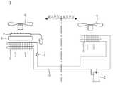
도 1에 도시된 바와 같이, 종래의 항온항습기(1)는 열매체가 순환되는 열매체라인(10)에 의해 연결된 압축기(2), 응축기(3), 팽창밸브(4) 및 증발기(5)를 포함한 히트펌프가 구비되는데, 상기 히트펌프는 실내유닛 측에 증발기(5)와 팽창밸브(4)가 설치되고, 실외유닛 측에 압축기(2)와 응축기(3)가 설치되며, 실내유닛 측에는 별도의 전기히터(6)와 가습기(7)가 더 내장되어 실내팬(8)에 의해 냉기나 온기 또는 수분을 실내에 송풍하도록 구비되고, 실외유닛 측에는 응축기(3)로부터 발생되는 폐열을 외부로 배출하는 실외팬(9)이 구비된 것이다.As shown in Figure 1, the conventional thermo-
그런데 이와 같은 종래의 항온항습기(1)는 증발기(5)를 작동하여 제습을 행하는 과정에서 실내의 온도를 낮아지는 경우에 별도의 전기히터(6)를 가동하여 실내온도를 보상하게 되는데, 이는 성적계수(COP)가 상대적으로 낮은 전기히터(6)를 사용함에 따른 에너지의 소모가 클 뿐만 아니라 전기히터(6)의 구조상 설정된 온도로 가열된 후의 잔열량이 많아 실내온도의 상승과 습도의 하락을 초래할 수 있으며, 이로 인해 히트펌프와 가습기(7)를 간헐적으로 운전시킬 수 있어 에너지의 소모를 부추기는 것이다.However, the conventional thermo-
또한 종래에는 정속으로 운전되는 압축기(2)를 사용하여 설정된 온도와 습도를 맞추기 위해 운전되는 것으로, 이는 설정온도를 맞추기 위해 압축기(2)가 가동될 뿐만 아니라 습도의 경우에도 압축기(2)를 가동하여 맞추도록 된 것이다.In addition, conventionally, a compressor 2 operated at a constant speed is used to match the set temperature and humidity, which not only operates the compressor 2 to match the set temperature, but also operates the compressor 2 in the case of humidity. It was made to fit.
여기에서, 종래의 압축기(2)는 일단 압축기(2)가 작동되면 100% 부하운전이 되므로, 온도나 습도를 맞추기 위해 100%의 작동상태로 운전하면 과냉각(예를 들면, 습도를 설정상태로 맞추려고 압축기가 작동하나, 그로 인해 실내온도가 지나치게 낮아지는 현상)이 발생되어 온도를 보상하기 위해 전기히터(6) 등을 추가로 작동시켜야 하는 문제점이 발생되는 것이다.Here, since the conventional compressor 2 is operated at 100% load once the compressor 2 is operated, supercooling (eg, setting the humidity to a preset state) when operating at 100% operating state to match temperature or humidity The compressor works to fit, but the room temperature is too low), which causes the problem that the
본 발명은 전술한 바와 같은 문제점을 해결하기 위한 것으로, 본 발명은 장치의 구성을 효과적으로 제어하여 온도와 습도를 일정하게 유지하고, 온도와 습도의 제어과정에서의 에너지 소모를 줄임과 동시에 난방이나 제습 등을 포함한 장치의 효율을 개선할 수 있는 항온항습기를 제공하는 것이다.The present invention is to solve the problems as described above, the present invention effectively controls the configuration of the device to maintain a constant temperature and humidity, reduce energy consumption in the process of controlling the temperature and humidity, and at the same time heating or dehumidifying It is to provide a thermo-hygrostat capable of improving the efficiency of a device including a lamp.
본 발명의 특징에 따르면, 실내열교환기(32)가 구비되어 냉기나 온기를 실내측으로 공급하도록 된 실내유닛(20)과, 상기 실내열교환기(32)에 대응되는 실외열교환기(35)가 구비되어 폐열을 방출하도록 된 실외유닛(21)과, 상기 실내열교환기(32)와 실외열교환기(35)를 상호 연결하여 열매체가 순환되도록 된 열매체라인(10)을 포함한 항온항습기에 있어서;According to a feature of the present invention, an
고온 고압의 열매체를 생산하여 상기 열매체라인(10)을 통해 공급하도록 연결됨과 동시에 열매체의 공급속도나 공급량을 조절하도록 운전되는 인버터 압축기(31)와;An
상기 실외유닛(21) 측에 구비되어 상기 실외열교환기(35)에서 발생된 폐열의 송풍량을 조절한 상태로 송풍하도록 된 인버터 실외팬(38)과;An inverter outdoor fan (38) provided on the outdoor unit (21) to blow air in a state in which the amount of waste heat generated by the outdoor heat exchanger (35) is regulated;
상기 실내유닛(20) 측에 구비되어 온도를 감지하도록 된 실내온도센서(41) 및 습도를 감지하도록 된 실내습도센서(42)와;An
상기 인버터 압축기(31) 및 인버터 실외팬(38)의 작동을 제어하도록 구비되되, 상기 실내온도센서에 의해 감지된 온도에 따라 상기 인버터 압축기(31)의 작동을 제어하고, 상기 실내습도센서(42)에 의해 감지된 습도에 따라 상기 인버터 실외팬(38)의 작동을 제어하도록 된 컨트롤러(40)와;It is provided to control the operation of the
상기 실내유닛(20) 측에 상기 열매체라인(10) 상에 연결된 상태로 구비되어 상기 실내열교환기(32)를 통과한 공기를 가열하도록 된 재열기(36)와;A reheater (36) provided on the heating unit line (10) connected to the indoor unit (20) to heat air passing through the indoor heat exchanger (32);
상기 열매체라인(10) 상에 구비되어 상기 재열기(36)를 통과한 열매체가 상기 실내열교환기(32)로 흐르도록 유도하거나 상기 실내열교환기(32)를 통과한 열매체가 상기 재열기(36)로 흐르도록 유도하는 밸브수단(50)을 포함하는 것을 특징으로 하는 항온항습기가 제공된다.The heat medium provided on the
본 발명의 다른 특징에 따르면, 상기 컨트롤러(40)에 의해서는 상기 실내온도센서(41)에 의해 감지된 실내온도가 설정온도에 비해 높은 경우에 상기 실내열교환기(32)가 증발기로 작동되는 냉방모드로 전환되어 냉각운전을 행하게 되고;According to another feature of the present invention, when the indoor temperature detected by the
상기 실내온도센서(41)에 의해 감지된 실내온도가 설정온도에 비해 낮은 경우에는 상기 실내열교환기(32)가 응축기로 작동되는 난방모드로 전환되어 가열운전을 행하며;When the indoor temperature sensed by the
상기 인버터 압축기(31)는The
실내의 온도가 설정온도에 비해 상승하게 되면 냉각운전의 경우에 상기 인버터 압축기(31)가 고속운전되어 실내온도를 낮추고, 가열운전의 경우에 상기 인버터 압축기(31)가 저속운전되어 실내온도를 낮추며;When the temperature of the room rises compared to the set temperature, the
실내의 온도가 설정온도에 비해 하락하게 되면 냉각운전의 경우에 상기 인버터 압축기(31)가 저속운전되어 실내온도를 높이고, 가열운전의 경우에 상기 인버터 압축기(31)가 고속운전되어 실내온도를 높이도록 된 것을 특징으로 하는 항온항습기가 제공된다.When the temperature of the room decreases compared to the set temperature, the
본 발명의 또 다른 특징에 따르면, 상기 컨트롤러(40)에 의해서는 상기 실내습도센서(42)에 의해 감지된 실내습도가 설정습도에 비해 높은 경우에 상기 실내열교환기(32)가 증발기로 작동되어 냉각제습운전을 행하게 되고;According to another feature of the present invention, the
상기 인버터 실외팬(38)은 실내의 습도가 설정습도에 비해 상승하게 되면 실내습도를 낮추도록 저속회전되고, 실내의 습도가 설정습도에 비해 하락하면 하락정도를 줄이도록 고속회전되는 것을 특징으로 하는 항온항습기가 제공된다.The inverter
본 발명의 또 다른 특징에 따르면, 상기 열매체라인(10) 상에는 냉방 또는 난방운전에 따라 상기 인버터 압축기(31) 측에서 공급되는 열매체의 흐름을 절환하도록 된 절환밸브(60)가 구비된 것을 특징으로 하는 항온항습기가 제공된다.According to another feature of the present invention, on the
본 발명의 또 다른 특징에 따르면, 상기 열매체라인(10) 상에는 난방운전시에 상기 팽창밸브(34)의 전단에서 열매체의 일부가 통과시켜 상기 인버터 압축기(31) 측으로 전달하도록 된 바이패스라인(11)이 연결되고;According to another feature of the present invention, a bypass line (11) configured to pass a portion of the heat medium through the front end of the expansion valve (34) during the heating operation on the heat medium line (10) to be delivered to the inverter compressor (31). ) Is connected;
상기 바이패스라인(11) 상에는 열매체를 팽창시키도록 된 팽창밸브(72)와, 상기 팽창밸브(72)를 통과한 열매체와 상기 열매체라인(10) 상의 열매체를 열교환시키도록 된 이코노마이저(70)가 구비되되, 상기 이코노마이저70)에 의해서는 상기 열매체라인(10) 상의 열매체를 과냉각시켜 상기 팽창밸브(34) 측에 전달함과 동시에 열교환 과정에서 증발된 기체상태의 열매체를 상기 바이패스라인(11)을 통해 상기 인버터 압축기(31) 측으로 전달하도록 구비되며;On the
상기 인버터 압축기(31)는 압축 도중에 상기 이코노마이저(70)를 통과한 열매체가 유입되도록 상기 바이패스라인(11)이 연결되는 베이퍼 인젝션 중간포트(M)가 구비된 베이퍼 인젝션 타입인 것을 특징으로 하는 항온항습기가 제공된다.The
이상에서와 같이 본 발명에 의하면, 실내온도센서(41)에 의해 감지된 온도에 따라 인버터 압축기(31)의 작동을 제어함에 따라, 실내의 온도를 조절하는 경우에 인버터 압축기(31)에 의해 부하상태에 따라 고속 또는 저속 등으로 상황에 맞는 부하운전이 가능할 뿐만 아니라 부하상태에 상관없이 불필요하게 고속으로 정속운전함에 따른 에너지 소모를 줄일 수 있는 장점이 있다.According to the present invention as described above, by controlling the operation of the
또한 본 발명은 실내습도센서(42)에 의해 감지된 습도에 따라 인버터 실외팬(38)의 작동을 제어함에 따라, 습도 조절시에 인버터 실외팬(38)에 의해 실외열교환기(35) 측의 폐열 방출량을 조절하여 실내열교환기(32)에 의한 냉각제습 정도를 조절할 수 있으며, 특히, 습도 조절시에 압축기를 풀부하 상태로 고속으로 운전함에 따른 실내온도의 저하를 줄일 수 있을 뿐만 아니라 실내온도의 저하에 따른 다른 열기구의 추가사용을 억제할 수 있는 장점이 있다.In addition, the present invention controls the operation of the
또한 본 발명은 열매체라인(10) 상에 연결되어 실내열교환기(32)를 통과한 공기를 가열하도록 된 재열기(36)가 구비됨에 따라, 열매체의 순환에 따른 열교환을 통해 공기를 가열하여 별도의 가열수단을 불비한 상태에서도 제습과정 등에서 낮아진 온도를 보상할 수 있으며, 밸브수단(50)에 의해 재열기(36)를 통과한 열매체가 실내열교환기(32)로 흐르도록 유도하여 공기와의 열교환 과정에서 대향류를 형성함에 따른 열전달 효율을 증대시킬 수 있는 장점이 있다.In addition, according to the present invention, as the
또한 본 발명은 열매체라인(10)을 분기하여 바이패스라인(11)을 연결하고, 이 바이패스라인(11) 상에 열매체의 일부가 통과시켜 열매체라인(10) 상의 열매체와의 열교환이 가능하도록 된 이코노마이저(70)가 구비됨에 따라, 난방운전시에 팽창밸브(34) 직전에서 고압액의 열매체 일부를 우회시켜 열교환을 통해 과냉각된 상태의 열매체를 팽창밸브(34)로 공급함과 동시에 기체상태로 증발된 열매체를 인버터 압축기(34) 측에 직접적으로 전달하게 되고, 이에 의해 열매체라인(10) 상의 열매체에 대한 과냉각도를 높여 실외열교환기(35)의 냉동능력을 증대시킴과 동시에 상기 인버터 압축기(31)로부터 공급되는 핫가스의 토출온도를 낮추어 실내열교환기(32) 측으로 순환되는 열매체의 순환량을 증대시킴에 따라 난방능력을 극대화시킬 수 있는 장점이 있다.In addition, the present invention connects the
도 1은 종래의 일례를 도시한 구성도
도 2는 본 발명의 일실시예를 도시한 구성도
도 3은 본 발명의 다른 실시예를 도시한 구성도
도 4는 본 발명의 일실시예에 따른 작동상태를 블록도
도 5는 본 발명의 일실시예에 따른 다른 작동상태를 도시한 블록도
도 6은 본 발명의 일실시예에 따른 운전상태를 도시한 흐름도
도 7은 본 발명의 일실시예에 따른 다른 운전상태를 도시한 흐름도
도 8은 본 발명의 일실시예에 따른 또 다른 운전상태를 도시한 흐름도
도 9는 본 발명의 또 다른 실시예를 도시한 구성도
도 10은 도 9에 따른 운전상태를 도시한 흐름도
도 11은 본 발명의 또 다른 실시예를 도시한 구성도
도 12는 도 11에 따른 운전상태를 도시한 흐름도
도 13은 본 발명의 또 다른 실시예를 도시한 흐름도1 is a block diagram showing a conventional example
Figure 2 is a block diagram showing an embodiment of the present invention
3 is a block diagram showing another embodiment of the present invention
Figure 4 is a block diagram showing the operating state according to an embodiment of the present invention
Figure 5 is a block diagram showing another operating state according to an embodiment of the present invention
6 is a flowchart showing an operation state according to an embodiment of the present invention
7 is a flowchart showing another operation state according to an embodiment of the present invention
8 is a flowchart illustrating another operation state according to an embodiment of the present invention
9 is a block diagram showing another embodiment of the present invention
10 is a flowchart showing an operation state according to FIG. 9.
11 is a block diagram showing another embodiment of the present invention
12 is a flowchart showing an operation state according to FIG. 11.
13 is a flow chart showing another embodiment of the present invention
상술한 본 발명의 목적, 특징들 및 장점은 다음의 상세한 설명을 통하여 보다 분명해질 것이다. 이하, 본 발명의 바람직한 실시예를 첨부한 도면에 의거하여 설명하면 다음과 같다.The above objects, features and advantages of the present invention will become more apparent through the following detailed description. Hereinafter, preferred embodiments of the present invention will be described with reference to the accompanying drawings.
도 2 내지 도 13은 본 발명의 다양한 실시예를 도시한 것이다. 도 2와 도 3에 도시된 바와 같이, 본 발명의 항온항습기(30)는 압축기, 응축기, 증발기 및 팽창밸브가 열매체라인에 의해 상호 연결되는 통상의 히트펌프에 의해 냉방과 난방을 공급함과 동시에 실내의 온도나 습도를 일정하게 유지할 수 있도록 된 것으로, 도 2의 경우에는 인버터 압축기(31) 측에 절환밸브(60)가 구비되어 냉방운전 또는 난방운전에 따라 열매체의 흐름을 변경할 수 있도록 된 냉난방 겸용의 시스템이고, 도 3의 경우에는 상기 절환밸브(60)가 구비되지 않은 냉방 전용이나 난방 전용의 시스템을 나타낸 것이다.2 to 13 show various embodiments of the present invention. 2 and 3, the thermo-
한편 실내측에는 냉기나 온기를 공급하도록 된 실내유닛(20)이 설치되고, 실외측에 냉난방 과정에서 발생되는 폐열을 배출하도록 된 실외유닛(21)이 구비된 것으로, 상기 실내유닛(20)에는 냉방운전 또는 난방운전에 따라 증발기나 응축기로 작동되는 실내열교환기(32)와 이 실내열교환기(32)에 의한 냉기나 온기를 실내로 송풍하는 실내팬(37)이 구비되는데, 이 실내유닛(20)은 통상의 실내기와 같이 하나의 케이스 내에 상기 실내열교환기(32)와 실내팬(37)이 장착된 상태로 실내측에 설치되는 것이다.On the other hand, the
또한 상기 실외유닛(21)에는 상기 실내열교환기(32)에 대응되어 응축기나 증발기로 작동되는 실외열교환기(35)와 이 실외열교환기(35)에 의한 폐열을 외부로 배출하기 위한 실외팬이 구비되는데, 이 실외유닛(21)는 통상의 실외기와 같이 다른 케이스 내에 상기 실외열교환기(35)와 실외팬이 장착된 상태로 실외측에 설치되고, 상기 실외팬의 경우에는 폐열의 송풍량을 조절할 수 있는 인버터 실외팬(38)으로 구비되게 된다.In addition, the
이러한 구성에 있어서, 상기 실내열교환기(32)와 실외열교환기(35)는 열매체가 순환되도록 연장 형성된 열매체라인(10)에 의해 상호 연결되고, 상기 열매체라인(10) 상에는 고온 고압의 열매체를 생산하는 압축기와 상기 실내열교환기(32)나 실외열교환기(35)의 전단 또는 후단에 팽창밸브(33,34)가 결합되게 된다.In this configuration, the indoor heat exchanger (32) and the outdoor heat exchanger (35) are interconnected by a heat medium line (10) formed so as to circulate the heat medium, and produce heat medium of high temperature and high pressure on the heat medium line (10). The
여기에서, 상기 압축기나 팽창밸브(33,34)의 설치위치는 특별히 한정되지 않는 것으로, 상기 실내유닛(20) 또는 실외유닛(21)에 내장되거나 외부에 별도로 설치될 수 있는 것이다. 또한 상기 압축기는 고온 고압의 열매체를 생산하여 상기 열매체라인(10)을 통해 공급하도록 연결됨과 동시에 열매체의 공급속도나 공급량을 조절하도록 된 인버터 압축기(31)로 구비되고, 상기 팽창밸브(33,34)는 제습운전이나 냉방 또는 난방운전 등에 따라 선택적으로 사용할 수 있도록 제1 팽창밸브(33)와 제2 팽창밸브(34)로 구비될 수 있는 것이다.Here, the installation position of the compressor or
또한 상기 실내유닛(20) 측에는 열매체라인(10) 상에 연결되어 상기 실내열교환기(32)를 통과한 공기를 가열하도록 된 재열기(36)가 구비되고, 상기 열매체라인(10) 상에는 재열기(36)를 통과한 열매체가 실내열교환기(32)로 흐르도록 유도하는 밸브수단(50)이 구비되는 것이다.In addition, a
또한 상기 실내유닛(20) 측에는 실내의 건조상태에 따라 수분을 공급할 수 있는 가습기(39)와 실내의 온도를 감지할 수 있도록 된 실내온도센서(41) 및 습도를 감지할 수 있도록 된 실내습도센서(42)가 구비되는데, 상기 실내온도센서(41)와 실내습도센서(42)에 의해 감지된 온도나 습도에 따라 장치의 작동을 제어하도록 된 컨트롤러(40)가 구비된 것이다.In addition, on the side of the
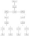
상기 컨트롤러(40)에 의해서는 항온운전 또는 항습운전에 따라 상기 인버터 압축기(31)나 인버터 실외팬(38)의 작동을 제어하게 되는데, 이를 도 4와 도 5에 의해 설명하면 다음과 같다.The
도 4에 도시된 바와 같이, 본 발명의 항온운전은 상기 실내온도센서(41)에 의해 감지된 온도에 따라 상기 인버터 압축기(31)의 작동을 제어하게 되는데, 사용자가 소정의 온도를 설정하게 되면 상기 실내온도센서(41)에 의해 감지된 실내온도가 설정온도에 비해 높은 경우에 상기 실내열교환기(32)가 증발기로 작동되는 냉방모드로 전환되어 냉각운전을 행하게 되고, 상기 실내온도센서(41)에 의해 감지된 실내온도가 설정온도에 비해 낮은 경우에는 상기 실내열교환기(32)가 응축기로 작동되는 난방모드로 전환되어 가열운전을 행하게 된다.4, the constant temperature operation of the present invention controls the operation of the
이러한 냉각운전이나 가열운전에 의해 실내온도가 설정온도에 도달하면 장치의 작동이 일정하게 유지되고, 이후에 실내의 온도가 상승하게 되면 냉각운전의 경우에 상기 인버터 압축기(31)가 고속운전되어 상기 실내열교환기(32)에 의한 냉각속도나 냉각량을 높여 온도를 낮추게 되며, 가열운전의 경우에는 상기 인버터 압축기(31)가 저속운전되어 상기 실내열교환기(32)에 의한 가열속도나 가열량을 줄여 온도를 낮추게 된다.When the room temperature reaches the set temperature by the cooling operation or the heating operation, the operation of the device is kept constant, and when the room temperature rises thereafter, the
한편, 실내의 온도가 하락하면 냉각운전의 경우에 상기 인버터 압축기(31)가 저속운전되어 상기 실내열교환기(32)에 의한 냉각속도나 냉각량을 낮춰 온도를 높이고, 가열운전의 경우에는 상기 인버터 압축기(31)가 고속운전되어 실내열교환기(32)에 의해 가열속도나 가열량을 높여 온도를 상승시키게 되는데, 이러한 인버터 압축기(31)의 작동이나 항온운전은 별도의 조작을 행하지 않더라도 상기 컨트롤러(40)에 의해 자동적으로 이루어지게 된다.On the other hand, when the temperature in the room decreases, the
또한 도 5에 도시된 바와 같이, 본 발명의 항습운전은 상기 실내습도센서(41)에 의해 감지된 습도에 따라 상기 인버터 실외팬(38)의 작동을 제어하게 되는데, 사용자가 소정의 습도를 설정하게 되면 상기 실내습도센서(42)에 의해 감지된 실내습도가 설정온도에 비해 높은 경우에 제습모드로 전환하게 되는데, 이 제습모드는 전술된 냉방모드와 같이 상기 실내열교환기(32)가 증발기로 작동되어 냉각제습운전을 행하게 된다.In addition, as shown in Figure 5, the humidity control of the present invention is to control the operation of the
이는 통상적인 제습의 경우에 가열에 의해 습기를 제거하는 것에 비해 냉각에 의해 습기를 제거하는 효율이 우수함에 따른 것으로, 이러한 냉각제습운전에 의해 실내습도가 설정습도에 도달하면 장치의 작동이 일정하게 유지되고, 이후에 실내의 습도가 상승하게 되면 상기 인버터 실외팬(38)이 저속회전되어 상기 실외열교환기(35)에서의 폐열 방출을 줄이게 되는데, 이에 의해서는 상기 재열기(36)로 투입되는 열매체의 열량을 증가시켜 실내온도를 상승시키고, 실내온도가 상승됨에 따라 인버터 압축기(31)가 고속회전되어 상기 실내열교환기(32)의 냉각효과를 높여 습도를 낮추게 되며, 반대로 실내의 습도가 하락하는 경우에는 상기 인버터 실외팬(38)이 고속회전되어 상기 실외열교환기(35)에서의 폐열 방출을 높이게 되는데, 이에 의해서는 상기 재열기(36)로 투입되는 열량을 감소시켜 실내온도의 상승정도가 크지 않게 되고, 이에 의해 상기 인버터 압축기(31)가 저속회전되어 상기 실내열교환기(32)의 냉각효과를 낮춤에 따라 습도가 하락되는 것을 줄이게 된다.This is due to the superior efficiency of removing moisture by cooling compared to removing moisture by heating in the case of conventional dehumidification, and when the indoor humidity reaches a set humidity by the cooling dehumidification operation, the operation of the device is constant. When the indoor humidity increases, the
한편, 실내습도가 설정습도에 비해 낮은 경우에는 장치를 가습모드로 전환하여 수분을 공급하는 가습운전을 하게 되는데, 이는 컨트롤러(40)에 의해 상기 가습기(39)를 작동시켜 수분을 공급하여 적정의 습도를 유지시키며, 실내의 습도가 상승하는 경우에는 가습기(39)의 가습량을 줄이고, 실내의 습도가 하락하는 경우에는 가습기(39)의 가습량을 늘리게 된다.On the other hand, when the indoor humidity is lower than the set humidity, the device is switched to a humidification mode to perform a humidification operation to supply moisture, which is operated by the
이와 같은 본 발명에 의한 제습과 냉방 및 난방에 의해 세부적인 작동상태를 도 6 내지 도 8에 의해 설명하면 다음과 같다.A detailed operation state by dehumidification, cooling, and heating according to the present invention will be described with reference to FIGS. 6 to 8 as follows.
도 6에 도시된 바와 같이, 제습운전시에는 인버터 압축기(31)에서 공급되는 고온 고압의 열매체가 상기 실외열교환기(35)로 공급되고, 제2 팽창밸브(34)를 우회하여 상기 밸브수단(50)에 의해 상기 재열기(36) 측으로 우선적으로 흐른 후에, 상기 제1 팽창밸브(33)와 실내열교환기(32)를 거쳐 상기 밸브수단(50)을 통해 인버터 압축기(31)로 복귀하게 되며, 상기 밸브수단(50)은 다방향 흐름이 가능한 사방밸브(51)와 특정 방향으로만 흐름이 가능한 복수의 체크밸브(52~55)로 구성될 수 있는 것이다.As shown in FIG. 6, during dehumidifying operation, the high-temperature and high-pressure heat medium supplied from the
이러한 열매체 흐름에 따르면, 상기 재열기(36) 측에 고온의 열매체가 통과되면서 상기 실내열교환기(32)에서 제습된 상태로 냉각된 공기를 가열하여 실내로 공급하게 되는데, 이때에 상기 밸브수단(50)에 의해 열매체가 재열기(36)를 우선적으로 통과하도록 유도함에 따라 열매체와 공기가 대향류를 형성하여 열교환이 이루어질 수 있는 것이다.According to this heat medium flow, while the high temperature heat medium is passed through the
이에 따르면, 상기 재열기(36)에 의해 공기를 가열한 상태로 실내에 공급함에 따라 제습과정에서의 실내온도가 저하되는 것을 방지함과 동시에 상기 재열기(36)의 작동이 히트펌프의 구성에 포함된 상태로 이루어져 가열을 위한 별도의 에너지 소모가 발생되지 않는 것이다.According to this, as the air is heated by the
또한 도 7에 도시된 바와 같이, 냉방운전시에는 인버터 압축기(31)로부터 공급되는 열매체가 실외열교환기(35)와 제2 팽창밸브(34)를 거쳐 상기 밸브수단(50)에 의해 재열기(36)에 우선적으로 공급되고, 이후에 상기 제1 팽창밸브(33)를 우회하여 상기 실내열교환기(32)를 통과한 후에, 상기 밸브수단을(50) 통해 인버터 압축기(31)로 복귀하게 된다.Also, as shown in FIG. 7, during cooling operation, the heat medium supplied from the
또한 도 8에 도시된 바와 같이, 난방운전시에는 인버터 압축기(31)로부터 공급되는 열매체가 상기 밸브수단(50)을 통해 재열기(36)로 우선적으로 공급된 후에, 상기 제1 팽창밸브(33)를 우회하여 실내열교환기(32)를 통과하게 되고, 이후에, 상기 밸브수단(50)를 통해 상기 제2 팽창밸브(34)와 실외열교환기(35)를 순차적으로 거쳐 인버터 압축기(31)로 복귀하게 된다.Also, as shown in FIG. 8, during heating operation, after the heating medium supplied from the
이와 같은 냉방운전과 난방운전에서도 열매체가 재열기(36)와 실내열교환기(32)를 순차적으로 거침에 따라, 열매체와 공기가 대향류를 형성하여 열교환이 이루어질 수 있는 것이며, 상기 밸브수단(50)의 경우에는 전술된 사방밸브(51)와 체크밸브(52~55)의 조합 이외에도 다른 밸브조합이 가능한데, 이를 도 9 내지 도 12에 의해 설명하면 다음과 같다.Even in the cooling operation and the heating operation, as the heat medium sequentially passes through the
도 9와 도 10에 도시된 바와 같이, 상기 열매체라인(10)에는 실내열교환기(32)와 재열기(36)의 전단에 대략 마름모 형태로 관로가 형성되고, 그 관로 상에 개별적으로 개폐 작동되는 복수개의 개폐밸브(56~59)가 장착된 것으로, 도 9의 경우에는 전술된 바와 같은 절환밸브(60)가 구비되어 열매체의 흐름을 변경하도록 된 냉난방 겸용의 시스템을 나타낸 것이고, 도 10의 경우에는 상기 절환밸브(60)가 구비되지 않은 냉방 전용이나 난방 전용의 시스템을 나타낸 것이다.9 and 10, the
또한 도 11과 도 12에 도시된 바와 같이, 상기 열매체라인(10)에는 상기 재열기(36)와 팽창밸브(44)의 전후단에 분기라인을 형성하여 4개의 개폐밸브(56~59)가 구비된 것이며, 이와 같은 밸브수단(56~59)에 의해서도 전술된 일실시예와 같은 제습과 냉난방 운전이 가능한 것인데, 도 11과 도 12는 상기 절환밸브(60)의 유무에 따른 시스템을 나타낸 것이다.11 and 12, the
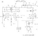
한편, 도 13에 도시된 바와 같이, 본 발명은 난방운전시에 난방능력을 극대화시킬 수 있도록 구비될 수 있는데, 이를 위해 열매체라인(10) 상에는 열매체의 흐름방향으로 볼 때에 상기 팽창밸브(34)의 전단에서 고압액 상태의 열매체 일부 우회시키도록 된 바이패스라인(11)이 분기되고, 이 바이패스라인(11) 상에는 열매체의 우회흐름을 제어하도록 된 개폐밸브(71)와 열매체를 팽창시켜 온도와 압력을 낮추는 팽창밸브(72)가 구비되며, 상기 팽창밸브(72)의 후단에 열매체라인(10) 상의 열매체와 바이패스라인(11) 상의 열매체를 상호 열교환시킬 수 있도록 된 이코노마이저(70)가 구비되게 된다.On the other hand, as shown in Figure 13, the present invention can be provided to maximize the heating capacity during the heating operation, for this purpose, the
상기 이코노마이저(70)에 의해서는 난방운전시에 팽창밸브(34) 직전에서 고압액의 열매체 일부를 우회시켜 열교환시키게 되는데, 상기 열매체라인(10) 상의 열매체는 과냉각된 상태로 팽창밸브(34)로 공급되고, 바이패스라인(11) 상의 열매체는 기체상태로 증발되어 인버터 압축기(31) 측에 전달되는 것으로, 이에 의해서는 열매체라인(10) 상의 열매체에 대한 과냉각도를 높여 실외열교환기(35)의 냉동능력을 증대시킴과 동시에 상기 인버터 압축기(31)로부터 공급되는 핫가스의 토출온도를 낮추어 실내열교환기(32) 측으로 순환되는 열매체의 순환량을 증대시킴에 따라 난방능력을 극대화시킬 수 있는 것이다.In the heating operation, the
한편, 상기 인버터 압축기(31)는 압축 도중에 기체상태의 열매체가 압축기 내로 주입되도록 된 베이퍼 인젝션 타입으로 구비되는데, 이 베이퍼 인젝션 타입의 인버터 압축기(31)에는 상기 바이패스라인(11)이 연결되는 베이퍼 인젝션 중간포트(M)가 구비되어 상기 이코노마이저(70)를 통과한 고압액을 과냉각시키면서 증발된 기체상태의 열매체가 유입되며, 상기 베이퍼 인젝션 중간포트(M)는 열매체의 유입과 토출이 이루어지도록 열매체라인(10)이 연결된 인포트(IN)와 아웃포트(OUT)와는 별도로 구비된 것이다.On the other hand, the
이와 같은 본 발명의 시스템은 난방운전시에 그 난방능력을 극대화시키도록 된 시스템임에 따라, 냉방운전시에는 상기 바이패스라인(11) 상의 개폐밸브(71)를 닫아 열매체의 우회를 차단하여 이코노마이저(70)에 의해 열매체를 과냉각시킬 필요가 없는 것이며, 이러한 시스템은 동절기에 외기온도가 낮은 한랭지역에서 최적하게 채용할 수 있는 운전방식이다.Since the system of the present invention is a system designed to maximize its heating capacity during heating operation, during cooling operation, the opening/closing
이상에서 설명되지 않은 부호는 상기 실외유닛(21) 측에 구비되어 환절기 등에 실외온도를 체크하기 위한 실외온도센서(43)와 상기 제1 팽창밸브(33)와 제2 팽창밸브(34) 측의 우회로에 구비된 개폐밸브(61,62)를 나타낸 것이며, 다른 부호는 바이패스라인(11) 상에 구비된 체크밸브(73)를 나타낸 것이다.Reference numerals not described above are provided on the
이상에서 설명한 본 발명은 전술한 실시예 및 첨부된 도면에 의해 한정되는 것이 아니고, 본 발명의 기술적 사상을 벗어나지 않는 범위 내에서 여러 가지 치환, 변형 및 변경이 가능함은 본 발명이 속하는 기술분야에서 통상의 지식을 가진 자에게 명백할 것이다.The present invention described above is not limited by the above-described embodiments and accompanying drawings, and various substitutions, modifications, and changes are possible within the scope of the present invention without departing from the technical spirit of the present invention. It will be apparent to those who have the knowledge of.
10: 열매체라인 11: 바이패스라인
20: 실내유닛 21: 실외유닛
31: 인버터 압축기 32: 실내열교환기
33: 제1 팽창밸브 34: 제2 팽창밸브
35: 실외열교환기 36: 재열기
37: 실내팬 38: 인버터 실외팬
39: 가습기 40: 컨트롤러
41: 실내온도센서 42: 실외온도센서
44: 팽창밸브 50: 밸브수단
51: 사방밸브 52~55: 체크밸브
56~59: 개폐밸브 60: 절환밸브
61,62: 개폐밸브 70: 이코노마이저
71: 개폐밸브 72: 팽창밸브10: heat medium line 11: bypass line
20: indoor unit 21: outdoor unit
31: inverter compressor 32: indoor heat exchanger
33: first expansion valve 34: second expansion valve
35: outdoor heat exchanger 36: reheat
37: indoor fan 38: inverter outdoor fan
39: humidifier 40: controller
41: indoor temperature sensor 42: outdoor temperature sensor
44: expansion valve 50: valve means
51: four-
56~59: Open/close valve 60: Switching valve
61,62: open/close valve 70: economizer
71: opening and closing valve 72: expansion valve
Claims (5)
Translated fromKorean고온 고압의 열매체를 생산하여 상기 열매체라인(10)을 통해 공급하도록 연결됨과 동시에 열매체의 공급속도나 공급량을 조절하도록 운전되는 인버터 압축기(31)와;
상기 실외유닛(21) 측에 구비되어 상기 실외열교환기(35)에서 발생된 폐열의 송풍량을 조절한 상태로 송풍하도록 된 인버터 실외팬(38)과;
상기 실내유닛(20) 측에 구비되어 온도를 감지하도록 된 실내온도센서(41) 및 습도를 감지하도록 된 실내습도센서(42)와;
상기 인버터 압축기(31) 및 인버터 실외팬(38)의 작동을 제어하도록 구비되되, 상기 실내온도센서(41)에 의해 감지된 온도에 따라 상기 인버터 압축기(31)의 작동을 제어하고, 상기 실내습도센서(42)에 의해 감지된 습도에 따라 상기 인버터 실외팬(38)의 작동을 제어하도록 된 컨트롤러(40)와;
상기 실내유닛(20) 측에 상기 열매체라인(10) 상에 연결된 상태로 구비되어 상기 실내열교환기(32)를 통과한 공기를 가열하도록 된 재열기(36)와;
상기 열매체라인(10) 상에 구비되어 상기 재열기(36)를 통과한 열매체가 상기 실내열교환기(32)로 흐르도록 유도하거나 상기 실내열교환기(32)를 통과한 열매체가 상기 재열기(36)로 흐르도록 유도하는 밸브수단(50)을 포함하는 것을 특징으로 하는 항온항습기.
The indoor unit 20 is provided with an indoor heat exchanger 32 to supply cold or warm air to the indoor side, and an outdoor heat exchanger 35 corresponding to the indoor heat exchanger 32 is provided to discharge waste heat. In the thermo-hygrostat including the unit (21), the indoor heat exchanger (32) and the outdoor heat exchanger (35) interconnecting each other, the heat medium line (10) through which the heat medium is circulated;
An inverter compressor 31 which is connected to produce a high-temperature and high-pressure heat medium and supply it through the heat medium line 10, and at the same time, adjust the supply speed or the supply quantity of the heat medium;
An inverter outdoor fan 38 provided on the outdoor unit 21 and configured to blow in a state in which the amount of waste heat generated in the outdoor heat exchanger 35 is adjusted;
An indoor temperature sensor 41 provided on the indoor unit 20 to sense temperature and an indoor humidity sensor 42 configured to detect humidity;
It is provided to control the operation of the inverter compressor 31 and the inverter outdoor fan 38, and controls the operation of the inverter compressor 31 according to the temperature sensed by the indoor temperature sensor 41, the indoor humidity A controller 40 configured to control the operation of the outdoor fan 38 of the inverter according to the humidity sensed by the sensor 42;
A reheater (36) provided on the heating unit line (10) connected to the indoor unit (20) to heat the air passing through the indoor heat exchanger (32);
The heat medium provided on the heat medium line 10 induces the heat medium that has passed through the reheater 36 to flow into the indoor heat exchanger 32 or the heat medium that passes through the indoor heat exchanger 32 is reheated 36 ) The constant temperature and humidity chamber, characterized in that it comprises a valve means (50) for guiding to flow.
상기 실내온도센서(41)에 의해 감지된 실내온도가 설정온도에 비해 낮은 경우에는 상기 실내열교환기(32)가 응축기로 작동되는 난방모드로 전환되어 가열운전을 행하며;
상기 인버터 압축기(31)는
실내의 온도가 설정온도에 비해 상승하게 되면 냉각운전의 경우에 상기 인버터 압축기(31)가 고속운전되어 실내온도를 낮추고, 가열운전의 경우에 상기 인버터 압축기(31)가 저속운전되어 실내온도를 낮추며;
실내의 온도가 설정온도에 비해 하락하게 되면 냉각운전의 경우에 상기 인버터 압축기(31)가 저속운전되어 실내온도를 높이고, 가열운전의 경우에 상기 인버터 압축기(31)가 고속운전되어 실내온도를 높이도록 된 것을 특징으로 하는 항온항습기.
According to claim 1, When the indoor temperature sensed by the controller 40 by the indoor temperature sensor 41 is higher than the set temperature, the indoor heat exchanger 32 is a cooling mode in which the evaporator is operated. Switching to perform cooling operation;
When the indoor temperature detected by the indoor temperature sensor 41 is lower than the set temperature, the indoor heat exchanger 32 is switched to a heating mode operated by a condenser to perform heating operation;
The inverter compressor 31
When the temperature in the room rises compared to the set temperature, the inverter compressor 31 is operated at high speed in the case of cooling operation to decrease the room temperature, and in the case of heating operation, the inverter compressor 31 is operated at low speed to decrease the room temperature. ;
When the temperature of the room decreases compared to the set temperature, the inverter compressor 31 is operated at low speed in the case of cooling operation to increase the room temperature, and in the case of heating operation, the inverter compressor 31 is operated at high speed to increase the room temperature. Thermo-hygrostat, characterized in that the intended.
상기 인버터 실외팬(38)은 실내의 습도가 설정습도에 비해 상승하게 되면 실내습도를 낮추도록 저속회전되고, 실내의 습도가 설정습도에 비해 하락하면 하락정도를 줄이도록 고속회전되는 것을 특징으로 하는 항온항습기.
The indoor heat exchanger (32) operates as an evaporator according to claim 1 or 2, wherein the indoor humidity detected by the indoor humidity sensor (42) is higher than the set humidity by the controller (40). The cooling and dehumidifying operation is performed;
The inverter outdoor fan 38 is rotated at a low speed to lower the indoor humidity when the humidity of the room rises compared to the set humidity, and is rotated at a high speed to reduce the degree of decline when the humidity of the room falls compared to the set humidity. Thermo-hygrostat.
The method according to claim 1 or 2, characterized in that a switching valve (60) is provided on the heating medium line (10) to switch the flow of the heating medium supplied from the inverter compressor (31) in response to cooling or heating operation. Thermo-hygrostat.
상기 바이패스라인(11) 상에는 열매체를 팽창시키도록 된 팽창밸브(72)와, 상기 팽창밸브(72)를 통과한 열매체와 상기 열매체라인(10) 상의 열매체를 열교환시키도록 된 이코노마이저(70)가 구비되되, 상기 이코노마이저70)에 의해서는 상기 열매체라인(10) 상의 열매체를 과냉각시켜 상기 팽창밸브(34) 측에 전달함과 동시에 열교환 과정에서 증발된 기체상태의 열매체를 상기 바이패스라인(11)을 통해 상기 인버터 압축기(31) 측으로 전달하도록 구비되며;
상기 인버터 압축기(31)는 압축 도중에 상기 이코노마이저(70)를 통과한 열매체가 유입되도록 상기 바이패스라인(11)이 연결되는 베이퍼 인젝션 중간포트(M)가 구비된 베이퍼 인젝션 타입인 것을 특징으로 하는 항온항습기.The bypass line (1) according to claim 1 or 2, wherein a part of the heating medium passes through the heating medium line (10) at the front end of the expansion valve (34) during heating operation, and is delivered to the inverter compressor (31). 11) is connected;
On the bypass line 11, an expansion valve 72 configured to expand the heating medium, and an economizer 70 configured to exchange heat between the heating medium passing through the expansion valve 72 and the heating medium on the heating medium line 10 Although provided, the economizer 70 supercools the heat medium on the heat medium line 10 and delivers the heat medium to the expansion valve 34, and simultaneously transfers the gas heat medium evaporated in the heat exchange process to the bypass line 11. It is provided to be transmitted to the inverter compressor 31 side through;
The inverter compressor 31 is a constant temperature constant, characterized in that the vapor injection intermediate port M to which the bypass line 11 is connected so that the heat medium passing through the economizer 70 flows in during compression is provided. Humidifier.
Priority Applications (1)
| Application Number | Priority Date | Filing Date | Title |
|---|---|---|---|
| PCT/KR2019/018522WO2020138978A2 (en) | 2018-12-28 | 2019-12-26 | Thermo-hygrostat |
Applications Claiming Priority (2)
| Application Number | Priority Date | Filing Date | Title |
|---|---|---|---|
| KR1020180171557 | 2018-12-28 | ||
| KR20180171557 | 2018-12-28 |
Publications (1)
| Publication Number | Publication Date |
|---|---|
| KR20200083294Atrue KR20200083294A (en) | 2020-07-08 |
Family
ID=71601027
Family Applications (1)
| Application Number | Title | Priority Date | Filing Date |
|---|---|---|---|
| KR1020190175299ACeasedKR20200083294A (en) | 2018-12-28 | 2019-12-26 | Constant temperature and humidity units |
Country Status (1)
| Country | Link |
|---|---|
| KR (1) | KR20200083294A (en) |
Cited By (6)
| Publication number | Priority date | Publication date | Assignee | Title |
|---|---|---|---|---|
| KR102205565B1 (en)* | 2020-08-06 | 2021-01-21 | 주식회사 넥스트티엔 | System for managing temperature and humidity via wireless of computerized equipment |
| CN114111075A (en)* | 2021-12-25 | 2022-03-01 | 珠海格力电器股份有限公司 | Air conditioning structure, air conditioning equipment and air conditioning method |
| CN114158196A (en)* | 2021-12-07 | 2022-03-08 | 江西华兴四海机械设备有限公司 | Heating device and heating method for working groove of circuit board manufacturing equipment |
| CN115307296A (en)* | 2022-08-12 | 2022-11-08 | 南京天加环境科技有限公司 | Constant-temperature and constant-humidity system for recovering condensation heat and control method thereof |
| KR102500579B1 (en) | 2022-07-05 | 2023-02-20 | 조영환 | Constant temperature and humidity air conditioning apparatus for using dehumidifying compressed air |
| CN116105310A (en)* | 2022-12-27 | 2023-05-12 | 青岛海尔空调器有限总公司 | Method and device for constant-temperature dehumidification, air conditioner and storage medium |
Citations (1)
| Publication number | Priority date | Publication date | Assignee | Title |
|---|---|---|---|---|
| KR100478755B1 (en) | 2002-05-09 | 2005-03-23 | 한국증권전산주식회사 | A Separate Type Constant Temperature and Humidity Chamber |
- 2019
- 2019-12-26KRKR1020190175299Apatent/KR20200083294A/ennot_activeCeased
Patent Citations (1)
| Publication number | Priority date | Publication date | Assignee | Title |
|---|---|---|---|---|
| KR100478755B1 (en) | 2002-05-09 | 2005-03-23 | 한국증권전산주식회사 | A Separate Type Constant Temperature and Humidity Chamber |
Cited By (7)
| Publication number | Priority date | Publication date | Assignee | Title |
|---|---|---|---|---|
| KR102205565B1 (en)* | 2020-08-06 | 2021-01-21 | 주식회사 넥스트티엔 | System for managing temperature and humidity via wireless of computerized equipment |
| CN114158196A (en)* | 2021-12-07 | 2022-03-08 | 江西华兴四海机械设备有限公司 | Heating device and heating method for working groove of circuit board manufacturing equipment |
| CN114158196B (en)* | 2021-12-07 | 2024-02-27 | 江西华兴四海机械设备有限公司 | Heating device and heating method for working groove of circuit board manufacturing equipment |
| CN114111075A (en)* | 2021-12-25 | 2022-03-01 | 珠海格力电器股份有限公司 | Air conditioning structure, air conditioning equipment and air conditioning method |
| KR102500579B1 (en) | 2022-07-05 | 2023-02-20 | 조영환 | Constant temperature and humidity air conditioning apparatus for using dehumidifying compressed air |
| CN115307296A (en)* | 2022-08-12 | 2022-11-08 | 南京天加环境科技有限公司 | Constant-temperature and constant-humidity system for recovering condensation heat and control method thereof |
| CN116105310A (en)* | 2022-12-27 | 2023-05-12 | 青岛海尔空调器有限总公司 | Method and device for constant-temperature dehumidification, air conditioner and storage medium |
Similar Documents
| Publication | Publication Date | Title |
|---|---|---|
| KR20200083294A (en) | Constant temperature and humidity units | |
| US4441901A (en) | Heat pump type airconditioner | |
| KR100876185B1 (en) | Energy-saving thermo-hygrostat, sensible heat cooling method and cooling dehumidification method | |
| WO2003050457A1 (en) | Energy efficient heat pump systems for water heating and air conditioning | |
| JPH0518630A (en) | Air conditioner | |
| JP3800210B2 (en) | Water source heat pump unit | |
| JP2017150778A (en) | Dehumidifying/reheating air-conditioning system utilizing ground thermal energy | |
| US12158282B2 (en) | Variable refrigerant flow system | |
| CN113864926B (en) | Air conditioner and dehumidification method | |
| WO2019116599A1 (en) | Air-conditioning device and air-conditioning system | |
| KR102257544B1 (en) | Energy enhanced air-conditioning system and control method thereof | |
| CN110107981B (en) | Air conditioning device | |
| JP7374633B2 (en) | Air conditioners and air conditioning systems | |
| JP4647399B2 (en) | Ventilation air conditioner | |
| KR102319187B1 (en) | Energy-saving Constant Temperature and Humidity Air Conditioning System using Waste Heat from Outdoor Unit | |
| JP2004044946A (en) | Air conditioner | |
| CN114278984A (en) | Multifunctional air conditioner, control method and computer readable storage medium | |
| KR100813555B1 (en) | Thermo-hygrostat | |
| JPH02290476A (en) | Cooling/heating/hot water system equipment | |
| KR101642437B1 (en) | Cooling and heating system | |
| KR102126903B1 (en) | Outdoor unit integrated precision air conditioner with function to discharge smoke | |
| KR102326225B1 (en) | Thermo-Hygrostat and Control Method thereof | |
| JP2012245496A (en) | Apparatus for dehumidifying compressed air | |
| JPH0375462A (en) | heat pump system | |
| WO2020138978A2 (en) | Thermo-hygrostat |
Legal Events
| Date | Code | Title | Description |
|---|---|---|---|
| PA0109 | Patent application | Patent event code:PA01091R01D Comment text:Patent Application Patent event date:20191226 | |
| PG1501 | Laying open of application | ||
| E902 | Notification of reason for refusal | ||
| PE0902 | Notice of grounds for rejection | Comment text:Notification of reason for refusal Patent event date:20240722 Patent event code:PE09021S01D | |
| PE0601 | Decision on rejection of patent |