KR20200080297A - Inspection device, inspection method, tablet printing device and tablet printing method - Google Patents
Inspection device, inspection method, tablet printing device and tablet printing methodDownload PDFInfo
- Publication number
- KR20200080297A KR20200080297AKR1020207015766AKR20207015766AKR20200080297AKR 20200080297 AKR20200080297 AKR 20200080297AKR 1020207015766 AKR1020207015766 AKR 1020207015766AKR 20207015766 AKR20207015766 AKR 20207015766AKR 20200080297 AKR20200080297 AKR 20200080297A
- Authority
- KR
- South Korea
- Prior art keywords
- tablet
- light
- imaging unit
- illumination
- optical axis
- Prior art date
- Legal status (The legal status is an assumption and is not a legal conclusion. Google has not performed a legal analysis and makes no representation as to the accuracy of the status listed.)
- Granted
Links
Images


Classifications
- G—PHYSICS
- G01—MEASURING; TESTING
- G01N—INVESTIGATING OR ANALYSING MATERIALS BY DETERMINING THEIR CHEMICAL OR PHYSICAL PROPERTIES
- G01N21/00—Investigating or analysing materials by the use of optical means, i.e. using sub-millimetre waves, infrared, visible or ultraviolet light
- G01N21/84—Systems specially adapted for particular applications
- G01N21/85—Investigating moving fluids or granular solids
- G—PHYSICS
- G01—MEASURING; TESTING
- G01N—INVESTIGATING OR ANALYSING MATERIALS BY DETERMINING THEIR CHEMICAL OR PHYSICAL PROPERTIES
- G01N21/00—Investigating or analysing materials by the use of optical means, i.e. using sub-millimetre waves, infrared, visible or ultraviolet light
- G01N21/01—Arrangements or apparatus for facilitating the optical investigation
Landscapes
- Physics & Mathematics (AREA)
- Health & Medical Sciences (AREA)
- Life Sciences & Earth Sciences (AREA)
- Chemical & Material Sciences (AREA)
- Analytical Chemistry (AREA)
- Biochemistry (AREA)
- General Health & Medical Sciences (AREA)
- General Physics & Mathematics (AREA)
- Immunology (AREA)
- Pathology (AREA)
- Investigating Materials By The Use Of Optical Means Adapted For Particular Applications (AREA)
- Medical Preparation Storing Or Oral Administration Devices (AREA)
Abstract
Translated fromKoreanDescription
Translated fromKorean본원 명세서에 개시되는 이 발명은, 예를 들어, 정제 (錠劑) 의 검사 및 인쇄 기술에 관한 것이다.This invention disclosed herein relates to, for example, inspection and printing techniques for tablets.
종래부터, 정제 등의 대상물의 외관 검사는, 대상물을 촬상하여 얻어진 화상 데이터에 소정의 화상 처리를 실시하고 외관의 양부를 판정함으로써 이루어지고 있다 (예를 들어, 특허문헌 1 을 참조).Conventionally, the appearance inspection of an object such as a tablet is performed by performing predetermined image processing on image data obtained by imaging the object and determining the appearance of the appearance (for example, refer to Patent Document 1).
종래의 방법에서는, 대상물에 대해 광이 균일하게 조사된 상태로 대상물의 촬상이 이루어지고 있었다. 그 때문에, 대상물에 비교적 얕은 흠집 등이 있는 경우에, 화상 데이터 상에서 판별하는 것이 어려운 경우가 있었다.In the conventional method, imaging of the object was performed in a state in which light was uniformly irradiated to the object. Therefore, in the case where the object has a relatively shallow scratch or the like, it may be difficult to discriminate on the image data.
본원 명세서에 개시되는 이 발명은, 이상에 기재된 것과 같은 문제를 해결하기 위해서 이루어진 것으로, 촬상에 의해 얻어진 화상에 의한 대상물의 외관 검사에서, 검사의 정밀도를 높이기 위한 기술을 제공하는 것을 목적으로 하는 것이다.The present invention disclosed in the present specification was made to solve the problems as described above, and an object thereof is to provide a technique for improving the accuracy of inspection in visual inspection of an object by an image obtained by imaging. .
본원 명세서에 개시되는 기술의 제 1 양태는, 대상물에 광을 조사 가능한 적어도 1 개의 조명과, 상기 조명에 의해 광이 조사된 상기 대상물을 촬상하며, 또한, 상기 대상물의 화상 데이터를 생성하는 촬상부와, 상기 대상물의 상기 화상 데이터에 기초하여, 상기 대상물의 외관 검사를 실시하는 검사부를 구비하고, 상기 대상물을 촬상하는 상기 촬상부의 광축을 따른 방향으로부터 제 1 방향으로 경사진 방향을 제 1 조사 방향으로 하고, 상기 촬상부의 상기 광축을 따른 방향으로부터 상기 제 1 방향과는 반대측의 제 2 방향으로 경사진 방향을 제 2 조사 방향으로 하고, 상기 조명이 상기 제 1 조사 방향을 따라서 상기 대상물에 조사하는 광량이, 상기 조명이 상기 제 2 조사 방향을 따라서 상기 대상물에 조사하는 광량보다 크다.A first aspect of the technology disclosed in the present specification includes at least one illumination capable of irradiating light onto an object, and an imaging unit that captures the object irradiated with the light and generates image data of the object. And an inspection unit for inspecting the appearance of the object based on the image data of the object, and a direction inclined in a first direction from a direction along the optical axis of the imaging unit for imaging the object in a first irradiation direction. The second irradiation direction is a direction inclined from a direction along the optical axis of the imaging unit to a second direction opposite to the first direction, and the illumination irradiates the object along the first irradiation direction. The amount of light is greater than the amount of light that the illumination irradiates on the object along the second irradiation direction.
본원 명세서에 개시되는 기술의 제 2 양태는, 제 1 양태에 관련된 것으로, 상기 조명은, 상기 촬상부의 상기 광축을 따른 방향에서 보아, 상기 대상물을 적어도 일부 둘러싸고 배치되는, 복수의 측방 조명을 포함한다.A second aspect of the technology disclosed in the present specification relates to a first aspect, wherein the illumination includes a plurality of lateral illuminations arranged at least partially surrounding the object as viewed in a direction along the optical axis of the imaging unit. .
본원 명세서에 개시되는 기술의 제 3 양태는, 제 2 양태에 관련된 것으로, 복수의 상기 측방 조명은, 상기 촬상부의 상기 광축을 따른 방향에서 보아 상기 대상물을 둘러싸고 배치되고, 상기 촬상부의 상기 광축을 따른 방향에서 보아, 상기 대상물을 사이에 끼운 1 쌍의 상기 측방 조명 중 하나만이, 상기 대상물에 대해 광을 조사한다.A third aspect of the technology disclosed in the present specification relates to a second aspect, wherein a plurality of the side lights are arranged to surround the object when viewed in a direction along the optical axis of the imaging unit, and along the optical axis of the imaging unit Viewed from the direction, only one of the pair of lateral lights sandwiching the object is irradiated with light.
본원 명세서에 개시되는 기술의 제 4 양태는, 제 1 양태 내지 제 3 양태 중 어느 하나에 관련된 것으로, 상기 조명은, 상기 촬상부의 상기 광축 상에 배치되는, 적어도 1 개의 상방 조명을 포함하고, 상기 상방 조명에 의해 광이 조사된 상기 대상물이 반사하는 광을, 상기 상방 조명을 우회하면서 상기 촬상부로 유도하는 광학계를 추가로 구비한다.A fourth aspect of the technology disclosed herein relates to any one of the first aspect to the third aspect, wherein the illumination includes at least one upward illumination disposed on the optical axis of the imaging unit, and The optical system further guides light reflected by the object irradiated by the upward illumination to the imaging unit while bypassing the upward illumination.
본원 명세서에 개시되는 기술의 제 5 양태는, 제 4 양태에 관련된 것으로, 상기 조명은, 상기 촬상부의 상기 광축을 따른 방향에서 보아 상기 대상물을 적어도 일부 둘러싸고 배치되는, 복수의 측방 조명을 포함하고, 복수의 상기 측방 조명은, 상기 촬상부의 상기 광축을 따른 방향에서 보아 상기 광학계가 배치되는 범위 내에 배치된다.A fifth aspect of the technology disclosed in this specification relates to a fourth aspect, wherein the illumination includes a plurality of lateral illuminations arranged at least partially surrounding the object when viewed in a direction along the optical axis of the imaging unit, The plurality of side lights are arranged within a range in which the optical system is arranged when viewed from a direction along the optical axis of the imaging unit.
본원 명세서에 개시되는 기술의 제 6 양태는, 제 1 양태 내지 제 5 양태 중 어느 하나에 관련된 것으로, 상기 제 1 조사 방향은, 평면에서 볼 때 상기 촬상부로부터 방사상으로 연장되는 방향이고, 상기 제 2 조사 방향은, 평면에서 볼 때 상기 촬상부의 주위로부터 상기 광축을 향한 방향이다.The sixth aspect of the technology disclosed in the present specification relates to any one of the first to fifth aspects, wherein the first irradiation direction is a direction extending radially from the imaging unit when viewed in a plane, and the 2 The irradiation direction is a direction from the periphery of the imaging section toward the optical axis when viewed in a plan view.
본원 명세서에 개시되는 기술의 제 7 양태는, 제 1 양태 내지 제 6 양태 중 어느 하나에 관련된 것으로, 상기 조명은, 상기 촬상부의 상기 광축을 따른 방향에서 보아, 상기 대상물을 적어도 일부 둘러싸고 배치되는, 복수의 측방 조명과, 상기 촬상부의 상기 광축 상에 배치되는, 적어도 1 개의 상방 조명을 포함하고, 상기 상방 조명에 의해 광이 조사된 상기 대상물이 반사하는 광을, 상기 상방 조명을 우회하면서 상기 촬상부로 유도하는 광학계를 추가로 구비하고, 상기 촬상부는, 복수의 상기 측방 조명 및 상기 상방 조명을 사용하는 복수의 조사 패턴에 의해 광이 조사된 상기 대상물을 촬상하며, 또한, 상기 대상물의 화상 데이터를 생성한다.A seventh aspect of the technology disclosed herein relates to any one of the first aspect to the sixth aspect, wherein the illumination is disposed at least partially surrounding the object when viewed in a direction along the optical axis of the imaging unit, A plurality of side lights, and at least one upward light disposed on the optical axis of the imaging unit, the light reflected by the object irradiated by the upward light is reflected while the upper light is bypassed, the imaging is performed. An optical system that leads to a negative is further provided, and the imaging unit captures the object to which light has been irradiated by a plurality of irradiation patterns using the plurality of side lights and the above lights, and further comprises image data of the object. To create.
본원 명세서에 개시되는 기술의 제 8 양태는, 제 1 양태 내지 제 7 양태 중 어느 하나에 관련된 것으로, 상기의 검사 장치와, 상기 검사 장치에 의해 검사된 정제에 인쇄를 실시하는 인쇄부를 구비한다.The eighth aspect of the technology disclosed in the present specification relates to any one of the first aspect to the seventh aspect, and includes the above-described inspection device and a printing unit for printing tablets inspected by the inspection device.
본원 명세서에 개시되는 기술의 제 9 양태는, 적어도 1 개의 조명에 의해 광이 조사된 대상물을 촬상하며, 또한, 상기 대상물의 화상 데이터를 생성하는 공정과, 상기 대상물의 상기 화상 데이터에 기초하여, 상기 대상물의 외관 검사를 실시하는 공정을 구비하고, 상기 대상물을 촬상하는 촬상부의 광축을 따른 방향으로부터 제 1 방향으로 경사진 방향을 제 1 조사 방향으로 하고, 상기 촬상부의 상기 광축을 따른 방향으로부터 상기 제 1 방향과는 반대측의 제 2 방향으로 경사진 방향을 제 2 조사 방향으로 하고, 상기 조명이 상기 제 1 조사 방향을 따라서 상기 대상물에 조사하는 광량이, 상기 조명이 상기 제 2 조사 방향을 따라서 상기 대상물에 조사하는 광량보다 크다.A ninth aspect of the technology disclosed in the present specification captures an object to which light has been irradiated by at least one illumination, and further comprises a step of generating image data of the object, and based on the image data of the object, A step of inspecting the appearance of the object is provided, and a direction inclined in a first direction from a direction along the optical axis of the imaging unit imaging the object is set as a first irradiation direction, and from a direction along the optical axis of the imaging unit. The direction inclined in the second direction opposite to the first direction is the second irradiation direction, and the amount of light that the illumination irradiates to the object along the first irradiation direction, and the illumination is along the second irradiation direction It is larger than the amount of light irradiated to the object.
본원 명세서에 개시되는 기술의 제 10 양태는, 제 9 양태에 관련된 것으로, 상기의 검사 방법에 의해 검사된 정제에 인쇄를 실시하는 공정을 구비한다.The tenth aspect of the technology disclosed in the present specification is related to the ninth aspect, and includes a step of printing a tablet inspected by the inspection method described above.
본원 명세서에 개시되는 기술의 제 1 및 제 9 양태에 의하면, 화상 데이터에 있어서의 계조도의 차를 크게함으로써 화상 인식의 정밀도를 높여, 촬상에 의한 대상물의 외관 검사의 정밀도를 높일 수 있다.According to the first and ninth aspects of the technology disclosed in the present specification, the accuracy of image recognition can be increased by increasing the difference in gradation degree in image data, and the accuracy of visual inspection of an object by imaging can be increased.
특히, 제 2 양태에 의하면, 측방 조명에 의해, 대상물의 주위 중 일방향으로부터만 광의 조사가 가능해지기 때문에, 비교적 얕은 결함 등이어도 용이하게 검출할 수 있다.In particular, according to the second aspect, since side light can irradiate light only from one direction of the periphery of the object, even relatively shallow defects can be easily detected.
특히, 제 3 양태에 의하면, 광축을 따른 방향에서 보아 대상물을 둘러싸는 측방 조명을 부분적으로 점등시키는 것에 의해, 대상물의 주위 중 일방향으로부터만 광을 조사한다. 그렇게 함으로써, 비교적 얕은 결함 등이어도 용이하게 검출할 수 있다.In particular, according to the third aspect, light is irradiated only from one direction among the circumferences of the object by partially lighting the side illumination surrounding the object when viewed from the direction along the optical axis. By doing so, even relatively shallow defects can be easily detected.
특히, 제 4 양태에 의하면, 상방 조명에 의해, 대상물의 주면 (主面) 에 방사상으로 조사되는 광량이, 대상물의 주위로부터 대상물을 향해 조사되는 광량보다 높아진다. 그 때문에, 대상물의 주면에 있어서의 계조도와 측면에 있어서의 계조도의 차가 커져, 화상 처리에 의해 비교적 얕은 결함 등을 용이하게 검출할 수 있다.In particular, according to the fourth aspect, the amount of light radiated to the main surface of the object by the upper illumination is higher than the amount of light radiated from the periphery of the object toward the object. Therefore, the difference between the gradation degree on the main surface of the object and the gradation degree on the side surface becomes large, and relatively shallow defects and the like can be easily detected by image processing.
특히, 제 5 양태에 의하면, 검사 장치의 구조를 작게 할 수 있기 때문에, 검사 장치를 조밀하게 배열하기 쉬워진다.In particular, according to the fifth aspect, since the structure of the inspection device can be made small, it is easy to densely arrange the inspection devices.
특히, 제 6 양태에 의하면, 상방 조명과 측방 조명을 조합하여 사용하는 경우에, 상방 조명으로부터 방사상으로 조사되는 광량이, 광축을 따른 방향에서 보아 대상물을 둘러싸는 측방 조명으로부터 대상물을 향해 조사되는 광량보다 높아지기 때문에, 대상물의 주면에 있어서의 계조도와 측면에 있어서의 계조도의 차가 커진다.Particularly, according to the sixth aspect, when the combination of the upper light and the side light is used, the amount of light radiated from the upper light to the object is viewed from the side light surrounding the object when viewed in the direction along the optical axis. Since it becomes higher, the difference between the gradation on the main surface of the object and the gradation on the side becomes large.
특히, 제 7 양태에 의하면, 상방 조명과 측방 조명을 사용하는 복수의 조사 패턴으로 대상물을 조사할 수 있기 때문에, 검사 정밀도를 향상시킬 수 있다.In particular, according to the seventh aspect, since the object can be irradiated with a plurality of irradiation patterns using upward and side illumination, inspection accuracy can be improved.
특히, 제 8 및 제 10 양태에 의하면, 높은 정밀도로 외관 검사가 이루어진 대상물에 대해서만 인쇄를 실시하기 때문에, 이물질, 흠집 또는 결함 등을 갖는 대상물이 양품 (良品) 으로서 회수되는 것을 방지할 수 있다.In particular, according to the eighth and tenth aspects, since printing is performed only on an object subjected to high-precision appearance inspection, it is possible to prevent the object having foreign matter, scratches, or defects from being recovered as a good product.
본원 명세서에 개시되는 기술에 관한 목적과 특징과 국면과 이점은, 이하에 나타내는 상세한 설명과 첨부 도면에 의해 한층 더 명백해진다.The objects, features, aspects, and advantages of the technology disclosed in the present specification become more apparent through the detailed description and accompanying drawings shown below.
도 1 은 실시형태에 관한, 정제 인쇄 장치의 전체 구성을 개략적으로 예시하는 도면이다.
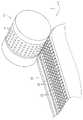
도 2 는 반송 드럼 및 반송 벨트의 외관을 나타내는 사시도이다.
도 3 은 촬상 유닛의 구체적인 구성을 예시하는 단면도이다.
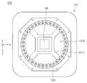
도 4 는 촬상 유닛을 Z 축 부 (負) 방향으로부터 올려다본 경우의 도면이다.
도 5 는 외관 검사 유닛에 있어서의 촬상 유닛의 배치를 예시하는 평면도이다.
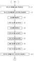
도 6 은 정제 인쇄 장치에 있어서의 처리 동작의 순서를 나타내는 플로 차트이다.
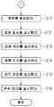
도 7 은 정제 인쇄 장치에 있어서의 처리 동작의 순서를 나타내는 플로 차트이다.
도 8 은 정제의 평면도이다.
도 9 는 촬상 유닛에 의한 촬상 결과의 일례를 나타내는 도면이다.
도 10 은 제 1 조사 패턴으로 촬상된 화상 데이터의 일례를 나타내는 도면이다.
도 11 은 상방 조명이 정제에 조사하는 광량과, 링 형상의 측방 조명이 정제에 조사하는 광량이 동일해지도록 설정한 상태로 촬상된 화상 데이터의 일례를 나타내는 도면이다.
도 12 는 정제의 제 1 면에 형성된 비교적 얕은 결함에 조사되는 광을 예시하는 개념도이다.
도 13 은 정제의 제 1 면에 형성된 비교적 얕은 결함에 조사되는 광을 예시하는 개념도이다.
도 14 는 제 2 조사 패턴으로 촬상된 화상 데이터의 다른 예를 나타내는 도면이다.
도 15 는 상방 조명을 소등시키고, 또한, 링 형상의 측방 조명의 전체 둘레분을 점등시킨 상태로 촬상된 화상 데이터의 일례를 나타내는 도면이다.
도 16 은 잉크젯 헤드에 의한 인쇄 처리 결과의 일례를 나타내는 도면이다.1 is a diagram schematically illustrating the overall configuration of a tablet printing apparatus according to an embodiment.
Fig. 2 is a perspective view showing the appearance of the conveying drum and conveying belt.
3 is a cross-sectional view illustrating a specific configuration of the imaging unit.
4 is a view when the imaging unit is viewed from the Z-axis portion (負) direction.
5 is a plan view illustrating the arrangement of the imaging unit in the visual inspection unit.
6 is a flowchart showing the procedure of the processing operation in the tablet printing apparatus.
7 is a flowchart showing the procedure of the processing operation in the tablet printing apparatus.
8 is a plan view of the tablet.
9 is a view showing an example of imaging results by the imaging unit.
10 is a view showing an example of image data captured by the first irradiation pattern.
It is a figure which shows an example of the image data imaged in the state which set so that the amount of light which the upper illumination may irradiate to a tablet, and the amount of light which the ring-shaped side illumination may irradiate to a tablet may be the same.
12 is a conceptual diagram illustrating light irradiated to relatively shallow defects formed on the first side of the tablet.
13 is a conceptual diagram illustrating light irradiated to relatively shallow defects formed on the first side of the tablet.
14 is a view showing another example of image data captured by the second irradiation pattern.
It is a figure which shows an example of image data imaged in the state which turned off the upper illumination and turned on the whole circumference of the ring-shaped side illumination.
It is a figure which shows an example of the print process result by an inkjet head.
이하, 첨부되는 도면을 참조하면서 실시형태에 대해 설명한다.Hereinafter, embodiments will be described with reference to the accompanying drawings.
또한, 도면은 개략적으로 나타내는 것으로, 설명의 편의를 위해, 적절히 구성의 생략, 또는 구성의 간략화가 이루어진 것이다. 또, 상이한 도면에 각각 나타내는 구성 등의 크기 및 위치의 상호 관계는, 반드시 정확하게 기재되는 것은 아니며, 적절히 변경될 수 있는 것이다.In addition, the drawings are shown schematically, and for convenience of description, omission of the configuration or simplification of the configuration is appropriately performed. In addition, the mutual relationship of the size and position of each structure etc. shown in a different figure is not necessarily exactly described, and can be changed suitably.
또, 이하에 나타나는 설명에서는, 동일한 구성 요소에는 동일한 부호를 부여하여 도시하고, 그들의 명칭과 기능에 대해서도 동일한 것으로 한다. 따라서, 그것들에 대한 상세한 설명을, 중복을 피하기 위해 생략하는 경우가 있다.In addition, in the following description, the same components are assigned with the same reference numerals, and their names and functions are the same. Therefore, detailed description of them may be omitted in order to avoid duplication.
또, 이하에 기재되는 설명에 있어서, 「상」, 「하」, 「좌」, 「우」, 「측」, 「바닥」, 「표 (表)」 또는 「리 (裏)」 등의 특정한 위치와 방향을 의미하는 용어가 사용되는 경우가 있어도, 이들 용어는, 실시형태의 내용을 이해하는 것을 용이하게 하기 위해 편의상 사용되는 것으로, 실제로 실시될 때의 방향과는 관계하지 않는 것이다.In addition, in the following description, specifics such as "top", "bottom", "left", "right", "side", "bottom", "table", or "li" Even if a term meaning position and direction is sometimes used, these terms are used for convenience in order to facilitate understanding of the contents of the embodiment, and are not related to the direction in practice.
또, 이하에 기재되는 설명에 있어서, 「제 1」, 또는 「제 2」 등의 서수가 사용되는 경우가 있어도, 이들 용어는, 실시형태의 내용을 이해하는 것을 용이하게 하기 위해 편의상 사용되는 것으로, 이들 서수에 의해서 생길 수 있는 순서 등에 한정되는 것은 아니다.In addition, in the following description, even though an ordinal number such as "first" or "second" may be used, these terms are used for convenience in order to facilitate understanding of the contents of the embodiment. , It is not limited to the order and the like that may be caused by these ordinal numbers.
<실시형태><Embodiment>
<정제 인쇄 장치의 구성에 대해><Constitution of tablet printing device>
도 1 은, 본 실시형태에 관한 정제 인쇄 장치의 전체 구성을 개략적으로 예시하는 도면이다. 도 1 에 예시되는 바와 같이, 정제 인쇄 장치 (1) 는, 정제의 표리 양면에 대해 인쇄 처리를 실시하는 장치이다.1 is a diagram schematically illustrating the overall configuration of a tablet printing apparatus according to the present embodiment. As illustrated in FIG. 1, the
정제 인쇄 장치 (1) 는, 적어도, 호퍼 (8) 와, 반송 드럼 (10) 과, 반송 벨트 (20) 와, 반송 벨트 (30) 와, 외관 검사 카메라 (51) 와, 외관 검사 유닛 (52) 과, 외관 검사 유닛 (53) 과, 잉크젯 헤드 (61) 와, 잉크젯 헤드 (62) 를 구비한다. 또, 정제 인쇄 장치 (1) 는, 장치에 형성된 각 구동부를 제어하여 정제에 대한 검사 처리 및 인쇄 처리를 진행시키는 제어부 (3) 를 구비한다.The
호퍼 (8) 는, 정제 인쇄 장치 (1) 의 케이싱 (5) 의 천정부 상측에 형성된다. 호퍼 (8) 는, 다수의 정제를 일괄하여 장치 내에 투입하기 위한 투입부이다. 호퍼 (8) 로부터 투입된 복수의 정제는, 경사면을 따라 직진 피더 (122) 로 흘러든다. 직진 피더 (122) 에 공급된 복수의 정제는, 진동 홈통의 진동에 의해, 회전 피더 (123) 측으로 반송된다. 그리고, 회전 피더 (123) 에 있어서의 회전대의 회전에 의한 원심력으로, 회전대의 외주부 부근에 모인다. 그리고, 회전대의 외주부 부근에 모인 정제는, 회전대의 외주부로부터 반송 드럼 (10) 까지 연직 하향으로 연장되는 공급 피더 (124) 에 의해, 반송 드럼 (10) 에 공급된다.The hopper 8 is formed above the ceiling part of the
도 2 는, 반송 드럼 (10) 및 반송 벨트 (20) 의 외관을 나타내는 사시도이다. 반송 드럼 (10) 은, 대략 원통 형상을 가지고 있고, 회전 구동 모터 (여기서는, 도시 생략) 에 의해 Y 축 방향을 따른 중심축을 회전 중심으로 하여 시계 방향으로 회전된다. 도 2 에 예시되는 바와 같이, 반송 드럼 (10) 의 외주면에는 복수의 흡착공 (11) 이 형성되어 있다. 본 실시형태에서는, 반송 드럼 (10) 의 중심축을 따라 등간격으로 5 열로 흡착공 (11) 이 형성되어 있다. 또, 5 열 1 조 (組) 의 흡착공 (11) 이 반송 드럼 (10) 의 외주면의 둘레 방향을 따라 등간격으로 복수 행으로 형성되어 있다.2 is a perspective view showing the appearances of the
흡착공 (11) 의 형상은, 검사 처리 및 인쇄 처리의 대상물의 형상에 따른 것이 된다. 예를 들어, 본 실시형태에서는 원반 형상의 정제를 처리하기 때문에, 흡착공 (11) 의 형상도 원형으로 하고 있다. 흡착공 (11) 의 사이즈는 정제의 크기보다 약간 크다. 예를 들어, 원반 형상의 정제의 직경이 약 10 ㎜ 이면, 흡착공 (11) 의 직경은 약 12 ㎜ 가 된다.The shape of the
복수의 흡착공 (11) 의 바닥부에는 흡착공 (11) 보다 작은 소공 (小孔) 이 형성되어 있고, 복수의 흡착공 (11) 의 각각은 당해 소공을 개재하여 반송 드럼 (10) 의 내부에 형성된 흡인 기구 (여기서는, 도시 생략) 와 연이어 통해 있다. 당해 흡인 기구를 작동시킴으로써, 복수의 흡착공 (11) 의 각각에 대기압보다 낮은 부압을 작용시킬 수 있다. 이로써, 반송 드럼 (10) 의 각 흡착공 (11) 은 1 개의 정제를 흡착 유지할 수 있다.Small holes smaller than the adsorption holes 11 are formed in the bottom portion of the plurality of adsorption holes 11, and each of the plurality of adsorption holes 11 is disposed inside the
또, 반송 드럼 (10) 의 내부에는, 반송 벨트 (20) 에 대향하는 부위의 근방에 블로우 기구가 형성되어 있다. 당해 블로우 기구는, 흡착공 (11) 의 바닥부에 형성된 상기의 소공을 향하여 가압된 에어를 분사한다. 블로우 기구가 소공에 에어를 분사함으로써, 흡착공 (11) 에는 대기압보다 높은 압력을 작용시킬 수 있다. 이로써, 흡착공 (11) 에 의한 정제의 흡착 상태를 해제할 수 있다. 이와 같이, 반송 드럼 (10) 에 형성된 복수의 흡착공 (11) 의 전체에는 흡인 기구에 의해 흡인력을 작용시키면서도, 반송 벨트 (20) 에 대향하고 있는 5 열 1 행의 흡착공 (11) 에 대해서는 블로우 기구에 의해 흡착을 해제할 수 있다.Moreover, inside the
반송 벨트 (20) 는, 복수의 유지판 (22) 을 벨트 형상으로 맞추어 이은 것을 1 쌍의 풀리에 건너질러 걸쳐서 구성된다. 1 쌍의 풀리가 구동 모터 (여기서는, 도시 생략) 에 의해 회전 구동됨으로써, 복수의 유지판 (22) 으로 이루어지는 벨트 형상체가 도 1 의 화살표 방향으로 이동한다. 반송 벨트 (20) 는, 복수의 유지판 (22) 으로 이루어지는 벨트 형상체의 일부가 반송 드럼 (10) 의 외주면에 근접하여 대향하도록 설치되어 있다.The
도 2 에 예시되는 바와 같이, 복수의 유지판 (22) 의 각각에는 벨트의 폭 방향 (Y 축 방향) 을 따라 등간격으로 복수의 흡착공 (21) 이 형성되어 있다. 본 실시형태에서는, 각 유지판 (22) 에 Y 축 방향을 따라 5 열로 흡착공 (21) 이 형성되어 있다. 반송 벨트 (20) 의 흡착공 (21) 자체의 형상 및 크기는 반송 드럼 (10) 의 흡착공 (11) 과 동일하다. 또, 각 유지판 (22) 에 5 열로 나란히 정렬된 흡착공 (21) 의 간격도, 반송 드럼 (10) 의 중심축을 따라 5 열로 나란히 정렬된 흡착공 (11) 의 간격과 동등하다.As illustrated in FIG. 2, a plurality of adsorption holes 21 are formed at equal intervals along the width direction (Y-axis direction) of the belt in each of the plurality of holding
흡착공 (11) 과 동일하게, 복수의 흡착공 (21) 의 바닥부에는 흡착공 (21) 보다 작은 소공이 형성되어 있고, 복수의 흡착공 (21) 의 각각은 당해 소공을 개재하여 반송 벨트 (20) 의 내부에 형성된 흡인 기구와 연이어 통해 있다. 당해 흡인 기구를 작동시킴으로써, 복수의 흡착공 (21) 의 각각에 대기압보다 낮은 부압을 작용시킬 수 있다. 이로써, 반송 벨트 (20) 의 각 흡착공 (21) 은 1 개의 정제를 흡착 유지할 수 있다.Similar to the
또, 반송 벨트 (20) 의 내부에는, 후술하는 반송 벨트 (30) 에 대향하는 부위의 근방에 블로우 기구가 형성되어 있다. 당해 블로우 기구는, 흡착공 (21) 의 바닥부에 형성된 상기 소공을 향하여 가압된 에어를 분사한다. 블로우 기구가 소공에 에어를 분사함으로써, 흡착공 (21) 에는 대기압보다 높은 압력을 작용시킬 수 있다. 이로써, 흡착공 (21) 에 의한 정제의 흡착 상태를 해제할 수 있다.Moreover, inside the
반송 벨트 (30) 의 구성은, 반송 벨트 (20) 와 대체로 동일하다. 즉, 반송 벨트 (30) 는, 복수의 유지판을 벨트 형상으로 맞춰서 이은 것을 1 쌍의 풀리에 건너질러 걸쳐서 구성된다. 1 쌍의 풀리가 구동 모터에 의해 회전 구동됨으로써, 반송 벨트 (30) 는 도 1 의 화살표 방향으로 이동한다. 반송 벨트 (30) 는, 복수의 유지판으로 이루어지는 벨트 형상체의 일부가 반송 벨트 (20) 에 근접하여 대향하도록 설치되어 있다.The configuration of the
반송 벨트 (30) 의 유지판에도, 벨트의 폭 방향 (Y 축 방향) 을 따라 등간격으로 복수 (본 실시형태에서는 5 열) 의 흡착공이 형성되어 있다.A plurality of (five rows in this embodiment) adsorption holes are formed in the holding plate of the
상기와 동일하게, 반송 벨트 (30) 의 흡착공에는, 반송 벨트 (30) 의 내부에 형성된 흡인 기구에 의해 대기압보다 낮은 부압을 작용시킬 수 있다. 이로써, 반송 벨트 (30) 의 각 흡착공은 1 개의 정제를 흡착 유지할 수 있다. 또, 반송 벨트 (30) 의 내부에는, 예를 들어 3 개 지점에 걸쳐서, 블로우 기구가 형성되어 있다. 블로우 기구가 에어를 분사함으로써 반송 벨트 (30) 의 흡착공에 대기압보다 높은 압력을 작용시켜 당해 흡착공에 의한 정제의 흡착 상태를 해제할 수 있다.In the same manner as above, a negative pressure lower than atmospheric pressure can be applied to the adsorption hole of the
반송 벨트 (30) 의 3 개 지점의 블로우 기구는, 모두 하방 또는 비스듬한 하방을 향하여 에어를 분사한다. 따라서, 3 개 지점의 블로우 기구 중, 양품 덕트 (48) 에 대향하는 부위에 형성된 블로우 기구가 에어를 분사하는 것에 의해, 흡착공에 의한 정제의 흡착 상태를 해제하고 당해 정제를 양품 덕트 (48) 로 방출할 수 있다. 양품 덕트 (48) 로 방출된 정제는 양품 회수 박스 (58) 에 회수된다.The blow mechanism of the three points of the
또, 외관 불량품 덕트 (47) 에 대향하는 부위에 형성된 블로우 기구가 에어를 분사하는 것에 의해, 흡착공에 의한 정제의 흡착 상태를 해제하고 당해 정제를 외관 불량품 덕트 (47) 로 방출할 수 있다. 외관 불량품 덕트 (47) 로 방출된 정제는 외관 불량품 박스 (57) 에 회수된다.Moreover, the blow mechanism formed in the part opposing the
그리고, 인쇄 불량품 덕트 (46) 에 대향하는 부위에 형성된 블로우 기구가 에어를 분사하는 것에 의해, 흡착공에 의한 정제의 흡착 상태를 해제하고 당해 정제를 인쇄 불량품 덕트 (46) 로 방출할 수 있다. 인쇄 불량품 덕트 (46) 로 방출된 정제는 인쇄 불량품 박스 (56) 에 회수된다.And the blow mechanism formed in the part opposing the
외관 검사 카메라 (51) 는, 소정 영역을 촬상하기 위한 촬상부이고, 예를 들어 CMOS 카메라 또는 CCD 카메라이다.The
외관 검사 카메라 (51) 는, 촬상 에어리어가 반송 드럼 (10) 의 외주면이 되도록 당해 외주면에 대향하여 설치되어 있다.The
외관 검사 카메라 (51) 는, 반송 드럼 (10) 의 흡착공 (11) 에 흡착 유지되어 반송되는 복수의 정제를 촬상한다. 외관 검사 카메라 (51) 의 촬상 에어리어의 크기는 적절한 것으로 하는 것이 가능하지만, 반송 드럼 (10) 의 원통 둘레면을 촬상하게 되기 때문에, 그 원통 둘레면의 광범위에 걸쳐서 초점을 맞추기는 곤란하다. 이 때문에, 외관 검사 카메라 (51) 의 촬상 에어리어는, 적어도 외관 검사 카메라 (51) 에 대향하고 있는 5 열 1 행의 정제를 촬상 가능한 크기이면 된다.The
외관 검사 유닛 (52) 은, 반송 벨트 (20) 의 반송 방향을 따라서 반송 드럼 (10) 과의 대향 위치보다 하류측이면서, 또한, 잉크젯 헤드 (61) 보다 상류측을 촬상할 수 있는 위치에 형성되어 있다. 외관 검사 유닛 (52) 은, 각각이 1 개의 정제를 순차 촬상하는 촬상 유닛 (52A) 을 복수 구비하고 있다. 각각의 촬상 유닛 (52A) 의 배치 및 구체적인 구성에 대해서는, 후술한다.The
외관 검사 유닛 (53) 은, 반송 벨트 (30) 의 반송 방향을 따라서 반송 벨트 (20) 와의 대향 위치보다 하류측이면서, 또한, 잉크젯 헤드 (62) 보다 상류측을 촬상할 수 있는 위치에 형성되어 있다. 외관 검사 유닛 (53) 은, 각각이 1 개의 정제를 순차 촬상하는 촬상 유닛 (53A) 을 복수 구비하고 있다. 촬상 유닛 (53A) 의 배치 및 구체적인 구성은, 외관 검사 유닛 (52) 에 있어서의 촬상 유닛 (52A) 과 동일하다.The
또한, 본 실시형태에서는, 2 개의 외관 검사 유닛을 구비하는 정제 인쇄 장치가 예시되어 있지만, 외관 검사 유닛의 배치 및 구비되는 수는, 본 실시형태에 예시된 경우로 한정되는 것은 아니다. 즉, 외관 검사 유닛이 반송 경로에 있어서의 다른 지점에 배치되는 경우를 상정할 수도 있고, 외관 검사 유닛이 1 개 구비되는 경우, 외관 검사 카메라 (51) 를 외관 검사 유닛으로 치환하여 외관 검사 유닛이 3 개 구비되는 경우, 나아가서는, 외관 검사 유닛이 3 개 이상 구비되는 경우를 상정할 수도 있다.Further, in the present embodiment, a tablet printing apparatus having two visual inspection units is illustrated, but the arrangement and number of the visual inspection units are not limited to those illustrated in the present embodiment. That is, it may be assumed that the visual inspection unit is disposed at a different point on the conveyance path, and when one visual inspection unit is provided, the
잉크젯 헤드 (61) 및 잉크젯 헤드 (62) 는, 복수의 토출 노즐을 구비하고 있고, 그들 토출 노즐로부터 잉크젯 방식에 의해 잉크의 액적을 토출한다. 잉크젯 방식은, 피에조 소자 (압전 소자) 에 전압을 가하여 변형시키는 것에 의해 잉크의 액적을 토출하는 피에조 방식이어도 되고, 히터에 통전시켜 잉크를 가열함으로써 잉크의 액적을 토출하는 서멀 방식이어도 된다.The
본 실시형태에 있어서는, 의약품의 정제 등에 인쇄 처리를 실시하기 때문에, 잉크젯 헤드 (61) 및 잉크젯 헤드 (62) 로부터 토출하는 잉크로는, 식품 위생법에서 인정되고 있는 원료에 의해 제조된 가식성 (可食性) 잉크를 사용하는 것이 바람직하다. 또, 잉크젯 헤드 (61) 및 잉크젯 헤드 (62) 는, 시안 (C), 마젠타 (M), 옐로 (Y) 및 블랙 (K) 의 4 색 잉크를 토출 가능하고, 이들을 혼합함으로써 컬러 인쇄가 가능하다. 단, 잉크젯 헤드 (61) 및 잉크젯 헤드 (62) 가 토출하는 잉크의 색은 이것에 한정되는 것은 아니다. 또, 각각의 헤드가 토출하는 잉크의 색이 모두 상이한 색일 필요는 없고, 일부 헤드가 토출하는 잉크의 색이 동일한 색이어도 된다.In this embodiment, since printing is performed on tablets for pharmaceuticals and the like, ink ejected from the
잉크젯 헤드 (61) 는, 반송 벨트 (20) 의 반송 방향을 따라서 외관 검사 유닛 (52) 보다 하류측에 형성되어 있다. 잉크젯 헤드 (61) 는, 반송 벨트 (20) 에 의해 흡착 유지되고 반송되는 복수의 정제에 대해 인쇄 처리를 실시한다.The
또, 잉크젯 헤드 (62) 는, 반송 벨트 (30) 의 반송 방향을 따라서 외관 검사 유닛 (53) 보다 하류측에 형성되어 있다. 잉크젯 헤드 (62) 는, 반송 벨트 (30) 에 의해 흡착 유지되고 반송되는 복수의 정제에 대해 인쇄 처리를 실시한다.Moreover, the
또한, 잉크젯 헤드 (61) 및 잉크젯 헤드 (62) 는, 각각 반송 벨트 (20) 및 반송 벨트 (30) 의 폭 방향 전역을 커버하는 풀라인 헤드인 것이 바람직하다.Moreover, it is preferable that the
또, 정제 인쇄 장치 (1) 는, 제품 검사 카메라 (71) 및 제품 검사 카메라 (72) 를 구비한다. 제품 검사 카메라 (71) 및 제품 검사 카메라 (72) 로는, 예를 들어 CCD 카메라를 사용할 수 있다. 제품 검사 카메라 (71) 는, 촬상 에어리어가 풀리 (10A) 의 외주면이 되도록 당해 외주면에 대향하여 설치되어 있다. 제품 검사 카메라 (71) 는, 반송 벨트 (20) 의 반송 방향을 따라서 잉크젯 헤드 (61) 보다 하류측을 촬상할 수 있는 위치에 형성되어 있다. 제품 검사 카메라 (71) 는, 반송 벨트 (20) 에 의해 흡착 유지되고 반송되는 복수의 정제를 촬상한다.Further, the
제품 검사 카메라 (72) 는, 촬상 에어리어가 풀리 (10B) 의 외주면이 되도록 당해 외주면에 대향하여 설치되어 있다. 제품 검사 카메라 (72) 는, 반송 벨트 (30) 에 의해 흡착 유지되고 반송되는 복수의 정제를 촬상한다.The
또, 정제 인쇄 장치 (1) 는, 히터 (76) 및 히터 (77) 를 구비한다. 히터 (76) 및 히터 (77) 로는, 예를 들어 열풍을 분사하여 정제를 가열해서 건조시키는 열풍 건조식 히터를 사용할 수 있다. 히터 (76) 는, 반송 벨트 (20) 의 반송 방향을 따라서 잉크젯 헤드 (61) 보다 하류측에 형성되어 있다. 히터 (76) 는, 잉크젯 헤드 (61) 에 의해 인쇄 처리가 실시된 정제에 대해 열풍을 분사하여 건조시킨다.Moreover, the
히터 (77) 는, 반송 벨트 (30) 의 반송 방향을 따라서 잉크젯 헤드 (62) 보다 하류측에 형성되어 있다. 히터 (77) 는, 잉크젯 헤드 (62) 에 의해 인쇄 처리가 실시된 정제에 대해 열풍을 분사하여 건조시킨다.The
또한, 히터 (76) 및 히터 (77) 는 각각 반송 벨트 (20) 및 반송 벨트 (30) 의 하방에 형성되어 있지만, 상기 서술한 것과 동일하게, 반송 벨트 (20) 및 반송 벨트 (30) 는 정제를 흡착 유지하여 반송하기 때문에, 정제가 하측을 향하고 있는 상태여도 당해 정제는 낙하하지 않고 반송된다.Moreover, although the
또, 정제의 건조 처리에는 히터가 반드시 사용될 필요는 없고, 정제의 종류에 따라서는 자연 건조에 의해 건조시키는 것이 바람직한 경우도 있다. 그 경우에는, 히터 (76) 및 히터 (77) 는 구비되어 있지 않아도 된다.In addition, a heater is not necessarily used for the drying treatment of the tablet, and depending on the type of tablet, it may be desirable to dry by natural drying. In that case, the
또한, 정제 인쇄 장치 (1) 는, 청소 기구 (83) 및 청소 기구 (84) 를 구비한다. 반송 벨트 (20) 및 반송 벨트 (30) 에는, 정제로부터 생긴 분체 (粉體) 가 부착되는 경우가 있다. 청소 기구 (83) 및 청소 기구 (84) 는, 각각 반송 벨트 (20) 및 반송 벨트 (30) 에 부착된 분체를 청소한다. 청소 기구 (83) 및 청소 기구 (84) 로는, 예를 들어 에어를 분사하여 주변 분위기를 흡인 회수하는 것을 채용할 수 있다.In addition, the
제어부 (3) 는, 정제 인쇄 장치 (1) 에 형성된 상기의 여러 가지 동작 기구를 제어한다. 제어부 (3) 의 하드웨어로서의 구성은 일반적인 컴퓨터와 동일하다. 즉, 제어부 (3) 는, 각종 연산 처리를 실시하는 CPU, 기본 프로그램을 기억하는 판독 출력 전용의 메모리인 ROM, 각종 정보를 기억하는 자유롭게 판독 기입 가능한 메모리인 RAM 및 제어용 소프트웨어나 데이터 등을 기억해 두는 자기 디스크를 구비하여 구성된다. 제어부 (3) 의 CPU 가 소정의 처리 프로그램을 실행함으로써 정제 인쇄 장치 (1) 에 있어서의 정제에 대한 처리가 진행된다. 또, 제어부 (3) 는, 외관 검사 카메라 (51), 외관 검사 유닛 (52) 및 외관 검사 유닛 (53) 등에 의해 취득된 화상 데이터에 기초하여 잉크젯 헤드 (61) 및 잉크젯 헤드 (62) 를 제어하는 인쇄 제어부로서의 기능도 가지고 있다.The control unit 3 controls the above-described various operating mechanisms formed in the
<촬상 유닛의 구성에 대해><About the configuration of the imaging unit>
도 3 은, 촬상 유닛 (52A) 의 구체적인 구성을 예시하는 단면도이다. 도 3 에 예시되는 바와 같이, 촬상 유닛 (52A) 은, 촬상 카메라 (102) 와, 광학계 (104) 와, 상방 조명 (106) 과, 링 형상으로 배치된 복수의 측방 조명 (108) 을 구비한다.3 is a cross-sectional view illustrating a specific configuration of the
촬상 카메라 (102) 는, 예를 들어, CMOS 카메라이다. 촬상 카메라 (102) 는, 광학계 (104) 로 유도된 광을 수광하는 렌즈 (102A) 를 구비한다. 촬상 카메라 (102) 는, 촬상 유닛 (52A) 의 케이싱 (101) 의 상면에, 렌즈 (102A) 가 구멍 부분 (101A) 에 끼워 넣어지는 양태로 장착된다. 촬상 카메라 (102) 는, 정제 (2) 를 촬상하고, 또한, 정제 (2) 의 화상 데이터를 생성한다.The
광학계 (104) 는, 반사 미러 (104A) 와, 사각추 미러 (104B) 를 구비한다. 광학계 (104) 는, 대상물인 정제 (2) 가 반사하는 광을, 상방 조명 (106) 을 우회하면서, 촬상 카메라 (102) 의 렌즈 (102A) 에 집광시킨다.The
사각추 미러 (104B) 는, 케이싱 (101) 내의 하부에 위치하면서, 또한, 촬상 카메라 (102) 의 광축 상에 배치된다. 반사 미러 (104A) 는, 케이싱 (101) 내의 하부에 위치하면서, 또한, 평면에서 볼 때 (즉, 촬상 카메라 (102) 의 광축을 따른 방향에서 보아) 사각추 미러 (104B) 의 주위를 둘러싸고 배치된다. 본 실시형태에 있어서는, 사각추 미러 (104B) 가 예시되었지만, 당해 미러의 형상은 사각추로 한정되는 것은 아니고, 다른 뿔 형상, 예를 들어, 원추 형상의 미러여도 된다.The
정제 (2) 가 반사하는 광은 반사 미러 (104A) 에 입사되고, 반사 미러 (104A) 에서 다시 반사되어, 사각추 미러 (104B) 에 입사된다. 그리고, 사각추 미러 (104B) 에서 다시 반사되어, 촬상 카메라 (102) 의 렌즈 (102A) 로 유도된다.The light reflected by the
상방 조명 (106) 은, 케이싱 (101) 의 하면에 장착되고, 또한, 촬상 카메라 (102) 의 광축 상 또는 광축 근방에 배치된다. 즉, 상방 조명 (106) 은, 케이싱 (101) 을 사이에 끼우고 사각추 미러 (104B) 의 대략 뒤편에 위치한다. 상방 조명 (106) 은 주로, 정제 (2) 의 상방 조명 (106) 과 대향하는 주면에 대해 광을 조사한다. 또한, 「상방 조명 (106) 과 대향하는 주면」이란, 즉, 반송되고 있는 정제 (2) 의 반송 벨트에 접촉하고 있는 면과는 반대측의 주면으로, 당해 면이 정제 (2) 의 표면인지 이면인지는 상관없다. 반송되고 있는 정제 (2) 가 연직 하측을 향하고 있는 상태 (흡착공이 하측을 향해 개방되어 있는 상태) 이면, 연직 하측을 향하고 있는 면이 대향하는 주면이 된다.The
링 형상으로 배치된 복수의 측방 조명 (108) 은, 케이싱 (101) 의 하방에 위치하고, 또한, 평면에서 볼 때 상방 조명 (106) 의 주위를 적어도 일부 둘러싸고 배치된다. 각각의 측방 조명 (108) 은 주로, 정제 (2) 의, 측방 조명 (108) 과 대향하는 측면에 대해 광을 조사한다. 측방 조명 (108) 의 광축과 연직 방향 (Z 축 방향) 이 이루는 각 (α) 은, 예를 들어, 50°이다. 또한, 링 형상의 측방 조명 (108) 은, 케이싱 (101) 과 일체로 형성되는 것이어도 된다.The plurality of
도 4 는, 촬상 유닛 (52A) 을 Z 축 부 방향으로부터 올려다본 경우의 도면이다. 도 4 에 예시되는 바와 같이, 상방 조명 (106) 및 측방 조명 (108) 은 각각, 정제 (2) 가 반사하는 광이 반사 미러 (104A) 에 입사될 때의 광의 경로를 피해서 배치된다.4 is a view when the
즉, 케이싱 (101) 의 하면에는 광을 유도해 내기 위한 개구 (101B) 가 형성되고, 상방 조명 (106) 은, 개구 (101B) 내에 있어서 케이싱 (101) 의 하면에 장착하기 위한 장착부 (101C) 에 장착되어 있다. 정제 (2) 가 반사하는 광은, 상방 조명 (106) 을 둘러싸고 형성되는 개구 (101B) 로부터 케이싱 (101) 내로 유도되어, 반사 미러 (104A) 에 도달한다. 반사 미러 (104A) 는, 평면에서 볼 때 정제 (2) 를 둘러싸면서, 또한, 정제 (2) 의 상방 조명 (106) 과 대향하는 주면의 상방에 위치한다.That is, an
또, 링 형상의 측방 조명 (108) 은, 평면에서 볼 때는 개구 (101B) 의 가장자리부와 겹치는 위치에 배치되어 있지만, 도 3 에 예시된 바와 같이 링 형상의 측방 조명 (108) 은, 정제 (2) 로부터 반사 미러 (104A) 에 이르는 광의 경로보다 하방에 위치하기 때문에, 정제 (2) 가 반사하는 광을 집광할 때에 방해가 되지는 않는다.In addition, the ring-shaped
각각의 촬상 유닛 (52A) 은, 촬상 에어리어가 반송 벨트 (20) 의 반송면에 배치된 1 개의 정제를 포함하도록, 당해 반송면에 대향하여 설치되어 있다. 본 실시형태에서는, 벨트의 폭 방향 (Y 축 방향) 으로 5 열의 정제가 배치되어 반송되기 때문에, 각각의 열의 정제 (2) 에 대응하여, 촬상 유닛 (52A) 도 5 개 구비된다.Each
도 5 는, 외관 검사 유닛 (52) 에 있어서의 촬상 유닛 (52A) 의 배치를 예시하는 평면도이다. 도 5 에 있어서는, 각각의 촬상 유닛 (52A) 이 촬상하는 정제 (2) 는, 촬상 유닛 (52A) 의 예를 들어 중심 위치에 배치되기 때문에 점선으로 나타낸다.5 is a plan view illustrating the arrangement of the
복수 배치된 정제에 대응하여, 촬상 유닛 (52A) 은 벨트의 폭 방향 (Y 축 방향) 으로 복수 나란히 정렬되어 있다. 단, 복수 배치된 정제의 벨트의 폭 방향 (Y 축 방향) 에 있어서의 간격이, 촬상 유닛 (52A) 의 케이싱 폭보다 좁은 경우에는, 도 5 에 예시되는 바와 같이, 촬상 유닛 (52A) 을, 반송 방향 (X 축 방향) 에 있어서의 복수의 행으로 나누어 배치해도 된다.Corresponding to a plurality of tablets arranged, the
여기서, 촬상 유닛 (52A) 을 조밀하게 배열하기 쉽게 하기 위해서는, 링 형상의 측방 조명 (108) 의 배치 폭을 광학계 (104) 의 배치 폭, 특히, 반사 미러 (104A) 의 배치 폭 내에 들어가게 하는 것이 바람직하다.Here, in order to make it easy to densely arrange the
<정제 인쇄 장치의 동작에 대해><About the operation of a tablet printer>
다음으로, 상기 구성을 갖는 정제 인쇄 장치 (1) 에 있어서의 처리 동작에 대해 설명한다. 도 6 및 도 7 은, 정제 인쇄 장치 (1) 에 있어서의 처리 동작의 순서를 나타내는 플로 차트이다.Next, the processing operation in the
먼저, 정제 인쇄 장치 (1) 의 호퍼 (8) 에 복수의 정제를 일괄 투입한다 (스텝 S1). 정제의 일괄 투입은, 작업자가 버킷 등을 사용하여 수동으로 실시하도록 해도 되고, 정제 인쇄 장치 (1) 와는 별체의 반송 기구 등에 의해 자동으로 실시하도록 해도 된다.First, a plurality of tablets are put into the hopper 8 of the
본 실시형태에서는, 복수의 원반 형상의 정제 (2) 가 호퍼 (8) 에 투입된다. 도 8 은, 정제 (2) 의 평면도이다. 정제 (2) 의 편면에는, 절반으로 나누기 위한 할선 (7) 이 형성되어 있다. 할선 (7) 은, 원반 형상의 정제 (2) 의 직경 방향을 따라 새겨진 홈이다. 할선 (7) 은 정제 (2) 의 편면에만 형성되어 있다.In the present embodiment, a plurality of disc-shaped
본 실시형태에서는, 할선 (7) 이 형성되어 있는 측의 면을 정제 (2) 의 표면으로 한다. 정제 (2) 의 이면에는 할선 (7) 은 형성되어 있지 않다. 또한, 정제 (2) 의 표면과 이면에서는 약제로서의 성질에 차이가 있는 것은 아니고, 단순히 구별을 위한 편의상, 할선 (7) 이 형성되어 있는 측의 면을 표면으로 하고 있는 것에 불과하다.In this embodiment, the surface on the side where the
호퍼 (8) 에 투입된 복수의 정제 (2) 는 반송 드럼 (10) 으로 유도되어, 복수의 정제 (2) 가 1 개씩 반송 드럼 (10) 의 흡착공 (11) 에 흡착 유지된다.The plurality of
반송 드럼 (10) 에는, 반송 방향 (반송 드럼 (10) 의 둘레 방향) 과 수직인 방향, 요컨대 반송 드럼 (10) 의 중심축 방향을 따라 5 열로 흡착공 (11) 이 형성되어 있다. 따라서, 반송 드럼 (10) 은, 반송 방향과 수직인 방향으로 5 개의 정제를 정렬시킨 5 열로 복수의 정제 (2) 를 반송한다.In the conveying
본 명세서에서는, 반송 드럼 (10) 의 반송 방향과 수직인 방향으로 5 개의 정제를 배열한 단위를 「행 (行)」이라고 표기한다. 즉, 반송 드럼 (10) 은, 각 흡착공 (11) 에 개별적으로 정제 (2) 를 흡착 유지하고, 복수의 정제 (2) 를 5 열 복수행으로 정렬시킨 상태로 반송한다 (스텝 S2).In the present specification, a unit in which five tablets are arranged in a direction perpendicular to the conveying direction of the conveying
또한, 호퍼 (8) 로부터 투입된 정제 (2) 를 반송 드럼 (10) 이 5 개씩 원활하게 흡착 유지할 수 있도록, 호퍼 (8) 에 복수의 정제 (2) 를 5 개씩 정렬시켜 공급하는 정렬 기구를 장착하도록 해도 된다. 이와 같은 정렬 기구로는, 예를 들어 볼 피더 방식의 기구를 채용할 수 있다.In addition, a sorting mechanism is provided in which a plurality of
다음으로, 반송 드럼 (10) 에 의해 반송되고 있는 복수의 정제 (2) 를 외관 검사 카메라 (51) 가 촬상한다 (스텝 S3). 복수의 정제 (2) 는, 반송 드럼 (10) 의 흡착공 (11) 에 유지되어 반송 드럼 (10) 의 둘레 방향을 따라서 도 1 의 지면상에서 시계 방향으로 반송된다. 복수의 정제 (2) 는, 5 열씩 정렬되어 반송되지만, 각 정제 (2) 의 표면이 반송 드럼 (10) 의 내측 (반송 드럼 (10) 의 중심측) 을 향하고 있는지 외측을 향하고 있는지는 완전히 랜덤이다. 또, 원형의 흡착공 (11) 에 의해 원형의 정제 (2) 를 유지하게 되기 때문에, 정제 (2) 의 방향성은 임의가 되고, 반송 드럼 (10) 에 의해 반송되는 각 정제 (2) 의 할선 (7) 의 방향도 완전히 랜덤이다.Next, the
외관 검사 카메라 (51) 는, 반송 드럼 (10) 의 외측으로부터 정제 (2) 를 촬상한다. 따라서, 외관 검사 카메라 (51) 에 의해 촬상되는 복수의 정제 (2) 에는, 외관 검사 카메라 (51) 에 대해 표면을 향하고 있는 것과 이면을 향하여 있는 것이 랜덤하게 포함되어 있다.The
또, 외관 검사 카메라 (51) 에 의해 복수의 정제 (2) 에 부착되어 있는 이물질 등을 검출한다 (스텝 S4). 통상, 의약품인 정제 (2) 의 제조에 있어서는 이물질 등의 혼입이 없도록 만전의 품질 관리가 되어 있지만, 그럼에도 여전히 이물질 등이 혼입되는 경우도 있다. 이와 같은 이물질로는, 예를 들어 사람의 머리카락이나 금속 가루 등이 있을 수 있다.In addition, a foreign substance or the like adhering to the plurality of
외관 검사 카메라 (51) 에 의해 촬상된 결과인 화상 데이터는, 제어부 (3) 로 전송된다. 제어부 (3) 는, 그 화상 데이터에 소정의 화상 처리를 실시함으로써, 정제 (2) 의 할선 (7) 의 방향 및 이물질이 부착되어 있는 정제 (2) 를 인식한다.Image data, which is the result captured by the
다음으로, 5 열 1 행의 정제 (2) 가 반송 드럼 (10) 에 의해 다시 반송되어 반송 벨트 (20) 에 근접 대향하는 위치에 도달한다. 이 때에, 반송 드럼 (10) 의 블로우 기구가 당해 5 열 1 행의 정제 (2) 가 흡착 유지되어 있는 5 개의 흡착공 (11) 에 에어를 분사함으로써, 당해 5 열 1 행의 정제 (2) 에 대한 흡착 상태를 해제시킨다.Next, the
한편, 반송 드럼 (10) 에 근접 대향하는 위치에 있어서의 반송 벨트 (20) 의 유지판 (22) 의 흡착공 (21) 에는 부압이 작용하고 있다. 따라서, 반송 드럼 (10) 에 의한 흡착 상태가 해제된 5 열 1 행의 정제 (2) 는, 반송 드럼 (10) 의 흡착공 (11) 으로부터 반송 벨트 (20) 의 흡착공 (21) 으로 건네져서 흡착 유지되게 된다.On the other hand, a negative pressure acts on the
이와 같은 정제 (2) 의 주고 받기를 확실하게 실시하기 위해, 제어부 (3) 는, 반송 드럼 (10) 의 반송 속도와 반송 벨트 (20) 의 반송 속도를 동일하게 함과 함께, 흡착공 (11) 과 흡착공 (21) 이 정확하게 대향하도록 쌍방의 반송부의 동작을 동기시키는 제어를 실시하고 있다.In order to reliably perform the exchange of the
반송 드럼 (10) 으로부터 반송 벨트 (20) 에 정제 (2) 가 건네질 때에, 각각의 정제 (2) 는 표리 반전되게 된다. 즉, 반송 드럼 (10) 에서는 할선 (7) 이 형성된 표면이 외측을 향하여 흡착 유지되고 있던 정제 (2) 는, 이면이 외측을 향하여 반송 벨트 (20) 의 흡착공 (21) 에 흡착 유지된다. 반대로, 반송 드럼 (10) 에서는 이면이 외측을 향하여 흡착 유지되고 있던 정제 (2) 는, 표면이 외측을 향하여 반송 벨트 (20) 에 흡착 유지된다.When the
따라서, 반송 드럼 (10) 에 의해 반송되고 있던 각 정제 (2) 는 그 방향을 유지한 채로 표리 반전되고, 반송 벨트 (20) 에 건네져 반송된다.Therefore, each
계속해서, 반송 벨트 (20) 에 의해 반송되고 있는 복수의 정제 (2) 를 외관 검사 유닛 (52) 이 촬상한다 (스텝 S5). 반송 벨트 (20) 는, 반송 드럼 (10) 으로부터 표리 반전시켜 수취한 복수의 정제 (2) 를 반송 방향과 수직 방향으로 5 열씩 정렬시켜 반송하고 있다. 외관 검사 유닛 (52) 은, 반송 벨트 (20) 의 외측으로부터 정제 (2) 를 촬상한다. 따라서, 외관 검사 유닛 (52) 에 의해 촬상되는 복수의 정제 (2) 에는, 외관 검사 유닛 (52) 에 대해 표면을 향하고 있는 것과 이면을 향하고 있는 것이 랜덤하게 포함되어 있다.Subsequently, the
단, 반송 드럼 (10) 으로부터 반송 벨트 (20) 에 각 정제 (2) 를 건넬 때 표리가 반전되기 때문에, 외관 검사 카메라 (51) 가 촬상한 각 정제 (2) 의 표리와 외관 검사 유닛 (52) 이 촬상한 대응하는 정제 (2) 의 표리는 완전하게 반대가 된다.However, since the front and back are reversed when passing each
도 9 는, 촬상 유닛 (52A) 에 의한 촬상 결과의 일례를 나타내는 도면이다. 도 9 에 예시되는 바와 같이, 촬상 유닛 (52A) 에 있어서 얻어지는 정제 (2) 의 화상은, 정제 (2) 의 상방 조명 (106) 과 대향하는 주면을 비스듬한 상방으로부터 포착한 화상이 된다. 이것은, 도 3 에 예시된 바와 같이, 광학계 (104) 에 의해 촬상 카메라 (102) 의 렌즈 (102A) 로 유도되는 광은, 정제 (2) 의 비스듬한 상방에 위치하는 반사 미러 (104A) 에 도달한 광이기 때문이다. 본 실시형태에서는, 반사 미러 (104A) 로부터 사각추 미러 (104B) 를 경유하여 렌즈 (102A) 로 유도된 광에 의해, 1 개의 정제 (2) 의 비스듬한 상방의 4 방향으로부터 포착한 화상이 작성되어 있다.9 is a diagram showing an example of imaging results by the
촬상 유닛 (52A) 이 도 9 에 예시된 것과 같은 정제 (2) 의 화상을 촬상함으로써, 정제 (2) 의 상방 조명 (106) 과 대향하는 주면 및 측면의 외관 검사를 동시에 실시할 수 있다. 여기서, 촬상 유닛 (52A) 에 있어서 촬상되는, 정제 (2) 의 상방 조명 (106) 과 대향하는 주면을, 편의상 「제 1 면」이라고 한다.By imaging the image of the
당해 화상을 사용하여, 1 개의 정제 (2) 의 제 1 면 및 측면의 외관 검사를 실시한다 (스텝 S6). 구체적으로는, 제 1 면 및 측면에 있어서, 이물질, 흠집 또는 결함 등이 없는지를 검사한다.Using this image, the external appearance inspection of the 1st surface and the side surface of 1
도 9 에 예시된 것과 같은 화상 데이터는, 제어부 (3) 에 전달된다. 제어부 (3) 는, 그 화상 데이터에 소정의 화상 처리를 실시함으로써, 1 개의 정제 (2) 의 제 1 면 및 측면에 있어서의 이물질, 흠집 또는 결함 등을 인식한다.Image data as illustrated in FIG. 9 is transmitted to the control unit 3. The control unit 3 recognizes foreign substances, scratches, defects, or the like on the first surface and the side surface of one
구체적으로는, 화상 데이터를 몇 개의 영역 (예를 들어, 정제의 표면의 할선에 의해 분할되는 2 개의 영역, 정제의 측면 또는 할선 주변 등) 으로 나누고, 각각의 영역에 있어서 계조도의 차 (계조차) 에 임계값을 설정한다. 그리고, 주위 영역과의 계조도의 차가 당해 임계값 이상인 부분을 결함으로서 검출한다.Specifically, the image data is divided into several regions (for example, two regions divided by a dividing line on the surface of the tablet, a side surface of the tablet, or a periphery of the dividing line, etc.), and the difference in gradation degree in each region (system Even). Then, a portion where the difference in gradation degree from the surrounding area is equal to or greater than the threshold is detected as a defect.
또는 이하의 방법에 의해도 된다. 즉, 화상 데이터에 있어서의 계조도의 차 (계조차) 를 이용하여 정제 (2) 의 윤곽을 추출한다. 당해 윤곽의 추출은, 예를 들어, 계조차에 기초한 점렬 (點列) 을 산출하고, 당해 점렬을 타원 근사시킴으로써 실시한다. 그리고, 제 1 면 및 측면의 각각에 있어서 미리 정해진 계조도의 임계값을 기준으로 하여, 정제 (2) 에 있어서의 흠집, 결함 또는 흑점 등을 검출한다.Alternatively, the following method may be used. That is, the outline of the
또한, 당해 흑점은, 주위의 영역보다 계조도가 낮은 지점으로, 예를 들어, 정제 (2) 에 있어서의 오염, 이물질 또는 그을음 등에 대응한다. 이 때, 제어부 (3) 는, 화상 데이터에 기초하여 정제 (2) 의 할선 (7) 의 방향도 인식한다.In addition, the black spot is a point where the gradation level is lower than that of the surrounding area, and corresponds to, for example, contamination, foreign matter or soot in the
여기서, 본 실시형태에 있어서의 촬상 유닛 (52A) 은, 상방 조명 (106) 및 복수의 측방 조명 (108) 이 조사하는 광량을 조정함으로써, 정제 (2) 에 대한 복수의 조사 패턴을 실현할 수 있다. 또한, 조사 패턴의 전환은, 촬상 유닛 (52A) 에 구비된 전환 스위치 및 조정 스위치에 의해 실시되어도 되고, 외부의 제어 장치 (예를 들어, 제어부 (3)) 에 의해 실시되어도 된다.Here, the
본 실시형태에 있어서는, 예를 들어 반송 속도 250 ㎜/s 로 정제 (2) 가 반송되고, 정제 (2) 를 촬상하기 위한 노광 시간이 50 μs 정도로 제한되는 경우를 상정한다. 이와 같은 경우에서, 촬상 유닛 (52A) 은, 이하의 2 가지의 조사 패턴으로 정제 (2) 를 촬상한다.In the present embodiment, it is assumed that the
<제 1 조사 패턴><First investigation pattern>
제 1 조사 패턴은, 촬상 유닛 (52A) 에 있어서의 상방 조명 (106) 이 정제 (2) 에 조사하는 광량을 비교적 높게 설정하고, 또한, 링 형상의 측방 조명 (108) 이 정제 (2) 에 조사하는 광량을 상방 조명 (106) 에 의한 것보다 낮게 설정한 조사 패턴이다.In the first irradiation pattern, the amount of light emitted from the
도 10 은, 제 1 조사 패턴으로 촬상된 화상 데이터의 일례를 나타내는 도면이다. 도 10 에 예시되는 바와 같이, 당해 화상 데이터에 있어서의 정제 (2) 는, 측면 중, 제 1 면에 가까운 경사 부분의 윤곽에 결함이 검출되어 있다.10 is a diagram showing an example of image data captured by the first irradiation pattern. As illustrated in FIG. 10, in the
제 1 조사 패턴으로 촬상함으로써, 정제 (2) 의 바로 윗쪽 (즉, 촬상 카메라 (102) 의 광축) 으로부터 방사상으로 조사되는 광량이, 정제 (2) 의 주위로부터 정제 (2) 를 향해 조사되는 광량보다 높아지기 때문에, 정제 (2) 의 제 1 면에 있어서의 계조도와 측면에 있어서의 계조도의 차를 크게 할 수 있다. 도 10 에 예시되는 경우에서는, 정제 (2) 의 제 1 면에 있어서의 평균적인 계조도와, 정제 (2) 의 측면에 있어서의 평균적인 계조도의 차는, 8 비트 (256 계조) 에서 20 계조 정도이다. 그 때문에, 정제 (2) 의 윤곽의 추출 정밀도도 높아진다.By imaging with the first irradiation pattern, the amount of light radiated from directly above the tablet 2 (that is, the optical axis of the imaging camera 102), and the amount of light emitted from the periphery of the
도 10 에 있어서는, 정제 (2) 의 측면 중, 제 1 면에 가까운 경사 부분의 윤곽도 높은 정밀도로 추출되고 있기 때문에, 결함 (6) 이 검출되어 있다. 또, 제 1 면의 계조도가 비교적 높기 때문에, 할선 (7) 의 내부 형상도 높은 정밀도로 인식할 수 있다. 그 때문에, 할선 (7) 내에 흠집, 결함 또는 흑점 등이 있는 경우에 대해서도 검출 가능하다.In FIG. 10, since the contour of the inclined portion close to the first surface among the side surfaces of the
이에 대해, 도 11 은, 동일한 정제 (2) 에 대해서, 상방 조명 (106) 이 정제 (2) 에 조사하는 광량과 링 형상의 측방 조명 (108) 이 정제 (2) 에 조사하는 광량이 동일해지도록 설정한 상태로 촬상된 화상 데이터의 일례를 나타내는 도면이다.On the other hand, FIG. 11 shows that the same amount of light emitted by the
도 11 에 있어서는, 상방 조명 (106) 이 정제 (2) 에 조사하는 광량과 링 형상의 측방 조명 (108) 이 정제 (2) 에 조사하는 광량의 차가 없이, 정제 (2) 에 대해 광이 균일하게 조사되고 있기 때문에, 측면 중, 제 1 면에 가까운 경사 부분의 윤곽을 화상 데이터 상에서 인식할 수 없다. 그 때문에, 당해 지점에 있어서의 결함을 검출할 수 없다.In FIG. 11, light is uniform with respect to the
여기서, 정제 (2) 에 대한 광의 균일한 조사란, 정제 (2) 를 촬상하는 촬상 카메라 (102) 의 광축을 따른 방향으로부터 제 1 방향으로 경사진 방향을 제 1 조사 방향 (평면에서 볼 때 촬상 카메라 (102) 로부터 방사상으로 연장되는 조사 방향) 으로 하고, 반대측으로 경사진 방향을 제 2 조사 방향 (평면에서 볼 때 촬상 카메라 (102) 의 주위로부터 광축을 향하는 조사 방향) 으로 하는 경우에, 제 1 조사 방향을 따라서 정제 (2) 에 조사하는 광량과 제 2 조사 방향을 따라서 정제 (2) 에 조사하는 광량이 동일한 광의 조사를 말한다.Here, the uniform irradiation of light to the
도 11 에 예시되는 경우에서는, 도 3 도 참조하면, 상방 조명 (106) 과 링 형상의 측방 조명 (108) 에 의해, 전방향적인 광이 정제 (2) 에 조사되고 있다. 그 때문에, 제 1 조사 방향을 따른 광량과 제 2 조사 방향을 따른 광량이 동일한 것으로 생각된다.In the case illustrated in FIG. 11, referring also to FIG. 3, the omnidirectional light is irradiated to the
한편, 도 10 에 예시되는 경우에서는, 도 3 도 참조하면, 평면에서 볼 때 촬상 카메라 (102) 로부터 방사상으로 연장되는 방향 (즉, 정제 (2) 에 가까워짐에 따라서 광축으로부터 이간되는 방향) 을 제 1 조사 방향으로 하면, 평면에서 볼 때 촬상 카메라 (102) 의 주위로부터 광축을 향한 방향 (즉, 정제 (2) 에 가까워짐에 따라서 광축에 접근하는 방향) 이 제 2 조사 방향이 되고, 제 1 조사 방향을 따른 광량이 제 2 조사 방향을 따른 광량보다 큰 것으로 생각된다. 이와 같이, 제 1 조사 방향을 따른 광량과 제 2 조사 방향을 따른 광량의 사이에 차이가 있음으로써, 계조도의 차를 크게 하여, 정제 (2) 의 윤곽의 추출 정밀도를 높일 수 있다.On the other hand, in the case illustrated in FIG. 10, referring also to FIG. 3, the direction extending radially from the
또한, 도 10 에서는, 정제 (2) 의 전체면에 있어서, 제 1 조사 방향을 따른 광량과 제 2 조사 방향을 따른 광량의 사이에 차이가 생기는 경우가 예시되었지만, 제 1 조사 방향을 따른 광량과 제 2 조사 방향을 따른 광량의 사이에 차이가 생기는 지점은, 정제 (2) 의 일부여도 된다. 또, 대상 지점에 대해서, 차이가 생기는 제 1 조사 방향과 제 2 조사 방향이 적어도 1 방향 정의되면 된다.In addition, in FIG. 10, although the case where a difference occurs between the light amount along the first irradiation direction and the light amount along the second irradiation direction is illustrated on the entire surface of the
또, 정제 (2) 에 있어서의 제 1 면과 측면의 계조도의 차가 클수록 정제 (2) 의 윤곽의 추출 정밀도는 높아지기 때문에, 링 형상의 측방 조명 (108) 을 소등하는 것도 고려된다. 즉, 상방 조명 (106) 에만 의해서, 제 1 조사 방향을 따른 광량이 제 2 조사 방향을 따른 광량보다 큰 상태를 실현시키는 것도 가능하다. 한편으론, 화상 데이터 전체의 광량이 충분하지 않으면 화상 처리를 위해서 충분한 광량을 갖는 화상 데이터를 취득하는 것이 어려워진다. 그러한 경우에는, 링 형상의 측방 조명 (108) 이 정제 (2) 의 측면을 조사하는 광량도 일정 이상은 필요해진다.In addition, the greater the difference in gradation between the first surface and the side surface of the
<제 2 조사 패턴><2nd irradiation pattern>
제 2 조사 패턴은, 정제 (2) 에 형성된 비교적 얕은 결함을 검출하기 위해서 바람직한 조사 패턴으로, 촬상 유닛 (52A) 에 있어서의 상방 조명 (106) 을 소등시키고, 또한, 평면에서 볼 때 상방 조명 (106) 을 둘러싸는 측방 조명 (108) 중 절반의 둘레분만을 점등시킨 조사 패턴이다.The second irradiation pattern is a preferable irradiation pattern for detecting relatively shallow defects formed in the
여기서, 정제 (2) 에 형성된 비교적 얕은 결함의 검출에 대해 검토한다. 도 12 및 도 13 은, 정제 (2) 의 제 1 면에 형성된 비교적 얕은 결함에 조사되는 광을 예시하는 개념도이다. 도 12 및 도 13 에 있어서, 촬상 유닛 (52A) 에 있어서의 촬상 카메라 (102) 의 광축의 방향은, Z 축 방향을 따른 방향이다.Here, the detection of relatively shallow defects formed in the
도 12 에 있어서는, 촬상 카메라 (102) 의 광축을 따른 방향으로부터 제 1 방향으로 경사져서 정제 (2) 를 조사하는 광 (200) 과, 촬상 카메라 (102) 의 광축을 따른 방향으로부터 제 2 방향으로 경사져서 정제 (2) 를 조사하는 광 (201) 이, 동일한 정도로 조사되고 있다. 즉 당해 방향에 있어서는, 정제 (2) 에 대해 광이 균일하게 조사되고 있다.In FIG. 12, the light 200 which is inclined in the first direction from the direction along the optical axis of the
이와 같은 상태에서는, 비교적 얕은 결함 (300) 은, 그 바닥면 및 측면에 균일하게 광이 조사되기 때문에, 결함이 형성되지 않은 영역과 비교하여, 화상 데이터에 있어서 계조도의 차가 나타나기 어렵다. 그 때문에, 이와 같은 광의 조사 상태에서는, 화상 처리에 의해 비교적 얕은 결함 (300) 을 검출하는 것은 어렵다.In such a state, since the relatively
한편, 도 13 에 있어서는, 광 (200) 은 조사되지 않고, 광 (201) 만이 조사되고 있다. 이와 같은 상태에서는, 비교적 얕은 결함 (300) 의 일방의 측면에는 광이 조사되지 않기 때문에, 광이 조사되지 않는 그림자 (202) 의 부분이 형성된다. 그 때문에, 결함이 형성되지 않은 영역과 비교하여 화상 데이터에 있어서 계조도의 차가 생겨, 화상 처리에 의해 비교적 얕은 결함 (300) 을 용이하게 검출할 수 있다.On the other hand, in FIG. 13, the light 200 is not irradiated, and only the light 201 is irradiated. In this state, since light is not irradiated to one side of the relatively
도 14 는, 제 2 조사 패턴으로 촬상된 화상 데이터의 다른 예를 나타내는 도면이다. 도 14 에 예시되는 바와 같이, 당해 화상 데이터에 있어서의 정제 (2) 는, 제 1 면에 비교적 얕은 결함 (300) 이 검출되어 있다.14 is a diagram illustrating another example of image data captured by the second irradiation pattern. As illustrated in FIG. 14, in the
제 2 조사 패턴으로 촬상함으로써, 상기의 도 13 에 예시된 바와 같이, 결함 (300) 에 광이 조사되지 않는 그림자 (202) 의 부분을 형성시킴으로써, 비교적 얕은 결함 (300) 을 용이하게 검출할 수 있다.By imaging with the second irradiation pattern, as illustrated in FIG. 13 above, by forming a portion of the
또한, 결함 (300) 에 그림자 (202) 의 부분을 형성시키기 위한 링 형상의 측방 조명 (108) 의 조사 패턴 (즉, 복수의 측방 조명 (108) 의 일부를 점등시키는 조사 패턴) 은, 상기의 절반의 둘레분을 점등시키는 조사 패턴에 한정되는 것은 아니다.In addition, the irradiation pattern of the ring-shaped
이에 대해, 도 15 는, 동일한 정제 (2) 에 대해서, 촬상 유닛 (52A) 에 있어서의 상방 조명 (106) 을 소등시키고, 또한, 평면에서 볼 때 상방 조명 (106) 을 둘러싸는 링 형상의 측방 조명 (108) 의 전체 둘레분을 점등시킨 상태로 촬상된 화상 데이터의 일례를 나타내는 도면이다.On the other hand, FIG. 15 turns off the
도 15 에 있어서는, 전체 둘레분의 측방 조명 (108) 에 의해 정제 (2) 에 대해 광이 균일하게 조사되고 있기 때문에, 비교적 얕은 결함에는 그림자의 부분이 형성되어 있지 않다. 그 때문에, 결함이 형성되지 않은 영역과 비교하여, 화상 데이터에 있어서 계조도의 차가 나타나기 어려워, 화상 처리에 의해 비교적 얕은 결함을 검출할 수 없다.In FIG. 15, since light is uniformly irradiated to the
도 15 에 예시되는 경우에서는, 도 3 도 참조하면, 전체 둘레분의 측방 조명 (108) 중 대향하는 측방 조명 (108) 끼리 서로가 제 1 조사 방향을 따른 조사 및 제 2 조사 방향을 따른 조사를 실시하게 되기 때문에, 제 1 조사 방향을 따른 광량과 제 2 조사 방향을 따른 광량이 동일한 것으로 생각된다.In the case illustrated in FIG. 15, referring to FIG. 3, the opposing
한편, 도 14 에 예시되는 경우에서는, 도 3 도 참조하면, 전체 둘레분의 측방 조명 (108) 중 대향하는 측방 조명 (108) 끼리가 점등 상태와 소등 상태의 페어가 되기 때문에, 제 1 조사 방향을 따른 광량과 제 2 조사 방향을 따른 광량의 사이에 차이가 있는 것으로 생각된다. 그 때문에, 결함 (300) 에 광이 조사되지 않는 그림자 (202) 의 부분을 형성시킴으로써, 비교적 얕은 결함 (300) 을 용이하게 검출할 수 있다.On the other hand, in the case illustrated in FIG. 14, referring also to FIG. 3, since the opposing
제 1 조사 패턴에 의하면, 정제 (2) 의 흠집, 결함 또는 흑점 등을 제 1 면과 측면을 동시에 검사할 수 있고, 또한, 계조도의 차에 의해 정제 (2) 의 윤곽을 높은 정밀도로 추출할 수 있다. 나아가, 할선 (7) 내의 흠집, 결함 또는 흑점 등도 검사할 수 있다.According to the first irradiation pattern, it is possible to simultaneously inspect the first surface and the side surface for flaws, defects, or black spots of the
또, 제 2 조사 패턴에 의하면, 제 1 조사 패턴만으로는 검출이 어려운 비교적 얕은 결함에 대해서도 계조도의 차에 의해 검출할 수 있다.Further, according to the second irradiation pattern, even relatively shallow defects that are difficult to detect only with the first irradiation pattern can be detected by the difference in gradation.
따라서, 상기의 2 가지의 조사 패턴을 사용함으로써, 노광 시간이 제한되는 상황하에서도, 높은 정밀도로, 또한 효율적으로, 정제 (2) 의 외관 검사를 실시할 수 있다.Therefore, by using the above-mentioned two irradiation patterns, the appearance of the
다음으로, 외관 검사 유닛 (52) 에 의해 촬상된 정제 (2) 가 반송 벨트 (20) 에 의해 다시 반송되어 잉크젯 헤드 (61) 에 대향하는 위치에 도달한다. 그리고, 잉크젯 헤드 (61) 가 정제 (2) 에 대한 인쇄 처리를 실시한다 (스텝 S7). 여기서, 제어부 (3) 는, 외관 검사 카메라 (51) 및 외관 검사 유닛 (52) 에 의해 취득된 화상 데이터에 기초하여 잉크젯 헤드 (61) 에 의한 인쇄 처리를 제어한다. 도 16 은, 잉크젯 헤드 (61) 에 의한 인쇄 처리 결과의 일례를 나타내는 도면이다.Next, the
잉크젯 헤드 (61) 는, 반송 벨트 (20) 에 의해 반송되는 복수의 정제 (2) 의 제 1 면에 대해 인쇄 처리를 실시하게 된다. 단, 잉크젯 헤드 (61) 는, 복수의 정제 (2) 중 외관 검사 공정 (스텝 S4) 및 외관 검사 공정 (스텝 S6) 에 있어서 이물질 등이 검출되지 않았던 정제 (2) 에 대해서만 인쇄 처리를 실시한다. 구체적으로는, 외관 검사 카메라 (51) 및 외관 검사 유닛 (52) 에 의해 취득된 화상 데이터에 기초하여, 복수의 정제 (2) 중 외관 검사 카메라 (51) 및 외관 검사 유닛 (52) 에 의해 이물질 등이 검출되지 않았던 정제 (2) 에 대해서만 인쇄 처리를 실시하도록, 제어부 (3) 가 잉크젯 헤드 (61) 를 제어한다. 즉, 외관 검사 카메라 (51) 및 외관 검사 유닛 (52) 에 의해 이물질 등이 검출된 정제 (2) 에 대해서는, 잉크젯 헤드 (61) 는 인쇄 처리를 실시하지 않는다.The
또, 제어부 (3) 는, 반송 벨트 (20) 에 의해 반송되는 복수의 정제 (2) 중 제 1 면이 표면인 정제 (2) 에 대해서는 표면용 인쇄 데이터에 기초하여 잉크젯 헤드 (61) 에 표면용 인쇄 처리를 실시시킨다. 여기서는 표면용 인쇄 데이터로서, 예를 들어 「ABCD」의 문자 데이터로 한다.In addition, the control unit 3, on the
또한 제어부 (3) 는, 당해 정제 (2) 의 표면에 형성된 할선 (7) 에 대한 소정 방향을 따라서 잉크젯 헤드 (61) 에 정제 (2) 의 표면에 대한 표면용 인쇄 처리를 실시시킨다. 본 실시형태에서는, 정제 (2) 의 표면의 할선 (7) 과 평행한 방향을 따라서 잉크젯 헤드 (61) 가 인쇄 처리를 실시한다. 반송 벨트 (20) 에 의해 반송되는 복수의 정제 (2) 중 제 1 면이 표면인 정제 (2) 에 있어서의 할선 (7) 의 방향에 대해서는, 외관 검사 카메라 (51) 및 외관 검사 유닛 (52) 에 의해 취득된 화상 데이터에 화상 처리를 실시함으로써 제어부 (3) 가 인식할 수 있다.In addition, the control unit 3 carries out a printing process for the surface of the
다음으로, 제 1 면에 대한 인쇄 처리가 실시된 정제 (2) 가, 반송 벨트 (20) 에 의해 다시 반송되어 제품 검사 카메라 (71) 에 대향하는 위치에 도달한다. 제품 검사 카메라 (71) 는, 반송 벨트 (20) 에 의해 반송되는 복수의 정제 (2) 의 제 1 면을 촬상하여, 잉크젯 헤드 (61) 에 의한 복수의 정제 (2) 의 제 1 면에 대한 인쇄 처리의 결과를 촬상한다.Next, the
제품 검사 카메라 (71) 는, 취득한 화상 데이터를 제어부 (3) 에 전달한다. 제어부 (3) 는, 제품 검사 카메라 (71) 에 의해 취득된 화상 데이터에 기초하여, 복수의 정제 (2) 의 제 1 면에 대한 잉크젯 헤드 (61) 의 인쇄 처리 결과를 확인한다 (스텝 S8).The
다음으로, 제 1 면의 인쇄 처리 결과가 검사된 정제 (2) 가 반송 벨트 (20) 에 의해 다시 반송되어 히터 (76) 에 대향하는 위치에 도달한다. 도 1 에 예시된 바와 같이, 히터 (76) 는 반송 벨트 (20) 보다 하방에 설치되어 있고, 정제 (2) 가 히터 (76) 에 대향하는 위치에 도달했을 때에는, 당해 정제 (2) 는 반송 벨트 (20) 에 의해 하향으로 유지되어 있게 된다. 반송 벨트 (20) 는 흡착공 (21) 에 부압을 작용시킴으로써 정제 (2) 를 흡착 유지하고 있기 때문에, 정제 (2) 를 하향으로 유지하는 것도 가능하다.Next, the
히터 (76) 는, 반송 벨트 (20) 에 의해 반송되는 복수의 정제 (2) 의 제 1 면에 대해 열풍을 분사하여 그들 복수의 정제 (2) 를 건조시킨다 (스텝 S9). 이와 같은 건조 처리를 실시함으로써, 잉크젯 헤드 (61) 로부터 복수의 정제 (2) 에 토출된 잉크를 신속히 건조시켜 번짐을 방지할 수 있다.The
다음으로, 히터 (76) 에 의해 건조된 5 열 1 행의 정제 (2) 가 반송 벨트 (20) 에 의해 다시 반송되어 반송 벨트 (30) 에 근접 대향하는 위치에 도달한다. 이 때에, 반송 벨트 (20) 의 블로우 기구가 당해 5 열 1 행의 정제 (2) 가 흡착 유지되고 있는 5 개의 흡착공 (21) 에 에어를 분사함으로써 당해 5 열 1 행의 정제 (2) 에 대한 흡착 상태를 해제한다. 한편, 반송 벨트 (20) 에 근접 대향하는 위치에 있어서의 반송 벨트 (30) 의 흡착공에는 부압이 작용하고 있다. 따라서, 반송 벨트 (20) 에 의한 흡착 상태가 해제된 5 열 1 행의 정제 (2) 는, 반송 벨트 (20) 의 흡착공 (21) 으로부터 반송 벨트 (30) 의 흡착공에 건네지고 흡착 유지되게 된다. 이와 같은 정제 (2) 의 주고 받기를 확실하게 실시하기 위해, 제어부 (3) 는, 반송 벨트 (20) 의 반송 속도와 반송 벨트 (30) 의 반송 속도를 동일하게 함과 함께, 쌍방의 반송 벨트의 흡착공이 정확하게 대향하도록 쌍방의 반송 벨트의 동작을 동기시키는 제어를 실시하고 있다.Next, the
반송 벨트 (20) 에서 반송 벨트 (30) 로 정제 (2) 가 건네질 때, 그 정제 (2) 는 회전 등을 하지 않고 그대로 이동한다. 즉, 각각의 정제 (2) 는 할선 (7) 의 방향을 유지한 채로 반송 벨트 (20) 에서 반송 벨트 (30) 로 건네지게 된다.When the
또, 반송 벨트 (20) 에서 반송 벨트 (30) 로 정제 (2) 가 건네질 때, 각각의 정제 (2) 는 표리 반전되게 된다. 즉, 반송 벨트 (20) 에서는 할선 (7) 이 형성된 표면이 외측을 향하여 흡착 유지되어 있던 정제 (2) 는 이면이 외측을 향하여 반송 벨트 (30) 에 흡착 유지된다. 반대로, 반송 벨트 (20) 에서는 이면이 외측을 향하여 흡착 유지되어 있던 정제 (2) 는 표면이 외측을 향하여 반송 벨트 (30) 에 흡착 유지된다. 따라서, 반송 벨트 (20) 에 의해 반송되고 있던 각 정제 (2) 는 그 방향을 유지한 채로 표리 반전되어 반송 벨트 (30) 에 건네지고 반송되는 것이다 (스텝 S10).Moreover, when the
계속해서, 반송 벨트 (30) 에 의해 반송되고 있는 복수의 정제 (2) 를 외관 검사 유닛 (53) 이 촬상한다 (스텝 S11). 반송 벨트 (30) 는, 반송 벨트 (20) 로부터 표리 반전시켜 수취한 복수의 정제 (2) 를 반송 방향과 수직인 방향으로 5 열씩 정렬시켜 반송하고 있다. 외관 검사 유닛 (53) 은, 반송 벨트 (30) 의 외측으로부터 정제 (2) 를 촬상한다. 따라서, 외관 검사 유닛 (53) 이 촬상한 각 정제 (2) 의 표리는, 외관 검사 유닛 (52) 이 촬상한 대응하는 정제 (2) 의 표리와는 완전히 반대가 된다.Subsequently, the
촬상 유닛 (52A) 과 동일한 구조인 촬상 유닛 (53A) 이, 도 9 에 예시된 것과 같은 정제 (2) 의 화상을 촬상함으로써, 정제 (2) 의 상방 조명 (106) 과 대향하는 주면 및 측면의 외관 검사를 동시에 실시할 수 있다. 여기서, 촬상 유닛 (53A) 에 있어서 촬상되는, 정제 (2) 의 상방 조명 (106) 과 대향하는 주면을, 편의상 「제 2 면」이라고 한다.The imaging unit 53A, which has the same structure as the
촬상 유닛 (53A) 이 취득하는 화상을 사용하여, 1 개의 정제 (2) 의 제 2 면 및 측면의 외관 검사를 실시한다 (스텝 S12). 구체적으로는, 제 2 면 및 측면에 있어서 이물질, 흠집 또는 결함 등이 없는지를, 상기의 제 1 조사 패턴 및 제 2 조사 패턴을 사용하여 촬상을 실시하고, 그리고 취득된 화상 데이터에 기초하여 검사한다.The image acquired by the imaging unit 53A is used to inspect the appearance of the second side and the side surface of one tablet 2 (step S12). Specifically, the second surface and side surfaces are free of foreign matter, scratches, or defects, and imaging is performed using the first irradiation pattern and the second irradiation pattern, and inspection is performed based on the acquired image data. .
다음으로, 외관 검사 유닛 (53) 에 의해 촬상된 정제 (2) 가, 반송 벨트 (30) 에 의해 다시 반송되어 잉크젯 헤드 (62) 에 대향하는 위치에 도달한다. 그리고, 잉크젯 헤드 (62) 가 정제 (2) 에 대한 인쇄 처리를 실시한다 (스텝 S13). 여기서, 제어부 (3) 는, 외관 검사 유닛 (53) 에 의해 취득된 화상 데이터에 기초하여 잉크젯 헤드 (62) 에 의한 인쇄 처리를 제어한다.Next, the
잉크젯 헤드 (62) 는, 반송 벨트 (30) 에 의해 반송되는 복수의 정제 (2) 의 제 2 면에 대해 인쇄 처리를 실시하게 된다. 단, 잉크젯 헤드 (61) 와 동일하게, 잉크젯 헤드 (62) 는, 복수의 정제 (2) 중 외관 검사 공정 (스텝 S4), 외관 검사 공정 (스텝 S6) 및 외관 검사 공정 (스텝 S12) 의 쌍방에 있어서 이물질 등이 검출되지 않았던 정제 (2) 에 대해서만 인쇄 처리를 실시한다.The
구체적으로는, 외관 검사 카메라 (51), 외관 검사 유닛 (52) 및 외관 검사 유닛 (53) 에 의해 취득된 화상 데이터에 기초하여, 복수의 정제 (2) 중 외관 검사 카메라 (51), 외관 검사 유닛 (52) 및 외관 검사 유닛 (53) 에 의해 이물질 등이 검출되지 않았던 정제 (2) 에 대해서만 인쇄 처리를 실시하도록, 제어부 (3) 가 잉크젯 헤드 (62) 를 제어한다.Specifically, on the basis of the image data acquired by the
즉, 외관 검사 카메라 (51), 외관 검사 유닛 (52) 또는 외관 검사 유닛 (53) 에 의해 이물질 등이 검출된 정제 (2) 에 대해서는, 잉크젯 헤드 (62) 는 인쇄 처리를 실시하지 않는다.That is, the
또, 제어부 (3) 는, 반송 벨트 (30) 에 의해 반송되는 복수의 정제 (2) 중 제 2 면이 표면인 정제 (2) 에 대해서는, 표면용 인쇄 데이터에 기초하여 잉크젯 헤드 (62) 에 표면용 인쇄 처리를 실시시킨다. 여기서는, 표면용 인쇄 데이터는, 상기와 동일한 「ABCD」의 문자 데이터이다.Moreover, the control part 3 is attached to the
또한, 제어부 (3) 는, 당해 정제 (2) 의 표면에 형성된 할선 (7) 에 대한 상기 소정 방향을 따라서 잉크젯 헤드 (62) 에 표면에 대한 표면용 인쇄 처리를 실시시킨다. 본 실시형태에서는, 정제 (2) 의 표면의 할선 (7) 과 평행한 방향을 따라서 잉크젯 헤드 (62) 가 인쇄 처리를 실시한다. 반송 벨트 (30) 에 의해 반송되는 복수의 정제 (2) 중 제 2 면이 표면인 정제 (2) 에 있어서의 할선 (7) 의 방향에 대해서는, 외관 검사 유닛 (53) 에 의해 취득된 화상 데이터에 화상 처리를 실시함으로써 제어부 (3) 가 인식할 수 있다.In addition, the control unit 3 carries out the
한편, 제어부 (3) 는, 반송 벨트 (30) 에 의해 반송되는 복수의 정제 (2) 중 제 2 면이 이면인 정제 (2) 에 대해서도, 이면용 인쇄 데이터에 기초하여 잉크젯 헤드 (62) 에 이면용 인쇄 처리를 실시시킬 수 있다.On the other hand, the control unit 3 also applies to the
제어부 (3) 는, 당해 정제 (2) 의 표면에 형성되어 있는 할선 (7) 에 대한 상기 소정 방향과 동일 방향을 따라서 잉크젯 헤드 (62) 에 당해 정제 (2) 의 이면에도 이면용 인쇄 처리를 실시시킨다. 본 실시형태에서는, 정제 (2) 의 표면에 대해서는 할선 (7) 과 평행한 방향을 따라서 인쇄 처리가 실시되고 있고, 정제 (2) 의 이면에 대해서도 표면측의 할선 (7) 과 평행한 방향을 따라서 잉크젯 헤드 (62) 가 인쇄 처리를 실시한다. 반송 벨트 (30) 에 의해 반송되는 복수의 정제 (2) 중 제 2 면이 이면인 정제 (2) 에 있어서의 표면측의 할선 (7) 의 방향에 대해서는, 외관 검사 카메라 및 외관 검사 유닛 (52) 에 의해 취득된 화상 데이터에 화상 처리를 실시함으로써 제어부 (3) 가 인식할 수 있다.The control unit 3 applies the
다음으로, 제 2 면에 대한 인쇄 처리가 실시된 정제 (2) 가, 반송 벨트 (30) 에 의해 다시 반송되어 제품 검사 카메라 (72) 에 대향하는 위치에 도달한다. 제품 검사 카메라 (72) 는, 반송 벨트 (30) 에 의해 반송되는 복수의 정제 (2) 의 제 2 면을 촬상하여, 잉크젯 헤드 (62) 에 의한 복수의 정제 (2) 의 제 2 면에 대한 인쇄 처리의 결과를 촬상한다.Next, the
제품 검사 카메라 (72) 는, 취득한 화상 데이터를 제어부 (3) 에 전달한다. 제어부 (3) 는, 제품 검사 카메라 (72) 에 의해 취득된 화상 데이터에 기초하여, 복수의 정제 (2) 의 제 2 면에 대한 잉크젯 헤드 (62) 의 인쇄 처리 결과를 확인한다 (스텝 S14).The
계속해서, 제 2 면의 인쇄 처리 결과가 검사된 정제 (2) 가, 반송 벨트 (30) 에 의해 다시 반송되어 히터 (77) 에 대향하는 위치에 도달한다. 히터 (77) 는, 반송 벨트 (30) 에 의해 반송되는 복수의 정제 (2) 의 제 2 면에 대해 열풍을 분사하여, 그들 복수의 정제 (2) 를 건조시킨다 (스텝 S15). 이와 같은 건조 처리를 실시함으로써, 잉크젯 헤드 (62) 로부터 복수의 정제 (2) 에 토출된 잉크를 신속히 건조시켜 번짐을 방지할 수 있다.Subsequently, the
마지막으로, 표리 양면의 검사가 종료된 정제 (2) 의 분류 처리가 실시된다 (스텝 S16). 스텝 S8 및 스텝 S14 에 있어서의 표리 양면의 인쇄 처리의 결과에 문제가 없었던 정제 (2), 요컨대 양품의 정제 (2) 에 대해서는, 블로우 기구로부터의 에어 분사에 의해 양품 덕트 (48) 에 투입된다. 양품 덕트 (48) 로 방출된 정제 (2) 는 양품 회수 박스 (58) 에 회수된다.Finally, the sorting process of the
한편, 표리 양면 중 어느 것의 인쇄 처리의 결과에 문제가 있었던 정제 (2), 요컨대 불량품의 정제 (2) 에 대해서는 블로우 기구로부터의 에어 분사에 의해 인쇄 불량품 덕트 (46) 에 투입된다. 인쇄 불량품 덕트 (46) 로 방출된 정제 (2) 는 인쇄 불량품 박스 (56) 에 회수된다.On the other hand, the
또, 복수의 정제 (2) 중 외관 검사 카메라 (51), 외관 검사 유닛 (52) 또는 외관 검사 유닛 (53) 에 의해 이상이 검출된 정제 (2) 에 대해서는, 블로우 기구로부터의 에어 분사에 의해 외관 불량품 덕트 (47) 에 투입된다. 외관 불량품 덕트 (47) 로 방출된 정제 (2) 는, 외관 불량품 박스 (57) 에 회수된다. 이와 같이, 결함 등이 검출된 정제 (2) 에 대해서는, 결함 등이 검출되지 않고 인쇄 처리가 실시된 정제 (2) 와는 별도로 외관 불량품 박스 (57) 에 회수할 수 있다.Moreover, the
이상과 같이 하여, 정제 인쇄 장치 (1) 에 있어서의 정제 (2) 에 대한 인쇄 처리가 종료된다.As described above, the printing process for the
<이상에서 기재된 실시형태에 의해 발생하는 효과에 대해서><About the effects produced by the embodiments described above>
다음으로, 이상에서 기재된 실시형태에 의해 발생하는 효과를 예시한다. 또한, 이하의 설명에 있어서는, 이상에서 기재된 실시형태에 예시된 구체적인 구성에 기초하여 당해 효과가 기재되지만, 동일한 효과가 발생하는 범위에서, 본원 명세서에 예시되는 다른 구체적인 구성으로 치환되어도 된다.Next, the effect produced by the embodiment described above is exemplified. In addition, in the following description, although the said effect is described based on the specific structure illustrated in the embodiment described above, in the range in which the same effect occurs, it may be substituted with another specific structure illustrated in the present specification.
이상에서 기재된 실시형태에 의하면, 검사 장치는, 적어도 1 개의 조명과, 촬상부와, 검사부를 구비한다. 여기서 조명은, 예를 들어, 상방 조명 (106) 및 링 형상의 측방 조명 (108) 중 적어도 1 개에 대응하는 것이다. 또, 촬상부는, 예를 들어, 촬상 카메라 (102) 에 대응하는 것이다. 또, 검사부는, 예를 들어, 제어부 (3) 에 대응하는 것이다. 조명은, 대상물에 광을 조사 가능하다. 여기서, 대상물은, 예를 들어, 정제 (2) 에 대응하는 것이다. 촬상 카메라 (102) 는, 조명에 의해 광이 조사된 정제 (2) 를 촬상하며, 또한, 정제 (2) 의 화상 데이터를 생성한다. 제어부 (3) 는, 정제 (2) 의 화상 데이터에 기초하여, 정제 (2) 의 외관 검사를 실시한다. 여기서, 정제 (2) 를 촬상하는 촬상 카메라 (102) 의 광축을 따른 방향으로부터 제 1 방향으로 경사진 방향을 제 1 조사 방향으로 한다. 또, 촬상 카메라 (102) 의 광축을 따른 방향으로부터 제 1 방향과는 반대측의 제 2 방향으로 경사진 방향을 제 2 조사 방향으로 한다. 그리고, 조명이 제 1 조사 방향을 따라서 정제 (2) 에 조사하는 광량이, 조명이 제 2 조사 방향을 따라서 정제 (2) 에 조사하는 광량보다 크다.According to the embodiment described above, the inspection apparatus includes at least one illumination, an imaging unit, and an inspection unit. Here, the illumination corresponds to at least one of the
이와 같은 구성에 의하면, 제 1 조사 방향을 따라서 조사되는 광량을 제 2 조사 방향을 따라서 조사되는 광량보다 크게 하여 화상 데이터에 있어서의 계조도의 차를 크게 함으로써, 화상 인식의 정밀도를 높여, 촬상에 의한 정제 (2) 의 외관 검사의 정밀도를 높일 수 있다.According to such a configuration, by increasing the amount of light irradiated along the first irradiation direction to be larger than the amount of light irradiated along the second irradiation direction, the difference in gradation degree in image data is increased, thereby improving the accuracy of image recognition and imaging. The precision of the visual inspection of the
또한, 본 실시형태에 있어서는, 상방 조명 (106) 과 복수의 측방 조명 (108) 이 쌍방 구비된 구성이 예시되었지만, 상방 조명 (106) 및 링 형상의 측방 조명 (108) 중 어느 일방만이 구비되는 구성이어도 된다. 또, 본 실시형태에 있어서는, 복수의 측방 조명 (108) 은, 평면에서 볼 때 상방 조명 (106) 의 전체 둘레를 둘러싸고 배치되었지만, 전체 둘레가 아니라 적어도 일부를 둘러싸는 형태여도 된다.Further, in the present embodiment, although the configuration in which both the
또, 이상에서 기재된 실시형태에 의하면, 조명은, 촬상 카메라 (102) 의 광축을 따른 방향에서 보아, 정제 (2) 를 적어도 일부 둘러싸고 배치되는, 복수의 측방 조명 (108) 을 포함한다. 이와 같은 구성에 의하면, 복수의 측방 조명 (108) 에 의해, 정제 (2) 의 주위 중 일방향으로부터만 광의 조사가 가능해져, 정제 (2) 의 화상에 그림자를 형성함으로써 비교적 얕은 결함이라도 용이하게 검출할 수 있다.In addition, according to the embodiment described above, the illumination includes a plurality of
또, 이상에서 기재된 실시형태에 의하면, 복수의 측방 조명 (108) 은, 촬상 카메라 (102) 의 광축을 따른 방향에서 보아 정제 (2) 를 둘러싸고 배치된다. 그리고, 촬상 카메라 (102) 의 광축을 따른 방향에서 보아, 정제 (2) 를 사이에 끼운 1 쌍의 측방 조명 (108) 중 하나만이, 정제 (2) 에 대해 광을 조사한다. 이와 같은 구성에 의하면, 링 형상의 측방 조명 (108) 을 부분적으로 점등시킴으로써 정제 (2) 의 주위 중 일방향으로부터만 광을 조사하여, 정제 (2) 의 화상에 그림자를 형성함으로써 비교적 얕은 결함이라도 용이하게 검출할 수 있다.In addition, according to the embodiment described above, the plurality of
또, 이상에서 기재된 실시형태에 의하면, 조명은, 촬상 카메라 (102) 의 광축 상에 배치되는, 적어도 1 개의 상방 조명 (106) 을 포함한다. 그리고, 검사 장치는, 상방 조명 (106) 에 의해 광이 조사된 정제 (2) 가 반사하는 광을, 상방 조명 (106) 을 우회하면서 촬상 카메라 (102) 로 유도하는 광학계 (104) 를 구비한다. 이와 같은 구성에 의하면, 상방 조명 (106) 에 의해, 촬상 카메라 (102) 의 광축으로부터 정제 (2) 에 대해 방사상으로 조사되는 광량이, 정제 (2) 의 주위로부터 정제 (2) 를 향해 조사되는 광량보다 높아진다. 그 때문에, 정제 (2) 의 주면에 있어서의 계조도와 측면에 있어서의 계조도의 차를 크게 하여, 화상 처리에 의해 비교적 얕은 결함을 용이하게 검출할 수 있다.Moreover, according to the embodiment described above, the illumination includes at least one
또, 이상에서 기재된 실시형태에 의하면, 조명은, 촬상 카메라 (102) 의 광축을 따른 방향에서 보아 정제 (2) 를 적어도 일부 둘러싸고 배치되는, 복수의 측방 조명 (108) 을 포함한다. 그리고, 복수의 측방 조명 (108) 은, 촬상 카메라 (102) 의 광축을 따른 방향에서 보아 광학계 (104) 가 배치되는 범위 내에 배치된다. 이와 같은 구성에 의하면, 촬상 유닛의 반송 벨트의 폭 방향 (Y 축 방향) 의 폭을 광학계 (104) 의 폭까지로 할 수 있기 때문에, 촬상 유닛의 구조를 작게 할 수 있어, 촬상 유닛을 조밀하게 배열하기 쉬워진다. 촬상 유닛을 반송 벨트의 폭 방향으로 조밀하게 배열할 수 있으면, 촬상 유닛을 반송 벨트의 반송 방향 (X 축 방향) 으로 비켜서 배치할 필요가 없어지거나, 또는, 반송 벨트의 반송 방향으로 비켜서 배치하는 범위를 억제할 수 있다.In addition, according to the embodiment described above, the illumination includes a plurality of
또, 이상에서 기재된 실시형태에 의하면, 제 1 조사 방향은, 평면에서 볼 때 촬상 카메라 (102) 로부터 방사상으로 연장되는 방향이다. 또, 제 2 조사 방향은, 평면에서 볼 때 촬상 카메라 (102) 의 주위로부터 광축을 향한 방향이다. 이와 같은 구성에 의하면, 상방 조명 (106) 과 링 형상의 측방 조명 (108) 을 조합하여 사용하는 경우에, 상방 조명 (106) 으로부터 방사상으로 조사되는 광량이, 정제 (2) 의 주위의 측방 조명 (108) 으로부터 정제 (2) 를 향해 조사되는 광량보다 높아지기 때문에, 정제 (2) 의 제 1 면에 있어서의 계조도와 측면에 있어서의 계조도의 차를 크게 할 수 있다.Moreover, according to the embodiment described above, the first irradiation direction is a direction extending radially from the
또, 이상에서 기재된 실시형태에 의하면, 검사 장치에 의해 검사된 정제 (2) 에 인쇄를 실시하는 인쇄부를 구비한다. 여기서, 인쇄부는, 예를 들어, 잉크젯 헤드 (61) 및 잉크젯 헤드 (62) 중의 적어도 1 개에 대응하는 것이다. 이와 같은 구성에 의하면, 높은 정밀도로 외관 검사가 실시된 정제 (2) 에 대해서만 인쇄를 실시하기 때문에, 이물질, 흠집 또는 결함 등을 갖는 정제 (2) 가 양품으로서 회수되는 것을 방지할 수 있다.Moreover, according to the embodiment described above, the printing part which prints on the
정제 인쇄 장치 (1) 는, 제품 검사 카메라 (71) 및 제품 검사 카메라 (72) 를 구비하고 있고, 이들에 의해 인쇄 처리 후의 정제 (2) 의 검사를 실시하고 있다. 그러나, 만일 이물질이 부착되어 있는 정제 (2) 에 대해 인쇄 처리를 실시한 경우, 당해 이물질의 위로부터 잉크를 도포하면, 그 이물질을 검출할 수 없이 이물질이 부착된 정제 (2) 를 양품으로서 양품 회수 박스 (58) 에 회수해 버릴 우려도 있다.The
본 실시형태와 같이, 복수의 정제 (2) 중 이물질 등이 검출되지 않았던 정제 (2) 에 대해서만 인쇄 처리를 실시하도록 하면, 이물질이 부착된 정제 (2) 에는 인쇄 처리가 실시되지 않기 때문에, 그러한 정제 (2) 가 검사를 통과하여 양품 회수 박스 (58) 에 회수되는 것은 방지된다. 그 결과, 이물질이 부착된 정제 (2) 의 혼입을 방지할 수 있다.As in the present embodiment, if the print processing is performed only on the
<이상에서 기재된 실시형태에 있어서의 변형예에 대해서><About modified examples in the embodiments described above>
이상, 실시형태가 설명되었지만, 본 발명은 그 취지를 일탈하지 않는 한 상기 서술한 것 이외에 여러 가지 변경을 실시하는 것이 가능하다. 예를 들어, 상기 실시형태에 있어서는, 정제 (2) 의 표리 양면에 인쇄 처리를 실시하고 있었지만, 표면 또는 이면 중 어느 일방에만 인쇄 처리를 실시하도록 해도 된다.As mentioned above, although the embodiment has been described, various modifications other than those described above can be made in the present invention without departing from the spirit. For example, in the above-described embodiment, the printing treatment was performed on both the front and back sides of the
예를 들어, 표면에만 인쇄 처리를 실시한다면, 반송 벨트 (20) 에 의해 반송되는 제 1 면이 표면인 정제 (2) 에 대해서는 잉크젯 헤드 (61) 에 의해 인쇄 처리를 실시하고, 반송 벨트 (30) 에 의해 반송되는 제 2 면이 표면인 정제 (2) 에 대해서는 잉크젯 헤드 (62) 에 의해 인쇄 처리를 실시한다.For example, if the printing process is performed only on the surface, the
또, 상기 실시형태에 있어서는, 화상 인식의 정밀도가 높아지는 외관 검사 유닛 (52) 및 외관 검사 유닛 (53) 을 사용하여 정제 (2) 의 외관 검사를 실시함으로써, 외관 검사의 정밀도를 높였지만, 외관 검사 카메라 (51) 에 외관 검사 유닛 (52) 과 동일한 구조를 적용시킴으로써, 정제 (2) 가 잉크젯 헤드 (62) 에 대향하는 위치에 도달하기 전에, 정제 (2) 의 표리 양면의 외관 검사를 높은 정밀도로 실시하는 것도 가능하다. 그 경우에는, 잉크젯 헤드 (62) 에 있어서 인쇄 처리를 실시하는 대상이 되는 정제 (2) 는, 표리 양면의 외관 검사에 문제가 없었던 정제 (2) 에 한정되기 때문에, 제조 효율을 높일 수 있다.Moreover, in the said embodiment, although the external inspection of the
한편, 상기 실시형태에 있어서의 경우와 같이, 평면인 반송 벨트 (20) 에 대향하는 위치의 외관 검사 유닛 (52) 및 외관 검사 유닛 (53) 을 사용하여 정제 (2) 의 외관 검사를 실시하는 경우에는, 반송 드럼의 원통 둘레면을 촬상하는 경우보다 광범위에 걸쳐서 초점을 맞출 수 있기 때문에, 촬상 가능해지는 정제의 종류 및 수의 자유도가 높아진다. 또, 화상 인식의 정밀도도 높일 수 있다.On the other hand, as in the case of the above-described embodiment, the appearance inspection of the
또, 정제 (2) 에 할선 (7) 이 형성되어 있지 않은 경우, 요컨대 표리의 구별이 없는 정제 (2) 에 대해 인쇄 처리를 실시하는 경우에도 본 실시형태에 관한 기술을 적용할 수 있다. 이 경우, 정제 (2) 의 편면에만 인쇄할 수 있으면 된다고 하면, 잉크젯 헤드 (61) 또는 잉크젯 헤드 (62) 중 어느 일방에 의해서만 인쇄를 실시하도록 해도 된다. 이 경우에도, 복수의 정제 (2) 중 외관 검사 카메라 (51), 외관 검사 유닛 (52) 및 외관 검사 유닛 (53) 에 의해 이물질 등이 검출되지 않았던 정제 (2) 에 대해서만, 잉크젯 헤드 (61) 또는 잉크젯 헤드 (62) 가 인쇄 처리를 실시한다.Moreover, in the case where the
또, 표리의 구별이 없는 정제 (2) 에 대해 인쇄 처리를 실시하는 경우에 잉크젯 헤드 (61) 또는 잉크젯 헤드 (62) 중 어느 일방에 의해서만 인쇄를 실시한다면, 반드시 외관 검사 카메라 (51), 외관 검사 유닛 (52) 및 외관 검사 유닛 (53) 에 의해 정제 (2) 의 양면에 대해 이물질 등의 검출을 실시할 필요는 없다. 이 경우에는, 정제 (2) 의 표리 양면 중 인쇄 처리를 실시하는 측의 면에 대해서만 이물질 등의 검출을 실시하여, 이물질 등이 검출되지 않았던 정제 (2) 에 대해서만 인쇄 처리를 실시하도록 하면, 이물질의 위로부터 인쇄 처리를 실시하는 것을 방지할 수 있다.In addition, when printing is performed on either the
또한, 정제 (2) 의 이물질 등의 검출을 실시하지 않은 측의 면에 이물질이 부착되어 있던 경우에는, 그 이물질은 별도의 검사 (예를 들어, 제품 검사 카메라 (71) 및 제품 검사 카메라 (72) 에 의한 검사) 에 의해 검지되기 때문에, 그 정제 (2) 가 양품에 혼입되는 것이 방지된다. 즉, 정제 (2) 의 표리 양면 중 적어도 인쇄 처리를 실시하는 측의 면에 대해서 이물질 등의 검출을 실시하도록 하면 된다.In addition, when a foreign substance adheres to the surface of the
또, 상기 실시형태에 있어서는, 잉크의 액적을 토출하는 잉크젯 방식에 의해 인쇄 처리를 실시하고 있었지만, 인쇄 처리의 수법은 이것으로 한정되는 것은 아니고, 철판 (凸版) 인쇄, 그라비아 인쇄를 포함하는 요판 (凹版) 인쇄, 또는, 레이저 인쇄 등이어도 된다.Moreover, in the above-mentioned embodiment, the printing process was performed by the inkjet method for discharging the droplets of the ink, but the method of the printing process is not limited to this, and the intaglio containing iron plate printing, gravure printing ( It may be printing or laser printing.
또, 정제 (2) 의 형상은 원반 형상으로 한정되는 것은 아니고, 예를 들어 대략 타원 형상이나 봉상 등 다른 형상이어도 된다. 이 경우, 각 반송부의 흡착공은 정제 (2) 의 형상에 따른 것이 된다.Moreover, the shape of the
또, 상기 실시형태에 있어서는, 5 열 1 행의 단위로 정제 (2) 를 반송하도록 하고 있지만, 이것으로 한정되는 것은 아니고, 1 열로 정제 (2) 를 반송하도록 해도 되고, 2 열 이상의 복수 열로 정제 (2) 를 반송하도록 해도 된다.In the above embodiment, the
1 : 정제 인쇄 장치
2 : 정제
3 : 제어부
5, 101 : 케이싱
6, 300 : 결함
7 : 할선
8 : 호퍼
10 : 반송 드럼
10A, 10B : 풀리
11, 21 : 흡착공
20, 30 : 반송 벨트
22 : 유지판
46 : 인쇄 불량품 덕트
47 : 외관 불량품 덕트
48 : 양품 덕트
51 : 외관 검사 카메라
52, 53 : 외관 검사 유닛
52A, 53A : 촬상 유닛
56 : 인쇄 불량품 박스
57 : 외관 불량품 박스
58 : 양품 회수 박스
61, 62 : 잉크젯 헤드
71, 72 : 제품 검사 카메라
76, 77 : 히터
83, 84 : 청소 기구
101A : 구멍 부분
101B : 개구
101C : 장착부
102 : 촬상 카메라
102A : 렌즈
104 : 광학계
104A : 반사 미러
104B : 사각추 미러
106 : 상방 조명
108 : 측방 조명
122 : 직진 피더
123 : 회전 피더
124 : 공급 피더
200, 201 : 광
202 : 그림자1: tablet printing device
2: tablets
3: Control
5, 101: casing
6, 300: defect
7: Split line
8: hopper
10: conveying drum
10A, 10B: Pulley
11, 21: adsorption hole
20, 30: conveying belt
22: retaining plate
46: defective printing duct
47: poor appearance duct
48: good quality duct
51: visual inspection camera
52, 53: visual inspection unit
52A, 53A: imaging unit
56: defective printing box
57: bad appearance box
58: good quality recovery box
61, 62: inkjet head
71, 72: product inspection camera
76, 77: heater
83, 84: cleaning mechanism
101A: hole
101B: opening
101C: Mounting part
102: imaging camera
102A: Lens
104: optical system
104A: reflective mirror
104B: Square Mirror
106: upward lighting
108: side lighting
122: straight feeder
123: rotary feeder
124: feeder
200, 201: optical
202: shadow
Claims (10)
Translated fromKorean상기 조명에 의해 광이 조사된 상기 대상물을 촬상하며, 또한, 상기 대상물의 화상 데이터를 생성하는 촬상부와,
상기 대상물의 상기 화상 데이터에 기초하여, 상기 대상물의 외관 검사를 실시하는 검사부를 구비하고,
상기 대상물을 촬상하는 상기 촬상부의 광축을 따른 방향으로부터 제 1 방향으로 경사진 방향을 제 1 조사 방향으로 하고,
상기 촬상부의 상기 광축을 따른 방향으로부터 상기 제 1 방향과는 반대측의 제 2 방향으로 경사진 방향을 제 2 조사 방향으로 하고,
상기 조명이 상기 제 1 조사 방향을 따라서 상기 대상물에 조사하는 광량이, 상기 조명이 상기 제 2 조사 방향을 따라서 상기 대상물에 조사하는 광량보다 큰, 검사 장치.At least one light capable of irradiating light to the object,
An imaging unit for imaging the object irradiated with light by the illumination and generating image data of the object;
And an inspection unit for inspecting the appearance of the object based on the image data of the object,
The direction inclined in the first direction from the direction along the optical axis of the imaging unit for imaging the object is the first irradiation direction,
A direction inclined in a second direction opposite to the first direction from a direction along the optical axis of the imaging unit is a second irradiation direction,
An inspection apparatus in which the amount of light that the illumination irradiates to the object along the first irradiation direction is greater than the amount of light that the illumination irradiates to the object along the second irradiation direction.
상기 조명은, 상기 촬상부의 상기 광축을 따른 방향에서 보아, 상기 대상물을 적어도 일부 둘러싸고 배치되는, 복수의 측방 조명을 포함하는, 검사 장치.According to claim 1,
The illumination includes a plurality of lateral illuminations, arranged in at least a portion surrounding the object, when viewed in a direction along the optical axis of the imaging unit.
복수의 상기 측방 조명은, 상기 촬상부의 상기 광축을 따른 방향에서 보아 상기 대상물을 둘러싸고 배치되고,
상기 촬상부의 상기 광축을 따른 방향에서 보아, 상기 대상물을 사이에 끼운 1 쌍의 상기 측방 조명 중 하나만이, 상기 대상물에 대해 광을 조사하는, 검사 장치.According to claim 2,
The plurality of side lights are arranged to surround the object when viewed from a direction along the optical axis of the imaging unit,
When viewed from a direction along the optical axis of the imaging unit, only one of the pair of side lights sandwiched between the objects irradiates the object with light.
상기 조명은, 상기 촬상부의 상기 광축 상에 배치되는, 적어도 1 개의 상방 조명을 포함하고,
상기 상방 조명에 의해 광이 조사된 상기 대상물이 반사하는 광을, 상기 상방 조명을 우회하면서 상기 촬상부로 유도하는 광학계를 추가로 구비하는, 검사 장치.The method according to any one of claims 1 to 3,
The illumination includes at least one upward illumination disposed on the optical axis of the imaging unit,
And an optical system that guides light reflected by the object irradiated by the upward illumination to the imaging unit while bypassing the upward illumination.
상기 조명은, 상기 촬상부의 상기 광축을 따른 방향에서 보아 상기 대상물을 적어도 일부 둘러싸고 배치되는, 복수의 측방 조명을 포함하고,
복수의 상기 측방 조명은, 상기 촬상부의 상기 광축을 따른 방향에서 보아 상기 광학계가 배치되는 범위 내에 배치되는, 검사 장치.The method of claim 4,
The illumination includes a plurality of lateral illuminations arranged at least partially surrounding the object when viewed in a direction along the optical axis of the imaging unit,
A plurality of the side lights are arranged in a range in which the optical system is disposed when viewed from a direction along the optical axis of the imaging unit.
상기 제 1 조사 방향은, 평면에서 볼 때 상기 촬상부로부터 방사상으로 연장되는 방향이고,
상기 제 2 조사 방향은, 평면에서 볼 때 상기 촬상부의 주위로부터 상기 광축을 향한 방향인, 검사 장치.The method according to any one of claims 1 to 5,
The first irradiation direction is a direction extending radially from the imaging unit when viewed in a plane,
The second irradiation direction is a direction toward the optical axis from the periphery of the imaging unit when viewed in plan.
상기 조명은,
상기 촬상부의 상기 광축을 따른 방향에서 보아, 상기 대상물을 적어도 일부 둘러싸고 배치되는, 복수의 측방 조명과,
상기 촬상부의 상기 광축 상에 배치되는, 적어도 1 개의 상방 조명을 포함하고,
상기 상방 조명에 의해 광이 조사된 상기 대상물이 반사하는 광을, 상기 상방 조명을 우회하면서 상기 촬상부로 유도하는 광학계를 추가로 구비하고,
상기 촬상부는, 복수의 상기 측방 조명 및 상기 상방 조명을 사용하는 복수의 조사 패턴에 의해 광이 조사된 상기 대상물을 촬상하며, 또한, 상기 대상물의 화상 데이터를 생성하는, 검사 장치.The method according to any one of claims 1 to 6,
The lighting,
A plurality of side lights arranged around and surrounding at least a part of the object, as viewed in a direction along the optical axis of the imaging unit;
And at least one upward illumination disposed on the optical axis of the imaging unit,
Further comprising an optical system for guiding the light reflected by the object irradiated by the upward illumination to the imaging unit while bypassing the upward illumination,
The imaging unit photographs the object to which light is irradiated by a plurality of irradiation patterns using the plurality of side lights and the above lights, and further generates image data of the object.
상기 검사 장치에 의해 검사된 정제에 인쇄를 실시하는 인쇄부를 구비하는, 정제 인쇄 장치.The inspection apparatus according to any one of claims 1 to 7, and
And a printing unit for printing the tablets inspected by the inspection device.
상기 대상물의 상기 화상 데이터에 기초하여, 상기 대상물의 외관 검사를 실시하는 공정을 구비하고,
상기 대상물을 촬상하는 촬상부의 광축을 따른 방향으로부터 제 1 방향으로 경사진 방향을 제 1 조사 방향으로 하고,
상기 촬상부의 상기 광축을 따른 방향으로부터 상기 제 1 방향과는 반대측의 제 2 방향으로 경사진 방향을 제 2 조사 방향으로 하고,
상기 조명이 상기 제 1 조사 방향을 따라서 상기 대상물에 조사하는 광량이, 상기 조명이 상기 제 2 조사 방향을 따라서 상기 대상물에 조사하는 광량보다 큰, 검사 방법.A step of imaging an object irradiated with light by at least one illumination and generating image data of the object;
And a step of inspecting the appearance of the object based on the image data of the object,
The direction inclined in the first direction from the direction along the optical axis of the imaging unit for imaging the object is the first irradiation direction,
A direction inclined in a second direction opposite to the first direction from a direction along the optical axis of the imaging unit is a second irradiation direction,
An inspection method in which the amount of light that the illumination irradiates to the object along the first irradiation direction is greater than the amount of light that the illumination irradiates to the object along the second irradiation direction.
Applications Claiming Priority (3)
| Application Number | Priority Date | Filing Date | Title |
|---|---|---|---|
| JP2018023770AJP7170400B2 (en) | 2018-02-14 | 2018-02-14 | Inspection device, inspection method, tablet printing device and tablet printing method |
| JPJP-P-2018-023770 | 2018-02-14 | ||
| PCT/JP2018/037507WO2019159426A1 (en) | 2018-02-14 | 2018-10-09 | Inspection device, inspection method, tablet printing device, and tablet printing method |
Publications (2)
| Publication Number | Publication Date |
|---|---|
| KR20200080297Atrue KR20200080297A (en) | 2020-07-06 |
| KR102318184B1 KR102318184B1 (en) | 2021-10-26 |
Family
ID=67619334
Family Applications (1)
| Application Number | Title | Priority Date | Filing Date |
|---|---|---|---|
| KR1020207015766AActiveKR102318184B1 (en) | 2018-02-14 | 2018-10-09 | Inspection apparatus, inspection method, tablet printing apparatus and tablet printing method |
Country Status (4)
| Country | Link |
|---|---|
| JP (1) | JP7170400B2 (en) |
| KR (1) | KR102318184B1 (en) |
| CN (1) | CN111727368B (en) |
| WO (1) | WO2019159426A1 (en) |
Families Citing this family (2)
| Publication number | Priority date | Publication date | Assignee | Title |
|---|---|---|---|---|
| TWI721632B (en)* | 2019-11-05 | 2021-03-11 | 新加坡商鴻運科股份有限公司 | Device and method for setting product detection threshold and storage medium |
| CN112785100B (en)* | 2019-11-05 | 2023-10-31 | 富联精密电子(天津)有限公司 | Product detection threshold setting device, method and computer readable storage medium |
Citations (6)
| Publication number | Priority date | Publication date | Assignee | Title |
|---|---|---|---|---|
| JP2007003543A (en)* | 2006-09-19 | 2007-01-11 | Ccs Inc | Light irradiator for image processing and light irradiation method for image processing |
| JP2007114180A (en) | 2006-05-29 | 2007-05-10 | Lion Engineering Co Ltd | Appearance inspection method and device for it |
| JP2009031247A (en)* | 2007-12-28 | 2009-02-12 | Lion Engineering Co Ltd | Article visual inspection apparatus and surface inspection apparatus |
| JP2015045521A (en)* | 2013-08-27 | 2015-03-12 | トヨタ自動車株式会社 | Image inspection device |
| WO2017119250A1 (en)* | 2016-01-08 | 2017-07-13 | 株式会社Screenホールディングス | Flaw detection device and flaw detection method |
| JP2017217784A (en)* | 2016-06-06 | 2017-12-14 | フロイント産業株式会社 | Solid pharmaceutical printing machine and solid pharmaceutical printing method |
Family Cites Families (20)
| Publication number | Priority date | Publication date | Assignee | Title |
|---|---|---|---|---|
| JPS63133046A (en)* | 1986-11-25 | 1988-06-04 | Matsushita Electric Works Ltd | Lighting fixture for inspection |
| JPH0587744A (en)* | 1991-03-01 | 1993-04-06 | Fujisawa Pharmaceut Co Ltd | Method for inspecting surface of article and device used therefor |
| JP3273208B2 (en)* | 1993-05-07 | 2002-04-08 | 池上通信機株式会社 | Apparatus for visual inspection of test objects |
| JPH07113625A (en)* | 1993-10-18 | 1995-05-02 | Daido Steel Co Ltd | Cylindrical inner surface inspection device |
| JPH09105725A (en)* | 1995-10-11 | 1997-04-22 | Kirin Techno Syst:Kk | Lighting system for inspection of bottle |
| JP2001324450A (en)* | 2000-03-06 | 2001-11-22 | View Engineering Inc | Method and system for illuminating object with focused light at varying angles of incidence and multi-color light source for use therein |
| JP2002328094A (en)* | 2001-05-02 | 2002-11-15 | Nidec Tosok Corp | Led ring lighting and image inspecting device with it |
| JP2004212122A (en)* | 2002-12-27 | 2004-07-29 | Kirin Techno-System Corp | Image pickup device equipped with polyhedral mirror |
| JP3109307U (en)* | 2004-08-10 | 2005-05-19 | 一 村上 | Multi-surface observation optical system |
| CN1844901A (en)* | 2005-04-08 | 2006-10-11 | 欧姆龙株式会社 | Defect inspection method and defect inspection system using the method |
| JP2009097986A (en)* | 2007-10-17 | 2009-05-07 | Soatec Inc | Light source apparatus and optical measuring apparatus |
| CN101354241B (en)* | 2008-07-11 | 2011-06-08 | 长安大学 | Method for evaluating aggregate digital image |
| CN101900579A (en)* | 2009-05-26 | 2010-12-01 | 大元科技股份有限公司 | Lighting device for automatic optical inspection system |
| CN202649134U (en)* | 2012-06-08 | 2013-01-02 | 北京大恒图像视觉有限公司 | Bottle cap quality detection device |
| JP6036517B2 (en)* | 2013-04-22 | 2016-11-30 | 新日鐵住金株式会社 | Surface state determination device, surface state determination method, surface state determination system, and program |
| SE537987C2 (en)* | 2014-04-07 | 2016-01-12 | Cgrain Ab | Imaging system for granular material with homogeneous background |
| JP6370177B2 (en)* | 2014-09-05 | 2018-08-08 | 株式会社Screenホールディングス | Inspection apparatus and inspection method |
| JP6486050B2 (en)* | 2014-09-29 | 2019-03-20 | 株式会社Screenホールディングス | Inspection apparatus and inspection method |
| JP2016156679A (en)* | 2015-02-24 | 2016-09-01 | 株式会社デンソー | Female thread inspection device |
| JP6922166B2 (en)* | 2016-07-14 | 2021-08-18 | 日本製鉄株式会社 | Cylindrical inner surface observation device, cylindrical inner surface observation method, cylindrical inner surface inspection device and cylindrical inner surface inspection method |
- 2018
- 2018-02-14JPJP2018023770Apatent/JP7170400B2/enactiveActive
- 2018-10-09WOPCT/JP2018/037507patent/WO2019159426A1/ennot_activeCeased
- 2018-10-09CNCN201880089375.6Apatent/CN111727368B/enactiveActive
- 2018-10-09KRKR1020207015766Apatent/KR102318184B1/enactiveActive
Patent Citations (6)
| Publication number | Priority date | Publication date | Assignee | Title |
|---|---|---|---|---|
| JP2007114180A (en) | 2006-05-29 | 2007-05-10 | Lion Engineering Co Ltd | Appearance inspection method and device for it |
| JP2007003543A (en)* | 2006-09-19 | 2007-01-11 | Ccs Inc | Light irradiator for image processing and light irradiation method for image processing |
| JP2009031247A (en)* | 2007-12-28 | 2009-02-12 | Lion Engineering Co Ltd | Article visual inspection apparatus and surface inspection apparatus |
| JP2015045521A (en)* | 2013-08-27 | 2015-03-12 | トヨタ自動車株式会社 | Image inspection device |
| WO2017119250A1 (en)* | 2016-01-08 | 2017-07-13 | 株式会社Screenホールディングス | Flaw detection device and flaw detection method |
| JP2017217784A (en)* | 2016-06-06 | 2017-12-14 | フロイント産業株式会社 | Solid pharmaceutical printing machine and solid pharmaceutical printing method |
Also Published As
| Publication number | Publication date |
|---|---|
| JP2019138824A (en) | 2019-08-22 |
| JP7170400B2 (en) | 2022-11-14 |
| KR102318184B1 (en) | 2021-10-26 |
| CN111727368A (en) | 2020-09-29 |
| CN111727368B (en) | 2023-07-25 |
| WO2019159426A1 (en) | 2019-08-22 |
Similar Documents
| Publication | Publication Date | Title |
|---|---|---|
| JP6297428B2 (en) | Tablet printing apparatus and tablet printing method | |
| KR102067948B1 (en) | Tablet printing device and tablet printing method | |
| JP6978970B2 (en) | Printing equipment and printing method | |
| JP6325699B2 (en) | Tablet printer | |
| KR20200080297A (en) | Inspection device, inspection method, tablet printing device and tablet printing method | |
| JP7023733B2 (en) | Judgment device, judgment method, tablet printing device and tablet printing method | |
| JP7682965B2 (en) | Inspection equipment and tablet printing equipment | |
| JP6633704B2 (en) | Tablet printing method | |
| KR20200034590A (en) | Tablet printing apparatus and tablet printing method | |
| JP6932151B2 (en) | Tablet printing device | |
| JP7394681B2 (en) | Tablet printing device and tablet manufacturing method | |
| JP6397061B2 (en) | Tablet printing method | |
| JP7538924B2 (en) | Tablet Printing Equipment | |
| JP7752010B2 (en) | Tablet printing device and tablet printing method | |
| JP7473515B2 (en) | Tablet printing device and tablet printing method | |
| JP2024128532A (en) | Inspection method and inspection device | |
| JP7146678B2 (en) | Determination device, determination method, tablet printing device and tablet printing method | |
| JP2022098784A (en) | Granular material printer and granular material printing method | |
| JP2022019772A (en) | Tablet printing device | |
| JP2021112345A (en) | Printer | |
| JP2017080502A (en) | Tablet printing device |
Legal Events
| Date | Code | Title | Description |
|---|---|---|---|
| P11-X000 | Amendment of application requested | St.27 status event code:A-2-2-P10-P11-nap-X000 | |
| P13-X000 | Application amended | St.27 status event code:A-2-2-P10-P13-nap-X000 | |
| PA0105 | International application | St.27 status event code:A-0-1-A10-A15-nap-PA0105 | |
| PA0201 | Request for examination | St.27 status event code:A-1-2-D10-D11-exm-PA0201 | |
| PG1501 | Laying open of application | St.27 status event code:A-1-1-Q10-Q12-nap-PG1501 | |
| D13-X000 | Search requested | St.27 status event code:A-1-2-D10-D13-srh-X000 | |
| D14-X000 | Search report completed | St.27 status event code:A-1-2-D10-D14-srh-X000 | |
| E902 | Notification of reason for refusal | ||
| PE0902 | Notice of grounds for rejection | St.27 status event code:A-1-2-D10-D21-exm-PE0902 | |
| E13-X000 | Pre-grant limitation requested | St.27 status event code:A-2-3-E10-E13-lim-X000 | |
| P11-X000 | Amendment of application requested | St.27 status event code:A-2-2-P10-P11-nap-X000 | |
| P13-X000 | Application amended | St.27 status event code:A-2-2-P10-P13-nap-X000 | |
| E701 | Decision to grant or registration of patent right | ||
| PE0701 | Decision of registration | St.27 status event code:A-1-2-D10-D22-exm-PE0701 | |
| GRNT | Written decision to grant | ||
| PR0701 | Registration of establishment | St.27 status event code:A-2-4-F10-F11-exm-PR0701 | |
| PR1002 | Payment of registration fee | St.27 status event code:A-2-2-U10-U12-oth-PR1002 Fee payment year number:1 | |
| PG1601 | Publication of registration | St.27 status event code:A-4-4-Q10-Q13-nap-PG1601 | |
| PR1001 | Payment of annual fee | St.27 status event code:A-4-4-U10-U11-oth-PR1001 Fee payment year number:4 | |
| PR1001 | Payment of annual fee | St.27 status event code:A-4-4-U10-U11-oth-PR1001 Fee payment year number:5 |