KR20200075535A - User interface device, master console for surgical robot apparatus and operating method of master console - Google Patents
User interface device, master console for surgical robot apparatus and operating method of master consoleDownload PDFInfo
- Publication number
- KR20200075535A KR20200075535AKR1020180164316AKR20180164316AKR20200075535AKR 20200075535 AKR20200075535 AKR 20200075535AKR 1020180164316 AKR1020180164316 AKR 1020180164316AKR 20180164316 AKR20180164316 AKR 20180164316AKR 20200075535 AKR20200075535 AKR 20200075535A
- Authority
- KR
- South Korea
- Prior art keywords
- force
- master console
- user interface
- interface device
- surgical tool
- Prior art date
- Legal status (The legal status is an assumption and is not a legal conclusion. Google has not performed a legal analysis and makes no representation as to the accuracy of the status listed.)
- Granted
Links
Images


Classifications
- A—HUMAN NECESSITIES
- A61—MEDICAL OR VETERINARY SCIENCE; HYGIENE
- A61B—DIAGNOSIS; SURGERY; IDENTIFICATION
- A61B34/00—Computer-aided surgery; Manipulators or robots specially adapted for use in surgery
- A61B34/30—Surgical robots
- A61B34/37—Leader-follower robots
- A—HUMAN NECESSITIES
- A61—MEDICAL OR VETERINARY SCIENCE; HYGIENE
- A61B—DIAGNOSIS; SURGERY; IDENTIFICATION
- A61B17/00—Surgical instruments, devices or methods
- A61B17/28—Surgical forceps
- A61B17/29—Forceps for use in minimally invasive surgery
- A—HUMAN NECESSITIES
- A61—MEDICAL OR VETERINARY SCIENCE; HYGIENE
- A61B—DIAGNOSIS; SURGERY; IDENTIFICATION
- A61B34/00—Computer-aided surgery; Manipulators or robots specially adapted for use in surgery
- A—HUMAN NECESSITIES
- A61—MEDICAL OR VETERINARY SCIENCE; HYGIENE
- A61B—DIAGNOSIS; SURGERY; IDENTIFICATION
- A61B34/00—Computer-aided surgery; Manipulators or robots specially adapted for use in surgery
- A61B34/25—User interfaces for surgical systems
- A—HUMAN NECESSITIES
- A61—MEDICAL OR VETERINARY SCIENCE; HYGIENE
- A61B—DIAGNOSIS; SURGERY; IDENTIFICATION
- A61B34/00—Computer-aided surgery; Manipulators or robots specially adapted for use in surgery
- A61B34/30—Surgical robots
- A61B34/35—Surgical robots for telesurgery
- A—HUMAN NECESSITIES
- A61—MEDICAL OR VETERINARY SCIENCE; HYGIENE
- A61B—DIAGNOSIS; SURGERY; IDENTIFICATION
- A61B34/00—Computer-aided surgery; Manipulators or robots specially adapted for use in surgery
- A61B34/70—Manipulators specially adapted for use in surgery
- A61B34/74—Manipulators with manual electric input means
- A—HUMAN NECESSITIES
- A61—MEDICAL OR VETERINARY SCIENCE; HYGIENE
- A61B—DIAGNOSIS; SURGERY; IDENTIFICATION
- A61B34/00—Computer-aided surgery; Manipulators or robots specially adapted for use in surgery
- A61B34/70—Manipulators specially adapted for use in surgery
- A61B34/77—Manipulators with motion or force scaling
- A—HUMAN NECESSITIES
- A61—MEDICAL OR VETERINARY SCIENCE; HYGIENE
- A61B—DIAGNOSIS; SURGERY; IDENTIFICATION
- A61B90/00—Instruments, implements or accessories specially adapted for surgery or diagnosis and not covered by any of the groups A61B1/00 - A61B50/00, e.g. for luxation treatment or for protecting wound edges
- A—HUMAN NECESSITIES
- A61—MEDICAL OR VETERINARY SCIENCE; HYGIENE
- A61B—DIAGNOSIS; SURGERY; IDENTIFICATION
- A61B17/00—Surgical instruments, devices or methods
- A61B17/28—Surgical forceps
- A61B17/29—Forceps for use in minimally invasive surgery
- A61B2017/2926—Details of heads or jaws
- A61B2017/2927—Details of heads or jaws the angular position of the head being adjustable with respect to the shaft
- A—HUMAN NECESSITIES
- A61—MEDICAL OR VETERINARY SCIENCE; HYGIENE
- A61B—DIAGNOSIS; SURGERY; IDENTIFICATION
- A61B34/00—Computer-aided surgery; Manipulators or robots specially adapted for use in surgery
- A61B34/70—Manipulators specially adapted for use in surgery
- A61B34/74—Manipulators with manual electric input means
- A61B2034/742—Joysticks
- A—HUMAN NECESSITIES
- A61—MEDICAL OR VETERINARY SCIENCE; HYGIENE
- A61B—DIAGNOSIS; SURGERY; IDENTIFICATION
- A61B90/00—Instruments, implements or accessories specially adapted for surgery or diagnosis and not covered by any of the groups A61B1/00 - A61B50/00, e.g. for luxation treatment or for protecting wound edges
- A61B90/06—Measuring instruments not otherwise provided for
- A61B2090/064—Measuring instruments not otherwise provided for for measuring force, pressure or mechanical tension
- A—HUMAN NECESSITIES
- A61—MEDICAL OR VETERINARY SCIENCE; HYGIENE
- A61B—DIAGNOSIS; SURGERY; IDENTIFICATION
- A61B2562/00—Details of sensors; Constructional details of sensor housings or probes; Accessories for sensors
- A61B2562/02—Details of sensors specially adapted for in-vivo measurements
- A61B2562/0261—Strain gauges
Landscapes
- Health & Medical Sciences (AREA)
- Engineering & Computer Science (AREA)
- Surgery (AREA)
- Life Sciences & Earth Sciences (AREA)
- Medical Informatics (AREA)
- General Health & Medical Sciences (AREA)
- Biomedical Technology (AREA)
- Heart & Thoracic Surgery (AREA)
- Nuclear Medicine, Radiotherapy & Molecular Imaging (AREA)
- Molecular Biology (AREA)
- Animal Behavior & Ethology (AREA)
- Robotics (AREA)
- Public Health (AREA)
- Veterinary Medicine (AREA)
- Human Computer Interaction (AREA)
- Ophthalmology & Optometry (AREA)
- Oral & Maxillofacial Surgery (AREA)
- Pathology (AREA)
- Manipulator (AREA)
Abstract
Description
Translated fromKorean본 발명은 장치 및 방법에 관한 것으로, 더 상세하게는 사용자 인터페이스 장치, 수술 로봇 장치의 마스터 콘솔 및 마스터 콘솔의 조작방법에 관한 것이다.The present invention relates to a device and method, and more particularly to a user interface device, a master console of a surgical robot device and a method of operating the master console.
수술 로봇은 외과의사에 의해 시행되던 수술 행위를 대신할 수 있는 기능을 가지는 로봇을 말한다. 이러한 수술 로봇은 사람에 비하여 정확하고 정밀한 동작을 할 수 있으며 원격 수술이 가능하다는 장점을 가진다. 현재 전 세계적으로 개발되고 있는 수술 로봇은 뼈 수술 로봇, 복강경(復腔鏡) 수술 로봇, 정위 수술 로봇 등이 있다Surgical robot refers to a robot having a function that can replace the operation performed by the surgeon. Such a surgical robot has the advantage of being able to perform accurate and precise motions compared to a person and to perform remote surgery. Surgical robots currently being developed worldwide are bone surgery robots, laparoscopic surgery robots, and stereotactic surgery robots.
수술 로봇 장치는 일반적으로 마스터 콘솔과 슬레이브 로봇으로 구성된다. 오퍼레이터가 마스터 콘솔에 구비된 조종 레버(예를 들어 핸들)를 조작하면, 슬레이브 로봇의 로봇 암에 결합되거나 로봇 암이 파지하고 있는 수술도구가 조작되어 수술이 수행된다.The surgical robotic device is generally composed of a master console and a slave robot. When the operator operates a control lever (for example, a handle) provided in the master console, the surgery is performed by operating a surgical tool that is coupled to the robot arm of the slave robot or that is held by the robot arm.
수술 로봇 시스템에서 의사 등의 오퍼레이터는 마스터 암에 연결된 입력 장치를 손을 이용하여 작동시킨다. 이를 통해 오퍼레이터는 마스터 암을 움직이게 되며, 슬레이브 로봇에 연결된 수술 도구의 자세(위치 및 방향)와 움직임 등을 결정한다.In the surgical robot system, an operator such as a doctor operates an input device connected to the master arm by hand. Through this, the operator moves the master arm, and determines the posture (position and direction) and movement of the surgical tool connected to the slave robot.
입력 장치는 사용자의 손가락 입력을 측정할 수 있는 부분을 추가적으로 포함할 수 있는데, 예를 들면 집게 형태를 이용하여 수술 도구가 무언가를 잡거나 자를 수 있게 하는 입력, 혹은 버튼 형태를 이용하여 시스템의 작동과 관련된 입력 등을 측정하여 시스템에 전달한다.The input device may additionally include a portion capable of measuring a user's finger input, for example, an input that allows a surgical tool to hold or cut something using a forceps shape, or a system operation using a button shape. The relevant inputs are measured and transmitted to the system.
오퍼레이터는 두개의 손가락이 입력장치의 집게 부분을 잡은 상태로 수술을 집도한다. 집게 부분은 손가락의 움직임에 따라 기구적으로 움직이게 되며, 마스터 암의 이동 및 방향 전환도 집게 부분 만을 통하여 만들어 지게 된다. 따라서 오퍼레이터는 두 개의 손가락만을 이용하는 작동에서 쉽게 피로감을 느낄 수 있으며, 집게의 작동과 마스터 암의 이동이 두 손가락을 이용하여 동시에 이뤄지게 되어 사용상에 불편함이 있을 수 있다.The operator performs the operation with two fingers holding the forceps of the input device. The forceps part moves mechanically according to the movement of the finger, and the movement and direction change of the master arm is made through only the forceps part. Therefore, the operator can easily feel fatigue in the operation using only two fingers, and the operation of the forceps and the movement of the master arm can be simultaneously performed using two fingers, which may cause inconvenience in use.
전술한 배경기술은 발명자가 본 발명의 도출을 위해 보유하고 있었거나, 본 발명의 도출 과정에서 습득한 기술 정보로서, 반드시 본 발명의 출원 전에 일반 공중에게 공개된 공지기술이라 할 수는 없다.The above-mentioned background technology is technical information acquired by the inventor for the derivation of the present invention or acquired in the derivation process of the present invention, and is not necessarily a known technology disclosed to the general public before filing the present invention.
본 발명은 조작이 쉽고, 안전성이 향상된 사용자 인터페이스 장치, 수술 로봇 장치의 마스터 콘솔과 그 구동방법을 제공하는 것을 목적으로 한다.An object of the present invention is to provide a user interface device that is easy to operate and has improved safety, a master console for a surgical robot device, and a driving method thereof.
본 발명의 일측면은, 사용자가 수술도구가 장착된 슬레이브 로봇을 원격조정하는 수술 로봇 장치의 마스터 콘솔에 있어서, 상기 수술도구의 위치를 설정하는 포지셔닝 암과, 상기 포지셔닝 암의 단부에 배치되며, 상기 수술도구의 방향을 설정하는 짐벌 암과, 상기 짐벌 암의 단부에 회전가능하게 장착 및 탈착되고, 상기 사용자가 접촉을 감지하고, 상기 사용자가 가하는 힘의 크기를 측정할 수 있는 사용자 인터페이스 장치, 및 상기 사용자 인터페이스 장치에서 전달받은 힘이나 접촉에 대한 정보를 기초로 상기 수술도구를 제어하는 컨트롤러를 포함하는 수술 로봇 장치의 마스터 콘솔를 제공한다.In one aspect of the present invention, in a master console of a surgical robot apparatus for a user to remotely control a slave robot equipped with a surgical tool, a positioning arm for setting the position of the surgical tool and an end of the positioning arm are disposed, A gimbal arm for setting the direction of the surgical tool, and a user interface device rotatably mounted and detachable at an end of the gimbal arm, the user sensing a contact, and measuring the magnitude of the force exerted by the user, And a controller for controlling the surgical tool based on information on force or contact received from the user interface device.
또한, 상기 사용자 인터페이스 장치는 하우징과, 일부가 상기 하우징의 외측 표면에 노출되며, 상기 사용자가 가하는 힘을 측정하는 제1 힘 측정부와, 상기 제1 힘 측정부와 이격되게 배치되며, 일부가 상기 하우징의 외측 표면에 노출되어 상기 사용자의 접촉을 감지하는 터치 측정부, 및 상기 하우징의 일측에 배치되고, 상기 짐벌 암에 접속하는 커넥터를 구비할 수 있다.In addition, the user interface device is a housing, a part of which is exposed to the outer surface of the housing, the first force measuring unit for measuring the force exerted by the user, and the first force measuring unit is spaced apart, a part A touch measurement unit exposed to the outer surface of the housing to sense the user's contact may be provided, and a connector disposed on one side of the housing and connected to the gimbal arm.
또한, 상기 하우징은 구 형상을 가질 수 있다.In addition, the housing may have a spherical shape.
또한, 상기 제1 힘 측정부는 상기 하우징의 외측에 배치되는 접촉 패드와, 상기 접촉 패드와 연결되며, 스트레인 게이지가 설치되는 브릿지, 및 상기 브릿지와 연결되며, 상기 하우징에 고정되는 고정단을 구비할 수 있다.In addition, the first force measurement unit may include a contact pad disposed outside the housing, a bridge connected to the contact pad, a strain gauge installed, and a fixed end connected to the bridge and fixed to the housing. Can.
또한, 상기 사용자 인터페이스 장치는 사용자 정보를 저장하는 정보 저장부를 더 구비하며, 상기 컨트롤러는 상기 사용자 인터페이스 장치가 상기 짐벌 암에 장착되면, 상기 사용자 정보에 대응하여 상기 포지셔닝 암과 상기 짐벌 암의 위치를 설정할 수 있다.In addition, the user interface device further includes an information storage unit for storing user information, and when the user interface device is mounted on the gimbal arm, the controller determines the position of the positioning arm and the gimbal arm in response to the user information. Can be set.
또한, 상기 사용자 인터페이스 장치는 상기 하우징의 외측에 배치되며, 사용자 인터페이스 장치의 상태에 관한 정보를 표시하는 표시부를 더 구비할 수 있다.In addition, the user interface device is disposed outside the housing, and may further include a display unit that displays information regarding the state of the user interface device.
또한, 상기 사용자 인터페이스 장치는 상기 슬레이브 로봇의 위치를 변경하여 상기 수술도구를 교체하거나, 상기 슬레이브 로봇에 장착된 카메라의 위치를 변경하는 스위칭부를 더 구비할 수 있다.In addition, the user interface device may further include a switching unit to change the position of the slave robot to replace the surgical tool or to change the position of the camera mounted on the slave robot.
또한, 상기 사용자 인터페이스 장치는 상기 제1 힘 측정부의 아래에 배치되는 제2 힘 측정부를 더 구비할 수 있다.In addition, the user interface device may further include a second force measurement unit disposed under the first force measurement unit.
또한, 상기 컨트롤러는 상기 사용자 인터페이스 장치에서 측정된 사용자의 힘의 크기가 기 설정된 범위이면, 상기 수술도구의 한 쌍의 조(jaw) 사이의 개도를 조절하고, 상기 사용자 인터페이스 장치에서 측정된 사용자의 힘의 크기가 기 설정된 범위를 초과하면, 상기 수술도구의 한 쌍의 조(jaw) 사이의 그립력을 조절할 수 있다.In addition, if the magnitude of the user's force measured by the user interface device is within a predetermined range, the controller adjusts the opening degree between a pair of jaws of the surgical tool, and the user's measured by the user interface device. When the magnitude of the force exceeds a preset range, the grip force between a pair of jaws of the surgical tool can be adjusted.
또한, 상기 컨트롤러는 상기 사용자 인터페이스 장치에서 상기 사용자의 접촉신호를 수신하면, 기 설정된 제1 지연 시간이 도과된 후에 상기 마스터 콘솔을 구동시키고, 상기 사용자 인터페이스 장치에서 상기 사용자의 접촉신호가 해제되면, 상기 제1 지연 시간보다 긴 제2 지연 시간이 도과된 후에 상기 마스터 콘솔의 구동을 정지할 수 있다.In addition, when the controller receives the user's contact signal from the user interface device, the controller starts the master console after a predetermined first delay time is reached, and when the user's contact signal is released from the user interface device, After the second delay time that is longer than the first delay time is reached, the driving of the master console may be stopped.
본 발명의 다른 측면은, 사용자가 수술도구가 장착된 슬레이브 로봇을 원격조정하는 수술 로봇 장치의 마스터 콘솔에 장착되는 사용자 인터페이스 장치에 있어서, 하우징과, 일부가 상기 하우징의 외측 표면에 노출되며, 상기 사용자가 가하는 힘을 측정하는 제1 힘 측정부와, 상기 제1 힘 측정부와 이격되게 배치되며, 일부가 상기 하우징의 외측 표면에 노출되어 상기 사용자의 접촉을 측정하는 터치 측정부, 및 상기 하우징의 일측에 배치되고, 상기 마스터 콘솔에 접속하는 커넥터를 구비하는 사용자 인터페이스 장치를 제공한다.In another aspect of the present invention, in a user interface device mounted on a master console of a surgical robot device for a user to remotely control a slave robot equipped with a surgical tool, the housing and a portion of the housing are exposed on the outer surface of the housing, and the A first force measuring unit for measuring a force applied by a user, a touch measuring unit disposed to be spaced apart from the first force measuring unit, and partially exposed to an outer surface of the housing to measure the user's contact, and the housing It provides a user interface device disposed on one side of the, and having a connector for connecting to the master console.
또한, 상기 제1 힘 측정부에서 측정된 힘의 크기가 기 설정된 범위이면, 상기 수술도구의 한 쌍의 조(jaw) 사이의 개도를 조절하고, 상기 제1 힘 측정부에서 측정된 힘의 크기가 기 설정된 범위를 초과하면, 상기 수술도구의 한 쌍의 조(jaw) 사이의 그립력을 조절할 수 있다.In addition, if the magnitude of the force measured by the first force measurement unit is a predetermined range, the opening degree between the pair of jaws of the surgical tool is adjusted, and the magnitude of the force measured by the first force measurement unit If is exceeds a preset range, the grip force between a pair of jaws of the surgical tool can be adjusted.
또한, 상기 제1 힘 측정부의 아래에 배치되는 제2 힘 측정부를 더 구비할 수 있다.In addition, a second force measurement unit disposed under the first force measurement unit may be further provided.
본 발명의 또 다른 측면은, 수술도구가 장착된 슬레이브 로봇을 원격조정하기 위한 수술 로봇 장치의 마스터 콘솔의 조작 방법에 있어서, 사용자 인터페이스 장치를 마스터 콘솔에 장착하는 단계와, 사용자가 상기 사용자 인터페이스 장치의 터치 측정부를 접촉하여 상기 마스터 콘솔을 구동하는 단계와, 상기 마스터 콘솔의 포지셔닝 암과 짐 벌암을 구동시켜서 상기 수술도구의 위치와 방향을 설정하는 단계, 및 상기 사용자 인터페이스 장치의 제1 힘 측정부에서 측정된 힘의 크기에 대한 데이터를 기초로 상기 수술도구의 조(jaw)의 개도와 그립력을 조절하는 수술도구 조작 단계를 포함하는 수술 로봇 장치의 마스터 콘솔의 조작 방법을 제공한다.In another aspect of the present invention, in a method of operating a master console of a surgical robot device for remotely controlling a slave robot equipped with a surgical tool, a step of mounting a user interface device on the master console, and the user the user interface device Driving the master console by contacting the touch measurement unit of the controller; setting the position and direction of the surgical tool by driving the positioning arm and the gimbal arm of the master console; and a first force measurement unit of the user interface device It provides a method for operating the master console of the surgical robot apparatus including a surgical tool operation step for adjusting the opening and grip force of the jaw of the surgical tool on the basis of the data on the magnitude of the force measured in the.
또한, 상기 수술도구 조작 단계는 상기 제1 힘 측정부에서 측정된 힘의 크기가 기 설정된 범위이면, 상기 수술도구의 한 쌍의 조(jaw) 사이의 개도를 조절하고, 상기 제1 힘 측정부에서 측정된 힘의 크기가 기 설정된 범위를 초과하면, 상기 수술도구의 한 쌍의 조(jaw) 사이의 그립력을 조절할 수 있다.In addition, in the step of operating the surgical tool, if the magnitude of the force measured by the first force measuring unit is within a preset range, the opening degree between a pair of jaws of the surgical tool is adjusted, and the first force measuring unit When the magnitude of the force measured at exceeds the preset range, the grip force between the pair of jaws of the surgical tool can be adjusted.
또한, 상기 마스터 콘솔을 구동하는 단계는 상기 터치 측정부에서 상기 사용자의 접촉신호를 수신하면, 기 설정된 제1 지연 시간 이후에 상기 마스터 콘솔을 구동시킬 수 있다.In addition, in the step of driving the master console, when the touch measurement unit receives the user's contact signal, the master console may be driven after a preset first delay time.
또한, 상기 사용자가 상기 제1 힘 측정부에 가력하는 힘을 유지하면서, 상기 제1 힘 측정부의 아래에 배치된 제2 힘 측정부를 조작하여, 상기 수술도구의 소작 기능을 실행하는 단계를 더 포함할 수 있다.In addition, while maintaining the force exerted by the user on the first force measuring unit, operating the second force measuring unit disposed under the first force measuring unit, further comprising the step of performing the cauterization function of the surgical tool can do.
또한, 상기 사용자 인터페이스 장치를 마스터 콘솔에 장착하는 단계는 상기 사용자 인터페이스 장치에서 사용자 정보를 상기 마스터 콘솔에 전송하고, 상기 사용자 정보에 대응하여 상기 마스터 콘솔의 포지셔닝 암과 짐벌 암의 위치를 설정할 수 있다.In addition, the step of mounting the user interface device on the master console may transmit user information from the user interface device to the master console, and set positions of the positioning arm and gimbal arm of the master console in response to the user information. .
이와 같은 본 발명에 따른 사용자 인터페이스 장치, 수술 로봇 장치의 마스터 콘솔과 그 구동방법은 오퍼레이터가 직관적으로 사용자 인터페이스 장치를 조작하여, 마스터 콘솔 및 수술 로봇 장치를 제어할 수 있다. 사용자 인터페이스 장치는 오퍼레이터가 가하는 한 방향의 힘을 통해서 수술도구를 이용할 수 있으므로, 수술 집도의 직관성이 향상될 수 있다. 또한, 오퍼레이터에 따라 마스터 콘솔이 셋팅되므로, 수술 준비 절차를 간소화 할 수 있다.In such a user interface device according to the present invention, the master console of the surgical robot device and its driving method, the operator can intuitively operate the user interface device to control the master console and the surgical robot device. Since the user interface device can use the surgical tool through a force in one direction applied by the operator, the intuitiveness of the surgical intensity can be improved. In addition, since the master console is set according to the operator, it is possible to simplify the surgical preparation procedure.
본 발명에 따른 사용자 인터페이스 장치, 수술 로봇 장치의 마스터 콘솔과 그 구동방법은 환자가 안전한 상태에서 수술을 수행할 수 있다. 사용자 인터페이스 장치는 수술도구의 개도이나 그립력을 직관적으로 인식할 수 있으며, 디바운싱을 적용하여 안전한 상태로 마스터 콘솔을 구동하므로, 수술 전과정에서의 안전성이 향상될 수 있다.The user interface device according to the present invention, the master console of the surgical robot device and its driving method can perform surgery in a safe state of the patient. The user interface device can intuitively recognize the opening or gripping force of the surgical tool, and by applying the debounce to drive the master console in a safe state, safety in the entire operation can be improved.
본 발명에 따른 사용자 인터페이스 장치, 수술 로봇 장치의 마스터 콘솔과 그 구동방법은 힘/토크 센서를 적용하여 마스터 콘솔을 정확하게 제어할 수 있다.The user interface device according to the present invention, the master console of the surgical robot device and its driving method can accurately control the master console by applying a force/torque sensor.
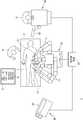
도 1은 본 발명의 일 실시예에 따른 수술 로봇 장치의 전체 시스템을 나타내는 평면도이다.
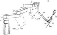
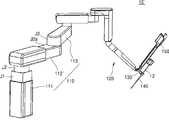
도 2a는 도 1의 슬레이브 로봇을 도시하는 도면이고, 도 2b는 슬레이브 로봇의 변형예를 도시하는 도면이다.
도 3a는 도 1의 마스터 콘솔의 일부 구성을 도시하는 사시도이며, 도 3b는 도 3a의 마스터 콘솔에 사용자 인터페이스 장치가 장착된 상태를 도시하는 사시도이다.
도 4는 본 발명의 일 실시예에 따른 사용자 인터페이스 장치를 도시하는 사시도이다.
도 5a와 도 5b는 도 4의 제1 힘 측정부를 도시하는 사시도이다.
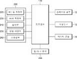
도 6은 도 1의 수술 로봇 장치의 일부 구성을 도시하는 구성도이다.
도 7a 및 도 7b는 본 발명의 다른 실시예에 따른 사용자 인터페이스 장치를 도시하는 사시도이다.
도 8은 본 발명의 일 실시예에 따른 수술 로봇 장치의 마스터 콘솔의 조작 방법을 도시하는 순서도이다.
도 9는 도 4의 사용자 인터페이스 장치에서 입력된 신호를 기초로 수술도구의 일 기능을 제어하는 것을 나타내는 그래프이다.
도 10는 도 4의 사용자 인터페이스 장치에서 입력된 신호를 기초로 수술도구의 다른 기능을 제어하는 것을 나타내는 그래프이다.
도 11은 도 4의 사용자 인터페이스 장치에서 입력된 신호를 기초로 수술도구의 또 다른 기능을 제어하는 것을 나타내는 그래프이다.1 is a plan view showing the entire system of a surgical robot apparatus according to an embodiment of the present invention.
FIG. 2A is a view showing the slave robot of FIG. 1, and FIG. 2B is a view showing a modification of the slave robot.
3A is a perspective view showing a partial configuration of the master console of FIG. 1, and FIG. 3B is a perspective view showing a state in which the user interface device is mounted on the master console of FIG. 3A.
4 is a perspective view showing a user interface device according to an embodiment of the present invention.
5A and 5B are perspective views illustrating the first force measurement unit of FIG. 4.
6 is a configuration diagram showing a partial configuration of the surgical robot apparatus of FIG. 1.
7A and 7B are perspective views illustrating a user interface device according to another embodiment of the present invention.
8 is a flowchart illustrating a method of operating a master console of a surgical robot apparatus according to an embodiment of the present invention.
FIG. 9 is a graph showing control of one function of a surgical tool based on a signal input from the user interface device of FIG. 4.
FIG. 10 is a graph illustrating controlling other functions of the surgical tool based on a signal input from the user interface device of FIG. 4.
FIG. 11 is a graph illustrating controlling another function of the surgical tool based on the signal input from the user interface device of FIG. 4.
본 발명은 다양한 변환을 가할 수 있고 여러 가지 실시 예를 가질 수 있는 바, 특정 실시 예들을 도면에 예시하고 상세한 설명에 상세하게 설명하고자 한다. 그러나, 이는 본 발명을 특정한 실시 형태에 대해 한정하려는 것이 아니며, 본 발명의 사상 및 기술 범위에 포함되는 모든 변환, 균등물 내지 대체물을 포함하는 것으로 이해되어야 한다. 본 발명을 설명함에 있어서 다른 실시예에 도시되어 있다 하더라도, 동일한 구성요소에 대하여서는 동일한 식별부호를 사용한다.The present invention can be applied to a variety of transformations and may have various embodiments, and specific embodiments will be illustrated in the drawings and described in detail in the detailed description. However, this is not intended to limit the present invention to specific embodiments, and should be understood to include all conversions, equivalents, and substitutes included in the spirit and scope of the present invention. In describing the present invention, even though it is illustrated in other embodiments, the same reference numerals are used for the same components.
제1, 제2 등의 용어는 다양한 구성요소들을 설명하는데 사용될 수 있지만, 구성요소들은 용어들에 의해 한정되어서는 안 된다. 용어들은 하나의 구성요소를 다른 구성요소로부터 구별하는 목적으로만 사용된다.Terms such as first and second may be used to describe various components, but components should not be limited by terms. The terms are only used to distinguish one component from other components.
본 출원에서 사용한 용어는 단지 특정한 실시 예를 설명하기 위해 사용된 것으로, 본 발명을 한정하려는 의도가 아니다. 본 출원에서, "포함하다" 또는 "가지다" 등의 용어는 명세서상에 기재된 특징, 숫자, 단계, 동작, 구성요소, 부품 또는 이들을 조합한 것이 존재함을 지정하려는 것이지, 하나 또는 그 이상의 다른 특징들이나 숫자, 단계, 동작, 구성요소, 부품 또는 이들을 조합한 것들의 존재 또는 부가 가능성을 미리 배제하지 않는 것으로 이해되어야 한다.Terms used in the present application are only used to describe specific embodiments, and are not intended to limit the present invention. In this application, the terms "include" or "have" are intended to indicate the presence of features, numbers, steps, actions, components, parts or combinations thereof described in the specification, but one or more other features. It should be understood that the existence or addition possibilities of fields or numbers, steps, operations, components, parts or combinations thereof are not excluded in advance.
이하, 첨부된 도면들에 도시된 본 발명에 관한 실시 예들을 참조하여 본 발명을 상세히 설명한다.Hereinafter, the present invention will be described in detail with reference to embodiments related to the present invention shown in the accompanying drawings.
도 1은 본 발명의 일 실시예에 따른 수술 로봇 장치(1)의 전체 시스템을 나타내는 평면도이다.1 is a plan view showing the entire system of the
도 1을 참조하면, 수술 로봇 장치(1)는 수술대(2)에 누워있는 환자(P)에게 수술을 행하는 슬레이브 로봇(10)과, 슬레이브 로봇(10)을 오퍼레이터(O)가 원격 조종하도록 하는 마스터 콘솔(20)을 포함한다. 또한, 수술 로봇 장치(1)는 비전 카트(30)를 포함할 수 있다. 비전 카트(30)의 디스플레이부(35)를 통해서, 보조자(A)가 수술의 진행 상황을 확인할 수 있다.Referring to FIG. 1, the
슬레이브 로봇(10)은 하나 이상의 로봇 암(11)을 포함할 수 있다. 일반적으로 로봇 암은 인간의 팔 및/또는 손목과 유사한 기능을 가지고 있으며 손목 부위에 소정의 도구를 부착시킬 수 있는 장치를 의미한다. 본 명세서에서 로봇 암(11)이란 상박, 하박, 손목, 팔꿈치 등의 구성 요소 및 상기 손목 부위에 결합되는 수술용 인스트루먼트 등을 모두 포괄하는 개념으로 정의할 수 있다. 이와 같은, 슬레이브 로봇(10)의 로봇 암(11)은 다자유도를 가지며 구동되도록 구현될 수 있다. 로봇 암(11)은 예를 들어 환자(P)의 수술 부위에 삽입되는 수술도구(12), 수술도구(12)를 수술 위치에 따라 요(yaw)방향으로 회전시키는 요동 구동부, 요동 구동부의 회전 구동과 직교하는 피치(pitch) 방향으로 수술도구를 회전시키는 피치 구동부, 수술도구(12)를 길이 방향으로 이동시키는 이송 구동부와, 수술도구를 회전시키는 회전 구동부, 수술도구(12)의 끝단에 설치되어 수술 병변을 절개 또는 절단하는 수술도구 구동부를 포함하여 구성될 수 있다. 다만, 로봇 암(11)의 구성이 이에 제한되지는 않으며, 이러한 예시가 본 발명의 권리범위를 제한하지 않는 것으로 이해되어야 한다. 여기서, 오퍼레이터(O)가 조작 레버를 조작함에 의해 로봇 암(11)이 상응하는 방향으로 회전, 이동하는 등의 실제 제어 과정에 대한 구체적인 설명은 생략한다.The
슬레이브 로봇(10)은 환자(P)를 수술하기 위하여 하나 이상으로 이용될 수 있으며, 수술 부위가 디스플레이부(35)를 통해 화상 이미지로 표시되도록 하기 위한 수술도구(12)는 독립된 슬레이브 로봇(10)으로 구현될 수도 있다. 또한, 앞서 설명된 바와 같이, 본 발명의 실시예들은 복강경 이외의 다양한 수술용 내시경(예를 들어, 흉강경, 관절경, 비경 등)이 이용되는 수술들에 범용적으로 사용될 수 있다.The
마스터 콘솔(20)과 슬레이브 로봇(10)이 반드시 물리적으로 독립된 별도의 장치로 분리되어야 하는 것은 아니며, 하나로 통합되어 일체형으로 구성될 수 있다. 다만, 이하에서는 설명의 편의를 위해서 마스터 콘솔(20)과 슬레이브 로봇(10)이 물리적으로 이격된 경우를 중심으로 설명하기로 한다.The
마스터 콘솔(20)은 조작 레버(미도시) 및 디스플레이 부재(미도시)를 포함한다. 또한, 마스터 콘솔(20)은 추가적으로 외측에 오퍼레이터(O)의 상태를 표시할 수 있는 외부의 디스플레이 장치(25)를 더 구비할 수 있다.The
상세히, 마스터 콘솔(20)은 오퍼레이터(O)가 양손에 각각 파지하여 조작할 수 있도록 조작 레버(미도시)를 구비한다. 조작 레버는 두 개 또는 그 이상의 수량의 핸들로 구현될 수 있으며, 오퍼레이터(O)의 핸들 조작에 따른 조작 신호가 유선 또는 무선 통신망을 통해 슬레이브 로봇(10)으로 전송되어 로봇 암(11)이 제어된다. 즉, 오퍼레이터(O)의 핸들 조작에 의해 로봇 암(11)의 위치 이동, 회전, 절단 작업 등의 수술 동작이 수행될 수 있다.In detail, the
예를 들어, 오퍼레이터(O)는 핸들 형태의 조작 레버를 이용하여 슬레이브 로봇 암(11)이나 수술도구(12) 등을 조작 할 수 있다. 이와 같은 조작 레버는 그 조작방식에 따라 다양한 기구적 구성을 가질 수 있으며, 슬레이브 로봇 암(11)이나 수술도구(12) 등의 동작을 조작하는 마스터 핸들과, 전체 시스템의 기능을 조작하기 위해 마스터 콘솔(20)에 부가된 조이스틱, 키패드, 트랙볼, 터치스크린과 같은 각종 입력도구와 같이, 슬레이브 로봇(10)의 로봇 암(11) 및/또는 기타 수술 장비를 작동시키기 위한 다양한 형태로 구비될 수 있다. 여기서, 조작 레버는 핸들의 형상으로 제한되지 않으며, 유선 또는 무선 통신망과 같은 네트워크를 통해 로봇 암(11)의 동작을 제어할 수 있는 형태이면 아무런 제한 없이 적용될 수 있다.For example, the operator O can operate the
마스터 콘솔(20)의 상기 디스플레이 부재에는 수술도구(12)를 통해 촬영되는 영상이 화상 이미지로 표시된다. 또한 디스플레이 부재에는 소정의 가상 조작판이 상기 수술도구(12)를 통해 촬영되는 영상과 함께 표시되거나 또는 독립적으로 표시될 수 있다.The image captured through the
디스플레이 부재는 오퍼레이터(O)가 영상을 확인할 수 있는 다양한 형태로 구비될 수 있다. 예를 들어, 오퍼레이터(O)의 양안에 대응하도록 디스플레이 장치가 설치될 수 있다. 다른 예로, 하나 이상의 모니터들로 구성될 수 있으며, 각 모니터에 수술시 필요한 정보들이 개별적으로 표시되도록 할 수 있다. 디스플레이 부재의 수량은 표시를 요하는 정보의 유형이나 종류 등에 따라 다양하게 결정될 수 있다. 더 상세한 마스터 콘솔(20)에 대한 설명은 하기에서 설명하기로 한다.The display member may be provided in various forms in which the operator O can check the image. For example, a display device may be installed to correspond to both eyes of the operator O. As another example, one or more monitors may be configured, and information necessary for surgery may be individually displayed on each monitor. The number of display members may be variously determined according to the type or type of information requiring display. More detailed description of the
비전 카트(30)는 슬레이브 로봇(10)이나 마스터 콘솔(20)에 이격되게 설치되고, 외부에서 수술의 진행상황을 디스플레이부(35)를 통해서 확인할 수 있다. 디스플레이부(35)에서 디스플레이되는 영상은 오퍼레이터(O)의 마스터 콘솔(20)에서 디스플레이 되는 영상과 동일할 수 있다. 보조자(A)는 디스플레이부(35)의 영상을 확인하면서, 오퍼레이터(O)의 수술 작업을 보조할 수 있다. 예를 들어, 보조자(A)는 수술의 진행상태에 따라 수술도구(12)를 인스트루먼트 카트(3)에서 교체할 수 있다.The
중앙 제어부(40)는 슬레이브 로봇(10), 마스터 콘솔(20) 및 비전 카트(30)와 연결되어, 각각의 신호를 송수신 할 수 있다. 중앙 제어부(40)는 슬레이브 로봇(10), 마스터 콘솔(20) 및 비전 카트(30) 중 어느 하나에 설치되거나, 독립적으로 설치될 수 있다.The
도 2a는 도 1의 슬레이브 로봇(10)을 도시하는 도면이고, 도 2b는 슬레이브 로봇의 변형예를 도시하는 도면이다.2A is a view showing the
도 2a를 참조하면, 슬레이브 로봇(10)은 패시브 암(110)과 액티브 암(120)을 구비할 수 있다.Referring to FIG. 2A, the
패시브 암(110)은 수술 준비과정에서 액티브 암(120)의 위치를 원하는 위치로 이동시킬 수 있으나, 수술 중에는 작동하지 않고 위치가 고정된다. 패시브 암(110)은 복수 개의 조인트와 이들 조인트들을 연결하는 링크(link)들을 포함한다. 각 조인트는 회전(rotation) 운동 혹은 직선(prismatic) 운동을 하며, 이러한 운동을 통하여 패시브 암(110)의 전체적인 움직임을 생성한다. 조인트는 구동기(actuator), 감속기, 센서, 브레이크(brake), 카운터밸런스(counterbalance) 등을 구비 할 수 있다.The
구동기는 주로 전기 모터가 이용되며, BDC(brushed DC) 모터, BLDC(brushless DC) 모터, AC 모터 등을 포함 할 수 있다. 감속기는 하모닉 드라이브(harmonic drive), 유성기어 등과 같이 기어(gear)로 구현될 수 있다. 센서는 조인트의 움직임을 측정하는 엔코더(encoder), 리솔버(resolver) 등이 이용될 수 있으며, 각 조인트와 연결된 링크에 작용하는 힘이나 토크를 측정하는 힘/토크(force/torque) 센서를 포함 할 수 있다. 브레이크는 조인트의 움직임을 제한하는 장치로 주로 솔레노이드(solenoid)와 스프링 등이 주요 구성 요소이며, 구동기에 연결되어 구동기의 움직임을 제한하는 형태, 링크에 연결되어 링크의 움직임을 제한하는 형태, 혹은 위의 두 가지 형태 모두를 포함 할 수 있다. 카운터밸런스는 로봇 암의 무게를 보상하는 장치로, 정적(static) 상태에서 로봇 암의 무게를 상쇄할 수 있는 힘을 작용한다.The electric motor is mainly used for the driver, and may include a brushed DC (BDC) motor, a brushless DC (BLDC) motor, or an AC motor. The reducer can be implemented as a gear, such as a harmonic drive, planetary gear, and the like. The sensor may be an encoder, a resolver, etc. that measures the movement of the joint, and includes a force/torque sensor that measures the force or torque acting on the link connected to each joint. can do. The brake is a device that restricts the movement of the joint. Mainly, solenoids and springs are the main components, and it is connected to the actuator to limit the movement of the actuator, and it is connected to the link to limit the movement of the link. Can include both forms of The counterbalance is a device that compensates for the weight of the robot arm, and acts to counteract the weight of the robot arm in a static state.
패시브 암(110)은 제1 링크(111), 제2 링크(112), 제3 링크(113)가 서로 연결되도록 배치되고, 3개의 조인트를 구비할 수 있다. 패시브 암(110)은 3개의 링크를 3개의 조인트로 조절하여, 패시브 암(110)을 3차원 공간에서 원하는 위치에 이동시킬 수 있다.The
제1 링크(111)는 지면에 대해서 수직 방향으로 설치되고, 내부에 제1 조인트(J1)가 배치되어 지면에 대해서 수직한 방향으로 직선 운동할 수 있다. 이로써, 패시브 암(110)은 액티브 암(120)의 높이를 조절할 수 있다.The
제2 링크(112)는 제1 링크(111)에 대해서 회전가능하게 연결되며, 제1 링크(111)와 수직된다. 제2 링크(112)는 제2 조인트(J2)로 제1 링크(111)와 연결되므로, 지면에 수직된 축을 기준으로 제1 링크(111)에 대해서 회전할 수 있다. 또한, 제2 링크(112)는 지면과 나란한 방향으로 연장되므로, 제1 링크(111)와 실질적으로 수직되게 배치된다.The
제3 링크(113)는 제2 링크(112)에 대해서 회전 가능하게 연결되며, 제2 링크(112)와 나란하게 배치된다. 제3 링크(113)는 제3 조인트(J3)로 제2 링크(112)와 연결되므로, 지면에 수직된 축을 기준으로 제2 링크(112)에 대해서 회전할 수 있다. 또한, 제3 링크(113)는 제2 링크(112)와 같이 지면에 대해서 나란하게 배치된다.The
액티브 암(120)은 말단부에 수술도구(12)나 내시경(미도시)이 장착되며, 수술중에 액티브 암(120)의 각 조인트를 구동하여 수술도구(12)나 내시경이 환자의 몸에서 움직일 수 있다. 액티브 암(120)은 복수 개의 조인트와 이들 조인트들을 연결하는 링크(link)들을 포함한다. 각 조인트는 회전(rotation) 운동 혹은 직선(prismatic) 운동을 하며, 이러한 운동을 통하여 액티브 암(120)의 전체적인 움직임을 생성한다. 조인트는 구동기(actuator), 감속기, 센서, 브레이크(brake), 카운터밸런스(counterbalance) 등을 구비 할 수 있다. 각 조인트의 구성은 전술한 패시브 암(110)의 조인트와 실질적으로 동일하고, 배치에 따른 작동이 상이한바 이하에서는 이에 대해서 상세하게 설명하기로 한다.The
액티브 암(120)은 제4 링크(121), 제5 링크(122), 제6 링크(123)가 서로 연결되도록 배치되고, 6개의 조인트를 구비할 수 있다. 액티브 암(120)은 3개의 링크를 6개의 조인트로 조절하여 수술도구(12)의 요(yaw), 피치(pitch), 롤(roll)의 각도를 조절하여, 수술 동작을 수행할 수 있다.The
제4 링크(121)는 패시브 암(110)의 제3 링크(113)와 연결된다. 제4 링크(121)는 제4 조인트(J4)와 연결되므로, 지면에 수직된 축을 기준으로 제3 링크(113)에 대해서 회전 할 수 있다. 또한, 제4 링크(121)의 후단에는 카운터밸런스가 배치되어, 액티브 암(120)의 무게를 보상할 수 있다.The
제4 링크(121)의 내부에는 제5 조인트(J5)가 배치되고, 제4 링크(121)의 길이 방향으로 직선 운동 할 수 있다. 제5 조인트(J5)는 제4 링크(121)의 길이를 조절할 수 있다.A fifth joint J5 is disposed inside the
제5 링크(122)는 제4 링크(121)에 대해서 회전 가능하게 연결된다. 제5 링크는 절곡되게 형성된다. 제5 링크(122)는 제4 링크(121)와 연결되는 부분은 지면에 나란하게 형성되나, 제6 링크(123)와 연결되는 부분은 지면에 수직되게 형성된다.The
제5 링크(122)는 제6 조인트(J6)와 연결되므로, 지면에 대해서 수직된 축을 기준으로 제4 링크(121)에 대해서 회전할 수 있다. 또한, 제5 링크(122)의 수직한 부분에는 지면에 대해서 수직한 방향으로 직선 운동할 수 있는 제7 조인트(J7)가 설치되어, 수직 방향으로 높이를 조절할 수 있다.Since the
제6 링크(123)는 제5 링크(122)에 대해서 소정의 경사를 가질 수 있다. 일 예로, 제6 링크(123)는 제5 링크(122)의 길이 방향에 대해서 45도의 경사를 가질 수 있다. 제6 링크(123)는 내부에 제8 조인트(J8)가 배치되어 제6 링크(123)의 길이 방향의 축에 대해서 회전 할 수 있다. 즉, 제8 조인트(J8)를 통해서 제6 링크(123)는 롤 운동을 할 수 있다.The
제6 링크(123)의 단부에는 슬라이드 가이드(150)가 설치되며, 제9 조인트(J9)가 슬라이드 가이드(150)의 피치각(pitch angle)를 조절할 수 있다. 슬라이드 가이드(150)는 수술도구(12)의 직선 운동을 안내할 수 있다.The
캐뉼러 홀더(130)는 제6 링크(123)의 단부에 장착되어 캐뉼러(140)를 구비할 수 있으며, 캐뉼러(140)는 수술도구(12)가 장착될 수 있으며, 외측에는 RCM(remote center of motion)의 위치를 확인할 수 있는 마커(M)가 표시될 수 있다.The
도 2b를 참조하면, 슬레이브 로봇(10’)은 패시브 암(110’)과 액티브 암(120)을 구비하고, 단부에는 캐뉼러 홀더(130), 캐뉼러(140), 슬라이드 가이드(150)가 장착될 수 있다. 전술한 일 실시예에 따른 슬레이브 로봇(10)과 비교하면, 패시브 암(110)에 제2a 조인트(J2a)가 더 구비된 점에 차이가 있는바, 이하에서는 상기 차이점에 대해서 상세히 설명하기로 한다.Referring to FIG. 2B, the
패시브 암(110)은 제1 링크(111), 제2 링크(112’), 제3 링크(113)를 구비하고, 4개의 조인트를 가질 수 있다.The
제1 조인트(J1)는 제1 링크(111)의 내부에 배치되 직선운동을 하여, 제1 링크(111)의 길이를 조절할 수 있다. 제2 조인트(J2)는 제1 링크(111)와 제2 링크(112’) 사이에 배치되고, 지면에 수직한 축을 중심으로 제2 링크(112)가 회전할 수 있다. 제2a 조인트(J2a)는 제2 링크(112’)의 내부에 배치되고, 제2 링크(112’)의 길이를 조절할 수 있다. 즉, 제2a 조인트(J2a)가 구동되면, 제2 링크(112’)의 길이가 변화하므로, 지면에 대한 수평방향으로 위치를 이동할 수 있다. 제3 조인트(J3)는 제2 링크(112’)와 제3 링크(113) 사이에 배치되고, 지면에 수직한 축을 중심으로 제3 링크(113)가 회전할 수 있다.The first joint J1 is disposed inside the
일실시예와 비교하면, 패시브 암(110’)은 제2a 조인트(J2a)를 더 구비하므로, 여자유도(redundant DOF)를 가질 수 있다. 이로써 액티브 암(120)을 정해진 하나의 위치로 설정시에, 이에 상응하는 여자유도를 가지는 패시브 암(110’)의 배치는 다양한 경우의 수를 생성할 수 있다. 또한, 여자유도를 구비한 패시브 암(110’)은 복수개의 슬레이브 로봇이 하나의 구조물에 배치시에, 각각의 슬레이브 로봇이 서로 간섭되지 않도록 이동할 수 있다.Compared with one embodiment, the
도 3a는 도 1의 마스터 콘솔(20)의 일부 구성을 도시하는 사시도이며, 도 3b는 도 3a의 마스터 콘솔(20)에 사용자 인터페이스 장치(200)가 장착된 상태를 도시하는 사시도이다.3A is a perspective view showing a partial configuration of the
도 3a와 도 3b를 참조하면, 마스터 콘솔(20)은 베이스(21), 포지셔닝 암(22), 짐벌 암(23), 사용자 인터페이스 장치(200)를 구비할 수 있다.3A and 3B, the
베이스(21)는 마스터 콘솔(20)의 일측에 고정되며, 포지셔닝 암(22)이 고정될 수 있다.The
포지셔닝 암(22)은 수술도구(12)를 위치를 설정할 수 있다. 오퍼레이터(O)가 사용자 인터페이스 장치(200)를 조작하여 포지셔닝 암(22)의 각 관절을 조절하면, 슬레이브 로봇(10)이나 수술도구(12)는 3차원 공간에서 설정된 위치로 배치될 수 있다.The
포지셔닝 암(22)은 복수개의 포지셔닝 링크, 구동기, 관절을 구비한다. 상세하게, 포지셔닝 암(22)은 복수개의 구동기를 이용하여 포지셔닝 암(22)의 말단부의 3자유도 위치를 결정하게 된다. 구동기는 주로 전기 모터가 이용되며, BDC(brushed DC)모터나 BLDC(brushless DC)모터가 이용되며, 브레이크가 연결될 수 있다. 짐벌 암(23)의 구동기는 토크의 증폭을 위해 감속기와 연결될 수 있다. 포지셔닝 암(22)은 백래쉬(backlash)와 마찰을 최소화 할 수 있는 캡스턴 메커니즘이 이용될 수 있다. 포지셔닝 암(22)의 말단부의 위치는 각 구동기와 연결된 관절의 위치를 측정하여 계산 할 수 있다. 또한 각 관절의 위치는 구동기와 직접 연결된 센서 혹은 구동기와 연결된 관절에 연결된 센서를 통해 알 수 있으며, 센서로는 주로 엔코더가 이용된다.The
짐벌 암(23)은 포지셔닝 암(22)의 단부에 배치되며, 수술도구(12)의 방향을 설정할 수 있다. 오퍼레이터(O)가 사용자 인터페이스 장치(200)를 조작하여 짐벌 암(23)의 각 관절을 조절하면, 슬레이브 로봇(10)이나 수술도구(12)는 3차원 공간에서 설정된 방향으로 조작될 수 있다.The
짐벌 암(23)은 말단부의 3자유도 방향을 결정하며, 1개의 여자유도를 가질 수 있도록, 전체 4개의 구동기로 구성된다. 짐벌 암(23)의 여자유도는 오퍼레이터(O)가 마스터 암을 잡고 움직일 때 사용의 편리성을 향상 시키기 위한 목적으로 구성된다.The
짐벌 암(23)은 복수개의 짐벌 링크, 구동기, 관절을 구비할 수 있다. 짐벌 암(23)의 구동기는 주로 전기 모터가 이용되며, BDC(brushed DC)모터나 BLDC(brushless DC)모터가 이용되며, 브레이크가 연결될 수 있다. 구동기는 토크의 증폭을 위해 감속기와 연결될 수 있다. 짐벌 암(23)은 백래쉬(backlash)와 마찰을 최소화 할 수 있는 캡스턴 메커니즘이 이용될 수 있다.The
짐벌 암(23)의 말단부의 방향은 각 구동기와 연결된 관절의 위치를 측정하여 계산 할 수 있다. 또한 각 관절의 위치는 구동기와 직접 연결된 센서 혹은 구동기와 연결된 관절에 연결된 센서를 통해 알 수 있으며, 센서로는 주로 엔코더가 이용된다.The direction of the distal end of the
구동기로 BLDC 모터가 이용되는 경우에는 모터에서 코깅 토크(cogging torque)가 발생하는데, 시스템의 성능과 사용자의 편의성 향상을 위해 이를 보상하는 것이 바람직하다. 코깅 토크의 보상은 상대적으로 빠른 제어 주기를 필요로 하므로, 모터 드라이브에서 구현될 수 있다.When a BLDC motor is used as a driver, cogging torque is generated in the motor, and it is desirable to compensate for the improvement of the system performance and user convenience. Compensation of cogging torque requires a relatively fast control cycle, so it can be implemented in a motor drive.
오퍼레이터(O)는 포지셔닝 암(22)과 짐벌 암(23)을 이용하여 3자유도 위치(x, y, z)와 3자유도 방향(yaw, pitch, roll)을 결정할 수 있으며, 이는 수술로봇 시스템의 중요한 입력 데이터로 이용된다.The operator O can determine the three degrees of freedom (x, y, z) and three degrees of freedom (yaw, pitch, roll) using the
사용자 인터페이스 장치(200)는 추가적인 오퍼레이터(O)의 입력을 위해서 짐벌 암(23)의 말단부에 장착될 수 있다. 사용자 인터페이스 장치(200)는 짐벌 암(23)에 장착 및 탈착될 수 있다.The
다른 실시예로, 도 6을 참조하면 사용자 인터페이스 장치(200)와 짐벌 암(23) 사이에는 힘/토크 센서(205)가 장착될 수 있다. 힘/토크 센서(205)는 짐벌 암(23)과 사용자 인터페이스 장치(200) 사이에 작용하는 힘/토크를 측정할 수 있으며, 측정된 힘/토크 값을 이용하여 포지셔닝 암(22)과 짐벌 암(23)의 성능과 사용자의 편의성을 향상시키는데 이용될 수 있다.In another embodiment, referring to FIG. 6, a force/
예를 들면, 중력, 관성력, 마찰력 보상을 통해 포지셔닝 암(22)과 짐벌 암(23)의 성능과 오퍼레이터(O)의 편의성을 향상시킬 수 있는데, 이를 위해서는 포지셔닝 암(22)과 짐벌 암(23)의 정확한 동역학 모델이 필요하다. 하지만 현실적으로 정확한 모델을 구하지 못한 경우에는 센서를 통해 측정된 값을 이용하여 모델의 정확도를 높여야 한다. 힘/토크 센서(205)는 사용자 인터페이스 장치(200)와 짐벌 암(23) 사이에 배치되므로, 정확한 힘/토크를 측정하고, 이를 통해서 오퍼레이터(O)의 편의성을 효과적으로 향상시킬 수 있다.For example, it is possible to improve the performance of the
힘/토크 센서(205)는 힘 피드백에 있어서도 유리한 장점을 가진다. 힘/토크 센서를 이용하지 않고 위치에 따른 힘 피드백 값을 계산하는 임피던스 표시(impedance display) 방법 대신에, 힘/토크 센서를 이용하여 기준 위치 값을 계산하는 어드미턴스 표시(admittance display) 방법을 적용할 수 있다. 어드미턴스 표시(admittance display) 방법은 포지셔닝 암(22)과 짐벌 암(23)이 안정적으로 표현할 수 있는 강성(stiffness)을 향상시킬 수 있으며, 장비의 성능과 사용자의 몰입감을 향상 시킬 수 있다.The force/
힘/토크 센서(205)는 3축의 힘을 측정하거나, 3축의 힘과 1축 이상의 토크를 측정할 수 있다. 짐벌 암(23)과 사용자 인터페이스 장치(200)를 기구적 및 전기적으로 연결할 수 있는 연결부를 포함하는데, 손쉬운 탈부착을 위해 스프링 커넥터(spring loaded connector) 등이 이용될 수 있다.The force/
도 4는 본 발명의 일 실시예에 따른 사용자 인터페이스 장치(200)를 도시하는 사시도이고, 도 5a와 도 5b는 도 4의 제1 힘 측정부(220)를 도시하는 사시도이며, 도 6은 도 1의 수술 로봇 장치(1)의 일부 구성을 도시하는 구성도이다.4 is a perspective view showing a
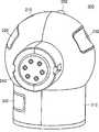
도 4 내지 도 6를 참조하면, 사용자 인터페이스 장치(200)는 하우징(210), 제1 힘 측정부(220), 터치 측정부(230), 커넥터(240), 표시부(250), 정보 저장부(260) 및 스위칭부(270)를 구비할 수 있다. 사용자 인터페이스 장치(200)는 짐벌 암(23)의 단부에 회전가능하게 장착 및 탈착될 수 있다. 사용자 인터페이스 장치(200)는 사용자 즉, 오퍼레이터(O)의 접촉을 감지하고, 오퍼레이터(O)가 가하는 힘의 크기를 측정할 수 있다.4 to 6, the
하우징(210)은 사용자 인터페이스 장치(200)의 외관을 형성하고, 구 형상을 가지 수 있다. 오퍼레이터(O)는 쉽고 직관적으로 구 형상의 하우징을 그립할 수 있으며, 조작을 편하게 할 수 있다.The
제1 힘 측정부(220)는 일부가 하우징(210)의 외측 표면에 노출되며, 오퍼레이터(O)가 가하는 힘을 측정할 수 있다. 사용자는 검지 손가락이나 중지 손가락을 이용하여, 접촉 패드(221)에 힘을 가하면, 브릿지(222)의 변형을 기초로 가해진 힘의 크기를 측정할 수 있다. 제1 힘 측정부(220)는 접촉 패드(221), 브릿지(222), 고정단(223)을 구비할 수 있다.A portion of the first
접촉 패드(221)는 하우징(210)에 노출되며, 오퍼레이터(O)가 접촉 및 가력 할 수 있다. 접촉 패드(221)에 가해지는 힘은 브릿지(222)를 변형할 수 있다.The
브릿지(222)는 접촉 패드(221)와 연결되며, 일 방향으로 연장될 수 있다. 브릿지(222)는 탄성체(elastic body)로 형성되므로, 외부에서 힘이나 토크가 가해지면 브릿지(222)가 변형되어 가해진 힘이나 토크를 측정할 수 있다.The
탄성체의 변형은 예컨대, 스트레인 게이지를 이용한 방법, 정전용량형(capacitive type) 센서를 이용한 방법, 유도형(inductive type)을 이용한 방법 등을 이용하여 측정할 수 있다. 탄성체 변형에 따른 전기신호 변화 측정할 수 있으며, 이렇게 발생한 전기신호를 증폭 및 필터링, 그리고 교정(calibration) 과정을 통하면 센서에 가해진 힘/토크를 측정할 수 있게 된다. 이하에서는 설명의 편의를 위해서, 스트레인 게이지가 장착된 경우를 중심으로 설명하기로 한다.Deformation of the elastic body can be measured using, for example, a method using a strain gauge, a method using a capacitive type sensor, a method using an inductive type, or the like. It is possible to measure the change in electrical signal due to elastic deformation, and the amplification, filtering, and calibration process of the generated electrical signal can measure the force/torque applied to the sensor. Hereinafter, for convenience of description, a description will be given focusing on the case where the strain gauge is mounted.
브릿지(222)의 각각의 면에는 스트레인 게이지가 설치될 수 있다. 도 5a 및 도 5b와 같이 4개(R1, R2, R3, R4)의 스트레인 게이지가 장착될 수 있다. 접촉 패드(221)에서 전달되는 힘은 브릿지(222)를 변형시키고, 스트레인 게이지는 브릿지(222)의 변형의 정도를 측정하여 외부에서 가해지는 힘을 측정할 수 있다.A strain gauge may be installed on each side of the
브릿지(222)에서의 힘의 측정은 브릿지 회로(bridge circuit)를 이용하며, 가해진 힘에 따른 전기 저항의 변화를 전압의 변화로 변환하여 측정한다. 출력 전압은 증폭, 필터링, A/D(analog/digital) 변환 등의 과정을 통해 측정되며, 측정된 전압은 교정(calibration)을 통해 가해진 힘으로 계산될 수 있다.The measurement of the force in the
온도, 습도 등 외란에 의해 스트레인 게이지의 저항 값이 영향을 받을 수 있으며, 결과적으로 정확한 힘의 측정이 어려워진다. 따라서 외란에 의한 영향은 제거되거나 최소화 되어야 하며, 인접하게 위치한 4개(R1, R2, R3, R4)의 스트레인 게이지를 이용한 풀 브릿지(full bridge) 회로가 이용될 수 있다.The resistance value of the strain gauge may be affected by disturbances such as temperature and humidity, and as a result, accurate force measurement becomes difficult. Therefore, the influence of the disturbance should be eliminated or minimized, and a full bridge circuit using four adjacently positioned (R1, R2, R3, R4) strain gauges can be used.
고정단(223)은 브릿지(222)와 연결되며, 하우징(210)에 고정될 수 있다. 고정단(223)은 제1 힘 측정부(220)를 하우징(210)과 연결시킬 수 있다.The
제1 힘 측정부(220)에서 측정된 힘에 대한 데이터는 컨트롤러(170)로 전달되어, 수술도구(12)의 수술 동작을 수행할 수 있다.The data about the force measured by the first
터치 측정부(230)는 일부가 하우징(210)의 외측 표면에 노출되어 오퍼레이터(O)의 접촉을 감지할 수 있다. 터치 측정부(230)는 제1 힘 측정부(220)와 이격되게 설치되어, 오퍼레이터(O)의 손가락을 쉽게 거치 및 접촉할 수 있다. 터치 측정부(230)는 정전 용량 터치 센서로 형성될 수 있다.The
터치 측정부(230)는 표면이 만곡되게 형성될 수 있다. 오퍼레이터(O)의 접촉을 신속하고 정확하게 인식하기 위해서 표면이 만곡되게 형성되어, 손가락의 접촉 면적이 증가하고, 손가락이 터치 측정부 상에서 위치를 유지할 수 있다. 터치 측정부(230)는 수술 로봇 장치(1)의 구동과 관련되어 있으므로, 신속하고 정확하게 터치를 측정되어야 한다. 오퍼레이터(O)가 수술 로봇 장치(1)를 사용중에 손가락의 위치를 유지하지 않으면, 사용자 인터페이스 장치(200)는 다른 신호로 인식하여 수술 로봇 장치(1)가 오작동 될 수 있다. 터치 측정부(230)의 만곡된 표면이 손가락의 위치를 유지하므로, 오퍼레이터(O)의 접촉 불량에 따른 오작동을 줄일 수 있다.The
커넥터(240)는 하우징(210)의 일측에 배치되고, 짐벌 암(23)에 접속할 수 있다. 커넥터(240)는 전원을 공급받을 수 있으며, 제1 힘 측정부(220)나 터치 측정부(230)에서 측정된 신호를 전달할 수 있다. 커넥터(240)는 짐벌 암(23)에 대해서 회전할 수 있도록 접속된다. 커넥터(240)가 삽입되면, 오퍼레이터(O)는 사용자 인터페이스 장치(200)를 그립한 상태에서 롤(roll) 운동을 할 수 있다.The
표시부(250)는 하우징(210)의 외측에 배치되며, 사용자 인터페이스 장치(200)의 상태에 관한 정보를 표시할 수 있다. 표시부(250)는 일예로 램프, 디스플레이 패널과 같은 다양한 형태로 형성될 수 있다. 이하에서는 설명의 편의를 위해서 LED 램프인 것을 중심으로 설명하기로 한다.The
표시부(250)는 사용자 인터페이스 장치(200)가 짐벌 암(23)에 결합되었다는 정보, 제1 힘 측정부(220)에서 가해지는 힘이 설정범위에 해당하거나 벗어났다는 것을 알려주는 정보, 터치 측정부(230)에서 오퍼레이터(O)의 접촉을 감지하였다는 정보 등을 인식하고, 이를 램프의 색상 변화, 깜빡임, 밝기 조절 등으로 표시할 수 있다.The
정보 저장부(260)는 사용자 인터페이스 장치(200)를 사용하는 각각의 사용자 정보를 저장할 수 있다. 보통 각각의 오퍼레이터(O)는 자신의 사용자 인터페이스 장치(200)로 수술을 집도한다. 사용자 인터페이스 장치(200)가 짐벌 암(23)에 장착되면, 컨트롤러(170)는 사용자 정보에 대응하여 포지셔닝 암(22)과 짐벌 암(23)의 위치를 셋팅할 수 있다. 즉, 오퍼레이터(O)의 신체 정보를 기초로, 포지셔닝 암(22)과 짐벌 암(23)의 위치를 자동적으로 조정하므로, 오퍼레이터(O)는 편안하게 수술을 집도할 수 있다.The
정보 저장부(260)는 제1 힘 측정부(220)와 터치 측정부(230)를 위한 교정 값(calibration data)을 저장할 수 있으며, 이를 사용자 인터페이스 장치(200)의 출력값을 계산하는데 이용할 수 있다. 또한 각각의 센서의 초기값은 시스템의 시작 단계에서 오퍼레이터(O)가 사용자 인터페이스 장치(200)를 손으로 잡지 않은 상태에서 얻어지며, 이러한 초기값을 이용하여 사용자 인터페이스 장치(200)의 측정 값들을 계산할 수 있다.The
스위칭부(270)는 슬레이브 로봇(10)의 위치를 변경하여 수술도구(12)를 교체하거나, 슬레이브 로봇(10)에 장착된 카메라(미도시)의 위치를 변경할 수 있다. 슬레이브 로봇(10)은 복수개로 구비되고, 각각의 슬레이브 로봇(10)에는 서로 다른 수술도구(12)가 장착된다. 수술 중에 수술도구(12)의 교체가 필요한 상황에서, 오퍼레이터(O)가 스위칭부(270)를 조작하여 슬레이브 로봇(10)을 스위칭 할 수 있다. 또한, 카메라가 필요한 상황에서, 오퍼레이터(O)가 스위칭부(270)를 조작하여 수술도구에서 카메라로 변환하거나, 카메라의 위치를 이동시킬 수 있다.The switching unit 270 may change the position of the
컨트롤러(170)는 사용자 인터페이스 장치(200)에서 전달받은 힘이나 접촉에 대한 정보를 기초로 수술도구(12)를 제어할 수 있다.The
예컨대, 사용자 인터페이스 장치(200)의 제1 힘 측정부(220)에서 전달 받은 신호로, 슬레이브 로봇(10)나 수술도구(12)를 조작할 수 있다. 또한, 터치 측정부(230)에서 전달받은 신호로 슬레이브 로봇(10)이나 마스터 콘솔(20)을 구동시킬 수 있다. 또한, 표시부(250)에 수술 로봇 장치(1)의 상태 정보를 전달하여 오퍼레이터(O)가 인식하게 할 수 있다. 또한, 정보 저장부(260)에서 전달받은 오퍼레이터(O)의 정보를 기초로, 마스터 콘솔(20)의 위치를 셋팅할 수 있다. 또한, 스위칭부(270)에서 전달받은 신호로 슬레이브 로봇(10)의 구동 및 위치를 변경할 수 있다.For example, as a signal received from the first
사용자 인터페이스 장치(200)에서 입력받은 신호를 기초로, 수술도구(12)의 구동을 제어하는 신호를 생성 및 명령하는 내용은 아래에서 보다 상세하게 설명하기로 한다.Based on the signal input from the
도 7a 및 도 7b는 본 발명의 다른 실시예에 따른 사용자 인터페이스 장치(300)를 도시하는 사시도이다.7A and 7B are perspective views illustrating a
도 7a 및 도 7b를 참조하면, 사용자 인터페이스 장치(300)는 복수개의 힘 측정부를 구비하여, 바이폴라 수술도구를 구동할 수 있다.7A and 7B, the
전술한 도 4의 일 실시예에 따른 사용자 인터페이스 장치(200)와 비교하면, 사용자 인터페이스 장치(300)는 케이스(310), 제2 힘 측정부(320)를 더 구비한다.Compared to the
케이스(310)는 하우징(210)의 아래에 배치되어, 제2 힘 측정부(320)가 설치되는 공간을 형성한다. 케이스(310)는 대략 원통형상을 가지고, 외측면에 제2 힘 측정부(320)가 배치된다.The
제2 힘 측정부(320)는 제1 힘 측정부(220)와 유사하게 형성되며, 오퍼레이터(O)가 가하는 힘의 크기를 측정할 수 있다.The second
오퍼레이터(O)는 제1 힘 측정부(220)와 제2 힘 측정부(320)를 이용하여, 바이폴라 방식의 수술도구(12)를 구동시킬 수 있다. 상세히, 제1 힘 측정부(220)로 수술도구(12)의 조(jaw)의 개도를 조절하거나, 그립력을 조절할 수 있다. 수술도구(12)의 개도가 닫혀진 상태에서, 오퍼레이터(O)가 제2 힘 측정부(320)를 가력하고, 측정된 힘이 설정된 값 이상이면 컨트롤러(170)는 전류를 수술도구(12)의 각각의 조(jaw)에 보내므로, 바이폴라 방식으로 소작기능을 수행할 수 있다.The operator O may drive the bipolar
도 8은 본 발명의 일 실시예에 따른 수술 로봇 장치(1)의 마스터 콘솔(20)의 조작 방법을 도시하는 순서도이다.8 is a flow chart showing a method of operating the
도 8을 참조하면, 수술도구(12)가 장착된 슬레이브 로봇(10)을 원격조정하기 위한 수술 로봇 장치의 마스터 콘솔(20)의 조작 방법은, 사용자 인터페이스 장치를 마스터 콘솔에 장착하는 단계(S10), 사용자가 상기 사용자 인터페이스 장치의 터치 측정부를 접촉하여 상기 마스터 콘솔을 구동하는 단계(S20), 상기 마스터 콘솔의 포지셔닝 암과 짐 벌암을 구동시켜서 상기 수술도구의 위치와 방향을 설정하는 단계(S30), 상기 사용자 인터페이스 장치의 제1 힘 측정부에서 측정된 힘의 크기에 대한 데이터를 기초로 상기 수술도구의 조(jaw)의 개도와 그립력을 조절하는 수술도구 조작 단계(S40)를 포함한다.Referring to FIG. 8, a method of operating the
사용자 인터페이스 장치를 마스터 콘솔에 장착하는 단계(S10)에서 오퍼레이터(O)는 사용자 인터페이스 장치(200)를 짐벌 암(23)의 단부에 장착한다. 사용자 인터페이스 장치(200)의 정보 저장부(260)에서 사용자 정보를 마스터 콘솔(20)에 전송하고, 사용자 정보에 대응하여, 마스터 콘솔(20)의 포지셔닝 암(22)과 짐벌 암(23)의 위치가 셋팅될 수 있다. 즉, 오퍼레이터(O)의 신체 정보를 고려하여, 마스터 콘솔(20)이 수술을 진행하기 위해서 셋팅된다.In step S10 of mounting the user interface device to the master console, the operator O mounts the
사용자가 상기 사용자 인터페이스 장치의 터치 측정부를 접촉하여 상기 마스터 콘솔을 구동하는 단계(S20)에서 오퍼레이터(O)는 수술 로봇 장치(1)를 구동시킬 수 있다. 터치 측정부(230)에서 오퍼레이터(O)의 접촉이 감지되면, 기 설정된 제1 지연 시간 이후에 마스터 콘솔을 구동시킬 수 있다.In operation S20 in which a user contacts the touch measurement unit of the user interface device to drive the master console, the operator O may drive the
상기 마스터 콘솔의 포지셔닝 암과 짐 벌암을 구동시켜서 상기 수술도구의 위치와 방향을 설정하는 단계(S30)에서 오퍼레이터(O)는 사용자 인터페이스 장치(200)의 감싼 상태로 이동시킬 수 있다. 이때, 포지셔닝 암(22)과 짐벌 암(23)의 위치와 방향이 변화하고, 사용자 인터페이스 장치(200)는 짐벌 암(23)에 대해서 롤운동을 할 수 있다.In step S30 of setting the position and direction of the surgical tool by driving the positioning arm and the gimbal arm of the master console, the operator O may move to the wrapped state of the
상기 사용자 인터페이스 장치의 제1 힘 측정부에서 측정된 힘의 크기에 대한 데이터를 기초로 상기 수술도구의 조(jaw)의 개도와 그립력을 조절하는 상기 수술도구 조작 단계(S40)에서는 제1 힘 측정부(220)에서 측정된 힘에 대한 정보를 기초로, 수술도구(12)를 이용하여 수술을 집도할 수 있다. 수술도구(12)의 단부인 조의 개도를 조절하거나 그립력을 조절할 수 있다.Based on data on the magnitude of the force measured by the first force measurement unit of the user interface device, the first force measurement is performed in the operation of the surgical tool (S40) for adjusting the jaw of the surgical tool and the grip force. Based on the information about the force measured by the
다른 실시예로, 상기 사용자가 상기 제1 힘 측정부에 가력하는 힘을 유지하면서, 수술도구의 소작 기능을 실행하는 단계를 더 포함할 수 있다.In another embodiment, the user may further include executing the cauterization function of the surgical tool while maintaining the force exerted on the first force measurement unit.
소작기능을 가지는 수술도구(12)가 슬레이브 로봇(10)에 장착된 경우에는 제1 힘 측정부(220)에서 가해지는 힘의 크기를 기초고로, 수술도구(12)에 전류를 공급하는 개시 신호를 생성할 수 있다. 즉, 소정의 크기의 힘이 제1 힘 측정부(220)에 전달되면, 모노폴라 방식으로 수술도구(12)의 소작기능이 진행될 수 있다.When the
다른 실시예로, 도 7a 및 도 7b에서의 사용자 인터페이스 장치(300)를 참고하면, 제1 힘 측정부(220)의 아래에 배치된 제2 힘 측정부(320)를 조작하여, 수술도구(12)의 소작 기능을 실행할 수 있다. 제1 힘 측정부(220)에서 측정된 힘은 수술도구(12)의 조(jaw)의 개도와 그립력을 조절하고, 제2 힘 측정부(320)에서 측정된 힘은 수술도구(12)의 조(jaw)로 전류를 개시하는 신호를 생성할 수 있다.In another embodiment, referring to the
도 9는 도 4의 사용자 인터페이스 장치(200)에서 입력된 신호를 기초로 수술도구(12)의 일 기능을 제어하는 것을 나타내는 그래프이다.FIG. 9 is a graph showing control of one function of the
도 9을 참조하면, 컨트롤러(170)는 제1 힘 측정부(220)에서 측정된 힘을 기초로 수술도구(12)의 조(jaw)의 개도와 그립력을 조절하도록 구동기에 제어신호를 전송할 수 있다. 제1 힘 측정부(220)에서 측정된 힘의 크기가 기 설정된 범위이면(포지션 컨트롤 모드), 수술도구(12)의 한 쌍의 조(jaw) 사이의 개도를 조절하고, 제1 힘 측정부(220)에서 측정된 힘의 크기가 기 설정된 범위를 초과하면(토크 컨트롤 모드), 상기 수술도구(12)의 한 쌍의 조(jaw) 사이의 그립력을 조절한다.Referring to FIG. 9, the
제1 힘 측정부(220)는 오프셋된 소정의 힘이 가해지면 힘을 측정한다. 즉, sensor offset된 이상의 힘이 제1 힘 측정부(220)에 가해지면 사용자 인터페이스 장치(200)가 힘의 크기를 센싱한다. 컨트롤러(170)는 역치값인 threshold force을 초과하기 전까지는 구동기(actuator)를 구동하지 않으므로, 수술도구(12)의 조(jaw)의 개도는 전체 개방된 상태를 가진다.The first
제1 힘 측정부(220)에서 측정된 힘이 역치값을 초과하면 구동기는 수술도구(12)의 조(jaw)의 개도를 조절한다. 컨트롤러(170)는 포지션 컨트롤 모드(position control mode)로 구동기를 제어하며, 측정된 힘의 크기에 비례하여 수술도구(12)의 조(jaw)가 개도를 선형적으로 닫는다. 포지션 컨트롤 모드에서는 구동기는 토크를 조절하는 것은 아니며, 수술도구(12)의 조의 개도를 조절한다.When the force measured by the first
제1 힘 측정부(220)에 가해지는 힘이 증가하여, 수술도구(12)의 조가 완전히 닫히면, 구동기는 수술도구(12)의 토크를 조절한다. 컨트롤러(170)는 토크 컨트롤 모드(torque control mode)로 구동기를 제어하고, 측정된 힘의 크기에 비례하여 수술도구의 토크를 선형적으로 제어한다.When the force applied to the first
토크 컨트롤 모드는 설정된 최대 토크(max. torque)까지 수술도구(12)의 토크를 제어한다. 설정된 최대 토크(max. torque)는 측정 가능한 최대 힘(sensor max. range)에 도달하기 전에 달성된다. 즉, 오퍼레이터(O)가 제1 힘 측정부(220)에 측정 가능한 최대 힘(sensor max. range)보다 적은 힘을 가하더라도, 컨트롤러(170)는 구동기를 최대 토크(max. torque)로 수렴시켜서, 사용자 인터페이스 장치(200)의 내구성 및 수술 과정에서의 안전을 유지할 수 있다.The torque control mode controls the torque of the
사용자 인터페이스 장치(200)는 오퍼레이터(O)가 가하는 힘에 비례하여 수술도구(12)의 개도를 조절하므로(포지션 컨트롤 모드), 오퍼레이터(O)가 직관적으로 수술도구(12)의 개도를 인식하고, 쉽게 수술을 집도할 수 있다. 또한, 오퍼레이터(O)가 가하는 힘에 비례하여 수술도구(12)의 그립력을 조절하므로(토크 컨트롤 모드), 오퍼레이터(O)가 직관적으로 수술도구(12)에 가해지는 토크를 인식하고, 그립력을 조절할 수 있다. 또한, 사용자 인터페이스 장치(200)는 허용가능한 최대 힘 이전에 최대 토크로 수렴되므로, 내구성과 안전성을 유지할 수 있다.Since the
도 10은 도 4의 사용자 인터페이스 장치(200)에서 입력된 신호를 기초로 수술도구(12)의 다른 기능을 제어하는 것을 나타내는 그래프이다.FIG. 10 is a graph illustrating controlling other functions of the
도 10을 참조하면, 컨트롤러(170)는 제1 힘 측정부(220)나 제2 힘 측정부(320)에서 측정된 힘을 기초로 수술도구(12)의 조(jaw)의 소작 기능을 수행하도록 제어신호를 전송할 수 있다.Referring to FIG. 10, the
일 실시예에 따른 사용자 인터페이스 장치(200)에서는 제1 힘 측정부(220)에서 가해지는 힘을 기초로 모노폴라 방식의 소작기능을 수행할 수 있다. 다른 실시예에 따른 사용자 인터페이스 장치(300)에서는 제1 힘 측정부(220)에서 가해지는 힘을 기초로 조(jaw)의 개도와 그립력을 조절하고, 제2 힘 측정부(320)에서 가해지는 힘을 기초로 바이폴라 방식의 소작기능을 수행할 수 있다. 이하에서는 설명의 편의를 위해서 제1 힘 측정부(220)에 의한 모노폴라 방식의 소작기능을 중심으로 설명하기로 한다.The
제1 힘 측정부(220)는 오프셋된 소정의 힘이 가해지면 힘을 측정한다. 즉, sensor offset된 이상의 힘이 제1 힘 측정부(220)에 가해지면 사용자 인터페이스 장치(200)가 힘의 크기를 센싱한다.The first
컨트롤러(170)는 제1 역치값인 threshold_on을 초과하기 전까지는 전류 개시 신호를 생성 및 전달하지 않는다.The
측정된 힘이 제1 역치값을 초과하면, 컨트롤러(170)는 수술도구(12)에 전류 개시 신호를 생성 및 전달하여, 소작기능이 수행된다. 이때, 소작 기능은 on/off제어로 측정된 힘의 크기와 관계없이 제1 역치값을 초과하면 기능이 수행된다.When the measured force exceeds the first threshold value, the
이후, 제1 힘 측정부(220)에서 측정된 힘이 제2 역치값인 threshold_off 이하가 되면, 컨트롤러(170)는 전류 해제 신호를 생성 및 전달하여, 소작기능이 중단된다. 제2 역치값은 제1 역치값보다 더 낮다.Thereafter, when the force measured by the first
사용자 인터페이스 장치(200)는 오퍼레이터(O)가 기설정된 제1 역치값을 초과하면 소작기능이 수행되고, 제2 역치값 이하이면 소작기능이 중단된다. 이때, 2 역치값이 제1 역치값보다 더 낮으므로, 소작시의 안전을 확보할 수 있다. 또한, 사용자 인터페이스 장치(200)의 출력에 히스테리시스(hysteresis) 특성을 추가하여 채터링(chattering)을 제거할 수 있다.The
도 11은 도 4의 사용자 인터페이스 장치(200)에서 입력된 신호를 기초로 수술도구(12)의 또 다른 기능을 제어하는 것을 나타내는 그래프이다.11 is a graph showing control of another function of the
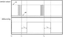
도 11을 참조하면, 컨트롤러(170)는 터치 측정부(230)에서 전달 받은 접촉 신호를 기초로 수술 로봇 장치(1)를 구동시킬 수 있다.Referring to FIG. 11, the
컨트롤러(170)는 디바운싱(debouncing)방식으로 터치 측정부(230)에서 전달받은 신호에서 발생하는 채터링(chattering)과 같은 노이즈를 줄일 수 있다.The
예를 들면, 마스터 콘솔(20)의 상태가 Off인 경우에는 On의 상태로 되기 위해서는 터치 측정부(230)의 출력이 On인 상태로 미리 정해진 일정 시간 동안 지속해야 한다. 사용자 인터페이스 장치(200)의 터치 측정부(230)에서 오퍼레이터(O)의 접촉신호를 수신하면, 기 설정된 제1 지연 시간(td1)이 도과된 후에 마스터 콘솔(20)을 구동한다. 이때, 컨트롤러(170)는 접촉신호가 터치 측정부(230)에서 지속적으로 On의 출력이 유지되면, 제1 지연 시간(td1)을 측정한다.For example, when the state of the
마스터 콘솔(20)의 상태가 On인 경우에는 Off 상태로 되기 위해서는 터치 측정부(230)의 출력이 Off인 상태로 미리 정해진 일정 시간 동안 지속해야 한다. 사용자 인터페이스 장치(200)의 터치 측정부(230)에서 오퍼레이터(O)의 접촉신호가 해제되면, 제2 지연 시간(td2)이 도과된 후에 마스터 콘솔(20)의 구동을 정지한다. 이때, 컨트롤러(170)는 접촉신호가 터치 측정부(230)에서 지속적으로 Off의 출력이 유지되면, 제2 지연 시간(td2)을 측정한다.When the state of the
제1 지연 시간(td1)은 완전히 On 출력이 유지되어야 기산되므로, 터치 측정부(230)에서의 접촉이 불완전하면 마스터 콘솔(20)은 구동되지 않는다. 또한, 제2 지연 시간(td2)은 완전히 Off 출력이 유지되어야 기산되므로, 터치 측정부(230)에서 접촉이 불완전하면 마스터 콘솔(20)은 전원을 유지한다. 이로써, 수술 로봇 장치(1)의 안전이 확보될 수 있다.Since the first delay time td1 is calculated only when the On output is completely maintained, the
제2 지연 시간(td2)은 제1 지연 시간(td1)보다 길다. 제2 지연 시간(td2)이 길게 설정되므로, 오퍼레이터(O)가 실수로 터치 측정부(230)의 터치를 유지하지 않아도, 마스터 콘솔(20)의 구동은 유지되어 환자(P)의 안전을 확보할 수 있다.The second delay time td2 is longer than the first delay time td1. Since the second delay time td2 is set to be long, even if the operator O does not accidentally maintain the touch of the
본 발명에 따른 사용자 인터페이스 장치, 수술 로봇 장치의 마스터 콘솔과 그 구동방법은 오퍼레이터가 직관적으로 사용자 인터페이스 장치를 조작하여, 마스터 콘솔 및 수술 로봇 장치를 제어할 수 있다. 사용자 인터페이스 장치는 오퍼레이터가 가하는 한 방향의 힘을 통해서 수술도구를 이용할 수 있으므로, 수술 집도의 직관성이 향상될 수 있다. 또한, 오퍼레이터에 따라 마스터 콘솔이 셋팅되므로, 수술 준비 절차를 간소화 할 수 있다.In the user interface device according to the present invention, the master console of the surgical robot device and its driving method, the operator can intuitively operate the user interface device to control the master console and the surgical robot device. Since the user interface device can use the surgical tool through a force in one direction applied by the operator, the intuitiveness of the surgical intensity can be improved. In addition, since the master console is set according to the operator, it is possible to simplify the surgical preparation procedure.
본 발명에 따른 사용자 인터페이스 장치, 수술 로봇 장치의 마스터 콘솔과 그 구동방법은 환자가 안전한 상태에서 수술을 수행할 수 있다. 사용자 인터페이스 장치는 수술도구의 개도이나 그립력을 직관적으로 인식할 수 있으며, 디바운싱을 적용하여 안전한 상태로 마스터 콘솔을 구동하므로, 수술 전과정에서의 안전성이 향상될 수 있다.The user interface device according to the present invention, the master console of the surgical robot device and its driving method can perform surgery in a safe state of the patient. The user interface device can intuitively recognize the opening or gripping force of the surgical tool, and by applying the debounce to drive the master console in a safe state, safety in the entire operation can be improved.
본 발명에 따른 사용자 인터페이스 장치, 수술 로봇 장치의 마스터 콘솔과 그 구동방법은 힘/토크 센서를 적용하여 마스터 콘솔을 정확하게 제어할 수 있다.The user interface device according to the present invention, the master console of the surgical robot device and its driving method can accurately control the master console by applying a force/torque sensor.
본 명세서에서는 본 발명을 한정된 실시예를 중심으로 설명하였으나, 본 발명의 범위 내에서 다양한 실시예가 가능하다. 또한 설명되지는 않았으나, 균등한 수단도 또한 본 발명에 그대로 결합되는 것이라 할 것이다. 따라서 본 발명의 진정한 보호범위는 아래의 특허청구범위에 의하여 정해져야 할 것이다.In the present specification, the present invention has been mainly described with limited embodiments, but various embodiments are possible within the scope of the present invention. Also, although not described, it will be said that equivalent means are also incorporated into the present invention. Therefore, the true protection scope of the present invention should be defined by the claims below.
1: 수술 로봇 장치
10: 슬레이브 로봇
20: 마스터 콘솔
22: 포지셔닝 암
23: 짐벌 암
170: 컨트롤러
200: 사용자 인터페이스 장치
210: 하우징
220: 제1 힘 측정부
230: 터치 측정부
240: 커넥터
250: 표시부
260: 정보 저장부
270: 스위칭부1: surgical robot device
10: slave robot
20: master console
22: positioning arm
23: gimbal arm
170: controller
200: user interface device
210: housing
220: first force measurement unit
230: touch measurement unit
240: connector
250: display unit
260: information storage
270: switching unit
Claims (18)
Translated fromKorean상기 수술도구의 위치를 설정하는 포지셔닝 암;
상기 포지셔닝 암의 단부에 배치되며, 상기 수술도구의 방향을 설정하는 짐벌 암;
상기 짐벌 암의 단부에 회전가능하게 장착 및 탈착되고, 상기 사용자가 접촉을 감지하고, 상기 사용자가 가하는 힘의 크기를 측정할 수 있는 사용자 인터페이스 장치; 및
상기 사용자 인터페이스 장치에서 전달받은 힘이나 접촉에 대한 정보를 기초로 상기 수술도구를 제어하는 컨트롤러;를 포함하는, 수술 로봇 장치의 마스터 콘솔.In the master console of the surgical robot device for the user to remotely control the slave robot equipped with a surgical tool,
A positioning arm for setting the position of the surgical tool;
A gimbal arm disposed at an end of the positioning arm and setting a direction of the surgical tool;
A user interface device rotatably mounted and detachable at an end of the gimbal arm, the user sensing a contact, and measuring a magnitude of the force exerted by the user; And
A controller for controlling the surgical tool based on information on the force or contact received from the user interface device.
상기 사용자 인터페이스 장치는
하우징;
일부가 상기 하우징의 외측 표면에 노출되며, 상기 사용자가 가하는 힘을 측정하는 제1 힘 측정부;
상기 제1 힘 측정부와 이격되게 배치되며, 일부가 상기 하우징의 외측 표면에 노출되어 상기 사용자의 접촉을 감지하는 터치 측정부; 및
상기 하우징의 일측에 배치되고, 상기 짐벌 암에 접속하는 커넥터;를 구비하는, 수술 로봇 장치의 마스터 콘솔.According to claim 1,
The user interface device
housing;
A first force measuring unit which partially exposes the outer surface of the housing and measures the force exerted by the user;
A touch measuring unit disposed to be spaced apart from the first force measuring unit and partially exposed to an outer surface of the housing to sense the user's contact; And
A connector disposed on one side of the housing and connected to the gimbal arm; including, a master console of the surgical robot apparatus.
상기 하우징은 구 형상을 가지는, 수술 로봇 장치의 마스터 콘솔.According to claim 2,
The housing has a spherical shape, the master console of the surgical robot apparatus.
상기 제1 힘 측정부는
상기 하우징의 외측에 배치되는 접촉 패드;
상기 접촉 패드와 연결되며, 스트레인 게이지가 설치되는 브릿지; 및
상기 브릿지와 연결되며, 상기 하우징에 고정되는 고정단;을 구비하는, 수술 로봇 장치의 마스터 콘솔.According to claim 2,
The first force measurement unit
A contact pad disposed outside the housing;
A bridge connected to the contact pad and on which a strain gauge is installed; And
It is connected to the bridge, a fixed end fixed to the housing; having, the master console of the surgical robot apparatus.
상기 사용자 인터페이스 장치는
사용자 정보를 저장하는 정보 저장부;를 더 구비하며,
상기 컨트롤러는
상기 사용자 인터페이스 장치가 상기 짐벌 암에 장착되면, 상기 사용자 정보에 대응하여 상기 포지셔닝 암과 상기 짐벌 암의 위치를 설정하는, 수술 로봇 장치의 마스터 콘솔.According to claim 2,
The user interface device
It further comprises an information storage unit for storing user information,
The controller
When the user interface device is mounted on the gimbal arm, the master console of the surgical robot device sets the positions of the positioning arm and the gimbal arm in response to the user information.
상기 사용자 인터페이스 장치는
상기 하우징의 외측에 배치되며, 사용자 인터페이스 장치의 상태에 관한 정보를 표시하는 표시부;를 더 구비하는, 수술 로봇 장치의 마스터 콘솔.According to claim 2,
The user interface device
Is disposed on the outside of the housing, a display unit for displaying information on the state of the user interface device; further comprising, a master console of the surgical robot device.
상기 사용자 인터페이스 장치는
상기 슬레이브 로봇의 위치를 변경하여 상기 수술도구를 교체하거나, 상기 슬레이브 로봇에 장착된 카메라의 위치를 변경하는 스위칭부;를 더 구비하는, 수술 로봇 장치의 마스터 콘솔.According to claim 2,
The user interface device
A switching unit for changing the position of the slave robot to replace the surgical tool or to change the position of the camera mounted on the slave robot; further comprising a master console of the surgical robot device.
상기 사용자 인터페이스 장치는
상기 제1 힘 측정부의 아래에 배치되는 제2 힘 측정부;를 더 구비하는, 수술 로봇 장치의 마스터 콘솔.According to claim 2,
The user interface device
Further comprising, a second force measuring unit disposed below the first force measuring unit, the master console of the surgical robot apparatus.
상기 컨트롤러는
상기 사용자 인터페이스 장치에서 측정된 사용자의 힘의 크기가 기 설정된 범위이면, 상기 수술도구의 한 쌍의 조(jaw) 사이의 개도를 조절하고,
상기 사용자 인터페이스 장치에서 측정된 사용자의 힘의 크기가 기 설정된 범위를 초과하면, 상기 수술도구의 한 쌍의 조(jaw) 사이의 그립력을 조절하는, 수술 로봇 장치의 마스터 콘솔.According to claim 1,
The controller
If the magnitude of the user's force measured by the user interface device is within a preset range, the opening degree between a pair of jaws of the surgical tool is adjusted,
When the magnitude of the user's force measured by the user interface device exceeds a preset range, the master console of the surgical robot device controls the grip force between the pair of jaws of the surgical tool.
상기 컨트롤러는
상기 사용자 인터페이스 장치에서 상기 사용자의 접촉신호를 수신하면, 기 설정된 제1 지연 시간이 도과된 후에 상기 마스터 콘솔을 구동시키고,
상기 사용자 인터페이스 장치에서 상기 사용자의 접촉신호가 해제되면, 상기 제1 지연 시간보다 긴 제2 지연 시간이 도과된 후에 상기 마스터 콘솔의 구동을 정지하는, 수술 로봇 장치의 마스터 콘솔.According to claim 1,
The controller
When the user interface device receives the user's contact signal, the master console is driven after the preset first delay time has elapsed,
When the user's contact signal is released from the user interface device, the master console of the surgical robot device stops driving the master console after a second delay time longer than the first delay time is reached.
하우징;
일부가 상기 하우징의 외측 표면에 노출되며, 상기 사용자가 가하는 힘을 측정하는 제1 힘 측정부;
상기 제1 힘 측정부와 이격되게 배치되며, 일부가 상기 하우징의 외측 표면에 노출되어 상기 사용자의 접촉을 측정하는 터치 측정부; 및
상기 하우징의 일측에 배치되고, 상기 마스터 콘솔에 접속하는 커넥터;를 구비하는, 사용자 인터페이스 장치.In the user interface device mounted on the master console of the surgical robot device for the user to remotely control the slave robot equipped with a surgical tool,
housing;
A first force measuring unit which partially exposes the outer surface of the housing and measures the force exerted by the user;
A touch measuring unit disposed to be spaced apart from the first force measuring unit and partially exposed to an outer surface of the housing to measure the user's contact; And
And a connector disposed on one side of the housing and connected to the master console.
상기 제1 힘 측정부에서 측정된 힘의 크기가 기 설정된 범위이면, 상기 수술도구의 한 쌍의 조(jaw) 사이의 개도를 조절하고,
상기 제1 힘 측정부에서 측정된 힘의 크기가 기 설정된 범위를 초과하면, 상기 수술도구의 한 쌍의 조(jaw) 사이의 그립력을 조절하는, 사용자 인터페이스 장치.The method of claim 11,
If the magnitude of the force measured by the first force measurement unit is a predetermined range, adjust the opening degree between a pair of jaws of the surgical tool,
When the magnitude of the force measured by the first force measurement unit exceeds a predetermined range, adjusts the grip force between a pair of jaws of the surgical tool, a user interface device.
상기 제1 힘 측정부의 아래에 배치되는 제2 힘 측정부;를 더 구비하는, 사용자 인터페이스 장치.The method of claim 11,
And a second force measurement unit disposed under the first force measurement unit.
사용자 인터페이스 장치를 마스터 콘솔에 장착하는 단계;
사용자가 상기 사용자 인터페이스 장치의 터치 측정부를 접촉하여 상기 마스터 콘솔을 구동하는 단계;
상기 마스터 콘솔의 포지셔닝 암과 짐 벌암을 구동시켜서 상기 수술도구의 위치와 방향을 설정하는 단계; 및
상기 사용자 인터페이스 장치의 제1 힘 측정부에서 측정된 힘의 크기에 대한 데이터를 기초로 상기 수술도구의 조(jaw)의 개도와 그립력을 조절하는 수술도구 조작 단계;를 포함하는, 수술 로봇 장치의 마스터 콘솔의 조작 방법.In the operation method of the master console of the surgical robot device for remote control of the slave robot equipped with a surgical tool,
Mounting the user interface device to the master console;
A user driving the master console by touching a touch measurement unit of the user interface device;
Setting the position and direction of the surgical tool by driving the positioning arm and the gimbal arm of the master console; And
A surgical tool operation step of adjusting the opening and gripping force of the jaw of the surgical tool based on the data on the magnitude of the force measured by the first force measuring unit of the user interface device. How to operate the master console.
상기 수술도구 조작 단계는
상기 제1 힘 측정부에서 측정된 힘의 크기가 기 설정된 범위이면, 상기 수술도구의 한 쌍의 조(jaw) 사이의 개도를 조절하고,
상기 제1 힘 측정부에서 측정된 힘의 크기가 기 설정된 범위를 초과하면, 상기 수술도구의 한 쌍의 조(jaw) 사이의 그립력을 조절하는, 수술 로봇 장치의 마스터 콘솔의 조작 방법.The method of claim 14,
The surgical tool operation step
If the magnitude of the force measured by the first force measurement unit is a predetermined range, adjust the opening degree between a pair of jaws of the surgical tool,
When the magnitude of the force measured by the first force measurement unit exceeds a predetermined range, adjusting the grip force between the pair of jaws of the surgical tool, the method of operating the master console of the surgical robot apparatus.
상기 마스터 콘솔을 구동하는 단계는
상기 터치 측정부에서 상기 사용자의 접촉신호를 수신하면, 기 설정된 제1 지연 시간 이후에 상기 마스터 콘솔을 구동시키는, 수술 로봇 장치의 마스터 콘솔의 조작 방법.The method of claim 14,
The step of driving the master console
When the touch measurement unit receives the user's contact signal, the master console is operated after a preset first delay time.
상기 사용자가 상기 제1 힘 측정부에 가력하는 힘을 유지하면서, 상기 제1 힘 측정부의 아래에 배치된 제2 힘 측정부를 조작하여, 상기 수술도구의 소작 기능을 실행하는 단계;를 더 포함하는, 수술 로봇 장치의 마스터 콘솔의 조작 방법.The method of claim 14,
Further comprising the step of performing the cauterization function of the surgical tool by operating the second force measurement unit disposed under the first force measurement unit, while the user maintains the force applied to the first force measurement unit. , The operation method of the master console of the surgical robot device.
상기 사용자 인터페이스 장치를 마스터 콘솔에 장착하는 단계는
상기 사용자 인터페이스 장치에서 사용자 정보를 상기 마스터 콘솔에 전송하고, 상기 사용자 정보에 대응하여 상기 마스터 콘솔의 포지셔닝 암과 짐벌 암의 위치를 설정하는, 수술 로봇 장치의 마스터 콘솔의 조작 방법.The method of claim 14,
The step of mounting the user interface device to the master console
The user interface device transmits user information to the master console, and sets a position of the positioning arm and the gimbal arm of the master console in response to the user information, the operation method of the master console of the surgical robot device.
Priority Applications (3)
| Application Number | Priority Date | Filing Date | Title |
|---|---|---|---|
| KR1020180164316AKR102221090B1 (en) | 2018-12-18 | 2018-12-18 | User interface device, master console for surgical robot apparatus and operating method of master console |
| PCT/KR2019/017856WO2020130559A2 (en) | 2018-12-18 | 2019-12-17 | User interface device, master console of surgical robot device, and operation method of master console |
| CN201980084183.0ACN113194870B (en) | 2018-12-18 | 2019-12-17 | User interface device, main control console of surgical robot device, and operation method thereof |
Applications Claiming Priority (1)
| Application Number | Priority Date | Filing Date | Title |
|---|---|---|---|
| KR1020180164316AKR102221090B1 (en) | 2018-12-18 | 2018-12-18 | User interface device, master console for surgical robot apparatus and operating method of master console |
Publications (2)
| Publication Number | Publication Date |
|---|---|
| KR20200075535Atrue KR20200075535A (en) | 2020-06-26 |
| KR102221090B1 KR102221090B1 (en) | 2021-02-26 |
Family
ID=71101402
Family Applications (1)
| Application Number | Title | Priority Date | Filing Date |
|---|---|---|---|
| KR1020180164316AActiveKR102221090B1 (en) | 2018-12-18 | 2018-12-18 | User interface device, master console for surgical robot apparatus and operating method of master console |
Country Status (3)
| Country | Link |
|---|---|
| KR (1) | KR102221090B1 (en) |
| CN (1) | CN113194870B (en) |
| WO (1) | WO2020130559A2 (en) |
Families Citing this family (4)
| Publication number | Priority date | Publication date | Assignee | Title |
|---|---|---|---|---|
| KR20230079178A (en)* | 2020-09-30 | 2023-06-05 | 버브 서지컬 인크. | Limitation of grip force in position control mode and maintenance of minimum jaw opening force, and control of grip force when switching between position control mode and force mode |
| EP4299032A4 (en)* | 2021-02-26 | 2024-09-25 | Wuhan United Imaging Healthcare Surgical Technology Co., Ltd. | MASTER HAND CONTROL DEVICE FOR ROBOTS AND ROBOTS |
| CN114391966B (en)* | 2022-01-20 | 2023-09-29 | 天津大学 | A new type of force feedback master hand |
| CN116636934B (en)* | 2023-06-28 | 2023-09-26 | 敏捷医疗科技(苏州)有限公司 | Master-slave delay testing device of surgical robot |
Citations (4)
| Publication number | Priority date | Publication date | Assignee | Title |
|---|---|---|---|---|
| KR20110004496A (en)* | 2009-07-08 | 2011-01-14 | 주식회사 이턴 | Surgical Robot and Setting Method |
| KR101096571B1 (en)* | 2011-03-03 | 2011-12-21 | 주식회사 이턴 | Force or torque measuring device of robot haptic master device and method thereof |
| KR20140121581A (en)* | 2013-04-08 | 2014-10-16 | 삼성전자주식회사 | Surgical robot system |
| KR101802463B1 (en)* | 2011-06-02 | 2017-11-28 | 주식회사 미래컴퍼니 | Master gripper of surgical robot and control method of surgical robot having the same |
Family Cites Families (11)
| Publication number | Priority date | Publication date | Assignee | Title |
|---|---|---|---|---|
| US8944070B2 (en)* | 1999-04-07 | 2015-02-03 | Intuitive Surgical Operations, Inc. | Non-force reflecting method for providing tool force information to a user of a telesurgical system |
| US8004229B2 (en)* | 2005-05-19 | 2011-08-23 | Intuitive Surgical Operations, Inc. | Software center and highly configurable robotic systems for surgery and other uses |
| CN107510506A (en)* | 2009-03-24 | 2017-12-26 | 伊顿株式会社 | Utilize the surgical robot system and its control method of augmented reality |
| US9119655B2 (en)* | 2012-08-03 | 2015-09-01 | Stryker Corporation | Surgical manipulator capable of controlling a surgical instrument in multiple modes |
| KR20130015440A (en)* | 2011-08-03 | 2013-02-14 | 주식회사 이턴 | Master gripper of surgical robot |
| JP5841451B2 (en)* | 2011-08-04 | 2016-01-13 | オリンパス株式会社 | Surgical instrument and control method thereof |
| WO2013059643A1 (en)* | 2011-10-21 | 2013-04-25 | Intuitive Surgical Operations, Inc. | Grip force control for robotic surgical instrument end effector |
| KR101527176B1 (en)* | 2013-12-09 | 2015-06-09 | (주)미래컴퍼니 | Surgical Robot Apparatus and Method for Controlling Surgical Robot Apparatus |
| KR101642883B1 (en)* | 2015-06-05 | 2016-07-27 | (주)미래컴퍼니 | Surgical robot system and control method thereof |
| CN104939800B (en)* | 2015-06-16 | 2017-04-05 | 西南医科大学附属医院 | A kind of the intestines and stomach automatic detection surgery apparatus |
| CN105105849B (en)* | 2015-07-22 | 2017-05-10 | 北京航空航天大学 | A robotic end effector in anterior cruciate ligament reconstruction |
- 2018
- 2018-12-18KRKR1020180164316Apatent/KR102221090B1/enactiveActive
- 2019
- 2019-12-17WOPCT/KR2019/017856patent/WO2020130559A2/ennot_activeCeased
- 2019-12-17CNCN201980084183.0Apatent/CN113194870B/enactiveActive
Patent Citations (4)
| Publication number | Priority date | Publication date | Assignee | Title |
|---|---|---|---|---|
| KR20110004496A (en)* | 2009-07-08 | 2011-01-14 | 주식회사 이턴 | Surgical Robot and Setting Method |
| KR101096571B1 (en)* | 2011-03-03 | 2011-12-21 | 주식회사 이턴 | Force or torque measuring device of robot haptic master device and method thereof |
| KR101802463B1 (en)* | 2011-06-02 | 2017-11-28 | 주식회사 미래컴퍼니 | Master gripper of surgical robot and control method of surgical robot having the same |
| KR20140121581A (en)* | 2013-04-08 | 2014-10-16 | 삼성전자주식회사 | Surgical robot system |
Also Published As
| Publication number | Publication date |
|---|---|
| WO2020130559A2 (en) | 2020-06-25 |
| CN113194870A (en) | 2021-07-30 |
| WO2020130559A3 (en) | 2020-08-06 |
| CN113194870B (en) | 2024-05-14 |
| KR102221090B1 (en) | 2021-02-26 |
Similar Documents
| Publication | Publication Date | Title |
|---|---|---|
| CN111770737B (en) | Haptic Hand Controller for Microsurgery | |
| US11737838B2 (en) | Robotic hand controller | |
| CN111084661B (en) | Surgical assistance device and recording medium | |
| US9713500B2 (en) | Surgical robot control apparatus | |
| CN113194870B (en) | User interface device, main control console of surgical robot device, and operation method thereof | |
| TW201719312A (en) | Robot system | |
| CN107961078A (en) | Surgical robot system and its operating theater instruments | |
| US10532466B2 (en) | Robotic hand controller | |
| WO2020154012A1 (en) | Wearable user interface device | |
| JP2020065910A (en) | Surgery assistance apparatus | |
| JP2020065904A (en) | Surgery support device | |
| WO2021188017A1 (en) | Assistive surgical complex | |
| WO2020209165A1 (en) | Surgical operation system and method for controlling surgical operation system | |
| RU2716353C1 (en) | Hand controller for use in robot surgery system operator's controller | |
| JP2023061245A (en) | Surgery support robot | |
| WO2025205060A1 (en) | Input device, operation console device, and surgery assistance robot system |
Legal Events
| Date | Code | Title | Description |
|---|---|---|---|
| PA0109 | Patent application | Patent event code:PA01091R01D Comment text:Patent Application Patent event date:20181218 | |
| PA0201 | Request for examination | ||
| E902 | Notification of reason for refusal | ||
| PE0902 | Notice of grounds for rejection | Comment text:Notification of reason for refusal Patent event date:20200611 Patent event code:PE09021S01D | |
| PG1501 | Laying open of application | ||
| AMND | Amendment | ||
| E601 | Decision to refuse application | ||
| PE0601 | Decision on rejection of patent | Patent event date:20201218 Comment text:Decision to Refuse Application Patent event code:PE06012S01D Patent event date:20200611 Comment text:Notification of reason for refusal Patent event code:PE06011S01I | |
| X091 | Application refused [patent] | ||
| AMND | Amendment | ||
| PX0901 | Re-examination | Patent event code:PX09011S01I Patent event date:20201218 Comment text:Decision to Refuse Application Patent event code:PX09012R01I Patent event date:20200811 Comment text:Amendment to Specification, etc. | |
| PX0701 | Decision of registration after re-examination | Patent event date:20210201 Comment text:Decision to Grant Registration Patent event code:PX07013S01D Patent event date:20210107 Comment text:Amendment to Specification, etc. Patent event code:PX07012R01I Patent event date:20201218 Comment text:Decision to Refuse Application Patent event code:PX07011S01I Patent event date:20200811 Comment text:Amendment to Specification, etc. Patent event code:PX07012R01I | |
| X701 | Decision to grant (after re-examination) | ||
| GRNT | Written decision to grant | ||
| PR0701 | Registration of establishment | Comment text:Registration of Establishment Patent event date:20210222 Patent event code:PR07011E01D | |
| PR1002 | Payment of registration fee | Payment date:20210223 End annual number:3 Start annual number:1 | |
| PG1601 | Publication of registration | ||
| PR1001 | Payment of annual fee | Payment date:20230314 Start annual number:4 End annual number:6 |