KR20200075014A - Noise-adaptive solid-state LIDAR system - Google Patents
Noise-adaptive solid-state LIDAR systemDownload PDFInfo
- Publication number
- KR20200075014A KR20200075014AKR1020207016928AKR20207016928AKR20200075014AKR 20200075014 AKR20200075014 AKR 20200075014AKR 1020207016928 AKR1020207016928 AKR 1020207016928AKR 20207016928 AKR20207016928 AKR 20207016928AKR 20200075014 AKR20200075014 AKR 20200075014A
- Authority
- KR
- South Korea
- Prior art keywords
- lasers
- detectors
- light
- lidar system
- electrical
- Prior art date
- Legal status (The legal status is an assumption and is not a legal conclusion. Google has not performed a legal analysis and makes no representation as to the accuracy of the status listed.)
- Granted
Links
- 238000005259measurementMethods0.000claimsabstractdescription52
- 238000005286illuminationMethods0.000claimsabstractdescription44
- 238000001514detection methodMethods0.000claimsabstractdescription40
- 230000003287optical effectEffects0.000claimsabstractdescription31
- 238000000034methodMethods0.000claimsdescription69
- XUIMIQQOPSSXEZ-UHFFFAOYSA-NSiliconChemical compound[Si]XUIMIQQOPSSXEZ-UHFFFAOYSA-N0.000claimsdescription4
- 229910052710siliconInorganic materials0.000claimsdescription4
- 239000010703siliconSubstances0.000claimsdescription4
- 230000005611electricityEffects0.000claims1
- 238000001914filtrationMethods0.000claims1
- 238000010586diagramMethods0.000description29
- 230000006870functionEffects0.000description10
- 238000012935AveragingMethods0.000description9
- 238000003491arrayMethods0.000description9
- 238000010791quenchingMethods0.000description9
- 230000000171quenching effectEffects0.000description9
- 230000003044adaptive effectEffects0.000description8
- 238000012545processingMethods0.000description8
- 230000005855radiationEffects0.000description6
- 238000004364calculation methodMethods0.000description5
- 238000013461designMethods0.000description5
- 238000010304firingMethods0.000description5
- 239000007787solidSubstances0.000description5
- 230000004044responseEffects0.000description4
- 238000000098azimuthal photoelectron diffractionMethods0.000description3
- 230000008901benefitEffects0.000description3
- 230000006872improvementEffects0.000description3
- 238000012986modificationMethods0.000description3
- 230000004048modificationEffects0.000description3
- 238000013459approachMethods0.000description2
- 230000005540biological transmissionEffects0.000description2
- 230000008859changeEffects0.000description2
- 238000004891communicationMethods0.000description2
- 238000005516engineering processMethods0.000description2
- 230000008569processEffects0.000description2
- 230000003068static effectEffects0.000description2
- RVCKCEDKBVEEHL-UHFFFAOYSA-N2,3,4,5,6-pentachlorobenzyl alcoholChemical compoundOCC1=C(Cl)C(Cl)=C(Cl)C(Cl)=C1ClRVCKCEDKBVEEHL-UHFFFAOYSA-N0.000description1
- 230000003466anti-cipated effectEffects0.000description1
- 230000000712assemblyEffects0.000description1
- 238000000429assemblyMethods0.000description1
- 230000000903blocking effectEffects0.000description1
- 230000015556catabolic processEffects0.000description1
- 230000007423decreaseEffects0.000description1
- 230000000694effectsEffects0.000description1
- 230000007613environmental effectEffects0.000description1
- 230000004927fusionEffects0.000description1
- 238000009532heart rate measurementMethods0.000description1
- 230000007774longtermEffects0.000description1
- 238000013507mappingMethods0.000description1
- 239000011159matrix materialSubstances0.000description1
- 238000012544monitoring processMethods0.000description1
- 230000009467reductionEffects0.000description1
- 238000002310reflectometryMethods0.000description1
- 238000005070samplingMethods0.000description1
- 230000035945sensitivityEffects0.000description1
- 230000001960triggered effectEffects0.000description1
Images


Classifications
- G—PHYSICS
- G01—MEASURING; TESTING
- G01S—RADIO DIRECTION-FINDING; RADIO NAVIGATION; DETERMINING DISTANCE OR VELOCITY BY USE OF RADIO WAVES; LOCATING OR PRESENCE-DETECTING BY USE OF THE REFLECTION OR RERADIATION OF RADIO WAVES; ANALOGOUS ARRANGEMENTS USING OTHER WAVES
- G01S7/00—Details of systems according to groups G01S13/00, G01S15/00, G01S17/00
- G01S7/48—Details of systems according to groups G01S13/00, G01S15/00, G01S17/00 of systems according to group G01S17/00
- G01S7/483—Details of pulse systems
- G01S7/486—Receivers
- G01S7/4861—Circuits for detection, sampling, integration or read-out
- G—PHYSICS
- G01—MEASURING; TESTING
- G01S—RADIO DIRECTION-FINDING; RADIO NAVIGATION; DETERMINING DISTANCE OR VELOCITY BY USE OF RADIO WAVES; LOCATING OR PRESENCE-DETECTING BY USE OF THE REFLECTION OR RERADIATION OF RADIO WAVES; ANALOGOUS ARRANGEMENTS USING OTHER WAVES
- G01S7/00—Details of systems according to groups G01S13/00, G01S15/00, G01S17/00
- G01S7/48—Details of systems according to groups G01S13/00, G01S15/00, G01S17/00 of systems according to group G01S17/00
- G01S7/483—Details of pulse systems
- G01S7/486—Receivers
- G01S7/4868—Controlling received signal intensity or exposure of sensor
- G—PHYSICS
- G01—MEASURING; TESTING
- G01S—RADIO DIRECTION-FINDING; RADIO NAVIGATION; DETERMINING DISTANCE OR VELOCITY BY USE OF RADIO WAVES; LOCATING OR PRESENCE-DETECTING BY USE OF THE REFLECTION OR RERADIATION OF RADIO WAVES; ANALOGOUS ARRANGEMENTS USING OTHER WAVES
- G01S7/00—Details of systems according to groups G01S13/00, G01S15/00, G01S17/00
- G01S7/48—Details of systems according to groups G01S13/00, G01S15/00, G01S17/00 of systems according to group G01S17/00
- G01S7/481—Constructional features, e.g. arrangements of optical elements
- G01S7/4814—Constructional features, e.g. arrangements of optical elements of transmitters alone
- G01S7/4815—Constructional features, e.g. arrangements of optical elements of transmitters alone using multiple transmitters
- B—PERFORMING OPERATIONS; TRANSPORTING
- B60—VEHICLES IN GENERAL
- B60W—CONJOINT CONTROL OF VEHICLE SUB-UNITS OF DIFFERENT TYPE OR DIFFERENT FUNCTION; CONTROL SYSTEMS SPECIALLY ADAPTED FOR HYBRID VEHICLES; ROAD VEHICLE DRIVE CONTROL SYSTEMS FOR PURPOSES NOT RELATED TO THE CONTROL OF A PARTICULAR SUB-UNIT
- B60W40/00—Estimation or calculation of non-directly measurable driving parameters for road vehicle drive control systems not related to the control of a particular sub unit, e.g. by using mathematical models
- B60W40/02—Estimation or calculation of non-directly measurable driving parameters for road vehicle drive control systems not related to the control of a particular sub unit, e.g. by using mathematical models related to ambient conditions
- G—PHYSICS
- G01—MEASURING; TESTING
- G01S—RADIO DIRECTION-FINDING; RADIO NAVIGATION; DETERMINING DISTANCE OR VELOCITY BY USE OF RADIO WAVES; LOCATING OR PRESENCE-DETECTING BY USE OF THE REFLECTION OR RERADIATION OF RADIO WAVES; ANALOGOUS ARRANGEMENTS USING OTHER WAVES
- G01S17/00—Systems using the reflection or reradiation of electromagnetic waves other than radio waves, e.g. lidar systems
- G01S17/02—Systems using the reflection of electromagnetic waves other than radio waves
- G01S17/06—Systems determining position data of a target
- G01S17/42—Simultaneous measurement of distance and other co-ordinates
- G—PHYSICS
- G01—MEASURING; TESTING
- G01S—RADIO DIRECTION-FINDING; RADIO NAVIGATION; DETERMINING DISTANCE OR VELOCITY BY USE OF RADIO WAVES; LOCATING OR PRESENCE-DETECTING BY USE OF THE REFLECTION OR RERADIATION OF RADIO WAVES; ANALOGOUS ARRANGEMENTS USING OTHER WAVES
- G01S17/00—Systems using the reflection or reradiation of electromagnetic waves other than radio waves, e.g. lidar systems
- G01S17/88—Lidar systems specially adapted for specific applications
- G01S17/89—Lidar systems specially adapted for specific applications for mapping or imaging
- G—PHYSICS
- G01—MEASURING; TESTING
- G01S—RADIO DIRECTION-FINDING; RADIO NAVIGATION; DETERMINING DISTANCE OR VELOCITY BY USE OF RADIO WAVES; LOCATING OR PRESENCE-DETECTING BY USE OF THE REFLECTION OR RERADIATION OF RADIO WAVES; ANALOGOUS ARRANGEMENTS USING OTHER WAVES
- G01S17/00—Systems using the reflection or reradiation of electromagnetic waves other than radio waves, e.g. lidar systems
- G01S17/88—Lidar systems specially adapted for specific applications
- G01S17/93—Lidar systems specially adapted for specific applications for anti-collision purposes
- G01S17/931—Lidar systems specially adapted for specific applications for anti-collision purposes of land vehicles
- G—PHYSICS
- G01—MEASURING; TESTING
- G01S—RADIO DIRECTION-FINDING; RADIO NAVIGATION; DETERMINING DISTANCE OR VELOCITY BY USE OF RADIO WAVES; LOCATING OR PRESENCE-DETECTING BY USE OF THE REFLECTION OR RERADIATION OF RADIO WAVES; ANALOGOUS ARRANGEMENTS USING OTHER WAVES
- G01S7/00—Details of systems according to groups G01S13/00, G01S15/00, G01S17/00
- G01S7/48—Details of systems according to groups G01S13/00, G01S15/00, G01S17/00 of systems according to group G01S17/00
- G01S7/481—Constructional features, e.g. arrangements of optical elements
- G01S7/4816—Constructional features, e.g. arrangements of optical elements of receivers alone
- G—PHYSICS
- G01—MEASURING; TESTING
- G01S—RADIO DIRECTION-FINDING; RADIO NAVIGATION; DETERMINING DISTANCE OR VELOCITY BY USE OF RADIO WAVES; LOCATING OR PRESENCE-DETECTING BY USE OF THE REFLECTION OR RERADIATION OF RADIO WAVES; ANALOGOUS ARRANGEMENTS USING OTHER WAVES
- G01S7/00—Details of systems according to groups G01S13/00, G01S15/00, G01S17/00
- G01S7/48—Details of systems according to groups G01S13/00, G01S15/00, G01S17/00 of systems according to group G01S17/00
- G01S7/483—Details of pulse systems
- G01S7/484—Transmitters
- G—PHYSICS
- G01—MEASURING; TESTING
- G01S—RADIO DIRECTION-FINDING; RADIO NAVIGATION; DETERMINING DISTANCE OR VELOCITY BY USE OF RADIO WAVES; LOCATING OR PRESENCE-DETECTING BY USE OF THE REFLECTION OR RERADIATION OF RADIO WAVES; ANALOGOUS ARRANGEMENTS USING OTHER WAVES
- G01S7/00—Details of systems according to groups G01S13/00, G01S15/00, G01S17/00
- G01S7/48—Details of systems according to groups G01S13/00, G01S15/00, G01S17/00 of systems according to group G01S17/00
- G01S7/483—Details of pulse systems
- G01S7/486—Receivers
- G01S7/4861—Circuits for detection, sampling, integration or read-out
- G01S7/4863—Detector arrays, e.g. charge-transfer gates
- G—PHYSICS
- G01—MEASURING; TESTING
- G01S—RADIO DIRECTION-FINDING; RADIO NAVIGATION; DETERMINING DISTANCE OR VELOCITY BY USE OF RADIO WAVES; LOCATING OR PRESENCE-DETECTING BY USE OF THE REFLECTION OR RERADIATION OF RADIO WAVES; ANALOGOUS ARRANGEMENTS USING OTHER WAVES
- G01S7/00—Details of systems according to groups G01S13/00, G01S15/00, G01S17/00
- G01S7/48—Details of systems according to groups G01S13/00, G01S15/00, G01S17/00 of systems according to group G01S17/00
- G01S7/483—Details of pulse systems
- G01S7/486—Receivers
- G01S7/4865—Time delay measurement, e.g. time-of-flight measurement, time of arrival measurement or determining the exact position of a peak
- G—PHYSICS
- G01—MEASURING; TESTING
- G01S—RADIO DIRECTION-FINDING; RADIO NAVIGATION; DETERMINING DISTANCE OR VELOCITY BY USE OF RADIO WAVES; LOCATING OR PRESENCE-DETECTING BY USE OF THE REFLECTION OR RERADIATION OF RADIO WAVES; ANALOGOUS ARRANGEMENTS USING OTHER WAVES
- G01S7/00—Details of systems according to groups G01S13/00, G01S15/00, G01S17/00
- G01S7/48—Details of systems according to groups G01S13/00, G01S15/00, G01S17/00 of systems according to group G01S17/00
- G01S7/483—Details of pulse systems
- G01S7/486—Receivers
- G01S7/487—Extracting wanted echo signals, e.g. pulse detection
- G01S7/4876—Extracting wanted echo signals, e.g. pulse detection by removing unwanted signals
- G—PHYSICS
- G01—MEASURING; TESTING
- G01S—RADIO DIRECTION-FINDING; RADIO NAVIGATION; DETERMINING DISTANCE OR VELOCITY BY USE OF RADIO WAVES; LOCATING OR PRESENCE-DETECTING BY USE OF THE REFLECTION OR RERADIATION OF RADIO WAVES; ANALOGOUS ARRANGEMENTS USING OTHER WAVES
- G01S7/00—Details of systems according to groups G01S13/00, G01S15/00, G01S17/00
- G01S7/48—Details of systems according to groups G01S13/00, G01S15/00, G01S17/00 of systems according to group G01S17/00
- G01S7/491—Details of non-pulse systems
- G01S7/4911—Transmitters
- G—PHYSICS
- G05—CONTROLLING; REGULATING
- G05D—SYSTEMS FOR CONTROLLING OR REGULATING NON-ELECTRIC VARIABLES
- G05D1/00—Control of position, course, altitude or attitude of land, water, air or space vehicles, e.g. using automatic pilots
- G05D1/02—Control of position or course in two dimensions
- G05D1/021—Control of position or course in two dimensions specially adapted to land vehicles
- G05D1/0231—Control of position or course in two dimensions specially adapted to land vehicles using optical position detecting means
- G05D1/0238—Control of position or course in two dimensions specially adapted to land vehicles using optical position detecting means using obstacle or wall sensors
- G05D1/024—Control of position or course in two dimensions specially adapted to land vehicles using optical position detecting means using obstacle or wall sensors in combination with a laser
- B—PERFORMING OPERATIONS; TRANSPORTING
- B60—VEHICLES IN GENERAL
- B60W—CONJOINT CONTROL OF VEHICLE SUB-UNITS OF DIFFERENT TYPE OR DIFFERENT FUNCTION; CONTROL SYSTEMS SPECIALLY ADAPTED FOR HYBRID VEHICLES; ROAD VEHICLE DRIVE CONTROL SYSTEMS FOR PURPOSES NOT RELATED TO THE CONTROL OF A PARTICULAR SUB-UNIT
- B60W2420/00—Indexing codes relating to the type of sensors based on the principle of their operation
- B60W2420/40—Photo, light or radio wave sensitive means, e.g. infrared sensors
- B60W2420/408—Radar; Laser, e.g. lidar
Landscapes
- Engineering & Computer Science (AREA)
- Physics & Mathematics (AREA)
- General Physics & Mathematics (AREA)
- Radar, Positioning & Navigation (AREA)
- Remote Sensing (AREA)
- Computer Networks & Wireless Communication (AREA)
- Electromagnetism (AREA)
- Automation & Control Theory (AREA)
- Mathematical Physics (AREA)
- Transportation (AREA)
- Mechanical Engineering (AREA)
- Optical Radar Systems And Details Thereof (AREA)
- Optics & Photonics (AREA)
- Aviation & Aerospace Engineering (AREA)
- Measurement Of Optical Distance (AREA)
- Photo Coupler, Interrupter, Optical-To-Optical Conversion Devices (AREA)
Abstract
Translated fromKorean
Description
Translated fromKorean본 발명은 광을 반사 및/또는 산란시키는 다양한 객체 또는 타겟까지의 거리를 측정하는 솔리드-스테이트 LIDAR 시스템에 관한 것이다.The present invention relates to a solid-state LIDAR system that measures the distance to various objects or targets that reflect and/or scatter light.
자율, 자체-주행 및 반-자율 자동차는 주변 객체의 검출 및 위치에 대해 레이더, 이미지-인식 카메라 및 소나(sonar)와 같은 상이한 센서 및 기술의 조합을 사용한다. 이러한 센서는 충돌 경고, 자동-비상 제동, 차선-이탈 경고, 차선-유지 지원, 적응형 크루즈 제어 및 파일럿 주행(piloted driving)을 포함하여 운전자 안전에 큰 개선을 가능하게 한다. 이러한 센서 기술 중 광 검출 및 거리 측정(LIDAR: light detection and ranging) 시스템은 중요한 역할을 차지하며, 주변 환경의 실시간, 고해상도 3D 매핑을 가능하게 한다.Autonomous, self-driving and semi-autonomous vehicles use a combination of different sensors and technologies such as radar, image-recognition cameras and sonars for the detection and location of surrounding objects. These sensors enable significant improvements in driver safety, including collision warning, auto-emergency braking, lane-departure warning, lane-holding support, adaptive cruise control and piloted driving. Among these sensor technologies, a light detection and ranging (LIDAR) system plays an important role and enables real-time, high-resolution 3D mapping of the surrounding environment.
자동차 어플리케이션의 점점 더 복잡해지는 어레이의 요건을 해결하기 위해, 빠르게 움직이는 객체에 반응할 수 있을 만큼 충분히 빠른 응답 시간을 갖는 LIDAR 시스템이 필요하다. LIDAR 시스템은 또한 수신된 신호가 멀리 있는 객체를 검출하기에 충분한 신호-대-잡음비를 가져야 한다. 또한, LIDAR 시스템은 최소한의 가동 부품으로 높은 신뢰성을 갖는 것이 바람직하다.To address the increasingly complex array requirements of automotive applications, a LIDAR system with a response time fast enough to respond to fast-moving objects is needed. The LIDAR system must also have a sufficient signal-to-noise ratio to detect objects in which the received signal is distant. It is also desirable that the LIDAR system has high reliability with minimal moving parts.
본 발명의 실시예에 따른, 광 검출 및 거리 측정(LIDAR: light detection and ranging) 시스템은 복수의 레이저를 포함하는 광 송신기를 포함하며, 여기서 복수의 레이저 각각은 시야(field-of-view)를 조명한다. 송신기 제어기는 복수의 레이저가 원하는 조명 영역에서 광을 생성하도록 복수의 레이저 중 원하는 레이저를 펄싱하도록 구성된다. 광 수신기는 원하는 조명 영역에 걸쳐 광을 검출하도록 위치된 복수의 검출기를 포함한다. 복수의 검출기는 전기 검출 신호를 생성한다. 비행-시간 측정 회로는 복수의 레이저로부터 복수의 검출기로의 광의 비행-시간을 측정한다. 광 수신기는 비행-시간 측정치들로부터 거리 정보를 계산한다. 수신기 제어기는 송신기 제어기에 전기적으로 접속되고 원하는 검출 신호 잡음 레벨을 달성하는 바이어스 포인트에서 복수의 검출기의 적어도 일부를 바이어싱하도록 구성된다.In accordance with an embodiment of the present invention, a light detection and ranging (LIDAR) system includes an optical transmitter comprising a plurality of lasers, where each of the plurality of lasers has a field-of-view. Illuminate. The transmitter controller is configured to pulse the desired laser among the plurality of lasers so that the plurality of lasers generate light in a desired illumination area. The optical receiver includes a plurality of detectors positioned to detect light over a desired illumination area. The multiple detectors generate electrical detection signals. The flight-time measurement circuit measures the flight-time of light from a plurality of lasers to a plurality of detectors. The optical receiver calculates distance information from flight-time measurements. The receiver controller is electrically connected to the transmitter controller and is configured to bias at least a portion of the plurality of detectors at bias points to achieve a desired detection signal noise level.
본 발명은 검출된 전기 신호에서 잡음을 감소시킴으로써 수신된 측정 신호에서 잡음을 감소시킬 수 있는 잡음-적응형 솔리드-스테이트 LIDAR 시스템을 설명한다. 이는 개선된 SNR 및 그에 따른 더 길어진 측정 범위로 귀결된다.The present invention describes a noise-adaptive solid-state LIDAR system capable of reducing noise in a received measurement signal by reducing noise in the detected electrical signal. This results in an improved SNR and thus a longer measurement range.
도 1은 차량에 구현되는 본 교시에 따른 LIDAR 시스템의 실시예를 나타낸다.
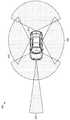
도 2는 본 교시에 따른 자동차의 주위에 대한 LIDAR 감지 시스템의 실시예의 2차원 시야 및 범위 요건을 나타내는 개략도를 나타낸다.
도 3은 본 교시의 다중-모듈 LIDAR 센서 시스템의 실시예를 나타낸다.
도 4a는 알려진 3D 플래시 LIDAR 시스템의 개략도를 나타낸다.
도 4b는 도 4a의 알려진 3D 플래시 LIDAR 시스템의 시스템 시야의 2차원 투사를 나타낸다.
도 5a는 기계적 스캐닝 접근법을 사용하는 알려진 LIDAR 시스템을 나타낸다.
도 5b는 도 5a의 LIDAR 시스템의 시스템 시야의 2차원 투사를 나타낸다.
도 6a는 본 교시에 따른 잡음-적응형 솔리드 스테이트 LIDAR 시스템의 실시예를 나타낸다.
도 6b는 도 6a의 잡음-적응형 솔리드 스테이트 LIDAR 시스템의 시스템 시야의 2차원 투사를 나타낸다.
도 6c는 개별 레이저 및 개별 검출기를 강조하는 도 6a의 잡음-적응형 솔리드 스테이트 LIDAR 시스템 시야의 2차원 투사를 나타낸다.
도 7a는 본 교시에 따른 잡음-적응형 솔리드 스테이트 LIDAR 시스템의 실시예에 대한 블록도를 나타낸다.
도 7b는 도 7a의 잡음-적응형 솔리드 스테이트 LIDAR 시스템의 실시예의 수신 및 TOF 계산 전자 기기의 상세 블록도를 나타낸다.
도 8은 알려진 초점 평면 어레이(FPA: Focal Plane Array)의 블록도를 나타낸다.
도 9는 알려진 실리콘 포토-멀티플라이어(photo-multiplier), 다중-픽셀 광자 카운터(MPPC: multi-pixel photon counter) 검출기의 개략도를 나타낸다.
도 10a는 본 교시에 따른 잡음 적응형 솔리드-스테이트 LIDAR 시스템에 대한 가이거-모드(Geiger-Mode) APD 및 ??칭(quenching) 저항을 사용하는 제어되는 검출기 어레이의 실시예의 개략도를 나타낸다.
도 10b는 본 교시에 따른 잡음 적응형 솔리드-스테이트 LIDAR 시스템에 대해 선형 APD를 사용하는 제어되는 검출기 어레이의 실시예의 개략도를 나타낸다.
도 10c는 본 교시에 따른 잡음 적응형 솔리드-스테이트 LIDAR 시스템에 대한 가이거-모드 APD 및 ??칭 저항을 갖는 4-요소 검출기 서브-어레이를 사용하는 제어되는 검출기 어레이의 실시예의 개략도를 나타낸다.
도 11a는 본 교시의 잡음 적응형 솔리드-스테이트 LIDAR 시스템의 가이거-모드 APD 및 ??칭 저항을 갖는 제어되는 검출기 어레이의 실시예에 대한 개략도를 나타낸다.
도 11b는 본 교시의 잡음 적응형 솔리드-스테이트 LIDAR 시스템에 대해 선형 APD를 사용하는 제어되는 검출기 어레이의 실시예에 대한 개략도를 나타낸다.
도 11c는 본 교시의 잡음 적응형 솔리드-스테이트 LIDAR 시스템의 가이거-모드 APD 및 ??칭 저항을 갖는 4-요소 검출기 서브-어레이를 포함하는 제어되는 검출기 어레이의 실시예에 대한 개략도를 나타낸다.
도 12는 본 교시의 LIDAR 시스템의 전단(front-end) 스위치를 갖는 증폭기를 갖는 제어되는 검출기 어레이의 실시예를 나타낸다.
도 13은 본 교시의 잡음-적응형 솔리드-스테이트 LIDAR 시스템의 알고리즘을 구현하는 방법의 실시예의 흐름도를 나타낸다.
도 14는 스마트 객체 검출을 통합하는 본 교시의 잡음-적응형 솔리드-스테이트 LIDAR 시스템의 알고리즘을 구현하는 방법의 실시예의 흐름도를 나타낸다.1 shows an embodiment of a LIDAR system according to the present teachings implemented in a vehicle.
2 shows a schematic diagram showing the two-dimensional field of view and range requirements of an embodiment of a LIDAR sensing system for the perimeter of a vehicle in accordance with the present teachings.
3 shows an embodiment of the multi-module LIDAR sensor system of the present teachings.
4A shows a schematic diagram of a known 3D flash LIDAR system.
4B shows a two-dimensional projection of the system field of view of the known 3D flash LIDAR system of FIG. 4A.
5A shows a known LIDAR system using a mechanical scanning approach.
5B shows a two-dimensional projection of the system field of view of the LIDAR system of FIG. 5A.
6A shows an embodiment of a noise-adaptive solid state LIDAR system according to the present teachings.
6B shows a two-dimensional projection of the system field of view of the noise-adaptive solid state LIDAR system of FIG. 6A.
6C shows a two-dimensional projection of the noise-adaptive solid state LIDAR system field of view of FIG. 6A highlighting individual lasers and individual detectors.
7A shows a block diagram of an embodiment of a noise-adaptive solid state LIDAR system according to the present teachings.
7B shows a detailed block diagram of a receiving and TOF calculating electronic device of the embodiment of the noise-adaptive solid state LIDAR system of FIG. 7A.
8 shows a block diagram of a known Focal Plane Array (FPA).
9 shows a schematic of a known silicon photo-multiplier, multi-pixel photon counter (MPPC) detector.
10A shows a schematic diagram of an embodiment of a controlled detector array using Geiger-Mode APD and quenching resistance for a noise-adaptive solid-state LIDAR system according to the present teachings.
10B shows a schematic diagram of an embodiment of a controlled detector array using linear APD for a noise-adaptive solid-state LIDAR system according to the present teachings.
10C shows a schematic diagram of an embodiment of a controlled detector array using a 4-element detector sub-array with Geiger-mode APD and quenching resistance for a noise-adaptive solid-state LIDAR system according to the present teachings.
11A shows a schematic diagram of an embodiment of a controlled detector array with Geiger-mode APD and quenching resistance of the noise adaptive solid-state LIDAR system of the present teachings.
11B shows a schematic diagram of an embodiment of a controlled detector array using linear APD for the noise adaptive solid-state LIDAR system of the present teachings.
11C shows a schematic diagram of an embodiment of a controlled detector array including a Geiger-mode APD and a 4-element detector sub-array with a quenching resistance of the noise adaptive solid-state LIDAR system of the present teachings.
12 shows an embodiment of a controlled detector array with an amplifier with front-end switches in the LIDAR system of the present teaching.
13 shows a flow diagram of an embodiment of a method of implementing the algorithm of the noise-adaptive solid-state LIDAR system of the present teachings.
14 shows a flow diagram of an embodiment of a method of implementing the algorithm of the present noise-adaptive solid-state LIDAR system incorporating smart object detection.
본원에서 사용된 섹션 제목은 단지 편집적인 목적을 위한 것이며 본 출원에 설명된 주제를 어떤 방식으로든 제한하는 것으로 해석되어서는 안된다.Section headings used herein are for editorial purposes only and should not be construed as limiting the subject matter described in this application in any way.
관련 출원에 대한 상호 참조Cross reference to related applications
본 출원은 2017년 11월 15일자로 출원되고 발명의 명칭이 "잡음 적응형 솔리드-스테이트 LIDAR 시스템"인 미국 가특허 출원 번호 62/586,557호의 정규 출원이다. 미국 가특허 출원 번호 62/586,557호의 전체 내용은 본원에 참조로 통합된다.This application is a regular application of U.S. Provisional Patent Application No. 62/586,557, filed November 15, 2017 and entitled "Noise Adaptive Solid-State LIDAR System". The entire contents of U.S. Provisional Patent Application No. 62/586,557 are incorporated herein by reference.
바람직한 그리고 예시적인 실시예에 따라, 그 추가적인 이점과 함께, 본 교시는 첨부 도면과 관련하여 이해되는 후술하는 상세한 설명에서 더욱 구체적으로 설명된다. 본 기술 분야의 통상의 기술자는 후술되는 도면이 단지 예시를 위한 것임을 이해할 것이다. 도면은 반드시 스케일대로는 아니며, 대신 일반적으로 교시의 원리를 설명하는 데 중점을 둔다. 도면은 어떠한 방식으로든 출원인의 교시의 범위를 한정하려는 것으로 의도되지 않는다.According to preferred and exemplary embodiments, along with their additional advantages, the present teachings are described in more detail in the following detailed description, which is understood in connection with the accompanying drawings. Those skilled in the art will understand that the drawings described below are for illustration only. The drawings are not necessarily to scale, but instead focus on describing the principles of teaching in general. The drawings are not intended to limit the scope of the applicant's teachings in any way.
본 교시는 이제 첨부 도면에 나타내어진 바와 같은 그 예시적인 실시예를 참조하여 더욱 상세하게 설명될 것이다. 본 교시는 다양한 실시예 및 예와 관련하여 설명되지만, 본 교시가 이러한 실시예로 한정되는 것으로 의도되지 않는다. 반대로, 본 교시는 본 기술 분야의 통상의 기술자에 의해 이해되는 바와 같이, 다양한 대안, 수정 및 등가물을 포함한다. 본원의 교시에 접근하는 본 기술 분야의 통상의 기술자는 본원에 설명되는 바와 같이 본 개시의 범위 내에 있는 추가의 구현, 수정 및 실시예뿐만 아니라 다른 사용 분야를 인식할 것이다.The present teachings will now be described in more detail with reference to its exemplary embodiments as shown in the accompanying drawings. Although the present teachings are described in connection with various embodiments and examples, it is not intended that the present teachings be limited to these embodiments. Conversely, the present teachings include various alternatives, modifications and equivalents, as understood by those skilled in the art. Those skilled in the art, accessing the teachings herein, will recognize additional implementations, modifications and embodiments as well as other fields of use within the scope of the present disclosure as described herein.
본 명세서에서 "일 실시예" 또는 "실시예"에 대한 언급은 실시예와 관련하여 설명되는 특정의 특징, 구조 또는 특성이 본 교시의 적어도 하나의 실시예에 포함됨을 의미한다. 명세서의 여러 곳에서의 "일 실시예에서"라는 문구의 출현이 반드시 모두 동일한 실시예를 언급하는 것은 아니다.Reference herein to “one embodiment” or “an embodiment” means that a particular feature, structure, or characteristic described in connection with the embodiment is included in at least one embodiment of the present teachings. The appearances of the phrase “in one embodiment” in various places in the specification are not necessarily all referring to the same embodiment.
본 교시의 방법의 개별 단계는 본 교시가 동작 가능한 한 임의의 순서로 및/또는 동시에 수행될 수 있음을 이해해야 한다. 또한, 본 교시의 장치 및 방법은 본 교시가 동작 가능한 한 설명되는 실시예 중 임의의 수 또는 전부를 포함할 수 있음을 이해해야 한다.It should be understood that the individual steps of the method of the present teachings can be performed in any order and/or simultaneously as long as the present teachings are operable. In addition, it should be understood that the apparatus and methods of the present teachings may include any number or all of the described embodiments as far as the present teachings are operable.
본 교시는 광을 반사 및/또는 산란시키는 다양한 객체 또는 타겟까지의 거리를 측정하는 솔리드-스테이트 LIDAR 시스템에 관한 것이다. 특히, 본 교시는 검출된 전기 신호에서 잡음을 감소시킴으로써 수신된 측정 신호에서 잡음을 감소시킬 수 있는 잡음-적응형 솔리드-스테이트 LIDAR 시스템을 설명한다. 이는 개선된 SNR 및 그에 따른 더 길어진 측정 범위로 귀결된다.This teaching relates to solid-state LIDAR systems that measure the distance to various objects or targets that reflect and/or scatter light. In particular, the present teaching describes a noise-adaptive solid-state LIDAR system capable of reducing noise in a received measurement signal by reducing noise in the detected electrical signal. This results in an improved SNR and thus a longer measurement range.
자동차 어플리케이션은 빠르게 움직이는 객체에 응답하기에 충분한 시간을 제공하기 위해 100 미터를 초과하는 측정 범위를 갖는 LIDAR 시스템을 필요로 한다. 예를 들어, 분할되지 않은 고속도로 상에서 반대 차선에 있는 2대의 차량은 250 km/h(150mph) 이상의 다가오는 상대 속도를 가질 수 있다. 250 km/h에서는, 두 차량 사이에 100 미터 간격을 좁히는 데 1.44 초 밖에 걸리지 않을 것이다.Automotive applications require a LIDAR system with a measurement range in excess of 100 meters to provide enough time to respond to fast-moving objects. For example, two vehicles in opposite lanes on an undivided highway may have an approaching relative speed of over 250 km/h (150 mph). At 250 km/h, it would take only 1.44 seconds to close the 100 meter gap between the two vehicles.
LIDAR 시스템에서 수신된 신호의 신호-대-잡음비(SNR: Signal-to-Noise Ratio)는 객체가 검출될 수 있는지 여부, 거리 및 에러율을 결정한다. 신호 강도는 송신되는 광 전력에 따르며, 더 높은 송신 전력은 더 강한 반사된 복귀 신호를 제공하여 범위를 증가시킨다. 그러나, 자동차 LIDAR 시스템은 통상적으로 송신될 수 있는 최대 허용 광 전력을 제한하는 클래스 1 레이저 눈 안전 표준(Class 1 laser eye safety standard)을 갖도록 제한된다. 클래스 1 눈-안전 표준 내에서 동작함으로써, 레이저 광을 방출하는 제품은 모든 합리적으로 예상되는 사용 조건 하에서 눈이 안전한 것으로 간주된다. 클래스 1 눈 안전 송신 광 전력 한계에 도달되면, 광 수신기 설계 및/또는 신호 프로세싱 이득을 통해 SNR에서의 추가 개선이 달성되어야 한다. 또한 LIDAR 시스템은 신뢰성을 최대화하기 위해 움직이는 부품을 갖지 않는 완전한 솔리드-스테이트인 것이 자동차 어플리케이션에 있어서 매우 바람직하다.The signal-to-noise ratio (SNR) of a signal received in a LIDAR system determines whether an object can be detected, distance, and error rate. The signal strength depends on the optical power being transmitted, and the higher transmit power provides a stronger reflected return signal, increasing the range. However, automotive LIDAR systems are typically limited to having a
도 1은 차량에 구현된 본 교시의 LIDAR 시스템(100)의 동작을 나타낸다. LIDAR 시스템(100)은 광원에 의해 생성된 광 빔(102)을 타겟 장면을 향해 투사하는 조명기로도 칭해지는 레이저 투사기, 및 그 타겟 장면에서 사람(106)으로 나타내어진 객체를 반사하는 광(104)을 수신하는 수신기를 포함한다. LIDAR 시스템은 통상적으로 반사된 광으로부터 객체(106)에 대한 거리 정보를 계산하는 제어기 및/또는 시스템 프로세서, 및 원하는 범위 및 시야(FOV: field-of-view)에 걸쳐 정적 패턴일 수 있는 특정 광 패턴을 스캐닝하거나 제공할 수 있는 요소를 포함한다. 수신기, 제어기 및 시스템 프로세서는 LIDAR 시스템 범위 및 FOV 내에 있는 주위 환경의 포인트별 3D 맵을 나타내는 측정치로 수신된 신호 광을 변환시키는 데 사용된다. 다양한 실시예에서, 제어기는 특정 어플리케이션에 따라 간단한 전기 회로 또는 보다 복잡한 프로세서일 수 있다.1 shows the operation of the
조명기 및 수신기를 형성하는 레이저 소스 및 광학 빔 투사 시스템은 차량(108)의 전방측 상에 위치될 수 있다. 레이저 소스 및 광 빔 투사 시스템은 또한 송신기로 지칭될 수 있다. 사람(106) 및/또는 자동차 또는 전등과 같은 다른 객체는 소스로부터 반사된 광을 수신기로 다시 제공할 것이다. 그 후, 제어기는 해당 객체까지의 범위 또는 거리를 결정한다. 본 기술 분야에 알려진 바와 같이, LIDAR 수신기는 광원으로부터 방출된 광 펄스의 비행-시간 측정치에 기초하여 범위 정보를 계산한다. 또한, 특정 범위와 연관되고 소스 및 투사기 시스템의 특정 설계에 기초하여 타겟 평면에서 장면을 조명하는 광 빔 프로파일에 대해 알려진 정보는 장면의 완전한 x, y, z 또는 3차원 픽처를 생성하기 위해 반사 표면에 대한 위치 정보를 결정하는 데 사용된다. 즉, 주위 환경의 포인트별 3D 맵은 LIDAR 시스템의 시야 내에서 소스로부터 수신기로의 조명을 반사하는 모든 표면으로부터의 위치 정보를 나타내는 측정 데이터의 모음을 나타낸다. 이러한 방식으로, LIDAR 시스템의 시야에서 객체의 3D 표현이 획득된다. 포인트별 3D 데이터 맵은 또한 측정 포인트 클라우드로 칭해질 수 있다.The laser source and optical beam projection system forming the illuminator and receiver can be located on the front side of the
도 2는 자동차(202)에 대한 통상적인 주위 감지 LIDAR 시스템(200)의 2차원 시야 및 범위 요건을 나타내는 개략도를 나타낸다. 예를 들어, 적응형 크루즈 제어 기능은 좁은 시야를 갖는 시야 및 범위(204)를 요구할 수 있지만, "서라운드 뷰" 시야 및 범위(206)를 바라보는 측면과 비교하여 더 긴 거리 범위 요건을 갖는다. 일반적으로, 자동차의 센서 기능은 LIDAR, 레이더, 카메라 및 초음파 센서의 조합에 의해 가능할 수 있다. 주위 환경에 대한 정보를 생성하기 위한 이러한 센서 데이터의 결합은 종종 "센서 퓨전(sensor fusion)"이라 칭해진다.2 shows a schematic diagram showing the two-dimensional field of view and range requirements of a conventional ambient
본 교시는 LIDAR가 자율, 자체-주행 또는 운전자-보조 차량에 널리 사용되는 자동차 차량과 관련하여 LIDAR 시스템을 설명하지만, 실시예는 임의의 차량에 적용 가능할 수 있음을 이해해야 한다. 다른 유형의 차량은 로봇, 트랙터, 트럭, 항공기, 드론, 보트, 선박 등을 포함할 수 있다. 본 교시는 또한 다양한 정적인 어플리케이션에 적용 가능하다. 예를 들어, 밀도가 높은 대도시 지역에서, LIDAR가 차량 및 보행자 모두의 트래픽을 모니터링하기 위해 채용될 수 있다. LIDAR 시스템의 비용이 시간이 지나면서 낮아짐에 따라 많은 상이한 어플리케이션에 배치된 LIDAR를 볼 것으로 예상할 수 있다. 본 기술 분야의 통상의 기술자는 본 발명이 검출되고 범위가 측정되고 있는 객체의 유형을 한정하지 않음을 이해할 것이다.While the present teachings describe LIDAR systems in relation to automotive vehicles, where LIDAR is widely used in autonomous, self-driving or driver-assisted vehicles, it should be understood that embodiments may be applicable to any vehicle. Other types of vehicles may include robots, tractors, trucks, aircraft, drones, boats, ships, and the like. The present teaching is also applicable to various static applications. For example, in a dense metropolitan area, LIDAR can be employed to monitor traffic for both vehicles and pedestrians. It can be expected to see LIDAR deployed in many different applications as the cost of the LIDAR system decreases over time. Those skilled in the art will understand that the present invention does not limit the type of object being detected and the range being measured.
도 3은 본 교시의 자동차(302)에 대한 센서 시스템(300)을 나타낸다. 도면에서 2D 웨지로 나타내어진 다양한 범위 및 시야로 동작하는 6개의 개별 LIDAR 모듈(304)이 있다. LIDAR 모듈(304) 중 4개는 주로 측면-뷰이고, 각각은 대략 120 도의 범위 및 시야(306)를 갖는다. 전방 모듈은 가장 좁은 시야 및 가장 긴 거리 범위를 갖는 범위 및 시야(308)를 갖는 것으로 나타내어진다.3 shows a sensor system 300 for an automobile 302 of the present teachings. There are six individual LIDAR modules 304 operating in a variety of ranges and fields of view, represented by 2D wedges in the figure. Four of the LIDAR modules 304 are mainly side-view, each with a range of approximately 120 degrees and a field of view 306. The front module is shown as having the narrowest field of view and the longest distance range and the field of view 308.
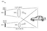
도 4a는 알려진 3D 플래시 LIDAR 시스템(400)의 개략도를 나타낸다. 플래시 LIDAR 시스템(400)에서, 고전력 레이저(402)는 타겟 범위(406)에서 객체를 조명하는 단일 송신된 펄스에서 전체 송신기 시야(404)를 조명하는 데 사용된다. 타겟 범위에서 객체로부터의 반사된 광은 초점 평면 어레이(FPA: focal plane array)(408)에 의해 수신되고, 여기서 어레이(408)의 각각의 개별 검출기는 3D 측정 포인트에 대응한다. 어레이(408)가 도 4a에 측면도로 나타내어진다. 도 4a에 나타낸 바와 같이, 송신기는 빔을 확장시키고 타겟 범위(406)에서 원하는 시야(404)를 조명하도록 작용하는 광학계(410)와 결합된 고전력 레이저(402)로 구성된다. 도 4b는 도 4a의 알려진 초점 평면 어레이(408)의 시스템 시야(420)의 2차원 투사를 나타낸다. 조명된 영역은 어레이(408) 위의 원형 투사(422)로 나타내어진다. 도 4a 및 도 4b 모두를 참조하면, 수신기는 검출기 어레이(408) 상에 이미지를 형성하는 수신기 광학계(412)로 구성되며, 여기서 각각의 개별 검출기는 정사각형(424)으로 나타내어지고 개별 3D 측정 포인트에 대응하는 검출기 시야를 갖는다. 전체 검출기 어레이의 시야는 도 6에 나타내어진 도면(620)에서 정사각형(424)의 전체 매트릭스에 의해 표현된다. 도면(620)은 조명 영역에서 원형 투사(422)인 검출기 어레이(408)의 시야와 송신기의 시야가 반드시 동일한 형상 및/또는 크기일 필요는 없음을 나타낸다.4A shows a schematic diagram of a known 3D
플래시 LIDAR는 통상적으로 움직이는 부품이 없는 솔리드-스테이트라는 이점을 갖는다. 플래시 LIDAR는 또한 송신기와 수신기 광학계가 별도로 최적화될 수 있다는 이점을 갖는다. 그러나 플래시 LIDAR의 하나의 주요 단점은 고전력 레이저(402)가 필요하다는 점이다. 플래시 LIDAR의 경우, 특히 800-nm 내지 1,000-nm 파장 범위의 파장에서 100 플러스 미터 타겟 범위까지 측정할 수 있는 시스템을 여전히 달성하면서, 클래스 1 눈 안전을 유지하기 어렵다. 눈의 안전을 위해, 플래시 LIDAR 시스템은 통상적으로 사람의 눈이 비교적 낮은 감도를 갖는 1,550-nm 파장으로 동작한다. 그러나 1,550-nm 파장 송신기 및 수신기 구성 요소는 상대적으로 비용이 높다.Flash LIDAR has the advantage of being a solid-state, typically without moving parts. Flash LIDAR also has the advantage that the transmitter and receiver optics can be optimized separately. However, one major drawback of Flash LIDAR is that it requires a
플래시 LIDAR 시스템의 두 번째 단점은 3D 포인트 클라우드의 해상도가 검출기 어레이(408)에 의해서만 결정된다는 것이다. 검출기(때로는 픽셀로 지칭됨)의 개수 및 어레이 크기는 측정 해상도를 결정한다. 자동차 LIDAR에 대한 각 해상도 요건을 충족하려면 매우 높은 밀도의 검출기 어레이(수천 개의 요소)가 필요할 것이다.The second disadvantage of the flash LIDAR system is that the resolution of the 3D point cloud is only determined by the
플래시 LIDAR의 세 번째 단점은 어레이(408)의 모든 개별 검출기가 카메라와 유사하게 병렬로 동작한다는 점이다. 단일 고전력 송신기 펄스의 경우, 측정은 모든 검출기로 동시에 수행된다. 결과적으로, 각각의 검출기는 TOF 및 진폭 데이터와 같은 신호 정보를 캡처하기 위한 그 자체 회로를 가져야 한다. 모든 픽셀이 병렬로 작동해야 하는 요건은 픽셀 밀도가 높아짐에 따라 매우 급격하게 증가하는 시스템의 비용을 초래한다. 리프레시 레이트는 더 늦은 리프레시 레이트로 이어지는 더 많은 픽셀 카운트로 또한 통상적으로 영향을 받는다.The third disadvantage of the flash LIDAR is that all individual detectors of the
도 5a는 기계적 스캐닝 접근법을 사용하는 알려진 LIDAR 시스템(500)을 나타낸다. 기계적 스캐닝 LIDAR 시스템에서, 레이저(502)에 의해 방출된 레이저 빔은 송신기 광학계(504)의 세트에 의해 고도로 시준되어 실용적으로 작은 빔 발산을 획득한다. 고도로 시준된 송신기 빔은 송신기 빔을 반사하고 원하는 시야에 걸쳐 레이저 빔을 스캐닝하도록 동작하는 회전 미러(506)로 지향된다.5A shows a known
나타내어진 기계적 스캐닝 LIDAR 시스템(500)에서, 수신기 시스템은 미러(506)로부터 반사된 광을 수신하도록 구성된 수신 광학계(508) 및 검출기(510)를 포함하여, 검출기(510)는 또한 좁은 시야를 갖는다. 도 5a의 개략도에서, 빔 결합기(512)는 송신 및 반사된 광을 공간적으로 결합하기 위해 사용된다. 도 5b는 도 5a의 LIDAR 시스템의 시스템 시야(520)의 2차원 투사를 나타낸다. 이상적으로, 도면에서 작은 정사각형(522)으로 표현되는 검출기 시야는 작은 원(524)으로 표현된 시준된 레이저 빔에 의해 조명된 영역보다 단지 약간 더 크다.In the mechanical
시스템 시야(520)의 2D 투사에서, 스캐닝 경로(526)의 일례가 나타내어져 있다. MEMS 디바이스로서 통상적으로 구현되는 미러(506)를 사용하는 것과 연관된 기계적 제약이 주어지면, 스캐닝 경로(526)는 먼저 한 행을 가로지른 후 다음 행을 가로질러 스위핑(sweeping)하는 연속적인 곡선이다. 미러(506)의 물리적 모션이 필요하기 때문에, 측정 포인트 사이를 이동할 때 항상 약간의 대기 시간이 존재한다.In the 2D projection of the system field of
기계적 스캐닝 LIDAR 시스템(500)은 회전 미러(506)에 의해 부과된 특정 제한을 갖는다. 스캐닝 속도는 미러 크기의 강한 함수일 것이고, 높은 리프레시 레이트를 갖기 위해, 그 미러의 크기는 종종 직경 5 mm 미만이다. 5 mm까지의 직경 외측의 임의의 전력은 손실되어 타겟으로 송신되지 않을 것이기 때문에, 레이저 빔의 크기는 임의로 확장될 수 없으므로 미러 크기는 송신기의 시준/발산을 제한한다. 수신 측에서, 수신기 광학계는 "미러를 통해 보기" 때문에, 수신기의 최대 클리어 개구는 다시 미러(506)의 크기와 등가이다. 5-mm 직경의 클리어 개구 내에서 수신된 반사된 광의 양은 타겟이 낮은 반사율을 갖고 및/또는 비, 안개 및/또는 눈과 같은 악천후 조건이 있는 경우와 같은 일부 조건에서, 단일-광자 검출로도 필요한 100 플러스 미터 범위에 도달하기에 충분하지 않을 수 있다. 또한, 문제가 되는 자동차 환경에서 사용되고 있는 기계 기반 스캐닝 LIDAR 시스템(500)에 대한 장기적인 신뢰성 문제가 있다.Mechanical
도 6a는 움직이는 부품이 없는 잡음 적응형 솔리드-스테이트 LIDAR 시스템(600)의 일 실시예의 개략도를 나타낸다. 도 6a에서, 송신기는 전체 시스템 시야를 한 번에 조명하는 플래시 광원이 아니다. 대신, 송신기는 레이저 어레이(602)를 포함하며, 여기서 어레이(602)의 각각의 레이저는 독립적으로 발사될 수 있으며, 어레이(602)의 각각의 레이저에 의해 방출된 광 빔은 단일 3D 측정 포인트에 대응한다. 도 6a의 송신기에서 각각의 레이저 빔은 고도로 시준되고 도 5a 및 도 5b와 관련하여 설명된 스캐닝 시스템과 유사하게 단일 측정 포인트에 대응하도록 포커싱된다. 일부 실시예에서, 레이저 어레이(602)의 레이저로부터의 모든 광 빔은 송신기 광학계(606)를 공유하고, 타겟 범위로부터의 반사된 광은 또한 수신기 광학계(608)를 공유한다. 이러한 송신기의 일례가 본 양수인에게 양도된 미국 특허 공개 제2017/0307736 A1호에 상세히 설명된다. 미국 특허 공개 제2017/0307736 A1호의 전체 내용은 본원에 참고로 통합된다.6A shows a schematic diagram of one embodiment of a noise-adaptive solid-
본 교시의 하나의 특징은, 송신기의 레이저 어레이가 개별의 구분된 파장을 갖는 광 빔을 방출하는 레이저를 포함할 수 있다는 것이다. 예를 들어, 특정 행, 열 또는 다른 레이저 그룹핑이 다른 행, 열 또는 다른 레이저 그룹핑과 상이한 파장으로 동작할 수 있다. 이러한 다중-파장 LIDAR 시스템은 단일 파장 LIDAR 시스템보다 낮은 비용의 컴팩트한 광학 설계로 더 미세한 각도 해상도와 성능을 제공한다. 또한, 본 교시의 다중-파장 LIDAR 시스템은 개선된 보안 및 병렬화에 대한 간단한 경로를 제공할 수 있다. 예를 들어, 2017년 3월 13일자로 출원되고 발명의 명칭이 "다중-파장 LIDAR 시스템"인 미국 특허 출원 제15/456,789호 및 2016년 9월 19일자로 출원되고 발명의 명칭이 "WDM Lidar 시스템"인 미국 가특허 출원 제62/396,295호를 참조하며, 이들 모두는 본원에 참고로 통합된다.One feature of the present teachings is that the laser array of the transmitter can include a laser that emits light beams having individual distinct wavelengths. For example, a particular row, column, or other laser grouping can operate at a different wavelength than another row, column, or other laser grouping. This multi-wavelength LIDAR system provides finer angular resolution and performance with a compact optical design at a lower cost than a single wavelength LIDAR system. In addition, the multi-wavelength LIDAR system of the present teaching can provide a simple path for improved security and parallelism. For example, U.S. Patent Application Nos. 15/456,789 filed March 13, 2017 and entitled "Multi-Wave LIDAR System" and filed September 19, 2016 and titled "WDM Lidar System, US Provisional Patent Application No. 62/396,295, all of which are incorporated herein by reference.
본 교시의 방법 및 장치는 상이한 주파수에서 광을 방출하는 레이저 또는 레이저의 어레이를 사용하는 다중-파장 잡음-적응형 LIDAR 시스템과 함께 사용될 수 있다. 이러한 시스템은 통합되거나 별개의 시준 광학계를 포함하여 LIDAR 시스템의 시야 및 범위에 걸쳐 다양한 타겟 평면에서의 원하는 빔 프로파일, 및 검출기 어레이에서의 파장의 함수인 연관된 원하는 조명 영역을 형성할 수 있다. 다양한 시스템에서, 수신기는 파장에 민감하거나 그렇지 않을 수 있다. 수신기가 상이한 파장을 방출하는 레이저 소스에 의해 방출된 2개의 파장으로부터의 광을 구분할 수 있는 실시예에서, 각각의 파장으로부터 반사된 조명은 개별적으로 프로세싱된다. 이러한 실시예에서, 시간의 함수로서의 조명 영역 형상 및 크기에 추가하여, 제어기는 레이저가 펄싱 온(on) 및 오프(off)되는 것에 기초하여 조명 영역의 파장을 결정할 수 있다. 이러한 방식으로, 조명 영역의 파장은 원하는 조명 패턴의 일부가 된다.The method and apparatus of the present teachings can be used with a multi-wavelength noise-adaptive LIDAR system using lasers or arrays of lasers that emit light at different frequencies. Such systems can incorporate or include separate collimating optics to form a desired beam profile at various target planes over the field of view and range of the LIDAR system, and the associated desired illumination area that is a function of wavelength in the detector array. In various systems, the receiver may or may not be wavelength sensitive. In embodiments in which the receiver can distinguish light from two wavelengths emitted by a laser source emitting different wavelengths, the illumination reflected from each wavelength is processed separately. In this embodiment, in addition to the shape and size of the illumination region as a function of time, the controller can determine the wavelength of the illumination region based on the laser being pulsed on and off. In this way, the wavelength of the illumination region becomes part of the desired illumination pattern.
도 6a에 나타낸 수신기는 움직이는 부품이 없는 솔리드-스테이트일 수 있다. 수신기는 통상적으로 송신기 어레이(602)가 개별 레이저를 갖는 것보다 적은 개수의 개별 검출기 요소를 갖는 검출기 어레이(604)를 사용한다. 도 6b는 도 6a의 LIDAR 시스템의 시스템 시야(620)의 2차원 투사를 나타낸다. 검출기 어레이(604)의 개별 검출기 시야는 작은 정사각형(622)으로 나타내어져 있다. 송신기 어레이(602)에서 개별 레이저와 연관된 조명된 측정 포인트는 원(624)으로 나타내어져 있다. 도 6b는 각각의 어레이에서 레이저의 개수에 대한 검출기의 개수의 비율이 각각 1 대 9임을 나타낸다. 이 예에서, 검출기 어레이는 5X5 어레이이다. 등가의 각도 해상도를 갖는 플래시 시스템과 비교하여, 도 6a에 나타낸 LIDAR 시스템의 검출기 어레이(604) 비용은, 검출기의 개수가 더 적을 수 있기 때문에 더 낮을 수 있다. 도 6a의 시스템의 측정 해상도는 검출기 요소의 크기에 의해 결정되지 않고, 대신 송신기 내의 레이저의 개수 및 개별 레이저 빔의 시준에 의해 결정된다.The receiver shown in FIG. 6A can be a solid-state with no moving parts. The receiver typically uses a
검출기 어레이(604) 및 각각의 검출기 요소의 필요한 크기는 전체 수신기 시야, 수신 광학계(608)의 초점 길이, 및 각각의 검출기 상의 잡음을 포함하는 몇몇 요인에 의해 영향을 받는다. 실외에서 동작하는 자동차 시스템의 경우, 고성능 수신기를 설계할 때 태양에 의해 생성되는 배경 잡음이 고려되어야 한다. 태양 방사 잡음은 파장 차단 필터의 적절한 선택뿐만 아니라 개별 검출기 시야를 제한함으로써 제한되어야 한다. LIDAR 시스템이 어떠한 태양 방사 잡음도 없이 실내에서만 동작되는 경우, 검출기의 크기는 훨씬 더 크게 될 수 있으며, 검출기에 대한 RF 요건(O/E 대역폭, 상승 시간, 하강 시간 등)에 의해서만 제한된다.The required size of the
도 6c는 개별 레이저 및 개별 검출기에 대해 도 6a와 관련하여 설명된 LIDAR 시스템의 시스템 시야(650)의 2차원 투사를 나타낸다. 도 6c는 도 6a의 실시예의 중요한 양태를 나타낸다. 도 6c에서, 도 6a의 LIDAR 시스템의 전체 FOV에서의 단일 3D 측정 포인트가 강조되고, 측정 포인트는 어두운 원(652)으로 나타내어진다. 이 포인트는 레이저 어레이(602)에서 특정 개별 레이저와 일-대-일로 대응한다. 도 6c에서, 이 측정 포인트는 개별 검출기 내에 속함을 추가로 알 수 있으며, 여기서 해당 개별 검출기의 FOV는 이를 식별하기 위한 크로스-해치(cross-hatch) 패턴을 갖는 정사각형(654)으로 나타내어져 있다. 일부 실시예에서, LIDAR 시스템에서 각각의 개별 레이저는 개별적으로 펄싱되며, 본 교시의 LIDAR 시스템은 각각의 레이저의 각 투사 각도와 각각의 개별 검출기의 대응하는 시야 간의 관계에 대한 지식을 갖는다. 이와 같이, 시스템은 특정 레이저 발사 패턴과 연관된 조명 영역 및 조명 영역에 의해 조명되는 특정 검출기 요소 사이의 대응 관계를 확립할 수 있다. 본 교시의 LIDAR 시스템은 이 대응 정보를 사용하여 TOF 측정 회로로 진입하는 잡음을 적응적으로 낮춘다. 측정 잡음이 최소화될 수 있는 방식에 대한 추가 설명은 후술된다.6C shows a two-dimensional projection of the system field of
본 교시의 일부 실시예에서, 개별 레이저 측정 포인트는 복수의 검출기와 중첩될 수 있으며, 여기서 검출기의 개수는 검출기의 전체 개수의 서브세트이다. 단일 레이저와 단일 검출기 간에 일-대-일 대응을 가질 필요는 없다. 필요한 모든 것은 LIDAR 시스템이 특정 레이저로부터 반사된 빛을 수신할 검출기를 식별할 수 있도록 개별 레이저와 개별 검출기 시야 간의 대응 관계를 이해하는 것이다.In some embodiments of the present teaching, individual laser measurement points may overlap a plurality of detectors, where the number of detectors is a subset of the total number of detectors. It is not necessary to have a one-to-one correspondence between a single laser and a single detector. All that is needed is to understand the correspondence between individual lasers and individual detector fields so that the LIDAR system can identify the detector that will receive the light reflected from that particular laser.
검출기의 그룹 또는 어레이를 사용하는 실시예에서, 어레이 또는 서브어레이 내의 애노드는 단일 입력에 접속될 수 있고, 어레이 또는 서브어레이 내의 캐소드는 단일 출력에 접속될 수 있어, 외부 회로에 대해 어레이 또는 서브 어레이 디바이스는 단일 요소처럼 작동한다. 검출기의 어레이 또는 서브어레이는 인접하거나 인접하지 않을 수 있고, 단일 출력을 생성하기 위해 병렬로 접속되거나 접속되지 않을 수 있다. 일부 실시예에서, 개별 검출기, 어레이 또는 서브어레이의 시야는 태양 배경 잡음의 영향을 감소시키도록 제한된다.In an embodiment using a group or array of detectors, the anode in the array or subarray can be connected to a single input, and the cathode in the array or subarray can be connected to a single output, such as an array or subarray for external circuitry. The device works like a single element. The array or subarray of the detectors may or may not be contiguous, and may or may not be connected in parallel to produce a single output. In some embodiments, the field of view of individual detectors, arrays or subarrays is limited to reduce the effect of solar background noise.
개별 레이저 또는 레이저의 어레이는 펄싱되어 검출기에서 조명 영역을 생성한다. 이 조명 영역은 특정 측정을 위해 발사되는 레이저의 패턴에 기초하여 다양한 형상과 크기를 가질 수 있다. 예를 들어, 단일 레이저가 발사되어 검출기에서 단일 레이저 시야 조명 형상을 생성할 수 있다. 상술한 바와 같이, 이 조명 영역은 LIDAR 시스템의 설계에 따라 다양한 크기를 가질 수 있다. 복수의 레이저가 발사될 때, 조명 영역의 형상 및 크기는 발사된 레이저의 위치 및 각각의 개별 레이저 시야에 따를 것이다.Individual lasers or arrays of lasers are pulsed to create an area of illumination at the detector. This illumination area can have a variety of shapes and sizes based on the pattern of the laser being fired for a particular measurement. For example, a single laser can be fired to create a single laser field illumination shape at the detector. As described above, this illumination area may have various sizes depending on the design of the LIDAR system. When multiple lasers are fired, the shape and size of the illumination area will depend on the location of the fired lasers and each individual laser field of view.
검출기 어레이는 다양한 검출 영역 크기 및 형상 및 어레이 간격을 포함하여 다양한 구성을 가질 수 있다. 이와 같이, 조명 영역은 어레이 또는 단일 검출기에서 복수의 검출기를 커버할 수 있다. 심지어 더 복잡한 조명 영역 및 관련 검출 영역을 갖는 조명 영역 및 검출기 구성이 알려져 있기 때문에, 레이저 발사 패턴과 조명 영역 내에 속하는 검출기 또는 검출기 그룹 사이에는 일-대-일 대응 관계가 존재한다. 이러한 대응 정보는 제어기에 의해 사용되어 검출기 어레이로부터 TOF 측정 회로의 입력에 의해 보이는 잡음을 적응적으로 낮춘다.The detector array can have a variety of configurations, including various detection area sizes and shapes and array spacing. As such, the illumination area can cover multiple detectors in an array or a single detector. There is a one-to-one correspondence between a laser firing pattern and a group of detectors or detectors belonging to the illumination region, as even illumination regions and detector configurations with more complex illumination regions and associated detection regions are known. This correspondence information is used by the controller to adaptively lower the noise seen by the input of the TOF measurement circuit from the detector array.
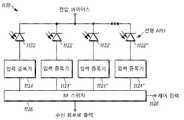
도 7a는 본 교시에 따른 실시예에 대한 LIDAR 시스템 블록도(700)를 나타낸다. LIDAR 시스템은: 제어기 및 인터페이스 전자 기기(702), 레이저 드라이버를 포함하는 송신 전자 기기(704), 레이저 어레이(706), 수신 및 TOF 계산 전자 기기(708) 및 검출기 어레이(710)의 5개의 주요 구성 요소를 갖는다. 제어기 및 인터페이스 전자 기기(702)는 LIDAR 시스템의 전체 기능을 제어하고 호스트 시스템 프로세서(712)에 디지털 통신을 제공한다. 송신 전자 기기(704)는 동작 및 레이저 어레이(706)를 제어하고 레이저 발사의 패턴을 설정한다. 수신 및 TOF 계산 전자 기기(708)는 검출기 어레이(710)로부터 전기 검출 신호를 수신하고, 이들 전기 검출 신호를 프로세싱하여 비행-시간 계산을 통한 범위 거리를 계산한다.7A shows a LIDAR system block diagram 700 for an embodiment in accordance with the present teachings. The LIDAR system includes five main components: a controller and interface electronics 702, a transmitting
도 7b는 도 7a과 관련하여 설명된 수신기 및 TOF 계산 전자 기기(708)의 상세한 블록도(750)를 나타낸다. 검출기 어레이로부터 수신된 전기 검출 신호(752)는 추가 프로세싱 전에 검출기로부터 수신된 전기 검출 신호(752)를 부스팅하는 입력 증폭기(756)를 통합하는 수신기 전단(754)에 입력된다. 이 증폭기로부터 출력된 신호는 몇몇 다른 회로로 분할될 수 있다. 함께 또는 임의의 조합으로 사용될 수 있는 3개의 가능한 회로(758, 760, 762)가 나타내어져 있다. 시간-대-디지털 변환기(TDC: Time-to-Digital Convertor)(758)는 입력 신호가 일부 진폭 임계값을 교차할 때를 인식하고 해당 이벤트의 시간의 디지털 표현을 제공하는 특수화된 회로이다. TOF 측정 시스템의 경우, 이벤트는 통상적으로 반사된 송신 펄스의 도달에 대응하고, 이러한 도달 시간은 객체의 거리에 대응한다. 진폭 신호 블록(760)은 TDC(758)와 동일한 이벤트에 의해 트리거링되는 회로이지만, 시간을 기록하는 대신 진폭을 기록한다. 아날로그-대-디지털 회로(762)는 아날로그 수신된 전기 검출 신호를 일부 샘플링 레이트에 대응하는 디지털 신호로 변환한다. 수신기 전단(754)으로부터 수신된 프로세싱된 신호는 트리거 및 동기 잠금 회로(766)와 인터페이싱하는 데이터 프로세싱 회로(764)에 입력된다. 데이터 모니터링 및 디지털 통신 인터페이스(768)는 그 후 신호를 제어기 및 인터페이스 전자 기기(702)(도 7a)로 전송한다.FIG. 7B shows a detailed block diagram 750 of the receiver and TOF
본 기술 분야의 통상의 기술자는 LIDAR 시스템의 기능을 나타내는 도 7a 및 도 7b에 나타내어진 블록도가 본 교시를 임의의 특정 하드웨어 구성으로 한정하지 않음을 이해할 것이다. 이들 회로 각각은 개별 회로이거나 통합될 수 있다. 예를 들어, 송신 및 수신 블록은 개별 인쇄 회로 보드 어셈블리(PCBA: printed circuit board assembly) 및/또는 개별 모듈 상에 있을 수 있다. 수신 전자 기기 블록의 경우, 전단의 전부 또는 일부는 검출기 어레이에 직접 부착된 집적 회로의 일부일 수 있거나, 이들 회로는 다른 회로와 함께 PCBA 상에 있을 수 있다. 일부 실시예에서, 제어기 기능은 필드 프로그래머블 게이트 어레이(FPGA: field programming gate array) 또는 어플리케이션-특정 집적 회로(ASIC: application-specific integrated circuit) 내부의 송신 및 수신 전자 기기의 일부 또는 전부와 결합될 수 있다.Those skilled in the art will understand that the block diagrams shown in FIGS. 7A and 7B representing the functionality of the LIDAR system do not limit the present teachings to any particular hardware configuration. Each of these circuits can be a separate circuit or can be integrated. For example, the transmit and receive blocks can be on separate printed circuit board assemblies (PCBAs) and/or on separate modules. In the case of a receiving electronics block, all or part of the front end may be part of an integrated circuit directly attached to the detector array, or these circuits may be on the PCBA along with other circuits. In some embodiments, the controller function may be combined with some or all of the transmit and receive electronic devices inside a field programmable gate array (FPGA) or application-specific integrated circuit (ASIC). have.
도 8은 알려진 초점 평면 어레이(FPA: Focal Plane Array)에 대한 블록도(800)를 나타낸다. FPA는 통상적으로 함께 부착되어 하이브리드 어셈블리를 형성하는 검출기 어레이 칩과 판독 집적 회로(ROIC: readout integrated circuit)를 모두 갖는 어셈블리로 칭해진다. 어레이의 각각의 개별 검출기(802, 802', 802'', 802''')가 나타내어지고 그 대응하는 개별 ROIC(804, 804', 804'', 804''')는 블록도에서 "단위 셀 전자 기기"로 표기된다. 검출기(802, 802', 802'', 802''') 및 각각의 검출기(802, 802', 802'', 802''')에 대한 개별 ROIC(804, 804', 804'', 804''')는 독립 디바이스로서 함께 작동하며, 때로는 "스마트 픽셀"로 칭해진다. ROIC(804, 804', 804'', 804''')는 각각의 검출기(802, 802', 802'', 802''')로부터 수신된 전기 검출 신호에 대한 TOF의 병렬 측정을 가능하게 하는 회로를 포함하고, 각각의 검출기(802, 802', 802'', 802''')는 그 자체의 TOF 회로를 갖는다. ROIC(804, 804', 804'', 804''')는 입력 증폭기(806), TDC(808), 진폭 신호 블록(810), 아날로그 대 디지털 회로(812), 동기화(814), 샘플러 및/또는 메모리(816) 및 출력 버퍼(818)를 포함한다. ROIC(804, 804', 804'', 804''')는 카메라와 같이 TOF 정보가 외부 회로로 판독/전달될 수 있도록 버퍼(818)에 각각의 단위 셀에 대한 TOF 정보를 저장한다. ROIC(804, 804', 804'', 804''')는 또한 복귀 펄스의 타이밍뿐만 아니라 진폭 정보도 캡처하는 추가 회로를 포함할 수 있다. 그러나, 통상적인 FPA는 어레이의 모든 검출기(802, 802', 802'', 802''')에 의해 공유되는 단일 전압 바이어스(820)를 갖는다.8 shows a block diagram 800 for a known Focal Plane Array (FPA). FPA is commonly referred to as an assembly having both a detector array chip and a readout integrated circuit (ROIC) that are attached together to form a hybrid assembly. Each individual detector of the array (802, 802', 802'', 802''') is shown and its corresponding individual ROIC (804, 804', 804'', 804''') is shown in block units Cell electronic devices.
각각의 검출기(802, 802', 802'', 802''')는 그 자신의 전용 단위 셀 전자 기기(804, 804', 804'', 804''')를 갖기 때문에, ROIC 칩 상의 회로는 검출기 요소와 선형으로 스케일링된다는 것이 이해될 수 있다. 다수의 검출기의 경우, 이 구성은 시스템 비용을 상당히 증가시킨다. 또한, 다수의 검출기를 사용하는 것은 전체 프레임 리프레시 레이트에 상당히 추가시킨다. 각각의 송신기 펄스 사이에서, 시스템은 광이 해당 최대 범위로부터 반사되는 데 필요한 시간을 기다려야 하며, 각각의 스마트 픽셀로부터의 모든 데이터는 ROIC 출력 버퍼를 통해 전달되어야 한다. 픽셀 개수, 데이터의 양 및 유형, 출력 버퍼의 속도 및 다른 요인과 같은 다양한 요인에 따라, 전체 측정 사이클에 필요한 시간이 상당히 변할 수 있다. FPA는 통상적으로 카메라와 유사한 60Hz 정도의 풀 프레임 리프레시 레이트로 동작한다. 이러한 비교적 느린 리프레시 레이트로, LIDAR 시스템은 복수의 펄스를 평균화하는 데 부적절한 시간이 있으므로, 단일 펄스 측정치에만 기초하여 거리를 계산해야 한다.Circuit on the ROIC chip, since each
도 9는 실리콘 포토멀티플라이어(SiPM: silicon photomultiplier) 또는 다중-픽셀 광자 카운터(MPPC: multi-pixel photon counter)(900)로도 칭해지는 알려진 가이거-모드(Geiger-mode) 애벌랜치 광 다이오드(APD) 어레이의 개략도를 나타낸다. 도 9에 나타낸 바와 같이, MPPC(900)는 가이거-모드에서 동작되는 몇몇 APD(902, 902', 902'', 902''')로 구성되며, 각각 그 자체의 ??칭 저항(904, 904', 904'', 904'''')을 갖는다. 가이거-모드 APD(902, 902', 902'', 902''')는 모두 병렬로 접속된다. MPPC(900)의 출력은 각각의 개별 가이거-모드 APD(902, 902', 902'', 902''')의 응답의 합일 것이다. 이러한 방식으로, MPPC(900)는 복수의 가이거-모드 APD 요소(902, 902', 902'', 902''')에 광이 입사될 때, 복수의 광자 이벤트에 대한 의사-선형(pseudo-linear) 응답을 생성할 수 있다.9 is a known Geiger-mode avalanche photodiode (APD) array, also referred to as a silicon photomultiplier (SiPM) or multi-pixel photon counter (MPPC) 900 The schematic diagram of As shown in Figure 9, the
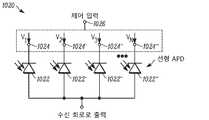
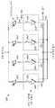
도 10a는 본 교시에 따른 잡음 적응형 솔리드-스테이트 LIDAR 시스템에 대한 가이거-모드 APD 및 ??칭 저항을 갖는 제어되는 검출기 어레이(1000)의 실시예의 개략도를 나타낸다. 도 10b는 본 교시에 따른 잡음 적응형 솔리드-스테이트 LIDAR 시스템에 대한 선형 APD를 갖는 제어되는 검출기 어레이(1020)의 실시예의 개략도를 나타낸다. 도 10c는 본 교시에 따른 잡음 적응형 솔리드-스테이트 LIDAR 시스템의 가이거-모드 APD 및 ??칭 저항을 갖는 4-요소 검출기 서브-어레이를 사용하는 제어되는 검출기 어레이(1050)의 실시예의 개략도를 나타낸다. 도 10a 내지 도 10c를 참조하면, 이들 각각의 실시예에서, 개별 검출기 또는 검출기의 서브-어레이에 대한 전압 바이어스는 LIDAR 시스템에 의해 독립적으로 제어될 수 있다. 도 10a에서, 도 9의 MPPC(900)의 것과 유사한 검출기 요소의 어레이, 가이거-모드 APD(1002, 1002', 1002'', 1002''')가 나타내어진다. 도 9에 나타낸 바와 같이 모든 요소에 대한 단일 전압 바이어스 대신, 각각의 가이거-모드 APD(1002, 1002', 1002'', 1002''')는 그 자체 전압 공급기(1004, 1004', 1004'', 1004''')를 갖는다. LIDAR 시스템은 제어 입력(1006)에 의해 제어되는 개별 전압 공급기(1004, 1004', 1004'', 1004''')를 사용하여 APD 바이어스의 개별 제어를 사용함으로써, 도 6b와 관련하여 설명된 바와 같이, 그 시야가 현재 펄싱되고 있는 특정 레이저의 시야 외측에 있는 검출기에 대한 전압을 적응적으로 낮출 수 있다. 즉, 제어기는 그 시야가 제어기에 의해 펄싱되거나 활성화되는 레이저 요소의 특정 그룹에 의해 생성된 조명 영역 외측에 있는 검출기에 대한 전압을 낮춘다. 현재 단일 펄스 송신기 시야 외측의 검출기의 경우, 이들 검출기에 대한 전압 바이어스는 전압 브레이크다운 포인트 아래로 떨어지거나 심지어 실질적으로 또는 완전히 꺼질 수 있다.10A shows a schematic diagram of an embodiment of a controlled
본 교시에 따른 LIDAR 시스템이 최소화하도록 작용하는 전기 검출 신호에는 2개 카테고리의 잡음이 존재한다. 제1 카테고리는 다이오드 상에 입사되는 임의의 광과 독립적인 검출기에 의해 발생되는 전기 잡음이다. 이 잡음을 종종 암전류라고 칭한다. 선형 APD, 가이거 모드 APD, SPAD 및 MPPC와 같은 LIDAR 시스템에 사용되는 검출기의 경우, 이러한 검출기 다이오드에 의해 발생되는 전기 잡음은 광이 존재하지 않는 때에도 상당하다. 전기 잡음은 인가된 전압 바이어스의 상당한 함수이므로, 인가된 전압 바이어스를 낮춤으로써, 검출기에 대한 전기 잡음이 상당히 감소된다.There are two categories of noise in the electrical detection signal that the LIDAR system according to this teaching acts to minimize. The first category is electrical noise generated by detectors independent of any light incident on the diode. This noise is often referred to as dark current. For detectors used in LIDAR systems such as linear APD, Geiger mode APD, SPAD and MPPC, the electrical noise generated by these detector diodes is significant even when no light is present. Since electrical noise is a significant function of the applied voltage bias, by lowering the applied voltage bias, electrical noise to the detector is significantly reduced.
본 교시의 LIDAR 시스템이 최소화하도록 작용하는 전기 검출 신호에서 제2 잡음 카테고리는 태양 방사로부터의 시스템에 대한 잡음 기여이다. 태양은 해당 파장에서 강한 방사를 생성하며, 태양 방사로 인해 수신기 상에 지속적으로 광자가 입사할 것이다. 송신된 레이저 펄스로부터가 아닌 이러한 광자는 암전류 잡음에 대한 추가 랜덤 잡음 소스로서 간주할 수 있는 신호 응답을 생성할 것이다. 수신기 설계에서 주의를 기울이지 않으면, 태양 방사로부터 입사된 광자로부터의 잡음 신호 레벨은 LIDAR 시스템의 범위를 제한하기에 충분히 높을 수 있다.The second category of noise in the electrical detection signal that the LIDAR system of this teaching acts to minimize is the contribution of noise to the system from solar radiation. The sun produces strong radiation at that wavelength, and the photon will continually enter the receiver due to solar radiation. These photons, not from the transmitted laser pulse, will generate a signal response that can be considered as an additional random noise source for dark current noise. If care is not taken in the receiver design, the noise signal level from photons incident from solar radiation can be high enough to limit the range of the LIDAR system.
본 교시의 LIDAR 시스템에서, 검출기 암전류 및 태양 잡음이 모두 억제된다. 도 10a에 나타낸 제어되는 검출기 어레이(1000)의 실시예에서, 전압(1004, 1004', 1004'', 1004''')은 현재 송신 펄스로부터 반사된 광을 수신하고 있지 않는 모든 검출기(1002, 1002', 1002'', 1002''')에 대한 제어 입력(1006)에 기초하여 감소된다. 이러한 방식으로, 전압 바이어스가 낮아진 검출기에 대한 출력 신호(잡음)가 상당히 감소될 것이며, 이는 공통 합 출력에 대한 전체 잡음을 감소시킬 것이다. 따라서, 전압(1004, 1004', 1004'', 1004''')을 감소시키는 제어 입력(1006)은 다운스트림 수신 회로에 접속된 특정 검출기 출력을 효과적으로 선택한다. 도 7b를 또한 참조하면, 일부 실시예에서, 전압(1004, 1004', 1004'', 1004''')을 감소시키는 제어 입력(1006)은 도 7b의 입력 증폭기(756)에 접속된 특정 검출기(1002, 1002', 1002'', 1002''') 출력을 효과적으로 선택한다.In the LIDAR system of the present teaching, both the detector dark current and solar noise are suppressed. In the embodiment of the controlled
도 10b는 가이거-모드 APD 대신 도 10a에 나타낸 제어되는 검출기 어레이의 유사한 실시예를 나타내며, 본 실시예는 선형 APD(1022, 1022', 1022'', 1022''')를 포함하는 제어되는 검출기 어레이(1020)를 사용한다. 도 10a에 나타낸 제어되는 검출기 어레이(1000)와 유사하게, 공통 합 출력에 대한 전체 잡음을 감소시키기 위해, 바이어스 전압이 또한 선형 APD(1022, 1022', 1022'', 1022''')에 대해 감소될 수 있어, 낮아진 전압 바이어스로 이러한 검출기에 대한 출력 신호(잡음)를 감소시킨다.FIG. 10B shows a similar embodiment of the controlled detector array shown in FIG. 10A instead of the Geiger-mode APD, this embodiment being a controlled detector comprising a
도 10c는 가이거-모드 APD의 서브-어레이(1052, 1052', 1052'', 1052''')가 사용되는 제어되는 검출기 어레이(1050)의 실시예를 나타낸다. 도 10a에 나타낸 실시예와 관련하여 설명된 동작 원리가 도 10c에 나타낸 시스템에 유사하게 적용될 수 있으며, 각각의 서브-어레이는 단일 요소로서 작용한다. 제어되는 검출기 어레이(1050)는 제어 입력(1056)에 의해 제어되는 제어 가능한 전압 바이어스(1054, 1054', 1054'', 1054''')를 사용한다. 이 구성에서, 바이어스 전압(1054, 1054', 1054'', 1054''')는 서브-어레이(1052, 1052', 1052'' 및 1052''')에서 검출기(1056, 1056', 1056'', 1056''')를 제어한다.10C shows an embodiment of a controlled
도 11a는 본 교시에 따른 잡음 적응형 솔리드-스테이트 LIDAR 시스템에 대한 가이거-모드 APD 및 ??칭 저항을 갖는 제어되는 검출기 어레이(1100)의 실시예의 개략도를 나타낸다. 도 11b는 본 교시에 따른 잡음 적응형 솔리드-스테이트 LIDAR 시스템에 대한 선형 APD를 갖는 제어되는 검출기 어레이(1120)의 실시예의 개략도를 나타낸다. 도 11c는 본 교시에 따른 잡음 적응형 솔리드-스테이트 LIDAR 시스템에 대한 가이거-모드 APD 및 ??칭 저항(1050)을 갖는 4-요소 검출기 서브-어레이를 포함하는 제어되는 검출기 어레이(1150)의 실시예의 개략도를 나타낸다.11A shows a schematic diagram of an embodiment of a controlled
도 11a에서, 공통 전압 바이어스(1102)가 MPPC 어레이에서 모든 검출기(1104, 1104', 1104'', 1104''')를 바이어싱하는 데 사용된다. 그러나, 각각의 가이거-모드 APD(1104, 1104', 1104'', 1104''')로부터의 출력은 더 이상 도 9와 관련하여 설명된 바와 같이 공통 출력에 직접 접속되지 않는다. 대신, 각각의 APD(1104, 1104', 1104'', 1104''')로부터의 출력은 입력 증폭기(1106, 1106', 1106'', 1106''')에 접속된 후, RF 스위치(1108)에 접속된다. RF 스위치(1108)는 단일 수신 신호 출력에 이용되고 있는 검출기(1104, 1104', 1104'', 1104''')로부터의 출력만을 지향시키기 위해 사용된다. 이러한 구성에서, 검출기 중 하나를 제외한 모든 검출기로부터의 잡음 기여가 실질적으로 제거되어, 주요한 잠재적 잡음 감소를 제공한다. 다시, 태양 잡음이 지속적으로 전체 시야를 조명하고 모든 검출기에서 잡음을 생성하는 자동차 어플리케이션에서 이는 특히 중요하다. 일부 실시예에서, 단일 레이저 및 검출기를 제어하는 대신 그 시야가 제어기에 의해 펄싱 또는 활성화되는 레이저 요소의 특정 그룹에 의해 생성된 조명 영역 내측에 있는 검출기의 서브세트로부터의 출력을 지향시키도록 제어기로부터의 입력(1110)은 RF 스위치(1108)를 설정한다.In FIG. 11A, a
도 11b는 도 11a와 관련하여 설명된 제어되는 검출기 어레이의 유사한 실시예를 나타내지만, 가이거-모드 APD 대신, 본 실시예는 선형 APD(1122, 1122', 1122'', 1122''')를 사용하는 제어되는 검출기 어레이(1120)를 포함한다. 선형 APD(1122, 1122', 1122'', 1122''')는 입력 증폭기(1124, 1124', 1124'', 1124''')에 접속된 다음 제어 입력(1128)을 통해 제어되는 RF 스위치(1126)에 접속된다. 동작에서, RF 스위치(1126)는 제어되는 송신기 어레이에 의해 생성된 조명 영역 내에 속하는 이러한 검출기(1122, 1122', 1122'', 1122''')로부터의 출력만을 제어 입력(1128)의 제어 하에 다운스트림 전자 기기로 보낸다.FIG. 11B shows a similar embodiment of the controlled detector array described in connection with FIG. 11A, but instead of the Geiger-mode APD, this embodiment uses a linear APD (1122, 1122', 1122'', 1122'''). And a controlled
도 11c는 가이거-모드 APD의 서브-어레이(1152, 1152', 1152'', 1152''')가 사용되는 제어되는 검출기 어레이(1150)의 실시예를 나타낸다. 도 11c에 나타낸 실시예는 도 11a와 관련하여 설명된 실시예와 유사하며, 여기서 각각의 서브-어레이(1152, 1152', 1152'', 1152''')는 단일 요소로서 작용한다. 제어되는 검출기 어레이(1150)는 제어 입력(1158)에 의해 제어되는 RF 스위치(1156)에 접속된 입력 증폭기(1154, 1154', 1154'', 1154''')를 포함한다. RF 스위치(1156)는 제어 입력(1158)을 통해 구성된다. 동작에서, RF 스위치(1156)는 제어되는 송신기 어레이에 의해 생성된 조명 영역 내에 속하는 이러한 검출기 서브-어레이(1152, 1152', 1152'', 1152''')만을 제어 입력(1158)의 제어 하에 다운스트림 전자 기기 또는 수신 회로로 보낸다.11C shows an embodiment of a controlled
본 기술 분야의 통상의 지식을 가진 자에게는 도 10a 내지 도 10c 및 도 11a 내지 도 11c는 PIN, APD, 가이거-모드 APD, MPPC, 또는 개별 검출기 또는 검출기의 어레이 또는 서브-어레이를 갖는 다른 유형의 검출기를 사용할 수 있는 많은 가능한 실시예의 단지 6개의 예일 뿐이라는 것이 명백할 것이다. 본 기술 분야의 통상의 기술자는, 측정 출력에 대한 잡음을 추가로 최적화하기 위하여 본 교시가 전압 제어(도 10a 및 도 10b)와 RF 스위칭(도 11a 및 도 11b) 모두가 함께 사용되는 도 10a 및 도 10b 그리고 도 11a 및 도 11b와 관련하여 설명된 실시예의 혼합을 포함한다는 것을 또한 이해할 것이다.For those skilled in the art, FIGS. 10A-10C and 11A-11C are PIN, APD, Geiger-mode APD, MPPC, or other types of individual detectors or arrays of detectors or sub-arrays. It will be apparent that there are only six examples of many possible embodiments in which a detector can be used. The person skilled in the art, in order to further optimize the noise for the measurement output, this teaching is shown in FIGS. 10A and 10B where both voltage control (FIGS. 10A and 10B) and RF switching (FIGS. 11A and 11B) are used together. It will also be understood that it includes a mix of the embodiments described with respect to FIGS. 10B and 11A and 11B.
예를 들어, 도 10a 및 도 10b 그리고 도 11a 및 도 11b와 관련하여 설명된 실시예와 같은 일부 실시예에서, 수신 신호 출력은 단일 접속을 통해 후속 TOF 계산 회로로 보내어진다. 후속 수신 회로 기능은 도 7a 및 도 7b로부터의 블록도에 설명된 바와 같다. 본 교시의 LIDAR 시스템은 각각의 검출기가 그 자체의 TOF 계산 회로를 가져야 하는 FPA를 사용하지 않는다는 점에 유의하는 것이 중요하다. 본 교시의 LIDAR 시스템에서, TOF 계산 회로는 많은 검출기들 사이에서 공유된다. 이러한 구성은 FPA를 사용하는 LIDAR 시스템에 비해 시스템 아키텍처에 따라 상당히 덜 복잡하고 상당히 더 낮은 비용을 갖는다. 또한, 본 교시에 따른 LIDAR 시스템은 필요한 고속 A/D의 개수를 최소화함으로써 상당한 비용 및 전력 절감을 제공할 수 있다.For example, in some embodiments, such as the embodiments described with respect to FIGS. 10A and 10B and FIGS. 11A and 11B, the received signal output is sent to a subsequent TOF calculation circuit through a single connection. Subsequent receiving circuit functions are as described in the block diagrams from FIGS. 7A and 7B. It is important to note that the LIDAR system of this teaching does not use FPA, where each detector must have its own TOF calculation circuit. In the LIDAR system of the present teaching, the TOF calculation circuit is shared among many detectors. This configuration is significantly less complex and has a significantly lower cost depending on the system architecture compared to LIDAR systems using FPA. In addition, the LIDAR system according to the present teachings can provide significant cost and power savings by minimizing the number of high-speed A/D required.
도 12는 본 교시에 따른 LIDAR 시스템의 실시예의 증폭기 전단 스위치(1202, 1202', 1202'', 1202''')를 갖는 제어되는 검출기 어레이(1200)를 나타낸다. 후속 프로세싱 전에 신호를 증가시키기 위해 광 다이오드에 바로 인접하게 제1 증폭기를 배치하는 것이 광 수신기에서 매우 통상적이다. 종종 이러한 증폭기는 검출기에 의해 생성된 전류를 단일 종단 또는 차동으로 전압 신호로 변환하는 트랜스-임피던스 증폭기이다. 도 12와 관련하여 설명된 실시예에서, 각각의 검출기(1204, 1204', 1204'', 1204''')는 증폭기(1206, 1206', 1206'', 1206''') 및 스위치(1208, 1208', 1208'', 1208''')를 통합하는 전용 증폭기 전단 스위치(1202, 1202', 1202'', 1202''')를 갖는다. 각각의 증폭기 전단 스위치(1202, 1202', 1202'', 1202''')의 스위치(1208, 1208', 1208'', 1208''')는 제어되는 송신기 어레이에 의해 생성된 조명 영역 내에 속하는 이러한 검출기(1204, 1204', 1204'', 1204''')만을 다운스트림 전자 기기 또는 수신 회로로 지향시키도록 제어 입력(1210)에 의해 제어된다. 심지어 단일 트랜지스터도 스위치로서 사용될 수 있다는 것이 공지되어 있으므로, 이러한 기능을 이러한 증폭기 구조에 통합시키는 비용 및 복잡성은 매우 작을 수 있다. 본 기술 분야의 통상의 기술자에게, 도 12의 실시예가 도 10b 및 도 10c 그리고 도 11b 및 도 11c에 의해 설명된 다른 검출기 구조로 확장될 수 있음이 명백할 것이다.12 shows a controlled
도 13은 본 교시의 잡음-적응형 솔리드-스테이트 LIDAR 시스템의 알고리즘을 구현하는 방법(1300)의 흐름도를 나타낸다. 방법(1300)의 제1 단계(1302)에서, 제어기가 초기화된다. 제어기는 예를 들어, 도 7a에 나타낸 제어기(702)일 수 있지만, 제어기는 잡음-적응형 솔리드-스테이트 LIDAR 시스템의 송신 어레이 및 검출기 어레이 모두에 접속된 임의의 제어기일 수 있다.13 shows a flow diagram of a
방법(1300)의 제2 단계(1304)에서, 3D 포인트 클라우드를 생성하기 위한 원하는 조명 패턴이 제어기에 의해 선택된다. 조명 패턴은 또한 시간의 함수로서 변할 수 있는 특정 조명 공간 형상을 포함한다. 제어기는 검출기 어레이 상의 타겟 범위 및 관련된 조명 영역에서 원하는 조명 패턴을 제공하기 위해 개별 레이저 또는 레이저 그룹 온(on) 및 오프(off)를 펄싱할 수 있다. 일부 실시예에서, 패턴은 균일한 리프레시 레이트를 제공하기 위해 연속적으로 반복되는 행의 각각의 레이저 요소의 간단한 행별(row-by-row) 스캔이다. 다른 실시예에서, 패턴은 시스템이 시간에 걸쳐 전체 송신기 어레이의 전체 시야를 균일하게 커버하도록 여전히 작용하는 비연속적인 방식으로 측정 포인트로부터 측정 포인트로 이동하는 의사-랜덤(pseudo-random)이다.In a
방법(1300)의 제3 단계(1306)에서, 제어기는 원하는 패턴에 기초하여 발사할 개별 레이저 또는 레이저의 그룹을 선택한다. 그 후, 제어기는 방법(1300)의 제4 단계(1308)에서 측정 잡음을 최소화하도록 제어 가능한 검출기 어레이 및 수신기를 구성한다. 도 10 내지 도 12의 설명과 관련하여 상술한 바와 같이, 다수의 잡음 최소화 방법이 사용될 수 있다.In a
방법(1300)의 제5 단계(1310)에서, LIDAR 시스템은 제3 단계(1306)에서 선택된 레이저 또는 레이저들을 발사한다. 방법(1300)의 제6 단계(1312)에서, LIDAR 시스템은 발사된 레이저로부터의 광 펄스를 제어되는 검출기 어레이에서 수신하고 TOF를 계산하고 원하는 진폭/시간을 샘플링한다. 시스템은 펄스 평균화가 제7 단계(1314)에서 구현되는지 여부를 결정한다. 펄스 평균화가 구현되면, 본 방법은 방법(1300)의 제5 단계(1310) 및 제6 단계(1312)를 통해 순환하여, 동일한 레이저 또는 레이저 그룹을 발사하고, 원하는 양의 평균화에 필요한만큼의 횟수로 레이저 또는 레이저들로부터 수신된 신호에 대해 측정한다. 예를 들어, 하나의 특정 방법에서, 평균화는 SNR을 개선하기 위해 4개까지의 펄스를 발사한다. 다른 특정 방법에서, 평균화는 25개까지의 펄스를 발사할 수 있으며, 이는 더 긴 시간이 걸리지만 4개의 펄스 평균화보다 SNR에서 더 큰 개선을 제공한다.In a
따라서, 일부 실시예에서, 특정 시야에서 복수의 레이저 펄스를 사용하는 복수의 측정 포인트의 조합이 평균화되어 SNR을 개선하기 위해 객체 거리를 결정한다. 동일한 레이저로부터의 복수의 펄스가 검출기에서 평균화되어 신호를 증가시킨다. 다양한 실시예는 상이한 개수의 펄스를 사용한다. 더 많은 펄스는 더 나은 SNR로 이어지지만, 시스템 리프레시 레이트에 의해 허용되는 시간에 기초하여 얼마나 많은 펄스가 평균화될 수 있는지에 대해 시스템은 제한된다. 일부 실시예에서, 4개 이상의 펄스가 사용된다. 다른 실시예에서, 10개 이상의 펄스가 사용되고, 또 다른 실시예에서 25개 초과의 펄스가 사용된다.Thus, in some embodiments, a combination of multiple measurement points using multiple laser pulses in a particular field of view is averaged to determine object distance to improve SNR. Multiple pulses from the same laser are averaged at the detector to increase the signal. Various embodiments use different numbers of pulses. More pulses lead to a better SNR, but the system is limited in how many pulses can be averaged based on the time allowed by the system refresh rate. In some embodiments, four or more pulses are used. In another embodiment, 10 or more pulses are used, and in another embodiment more than 25 pulses are used.
방법(1300)의 제8 단계(1316)에서, 개별 레이저 또는 레이저들에 대한 원하는 개수의 펄스를 획득한 후, 시스템은 디지털 신호 프로세싱을 적용하여 소정의 방식으로 데이터를 조작할 수 있다. 프로세싱 후, 제어기는 제9 단계(1318)에서 데이터를 저장 및/또는 통신한다. 방법(1300)의 제10 단계(1320)에서, 중지 또는 계속에 대한 결정이 이루어진다. 그 후, 제어기는 방법의 제3 단계에서의 패턴에서 다음 레이저 상으로 이동한다. 시스템은 방법(1300)의 제11 단계(1322)에서 중단될 때까지 원하는 패턴을 통해 스위핑(sweeping)하도록 계속 동작한다.In the
도 14는 스마트 객체 검출을 통합하는 본 교시의 잡음-적응형 솔리드-스테이트 LIDAR 시스템의 알고리즘을 구현하기 위한 방법(1400)의 흐름도(1400)를 나타낸다. 방법(1400)의 몇몇 단계는 도 13과 관련하여 설명된 방법(1300)과 유사하거나 동일하다. 유사한 단계의 일부 설명은 반복되지 않는다. 방법(1400)의 제1 단계(1402)에서, 시스템은 초기화된다. 제2 단계(1404)에서, 3D 포인트 클라우드를 생성하기 위한 원하는 조명 패턴이 제어기에 의해 선택된다. 방법(1400)의 제3 단계(1406)에서, 제어기는 원하는 패턴에 기초하여 발사할 개별 레이저 또는 레이저 그룹을 선택한다. 제어기는 그 후 방법(1400)의 제4 단계(1408)에서 측정 잡음을 최소화하도록 제어 가능한 검출기 어레이 및 수신기를 구성한다.14 shows a
방법(1400)의 제5 단계(1410)에서, LIDAR 시스템은 제3 단계(1406)에서 선택된 레이저 또는 레이저 그룹을 발사한다. 방법(1400)의 제6 단계(1412)에서, LIDAR 시스템은 발사된 레이저 펄스를 제어되는 검출기 어레이에서 수신하고 TOF를 계산하고 원하는 진폭/시간을 샘플링한다. 시스템은 펄스 평균화가 방법(1400)의 제7 단계(1414)에서 구현되는지 여부를 결정하고 원하는 개수의 펄스가 발사되었으면 제5 단계(1410)로 루프백한다. 방법(1400)의 제8 단계(1416)에서, 개별 레이저 또는 레이저 그룹에 대해 원하는 개수의 펄스를 획득한 후, 시스템은 소정의 방식으로 데이터를 조작하기 위해 디지털 신호 프로세싱을 적용할 수 있다. 프로세싱 후, 제어기는 방법(1400)의 제9 단계(1418)에서 데이터를 저장 및/또는 통신한다.In a
방법(1400)의 제10 단계(1420)에서, 중단 또는 계속에 대한 결정이 이루어진다. 계속하기로 결정되면, 시스템은 스마트 객체 검출 및 패턴 조정이 수행되는 방법의 제11 단계(1422)로 이동한다. 본 방법의 제11 단계(1422)에서, 제어기는 3D 포인트 클라우드를 분석하고, 특정 규칙을 다루고 및/또는 전체 성능을 최적화하기 위해 레이저 발사의 패턴뿐만 아니라 펄스 평균화를 조정하는 결정을 내릴 수 있는 능력을 갖는다. 예를 들어, 자동차 LIDAR 시스템은 제어기가 객체가 차량과 잠재적으로 충돌할 수 있는 것으로 결정한 경우, LIDAR 시스템이 해당 객체의 리프레시 레이트 및/또는 측정의 정확도를 증가시키기 위하여 해당 객체를 "고정"하여 발사 패턴 및/또는 시야를 변경할 수 있는 규칙을 가질 수 있다. 다른 실시예에서, 제어기는 계산된 검출 확률, 에러율, 각각의 레이저에 대해 측정된 객체까지의 거리, 및/또는 환경 조건과 같은 다양한 기준에 기초하여 각각의 개별 레이저에 대한 펄스 평균화의 양 또는 발사 패턴을 조정할 수 있다. 시스템은 중단하라는 결정이 내려지면 방법(1400)의 제12 단계(1424)로 이동하여 방법을 종료한다.In a
등가물Equivalent
본 출원인의 교시가 다양한 실시예와 관련하여 설명되었지만, 본 출원인의 교시는 이러한 실시예로 제한되는 것으로 의도되지 않는다. 반대로, 본 출원인의 교시는 본 기술 분야의 통상의 기술자에 의해 이해되는 바와 같이 다양한 대안, 수정 및 등가물을 포함하며, 이는 본 교시의 사상 및 범위를 벗어나지 않고 그 내부에서 이루어질 수 있다.Although the applicant's teachings have been described in connection with various embodiments, the applicant's teachings are not intended to be limited to these embodiments. Conversely, the applicant's teachings include various alternatives, modifications, and equivalents as understood by those skilled in the art, which can be done within the spirit and scope of the teachings.
Claims (40)
Translated fromKoreana) 복수의 레이저를 포함하는 광 송신기로서, 상기 복수의 레이저 각각은 시야(field-of-view)를 조명하는, 광 송신기;
b) 복수의 전기 출력을 갖는 송신기 제어기로서, 상기 복수의 전기 출력 각각은 상기 복수의 레이저 각각의 전기 입력 각각에 접속되고, 상기 복수의 레이저가 원하는 조명 영역에서 광을 생성하도록 상기 송신기 제어기가 상기 복수의 레이저 중 원하는 레이저를 펄싱하도록 구성되는, 송신기 제어기;
c) 상기 원하는 조명 영역에 걸쳐 광을 검출하도록 위치되고 전기 검출 신호를 생성하는 복수의 검출기, 및 상기 복수의 레이저로부터 상기 복수의 검출기로의 광의 비행-시간을 측정하는 비행-시간 측정 회로를 포함하고, 비행-시간 측정치들로부터 거리 정보를 계산하는 광 수신기; 및
d) 상기 송신기 제어기에 전기적으로 접속되고 복수의 전기 출력을 갖는 광 수신기 제어기로서, 상기 복수의 전기 출력 각각은 복수의 검출기 각각의 입력 각각에 접속되고, 상기 광 수신기 제어기는 상기 전기 검출 신호의 원하는 잡음 레벨을 달성하는 바이어스 포인트에서 상기 복수의 검출기 중 적어도 일부를 바이어싱하도록 구성되는, 광 수신기 제어기를 포함하는, LIDAR 시스템.A light detection and ranging (LIDAR) system, comprising:
a) an optical transmitter comprising a plurality of lasers, each of the plurality of lasers illuminating a field-of-view;
b) a transmitter controller having a plurality of electrical outputs, each of the plurality of electrical outputs being connected to each of the electrical inputs of each of the plurality of lasers, and the transmitter controller is configured such that the plurality of lasers generate light in a desired illumination area. A transmitter controller, configured to pulse a desired laser among a plurality of lasers;
c) a plurality of detectors positioned to detect light across the desired illumination area and generating an electrical detection signal, and a flight-time measurement circuit that measures the flight-time of light from the plurality of lasers to the plurality of detectors. And an optical receiver for calculating distance information from flight-time measurements; And
d) an optical receiver controller electrically connected to the transmitter controller and having a plurality of electrical outputs, each of the plurality of electrical outputs being connected to each of the inputs of each of the plurality of detectors, and the optical receiver controller is configured to obtain the desired electrical detection signal. And an optical receiver controller configured to bias at least some of the plurality of detectors at a bias point to achieve a noise level.
상기 복수의 검출기 중 적어도 2개는 상기 복수의 레이저 중 적어도 2개에 의해 조명되는 중첩 시야에서 광을 검출하도록 위치되는, LIDAR 시스템.According to claim 1,
The LIDAR system, wherein at least two of the plurality of detectors are positioned to detect light in an overlapping field of view illuminated by at least two of the plurality of lasers.
상기 비행-시간 측정 회로는 시간-대-디지털 회로를 포함하는, LIDAR 시스템.According to claim 1,
The flight-time measurement circuit comprises a time-to-digital circuit, LIDAR system.
상기 비행-시간 측정 회로는 아날로그-대-디지털 변환기 회로를 포함하는, LIDAR 시스템.According to claim 1,
The flight-time measurement circuit comprises an analog-to-digital converter circuit, a LIDAR system.
상기 광 수신기의 상기 복수의 검출기 중 적어도 하나는 PIN 검출기, 선형 애벌랜치 광 검출기(APD: avalanche photodetector), 가이거-모드(Geiger-Mode) APD, 실리콘 포토멀티플라이어(SiPM) 및 다중-픽셀 광자 카운터(MPPC: multi-pixel photon counter)로 이루어진 그룹으로부터 선택되는, LIDAR 시스템.According to claim 1,
At least one of the plurality of detectors of the optical receiver includes a PIN detector, a linear avalanche photodetector (APD), a Geiger-Mode APD, a silicon photomultiplier (SiPM) and a multi-pixel photon counter ( MPPC: LIDAR system, selected from the group consisting of multi-pixel photon counters.
상기 복수의 검출기 중 적어도 하나는 적어도 일부의 공통 전기 접속부들을 갖는 검출기들의 어레이를 포함하는, LIDAR 시스템.According to claim 1,
At least one of the plurality of detectors comprises an array of detectors having at least some common electrical connections.
상기 복수의 검출기 중 적어도 하나는 상기 검출기의 입력으로의 태양 배경 광의 강도를 감소시키는 입력 필터를 포함하는, LIDAR 시스템.According to claim 1,
At least one of the plurality of detectors comprises an input filter that reduces the intensity of the solar background light to the input of the detector.
상기 복수의 검출기 중 적어도 하나는 제한된 검출 영역 시야를 갖도록 구성되는, LIDAR 시스템.According to claim 1,
At least one of the plurality of detectors is configured to have a limited detection area field of view, LIDAR system.
상기 송신기 제어기는 원하는 신호-대-잡음비를 갖는 검출된 광 신호를 달성하는 듀티 사이클 당 펄스의 개수로 상기 복수의 레이저 중 원하는 레이저를 펄싱하도록 구성되는, LIDAR 시스템.According to claim 1,
And the transmitter controller is configured to pulse the desired laser out of the plurality of lasers with the number of pulses per duty cycle to achieve a detected optical signal with a desired signal-to-noise ratio.
상기 송신기 제어기는 듀티 사이클 당 4개 이상의 펄스로 상기 복수의 레이저 중 원하는 레이저를 펄싱하도록 구성되는, LIDAR 시스템.The method of claim 9,
The transmitter controller is configured to pulse a desired laser among the plurality of lasers with 4 or more pulses per duty cycle, the LIDAR system.
상기 송신기 제어기는 듀티 사이클 당 10개 이상의 펄스로 상기 복수의 레이저 중 원하는 레이저를 펄싱하도록 구성되는, LIDAR 시스템.The method of claim 9,
The transmitter controller is configured to pulse a desired laser among the plurality of lasers with 10 or more pulses per duty cycle, the LIDAR system.
상기 송신기 제어기는 듀티 사이클 당 25개 이상의 펄스로 상기 복수의 레이저 중 원하는 레이저를 펄싱하도록 구성되는, LIDAR 시스템.The method of claim 9,
The transmitter controller is configured to pulse a desired laser among the plurality of lasers with 25 or more pulses per duty cycle.
상기 복수의 레이저 중 적어도 2개는 상이한 파장을 방출하는, LIDAR 시스템.According to claim 1,
The LIDAR system, wherein at least two of the plurality of lasers emit different wavelengths.
a) 복수의 레이저를 포함하는 광 송신기로서, 상기 복수의 레이저 각각은 시야를 조명하는, 광 송신기;
b) 복수의 전기 출력을 갖는 송신기 제어기로서, 상기 복수의 전기 출력 각각은 상기 복수의 레이저 각각의 입력 각각에 접속되고, 상기 복수의 레이저가 원하는 조명 영역에서 광을 생성하도록 상기 송신기 제어기가 상기 복수의 레이저 중 원하는 레이저를 펄싱하도록 구성되는, 송신기 제어기;
c) 광 수신기로서, 상기 광 수신기는:
i. 상기 원하는 조명 영역에 걸쳐 광을 검출하도록 위치되고, 전기 검출 신호를 생성하는 복수의 검출기;
ii. 전기 출력 및 복수의 전기 입력을 포함하는 RF 스위치로서, 상기 복수의 전기 입력 각각은 상기 복수의 검출기 중 하나의 각각의 전기 출력에 접속되는, RF 스위치; 및
iii. 상기 RF 스위치의 전기 출력에 접속된 전기 입력을 갖고, 상기 복수의 레이저로부터 상기 복수의 검출기로의 광의 비행-시간을 측정하는 비행-시간 측정 회로를 포함하고,
상기 광 수신기는 비행-시간 측정치들로부터 거리 정보를 계산하는, 광 수신기; 및
d) 상기 송신기 제어기에 전기적으로 접속되고 상기 RF 스위치의 전기 입력에 접속된 출력을 갖는 광 수신기 제어기로서, 상기 광 수신기 제어기는 상기 전기 검출 신호의 원하는 잡음 레벨을 달성하기 위해 상기 RF 스위치의 상기 전기 입력들의 적어도 일부를 상기 비행-시간 측정 회로의 전기 입력으로 지향시키도록 구성되는, 광 수신기 제어기를 포함하는, LIDAR 시스템.As a light detection and distance measurement (LIDAR) system,
a) an optical transmitter comprising a plurality of lasers, each of the plurality of lasers illuminating a field of view;
b) A transmitter controller having a plurality of electrical outputs, each of the plurality of electrical outputs being connected to each of the inputs of each of the plurality of lasers, and the transmitter controller allowing the plurality of lasers to generate light in a desired illumination area. A transmitter controller configured to pulse a desired laser among the lasers of the;
c) an optical receiver, the optical receiver comprising:
i. A plurality of detectors positioned to detect light across the desired illumination area and generating an electrical detection signal;
ii. An RF switch comprising an electrical output and a plurality of electrical inputs, each of the plurality of electrical inputs being connected to a respective electrical output of one of the plurality of detectors; And
iii. A flight-time measurement circuit having an electrical input connected to the electrical output of the RF switch and measuring the flight-time of light from the plurality of lasers to the plurality of detectors,
The optical receiver includes an optical receiver for calculating distance information from flight-time measurements; And
d) an optical receiver controller having an output electrically connected to the transmitter controller and connected to the electrical input of the RF switch, the optical receiver controller to achieve the desired noise level of the electrical detection signal; And an optical receiver controller configured to direct at least some of the inputs to the electrical inputs of the flight-time measurement circuit.
상기 복수의 검출기 중 적어도 2개는 상기 복수의 레이저 중 적어도 2개에 의해 조명되는 중첩 시야에서 광을 검출하도록 위치되는, LIDAR 시스템.The method of claim 14,
The LIDAR system, wherein at least two of the plurality of detectors are positioned to detect light in an overlapping field of view illuminated by at least two of the plurality of lasers.
상기 비행-시간 측정 회로는 시간-대-디지털 회로를 포함하는, LIDAR 시스템.The method of claim 14,
The flight-time measurement circuit comprises a time-to-digital circuit, LIDAR system.
상기 비행-시간 측정 회로는 아날로그-대-디지털 변환기 회로를 포함하는, LIDAR 시스템.The method of claim 14,
The flight-time measurement circuit comprises an analog-to-digital converter circuit, a LIDAR system.
상기 광 수신기의 상기 복수의 검출기 중 적어도 하나는 PIN 검출기, 선형 애벌랜치 광 검출기(APD), 가이거-모드 APD, 실리콘 포토멀티플라이어(SiPM) 및 다중-픽셀 광자 카운터(MPPC)로 이루어진 그룹으로부터 선택되는, LIDAR 시스템.The method of claim 14,
At least one of the plurality of detectors of the optical receiver is selected from the group consisting of a PIN detector, a linear avalanche photodetector (APD), a Geiger-mode APD, a silicon photomultiplier (SiPM) and a multi-pixel photon counter (MPPC). , LIDAR system.
상기 복수의 검출기 중 적어도 하나는 적어도 일부의 공통 전기 접속부들을 갖는 검출기들의 어레이를 포함하는, LIDAR 시스템.The method of claim 14,
At least one of the plurality of detectors comprises an array of detectors having at least some common electrical connections.
상기 복수의 검출기 중 적어도 하나는 상기 검출기의 입력으로의 태양 배경 광의 강도를 감소시키는 입력 필터를 포함하는, LIDAR 시스템.The method of claim 14,
At least one of the plurality of detectors comprises an input filter that reduces the intensity of the solar background light to the input of the detector.
상기 복수의 검출기 중 적어도 하나는 제한된 검출 영역 시야를 갖도록 구성되는, LIDAR 시스템.The method of claim 14,
At least one of the plurality of detectors is configured to have a limited detection area field of view, LIDAR system.
상기 송신기 제어기는 원하는 신호-대-잡음비를 갖는 수신기 신호를 달성하는 듀티 사이클 당 펄스의 개수로 상기 복수의 레이저 중 원하는 레이저를 펄싱하도록 구성되는, LIDAR 시스템.The method of claim 14,
And the transmitter controller is configured to pulse a desired laser out of the plurality of lasers with the number of pulses per duty cycle to achieve a receiver signal with a desired signal-to-noise ratio.
상기 송신기 제어기는 듀티 사이클 당 4개 이상의 펄스로 상기 복수의 레이저 중 원하는 레이저를 펄싱하도록 구성되는, LIDAR 시스템.The method of claim 22,
The transmitter controller is configured to pulse a desired laser among the plurality of lasers with 4 or more pulses per duty cycle, the LIDAR system.
상기 송신기 제어기는 듀티 사이클 당 10개 이상의 펄스로 상기 복수의 레이저 중 원하는 레이저를 펄싱하도록 구성되는, LIDAR 시스템.The method of claim 22,
The transmitter controller is configured to pulse a desired laser among the plurality of lasers with 10 or more pulses per duty cycle, the LIDAR system.
상기 송신기 제어기는 듀티 사이클 당 25개 이상의 펄스로 상기 복수의 레이저 중 원하는 레이저를 펄싱하도록 구성되는, LIDAR 시스템.The method of claim 22,
The transmitter controller is configured to pulse a desired laser among the plurality of lasers with 25 or more pulses per duty cycle.
상기 복수의 레이저 중 적어도 2개는 상이한 파장을 방출하는, LIDAR 시스템.The method of claim 14,
The LIDAR system, wherein at least two of the plurality of lasers emit different wavelengths.
a) 각각 원하는 시야를 조명하는 복수의 레이저 중 선택된 레이저에 에너지를 공급함으로써 원하는 조명 영역에서 광을 생성하는 단계;
b) 상기 원하는 조명 영역에 걸쳐 광을 검출하도록 위치된 복수의 검출기 중 선택된 검출기로 상기 원하는 조명 영역에서 광을 검출함으로써 전기 검출 신호를 생성하는 단계로서, 상기 복수의 검출기 중 선택된 검출기는 상기 전기 검출 신호의 원하는 잡음 레벨을 달성하도록 선택되는, 전기 검출 신호를 생성하는 단계;
c) 상기 복수의 레이저에 의해 상기 복수의 검출기로 방출된 광의 비행-시간을 측정하는 단계; 및
d) 상기 원하는 조명 영역에서 검출된 광의 비행-시간 측정치들로부터 거리 정보를 계산하는 단계를 포함하는, 방법.As a method of light detection and distance measurement (LIDAR),
a) generating light in a desired illumination area by supplying energy to a selected laser among a plurality of lasers each illuminating a desired field of view;
b) generating an electrical detection signal by detecting light in the desired illumination area with a selected one of a plurality of detectors positioned to detect light across the desired illumination area, wherein the selected one of the plurality of detectors detects the electricity Generating an electrical detection signal, selected to achieve a desired noise level of the signal;
c) measuring the flight-time of light emitted by the plurality of lasers to the plurality of detectors; And
d) calculating distance information from flight-time measurements of light detected in the desired illumination area.
상기 복수의 레이저 중 선택된 레이저에 에너지를 공급하는 단계는 원하는 개수의 펄스로 복수의 레이저 중 선택된 레이저를 펄싱하는 단계를 포함하는, 방법.The method of claim 27,
The step of supplying energy to the selected laser among the plurality of lasers includes pulsing the selected laser among the plurality of lasers with a desired number of pulses.
듀티 사이클 당 펄스들의 상기 원하는 개수는 상기 전기 검출 신호의 원하는 신호-대-잡음비를 달성하도록 선택되는, 방법.The method of claim 28,
Wherein the desired number of pulses per duty cycle is selected to achieve a desired signal-to-noise ratio of the electrical detection signal.
듀티 사이클 당 펄스들의 상기 원하는 개수는 4 이상인, 방법.The method of claim 28,
Wherein the desired number of pulses per duty cycle is 4 or more.
듀티 사이클 당 펄스들의 상기 원하는 개수는 10 이상인, 방법.The method of claim 28,
Wherein the desired number of pulses per duty cycle is 10 or more.
듀티 사이클 당 펄스들의 상기 원하는 개수는 25 이상인, 방법.The method of claim 28,
Wherein the desired number of pulses per duty cycle is 25 or more.
상기 원하는 조명 영역에서 광을 검출함으로써 상기 전기 검출 신호를 생성하는 단계는 상기 전기 검출 신호의 원하는 잡음 레벨을 달성하는 바이어스 포인트에서 상기 복수의 검출기 중 선택된 검출기를 바이어싱하는 단계를 포함하는, 방법.The method of claim 27,
Generating the electrical detection signal by detecting light in the desired illumination area comprises biasing a selected one of the plurality of detectors at a bias point to achieve a desired noise level of the electrical detection signal.
상기 복수의 레이저 중 적어도 2개에 의해 조명되는 중첩 시야에서 광을 검출하도록 상기 복수의 검출기 중 적어도 2개를 위치시키는 단계를 더 포함하는, 방법.The method of claim 27,
And positioning at least two of the plurality of detectors to detect light in an overlapping field of view illuminated by at least two of the plurality of lasers.
상기 복수의 레이저에 의해 상기 복수의 검출기로 방출된 광의 상기 비행-시간을 측정하는 단계는 시간의 디지털 표현을 제공하는 단계를 포함하는, 방법.The method of claim 27,
The measuring flight-time of light emitted by the plurality of lasers to the plurality of detectors comprises providing a digital representation of time.
상기 복수의 레이저에 의해 상기 복수의 검출기로 방출된 광의 상기 비행-시간을 측정하는 단계는 아날로그 신호를 디지털 표현으로 변환하는 단계를 포함하는, 방법.The method of claim 27,
Measuring the flight-time of light emitted by the plurality of lasers to the plurality of detectors comprises converting an analog signal to a digital representation.
상기 원하는 조명 영역에서 광을 검출함으로써 상기 전기 검출 신호를 생성하는 단계는 공통 전기 접속부들을 갖는 검출기 어레이로 상기 원하는 조명을 검출하는 단계를 포함하는, 방법.The method of claim 27,
The method of generating the electrical detection signal by detecting light in the desired illumination area comprises detecting the desired illumination with a detector array having common electrical connections.
태양 배경 광의 강도를 감소시키기 위해 검출 전에 상기 원하는 조명 영역에서 생성된 광을 필터링하는 단계를 더 포함하는, 방법.The method of claim 27,
And filtering the light generated in the desired illumination area prior to detection to reduce the intensity of solar background light.
태양 배경 광의 강도를 감소시키기 위해 검출 영역을 제한하는 단계를 더 포함하는, 방법.The method of claim 27,
And further comprising limiting the detection area to reduce the intensity of the solar background light.
상기 원하는 조명 영역에서 광을 생성하는 단계는 적어도 2개의 상이한 중심 파장을 갖는 광을 생성하는 단계를 포함하는, 방법.
The method of claim 27,
The method of generating light in the desired illumination area comprises generating light having at least two different center wavelengths.
Priority Applications (1)
| Application Number | Priority Date | Filing Date | Title |
|---|---|---|---|
| KR1020227004969AKR102589319B1 (en) | 2017-11-15 | 2018-10-23 | Noise adaptive solid-state lidar system |
Applications Claiming Priority (3)
| Application Number | Priority Date | Filing Date | Title |
|---|---|---|---|
| US201762586557P | 2017-11-15 | 2017-11-15 | |
| US62/586,557 | 2017-11-15 | ||
| PCT/US2018/057026WO2019221776A2 (en) | 2017-11-15 | 2018-10-23 | Noise adaptive solid-state lidar system |
Related Child Applications (1)
| Application Number | Title | Priority Date | Filing Date |
|---|---|---|---|
| KR1020227004969ADivisionKR102589319B1 (en) | 2017-11-15 | 2018-10-23 | Noise adaptive solid-state lidar system |
Publications (2)
| Publication Number | Publication Date |
|---|---|
| KR20200075014Atrue KR20200075014A (en) | 2020-06-25 |
| KR102364531B1 KR102364531B1 (en) | 2022-02-23 |
Family
ID=66432059
Family Applications (3)
| Application Number | Title | Priority Date | Filing Date |
|---|---|---|---|
| KR1020207016928AActiveKR102364531B1 (en) | 2017-11-15 | 2018-10-23 | Noise Adaptive Solid-State LIDAR System |
| KR1020227004969AActiveKR102589319B1 (en) | 2017-11-15 | 2018-10-23 | Noise adaptive solid-state lidar system |
| KR1020237034623AActiveKR102634870B1 (en) | 2017-11-15 | 2018-10-23 | Noise adaptive solid-state lidar system |
Family Applications After (2)
| Application Number | Title | Priority Date | Filing Date |
|---|---|---|---|
| KR1020227004969AActiveKR102589319B1 (en) | 2017-11-15 | 2018-10-23 | Noise adaptive solid-state lidar system |
| KR1020237034623AActiveKR102634870B1 (en) | 2017-11-15 | 2018-10-23 | Noise adaptive solid-state lidar system |
Country Status (6)
| Country | Link |
|---|---|
| US (2) | US11802943B2 (en) |
| EP (1) | EP3710855A4 (en) |
| JP (3) | JP7388720B2 (en) |
| KR (3) | KR102364531B1 (en) |
| CN (1) | CN111356934B (en) |
| WO (1) | WO2019221776A2 (en) |
Cited By (11)
| Publication number | Priority date | Publication date | Assignee | Title |
|---|---|---|---|---|
| US11513195B2 (en) | 2019-06-10 | 2022-11-29 | OPSYS Tech Ltd. | Eye-safe long-range solid-state LIDAR system |
| US11740331B2 (en) | 2017-07-28 | 2023-08-29 | OPSYS Tech Ltd. | VCSEL array LIDAR transmitter with small angular divergence |
| US11762068B2 (en) | 2016-04-22 | 2023-09-19 | OPSYS Tech Ltd. | Multi-wavelength LIDAR system |
| US11802943B2 (en) | 2017-11-15 | 2023-10-31 | OPSYS Tech Ltd. | Noise adaptive solid-state LIDAR system |
| US11846728B2 (en) | 2019-05-30 | 2023-12-19 | OPSYS Tech Ltd. | Eye-safe long-range LIDAR system using actuator |
| US11906663B2 (en) | 2018-04-01 | 2024-02-20 | OPSYS Tech Ltd. | Noise adaptive solid-state LIDAR system |
| US11927694B2 (en) | 2017-03-13 | 2024-03-12 | OPSYS Tech Ltd. | Eye-safe scanning LIDAR system |
| US11965964B2 (en) | 2019-04-09 | 2024-04-23 | OPSYS Tech Ltd. | Solid-state LIDAR transmitter with laser control |
| US12055629B2 (en) | 2019-06-25 | 2024-08-06 | OPSYS Tech Ltd. | Adaptive multiple-pulse LIDAR system |
| US12153163B2 (en) | 2018-08-03 | 2024-11-26 | OPSYS Tech Ltd. | Distributed modular solid-state lidar system |
| US12222445B2 (en) | 2019-07-31 | 2025-02-11 | OPSYS Tech Ltd. | High-resolution solid-state LIDAR transmitter |
Families Citing this family (20)
| Publication number | Priority date | Publication date | Assignee | Title |
|---|---|---|---|---|
| US11172322B2 (en)* | 2017-11-29 | 2021-11-09 | GuRu Wireless, Inc. | Wireless access authentication based on user location |
| WO2019245614A2 (en) | 2018-03-09 | 2019-12-26 | Innovusion Ireland Limited | Lidar safety systems and methods |
| CN108490444A (en)* | 2018-04-03 | 2018-09-04 | 深圳市速腾聚创科技有限公司 | Laser radar and laser radar control method |
| US11614526B1 (en)* | 2018-08-24 | 2023-03-28 | Innovusion, Inc. | Virtual windows for LIDAR safety systems and methods |
| CN112969937A (en)* | 2018-10-19 | 2021-06-15 | 创新科技有限公司 | LIDAR system and method |
| US11320520B2 (en)* | 2018-11-07 | 2022-05-03 | Baidu Usa Llc | Lidar peak detection using time-to-digital converter and multi-pixel photon counter for autonomous driving vehicles |
| JP7389578B2 (en)* | 2019-07-16 | 2023-11-30 | シャープ株式会社 | Distance sensor |
| CN114450604B (en)* | 2019-08-08 | 2025-08-01 | 神经推进系统股份有限公司 | Distributed aperture optical ranging system |
| WO2021026709A1 (en)* | 2019-08-12 | 2021-02-18 | 深圳市速腾聚创科技有限公司 | Laser radar system |
| US11131781B2 (en) | 2019-09-20 | 2021-09-28 | Waymo Llc | Programmable SiPM arrays |
| US20220291340A1 (en)* | 2019-10-28 | 2022-09-15 | Sony Semiconductor Solutions Corporation | Ranging system, drive method, and electronic device |
| DE102019134701A1 (en)* | 2019-12-17 | 2021-06-17 | Sick Ag | Optoelectronic sensor and method for detecting an object |
| US20220355723A1 (en)* | 2019-12-31 | 2022-11-10 | Hasco Vision Technology Co., Ltd. | Illumination and detection lamp assembly and vehicle |
| US20210302586A1 (en)* | 2020-03-25 | 2021-09-30 | Oulun Yliopisto | Range imaging apparatus and method of performing range imaging |
| US12436287B1 (en)* | 2020-09-03 | 2025-10-07 | United States Of America As Represented By The Administrator Of Nasa | 3-dimensional imaging lidar system |
| US20220113405A1 (en)* | 2020-10-14 | 2022-04-14 | Argo AI, LLC | Multi-Detector Lidar Systems and Methods |
| US12241740B2 (en)* | 2020-11-02 | 2025-03-04 | Artilux, Inc. | Optical sensing apparatus with deactivated photodetector regions and method thereof |
| KR20230045646A (en)* | 2021-09-27 | 2023-04-05 | 현대모비스 주식회사 | Method And Apparatus for Assisting Camera-based BCA |
| US12021107B2 (en) | 2022-06-03 | 2024-06-25 | Lg Innotek Co., Ltd. | Systems and methods for breakdown voltage correction in Geiger-mode avalanche photodiode (APD) focal plane arrays (FPA) |
| KR20250066195A (en)* | 2023-11-06 | 2025-05-13 | 현대모비스 주식회사 | LIDAR sensor able to obtain tolerance margin of optical alignment and driving system thereof |
Citations (3)
| Publication number | Priority date | Publication date | Assignee | Title |
|---|---|---|---|---|
| US20060231771A1 (en)* | 2004-11-19 | 2006-10-19 | Science & Engineering Services, Inc. | Enhanced portable digital lidar system |
| US20160266242A1 (en)* | 2015-03-13 | 2016-09-15 | Advanced Scientific Concepts, Inc. | Beam steering ladar sensor |
| US20170307736A1 (en)* | 2016-04-22 | 2017-10-26 | OPSYS Tech Ltd. | Multi-Wavelength LIDAR System |
Family Cites Families (283)
| Publication number | Priority date | Publication date | Assignee | Title |
|---|---|---|---|---|
| US5157257A (en) | 1990-06-18 | 1992-10-20 | Lasen, Inc. | Mid-infrared light hydrocarbon DIAL LIDAR |
| JP3111599B2 (en) | 1992-03-02 | 2000-11-27 | 松下電器産業株式会社 | Optoelectronic integrated circuits |
| JP3042278B2 (en) | 1993-09-17 | 2000-05-15 | 三菱電機株式会社 | Distance measuring device |
| JPH07253460A (en) | 1994-03-14 | 1995-10-03 | Nikon Corp | Distance measuring device |
| JPH08280173A (en) | 1995-02-08 | 1996-10-22 | Meidensha Corp | Capacitor charging device |
| DE69635858T2 (en) | 1995-06-22 | 2006-11-30 | 3Dv Systems Ltd. | TELECENTRIC 3D CAMERA AND RELATED METHOD |
| JPH10126007A (en) | 1996-10-21 | 1998-05-15 | Fuji Xerox Co Ltd | Two-dimensional semiconductor laser array light emitting device and its driving method |
| US5909296A (en) | 1997-04-04 | 1999-06-01 | The United States Of America As Represented By The Secretary Of The Air Force | Effective wide angle beam steering using spherical laser diode arrays |
| DE19717399C2 (en) | 1997-04-24 | 2001-05-23 | Martin Spies | Device for determining the distance and type of objects and the visibility |
| US6246708B1 (en) | 1997-08-27 | 2001-06-12 | Xerox Corporation | Semiconductor laser with associated electronic components integrally formed therewith |
| WO1999042856A2 (en) | 1998-02-19 | 1999-08-26 | Amerigon Inc. | High performance vehicle radar system |
| JP2000056020A (en) | 1998-08-07 | 2000-02-25 | Honda Motor Co Ltd | Object detection device |
| US6775480B1 (en) | 1998-09-10 | 2004-08-10 | Nortel Networks Limited | Free space optical interconnect system |
| JP2000147604A (en) | 1998-11-13 | 2000-05-26 | Matsushita Electric Ind Co Ltd | Range finder |
| US6560262B1 (en) | 1999-01-26 | 2003-05-06 | Triquint Technology Holding Co. | Vertical cavity surface emitting laser array and a process for making same |
| US6959870B2 (en) | 1999-06-07 | 2005-11-01 | Metrologic Instruments, Inc. | Planar LED-based illumination array (PLIA) chips |
| GB0000908D0 (en) | 2000-01-14 | 2000-03-08 | Scient Generics Ltd | Parallel free-space optical communications |
| DE10004398A1 (en) | 2000-02-02 | 2001-08-16 | Infineon Technologies Ag | VCSEL with monolithically integrated photodetector |
| AT408818B (en) | 2000-02-11 | 2002-03-25 | Riegl Laser Measurement Sys | METHOD FOR RECORDING AN OBJECT SPACE |
| EP1160540A1 (en) | 2000-06-03 | 2001-12-05 | Leica Geosystems AG | Optical rangefinder |
| RU2172560C1 (en) | 2000-06-08 | 2001-08-20 | Васильев Владимир Павлович | Optical communication facility |
| US6353502B1 (en) | 2000-06-13 | 2002-03-05 | Eastman Kodak Company | VCSEL field correction |
| US6888871B1 (en) | 2000-07-12 | 2005-05-03 | Princeton Optronics, Inc. | VCSEL and VCSEL array having integrated microlenses for use in a semiconductor laser pumped solid state laser system |
| US6680788B1 (en) | 2000-10-12 | 2004-01-20 | Mcnc | Scanning apparatus and associated method |
| FR2816264B1 (en) | 2000-11-09 | 2003-02-21 | Thomas Bleiner | VISUAL SIGNALING DEVICE ADAPTABLE TO A VEHICLE |
| JP3789757B2 (en) | 2001-01-22 | 2006-06-28 | 小糸工業株式会社 | Object detection device |
| US20020117340A1 (en) | 2001-01-31 | 2002-08-29 | Roger Stettner | Laser radar based collision avoidance system for stationary or moving vehicles, automobiles, boats and aircraft |
| AUPR301401A0 (en) | 2001-02-09 | 2001-03-08 | Commonwealth Scientific And Industrial Research Organisation | Lidar system and method |
| US6556282B2 (en) | 2001-09-04 | 2003-04-29 | Rosemount Aerospace, Inc. | Combined LOAS and LIDAR system |
| US6897941B2 (en) | 2001-11-07 | 2005-05-24 | Applied Materials, Inc. | Optical spot grid array printer |
| NO316632B1 (en) | 2001-11-16 | 2004-03-15 | Thin Film Electronics Asa | Matrix addressable optoelectronic apparatus and electrode assembly in the same |
| JP2003258359A (en) | 2002-03-06 | 2003-09-12 | Sharp Corp | Optical system |
| JP3931127B2 (en) | 2002-09-03 | 2007-06-13 | オリンパス株式会社 | LIGHTING DEVICE AND DISPLAY DEVICE USING THE SAME |
| EP1561263A4 (en) | 2002-10-17 | 2006-04-12 | Lumenis Inc | SYSTEM, METHOD AND APPARATUS FOR PRODUCING LASER BEAMS OF AT LEAST TWO WAVELENGTHS |
| US20040120717A1 (en) | 2002-12-18 | 2004-06-24 | Lightpointe Communications, Inc. | Extended source free-space optical communication system |
| US6860350B2 (en) | 2002-12-20 | 2005-03-01 | Motorola, Inc. | CMOS camera with integral laser ranging and velocity measurement |
| US7065112B2 (en) | 2003-05-12 | 2006-06-20 | Princeton Optronics, Inc. | Wavelength locker |
| US6788715B1 (en) | 2003-05-30 | 2004-09-07 | Princeton Optronics | Stabilized laser using multiphoton absorption to reduce intensity fluctuations |
| JP2004361315A (en) | 2003-06-06 | 2004-12-24 | Nissan Motor Co Ltd | Radar equipment |
| DE60333632D1 (en) | 2003-09-01 | 2010-09-16 | Avalon Photonics Ag | High-energy top emitter VCSEL |
| WO2005048319A2 (en)* | 2003-11-06 | 2005-05-26 | Yale University | Large-area detector |
| JP3940395B2 (en) | 2003-11-14 | 2007-07-04 | パイオニア株式会社 | Method and apparatus for driving light emitting element |
| DE102004002221B3 (en) | 2004-01-15 | 2005-05-19 | Unique-M.O.D.E. Ag | Optical symmetry device for high power laser diode array used in materials processing, medical, telecommunications, illumination, display, analysis, printing or photographic device, or for laser pumping |
| US7209502B2 (en) | 2004-02-12 | 2007-04-24 | Avago Technologies Ecbu Ip (Singapore) Pte. Ltd. | Open loop laser power control for optical navigation devices and optical systems |
| US7026600B2 (en) | 2004-02-26 | 2006-04-11 | Rosemount Aerospace Inc. | System and method of identifying an object in a laser beam illuminated scene based on material types |
| JP3962929B2 (en)* | 2004-05-18 | 2007-08-22 | 防衛省技術研究本部長 | Laser distance image generating apparatus and method |
| KR20070065439A (en) | 2004-10-15 | 2007-06-22 | 트리코 프로덕츠 코포레이션 오브 테네시 | Object Detection System with VCSEL Diode Array |
| JP2006162386A (en) | 2004-12-06 | 2006-06-22 | Canon Inc | 3D model generation apparatus, 3D model generation system, and 3D model generation program |
| US7440084B2 (en) | 2004-12-16 | 2008-10-21 | Arete' Associates | Micromechanical and related lidar apparatus and method, and fast light-routing components |
| US7566861B2 (en) | 2005-04-27 | 2009-07-28 | Sanyo Electric Co., Ltd. | Detection device controlled by driving speed and driving direction |
| US7652752B2 (en) | 2005-07-14 | 2010-01-26 | Arete' Associates | Ultraviolet, infrared, and near-infrared lidar system and method |
| US7339670B2 (en) | 2005-07-29 | 2008-03-04 | Lockheed Martin Coherent Technologies, Inc. | Wavelength normalized depolarization ratio lidar |
| US20070071056A1 (en) | 2005-09-09 | 2007-03-29 | Ye Chen | Laser ranging with large-format VCSEL array |
| US7417717B2 (en) | 2005-10-05 | 2008-08-26 | Utah State University | System and method for improving lidar data fidelity using pixel-aligned lidar/electro-optic data |
| US7253386B2 (en) | 2005-12-12 | 2007-08-07 | Xerox Corporation | Method and apparatus for monitoring and controlling laser intensity in a ROS scanning system |
| US7936448B2 (en) | 2006-01-27 | 2011-05-03 | Lightwire Inc. | LIDAR system utilizing SOI-based opto-electronic components |
| ATE481653T1 (en) | 2006-01-29 | 2010-10-15 | Rafael Armament Dev Authority | LADAR WITH PASSIVE FIBER OPTICAL SCANNER |
| US7544945B2 (en) | 2006-02-06 | 2009-06-09 | Avago Technologies General Ip (Singapore) Pte. Ltd. | Vertical cavity surface emitting laser (VCSEL) array laser scanner |
| US8050863B2 (en) | 2006-03-16 | 2011-11-01 | Gray & Company, Inc. | Navigation and control system for autonomous vehicles |
| WO2007113478A1 (en) | 2006-03-30 | 2007-10-11 | 1...Limited | Camera lens actuation apparatus |
| US20090154306A1 (en) | 2006-06-01 | 2009-06-18 | Koninklijke Philips Electronics N.V. | Optimizing focus crosstalk cancelling |
| JP2008015434A (en) | 2006-07-10 | 2008-01-24 | Nippon Telegr & Teleph Corp <Ntt> | Optical module and manufacturing method thereof |
| CN101688774A (en) | 2006-07-13 | 2010-03-31 | 威力登音响公司 | High-precision laser radar system |
| US7773204B1 (en) | 2006-07-20 | 2010-08-10 | United States Of America As Represented By The Secretary Of The Navy | Apparatus and method for spatial encoding of a search space |
| EP1901093B1 (en) | 2006-09-15 | 2018-11-14 | Triple-IN Holding AG | Capture of distance images |
| US7701558B2 (en) | 2006-09-22 | 2010-04-20 | Leica Geosystems Ag | LIDAR system |
| CN100429478C (en) | 2007-01-15 | 2008-10-29 | 哈尔滨工业大学 | Measurement method of laser beam divergence angle based on microlens array |
| US8072581B1 (en) | 2007-01-19 | 2011-12-06 | Rockwell Collins, Inc. | Laser range finding system using variable field of illumination flash lidar |
| DE102007011804A1 (en) | 2007-01-25 | 2008-07-31 | Osram Opto Semiconductors Gmbh | Measuring arrangement and measuring system |
| US7746450B2 (en) | 2007-08-28 | 2010-06-29 | Science Applications International Corporation | Full-field light detection and ranging imaging system |
| JP5169136B2 (en) | 2007-10-22 | 2013-03-27 | 株式会社デンソー | Laser beam irradiation device |
| US7963447B2 (en) | 2007-11-30 | 2011-06-21 | Symbol Technologies, Inc. | Enhanced monitoring of laser output power in electro-optical readers |
| JP4831151B2 (en) | 2007-12-20 | 2011-12-07 | 株式会社デンソー | Laser array drive circuit |
| DE102008062544B4 (en) | 2007-12-20 | 2017-11-09 | Denso Corporation | Laser array circuit |
| JP2009204691A (en) | 2008-02-26 | 2009-09-10 | Toyota Central R&D Labs Inc | Optical scanner, laser radar device and optical scanning method |
| DE102008022941A1 (en) | 2008-02-29 | 2009-09-03 | Osram Opto Semiconductors Gmbh | Sensor system with a lighting device and a detector device |
| US7702191B1 (en) | 2008-03-13 | 2010-04-20 | Compass Electro-Optical Systems Ltd | Electro-optical chip assembly |
| US20090273770A1 (en) | 2008-04-30 | 2009-11-05 | Honeywell International Inc. | Systems and methods for safe laser imaging, detection and ranging (lidar) operation |
| US8301027B2 (en) | 2008-05-02 | 2012-10-30 | Massachusetts Institute Of Technology | Agile-beam laser array transmitter |
| EP2362963A2 (en) | 2008-10-06 | 2011-09-07 | Mantisvision Ltd. | Method and system for providing three-dimensional and range inter-planar estimation |
| JP2010091855A (en) | 2008-10-09 | 2010-04-22 | Denso Corp | Laser beam irradiation device |
| US10038304B2 (en)* | 2009-02-17 | 2018-07-31 | Trilumina Corp. | Laser arrays for variable optical properties |
| US7949024B2 (en) | 2009-02-17 | 2011-05-24 | Trilumina Corporation | Multibeam arrays of optoelectronic devices for high frequency operation |
| US20130223846A1 (en) | 2009-02-17 | 2013-08-29 | Trilumina Corporation | High speed free-space optical communications |
| JP2010256291A (en) | 2009-04-28 | 2010-11-11 | Toyota Motor Corp | Distance imaging device |
| CN101545582B (en) | 2009-05-05 | 2011-01-05 | 浙江大学 | Beam shaping illumination system of semiconductor laser array |
| WO2010141631A1 (en) | 2009-06-02 | 2010-12-09 | Velodyne Acoustics, Inc. | Color lidar scanner |
| JP5515445B2 (en) | 2009-06-19 | 2014-06-11 | 富士ゼロックス株式会社 | Surface emitting semiconductor laser, surface emitting semiconductor laser device, optical transmission device, and information processing device |
| EP2446301B1 (en)* | 2009-06-22 | 2018-08-01 | Toyota Motor Europe | Pulsed light optical rangefinder |
| EP2478602B1 (en) | 2009-08-20 | 2014-12-10 | Koninklijke Philips N.V. | Laser device with configurable intensity distribution |
| US9825425B2 (en) | 2013-06-19 | 2017-11-21 | Apple Inc. | Integrated structured-light projector comprising light-emitting elements on a substrate |
| EP3786668A1 (en) | 2010-05-17 | 2021-03-03 | Velodyne Lidar, Inc. | High definition lidar system |
| WO2012000074A1 (en) | 2010-06-28 | 2012-01-05 | Institut National D'optique | Method and apparatus for compensating for a parameter change in a synthetic aperture imaging system |
| US8736818B2 (en) | 2010-08-16 | 2014-05-27 | Ball Aerospace & Technologies Corp. | Electronically steered flash LIDAR |
| US8488055B2 (en) | 2010-09-30 | 2013-07-16 | Apple Inc. | Flash synchronization using image sensor interface timing signal |
| EP2469295A1 (en) | 2010-12-23 | 2012-06-27 | André Borowski | 3D landscape real-time imager and corresponding imaging methods |
| EP2469301A1 (en) | 2010-12-23 | 2012-06-27 | André Borowski | Methods and devices for generating a representation of a 3D scene at very high speed |
| EP2469294A1 (en) | 2010-12-23 | 2012-06-27 | André Borowski | 2D/3D real-time imager and corresponding imaging methods |
| DE102011005740A1 (en) | 2011-03-17 | 2012-09-20 | Robert Bosch Gmbh | Measuring device for measuring a distance between the measuring device and a target object by means of optical measuring radiation |
| KR101071362B1 (en)* | 2011-03-25 | 2011-10-07 | 위재영 | Vehicle object recognition system and operation method |
| EP2721593B1 (en) | 2011-06-17 | 2017-04-05 | Leddartech Inc. | System and method for traffic side detection and characterization |
| US20160025993A1 (en) | 2014-07-28 | 2016-01-28 | Apple Inc. | Overlapping pattern projector |
| JP5858688B2 (en) | 2011-08-30 | 2016-02-10 | スタンレー電気株式会社 | Distance image generator |
| JP2013113669A (en) | 2011-11-28 | 2013-06-10 | Mitsubishi Electric Corp | Laser radar device |
| US8675706B2 (en) | 2011-12-24 | 2014-03-18 | Princeton Optronics Inc. | Optical illuminator |
| US8576885B2 (en) | 2012-02-09 | 2013-11-05 | Princeton Optronics, Inc. | Optical pump for high power laser |
| US20130163627A1 (en) | 2011-12-24 | 2013-06-27 | Princeton Optronics | Laser Illuminator System |
| US20150253428A1 (en) | 2013-03-15 | 2015-09-10 | Leap Motion, Inc. | Determining positional information for an object in space |
| EP2805179B8 (en) | 2012-01-18 | 2018-06-27 | RISE Acreo AB | Optical system for range finding |
| US20130208256A1 (en) | 2012-02-10 | 2013-08-15 | Optical Air Data Systems, Llc. | LDV with Diffractive Optical Element for Transceiver Lens |
| CN104160240B (en) | 2012-02-15 | 2017-02-22 | 苹果公司 | Scanning depth engine |
| WO2013132494A1 (en) | 2012-03-09 | 2013-09-12 | Galil Soft Ltd | System and method for non-contact measurement of 3d geometry |
| US9915726B2 (en) | 2012-03-16 | 2018-03-13 | Continental Advanced Lidar Solutions Us, Llc | Personal LADAR sensor |
| US9091535B2 (en) | 2012-05-22 | 2015-07-28 | Korea Institute Of Industrial Technology | 3D scanning system and method of obtaining 3D image |
| US8793046B2 (en) | 2012-06-01 | 2014-07-29 | Google Inc. | Inferring state of traffic signal and other aspects of a vehicle's environment based on surrogate data |
| KR102038533B1 (en) | 2012-06-14 | 2019-10-31 | 한국전자통신연구원 | Laser Radar System and Method for Acquiring Target Image |
| WO2014014838A2 (en) | 2012-07-15 | 2014-01-23 | 2R1Y | Interactive illumination for gesture and/or object recognition |
| KR101908304B1 (en) | 2012-08-10 | 2018-12-18 | 엘지전자 주식회사 | Distance detecting device and Image processing apparatus including the same |
| US9297889B2 (en) | 2012-08-14 | 2016-03-29 | Microsoft Technology Licensing, Llc | Illumination light projection for a depth camera |
| US9683841B2 (en) | 2012-09-07 | 2017-06-20 | Apple Inc. | Imaging range finder fabrication |
| EP2708913A1 (en) | 2012-09-18 | 2014-03-19 | Sick Ag | Opto-electronic sensor and object detection method |
| JP6236758B2 (en) | 2012-10-09 | 2017-11-29 | 株式会社豊田中央研究所 | Optical distance measuring device |
| US20140139467A1 (en) | 2012-11-21 | 2014-05-22 | Princeton Optronics Inc. | VCSEL Sourced Touch Screen Sensor Systems |
| JP6270863B2 (en) | 2012-11-29 | 2018-01-31 | コーニンクレッカ フィリップス エヌ ヴェKoninklijke Philips N.V. | Laser apparatus for projecting structured light patterns onto a scene |
| US9264679B2 (en) | 2012-12-10 | 2016-02-16 | Texas Instruments Incorporated | Maintaining distortion-free projection from a mobile device |
| US9285477B1 (en) | 2013-01-25 | 2016-03-15 | Apple Inc. | 3D depth point cloud from timing flight of 2D scanned light beam pulses |
| ES2512965B2 (en) | 2013-02-13 | 2015-11-24 | Universitat Politècnica De Catalunya | System and method to scan a surface and computer program that implements the method |
| US8824519B1 (en) | 2013-03-01 | 2014-09-02 | Princeton Optronics Inc. | VCSEL pumped fiber optic gain systems |
| US9110169B2 (en) | 2013-03-08 | 2015-08-18 | Advanced Scientific Concepts, Inc. | LADAR enabled impact mitigation system |
| US20140267701A1 (en) | 2013-03-12 | 2014-09-18 | Ziv Aviv | Apparatus and techniques for determining object depth in images |
| US9183198B2 (en) | 2013-03-19 | 2015-11-10 | International Business Machines Corporation | Customizable and low-latency interactive computer-aided translation |
| US9185762B2 (en) | 2013-04-19 | 2015-11-10 | Infineon Technologies Ag | Time of flight illumination circuit |
| US9069080B2 (en) | 2013-05-24 | 2015-06-30 | Advanced Scientific Concepts, Inc. | Automotive auxiliary ladar sensor |
| US9835795B2 (en) | 2013-07-10 | 2017-12-05 | Nkt Photonics A/S | Microstructured optical fiber, supercontinuum light source comprising microstructured optical fiber and use of such light source |
| US9268012B2 (en) | 2013-07-12 | 2016-02-23 | Princeton Optronics Inc. | 2-D planar VCSEL source for 3-D imaging |
| US20150260830A1 (en) | 2013-07-12 | 2015-09-17 | Princeton Optronics Inc. | 2-D Planar VCSEL Source for 3-D Imaging |
| US10126412B2 (en) | 2013-08-19 | 2018-11-13 | Quanergy Systems, Inc. | Optical phased array lidar system and method of using same |
| US8836922B1 (en) | 2013-08-20 | 2014-09-16 | Google Inc. | Devices and methods for a rotating LIDAR platform with a shared transmit/receive path |
| US9038883B2 (en) | 2013-09-11 | 2015-05-26 | Princeton Optronics Inc. | VCSEL packaging |
| CN105556200B (en) | 2013-09-17 | 2016-12-21 | 三菱电机株式会社 | Automotive headlamps |
| US9443310B2 (en) | 2013-10-09 | 2016-09-13 | Microsoft Technology Licensing, Llc | Illumination modules that emit structured light |
| KR102136401B1 (en) | 2013-10-21 | 2020-07-21 | 한국전자통신연구원 | Multi-wave image lidar sensor apparatus and signal processing method thereof |
| KR102027184B1 (en) | 2013-10-23 | 2019-10-01 | 페이스북, 인크. | Three dimensional depth mapping using dynamic structured light |
| EP2866051B1 (en) | 2013-10-23 | 2018-10-03 | Ladar Limited | A laser detection and ranging device for detecting an object under a water surface |
| US9424672B2 (en) | 2013-11-07 | 2016-08-23 | Here Global B.V. | Method and apparatus for processing and aligning data point clouds |
| US10203399B2 (en) | 2013-11-12 | 2019-02-12 | Big Sky Financial Corporation | Methods and apparatus for array based LiDAR systems with reduced interference |
| JP6292533B2 (en) | 2013-12-06 | 2018-03-14 | 株式会社リコー | Object detection device and sensing device |
| CN103633557B (en) | 2013-12-11 | 2016-08-17 | 中国科学院合肥物质科学研究院 | A kind of laser radar semiconductor laser light resource collimator and extender device |
| CN106464366A (en) | 2014-01-10 | 2017-02-22 | 八河流资产有限责任公司 | Diverging Beam Communication System |
| KR102025258B1 (en) | 2014-01-28 | 2019-09-27 | 알피니언메디칼시스템 주식회사 | Image synthesis method and apparatus using plane wave in transducer having sub-array |
| US9831630B2 (en) | 2014-02-06 | 2017-11-28 | GM Global Technology Operations LLC | Low cost small size LiDAR for automotive |
| US9520696B2 (en) | 2014-03-04 | 2016-12-13 | Princeton Optronics Inc. | Processes for making reliable VCSEL devices and VCSEL arrays |
| US9176361B2 (en)* | 2014-03-11 | 2015-11-03 | Sony Corporation | Optical analog to digital converter and method |
| US9658322B2 (en) | 2014-03-13 | 2017-05-23 | Garmin Switzerland Gmbh | LIDAR optical scanner system |
| US10024955B2 (en) | 2014-03-28 | 2018-07-17 | GM Global Technology Operations LLC | System and method for determining of and compensating for misalignment of a sensor |
| US9360554B2 (en) | 2014-04-11 | 2016-06-07 | Facet Technology Corp. | Methods and apparatus for object detection and identification in a multiple detector lidar array |
| US20150311673A1 (en) | 2014-04-29 | 2015-10-29 | Princeton Optronics Inc. | Polarization Control in High Peak Power, High Brightness VCSEL |
| US9575184B2 (en)* | 2014-07-03 | 2017-02-21 | Continental Advanced Lidar Solutions Us, Inc. | LADAR sensor for a dense environment |
| US9476968B2 (en) | 2014-07-24 | 2016-10-25 | Rosemount Aerospace Inc. | System and method for monitoring optical subsystem performance in cloud LIDAR systems |
| US9823350B2 (en) | 2014-07-31 | 2017-11-21 | Raytheon Company | Linear mode computational sensing LADAR |
| DE102014216390A1 (en) | 2014-08-19 | 2016-02-25 | Siemens Aktiengesellschaft | projector |
| JP6938371B2 (en) | 2014-09-09 | 2021-09-22 | レッダーテック インコーポレイテッド | Discretization of detection zones |
| US20160072258A1 (en) | 2014-09-10 | 2016-03-10 | Princeton Optronics Inc. | High Resolution Structured Light Source |
| US9578311B2 (en) | 2014-10-22 | 2017-02-21 | Microsoft Technology Licensing, Llc | Time of flight depth camera |
| WO2016090135A1 (en)* | 2014-12-03 | 2016-06-09 | Robert Bosch Gmbh | Pixel structure for energy harvesting and image sensing |
| US9674415B2 (en) | 2014-12-22 | 2017-06-06 | Google Inc. | Time-of-flight camera system with scanning illuminator |
| US9635231B2 (en) | 2014-12-22 | 2017-04-25 | Google Inc. | Time-of-flight camera system and method to improve measurement quality of weak field-of-view signal regions |
| JP2016146417A (en) | 2015-02-09 | 2016-08-12 | パナソニックIpマネジメント株式会社 | Semiconductor light emitting device, distance measuring device using the same, and driving method of distance measuring device |
| LU92665B1 (en)* | 2015-02-24 | 2016-08-25 | Leica Microsystems | METHOD FOR IMPROVING THE DYNAMIC RANGE OF A DEVICE FOR DETECTING LIGHT |
| LU92664B1 (en)* | 2015-02-24 | 2016-08-25 | Leica Microsystems | DEVICE AND METHOD FOR DETECTING LIGHT |
| US9553423B2 (en) | 2015-02-27 | 2017-01-24 | Princeton Optronics Inc. | Miniature structured light illuminator |
| US10036801B2 (en) | 2015-03-05 | 2018-07-31 | Big Sky Financial Corporation | Methods and apparatus for increased precision and improved range in a multiple detector LiDAR array |
| JP6671629B2 (en) | 2015-03-18 | 2020-03-25 | 株式会社リコー | Object detection device, sensing device, and mobile device |
| US9625582B2 (en) | 2015-03-25 | 2017-04-18 | Google Inc. | Vehicle with multiple light detection and ranging devices (LIDARs) |
| JP2016188808A (en)* | 2015-03-30 | 2016-11-04 | 竹前 義博 | Range sensor and components thereof |
| US10043282B2 (en) | 2015-04-13 | 2018-08-07 | Gerard Dirk Smits | Machine vision for ego-motion, segmenting, and classifying objects |
| KR102326479B1 (en) | 2015-04-16 | 2021-11-16 | 삼성전자주식회사 | Cleaning robot and controlling method thereof |
| US10288736B2 (en) | 2015-05-07 | 2019-05-14 | GM Global Technology Operations LLC | Multi-wavelength array lidar |
| US10459114B2 (en) | 2015-05-18 | 2019-10-29 | Lasermotive, Inc. | Wireless power transmitter and receiver |
| US9574541B2 (en) | 2015-05-27 | 2017-02-21 | Princeton Optronics Inc. | Compact laser ignition device for combustion engine |
| US10356392B2 (en) | 2015-05-28 | 2019-07-16 | University College Cork—National Univesity of Ireland, Cork | Coded access optical sensor |
| JP2017009339A (en)* | 2015-06-18 | 2017-01-12 | 株式会社リコー | Sensor, sensing apparatus, and distance measurement method |
| US10527726B2 (en) | 2015-07-02 | 2020-01-07 | Texas Instruments Incorporated | Methods and apparatus for LIDAR with DMD |
| US10514296B2 (en) | 2015-07-29 | 2019-12-24 | Samsung Electronics Co., Ltd. | Spectrometer including metasurface |
| US9798126B2 (en) | 2015-08-25 | 2017-10-24 | Rockwell Automation Technologies, Inc. | Modular illuminator for extremely wide field of view |
| JP2017053833A (en)* | 2015-09-10 | 2017-03-16 | ソニー株式会社 | Correction device, correction method, and distance measuring device |
| US9992477B2 (en) | 2015-09-24 | 2018-06-05 | Ouster, Inc. | Optical system for collecting distance information within a field |
| US10063849B2 (en) | 2015-09-24 | 2018-08-28 | Ouster, Inc. | Optical system for collecting distance information within a field |
| CN108604053B (en) | 2015-10-21 | 2021-11-02 | 普林斯顿光电子股份有限公司 | Coded Pattern Projector |
| EP3159711A1 (en) | 2015-10-23 | 2017-04-26 | Xenomatix NV | System and method for determining a distance to an object |
| US10436909B2 (en) | 2015-10-30 | 2019-10-08 | The Government Of The United States Of America, As Represented By The Secretary Of The Navy | Compressive line sensing imaging using individually addressable laser diode array |
| EP3371625A4 (en) | 2015-11-05 | 2019-05-15 | Luminar Technologies, Inc. | LIDAR SYSTEM WITH ENHANCED SCAN SPEED FOR HIGH RESOLUTION DEPTH CARTOGRAPHY |
| EP3168641B1 (en) | 2015-11-11 | 2020-06-03 | Ibeo Automotive Systems GmbH | Method and device for optically measuring distances |
| FR3043797A1 (en) | 2015-11-16 | 2017-05-19 | Stmicroelectronics (Grenoble 2) Sas | |
| JP6852085B2 (en) | 2015-11-30 | 2021-03-31 | ルミナー テクノロジーズ インコーポレイテッド | Photodetection and ranging systems with distributed lasers and multiple sensor heads, and pulsed lasers for photodetection and ranging systems |
| US20170168162A1 (en) | 2015-12-09 | 2017-06-15 | The Boeing Company | Light detection and ranging (lidar) imaging systems and methods |
| JP6644892B2 (en) | 2015-12-20 | 2020-02-12 | アップル インコーポレイテッドApple Inc. | Light detection distance measuring sensor |
| US10324171B2 (en)* | 2015-12-20 | 2019-06-18 | Apple Inc. | Light detection and ranging sensor |
| US11512836B2 (en) | 2016-01-26 | 2022-11-29 | Ams Sensors Singapore Pte. Ltd. | Multi-mode illumination module and related method |
| CN107025642B (en) | 2016-01-27 | 2018-06-22 | 百度在线网络技术(北京)有限公司 | Vehicle's contour detection method and device based on point cloud data |
| EP3408677A4 (en) | 2016-01-29 | 2019-10-09 | Ouster, Inc. | SYSTEMS AND METHODS FOR CALIBRATING AN OPTICAL DISTANCE SENSOR |
| WO2017132704A1 (en) | 2016-01-31 | 2017-08-03 | Velodyne Lidar, Inc. | Lidar based 3-d imaging with far-field illumination overlap |
| US9933513B2 (en) | 2016-02-18 | 2018-04-03 | Aeye, Inc. | Method and apparatus for an adaptive ladar receiver |
| WO2017145170A1 (en)* | 2016-02-28 | 2017-08-31 | Technion Research & Development Foundation Limited | Cmos spad array, a method and device for monitoring a living being using the cmos spad array |
| EP3424113B1 (en) | 2016-03-04 | 2021-04-28 | Princeton Optronics, Inc. | High-speed vcsel device |
| JP2019512704A (en) | 2016-03-21 | 2019-05-16 | ベロダイン ライダー, インク. | Three-dimensional imaging based on LIDAR with variable pulse repetition rate |
| US11300666B2 (en) | 2016-04-13 | 2022-04-12 | Oulun Yliopisto | Distance measuring device and transmitter, receiver and method thereof |
| US10451740B2 (en) | 2016-04-26 | 2019-10-22 | Cepton Technologies, Inc. | Scanning lidar systems for three-dimensional sensing |
| EP3465845B1 (en) | 2016-06-03 | 2023-01-11 | Princeton Optronics, Inc. | Vcsel illuminator package |
| US9909862B2 (en) | 2016-06-13 | 2018-03-06 | Google Llc | Curved array of light-emitting elements for sweeping out an angular range |
| JP6867762B2 (en) | 2016-08-09 | 2021-05-12 | 浜松ホトニクス株式会社 | Divergence angle adjustment device and divergence angle adjustment method |
| US10890649B2 (en)* | 2016-08-11 | 2021-01-12 | Qualcomm Incorporated | System and method for measuring reference and returned light beams in an optical system |
| WO2018028795A1 (en) | 2016-08-12 | 2018-02-15 | Fastree3D Sa | Method and device for measuring a distance to a target in a multi-user environment by means of at least one detector |
| CA3035094A1 (en) | 2016-08-24 | 2018-03-01 | Ouster, Inc. | Optical system for collecting distance information within a field |
| US10305247B2 (en) | 2016-08-30 | 2019-05-28 | Apple Inc. | Radiation source with a small-angle scanning array |
| US10066986B2 (en) | 2016-08-31 | 2018-09-04 | GM Global Technology Operations LLC | Light emitting sensor having a plurality of secondary lenses of a moveable control structure for controlling the passage of light between a plurality of light emitters and a primary lens |
| US20180074198A1 (en) | 2016-09-15 | 2018-03-15 | Qualcomm Incorporated | Optical beam identification using optical demodulation |
| US9791557B1 (en) | 2016-09-15 | 2017-10-17 | Qualcomm Incorporated | System and method for multi-area LIDAR ranging |
| EP4194887A1 (en) | 2016-09-20 | 2023-06-14 | Innoviz Technologies Ltd. | Lidar systems and methods |
| US10379540B2 (en) | 2016-10-17 | 2019-08-13 | Waymo Llc | Light detection and ranging (LIDAR) device having multiple receivers |
| WO2018082762A1 (en) | 2016-11-01 | 2018-05-11 | Fastree3D Sa | Method and device for measuring a distance to a target in a multi-user environment using at least two wavelengths |
| KR101866084B1 (en) | 2016-11-04 | 2018-06-08 | 한국광기술원 | Apparatus for controlling light emitting of lidar system with matrix structure |
| KR102035018B1 (en) | 2016-12-06 | 2019-10-22 | 주식회사 유진로봇 | Apparatus for controlling cleaning function and robotic cleaner with the apparatus |
| CN106842232A (en)* | 2016-12-12 | 2017-06-13 | 清华大学 | A kind of laser radar apparatus and detection method |
| US10690754B2 (en) | 2016-12-23 | 2020-06-23 | Cepton Technologies, Inc. | Scanning apparatuses and methods for a lidar system |
| US10295660B1 (en) | 2016-12-30 | 2019-05-21 | Panosense Inc. | Aligning optical components in LIDAR systems |
| US11105925B2 (en) | 2017-03-01 | 2021-08-31 | Ouster, Inc. | Accurate photo detector measurements for LIDAR |
| CN120630153A (en) | 2017-03-01 | 2025-09-12 | 奥斯特公司 | Accurate photodetector measurement for LIDAR |
| KR102619582B1 (en) | 2017-03-13 | 2024-01-02 | 옵시스 테크 엘티디 | Eye-Safe Scanning LIDAR System |
| EP3596491A1 (en) | 2017-03-16 | 2020-01-22 | Fastree3D SA | Method and device for optimizing the use of multiple emitters and a detector in an active remote sensing application |
| CN110537103A (en) | 2017-03-16 | 2019-12-03 | 法斯特里3D公司 | Optimize the method and apparatus that transmitter and detector use in active remote sensing application |
| US9905992B1 (en) | 2017-03-16 | 2018-02-27 | Luminar Technologies, Inc. | Self-Raman laser for lidar system |
| US11487128B2 (en) | 2017-03-16 | 2022-11-01 | Fastree3D Sa | Apparatus for beam shaping the pulsed laser emission of a remote sensing operating at wavelengths in the retinal hazard region |
| US10007001B1 (en) | 2017-03-28 | 2018-06-26 | Luminar Technologies, Inc. | Active short-wave infrared four-dimensional camera |
| US10114111B2 (en) | 2017-03-28 | 2018-10-30 | Luminar Technologies, Inc. | Method for dynamically controlling laser power |
| WO2018181250A1 (en) | 2017-03-30 | 2018-10-04 | パナソニックIpマネジメント株式会社 | Distance image generation device and distance image generation method |
| JP6846708B2 (en) | 2017-03-30 | 2021-03-24 | パナソニックIpマネジメント株式会社 | Image recognition device and distance image generation method |
| US9989629B1 (en) | 2017-03-30 | 2018-06-05 | Luminar Technologies, Inc. | Cross-talk mitigation using wavelength switching |
| CN110869796A (en) | 2017-04-12 | 2020-03-06 | 感应光子公司 | Device including integrated detector and subminiature vertical cavity surface emitting laser emitter |
| US10473767B2 (en) | 2017-06-19 | 2019-11-12 | Hesai Photonics Technology Co., Ltd. | Lidar system and method |
| WO2019005260A1 (en) | 2017-06-29 | 2019-01-03 | Apple Inc. | Time-of-flight depth mapping with parallax compensation |
| JP6535053B2 (en) | 2017-06-30 | 2019-06-26 | 本田技研工業株式会社 | Intake manifold |
| WO2019008670A1 (en) | 2017-07-04 | 2019-01-10 | 三菱電機株式会社 | Laser radar device |
| CN113466882A (en) | 2017-07-05 | 2021-10-01 | 奥斯特公司 | Optical distance measuring device |
| DE102017115710A1 (en) | 2017-07-12 | 2019-02-07 | Airbus Defence and Space GmbH | LIDAR arrangement and lidar method |
| EP3659188B1 (en) | 2017-07-25 | 2022-10-19 | Lumentum Operations LLC | A single-chip series connected vcsel array |
| KR102218679B1 (en) | 2017-07-28 | 2021-02-23 | 옵시스 테크 엘티디 | VCSEL Array LIDAR Transmitter with Small Angle Divergence |
| EP3460520B1 (en) | 2017-09-25 | 2023-07-19 | Hexagon Technology Center GmbH | Multi-beam laser scanner |
| JP6914158B2 (en) | 2017-09-25 | 2021-08-04 | シャープ株式会社 | Distance measurement sensor |
| EP4220230B1 (en) | 2017-09-26 | 2025-03-26 | Innoviz Technologies Ltd. | Lidar systems and methods |
| JP2019068528A (en) | 2017-09-28 | 2019-04-25 | 株式会社リコー | Step-up circuit, power supply circuit, light source drive circuit and distance measuring device |
| US10523880B2 (en) | 2017-09-28 | 2019-12-31 | Waymo Llc | Synchronized spinning LIDAR and rolling shutter camera system |
| CN107728156B (en) | 2017-09-29 | 2019-11-22 | 西安知微传感技术有限公司 | A kind of method and system enhancing laser radar anti-interference |
| EP3710855A4 (en) | 2017-11-15 | 2021-08-04 | Opsys Tech Ltd. | Noise adaptive solid-state lidar system |
| US10690773B2 (en) | 2017-12-07 | 2020-06-23 | Velodyne Lidar, Inc. | Systems and methods for efficient multi-return light detectors |
| US10942244B2 (en) | 2017-12-12 | 2021-03-09 | Waymo Llc | Systems and methods for LIDARs with adjustable resolution and failsafe operation |
| DE102017222971A1 (en) | 2017-12-15 | 2019-07-11 | Ibeo Automotive Systems GmbH | LIDAR receiving unit |
| DE102017223102A1 (en) | 2017-12-18 | 2019-06-19 | Robert Bosch Gmbh | Multipulse lidar system for multi-dimensional detection of objects |
| KR102132519B1 (en) | 2017-12-22 | 2020-07-10 | 주식회사 에스오에스랩 | Device and method for controlling detection signal of lidar |
| US11061234B1 (en) | 2018-02-01 | 2021-07-13 | Facebook Technologies, Llc | Depth camera assembly based on near infra-red illuminator |
| US10739607B2 (en) | 2018-03-22 | 2020-08-11 | Industrial Technology Research Institute | Light source module, sensing device and method for generating superposition structured patterns |
| KR102604050B1 (en) | 2018-04-01 | 2023-11-22 | 옵시스 테크 엘티디 | Noise adaptive solid-state lidar system |
| US11822020B2 (en) | 2018-07-10 | 2023-11-21 | Cepton Technologies, Inc. | Scanning lidar systems with moving lens assembly |
| TWI801572B (en) | 2018-07-24 | 2023-05-11 | 南韓商三星電子股份有限公司 | Image sensor, imaging unit and method to generate a greyscale image |
| JP2021532368A (en) | 2018-08-03 | 2021-11-25 | オプシス テック リミテッド | Distributed modular solid-state lidar system |
| DE102019005059A1 (en) | 2018-08-21 | 2020-02-27 | Semiconductor Components Industries Llc | Lidar driver systems and methods and diode drivers for controlling the same |
| US11425359B2 (en) | 2018-08-23 | 2022-08-23 | Lg Electronics Inc. | Apparatus and method for generating three-dimensional image |
| US11709240B2 (en) | 2018-10-18 | 2023-07-25 | Aeva, Inc. | Descan compensation in scanning LIDAR |
| US11086018B2 (en) | 2018-10-22 | 2021-08-10 | The Government of the United States of America, as represented by the Secretary of Homeland Security | Orbiting actuated three-dimensional spinning sensor |
| US11585906B2 (en) | 2018-12-26 | 2023-02-21 | Ouster, Inc. | Solid-state electronic scanning laser array with high-side and low-side switches for increased channels |
| US12007504B2 (en) | 2019-03-01 | 2024-06-11 | Vixar, Inc. | 3D and LiDAR sensing modules |
| CN113692540B (en) | 2019-04-09 | 2025-06-17 | 欧普赛斯技术有限公司 | Solid-state LIDAR transmitter with laser control |
| JP7603998B2 (en) | 2019-05-30 | 2024-12-23 | オプシス テック リミテッド | Eye-safe long-range LIDAR system using actuators |
| US11513195B2 (en) | 2019-06-10 | 2022-11-29 | OPSYS Tech Ltd. | Eye-safe long-range solid-state LIDAR system |
| EP3990943A4 (en) | 2019-06-25 | 2023-07-05 | Opsys Tech Ltd. | Adaptive multiple-pulse lidar system |
| KR20220038691A (en) | 2019-07-31 | 2022-03-29 | 옵시스 테크 엘티디 | High-Resolution Solid-State LIDAR Transmitter |
| EP3994493A1 (en) | 2019-08-07 | 2022-05-11 | Velodyne Lidar USA, Inc. | Apparatus and methods for safe pulsed laser operation |
| KR102750638B1 (en) | 2019-09-27 | 2025-01-08 | 엘지전자 주식회사 | Lidar system and method of controlling the lidar system, and autonomous driving system including the lidar system |
| KR102374211B1 (en) | 2019-10-28 | 2022-03-15 | 주식회사 에스오에스랩 | Object recognition method and object recognition device performing the same |
| KR20220124192A (en) | 2020-01-23 | 2022-09-13 | 옵시스 테크 엘티디 | Matrix Addressable VCSELs for Solid State LiDAR |
| WO2021236201A2 (en) | 2020-03-05 | 2021-11-25 | OPSYS Tech Ltd. | Noise filtering system and method for solid-state lidar |
| CN111540004B (en) | 2020-04-16 | 2023-07-14 | 北京清微智能科技有限公司 | Single camera polar line correction method and device |
| CN116710801A (en) | 2020-11-12 | 2023-09-05 | 欧普赛斯技术有限公司 | LiDAR system with transmit optical power monitor |
- 2018
- 2018-10-23EPEP18918938.4Apatent/EP3710855A4/enactivePending
- 2018-10-23CNCN201880074279.4Apatent/CN111356934B/enactiveActive
- 2018-10-23KRKR1020207016928Apatent/KR102364531B1/enactiveActive
- 2018-10-23WOPCT/US2018/057026patent/WO2019221776A2/ennot_activeCeased
- 2018-10-23USUS16/168,054patent/US11802943B2/enactiveActive
- 2018-10-23KRKR1020227004969Apatent/KR102589319B1/enactiveActive
- 2018-10-23JPJP2020526502Apatent/JP7388720B2/enactiveActive
- 2018-10-23KRKR1020237034623Apatent/KR102634870B1/enactiveActive
- 2021
- 2021-10-14JPJP2021168642Apatent/JP2022001885A/enactivePending
- 2023
- 2023-09-11JPJP2023146773Apatent/JP2023158200A/enactivePending
- 2023-10-17USUS18/488,293patent/US20240045038A1/enactivePending
Patent Citations (3)
| Publication number | Priority date | Publication date | Assignee | Title |
|---|---|---|---|---|
| US20060231771A1 (en)* | 2004-11-19 | 2006-10-19 | Science & Engineering Services, Inc. | Enhanced portable digital lidar system |
| US20160266242A1 (en)* | 2015-03-13 | 2016-09-15 | Advanced Scientific Concepts, Inc. | Beam steering ladar sensor |
| US20170307736A1 (en)* | 2016-04-22 | 2017-10-26 | OPSYS Tech Ltd. | Multi-Wavelength LIDAR System |
Cited By (12)
| Publication number | Priority date | Publication date | Assignee | Title |
|---|---|---|---|---|
| US11762068B2 (en) | 2016-04-22 | 2023-09-19 | OPSYS Tech Ltd. | Multi-wavelength LIDAR system |
| US11927694B2 (en) | 2017-03-13 | 2024-03-12 | OPSYS Tech Ltd. | Eye-safe scanning LIDAR system |
| US12013488B2 (en) | 2017-03-13 | 2024-06-18 | OPSYS Tech Lid. | Eye-safe scanning LIDAR system |
| US11740331B2 (en) | 2017-07-28 | 2023-08-29 | OPSYS Tech Ltd. | VCSEL array LIDAR transmitter with small angular divergence |
| US11802943B2 (en) | 2017-11-15 | 2023-10-31 | OPSYS Tech Ltd. | Noise adaptive solid-state LIDAR system |
| US11906663B2 (en) | 2018-04-01 | 2024-02-20 | OPSYS Tech Ltd. | Noise adaptive solid-state LIDAR system |
| US12153163B2 (en) | 2018-08-03 | 2024-11-26 | OPSYS Tech Ltd. | Distributed modular solid-state lidar system |
| US11965964B2 (en) | 2019-04-09 | 2024-04-23 | OPSYS Tech Ltd. | Solid-state LIDAR transmitter with laser control |
| US11846728B2 (en) | 2019-05-30 | 2023-12-19 | OPSYS Tech Ltd. | Eye-safe long-range LIDAR system using actuator |
| US11513195B2 (en) | 2019-06-10 | 2022-11-29 | OPSYS Tech Ltd. | Eye-safe long-range solid-state LIDAR system |
| US12055629B2 (en) | 2019-06-25 | 2024-08-06 | OPSYS Tech Ltd. | Adaptive multiple-pulse LIDAR system |
| US12222445B2 (en) | 2019-07-31 | 2025-02-11 | OPSYS Tech Ltd. | High-resolution solid-state LIDAR transmitter |
Also Published As
| Publication number | Publication date |
|---|---|
| WO2019221776A2 (en) | 2019-11-21 |
| CN111356934A (en) | 2020-06-30 |
| JP2023158200A (en) | 2023-10-26 |
| KR20230147212A (en) | 2023-10-20 |
| WO2019221776A3 (en) | 2020-01-30 |
| KR20220025924A (en) | 2022-03-03 |
| CN111356934B (en) | 2024-03-12 |
| KR102364531B1 (en) | 2022-02-23 |
| JP2021503085A (en) | 2021-02-04 |
| US20190146071A1 (en) | 2019-05-16 |
| EP3710855A4 (en) | 2021-08-04 |
| EP3710855A2 (en) | 2020-09-23 |
| KR102634870B1 (en) | 2024-02-13 |
| KR102589319B1 (en) | 2023-10-16 |
| JP2022001885A (en) | 2022-01-06 |
| US20240045038A1 (en) | 2024-02-08 |
| US11802943B2 (en) | 2023-10-31 |
| JP7388720B2 (en) | 2023-11-29 |
Similar Documents
| Publication | Publication Date | Title |
|---|---|---|
| KR102364531B1 (en) | Noise Adaptive Solid-State LIDAR System | |
| US12306341B2 (en) | Noise adaptive solid-state LIDAR system | |
| EP4042203B1 (en) | Adaptive emitter and receiver for lidar systems | |
| US20210278540A1 (en) | Noise Filtering System and Method for Solid-State LiDAR | |
| US20220365219A1 (en) | Pixel Mapping Solid-State LIDAR Transmitter System and Method | |
| US20240393438A1 (en) | HYBRID LiDAR SYSTEM | |
| US20240219527A1 (en) | LONG-RANGE LiDAR | |
| US20230375672A1 (en) | Lidar device with spatial light modulators |
Legal Events
| Date | Code | Title | Description |
|---|---|---|---|
| PA0105 | International application | Patent event date:20200612 Patent event code:PA01051R01D Comment text:International Patent Application | |
| PG1501 | Laying open of application | ||
| A201 | Request for examination | ||
| PA0201 | Request for examination | Patent event code:PA02012R01D Patent event date:20210315 Comment text:Request for Examination of Application | |
| PA0302 | Request for accelerated examination | Patent event date:20210315 Patent event code:PA03022R01D Comment text:Request for Accelerated Examination | |
| E902 | Notification of reason for refusal | ||
| PE0902 | Notice of grounds for rejection | Comment text:Notification of reason for refusal Patent event date:20210716 Patent event code:PE09021S01D | |
| E701 | Decision to grant or registration of patent right | ||
| PE0701 | Decision of registration | Patent event code:PE07011S01D Comment text:Decision to Grant Registration Patent event date:20211116 | |
| GRNT | Written decision to grant | ||
| PA0104 | Divisional application for international application | Comment text:Divisional Application for International Patent Patent event code:PA01041R01D Patent event date:20220215 | |
| PR0701 | Registration of establishment | Comment text:Registration of Establishment Patent event date:20220215 Patent event code:PR07011E01D | |
| PR1002 | Payment of registration fee | Payment date:20220216 End annual number:3 Start annual number:1 | |
| PG1601 | Publication of registration | ||
| PR1001 | Payment of annual fee | Payment date:20250123 Start annual number:4 End annual number:4 |