KR20200072142A - Expandable Cage for Intervertebral Body - Google Patents
Expandable Cage for Intervertebral BodyDownload PDFInfo
- Publication number
- KR20200072142A KR20200072142AKR1020180159980AKR20180159980AKR20200072142AKR 20200072142 AKR20200072142 AKR 20200072142AKR 1020180159980 AKR1020180159980 AKR 1020180159980AKR 20180159980 AKR20180159980 AKR 20180159980AKR 20200072142 AKR20200072142 AKR 20200072142A
- Authority
- KR
- South Korea
- Prior art keywords
- support
- support portion
- expansion frame
- rear end
- cage
- Prior art date
- Legal status (The legal status is an assumption and is not a legal conclusion. Google has not performed a legal analysis and makes no representation as to the accuracy of the status listed.)
- Granted
Links
- 238000000034methodMethods0.000claimsdescription9
- 230000007423decreaseEffects0.000claimsdescription4
- 238000000926separation methodMethods0.000claimsdescription4
- 210000004185liverAnatomy0.000claims1
- 230000004927fusionEffects0.000description6
- 238000003780insertionMethods0.000description6
- 230000037431insertionEffects0.000description6
- 208000008035Back PainDiseases0.000description4
- RTZKZFJDLAIYFH-UHFFFAOYSA-NDiethyl etherChemical compoundCCOCCRTZKZFJDLAIYFH-UHFFFAOYSA-N0.000description4
- 230000002265preventionEffects0.000description4
- 238000001356surgical procedureMethods0.000description4
- 208000008930Low Back PainDiseases0.000description3
- 210000005036nerveAnatomy0.000description3
- 241000282414Homo sapiensSpecies0.000description2
- 239000004696Poly ether ether ketoneSubstances0.000description2
- 239000004721Polyphenylene oxideSubstances0.000description2
- 229920000570polyetherPolymers0.000description2
- 229920002530polyetherether ketonePolymers0.000description2
- RTAQQCXQSZGOHL-UHFFFAOYSA-NTitaniumChemical compound[Ti]RTAQQCXQSZGOHL-UHFFFAOYSA-N0.000description1
- 238000005299abrasionMethods0.000description1
- 238000013459approachMethods0.000description1
- 239000000560biocompatible materialSubstances0.000description1
- 210000000845cartilageAnatomy0.000description1
- 238000010586diagramMethods0.000description1
- 201000010099diseaseDiseases0.000description1
- 208000037265diseases, disorders, signs and symptomsDiseases0.000description1
- 239000003814drugSubstances0.000description1
- 229940079593drugDrugs0.000description1
- 238000001125extrusionMethods0.000description1
- 238000001746injection mouldingMethods0.000description1
- 238000005461lubricationMethods0.000description1
- 229910052751metalInorganic materials0.000description1
- 239000002184metalSubstances0.000description1
- 238000000465mouldingMethods0.000description1
- 238000003672processing methodMethods0.000description1
- 230000005855radiationEffects0.000description1
- 239000010936titaniumSubstances0.000description1
- 229910052719titaniumInorganic materials0.000description1
Images


Classifications
- A—HUMAN NECESSITIES
- A61—MEDICAL OR VETERINARY SCIENCE; HYGIENE
- A61F—FILTERS IMPLANTABLE INTO BLOOD VESSELS; PROSTHESES; DEVICES PROVIDING PATENCY TO, OR PREVENTING COLLAPSING OF, TUBULAR STRUCTURES OF THE BODY, e.g. STENTS; ORTHOPAEDIC, NURSING OR CONTRACEPTIVE DEVICES; FOMENTATION; TREATMENT OR PROTECTION OF EYES OR EARS; BANDAGES, DRESSINGS OR ABSORBENT PADS; FIRST-AID KITS
- A61F2/00—Filters implantable into blood vessels; Prostheses, i.e. artificial substitutes or replacements for parts of the body; Appliances for connecting them with the body; Devices providing patency to, or preventing collapsing of, tubular structures of the body, e.g. stents
- A61F2/02—Prostheses implantable into the body
- A61F2/30—Joints
- A61F2/44—Joints for the spine, e.g. vertebrae, spinal discs
- A61F2/4455—Joints for the spine, e.g. vertebrae, spinal discs for the fusion of spinal bodies, e.g. intervertebral fusion of adjacent spinal bodies, e.g. fusion cages
- A—HUMAN NECESSITIES
- A61—MEDICAL OR VETERINARY SCIENCE; HYGIENE
- A61F—FILTERS IMPLANTABLE INTO BLOOD VESSELS; PROSTHESES; DEVICES PROVIDING PATENCY TO, OR PREVENTING COLLAPSING OF, TUBULAR STRUCTURES OF THE BODY, e.g. STENTS; ORTHOPAEDIC, NURSING OR CONTRACEPTIVE DEVICES; FOMENTATION; TREATMENT OR PROTECTION OF EYES OR EARS; BANDAGES, DRESSINGS OR ABSORBENT PADS; FIRST-AID KITS
- A61F2/00—Filters implantable into blood vessels; Prostheses, i.e. artificial substitutes or replacements for parts of the body; Appliances for connecting them with the body; Devices providing patency to, or preventing collapsing of, tubular structures of the body, e.g. stents
- A61F2/02—Prostheses implantable into the body
- A61F2/30—Joints
- A61F2/30767—Special external or bone-contacting surface, e.g. coating for improving bone ingrowth
- A—HUMAN NECESSITIES
- A61—MEDICAL OR VETERINARY SCIENCE; HYGIENE
- A61F—FILTERS IMPLANTABLE INTO BLOOD VESSELS; PROSTHESES; DEVICES PROVIDING PATENCY TO, OR PREVENTING COLLAPSING OF, TUBULAR STRUCTURES OF THE BODY, e.g. STENTS; ORTHOPAEDIC, NURSING OR CONTRACEPTIVE DEVICES; FOMENTATION; TREATMENT OR PROTECTION OF EYES OR EARS; BANDAGES, DRESSINGS OR ABSORBENT PADS; FIRST-AID KITS
- A61F2/00—Filters implantable into blood vessels; Prostheses, i.e. artificial substitutes or replacements for parts of the body; Appliances for connecting them with the body; Devices providing patency to, or preventing collapsing of, tubular structures of the body, e.g. stents
- A61F2/02—Prostheses implantable into the body
- A61F2/30—Joints
- A61F2002/30001—Additional features of subject-matter classified in A61F2/28, A61F2/30 and subgroups thereof
- A61F2002/30316—The prosthesis having different structural features at different locations within the same prosthesis; Connections between prosthetic parts; Special structural features of bone or joint prostheses not otherwise provided for
- A61F2002/30535—Special structural features of bone or joint prostheses not otherwise provided for
- A61F2002/30537—Special structural features of bone or joint prostheses not otherwise provided for adjustable
- A—HUMAN NECESSITIES
- A61—MEDICAL OR VETERINARY SCIENCE; HYGIENE
- A61F—FILTERS IMPLANTABLE INTO BLOOD VESSELS; PROSTHESES; DEVICES PROVIDING PATENCY TO, OR PREVENTING COLLAPSING OF, TUBULAR STRUCTURES OF THE BODY, e.g. STENTS; ORTHOPAEDIC, NURSING OR CONTRACEPTIVE DEVICES; FOMENTATION; TREATMENT OR PROTECTION OF EYES OR EARS; BANDAGES, DRESSINGS OR ABSORBENT PADS; FIRST-AID KITS
- A61F2/00—Filters implantable into blood vessels; Prostheses, i.e. artificial substitutes or replacements for parts of the body; Appliances for connecting them with the body; Devices providing patency to, or preventing collapsing of, tubular structures of the body, e.g. stents
- A61F2/02—Prostheses implantable into the body
- A61F2/30—Joints
- A61F2002/30001—Additional features of subject-matter classified in A61F2/28, A61F2/30 and subgroups thereof
- A61F2002/30316—The prosthesis having different structural features at different locations within the same prosthesis; Connections between prosthetic parts; Special structural features of bone or joint prostheses not otherwise provided for
- A61F2002/30535—Special structural features of bone or joint prostheses not otherwise provided for
- A61F2002/30579—Special structural features of bone or joint prostheses not otherwise provided for with mechanically expandable devices, e.g. fixation devices
- A—HUMAN NECESSITIES
- A61—MEDICAL OR VETERINARY SCIENCE; HYGIENE
- A61F—FILTERS IMPLANTABLE INTO BLOOD VESSELS; PROSTHESES; DEVICES PROVIDING PATENCY TO, OR PREVENTING COLLAPSING OF, TUBULAR STRUCTURES OF THE BODY, e.g. STENTS; ORTHOPAEDIC, NURSING OR CONTRACEPTIVE DEVICES; FOMENTATION; TREATMENT OR PROTECTION OF EYES OR EARS; BANDAGES, DRESSINGS OR ABSORBENT PADS; FIRST-AID KITS
- A61F2/00—Filters implantable into blood vessels; Prostheses, i.e. artificial substitutes or replacements for parts of the body; Appliances for connecting them with the body; Devices providing patency to, or preventing collapsing of, tubular structures of the body, e.g. stents
- A61F2/02—Prostheses implantable into the body
- A61F2/30—Joints
- A61F2/30767—Special external or bone-contacting surface, e.g. coating for improving bone ingrowth
- A61F2/30771—Special external or bone-contacting surface, e.g. coating for improving bone ingrowth applied in original prostheses, e.g. holes or grooves
- A61F2002/30904—Special external or bone-contacting surface, e.g. coating for improving bone ingrowth applied in original prostheses, e.g. holes or grooves serrated profile, i.e. saw-toothed
Landscapes
- Health & Medical Sciences (AREA)
- Engineering & Computer Science (AREA)
- Biomedical Technology (AREA)
- Orthopedic Medicine & Surgery (AREA)
- Heart & Thoracic Surgery (AREA)
- Cardiology (AREA)
- Oral & Maxillofacial Surgery (AREA)
- Transplantation (AREA)
- Neurology (AREA)
- Vascular Medicine (AREA)
- Life Sciences & Earth Sciences (AREA)
- Animal Behavior & Ethology (AREA)
- General Health & Medical Sciences (AREA)
- Public Health (AREA)
- Veterinary Medicine (AREA)
- Prostheses (AREA)
Abstract
Description
Translated fromKorean본 발명은 확장형 케이지에 관한 것으로, 더욱 상세하게는 척추체간에 삽입되어 척추체간의 공간을 확장시킬 수 있도록 구현한 척추체간 확장형 케이지에 관한 것이다.The present invention relates to an expandable cage, and more particularly, to an intervertebral expandable cage implemented to be inserted into an intervertebral body to expand a space between the intervertebral bodies.
일반적으로 사람의 척추는 복수의 척추체로 구성되고, 서로 인접한 척추체의 사이에는 디스크라고 일컫는 추간원판이 위치되어 척추를 유연하게 움직이게 하는 동시에 척추체가 곧게 펴질 수 있도록 지탱한다.In general, a human vertebra is composed of a plurality of vertebral bodies, and an intervertebral disc called a disc is positioned between adjacent vertebral bodies to flexibly move the vertebrae while supporting the vertebral bodies to be straightened.
한편, 추간원판은 사람의 경우 통상 23개가 위치되며, 강한 탄력성과 팽창성을 가지는 섬유연골로 형성되고, 척추의 부위에 따라 그 크기 및 두께가 다르게 구성된다.On the other hand, the intervertebral discs are usually 23 in the case of human beings, are formed of fibrous cartilage having strong elasticity and expandability, and have different sizes and thicknesses depending on the area of the spine.
이러한 추간원판이 파손되면 서로 인접한 척추체의 사이에서 윤활작용을 상실하고 신경을 압박하여 요통을 유발한다.When such an intervertebral disc is damaged, lubrication is lost between adjacent vertebral bodies, and nerves are compressed to cause back pain.
추간원판의 파손으로 인한 요통의 치료법으로는, 요통이 심하지 않을 경우에는 약물을 투약하여 치료가 일부 가능하지만 요통이 심하게 발생할 경우에는 척추융합술을 시행한다.As a treatment method for low back pain due to damage to the intervertebral disc, some treatment is possible by administering a drug when the low back pain is not severe, but spinal fusion is performed when the low back pain occurs severely.
통상의 척추융합술은, 손상된 디스크가 신경을 압박하지 않도록 신경을 압박하는 디스크의 부분을 제거하고, 척추체에 나사못을 설치하여 서로 인접한 척추체가 손상된 디스크를 압박하지 않도록 척추체를 고정하는 시술방법의 하나이다.Conventional spinal fusion surgery is one of the methods of removing the portion of the disc that compresses the nerve so that the damaged disc does not compress the nerve, and installing screws in the vertebral body to fix the vertebral body so that adjacent vertebral bodies do not compress the damaged disc.
그러나, 나사못을 이용한 척추융합술은 나사못을 서로 인접한 척추에 설치하기 때문에 신체를 크게 절개해야 하며, 무리한 동작으로 인해 설치된 나사못이 체결이 해제된 경우 재시술을 해야 하는 문제점이 있었다.However, spinal fusion using a screw has a problem in that a body must be largely incised because the screw is installed on a vertebra adjacent to each other, and a re-operation is required when the installed screw is released due to excessive force.
이를 해결하기 위해 고안된 것이 척추체간 융합술용 케이지이다.Cage for intervertebral fusion surgery is designed to solve this.
이러한 척추체간 융합술용 케이지는, 나사못 대신 서로 인접한 척추체의 사이에 케이지를 삽입하여 신체를 작은 크기로 절개할 수 있으면서, 용이하게 척추체간 융합술을 시술할 수 있었다.The cage for intervertebral fusion surgery was able to easily dissect the intervertebral vertebral body easily while inserting a cage between the vertebral bodies adjacent to each other instead of a screw to cut the body into small sizes.
하지만, 종래의 척추체간 융합술용 케이지는, 척추체간에 삽입할 수 있는 높이가 한정되기 때문에 한정된 높이보다 높은 크기의 케이지를 설치하기 어려웠을 뿐만 아니라, 척추체간으로 수평 방향으로만 삽입될 수 있어 수직 방향으로 확장할 수 없다는 단점을 가지고 있었다.However, a conventional cage for intervertebral fusion surgery has a difficulty in installing a cage having a size higher than a limited height because the height that can be inserted between the vertebral bodies is limited, and can only be inserted in the horizontal direction between the vertebral bodies, so that it is vertical. It had the disadvantage that it could not be extended to.
본 발명의 일측면은, 척추체간에 삽입된 상태에서 회전한 후 확장되어 척추체간의 공간을 확장시킬 수 있도록 구현한 척추체간 확장형 케이지를 제공한다.An aspect of the present invention provides an intervertebral body extension cage implemented to expand the space between the vertebral bodies after being rotated while being inserted between the vertebral bodies.
본 발명의 다른 일측면은, 추가적인 프레임을 설치하여 보다 큰 하중을 지탱할 수 있도록 구현한 척추체간 확장형 케이지를 제공한다.Another aspect of the present invention, by providing an additional frame to provide an extended cage between the vertebral body implemented to support a larger load.
본 발명의 기술적 과제는 이상에서 언급한 기술적 과제로 제한되지 않으며, 언급되지 않은 또 다른 기술적 과제들은 아래의 기재로부터 당업자에게 명확하게 이해될 수 있을 것이다.The technical problem of the present invention is not limited to the technical problem mentioned above, and other technical problems not mentioned will be clearly understood by those skilled in the art from the following description.
본 발명의 일 실시예에 따른 척추체간 확장형 케이지는, 척추체간에 삽입되는 제1 지지부와, 상기 제1 지지부의 일측에 대향하며 연결 설치되는 제2 지지부를 포함하고, 상기 제1 지지부 및 상기 제2 지지부의 척추체간으로 삽입되는 방향에 있는 각각의 전단부가 서로 가까워지는 방향으로 경사지도록 형성되며, 상기 제1 지지부와 상기 제2 지지부가 서로 멀어지는 방향으로 확장되어 척추체간의 공간을 확장시켜 주는 케이지 본체; 일측이 상기 제1 지지부의 상부에 연결 설치되어 상기 제1 지지부의 전단 또는 상기 제1 지지부의 후단 방향으로 슬라이딩 이동하며, 다른 일측이 상기 제2 지지부의 상부의 전단에 연결 설치되어 회동하는 제1 확장 프레임; 및 일측이 상기 제1 지지부의 하부에 연결 설치되어 상기 제1 지지부의 전단 또는 후단 방향으로 슬라이딩 이동하며, 다른 일측이 상기 제2 지지부의 하부의 후단에 연결 설치되어 회동하는 제2 확장 프레임을 포함한다.An intervertebral body extension cage according to an embodiment of the present invention includes a first support part inserted between the vertebral bodies and a second support part facing and connected to one side of the first support part, and the first support part and the second part A cage body that is formed to be inclined in a direction in which each front end portion in a direction of being inserted into the intervertebral body of the support portion approaches each other, and extends in a direction away from the first support portion and the second support portion to expand a space between the vertebral bodies; One side is connected to the upper portion of the first support portion is installed in the front end of the first support portion or sliding to the rear end direction of the first support portion, the other side is connected to the front end of the upper portion of the second support portion is installed to rotate Expansion frame; And a second expansion frame in which one side is connected to the lower portion of the first support portion and is slidably moved toward the front end or the rear end portion of the first support portion, and the other side is connected to the rear end portion of the lower portion of the second support portion to rotate. do.
일 실시예에서, 상기 케이지 본체는, 상기 제1 확장 프레임의 일측이 상기 제1 지지부의 후단으로부터 전단으로 슬라이딩 이동하고, 상기 제2 확장 프레임의 일측이 상기 제1 지지부의 전단으로부터 후단으로 슬라이딩 이동하여 상기 제1 확장 프레임 및 상기 제2 확장 프레임이 각각 상기 제2 지지부와 직각을 형성함에 따라 상기 제1 지지부와 상기 제2 지지부가 서로 멀어지는 방향으로 확장될 수 있다.In one embodiment, in the cage body, one side of the first expansion frame slides from the rear end of the first support to the front end, and one side of the second expansion frame slides from the front end of the first support to the rear end. Thus, as the first expansion frame and the second expansion frame respectively form a right angle with the second support, the first support and the second support may be extended in a direction away from each other.
일 실시예에서, 상기 제1 지지부는, 척추체간에 삽입되는 제1 지지 몸체; 상기 제1 확장 프레임의 일측을 연결 설치하여 상기 제1 지지 몸체의 전단 또는 후단 방향으로 슬라이딩 이동시킬 수 있도록 상기 제1 지지 몸체의 상부에 길이 방향으로 형성되는 제1 슬라이딩홈; 및 상기 제2 확장 프레임의 일측을 연결 설치하여 상기 제1 지지 몸체의 전단 또는 후단 방향으로 슬라이딩 이동시킬 수 있도록 상기 제1 지지 몸체의 하부에 길이 방향으로 형성되는 제2 슬라이딩홈을 포함할 수 있다.In one embodiment, the first support portion, the first support body is inserted between the vertebral body; A first sliding groove formed in a longitudinal direction on the upper portion of the first support body so as to be connected to one side of the first expansion frame to be slidably moved in the front end or rear end direction of the first support body; And it may include a second sliding groove formed in the longitudinal direction on the lower portion of the first support body so as to be connected to one side of the second expansion frame to be slidably moved in the front or rear direction of the first support body. .
일 실시예에서, 상기 제1 지지 몸체는, 전단으로부터 후단으로 갈수록 높이가 줄어들도록 형성될 수 있다.In one embodiment, the first support body may be formed such that its height decreases from the front end to the rear end.
일 실시예에서, 상기 제1 지지 몸체는, 척추체간에서 상기 케이지 본체의 이탈을 방지할 수 있도록 상기 케이지 본체가 척추체간에 삽입되는 반대 방향을 향해 경사지는 톱니 모양으로 돌출 형성되는 복수 개의 이탈방지돌기를 상부 및 하부에 형성할 수 있다.In one embodiment, the first support body, a plurality of anti-separation protrusions protruding in a serrated shape inclined toward the opposite direction in which the cage body is inserted between the vertebral bodies so as to prevent the cage body from being separated from the intervertebral body It can be formed on the upper and lower.
일 실시예에서, 상기 제1 지지부는, 상기 제1 확장 프레임 및 상기 제2 확장 프레임이 상기 제1 지지 몸체와 직각을 형성한 경우, 상기 제1 확장 프레임 및 상기 제2 확장 프레임의 일측을 체결할 수 있도록 상기 제1 슬라이딩홈의 전단 및 상기 제2 슬라이딩홈의 후단에 상기 제2 지지부로부터 멀어지는 방향으로 파인 걸림턱을 각각 형성할 수 있다.In one embodiment, when the first support frame, the first expansion frame and the second expansion frame form a right angle with the first support body, fastening one side of the first expansion frame and the second expansion frame In order to be able to do so, fine locking jaws may be formed in a direction away from the second support part at the front end of the first sliding groove and the rear end of the second sliding groove.
일 실시예에서, 상기 제1 지지부는, 상기 제1 슬라이딩홈의 후단 및 상기 제2 슬라이딩홈의 전단으로부터 기 설정된 거리에 추가적으로 설치될 수 있는 확장 프레임의 일측을 연결 설치하기 위한 추가 체결홈을 더 포함할 수 있다.In one embodiment, the first support portion further comprises an additional fastening groove for connecting and installing one side of the expansion frame that can be additionally installed at a predetermined distance from the rear end of the first sliding groove and the front end of the second sliding groove. It can contain.
일 실시예에서, 상기 제2 지지부는, 상기 제1 확장 프레임 및 제2 확장 프레임에 의해 상기 제1 지지부에 대향하며 연결 설치되는 제2 지지 몸체; 상기 제2 지지 몸체의 상부 전단에 형성되어 상기 제1 확장 프레임의 다른 일측을 회동 가능하도록 연결 설치하는 제1 체결홈; 및 상기 제2 지지 몸체의 하부 후단에 형성되어 상기 제2 확장 프레임의 다른 일측을 회동 가능하도록 연결 설치하는 제2 체결홈을 포함할 수 있다.In one embodiment, the second support portion, the second support body is installed to be connected to the first support frame by the first expansion frame and the second expansion frame; A first fastening groove formed at an upper front end of the second support body to connect and install the other side of the first expansion frame to be rotatable; And a second fastening groove formed at a lower rear end of the second support body to connect and install the other side of the second expansion frame so as to be rotatable.
일 실시예에서, 상기 제2 지지부는, 상기 제1 체결홈의 후단 및 상기 제2 체결홈의 전단으로부터 기 설정된 거리에 추가적으로 설치될 수 있는 확장 프레임의 다른 일측이 연결 설치되어 슬라이딩 이동시키기 위한 추가 슬라이딩홈을 더 포함할 수 있다.In one embodiment, the second support, the other end of the expansion frame that can be additionally installed at a predetermined distance from the rear end of the first fastening groove and the front end of the second fastening groove is connected is installed to add sliding It may further include a sliding groove.
일 실시예에서, 상기 제1 확장 프레임은, 일측이 상기 제1 지지부의 상부에 연결 설치되어 상기 제1 지지부의 전단 또는 후단 방향으로 슬라이딩 이동하며, 다른 일측이 상기 제2 지지부의 상부 전단에 연결 설치되어 회동하는 연결 프레임; 상기 제1 지지부에 상기 연결 프레임의 일측을 연결 설치할 수 있도록 상기 제1 지지부의 내측으로부터 외측 방향으로 삽입되어 상기 연결 프레임의 일측에 체결되는 제1 체결볼트; 및 상기 제2 지지부에 상기 연결 프레임의 다른 일측을 연결 설치할 수 있도록 상기 제2 지지부의 내측으로부터 외측 방향으로 삽입되어 상기 연결 프레임의 다른 일측에 체결되는 제2 체결볼트를 포함할 수 있다.In one embodiment, the first expansion frame, one side is installed connected to the upper portion of the first support portion is slidingly moved in the direction of the front end or rear end of the first support portion, the other side is connected to the upper front end of the second support portion A connection frame installed and rotating; A first fastening bolt which is inserted from the inner side of the first support portion to the outer side of the first support portion to be connected to the first support portion and fastened to one side of the connection frame; And a second fastening bolt that is inserted from the inside of the second support to the outside in the outer direction so as to connect and install the other side of the connection frame to the second support.
일 실시예에서, 상기 척추체간 확장형 케이지는, 일측이 상기 제1 지지부의 상부 후단에 연결 설치되어 회동하며, 다른 일측이 상기 제2 지지부의 상부에 연결 설치되어 상기 제2 지지부의 전단 또는 후단 방향으로 슬라이딩 이동하는 제1 추가 확장 프레임; 및 일측이 상기 제1 지지부의 하부 전단에 연결 설치되어 회동하며, 다른 일측이 상기 제2 지지부의 하부에 연결 설치되어 상기 제2 지지부의 전단 또는 후단 방향으로 슬라이딩 이동하는 제2 추가 확장 프레임을 더 포함할 수 있다.In one embodiment, the intervertebral body extended cage, one side is connected to the upper rear end of the first support part to rotate, and the other side is installed to be connected to the upper part of the second support part in the front end or rear end direction of the second support part. A first additional expansion frame that slides into the body; And a second additional expansion frame in which one side is connected to the lower front end of the first support part to rotate, and the other side is connected to the lower end of the second support part to slide in the direction of the front end or the rear end of the second support part. It can contain.
상술한 본 발명의 일측면에 따르면, 기존의 확장형 케이지와는 달리 상하 방향뿐만 아니라 좌우 방향으로도 확장이 가능하여 환자의 환부에 대응하여 다양한 수술이 가능하도록 하며, 전체적인 크기를 축소시켜 환자의 신체 내부로 용이하게 삽입이 가능하다.According to one aspect of the present invention described above, unlike the conventional expandable cage, it is possible to expand not only in the vertical direction but also in the horizontal direction, so that various operations are possible in response to the patient's affected area, and the overall size is reduced to reduce the patient's body It can be easily inserted inside.
또한, 추가적인 프레임을 설치하여, 환자의 척추로 보다 큰 하중이 전해지는 경우에도 파손되지 아니하고 척추를 안정적으로 지탱할 수 있다.In addition, by installing an additional frame, even when a greater load is transmitted to the patient's spine, the spine can be stably supported without being damaged.
도 1 및 도 2는 본 발명의 일 실시예에 따른 척추체간 확장형 케이지를 설명하는 도면들이다.
도 3 내지 도 5는 도 1의 척추체간 확장형 케이지의 사용예를 보여주는 도면들이다.
도 6은 도 1의 척추체간 확장형 케이지의 제1 지지부를 설명하는 도면이다.
도 7은 도 1의 척추체간 확장형 케이지의 제2 지지부를 설명하는 도면이다.
도 8은 도 1의 척추체간 확장형 케이지의 제1 확장 프레임을 설명하는 도면이다.
도 9는 본 발명의 다른 실시예에 따른 척추체간 확장형 케이지를 설명하는 도면이다.1 and 2 are diagrams for explaining the intervertebral extension cage according to an embodiment of the present invention.
3 to 5 are views showing an example of use of the intervertebral extension cage of FIG. 1.
FIG. 6 is a view for explaining a first support portion of the intervertebral body extension cage of FIG. 1.
FIG. 7 is a view for explaining the second support portion of the intervertebral body extension cage of FIG. 1.
FIG. 8 is a view for explaining a first expansion frame of the intervertebral extension cage of FIG. 1.
9 is a view for explaining an inter-vertebral extension cage according to another embodiment of the present invention.
후술하는 본 발명에 대한 상세한 설명은, 본 발명이 실시될 수 있는 특정 실시예를 예시로서 도시하는 첨부 도면을 참조한다. 이들 실시예는 당업자가 본 발명을 실시할 수 있기에 충분하도록 상세히 설명된다. 본 발명의 다양한 실시예는 서로 다르지만 상호 배타적일 필요는 없음이 이해되어야 한다. 예를 들어, 여기에 기재되어 있는 특정 형상, 구조 및 특성은 일 실시예와 관련하여 본 발명의 정신 및 범위를 벗어나지 않으면서 다른 실시예로 구현될 수 있다. 또한, 각각의 개시된 실시예 내의 개별 구성요소의 위치 또는 배치는 본 발명의 정신 및 범위를 벗어나지 않으면서 변경될 수 있음이 이해되어야 한다. 따라서, 후술하는 상세한 설명은 한정적인 의미로서 취하려는 것이 아니며, 본 발명의 범위는, 적절하게 설명된다면, 그 청구항들이 주장하는 것과 균등한 모든 범위와 더불어 첨부된 청구항에 의해서만 한정된다. 도면에서 유사한 참조부호는 여러 측면에 걸쳐서 동일하거나 유사한 기능을 지칭한다.For a detailed description of the present invention, which will be described later, reference is made to the accompanying drawings that illustrate, by way of example, specific embodiments in which the invention may be practiced. These examples are described in detail enough to enable those skilled in the art to practice the present invention. It should be understood that the various embodiments of the invention are different, but need not be mutually exclusive. For example, the specific shapes, structures, and properties described herein can be implemented in other embodiments without departing from the spirit and scope of the invention in connection with one embodiment. In addition, it should be understood that the location or placement of individual components within each disclosed embodiment can be changed without departing from the spirit and scope of the invention. Therefore, the following detailed description is not intended to be taken in a limiting sense, and the scope of the present invention, if appropriately described, is limited only by the appended claims, along with all ranges equivalent to those claimed. In the drawings, similar reference numerals refer to the same or similar functions across various aspects.
이하, 도면들을 참조하여 본 발명의 바람직한 실시예들을 보다 상세하게 설명하기로 한다.Hereinafter, preferred embodiments of the present invention will be described in more detail with reference to the drawings.
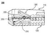
도 1은 본 발명의 일 실시예에 따른 척추체간 확장형 케이지를 설명하는 도면이다.1 is a view illustrating an intervertebral body extended cage according to an embodiment of the present invention.
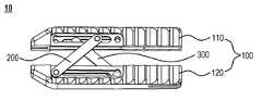
도 1을 참조하면, 본 발명의 일 실시예에 따른 척추체간 확장형 케이지(10)는, 케이지 본체(100), 제1 확장 프레임(200) 및 제2 확장 프레임(300)을 포함한다.1, the intervertebral
케이지 본체(100)는, 척추체간에 삽입되어 척추체간의 제1 척추체 및 제2 척추체를 지지하는 제1 지지부(110)와, 제1 확장 프레임(200) 및 제2 확장 프레임(300)에 의해 제1 지지부(110)에 대향하며 연결 설치되어 척추체간의 제1 척추체 및 제2 척추체를 지지하는 제2 지지부(120)를 포함한다.The
이때, 제1 지지부(110) 및 제2 지지부(120)는, 척추체간으로의 삽입을 보다 용이하도록 하기 위해 척추체간으로 삽입되는 방향에 있는 각각의 전단부(도 1의 좌측 머리 부분)가 서로 가까워지는 방향으로 경사지도록 형성(즉, 전단부 방향으로 갈수록 뾰족한 형상)될 수 있다.At this time, the
케이지 본체(100)는, 제1 확장 프레임(200)과 제2 확장 프레임(300)이 직립함에 따라 제1 지지부(110)와 제2 지지부(120)가 서로 멀어지는 방향으로 확장되어 척추체간의 공간을 확장시켜 준다.The
본 발명에 있어서, 척추체간이라 함은, 서로 이웃하는 제1 척추체 및 제2 척추체, 즉 추간원판(椎間圓板)이 위치되는 사이를 의미한다.In the present invention, the term "vertebral intervertebral body" means that the first and second vertebral bodies adjacent to each other, that is, the intervertebral discs are positioned.
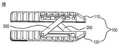
본 발명에 의한 케이지 본체(100)는, 제1 확장 프레임(200)의 일측(도 1를 기준으로 제1 확장 프레임(200)의 상측 부분)이 제1 지지부(110)의 후단으로부터 전단으로 슬라이딩 이동하고, 제2 확장 프레임(300)의 일측(도 2를 기준으로 제2 확장 프레임(300)의 상측 부분)이 제1 지지부(110)의 전단(경사지도록 형성된 머리 부분)으로부터 후단으로 슬라이딩 이동하여 제1 확장 프레임(200) 및 제2 확장 프레임(300)이 각각 제2 지지부(120)와 직각을 형성함에 따라 제1 지지부(110)와 제2 지지부(120)가 서로 멀어지는 방향으로 확장될 수 있다.In the
척추체간 확장형 케이지(10)의 도 1를 참조하면, 제1 확장 프레임(200)은, 일측이 제1 지지부(110)의 상부에 연결 설치되어 제1 지지부(110)의 전단 또는 제1 지지부(110)의 후단 방향으로 슬라이딩 이동하며, 다른 일측이 제2 지지부(120)의 상부의 전단에 연결 설치되어 회동한다.Referring to FIG. 1 of the intervertebral body extension-
여기서, 제1 지지부(110)의 상부라 함은, 척추체간에 삽입된 후 제1 척추체 또는 제2 척추체와 대향하며 지지하는 부분(즉, 제1 확장 프레임(200)의 일측이 연결 설치되는 부분)을 가리킨다.Here, the upper portion of the
척추체간 확장형 케이지(10)의 도 2를 참조하면, 제2 확장 프레임(300)은, 일측이 제1 지지부(110)의 하부에 연결 설치되어 제1 지지부(110)의 전단 또는 후단 방향으로 슬라이딩 이동하며, 다른 일측이 제2 지지부(120)의 하부의 후단에 연결 설치되어 회동한다.Referring to FIG. 2 of the intervertebral body extension-
여기서, 제1 지지부(110)의 하부라 함은, 척추체간에 삽입된 후 제1 지지부(110)의 상부가 지지하는 제1 척추체 또는 제2 척추체와 대향하고 있는 제2 척추체 또는 제1 척추체와 대향하며 지지하는 부분(즉, 제2 확장 프레임(300)의 일측이 연결 설치되는 부분)을 가리킨다.Here, the lower portion of the
그리고, 제2 지지부(120)의 상부 또는 하부라 함은, 대향하며 연결 설치된 제1 지지부(110)의 상부 또는 하부에 대응하는 부분을 가리킨다.In addition, the upper or lower portion of the
기존의 확장형 케이지는, 척추체간으로 수평 방향(즉, 상하 방향으로 형성되는 척추와 직각되는 방향)으로 삽입된 후, 상하 방향으로 대향하고 있는 두 척추체 사이를 확장 및 지탱하는 것에 그쳤다.The existing extended cage was only inserted in a horizontal direction (ie, a direction perpendicular to the spine formed in the vertical direction) between the vertebral bodies, and then extended and supported between two vertebral bodies facing the vertical direction.
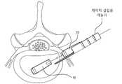
상술한 바와 같은 구성을 가지는 척추체간 확장형 케이지(10)는, 도 3에 도시된 바와 같이 디스크 질환으로 얇아진 디스크 공간으로의 삽입이 용이하도록 제1 지지부(110)의 일측(즉, 제2 지지부(120)와 대향하고 있지 않는 외측)이 제1 척추체와 대향하고 제2 지지부(120)의 일측(즉, 제1 지지부(110)와 대향하고 있지 않는 외측)이 제2 척추체와 대향하거나, 제2 지지부(120)의 일측이 제1 척추체와 대향하고 제1 지지부(110)의 일측이 제2 척추체와 대향하도록 눕힌 상태로 케이지 삽입용 케뉼라를 통해 척추의 디스크 공간으로 삽입될 수 있다.The intervertebral body extended
척추의 디스크 공간으로 삽입이 완료되면, 별도의 케이지 삽입 도구를 이용하여 눕혀졌던 방향을 회전시켜 도 4에 도시된 바와 같이 제1 지지부(110) 및 제2 지지부(120)의 상부 또는 하부가 제1 척추체 또는 제2 척추체와 대향하도록 바로잡게 된다.When the insertion into the disc space of the spine is completed, the upper or lower portions of the
다음으로, 케이지 삽입 도구를 이용하여 도 5에 도시된 바와 같이 제1 확장 프레임(200)과 제2 확장 프레임(300)을 직립시킴에 따라 제1 지지부(110)와 제2 지지부(120)가 완전히 확장되어 척추체간의 공간을 확장 및 지탱할 수 있다.Next, as shown in FIG. 5 by using a cage insertion tool, the
상술한 바와 같은 구성을 가지는 척추체간 확장형 케이지(10)의 각각의 구성들은, 폴리에터에터캐톤(polyetheretherketone, PEEK)으로 형성될 수 있다.Each of the components of the intervertebral
여기서, 폴리에터에터캐톤이라 함은, 티타늄(titanium)을 대신할 고성능 생체 적합 물질로서, 금속과 같이 사출성형, 몰딩, 가공, 압출 방법 등의 다양한 방법으로 제작이 가능할 뿐만 아니라, 충격 및 마모에 강하며, 다양한 온도 범위에서 높은 기계적 강도를 가지고, 방사선 안정성이 뛰어난 물질이다.Here, the polyether ether carton is a high-performance biocompatible material that replaces titanium, and can be manufactured by various methods such as injection molding, molding, processing, and extrusion methods such as metal, as well as impact and It is resistant to abrasion, has high mechanical strength in various temperature ranges, and is excellent in radiation stability.
이와 같이, 폴리에터에터캐톤으로 척추체간 확장형 케이지(10)를 형성할 경우, 신체의 친화력이 높아 신체에 거부반응을 최소화할 수 있을 뿐만 아니라, 강도가 높아 신체에 장기간 이식하여 사용할 수 있다.As described above, when the intervertebral body
상술한 바와 같은 구성을 가지는 척추체간 확장형 케이지(10)는, 기존의 확장형 케이지와는 달리 상하 방향뿐만 아니라 좌우 방향으로도 확장이 가능하여 환자의 환부에 대응하여 다양한 수술이 가능하도록 하며, 전체적인 크기를 축소시켜 환자의 신체 내부로 용이하게 삽입이 가능하다.The intervertebral body extended
도 6은 도 1의 척추체간 확장형 케이지의 제1 지지부를 설명하는 도면이다.FIG. 6 is a view for explaining a first support portion of the intervertebral body extension cage of FIG. 1.
도 6을 참조하면, 제1 지지부(110)는, 제1 지지 몸체(111), 제1 슬라이딩홈(112) 및 제2 슬라이딩홈(113)을 포함한다.Referring to FIG. 6, the
제1 지지 몸체(111)는, 척추체간에 삽입되어 제1 척추체 및 제2 척추체를 지지하고, 제1 척추체를 지지를 지지하는 상부에 길이 방향으로 제1 슬라이딩홈(112)이 형성되고, 제2 척추체를 지지를 지지하는 하부에 길이 방향으로 제2 슬라이딩홈(113)이 형성된다.The
일 실시예에서, 제1 지지 몸체(111)는, 환자의 신체 내로 삽입된 후 다시 빠져나오는 것을 방지할 수 있도록 전단으로부터 후단으로 갈수록 높이가 줄어들도록 형성될 수 있다.In one embodiment, the
예를 들어, 이탈방지돌기(114)를 제외한 제1 지지 몸체(111) 전단부의 높이가 약 8mm 내지 10mm, 예를 들어 9mm 등으로 형성된다고 할 경우, 이탈방지돌기(114)를 제외한 제1 지지 몸체(111) 후단부의 높이는 약 6mm 내지 8mm, 예를 들어 7mm 등으로 형성됨으로써, 제1 지지 몸체(111)의 전단부로부터 후단부로 갈수록 높이가 점진적으로 줄어들도록 형성될 수 있다.For example, when the height of the front end portion of the
또한, 제1 지지 몸체(111)는, 척추체간에서 케이지 본체(100)의 이탈을 방지할 수 있도록 케이지 본체(100)가 척추체간에 삽입되는 반대 방향을 향해 경사지는 톱니 모양으로 돌출 형성(약 0.5mm 내지 1.5mm, 예를 들어 1mm 등)되는 복수 개의 이탈방지돌기(114)를 상부 및 하부에 형성할 수 있다.In addition, the
제2 지지부(120) 제1 지지부(110)에 대응하는 형태로 형성되고, 복수 개의 이탈방지돌기(114) 역시 형성하나, 동일한 내용이므로 그 설명을 생략한다.The
제1 슬라이딩홈(112)은, 제1 확장 프레임(200)의 일측을 연결 설치하여 제1 지지 몸체(111)의 전단 또는 후단 방향으로 슬라이딩 이동시킬 수 있도록 제1 지지 몸체(111)의 상부에 길이 방향으로 기 설정된 길이(약 10mm 내지 14mm, 예를 들어 12mm 등)로 형성된다.The first sliding
제2 슬라이딩홈(113)은, 제2 확장 프레임(300)의 일측을 연결 설치하여 제1 지지 몸체(111)의 전단 또는 후단 방향으로 슬라이딩 이동시킬 수 있도록 제1 지지 몸체(111)의 하부에 길이 방향으로 제1 슬라이딩홈(112)에 대응하는 기 설정된 길이(약 10mm 내지 14mm, 예를 들어 12mm 등)로 형성된다.The second sliding
상술한 바와 같은 구성을 가지는 제1 지지부(110)는, 제1 확장 프레임(200) 및 제2 확장 프레임(300)이 제1 지지 몸체(111)와 직각을 형성한 경우, 제1 확장 프레임(200) 및 제2 확장 프레임(300)의 일측을 체결할 수 있도록 제1 슬라이딩홈(112)의 전단 및 제2 슬라이딩홈(113)의 후단에 제2 지지부(120)로부터 멀어지는 방향으로 파인 걸림턱(115)을 각각 형성할 수 있다.The
상술한 바와 같은 구성을 가지는 제1 지지부(110)는, 제1 슬라이딩홈(112)의 후단 및 제2 슬라이딩홈(113)의 전단으로부터 기 설정된 거리(약 0.5mm 내지 1.5mm, 예를 들어 1mm 등)에 추가적으로 설치될 수 있는 확장 프레임의 일측을 연결 설치하기 위한 추가 체결홈(116)을 더 포함할 수 있다.The
여기서, 추가 체결홈(116)은, 도 9에서 후술하는 제1 추가 확장 프레임(400) 또는 제2 추가 확장 프레임(500)의 일측을 연결 설치하여 회동시켜 줄 수 있다.Here, the
도 7은 도 1의 척추체간 확장형 케이지의 제2 지지부를 설명하는 도면이다.FIG. 7 is a view for explaining the second support portion of the intervertebral body extension cage of FIG. 1.
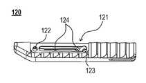
도 7을 참조하면, 제2 지지부(120)는, 제2 지지 몸체(121), 제1 체결홈(122) 및 제2 체결홈(123)을 포함한다.Referring to FIG. 7, the
제2 지지 몸체(121)는, 제1 확장 프레임(200) 및 제2 확장 프레임(300)에 의해 제1 지지부(110)에 대향하며 연결 설치되어 척추체간의 제2 척추체를 지지하고, 제1 척추체를 지지하는 상부 전단에 제1 체결홈(122)을 형성하고, 제2 척추체를 지지하는 하부 후단에 제2 체결홈(123)을 형성한다.The
제1 체결홈(122)은, 제2 지지 몸체(121)의 상부 전단에 형성되어 제1 확장 프레임(200)의 다른 일측을 회동 가능하도록 연결 설치한다.The
제2 체결홈(123)은, 제2 지지 몸체(121)의 하부 후단에 형성되어 제2 확장 프레임(300)의 다른 일측을 회동 가능하도록 연결 설치한다.The
상술한 바와 같은 구성을 가지는 제2 지지부(120)는, 제1 체결홈(122)의 후단 및 제2 체결홈(123)의 전단으로부터 기 설정된 거리(약 0.5mm 내지 1.5mm, 예를 들어 1mm 등)에 추가적으로 설치될 수 있는 확장 프레임의 다른 일측이 연결 설치되어 슬라이딩 이동시키기 위한 추가 슬라이딩홈(124)을 더 포함할 수 있다.The
여기서, 추가 슬라이딩홈(124)은, 도 9에서 후술하는 제1 추가 확장 프레임(400) 또는 제2 추가 확장 프레임(500)의 다른 일측을 연결 설치하여 전후 방향으로 슬라이딩 이동시켜 줄 수 있다.Here, the additional sliding
도 8은 도 1의 척추체간 확장형 케이지의 제1 확장 프레임을 설명하는 도면이다.FIG. 8 is a view for explaining a first expansion frame of the intervertebral extension cage of FIG. 1.
도 8을 참조하면, 제1 확장 프레임(200)은, 연결 프레임(210), 제1 체결볼트(220) 및 제2 체결볼트(230)를 포함한다.Referring to FIG. 8, the
연결 프레임(210)은, 일측이 제1 체결볼트(220)에 의해 제1 지지부(110)의 상부에 연결 설치되어 제1 지지부(110)의 전단 또는 후단 방향으로 슬라이딩 이동하며, 다른 일측이 제2 체결볼트(230)에 의해 제2 지지부(120)의 상부의 전단에 연결 설치되어 회동한다.The
제1 체결볼트(220)는, 제1 지지부(110)에 연결 프레임(210)의 일측을 연결 설치할 수 있도록 제1 지지부(110)의 내측으로부터 외측 방향으로 삽입되어 연결 프레임(210)의 일측에 체결하며, 제1 지지부(110)의 상부에 형성된 제1 슬라이딩홈(112)에서 슬라이딩 이동한다.The
제2 체결볼트(230)는, 제2 지지부(120)에 연결 프레임(210)의 다른 일측을 연결 설치할 수 있도록 제2 지지부(120)의 내측으로부터 외측 방향으로 삽입되어 연결 프레임(210)의 다른 일측에 체결되며, 제2 지지부(120)의 제1 체결홈(122)에서 회동한다.The
상술한 바와 같은 구성을 가지는 제1 확장 프레임(200)은, 제2 확장 프레임(300)에도 동일하게 적용을 할 수 있으므로, 제2 확장 프레임(300)에 대한 설명을 생략하기로 한다.Since the
상술한 바와 같은 구성을 가지는 제1 확장 프레임(200)은, 제2 체결볼트(230)가 제1 체결홈(122)에서 회동함에 따라 제1 체결볼트(220)가 제1 슬라이딩홈(112)에서 슬라이딩 이동하면서 연결 프레임(210)이 각각의 지지부와 직각을 형성하여 제1 지지부(110)과 제2 지지부(120) 사이의 공간을 확장시켜 줄 수 있다.In the
도 9는 본 발명의 다른 실시예에 따른 척추체간 확장형 케이지를 설명하는 도면이다.9 is a view for explaining an inter-vertebral extension cage according to another embodiment of the present invention.
도 9를 참조하면, 본 발명의 다른 실시예에 따른 척추체간 확장형 케이지(20)는, 케이지 본체(100), 제1 확장 프레임(200), 제2 확장 프레임(300), 제1 추가 확장 프레임(400) 및 제2 추가 확장 프레임(500)을 포함한다. 여기서, 케이지 본체(100), 제1 확장 프레임(200) 및 제2 확장 프레임(300)은, 도 1의 구성요소와 동일하므로 그 설명을 생략한다.9, the intervertebral
제1 추가 확장 프레임(400)은, 일측이 제1 지지부(110)의 상부 후단(즉, 도 6에서 제1 슬라이딩홈(112)이 위치하는 일측에 형성되는 추가 체결홈(116))에 연결 설치되어 회동하며, 다른 일측이 제2 지지부(120)의 상부(즉, 도 7에서 제1 체결홈(122)이 위치하는 일측에 형성되는 추가 슬라이딩홈(124))에 연결 설치되어 제2 지지부(120)의 전단 또는 후단 방향으로 슬라이딩 이동한다.The first
제2 추가 확장 프레임(500)은, 일측이 제1 지지부(110)의 하부 전단(즉, 도 6에서 제2 슬라이딩홈(113)이 위치하는 일측에 형성되는 추가 체결홈(116))에 연결 설치되어 회동하며, 다른 일측이 제2 지지부(120)의 하부(즉, 도 7에서 제2 체결홈(123)이 위치하는 일측에 형성되는 추가 슬라이딩홈(124))에 연결 설치되어 제2 지지부(120)의 전단 또는 후단 방향으로 슬라이딩 이동한다.The second
여기서, 제1 추가 확장 프레임(400) 및 제2 추가 확장 프레임(500)은, 도 8에서 상술한 제1 확장 프레임(200)과 동일한 구성으로 형성될 수 있는 바, 그 설명을 생략한다.Here, since the first
상술한 바와 같은 구성을 가지는 척추체간 확장형 케이지(20)는, 제1 확장 프레임(200)과 제2 확장 프레임(300) 이외에, 제1 확장 프레임(200)과 제2 확장 프레임(300)의 기능을 동일하게 수행할 수 있는 제1 추가 확장 프레임(400) 및 제2 추가 확장 프레임(500)을 추가로 구비함으로써, 제1 척추체와 제2 척추체로부터 보다 큰 압력이 가해지는 경우에도 파손 없이 본래의 기능을 수행할 수 있다.The intervertebral
이상에서는 실시예들을 참조하여 설명하였지만, 해당 기술 분야의 숙련된 당업자는 하기의 특허 청구의 범위에 기재된 본 발명의 사상 및 영역으로부터 벗어나지 않는 범위 내에서 본 발명을 다양하게 수정 및 변경시킬 수 있음을 이해할 수 있을 것이다.Although described above with reference to the embodiments, those skilled in the art can variously modify and change the present invention without departing from the spirit and scope of the present invention as set forth in the claims below. You will understand.
100: 케이지 본체110: 제1 지지부
111: 제1 지지 몸체112: 제1 슬라이딩홈
113: 제2 슬라이딩홈114: 이탈방지돌기
115: 걸림턱116: 추가 체결홈
120: 제2 지지부121: 제2 지지 몸체
122: 제1 체결홈123: 제2 체결홈
124: 추가 슬라이딩홈200: 제1 확장 프레임
210: 연결 프레임220: 제1 체결볼트
230: 제2 체결볼트300: 제2 확장 프레임
400: 제1 추가 확장 프레임500: 제2 추가 확장 프레임100: cage body 110: first support
111: first support body 112: first sliding groove
113: second sliding groove 114: departure prevention projections
115: locking jaw 116: additional fastening groove
120: second support portion 121: second support body
122: first fastening groove 123: second fastening groove
124: additional sliding groove 200: first expansion frame
210: connection frame 220: first fastening bolt
230: second fastening bolt 300: second expansion frame
400: first additional expansion frame 500: second additional expansion frame
Claims (11)
Translated fromKorean일측이 상기 제1 지지부의 상부에 연결 설치되어 상기 제1 지지부의 전단 또는 상기 제1 지지부의 후단 방향으로 슬라이딩 이동하며, 다른 일측이 상기 제2 지지부의 상부의 전단에 연결 설치되어 회동하는 제1 확장 프레임; 및
일측이 상기 제1 지지부의 하부에 연결 설치되어 상기 제1 지지부의 전단 또는 후단 방향으로 슬라이딩 이동하며, 다른 일측이 상기 제2 지지부의 하부의 후단에 연결 설치되어 회동하는 제2 확장 프레임을 포함하는, 척추체간 확장형 케이지.
A first support part inserted between the vertebral bodies and a second support part facing and connected to one side of the first support part, and each front end part in a direction inserted into the intervertebral body of the first support part and the second support part A cage body formed to be inclined in a direction closer to each other, the first support portion and the second support portion extending in a direction away from each other to expand a space between vertebral bodies;
One side is connected to the upper portion of the first support portion is installed in the front end of the first support portion or sliding to the rear end direction of the first support portion, the other side is connected to the front end of the upper portion of the second support portion is installed to rotate Expansion frame; And
One side is connected to the lower portion of the first support is installed to slide in the direction of the front end or rear end of the first support, the other side is connected to the rear end of the second support portion is installed and includes a second expansion frame to rotate , Intervertebral body expandable cage.
상기 제1 확장 프레임의 일측이 상기 제1 지지부의 후단으로부터 전단으로 슬라이딩 이동하고, 상기 제2 확장 프레임의 일측이 상기 제1 지지부의 전단으로부터 후단으로 슬라이딩 이동하여 상기 제1 확장 프레임 및 상기 제2 확장 프레임이 각각 상기 제2 지지부와 직각을 형성함에 따라 상기 제1 지지부와 상기 제2 지지부가 서로 멀어지는 방향으로 확장되는, 척추체간 확장형 케이지.
According to claim 1, The cage body,
One side of the first expansion frame slides from the rear end of the first support portion to the front end, and one side of the second expansion frame slides from the front end of the first support portion to the rear end, and the first expansion frame and the second The intervertebral body extension cage, wherein the first support portion and the second support portion extend in a direction away from each other as the expansion frames respectively form a right angle with the second support portion.
척추체간에 삽입되는 제1 지지 몸체;
상기 제1 확장 프레임의 일측을 연결 설치하여 상기 제1 지지 몸체의 전단 또는 후단 방향으로 슬라이딩 이동시킬 수 있도록 상기 제1 지지 몸체의 상부에 길이 방향으로 형성되는 제1 슬라이딩홈; 및
상기 제2 확장 프레임의 일측을 연결 설치하여 상기 제1 지지 몸체의 전단 또는 후단 방향으로 슬라이딩 이동시킬 수 있도록 상기 제1 지지 몸체의 하부 일측에 길이 방향으로 형성되는 제2 슬라이딩홈을 포함하는, 척추체간 확장형 케이지.
The method of claim 1, wherein the first support,
A first support body inserted between the vertebral bodies;
A first sliding groove formed in a longitudinal direction on the upper portion of the first support body so as to be connected to one side of the first expansion frame to be slidably moved in the front end or rear end direction of the first support body; And
A vertebral body including a second sliding groove formed in a longitudinal direction on a lower side of the first support body so as to be connected to one side of the second expansion frame to be slidably moved in a front end or a rear end direction of the first support body. Liver expandable cage.
전단으로부터 후단으로 갈수록 높이가 줄어들도록 형성되는, 척추체간 확장형 케이지.
The method of claim 3, wherein the first support body,
An intervertebral body extended cage formed to decrease in height from the front end to the rear end.
척추체간에서 상기 케이지 본체의 이탈을 방지할 수 있도록 상기 케이지 본체가 척추체간에 삽입되는 반대 방향을 향해 경사지는 톱니 모양으로 돌출 형성되는 복수 개의 이탈방지돌기를 상부 및 하부에 형성하는, 척추체간 확장형 케이지.
The method of claim 3, wherein the first support body,
In order to prevent separation of the cage body from the intervertebral body, the intervertebral body extended cage forming a plurality of anti-separation protrusions protruding in a serrated shape inclined toward the opposite direction in which the cage body is inserted between the vertebral bodies. .
상기 제1 확장 프레임 및 상기 제2 확장 프레임이 상기 제1 지지 몸체와 직각을 형성한 경우, 상기 제1 확장 프레임 및 상기 제2 확장 프레임의 일측을 체결할 수 있도록 상기 제1 슬라이딩홈의 전단 및 상기 제2 슬라이딩홈의 후단에 상기 제2 지지부로부터 멀어지는 방향으로 파인 걸림턱을 각각 형성하는, 척추체간 확장형 케이지.
According to claim 3, The first support,
When the first expansion frame and the second expansion frame form a right angle with the first support body, the front end of the first sliding groove and the first expansion frame so as to fasten one side of the first expansion frame and the second expansion frame and An intervertebral body extended cage, each of which forms a fine locking jaw in a direction away from the second support portion at a rear end of the second sliding groove.
상기 제1 슬라이딩홈의 후단 및 상기 제2 슬라이딩홈의 전단으로부터 기 설정된 거리에 추가적으로 설치될 수 있는 확장 프레임의 일측을 연결 설치하기 위한 추가 체결홈을 더 포함하는, 척추체간 확장형 케이지.
According to claim 3, The first support,
Further comprising an additional fastening groove for connecting one side of the expansion frame that can be additionally installed at a predetermined distance from the rear end of the first sliding groove and the front end of the second sliding groove, intervertebral body extended cage.
상기 제1 확장 프레임 및 제2 확장 프레임에 의해 상기 제1 지지부에 대향하며 연결 설치되는 제2 지지 몸체;
상기 제2 지지 몸체의 상부 전단에 형성되어 상기 제1 확장 프레임의 다른 일측을 회동 가능하도록 연결 설치하는 제1 체결홈; 및
상기 제2 지지 몸체의 하부 후단에 형성되어 상기 제2 확장 프레임의 다른 일측을 회동 가능하도록 연결 설치하는 제2 체결홈을 포함하는, 척추체간 확장형 케이지.
The method of claim 1, wherein the second support,
A second support body which is connected to and installed on the first support portion by the first and second expansion frames;
A first fastening groove formed at an upper front end of the second support body to connect and install the other side of the first expansion frame to be rotatable; And
And a second fastening groove formed at a lower rear end of the second support body and connected to the other side of the second expansion frame so as to be rotatable.
상기 제1 체결홈의 후단 및 상기 제2 체결홈의 전단으로부터 기 설정된 거리에 추가적으로 설치될 수 있는 확장 프레임의 다른 일측이 연결 설치되어 슬라이딩 이동시키기 위한 추가 슬라이딩홈을 더 포함하는, 척추체간 확장형 케이지.
The method of claim 8, wherein the second support,
The other end of the expansion frame, which can be additionally installed at a predetermined distance from the rear end of the first fastening groove and the front end of the second fastening groove, is further installed, and further includes an additional sliding groove for sliding movement, intervertebral body extended cage .
일측이 상기 제1 지지부의 상부에 연결 설치되어 상기 제1 지지부의 전단 또는 후단 방향으로 슬라이딩 이동하며, 다른 일측이 상기 제2 지지부의 상부 전단에 연결 설치되어 회동하는 연결 프레임;
상기 제1 지지부에 상기 연결 프레임의 일측을 연결 설치할 수 있도록 상기 제1 지지부의 내측으로부터 외측 방향으로 삽입되어 상기 연결 프레임의 일측에 체결되는 제1 체결볼트; 및
상기 제2 지지부에 상기 연결 프레임의 다른 일측을 연결 설치할 수 있도록 상기 제2 지지부의 내측으로부터 외측 방향으로 삽입되어 상기 연결 프레임의 다른 일측에 체결되는 제2 체결볼트를 포함하는, 척추체간 확장형 케이지.
The method of claim 1, wherein the first expansion frame,
A connection frame on which one side is installed connected to the upper portion of the first support portion and is slidably moved in the front end or rear end direction of the first support portion, and the other side is connected to the upper end portion of the second support portion to rotate;
A first fastening bolt which is inserted from the inner side of the first support portion to the outer side of the first support portion to be connected to the first support portion and fastened to one side of the connection frame; And
And a second fastening bolt which is inserted from the inner side of the second support portion to the other side of the connection frame and fastened to the other side of the connection frame so as to connect and install the other side of the connection frame to the second support portion.
일측이 상기 제1 지지부의 상부 후단에 연결 설치되어 회동하며, 다른 일측이 상기 제2 지지부의 상부에 연결 설치되어 상기 제2 지지부의 전단 또는 후단 방향으로 슬라이딩 이동하는 제1 추가 확장 프레임; 및
일측이 상기 제1 지지부의 하부 전단에 연결 설치되어 회동하며, 다른 일측이 상기 제2 지지부의 하부에 연결 설치되어 상기 제2 지지부의 전단 또는 후단 방향으로 슬라이딩 이동하는 제2 추가 확장 프레임을 더 포함하는, 척추체간 확장형 케이지.According to claim 1,
A first additional expansion frame in which one side is connected to the upper rear end of the first support and rotates, and the other side is connected to the upper portion of the second support to slide and move in the front or rear end direction of the second support; And
One side is connected to the lower front end of the first support and rotates, and the other side is further installed to the lower end of the second support and further includes a second additional expansion frame slidingly moving toward the front end or rear end of the second support portion. The intervertebral body extension cage.
Priority Applications (1)
| Application Number | Priority Date | Filing Date | Title |
|---|---|---|---|
| KR1020180159980AKR102163985B1 (en) | 2018-12-12 | 2018-12-12 | Expandable Cage for Intervertebral Body |
Applications Claiming Priority (1)
| Application Number | Priority Date | Filing Date | Title |
|---|---|---|---|
| KR1020180159980AKR102163985B1 (en) | 2018-12-12 | 2018-12-12 | Expandable Cage for Intervertebral Body |
Publications (2)
| Publication Number | Publication Date |
|---|---|
| KR20200072142Atrue KR20200072142A (en) | 2020-06-22 |
| KR102163985B1 KR102163985B1 (en) | 2020-10-12 |
Family
ID=71142172
Family Applications (1)
| Application Number | Title | Priority Date | Filing Date |
|---|---|---|---|
| KR1020180159980AActiveKR102163985B1 (en) | 2018-12-12 | 2018-12-12 | Expandable Cage for Intervertebral Body |
Country Status (1)
| Country | Link |
|---|---|
| KR (1) | KR102163985B1 (en) |
Cited By (2)
| Publication number | Priority date | Publication date | Assignee | Title |
|---|---|---|---|---|
| KR102511114B1 (en)* | 2022-04-08 | 2023-03-15 | 김현성 | Unidirectional expandable intervertebral fusion cage device |
| CN119523698A (en)* | 2024-11-07 | 2025-02-28 | 德州金康辰医疗器械有限公司 | Scissor-type intervertebral fusion cage |
Citations (6)
| Publication number | Priority date | Publication date | Assignee | Title |
|---|---|---|---|---|
| US20120004732A1 (en)* | 2009-03-13 | 2012-01-05 | University Of Toledo | Minimally Invasive Collapsible Cage |
| US20130116791A1 (en)* | 2011-11-04 | 2013-05-09 | Boo Holdings, Llc | Expandable intervertebral spacer implant |
| KR20130082281A (en) | 2012-01-11 | 2013-07-19 | 주식회사 디오메디칼 | A lumbar expandable cage |
| KR20150115732A (en) | 2012-12-14 | 2015-10-14 | 패시트-링크 아이엔씨. | Intervertebral cage expandable step-by-step |
| JP2018517465A (en)* | 2015-05-12 | 2018-07-05 | ニューヴェイジヴ,インコーポレイテッド | Expandable lordosis intervertebral implant |
| JP2018525131A (en)* | 2015-08-25 | 2018-09-06 | アイエムディーエス リミテッド ライアビリティ カンパニー | Expandable intervertebral implant |
- 2018
- 2018-12-12KRKR1020180159980Apatent/KR102163985B1/enactiveActive
Patent Citations (6)
| Publication number | Priority date | Publication date | Assignee | Title |
|---|---|---|---|---|
| US20120004732A1 (en)* | 2009-03-13 | 2012-01-05 | University Of Toledo | Minimally Invasive Collapsible Cage |
| US20130116791A1 (en)* | 2011-11-04 | 2013-05-09 | Boo Holdings, Llc | Expandable intervertebral spacer implant |
| KR20130082281A (en) | 2012-01-11 | 2013-07-19 | 주식회사 디오메디칼 | A lumbar expandable cage |
| KR20150115732A (en) | 2012-12-14 | 2015-10-14 | 패시트-링크 아이엔씨. | Intervertebral cage expandable step-by-step |
| JP2018517465A (en)* | 2015-05-12 | 2018-07-05 | ニューヴェイジヴ,インコーポレイテッド | Expandable lordosis intervertebral implant |
| JP2018525131A (en)* | 2015-08-25 | 2018-09-06 | アイエムディーエス リミテッド ライアビリティ カンパニー | Expandable intervertebral implant |
Cited By (3)
| Publication number | Priority date | Publication date | Assignee | Title |
|---|---|---|---|---|
| KR102511114B1 (en)* | 2022-04-08 | 2023-03-15 | 김현성 | Unidirectional expandable intervertebral fusion cage device |
| WO2023195610A1 (en)* | 2022-04-08 | 2023-10-12 | 김현성 | Unidirectionally-expandable interbody fusion cage device |
| CN119523698A (en)* | 2024-11-07 | 2025-02-28 | 德州金康辰医疗器械有限公司 | Scissor-type intervertebral fusion cage |
Also Published As
| Publication number | Publication date |
|---|---|
| KR102163985B1 (en) | 2020-10-12 |
Similar Documents
| Publication | Publication Date | Title |
|---|---|---|
| US11986398B2 (en) | Expandable implant assembly | |
| US20250120821A1 (en) | Expandable intervertebral cage | |
| US10231842B2 (en) | Intervertebral tensional artificial disc replacement | |
| US9114023B2 (en) | Interbody fusion device with snap on anterior plate and associated methods | |
| US9943349B2 (en) | Orthopedic devices with a locking mechanism | |
| US7338500B2 (en) | Internal pedicle insulator apparatus and method of use | |
| US8920505B2 (en) | Minimally invasive lateral intervertebral fixation system, device and method | |
| US9474624B1 (en) | Intervertebral fusion cage | |
| KR101352820B1 (en) | A lumbar expandable cage | |
| US8062374B2 (en) | Compliant interbody fusion device with deployable bone anchors | |
| US9023107B2 (en) | Vertebral body replacement | |
| US9579128B2 (en) | Translational plate and compressor instrument | |
| EP3614975A1 (en) | Expandable spinal interbody assembly | |
| KR20200072142A (en) | Expandable Cage for Intervertebral Body | |
| US9179946B2 (en) | Low-profile anterior vertebral plate assemblies and methods of use | |
| US20150282947A1 (en) | Vertebral body replacement | |
| KR102346366B1 (en) | Intervertebral body fusion device | |
| US8728132B2 (en) | Internal pedicle insulator apparatus and method of use | |
| US20200060730A1 (en) | Connector for simultaneously fixing screw head and rod | |
| KR102573983B1 (en) | Disc implant assembly | |
| KR20230155210A (en) | Interbody fusion device |
Legal Events
| Date | Code | Title | Description |
|---|---|---|---|
| PA0109 | Patent application | Patent event code:PA01091R01D Comment text:Patent Application Patent event date:20181212 | |
| PA0201 | Request for examination | ||
| PG1501 | Laying open of application | ||
| E701 | Decision to grant or registration of patent right | ||
| PE0701 | Decision of registration | Patent event code:PE07011S01D Comment text:Decision to Grant Registration Patent event date:20200630 | |
| GRNT | Written decision to grant | ||
| PR0701 | Registration of establishment | Comment text:Registration of Establishment Patent event date:20201005 Patent event code:PR07011E01D | |
| PR1002 | Payment of registration fee | Payment date:20201006 End annual number:3 Start annual number:1 | |
| PG1601 | Publication of registration | ||
| PR1001 | Payment of annual fee | Payment date:20230911 Start annual number:4 End annual number:4 | |
| PR1001 | Payment of annual fee |