KR20200071684A - Fluid Sensor Assembly - Google Patents
Fluid Sensor AssemblyDownload PDFInfo
- Publication number
- KR20200071684A KR20200071684AKR1020190164027AKR20190164027AKR20200071684AKR 20200071684 AKR20200071684 AKR 20200071684AKR 1020190164027 AKR1020190164027 AKR 1020190164027AKR 20190164027 AKR20190164027 AKR 20190164027AKR 20200071684 AKR20200071684 AKR 20200071684A
- Authority
- KR
- South Korea
- Prior art keywords
- fluid
- tank
- sample
- sensor
- assembly
- Prior art date
- Legal status (The legal status is an assumption and is not a legal conclusion. Google has not performed a legal analysis and makes no representation as to the accuracy of the status listed.)
- Granted
Links
Images


Classifications
- G—PHYSICS
- G01—MEASURING; TESTING
- G01F—MEASURING VOLUME, VOLUME FLOW, MASS FLOW OR LIQUID LEVEL; METERING BY VOLUME
- G01F23/00—Indicating or measuring liquid level or level of fluent solid material, e.g. indicating in terms of volume or indicating by means of an alarm
- G01F23/30—Indicating or measuring liquid level or level of fluent solid material, e.g. indicating in terms of volume or indicating by means of an alarm by floats
- G01F23/64—Indicating or measuring liquid level or level of fluent solid material, e.g. indicating in terms of volume or indicating by means of an alarm by floats of the free float type without mechanical transmission elements
- G01F23/72—Indicating or measuring liquid level or level of fluent solid material, e.g. indicating in terms of volume or indicating by means of an alarm by floats of the free float type without mechanical transmission elements using magnetically actuated indicating means
- G01F23/74—Indicating or measuring liquid level or level of fluent solid material, e.g. indicating in terms of volume or indicating by means of an alarm by floats of the free float type without mechanical transmission elements using magnetically actuated indicating means for sensing changes in level only at discrete points
- B—PERFORMING OPERATIONS; TRANSPORTING
- B60—VEHICLES IN GENERAL
- B60K—ARRANGEMENT OR MOUNTING OF PROPULSION UNITS OR OF TRANSMISSIONS IN VEHICLES; ARRANGEMENT OR MOUNTING OF PLURAL DIVERSE PRIME-MOVERS IN VEHICLES; AUXILIARY DRIVES FOR VEHICLES; INSTRUMENTATION OR DASHBOARDS FOR VEHICLES; ARRANGEMENTS IN CONNECTION WITH COOLING, AIR INTAKE, GAS EXHAUST OR FUEL SUPPLY OF PROPULSION UNITS IN VEHICLES
- B60K15/00—Arrangement in connection with fuel supply of combustion engines or other fuel consuming energy converters, e.g. fuel cells; Mounting or construction of fuel tanks
- B60K15/03—Fuel tanks
- G—PHYSICS
- G01—MEASURING; TESTING
- G01N—INVESTIGATING OR ANALYSING MATERIALS BY DETERMINING THEIR CHEMICAL OR PHYSICAL PROPERTIES
- G01N29/00—Investigating or analysing materials by the use of ultrasonic, sonic or infrasonic waves; Visualisation of the interior of objects by transmitting ultrasonic or sonic waves through the object
- G01N29/22—Details, e.g. general constructional or apparatus details
- G01N29/222—Constructional or flow details for analysing fluids
- G—PHYSICS
- G01—MEASURING; TESTING
- G01N—INVESTIGATING OR ANALYSING MATERIALS BY DETERMINING THEIR CHEMICAL OR PHYSICAL PROPERTIES
- G01N33/00—Investigating or analysing materials by specific methods not covered by groups G01N1/00 - G01N31/00
- B—PERFORMING OPERATIONS; TRANSPORTING
- B60—VEHICLES IN GENERAL
- B60K—ARRANGEMENT OR MOUNTING OF PROPULSION UNITS OR OF TRANSMISSIONS IN VEHICLES; ARRANGEMENT OR MOUNTING OF PLURAL DIVERSE PRIME-MOVERS IN VEHICLES; AUXILIARY DRIVES FOR VEHICLES; INSTRUMENTATION OR DASHBOARDS FOR VEHICLES; ARRANGEMENTS IN CONNECTION WITH COOLING, AIR INTAKE, GAS EXHAUST OR FUEL SUPPLY OF PROPULSION UNITS IN VEHICLES
- B60K15/00—Arrangement in connection with fuel supply of combustion engines or other fuel consuming energy converters, e.g. fuel cells; Mounting or construction of fuel tanks
- B60K15/01—Arrangement of fuel conduits
- F—MECHANICAL ENGINEERING; LIGHTING; HEATING; WEAPONS; BLASTING
- F01—MACHINES OR ENGINES IN GENERAL; ENGINE PLANTS IN GENERAL; STEAM ENGINES
- F01N—GAS-FLOW SILENCERS OR EXHAUST APPARATUS FOR MACHINES OR ENGINES IN GENERAL; GAS-FLOW SILENCERS OR EXHAUST APPARATUS FOR INTERNAL-COMBUSTION ENGINES
- F01N11/00—Monitoring or diagnostic devices for exhaust-gas treatment apparatus
- F—MECHANICAL ENGINEERING; LIGHTING; HEATING; WEAPONS; BLASTING
- F01—MACHINES OR ENGINES IN GENERAL; ENGINE PLANTS IN GENERAL; STEAM ENGINES
- F01N—GAS-FLOW SILENCERS OR EXHAUST APPARATUS FOR MACHINES OR ENGINES IN GENERAL; GAS-FLOW SILENCERS OR EXHAUST APPARATUS FOR INTERNAL-COMBUSTION ENGINES
- F01N3/00—Exhaust or silencing apparatus having means for purifying, rendering innocuous, or otherwise treating exhaust
- F01N3/08—Exhaust or silencing apparatus having means for purifying, rendering innocuous, or otherwise treating exhaust for rendering innocuous
- F01N3/10—Exhaust or silencing apparatus having means for purifying, rendering innocuous, or otherwise treating exhaust for rendering innocuous by thermal or catalytic conversion of noxious components of exhaust
- F01N3/18—Exhaust or silencing apparatus having means for purifying, rendering innocuous, or otherwise treating exhaust for rendering innocuous by thermal or catalytic conversion of noxious components of exhaust characterised by methods of operation; Control
- F01N3/20—Exhaust or silencing apparatus having means for purifying, rendering innocuous, or otherwise treating exhaust for rendering innocuous by thermal or catalytic conversion of noxious components of exhaust characterised by methods of operation; Control specially adapted for catalytic conversion
- F01N3/206—Adding periodically or continuously substances to exhaust gases for promoting purification, e.g. catalytic material in liquid form, NOx reducing agents
- F01N3/2066—Selective catalytic reduction [SCR]
- G—PHYSICS
- G01—MEASURING; TESTING
- G01F—MEASURING VOLUME, VOLUME FLOW, MASS FLOW OR LIQUID LEVEL; METERING BY VOLUME
- G01F23/00—Indicating or measuring liquid level or level of fluent solid material, e.g. indicating in terms of volume or indicating by means of an alarm
- G—PHYSICS
- G01—MEASURING; TESTING
- G01N—INVESTIGATING OR ANALYSING MATERIALS BY DETERMINING THEIR CHEMICAL OR PHYSICAL PROPERTIES
- G01N1/00—Sampling; Preparing specimens for investigation
- G01N1/02—Devices for withdrawing samples
- G01N1/10—Devices for withdrawing samples in the liquid or fluent state
- G01N1/14—Suction devices, e.g. pumps; Ejector devices
- G—PHYSICS
- G01—MEASURING; TESTING
- G01N—INVESTIGATING OR ANALYSING MATERIALS BY DETERMINING THEIR CHEMICAL OR PHYSICAL PROPERTIES
- G01N1/00—Sampling; Preparing specimens for investigation
- G01N1/28—Preparing specimens for investigation including physical details of (bio-)chemical methods covered elsewhere, e.g. G01N33/50, C12Q
- G01N1/42—Low-temperature sample treatment, e.g. cryofixation
- G—PHYSICS
- G01—MEASURING; TESTING
- G01N—INVESTIGATING OR ANALYSING MATERIALS BY DETERMINING THEIR CHEMICAL OR PHYSICAL PROPERTIES
- G01N1/00—Sampling; Preparing specimens for investigation
- G01N1/28—Preparing specimens for investigation including physical details of (bio-)chemical methods covered elsewhere, e.g. G01N33/50, C12Q
- G01N1/44—Sample treatment involving radiation, e.g. heat
- G—PHYSICS
- G01—MEASURING; TESTING
- G01N—INVESTIGATING OR ANALYSING MATERIALS BY DETERMINING THEIR CHEMICAL OR PHYSICAL PROPERTIES
- G01N21/00—Investigating or analysing materials by the use of optical means, i.e. using sub-millimetre waves, infrared, visible or ultraviolet light
- G01N21/17—Systems in which incident light is modified in accordance with the properties of the material investigated
- G01N21/25—Colour; Spectral properties, i.e. comparison of effect of material on the light at two or more different wavelengths or wavelength bands
- G01N21/31—Investigating relative effect of material at wavelengths characteristic of specific elements or molecules, e.g. atomic absorption spectrometry
- G01N21/35—Investigating relative effect of material at wavelengths characteristic of specific elements or molecules, e.g. atomic absorption spectrometry using infrared light
- G01N21/3504—Investigating relative effect of material at wavelengths characteristic of specific elements or molecules, e.g. atomic absorption spectrometry using infrared light for analysing gases, e.g. multi-gas analysis
- G—PHYSICS
- G01—MEASURING; TESTING
- G01N—INVESTIGATING OR ANALYSING MATERIALS BY DETERMINING THEIR CHEMICAL OR PHYSICAL PROPERTIES
- G01N21/00—Investigating or analysing materials by the use of optical means, i.e. using sub-millimetre waves, infrared, visible or ultraviolet light
- G01N21/17—Systems in which incident light is modified in accordance with the properties of the material investigated
- G01N21/25—Colour; Spectral properties, i.e. comparison of effect of material on the light at two or more different wavelengths or wavelength bands
- G01N21/31—Investigating relative effect of material at wavelengths characteristic of specific elements or molecules, e.g. atomic absorption spectrometry
- G01N21/35—Investigating relative effect of material at wavelengths characteristic of specific elements or molecules, e.g. atomic absorption spectrometry using infrared light
- G01N21/3577—Investigating relative effect of material at wavelengths characteristic of specific elements or molecules, e.g. atomic absorption spectrometry using infrared light for analysing liquids, e.g. polluted water
- G—PHYSICS
- G01—MEASURING; TESTING
- G01N—INVESTIGATING OR ANALYSING MATERIALS BY DETERMINING THEIR CHEMICAL OR PHYSICAL PROPERTIES
- G01N29/00—Investigating or analysing materials by the use of ultrasonic, sonic or infrasonic waves; Visualisation of the interior of objects by transmitting ultrasonic or sonic waves through the object
- G01N29/02—Analysing fluids
- G—PHYSICS
- G01—MEASURING; TESTING
- G01N—INVESTIGATING OR ANALYSING MATERIALS BY DETERMINING THEIR CHEMICAL OR PHYSICAL PROPERTIES
- G01N33/00—Investigating or analysing materials by specific methods not covered by groups G01N1/00 - G01N31/00
- G01N33/26—Oils; Viscous liquids; Paints; Inks
- G01N33/28—Oils, i.e. hydrocarbon liquids
- G01N33/2835—Specific substances contained in the oils or fuels
- B—PERFORMING OPERATIONS; TRANSPORTING
- B60—VEHICLES IN GENERAL
- B60K—ARRANGEMENT OR MOUNTING OF PROPULSION UNITS OR OF TRANSMISSIONS IN VEHICLES; ARRANGEMENT OR MOUNTING OF PLURAL DIVERSE PRIME-MOVERS IN VEHICLES; AUXILIARY DRIVES FOR VEHICLES; INSTRUMENTATION OR DASHBOARDS FOR VEHICLES; ARRANGEMENTS IN CONNECTION WITH COOLING, AIR INTAKE, GAS EXHAUST OR FUEL SUPPLY OF PROPULSION UNITS IN VEHICLES
- B60K15/00—Arrangement in connection with fuel supply of combustion engines or other fuel consuming energy converters, e.g. fuel cells; Mounting or construction of fuel tanks
- B60K15/03—Fuel tanks
- B60K2015/0321—Fuel tanks characterised by special sensors, the mounting thereof
- B60K2015/03217—Fuel level sensors
- B—PERFORMING OPERATIONS; TRANSPORTING
- B60—VEHICLES IN GENERAL
- B60K—ARRANGEMENT OR MOUNTING OF PROPULSION UNITS OR OF TRANSMISSIONS IN VEHICLES; ARRANGEMENT OR MOUNTING OF PLURAL DIVERSE PRIME-MOVERS IN VEHICLES; AUXILIARY DRIVES FOR VEHICLES; INSTRUMENTATION OR DASHBOARDS FOR VEHICLES; ARRANGEMENTS IN CONNECTION WITH COOLING, AIR INTAKE, GAS EXHAUST OR FUEL SUPPLY OF PROPULSION UNITS IN VEHICLES
- B60K15/00—Arrangement in connection with fuel supply of combustion engines or other fuel consuming energy converters, e.g. fuel cells; Mounting or construction of fuel tanks
- B60K15/03—Fuel tanks
- B60K2015/03243—Fuel tanks characterised by special pumps, the mounting thereof
- B—PERFORMING OPERATIONS; TRANSPORTING
- B60—VEHICLES IN GENERAL
- B60Y—INDEXING SCHEME RELATING TO ASPECTS CROSS-CUTTING VEHICLE TECHNOLOGY
- B60Y2400/00—Special features of vehicle units
- B60Y2400/30—Sensors
- F—MECHANICAL ENGINEERING; LIGHTING; HEATING; WEAPONS; BLASTING
- F01—MACHINES OR ENGINES IN GENERAL; ENGINE PLANTS IN GENERAL; STEAM ENGINES
- F01N—GAS-FLOW SILENCERS OR EXHAUST APPARATUS FOR MACHINES OR ENGINES IN GENERAL; GAS-FLOW SILENCERS OR EXHAUST APPARATUS FOR INTERNAL-COMBUSTION ENGINES
- F01N2610/00—Adding substances to exhaust gases
- F01N2610/14—Arrangements for the supply of substances, e.g. conduits
- F01N2610/1406—Storage means for substances, e.g. tanks or reservoirs
- F—MECHANICAL ENGINEERING; LIGHTING; HEATING; WEAPONS; BLASTING
- F01—MACHINES OR ENGINES IN GENERAL; ENGINE PLANTS IN GENERAL; STEAM ENGINES
- F01N—GAS-FLOW SILENCERS OR EXHAUST APPARATUS FOR MACHINES OR ENGINES IN GENERAL; GAS-FLOW SILENCERS OR EXHAUST APPARATUS FOR INTERNAL-COMBUSTION ENGINES
- F01N2610/00—Adding substances to exhaust gases
- F01N2610/14—Arrangements for the supply of substances, e.g. conduits
- F01N2610/1486—Means to prevent the substance from freezing
- F—MECHANICAL ENGINEERING; LIGHTING; HEATING; WEAPONS; BLASTING
- F01—MACHINES OR ENGINES IN GENERAL; ENGINE PLANTS IN GENERAL; STEAM ENGINES
- F01N—GAS-FLOW SILENCERS OR EXHAUST APPARATUS FOR MACHINES OR ENGINES IN GENERAL; GAS-FLOW SILENCERS OR EXHAUST APPARATUS FOR INTERNAL-COMBUSTION ENGINES
- F01N2900/00—Details of electrical control or of the monitoring of the exhaust gas treating apparatus
- F01N2900/06—Parameters used for exhaust control or diagnosing
- F01N2900/18—Parameters used for exhaust control or diagnosing said parameters being related to the system for adding a substance into the exhaust
- F01N2900/1806—Properties of reducing agent or dosing system
- F01N2900/1814—Tank level
- F—MECHANICAL ENGINEERING; LIGHTING; HEATING; WEAPONS; BLASTING
- F01—MACHINES OR ENGINES IN GENERAL; ENGINE PLANTS IN GENERAL; STEAM ENGINES
- F01N—GAS-FLOW SILENCERS OR EXHAUST APPARATUS FOR MACHINES OR ENGINES IN GENERAL; GAS-FLOW SILENCERS OR EXHAUST APPARATUS FOR INTERNAL-COMBUSTION ENGINES
- F01N2900/00—Details of electrical control or of the monitoring of the exhaust gas treating apparatus
- F01N2900/06—Parameters used for exhaust control or diagnosing
- F01N2900/18—Parameters used for exhaust control or diagnosing said parameters being related to the system for adding a substance into the exhaust
- F01N2900/1806—Properties of reducing agent or dosing system
- F01N2900/1818—Concentration of the reducing agent
- G—PHYSICS
- G01—MEASURING; TESTING
- G01N—INVESTIGATING OR ANALYSING MATERIALS BY DETERMINING THEIR CHEMICAL OR PHYSICAL PROPERTIES
- G01N1/00—Sampling; Preparing specimens for investigation
- G01N1/02—Devices for withdrawing samples
- G01N1/10—Devices for withdrawing samples in the liquid or fluent state
- G01N2001/1031—Sampling from special places
- G01N2001/1037—Sampling from special places from an enclosure (hazardous waste, radioactive)
Landscapes
- Chemical & Material Sciences (AREA)
- Physics & Mathematics (AREA)
- Engineering & Computer Science (AREA)
- Life Sciences & Earth Sciences (AREA)
- Health & Medical Sciences (AREA)
- General Physics & Mathematics (AREA)
- Pathology (AREA)
- Immunology (AREA)
- General Health & Medical Sciences (AREA)
- Biochemistry (AREA)
- Analytical Chemistry (AREA)
- Mechanical Engineering (AREA)
- Combustion & Propulsion (AREA)
- Chemical Kinetics & Catalysis (AREA)
- Spectroscopy & Molecular Physics (AREA)
- Acoustics & Sound (AREA)
- Transportation (AREA)
- Sustainable Energy (AREA)
- Sustainable Development (AREA)
- General Engineering & Computer Science (AREA)
- Food Science & Technology (AREA)
- Medicinal Chemistry (AREA)
- Fluid Mechanics (AREA)
- Toxicology (AREA)
- Hydrology & Water Resources (AREA)
- General Chemical & Material Sciences (AREA)
- Oil, Petroleum & Natural Gas (AREA)
- Measuring Temperature Or Quantity Of Heat (AREA)
Abstract
Translated fromKoreanDescription
Translated fromKorean본 명세서 내의 대상물은 일반적으로 유체 센서 조립체에 관한 것이다.Objects within this specification generally relate to fluid sensor assemblies.
일부 적용에서, 예를 들어 엔진의 연료 공급 시스템 또는 SCR (선택적 촉매 환원) 장치의 DEF (디젤 배기 유체) 전달 시스템에서, 유체 레벨은 특정 레벨 이상으로 유지될 필요가 있으며, 불순물이 섞인 유체 또는 희석된 유체와 같은 유체 품질 문제는 시스템 성능의 저하 및 시스템에 대한 손상을 방지하기 위해 검출될 필요가 있다. 이러한 적용에서, 유체 레벨 센서 및 유체 품질 센서가 유체 레벨을 측정하고 유체 품질을 모니터링하기 위해 사용된다. 예를 들어, 유체 레벨 센서는 다양한 시스템에서 리드 스위치 센서이며 유체 품질 센서는 초음파 센서를 포함하고 있다. 유체 레벨 센서와 유체 품질 센서는 전형적으로 유체 탱크 내의 유체 센서 하우징에 의해 유지된다. 유체 탱크 내에서 유체 품질을 모니터링하는 것은 어려우며 부정확한 품질 측정으로 이어질 수 있다. 부가적으로, 유체 센서들은 공통 센서 유닛으로 통합된다. 수리 또는 교체 시 센서 유닛 제거와 전체 감지 유닛 교체가 필요하다. 해결되어야 할 문제는 강력하고 비용 효율적인 유체 센서 조립체를 제공하는 것이다.In some applications, for example in the engine's fuel supply system or the SCR (selective catalytic reduction) device's DEF (diesel exhaust fluid) delivery system, the fluid level needs to be maintained above a certain level, impurity mixed fluid or dilution Fluid quality problems, such as impaired fluids, need to be detected to prevent degradation of system performance and damage to the system. In these applications, fluid level sensors and fluid quality sensors are used to measure fluid levels and monitor fluid quality. For example, the fluid level sensor is a reed switch sensor in various systems, and the fluid quality sensor includes an ultrasonic sensor. The fluid level sensor and fluid quality sensor are typically maintained by a fluid sensor housing in the fluid tank. Monitoring fluid quality within a fluid tank is difficult and can lead to inaccurate quality measurements. Additionally, fluid sensors are integrated into a common sensor unit. When repairing or replacing, it is necessary to remove the sensor unit and replace the entire sensing unit. The problem to be solved is to provide a robust and cost effective fluid sensor assembly.
위의 문제는 유체 탱크에 연결되도록 구성된 베이스 플레이트를 갖는 하우징 유닛을 포함하는 차량의 유체 탱크에 담겨 있는 유체를 감지하기 위하여 제공된 유체 센서 조립체에 의하여 해결된다. 하우징 유닛은 유체 탱크 내의 유체와 유체 연통하도록 구성된 샘플 흡인 라인과 샘플 복귀 라인을 포함하고 있다. 유체 센서 조립체는 하우징 유닛에 분리 가능하게 연결된 헤더 하우징을 갖는 헤더 조립체를 포함하고 있다. 헤더 하우징은 차량의 유체 탱크의 외부에 위치되도록 구성되어 있다. 헤더 조립체에는 샘플 흡인 라인 및 샘플 복귀 라인과 유체 연통하는 샘플 탱크를 갖고 있다. 샘플 탱크는 유체 탱크로부터 유체를 받도록 구성되어 있다. 헤더 조립체는 유체 탱크의 내부로부터 떨어진 위치에서의 유체의 품질 샘플링을 위해 샘플 탱크 내의 유체의 품질 특성을 감지하는 유체 품질 센서를 포함하고 있다.The above problem is solved by a fluid sensor assembly provided for sensing the fluid contained in the fluid tank of a vehicle comprising a housing unit having a base plate configured to be connected to the fluid tank. The housing unit includes a sample suction line and a sample return line configured to be in fluid communication with a fluid in the fluid tank. The fluid sensor assembly includes a header assembly having a header housing detachably connected to the housing unit. The header housing is configured to be located outside the vehicle's fluid tank. The header assembly has a sample tank in fluid communication with the sample suction line and sample return line. The sample tank is configured to receive fluid from the fluid tank. The header assembly includes a fluid quality sensor that senses the quality characteristics of the fluid in the sample tank for sampling the fluid quality at a location away from the interior of the fluid tank.
본 발명이 이제 첨부 도면을 참조하여 예로서 설명될 것이다.The invention will now be described by way of example with reference to the accompanying drawings.
도 1은 예시적인 실시예에 따른 유체 센서 조립체의 개략적인 도면이다.
도 2는 예시적인 실시예에 따른 유체 센서 조립체의 헤더 조립체의 개략적인 도면이다.
도 3은 예시적인 실시예에 따른 유체 센서 조립체의 분해도이다.
도 4는 예시적인 실시예에 따른 유체 센서 조립체의 분해도이다.1 is a schematic diagram of a fluid sensor assembly according to an exemplary embodiment.
2 is a schematic view of a header assembly of a fluid sensor assembly according to an exemplary embodiment.
3 is an exploded view of a fluid sensor assembly according to an exemplary embodiment.
4 is an exploded view of a fluid sensor assembly according to an exemplary embodiment.
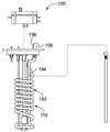
도 1은 차량(106)의 유체 탱크(104) 내에 들어있는 유체(102)를 감지하기 위한 유체 센서 조립체(100)의 개략적인 도면이다. 차량(106)은 자동차 및 농업용 차량, 항공기, 해양 선박 등일 수 있다. 유체 센서 조립체(100)는 유체(102)의 하나 이상의 유체 특성을 감지할 수 있다. 예를 들어, 유체 센서 조립체(100)는 유체(102) 내의 하나 이상의 물질의 농도를 감지할 수 있다. 유체 센서 조립체(100)는 유체(102)의 오염을 감지할 수 있다. 유체 센서 조립체(100)는 온도, 점도, 밀도 등과 같은 다른 유체 특성을 감지할 수 있다. 유체(102)는 연료, 오일, 유압 유체, 변속기 유체 또는 다른 유형의 유체일 수 있다. 다양한 실시예에서, 유체(102)는 디젤 배기 유체(DEF)이며, 유체 센서 조립체(100)는 DEF 품질 센서이다. DEF 품질 센서는 DEF 유체 내의 요소(urea) 또는 다른 환원제의 품질을 감지할 수 있다.1 is a schematic diagram of a
예시적인 실시예에서, 유체 센서 조립체(100)는 차량(106)의 차량 시스템(108)에 연결되어 있다. 예를 들어, 유체 센서 조립체(100)는 유체(102)의 유체 품질과 관련된 데이터를 차량 시스템(108)에 전달하기 위하여 차량 시스템(108)에 전기적으로 연결될 수 있다. 유체 센서 조립체(100)는 차량 시스템(108)에 전기적으로 연결되어 유체 센서 조립체(100)의 하나 이상의 구성 요소에 전력을 공급할 수 있다. 유체 센서 조립체(100)는 유체 탱크(104) 내의 유체(102)를 가열하기 위하여, 차량(106)의 냉각제 시스템과 같은 다른 유형의 차량 시스템에 연결될 수 있다.In an exemplary embodiment, the
예시적인 실시예에서, 유체 센서 조립체(100)는 하우징 유닛(110), 헤더 조립체(112), 유체 레벨 센서 조립체(114) 및 온도 제어 장치(116)를 포함하고 있다. 하우징 유닛(110)은 유체 탱크(104)에 연결되도록 구성된 베이스 플레이트(120)를 포함하고 있다. 예시적인 실시예에서, 헤더 조립체(112)는 하우징 유닛(110)의 베이스 플레이트(120)에 분리 가능하게 연결되어 있다. 예를 들어, 헤더 조립체(112)는 하우징 유닛(110)에 대해 제거 가능하고 교체 가능할 수 있다. 예시적인 실시예에서, 유체 레벨 센서 조립체(114)는 하우징 유닛(110)의 베이스 플레이트(120)에 분리 가능하게 연결되어 있다. 예를 들어, 유체 레벨 센서 조립체(114)는 하우징 유닛(110)에 대해 제거 가능하고 교체 가능할 수 있다. 예시적인 실시예에서, 유체 레벨 센서 조립체(114)는 헤더 조립체(112)에 분리 가능하게 연결되어 있다. 예를 들어, 유체 레벨 센서 조립체(114)는 헤더 조립체(112)에 대해 제거 가능하고 교체 가능할 수 있다. 예시적인 실시예에서, 온도 제어 장치(116)는 하우징 유닛(110)의 베이스 플레이트(120)에 분리 가능하게 연결되어 있다. 예를 들어, 온도 제어 장치(116)는 하우징 유닛(110)에 대해 제거 가능하고 교체 가능할 수 있다. 예시적인 실시예에서, 온도 제어 장치(116)는 헤더 조립체(112)에 분리 가능하게 연결되어 있다. 예를 들어, 온도 제어 장치(116)는 헤더 조립체(112)에 대해 제거 가능하고 교체 가능할 수 있다.In an exemplary embodiment, the
예시적인 실시예에서, 유체 센서 조립체(100)의 일부분은 유체(102)와 접촉하는 유체 탱크(104)의 내부에 위치되어 있다. 예를 들어, 하우징 유닛(110)의 일부분 및/또는 유체 레벨 센서 조립체(114)의 일부분 및/또는 온도 제어 장치(116)의 일부분은 유체(102)와 접촉하는 유체 탱크(104) 내로 연장될 수 있다. 예시적인 실시예에서, 유체 센서 조립체(100)의 일부분은 유체 탱크(104)의 외부에 위치되어 있으며 유체(102)와 이격되어 있다. 예를 들어, 헤더 조립체(112)는 유체 탱크(104)의 외부에 위치될 수 있다. 선택적으로, 헤더 조립체(112)는 유체 탱크(104)로부터 하우징 유닛(110)을 제거하지 않고 하우징 유닛(110)으로부터 제거 가능할 수 있다.In an exemplary embodiment, a portion of the
예시적인 실시예에서, 하우징 유닛(110)은 유체 탱크(104) 내의 유체(102)와 유체 연통하도록 구성된 샘플 흡인 라인(122) 및 샘플 복귀 라인(124)을 포함하고 있다. 선택적으로 샘플 흡인 라인(122)과 샘플 복귀 라인(124)은 유체 센서 조립체(100)를 통해 유체(102)의 샘플을 순환시키기 위한 폐 샘플 루프(closed sample loop)를 형성한다. 유체의 샘플은 샘플링 후에 유체 탱크(104)로 복귀된다. 유체 센서 조립체(100)는, 예를 들어 차량(106)의 작동 동안 유체(102)의 소비를 위해 유체 탱크(104)로부터 유체(102)를 제거하도록 사용되는 주 흡인 라인과는 별개이다. 유체 센서 조립체(100)는 유체 탱크(104)로부터의 주 흡인 라인 내의 유체를 샘플링하기 보다는 유체 탱크(104)로부터 유체(102)를 샘플링한다. 예시적인 실시예에서, 폐 샘플 루프는 헤더 조립체(112)를 통해 흐른다. 예를 들어, 하우징 유닛(110)은 샘플 흡인 라인(122) 및 샘플 복귀 라인(124)과 각각 흐름 연통하는 흡인 라인 피팅(fitting)(126) 및 복귀 라인 피팅(128)을 포함하고 있다. 헤더 조립체(112)는 하우징 유닛(110)의 흡인 라인 피팅(126) 및 복귀 라인 피팅(128)에 연결되도록 구성된 대응 흡인 라인 피팅(130) 및 대응 복귀 라인 피팅(132)을 포함하고 있다. 피팅(126, 128, 130, 132)은 분리 가능하여 헤더 조립체(112)가 하우징 유닛(110)으로부터 분리되는 것을 허용한다. 피팅(126, 128, 130, 132)은 각각의 인터페이스에서 밀봉되어 폐 샘플 루프 내에서의 유체(102)를 손실 또는 누설하지 않고 연결 및 분리를 허용할 수 있다. 피팅(126, 128)은 수 피팅 또는 암 피팅일 수 있으며, 피팅(130, 132)은 수 피팅 또는 암 피팅일 수 있다. 도시된 실시예에서, 흡인 라인(122, 124)은 베이스 플레이트(120)에 연결되고 유체 탱크(104)의 내부로 연장되어 있으며, 헤더 조립체(112)와 인터페이스하기 위하여 피팅(126, 128)은 베이스 플레이트(120)의 외부에서 베이스 플레이트(120)에 연결되어 있다. 유체(102)는 하우징 유닛(110)을 통하여 유체 탱크(104)의 내부와 유체 탱크(104)의 외부 사이를 이동한다. 예를 들어, 유체(102)는 샘플 복귀 라인(124)을 통해 유체 탱크(104) 내로 뒤로 순환되기 전에 유체 탱크(104) 외부의 헤더 조립체(112)에서 샘플링될 수 있다.In the exemplary embodiment, the
예시적인 실시예에서, 헤더 조립체(112)는 하우징 유닛(110)의 베이스 플레이트(120)에 연결되도록 구성된 헤더 하우징(134)을 포함하고 있다. 다양한 실시예에서 헤더 하우징(134)은 베이스 플레이트(120)에 직접 연결될 수 있다. 다른 대안적인 실시예에서, 헤더 하우징(134)은 떨어진 위치에서 베이스 플레이트(120)로부터 이격될 수 있으며 하우징 유닛(110)과 헤더 조립체(112) 사이에서 유체를 순환시키기 위하여 하나 이상의 유체 라인에 의하여 하우징 유닛(110)에 연결될 수 있다.In an exemplary embodiment, the
헤더 조립체(112)는 차량 시스템(108)과 인터페이스하기 위하여 차량 커넥터(136)를 포함하고 있다. 예를 들어, 차량 시스템(108)의 전기 커넥터(138)는 차량 커넥터(136)에 연결되어 있다. 전기 신호는 차량 커넥터(136)와 전기 커넥터(138)를 통하여 차량 시스템(108)과 헤더 조립체(112) 사이에서 전송될 수 있다. 예를 들어, 유체 센서 조립체(100)에 의해 측정된 유체 품질 특성과 관련된 데이터는 차량 시스템(108)으로 전송될 수 있다. 전기 커넥터(138)와 차량 커넥터(136)를 통하여 헤더 조립체(112)에 전력이 공급될 수 있다.The
예시적인 실시예에서, 헤더 조립체(112)는 유체 레벨 센서 조립체(114)에 전기적으로 연결되도록 구성된 센서 커넥터(140)를 포함하고 있다. 유체 레벨 센서 조립체(114)는 유체(102) 및 유체 탱크(104)의 유체 레벨을 결정하는데 사용된다. 유체 레벨 센서 조립체(114)로부터의 신호는 센서 커넥터(140)를 통해 헤더 조립체(112)로 전송될 수 있다. 예시적인 실시예에서, 유체 레벨 센서 조립체(114)는 유체(102) 및 유체 탱크(104)의 유체 레벨을 감지하는데 사용되는 리드 스위치(reed switch; 142)를 포함하고 있다. 유체 레벨 센서 조립체(114)는 다수의 리드 스위치를 포함할 수 있다. 다양한 실시예에서, 유체 레벨 센서는 플로트 튜브(146) 상에 있는, 유체 탱크(104) 내의 플로트(144)를 포함할 수 있으며, 플로트 튜브는 플로트(144)를 유체 탱크(104) 내에 위치시킨다. 플로트(144)는 유체(102)의 최상부에 떠있는다. 플로트(144)가 리드 스위치(142)에 도달할 때, 유체 레벨 센서 조립체(114)는 유체 탱크(104) 내의 낮은 유체 레벨에 관한 신호를 전송할 수 있다. 예를 들어, 리드 스위치(142)는 센서 커넥터(140)에 전기적으로 연결된 리드 스위치 회로 보드(148)에 연결될 수 있다. 유체 탱크(104) 내의 유체 레벨을 결정하기 위한 대안적인 실시예에서 다른 유형의 레벨 센서가 사용될 수 있다. 대안적인 실시예에서, 자기 저항 유닛, 초음파 센서 등과 같은 다른 유형의 유체 레벨 센서가 사용될 수 있다.In an exemplary embodiment,
예시적인 실시예에서, 온도 제어 장치(116)는 하우징 유닛(110)의 베이스 플레이트(120)에 연결되어 있다. 온도 제어 장치(116)는 유체 탱크(104) 내로 연장되며 유체(102)와 열 접촉할 수 있다. 온도 제어 장치(116)는 유체(102)와 유체 탱크(104)의 온도에 영향을 주도록 작동될 수 있다. 예시적인 실시예에서, 온도 제어 장치(116)는 유체(102)를 가열하기 위한 가열 요소를 포함하고 있다. 예를 들어, 가열 요소는 헤더 조립체(112)를 통해 전력이 공급되는 전기 가열 요소일 수 있다. 예시적인 실시예에서, 온도 제어 장치(116)는 유체(102)를 냉각시키기 위한 냉각 요소를 포함하고 있다. 예를 들어, 냉각 요소는 유체(104)를 냉각시키기 위해 유체 탱크(104)를 통해 냉매를 순환시키는 냉매 라인일 수 있다. 냉매 라인은, 예를 들어 헤더 조립체(112) 및/또는 하우징 유닛(110)의 베이스 플레이트(120) 상의 하나 이상의 피팅을 통하여 차량(106)의 냉각 시스템에 연결될 수 있다.In the exemplary embodiment, the
예시적인 실시예에서, 유체 센서 조립체(100)는 모듈식으로 설계되어 유체 센서 조립체(100)의 다른 요소를 교체할 필요 없이 유체 센서 조립체(100)의 하나 이상의 요소의 수리 및/또는 교체를 허용한다. 예를 들어, 헤더 조립체(112)는 하우징 유닛(110) 및/또는 유체 레벨 센서 조립체(114) 및/또는 온도 제어 장치(116)를 교체하지 않고 업그레이드된 헤더 조립체(112)로 제거 및 교체될 수 있다. 독립 요소들은 별도로 제조 가능하다. 요소들은 서로 별도로 생산, 테스트 및 교정될 수 있으며 서로 일체화될 수 있다. 유체 센서 조립체(100)의 요소는 현장 수리 가능 가능하며 및/또는 현장 교체 가능하다. 예시적인 실시예에서, 유체 센서 조립체(100)는 유체 탱크(104) 외부의 헤더 조립체(112)에서와 같이 유체 탱크(104)에서 떨어진 위치에서 유체 샘플링 및 테스트를 허용한다. 보다 정확한 테스트를 위하여 테스트 동안 유체의 환경 조건은 더 반복적이고 일관적으로 제어될 수 있다. 예를 들어, 샘플 테스트는 열악한 운영 환경에서 떨어져 수행될 수 있다. 예를 들어, 샘플링되고 있는 유체의 온도 및 압력은 유체 탱크(104) 내의 현장(in situ)과는 대조적으로 유체 탱크(104) 외부의 헤더 조립체(112) 내에서 더 잘 제어될 수 있다.In an exemplary embodiment, the
도 2는 예시적인 실시예에 따른 유체 센서 조립체(100)의 헤더 조립체(112)의 개략적인 도면이다. 헤더 조립체(112)는 헤더 하우징(134) 내에 구성 요소를 포함하고 있다. 예시적인 실시예에서, 헤더 하우징(134)은 밀봉되어 구성 요소를 위한 그리고 유체 테스트를 위한 밀봉된 환경을 제공할 수 있다. 흡인 라인 피팅(130)과 복귀 라인 피팅(132)은 하우징 유닛(110)과 인터페이스하기 위해 헤더 하우징(134)으로부터 연장되어 헤더 조립체(112)를 통한 유체(102)를 위한 흐름 경로를 생성한다. 차량 커넥터(136)는 헤더 하우징(134)으로부터 연장되어 차량(106)의 차량 시스템(108)과의 전기적 연결을 생성한다.2 is a schematic diagram of a
예시적인 실시예에서, 헤더 조립체(112)는 헤더 조립체(112)를 통하여 유체를 순환시키기 위한 유체 펌프(150)를 포함하고 있다. 예를 들어, 유체 펌프(150)는 시스템을 통하여 유체를 펌핑하기 위하여 흡인 라인 피팅(130)에 연결될 수 있다. 유체 펌프(150)는 유체 센서 조립체(100)에 의한 일관된 샘플링을 위하여 폐 샘플 루프 내에서 유체의 압력을 제어하는데 사용된다. 유체 펌프(150)는 일정한 압력에서 샘플링이 발생하도록 샘플 루프 내에서 일정한 압력을 유지할 수 있다. 유체 펌프(150)는 유체를 유체 탱크(104)로부터 헤더 조립체(112) 내로 배출해 내기 위해 사용된다. 샘플 루프 내의 유체(102)는 기포가 없을 수 있으며, 이는 유체(102)의 시험 품질을 향상시킬 수 있다. 예를 들어, 유체 펌프(150)는 유체를 가압하여 샘플 루프 내의 임의의 기포를 제거할 수 있다.In an exemplary embodiment,
헤더 조립체(112)는 흡인 라인 피팅(130) 및 복귀 라인 피팅(132)과 유체 연통하는 샘플 탱크(152)를 포함하고 있다. 예시적인 실시예에서, 샘플 탱크(152)는 헤더 하우징(134) 내에 있다. 대안적으로, 샘플 탱크(152)는 유체 탱크(104) 외부의 헤더 하우징(134)으로부터 떨어져 위치할 수 있다. 유체(102)는 유체 펌프(150)에 의해 샘플 탱크(152)를 통해 샘플 흡인 라인(122)으로부터 샘플 복귀 라인(124)으로 순환된다. 예시적인 실시예에서, 유체는 샘플 탱크(152) 내에서 테스트된다. 이와 같이, 유체(102)의 샘플링은 헤더 조립체(112)의 헤더 하우징(134) 내에서와 같이 유체 탱크(104) 외부에서 발생한다. 샘플 탱크(152)는 유체를 테스트하기 위한 소규모의 통제된 환경일 수 있다. 예를 들어, 샘플 탱크가 유체 탱크(104)로부터 떨어져 있기 때문에 온도는 대체로 유체 탱크(104) 내의 유체의 온도와는 관계없이 샘플 탱크(152) 내에서 제어될 수 있다. 샘플 탱크가 유체 탱크(104)로부터 떨어져 있기 때문에 샘플 탱크는 대체로 유체 탱크(104) 내의 유체의 압력과 관계없이 샘플 탱크(152) 내의 압력 조절을 제어할 수 있다.
예시적인 실시예에서, 헤더 조립체(112)는 헤더 하우징(134) 내의 유체 품질 센서(154)를 포함하고 있다. 유체 품질 센서(154)는 샘플 탱크(152) 내에서 유체(102)를 테스트한다. 유체 품질 센서(154)는 유체(102)의 하나 이상의 유체 특성을 감지할 수 있다. 예를 들어, 유체 품질 센서(154)는 유체(102) 내의 하나 이상의 물질의 농도를 감지할 수 있다. 유체 품질 센서(154)는 유체(102)의 오염을 감지할 수 있다. 유체 품질 센서(154)는 온도, 점도, 밀도 등과 같은 다른 유체 특성을 감지할 수 있다. 예시적인 실시예에서, 유체 품질 센서(154)는 유체(102)의 품질 샘플링을 위한 초음파 변환기(156)를 포함하고 있다. 다른 유형의 샘플링 센서가 다른 다양한 실시예에 제공될 수 있다. 초음파 변환기(156)는 유체(102)의 품질 테스트를 위하여 샘플 탱크(152)에 또는 내에 위치될 수 있다. 초음파 변환기(156)는 유체의 하나 이상의 품질 특성을 테스트하기 위하여 유체(102)를 통해 초음파 신호를 전송한다. 다른 다양한 실시예에서, 유체 품질 센서(154)는 다른 유형의 감지 요소를 포함할 수 있다. 예를 들어, 유체 품질 센서(154)는 샘플 탱크(152) 내의 유체를 통해 적외선 신호를 전송하도록 구성된 적외선 센서를 포함할 수 있다. 선택적으로, 유체 품질 센서(154)는 유체의 상이한 품질 특성을 감지하기 위한 다른 유형의 센서들을 포함할 수 있다.In an exemplary embodiment,
예시적인 실시예에서, 헤더 조립체(112)는 센서 회로 보드(160) 상에 하나 이상의 센서 구성 요소(162)를 갖는 센서 회로 보드(160)를 포함하고 있다. 센서 구성 요소(162)는 유체 품질 센서(154)로부터의 신호의 데이터 처리를 위하여 사용되어 유체(102)의 하나 이상의 품질 특성을 결정할 수 있다. 센서 구성 요소(162)는 하나 이상의 프로세서, 메모리, 통신 구성 요소 등을 포함할 수 있다. 유체 품질 센서(154)는, 예를 들어 와이어, 커넥터 등에 의하여 센서 회로 보드(160)에 전기적으로 연결되어 있다. 유체 품질 센서(154)의 작동은 센서 회로 보드(160) 상의 하나 이상의 센서 구성 요소(162)에 의하여 제어될 수 있다. 유체 품질 센서(154)로부터의 데이터는 센서 회로 보드(160) 상의 하나 이상의 센서 구성 요소(162)에 의하여 분석될 수 있다. 유체 품질 센서(154)로부터의 데이터는 하나 이상의 센서 구성 요소(162)에 의하여 차량 커넥터(136) 및/또는 차량 시스템(108)과 같은 다른 구성 요소로 전송될 수 있다.In an exemplary embodiment,
예시적인 실시예에서, 센서 커넥터(140)는 센서 회로 보드(160)에 전기적으로 연결되어 있다. 유체 레벨 센서 조립체(114)로부터의 데이터는 센서 커넥터(140)를 통해 센서 회로 보드(160) 상의 하나 이상의 센서 구성 요소(162)로 전송될 수 있다. 유체 레벨 센서 조립체(114)로부터의 데이터는 하나 이상의 센서 구성 요소(162)에 의하여 차량 커넥터(136) 및/또는 차량 시스템(108)과 같은 다른 구성 요소로 전송될 수 있다.In an exemplary embodiment,
예시적인 실시예에서, 헤더 조립체(112)는 온도 제어 장치(116)의 가열 요소(172)의 작동을 제어하기 위한 가열 요소 회로 보드(170)를 포함하고 있다. 가열 요소 회로 보드(170)는, 예를 들어 차량으로부터 전력을 수신하기 위해 차량 커넥터(136)에 전기적으로 연결될 수 있다.In an exemplary embodiment, the
도 3은 예시적인 실시예에 따른 유체 센서 조립체(100)의 분해도이다. 도 3은 가열 요소(172)를 포함하는 온도 제어 장치(116)를 도시하고 있다. 가열 요소(172)는 헤더 조립체(112)에 전기적으로 연결되도록 구성된 가열 요소 커넥터(174)를 포함하고 있다. 도 3은 베이스 플레이트(120)의 최하부로부터 연장되는 샘플 흡인 라인(122)과 샘플 복귀 라인(124)을 도시하고 있다. 예시적인 실시예에서, 필터(180)는 샘플 흡인 라인(122) 상에 제공되어 폐 샘플 루프를 통해 순환되는 유체(102)를 필터링한다. 도 3은 헤더 조립체(112)와 인터페이스하기 위한, 베이스 플레이트(120)의 최상부에서의 흡인 라인 피팅(126) 및 복귀 라인 피팅(128)을 도시하고 있다.3 is an exploded view of a
예시적인 실시예에서, 헤더 조립체(112)는 하우징 유닛(110)과 별도로 제공되며 하우징 유닛(110)에 제거 가능하게 연결되도록 구성되어 있다. 흡인 라인 피팅(130)과 복귀 라인 피팅(132)은 흡인 라인 피팅(126)과 복귀 라인 피팅(128)과 각각 정합될 수 있다. 헤더 조립체(112)는, 예를 들어 온도 제어 장치(116)에 전력을 공급하기 위해, 온도 제어 장치(116)의 가열 요소 커넥터(174)와 정합되도록 구성된 가열 요소 커넥터(176)를 포함하고 있다. 헤더 조립체(112)는 유체 레벨 센서 조립체(114)의 유체 레벨 센서 커넥터(182)에 연결되도록 구성된 센서 커넥터(140)를 포함하고 있다. 헤더 조립체(112)는, 예를 들어 헤더 조립체(112)의 하나 이상의 구성 요소에 결함이 있거나 업그레이드가 필요한 경우 헤더 조립체(112)가 교체될 수 있도록 하우징 유닛(110)에 제거 가능하게 연결되어 있다. 헤더 조립체(112)는 하우징 유닛(110)을 제거 및/또는 교체하지 않고 현장에서 제거 및 교체될 수 있다.In an exemplary embodiment, the
예시적인 실시예에서, 유체 레벨 센서 조립체(114)는 하우징 유닛(110)과 별도로 제공되며 하우징 유닛(110)에 제거 가능하게 연결되도록 구성되어 있다. 유체 레벨 센서 커넥터(182)는 센서 커넥터(140)에 제거 가능하게 연결될 수 있다. 예를 들어, 유체 레벨 센서 조립체(114)는 헤더 조립체(112)와 인터페이스하기 위하여 베이스 플레이트(120)에 연결될 수 있으며 및/또는 베이스 플레이트(120)를 통해 연장될 수 있다.In an exemplary embodiment, the fluid
도 4는 예시적인 실시예에 따른 유체 센서 조립체(100)의 분해도이다. 도 4는 냉각 요소(192)를 포함하고 있는 온도 제어 장치(116)를 도시하고 있다. 냉각 요소(192)는 공급 피팅(196)과 복귀 피팅(198)을 갖는 냉각제 라인(194)을 포함하고 있다. 냉각제는 냉각제 라인(194)을 통해 순환된다. 냉각제 라인(194)은 유체(102)를 가열하기 위해, 예를 들어 유체(102)의 동결을 방지하고자, 유체 탱크(104) 내의 유체(102)와 열 연통하도록 구성된다. 선택적으로, 유체를 가열하기 위해 가열 요소가 제공될 수 있다.4 is an exploded view of a
Claims (10)
Translated fromKorean상기 유체 탱크에 연결되도록 구성된 베이스 플레이트(120)를 가지며, 상기 유체 탱크 내의 유체와 유체 연통하도록 구성된 샘플 흡인 라인(122) 및 샘플 복귀 라인(124)을 포함하는 하우징 유닛(110); 및
상기 하우징 유닛에 분리 가능하게 연결되고 상기 차량의 상기 유체 탱크의 외부에 위치되도록 구성된 헤더 하우징(134)을 가지며, 상기 샘플 흡인 라인 및 상기 샘플 복귀 라인과 유체 연통하고 상기 유체 탱크로부터의 유체를 수용하도록 구성된 샘플 탱크(152)를 가지며, 상기 유체 탱크의 내부로부터 떨어진 위치에서 상기 유체의 품질 샘플링을 위하여 상기 샘플 탱크 내의 상기 유체의 품질 특성을 감지하는 유체 품질 센서(154)를 포함하는 헤더 조립체(102)를 포함하는 유체 센서 조립체(100).A fluid sensor assembly (100) for sensing fluid (102) contained within a fluid tank (104) of a vehicle (106),
A housing unit 110 having a base plate 120 configured to be connected to the fluid tank, and including a sample suction line 122 and a sample return line 124 configured to be in fluid communication with the fluid in the fluid tank; And
Has a header housing (134) detachably connected to the housing unit and configured to be located outside the fluid tank of the vehicle, in fluid communication with the sample suction line and the sample return line and receiving fluid from the fluid tank A header assembly comprising a fluid quality sensor 154 that has a sample tank 152 configured to sense the quality characteristics of the fluid in the sample tank for sampling the quality of the fluid at a location away from the interior of the fluid tank 102) a fluid sensor assembly (100).
상기 헤더 조립체(102)는 상기 하우징 유닛을 상기 유체 탱크(104)로부터 제거하지 않고 상기 하우징 유닛(110)으로부터 분리 가능한 유체 센서 조립체(100).According to claim 1,
The header assembly 102 is a fluid sensor assembly 100 detachable from the housing unit 110 without removing the housing unit from the fluid tank 104.
상기 헤더 조립체(102)는 밀봉된 유체 센서 조립체(100).According to claim 1,
The header assembly 102 is a sealed fluid sensor assembly 100.
상기 샘플 탱크(152)는 상기 헤더 하우징(134) 내에 들어있는 유체 센서 조립체(100).According to claim 1,
The sample tank 152 is a fluid sensor assembly 100 contained within the header housing 134.
상기 하우징 유닛(110)은 흡인 라인 피팅(126) 및 복귀 라인 피팅(128)을 포함하며, 상기 헤더 조립체(102)는 상기 하우징 유닛의 상기 흡인 라인 피팅에 제거 가능하게 연결된 흡인 라인 피팅(130)을 포함하고, 상기 헤더 조립체는 상기 하우징 유닛의 상기 복귀 라인 피팅에 제거 가능하게 연결된 복귀 라인 피팅(132)을 포함하는 유체 센서 조립체(100).According to claim 1,
The housing unit 110 includes a suction line fitting 126 and a return line fitting 128, wherein the header assembly 102 is a suction line fitting 130 removably connected to the suction line fitting of the housing unit And a return line fitting 132 removably connected to the return line fitting of the housing unit.
상기 샘플 흡인 라인(122)과 상기 샘플 복귀 라인(124)은 상기 유체(102)를 샘플링하기 위한 폐 샘플 루프를 형성하는 유체 센서 조립체(100).According to claim 1,
The sample suction line 122 and the sample return line 124 are fluid sensor assemblies 100 forming a closed sample loop for sampling the fluid 102.
상기 헤더 조립체(102)는 상기 차량(106)의 전기 커넥터(138)에 연결되도록 구성된 차랑 커넥터(136)를 포함하는 유체 센서 조립체(100).According to claim 1,
The header assembly 102 is a fluid sensor assembly 100 comprising a vehicular connector 136 configured to be connected to an electrical connector 138 of the vehicle 106.
상기 헤더 조립체(102)는 상기 샘플 흡인 라인(122)과 흐름 연통하는 펌프(150)를 포함하는 유체 센서 조립체(100).According to claim 1,
The header assembly 102 is a fluid sensor assembly 100 comprising a pump 150 in flow communication with the sample suction line 122.
상기 헤더 조립체(102)는 센서 회로 보드(160)를 포함하며, 상기 센서 회로 보드는 상기 유체 품질 센서(154)에 전기적으로 연결되어 있는 유체 센서 조립체(100).According to claim 1,
The header assembly 102 includes a sensor circuit board 160, wherein the sensor circuit board is a fluid sensor assembly 100 that is electrically connected to the fluid quality sensor 154.
상기 유체 품질 센서(154)는 상기 유체(102)의 품질 샘플링을 위하여 상기 샘플 탱크(152) 내에 초음파 변환기(156)를 포함하는 유체 센서 조립체(100).According to claim 1,
The fluid quality sensor 154 is a fluid sensor assembly 100 that includes an ultrasonic transducer 156 in the sample tank 152 for quality sampling of the fluid 102.
Applications Claiming Priority (2)
| Application Number | Priority Date | Filing Date | Title |
|---|---|---|---|
| US16/214,348US10948460B2 (en) | 2018-12-10 | 2018-12-10 | Fluid sensor assembly |
| US16/214,348 | 2018-12-10 |
Publications (2)
| Publication Number | Publication Date |
|---|---|
| KR20200071684Atrue KR20200071684A (en) | 2020-06-19 |
| KR102655658B1 KR102655658B1 (en) | 2024-04-09 |
Family
ID=68808019
Family Applications (1)
| Application Number | Title | Priority Date | Filing Date |
|---|---|---|---|
| KR1020190164027AActiveKR102655658B1 (en) | 2018-12-10 | 2019-12-10 | Fluid Sensor Assembly |
Country Status (4)
| Country | Link |
|---|---|
| US (1) | US10948460B2 (en) |
| EP (1) | EP3667262B1 (en) |
| KR (1) | KR102655658B1 (en) |
| CN (1) | CN111289691B (en) |
Families Citing this family (5)
| Publication number | Priority date | Publication date | Assignee | Title |
|---|---|---|---|---|
| AU2021202232A1 (en)* | 2020-01-27 | 2021-08-12 | Logilube, LLC | Methods and devices for monitoring machine fluids |
| CN114542242A (en)* | 2020-11-26 | 2022-05-27 | 森泰科股份公司 | Liquid Level Sensor Assembly |
| CN114151181B (en)* | 2022-01-05 | 2024-07-23 | 深圳市昊岳科技有限公司 | Urea sensor |
| US20240264134A1 (en) | 2023-02-06 | 2024-08-08 | International Engine Intellectual Property Company, Llc | Def quality sensor integrated into a def tank with replaceable control circuitry |
| US12421884B2 (en)* | 2023-02-27 | 2025-09-23 | Shaw Development, Llc | Diesel exhaust fluid header and header adapters |
Citations (2)
| Publication number | Priority date | Publication date | Assignee | Title |
|---|---|---|---|---|
| JP5471831B2 (en)* | 2010-05-25 | 2014-04-16 | いすゞ自動車株式会社 | SCR system |
| US9297686B1 (en)* | 2015-04-02 | 2016-03-29 | Texas Lfp, Llc | Liquid level transducer with insertable quality sensor |
Family Cites Families (22)
| Publication number | Priority date | Publication date | Assignee | Title |
|---|---|---|---|---|
| JP3176323B2 (en)* | 1997-07-07 | 2001-06-18 | 東京計装株式会社 | Method and apparatus for measuring density of liquid in tank |
| JP2007095621A (en)* | 2005-09-30 | 2007-04-12 | Honda Motor Co Ltd | Fuel cell exhaust gas treatment device |
| JP5015077B2 (en)* | 2008-06-27 | 2012-08-29 | 日立建機株式会社 | Hydraulic oil contamination detection device |
| KR101011124B1 (en)* | 2008-06-30 | 2011-01-28 | 쌍용자동차 주식회사 | Fuel evaporation gas leak detection device of vehicle |
| US20110271754A1 (en) | 2010-05-04 | 2011-11-10 | Rochester Gauges, Inc. | Liquid Level Transducer with Heating Unit |
| JP5585203B2 (en)* | 2010-05-17 | 2014-09-10 | いすゞ自動車株式会社 | SCR sensor |
| US20130145749A1 (en)* | 2011-12-12 | 2013-06-13 | Caterpillar Inc. | Fluid manifold for use in an scr dosing system |
| KR101205232B1 (en)* | 2012-09-20 | 2012-11-27 | 주식회사 테스크 | The urea tank for a diesel car |
| DE112014002334B4 (en)* | 2013-05-07 | 2025-02-06 | Tenneco Automotive Operating Company Inc. | exhaust gas treatment fluid system |
| EP2848931A1 (en) | 2013-09-16 | 2015-03-18 | Inergy Automotive Systems Research (Société Anonyme) | A vehicle urea tank associated with a sensing chamber for acoustic quality and level sensing |
| US9488368B2 (en)* | 2013-08-01 | 2016-11-08 | Ssi Technologies, Inc. | Defrosting a sensor in a vehicle system |
| CN105548294A (en)* | 2014-11-03 | 2016-05-04 | 中国飞行试验研究院 | Airplane fuel tank oxygen concentration measurement system |
| CN104390814B (en)* | 2014-11-25 | 2016-09-21 | 中国环境科学研究院 | A kind of oil product monitors automobile-used sampling volume controllable type oiling sampling apparatus in real time |
| WO2016156151A1 (en)* | 2015-03-27 | 2016-10-06 | Wema System As | Suction tube, urea sensor with a suction tube and selective catalytic reduction (scr) system with a urea sensor and a suction mechanism and suction tube |
| EP3078570B1 (en)* | 2015-04-08 | 2018-03-07 | Danfoss Power Solutions Aps | Hydraulic steering system |
| CN204591423U (en)* | 2015-05-05 | 2015-08-26 | 合肥蓝海电子科技有限公司 | The urea box that a kind of integrated urea quality detects |
| CN105181530B (en)* | 2015-07-31 | 2017-10-13 | 吉林大学 | A kind of engine motor oil viscosity on-line measuring device and its detection method |
| US9804004B1 (en)* | 2016-05-13 | 2017-10-31 | Deere & Company | Fluid quality sensor and cover assembly |
| MY192191A (en)* | 2016-07-11 | 2022-08-05 | Terra Primoris Holdings Llc | Method for aeration of a flammable liquid to extract flammable vapor |
| US10684196B2 (en)* | 2017-03-14 | 2020-06-16 | International Engine Intellectual Property Company, Llc. | Virtual diesel exhaust fluid (DEF) quality monitor |
| NO343381B1 (en)* | 2017-10-05 | 2019-02-18 | Sentec As | Level sensor assembly |
| CN208109623U (en)* | 2018-02-13 | 2018-11-16 | 维玛环境科技(上海)有限公司 | Urea monitoring device and urea selective catalysis reduction apparatus |
- 2018
- 2018-12-10USUS16/214,348patent/US10948460B2/enactiveActive
- 2019
- 2019-12-05EPEP19213889.9Apatent/EP3667262B1/enactiveActive
- 2019-12-09CNCN201911248408.XApatent/CN111289691B/enactiveActive
- 2019-12-10KRKR1020190164027Apatent/KR102655658B1/enactiveActive
Patent Citations (2)
| Publication number | Priority date | Publication date | Assignee | Title |
|---|---|---|---|---|
| JP5471831B2 (en)* | 2010-05-25 | 2014-04-16 | いすゞ自動車株式会社 | SCR system |
| US9297686B1 (en)* | 2015-04-02 | 2016-03-29 | Texas Lfp, Llc | Liquid level transducer with insertable quality sensor |
Also Published As
| Publication number | Publication date |
|---|---|
| EP3667262B1 (en) | 2022-10-05 |
| CN111289691B (en) | 2024-08-20 |
| US10948460B2 (en) | 2021-03-16 |
| US20200182833A1 (en) | 2020-06-11 |
| EP3667262A1 (en) | 2020-06-17 |
| KR102655658B1 (en) | 2024-04-09 |
| CN111289691A (en) | 2020-06-16 |
Similar Documents
| Publication | Publication Date | Title |
|---|---|---|
| KR102655658B1 (en) | Fluid Sensor Assembly | |
| US6557396B2 (en) | Flexible circuit film engine oil sensor | |
| US11428566B2 (en) | Level sensor assembly | |
| US12188848B2 (en) | Fluid management system and method | |
| CN105929124A (en) | On-line water quality analysis instrument and water quality analysis method thereof | |
| EP2263449A3 (en) | A device for monitoring a milk tank, and an assembly of a milking robot with an automatic starting-up-unit and such a device | |
| CN112368210B (en) | Onboard tank for exhaust from aircraft engines | |
| US11898978B2 (en) | Sensor system for fluids | |
| US6750763B2 (en) | System and method for measuring oil condition in large engines | |
| KR20120090960A (en) | Leakage tester utilizing presuure | |
| CN111182957A (en) | Disposable filter with accessory port | |
| US11408790B2 (en) | Fluid circuit monitoring system for determining when to perform preventative maintenance | |
| CN205958562U (en) | Online water quality analyzer ware | |
| CN112816036B (en) | Water meter detection device and method | |
| US20140047827A1 (en) | Aeration in liquid reservoirs | |
| US20200173834A1 (en) | Device for Detecting the Fill Level of Media in Containers | |
| CN223257196U (en) | Hydraulic control system for differential pressure signaling device test | |
| TWI612879B (en) | Test system having liquid containment chambers over connectors | |
| US20190376868A1 (en) | Detecting a fluid leak in a vacuum chamber | |
| US11397164B2 (en) | Ion concentration measurement device | |
| WO2022180191A1 (en) | Apparatus for indicating the boiling point of a fluid | |
| CN120741325A (en) | Coolant detection device | |
| JP2023035286A (en) | Flow rate sensor system |
Legal Events
| Date | Code | Title | Description |
|---|---|---|---|
| PA0109 | Patent application | St.27 status event code:A-0-1-A10-A12-nap-PA0109 | |
| PG1501 | Laying open of application | St.27 status event code:A-1-1-Q10-Q12-nap-PG1501 | |
| R17-X000 | Change to representative recorded | St.27 status event code:A-3-3-R10-R17-oth-X000 | |
| A201 | Request for examination | ||
| PA0201 | Request for examination | St.27 status event code:A-1-2-D10-D11-exm-PA0201 | |
| E902 | Notification of reason for refusal | ||
| PE0902 | Notice of grounds for rejection | St.27 status event code:A-1-2-D10-D21-exm-PE0902 | |
| AMND | Amendment | ||
| P11-X000 | Amendment of application requested | St.27 status event code:A-2-2-P10-P11-nap-X000 | |
| P13-X000 | Application amended | St.27 status event code:A-2-2-P10-P13-nap-X000 | |
| E601 | Decision to refuse application | ||
| PE0601 | Decision on rejection of patent | St.27 status event code:N-2-6-B10-B15-exm-PE0601 | |
| AMND | Amendment | ||
| E13-X000 | Pre-grant limitation requested | St.27 status event code:A-2-3-E10-E13-lim-X000 | |
| P11-X000 | Amendment of application requested | St.27 status event code:A-2-2-P10-P11-nap-X000 | |
| P13-X000 | Application amended | St.27 status event code:A-2-2-P10-P13-nap-X000 | |
| PX0901 | Re-examination | St.27 status event code:A-2-3-E10-E12-rex-PX0901 | |
| PX0701 | Decision of registration after re-examination | St.27 status event code:A-3-4-F10-F13-rex-PX0701 | |
| X701 | Decision to grant (after re-examination) | ||
| GRNT | Written decision to grant | ||
| PR0701 | Registration of establishment | St.27 status event code:A-2-4-F10-F11-exm-PR0701 | |
| PR1002 | Payment of registration fee | St.27 status event code:A-2-2-U10-U11-oth-PR1002 Fee payment year number:1 | |
| PG1601 | Publication of registration | St.27 status event code:A-4-4-Q10-Q13-nap-PG1601 | |
| PN2301 | Change of applicant | St.27 status event code:A-5-5-R10-R11-asn-PN2301 | |
| PN2301 | Change of applicant | St.27 status event code:A-5-5-R10-R14-asn-PN2301 |