KR20200065083A - Device for performing minimally invasive surgery with bellows support housing - Google Patents
Device for performing minimally invasive surgery with bellows support housingDownload PDFInfo
- Publication number
- KR20200065083A KR20200065083AKR1020207014612AKR20207014612AKR20200065083AKR 20200065083 AKR20200065083 AKR 20200065083AKR 1020207014612 AKR1020207014612 AKR 1020207014612AKR 20207014612 AKR20207014612 AKR 20207014612AKR 20200065083 AKR20200065083 AKR 20200065083A
- Authority
- KR
- South Korea
- Prior art keywords
- access
- bellows
- rigid
- flexible support
- support
- Prior art date
- Legal status (The legal status is an assumption and is not a legal conclusion. Google has not performed a legal analysis and makes no representation as to the accuracy of the status listed.)
- Granted
Links
Images


Classifications
- A—HUMAN NECESSITIES
- A61—MEDICAL OR VETERINARY SCIENCE; HYGIENE
- A61B—DIAGNOSIS; SURGERY; IDENTIFICATION
- A61B17/00—Surgical instruments, devices or methods
- A61B17/34—Trocars; Puncturing needles
- A61B17/3462—Trocars; Puncturing needles with means for changing the diameter or the orientation of the entrance port of the cannula, e.g. for use with different-sized instruments, reduction ports, adapter seals
- A—HUMAN NECESSITIES
- A61—MEDICAL OR VETERINARY SCIENCE; HYGIENE
- A61B—DIAGNOSIS; SURGERY; IDENTIFICATION
- A61B17/00—Surgical instruments, devices or methods
- A61B17/34—Trocars; Puncturing needles
- A61B17/3417—Details of tips or shafts, e.g. grooves, expandable, bendable; Multiple coaxial sliding cannulas, e.g. for dilating
- A61B17/3421—Cannulas
- A61B17/3423—Access ports, e.g. toroid shape introducers for instruments or hands
- A—HUMAN NECESSITIES
- A61—MEDICAL OR VETERINARY SCIENCE; HYGIENE
- A61B—DIAGNOSIS; SURGERY; IDENTIFICATION
- A61B17/00—Surgical instruments, devices or methods
- A61B17/34—Trocars; Puncturing needles
- A61B17/3417—Details of tips or shafts, e.g. grooves, expandable, bendable; Multiple coaxial sliding cannulas, e.g. for dilating
- A61B17/3421—Cannulas
- A61B17/3431—Cannulas being collapsible, e.g. made of thin flexible material
- A—HUMAN NECESSITIES
- A61—MEDICAL OR VETERINARY SCIENCE; HYGIENE
- A61M—DEVICES FOR INTRODUCING MEDIA INTO, OR ONTO, THE BODY; DEVICES FOR TRANSDUCING BODY MEDIA OR FOR TAKING MEDIA FROM THE BODY; DEVICES FOR PRODUCING OR ENDING SLEEP OR STUPOR
- A61M39/00—Tubes, tube connectors, tube couplings, valves, access sites or the like, specially adapted for medical use
- A61M39/02—Access sites
- A61M39/06—Haemostasis valves, i.e. gaskets sealing around a needle, catheter or the like, closing on removal thereof
- A—HUMAN NECESSITIES
- A61—MEDICAL OR VETERINARY SCIENCE; HYGIENE
- A61B—DIAGNOSIS; SURGERY; IDENTIFICATION
- A61B17/00—Surgical instruments, devices or methods
- A61B2017/00477—Coupling
- A—HUMAN NECESSITIES
- A61—MEDICAL OR VETERINARY SCIENCE; HYGIENE
- A61B—DIAGNOSIS; SURGERY; IDENTIFICATION
- A61B17/00—Surgical instruments, devices or methods
- A61B2017/00831—Material properties
- A61B2017/00862—Material properties elastic or resilient
- A—HUMAN NECESSITIES
- A61—MEDICAL OR VETERINARY SCIENCE; HYGIENE
- A61B—DIAGNOSIS; SURGERY; IDENTIFICATION
- A61B17/00—Surgical instruments, devices or methods
- A61B17/34—Trocars; Puncturing needles
- A61B17/3417—Details of tips or shafts, e.g. grooves, expandable, bendable; Multiple coaxial sliding cannulas, e.g. for dilating
- A61B2017/3419—Sealing means between cannula and body
- A—HUMAN NECESSITIES
- A61—MEDICAL OR VETERINARY SCIENCE; HYGIENE
- A61B—DIAGNOSIS; SURGERY; IDENTIFICATION
- A61B17/00—Surgical instruments, devices or methods
- A61B17/34—Trocars; Puncturing needles
- A61B17/3417—Details of tips or shafts, e.g. grooves, expandable, bendable; Multiple coaxial sliding cannulas, e.g. for dilating
- A61B17/3421—Cannulas
- A61B2017/3445—Cannulas used as instrument channel for multiple instruments
- A61B2017/3449—Cannulas used as instrument channel for multiple instruments whereby the instrument channels merge into one single channel
- A—HUMAN NECESSITIES
- A61—MEDICAL OR VETERINARY SCIENCE; HYGIENE
- A61B—DIAGNOSIS; SURGERY; IDENTIFICATION
- A61B17/00—Surgical instruments, devices or methods
- A61B17/34—Trocars; Puncturing needles
- A61B17/3462—Trocars; Puncturing needles with means for changing the diameter or the orientation of the entrance port of the cannula, e.g. for use with different-sized instruments, reduction ports, adapter seals
- A61B2017/3464—Trocars; Puncturing needles with means for changing the diameter or the orientation of the entrance port of the cannula, e.g. for use with different-sized instruments, reduction ports, adapter seals with means acting on inner surface of valve or seal for expanding or protecting, e.g. inner pivoting fingers
- A—HUMAN NECESSITIES
- A61—MEDICAL OR VETERINARY SCIENCE; HYGIENE
- A61B—DIAGNOSIS; SURGERY; IDENTIFICATION
- A61B17/00—Surgical instruments, devices or methods
- A61B17/34—Trocars; Puncturing needles
- A61B17/3462—Trocars; Puncturing needles with means for changing the diameter or the orientation of the entrance port of the cannula, e.g. for use with different-sized instruments, reduction ports, adapter seals
- A61B2017/3466—Trocars; Puncturing needles with means for changing the diameter or the orientation of the entrance port of the cannula, e.g. for use with different-sized instruments, reduction ports, adapter seals for simultaneous sealing of multiple instruments
- A—HUMAN NECESSITIES
- A61—MEDICAL OR VETERINARY SCIENCE; HYGIENE
- A61B—DIAGNOSIS; SURGERY; IDENTIFICATION
- A61B90/00—Instruments, implements or accessories specially adapted for surgery or diagnosis and not covered by any of the groups A61B1/00 - A61B50/00, e.g. for luxation treatment or for protecting wound edges
- A61B90/03—Automatic limiting or abutting means, e.g. for safety
- A61B2090/033—Abutting means, stops, e.g. abutting on tissue or skin
- A61B2090/034—Abutting means, stops, e.g. abutting on tissue or skin abutting on parts of the device itself
- A61B2090/035—Abutting means, stops, e.g. abutting on tissue or skin abutting on parts of the device itself preventing further rotation
Landscapes
- Health & Medical Sciences (AREA)
- Life Sciences & Earth Sciences (AREA)
- Surgery (AREA)
- Heart & Thoracic Surgery (AREA)
- Public Health (AREA)
- Animal Behavior & Ethology (AREA)
- Biomedical Technology (AREA)
- Veterinary Medicine (AREA)
- Engineering & Computer Science (AREA)
- General Health & Medical Sciences (AREA)
- Medical Informatics (AREA)
- Molecular Biology (AREA)
- Pathology (AREA)
- Nuclear Medicine, Radiotherapy & Molecular Imaging (AREA)
- Pulmonology (AREA)
- Anesthesiology (AREA)
- Hematology (AREA)
- Surgical Instruments (AREA)
Abstract
Translated fromKoreanDescription
Translated fromKorean관련 출원에 대한 상호 참조Cross reference to related applications
본 출원은, 2017년 10월 23일에 출원된 미국 특허 출원번호 제15/790,658호에 대한 우선권의 이익을 주장하며, 본 개시는 그 전체가 참조로서 본원에 통합되다.This application claims the benefit of priority to U.S. Patent Application No. 15/790,658 filed on October 23, 2017, the disclosure of which is incorporated herein by reference in its entirety.
기술 분야Technical field
본 발명은 수술용 액세스 장치에 관한 것으로, 더욱 구체적으로는, 최소 침습성 수술 절차를 위한 멀티 포트 액세스 장치에 관한 것이다.The present invention relates to a surgical access device, and more particularly, to a multi-port access device for minimally invasive surgical procedures.
담낭 절제술, 맹장 수술, 탈장 복구, 및 신장 절제술과 같은 시술을 수행함에 있어서 복강경 또는 "최소 침습성" 수술 기술이 점점 흔해지고 있다. 이러한 시술의 이점은 환자에 대한 외상의 감소, 감염 확률의 감소, 및 회복 시간의 단축을 포함한다. 이러한 시술은 일반적으로 소위 기복(pneumoperitoneum)이란 것을 생성하기 위해, 이산화탄소와 같은 가압된 유체를 복강(복막강)에 채우거나 "주입(insufflating)" 단계를 포함한다.Laparoscopic or "minimally invasive" surgical techniques are becoming increasingly common in performing procedures such as cholecystectomy, appendectomy, hernia repair, and renal resection. Advantages of this procedure include reduced trauma to the patient, reduced probability of infection, and shortened recovery time. These procedures generally involve filling the abdominal cavity (peritoneal cavity) with a pressurized fluid, such as carbon dioxide, or a “insufflating” step to produce what is called pneumoperitoneum.
주입은, 주입 유체를 전달하기 위해 구비된 수술용 액세스 장치에 의해서, 주입(베레스(veress)) 바늘과 같은 별도의 주입 장치에 의해 수행될 수 있다. 미국 특허 제7,854,724호 및 미국 특허 제8,795,223호에 전체적으로 또는 부분적으로 기술된 바와 같이, CONMED Corporation(미국 뉴욕주 Utica 소재)은 주입된 수술 공동에 대한 액세스를 종래의 기계적 밀봉없이 가능하게 하는 독특한 수술용 액세스 장치를 개발하였고, 이러한 액세스 장치에 대한 충분한 압력과 유속을 제공하기 위한 관련된 가스 전달 시스템을 개발하였으며, 이 개시는 그 전체가 참조로서 본원에 통합된다.Infusion may be performed by a separate infusion device, such as an infusion (veress) needle, by means of a surgical access device provided to deliver the infusion fluid. As described in whole or in part in U.S. Pat.No. 7,854,724 and U.S. Pat. An access device has been developed, and an associated gas delivery system has been developed to provide sufficient pressure and flow rate for this access device, the disclosure of which is incorporated herein by reference in its entirety.
통상적인 복강경 시술 동안, 외과의사는 보통 각각 약 12mm 이하로, 3개 내지 4개의 작은 절개부를 만든다. 통상적으로, 수술용 액세스 장치는 내부에 배치된 별도의 삽입기 또는 폐색구를 사용하여 절개부 내로 삽입된다. 삽입 후에 삽입기가 제거되면, 투관침은 장치가 복강 내로 삽입될 수 있게 한다.During normal laparoscopic procedures, surgeons usually make 3 to 4 small incisions, each about 12 mm or less. Typically, the surgical access device is inserted into the incision using a separate inserter or occlusion device disposed therein. If the inserter is removed after insertion, the trocar allows the device to be inserted into the abdominal cavity.
다수의 작은 절개부를 통해서보다는, 최소 침습성 절차를 수행하기 위해, 단일의 상대적으로 큰 절개부를 통해 수술 부위에 액세스하기 위한 다양한 더 큰 액세스 장치가 당 기술분야에 공지되어 있다. 이러한 장치들의 예는 미국 특허출원공개 제2013/0012782호에 개시되어 있으며, 그 개시내용은 그 전체가 참고로 본원에 통합되어 있다.Various larger access devices are known in the art for accessing a surgical site through a single relatively large incision to perform minimally invasive procedures, rather than through multiple small incisions. Examples of such devices are disclosed in US Patent Application Publication No. 2013/0012782, the disclosure of which is incorporated herein by reference in its entirety.
경항문 최소 침습성 수술(Trans-anal minimally invasive surgery, TAMIS)은 직장 및 하부 구불 결장 내에서 양성 폴립과 일부 암성 종양을 제거하기 위한 특수한 최소 침습성 접근법이다. TAMIS의 이점은 기관-보존(organ-sparing) 절차로 간주되고, 전체적으로 몸체의 천연 개구를 통해 수행되며, 폴립이나 종양에 액세스하기 위해 피부 절개부를 필요로 하지 않는다. 이 흉터 없는 회복은 정상 장 기능에 신속하게 복귀한다. 대장의 주요 부분이 제거되는 전통적인 수술과는 달리, TAMIS로 인해 외과의사가 질환있는 조직을 정밀하게 제거하여, 자연 장 루멘(lumen)의 나머지를 온전히 두어 정상적으로 기능하게 할 것이다. 전통적인 수술은 종종 큰 절개 및 수일 내지 1주일 넘게 병원에 머무르기를 요구한다. TAMIS 절차는 오직 병원에 밤새 머무르기를 요구할 수 있거나 외래 환자 절차로서 수행될 수 있으며, 종종 환자가 활동적인 생활방식으로 즉시 돌아가도록 허용할 수 있다. TATMe(경항문 전 직장간막 절제술(Trans-anal Total Mesorectal Excison)는 더 중요한 경항문 절차이다.Trans-anal minimally invasive surgery (TAMIS) is a special minimally invasive approach to remove benign polyps and some cancerous tumors within the rectal and lower serous colon. The advantage of TAMIS is considered an organ-sparing procedure, is performed through the natural opening of the body as a whole, and does not require skin incisions to access polyps or tumors. This scar-free recovery quickly returns to normal bowel function. Unlike traditional surgery, where the major part of the large intestine is removed, TAMIS will allow the surgeon to precisely remove diseased tissue, leaving the rest of the natural intestinal lumen intact to function normally. Traditional surgery often requires large incisions and stays in the hospital for days to over a week. TAMIS procedures can only require staying overnight in a hospital or can be performed as an outpatient procedure, often allowing a patient to return immediately to an active lifestyle. TATMe (Trans-anal Total Mesorectal Excison) is a more important transnasal procedure.
복강경 수술 절차 동안 외과의사에게 기구 도입을 위한 더 많은 옵션을 제공하기 위해 다양한 상이한 포트 크기를 갖는 다수의 포트를 갖는 단일의 절개 액세스 장치를 제공하는 것이 유리할 것이다. 또한, 경항문 최소 침습 수술 절차 등을 수행하기 위한 천연 오리피스에 대한 준비된 액세스를 가능하게 하는 다양한 상이한 포트 크기를 갖는 다수의 포트를 갖는 액세스 장치를 제공하는 것이 또한 유리할 것이다.It would be advantageous to provide a single incision access device with multiple ports with various different port sizes to provide surgeons with more options for instrument introduction during laparoscopic surgical procedures. It would also be advantageous to provide an access device having multiple ports with a variety of different port sizes that allows for ready access to natural orifices for performing light portal minimally invasive surgical procedures and the like.
수술 절차를 위한 액세스 장치는, 환자의 신체 내에 별도의 수술 기구의 도입을 수용하기 위한 복수의 별도의 액세스 포트들을 갖는 강성 몸체에 밀봉식으로 장착되어 있는 가요성 지지체를 갖는 강성 몸체를 가지는 멀티포트 말단 캡을 포함한다. 액세스 포트들 중 적어도 하나는 가요성 지지체에 밀봉식으로 부착되어 있고 그로부터 근위 방향으로 연장된다. 가요성 지지체는 액세스 포트들을 통해 도입되는 수술 기구를 위치시키기 위한 유연성을 제공하기 위한 액세스 포트들 중 적어도 하나의 상대적인 각도 이동을 제공하기 위해 강성 몸체 및 액세스 포트의 것보다 더 가요성인 재료로 된 것이다.The access device for a surgical procedure is a multiport with a rigid body with a flexible support that is sealingly mounted to a rigid body with a plurality of separate access ports to accommodate the introduction of separate surgical instruments into the patient's body. Includes end cap. At least one of the access ports is hermetically attached to the flexible support and extends proximally therefrom. The flexible support is made of a material that is more flexible than that of the rigid body and access port to provide relative angular movement of at least one of the access ports to provide flexibility for positioning the surgical instrument introduced through the access ports. .
가요성 지지체는 적어도 하나의 가요성 벨로우즈를 포함할 수 있다. 적어도 하나의 가요성 벨로우즈는 고무 재료, 고무 유사 재료, 및/또는 VersaFlex 재료 중 적어도 하나를 포함한다. 강성 몸체는 강성 상단 몸체 및 강성 벨로우즈 지지체를 포함할 수 있고, 여기서 강성 상단 몸체 및 강성 벨로우즈 지지체는 그 사이에서 가요성 지지체의 외부 경계 에지를 압축하여 강성 몸체와 가요성 지지체 사이의 밀봉 체결(sealing engagement)을 형성한다. 강성 벨로우즈 지지체는, 강성 벨로우즈 지지체로부터 벨로우즈로 근위로 연장되는 적어도 하나의 지지 리브를 포함할 수 있어서 액세스 포트 내로의 기구 삽입 동안 벨로우즈의 반전(inversion)을 억제한다.The flexible support can include at least one flexible bellows. The at least one flexible bellows comprises at least one of a rubber material, a rubber like material, and/or a VersaFlex material. The rigid body can include a rigid top body and a rigid bellows support, wherein the rigid top body and rigid bellows support compress the outer boundary edge of the flexible support between them to seal the seal between the rigid body and the flexible support (sealing engagement). The rigid bellows support can include at least one support rib extending proximally from the rigid bellows support to the bellows to suppress inversion of the bellows during instrument insertion into the access port.
적어도 하나의 액세스 포트는 액세스 포트와 압축 링 사이에서 압축된 가요성 지지체의 내부 에지를 갖는 액세스 포트의 원위 단부에 체결된 압축 링을 포함해서 적어도 하나의 액세스 포트와 가요성 지지체 사이의 밀봉 체결을 형성한다. 적어도 하나의 액세스 포트 및 압축 링은 파지 림들 사이에서 파지된 가요성 지지체의 일부분을 갖는 축방향으로 대향하는 쌍의 파지 림을 포함할 수 있다. 가요성 지지체는 각각의 파지 림을 체결하기 위해 내부에 정의된 각각의 수용부 홈을 가질 수 있다. 각각의 액세스 포트는 수술 기구가 이를 통해 도입되지 않을 때 기체 흐름에 대해 밀봉하도록 그리고 이를 통해 도입되는 수술 기구 주위를 밀봉하도록 구성된 각각의 밀봉부를 포함할 수 있다.The at least one access port includes a compression ring fastened to the distal end of the access port having an inner edge of the flexible support compressed between the access port and the compression ring to secure a seal between the at least one access port and the flexible support. To form. The at least one access port and the compression ring can include an axially opposite pair of gripping rims having a portion of a flexible support gripped between the gripping rims. The flexible support can have respective recess grooves defined therein to engage each grip rim. Each access port can include a respective seal configured to seal against gas flow when the surgical instrument is not introduced through it and to seal around the surgical instrument introduced through it.
말단 캡으로부터 근위로 연장되는 3개의 액세스 포트들이 있을 수 있다. 액세스 포트들 중 적어도 하나는 가요성 지지체를 통해 강성 몸체에 연결할 수 있고, 여기서 가요성 지지체는 단일 벨로우즈를 갖는다. 액세스 포트들 중 2개는 가요성 지지체를 통해 강성 몸체에 연결할 수 있고, 여기서 가요성 지지체는 2개의 액세스 포트들 각각에 대해 하나씩, 2개의 벨로우즈들을 갖는다. 강성 지지체는, 강성 지지체로부터 2개의 벨로우즈 중 각각의 하나 내로 근위로 연장되는 각각의 지지 리브를 포함하여, 액세스 포트 내로의 기구 삽입 동안 2개의 벨로우즈들의 반전을 억제할 수 있다. 제2 가요성 지지체는 3개의 액세스 포트들 중 세번째를 강성 몸체에 연결하기 위한 단일 벨로우즈와 함께 포함될 수 있다. 또한, 3개의 액세스 포트들은 가요성 지지체를 통해 강성 몸체에 연결할 수 있고, 가요성 지지체는 3개의 액세스 포트들 각각에 대해 하나씩, 3개의 벨로우즈들을 갖고 있는 것으로 고려된다. 강성 지지체는, 액서스 포트 내로의 기구 삽입 동안 강성 지지체로부터 2개의 벨로우즈들 중 각각의 하나 내로 근위로 연장되어 있는 각각의 지지 리브를 포함하여, 각각 2개의 벨로우즈들의 반전을 억제할 수 있다.There may be three access ports extending proximally from the end cap. At least one of the access ports can connect to the rigid body through the flexible support, where the flexible support has a single bellows. Two of the access ports can be connected to the rigid body through the flexible support, where the flexible support has two bellows, one for each of the two access ports. The rigid support can include reversal of the two bellows during instrument insertion into the access port, including each support rib extending proximally into each one of the two bellows from the rigid support. The second flexible support can be included with a single bellows for connecting the third of the three access ports to the rigid body. It is also contemplated that the three access ports can connect to the rigid body through the flexible support, and the flexible support has three bellows, one for each of the three access ports. The rigid support can inhibit reversal of the two bellows each, including each support rib extending proximally into each one of the two bellows from the rigid support during instrument insertion into the access port.
가요성 지지체는 멀티포트 말단 캡 내에 적어도 하나의 액세스 포트의 원위 단부를 위치시키는 단일 S자 형상(sigmoidal)의 단면을 갖는 벨로우즈를 포함할 수 있다. 가요성 지지체는, 멀티포트 말단 캡으로부터 근위로 적어도 하나의 액세스 포트의 원위 단부를 이격시키는 아코디언 단면을 갖는 벨로우즈를 포함할 수 있다. 가요성 지지체는, 둥근 및 다이아몬드 형상 중 적어도 하나를 포함하는 적어도 하나의 액세스 포트에 대해 경계부 형상을 갖는 벨로우즈를 포함할 수 있다.The flexible support can include a bellows having a single sigmoidal cross-section that positions the distal end of the at least one access port within the multiport end cap. The flexible support can include a bellows having an accordion cross-section that spaces the distal end of the at least one access port proximally from the multiport end cap. The flexible support can include bellows having a border shape for at least one access port, including at least one of round and diamond shapes.
하단 몸체는 수술 기구를 액세스 포트로부터 환자의 신체 내로 수용하기 위해 이를 통해 정의된 액세스 채널을 갖는 원위로 연장되는 관형 몸체에 포함될 수 있다. 하단 몸체는 액세스 채널과 유체 연통하는 가스 유입구를 포함할 수 있다. 액세스 포트들은, 기구가 액세스 포트를 통해 삽입될 때 및 액세스 포트를 통해 기구가 삽입되지 않을 때, 주입 가스에 대한 기계적 밀봉을 형성하도록 구성될 수 있다. 관형 몸체는 몸체 루멘을 통해 또는 환자의 복강 벽면에 형성된 단일 절개부를 통해 도입되도록 구성될 수 있다. 관형 몸체는 경항문 도입을 위해 구성될 수 있다. 말단 캡은 하단 몸체에 대해 완전한 360° 축방향 회전하도록 구성될 수 있다. 관형 몸체는 하단 몸체의 메인 링 부분에 장착될 수 있으며, 관형 몸체는 메인 링 부분의 것보다 덜 강성 재료로 되어 있다. 강성 몸체는, 하단 몸체와 체결하고 체결해제하도록 구성된 적어도 하나의 가요성 탭을 포함하여, 멀티포트 말단 캡 및 하단 몸체의 상대적인 축방향 회전을 선택적으로 허용하거나 방지할 수 있다.The lower body can be included in a tubular body extending distally with an access channel defined therethrough to receive the surgical instrument from the access port into the patient's body. The lower body can include a gas inlet in fluid communication with the access channel. The access ports can be configured to form a mechanical seal to the injection gas when the instrument is inserted through the access port and when the instrument is not inserted through the access port. The tubular body can be configured to be introduced through a body lumen or through a single incision formed in the patient's abdominal wall. The tubular body can be configured for the introduction of a light portal. The end cap can be configured to rotate fully 360° axially relative to the bottom body. The tubular body can be mounted on the main ring portion of the lower body, and the tubular body is made of a less rigid material than that of the main ring portion. The rigid body can optionally allow or prevent relative axial rotation of the multiport end cap and the lower body, including at least one flexible tab configured to engage and disengage the lower body.
본 발명의 시스템 및 방법의 이들 및 다른 특징들은 도면과 관련하여 작성된 바람직한 구현예들에 대한 다음의 상세한 설명으로부터 당업자에게 보다 쉽게 명백해질 것이다.These and other features of the system and method of the present invention will become more readily apparent to those skilled in the art from the following detailed description of preferred embodiments made in connection with the drawings.
본 발명이 속한 기술분야의 숙련자가 과도한 실험 없이 본 발명의 장치 및 방법을 만드는 방법을 쉽게 이해하도록, 본 발명의 바람직한 구현예들이 특정 도면을 참조하여 이하에서 상세히 설명될 것이며, 도면 중:
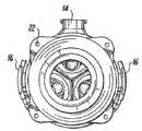
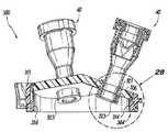
도 1은 멀티포트 말단 캡의 상대적인 축방향 회전을 선택적으로 허용하거나 방지하도록 구성된 가요성 탭 및 톱니부를 보여주는, 본 개시에 따라 구성된 액세스 장치의 예시적인 구현예의 사시도이다;
도 2는, 멀티포트 말단 캡이 하단 몸체로부터 제거된 것을 보여주는, 도 1의 액세스 장치의 분해 사시도이다;
도 3은, 원위(distally)로 보이는 두 개의 대향하는 가요성 탭들을 보여주는, 도 1의 액세스 장치의 평면도이다;
도 4는, 근위로 보이는 두 개의 대향하는 가요성 탭들을 보여주는, 도 1의 액세스 장치의 평면도이다;
도 5는 튜브 세트를 위한 연결 포트를 보여주는, 도 1의 액세스 장치의 측면도이다;
도 6은 하단 몸체의 근위 림에 대하여 밀봉하는 말단 캡의 밀봉 링을 보여주는, 도 1의 액세스 장치의 측단면도이다;
도 7은 가요성 탭이 하단 몸체의 톱니부와 체결하는 가요성 탭을 보여주는, 도 1의 액세스 장치의 측단면도이다;
도 8a는 가요성 탭을 위한 유연한 경첩 대신에 축회전 경첩을 보여주는, 도 1의 액세스 장치의 일부에 대한 측단면도이다;
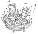
도 8b는 말단 캡을 보여주는, 도 1의 액세스 장치의 일부분의 사시도이다;
도 9는 말단 캡의 면(facet) 접합부들의 각도를 보여주는, 도 8의 말단 캡의 측면 입면도이다;
도 10은 가요성 탭의 톱니부를 보여주는, 도 8의 말단 캡의 평면도이다;
도 11은 가요성 탭들 중 하나의 톱니부를 보여주는, 도 8의 말단 캡의 일부분의 평면도이고;
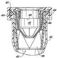
도 12는 벨로우즈(bellow)를 보여주는, 도 8의 말단 캡의 액세스 포트들 중 하나의 측면도이다;
도 13은 벨로우즈의 단면을 보여주는, 도 12의 액세스 포트의 측단면도이다;
도 14는 아코디언 단면을 갖는 벨로우즈를 보여주는, 본 개시에 따라 구성된 말단 캡의 다른 구현예의 측면도이다;
도 15는 벨로우즈 중 하나의 단면을 보여주는, 도 14의 말단 캡의 측단면도이다;
도 16은 단일 벨로우즈를 포함하는 것 및 이중 벨로우즈를 포함하는 것, 두 개의 가요성 지지체를 보여주는, 본 개시에 따라 구성된 말단 캡의 다른 예시적인 구현예의 사시도이다;
도 17은 벨로우즈의 반전을 억제하기 위한 지지 리브를 갖는 강성 벨로우즈 지지체들을 보여주는, 도 16의 말단 캡의 분해 사시도이다;
도 18은 도 16의 이중 벨로우즈의 사시도이다;
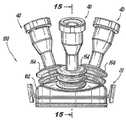
도 19는 3개의 벨로우즈를 갖는 단일 가요성 지지체를 보여주는, 본 개시에 따라 구성된 말단 캡의 또 다른 예시적인 구현예의 사시도이다;
도 20은 벨로우즈의 반전을 억제하기 위한 지지 리브를 갖는 강성 벨로우즈 지지체를 보여주는, 도 19의 말단 캡의 분해 사시도이다;
도 21은 도 19의 삼중 벨로우즈의 사시도이다;
도 22는 가요성 폼 재료를 포함하는 가요성 몸체를 보여주는, 본 발명에 따라 구성된 말단 캡의 다른 예시적인 구현예의 사시도이다;
도 23은 강성 몸체가 가요성 폼 지지체로부터 분리된 것을 보여주는, 도 22의 말단 캡의 분해 사시도이다;
도 24는 본 발명에 따라 구성된 말단 캡의 다른 예시적인 구현예의 사시도이다;
도 25는 액세스 포트가 가요성 폼 지지체로부터 분리된 것을 보여주는, 도 24의 말단 캡의 분해 사시도이다;
도 26은 가요성 탭을 보여주는, 도 24의 말단 캡의 평면도이다;
도 27은 가요성 폼 지지체에 대한 액세스 포트 중 하나의 부착을 보여주는, 도 24의 말단 캡의 측단면도이다;
도 28은 가요성 지지체를 파지하는 액세스 포트들 중 하나의 파지 림을 보여주는, 도 24의 말단 캡의 일부분의 측단면도이다;
도 29는 밀봉 가드를 보여주는, 예시적인 구현예에 따라 구성된 액세스 포트 중 하나의 분해 사시도이다;
도 30은 수술용 포트 몸체의 근위 단부 상에 장착된 캡을 보여주는, 도 29의 액세스 포트의 측면도이다;
도 31은 캡 및 수술용 포트 몸체에 대해 고정되지 않고 떠 있는 밀봉 가드의 베이스를 갖는, 캡과 수술 포트 몸체 사이에 고정된 메인 및 덕 빌(duck bill) 밀봉부의 베이스를 보여주는, 도 29의 액세스 포트의 일부분의 측단면도이다;
도 32는 액세스 슬릿을 보여주는, 도 29의 밀봉 가드의 측단면도이다;
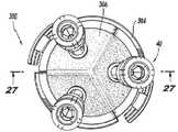
도 33은 액세스 슬릿들의 원주 간격을 보여주는, 도 32의 밀봉 가드의 원위 말단도이다; 그리고
도 34는 서로에 대하여 크기가 다양한 액세스 포트(40)를 보여주는, 도 1의 액세스 장치의 개략도이다.Preferred embodiments of the present invention will be described in detail below with reference to specific drawings so that those skilled in the art to which the present invention pertains may easily understand how to make the devices and methods of the present invention without undue experimentation, among which:
1 is a perspective view of an exemplary implementation of an access device constructed in accordance with the present disclosure showing flexible tabs and teeth configured to selectively allow or prevent relative axial rotation of the multiport end cap;
2 is an exploded perspective view of the access device of FIG. 1 showing that the multiport end cap has been removed from the lower body;
FIG. 3 is a top view of the access device of FIG. 1 showing two opposing flexible tabs that appear distally;
4 is a top view of the access device of FIG. 1, showing two opposing flexible tabs viewed proximally;
5 is a side view of the access device of FIG. 1, showing the connection port for the tube set;
FIG. 6 is a side cross-sectional view of the access device of FIG. 1 showing the sealing ring of the end cap sealing against the proximal rim of the lower body;
7 is a cross-sectional side view of the access device of FIG. 1, showing the flexible tab with the flexible tab engaging the teeth of the lower body;
8A is a cross-sectional side view of a portion of the access device of FIG. 1 showing an axial hinge instead of a flexible hinge for a flexible tab;
8B is a perspective view of a portion of the access device of FIG. 1 showing the end cap;
9 is a side elevational view of the end cap of FIG. 8 showing the angle of the facet joints of the end cap;
10 is a top view of the end cap of FIG. 8, showing the teeth of the flexible tab;
11 is a top view of a portion of the end cap of FIG. 8, showing the teeth of one of the flexible tabs;
Fig. 12 is a side view of one of the access ports of the end cap of Fig. 8, showing the bellows;
13 is a cross-sectional side view of the access port of FIG. 12 showing a cross-section of the bellows;
14 is a side view of another embodiment of an end cap constructed in accordance with the present disclosure showing a bellows having an accordion cross section;
15 is a cross-sectional side view of the end cap of FIG. 14 showing a cross section of one of the bellows;
16 is a perspective view of another exemplary embodiment of an end cap constructed in accordance with the present disclosure, including a single bellows and a double bellows, showing two flexible supports;
FIG. 17 is an exploded perspective view of the end cap of FIG. 16 showing rigid bellows supports with support ribs to suppress reversal of bellows;
18 is a perspective view of the double bellows of FIG. 16;
19 is a perspective view of another exemplary embodiment of an end cap constructed in accordance with the present disclosure showing a single flexible support with three bellows;
20 is an exploded perspective view of the end cap of FIG. 19, showing a rigid bellows support with support ribs to suppress reversal of the bellows;
21 is a perspective view of the triple bellows of FIG. 19;
22 is a perspective view of another exemplary embodiment of an end cap constructed in accordance with the present invention showing a flexible body comprising a flexible foam material;
23 is an exploded perspective view of the end cap of FIG. 22 showing the rigid body separated from the flexible foam support;
24 is a perspective view of another exemplary embodiment of an end cap constructed in accordance with the present invention;
25 is an exploded perspective view of the end cap of FIG. 24 showing that the access port is separated from the flexible foam support;
26 is a top view of the end cap of FIG. 24 showing the flexible tab;
27 is a side cross-sectional view of the end cap of FIG. 24 showing attachment of one of the access ports to the flexible foam support;
FIG. 28 is a side cross-sectional view of a portion of the end cap of FIG. 24 showing the grip rim of one of the access ports gripping the flexible support;
29 is an exploded perspective view of one of the access ports constructed in accordance with an exemplary embodiment, showing a sealing guard;
30 is a side view of the access port of FIG. 29, showing the cap mounted on the proximal end of the surgical port body;
FIG. 31 is the access of FIG. 29 showing the base of the main and duck bill seals secured between the cap and the surgical port body, with the base of the cap and surgical port body floating and not fixed to the surgical port body. It is a side sectional view of a part of the port;
32 is a side cross-sectional view of the sealing guard of FIG. 29 showing the access slit;
Figure 33 is a distal end view of the sealing guard of Figure 32, showing the circumferential spacing of the access slits; And
34 is a schematic view of the access device of FIG. 1
이제부터 도면에 대한 참조가 이루어지며, 여기서, 동일한 참조부호는 본 발명의 동일한 구조적 특징부 또는 양태를 나타낸다. 설명과 예시를 목적으로(한정하지 않음), 본 개시에 따른 액세스 장치의 예시적인 구현예의 부분도가 도 1에 도시되고, 전체적으로는 참조부호(10)로 지정된다. 본 개시에 따른 액세스 장치의 다른 구현예, 또는 이의 측면은 후술되는 바와 같이 도 2 내지 도 34에 제공된다. 본원에서 설명되고 있는 시스템 및 방법은 다수의 포트를 가지고, 경항문 최소 침습성 수술 절차와 같은 단일 절개/천연 오리피스 수술 접근에 사용될 수 있다. 일반적으로 양도된 미국 특허출원 공개번호 제2016/0287817호 및 제2017/0056064호는 그 전문이 본원에 참고로 통합되어 있다. 미국 특허출원공개 제2017/0050011호는 그 전문이 본원에 참고로 통합되어 있다.Reference is now made to the drawings, where the same reference numbers refer to the same structural features or aspects of the invention. For purposes of explanation and illustration (not limitation), a partial view of an exemplary implementation of an access device in accordance with the present disclosure is shown in FIG. 1 and is designated generally by
수술 절차를 위한 액세스 장치(10)는 멀티포트 말단 캡(20) 및 하단 몸체(30)를 포함한다. 말단 캡은 환자의 신체 내로 개별 수술 기구의 도입을 수용하기 위한 복수의 별도의 액세스 포트(40)를 포함한다. 액세스 포트(40)는 근위 방향으로, 즉 도 1에서 배향된 바와 같이 상향 연장된다. 하단 몸체(30)는, 이를 통해 액세스 포트(40)로부터 환자의 신체 내로 수술 기구를 수용하기 위해 통해서 정의된, 도 6 및 도 7에 도시되어 있는 액세스 채널(9)을 갖는, 원위로 연장된, 즉 도 1에서 배향된 바와 같이 하향 연장된 관형 몸체(8)를 가진다. 관형 몸체(8)는 하단 몸체(30)의 메인 링 부분(6)에 장착된다. 관형 몸체(8)는 메인 링 부분(6)의 것보다 덜 강성 재료로 되어 있다. 관형 몸체(8)는 예를 들어 경항문 도입을 위해, 또는 환자의 복강 벽에 형성된 단일 절개부를 통해 환자의 신체에 도입되도록 구성된다. 하단 몸체(30)는, 도 4에서 식별되는, 봉합사 고정구(suture tie downs)(22)를 포함한다. 하단 몸체(30)의 관형 몸체(8)가 체강 또는 절개부 내로 삽입된 후, 말단 캡(20)이 하단 몸체(30)에 부착되어 기밀 기능성을 제공할 수 있다.The
하단 몸체(30)는 관형 몸체(8)를 통해 액세스 채널(9)과 유체 연통하는 주입 가스 유입구(14)를 포함한다. 도 5에 도시된 주입 가스 유입구(14)는 하나 이상의 루멘을 갖는 튜브 세트, 예를 들어 이중 루멘 튜브 세트를 수용하도록 구성되지만, 당업자는 본 개시의 범위를 벗어나지 않고 임의의 다른 적합한 유형의 유입구가 사용될 수 있음을 쉽게 이해할 것이다. 액세스 포트(40)는, 기구가 액세스 포트(40)를 통해 삽입되는 경우, 그리고 액세스 포트(40)를 통해 삽입된 기구가 없는 경우, 주입 가스에 대한 기계적 밀봉을 형성하도록 구성된다.The
이제 도 2를 참조하면, 말단 캡(20)은 원위로 연장되는 밀봉 링(2)을 포함한다. 말단 캡(20)의 밀봉 링(2)은 내부에 수용되고 하단 몸체(30)의 근위 림(3)에 대해 밀봉된다. 말단 캡(20)은 하단 몸체(30)의 가장 근위 표면(19)과 접경하는 방사상으로 돌출된 스토퍼 림(5)을 포함한다. 탄성중합체 밀봉 링(12)은 말단 캡(20)의 밀봉 링(2)과 하단 몸체(30)의 근위 림(3) 사이에 밀봉을 형성하여, 길이방향 축(A)을 중심으로 하는 말단 캡(20) 및 하단 몸체(30)의 상대적인 회전 중에도 밀봉을 제공한다. 탄성중합체 밀봉부(12)는 밀봉 링(2)에 정의된 원주방향 채널(13)에 안착된다.Referring now to FIG. 2, the
하단 몸체(30)는 근위 림(3)의 외측에 복수의 원주 방향으로 이격된 톱니부(18)를 포함한다. 말단 캡(20)은, 길이방향 축(A) 주위에서 멀티포트 말단 캡(20)의 상대적인 축방향 회전을 선택적으로 허용하거나 방지하기 위해 하단 몸체(30)의 반경방향 외측으로 연장되는 톱니부(18)와 체결하고 체결해제되도록 구성된, 도 10과 도 11에 도시한 반경방향 내부로 연장되는 원위 톱니부(32)를 상부에 가진, 도 3 내지 도 4에 도시된 대향하는 한 쌍의 가요성 탭(16)을 포함한다.The
이제 도 7 및 도 8a를 참조하면, 가요성 탭(16)들의 각각은, 근위로 연장된 조작 부재(17) 및 조작 부재와 가요성 탭(16)의 원위 톱니부(32) 사이의 순응적 경첩 부재(24)를 포함한다. 도 7에서, 경첩 부재(24)는 순응적 경첩 부재로서 도시되어 있지만, 도 8a에 도시된 바와 같이 또한 축회전 경첩 부재(24)일 수도 있다. 가요성 탭(16)은 말단 캡(20)과 일체형이며, 순응적 경첩 부재(24)에 의해 말단 캡(20)에 연결된다. 두 개의 원주 방향으로 대향하는 가요성 탭(16)이 존재하기 때문에, 조작 부재(17)들을 함께 압착하면, 즉, 서로 방사상 내측으로, 길이방향 축(A) 주위에서의 하단 몸체(30)에 대한 말단 캡(20)의 회전을 허용하도록 가요성 탭(16)들의 톱니부(32)를 하단 몸체(30)의 톱니부(18)로부터 해제한다. 말단 캡(20)은 하단 몸체(30)에 대하여 완전한 360° 축방향 회전하도록 구성된다. 가요성 탭(16)을 해제하면 톱니부(18, 32)와 재체결되어 추가 회전을 방지한다. 하단 몸체(30)는 그의 톱니부(18)에 근접한, 도 8a에 라벨링된, 걸쇠 표면(23)을 포함한다. 가요성 탭(16)은 걸쇠 표면(23)과 걸쇠(latch)되어, 톱니부(18, 32)가 체결될 때 하단 몸체로부터 멀리 말단 캡의 축방향 이동을 방지하고, 회전하는 동안 하단 몸체(30)에 대한 말단 캡(20)의 축방향 변위를 방지하도록 말단 캡(20)과 하단 몸체(30)의 상대적인 축방향 회전 동안 톱니부(18 및 32)가 결합해제될 때 심지어 걸쇠를 유지할 수 있다. 선택사양인 피드백 부재(11)는 캠(7)에 대해 캠(cam)하여 사용자가 조작 멤버(17)들을 압착함에 따라 힘의 피드백을 증가시켜서 과압착되는 것을 방지하여 하단 몸체(30)로부터 축방향으로 제거하지 않고 말단 캡(20)을 회전시키는 경우 톱니부(32)에 걸쇠 표면(23)을 체결된 채로 유지한다. 근위 림(3)은 도 7의 단면에 도시된 바와 같이, 말단 캡(20)의 밀봉 링(2)과 톱니부(32) 사이에 끼워져 있다.Referring now to FIGS. 7 and 8A, each of the
이제 도 8b를 참조하면, 말단 캡(20)으로부터 근위로 연장되는 3개의 액세스 포트(40)들이 있다. 도 3 및 도 10에 도시된 바와 같이, 액세스 포트(40)는 말단 캡(20)을 중심으로 원주 방향으로 균등하게 이격되고, 3개의 액세스 포트(40)들은 서로 균일한 크기를 가질 수 있거나, 크기가 가변될 수 있다. 각각의 액세스 포트(40)는 각각의 액세스 포트(40)를 통과하는 수술 기구에 대하여 밀봉하기 위해, 도 6에 도시된, 밀봉 조립체(50)를 수용하는 강성 캐뉼라 몸체(42) 및 캐뉼라 캡(44)을 포함한다. 각각의 캐뉼라 몸체(42)는, 예를 들어, 접착제, 초음파 용접, 과몰딩, 또는 임의의 다른 적절한 결합 공정에 의해), 예를 들어, 말단 캡(20)의 각각의 면(facet, 25)에 기밀한 방식으로 차례로 영구적으로 부착된 탄성중합체 재료의, 벨로우즈(4)에 기밀한 방식으로 영구적으로 부착된다. 벨로우즈(4)의 유연성은, 액세스 포트(40)를 통해 삽입된 수술 장치에 대해 유연성 및 이동을 제공하도록 서로에 대하여 강성 캐뉼라 몸체들(42)의 상대적인 이동을 허용한다.Referring now to FIG. 8B, there are three
각각의 액세스 포트(40)는 말단 캡(40)의 각각의 평면형 면(25)으로부터 연장된다. 각각의 액세스 포트(40)는 말단 캡(20)의 각각의 면(25)으로부터 수직 연장된다. 각각의 면(25)는 면 접합부(27)에서 만나고, 면 접합부들은 말단 캡(20)의 정점(apex, 29)에서 서로 만난다. 도 9에 도시된 바와 같이, 각각의 면(25)은, 예를 들어, 림(5)에 평행한 평면에 대하여, 말단 캡(20)의 원주방향 평면으로부터 각도 α 로 각을 이룬다. 각도 α는 0°보다 크고 60° 이하이다.Each
이제 도 12를 참조하면, 벨로우즈(52)의 다른 구현예를 갖는 액세스 포트가 도시되고, 여기서 벨로우즈(52)의 베이스(53)는 원형이다. 도 13에 도시된 바와 같이, 벨로우즈(52)는, 파선에 의해 도 13에 나타나고, 도 6 및 도 7의 단면에 도시된 바와 같이, 멀티포트 말단 캡 내에 적어도 하나의 액세스 포트(40)의 원위 단부(51)를 위치시키는 단일 S자 형상(sigmoidal)의 단면을 갖는 가요성 지지체를 형성한다. 본원에 기술된, 예를 들어, 벨로우즈(52)를 포함하는 가요성 지지체는 고무 재료, 고무 유사 재료, 및/또는 캔자스 주 캔자스시티 소재의 VersaFlex Incorporated로부터 입수 가능한 VersaFlex 재료 중 적어도 하나를 포함할 수 있다.Referring now to FIG. 12, an access port with another implementation of the
이제 도 14를 참조하면, 수술 절차를 위한 액세스 장치(100)의 또 다른 예시적인 구현예는, 액세스 장치(10)에 대하여 전술한 바와 같이 많이, 환자 신체 내에 개별 수술 기구의 도입을 수용하기 위해 복수의 별도의 액세스 포트(40)들을 갖는 강성 몸체(102)에 밀봉식으로 장착되어 있는 가요성 지지체(154)들을 갖는 강성 몸체(102)를 갖는 멀티포트 말단 캡(120)을 포함한다. 각각의 액세스 포트(40)는 가요성 지지체들(154) 중 각각의 하나에 밀봉식으로 부착되고, 그로부터 근위 방향으로, 즉 도 14에 배향된 바와 같이 상향으로 연장된다. 가요성 지지체(154)는 액세스 포트(40)를 통해 도입되는 수술 기구를 위치시키기 위한 유연성을 제공하기 위해 액세스 포트(40)의 상대적인 각도 이동을 제공하도록 강성 몸체(102) 및 액세스 포트(40)의 것보다 가요성 재료이다. 각각의 가요성 지지체(154)는 도 15에 도시된 바와 같이, 멀티포트 말단 캡(20)으로부터 근위로 각각의 액세스 포트(40)의 원위 단부(55)와 이격되는 아코디언 단면을 갖는 가요성 벨로우즈를 포함한다.Referring now to FIG. 14, another exemplary embodiment of an
이제 도 16을 참조하면, 말단 캡(60)의 다른 예시적인 구현예가 도시되어 있다. 도 12 내지 도 15의 벨로우즈(52 및 154)는 말단 캡(60)에, 둥근 각각의 액세스 포트들에 대한 경계부 형상을 갖는 반면에, 벨로우즈(66)는 각각의 액세스 포트(40) 주위에 다이아몬드 형상 경계부를 갖는다. 도 17에 도시된 바와 같이, 말단 캡(60)의 강성 몸체는 강성 상단 몸체(62) 및 2개의 강성 벨로우즈 지지체(72 및 74)를 포함한다. 강성 상단 몸체(62) 및 강성 벨로우즈 지지체들(72, 74)은, 말단 캡(60)의 강성 몸체와 가요성 지지체들(64, 65) 사이의 밀봉 맞물림을 형성하기 위해, 예를 들어, 초음파 용접, 접착제, 또는 임의의 다른 적절한 결합 기술에 의해, 축방향으로 그 사이에서 가요성 지지체들(64, 65)의 외부 경계 에지(67)를 압축한다. 강성 벨로우즈 지지체들(72, 74)은 각각, 강성 벨로우즈 지지체(72, 74)로부터 각각의 벨로우즈(66) 내로 근위로 연장되는 각각의 지지 리브(76 및 78)를 포함하여, 액세스 포트(40)로의 기구 삽입 동안 벨로우즈(66)의 반전을 억제한다.Referring now to FIG. 16, another exemplary implementation of
각각의 액세스 포트(40)는 액세스 포트(40)의 원위 단부(51)에 맞물리는 압축 링(68)을 포함할 수 있다. 가요성 지지체들(64, 65)의 내부 에지(69)는 각각의 액세스 포트(40)와 압축 링(68) 사이에서 압축되어 액세스 포트(40)와 가요성 지지체들(64, 65) 사이에 밀봉 체결을 형성한다. 각각의 쌍을 이루는 액세스 포트(40) 및 압축 링(68)은 파지 림들(71, 73) 사이에 파지된 각각의 가요성 지지체들(64, 65)의 일부분과 축방향으로 대향하는 각각의 한 쌍의 파지 림들(71 및 73)을 포함한다. 각각의 가요성 지지체는 파지 림들(71, 73)의 각각을 체결하기 위해 내부에 정의된 각각의 수용부 홈(75)을 갖는다. 각각의 액세스 포트(40)는, 수술 기구가 이를 통해 도입되지 않는 경우 가스 흐름에 대해 밀봉하고, 이를 통해 도입되는 수술 기구 주위를 밀봉하도록 구성되어 있는, 전술한 밀봉 조립체(50)와 매우 유사한, 각각의 밀봉부를 포함한다.Each
전술한 말단 캡(20)에서와 같이, 말단 캡(60)은 말단 캡(60)으로부터 근위로 연장되는 3개의 액세스 포트(40)들을 포함한다. 액세스 포트(40) 중 하나는 가요성 지지체(65)를 통해 말단 캡(60)의 강성 몸체에 연결되고, 가요성 지지체(65)는 단일 벨로우즈(66)를 갖는다. 나머지 2개의 액세스 포트(40)들은 가요성 지지체(64)를 통해 말단 캡(60)의 강성 몸체에 연결되고, 가요성 지지체(64)는 2개의 벨로우즈(66), 즉 2개의 액세스 포트(40)의 각각에 대해 하나씩, 도 18에 도시된 바와 같이, 이중 벨로우즈들을 갖는다.As in the
도 17을 다시 참조하면, 강성 지지체의 강성 벨로우즈 지지체(72)는 강성 지지체(72)로부터 각각 2개의 벨로우즈(66) 중 각각으로 근위로 연장되는 2개의 각각의 지지 리브(76)를 포함하여, 액세스 포트(40)에 기구 삽입 동안 2개의 벨로우즈(66)의 반전을 억제한다. 강성 벨로우즈 지지체(74)는 강성 지지체(74)로부터 동일한 목적을 위해 각각의 벨로우즈(66) 내로 근위로 연장되는 단일 지지 리브(76)를 포함한다.Referring again to FIG. 17, the rigid bellows support 72 of the rigid support includes two respective support ribs 76 extending proximally to each of the two bellows 66 from the rigid support 72, The inversion of the two bellows 66 is suppressed during instrument insertion into the
이제 도 19를 참조하면, 전술한 말단 캡(20, 60)과 매우 유사한 말단 캡(80)의 또 다른 예시적인 구현예가 다이아몬드 형상의 벨로우즈(66)를 가지고 도시되어 있다. 3개의 액세스 포트(40)는 가요성 지지체(84)를 통해 말단 캡(80)의 강성 몸체에 연결되고, 여기서 가요성 지지체(84)는 3개의 벨로우즈(66), 3개의 액세스 포트(40)의 각각에 대해 하나씩, 즉 도 21에 도시된 바와 같이 삼중 벨로우즈를 갖는다. 도 20에 도시된 바와 같이, 말단 캡(80)의 강성 몸체는 강성 상단 몸체(82) 및 단일 강성 벨로우즈 지지체(86)를 포함한다. 강성 상단 몸체(82) 및 강성 벨로우즈 지지체(86)는 그 사이에서 가요성 지지체(84)의 외부 경계 에지(87)를 압축하여 말단 캡(80)의 강성 몸체와 가요성 지지체(84) 사이에 밀봉 체결을 형성한다. 강성 지지체(86)로부터 3개의 벨로우즈(66) 중 각각 내로 근위로 연장되는 3개의 각각의 지지 리브(88)가 액세스 포트(40) 내로의 기구 삽입 동안 벨로우즈(66)의 반전을 억제한다.Referring now to FIG. 19, another exemplary embodiment of an
이제 도 22를 참조하면, 액세스 장치(200)의 다른 예시적인 구현예가 수술 절차를 위해 도시된다. 액세스 장치(200)는, 환자의 신체 내에 개별 수술 기구의 도입을 수용하기 위해 전술한 바와 같은 복수의 별도의 액세스 포트(40)들을 갖는 강성 몸체(204)에 밀봉식으로 장착되는 가요성 지지체(206)를 갖는 강성 몸체(204)를 갖는 멀티포트 말단 캡(220)을 포함한다.Referring now to FIG. 22, another exemplary implementation of an
하단 몸체(230)는, 전술한 구현예에서와 같이 액세스 포트(40)로부터 환자의 신체 내로 수술 기구를 수용하기 위해 이를 통해 정의된 액세스 채널을 갖는 원위로 연장되는 관형 몸체(202)를 가지고, 액세스 장치(200)에 포함된다. 하단 몸체(230)는 액세스 장치(10)에 대하여 전술한 바와 같이 액세스 채널과 유체 연통하는 하나 이상의 루멘과 튜브 세트를 연결하기 위한 연결 포트(203)를 포함한다. 액세스 포트(40)는, 기구가 액세스 포트(40)를 통해 삽입되는 경우, 그리고 액세스 포트(40)를 통해 삽입된 기구가 없는 경우, 주입 가스에 대한 기계적 밀봉을 형성하도록 구성된다. 관형 몸체(202)는 하단 몸체(230)의 메인 링 부분(207)에 장착되고, 관형 몸체(202)는 메인 링 부분(207)의 것보다 덜 강성 재료로 되어 있다. 관형 몸체(202)는 경항문 도입(trans-anal introduction) 또는 임의의 다른 적절한 도입 모드에 의해 신체 루멘의 천연 오리피스 또는 환자의 복강 벽에 형성된 단일 절개를 통해 도입되도록 구성된다.The
상술한 구현예에서와 같이, 말단 캡(220)은 길이방향 축(A) 주위에 하단 몸체(230)에 대하여 완전한 360° 축방향 회전하도록 구성된다. 강성 몸체는, 액세스 장치(10)에 대하여 전술한 바와 같이 멀티포트 말단 캡(220) 및 하단 몸체(230)의 상대적인 축방향 회전을 선택적으로 허용하거나 방지하기 위해 하단 몸체(230)와 체결하고 체결해제되도록 구성된 적어도 하나의 가요성 탭(216)을 포함한다. 각각의 액세스 포트(40)는 위의 구현예와 관련하여 설명된 바와 같은 각각의 밀봉 조립체를 포함한다.As in the above-described embodiment, the
액세스 포트(40)는 가요성 지지체(206)에 밀봉식으로 부착되고, 그로부터 근위 방향으로, 즉 도 22에서 배향된 바와 같이 상향 연장된다. 가요성 지지체(206)는 액세스 포트를 통해 도입되는 수술 기구를 위치시키기 위한 유연성을 제공하기 위해, 액세스 포트(40)의 상대적인 각도 이동을 제공하기 위해 강성 몸체(204) 및 액세스 포트(40)의 것보다 더 가요성 및/또는 신축성인 재료이다.The
이제 도 23을 참조하면, 가요성 지지체(206)는 이를 통해 가스 흐름을 방지하는 밀봉을 제공하기 위한 가요성 폐쇄 셀 폼 재료를 포함한다; 그러나, 개방 셀 폼 재료가 기밀 코팅과 함께 사용될 수 있는 것으로 또한 고려된다. 또한, 폼 재료는 고무 재료, 고무 유사 재료, 캔자스시티 소재의 VersaFlex Incorporated로부터 입수 가능한 VersaFlex 재료, 및/또는 겔 또는 겔형 재료로 제조된 폼 재료 중 적어도 하나를 포함할 수 있는 것으로 또한 고려된다. 액세스 포트(40)는 가요성 지지체(206)의 원위 표면, 즉 도 23에서 배향된 바와 같이 가요성 지지체(206)의 하단 표면에 장착되고, 가요성 지지체(206)에서 각각의 보어(209)들을 통해 근위로 연장되어서 가요성 지지체(206)로부터 근위로 연장된다. 강성 몸체(204)는 완전한 원주 링을 정의하고, 여기서 가요성 지지체(206)는 강성 몸체(204)와 가요성 지지체(206) 사이에 완전한 원주 밀봉부를 형성하는 원주 링 내에 장착되고 그에 걸쳐 있다. 가요성 지지체(206)는 임의의 다른 적절한 결합 기술에 의해 원주 링의 내측 대향면(211)에 접착되거나, 초음파 용접되거나, 클램핑되거나 결합되어서 가요성 지지체(206)와 강성 몸체(204) 사이에 기밀 밀봉부를 형성한다.Referring now to Figure 23,
상술한 구현예에서와 같이, 말단 캡(220)으로부터 근위로 연장되는 3개의 액세스 포트(40)가 있으며, 말단 캡(220)을 중심으로 원주 방향으로 균일하게 이격되고, 서로 크기가 균일하게 이격되어 있지만, 말단 캡에서 도 34에 개략적으로 도시된 바와 같이 서로 다른 크기의 포트를 가질 수 있음이 또한 고려된다. 각각의 액세스 포트(40)는 가요성 지지체(206)의 각각의 평면형 면(225)으로부터 연장된다. 각각의 액세스 포트(40)는 가요성 지지체의 각각의 면(225)으로부터 수직 연장된다. 각각의 면(225)은 면 접합부(227)에서 만나고, 면 접합부(227)는 가요성 지지체(206)의 정점(229)에서 서로 만난다. 각각의 면(225)은 말단 캡(220)의 원주방향 평면으로부터 각도 α로 각을 이룬다. 각도 α는 도 23에서 라벨링되지 않았지만, 전술한 바와 같이 도 9에 라벨링된 각도 α를 참조한다. 각도 α는 0°보다 크고 60° 이하이다. 또한, 예를 들어 각도 α가 0°가 되는 경우, 가요성 지지체(206)가 평면일 수 있는 것이 고려된다.As in the above-described embodiment, there are three
이제 도 24를 참조하면, 액세스 장치(200)에 대하여 전술한 바와 같은 가요성 지지체(306)를 포함하는 액세스 장치(300)의 또 다른 예시적인 구현예가 도시된다. 도 25에 도시된 바와 같이, 강성 몸체(304)의 원주 링은 근위 링 부분(313) 및 원위 링 부분(314)을 포함한다. 도 26 내지 도 27에 도시된 바와 같이, 가요성 지지체(306)는 근위 및 원위 링 부분(313 및 314) 사이에서 압착된다. 가요성 지지체(306)는 근위 및 원위 링 부분(313 및 314)의 원주방향 림을 수용하기 위해 그의 근위 및 원위 표면들 내에 각각의 링 홈(315)(도 25와 도 28에 라벨링됨)을 정의한다. 근위 및 원위 부분(313, 314)은 초음파 용접, 접착제, 또는 임의의 다른 적절한 결합 기술에 의해 가요성 지지체(306)에 밀봉식으로 결합될 수 있다.Referring now to FIG. 24, another exemplary implementation of an
각각의 액세스 포트(40)는 각각의 액세스 포트(40)의 원위 단부에 결합된 압축 링(323) 상에 정의된 근위로 연장되는 파지 림(321)을 포함하여, 축방향으로 대향하는 한 쌍의 파지 림(321)을 포함한다. 가요성 지지체(306)의 일부분은 각각의 액세스 포트(40)의 각각의 파지 림들(321) 사이에서 파지된다. 가요성 지지체(306)는 파지 림들(321)의 각각을 수용하기 위해 내부에 정의된 각각의 수용부 홈(325)을 갖는다.Each
이제 도 29를 참조하면, 액세스 포트(40) 중 적어도 하나는 수술 절차 동안 압력 손실을 감소시키기 위해 수술 기구를 위한 기계적 밀봉을 제공하는 수술용 포트 조립체를 포함할 수 있다. 조립체는 말단 캡의 상부 표면, 예를 들어 전술한 말단 캡들 중 임의의 것으로부터 연장되고, 이를 통해 액세스 채널(401)을 정의하는 관형 수술용 포트 몸체(402)를 포함한다. 캡(404)은, 수술용 포트 몸체(402)의 근위 단부에 장착되고, 도 30과 도 31에 도시한 바와 같이, 수술 포트 몸체(402)의 액세스 채널(401) 내로 개방된다. 메인 밀봉부(406)는, 액세스 채널(401)을 통해 연장되는 수술 기구에 대한 기계적 밀봉을 제공하기 위해 도 31에 도시된 바와 같이, 액세스 채널(401)을 가로질러 메인 밀봉부(406)를 정지시키도록, 캡(404)과 수술 포트 몸체(402) 사이에 고정되어 있는, 베이스(407)를 갖는다. 덕 빌(duck bill) 밀봉부(408)는 액세스 채널(401) 내의 메인 밀봉부(406)로부터 원위에 포함된다. 덕 빌 밀봉부(408)는 캡(404)과 수술 포트 몸체(402) 사이에 고정되는 베이스(409)를 포함하고, 메인 밀봉부(406)에 의해 제공되는 밀봉에 더하여 액세스 채널(401)을 통해 연장되는 수술 기구에 대한 기계적 밀봉을 제공한다.Referring now to FIG. 29, at least one of the
밀봉 가드(412)는 액세스 채널(401) 내에서 캡(404)과 메인 밀봉부(406) 사이에서 미고정 방식으로 안착된다. 밀봉 가드(412)는, 기구가 액세스 채널(401)을 통해 삽입될 때 메인 밀봉부(406) 및 덕 빌 밀봉부(408)에 대한 보호를 제공하고, 예를 들어, 수술 기구를 액세스 채널(401)로부터 인출할 때 메인 밀봉부(406) 및/또는 덕 빌 밀봉부(408)의 반전을 방지하도록, 메인 밀봉부(406) 및 덕 빌 밀봉부(408)의 재료의 것보다 강성인 재료로 되어 있다.The sealing
계속해서 도 31을 참조하면, 밀봉 가드(412)는 액세스 채널(401)을 가로질러 연장되고, 캡(404) 및 수술용 포트 몸체(402)에 대하여 상대적으로 이동해서 액세스 채널(401)을 통해 연장되는 수술 기구의 이동을 수용하도록 구성된다. 밀봉 가드(412)는 메인 밀봉부(406)와 덕 빌 밀봉부(408)의 베이스(407 및 407)에 대해 이동할 수 있다. 이러한 이동은 액세스 채널(401) 내에서 캡(404)의 내향 림(403)을 중심으로 하는 밀봉 가드(412)의 베이스(413)의 안착에 의해 수용된다. 캡(404) 및 수술용 포트 몸체(402)에 대해 자유롭게 움직일 수 있기 때문에, 밀봉 가드(412)는 수술용 포트 몸체(402)에 대한 기구의 이동을 수용할 수 있고, 그에 따라 밀봉 가드(412)가 캡(404) 및 수술용 포트 몸체(402)에 대해서 견고하게 장착된 경우에 달성되는 밀봉에 대해 메인 밀봉부(406)와 덕 빌 밀봉부(408)에 의해 기구에 대한 밀봉을 개선할 수 있다.With continued reference to FIG. 31, the sealing
도 32와 도 33에 도시된 바와 같이, 밀봉 가드(412)는 밀봉 가드(412)의 원위, 원추형 섹션에서 이를 통해 8개의 균등하게 이격된 액세스 슬릿(414)을 정의한다. 액세스 슬릿들은 액세스 슬릿(414)에 의해 분리된 편향 가능한 패널에 의해 수용된, 밀봉 가드(412)를 통한 수술 기구의 통과를 위해 밀봉 가드(412)의 중앙 구멍(215)에 원주 방향으로 이격된다. 액세스 슬릿(414)은 수술 중에 메인 밀봉부(406) 및 덕 빌 밀봉부(408)를 통한 가압 가스의 누출을 감소시키기 위해 메인 밀봉부(406) 및 덕 빌 밀봉부(408)를 통하는 개구부들과 수술 기구의 정렬을 용이하게 한다.32 and 33, the sealing
전술되어 있고 도면에 도시된 바와 같이 본 개시의 방법 및 시스템은, 액세스 포트의 상대적인 이동에 대해 유연성을 갖는 최소 침습성 다중 포트 액세스를 포함하는 우수한 특성을 갖는 단일 절개/천연 오리피스 수술 액세스를 제공한다. 본 발명의 장치 및 방법은 바람직한 구현예를 참조하여 도시되고 설명되었지만, 당업자는 본 발명의 범주를 벗어나지 않고도 본 발명에 대한 변경 및/또는 변형이 이루어질 수 있음을 쉽게 이해할 것이다.As described above and shown in the drawings, the methods and systems of the present disclosure provide single incision/natural orifice surgical access with superior properties including minimally invasive multi-port access with flexibility for relative movement of access ports. Although the devices and methods of the present invention have been shown and described with reference to preferred embodiments, those skilled in the art will readily understand that changes and/or modifications to the present invention can be made without departing from the scope of the invention.
Claims (27)
Translated fromKorean환자의 신체 내에 개별 수술 기구의 도입을 수용하기 위한 복수의 별도의 액세스 포트들을 갖는 강성 몸체에 밀봉식으로 장착되어 있는 가요성 지지체를 가지는 강성 몸체를 포함하는 멀티포트 말단 캡을 포함하되, 상기 액세스 포트들 중 적어도 하나는 상기 가요성 지지체에 밀봉식으로 부착되어 있고 상기 가요성 지지체로부터 근위 방향으로 연장되며, 상기 가요성 지지체는 상기 액세스 포트들을 통해 도입되는 수술 기구들을 위치시키기 위한 유연성을 제공하기 위한 상기 액세스 포트들 중 적어도 하나의 상대적인 각도 이동을 제공하기 위해 상기 강성 몸체 및 액세스 포트보다 더 가요성인 재료로 이루어져 있는, 액세스 장치.An access device for a surgical procedure,
A multiport end cap comprising a rigid body having a flexible support that is sealingly mounted to a rigid body having a plurality of separate access ports for accommodating the introduction of individual surgical instruments into the patient's body, wherein the access At least one of the ports is hermetically attached to the flexible support and extends proximally from the flexible support, the flexible support providing flexibility for positioning surgical instruments introduced through the access ports The access device, which is made of a material that is more flexible than the rigid body and the access port to provide relative angular movement of at least one of the access ports.
상기 가요성 지지체는 적어도 하나의 가요성 벨로우즈(bellow)를 포함하는, 액세스 장치.According to claim 1,
Wherein the flexible support comprises at least one flexible bellow.
상기 적어도 하나의 가요성 벨로우즈는 고무 재료, 고무 유사 재료, 및/또는 VersaFlex 재료 중 적어도 하나를 포함하는, 액세스 장치.According to claim 2,
And the at least one flexible bellows comprises at least one of a rubber material, a rubber like material, and/or a VersaFlex material.
상기 강성 몸체는 강성 상단 몸체 및 강성 벨로우즈 지지체를 포함하고,
상기 강성 상단 몸체 및 상기 강성 벨로우즈 지지체는 그 사이에서 상기 가요성 지지체의 외부 경계 에지를 압축하여 상기 강성 몸체와 상기 가요성 지지체 사이의 밀봉 체결을 형성하는, 액세스 장치.According to claim 2,
The rigid body includes a rigid top body and a rigid bellows support,
And the rigid top body and the rigid bellows support compress the outer boundary edge of the flexible support therebetween to form a seal fastening between the rigid body and the flexible support.
상기 강성 벨로우즈 지지체는,
상기 강성 벨로우즈 지지체로부터 상기 벨로우즈 내로 근위로 연장되는 적어도 하나의 지지 리브를 포함하여, 상기 액세스 포트 내로의 기구 삽입 동안 상기 벨로우즈의 반전을 억제하는, 액세스 장치.The method of claim 4,
The rigid bellows support,
And at least one support rib extending proximally from the rigid bellows support into the bellows to inhibit reversal of the bellows during instrument insertion into the access port.
상기 적어도 하나의 액세스 포트는 상기 액세스 포트와 압축 링 사이에서 압축된 상기 가요성 지지체의 내부 에지를 가지고 상기 액세스 포트의 원위 단부에 체결된 압축 링을 포함해서 상기 적어도 하나의 액세스 포트와 상기 가요성 지지체 간의 밀봉 체결을 형성하는, 액세스 장치.According to claim 1,
The at least one access port includes the compression ring fastened to the distal end of the access port with an inner edge of the flexible support compressed between the access port and the compression ring to include the at least one access port and the flexible An access device that forms a seal fastening between supports.
상기 적어도 하나의 액세스 포트 및 압축 링은 파지 림들 사이에서 파지된 상기 가요성 지지체의 일부분을 갖는 축방향으로 대향하는 쌍의 파지 림들을 포함하는, 액세스 장치.The method of claim 6,
The at least one access port and compression ring comprising an axially opposite pair of gripping rims having a portion of the flexible support gripped between the gripping rims.
상기 가요성 지지체는 각각의 파지 림을 체결하기 위해 내부에 정의된 각각의 수용부 홈을 갖는, 액세스 장치.The method of claim 7,
The flexible support has an access groove defined therein for engaging each grip rim.
상기 말단 캡으로부터 근위로 연장되는 3개의 액세스 포트가 있는, 액세스 장치.According to claim 1,
An access device having three access ports extending proximally from the end cap.
상기 액세스 포트들 중 적어도 하나는 상기 가요성 지지체를 통해 상기 강성 몸체에 연결되고, 상기 가요성 지지체는 단일 벨로우즈를 갖는, 액세스 장치.The method of claim 9,
At least one of the access ports is connected to the rigid body through the flexible support, wherein the flexible support has a single bellows.
상기 액세스 포트들 중 2개는 상기 가요성 지지체를 통해 상기 강성 몸체에 연결되고, 상기 가요성 지지체는 2개의 액세스 포트들 각각에 대해 하나씩, 2개의 벨로우즈들을 갖는, 액세스 장치.The method of claim 9,
Two of the access ports are connected to the rigid body through the flexible support, the flexible support having two bellows, one for each of the two access ports.
상기 강성 지지체는 상기 강성 지지체로부터 상기 2개의 벨로우즈 중 각각의 하나 내로 근위로 연장되는 각각의 지지 리브를 포함하여, 각각, 상기 액세스 포트 내로의 기구 삽입 동안 상기 2개의 벨로우즈들의 반전을 억제하는, 액세스 장치.The method of claim 11,
The rigid support includes each support rib extending proximally from the rigid support into each one of the two bellows, each access inhibiting reversal of the two bellows during instrument insertion into the access port Device.
상기 3개의 액세스 포트들 중 세번째를 상기 강성 몸체에 연결하기 위한 단일 벨로우즈를 갖는 제2 가요성 지지체를 더 포함하는, 액세스 장치.The method of claim 11,
And a second flexible support having a single bellows for connecting a third of the three access ports to the rigid body.
상기 3개의 액세스 포트들은 상기 가요성 지지체를 통해 상기 강성 몸체에 연결되고, 상기 가요성 지지체는 상기 3개의 액세스 포트들 각각에 대해 하나씩, 3개의 벨로우즈들을 갖는, 액세스 장치.The method of claim 9,
The three access ports are connected to the rigid body through the flexible support, the flexible support having three bellows, one for each of the three access ports.
상기 강성 지지체는 상기 강성 지지체로부터 상기 2개의 벨로우즈들 중 각각의 하나 내로 근위로 연장되는 각각의 지지 리브를 포함하여, 각각, 상기 액서스 포트 내로의 기구 삽입 동안 상기 2개의 벨로우즈들의 반전을 억제하는, 액세스 장치.The method of claim 14,
The rigid support includes a respective support rib extending proximally from the rigid support into each one of the two bellows, each inhibiting reversal of the two bellows during instrument insertion into the access port, Access device.
상기 가요성 지지체는 상기 멀티포트 말단 캡 내에 상기 적어도 하나의 액세스 포트의 원위 단부를 위치시키는 단일 S자 형상(sigmoidal)의 단면을 갖는 벨로우즈를 포함하는, 액세스 장치.According to claim 1,
The flexible support includes a bellows having a single sigmoidal cross-section that positions the distal end of the at least one access port within the multiport end cap.
상기 가요성 지지체는 상기 멀티포트 말단 캡으로부터 근위로 상기 적어도 하나의 액세스 포트의 원위 단부를 이격시키는 아코디언 단면을 갖는 벨로우즈를 포함하는, 액세스 장치.According to claim 1,
Wherein the flexible support includes a bellows having an accordion cross-section that spaces the distal end of the at least one access port proximally from the multiport end cap.
상기 가요성 지지체는, 둥근 및 다이아몬드 형상 중 적어도 하나를 포함하는 적어도 하나의 액세스 포트에 대해 경계부 형상을 갖는 벨로우즈를 포함하는, 액세스 장치.According to claim 1,
The flexible support comprises an bellows having a border shape with respect to at least one access port comprising at least one of a round and diamond shape.
수술 기구를 상기 액세스 포트로부터 환자의 신체 내로 수용하기 위해 이를 통해 정의된 액세스 채널을 갖는, 원위로 연장되는 관형 몸체를 갖는 하단 몸체를 더 포함하는, 액세스 장치.According to claim 1,
And a lower body having a distally extending tubular body having an access channel defined therethrough for receiving a surgical instrument from said access port into a patient's body.
상기 하단 몸체는 상기 액세스 채널과 유체 연통하는 가스 유입구를 포함하는, 액세스 장치.The method of claim 19,
The lower body comprises a gas inlet in fluid communication with the access channel.
상기 액세스 포트들은, 기구가 상기 액세스 포트를 통해 삽입될 때 및 상기 액세스 포트를 통해 기구가 삽입되지 않을 때, 주입 가스에 대한 기계적 밀봉을 형성하도록 구성되는, 액세스 장치.The method of claim 20,
The access ports are configured to form a mechanical seal against the injection gas when the instrument is inserted through the access port and when the instrument is not inserted through the access port.
상기 관형 몸체는 몸체 루멘(lumen)을 통해 또는 환자의 복강 벽면에 형성된 단일 절개부를 통해 도입되도록 구성되는, 액세스 장치.The method of claim 19,
The tubular body is configured to be introduced through a body lumen or through a single incision formed in the patient's abdominal wall.
상기 관형 몸체는 경항문 도입을 위해 구성되는, 액세스 장치.The method of claim 19,
The tubular body is configured for the introduction of a hard passage, the access device.
상기 말단 캡은 상기 하단 몸체에 대해 완전한 360° 축방향 회전하도록 구성되는, 액세스 장치.The method of claim 19,
The end cap is configured to rotate 360° axially full relative to the bottom body.
상기 관형 몸체는 상기 하단 몸체의 메인 링 부분에 장착되고,
상기 관형 몸체는 상기 메인 링 부분의 것보다 덜 강성 재료로 된, 액세스 장치.The method of claim 19,
The tubular body is mounted on the main ring portion of the lower body,
The tubular body is made of a less rigid material than that of the main ring portion, the access device.
상기 강성 몸체는 상기 하단 몸체와 체결하고 체결해제하도록 구성된 적어도 하나의 가요성 탭을 포함하여, 상기 멀티포트 말단 캡 및 하단 몸체의 상대적인 축방향 회전을 선택적으로 허용하거나 방지하는, 액세스 장치.The method of claim 19,
The rigid body comprises at least one flexible tab configured to engage and disengage the lower body, to selectively allow or prevent relative axial rotation of the multiport end cap and lower body.
상기 액세스 포트들의 각각은, 수술 기구가 상기 액세스 포트들을 통해 도입되지 않는 경우 기체 흐름에 대하여 밀봉하도록, 그리고 상기 액세스 포트들을 통해 도입된 수술 기구 주위를 밀봉하도록 구성된 각각의 밀봉부를 포함하는, 액세스 장치.According to claim 1,
Each of the access ports includes an access device configured to seal against gas flow when the surgical instrument is not introduced through the access ports and to seal around the surgical instrument introduced through the access ports. .
Applications Claiming Priority (3)
| Application Number | Priority Date | Filing Date | Title |
|---|---|---|---|
| US15/790,658US10463396B2 (en) | 2017-10-23 | 2017-10-23 | Devices for performing minimally invasive surgery having bellows support housing |
| US15/790,658 | 2017-10-23 | ||
| PCT/US2018/052527WO2019083664A1 (en) | 2017-10-23 | 2018-09-25 | Devices for performing minimally invasive surgery having bellows supprot housing |
Publications (2)
| Publication Number | Publication Date |
|---|---|
| KR20200065083Atrue KR20200065083A (en) | 2020-06-08 |
| KR102493686B1 KR102493686B1 (en) | 2023-02-06 |
Family
ID=66170328
Family Applications (1)
| Application Number | Title | Priority Date | Filing Date |
|---|---|---|---|
| KR1020207014612AActiveKR102493686B1 (en) | 2017-10-23 | 2018-09-25 | Apparatus for performing minimally invasive surgery with a bellows supported housing |
Country Status (9)
| Country | Link |
|---|---|
| US (1) | US10463396B2 (en) |
| EP (1) | EP3700444B1 (en) |
| JP (1) | JP6949214B2 (en) |
| KR (1) | KR102493686B1 (en) |
| CN (1) | CN111246814B (en) |
| AU (1) | AU2018354578B2 (en) |
| CA (1) | CA3078494C (en) |
| ES (1) | ES2965982T3 (en) |
| WO (1) | WO2019083664A1 (en) |
Families Citing this family (4)
| Publication number | Priority date | Publication date | Assignee | Title |
|---|---|---|---|---|
| US8961406B2 (en) | 2009-03-06 | 2015-02-24 | Ethicon Endo-Surgery, Inc. | Surgical access devices and methods providing seal movement in predefined movement regions |
| US10413324B2 (en) | 2017-10-23 | 2019-09-17 | Conmed Corporation | Devices for performing minimally invasive surgery having foam support housing |
| CN113729799B (en)* | 2021-08-31 | 2023-05-05 | 重庆西山科技股份有限公司 | Surgical device, composite operation channel and multi-degree-of-freedom positioning structure |
| WO2024073069A1 (en)* | 2022-09-30 | 2024-04-04 | Vicarious Surgical Inc. | Trocars with sealing assemblies for minimally invasive surgical applications |
Citations (6)
| Publication number | Priority date | Publication date | Assignee | Title |
|---|---|---|---|---|
| US6551270B1 (en)* | 2000-08-30 | 2003-04-22 | Snowden Pencer, Inc. | Dual lumen access port |
| US20100081880A1 (en)* | 2008-09-30 | 2010-04-01 | Ethicon Endo-Surgery, Inc. | Surgical Access Device |
| WO2010082722A1 (en)* | 2009-01-16 | 2010-07-22 | (주)다림써지넷 | Multi-channel trocar with an attachable/detachable sealing member |
| US20100228092A1 (en)* | 2009-03-06 | 2010-09-09 | Ethicon Endo-Surgery, Inc. | Surgical access devices and methods providing seal movement in predefined paths |
| US20100268035A1 (en)* | 2009-04-17 | 2010-10-21 | Oberlaender Martin | Seal For Closing-Off An Access Instrument Into A Body |
| US20170056064A1 (en)* | 2015-09-01 | 2017-03-02 | Surgiquest, Inc. | Multi-port access device for minimally invasive surgical procedures |
Family Cites Families (42)
| Publication number | Priority date | Publication date | Assignee | Title |
|---|---|---|---|---|
| US4844484A (en) | 1988-06-28 | 1989-07-04 | Dana Corporation | Floating lip seal with reinforced flexible portion |
| US4998740A (en) | 1989-09-29 | 1991-03-12 | Rockwell International Corporation | Face seal assembly |
| US5865728A (en)* | 1991-05-29 | 1999-02-02 | Origin Medsystems, Inc. | Method of using an endoscopic inflatable lifting apparatus to create an anatomic working space |
| US5366446A (en)* | 1993-11-17 | 1994-11-22 | Unisurge, Inc. | Introducer assembly |
| US7930782B2 (en) | 1994-04-19 | 2011-04-26 | Applied Elastomerics, Inc. | Gels, gel composites, and gel articles |
| US6440063B1 (en)* | 1997-04-30 | 2002-08-27 | University Of Massachusetts | Surgical access port and laparoscopic surgical method |
| EP2111884A1 (en) | 1997-05-28 | 2009-10-28 | United States Surgical Corporation | Trocar seal system |
| US7559893B2 (en)* | 1998-12-01 | 2009-07-14 | Atropos Limited | Wound retractor device |
| US6595946B1 (en)* | 2000-02-25 | 2003-07-22 | United States Surgical Corporation | Valve assembly |
| US7854724B2 (en) | 2003-04-08 | 2010-12-21 | Surgiquest, Inc. | Trocar assembly with pneumatic sealing |
| AU2004273890A1 (en) | 2003-09-15 | 2005-03-31 | Robert O. Dean | Operating room smoke evacuator with integrated vacuum motor and filter |
| US7163510B2 (en) | 2003-09-17 | 2007-01-16 | Applied Medical Resources Corporation | Surgical instrument access device |
| US7753901B2 (en) | 2004-07-21 | 2010-07-13 | Tyco Healthcare Group Lp | Laparoscopic instrument and cannula assembly and related surgical method |
| US8262622B2 (en) | 2003-10-28 | 2012-09-11 | Applied Medical Resources Corporation | Surgical gel seal |
| US20060247678A1 (en)* | 2005-04-08 | 2006-11-02 | Weisenburgh William B Ii | Surgical instrument system |
| AU2006304141B2 (en) | 2005-10-14 | 2012-07-05 | Applied Medical Resources Corporation | Gel cap for wound retractor |
| US8357085B2 (en)* | 2009-03-31 | 2013-01-22 | Ethicon Endo-Surgery, Inc. | Devices and methods for providing access into a body cavity |
| WO2008141291A1 (en) | 2007-05-11 | 2008-11-20 | Applied Medical Resources Corporation | Surgical retractor with gel pad |
| WO2008149332A1 (en) | 2007-06-05 | 2008-12-11 | Atropos Limited | An instrument access device |
| US8657740B2 (en) | 2007-06-05 | 2014-02-25 | Atropos Limited | Instrument access device |
| WO2009035663A2 (en) | 2007-09-12 | 2009-03-19 | Synecor, Llc | Multi-instrument access devices and systems |
| US20090093752A1 (en) | 2007-10-05 | 2009-04-09 | Tyco Healthcare Group Lp | Seal anchor for use in surgical procedures |
| US8795326B2 (en) | 2007-10-05 | 2014-08-05 | Covidien Lp | Expanding seal anchor for single incision surgery |
| US8273017B1 (en) | 2007-10-30 | 2012-09-25 | Ethicon Endo-Surgery, Inc. | Surgical access port with ring actuated latching mechanism |
| US8763892B2 (en) | 2007-12-31 | 2014-07-01 | Oridon Medical 1987 Ltd. | Tube verifier |
| US8328761B2 (en)* | 2008-09-30 | 2012-12-11 | Ethicon Endo-Surgery, Inc. | Variable surgical access device |
| KR101829726B1 (en) | 2008-10-10 | 2018-02-19 | 서지퀘스트, 인코포레이티드 | Low-profile surgical access devices with anchoring |
| US8574153B2 (en) | 2009-03-20 | 2013-11-05 | Covidien Lp | Flexible port seal |
| US20100249520A1 (en) | 2009-03-31 | 2010-09-30 | Shelton Iv Frederick E | Method Of Surgical Access |
| US8795163B2 (en) | 2009-06-05 | 2014-08-05 | Ethicon Endo-Surgery, Inc. | Interlocking seal components |
| US8475490B2 (en) | 2009-06-05 | 2013-07-02 | Ethicon Endo-Surgery, Inc. | Methods and devices for providing access through tissue to a surgical site |
| US9173677B2 (en) | 2009-07-08 | 2015-11-03 | Covidien Lp | Apparatus and method for transvaginal surgery |
| US8376938B2 (en) | 2009-11-20 | 2013-02-19 | Ethicon Endo-Surgery, Inc. | Discrete flexion head for single port device |
| US8764647B2 (en) | 2009-11-24 | 2014-07-01 | Covidien Lp | Foam port device having closed-end lumens |
| US8480683B2 (en) | 2009-11-24 | 2013-07-09 | Covidien Lp | Foam introduction system including modified port geometry |
| US8500633B2 (en)* | 2009-12-11 | 2013-08-06 | Ethicon Endo-Surgery, Inc. | Methods and devices for providing surgical access through tissue to a surgical site |
| KR101022754B1 (en) | 2010-08-24 | 2011-03-17 | 류성엽 | Multichannel trocar with ound retractor |
| JP6396657B2 (en) | 2010-10-01 | 2018-09-26 | アプライド メディカル リソーシーズ コーポレイション | Natural orifice surgery system |
| US8602983B2 (en) | 2010-12-20 | 2013-12-10 | Covidien Lp | Access assembly having undercut structure |
| WO2012122263A2 (en) | 2011-03-08 | 2012-09-13 | Surgiquest, Inc. | Trocar assembly with pneumatic sealing |
| GB201500328D0 (en)* | 2015-01-09 | 2015-02-25 | Cannula sealing | |
| US10159809B2 (en) | 2015-01-30 | 2018-12-25 | Surgiquest, Inc. | Multipath filter assembly with integrated gaseous seal for multimodal surgical gas delivery system |
- 2017
- 2017-10-23USUS15/790,658patent/US10463396B2/enactiveActive
- 2018
- 2018-09-25ESES18870102Tpatent/ES2965982T3/enactiveActive
- 2018-09-25CACA3078494Apatent/CA3078494C/enactiveActive
- 2018-09-25CNCN201880068546.7Apatent/CN111246814B/enactiveActive
- 2018-09-25KRKR1020207014612Apatent/KR102493686B1/enactiveActive
- 2018-09-25WOPCT/US2018/052527patent/WO2019083664A1/ennot_activeCeased
- 2018-09-25AUAU2018354578Apatent/AU2018354578B2/enactiveActive
- 2018-09-25JPJP2020522676Apatent/JP6949214B2/enactiveActive
- 2018-09-25EPEP18870102.3Apatent/EP3700444B1/enactiveActive
Patent Citations (6)
| Publication number | Priority date | Publication date | Assignee | Title |
|---|---|---|---|---|
| US6551270B1 (en)* | 2000-08-30 | 2003-04-22 | Snowden Pencer, Inc. | Dual lumen access port |
| US20100081880A1 (en)* | 2008-09-30 | 2010-04-01 | Ethicon Endo-Surgery, Inc. | Surgical Access Device |
| WO2010082722A1 (en)* | 2009-01-16 | 2010-07-22 | (주)다림써지넷 | Multi-channel trocar with an attachable/detachable sealing member |
| US20100228092A1 (en)* | 2009-03-06 | 2010-09-09 | Ethicon Endo-Surgery, Inc. | Surgical access devices and methods providing seal movement in predefined paths |
| US20100268035A1 (en)* | 2009-04-17 | 2010-10-21 | Oberlaender Martin | Seal For Closing-Off An Access Instrument Into A Body |
| US20170056064A1 (en)* | 2015-09-01 | 2017-03-02 | Surgiquest, Inc. | Multi-port access device for minimally invasive surgical procedures |
Also Published As
| Publication number | Publication date |
|---|---|
| CN111246814A (en) | 2020-06-05 |
| ES2965982T3 (en) | 2024-04-17 |
| EP3700444A4 (en) | 2021-07-21 |
| AU2018354578A1 (en) | 2020-05-21 |
| JP6949214B2 (en) | 2021-10-13 |
| US20190117257A1 (en) | 2019-04-25 |
| JP2021500144A (en) | 2021-01-07 |
| AU2018354578B2 (en) | 2021-02-11 |
| US10463396B2 (en) | 2019-11-05 |
| KR102493686B1 (en) | 2023-02-06 |
| EP3700444B1 (en) | 2023-09-13 |
| CA3078494C (en) | 2022-07-26 |
| CA3078494A1 (en) | 2019-05-02 |
| WO2019083664A1 (en) | 2019-05-02 |
| CN111246814B (en) | 2023-07-18 |
| WO2019083664A8 (en) | 2020-02-06 |
| EP3700444A1 (en) | 2020-09-02 |
Similar Documents
| Publication | Publication Date | Title |
|---|---|---|
| KR102493685B1 (en) | Apparatus for performing minimally invasive surgery with rotating multiport access | |
| KR102493687B1 (en) | Apparatus for performing minimally invasive surgery with a foam support housing | |
| KR20200065083A (en) | Device for performing minimally invasive surgery with bellows support housing | |
| US20200337723A1 (en) | Seals for surgical access devices | |
| CA2731487A1 (en) | Seal assembly for use with an access device |
Legal Events
| Date | Code | Title | Description |
|---|---|---|---|
| PA0105 | International application | St.27 status event code:A-0-1-A10-A15-nap-PA0105 | |
| PA0201 | Request for examination | St.27 status event code:A-1-2-D10-D11-exm-PA0201 | |
| PG1501 | Laying open of application | St.27 status event code:A-1-1-Q10-Q12-nap-PG1501 | |
| E902 | Notification of reason for refusal | ||
| PE0902 | Notice of grounds for rejection | St.27 status event code:A-1-2-D10-D21-exm-PE0902 | |
| E13-X000 | Pre-grant limitation requested | St.27 status event code:A-2-3-E10-E13-lim-X000 | |
| P11-X000 | Amendment of application requested | St.27 status event code:A-2-2-P10-P11-nap-X000 | |
| P13-X000 | Application amended | St.27 status event code:A-2-2-P10-P13-nap-X000 | |
| E701 | Decision to grant or registration of patent right | ||
| PE0701 | Decision of registration | St.27 status event code:A-1-2-D10-D22-exm-PE0701 | |
| R18-X000 | Changes to party contact information recorded | St.27 status event code:A-3-3-R10-R18-oth-X000 | |
| PR0701 | Registration of establishment | St.27 status event code:A-2-4-F10-F11-exm-PR0701 | |
| PR1002 | Payment of registration fee | St.27 status event code:A-2-2-U10-U12-oth-PR1002 Fee payment year number:1 | |
| PG1601 | Publication of registration | St.27 status event code:A-4-4-Q10-Q13-nap-PG1601 |