KR20200064056A - Handheld surface cleaning device - Google Patents
Handheld surface cleaning deviceDownload PDFInfo
- Publication number
- KR20200064056A KR20200064056AKR1020207005226AKR20207005226AKR20200064056AKR 20200064056 AKR20200064056 AKR 20200064056AKR 1020207005226 AKR1020207005226 AKR 1020207005226AKR 20207005226 AKR20207005226 AKR 20207005226AKR 20200064056 AKR20200064056 AKR 20200064056A
- Authority
- KR
- South Korea
- Prior art keywords
- dust cup
- surface cleaning
- cleaning device
- dust
- handheld surface
- Prior art date
- Legal status (The legal status is an assumption and is not a legal conclusion. Google has not performed a legal analysis and makes no representation as to the accuracy of the status listed.)
- Granted
Links
Images


Classifications
- A—HUMAN NECESSITIES
- A47—FURNITURE; DOMESTIC ARTICLES OR APPLIANCES; COFFEE MILLS; SPICE MILLS; SUCTION CLEANERS IN GENERAL
- A47L—DOMESTIC WASHING OR CLEANING; SUCTION CLEANERS IN GENERAL
- A47L5/00—Structural features of suction cleaners
- A47L5/12—Structural features of suction cleaners with power-driven air-pumps or air-compressors, e.g. driven by motor vehicle engine vacuum
- A47L5/22—Structural features of suction cleaners with power-driven air-pumps or air-compressors, e.g. driven by motor vehicle engine vacuum with rotary fans
- A47L5/24—Hand-supported suction cleaners
- A—HUMAN NECESSITIES
- A47—FURNITURE; DOMESTIC ARTICLES OR APPLIANCES; COFFEE MILLS; SPICE MILLS; SUCTION CLEANERS IN GENERAL
- A47L—DOMESTIC WASHING OR CLEANING; SUCTION CLEANERS IN GENERAL
- A47L11/00—Machines for cleaning floors, carpets, furniture, walls, or wall coverings
- A47L11/24—Floor-sweeping machines, motor-driven
- A—HUMAN NECESSITIES
- A47—FURNITURE; DOMESTIC ARTICLES OR APPLIANCES; COFFEE MILLS; SPICE MILLS; SUCTION CLEANERS IN GENERAL
- A47L—DOMESTIC WASHING OR CLEANING; SUCTION CLEANERS IN GENERAL
- A47L5/00—Structural features of suction cleaners
- A47L5/12—Structural features of suction cleaners with power-driven air-pumps or air-compressors, e.g. driven by motor vehicle engine vacuum
- A47L5/22—Structural features of suction cleaners with power-driven air-pumps or air-compressors, e.g. driven by motor vehicle engine vacuum with rotary fans
- A47L5/225—Convertible suction cleaners, i.e. convertible between different types thereof, e.g. from upright suction cleaners to sledge-type suction cleaners
- A—HUMAN NECESSITIES
- A47—FURNITURE; DOMESTIC ARTICLES OR APPLIANCES; COFFEE MILLS; SPICE MILLS; SUCTION CLEANERS IN GENERAL
- A47L—DOMESTIC WASHING OR CLEANING; SUCTION CLEANERS IN GENERAL
- A47L5/00—Structural features of suction cleaners
- A47L5/12—Structural features of suction cleaners with power-driven air-pumps or air-compressors, e.g. driven by motor vehicle engine vacuum
- A47L5/22—Structural features of suction cleaners with power-driven air-pumps or air-compressors, e.g. driven by motor vehicle engine vacuum with rotary fans
- A47L5/24—Hand-supported suction cleaners
- A47L5/26—Hand-supported suction cleaners with driven dust-loosening tools
- A—HUMAN NECESSITIES
- A47—FURNITURE; DOMESTIC ARTICLES OR APPLIANCES; COFFEE MILLS; SPICE MILLS; SUCTION CLEANERS IN GENERAL
- A47L—DOMESTIC WASHING OR CLEANING; SUCTION CLEANERS IN GENERAL
- A47L9/00—Details or accessories of suction cleaners, e.g. mechanical means for controlling the suction or for effecting pulsating action; Storing devices specially adapted to suction cleaners or parts thereof; Carrying-vehicles specially adapted for suction cleaners
- A47L9/0009—Storing devices ; Supports, stands or holders
- A47L9/0018—Storing devices ; Supports, stands or holders integrated in or removably mounted upon the suction cleaner for storing parts of said suction cleaner
- A—HUMAN NECESSITIES
- A47—FURNITURE; DOMESTIC ARTICLES OR APPLIANCES; COFFEE MILLS; SPICE MILLS; SUCTION CLEANERS IN GENERAL
- A47L—DOMESTIC WASHING OR CLEANING; SUCTION CLEANERS IN GENERAL
- A47L9/00—Details or accessories of suction cleaners, e.g. mechanical means for controlling the suction or for effecting pulsating action; Storing devices specially adapted to suction cleaners or parts thereof; Carrying-vehicles specially adapted for suction cleaners
- A47L9/009—Carrying-vehicles; Arrangements of trollies or wheels; Means for avoiding mechanical obstacles
- A—HUMAN NECESSITIES
- A47—FURNITURE; DOMESTIC ARTICLES OR APPLIANCES; COFFEE MILLS; SPICE MILLS; SUCTION CLEANERS IN GENERAL
- A47L—DOMESTIC WASHING OR CLEANING; SUCTION CLEANERS IN GENERAL
- A47L9/00—Details or accessories of suction cleaners, e.g. mechanical means for controlling the suction or for effecting pulsating action; Storing devices specially adapted to suction cleaners or parts thereof; Carrying-vehicles specially adapted for suction cleaners
- A47L9/02—Nozzles
- A47L9/04—Nozzles with driven brushes or agitators
- A47L9/0461—Dust-loosening tools, e.g. agitators, brushes
- A47L9/0466—Rotating tools
- A47L9/0477—Rolls
- A—HUMAN NECESSITIES
- A47—FURNITURE; DOMESTIC ARTICLES OR APPLIANCES; COFFEE MILLS; SPICE MILLS; SUCTION CLEANERS IN GENERAL
- A47L—DOMESTIC WASHING OR CLEANING; SUCTION CLEANERS IN GENERAL
- A47L9/00—Details or accessories of suction cleaners, e.g. mechanical means for controlling the suction or for effecting pulsating action; Storing devices specially adapted to suction cleaners or parts thereof; Carrying-vehicles specially adapted for suction cleaners
- A47L9/10—Filters; Dust separators; Dust removal; Automatic exchange of filters
- A47L9/106—Dust removal
- A—HUMAN NECESSITIES
- A47—FURNITURE; DOMESTIC ARTICLES OR APPLIANCES; COFFEE MILLS; SPICE MILLS; SUCTION CLEANERS IN GENERAL
- A47L—DOMESTIC WASHING OR CLEANING; SUCTION CLEANERS IN GENERAL
- A47L9/00—Details or accessories of suction cleaners, e.g. mechanical means for controlling the suction or for effecting pulsating action; Storing devices specially adapted to suction cleaners or parts thereof; Carrying-vehicles specially adapted for suction cleaners
- A47L9/10—Filters; Dust separators; Dust removal; Automatic exchange of filters
- A47L9/12—Dry filters
- A—HUMAN NECESSITIES
- A47—FURNITURE; DOMESTIC ARTICLES OR APPLIANCES; COFFEE MILLS; SPICE MILLS; SUCTION CLEANERS IN GENERAL
- A47L—DOMESTIC WASHING OR CLEANING; SUCTION CLEANERS IN GENERAL
- A47L9/00—Details or accessories of suction cleaners, e.g. mechanical means for controlling the suction or for effecting pulsating action; Storing devices specially adapted to suction cleaners or parts thereof; Carrying-vehicles specially adapted for suction cleaners
- A47L9/10—Filters; Dust separators; Dust removal; Automatic exchange of filters
- A47L9/16—Arrangement or disposition of cyclones or other devices with centrifugal action
- A47L9/165—Construction of inlets
- A—HUMAN NECESSITIES
- A47—FURNITURE; DOMESTIC ARTICLES OR APPLIANCES; COFFEE MILLS; SPICE MILLS; SUCTION CLEANERS IN GENERAL
- A47L—DOMESTIC WASHING OR CLEANING; SUCTION CLEANERS IN GENERAL
- A47L9/00—Details or accessories of suction cleaners, e.g. mechanical means for controlling the suction or for effecting pulsating action; Storing devices specially adapted to suction cleaners or parts thereof; Carrying-vehicles specially adapted for suction cleaners
- A47L9/10—Filters; Dust separators; Dust removal; Automatic exchange of filters
- A47L9/16—Arrangement or disposition of cyclones or other devices with centrifugal action
- A47L9/1691—Mounting or coupling means for cyclonic chamber or dust receptacles
- A—HUMAN NECESSITIES
- A47—FURNITURE; DOMESTIC ARTICLES OR APPLIANCES; COFFEE MILLS; SPICE MILLS; SUCTION CLEANERS IN GENERAL
- A47L—DOMESTIC WASHING OR CLEANING; SUCTION CLEANERS IN GENERAL
- A47L9/00—Details or accessories of suction cleaners, e.g. mechanical means for controlling the suction or for effecting pulsating action; Storing devices specially adapted to suction cleaners or parts thereof; Carrying-vehicles specially adapted for suction cleaners
- A47L9/20—Means for cleaning filters
- A—HUMAN NECESSITIES
- A47—FURNITURE; DOMESTIC ARTICLES OR APPLIANCES; COFFEE MILLS; SPICE MILLS; SUCTION CLEANERS IN GENERAL
- A47L—DOMESTIC WASHING OR CLEANING; SUCTION CLEANERS IN GENERAL
- A47L9/00—Details or accessories of suction cleaners, e.g. mechanical means for controlling the suction or for effecting pulsating action; Storing devices specially adapted to suction cleaners or parts thereof; Carrying-vehicles specially adapted for suction cleaners
- A47L9/28—Installation of the electric equipment, e.g. adaptation or attachment to the suction cleaner; Controlling suction cleaners by electric means
- A47L9/2868—Arrangements for power supply of vacuum cleaners or the accessories thereof
- A47L9/2873—Docking units or charging stations
- A—HUMAN NECESSITIES
- A47—FURNITURE; DOMESTIC ARTICLES OR APPLIANCES; COFFEE MILLS; SPICE MILLS; SUCTION CLEANERS IN GENERAL
- A47L—DOMESTIC WASHING OR CLEANING; SUCTION CLEANERS IN GENERAL
- A47L9/00—Details or accessories of suction cleaners, e.g. mechanical means for controlling the suction or for effecting pulsating action; Storing devices specially adapted to suction cleaners or parts thereof; Carrying-vehicles specially adapted for suction cleaners
- A47L9/28—Installation of the electric equipment, e.g. adaptation or attachment to the suction cleaner; Controlling suction cleaners by electric means
- A47L9/2868—Arrangements for power supply of vacuum cleaners or the accessories thereof
- A47L9/2884—Details of arrangements of batteries or their installation
- A—HUMAN NECESSITIES
- A47—FURNITURE; DOMESTIC ARTICLES OR APPLIANCES; COFFEE MILLS; SPICE MILLS; SUCTION CLEANERS IN GENERAL
- A47L—DOMESTIC WASHING OR CLEANING; SUCTION CLEANERS IN GENERAL
- A47L9/00—Details or accessories of suction cleaners, e.g. mechanical means for controlling the suction or for effecting pulsating action; Storing devices specially adapted to suction cleaners or parts thereof; Carrying-vehicles specially adapted for suction cleaners
- A47L9/32—Handles
- A47L9/322—Handles for hand-supported suction cleaners
- A—HUMAN NECESSITIES
- A47—FURNITURE; DOMESTIC ARTICLES OR APPLIANCES; COFFEE MILLS; SPICE MILLS; SUCTION CLEANERS IN GENERAL
- A47L—DOMESTIC WASHING OR CLEANING; SUCTION CLEANERS IN GENERAL
- A47L9/00—Details or accessories of suction cleaners, e.g. mechanical means for controlling the suction or for effecting pulsating action; Storing devices specially adapted to suction cleaners or parts thereof; Carrying-vehicles specially adapted for suction cleaners
- A47L9/32—Handles
- A47L9/325—Handles for wheeled suction cleaners with steering handle
- A—HUMAN NECESSITIES
- A47—FURNITURE; DOMESTIC ARTICLES OR APPLIANCES; COFFEE MILLS; SPICE MILLS; SUCTION CLEANERS IN GENERAL
- A47L—DOMESTIC WASHING OR CLEANING; SUCTION CLEANERS IN GENERAL
- A47L2201/00—Robotic cleaning machines, i.e. with automatic control of the travelling movement or the cleaning operation
- A47L2201/02—Docking stations; Docking operations
- A47L2201/022—Recharging of batteries
- A—HUMAN NECESSITIES
- A47—FURNITURE; DOMESTIC ARTICLES OR APPLIANCES; COFFEE MILLS; SPICE MILLS; SUCTION CLEANERS IN GENERAL
- A47L—DOMESTIC WASHING OR CLEANING; SUCTION CLEANERS IN GENERAL
- A47L9/00—Details or accessories of suction cleaners, e.g. mechanical means for controlling the suction or for effecting pulsating action; Storing devices specially adapted to suction cleaners or parts thereof; Carrying-vehicles specially adapted for suction cleaners
- A47L9/10—Filters; Dust separators; Dust removal; Automatic exchange of filters
- A47L9/102—Dust separators
- A—HUMAN NECESSITIES
- A47—FURNITURE; DOMESTIC ARTICLES OR APPLIANCES; COFFEE MILLS; SPICE MILLS; SUCTION CLEANERS IN GENERAL
- A47L—DOMESTIC WASHING OR CLEANING; SUCTION CLEANERS IN GENERAL
- A47L9/00—Details or accessories of suction cleaners, e.g. mechanical means for controlling the suction or for effecting pulsating action; Storing devices specially adapted to suction cleaners or parts thereof; Carrying-vehicles specially adapted for suction cleaners
- A47L9/10—Filters; Dust separators; Dust removal; Automatic exchange of filters
- A47L9/16—Arrangement or disposition of cyclones or other devices with centrifugal action
- A47L9/1683—Dust collecting chambers; Dust collecting receptacles
Landscapes
- Engineering & Computer Science (AREA)
- Mechanical Engineering (AREA)
- Robotics (AREA)
- Nozzles For Electric Vacuum Cleaners (AREA)
- Electric Vacuum Cleaner (AREA)
- Cleaning In General (AREA)
- Filters For Electric Vacuum Cleaners (AREA)
- Electric Suction Cleaners (AREA)
- Drawers Of Furniture (AREA)
- Cleaning Implements For Floors, Carpets, Furniture, Walls, And The Like (AREA)
- Telephone Function (AREA)
- Brushes (AREA)
Abstract
Translated fromKorean
Description
Translated fromKorean본 명세서는 일반적으로 표면 청소 장치에 관한 것으로, 보다 상세하게는 핸드헬드 표면 청소 장치 및 이를 구현하는 진공 시스템에 관한 것이다.The present specification generally relates to a surface cleaning device, and more particularly, to a handheld surface cleaning device and a vacuum system implementing the same.
진공 청소기 및 다른 표면 장치는 하나 이상의 전원(예를 들어, 하나 이상의 배터리 또는 전기 전원)으로부터 전력을 각각 받는 복수의 구성요소를 가질 수 있다. 예를 들어, 진공 청소기는 청소 헤드(cleaning head) 내에 진공을 발생시키기 위한 흡입 모터(suction motor)를 포함할 수 있다. 발생된 진공은 청소될 표면으로부터 이물질(또는 쓰레기)을 수집하고 이물질을 이물질 수집기(debris collector) 내에 모은다. 진공은 또한 청소 헤드 내에서 브러시롤을 회전시키기 위한 모터를 포함할 수 있다. 브러시롤의 회전은 생성된 진공이 표면으로부터 이물질을 제거할 수 있도록 청소될 표면에 부착된 이물질을 교반한다. 진공 청소기는, 청소를 위한 전기 구성요소들 외에, 청소될 영역을 조명하기 위해 하나 이상의 광원을 포함할 수 있다.Vacuum cleaners and other surface devices may have multiple components that each receive power from one or more power sources (eg, one or more batteries or electrical power sources). For example, the vacuum cleaner may include a suction motor for generating a vacuum in the cleaning head. The generated vacuum collects debris (or garbage) from the surface to be cleaned and collects debris in a debris collector. The vacuum may also include a motor to rotate the brush roll within the cleaning head. The rotation of the brush roll stirs the foreign matter attached to the surface to be cleaned so that the generated vacuum can remove the foreign matter from the surface. The vacuum cleaner may include one or more light sources to illuminate the area to be cleaned, in addition to the electrical components for cleaning.
진공 청소기는 일반적으로 옷장이나 다른 보관 장소에서 비교적 많은 공간을 차지한다. 예를 들어, 업라이트형 청소기(up-right vacuum)는 나중에 사용하기 위해 보관할 때, 사용 중인 곧바로 선 상태(upright position)로 유지되는 경향이 있다. 이를 위해 진공 청소기를 보관하려면 청소기의 전체 높이와 너비를 수용할 수 있은 공간이 필요하다. 이것은 종종 청소기를 옷장, 차고 또는 기타 외진 장소와 같은 보이지 않는 장소의 보관 장소에 보관시킨다. 이러한 장소는 방 및 주기적 청소를 필요로 할 수 있은 기타 장소와 어느 정도 거리가 있을 수 있으며, 이로 인해 보관 장소로 청소기를 운반하는 것이 비실용적이거나 불편할 수 있기 때문에 해당 보관 장소의 청소가 덜 이루어질 수 있다.Vacuum cleaners generally occupy a relatively large amount of space in a closet or other storage area. For example, an up-right vacuum tends to remain in an upright position in use when stored for later use. To do this, a space that can accommodate the overall height and width of the vacuum cleaner is required to store the vacuum cleaner. This often keeps the cleaner in storage in an invisible place such as a closet, garage or other remote location. Such a place may be some distance from the room and other places that may require periodic cleaning, which may result in less cleaning of the storage place, as it may be impractical or inconvenient to transport the cleaner to the storage location. .
본 발명은 핸드헬드 표면 청소 장치에 관한 것이고, 상기 핸드헬드 표면 청소 장치는 사용자가 비교적 작은 청소 동작을 쉽게 수행하기 위해, 그렇지 않으면 보관 장소에서 전체 크기 청소기를 찾아야 하지만, 가까운 곳에(예를 들어, 서랍 내, 관련 충전 도크 내, 테이블상) 이를 저장할 수 있도록 비교적 콤팩트 폼팩터(compact form-factor)를 포함한다. 본 발명의 양태와 일치하는 핸드헬드 표면 청소 장치는 본체(또는 본체부), 그 내부에 배치된 모터, 전원 및 더스트컵을 포함한다. 본체부는 또한 핸드헬드 표면 청소 장치가 예를 들어 한 손으로 조작될 수 있도록 핸드 그립(handgrip)으로서 기능한다. 따라서, 본체부는 또한 핸드 그립, 핸들부 또는 단순히 핸들로 지칭될 수 있다.The present invention relates to a handheld surface cleaning device, wherein the handheld surface cleaning device requires the user to find a full-sized cleaner in a storage area, in order to easily perform a relatively small cleaning operation, but close (eg, Includes a relatively compact form-factor to store it in a drawer, in an associated filling dock, on a table). A handheld surface cleaning apparatus consistent with aspects of the present invention includes a body (or body portion), a motor disposed therein, a power supply, and a dust cup. The body portion also functions as a handgrip so that the handheld surface cleaning device can be operated with one hand, for example. Thus, the body portion may also be referred to as a hand grip, handle portion or simply a handle.
본 발명의 특징 및 다른 특징의 장점은 도면과 함께 이하의 상세한 설명으로부터 더욱 명백해질 것이다:
도 1은 본 발명의 실시예에 일치하는 핸드헬드 표면 청소 장치의 예시적인 실시예를 도시한다.
도 2는 본 발명의 실시예에 일치하는 도 1의 핸드헬드 표면 청소 장치의 평면도를 도시한다.
도 3은 본 발명의 실시예에 일치하는 도 1의 핸드헬드 표면 청소 장치의 측면 사시도를 도시한다.
도 4는 본 발명의 실시예에 일치하는 라인 4-4를 따라 취한 도 1의 핸드헬드 표면 청소 장치의 단면도를 도시한다.
도 5는 도 1의 핸드헬드 표면 청소 장치에 사용하기에 적합한 더스트컵(dust cup)의 예를 도시한다.
도 6은 본 발명의 실시예에 일치하는 도 1의 핸드헬드 표면 청소 장치의 다른 단면도를 도시한다.
도 7은 본 발명의 실시예에 일치하는 도 1의 핸드헬드 표면 청소 장치의 다른 단면도를 도시한다.
도 8은 본 발명의 실시예에 일치하는 핸드헬드 표면 청소 장치를 수용하기 위한 리셉터클(receptacle)을 갖는 예시적인 진공 청소기 프레임을 도시한다.
도 9는 본 발명의 실시예에 일치하는 도 8의 예시적인 진공 청소기 프레임에 의해 사용되는 예시적인 더스트컵을 도시한다.
도 10은 본 발명의 실시예에 일치하는 도크(dock)에 결합된 핸드헬드 표면 청소 장치의 예를 도시한다.
도 11은 본 발명의 실시예에 일치하는 도크에 결합된 핸드헬드 표면 청소 장치의 다른 예를 도시한다.
도 12는 본 발명의 실시예에 일치하는 도크에 결합된 핸드헬드 표면 청소 장치의 다른 예를 도시한다.
도 13a 내지 13d는 본 발명의 실시예에 일치하는 도크에 결합된 핸드헬드 표면 청소 장치의 다른 예를 도시한다.
도 14a 내지 14c는 본 발명의 실시예에 일치하는 도크에 결합된 핸드헬드 표면 청소 장치의 다른 예를 도시한다.
도 15a 내지 15c는 본 발명의 실시예에 일치하는 도크에 결합된 핸드헬드 표면 청소 장치의 다른 예를 도시한다.
도 16a 내지 16c는 본 발명의 실시예에 일치하는 도크에 결합된 핸드헬드 표면 청소 장치의 다른 예를 도시한다.
도 17a 내지 17c는 본 발명의 실시예에 일치하는 도크에 결합된 핸드헬드 표면 청소 장치의 다른 예를 도시한다.
도 18a 내지 18c는 본 발명의 실시예에 일치하는 도크에 결합된 핸드헬드 표면 청소 장치의 다른 예를 도시한다.
도 19a 내지 19b는 본 발명의 실시예에 일치하는 도크에 결합된 핸드헬드 표면 청소 장치의 다른 예를 도시한다.
도 20a 내지 20b는 본 발명의 실시예에 일치하는 도크에 결합된 핸드헬드 표면 청소 장치의 다른 예를 도시한다.
도 21은 본 발명의 일 실시예에 따른 핸드헬드 표면 청소 장치의 사시도를 도시한다.
도 22a는 본 발명의 일 실시예에 따른 도 21의 핸드헬드 표면 청소 장치의 본체부의 사시도를 도시한다.
도 22b는 본 발명의 일 실시예에 따른 도 21의 핸드헬드 표면 청소 장치의 본체부의 다른 사시도를 도시한다.
도 23a는 본 발명의 일 실시예에 따른 도 21의 핸드헬드 표면 청소 장치에 사용하기에 적합한 예시적인 전원을 도시한다.
도 23b는 본 발명의 일 실시예에 따른 도 21의 핸드헬드 표면 청소 장치에 사용하기에 적합한 다른 예시적인 전원을 도시한다.
도 23c는 본 발명의 일 실시예에 따른 도 21의 핸드헬드 표면 청소 장치의 단면도를 도시한다.
도 23d는 본 발명의 일 실시예에 따른 도 21의 핸드헬드 표면 청소 장치에 사용하기에 적합한 예시적인 모터의 예를 도시한다.
도 24a 내지 24c는 본 발명에 일치하는 추가의 예시적인 실시예들을 도시한다.
도 25는 본 발명에 따른 핸드헬드 표면 청소 장치의 예를 도시한다.
도 26a는 본 발명의 일 실시예에 따른 도 25의 핸드헬드 표면 청소 장치의 단면도를 도시한다.
도 26b는 본 발명의 일 실시예에 따른 도 25의 핸드헬드 표면 청소 장치의 청소 헤드의 예를 도시한다.
도 26c는 본 발명의 일 실시예에 따른 도 25의 핸드헬드 표면 청소 장치의 예시적인 핸들을 도시한다.
도 27은 본 발명에 일치하는 다른 예의 핸드헬드 표면 청소 장치를 도시한다.
도 28a 내지 28c는 본 발명의 실시예에 일치하는 표면 청소 장치의 추가 실시예를 도시한다.
도 29a 내지 29h는 본 발명의 실시예에 일치하는 표면 청소 장치의 추가 실시예를 도시한다.
도 30a 내지 30c는 본 발명의 실시예에 일치하는 표면 청소 장치의 추가 실시예를 도시한다.
도 31a는 본 발명의 실시예에 따른 닫힘/도킹 상태(closed/docked position)에 있는 표면 청소 장치의 추가 예를 도시한다.
도 31b는 본 발명의 실시예에 일치하는 개방 상태(open position)에 있는 표면 청소 장치의 추가 예를 도시한다.
도 31c는 c-c 선을 따라 취한 도 31a의 표면 청소 장치의 단면도를 도시한다.
도 31d는 d-d 선을 따라 취한 도 31b의 표면 청소 장치의 단면도를 도시한다.
도 32a 내지 32d는 본 발명의 실시예에 일치하는 표면 청소 장치의 추가 실시예를 도시한다.
도 33은 본 발명의 실시예에 일치하는 표면 청소 장치의 추가 실시예를 도시한다.
도 34a 내지 34c는 본 발명의 실시예에 일치하는 표면 청소 장치의 추가 실시예를 도시한다.
도 35a 내지 35b는 본 발명의 실시예에 일치하는 표면 청소 장치의 추가 실시예를 도시한다.
도 36a 내지 36c는 본 발명의 실시예에 일치하는 표면 청소 장치의 추가 실시예를 도시한다.
도 37은 본 발명의 실시예에 일치하는 표면 청소 장치의 추가 실시예를 도시한다.
도 38은 본 발명의 실시예에 일치하는 도 37의 예시적인 실시예의 사시도를 도시한다.
도 39는 본 발명의 실시예에 일치하는 도 37의 예시적인 실시예의 단면도를 도시한다.
도 40은 본 발명의 실시예에 일치하는 도 37의 예시적인 실시예의 다른 사시도를 도시한다.
도 41은 본 발명의 실시예에 일치하는 도 37의 예시적인 실시예의 다른 단면도를 도시한다.
도 42는 본 발명의 실시예에 일치하는 도 37의 예시적인 실시예의 다른 사시도를 도시한다.
도 43은 본 발명의 실시예에 일치하는 도 37의 예시적인 실시예의 분해도를 도시한다.
도 44는 본 발명의 실시예에 일치하는 도 37의 예시적인 실시예의 다른 분해도를 도시한다.
도 45는 본 발명의 실시예에 일치하는 도 37의 예시적인 실시예의 다른 단면도를 도시한다.Advantages of the features of the invention and other features will become more apparent from the following detailed description in conjunction with the drawings:
1 shows an exemplary embodiment of a handheld surface cleaning apparatus consistent with embodiments of the present invention.
FIG. 2 shows a top view of the handheld surface cleaning apparatus of FIG. 1 consistent with an embodiment of the invention.
FIG. 3 shows a side perspective view of the handheld surface cleaning apparatus of FIG. 1 consistent with an embodiment of the invention.
4 shows a cross-sectional view of the handheld surface cleaning apparatus of FIG. 1 taken along line 4-4 consistent with an embodiment of the invention.
FIG. 5 shows an example of a dust cup suitable for use in the handheld surface cleaning apparatus of FIG. 1.
6 shows another cross-sectional view of the handheld surface cleaning apparatus of FIG. 1 in accordance with an embodiment of the present invention.
7 shows another cross-sectional view of the handheld surface cleaning apparatus of FIG. 1 in accordance with an embodiment of the present invention.
8 shows an exemplary vacuum cleaner frame with a receptacle for receiving a handheld surface cleaning device consistent with an embodiment of the present invention.
9 shows an exemplary dust cup used by the exemplary vacuum cleaner frame of FIG. 8 consistent with an embodiment of the present invention.
10 shows an example of a handheld surface cleaning device coupled to a dock consistent with embodiments of the present invention.
11 shows another example of a handheld surface cleaning device coupled to a dock consistent with embodiments of the present invention.
12 shows another example of a handheld surface cleaning device coupled to a dock consistent with embodiments of the present invention.
13A-13D show another example of a handheld surface cleaning device coupled to a dock consistent with embodiments of the present invention.
14A-14C show another example of a handheld surface cleaning device coupled to a dock consistent with embodiments of the present invention.
15A-15C show another example of a handheld surface cleaning device coupled to a dock consistent with embodiments of the present invention.
16A-16C show another example of a handheld surface cleaning device coupled to a dock consistent with embodiments of the present invention.
17A-17C show another example of a handheld surface cleaning device coupled to a dock consistent with embodiments of the present invention.
18A-18C show another example of a handheld surface cleaning device coupled to a dock consistent with embodiments of the present invention.
19A-19B show another example of a handheld surface cleaning device coupled to a dock consistent with embodiments of the present invention.
20A-20B show another example of a handheld surface cleaning device coupled to a dock consistent with embodiments of the present invention.
21 is a perspective view of a handheld surface cleaning apparatus according to an embodiment of the present invention.
22A illustrates a perspective view of a body portion of the handheld surface cleaning apparatus of FIG. 21 according to one embodiment of the present invention.
22B shows another perspective view of the body portion of the handheld surface cleaning apparatus of FIG. 21 according to one embodiment of the present invention.
23A shows an exemplary power source suitable for use in the handheld surface cleaning apparatus of FIG. 21 in accordance with one embodiment of the present invention.
23B shows another exemplary power source suitable for use in the handheld surface cleaning apparatus of FIG. 21 in accordance with one embodiment of the present invention.
23C illustrates a cross-sectional view of the handheld surface cleaning apparatus of FIG. 21 in accordance with one embodiment of the present invention.
23D shows an example of an exemplary motor suitable for use in the handheld surface cleaning apparatus of FIG. 21 in accordance with one embodiment of the present invention.
24A-24C show additional exemplary embodiments consistent with the present invention.
25 shows an example of a handheld surface cleaning apparatus according to the present invention.
26A illustrates a cross-sectional view of the handheld surface cleaning apparatus of FIG. 25 according to one embodiment of the present invention.
26B shows an example of a cleaning head of the handheld surface cleaning apparatus of FIG. 25 according to one embodiment of the present invention.
26C shows an exemplary handle of the handheld surface cleaning apparatus of FIG. 25 in accordance with one embodiment of the present invention.
27 shows another example handheld surface cleaning apparatus consistent with the present invention.
28A-C show further embodiments of a surface cleaning apparatus consistent with embodiments of the present invention.
29A-29H show a further embodiment of a surface cleaning apparatus consistent with an embodiment of the present invention.
30A to 30C show a further embodiment of a surface cleaning apparatus consistent with an embodiment of the present invention.
31A shows a further example of a surface cleaning device in a closed/docked position according to an embodiment of the invention.
31B shows a further example of a surface cleaning device in an open position consistent with an embodiment of the invention.
31C shows a cross-sectional view of the surface cleaning apparatus of FIG. 31A taken along line cc.
31D shows a cross-sectional view of the surface cleaning apparatus of FIG. 31B taken along line dd.
32A-32D show a further embodiment of a surface cleaning apparatus consistent with embodiments of the present invention.
33 shows a further embodiment of a surface cleaning apparatus consistent with an embodiment of the present invention.
34A-34C show further embodiments of a surface cleaning apparatus consistent with embodiments of the present invention.
35A-B show further embodiments of a surface cleaning apparatus consistent with embodiments of the present invention.
36A-36C show a further embodiment of a surface cleaning apparatus consistent with embodiments of the present invention.
37 shows a further embodiment of a surface cleaning apparatus consistent with an embodiment of the present invention.
38 shows a perspective view of the exemplary embodiment of FIG. 37 consistent with an embodiment of the present invention.
39 shows a cross-sectional view of the exemplary embodiment of FIG. 37 consistent with embodiments of the present invention.
40 shows another perspective view of the exemplary embodiment of FIG. 37 consistent with embodiments of the present invention.
41 illustrates another cross-sectional view of the exemplary embodiment of FIG. 37 consistent with embodiments of the present invention.
42 shows another perspective view of the exemplary embodiment of FIG. 37 consistent with embodiments of the present invention.
43 shows an exploded view of the exemplary embodiment of FIG. 37 consistent with embodiments of the present invention.
44 shows another exploded view of the exemplary embodiment of FIG. 37 consistent with an embodiment of the present invention.
45 shows another cross-sectional view of the exemplary embodiment of FIG. 37 consistent with embodiments of the present invention.
본 출원은 2017 년 9 월 22 일에 출원된 미국 가특허 출원번호 제62/561,851호, 2017 년 11 월 13 일에 출원된 미국 가특허 출원번호 제62/585,320호, 2018 년 1 월 12 일에 출원된 미국 가특허 출원번호 제62/616,908호, 및 2018 년 1 월 19 일에 출원된 미국 가특허 출원번호 제62/619,309호의 이점을 주장하고, 각각은 본원에 참조로 완전히 포함된다.This application is filed on September 22, 2017, United States Provisional Patent Application No. 62/561,851, November 13, 2017, United States Provisional Patent Application No. 62/585,320, on January 12, 2018. Claims the advantages of U.S. Provisional Patent Application No. 62/616,908 filed, and U.S. Provisional Patent Application No. 62/619,309 filed on January 19, 2018, each of which is incorporated herein by reference in its entirety.
일반적으로, 본 발명은 핸드헬드 표면 청소 장치에 관한 것이고, 상기 핸드헬드 표면 청소 장치는 사용자가 비교적 작은 청소 동작을 쉽게 수행하기 위해, 그렇지 않으면 보관 장소에서 전체 크기 청소기를 찾아야 하지만, 가까운 곳에(예를 들어, 서랍 내, 관련 충전 도크 내, 테이블상) 이를 저장할 수 있도록 비교적 콤팩트 폼팩터(compact form-factor)를 포함한다. 본 발명의 양태와 일치하는 핸드헬드 표면 청소 장치는 본체(또는 본체부), 그 내부에 배치된 모터, 전원 및 더스트컵을 포함한다. 본체부는 또한 핸드헬드 표면 청소 장치가 예를 들어 한 손으로 조작될 수 있도록 핸드 그립(handgrip)으로서 기능한다. 따라서, 본체부는 또한 핸드 그립, 핸들부 또는 단순히 핸들로 지칭될 수 있다.In general, the present invention relates to a handheld surface cleaning device, wherein the handheld surface cleaning device requires the user to find a full-sized cleaner in a storage area to easily perform a relatively small cleaning operation, but close (eg, For example, it includes a relatively compact form-factor to store it in a drawer, in an associated charging dock, on a table). A handheld surface cleaning apparatus consistent with aspects of the present invention includes a body (or body portion), a motor disposed therein, a power supply, and a dust cup. The body portion also functions as a handgrip so that the handheld surface cleaning device can be operated with one hand, for example. Thus, the body portion may also be referred to as a hand grip, handle portion or simply a handle.
일 실시예에서, 본 발명에 따른 핸드헬드 표면 청소 장치는 핸들부 및 더러운 공기 통로(dirty air passageway)를 포함하는 본체를 포함한다. 본체는 더러운 공기 통로로 먼지 및 이물질을 끌어 들이기 위한 흡입을 생성하기 위한 모터를 수용하기 위한 캐비티(cavity), 모터를 구동하기 위한 전원, 및 먼지를 수용 및 저장하기 위한 더스트컵을 포함할 수 있다. 본체 내의 각 구성요소는 동축 방식으로 배치될 수 있다. 전원, 모터 및 더스트컵 각각은 핸드헬드 표면 청소 장치의 본체에 일반적으로 대응하는 형상, 예를 들어 실질적으로 원통형 형상, 직사각형 형상 등을 포함할 수 있다. 따라서, 본체는 사용자가 청소 동작 동안 손에 본체를 편안하게 쥘 수 있도록 길이에 대해 비교적 연속적인 폭을 포함할 수 있다. 핸드헬드 표면 청소 장치는 또한 본체와 평행한 세로축(longitudinal axis)을 포함하는 청소 헤드(또는 노즐)를 포함하여, 일반적으로 핸드헬드 표면 청소 장치가 대량의 트레일링 호스를 추가하지 않고도 청소할 다양한 표면을 대상으로 기존의 전체 크기의 청소기의 완드(wand)와 유사하게 작동될 수 있게 한다.In one embodiment, the handheld surface cleaning apparatus according to the present invention includes a body including a handle portion and a dirty air passageway. The body may include a cavity for accommodating a motor for generating suction for drawing dust and foreign substances into a dirty air passage, a power supply for driving the motor, and a dust cup for receiving and storing dust. . Each component in the body can be arranged in a coaxial manner. Each of the power source, motor, and dust cup may include a shape generally corresponding to the body of the handheld surface cleaning apparatus, for example, a substantially cylindrical shape, a rectangular shape, and the like. Accordingly, the body may include a relatively continuous width over length to allow the user to comfortably hold the body in hand during the cleaning operation. The handheld surface cleaning device also includes a cleaning head (or nozzle) that includes a longitudinal axis parallel to the body, so that the handheld surface cleaning device is generally capable of cleaning various surfaces to be cleaned without adding a large amount of trailing hose. The object can be operated similarly to the wand of the existing full-sized cleaner.
본 명세서에서 일반적으로 언급되는 바와 같이, 먼지 및 이물질은 먼지, 티끌, 물 또는 핸드헬드 표면 청소 장치에 흡입에 의해 끌어 당겨질 수 있은 임의의 입자를 지칭한다.As generally referred to herein, dust and debris refers to any particles that can be attracted by inhalation to dust, dirt, water, or handheld surface cleaning devices.
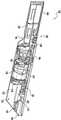
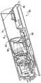
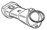
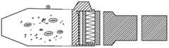
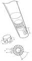
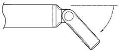
도면을 참조하면, 도 1 내지 도 4는 본 발명의 일 실시예에 따른 핸드헬드 표면 청소 장치(100)를 도시한다. 도시된 바와 같이, 핸드헬드 표면 청소 장치(100)는 세로축(116)을 따라 제1 단부(140)로부터 제2 단부(142)까지 연장되는 본체(102)를 포함한다. 핸드헬드 표면 청소 장치(100)의 본체(102)는 제1 단부(140)에 인접한 핸들부(104), 모터부(또는 섹션)(106), 필터부(108), 더스트컵(110), 및 제2 단부(142)에 인접한 노즐(114)을 포함한다. 본체(102)는 실질적으로 평평하고 연속적인 표면(180)을 포함할 수 있고, 상기 표면은 "완드(wand)" 유사 장치를 형성 하도록 제1 단부(140)로부터 제2 단부(142)까지 연장된다. 일 실시예에서, 핸들부(104), 모터부(106), 필터부(108), 및 노즐(114)은 단일, 모놀리식형으로 형성될 수 있다. 다른 경우에, 노즐(114) 및/또는 필터부(108)와 같은 부분은 제거 가능할 수 있다.Referring to the drawings, FIGS. 1 to 4 show a handheld
도시된 바와 같이, 핸드헬드 표면 청소 장치(100)의 핸들부(104)는 작동 중에 사용자의 손에 편안하게 맞도록 윤곽이 형성된다. 테이퍼 영역(146)은 유리하게는 사용자의 손과 손가락이 핸드헬드 표면 청소 장치(100)를 보다 편안하게 잡고 작동할 수 있게 한다. 핸드헬드 표면 청소 장치(100)의 본체(102)는 온/오프 버튼(118) 및 더스트컵 해제버튼(dust-cup release button, 112)을 더 포함한다. 온/오프 버튼(118) 및 더스트컵 해제버튼(112)은 핸들부(104)가 동일하게 쥐어졌을 때 사용자 손의 엄지 손가락에 의해 작동될 수 있다. 더스트컵 해제버튼(112)은 더스트컵(110)의 잠금을 해제하기 위해, 예를 들어, 사용자의 엄지에 의해 변위 되어 슬라이딩 가능하게 결합될 수 있고, 이는 하기 더 자세히 기재될 것이다. 더스트컵 해제버튼(112)은 사용자가 제공하는 힘이 없는 상태에서 후방 위치로 복귀하도록 스프링 바이어스(spring-biased) 될 수 있다.As shown, the
본체(102)의 모터섹션(106)은 그 안에 배치된 모터(126)(도 4 참조)에 전력을 선택적으로 공급하기 위한 회로(미도시)를 포함할 수 있다. 모터(126)는 dc 모터 또는 흡입을 발생시키기 위한 다른 적절한 모터일 수 있다. 일부 실시예에서, 핸드헬드 표면 청소 장치(100)는 와류 배열(vortex arrangement)을 포함할 수 있으므로, 도시된 실시예는 본 발명을 제한하려는 의도가 아니다. 모터(126)는 더러운 공기 유입구(120)로 공기를 끌어 들이기 위해 흡입을 발생시킨다. 모터(126)에 공급되는 전력량은 흡입 전력량을 비례적으로 조정하도록 변할 수 있다. 대안적으로, 온/오프 버튼(118)은 단순히 일정한 양의 전력이 모터(126)에 공급되게 할 수 있다.The
더스트컵(110)은 더러운 공기 유입구(120)를 통해 수용된 먼지 및 이물질을 수용 및 저장하도록 구성될 수 있다. 도시된 바와 같이, 더스트컵(110)은 본체(102)에, 보다 구체적으로는 더러운 공기 유입구(120)의 일부분에, 힌지(149)에 의해 회전 가능하게 결합되고, 상기 힌지(149)는 세로축(116)에 대해 실질적으로 횡방향으로 본체(102)를 통해 연장되는 핀에 의해 형성된다. 노즐(114)은 힌지(149)를 제공할 수 있다. 몇몇의 경우, 노즐(114)은 제거 가능하다. 따라서, 더스트컵(110)은, 예를 들어 더스트컵 해제버튼(112)를 통해 해제될 때, 제1 회전축을 따라 회전할 수 있다. 예를 들어, 도 3에 도시된 바와 같이, 더스트컵(110)은 일반적으로 d로 지시된 방향으로 회전할 수 있고, 본체(102)의 세로축(116)에 대하여 90도의 각도에서 정지부에 들어갈 수 있다. 더스트컵(110)의 이 위치는 개방, 해제 또는 폐기 방향으로 정확하게 지칭될 수 있다. 개방 방향에서, 개구부(148)는 먼지 및 이물질이 예를 들어 더스트컵(110)을 빠져나가 쓰레기통으로 나가게 하는데 사용될 수 있다. 따라서, 더스트컵(110)은, 예컨대 도 1에 도시된 바와 같이, 잠금/닫힘 방향(locked/close orientation) 사이에서, 도 3에 도시된 바와 같이, 개방/폐기 방향(open/disposal orientation)으로 전환될 수 있다. 닫힘 방향에 있을 때, 더스트컵(110)은 개구부(148)에 의해 필터섹션(108)의 필터와 유체 연결(fluid communication) 된다. 반면에 개방 방향에 있을 때, 더스트컵(110)은 필터섹션(108)의 필터와 유체 연결로부터 분리되고 개구부(148)가 더스트컵(110) 내에 저장된 먼지 및 이물질을 배출되게 한다.The
하기 더 논의되는 바와 같이, 더스트컵(110)은 필터섹션(108) 내에서 필터를 교반하는 청소 또는 교반 요소, 예를 들어 솔(bristle)을 포함할 수 있다. 필터섹션(108) 내에서 필터의 교반은 먼지 및 이물질을 자유롭게 포획/고정시킬 수 있고, 일반적으로 막힘이 최소화되거나 흡입력 감소를 막기 위해 공기의 유체 연결을 증가시킬 수 있다.As discussed further below, the
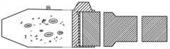
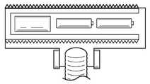
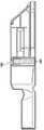
도 4는 도 1의 라인 4-4를 따라 취해진 핸드헬드 표면 청소 장치(100)의 예시적인 단면도를 도시한다. 도시된 바와 같이, 본체(102), 특히 핸들부(104)는, 배터리와 같은 하나 이상의 전원을 수용할 수 있은 캐비티(150)을 포함한다. 캐비티는 배터리를 모터(126)에 전기적으로 연결하기 위해 배터리를 관련 전기 접점(electrical contacts, 미도시)과 위치 및 정렬시키기 위해 배터리 홀더(128) 또는 배터리 받침대(128)을 포함할 수 있다. 상기 논의된 바와 같이, 핸들부(104)는 테이퍼 영역(146)을 제공하고, 상기 테이퍼 영역(146)은 핸들부(104)와 모터섹션(106) 사이의 이동을 제공한다.FIG. 4 shows an exemplary cross-sectional view of a handheld
본체(102)에 의해 형성된 캐비티(150)는 모터섹션(106)을 통해 계속된다. 모터섹션은 캐비티(150)에 배치된 모터(126)를 포함한다. 모터섹션에 이어, 캐비티(150)는 필터섹션(108)을 통해 계속된다. 필터(124)는 필터섹션의 캐비티(150)에 배치될 수 있다. 도시된 바와 같이, 필터(124)는 원뿔형 필터이지만, 다른 필터 장치가 본 발명의 범위 내에 포함된다. 따라서, 캐비티(150)는 핸들부(104)의 기준의 제1 단부(140)로부터 더러운 공기 유입구(120)의 제2 단부까지 연장될 수 있다.The
필터섹션(108)에 인접한 더스트컵(110)은 필터(124)에 결합된다. 따라서, 더스트컵(110)은 개구부(148)를 통해 필터섹션(108)과 유체적으로 연결될 수 있다. 스크린(154)(도 6 참조)은 모터섹션(106) 내로 먼지 및 이물질이 유입되는 것을 방지하기 위해 개구부(148)를 덮을 수 있다. 이는 하기 더 상세히 논의된다. 추가로 도시된 바와 같이, 더러운 공기 유입구(120)는 먼지 및 이물질을 수용 및 저장하기 위해 더스트컵(110)과 유체 연결된다.The
더스트컵(110)과 더러운 공기 유입구(120) 사이에 탄성재 또는 완충재로 형성된 밸브 본체(122)가 배치될 수 있다. 모터(126)에 의해 제공되는 흡입이 없을 때, 밸브 본체(122)는 도 4에 도시된 바와 같이 밸브 시트 위치(valve seat position)로 유지될 수 있다. 밸브 본체(122)는 스프링 장력, 예를 들어 물질로 도입된 굽힘 또는 다른 적절한 배열에 기초하여 더러운 공기 유입구(120)를 향해 편향될 수 있다. 밸브 본체(122)의 시트 위치는 더러운 공기 유입구(120)의 개구부와 이와 정렬되는 더스트컵(110)의 개구부 사이에 밀봉, 예를 들어 공기 흐름의 100 %를 방지하는 공기 밀봉(air-tight seal), 또는 공기 흐름의 80 % 이상을 방지하는 부분 공기 밀봉을 형성할 수 있고, 이의 각각은 일반적으로 170으로 도시되어있다. 따라서, 밸브 본체(122)의 시트 위치는, 표면 청소 장치(100)이 오프, 예를 들어 모터(126)로부터의 흡입이 존재하지 않을 때, 170에서 정렬된 개구부를 통해 더스트컵(110)으로부터 먼지 및 이물질이 배출되는 것을 방지 할 수 있다. 밸브 본체(122)는, 모터(126)에 의해 생성된 흡입력이 더러운 공기 유입구 및 궁극적으로 더스트컵(110) 내로 공기를 끌어 들일 때, 더스트컵(110)의 캐비티(152)로 변위되도록/구부러지도록 구성될 수 있다.A
일 실시예에서, 도 3에 도시된 바와 같이, 더스트컵(110)이 해제 방향에 있을 때, 시트 위치의 밸브 본체(122)는 먼지 및 이물질이 개구부(145)를 통해서만 더스트컵(110)을 빠져나가도록, 더스트컵(110)의 캐비티를 형성하는 하나 이상의 표면에 대해 동일하게 유지하기 위해 더스트컵(110)으로부터 멀어 지도록 밸브 본체(122)를 편향시키는 스프링력(spring force)에 기초하여, 더스트컵(110)의 캐비티를 계속해서 밀봉한다.In one embodiment, as shown in Figure 3, when the
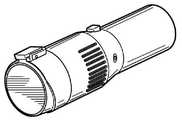
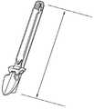
도 5를 참조하면, 도 1 내지 도 4의 핸드헬드 표면 청소 장치(100)에 사용하기에 적합한 더스트컵의 다른 예시적인 실시예가 도시되어있다. 도시된 바와 같이, 더스트컵은 복수의 솔 형태의 교반기 부재(agitator member, 155)를 포함한다. 솔은 예를 들어 플라스틱 또는 다른 적절한 강성 물질로 형성될 수 있다. 도 6에 도시된 바와 같이, 닫힘 위치에 있을 때, 솔(155)은 핸드헬드 표면 청소 장치(100)의 본체(102)의 상부 표면(180)에 인접하게 배치될 수 있다.Referring to FIG. 5, another exemplary embodiment of a dust cup suitable for use in the handheld
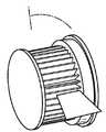
도 6의 단면도에 도시된 바와 같이, 더스트컵(110)은 축(160)을 중심으로 회전하여 닫힘 방향에서 개방 방향으로 전환될 때, 교반기 부재(155)가 필터섹션(106)의 스크린(154)과 접촉한다. 스크린(154) 및 필터(124)는 본 명세서에서 전체적으로 필터 배열(filter arrangement)로 지칭될 수 있다. 이러한 접촉은, 일반적으로, 모터, 필터 및 더러운 공기 유입구(120) 사이의 흡입력 손실을 최소화하거나 감소시키기 위해 스크린(154)에 부착된 이물질을 유리하게 제거할 수 있은, 스크린(154)을 "긁어낸다(scrape)".As shown in the cross-sectional view of FIG. 6, when the
더스트컵(110)을 개방 방향에서 닫힘 방향으로 전환할 때 동일한 긁힘 동작이 달성될 수 있다. 이를 위해, 사용자에 의해 수행되는 더스트컵(110)의 각각의 청소 동작(cleaning operation)은 2-단계의 청소 동작을 야기할 수 있고, 이에 의해 제1 단계는 더스트컵(110)이 해제됨에 따라 제1 방향(d1)을 따라 스크린(154)을 긁는 단계를 포함하고, 제2 단계는 더스트컵(110)이 닫힘 위치로 전환됨에 따라 제2 방향(d2)(도 7 참조)을 따라 스크린(154)을 긁는 단계를 포함한다. 몇몇의 경우에, 사용자는 더스트컵(110)을 여러 번 해제하고 닫아서 상기 2-단계 청소 동작을 하여 장애물을 제거하게 할 수 있다.The same scratching action can be achieved when switching the
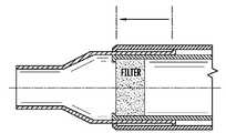
도 7에 도시된 바와 같이, 필터섹션(106)은 필터(124)가 교체되거나 청소될 수 있도록 제거 가능한 필터 캐리지(107)를 포함할 수 있다. 도시된 바와 같이, 상기 실시예는 제거 가능한 필터 캐리지(107)를 제거하기 전에 해제 방향에 있는 더스트컵(110)을 포함한다. 대안적으로 또는 추가로, 전체 필터 캐리지(107) 및 필터(124)는 사용의 용이성을 위해 단일 유닛으로서 교체될 수 있다.As shown in FIG. 7, the
도 8은 핸드헬드 표면 청소 장치(1)에 제거 가능하게 결합되도록 구성된 진공 청소 장치(800)의 예를 도시한다. 핸드헬드 표면 청소 장치(1)는 도 1의 핸드헬드 표면 청소 장치(100)로서 구현될 수 있다. 그리고 본 발명은 이 점을 제한하려는 것이 아니다. 도시된 바와 같이, 진공 청소 장치(800)는 진공 프레임(802)(단순히 프레임(802)), 접이식 조인트(804), 핸드헬드 표면 청소기 리셉터클(806), 더스트컵 리셉터클(808), 제거 가능한 더스트컵(810), 청소 헤드(812), 및 더러운 공기 유입구(814)를 포함한다.8 shows an example of a
프레임(802)은 핸드헬드 표면 청소기 리셉터클(806) 또는 핸드헬드 리셉터클을 형성하며, 핸드헬드 리셉터클은 핸드헬드 표면 청소 장치(1)를 단단히 유지하도록 구성된다. 핸드헬드 표면 청소 장치(1)가 핸드헬드 리셉터클(806) 내에 배치/장착된 경우, 더러운 공기 유입구(120)는 더러운 공기 유입구(814)를 더스트컵(810)과 유체적으로 연결시키는 더러운 공기 채널(미도시)과 정렬되고 유체 연결될 수 있다. 따라서, 핸드헬드 표면 청소 장치(1)의 모터에 의해 생성된 흡입은 공기를 더러운 공기 유입구(814)로 끌어들이는데 사용될 수 있다. 먼지 및 이물질은 더스트컵(810)(또는 제1 더스트컵) 및/또는 핸드헬드 표면 청소 장치(1)의 더스트컵(110)(또는 제2 더스트컵)에 저장될 수 있다.The
몇몇의 경우에, 더스트컵(810)의 존재는 더스트컵(110)을 단독으로 사용하는 것에 비해 먼지 및 이물질에 대한 전체 저장량을 효과적으로 증가(예를 들어, 2 배 이상)시키지만, 일부 실시예에서 더스트컵(110)은 단독으로 사용될 수 있다. 또한 도시된 바와 같이, 프레임(802)은 프레임(802)의 상부 핸들부가 저장용 핸드헬드 리셉터클(806)을 갖는 하부에 평행하게 구부려 질 수 있게 하는 선택적인 접이식 조인트(804)를 포함한다(도 34a-34c 참조).In some cases, the presence of the
도 9는 더스트컵(810)의 본체(840)에 힌지될 수 있은 도어(850)를 갖는 더스트컵(810)의 예를 도시한다. 상기 예에서, 버튼은 도어(850)를 해제하고, 저장된 먼지 및 이물질이 더스트컵(810)의 본체(840)를 빠져 나갈 수 있게 개방하도록 도어를 스윙/회전하게 눌려질 수 있다.9 shows an example of a
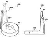
도 10은 도크(4401), 핸드헬드 표면 청소 장치(4022) 및 로봇 청소기(4033)를 포함하는 도킹 시스템(docking system, 4400)의 예시적인 실시예를 도시한다. 일 실시예에서, 예를 들어, 핸드헬드 표면 청소 장치(4022)는 도 1의 핸드헬드 표면 청소 장치(100) 또는 도 21의 핸드헬드 표면 청소 장치(1)로서 구현된다. 도시된 바와 같이, 도크(4401)는 베이스(4404)에 의해 적어도 부분적으로 형성된 로봇 청소기 결합섹션을 포함하고, 상기 베이스(4404)는 로봇 청소기(4033)에 제거 가능하게 결합되도록 구성된다. 베이스(4404)는 재충전 목적으로 로봇 청소기(4033)와 전기적으로 결합하기 위한 전기 접점/단자(electrical contact/terminal)를 더 포함할 수 있다.10 shows an exemplary embodiment of a
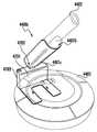
도크(4401)는 단순히 완드 결합섹션(wand coupling section)으로도 지칭될 수 있은 핸드헬드 표면 청소 장치 결합섹션(4405)을 더 포함한다. 완드 결합섹션(4405)은 완드 리셉터클(4406) 및 완드 해제(wand release, 4410)(또는 완드 해제 페달(4410))를 포함할 수 있다. 도 11의 예시적인 실시예에 도시된 바와 같이, 완드 리셉터클(4406)(또는 리셉터클)은 완드 결합섹션(4405)의 측벽에 의해 형성된 리세스(recess)/개구부(opening) 일 수 있다. 완드 리셉터클(4406)은 도크(4401)의 세로축(4408)에 대해 실질적으로 수직으로 연장될 수 있다. 완드 리셉터클(4406)은 핸드헬드 표면 청소 장치(4022)를 적어도 부분적으로 수용하도록 구성될 수 있다. 도시된 바와 같이, 완드 리셉터클(4406)은 핸드헬드 표면 청소 장치(4022)의 상부 표면(4409)이 완드 리셉터클(4406)을 형성하는 표면(4401)을 갖는 플러시(flush)를 장착할 수 있게 하는 깊이를 포함한다. 따라서, 핸드헬드 표면 청소 장치(4022)는 완드 리셉터클(4406)에 장착될 때 상대적으로 숨겨질 수 있고, 일반적으로 완드 결합섹션(4405)의 형상에 대응하는 외형을 갖는다.
완드 리셉터클(4406)에 핸드헬드 표면 청소 장치(4022)의 삽입은 제1 각도에서, 예를 들어, 약 80도에서, 핸드헬드 표면 청소 장치(4022)를 삽입하는 것을 포함할 수 있고, 핸드헬드 표면 청소 장치(4022)의 노즐은 스프링-하중 메커니즘(spring-loaded mechanism, 미도시)을 편향시키고 결합시키는 데 사용된다. 일단 삽입되면, 핸드헬드 표면 청소 장치(4022)는 멈춤쇠(detent, 미도시) 또는 다른 적절한 잠금 메커니즘(locking mechanism)을 통해 제 위치에 고정될 수 있다.Insertion of handheld surface cleaning device 4022 into
핸드헬드 표면 청소 장치(4022)를 제거하기 위해, 완드 해제(4410)에 대해 제공된 사용자-제공 힘(예를 들어, 사용자의 발 또는 손에 의한 힘)은 잠금 메커니즘을 해제시키고 스프링-하중 메커니즘이 핸드헬드 표면 청소 장치(4022)를 저장 위치로부터 연장/해제 위치로 전환할 수 있게 한다. 도시된 바와 같이, 이러한 전환은 세로축(4408)과 실질적으로 평행하게 연장되는 제1 회전축(4412)을 중심으로 핸드헬드 표면 청소 장치(4402)가 회전하는 것을 포함할 수 있다. 해제 위치에서, 사용자는 단순히 핸드헬드 표면 청소 장치(4022)를 사용하기 위한 분리를 위해 이를 단순히 잡을 수 있고 완드 리셉터클(4406)로부터 수직으로 멀어지는 방향으로 힘을 공급할 수 있다.To remove the handheld surface cleaning device 4022, the user-provided force (e.g., force by the user's foot or hand) provided for the
도 11은 본 발명에 따른 도킹 시스템(4400a)의 다른 예시적인 실시예를 도시한다. 도 11의 실시예는 또한 업라이트 구성으로 정확하게 지칭될 수 있으며, 핸드헬드 표면 청소 장치(4022)는 도크(1401a)로부터 수직으로 연장된다. 보다 상세하게는, 도크(1401a)는 베이스(4404a) 및 완드 결합섹션(4405a)을 포함한다. 베이스(4404a)는 해제버튼(4501 및 4502)을 포함한다. 해제버튼(4501 및 4502)은 사용자-제공 힘(예를 들어, 사용자의 발에 의한 힘)에 기초하여 로봇 청소기(4403) 및 핸드헬드 스크린 구동 장치(4402)의 분리를 허용할 수 있다. 도시된 바와 같이, 해제버튼(4501 및 4502)은 로봇 청소기가 도크(4401a)에 결합하기 위해 이동할 수 있은 램프를 적어도 부분적으로 형성할 수 있다.11 shows another exemplary embodiment of a
완드 결합섹션(4405a)은 핸드헬드 표면 청소 장치(4022)를 적어도 부분적으로 수용하도록 구성된 완드 리셉터클(4406a)을 포함할 수 있다. 특히, 완드 리셉터클(4406a)은 핸드헬드 표면 청소 장치(4022)의 세로축과 실질적으로 수직으로 연장될 수 있는 세로축을 갖는 긴 캐비티를 포함할 수 있다. 따라서, 핸드헬드 표면 청소 장치(4022)의 핸들섹션/영역은 저장 위치에 있을 때 완드 리셉터클(4406a)로부터 적어도 부분적으로 연장될 수 있다.
완드 결합섹션(4405a)은 로봇 청소기 결합섹션에 인접한 테이퍼를 포함하여 로봇 청소기를 적어도 부분적으로 수용하기 위한 리세스를 제공할 수 있다. 따라서, 테이퍼는 로봇 청소기 결합섹션의 적어도 일부를 형성할 수 있다. 로봇 청소기(4403)가 베이스(4404a)에 결합될 때, 완드 결합섹션(4405a)의 적어도 일부(4503)는 로봇 청소기(4403) 위로 연장될 수 있다. 이는 로봇 청소기가 저장 위치일 때, 즉, 베이스(4404a)에 결합되었을 때, 도킹 시스템(4400a)의 전체 차지하는 공간(footprint)을 유리하게 감소시킬 수 있다.The
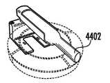
그 후, 사용자는 핸드헬드 표면 청소 장치(4402)의 핸들섹션/영역을 잡고, 완드 리셉터클(4406a)로부터 분리하기 위해 d2 방향을 따라 일반적으로 힘을 공급할 수 있다. 몇몇의 경우에, 사용자는 완드 리셉터클(4406a)로부터 핸드헬드 표면 청소 장치(4022)를 잠금 해제를 하기 위해 먼저 해제버튼(4502)을 작동시켜야 한다. 또한, 완드 리셉터클(4406a)은, 사용자가 해제버튼(4402)에 힘을 공급하는 것에 응답하여, 핸드헬드 표면 청소 장치(1402)가 적어도 부분적으로 완드 리셉터클(4406a) 내부에 유지되도록 하면서 d2 방향을 따라 위쪽으로 이동하는 스프링-하중 메커니즘을 포함할 수 있다. d2 방향은 도크(4401a)의 세로축(4408a)에 대해 실질적으로 수직으로 연장될 수 있다. 이것은 유리하게는 사용자가 핸드헬드 표면 청소 장치(4022)를 잡기 위해 얼마나 멀리 떨어져 있어야 하는지를 감소시킬 수 있다.Thereafter, the user can grasp the handle section/area of the handheld
도 12는 본 발명에 따른 업라이트 구성의 도킹 시스템(4400b)의 다른 예시적인 실시예를 도시한다. 도시된 바와 같이, 상기 실시예는 도킹 시스템(4400a)의 것과 실질적으로 유사하며, 간결성을 위해 그 설명은 반복되지 않을 것이다. 그러나, 도킹 시스템(4400a)은 잠금 메커니즘이 없는 완드 리셉터클(4406b)을 포함하고, 대신 마찰 맞춤(friction-fit) 또는 단순히 중력을 이용할 수 있다. 따라서, 핸드헬드 표면 청소 장치(4402)는 해제버튼(4502)(도 45)과 같은 해제를 작동시키지 않고 도크(4501b)로/로부터 삽입/제거될 수 있다.12 shows another exemplary embodiment of a
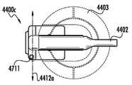
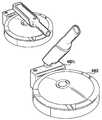
도 13a 내지 13d는 본 발명의 양태에 따른 도킹 시스템(4400c)의 다른 예시적인 실시예를 도시한다. 도시된 바와 같이, 도킹 시스템(4400c)은 도크(4401c), 핸드헬드 표면 청소 장치(4402) 및 로봇 청소기(4403)를 포함한다. 도크(4401c)는 로봇 청소기 결합섹션을 형성하는 베이스(4404b)를 포함한다. 완드 결합섹션(4401c)는 힌지(4702)를 통해 완드 리셉터클(4407b)에 회전 가능하게 결합된 고정 위치(고정부, 4703)를 포함한다. 따라서 완드 리셉터클(4407b)은 저장 위치(도 13/c/d)와 해제 위치(도 47a) 사이에서 제2 회전축(4412a)을 중심으로 회전 할 수 있고 이는 하기 더 상세히 논의된다.13A-13D show another exemplary embodiment of a
도 13a 내지 13d의 실시예에서, 완드 리셉터클(4407b)은 핸드헬드 표면 청소 장치(4022)를 적어도 부분적으로 둘러쌀 수 있다. 일반적으로, 완드 리셉터클(4407b)은 마찰-맞춤 연결, 중력, 또는 둘 모두에 기초하여 핸드헬드 표면 청소 장치(4402)를 고정 위치에 유지하는 크래들(cradle)을 형성할 수 있다.In the embodiments of FIGS. 13A-13D, the
도 13a에 도시된 바와 같이, 완드 리셉터클(4407b)은 해제 위치에 있고, 완드 리셉터클(4407b)은 베이스의 세로축(4408b)에 대해 약 45±20도로 연장된다. 따라서, 사용자는 핸드헬드 표면 청소 장치(4402)에 쉽게 도달하여 잡을 수 있다. 한편, 완드 리셉터클(4407b)은 도 13c에 도시된 바와 같이 저장 위치에 있을 때 베이스의 세로축(4408b)과 실질적으로 평행하게 연장된다.As shown in FIG. 13A, the
일 실시예에서, 완드 리셉터클(4407b)은 힌지(4702) 또는 제2 회전 축(4412a)을 중심으로 회전할 수 있은 다른 적절한 결합 장치에 의해 저장 위치와 해제 위치 사이에서 전환될 수 있다. 도크(4401c)는 저장 위치와 해제 위치 사이에서 완드 리셉터클(4407b)의 회전을 야기하기 위한 기계적 메커니즘(예를 들어, 기어, 벨트 구동 또는 다른 적절한 메커니즘)을 포함할 수 있다. 고정부(4703)는 적외선(IR) 센서와 같은 근접 센서(4711)를 포함할 수 있다. 근접 센서(4711)는 사용자의 손(또는 다른 부분)에 의해 잘못되었을 때 완드 리셉터클(4407b)이 자동으로 해제 위치로 회전하여 핸드헬드 표면 청소 장치(4022)를 쉽게 분리할 수 있게 하는 수직 IR 필드(vertical IR field)를 유도할 수 있다. 해제 위치는 또한 로봇 청소기(4403)의 상부 표면 상에 제어 허용을 "밝히거나(reveal)" 다른 방식으로 제공할 수 있다(도 14a-14c 참조).In one embodiment, the
도 14a-14c는 도 13a-13d의 실시예를 더 상세하게 도시한다. 도시된 바와 같이, 도크(4401c)는 고정섹션(4799)으로부터 고정섹션(4799)의 높이(h2)의 1.5 배 이상인 거리(d1)까지 연장되는 연장 레그(elongatesd legs, 4802)를 포함할 수 있다. 따라서, 연장 레그(4802)는 유리하게는 완드 리셉터클(4407b)(및 핸드헬드 표면 청소 장치(4022))을 로봇 청소기(4403)이 없는 상태에서 지지할 수 있다.14A-14C illustrate the embodiment of FIGS. 13A-13D in more detail. As shown, the dock 4401c may include elongates
도 15는 본 발명의 양태와 일치하는 도킹 시스템(4400d)의 다른 실시예를 도시한다. 도킹 시스템(4400d)은 도 11의 도킹 시스템(4400a)과 유사하며, 상기 설명은 간결성을 위해 반복되지 않을 것이다. 도시된 바와 같이, 완드 결합섹션(4405b)은 IR 센서(또는 다른 적합한 근접 센서) 및 톱니/멈춤쇠(미도시), 엘리베이터/연장기 메커니즘을 갖는 완드 리셉터클(4407c)을 포함한다. IR 센서는 도크(4401d)에 인접한 IR 빔을 방출할 수 있다. IR 빔이(예를 들어, 사용자의 손에 의해) 위반되는 경우, 신호가 엘리베이터/연장기 메커니즘으로 전송되어 수직의 d3 방향을 따라 위쪽으로 연장되게 할 수 있다. 톱니/멈춤쇠는 핸드헬드 표면 청소 장치(4022)의 길이를 따라 배치된 가이드/트랙과 맞물려서 비교적 직선 경로를 따라 수직으로 이동할 수 있다. 일 실시예에서, 다른 구성이 본 발명의 범위 내에 있지만 핸드헬드 표면 청소 장치(4402)가 6 인치 내지 8 인치 증가할 수 있다. IR 센서는 센서의 위치에 대한 사용자의 주의를 끌기 위한 시각적 표시기, 예를 들어 Led를 더 포함할 수 있다.15 shows another embodiment of a
도 15에 또한 도시된 바와 같이, 완드 결합섹션(4405b)은 완드 리셉터클(4407c)을 거리(d4)만큼 인접한 벽으로부터 오프셋하기 위해 테이퍼(측면 프로파일에 도시된 바와 같이)질 수 있다. 이는 유리하게도 도크(4401d)가 벽에 대해 수평하게 배치된 경우에도 사용자가 손을 핸드헬드 표면 청소 장치(4402)에 도달하여 용이하게 핸드헬드 표면 청소 장치(4402)를 잡을 수 있게 할 수 있다.As also shown in FIG. 15, the
도 16a-16c는 본 발명의 양태에 따른 도킹 시스템(4400e)의 다른 실시예를 총괄적으로 도시한다. 도시된 바와 같이, 도크(440le)는 도크(4401e)의 제1 단부(5001)에 인접한 완드 리셉터클(4407d)을 포함한다. 도시된 바와 같이, 완드 리셉터클(4407d)은 단일 모놀리식으로서 도크(440e)와 일체로 형성된다. 그러나, 완드 리셉터클(4407d) 및 도크(440le)는 원하는 구성에 따라 별개의 조각으로 형성될 수 있다. 완드 리셉터클(4407d)은 심미적 매력을 증가시키고 일반적으로 핸드헬드 표면 청소 장치(4022)의 형상에 대응하는 형상을 형성하기 위해 곡선형 프로파일/형상을 포함할 수 있다.16A-16C collectively illustrate another embodiment of a
도시된 바와 같이, 완드 리셉터클(4407d)은 고정된 배향을 가지며, 그 안에 배치된 핸드헬드 표면 청소 장치(4022)는 도크(440le)를 형성하는 상부 표면(5002)에 대해 약 45도 각도로 유지된다. 다른 각도도 본 발명의 범위에 포함된다. 도 16a 내지 도 16c의 실시예는 완드 리셉터클(4407d)이 로봇 청소기가 도크(440le)에 결합되는 영역에 인접하여(예를 들어, 측 방향으로 배치됨) 나란한 구성(side- by-side configuration)으로 정확하게 지칭될 수 있다. 따라서, 완드 리셉터클(4407d)에 삽입될 때, 핸드헬드 표면 청소 장치(4022)는 도크(440le)에 접한 로봇 청소기의 중심선(4408e)으로부터 d5의 거리만큼 수평으로 오프셋되어 배치된 종방향 중심선(longitudinal center line, 4408d)을 포함하고, 상기 거리 d5는 적어도 로봇 청소기의 반경(R1)과 동일하다.As shown, the
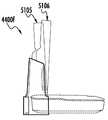
도 17은 본 발명의 양태에 따른 도킹 시스템(4400f)의 다른 실시예를 도시한다. 도시된 바와 같이, 도 51의 실시예는 도 50의 도킹 시스템(4400e)의 실시예와 유사하며, 이러한 이유로 그 설명은 간결성을 위해 반복되지 않을 것이다. 도시된 바와 같이, 도크(440lf)는 로봇식 결합섹션(4420c)과 나란한 구성으로 완드 리셉터클(4407e)을 포함하는 완드 결합섹션(4405c)을 포함한다. 완드 결합섹션(4405c)은 IR 센서(5102)(또는 다른 적절한 근접 센서)를 더 포함한다. 사용자가 IR 센서(5102)에 의해 방출된 IR 빔을 위반하는 것에 응답하여, 신호가 완드 리셉터클(4407e)로 전송될 수 있다. 리프트 앤드 틸트 메커니즘(lift and tilt mechanism, 미도시)은 그 후 신호를 수신하고 핸드헬드 표면 청소 장치(4022)를 저장 위치(5105)로부터 해제 위치(5106)로 전환시킬 수 있다. 도시된 바와 같이, 해제 위치(5106)로의 전환은 핸드헬드 진공 청소 장치(4022)를 로봇 청소기의 상부 표면에 대해 수직 경로를 따라 먼저 이동시키고(예를 들어, 로봇 청소기로부터 멀어짐), 핸드헬드 진공 청소 장치(4022)를 예를 들어 로봇 청소기에 대해 약 70±15 도의 각도로 로봇 청소기를 향해 "틸팅 (tilting)"을 야기시킨다. 한편, 저장 위치(5105)로의 전환은 해제 위치(5106)로의 전환의 역전을 야기한다, 예를 들어 수직 배향으로 다시 틸팅한 후 로봇 청소기 장치를 향해 하향으로 이동하게 한다.17 shows another embodiment of a
사용자가 검출되지 않는 경우, 예를 들어, 사용자가 도크(4401f)로부터 멀어지면, 리프트 앤드 틸트 메커니즘은 자동으로 핸드헬드 표면 청소 장치를 다시 저장 위치(5105)로 전환할 수 있다. 이는 유리하게는 사용자가 완드 리셉터클(4407e)에 핸드헬드 표면 청소 장치(4022)를 삽입할 수 있게 하고, 완드 리셉터클(4407e)이 다시 저장 위치(5105)로 전환하는 동안 간단히 걸어 나갈 수 있게 한다.If the user is not detected, for example, if the user moves away from the
다음의 추가 실시예 및 예는 전술한 발명에 동일하게 적용 가능하다. 예를 들어, 도 21의 핸드헬드 표면 청소 장치(1)은 예를 들어 로봇 청소 장치 및 핸드헬드 청소 장치에 결합하기 위해 사용될 수 있는 베이스(도 10-20b 참조)를 포함하여 상기 기재된 다양한 실시예에서 사용될 수 있다.The following additional examples and examples are equally applicable to the above-described invention. For example, the handheld
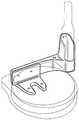
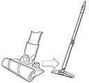
도 21은 본 발명의 일 실시예에 따른 핸드헬드 표면 청소 장치(1)의 사시도를 도시한다. 도시된 바와 같이, 핸드헬드 표면 청소 장치(1)는 청소 헤드(3)에 연결된 본체(2)를 포함한다. 가요성 도관(flexible conduit)으로도 지칭될 수 있은 선택적인 가요성 영역(flexible region, 4)은 본체(2)를 청소 헤드(3)에 결합시킬 수 있고, 청소 동작 동안 본체(2)에 대한 청소 헤드(3)의 회전을 허용한다. 더러운 공기 통로(14)는 청소 헤드(3)에 의해 청소 헤드(3) 및 본체(2)를 통해 제공된 더러운 공기 유입구(11)로부터 청소 헤드(3)에 대해 본체의 말단부에 인접하여 배치된 더스트컵(23)(도 22a 및 22b 참조)까지 연장될 수 있다. 따라서, 본체(2) 및 청소 헤드(3)는 더러운 공기 통로를 통해 먼지 및 이물질을 수용하도록 유체 연결일 수 있다.21 shows a perspective view of a handheld
본체(2)는 제1 세로축(9)을 따라 제1 단부(10-1)로부터 제2 단부(10-2)까지 연장된다. 다른 형상 (예를 들어, 직사각형, 정사각형, 불규칙 등) 및 구성이 본 개시의 범위 내에 있지만, 도시된 바와 같이, 실질적으로 원통형 형상을 가질 수 있다. 본체(2)는 플라스틱 또는 다른 적절한 강성 물질로 형성될 수 있다. 본체(2)는 다수의 조각을 포함할 수 있거나 단일 조각으로 형성될 수 있다. 도시된 바와 같이, 본체(2)는 더스트컵 부분(6)을 전원모터부(8)으로부터 분리하기 위해 제거 가능한 조각을 포함한다.The
본체(2)는, 핸드 그립 표면(5)으로도 지칭될 수 있는, 표면(5)에 의해 정의될 수 있다. 본체(2)는 사용 중에 사용자의 손에 편안하게 맞도록 윤곽을 형성할 수 있다. 따라서, 핸드 그립 표면(5)은 전원모터부(8) 및 더스트컵 부분(6) 주위에서 적어도 부분적으로 연장될 수 있다.The
본체(2)는 제1 단부(10-1)에 가까이에 배치된 전원모터부(8) 및 더스트컵 부분(6)을 포함할 수 있다. 하기 더 상세히 논의되는 바와 같이, 전원모터부(8) 내의 구성요소(예를 들어, 하나 이상의 모터 및 배터리와 같은 하나 이상의 전원)은 본체(2)의 더스트컵 부분(6)과 동축으로 배치될 수 있다. 전원모터부(8)가 더스트컵 부분(6)의 전방(예를 들어, 업-스트림)에 배치될 때, 전원모터부(8)의 구성요소는 전체적으로 더러운 공기가 더러운 공기 통로(14)를 따라 이동하여 저장 목적으로 더스트컵 부분(6)에 도달할 수 있도록 캐비티를 형성할 수 있다.The
본체(2)는 제2 단부(10-2)에 인접하게 배치되어 여과된/깨끗한 공기가 본체(2)를 빠져 나가게 하는 복수의 통풍구(7)를 포함할 수 있다. 복수의 통풍구(7)는 제2 단부(10-2)에 인접하여 배치되어, 작동 중에 사용자의 손이 실수로 복수의 통풍구(7)를 덮지 않도록 보장할 수 있다. 복수의 통풍구(7)의 다른 위치는 본 발명의 범위 내에 있고 도 21에 도시된 예는 제한적인 것으로 해석되어서는 안 된다.The
도 21를 참조하면, 청소 헤드(3)는 제2 세로축(15)을 따라 제1 단부(12-1)로부터 제2 단부(12-2)까지 연장될 수 있다. 청소 헤드(3)는 본체(2)와 동일한 물질로 형성될 수 있거나 또는 다른 물질을 포함할 수 있다. 몇몇의 경우에, 청소 헤드(3)는 구부러질 수 있은 물질, 예를 들어, 사용자-제공 힘에 기초하여 구부러지거나 구부러질 수 없는 물질로 형성된다. 다른 경우에, 청소 헤드(3)는 굽힘에 저항하는 비교적 단단한 물질로 형성된다. 또 다른 경우에, 청소 헤드(3)는 다수의 물질로 형성된다. 예를 들어, 더러운 공기 유입구(11)에 인접한 제1 단부(12-1)는 비교적 단단한 물질로 형성될 수 있고, 제2 단부(12-2)는 비교적 단단한 물질로 형성될 수 있다.Referring to FIG. 21, the cleaning
몇몇의 경우에, 본체(2)의 제1 세로축(9)은, 예를 들어 저장 목적, 도킹 목적으로, 또는 사용자가 청소 헤드(3)가 본체(2)로부터 직선으로 연장되기를 원하는 경우에, 제2 세로축(15)에 대해 실질적으로 평행할 수 있다. 도시된 바와 같이, 다른 경우에, 청소 헤드(3)의 제2 세로축(15)은 제1 세로축(9)에 대해 각도(17)로 연장될 수 있으며, 각도(17)는 1도 내지 180도, 바람직하게는 30 내지 90도이다.In some cases, the first longitudinal axis 9 of the
도시된 바와 같이, 더러운 공기 유입구(11)는 제1 단부(12-1)에 배치된다. 더러운 공기 유입구(11)는 폭(W1) 및 높이(hI)를 갖는 개구부를 형성할 수 있다. W1 대 hI의 비는 예를 들어 약 2 : 1, 3 : 1, 4 : 1, 10 : 1, 15 : 1일 수 있고, 이들 사이의 모든 범위를 포함한다. 폭(W1)에 대한 전체 길이(LI)의 비는 약 1 : 1, 1.25 : 1, 1.5 : 1, 2 : 1일 수 있고, 이들 사이의 모든 범위를 포함한다. 다른 비율도 본 발명의 범위 내에 있고, 제공된 예는 본 발명을 제한하려는 의도가 아니다. 더러운 공기 유입구(11)의 폭(W1)은 제2 단부(12-2)에 근접한 청소 헤드(3)의 폭(W2)보다 클 수 있다. 따라서, 청소 헤드(3)는 제1 단부(12-1)로부터 제2 단부(12-2)로 안쪽으로 테이퍼질 수 있다. 그러나, 청소 헤드(3)는 도시된 바와 같이 테이퍼질 필요는 없으며, 세로축(15)을 따라 실질적으로 연속적인 폭을 포함할 수 있다.As shown, a dirty air inlet 11 is disposed at the first end 12-1. The dirty air inlet 11 may form an opening having a width W1 and a height hI. The ratio of W1 to hI can be, for example, about 2:1, 3:1, 4:1, 10:1, 15:1, and includes all ranges therebetween. The ratio of the total length LI to the width W1 may be about 1:1, 1.25:1, 1.5:1, 2:1, and includes all ranges therebetween. Other ratios are also within the scope of the invention, and the examples provided are not intended to limit the invention. The width W1 of the dirty air inlet 11 may be greater than the width W2 of the
핸드헬드 표면 청소 장치는 본체(2)와 청소 헤드(3) 사이에 배치된 가요성 영역(4)(또는 가요성 도관)을 선택적으로 더 포함할 수 있다. 특히, 가요성 영역(4)의 제1 단부는 청소 헤드(3)의 제2 단부(12-2)에 결합될 수 있다. 제1 단부의 반대편에 있는 가요성 영역(4)의 제2 단부는 본체(2)의 제1 단부(10-1)에 결합될 수 있다. 가요성 영역(4)은 더러운 공기 통로(14)의 적어도 일 부분을 형성하는 캐비티를 포함할 수 있다.The handheld surface cleaning device may further optionally include a flexible area 4 (or flexible conduit) disposed between the
가요성 영역(4)은 플라스틱 또는 사용자-제공 힘에 기초하여 굽힘을 허용하는 기타 굽힘 가능 물질로 형성될 수 있다. 가요성 영역(4)은 사용자-제공 힘이 없을 때 특정 휴지 상태(resting state)로 복귀하도록 구성될 수 있다. 예를 들어, 가요성 영역(4)은 본체(2) 및 청소 헤드(3)의 제1 및 제2 세로축(9 및 15)을 각각 실질적으로 평행하게 연장시키는 구부러지지 않은 상태로 복귀할 수 있다. 다른 경우에, 가요성 영역(4)은 사용자가 청소 헤드를 본체(2)에 대해 다른 위치로 전환시키는 힘을 공급할 때까지, 예를 들어 클립 또는 다른 기계적 유지 특징부를 통해 구부러진 위치에 유지되도록 구성될 수 있다.The
임의의 경우에, 가요성 영역(4)은 청소 헤드(3)가 본체(2)에 대해 회전할 수 있게 한다. 몇몇의 경우에, 가요성 영역(4)은 전술한 바와 같이 0도 내지 180도 사이에서 측정되는 각도(17)를 허용할 수 있다. 가요성 영역(4)은 최대 90 도의 회전을 허용하는 것이 바람직하다.In any case, the
몇몇의 경우에, 본체(2)에 대한 청소 헤드(3)의 회전은 핸드헬드 표면 청소 장치가 스위치 온(ON) 되게 할 수 있다. 예를 들어, 사용자가 특정 표면을 청소하고자 하는 경우, 사용자는 청소 헤드(3)가 표면과 맞물리고 가요성 영역(4)을 구부리게 하는 힘을 공급함으로써 핸드헬드 표면 청소 장치(1)를 자동으로 스위치 온(ON) 되게 할 수 있다. 가요성 영역(4)의 굽힘에 응답하여, 핸드헬드 표면 청소 장치(1)는 더러운 공기 통로(14)를 따라 흡입을 유도하기 위해 모터에 전력을 공급할 수 있다. 마찬가지로, 사용자-제공 힘이 없는 경우, 핸드헬드 표면 청소 장치(1)를 스위치 오프(Off) 되게 할 수 있다.In some cases, rotation of the
대안적으로, 또는 위에서 논의된 자동-온 특징들에 부가하여, 본체(2)는 핸드헬드 표면 청소 장치(1)의 온/오프(ON/Off)의 수동 전환을 가능하게 하는 버튼 또는 다른 적절한 제어(미도시)를 포함할 수 있다.Alternatively, or in addition to the auto-on features discussed above, the
가요성 영역(4)은 선택적이다. 예를 들어, 본체(2)는 단순히 청소 헤드(3)에 직접 결합될 수 있다. 대안적으로, 가요성 영역(4)은 사용자-제공 힘에 기초하여 구부러지지 않는 강성 부분(또는 강성 도관)으로 대체될 수 있다.The
임의의 이러한 경우에, 본체(2) 및/또는 청소 헤드(3)는 가요성 영역(4)에 제거 가능하게 결합될 수 있다. 따라서, 사용자는 가요성 영역(4)으로부터 본체(2) 및/또는 청소 헤드(3)를 제거하여 예를 들어, 더러운 공기 통로(14)를 뚫거나 솔로 구성된 청소 헤드와 같은 다른 유형의 청소 헤드(3)를 부착할 수 있다.In any such case, the
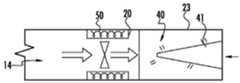
도 22a를 참조하면, 본 발명의 일 실시예에 따라 본체(2)가 청소 헤드(3) 및 가요성 영역(4)으로부터 분리된 것으로 도시되어있다. 본체(2)는 단순화된 형태로 도시되고 다른 구성요소는 본체(2) 내에 배치될 수 있다. 도시된 바와 같이, 본체는 캐비티(19)을 포함한다. 본체(2)는 캐비티(19) 내에 배치된 모터(20), 전원(22) 및 더스트컵(23)을 더 포함한다. 모터(20), 전원(22) 및 더스트컵(23) 각각은 세로축(9)과 실질적으로 평행한 세로축을 포함할 수 있다.Referring to FIG. 22A, the
따라서, 모터(20), 전원(22) 및 더스트컵(23)은 후술하는 바와 같이, 캐비티(19)와 동축으로 배열될 수 있다. 하기 기재된 바와 같이, 이러한 동축배열(coaxial arrangement)은 모터(20), 전원(22) 및 더스트컵(23)이 각각의 캐비티가 하나의 더러운 공기 통로, 예를 들어 더러운-공기 통로(14)를 일괄적으로 형성하도록 허용한다. 동축배열은 원하는 구성에 따라 복수의 더러운-공기 통로를 형성할 수 있으며, 본 발명은 단일 통로로 제한되는 것으로 해석되어서는 안 된다.Therefore, the
모터(20)는 예를 들어 브러시리스 dc 모터(brushless dc motor)를 포함할 수 있지만, 다른 유형의 모터도 본 발명의 범위에 포함된다. 모터(20)는 후술하는 바와 같이 충전 회로를 통해 전원(22) 및/또는 ac 메인에 전기적으로 연결될 수 있다. 모터(20)는 더러운 공기 통로(14)가 이를 통해 연장될 수 있도록 캐비티(52)(도 23c 참조)을 포함할 수 있다. 모터(20)는 더스트컵(23)을 향해 공기 흐름/흡입을 도입하는 임펠러(impeller)/팬(50)을 포함할 수 있다.
도 23c 및 23b는 본 발명의 일 실시예에 따른 모터(20)를 더 상세히 도시한다. 도시된 바와 같이, 모터(20)는 캐비티(52)에 배치된 내장 팬(built in fan, 50)을 포함할 수 있다. 모터(20)는 선택적으로 공기 흐름을 조절하기 위해 측벽(53)을 따라 개구부/통풍구(51)를 더 포함할 수 있다.23C and 23B show the
도 22a을 다시 참조하면, 전원(22)은 복수의 배터리 셀(29)을 포함할 수 있다. 일 실시예에서, 각각의 배터리 셀은 리튬-이온 배터리 셀이지만, 다른 유형의 배터리 셀도 본 발명의 범위에 포함된다. 도 23a의 전원(22a)에 도시된 바와 같이, 복수의 배터리 셀(29) 각각은 환형 배열(annular arrangement)을 형성할 수 있다. 환형 배열은 관통 연장되는 캐비티(32)을 포함할 수 있다. 환형 배열에서, 각각의 배터리 셀은 전원(22a)이 동일하게 배치될 때 본체(2)의 세로축(9)과 실질적으로 평행한 각각의 세로축을 가질 수 있다. 도 23b는 링-형 커패시터(ring-shaped capacitor)로서 구성된 다른 예시적인 전원(22b)을 도시한다. 링-형 커패시터는 또한 이를 관통 연장되는 캐비티(33)을 포함할 수 있다. 임의의 이러한 경우에, 전원(22)은 연관된 캐비티에 기초하여 더러운 공기 통로(14)를 적어도 부분적으로 정의할 수 있다. 따라서, 전원(22)의 캐비티, 예를 들어, 캐비티(32 또는 33)은 전원(22) 및 캐비티(52)가 본체(2)의 캐비티(19) 내에 배치될 때 모터의 캐비티(52)와 정렬될 수 있다.Referring again to FIG. 22A, the
도 22a를 다시 참조하면, 전원(22)은 관련 충전 회로(미도시)를 통해 충전될 수 있다. 충전 회로는, 예를 들어, 전원(22)을 충전하기 위해 충전을 수신하기 위한 유도 코일을 포함할 수 있다. 대안적으로 또는 추가로, 충전 회로는 예를 들어 충전 목적으로 베이스/도킹 상태에 연결하기 위한 단자(terminal) 또는 다른 적절한 상호 접속부(interconnects)(예를 들어, USb-c 포트)를 포함 할 수 있다. 충전 회로는 또한 주전원으로부터의 전력이 핸드헬드 표면 청소 장치(1)에 의해 직접 사용될 수 있게 하는 동시에 전원(22)을 충전할 수 있다.Referring again to FIG. 22A, the
도 22b는 도 22a의 본체(2)와 실질적으로 유사한 구성의 본체(2')를 도시하고, 이러한 이유로 상기 설명은 본체(2')에 동일하게 적용 가능하고 간결성을 위해 반복되지 않을 것이다. 그러나, 본체(2')는 모터(20) 이전에 배치된 전원(22)을 포함한다. 따라서, 본체(2')는 본체(2)의 제1 단부(10-1) 가까이에 배치된 전원(22), 그 다음에 모터(20) 및 더스트컵(23)을 포함한다.22B shows the body 2'having a configuration substantially similar to the
도 22a 및 22b의 본체(2) 및 (2')는 각각 더러운 공기 통로(14)를 형성하기 위해 캐비티(19) 내에 배치 및 정렬된 복수의 전원(22) 및/또는 복수의 모터(20)를 포함할 수 있다. 따라서, 상기 예는 단일 모터 및 전원을 예시하지만, 본 개시는 이와 관련하여 제한되지 않는다. 마찬가지로, 각각의 모터, 전원 및 더스트컵이 실질적으로 원통형인 형상으로 도시되어 있지만, 본 발명은 이와 관련하여 제한되지 않는다. 다른 형상 및 구성도 본 발명의 범위에 포함된다.The
도 23c-23d를 참조하면, 더스트컵(23)은 더러운 공기 통로(14)로부터의 먼지 및 이물질을 수용 및 저장하도록 구성될 수 있다. 더스트컵은 먼지 및 이물질을 저장하기 위한 캐비티(40)을 포함할 수 있다. 더스트컵은 먼지 및 이물질을 끌어 당기고 포집하는 것을 돕기 위해 정적으로 대전된 축압기(statically-charged accumulator, 41)를 더 포함할 수 있다. 몇몇의 경우에, 정적으로 대전된 축압기(41)는 자연적으로 정전기를 유지하는 경향이 있는 물질로 형성된다. 대안적으로 또는 추가적으로, 정적으로 대전된 축압기(41)는 예를 들어 전원(22)을 통해 통전될 수 있다.23C-23D, the
도 24a-24c는 본 발명에 일치하는 추가 실시예를 도시한다. 도 24b에 도시된 바와 같이, 핸드 헬드 표면 청소 장치는 재충전 목적으로 베이스에 도킹될 수 있다.24A-24C show further embodiments consistent with the present invention. As shown in Fig. 24B, the handheld surface cleaning device can be docked to the base for recharging purposes.
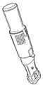
도 25는 본 발명에 따른 핸드헬드 표면 청소 장치의 예를 도시한다. 도 26a 는 본 발명의 일 실시예에 따른 도 25의 핸드헬드 표면 청소 장치의 단면도를 도시한다. 도 26b는 본 발명의 일 실시예에 따른 도 25의 핸드헬드 표면 청소 장치의 청소 헤드의 예를 도시한다. 도 26c는 본 발명의 일 실시예에 따른 도 25의 핸드헬드 표면 청소 장치의 예시적인 핸들을 도시한다.25 shows an example of a handheld surface cleaning apparatus according to the present invention. 26A illustrates a cross-sectional view of the handheld surface cleaning apparatus of FIG. 25 according to one embodiment of the present invention. 26B shows an example of a cleaning head of the handheld surface cleaning apparatus of FIG. 25 according to one embodiment of the present invention. 26C shows an exemplary handle of the handheld surface cleaning apparatus of FIG. 25 in accordance with one embodiment of the present invention.
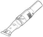
도 27은 본 발명에 따른 다른 예의 핸드헬드 표면 청소 장치를 도시한다. 도 27에 도시된 바와 같이, 핸들부는 하나 이상의 위치로 전환/관절되도록 본체에 대해 회전할 수 있다. a-a를 따라 취한 단면에 도시된 바와 같이, 배터리는 핸들부에 배치될 수 있다. 이러한 배열은 핸들부가 길이에 걸쳐 비교적 작은 폼 팩터(form-factor)를 갖도록 할 수 있다.27 shows another example handheld surface cleaning apparatus in accordance with the present invention. As shown in FIG. 27, the handle portion can rotate relative to the body to switch/join to one or more positions. As shown in the cross-section taken along a-a, the battery can be placed in the handle portion. This arrangement allows the handle portion to have a relatively small form-factor over length.
도 28a-28c는 본 발명의 실시예에 일치하는 표면 청소 장치의 추가 실시예를 도시한다.28A-28C show a further embodiment of a surface cleaning apparatus consistent with embodiments of the present invention.
도 29a-29h는 본 발명의 실시예에 일치하는 표면 청소 장치의 추가 실시예를 도시한다. 도시된 바와 같이, 본 발명에 따른 핸드헬드 표면 청소 장치는 더스트컵 비우기 절차 동안 먼지를 닦아내고/제거하기 위한 장치(arrangement)를 포함할 수 있다.29A-29H show a further embodiment of a surface cleaning apparatus consistent with embodiments of the present invention. As shown, the handheld surface cleaning apparatus according to the present invention may include an arrangement for wiping off/removing dust during the dust cup emptying procedure.
도 30a-30c는 본 발명의 실시예에 일치하는 표면 청소 장치의 추가 실시예를 도시한다. 도시된 바와 같이, 더스트컵은 연장되어 저장 용량을 증가시킬 수 있다.30A-30C show a further embodiment of a surface cleaning apparatus consistent with embodiments of the present invention. As shown, the dust cup can be extended to increase the storage capacity.
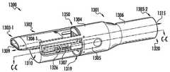
도 31a 내지 도 31d를 참조하면, 예시적인 표면 청소 장치(1300)가 본 발명의 실시예와 일치하는 것으로 도시되어있다. 도시된 바와 같이, 표면 청소 장치(1300)는 본체(1301) 및 본체(1301)의 제1 단부(1319)에 결합된 더스트컵(1302)을 포함한다. 도 1 내지 도 20b 및 도 21 내지 도 30c와 관련하여 상기 도시되고 설명된 양태 및 실시예는 표면 청소 장치(1300)에 동등하게 적용 가능하고, 간결성을 위해 반복되지 않을 것이다.31A-31D, an exemplary
본 명세서에서 일반적으로 언급된 바와 같이, "닫힘 위치"및 "도킹 위치"라는 용어는 상호 교환 가능하게 사용될 수 있고, 더스트컵(1302)이 본체(1301)에, 보다 상세하게는 더스트컵(1302) 내로 먼지 및 이물질을 끌어 들이기 위해 흡입을 발생시키는 본체(1301)의 캐비티 내에 배치된 모터(132)에, 결합되고 유체 연결되는, 본체(1301)에 대한 더스트컵(1302)의 위치를 지칭할 수 있다. 몇몇의 경우에, 닫힘 위치는, 도 31a에 도시된 바와 같이, 본체(1301)의 세로축과 실질적으로 평행하게 연장되는 세로축을 갖는 더스트컵(1302)을 초래할 수 있다.As generally referred to herein, the terms "closed position" and "dock position" may be used interchangeably, with a
반대로, "개방 위치(open position)"또는 "비우기 위치(emptying position)"라는 용어는 상호 교환 가능하게 사용될 수 있고, 더스트컵(1302)이 비우기를 허용하도록 본체(1301)에 대해 실질적으로 직각으로 기울어진 더스트컵(1302)의 위치를 지칭할 수 있다. 더스트컵(1302)은 더스트컵(1302)이 개방 위치로 전환하도록 본체(1301)에 회전 가능/피봇 가능하게 결합될 수 있다. 이러한 전환은 예를 들어 본체(1301) 상에 배치된 버튼(들)(1305)에 의해 착수될 수 있으며, 이는 하기 더 상세히 논의될 것이다. 따라서, 개방 위치에 있을 때, 더스트컵은 하우징에 피봇 가능하게/회전 가능하게 결합된 상태로 모터(1322)로부터 유체적으로 분리될 수 있다.Conversely, the terms “open position” or “emptying position” can be used interchangeably, and are substantially perpendicular to the
하기 더 상세히 논의되는 바와 같이, 더스트컵(1302)은 스프링-하중되어 더스트컵(1302)이 개방 위치로 움직이도록/가도록 할 수 있다. 본체(1301)는 예를 들어 측벽(1340)(도 31b) 또는 다른 표면을 정지시켜, 더스트컵(1302)이 스프링 장력의 해제로 인해 회전하는 동안, 더스트컵(1302)과 결합할 수 있다. 정지는 더스트컵(1302)이 회전이동을 갑자기 정지 시킬 수 있고, 영향은 더스트컵(1302) 내에 저장된 먼지 및 이물질을 유리하게 제거할 수 있다. 그런 다음 중력을 사용하여 제거된 먼지 및 이물질을, 더러운 공기를 수용하기 위한 유입구의 반대쪽 단부에 위치한, 더스트컵의 개구부로부터 비워 지도록 할 수 있다. 사용자가 더스트컵(1302)을 다시 닫힘 위치로 전환시키기를 원할 때까지 스프링 바이어스(spring bias)는 더스트컵(1302)을 개방 위치로 유지할 수 있다. 따라서, 사용자는 단순히 쓰레기통의 입구 위로 핸드헬드 표면 청소 장치(1300)를 기울이고, 예를 들어, 버튼(1305)의 작동을 통해, 더스트컵(1302)을 비우기 위해 개방 위치로 더스트컵(1302)을 전환할 수 있다.As discussed in more detail below, the
또한, 실시예에 따르면, 필터 장치(1314)는 본체(1301) 내에 적어도 부분적으로 배치될 수 있다. 필터 장치(1314)는 또한 스프링 하중되고 전방으로 "움직(스프링)"여(되어) (도 31b 및 31d 참조) 본체(1301)로부터 적어도 부분적으로 연장되고, 미리 결정된 거리(d1)에서 정지할 수 있다. 상기 실시예에서, 필터 장치(1314)는 본체(1301) 내부 또는 외부에 제공된 정지부, 예를 들어 랩(lap), 캐치(catch) 또는 다른 돌출부(1398)(도 31b 참조)와 만나기 전에 거리(d1)로 본체(1301)로부터 멀어지게 이동할 수 있다((더스트컵(1302)이 필터 장치(1314)로부터 멀어지게 회전한 후). 스프링 바이어스는, 예를 들어 사용자-제공 힘에 기초하여 더스트컵(1302)이 닫힘 위치로 복귀될 때, 더스트컵(1302)이 필터 장치(1314)를 변위시킬 때까지 필터 장치(1314)를 연장된 위치로 유지할 수 있다.Further, according to an embodiment, the
따라서, 표면 청소 장치(1300)는 단일 사용자 제공 모션에 기초하여 다상(multi-phase)(또는 다단계(multi-stag)) 개방 시퀀스(opening sequence)를 갖는 것으로 정확하게 설명될 수 있고, 단일 사용자 제공 모션(예를 들어, 버튼 누름)에 응답하여, 더스트컵은 먼저 스냅/스프링/런칭(종방향으로)하고, 수직/업라이트 위치로 회전하고, 더스트컵이 전환할 때 또는 그 직후에 필터 장치가 스냅/스프링된다(예: 더스트컵(1302)과 관련된 스프링의 스프링 상수/구성과는 다른 스프링 상수/구성을 갖는 필터 장치(1314)의 스프링에 기초하여). 더스트컵(1302)은 업라이트 위치(도 31b 참조)를 야기할 수 있다. 대안적으로 또는 추가적으로, 더스트컵(1302)은 회전을 발생하게 하는 본체(1301)에 의해 제공된 트랙에 기초하여 업라이트 위치로 될 수 있다. 더스트컵(1302)은 도 5의 더스트컵(110)과 유사한 교반 장치, 예를 들어 솔로 구성될 수 있으며, 상기 기재된 실시예는 도 31a-31d 의 핸드헬드 표면 청소 장치에 동일하게 적용 가능하다.Thus, the
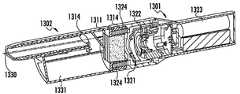
도 31a-31d를 참조하면, 모터(1322)는 본체(1301) 내에 배치되고 사용 중에 더러운 공기 통로(1330)(도 31c 참조)를 통해 더러운 공기를 유입구(1309)(또는 노즐)로 끌어 들이기 위해 흡입을 발생시킨다. 더스트컵(1302)은, 특히 더러운 공기 통로(1330)는, 더스트컵(1302)이 도 13a에 도시된 바와 같이 닫힘 위치에 있을 때 모터(1322)와 유체 연결일 수 있다. 본체(1301)와 더스트컵(1302) 사이에 배치된 필터(1311)는 먼지 및 이물질이 본체(1301)로 유입되는 것을 방지/감소시키고 궁극적으로 모터(1322)의 막힘을 방지/감소시킬 수 있다. 이어서, 먼지 및 이물질은 표면 청소 장치(1300)의 작동 중에 더스트컵(1302)의 캐비티 내의 먼지 저장 영역(1331)(도 31c)에 저장될 수 있다.Referring to Figures 31A-31D, a
일 실시예에서, 더스트컵(1302)은, 본체(1301)에 대한 더스트컵(1302)의 회전에 기초하여 개방 위치에 있을 때, 모터(1322)의 흡입으로부터 분리될 수 있다. 예를 들어, 도 31b에 도시된 바와 같이, 더스트컵(1302)의 일 단부는 본체(1301)로부터 분리될 수 있고 더스트컵(1302)이 본체(1301)에 대해 실질적으로 횡방향으로 기울어지도록 회전될 수 있다.In one embodiment, the
도 31d에 도시된 바와 같이, 더스트컵(1302)의 개방 위치는 본체의 세로축(1315)에 대해 실질적으로 횡방향인 세로축(1316)을 갖는 더스트컵(1302)을 초래할 수 있다. 더스트컵(1302)이 본체(1301)에 대해 연장되는 각도는 원하는 구성에 따라, 예를 들어 15도 내지 180도, 바람직하게는 15도 내지 90도 다양할 수 있다.31D, the open position of the
일 실시예에서, 본체(1301)는 플라스틱, 금속 및/또는 임의의 다른 적절한 강성 물질로 형성될 수 있다. 본체(1301)는 단일 조각 또는 여러 조각으로 형성될 수 있다.In one embodiment, the
본체(1301)는 먼지 결합 단부(1319)로 지칭될 수 있은 제1 단부(1319)로부터 제2 단부(1320)까지 세로축(1315)을 따라 연장되는 벽에 의해 정의될 수 있다. 벽은 표면(1306)에 의해 정의될 수 있고, 상기 표면(1306)은 표면 청소 장치(1300)의 작동 중에 사용자의 손에 편안하게 잡힐 수 있은 핸들부 또는 핸들을 제공한다.The
본체(1301)는 더스트컵(1302)이 예를 들어, 도 31a에 도시된 바와 같이, 닫힘 위치로부터 예를 들어, 도 31b에 도시된 바와 같이, 개방 위치로 전환되도록 하는 버튼(들)(1305)을 더 포함한다. 버튼(들)(1305)은, 표면 청소 장치(1300)가 닫힘 위치에서 개방 위치로 전환하게 하기 위해 사용자가 버튼을 누르는, 기계 버튼으로 반드시 제한되는 것은 아니다. 예를 들어, 버튼(1305)은 또한 슬라이더 버튼, 정전식 터치 버튼(capacitive touch button), 및 본체(1301)의 직경 주위로 연장되는 회전 가능한 링과 같은 임의의 다른 적합한 사용자 입력 장치일 수 있다.The
본체(1301)는 캐비티(1321)(도 31c)을 포함할 수 있다. 캐비티는 그 안에 배치된 필터 장치(1314), 모터(1322) 및 전원(1323)을 포함할 수 있다. 모터(1322)는 예를 들어 브러시리스 dc 모터를 포함할 수 있지만, 다른 유형의 모터도 본 발명의 범위에 포함된다. 모터(1322)는 전원(1323)에 전기적으로 결합될 수 있고, 더스트컵(1302) 내로 먼지 및 이물질을 흡입하기 위한 흡입을 생성할 수 있다.The
더스트컵(1302)은 플라스틱, 금속 또는 임의의 다른 적절한 강성 물질을 포함할 수 있다. 더스트컵(1302)은 세로축(1316)을 따라 제1 단부(1309)(또는 노즐)로부터 제2 단부(1350)(흡입 결합 단부 또는 흡입 결합섹션)까지 연장되는 하나 이상의 벽에 의해 형성될 수 있다(도 31d). 더스트컵(1302)은 적어도 부분적으로 캐비티를 통해 연장되는 더러운 공기 통로(1330)를 갖는 캐비티를 더 포함하고, 상기 더러운 공기 통로(1330)는 세로축(1316)과 실질적으로 평행하게 연장된다. 더스트컵(1302)은 먼지와 이물질을 수용하고 보관하기 위한 캐비티 내에 먼지 저장 영역(1331)을 더 포함한다. 먼지 저장 영역(1331)을 둘러싸는 벽은 광 투과성, 예를 들어, 입사 가시 파장의 80 % 이상을 허용하여, 사용자가 벽을 통해 먼지 저장 영역에 저장된 먼지 및 이물질의 현재 량을 눈으로 검사할 수 있게 한다. 또한, 흡입 결합 단부(1350)는 더스트컵(1302)이 개방 위치에서 업라이트/수직으로 배향될 때 먼지 및 이물질을 비우기 위한 개구부를 제공한다.The
필터 장치(1314)는 일반적으로 본체(1301)의 형상에 상응하는 원통형 하우징을 포함한다. 필터 장치(1314)에 대한 다른 형상 및 구성도 본 발명의 범위에 포함된다. 필터 장치(1314)는 도 31c에 도시된 주름진 필터(1311)와 같은 하나 이상의 필터를 포함할 수 있다. 하나 이상의 필터는 예를 들어 폴리에스테르 물질, PTfe, 유리 섬유 또는 임의의 다른 적합한 필터 물질을 포함할 수 있다. 하나 이상의 필터는 필터의 용이한 제거 및 교체를 위해 카트리지 본체(cartridge body)를 포함할 수 있다The
필터 장치(1314)는 필터 장치(1314)를 본체(1301)로부터 멀어지고 더스트컵(1302)쪽으로 편향시키기 위한 스프링(1324)을 더 포함할 수 있다. 더스트컵(1302)이, 도 31a 및 31c 에 도시된 바와 같이, 닫힘 위치에 있을 때, 스프링(1324)은 필터 장치 (1314)를 본체(1301)의 캐비티(1321)쪽으로 변위시키는 더스트컵(1302)에 기초하여 압축될 수 있다. 스프링(1324)은 원하는 구성에 따라 더 적은 수의 스프링, 예를 들어 단일 스프링을 포함할 수 있다The
암(arm, 1308-1 및 1308-2)(또는 암부(arm portion))은 세로축(1315)을 따라 본체(1301)로부터 연장될 수 있다. 암(1308-1, 1308-2)은 단일 모놀리식으로서 본체(1301)와 일체로 또는 복수의 조각으로 형성될 수 있다. 일 실시예에서, 암(1308-1 및 1308-2)은 본체(1301)와 동일한 물질, 예를 들어 플라스틱 또는 다른 적절한 강성 물질로 형성될 수 있다. 몇몇의 경우에, 암(1308-1 및 1308-2)은 본체(1301)와 다른 물질로 형성될 수 있다. 예를 들어, 암(1308-1 및 1308-2)은 암을 강화하기 위해 적어도 부분적으로 금속 또는 금속 합금으로 형성될 수 있다.Arms 1308-1 and 1308-2 (or arm portions) may extend from
암(1308-1, 1308-2)은 각각 더스트컵(1302)에 피봇식으로 결합되어 일반적으로 d(도 31b)로 표시된 방향/경로를 따라 회전 이동할 수 있다. 따라서, 더스트컵(1302)은 회전축(1325)에 기초하여 암(1308-1 및 1308-2)에 대해 피봇/회전할 수 있으며, 상기 회전축(1325)은 세로축(1315)과 실질적으로 수직이다.The arms 1308-1 and 1308-2 are pivotally coupled to the
암(1308-1 및 1308-2)은 캐비티를 더 포함할 수 있다. 암(1308-1 및 1308-2)에 의해 형성된 캐비티는 스프링(들)(1307)을 포함할 수 있다. 각각의 스프링(1307)은, 예를 들어, 더스트컵 캐리어(1326) 또는 더스트컵(1302)과 결합된 다른 메커니즘에 대항하여 힘을 공급함으로써 더스트컵(1302)을 본체(1301)로부터 멀어지게 편향시킬 수 있다. 더스트컵 캐리어(1326)는 더스트컵(1302)과 일체로, 즉 단일 모놀리식 조각으로서 형성될 수 있거나 또는 여러 조각으로 형성될 수 있다. 더스트컵 캐리어(1326)는 암(1308-1, 1308-2)에 의해 제공된 트랙/가이드를 따라 종방향으로 이동하도록 구성된다. 따라서, 더스트컵 캐리어(1326)는 더스트컵(1302)을 닫힘 위치에서 개방 위치로 전환/변위시키는데 사용될 수 있다.Arms 1308-1 and 1308-2 may further include cavities. The cavities formed by arms 1308-1 and 1308-2 may include spring(s) 1307. Each
더스트컵 캐리어(1326)를 닫힘 위치에 단단히 유지시키고, 더 나아가 더스트컵(1302)을 닫힘 위치에 유지하기 위해, 멈춤쇠(detent, 1399)(도 31b) 또는 다른 적절한 잠금 메커니즘이 암(1308-1 및 1308-2)의 표면으로부터 연장될 수 있다. 멈춤쇠(1399)는 캐치/리세스(1327)와 같은 더스트컵(1302)의 대응 표면 특징부와 맞물리도록 스프링-편향되고 구성될 수 있다. 따라서, 더스트컵(1302)이 예를 들어, 사용자-제공 힘에 기초하여 필터 장치(1314)에 대해 정렬되고 가압될 때, 멈춤쇠(1399)는 더스트컵(1302)의 캐치(1327)와 맞물려 더스트컵(1302)을 본체(1301)에 대한 위치에서 단단히 유지시킬 수 있다.In order to keep the
더스트컵(1302)을 해제하고 이를 개방 위치로 전환시키기 위해, 사용자는 버튼(1305)을 누를 수 있다. 버튼(들)(1305)을 누르는 것은 본체(1301)의 반대쪽에 배치된 버튼들에 대해 꼬집는 동작으로 엄지 및 검지 손가락을 사용하는 것을 포함할 수 있다. 이에 응답하여, 버튼(들)(1305)은 더스트컵(1302)의 캐치로부터 이를 해제하기 위해 멈춤쇠(1399)를 기계적으로 작동시킬 수 있다. 대안적으로, 버튼(1305)은, 모터 또는 다른 기계적 액추에이터로 멈춤쇠(1399)를 푸는데 이용될 수 있는 전기 신호를 제공할 수 있다.To release the
임의의 경우에, 버튼(1305)은 사용자가 더스트컵(1302)을 비우고 먼지 및 이물질의 필터를 청소하도록 더스트컵(1302)을 개방 위치로 전환하게 할 수 있다. 더스트컵(1302)은 측벽(1341)을 형성하는 오목한 표면(1339)(도 31b 참조) 또는 오목한 영역(1339)을 포함할 수 있고, 상기 측벽(1341)은 표면(1339)에 대해 실질적으로 수직으로 연장된다. 측벽(1341)은 미리 정해진 한계값을, 예를 들어 90도를, 넘어서 더스트컵(1302)의 회전이동을 방지하기 위해 암(1308-1 및 1308-2)의 정지 표면(stop surface)(1340)과 맞물리도록 구성될 수 있다. 정지 표면(1340)과 마주하는 더스트컵(1302)의 영향은 유리하게는 더스트컵(1302) 내의 먼지 및 이물질을 제거할 수 있다.In any case,
마찬가지로, 도 31d에 도시된 바와 같이, 필터 장치(1314)는 본체(1301)의 대응 정지/돌출부(1398)와 맞물리도록 돌출부/캐치/표면(1344)을 포함할 수 있다. 더스트컵(1302)은 돌출부(1398)와 맞물리기 위해 오목한 영역/가이드(1340)를 포함할 수 있다. 더스트컵(1302)이 닫힘 위치로 다시 전환될 때, 돌출부(1398)는 더스트컵(1302)을 본체(1301)와 정렬되도록 정렬 및 가이드에 사용될 수 있다.Similarly, as shown in FIG. 31D, the
일 실시예에서, 표면 청소 장치(1300)는 한 손으로 유지될 수 있고 동일한 손으로 닫힘 위치에서 개방 위치로 전환될 수 있다.In one embodiment, the
도 32a-32d는 닫힘 위치에서 개방 위치로 전환하는 핸드헬드 표면 청소 장치(1300)를 총괄적으로 도시한다. 특히, 도 32a는 본 발명의 일 실시예에 따라 더스트컵(1302)이 본체(1301)에 배치된 모터와 유체 연결하는 닫힘 위치에서의 핸드헬드 표면 청소 장치(1300)를 도시한다.32A-32D collectively show the handheld
도 32b는 본 발명의 일 실시예에 따른 본체(1301)의 어느 한 측면상의 버튼(들)(1305) 중 하나 또는 둘 다가 사용자에 의해 눌린 후의 핸드헬드 표면 청소 장치(1300)를 도시한다. 버튼(들)(1305)이 눌려지면, 멈춤쇠(1399)(도 31b)는 더스트컵(1302)으로부터 분리될 수 있다. 마찬가지로, 도 32c에 도시된 바와 같이, 더스트컵(1302) 및 필터 장치(1314)는 본체(1301)로부터 종방향으로 멀어질 수 있다. 몇몇의 경우에, 원하는 구성에 따라 더스트컵(1302)의 회전 이동과 필터 장치(1314)의 이동 사이에 일시적인 정지가 있을 수 있다.32B shows a handheld
도 32d에 도시된 바와 같이, 더스트컵(1302)은 본체(1301)에 대해 회전/피봇될 수 있고, 본체(1301)에 대해 실질적으로 횡방향인 방향에서 더스트컵(1302)을 유지하는 위치에서 정지할 수 있다. 더스트컵(1302)은 암(1308-1, 1308-2)에 의해 제공된 트랙/가이드에 기초하여 피봇될 수 있다. 대안적으로 또는 추가적으로, 가중이 더스트컵(1302)에 부가되어 동일하게 수직/업라이트 방향으로 향하게 하는 경향이 있을 수 있다.As shown in FIG. 32D, the
더스트컵(1302)은 제1 암(1308-1) 및 제2 암(1308-2)(도 31b 참조)에 배치된 스프링(들)(1307)에 적어도 부분적으로 기초하여 상기 위치에서 유지될 수 있다. 마찬가지로, 필터 장치(1314)는 스프링(들)(1324)으로부터의 스프링 바이어스에 기초하여 연장된 위치에서 유지될 수 있다. 따라서, 사용자는 더스트컵(1302)으로부터 먼지 및 이물질이 비워 지도록 핸드헬드 표면 청소 장치(1300)를 흔들 수 있다. 더스트컵(1302)을 추가 사용을 위해 닫힘 위치로 가져 오려면, 사용자는 더스트컵(1302)을 본체(1301)와 정렬되도록 회전시킨 다음, 더스트컵(1302)의 측벽부, 예를 들어 리세스(1327)와 맞물리는 멈춤쇠(1399)에 기초하여 더스트컵(1302)을 본체(1301)쪽으로 밀어서 필터 장치(1314) 및 "락(lock)"을 닫힘 위치로 변위시킬 수 있다.The
도 33은 본 발명의 실시예에 일치하는 표면 청소 장치의 추가 실시예를 도시한다.33 shows a further embodiment of a surface cleaning apparatus consistent with an embodiment of the present invention.
도 34a-34c는 본 발명의 실시예에 일치하는 표면 청소 장치의 추가 실시예를 도시한다. 도 34a-34c에 도시된 예시적인 양태는 도 8에 도시된 실시예에도 동일하게 적용 가능하다.34A-34C show a further embodiment of a surface cleaning apparatus consistent with embodiments of the present invention. The exemplary aspect shown in FIGS. 34A-34C is equally applicable to the embodiment shown in FIG. 8.
도 35-35b는 본 발명의 실시예에 일치하는 표면 청소 장치의 추가 실시예를 도시한다.35-35b show a further embodiment of a surface cleaning apparatus consistent with embodiments of the present invention.
도 36a-36b는 본 발명의 실시예에 일치하는 표면 청소 장치의 추가 실시예를 도시한다.36A-36B show a further embodiment of a surface cleaning apparatus consistent with embodiments of the present invention.
도 37-45는 핸들(1907), 연장 가능한 틈새툴(extendable crevice, 1902), 사이클론 어셈블리(1904), 및 적어도 하나의 배터리(1905)에 전기적으로 연결된 모터(1912)를 포함하는 본체(1901)를 갖는 핸드헬드 표면 청소 장치(1900)의 추가 실시예를 도시한다. 배터리(1905)는 핸들(1907)에 저장될 수 있다. 도시된 바와 같이, 사이클론 어셈블리(1904)는 틈새툴(1902)에 유체 결합되는 유입구(1906), 와류 파인더(1908), 수집 영역(1910) 및 필터(1914)를 포함한다. 작동 시, 공기는 틈새툴 유입구(1916)로부터 사이클론 어셈블리(1904) 내로 끌어 당겨진다. 공기는 예를 들어 청소 동작 중에 수집된 이물질을 포함할 수 있다. 공기 중에 운반된 이물질은 사이클론 어셈블리(1904) 내에(예를 들어, 수집 영역(1910) 내에) 수집될 수 있다.37-45 are a
사이클론 어셈블리(1904) 내에 충분한 양의 이물질이 수집될 때, 작업자는 도어(1918)를 개방시킴으로써 이물질을 비울 수 있다. 도어(1918)가 개방되면 이물질은 사이클론 어셈블리(1904)를 빠져 나갈 수 있다(예를 들어, 중력에 의해). 작업자는 버튼(또는 트리거)(1920)을 작동시킴으로써 도어(1918)가 개방되게 할 수 있다. 몇몇의 경우에, 버튼(1920)의 작동은 푸시로드(push rod, 1922)의 이동을 초래할 수 있다. 푸시로드(1922)가 제1 및 제2 위치 사이를 이동할 때, 푸시로드(1922)는 도어(1918)를 닫힘 위치로 유지하는 래치(1924)와 맞물릴 수 있다. 도시된 바와 같이, 래치(1924)가 도어(1918)와 맞물리지 않고 이동될 때, 도어(1918)는 축(1926)을 중심으로 회전한다.When a sufficient amount of foreign matter has been collected in the
일단 해제되면, 작업자는 도어(1918)를 래치(1924)와 맞물리도록 다시 밀어서 도어(1918)를 다시 닫을 수 있다. 추가로, 또는 대안적으로, 사용자는 버튼(1920)을 다시 한번 작동 시키거나(또는 다른 버튼 또는 트리거를 작동시켜) 도어(1918)를 닫을 수 있다. 몇몇 예에서, 래치(1924)는, 래치(1924)를 맞물림 위치(예를 들어, 래치(1924)가 도어(1918)와 맞물릴 수 있은 위치)를 향해 압박하는, 바이어싱 부재(biasing member)(예를 들어, 스프링)를 포함할 수 있다.Once released, the operator can push the
틈새툴(1902)은 제1 위치에서 제2 위치로 연장될 수 있다. 예를 들어, 작업자는 틈새툴(1902)를 수동으로 잡고 틈새툴(1902)를 잡아 당겨(또는 밀어) 틈새툴(1902)이 제1 위치와 제2 위치 사이에서 전환되게 할 수 있다. 추가적으로 또는 대안적으로, 틈새툴(1902)은 버튼(또는 트리거)의 작동에 응답하여 제1 위치와 제2 위치 사이에서 전환할 수 있다.The
또한 도시된 바와 같이, 사이클론 어셈블리(1904)의 적어도 일부는 핸드헬드 표면 청소 장치(1900)의 본체(1901)에 제거 가능하게 결합될 수 있다. 예를 들어, 사이클론 어셈블리(1904)의 제거는 사용자가 필터(1914)를 청소 및/또는 교체할 수 있게 할 수 있다. 다른 예로서, 와류 파인더(1908)는 제거 가능할 수 있다. 도시된 바와 같이, 특징부(1917)의 토우(toe)는 사이클론 어셈블리(1904)를 본체(1901)에 결합시키기 위해 제공될 수 있다.Also, as shown, at least a portion of the
일부 예에서 핸드헬드 표면 청소 장치(1900)는 로봇 청소기 시스템에서 사용될 수 있다. 예를 들어, 핸드헬드 표면 청소 장치(1900)는 로봇 진공 청소기로부터 이물질을 제거하는데 사용될 수 있다.In some examples, the handheld
일 양태에 따른 핸드헬드 표면 청소 장치가 기재된다. 핸드헬드 표면 청소 장치는 제1 단부로부터 제2 단부로 연장되는 본체, 제1 단부에 인접한 본체에 의해 정의되는 핸들부, 제2 단부에 인접한 본체에 의해 정의되는 더러운 공기 유입구를 갖는 노즐, 흡입을 발생하고 더러운 공기 유입구로 공기를 흡입하기 위한 모터, 및 먼지 및 이물질을 수용 및 저장하기 위한 더스트컵을 포함하고, 상기 더스트컵은 핸드헬드 표면 청소 장치의 본체에 회전 가능하게 결합되고, 더스트컵을 더러운 공기 유입구 및 모터와 유체적으로 연결하기 위한 닫힘 방향과, 더스트컵을 더러운 공기 유입구 및 모터에서 분리하여 더스트컵에 저장된 먼지 및 이물질이 더스트컵의 개구부로부터 빠져 나가게 하기 위한 해제 방향 사이를 전환하도록 구성된다.A handheld surface cleaning apparatus according to one aspect is described. The handheld surface cleaning apparatus comprises a body extending from a first end to a second end, a handle portion defined by a body adjacent to the first end, a nozzle having a dirty air inlet defined by a body adjacent to the second end, and suction And a dust cup for receiving and storing dust and debris, and a motor for suctioning air through the generated and dirty air inlet, the dust cup being rotatably coupled to the body of the handheld surface cleaning device, and To switch between the closing direction for fluid connection with the dirty air inlet and the motor, and the release direction for separating the dust cup from the dirty air inlet and the motor so that dust and debris stored in the dust cup escape from the opening of the dust cup. It is composed.
다른 양태에 따른 도킹 시스템이 기재된다. 도킹 시스템은 로봇 청소기 결합섹션을 포함하는 도크 및 핸드헬드 표면 청소 장치를 포함하고, 여기서 핸드헬드 표면 청소 장치는 제1 단부에서 제2 단부로 연장되는 본체, 제1 단부에 인접한 본체에 의해 정의되는 핸들부, 제2 단부에 인접한 본체에 의해 정의되는 더러운 공기 유입구를 갖는 노즐, 흡입을 생성하고 더러운 공기 유입구 내로 공기를 흡입하기 위한 모터; 및 먼지 및 이물질을 수용 및 저장하기 위한 더스트컵, 핸드헬드 표면 청소 장치의 제1 단부를 수용하고 결합되어 핸들부를 형성하는 제2 단부가 도크에서 멀어지도록 연장되는 도크에 의해 형성된 리셉터클을 포함하고, 상기 더스트컵은 핸드헬드 표면 청소 장치의 본체에 회전 가능하게 결합되고, 더스트컵을 더러운 공기 유입구 및 모터와 유체 결합시키기 위한 닫힘 방향과, 더스트컵에 저장된 먼지 및 이물질을 더스트컵의 개구부로부터 빠져 나가도록 더스트컵을 더러운 공기 유입구 및 모터로부터 분리하기 위한 해제 방향 사이를 전환하도록 구성된다.A docking system according to another aspect is described. The docking system includes a dock and a handheld surface cleaning device comprising a robot cleaner engaging section, wherein the handheld surface cleaning device is defined by a body extending from the first end to the second end, a body adjacent to the first end A handle portion, a nozzle having a dirty air inlet defined by a body adjacent to the second end, a motor for generating suction and drawing air into the dirty air inlet; And a dust cup for accommodating and storing dust and debris, a receptacle formed by a dock that receives the first end of the handheld surface cleaning device and extends so that the second end coupled to form a handle portion extends away from the dock, The dust cup is rotatably coupled to the body of the handheld surface cleaning device, the closing direction for fluidly bonding the dust cup to the dirty air inlet and the motor, and to remove dust and foreign substances stored in the dust cup from the opening of the dust cup. The dust cup is configured to switch between a dirty air inlet and a release direction to separate the motor.
본 발명의 원리가 본 명세서에 설명되었지만, 당업자는 이러한 설명 이 단지 예시로서 이루어지며 본 발명의 범위에 대한 제한이 아니라는 것을 이해할 것이다. 본 명세서에 도시되고 설명된 예시적인 실시예 이외에 다른 실시예가 본 발명의 범위 내에서 고려된다. 표면 청소장치는 본 명세서에 포함된 임의의 하나 이상의 특징을 구체화할 수 있고, 특징은 임의의 특정 조합 또는 서브 조합으로 사용될 수 있다는 것이 당업자에 의해 인식될 것이다. 당업자에 의한 수정 및 대체는 본 발명의 범위 내에 있는 것으로 간주되며, 이는 다음 청구 범위를 제외하고는 제 한되지 않는다.Although the principles of the invention have been described herein, those skilled in the art will understand that this description is made by way of illustration only and is not a limitation of the scope of the invention. Other embodiments other than the exemplary embodiments shown and described herein are contemplated within the scope of the present invention. It will be appreciated by those skilled in the art that the surface cleaning device may embody any one or more features included herein, and the features may be used in any particular combination or subcombination. Modifications and replacements by those skilled in the art are considered to be within the scope of the present invention, which is not limited except for the following claims.
Claims (20)
Translated fromKorean제1 단부에 인접한 본체에 의해 정의되는 핸들부;
제2 단부에 인접한 본체에 의해 정의되는 더러운 공기 유입구를 갖는 노즐;
더러운 공기 유입구로 흡입을 생성하고 공기를 빨아들이는 모터; 및
먼지 및 이물질을 수용 및 저장하기 위한 더스트컵을 포함하고,
상기 더스트컵은 핸드헬드 표면 청소 장치의 본체에 회전 가능하게 결합되고, 더스트컵을 더러운 공기 유입구 및 모터와 유체 결합시키기 위한 닫힘 방향과 더스트컵에 저장된 먼지 및 이물질을 더스트컵의 개구부로부터 빠져 나가도록 더스트컵을 더러운 공기 유입구 및 모터로부터 분리하기 위한 해제 방향 사이를 전환하도록 구성되는 핸드헬드 표면 청소 장치.A body extending from the first end to the second end;
A handle portion defined by a body adjacent to the first end;
A nozzle having a dirty air inlet defined by a body adjacent to the second end;
A motor that creates suction through a dirty air inlet and sucks in the air; And
Contains a dust cup for receiving and storing dust and foreign matter,
The dust cup is rotatably coupled to the body of the handheld surface cleaning device, and the closing direction for fluidly bonding the dust cup to the dirty air inlet and the motor, and to remove dust and foreign substances stored in the dust cup from the opening of the dust cup. A handheld surface cleaning device configured to switch between the dust cup and the release direction for separating from the dirty air inlet and the motor.
상기 본체는 세로축을 따라 제1 단부에서 제2 단부로 연장되고,
상기 핸들부는 제1 단부에 배치되고 더러운 공기 유입구는 제2 단부에 배치되는 핸드헬드 표면 청소 장치.According to claim 1,
The body extends from the first end to the second end along the longitudinal axis,
The handle portion is disposed on the first end and the dirty air inlet is disposed on the second handheld surface cleaning device.
상기 닫힘 방향의 더스트컵은 더스트컵이 본체와 평행하게 연장되고,
상기 개방 방향의 더스트컵은 더스트컵이 본체에 대해 실질적으로 횡방향으로 연장되는 핸드헬드 표면 청소 장치.According to claim 2,
In the closed direction dust cup, the dust cup extends parallel to the main body,
The open direction dust cup is a handheld surface cleaning device in which the dust cup extends substantially transverse to the body.
상기 더스트컵은 노즐에 의해 제공된 힌지를 통해 본체에 회전 가능하게 결합되고,
상기 노즐은 제거 가능한 핸드헬드 표면 청소 장치.According to claim 1,
The dust cup is rotatably coupled to the body through a hinge provided by the nozzle,
The nozzle is a removable handheld surface cleaning device.
상기 본체는 더스트컵이 닫힘 방향에서 해제 방향으로 전환되도록 하는 버튼을 포함하는 핸드헬드 표면 청소 장치.According to claim 1,
The main body is a hand-held surface cleaning apparatus including a button for allowing the dust cup to switch from the closing direction to the release direction.
상기 더러운 공기 유입구 및 상기 더스트컵은 정렬되는 각각의 개구부에 적어도 부분적으로 기초하여 서로 유체 연결되고,
상기 핸드헬드 표면 청소 장치는, 밀봉을 형성하고 모터로부터 흡입이 없는 상태에서 먼지 및 이물질이 더스트컵을 빠져 나가는 것을 방지하기 위한 각각의 개구부를 덮는, 시트 위치의 밸브 본체를 더 포함하는 핸드헬드 표면 청소 장치.According to claim 1,
The dirty air inlet and the dust cup are fluidly connected to each other based at least in part on each opening to be aligned,
The handheld surface cleaning device further comprises a valve body in a seat position, which forms a seal and covers each opening to prevent dust and debris from escaping the dust cup without suction from the motor. Cleaning device.
상기 밸브 본체는, 모터로부터 흡입이 공급될 때, 상기 더스트컵 방향으로 변위되고, 상기 변위된 밸브 본체는 먼지 및 이물질이 더러운 공기 유입구로 유입되어 더스트컵에 유체 결합되는 핸드헬드 표면 청소 장치.The method of claim 6,
The valve body is displaced in the direction of the dust cup when suction is supplied from a motor, and the displaced valve body is a handheld surface cleaning device in which dust and foreign substances are introduced into a dirty air inlet and fluidly coupled to the dust cup.
상기 핸드헬드 표면 청소 장치는 상기 모터 및 상기 더스트컵 사이에 배치되는 필터 장치를 더 포함하고,
상기 더스트컵은, 상기 더스트컵이 해제 방향 및/또는 닫힘 방향으로 전환할 때, 먼지 및 이물질을 제거하기 위하여 필터 장치의 적어도 일부와 맞물리도록 교반기 부재를 포함하는 핸드헬드 표면 청소 장치.According to claim 1,
The handheld surface cleaning device further includes a filter device disposed between the motor and the dust cup,
The dust cup comprises a stirrer member to engage with at least a portion of the filter device to remove dust and debris when the dust cup switches in the release direction and/or the closing direction.
상기 교반기 부재는 복수의 솔을 포함하는 핸드헬드 표면 청소 장치.The method of claim 8,
The stirrer member is a handheld surface cleaning apparatus comprising a plurality of brushes.
상기 필터 장치의 적어도 일부는, 상기 더스트컵이 해제 방향에 있을 때, 상기 핸드헬드 표면 청소 장치의 본체로부터 제거 가능한 핸드헬드 표면 청소 장치.The method of claim 8,
At least a part of the filter device, when the dust cup is in the release direction, a handheld surface cleaning device removable from the body of the handheld surface cleaning device.
제1 단부에서 제2 단부로 연장되는 본체;
제1 단부에 인접한 본체에 의해 정의되는 핸들부;
제2 단부에 인접한 본체에 의해 정의되는 더러운 공기 유입구를 갖는 노즐;
더러운 공기 유입구로 흡입을 생성하고 공기를 빨아들이는 모터; 및
먼지 및 이물질을 수용 및 저장하기 위한 더스트컵을 포함하는
핸드헬드 표면 청소 장치, 여기서 상기 더스트컵은 핸드헬드 표면 청소 장치의 본체에 회전 가능하게 결합되고, 더스트컵을 더러운 공기 유입구 및 모터와 유체 결합시키기 위한 닫힘 방향과 더스트컵에 저장된 먼지 및 이물질을 더스트컵의 개구부로부터 빠져 나가도록 더스트컵을 더러운 공기 유입구 및 모터로부터 분리하기 위한 해제 방향 사이를 전환하도록 구성되고,
상기 핸드헬드 표면 청소 장치의 제1 단부를 수용하고 결합되어 핸들부를 형성하는 제2 단부가 도크에서 멀어지도록 연장되는 도크에 의해 형성된 리셉터클
을 포함하는 도킹 시스템.A dock including a robot cleaner coupling section; And
A body extending from the first end to the second end;
A handle portion defined by a body adjacent to the first end;
A nozzle having a dirty air inlet defined by a body adjacent to the second end;
A motor that creates suction through a dirty air inlet and sucks in the air; And
Containing dust cup for receiving and storing dust and foreign matter
Handheld surface cleaning device, wherein the dust cup is rotatably coupled to the body of the handheld surface cleaning device, and dust and dirt stored in the dust cup and the closing direction for fluidly bonding the dust cup to the dirty air inlet and the motor. Configured to switch between the dust cup and the release direction for separating it from the motor so as to escape from the opening of the cup,
A receptacle formed by a dock that receives the first end of the handheld surface cleaning device and is coupled so that the second end forming a handle portion extends away from the dock.
Docking system comprising a.
상기 핸드헬드 표면 청소 장치의 노즐은, 상기 리셉터클에 배치될 때, 도크쪽으로 연장되는 도킹 시스템.The method of claim 11,
The nozzle of the handheld surface cleaning device, when disposed in the receptacle, extends toward the dock.
상기 로봇 청소기 결합섹션은 상기 로봇 청소기에 전기적으로 결합하기 위한 전기 접점을 포함하고,
상기 리셉터클은 상기 핸드헬드 표면 청소 장치에 전기적으로 결합하기 위한 전기 접점을 포함하는 도킹 시스템.The method of claim 11,
The robot cleaner coupling section includes electrical contacts for electrically coupling to the robot cleaner,
The receptacle comprises a docking system comprising an electrical contact for electrically coupling to the handheld surface cleaning device.
상기 핸드헬드 표면 청소 장치의 본체는 세로축을 따라 제1 단부에서 제2 단부로 연장하고,
상기 핸들부는 제1 단부에 배치되고 상기 더러운 공기 유입구는 제2 단부에 배치되는 도킹 시스템.The method of claim 11,
The body of the handheld surface cleaning device extends from a first end to a second end along a longitudinal axis,
A docking system wherein the handle portion is disposed at a first end and the dirty air inlet is disposed at a second end.
상기 닫힘 방향의 상기 핸드헬드 표면 청소 장치의 더스트컵은 상기 더스트컵이 상기 핸드헬드 표면 청소 장치의 본체와 평행하게 연장되고,
상기 개방 방향의 상기 더스트컵은 상기 더스트컵이 상기 핸드헬드 표면 청소 장치의 본체에 대하여 실질적으로 횡방향으로 연장되는 도킹 시스템.The method of claim 14,
The dust cup of the handheld surface cleaning device in the closing direction is such that the dust cup extends parallel to the body of the handheld surface cleaning device,
The dust cup in the open direction is a docking system in which the dust cup extends substantially transverse to the body of the handheld surface cleaning device.
상기 핸드헬드 표면 청소 장치의 본체는 상기 더스트컵이 닫힘 방향과 해제 방향 사이에서 전환되도록 하는 버튼을 포함하는 도킹 시스템.The method of claim 15,
The body of the handheld surface cleaning device comprises a button that allows the dust cup to switch between a closed direction and a released direction.
상기 핸드헬드 표면 청소 장치의 더러운 공기 유입구 및 더스트컵은 정렬되는 각각의 개구부에 적어도 부분적으로 기초하여 서로 유체 연결되고,
상기 핸드헬드 표면 청소 장치는, 밀봉을 형성하고 모터로부터 흡입이 없는 상태에서 먼지 및 이물질이 더스트컵을 빠져 나가는 것을 방지하기 위한 각각의 개구부를 덮는, 시트 위치의 밸브 본체를 더 포함하는 도킹 시스템.The method of claim 11,
The dirty air inlets and dust cups of the handheld surface cleaning device are fluidly connected to each other based at least in part on each opening to be aligned,
The handheld surface cleaning device further comprises a valve body in a seat position, covering each opening to form a seal and prevent dust and debris from escaping the dust cup without suction from the motor.
상기 밸브 본체는, 모터로부터 흡입이 공급될 때, 상기 더스트컵 방향으로 변위되고, 상기 변위된 밸브 본체는 먼지 및 이물질이 더러운 공기 유입구로 유입되어 더스트컵에 유체 결합되는 도킹 시스템.The method of claim 17,
The valve body is displaced in the direction of the dust cup when suction is supplied from a motor, and the displaced valve body is a docking system in which dust and foreign substances are introduced into a dirty air inlet and fluidly coupled to the dust cup.
상기 도킹 시스템은 상기 핸드헬드 표면 청소 장치의 모터 및 더스트컵 사이에 배치되는 필터 장치를 더 포함하고,
상기 더스트컵은, 상기 더스트컵이 해제 방향 및/또는 닫힘 방향으로 전환할 때, 먼지 및 이물질을 제거하기 위하여 필터 장치의 적어도 일부와 맞물리도록 교반기 부재를 포함하는 도킹 시스템.The method of claim 11,
The docking system further includes a filter device disposed between the motor and the dust cup of the handheld surface cleaning device,
The dust cup comprises a stirrer member to engage with at least a portion of the filter device to remove dust and debris when the dust cup is switched in the release direction and/or the closing direction.
상기 교반기 부재는 복수의 솔을 포함하는 도킹 시스템.The method of claim 19,
The stirrer member is a docking system comprising a plurality of brushes.
Priority Applications (1)
| Application Number | Priority Date | Filing Date | Title |
|---|---|---|---|
| KR1020217019325AKR20210081446A (en) | 2017-09-22 | 2018-09-20 | hand-held surface cleaning device |
Applications Claiming Priority (9)
| Application Number | Priority Date | Filing Date | Title |
|---|---|---|---|
| US201762561851P | 2017-09-22 | 2017-09-22 | |
| US62/561,851 | 2017-09-22 | ||
| US201762585320P | 2017-11-13 | 2017-11-13 | |
| US62/585,320 | 2017-11-13 | ||
| US201862616908P | 2018-01-12 | 2018-01-12 | |
| US62/616,908 | 2018-01-12 | ||
| US201862619309P | 2018-01-19 | 2018-01-19 | |
| US62/619,309 | 2018-01-19 | ||
| PCT/US2018/051978WO2019060564A1 (en) | 2017-09-22 | 2018-09-20 | Hand-held surface cleaning device |
Related Child Applications (2)
| Application Number | Title | Priority Date | Filing Date |
|---|---|---|---|
| KR1020207014700ADivisionKR20200064151A (en) | 2017-09-22 | 2018-09-20 | Hand-held surface cleaning device |
| KR1020217019325ADivisionKR20210081446A (en) | 2017-09-22 | 2018-09-20 | hand-held surface cleaning device |
Publications (2)
| Publication Number | Publication Date |
|---|---|
| KR20200064056Atrue KR20200064056A (en) | 2020-06-05 |
| KR102294008B1 KR102294008B1 (en) | 2021-08-30 |
Family
ID=65807034
Family Applications (8)
| Application Number | Title | Priority Date | Filing Date |
|---|---|---|---|
| KR1020247032345AActiveKR102789119B1 (en) | 2017-09-22 | 2018-09-20 | hand-held surface cleaning device |
| KR1020207005226AActiveKR102294008B1 (en) | 2017-09-22 | 2018-09-20 | handheld surface cleaning device |
| KR1020247018123AActiveKR102712806B1 (en) | 2017-09-22 | 2018-09-20 | hand-held surface cleaning device |
| KR1020227033255AActiveKR102671830B1 (en) | 2017-09-22 | 2018-09-20 | hand-held surface cleaning device |
| KR1020207014700ACeasedKR20200064151A (en) | 2017-09-22 | 2018-09-20 | Hand-held surface cleaning device |
| KR1020217019325ACeasedKR20210081446A (en) | 2017-09-22 | 2018-09-20 | hand-held surface cleaning device |
| KR1020257009985APendingKR20250057853A (en) | 2017-09-22 | 2018-09-20 | hand-held surface cleaning device |
| KR1020217014892AActiveKR102422500B1 (en) | 2017-09-22 | 2018-09-20 | Hand-held surface cleaning device |
Family Applications Before (1)
| Application Number | Title | Priority Date | Filing Date |
|---|---|---|---|
| KR1020247032345AActiveKR102789119B1 (en) | 2017-09-22 | 2018-09-20 | hand-held surface cleaning device |
Family Applications After (6)
| Application Number | Title | Priority Date | Filing Date |
|---|---|---|---|
| KR1020247018123AActiveKR102712806B1 (en) | 2017-09-22 | 2018-09-20 | hand-held surface cleaning device |
| KR1020227033255AActiveKR102671830B1 (en) | 2017-09-22 | 2018-09-20 | hand-held surface cleaning device |
| KR1020207014700ACeasedKR20200064151A (en) | 2017-09-22 | 2018-09-20 | Hand-held surface cleaning device |
| KR1020217019325ACeasedKR20210081446A (en) | 2017-09-22 | 2018-09-20 | hand-held surface cleaning device |
| KR1020257009985APendingKR20250057853A (en) | 2017-09-22 | 2018-09-20 | hand-held surface cleaning device |
| KR1020217014892AActiveKR102422500B1 (en) | 2017-09-22 | 2018-09-20 | Hand-held surface cleaning device |
Country Status (10)
| Country | Link |
|---|---|
| US (8) | US11672388B2 (en) |
| EP (5) | EP3684237B1 (en) |
| JP (4) | JP6857283B2 (en) |
| KR (8) | KR102789119B1 (en) |
| CN (5) | CN109602326B (en) |
| AU (3) | AU2018336913B2 (en) |
| CA (3) | CA3201669A1 (en) |
| ES (1) | ES2974416T3 (en) |
| GB (3) | GB2581647B (en) |
| WO (1) | WO2019060564A1 (en) |
Families Citing this family (83)
| Publication number | Priority date | Publication date | Assignee | Title |
|---|---|---|---|---|
| US11751733B2 (en) | 2007-08-29 | 2023-09-12 | Omachron Intellectual Property Inc. | Portable surface cleaning apparatus |
| US11445871B2 (en) | 2014-12-17 | 2022-09-20 | Omachron Intellectual Property Inc. | Surface cleaning apparatus |
| US11647881B2 (en) | 2015-10-21 | 2023-05-16 | Sharkninja Operating Llc | Cleaning apparatus with combing unit for removing debris from cleaning roller |
| US10786126B2 (en) | 2015-11-10 | 2020-09-29 | Techtronic Industries Co. Ltd. | Handheld vacuum cleaner |
| WO2018049169A1 (en) | 2016-09-09 | 2018-03-15 | Sharkninja Operating Llc | Agitator with hair removal |
| US11285495B2 (en)* | 2016-12-27 | 2022-03-29 | Omachron Intellectual Property Inc. | Multistage cyclone and surface cleaning apparatus having same |
| CN114403741B (en) | 2017-03-10 | 2024-02-27 | 尚科宁家运营有限公司 | Agitator with a hair remover and hair removal |
| US11202542B2 (en) | 2017-05-25 | 2021-12-21 | Sharkninja Operating Llc | Robotic cleaner with dual cleaning rollers |
| US11219906B2 (en)* | 2019-01-23 | 2022-01-11 | Omachron Intellectual Property Inc. | Surface cleaning apparatus, cyclonic air treatment member and surface cleaning apparatus including the same |
| US11730327B2 (en)* | 2020-03-18 | 2023-08-22 | Omachron Intellectual Property Inc. | Surface cleaning apparatus with removable air treatment assembly |
| US11745190B2 (en) | 2019-01-23 | 2023-09-05 | Omachron Intellectual Property Inc. | Surface cleaning apparatus |
| EP3684237B1 (en) | 2017-09-22 | 2023-07-19 | SharkNinja Operating LLC | Hand-held surface cleaning device |
| US11122945B2 (en)* | 2017-12-04 | 2021-09-21 | Transform Sr Brands Llc | Two-in-one upright vacuum |
| US10959585B2 (en)* | 2018-03-16 | 2021-03-30 | Omachron Intellectual Property Inc. | Hand vacuum cleaner |
| US10959588B2 (en)* | 2018-03-16 | 2021-03-30 | Omachron Intellectual Property Inc. | Hand vacuum cleaner |
| US11439285B2 (en)* | 2018-03-16 | 2022-09-13 | Omachron Intellectual Property Inc. | Hand vacuum cleaner |
| US10952583B2 (en)* | 2018-03-16 | 2021-03-23 | Omachron Intellectual Property Inc. | Hand vacuum cleaner |
| US20190282052A1 (en)* | 2018-03-16 | 2019-09-19 | Omachron Intellectual Property Inc. | Hand vacuum cleaner |
| US11672395B2 (en) | 2021-01-06 | 2023-06-13 | Omachron Intellectual Property Inc. | Surface cleaning apparatus |
| US11687092B2 (en) | 2018-04-23 | 2023-06-27 | Sharkninja Operating Llc | Techniques for bounding cleaning operations of a robotic surface cleaning device within a region of interest |
| KR102073618B1 (en)* | 2018-05-31 | 2020-02-05 | 엘지전자 주식회사 | Cleaning Appliance |
| US11399675B2 (en) | 2018-07-31 | 2022-08-02 | Sharkninja Operating Llc | Upright surface treatment apparatus having removable pod |
| US11154169B2 (en) | 2018-08-13 | 2021-10-26 | Omachron Intellectual Property Inc. | Cyclonic air treatment member and surface cleaning apparatus including the same |
| US10882059B2 (en)* | 2018-09-21 | 2021-01-05 | Omachron Intellectual Property Inc. | Multi cyclone array for surface cleaning apparatus and a surface cleaning apparatus having same |
| CN109645881B (en)* | 2019-01-31 | 2024-05-28 | 莱克电气股份有限公司 | Dust suction device |
| WO2020186342A1 (en)* | 2019-03-15 | 2020-09-24 | Omachron Intellectual Property Inc. | Surface cleaning apparatus |
| DE102019002827A1 (en)* | 2019-04-18 | 2020-10-22 | Vorwerk & Co. Interholding Gmbh | Base station and method of assembling a base station |
| ES2956793T3 (en)* | 2019-04-18 | 2023-12-28 | Vorwerk Co Interholding | Operating procedure of a cleaning system, base station and filtration device |
| WO2020223619A1 (en)* | 2019-05-01 | 2020-11-05 | Sharkninja Operating Llc | Vacuum cleaner and docking station for use with the same |
| CN110123202B (en)* | 2019-05-27 | 2024-05-03 | 东莞优乐家智能家电有限公司 | Dustbin type dust collector |
| CN110179387B (en)* | 2019-06-04 | 2024-05-28 | 莱克电气股份有限公司 | A handheld cleaning device |
| GB2616963B (en)* | 2019-06-13 | 2023-12-27 | Omachron Intellectual Property Inc | Surface cleaning apparatus |
| CN110250991A (en)* | 2019-07-08 | 2019-09-20 | 炬大科技有限公司 | A handheld vacuum cleaner |
| CN114126463B (en) | 2019-07-11 | 2023-07-18 | 尚科宁家运营有限公司 | Smart nozzle and surface cleaning device implementing the smart nozzle |
| CN112386159A (en)* | 2019-08-11 | 2021-02-23 | 苏州谷为电器有限公司 | Hand-held type surface cleaning device |
| CN112438653B (en)* | 2019-08-29 | 2024-05-31 | 苏州爱普电器有限公司 | Hand-held dust collector |
| CN110558897B (en)* | 2019-08-30 | 2024-04-09 | 追觅创新科技(苏州)有限公司 | A portable vacuum cleaner |
| CN112438652B (en)* | 2019-09-05 | 2024-05-28 | 苏州市春菊电器有限公司 | Dust cup of dust collector with self-locking function handle |
| CN110584531A (en)* | 2019-09-10 | 2019-12-20 | 北京众清科技有限公司 | Portable dust collector and method for enabling portable dust collector to be compatible with various motors |
| CN110477800B (en)* | 2019-09-11 | 2024-07-02 | 宁波富佳实业股份有限公司 | Handheld dust collector and handheld vertical integrated dust collector |
| USD938675S1 (en) | 2019-09-16 | 2021-12-14 | Techtronic Cordless Gp | Handheld cleaner |
| US11350806B2 (en) | 2020-01-03 | 2022-06-07 | Techtronic Cordless Gp | Handheld vacuum cleaner |
| IT202000004126A1 (en)* | 2020-02-27 | 2020-05-27 | Dongguan Lize Tech Co Ltd | Cordless handheld vacuum cleaner |
| WO2021207139A1 (en) | 2020-04-06 | 2021-10-14 | Sharkninja Operating Llc | Allergen reduction device |
| JP7437687B2 (en)* | 2020-04-24 | 2024-02-26 | パナソニックIpマネジメント株式会社 | dust collector |
| USD995016S1 (en)* | 2020-07-29 | 2023-08-08 | Sharkninja Operating Llc | Vacuum cleaner |
| KR20230041777A (en)* | 2020-07-29 | 2023-03-24 | 샤크닌자 오퍼레이팅 엘엘씨 | surface cleaning device |
| EP4188182A4 (en)* | 2020-07-29 | 2024-12-25 | SharkNinja Operating LLC | Surface cleaning apparatus |
| KR102387678B1 (en) | 2020-10-28 | 2022-04-19 | 레이캅코리아 주식회사 | handheld cleaner |
| CN112386160B (en)* | 2020-12-01 | 2025-04-15 | 爱源(厦门)电子有限公司 | Self-cleaning dust cylinder assembly and handheld vacuum cleaner having the same |
| CN112656291B (en)* | 2020-12-28 | 2024-04-09 | 追创科技(苏州)有限公司 | Cleaning device |
| CN112842131B (en)* | 2021-01-15 | 2022-06-14 | 深圳市杉川机器人有限公司 | Hand-held vacuum cleaner |
| US11607096B2 (en) | 2021-02-03 | 2023-03-21 | Black & Decker, Inc. | Vacuum cleaner |
| JP2022146259A (en)* | 2021-03-22 | 2022-10-05 | 日立グローバルライフソリューションズ株式会社 | vacuum cleaner |
| USD971533S1 (en)* | 2021-03-23 | 2022-11-29 | Black & Decker, Inc. | Vacuum cleaner |
| KR20220135545A (en)* | 2021-03-30 | 2022-10-07 | 삼성전자주식회사 | Cleaner |
| EP4322812A4 (en) | 2021-04-12 | 2025-04-23 | SharkNinja Operating LLC | Robotic cleaner |
| JP7539705B2 (en) | 2021-04-21 | 2024-08-26 | アイリスオーヤマ株式会社 | Vacuum Cleaner System |
| GB2620092A (en) | 2021-04-23 | 2023-12-27 | Sharkninja Operating Llc | Determining state of charge for battery powered devices including battery powered surface treatment apparatuses |
| US12108920B2 (en) | 2021-07-13 | 2024-10-08 | Omachron Intellectual Property Inc. | Hand vacuum cleaner |
| US12433461B2 (en) | 2022-07-05 | 2025-10-07 | Sharkninja Operating Llc | Vacuum cleaner |
| US12075966B2 (en) | 2021-08-05 | 2024-09-03 | Omachron Intellectual Property Inc. | Household appliance having an improved cyclone and a cyclone for same |
| US11779178B2 (en) | 2021-08-05 | 2023-10-10 | Omachron Intellectual Property Inc. | Household appliance having an improved cyclone and a cyclone for same |
| USD1092892S1 (en)* | 2021-08-13 | 2025-09-09 | Sharkninja Operating Llc | Docking station |
| USD1078202S1 (en)* | 2021-08-13 | 2025-06-03 | Sharkninja Operating Llc | Wand vacuum assembly |
| WO2023018947A1 (en) | 2021-08-13 | 2023-02-16 | Sharkninja Operating Llc | Robotic cleaner |
| US12358169B2 (en) | 2021-09-07 | 2025-07-15 | Sharkninja Operating Llc | Robotic cleaner |
| USD1032121S1 (en)* | 2021-09-29 | 2024-06-18 | Shenzhen Carku Technology Co., Limited | Vehicle vacuum cleaner |
| USD1000735S1 (en)* | 2021-09-29 | 2023-10-03 | Black & Decker, Inc. | Handheld vacuum |
| CN220144215U (en) | 2021-11-05 | 2023-12-08 | 尚科宁家运营有限公司 | Surface cleaning device |
| USD1014881S1 (en)* | 2022-01-25 | 2024-02-13 | Shenzhen WoMei Tech Co., Ltd. | Cordless handheld vacuum cleaner |
| CN116236102A (en)* | 2022-02-21 | 2023-06-09 | 北京顺造科技有限公司 | Surface cleaning apparatus and method of assembly thereof |
| US12329350B2 (en) | 2022-05-09 | 2025-06-17 | Sharkninja Operating Llc | Robotic cleaner |
| GB2635620A (en)* | 2022-06-17 | 2025-05-21 | Origyn LLC | Waste receptacle and vacuum cleaner |
| WO2024003813A1 (en)* | 2022-06-29 | 2024-01-04 | Dyson Technology Limited | Vacuum cleaner |
| EP4586870A1 (en) | 2022-09-15 | 2025-07-23 | SharkNinja Operating LLC | Vacuum cleaner and docking station configured to cooperate with the same |
| US20240180381A1 (en)* | 2022-12-01 | 2024-06-06 | Tineco Intelligent Technology Co., Ltd. | Cleaning device and combined cleaning system |
| USD1006357S1 (en)* | 2023-06-28 | 2023-11-28 | Yongquan Wu | Vacuum cleaner with mobile power supply |
| CN116898322A (en)* | 2023-07-19 | 2023-10-20 | 苏州利飞特新能源电气有限公司 | Filter assembly and dust collector |
| WO2025043328A1 (en)* | 2023-08-25 | 2025-03-06 | Omachron Intellectual Property Inc. | Hand vacuum cleaner |
| JP2025051178A (en)* | 2023-09-25 | 2025-04-04 | アイリスオーヤマ株式会社 | Vacuum cleaner |
| WO2025065085A1 (en)* | 2023-09-26 | 2025-04-03 | Omachron Intellectual Property Inc. | Surface cleaning apparatus with rotatable component |
| US20250235063A1 (en)* | 2024-01-23 | 2025-07-24 | The Noco Company | Portable Vacuum Cleaner |
Citations (7)
| Publication number | Priority date | Publication date | Assignee | Title |
|---|---|---|---|---|
| JPS60188124A (en)* | 1984-03-07 | 1985-09-25 | シ−アイシ− インタ−ナシヨナル コ−ポレ−シヨン | Vacuum cleaner |
| KR930011949A (en)* | 1991-12-18 | 1993-07-20 | 이헌조 | Cyclone vacuum cleaner |
| KR20010027468A (en)* | 1999-09-14 | 2001-04-06 | 배길성 | Portable vacuum cleaner |
| KR20050001766A (en)* | 2003-06-26 | 2005-01-07 | 삼성광주전자 주식회사 | A vacuum cleaner for many purposes |
| JP2006333925A (en)* | 2005-05-31 | 2006-12-14 | Sanyo Electric Co Ltd | Vertical type cleaner |
| US20090144931A1 (en)* | 2003-10-15 | 2009-06-11 | Black & Decker Inc. | Hand-Held Cordless Vacuum Cleaner |
| KR20120003054A (en)* | 2010-07-02 | 2012-01-10 | (주)마미로봇 | Handy Vacuum Cleaner |
Family Cites Families (306)
| Publication number | Priority date | Publication date | Assignee | Title |
|---|---|---|---|---|
| FR1094603A (en) | 1955-05-23 | |||
| CA161428A (en) | 1915-01-07 | 1915-03-23 | The Vulcan Metals Company | Vacuum cleaner |
| FR497856A (en) | 1915-07-16 | 1919-12-19 | Lux Ab | Improvements to dust vacuum cleaners |
| GB194963A (en) | 1922-04-21 | 1923-03-22 | Gustav Oscar Lehmann | Improvements in vacuum cleaning and dusting apparatus |
| GB283179A (en) | 1927-01-06 | 1928-08-09 | Inventia Patent Verwert Ges | Improvements in dust suction apparatus |
| US1940609A (en) | 1928-09-17 | 1933-12-19 | Arthur Koenreich | Vacuum cleaner |
| US2149135A (en) | 1936-01-03 | 1939-02-28 | Electrolux Corp | Vacuum cleaner |
| BE425021A (en) | 1936-12-05 | |||
| CH203675A (en) | 1938-05-27 | 1939-03-31 | Joerg Peter | Vacuum cleaner. |
| US2477685A (en) | 1945-12-19 | 1949-08-02 | Electrolux Corp | Latch for vacuum cleaner covers |
| JPS4820449Y1 (en)* | 1970-06-15 | 1973-06-13 | ||
| JPS4925163Y2 (en) | 1971-03-03 | 1974-07-06 | ||
| JPS4820449U (en) | 1971-07-14 | 1973-03-08 | ||
| JPS5524870B2 (en) | 1972-06-27 | 1980-07-02 | ||
| SE371928B (en)* | 1973-01-16 | 1974-12-09 | Electrolux Ab | |
| JPS53145375A (en) | 1977-05-24 | 1978-12-18 | Toshiba Corp | Fluorescent lamp |
| US4209875A (en) | 1978-08-11 | 1980-07-01 | Black & Decker, Inc. | Cordless vacuum cleaner bowl and filter system |
| GB2035787B (en) | 1978-11-11 | 1982-10-13 | L & H Designs Ltd & Merritt H | Suction cleaning device |
| USD273146S (en) | 1981-09-04 | 1984-03-20 | Grace Farr | Vacuum cleaner intake member |
| US4473923A (en) | 1982-05-10 | 1984-10-02 | Dayco Corporation | Vacuum cleaning tool adapter with electrical control means |
| JPS5927063A (en) | 1982-08-06 | 1984-02-13 | 山陽国策パルプ株式会社 | Ageing of building foundation material |
| JPS608814A (en) | 1983-06-29 | 1985-01-17 | Minorikawa Kojo:Kk | Converging device of light beam or electromagnetic wave |
| US4573234A (en)* | 1984-01-30 | 1986-03-04 | The Scott & Fetzer Company | Hand-held vacuum cleaner |
| EP0215165B1 (en) | 1985-09-09 | 1991-07-10 | Black & Decker Inc. | Wet-dry vacuum cleaner |
| JPS61222431A (en) | 1985-03-28 | 1986-10-02 | シャープ株式会社 | Small-sized cleaner |
| JPS6210850A (en) | 1985-07-08 | 1987-01-19 | Matsushita Electric Ind Co Ltd | Electron beam electrostatic lens |
| KR870001812A (en)* | 1985-08-08 | 1987-03-28 | 이노우에 가오루 | Mini Portable Electric Cleaner |
| JPS62142532A (en) | 1985-12-17 | 1987-06-25 | 松下電器産業株式会社 | rechargeable vacuum cleaner |
| JPS63127734A (en) | 1986-11-18 | 1988-05-31 | 松下電器産業株式会社 | Upright electric cleaner |
| JPS63129551A (en) | 1986-11-19 | 1988-06-01 | Matsushita Electric Ind Co Ltd | Cassette loading control device |
| JPH07100052B2 (en)* | 1987-01-13 | 1995-11-01 | 三洋電機株式会社 | Vacuum cleaner |
| JPS63129551U (en)* | 1987-02-13 | 1988-08-24 | ||
| JPS6445023A (en) | 1987-08-14 | 1989-02-17 | Univ Tokai | Heat treatment method for superconductive film |
| USD315043S (en) | 1988-08-01 | 1991-02-26 | Hayden Theodore R | Central vacuum system hose handle |
| USD334447S (en) | 1990-01-22 | 1993-03-30 | Rexair, Inc. | Vacuum cleaner handle |
| US5020187A (en) | 1990-03-19 | 1991-06-04 | Black & Decker, Inc. | Filter assembly for a vacuum cleaner |
| USD333023S (en) | 1990-10-10 | 1993-02-02 | Ryobi Motor Products Corp. | Vacuum cleaner hose handle |
| CH682801A5 (en) | 1990-11-16 | 1993-11-30 | Radwulf Sa | Appliance appliances. |
| US5267371A (en) | 1992-02-19 | 1993-12-07 | Iona Appliances Inc. | Cyclonic back-pack vacuum cleaner |
| US5379483A (en)* | 1992-07-21 | 1995-01-10 | Bissell, Inc. | Vacuum cleaner having a tool attached to the nozzle |
| US5323510A (en) | 1993-07-09 | 1994-06-28 | Redding Glenn K | Vacuum cleaner having improved steering features |
| US5561885A (en)* | 1995-01-13 | 1996-10-08 | Royal Appliance Mfg. Co. | Portable hand-held vacuum cleaner |
| JP3733613B2 (en) | 1995-07-07 | 2006-01-11 | 住友電気工業株式会社 | Diamond sintered body and manufacturing method thereof |
| US5926909A (en)* | 1996-08-28 | 1999-07-27 | Mcgee; Daniel | Remote control vacuum cleaner and charging system |
| US5794305A (en) | 1996-12-17 | 1998-08-18 | Weger; Kenneth J. | Articulation device for a vacuum cleaner |
| US6055703A (en) | 1997-10-14 | 2000-05-02 | Oreck Holdings Llc | Upright vacuum cleaner having improved steering apparatus with a lock out feature |
| CA2256777A1 (en) | 1998-01-09 | 1999-07-09 | Samuel E. Hohulin | Vacuum cleaner having a reusable dirt cup |
| USD419731S (en)* | 1998-08-24 | 2000-01-25 | Rexair, Inc. | Combined wet-dry vacuum cleaner |
| USD431335S (en) | 1998-12-10 | 2000-09-26 | Matsushita Electric Corporation Of America | Vacuum cleaner handle |
| CN1143652C (en) | 1999-02-24 | 2004-03-31 | Lg电子株式会社 | Cyclone dust collector in vacuum cleaner |
| JP3476066B2 (en) | 1999-07-19 | 2003-12-10 | シャープ株式会社 | Electric vacuum cleaner |
| AU1775401A (en) | 1999-11-18 | 2001-05-30 | Procter & Gamble Company, The | Home cleaning robot |
| US6558453B2 (en) | 2000-01-14 | 2003-05-06 | White Consolidated Industries, Inc. | Bagless dustcup |
| US6295692B1 (en) | 2000-05-10 | 2001-10-02 | Pro-Team, Inc. | Convertible vacuum cleaner |
| US6485536B1 (en) | 2000-11-08 | 2002-11-26 | Proteam, Inc. | Vortex particle separator |
| GB0104678D0 (en) | 2001-02-24 | 2001-04-11 | Dyson Ltd | A vacuum cleaner |
| GB0104680D0 (en) | 2001-02-24 | 2001-04-11 | Dyson Ltd | A collecting chamber for a vacuum cleaner |
| US6493903B1 (en) | 2001-05-18 | 2002-12-17 | Quest Industries, Inc. | Hand-held vacuum cleaner with headlamp |
| GB2385292B (en) | 2002-02-16 | 2006-01-11 | Dyson Ltd | Cyclonic separating apparatus |
| US6829804B2 (en) | 2002-03-26 | 2004-12-14 | White Consolidated, Ltd. | Filtration arrangement of a vacuum cleaner |
| GB2391459A (en) | 2002-08-09 | 2004-02-11 | Dyson Ltd | A surface treating appliance with increased manoeuverability |
| US20040134022A1 (en) | 2003-01-10 | 2004-07-15 | Royal Manufacturing Co. | Bagless stick type vacuum cleaner |
| SE0300355D0 (en)* | 2003-02-10 | 2003-02-10 | Electrolux Ab | Hand held vacuum cleaner |
| US7418763B2 (en) | 2003-02-26 | 2008-09-02 | Black & Decker Inc. | Hand vacuum with filter indicator |
| CN101390726A (en)* | 2003-02-26 | 2009-03-25 | 布莱克和戴克公司 | Hand-held vacuum cleaner with filter indicator |
| GB2399780A (en) | 2003-03-28 | 2004-09-29 | Dyson Ltd | Arrangement of cyclones for noise damping |
| US7003846B2 (en) | 2003-04-01 | 2006-02-28 | Holtz Engineering, Ltd. | Vacuum and disposal system for animal feces |
| USD510465S1 (en) | 2003-04-25 | 2005-10-04 | Sanyo Electric Co., Ltd. | Electric vacuum cleaner |
| KR100474078B1 (en) | 2003-06-02 | 2005-03-14 | 삼성광주전자 주식회사 | A cyclone dust-collecting apparatus of vacuum cleaner |
| KR100536506B1 (en) | 2003-09-09 | 2005-12-14 | 삼성광주전자 주식회사 | A cyclone separating apparatus and vacumm cleaner equipped whth such a device |
| EP1658003B1 (en) | 2003-08-22 | 2011-07-13 | Bissell Homecare, Inc. | Wet/dry bare floor cleaner |
| US20050086762A1 (en) | 2003-10-27 | 2005-04-28 | Paris Kenneth S. | Bagless portable backpack vacuum cleaner with bottom-mounted inlet hose |
| US7351269B2 (en) | 2003-12-22 | 2008-04-01 | Lau Kwok Yau | Self cleaning filter and vacuum incorporating same |
| US20050198769A1 (en) | 2004-03-11 | 2005-09-15 | Lg Electronics Inc. | Vacuum cleaner |
| KR100549990B1 (en) | 2004-04-16 | 2006-02-08 | 삼성광주전자 주식회사 | Dust collector for vacuum cleaner |
| USD510066S1 (en) | 2004-05-05 | 2005-09-27 | Irobot Corporation | Base station for robot |
| GB2416483B (en) | 2004-07-23 | 2007-12-27 | Dyson Ltd | A surface-treating appliance |
| US20060026788A1 (en) | 2004-08-06 | 2006-02-09 | Fischer Richard J | Upright vacuum cleaner incorporating telescopic handle and wand assembly with electrified hose |
| DE102004052306A1 (en) | 2004-10-16 | 2006-04-20 | Stein & Co Gmbh | Device for arranging a suction attachment |
| KR20060037980A (en) | 2004-10-29 | 2006-05-03 | 엘지전자 주식회사 | Main body of vacuum cleaner |
| US20060090290A1 (en) | 2004-11-01 | 2006-05-04 | Lau Ying W | Handheld vacuum with accelerated cyclonic flow and air freshener |
| US7805804B2 (en) | 2004-12-21 | 2010-10-05 | Royal Appliance Mfg. Co. | Steerable upright vacuum cleaner |
| US7645309B2 (en) | 2004-12-27 | 2010-01-12 | Lg Electronics Inc. | Dust collection unit and vacuum cleaner with the same |
| US20060156508A1 (en) | 2005-01-14 | 2006-07-20 | Royal Appliance Mfg. Co. | Vacuum cleaner with cyclonic separating dirt cup and dirt cup door |
| GB2422094B8 (en) | 2005-01-18 | 2008-06-05 | Dyson Technology Ltd | Surface-treating appliance |
| US7412749B2 (en) | 2005-01-24 | 2008-08-19 | Euro-Pro Operating, Llc | Vacuum cleaner and floor dustpan system |
| USD545511S1 (en) | 2005-04-08 | 2007-06-26 | Vax Limited | Dry only canister machine |
| USD565266S1 (en) | 2005-08-25 | 2008-03-25 | Shop Vac Corporation | Canister vacuum |
| WO2007084543A2 (en) | 2006-01-17 | 2007-07-26 | Electrolux Home Care Products North America | Stair cleaning vacuum cleaner |
| US20070209334A1 (en) | 2006-03-10 | 2007-09-13 | Gbd Corp. | Vacuum cleaner with a removable screen |
| SE0600668L (en) | 2006-03-24 | 2007-10-23 | Electrolux Abp | Handheld vacuum cleaner |
| US20080040883A1 (en) | 2006-04-10 | 2008-02-21 | Jonas Beskow | Air Flow Losses in a Vacuum Cleaners |
| EP2007264B1 (en) | 2006-04-10 | 2019-03-13 | Aktiebolaget Electrolux | Vacuum cleaner with filter cleaning means |
| SE531125C2 (en) | 2007-01-19 | 2008-12-23 | Electrolux Ab | Improvements in air flow losses in a vacuum cleaner |
| CN101061932A (en) | 2006-04-28 | 2007-10-31 | 光荣电业有限公司 | Cyclone Handheld Vacuums |
| GB2440125A (en) | 2006-07-18 | 2008-01-23 | Dyson Technology Ltd | Cyclonic separating apparatus |
| GB2474176A (en) | 2006-07-18 | 2011-04-06 | Dyson Technology Ltd | A hand-held vacuum cleaner with handle and suction pipe relatively angled |
| GB2441300B (en) | 2006-09-01 | 2011-10-12 | Dyson Technology Ltd | A collecting chamber for a vacuum cleaner |
| US9301666B2 (en) | 2006-12-12 | 2016-04-05 | Omachron Intellectual Property Inc. | Surface cleaning apparatus |
| US9888817B2 (en) | 2014-12-17 | 2018-02-13 | Omachron Intellectual Property Inc. | Surface cleaning apparatus |
| US9192269B2 (en) | 2006-12-15 | 2015-11-24 | Omachron Intellectual Property Inc. | Surface cleaning apparatus |
| EP1955630A3 (en)* | 2007-02-12 | 2009-10-07 | Black & Decker, Inc. | Motor, fan and filter arrangement for a vacuum cleaner |
| USD573759S1 (en) | 2007-02-27 | 2008-07-22 | Matsushita Electric Industrial Co., Ltd. | Electric vacuum cleaner |
| USD580116S1 (en) | 2007-03-09 | 2008-11-04 | Bissell Homecare, Inc. | Wand grip |
| ATE514367T1 (en) | 2007-04-04 | 2011-07-15 | Black & Decker Inc | FILTER CLEANING MECHANISMS |
| US8032983B2 (en) | 2007-05-17 | 2011-10-11 | Bissell Homecare, Inc. | Dust cup latch for cyclone separator vacuum |
| CA121151S (en) | 2007-06-21 | 2008-12-23 | Gbd Corp | Vacuum cleaner |
| EP2173226B1 (en) | 2007-07-09 | 2014-11-19 | S. C. Johnson & Son, Inc. | Handheld portable devices for touchless particulate matter removal |
| DE102007040957A1 (en) | 2007-08-30 | 2009-03-05 | Miele & Cie. Kg | Upright vacuum cleaner |
| DE102007040958A1 (en) | 2007-08-30 | 2009-03-05 | Miele & Cie. Kg | Upright vacuum cleaner |
| DE102007040961A1 (en) | 2007-08-30 | 2009-03-05 | Miele & Cie. Kg | Upright vacuum cleaner |
| KR101462952B1 (en) | 2007-12-20 | 2014-11-20 | 삼성전자주식회사 | A handle assembly rotatable in all directions and a cleaner having the same |
| GB2468797B (en) | 2008-03-14 | 2011-12-07 | Bissell Homecare Inc | Handheld vacuum cleaner with deployable suction arm |
| USD587870S1 (en) | 2008-07-28 | 2009-03-03 | Samsung Electronics Co., Ltd. | Vacuum cleaner |
| USD635728S1 (en) | 2008-10-21 | 2011-04-05 | Aktiebolaget Electrolux | Vacuum cleaner |
| US8069529B2 (en) | 2008-10-22 | 2011-12-06 | Techtronic Floor Care Technology Limited | Handheld vacuum cleaner |
| CN201299513Y (en) | 2008-10-23 | 2009-09-02 | 耀川电子(深圳)有限公司 | Remote operated handheld dust collector for emptying dust in duct chamber |
| US8533907B2 (en) | 2009-01-06 | 2013-09-17 | Emerson Electric Co. | Flexible crevice tool attachment for vacuum appliances |
| US9591952B2 (en)* | 2009-03-11 | 2017-03-14 | Omachron Intellectual Property Inc. | Hand vacuum cleaner with removable dirt chamber |
| CA2658019A1 (en) | 2009-03-11 | 2010-09-11 | G.B.D. Corp. | Configuration of a hand vacuum cleaner |
| US9265395B2 (en) | 2010-03-12 | 2016-02-23 | Omachron Intellectual Property Inc. | Surface cleaning apparatus |
| US9427122B2 (en) | 2009-03-13 | 2016-08-30 | Omachron Intellectual Property Inc. | Surface cleaning apparatus |
| KR101672787B1 (en) | 2009-06-19 | 2016-11-17 | 삼성전자주식회사 | Robot cleaner and docking station and robot cleaner system having the same and control method thereof |
| US8082624B2 (en) | 2009-11-10 | 2011-12-27 | Oreck Holdings Llc | Rotatable coupling for steering vacuum cleaner |
| CN201658325U (en)* | 2009-12-16 | 2010-12-01 | 耀川电子(深圳)有限公司 | Handheld dust collector capable of cleaning dust collection box through operation the front end |
| USD633264S1 (en) | 2010-02-12 | 2011-02-22 | Samsung Electronics Co., Ltd. | Vacuum cleaner |
| US8448295B2 (en) | 2010-03-12 | 2013-05-28 | Electrolux Home Care Products, Inc. | Vacuum cleaner with rotating handle |
| USD644385S1 (en) | 2010-05-12 | 2011-08-30 | Dyson Limited | Part of a vacuum cleaner |
| US10517449B2 (en) | 2010-05-31 | 2019-12-31 | Samsung Electronics Co., Ltd. | Cyclone dust collecting apparatus and hand-held cleaner having the same |
| USD640194S1 (en) | 2010-07-22 | 2011-06-21 | Samsung Electronics Co., Ltd. | Charger for vacuum cleaner |
| US8769764B2 (en) | 2010-08-05 | 2014-07-08 | Panasonic Corporation Of North America | Hand-held and conversion vacuum cleaner with adapter |
| USD641114S1 (en) | 2010-08-19 | 2011-07-05 | Samsung Electronics Co., Ltd. | Handle for vacuum cleaner |
| USD675154S1 (en) | 2010-08-31 | 2013-01-29 | Lg Electronics Inc. | Charger for robot cleaner |
| USD670458S1 (en) | 2010-09-03 | 2012-11-06 | Lg Electronics Inc. | Combined vacuum cleaner and charger |
| USD645403S1 (en) | 2010-09-03 | 2011-09-20 | Lg Electronics Inc. | Charger for vacuum cleaners |
| USD662272S1 (en) | 2010-12-09 | 2012-06-19 | G.B.D Corp. | Vacuum cleaner |
| USD662271S1 (en) | 2010-12-09 | 2012-06-19 | G.B.D. Corp. | Vacuum cleaner |
| KR101192540B1 (en)* | 2010-12-20 | 2012-10-17 | (주)마미로봇 | Multifunction charger for wireless cleaner |
| USD639735S1 (en) | 2011-01-05 | 2011-06-14 | Samsung Electronics Co., Ltd. | Charger for vacuum cleaner |
| USD639237S1 (en) | 2011-01-05 | 2011-06-07 | Samsung Electronics Co., Ltd. | Charger for vacuum cleaner |
| EP2820995B1 (en)* | 2011-01-07 | 2016-07-06 | iRobot Corporation | Evacuation station system |
| USD659923S1 (en) | 2011-01-27 | 2012-05-15 | Dyson Limited | Part of a vacuum cleaner |
| USD670056S1 (en) | 2011-02-02 | 2012-10-30 | Dyson Limited | Part of a vacuum cleaner |
| CN106108808B (en) | 2011-02-03 | 2019-08-16 | 尚科宁家运营有限公司 | Steam appliance |
| US8595894B1 (en) | 2011-05-09 | 2013-12-03 | Issa Kakish | Hand-held pest vacuum |
| CN202173358U (en) | 2011-08-17 | 2012-03-28 | 苏州市伊塔电器科技有限公司 | Handheld dust collector |
| CN202184686U (en)* | 2011-08-17 | 2012-04-11 | 苏州市伊塔电器科技有限公司 | Handheld dust collector provided with dust collecting box and filtering mechanism separated from each other |
| US9964299B2 (en) | 2011-09-02 | 2018-05-08 | Sharkninja Operating Llc | Steam generator |
| USD680288S1 (en) | 2011-09-26 | 2013-04-16 | Euro-Pro Operating Llc | Vacuum cleaner |
| USD684326S1 (en) | 2011-10-28 | 2013-06-11 | Panasonic Corporation | Vacuum cleaner |
| WO2013071190A1 (en) | 2011-11-11 | 2013-05-16 | Evolution Robotics, Inc. | Scaling vector field slam to large environments |
| TWM425634U (en) | 2011-11-14 | 2012-04-01 | Agait Technology Corp | Automatic walking device and electric charging base |
| US10016107B2 (en) | 2011-12-14 | 2018-07-10 | Sharkninja Operating Llc | Surface cleaning apparatus with a sideways pivoting handle |
| GB2497945B (en) | 2011-12-22 | 2014-11-12 | Dyson Technology Ltd | Vacuum cleaner |
| DE102012100050A1 (en) | 2012-01-04 | 2013-07-04 | Miele & Cie. Kg | Detachable dust collection container for battery-powered suction cleaner, e.g. handheld cleaner, has airflow filter element connected with container and removable via opposite end of container from opening used to discharge accumulated dust |
| USD681894S1 (en) | 2012-01-12 | 2013-05-07 | Telebrands Corp. | Vacuum adapter for lint removal |
| USD695980S1 (en) | 2012-03-08 | 2013-12-17 | Euro-Pro Operating Llc | Vacuum cleaner |
| USD686377S1 (en) | 2012-03-08 | 2013-07-16 | Euro-Pro Operating Llc | Cleaning apparatus |
| US9955831B2 (en) | 2012-03-09 | 2018-05-01 | Sharkninja Operating Llc | Surface cleaning apparatus with an adjustable handle |
| USD685961S1 (en) | 2012-03-09 | 2013-07-09 | Euro-Pro Operating Llc | Vacuum cleaner |
| US9814361B2 (en) | 2012-03-09 | 2017-11-14 | Sharkninja Operating Llc | Surface cleaning apparatus |
| JP5987404B2 (en)* | 2012-03-28 | 2016-09-07 | ツインバード工業株式会社 | Electric vacuum cleaner |
| US8806702B2 (en) | 2012-03-30 | 2014-08-19 | Shop Vac Corporation | Portable vacuum cleaner |
| US8918947B2 (en) | 2012-06-12 | 2014-12-30 | Michael N. Schwartz | Crevice tool for vacuum cleaners |
| USD691553S1 (en) | 2012-08-30 | 2013-10-15 | Samsung Electronics Co., Ltd. | Charger for vacuum cleaner |
| CN202776167U (en) | 2012-08-31 | 2013-03-13 | 莱克电气股份有限公司 | Multifunctional dust collector with cyclone assembly |
| US9714955B2 (en) | 2012-11-02 | 2017-07-25 | Qualcomm Incorporated | Method for aligning a mobile device surface with the coordinate system of a sensor |
| USD698310S1 (en) | 2012-11-21 | 2014-01-28 | Samsung Electronics Co., Ltd. | Charger for vacuum cleaner |
| GB201509668D0 (en) | 2012-11-29 | 2015-07-22 | Euro Pro Operating Llc | Steam cleaning appliance |
| EP2946567B1 (en) | 2013-01-18 | 2020-02-26 | iRobot Corporation | Environmental management systems including mobile robots and methods using same |
| USD693975S1 (en) | 2013-01-18 | 2013-11-19 | Bissell Homecare, Inc. | Vacuum cleaner module |
| US9314138B2 (en) | 2013-02-28 | 2016-04-19 | Omachron Intellectual Property Inc. | Surface cleaning apparatus |
| US9451855B2 (en) | 2013-02-28 | 2016-09-27 | Omachron Intellectual Property Inc. | Surface cleaning apparatus |
| WO2015009717A1 (en) | 2013-07-17 | 2015-01-22 | Euro-Pro Operating Llc | Variable flow rate mechanical pump assembly |
| CA2833555C (en)* | 2013-11-18 | 2020-03-10 | Canplas Industries Ltd. | Handheld vacuum cleaner and docking assembly for connecting to a central vacuum system |
| US9516979B2 (en) | 2013-11-21 | 2016-12-13 | Sharkninja Operating Llc | Surface cleaning apparatus configurable in a storage position |
| KR101771869B1 (en) | 2013-12-13 | 2017-08-25 | 도시바 라이프스타일 가부시키가이샤 | Traveling body device |
| USD743125S1 (en)* | 2014-01-14 | 2015-11-10 | Samsung Electronics Co., Ltd. | Cleaner |
| USD762932S1 (en) | 2014-02-10 | 2016-08-02 | Dyson Technology Limited | Tool for a vacuum cleaner |
| CN105979841B (en) | 2014-03-12 | 2019-11-08 | 伊莱克斯公司 | Bagless with filter cleaning element |
| US9844308B2 (en) | 2014-04-08 | 2017-12-19 | Sharkninja Operating Llc | Surface cleaning apparatus |
| EP2929820B1 (en)* | 2014-04-11 | 2018-09-12 | Black & Decker Inc. | A vacuum cleaning device |
| US9499134B2 (en) | 2014-04-25 | 2016-11-22 | Amber Camiller | Hand-held cleaning device and vehicle configured to equip the same |
| US9962049B2 (en) | 2014-06-06 | 2018-05-08 | Sharkninja Operating Llc | Surface cleaning apparatus |
| USD764125S1 (en) | 2014-06-30 | 2016-08-16 | Sharkninja Operating Llc | Duster |
| US9314139B2 (en) | 2014-07-18 | 2016-04-19 | Omachron Intellectual Property Inc. | Portable surface cleaning apparatus |
| US10584868B2 (en) | 2014-11-04 | 2020-03-10 | Sharkninja Operating Llc | Steam generator |
| US11992172B2 (en) | 2018-10-19 | 2024-05-28 | Sharkninja Operating Llc | Agitator for a surface treatment apparatus and a surface treatment apparatus having the same |
| USD782412S1 (en) | 2014-11-28 | 2017-03-28 | Samsung Electronics Co., Ltd. | Charger for cleaner |
| US11445873B2 (en)* | 2014-12-17 | 2022-09-20 | Omachron Intellectual Property Inc. | Hand carryable surface cleaning apparatus |
| WO2016100964A2 (en) | 2014-12-19 | 2016-06-23 | Sharkninja Operating Llc | Vacuum cleaner attachment with floating cleaning element and surface cleaning apparatus including the same |
| DE102014119192A1 (en)* | 2014-12-19 | 2016-06-23 | Vorwerk & Co. Interholding Gmbh | Base station for a vacuum cleaner |
| JP6459544B2 (en) | 2015-01-21 | 2019-01-30 | 三菱電機株式会社 | Electric vacuum cleaner |
| US9456723B2 (en) | 2015-01-30 | 2016-10-04 | Sharkninja Operating Llc | Surface cleaning head including openable agitator chamber and a removable rotatable agitator |
| US9955832B2 (en) | 2015-01-30 | 2018-05-01 | Sharkninja Operating Llc | Surface cleaning head with removable non-driven agitator having cleaning pad |
| US9655486B2 (en) | 2015-01-30 | 2017-05-23 | Sharkninja Operating Llc | Surface cleaning head including removable rotatable driven agitator |
| US10130237B2 (en) | 2015-05-28 | 2018-11-20 | Sharkninja Operating Llc | Systems for steam cleaning |
| CN104840150B (en) | 2015-06-02 | 2016-08-31 | 莱克电气股份有限公司 | Band independence dust and gas separates and the hand-held two-in-one split vacuum cleaner of rod-type of storage apparatus for ash |
| EP3316752B1 (en) | 2015-06-30 | 2022-01-12 | Techtronic Industries Co. Ltd. | Vacuum cleaner with brushroll control |
| USD801923S1 (en) | 2015-07-01 | 2017-11-07 | Samsung Electronics Co., Ltd | Charger for vacuum cleaner |
| USD789634S1 (en) | 2015-07-09 | 2017-06-13 | Oneida Air Systems, Inc. | Vacuum assist scraper tool |
| USD796135S1 (en) | 2015-07-31 | 2017-08-29 | Samsung Electronics Co., Ltd. | Intake for vacuum cleaner |
| US10966584B2 (en) | 2015-08-06 | 2021-04-06 | Sharkninja Operating Llc | Low profile surface cleaning head |
| US10076183B2 (en) | 2015-08-14 | 2018-09-18 | Sharkninja Operating Llc | Surface cleaning head |
| USD812829S1 (en)* | 2015-09-15 | 2018-03-13 | Lg Electronics Inc. | Clothes cleaning machine |
| GB2542387B (en) | 2015-09-17 | 2017-11-01 | Dyson Technology Ltd | Vacuum cleaner |
| GB2542385B (en) | 2015-09-17 | 2018-10-10 | Dyson Technology Ltd | Vacuum Cleaner |
| US10702108B2 (en) | 2015-09-28 | 2020-07-07 | Sharkninja Operating Llc | Surface cleaning head for vacuum cleaner |
| US20170105591A1 (en) | 2015-10-14 | 2017-04-20 | Tammy Bernhard-Tanis | Small Portable Handheld Vacuum Device |
| US11647881B2 (en) | 2015-10-21 | 2023-05-16 | Sharkninja Operating Llc | Cleaning apparatus with combing unit for removing debris from cleaning roller |
| WO2017070492A1 (en) | 2015-10-21 | 2017-04-27 | Sharkninja Operating Llc | Surface cleaning head with dual rotating agitators |
| US10966581B2 (en) | 2015-10-22 | 2021-04-06 | Sharkninja Operating Llc | Vacuum cleaning device with foldable wand to provide storage configuration |
| US10398279B2 (en) | 2015-11-19 | 2019-09-03 | Sharkninja Operating Llc | Dispensing enclosure for a container |
| USD779753S1 (en) | 2015-11-20 | 2017-02-21 | Bissell Homecare, Inc. | Accessory tool for a floor care appliance |
| EP3400860B1 (en) | 2016-01-04 | 2021-03-17 | Jiangsu Midea Cleaning Appliances Co., Ltd. | Handheld dust collector |
| WO2017124632A1 (en)* | 2016-01-20 | 2017-07-27 | 江苏美的清洁电器股份有限公司 | Vacuum cleaner |
| GB2546541B (en)* | 2016-01-22 | 2018-07-04 | Dyson Technology Ltd | Vacuum cleaning apparatus |
| USD805267S1 (en) | 2016-01-25 | 2017-12-12 | Russell Maune | Water heater clean-out device |
| US10568477B2 (en) | 2016-04-11 | 2020-02-25 | Omachron Intellectual Property Inc. | Surface cleaning apparatus |
| CN105919515B (en)* | 2016-04-15 | 2018-08-28 | 苏州腾普电气科技有限公司 | Hand held cleaner host |
| CN205671986U (en)* | 2016-04-18 | 2016-11-09 | 苏州诚河清洁设备有限公司 | A kind of hand held cleaner |
| USD796133S1 (en) | 2016-04-18 | 2017-08-29 | CPA Pool Products, Inc. | Swimming pool telescoping pole |
| CN205849380U (en)* | 2016-05-16 | 2017-01-04 | 广东金莱特电器股份有限公司 | A kind of improved hand-held vacuum cleaner |
| US10531771B2 (en) | 2016-08-08 | 2020-01-14 | Sharkninja Operating Llc | Surface cleaning apparatus with cordless convertible handheld configuration |
| CN206280276U (en)* | 2016-11-29 | 2017-06-27 | 苏州宝时得电动工具有限公司 | Hand-held air-blast device |
| TWI749018B (en) | 2016-08-25 | 2021-12-11 | 南韓商Lg電子股份有限公司 | Cleaner |
| CA3035827C (en) | 2016-09-02 | 2021-06-08 | Sharkninja Operating Llc | Multifunction switch for use with cleaning device and/or other powered devices |
| CA3035828C (en) | 2016-09-02 | 2021-10-19 | Sharkninja Operating Llc | A hose clip arrangement for use with cleaning device and/or other devices |
| WO2018049169A1 (en) | 2016-09-09 | 2018-03-15 | Sharkninja Operating Llc | Agitator with hair removal |
| CN206295328U (en) | 2016-10-09 | 2017-07-04 | 苏州克林威尔电器有限公司 | Hand-held Efficient dust collector |
| CN109890258A (en) | 2016-11-01 | 2019-06-14 | 尚科宁家运营有限公司 | Multi-mode cleaning device with suction |
| CN106923745B (en) | 2017-01-17 | 2022-09-27 | 苏州爱普电器有限公司 | Multifunctional surface cleaning system |
| CN106923739B (en) | 2017-01-17 | 2022-11-11 | 苏州爱普电器有限公司 | Surface cleaning system |
| CN114403741B (en) | 2017-03-10 | 2024-02-27 | 尚科宁家运营有限公司 | Agitator with a hair remover and hair removal |
| CN107049138A (en) | 2017-03-29 | 2017-08-18 | 江苏美的清洁电器股份有限公司 | Hand-held cleaners |
| CN207152536U (en) | 2017-03-29 | 2018-03-30 | 江苏美的清洁电器股份有限公司 | Hand-held cleaners |
| US11284702B2 (en) | 2017-05-15 | 2022-03-29 | Sharkninja Operating Llc | Side brush with bristles at different lengths and/or angles for use in a robot cleaner and side brush deflectors |
| US11202542B2 (en) | 2017-05-25 | 2021-12-21 | Sharkninja Operating Llc | Robotic cleaner with dual cleaning rollers |
| EP3629866B1 (en) | 2017-05-26 | 2022-01-19 | SharkNinja Operating LLC | Hair cutting brushroll |
| EP3638088B1 (en) | 2017-06-12 | 2023-11-08 | SharkNinja Operating LLC | Surface cleaning device with compact storage configuration |
| USD854767S1 (en) | 2017-07-25 | 2019-07-23 | Sharkninja Operating Llc | Vacuum cleaner tool |
| CN208211971U (en) | 2017-07-31 | 2018-12-11 | 江苏美的清洁电器股份有限公司 | The storage dirt cup locking structure and dust catcher of dust catcher |
| CN110996736A (en) | 2017-08-02 | 2020-04-10 | 尚科宁家运营有限公司 | Flexible hose with compact storage configuration and cleaning device using flexible hose |
| CA3073151C (en) | 2017-08-16 | 2021-02-16 | Sharkninja Operating Llc | Robotic vacuum |
| US11458771B2 (en) | 2017-08-31 | 2022-10-04 | Sharkninja Operating Llc | Wheels having shock absorbing characteristics and a surface treatment apparatus using the same |
| US11234567B2 (en) | 2017-09-01 | 2022-02-01 | Sharkninja Operating Llc | Vacuum cleaner tool having a rotatable duct for moving between a use position and storage position on a vacuum cleaner |
| EP3678902B1 (en) | 2017-09-07 | 2023-06-21 | SharkNinja Operating LLC | Robotic cleaner |
| EP3684237B1 (en)* | 2017-09-22 | 2023-07-19 | SharkNinja Operating LLC | Hand-held surface cleaning device |
| CN107928544B (en) | 2017-12-01 | 2023-11-17 | 莱克电气股份有限公司 | Handheld vacuum cleaner and assembly method |
| CN111787836B (en) | 2017-12-27 | 2022-10-14 | 尚科宁家运营有限公司 | End cap assembly |
| US11672393B2 (en) | 2017-12-27 | 2023-06-13 | Sharkninja Operating Llc | Cleaning apparatus with selectable combing unit for removing debris from cleaning roller |
| CN111885951B (en) | 2018-02-09 | 2022-10-11 | 尚科宁家运营有限公司 | Accessory for surface treatment equipment |
| US11160427B2 (en) | 2018-03-07 | 2021-11-02 | Sharkninja Operating Llc | Cover for a fluff screen in a surface treatment apparatus |
| CN112204486B (en) | 2018-04-03 | 2024-08-09 | 尚科宁家运营有限公司 | Time-of-flight sensor arrangement for robot navigation and method for positioning using the same |
| CN209826545U (en) | 2018-04-13 | 2019-12-24 | 添可电器有限公司 | Hand-held vacuum cleaner |
| US11687092B2 (en) | 2018-04-23 | 2023-06-27 | Sharkninja Operating Llc | Techniques for bounding cleaning operations of a robotic surface cleaning device within a region of interest |
| GB2586193B (en) | 2018-04-23 | 2021-09-15 | Sharkninja Operating Llc | Assisted drive for surface cleaning devices |
| CN112004449B (en) | 2018-05-01 | 2021-05-25 | 尚科宁家运营有限公司 | Docking station for robot cleaner |
| EP3790436B1 (en) | 2018-05-09 | 2023-07-19 | SharkNinja Operating LLC | Upright vacuum cleaner including main body moving independently of wand to reduce movement of main body center of gravity |
| US11051668B2 (en) | 2018-05-25 | 2021-07-06 | Sharkninja Operating Llc | Vacuum cleaner having reconfigurable weight distribution |
| GB2589774B (en) | 2018-07-02 | 2022-11-30 | Sharkninja Operating Llc | Vacuum pod configured to couple to one or more accessories |
| CN115089055B (en) | 2018-07-20 | 2024-02-13 | 尚科宁家运营有限公司 | Docking station and cleaning system for robotic cleaner |
| USD873516S1 (en)* | 2018-07-30 | 2020-01-21 | Sharkninja Operating Llc | Wand vacuum |
| US11399675B2 (en) | 2018-07-31 | 2022-08-02 | Sharkninja Operating Llc | Upright surface treatment apparatus having removable pod |
| CN211933894U (en) | 2018-08-01 | 2020-11-17 | 尚科宁家运营有限公司 | Robot vacuum cleaner |
| US11503968B2 (en) | 2018-08-10 | 2022-11-22 | Sharkninja Operating Llc | System and method for reducing noise and/or vibration in a cleaning apparatus with combing unit for removing debris |
| WO2020051433A1 (en) | 2018-09-07 | 2020-03-12 | Sharkninja Operating Llc | Battery and suction motor assembly for a surface treatment apparatus and a surface treatment apparatus having the same |
| JP7200362B2 (en) | 2018-09-19 | 2023-01-06 | シャークニンジャ オペレーティング エルエルシー | Cleaning head for surface treatment apparatus having one or more stabilizers and surface treatment apparatus having the same |
| CA3114587C (en) | 2018-10-02 | 2022-06-21 | Sharkninja Operating Llc | Surface cleaning apparatus illumination system |
| CN116158688A (en) | 2018-10-19 | 2023-05-26 | 尚科宁家运营有限公司 | Vacuum cleaner and agitator for a vacuum cleaner |
| AU2019365813B2 (en) | 2018-10-22 | 2023-02-02 | Sharkninja Operating Llc | Docking station for robotic cleaner |
| CN212368885U (en) | 2018-11-07 | 2021-01-19 | 尚科宁家运营有限公司 | Robot cleaner and illuminator subassembly thereof |
| CA3121163C (en) | 2018-11-28 | 2023-09-05 | Sharkninja Operating Llc | Optical beacon for autonomous device and autonomous device configured to use the same |
| CN113365535B (en) | 2018-12-03 | 2023-01-06 | 尚科宁家运营有限公司 | Optical marker for communicating information to autonomous device |
| WO2020132466A1 (en) | 2018-12-20 | 2020-06-25 | Sharkninja Operating Llc | Robotic cleaner having distance sensors for use in estimating a velocity of the robotic cleaner |
| WO2020139996A1 (en) | 2018-12-28 | 2020-07-02 | Sharkninja Operating Llc | Wheel assembly for robotic cleaner and robotic cleaner having the same |
| CN210354542U (en) | 2019-06-13 | 2020-04-21 | 江门市贝尔斯顿电器有限公司 | Shell structure of handheld dust collector |
| USD891014S1 (en)* | 2019-07-25 | 2020-07-21 | Suzhou Sheng Jiajie Intelligent Technology Co., Ltd. | Vacuum cleaner |
| CN110558897B (en)* | 2019-08-30 | 2024-04-09 | 追觅创新科技(苏州)有限公司 | A portable vacuum cleaner |
| USD942721S1 (en)* | 2019-09-03 | 2022-02-01 | Samsung Electronics Co., Ltd. | Cleaner |
| USD938675S1 (en)* | 2019-09-16 | 2021-12-14 | Techtronic Cordless Gp | Handheld cleaner |
| JP1668589S (en)* | 2019-10-25 | 2020-09-23 | ||
| CN211862669U (en) | 2019-10-25 | 2020-11-06 | 苏州意达产品设计有限公司 | Handheld dust collector with dust cup and cup cover opened by one key |
| CN211324705U (en) | 2019-12-02 | 2020-08-25 | 珠海格力电器股份有限公司 | Cleaning equipment and dust collector |
| CN212015446U (en) | 2019-12-25 | 2020-11-27 | 浙江东亿磁业有限公司 | Two-in-one split dust collector |
| CN212037365U (en) | 2019-12-25 | 2020-12-01 | 浙江东亿磁业有限公司 | Dust collector with detachable connecting mechanism |
| CN211609590U (en) | 2020-01-10 | 2020-10-02 | 宁波市美斯凯电器有限公司 | Hand-held cleaning device |
| CN212234298U (en) | 2020-02-18 | 2020-12-29 | 苏州图途智能科技有限公司 | Dust collector |
| USD998917S1 (en)* | 2020-02-28 | 2023-09-12 | Sharkninja Operating Llc | Vacuum cleaner |
| USD898219S1 (en)* | 2020-03-30 | 2020-10-06 | Fanzhida Technology (Shenzhen) Co., Ltd. | Handheld UV sanitizer lamp |
| MX2022013967A (en)* | 2020-05-07 | 2023-04-19 | Dreame Innovation Tech Suzhou Co Ltd | Handheld vacuum cleaner. |
| CN212661752U (en) | 2020-05-08 | 2021-03-09 | 苏州市利飞特电器有限公司 | Handheld dust collector convenient for cleaning filter screen |
| USD948817S1 (en)* | 2020-06-02 | 2022-04-12 | Fine Dragon Technology Limited | Handheld vacuum cleaner |
| CN213155648U (en) | 2020-06-03 | 2021-05-11 | 尚科宁家(中国)科技有限公司 | Handheld dust collector and cleaning equipment |
| CN212879123U (en) | 2020-07-09 | 2021-04-06 | 苏州腾普电气科技有限公司 | Desktop dust collector |
| USD995019S1 (en)* | 2020-07-29 | 2023-08-08 | Sharkninja Operating Llc | Vacuum cleaner |
| USD995016S1 (en)* | 2020-07-29 | 2023-08-08 | Sharkninja Operating Llc | Vacuum cleaner |
| USD963268S1 (en)* | 2020-08-21 | 2022-09-06 | Dongguan San Long Electronic Technology Co., Ltd. | Vacuum cleaner |
| USD967573S1 (en)* | 2020-10-23 | 2022-10-18 | Anker Innovations Technology Co., Ltd. | Handheld vacuum cleaner |
| USD943848S1 (en)* | 2021-01-22 | 2022-02-15 | Songqing Liu | Handheld vacuum cleaner |
| US11607096B2 (en)* | 2021-02-03 | 2023-03-21 | Black & Decker, Inc. | Vacuum cleaner |
| JP1693557S (en)* | 2021-02-04 | 2021-08-23 | ||
| USD971533S1 (en)* | 2021-03-23 | 2022-11-29 | Black & Decker, Inc. | Vacuum cleaner |
| USD961868S1 (en)* | 2021-10-12 | 2022-08-23 | Shantou Mankol Toys Industrial Co., Ltd. | Vacuum cleaner |
| USD965239S1 (en)* | 2021-11-03 | 2022-09-27 | Liang Jun Chen | Vacuum cleaner |
| USD988623S1 (en)* | 2023-03-09 | 2023-06-06 | Fuzhou Fireegg Electrical Appliances Co., LTD. | Handheld vacuum cleaner |
- 2018
- 2018-09-20EPEP18857772.0Apatent/EP3684237B1/enactiveActive
- 2018-09-20KRKR1020247032345Apatent/KR102789119B1/enactiveActive
- 2018-09-20EPEP23185652.7Apatent/EP4248824B1/enactiveActive
- 2018-09-20KRKR1020207005226Apatent/KR102294008B1/enactiveActive
- 2018-09-20CACA3201669Apatent/CA3201669A1/enactivePending
- 2018-09-20JPJP2020516621Apatent/JP6857283B2/enactiveActive
- 2018-09-20EPEP20217725.9Apatent/EP3831260B1/enactiveActive
- 2018-09-20GBGB2005612.3Apatent/GB2581647B/enactiveActive
- 2018-09-20KRKR1020247018123Apatent/KR102712806B1/enactiveActive
- 2018-09-20KRKR1020227033255Apatent/KR102671830B1/enactiveActive
- 2018-09-20KRKR1020207014700Apatent/KR20200064151A/ennot_activeCeased
- 2018-09-20KRKR1020217019325Apatent/KR20210081446A/ennot_activeCeased
- 2018-09-20AUAU2018336913Apatent/AU2018336913B2/enactiveActive
- 2018-09-20CACA3076636Apatent/CA3076636C/enactiveActive
- 2018-09-20KRKR1020257009985Apatent/KR20250057853A/enactivePending
- 2018-09-20EPEP21181376.1Apatent/EP3909486B1/enactiveActive
- 2018-09-20WOPCT/US2018/051978patent/WO2019060564A1/ennot_activeCeased
- 2018-09-20GBGB2109060.0Apatent/GB2595780B/enactiveActive
- 2018-09-20ESES21181376Tpatent/ES2974416T3/enactiveActive
- 2018-09-20USUS16/649,469patent/US11672388B2/enactiveActive
- 2018-09-20EPEP25151856.9Apatent/EP4516183A3/enactivePending
- 2018-09-20GBGB2109055.0Apatent/GB2595779B/enactiveActive
- 2018-09-20KRKR1020217014892Apatent/KR102422500B1/enactiveActive
- 2018-09-20USUS16/136,934patent/US11213177B2/enactiveActive
- 2018-09-20CACA3118406Apatent/CA3118406C/enactiveActive
- 2018-09-25CNCN201811114067.2Apatent/CN109602326B/enactiveActive
- 2018-09-25CNCN201821563814.6Upatent/CN210144592U/enactiveActive
- 2018-09-25CNCN202020166985.6Upatent/CN214073134U/enactiveActive
- 2018-09-25CNCN202110525107.8Apatent/CN113331727B/enactiveActive
- 2018-09-25CNCN202010302794.2Apatent/CN111466820B/enactiveActive
- 2020
- 2020-03-06USUS29/726,897patent/USD1015660S1/enactiveActive
- 2020-12-23AUAU2020294284Apatent/AU2020294284B2/enactiveActive
- 2021
- 2021-01-06JPJP2021000867Apatent/JP7229279B2/enactiveActive
- 2021-04-06USUS17/224,090patent/US11864714B2/enactiveActive
- 2021-04-06USUS17/224,092patent/US11930988B2/enactiveActive
- 2022
- 2022-04-28JPJP2022074011Apatent/JP2022093517A/enactivePending
- 2023
- 2023-03-29AUAU2023201902Apatent/AU2023201902B2/enactiveActive
- 2023-11-08USUS18/387,907patent/US12029375B2/enactiveActive
- 2024
- 2024-06-03USUS18/732,030patent/US12336681B2/enactiveActive
- 2024-09-26JPJP2024166819Apatent/JP2024174048A/enactivePending
- 2025
- 2025-01-16USUS19/024,937patent/US20250151962A1/enactivePending
Patent Citations (7)
| Publication number | Priority date | Publication date | Assignee | Title |
|---|---|---|---|---|
| JPS60188124A (en)* | 1984-03-07 | 1985-09-25 | シ−アイシ− インタ−ナシヨナル コ−ポレ−シヨン | Vacuum cleaner |
| KR930011949A (en)* | 1991-12-18 | 1993-07-20 | 이헌조 | Cyclone vacuum cleaner |
| KR20010027468A (en)* | 1999-09-14 | 2001-04-06 | 배길성 | Portable vacuum cleaner |
| KR20050001766A (en)* | 2003-06-26 | 2005-01-07 | 삼성광주전자 주식회사 | A vacuum cleaner for many purposes |
| US20090144931A1 (en)* | 2003-10-15 | 2009-06-11 | Black & Decker Inc. | Hand-Held Cordless Vacuum Cleaner |
| JP2006333925A (en)* | 2005-05-31 | 2006-12-14 | Sanyo Electric Co Ltd | Vertical type cleaner |
| KR20120003054A (en)* | 2010-07-02 | 2012-01-10 | (주)마미로봇 | Handy Vacuum Cleaner |
Also Published As
Similar Documents
| Publication | Publication Date | Title |
|---|---|---|
| KR102422500B1 (en) | Hand-held surface cleaning device |
Legal Events
| Date | Code | Title | Description |
|---|---|---|---|
| PA0105 | International application | Patent event date:20200221 Patent event code:PA01051R01D Comment text:International Patent Application | |
| A107 | Divisional application of patent | ||
| A201 | Request for examination | ||
| A302 | Request for accelerated examination | ||
| AMND | Amendment | ||
| PA0104 | Divisional application for international application | Comment text:Divisional Application for International Patent Patent event code:PA01041R01D Patent event date:20200522 | |
| PA0201 | Request for examination | Patent event code:PA02012R01D Patent event date:20200522 Comment text:Request for Examination of Application | |
| PA0302 | Request for accelerated examination | Patent event date:20200522 Patent event code:PA03022R01D Comment text:Request for Accelerated Examination | |
| PG1501 | Laying open of application | ||
| E902 | Notification of reason for refusal | ||
| PE0902 | Notice of grounds for rejection | Comment text:Notification of reason for refusal Patent event date:20200831 Patent event code:PE09021S01D | |
| AMND | Amendment | ||
| E90F | Notification of reason for final refusal | ||
| PE0902 | Notice of grounds for rejection | Comment text:Final Notice of Reason for Refusal Patent event date:20210224 Patent event code:PE09021S02D | |
| AMND | Amendment | ||
| PA0104 | Divisional application for international application | Comment text:Divisional Application for International Patent Patent event code:PA01041R01D Patent event date:20210608 | |
| E601 | Decision to refuse application | ||
| PE0601 | Decision on rejection of patent | Patent event date:20210618 Comment text:Decision to Refuse Application Patent event code:PE06012S01D Patent event date:20210224 Comment text:Final Notice of Reason for Refusal Patent event code:PE06011S02I Patent event date:20200831 Comment text:Notification of reason for refusal Patent event code:PE06011S01I | |
| X091 | Application refused [patent] | ||
| A107 | Divisional application of patent | ||
| PA0104 | Divisional application for international application | Comment text:Divisional Application for International Patent Patent event code:PA01041R01D Patent event date:20210622 | |
| AMND | Amendment | ||
| PX0901 | Re-examination | Patent event code:PX09011S01I Patent event date:20210618 Comment text:Decision to Refuse Application Patent event code:PX09012R01I Patent event date:20210426 Comment text:Amendment to Specification, etc. Patent event code:PX09012R01I Patent event date:20201124 Comment text:Amendment to Specification, etc. Patent event code:PX09012R01I Patent event date:20200522 Comment text:Amendment to Specification, etc. | |
| PX0701 | Decision of registration after re-examination | Patent event date:20210806 Comment text:Decision to Grant Registration Patent event code:PX07013S01D Patent event date:20210726 Comment text:Amendment to Specification, etc. Patent event code:PX07012R01I Patent event date:20210618 Comment text:Decision to Refuse Application Patent event code:PX07011S01I Patent event date:20210426 Comment text:Amendment to Specification, etc. Patent event code:PX07012R01I Patent event date:20201124 Comment text:Amendment to Specification, etc. Patent event code:PX07012R01I Patent event date:20200522 Comment text:Amendment to Specification, etc. Patent event code:PX07012R01I | |
| X701 | Decision to grant (after re-examination) | ||
| PR0701 | Registration of establishment | Comment text:Registration of Establishment Patent event date:20210820 Patent event code:PR07011E01D | |
| PR1002 | Payment of registration fee | Payment date:20210823 End annual number:3 Start annual number:1 | |
| PG1601 | Publication of registration | ||
| PR1001 | Payment of annual fee | Payment date:20240703 Start annual number:4 End annual number:4 |