KR20200056397A - Improved detection system for electronic nose and electronic nose comprising such system - Google Patents
Improved detection system for electronic nose and electronic nose comprising such systemDownload PDFInfo
- Publication number
- KR20200056397A KR20200056397AKR1020207009972AKR20207009972AKR20200056397AKR 20200056397 AKR20200056397 AKR 20200056397AKR 1020207009972 AKR1020207009972 AKR 1020207009972AKR 20207009972 AKR20207009972 AKR 20207009972AKR 20200056397 AKR20200056397 AKR 20200056397A
- Authority
- KR
- South Korea
- Prior art keywords
- substrate
- compounds
- sensitive
- detection system
- detection
- Prior art date
- Legal status (The legal status is an assumption and is not a legal conclusion. Google has not performed a legal analysis and makes no representation as to the accuracy of the status listed.)
- Abandoned
Links
Images


Classifications
- G—PHYSICS
- G01—MEASURING; TESTING
- G01N—INVESTIGATING OR ANALYSING MATERIALS BY DETERMINING THEIR CHEMICAL OR PHYSICAL PROPERTIES
- G01N33/00—Investigating or analysing materials by specific methods not covered by groups G01N1/00 - G01N31/00
- G01N33/0004—Gaseous mixtures, e.g. polluted air
- G01N33/0009—General constructional details of gas analysers, e.g. portable test equipment
- G01N33/0027—General constructional details of gas analysers, e.g. portable test equipment concerning the detector
- G01N33/0031—General constructional details of gas analysers, e.g. portable test equipment concerning the detector comprising two or more sensors, e.g. a sensor array
- G—PHYSICS
- G01—MEASURING; TESTING
- G01N—INVESTIGATING OR ANALYSING MATERIALS BY DETERMINING THEIR CHEMICAL OR PHYSICAL PROPERTIES
- G01N21/00—Investigating or analysing materials by the use of optical means, i.e. using sub-millimetre waves, infrared, visible or ultraviolet light
- G01N21/17—Systems in which incident light is modified in accordance with the properties of the material investigated
- G01N21/55—Specular reflectivity
- G01N21/552—Attenuated total reflection
- G01N21/553—Attenuated total reflection and using surface plasmons
- G—PHYSICS
- G01—MEASURING; TESTING
- G01N—INVESTIGATING OR ANALYSING MATERIALS BY DETERMINING THEIR CHEMICAL OR PHYSICAL PROPERTIES
- G01N21/00—Investigating or analysing materials by the use of optical means, i.e. using sub-millimetre waves, infrared, visible or ultraviolet light
- G01N21/75—Systems in which material is subjected to a chemical reaction, the progress or the result of the reaction being investigated
- G01N21/77—Systems in which material is subjected to a chemical reaction, the progress or the result of the reaction being investigated by observing the effect on a chemical indicator
- G01N21/7703—Systems in which material is subjected to a chemical reaction, the progress or the result of the reaction being investigated by observing the effect on a chemical indicator using reagent-clad optical fibres or optical waveguides
- G—PHYSICS
- G01—MEASURING; TESTING
- G01N—INVESTIGATING OR ANALYSING MATERIALS BY DETERMINING THEIR CHEMICAL OR PHYSICAL PROPERTIES
- G01N33/00—Investigating or analysing materials by specific methods not covered by groups G01N1/00 - G01N31/00
- G01N33/0004—Gaseous mixtures, e.g. polluted air
- G01N33/0009—General constructional details of gas analysers, e.g. portable test equipment
- G01N33/007—Arrangements to check the analyser
- G—PHYSICS
- G01—MEASURING; TESTING
- G01N—INVESTIGATING OR ANALYSING MATERIALS BY DETERMINING THEIR CHEMICAL OR PHYSICAL PROPERTIES
- G01N21/00—Investigating or analysing materials by the use of optical means, i.e. using sub-millimetre waves, infrared, visible or ultraviolet light
- G01N21/75—Systems in which material is subjected to a chemical reaction, the progress or the result of the reaction being investigated
- G01N21/77—Systems in which material is subjected to a chemical reaction, the progress or the result of the reaction being investigated by observing the effect on a chemical indicator
- G01N2021/7793—Sensor comprising plural indicators
Landscapes
- Chemical & Material Sciences (AREA)
- Health & Medical Sciences (AREA)
- Life Sciences & Earth Sciences (AREA)
- Physics & Mathematics (AREA)
- Engineering & Computer Science (AREA)
- General Physics & Mathematics (AREA)
- Pathology (AREA)
- Analytical Chemistry (AREA)
- Biochemistry (AREA)
- General Health & Medical Sciences (AREA)
- Immunology (AREA)
- Combustion & Propulsion (AREA)
- Food Science & Technology (AREA)
- Medicinal Chemistry (AREA)
- Chemical Kinetics & Catalysis (AREA)
- Plasma & Fusion (AREA)
- Investigating Or Analysing Materials By Optical Means (AREA)
- Investigating Or Analysing Materials By The Use Of Chemical Reactions (AREA)
- Investigating Or Analyzing Materials By The Use Of Electric Means (AREA)
- Investigating Or Analysing Biological Materials (AREA)
- Investigating Or Analyzing Materials By The Use Of Fluid Adsorption Or Reactions (AREA)
Abstract
Translated fromKoreanDescription
Translated fromKorean본 발명은 전자 노우즈의 분야에 있다.The present invention is in the field of electronic nose.
보다 상세하게는, 본 발명은 전자 노우즈에 대한 개선된 검출 시스템뿐만 아니라 그러한 검출 시스템을 포함하는 전자 노우즈에 관한 것이다.More particularly, the present invention relates to improved detection systems for electronic noses as well as electronic noses comprising such detection systems.
본 발명은 많은 응용을 갖고, 특히 거의 국한된 환경의 후각 공해 및 특질의 모니터링을 위한 특히, 환경의 보호에서, 잠재적으로 위험하거나 냄새를 발산하는 휘발성 재료를 제조하고/하거나, 저장하고/하거나, 취급하고/하거나, 이에 의해 오염될 것 같은 부지의 모니터링에서, 예를 들어 후각 상실증으로 고통 받는 사람들에게 냄새의 감각을 위한 대체물을 제공하거나 휘발성 생물학 표지를 검출하기 위한 건강에서, 예를 들어 식품 제조 및/또는 유통망에서의 오염의 검출뿐만 아니라 냄새를 갖는 임의의 제품의 검사를 위한 식품 산업에서 많은 응용을 갖는다.The present invention has many applications, and in particular for the monitoring of olfactory pollution and properties in an almost confined environment, in the protection of the environment, manufacture and / or storage and / or handling of potentially hazardous or odorous volatile materials. And / or in monitoring sites that are likely to be contaminated by, for example, in the health to provide alternatives for the sense of smell to people suffering from olfactory loss or to detect volatile biological markers, for example in food manufacturing and And / or has many applications in the food industry for the detection of any product with odor as well as the detection of contamination in the distribution network.
“전자 노우즈”는 냄새의 검출 및 식별을 통해 기체상의 타겟 화합물을 검출하고 식별하는 디바이스이다.“Electronic nose” is a device that detects and identifies target compounds in the gas phase through the detection and identification of odors.
전자 노우즈는 전자 노우즈의 명칭이 전자 노우즈의 작동과 사람 후각 기관의 작동 사이의 유사점 덕분이다.Electronic nose is due to the similarity between the name of the electronic nose and the operation of the electronic nose and the operation of the human olfactory organ.
전자 노우즈는 3개의 주요 시스템, 즉:Electronic nose has three main systems:
(1) 분석될 기체상에 대한 샘플링 시스템;(1) a sampling system for the gas phase to be analyzed;
(2) 타겟 화합물과 물리 화학적 방식으로 상호 작용할 수 있는 센서의 네트워크를 포함하는 검출 시스템으로서, 센서는 후각 수용기의 역할을 하는 검출 시스템;(2) a detection system comprising a network of sensors capable of interacting with a target compound in a physicochemical manner, the sensor comprising: a detection system serving as an olfactory receptor;
(3) 물리 화학적 상호 작용의 결과로서 신호의 형태로 센서에 의해 신호의 형태로 발해지는 응답을 처리하고 분석하는 컴퓨터 시스템으로서, 두뇌의 역할을 하는 컴퓨터 시스템으로 구성된다.(3) As a result of physicochemical interactions, it is a computer system that processes and analyzes the responses emitted in the form of signals by sensors in the form of signals. It consists of computer systems that act as brains.
전자 노우즈의 예로서, 17th International Symposium on Olfaction and Electronic Noses (May 28-31, 2017, Montr
작동이 센서로부터의 신호의 발함에 기반하는 모든 분석 디바이스와 같이, 전자 노우즈는 한편으로는, 유용한 신호, 즉 복구되는 것이 추구되는 정보 상에서 중첩되는, “측정 잡음”이라는 이름으로 함께 분류되는, 기생 신호의 근원 그리고 다른 한편으로는, 센서 드리프트에서의 근원이다.Like any analytical device whose operation is based on the emission of a signal from a sensor, the electronic nose, on the one hand, is parasitic, grouped together under the name “measurement noise”, superimposed on useful signals, ie the information sought to be recovered. The source of the signal and, on the other hand, the source of sensor drift.
측정 잡음은 온도, 압력, 습도의 변화와 같은 전자 노우즈의 외부 또는 내부의 다수의 요인 그리고 특히, 측정 동안 앞서 언급한 요인들의 변화로 인한 측정 시스템에서의 변동에 의해 야기될 수 있다. 이러한 잡음은 언제라도 일어나고 센서에 의해 발해지는 신호의 해석에서의 오류로 이어질 수 있다.Measurement noise can be caused by variations in the measurement system due to a number of factors, such as changes in temperature, pressure, and humidity, external or internal to the electronic nose, and in particular the factors mentioned above during the measurement. This noise can occur at any time and lead to errors in the interpretation of the signal emitted by the sensor.
센서 드리프트는 센서가 동일한 작동 조건 하에서 동일한 타겟 화합물에 노출될 때 관측되는 센서에 의해 발해지는 신호의 점진적인 장기 변화로 구성된다. 이는 복잡한 물리 화학적 메커니즘에 의해 유발되며: 이는 특히 센서의 중독 또는 센서의 노화로 인할 수 있지만, 이는 (온도, 압력 및 습도와 같은) 물리적인, 환경적 파라미터 및/또는 (전자 노우즈의 구성 요소들의 가열의 현상과 같은) 실험적 파라미터의 변화로 인할 수도 있다.Sensor drift consists of gradual long-term changes in the signal emitted by the sensor observed when the sensor is exposed to the same target compound under the same operating conditions. This is triggered by complex physicochemical mechanisms: this may be due in particular to sensor poisoning or sensor aging, but this may be due to physical, environmental parameters (such as temperature, pressure and humidity) and / or components of the electronic nose. This may be due to changes in experimental parameters (such as the phenomenon of heating of the field.
작동이 자물쇠 열쇠 원리에 기반하는, 즉 생물학적으로 활성의 분자(예를 들어, 항원)가 특정 리간드(예를 들어, 그러한 항원에 특이적인 항체)에 의해 인지되는 바이오센서 또는 바이오칩에서, 분석될 분자에 특정하지 않은 리간드는 일반적으로 측정 잡음 및 임의의 센서 드리프트를 결정하고 따라서 이러한 센서에 의해 발해지는 신호를 검증하기 위한 음성 대조군으로서 사용된다.Molecules to be analyzed, in a biosensor or biochip whose operation is based on the lock key principle, i.e., a biologically active molecule (e.g., an antigen) is recognized by a specific ligand (e.g., an antibody specific for that antigen) Ligands not specific to are generally used as negative controls to determine measurement noise and any sensor drift and thus verify the signal emitted by these sensors.
마찬가지로, 작동이 기체와 기체-특이적 센서 사이의 상호 작용에 기반하는 화학 기체 다중 센서에서, 측정 잡음을 보정하는 참조 센서의 존재를 제공하는 것이 알려져 있으며, 이러한 센서는 전형적으로 (화학 환경에 비감응성인) 형광 발광 기준을 측정하기 위한, 예를 들어 Y. C. Lee 외 (19th International Conference on Solid-State Sensors, Actuators and Microsystems (Transducers), IEEE, 2017, pp. 672-675(이하에 참고 문헌 [2])에 의해 설명하는 바와 같은 감응성 재료가 없는 다중 센서의 영역이다. 이러한 경우에, 기체 화합물은 센서의 형광 발광 신호를 소멸시킬 것이다.Likewise, in chemical gas multi-sensors whose operation is based on the interaction between a gas and a gas-specific sensor, it is known to provide the presence of a reference sensor that compensates for measurement noise, and such sensors are typically (compared to chemical environments). For measuring fluorescence emission standards, for example, YC Lee et al. (19th International Conference on Solid-State Sensors, Actuators and Microsystems (Transducers), IEEE, 2017, pp. 672-675 (ref. This is the area of multiple sensors without sensitive material as described by 2]. In this case, the gaseous compound will extinguish the sensor's fluorescence emission signal.
다른 한편으로는, 작동이 교차 반응성의 원리에 기반하는, 즉 수용기라 일컬어지는 각각의 리간드가 타겟 화합물과 더 많거나 더 적은 친화력으로 상호 작용하는 전자 노우즈에서, 센서에 의해 발해지는 모든 신호는 이들이 강한지 아니면 약한지가 고려되고, 인지 패턴을 구성하는 것이 이러한 신호들 모두이며, 이러한 패턴은 타겟 화합물의 특성이고 이러한 화합물의 디지털 핑거프린트로 고려될 수 있다(참고 문헌 [1] 참조).On the other hand, in the electronic nose, where the action is based on the principle of cross-reactivity, ie each ligand, called a receptor, interacts with a target compound with more or less affinity, all signals emitted by the sensor are Whether strong or weak is considered, it is all of these signals that make up the cognitive pattern, and this pattern is characteristic of the target compound and can be considered as a digital fingerprint of this compound (see reference [1]).
따라서 전자 노우즈의 경우에, 센서에 의해 발해지는 신호의 약함이 하나 이상의 타겟 화합물에 대한 이러한 센서의 친화력의 결여에 상응하는지 아니면 측정 잡음에 상응하는지를 판단하는 것은 현재 불가능하다.Therefore, in the case of electronic nose, it is currently impossible to determine whether the weakness of the signal emitted by the sensor corresponds to the lack of affinity of this sensor for one or more target compounds or the measurement noise.
가능성이 있는 센서 드리프트를 결정하기 위해, 하나 이상의 참조 기체를 사용하는 것이 제안되었다(Handbook of Machine Olfaction: Electronic Nose Technology, chapter 13, John Wiley & Sons 2006(이후로 참고 문헌 [3]) 참조). 발상은 측정 연속의 시작에서 그리고 그 다음 센서들이 사용되는 것만큼 오랜 일정 시간 간격들에서 참조 기체(들)로 측정을 수행하는 것이다. 참조 기체(들)에 대한 센서들의 응답의 변화는 모든 다른 측정에 대한 응답의 변화의 기준으로서 취해진다. 그러므로, 분석될 기체 샘플들에 대한 드리프트의 양호한 추정치를 얻기 위해, 이러한 샘플들로 얻어질 수 있는 드리프트를 완벽하게 반영하는 참조 기체가 발견되어야 한다. 그러나 불가능하지 않지만, 그러한 참조 기체를 발견하는 것은 매우 어렵다.To determine possible sensor drift, it has been proposed to use one or more reference gases (see Handbook of Machine Olfaction: Electronic Nose Technology,
게다가, 드리프트의 영향을 감소시키기 위한 많은 방법이 개발되었다. 이들은 흔히 센서 성능의 변화를 보정하는 수학적 모델에 기반한다. 이러한 방법들은 이하의 4개의 주요 카테고리로 나뉘어질 수 있다: 센서 신호의 전처리를 수반하는 방법, 주기적 교정, 데이터 일치 방법 및 적응형 방법(S. Di Carlo and M. Falasconi, Drift correction methods for gas chemical sensors in artificial olfaction systems: techniques and challenges. InTech: 2012(이하에 참고 문헌 [4]) 참조). 적응형 방법들과 같은 이러한 방법들 중 일부(신경망, 진화 알고리즘 등)가 촉망되는 것으로 보이지만, 이들은 실제로 이용하기에 여전히 어렵다.Moreover, many methods have been developed to reduce the effects of drift. They are often based on mathematical models that compensate for changes in sensor performance. These methods can be divided into four main categories: methods involving pre-processing of sensor signals, periodic calibration, data matching methods and adaptive methods (S. Di Carlo and M. Falasconi, Drift correction methods for gas chemical) sensors in artificial olfaction systems: techniques and challenges.InTech: 2012 (see reference [4] below). Some of these methods, such as adaptive methods (neural networks, evolutionary algorithms, etc.) appear to be promising, but they are still difficult to actually use.
위의 것의 결과로서, 전자 노우즈 유닛의 측정 잡음 및/또는 센서 드리프트의 결정, 그리고 드리프트가 일어난다면, 이러한 드리프트의 영향의 감소는 높은 잡음 및/또는 센서 드리프트의 존재가 이러한 타입의 계기의 사용을 방해할 뿐만 아니라 신뢰성 및 재현성의 결여를 야기할 수 있음에 따라, 주요 문제로 남아 있다.As a result of the above, the determination of the measurement noise and / or sensor drift of the electronic nose unit, and if drift occurs, the reduction of the effect of this drift is due to the presence of high noise and / or sensor drift and the use of this type of instrument. It remains a major problem as it not only hinders but can also lead to a lack of reliability and reproducibility.
본 발명은 바로 이러한 문제에 대한 해결책을 제공하는 것을 목표로 한다.The present invention aims to provide a solution to this very problem.
그러므로 우선, 본 발명은 기체 샘플에 존재할 것 같은 화합물들의 세트(S)를 검출하고 식별할 수 있는 전자 노우즈에 대한 검출 시스템에 관한 것으로, 검출 시스템은 기체 샘플에서의 세트(S)의 하나 이상의 화합물의 존재를 나타내는 신호들을 제공하는 복수의 교차 반응성 검출 센서를 포함하며, 각각의 검출 센서는 감응성 부분을 포함하고:Therefore, first of all, the present invention relates to a detection system for an electronic nose capable of detecting and identifying a set (S) of compounds likely to be present in a gas sample, wherein the detection system comprises one or more compounds of the set (S) in a gas sample. It includes a plurality of cross-reactivity detection sensors that provide signals indicative of the presence of each detection sensor comprising a sensitive portion:
- 검출 시스템의 측정 잡음을 나타내는 신호를 제공하는 적어도 하나의 참조 센서로서, 참조 센서는 감응성 부분을 포함하는 적어도 하나의 참조 센서;-At least one reference sensor providing a signal indicative of the measurement noise of the detection system, the reference sensor comprising at least one reference sensor comprising a sensitive portion;
- 검출 센서들의 감응성 부분들 및 참조 센서의 감응성 부분이 배열되는 표면을 포함하는 기판을 포함하고;-A substrate comprising a surface on which the sensitive parts of the detection sensors and the sensitive parts of the reference sensor are arranged;
기판의 표면은:The surface of the substrate is:
* 복수의 감응성 영역으로서, 상기 감응성 영역들 각각은 검출 센서들 중 하나의 감응성 부분에 상응하고 세트(S)의 적어도 하나의 화합물과 물리 화학적으로 상호 작용할 수 있는 적어도 하나의 수용기를 포함하는 복수의 감응성 영역; 및* A plurality of sensitive regions, each of said sensitive regions comprising at least one receptor corresponding to a sensitive portion of one of the detection sensors and capable of physically and chemically interacting with at least one compound of the set (S) Sensitive area; And
* 참조 센서의 감응성 부분에 상응하고 적어도 하나의 퍼플루오로화 말단 알킬기 및 플루오로화 중합체들을 포함하는 화합물들로부터 선택되는 적어도 하나의 플루오로화 화합물로 기능화되는 적어도 하나의 감응성 영역을 포함하는 것을 특징으로 한다.* Comprising at least one sensitive region functionalized with at least one fluorinated compound selected from compounds comprising at least one perfluorinated terminal alkyl group and fluorinated polymers corresponding to the sensitive portion of the reference sensor It is characterized by.
따라서 본 발명에 따르면, 기능이 기체 샘플에 존재할 것 같은 화합물들에 대한 정보를 제공하는 것이 아닌 이러한 검출 시스템의 측정 잡음에 대한 정보를 제공하는 것이고, 따라서, 측정 잡음 및/또는 검출 센서들의 임의의 가능한 드리프트의 교정을 가능하게 하는 것인 적어도 하나의 센서(즉, 하나 이상의 센서)의 존재를 전자 노우즈에 대한 검출 시스템에서 제공하는 것이 제안된다.Thus, according to the present invention, the function is not to provide information about the compounds likely to be present in the gas sample, but to provide information about the measurement noise of such a detection system, and thus any noise of the measurement noise and / or detection sensors. It is proposed to provide in the detection system for electronic noses the presence of at least one sensor (i.e., one or more sensors) that allows for the correction of possible drift.
참조 센서(들)의 감응성 부분이 적어도 하나의 플루오로화 화합물로 기능화되며, 이러한 화합물은 적어도 하나의 퍼플루오로화 말단 알킬기, 즉 적어도 하나의 -CF3 기, 및 플루오로화 중합체들을 포함하는 화합물들로부터 선택되며, 이러한 타입의 화합물들 및 중합체들은 화학 불활성 및 비습윤성 특성들 둘 다를 갖는 이점을 갖는 것이 추가로 제안된다.The sensitive portion of the reference sensor (s) is functionalized with at least one fluorinated compound, the compound comprising at least one perfluorinated terminal alkyl group, ie at least one -CF3 group, and fluorinated polymers It is further proposed that compounds of this type and polymers are selected from compounds and have the advantage of having both chemically inert and non-wetting properties.
전술한 것 및 이하의 것에서:In the foregoing and the following:
* “센서”는 세트(S)의 화합물들 중 적어도 하나와 물리 화학적 방식으로 상호 작용할 수 있는 적어도 하나의 수용기를 포함하는 감응성 부분, 그리고 기능이 물리 화학적 상호 작용에 기인하는 물리적 양의 변화를 측정하고 이러한 측정치를 사용 가능한 신호로 변환하는 것인 전형적으로 트랜스듀서라 일컬어지는 측정 시스템을 포함하는 어셈블리를 의미하며, 검출 시스템의 센서들 각각이 그 자체의 측정 시스템을 포함하거나 검출 시스템의 센서들에 공통인 측정 시스템을 다른 센서들과 공유할 수 있다는 점이 이해되고;* “Sensor” measures the change in physical quantity due to a sensitive part comprising at least one receptor capable of interacting with at least one of the compounds of the set (S) in a physicochemical manner, and the function due to the physicochemical interaction And converts these measurements into usable signals, meaning an assembly that includes a measurement system, typically called a transducer, where each of the sensors in the detection system includes its own measurement system or is attached to the sensors of the detection system. It is understood that a common measurement system can be shared with other sensors;
* “교차 반응성”은 검출 센서의 감응성 부분이 세트(S)의 상이한 화합물들과 물리 화학적 방식으로 상호 작용할 수 있고, 정반대로, 세트(S)의 화합물이 상이한 검출 센서들의 감응성 부분과 물리 화학적 방식으로 상호 작용할 수 있는 것을 의미하고;* “Cross-reactivity” means that the sensitive part of the detection sensor can interact with different compounds of the set (S) in a physicochemical manner, and conversely, the sensitive part of the set (S) is different from the sensitive part of the detection sensors and the physicochemical method Means being able to interact with;
* “측정 잡음”은 세트(S)의 화합물들 중 하나와의 센서의 물리 화학적 상호 작용 이외의 요인들, 예를 들어 온도의 변화, 압력의 변화, 습도의 변화, 검출 시스템의 전기 공급 전압의 변화, 진동들 등에 의해 유도되는 센서에 의해 발해지는 신호의 일부를 의미하고;* “Measurement noise” refers to factors other than the physicochemical interaction of the sensor with one of the compounds of the set (S), such as changes in temperature, changes in pressure, changes in humidity, changes in the electrical supply voltage of the detection system. Means a portion of a signal emitted by a sensor induced by changes, vibrations, etc .;
* “측정 시스템 드리프트”는 측정 잡음의 평균 레벨의 시간이 지남에 따른 점진적인 변화를 의미하고;* “Measurement system drift” means a gradual change over time of the average level of measurement noise;
* “센서 드리프트”는 이러한 센서가 동일한 조건들 하에서, 즉 이러한 센서가 동일한 기체 샘플에 노출될 때, 그리고 동일한 작동 파라미터들로 발하는 것으로 추정되는 신호에 대하여 센서에 의해 발해지는 신호의 시간이 지남에 따른 점진하는 변화를 의미하며; 센서의 드리프트는 측정 시스템의 드리프트 및 센서의 화학적 드리프트, 즉 세트(S)의 화합물들 중 적어도 하나와 물리 화학적 방식으로 상호 작용하는 이러한 센서의 감응성 부분의 능력의 시간이 지남에 따른 점진하는 변화의 합계에 상응한다.* “Sensor drift” is the time over which the signal emitted by the sensor over time is estimated under these same conditions, i.e. when the sensor is exposed to the same gas sample and with the same operating parameters. Means incremental changes that follow; The drift of the sensor is a measure of the drift of the measurement system and the chemical drift of the sensor, i.e. the gradual change over time of the ability of the sensitive part of these sensors to interact in a physicochemical manner with at least one of the compounds of the set (S) Corresponds to the sum.
게다가, “수용기”는 그 자체에 의해 또는 수용기가 수용기들의 혼합물 내에서 하나 이상의 다른 수용기와 연관될 때, 세트(S)의 하나 이상의 화합물과 물리 화학적 방식으로 상호 작용할 수 있는 단순하거나 복잡한(즉 특히, 고분자일 수 있는) 임의의 화학 분자를 의미하며, 이러한 물리 화학적 상호 작용은 전형적으로 수착 그리고 보다 상세하게는, 흡착에 속한다.In addition, a “receptor” is a simple or complex (ie particularly physicochemical) capable of interacting with one or more compounds of set (S) by itself or when the receptor is associated with one or more other receptors in a mixture of receptors. , Which may be a polymer), and this physicochemical interaction typically belongs to sorption and, more particularly, adsorption.
바람직하게는, 플루오로화 화합물은 화학식 CvF2v+2의 화합물들(여기서, v는 범위가 4 내지 20인 정수임), 및 화학식 CwF2w+1-(L)x-Z의 화합물들(여기서, w는 범위가 1 내지 12인 정수이며, x는 0 또는 1이며, L은 2가 스페이서기를 나타내는 반면에, Z는 기판의 표면 상의 화합물의 공유 또는 비공유 결합들에 의한 부착을 가능하게 할 수 있는 기를 나타냄)로부터 선택된다.Preferably, the fluorinated compound is a compound of formula Cv F2v + 2 , where v is an integer ranging from 4 to 20, and a compound of formula Cw F2w + 1- (L)x -Z (Where, w is an integer ranging from 1 to 12, x is 0 or 1, L represents a divalent spacer group, while Z is capable of adhesion by covalent or non-covalent bonds of the compound on the surface of the substrate. It is selected from the group that can be made.
2가 스페이서기는, 특히 1개 내지 20개의 탄소 원자 및 선택적으로 하나 이상의 헤테로 원자를 포함하는 선형 또는 분지형의, 포화 또는 불포화 탄화 수소기일 수 있으며, 이러한 헤테로 원자 또는 이러한 헤테로 원자들은 전형적으로 산소, 질소, 황 및 규소로부터 선택된다. 따라서, 2가 스페이서기는, 예를 들어 1개 내지 20개의 탄소 원자, 그리고 보다 바람직하게는, 1개 내지 12개의 탄소 원자를 포함하는 2가 알킬렌기이다.The divalent spacer group may be a linear or branched, saturated or unsaturated hydrocarbon group, especially including 1 to 20 carbon atoms and optionally one or more hetero atoms, which heteroatoms or such heteroatoms are typically oxygen, It is selected from nitrogen, sulfur and silicon. Thus, the divalent spacer group is, for example, a divalent alkylene group containing 1 to 20 carbon atoms, and more preferably 1 to 12 carbon atoms.
유리하게는, Z는 티올, 아미노, 실라놀, 카르보닐 또는 카르복실기를 나타낸다.Advantageously, Z represents a thiol, amino, silanol, carbonyl or carboxyl group.
본 발명의 특히 바람직한 실시예에 따르면, 플루오로화 화합물은 화학식 CF3(CF2)y(CH2)zSH의 퍼플루오로알칸티올(여기서, y는 0 내지 11의 정수이고 z는 0 내지 20 그리고 바람직하게는, 1 내지 12의 정수임)이다.According to a particularly preferred embodiment of the invention, the fluorinated compound is a perfluoroalkanthiol of the formula CF3 (CF2 )y (CH2 )z SH, where y is an integer from 0 to 11 and z is 0 to 20 and preferably, an integer from 1 to 12).
그러한 플루오로화 화합물의 예들로서, 1H,1H-트리플루오로에탄티올, 1H,1H,2H,2H-퍼플루오로펜탄티올, 1H,1H,2H,2H-퍼플루오로핵산티올, 1H,1H,2H,2H-퍼플루오로옥탄티올 및 1H,1H,2H,2H-퍼플루오로데칸티올이 언급될 수 있다.Examples of such fluorinated compounds include 1H, 1H-trifluoroethanethiol, 1H, 1H, 2H, 2H-perfluoropentanethiol, 1H, 1H, 2H, 2H-perfluoronucleic acid thiol, 1H, 1H , 2H, 2H-perfluorooctanethiol and 1H, 1H, 2H, 2H-perfluorodecanthiol.
앞서 언급된 바와 같이, 플루오로화 화합물은 플루오로 중합체일 수도 있으며, 이 경우, 플루오로화 화합물은 유리하게는 폴리테트라플루오로에틸렌류, 폴리비닐 플루오라이드류, 폴리비닐리덴 플루오라이드류, 퍼플루오로알콕시 알칸류, 플루오로화 에틸렌-프로필렌 공중합체들 및 폴리(에틸렌-co-테트라플루오로에틸렌)으로부터 선택된다.As mentioned above, the fluorinated compound may be a fluoro polymer, in which case the fluorinated compound is advantageously polytetrafluoroethylenes, polyvinyl fluorides, polyvinylidene fluorides, purple Luoroalkoxy alkanes, fluorinated ethylene-propylene copolymers and poly (ethylene-co-tetrafluoroethylene).
본 발명에 따르면, 참조 센서의 감응성 부분에 상응하는 감응성 영역은 물리적 또는 화학적 흡착, 공유 그래프팅, 분자 제트 에피택시, 박막 증착, 분자 자가 결집 등과 같은 당업자에게 알려져 있는 표면 기능화 기법들 중 임의의 것에 의해 형성될 수 있으며, 이러한 기법의 선택이 기판의 표면의 화학적 본질, 참조 센서의 상기 감응성 영역 및 측정 시스템을 기능화하는 데 사용되는 화합물의 화학적 본질 및 분자 크기에 의존할 것이라는 점이 이해된다.According to the present invention, the sensitive region corresponding to the sensitive portion of the reference sensor is any of the surface functionalization techniques known to those skilled in the art, such as physical or chemical adsorption, covalent grafting, molecular jet epitaxy, thin film deposition, molecular self-aggregation, etc. It can be formed by, and it is understood that the choice of this technique will depend on the chemical nature of the surface of the substrate, the sensitive area of the reference sensor and the chemical nature and molecular size of the compound used to functionalize the measurement system.
이러한 기법들 중에서도 본 발명의 맥락에서, 분자 자가 결집이 바람직하다.Among these techniques, in the context of the present invention, molecular self-aggregation is preferred.
본 발명의 다른 특히 바람직한 실시예에 따르면, 기판의 표면은 부동태화 표면이며, 즉 기판의 표면은 이러한 표면과 세트(S)의 화합물들 사이에서 일어날 수 있는 물리 화학적 상호 작용들을 최소화하고, 따라서, 검출 센서들의 감응성 부분들의 중독 및 노화를 감소시키는 데 적절한 처리를 받았다.According to another particularly preferred embodiment of the invention, the surface of the substrate is a passivation surface, ie the surface of the substrate minimizes the physicochemical interactions that can occur between this surface and the compounds of the set (S), and, accordingly, Adequate treatment was given to reduce poisoning and aging of the sensitive parts of the detection sensors.
이 경우에, 기판의 표면은 바람직하게는 또한 적어도 하나의 퍼플루오로화 말단 알킬기 및 플루오로화 중합체들 그리고 특히, 앞서 언급된 것들을 포함하는 화합물들로부터 선택되는 적어도 하나의 플루오로화 화합물로 부동태화된다.In this case, the surface of the substrate is preferably also immobilized with at least one perfluorinated terminal alkyl group and at least one fluorinated compound selected from compounds comprising fluorinated polymers and in particular those mentioned above. It will be fired.
본 발명에 따르면, 이러한 플루오로화 화합물은 참조 센서의 감응성 부분에 상응하는 감응성 영역이 기능화되는 동일한 화합물일 수 있거나 이러한 플루오로화 화합물이 적어도 하나의 퍼플루오로화 말단 알킬기 및 플루오로화 중합체들을 포함하는 화합물들로부터 선택된다면, 상이한 화합물일 수 있다.According to the present invention, such a fluorinated compound may be the same compound in which a sensitive region corresponding to the sensitive portion of the reference sensor is functionalized, or the fluorinated compound may contain at least one perfluorinated terminal alkyl group and fluorinated polymers. It may be a different compound if it is selected from the inclusive compounds.
앞서 나타내어진 바와 같이, 검출 시스템에 포함되는 센서들 각각은 그 자체의 측정 시스템(또는 트랜스듀서)을 포함하거나 검출 시스템에 포함되는 센서들에 공통인 측정 시스템을 다른 센서들과 공유할 수 있다. 둘 다의 경우에, 측정 시스템은 기체 상태에서의 화합물과 센서의 감응성 부분 사이의 물리 화학적 상호 작용 동안 사용 가능한 신호를 생성하는 임의의 측정 시스템일 수 있고, 특히 저항성, 압전성, 기계, 음향 또는 광학 타입일 수 있다. 즉, 센서들은 저항성, 압전성, 기계, 음향 및/또는 광학 센서들일 수 있다.As indicated above, each of the sensors included in the detection system may include its own measurement system (or transducer) or share a measurement system common to the sensors included in the detection system with other sensors. In both cases, the measurement system can be any measurement system that generates a signal usable during a physicochemical interaction between a compound in a gaseous state and a sensitive portion of the sensor, in particular resistive, piezoelectric, mechanical, acoustic or optical. It can be a type. That is, the sensors can be resistive, piezoelectric, mechanical, acoustic and / or optical sensors.
그러나 본 발명의 목적으로, 센서들이 광학 표면 플라즈몬 공명 센서들인 것이 바람직하다. 그 자체로 알려져 있는 이러한 타입의 변환은 일반적으로 플라즈몬 여기를 야기하는, 예를 들어 LED 타입의 광원 및 플라즈몬 공명에 기인하는 신호를 기록하는 CCD 카메라를 결합시킨다. 이에 따라, 센서들에 의해 발해지는 신호들이 영상 모드로 추적되며, 이는 사용되는 CCD 카메라의 이미지를 구성하는 모든 화소의 신호 변화들을 주시하는 것으로 구성되는 것이 특히 바람직하다.However, for the purposes of the present invention, it is preferred that the sensors are optical surface plasmon resonance sensors. This type of conversion, known per se, combines a CCD camera that records a signal, typically due to plasmon resonance and a light source of, for example, an LED type, which causes plasmon excitation. Accordingly, the signals emitted by the sensors are tracked in the image mode, which is particularly preferably configured to watch for signal changes of all pixels constituting the image of the CCD camera used.
기판은 측정 시스템에 적절한 재료로 만들어진다. 따라서, 측정이 표면 플라즈몬 공명에 의해 수행되면, 그 때 기판은 바람직하게는 하나의 측부가 전형적으로 10 ㎚ 내지 100 ㎚ 두께의 금속 층, 바람직하게는 금 또는 은으로 코팅되는 유리 프리즘을 포함한다. 이러한 금속 층은 앞서 언급된 바와 같이 부동태화될 수 있다.The substrate is made of a material suitable for a measurement system. Thus, if the measurement is performed by surface plasmon resonance, then the substrate preferably comprises a glass prism with one side typically coated with a metal layer of typically 10 nm to 100 nm thick, preferably gold or silver. This metal layer can be passivated as mentioned above.
이하의 예들에 나타내어질 것인 바와 같이, 본 발명은 많은 이점을 갖는다.As will be shown in the following examples, the present invention has many advantages.
실제로, 기능이 검출 시스템의 측정 잡음을 나타내는 신호를 제공하는 것인 참조 센서를 이러한 검출 시스템에 제공함으로써, 본 발명은 이러한 측정 잡음을 인지하는 것에 더하여 그리고 그러므로, 전자 노우즈 유닛의 작동의 더 큰 신뢰성 및 재현성으로, 이러한 측정 잡음을 검출 센서들에 의해 발해지는 신호들로부터 감산하고, 측정 시스템의 임의의 드리프트뿐만 아니라 검출 센서들의 임의의 드리프트를 검출하고, 따라서 한 번 더 전자 노우즈 유닛의 작동의 더 큰 신뢰성 및 재현성으로, 따라서, 검출 센서들에 의해 발해지는 신호들을 교정하는 것을 가능하게 한다.Indeed, by providing such a detection system with a reference sensor whose function is to provide a signal indicative of the measurement noise of the detection system, the present invention is in addition to recognizing this measurement noise and therefore, greater reliability of the operation of the electronic nose unit. And with reproducibility, subtracting this measurement noise from the signals emitted by the detection sensors, detecting any drift of the detection sensors as well as any drift of the measurement system, and thus once more of the operation of the electronic nose unit With great reliability and reproducibility, it is thus possible to correct the signals emitted by the detection sensors.
게다가, 검출 시스템의 검출 센서들 및 참조 센서의 감응성 부분들이 배열되거나 배열될 기판의 표면을 부동태화하는 것을 제공함으로써, 본 발명은 더욱이 검출 센서들의 드리프트, 검출 센서들의 감응성 부분들의 중독 및 노화를 감소시키고, 따라서, 전자 노우즈의 더 큰 안정성 및 수명을 제공한다.In addition, by providing a passivation surface of the substrate on which the detection sensors of the detection system and the sensitive parts of the reference sensor are to be arranged or arranged, the present invention further reduces the drift of the detection sensors, the poisoning and the aging of the sensitive parts of the detection sensors. And thus provides greater stability and longevity of the electronic nose.
본 발명은 또한 기체 샘플에 존재할 것 같은 화합물들의 세트(S)를 검출하고 식별할 수 있는 전자 노우즈에 관한 것으로, 전자 노우즈는 상술한 바와 같은 검출 시스템을 포함하는 것을 특징으로 한다.The present invention also relates to an electronic nose capable of detecting and identifying a set (S) of compounds likely to be present in a gas sample, the electronic nose being characterized by including a detection system as described above.
본 발명에 따르면, 전자 노우즈는 바람직하게는 휘발성 유기 화합물들, 수소 황화물(H2S) 및 암모니아(NH3)의 검출 및 식별에 전용이며, 이러한 화합물들이 기체 샘플에서 단독으로 또는 혼합물로서 존재하는 것이 가능하다.According to the present invention, the electronic nose is preferably dedicated to the detection and identification of volatile organic compounds, hydrogen sulfide (H2 S) and ammonia (NH3 ), where these compounds are present alone or as a mixture in a gas sample. It is possible.
전술한 것 및 이하의 것에서, “휘발성 유기 화합물”은 이하를 명시하는 1999년 3월 11일의 유럽 협의회 지령 1999/13/EC에 따라 정의된다:In the foregoing and the following, “volatile organic compounds” are defined in accordance with the European Council Directive 1999/13 / EC of 11 March 1999 specifying:
- 휘발성 유기 화합물은 “293.15 K(즉, 20 ℃)의 온도에서 0.01 ㎪(즉 9.87·10-5 atm) 이상의 증기 압력을 갖거나 특정 사용 조건들 하에서 상응하는 휘발성을 갖는 임의의 유기 화합물”이며(지령의 조항 2의 17 절 참조);-Volatile organic compounds are "any organic compound having a vapor pressure of at least 0.01 kPa (ie 9.87 · 10-5 atm) at a temperature of 293.15 K (ie 20 ° C) or corresponding volatility under certain conditions of use" (See section 17 of
- 유기 화합물은 “적어도 탄소 요소 및 이하의 요소들: 탄소 산화물들 및 무기 탄산염들 및 중탄산염들은 제외하고 수소, 할로겐류, 산소, 황, 인, 규소 또는 질소 중 하나 이상을 포함하는 임의의 화합물”이다(지령의 조항 2의 16 절 참조).-The organic compound is "any compound containing at least one of hydrogen, halogens, oxygen, sulfur, phosphorus, silicon or nitrogen, except at least carbon elements and the following elements: carbon oxides and inorganic carbonates and bicarbonates" (See section 16 of
따라서, 이하의 것: 에탄, 프로판, n-부탄, n-핵산, 에틸렌, 프로필렌, 1,3-부타디엔 및 아세틸렌과 같은 특정 포화 또는 불포화 비고리 탄화 수소들, 시클로프로판, 시클로펜탄 및 시클로핵산과 같은 특정 포화 또는 불포화 비방향족 고리형 탄화 수소들, 벤젠, 톨루엔, 크실렌류 및 에틸벤젠과 같은 특정 방향족 탄화 수소들, 디클로로메탄, 트리클로로메탄, 클로로에탄, 트리클로로에틸렌 및 테트라클로로에틸렌과 같은 특정 할로겐화 탄화 수소들, 메탄올, 에탄올, 1-프로판올, 2-프로판올, 에틸렌 글리콜 및 프로필렌 글리콜과 같은 특정 알코올류, 포름알데히드, 아세트알데히드, 프로판알 및 2-프로펜알(또는 아크롤레인)과 같은 특정 알데히드류, 아세톤, 메틸 에틸 케톤, 2-부탄온 및 메틸 비닐 케톤과 같은 특정 케톤류, 메틸 아세테이트, 에틸 아세테이트, 이소프로필 아세테이트 및 이소아밀 부티레이트와 같은 특정 에스테르류, 디에틸 에테르, 에틸렌 글리콜 n-부틸 에테르(EGBE) 및 1,4-디옥산과 같은 특정 에테르류, 아세트산 및 프로판산과 같은 특정 산들, 에틸아민, 디메틸아민, 트리메틸아민, 디에틸아민 및 아밀아민과 같은 특정 아민류, 디메틸포름아미드와 같은 특정 아미드류, 메틸 메르캅탄(또는 메탄티올) 및 에틸 메르캅탄(또는 에탄티올)과 같은 황 화합물들, 그리고 아세토니트릴 및 아크릴로니트릴과 같은 특정 니트릴류가 휘발성 유기 화합물들인 것으로 특히 고려된다.Thus, the following: with certain saturated or unsaturated acyclic hydrocarbons such as ethane, propane, n-butane, n-nucleic acid, ethylene, propylene, 1,3-butadiene and acetylene, cyclopropane, cyclopentane and cyclonucleic acid Certain saturated or unsaturated non-aromatic cyclic hydrocarbons, such as benzene, toluene, xylenes and certain aromatic hydrocarbons such as ethylbenzene, certain such as dichloromethane, trichloromethane, chloroethane, trichloroethylene and tetrachloroethylene. Halogenated hydrocarbons, certain alcohols such as methanol, ethanol, 1-propanol, 2-propanol, ethylene glycol and propylene glycol, certain aldehydes such as formaldehyde, acetaldehyde, propanal and 2-propene (or acrolein) , Certain ketones such as acetone, methyl ethyl ketone, 2-butanone and methyl vinyl ketone, certain esters such as methyl acetate, ethyl acetate, isopropyl acetate and isoamyl butyrate, diethyl ether, ethylene glycol n-butyl ether ( EGBE) and certain ethers such as 1,4-dioxane, certain acids such as acetic acid and propanoic acid, certain amines such as ethylamine, dimethylamine, trimethylamine, diethylamine and amylamine, certain amines such as dimethylformamide It is particularly contemplated that sulfur compounds such as Drew, methyl mercaptan (or methanethiol) and ethyl mercaptan (or ethanethiol), and certain nitriles such as acetonitrile and acrylonitrile are volatile organic compounds.
본 발명의 다른 특징들 및 이점들이 첨부 도면들을 참조하여 주어지는 이하의 부가 설명으로부터 명백해질 것이다.Other features and advantages of the present invention will become apparent from the following additional description given with reference to the accompanying drawings.
그러나, 이러한 부가 설명이 본 발명의 본 논제 사안의 예시로서만 주어지고 결코 그러한 논제 사안의 제한으로서 해석되지 않아야 한다는 것은 말할 것도 없다.It goes without saying, however, that this additional description is given only as an illustration of the subject matter of the present invention and should never be construed as a limitation of such subject matter.
도 1 내지 도 3은 검출 센서들 및 참조 센서들의 감응성 부분들이 공통 기판의 표면 상에 배열되는 본 발명에 따른 검출 시스템의 기판의 3가지의 예시적 실시예를 개략적으로 도시한다.
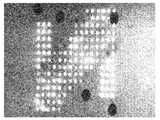
도 4는 VOC, 이러한 경우에 이소아밀 부티레이트를 포함하는 기체 샘플에 대한 비부동태화 기판을 갖는 본 발명에 따른 검출 시스템의 노출 후에 표면 플라즈몬 공명 영상(SPRi)에 의해 얻어지는 차분 이미지이다.
도 5는 1H,1H,2H,2H-퍼플루오로데칸티올 및 도데칸티올의 자가 결집된 층들이 얻어졌던 용액들의, [C]로 나타내어지고 mmol/L로 표현되는 농도에 따른, 기판의 표면 상에 배열되는 이러한 자가 결집된 층들에 대한 SPRi에 의해 얻어지는 바에 따른 Δ%R로 나타내어지는 반사율의 변화를 막대 그래프의 형태로 도시하며; 기판의 표면을 형성하는 금층의 영역에 대해 얻어지는 반사율의 변화(Au로 나타내어지는 막대)가 또한 나타내어진다.
도 6은 공기만으로 구성되는 기체 샘플에 대한 노출 후에 비부동태화 기판을 갖는 본 발명에 따른 검출 시스템의 검출 센서들 및 참조 센서들에 대한 SPRi에 의해 얻어지는 바에 따른 플라즈몬들의 곡선들을 도시하며; 이러한 도면에서, y축은 %R로 나타내어지는 반사율에 상응하는 반면에, x축은 Θ로 나타내어지고 도(°)로 표현되는 입사각에 상응한다.
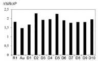
도 7은 초과 압력(ΔΡ)에 응하여 비부동태화 기판을 갖는 본 발명에 따른 검출 시스템의 D1 내지 D10으로 나타내어지는 10개의 검출 센서, 그리고 R1로 나타내어지는 참조 센서에 대한 SPRi에 의해 얻어지는 바에 따른 비율(Δ%R/ΔP)(반사율의 변화 대 압력의 변화)을 막대 그래프의 형태로 도시하며; 기판의 표면을 형성하는 Au로 나타내어지는 금층의 영역에 대해 얻어지는 비율(Δ%R/ΔP)이 또한 나타내어진다.
도 8a는 이소아밀 부티레이트를 포함하는 기체 샘플에 대한 노출 동안 SPRi에 의해 얻어지는 바에 따른, t로 나타내어지고 분으로 표현되는 시간에 따른, Δ%R로 나타내어지는 반사율의 교정되지 않은 변화를 도시하며, 도 8a에서 측정 시스템에서의 방해들로 인한 간섭성 잡음 및 신호 급증이 관측되는 반면에, 도 8b는 참조 센서에 의한 데이터의 교정 후를 제외하고 도 8a에 상응한다.
도 9는 2개의 검출 센서(라인들(D1 및 D2)) 및 참조 센서(라인(R1))가 첫 번째로, 이소아밀 부티레이트 그리고 다른 4개에 대해, 아밀아민을 포함하는 5개의 기체 샘플에 연속적으로 노출되었던 155 분의 기간에 걸쳐 비부동태화 기판을 갖는 본 발명에 따른 검출 시스템의 이러한 센서들에 대한 SPRi에 의해 얻어지는 바에 따른, t로 나타내어지고 분으로 표현되는 시간에 따른, %R로 나타내어지는 반사율의 변화를 도시하며; 이러한 도면에서, 괄호(A)는 측정 시스템의 드리프트를 기호화하며; 라인(R1)이 라인들(D1 및 D2) 아래에서 중복되었고, 괄호들(B 및 C)은 센서들(D1 및 D2)의 화학적 드리프트를 각각 기호화한다.
도 10은 이소아밀 부티레이트를 포함하는 기체 샘플에 대한 부동태화 기판을 갖는 본 발명에 따른 검출 시스템의 노출 후에 SPRi에 의해 얻어지는 차분 이미지이다.
도 11a는 4개의 검출 센서(라인들(D1, D2, D3 및 D4)) 및 참조 센서(라인(R1))가 VOC를 각각 포함하는 상이한 기체 샘플들에 연속적으로 노출되었던 300 분의 기간에 걸쳐 비부동태화 기판을 갖는 본 발명에 따른 검출 시스템의 이러한 센서들에 대한 SPRi에 의해 얻어지는 바에 따른, t로 나타내어지고 분으로 표현되는 시간에 따른, %R로 나타내어지는 반사율의 변화를 도시하며; 이러한 도면 상에서, 기판의 표면을 형성하는 금층의 영역에 대해 얻어지는 반사율의 변화(라인(Au))가 또한 도시된다.
도 11b는 부동태화 기판을 갖는 본 발명에 따른 검출 시스템에 대해서를 제외하고 도 11a의 도면과 유사한 도면이며; 그러므로, 이러한 도면은 라인(Au)을 포함하지 않고 부동태화 기판의 표면의 영역에 대해 얻어지는 반사율의 변화에 상응하는 라인(P1)을 포함한다.
도 12a는 아밀아민을 포함하는 기체 샘플에 대한 6 분 노출 동안 그리고 그 다음 청결한 공기의 흐름 하에서 기판의 14 분 헹굼 동안 비부동태화 기판을 갖는 본 발명에 따른 검출 시스템의 센서들에 대한 SPRi에 의해 얻어지는 바에 따른, t로 나타내어지고 분으로 표현되는 시간에 따른, Δ%R로 나타내어지는 반사율의 변화를 도시하며; 이러한 도면에서, 수직 점선은 노출의 종료 및 헹굼의 시작을 기호화한다.
도 12b는 부동태화 기판을 갖는 본 발명에 따른 검출 시스템에 대해서를 제외하고 도 12a와 유사한 도면이다.
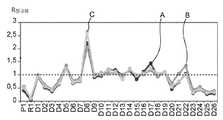
도 13a는 이소아밀 부티레이트를 포함하는 기체 샘플에 대한 3번의 노출 동안 비부동태화 기판을 갖는 본 발명에 따른 검출 시스템의 D1 내지 D26으로 나타내어지는 26개의 검출 센서, 그리고 R1로 나타내어지는 참조 센서에 대한 SPRi에 의해 얻어지는 바에 따른 R정규화로 나타내어지는 정규화된 반사율을 도시하며; 이소아밀 부티레이트에 대한 각각의 노출 사이에서, 아밀아민이 수회 주사되었으며; 이러한 도면 상에서, 기판의 표면을 형성하는 Au로 나타내어지는 금층의 영역에 대해 얻어지는 정규화된 반사율이 또한 도시되며; 라인(A) 상의 지점들은 아밀아민 주사들의 시작 전에 얻어지는 정규화된 반사율들에 상응하며; 라인(B) 상의 지점들은 아밀아민 주사들의 중간에서 얻어지는 정규화된 반사율들에 상응하는 반면에, 곡선(C) 상의 지점들은 아밀아민 주사들의 종료 후에 얻어지는 정규화된 반사율들에 상응한다.
도 13b는 부동태화 기판을 갖는 본 발명에 따른 검출 시스템에 대해서를 제외하고 도 13a와 유사한 도면이고, 여기서 도 11a에서의 영역(Au)에 대해 도시된 정규화된 반사율은 그러므로 P1로 나타내어지는 부동태화 기판의 표면의 영역에 대해 얻어지는 정규화된 반사율로 대체되었다.
도 14a는 6, 14 및 56 사용일에서 이소아밀 부티레이트를 포함하는 기체 샘플에 대한 노출들 동안 비부동태화 기판을 갖는 본 발명에 따른 검출 시스템의 D1 내지 D18로 나타내어지는 18개의 검출 센서, 그리고 R1로 나타내어지는 참조 센서에 대한 SPRi에 의해 얻어지는 바에 따른 R정규화로 나타내어지는 정규화된 반사율을 도시하며; 이러한 도면 상에서, 기판의 표면을 형성하는 Au로 나타내어지는 금층의 영역에 대해 얻어지는 정규화된 반사율이 또한 도시된다.
도 14b는 9, 15 및 61 사용일에서 이소아밀 부티레이트를 포함하는 기체 샘플에 노출되었던 부동태화 기판을 갖는 본 발명에 따른 검출 시스템에 대해서를 제외하고 도 14a와 유사한 도면이며; 이러한 도면에서, 도 14a에서의 영역(Au)에 대해 도시된 정규화된 반사율은 그러므로 P1로 나타내어지는 부동태화 기판의 표면의 영역에 대해 얻어지는 정규화된 반사율로 대체되었다.
도 15는 S1로 나타내어지는 비부동태화 기판을 갖는 본 발명에 따른 검출 시스템의 참조 센서, 그리고 S2 및 S3으로 나타내어지는 부동태화 기판을 갖는 본 발명에 따른 2개의 검출 시스템의 참조 센서에 대한, 이러한 센서들이 이소아밀 부티레이트를 포함하는 3개의 기체 샘플에 연속적으로 노출되었던 180 일의 기간에 걸쳐 SPRi에 의해 얻어지는 바에 따른, t로 나타내어지고 일(日)로 표현되는 시간에 따른, Δ%R로 나타내어지는 반사율의 변화를 도시한다.
도 16a 및 도 16b는 이하의 2번의 상이한 노출: 가솔린 연소 기체 샘플에 대한 한 번의 노출, 수증기 샘플에 대한 다른 한 번의 노출을 추종하여 비부동태화 기판을 갖는 본 발명에 따른 검출 시스템의 센서들에 의해 발해지는 바에 따른 비정규화된(도 16a) 그리고 정규화된(도 16b) 신호들을 스파이더 웹 도면들의 형태로 도시하며; 이러한 도면들에서, 화살표들(f1)은 연소 기체 샘플에 대해 발해지는 신호들에 상응하는 반면에, 화살표들(f2)은 수증기 샘플에 대해 발해지는 신호들에 상응한다.
도 17a 및 도 17b는 부동태화 기판을 갖는 본 발명에 따른 검출 시스템에 대해서를 제외하고 도 16a 및 도 16b와 유사한 도면들이며; 이러한 도면들에서, 화살표들(f1)은 연소 기체 샘플에 대해 발해지는 신호들에 상응하는 반면에, 화살표들(f2)은 수증기 샘플에 대해 발해지는 신호들에 상응한다.
도 1 내지 도 3에서, 동일한 요소들은 동일한 참조 부호들로 지정된다.1 to 3 schematically show three exemplary embodiments of the substrate of the detection system according to the invention in which the sensitive parts of the detection sensors and reference sensors are arranged on the surface of a common substrate.
4 is a differential image obtained by surface plasmon resonance imaging (SPRi) after exposure of a detection system according to the invention with a non-passivated substrate for a gas sample comprising VOC, in this case isoamyl butyrate.
Figure 5 shows the surface of the substrate, according to the concentration represented by [C] and expressed in mmol / L, of solutions in which self-aggregated layers of 1H, 1H, 2H, 2H-perfluorodecanthiol and dodecanthiol were obtained. The change in reflectivity, expressed as Δ% R, as obtained by SPRi for these self-aggregated layers arranged on the phase is shown in the form of a bar graph; The change in reflectivity (rod represented by Au) obtained for the region of the gold layer forming the surface of the substrate is also shown.
FIG. 6 shows curves of plasmons as obtained by SPRi for detection sensors and reference sensors of a detection system according to the present invention with a non-passivated substrate after exposure to a gas sample consisting only of air; In this figure, the y-axis corresponds to the reflectance represented by% R, while the x-axis corresponds to the angle of incidence represented by Θ and expressed in degrees (°).
7 is a ratio obtained by SPRi for 10 detection sensors represented by D1 to D10 of the detection system according to the present invention having a non-passivating substrate in response to excess pressure (ΔΡ), and a reference sensor represented by R1. (Δ% R / ΔP) (change in reflectance versus change in pressure) in the form of a bar graph; The ratio (Δ% R / ΔP) obtained for the region of the gold layer represented by Au forming the surface of the substrate is also shown.
FIG. 8A shows an uncorrected change in reflectivity expressed in Δ% R over time expressed in t and expressed in minutes, as obtained by SPRi during exposure to a gas sample comprising isoamyl butyrate, In FIG. 8A coherent noise and signal spikes due to disturbances in the measurement system are observed, while FIG. 8B corresponds to FIG. 8A except after correction of the data by the reference sensor.
FIG. 9 shows five gas samples containing amylamine, with two detection sensors (lines D1 and D2) and a reference sensor (line R1) first, isoamyl butyrate and the other four. In% R, over time, expressed in t and expressed in minutes, as obtained by SPRi for these sensors of the detection system according to the invention with a non-passivated substrate over a period of 155 minutes that were continuously exposed Showing the change in the reflectance shown; In this figure, parentheses (A) symbolize the drift of the measurement system; Line R1 overlaps under lines D1 and D2, and parentheses B and C symbolize the chemical drift of sensors D1 and D2, respectively.
10 is a differential image obtained by SPRi after exposure of a detection system according to the invention with a passivation substrate for a gas sample comprising isoamyl butyrate.
FIG. 11A is over a period of 300 minutes in which four detection sensors (lines D1, D2, D3 and D4) and a reference sensor (line R1) were continuously exposed to different gas samples each containing VOC. Showing the change in reflectivity, expressed in% R, over time, expressed in t and in minutes, as obtained by SPRi for these sensors of the detection system according to the invention with a non-passivated substrate; On this figure, the change in reflectance (line Au) obtained for the region of the gold layer forming the surface of the substrate is also shown.
FIG. 11B is a view similar to that of FIG. 11A except for the detection system according to the invention with a passivation substrate; Therefore, this figure does not include the line Au but includes the line P1 corresponding to the change in reflectivity obtained for the area of the surface of the passivated substrate.
12A shows SPRi for sensors of a detection system according to the invention with a non-passivating substrate during a 6 minute exposure to a gas sample comprising amylamine and then during a 14 minute rinse of the substrate under a stream of clean air. Shows the change in reflectivity, expressed as Δ% R, over time, expressed in t and minutes, as obtained; In this figure, vertical dotted lines symbolize the end of exposure and the start of rinsing.
12B is a view similar to FIG. 12A except for the detection system according to the present invention with a passivation substrate.
13A shows 26 detection sensors represented by D1 to D26 of a detection system according to the present invention having a non-passivated substrate during three exposures to a gas sample comprising isoamyl butyrate, and a reference sensor represented by R1. Shows normalized reflectance represented by Rnormalization as obtained by SPRi; Between each exposure to isoamyl butyrate, amylamine was injected several times; On this figure, the normalized reflectance obtained for the region of the gold layer represented by Au forming the surface of the substrate is also shown; The points on line (A) correspond to the normalized reflectances obtained before the start of amylamine injections; The points on line (B) correspond to the normalized reflectances obtained in the middle of amylamine injections, while the points on curve (C) correspond to the normalized reflectances obtained after the end of amylamine injections.
FIG. 13B is a view similar to FIG. 13A except for the detection system according to the invention with a passivation substrate, where the normalized reflectivity shown for area Au in FIG. 11A is therefore passivated represented by P1 Replaced with the normalized reflectivity obtained for the area of the surface of the substrate.
14A shows 18 detection sensors represented by D1 to D18 of the detection system according to the present invention with a non-passivated substrate during exposures to gas samples comprising isoamyl butyrate at 6, 14 and 56 days of use, and R1 Shows the normalized reflectance represented by Rnormalization as obtained by SPRi for the reference sensor represented by; On this figure, the normalized reflectance obtained for the region of the gold layer represented by Au forming the surface of the substrate is also shown.
FIG. 14B is a view similar to FIG. 14A except for the detection system according to the present invention with a passivation substrate exposed to gas samples containing isoamyl butyrate at 9, 15 and 61 days of use; In this figure, the normalized reflectivity shown for the area Au in FIG. 14A was therefore replaced by the normalized reflectivity obtained for the area of the surface of the passivation substrate, denoted P1.
15 is a reference sensor of a detection system according to the invention with a non-passivating substrate represented by S1 and a reference sensor of two detection systems according to the invention with a passivation substrate represented by S2 and S3, Denoted by t and as Δ% R, over time expressed as days, as obtained by SPRi over a period of 180 days when the sensors were continuously exposed to three gas samples containing isoamyl butyrate. The paper shows the change in reflectivity.
16A and 16B follow the following two different exposures: one exposure to a gasoline combustion gas sample, and another exposure to a water vapor sample to the sensors of the detection system according to the invention with a non-passivating substrate. Denormalized (FIG. 16A) and normalized (FIG. 16B) signals as produced by are shown in the form of spider web drawings; In these figures, arrows f1 correspond to signals emitted for the combustion gas sample, while arrows f2 correspond to signals emitted for the water vapor sample.
17A and 17B are views similar to FIGS. 16A and 16B except for the detection system according to the present invention having a passivation substrate; In these figures, arrows f1 correspond to signals emitted for the combustion gas sample, while arrows f2 correspond to signals emitted for the water vapor sample.
1 to 3, the same elements are designated with the same reference numerals.
I -I-본 발명에 따른 검출 시스템의 기판의 예시적 실시예들Exemplary embodiments of the substrate of the detection system according to the invention
검출 센서들 및 참조 센서들의 감응성 부분들이 동일한 기판의 표면 상에 배열되는 본 발명에 따른 검출 시스템의 기판(10)의 제1 실시예를 개략적으로 도시하는 도 1을 우선 참조한다.Reference is first made to FIG. 1, which schematically shows a first embodiment of a
이러한 도면에서 알 수 있는 바와 같이, 기판(10)은 각각이 검출 센서의 감응성 부분에 상응하고 그러므로 이하에 “검출 감응성 영역들”로 지칭될 D1, D2, D3, D4, D5, D6 및 D7로 각각 참조 표시된 복수의 감응성 영역이 배열되는 표면(11)을 포함한다. 이러한 도면의 단순화를 위해 도 1에서 이러한 감응성 영역들 중 7개가 있고 따라서, 이들은 7개의 검출 센서에 상응한다.As can be seen in this figure, the
그러나, 훨씬 더 큰 수의 검출 센서, 예를 들어 100개, 500개, 1000개, 3000개 또는 심지어 5000개의 검출 센서, 그리고 따라서 표면 상에 상응하는 수의 검출 감응성 영역이 배열되는 기판을 포함하는 본 발명에 따른 검출 시스템을 설계하는 것이 가능하다는 것은 말할 것도 없다.However, a much larger number of detection sensors, for example 100, 500, 1000, 3000 or even 5000 detection sensors, and thus a substrate on which a corresponding number of detection sensitive regions are arranged on the surface It goes without saying that it is possible to design a detection system according to the invention.
기판(10)의 표면(11)은 또한 참조 센서의 감응성 부분에 상응하고 그러므로 이하에 “참조 감응성 영역”으로 지칭될 R1로 참조 표시된 감응성 영역을 포함한다. 한 번 더 단순함을 위해, 도 1은 하나의 참조 센서에 상응하는 하나의 참조 감응성 영역만을 도시한다.The
그러나 여기서 또한, 복수의 참조 센서, 예를 들어 5개, 10개 또는 심지어 50개의 참조 센서 그리고 따라서, 표면 상에 상응하는 수의 참조 감응성 영역이 배열되는 기판을 포함하는 검출 시스템을 설계하는 것이 가능하다.However, it is also possible here to design a detection system comprising a plurality of reference sensors, for example 5, 10 or even 50 reference sensors and thus a substrate on which a corresponding number of reference sensitive regions are arranged on a surface. Do.
본 발명에 따르면, 검출 감응성 영역들(D1 내지 D7)은, 즉 전자 노우즈가 기체 샘플에서 검출하고 식별할 수 있는 화합물들의 세트(S)의 화합물들 중 적어도 하나와 수착 그리고 보다 상세하게는, 흡착 메커니즘에 의해 전형적으로 물리 화학적 방식으로 상호 작용할 수 있는 하나 이상의 수용기, 즉 하나 이상의 화합물의 하나 이상의 수용기로 기판(10)의 표면(11)의 7개의 별개의 영역을 기능화함으로써 생성될 수 있다.According to the invention, the detection sensitive regions D1 to D7 are sorbed, and more specifically, adsorbed with at least one of the compounds of the set S of compounds that the electron nose can detect and identify in the gas sample. It can be created by functionalizing seven distinct regions of the
이러한 기능화는 당업자에게 알려져 있는 표면 기능화 기법들 중 임의의 것(물리적 또는 화학적 흡착, 공유 그래프팅, 분자 제트 에피택시, 박막 증착, 분자 자가 결집 등)에 의해 또는 이들 중 수개에 의해 달성될 수 있으며, 이러한 기법 또는 이러한 기법들의 선택은, 특히 기판의 표면의 화학적 본질, 수용기들의 화학적 본질 및 분자 크기, 그리고 검출 센서들의 측정 시스템의 상관적 요소이다.Such functionalization can be achieved by any of the surface functionalization techniques known to those skilled in the art (physical or chemical adsorption, covalent grafting, molecular jet epitaxy, thin film deposition, molecular self-aggregation, etc.) or by several of them. , This technique or the choice of these techniques, in particular the chemical nature of the surface of the substrate, the chemical nature and molecular size of the receptors, and the correlation elements of the measurement system of the detection sensors.
세트(S)의 화합물들이 VOC들, H2S 및 NH3인 경우에, 그 때 수용기들은, 특히 금속, 금속 산화물, 비플루오로화 유기 화합물, 비플루오로화 중합체, DNA 분자, 올리고뉴클레오티드, 당분, 펩티드, 단백질, 인지질과 같은 생체 분자, 및 이러한 생체 분자들의 유도체 중에서, 또는 그래핀, 나노튜브, 그라파이트 카본 등과 같은 탄소의 상이한 분자 배열들 중에서 선택될 수 있다. 이러한 점에서, 독자는 사용될 수 있는 수용기들의 타입들에 대한 더 많은 정보에 대해 K. Arshak 외 in Sensor Review 2004, vol. 24, pp. 181-198; T. Wasilewski 외, Biosensors and Bioelectronics 2017, vol. 87, pp. 480-494; 및 A. D. Wilson 및 M. Baietto, Sensors (Basel) 2009, vol. 9, pp. 5099-5148(이후로 참고 문헌들 [5] 내지 [7])에 의한 논문들을 언급할 수 있다.When the compounds of the set (S) are VOCs, H2 S and NH3 , then the receptors are, in particular, metals, metal oxides, non-fluorinated organic compounds, non-fluorinated polymers, DNA molecules, oligonucleotides, It can be selected from biomolecules such as sugars, peptides, proteins, phospholipids, and derivatives of these biomolecules, or from different molecular arrangements of carbon such as graphene, nanotubes, graphite carbon, and the like. In this regard, the reader is informed by K. Arshak et al. In Sensor Review 2004, vol. 24, pp. 181-198; T. Wasilewski et al., Biosensors and Bioelectronics 2017, vol. 87, pp. 480-494; And AD Wilson and M. Baietto, Sensors (Basel) 2009, vol. 9, pp. References can be made to articles by 5099-5148 (hereafter references [5] to [7]).
참조 감응성 영역(R1)은 세트(S)의 화합물들과 물리 화학적으로 상호 작용하지 않거나, 하나 이상의 화합물이 이러한 화합물들 중 하나 이상과 상호 작용하면, 감응성 영역들(D1 내지 D7)의 수용기들과 세트(S)의 상기 화합물들 사이에서 일어날 것 같은 상호 작용들과 비교하여 매우 약한 상호 작용들을 야기하는 하나 이상의 화합물로 검출 감응성 영역들(D1 내지 D7)과 별개인 기판(10)의 표면(11) 상의 영역을 기능화함으로써 생성될 수 있다.The reference sensitive region R1 does not physically and chemically interact with the compounds of the set S, or if one or more compounds interact with one or more of these compounds, with the receptors of the sensitive regions D1 to D7. The
여기서 한 번 더, 이러한 기능화는 기판의 화학적 본질, 화합물(들)의 화학적 본질 및 분자 크기, 그리고 참조 센서의 측정 시스템에 따른 당업자에게 알려져 있는 표면 기능화 기법들 중 임의의 것에 의해 달성될 수 있다.Once again, such functionalization can be accomplished by any of the surface functionalization techniques known to those skilled in the art depending on the chemical nature of the substrate, the chemical nature and molecular size of the compound (s), and the measurement system of the reference sensor.
본 발명에 따르면, 세트(S)의 화합물들과 상호 작용하지 않거나 매우 약하게만 상호 작용하는 화합물 또는 화합물들은 적어도 하나의 퍼플루오로화 말단 알킬기, 즉 적어도 하나의 -CF3 기를 포함하는 플루오로화 화합물들 및 플루오로화 중합체들로부터, 한편으로는, 이러한 타입의 화합물들 및 중합체들을 특성화하는 화학적 불활성, 그리고 다른 한편으로는, 이러한 타입의 화합물들 및 중합체들의 비습윤성 특성들로 인해 선택된다.According to the present invention, compounds or compounds that do not interact with the compounds of the set (S) or that interact only very weakly are fluorinated comprising at least one perfluorinated terminal alkyl group, i.e., at least one -CF3 group. It is selected from compounds and fluorinated polymers, on the one hand, due to the chemically inert characterizing these types of compounds and polymers, and on the other hand, to the non-wetting properties of these types of compounds and polymers.
적어도 하나의 퍼플루오로화 말단 알킬기를 갖는 플루오로화 화합물들은, 특히 퍼플루오로화 화합물들, 즉 화학식 CvF2v+2의 화합물들(여기서, v는 4 내지 20의 정수임), 또는 화학식 CwF2w+1-(L)x-Z의 화합물들(여기서, w는 1 내지 12의 정수이고, x는 0 또는 1이고, L은 2가 스페이서기, 예를 들어 1개 내지 20개의 탄소 원자 그리고 선택적으로 하나 이상의 헤테로 원자, 전형적으로 O, N, S 및/또는 Si를 포함하는 선형 또는 분지형의, 포화 또는 불포화 탄화 수소기인 반면에, Z는 기판의 표면에 공유 또는 비공유 결합들에 의해 화합물들이 부착되는 것을 가능하게 할 수 있는 기를 나타냄)일 수 있다.Fluorinated compounds having at least one perfluorinated terminal alkyl group are, in particular, perfluorinated compounds, ie compounds of the formula Cv F2v + 2 (where v is an integer from 4 to 20), or formula Compounds of Cw F2w + 1- (L)x -Z, where w is an integer from 1 to 12, x is 0 or 1, and L is a divalent spacer group, for example 1 to 20 Is a linear or branched, saturated or unsaturated hydrocarbon group comprising carbon atoms and optionally one or more heteroatoms, typically O, N, S and / or Si, while Z is covalent or non-covalent bonds to the surface of the substrate By indicating a group that can enable the compound to be attached).
(본 발명의 맥락에서 바람직한 기능화 기법인) 분자 자가 결집에 의한 기능화의 경우, 기 Z는 예를 들어, 기판의 표면이 금, 백금, 은, 팔라듐 또는 구리이면, 티올(-SH) 또는 아미노(-NH2)기 그렇지 않으면 기판의 표면이 유리, 석영, 규소 또는 실리카이면, 실라놀(-SiOH)기일 수 있다.For functionalization by molecular self-assembly (which is a preferred functionalization technique in the context of the present invention), group Z is, for example, thiol (-SH) or amino (if the surface of the substrate is gold, platinum, silver, palladium or copper) -NH2 ) group Otherwise, if the surface of the substrate is glass, quartz, silicon or silica, it may be a silanol (-SiOH) group.
화학식 CwF2w+1-(L)x-Z의 화합물들 중에서도, SIGMA-ALDRICH로부터 모두 이용 가능한 화학식 CF3CH2SH의 1H,1H-트리플루오로에탄티올, 화학식 CF3(CF2)2(CH2)2SH의 1H,1H,2H,2H-퍼플루오로펜탄티올, 화학식 CF3(CF2)3(CH2)2SH의 1H,1H,2H,2H-퍼플루오로핵산티올, 화학식 CF3(CF2)5(CH2)2SH의 1H,1H,2H,2H-퍼플루오로옥탄티올, 및 화학식 CF3(CF2)7(CH2)2SH의 1H,1H,2H,2H-퍼플루오로데칸티올과 같은 화학식 CF3(CF2)y(CH2)zSH의 퍼플루오로알칸티올류(여기서, y는 범위가 0 내지 11에 이르는 정수이고 z는 범위가 1 내지 20 그리고 훨씬 더 앙호하게는, 1 내지 12에 이르는 정수임)가 바람직하다.Among compounds of formula Cw F2w + 1- (L)x -Z, 1H, 1H-trifluoroethanethiol of formula CF3 CH2 SH, formula CF3 (CF2 ), all available from SIGMA-ALDRICH 1H, 1H, 2H, 2H-perfluoronucleic acid thiol of2 (CH2 )2 SH 1H, 1H, 2H, 2H-perfluoropentanethiol, formula CF3 (CF2 )3 (CH2 )2 SH , 1H, 1H, 2H, 2H-perfluorooctanethiol of the formula CF3 (CF2 )5 (CH2 )2 SH, and 1H, 1H of the formula CF3 (CF2 )7 (CH2 )2 SH Perfluoroalkanthiols of the formula CF3 (CF2 )y (CH2 )z SH, such as 2H, 2H-perfluorodecanthiol, where y is an integer ranging from 0 to 11 and z is the
사용될 것 같은 플루오로화 중합체들은, 특히 상표명 Teflon™ 하에서 DUPONT에 의해 시판되는 것들과 같은 폴리테트라플루오로에틸렌류(PTFE), 상표명 Tedlar™ 하에서 DUPONT에 의해 시판되는 것들과 같은 폴리비닐 플루오라이드류(PVF), 및 상표명 Kynar™ 하에서 ARKEMA에 의해 시판되는 것들과 같은 폴리비닐리덴 플루오라이드류(PVDF), 상표명 Teflon™-PFA 하에서 DUPONT에 의해 시판되는 것들과 같은 퍼플루오로알콕시 알칸류(PFA), 상표명 Teflon™-FEP 하에서 DUPONT에 의해 시판되는 것들과 같은 플루오로화 에틸렌-프로필렌 공중합체들(또한 플루오로화 에틸렌-프로필렌류 또는 FEP로서 알려져 있음), 그리고 상표명 Tefzel™ 하에서 DUPONT에 의해 시판되는 것들과 같은 폴리(에틸렌-co-테트라플루오로에틸렌류)(ETFE)를 포함한다.Fluorinated polymers that are likely to be used include, in particular, polytetrafluoroethylenes (PTFE), such as those sold by DUPONT under the trade name Teflon ™, and polyvinyl fluorides, such as those sold by DUPONT under the trade name Tedlar ™ ( PVF), and polyvinylidene fluorides (PVDF) such as those sold by ARKEMA under the trade name Kynar ™, perfluoroalkoxy alkanes (PFA) such as those sold by DUPONT under the trade name Teflon ™ -PFA, Fluorinated ethylene-propylene copolymers (also known as fluorinated ethylene-propylenes or FEP), such as those sold by DUPONT under the trade name Teflon ™ -FEP, and those sold by DUPONT under the trade name Tefzel ™. Poly (ethylene-co-tetrafluoroethylenes) (ETFE).
검출 및 참조 센서들의 감응성 부분들이 또한 공통 기판 상에 배열되는 본 발명에 따른 검출 시스템의 기판(10)의 제2 실시예를 개략적으로 도시하는 도 2를 이제 참조한다.Reference is now made to FIG. 2, which schematically shows a second embodiment of the
이러한 예에서, 기판(10)은 기판(10)의 표면(11)이 참조 감응성 영역(R1)을 형성하는 화합물 또는 화합물들과 동일한 화합물 또는 화합물들로 부동태화 처리를 받았다는 점에서만 도 1에 도시된 기판(10)과 상이하다.In this example, the
검출 감응성 영역들(D1 내지 D7)이 공유 그래프팅 또는 분자 자가 결집에 의해 생성되고 부동태화 처리 그 자체가 이러한 2가지의 기법 중 한가지에 의해 수행되는 경우에, 그 때 이러한 부동태화 처리는 검출 감응성 영역들(D1 내지 D7)의 생성 후에 수행될 수 있으며, 이 경우, 검출 감응성 영역들(D1 내지 D7)에 의해 자유롭게 남는 기판(10)의 표면(11)의 부분들만이 부동태화되고 참조 감응성 영역(R1)이 이러한 부동태화된 부분들 중 하나 상에서 선택된다.If the detection-sensitive regions D1 to D7 are generated by covalent grafting or molecular self-aggregation and the passivation treatment itself is performed by one of these two techniques, then this passivation treatment is detected sensitivity It can be performed after the creation of the regions D1 to D7, in which case only the portions of the
대안적으로, 부동태화 처리는 검출 감응성 영역들(D1 내지 D7)의 생성 전에 수행될 수도 있으며, 이 경우, 이러한 감응성 영역들은 기판(10)의 표면(11)의 7개의 별개의 영역에서, 하나 이상의 수용기로 이러한 영역들 상에 존재하는 부동태화 화합물 또는 화합물들을 커버하거나, 예를 들어, 리소그래피에 의해 기판(10)의 표면(11)의 7개의 별개의 영역을 탈부동태화하고 하나 이상의 수용기로 따라서 탈부동태화되는 영역들을 기능화함으로써 생성될 수 있다. 여기서 또한, 참조 감응성 영역(R1)은 그 다음 검출 감응성 영역들(D1 내지 D7)에 의해 자유롭게 남는 기판(10)의 표면(11)의 부분들 중 하나 상에서 선택될 수 있다.Alternatively, the passivation treatment may be performed prior to the generation of detection sensitive regions D1 to D7, in which case these sensitive regions are one in seven distinct regions of the
도 3은 본 발명에 따른 검출 시스템의 기판(10)의 제2 예시적 실시예의 변형예를 개략적으로 도시하며, 이 변형예에서, 기판(10)의 표면(11)은 참조 감응성 영역(R1)을 형성하는 화합물 또는 화합물들과 상이하지만 또한 퍼플루오로화 말단 알킬기 및 플루오로화 중합체들을 포함하는 화합물들로부터 선택되는 하나 이상의 화합물로 부동태화 처리를 받았다.3 schematically shows a variant of the second exemplary embodiment of the
따라서 예를 들어, 참조 감응성 영역(R1)을 형성하고 기판의 표면(11)을 부동태화하기 위해 퍼플루오로화 화합물들 및 앞서 정의된 바와 같은 화학식 CwF2w+1-(L)x-Z의 화합물들로부터 선택되는 2개의 상이한 화합물을 사용하는 것이 가능하다.Thus, for example, perfluorinated compounds and the formula Cw F2w + 1- (L)x -as defined above to form the reference sensitive region R1 and passivate the
대안적으로, 참조 감응성 영역(R1)을 형성하기 위해 퍼플루오로화 화합물 또는 앞서 정의된 바와 같은 화학식 CwF2w+1-(L)x-Z의 화합물을 사용하고 PTFE와 같은 플루오로화 중합체로 기판(10)의 표면(11)을 부동태화하는 것이 또한 가능하다.Alternatively, use a perfluorinated compound or a compound of formula Cw F2w + 1- (L)x -Z as defined above to form a reference sensitive region (R1) and fluorinated such as PTFE It is also possible to passivate the
여기서 한 번 더, 부동태화 처리는 상술한 바와 동일한 방식으로 검출 감응성 영역들(D1 내지 D7) 및 참조 감응성 영역(R1)의 생성 후에 또는 전에 수행될 수 있다.Here again, the passivation processing can be performed after or before the generation of the detection sensitive regions D1 to D7 and the reference sensitive regions R1 in the same manner as described above.
도 1 내지 도 3이 본 발명에 따른 검출 시스템의 실시예들의 개략 예시들에 상응하므로, 감응성 영역들(D1 내지 D7, 및 R1)이 이러한 도면들 상에서 원형 형태로 나타내어진다는 점을 주목해야 한다.It should be noted that since FIGS. 1 to 3 correspond to schematic examples of embodiments of the detection system according to the present invention, the sensitive regions D1 to D7 and R1 are shown in a circular form on these figures. .
그러나, 검출 감응성 영역들 및 참조 감응성 영역들이 완전히 상이한 형상, 예를 들어 다각형 및, 특히 평행 육면체를 갖거나, 임의의 형상일 수 있다는 것은 말할 것도 없다.It goes without saying, however, that the detection sensitive regions and the reference sensitive regions may have completely different shapes, for example polygons, and especially parallelepipeds, or may be arbitrary shapes.
마찬가지로, 감응성 영역들(D1 내지 D7, 및 R1)은 도 1 내지 도 3에서 서로로부터 따로따로 도시되지만, 검출 감응성 영역들 및 참조 감응성 영역들이 서로에 인접한 것을 제법 상상할 수 있다.Likewise, while the sensitive regions D1 to D7 and R1 are shown separately from each other in FIGS. 1 to 3, it is quite conceivable that the detection sensitive regions and reference sensitive regions are adjacent to each other.
II -II-비부동태화 기판을 갖는 본 발명에 따른 검출 시스템의 특성들Characteristics of the detection system according to the invention with a non-passivated substrate
II.1 -II.1-VOC들에 대한 검출 센서들과 참조 센서들 사이에 존재하는 감도의 차이의 영상에 의한 입증Image-based verification of the difference in sensitivity between detection and reference sensors for VOCs::
본 테스트는 유리 프리즘의 면들 중 하나 상에서 그 자체가 금의 층(대략 50 ㎚ 두께)으로 커버되는 크롬의 층(대략 2 ㎚ 두께)으로 커버되는 유리 프리즘으로 구성되고:The test consisted of a glass prism covered on itself on one of the sides of the glass prism with a layer of chromium (approximately 2 nm thick) covered with a layer of gold (approximately 50 nm thick):
- 복수의 검출 감응성 영역으로서, 이러한 영역들은 상이한 교차 반응성 수용기들의 자가 결집된 층들로 형성되며(즉, 수용기는 상이한 VOC들과 상호 작용할 수 있고, 정반대로, VOC는 상이한 수용기들과 상호 작용할 수 있음), 수용기들 각각은 금층에의 수용기들 각각의 부착을 위해 티올 관능기를 포함하는 복수의 검출 감응성 영역, 및-As a plurality of detection-sensitive regions, these regions are formed of self-aggregated layers of different cross-reactive receptors (i.e., receptors can interact with different VOCs, and conversely, VOCs can interact with different receptors) ), Each of the receptors is a plurality of detection-sensitive regions comprising a thiol functional group for attachment of each of the receptors to the gold layer, and
- 복수의 참조 감응성 영역으로서, 이러한 영역들은 1H,1H,2H,2H-퍼플루오로데칸티올의 자가 결집된 층들로 형성되며, 이러한 자가 결집은 금층 상에 7 mmol/L의 이러한 화합물을 포함하는 용액의 로봇에 의한 미세 증착에 의해 수행되었던 복수의 참조 감응성 영역을 포함하는 기판을 사용하여 수행되었다.-As a plurality of reference sensitive regions, these regions are formed of self-aggregated layers of 1H, 1H, 2H, 2H-perfluorodecanthiol, which self-aggregation comprises 7 mmol / L of this compound on the gold layer This was done using a substrate comprising a plurality of reference sensitive regions that had been performed by microevaporation of a solution by a robot.
이러한 기판은 VOC, 이러한 경우에, 대략 30 ppm의 농도에서의 이소아밀 부티레이트(CH3(CH2)2C(O)O(CH2)2CH(CH3)2)를 포함하는 기체 샘플에 10 분 동안 노출되었고, 이러한 VOC와 기판의 다양한 감응성 영역 사이의 상호 작용들은 표면 플라즈몬 공명 영상(SPRi)에 의해 모니터링되었다.Such a substrate is a gas sample comprising VOC, in this case, isoamyl butyrate (CH3 (CH2 )2 C (O) O (CH2 )2 CH (CH3 )2 ) at a concentration of approximately 30 ppm. It was exposed for 10 minutes, and the interactions between these VOCs and various sensitive regions of the substrate were monitored by surface plasmon resonance imaging (SPRi).
따라서, 도 4에 도시된 차분 이미지가 얻어졌다.Thus, the difference image shown in Fig. 4 was obtained.
SPRi는 더 많은 상호 작용이 화합물과 표면 사이에 있을수록, 판독 시스템에 의해 발해지는 광학 신호가 더 많이 증가하는 광학 평형에 비유될 수 있는 표면 상호 작용들을 광학적으로 판독하는 기법이다. 차분 이미지는 표면이 화합물에 노출되기 전에 취해지는 참조 이미지에 대한 이러한 광학 신호의 변화를 나타낸다. 또한, 차분 이미지의 영역이 더 밝을수록, 화합물과 표면의 상응하는 영역 사이의 물리 화학적 상호 작용은 더 크다. 정반대로, 차분 이미지의 영역이 더 어두울수록, 화합물과 표면 영역 사이의 물리 화학적 상호 작용은 더 작다.SPRi is a technique for optically reading surface interactions that can be compared to optical equilibrium, where the more interaction is between the compound and the surface, the more the optical signal emitted by the reading system increases. The differential image represents the change in this optical signal relative to the reference image taken before the surface is exposed to the compound. In addition, the brighter the region of the differential image, the greater the physicochemical interaction between the compound and the corresponding region of the surface. Conversely, the darker the area of the difference image, the smaller the physicochemical interaction between the compound and the surface area.
도면에 도시된 바와 같이, 차분 이미지는 이소아밀 부티레이트가 흡착되었던 기판의 검출 감응성 영역들에 상응하는 매우 밝거나 심지어 백색인 영역들, 그리고 이소아밀 부티레이트가 흡착되지 않았거나 매우 조금 흡착되었던 기판의 참조 감응성 영역들에 상응하는 흑색인 영역들을 가지며, 이는 1H,1H,2H,2H-퍼플루오로데칸티올에 의해 기능화되는 기판의 영역들이 이소아밀 부티레이트와 같은 VOC들을 향한 진정한 화학적 불활성을 갖는다는 것을 입증한다.As shown in the figure, the differential image refers to the regions that are very bright or even white corresponding to the detection sensitive regions of the substrate on which the isoamyl butyrate was adsorbed, and the substrates on which the isoamyl butyrate was not adsorbed or adsorbed very little. It has black regions corresponding to the sensitive regions, demonstrating that regions of the substrate functionalized by 1H, 1H, 2H, 2H-perfluorodecanthiol have true chemical inertness towards VOCs such as isoamyl butyrate. do.
11.2 -11.2-감응성 부분들이 퍼플루오로알칸티올로 형성되는 센서들의 VOC들에 대한 감도와 감응성 부분들이 비플루오로화 알칸티올로 형성되는 센서들의 VOC들에 대한 감도 사이의 비교Comparison between the sensitivity of the sensors in which the sensitive parts are formed of perfluoroalkanthiol to the VOCs and the sensitivity of the sensors in which the sensitive parts are formed of non-fluorinated alkanthiols to the VOCs.::
본 테스트는 유리 프리즘들의 면들 중 하나 상에서 금의 층(대략 50 ㎚ 두께)으로 코팅되는 유리 프리즘들로 구성되고, 한편으로는, 1H,1H,2H,2H-퍼플루오로데칸티올의 자가 결집된 층들로 형성되는 영역들 그리고 다른 한편으로는, 도데칸티올(CH3(CH2)11SH)의 자가 결집된 층들로 형성되는 영역들을 포함하는 일련의 기판들을 사용하여 수행되었으며, 자가 결집들은 금층 상에 5 mmol/L 내지 10 mmol/L의 이러한 화합물들 중 하나를 포함하는 용액들의 로봇에 의한 미세 증착에 의해 얻어졌다.The test consisted of glass prisms coated with a layer of gold (approximately 50 nm thick) on one of the sides of the glass prisms, on the one hand self-aggregated of 1H, 1H, 2H, 2H-perfluorodecanthiol The regions formed of layers and, on the other hand, were performed using a series of substrates comprising regions formed of self-aggregated layers of dodecanthiol (CH3 (CH2 )11 SH), the self-aggregations being a gold layer Obtained by robotic microevaporation of solutions containing 5 mmol / L to 10 mmol / L of one of these compounds on the phase.
이러한 기판들은 20 ppm 이소아밀 부티레이트를 포함하는 기체 샘플들에 노출되었고 이러한 VOC와 기판들 상에 존재하는 상이한 자가 결집된 층들 사이의 상호 작용들이 SPRi에 의해 모니터링되었다.These substrates were exposed to gas samples containing 20 ppm isoamyl butyrate and the interactions between these VOCs and the different self-aggregated layers present on the substrates were monitored by SPRi.
이러한 테스트의 결과들이 2가지의 타입의 층들 각각 그리고 이러한 층들이 얻어졌던 용액들의 [C]로 나타내어지고 mmol/L로 표현되는 농도들 각각에 대해 얻어지는 바에 따른 Δ%R로서 나타내어지는 반사율의 변화를 막대 그래프의 형태로 도시하는 도 5에 도시된다. 비교로서, 도 5는 또한 금층의 영역에 대해 얻어지는 반사율의 변화(Au로 나타내어지는 막대)를 도시한다.The results of these tests were used to determine the change in reflectivity as Δ% R as obtained for each of the two types of layers and for each of the concentrations expressed in [C] and mmol / L of the solutions from which these layers were obtained. It is shown in Fig. 5, which is shown in the form of a bar graph. As a comparison, FIG. 5 also shows the change in reflectance (bar represented by Au) obtained for the region of the gold layer.
이러한 도면에 도시된 바와 같이, (이소아밀 부티레이트에 대한 자가 결집된 도데칸티올층들의 감도를 반영하는) 자가 결집된 도데칸티올층들에 대해 관측되는 반사율의 변화는 금층에 대해 관측되는 반사율의 변화보다 더 낮지만, 이러한 층들을 증착시키는 데 사용되는 용액의 농도에 관계 없이 1H,1H,2H,2H-퍼플루오로데칸티올층들에 대해 관측되는 반사율의 변화보다 체계적으로 더 높다.As shown in this figure, the change in reflectivity observed for the self-aggregated dodecanethiol layers (reflecting the sensitivity of the self-aggregated dodecanethiol layers to isoamyl butyrate) is the amount of reflectivity observed for the gold layer. Lower than the change, but systematically higher than the change in reflectivity observed for the 1H, 1H, 2H, 2H-perfluorodecanthiol layers regardless of the concentration of solution used to deposit these layers.
따라서, 도데칸티올층들 상의 이소아밀 부티레이트의 흡착 작용은 1H,1H,2H,2H-퍼플루오로데칸티올층들 상의 이소아밀 부티레이트의 흡착 작용보다 체계적으로 더 크다.Thus, the adsorption action of isoamyl butyrate on dodecanthiol layers is systematically greater than the adsorption action of isoamyl butyrate on 1H, 1H, 2H, 2H-perfluorodecanthiol layers.
이러한 도면에 또한 도시된 바와 같이, 자가 결집된 층들의 반사율의 변화는 이러한 층들의 증착에 사용되는 용액의 농도에 의존한다. 1H,1H,2H,2H-퍼플루오로데칸티올의 경우에, 반사율의 최저 변화는 범위가 6 mmol/L 내지 7 mmol/L인 농도에 대해 관측되며, 이 농도에서, 이러한 변화는 도데칸티올의 자가 결집된 층들에 대해 얻어지는 변화 2배 초과만큼 낮다.As also shown in this figure, the change in reflectivity of the self-aggregated layers depends on the concentration of the solution used for the deposition of these layers. In the case of 1H, 1H, 2H, 2H-perfluorodecanthiol, the lowest change in reflectance is observed for concentrations ranging from 6 mmol / L to 7 mmol / L, at which concentration this change is dodecanethiol The change obtained for the self-assembled layers is as low as more than twice the change.
11.3 -11.3-참조 센서들의 기능의 검증Verification of the function of reference sensors::
도 4에서의 이미지에서 관측되는 어두운 영역들이 실제로 위의 실시예 II.1에 설명하는 이소아밀 부티레이트와 기판의 참조 감응성 영역들 사이의 물리 화학적 상호 작용의 부재 또는 준부재로 인한다는 것을 확실히 하기 위해, 이러한 기판이 공기만으로 구성되는(그리고 그러므로, 검출 감응성 영역들과 상호 작용할 것 같은 임의의 화학적 화합물이 없는) 기체 샘플에 노출되었고 플라즈몬 곡선들이 검출 및 참조 감응성 영역들에 대해 SPRi에 의해 확립되었다.To ensure that the dark areas observed in the image in FIG. 4 are actually due to the absence or quasi-physical interaction between the isoamyl butyrate described in Example II.1 above and the reference sensitive areas of the substrate. , This substrate was exposed to a gas sample consisting only of air (and therefore without any chemical compound likely to interact with detection sensitive regions) and plasmon curves were established by SPRi for detection and reference sensitive regions.
이러한 곡선들이 도 6에 도시된다.These curves are shown in FIG. 6.
이러한 도면에 도시된 바와 같이, 참조 감응성 영역들에 대해 얻어지는 플라즈몬 곡선들은 검출 감응성 영역들에 대해 얻어지는 플라즈몬 곡선들과 일치한다.As shown in this figure, the plasmon curves obtained for the reference sensitive regions coincide with the plasmon curves obtained for the detection sensitive regions.
그러므로, 도 4에서의 이미지에서 관측되는 어두운 영역들은 이소아밀 부티레이트와 기판의 참조 감응성 영역들 사이의 물리 화학적 상호 작용의 부재 또는 근부재로 인하고 SPRi가 SPRi의 감도 범위 밖에 있을 것이라는 사실로 인한 것이 아니다.Therefore, the dark areas observed in the image in FIG. 4 are due to the absence or near absence of the physicochemical interaction between isoamyl butyrate and the reference sensitive areas of the substrate and due to the fact that the SPRi will be outside the sensitivity range of the SPRi. no.
11.4 -11.4-물리적 파라미터들의 변화들에 대한 참조 센서들의 감도Sensitivity of reference sensors to changes in physical parameters::
위의 실시예 II.1에 설명하는 기판의 참조 감응성 영역들이 VOC들의 존재에 비감응성이거나 약간만 감응성이지만, 그럼에도 불구하고 환경적이거나 실험적인 물리적 파라미터들의 변화들에 감응성이라는 것을 검증하기 위해, “인덱스 점프” 테스트로서 알려져 있는 테스트가 수행되었다.To verify that the reference sensitive regions of the substrate described in Example II.1 above are non-sensitive or only slightly sensitive to the presence of VOCs, but nevertheless sensitive to changes in environmental or experimental physical parameters, “index. A test known as the "jump" test was performed.
이러한 테스트의 원리는 물리적 파라미터에 의해 공기만으로 구성되는(그리고 그러므로, 기판의 검출 감응성 영역들과 화학적으로 상호 작용할 것 같은 임의의 화학적 화합물이 없는) 기체 샘플의 굴절률을 변화시키고, 굴절률의 변화가 기판의 검출 감응성 영역들 및 참조 감응성 영역들에 대한 SPRi에 의해 얻어지는 광학 신호들의 변화를 야기하는지 아닌지 여부를 관측하는 것이다.The principle of this test changes the refractive index of a gas sample consisting of only air by physical parameters (and therefore, without any chemical compound likely to chemically interact with the detection sensitive regions of the substrate), and the change in refractive index of the substrate Is to observe whether or not to cause a change in the optical signals obtained by the SPRi for the detection sensitive regions and the reference sensitive regions.
이러한 경우에, 테스트는 기판에 초과 압력(ΔΡ = 0.5 bar)을 인가함으로써 수행되었다.In this case, the test was performed by applying an excess pressure (ΔΡ = 0.5 bar) to the substrate.
이러한 테스트의 결과들이 기판의 R1로 나타내어지는 참조 감응성 영역, D1 내지 D10으로 나타내어지는 10개의 검출 감응성 영역, 그리고 Au로 나타내어지는 금층의 영역에 대해 얻어지는 비율(Δ%R/ΔP)을 막대 그래프의 형태로 표현하는 도 7에 제공된다.The ratio (Δ% R / ΔP) obtained from the results of these tests for the reference sensitive region represented by R1 of the substrate, the 10 detected sensitive regions represented by D1 to D10, and the region of the gold layer represented by Au is shown in the bar graph. It is provided in FIG. 7 expressed in the form.
이러한 도면에 도시된 바와 같이, 기체 샘플의 굴절률의 변화의 유일한 근원으로서 물리적 파라미터의 변화를 갖는 기체 샘플의 굴절률의 변화는 기판의 모든 감응성 영역에 대해 필적하는 Δ%R/ΔP 비율을 야기하였다.As shown in this figure, the change in the refractive index of the gas sample with a change in physical parameter as the only source of change in the refractive index of the gas sample resulted in a comparable Δ% R / ΔP ratio for all sensitive regions of the substrate.
그러므로, 물리적 파라미터들의 변화들에 대한 감도는 기판의 모든 감응성 영역에 대해 동일한 것으로 고려될 수 있다.Therefore, sensitivity to changes in physical parameters can be considered to be the same for all sensitive regions of the substrate.
그러므로, 참조 감응성 영역들은 물리적 파라미터들의 변화들, 이러한 경우에 압력의 변화에 감응성이지만, VOC들에 감응성이 아니거나 약간만 감응성이다. 그러므로, 참조 감응성 영역들은 기판 상에서 일어날 것 같은 VOC들과의 물리 화학적 상호 작용들에 대한 음성 또는 영점 기준들로서 사용될 수 있다.Therefore, the reference sensitive regions are sensitive to changes in physical parameters, in this case a change in pressure, but not or only slightly to VOCs. Therefore, the reference sensitive regions can be used as negative or zero criteria for physicochemical interactions with VOCs likely to occur on the substrate.
11.5 -11.5-측정 잡음의 평가Evaluation of measurement noise::
앞선 실시예에 도시된 바와 같이, 위의 실시예 II.1에 설명하는 기판의 참조 감응성 영역들이 물리적 파라미터들의 변화들에 감응성인 한은, 그러한 기판을 포함하는 검출 시스템의 측정 잡음은 이소아밀 부티레이트와 같은 VOC를 포함하는 기체 샘플에 노출될 때, 이러한 감응성 영역들에 대해 얻어지는 광학 신호들의 단기 변동을 측정함으로써 추정될 수 있다.As shown in the previous embodiment, as long as the reference sensitive regions of the substrate described in Example II.1 above are sensitive to changes in physical parameters, the measurement noise of a detection system comprising such a substrate is measured with isoamyl butyrate. When exposed to a gas sample containing the same VOC, it can be estimated by measuring the short-term fluctuations of the optical signals obtained for these sensitive regions.
도 8a는 통상적으로 측정되는 측정 잡음이 대략 ± 0.05 %R이라는 것(14 내지 18 분 참조)을 나타낸다.8A shows that the measurement noise that is typically measured is approximately ± 0.05% R (see 14-18 minutes).
이러한 도면은 또한 간섭성 잡음, 즉 센서들에 의해 발해지는 모든 광학 신호 상에서 동일한 방식으로 반사되는 잡음(0 내지 12 분 참조)뿐만 아니라 신호 점프를 나타낸다. 이러한 현상들은 외부 파라미터들, 예를 들어 간섭성 잡음의 경우에 진동들 또는 신호 점프의 경우에 급작스러운 압력의 변화로 인한다. 이러한 현상들이 화학 검출과 관련되지 않으므로, 이러한 현상들은 참조 감응성 영역들에 대해 시간(t)에서 얻어지는 평균 광학 신호를 검출 감응성 영역들 각각에 대해 동일한 시간(t)에서 얻어지는 평균 광학 신호로부터 감산함으로써 본 발명에 따른 검출 시스템의 참조 센서들에 의해 제거될 수 있다.This figure also shows coherent noise, ie noise reflected in the same way on all optical signals emitted by sensors (see 0-12 min) as well as signal jump. These phenomena are due to external parameters, such as vibrations in the case of coherent noise or sudden pressure changes in the case of signal jumps. Since these phenomena are not related to chemical detection, these phenomena are seen by subtracting the average optical signal obtained at time t for the reference sensitive regions from the average optical signal obtained at the same time t for each of the detection sensitive regions. It can be removed by reference sensors of the detection system according to the invention.
따라서, “흠이 없게 된” 광학 신호가 도 8b에 도시된 바와 같이, 각각의 검출 감응성 영역에 대해 얻어진다.Thus, an “no flaw” optical signal is obtained for each detection sensitive region, as shown in FIG. 8B.
11.6 -11.6-측정 시스템 드리프트 및 각각의 검출 센서의 드리프트의 평가Measurement system drift and evaluation of the drift of each detection sensor::
위의 실시예 II.1에 설명하는 기판을 155 분의 총 지속 기간에 걸쳐 첫 번째로 22 ppm 이소아밀 부티레이트, 두 번째로 3.2 ppm 아밀아민, 세 번째로 4.2 ppm 아밀아민, 네 번째로 5 ppm 아밀아민 및 다섯 번째로 14.20 ppm 아밀아민을 포함하는 5개의 기체 샘플에 연속적으로 노출시키고 이러한 노출의 전체 지속 기간 전체에 걸쳐 R1로 나타내어지는 참조 감응성 영역, 그리고 D1 및 D2로 나타내어지는 이러한 기판의 2개의 검출 감응성 영역에 대한 반사율의 변화를 SPRi에 의해 모니터링하는 것을 구성하는 테스트.The substrate described in Example II.1 above was first 22 ppm isoamyl butyrate, second 3.2 ppm amylamine, third 4.2 ppm amylamine, fourthly 5 ppm over a total duration of 155 minutes. Five consecutive gas samples containing amylamine and fifthly 14.20 ppm amylamine and reference sensitive regions represented by R1 over the entire duration of this exposure, and 2 of these substrates represented by D1 and D2 A test consisting of monitoring the change in reflectance for a dog's detection-sensitive area by SPRi.
따라서, R1로 나타내어지는 라인이 영역(R1)에 대해 관측되는 바에 따른 %R로 나타내어지는 반사율의 변화에 상응하는 반면에, D1 및 D2로 나타내어지는 라인들이 각각 영역들(D1 및 D2)에 대해 관측되는 바에 따른 %R의 변화를 나타내는 도 9가 확립되었다. 이러한 도면에서, 측정 시스템의 드리프트에 상응하는 라인(R1)이 라인들(D1 및 D2) 각각 아래에 중복되었다.Thus, the line represented by R1 corresponds to the change in reflectivity represented by% R as observed for the region R1, whereas the lines represented by D1 and D2 for the regions D1 and D2, respectively. 9 was established showing the change in% R as observed. In this figure, the line R1 corresponding to the drift of the measurement system is overlapped under each of the lines D1 and D2.
앞서 언급된 바와 같이, 측정 시스템 드리프트는 환경 변화들(예를 들어, SPRi의 경우에 온도 변화도), 교차 오염, 이른바 “유독한” 화합물들에 의한 전자 노우즈의 공해 등에 특히 관련될 수 있는 복잡한 현상들에 의해 야기될 수 있는 측정 잡음 또는 신호 기준치의 평균 레벨의 시간이 지남에 따른 점진하는 변화이다.As mentioned earlier, measurement system drift is complex, which can be particularly relevant for environmental changes (eg, temperature gradients in the case of SPRi), cross-contamination, so-called "noxious" chemicals, and pollution of electronic noise. It is a gradual change over time of the average level of measurement noise or signal reference that may be caused by phenomena.
참조 센서들이 물리적 파라미터들의 변화들에만 감응성임에 따라, 측정 시스템의 드리프트는 도 9에서 A로 나타내어지는 괄호로 도시되는 바와 같은 이러한 참조 센서들에 의해 발해지는 신호의 드리프트로서 평가될 수 있다. 이러한 드리프트가 또한 검출 센서들에 영향을 주므로, 이러한 드리프트는 참조 센서에 의해 발해지는 신호를 검출 센서들에 의해 발해지는 신호들로부터 감산함으로써 교정될 수 있다.As the reference sensors are only sensitive to changes in physical parameters, the drift of the measurement system can be evaluated as the drift of the signal emitted by these reference sensors, as shown by the parentheses indicated by A in FIG. 9. Since this drift also affects the detection sensors, this drift can be corrected by subtracting the signal emitted by the reference sensor from the signals emitted by the detection sensors.
또한 앞서 언급된 바와 같이, 센서 드리프트는, 예를 들어 센서의 감응성 부분의 중독 또는 점진하는 화학 공해에 의해 야기되는 측정 시스템 드리프트 및 화학 센서 드리프트의 합계이다.Also as mentioned above, the sensor drift is the sum of the measurement system drift and the chemical sensor drift caused by, for example, poisoning of the sensitive portion of the sensor or increasing chemical pollution.
주어진 검출 센서에 의해 발해지는 신호만을 추종함으로써, 이러한 2개의 드리프트의 소스를 구별하는 것은 불가능하다. 다른 한편으로는, 검출 센서에 의해 발해지는 신호와 참조 센서에 의해 발해지는 신호 사이의 차이는 도 9에서 B 및 C로 나타내어지는 괄호들로 도시되는 바와 같이 센서마다의 화학적 드리프트를 정량화하는 것을 가능하게 한다.By following only the signals emitted by a given detection sensor, it is impossible to distinguish the sources of these two drifts. On the other hand, the difference between the signal emitted by the detection sensor and the signal emitted by the reference sensor makes it possible to quantify the chemical drift for each sensor as shown by the parentheses denoted by B and C in FIG. 9. To do.
각각의 검출 센서의 화학적 드리프트를 결정할 수 있는 것은 단독으로 가능한 한 많이 각각의 검출 센서의 화학적 드리프트를 감소시키기 위한 실험적 해결책들의 유효성을 테스트하는 것을 가능하게 한다. 이러한 방식으로, 전자 노우즈는 장기적으로 더 신뢰 가능하고 재현 가능해질 수 있다.Being able to determine the chemical drift of each detection sensor alone makes it possible to test the effectiveness of experimental solutions to reduce the chemical drift of each detection sensor as much as possible. In this way, the electronic nose can become more reliable and reproducible in the long run.
III -III-부동태화 기판을 갖는 본 발명에 따른 검출 시스템의 특성들Characteristics of the detection system according to the invention with a passivated substrate
III.1 -III.1-기판 상의 VOC들의 흡착에 대한 부동태화의 영향의 영상에 의한 입증Imaging proof of the effect of passivation on adsorption of VOCs on a substrate::
본 테스트는 1H,1H,2H,2H-퍼플루오로데칸티올과 같이, 퍼플루오로화 알킬기를 갖지만 더 짧은 탄소 사슬(10개 대신에 2개 탄소 원자)을 갖는 화합물인 트리플루오로에탄티올을 사용하여 위의 실시예 II.1에 설명하는 바와 같지만 위의 실시예 II.1과 상이한 기능화 패턴(즉, 검출 및 참조 감응성 영역들의 상이한 분포)을 갖는 기판의 표면을 부동태화함으로써 수행되었다.This test used trifluoroethanethiol, a compound with a shorter carbon chain (2 carbon atoms instead of 10) but with a perfluorinated alkyl group, such as 1H, 1H, 2H, 2H-perfluorodecanthiol. It was performed by passivating the surface of a substrate as described in Example II.1 above, but having a different functionalization pattern (ie, different distributions of detection and reference sensitive regions) than Example II.1 above.
이러한 부동태화는 기판의 표면으로의 액체상의 트리플루오로에탄티올의 확산에 의해 달성되었다.This passivation was achieved by diffusion of the liquid phase trifluoroethane thiol onto the surface of the substrate.
이러한 기판은 위의 실시예 II.1에 설명하는 조건들와 동일한 조건들 하에서 이소아밀 부티레이트를 포함하는 기체 샘플에 노출되었고 이러한 VOC와 기판의 상이한 감응성 영역들 사이의 상호 작용들이 SPRi에 의해 한 번 더 모니터링되었다.This substrate was exposed to a gas sample containing isoamyl butyrate under the same conditions as described in Example II.1 above, and the interactions between these VOCs and different sensitive regions of the substrate were once again by SPRi. Was monitored.
따라서, 도 4에서의 이미지에 대해 사용되는 대비 및 밝기 조건들과 동일한 대비 및 밝기 조건들 하에서 도 10에 도시된 차분 이미지가 얻어졌다.Thus, the difference image shown in FIG. 10 was obtained under the same contrast and brightness conditions as the contrast and brightness conditions used for the image in FIG. 4.
이러한 2개의 이미지의 비교는 검출 및 참조 감응성 영역들에 의해 자유롭게 남는 기판의 표면의 일부가 도 10에서의 이미지에서 더 어두운 것으로 나타나는 것을 나타내며, 이는 이러한 표면 상의 이소아밀 부티레이트의 흡착이 비부동태화 기판의 표면 상의 이소아밀 부티레이트의 흡착과 비교하여 감소된 것을 의미한다.The comparison of these two images indicates that a portion of the surface of the substrate left free by the detection and reference sensitive regions appears darker in the image in FIG. 10, which is the reason why the adsorption of isoamyl butyrate on such a surface is a non-passivated substrate. Means reduced compared to the adsorption of isoamyl butyrate on the surface of.
III.2 -III.2-센서들의 화학적 드리프트의 감소Reduced chemical drift of sensors::
테스트는 연속적으로:The tests are continuously:
- 한편으로는, 첫 번째로 2개의 이소아밀 부티레이트(44.2 ppm 및 37.1 ppm), 세 번째로 에탄올(173 ppm), 네 번째로 1-옥타놀(4.2 ppm), 다섯 번째로 1-프로판올(192 ppm), 여섯 번째로 1-부탄올(75.6 ppm), 및 일곱 번째로 이소아밀 부티레이트(40.6 ppm)를 포함하는 7개의 기체 샘플에 위의 실시예 II.1에 설명하는 바와 같은 비부동태화 기판, 그리고On the one hand, the first two isoamyl butyrates (44.2 ppm and 37.1 ppm), the third ethanol (173 ppm), the fourth 1-octanol (4.2 ppm), and the fifth 1-propanol (192 ppm), sixth 1-butanol (75.6 ppm), and seventh isoamyl butyrate (40.6 ppm) in a non-passivated substrate as described in Example II.1 above, And
- 다른 한편으로는,첫 번째로 2개의 이소아밀 부티레이트(47.9 ppm 및 53.2 ppm), 세 번째로 에탄올(168 ppm), 네 번째로 1-옥타놀(3.8 ppm), 다섯 번째로 1-프로판올(165 ppm) 및 여섯 번째로 1-부탄올(82.1 ppm)을 포함하는 6개의 기체 샘플로 위의 실시예 III.1에서 마련되는 바와 같은 부동태화 기판을 300 분의 기간에 걸쳐 노출시키고,On the other hand, first two isoamyl butyrates (47.9 ppm and 53.2 ppm), thirdly ethanol (168 ppm), fourthly 1-octanol (3.8 ppm), fifthly 1-propanol ( 165 ppm) and sixth, a 6 gas sample comprising 1-butanol (82.1 ppm) to expose the passivation substrate as prepared in Example III.1 above over a period of 300 minutes,
이러한 기간에 걸쳐 R1로 나타내어지는 참조 감응성 영역, 그리고 D1 내지 D4로 나타내어지는 4개의 검출 감응성 영역에 대한 반사율(%R)의 변화를 SPRi에 의해 그리고 각각의 기판에 대해 모니터링함으로써 수행되었다.Changes in reflectance (% R) for the reference sensitive regions represented by R1 over these periods and the four detected sensitive regions represented by D1 to D4 were performed by SPRi and by monitoring for each substrate.
반사율의 변화는 또한 비부동태화 기판의 Au로 나타내어지는 금층의 영역 그리고 P1로 나타내어지는 부동태화 기판의 표면의 영역에 대해 모니터링되었다.The change in reflectivity was also monitored for the region of the gold layer, represented by Au of the non-passivated substrate, and the region of the surface of the passivated substrate, represented by P1.
따라서, 도 11a 및 도 11b가 확립되었으며, 도 11a는 비부동태화 기판에 상응하고 도 11b는 부동태화 기판에 상응한다.Accordingly, FIGS. 11A and 11B have been established, and FIG. 11A corresponds to a non-passivated substrate and FIG. 11B corresponds to a passivated substrate.
이러한 도면들의 비교는 부동태화가 모든 검출 감응성 영역(D1 내지 D4)에 대한 화학적 드리프트의 감소를 가능하게 하는 것을 나타낸다. 300 분(즉, 5 시간)의 분석을 통해, 화학적 드리프트는 따라서 0.6 %R·h-1(비부동태화 기판)에서 0.3 %R·h-1(부동태화 기판)로 반으로 줄여질 수 있다. 10 분에 걸친 VOC의 분석의 경우, 얻어지는 화학적 드리프트는 대개 측정 잡음의 정도, 즉 0.05 %R이 된다.The comparison of these figures shows that passivation enables reduction of chemical drift for all detection sensitive regions D1 to D4. Through an analysis of 300 minutes (i.e., 5 hours), the chemical drift can thus be cut in half from 0.6% Rh-1 (non-passivated substrate) to 0.3% Rh-1 (passivated substrate). . For the analysis of VOC over 10 minutes, the chemical drift obtained is usually the level of measurement noise, ie 0.05% R.
III.3 -III.3-“독물 효과”에 대한 검출 시스템의 저항력Resistance of the detection system to the "poison effect"::
특정 VOC들은 금의 층으로 커버되는 기판들에 대해 특정 친화력을 갖고 이러한 타입의 기판 상의 특정 VOC들의 비가역성 부착은 결과적으로 검출 시스템에 의해 제공되는 검출의 신뢰성 및 재현성의 감소를 갖는 이러한 시스템의 중독을 야기할 수 있다. 예를 들어, 아민류 및 티올류는 금에 불가역적으로 흡착될 수 있다. 그러나, 이러한 화합물들은 특정 응용들에 대해, 특히 아민류의 경우에 식품 생산 산업에서 관심 있는 타겟들일 수 있다.Certain VOCs have a specific affinity for substrates covered with a layer of gold, and irreversible attachment of certain VOCs on this type of substrate results in the poisoning of such a system with a decrease in the reliability and reproducibility of detection provided by the detection system. Can cause. For example, amines and thiols can be irreversibly adsorbed to gold. However, these compounds may be targets of interest in the food production industry for certain applications, especially in the case of amines.
그러므로, 금의 층으로 커버되는 기판의 부동태화가 이러한 기판의 중독을 감소시킬 수 있는지 여부를 체크하기 위해 2번의 테스트가 수행되었다.Therefore, two tests were performed to check whether passivation of the substrate covered with a layer of gold could reduce the poisoning of this substrate.
제1 테스트는 한편으로는, 위의 실시예 II.1에 설명하는 바와 같은 비부동태화 기판, 그리고 다른 한편으로는, 위의 실시예 III.1에서 마련되는 바와 같은 부동태화 기판을 아민, 이러한 경우에 아밀아민(CH3(CH2)4NH2)을 포함하는 기체 샘플에 5 분 동안 노출시킴으로써 수행되었으며, 이후에 기판들은 청결한 공기의 흐름 하에서 14 분 동안 헹궈졌다.The first test, on the one hand, amines the non-passivating substrate as described in Example II.1 above, and on the other hand, the passivating substrate as provided in Example III.1 above, This was done by exposing to a gas sample containing amylamine (CH3 (CH2 )4 NH2 ) for 5 minutes, after which the substrates were rinsed for 14 minutes under a stream of clean air.
제2 테스트는 이소아밀 부티레이트를 포함하는 기체 샘플에 대한 일련의 3번의 노출에 이러한 동일한 기판들을 노출시킴으로써 수행되었다. 각각의 노출 사이에서, 아밀아민이 범위가 3 ppm 내지 50 ppm인 농도로 수회 주사되었다.The second test was performed by exposing these same substrates to a series of three exposures to a gas sample containing isoamyl butyrate. Between each exposure, amylamine was injected several times at a concentration ranging from 3 ppm to 50 ppm.
테스트들 둘 다에서, 반사율(%R)의 변화가 R1로 나타내어지는 참조 감응성 영역, 그리고 D1 내지 D26으로 나타내어지는 26개의 검출 감응성 영역에 대해 SPRi에 의해 모니터링되었다. 반사율의 변화가 또한 비부동태화 기판의 Au로 나타내어지는 금층의 영역 그리고 P1로 나타내어지는 부동태화 기판의 표면의 영역에 대해 주시되었다.In both tests, the change in reflectance (% R) was monitored by SPRi for the reference sensitive regions represented by R1 and 26 detection sensitive regions represented by D1 to D26. Changes in reflectance were also noted for the region of the gold layer represented by Au of the non-passivated substrate and the region of the surface of the passivated substrate represented by P1.
반사율 변화들(Δ%R)로 표현되는 제1 테스트의 결과들이 도 12a 및 도 12b에 도시되는 반면에, 정규화된 반사율들(R정규화)로 표현되는 제2 테스트의 결과들이 도 13a 및 도 13b에 도시된다.The results of the first test expressed in reflectance changes (Δ% R) are shown in FIGS. 12A and 12B, while the results of the second test expressed innormalized reflectances (Rnormalized ) are shown in FIGS. 13A and 13B. Is shown in.

이러한 도면들은 비부동태화 기판(도 12a 및 도 13a)의 경우에, 대다수의 센서에 의해 발해지는 신호들이 청결한 공기 흐름 하에서 기판을 헹군 후에 기준치로 복귀하지 않는 것을 나타낸다. 그러므로, 아밀아민은 실험적 조건들 하에서 불가역적으로 결속되었다.These figures show that in the case of non-passivated substrates (FIGS. 12A and 13A), the signals emitted by the majority of sensors do not return to baseline after rinsing the substrate under clean air flow. Therefore, amylamine was irreversibly bound under experimental conditions.
다른 한편으로는, 부동태화 기판(도 12b 및 도 13b)의 경우에, 기준치로의 복귀가 훨씬 더 양호하고 그러므로 아밀아민의 불가역성 부착이 제한되었다.On the other hand, in the case of the passivation substrates (Figs. 12B and 13B), the return to the reference was much better and therefore irreversible adhesion of amylamine was limited.
도 13a 및 도 13b는 또한 부동태화로의 검출 시스템의 반복성의 개선을 나타낸다. 실제로, 이소아밀 부티레이트에 대해 얻어지는 프로파일은 아밀아민과 같은 유독한 화합물에 대한 노출 후에도 유지된다.13A and 13B also show an improvement in repeatability of the detection system in the passivation furnace. Indeed, the profile obtained for isoamyl butyrate is maintained even after exposure to toxic compounds such as amylamine.
III.4 -III.4-검출 시스템의 노화의 개선Improvement of aging detection system::
그러므로, 금층으로 커버되는 기판의 부동태화가 검출 시스템의 노화를 감소시킬 수 있는지 여부를 체크하기 위해 2번의 테스트가 수행되었다.Therefore, two tests were performed to check whether passivation of the substrate covered with the gold layer could reduce the aging of the detection system.
제1 테스트는 한편으로는, 위의 실시예 II.1에 설명하는 바와 같은 비부동태화 기판, 그리고 다른 한편으로는, 위의 실시예 III.1에서 마련되는 바와 같은 부동태화 기판을 제1 기판에 대해 (3번의 노출로) 제6 사용일에서, (2번의 노출로) 제14 사용일에서 및 (2번의 노출로) 제56 사용일에서, 그리고 제2 기판에 대해 (3번의 노출로) 제9 사용일에서, (2번의 노출로) 제15 사용일에서 및 (2번의 노출로) 제61 사용일에서 35 ppm 내지 55 ppm 이소아밀 부티레이트를 포함하는 기체 샘플들에 노출시키고, R1로 나타내어지는 참조 감응성 영역, 그리고 D1 내지 D18로 나타내어지는 18개의 검출 감응성 영역에 대한 반사율의 변화를 SPRi에 의해 그리고 각각의 기판에 대해 모니터링함으로써 수행되었다. 반사율의 변화가 또한 비부동태화 기판의 Au로 나타내어지는 금층의 영역 그리고 P1로 나타내어지는 부동태화 기판의 표면의 영역에 대해 모니터링되었다.The first test comprises, on the one hand, a non-passivating substrate as described in Example II.1 above, and on the other hand, a first substrate using a passivating substrate as provided in Example III.1 above. For (at 3 exposures) at the 6th use day, (at 2 exposures) at the 14th use day and (at 2 exposures) at the 56th use day, and for the 2nd substrate (at 3 exposures) On the 9th day of use, exposed to gas samples containing 35 ppm to 55 ppm isoamyl butyrate at the 15th day of use (with 2 exposures) and at the 61st day of use (with 2 exposures), denoted by R1 The paper was performed by monitoring the change in reflectivity for the reference sensitive regions, and the 18 detected sensitive regions represented by D1 to D18 by SPRi and for each substrate. The change in reflectance was also monitored for the region of the gold layer represented by Au of the non-passivated substrate and the region of the surface of the passivated substrate represented by P1.
제2 테스트가:The second test:
- 이하에 S1로 지칭되는 위의 실시예 II.1에 설명하는 바와 같은 비부동태화 기판,-A non-passivated substrate as described in Example II.1 above, referred to below as S1,
- 이하에 S2로 지칭되는 위의 실시예 III.1에서 마련되는 바와 같은, 즉 트리플루오로에탄티올의 액체 확산에 의해 부동태화되는 부동태화 기판, 및-A passivation substrate as provided in Example III.1 above, referred to below as S2, i.e. passivated by liquid diffusion of trifluoroethanethiol, and
- 이하에 S3으로 지칭되는 1H,1H,2H,2H-퍼플루오로데칸티올의 액체 확산에 의해 위의 실시예 II.1에 설명하는 바와 같은 기판의 표면을 부동태화함으로써 마련되는 기판을,-A substrate prepared by passivating the surface of a substrate as described in Example II.1 above by liquid diffusion of 1H, 1H, 2H, 2H-perfluorodecanthiol, referred to below as S3,
이러한 기판들의 1 주일, 2 개월 및 6 개월 사용에서 35 ppm 내지 55 ppm 이소아밀 부티레이트를 포함하는 기체 샘플들에 노출시키고, 참조 감응성 영역에 대한 반사율의 변화를 SPRi에 의해 그리고 기판들(S1, S2 및 S3) 각각에 대해 모니터링함으로써 수행되었다.Exposure to gas samples containing 35 ppm to 55 ppm isoamyl butyrate in one-week, two-month and six-month use of these substrates, the change in reflectivity for the reference sensitive region by SPRi and substrates (S1, S2) And S3) for each.
정규화된 반사율들(R정규화)로 표현되는 제1 테스트의 결과들이 도 14a 및 도 14b에 도시되는 반면에, 반사율의 변화들(Δ%R)로 표현되는 제2 테스트의 결과들이 도 15에 도시된다.The results of the first test expressed innormalized reflectances (Rnormalization ) are shown in FIGS. 14A and 14B, while the results of the second test expressed in changes in reflectance (Δ% R) are shown in FIG. 15. do.
도 14a 및 도 14b는 비부동태화 기판(S1)의 경우에, 모든 센서 상에서 얻어지는 프로파일이 각각의 센서의 응답이 동일한 값을 향하는 경향이 있으므로, 시간 맞춰 악화되는 것을 나타낸다. 따라서, VOC들 사이를 구별하는 전자 기기 노우즈 콘의 능력이 손실된다. 다른 한편으로는, 부동태화 기판(S2 및 S3)의 경우에, 모든 센서 상에서 얻어지는 프로파일은 양호하게 보존된다.14A and 14B show that in the case of the non-passivating substrate S1, the profiles obtained on all the sensors tend to deteriorate in time because the response of each sensor tends toward the same value. Thus, the ability of the electronics nose cone to differentiate between VOCs is lost. On the other hand, in the case of the passivation substrates S2 and S3, the profiles obtained on all sensors are well preserved.
도 15는 참조 센서들의 VOC들에 대한 둔감 또는 매우 낮은 감도가 부동태화 기판으로 또한 더 양호하게 보존되는 것을 나타낸다. 부동태화 화합물(S2)로서 트리플루오로에탄티올을 사용함으로써, 참조 센서들은 6 개월 사용까지도 안정화된다.15 shows that the desensitization or very low sensitivity of the reference sensors to VOCs is also better preserved with the passivation substrate. By using trifluoroethane thiol as the passivating compound (S2), the reference sensors are stabilized up to 6 months of use.
III.5 -III.5-기체 샘플에 존재하는 물과의 간섭의 감소Reduced interference with water present in gas samples::
본 테스트는 위의 실시예 II.1에 설명하는 바와 같지만 상기 실시예와 상이한 기능화 패턴(즉, 검출 및 참조 감응성 영역들의 상이한 분포)을 갖는 2개의 기판을 사용하여 수행되었다.This test was performed using two substrates as described in Example II.1 above, but with different functionalization patterns (i.e., different distributions of detection and reference sensitive regions) than the above example.
제1 기판은 부동태화되지 않았던 반면에, 제2 기판은 1H,1H,2H,2H-퍼플루오로핵산티올로 부동태화되었다.The first substrate was not passivated, while the second substrate was passivated with 1H, 1H, 2H, 2H-perfluoronucleic acid thiol.
이러한 부동태화는 에탄올에서 1 mmol/L의 농도로 액체상의 1H,1H,2H,2H-퍼플루오로핵산티올의 제2 기판의 표면 상의 확산에 의해 수행되었다.This passivation was performed by diffusion of 1H, 1H, 2H, 2H-perfluoronucleic acid thiol in the liquid phase onto the surface of the second substrate in a concentration of 1 mmol / L in ethanol.
각각의 기판은 가솔린 차량 배기 가스로부터의 가솔린 연소 기체들을 포함하는 기체 샘플에 노출되었다.Each substrate was exposed to a gas sample containing gasoline combustion gases from gasoline vehicle exhaust.
이러한 연소 기체들과 2개의 기판의 상이한 감응성 영역들 사이의 상호 작용들이 SPRi에 의해 모니터링되었다.The interactions between these combustion gases and different sensitive regions of the two substrates were monitored by SPRi.
물이 가솔린의 연소 생성물이기 때문에, 연소 생성물들이 높은 레벨들의 수증기를 함유하므로(대략 70% 상대 습도), 이러한 상호 작용들은 단독으로 수증기에 대해 얻어지는 상호 작용들과 비교되었다.Since water is the combustion product of gasoline, since these combustion products contain high levels of water vapor (approximately 70% relative humidity), these interactions alone were compared to the interactions obtained for water vapor.
결과들이 비부동태화 기판에 대해 도 16a 및 도 16b에서 그리고 부동태화 기판에 대해 도 17a 및 도 17b에서 스파이더 웹 도면들(또는 레이더 도면들)의 형태로 도시된다. 이러한 도면들에서, 각각의 광선은 도 16a 및 도 17a에 대해 절대 강도 그리고 도 16b 및 도 17b에 대해 정규화된 강도에서의 기판의 감응성 영역에 의해 발해지는 신호에 상응한다. 화살표들(f1)은 가솔린 연소 기체 샘플들에 대해 발해지는 신호들에 상응하고 화살표들(f2)은 수증기 샘플들에 대해 발해지는 신호들에 상응한다.Results are shown in the form of spider web drawings (or radar drawings) in FIGS. 16A and 16B for a non-passivated substrate and in FIGS. 17A and 17B for a passivated substrate. In these figures, each ray corresponds to a signal emitted by the sensitive region of the substrate at absolute intensity for FIGS. 16A and 17A and normalized intensity for FIGS. 16B and 17B. Arrows f1 correspond to signals emitted for gasoline combustion gas samples and arrows f2 correspond to signals emitted for water vapor samples.
도 16a 및 도 16b는 비부동태화 기판의 경우, 샘플의 타입들 둘 다에 존재하는 수증기와 기판의 감응성 영역들의 상호 작용들로 인한 신호들이 연소 기체들(대략 260 ppm VOC)과 이러한 동일한 감응성 영역들의 상호 작용들로 인한 신호들을 거의 완전히 커버하여 정규화된 데이터에서, 연소 기체들의 존재를 거의 볼 수 없는 것을 나타낸다(도 16b).16A and 16B show that in the case of a non-passivated substrate, the signals due to the interactions of the sensitive regions of the substrate with water vapor present in both types of sample are the same sensitive regions as the combustion gases (approximately 260 ppm VOC). The signals due to their interactions almost completely cover the normalized data, indicating that the presence of combustion gases is hardly visible (Fig. 16B).
그에 반해서, 퍼플루오로화 화합물로 부동태화된 기판의 경우, 샘플의 타입들 둘 다에 존재하는 수증기는 감응성 영역들으로부터 더 낮은 응답을 생성하고 정규화된 데이터에서의 결과들은 수증기 샘플 및 연소 기체 샘플에 대해 분명히 상이하다(도 17b). 수증기 이외의 연소 기체 성분들로 인한 신호들은 분명히 가시적이고 검출 가능하다.In contrast, in the case of a substrate passivated with a perfluorinated compound, water vapor present in both types of sample produces a lower response from sensitive regions and the results in the normalized data are water vapor sample and combustion gas sample. Is clearly different (Fig. 17B). Signals due to combustion gas components other than water vapor are clearly visible and detectable.
이는 기판을 부동태화하는 데 사용될 때, 검출되고 식별되는 화합물들의 농도들보다 훨씬 더 높은 농도들에서 흔히 많은 냄새를 발산하는 샘플에 존재하는 수분과의 간섭을 감소시키는 퍼플루오로화 코팅의 능력을 예시한다.This, when used to passivate the substrate, enhances the ability of the perfluorinated coating to reduce interference with moisture present in samples that often emit a lot of odor at concentrations much higher than those of the compounds detected and identified. For example.
인용된 참고 문헌들References cited
[1] S. Brenet 외, ISOCS/IEEE International Symposium on Olfaction and Electronic Nose (ISOEN), IEEE, 2017, pp. 1-3[1] S. Brenet et al., ISOCS / IEEE International Symposium on Olfaction and Electronic Nose (ISOEN), IEEE, 2017, pp. 1-3
[2] Y. C. Lee 외, 19th International Conference on Solid-State Sensors, Actuators and Microsystems (Transducers), IEEE, 2017, pp. 672-675[2] Y. C. Lee et al., 19th International Conference on Solid-State Sensors, Actuators and Microsystems (Transducers), IEEE, 2017, pp. 672-675
[3] Handbook of Machine Olfaction: Electronic Nose Technology, chapter 13, John Wiley & Sons 2006[3] Handbook of Machine Olfaction: Electronic Nose Technology,
[4] S. Di Carlo 및 M. Falasconi, Drift correction methods for gas chemical sensors in artificial olfaction systems: techniques and challenges. InTech: 2012[4] S. Di Carlo and M. Falasconi, Drift correction methods for gas chemical sensors in artificial olfaction systems: techniques and challenges. InTech: 2012
[5] K. Arshak, E. Moore, G. M. Lyons, J. Harris 및 S. Clifford, A review of gas sensors employed in electronic nose applications, Sensor Review 2004, vol. 24, pp. 181-198[5] K. Arshak, E. Moore, G. M. Lyons, J. Harris and S. Clifford, A review of gas sensors employed in electronic nose applications, Sensor Review 2004, vol. 24, pp. 181-198
[6] T. Wasilewski, J. G
[7] A. D. Wilson 및 M. Baietto, Applications and Advances in Electronic-Nose Technologies, Sensors (Basel) 2009, vol. 9, pp. 5099-5148[7] A. D. Wilson and M. Baietto, Applications and Advances in Electronic-Nose Technologies, Sensors (Basel) 2009, vol. 9, pp. 5099-5148
Claims (14)
Translated fromKorean- 상기 검출 시스템의 측정 잡음을 나타내는 신호를 제공하는 적어도 하나의 참조 센서로서, 상기 참조 센서는 감응성 부분을 포함하는 적어도 하나의 참조 센서;
- 상기 검출 센서들의 상기 감응성 부분들 및 상기 참조 센서의 상기 감응성 부분이 배열되는 표면을 포함하는 기판을 포함하고;
상기 기판의 상기 표면은:
* 복수의 감응성 영역으로서, 상기 감응성 영역들 각각은 상기 검출 센서들 중 하나의 상기 감응성 부분에 상응하고 상기 세트(S)의 적어도 하나의 화합물과 물리 화학적으로 상호 작용할 수 있는 적어도 하나의 수용기를 포함하는 복수의 감응성 영역; 및
* 상기 참조 센서의 상기 감응성 부분에 상응하고 적어도 하나의 퍼플루오로화 말단 알킬기 및 플루오로화 중합체들을 포함하는 화합물들로부터 선택되는 적어도 하나의 플루오로화 화합물로 기능화되는 적어도 하나의 감응성 영역을 포함하는 것을 특징으로 하는 검출 시스템.A detection system for an electronic nose capable of detecting and identifying a set (S) of compounds likely to be present in a gas sample, said detection system indicating a presence of one or more compounds of said set (S) in said gas sample It includes a plurality of cross-reactivity detection sensors, each detection sensor comprising a sensitive portion:
At least one reference sensor providing a signal indicative of the measurement noise of the detection system, the reference sensor comprising at least one reference sensor comprising a sensitive portion;
-A substrate comprising a surface on which said sensitive parts of said detection sensors and said sensitive part of said reference sensor are arranged;
The surface of the substrate is:
* As a plurality of sensitive regions, each of the sensitive regions corresponds to the sensitive portion of one of the detection sensors and comprises at least one receptor capable of physically and chemically interacting with at least one compound of the set (S) A plurality of sensitive regions; And
* At least one sensitive region corresponding to the sensitive portion of the reference sensor and functionalized with at least one fluorinated compound selected from compounds comprising at least one perfluorinated terminal alkyl group and fluorinated polymers Detection system characterized in that.
상기 기판의 상기 표면은 부동태화 표면인 것을 특징으로 하는 검출 시스템.According to claim 1,
And the surface of the substrate is a passivated surface.
상기 기판의 상기 표면은 적어도 하나의 퍼플루오로화 말단 알킬기 및 플루오로화 중합체들을 포함하는 화합물들로부터 선택되는 플루오로화 화합물로 부동태화되는 것을 특징으로 하는 검출 시스템.According to claim 2,
And the surface of the substrate is passivated with a fluorinated compound selected from compounds comprising at least one perfluorinated terminal alkyl group and fluorinated polymers.
상기 플루오로화 화합물은 화학식 CvF2v+2의 화합물들(여기서, v는 범위가 4 내지 20인 정수임), 및 화학식 CwF2w+1-(L)x-Z의 화합물들(여기서, w는 범위가 1 내지 12인 정수이며, x는 0 또는 1이며, L은 2가 스페이서기를 나타내는 반면에, Z는 상기 화합물이 상기 기판의 상기 표면에 부착되는 것을 가능하게 할 수 있는 기, 바람직하게는 티올, 아민, 실라놀, 카르보닐 또는 카르복실기를 나타냄)로부터 선택되는 것을 특징으로 하는 검출 시스템.The method according to any one of claims 1 to 3,
The fluorinated compounds are compounds of formula Cv F2v + 2 (where v is an integer ranging from 4 to 20), and compounds of formula Cw F2w + 1- (L)x -Z (where , w is an integer ranging from 1 to 12, x is 0 or 1, L is a divalent spacer group, while Z is a group that can enable the compound to be attached to the surface of the substrate, Preferably it is selected from thiol, amine, silanol, carbonyl or carboxyl group).
상기 2가 스페이서기는 1개 내지 20개의 탄소 원자 및 선택적으로 하나 이상의 헤테로 원자를 포함하는 선형 또는 분지형의, 포화 또는 불포화 탄화 수소기인 것을 특징으로 하는 검출 시스템.The method of claim 4,
Wherein the divalent spacer group is a linear or branched, saturated or unsaturated hydrocarbon group comprising 1 to 20 carbon atoms and optionally one or more heteroatoms.
상기 2가 스페이서기는 1개 내지 20개의 탄소 원자, 바람직하게는 1개 내지 12개의 탄소 원자를 포함하는 2가 알킬렌기인 것을 특징으로 하는 검출 시스템.The method of claim 5,
The divalent spacer group is a detection system characterized in that it is a divalent alkylene group containing 1 to 20 carbon atoms, preferably 1 to 12 carbon atoms.
상기 플루오로화 화합물은 화학식 CF3(CF2)y(CH2)zSH의 퍼플루오로알칸티올(여기서, y는 0 내지 11의 정수이고 z는 0 내지 20, 바람직하게는 1 내지 12의 정수임)인 것을 특징으로 하는 검출 시스템.The method according to any one of claims 4 to 6,
The fluorinated compound is a perfluoroalkanthiol of the formula CF3 (CF2 )y (CH2 )z SH (where y is an integer from 0 to 11 and z is 0 to 20, preferably 1 to 12). Detection system).
상기 플루오로화 화합물은 1H,1H-트리플루오로에탄티올, 1H,1H,2H,2H-퍼플루오로펜탄티올, 1H,1H,2H,2H-퍼플루오로핵산티올, 1H,1H,2H,2H-퍼플루오로옥탄티올 및 1H,1H,2H,2H-퍼플루오로데칸티올인 것을 특징으로 하는 검출 시스템.The method of claim 7,
The fluorinated compound is 1H, 1H-trifluoroethanethiol, 1H, 1H, 2H, 2H-perfluoropentanethiol, 1H, 1H, 2H, 2H-perfluoronucleic acid thiol, 1H, 1H, 2H, A detection system characterized by 2H-perfluorooctanethiol and 1H, 1H, 2H, 2H-perfluorodecanethiol.
상기 플루오로화 화합물은 폴리테트라플루오로에틸렌류, 폴리비닐 플루오라이드류, 폴리비닐리덴 플루오라이드류, 퍼플루오로알콕시 알칸류, 플루오로화 에틸렌-프로필렌 공중합체들 및 폴리(에틸렌-co-테트라플루오로에틸렌)으로부터 선택되는 것을 특징으로 하는 검출 시스템.The method according to any one of claims 1 to 3,
The fluorinated compounds include polytetrafluoroethylenes, polyvinyl fluorides, polyvinylidene fluorides, perfluoroalkoxy alkanes, fluorinated ethylene-propylene copolymers and poly (ethylene-co-tetra) Fluoroethylene).
상기 참조 센서의 상기 감응성 부분에 상응하는 상기 감응성 영역은 상기 플루오로화 화합물의 자가 결집된 층에 의해 형성되는 것을 특징으로 하는 검출 시스템.According to claim 1,
And the sensitive region corresponding to the sensitive portion of the reference sensor is formed by a self-aggregated layer of the fluorinated compound.
상기 검출 센서들 및 상기 참조 센서는 저항성, 압전성, 기계, 음향 및/또는 광학 센서들인 것을 특징으로 하는 검출 시스템.The method according to any one of claims 1 to 10,
The detection sensors and the reference sensor are resistive, piezoelectric, mechanical, acoustic and / or optical sensors.
상기 검출 센서들 및 상기 참조 센서는 광학 표면 플라즈몬 공명 센서들인 것을 특징으로 하는 검출 시스템.The method of claim 11,
The detection sensors and the reference sensor are optical surface plasmon resonance sensors, characterized in that the detection system.
상기 세트(S)의 상기 화합물들은 휘발성 유기 화합물들, 수소 황화물 및 암모니아인 것을 특징으로 하는 전자 노우즈.The method of claim 13,
The electronic nose, characterized in that the compounds of the set (S) are volatile organic compounds, hydrogen sulfide and ammonia.
Applications Claiming Priority (3)
| Application Number | Priority Date | Filing Date | Title |
|---|---|---|---|
| FR1758547 | 2017-09-14 | ||
| FR1758547AFR3071061B1 (en) | 2017-09-14 | 2017-09-14 | IMPROVED DETECTION SYSTEM FOR ELECTRONIC NOSE AND ELECTRONIC NOSE COMPRISING SUCH A SYSTEM |
| PCT/FR2018/052219WO2019053366A1 (en) | 2017-09-14 | 2018-09-11 | Improved detection system for an electronic nose and an electronic nose comprising such a system |
Publications (1)
| Publication Number | Publication Date |
|---|---|
| KR20200056397Atrue KR20200056397A (en) | 2020-05-22 |
Family
ID=60955154
Family Applications (1)
| Application Number | Title | Priority Date | Filing Date |
|---|---|---|---|
| KR1020207009972AAbandonedKR20200056397A (en) | 2017-09-14 | 2018-09-11 | Improved detection system for electronic nose and electronic nose comprising such system |
Country Status (8)
| Country | Link |
|---|---|
| US (1) | US11287377B2 (en) |
| EP (1) | EP3665478B1 (en) |
| JP (1) | JP7370511B2 (en) |
| KR (1) | KR20200056397A (en) |
| CN (1) | CN111201436A (en) |
| ES (1) | ES2883422T3 (en) |
| FR (1) | FR3071061B1 (en) |
| WO (1) | WO2019053366A1 (en) |
Families Citing this family (13)
| Publication number | Priority date | Publication date | Assignee | Title |
|---|---|---|---|---|
| FR3092910B1 (en)* | 2019-02-18 | 2021-07-09 | Aryballe Tech | Method of identifying an item by scent signature |
| FR3094490B1 (en)* | 2019-03-28 | 2021-04-30 | Aryballe Tech | Method for determining a potential poisoning of a sensor of an electronic nose by a volatile compound |
| FR3098596B1 (en) | 2019-07-12 | 2021-07-23 | Commissariat Energie Atomique | Detection system for electronic nose allowing physicochemical classification of odors and electronic nose comprising such a system |
| FR3101173B1 (en)* | 2019-09-19 | 2021-08-27 | Aryballe Tech | Odor identification device, odor identification method and corresponding computer program |
| FR3106212B1 (en) | 2020-01-10 | 2022-10-14 | Aryballe Tech | Electronic device, method and computer program for estimating the state of a product by smell |
| JP7618195B2 (en)* | 2020-06-30 | 2025-01-21 | 株式会社香味醗酵 | Measuring equipment and programs |
| EP3968018B1 (en)* | 2020-09-14 | 2024-10-30 | Aryballe | Sensor for identifying a fluid sample and method for applying a qualification test to such a sensor |
| CN116806306A (en) | 2021-02-11 | 2023-09-26 | 艾迈斯传感器德国有限责任公司 | Sensor device and sensor arrangement |
| FR3122736A1 (en) | 2021-05-10 | 2022-11-11 | Aryballe | Device and method for multisensory measurement of adsorption and desorption of compounds in a fluid |
| FR3134183B1 (en) | 2022-03-29 | 2024-03-22 | Aryballe | Device and method for multivariate measurement of the presence of compounds in a fluid |
| DE102022110305A1 (en) | 2022-04-28 | 2023-11-02 | Rutronik Elektronische Bauelemente Gmbh | Method for determining, distinguishing and/or influencing at least one VOC |
| FR3144867A1 (en) | 2023-01-10 | 2024-07-12 | Aryballe | Device and method for characterizing a fluid |
| WO2025019242A1 (en) | 2023-07-17 | 2025-01-23 | Bard Access Systems, Inc. | Infection-sensing medical systems and methods |
Family Cites Families (23)
| Publication number | Priority date | Publication date | Assignee | Title |
|---|---|---|---|---|
| US5627079A (en)* | 1989-03-27 | 1997-05-06 | The Research Foundation Of State University Of New York | Refunctionalized oxyfluorinated surfaces |
| US5152287A (en)* | 1990-08-15 | 1992-10-06 | Cordis Corporation | Cross-linked fluorinated polymers for use in gas sensors |
| US5922550A (en)* | 1996-12-18 | 1999-07-13 | Kimberly-Clark Worldwide, Inc. | Biosensing devices which produce diffraction images |
| US6085576A (en)* | 1998-03-20 | 2000-07-11 | Cyrano Sciences, Inc. | Handheld sensing apparatus |
| NZ507177A (en)* | 1998-03-20 | 2003-09-26 | Cyrano Sciences Inc | Handheld sensing apparatus with at least two sensors having a common sampling chamber and a microprocessor to analyze sensed response |
| JP2006090914A (en)* | 2004-09-27 | 2006-04-06 | National Institute Of Advanced Industrial & Technology | Molecular detection device, odor sensor, optical element, molecular detection method |
| US20060141527A1 (en)* | 2004-12-29 | 2006-06-29 | Caracci Stephen J | Method for creating a reference region and a sample region on a biosensor and the resulting biosensor |
| US20060145598A1 (en)* | 2004-12-30 | 2006-07-06 | Macpherson Charles D | Electronic devices and process for forming the same |
| JP4428332B2 (en)* | 2005-09-30 | 2010-03-10 | 国立大学法人九州大学 | Sensors that detect and classify chemical substances by specific molecular structure |
| JP4777315B2 (en)* | 2007-08-29 | 2011-09-21 | 富士フイルム株式会社 | Biosensor chip, manufacturing method thereof, and sensor for surface plasmon resonance analysis |
| GB0809237D0 (en)* | 2008-05-21 | 2008-06-25 | Vivacta Ltd | A sensor |
| CN101581685B (en)* | 2008-07-02 | 2013-05-08 | 孙一慧 | Sensor instrumentation system and method for detecting an analyte in a fluid |
| US8564781B2 (en)* | 2008-09-01 | 2013-10-22 | Hitachi Chemical Company, Ltd. | SPR sensor |
| EP2218764B1 (en)* | 2009-02-13 | 2012-01-18 | Merck Patent GmbH | Chiral reactive mesogen mixture |
| EP2734841B1 (en)* | 2011-07-20 | 2017-07-05 | University Of Washington Through Its Center For Commercialization | Photonic blood typing |
| EP3044582A1 (en)* | 2013-09-12 | 2016-07-20 | Yeda Research and Development Co., Ltd. | Method and electronic nose for comparing odors |
| US9474824B2 (en)* | 2014-04-18 | 2016-10-25 | Thomas A. Conroy | Method and system of identifying tampering in a scent management system |
| WO2015162528A1 (en)* | 2014-04-22 | 2015-10-29 | Basf Se | Detector for optically detecting at least one object |
| US20160282265A1 (en)* | 2015-03-26 | 2016-09-29 | Intel Corporation | Integrated Photonics Based Sensor System |
| WO2017085796A1 (en)* | 2015-11-17 | 2017-05-26 | 株式会社アロマビット | Odor sensor and odor measurement system |
| FR3046244A1 (en)* | 2015-12-23 | 2017-06-30 | Commissariat Energie Atomique | GAS SENSOR WITH IMPROVED SELECTIVITY AND INCREASED COMPACITY |
| US20180120278A1 (en)* | 2016-11-01 | 2018-05-03 | The University Of British Columbia | Apparatus for volatile organic compound (voc) detection |
| CN106483053A (en)* | 2016-12-12 | 2017-03-08 | 中国建筑设计院有限公司 | Integrated backpack EMS |
- 2017
- 2017-09-14FRFR1758547Apatent/FR3071061B1/ennot_activeExpired - Fee Related
- 2018
- 2018-09-11JPJP2020515688Apatent/JP7370511B2/enactiveActive
- 2018-09-11USUS16/647,414patent/US11287377B2/enactiveActive
- 2018-09-11ESES18780183Tpatent/ES2883422T3/enactiveActive
- 2018-09-11WOPCT/FR2018/052219patent/WO2019053366A1/ennot_activeCeased
- 2018-09-11CNCN201880059327.2Apatent/CN111201436A/enactivePending
- 2018-09-11EPEP18780183.2Apatent/EP3665478B1/enactiveActive
- 2018-09-11KRKR1020207009972Apatent/KR20200056397A/ennot_activeAbandoned
Also Published As
| Publication number | Publication date |
|---|---|
| JP7370511B2 (en) | 2023-10-30 |
| WO2019053366A1 (en) | 2019-03-21 |
| FR3071061A1 (en) | 2019-03-15 |
| EP3665478B1 (en) | 2021-06-16 |
| JP2020533605A (en) | 2020-11-19 |
| FR3071061B1 (en) | 2019-09-13 |
| US11287377B2 (en) | 2022-03-29 |
| EP3665478A1 (en) | 2020-06-17 |
| CN111201436A (en) | 2020-05-26 |
| US20200256793A1 (en) | 2020-08-13 |
| ES2883422T3 (en) | 2021-12-07 |
Similar Documents
| Publication | Publication Date | Title |
|---|---|---|
| JP7370511B2 (en) | Improved detection systems for electronic olfactory senses and electronic olfactory senses comprising such systems | |
| Ahmad et al. | Electrochemical immunosensor modified with self-assembled monolayer of 11-mercaptoundecanoic acid on gold electrodes for detection of benzo [a] pyrene in water | |
| Wilson et al. | Array optimization and preprocessing techniques for chemical sensing microsystems | |
| Vashist et al. | Recent advances in quartz crystal microbalance‐based sensors | |
| US8683845B2 (en) | Carbon dioxide sensor and associated method for generating a gas measurement value | |
| US9523665B2 (en) | Device and method for determining carbon dioxide content of air | |
| Soares et al. | A simple architecture with self-assembled monolayers to build immunosensors for detecting the pancreatic cancer biomarker CA19-9 | |
| JP7544804B2 (en) | DETECTION SYSTEM FOR AN ELECTRONIC NOSE ALLOWING PHYSICAL-CHEMICAL CLASSIFICATION OF ODORS AND ELECTRONIC NOSE COMPRISING SUCH A SYSTEM - Patent application | |
| CA2076896A1 (en) | Chemical sensor for carbon monoxide detection | |
| JP6713164B2 (en) | Signal analysis method and sample gas identification method | |
| Hoffmann et al. | The concept of thin film bulk acoustic resonators as selective CO 2 gas sensors | |
| Benounis et al. | High sensitive surface plasmon resonance (SPR) sensor based on modified calix (4) arene self assembled monolayer for cadmium ions detection | |
| Cid et al. | Carbon nanotube field effect transistors for the fast and selective detection of human immunoglobulin G | |
| US10600952B2 (en) | Surface acoustic wave sensor coating | |
| Dallin et al. | Structural features of interfacial water predict the hydrophobicity of chemically heterogeneous surfaces | |
| Politi et al. | Reversible sensing of heavy metal ions using lysine modified oligopeptides on porous silicon and gold | |
| Ding et al. | Highly sensitive extended gate-AlGaN/GaN high electron mobility transistor for bioassay applications | |
| Di Franco et al. | Electric Field Cycling of Physisorbed Antibodies Reduces Biolayer Polarization Dispersion | |
| de Campos et al. | An integrated digital microfluidic electrochemical impedimetric lipopolysaccharide sensor based on toll-like receptor-4 protein | |
| US7765854B2 (en) | Microcantilever stress sensor for fluid analysis | |
| Morita et al. | Surface plasmon resonance for detecting clenbuterol: Influence of monolayer structure | |
| US20240175853A1 (en) | Method for characterizing an analyte present in a gas sample containing at least one parasitic chemical species | |
| Raman et al. | Detecting and recognizing chemical targets in untrained backgrounds with temperature programmed sensors | |
| JP2023504064A (en) | A Method for Characterizing Target Compounds in Measurement Chambers with Changes in Relative Humidity | |
| Griffin | Electronic Noses: Multi-Sensor Arrays |
Legal Events
| Date | Code | Title | Description |
|---|---|---|---|
| PA0105 | International application | St.27 status event code:A-0-1-A10-A15-nap-PA0105 | |
| P11-X000 | Amendment of application requested | St.27 status event code:A-2-2-P10-P11-nap-X000 | |
| P13-X000 | Application amended | St.27 status event code:A-2-2-P10-P13-nap-X000 | |
| PG1501 | Laying open of application | St.27 status event code:A-1-1-Q10-Q12-nap-PG1501 | |
| A201 | Request for examination | ||
| PA0201 | Request for examination | St.27 status event code:A-1-2-D10-D11-exm-PA0201 | |
| R18-X000 | Changes to party contact information recorded | St.27 status event code:A-3-3-R10-R18-oth-X000 | |
| E902 | Notification of reason for refusal | ||
| PE0902 | Notice of grounds for rejection | St.27 status event code:A-1-2-D10-D21-exm-PE0902 | |
| P11-X000 | Amendment of application requested | St.27 status event code:A-2-2-P10-P11-nap-X000 | |
| P13-X000 | Application amended | St.27 status event code:A-2-2-P10-P13-nap-X000 | |
| E701 | Decision to grant or registration of patent right | ||
| PE0701 | Decision of registration | St.27 status event code:A-1-2-D10-D22-exm-PE0701 | |
| PC1904 | Unpaid initial registration fee | St.27 status event code:A-2-2-U10-U14-oth-PC1904 St.27 status event code:N-2-6-B10-B12-nap-PC1904 |